cisco 12012 gigabit switch router cable- management kit ... · pdf filecisco 12012 gigabit...
TRANSCRIPT
Doc. No. 78-4346-02
Cisco 12012 Gigabit Switch Router Cable- Management Kit Installation Instructions
Product Numbers: ACS-GSR12-CCBLM=, ACS-GSR-LCCBLM=Document Order Number: DOC-784346=
This document contains instructions for installing or replacing cable-management kit components in the Cisco 12012 Gigabit Switch Router (GSR).
The sections in this document include the following:
• Product Overview, page 1
• Safety Guidelines, page 4
• Tools and Parts Required, page 5
• Removing and Replacing the Cable-Management System, page 6
• FCC Class A Compliance, page 12
• Cisco Connection Online, page 13
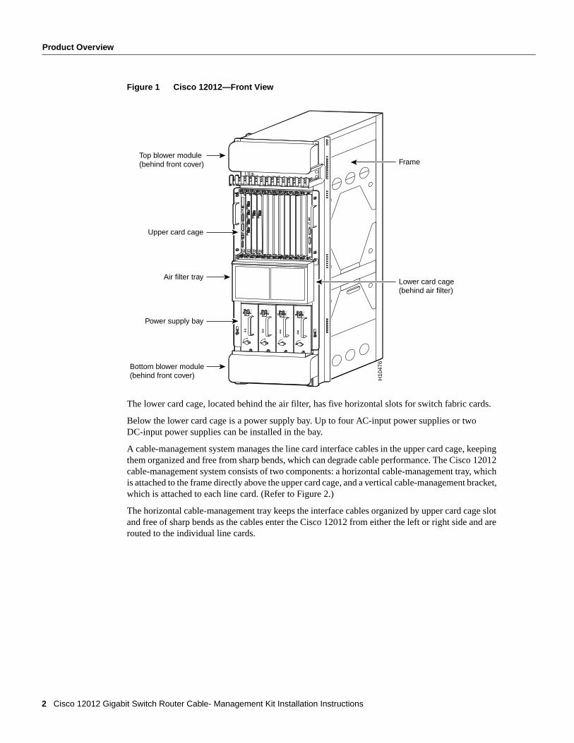
Product OverviewThe Cisco 12012 has two card cages; the upper card cage and the lower card cage. (Refer to Figure 1.) The upper card cage has 12 user-configurable slots available for line cards and a route processor (RP). One additional slot (rightmost slot) in the upper card cage is non-configurable; it is reserved for an alarm card. The line cards and the RP are not slot dependent; you can install the line cards and the RP in any of the first 12 available slots.
1Cisco Systems, Inc.All rights reserved.
170 West Tasman DriveSan Jose, CA 95134-1706USA
Cisco Systems, Inc.Corporate Headquarters
Copyright © 1997-2002
Product Overview
Figure 1 Cisco 12012—Front View
The lower card cage, located behind the air filter, has five horizontal slots for switch fabric cards.
Below the lower card cage is a power supply bay. Up to four AC-input power supplies or two DC-input power supplies can be installed in the bay.
A cable-management system manages the line card interface cables in the upper card cage, keeping them organized and free from sharp bends, which can degrade cable performance. The Cisco 12012 cable-management system consists of two components: a horizontal cable-management tray, which is attached to the frame directly above the upper card cage, and a vertical cable-management bracket, which is attached to each line card. (Refer to Figure 2.)
The horizontal cable-management tray keeps the interface cables organized by upper card cage slot and free of sharp bends as the cables enter the Cisco 12012 from either the left or right side and are routed to the individual line cards.
INPUT:200 -240V ~10 A50/60 HZ2000 W
ACOK
OUTPUTFAIL
INPUT:200 -240V ~10 A50/60 HZ2000 W
ACOK
OUTPUTFAIL
INPUT:200 -240V ~10 A50/60 HZ2000 W
ACOK
OUTPUTFAIL
INPUT:200 -240V ~10 A50/60 HZ2000 W
ACOK
OUTPUTFAIL
SLOT-0
RO
UT
E PR
OC
ESSO
R
SLOT-1COLL
LINKTX
RXRJ-45
MII
RESET
AUX
CONSOLE
EJECT
ACTIVE
0
CARRIER
RX PKT
ACTIVE
1
CARRIER
RX PKT
ACTIVE
2
CARRIER
RX PKT
ACTIVE
3
CARRIER
RX PKT
Q O
C-3/ST
M-PO
S
ACTIVE
0
CARRIER
RX CELL
OC
-12/STM
-4 AT
M
OC
-12/STM
-4 POS
ACTIVE
0
CARRIER
RX CELL
ACO/LT
AL
AR
M
CSC
0
FAIL
10
12
ENABLED
CRITICALMAJORMINOR
SFCALAR
M 1
ALARM
2
H10
476
Top blower module(behind front cover)
Upper card cage
Lower card cage(behind air filter)
Frame
Air filter tray
Power supply bay
Bottom blower module(behind front cover)
2 Cisco 12012 Gigabit Switch Router Cable- Management Kit Installation Instructions

Product Overview
Figure 2 Cisco 12012 Cable-Management System
The vertical cable-management bracket attaches to each line card with two captive screws. Rubber clips on the vertical cable-management bracket hold the line card’s interface cables in place, allowing installation and removal of adjacent line cards. A vertical cable-management bracket can be detached from the line card with the interface cables still in their clips, aligned to their respective line card ports. This speeds up a line card removal and replacement.
SLOT-0
GIG
AB
IT R
OU
TE
PRO
CE
SSOR
SLOT-1COLL
LINKTX
RXRJ-45
MII
RESET
AUX
CONSOLE
EJECT
ACTIVE
0
CARRIER
RX PKT
ACTIVE
1
CARRIER
RX PKT
ACTIVE
2
CARRIER
RX PKT
ACTIVE
3
CARRIER
RX PKT
Q O
C-3/ST
M-PO
S
ACTIVE
0
CARRIER
RX CELL
OC
-12/STM
-4 AT
M
OC
-12/STM
-4 POS
ACTIVE
0
CARRIER
RX CELL
ACO/LT
ALARM
1ALAR
M 2
AL
AR
M
CSC
0
FAIL
10
12
ENABLED
CRITICALMAJORMINOR
SFC
H10
706
Captive screw
Interface cable
Captive screw
Cutout for hook Chassis cable-management tray
Line cardcable-management
bracket
Hook
Cisco 12012 Gigabit Switch Router Cable- Management Kit Installation Instructions 3

Safety Guidelines
Safety GuidelinesBefore you begin the procedures in this document, review the safety guidelines in this section to avoid injuring yourself or damaging the equipment.
In addition, review the safety warnings listed in the document Regulatory Compliance and Safety Information for the Cisco 12012 Gigabit Switch Router (Document Number 78-4347-xx) that supports your Cisco 12012 before installing, configuring, or maintaining the router.
Safety with EquipmentThe following guidelines will help ensure your safety and protect the equipment. This list is not inclusive of all potentially hazardous situations, so be alert.
• Always disconnect all power cords and interface cables before moving the card cage assembly.
• Keep tools and assembly components away from walk areas.
• Do not work alone if potentially hazardous conditions exist.
• Do not perform any action that creates a potential hazard to people or makes the equipment unsafe.
• Carefully examine your work area for possible hazards such as moist floors, ungrounded power extension cables, and missing safety grounds.
Safety with ElectricityThe line cards, RP, switch fabric cards, alarm card, blower modules, and redundant power supplies are designed to be removed and replaced while the system is operating without presenting an electrical hazard or damage to the system.
Follow these basic guidelines when working with any electrical equipment:
• Before beginning any procedures requiring access to the interior of the Cisco 12012, locate the emergency power-off switch for the room in which you are working.
• Look carefully for possible hazards in your work area, such as moist floors, ungrounded power extension cables, and missing safety grounds.
• If an electrical accident occurs, proceed as follows:
— Use caution; do not become a victim yourself. Disconnect power to the system.
— If possible, send another person to get medical aid. Otherwise, assess the condition of the victim and then call for help.
— Determine if the person needs rescue breathing or external cardiac compressions; then take appropriate action.
• Disconnect all power and external cables before installing or removing a router.
• Never assume that power has been disconnected from a circuit; always check.
• Do not perform any action that creates a potential hazard to people or makes the equipment unsafe.
• Never install equipment that appears damaged.
4 Cisco 12012 Gigabit Switch Router Cable- Management Kit Installation Instructions

Tools and Parts Required
In addition, use the guidelines that follow when working with any equipment that is disconnected from a power source, but still connected to telephone or network wiring:
• Never install telephone wiring during a lightning storm.
• Never install telephone jacks in wet locations unless the jack is specifically designed for wet locations.
• Never touch uninsulated telephone wires or terminals unless the telephone line has been disconnected at the network interface.
• Use caution when installing or modifying telephone lines.
Preventing Electrostatic Discharge DamageElectrostatic discharge damage, which can occur when electronic boards or components are handled improperly, can result in complete or intermittent failures.
Following are guidelines for preventing ESD damage:
• Always use an ESD-preventive wrist strap or ankle strap and ensure that it makes good skin contact.
• When removing or installing a horizontal cable-management tray or vertical cable-management bracket, connect the equipment end of a ground strap to one of the two ESD ground sockets located on the front sides of the upper card cage or to a bare metal surface on the frame.
• If you plan to return a replaced part to the factory, immediately place it in a static shielding bag to avoid ESD damage to the part.
• The wrist strap only protects the part from ESD voltages on the body; ESD voltages on clothing can still cause damage.
Caution You should periodically check the resistance value of the antistatic strap. The measurement should be between 1 and 10 megohms.
Tools and Parts RequiredYou need the following tools and parts to install or replace a horizontal cable-management tray or vertical cable-management bracket:
• 3/16-inch flat-blade screwdriver
• ESD-preventive wrist strap
• A cable-management kit (Product Number ACS-GSR12-CCBLM=) or a vertical cable-management kit (Product Number ACS-GSR-LCCBLM=)
Cisco 12012 Gigabit Switch Router Cable- Management Kit Installation Instructions 5
Removing and Replacing the Cable-Management System
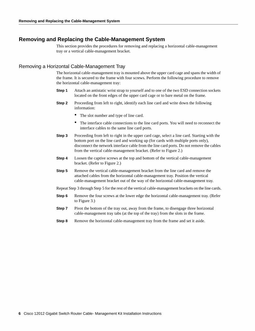
Removing and Replacing the Cable-Management SystemThis section provides the procedures for removing and replacing a horizontal cable-management tray or a vertical cable-management bracket.
Removing a Horizontal Cable-Management TrayThe horizontal cable-management tray is mounted above the upper card cage and spans the width of the frame. It is secured to the frame with four screws. Perform the following procedure to remove the horizontal cable-management tray:
Step 1 Attach an antistatic wrist strap to yourself and to one of the two ESD connection sockets located on the front edges of the upper card cage or to bare metal on the frame.
Step 2 Proceeding from left to right, identify each line card and write down the following information:
• The slot number and type of line card.
• The interface cable connections to the line card ports. You will need to reconnect the interface cables to the same line card ports.
Step 3 Proceeding from left to right in the upper card cage, select a line card. Starting with the bottom port on the line card and working up (for cards with multiple ports only), disconnect the network interface cable from the line card ports. Do not remove the cables from the vertical cable-management bracket. (Refer to Figure 2.)
Step 4 Loosen the captive screws at the top and bottom of the vertical cable-management bracket. (Refer to Figure 2.)
Step 5 Remove the vertical cable-management bracket from the line card and remove the attached cables from the horizontal cable-management tray. Position the vertical cable-management bracket out of the way of the horizontal cable-management tray.
Repeat Step 3 through Step 5 for the rest of the vertical cable-management brackets on the line cards.
Step 6 Remove the four screws at the lower edge the horizontal cable-management tray. (Refer to Figure 3.)
Step 7 Pivot the bottom of the tray out, away from the frame, to disengage three horizontal cable-management tray tabs (at the top of the tray) from the slots in the frame.
Step 8 Remove the horizontal cable-management tray from the frame and set it aside.
6 Cisco 12012 Gigabit Switch Router Cable- Management Kit Installation Instructions

Removing and Replacing the Cable-Management System
Figure 3 Removing the Horizontal Cable-Management Tray
Installing a Horizontal Cable-Management TrayPerform the following steps to install a replacement horizontal cable-management tray:
Step 1 Attach an antistatic wrist strap to yourself and to one of the two ESD connection sockets located on the front edges of the upper card cage or to bare metal on the frame.
Step 2 Remove the replacement horizontal cable-management tray from its shipping packaging.
Step 3 Angle the horizontal cable-management tray so that the top of the tray goes into the front of the frame first. Fit the three tabs at the top of the horizontal cable-management tray into the slots in the frame.
Step 4 Pivot the horizontal cable-management tray down so that the rest of the tray is in contact with the frame.
Step 5 Secure the horizontal cable-management tray in the frame with the four screws.
Step 6 Consulting your list of line cards and their interface cable connections, select the vertical cable-management bracket for the first line card (proceeding from left to right in the upper card cage).
SLOT-0
GIG
AB
IT R
OU
TE
PRO
CE
SSOR
SLOT-1COLL
LINKTX
RXRJ-45
MII
RESET
AUX
EJECT
ACTIVE
0
CARRIER
RX PKT
ACTIVE
1
CARRIER
RX PKT
ACTIVE
2
CARRIER
RX PKT
ACTIVE
3
CARRIER
RX PKT
Q O
C-3/ST
M-PO
S
ACTIVE
0
CARRIER
RX CELL
OC
-12/STM
-4 AT
M
OC
-12/STM
-4 POS
ACTIVE
0
CARRIER
RX CELL
ACO/LT
AL
AR
M
CSC
0
FAIL
10
12
ENABLED
CRITICALMAJORMINOR
SFCALAR
M 1
ALARM
2
H10
905
Horizontalcable-managementtray
Tabs (3)
Screws (4)
Frame
Cisco 12012 Gigabit Switch Router Cable- Management Kit Installation Instructions 7
Removing and Replacing the Cable-Management System
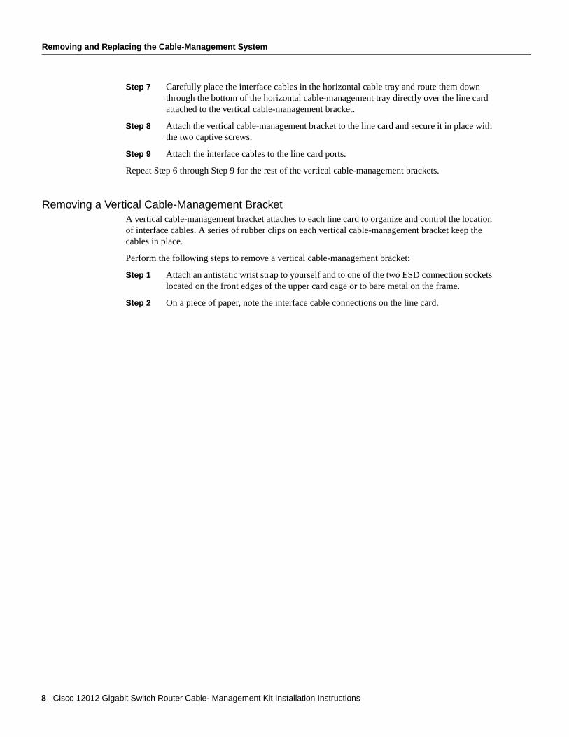
Step 7 Carefully place the interface cables in the horizontal cable tray and route them down through the bottom of the horizontal cable-management tray directly over the line card attached to the vertical cable-management bracket.
Step 8 Attach the vertical cable-management bracket to the line card and secure it in place with the two captive screws.
Step 9 Attach the interface cables to the line card ports.
Repeat Step 6 through Step 9 for the rest of the vertical cable-management brackets.
Removing a Vertical Cable-Management BracketA vertical cable-management bracket attaches to each line card to organize and control the location of interface cables. A series of rubber clips on each vertical cable-management bracket keep the cables in place.
Perform the following steps to remove a vertical cable-management bracket:
Step 1 Attach an antistatic wrist strap to yourself and to one of the two ESD connection sockets located on the front edges of the upper card cage or to bare metal on the frame.
Step 2 On a piece of paper, note the interface cable connections on the line card.
8 Cisco 12012 Gigabit Switch Router Cable- Management Kit Installation Instructions

Removing and Replacing the Cable-Management System
Step 3 Proceeding from the bottom port on the line card (for line cards with multiple ports only), disconnect the network interface cable from the each port on the line card. (Refer to Figure 4a.)
Step 4 Carefully remove the interface cable from the vertical cable-management bracket clips. (Refer to Figure 4b.)
Step 5 Carefully remove the interface cable from the vertical cable-management bracket clip nearest the line card port. (Refer to Figure 4c.) Set the interface cable aside.
Repeat Step 3 through Step 5 for the rest of the interface cables attached to the line card.
Figure 4 Removing the Cables From a Vertical Cable-Management Bracket
ACTIVE
0
CARRIER
RX PKT
ACTIVE
1
CARRIER
RX PKT
ACTIVE
2
CARRIER
RX PKT
ACTIVE
3
CARRIER
RX PKT
a
Chassiscable-management
tray
Line cardcable-management
bracketInterface
cable
ACTIVE
0
CARRIER
RX PKT
ACTIVE
1
CARRIER
RX PKT
ACTIVE
2
CARRIER
RX PKT
ACTIVE
3
CARRIER
RX PKT
b
Cable clip Cable clips
ACTIVE
0
CARRIER
RX PKT
ACTIVE
1
CARRIER
RX PKT
ACTIVE
2
CARRIER
RX PKT
ACTIVE
3
CARRIER
RX PKT
ACTIVE
0
CARRIER
RX PKT
ACTIVE
1
CARRIER
RX PKT
ACTIVE
2
CARRIER
RX PKT
ACTIVE
3
CARRIER
RX PKT
c
H10
880
Cisco 12012 Gigabit Switch Router Cable- Management Kit Installation Instructions 9

Removing and Replacing the Cable-Management System
Step 6 Loosen the two captive screws at the top and bottom of the vertical cable-management bracket.
Step 7 Remove the vertical cable-management bracket from the line card.
Installing a Vertical Cable-Management BracketIf you have installed a new line card in your Cisco 12012, you need to install a vertical cable-management bracket to keep the interface cables organized. The vertical cable-management bracket attaches to the line card faceplate with two captive screws; the interface cables are secured with clips.
Perform the following steps to install a vertical cable-management bracket:
Step 1 Attach an antistatic wrist strap to yourself and to one of the two ESD connection sockets located on the front edges of the upper card cage or to bare metal on the frame.
Step 2 Attach the vertical cable-management bracket to the line card. Secure the bracket in place with two captive screws.
Step 3 Carefully route the line card interface cables up through the horizontal cable-management tray and exit the horizontal tray either to the left side or the right side.
10 Cisco 12012 Gigabit Switch Router Cable- Management Kit Installation Instructions

Removing and Replacing the Cable-Management System
Step 4 Proceeding from the bottom port to the top port (for line cards with multiple ports only) identify the interface cable that connects to each line card port. Connect the interface cable to the line card port. (Refer to Figure 5a.)
Step 5 Proceeding from the bottom port to the top port (for line cards with multiple ports only), carefully press the interface cable into the vertical cable-management bracket clip. Avoid any kinks or sharp bends in the interface cable. (Refer to Figure 5b.)
Step 6 Proceeding from the bottom port to the top port (for line cards with multiple ports only), route the interface cable up the vertical cable-management bracket and carefully press the interface cable into the rest of the cable clips. (Refer to Figure 5c.)
Figure 5 Installing the Interface Cables in a Vertical Cable-Management Bracket
Repeat Step 3 through Step 6 for the rest of the interface cables to the line card.
ACTIVE
0
CARRIER
RX PKT
ACTIVE
1
CARRIER
RX PKT
ACTIVE
2
CARRIER
RX PKT
ACTIVE
3
CARRIER
RX PKT
Chassiscable-management
tray
Line cardcable-management
bracket
a
Interfacecable
ACTIVE
0
CARRIER
RX PKT
ACTIVE
1
CARRIER
RX PKT
ACTIVE
2
CARRIER
RX PKT
ACTIVE
3
CARRIER
RX PKT
Cable clip
b
ACTIVE
0
CARRIER
RX PKT
ACTIVE
1
CARRIER
RX PKT
ACTIVE
2
CARRIER
RX PKT
ACTIVE
3
CARRIER
RX PKT
H10
879
Cable clips
c
Cisco 12012 Gigabit Switch Router Cable- Management Kit Installation Instructions 11
FCC Class A Compliance
FCC Class A ComplianceThis equipment has been tested and found to comply with the limits for a Class A digital device, pursuant to part 15 of the FCC rules. These limits are designed to provide reasonable protection against harmful interference when the equipment is operated in a commercial environment. This equipment generates, uses, and can radiate radio-frequency energy and, if not installed and used in accordance with the instruction manual, may cause harmful interference to radio communications. Operation of this equipment in a residential area is likely to cause harmful interference, in which case users will be required to correct the interference at their own expense.
You can determine whether your equipment is causing interference by turning it off. If the interference stops, it was probably caused by the Cisco equipment or one of its peripheral devices. If the equipment causes interference to radio or television reception, try to correct the interference by using one or more of the following measures:
• Turn the television or radio antenna until the interference stops.
• Move the equipment to one side or the other of the television or radio.
• Move the equipment farther away from the television or radio.
• Plug the equipment into an outlet that is on a different circuit from the television or radio. (That is, make certain the equipment and the television or radio are on circuits controlled by different circuit breakers or fuses.)
Modifications to this product not authorized by Cisco Systems, Inc. could void the FCC approval and negate your authority to operate the product.
12 Cisco 12012 Gigabit Switch Router Cable- Management Kit Installation Instructions

Cisco Connection Online
Cisco Connection OnlineCisco Connection Online (CCO) is Cisco Systems’ primary, real-time support channel. Maintenance customers and partners can self-register on CCO to obtain additional information and services.
Available 24 hours a day, 7 days a week, CCO provides a wealth of standard and value-added services to Cisco’s customers and business partners. CCO services include product information, product documentation, software updates, release notes, technical tips, the Bug Navigator, configuration notes, brochures, descriptions of service offerings, and download access to public and authorized files.
CCO serves a wide variety of users through two interfaces that are updated and enhanced simultaneously: a character-based version and a multimedia version that resides on the World Wide Web (WWW). The character-based CCO supports Zmodem, Kermit, Xmodem, FTP, and Internet e-mail, and it is excellent for quick access to information over lower bandwidths. The WWW version of CCO provides richly formatted documents with photographs, figures, graphics, and video, as well as hyperlinks to related information.
You can access CCO in the following ways:
• WWW: http://www.cisco.com
• WWW: http://www-europe.cisco.com
• WWW: http://www-china.cisco.com
• Telnet: cco.cisco.com
• Modem: From North America, 408 526-8070; from Europe, 33 1 64 46 40 82. Use the following terminal settings: VT100 emulation; databits: 8; parity: none; stop bits: 1; and connection rates up to 28.8 kbps.
For a copy of CCO’s Frequently Asked Questions (FAQ), contact [email protected]. For additional information, contact [email protected].
Note If you are a network administrator and need personal technical assistance with a Cisco product that is under warranty or covered by a maintenance contract, contact Cisco’s Technical Assistance Center (TAC) at 800 553-2447, 408 526-7209, or [email protected]. To obtain general information about Cisco Systems, Cisco products, or upgrades, contact 800 553-6387, 408 526-7208, or [email protected].
This document is to be used in conjunction with the Cisco 12012 Gigabit Switch Router Installation and Configuration Guide.
CCIP, the Cisco Powered Network mark, the Cisco Systems Verified logo, Cisco Unity, Follow Me Browsing, FormShare, Internet Quotient, iQ Breakthrough, iQ Expertise, iQ FastTrack, the iQ Logo, iQ Net Readiness Scorecard, Networking Academy, ScriptShare, SMARTnet, TransPath, and Voice LAN are trademarks of Cisco Systems, Inc.; Changing the Way We Work, Live, Play, and Learn, Discover All That’s Possible, The Fastest Way to Increase Your Internet Quotient, and iQuick Study are service marks of Cisco Systems, Inc.; and Aironet, ASIST, BPX, Catalyst, CCDA, CCDP, CCIE, CCNA, CCNP, Cisco, the Cisco Certified Internetwork Expert logo, Cisco IOS, the Cisco IOS logo, Cisco Press, Cisco Systems, Cisco Systems Capital, the Cisco Systems logo, Empowering the Internet Generation, Enterprise/Solver, EtherChannel, EtherSwitch, Fast Step, GigaStack, IOS, IP/TV, LightStream, MGX, MICA, the Networkers logo, Network Registrar, Packet, PIX, Post-Routing, Pre-Routing, RateMUX, Registrar, SlideCast, StrataView Plus, Stratm, SwitchProbe, TeleRouter, and VCO are registered trademarks of Cisco Systems, Inc. and/or its affiliates in the U.S. and certain other countries.
All other trademarks mentioned in this document or Web site are the property of their respective owners. The use of the word partner does not imply a partnership relationship between Cisco and any other company. (0203R)
Copyright © 1997-2002, Cisco Systems, Inc.All rights reserved.
Cisco 12012 Gigabit Switch Router Cable- Management Kit Installation Instructions 13

Cisco Connection Online
14 Cisco 12012 Gigabit Switch Router Cable- Management Kit Installation Instructions