cisco 1900 series integrated services router hardware ... · vii cisco 1900 series hardware...
TRANSCRIPT
Preface
This preface describes the objectives, audience, organization, and conventions of this guide, and describes related documents that have additional information.
• Objectives, page vii
• Audience, page vii
• Organization, page viii
• Conventions, page viii
• Related Documentation, page xv
• Searching within Cisco Documents, page xvi
• Obtaining Documentation and Submitting a Service Request, page xvi
ObjectivesThis guide provides an overview and explains how to install, connect, and perform initial configuration for the Cisco 1900 Integrated Services Routers (ISRs). Some information may not apply to your particular router model.
For warranty, service, and support information, see the “Cisco Warranty Terms” section in the Readme First for the Cisco 1900 Series Integrated Services Routers document that was shipped with your router.
AudienceThis documentation is designed for the person installing, configuring, and maintaining the router, who should be familiar with electronic circuitry and wiring practices and has experience as an electronic or electromechanical technician. It identifies certain procedures that should be performed only by trained and qualified personnel.
viiCisco 1900 Series Hardware Installation
OL-19084-02
Preface
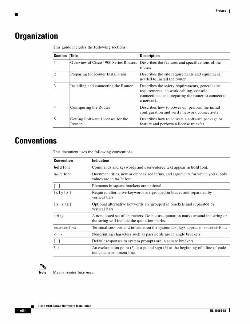
OrganizationThis guide includes the following sections:
ConventionsThis document uses the following conventions:
Note Means reader take note.
Section Title Description
1 Overview of Cisco 1900 Series Routers Describes the features and specifications of the router.
2 Preparing for Router Installation Describes the site requirements and equipment needed to install the router.
3 Installing and connecting the Router Describes the safety requirements, general site requirements, network cabling, console connections, and preparing the router to connect to a network.
4 Configuring the Router Describes how to power up, perform the initial configuration and verify network connectivity.
5 Getting Software Licenses for the Router
Describes how to activate a software package or feature and perform a license transfer.
Convention Indication
bold font Commands and keywords and user-entered text appear in bold font.
italic font Document titles, new or emphasized terms, and arguments for which you supply values are in italic font.
[ ] Elements in square brackets are optional.
{x | y | z } Required alternative keywords are grouped in braces and separated by vertical bars.
[ x | y | z ] Optional alternative keywords are grouped in brackets and separated by vertical bars.
string A nonquoted set of characters. Do not use quotation marks around the string or the string will include the quotation marks.
courier font Terminal sessions and information the system displays appear in courier font.
< > Nonprinting characters such as passwords are in angle brackets.
[ ] Default responses to system prompts are in square brackets.
!, # An exclamation point (!) or a pound sign (#) at the beginning of a line of code indicates a comment line.
viiiCisco 1900 Series Hardware Installation
OL-19084-02
Preface
Tip Means the following information will help you solve a problem.
Caution Means reader be careful. In this situation, you might perform an action that could result in equipment damage or loss of data.
Timesaver Means the described action saves time. You can save time by performing the action described in the paragraph.
Warning IMPORTANT SAFETY INSTRUCTIONS
This warning symbol means danger. You are in a situation that could cause bodily injury. Before you work on any equipment, be aware of the hazards involved with electrical circuitry and be familiar with standard practices for preventing accidents. Use the statement number provided at the end of each warning to locate its translation in the translated safety warnings that accompanied this device. Statement 1071
SAVE THESE INSTRUCTIONS
Waarschuwing BELANGRIJKE VEILIGHEIDSINSTRUCTIES
Dit waarschuwingssymbool betekent gevaar. U verkeert in een situatie die lichamelijk letsel kan veroorzaken. Voordat u aan enige apparatuur gaat werken, dient u zich bewust te zijn van de bij elektrische schakelingen betrokken risico's en dient u op de hoogte te zijn van de standaard praktijken om ongelukken te voorkomen. Gebruik het nummer van de verklaring onderaan de waarschuwing als u een vertaling van de waarschuwing die bij het apparaat wordt geleverd, wilt raadplegen.
BEWAAR DEZE INSTRUCTIES
Varoitus TÄRKEITÄ TURVALLISUUSOHJEITA
Tämä varoitusmerkki merkitsee vaaraa. Tilanne voi aiheuttaa ruumiillisia vammoja. Ennen kuin käsittelet laitteistoa, huomioi sähköpiirien käsittelemiseen liittyvät riskit ja tutustu onnettomuuksien yleisiin ehkäisytapoihin. Turvallisuusvaroitusten käännökset löytyvät laitteen mukana toimitettujen käännettyjen turvallisuusvaroitusten joukosta varoitusten lopussa näkyvien lausuntonumeroiden avulla.
SÄILYTÄ NÄMÄ OHJEET
ixCisco 1900 Series Hardware Installation
OL-19084-02
Preface
Attention IMPORTANTES INFORMATIONS DE SÉCURITÉ
Ce symbole d'avertissement indique un danger. Vous vous trouvez dans une situation pouvant entraîner des blessures ou des dommages corporels. Avant de travailler sur un équipement, soyez conscient des dangers liés aux circuits électriques et familiarisez-vous avec les procédures couramment utilisées pour éviter les accidents. Pour prendre connaissance des traductions des avertissements figurant dans les consignes de sécurité traduites qui accompagnent cet appareil, référez-vous au numéro de l'instruction situé à la fin de chaque avertissement.
CONSERVEZ CES INFORMATIONS
Warnung WICHTIGE SICHERHEITSHINWEISE
Dieses Warnsymbol bedeutet Gefahr. Sie befinden sich in einer Situation, die zu Verletzungen führen kann. Machen Sie sich vor der Arbeit mit Geräten mit den Gefahren elektrischer Schaltungen und den üblichen Verfahren zur Vorbeugung vor Unfällen vertraut. Suchen Sie mit der am Ende jeder Warnung angegebenen Anweisungsnummer nach der jeweiligen Übersetzung in den übersetzten Sicherheitshinweisen, die zusammen mit diesem Gerät ausgeliefert wurden.
BEWAHREN SIE DIESE HINWEISE GUT AUF.
Avvertenza IMPORTANTI ISTRUZIONI SULLA SICUREZZA
Questo simbolo di avvertenza indica un pericolo. La situazione potrebbe causare infortuni alle persone. Prima di intervenire su qualsiasi apparecchiatura, occorre essere al corrente dei pericoli relativi ai circuiti elettrici e conoscere le procedure standard per la prevenzione di incidenti. Utilizzare il numero di istruzione presente alla fine di ciascuna avvertenza per individuare le traduzioni delle avvertenze riportate in questo documento.
CONSERVARE QUESTE ISTRUZIONI
Advarsel VIKTIGE SIKKERHETSINSTRUKSJONER
Dette advarselssymbolet betyr fare. Du er i en situasjon som kan føre til skade på person. Før du begynner å arbeide med noe av utstyret, må du være oppmerksom på farene forbundet med elektriske kretser, og kjenne til standardprosedyrer for å forhindre ulykker. Bruk nummeret i slutten av hver advarsel for å finne oversettelsen i de oversatte sikkerhetsadvarslene som fulgte med denne enheten.
TA VARE PÅ DISSE INSTRUKSJONENE
Aviso INSTRUÇÕES IMPORTANTES DE SEGURANÇA
Este símbolo de aviso significa perigo. Você está em uma situação que poderá ser causadora de lesões corporais. Antes de iniciar a utilização de qualquer equipamento, tenha conhecimento dos perigos envolvidos no manuseio de circuitos elétricos e familiarize-se com as práticas habituais de prevenção de acidentes. Utilize o número da instrução fornecido ao final de cada aviso para localizar sua tradução nos avisos de segurança traduzidos que acompanham este dispositivo.
GUARDE ESTAS INSTRUÇÕES
xCisco 1900 Series Hardware Installation
OL-19084-02
Preface
¡Advertencia! INSTRUCCIONES IMPORTANTES DE SEGURIDAD
Este símbolo de aviso indica peligro. Existe riesgo para su integridad física. Antes de manipular cualquier equipo, considere los riesgos de la corriente eléctrica y familiarícese con los procedimientos estándar de prevención de accidentes. Al final de cada advertencia encontrará el número que le ayudará a encontrar el texto traducido en el apartado de traducciones que acompaña a este dispositivo.
GUARDE ESTAS INSTRUCCIONES
Varning! VIKTIGA SÄKERHETSANVISNINGAR
Denna varningssignal signalerar fara. Du befinner dig i en situation som kan leda till personskada. Innan du utför arbete på någon utrustning måste du vara medveten om farorna med elkretsar och känna till vanliga förfaranden för att förebygga olyckor. Använd det nummer som finns i slutet av varje varning för att hitta dess översättning i de översatta säkerhetsvarningar som medföljer denna anordning.
SPARA DESSA ANVISNINGAR
xiCisco 1900 Series Hardware Installation
OL-19084-02
Preface
Aviso INSTRUÇÕES IMPORTANTES DE SEGURANÇA
Este símbolo de aviso significa perigo. Você se encontra em uma situação em que há risco de lesões corporais. Antes de trabalhar com qualquer equipamento, esteja ciente dos riscos que envolvem os circuitos elétricos e familiarize-se com as práticas padrão de prevenção de acidentes. Use o número da declaração fornecido ao final de cada aviso para localizar sua tradução nos avisos de segurança traduzidos que acompanham o dispositivo.
GUARDE ESTAS INSTRUÇÕES
Advarsel VIGTIGE SIKKERHEDSANVISNINGER
Dette advarselssymbol betyder fare. Du befinder dig i en situation med risiko for legemesbeskadigelse. Før du begynder arbejde på udstyr, skal du være opmærksom på de involverede risici, der er ved elektriske kredsløb, og du skal sætte dig ind i standardprocedurer til undgåelse af ulykker. Brug erklæringsnummeret efter hver advarsel for at finde oversættelsen i de oversatte advarsler, der fulgte med denne enhed.
GEM DISSE ANVISNINGER
xiiCisco 1900 Series Hardware Installation
OL-19084-02
Preface
xiiiCisco 1900 Series Hardware Installation
OL-19084-02
Preface
Warning When installing the product, please use the provided or designated connection cables/power cables/AC adaptors. Using any other cables/adaptors could cause a malfunction or a fire. Electrical Appliance and Material Safety Law prohibits the use of UL-certified cables (that have the “UL” shown on the code) for any other electrical devices than products designated by CISCO. The use of cables that are certified by Electrical Appliance and Material Safety Law (that have “PSE” shown on the code) is not limited to CISCO-designated products. Statement 371.
Warning There is the danger of explosion if the battery is replaced incorrectly. Replace the battery only with the same or equivalent type recommended by the manufacturer. Dispose of used batteries according to the manufacturer’s instructions. Statement 1015
Warning Do not use this product near water; for example, near a bath tub, wash bowl, kitchen sink or laundry tub, in a wet basement, or near a swimming pool. Statement 1035
Warning Never install telephone jacks in wet locations unless the jack is specifically designed for wet locations. Statement 1036
Warning Never touch uninsulated telephone wires or terminals unless the telephone line has been disconnected at the network interface. Statement 1037
xivCisco 1900 Series Hardware Installation
OL-19084-02
Preface
Avoid using a telephone (other than a cordless type) during an electrical storm. There may be a remote risk of electric shock from lightning. Statement 1038
Related DocumentationThe Cisco IOS software that runs your Cisco 1940 series router includes extensive features and functionality. For information that is beyond the scope of this document, or for additional information, use the following resources.
Timesaver Make sure that you have access to the documents listed below. Some of these documents are available in print, and all are on the Internet. If you need to order printed documents, see the “Obtaining Documentation and Submitting a Service Request” section on page xvi.
• Regulatory Compliance and Safety Information for Cisco 1900 Series Integrated Services Routers
• Software Activation for Cisco Integrated Services Routers
• Cisco IOS Software Activation Configuration Guide
• Cisco CP Express User’s Guide
• Overview of Cisco Network Modules and Service Modules for Cisco Access Routers
• Installing Cisco Network Modules and Service Modules in Cisco Access Routers
• Cisco Interface Cards for Cisco Access Routers
• Installing Cisco Interface Cards in Cisco Access Routers
• Installing, Replacing, and Upgrading Components in Cisco Modular Access Routers and Integrated Services Routers
• Declarations of Conformity and Regulatory Information for Cisco Access Products with 802.11a/b/g and 802.11b/g Radios
• Cisco IOS Release Notes
• Cisco IOS Quality of Service Solutions Command Reference, Release 12.4T
• Cisco IOS Security Configuration Guide, Release 12.4T
• Cisco IOS Security Command Reference, Release 12.4T
• Cisco IOS Command Reference for Cisco Aironet Access Points and Bridges, versions 12.4(10b) JA and 12.3(8) JEC
• Wireless LAN Controllers
• Unified Wireless LAN Access Points
• Cisco IOS Voice Port Configuration Guide
• SCCP Controlled Analog (FXS) Ports with Supplementary Features in Cisco IOS Gateways
• Cisco Modular Access Router Cable Specifications
• Module Support on Cisco's Integrated Services Routers Generation 2
• Installing and Upgrading Internal Modules and FRUs in Cisco 1900 Series ISRs
xvCisco 1900 Series Hardware Installation
OL-19084-02
Preface
Searching within Cisco DocumentsTo search an HTML document using a web browser, press Ctrl-F (Windows) or Cmd-F (Apple). In most browsers, the option to search whole words only, invoke case sensitivity, or search forward and backward is also available.
To search a PDF document in Adobe Reader, use the basic Find toolbar (Ctrl-F) or the Full Reader Search window (Shift-Ctrl-F). Use the Find toolbar to find words or phrases within a specific document. Use the Full Reader Search window to search multiple PDF files simultaneously and to change case sensitivity and other options. Adobe Reader's online help has more information about how to search PDF documents.
Obtaining Documentation and Submitting a Service RequestFor information on obtaining documentation, submitting a service request, and gathering additional information, see the monthly What’s New in Cisco Product Documentation, which also lists all new and revised Cisco technical documentation, at:
http://www.cisco.com/en/US/docs/general/whatsnew/whatsnew.html
Subscribe to the What’s New in Cisco Product Documentation as a Really Simple Syndication (RSS) feed and set content to be delivered directly to your desktop using a reader application. The RSS feeds are a free service and Cisco currently supports RSS Version 2.0.
xviCisco 1900 Series Hardware Installation
OL-19084-02
OL-19084-02
C H A P T E R 1
Overview of the RouterThe Cisco 1900 Series Integrated Services Routers (ISRs) are modular routers with LAN and WAN connections that can be configured by means of interchangeable interface cards and internal service modules (ISMs). The series currently consists of the 1905, 1921, 1941, and 1941W (wireless) models. The 1941W is Wi-Fi CERTIFIED™ and 802.11a/b/g/n-compliant. The modular design of the routers provides flexibility, allowing you to configure your router according to your needs.
This ISR series has new slots that support next generation Enhanced High-Speed WAN Interface Cards (EHWICs), Internal Services Modules (ISMs, 1941 only), and 2 CompactFlash cards (1941 only). Universal serial bus (USB) ports are available for USB devices, and a USB mini Type-B serial console port is available in addition to the RJ-45 console connector.
This chapter provides an overview of the Cisco 1900 series routers and includes the following sections:
• Safety Warnings, page 1-1
• Chassis Views, page 1-2
• Hardware Features, page 1-5
• Interface Numbering, page 1-13
• Specifications, page 1-13
• Regulatory Compliance, page 1-18
Safety Warnings
Warning IMPORTANT SAFETY INSTRUCTIONS
This warning symbol means danger. You are in a situation that could cause bodily injury. Before you work on any equipment, be aware of the hazards involved with electrical circuitry and be familiar with standard practices for preventing accidents. Use the statement number provided at the end of each warning to locate its translation in the translated safety warnings that accompanied this device. Statement 1071
SAVE THESE INSTRUCTIONS
Warning Ultimate disposal of this product should be handled according to all national laws and regulations. Statement 1040
1-1Cisco 1900 Series Hardware Installation
Chapter 1 Overview of the Router Chassis Views
Warning No user-serviceable parts inside. Do not open. Statement 1073
Warning Only trained and qualified personnel should be allowed to install, replace, or service this equipment. Statement 1030
Safety Warnings for Finland, Norway and SwedenWarning statement 1017 applies to the countries of Finland, Norway, and Sweden.
Warning This unit is intended for installation in restricted access areas. A restricted access area can be accessed only through the use of a special tool, lock and key, or other means of security. Statement 1017
Chassis ViewsThis section contains views of the front and rear panels of Cisco 1900 series routers, showing the locations of the power and signal interfaces, the interface card slots, and the status indicators.
Figure 1-1 shows the front panel of the Cisco 1905 and Cisco 1921 router. Figure 1-2 shows the back panel connectors on the Cisco 1905 and Cisco 1921 router. Figure 1-3 shows the front panel of a Cisco 1941 wireless router and Figure 1-4 shows the LEDs of the Cisco 1941 router. Figure 1-5 shows the back panel connectors on the Cisco 1941 router.
Caution Power off the router and the power over Ethernet (PoE) before installing an EHWIC in the Cisco 1905 and Cisco 1921 ISRs.
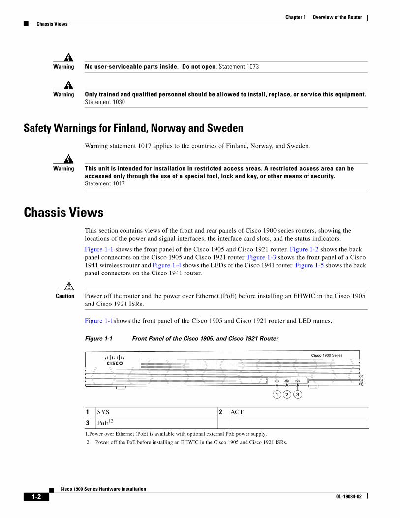
Figure 1-1shows the front panel of the Cisco 1905 and Cisco 1921 router and LED names.
Figure 1-1 Front Panel of the Cisco 1905, and Cisco 1921 Router
1 SYS 2 ACT
3 PoE12
1.Power over Ethernet (PoE) is available with optional external PoE power supply.
2. Power off the PoE before installing an EHWIC in the Cisco 1905 and Cisco 1921 ISRs.
Cisco 1900 Series
SYS ACT POE
2537
07
1 2 3
1-2Cisco 1900 Series Hardware Installation
OL-19084-02
Chapter 1 Overview of the Router Chassis Views
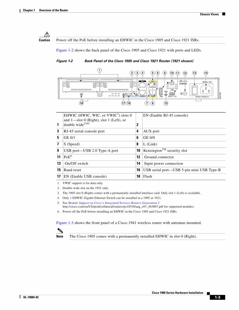
Caution Power off the PoE before installing an EHWIC in the Cisco 1905 and Cisco 1921 ISRs.
Figure 1-2 shows the back panel of the Cisco 1905 and Cisco 1921 with ports and LEDs.
Figure 1-2 Back Panel of the Cisco 1905 and Cisco 1921 Router (1921 shown)
Figure 1-3 shows the front panel of a Cisco 1941 wireless router with antennas mounted.
Note The Cisco 1905 comes with a permanently installed EHWIC in slot 0 (Right).
1
EHWIC (HWIC, WIC, or VWIC1) slots 0 and 1—slot 0 (Right), slot 1 (Left), or double wide2345
1. VWIC support is for data only.
2. Double-wide slot on the 1921 only.
3. The 1905 slot 0 (Right) comes with a permanently installed interface card. Only slot 1 (Left) is available.
4. Only 1 EHWIC Gigabit Ethernet Switch can be installed in a 1905 or 1921.
5. See Module Support on Cisco’s Integrated Services Routers Generation 2 http://cisco.com/en/US/prod/collateral/routers/ps10538/aag_c07_563807.pdf for supported modules.
2
EN (Enable RJ-45 console)
3 RJ-45 serial console port 4 AUX port
5 GE 0/1 6 GE 0/0
7 S (Speed) 8 L (Link)
9 USB port—USB 2.0 Type-A port 10 KensingtonTM security slot
11 PoE6
6. Power off the PoE before installing an EHWIC in the Cisco 1905 and Cisco 1921 ISRs.
12 Ground connector
13 On/Off switch 14 Input power connection
15 Baud reset 16 USB serial port—USB 5-pin mini USB Type-B
17 EN (Enable USB console) 18 Flash
EN EN
S L
CONSOLE
AUX
GE 0/0
GE 0/1
POE
FLASH
Cisco 1921
RESET
EHWIC 1 EHWIC 0
S L
BAUD
53VDC 1.5A 100-240 V~ 50-60 Hz 1A
25
37
08
4 10 121
15
3 5 6 9 11 13
161718
2 14
7 8
1-3Cisco 1900 Series Hardware Installation
OL-19084-02
Chapter 1 Overview of the Router Chassis Views
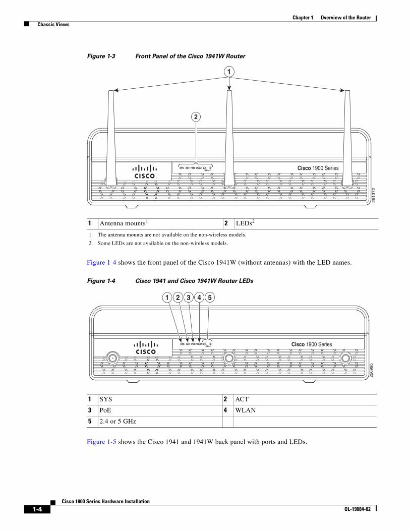
Figure 1-3 Front Panel of the Cisco 1941W Router
Figure 1-4 shows the front panel of the Cisco 1941W (without antennas) with the LED names.
Figure 1-4 Cisco 1941 and Cisco 1941W Router LEDs
Figure 1-5 shows the Cisco 1941 and 1941W back panel with ports and LEDs.
1 Antenna mounts1
1. The antenna mounts are not available on the non-wireless models.
2 LEDs2
2. Some LEDs are not available on the non-wireless models.
GHzSYS ACT POE WLAN 2.4 5
25
13
72
1
2
Cisco 1900 Series
1 SYS 2 ACT
3 PoE 4 WLAN
5 2.4 or 5 GHz
GHzSYS ACT POE WLAN 2.4 5
1 2 3 4
25
09
95
5
Cisco 1900 Series
1-4Cisco 1900 Series Hardware Installation
OL-19084-02
Chapter 1 Overview of the Router Hardware Features
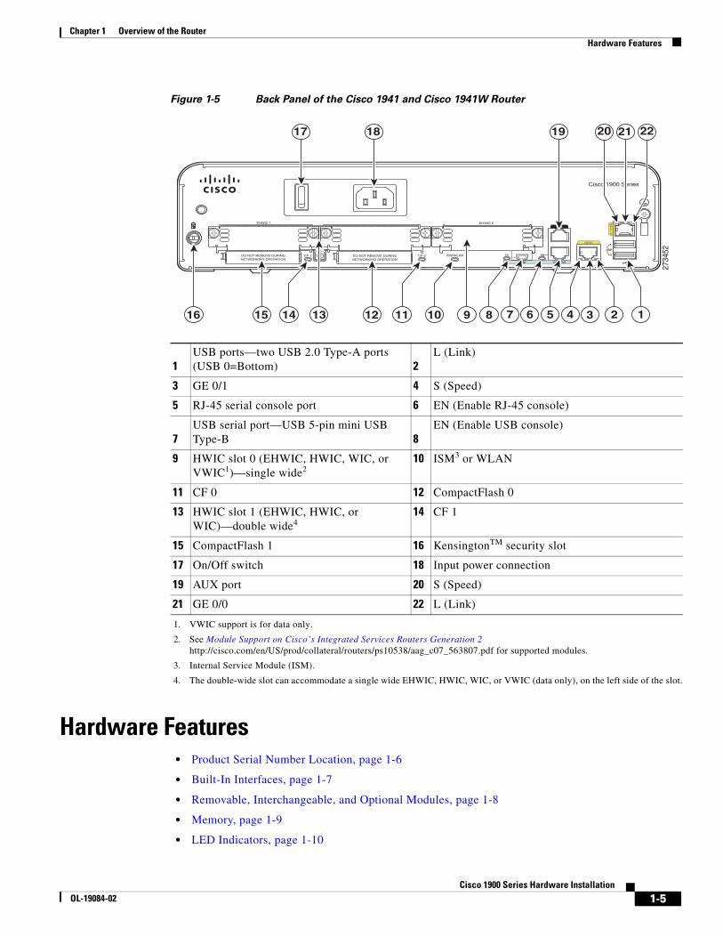
Figure 1-5 Back Panel of the Cisco 1941 and Cisco 1941W Router
Hardware Features• Product Serial Number Location, page 1-6
• Built-In Interfaces, page 1-7
• Removable, Interchangeable, and Optional Modules, page 1-8
• Memory, page 1-9
• LED Indicators, page 1-10
1USB ports—two USB 2.0 Type-A ports (USB 0=Bottom) 2
L (Link)
3 GE 0/1 4 S (Speed)
5 RJ-45 serial console port 6 EN (Enable RJ-45 console)
7USB serial port—USB 5-pin mini USB Type-B 8
EN (Enable USB console)
9 HWIC slot 0 (EHWIC, HWIC, WIC, or VWIC1)—single wide2
1. VWIC support is for data only.
2. See Module Support on Cisco’s Integrated Services Routers Generation 2 http://cisco.com/en/US/prod/collateral/routers/ps10538/aag_c07_563807.pdf for supported modules.
10 ISM3 or WLAN
3. Internal Service Module (ISM).
11 CF 0 12 CompactFlash 0
13 HWIC slot 1 (EHWIC, HWIC, or WIC)—double wide4
4. The double-wide slot can accommodate a single wide EHWIC, HWIC, WIC, or VWIC (data only), on the left side of the slot.
14 CF 1
15 CompactFlash 1 16 KensingtonTM security slot
17 On/Off switch 18 Input power connection
19 AUX port 20 S (Speed)
21 GE 0/0 22 L (Link)
2734
52
L
CONSOLE
AUX
S
USB
1
GE0/0
0EN ENCF 0CF 1 ISM/WLAN
EHWIC 1 EHWIC 0
S L
GE 0/1
DO NOT REMOVE DURINGNETWORKING OPERATION
DO NOT REMOVE DURINGNETWORKING OPERATION
Cisco 1900 Series
1516 38 7 6 5 4 2
2220
1112
17 18 19 21
13 191014
1-5Cisco 1900 Series Hardware Installation
OL-19084-02
Chapter 1 Overview of the Router Hardware Features
• Chassis Ventilation, page 1-12
• Real-Time Clock, page 1-12
• Chassis Security, page 1-12
• Wireless LAN Connectivity, page 1-12
• Baud Reset Button, page 1-13
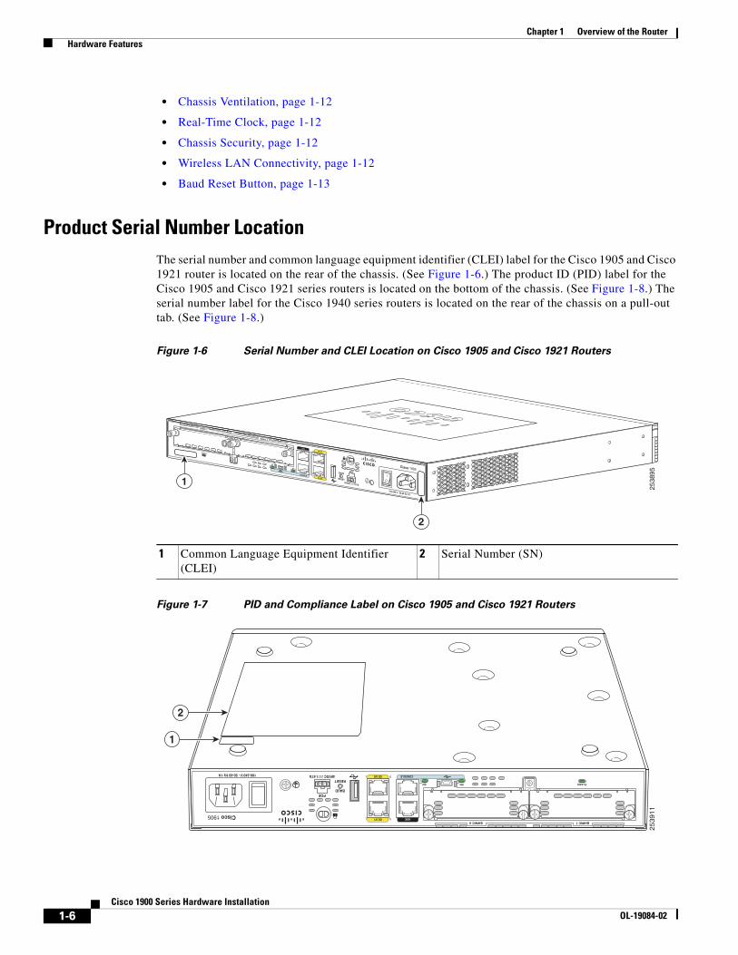
Product Serial Number LocationThe serial number and common language equipment identifier (CLEI) label for the Cisco 1905 and Cisco 1921 router is located on the rear of the chassis. (See Figure 1-6.) The product ID (PID) label for the Cisco 1905 and Cisco 1921 series routers is located on the bottom of the chassis. (See Figure 1-8.) The serial number label for the Cisco 1940 series routers is located on the rear of the chassis on a pull-out tab. (See Figure 1-8.)
Figure 1-6 Serial Number and CLEI Location on Cisco 1905 and Cisco 1921 Routers
Figure 1-7 PID and Compliance Label on Cisco 1905 and Cisco 1921 Routers
EN
EN
CONSOLE
FLASH
EHWIC 1
EHWIC 0
SL
AUX
GE 0/0
GE 0/1
POE
Cisco 1905
RESETS
L
BAUD
48VDC 1.67A
100-240 V~ 50-60 Hz 1A
2538
95
2
1
1 Common Language Equipment Identifier (CLEI)
2 Serial Number (SN)
ENEN
SL
CONSOLE
AUX
GE 0/0
GE 0/1
POE
FLASH
Cisco 1905
RESET
EHWIC 1EHWIC 0
SL
BAUD
48VDC 1.67A100-240 V~ 50-60 Hz 1A
25
39
11
1
2
1-6Cisco 1900 Series Hardware Installation
OL-19084-02

Chapter 1 Overview of the Router Hardware Features
Figure 1-8 Serial Number, PID/VID, and CLEI Number Location on Cisco 1940 Series Routers
Note The serial number for Cisco 1900 series routers is 11 characters long.
Cisco Product Identification Tool
The Cisco Product Identification (CPI) tool provides detailed illustrations and descriptions showing where to locate serial number labels on Cisco products. It includes the following features:
• A search option that allows browsing for models using a tree-structured product hierarchy
• A search field on the final results page making it easier to look up multiple products
• End-of-sale products are clearly identified in results lists
The tool streamlines the process of locating serial number labels and identifying products. Serial number information expedites the entitlement process and is important for access to support services.
The Cisco Product Identification tool can be accessed at the following URL:
http://tools.cisco.com/Support/CPI/index.do
Built-In InterfacesTable describes the interfaces available on the Cisco 1900 series routers.
1 Product ID (PID) 2 Compliance label
DO NOT REMOVE DURINGNETWORK OPERATION DO NOT REMOVE DURING NETWORK OPERATION
2513
70
1
4 3
2
OVE DURING
K OPERATION
1 Product ID (PID) 2 Serial Number (SN)
3 Product ID/Version ID (PID/VID) 4 Common Language Equipment Identifier (CLEI)
1-7Cisco 1900 Series Hardware Installation
OL-19084-02
Chapter 1 Overview of the Router Hardware Features
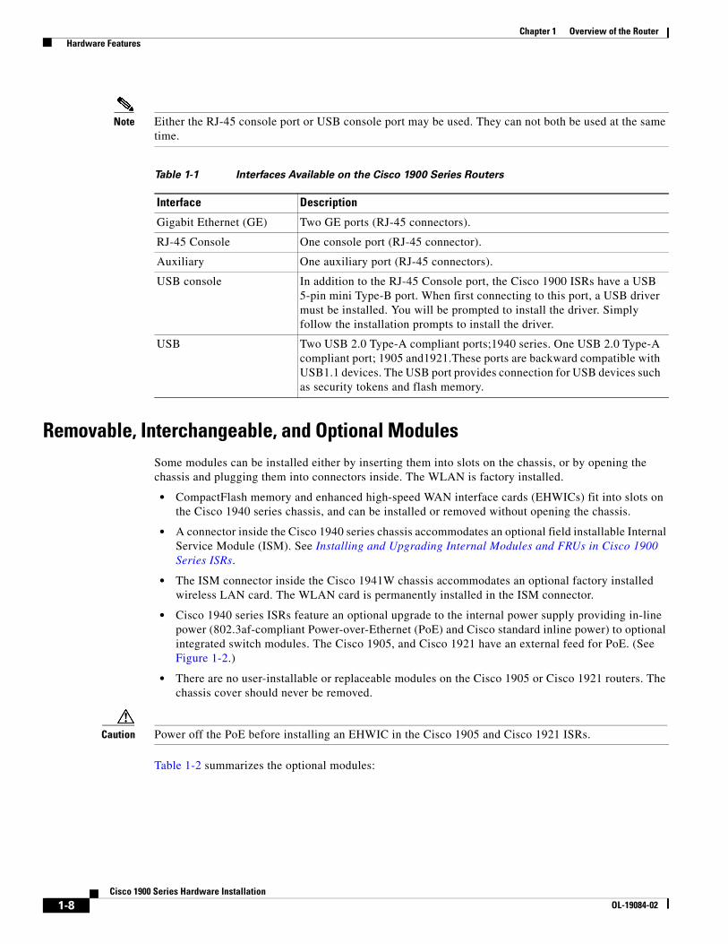
Note Either the RJ-45 console port or USB console port may be used. They can not both be used at the same time.
Removable, Interchangeable, and Optional ModulesSome modules can be installed either by inserting them into slots on the chassis, or by opening the chassis and plugging them into connectors inside. The WLAN is factory installed.
• CompactFlash memory and enhanced high-speed WAN interface cards (EHWICs) fit into slots on the Cisco 1940 series chassis, and can be installed or removed without opening the chassis.
• A connector inside the Cisco 1940 series chassis accommodates an optional field installable Internal Service Module (ISM). See Installing and Upgrading Internal Modules and FRUs in Cisco 1900 Series ISRs.
• The ISM connector inside the Cisco 1941W chassis accommodates an optional factory installed wireless LAN card. The WLAN card is permanently installed in the ISM connector.
• Cisco 1940 series ISRs feature an optional upgrade to the internal power supply providing in-line power (802.3af-compliant Power-over-Ethernet (PoE) and Cisco standard inline power) to optional integrated switch modules. The Cisco 1905, and Cisco 1921 have an external feed for PoE. (See Figure 1-2.)
• There are no user-installable or replaceable modules on the Cisco 1905 or Cisco 1921 routers. The chassis cover should never be removed.
Caution Power off the PoE before installing an EHWIC in the Cisco 1905 and Cisco 1921 ISRs.
Table 1-2 summarizes the optional modules:
Table 1-1 Interfaces Available on the Cisco 1900 Series Routers
Interface Description
Gigabit Ethernet (GE) Two GE ports (RJ-45 connectors).
RJ-45 Console One console port (RJ-45 connector).
Auxiliary One auxiliary port (RJ-45 connectors).
USB console In addition to the RJ-45 Console port, the Cisco 1900 ISRs have a USB 5-pin mini Type-B port. When first connecting to this port, a USB driver must be installed. You will be prompted to install the driver. Simply follow the installation prompts to install the driver.
USB Two USB 2.0 Type-A compliant ports;1940 series. One USB 2.0 Type-A compliant port; 1905 and1921.These ports are backward compatible with USB1.1 devices. The USB port provides connection for USB devices such as security tokens and flash memory.
1-8Cisco 1900 Series Hardware Installation
OL-19084-02
Chapter 1 Overview of the Router Hardware Features
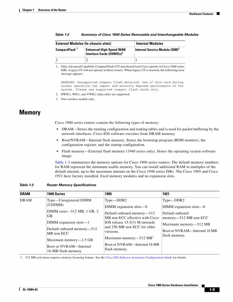
MemoryCisco 1900 series routers contain the following types of memory:
• DRAM—Stores the running configuration and routing tables and is used for packet buffering by the network interfaces. Cisco IOS software executes from DRAM memory.
• Boot/NVRAM—Internal flash memory. Stores the bootstrap program (ROM monitor), the configuration register, and the startup configuration.
• Flash memory—External flash memory (1940 series only). Stores the operating system software image.
Table 1-3 summarizes the memory options for Cisco 1900 series routers. The default memory numbers for RAM represent the minimum usable memory. You can install additional RAM in multiples of the default amount, up to the maximum amount on the Cisco 1940 series ISRs. The Cisco 1905 and Cisco 1921 have factory installed, fixed memory modules and no expansion slots.
Table 1-2 Summary of Cisco 1940 Series Removable and Interchangeable Modules
External Modules (In chassis slots) Internal Modules
CompactFlash 1
1. Only Advanced Capability CompactFlash (CF) purchased from Cisco operate in Cisco 1900 series ISRs. Legacy CF will not operate in these routers. When legacy CF is inserted, the following error message appears:
WARNING: Unsupported compact flash detected. Use of this card during normal operation can impact and severely degrade performance of the system. Please use supported compact flash cards only.
Enhanced High-Speed WAN Interface Cards (EHWICs)2
2. HWICs, WICs, and VWICs (data only) are supported.
Internal Service Module (ISM)3
3. Non wireless models only.
2 2 1
Table 1-3 Router Memory Specifications
DRAM 1940 Series 1905 1921
DRAM Type—Unregistered DIMM (UDIMM)
DIMM sizes—512 MB, 1 GB, 2 GB
DIMM expansion slots—1
Default onboard memory—512 MB non ECC
Maximum memory—2.5 GB
Boot or NVRAM—Internal 16-MB flash memory.
Type—DDR2
DIMM expansion slots—0
Default onboard memory—512 MB non ECC effective with Cisco IOS release 15.5(3) M onwards and 256 MB non ECC for older versions.
Maximum memory—512 MB1
Boot or NVRAM—Internal 16 MB flash memory.
1. 512 MB activation requires memory licensing feature. See the Cisco IOS Software Activation Configuration Guide for details.
Type—DDR2
DIMM expansion slots—0
Default onboard memory—512 MB non ECC
Maximum memory—512 MB
Boot or NVRAM—Internal 16 MB flash memory.
1-9Cisco 1900 Series Hardware Installation
OL-19084-02
Chapter 1 Overview of the Router Hardware Features
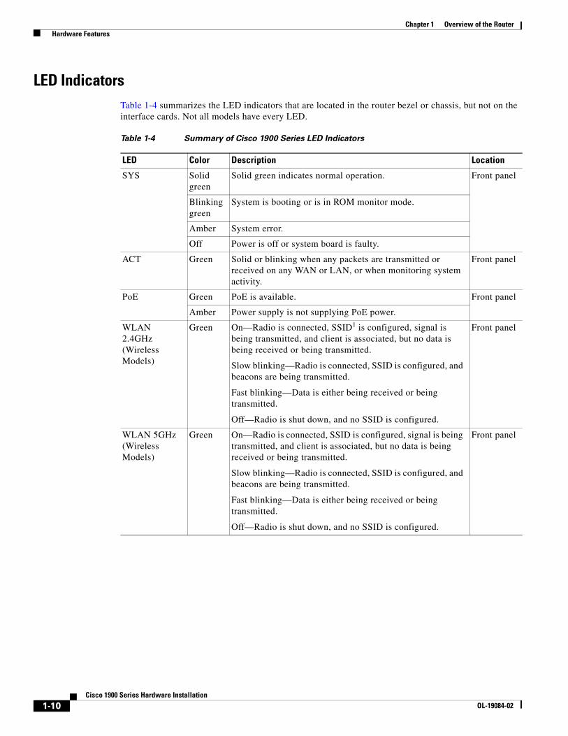
LED IndicatorsTable 1-4 summarizes the LED indicators that are located in the router bezel or chassis, but not on the interface cards. Not all models have every LED.
Table 1-4 Summary of Cisco 1900 Series LED Indicators
LED Color Description Location
SYS Solid green
Solid green indicates normal operation. Front panel
Blinking green
System is booting or is in ROM monitor mode.
Amber System error.
Off Power is off or system board is faulty.
ACT Green Solid or blinking when any packets are transmitted or received on any WAN or LAN, or when monitoring system activity.
Front panel
PoE Green PoE is available. Front panel
Amber Power supply is not supplying PoE power.
WLAN 2.4GHz (Wireless Models)
Green On—Radio is connected, SSID1 is configured, signal is being transmitted, and client is associated, but no data is being received or being transmitted.
Slow blinking—Radio is connected, SSID is configured, and beacons are being transmitted.
Fast blinking—Data is either being received or being transmitted.
Off—Radio is shut down, and no SSID is configured.
Front panel
WLAN 5GHz (Wireless Models)
Green On—Radio is connected, SSID is configured, signal is being transmitted, and client is associated, but no data is being received or being transmitted.
Slow blinking—Radio is connected, SSID is configured, and beacons are being transmitted.
Fast blinking—Data is either being received or being transmitted.
Off—Radio is shut down, and no SSID is configured.
Front panel
1-10Cisco 1900 Series Hardware Installation
OL-19084-02
Chapter 1 Overview of the Router Hardware Features
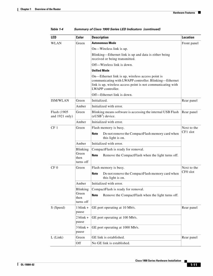
WLAN Green Autonomous Mode
On—Wireless link is up.
Blinking—Ethernet link is up and data is either being received or being transmitted.
Off—Wireless link is down.
Unified Mode
On—Ethernet link is up, wireless access point is communicating with LWAPP controller. Blinking—Ethernet link is up, wireless access point is not communicating with LWAPP controller.
Off—Ethernet link is down.
Front panel
ISM/WLAN Green Initialized. Rear panel
Amber Initialized with error.
Flash (1905 and 1921 only)
Green Blinking means software is accessing the internal USB Flash (eUSB2) device.
Rear panel
Amber Initialized with error.
CF 1 Green Flash memory is busy.
Note Do not remove the CompactFlash memory card when this light is on.
Next to the CF1 slot
Amber Initialized with error.
Blinking Green then turns off
CompactFlash is ready for removal.
Note Remove the CompactFlash when the light turns off.
CF 0 Green Flash memory is busy.
Note Do not remove the CompactFlash memory card when this light is on.
Next to the CF0 slot
Amber Initialized with error.
Blinking Green then turns off
CompactFlash is ready for removal.
Note Remove the CompactFlash when the light turns off.
S (Speed) 1 blink + pause
GE port operating at 10 Mb/s. Rear panel
2 blink + pause
GE port operating at 100 Mb/s.
3 blink + pause
GE port operating at 1000 Mb/s.
L (Link) Green GE link is established. Rear panel
Off No GE link is established.
Table 1-4 Summary of Cisco 1900 Series LED Indicators (continued)
LED Color Description Location
1-11Cisco 1900 Series Hardware Installation
OL-19084-02
Chapter 1 Overview of the Router Hardware Features
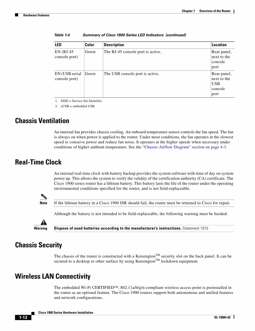
Chassis VentilationAn internal fan provides chassis cooling. An onboard temperature sensor controls the fan speed. The fan is always on when power is applied to the router. Under most conditions, the fan operates at the slowest speed to conserve power and reduce fan noise. It operates at the higher speeds when necessary under conditions of higher ambient temperature. See the “Chassis Airflow Diagram” section on page 4-3.
Real-Time ClockAn internal real-time clock with battery backup provides the system software with time of day on system power up. This allows the system to verify the validity of the certification authority (CA) certificate. The Cisco 1900 series router has a lithium battery. This battery lasts the life of the router under the operating environmental conditions specified for the router, and is not field-replaceable.
Note If the lithium battery in a Cisco 1900 ISR should fail, the router must be returned to Cisco for repair.
Although the battery is not intended to be field-replaceable, the following warning must be heeded:
Warning Dispose of used batteries according to the manufacturer’s instructions. Statement 1015
Chassis SecurityThe chassis of the router is constructed with a KensingtonTM security slot on the back panel. It can be secured to a desktop or other surface by using KensingtonTM lockdown equipment.
Wireless LAN ConnectivityThe embedded Wi-Fi CERTIFIED™, 802.11a/b/g/n-compliant wireless access point is preinstalled in the router as an optional feature. The Cisco 1900 routers support both autonomous and unified features and network configurations.
EN (RJ-45 console port)
Green The RJ-45 console port is active. Rear panel, next to the console port
EN (USB serial console port)
Green The USB console port is active. Rear panel, next to the USB console port
1. SSID = Service Set Identifier
2. eUSB = embedded USB
Table 1-4 Summary of Cisco 1900 Series LED Indicators (continued)
LED Color Description Location
1-12Cisco 1900 Series Hardware Installation
OL-19084-02
Chapter 1 Overview of the Router Interface Numbering
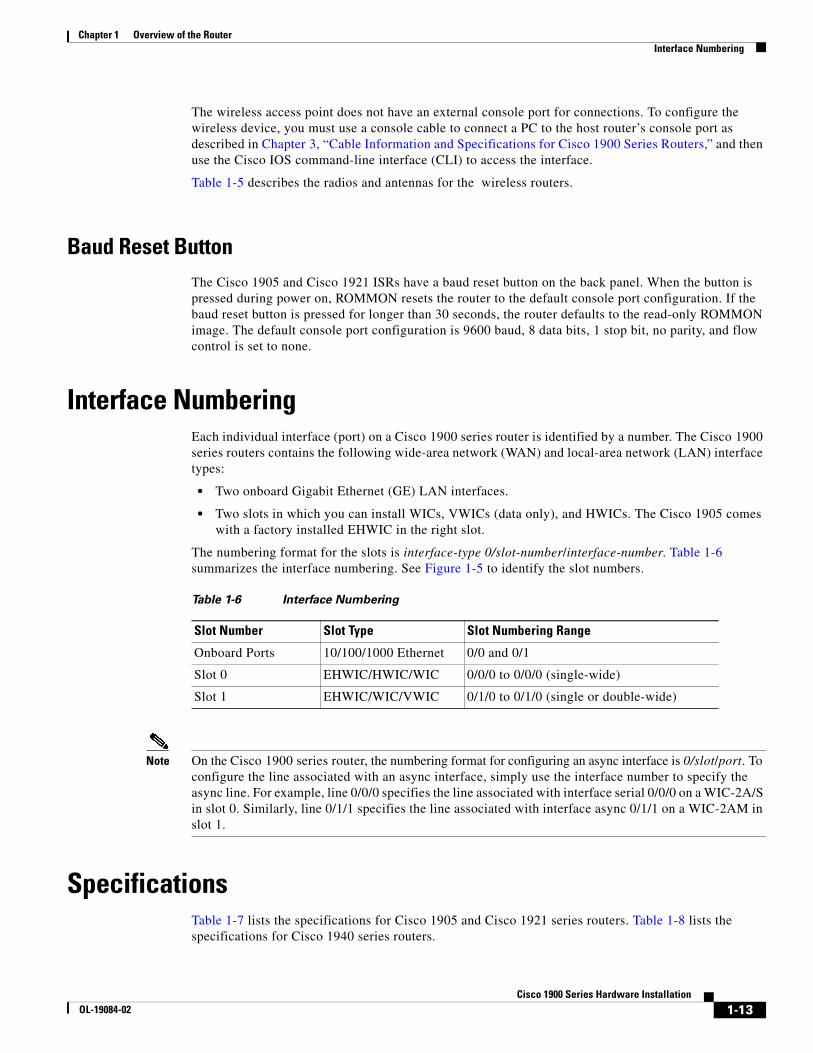
The wireless access point does not have an external console port for connections. To configure the wireless device, you must use a console cable to connect a PC to the host router’s console port as described in Chapter 3, “Cable Information and Specifications for Cisco 1900 Series Routers,” and then use the Cisco IOS command-line interface (CLI) to access the interface.
Table 1-5 describes the radios and antennas for the wireless routers.
Baud Reset ButtonThe Cisco 1905 and Cisco 1921 ISRs have a baud reset button on the back panel. When the button is pressed during power on, ROMMON resets the router to the default console port configuration. If the baud reset button is pressed for longer than 30 seconds, the router defaults to the read-only ROMMON image. The default console port configuration is 9600 baud, 8 data bits, 1 stop bit, no parity, and flow control is set to none.
Interface NumberingEach individual interface (port) on a Cisco 1900 series router is identified by a number. The Cisco 1900 series routers contains the following wide-area network (WAN) and local-area network (LAN) interface types:
• Two onboard Gigabit Ethernet (GE) LAN interfaces.
• Two slots in which you can install WICs, VWICs (data only), and HWICs. The Cisco 1905 comes with a factory installed EHWIC in the right slot.
The numbering format for the slots is interface-type 0/slot-number/interface-number. Table 1-6 summarizes the interface numbering. See Figure 1-5 to identify the slot numbers.
Note On the Cisco 1900 series router, the numbering format for configuring an async interface is 0/slot/port. To configure the line associated with an async interface, simply use the interface number to specify the async line. For example, line 0/0/0 specifies the line associated with interface serial 0/0/0 on a WIC-2A/S in slot 0. Similarly, line 0/1/1 specifies the line associated with interface async 0/1/1 on a WIC-2AM in slot 1.
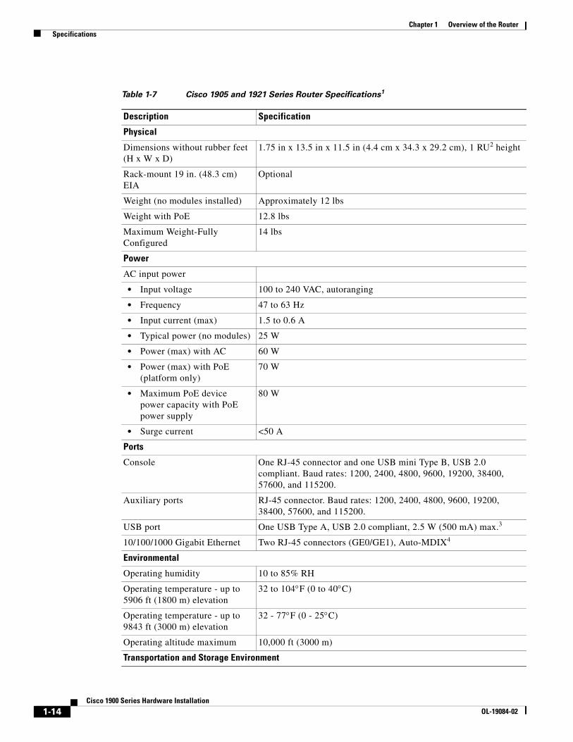
SpecificationsTable 1-7 lists the specifications for Cisco 1905 and Cisco 1921 series routers. Table 1-8 lists the specifications for Cisco 1940 series routers.
Table 1-6 Interface Numbering
Slot Number Slot Type Slot Numbering Range
Onboard Ports 10/100/1000 Ethernet 0/0 and 0/1
Slot 0 EHWIC/HWIC/WIC 0/0/0 to 0/0/0 (single-wide)
Slot 1 EHWIC/WIC/VWIC 0/1/0 to 0/1/0 (single or double-wide)
1-13Cisco 1900 Series Hardware Installation
OL-19084-02
Chapter 1 Overview of the Router Specifications
Table 1-7 Cisco 1905 and 1921 Series Router Specifications1
Description Specification
Physical
Dimensions without rubber feet (H x W x D)
1.75 in x 13.5 in x 11.5 in (4.4 cm x 34.3 x 29.2 cm), 1 RU2 height
Rack-mount 19 in. (48.3 cm) EIA
Optional
Weight (no modules installed) Approximately 12 lbs
Weight with PoE 12.8 lbs
Maximum Weight-Fully Configured
14 lbs
Power
AC input power
• Input voltage 100 to 240 VAC, autoranging
• Frequency 47 to 63 Hz
• Input current (max) 1.5 to 0.6 A
• Typical power (no modules) 25 W
• Power (max) with AC 60 W
• Power (max) with PoE (platform only)
70 W
• Maximum PoE device power capacity with PoE power supply
80 W
• Surge current <50 A
Ports
Console One RJ-45 connector and one USB mini Type B, USB 2.0 compliant. Baud rates: 1200, 2400, 4800, 9600, 19200, 38400, 57600, and 115200.
Auxiliary ports RJ-45 connector. Baud rates: 1200, 2400, 4800, 9600, 19200, 38400, 57600, and 115200.
USB port One USB Type A, USB 2.0 compliant, 2.5 W (500 mA) max.3
10/100/1000 Gigabit Ethernet Two RJ-45 connectors (GE0/GE1), Auto-MDIX4
Environmental
Operating humidity 10 to 85% RH
Operating temperature - up to 5906 ft (1800 m) elevation
32 to 104F (0 to 40C)
Operating temperature - up to 9843 ft (3000 m) elevation
32 - 77F (0 - 25C)
Operating altitude maximum 10,000 ft (3000 m)
Transportation and Storage Environment
1-14Cisco 1900 Series Hardware Installation
OL-19084-02
Chapter 1 Overview of the Router Specifications
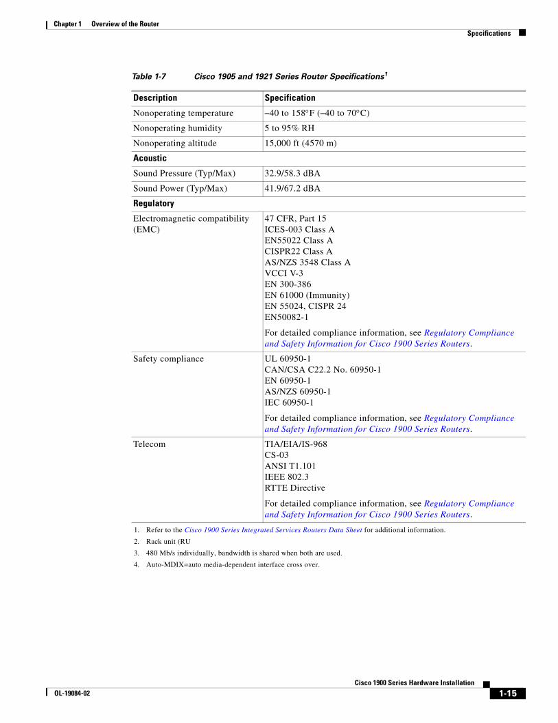
Nonoperating temperature –40 to 158F (–40 to 70C)
Nonoperating humidity 5 to 95% RH
Nonoperating altitude 15,000 ft (4570 m)
Acoustic
Sound Pressure (Typ/Max) 32.9/58.3 dBA
Sound Power (Typ/Max) 41.9/67.2 dBA
Regulatory
Electromagnetic compatibility (EMC)
47 CFR, Part 15ICES-003 Class AEN55022 Class ACISPR22 Class AAS/NZS 3548 Class AVCCI V-3EN 300-386EN 61000 (Immunity)EN 55024, CISPR 24EN50082-1
For detailed compliance information, see Regulatory Compliance and Safety Information for Cisco 1900 Series Routers.
Safety compliance UL 60950-1CAN/CSA C22.2 No. 60950-1EN 60950-1AS/NZS 60950-1IEC 60950-1
For detailed compliance information, see Regulatory Compliance and Safety Information for Cisco 1900 Series Routers.
Telecom TIA/EIA/IS-968CS-03ANSI T1.101IEEE 802.3RTTE Directive
For detailed compliance information, see Regulatory Compliance and Safety Information for Cisco 1900 Series Routers.
1. Refer to the Cisco 1900 Series Integrated Services Routers Data Sheet for additional information.
2. Rack unit (RU
3. 480 Mb/s individually, bandwidth is shared when both are used.
4. Auto-MDIX=auto media-dependent interface cross over.
Table 1-7 Cisco 1905 and 1921 Series Router Specifications1
Description Specification
1-15Cisco 1900 Series Hardware Installation
OL-19084-02
Chapter 1 Overview of the Router Specifications
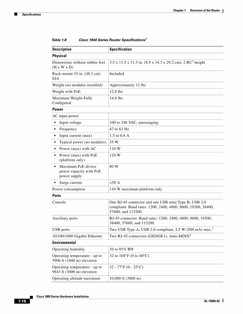
Table 1-8 Cisco 1940 Series Router Specifications1
Description Specification
Physical
Dimensions without rubber feet (H x W x D)
3.5 x 13.5 x 11.5 in. (8.9 x 34.3 x 29.2 cm), 2 RU2 height
Rack-mount 19 in. (48.3 cm) EIA
Included
Weight (no modules installed) Approximately 12 lbs
Weight with PoE 12.8 lbs
Maximum Weight-Fully Configured
14.0 lbs
Power
AC input power
• Input voltage 100 to 240 VAC, autoranging
• Frequency 47 to 63 Hz
• Input current (max) 1.5 to 0.6 A
• Typical power (no modules) 35 W
• Power (max) with AC 110 W
• Power (max) with PoE (platform only)
110 W
• Maximum PoE device power capacity with PoE power supply
80 W
• Surge current <50 A
Power consumption 110 W maximum platform only
Ports
Console One RJ-45 connector and one USB mini Type B, USB 2.0 compliant. Baud rates: 1200, 2400, 4800, 9600, 19200, 38400, 57600, and 115200.
Auxiliary ports RJ-45 connector. Baud rates: 1200, 2400, 4800, 9600, 19200, 38400, 57600, and 115200.
USB ports Two USB Type A, USB 2.0 compliant, 2.5 W (500 mA) max.3
10/100/1000 Gigabit Ethernet Two RJ-45 connectors (GE0/GE1), Auto-MDIX4
Environmental
Operating humidity 10 to 85% RH
Operating temperature - up to 5906 ft (1800 m) elevation
32 to 104F (0 to 40C)
Operating temperature - up to 9843 ft (3000 m) elevation
32 - 77F (0 - 25C)
Operating altitude maximum 10,000 ft (3000 m)
1-16Cisco 1900 Series Hardware Installation
OL-19084-02
Chapter 1 Overview of the Router Specifications
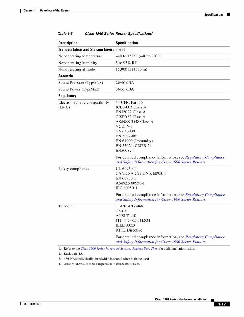
Transportation and Storage Environment
Nonoperating temperature –40 to 158F (–40 to 70C)
Nonoperating humidity 5 to 95% RH
Nonoperating altitude 15,000 ft (4570 m)
Acoustic
Sound Pressure (Typ/Max) 26/46 dBA
Sound Power (Typ/Max) 36/55 dBA
Regulatory
Electromagnetic compatibility (EMC)
47 CFR, Part 15ICES-003 Class AEN55022 Class ACISPR22 Class AAS/NZS 3548 Class AVCCI V-3CNS 13438EN 300-386EN 61000 (Immunity)EN 55024, CISPR 24EN50082-1
For detailed compliance information, see Regulatory Compliance and Safety Information for Cisco 1900 Series Routers.
Safety compliance UL 60950-1CAN/CSA C22.2 No. 60950-1EN 60950-1AS/NZS 60950-1IEC 60950-1
For detailed compliance information, see Regulatory Compliance and Safety Information for Cisco 1900 Series Routers.
Telecom TIA/EIA/IS-968CS-03ANSI T1.101ITU-T G.823, G.824IEEE 802.3RTTE Directive
For detailed compliance information, see Regulatory Compliance and Safety Information for Cisco 1900 Series Routers.
1. Refer to the Cisco 1900 Series Integrated Services Routers Data Sheet for additional information.
2. Rack unit (RU
3. 480 Mb/s individually, bandwidth is shared when both are used.
4. Auto-MDIX=auto media-dependent interface cross over.
Table 1-8 Cisco 1940 Series Router Specifications1
Description Specification
1-17Cisco 1900 Series Hardware Installation
OL-19084-02

Chapter 1 Overview of the Router Regulatory Compliance
Regulatory ComplianceFor compliance information, refer to Regulatory Compliance and Safety Information for Cisco 1900 Series Routers.
1-18Cisco 1900 Series Hardware Installation
OL-19084-02
OL-19084-02
C H A P T E R 2
Preparing for Router InstallationThis chapter describes the site requirements and equipment needed to install your Cisco 1900 series integrated services router.
• Safety Recommendations, page 2-1
• General Site Requirements, page 2-3
• Inspecting the Router, page 2-5
• Installation Checklist, page 2-5
• Site Log, page 2-6
• Inspecting the Router, page 2-5
• Required Tools and Equipment for Installation and Maintenance, page 2-7
Note To see translations of the warnings that appear in this publication, refer to the Regulatory Compliance and Safety Information for Cisco 1900 Series Routers document that accompanies your router.
Safety Recommendations• General Guidelines, page 2-1
• Safety with Electricity, page 2-2
• Preventing Electrostatic Discharge Damage, page 2-3
General GuidelinesFollow these guidelines to ensure general safety:
• Keep the chassis area clear and dust-free during and after installation.
• If you remove the chassis cover, put it in a safe place.
• Keep tools and chassis components away from walk areas.
• Do not wear loose clothing that could get caught in the chassis. Fasten your tie or scarf, and roll up your sleeves.
• Wear safety glasses when working under conditions that might be hazardous to your eyes.
• Do not perform any action that creates a hazard to people or makes the equipment unsafe.
2-1Cisco 1900 Series Hardware Installation
Chapter 2 Preparing for Router Installation Safety Recommendations
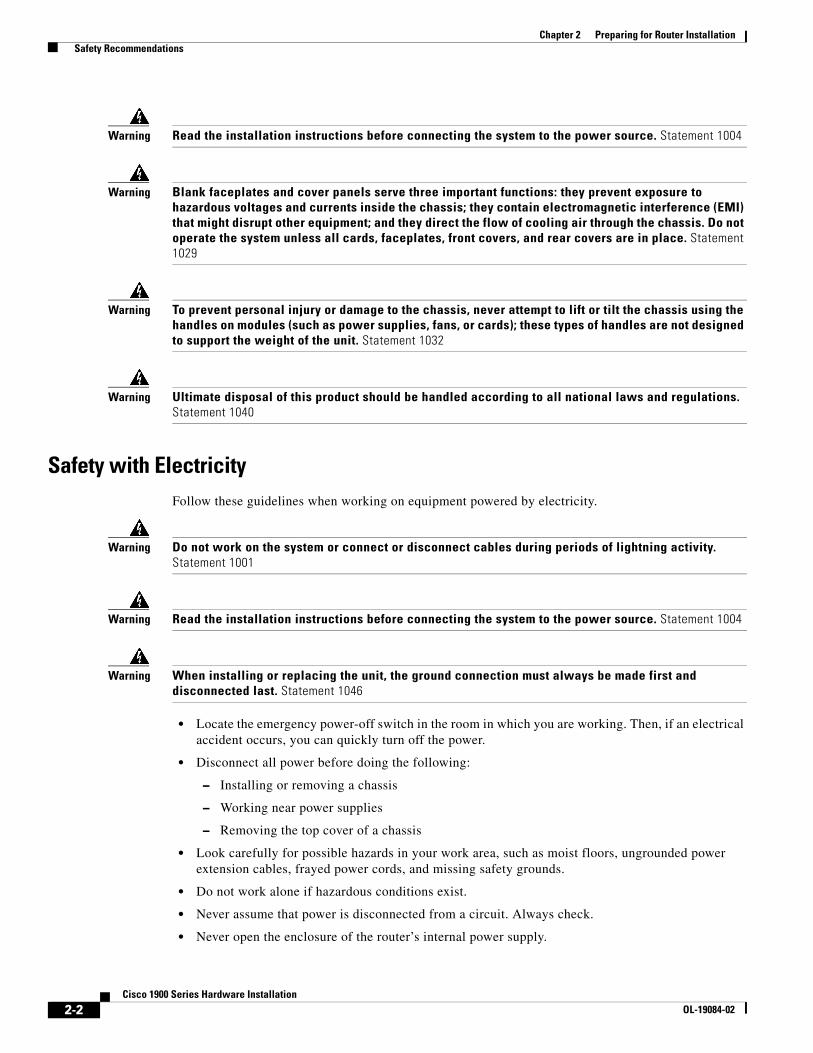
Warning Read the installation instructions before connecting the system to the power source. Statement 1004
Warning Blank faceplates and cover panels serve three important functions: they prevent exposure to hazardous voltages and currents inside the chassis; they contain electromagnetic interference (EMI) that might disrupt other equipment; and they direct the flow of cooling air through the chassis. Do not operate the system unless all cards, faceplates, front covers, and rear covers are in place. Statement 1029
Warning To prevent personal injury or damage to the chassis, never attempt to lift or tilt the chassis using the handles on modules (such as power supplies, fans, or cards); these types of handles are not designed to support the weight of the unit. Statement 1032
Warning Ultimate disposal of this product should be handled according to all national laws and regulations. Statement 1040
Safety with ElectricityFollow these guidelines when working on equipment powered by electricity.
Warning Do not work on the system or connect or disconnect cables during periods of lightning activity. Statement 1001
Warning Read the installation instructions before connecting the system to the power source. Statement 1004
Warning When installing or replacing the unit, the ground connection must always be made first and disconnected last. Statement 1046
• Locate the emergency power-off switch in the room in which you are working. Then, if an electrical accident occurs, you can quickly turn off the power.
• Disconnect all power before doing the following:
– Installing or removing a chassis
– Working near power supplies
– Removing the top cover of a chassis
• Look carefully for possible hazards in your work area, such as moist floors, ungrounded power extension cables, frayed power cords, and missing safety grounds.
• Do not work alone if hazardous conditions exist.
• Never assume that power is disconnected from a circuit. Always check.
• Never open the enclosure of the router’s internal power supply.
2-2Cisco 1900 Series Hardware Installation
OL-19084-02
Chapter 2 Preparing for Router Installation General Site Requirements
• If an electrical accident occurs, proceed as follows:
– Use caution; do not become a victim yourself.
– Turn off power to the device.
– If possible, send another person to get medical aid. Otherwise, assess the victim’s condition and then call for help.
– Determine whether the person needs rescue breathing or external cardiac compressions; then take appropriate action.
In addition, use the following guidelines when working with any equipment that is disconnected from a power source, but is still connected to telephone wiring or other network cabling:
• Never install telephone wiring during a lightning storm.
• Never install telephone jacks in wet locations unless the jack is specifically designed for it.
• Never touch uninsulated telephone wires or terminals unless the telephone line is disconnected at the network interface.
• Use caution when installing or modifying telephone lines.
Preventing Electrostatic Discharge DamageElectrostatic discharge (ESD) can damage equipment and impair electrical circuitry. ESD can occur if electronic printed circuit cards are improperly handled and can cause complete or intermittent failures. Always follow ESD prevention procedures when removing and replacing modules:
• Ensure that the router chassis is electrically connected to earth ground.
• Wear an ESD-preventive wrist strap, ensuring that it makes good skin contact. Connect the clip to an unpainted surface of the chassis frame to channel unwanted ESD voltages safely to ground. To guard against ESD damage and shocks, the wrist strap and cord must operate effectively.
• If no wrist strap is available, ground yourself by touching a metal part of the chassis.
Caution For the safety of your equipment, periodically check the resistance value of the antistatic strap. It should be between 1 and 10 megohms (Mohm).
General Site RequirementsThis section describes the requirements that your site must meet for safe installation and operation of your router. Ensure that the site is properly prepared before beginning installation. If you are experiencing shutdowns or unusually high errors with your existing equipment, this section can also help you isolate the cause of failures and prevent future problems.
• Power Supply Considerations, page 2-4
• Site Environment, page 2-4
• Site Configuration, page 2-4
• Wireless LAN Considerations, page 2-5
2-3Cisco 1900 Series Hardware Installation
OL-19084-02
Chapter 2 Preparing for Router Installation General Site Requirements
Power Supply ConsiderationsCheck the power at your site to ensure that you are receiving “clean” power (free of spikes and noise). Install a power conditioner if necessary.
Warning The device is designed for connection to TN and IT power systems. Statement 1007
The AC power supply includes the following features:
• Autoselects either 110 V or 220 V operation.
• All units include a 6-foot (1.8-meter) electrical power cord. (A label near the power cord indicates the correct voltage, frequency, current draw, and power dissipation for the unit.)
Site EnvironmentThe Cisco 1900 series router is designed for placement on a desktop, rack-mounted or wall mounted.
The location of your router is an extremely important consideration for proper operation. Equipment placed too close together, inadequate ventilation, and inaccessible panels can cause malfunctions and shutdowns, and can also make maintenance difficult. Plan for access to both front and back panels of the router.
When planning your site layout and equipment locations, remember the precautions described in the “Site Configuration” section on page 2-4 to help avoid equipment failures and reduce the possibility of environmentally caused shutdowns. If you are currently experiencing shutdowns or an unusually high number of errors with your existing equipment, these precautions may help you isolate the cause of the failures and prevent future problems.
Site ConfigurationThe following precautions will help you plan an acceptable operating environment for your router and will help you avoid environmentally caused equipment failures:
• Make sure that the room where your router operates has adequate circulation. Electrical equipment generates heat. Without adequate circulation, ambient air temperature may not cool equipment to acceptable operating temperatures. See the “Chassis Airflow Diagram” section on page 4-3.
• Always follow the ESD-prevention procedures described in the “Preventing Electrostatic Discharge Damage” section on page 2-3 to avoid damage to equipment. Damage from static discharge can cause immediate or intermittent equipment failure.
• Make sure that the chassis cover and module back panels are secure. All empty interface card slots must have filler panels installed. The chassis is designed to allow cooling air to flow within it, through specially designed cooling slots. A chassis with uncovered openings creates air leaks, which may interrupt and reduce the flow of air across internal components.
2-4Cisco 1900 Series Hardware Installation
OL-19084-02
Chapter 2 Preparing for Router Installation Inspecting the Router
Wireless LAN ConsiderationsWireless communication depends upon the propagation of radio waves. Many environmental factors influence radio waves. The Cisco Multiband Swivel-Mount Dipole Antenna Installation Notes describes factors affecting this. We recommend that you review these factors before you determine a location for the router.
The type of antenna used with your wireless router and its location greatly impact the quality of wireless connections to the router. Cisco 1900 series wireless routers are compatible with three different antenna types—swivel-mount dipole antennas that mounts on the back panel of the router, a wall-mount antenna, and a ceiling-mount antenna.
For more information about antenna coverage and optimal usage, see the following documents:
• Cisco Multiband Swivel-Mount Dipole Antenna
• Cisco Multiband Diversity Omnidirectional Ceiling-Mount Antenna
Inspecting the RouterDo not unpack the router until you are ready to install it. If the final installation site will not be ready for some time, keep the chassis in its shipping container to prevent accidental damage. When you are ready to install the router, proceed with unpacking it.
The router, cables, publications, and any optional equipment that you ordered may be shipped in more than one container.
Inspect all items for shipping damage. If anything appears to be damaged, or if you encounter problems installing or configuring your router, contact customer service. Warranty, service, and support information is in the quick start guide that shipped with your router.
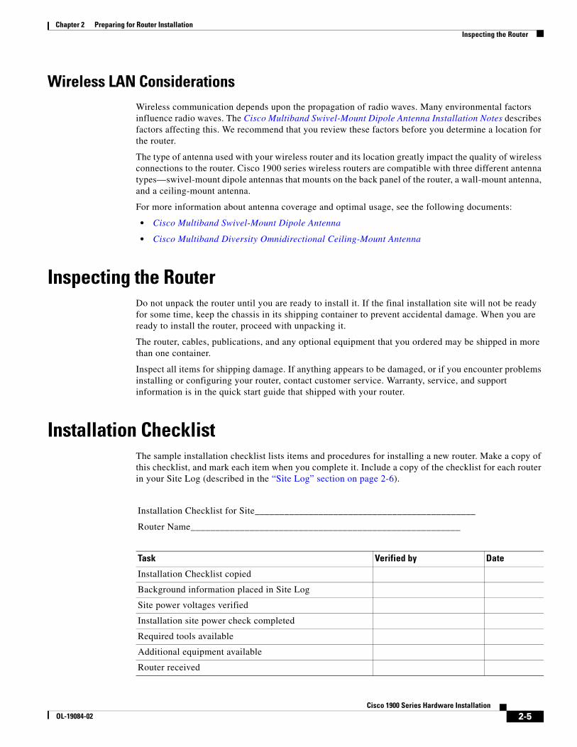
Installation ChecklistThe sample installation checklist lists items and procedures for installing a new router. Make a copy of this checklist, and mark each item when you complete it. Include a copy of the checklist for each router in your Site Log (described in the “Site Log” section on page 2-6).
Installation Checklist for Site_____________________________________________
Router Name_______________________________________________________
Task Verified by Date
Installation Checklist copied
Background information placed in Site Log
Site power voltages verified
Installation site power check completed
Required tools available
Additional equipment available
Router received
2-5Cisco 1900 Series Hardware Installation
OL-19084-02
Chapter 2 Preparing for Router Installation Site Log
Site LogThe Site Log is a record of all actions related to the router. Keep it in an accessible place near the chassis so that anyone who performs tasks has easy access to it. Use the Installation Checklist to verify steps in installation and maintenance of the router. Site Log entries might include the following information:
• Installation progress—Make a copy of the Installation Checklist, and insert it into the Site Log. Record the pertinent information as each procedure is completed.
• Upgrade and maintenance procedures—Use the Site Log as a record of ongoing router maintenance and expansion history. A Site Log might include the following events:
– Installation of network modules
– Removal or replacement of network modules and other upgrades
– Configuration changes
– Maintenance schedules and requirements
– Maintenance procedures performed
– Intermittent problems
– Comments and notes
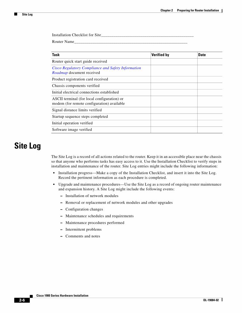
Router quick start guide received
Cisco Regulatory Compliance and Safety Information Roadmap document received
Product registration card received
Chassis components verified
Initial electrical connections established
ASCII terminal (for local configuration) or modem (for remote configuration) available
Signal distance limits verified
Startup sequence steps completed
Initial operation verified
Software image verified
Installation Checklist for Site_____________________________________________
Router Name_______________________________________________________
Task Verified by Date
2-6Cisco 1900 Series Hardware Installation
OL-19084-02
Chapter 2 Preparing for Router Installation Required Tools and Equipment for Installation and Maintenance
Required Tools and Equipment for Installation and MaintenanceYou need the following tools and equipment for installing and upgrading the router and its components:
• ESD-preventive cord and wrist strap
• Number 2 Phillips screwdriver for installing or removing modules, and a flat-blade screwdriver for removing Compact Flash cover, upgrading memory, or other components: small, 3/16-inch (0.48 centimeter) and medium, 1/4-inch (0.63 centimeter).
• A 1/4-inch (0.63 centimeter) nut driver
• Wire crimper
• AWG 14 wire for connecting the router chassis to earth ground
In addition, depending on the type of modules that you plan to use, you might need the following equipment to connect a port to an external network:
• Cables for connection to WAN and LAN ports (dependent on configuration)
Note For more information on cable specifications, refer to Cisco Modular Access Router Cable Specifications.
• Ethernet hub or PC with a network interface card for connection to Ethernet (LAN) ports
• Console terminal (an ASCII terminal or a PC running terminal emulation software) configured for 9600 baud, 8 data bits, no parity, and 1 stop bit
• Modem for connection to the auxiliary port for remote administrative access
• Data service unit (DSU) or channel service unit/data service unit (CSU/DSU) as appropriate for serial interfaces
• External CSU for any CT1/PRI modules without a built-in CSU
• NT1 device for ISDN BRI S/T interfaces (if not supplied by your service provider)
2-7Cisco 1900 Series Hardware Installation
OL-19084-02

Chapter 2 Preparing for Router Installation Required Tools and Equipment for Installation and Maintenance
2-8Cisco 1900 Series Hardware Installation
OL-19084-02
OL-19084-01
C H A P T E R 3
Cable Information and Specifications for Cisco 1900 Series RoutersThis document gives cable information and specifications for the console port, auxiliary port, and network ports on your Cisco 1900 series integrated services router.
• Console and Auxiliary Port Considerations, page 3-1
• Preparing to Connect to a Network, page 3-3
Console and Auxiliary Port Considerations• About Console and Auxiliary Ports, page 3-1
• Console Port Connections, page 3-1
• Auxiliary Port Connections, page 3-3
About Console and Auxiliary PortsThe router includes USB, asynchronous serial and auxiliary ports. The console and auxiliary ports provide access to the router either locally using a console terminal connected to the console port, or remotely, using a modem connected to the auxiliary port. This section provides important cabling information to consider before connecting the router to a console terminal or modem.
The main difference between the console and auxiliary ports is that the auxiliary port supports flow control, whereas the console port does not. Flow control paces the transmission of data between a sending device and a receiving device. Flow control ensures that the receiving device can absorb the data sent to it before the sending device sends more. When the buffers on the receiving device are full, a message is sent to the sending device to suspend transmission until the data in the buffers has been processed. Because the auxiliary port supports flow control, it is ideally suited for use with the high-speed transmissions of a modem. Console terminals send data at slower speeds than modems; therefore, the console port is ideally suited for use with console terminals.
Console Port ConnectionsThe router has an EIA/TIA-232 asynchronous serial console port (RJ-45) and at least one USB Type-A 2.0 compliant ports. See Table 1-1 on page 1-8 for a list of ports.
• EIA/TIA-232 Port, page 3-2
3-1Cisco 1900 Series Hardware Installation
Chapter 3 Cable Information and Specifications for Cisco 1900 Series Routers Console and Auxiliary Port Considerations
• USB Serial Console, page 3-2
EIA/TIA-232 Port
Depending on the cable and the adapter used, this port will appear as a data terminal equipment (DTE) or data communications equipment (DCE) device at the end of the cable.
To connect a PC running terminal emulation software use a RJ-45-to-DB-9 cable.
To connect the router to an ASCII terminal, use a RJ-45-to-DB-9 cable and a DB-9-to-DB-25 adapter.
The default parameters for the console port are 9600 baud, 8 data bits, no parity, and 1 stop bit. The console port does not support mode control. For detailed information about installing a console terminal, see the “Connecting to the Console Port with Microsoft Windows” section on page 4-15.
For cable and port pinouts, refer to Cisco Modular Access Router Cable Specifications.
USB Serial Console
The USB serial console port connects directly to the USB connector of a PC using a USB Type A to 5-pin mini Type-B cable. The USB Console supports full speed (12Mb/s) operation. The console port does not support hardware flow control.
The default parameters for the console port are 9600 baud, 8 data bits, no parity, and 1 stop bit. The console port does not support mode control. For detailed information about installing a console terminal, see the “Connecting to the Console Port with Microsoft Windows” section on page 4-15.
For operation with Microsoft Windows, the Cisco Windows USB Console Driver must be installed on any PC connected to the Console port. If it is not installed, prompts guide you through a simple installation process.
The Cisco Windows USB Console Driver allows plugging and unplugging the USB cable from the console port without affecting Windows HyperTerminal operations. No special drivers are needed for Mac OS X or Linux.
Only one console port can be active at a time. When a cable is plugged into the USB console port the RJ 45 port becomes inactive. Conversely, when the USB cable is removed from the USB port the RJ 45 port becomes active.
Baud rates for the USB console port are 1200, 2400, 4800, 9600, 19200, 38400, 57600, 115200 bps.
Note 4-pin mini Type-B connectors are easily confused with 5-pin mini Type-B connectors. They are not compatible Only the 5-pin mini Type-B can be used.
USB Console OS Compatibility
• Windows 2000, Windows XP 32- and 64-bit, Windows Vista 32- and 64-bit
• Mac OS X version 10.5.4
• Redhat / Fedora Core 10 with kernel 2.6.27.5-117
• Ubuntu 8.10 with kernel 2.6.27-11
• Debian 5.0 with kernel 2.6
• Suse 11.1 with kernel 2.6.27.7-9
3-2Cisco 1900 Series Hardware Installation
OL-19084-01
Chapter 3 Cable Information and Specifications for Cisco 1900 Series Routers Preparing to Connect to a Network
Auxiliary Port ConnectionsThe router has an EIA/TIA-232 asynchronous serial auxiliary port (RJ-45) that supports flow control. Depending on the cable and the adapter used, this port will appear as a DTE or DCE device at the end of the cable.
For connection to a modem use an RJ-45-to-DB-9 cable and a DB-9-to-DB-25 adapter.
For detailed information about connecting devices to the auxiliary port, see the “Connecting to the Auxiliary Port” section on page 4-20.
For cable and port pinouts, refer to Cisco Modular Access Router Cable Specifications.
Preparing to Connect to a NetworkWhen setting up your router, consider distance limitations and potential electromagnetic interference (EMI) as defined by the applicable local and international regulations.
The following sections describe network connection considerations for several types of network interfaces:
• Ethernet Connections, page 3-3
• Serial Connections, page 3-3
• ISDN BRI Connections, page 3-6
• CSU/DSU Connections, page 3-6
Refer to Cisco Modular Access Router Cable Specifications for more information about network connections and interfaces.
Ethernet ConnectionsThe IEEE has established Ethernet as standard IEEE 802.3. The Cisco 1941 Ethernet implementations are as follows:
• 1000BASE-T—1000 Mb/s full-duplex transmission over a Category 5 or better unshielded twisted-pair (UTP) cable. Supports the Ethernet maximum length of 328 feet (100 meters).
• 100BASE-T—100 Mb/s full-duplex transmission over a Category 5 or better unshielded twisted-pair (UTP) cable. Supports the Ethernet maximum length of 328 feet (100 meters).
• 10BASE-T—10 Mb/s full-duplex transmission over a Category 5 or better unshielded twisted-pair (UTP) cable. Supports the Ethernet maximum length of 328 feet (100 meters).
Refer to Cisco Modular Access Router Cable Specificationsfor information about Ethernet cables, connectors, and pinouts.
Serial Connections• About Serial Connections, page 3-4
• Configuring Serial Connections, page 3-4
• Serial DTE or DCE Devices, page 3-4
• Signaling Standards Supported, page 3-4
3-3Cisco 1900 Series Hardware Installation
OL-19084-01
Chapter 3 Cable Information and Specifications for Cisco 1900 Series Routers Preparing to Connect to a Network
• Transmission Speeds and Distance Limitations, page 3-5
• Asynchronous/Synchronous Serial Module Baud Rates, page 3-5
About Serial Connections
Serial connections are provided by serial WAN interface cards (WICs). For more information on WICs, refer to Cisco.com. This document can be accessed online.
Before you connect a device to a serial port, you need to know the following:
• Type of device—data terminal equipment (DTE) or data communications equipment (DCE)—that you are connecting to the synchronous serial interface
• Type of connector—male or female—that is required for connecting to the device
• Signaling standard that is required by the device
Configuring Serial Connections
The serial ports on the serial WICs use DB-60 connectors. Serial ports can be configured as DTEs or DCEs, depending on the serial cable used.
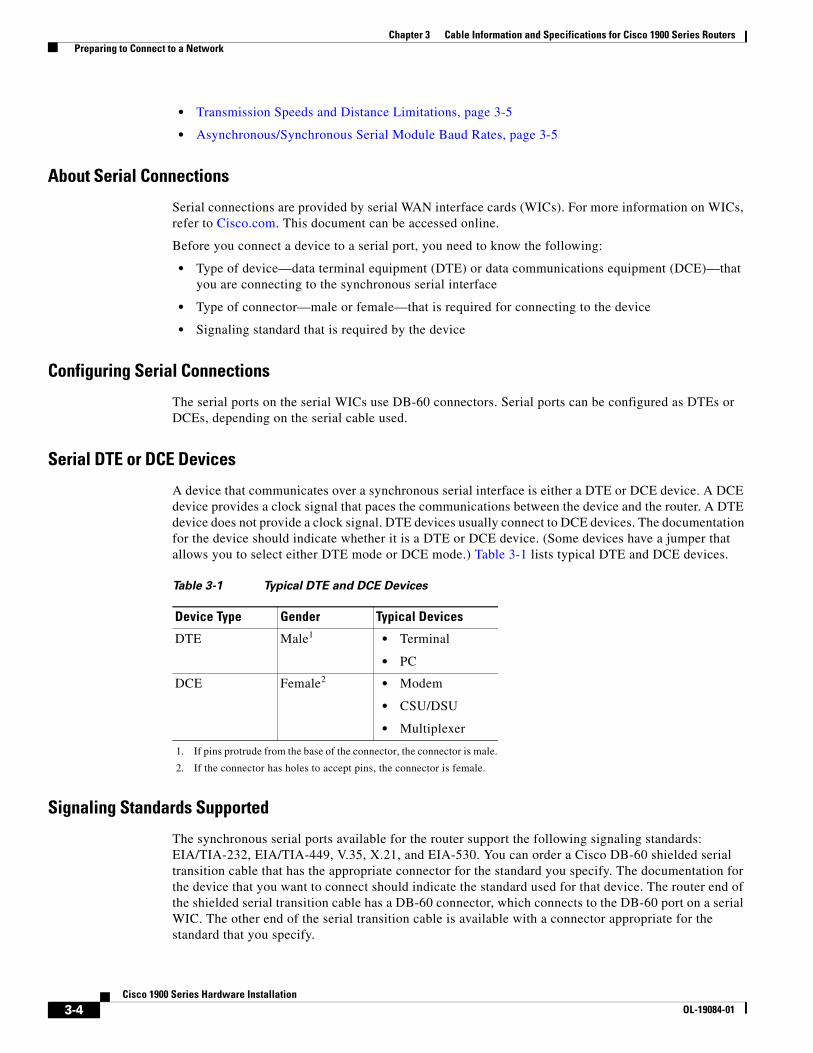
Serial DTE or DCE Devices
A device that communicates over a synchronous serial interface is either a DTE or DCE device. A DCE device provides a clock signal that paces the communications between the device and the router. A DTE device does not provide a clock signal. DTE devices usually connect to DCE devices. The documentation for the device should indicate whether it is a DTE or DCE device. (Some devices have a jumper that allows you to select either DTE mode or DCE mode.) Table 3-1 lists typical DTE and DCE devices.
Signaling Standards Supported
The synchronous serial ports available for the router support the following signaling standards: EIA/TIA-232, EIA/TIA-449, V.35, X.21, and EIA-530. You can order a Cisco DB-60 shielded serial transition cable that has the appropriate connector for the standard you specify. The documentation for the device that you want to connect should indicate the standard used for that device. The router end of the shielded serial transition cable has a DB-60 connector, which connects to the DB-60 port on a serial WIC. The other end of the serial transition cable is available with a connector appropriate for the standard that you specify.
Table 3-1 Typical DTE and DCE Devices
Device Type Gender Typical Devices
DTE Male1
1. If pins protrude from the base of the connector, the connector is male.
• Terminal
• PC
DCE Female2
2. If the connector has holes to accept pins, the connector is female.
• Modem
• CSU/DSU
• Multiplexer
3-4Cisco 1900 Series Hardware Installation
OL-19084-01
Chapter 3 Cable Information and Specifications for Cisco 1900 Series Routers Preparing to Connect to a Network
The synchronous serial port can be configured as DTE or DCE, depending on the attached cable (except EIA-530, which is DTE only). To order a shielded cable, contact customer service. See the “Obtaining Documentation and Submitting a Service Request” section on page xvi.
Note All serial ports configured as DTE require external clocking from a channel service unit/data service unit (CSU/DSU) or other DCE device.
Although we do not recommend manufacturing your own serial cables (because of the small size of the pins on the DB-60 serial connector), cable pinouts are provided in the Cisco Modular Access Router Cable Specifications.
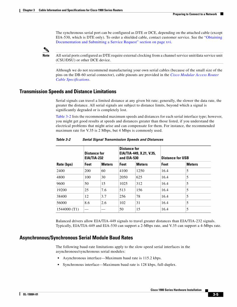
Transmission Speeds and Distance Limitations
Serial signals can travel a limited distance at any given bit rate; generally, the slower the data rate, the greater the distance. All serial signals are subject to distance limits, beyond which a signal is significantly degraded or is completely lost.
Table 3-2 lists the recommended maximum speeds and distances for each serial interface type; however, you might get good results at speeds and distances greater than those listed, if you understand the electrical problems that might arise and can compensate for them. For instance, the recommended maximum rate for V.35 is 2 Mbps, but 4 Mbps is commonly used.
Balanced drivers allow EIA/TIA-449 signals to travel greater distances than EIA/TIA-232 signals. Typically, EIA/TIA-449 and EIA-530 can support a 2-Mbps rate, and V.35 can support a 4-Mbps rate.
Asynchronous/Synchronous Serial Module Baud Rates
The following baud-rate limitations apply to the slow-speed serial interfaces in the asynchronous/synchronous serial modules:
• Asynchronous interface—Maximum baud rate is 115.2 kbps.
• Synchronous interface—Maximum baud rate is 128 kbps, full-duplex.
Table 3-2 Serial Signal Transmission Speeds and Distances
Distance for EIA/TIA-232
Distance for EIA/TIA-449, X.21, V.35, and EIA-530 Distance for USB
Rate (bps) Feet Meters Feet Meters Feet Meters
2400 200 60 4100 1250 16.4 5
4800 100 30 2050 625 16.4 5
9600 50 15 1025 312 16.4 5
19200 25 7.6 513 156 16.4 5
38400 12 3.7 256 78 16.4 5
56000 8.6 2.6 102 31 16.4 5
1544000 (T1) — — 50 15 16.4 5
3-5Cisco 1900 Series Hardware Installation
OL-19084-01
Chapter 3 Cable Information and Specifications for Cisco 1900 Series Routers Preparing to Connect to a Network
ISDN BRI ConnectionsThe BRI WICs provide Integrated Services Digital Network (ISDN) Basic Rate Interface (BRI) connections. BRI WICs are available with either an S/T interface that requires an external Network Termination 1 (NT1), or a U interface that has a built-in NT1. You can install the BRI WICs in any available WIC slots in the chassis.
Warning The ISDN connection is regarded as a source of voltage that should be inaccessible to user contact. Do not attempt to tamper with or open any public telephone operator (PTO)-provided equipment or connection hardware. Any hardwired connection (other than by a nonremovable, connect-one-time-only plug) must be made only by PTO staff or suitably trained engineers. Statement 23
Warning Hazardous network voltages are present in WAN ports regardless of whether power to the unit is OFF or ON. To avoid electric shock, use caution when working near WAN ports. When detaching cables, detach the end away from the unit first. Statement 1026
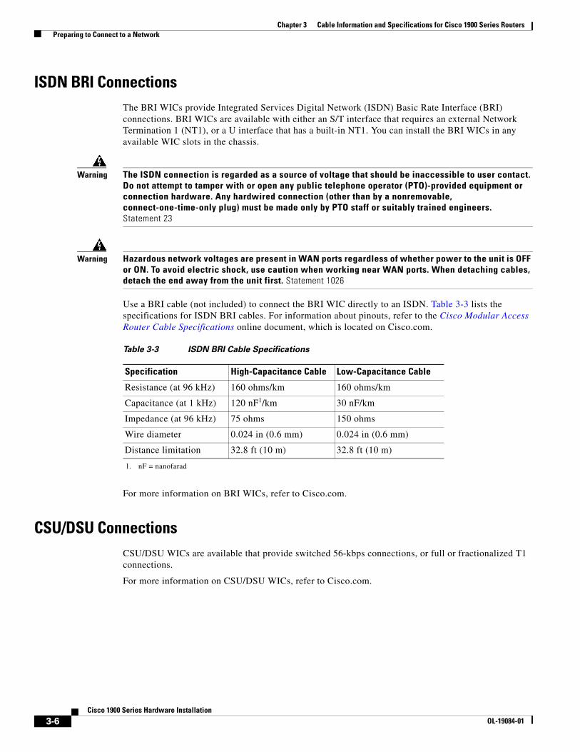
Use a BRI cable (not included) to connect the BRI WIC directly to an ISDN. Table 3-3 lists the specifications for ISDN BRI cables. For information about pinouts, refer to the Cisco Modular Access Router Cable Specifications online document, which is located on Cisco.com.
For more information on BRI WICs, refer to Cisco.com.
CSU/DSU ConnectionsCSU/DSU WICs are available that provide switched 56-kbps connections, or full or fractionalized T1 connections.
For more information on CSU/DSU WICs, refer to Cisco.com.
Table 3-3 ISDN BRI Cable Specifications
Specification High-Capacitance Cable Low-Capacitance Cable
Resistance (at 96 kHz) 160 ohms/km 160 ohms/km
Capacitance (at 1 kHz) 120 nF1/km
1. nF = nanofarad
30 nF/km
Impedance (at 96 kHz) 75 ohms 150 ohms
Wire diameter 0.024 in (0.6 mm) 0.024 in (0.6 mm)
Distance limitation 32.8 ft (10 m) 32.8 ft (10 m)
3-6Cisco 1900 Series Hardware Installation
OL-19084-01
OL-19084-02
C H A P T E R 4
Installing and Connecting the RouterCisco 1900 series routers are normally shipped with a complement of components that can be upgraded or replaced to expand and enhance the router’s functionality. These components either are inserted internally into the router or are plugged into slots in the router chassis.
This chapter tells how to physically set up Cisco 1900 series integrated services routers.
• About Modules, page 4-1
• Safety Warnings, page 4-2
• Setting Up the Chassis, page 4-3
• Installing the Chassis Ground Connection, page 4-9
• Connecting WAN and LAN Cables, page 4-11
• Connecting to a Console Terminal or Modem, page 4-14
• Installing the Cisco Microsoft Windows USB Device Driver, page 4-17
• Uninstalling the Cisco USB Driver, page 4-19
• Connecting to the Auxiliary Port, page 4-20
• Connecting Power, page 4-21
About Modules• Internal Modules, page 4-1
• Plug-In Modules, page 4-2
Internal Modules
Note The Cisco model 1905 and Cisco 1921 have no user accessible internal modules.
The router’s internal components include the following:
• DRAM
• Internal services module (ISM)
4-1Cisco 1900 Series Hardware Installation
Chapter 4 Installing and Connecting the Router Safety Warnings
If you need to remove or upgrade either of these items, follow the procedures given in Installing and Upgrading Internal Modules and FRUs in Cisco 1900 Series ISRs.
Plug-In ModulesThe following components plug into the router chassis:
• WAN interface cards (WICs)
• Voice/WAN interface cards (VWICs), data mode only
• High-speed WICs (HWICs)
• Enhanced High-speed WICs (EHWICs)
• Compact Flash memory card
If you need to remove or install WICs, VWICs, HWICs, or EHWICs follow the procedures in the Installing Cisco Interface Cards in Cisco Access Routers. If you need to remove or upgrade the Compact Flash memory card (1940 series only), follow the procedure in Installing and Upgrading Internal Modules and FRUs in Cisco 1900 Series ISRs.
Safety Warnings
Note To see translations of the warnings that appear in this publication, refer to the Regulatory Compliance and Safety Information for Cisco 1900 Series Routers document that accompanies your router.
Warning IMPORTANT SAFETY INSTRUCTIONS
This warning symbol means danger. You are in a situation that could cause bodily injury. Before you work on any equipment, be aware of the hazards involved with electrical circuitry and be familiar with standard practices for preventing accidents. Use the statement number provided at the end of each warning to locate its translation in the translated safety warnings that accompanied this device. Statement 1071
SAVE THESE INSTRUCTIONS
Warning No user-serviceable parts inside. Do not open. Statement 1073
Warning Read the installation instructions before you connect the system to its power source. Statement 1004
Warning Only trained and qualified personnel should be allowed to install, replace, or service this equipment. Statement 1030
4-2Cisco 1900 Series Hardware Installation
OL-19084-02
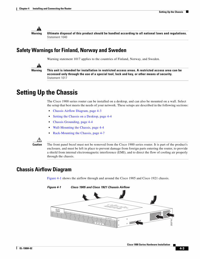
Chapter 4 Installing and Connecting the Router Setting Up the Chassis
Warning Ultimate disposal of this product should be handled according to all national laws and regulations. Statement 1040
Safety Warnings for Finland, Norway and SwedenWarning statement 1017 applies to the countries of Finland, Norway, and Sweden.
Warning This unit is intended for installation in restricted access areas. A restricted access area can be accessed only through the use of a special tool, lock and key, or other means of security. Statement 1017
Setting Up the ChassisThe Cisco 1900 series router can be installed on a desktop, and can also be mounted on a wall. Select the setup that best meets the needs of your network. These setups are described in the following sections:
• Chassis Airflow Diagram, page 4-3
• Setting the Chassis on a Desktop, page 4-4
• Chassis Grounding, page 4-4
• Wall-Mounting the Chassis, page 4-4
• Rack-Mounting the Chassis, page 4-7
Caution The front panel bezel must not be removed from the Cisco 1900 series router. It is part of the product's enclosure, and must be left in place to prevent damage from foreign parts entering the router, to provide a shield from internal electromagnetic interference (EMI), and to direct the flow of cooling air properly through the chassis.
Chassis Airflow DiagramFigure 4-1 shows the airflow through and around the Cisco 1905 and Cisco 1921 chassis.
Figure 4-1 Cisco 1905 and Cisco 1921 Chassis Airflow
Cisco 1900 Series
SYS ACT POE
2537
16
4-3Cisco 1900 Series Hardware Installation
OL-19084-02
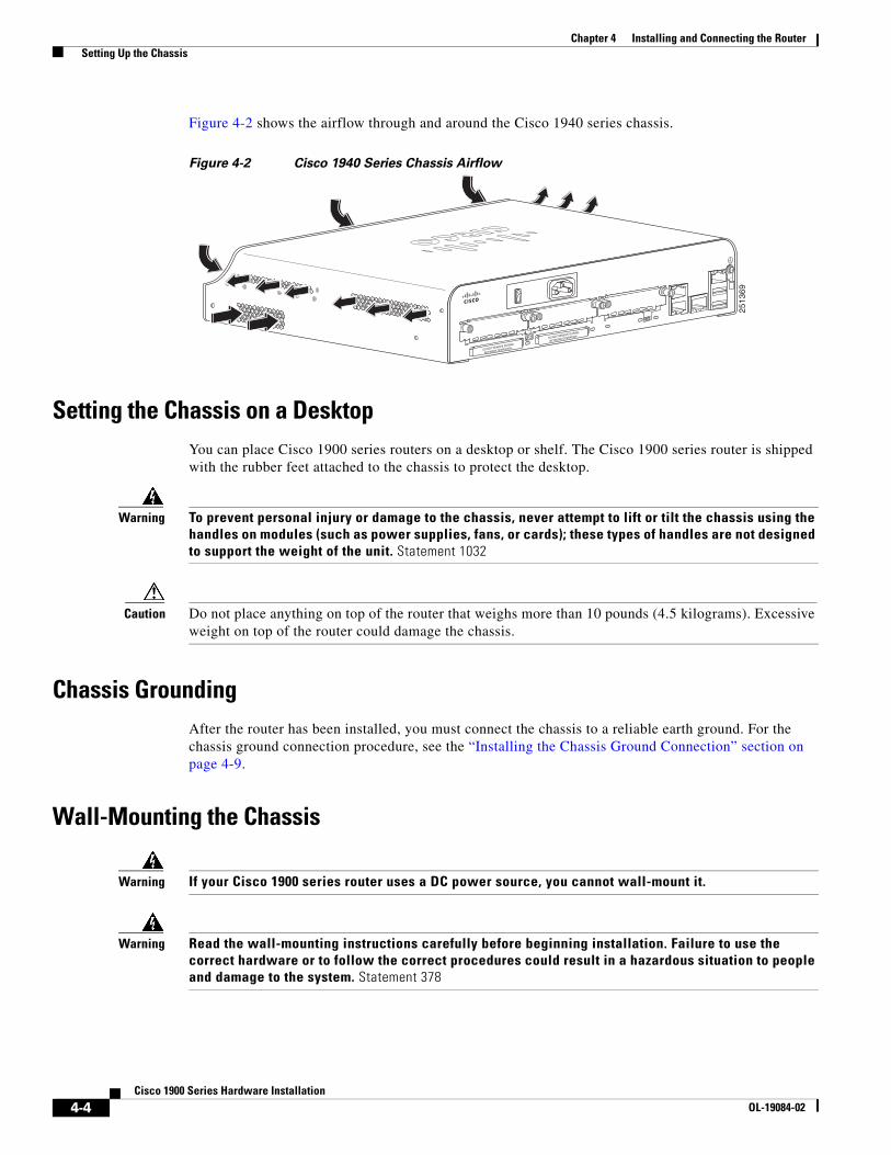
Chapter 4 Installing and Connecting the Router Setting Up the Chassis
Figure 4-2 shows the airflow through and around the Cisco 1940 series chassis.
Figure 4-2 Cisco 1940 Series Chassis Airflow
Setting the Chassis on a DesktopYou can place Cisco 1900 series routers on a desktop or shelf. The Cisco 1900 series router is shipped with the rubber feet attached to the chassis to protect the desktop.
Warning To prevent personal injury or damage to the chassis, never attempt to lift or tilt the chassis using the handles on modules (such as power supplies, fans, or cards); these types of handles are not designed to support the weight of the unit. Statement 1032
Caution Do not place anything on top of the router that weighs more than 10 pounds (4.5 kilograms). Excessive weight on top of the router could damage the chassis.
Chassis GroundingAfter the router has been installed, you must connect the chassis to a reliable earth ground. For the chassis ground connection procedure, see the “Installing the Chassis Ground Connection” section on page 4-9.
Wall-Mounting the Chassis
Warning If your Cisco 1900 series router uses a DC power source, you cannot wall-mount it.
Warning Read the wall-mounting instructions carefully before beginning installation. Failure to use the correct hardware or to follow the correct procedures could result in a hazardous situation to people and damage to the system. Statement 378
DO NOT REMOVE DURING
NETWORK OPERATION
DO NOT REMOVE DURING
NETWORK OPERATION
2513
69
4-4Cisco 1900 Series Hardware Installation
OL-19084-02
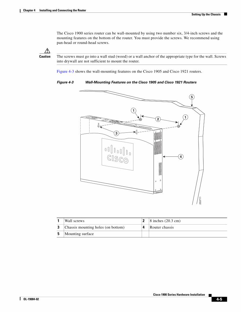
Chapter 4 Installing and Connecting the Router Setting Up the Chassis
The Cisco 1900 series router can be wall-mounted by using two number six, 3/4-inch screws and the mounting features on the bottom of the router. You must provide the screws. We recommend using pan-head or round-head screws.
Caution The screws must go into a wall stud (wood) or a wall anchor of the appropriate type for the wall. Screws into drywall are not sufficient to mount the router.
Figure 4-3 shows the wall-mounting features on the Cisco 1905 and Cisco 1921 routers.
Figure 4-3 Wall-Mounting Features on the Cisco 1905 and Cisco 1921 Routers
1 Wall screws 2 8 inches (20.3 cm)
3 Chassis mounting holes (on bottom) 4 Router chassis
5 Mounting surface
2537
11
5
4
3
2
1
1
4-5Cisco 1900 Series Hardware Installation
OL-19084-02
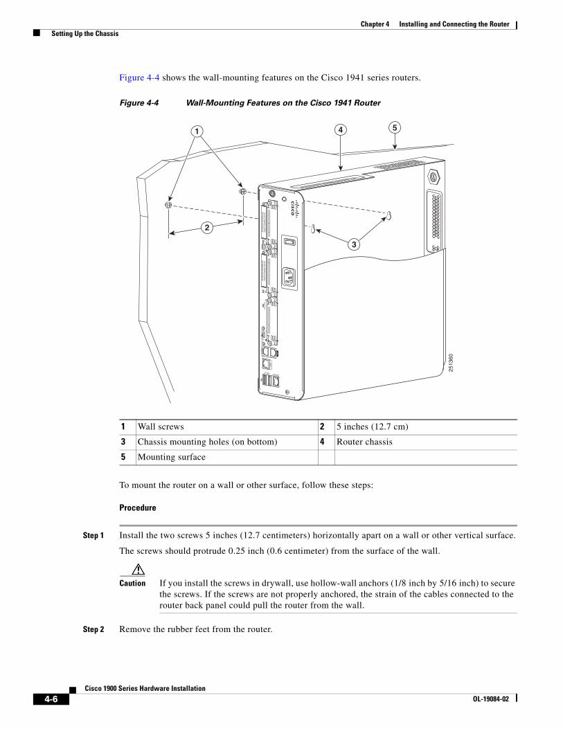
Chapter 4 Installing and Connecting the Router Setting Up the Chassis
Figure 4-4 shows the wall-mounting features on the Cisco 1941 series routers.
Figure 4-4 Wall-Mounting Features on the Cisco 1941 Router
To mount the router on a wall or other surface, follow these steps:
Procedure
Step 1 Install the two screws 5 inches (12.7 centimeters) horizontally apart on a wall or other vertical surface.
The screws should protrude 0.25 inch (0.6 centimeter) from the surface of the wall.
Caution If you install the screws in drywall, use hollow-wall anchors (1/8 inch by 5/16 inch) to secure the screws. If the screws are not properly anchored, the strain of the cables connected to the router back panel could pull the router from the wall.
Step 2 Remove the rubber feet from the router.
1 Wall screws 2 5 inches (12.7 cm)
3 Chassis mounting holes (on bottom) 4 Router chassis
5 Mounting surface25
1360S
L
L
CO
NS
OL
E AU
X
SL
US
B 1G
E 0/1
GE0/0
0E
NE
ND
O N
OT R
EMO
VE DU
RIN
GN
ETWO
RKIN
G O
PERATIO
NC
F 2
CF
1D
O N
OT R
EMO
VE DU
RIN
GN
ETWO
RKIN
G O
PERATIO
NIS
M/W
LA
N
1 54
3
2
4-6Cisco 1900 Series Hardware Installation
OL-19084-02
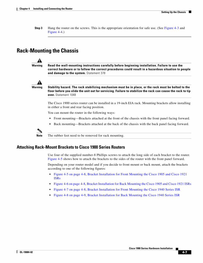
Chapter 4 Installing and Connecting the Router Setting Up the Chassis
Step 3 Hang the router on the screws. This is the appropriate orientation for safe use. (See Figure 4-3 and Figure 4-4.)
Rack-Mounting the Chassis
Warning Read the wall-mounting instructions carefully before beginning installation. Failure to use the correct hardware or to follow the correct procedures could result in a hazardous situation to people and damage to the system. Statement 378
Warning Stability hazard. The rack stabilizing mechanism must be in place, or the rack must be bolted to the floor before you slide the unit out for servicing. Failure to stabilize the rack can cause the rack to tip over. Statement 1048
The Cisco 1900 series router can be installed in a 19-inch EIA rack. Mounting brackets allow installing in either a front and rear facing position.
You can mount the router in the following ways:
• Front mounting—Brackets attached at the front of the chassis with the front panel facing forward.
• Back mounting—Brackets attached at the back of the chassis with the back panel facing forward.
Note The rubber feet need to be removed for rack mounting.
Attaching Rack-Mount Brackets to Cisco 1900 Series Routers
Use four of the supplied number-8 Phillips screws to attach the long side of each bracket to the router. Figure 4-5 shows how to attach the brackets to the sides of the router with the front panel forward.
Depending on your router model and if you decide to front mount or back mount, attach the brackets according to one of the following figures:
• Figure 4-5 on page 4-8, Bracket Installation for Front Mounting the Cisco 1905 and Cisco 1921 ISRs
• Figure 4-6 on page 4-8, Bracket Installation for Back Mounting the Cisco 1905 and Cisco 1921 ISRs
• Figure 4-7 on page 4-8, Bracket Installation for Front Mounting the Cisco 1940 Series ISR
• Figure 4-8 on page 4-9, Bracket Installation for Back Mounting the Cisco 1940 Series ISR
4-7Cisco 1900 Series Hardware Installation
OL-19084-02
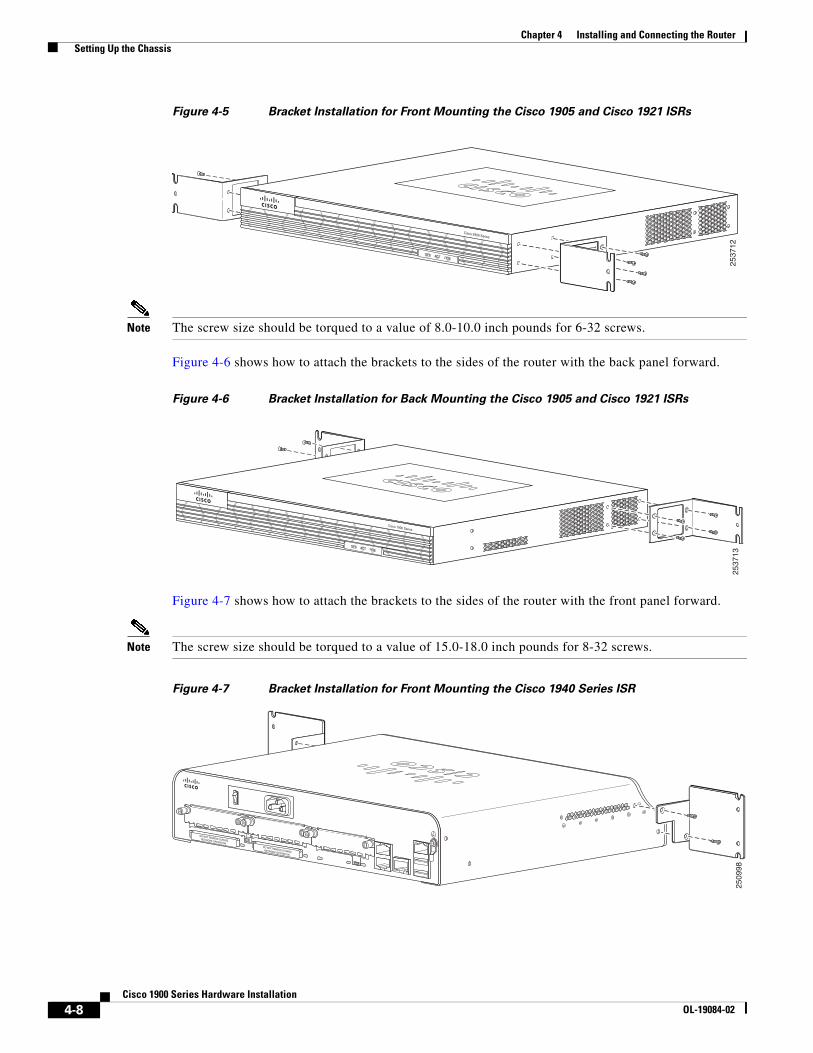
Chapter 4 Installing and Connecting the Router Setting Up the Chassis
Figure 4-5 Bracket Installation for Front Mounting the Cisco 1905 and Cisco 1921 ISRs
Note The screw size should be torqued to a value of 8.0-10.0 inch pounds for 6-32 screws.
Figure 4-6 shows how to attach the brackets to the sides of the router with the back panel forward.
Figure 4-6 Bracket Installation for Back Mounting the Cisco 1905 and Cisco 1921 ISRs
Figure 4-7 shows how to attach the brackets to the sides of the router with the front panel forward.
Note The screw size should be torqued to a value of 15.0-18.0 inch pounds for 8-32 screws.
Figure 4-7 Bracket Installation for Front Mounting the Cisco 1940 Series ISR
2537
12
Cisco 2900 Series
SYS ACT POE
2537
13
Cisco 1900 Series
SYS ACT POE
DO NOT REMOVE DURINGNETWORK OPERATION DO NOT REMOVE DURINGNETWORK OPERATION
2509
98
4-8Cisco 1900 Series Hardware Installation
OL-19084-02
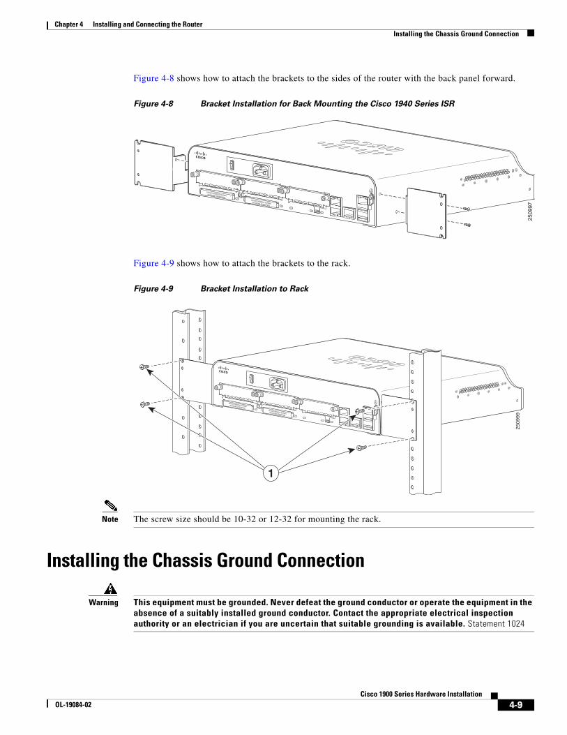
Chapter 4 Installing and Connecting the Router Installing the Chassis Ground Connection
Figure 4-8 shows how to attach the brackets to the sides of the router with the back panel forward.
Figure 4-8 Bracket Installation for Back Mounting the Cisco 1940 Series ISR
Figure 4-9 shows how to attach the brackets to the rack.
Figure 4-9 Bracket Installation to Rack
Note The screw size should be 10-32 or 12-32 for mounting the rack.
Installing the Chassis Ground Connection
Warning This equipment must be grounded. Never defeat the ground conductor or operate the equipment in the absence of a suitably installed ground conductor. Contact the appropriate electrical inspection authority or an electrician if you are uncertain that suitable grounding is available. Statement 1024
DO NOT REMOVE DURINGNETWORK OPERATION DO NOT REMOVE DURINGNETWORK OPERATION
2509
97
DO NOT REMOVE DURINGNETWORK OPERATION DO NOT REMOVE DURINGNETWORK OPERATION
2509
99
1
4-9Cisco 1900 Series Hardware Installation
OL-19084-02
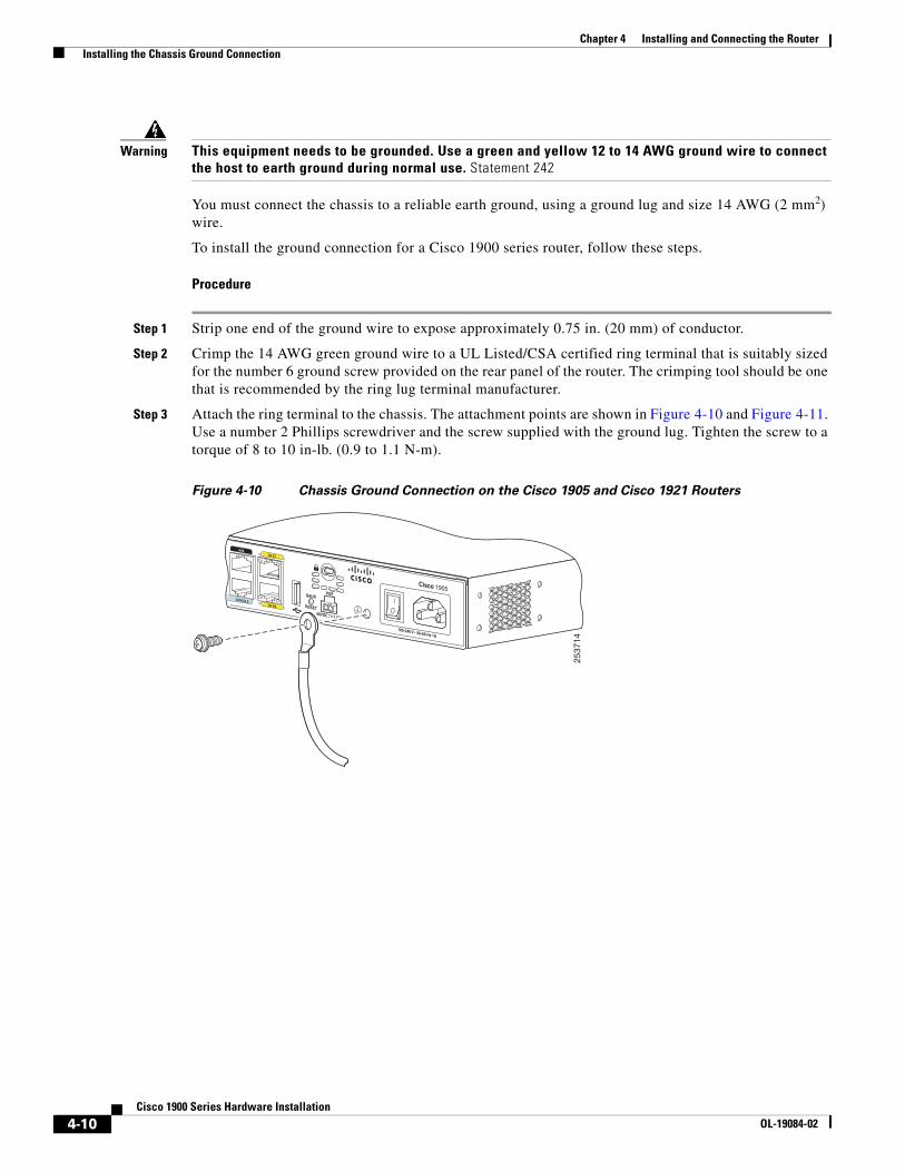
Chapter 4 Installing and Connecting the Router Installing the Chassis Ground Connection
Warning This equipment needs to be grounded. Use a green and yellow 12 to 14 AWG ground wire to connect the host to earth ground during normal use. Statement 242
You must connect the chassis to a reliable earth ground, using a ground lug and size 14 AWG (2 mm2) wire.
To install the ground connection for a Cisco 1900 series router, follow these steps.
Procedure
Step 1 Strip one end of the ground wire to expose approximately 0.75 in. (20 mm) of conductor.
Step 2 Crimp the 14 AWG green ground wire to a UL Listed/CSA certified ring terminal that is suitably sized for the number 6 ground screw provided on the rear panel of the router. The crimping tool should be one that is recommended by the ring lug terminal manufacturer.
Step 3 Attach the ring terminal to the chassis. The attachment points are shown in Figure 4-10 and Figure 4-11. Use a number 2 Phillips screwdriver and the screw supplied with the ground lug. Tighten the screw to a torque of 8 to 10 in-lb. (0.9 to 1.1 N-m).
Figure 4-10 Chassis Ground Connection on the Cisco 1905 and Cisco 1921 Routers
SL
CONSOLE
AUX
GE 0/0
GE 0/1
POE
Cisco 1905
RESETS
L
BAUD
48VDC 1.67A
100-240 V~ 50-60 Hz 1A
2537
14
4-10Cisco 1900 Series Hardware Installation
OL-19084-02
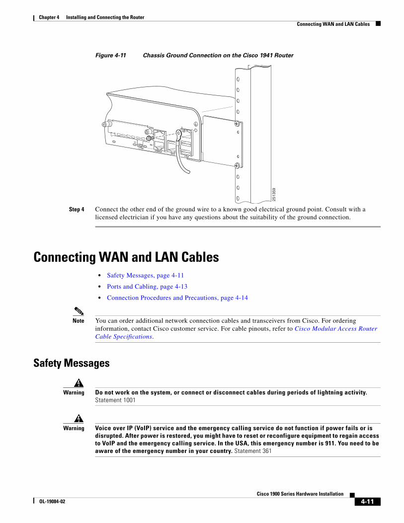
Chapter 4 Installing and Connecting the Router Connecting WAN and LAN Cables
Figure 4-11 Chassis Ground Connection on the Cisco 1941 Router
Step 4 Connect the other end of the ground wire to a known good electrical ground point. Consult with a licensed electrician if you have any questions about the suitability of the ground connection.
Connecting WAN and LAN Cables• Safety Messages, page 4-11
• Ports and Cabling, page 4-13
• Connection Procedures and Precautions, page 4-14
Note You can order additional network connection cables and transceivers from Cisco. For ordering information, contact Cisco customer service. For cable pinouts, refer to Cisco Modular Access Router Cable Specifications.
Safety Messages
Warning Do not work on the system, or connect or disconnect cables during periods of lightning activity. Statement 1001
Warning Voice over IP (VoIP) service and the emergency calling service do not function if power fails or is disrupted. After power is restored, you might have to reset or reconfigure equipment to regain access to VoIP and the emergency calling service. In the USA, this emergency number is 911. You need to be aware of the emergency number in your country. Statement 361
GE 0/1
CONSOLE
ENEN
LS
USB
1
GE0/0
0
2513
59
4-11Cisco 1900 Series Hardware Installation
OL-19084-02
Chapter 4 Installing and Connecting the Router Connecting WAN and LAN Cables
Warning Do not use this product near water; for example, near a bath tub, wash bowl, kitchen sink or laundry tub, in a wet basement, or near a swimming pool. Statement 1035
Warning Never install telephone jacks in wet locations unless the jack is specifically designed for wet locations. Statement 1036
Warning Avoid using a telephone (other than a cordless type) during an electrical storm. There may be a remote risk of electric shock from lightning. Statement 1038
Warning To report a gas leak, do not use a telephone in the vicinity of the leak. Statement 1039
Warning To avoid electric shock, do not connect safety extra-low voltage (SELV) circuits to telephone-network voltage (TNV) circuits. LAN ports contain SELV circuits, and WAN ports contain TNV circuits. Some LAN and WAN ports both use RJ-45 connectors. Use caution when connecting cables. Statement 1021
Warning Hazardous network voltages are present in WAN ports regardless of whether power to the router is OFF or ON. To avoid electric shock, use caution when working near WAN ports. When detaching cables, detach the end away from the router first. Statement 1026
Warning Blank faceplates and cover panels serve three important functions: they prevent exposure to hazardous voltages and currents inside the chassis; they contain electromagnetic interference (EMI) that might disrupt other equipment; and they direct the flow of cooling air through the chassis. Do not operate the system unless all cards, faceplates, front covers, and rear covers are in place. Statement 1029
Warning Invisible laser radiation may be emitted from disconnected fibers or connectors. Do not stare into beams or view directly with optical instruments. Statement 1051
Warning Do not locate the antenna near overhead power lines or other electric light or power circuits, or where it can come into contact with such circuits. When installing the antenna, take extreme care not to come into contact with such circuits, because they may cause serious injury or death. For proper installation and grounding of the antenna, please refer to national and local codes (for example, U.S.:NFPA 70, National Electrical Code, Article 810, Canada: Canadian Electrical Code, Section 54). Statement 1052
Warning Class I (CDRH) and Class 1M (IEC) laser products. Statement 1055
4-12Cisco 1900 Series Hardware Installation
OL-19084-02
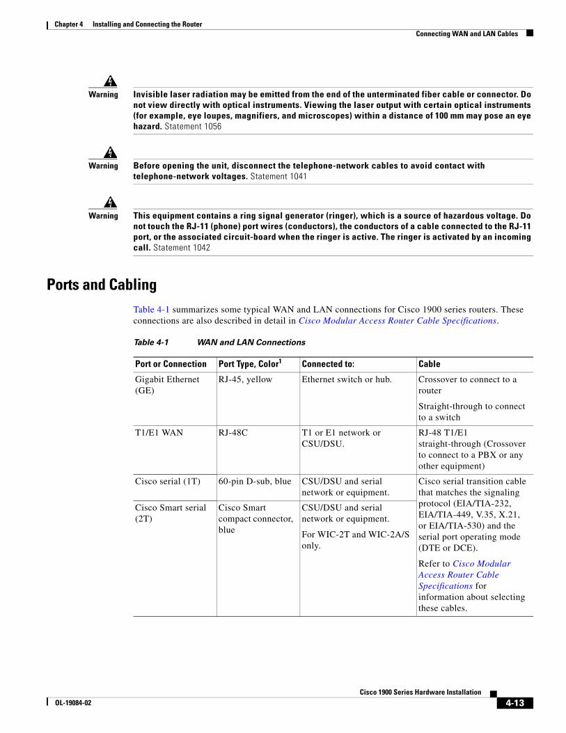
Chapter 4 Installing and Connecting the Router Connecting WAN and LAN Cables
Warning Invisible laser radiation may be emitted from the end of the unterminated fiber cable or connector. Do not view directly with optical instruments. Viewing the laser output with certain optical instruments (for example, eye loupes, magnifiers, and microscopes) within a distance of 100 mm may pose an eye hazard. Statement 1056
Warning Before opening the unit, disconnect the telephone-network cables to avoid contact with telephone-network voltages. Statement 1041
Warning This equipment contains a ring signal generator (ringer), which is a source of hazardous voltage. Do not touch the RJ-11 (phone) port wires (conductors), the conductors of a cable connected to the RJ-11 port, or the associated circuit-board when the ringer is active. The ringer is activated by an incoming call. Statement 1042
Ports and CablingTable 4-1 summarizes some typical WAN and LAN connections for Cisco 1900 series routers. These connections are also described in detail in Cisco Modular Access Router Cable Specifications.
Table 4-1 WAN and LAN Connections
Port or Connection Port Type, Color1 Connected to: Cable
Gigabit Ethernet (GE)
RJ-45, yellow Ethernet switch or hub. Crossover to connect to a router
Straight-through to connect to a switch
T1/E1 WAN RJ-48C T1 or E1 network or CSU/DSU.
RJ-48 T1/E1 straight-through (Crossover to connect to a PBX or any other equipment)
Cisco serial (1T) 60-pin D-sub, blue CSU/DSU and serialnetwork or equipment.
Cisco serial transition cable that matches the signaling protocol (EIA/TIA-232, EIA/TIA-449, V.35, X.21, or EIA/TIA-530) and the serial port operating mode (DTE or DCE).
Refer to Cisco Modular Access Router Cable Specifications for information about selecting these cables.
Cisco Smart serial (2T)
Cisco Smart compact connector, blue
CSU/DSU and serialnetwork or equipment.
For WIC-2T and WIC-2A/S only.
4-13Cisco 1900 Series Hardware Installation
OL-19084-02
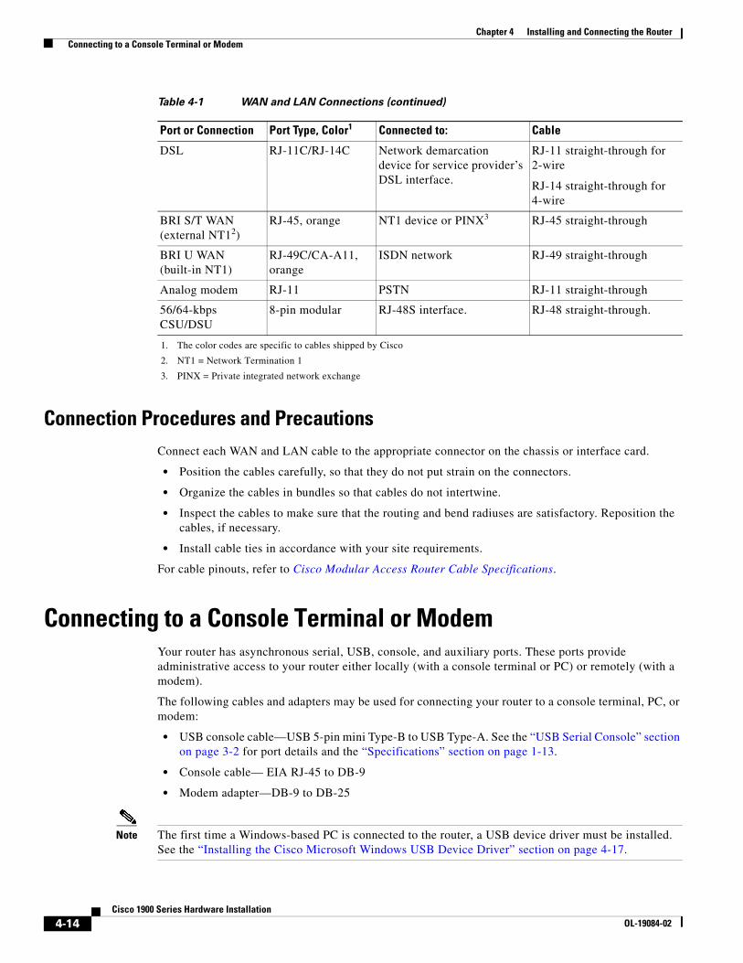
Chapter 4 Installing and Connecting the Router Connecting to a Console Terminal or Modem
Connection Procedures and PrecautionsConnect each WAN and LAN cable to the appropriate connector on the chassis or interface card.
• Position the cables carefully, so that they do not put strain on the connectors.
• Organize the cables in bundles so that cables do not intertwine.
• Inspect the cables to make sure that the routing and bend radiuses are satisfactory. Reposition the cables, if necessary.
• Install cable ties in accordance with your site requirements.
For cable pinouts, refer to Cisco Modular Access Router Cable Specifications.
Connecting to a Console Terminal or ModemYour router has asynchronous serial, USB, console, and auxiliary ports. These ports provide administrative access to your router either locally (with a console terminal or PC) or remotely (with a modem).
The following cables and adapters may be used for connecting your router to a console terminal, PC, or modem:
• USB console cable—USB 5-pin mini Type-B to USB Type-A. See the “USB Serial Console” section on page 3-2 for port details and the “Specifications” section on page 1-13.
• Console cable— EIA RJ-45 to DB-9
• Modem adapter—DB-9 to DB-25
Note The first time a Windows-based PC is connected to the router, a USB device driver must be installed. See the “Installing the Cisco Microsoft Windows USB Device Driver” section on page 4-17.
DSL RJ-11C/RJ-14C Network demarcationdevice for service provider’sDSL interface.
RJ-11 straight-through for 2-wire
RJ-14 straight-through for 4-wire
BRI S/T WAN (external NT12)
RJ-45, orange NT1 device or PINX3 RJ-45 straight-through
BRI U WAN (built-in NT1)
RJ-49C/CA-A11, orange
ISDN network RJ-49 straight-through
Analog modem RJ-11 PSTN RJ-11 straight-through
56/64-kbps CSU/DSU
8-pin modular RJ-48S interface. RJ-48 straight-through.
1. The color codes are specific to cables shipped by Cisco
2. NT1 = Network Termination 1
3. PINX = Private integrated network exchange
Table 4-1 WAN and LAN Connections (continued)
Port or Connection Port Type, Color1 Connected to: Cable
4-14Cisco 1900 Series Hardware Installation
OL-19084-02
Chapter 4 Installing and Connecting the Router Connecting to a Console Terminal or Modem
This section describes how to connect a console terminal or PC to the console port and how to connect a modem to the auxiliary port.
• Connecting to the Console Port with Microsoft Windows, page 4-15
• Connecting to the Console Port with Mac OS X, page 4-16
• Connecting to the Console Port with Linux, page 4-17
Connecting to the Console Port with Microsoft WindowsTo configure the router through the Cisco IOS command-line interface (CLI), you must connect the router console port to a terminal or PC. See the “Console and Auxiliary Port Considerations” section on page 3-1.
A Microsoft Windows PC must have HyperTerminal or similar terminal emulation software installed. The software should be configured with the following parameters: 9600 baud, 8 data bits, no parity, 1 stop bit, and no flow control. Refer to the Cisco 3900 Series, 2900 Series, and 1900 Series Software Configuration Guide for detailed information about using Cisco IOS software for configuring the router.
To connect the router to a terminal or PC, follow these steps:
Procedure
Step 1 Connect the end of the console cable with the RJ-45 connector to the light blue console port on the router, or USB 5-pin mini Type-B to the USB console port as shown in Figure 4-12. If connecting the USB port for the first time on a Windows based PC, you must install the Windows USB driver. See the “Installing the Cisco Microsoft Windows USB Device Driver” section on page 4-17.
Note You must use either the USB port or the RJ-45 port, but not both simultaneously. See the “USB Serial Console” section on page 3-2. When the USB port is used it takes priority over the RJ-45 EIA port.
4-15Cisco 1900 Series Hardware Installation
OL-19084-02
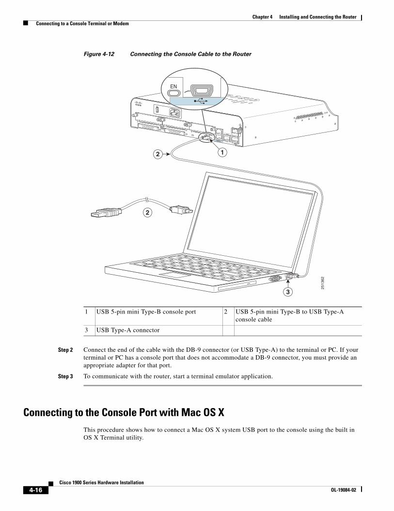
Chapter 4 Installing and Connecting the Router Connecting to a Console Terminal or Modem
Figure 4-12 Connecting the Console Cable to the Router
Step 2 Connect the end of the cable with the DB-9 connector (or USB Type-A) to the terminal or PC. If your terminal or PC has a console port that does not accommodate a DB-9 connector, you must provide an appropriate adapter for that port.
Step 3 To communicate with the router, start a terminal emulator application.
Connecting to the Console Port with Mac OS XThis procedure shows how to connect a Mac OS X system USB port to the console using the built in OS X Terminal utility.
1 USB 5-pin mini Type-B console port 2 USB 5-pin mini Type-B to USB Type-A console cable
3 USB Type-A connector
DO NOT REMOVE DURINGNETWORK OPERATION DO NOT REMOVE DURINGNETWORK OPERATION GE 0/1
LS
USB
1
GE0/0
0CONSOLE
ENEN
3
12
2
2513
62
EN
4-16Cisco 1900 Series Hardware Installation
OL-19084-02
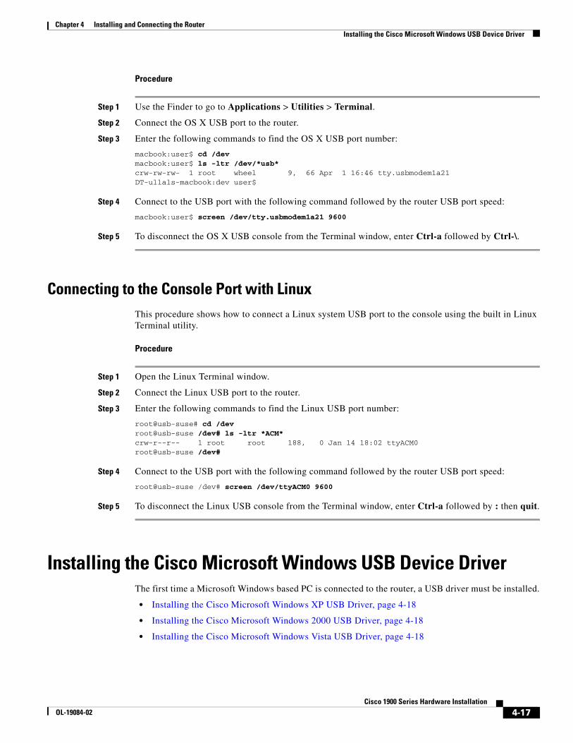
Chapter 4 Installing and Connecting the Router Installing the Cisco Microsoft Windows USB Device Driver
Procedure
Step 1 Use the Finder to go to Applications > Utilities > Terminal.
Step 2 Connect the OS X USB port to the router.
Step 3 Enter the following commands to find the OS X USB port number:
macbook:user$ cd /devmacbook:user$ ls -ltr /dev/*usb*crw-rw-rw- 1 root wheel 9, 66 Apr 1 16:46 tty.usbmodem1a21 DT-ullals-macbook:dev user$
Step 4 Connect to the USB port with the following command followed by the router USB port speed:
macbook:user$ screen /dev/tty.usbmodem1a21 9600
Step 5 To disconnect the OS X USB console from the Terminal window, enter Ctrl-a followed by Ctrl-\.
Connecting to the Console Port with LinuxThis procedure shows how to connect a Linux system USB port to the console using the built in Linux Terminal utility.
Procedure
Step 1 Open the Linux Terminal window.
Step 2 Connect the Linux USB port to the router.
Step 3 Enter the following commands to find the Linux USB port number:
root@usb-suse# cd /devroot@usb-suse /dev# ls -ltr *ACM*crw-r--r-- 1 root root 188, 0 Jan 14 18:02 ttyACM0root@usb-suse /dev#
Step 4 Connect to the USB port with the following command followed by the router USB port speed:
root@usb-suse /dev# screen /dev/ttyACM0 9600
Step 5 To disconnect the Linux USB console from the Terminal window, enter Ctrl-a followed by : then quit.
Installing the Cisco Microsoft Windows USB Device DriverThe first time a Microsoft Windows based PC is connected to the router, a USB driver must be installed.
• Installing the Cisco Microsoft Windows XP USB Driver, page 4-18
• Installing the Cisco Microsoft Windows 2000 USB Driver, page 4-18
• Installing the Cisco Microsoft Windows Vista USB Driver, page 4-18
4-17Cisco 1900 Series Hardware Installation
OL-19084-02
Chapter 4 Installing and Connecting the Router Installing the Cisco Microsoft Windows USB Device Driver
Installing the Cisco Microsoft Windows XP USB Driver
Before You Begin
• Download the driver for your router model from the Tools and Resources Download Software site, USB Console Software category, at http://www.cisco.com/cisco/software/type.html?mdfid=282977114&flowid=716
Procedure
Step 1 Unzip the file cisco_usbconsole_driver_X_X.zip (where X is a revision number).
Step 2 Double-click the file setup.exe.
Step 3 The Cisco Virtual Com InstallShield Wizard begins. Click Next.
Step 4 The Ready to Install the Program window appears, Click Install.
Step 5 The InstallShield Wizard Completed window appears. Click Finish.
Step 6 Connect the USB cable to the PC and router USB console ports. See Table 4-1 on page 4-16. The EN LED for the USB console port turns green, and within a few moments the Found New Hardware Wizard appears.
The USB console is ready for use.
Installing the Cisco Microsoft Windows 2000 USB Driver
Procedure
Step 1 Obtain the file cisco_usbconsole.zip from the Cisco.com web site and unzip it.
Step 2 Double-click the file setup.exe.
Step 3 The Cisco Virtual Com InstallShield Wizard begins. Click Next.
Step 4 The Ready to Install the Program window appears, Click Install.
Step 5 The InstallShield Wizard Completed window appears. Click Finish.
Step 6 Connect the USB cable to the PC and router USB console ports. See Table 4-1 on page 4-16. The EN LED for the USB console port turns green, and within a few moments a series of Found New Hardware Wizard windows appear.
The USB console is ready for use.
Installing the Cisco Microsoft Windows Vista USB Driver
Procedure
Step 1 Obtain the file cisco_usbconsole.zip from the Cisco.com web site and unzip it.
Step 2 Double-click the file setup.exe.
4-18Cisco 1900 Series Hardware Installation
OL-19084-02
Chapter 4 Installing and Connecting the Router Uninstalling the Cisco USB Driver
Step 3 The Cisco Virtual Com InstallShield Wizard begins. Click Next.
Step 4 The Ready to Install the Program window appears, Click Install.
Note If a User Account Control warning appears, click “Allow - I trust this program...” to proceed.
Step 5 The InstallShield Wizard Completed window appears. Click Finish.
Step 6 Connect the USB cable to the PC and router USB console ports. See Table 4-1 on page 4-16. The EN LED for the USB console port turns green, and within a few moments a pop up window stating “Installing device driver software” appears.
The USB console is ready for use.
Uninstalling the Cisco USB Driver• Uninstalling the Cisco Microsoft Windows XP and 2000 USB Driver, page 4-19
• Uninstalling the Cisco Microsoft Windows Vista USB Driver, page 4-20
Uninstalling the Cisco Microsoft Windows XP and 2000 USB DriverThese procedures show how to uninstall both the Microsoft Windows XP and 2000 USB driver. The driver can be removed using the Windows Add Remove Programs utility or the setup.exe program.
• Using the Add Remove Programs Utility, page 4-19
• Using the Setup.exe Program, page 4-19
Using the Add Remove Programs Utility
Before You Begin
Disconnect the router console terminal before uninstalling the driver.
Procedure
Step 1 Click Start > Control Panel > Add or Remove Programs.
Step 2 Scroll to Cisco Virtual Com and click Remove.
Step 3 When the Program Maintenance window appears, select the Remove radio button.
Step 4 Click Next.
Using the Setup.exe Program
Before You Begin
Disconnect the router console terminal before uninstalling the driver.
4-19Cisco 1900 Series Hardware Installation
OL-19084-02
Chapter 4 Installing and Connecting the Router Connecting to the Auxiliary Port
Procedure
Step 1 Run the setup.exe program. Click Next.
Step 2 The InstallShield Wizard for Cisco Virtual Com appears. Click Next.
Step 3 When the Program Maintenance window appears, select the Remove radio button. Click Next.
Step 4 When the Remove the Program window appears, click Remove.
Step 5 When the InstallShield Wizard Completed window appears click Finish.
Uninstalling the Cisco Microsoft Windows Vista USB Driver
Before You Begin
Disconnect the router console terminal before uninstalling the driver.
Procedure
Step 1 Run the setup.exe program. Click Next.
Step 2 The InstallShield Wizard for Cisco Virtual Com appears. Click Next.
Step 3 When the Program Maintenance window appears, select the Remove radio button.
Step 4 Click Next.
Step 5 When the Remove the Program window appears, click Remove.
Note If a User Account Control warning appears, click “Allow - I trust this program...” to proceed.
Step 6 When the InstallShield Wizard Completed window appears click Finish.
Connecting to the Auxiliary PortWhen a modem is connected to the auxiliary port, a remote user can dial in to the router and configure it. Use the light blue console cable and the DB-9-to-DB-25 connector adapter that came in the router accessory kit.
To connect a modem to the router, follow these steps.
Procedure
Step 1 Connect the RJ-45 end of the adapter cable to the black AUX port on the router. See Figure 4-13.
4-20Cisco 1900 Series Hardware Installation
OL-19084-02
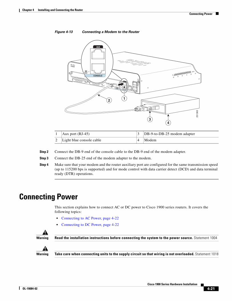
Chapter 4 Installing and Connecting the Router Connecting Power
Figure 4-13 Connecting a Modem to the Router
Step 2 Connect the DB-9 end of the console cable to the DB-9 end of the modem adapter.
Step 3 Connect the DB-25 end of the modem adapter to the modem.
Step 4 Make sure that your modem and the router auxiliary port are configured for the same transmission speed (up to 115200 bps is supported) and for mode control with data carrier detect (DCD) and data terminal ready (DTR) operations.
Connecting PowerThis section explains how to connect AC or DC power to Cisco 1900 series routers. It covers the following topics:
• Connecting to AC Power, page 4-22
• Connecting to DC Power, page 4-22
Warning Read the installation instructions before connecting the system to the power source. Statement 1004
Warning Take care when connecting units to the supply circuit so that wiring is not overloaded. Statement 1018
1 Aux port (RJ-45) 3 DB-9-to-DB-25 modem adapter
2 Light blue console cable 4 Modem
DO NOT REMOVE DURINGNETWORK OPERATION DO NOT REMOVE DURINGNETWORK OPERATION GE 0/1
CONSOLE
ENEN
LS
USB
1
GE0/0
0
2513
63
2
34
CONSOLE
AUX
EN
AUX
1
4-21Cisco 1900 Series Hardware Installation
OL-19084-02
Chapter 4 Installing and Connecting the Router Connecting Power
Warning This unit might have more than one power supply connection. All connections must be removed to de-energize the unit. Statement 1028
Warning Only trained and qualified personnel should be allowed to install, replace, or service this equipment. Statement 1030
Note The installation must comply with all required electrical codes applicable at the installation site.
Connecting to AC PowerIf your router uses AC power, connect it to a 15A, 120VAC (10A, 240VAC) circuit with overcurrent protection.
Note The input voltage tolerance limits for AC power are 85 and 264 VAC.
Note This product requires surge protection to be provided as part of the building installation. To comply with the Telcordia GR-1089 NEBS standard for electromagnetic compatibility and safety, an external surge protective device (SPD) is required at the AC power service equipment.
Warning AC connected units must have a permanent ground connection in addition to the power cable ground wire. NEBS-compliant grounding satisfies this requirement. Statement 284
Warning This product requires short-circuit (overcurrent) protection, to be provided as part of the building installation. Install only in accordance with national and local wiring regulations. Statement 1045
Warning This product relies on the building’s installation for short-circuit (over current) protection. Ensure that the protective device is rated not greater than: 15A, 120VAC (10A, 240VAC). Statement 1005
Connecting to DC PowerIf your router has a DC-input power supply, follow the directions in this section for proper wiring. A router with a DC-input power supply has a terminal block for the DC power connections.
• DC Wiring Requirements for Cisco 1900 Series Routers, page 4-23
• Cisco 1900 Series Router Wiring Procedure for DC Input, page 4-23
Caution DC return is isolated from the frame. (NEBS DC-1)
4-22Cisco 1900 Series Hardware Installation
OL-19084-02
Chapter 4 Installing and Connecting the Router Connecting Power
Warning This product requires short-circuit (overcurrent) protection, to be provided as part of the building installation. Install only in accordance with national and local wiring regulations. Statement 1045
Warning This product relies on the building’s installation for short-circuit (over current) protection. Ensure that the protective device is rated not greater than: 60VDC, 20A. Statement 1005
Warning Only trained and qualified personnel should be allowed to install, replace, or service this equipment. Statement 1030
Warning Use copper conductors only. Statement 1025
DC Wiring Requirements for Cisco 1900 Series Routers
A Cisco 1921 router with a DC-input power supply requires copper wire and crimp-type terminals for the power connections. Table 4-2 summarizes the wiring requirements.
You can connect a single DC power source to either the A input or the B input. If there are dual power sources, connect one source to the A input and one source to the B input; both sources must be the same polarity and voltage.
Cisco 1900 Series Router Wiring Procedure for DC Input
To connect a router to a DC power source, perform the following steps.
Procedure
Step 1 Remove power from the DC circuit. To ensure that power is removed from the DC circuit, locate the circuit breaker for the DC circuit, switch the circuit breaker to the OFF position, and tape the circuit-breaker switch in the OFF position.
Warning Before performing any of the following procedures, ensure that power is removed from the DC circuit. Statement 1003
Warning Use copper conductors only. Statement 1025
Table 4-2 DC Wiring Requirements for Cisco 1900 Routers
DC Power InputDC Input Wire Size
Safety Ground Wire Size Wire Terminal (Lug)
Overcurrent Protection
32-60 VDC, 4A, positive or negative, single source
AWG 14 (2.0 mm2)
AWG 14 (2.0 mm2), minimum
Amp/Tyco No. 32957 20 A maximum
4-23Cisco 1900 Series Hardware Installation
OL-19084-02
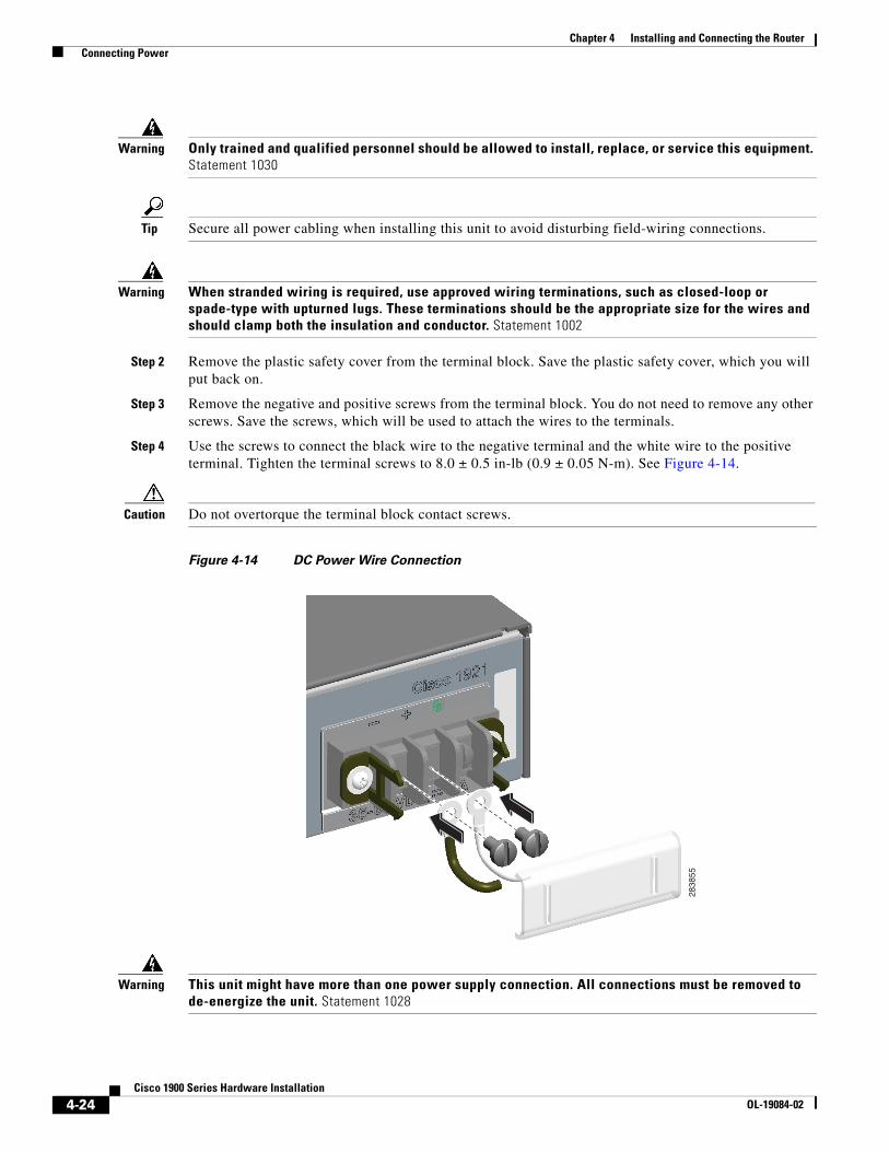
Chapter 4 Installing and Connecting the Router Connecting Power
Warning Only trained and qualified personnel should be allowed to install, replace, or service this equipment. Statement 1030
Tip Secure all power cabling when installing this unit to avoid disturbing field-wiring connections.
Warning When stranded wiring is required, use approved wiring terminations, such as closed-loop or spade-type with upturned lugs. These terminations should be the appropriate size for the wires and should clamp both the insulation and conductor. Statement 1002
Step 2 Remove the plastic safety cover from the terminal block. Save the plastic safety cover, which you will put back on.
Step 3 Remove the negative and positive screws from the terminal block. You do not need to remove any other screws. Save the screws, which will be used to attach the wires to the terminals.
Step 4 Use the screws to connect the black wire to the negative terminal and the white wire to the positive terminal. Tighten the terminal screws to 8.0 ± 0.5 in-lb (0.9 ± 0.05 N-m). See Figure 4-14.
Caution Do not overtorque the terminal block contact screws.
Figure 4-14 DC Power Wire Connection
Warning This unit might have more than one power supply connection. All connections must be removed to de-energize the unit. Statement 1028
2838
55
4-24Cisco 1900 Series Hardware Installation
OL-19084-02
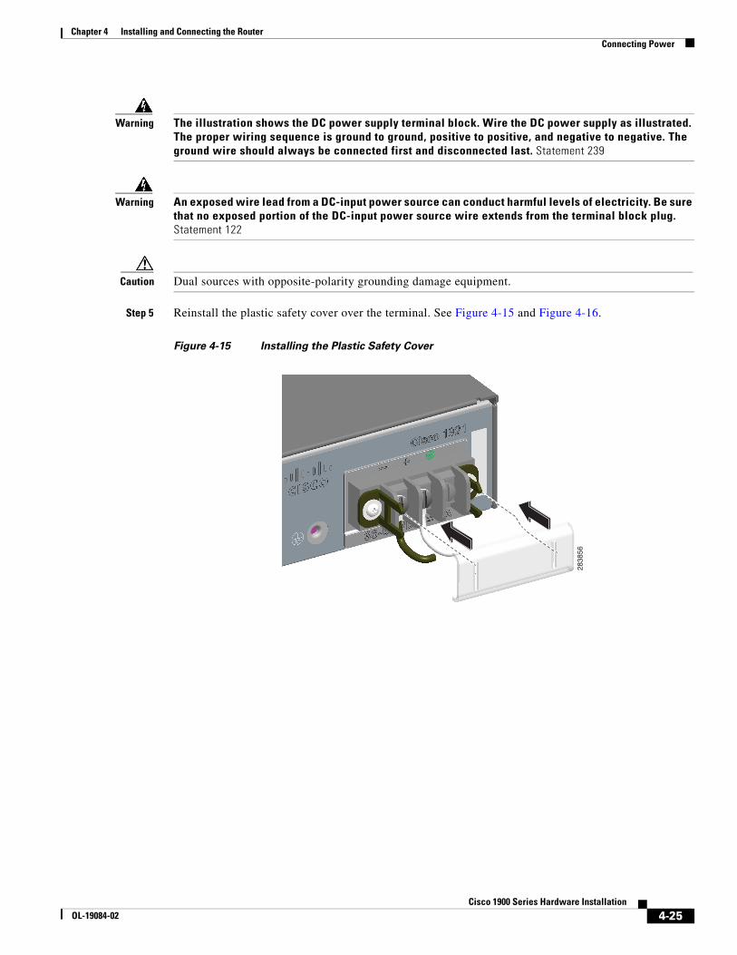
Chapter 4 Installing and Connecting the Router Connecting Power
Warning The illustration shows the DC power supply terminal block. Wire the DC power supply as illustrated. The proper wiring sequence is ground to ground, positive to positive, and negative to negative. The ground wire should always be connected first and disconnected last. Statement 239
Warning An exposed wire lead from a DC-input power source can conduct harmful levels of electricity. Be sure that no exposed portion of the DC-input power source wire extends from the terminal block plug. Statement 122
Caution Dual sources with opposite-polarity grounding damage equipment.
Step 5 Reinstall the plastic safety cover over the terminal. See Figure 4-15 and Figure 4-16.
Figure 4-15 Installing the Plastic Safety Cover
2838
56
4-25Cisco 1900 Series Hardware Installation
OL-19084-02
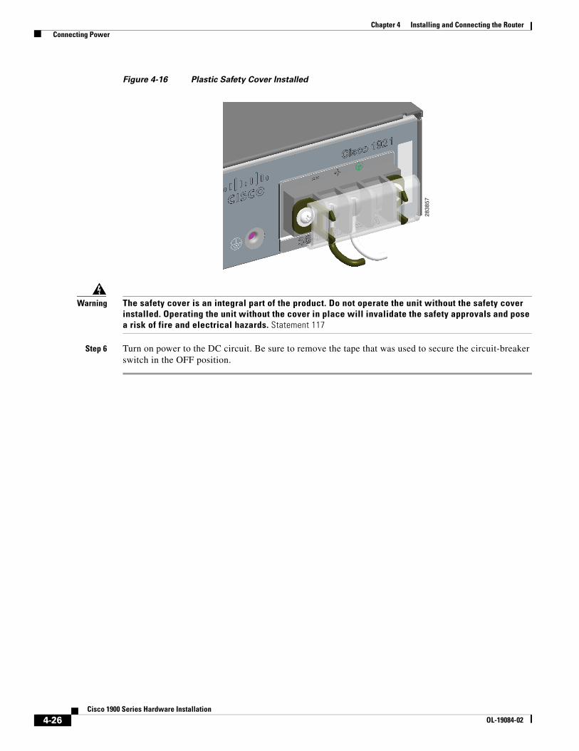
Chapter 4 Installing and Connecting the Router Connecting Power
Figure 4-16 Plastic Safety Cover Installed
Warning The safety cover is an integral part of the product. Do not operate the unit without the safety cover installed. Operating the unit without the cover in place will invalidate the safety approvals and pose a risk of fire and electrical hazards. Statement 117
Step 6 Turn on power to the DC circuit. Be sure to remove the tape that was used to secure the circuit-breaker switch in the OFF position.
2838
57
4-26Cisco 1900 Series Hardware Installation
OL-19084-02
OL-19084-02
C H A P T E R 5
Configuring the RouterThis chapter describes how to power up the router and perform the initial configuration in the following sections:
• Powering up the Router, page 5-1
• Performing the Initial Configuration on the Router, page 5-3
– Using the Cisco Setup Command Facility, page 5-3
– Using Cisco Configuration Professional Express, page 5-6
– Using the Cisco CLI—Manual Configuration, page 5-6
• Verifying the Initial Configuration, page 5-23
Powering up the Router
Warning Blank faceplates and cover panels serve three important functions: they prevent exposure to hazardous voltages and currents inside the chassis; they contain electromagnetic interference (EMI) that might disrupt other equipment; and they direct the flow of cooling air through the chassis. Do not operate the system unless all cards, faceplates, front covers, and rear covers are in place. Statement 1029
• Checklist Before Powering Up the Cisco Router, page 5-1
• Powering Up the Cisco Router, page 5-2
• Verifying the Front Panel LED Indications, page 5-3
Checklist Before Powering Up the Cisco RouterCheck the following items before powering up the router:
• You have securely mounted and grounded the chassis.
• You have connected the power and interface cables.
• You have properly seated the external Compact Flash memory card into its slot. For installation instructions, see Installing and Upgrading Internal Modules and FRUs in Cisco 1900 Series ISRs.
5-1Cisco 1900 Series Hardware Installation
Chapter 5 Configuring the Router Powering up the Router
• You have a PC with a terminal emulation program (HyperTerminal or equivalent) that is connected to the console port. It is configured for 9600 baud, 8 data bits, 1 stop bit, no parity, and flow control is set to “none.”
• You have selected a suitable PC COM port in the terminal emulation program.
• You have selected passwords for access control.
• You have determined the IP addresses for the Ethernet and serial interfaces.
Powering Up the Cisco RouterTo power up your Cisco router, follow this procedure to verify the router has performed the initialization and self-test. When the procedure is finished, the router is ready to configure.
If you encounter problems while powering on the router, see the routers troubleshooting page on Cisco.com.
For information about the ROM monitor and the bootstrap program, see Using the ROM Monitor. For information about the configuration register, see Changing the Configuration Register Settings.
Note To view the boot sequence, you must establish console connection to the Cisco router before it powers up.
Before You Begin
• Make sure that your PC is ready to be powered up and connected as described in the “Checklist Before Powering Up the Cisco Router” section on page 5-1.
Procedure
Step 1 Move the power switch to the ON position.
• The SYS LED on the front of the chassis begins blinking green.
• The fans begin operating.
• Startup messages appear in your console window. When the startup messages finish, the SYS LED appears solid green.
• Depending on your installation, some LEDs at the rear of the chassis and on installed modules might also illuminate.
Caution Do not press any keys on the keyboard until the messages stop and the SYS LED is solid green. Any keys pressed during this time are interpreted as the first command typed when the messages stop, which might cause the router to power off and start over. It takes a few minutes for the messages to stop.
Related Information
If you encounter a problem during the power up process see Troubleshooting Cisco 3900 Series, 2900 Series, and 1900 Series ISRs.
5-2Cisco 1900 Series Hardware Installation
OL-19084-02
Chapter 5 Configuring the Router Performing the Initial Configuration on the Router
Verifying the Front Panel LED IndicationsThe front-panel indicator LEDs described in Table 1-4 provide power, activity, and status information useful during power up.
Performing the Initial Configuration on the RouterUse any of the following tools to perform the initial configuration on the router:
• Using the Cisco Setup Command Facility, page 5-3
• Using Cisco Configuration Professional Express, page 5-6
• Using the Cisco CLI—Manual Configuration, page 5-6
Note Cisco recommends using Cisco Configuration Professional Express to perform the initial configuration on the router because it provides a web-based graphical-user interface (GUI).
Using the Cisco Setup Command FacilityCisco Setup Command Facility lets you configure the initial router settings through a configuration dialog. If you see the following messages, the router has booted and is ready for initial configuration using the setup command facility.
--- System Configuration Dialog ---
At any point you may enter a question mark '?' for help.Use ctrl-c to abort configuration dialog at any prompt.Default settings are in square brackets '[]'.
Would you like to enter the initial configuration dialog? [yes/no]:
If the system configuration dialog message does not appear, a default configuration file was installed on the router prior to shipping. See the “Using Cisco Configuration Professional Express” section on page 5-6 to configure the router.
The setup command facility prompts you to enter the information that is needed to configure a router quickly. The facility steps you through a initial configuration, including LAN and WAN interfaces. For more general information about the setup command facility, see Cisco IOS Configuration Fundamentals Configuration Guide, Release 12.4.
Note • The messages that are displayed will vary based on your router model, the installed interface modules, and the software image. The following example and the user entries (in bold) are shown as examples only.
• If you make a mistake while using the setup command facility, you can exit and run the setup command facility again. Press Ctrl-C, and enter the setup command in privileged EXEC mode (Router#).
5-3Cisco 1900 Series Hardware Installation
OL-19084-02
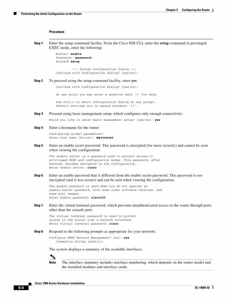
Chapter 5 Configuring the Router Performing the Initial Configuration on the Router
Procedure
Step 1 Enter the setup command facility. From the Cisco IOS CLI, enter the setup command in privileged EXEC mode, enter the following:
Router> enablePassword: <password>Router# setup
--- System Configuration Dialog ---Continue with configuration dialog? [yes/no]:
Step 2 To proceed using the setup command facility, enter yes.
Continue with configuration dialog? [yes/no]:
At any point you may enter a question mark '?' for help.
Use ctrl-c to abort configuration dialog at any prompt.Default settings are in square brackets '[]'.
Step 3 Proceed using basic management setup, which configures only enough connectivity:
Would you like to enter basic management setup? [yes/no]: yes
Step 4 Enter a hostname for the router:
Configuring global parameters:Enter host name [Router]: myrouter
Step 5 Enter an enable secret password. This password is encrypted (for more security) and cannot be seen when viewing the configuration.
The enable secret is a password used to protect access toprivileged EXEC and configuration modes. This password, afterentered, becomes encrypted in the configuration.Enter enable secret: cisco
Step 6 Enter an enable password that is different from the enable secret password. This password is not encrypted (and is less secure) and can be seen when viewing the configuration.
The enable password is used when you do not specify anenable secret password, with some older software versions, andsome boot images.Enter enable password: cisco123
Step 7 Enter the virtual terminal password, which prevents unauthenticated access to the router through ports other than the console port:
The virtual terminal password is used to protectaccess to the router over a network interface.Enter virtual terminal password: cisco
Step 8 Respond to the following prompts as appropriate for your network:
Configure SNMP Network Management? [no]: yes Community string [public]:
The system displays a summary of the available interfaces.
Note The interface summary includes interface numbering, which depends on the router model and the installed modules and interface cards.
5-4Cisco 1900 Series Hardware Installation
OL-19084-02
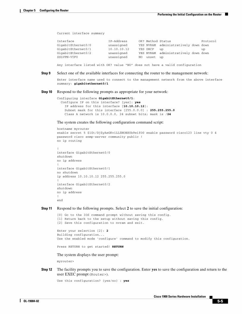
Chapter 5 Configuring the Router Performing the Initial Configuration on the Router
Current interface summary
Interface IP-Address OK? Method Status ProtocolGigabitEthernet0/0 unassigned YES NVRAM administratively down down GigabitEthernet0/1 10.10.10.12 YES DHCP up up GigabitEthernet0/2 unassigned YES NVRAM administratively down down SSLVPN-VIF0 unassigned NO unset up
Any interface listed with OK? value "NO" does not have a valid configuration
Step 9 Select one of the available interfaces for connecting the router to the management network:
Enter interface name used to connect to the management network from the above interface summary: gigabitethernet0/1
Step 10 Respond to the following prompts as appropriate for your network:
Configuring interface GigabitEthernet0/1: Configure IP on this interface? [yes]: yes IP address for this interface [10.10.10.12]: Subnet mask for this interface [255.0.0.0] : 255.255.255.0 Class A network is 10.0.0.0, 24 subnet bits; mask is /24
The system creates the following configuration command script:
hostname myrouterenable secret 5 $1$t/Dj$yAeGKviLLZNOBX0b9eifO0 enable password cisco123 line vty 0 4 password cisco snmp-server community public !no ip routing
!interface GigabitEthernet0/0shutdownno ip address!interface GigabitEthernet0/1no shutdownip address 10.10.10.12 255.255.255.0!interface GigabitEthernet0/2shutdownno ip address!end
Step 11 Respond to the following prompts. Select 2 to save the initial configuration:
[0] Go to the IOS command prompt without saving this config.[1] Return back to the setup without saving this config.[2] Save this configuration to nvram and exit.
Enter your selection [2]: 2Building configuration...Use the enabled mode 'configure' command to modify this configuration.
Press RETURN to get started! RETURN
The system displays the user prompt:
myrouter>
Step 12 The facility prompts you to save the configuration. Enter yes to save the configuration and return to the user EXEC prompt (Router>).
Use this configuration? {yes/no} : yes
5-5Cisco 1900 Series Hardware Installation
OL-19084-02
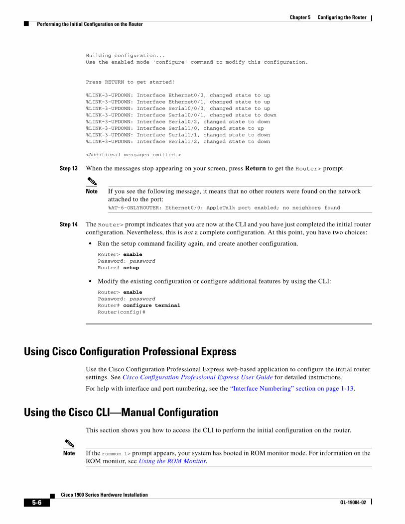
Chapter 5 Configuring the Router Performing the Initial Configuration on the Router
Building configuration...Use the enabled mode 'configure' command to modify this configuration.
Press RETURN to get started!
%LINK-3-UPDOWN: Interface Ethernet0/0, changed state to up%LINK-3-UPDOWN: Interface Ethernet0/1, changed state to up%LINK-3-UPDOWN: Interface Serial0/0/0, changed state to up%LINK-3-UPDOWN: Interface Serial0/0/1, changed state to down%LINK-3-UPDOWN: Interface Serial0/2, changed state to down%LINK-3-UPDOWN: Interface Serial1/0, changed state to up%LINK-3-UPDOWN: Interface Serial1/1, changed state to down%LINK-3-UPDOWN: Interface Serial1/2, changed state to down
<Additional messages omitted.>
Step 13 When the messages stop appearing on your screen, press Return to get the Router> prompt.
Note If you see the following message, it means that no other routers were found on the network attached to the port:%AT-6-ONLYROUTER: Ethernet0/0: AppleTalk port enabled; no neighbors found
Step 14 The Router> prompt indicates that you are now at the CLI and you have just completed the initial router configuration. Nevertheless, this is not a complete configuration. At this point, you have two choices:
• Run the setup command facility again, and create another configuration.
Router> enablePassword: passwordRouter# setup
• Modify the existing configuration or configure additional features by using the CLI:
Router> enablePassword: passwordRouter# configure terminalRouter(config)#
Using Cisco Configuration Professional ExpressUse the Cisco Configuration Professional Express web-based application to configure the initial router settings. See Cisco Configuration Professional Express User Guide for detailed instructions.
For help with interface and port numbering, see the “Interface Numbering” section on page 1-13.
Using the Cisco CLI—Manual ConfigurationThis section shows you how to access the CLI to perform the initial configuration on the router.
Note If the rommon 1> prompt appears, your system has booted in ROM monitor mode. For information on the ROM monitor, see Using the ROM Monitor.
5-6Cisco 1900 Series Hardware Installation
OL-19084-02
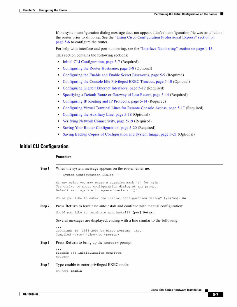
Chapter 5 Configuring the Router Performing the Initial Configuration on the Router
If the system configuration dialog message does not appear, a default configuration file was installed on the router prior to shipping. See the “Using Cisco Configuration Professional Express” section on page 5-6 to configure the router.
For help with interface and port numbering, see the “Interface Numbering” section on page 1-13.
This section contains the following sections:
• Initial CLI Configuration, page 5-7 (Required)
• Configuring the Router Hostname, page 5-8 (Optional)
• Configuring the Enable and Enable Secret Passwords, page 5-9 (Required)
• Configuring the Console Idle Privileged EXEC Timeout, page 5-10 (Optional)
• Configuring Gigabit Ethernet Interfaces, page 5-12 (Required)
• Specifying a Default Route or Gateway of Last Resort, page 5-14 (Required)
• Configuring IP Routing and IP Protocols, page 5-14 (Required)
• Configuring Virtual Terminal Lines for Remote Console Access, page 5-17 (Required)
• Configuring the Auxiliary Line, page 5-18 (Optional)
• Verifying Network Connectivity, page 5-19 (Required)
• Saving Your Router Configuration, page 5-20 (Required)
• Saving Backup Copies of Configuration and System Image, page 5-21 (Optional)
Initial CLI Configuration
Procedure
Step 1 When the system message appears on the router, enter no.
--- System Configuration Dialog ---
At any point you may enter a question mark '?' for help.Use ctrl-c to abort configuration dialog at any prompt.Default settings are in square brackets '[]'.
Would you like to enter the initial configuration dialog? [yes/no]: no
Step 2 Press Return to terminate autoinstall and continue with manual configuration:
Would you like to terminate autoinstall? [yes] Return
Several messages are displayed, ending with a line similar to the following:
...Copyright (c) 1986-2004 by cisco Systems, Inc.Compiled <date> <time> by <person>
Step 3 Press Return to bring up the Router> prompt.
...flashfs[4]: Initialization complete.Router>
Step 4 Type enable to enter privileged EXEC mode:
Router> enable
5-7Cisco 1900 Series Hardware Installation
OL-19084-02
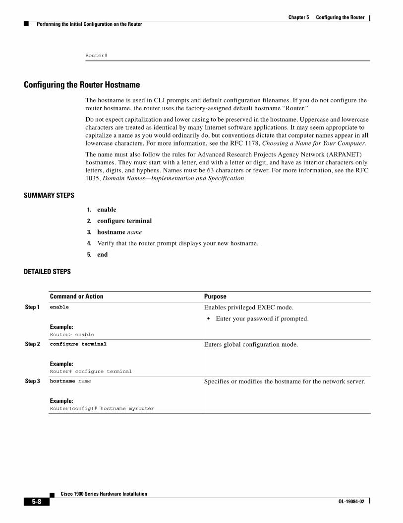
Chapter 5 Configuring the Router Performing the Initial Configuration on the Router
Router#
Configuring the Router Hostname
The hostname is used in CLI prompts and default configuration filenames. If you do not configure the router hostname, the router uses the factory-assigned default hostname “Router.”
Do not expect capitalization and lower casing to be preserved in the hostname. Uppercase and lowercase characters are treated as identical by many Internet software applications. It may seem appropriate to capitalize a name as you would ordinarily do, but conventions dictate that computer names appear in all lowercase characters. For more information, see the RFC 1178, Choosing a Name for Your Computer.
The name must also follow the rules for Advanced Research Projects Agency Network (ARPANET) hostnames. They must start with a letter, end with a letter or digit, and have as interior characters only letters, digits, and hyphens. Names must be 63 characters or fewer. For more information, see the RFC 1035, Domain Names—Implementation and Specification.
SUMMARY STEPS
1. enable
2. configure terminal
3. hostname name
4. Verify that the router prompt displays your new hostname.
5. end
DETAILED STEPS
Command or Action Purpose
Step 1 enable
Example:Router> enable
Enables privileged EXEC mode.
• Enter your password if prompted.
Step 2 configure terminal
Example:Router# configure terminal
Enters global configuration mode.
Step 3 hostname name
Example:Router(config)# hostname myrouter
Specifies or modifies the hostname for the network server.
5-8Cisco 1900 Series Hardware Installation
OL-19084-02
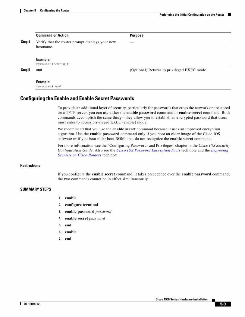
Chapter 5 Configuring the Router Performing the Initial Configuration on the Router
Configuring the Enable and Enable Secret Passwords
To provide an additional layer of security, particularly for passwords that cross the network or are stored on a TFTP server, you can use either the enable password command or enable secret command. Both commands accomplish the same thing—they allow you to establish an encrypted password that users must enter to access privileged EXEC (enable) mode.
We recommend that you use the enable secret command because it uses an improved encryption algorithm. Use the enable password command only if you boot an older image of the Cisco IOS software or if you boot older boot ROMs that do not recognize the enable secret command.
For more information, see the “Configuring Passwords and Privileges” chapter in the Cisco IOS Security Configuration Guide. Also see the Cisco IOS Password Encryption Facts tech note and the Improving Security on Cisco Routers tech note.
Restrictions
If you configure the enable secret command, it takes precedence over the enable password command; the two commands cannot be in effect simultaneously.
SUMMARY STEPS
1. enable
2. configure terminal
3. enable password password
4. enable secret password
5. end
6. enable
7. end
Step 4 Verify that the router prompt displays your new hostname.
Example:myrouter(config)#
—
Step 5 end
Example:myrouter# end
(Optional) Returns to privileged EXEC mode.
Command or Action Purpose
5-9Cisco 1900 Series Hardware Installation
OL-19084-02
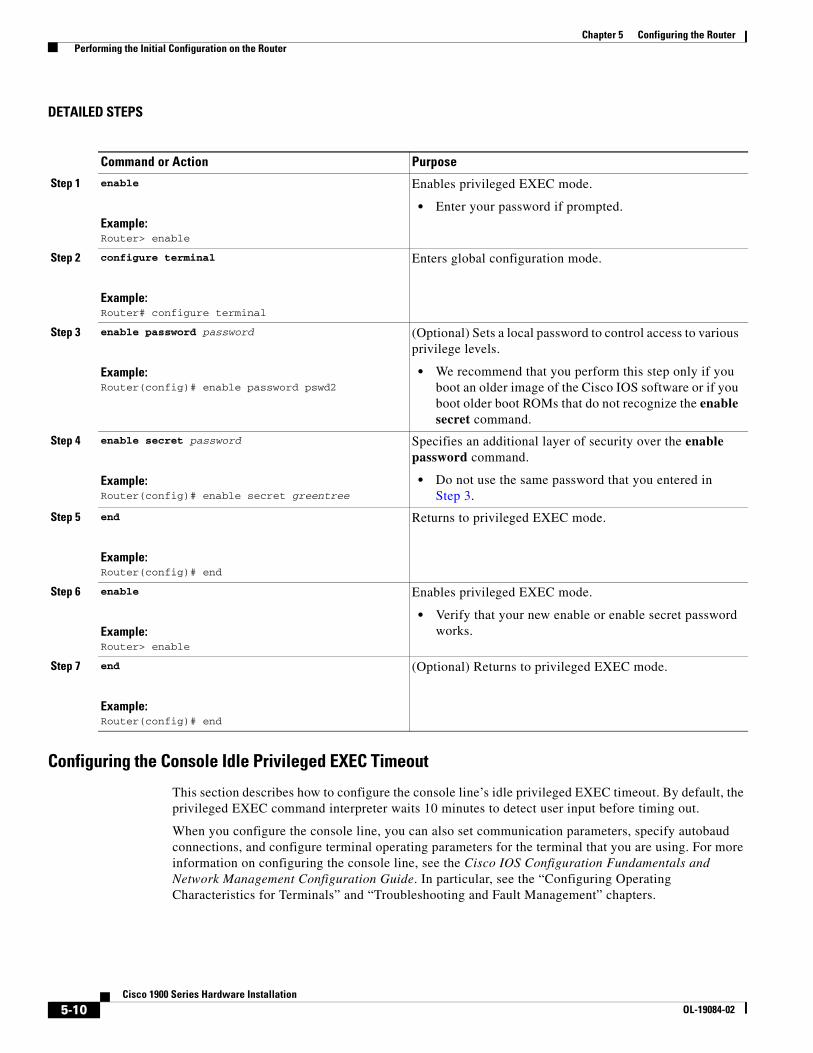
Chapter 5 Configuring the Router Performing the Initial Configuration on the Router
DETAILED STEPS
Configuring the Console Idle Privileged EXEC Timeout
This section describes how to configure the console line’s idle privileged EXEC timeout. By default, the privileged EXEC command interpreter waits 10 minutes to detect user input before timing out.
When you configure the console line, you can also set communication parameters, specify autobaud connections, and configure terminal operating parameters for the terminal that you are using. For more information on configuring the console line, see the Cisco IOS Configuration Fundamentals and Network Management Configuration Guide. In particular, see the “Configuring Operating Characteristics for Terminals” and “Troubleshooting and Fault Management” chapters.
Command or Action Purpose
Step 1 enable
Example:Router> enable
Enables privileged EXEC mode.
• Enter your password if prompted.
Step 2 configure terminal
Example:Router# configure terminal
Enters global configuration mode.
Step 3 enable password password
Example:Router(config)# enable password pswd2
(Optional) Sets a local password to control access to various privilege levels.
• We recommend that you perform this step only if you boot an older image of the Cisco IOS software or if you boot older boot ROMs that do not recognize the enable secret command.
Step 4 enable secret password
Example:Router(config)# enable secret greentree
Specifies an additional layer of security over the enable password command.
• Do not use the same password that you entered in Step 3.
Step 5 end
Example:Router(config)# end
Returns to privileged EXEC mode.
Step 6 enable
Example:Router> enable
Enables privileged EXEC mode.
• Verify that your new enable or enable secret password works.
Step 7 end
Example:Router(config)# end
(Optional) Returns to privileged EXEC mode.
5-10Cisco 1900 Series Hardware Installation
OL-19084-02
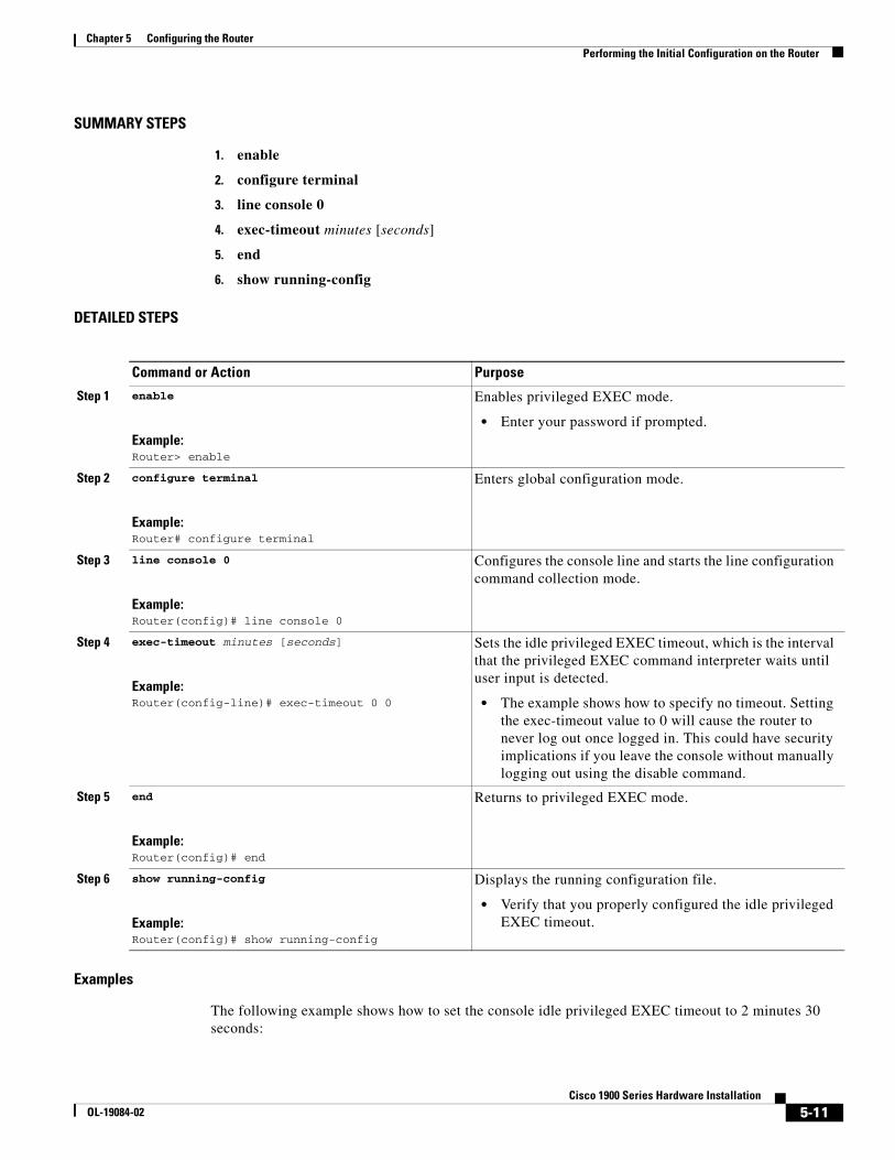
Chapter 5 Configuring the Router Performing the Initial Configuration on the Router
SUMMARY STEPS
1. enable
2. configure terminal
3. line console 0
4. exec-timeout minutes [seconds]
5. end
6. show running-config
DETAILED STEPS
Examples
The following example shows how to set the console idle privileged EXEC timeout to 2 minutes 30 seconds:
Command or Action Purpose
Step 1 enable
Example:Router> enable
Enables privileged EXEC mode.
• Enter your password if prompted.
Step 2 configure terminal
Example:Router# configure terminal
Enters global configuration mode.
Step 3 line console 0
Example:Router(config)# line console 0
Configures the console line and starts the line configuration command collection mode.
Step 4 exec-timeout minutes [seconds]
Example:Router(config-line)# exec-timeout 0 0
Sets the idle privileged EXEC timeout, which is the interval that the privileged EXEC command interpreter waits until user input is detected.
• The example shows how to specify no timeout. Setting the exec-timeout value to 0 will cause the router to never log out once logged in. This could have security implications if you leave the console without manually logging out using the disable command.
Step 5 end
Example:Router(config)# end
Returns to privileged EXEC mode.
Step 6 show running-config
Example:Router(config)# show running-config
Displays the running configuration file.
• Verify that you properly configured the idle privileged EXEC timeout.
5-11Cisco 1900 Series Hardware Installation
OL-19084-02
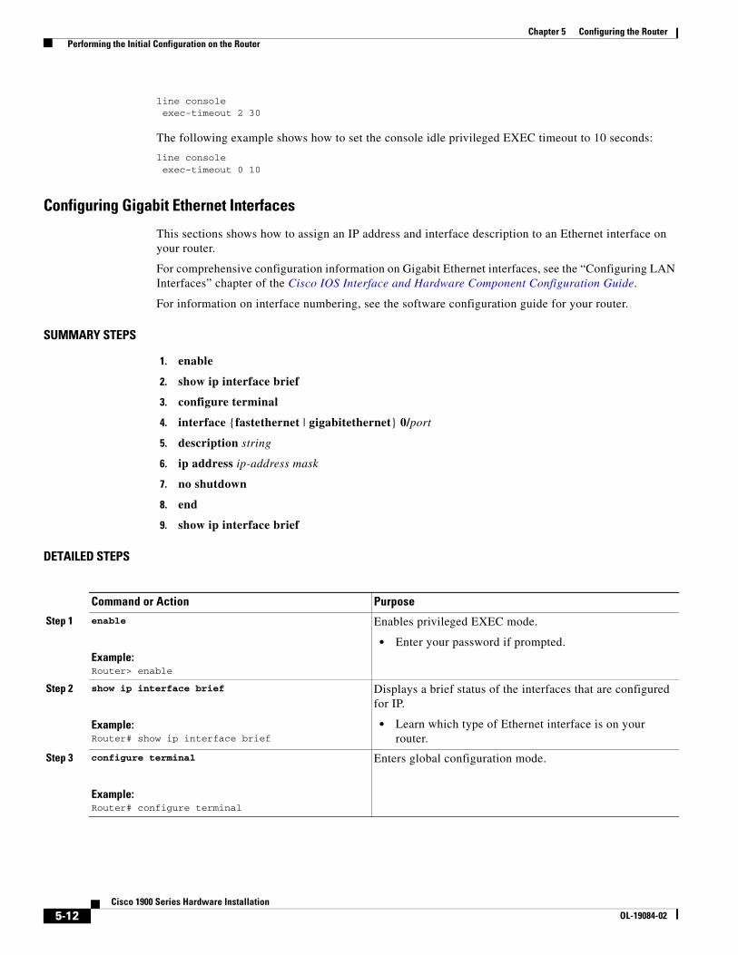
Chapter 5 Configuring the Router Performing the Initial Configuration on the Router
line console exec-timeout 2 30
The following example shows how to set the console idle privileged EXEC timeout to 10 seconds:
line console exec-timeout 0 10
Configuring Gigabit Ethernet Interfaces
This sections shows how to assign an IP address and interface description to an Ethernet interface on your router.
For comprehensive configuration information on Gigabit Ethernet interfaces, see the “Configuring LAN Interfaces” chapter of the Cisco IOS Interface and Hardware Component Configuration Guide.
For information on interface numbering, see the software configuration guide for your router.
SUMMARY STEPS
1. enable
2. show ip interface brief
3. configure terminal
4. interface {fastethernet | gigabitethernet} 0/port
5. description string
6. ip address ip-address mask
7. no shutdown
8. end
9. show ip interface brief
DETAILED STEPS
Command or Action Purpose
Step 1 enable
Example:Router> enable
Enables privileged EXEC mode.
• Enter your password if prompted.
Step 2 show ip interface brief
Example:Router# show ip interface brief
Displays a brief status of the interfaces that are configured for IP.
• Learn which type of Ethernet interface is on your router.
Step 3 configure terminal
Example:Router# configure terminal
Enters global configuration mode.
5-12Cisco 1900 Series Hardware Installation
OL-19084-02
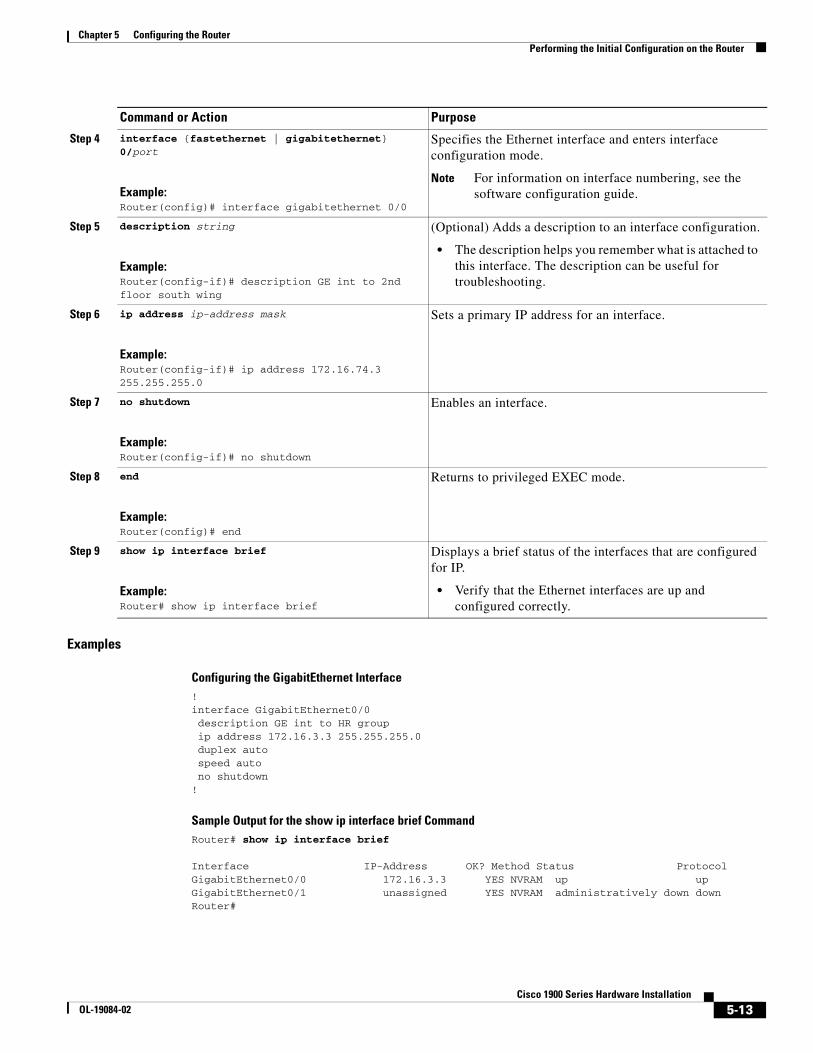
Chapter 5 Configuring the Router Performing the Initial Configuration on the Router
Examples
Configuring the GigabitEthernet Interface!interface GigabitEthernet0/0 description GE int to HR group ip address 172.16.3.3 255.255.255.0 duplex auto speed auto no shutdown!
Sample Output for the show ip interface brief CommandRouter# show ip interface brief
Interface IP-Address OK? Method Status ProtocolGigabitEthernet0/0 172.16.3.3 YES NVRAM up upGigabitEthernet0/1 unassigned YES NVRAM administratively down downRouter#
Step 4 interface {fastethernet | gigabitethernet} 0/port
Example:Router(config)# interface gigabitethernet 0/0
Specifies the Ethernet interface and enters interface configuration mode.
Note For information on interface numbering, see the software configuration guide.
Step 5 description string
Example:Router(config-if)# description GE int to 2nd floor south wing
(Optional) Adds a description to an interface configuration.
• The description helps you remember what is attached to this interface. The description can be useful for troubleshooting.
Step 6 ip address ip-address mask
Example:Router(config-if)# ip address 172.16.74.3 255.255.255.0
Sets a primary IP address for an interface.
Step 7 no shutdown
Example:Router(config-if)# no shutdown
Enables an interface.
Step 8 end
Example:Router(config)# end
Returns to privileged EXEC mode.
Step 9 show ip interface brief
Example:Router# show ip interface brief
Displays a brief status of the interfaces that are configured for IP.
• Verify that the Ethernet interfaces are up and configured correctly.
Command or Action Purpose
5-13Cisco 1900 Series Hardware Installation
OL-19084-02
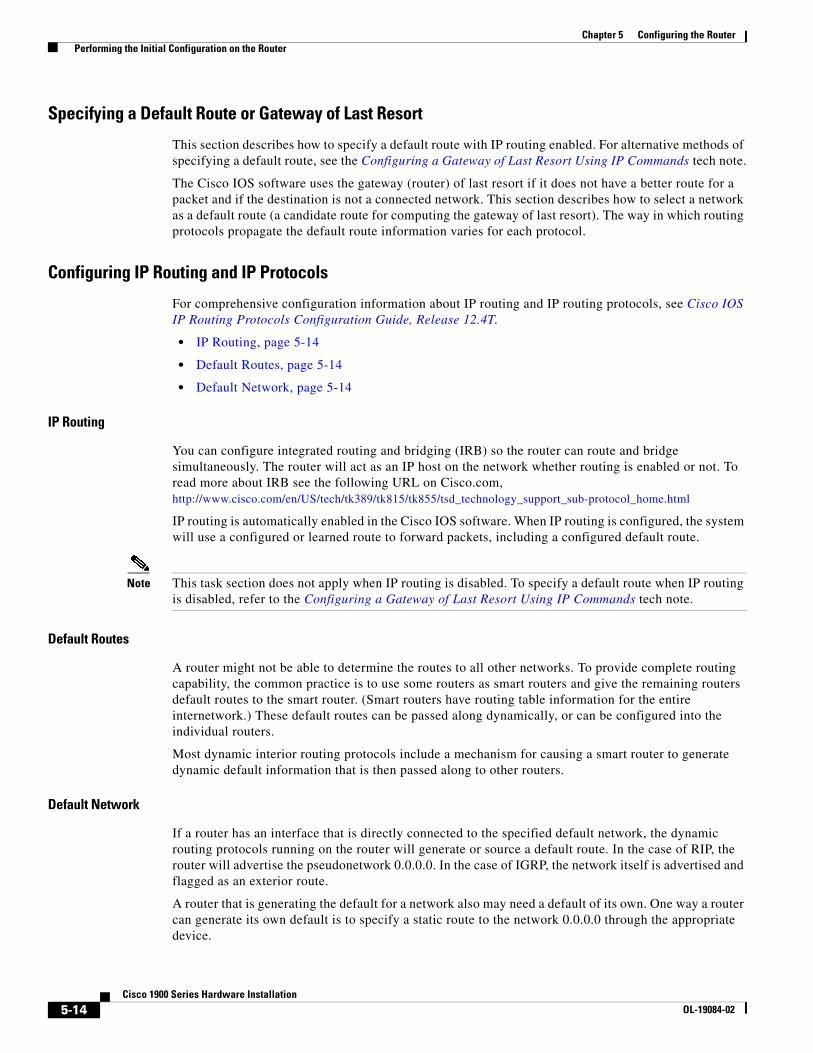
Chapter 5 Configuring the Router Performing the Initial Configuration on the Router
Specifying a Default Route or Gateway of Last Resort
This section describes how to specify a default route with IP routing enabled. For alternative methods of specifying a default route, see the Configuring a Gateway of Last Resort Using IP Commands tech note.
The Cisco IOS software uses the gateway (router) of last resort if it does not have a better route for a packet and if the destination is not a connected network. This section describes how to select a network as a default route (a candidate route for computing the gateway of last resort). The way in which routing protocols propagate the default route information varies for each protocol.
Configuring IP Routing and IP Protocols
For comprehensive configuration information about IP routing and IP routing protocols, see Cisco IOS IP Routing Protocols Configuration Guide, Release 12.4T.
• IP Routing, page 5-14
• Default Routes, page 5-14
• Default Network, page 5-14
IP Routing
You can configure integrated routing and bridging (IRB) so the router can route and bridge simultaneously. The router will act as an IP host on the network whether routing is enabled or not. To read more about IRB see the following URL on Cisco.com, http://www.cisco.com/en/US/tech/tk389/tk815/tk855/tsd_technology_support_sub-protocol_home.html
IP routing is automatically enabled in the Cisco IOS software. When IP routing is configured, the system will use a configured or learned route to forward packets, including a configured default route.
Note This task section does not apply when IP routing is disabled. To specify a default route when IP routing is disabled, refer to the Configuring a Gateway of Last Resort Using IP Commands tech note.
Default Routes
A router might not be able to determine the routes to all other networks. To provide complete routing capability, the common practice is to use some routers as smart routers and give the remaining routers default routes to the smart router. (Smart routers have routing table information for the entire internetwork.) These default routes can be passed along dynamically, or can be configured into the individual routers.
Most dynamic interior routing protocols include a mechanism for causing a smart router to generate dynamic default information that is then passed along to other routers.
Default Network
If a router has an interface that is directly connected to the specified default network, the dynamic routing protocols running on the router will generate or source a default route. In the case of RIP, the router will advertise the pseudonetwork 0.0.0.0. In the case of IGRP, the network itself is advertised and flagged as an exterior route.
A router that is generating the default for a network also may need a default of its own. One way a router can generate its own default is to specify a static route to the network 0.0.0.0 through the appropriate device.
5-14Cisco 1900 Series Hardware Installation
OL-19084-02
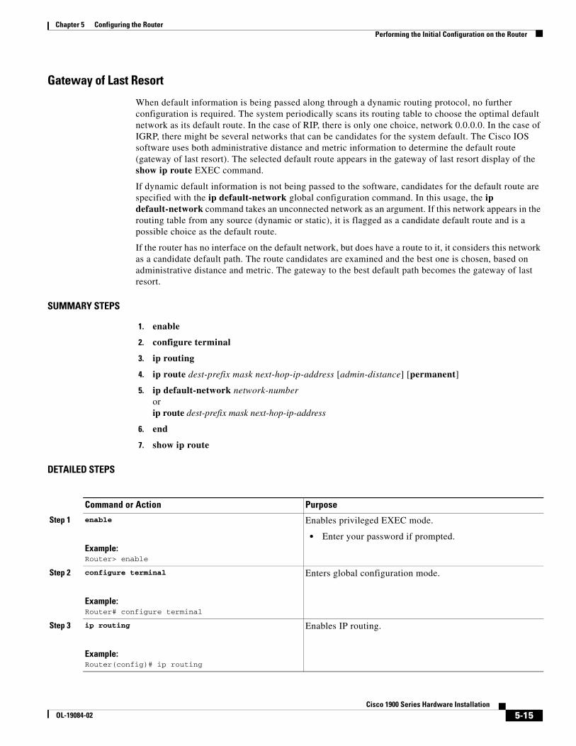
Chapter 5 Configuring the Router Performing the Initial Configuration on the Router
Gateway of Last Resort
When default information is being passed along through a dynamic routing protocol, no further configuration is required. The system periodically scans its routing table to choose the optimal default network as its default route. In the case of RIP, there is only one choice, network 0.0.0.0. In the case of IGRP, there might be several networks that can be candidates for the system default. The Cisco IOS software uses both administrative distance and metric information to determine the default route (gateway of last resort). The selected default route appears in the gateway of last resort display of the show ip route EXEC command.
If dynamic default information is not being passed to the software, candidates for the default route are specified with the ip default-network global configuration command. In this usage, the ip default-network command takes an unconnected network as an argument. If this network appears in the routing table from any source (dynamic or static), it is flagged as a candidate default route and is a possible choice as the default route.
If the router has no interface on the default network, but does have a route to it, it considers this network as a candidate default path. The route candidates are examined and the best one is chosen, based on administrative distance and metric. The gateway to the best default path becomes the gateway of last resort.
SUMMARY STEPS
1. enable
2. configure terminal
3. ip routing
4. ip route dest-prefix mask next-hop-ip-address [admin-distance] [permanent]
5. ip default-network network-number orip route dest-prefix mask next-hop-ip-address
6. end
7. show ip route
DETAILED STEPS
Command or Action Purpose
Step 1 enable
Example:Router> enable
Enables privileged EXEC mode.
• Enter your password if prompted.
Step 2 configure terminal
Example:Router# configure terminal
Enters global configuration mode.
Step 3 ip routing
Example:Router(config)# ip routing
Enables IP routing.
5-15Cisco 1900 Series Hardware Installation
OL-19084-02
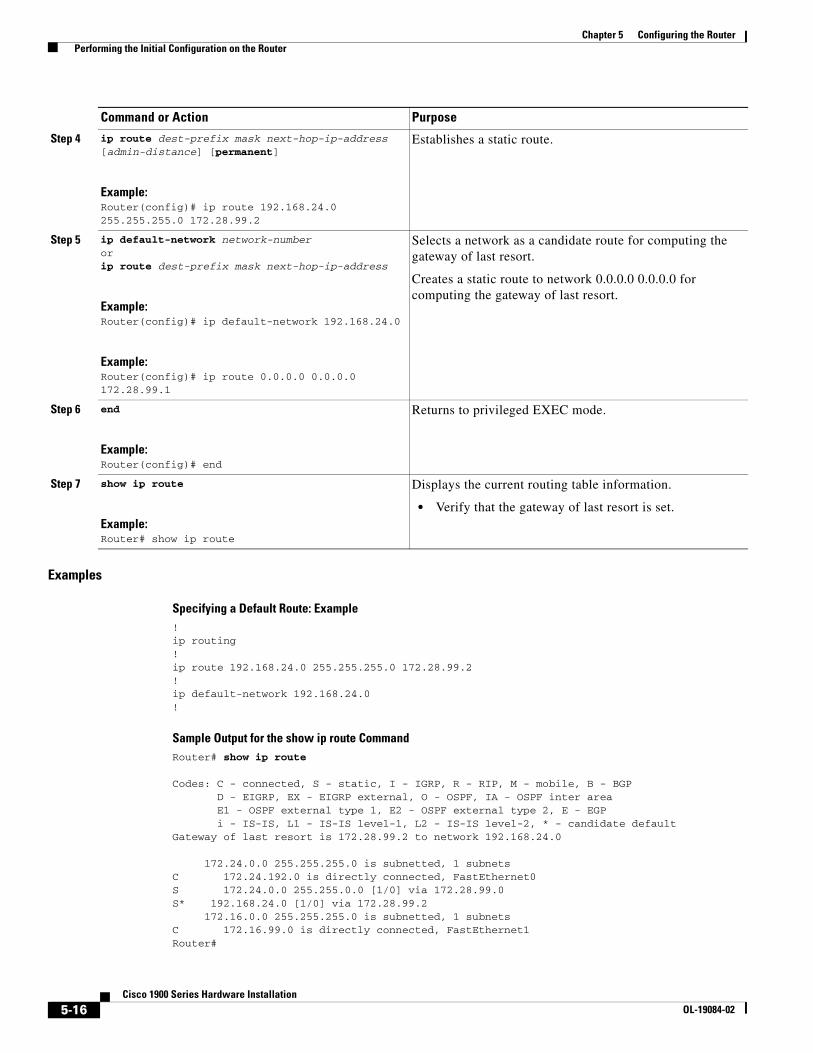
Chapter 5 Configuring the Router Performing the Initial Configuration on the Router
Examples
Specifying a Default Route: Example!ip routing!ip route 192.168.24.0 255.255.255.0 172.28.99.2!ip default-network 192.168.24.0!
Sample Output for the show ip route CommandRouter# show ip route
Codes: C - connected, S - static, I - IGRP, R - RIP, M - mobile, B - BGP D - EIGRP, EX - EIGRP external, O - OSPF, IA - OSPF inter area E1 - OSPF external type 1, E2 - OSPF external type 2, E - EGP i - IS-IS, L1 - IS-IS level-1, L2 - IS-IS level-2, * - candidate defaultGateway of last resort is 172.28.99.2 to network 192.168.24.0 172.24.0.0 255.255.255.0 is subnetted, 1 subnetsC 172.24.192.0 is directly connected, FastEthernet0S 172.24.0.0 255.255.0.0 [1/0] via 172.28.99.0 S* 192.168.24.0 [1/0] via 172.28.99.2 172.16.0.0 255.255.255.0 is subnetted, 1 subnetsC 172.16.99.0 is directly connected, FastEthernet1Router#
Step 4 ip route dest-prefix mask next-hop-ip-address [admin-distance] [permanent]
Example:Router(config)# ip route 192.168.24.0 255.255.255.0 172.28.99.2
Establishes a static route.
Step 5 ip default-network network-numberorip route dest-prefix mask next-hop-ip-address
Example:Router(config)# ip default-network 192.168.24.0
Example:Router(config)# ip route 0.0.0.0 0.0.0.0 172.28.99.1
Selects a network as a candidate route for computing the gateway of last resort.
Creates a static route to network 0.0.0.0 0.0.0.0 for computing the gateway of last resort.
Step 6 end
Example:Router(config)# end
Returns to privileged EXEC mode.
Step 7 show ip route
Example:Router# show ip route
Displays the current routing table information.
• Verify that the gateway of last resort is set.
Command or Action Purpose
5-16Cisco 1900 Series Hardware Installation
OL-19084-02
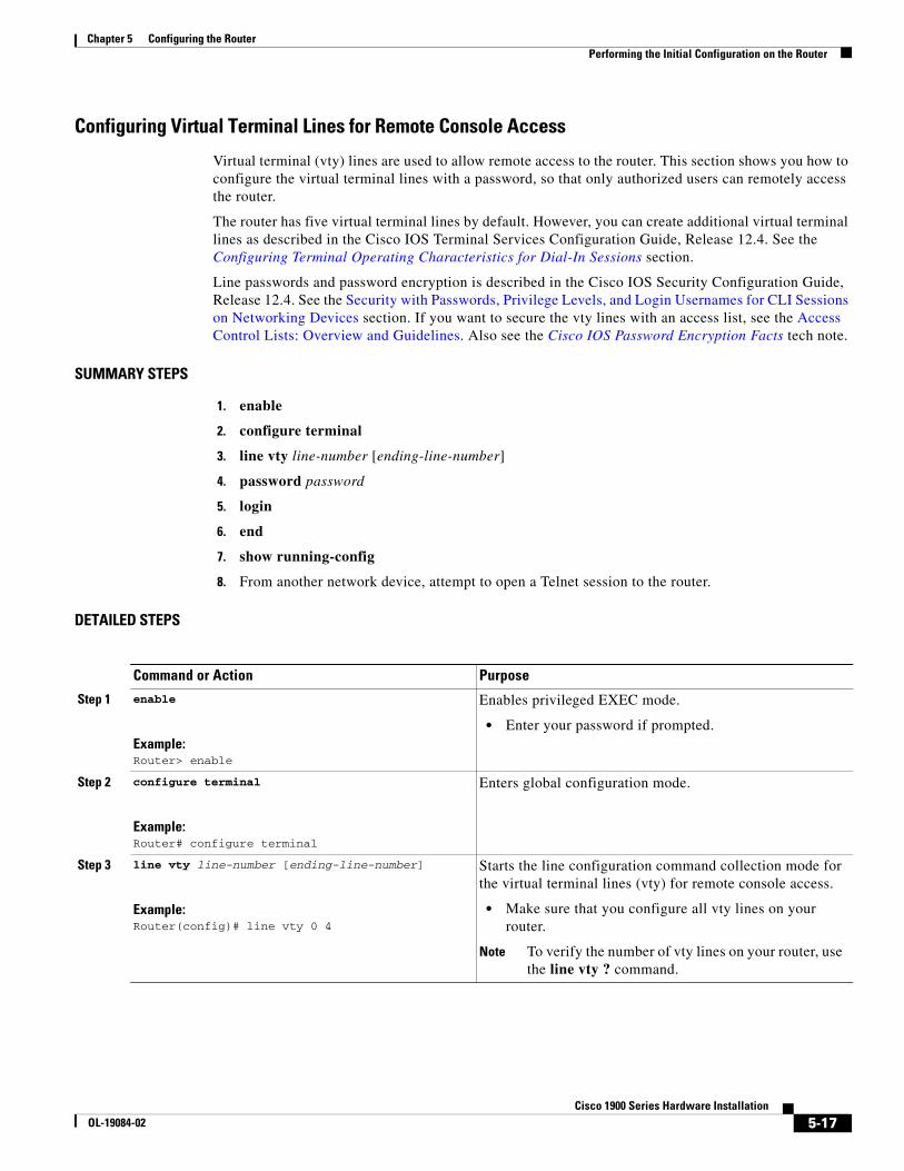
Chapter 5 Configuring the Router Performing the Initial Configuration on the Router
Configuring Virtual Terminal Lines for Remote Console Access
Virtual terminal (vty) lines are used to allow remote access to the router. This section shows you how to configure the virtual terminal lines with a password, so that only authorized users can remotely access the router.
The router has five virtual terminal lines by default. However, you can create additional virtual terminal lines as described in the Cisco IOS Terminal Services Configuration Guide, Release 12.4. See the Configuring Terminal Operating Characteristics for Dial-In Sessions section.
Line passwords and password encryption is described in the Cisco IOS Security Configuration Guide, Release 12.4. See the Security with Passwords, Privilege Levels, and Login Usernames for CLI Sessions on Networking Devices section. If you want to secure the vty lines with an access list, see the Access Control Lists: Overview and Guidelines. Also see the Cisco IOS Password Encryption Facts tech note.
SUMMARY STEPS
1. enable
2. configure terminal
3. line vty line-number [ending-line-number]
4. password password
5. login
6. end
7. show running-config
8. From another network device, attempt to open a Telnet session to the router.
DETAILED STEPS
Command or Action Purpose
Step 1 enable
Example:Router> enable
Enables privileged EXEC mode.
• Enter your password if prompted.
Step 2 configure terminal
Example:Router# configure terminal
Enters global configuration mode.
Step 3 line vty line-number [ending-line-number]
Example:Router(config)# line vty 0 4
Starts the line configuration command collection mode for the virtual terminal lines (vty) for remote console access.
• Make sure that you configure all vty lines on your router.
Note To verify the number of vty lines on your router, use the line vty ? command.
5-17Cisco 1900 Series Hardware Installation
OL-19084-02
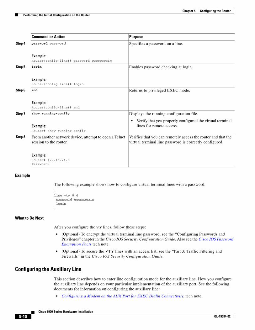
Chapter 5 Configuring the Router Performing the Initial Configuration on the Router
Example
The following example shows how to configure virtual terminal lines with a password:
!line vty 0 4 password guessagain login
!
What to Do Next
After you configure the vty lines, follow these steps:
• (Optional) To encrypt the virtual terminal line password, see the “Configuring Passwords and Privileges” chapter in the Cisco IOS Security Configuration Guide. Also see the Cisco IOS Password Encryption Facts tech note.
• (Optional) To secure the VTY lines with an access list, see the “Part 3: Traffic Filtering and Firewalls” in the Cisco IOS Security Configuration Guide.
Configuring the Auxiliary Line
This section describes how to enter line configuration mode for the auxiliary line. How you configure the auxiliary line depends on your particular implementation of the auxiliary port. See the following documents for information on configuring the auxiliary line:
• Configuring a Modem on the AUX Port for EXEC Dialin Connectivity, tech note
Step 4 password password
Example:Router(config-line)# password guessagain
Specifies a password on a line.
Step 5 login
Example:Router(config-line)# login
Enables password checking at login.
Step 6 end
Example:Router(config-line)# end
Returns to privileged EXEC mode.
Step 7 show running-config
Example:Router# show running-config
Displays the running configuration file.
• Verify that you properly configured the virtual terminal lines for remote access.
Step 8 From another network device, attempt to open a Telnet session to the router.
Example:Router# 172.16.74.3Password:
Verifies that you can remotely access the router and that the virtual terminal line password is correctly configured.
Command or Action Purpose
5-18Cisco 1900 Series Hardware Installation
OL-19084-02
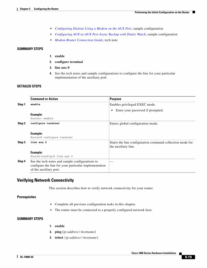
Chapter 5 Configuring the Router Performing the Initial Configuration on the Router
• Configuring Dialout Using a Modem on the AUX Port, sample configuration
• Configuring AUX-to-AUX Port Async Backup with Dialer Watch, sample configuration
• Modem-Router Connection Guide, tech note
SUMMARY STEPS
1. enable
2. configure terminal
3. line aux 0
4. See the tech notes and sample configurations to configure the line for your particular implementation of the auxiliary port.
DETAILED STEPS
Verifying Network Connectivity
This section describes how to verify network connectivity for your router.
Prerequisites
• Complete all previous configuration tasks in this chapter.
• The router must be connected to a properly configured network host.
SUMMARY STEPS
1. enable
2. ping [ip-address | hostname]
3. telnet {ip-address | hostname}
Command or Action Purpose
Step 1 enable
Example:Router> enable
Enables privileged EXEC mode.
• Enter your password if prompted.
Step 2 configure terminal
Example:Router# configure terminal
Enters global configuration mode.
Step 3 line aux 0
Example:Router(config)# line aux 0
Starts the line configuration command collection mode for the auxiliary line.
Step 4 See the tech notes and sample configurations to configure the line for your particular implementation of the auxiliary port.
—
5-19Cisco 1900 Series Hardware Installation
OL-19084-02
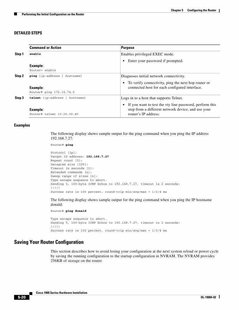
Chapter 5 Configuring the Router Performing the Initial Configuration on the Router
DETAILED STEPS
Examples
The following display shows sample output for the ping command when you ping the IP address 192.168.7.27:
Router# ping
Protocol [ip]:Target IP address: 192.168.7.27Repeat count [5]:Datagram size [100]:Timeout in seconds [2]:Extended commands [n]:Sweep range of sizes [n]:Type escape sequence to abort.Sending 5, 100-byte ICMP Echos to 192.168.7.27, timeout is 2 seconds:!!!!!Success rate is 100 percent, round-trip min/avg/max = 1/2/4 ms
The following display shows sample output for the ping command when you ping the IP hostname donald:
Router# ping donald
Type escape sequence to abort.Sending 5, 100-byte ICMP Echos to 192.168.7.27, timeout is 2 seconds:!!!!!Success rate is 100 percent, round-trip min/avg/max = 1/3/4 ms
Saving Your Router Configuration
This section describes how to avoid losing your configuration at the next system reload or power cycle by saving the running configuration to the startup configuration in NVRAM. The NVRAM provides 256KB of storage on the router.
Command or Action Purpose
Step 1 enable
Example:Router> enable
Enables privileged EXEC mode.
• Enter your password if prompted.
Step 2 ping [ip-address | hostname]
Example:Router# ping 172.16.74.5
Diagnoses initial network connectivity.
• To verify connectivity, ping the next hop router or connected host for each configured interface.
Step 3 telnet {ip-address | hostname}
Example:Router# telnet 10.20.30.40
Logs in to a host that supports Telnet.
• If you want to test the vty line password, perform this step from a different network device, and use your router’s IP address.
5-20Cisco 1900 Series Hardware Installation
OL-19084-02
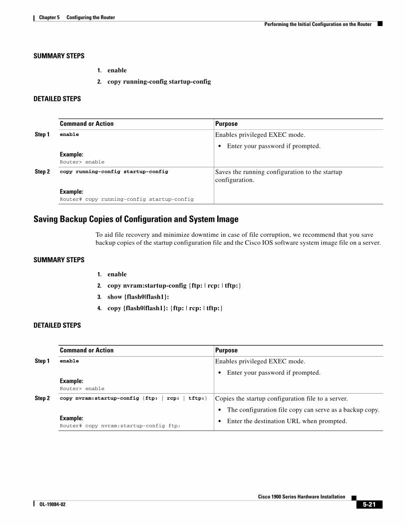
Chapter 5 Configuring the Router Performing the Initial Configuration on the Router
SUMMARY STEPS
1. enable
2. copy running-config startup-config
DETAILED STEPS
Saving Backup Copies of Configuration and System Image
To aid file recovery and minimize downtime in case of file corruption, we recommend that you save backup copies of the startup configuration file and the Cisco IOS software system image file on a server.
SUMMARY STEPS
1. enable
2. copy nvram:startup-config {ftp: | rcp: | tftp:}
3. show {flash0|flash1}:
4. copy {flash0|flash1}: {ftp: | rcp: | tftp:}
DETAILED STEPS
Command or Action Purpose
Step 1 enable
Example:Router> enable
Enables privileged EXEC mode.
• Enter your password if prompted.
Step 2 copy running-config startup-config
Example:Router# copy running-config startup-config
Saves the running configuration to the startup configuration.
Command or Action Purpose
Step 1 enable
Example:Router> enable
Enables privileged EXEC mode.
• Enter your password if prompted.
Step 2 copy nvram:startup-config {ftp: | rcp: | tftp:}
Example:Router# copy nvram:startup-config ftp:
Copies the startup configuration file to a server.
• The configuration file copy can serve as a backup copy.
• Enter the destination URL when prompted.
5-21Cisco 1900 Series Hardware Installation
OL-19084-02
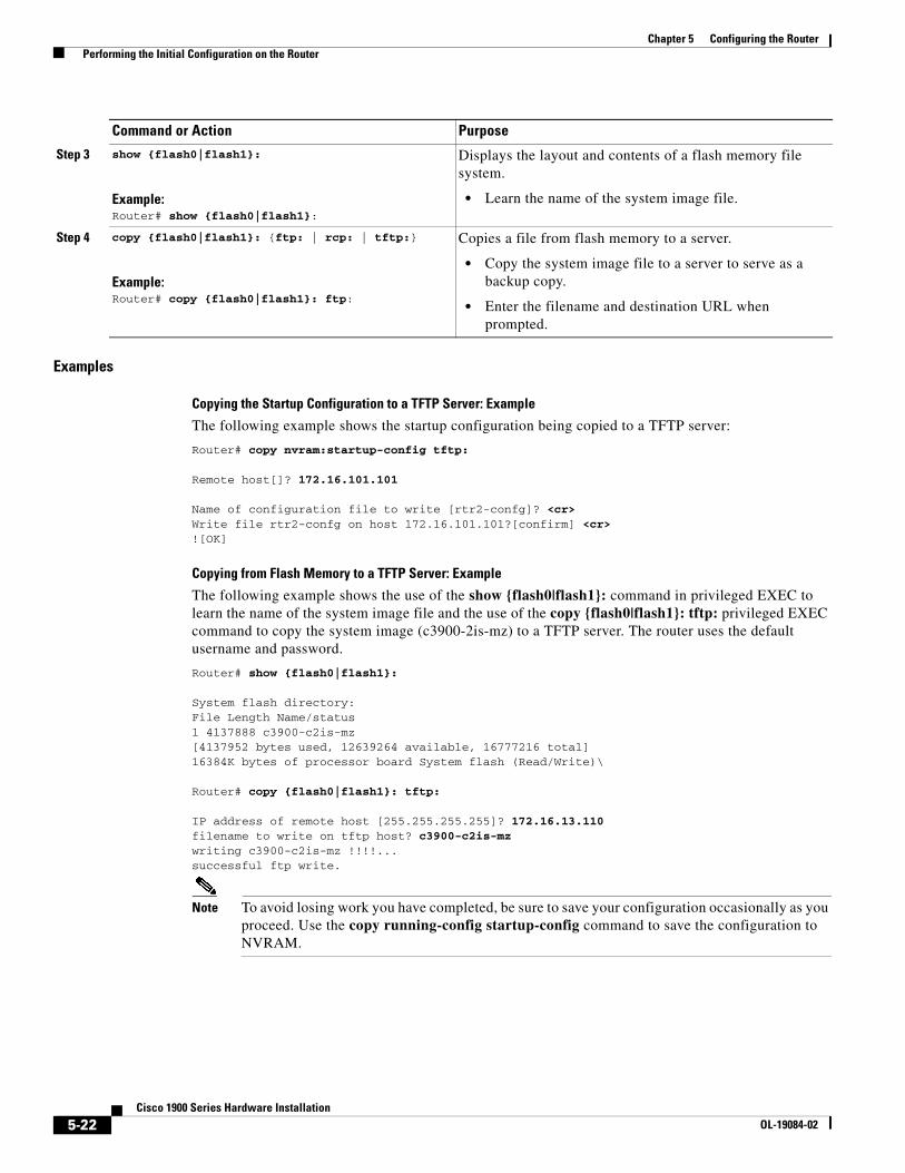
Chapter 5 Configuring the Router Performing the Initial Configuration on the Router
Examples
Copying the Startup Configuration to a TFTP Server: Example
The following example shows the startup configuration being copied to a TFTP server:
Router# copy nvram:startup-config tftp:
Remote host[]? 172.16.101.101
Name of configuration file to write [rtr2-confg]? <cr> Write file rtr2-confg on host 172.16.101.101?[confirm] <cr> ![OK]
Copying from Flash Memory to a TFTP Server: Example
The following example shows the use of the show {flash0|flash1}: command in privileged EXEC to learn the name of the system image file and the use of the copy {flash0|flash1}: tftp: privileged EXEC command to copy the system image (c3900-2is-mz) to a TFTP server. The router uses the default username and password.
Router# show {flash0|flash1}:
System flash directory:File Length Name/status1 4137888 c3900-c2is-mz[4137952 bytes used, 12639264 available, 16777216 total]16384K bytes of processor board System flash (Read/Write)\
Router# copy {flash0|flash1}: tftp:
IP address of remote host [255.255.255.255]? 172.16.13.110 filename to write on tftp host? c3900-c2is-mz writing c3900-c2is-mz !!!!...successful ftp write.
Note To avoid losing work you have completed, be sure to save your configuration occasionally as you proceed. Use the copy running-config startup-config command to save the configuration to NVRAM.
Step 3 show {flash0|flash1}:
Example:Router# show {flash0|flash1}:
Displays the layout and contents of a flash memory file system.
• Learn the name of the system image file.
Step 4 copy {flash0|flash1}: {ftp: | rcp: | tftp:}
Example:Router# copy {flash0|flash1}: ftp:
Copies a file from flash memory to a server.
• Copy the system image file to a server to serve as a backup copy.
• Enter the filename and destination URL when prompted.
Command or Action Purpose
5-22Cisco 1900 Series Hardware Installation
OL-19084-02
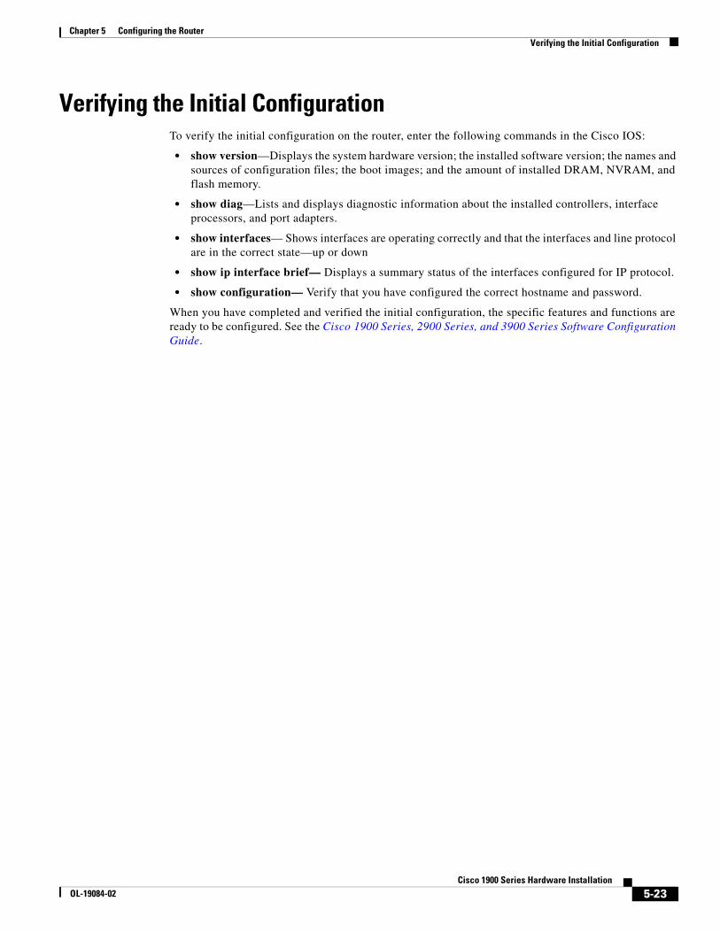
Chapter 5 Configuring the Router Verifying the Initial Configuration
Verifying the Initial ConfigurationTo verify the initial configuration on the router, enter the following commands in the Cisco IOS:
• show version—Displays the system hardware version; the installed software version; the names and sources of configuration files; the boot images; and the amount of installed DRAM, NVRAM, and flash memory.
• show diag—Lists and displays diagnostic information about the installed controllers, interface processors, and port adapters.
• show interfaces— Shows interfaces are operating correctly and that the interfaces and line protocol are in the correct state—up or down
• show ip interface brief— Displays a summary status of the interfaces configured for IP protocol.
• show configuration— Verify that you have configured the correct hostname and password.
When you have completed and verified the initial configuration, the specific features and functions are ready to be configured. See the Cisco 1900 Series, 2900 Series, and 3900 Series Software Configuration Guide.
5-23Cisco 1900 Series Hardware Installation
OL-19084-02

Chapter 5 Configuring the Router Verifying the Initial Configuration
5-24Cisco 1900 Series Hardware Installation
OL-19084-02
OL-19084-02
C H A P T E R 6
Getting Software Licenses for the RouterThe Integrated Services Router Generation 2 (ISR G2) platforms offer a new Universal Cisco Internet Operating System (IOS) software image. The Universal image and its licensing provisions provide greater flexibility to deploy new features while also improving visibility and management of existing licenses on routers in the network.
When you order a new ISR G2, it is shipped with the software image and the corresponding permanent licenses for the packages and features that you specified, preinstalled. The software does not need to be activated or registered prior to use.
Use the Cisco management application such as Cisco License Manager (CLM), or use the Cisco IOS command show license feature to determine the licenses activated on your system.
The router comes with an evaluation license, also known as a temporary license, for most packages and features supported on the router. To try a new software package or feature, activate the evaluation license for that package or feature.
This chapter contains the following sections:
• Activating a New Software Package or Feature, page 6-1
• RMA License Transfer, page 6-2
• Additional Information, page 6-3
Activating a New Software Package or FeatureBefore You Begin
• If you do not have a Cisco.com username and password, register for an account at the following URL https://tools.cisco.com/RPF/register/register.do.
Procedure
Step 1 Purchase the software package or feature you want to install. You will receive a product activation key (PAK) with your purchase.
Step 2 Get the license file using one of the following options:
• Cisco License Manager (CLM): CLM is a free software application available at http://www.cisco.com/go/clm.
6-1Cisco 1900 Series Hardware Installation
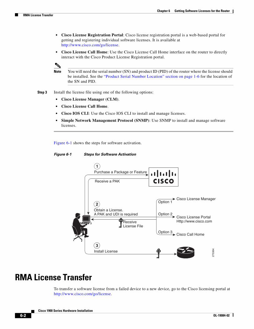
Chapter 6 Getting Software Licenses for the Router RMA License Transfer
• Cisco License Registration Portal: Cisco license registration portal is a web-based portal for getting and registering individual software licenses. It is available at http://www.cisco.com/go/license.
• Cisco License Call Home: Use the Cisco License Call Home interface on the router to directly interact with the Cisco Product License Registration portal.
Note You will need the serial number (SN) and product ID (PID) of the router where the license should be installed. See the “Product Serial Number Location” section on page 1-6 for the location of the SN and PID.
Step 3 Install the license file using one of the following options:
• Cisco License Manager (CLM).
• Cisco License Call Home.
• Cisco IOS CLI: Use the Cisco IOS CLI to install and manage licenses.
• Simple Network Management Protocol (SNMP): Use SNMP to install and manage software licenses.
Figure 6-1 shows the steps for software activation.
Figure 6-1 Steps for Software Activation
RMA License TransferTo transfer a software license from a failed device to a new device, go to the Cisco licensing portal at http://www.cisco.com/go/license.
1
2
3
Purchase a Package or Feature
Receive a PAK
Obtain a License.A PAK and UDI is required
Cisco License ManagerOption 1
Option 2
Option 3
Cisco License PortalHttp://www.cisco.com
Cisco Call Home
ReceiveLicense File
Install License
2753
64
6-2Cisco 1900 Series Hardware Installation
OL-19084-02
Chapter 6 Getting Software Licenses for the Router Additional Information
Note You will need the SN and PID of the defective device, as well as the RMA router to initiate an RMA replacement license.
Additional InformationSee Software Activation on Cisco Integrated Services Routers and Cisco Integrated Service Routers Generation 2 for detailed information about software activation on Cisco ISR G2 platforms.
6-3Cisco 1900 Series Hardware Installation
OL-19084-02

Chapter 6 Getting Software Licenses for the Router Additional Information
6-4Cisco 1900 Series Hardware Installation
OL-19084-02
Americas Headquarters:Cisco Systems, Inc., 170 West Tasman Drive, San Jose, CA 95134-1706 USA
Installing and Upgrading Internal Modules and FRUs in Cisco 1900 Series ISRs
First Published: May, 14, 2010OL-22230-01
This document describes how to install or upgrade modules that are located internally within your Cisco 1900 series integrated services router, such as internal modules, memory, internal service modules (ISMs), power supplies, and blowers. You need to remove the cover from the router to install or remove any of these items. The document contains the following sections:
Note The Cisco 1905 ISR and Cisco 1921 ISR have no user- removable or user-installable components. Do not remove the chassis cover.
• Safety Warnings, page 2
• Modules Internal to the Cisco 1905 and 1921 Routers, page 4
• Modules Internal to the Cisco 1905 and 1921 Routers, page 4
• Obtaining Documentation and Submitting a Service Request, page 24
Note To see translations of the warnings that appear in this publication, refer to the Regulatory Compliance and Safety Information for Cisco 1900 Series Integrated Services Routers document that accompanies your router.
Installing and Upgrading Internal Modules and FRUs in Cisco 1900 Series ISRs Safety Warnings
2Installing and Upgrading Internal Modules and FRUs in Cisco 1900 Series ISRs
Safety Warnings
Warning IMPORTANT SAFETY INSTRUCTIONS
This warning symbol means danger. You are in a situation that could cause bodily injury. Before you work on any equipment, be aware of the hazards involved with electrical circuitry and be familiar with standard practices for preventing accidents. Use the statement number provided at the end of each warning to locate its translation in the translated safety warnings that accompanied this device. Statement 1071
SAVE THESE INSTRUCTIONS
Warning No user-serviceable parts inside. Do not open. Statement 1073
Warning Before working on a system that has an on/off switch, turn OFF the power and unplug the power cord. Statement 1
Warning During this procedure, wear grounding wrist straps to avoid ESD damage to the card. Do not directly touch the backplane with your hand or any metal tool, or you could shock yourself. Statement 94
Warning Do not work on the system or connect or disconnect cables during periods of lightning activity. Statement 1001
Warning Read the installation instructions before you connect the system to its power source. Statement 1004
Warning This product relies on the building’s installation for short-circuit (overcurrent) protection. Ensure that the protective device is rated not greater than: 120 Vac, 15A (240Vac, 16A ). Statement 1005
Warning This equipment has been designed for connection to TN and IT power systems. Statement 1007
Warning To avoid electric shock, do not connect safety extra-low voltage (SELV) circuits to telephone-network voltage (TNV) circuits. LAN ports contain SELV circuits, and WAN ports contain TNV circuits. Some LAN and WAN ports both use RJ-45 connectors. Use caution when connecting cables. Statement 1021
Warning To reduce the risk of fire, use only No. 26 AWG or larger telecommunication line cord. Statement 1023
Installing and Upgrading Internal Modules and FRUs in Cisco 1900 Series ISRs Safety Warnings
3Installing and Upgrading Internal Modules and FRUs in Cisco 1900 Series ISRs
Warning This equipment must be grounded. Never defeat the ground conductor or operate the equipment in the absence of a suitably installed ground conductor. Contact the appropriate electrical inspection authority or an electrician if you are uncertain that suitable grounding is available. Statement 1024
Warning Hazardous network voltages are present in WAN ports regardless of whether power to the router is OFF or ON. To avoid electric shock, use caution when working near WAN ports. When detaching cables, detach the end away from the router first. Statement 1026
Warning Blank faceplates and cover panels serve three important functions: they prevent exposure to hazardous voltages and currents inside the chassis; they contain electromagnetic interference (EMI) that might disrupt other equipment; and they direct the flow of cooling air through the chassis. Do not operate the system unless all cards, faceplates, front covers, and rear covers are in place. Statement 1029
Warning Only trained and qualified personnel should be allowed to install, replace, or service this equipment. Statement 1030
Warning To prevent personal injury or damage to the chassis, never attempt to lift or tilt the chassis using the handles on modules (such as power supplies, fans, or cards); these types of handles are not designed to support the weight of the unit. Statement 1032
Warning Do not use this product near water; for example, near a bath tub, wash bowl, kitchen sink or laundry tub, in a wet basement, or near a swimming pool. Statement 1035
Warning Never install telephone jacks in wet locations unless the jack is specifically designed for wet locations. Statement 1036
Warning Never touch uninsulated telephone wires or terminals unless the telephone line has been disconnected at the network interface. Statement 1037
Warning Avoid using a telephone (other than a cordless type) during an electrical storm. There may be a remote risk of electric shock from lightning. Statement 1038
Warning To report a gas leak, do not use a telephone in the vicinity of the leak. Statement 1039
Installing and Upgrading Internal Modules and FRUs in Cisco 1900 Series ISRs Modules Internal to the Cisco 1905 and 1921 Routers
4Installing and Upgrading Internal Modules and FRUs in Cisco 1900 Series ISRs
Warning Ultimate disposal of this product should be handled according to all national laws and regulations. Statement 1040
Warning Before opening the unit, disconnect the telephone-network cables to avoid contact with telephone-network voltages. Statement 1041
Warning This equipment contains a ring signal generator (ringer), which is a source of hazardous voltage. Do not touch the RJ-11 (phone) port wires (conductors), the conductors of a cable connected to the RJ-11 port, or the associated circuit-board when the ringer is active. The ringer is activated by an incoming call. Statement 1042
Warning The covers are an integral part of the safety design of the product. Do not operate the unit without the covers installed. Statement 1077
Warning For connections outside the building where the equipment is installed, the following ports must be connected through an approved network termination unit with integral circuit protection.
T1 SFP Statement 1044
Safety Warnings for Finland, Norway and SwedenWarning statement 1017 applies to the countries of Finland, Norway, and Sweden.
Warning This unit is intended for installation in restricted access areas. A restricted access area can be accessed only through the use of a special tool, lock and key, or other means of security. Statement 1017
Modules Internal to the Cisco 1905 and 1921 Routers
Warning No user-serviceable parts inside. Do not open. Statement 1073
Warning Only trained and qualified personnel should be allowed to install, replace, or service this equipment. Statement 1030
There are no user-serviceable or field replaceable parts in the 1905 and 1921 model routers. For service and support issues see “Obtaining Documentation and Submitting a Service Request”.
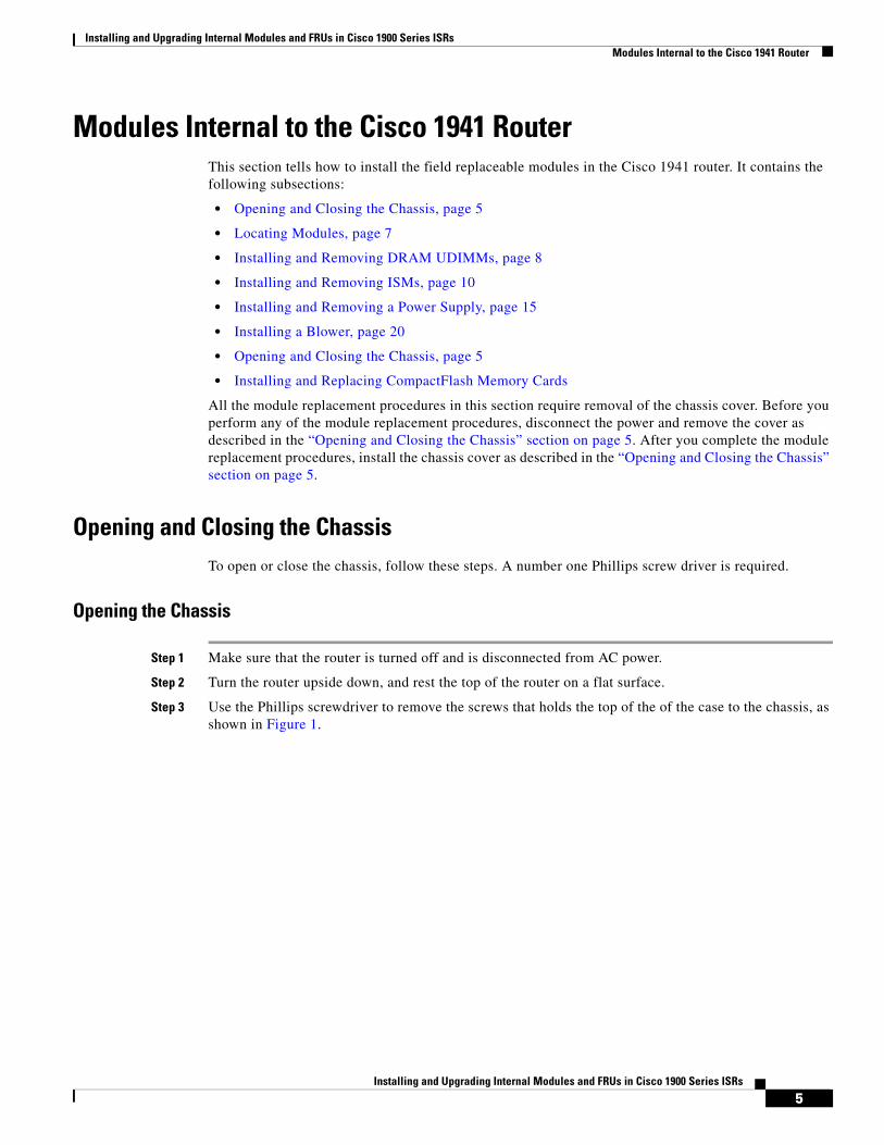
Installing and Upgrading Internal Modules and FRUs in Cisco 1900 Series ISRs Modules Internal to the Cisco 1941 Router
5Installing and Upgrading Internal Modules and FRUs in Cisco 1900 Series ISRs
Modules Internal to the Cisco 1941 RouterThis section tells how to install the field replaceable modules in the Cisco 1941 router. It contains the following subsections:
• Opening and Closing the Chassis, page 5
• Locating Modules, page 7
• Installing and Removing DRAM UDIMMs, page 8
• Installing and Removing ISMs, page 10
• Installing and Removing a Power Supply, page 15
• Installing a Blower, page 20
• Opening and Closing the Chassis, page 5
• Installing and Replacing CompactFlash Memory Cards
All the module replacement procedures in this section require removal of the chassis cover. Before you perform any of the module replacement procedures, disconnect the power and remove the cover as described in the “Opening and Closing the Chassis” section on page 5. After you complete the module replacement procedures, install the chassis cover as described in the “Opening and Closing the Chassis” section on page 5.
Opening and Closing the ChassisTo open or close the chassis, follow these steps. A number one Phillips screw driver is required.
Opening the Chassis
Step 1 Make sure that the router is turned off and is disconnected from AC power.
Step 2 Turn the router upside down, and rest the top of the router on a flat surface.
Step 3 Use the Phillips screwdriver to remove the screws that holds the top of the of the case to the chassis, as shown in Figure 1.
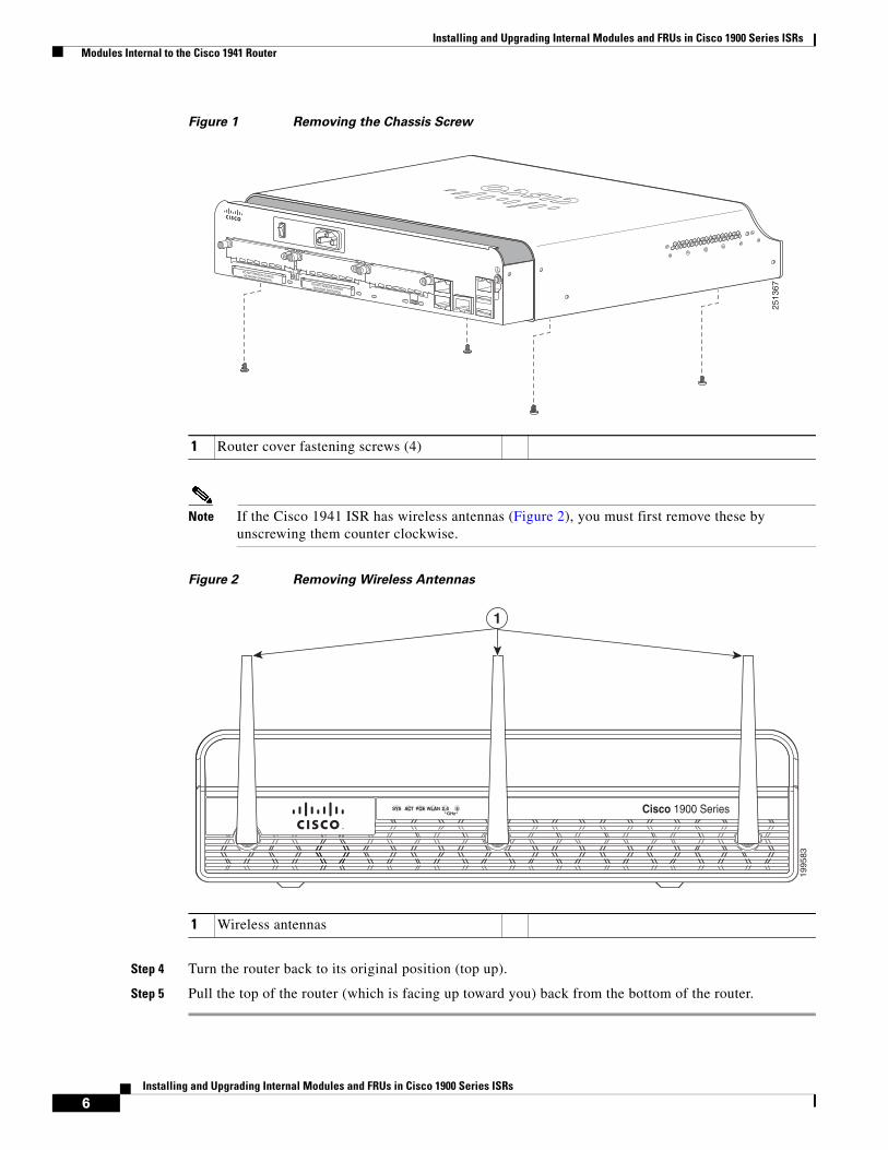
Installing and Upgrading Internal Modules and FRUs in Cisco 1900 Series ISRs Modules Internal to the Cisco 1941 Router
6Installing and Upgrading Internal Modules and FRUs in Cisco 1900 Series ISRs
Figure 1 Removing the Chassis Screw
Note If the Cisco 1941 ISR has wireless antennas (Figure 2), you must first remove these by unscrewing them counter clockwise.
Figure 2 Removing Wireless Antennas
Step 4 Turn the router back to its original position (top up).
Step 5 Pull the top of the router (which is facing up toward you) back from the bottom of the router.
1 Router cover fastening screws (4)
DO NOT REMOVE DURINGNETWORK OPERATION DO NOT REMOVE DURINGNETWORK OPERATION
2513
67
1 Wireless antennas
GHzSYS ACT POE WLAN 2.4 5
1995
83
1
Cisco 1900 Series
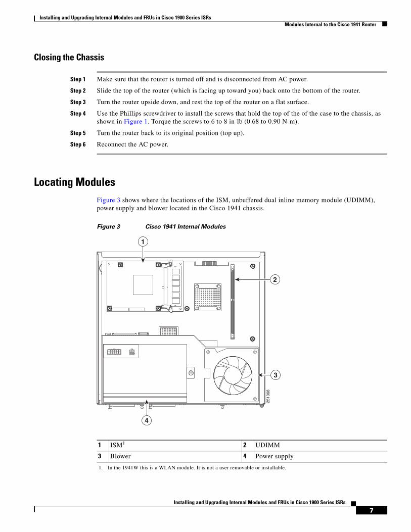
Installing and Upgrading Internal Modules and FRUs in Cisco 1900 Series ISRs Modules Internal to the Cisco 1941 Router
7Installing and Upgrading Internal Modules and FRUs in Cisco 1900 Series ISRs
Closing the Chassis
Step 1 Make sure that the router is turned off and is disconnected from AC power.
Step 2 Slide the top of the router (which is facing up toward you) back onto the bottom of the router.
Step 3 Turn the router upside down, and rest the top of the router on a flat surface.
Step 4 Use the Phillips screwdriver to install the screws that hold the top of the of the case to the chassis, as shown in Figure 1. Torque the screws to 6 to 8 in-lb (0.68 to 0.90 N-m).
Step 5 Turn the router back to its original position (top up).
Step 6 Reconnect the AC power.
Locating ModulesFigure 3 shows where the locations of the ISM, unbuffered dual inline memory module (UDIMM), power supply and blower located in the Cisco 1941 chassis.
Figure 3 Cisco 1941 Internal Modules
1 ISM1
1. In the 1941W this is a WLAN module. It is not a user removable or installable.
2 UDIMM
3 Blower 4 Power supply
2513
68
2
1
4
3
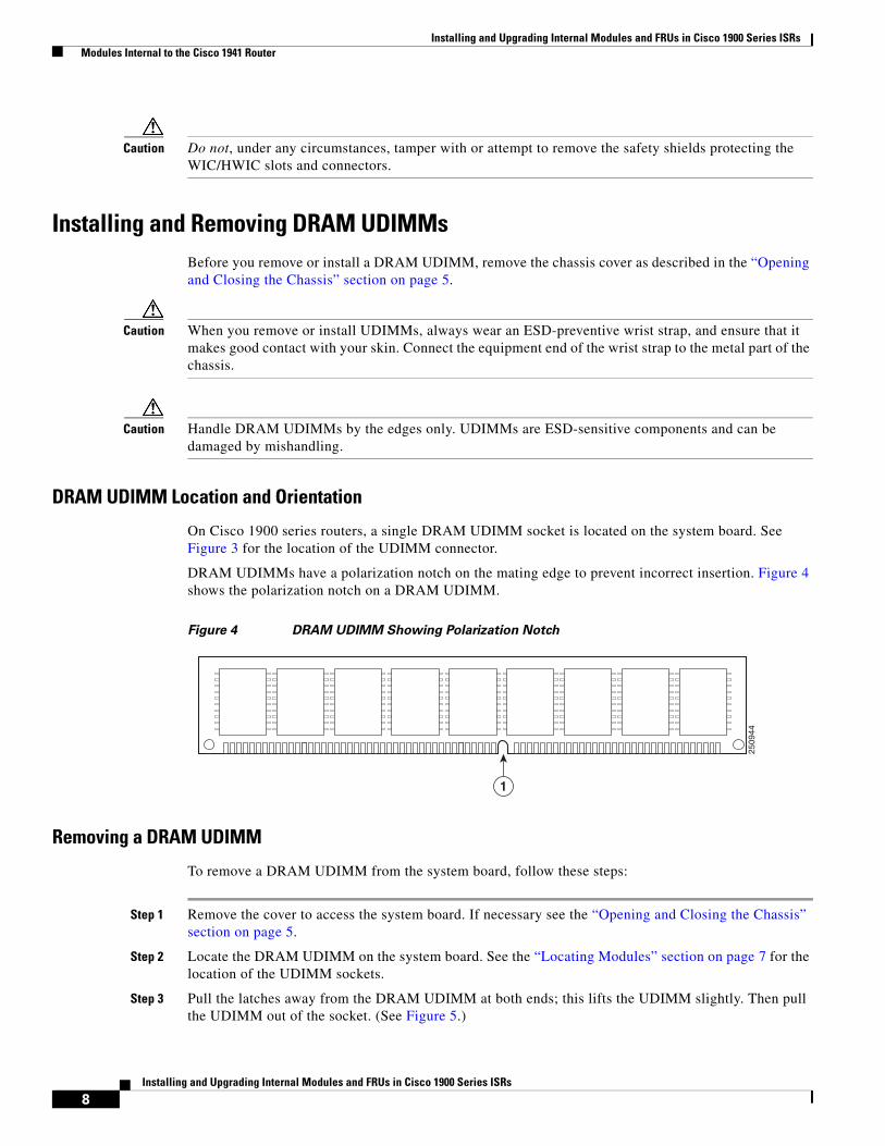
Installing and Upgrading Internal Modules and FRUs in Cisco 1900 Series ISRs Modules Internal to the Cisco 1941 Router
8Installing and Upgrading Internal Modules and FRUs in Cisco 1900 Series ISRs
Caution Do not, under any circumstances, tamper with or attempt to remove the safety shields protecting the WIC/HWIC slots and connectors.
Installing and Removing DRAM UDIMMsBefore you remove or install a DRAM UDIMM, remove the chassis cover as described in the “Opening and Closing the Chassis” section on page 5.
Caution When you remove or install UDIMMs, always wear an ESD-preventive wrist strap, and ensure that it makes good contact with your skin. Connect the equipment end of the wrist strap to the metal part of the chassis.
Caution Handle DRAM UDIMMs by the edges only. UDIMMs are ESD-sensitive components and can be damaged by mishandling.
DRAM UDIMM Location and Orientation
On Cisco 1900 series routers, a single DRAM UDIMM socket is located on the system board. See Figure 3 for the location of the UDIMM connector.
DRAM UDIMMs have a polarization notch on the mating edge to prevent incorrect insertion. Figure 4 shows the polarization notch on a DRAM UDIMM.
Figure 4 DRAM UDIMM Showing Polarization Notch
Removing a DRAM UDIMM
To remove a DRAM UDIMM from the system board, follow these steps:
Step 1 Remove the cover to access the system board. If necessary see the “Opening and Closing the Chassis” section on page 5.
Step 2 Locate the DRAM UDIMM on the system board. See the “Locating Modules” section on page 7 for the location of the UDIMM sockets.
Step 3 Pull the latches away from the DRAM UDIMM at both ends; this lifts the UDIMM slightly. Then pull the UDIMM out of the socket. (See Figure 5.)
2509
44
1
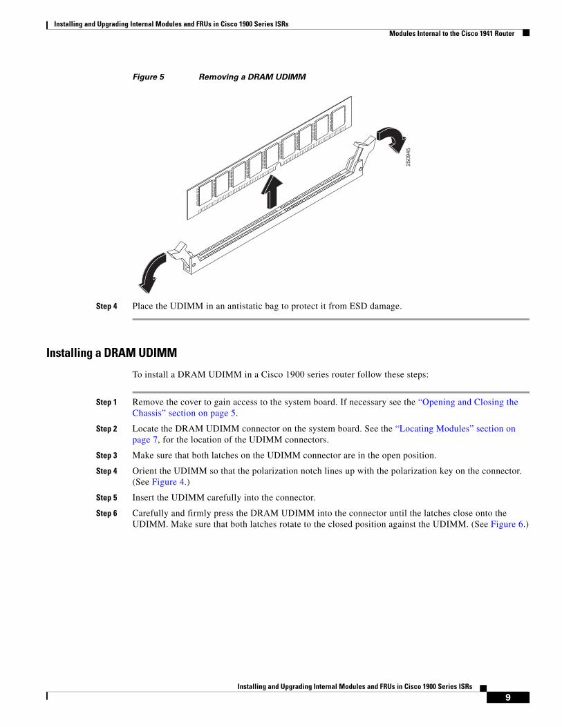
Installing and Upgrading Internal Modules and FRUs in Cisco 1900 Series ISRs Modules Internal to the Cisco 1941 Router
9Installing and Upgrading Internal Modules and FRUs in Cisco 1900 Series ISRs
Figure 5 Removing a DRAM UDIMM
Step 4 Place the UDIMM in an antistatic bag to protect it from ESD damage.
Installing a DRAM UDIMM
To install a DRAM UDIMM in a Cisco 1900 series router follow these steps:
Step 1 Remove the cover to gain access to the system board. If necessary see the “Opening and Closing the Chassis” section on page 5.
Step 2 Locate the DRAM UDIMM connector on the system board. See the “Locating Modules” section on page 7, for the location of the UDIMM connectors.
Step 3 Make sure that both latches on the UDIMM connector are in the open position.
Step 4 Orient the UDIMM so that the polarization notch lines up with the polarization key on the connector. (See Figure 4.)
Step 5 Insert the UDIMM carefully into the connector.
Step 6 Carefully and firmly press the DRAM UDIMM into the connector until the latches close onto the UDIMM. Make sure that both latches rotate to the closed position against the UDIMM. (See Figure 6.)
2509
45
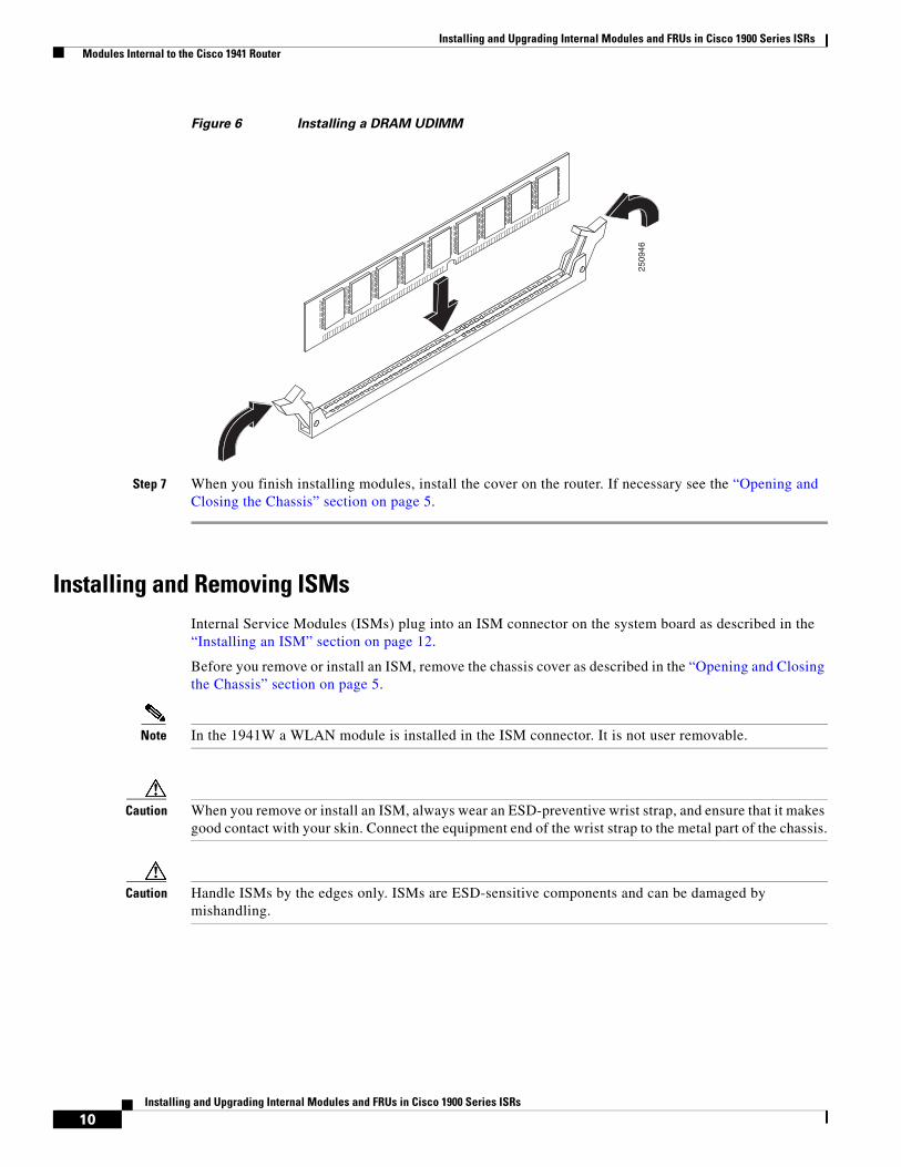
Installing and Upgrading Internal Modules and FRUs in Cisco 1900 Series ISRs Modules Internal to the Cisco 1941 Router
10Installing and Upgrading Internal Modules and FRUs in Cisco 1900 Series ISRs
Figure 6 Installing a DRAM UDIMM
Step 7 When you finish installing modules, install the cover on the router. If necessary see the “Opening and Closing the Chassis” section on page 5.
Installing and Removing ISMsInternal Service Modules (ISMs) plug into an ISM connector on the system board as described in the “Installing an ISM” section on page 12.
Before you remove or install an ISM, remove the chassis cover as described in the “Opening and Closing the Chassis” section on page 5.
Note In the 1941W a WLAN module is installed in the ISM connector. It is not user removable.
Caution When you remove or install an ISM, always wear an ESD-preventive wrist strap, and ensure that it makes good contact with your skin. Connect the equipment end of the wrist strap to the metal part of the chassis.
Caution Handle ISMs by the edges only. ISMs are ESD-sensitive components and can be damaged by mishandling.
2509
46
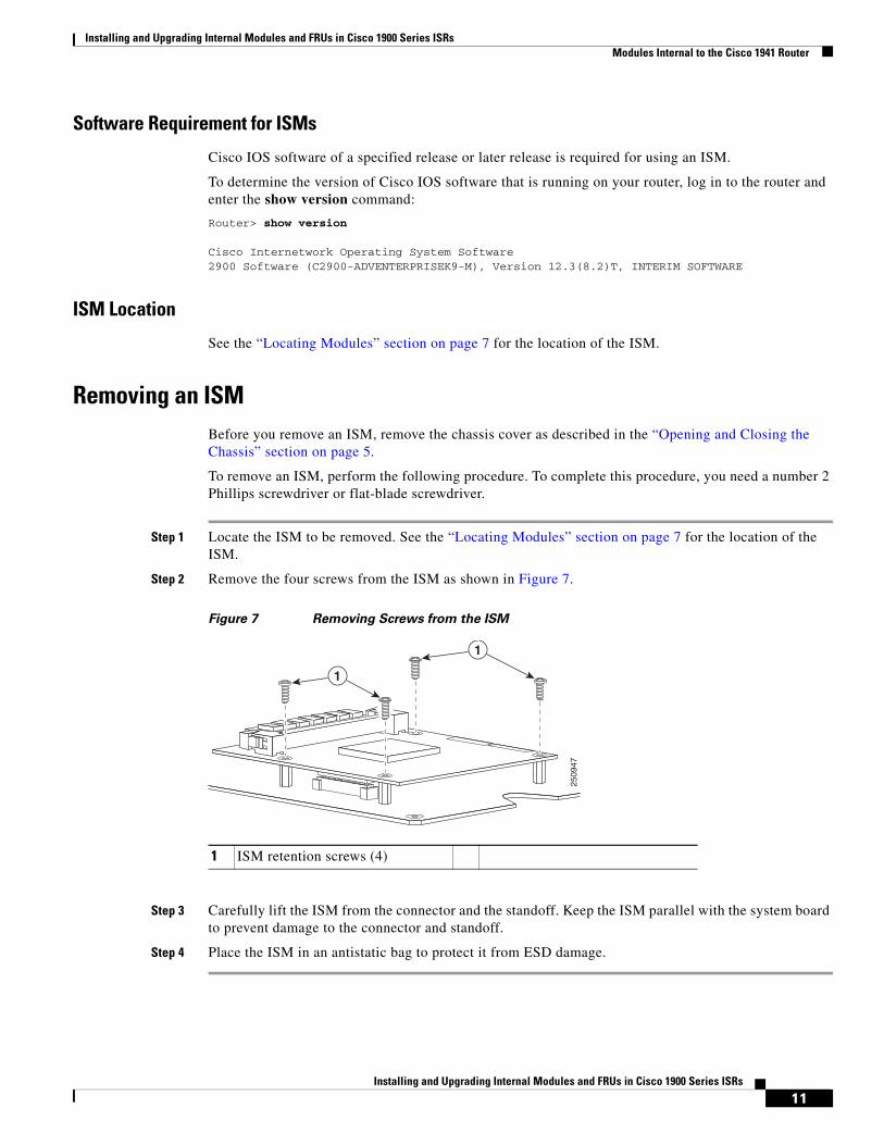
Installing and Upgrading Internal Modules and FRUs in Cisco 1900 Series ISRs Modules Internal to the Cisco 1941 Router
11Installing and Upgrading Internal Modules and FRUs in Cisco 1900 Series ISRs
Software Requirement for ISMs
Cisco IOS software of a specified release or later release is required for using an ISM.
To determine the version of Cisco IOS software that is running on your router, log in to the router and enter the show version command:
Router> show version
Cisco Internetwork Operating System Software 2900 Software (C2900-ADVENTERPRISEK9-M), Version 12.3(8.2)T, INTERIM SOFTWARE
ISM Location
See the “Locating Modules” section on page 7 for the location of the ISM.
Removing an ISMBefore you remove an ISM, remove the chassis cover as described in the “Opening and Closing the Chassis” section on page 5.
To remove an ISM, perform the following procedure. To complete this procedure, you need a number 2 Phillips screwdriver or flat-blade screwdriver.
Step 1 Locate the ISM to be removed. See the “Locating Modules” section on page 7 for the location of the ISM.
Step 2 Remove the four screws from the ISM as shown in Figure 7.
Figure 7 Removing Screws from the ISM
Step 3 Carefully lift the ISM from the connector and the standoff. Keep the ISM parallel with the system board to prevent damage to the connector and standoff.
Step 4 Place the ISM in an antistatic bag to protect it from ESD damage.
1 ISM retention screws (4)
2509
47
1
1
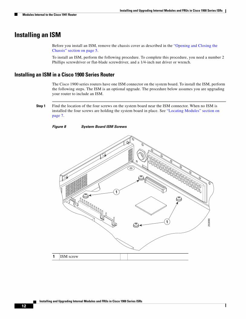
Installing and Upgrading Internal Modules and FRUs in Cisco 1900 Series ISRs Modules Internal to the Cisco 1941 Router
12Installing and Upgrading Internal Modules and FRUs in Cisco 1900 Series ISRs
Installing an ISMBefore you install an ISM, remove the chassis cover as described in the “Opening and Closing the Chassis” section on page 5.
To install an ISM, perform the following procedure. To complete this procedure, you need a number 2 Phillips screwdriver or flat-blade screwdriver, and a 1/4-inch nut driver or wrench.
Installing an ISM in a Cisco 1900 Series Router
The Cisco 1900 series routers have one ISM connector on the system board. To install the ISM, perform the following steps. The ISM is an optional upgrade. The procedure below assumes you are upgrading your router to include an ISM.
Step 1 Find the location of the four screws on the system board near the ISM connector. When no ISM is installed the four screws are holding the system board in place. See “Locating Modules” section on page 7.
Figure 8 System Board ISM Screws
1 ISM screw
2530
90
1
1
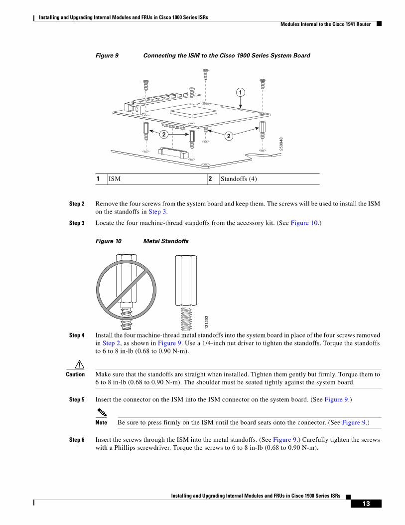
Installing and Upgrading Internal Modules and FRUs in Cisco 1900 Series ISRs Modules Internal to the Cisco 1941 Router
13Installing and Upgrading Internal Modules and FRUs in Cisco 1900 Series ISRs
Figure 9 Connecting the ISM to the Cisco 1900 Series System Board
Step 2 Remove the four screws from the system board and keep them. The screws will be used to install the ISM on the standoffs in Step 3.
Step 3 Locate the four machine-thread standoffs from the accessory kit. (See Figure 10.)
Figure 10 Metal Standoffs
Step 4 Install the four machine-thread metal standoffs into the system board in place of the four screws removed in Step 2, as shown in Figure 9. Use a 1/4-inch nut driver to tighten the standoffs. Torque the standoffs to 6 to 8 in-lb (0.68 to 0.90 N-m).
Caution Make sure that the standoffs are straight when installed. Tighten them gently but firmly. Torque them to 6 to 8 in-lb (0.68 to 0.90 N-m). The shoulder must be seated tightly against the system board.
Step 5 Insert the connector on the ISM into the ISM connector on the system board. (See Figure 9.)
Note Be sure to press firmly on the ISM until the board seats onto the connector. (See Figure 9.)
Step 6 Insert the screws through the ISM into the metal standoffs. (See Figure 9.) Carefully tighten the screws with a Phillips screwdriver. Torque the screws to 6 to 8 in-lb (0.68 to 0.90 N-m).
1 ISM 2 Standoffs (4)
2509
48
1
22
1212
02
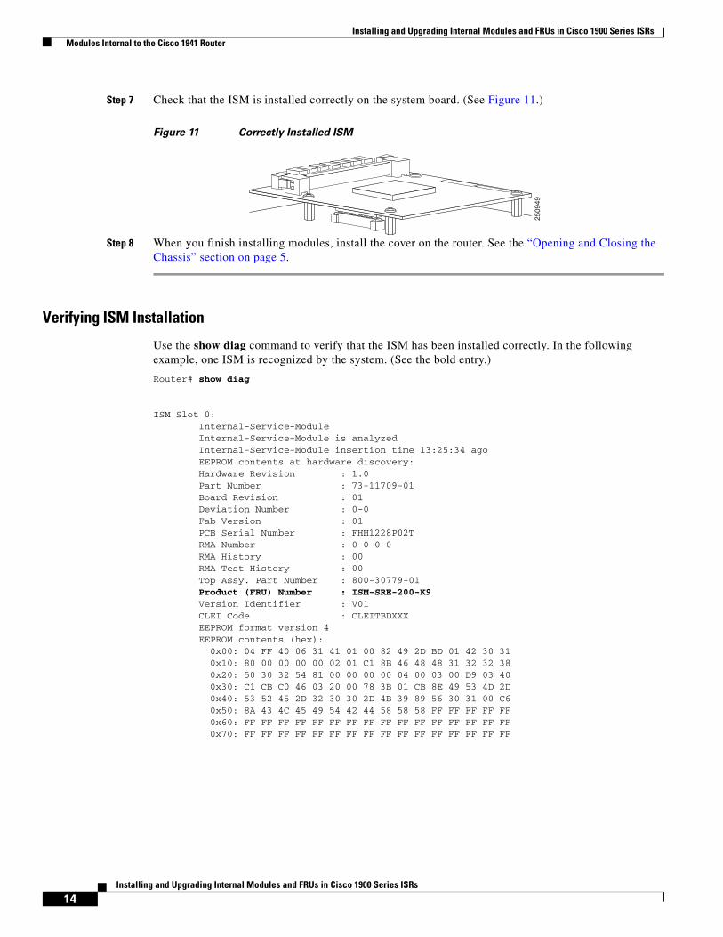
Installing and Upgrading Internal Modules and FRUs in Cisco 1900 Series ISRs Modules Internal to the Cisco 1941 Router
14Installing and Upgrading Internal Modules and FRUs in Cisco 1900 Series ISRs
Step 7 Check that the ISM is installed correctly on the system board. (See Figure 11.)
Figure 11 Correctly Installed ISM
Step 8 When you finish installing modules, install the cover on the router. See the “Opening and Closing the Chassis” section on page 5.
Verifying ISM Installation
Use the show diag command to verify that the ISM has been installed correctly. In the following example, one ISM is recognized by the system. (See the bold entry.)
Router# show diag
ISM Slot 0: Internal-Service-Module Internal-Service-Module is analyzed Internal-Service-Module insertion time 13:25:34 ago EEPROM contents at hardware discovery: Hardware Revision : 1.0 Part Number : 73-11709-01 Board Revision : 01 Deviation Number : 0-0 Fab Version : 01 PCB Serial Number : FHH1228P02T RMA Number : 0-0-0-0 RMA History : 00 RMA Test History : 00 Top Assy. Part Number : 800-30779-01 Product (FRU) Number : ISM-SRE-200-K9 Version Identifier : V01 CLEI Code : CLEITBDXXX EEPROM format version 4 EEPROM contents (hex): 0x00: 04 FF 40 06 31 41 01 00 82 49 2D BD 01 42 30 31 0x10: 80 00 00 00 00 02 01 C1 8B 46 48 48 31 32 32 38 0x20: 50 30 32 54 81 00 00 00 00 04 00 03 00 D9 03 40 0x30: C1 CB C0 46 03 20 00 78 3B 01 CB 8E 49 53 4D 2D 0x40: 53 52 45 2D 32 30 30 2D 4B 39 89 56 30 31 00 C6 0x50: 8A 43 4C 45 49 54 42 44 58 58 58 FF FF FF FF FF 0x60: FF FF FF FF FF FF FF FF FF FF FF FF FF FF FF FF 0x70: FF FF FF FF FF FF FF FF FF FF FF FF FF FF FF FF
2509
49
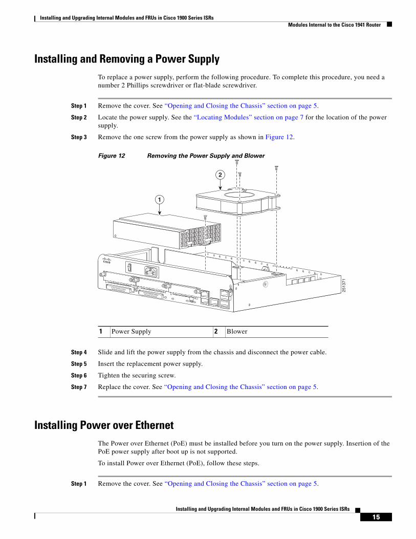
Installing and Upgrading Internal Modules and FRUs in Cisco 1900 Series ISRs Modules Internal to the Cisco 1941 Router
15Installing and Upgrading Internal Modules and FRUs in Cisco 1900 Series ISRs
Installing and Removing a Power SupplyTo replace a power supply, perform the following procedure. To complete this procedure, you need a number 2 Phillips screwdriver or flat-blade screwdriver.
Step 1 Remove the cover. See “Opening and Closing the Chassis” section on page 5.
Step 2 Locate the power supply. See the “Locating Modules” section on page 7 for the location of the power supply.
Step 3 Remove the one screw from the power supply as shown in Figure 12.
Figure 12 Removing the Power Supply and Blower
Step 4 Slide and lift the power supply from the chassis and disconnect the power cable.
Step 5 Insert the replacement power supply.
Step 6 Tighten the securing screw.
Step 7 Replace the cover. See “Opening and Closing the Chassis” section on page 5.
Installing Power over EthernetThe Power over Ethernet (PoE) must be installed before you turn on the power supply. Insertion of the PoE power supply after boot up is not supported.
To install Power over Ethernet (PoE), follow these steps.
Step 1 Remove the cover. See “Opening and Closing the Chassis” section on page 5.
2513
71
DO NOT REMOVE DURINGNETWORK OPERATION DO NOT REMOVE DURINGNETWORK OPERATION
1
2
1 Power Supply 2 Blower
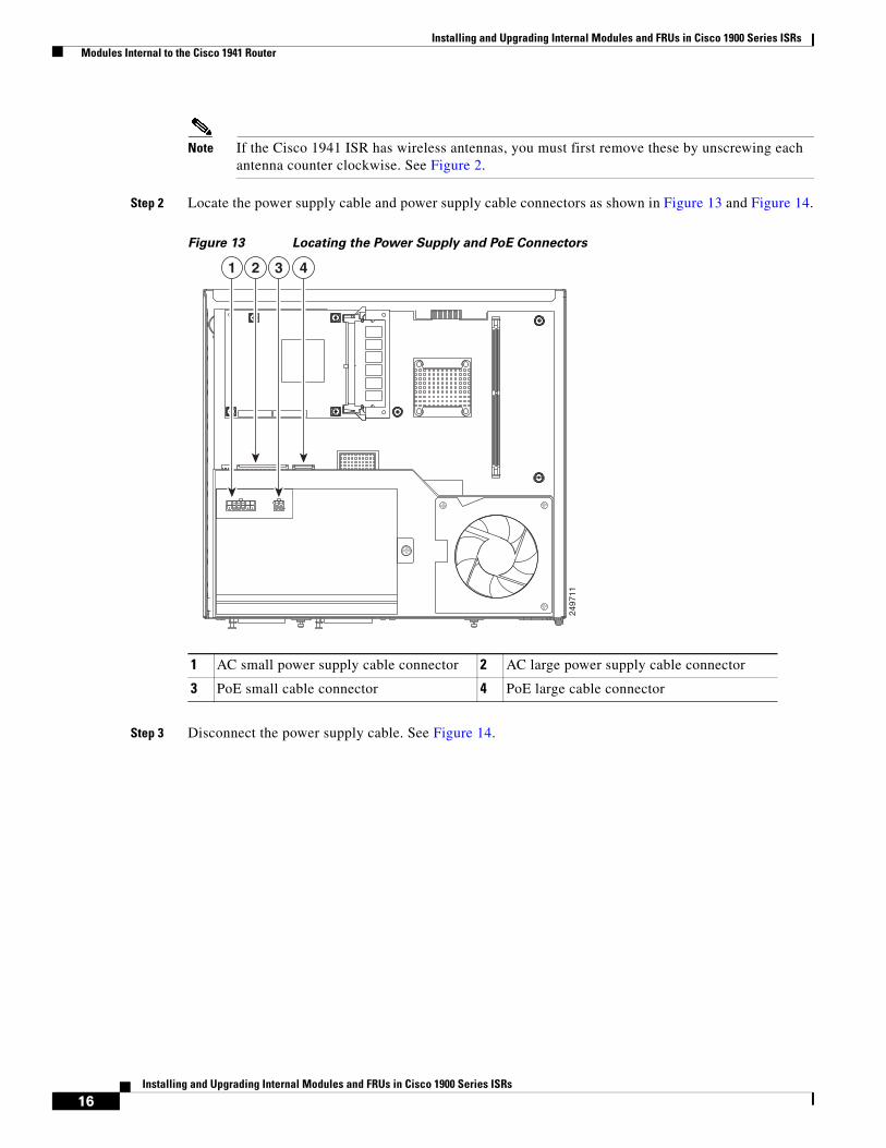
Installing and Upgrading Internal Modules and FRUs in Cisco 1900 Series ISRs Modules Internal to the Cisco 1941 Router
16Installing and Upgrading Internal Modules and FRUs in Cisco 1900 Series ISRs
Note If the Cisco 1941 ISR has wireless antennas, you must first remove these by unscrewing each antenna counter clockwise. See Figure 2.
Step 2 Locate the power supply cable and power supply cable connectors as shown in Figure 13 and Figure 14.
Figure 13 Locating the Power Supply and PoE Connectors
Step 3 Disconnect the power supply cable. See Figure 14.
2497
11
1 2 3 4
1 AC small power supply cable connector 2 AC large power supply cable connector
3 PoE small cable connector 4 PoE large cable connector
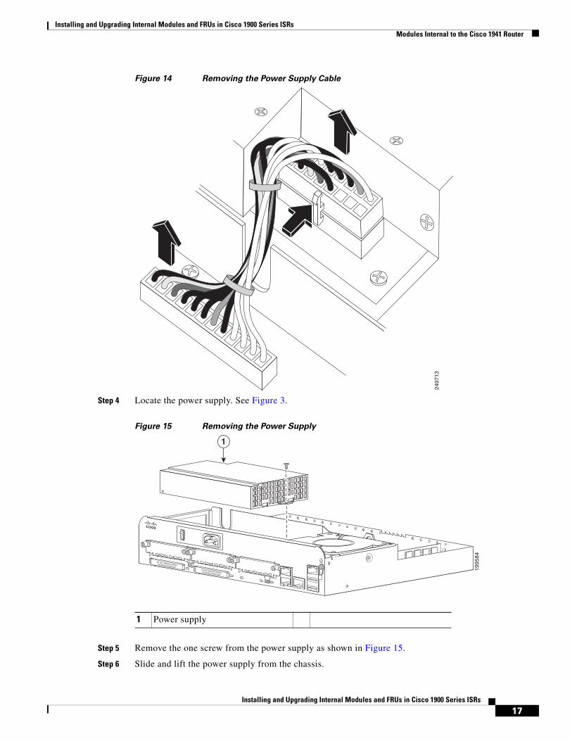
Installing and Upgrading Internal Modules and FRUs in Cisco 1900 Series ISRs Modules Internal to the Cisco 1941 Router
17Installing and Upgrading Internal Modules and FRUs in Cisco 1900 Series ISRs
Figure 14 Removing the Power Supply Cable
Step 4 Locate the power supply. See Figure 3.
Figure 15 Removing the Power Supply
Step 5 Remove the one screw from the power supply as shown in Figure 15.
Step 6 Slide and lift the power supply from the chassis.
2497
13
1995
84
DO NOT REMOVE DURINGNETWORK OPERATION DO NOT REMOVE DURINGNETWORK OPERATION
1
1 Power supply
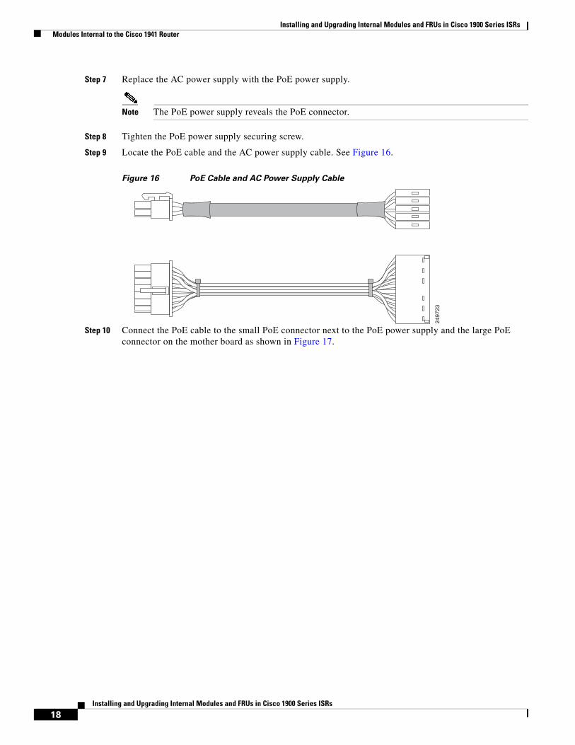
Installing and Upgrading Internal Modules and FRUs in Cisco 1900 Series ISRs Modules Internal to the Cisco 1941 Router
18Installing and Upgrading Internal Modules and FRUs in Cisco 1900 Series ISRs
Step 7 Replace the AC power supply with the PoE power supply.
Note The PoE power supply reveals the PoE connector.
Step 8 Tighten the PoE power supply securing screw.
Step 9 Locate the PoE cable and the AC power supply cable. See Figure 16.
Figure 16 PoE Cable and AC Power Supply Cable
Step 10 Connect the PoE cable to the small PoE connector next to the PoE power supply and the large PoE connector on the mother board as shown in Figure 17.
2497
23
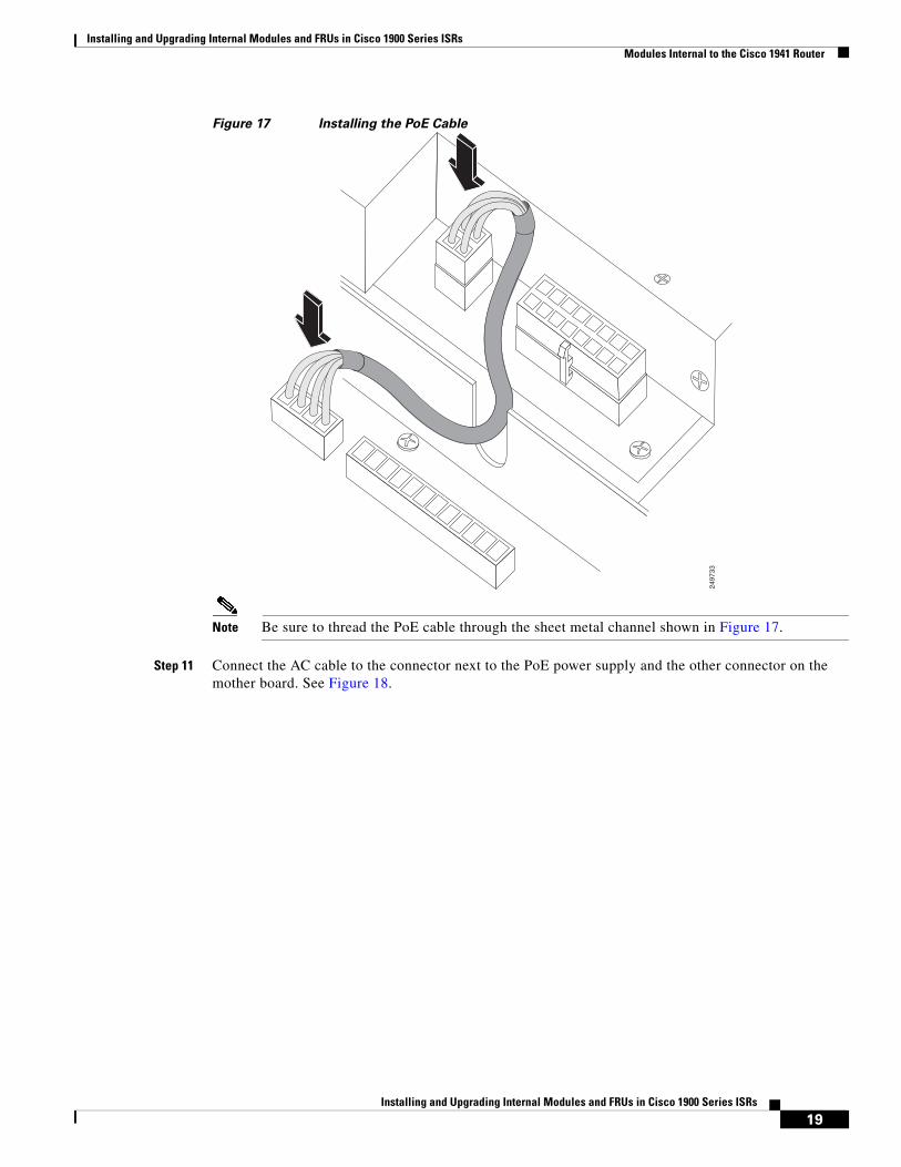
Installing and Upgrading Internal Modules and FRUs in Cisco 1900 Series ISRs Modules Internal to the Cisco 1941 Router
19Installing and Upgrading Internal Modules and FRUs in Cisco 1900 Series ISRs
Figure 17 Installing the PoE Cable
Note Be sure to thread the PoE cable through the sheet metal channel shown in Figure 17.
Step 11 Connect the AC cable to the connector next to the PoE power supply and the other connector on the mother board. See Figure 18.
2497
33
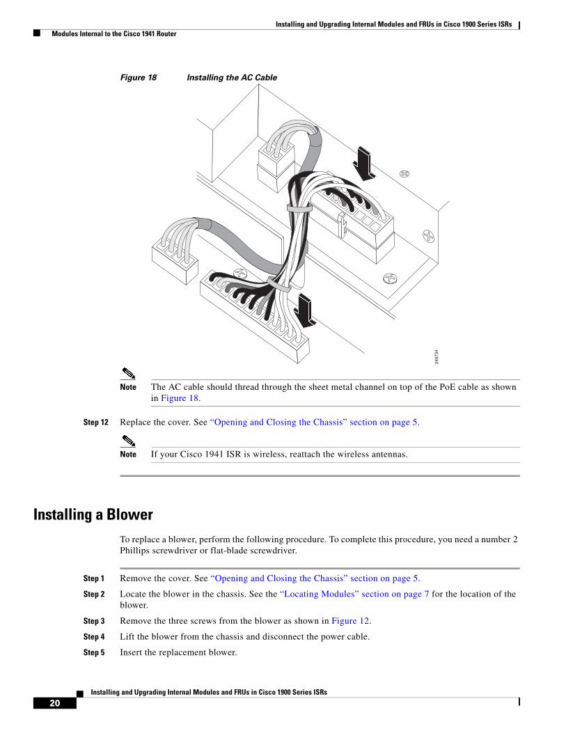
Installing and Upgrading Internal Modules and FRUs in Cisco 1900 Series ISRs Modules Internal to the Cisco 1941 Router
20Installing and Upgrading Internal Modules and FRUs in Cisco 1900 Series ISRs
Figure 18 Installing the AC Cable
Note The AC cable should thread through the sheet metal channel on top of the PoE cable as shown in Figure 18.
Step 12 Replace the cover. See “Opening and Closing the Chassis” section on page 5.
Note If your Cisco 1941 ISR is wireless, reattach the wireless antennas.
Installing a BlowerTo replace a blower, perform the following procedure. To complete this procedure, you need a number 2 Phillips screwdriver or flat-blade screwdriver.
Step 1 Remove the cover. See “Opening and Closing the Chassis” section on page 5.
Step 2 Locate the blower in the chassis. See the “Locating Modules” section on page 7 for the location of the blower.
Step 3 Remove the three screws from the blower as shown in Figure 12.
Step 4 Lift the blower from the chassis and disconnect the power cable.
Step 5 Insert the replacement blower.
2497
34
Installing and Upgrading Internal Modules and FRUs in Cisco 1900 Series ISRs Modules Internal to the Cisco 1941 Router
21Installing and Upgrading Internal Modules and FRUs in Cisco 1900 Series ISRs
Step 6 Tighten the securing screws.
Step 7 Replace the cover. See “Opening and Closing the Chassis” section on page 5.
Installing and Replacing CompactFlash Memory CardsThis section describes installing and replacing CompactFlash (CF) memory cards in Cisco 1941 integrated services routers. You can perform these procedures when the router has been installed in its working location with all power and interface cables connected. This chapter contains the following sections:
• Preventing Electrostatic Discharge Damage, page 21
• Removing a CompactFlash Memory Card, page 21
• Installing a CompactFlash Memory Card, page 23
Preventing Electrostatic Discharge Damage
This section describes installing and replacing CompactFlash (CF) memory cards in Cisco 1900 series integrated services routers. It contains the following sections:
To prevent ESD damage, follow these guidelines:
• Always use an ESD wrist or ankle strap and ensure that it makes good skin contact.
• Connect the equipment end of the strap to an unfinished chassis surface.
• Place a removed CompactFlash memory card on an antistatic surface or in a static shielding bag. If the card will be returned to the factory, immediately place it in a static shielding bag.
• Avoid contact between the card and clothing. The wrist strap protects the card from ESD voltages on the body only; ESD voltages on clothing can still cause damage.
• Do not remove the wrist strap until the installation is complete.
Caution For safety, periodically check the resistance value of the antistatic strap. The measurement should be between 1 and 10 megohms (Mohms).
Removing a CompactFlash Memory Card
To remove a CompactFlash memory card from the chassis, perform the following steps:
Caution Do not remove a CompactFlash memory card from the chassis while it is being accessed. The CF LED blinks to indicate when flash memory is being accessed. Removing the CompactFlash memory card from the router while flash memory is being accessed can cause data corruption and erratic operation.
Step 1 Remove the CompactFlash cover by placing a flat screwdriver in the slot and pushing sideways against the tension to release the cover door. (See Figure 19 and Figure 20.)
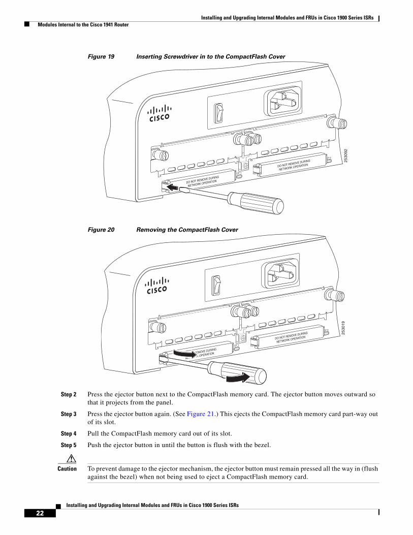
Installing and Upgrading Internal Modules and FRUs in Cisco 1900 Series ISRs Modules Internal to the Cisco 1941 Router
22Installing and Upgrading Internal Modules and FRUs in Cisco 1900 Series ISRs
Figure 19 Inserting Screwdriver in to the CompactFlash Cover
Figure 20 Removing the CompactFlash Cover
Step 2 Press the ejector button next to the CompactFlash memory card. The ejector button moves outward so that it projects from the panel.
Step 3 Press the ejector button again. (See Figure 21.) This ejects the CompactFlash memory card part-way out of its slot.
Step 4 Pull the CompactFlash memory card out of its slot.
Step 5 Push the ejector button in until the button is flush with the bezel.
Caution To prevent damage to the ejector mechanism, the ejector button must remain pressed all the way in (flush against the bezel) when not being used to eject a CompactFlash memory card.
2530
92
CF 1
CF 0
DO NOT REMOVE DURING
NETWORK OPERATION
DO NOT REMOVE DURING
NETWORK OPERATION
2530
19CF 1
CF 0
DO NOT REMOVE DURING
NETWORK OPERATION
DO NOT REMOVE DURING
NETWORK OPERATION
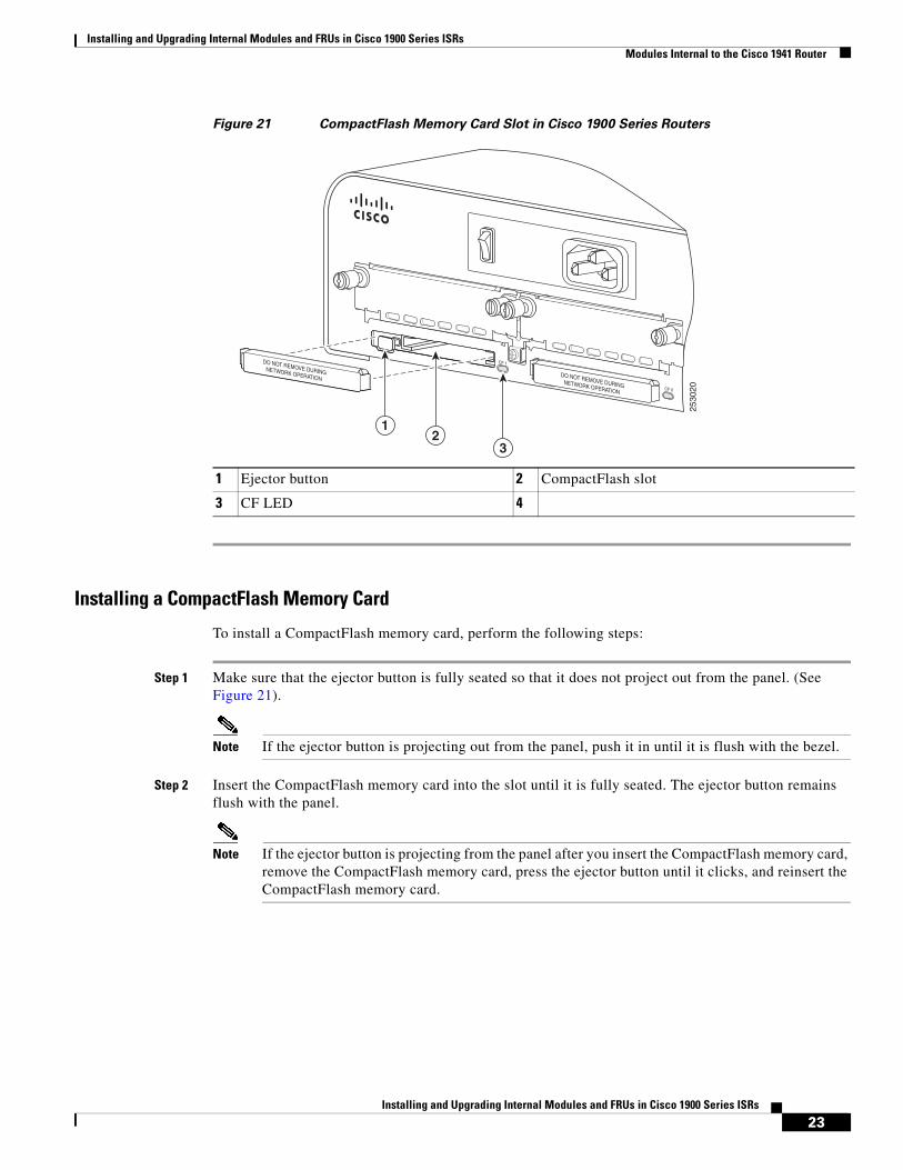
Installing and Upgrading Internal Modules and FRUs in Cisco 1900 Series ISRs Modules Internal to the Cisco 1941 Router
23Installing and Upgrading Internal Modules and FRUs in Cisco 1900 Series ISRs
Figure 21 CompactFlash Memory Card Slot in Cisco 1900 Series Routers
Installing a CompactFlash Memory Card
To install a CompactFlash memory card, perform the following steps:
Step 1 Make sure that the ejector button is fully seated so that it does not project out from the panel. (See Figure 21).
Note If the ejector button is projecting out from the panel, push it in until it is flush with the bezel.
Step 2 Insert the CompactFlash memory card into the slot until it is fully seated. The ejector button remains flush with the panel.
Note If the ejector button is projecting from the panel after you insert the CompactFlash memory card, remove the CompactFlash memory card, press the ejector button until it clicks, and reinsert the CompactFlash memory card.
1 Ejector button 2 CompactFlash slot
3 CF LED 4
DO NOT REMOVE DURINGNETWORK OPERATION
CF 1
CF 0
2530
20
DO NOT REMOVE DURINGNETWORK OPERATION
12
3
Installing and Upgrading Internal Modules and FRUs in Cisco 1900 Series ISRs Obtaining Documentation and Submitting a Service Request
24Installing and Upgrading Internal Modules and FRUs in Cisco 1900 Series ISRs
Caution To prevent damage to the ejector mechanism, the ejector button must remain fully seated when not being used to eject a CompactFlash memory card.
Step 3 Replace the CompactFlash cover by pushing it in place until it snaps in place.
Obtaining Documentation and Submitting a Service RequestFor information on obtaining documentation, submitting a service request, and gathering additional information, see the monthly What’s New in Cisco Product Documentation, which also lists all new and revised Cisco technical documentation, at:
http://www.cisco.com/en/US/docs/general/whatsnew/whatsnew.html
Subscribe to the What’s New in Cisco Product Documentation as a Really Simple Syndication (RSS) feed and set content to be delivered directly to your desktop using a reader application. The RSS feeds are a free service and Cisco currently supports RSS Version 2.0.
Cisco and the Cisco logo are trademarks or registered trademarks of Cisco and/or its affiliates in the U.S. and other countries. To view a list of Cisco trademarks, go to this URL: www.cisco.com/go/trademarks. Third-party trademarks mentioned are the property of their respective owners. The use of the word partner does not imply a partnership relationship between Cisco and any other company. (1721R)
© 2010 Cisco Systems, Inc. All rights reserved.