cisco 4000 integrated service routers · configure isr 4k configuration the below configuration can...
TRANSCRIPT

StorMagic. Copyright © 2019. All rights reserved. 1
Advanced Network Connectivity & HA Storage with Stormagic SvSAN in a Converged Infrastructure Solution
CISCO 4000 INTEGRATED SERVICE ROUTERS

StorMagic. Copyright © 2019. All rights reserved. 2
SVSAN WITH CISCO UCS E-SERIES
INTRODUCTIONBUSINESS OBJECTIVES
Enterprises with remote locations face a significant challenge: ensuring continuous uptime of business-critical applications at their distributed sites. Increasing demand for floor space at remote locations coupled with providing robust network connectivity plus data availability only compounds the issue. And the challenge only grows when enterprises seek to reduce capital and operational expenses. Cisco has partnered with StorMagic, a leader in software-defined storage, to introduce a game-changing solution. StorMagic’s SvSAN working on Cisco® UCS® E-Series Servers enables distributed enterprises to take advantage of shared storage features such as workload mobility and application uptime without added hardware or management costs.
This paper describes an Integrated Infrastructure solution that enables shared storage at the remote sites, using capacity attached directly to the compute layer, for a self-contained application delivery platform. Stormagic SvSAN combined with UCS E-Series and a 4000 Series router provides compute, networking, and storage support in an extremely compact footprint.
TARGET AUDIENCE
This white paper is intended for Solution Architects, IT designers, and Network Administrators who are tasked with providing the enterprise remote sites with advanced network functionality and robust connectivity. Increasingly, they are also asked to help insure application uptime without incurring exorbitant capital or operating expenses. Additionally, any technical member of staff who desires a cost-effective, easy to maintain infrastructure without the need for a special SAN for shared storage.
DOCUMENT PURPOSE
This document details how to setup a two-node virtualized environment with StorMagic SvSAN, VMware and Cisco UCS E-series blades. Virtualization saves in hardware and management costs and enables high availablility when utilized with shared storage, in this case StorMagic SvSAN.
NOTE
Throughout this document there are a number references to StorMagic Neutral Storage Host or NSH. This is also known as the StorMagic SvSAN Witness.

StorMagic. Copyright © 2019. All rights reserved. 3
SOLUTION ARCHITECTURESOLUTION PRIMARY COMPONENTS
Figure 1 - Cisco ISR 4000 Series Routers
Cisco ISR 4000 Series Router
The 4000 Series offers secure WAN connectivity, application experience, unified communications, network automation, virtualization, and branch and direct Internet access security solutions in one platform.
www.cisco.com/c/en/us/products/routers/4000-series-integrated-services-routers-isr/index.html
Cisco UCS E-Series Blades
Reduce costs without compromising vital network services with UCS E-Series router-integrated branch blade servers. Virtualization-ready and application-centric. Built with network, compute, and storage capacities for high-performance application hosting. Supported with VMware vSphere ESXi, Citrix XenServer, and Linux KVM hypervisors.
UCS E-Series Servers are x86 64-bit service modules that reside in Cisco 4000 Series ISR platforms. They balance simplicity, performance, and power efficiency. They are well suited for distributed branch offices with small IT footprint.
www.cisco.com/c/en/us/products/servers-unified-computing/ucs-e-series-servers/index.html
Figure 2 - Cisco UCS E Series

StorMagic. Copyright © 2019. All rights reserved. 4
STORMAGIC SvSAN
SvSAN is a software solution, which enables enterprises to eliminate downtime of business critical applications at the edge, where this disruption directly equates to a loss in service and revenue. SvSAN ensures high availability through a virtual storage platform, appliance (VSA), so that business critical edge applications remain operational.
StorMagic’s typical customer has anywhere between 10 – 10,000 edge sites, where local IT support is not available, but uptime of applications is a must.
SvSAN provides an intuitive, standardized management interface that allows multiple SvSAN VSAs, spread across remote sites, to be managed and provisioned quickly and simply either locally, or remotely, from a central location. SvSAN’s efficient and flexible architecture and its modular approach enable it to meet the ever-changing and increasingly demanding storage requirements within any organization.
SvSAN’s unique benefits include:
Abstraction of storage services away from traditional storage arrays, making it a key
component of a software-defined storage strategyElimination of the need for a physical Storage Area Network (SAN)Virtualization of internal disk drives and external, direct-attached storage arrays (DAS) to enable storage sharing among multiple serversHigh availability in a simple two-server solutionReduced remote site IT costs by up to 40%, with elimination of physical SANs and less spend on servers and softwareMaximized application uptimeCentralized storage management of entiremulti-site infrastructureRapid, scripted deployments and updates of multiple sites simultaneously with automated provisioningOptimal flexibility, as SvSAN is hardware and hypervisor agnostic and can scale as storage requirements growOptional SSD read/write caching, memory based read caching and memory data pinning to accelerate workloadsEnterprise Data-at-rest-encryption for edge site data securityFast resynchronization through restore capability, enabling users to replace a failed server with a new one and automatically rebuild their environment
Figure 3 – StorMagic SvSAN Architectural Overview

StorMagic. Copyright © 2019. All rights reserved. 5
SOLUTION DETAILBASIC ARCHITECTURE
This architecture is storage self-contained. Rather than utilize remote SAN based storage over networks that may have high latency and low reliability, this combined ISR 4K and UCS-E series based design connects the storage and compute nodes into one unified platform.
The 2x UCS E-series blades and SvSAN create an architecture with virtualized compute and storage. The enables High Availability, vMotion and even Fault Tolerance protection of edge virtual machines for low cost, eliminating single points of failure and create a set and forget solution enabling distributed enterprise scale of thousands of locations.
COMPONENTS
ISR4451-X/K9: This router represents a single branch
MEM-4400-4GU8G - 4G to 8G DRAM Upgrade (4G+4G) for Cisco ISR 4400
NIM-ES2-4: This switch module is used to show the network integration options
2x UCS-E160S-M3/K9: x86 server blades to host the virtualized layer
Optional – To host the SvSAN witness on prem in the ISR rather than centrally over the WAN
NIM-SSD + SSD-SATA-400G: This will host the virtualized witness in the ISR 4K router as a Service Container
VMWare vCenter: The central management application for the most commonly deployed hypervisor, ESXi
VMware vSphere is a virtualization platform for holistically managing large collections of infrastructure resources —CPUs, storage, networking — as a seamless, versatile, and dynamic operating environment. Unlike traditional operating systems that manage an individual machine, VMware vSphere aggregates the infrastructure of an entire datacenter to create a single powerhouse with resources that can be allocated quickly and dynamically to any application in need. The VMware vSphere environment delivers a robust application environment. For example, with VMware vSphere, all applications can be protected from downtime with VMware High Availability (HA) without the complexity of conventional clustering. In addition, applications can be scaled dynamically to meet changing loads with capabilities such as Hot Add and VMware Distributed Resource Scheduler (DRS).
www.vmware.com/products/datacenter-virtualization/vsphere/overview.html
StorMagic. Copyright © 2019. All rights reserved. 6
CONFIGURE
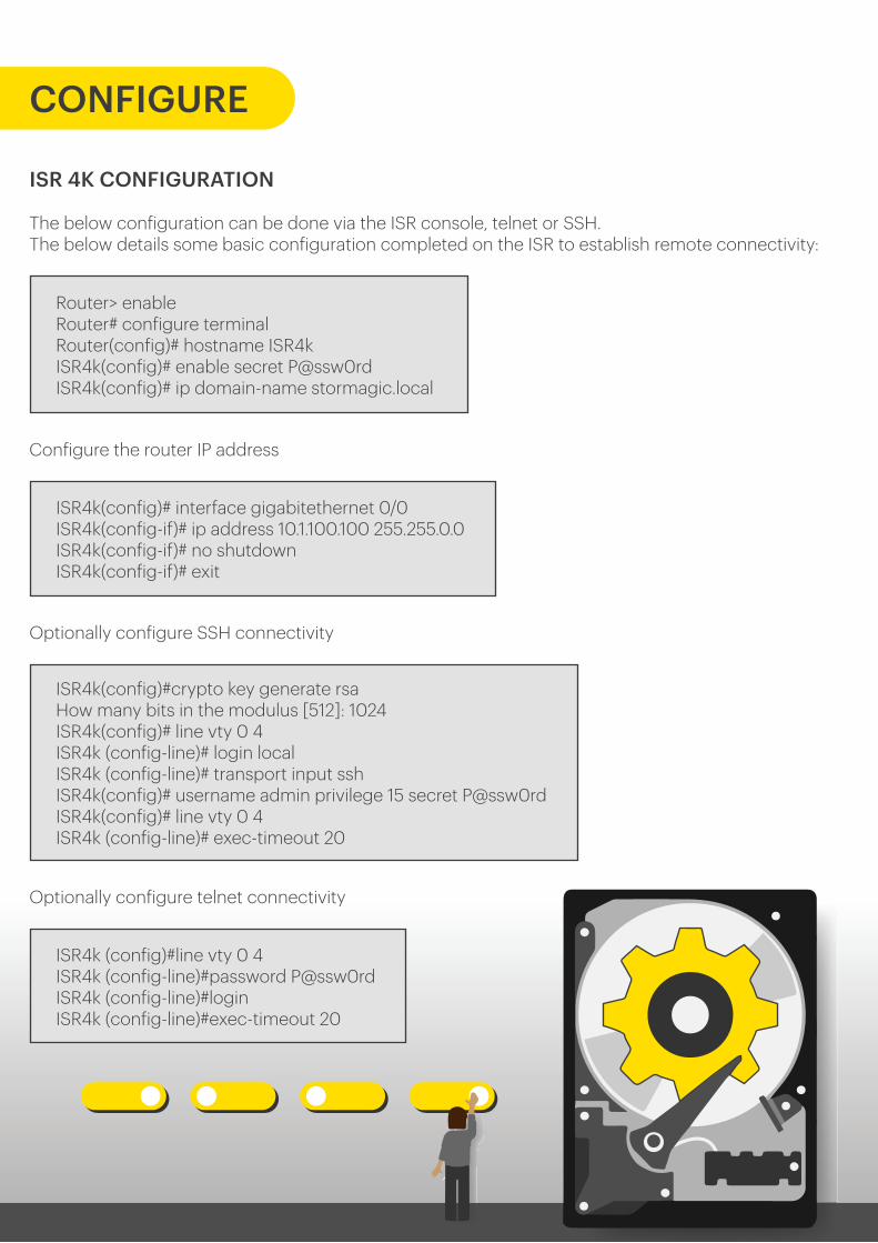
ISR 4K CONFIGURATION
The below configuration can be done via the ISR console, telnet or SSH.The below details some basic configuration completed on the ISR to establish remote connectivity:
Router> enableRouter# configure terminalRouter(config)# hostname ISR4kISR4k(config)# enable secret P@ssw0rdISR4k(config)# ip domain-name stormagic.local
Configure the router IP address
ISR4k(config)# interface gigabitethernet 0/0ISR4k(config-if)# ip address 10.1.100.100 255.255.0.0ISR4k(config-if)# no shutdownISR4k(config-if)# exit
Optionally configure SSH connectivity
ISR4k(config)#crypto key generate rsaHow many bits in the modulus [512]: 1024 ISR4k(config)# line vty 0 4ISR4k (config-line)# login localISR4k (config-line)# transport input sshISR4k(config)# username admin privilege 15 secret P@ssw0rdISR4k(config)# line vty 0 4ISR4k (config-line)# exec-timeout 20
Optionally configure telnet connectivity
ISR4k (config)#line vty 0 4ISR4k (config-line)#password P@ssw0rdISR4k (config-line)#loginISR4k (config-line)#exec-timeout 20

StorMagic. Copyright © 2019. All rights reserved. 7
Figure 4 – ISR 4K router to blade connectivity options
Figure 5 – ISR 4K router to blade connectivity options
Next, choose how the ISR “int ucseX/0/0” connects to the UCS E Server.
There are several options to choose from:
3A. Dedicated Subnet 3C. Layer 2 BDI Mode3B. Shared Subnet (via “ip unnumbered”) 3D. Layer 2 SVI Mode
The following diagram illustrates these options:
Internal UCSE connectivity options are:1. Dedicated CIMC (Cisco Integrated Management Controller) Interface
a. (only available on UCS-E Generation M1 & M2, we are using M3)2. Shared External Interface3. Shared Internal Interface
The following diagram illustrates these options:
StorMagic. Copyright © 2019. All rights reserved. 8
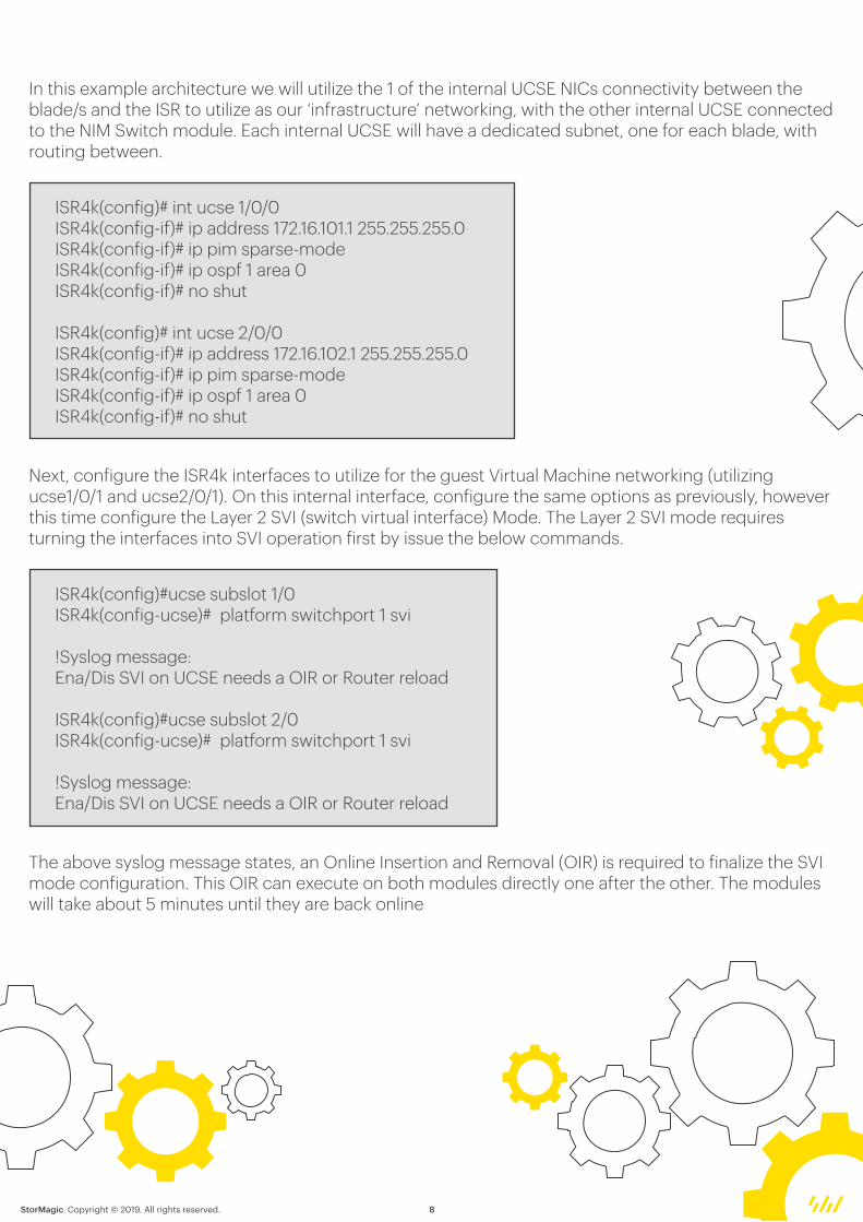
In this example architecture we will utilize the 1 of the internal UCSE NICs connectivity between the blade/s and the ISR to utilize as our ‘infrastructure’ networking, with the other internal UCSE connected to the NIM Switch module. Each internal UCSE will have a dedicated subnet, one for each blade, with routing between.
ISR4k(config)# int ucse 1/0/0ISR4k(config-if)# ip address 172.16.101.1 255.255.255.0ISR4k(config-if)# ip pim sparse-modeISR4k(config-if)# ip ospf 1 area 0ISR4k(config-if)# no shut
ISR4k(config)# int ucse 2/0/0ISR4k(config-if)# ip address 172.16.102.1 255.255.255.0ISR4k(config-if)# ip pim sparse-modeISR4k(config-if)# ip ospf 1 area 0ISR4k(config-if)# no shut
Next, configure the ISR4k interfaces to utilize for the guest Virtual Machine networking (utilizing ucse1/0/1 and ucse2/0/1). On this internal interface, configure the same options as previously, however this time configure the Layer 2 SVI (switch virtual interface) Mode. The Layer 2 SVI mode requires turning the interfaces into SVI operation first by issue the below commands.
ISR4k(config)#ucse subslot 1/0ISR4k(config-ucse)# platform switchport 1 svi
!Syslog message:Ena/Dis SVI on UCSE needs a OIR or Router reload
ISR4k(config)#ucse subslot 2/0ISR4k(config-ucse)# platform switchport 1 svi
!Syslog message:Ena/Dis SVI on UCSE needs a OIR or Router reload
The above syslog message states, an Online Insertion and Removal (OIR) is required to finalize the SVI mode configuration. This OIR can execute on both modules directly one after the other. The modules will take about 5 minutes until they are back online
StorMagic. Copyright © 2019. All rights reserved. 9
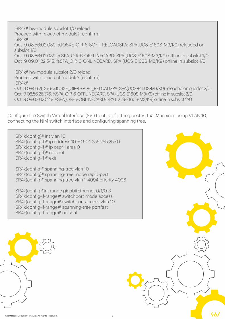
ISR4k# hw-module subslot 1/0 reloadProceed with reload of module? [confirm]ISR4k#Oct 9 08:56:02.039: %IOSXE_OIR-6-SOFT_RELOADSPA: SPA(UCS-E160S-M3/K9) reloaded on subslot 1/0Oct 9 08:56:02.039: %SPA_OIR-6-OFFLINECARD: SPA (UCS-E160S-M3/K9) offline in subslot 1/0Oct 9 09:01:22.545: %SPA_OIR-6-ONLINECARD: SPA (UCS-E160S-M3/K9) online in subslot 1/0
ISR4k# hw-module subslot 2/0 reloadProceed with reload of module? [confirm]ISR4k#Oct 9 08:56:26.376: %IOSXE_OIR-6-SOFT_RELOADSPA: SPA(UCS-E160S-M3/K9) reloaded on subslot 2/0Oct 9 08:56:26.376: %SPA_OIR-6-OFFLINECARD: SPA (UCS-E160S-M3/K9) offline in subslot 2/0Oct 9 09:03:02.526: %SPA_OIR-6-ONLINECARD: SPA (UCS-E160S-M3/K9) online in subslot 2/0
Configure the Switch Virtual Interface (SVI) to utilize for the guest Virtual Machines using VLAN 10, connecting the NIM switch interface and configuring spanning tree.
ISR4k(config)# int vlan 10ISR4k(config-if)# ip address 10.50.50.1 255.255.255.0ISR4k(config-if)# ip ospf 1 area 0ISR4k(config-if)# no shutISR4k(config-if)# exit
ISR4k(config)# spanning-tree vlan 10ISR4k(config)# spanning-tree mode rapid-pvstISR4k(config)# spanning-tree vlan 1-4094 priority 4096
ISR4k(config)#int range gigabitEthernet 0/1/0-3ISR4k(config-if-range)# switchport mode accessISR4k(config-if-range)# switchport access vlan 10ISR4k(config-if-range)# spanning-tree portfastISR4k(config-if-range)# no shut

StorMagic. Copyright © 2019. All rights reserved. 10
Ensure the modules are fully bootedConfigure the “interface ucseX/0/1” to switching mode. Additionally, all routed ports are set default to be in “Shutdown” mode, so a “no shut” command on the routed ports is required.
Trunk the connections to be utilized for guest VM NetworkISR4k(config)# int ucse 1/0/1ISR4k(config-if)# switchport mode trunkISR4k(config-if)# no shutISR4k(config-if)# exit
ISR4k(config)# int ucse 2/0/1ISR4k(config-if)# switchport mode trunkISR4k(config-if)# no shutISR4k(config-if)# exit
Internal routed ports for infrastructure connectivityISR4k(config)# int ucse 1/0/0ISR4k(config-if)# no shut
ISR4k(config)# int ucse 2/0/0ISR4k(config-if)# no shut
With the layer 2 connectivity configured, verify using “show spanning-tree vlan 10” that all interfaces are participating in the spanning-tree domain:
ISR4k#sh spanning-tree vlan 10
G0:VLAN0010 Spanning tree enabled protocol rstp Root ID Priority 4106 Address b838.61a2.8a31 This bridge is the root Hello Time 2 sec Max Age 20 sec Forward Delay 15 sec
Bridge ID Priority 4106 (priority 4096 sys-id-ext 10) Address b838.61a2.8a31 Hello Time 2 sec Max Age 20 sec Forward Delay 15 sec Aging Time 300
Interface Role Sts Cost Prio.Nbr Type------------------- ---- --- --------- -------- --------------------------------Gi0/1/0 Desg FWD 4 128.10 Edge P2puc1/0/1 Desg FWD 4 128.24 Edge P2puc2/0/1 Desg FWD 4 128.25 Edge P2p

StorMagic. Copyright © 2019. All rights reserved. 11
CONFIGURE THE BLADE CIMC INTERFACES
These settings can be configured from within IOS-XE
ISR4k(config)#ucse subslot 1/0ISR4k(config-ucse)#imc access-port shared-lom consoleISR4k(config-ucse)#imc ip address 172.16.101.2 255.255.255.0 default-gateway 172.16.101.1ISR4k(config-ucse)#exit
ISR4k(config)#ucse subslot 2/0ISR4k(config-ucse)#imc access-port shared-lom consoleISR4k(confi1g-ucse)#imc ip address 172.16.102.2 255.255.255.0 default-gateway 172.16.102.1ISR4k(config-if)#no shut
Verify the interfaces are responding to pings internal to the router:
ISR4k# ping 172.16.101.2Type escape sequence to abort.Sending 5, 100-byte ICMP Echos to 172.16.101.2, timeout is 2 seconds:.!!!!Success rate is 80 percent (4/5), round-trip min/avg/max = 2/2/2 msISR4k# ping 172.16.102.2Type escape sequence to abort.Sending 5, 100-byte ICMP Echos to 172.16.102.2, timeout is 2 seconds:.!!!!Success rate is 80 percent (4/5), round-trip min/avg/max = 2/2/2 ms
Optional: Reset the CIMC password
ISR4k#ucse subslot 1/0 imc password-resetISR4k#ucse subslot 2/0 imc password-reset
StorMagic. Copyright © 2019. All rights reserved. 12
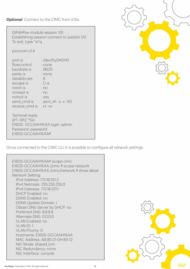
Optional: Connect to the CIMC from iOSx
ISR4k#hw-module session 1/0Establishing session connect to subslot 1/0To exit, type ^a^q
picocom v1.4
port is : /dev/ttyDASH0flowcontrol : nonebaudrate is : 9600parity is : nonedatabits are : 8escape is : C-anoinit is : nonoreset is : nonolock is : yessend_cmd is : ascii_xfr -s -v -l10receive_cmd is : rz -vv
Terminal ready|é°ì <M\}¯°|Q<¤E160S- GCCAAH1KAA login: adminPassword: passwordE160S-GCCAAH1KAA#
Once connected to the CIMC CLI it is possible to configure all network settings:
E160S-GCCAAH1KAA# scope cimcE160S-GCCAAH1KAA /cimc # scope networkE160S-GCCAAH1KAA /cimc/network # show detailNetwork Setting: IPv4 Address: 172.16.101.2 IPv4 Netmask: 255.255.255.0 IPv4 Gateway: 172.16.101.1 DHCP Enabled: no DDNS Enabled: no DDNS Update Domain: i Obtain DNS Server by DHCP: no Preferred DNS: 8.8.8.8 Alternate DNS: 0.0.0.0 VLAN Enabled: no VLAN ID: 1 VLAN Priority: 0 Hostname: E160S-GCCAAH1KAA MAC Address: A8:9D:21:GH:8A:12 NIC Mode: shared_lom NIC Redundancy: none NIC Interface: console

StorMagic. Copyright © 2019. All rights reserved. 13
The ISR4k only updates the parameters being explicitly configured. Each parameter can be manually changed via the “set” commands. Ensure to “commit” the change afterwards.The below commands could be helpful for troubleshooting.
E160S-GCCAAH1KAA /cimc/network # set ? alternate-dns-server Alternate DNS cli CLI options ddns-enabled DDNS Enabled ddns-update-domain DDNS Update Domain dhcp-enabled DHCP Enabled dns-use-dhcp Obtain DNS Server by DHCP hostname Hostname interface NIC Interface mode NIC Mode preferred-dns-server Preferred DNS redundancy NIC Redundancy v4-addr IPv4 Address v4-gateway IPv4 Gateway v4-netmask IPv4 Netmask vlan-enabled VLAN Enabled vlan-id VLAN ID vlan-priority VLAN PriorityE160S-GCCAAH1KAA /cimc/network # commit
To leave the CIMC Console session press the keys “CTRL+A” followed by “CTRL+Q”.Ensure both blade CIMC interfaces are configured. E-series Blade configuration

StorMagic. Copyright © 2019. All rights reserved. 14
E-SERIES BLADE CONFIGURATION
Connect to the E-series CIMC interfaces for each blade and login.
The default credentials after the password reset are:Username: admin Password: password
Confirm the health of the blade
StorMagic. Copyright © 2019. All rights reserved. 15
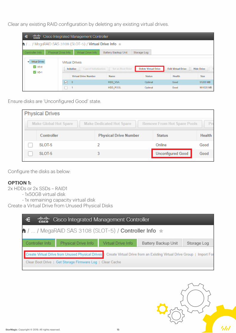
Clear any existing RAID configuration by deleting any existing virtual drives.
Ensure disks are ‘Unconfigured Good’ state.
Configure the disks as below:
OPTION 1: 2x HDDs or 2x SSDs – RAID1 - 1x50GB virtual disk - 1x remaining capacity virtual diskCreate a Virtual Drive from Unused Physical Disks
StorMagic. Copyright © 2019. All rights reserved. 16
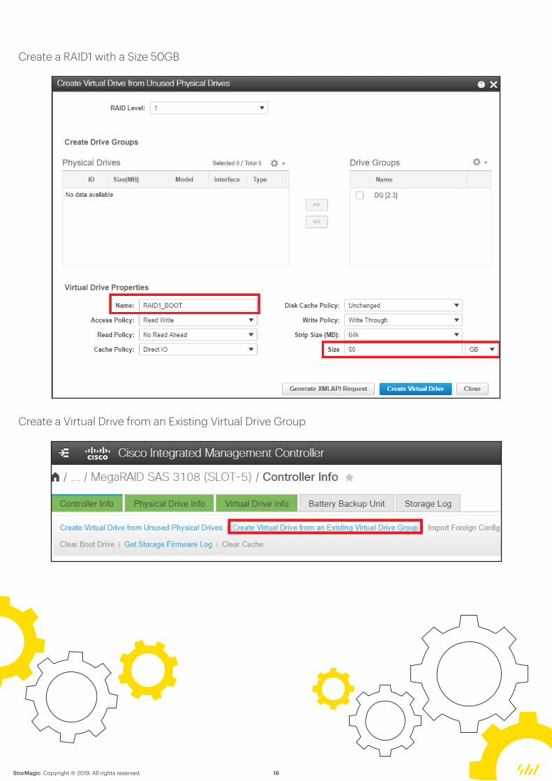
Create a RAID1 with a Size 50GB
Create a Virtual Drive from an Existing Virtual Drive Group
StorMagic. Copyright © 2019. All rights reserved. 17
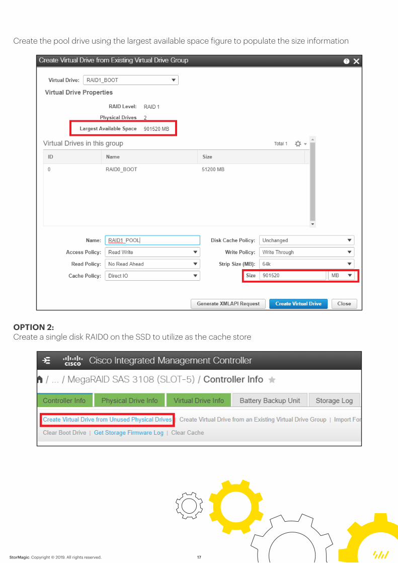
Create the pool drive using the largest available space figure to populate the size information
OPTION 2:Create a single disk RAID0 on the SSD to utilize as the cache store

StorMagic. Copyright © 2019. All rights reserved. 18
SSD RAID0
Create a split virtual disk configuration on the HDD to create a boot device and pool
StorMagic. Copyright © 2019. All rights reserved. 19
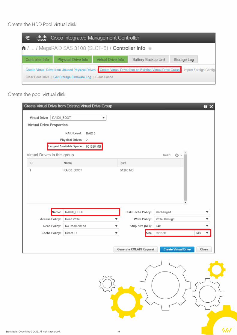
Create the HDD Pool virtual disk
Create the pool virtual disk

StorMagic. Copyright © 2019. All rights reserved. 20
Enable NTP (CIMC menu > Admin > Networking > NTP Setting > Save Changes)
Enable SNMP (CIMC menu > Admin > Communication Services > SNMP > Save Changes)
StorMagic. Copyright © 2019. All rights reserved. 21
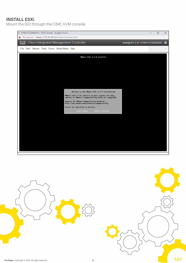
INSTALL ESXiMount the ISO through the CIMC KVM console
StorMagic. Copyright © 2019. All rights reserved. 22
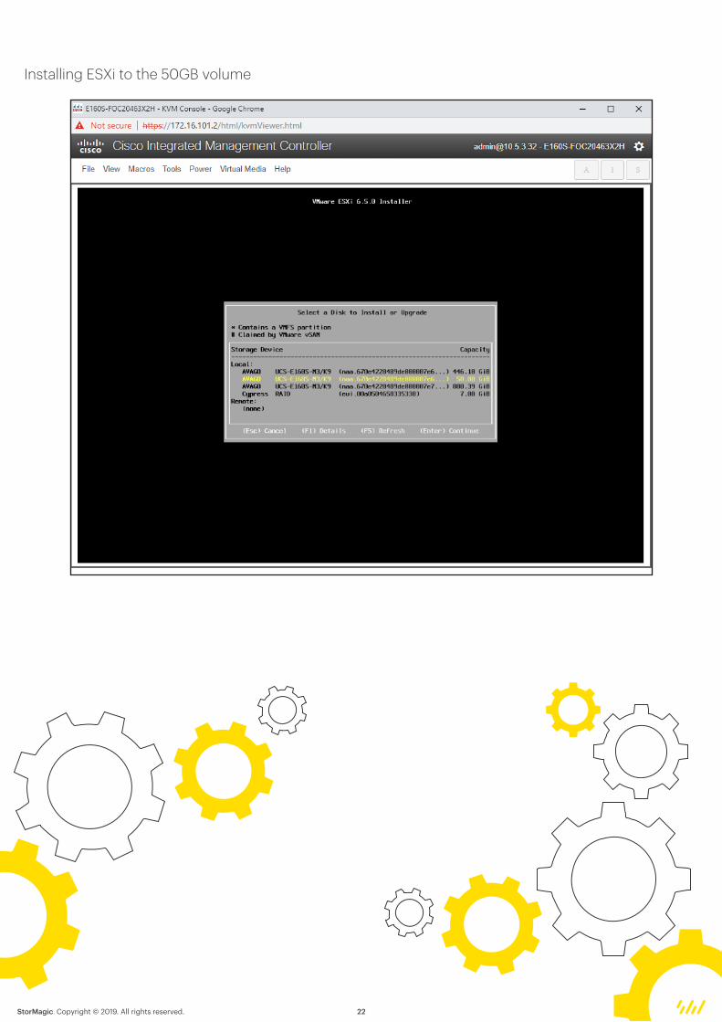
Installing ESXi to the 50GB volume
StorMagic. Copyright © 2019. All rights reserved. 23
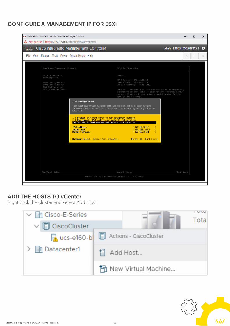
CONFIGURE A MANAGEMENT IP FOR ESXi
ADD THE HOSTS TO vCenterRight click the cluster and select Add Host

StorMagic. Copyright © 2019. All rights reserved. 24
Enter the host details
Ensure both hosts are healthy in the cluster
StorMagic. Copyright © 2019. All rights reserved. 25
SETUP THE STORMAGIC WITNESS
MIRRORING, QUORUM AND HIGH AVAILABILITY
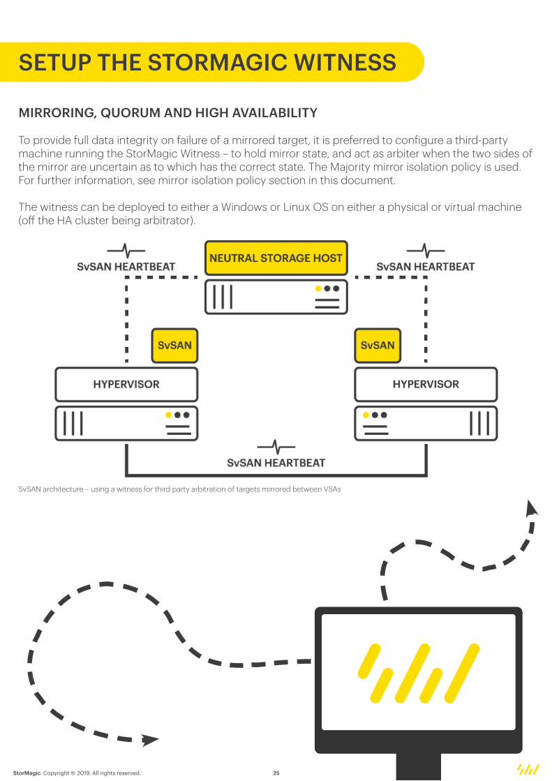
To provide full data integrity on failure of a mirrored target, it is preferred to configure a third-party machine running the StorMagic Witness – to hold mirror state, and act as arbiter when the two sides of the mirror are uncertain as to which has the correct state. The Majority mirror isolation policy is used. For further information, see mirror isolation policy section in this document.
The witness can be deployed to either a Windows or Linux OS on either a physical or virtual machine (off the HA cluster being arbitrator).
SvSAN architecture – using a witness for third party arbitration of targets mirrored between VSAs
StorMagic. Copyright © 2019. All rights reserved. 26
OPTION 1: SETUP WITNESS VM ON ROUTER
Requirements:
ISR running IOS-XE 3.17 or laterAny ISR 4000 series router with at least 8GB DRAM and more Flash, and either mSATA SSD
(4300 series only) or NIM-SSD or NIM-HD 4321 router has only 1 core (4 vcpu) available for service containers All other 4000 series have 3 cores (12 vcpu) available
Copy the StorMagic witness OVA appliance file to the ISR4k router via USB or TFTP
USB
ISR4k#copy usb0:ubuntu.ova bootflash:
TFTP
ISR4k#copy tftp: bootflash:Address or name of remote host []? 10.1.117.100Source filename []? ubuntu.ovaDestination filename [ubuntu.ova]?
Configure the internal virtual port group for the witness VM
ISR4k(config)#interface VirtualPortGroup0ISR4k(config-if)#ip address 172.16.100.1 255.255.255.0ISR4k(config-if)#exit
Configure the service container signing level to unsigned by Cisco
ISR4k(config)#virtual-serviceISR4k(config-virt-serv-global)#signing level unsigned% Support for unsigned packages has been user-enabled. Unsigned packages are not endorsed by Cisco Systems, Inc. User assumes all responsibility
StorMagic. Copyright © 2019. All rights reserved. 27
SvSAN WITNESS APPLIANCE CREDENTIALS
Username: svsan-witness Password: St0rMag1c! Load the svsan-witness service
ISR4k#virtual-service install name svsan witness package bootflash: ubuntu.ova
ISR4K#show virtual-service listSystem busy installing virtual-service 'svsanwitness'. The request may take several minutes...Virtual Service List:
Name Status Package Name------------------------------------------------------------------------------svsanwitness Installing ubuntu.ova
ISR4K#show virtual-service listVirtual Service List:
Name Status Package Name------------------------------------------------------------------------------svsanwitness Installed ubuntu.ova
ISR4K(config-virt-serv)#activate% Activating virtual-service 'svsanwitness', this might take a few minutes. Use 'show virtual-service list' for progress.
ISR4K#show virtual-service listVirtual Service List:
Name Status Package Name------------------------------------------------------------------------------svsanwitness Activated ubuntu.ova
Create the NAT rules for the virtual service
ISR4K(config)#interface virtualportgroup0ISR4K(config)#interface ucse1/0/0ISR4K(config-if)#ip nat outsideISR4K(config)#interface ucse2/0/0ISR4K(config-if)#ip nat outside
StorMagic. Copyright © 2019. All rights reserved. 28
VIRTUAL-SERVICE UBUNTU
ISR4K(config)#virtual-service svsan-witnessISR4K(config-if)#vnic gateway VirtualPortGroup0ISR4K(config)#exitISR4K(config)#activate
ABOUT THE SvSAN WITNESS CISCO ISR OVA IMAGE
The SvSAN Witness Cisco ISR OVA is available at: http://support.stormagic.comThe OVA was built following this service containers tutorial available on Cisco DevNet, under the KVM section.
OPTION 2: INSTALL WITNESS SERVICE ON CISCO NEXUS 9000 SWITCH
Enable guestshell in the switch
Nexus#guestshell enable
Resize the guestshell file system to 2000MB and reboot to apply
Nexus#guestshell resize rootfs 2000Nexus#guestshell reboot
Copy witness rpm package to n9k for example from external scp server. Example:
Nexus#scp userid@scp-server-ip-address: svsan_6-2-37-6855_nsh_x86.rpm.
Install the RPM
Nexus#sudo yum localinstall /root/rpmbuild/RPMS/x86_64/svsan-6-2-37-6855_x86.rpm
Modify StorMagicNSH file in /etc/init.d by adding ip netns exec management command to start option in order to select a VRF capable of communicating to VSA’s. Example:
Nexus#ip netns exec management "$(oem_path init rc)" start
Start the witness service with command
Nexus#sudo /etc/init.d/StorMagic.sh start
StorMagic. Copyright © 2019. All rights reserved. 29
Ensure the witness is started automatically:
Nexus#sudo chkconfig --add StorMagicNSHNexus#sudo chkconfig --level 3 StorMagicNSH
OPTION 3: INSTALL SvSAN PLUGIN TO vCenter (INCLUDING THE WITNESS SERVICE)
Deploy the SvSAN plugin to the vCSA as per the below online documentationwww.stormagic.com/doc/svsan/6-2/en/Content/vCenter-Server-Appliance-plugin-installation.htm
Ensuring to including the witness service
vCSA#./StorMagic.sh --install [email protected] P@ssw0rd --include-nsh
DEPLOY VSAs
The hypervisor utilizes virtual network interfaces to enable VMs to have access to the LAN network external to the host. This will be true for guest VMs as well as SvSAN storage networking.SvSAN uses three different network interface traffic types
TRAFFIC FLAG PURPOSE
Management Used for accessing the VSA web GUI. At least one must be present
iSCSI Listens for incoming connection requests from iSCSI initiators. At least one must be present.
Mirror VSA nodes communicate data and metadata associated with mirrored volumes.This includes synchronous mirroring traffic
Both Switched and Directly connected links are fully supported.
StorMagic. Copyright © 2019. All rights reserved. 30
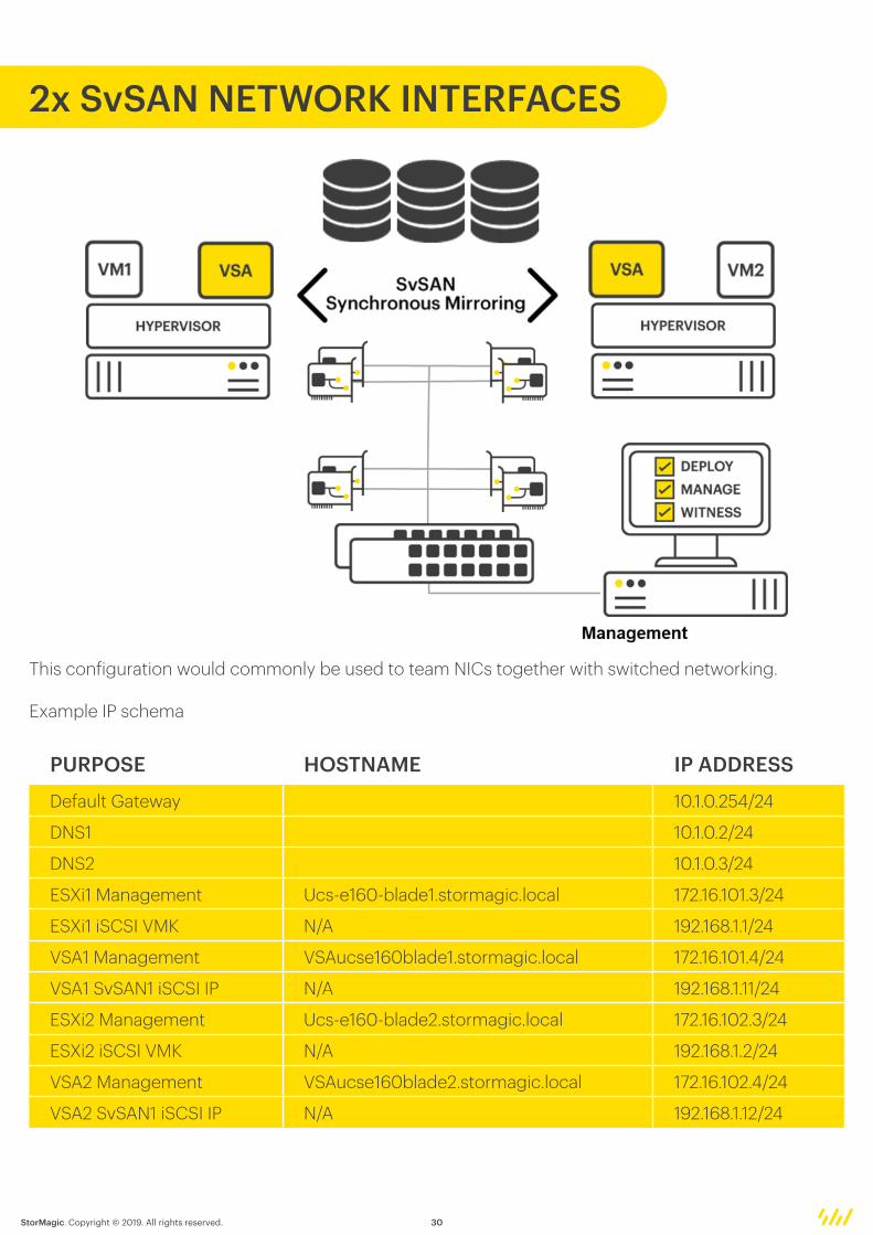
2x SvSAN NETWORK INTERFACES
This configuration would commonly be used to team NICs together with switched networking.
Example IP schema
PURPOSE HOSTNAME IP ADDRESS
Default Gateway 10.1.0.254/24
DNS1 10.1.0.2/24
DNS2 10.1.0.3/24
ESXi1 Management Ucs-e160-blade1.stormagic.local 172.16.101.3/24
ESXi1 iSCSI VMK N/A 192.168.1.1/24
VSA1 Management VSAucse160blade1.stormagic.local 172.16.101.4/24
VSA1 SvSAN1 iSCSI IP N/A 192.168.1.11/24
ESXi2 Management Ucs-e160-blade2.stormagic.local 172.16.102.3/24
ESXi2 iSCSI VMK N/A 192.168.1.2/24
VSA2 Management VSAucse160blade2.stormagic.local 172.16.102.4/24
VSA2 SvSAN1 iSCSI IP N/A 192.168.1.12/24
StorMagic. Copyright © 2019. All rights reserved. 31
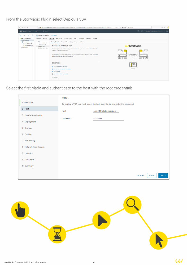
From the StorMagic Plugin select Deploy a VSA
Select the first blade and authenticate to the host with the root credentials

StorMagic. Copyright © 2019. All rights reserved. 32
Accept the license agreement and assign the DNS hostname for the appliance
Select the HDD storage to assign to the appliance
StorMagic. Copyright © 2019. All rights reserved. 33
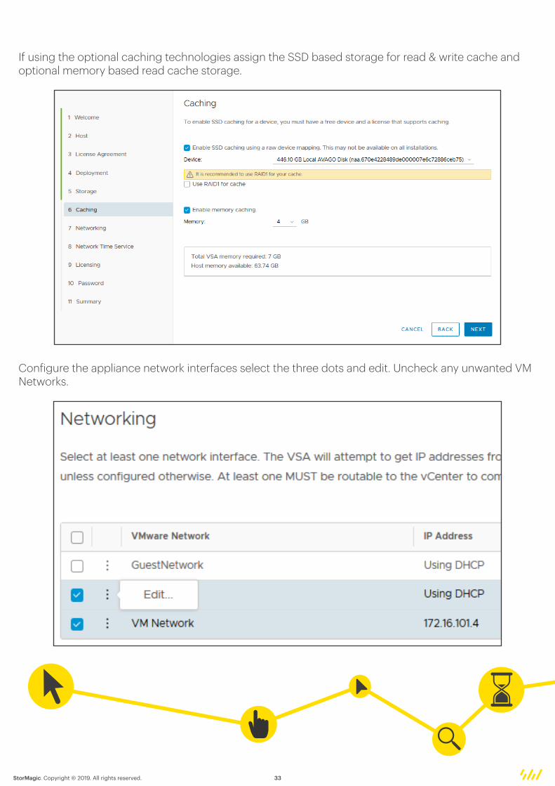
If using the optional caching technologies assign the SSD based storage for read & write cache and optional memory based read cache storage.
Configure the appliance network interfaces select the three dots and edit. Uncheck any unwanted VM Networks.

StorMagic. Copyright © 2019. All rights reserved. 34
Configure the management interface deselecting the iSCSI and mirror flags.
Configure the appliance storage networking interface, on the same IP subnet as the host VMKs to be used for storage.

StorMagic. Copyright © 2019. All rights reserved. 35
Select next and configure an optional, but best practice, NTP server.
Assign the appliance license. This is created after registering the PAK code with Cisco. One key for each appliance.
The appliance will try and route out, automatically, during deployment to https://licensing.stormagic.com to assign the key. If this fails the deployment will complete however the VSA will be unlicensed and need licensing post deployment
If the appliance is in a closed environment offline license files from https://licensing.stormagic.com/license/download

StorMagic. Copyright © 2019. All rights reserved. 36
Assign a VSA admin password
After reviewing the summary select Finish to start the deployment
This will deploy an OVA from the vCenter out the host around ~150MB of data.
The VSA will boot, try and communicate back to the vCenter on the Discovery Service using TCP/UDP 4174 and resolve the DNS hostnames. This Discovery service uses multicast with a static Discovery entry created during deployment.
StorMagic. Copyright © 2019. All rights reserved. 37
If this communication is not successfully established the TaskManager on vCenter will wait on a 20minute timeout, before powering down and deleting the VSA.
The option to ‘Keep VSA on deployment failure’ can be select to forego the removal and troubleshoot networking after deployment.
A Powershell script of the deployment can also be download to run later.
VSA2 DEPLOYMENT
Repeat the above steps to deploy a VSA to the other host select different IPs in the same subnet. See example IP schema previously.
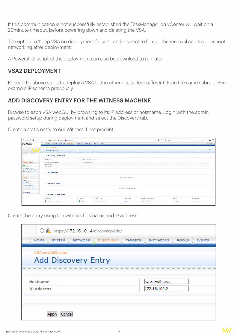
ADD DISCOVERY ENTRY FOR THE WITNESS MACHINE
Browse to each VSA webGUI by browsing to its IP address or hostname. Login with the admin password setup during deployment and select the Discovery tab.
Create a static entry to our Witness if not present.
Create the entry using the witness hostname and IP address

StorMagic. Copyright © 2019. All rights reserved. 38
CREATE MIRRORED STORAGE
Select create a shared datastore
Select the VSAs to create the mirror datastore/s between

StorMagic. Copyright © 2019. All rights reserved. 39
Select the witness to utilize for the mirror quorum.
Enable or disable the optional caching featuresUncached
StorMagic. Copyright © 2019. All rights reserved. 40
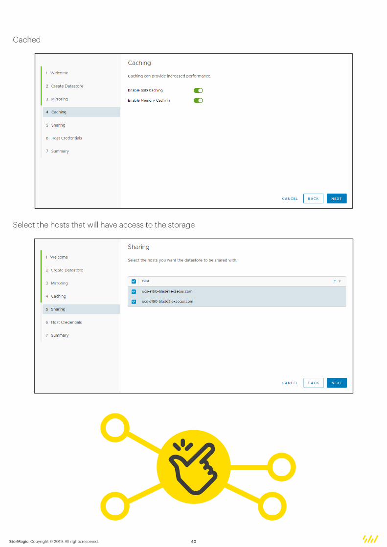
Cached
Select the hosts that will have access to the storage
StorMagic. Copyright © 2019. All rights reserved. 41
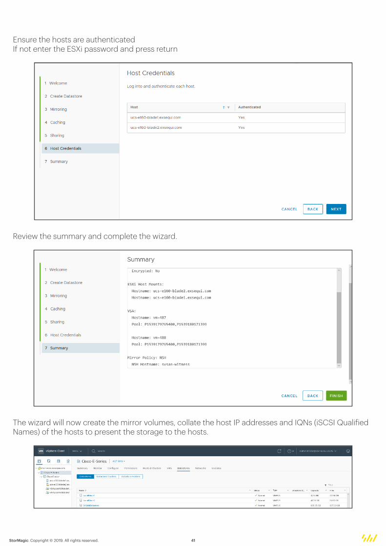
Ensure the hosts are authenticatedIf not enter the ESXi password and press return
Review the summary and complete the wizard.
The wizard will now create the mirror volumes, collate the host IP addresses and IQNs (iSCSI Qualified Names) of the hosts to present the storage to the hosts.

StorMagic. Copyright © 2019. All rights reserved. 42
Once complete the storage will be available to both ESXi hosts however be completing a full synchronization in the background.
HA/DRS
Configure VMware High Availability (HA) as per the desired settings
Configure VMware Distribute Resource Scheduler (DRS) as per the desired settings
NETWORK SPEED TEST
It is possible to ensure the environment is able to achieve the expected network throughput with a speed test utility in the VSA.
StorMagic. Copyright © 2019. All rights reserved. 43
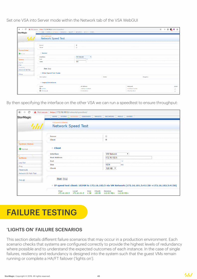
Set one VSA into Server mode within the Network tab of the VSA WebGUI
By then specifying the interface on the other VSA we can run a speedtest to ensure throughput:
FAILURE TESTING
‘LIGHTS ON’ FAILURE SCENARIOS
This section details different failure scenarios that may occur in a production environment. Each scenario checks that systems are configured correctly to provide the highest levels of redundancy where possible and to understand the expected outcomes of each instance. In the case of single failures, resiliency and redundancy is designed into the system such that the guest VMs remain running or complete a HA/FT failover (‘lights on’).
StorMagic. Copyright © 2019. All rights reserved. 44
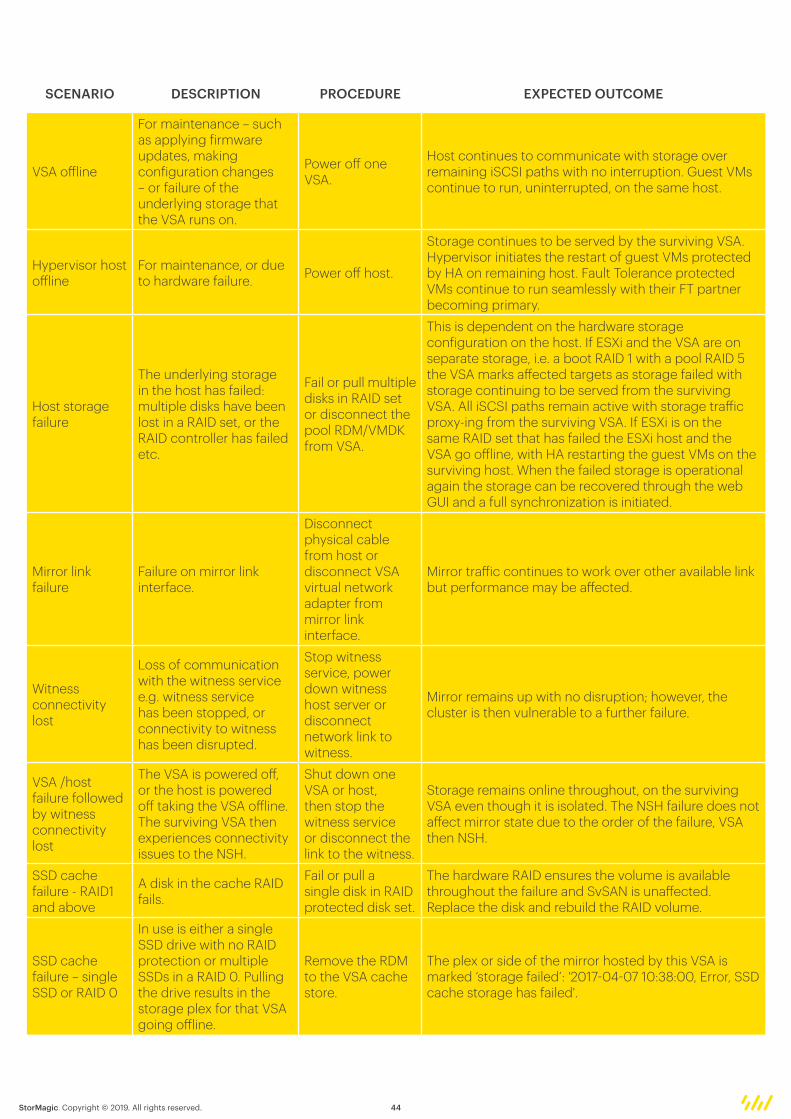
SCENARIO DESCRIPTION PROCEDURE EXPECTED OUTCOME
VSA offline
For maintenance – suchas applying firmwareupdates, makingconfiguration changes – or failure of the underlying storage that the VSA runs on.
Power off one VSA.
Host continues to communicate with storage over remaining iSCSI paths with no interruption. Guest VMs continue to run, uninterrupted, on the same host.
Hypervisor host offline
For maintenance, or due to hardware failure. Power off host.
Storage continues to be served by the surviving VSA. Hypervisor initiates the restart of guest VMs protected by HA on remaining host. Fault Tolerance protected VMs continue to run seamlessly with their FT partner becoming primary.
Host storage failure
The underlying storage in the host has failed: multiple disks have been lost in a RAID set, or the RAID controller has failed etc.
Fail or pull multiple disks in RAID set or disconnect the pool RDM/VMDK from VSA.
This is dependent on the hardware storage configuration on the host. If ESXi and the VSA are on separate storage, i.e. a boot RAID 1 with a pool RAID 5 the VSA marks affected targets as storage failed with storage continuing to be served from the surviving VSA. All iSCSI paths remain active with storage traffic proxy-ing from the surviving VSA. If ESXi is on the same RAID set that has failed the ESXi host and the VSA go offline, with HA restarting the guest VMs on the surviving host. When the failed storage is operational again the storage can be recovered through the web GUI and a full synchronization is initiated.
Mirror link failure
Failure on mirror link interface.
Disconnect physical cable from host or disconnect VSA virtual network adapter from mirror link interface.
Mirror traffic continues to work over other available link but performance may be affected.
Witness connectivity lost
Loss of communication with the witness service e.g. witness service has been stopped, or connectivity to witness has been disrupted.
Stop witness service, power down witness host server or disconnect network link to witness.
Mirror remains up with no disruption; however, the cluster is then vulnerable to a further failure.
VSA /host failure followed by witness connectivity lost
The VSA is powered off, or the host is powered off taking the VSA offline. The surviving VSA then experiences connectivity issues to the NSH.
Shut down one VSA or host, then stop the witness service or disconnect the link to the witness.
Storage remains online throughout, on the surviving VSA even though it is isolated. The NSH failure does not affect mirror state due to the order of the failure, VSA then NSH.
SSD cache failure - RAID1 and above
A disk in the cache RAID fails.
Fail or pull a single disk in RAID protected disk set.
The hardware RAID ensures the volume is available throughout the failure and SvSAN is unaffected. Replace the disk and rebuild the RAID volume.
SSD cache failure – single SSD or RAID 0
In use is either a single SSD drive with no RAID protection or multiple SSDs in a RAID 0. Pulling the drive results in the storage plex for that VSA going offline.
Remove the RDM to the VSA cache store.
The plex or side of the mirror hosted by this VSA is marked ‘storage failed’: '2017-04-07 10:38:00, Error, SSD cache storage has failed'.

StorMagic. Copyright © 2019. All rights reserved. 45
SCENARIO DESCRIPTION PROCEDURE EXPECTED OUTCOME
NSH lost followed by host/VSA failure
The witness service is stopped or communication to the witness disrupted for both VSAs. The environment continues to run uninterrupted. A VSA is then taken offline.
Stop the witness service then power down one VSA.
The surviving VSA is isolated and unable to determine mirror state so consequently takes the storage offline to protect the data. A ‘loss of quorum’ eventis posted: '2017-04-06 01:30:14, Error, Mirrored target 'm0datastore01' was taken offline due to loss of quorum’.
Dual VSA failure
The two VSAs presenting the mirror fail simultaneously or in sequence.
Manually power off both the VSAs.
The hosts lose access to all iSCSI paths to the storage, guest VMs hang and the host experiences an all paths down state. On powering on the VSAs, the datastores automatically establish leadership, start a quick resynchronization, and rescan the hosts to ensure reconnection to the storage and guest VMs respond.
Dual host failure
The two hosts of the VSAs fail simultaneously or in sequence. e.g. an environment power failure.
Force reset or pull power cables of both ESXi hosts.
With both hosts back online the VSAs auto start (due to the HA cluster), the datastores automatically establishleadership, start a quick resynchronization and rescan the hosts to ensure reconnection to the storage. Guest VMs are then started according to cluster settings.
Full network failure with redundancy lost
All network communications are lost simultaneously. Network resiliency is best practice. A real-world scenario might be running all networking through a single switch, in which case neither the hosts nor the VMs will be accessible on the network.
Remove all networking from hosts at the same time.
SvSAN VSAs are unable to establish quorum as they cannot communicate with each other or the witness. Storage istaken offline until network connectivity is returned.
'LIGHTS OFF’ FAILURE SCENARIOS
This section details different failure scenarios that may occur in a production environment. Each scenario checks that systems are configured correctly to provide the highest levels of redundancy where possible and to understand the expected outcomes of each instance. In the case of dual failures, such as both hosts losing power, guest VMs are offline ('lights off')
OFFLINE ONLINE

StorMagic. Copyright © 2019. All rights reserved. 46
ACKNOWLEDGMENTS
A special thanks to the team at Cisco including Mirko Grabel, Shabaz Yousef, Tobias Huelsdau and Lucas Hanson for their assistance in producing the architecture document.
REFERENCES
http://stormagic.com/manual
https://www.cisco.com/c/en/us/products/routers/4000-series-integrated-services-routers-isr/index.html
https://www.cisco.com/c/en/us/products/servers-unified-computing/ucs-e-series-servers/index.html
https://www.vmware.com/products/vsphere.html
https://www.cisco.com/c/en/us/td/docs/routers/asr9000/software/asr9k_r5-3/interfaces/configuration/guide2/b-interfaces-cg53x-asr9k/Configuring_Virtual_Services.pdf