cisco aironet 1562 e/i/d/ps, 2802 e/i and 3802 e/i/p ... · ... (hw: 1562e) cisco aironet ... 1.3...
TRANSCRIPT

© Copyright 2017 Cisco Systems, Inc. This document may be freely reproduced and distributed whole and intact including this Copyright Notice.
1
Cisco Aironet 1562 e/i/d/ps, 2802 e/i and 3802 e/i/p Wireless LAN Access Points
FIPS 140-2 Non Proprietary Security Policy Level 2 Validation
Version 0.1
April 18, 2017

© Copyright 2017 Cisco Systems, Inc. This document may be freely reproduced and distributed whole and intact including this Copyright Notice.
2
Table of Contents
1 INTRODUCTION .................................................................................................................. 3
1.1 PURPOSE ............................................................................................................................. 3 1.2 MODELS ............................................................................................................................. 3 1.3 MODULE VALIDATION LEVEL ............................................................................................ 3 1.4 REFERENCES ....................................................................................................................... 4 1.5 TERMINOLOGY ................................................................................................................... 4
1.6 DOCUMENT ORGANIZATION ............................................................................................... 4
2 CISCO AIRONET 1562 E/I/D/PS, 2802 E/I AND 3802 E/I/P WIRELESS LAN
ACCESS POINTS ......................................................................................................................... 5
2.1 CRYPTOGRAPHIC MODULE PHYSICAL CHARACTERISTICS .................................................. 5 2.2 MODULE INTERFACES ......................................................................................................... 5 2.3 ROLES AND SERVICES ....................................................................................................... 18 2.4 UNAUTHENTICATED SERVICES ......................................................................................... 20
2.5 PHYSICAL SECURITY......................................................................................................... 20 2.6 CRYPTOGRAPHIC ALGORITHMS ........................................................................................ 30
2.7 CRYPTOGRAPHIC KEY MANAGEMENT .............................................................................. 31 2.8 SELF-TESTS ...................................................................................................................... 35
3 SECURE OPERATION OF THE CISCO AIRONET ACCESS POINTS .................... 36

© Copyright 2017 Cisco Systems, Inc. This document may be freely reproduced and distributed whole and intact including this Copyright Notice.
3
1 Introduction
1.1 Purpose
This is a non-proprietary Cryptographic Module Security Policy for the Cisco Aironet 1562
e/i/d/ps, 2802 e/I and 3802 e/i/p Wireless LAN Access Points, Firmware version 8.3 referred to
in this document as Access Points (APs). This security policy describes how the modules meet
the security requirements of FIPS 140-2 Level 2 and may be freely distributed.
1.2 Models
Cisco Aironet 1562e Access Point with (HW: 1562e)
Cisco Aironet 1562i Access Point with (HW: 1562i)
Cisco Aironet 1562d Access Point with (HW: 1562d)
Cisco Aironet 1562ps Access Point with (HW: 1562ps)
Cisco Aironet 2802e Access Point with (HW: 2802e)
Cisco Aironet 2802i Access Point with (HW: 2802i)
Cisco Aironet 3802e Access Point (HW: 3802e)
Cisco Aironet 3802i Access Point (HW: 3802i)
Cisco Aironet 3802p Access Point (HW: 3802p)
FIPS 140-2 (Federal Information Processing Standards Publication 140-2 — Security
Requirements for Cryptographic Modules) details the U.S. Government requirements for
cryptographic modules. More information about the FIPS 140-2 standard and validation program
is available on the NIST website at http://csrc.nist.gov/groups/STM/index.html.
1.3 Module Validation Level
The following table lists the level of validation for each area in the FIPS PUB 140-2.
No. Area Title Level
1 Cryptographic Module Specification 2
2 Cryptographic Module Ports and Interfaces 2
3 Roles, Services, and Authentication 2
4 Finite State Model 2
5 Physical Security 2
6 Operational Environment N/A
7 Cryptographic Key management 2
8 Electromagnetic Interface/Electromagnetic Compatibility 2
9 Self-Tests 2
10 Design Assurance 2
11 Mitigation of Other Attacks N/A
Overall Overall module validation level 2
Module Validation Level

© Copyright 2017 Cisco Systems, Inc. This document may be freely reproduced and distributed whole and intact including this Copyright Notice.
4
1.4 References
This document deals only with operations and capabilities of the Cisco Aironet 1562 e/i/d/ps,
2802 e/i and 3802 e/i/p Wireless LAN Access Points cryptographic module security policy.
More information is available on the routers from the following sources:
For answers to technical or sales related questions please refer to the contacts listed on the Cisco
Systems website at www.cisco.com.
The NIST Validated Modules website (http://csrc.nist.gov/groups/STM/cmvp/validation.html)
contains contact information for answers to technical or sales-related questions for the module.
1.5 Terminology
In this document, the Cisco Aironet 1562 e/i/d/ps, 2802 e/i and 3802 e/i/p Wireless LAN Access
Points are referred to as access points, APs or the modules.
1.6 Document Organization
The Security Policy document is part of the FIPS 140-2 Submission Package. In addition to this
document, the Submission Package contains:
Vendor Evidence document
Finite State Machine
Other supporting documentation as additional references
This document provides an overview of the Cisco Aironet 1562 e/i/d/ps, 2802 e/i and 3802 e/i/p
Wireless LAN Access Points and explains the secure configuration and operation of the module.
This introduction section is followed by Section 2, which details the general features and
functionality of the appliances. Section 3 specifically addresses the required configuration for
secure operation.
With the exception of this Non-Proprietary Security Policy, the FIPS 140-2 Validation
Submission Documentation is Cisco-proprietary and is releasable only under appropriate non-
disclosure agreements. For access to these documents, please contact Cisco Systems.

© Copyright 2017 Cisco Systems, Inc. This document may be freely reproduced and distributed whole and intact including this Copyright Notice.
5
2 Cisco Aironet 1562 e/i/d/ps, 2802 e/i and 3802 e/i/p Wireless LAN Access
Points
The Cisco Aironet 1560, 2800 and 3800 Series Access Points are highly versatile and deliver the
most functionality of any access points in the industry. For organizations paving the way for the
new 802.11ac Wave 2 standard, the Cisco Aironet 1560, 2800 and 3800 Series are the perfect
solution. The access points go beyond getting ready for the new standard, providing the ultimate
in flexibility and versatility.
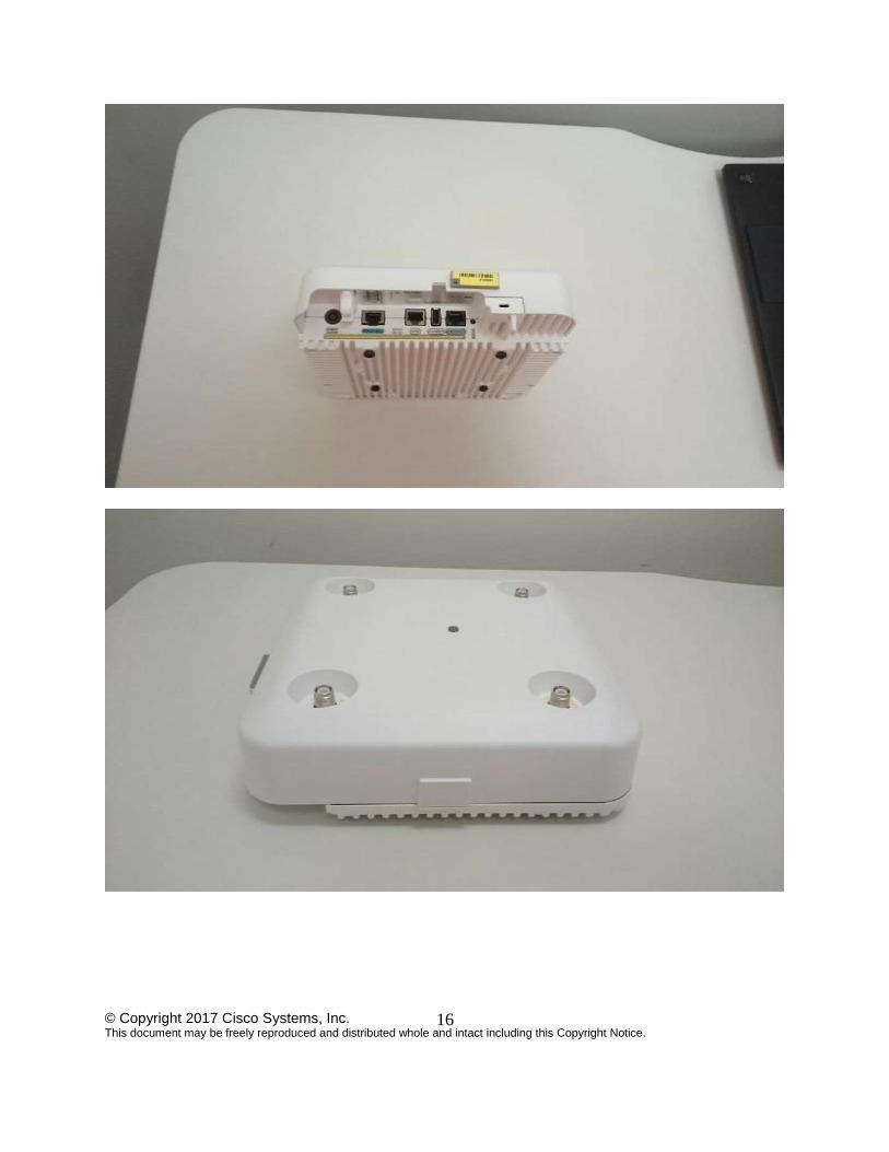
2.1 Cryptographic Module Physical Characteristics
Each access point is a multi-chip standalone security appliance, and the cryptographic boundary
is defined as encompassing the “top,” “front,” “left,” “right,” and “bottom” surfaces of the case.
2.2 Module Interfaces
The module provides a number of physical and logical interfaces to the device, and the physical
interfaces provided by the module are mapped to the following FIPS 140-2 defined logical
interfaces: data input, data output, control input, status output, and power. The logical interfaces
and their mapping are described in the following tables:
Router Physical Interface FIPS 140-2 Logical
Interface Radio Antennas Data Input Interface
Radio Antennas Data Output Interface
Radio Antennas, Ethernet ports Control Input Interface
Radio Antennas, LEDs, Ethernet ports Status Output Interface
Power plug and PoE port Power Interface
Module Physical Interface/Logical Interface Mapping

© Copyright 2017 Cisco Systems, Inc. This document may be freely reproduced and distributed whole and intact including this Copyright Notice.
6
© Copyright 2017 Cisco Systems, Inc. This document may be freely reproduced and distributed whole and intact including this Copyright Notice.
7
© Copyright 2017 Cisco Systems, Inc. This document may be freely reproduced and distributed whole and intact including this Copyright Notice.
8
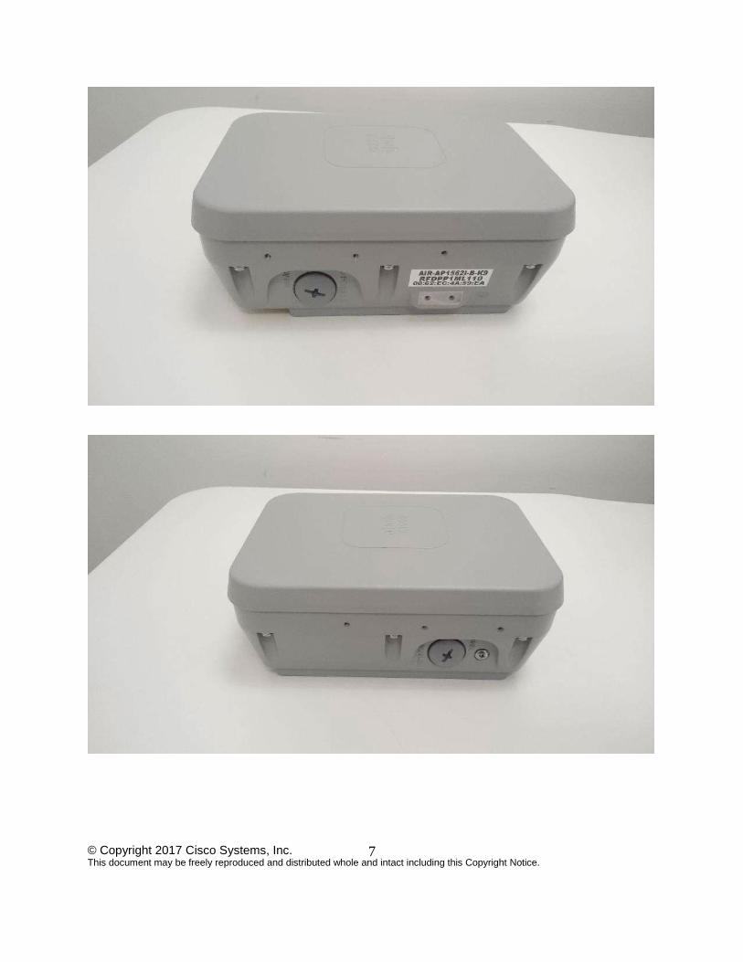
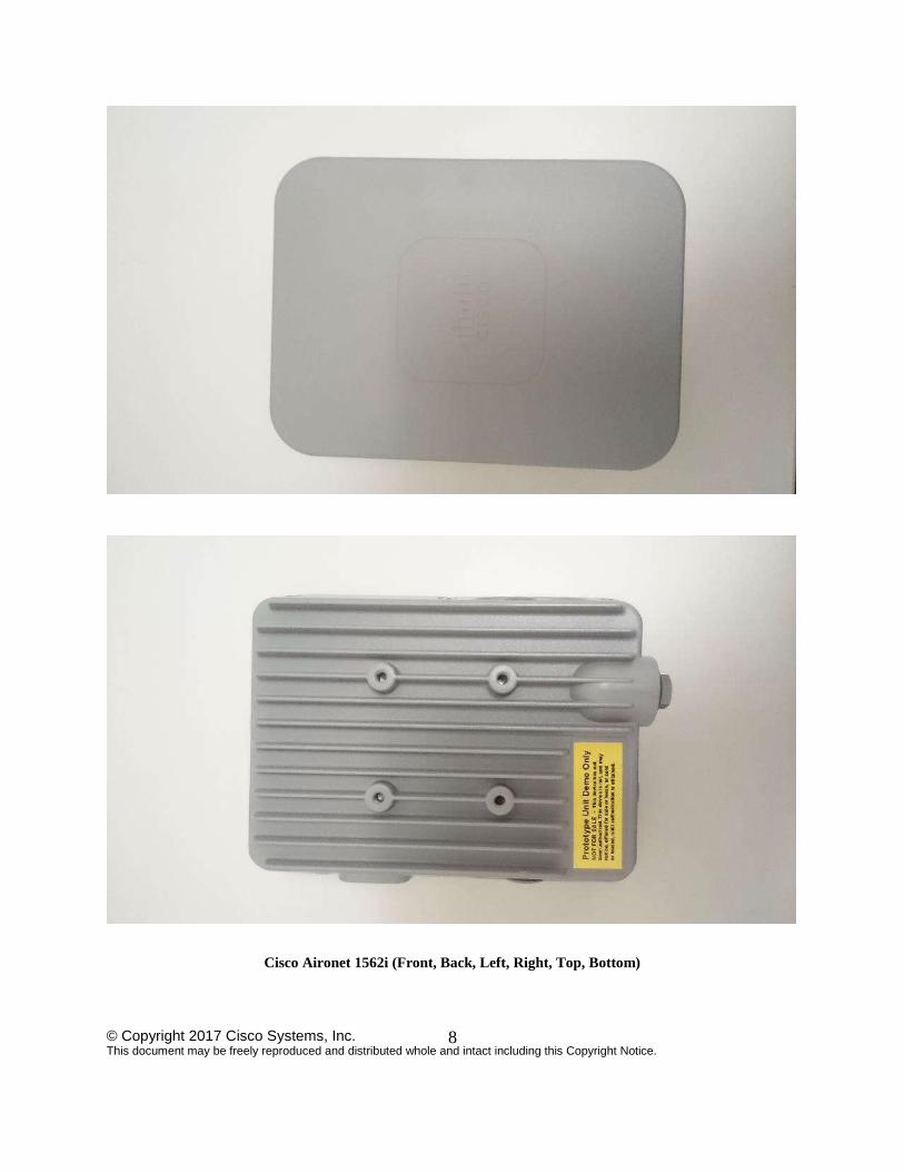
Cisco Aironet 1562i (Front, Back, Left, Right, Top, Bottom)

© Copyright 2017 Cisco Systems, Inc. This document may be freely reproduced and distributed whole and intact including this Copyright Notice.
9
© Copyright 2017 Cisco Systems, Inc. This document may be freely reproduced and distributed whole and intact including this Copyright Notice.
10

© Copyright 2017 Cisco Systems, Inc. This document may be freely reproduced and distributed whole and intact including this Copyright Notice.
11
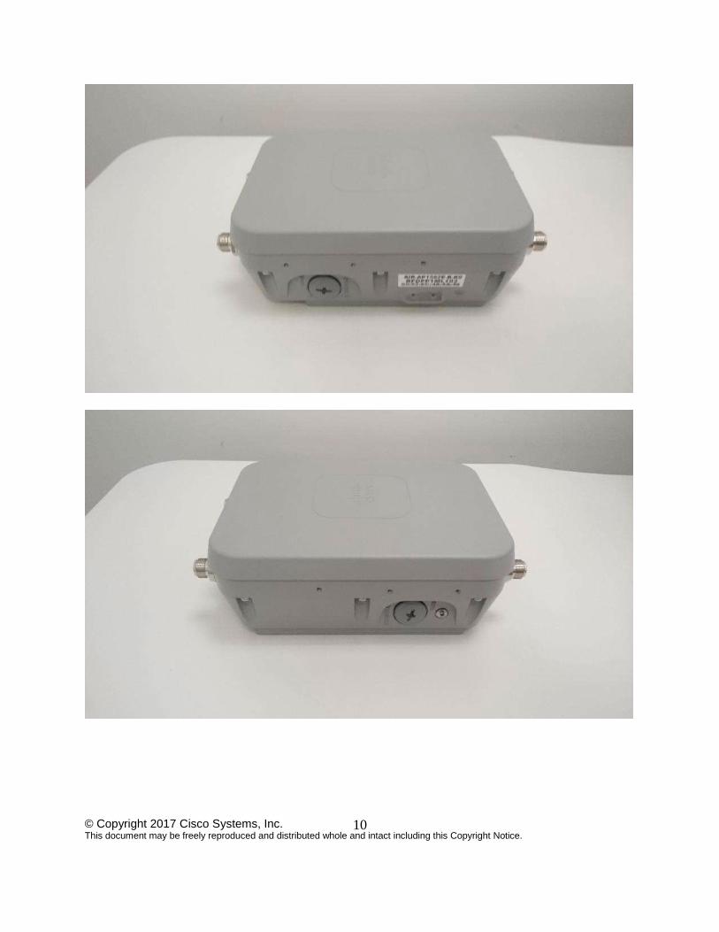
Cisco Aironet 1562e/d/ps (Front, Back, Left, Right, Top, Bottom)
© Copyright 2017 Cisco Systems, Inc. This document may be freely reproduced and distributed whole and intact including this Copyright Notice.
12

© Copyright 2017 Cisco Systems, Inc. This document may be freely reproduced and distributed whole and intact including this Copyright Notice.
13
© Copyright 2017 Cisco Systems, Inc. This document may be freely reproduced and distributed whole and intact including this Copyright Notice.
14
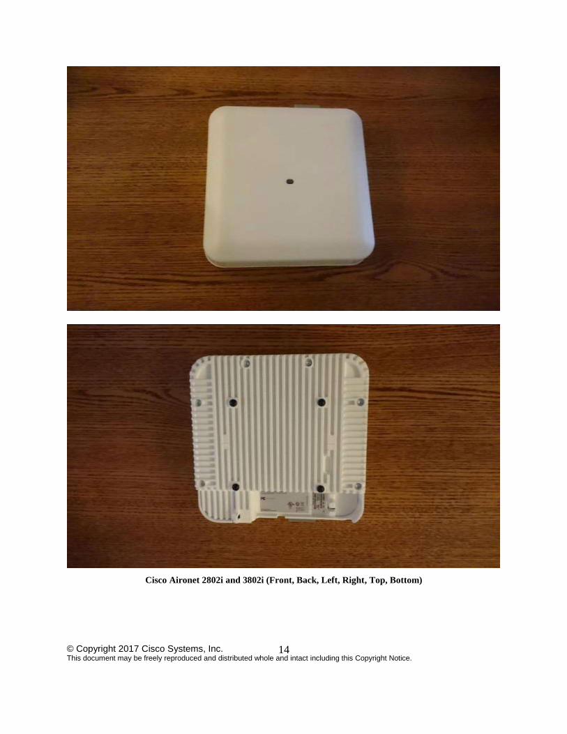
Cisco Aironet 2802i and 3802i (Front, Back, Left, Right, Top, Bottom)

© Copyright 2017 Cisco Systems, Inc. This document may be freely reproduced and distributed whole and intact including this Copyright Notice.
15
© Copyright 2017 Cisco Systems, Inc. This document may be freely reproduced and distributed whole and intact including this Copyright Notice.
16

© Copyright 2017 Cisco Systems, Inc. This document may be freely reproduced and distributed whole and intact including this Copyright Notice.
17

© Copyright 2017 Cisco Systems, Inc. This document may be freely reproduced and distributed whole and intact including this Copyright Notice.
18
Cisco Aironet 2802e and 3802e (Front, Back, Left, Right, Top, Bottom)
2.3 Roles and Services
The module supports the roles of Crypto Officer and User. The CO role is fulfilled by the
wireless LAN controller on the network that the module communicates with, and performs
routine management and configuration services, including loading session keys and zeroization
of the module. The User role is fulfilled by wireless clients. The module does not support a
maintenance role.
CO Authentication
The Crypto Officer (Wireless LAN Controller) authenticates to the module through the
CAPWAP protocol, using an RSA key pair with 2048 bits modulus, which has an equivalent
symmetric key strength of 112 bits. An attacker would have a 1 in 2^112 chance of randomly
obtaining the key, which is much stronger than the one in a million chance required by FIPS 140-
2. To exceed a one in 100,000 probability of a successful random key guess in one minute, an
attacker would have to be capable of approximately 5.2x10^33 attempts per minute, which far
exceeds the operational capabilities of the modules to support.
© Copyright 2017 Cisco Systems, Inc. This document may be freely reproduced and distributed whole and intact including this Copyright Notice.
19
User Authentication
The module performs mutual authentication with a wireless client through EAP-TLS or EAP-
FAST protocols. EAP-FAST is based on EAP-TLS and uses EAP-TLS key pair and certificates.
The RSA key pair for the EAP-TLS credentials has modulus size of 2048 bits, thus providing
112 bits of strength. Assuming the low end of that range, an attacker would have a 1 in 2^112
chance of randomly obtaining the key, which is much stronger than the one in a million chance
required by FIPS 140-2. To exceed a one in 100,000 probability of a successful random key
guess in one minute, an attacker would have to be capable of approximately 5.2x10^33 attempts
per minute, which far exceeds the operational capabilities of the modules to support.
Please notice that RSA used in CO role (RSA 2048 bits) or User role (RSA 2048 bits)
authentication above only performs RSA signature verification. More information can be
obtained in section 2.6 in this document.
User Services
The services available to the User role consist of the following:
Services &
Access
Description Keys & CSPs
Run Network
Functions
MFP
Validating one AP with a neighboring
AP's management frames using
infrastructure MFP
Encrypt and sign management frames
between AP and wireless client using
client MFP CCKM
Establishment and subsequent data
transfer of a CCKM session for use
between the wireless client and the AP.
802.11
Establishment and subsequent data
transfer of an 802.11 session for use
between the wireless client and the AP.
802.11 Pairwise Transient Key (PTK),
802.11 Group Temporal Key (GTK),
802.11 Key Confirmation Key (KCK)
802.11 Key Encryption Key (KEK),
802.11 Pairwise Transient Key (PTK) –
(w, d)
User Services
Crypto Officer Services
The Crypto Officer services consist of the following:
Services & Access Description Keys & CSPs Configure the AP
Configure the AP based on the steps detailed
in section 3 (Secure Operation of the Cisco
Aironet Access Points) of this document.
N/A
View Status Functions
View the configuration, routing tables, active
sessions, memory status, packet statistics,
N/A
© Copyright 2017 Cisco Systems, Inc. This document may be freely reproduced and distributed whole and intact including this Copyright Notice.
20
review accounting logs, and view physical
interface status.
Manage the AP
Log off users, view complete configurations,
view full status, manage user access, and
restore configurations.
N/A
Perform Self-Tests
Execute Known Answer Test on Algorithms
within the cryptographic module.
N/A
DTLS Data Encrypt Enabling DTLS data path encryption between
controller and AP.
DTLS Pre-Master Secret, DTLS
Master Secret, DTLS Encryption
Key (CAPWAP session key),
DTLS Integrity Key, DTLS
ECDSA private key, Infrastructure
MFP MIC Key – (w, d)
SSH Establishment and subsequent data transfer of a
SSH session SSH encryption key, SSH integrity
key, SSH ECDSA private key – (w,
d)
Configure 802.11 Establishment and subsequent data transfer of
an 802.11 session for use between the client
and the access point.
802.11 Pairwise Transient Key
(PTK), 802.11 Group Temporal
Key (GTK), 802.11 Key
Confirmation Key (KCK)
802.11 Key Encryption Key (KEK),
802.11 Pairwise Transient Key
(PTK) – (w, d)
Zeroization Zeroize CSPs and cryptographic keys by
calling ‘switchconfig key-zeroize controller’
command or cycling power (shutdown and
reload) to zeroize all cryptographic keys
stored in SDRAM. The CSPs (Cisco Mfg CA
publc key and Cisco root CA public key)
stored in Flash can be zeroized by overwriting
with a new value.
All Keys and CSPs will be destroyed
Crypto Officer Services (w = write, d = delete)
2.4 Unauthenticated Services
An unauthenticated operator may observe the System Status by viewing the LEDs on the
module, which show network activity and overall operational status. A solid green LED indicates
normal operation and the successful completion of self-tests. The module does not support a
bypass capability.
2.5 Physical Security
This section describes placement of tamper-evident labels on the module. Labels must be placed
on the device(s) and maintained by the Crypto Officer in order to operate in a FIPS approved
state.
The APs (Access Points) are required to have Tamper Evident Labels (TELs) applied in order to
meet the FIPS requirements. Specifically, AIRLAP-FIPSKIT=, VERSION B0 contains the
necessary TELs required for the AP. The CO on premise is responsible for securing and having

© Copyright 2017 Cisco Systems, Inc. This document may be freely reproduced and distributed whole and intact including this Copyright Notice.
21
control at all times of any unused tamper evident labels. Below are the instructions to TEL
placement on the AP’s.

© Copyright 2017 Cisco Systems, Inc. This document may be freely reproduced and distributed whole and intact including this Copyright Notice.
22
1
2

© Copyright 2017 Cisco Systems, Inc. This document may be freely reproduced and distributed whole and intact including this Copyright Notice.
23
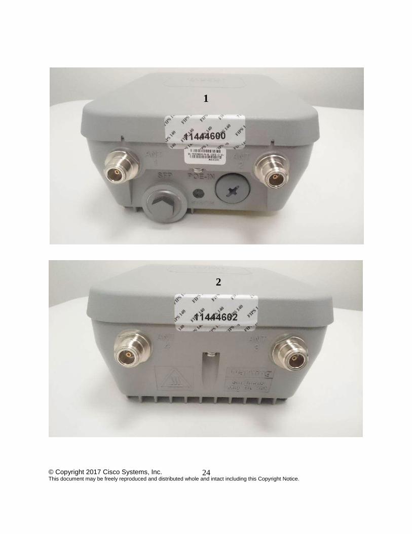
Cisco Aironet 1562i tamper label placement (Front, Back, Left, Right)
3
4
5
© Copyright 2017 Cisco Systems, Inc. This document may be freely reproduced and distributed whole and intact including this Copyright Notice.
24
1
2

© Copyright 2017 Cisco Systems, Inc. This document may be freely reproduced and distributed whole and intact including this Copyright Notice.
25
Cisco Aironet 1562e/d/ps tamper label placement (Front, Back, Left, Right)
3
4
5

© Copyright 2017 Cisco Systems, Inc. This document may be freely reproduced and distributed whole and intact including this Copyright Notice.
26
1
2

© Copyright 2017 Cisco Systems, Inc. This document may be freely reproduced and distributed whole and intact including this Copyright Notice.
27
Cisco Aironet 2802i and 3802i tamper label placement (Front, Back, Left, Right)
3
4

© Copyright 2017 Cisco Systems, Inc. This document may be freely reproduced and distributed whole and intact including this Copyright Notice.
28
1
2

© Copyright 2017 Cisco Systems, Inc. This document may be freely reproduced and distributed whole and intact including this Copyright Notice.
29
Cisco Aironet 2802e and 3802e tamper label placement (Front, Back, Left, Right)
3
4

© Copyright 2017 Cisco Systems, Inc. This document may be freely reproduced and distributed whole and intact including this Copyright Notice.
30
The tamper evident seals are produced from a special thin gauge vinyl with self-adhesive backing. Any
attempt to open the device will damage the tamper evident seals or the material of the security appliance
cover. Because the tamper evident seals have non-repeated serial numbers, they may be inspected for
damage and compared against the applied serial numbers to verify that the security appliance has not been
tampered with. Tamper evident seals can also be inspected for signs of tampering, which include the
following: curled corners, rips, and slices. The word “OPEN” may appear if the label was peeled back.
The crypto officer is required to regularly check for any evidence of tampering. If evidence of tampering
is found with the TELs, the module must immediately be powered down and all administrators must be
made aware of a physical security breach. NOTE: Any unused TELs must be securely stored, accounted for, and maintained by the CO in a
protected location.
2.6 Cryptographic Algorithms
Approved Cryptographic Algorithms
The table below details the FIPS approved algorithms from each algorithm implementation
Approved Cryptographic Algorithms
KTS (AES Cert. #4409; key wrapping; key establishment methodology provides 128 and
256 bits of encryption strength)
Non-Approved but Allowed Cryptographic Algorithms
The module supports the following non-approved, but allowed cryptographic algorithms:
Diffie-Hellman (key agreement; key establishment methodology provides 112 bits of
encryption strength)
EC Diffie-Hellman (CVL Cert. #1116, key agreement; key establishment methodology
provides 128 and 192 bits of encryption strength)
MD5 (MD5 is allowed for use in DTLS)
Cisco FOM u-boot GCM 88W8964C 88F6920
AES #4409 N/A #4340 #4114 #4367
SHA #3635 #3576 N/A N/A #3604
HMAC SHA #2931 N/A N/A N/A #2906
DRBG #1422 N/A N/A N/A N/A
RSA #2396 #2344 N/A N/A N/A
ECDSA #1061 N/A N/A N/A N/A
CVL (SP800-
135)
#1115 N/A N/A N/A N/A
CVL (SP800-
56A)
#1116 N/A N/A N/A N/A
KBKDF
(SP800-108)
#126 N/A N/A N/A N/A

© Copyright 2017 Cisco Systems, Inc. This document may be freely reproduced and distributed whole and intact including this Copyright Notice.
31
NDRNG
Note:
The KDF (key derivation function) used in SSH and TLS protocol was certified by
CAVP with CVL Cert. #1115.
SSH and TLS protocols have not been reviewed or tested by the CAVP and CMVP.
Please refer IG D.11, bullet 2 for more information.
Note that the TLS KDF CVL cert is only listed because the module supports DTLS
2.7 Cryptographic Key Management
Cryptographic keys are stored in either Flash or in SDRAM for active keys.
The DTLS Pre-Master Secret is generated in the AP using the approved DRBG. The DTLS Pre-
Master Secret is used to derive the DTLS Encryption and Integrity Key. All other keys are input
into the module from the controller encrypted over a CAPWAP session. During a CAPWAP
session, the APs first authenticate to the Wireless LAN controller. All traffic between the AP and
the controller is encrypted in the DTLS tunnel. Keys such as the 802.11, CCKM and MFP keys
are input into the module encrypted with the DTLS session key over the CAPWAP session. Key
generation and seeds for asymmetric key generation is performed as per SP 800-133 Scenario 1.
The APs rely on the embedded ACT2Lite module (Certificate #2125) for entropy output for use
by the SP 800-90A DRBG and secure storage of the SUDI RSA2 and ECC CA certificates used
for DTLS authentication. The module does not output any plaintext cryptographic keys.
Key/CSP Name Algorithm Description Storage Zeroization
General Keys/CSPs DRBG entropy input SP 800-90A
CTR_DRBG
256 bit. HW based
entropy source output
used to construct seed
SDRAM (plaintext) ‘switchconfig
key-zeroize
controller’
command or
Power cycle
DRBG seed SP 800-90A
CTR_DRBG
384-bits. Input to the
DRBG that determines
the internal state of the
DRBG. Generated using
DRBG derivation
function that includes the
entropy input from
hardware-based entropy
source.
SDRAM (plaintext) ‘switchconfig
key-zeroize
controller’
command or
Power cycle
DRBG V SP 800-90A
CTR_DRBG
The DRBG V is one of
the critical values of the
internal state upon which
the security of this
DRBG mechanism
depends. Generated
during DRBG
SDRAM (plain text) ‘switchconfig
key-zeroize
controller’
command or
Power cycle

© Copyright 2017 Cisco Systems, Inc. This document may be freely reproduced and distributed whole and intact including this Copyright Notice.
32
Key/CSP Name Algorithm Description Storage Zeroization
instantiation and then
subsequently updated
using the DRBG update
function.
DRBG Key SP 800-90A
CTR_DRBG
256-bits DRBG key used
for SP 800-90A
CTR_DRBG. Established per SP 800-
90A CTR_DRBG
SDRAM (plaintext) ‘switchconfig
key-zeroize
controller’
command or
Power cycle
Diffie-Hellman public key Diffie-
Hellman
(Group 14)
2048 bits DH public key
used in Diffie-Hellman
(DH) exchange. This key
is derived per the Diffie-
Hellman key agreement.
SDRAM (plaintext) ‘switchconfig
key-zeroize
controller’
command or
Power cycle
Diffie-Hellman private key Diffie-
Hellman
(Group 14)
224 bits DH private key
used in Diffie-Hellman
(DH) exchange.
Generated by calling the
SP 800-90A CTR-
DRBG.
SDRAM (plaintext) ‘switchconfig
key-zeroize
controller’
command or
Power cycle
Diffie-Hellman shared secret Diffie-
Hellman
(Group 14)
2048 bits DH shared
secret derived in Diffie-
Hellman (DH) exchange.
SDRAM (plaintext) ‘switchconfig
key-zeroize
controller’
command or
Power cycle
EC Diffie-Hellman public key Diffie-
Hellman
(Groups 19
and 20)
P-256 and P-384 public
key used in EC Diffie-
Hellman exchange. This
key is derived per the
Diffie-Hellman key
agreement.
SDRAM (plaintext) ‘switchconfig
key-zeroize
controller’
command or
Power cycle
EC Diffie-Hellman private key Diffie-
Hellman
(Groups 19
and 20)
P-256 and P-384 private
key used in EC Diffie-
Hellman exchange.
Generated by calling the
SP 800-90A CTR-
DRBG.
SDRAM (plaintext) ‘switchconfig
key-zeroize
controller’
command or
Power cycle
EC Diffie-Hellman shared
secret
Diffie-
Hellman
(Groups 19
and 20)
P-256 and P-384 shared
secret derived in EC
Diffie-Hellman exchange
SDRAM (plaintext) ‘switchconfig
key-zeroize
controller’
command or
Power cycle
Cisco Mfg CA public key rsa-pkcs1-
sha2
Public Key used with
CAPWAP to
authenticate the AP. This
is the RSA public key
used for signature
verification. This key is
loaded into the module at
manufacturing.
Flash (plain text) Overwrite
with new
public key
Cisco Root CA public key rsa-pkcs1-
sha2
Public Key used with
CAPWAP to
authenticate the AP This
is the RSA public key
used for signature
verification. This key is
Flash (plain text) Overwrite
with new
public key

© Copyright 2017 Cisco Systems, Inc. This document may be freely reproduced and distributed whole and intact including this Copyright Notice.
33
Key/CSP Name Algorithm Description Storage Zeroization
loaded into the module at
manufacturing.
DTLS
DTLS Pre-Master Secret Shared Secret Computed as specified in
SP 800-135 section 4.2
SDRAM (plain text) ‘switchconfig
key-zeroize
controller’
command or
Power cycle
DTLS Master Secret Shared Secret Derived from DTLS Pre-
Master Secret. Used to
derive DTLS encryption
key and DTLS integrity
key.
SDRAM (plain text) ‘switchconfig
key-zeroize
controller’
command or
Power cycle
DTLS Encryption Key
(CAPWAP session key)
AES-CBC,
AES-GCM
128 and 256 bit DTLS
session Key used to
protect CAPWAP
control messages. It is
derived from DTLS
Master Secret via key
derivation function
defined in SP800-135
(TLS).
SDRAM (plain text)
‘switchconfig
key-zeroize
controller’
command or
Power cycle
DTLS Integrity Key HMAC-
SHA1,
HMAC-
SHA256,
HMAC-
SHA384
Session key used for
integrity checks on
CAPWAP control
messages. It is derived
from DTLS Master
Secret via key derivation
function defined in
SP800-135 (TLS).
SDRAM (plain text) ‘switchconfig
key-zeroize
controller’
command or
Power cycle
DTLS ECDSA private key ECDSA P-256 and P-384
generated by calling the
SP 800-90A CTR-
DRBG.
SDRAM (plaintext) ‘switchconfig
key-zeroize
controller’
command or
Power cycle
Infrastructure MFP MIC Key AES-CMAC,
AES-GMAC
This 128 and 256-bit
AES key is generated in
the controller using
approved DRBG. This
key is sent to the AP
encrypted with the DTLS
encryption key. This key
is used by the AP to sign
management frames
when infrastructure MFP
is enabled.
SDRAM (plain text) ‘switchconfig
key-zeroize
controller’
command or
Power cycle
SSHv2

© Copyright 2017 Cisco Systems, Inc. This document may be freely reproduced and distributed whole and intact including this Copyright Notice.
34
Key/CSP Name Algorithm Description Storage Zeroization
SSH Encryption Key AES-CBC,
AES-GCM
Symmetric AES key for
encrypting SSH.
SDRAM ‘switchconfig
key-zeroize
controller’
command or
Power cycle
SSH Integrity Key HMAC Used for SSH integrity
protection.
SDRAM ‘switchconfig
key-zeroize
controller’
command or
Power cycle
SSH ECDSA Private Key ECDSA P-256 and P-384
generated by calling the
SP 800-90A CTR-
DRBG.
SDRAM ‘switchconfig
key-zeroize
controller’
command or
Power cycle
802.11
802.11 Pairwise Transient Key
(PTK)
AES-CCM,
AES-GCM
The PTK is the 128 or
256 bit 802.11 session
key for unicast
communications. This
key is generated in the
WLAN controller
(outside the
cryptographic boundary)
and is transported into
the module encrypted by
DTLS Encryption Key.
SDRAM (plain text) ‘switchconfig
key-zeroize
controller’
command or
Power cycle
802.11 Group Temporal Key
(GTK)
AES-CCM,
AES-GCM
The GTK is the 128 or
256 bit 802.11 session
key for broadcast
communications. This
key is generated in the
WLAN controller
(outside the
cryptographic boundary)
and is transported into
the module encrypted by
DTLS Encryption Key.
SDRAM (plain text) ‘switchconfig
key-zeroize
controller’
command or
Power cycle
802.11 Key Confirmation Key
(KCK)
HMAC-
SHA1,
HMAC-
SHA256,
HMAC-
SHA384
The KCK is used to
provide data origin
authenticity in the 4-Way
Handshake and Group
Key Handshake
messages. This key is
generated in the WLAN
controller (outside the
cryptographic boundary)
and is transported into
the module encrypted by
DTLS Encryption Key.
SDRAM (plain text) ‘switchconfig
key-zeroize
controller’
command or
Power cycle
802.11 Key Encryption Key
(KEK)
AES Key
Wrap
128 or 256 bit AES
KEK. The KEK is used
by the EAPOL-Key
frames to provide
confidentiality in the 4-
SDRAM (plain text) ‘switchconfig
key-zeroize
controller’
command or
Power cycle

© Copyright 2017 Cisco Systems, Inc. This document may be freely reproduced and distributed whole and intact including this Copyright Notice.
35
Key/CSP Name Algorithm Description Storage Zeroization
Way Handshake and
Group Key Handshake
messages. This key is
generated in the WLAN
controller (outside the
cryptographic boundary)
and is transported into
the module encrypted by
DTLS Encryption Key.
802.11 Pairwise Transient Key
(PTK)
AES-CCM,
AES-GCM
The CCKM PTK is 128
or 256 bit session key for
unicast communications
This key is generated
outside the cryptographic
boundary and is
transported into the
module encrypted by
DTLS Encryption Key.
SDRAM (plain text) ‘switchconfig
key-zeroize
controller’
command or
Power cycle
Cryptographic Keys and CSPs
Note: The KDF infrastructure used in DTLS was tested against the SP 800-135 TLS KDF
requirements and was certified by CVL Cert. #1115.
2.8 Self-Tests
The modules include an array of self-tests that are run during startup and periodically during
operations to prevent any secure data from being released and to insure all components are
functioning correctly.
Firmware Integrity Test (u-boot) RSA 2048 with SHA-512
Cisco FOM algorithm implementation
o AES encryption KAT
o AES decryption KAT
o SHA-1 KAT
o SHA-224 KAT
o SHA-256 KAT
o SHA-384 KAT
o SHA-512 KAT
o HMAC SHA-1 KAT
o HMAC SHA-224 KAT
o HMAC SHA-256 KAT
o HMAC SHA-384 KAT
o HMAC SHA-512 KAT
o ECDSA KAT

© Copyright 2017 Cisco Systems, Inc. This document may be freely reproduced and distributed whole and intact including this Copyright Notice.
36
o ECDH KAT
o RSA sign and verify KATs
o SP 800-90A DRBG KAT
o SP 800-90A Section 11 Health Tests
Cisco Aironet 3800 GCM SW Crypto
o AES GCM KAT
Cisco Aironet 3800 88W8964C
o AES KAT
o AES CCM KAT
o AES GCM KAT
Cisco Aironet 3800 88F6920
o AES KAT
o SHA-1 KAT
o SHA-256 KAT
o HMAC SHA-1 KAT
o HMAC SHA-256 KAT
The access points perform all power-on self-tests automatically at boot. All power-on self-tests
must be passed before a User/Crypto Officer can perform services. The power-on self-tests are
performed after the cryptographic systems are initialized but prior to the initialization of the
LAN’s interfaces; this prevents the AP’s from passing any data during a power-on self-test
failure.
Conditional Tests performed:
o Continuous Random Number Generator Test to FIPS-approved DRBG
o Continuous Random Number Generator Test to NDRNG (output from embedded
ACT2Lite entropy source module validation certificate #2125)
o ECDSA pairwise consistency test
o RSA pairwise consistency test
3 Secure Operation of the Cisco Aironet Access Points
This section details the steps used to securely configure the modules. The administrator
configures the modules from the wireless LAN controller with which the access point is
associated. The wireless LAN controller shall be placed in FIPS 140-2 mode of operation prior to
secure configuration of the access points.
The Cisco Wireless LAN controller Security Policy contains instructions for configuring the
controller to operate in the FIPS 140-2 approved mode of operation. Crypto Officer Guidance -
System Initialization
© Copyright 2017 Cisco Systems, Inc. This document may be freely reproduced and distributed whole and intact including this Copyright Notice.
37
The Cisco Aironet Access Points series security appliances were validated with firmware version
8.3. This is the only allowable image for use in FIPS. Configuring the module without
maintaining the following settings will make the module be non-operational (Hard Error). The Crypto Officer must configure and enforce the following initialization steps:
1. Configure CCKM (Cisco Centralized Key Management)
a. CCKM is Cisco's wireless key management permitted by this security policy. It
uses the same cipher suite as 802.11. The following controller CLI command
configures CCKM on a given WLAN:
> config wlan security wpa akm cckm enable index
Refer to the Cisco Wireless LAN Controller Configuration Guide for additional
instructions.
2. Connect AP to a controller
a. Establish an Ethernet connection between the AP Cryptographic Module and a
LAN controller configured for the FIPS 140-2 approved mode of operation.
3. Set Primary Controller
a. Enter the following controller CLI command from a wireless LAN controller with
which the access point is associated to configure the access point to communicate
with trusted wireless LAN controllers:
> config ap primary-base controller-name access-point
Enter this command once for each trusted controller. Enter show ap summary to
find the access point name. Enter show sysinfo to find the name of a controller.
4. Save and Reboot
a. After executing the above commands, you must save the configuration and reboot
the wireless LAN controller:
> save config
> reset system