cisco ccie fundamentals network - ostad online
TRANSCRIPT

About This Manual xix
About This Manual
Document ObjectivesThis publication provides internetworking design and implementation information and helps youidentify and implement practical internetworking strategies that are both flexible and scalable.
This publication was developed to assist professionals preparing for Cisco Certified InternetworkExpert (CCIE) candidacy, though it is a valuable resource for all internetworking professionals. It isdesigned for use in conjunction with other Cisco manuals or as a standalone reference. You may findit helpful to refer to theCisco CCIE Fundamentals: Case Studies, which provides case studies andexamples of the network design strategies described in this book.
AudienceThis publication is intended to support the network administrator who designs and implementsrouter- or switched-based internetworks.
Readers will better understand the material in this publication if they are familiar with networkingterminology. The CiscoInternetworking Terms and Acronyms publication is a useful reference forthose with minimal knowledge of networking terms.
Document OrganizationThis manual contains three parts, which are described below:
Part I, “Overview,” provides an introduction to the type of internetworking design topics that will bediscussed in this publication.
Part II, “Design Concepts,” provides detailed information about each of the design strategies andtechnologies contained in this publication.
Part III, “Appedixes,” contains reference material.
Document ConventionsIn this publication, the following conventions are used:
• Commands and keywords are inboldface.
• New, important terms areitalicizedwhen accompanied by a definition or discussion of the term.
• Protocol names areitalicized at their first use in each chapter.

Document Conventions
xx Cisco CCIE Fundamentals: Network Design
Note Meansreader take note. Notes contain helpful suggestions or references to materials notcontained in this manual.

C H A P T E R
Introduction 1-1
1
Introduction
Internetworking—the communication between two or more networks—encompasses every aspectof connecting computers together. Internetworks have grown to support vastly disparateend-system communication requirements. An internetwork requires many protocols and features topermit scalability and manageability without constant manual intervention. Large internetworks canconsist of the following three distinct components:
• Campus networks, which consist of locally connected users in a building or group of buildings
• Wide-area networks (WANs), which connect campuses together
• Remote connections, which link branch offices and single users (mobile users and/ortelecommuters) to a local campus or the Internet
Figure 1-1 provides an example of a typical enterprise internetwork.
Figure 1-1 Example of a typical enterprise internetwork.
Designing an internetwork can be a challenging task. To design reliable, scalable internetworks,network designers must realize that each of the three major components of an internetwork havedistinct design requirements. An internetwork that consists of only 50 meshed routing nodes canpose complex problems that lead to unpredictable results. Attempting to optimize internetworks thatfeature thousands of nodes can pose even more complex problems.
Switch
Switch
WAN
SwitchLAN
Site 2
LAN
Site 1
WAN
WAN
CampusCampus
Host A Host B
Router A Router B

Designing Campus Networks
Cisco CCIE Fundamentals: Network Design1-2
Despite improvements in equipment performance and media capabilities, internetwork design isbecoming more difficult. The trend is toward increasingly complex environments involving multiplemedia, multiple protocols, and interconnection to networks outside any single organization’sdominion of control. Carefully designing internetworks can reduce the hardships associated withgrowth as a networking environment evolves.
This chapter provides an overview of the technologies available today to design internetworks.Discussions are divided into the following general topics:
• Designing Campus Networks
• Designing WANs
• Utilizing Remote Connection Design
• Providing Integrated Solutions
• Determining Your Internetworking Requirements
Designing Campus NetworksA campusis a building or group of buildings all connected into one enterprise network that consistsof many local area networks (LANs). A campus is generally a portion of a company (or the wholecompany) constrained to a fixed geographic area, as shown in Figure 1-2.
Figure 1-2 Example of a campus network.
The distinct characteristic of a campus environment is that the company that owns the campusnetwork usually owns the physical wires deployed in the campus. The campus network topology isprimarily LAN technology connecting all the end systems within the building. Campus networksgenerally use LAN technologies, such as Ethernet, Token Ring, Fiber Distributed Data Interface(FDDI), Fast Ethernet, Gigabit Ethernet, and Asynchronous Transfer Mode (ATM).
TokenRing
Switch
WAN
Building A
Building B
Building C
TokenRing
Router Router
Router

Introduction 1-3
Trends in Campus Design
A large campus with groups of buildings can also use WAN technology to connect the buildings.Although the wiring and protocols of a campus might be based on WAN technology, they do notshare the WAN constraint of the high cost of bandwidth. After the wire is installed, bandwidth isinexpensive because the company owns the wires and there is no recurring cost to a service provider.However, upgrading the physical wiring can be expensive.
Consequently, network designers generally deploy a campus design that is optimized for the fastestfunctional architecture that runs on existing physical wire. They might also upgrade wiring to meetthe requirements of emerging applications. For example, higher-speed technologies, such as FastEthernet, Gigabit Ethernet, and ATM as a backbone architecture, and Layer 2 switching providededicated bandwidth to the desktop.
Trends in Campus DesignIn the past, network designers had only a limited number of hardware options—routers orhubs—when purchasing a technology for their campus networks. Consequently, it was rare to makea hardware design mistake. Hubs were for wiring closets and routers were for the data center or maintelecommunications operations.
Recently, local-area networking has been revolutionized by the exploding use of LAN switching atLayer 2 (the data link layer) to increase performance and to provide more bandwidth to meet newdata networking applications. LAN switches provide this performance benefit by increasingbandwidth and throughput for workgroups and local servers. Network designers are deploying LANswitches out toward the network’s edge in wiring closets. As Figure 1-3 shows, these switches areusually installed to replace shared concentrator hubs and give higher bandwidth connections to theend user.
Figure 1-3 Example of trends in campus design.
Layer 3 networking is required in the network to interconnect the switched workgroups and toprovide services that include security, quality of service (QoS), and traffic management. Routingintegrates these switched networks, and provides the security, stability, and control needed to buildfunctional and scalable networks.
ATM campusswitch
Cisco router
Shared hubMultilayer switch(Layers 2 and 3)
LAN switch (Layer 2) Hub
CDDI/FDDIconcentrator
Shared hubThe new backbone
The new wiring closet
Traditional backbone
Traditional wiring closet
Cisco router
Si

Designing WANs
Cisco CCIE Fundamentals: Network Design1-4
Traditionally, Layer 2 switching has been provided by LAN switches, and Layer 3 networking hasbeen provided by routers. Increasingly, these two networking functions are being integrated intocommon platforms. For example, multilayer switches that provide Layer 2 and 3 functionality arenow appearing in the marketplace.
With the advent of such technologies as Layer 3 switching, LAN switching, and virtual LANs(VLANs), building campus networks is becoming more complex than in the past. Table 1-1summarizes the various LAN technologies that are required to build successful campus networks.Cisco Systems offers product solutions in all of these technologies.
Table 1-1 Summary of LAN Technologies
Network designers are now designing campus networks by purchasing separate equipment types (forexample, routers, Ethernet switches, and ATM switches) and then linking them together. Althoughindividual purchase decisions might seem harmless, network designers must not forget that the entirenetwork forms an internetwork.
It is possible to separate these technologies and build thoughtful designs using each new technology,but network designers must consider the overall integration of the network. If this overall integrationis not considered, the result can be networks that have a much higher risk of network outages,downtime, and congestion than ever before.
Designing WANsWAN communication occurs between geographically separated areas. In enterprise internetworks,WANs connect campuses together. When a local end station wants to communicate with a remoteend station (an end station located at a different site), information must be sent over one or moreWAN links. Routers within enterprise internetworks represent the LAN/WAN junction points of aninternetwork. These routers determine the most appropriate path through the internetwork for therequired data streams.
WAN links are connected by switches, which are devices that relay information through the WANand dictate the service provided by the WAN. WAN communication is often called aservicebecausethe network provider often charges users for the services provided by the WAN (calledtariffs). WANservices are provided through the following three primary switching technologies:
LAN Technology Typical Uses
Routing technologies Routing is a key technology for connecting LANs in a campus network. It can beeither Layer 3 switching or more traditional routing with Layer 3 switching andadditional router features.
Gigabit Ethernet Gigabit Ethernet builds on top of the Ethernet protocol, but increases speed ten-foldover Fast Ethernet to 1000 Mbps, or 1 Gbps. Gigabit Ethernet provides highbandwidth capacity for backbone designs while providing backward compatibility forinstalled media.
LAN switching technologies
• Ethernet switching
• Token Ring switching
Ethernet switching provides Layer 2 switching, and offers dedicated Ethernetsegments for each connection. This is the base fabric of the network.
Token Ring switching offers the same functionality as Ethernet switching, but usesToken Ring technology. You can use a Token Ring switch as either a transparentbridge or as a source-route bridge.
ATM switching technologies ATM switching offers high-speed switching technology for voice, video, and data. Itsoperation is similar to LAN switching technologies for data operations. ATM,however, offers high bandwidth capacity.
Introduction 1-5
Trends in WAN Design
• Circuit switching
• Packet switching
• Cell switching
Each switching technique has advantages and disadvantages. For example,circuit-switchednetworks offer users dedicated bandwidth that cannot be infringed upon by other users. In contrast,packet-switched networks have traditionally offered more flexibility and used network bandwidthmore efficiently than circuit-switched networks.Cell switching, however, combines some aspects ofcircuit and packet switching to produce networks with low latency and high throughput. Cellswitching is rapidly gaining in popularity. ATM is currently the most prominent cell-switchedtechnology. For more information on switching technology for WANs and LANs, see Chapter 2,“Internetworking Design Basics.”
Trends in WAN DesignTraditionally, WAN communication has been characterized by relatively low throughput, high delay,and high error rates. WAN connections are mostly characterized by the cost of renting media (wire)from a service provider to connect two or more campuses together. Because the WAN infrastructureis often rented from a service provider, WAN network designs must optimize the cost of bandwidthand bandwidth efficiency. For example, all technologies and features used to connect campuses overa WAN are developed to meet the following design requirements:
• Optimize WAN bandwidth
• Minimize the tariff cost
• Maximize the effective service to the end users
Recently, traditional shared-media networks are being overtaxed because of the following newnetwork requirements:
• Necessity to connect to remote sites
• Growing need for users to have remote access to their networks
• Explosive growth of the corporate intranets
• Increased use of enterprise servers
Network designers are turning to WAN technology to support these new requirements. WANconnections generally handle mission-critical information, and are optimized for price/performancebandwidth. The routers connecting the campuses, for example, generally apply traffic optimization,multiple paths for redundancy, dial backup for disaster recovery, and QoS for critical applications.
Table 1-2 summarizes the various WAN technologies that support such large-scale internetworkrequirements.
Table 1-2 Summary of WAN Technologies
WAN Technology Typical Uses
Asymmetric Digital Subscriber Line A new modem technology. Converts existing twisted-pair telephonelines into access paths for multimedia and high-speed datacommunica- tions. ADSL transmits more than 6 Mbps to asubscriber, and as much as 640 kbps more in both directions.
Analog modem Analog modems can be used by telecommuters and mobile userswho access the network less than two hours per day, or for backupfor another type of link.

Utilizing Remote Connection Design
Cisco CCIE Fundamentals: Network Design1-6
Utilizing Remote Connection DesignRemote connections link single users (mobile users and/or telecommuters) and branch offices to alocal campus or the Internet. Typically, a remote site is a small site that has few users and thereforeneeds a smaller size WAN connection. The remote requirements of an internetwork, however,usually involve a large number of remote single users or sites, which causes the aggregate WANcharge to be exaggerated.
Because there are so many remote single users or sites, the aggregate WAN bandwidth cost isproportionally more important in remote connections than in WAN connections. Given that thethree-year cost of a network is nonequipment expenses, the WAN media rental charge from a serviceprovider is the largest cost component of a remote network. Unlike WAN connections, smaller sitesor single users seldom need to connect 24 hours a day.
Consequently, network designers typically choose between dial-up and dedicated WAN options forremote connections. Remote connections generally run at speeds of 128 Kbps or lower. A networkdesigner might also employ bridges in a remote site for their ease of implementation, simpletopology, and low traffic requirements.
Trends in Remote ConnectionsToday, there is a large selection of remote WAN media that include the following:
• Analog modem
• Asymmetric Digital Subscriber Line
• Leased line
• Frame Relay
• X.25
• ISDN
Remote connections also optimize for the appropriate WAN option to provide cost-effectivebandwidth, minimize dial-up tariff costs, and maximize effective service to users.
Leased line Leased lines can be used for Point-to-Point Protocol (PPP) networksand hub-and-spoke topologies, or for backup for another type of link.
Integrated Services Digital Network (ISDN) ISDN can be used for cost-effective remote access to corporatenetworks. It provides support for voice and video as well as a backupfor another type of link.
Frame Relay Frame Relay provides a cost-effective, high- speed, low-latencymesh topology between remote sites. It can be used in both privateand carrier-provided networks.
Switched Multimegabit Data Service (SMDS) SMDS provides high-speed, high-performance connections acrosspublic data networks. It can also be deployed in metropolitan-areanetworks (MANs).
X.25 X.25 can provide a reliable WAN circuit or backbone. It alsoprovides support for legacy applications.
WAN ATM WAN ATM can be used to accelerate bandwidth requirements. It alsoprovides support for multiple QoS classes for differing applicationrequirements for delay and loss.

Introduction 1-7
Trends in LAN/WAN Integration
Trends in LAN/WAN IntegrationToday, 90 percent of computing power resides on desktops, and that power is growing exponentially.Distributed applications are increasingly bandwidth hungry, and the emergence of the Internet isdriving many LAN architectures to the limit. Voice communications have increased significantlywith more reliance on centralized voice mail systems for verbal communications. The internetworkis the critical tool for information flow. Internetworks are being pressured to cost less, yet supportthe emerging applications and higher number of users with increased performance.
To date, local- and wide-area communications have remained logically separate. In the LAN,bandwidth is free and connectivity is limited only by hardware and implementation costs. The LANhas carried data only. In the WAN, bandwidth has been the overriding cost, and such delay-sensitivetraffic as voice has remained separate from data. New applications and the economics of supportingthem, however, are forcing these conventions to change.
The Internet is the first source of multimedia to the desktop, and immediately breaks the rules. SuchInternet applications as voice and real-time video require better, more predictable LAN and WANperformance. These multimedia applications are fast becoming an essential part of the businessproductivity toolkit. As companies begin to consider implementing new intranet-based, bandwidth-intensive multimedia applications—such as video training, videoconferencing, and voice overIP—the impact of these applications on the existing networking infrastructure is a serious concern.If a company has relied on its corporate network for business-critical SNA traffic, for example, andwants to bring a new video training application on line, the network must be able to provideguaranteed quality of service (QoS) that delivers the multimedia traffic, but does not allow it tointerfere with the business-critical traffic. ATM has emerged as one of the technologies forintegrating LANs and WANs. The Quality of Service (QoS) features of ATM can support any traffictype in separate or mixed streams, delay sensitive traffic, and nondelay-sensitive traffic, as shown inFigure 1-4.
ATM can also scale from low to high speeds. It has been adopted by all the industry’s equipmentvendors, from LAN to private branch exchange (PBX).
Figure 1-4 ATM support of various traffic types.
Cell switching
Cells
Streams
Frames
Cells
Circuit
PacketSNA
PBX
FEP
LAN
Q
ATM

Providing Integrated Solutions
Cisco CCIE Fundamentals: Network Design1-8
Providing Integrated SolutionsThe trend in internetworking is to provide network designers greater flexibility in solving multipleinternetworking problems without creating multiple networks or writing off existing datacommunication investments. Routers might be relied upon to provide a reliable, secure network andact as a barrier against inadvertent broadcast storms in the local networks. Switches, which can bedivided into two main categories—LAN switches and WAN switches—can be deployed at theworkgroup, campus backbone, or WAN level. Remote sites might use low-end routers for connectionto the WAN.
Underlying and integrating all Cisco products is the Cisco Internetworking Operating System (CiscoIOS) software. The Cisco IOS software enables disparate groups, diverse devices, and multipleprotocols all to be integrated into a highly reliable and scalable network. Cisco IOS software alsosupports this internetwork with advanced security, quality of service, and traffic services.
Determining Your Internetworking RequirementsDesigning an internetwork can be a challenging task. Your first step is to understand yourinternetworking requirements. The rest of this chapter is intended as a guide for helping youdetermine these requirements. After you have identified these requirements, refer to Chapter 2,“Internetworking Design Basics,” for information on selecting internetwork capability andreliability options that meet these requirements.
Internetworking devices must reflect the goals, characteristics, and policies of the organizations inwhich they operate. Two primary goals drive internetworking design and implementation:
• Application availability—Networks carry application information between computers. If theapplications are not available to network users, the network is not doing its job.
• Cost of ownership—Information system (IS) budgets today often run in the millions of dollars.As large organizations increasingly rely on electronic data for managing business activities, theassociated costs of computing resources will continue to rise.
A well-designed internetwork can help to balance these objectives. When properly implemented, thenetwork infrastructure can optimize application availability and allow the cost-effective use ofexisting network resources.
The Design Problem: Optimizing Availability and CostIn general, the network design problem consists of the following three general elements:
• Environmental givens—Environmental givens include the location of hosts, servers, terminals,and other end nodes; the projected traffic for the environment; and the projected costs fordelivering different service levels.
• Performance constraints—Performance constraints consist of network reliability, trafficthroughput, and host/client computer speeds (for example, network interface cards and hard driveaccess speeds).
• Internetworking variables—Internetworking variables include the network topology, linecapacities, and packet flow assignments.
The goal is to minimize cost based on these elements while delivering service that does notcompromise established availability requirements. You face two primary concerns: availability andcost. These issues are essentially at odds. Any increase in availability must generally be reflected asan increase in cost. As a result, you must weigh the relative importance of resource availability andoverall cost carefully.

Introduction 1-9
The Design Problem: Optimizing Availability and Cost
As Figure 1-5 shows, designing your network is an iterative activity. The discussions that followoutline several areas that you should carefully consider when planning your internetworkingimplementation.
Figure 1-5 General network design process.
Assessing User RequirementsIn general, users primarily want application availability in their networks. The chief components ofapplication availability areresponse time, throughput, andreliability:
• Response time is the time between entry of a command or keystroke and the host system’sexecution of the command or delivery of a response. User satisfaction about response time isgenerally considered to be amonotonicfunction up to some limit, at which point user satisfactionfalls off to nearly zero. Applications in which fast response time is considered critical includeinteractive online services, such as automated tellers and point-of-sale machines.
• Applications that put high-volume traffic onto the network have more effect on throughput thanend-to-end connections. Throughput-intensive applications generally involve file-transferactivities. However, throughput-intensive applications also usually have lowresponse-timerequirements. Indeed, they can often be scheduled at times whenresponse-time-sensitive traffic is low (for example, after normal work hours).
• Although reliability is always important, some applications have genuine requirements thatexceed typical needs. Organizations that require nearly 100 percent up time conduct all activitiesonline or over the telephone. Financial services, securities exchanges, andemergency/police/military operations are a few examples. These situations imply a requirementfor a high level of hardware and topological redundancy. Determining the cost of any downtimeis essential in determining the relative importance of reliability to your internetwork.
Assess needs and costs
Select topologies and technologies to satisfy needs
Model network workload
Simulate behavior under expected load
Perform sensitivity tests
Rework design as needed

Determining Your Internetworking Requirements
Cisco CCIE Fundamentals: Network Design1-10
You can assess user requirements in a number of ways. The more involved your users are in theprocess, the more likely that your evaluation will be accurate. In general, you can use the followingmethods to obtain this information:
• User community profiles—Outline what different user groups require. This is the first step indetermining internetwork requirements. Although many users have roughly the samerequirements of an electronic mail system, engineering groups using XWindows terminals andSun workstations in an NFS environment have different needs from PC users sharing printservers in a finance department.
• Interviews, focus groups, and surveys—Build a baseline for implementing an internetwork.Understand that some groups might require access to common servers. Others might want toallow external access to specific internal computing resources. Certain organizations mightrequire IS support systems to be managed in a particular way according to some externalstandard. The least formal method of obtaining information is to conduct interviews with keyuser groups. Focus groups can also be used to gather information and generate discussion amongdifferent organizations with similar (or dissimilar) interests. Finally, formal surveys can be usedto get a statistically valid reading of user sentiment regarding a particular service level orproposed internetworking architecture.
• Human factors tests—The most expensive, time-consuming, and possibly revealing method is toconduct a test involving representative users in a lab environment. This is most applicable whenevaluating response time requirements. As an example, you might set up working systems andhave users perform normal remote host activities from the lab network. By evaluating userreactions to variations in host responsiveness, you can create benchmark thresholds foracceptable performance.
Assessing Proprietary and Nonproprietary SolutionsCompatibility, conformance, and interoperability are related to the problem of balancing proprietaryfunctionality and open internetworking flexibility. As a network designer, you might be forced tochoose between implementing a multivendor environment and implementing a specific, proprietarycapability. For example, theInterior Gateway Routing Protocol (IGRP) provides many usefulcapabilities, such as a number of features that are designed to enhance its stability. These includehold-downs, split horizons, andpoison reverse updates.
The negative side is that IGRP is a proprietary routing protocol. In contrast, the integratedIntermediate System-to Intermediate System(IS-IS) protocol is an open internetworking alternativethat also provides a fast converging routing environment; however, implementing an open routingprotocol can potentially result in greater multiple-vendor configuration complexity.
The decisions that you make have far-ranging effects on your overall internetwork design. Assumethat you decide to implement integrated IS-IS instead of IGRP. In doing this, you gain a measure ofinteroperability; however, you lose some functionality. For instance, you cannot load balance trafficover unequal parallel paths. Similarly, some modems provide a high level of proprietary diagnosticcapabilities, but require that all modems throughout a network be of the same vendor type to fullyexploit proprietary diagnostics.
Previous internetworking (and networking) investments and expectations for future requirementshave considerable influence over your choice of implementations. You need to consider installedinternetworking and networking equipment; applications running (or to be run) on the network;traffic patterns; physical location of sites, hosts, and users; rate of growth of the user community; andboth physical and logical network layout.

Introduction 1-11
The Design Problem: Optimizing Availability and Cost
Assessing CostsThe internetwork is a strategic element in your overall information system design. As such, the costof your internetwork is much more than the sum of your equipment purchase orders. View it as atotal cost-of-ownership issue. You must consider the entire life cycle of your internetworkingenvironment. A brief list of costs associated with internetworks follows:
• Equipment hardware and software costs—Consider what is really being bought when youpurchase your systems; costs should include initial purchase and installation, maintenance, andprojected upgrade costs.
• Performance tradeoff costs—Consider the cost of going from a five-second response time to ahalf-second response time. Such improvements can cost quite a bit in terms of media selection,network interfaces, internetworking nodes, modems, and WAN services.
• Installation costs—Installing a site’s physical cable plant can be the most expensive element ofa large network. The costs include installation labor, site modification, fees associated with localcode conformance, and costs incurred to ensure compliance with environmental restrictions(such as asbestos removal). Other important elements in keeping your costs to a minimum willinclude developing a well-planned wiring closet layout and implementing color code conventionsfor cable runs.
• Expansion costs—Calculate the cost of ripping out all thick Ethernet, adding additionalfunctionality, or moving to a new location. Projecting your future requirements and accountingfor future needs saves time and money.
• Support costs—Complicated internetworks cost more to monitor, configure, and maintain. Yourinternetwork should be no more complicated than necessary. Costs include training, direct labor(network managers and administrators), sparing, and replacement costs. Additional cost thatshould be included is out-of-band management, SNMP management stations, and power.
• Cost of downtime—Evaluate the cost for every minute that a user is unable to access a file serveror a centralized database. If this cost is high, you must attribute a high cost to downtime. If thecost is high enough, fully redundant internetworks might be your best option.
• Opportunity costs—Every choice you make has an opposing alternative option. Whether thatoption is a specific hardware platform, topology solution, level of redundancy, or systemintegration alternative, there are always options.Opportunity costs are the costs ofnot pickingone of those options. The opportunity costs of not switching to newer technologies andtopologies might be lost competitive advantage, lower productivity, and slower overallperformance. Any effort to integrate opportunity costs into your analysis can help to makeaccurate comparisons at the beginning of your project.
• Sunken costs—Your investment in existing cable plant, routers, concentrators, switches, hosts,and other equipment and software are yoursunken costs. If the sunken cost is high, you mightneed to modify your networks so that your existing internetwork can continue to be utilized.Although comparatively low incremental costs might appear to be more attractive than significantredesign costs, your organization might pay more in the long run by not upgrading systems. Overreliance on sunken costs can cost your organization sales and market share when calculating thecost of internetwork modifications and additions.
Estimating Traffic: Work Load ModelingEmpiricalwork-load modeling consists of instrumenting a working internetwork and monitoringtraffic for a given number of users, applications, and network topology. Try to characterize activitythroughout a normal work day in terms of the type of traffic passed, level of traffic, response time ofhosts, time to execute file transfers, and so on. You can also observe utilization on existing networkequipment over the test period.

Summary
Cisco CCIE Fundamentals: Network Design1-12
If the tested internetwork’s characteristics are close to the new internetwork, you can tryextrapolating to the new internetwork’s number of users, applications, and topology. This is abest-guessapproach to traffic estimation given the unavailability of tools to characterize detailed trafficbehavior.
In addition to passive monitoring of an existing network, you can measure activity and trafficgenerated by a known number of users attached to a representative test network and then extrapolatefindings to your anticipated population.
One problem with modeling workloads on networks is that it is difficult to accurately pinpoint trafficload and network device performance as functions of the number of users, type of application, andgeographical location. This is especially true without a real network in place. Consider the followingfactors that influence the dynamics of the network:
• The time-dependent nature of network access—Peak periods can vary; measurements mustreflect a range of observations that includes peak demand.
• Differences associated with type of traffic—Routed and bridged traffic place different demandson internetwork devices and protocols; some protocols are sensitive to dropped packets; someapplication types require more bandwidth.
• The random (nondeterministic) nature of network traffic—Exact arrival time and specific effectsof traffic are unpredictable.
Sensitivity TestingFrom a practical point of view, sensitivity testing involves breaking stable links and observing whathappens. When working with a test network, this is relatively easy. Disturb the network by removingan active interface, and monitor how the change is handled by the internetwork: how traffic isrerouted, the speed of convergence, whether any connectivity is lost, and whether problems arise inhandling specific types of traffic. You can also change the level of traffic on a network to determinethe effects on the network when traffic levels approach media saturation. This empirical testing is atype ofregressiontesting: A series of specific modifications (tests) are repeated on different versionsof network configurations. By monitoring the effects on the design variations, you can characterizethe relative resilience of the design.
Note Modeling sensitivity tests using a computer is beyond the scope of this publication. A usefulsource for more information about computer-based network design and simulation isA.S. Tannenbaum,Computer Networks, Upper Saddle River, New Jersey: Prentice Hall, 1996.
SummaryAfter you have determined your network requirements, you must identify and then select the specificcapability that fits your computing environment. For basic information on the different types ofinternetworking devices along with a description of a hierarchical approach to internetworking, referto Chapter 2, “Internetworking Design Basics.”
Chapters 2–13 in this book are technology chapters that present detailed discussions about specificimplementations of large-scale internetworks in the following environments:
• Large-scale Internetwork Protocol (IP) internetworks
— Enhanced Interior Gateway Routing Protocol (IGRP) design
— Open Shortest Path First (OSPF) design
• IBM System Network Architecture (SNA) internetworks

Introduction 1-13
Summary
— Source-route bridging (SRB) design
— Synchronous Data Link Control (SDLC) and serial tunneling (STUN), SDLC Logical LinkControl type 2 (SDLLC), and Qualified Logical Link Control (QLLC) design
— Advanced Peer-to-Peer Networking (APPN) and Data Link Switching (DLSw) design
• ATM internetworks
• Packet service internetworks
— Frame Relay design
• Dial-on-demand routing (DDR) internetworks
• ISDN internetworks
In addition to these technology chapters there are chapters on designing switched LANinternetworks, campus LANs, and internetworks for multimedia applications. The last 12 chaptersof this book include case studies relating to the concepts learned in the previous chapters.

Summary
Cisco CCIE Fundamentals: Network Design1-14

C H A P T E R
Internetworking Design Basics 2-1
2
Internetworking Design Basics
Designing an internetwork can be a challenging task. An internetwork that consists of only50 meshed routing nodes can pose complex problems that lead to unpredictable results. Attemptingto optimize internetworks that feature thousands of nodes can pose even more complex problems.
Despite improvements in equipment performance and media capabilities, internetwork design isbecoming more difficult. The trend is toward increasingly complex environments involving multiplemedia, multiple protocols, and interconnection to networks outside any single organization’sdominion of control. Carefully designing internetworks can reduce the hardships associated withgrowth as a networking environment evolves.
This chapter provides an overview of planning and design guidelines. Discussions are divided intothe following general topics:
• Understanding Basic Internetworking Concepts
• Identifying and Selecting Internetworking Capabilities
• Identifying and Selecting Internetworking Devices
Understanding Basic Internetworking ConceptsThis section covers the following basic internetworking concepts:
• Overview of Internetworking Devices
• Switching Overview
Overview of Internetworking DevicesNetwork designers faced with designing an internetwork have four basic types of internetworkingdevices available to them:
• Hubs (concentrators)
• Bridges
• Switches
• Routers
Table 2-1 summarizes these four internetworking devices.

Understanding Basic Internetworking Concepts
Cisco CCIE Fundamentals: Network Design2-2
Table 2-1 Summary of Internetworking Devices
Data communications experts generally agree that network designers are moving away from bridgesand concentrators and primarily using switches and routers to build internetworks. Consequently,this chapter focuses primarily on the role of switches and routers in internetwork design.
Switching OverviewToday in data communications, all switching and routing equipment perform two basic operations:
• Switching data frames—This is generally a store-and-forward operation in which a frame arriveson an input media and is transmitted to an output media.
• Maintenance of switching operations—In this operation, switches build and maintain switchingtables and search for loops. Routers build and maintain both routing tables and service tables.
There are two methods of switching data frames: Layer 2 and Layer 3 switching.
Layer 2 and Layer 3 SwitchingSwitching is the process of taking an incoming frame from one interface and delivering it outthrough another interface. Routers use Layer 3 switching to route a packet, and switches (Layer 2switches) use Layer 2 switching to forward frames.
The difference between Layer 2 and Layer 3 switching is the type of information inside the framethat is used to determine the correct output interface. With Layer 2 switching, frames areswitched based on MAC address information. With Layer 3 switching, frames are switched basedon network-layer information.
Layer 2 switching does not look inside a packet for network-layer information as does Layer 3switching. Layer 2 switching is performed by looking at a destination MAC address within a frame.It looks at the frame’s destination address and sends it to the appropriate interface if it knows thedestination address location. Layer 2 switching builds and maintains a switching table that keepstrack of which MAC addresses belong to each port or interface.
If the Layer 2 switch does not know where to send the frame, it broadcasts the frame out all its portsto the network to learn the correct destination. When the frame’s reply is returned, the switch learnsthe location of the new address and adds the information to the switching table.
Device Description
Hubs (concentrators) Hubs (concentrators) are used to connect multiple users to a single physical device, whichconnects to the network. Hubs and concentrators act as repeaters by regenerating the signal asit passes through them.
Bridges Bridges are used to logically separate network segments within the same network. Theyoperate at the OSI data link layer (Layer 2) and are independent of higher-layer protocols.
Switches Switches are similar to bridges but usually have more ports. Switches provide a uniquenetwork segment on each port, thereby separating collision domains. Today, networkdesigners are replacing hubs in their wiring closets with switches to increase their networkperformance and bandwidth while protecting their existing wiring investments.
Routers Routers separate broadcast domains and are used to connect different networks. Routers directnetwork traffic based on the destination network layer address (Layer 3) rather than theworkstation data link layer or MAC address. Routers are protocol dependent.

Internetworking Design Basics 2-3
Switching Overview
Layer 2 addresses are determined by the manufacturer of the data communications equipment used.They are unique addresses that are derived in two parts: the manufacturing (MFG) code and theunique identifier. The MFG code is assigned to each vendor by the IEEE. The vendor assigns aunique identifier to each board it produces. Except for Systems Network Architecture (SNA)networks, users have little or no control over Layer 2 addressing because Layer 2 addresses are fixedwith a device, whereas Layer 3 addresses can be changed. In addition, Layer 2 addresses assume aflat address space with universally unique addresses.
Layer 3 switching operates at the network layer. It examinespacket information and forwardspackets based on their network-layer destination addresses. Layer 3 switching also supports routerfunctionality.
For the most part, Layer 3 addresses are determined by the network administrator who installs ahierarchy on the network. Protocols such as IP, IPX, and AppleTalk use Layer 3 addressing. Bycreating Layer 3 addresses, a network administrator creates local areas that act as single addressingunits (similar to streets, cities, states, and countries), and assigns a number to each local entity. Ifusers move to another building, their end stations will obtain new Layer 3 addresses, but their Layer2 addresses remain the same.
As routers operate at Layer 3 of the OSI model, they can adhere to and formulate a hierarchicaladdressing structure. Therefore, a routed network can tie a logical addressing structure to a physicalinfrastructure, for example, through TCP/IP subnets or IPX networks for each segment. Traffic flowin a switched (flat) network is therefore inherently different from traffic flow in a routed(hierarchical) network. Hierarchical networks offer more flexible traffic flow than flat networksbecause they can use the network hierarchy to determine optimal paths and contain broadcastdomains.
Implications of Layer 2 and Layer 3 SwitchingThe increasing power of desktop processors and the requirements of client-server and multimediaapplications have driven the need for greater bandwidth in traditional shared-media environments.These requirements are prompting network designers to replace hubs in wiring closets withswitches.
Although Layer 2 switches use microsegmentation to satisfy the demands for more bandwidth andincreased performance, network designers are now faced with increasing demands for intersubnetcommunication. For example, every time a user accesses servers and other resources, which arelocated on different subnets, the traffic must go through a Layer 3 device. Figure 2-1 shows the routeof intersubnet traffic with Layer 2 switches and Layer 3 switches.
Figure 2-1 Flow of intersubnet traffic with Layer 2 switches and routers.
As Figure 2-1 shows, for Client X to communicate with Server Y, which is on another subnet, it musttraverse through the following route: first through Switch A (a Layer 2 switch) and then throughRouter A (a Layer 3 switch) and finally through Switch B (a Layer 2 switch). Potentially there is atremendous bottleneck, which can threaten network performance, because the intersubnet trafficmust pass from one network to another.
Router ALayer 3 switch
Switch ALayer 2 switch
Client XSubnet 1
Switch BLayer 2 switch
Server YSubnet 2

Identifying and Selecting Internetworking Capabilities
Cisco CCIE Fundamentals: Network Design2-4
To relieve this bottleneck, network designers can add Layer 3 capabilities throughout the network.They are implementing Layer 3 switching on edge devices to alleviate the burden on centralizedrouters. Figure 2-2 illustrates how deploying Layer 3 switching throughout the network allowsClient X to directly communicate with Server Y without passing through Router A.
Figure 2-2 Flow of intersubnet traffic with Layer 3 switches.
Identifying and Selecting Internetworking CapabilitiesAfter you understand your internetworking requirements, you must identify and then select thespecific capabilities that fit your computing environment. The following discussions provide astarting point for making these decisions:
• Identifying and Selecting an Internetworking Model
• Choosing Internetworking Reliability Options
Identifying and Selecting an Internetworking ModelHierarchical models for internetwork design allow you to design internetworks in layers. Tounderstand the importance of layering, consider the Open System Interconnection (OSI) referencemodel, which is a layered model for understanding and implementing computer communications.By using layers, the OSI model simplifies the task required for two computers to communicate.Hierarchical models for internetwork design also uses layers to simplify the task required forinternetworking. Each layer can be focused on specific functions, thereby allowing the networkingdesigner to choose the right systems and features for the layer.
Using a hierarchical design can facilitate changes. Modularity in network design allows you to createdesign elements that can be replicated as the network grows. As each element in the network designrequires change, the cost and complexity of making the upgrade is constrained to a small subset ofthe overall network. In large flat or meshed network architectures, changes tend to impact a largenumber of systems. Improved fault isolation is also facilitated by modular structuring of the networkinto small, easy-to-understand elements. Network mangers can easily understand the transitionpoints in the network, which helps identify failure points.
Using the Hierarchical Design ModelA hierarchical network design includes the following three layers:
Switch BLayer 2 and 3 switch
Router A
Client X
Switch ALayer 2 and 3 switching
Switch CLayer 2 and 3 switching
Server Y
Si
SiSi

Internetworking Design Basics 2-5
Using the Hierarchical Design Model
• The backbone (core) layer that provides optimal transport between sites
• The distribution layer that provides policy-based connectivity
• The local-access layer that provides workgroup/user access to the network
Figure 2-3 shows a high-level view of the various aspects of a hierarchical network design. Ahierarchical network design presents three layers—core, distribution, and access—with each layerproviding different functionality.
Figure 2-3 Hierarchical network design model.
Function of the Core LayerThe core layer is a high-speed switching backbone and should be designed to switch packets as fastas possible. This layer of the network should not perform any packet manipulation, such as accesslists and filtering, that would slow down the switching of packets.
Function of the Distribution LayerThe distribution layer of the network is the demarcation point between the access and core layersand helps to define and differentiate the core. The purpose of this layer is to provide boundarydefinition and is the place at which packet manipulation can take place. In the campus environment,the distribution layer can include several functions, such as the following:
• Address or area aggregation
• Departmental or workgroup access
• Broadcast/multicast domain definition
• Virtual LAN (VLAN) routing
• Any media transitions that need to occur
• Security
In the non-campus environment, the distribution layer can be a redistribution point between routingdomains or the demarcation between static and dynamic routing protocols. It can also be the pointat which remote sites access the corporate network. The distribution layer can be summarized as thelayer that provides policy-based connectivity.
Core
High-speed switching
Policy-based connectivity
Distribution
Access
Local and remote workgroup access

Identifying and Selecting Internetworking Capabilities
Cisco CCIE Fundamentals: Network Design2-6
Function of the Access LayerThe access layer is the point at which local end users are allowed into the network. This layer mayalso use access lists or filters to further optimize the needs of a particular set of users. In the campusenvironment, access-layer functions can include the following:
• Shared bandwidth
• Switched bandwidth
• MAC layer filtering
• Microsegmentation
In the non-campus environment, the access layer can give remote sites access to the corporatenetwork via some wide-area technology, such as Frame Relay, ISDN, or leased lines.
It is sometimes mistakenly thought that the three layers (core, distribution, and access) must exist inclear and distinct physical entities, but this does not have to be the case. The layers are defined to aidsuccessful network design and to represent functionality that must exist in a network. Theinstantiation of each layer can be in distinct routers or switches, can be represented by a physicalmedia, can be combined in a single device, or can be omitted altogether. The way the layers areimplemented depends on the needs of the network being designed. Note, however, that for a networkto function optimally, hierarchy must be maintained.
The discussions that follow outline the capabilities and services associated with backbone,distribution, and local access internetworking services.
Evaluating Backbone ServicesThis section addresses internetworking features that support backbone services. The followingtopics are discussed:
• Path Optimization
• Traffic Prioritization
• Load Balancing
• Alternative Paths
• Switched Access
• Encapsulation (Tunneling)
Path OptimizationOne of the primary advantages of a router is its capability to help you implement a logicalenvironment in which optimal paths for traffic are automatically selected. Routers rely on routingprotocols that are associated with the various network layer protocols to accomplish this automatedpath optimization.
Depending on the network protocols implemented, routers permit you to implement routingenvironments that suit your specific requirements. For example, in an IP internetwork, Cisco routerscan support all widely implemented routing protocols, including Open Shortest Path First (OSPF),RIP, IGRP, Border Gateway Protocol (BGP), Exterior Gateway Protocol (EGP), and HELLO. Keybuilt-in capabilities that promote path optimization include rapid and controllable route convergenceand tunable routing metrics and timers.

Internetworking Design Basics 2-7
Evaluating Backbone Services
Convergence is the process of agreement, by all routers, on optimal routes. When a network eventcauses routes to either halt operation or become available, routers distribute routing updatemessages. Routing update messages permeate networks, stimulating recalculation of optimal routesand eventually causing all routers to agree on these routes. Routing algorithms that converge slowlycan cause routing loops or network outages.
Many different metrics are used in routing algorithms. Some sophisticated routing algorithms baseroute selection on a combination of multiple metrics, resulting in the calculation of a single hybridmetric. IGRP uses one of the most sophisticated distance vector routing algorithms. It combinesvalues for bandwidth, load, and delay to create a composite metric value. Link state routingprotocols, such as OSPF and IS-IS, employ a metric that represents the cost associated with a givenpath.
Traffic PrioritizationAlthough some network protocols can prioritize internal homogeneous traffic, the router prioritizesthe heterogeneous traffic flows. Such traffic prioritization enables policy-based routing and ensuresthat protocols carrying mission-critical data take precedence over less important traffic.
Priority QueuingPriority queuing allows the network administrator to prioritize traffic. Traffic can be classifiedaccording to various criteria, including protocol and subprotocol type, and then queued on one offour output queues (high, medium, normal, or low priority). For IP traffic, additional fine-tuning ispossible. Priority queuing is most useful on low-speed serial links. Figure 2-4 shows how priorityqueuing can be used to segregate traffic by priority level, speeding the transit of certain packetsthrough the network.
Figure 2-4 Priority queuing.
You can also use intraprotocol traffic prioritization techniques to enhance internetworkperformance. IP’s type-of-service (TOS) feature and prioritization of IBM logical units (LUs)are intraprotocol prioritization techniques that can be implemented to improve traffic handling overrouters. Figure 2-5 illustrates LU prioritization.
Traffic sent to routerwithout any priority
UDPBridged LAT
DECnetVINESTCPOther bridged
All other traffic
AppleTalk
Traffic Priority
High priority
Mediumpriority
Normalpriority
Lowpriority
Backbonenetwork
Traffic sent tobackbone in
order of priority
Router

Identifying and Selecting Internetworking Capabilities
Cisco CCIE Fundamentals: Network Design2-8
Figure 2-5 LU prioritization implementation.
In Figure 2-5, the IBM mainframe is channel-attached to a 3745 communications controller, whichis connected to a 3174 cluster controller via remote source-route bridging (RSRB). Multiple 3270terminals and printers, each with a unique local LU address, are attached to the 3174. By applyingLU address prioritization, you can assign a priority to each LU associated with a terminal or printer;that is, certain users can have terminals that have better response time than others, and printers canhave lowest priority. This function increases application availability for those users runningextremely important applications.
Finally, most routed protocols (such as AppleTalk, IPX, and DECnet) employ a cost-based routingprotocol to assess the relative merit of the different routes to a destination. By tuning associatedparameters, you can force particular kinds of traffic to take particular routes, thereby performing atype of manual traffic prioritization.
Custom QueuingPriority queuing introduces a fairness problem in that packets classified to lower priority queuesmight not get serviced in a timely manner, or at all. Custom queuing is designed to address thisproblem. Custom queuing allows more granularity than priority queuing. In fact, this feature iscommonly used in the internetworking environment in which multiple higher-layer protocols aresupported. Custom queuing reserves bandwidth for a specific protocol, thus allowing mission-critical traffic to receive a guaranteed minimum amount of bandwidth at any time.
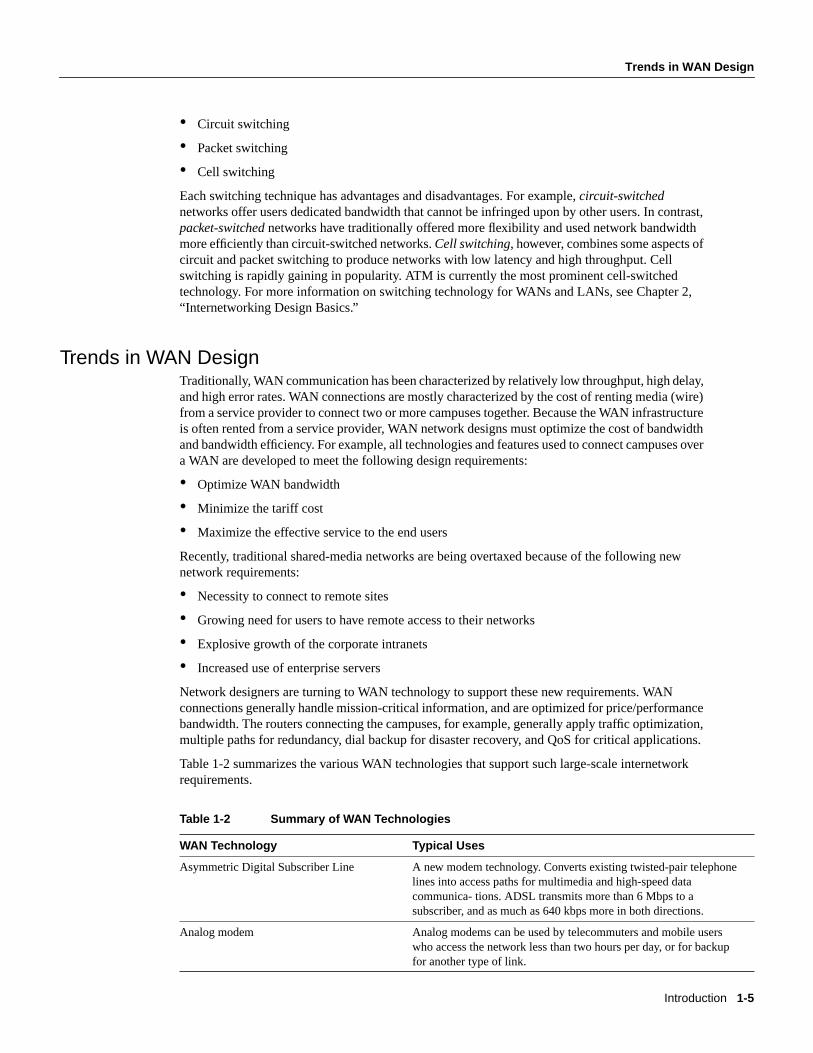
The intent is to reserve bandwidth for a particular type of traffic. For example, in Figure 2-6, SNAhas 40 percent of the bandwidth reserved using custom queuing, TCP/IP 20 percent, NetBIOS20 percent, and the remaining protocols 20 percent. The APPN protocol itself has the concept ofclass of service (COS), which determines the transmission priority for every message. APPNprioritizes the traffic before sending it to the DLC transmission queue.
TokenRing
37451.0.0.21.0.0.1
IPnetwork Token
Ring
3278LU03
3278LU02
3174
3278LU04
Router AE2
Router BE1
Internetworking Design Basics 2-9
Evaluating Backbone Services
Figure 2-6 Custom queuing.
Custom queuing prioritizes multiprotocol traffic. A maximum of 16 queues can be built with customqueuing. Each queue is serviced sequentially until the number of bytes sent exceeds the configurablebyte count or the queue is empty. One important function of custom queuing is that if SNA trafficuses only 20 percent of the link, the remaining 20 percent allocated to SNA can be shared by theother traffic.
Custom queuing is designed for environments that want to ensure a minimum level of service for allprotocols. In today’s multiprotocol internetwork environment, this important feature allowsprotocols of different characteristics to share the media.
Weighted Fair QueuingWeighted fair queuing is a traffic priority management algorithm that uses the time-divisionmultiplexing (TDM) model to divide the available bandwidth among clients that share the sameinterface. In time-division multiplexing, each client is allocated a time slice in a round-robin fashion.In weighted fair queuing, the bandwidth is distributed evenly among clients so that each client getsa fair share if every one has the same weighting. You can assign a different set of weights, forexample through type-of-service, so that more bandwidth is allocated.
If every client is allocated the same bandwidth independent of the arrival rates, the low volume traffichas effective priority over high volume traffic. The use of weighting allows time-delay-sensitivetraffic to obtain additional bandwidth, thus consistent response time is guaranteed under heavytraffic. There are different types of data stream converging on a wire, as shown in Figure 2-7.
S
S
S
S S S
TCP/IPtraffic
T T 20%
APPNtraffic
A A
40%
NetBIOStraffic
N
M N A T S S
N 20%
Miscellaneoustraffic
M M M 20%
H
M
H
L
N H M
N = Network priority
H = High priority
M = Medium priority
L = Low priority
S = SNA traffic
L

Identifying and Selecting Internetworking Capabilities
Cisco CCIE Fundamentals: Network Design2-10
Figure 2-7 Weighted fair queuing.
Both C and E are FTP sessions, and they are high-volume traffic. A, B, and D are interactive sessionsand they are low-volume traffic. Every session in this case is termed aconversation. If eachconversation is serviced in a cyclic manner and gets a slot regardless of its arrival rate, the FTPsessions do not monopolize the bandwidth. Round trip delays for the interactive traffic, therefore,become predictable.
Weighted fair queuing provides an algorithm to identify data streams dynamically using an interface,and sorts them into separate logical queues. The algorithm uses various discriminators based onwhatever network layer protocol information is available and sorts among them. For example, for IPtraffic, the discriminators are source and destination address, protocol type, socket numbers, andTOS. This is how the two Telnet sessions (Sessions B and D) are assigned to different logical queues,as shown in Figure 2-7.
Ideally, the algorithm would classify every conversation that is sharing the wire so that eachconversation receives its fair share of the bandwidth. Unfortunately, with such protocols as SNA, youcannot distinguish one SNA session from another. For example, in DLSw+, SNA traffic ismultiplexed onto a single TCP session. Similarly in APPN, SNA sessions are multiplexed onto asingle LLC2 session.
The weighted fair queuing algorithm treats these sessions as a single conversation. If you have manyTCP sessions, the TCP sessions get the majority of the bandwidth and the SNA traffic gets theminimum. For this reason, this algorithm is not recommended for SNA using DLSw+ TCP/IPencapsulation and APPN.
Weighted fair queuing, however, has many advantages over priority queuing and custom queuing.Priority queuing and custom queuing require the installation of access lists; the bandwidth has to bepre-allocated and priorities have to be predefined. This is clearly a burden. Sometimes, networkadministrators cannot identify and prioritize network traffic in real time. Weighted fair queuing sortsamong individual traffic streams without the administrative burden associated with the other twotypes of queuing.
Load BalancingThe easiest way to add bandwidth in a backbone network is to implement additional links. Routersprovide built-in load balancing for multiple links and paths. You can use up to four paths to adestination network. In some cases, the paths need not be of equal cost.
Within IP, routers provide load balancing on both a per-packet and a per-destination basis. Forper-destination load balancing, each router uses its route cache to determine the output interface. IfIGRP or Enhanced IGRP routing is used, unequal-cost load balancing is possible. The router usesmetrics to determine which paths the packets will take; the amount of load balancing can be adjustedby the user.
Telnet session BB B B B
IPX session AA A A A
FTP session C
CCCCCCC C
Telnet session DD
B A B D C E A
DFTP session E
EEEEEE E E

Internetworking Design Basics 2-11
Evaluating Backbone Services
Load balancing bridged traffic over serial lines is also supported. Serial lines can be assigned tocircuit groups. If one of the serial links in the circuit group is in the spanning tree for a network, anyof the serial links in the circuit group can be used for load balancing. Data ordering problems areavoided by assigning each destination to a serial link. Reassignment is done dynamically if interfacesgo down or come up.
Alternative PathsMany internetwork backbones carry mission-critical information. Organizations running suchbackbones are usually interested in protecting the integrity of this information at virtually any cost.Routers must offer sufficient reliability so that they are not the weak link in the internetwork chain.The key is to provide alternative paths that can come on line whenever link failures occur alongactive networks.
End-to-end reliability is not ensured simply by making the backbone fault tolerant. Ifcommunication on a local segment within any building is disrupted for any reason, that informationwill not reach the backbone. End-to-end reliability is only possible when redundancy is employedthroughout the internetwork. Because this is usually cost prohibitive, most companies prefer toemploy redundant paths only on those segments that carry mission-critical information.
What does it take to make the backbone reliable? Routers hold the key to reliable internetworking.Depending on the definition of reliability, this can mean duplicating every major system on eachrouter and possibly every component. However, hardware component duplication is not the entiresolution because extra circuitry is necessary to link the duplicate components to allow them tocommunicate. This solution is usually very expensive, but more importantly, it does not completelyaddress the problem. Even assuming all routers in your network are completely reliable systems, linkproblems between nodes within a backbone can still defeat a redundant hardware solution.
To really address the problem of network reliability,links must be redundant. Further, it is notenough to simply duplicate all links. Dual links must terminate at multiple routers unless allbackbone routers are completely fault tolerant (no single points of failure). Otherwise, backbonerouters that are not fault tolerant become single points of failure. The inevitable conclusion is that acompletely redundant router is not the most effective solution to the reliability problem because it isexpensive and still does not address link reliability.
Most network designers do not implement a completely redundant network. Instead, networkdesigners implement partially redundant internetworks. The section, “Choosing InternetworkingReliability Options,” later in this chapter, addresses several hypothetical networks that representcommonly implemented points along the reliability continuum.
Switched AccessSwitched access provides the capability to enable a WAN link on an as-needed basis via automatedrouter controls. One model for a reliable backbone consists of dual, dedicated links and one switchedlink for idle hot backup. Under normal operational conditions, you can load balance over the duallinks, but the switched link is not operational until one of the dedicated links fails.
Traditionally, WAN connections over the Public Switched Telephone Network (PSTN) have useddedicated lines. This can be very expensive when an application requires only low-volume, periodicconnections. To reduce the need for dedicated circuits, a feature calleddial-on-demand routing(DDR) is available. Figure 2-8 illustrates a DDR connection.

Identifying and Selecting Internetworking Capabilities
Cisco CCIE Fundamentals: Network Design2-12
Figure 2-8 The Dial-on-demand routing environment.
Using DDR, low-volume, periodic network connections can be made over the PSTN. A routeractivates the DDR feature when it receives a bridged or routed IP packet destined for a location onthe other side of the dial-up line. After the router dials the destination phone number and establishesthe connection, packets of any supported protocol can be transmitted. When the transmission iscomplete, the line is automatically disconnected. By terminating unneeded connections, DDRreduces cost of ownership.
Encapsulation (Tunneling)Encapsulationtakes packets or frames from one network system and places them inside frames fromanother network system. This method is sometimes calledtunneling. Tunneling provides a meansfor encapsulating packets inside a routable protocol via virtual interfaces. Synchronous Data LinkControl (SDLC) transport is also an encapsulation of packets in a routable protocol. In addition,transport provides enhancements to tunneling, such as local data-link layer termination, broadcastavoidance, media conversion, and other scalability optimizations.
Cisco routers support the following encapsulation and tunneling techniques:
• The IBM technology feature set provides these methods:
— Serial tunneling (STUN) or Synchronous Data Link Control (SDLC) Transport
— SRB with direct encapsulation
— SRB with Fast Sequenced Transport (FST) encapsulation
— SRB with Transmission Control Protocol/Internet Protocol (TCP/IP) encapsulation
— Data Link Switching Plus (DLSw+) with direct encapsulation
— DLSw+ with TCP/IP encapsulation
— DLSw+ with Fast Sequenced Transport/Internet Protocol (FST/IP) encapsulation
— DLSw+ with DLSw Lite (Logical Link Control Type 2 [LLC2]) encapsulation
• Generic Routing Encapsulation (GRE)
Cisco supports encapsulating Novell Internetwork Packet Exchange (IPX), Internet Protocol(IP), Connectionless Network Protocol (CLNP), AppleTalk, DECnet Phase IV, Xerox NetworkSystems (XNS), Banyan Virtual Network System (VINES), and Apollo packets for transportover IP
• Single-protocol tunneling techniques: Cayman (AppleTalk over IP), AURP (AppleTalk over IP),EON (CLNP over IP), and NOS (IP over IP)
The following discussion focuses on IBM encapsulations and the multiprotocol GRE tunnelingfeature.
DCEdevice
DCEdevice
Ethernet
Ethernet
TokenRing
TokenRing
Public Switched
TelephoneNetwork
RouterRouter

Internetworking Design Basics 2-13
Evaluating Backbone Services
IBM FeaturesSTUN allows two devices that are normally connected by a direct serial link, using protocolscompliant with SDLC or High-level Data Link Control (HDLC), to be connected through one ormore routers. The routers can be connected via a multiprotocol network of arbitrary topology. STUNallows integration of System Network Architecture (SNA) networks and non-SNA networks usingrouters and existing network links. Transport across the multiprotocol network that connects therouters can use TCP/IP. This type of transport offers reliability and intelligent routing via anysupported IP routing protocol. A STUN configuration is shown in Figure 2-9.
Figure 2-9 STUN configuration.
SDLC Transport is a variation of STUN that allows sessions using SDLC protocols and TCP/IPencapsulation to be locally terminated. SDLC Transport permits participation in SDLC windowingand retransmission activities.
When connecting remote devices that use SRB over a slow-speed serial link, most network designerschoose RSRB with direct HDLC encapsulation. In this case, SRB frames are encapsulated in anHDLC-compliant header. This solution adds little overhead, preserving valuable serial linkbandwidth. Direct HDLC encapsulation is not restricted to serial links (it can also be used overEthernet, Token Ring, and FDDI links), but is most useful in situations in which additional controloverhead on the encapsulating network is not tolerable.
TokenRing
TokenRing
Local site
Remote site
16/4Mbps
16/4Mbps
Sun workstations
3270 3270 3270
IBM terminals
IBM mainframe
Sun workstations
Cluster controller 3x74
SNAbackbone
TokenRing
16/4Mbps
37x5
Router
Router
Router
Router

Identifying and Selecting Internetworking Capabilities
Cisco CCIE Fundamentals: Network Design2-14
When more overhead can be tolerated, frame sequencing is important, but extremely reliabledelivery is not needed, and SRB packets can be sent over serial, Token Ring, Ethernet, and FDDInetworks using FST encapsulation. FST is similar to TCP in that it provides packet sequencing.However, unlike TCP, FST does not provide packet-delivery acknowledgment.
For extremely reliable delivery in environments in which moderate overhead can be tolerated, youcan choose to encapsulate SRB frames in TCP/IP packets. This solution is not only reliable, it canalso take advantage of routing features that include handling via routing protocols, packet filtering,and multipath routing.
Generic Routing Encapsulation (GRE)Cisco’s Generic Routing Encapsulation (GRE) multiprotocol carrier protocol encapsulates IP,CLNP, IPX, AppleTalk, DECnet Phase IV, XNS, VINES, and Apollo packets inside IP tunnels. WithGRE tunneling, a Cisco router at each site encapsulates protocol-specific packets in an IP header,creating a virtual point-to-point link to Cisco routers at other ends of an IP cloud, where the IP headeris stripped off. By connecting multiprotocol subnetworks in a single-protocol backboneenvironment, IP tunneling allows network expansion across a single-protocol backboneenvironment. GRE tunneling involves three types of protocols:
• Passenger—The protocol is encapsulated (IP, CLNP, IPX, AppleTalk, DECnet Phase IV, XNS,VINES and Apollo).
• Carrier—GRE protocol provides carrier services.
• Transport—IP carries the encapsulated protocol.
GRE tunneling allows desktop protocols to take advantage of the enhanced route selectioncapabilities of IP. Many local-area network (LAN) protocols, including AppleTalk and Novell IPX,are optimized for local use. They have limited route selection metrics and hop count limitations. Incontrast, IP routing protocols allow more flexible route selection and scale better over largeinternetworks. Figure 2-10 illustrates GRE tunneling across a single IP backbone between sites.Regardless of how many routers and paths may be associated with the IP cloud, the tunnel is seen asa single hop.
Figure 2-10 Using a single protocol backbone.
GRE provides key capabilities that other encapsulation protocols lack: sequencing and the capabilityto carry tunneled data at high speeds. Some higher-level protocols require that packets are deliveredin correct order. The GRE sequencing option provides this capability. GRE also has an optional key
AppleTalksite
Novellsite
AppleTalksite
AppleTalk/Novellsite
IPBackbone
GRE tunnel

Internetworking Design Basics 2-15
Evaluating Backbone Services
feature that allows you to avoid configuration errors by requiring the same key to be entered at eachtunnel endpoint before the tunneled data is processed. IP tunneling also allows network designers toimplement policies, such as which types of traffic can use which routes or assignment of priority orsecurity levels to particular traffic. Capabilities like these are lacking in many native LAN protocols.
IP tunneling provides communication between subnetworks that have invalid or discontiguousnetwork addresses. With tunneling, virtual network addresses are assigned to subnetworks, makingdiscontiguous subnetworks reachable. Figure 2-11 illustrates that with GRE tunneling, it is possiblefor the two subnetworks of network 131.108.0.0 to talk to each other even though they are separatedby another network.
Figure 2-11 Connecting discontiguous networks with tunnels.
Because encapsulation requires handling of the packets, it is generally faster to route protocolsnatively than to use tunnels. Tunneled traffic is switched at approximately half the typical processswitching rates. This means approximately 1,000 packets per second (pps) aggregate for each router.Tunneling is CPU intensive, and as such, should be turned on cautiously. Routing updates, SAPupdates, and other administrative traffic may be sent over each tunnel interface. It is easy to saturatea physical link with routing information if several tunnels are configured over it. Performancedepends on the passenger protocol, broadcasts, routing updates, and bandwidth of the physicalinterfaces. It is also difficult to debug the physical link if problems occur. This problem can bemitigated in several ways. In IPX environments, route filters and SAP filters cut down on the size ofthe updates that travel over tunnels. In AppleTalk networks, keeping zones small and using routefilters can limit excess bandwidth requirements.
Tunneling can disguise the nature of a link, making it look slower, faster, or more or less costly thanit may actually be in reality. This can cause unexpected or undesirable route selection. Routingprotocols that make decisions based only on hop count will usually prefer a tunnel to a real interface.This may not always be the best routing decision because an IP cloud can comprise several differentmedia with very disparate qualities; for example, traffic may be forwarded across both 100-MbpsEthernet lines and 9.6-Kbps serial lines. When using tunneling, pay attention to the media overwhich virtual tunnel traffic passes and the metrics used by each protocol.
If a network has sites that use protocol-based packet filters as part of a firewall security scheme, beaware that because tunnels encapsulate unchecked passenger protocols, you must establish filteringon the firewall router so that only authorized tunnels are allowed to pass. If tunnels are accepted fromunsecured networks, it is a good idea to establish filtering at the tunnel destination or to place thetunnel destination outside the secure area of your network so that the current firewall scheme willremain secure.
131.108.20.0255.255.255.0
131.108.10.0255.255.255.0
Tunnel
Network192.1.1.0
Router Router

Identifying and Selecting Internetworking Capabilities
Cisco CCIE Fundamentals: Network Design2-16
When tunneling IP over IP, you must be careful to avoid inadvertently configuring a recursive routingloop. A routing loop occurs when the passenger protocol and the transport protocol are identical. Therouting loop occurs because the best path to the tunnel destination is via the tunnel interface. Arouting loop can occur when tunneling IP over IP, as follows:
1 The packet is placed in the output queue of the tunnel interface.
2 The tunnel interface includes a GRE header and enqueues the packet to the transport protocol (IP)for the destination address of the tunnel interface.
3 IP looks up the route to the tunnel destination address and learns that the path is the tunnelinterface.
4 Once again, the packet is placed in the output queue of the tunnel interface, as described inStep 1, hence, the routing loop.
When a router detects a recursive routing loop, it shuts down the tunnel interface for 1 to 2 minutesand issues a warning message before it goes into the recursive loop. Another indication that arecursive route loop has been detected is if the tunnel interface is up and the line protocol is down.
To avoid recursive loops, keep passenger and transport routing information in separate locations byimplementing the following procedures:
• Use separate routing protocol identifiers (for example, igrp 1 and igrp 2).
• Use different routing protocols.
• Assign the tunnel interface a very low bandwidth so that routing protocols, such as IGRP, willrecognize a very high metric for the tunnel interface and will, therefore, choose the correct nexthop (that is, choose the best physical interface instead of the tunnel).
• Keep the two IP address ranges distinct; that is, use a major address for your tunnel network thatis different from your actual IP network. Keeping the address ranges distinct also aids indebugging because it is easy to identify an address as the tunnel network instead of the physicalnetwork and vice versa.
Evaluating Distribution ServicesThis section addresses internetworking features that support distribution services. The followingtopics are discussed:
• Backbone Bandwidth Management
• Area and Service Filtering
• Policy-Based Distribution
• Gateway Service
• Interprotocol Route Redistribution
• Media Translation
Backbone Bandwidth ManagementTo optimize backbone network operations, routers offer several performance tuning features.Examples include priority queuing, routing protocol metrics, and local session termination.

Internetworking Design Basics 2-17
Evaluating Distribution Services
You can adjust the output queue length on priority queues. If a priority queue overflows, excesspackets are discarded and quench messages that halt packet flow are sent, if appropriate, for thatprotocol. You can also adjust routing metrics to increase control over the paths that the traffic takesthrough the internetwork.
Local session termination allows routers to act as proxies for remote systems that represent sessionendpoints. (Aproxy is a device that acts on behalf of another device.) Figure 2-12 illustrates anexample of local session termination in an IBM environment.
Figure 2-12 Local session termination over multiprotocol backbone.
In Figure 2-12, the routers locally terminate Logical Link Control type 2 (LLC2) data-link controlsessions. Instead of end-to-end sessions, during which all session control information is passed overthe multiprotocol backbone, the routers take responsibility for acknowledging packets that comefrom hosts on directly attached LANs. Local acknowledgment saves WAN bandwidth (and,therefore, WAN utilization costs), solves session timeout problems, and provides faster response tousers.
Area and Service FilteringTraffic filters based onareaor servicetype are the primary distribution service tools used to providepolicy-based access control into backbone services. Both area and service filtering are implementedusingaccess lists. An access list is a sequence of statements, each of which either permits or deniescertain conditions or addresses. Access lists can be used to permit or deny messages from particularnetwork nodes and messages sent using particular protocols and services.
Area or network access filters are used to enforce the selective transmission of traffic based onnetwork address. You can apply these on incoming or outgoing ports. Service filters use access listsapplied to protocols (such as IP’s UDP), applications such as the Simple Mail Transfer Protocol(SMTP), and specific protocols.
Suppose you have a network connected to the Internet, and you want any host on an Ethernet to beable to form TCP connections to any host on the Internet. However, you do not want Internet hoststo be able to form TCP connections to hosts on the Ethernet except to the SMTP port of a dedicatedmail host.
SMTP uses TCP port 25 on one end of the connection and a random port number on the other end.The same two port numbers are used throughout the life of the connection. Mail packets coming infrom the Internet will have a destination port of 25. Outbound packets will have the port numbers
TokenRing
TokenRing
Multiprotocolbackbone
3x74 controller
Acknowledgments
LLC2 sessionT1 timer
Acknowledgments
LLC2 sessionT1 timer
3745 TCP/IP session• Reliable transport• TCP flow control• Error recovery
Router Router

Identifying and Selecting Internetworking Capabilities
Cisco CCIE Fundamentals: Network Design2-18
reversed. The fact that the secure system behind the router always accepts mail connections onport 25 is what makes it possible to separately control incoming and outgoing services. The accesslist can be configured on either the outbound or inbound interface.
In the following example, the Ethernet network is a Class B network with the address 128.88.0.0,and the mail host’s address is 128.88.1.2.The keywordestablishedis used only for the TCP protocolto indicate an established connection. A match occurs if the TCP datagram has the ACK or RST bitsset, which indicate that the packet belongs to an existing connection.
access-list 102 permit tcp 0.0.0.0 255.255.255.255 128.88.0.0 0.0.255.255 establishedaccess-list 102 permit tcp 0.0.0.0 255.255.255.255 128.88.1.2 0.0.0.0 eq 25interface ethernet 0ip access-group 102
Policy-Based DistributionPolicy-based distribution is based on the premise that different departments within a commonorganization might have different policies regarding traffic dispersion through the organization-wideinternetwork. Policy-based distribution aims to meet the differing requirements withoutcompromising performance and information integrity.
A policy within this internetworking context is a rule or set of rules that governs end-to-enddistribution of traffic to (and subsequently through) a backbone network. One department might sendtraffic representing three different protocols to the backbone, but might want to expedite oneparticular protocol’s transit through the backbone because it carries mission-critical applicationinformation. To minimize already excessive internal traffic, another department might want toexclude all backbone traffic except electronic mail and one key custom application from entering itsnetwork segment.
These examples reflect policies specific to a single department. However, policies can reflect overallorganizational goals. For example, an organization might want to regulate backbone traffic to amaximum of 10 percent average bandwidth during the work day and 1-minute peaks of 30 percentutilization. Another corporate policy might be to ensure that communication between two remotedepartments can freely occur, despite differences in technology.
Different policies frequently require different workgroup and department technologies. Therefore,support for policy-based distribution implies support for the wide range of technologies currentlyused to implement these policies. This in turn allows you to implement solutions that support a widerange of policies, which helps to increase organizational flexibility and application availability.
In addition to support for internetworking technologies, there must be a means both to keep separateand integrate these technologies, as appropriate. The different technologies should be able to coexistor combine intelligently, as the situation warrants.
Consider the situation depicted in Figure 2-13. Assume that a corporate policy limits unnecessarybackbone traffic. One way to do this is to restrict the transmission of Service Advertisement Protocol(SAP) messages. SAP messages allow NetWare servers to advertise services to clients. Theorganization might have another policy stating that all NetWare services should be provided locally.If this is the case, there should be no reason for services to be advertised remotely. SAP filters preventSAP traffic from leaving a router interface, thereby fulfilling this policy.

Internetworking Design Basics 2-19
Evaluating Distribution Services
Figure 2-13 Policy-based distributation: SAP filtering.
Gateway ServiceProtocol gateway capabilities are part of each router’s standard software. For example, DECnet iscurrently in Phase V. DECnet Phase V addresses are different than DECnet Phase IV addresses. Forthose networks that require both type of hosts to coexist, two-way Phase IV/Phase V translationconforms to Digital-specified guidelines. The routers interoperate with Digital routers, and Digitalhosts do not differentiate between the different devices.
The connection of multiple independent DECnet networks can lead to addressing problems. Nothingprecludes two independent DECnet administrators from assigning node address 10 to one of thenodes in their respective networks. When the two networks are connected at some later time,conflicts result. DECnet address translation gateways (ATGs) address this problem. The ATGsolution provides router-based translation between addresses in two different DECnet networksconnected by a router. Figure 2-14 illustrates an example of this operation.
Figure 2-14 Sample DECnet ATG implementation.
In Network 0, the router is configured at address 19.4 and is a Level 1 router. In Network 1, the routeris configured at address 50.5 and is an area router. At this point, no routing information is exchangedbetween the two networks. The router maintains a separate routing table for each network. Byestablishing a translation map, packets in Network 0 sent to address 19.5 will be routed toNetwork 1, and the destination address will be translated to 50.1. Similarly, packets sent toaddress 19.6 in Network 0 will be routed to Network 1 as 19.1; packets sent to address 47.1 inNetwork 1 will be routed to Network 0 as 19.1; and packets sent to 47.2 in Network 1 will be sentto Network 0 as 19.3.
Backbonenetwork
Client Client Client Client Client Client
SAP filter SAP filter
NetWare server NetWare server
Router Router
Network 0 Network 1
19.5 50.1
19.6 19.1
19.1 47.1
19.3 47.2
19.1A::
19.2B::
19.3C::
50.1D::
60.1E::
19.1F::
DECnet translation table
19.4 50.5
Router A
E0 E1

Identifying and Selecting Internetworking Capabilities
Cisco CCIE Fundamentals: Network Design2-20
AppleTalk is another protocol with multiple revisions, each with somewhat different addressingcharacteristics. AppleTalk Phase 1 addresses are simple local forms; AppleTalk Phase 2 usesextended (multinetwork) addressing. Normally, information sent from a Phase 2 node cannot beunderstood by a Phase 1 node if Phase 2 extended addressing is used. Routers support routingbetween Phase 1 and Phase 2 nodes on the same cable by using transitional routing.
You can accomplish transitional routing by attaching two router ports to the same physical cable.Configure one port to support nonextended AppleTalk and the other to support extended AppleTalk.Both ports must have unique network numbers. Packets are translated and sent out the other port asnecessary.
Interprotocol Route RedistributionThe preceding section, “Gateway Service,” discussed howrouted protocol gateways (such as onethat translates between AppleTalk Phase 1 and Phase 2) allow two end nodes with differentimplementations to communicate. Routers can also act as gateways forrouting protocols.Information derived from one routing protocol, such as the IGRP, can be passed to, and used by,another routing protocol, such as RIP. This is useful when running multiple routing protocols in thesame internetwork.
Routing information can be exchanged between any supported IP routing protocols. These includeRIP, IGRP, OSPF, HELLO, EGP, and BGP. Similarly, route redistribution is supported by ISO CLNSfor route redistribution between ISO IGRP and IS-IS. Static route information can also beredistributed. Defaults can be assigned so that one routing protocol can use the same metric for allredistributed routes, thereby simplifying the routing redistribution mechanism.
Media TranslationMedia translation techniques translate frames from one network system into frames of another. Suchtranslations are rarely 100 percent effective because one system might have attributes with no corollaryto the other. For example, Token Ring networks support a built-in priority and reservation system,whereas Ethernet networks do not. Translations between Token Ring and Ethernet networks mustsomehow account for this discrepancy. It is possible for two vendors to make different decisionsabout how this discrepancy will be handled, which can prevent multivendor interoperation.
For those situations in which communication between end stations on different media is required,routers can translate between Ethernet and Token Ring frames. For direct bridging between Ethernetand Token Ring environments, use either source-route translational bridging or source-routetransparent bridging (SRT). Source-route translational bridging translates between Token Ring andEthernet frame formats; SRT allows routers to use both SRB and the transparent bridging algorithmused in standard Ethernet bridging.
When bridging from the SRB domain to the transparent bridging domain, the SRB fields of theframes are removed. RIFs are cached for use by subsequent return traffic. When bridging in theopposite direction, the router checks the packet to determine whether it has a multicast or broadcastdestination or a unicast destination. If it has a multicast or broadcast destination, the packet is sentas a spanning-tree explorer. If it has a unicast destination, the router looks up the path to thedestination in the RIF cache. If a path is found, it will be used; otherwise, the router will send thepacket as a spanning-tree explorer. A simple example of this topology is shown in Figure 2-15.

Internetworking Design Basics 2-21
Evaluating Distribution Services
Figure 2-15 Source-route translational bridging topology.
Routers support SRT through implementation of both transparent bridging and SRB algorithms oneach SRT interface. If an interface notes the presence of a RIF field, it uses the SRB algorithm; ifnot, it uses the transparent bridging algorithm.
Translation between serial links running the SDLC protocol and Token Rings running LLC2 is alsoavailable. This is referred to as SDLLC frame translation. SDLLC frame translation allowsconnections between serial lines and Token Rings. This is useful for consolidating traditionallydisparate SNA/SDLC networks into a LAN-based, multiprotocol, multimedia backbone network.Using SDLLC, routers terminate SDLC sessions, translate SDLC frames to LLC2 frames, and thenforward the LLC2 frames using RSRB over a point-to-point or IP network. Because a router-basedIP network can use arbitrary media, such as FDDI, Frame Relay, X.25, or leased lines, routerssupport SDLLC over all such media through IP encapsulation.
A complex SDLLC configuration is shown in Figure 2-16.
Source-routebridged domain
Frames lose their RIFs in this direction
Frames gain RIFs in this direction
TokenRing
Transparentbridging domain
Transparentbridging ring
Source-route translational bridging
Router

Identifying and Selecting Internetworking Capabilities
Cisco CCIE Fundamentals: Network Design2-22
Figure 2-16 Complex SDLLC configuration.
Evaluating Local-Access ServicesThe following discussion addresses internetworking features that support local-access services.Local-access service topics outlined here include the following:
• Value-Added Network Addressing
• Network Segmentation
• Broadcast and Multicast Capabilities
• Naming, Proxy, and Local Cache Capabilities
• Media Access Security
• Router Discovery
Value-Added Network AddressingAddress schemes for LAN-based networks, such as NetWare and others, do not always adaptperfectly to use over multisegment LANs or WANs. One tool routers implement to ensure operationof such protocols is protocol-specifichelper addressing. Helper addressing is a mechanism to assistthe movement of specific traffic through a network when that traffic might not otherwise transit thenetwork.
3270 3270
RSRB Virtual Ring 100
C2
SDLLC Ring 8
Token Ring 10
SDLLC Ring 9
SDLLC Ring 7
32703x74
3x74
3x743270
C3
C1
WAN
37x5
Host
T0E0
Router A Router BSDLLC
S1
E0
S0
Router CSDLLC
E0
S0

Internetworking Design Basics 2-23
Evaluating Local-Access Services
The use ofhelper addressingis best illustrated with an example. Consider the use of helper addressesin Novell IPX internetworks. Novell clients send broadcast messages when looking for a server. Ifthe server is not local, broadcast traffic must be sent through routers. Helper addresses and accesslists can be used together to allow broadcasts from certain nodes on one network to be directedspecifically to certain servers on another network. Multiple helper addresses on each interface aresupported, so broadcast packets can be forwarded to multiple hosts. Figure 2-17 illustrates the useof NetWare-based helper addressing.
Figure 2-17 Sample network map illustrating helper address broadcast control.
NetWare clients on Network AA are allowed to broadcast to any server on Network BB. Anapplicable access list would specify that broadcasts of type 10 will be permitted from all nodes onNetwork AA. A configuration-specified helper address identifies the addresses on Network BB towhich these broadcasts are directed. No other nodes on Network BB receive the broadcasts. No otherbroadcasts other than type 10 broadcasts are routed.
Any downstream networks beyond Network AA (for example, some Network AA1) are not allowedto broadcast to Network BB through Router C1, unless the routers partitioning Networks AA andAA1 are configured to forward broadcasts with a series of configuration entries. These entries mustbe applied to the input interfaces and be set to forward broadcasts between directly connectednetworks. In this way, traffic is passed along in a directed manner from network to network.
Network SegmentationThe splitting of networks into more manageable pieces is an essential role played by local-accessrouters. In particular, local-access routers implement local policies and limit unnecessary traffic.Examples of capabilities that allow network designers to use local-access routers to segmentnetworks include IP subnets, DECnet area addressing, and AppleTalk zones.
You can use local-access routers to implement local policies by placing the routers in strategiclocations and by configuring specific segmenting policies. For example, you can set up a series ofLAN segments with different subnet addresses; routers would be configured with suitable interfaceaddresses and subnet masks. In general, traffic on a given segment is limited to local broadcasts,
NetWareclient B
NetWare client A
NetWare server A
NetWareserver B
00b4.23cd.110a
0090.aa23.ef01
BB
AA
CC
Allows type 10 broadcasts only
Router C1 E1
E0
E2

Identifying and Selecting Internetworking Capabilities
Cisco CCIE Fundamentals: Network Design2-24
traffic intended for a specific end station on that segment, or traffic intended for another specificrouter. By distributing hosts and clients carefully, you can use this simple method of dividing up anetwork to reduce overall network congestion.
Broadcast and Multicast CapabilitiesMany protocols usebroadcastandmulticastcapabilities. Broadcasts are messages that are sent outto all network destinations. Multicasts are messages sent to a specific subset of network destinations.Routers inherently reduce broadcast proliferation by default. However, routers can be configured torelay broadcast traffic if necessary. Under certain circumstances, passing along broadcastinformation is desirable and possibly necessary. The key is controlling broadcasts and multicastsusing routers.
In the IP world, as with many other technologies, broadcast requests are very common. Unlessbroadcasts are controlled, network bandwidth can be seriously reduced. Routers offer variousbroadcast-limiting functions that reduce network traffic and minimize broadcast storms. Forexample, directed broadcasting allows for broadcasts to a specific network or a series of networks,rather than to the entire internetwork. When flooded broadcasts (broadcasts sent through the entireinternetwork) are necessary, Cisco routers support a technique by which these broadcasts are sentover a spanning tree of the network. The spanning tree ensures complete coverage without excessivetraffic because only one packet is sent over each network segment.
As discussed previously in the section “Value-Added Network Addressing,” broadcast assistance isaccommodated with thehelper address mechanisms. You can allow a router or series of routers torelay broadcasts that would otherwise be blocked by using helper addresses. For example, you canpermit retransmission of SAP broadcasts using helper addresses, thereby notifying clients ondifferent network segments of certain NetWare services available from specific remote servers.
The Cisco IP multicast feature allows IP traffic to be propagated from one source to any number ofdestinations. Rather than sending one packet to each destination, one packet is sent to a multicastgroup identified by a single IP destination group address. IP multicast provides excellent support forsuch applications as video and audio conferencing, resource discovery, and stock market trafficdistribution.
For full support of IP multicast, IP hosts must run the Internet Group Management Protocol (IGMP).IGMP is used by IP hosts to report their multicast group memberships to an immediatelyneighboring multicast router. The membership of a multicast group is dynamic. Multicast routerssend IGMP query messages on their attached local networks. Host members of a multicast grouprespond to a query by sending IGMP reports for multicast groups to which they belong. Reports sentby the first host in a multicast group suppress the sending of identical reports from other hosts of thesame group.
The multicast router attached to the local network takes responsibility for forwarding multicastdatagrams from one multicast group to all other networks that have members in the group. Routersbuild multicast group distribution trees (routing tables) so that multicast packets have loop-free pathsto all multicast group members so that multicast packets are not duplicated. If no reports are receivedfrom a multicast group after a set number of IGMP queries, the multicast routers assume the grouphas no local members and stop forwarding multicasts intended for that group.
Cisco routers also support Protocol Independent Multicast (PIM). For more information on thistopic, see Chapter 13, “Designing Internetworks for Multimedia.”
Naming, Proxy, and Local Cache CapabilitiesThree key router capabilities help reduce network traffic and promote efficient internetworkingoperation: name service support, proxy services, and local caching of network information.

Internetworking Design Basics 2-25
Evaluating Local-Access Services
Network applications and connection services provided over segmented internetworks require arational way to resolve names to addresses. Various facilities accommodate this requirement. Anyrouter you select must support the name services implemented for different end-systemenvironments. Examples of supported name services include NetBIOS, IP’s Domain Name System(DNS) and IEN-116, and AppleTalk Name Binding Protocol (NBP).
A router can also act as aproxyfor a name server. The router’s support of NetBIOS name caching isone example of this kind of capability. NetBIOS name caching allows the router to maintain a cacheof NetBIOS names, which avoids the overhead of transmitting all of the broadcasts between clientand server NetBIOS PCs (IBM PCs or PS/2s) in an SRB environment. When NetBIOS name cachingis enabled, the router does the following:
• Notices when any host sends a series of duplicate query frames and limits retransmission to oneframe per period. The time period is a configuration parameter.
• Keeps a cache of mappings between NetBIOS server and client names and their MAC addresses.As a result, broadcast requests sent by clients to find servers (and by servers in response to theirclients) can be sent directly to their destinations, rather than being broadcast across the entirebridged network.
When NetBIOS name caching is enabled and default parameters are set on the router, the NetBIOSname server, and the NetBIOS name client, approximately 20 broadcast packets per login are kepton the local ring where they are generated.
In most cases, the NetBIOS name cache is best used when large amounts of NetBIOS broadcasttraffic might create bottlenecks on a WAN that connects local internetworks to distant locations.
The router can also save bandwidth (or handle nonconforming name resolution protocols) by usinga variety of other proxy facilities. By using routers to act on behalf of other devices to performvarious functions, you can more easily scale networks. Instead of being forced to add bandwidthwhen a new workgroup is added to a location, you can use a router to manage address resolution andcontrol message services. Examples of this kind of capability include the proxy explorer feature ofSRB and the proxy polling feature of STUN implementations.
Sometimes portions of networks cannot participate in routing activity or do not implement softwarethat conforms to generally implemented address-resolution protocols. Proxy implementations onrouters allow network designers to support these networks or hosts without reconfiguring aninternetwork. Examples of these kinds of capabilities include proxy ARP address resolution for IPinternetworks and NBP proxy in AppleTalk internetworks.
Local caches store previously learned information about the network so that new informationrequests do not need to be issued each time the same piece of information is desired. A router’s ARPcache stores physical address and network address mappings so that it does not need to broadcastARP requests more than once within a given time period for the same address. Address caches aremaintained for many other protocols as well, including DECnet, Novell IPX, and SRB, where RIFinformation is cached.
Media Access SecurityIf all corporate information is readily available to all employees, security violations andinappropriate file access can occur. To prevent this, routers must do the following:
• Keep local traffic from inappropriately reaching the backbone
• Keep backbone traffic from exiting the backbone into an inappropriate department or workgroupnetwork

Identifying and Selecting Internetworking Capabilities
Cisco CCIE Fundamentals: Network Design2-26
These two functions require packet filtering. Packet filtering capabilities should be tailored tosupport a variety of corporate policies. Packet filtering methods can reduce traffic levels on anetwork, thereby allowing a company to continue using its current technology rather than investingin more network hardware. In addition, packet filters can improve security by keeping unauthorizedusers from accessing information and can minimize network problems caused by excessivecongestion.
Routers support many filtering schemes designed to provide control over network traffic that reachesthe backbone. Perhaps the most powerful of these filtering mechanisms is the access list. Each of thefollowing possible local-access services can be provided through access lists:
• You have an Ethernet-to-Internet routing network and you want any host on the Ethernet to beable to form TCP connections to any host on the Internet. However, you do not want Internethosts to be able to form TCP connections into the Ethernet except to the SMTP port of a dedicatedmail host.
• You want to advertise only one network through a RIP routing process.
• You want to prevent packets that originated on any Sun workstation from being bridged on aparticular Ethernet segment.
• You want to keep a particular protocol based on Novell IPX from establishing a connectionbetween a source network or source port combination and a destination network or destinationport combination.
Access lists logically prevent certain packets from traversing a particular router interface, therebyproviding a general tool for implementing network security. In addition to this method, severalspecific security systems already exist to help increase network security. For example, the U.S.government has specified the use of an optional field within the IP packet header to implement ahierarchical packet security system called the Internet Protocol Security Option (IPSO).
IPSO support on routers addresses both the basic and extended security options described in a draftof the IPSO circulated by the Defense Communications Agency. This draft document is an earlyversion of Request for Comments (RFC) 1108. IPSO defines security levels (for example, TOPSECRET, SECRET, and others) on a per-interface basis and accepts or rejects messages based onwhether they include adequate authorization.
Some security systems are designed to keep remote users from accessing the network unless theyhave adequate authorization. For example, the Terminal Access Controller Access Control System(TACACS) is a means of protecting modem access into a network. The Defense Data Network(DDN) developed TACACS to control access to its TAC terminal servers.
The router’s TACACS support is patterned after the DDN application. When a user attempts to startan EXEC command interpreter on a password-protected line, TACACS prompts for a password. Ifthe user fails to enter the correct password, access is denied. Router administrators can controlvarious TACACS parameters, such as the number of retries allowed, the timeout interval, and theenabling of TACACS accounting.
The Challenge Handshake Authentication Protocol (CHAP) is another way to keep unauthorizedremote users from accessing a network. It is also commonly used to control router-to-routercommunications. When CHAP is enabled, a remote device (for example, a PC, workstation, router,or communication server) attempting to connect to a local router is “challenged” to provide anappropriate response. If the correct response is not provided, network access is denied.
CHAP is becoming popular because it does not require a secret password to be sent over the network.CHAP is supported on all router serial lines using Point-to-Point Protocol (PPP) encapsulation.

Internetworking Design Basics 2-27
Choosing Internetworking Reliability Options
Router DiscoveryHosts must be able to locate routers when they need access to devices external to the local network.When more than one router is attached to a host’s local segment, the host must be able to locate therouter that represents the optimal path to the destination. This process of finding routers is calledrouter discovery.
The following are router discovery protocols:
• End System-to-Intermediate System (ES-IS)—This protocol is defined by the ISO OSI protocolsuite. It is dedicated to the exchange of information between intermediate systems (routers) andend systems (hosts). ESs send “ES hello” messages to all ISs on the local subnetwork. In turn,“IS hello” messages are sent from all ISs to all ESs on the local subnetwork. Both types ofmessages convey the subnetwork and network-layer addresses of the systems that generate them.Using this protocol, end systems and intermediate systems can locate one another.
• ICMP Router Discovery Protocol (IRDP)—Although the issue is currently under study, there iscurrently no single standardized manner for end stations to locate routers in the IP world. In manycases, stations are simply configured manually with the address of a local router. However,RFC 1256 outlines a router discovery protocol using the Internet Control Message Protocol(ICMP). This protocol is commonly referred to as IRDP.
• Proxy Address Resolution Protocol (ARP)—ARP uses broadcast messages to determine theMAC-layer address that corresponds to a particular internetwork address. ARP is sufficientlygeneric to allow use of IP with virtually any type of underlying media-access mechanism. Arouter that has proxy ARP enabled responds to ARP requests for those hosts for which it has aroute, which allows hosts to assume that all other hosts are actually on their network.
• RIP—RIP is a routing protocol that is commonly available on IP hosts. Many hosts use RIP tofind the address of the routers on a LAN or, when there are multiple routers, to pick the best routerto use for a given internetwork address.
Cisco routers support all the router discovery protocols listed. You can choose the router discoverymechanism that works best in your particular environment.
Choosing Internetworking Reliability OptionsOne of the first concerns of most network designers is to determine the required level of applicationavailability. In general, this key consideration is balanced against implementation cost. For mostorganizations, the cost of making a network completely fault tolerant is prohibitive. Determining theappropriate level of fault tolerance to be included in a network and where redundancy should be usedis not trivial.
The nonredundant internetwork design in Figure 2-18 illustrates the considerations involved withincreasing levels of internetwork fault tolerance.

Identifying and Selecting Internetworking Capabilities
Cisco CCIE Fundamentals: Network Design2-28
Figure 2-18 Typical nonredundant internetwork design.
The internetwork shown in Figure 2-18 has two levels of hierarchy: a corporate office and remoteoffices. Assume the corporate office has eight Ethernet segments, to which approximately 400 users(an average of 50 per segment) are connected. Each Ethernet segment is connected to a router. In theremote offices, two Ethernet segments are connected to the corporate office through a router. Therouter in each remote office is connected to the router in the corporate office through a T1 link.
The following sections address various approaches to creating redundant internetworks, providesome context for each approach, and contrast their relative merits and drawbacks. The following foursections are provided:
• Redundant Links Versus Meshed Topologies
• Redundant Power Systems
• Fault-Tolerant Media Implementations
• Backup Hardware
Redundant Links Versus Meshed TopologiesTypically, WAN links are the least reliable components in an internetwork, usually because ofproblems in the local loop. In addition to being relatively unreliable, these links are often an orderof magnitude slower than the LANs they connect. However, because they are capable of connectinggeographically diverse sites, WAN links often make up the backbone network, and are thereforecritical to corporate operations. The combination of potentially suspect reliability, lack of speed, andhigh importance makes the WAN link a good candidate for redundancy.
As a first step in making the example internetwork more fault tolerant, you might add a WAN linkbetween each remote office and the corporate office. This results in the topology shown in Figure2-19. The new topology has several advantages. First, it provides a backup link that can be used if aprimary link connecting any remote office and the corporate office fails. Second, if the routerssupport load balancing, link bandwidth has now been increased, lowering response times for usersand increasing application availability.
Corporate office
Remote office 1 Remote office 2 Remote office 3
Router
Router Router Router

Internetworking Design Basics 2-29
Choosing Internetworking Reliability Options
Figure 2-19 Internetwork with dual links to remote offices.
Load balancing in transparent bridging and IGRP environments is another tool for increasing faulttolerance. Routers also support load balancing on either a per-packet or a per-destination basis in allIP environments. Per-packet load balancing is recommended if the WAN links are relatively slow(for example, less than 56 Kbps). If WAN links are faster than 56 Kbps, enabling fastswitching onthe routers is recommended. When fast switching is enabled, load balancing occurs on a per-destination basis.
Routers can automatically compensate for failed WAN links through routing algorithms ofprotocols, such as IGRP, OSPF, and IS-IS. If one link fails, the routing software recalculates therouting algorithm and begins sending all traffic through another link. This allows applications toproceed in the face of WAN link failure, improving application availability.
The primary disadvantage of duplicating WAN links to each remote office is cost. In the exampleoutlined in Figure 2-19, three new WAN links are required. In large star networks with more remoteoffices, 10 or 20 new WAN links might be needed, as well as new equipment (including new WANrouter interfaces). A lower cost alternative that is becoming increasingly popular links the remoteoffices using a meshed topology, as shown in Figure 2-20.
Figure 2-20 Evolution from a star to a meshed topology.
Corporate office
Remote office 1 Remote office 2 Remote office 3
Router
Router Router Router
Corporate office
Remote office 1 Remote office 2
A B
Before
Corporate office
Remote office 1 Remote office 2
A B
After
C
Identifying and Selecting Internetworking Capabilities
Cisco CCIE Fundamentals: Network Design2-30
In the “before” portion of Figure 2-20, any failure associated with either Link A or B blocks accessto a remote site. The failure might involve the link connection equipment, such as a data service unit(DSU) or a channel service unit (CSU), the router (either the entire router or a single router port), orthe link itself. Adding Link C as shown in the “after” portion of the figure, offsets the effect of afailure in any single link. If Link A or B fails, the affected remote site can still access the corporateoffice through Link C and the other site’s link to the corporate office. Note also that if Link C fails,the two remote sites can communicate through their connections to the corporate office.
A meshed topology has three distinct advantages over a redundant star topology:
• A meshed topology is usually slightly less expensive (at least by the cost of one WAN link).
• A meshed topology provides more direct (and potentially faster) communication between remotesites, which translates to greater application availability. This can be useful if direct trafficvolumes between remote sites are relatively high.
• A meshed topology promotes distributed operation, preventing bottlenecks on the corporaterouter and further increasing application availability.
A redundant star is a reasonable solution under the following conditions:
• Relatively little traffic must travel between remote offices.
• Traffic moving between corporate and remote offices is delay sensitive and mission critical. Thedelay and potential reliability problems associated with making an extra hop when a link betweena remote office and the corporate office fails might not be tolerable.
Redundant Power SystemsPower faults are common in large-scale networks. Because they can strike across a very local or avery wide scale, power faults are difficult to preempt. Simple power problems include dislodgedpower cords, tripped circuit breakers, and local power supply failures. More extensive powerproblems include large-scale outages caused by natural phenomena (such as lightning strikes) orbrown-outs. Each organization must assess its needs and the probability of each type of power outagebefore determining which preventative actions to take.
You can take many precautions to try to ensure that problems, such as dislodged power cords, do notoccur frequently. These fall outside the scope of this publication and will not be discussed here. Thischapter focuses on issues addressable by internetworking devices.
From the standpoint of internetworking devices, dual power systems can prevent otherwisedebilitating failures. Imagine a situation where the so-calledbackbone-in-a-box configuration isbeing used. This configuration calls for the connection of many networks to a router being used as aconnectivity hub. Benefits include a high-speed backbone (essentially the router’s backplane) andcost efficiency (less media). Unfortunately, if the router’s power system becomes faulty, eachnetwork connected to that router loses its capability to communicate with all other networksconnected to that router.
Some backbone-in-a-box routers can address this requirement by providing redundant powersystems. In addition, many sites connect one power system to the local power grid and the other toan uninterruptable power supply. If router power fails, the router can continue to provideconnectivity to each connected network.
General power outages are usually more common than failures in a router’s power system. Considerthe effect of a site-wide power failure on redundant star and meshed topologies. If the power fails inthe corporate office, the organization might be seriously inconvenienced. Key network applicationsare likely to be placed at a centralized, corporate location. The organization could easily lose revenuefor every minute its network is down. The meshed network configuration is superior in this casebecause links between the remote offices would still be able to communicate with each other.

Internetworking Design Basics 2-31
Choosing Internetworking Reliability Options
If power fails at a remote site, all connections to that remote site will be terminated unless otherwiseprotected. Neither the redundant star nor the meshed topology is superior. In both cases, all otherremote offices will still be able to communicate with the corporate office. Generally, power failuresin a remote office are more serious when network services are widely distributed.
To protect against local and site-wide power outages, some companies have negotiated anarrangement with local power companies to use multiple power grids within their organization.Failure within one power grid will not affect the network if all critical components have access tomultiple power grids. Unfortunately, this arrangement is very expensive and should only beconsidered by companies with substantial resources, extremely mission-critical operations, and arelatively high likelihood of power failures.
The effect of highly localized power failures can be minimized with prudent network planning.Wherever possible, redundant components should use power supplied by different circuits. Further,these redundant components should not be physically colocated. For example, if redundant routersare employed for all stations on a given floor, these routers can be physically stationed in wiringclosets on different floors. This prevents local wiring closet power problems from affecting thecapability of all stations on a given floor to communicate. Figure 2-21 shows such a configuration.
Figure 2-21 Redundant components on different floors.
For some organizations, the need for fault tolerance is so great that potential power failures areprotected against with a duplicate corporate data center. Organizations with these requirements oftenlocate a redundant data center in another city, or in a part of the same city that is some distance fromthe primary data center. All backend services are duplicated, and transactions coming in from remoteoffices are sent to both data centers. This configuration requires duplicate WAN links from all remoteoffices, duplicate network hardware, duplicate servers and server resources, and leasing anotherbuilding. Because this approach is so costly, it is typically the last step taken by companies desiringthe ultimate in fault tolerance.
Partial duplication of the data center is also a possibility. Several key servers and links to thoseservers can be duplicated. This is a common compromise to the problem presented by power failures.
To end stations on floor X+2
End stations
End stations
Shared media LANs
Shared media LANs
Router on floor X-1
Floor X+1
Floor X
To other routers
To other routers
Router
Router
Router
Router

Identifying and Selecting Internetworking Capabilities
Cisco CCIE Fundamentals: Network Design2-32
Fault-Tolerant Media ImplementationsMedia failure is another possible network fault. Included in this category are all problems associatedwith the media and its link to each individual end station. Under this definition, media componentsinclude network interface controller failures, lobe or attachment unit interface (AUI) cable failures,transceiver failures, hub failures, and all failures associated with media components (for example,the cable itself, terminators, and other parts). Many media failures are caused by operator negligenceand cannot easily be eliminated.
One way to reduce the havoc caused by failed media is to divide existing media into smallersegments and support each segment with different hardware. This minimizes the effect of a failureon a particular segment. For example, if you have 100 stations attached to a single switch, movesome of them to other switches. This reduces the effect of a hub failure and of certain subnetworkfailures. If you place an internetworking device (such as a router) between segments, you protectagainst additional problems and cut subnetwork traffic.
As shown in Figure 2-21, redundancy can be employed to help minimize media failures. Each stationin this figure is attached to two different media segments. NICs, hub ports, and interface cables areall redundant. This approach doubles the cost of network connectivity for each end station as wellas the port usage on all internetworking devices, and is therefore only recommended in situationswhere complete redundancy is required. It also assumes that end station software, including both thenetwork and the application subsystems, can handle and effectively use the redundant components.The application software or the networking software or both must be able to detect network failuresand initiate use of the other network.
Certain media access protocols have some fault-tolerant features built in. Token Ring multistationaccess units (MAUs) can detect certain media connection failures and bypass the failure internally.FDDI dual rings can wrap traffic onto the backup ring to avoid portions of the network withproblems.
From a router’s standpoint, many media failures can be bypassed so long as alternative paths areavailable. Using various hardware detection techniques, routers can sense certain media-levelproblems. If routing updates or routing keepalive messages have not been received from devices thatwould normally be reached through a particular router port, the router will soon declare that routedown and will look for alternative routes. Meshed networks provide these alternative paths, allowingthe router to compensate for media failures.
Backup HardwareLike all complex devices, routers, switches, and other internetworking devices develop hardwareproblems. When serious failures occur, the use of dual devices can effectively reduce the adverseeffects of a hardware failure. After a failure, discovery protocols help end stations choose new pathswith which to communicate across the network. If each network connected to the failed device hasan alternative path out of the local area, complete connectivity will still be possible.
For example, when backup routers are used, routing metrics can be set to ensure that the backuprouters will not be used unless the primary routers are not functioning. Switchover is automatic andrapid. For example, consider the situation shown in Figure 2-22. In this network, dual routers areused at all sites with dual WAN links. If Router R1 fails, the routers on FDDI 1 will detect the failureby the absence of messages from Router R1. Using any of several dynamic routing protocols,Router A, Router B, and Router C will designate Router R3 as the new next hop on the way toremote resources accessible via Router R4.
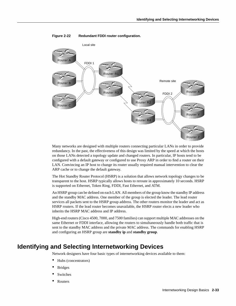
Internetworking Design Basics 2-33
Identifying and Selecting Internetworking Devices
Figure 2-22 Redundant FDDI router configuration.
Many networks are designed with multiple routers connecting particular LANs in order to provideredundancy. In the past, the effectiveness of this design was limited by the speed at which the hostson those LANs detected a topology update and changed routers. In particular, IP hosts tend to beconfigured with a default gateway or configured to use Proxy ARP in order to find a router on theirLAN. Convincing an IP host to change its router usually required manual intervention to clear theARP cache or to change the default gateway.
The Hot Standby Router Protocol (HSRP) is a solution that allows network topology changes to betransparent to the host. HSRP typically allows hosts to reroute in approximately 10 seconds. HSRPis supported on Ethernet, Token Ring, FDDI, Fast Ethernet, and ATM.
An HSRP group can be defined on each LAN. All members of the group know the standby IP addressand the standby MAC address. One member of the group is elected the leader. The lead routerservices all packets sent to the HSRP group address. The other routers monitor the leader and act asHSRP routers. If the lead router becomes unavailable, the HSRP router elects a new leader whoinherits the HSRP MAC address and IP address.
High-end routers (Cisco 4500, 7000, and 7500 families) can support multiple MAC addresses on thesame Ethernet or FDDI interface, allowing the routers to simultaneously handle both traffic that issent to the standby MAC address and the private MAC address. The commands for enabling HSRPand configuring an HSRP group arestandby ip andstandby group.
Identifying and Selecting Internetworking DevicesNetwork designers have four basic types of internetworking devices available to them:
• Hubs (concentrators)
• Bridges
• Switches
• Routers
FDDI 1
FDDI 2
Local site
Remote site
Router A
Router B
Router C
Router R1
Router R3
Router R2
Router R4
Router X
Router Y
Router Z

Identifying and Selecting Internetworking Devices
Cisco CCIE Fundamentals: Network Design2-34
For a summary of these four internetworking devices, see Table 2-1 earlier in this chapter. Datacommunications experts generally agree that network designers are moving away from bridges andprimarily using switches and routers to build internetworks. Consequently, this section focuses onthe role of switches and routers in designing internetworks.
Switches can be functionally divided into two main groups: Layer 2 switches and multilayerswitches that provide Layer 2 and Layer 3 switching capabilities. Today, network designers arereplacing hubs in their wiring closets with switches to increase their network performance andprotect their existing wiring investments.
Routers segment network traffic based on the destination network layer address (Layer 3) rather thanthe workstation data link layer or MAC address. Consequently, routers are protocol dependent.
Benefits of Switches (Layer 2 Services)An individual Layer 2 switch might offer some or all of the following benefits:
• Bandwidth—LAN switches provide excellent performance for individual users by allocatingdedicated bandwidth to each switch port. Each switch port represents a different networksegment. This technique is known asmicrosegmenting.
• VLANs—LAN switches can group individual ports into switched logical workgroups calledVLANs, thereby restricting the broadcast domain to designated VLAN member ports. VLANsare also known as switched domains and autonomous switching domains. Communicationbetween VLANs requires a router.
• Automated packet recognition and translation—This capability allows the switch to translateframe formats automatically, such as Ethernet MAC to FDDI SNAP.
Benefits of Routers (Layer 3 Services)Because routers use Layer 3 addresses, which typically have structure, routers can use techniques(such as address summarization) to build networks that maintain performance and responsiveness asthey grow in size. By imposing structure (usually hierarchical) on a network, routers can effectivelyuse redundant paths and determine optimal routes even in a dynamically changing network.
Routers are necessary to ensure scalability as the network grows and expands. They provide thefollowing capabilities that are vital in network designs:
• Broadcast and multicast control
• Broadcast segmentation
• Security
• Quality of service (QoS)
• Multimedia
Backbone Routing OptionsIn an ideal world, the perfect enterprise-wide internetwork would feature a single, bullet-proofnetwork protocol capable of transporting all manner of data communications seamlessly, error free,and with sufficient resilience to accommodate any unforeseen connectivity disruption. However, inthe real world, there are many protocols with varying levels of resilience.
In designing a backbone for your organization, you might consider several options. These optionsare typically split into the following two primary categories:

Internetworking Design Basics 2-35
Types of Switches
• Multiprotocol routing backbone
• Single-protocol backbone
The following discussions outline the characteristics and properties of these two strategies.
Multiprotocol Routing BackboneWhen multiple network layer protocols are routed throughout a common backbone withoutencapsulation (also referred to asnative mode routing), the environment is referred to as amultiprotocol routing backbone. A multiprotocol backbone environment can adopt one of tworouting strategies, or both, depending on the routed protocol involved. The two strategies aregenerally referred to as the following:
• Integrated routing—Integrated routing involves the use of a single routing protocol (for example,a link state protocol) that determines the least cost path for different routed protocols.
• Ships in the night—The ships-in-the-night approach involves the use of a different routingprotocol for each network protocol. For instance, some large-scale networks might featuremultiple protocols in which Novell IPX traffic is routed using a proprietary version of the RoutingInformation Protocol (RIP), IP is routed with IGRP, and DECnet Phase V traffic is routed via ISOCLNS-compliant IS-IS.
Each of these network layer protocols is routed independently, with separate routing processeshandling their traffic and separate paths calculated. Mixing routers within an internetwork thatsupports different combinations of multiple protocols can create a confusing situation, particularlyfor integrated routing. In general, integrated routing is easier to manage if all the routers attached tothe integrated routing backbone support the same integrated routing scheme. Routes for otherprotocols can be calculated separately. As an alternative, you can use encapsulation to transmit trafficover routers that do not support a particular protocol.
Single-Protocol BackboneWith a single-protocol backbone, all routers are assumed to support a single routing protocol for asingle network protocol. In this kind of routing environment, all other routing protocols are ignored.If multiple protocols are to be passed over the internetwork, unsupported protocols must beencapsulated within the supported protocol or they will be ignored by the routing nodes.
Why implement a single-protocol backbone? If relatively few other protocols are supported at alimited number of isolated locations, it is reasonable to implement a single protocol backbone.However, encapsulation does add overhead to traffic on the network. If multiple protocols aresupported widely throughout a large internetwork, a multiprotocol backbone approach is likely towork better.
In general, you should support all the network layer protocols in an internetwork with a nativerouting solution and implement as few network layer protocols as possible.
Types of SwitchesSwitches can be categorized as follows:
• LAN switches—The switches within this category can be further divided into Layer 2 switchesand multilayer switches.
• ATM switches—ATM switching and ATM routers offer greater backbone bandwidth required byhigh-throughput data services.
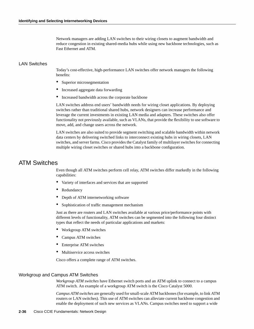
Identifying and Selecting Internetworking Devices
Cisco CCIE Fundamentals: Network Design2-36
Network managers are adding LAN switches to their wiring closets to augment bandwidth andreduce congestion in existing shared-media hubs while using new backbone technologies, such asFast Ethernet and ATM.
LAN SwitchesToday’s cost-effective, high-performance LAN switches offer network managers the followingbenefits:
• Superior microsegmentation
• Increased aggregate data forwarding
• Increased bandwidth across the corporate backbone
LAN switches address end users’ bandwidth needs for wiring closet applications. By deployingswitches rather than traditional shared hubs, network designers can increase performance andleverage the current investments in existing LAN media and adapters. These switches also offerfunctionality not previously available, such as VLANs, that provide the flexibility to use software tomove, add, and change users across the network.
LAN switches are also suited to provide segment switching and scalable bandwidth within networkdata centers by delivering switched links to interconnect existing hubs in wiring closets, LANswitches, and server farms. Cisco provides the Catalyst family of multilayer switches for connectingmultiple wiring closet switches or shared hubs into a backbone configuration.
ATM SwitchesEven though all ATM switches perform cell relay, ATM switches differ markedly in the followingcapabilities:
• Variety of interfaces and services that are supported
• Redundancy
• Depth of ATM internetworking software
• Sophistication of traffic management mechanism
Just as there are routers and LAN switches available at various price/performance points withdifferent levels of functionality, ATM switches can be segmented into the following four distincttypes that reflect the needs of particular applications and markets:
• Workgroup ATM switches
• Campus ATM switches
• Enterprise ATM switches
• Multiservice access switches
Cisco offers a complete range of ATM switches.
Workgroup and Campus ATM SwitchesWorkgroup ATM switches have Ethernet switch ports and an ATM uplink to connect to a campusATM switch. An example of a workgroup ATM switch is the Cisco Catalyst 5000.
Campus ATM switchesare generally used for small-scale ATM backbones (for example, to link ATMrouters or LAN switches). This use of ATM switches can alleviate current backbone congestion andenable the deployment of such new services as VLANs. Campus switches need to support a wide

Internetworking Design Basics 2-37
Switches and Routers Compared
variety of both local backbone and WAN types, but be price/performance optimized for the localbackbone function. In this class of switches, ATM routing capabilities that allow multiple switchesto be tied together is very important. Congestion control mechanisms for optimizing backboneperformance is also important. The LightStream 1010 family of ATM switches is an example of acampus ATM switch. For more information on deploying workgroup and campus ATM switches inyour internetwork, see Chapter 12, “Designing Switched LAN Internetworks.”
Enterprise ATM SwitchesEnterprise ATM switches are sophisticated multiservice devices that are designed to form the corebackbones of large, enterprise networks. They are intended to complement the role played by today’shigh-end multiprotocol routers. Enterprise ATM switches are used to interconnect campus ATMswitches. Enterprise-class switches, however, can act not only as ATM backbones but can serve asthe single point of integration for all of the disparate services and technology found in enterprisebackbones today. By integrating all of these services onto a common platform and a common ATMtransport infrastructure, network designers can gain greater manageability and eliminate the need formultiple overlay networks.
Cisco’s BPX/AXIS is a powerful broadband ATM switch designed to meet the demanding,high-traffic needs of a large private enterprise or public service provider. For more information ondeploying enterprise ATM switches in your internetwork, see Chapter 8, “Designing ATMInternetworks.”
Multiservice Access SwitchesBeyond private networks, ATM platforms will also be widely deployed by service providers both ascustomer premises equipment (CPE) and within public networks. Such equipment will be used tosupport multiple MAN and WAN services—for example, Frame Relay switching, LANinterconnect, or public ATM services—on a common ATM infrastructure. Enterprise ATM switcheswill often be used in these public network applications because of their emphasis on high availabilityand redundancy, their support of multiple interfaces, and capability to integrate voice and data.
Switches and Routers ComparedTo highlight the differences between switches and routers, the following sections examine thedifferent roles of these devices in the following situations:
• Implementation of VLANs
• Implementation of switched internetworks
Role of Switches and Routers in VLANsVLANs address the following two problems:
• Scalability issues of a flat network topology
• Simplification of network management by facilitating network reconfigurations (moves andchanges)
A VLAN consists of a single broadcast domain and solves the scalability problems of large flatnetworks by breaking a single broadcast domain into several smaller broadcast domains or VLANs.Virtual LANs offer easier moves and changes in a network design than traditional networks. LANswitches can be used to segment networks into logically defined virtual workgroups. This logicalsegmentation, commonly referred to as VLAN communication, offers a fundamental change in how

Identifying and Selecting Internetworking Devices
Cisco CCIE Fundamentals: Network Design2-38
LANs are designed, administered, and managed. Although logical segmentation provides substantialbenefits in LAN administration, security, and management of network broadcast across theenterprise, there are many components of VLAN solutions that network designers should considerprior to large scale VLAN deployment.
Switches and routers each play an important role in VLAN design. Switches are the core devicethat controls individual VLANs while routers provide interVLAN communication, as shown inFigure 2-23.
Figure 2-23 Role of switches and routers in VLANs.
Switches remove the physical constraints imposed by a shared-hub architecture because theylogically group users and ports across the enterprise. As a replacement for shared hubs, switchesremove the physical barriers imposed within each wiring closet. Additionally, the role of the routerevolves beyond the more traditional role of firewalls and broadcast suppression to policy-basedcontrol, broadcast management, and route processing and distribution. Equally as important,routers remain vital for switched architectures configured as VLANs because they provide thecommunication between VLANs. Routers also provide VLAN access to shared resources, such asservers and hosts. For more information on deploying VLANs, see Chapter 12, “Designing SwitchedLAN Internetworks.”
Examples of Campus Switched Internetwork DesignsA successful campus switched internetworking solution must combine the benefits of both routersand switches in every part of the network, as well as offer a flexible evolution path fromshared-media networking to switched internetworks.
For example, incorporating switches in campus network designs will generally result in thefollowing benefits:
• High bandwidth
• Improved performance
• Low cost
• Easy configuration
If you need advanced internetworking services, however, routers are necessary. Routers offer thefollowing services:
Floor 3
Access controlbetween VLANs
VLAN Group 1 VLAN Group 2
Floor 2
Floor 1

Internetworking Design Basics 2-39
Switches and Routers Compared
• Broadcast firewalling
• Hierarchical addressing
• Communication between dissimilar LANs
• Fast convergence
• Policy routing
• QoS routing
• Security
• Redundancy and load balancing
• Traffic flow management
• Multimedia group membership
Some of these router services will be offered by switches in the future. For example, support formultimedia often requires a protocol, such as Internet Group Management Protocol (IGMP), thatallows workstations to join a group that receives multimedia multicast packets. In the future, Ciscowill allow switches to participate in this process by using the Cisco Group Management Protocol(CGMP). One router will still be necessary, but you will not need a router in each departmentbecause CGMP switches can communicate with the router to determine if any of their attached usersare part of a multicast group.
Switching and bridging sometimes can result in non-optimal routing of packets. This is becauseevery packet must go through the root bridge of the spanning tree. When routers are used, the routingof packets can be controlled and designed for optimal paths. Cisco now provides support forimproved routing and redundancy in switched environments by supporting one instance of thespanning tree per VLAN.
The following figures illustrate how network designers can use switches and routers to evolve theirshared-media networks to switching internetworks. Typically, this evolution to a campus switchedinternetwork architecture will extend over four phases.
Phase 1 is the microsegmentation phase in which network designers retain their hubs and routers,but insert a LAN switch to enhance performance. Figure 2-24 shows an example of how a LANswitch can be used to segment a network.
Figure 2-24 Using switches for microsegmentation.
Cisco router
Shared hubLAN switch

Identifying and Selecting Internetworking Devices
Cisco CCIE Fundamentals: Network Design2-40
Phase 2 is the addition of high-speed backbone technology and routing between switches. LANswitches perform switch processing and provide dedicated bandwidth to the desktop and toshared-media hubs. Backbone routers are attached to either Fast Ethernet or ATM switches. Theincrease in backbone bandwidth matches the increase bandwidth in the wiring closet. Figure 2-25shows an example of how you can add high-speed backbone technology and routing betweenexisting switches in your network.
Figure 2-25 Adding high-speed backbone technology and routing between switches.
In Phase 3, routers are distributed between the LAN switches in the wiring closet and the high-speedcore switch. The network backbone is now strictly a high-speed transport mechanism with all otherdevices, such as the distributed routers, at the periphery. Figure 2-26 illustrates such a network.
Figure 2-26 Distributing routers between high-speed core and LAN switches.
ATM campus switch
LAN switch
High-speedcore switch
Router
LAN switch
High-speedswitch

Internetworking Design Basics 2-41
Summary
Phase 4 is the final phase—the end point. It involves end-to-end switching with integral VLANs andmultilayer switching capability. By this point, Layer 2 and Layer 3 integrated switching is distributedacross the network and is connected to the high-speed core. Figure 2-27 shows an example of thisfinal phase.
Figure 2-27 End-to-end switching with VLAN and multilayer switching capability.
SummaryNow that the basic internetworking devices and general design principles have been examined, theremaining chapters in this part focus on the different technologies available when designing aninternetwork.
RouterHigh-speedcore switch
LAN switch
Si
Si

Summary
Cisco CCIE Fundamentals: Network Design2-42

C H A P T E R
Designing Large-Scale IP Internetworks 3-1
3
Designing Large-ScaleIP Internetworks
This chapter focuses on the following design implications of the Enhanced Interior Gateway RoutingProtocol (IGRP), Open Shortest Path First (OSPF) protocols, and the Border Gateway Protocol(BGP):
• Network Topology
• Addressing and Route Summarization
• Route Selection
• Convergence
• Network Scalability
• Security
Enhanced IGRP, OSPF, and BGP are routing protocols for the Internet Protocol (IP). Anintroductory discussion outlines general routing protocol issues; subsequent discussions focus ondesign guidelines for the specific IP protocols.
Implementing Routing ProtocolsThe following discussion provides an overview of the key decisions you must make when selectingand deploying routing protocols. This discussion lays the foundation for subsequent discussionsregarding specific routing protocols.
Network TopologyThe physical topology of an internetwork is described by the complete set of routers and thenetworks that connect them. Networks also have a logical topology. Different routing protocolsestablish the logical topology in different ways.
Some routing protocols do not use a logical hierarchy. Such protocols use addressing to segregatespecific areas or domains within a given internetworking environment and to establish a logicaltopology. For such nonhierarchical, orflat, protocols, no manual topology creation is required.
Other protocols require the creation of an explicit hierarchical topology through establishment of abackbone and logical areas. The OSPF and Intermediate System-to-Intermediate System (IS-IS)protocols are examples of routing protocols that use a hierarchical structure. A general hierarchicalnetwork scheme is illustrated in Figure 3-1. The explicit topology in a hierarchical scheme takesprecedence over the topology created through addressing.

Implementing Routing Protocols
Internetwork Design Guide3-2
Figure 3-1 Hierarchical network.
If a hierarchical routing protocol is used, the addressing topology should be assigned to reflect thehierarchy. If a flat routing protocol is used, the addressing implicitly creates the topology. There aretwo recommended ways to assign addresses in a hierarchical network. The simplest way is to giveeach area (including the backbone) a unique network address. An alternative is to assign addressranges to each area.
Areas are logical collections of contiguous networks and hosts. Areas also include all the routershaving interfaces on any one of the included networks. Each area runs a separate copy of the basicrouting algorithm. Therefore, each area has its own topological database.
Addressing and Route SummarizationRoute summarization procedures condense routing information. Without summarization, eachrouter in a network must retain a route to every subnet in the network. With summarization, routerscan reduce some sets of routes to a single advertisement, reducing both the load on the router andthe perceived complexity of the network. The importance of route summarization increases withnetwork size.
Figure 3-2 illustrates an example of route summarization. In this environment, Router R2 maintainsone route for all destination networks beginning with B, and Router R4 maintains one route for alldestination networks beginning with A. This is the essence of route summarization. Router R1 tracksall routes because it exists on the boundary between A and B.
Backbone
Area 1 Area 2 Area 3
Router Router Router
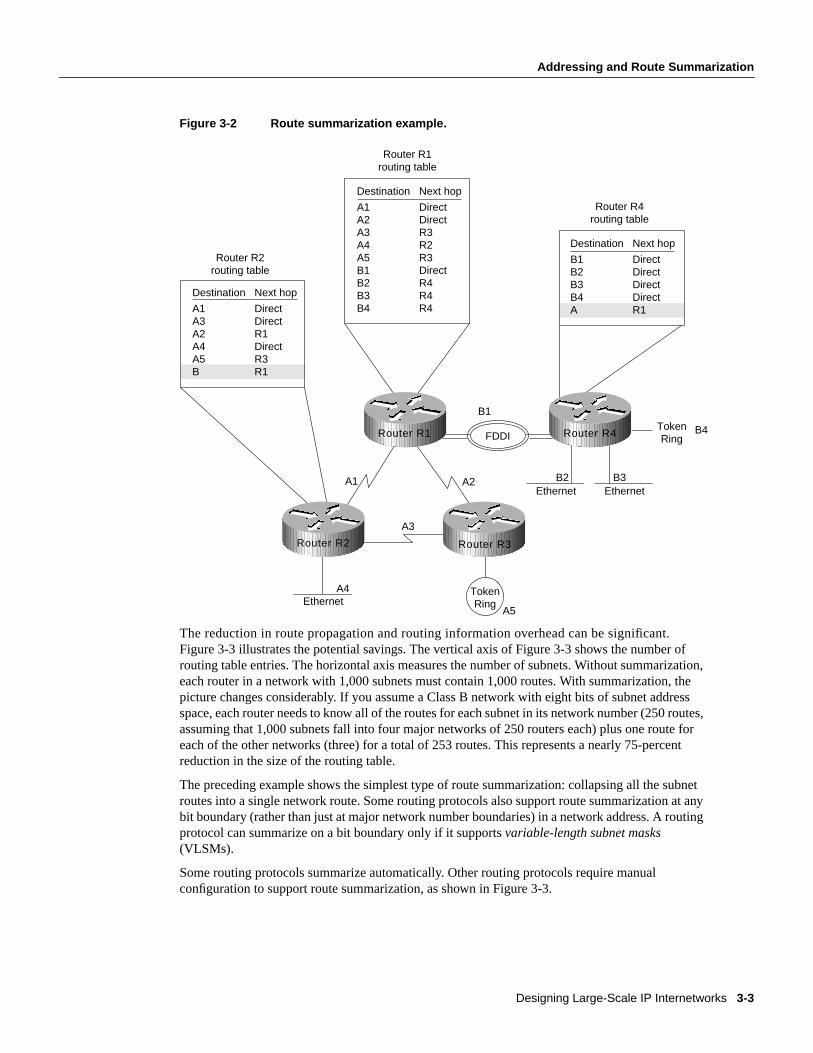
Designing Large-Scale IP Internetworks 3-3
Addressing and Route Summarization
Figure 3-2 Route summarization example.
The reduction in route propagation and routing information overhead can be significant.Figure 3-3 illustrates the potential savings. The vertical axis of Figure 3-3 shows the number ofrouting table entries. The horizontal axis measures the number of subnets. Without summarization,each router in a network with 1,000 subnets must contain 1,000 routes. With summarization, thepicture changes considerably. If you assume a Class B network with eight bits of subnet addressspace, each router needs to know all of the routes for each subnet in its network number (250 routes,assuming that 1,000 subnets fall into four major networks of 250 routers each) plus one route foreach of the other networks (three) for a total of 253 routes. This represents a nearly 75-percentreduction in the size of the routing table.
The preceding example shows the simplest type of route summarization: collapsing all the subnetroutes into a single network route. Some routing protocols also support route summarization at anybit boundary (rather than just at major network number boundaries) in a network address. A routingprotocol can summarize on a bit boundary only if it supportsvariable-length subnet masks(VLSMs).
Some routing protocols summarize automatically. Other routing protocols require manualconfiguration to support route summarization, as shown in Figure 3-3.
TokenRing
TokenRingFDDI
EthernetA4
A1 A2
A3
EthernetB2
EthernetB3
B1
B4
A5
Destination
B1B2B3B4A
Next hop
DirectDirectDirectDirectR1
Router R4routing table
Destination
A1A2A3A4A5B1B2B3B4
Next hop
DirectDirectR3R2R3DirectR4R4R4
Router R1routing table
Destination
A1A3A2A4A5B
Next hop
DirectDirectR1DirectR3R1
Router R2routing table
Router R1 Router R4
Router R2 Router R3

Implementing Routing Protocols
Internetwork Design Guide3-4
Figure 3-3 Route summarization benefits.
Route SelectionRoute selection is trivial when only a single path to the destination exists. However, if any part ofthat path should fail, there is no way to recover. Therefore, most networks are designed with multiplepaths so there are alternatives in case a failure occurs.
Routing protocols compare route metrics to select the best route from a group of possible routes.Route metrics are computed by assigning a characteristic or set of characteristics to each physicalnetwork. The metric for the route is an aggregation of the characteristics of each physical networkin the route. Figure 3-4 shows a typical meshed network with metrics assigned to each link and thebest route from source to destination identified.
Figure 3-4 Routing metrics and route selection.
Routing protocols use different techniques for assigning metrics to individual networks. Further,each routing protocol forms a metric aggregation in a different way. Most routing protocols can usemultiple paths if the paths have an equal cost. Some routing protocols can even use multiple pathswhen paths have an unequal cost. In either case, load balancing can improve overall allocation ofnetwork bandwidth.
0
250
500
750
1000
0 250 500 750 1000
Without summarization
Routingtable
entries
Number of subnets
With summarization
Source Destination
5
6
8
4
2
3 5
7
13
8
3
Router 1 Router 4
Router 3
Router 2 Router 5

Designing Large-Scale IP Internetworks 3-5
Convergence
When multiple paths are used, there are several ways to distribute the packets. The two mostcommon mechanisms areper-packet load balancingandper-destination load balancing. Per-packetload balancing distributes the packets across the possible routes in a manner proportional to the routemetrics. With equal-cost routes, this is equivalent to a round-robin scheme. One packet or destination(depending on switching mode) is distributed to each possible path. Per-destination load balancingdistributes packets across the possible routes based on destination. Each new destination is assignedthe next available route. This technique tends to preserve packet order.
Note Most TCP implementations can accommodate out-of-order packets. However, out-of-orderpackets may cause performance degradation.
When fast switching is enabled on a router (default condition), route selection is done on a per-destination basis. When fast switching is disabled, route selection is done on a per-packet basis. Forline speeds of 56 Kbps and faster, fast switching is recommended.
ConvergenceWhennetwork topology changes, network traffic must reroute quickly. The phrase “convergencetime” describes the time it takes a router to start using a new route after a topology changes. Routersmust do three things after a topology changes:
• Detect the change
• Select a new route
• Propagate the changed route information
Some changes are immediately detectable. For example, serial line failures that involve carrier lossare immediately detectable by a router. Other failures are harder to detect. For example, if a serialline becomes unreliable but the carrier is not lost, the unreliable link is not immediately detectable.In addition, some media (Ethernet, for example) do not provide physical indications such as carrierloss. When a router is reset, other routers do not detect this immediately. In general, failure detectionis dependent on the media involved and the routing protocol used.
Once a failure has been detected, the routing protocol must select a new route. The mechanisms usedto do this are protocol-dependent. All routing protocols must propagate the changed route. Themechanisms used to do this are also protocol-dependent.
Network ScalabilityThe capability to extend your internetwork is determined, in part, by the scaling characteristics ofthe routing protocols used and the quality of the network design.
Network scalability is limited by two factors: operational issues and technical issues. Typically,operational issues are more significant than technical issues. Operational scaling concerns encouragethe use of large areas or protocols that do not require hierarchical structures. When hierarchicalprotocols are required, technical scaling concerns promote the use of small areas. Finding the rightbalance is the art of network design.
From a technical standpoint, routing protocols scale well if their resource use grows less thanlinearly with the growth of the network. Three critical resources are used by routing protocols:memory, central processing unit (CPU), and bandwidth.

Implementing Routing Protocols
Internetwork Design Guide3-6
MemoryRouting protocols use memory to store routing tables and topology information. Routesummarization cuts memory consumption for all routing protocols. Keeping areas small reduces thememory consumption for hierarchical routing protocols.
CPUCPU usage is protocol-dependent. Some protocols use CPU cycles to compare new routes to existingroutes. Other protocols use CPU cycles to regenerate routing tables after a topology change. In mostcases, the latter technique will use more CPU cycles than the former. For link-state protocols,keeping areas small and using summarization reduces CPU requirements by reducing the effect of atopology change and by decreasing the number of routes that must be recomputed after a topologychange.
BandwidthBandwidth usage is also protocol-dependent. Three key issues determine the amount of bandwidtha routing protocol consumes:
• When routing information is sent—Periodic updates are sent at regular intervals. Flash updatesare sent only when a change occurs.
• What routing information is sent—Complete updates contain all routing information. Partialupdates contain only changed information.
• Where routing information is sent—Flooded updates are sent to all routers. Bounded updates aresent only to routers that are affected by a change.
Note These three issues also affect CPU usage.
Distance vector protocols such as Routing Information Protocol (RIP), Interior Gateway RoutingProtocol (IGRP), Internetwork Packet Exchange (IPX) RIP, IPX Service Advertisement Protocol(SAP), and Routing Table Maintenance Protocol (RTMP), broadcast their complete routing tableperiodically, regardless of whether the routing table has changed. This periodic advertisement variesfrom every 10 seconds for RTMP to every 90 seconds for IGRP. When the network is stable, distancevector protocols behave well but waste bandwidth because of the periodic sending of routing tableupdates, even when no change has occurred. When a failure occurs in the network, distance vectorprotocols do not add excessive load to the network, but they take a long time to reconverge to analternative path or to flush a bad path from the network.
Link-state routing protocols, such as Open Shortest Path First (OSPF), Intermediate System-to-Intermediate System (IS-IS), and NetWare Link Services Protocol (NLSP), were designed toaddress the limitations of distance vector routing protocols (slow convergence and unnecessarybandwidth usage). Link-state protocols are more complex than distance vector protocols, andrunning them adds to the router’s overhead. The additional overhead (in the form of memoryutilization and bandwidth consumption when link-state protocols first start up) constrains thenumber of neighbors that a router can support and the number of neighbors that can be in an area.
When the network is stable, link-state protocols minimize bandwidth usage by sending updates onlywhen a change occurs. A hello mechanism ascertains reachability of neighbors. When a failureoccurs in the network, link-state protocols flood link-state advertisements (LSAs) throughout anarea. LSAs cause every router within the failed area to recalculate routes. The fact that LSAs needto be flooded throughout the area in failure mode and the fact that all routers recalculate routingtables constrain the number of neighbors that can be in an area.

Designing Large-Scale IP Internetworks 3-7
Security
Enhanced IGRP is an advanced distance vector protocol that has some of the properties of link-stateprotocols. Enhanced IGRP addresses the limitations of conventional distance vector routingprotocols (slow convergence and high bandwidth consumption in a steady state network). When thenetwork is stable, Enhanced IGRP sends updates only when a change in the network occurs. Likelink-state protocols, Enhanced IGRP uses a hello mechanism to determine the reachability ofneighbors. When a failure occurs in the network, Enhanced IGRP looks for feasible successors bysending messages to its neighbors. The search for feasible successors can be aggressive in terms ofthe traffic it generates (updates, queries, and replies) to achieve convergence. This behaviorconstrains the number of neighbors that is possible.
In WANs, consideration of bandwidth is especially critical. For example, Frame Relay, whichstatistically multiplexes many logical data connections (virtual circuits) over a single physical link,allows the creation of networks that share bandwidth. Public Frame Relay networks use bandwidthsharing at all levels within the network. That is, bandwidth sharing may occur within the FrameRelay network of Corporation X, as well as between the networks of Corporation X andCorporation Y.
Two factors have a substantial effect on the design of public Frame Relay networks:
• Users are charged for each permanent virtual circuit (PVC), which encourages network designersto minimize the number of PVCs.
• Public carrier networks sometimes provide incentives to avoid the use of committed informationrate (CIR) circuits. Although service providers try to ensure sufficient bandwidth, packets can bedropped.
Overall, WANs can lose packets because of lack of bandwidth. For Frame Relay networks, thispossibility is compounded because Frame Relay does not have a broadcast replication facility, so forevery broadcast packet that is sent out a Frame Relay interface, the router must replicate it for eachPVC on the interface. This requirement limits the number of PVCs that a router can handleeffectively.
In addition to bandwidth, network designers must consider the size of routing tables that need to bepropagated. Clearly, the design considerations for an interface with 50 neighbors and 100 routes topropagate are very different from the considerations for an interface with 50 neighbors and10,000 routes to propagate. Table 3-1 gives a rough estimate of the number of WAN neighbors thata routing protocol can handle effectively.
Table 3-1 Routing Protocols and Number of WAN Neighbors
SecurityControlling access to network resources is a primary concern. Some routing protocols providetechniques that can be used as part of a security strategy. With some routing protocols, you can inserta filter on the routes being advertised so that certain routes are not advertised in some parts of thenetwork.
Routing Protocol Number of Neighbors per Router
Distance vector 50
Link state 30
Advanced distance vector 30

Enhanced IGRP Internetwork Design Guidelines
Internetwork Design Guide3-8
Some routing protocols can authenticate routers that run the same protocol. Authenticationmechanisms are protocol specific and generally weak. In spite of this, it is worthwhile to takeadvantage of the techniques that exist. Authentication can increase network stability by preventingunauthorized routers or hosts from participating in the routing protocol, whether those devices areattempting to participate accidentally or deliberately.
Enhanced IGRP Internetwork Design GuidelinesThe Enhanced Interior Gateway Routing Protocol (Enhanced IGRP) is a routing protocol developedby Cisco Systems and introduced with Software Release 9.21 and Cisco Internetworking OperatingSystem (Cisco IOS) Software Release 10.0. Enhanced IGRP combines the advantages of distancevector protocols, such as IGRP, with the advantages of link-state protocols, such as Open ShortestPath First (OSPF). Enhanced IGRP uses the Diffusing Update ALgorithm (DUAL) to achieveconvergence quickly.
Enhanced IGRP includes support for IP, Novell NetWare, and AppleTalk. The discussion onEnhanced IGRP covers the following topics:
• Enhanced IGRP Network Topology
• Enhanced IGRP Addressing
• Enhanced IGRP Route Summarization
• Enhanced IGRP Route Selection
• Enhanced IGRP Convergence
• Enhanced IGRP Network Scalability
• Enhanced IGRP Security
Caution If you are usingcandidate default routein IP Enhanced IGRP and have installed multiple releasesof Cisco router software within your internetwork that include any versions prior to September 1994, contactyour Cisco technical support representative for version compatibility and software upgrade information.Refer to your software release notes for details.
Enhanced IGRP Network TopologyEnhanced IGRP uses a nonhierarchical (or flat) topology by default. Enhanced IGRP automaticallysummarizes subnet routes of directly connected networks at a network number boundary. Thisautomatic summarization is sufficient for most IP networks. See the section “Enhanced IGRP RouteSummarization” later in this chapter for more details.
Enhanced IGRP AddressingThe first step in designing an Enhanced IGRP network is to decide on how to address the network.In many cases, a company is assigned a single NIC address (such as a Class B network address) tobe allocated in a corporate internetwork. Bit-wise subnetting and variable-length subnetwork masks(VLSMs) can be used in combination to save address space. Enhanced IGRP for IP supports the useof VLSMs.
Consider a hypothetical network where a Class B address is divided into subnetworks, andcontiguous groups of these subnetworks are summarized by Enhanced IGRP. The Class B network156.77.0.0 might be subdivided as illustrated in Figure 3-5.

Designing Large-Scale IP Internetworks 3-9
Enhanced IGRP Route Summarization
Figure 3-5 Variable-length subnet masks (VLSMs) and route summarization boundaries.
In Figure 3-5, the letters x, y, and z represent bits of the last two octets of the Class B network asfollows:
• The fourx bits represent the route summarization boundary.
• The fivey bits represent up to 32 subnets per summary route.
• The seven z bits allow for 126 (128-2) hosts per subnet.
Enhanced IGRP Route SummarizationWith Enhanced IGRP, subnet routes of directly connected networks are automatically summarizedat network number boundaries. In addition, a network administrator can configure routesummarization at any interface with any bit boundary, allowing ranges of networks to besummarized arbitrarily.
Enhanced IGRP Route SelectionRouting protocols compare route metrics to select the best route from a group of possible routes. Thefollowing factors are important to understand when designing an Enhanced IGRP internetwork.Enhanced IGRP uses the same vector of metrics as IGRP. Separate metric values are assigned forbandwidth, delay, reliability, and load. By default, Enhanced IGRP computes the metric for a routeby using the minimum bandwidth of each hop in the path and adding a media-specific delay for eachhop. The metrics used by Enhanced IGRP are as follows:
• Bandwidth—Bandwidth is deduced from the interface type. Bandwidth can be modified with thebandwidth command.
• Delay—Each media type has a propagation delay associated with it. Modifying delay is veryuseful to optimize routing in network with satellite links. Delay can be modified with thedelaycommand.
• Reliability—Reliability is dynamically computed as a rolling weighted average over fiveseconds.
• Load—Load is dynamically computed as a rolling weighted average over five seconds.
When Enhanced IGRP summarizes a group of routes, it uses the metric of the best route in thesummary as the metric for the summary.
Note For information on Enhanced IGRP load sharing, see the section “SRB Technology Overviewand Implementation Issues” in Chapter 4, “Designing SRB Internetworks.”
156.77.xxxx yyyy.y zzzzzzz
Route summarization boundary
Subnet mask boundary

Enhanced IGRP Internetwork Design Guidelines
Internetwork Design Guide3-10
Enhanced IGRP ConvergenceEnhanced IGRP implements a new convergence algorithm known as DUAL (Diffusing UpdateALgorithm). DUAL uses two techniques that allow Enhanced IGRP to converge very quickly. First,each Enhanced IGRP router stores its neighbors’ routing tables. This allows the router to use a newroute to a destination instantly if anotherfeasibleroute is known. If no feasible route is known basedupon the routing information previously learned from its neighbors, a router running EnhancedIGRP becomesactive for that destination and sends a query to each of its neighbors, asking for analternative route to the destination. These queries propagate until an alternative route is found.Routers that are not affected by a topology change remainpassiveand do not need to be involved inthe query and response.
A router using Enhanced IGRP receives full routing tables from its neighbors when it firstcommunicates with the neighbors. Thereafter, onlychanges to the routing tables are sent and onlyto routersthat areaffectedby the change. Asuccessoris a neighboring router that is currently beingused for packet forwarding, provides theleast cost route to the destination, and is not part of arouting loop. Information in the routing table is based onfeasible successors. Feasible successorroutes can be used in case the existing route fails. Feasible successors provide thenext least-costpathwithout introducing routing loops.
The routing table keeps a list of the computed costs of reaching networks. The topology table keepsa list of all routes advertised by neighbors. For each network, the router keeps the real cost of gettingto that network and also keeps the advertised cost from its neighbor. In the event of a failure,convergence is instant if a feasible successor can be found. A neighbor is a feasible successor if itmeets the feasibility condition set by DUAL. DUAL finds feasible successors by the performing thefollowing computations:
• Determines membership of V1. V1 is the set of all neighbors whose advertised distance tonetworkx is less than FD. (FD is the feasible distance and is defined as the best metric during anactive-to-passive transition.)
• Calculates Dmin. Dmin is the minimum computed cost to networkx.
• Determines membership of V2. V2 is the set of neighbors that are in V1 whose computed cost tonetworkx equals Dmin.
The feasibility condition is met when V2 has one or more members. The concept of feasiblesuccessors is illustrated in Figure 3-6. Consider Router A’s topology table entries for Network 7.Router B is thesuccessorwith a computed cost of 31 to reach Network 7, compared to the computedcosts of Router D (230) and Router H (40).

Designing Large-Scale IP Internetworks 3-11
Enhanced IGRP Convergence
Figure 3-6 DUAL feasible successor.
If Router B becomes unavailable, Router A will go through the following three-step process to finda feasible successor for Network 7:
Step 1 Determining which neighbors have an advertised distance to Network 7 that is less thanRouter A’s feasible distance (FD) to Network 7. The FD is 31 and Router H meets thiscondition. Therefore, Router H is a member of V1.
Step 2 Calculating the minimum computed cost to Network 7. Router H provides a cost of 40,and Router D provides a cost of 230. Dmin is, therefore, 40.
Step 3 Determining the set of neighbors that are in V1 whose computed cost to Network 7 equalsDmin (40). Router H meets this condition.
The feasible successor is Router H which provides a least cost route of 40 from Router A toNetwork 7. If Router H now also becomes unavailable, Router A performs the followingcomputations:
Step 1 Determines which neighbors have an advertised distance to Network 7 that is less thanthe FD for Network 7. Because both Router B and H have become unavail- able, onlyRouter D remains. However, the advertised cost of Router D to Network 7 is 220, which isgreater than Router A’s FD (31) to Network 7. Router D, therefore, cannot be a memberof V1. The FD remains at 31—the FD can only change during an active-to-passivetransition, and this did not occur. There was no transition to active state for Network 7;this is known as alocal computation.
Step 2 Because there are no members of V1, there can be no feasible successors. Router A,therefore, transitions from passive to active state for Network 7 and queries its neighborsabout Network 7. There was a transition to active; this is known as adiffusingcomputation.
Network 3
Network 4 Network 5
Network 6
Network 1
(10) (10) (10)
(100)(100)
(1)
No.7 (31/21)(230/220)(40/30)
BDH
Network 8(20)
FDDI Dual ring
Network 2Network 7
Net Cost(computed/
adv.)
Neighbor
(10)
No.7No.7
Router H
Router A
Router B
Router D Router E Router F
Router C
Router G

Enhanced IGRP Internetwork Design Guidelines
Internetwork Design Guide3-12
The following example and graphics further illustrate how Enhanced IGRP supports virtuallyinstantaneous convergence in a changing internetwork environment. In Figure 3-7, all routers canaccess one another and Network N. The computed cost to reach other routers and Network N isshown. For example, the cost from Router E to Router B is 10. The cost from Router E to NetworkN is 25 (cumulative of 10 + 10 + 5 = 25).
Figure 3-7 DUAL example (part 1): initial network connectivity.
In Figure 3-8, the connection between Router B and Router E fails. Router E sends a multicast queryto all of its neighbors and puts Network N into an active state.
Figure 3-8 DUAL example (part 2): sending queries.
Next, as illustrated in Figure 3-9, Router D determines that it has a feasible successor. It changes itssuccessor from Router E to Router C and sends a reply to Router E.
Network N
Router E
(5)
(10)
(10)25
30
(15)
(15)
40
(15)
Router A
Router B
Router E Router D
Router C
Network N
E query
Router A
Router B Router C
Router E Router D

Designing Large-Scale IP Internetworks 3-13
Enhanced IGRP Network Scalability
Figure 3-9 UAL example (part 3): switching to a feasible successor.
In Figure 3-10, Router E has received replies from all neighbors and therefore brings Network N outof active state. Router E puts Network N into its routing table at a distance of 60.
Figure 3-10 Flow of intersubnet traffic with layer 3 switches.
Note Router A, Router B, and Router C were not involved in route recomputation. Router Drecomputed its path to Network N without first needing to learn new routing information from itsdownstream neighbors.
Enhanced IGRP Network ScalabilityNetwork scalability is limited by two factors: operational issues and technical issues. Operationally,Enhanced IGRP provides easy configuration and growth. Technically, Enhanced IGRP usesresources at less than a linear rate with the growth of a network.
Network N
D replies
Router A
Router B Router C
Router DRouter E
Network N
30
60
45
Router ARouter A
Router B Router C
Router DRouter E

OSPF Internetwork Design Guidelines
Internetwork Design Guide3-14
MemoryA router running Enhanced IGRP stores all routes advertised by neighbors so that it can adaptquickly to alternative routes. The more neighbors a router has, the more memory a router uses.Enhanced IGRP automatic route aggregation bounds the routing table growth naturally. Additionalbounding is possible with manual route aggregation.
CPUEnhanced IGRP uses the DUAL algorithm to provide fast convergence. DUAL recomputes onlyroutes which are affected by a topology change. DUAL is not computationally complex, so it doesnot require a lot of CPU.
BandwidthEnhanced IGRP uses partial updates. Partial updates are generated only when a change occurs; onlythe changed information is sent, and this changed information is sent only to the routers affected.Because of this, Enhanced IGRP is very efficient in its usage of bandwidth. Some additionalbandwidth is used by Enhanced IGRP’s HELLO protocol to maintain adjacencies betweenneighboring routers.
Enhanced IGRP SecurityEnhanced IGRP is available only on Cisco routers. This prevents accidental or malicious routingdisruption caused by hosts in a network. In addition, route filters can be set up on any interface toprevent learning or propagating routing information inappropriately.
OSPF Internetwork Design GuidelinesOSPF is an Interior Gateway Protocol (IGP) developed for use in Internet Protocol (IP)-basedinternetworks. As an IGP, OSPF distributes routing information between routers belonging to asingle autonomous system (AS). An AS is a group of routers exchanging routing information via acommon routing protocol. The OSPF protocol is based on shortest-path-first, or link-state,technology.
The OSPF protocol was developed by the OSPF working group of the Internet Engineering TaskForce (IETF). It was designed expressly for the Internet Protocol (IP) environment, includingexplicit support for IP subnetting and the tagging of externally derived routing information. OSPFVersion 2 is documented in Request for Comments (RFC) 1247.
Whether you are building an OSPF internetwork from the ground up or converting your internetworkto OSPF, the following design guidelines provide a foundation from which you can construct areliable, scalable OSPF-based environment.
Two design activities are critically important to a successful OSPF implementation:
• Definition of area boundaries
• Address assignment
Ensuring that these activities are properly planned and executed will make all the difference in yourOSPF implementation. Each is addressed in more detail with the discussions that follow. Thesediscussions are divided into nine sections:
• OSPF Network Topology
• OSPF Addressing and Route Summarization

Designing Large-Scale IP Internetworks 3-15
OSPF Network Topology
• OSPF Route Selection
• OSPF Convergence
• OSPF Network Scalability
• OSPF Security
• OSPF NSSA (Not-So-Stubby Area) Capabilities
• OSPF On Demand Circuit Protocol Issues
• OSPF over Non-Broadcast Networks
OSPF Network TopologyOSPF works best in a hierarchical routing environment. The first and most important decision whendesigning an OSPF network is to determine which routers and links are to be included in thebackbone and which are to be included in each area. There are several important guidelines toconsider when designing an OSPF topology:
• The number of routers in an area—OSPF uses a CPU-intensive algorithm. The number ofcalculations that must be performed givenn link-state packets is proportional ton log n. As aresult, the larger and more unstable the area, the greater the likelihood for performance problemsassociated with routing protocol recalculation. Generally, an area should have no more than50 routers. Areas with unstable links should be smaller.
• The number of neighbors for any one router—OSPF floods all link-state changes to all routers inan area. Routers with many neighbors have the most work to do when link-state changes occur.In general, any one router should have no more than 60 neighbors.
• The number of areas supported by any one router—A router must run the link-state algorithm foreach link-state change that occurs for every area in which the router resides. Every area borderrouter is in at least two areas (the backbone and one area). In general, to maximize stability, onerouter should not be in more than three areas.
• Designated router selection—In general, the designated router and backup designated router ona local-area network (LAN) have the most OSPF work to do. It is a good idea to select routersthat are not already heavily loaded with CPU-intensive activities to be the designated router andbackup designated router. In addition, it is generally not a good idea to select the same router tobe designated router on many LANs simultaneously.
The discussions that follow address topology issues that are specifically related to the backbone andthe areas.
Backbone ConsiderationsStabilityandredundancyare the most important criteria for the backbone. Stability is increased bykeeping the size of the backbone reasonable. This is caused by the fact that every router in thebackbone needs to recompute its routes after every link-state change. Keeping the backbone smallreduces the likelihood of a change and reduces the amount of CPU cycles required to recomputeroutes. As a general rule, each area (including the backbone) should contain no more than 50routers. If link quality is high and the number of routes is small, the number of routers can beincreased. Redundancy is important in the backbone to prevent partition when a link fails. Goodbackbones are designed so that no single link failure can cause a partition.
OSPF backbones must be contiguous. All routers in the backbone should be directly connected toother backbone routers. OSPF includes the concept of virtual links. A virtual link creates a pathbetween two area border routers (an area border router is a router connects an area to the backbone)

OSPF Internetwork Design Guidelines
Internetwork Design Guide3-16
that are not directly connected. A virtual link can be used to heal a partitioned backbone. However,it is not a good idea to design an OSPF network to require the use of virtual links. The stability of avirtual link is determined by the stability of the underlying area. This dependency can maketroubleshooting more difficult. In addition, virtual links cannot run across stub areas. See the section“Backbone-to-Area Route Advertisement” later in this chapter for a detailed discussion of stubareas.
Avoid placing hosts (such as workstations, file servers, or other shared resources) in the backbonearea. Keeping hosts out of the backbone area simplifies internetwork expansion and creates a morestable environment.
Area ConsiderationsIndividual areas must be contiguous. In this context, a contiguous area is one in which a continuouspath can be traced from any router in an area to any other router in the same area. This does not meanthat all routers must share common network media. It is not possible to use virtual links to connecta partitioned area. Ideally, areas should be richly connected internally to prevent partitioning. Thetwo most critical aspects of area design follow:
• Determining how the area is addressed
• Determining how the area is connected to the backbone
Areas should have a contiguous set of network and/or subnet addresses. Without a contiguousaddress space, it is not possible to implement route summarization. The routers that connect an areato the backbone are calledarea border routers. Areas can have a single area border router or theycan have multiple area border routers. In general, it is desirable to have more than one area borderrouter per area to minimize the chance of the area becoming disconnected from the backbone.
When creating large-scale OSPF internetworks, the definition of areas and assignment of resourceswithin areas must be done with a pragmatic view of your internetwork. The following are generalrules that help ensure that your internetwork remains flexible and provides the kind of performanceneeded to deliver reliable resource access:
• Consider physical proximity when defining areas—If a particular location is densely connected,create an area specifically for nodes at that location.
• Reduce the maximum size of areas if links are unstable—If your internetwork includes unstablelinks, consider implementing smaller areas to reduce the effects of route flapping. Whenever aroute is lost or comes online, each affected area must converge on a new topology. The Dykstraalgorithm will run on all the affected routers. By segmenting your internetwork into smallerareas, you can isolate unstable links and deliver more reliable overall service.
OSPF Addressing and Route SummarizationAddress assignment and route summarization are inextricably linked when designing OSPFinternetworks. To create a scalable OSPF internetwork, you should implement route summarization.To create an environment capable of supporting route summarization, you must implement aneffective hierarchical addressing scheme. The addressing structure that you implement can have aprofound impact on the performance and scalability of your OSPF internetwork. The followingsections discuss OSPF route summarization and three addressing options:
• Separate network numbers for each area
• Network Information Center (NIC)-authorized address areas created using bit-wise subnettingand VLSM
• Private addressing, with ademilitarized zone (DMZ) buffer to the official Internet world

Designing Large-Scale IP Internetworks 3-17
OSPF Addressing and Route Summarization
Note You should keep your addressing scheme as simple as possible, but be wary ofoversimplifying your address assignment scheme. Although simplicity in addressing saves time laterwhen operating and troubleshooting your network, taking shortcuts can have certain severeconsequences. In building a scalable addressing environment, use a structured approach. Ifnecessary, use bit-wise subnetting— but make sure that route summarization can be accomplishedat the area border routers.
OSPF Route SummarizationRoute summarization is extremely desirable for a reliable and scalable OSPF internetwork. Theeffectiveness of route summarization, and your OSPF implementation in general, hinges on theaddressing scheme that you adopt. Summarization in an OSPF internetwork occurs between eacharea and the backbone area. Summarization must be configured manually in OSPF. When planningyour OSPF internetwork, consider the following issues:
• Be sure that your network addressing scheme is configured so that the range of subnets assignedwithin an area is contiguous.
• Create an address space that will permit you to split areas easily as your network grows. Ifpossible, assign subnets according to simple octet boundaries. If you cannot assign addresses inan easy-to-remember and easy-to-divide manner, be sure to have a thoroughly defined addressingstructure. If you know how your entire address space is assigned (or will be assigned), you canplan for changes more effectively.
• Plan ahead for the addition of new routers to your OSPF environment. Be sure that new routersare inserted appropriately as area, backbone, or border routers. Because the addition of newrouters creates a new topology, inserting new routers can cause unexpected routing changes (andpossibly performance changes) when your OSPF topology is recomputed.
Separate Address Structures for Each AreaOne of the simplest ways to allocate addresses in OSPF is to assign a separate network number foreach area. With this scheme, you create a backbone and multiple areas, and assign a separate IPnetwork number to each area. Figure 3-11 illustrates this kind of area allocation.
Figure 3-11 Assignment of NIC addresses example.
Backbone82.0.0.0
Area 6131.108.0.0
Area 5195.22.56.0
Area 4150.98.0.0
Areaborderrouters
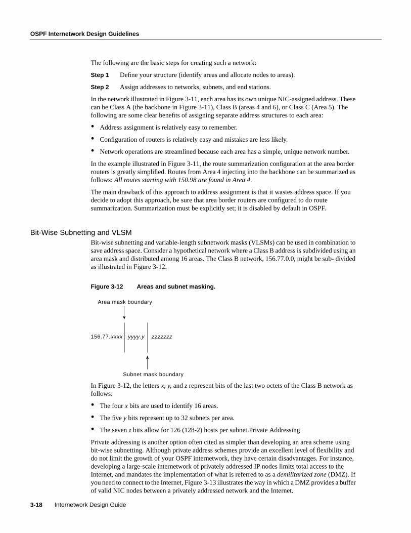
OSPF Internetwork Design Guidelines
Internetwork Design Guide3-18
The following are the basic steps for creating such a network:
Step 1 Define your structure (identify areas and allocate nodes to areas).
Step 2 Assign addresses to networks, subnets, and end stations.
In the network illustrated in Figure 3-11, each area has its own unique NIC-assigned address. Thesecan be Class A (the backbone in Figure 3-11), Class B (areas 4 and 6), or Class C (Area 5). Thefollowing are some clear benefits of assigning separate address structures to each area:
• Address assignment is relatively easy to remember.
• Configuration of routers is relatively easy and mistakes are less likely.
• Network operations are streamlined because each area has a simple, unique network number.
In the example illustrated in Figure 3-11, the route summarization configuration at the area borderrouters is greatly simplified. Routes from Area 4 injecting into the backbone can be summarized asfollows: All routes starting with 150.98 are found in Area 4.
The main drawback of this approach to address assignment is that it wastes address space. If youdecide to adopt this approach, be sure that area border routers are configured to do routesummarization. Summarization must be explicitly set; it is disabled by default in OSPF.
Bit-Wise Subnetting and VLSMBit-wise subnetting and variable-length subnetwork masks (VLSMs) can be used in combination tosave address space. Consider a hypothetical network where a Class B address is subdivided using anarea mask and distributed among 16 areas. The Class B network, 156.77.0.0, might be sub- dividedas illustrated in Figure 3-12.
Figure 3-12 Areas and subnet masking.
In Figure 3-12, the lettersx, y, andz represent bits of the last two octets of the Class B network asfollows:
• The fourx bits are used to identify 16 areas.
• The fivey bits represent up to 32 subnets per area.
• The seven z bits allow for 126 (128-2) hosts per subnet.Private Addressing
Private addressing is another option often cited as simpler than developing an area scheme usingbit-wise subnetting. Although private address schemes provide an excellent level of flexibility anddo not limit the growth of your OSPF internetwork, they have certain disadvantages. For instance,developing a large-scale internetwork of privately addressed IP nodes limits total access to theInternet, and mandates the implementation of what is referred to as ademilitarized zone(DMZ). Ifyou need to connect to the Internet, Figure 3-13 illustrates the way in which a DMZ provides a bufferof valid NIC nodes between a privately addressed network and the Internet.
156.77.xxxx yyyy.y zzzzzzz
Area mask boundary
Subnet mask boundary

Designing Large-Scale IP Internetworks 3-19
OSPF Addressing and Route Summarization
All nodes (end systems and routers) on the network in the DMZ must have NIC-assigned IPaddresses. The NIC might, for example, assign a single Class C network number to you. The DMZshown in Figure 3-13 has two routers and a single application gateway host (Garp). Router Aprovides the interface between the DMZ and the Internet, and Router B provides the firewall betweenthe DMZ and the private address environment. All applications that need to run over the Internetmust access the Internet through the application gateway.
Figure 3-13 Connecting to the Internet from a privately addressed network.
Route Summarization TechniquesRoute summarization is particularly important in an OSPF environment because it increases thestability of the network. If route summarization is being used, routes within an area that change donot need to be changed in the backbone or in other areas. Route summarization addresses twoimportant questions of route information distribution:
• What information does the backbone need to know about each area? The answer to this questionfocuses attention on area-to-backbone routing information.
• What information does each area need to know about the backbone and other areas? The answerto this question focuses attention on backbone-to-area routing information.
Locally administeredprivate address space
NIC-administeredInternet environment
Internet nodes communicatewith IP host Garp in DMZ
Garp provides electronic mail, file transfer, and any other
service to the Internet required by users in private networks
connected to Router B
NIC-compliantDMZ OSPF area
Router A
Router B
IP hostGarp

OSPF Internetwork Design Guidelines
Internetwork Design Guide3-20
Area-to-Backbone Route AdvertisementThere are several key considerations when setting up your OSPF areas for proper summarization:
• OSPF route summarization occurs in the area border routers.
• OSPF supports VLSM, so it is possible to summarize on any bit boundary in a network or subnetaddress.
• OSPF requires manual summarization. As you design the areas, you need to determinesummarization at each area border router.
Backbone-to-Area Route AdvertisementThere are four potential types of routing information in an area:
• Default—If an explicit route cannot be found for a given IP network or subnetwork, the routerwill forward the packet to the destination specified in the default route.
• Intra-area routes—Explicit network or subnet routes must be carried for all networks or subnetsinside an area.
• Interarea routes—Areas may carry explicit network or subnet routes for networks or subnets thatare in this AS but not in this area.
• External routes—When different ASs exchange routing information, the routes they exchangeare referred to as external routes.
In general, it is desirable to restrict routing information in any area to the minimal set that the areaneeds. There are three types of areas, and they are defined in accordance with the routing informationthat is used in them:
• Nonstub areas—Nonstub areas carry a default route, static routes, intra-area routes, interarearoutes, and external routes. An area must be a nonstub area when it contains a router that usesboth OSPF and any other protocol, such as the Routing Information Protocol (RIP). Such a routeris known as an autonomous system border router (ASBR). An area must also be a nonstub areawhen a virtual link is configured across the area. Nonstub areas are the most resource-intensivetype of area.
• Stub areas—Stub areas carry a default route, intra-area routes and interarea routes, but they donot carry external routes. Stub areas are recommended for areas that have only one area borderrouter and they are often useful in areas with multiple area border routers. See “ControllingInterarea Traffic” later in this chapter for a detailed discussion of the design trade-offs in areaswith multiple area border routers.There are two restrictions on the use of stub areas: Virtual linkscannot be configured across them and they cannot contain an ASBR.
• Stub areas without summaries—Software releases 9.1(11), 9.21(2), and 10.0(1) and later supportstub areas without summaries, allowing you to create areas that carry only a default route andintra-area routes. Stub areas without summaries do not carry interarea routes or external routes.This type of area is recommended for simple configurations in which a single router connects anarea to the backbone.
Table 3-2 shows the different types of areas according to the routing information that they use.

Designing Large-Scale IP Internetworks 3-21
OSPF Route Selection
Routing Information Used in OSPF Areas
Stub areas are configured using theareaarea-idstub router configuration command. Routes aresummarized using theareaarea-idrangeaddress mask router configuration command. Refer toyourRouter Products Configuration GuideandRouter Products Command Referencepublicationsfor more information regarding the use of these commands.
OSPF Route SelectionWhen designing an OSPF internetwork for efficient route selection, consider three important topics:
• Tuning OSPF Metrics
• Controlling Interarea Traffic
• Load Balancing in OSPF Internetworks
Tuning OSPF MetricsThe default value for OSPF metrics is based on bandwidth. The following characteristics show howOSPF metrics are generated:
• Each link is given a metric value based on its bandwidth. The metric for a specific link is theinverse of the bandwidth for that link. Link metrics are normalized to give FDDI a metric of 1.The metric for a route is the sum of the metrics for all the links in the route.
Note In some cases, your network might implement a media type that is faster than the fastestdefault media configurable for OSPF (FDDI). An example of a faster media is ATM. By default, afaster media will be assigned a cost equal to the cost of an FDDI link—a link-state metric cost of 1.Given an environment with both FDDI and a faster media type, you must manually configure linkcosts to configure the faster link with a lower metric. Configure any FDDI link with a cost greaterthan 1, and the faster link with a cost less than the assigned FDDI link cost. Use theip ospf costinterface configuration command to modify link-state cost.
• When route summarization is enabled, OSPF uses the metric of the best route in the summary.
• There are two forms of external metrics: type 1 and type 2. Using an external type 1 metric resultsin routes adding the internal OSPF metric to the external route metric. External type 2 metrics donot add the internal metric to external routes. The external type 1 metric is generally preferred.If you have more than one external connection, either metric can affect how multiple paths areused.
Area Type Default Route Intra-area Routes Interarea Routes External Routes
Nonstub Yes Yes Yes Yes
Stub Yes Yes Yes No
Stub without summaries Yes Yes No No

OSPF Internetwork Design Guidelines
Internetwork Design Guide3-22
Controlling Interarea TrafficWhen an area has only a single area border router, all traffic that does not belong in the area will besent to the area border router. In areas that have multiple area border routers, two choices areavailable for traffic that needs to leave the area:
• Use the area border router closest to the originator of the traffic. (Traffic leaves the area as soonas possible.)
• Use the area border router closest to the destination of the traffic. (Traffic leaves the area as lateas possible.)
If the area border routers inject only the default route, the traffic goes to the area border router thatis closest to the source of the traffic. Generally, this behavior is desirable because the backbonetypically has higher bandwidth lines available. However, if you want the traffic to use the area borderrouter that is nearest the destination (so that traffic leaves the area as late as possible), the area borderrouters should inject summaries into the area instead of just injecting the default route.
Most network designers prefer to avoid asymmetric routing (that is, using a different path for packetsthat are going from A to B than for those packets that are going from B to A). It is important tounderstand how routing occurs between areas to avoid asymmetric routing.
Load Balancing in OSPF InternetworksInternetwork topologies are typically designed to provide redundant routes in order to prevent apartitioned network. Redundancy is also useful to provide additional bandwidth for high trafficareas. If equal-cost paths between nodes exist, Cisco routers automatically load balance in an OSPFenvironment.
Cisco routers can use up to four equal-cost paths for a given destination. Packets might be distributedeither on a per-destination (when fast switching) or a per-packet basis. Per-destination loadbalancing is the default behavior. Per-packet load balancing can be enabled by turning off fastswitching using theno ip route-cacheinterface configuration command. For line speeds of 56 Kbpsand faster, it is recommended that you enable fast switching.
OSPF ConvergenceOne of the most attractive features about OSPF is the capability to quickly adapt to topologychanges. There are two components to routing convergence:
• Detection of topology changes—OSPF uses two mechanisms to detect topology changes.Interface status changes (such as carrier failure on a serial link) is the first mechanism. Thesecond mechanism is failure of OSPF to receive a hello packet from its neighbor within a timingwindow called adead timer. After this timer expires, the router assumes the neighbor is down.The dead timer is configured using theip ospf dead-interval interface configuration command.The default value of the dead timer is four times the value of the Hello interval. That results in adead timer default of 40 seconds for broadcast networks and two minutes for nonbroadcastnetworks.
• Recalculation of routes—After a failure has been detected, the router that detected the failuresends a link-state packet with the change information to all routers in the area. All the routersrecalculate all of their routes using the Dykstra (or SPF) algorithm. The time required to run thealgorithm depends on a combination of the size of the area and the number of routes in thedatabase.

Designing Large-Scale IP Internetworks 3-23
OSPF Network Scalability
OSPF Network ScalabilityYour ability to scale an OSPF internetwork depends on your overall network structure andaddressing scheme. As outlined in the preceding discussions concerning network topology and routesummarization, adopting a hierarchical addressing environment and a structured address assignmentwill be the most important factors in determining the scalability of your internetwork. Networkscalability is affected by operational and technical considerations:
• Operationally, OSPF networks should be designed so that areas do not need to be split toaccommodate growth. Address space should be reserved to permit the addition of new areas.
• Technically, scaling is determined by the utilization of three resources: memory, CPU, andbandwidth, all discussed in the following sections.
MemoryAn OSPF router stores all of the link states for all of the areas that it is in. In addition, it can storesummaries and externals. Careful use of summarization and stub areas can reduce memory usesubstantially.
CPUAn OSPF router uses CPU cycles whenever a link-state change occurs. Keeping areas small andusing summarization dramatically reduces CPU use and creates a more stable environment forOSPF.
BandwidthOSPF sends partial updates when a link-state change occurs. The updates are flooded to all routersin the area. In a quiet network, OSPF is a quiet protocol. In a network with substantial topologychanges, OSPF minimizes the amount of bandwidth used.
OSPF SecurityTwo kinds of security are applicable to routing protocols:
• Controlling the routers that participate in an OSPF network
OSPF contains an optional authentication field. All routers within an area must agree on the valueof the authentication field. Because OSPF is a standard protocol available on many platforms,including some hosts, using the authentication field prevents the inadvertent startup of OSPF inan uncontrolled platform on your network and reduces the potential for instability.
• Controlling the routing information that routers exchange
All routers must have the same data within an OSPF area. As a result, it is not possible to useroute filters in an OSPF network to provide security.
OSPF NSSA (Not-So-Stubby Area) OverviewPrior to NSSA, to disable an area from receiving external (Type 5) link-state advertisements (LSAs),the area needed to be defined as a stub area. Area Border Routers (ABRs) that connect stub areas donot flood any external routes they receive into the stub areas. To return packets to destinations outsideof the stub area, a default route through the ABR is used.

OSPF Internetwork Design Guidelines
Internetwork Design Guide3-24
RFC 1587 defines a hybrid area called the Not-So-Stubby Area (NSSA). An OSPF NSSA is similarto an OSPF stub area but allows for the following capabilities:
• Importing (redistribution) of external routes as Type 7 LSAs into NSSAs by NSSA AutonomousSystem Boundary Routers (ASBRs).
• Translation of specific Type 7 LSAs routes into Type 5 LSAs by NSSA ABRs.
Using OSPF NSSAUse OSPF NSSA in the following scenarios:
• When you want to summarize or filter Type 5 LSAs before they are forwarded into an OSPF area.The OSPF Specification (RFC 1583) prohibits the summarizing or filtering of Type 5 LSAs. It isan OSPF requirement that Type 5 LSAs always be flooding throughout a routing domain. Whenyou define an NSSA, you can import specific external routes as Type 7 LSAs into the NSSA. Inaddition, when translating Type 7 LSAs to be imported into nonstub areas, you can summarizeor filter the LSAs before importing them as Type 5 LSAs.
• If you are an Internet service provider (ISP) or a network administrator that has to connect acentral site using OSPF to a remote site that is using a different protocol, such as RIP or EIGRP,you can use NSSA to simplify the administration of this kind of topology. Prior to NSSA, theconnection between the corporate site ABR and the remote router used RIP or EIGRP. Thismeant maintaining two routing protocols. Now, with NSSA, you can extend OSPF to cover theremote connection by defining the area between the corporate router and the remote router as anNSSA, as shown in Figure 3-14. You cannot expand the normal OSPF area to the remote sitebecause the Type 5 external will overwhelm both the slow link and the remote router.
In Figure 3-14, the central site and branch office are interconnected through a slow WAN link. Thebranch office is not using OSPF, but the central site is. Rather than define an RIP domain to connectthe sites, you can define an NSSA.
Figure 3-14 OSPF NSSA operation.
In this scenario, Router A is defined as an ASBR (autonomous system border router). It is configuredto redistribute any routes within the RIP/EIGRP domain to the NSSA. The following lists whathappens when the area between the connecting routers is defined as an NSSA:
1 Router A receives RIP or EGRP routes for networks 10.10.0.0/16, 10.11.0.0/16, and 20.0.0.0/8.
10.10.0.0/1610.11.0.0/1620.0.0.0/8
Backbone Area 0172.19.89.0/24
NSSA 1
Central Site
43
RIP or EIGRP10.10.0.0/1610.11.0.0/1620.0.0.0/8
Branch Office172.19.92.0
19.2kbps
1
2
AB
Redistribute 10.10.0.0, 10.11.0.0, and20.0.0.0 to advertise to outside areas.
Type 7Type 5

Designing Large-Scale IP Internetworks 3-25
OSPF NSSA (Not-So-Stubby Area) Overview
2 Because Router A is also connected to an NSSA, it redistributes the RIP or EIGRP routers asType 7 LSAs into the NSSA.
3 Router B, an ABR between the NSSA and the backbone Area 0, receives the Type 7 LSAs.
4 After the SPF calculation on the forwarding database, Router B translates the Type 7 LSAs intoType 5 LSAs and then floods them throughout Backbone Area 0. It is at this point that router Bcould have summarized routes 10.10.0.0/16 and 10.11.0.0/16 as 10.0.0.0/8, or could have filteredone or more of the routes.
Type 7 LSA CharacteristicsType 7 LSAs have the following characteristics:
• They are originated only by ASBRs that are connected between the NSSA and autonomoussystem domain.
• They include a forwarding address field. This field is retained when a Type 7 LSA is translatedas a Type 5 LSA.
• They are advertised only within an NSSA.
• They are not flooded beyond an NSSA. The ABR that connects to another nonstub areareconverts the Type 7 LSA into a Type 5 LSA before flooding it.
• NSSA ABRs can be configured to summarize or filter Type 7 LSAs into Type 5 LSAs.
• NSSA ABRs can advertise a Type 7 default route into the NSSA.
• Type 7 LSAs have a lower priority than Type 5 LSAs, so when a route is learned with a Type 5LSA and Type 7 LSA, the route defined in the Type 5 LSA will be selected first.
Configuring OSPF NSSAThe steps used to configure OSPF NSSA are as follows:
Step 1 Configure standard OSPF operation on one or more interfaces that will be attached toNSSAs.
Step 2 Configure an area as NSSA using the following commands:
router(config)#area area-id nssa
Step 3 (Optional) Control the summarization or filtering during the translation. Figure 3-15shows how Router will summarize routes using the following command:
router(config)#summary-address prefix mask [not-advertise] [tag tag]

OSPF Internetwork Design Guidelines
Internetwork Design Guide3-26
Figure 3-15 Configuring OSPF NSSA.
NSSA Implementation ConsiderationsBe sure to evaluate these considerations before implementing NSSA. As shown in Figure 3-15, youcan set a Type 7 default route that can be used to reach external destinations. The command to issuea Type 7 default route is as follows:
router(config)#area area-id nssa [default-information-originate]
When configured, the router generates a Type 7 default into the NSSA by the NSSA ABR. Everyrouter within the same area must agree that the area is NSSA; otherwise, the routers will not be ableto communicate with one another.
If possible, avoid doing explicit redistribution on NSSA ABR because you could get confused aboutwhich packets are being translated by which router.
OSPF On Demand CircuitOSPF On Demand Circuit is an enhancement to the OSPF protocol that allows efficient operationover on-demand circuits such as ISDN, X.25 SVCs, and dial-up lines. This feature supports RFC1793, OSPF Over On Demand Circuits. This RFC is useful in understanding the operation of thisfeature. It has good examples and explains the operation of OSPF in this type of environment.
Prior to this feature, OSPF periodic Hello and link-state advertisement (LSA) updates would beexchanged between routers that connected the on-demand link even when there were no changes inthe Hello or LSA information.
With OSPF On Demand Circuit, periodic Hellos are suppressed and periodic refreshes of LSAs arenot flooded over demand circuits. These packets bring up the links only when they are exchangedfor the first time, or when there is a change in the information they contain. This operation allowsthe underlying data link layer to be closed when the network topology is stable, thus keeping the costof the demand circuit to a minimum.
This feature is a standards-based mechanism that is similar to the Cisco Snapshot feature used fordistance vector protocols such as RIP.
Backbone Area 0172.19.88.0/24
RIP or EIGRP10.10.0.0/1610.11.0.0/1620.0.0.0/8
200.0.0.63Router ID
200.0.0.62Router ID
19.2kbps
NSSA 1
172.19.92.0/24
AB
router ospf 1redistribute rip subnetsnetwork 172.19.92.0. 0.0.0. area 1area 1 nssa!
router ospf 1summary–address 10.0.0.0 255.0.0.0 tag 8network 172.19.89.0.0.0.0255 area 0network 172.19.92.0.0.0.0.255 area 1area 1 nssa!

Designing Large-Scale IP Internetworks 3-27
OSPF On Demand Circuit
Why Use OSPF On Demand Circuit?This feature is useful when you want to have an OSPF backbone at the central site and you want toconnect telecommuters or branch offices to the central site. In this case, OSPF On Demand Circuitallows the benefits of OSPF over the entire domain without excessive connection costs. Periodicrefreshes of Hello updates and LSA updates and other protocol overhead are prevented fromenabling the on-demand circuit when there is no “real” data to transmit.
Overhead protocols such as Hellos and LSAs are transferred over the on-demand circuit only uponinitial setup and when they reflect a change in the topology. This means that topology-criticalchanges that require new shortest path first (SPF) calculations are transmitted in order to maintainnetwork topology integrity, but periodic refreshes that do not include changes are not transmittedacross the link.
OSPF On Demand Circuit OperationFigure 3-16 illustrates general OSPF operation over on-demand circuits.
Figure 3-16 OSPF area.
The following steps describe the procedure shown in Figure 3-16:
1 Upon initialization, Router A brings up the on demand circuit to exchange Hellos andsynchronize LSA databases with Router B. Because both routers are configured for OSPF OnDemand Circuit, each router’s Hello packets and database description packets have the demandcircuit (DC) bit set. As a result, both routers know to suppress periodic Hello packet updates.When each router floods LSAs over the network, the LSAs will have the DoNotAge (DNA) bitset. This means that the LSAs will not age. They can be updated if a new LSA is received withchanged information, but no periodic LSA refreshes will be issued over the demand circuit.
2 When Router A receives refreshed LSAs for existing entries in its database, it will determinewhether the LSAs include changed information. If not, Router A will update the existing LSAentries, but it will not flood the information to Router B. Therefore, both routers will have thesame entries, but the entry sequence numbers may not be identical.
3 When Router A does receive an LSA for a new route or an LSA that includes changedinformation, it will update its LSA database, bring up the on-demand circuit, and flood theinformation to Router B. At this point, both routers will have identical sequence numbers for thisLSA entry.
4 If there is no data to transfer while the link is up for the updates, the link is terminated.
5 When a host on either side needs to transfer data to another host at the remote site, the link willbe brought up.
Branch Office Central Site
Rtr A
Rtr ASwitched 56
OSPF Area

OSPF Internetwork Design Guidelines
Internetwork Design Guide3-28
Configuring OSPF On Demand CircuitThe steps used to configure OSPF On Demand Circuit are summarized as follows:
Step 1 Configure your on-demand circuit. For example:
interface bri 0ip address 10.1.1.1 255.255.255.0encapsulation pppdialer idle-timeout 3600dialer map ip name rtra 10.1.1.2 broadcast 1234dialer group 1ppp authentication chapdialer list 1 protocol ip permit
Step 2 Enable OSPF operation, as follows:
router(config)#router ospf process-id
Step 3 Configure OSPF on an on-demand circuit using the following interface command:
interface bri 0ip ospf demand-circuit
If the router is part of a point-to-point topology, only one end of the demand circuit needs to beconfigured with this command, but both routers need to have this feature loaded. All routers that arepart of a point-to-multipoint topology need to be configured with this command.
Implementation Considerations for OSPF On Demand CircuitEvaluate the following considerations before implementing OSPF On Demand Circuit:
1 Because LSAs indicating topology changes are flooded over an on-demand circuit, you areadvised to put demand circuits within OSPF stub areas or within NSSAs to isolate the demandcircuits from as many topology changes as possible.
2 To take advantage of the on-demand circuit functionality within a stub area or NSSA, everyrouter in the area must have this feature loaded. If this feature is deployed within a regular area,all other regular areas must also support this feature before the demand circuit functionality cantake effect. This is because external LSAs are flooded throughout all areas.
3 Do not enable this feature on a broadcast-based network topology because Hellos cannot besuccessfully suppressed, which means the link will remain up.
OSPF Over Non-Broadcast NetworksNBMA networks are those networks that support many (more than two) routers, but have nobroadcast capability. Neighboring routers are maintained on these nets using OSPF’s HelloProtocol. However, due to the lack of broadcast capability, some configuration information may benecessary to aid in the discovery of neighbors. On non-broadcast networks, OSPF protocol packetsthat are normally multicast need to be sent to each neighboring router, in turn. An X.25 Public DataNetwork (PDN) is an example of a non-broadcast network. Note the following:
• OSPF runs in one of two modes over non-broadcast networks. The first mode, callednon-broadcast multiaccess or NBMA, simulates the operation of OSPF on a broadcast network.The second mode, called point-to-multipoint, treats the non-broadcast network as a collection ofpoint-to-point links. Non-broadcast networks are referred to as NBMA networks orpoint-to-multipoint networks, depending on OSPF’s mode of operation over the network.
• In NBMA mode, OSPF emulates operation over a broadcast network. A Designated Router iselected for the NBMA network, and the Designated Router originates an LSA for the network.The graph representation for broadcast networks and NBMA networks is identical.

Designing Large-Scale IP Internetworks 3-29
OSPF Over Non-Broadcast Networks
NBMA ModeNBMA mode is the most efficient way to run OSPF over non-broadcast networks, both in terms oflink-state database size and in terms of the amount of routing protocol traffic. However, it has onesignificant restriction: It requires all routers attached to the NBMA network to be able tocommunicate directly. This restriction may be met on some non-broadcast networks, such as anATM subnet utilizing SVCs. But it is often not met on other non-broadcast networks, such asPVC-only Frame Relay networks.
On non-broadcast networks in which not all routers can communicate directly, you can break thenon-broadcast network into logical subnets, with the routers on each subnet being able tocommunicate directly. Then each separate subnet can be run as an NBMA network or apoint-to-point network if each virtual circuit is defined as a separate logical subnet. This setup,however, requires quite a bit of administrative overhead, and is prone to misconfiguration. It isprobably better to run such a non-broadcast network in Point-to-MultiPoint mode.
Point-to-MultiPoint ModePoint-to-MultiPoint networks have been designed to work simply and naturally when faced withpartial mesh connectivity. In Point-to-MultiPoint mode, OSPF treats all router-to-router connectionsover the non-broadcast network as if they were point-to-point links. No Designated Router is electedfor the network, nor is there an LSA generated for the network. It may be necessary toconfigure theset of neighbors that are directly reachable over the Point-to-MultiPoint network. Each neighboris identified by its IP address on the Point-to-MultiPoint network. Because no Designated Routersare elected on Point-to-MultiPoint networks, the Designated Router eligibility of configuredneighbors is undefined.
Alternatively, neighbors on Point-to-MultiPoint networks may be dynamically discovered bylower-level protocols such as Inverse ARP. In contrast to NBMA networks, Point-to-MultiPointnetworks have the following properties:
1 Adjacencies are established between all neighboring routers. There is no Designated Router orBackup Designated Router for a Point-to-MultiPoint network. No network-LSA is originated forPoint-to-MultiPoint networks. Router Priority is not configured for Point-to-MultiPointinterfaces, nor for neighbors on Point-to-MultiPoint networks.
2 When originating a router-LSA, Point-to-MultiPoint interface is reported as a collection of“point-to-point links” to all of the interface’s adjacent neighbors, together with a single stub linkadvertising the interface’s IP address with a cost of 0.
3 When flooding out a non-broadcast interface (when either in NBMA or Point-to-MultiPoint mode) the Link State Update or Link State Acknowledgment packet must bereplicated in order to be sent to each of the interface’s neighbors.

OSPF Internetwork Design Guidelines
Internetwork Design Guide3-30
The following is an example of point-to-multipoint configuration on a NBMA (Frame Relay in thiscase) network. Attached is the resulting routing table and Router Link state along with otherpertinent information:
interface Ethernet0 ip address 130.10.6.1 255.255.255.0!interface Serial0 no ip address encapsulation frame-relay frame-relay lmi-type ansi!interface Serial0.1 multipoint ip address 130.10.10.3 255.255.255.0 ip ospf network point-to-multipoint ip ospf priority 10 frame-relay map ip 130.10.10.1 140 broadcast frame-relay map ip 130.10.10.2 150 broadcast!router ospf 2 network 130.10.10.0 0.0.0.255 area 0 network 130.10.6.0 0.0.0.255 area 1
R6#sh ip ospf int s 0.1Serial0.1 is up, line protocol is upInternet Address 130.10.10.3/24, Area 0Process ID 2, Router ID 140.10.1.1, Network Type POINT_TO_MULTIPOINT, Cost: 6,Timer intervals configured, Hello 30, Dead 120, Wait 120, Retransmit 5Hello due in 00:00:18Neighbor Count is 2, Adjacent neighbor count is 2Adjacent with neighbor 130.10.10.2Adjacent with neighbor 130.10.5.129
R6#sh ip ospf ne
Neighbor ID PriStateDead Time Address Interface130.10.10.20FULL/ 00:01:37130.10.10.2 Serial0.1130.10.5.129 0FULL/ -00:01:53 130.10.10.1 Serial0.1R6#
R6#sh ip roCodes: C - connected, S - static, I - IGRP, R - RIP, M - mobile, B - BGP D - EIGRP, EX - EIGRP external, O - OSPF, IA - OSPF inter area E1 - OSPF external type 1, E2 - OSPF external type 2, E - EGP i - IS-IS, L1 - IS-IS level-1, L2 - IS-IS level-2, * - candidate default U - per-user static route
Gateway of last resort is not set
130.10.0.0/16 is variably subnetted, 9 subnets, 3 masksO130.10.10.2/32 [110/64] via 130.10.10.2, 00:03:28, Serial0.1C130.10.10.0/24 is directly connected, Serial0.1O130.10.10.1/32 [110/64] via 130.10.10.1, 00:03:28, Serial0.1O IA130.10.0.0/22 [110/74] via 130.10.10.1, 00:03:28, Serial0.1O130.10.4.0/24 [110/74] via 130.10.10.2, 00:03:28, Serial0.1C130.10.6.0/24 is directly connected, Ethernet0
R6#sh ip ospf data router 140.10.1.1
OSPF Router with ID (140.10.1.1) (Process ID 2)
Router Link States (Area 0)
LS age: 806

Designing Large-Scale IP Internetworks 3-31
BGP Internetwork Design Guidelines
Options: (No TOS-capability) LS Type: Router Links Link State ID: 140.10.1.1 Advertising Router: 140.10.1.1 LS Seq Number: 80000009 Checksum: 0x42C1 Length: 60 Area Border Router Number of Links: 3
Link connected to: another Router (point-to-point) (Link ID) Neighboring Router ID: 130.10.10.2 (Link Data) Router Interface address: 130.10.10.3 Number of TOS metrics: 0 TOS 0 Metrics: 64
Link connected to: another Router (point-to-point) (Link ID) Neighboring Router ID: 130.10.5.129 (Link Data) Router Interface address: 130.10.10.3 Number of TOS metrics: 0 TOS 0 Metrics: 64
Link connected to: a Stub Network (Link ID) Network/subnet number: 130.10.10.3 (Link Data) Network Mask: 255.255.255.255 Number of TOS metrics: 0 TOS 0 Metrics: 0
BGP Internetwork Design GuidelinesThe Border Gateway Protocol (BGP) is an interautonomous system routing protocol. The primaryfunction of a BGP speaking system is to exchange network reachability information with other BGPsystems. This network reachability information includes information on the list of AutonomousSystems (ASs) that reachability information traverses. BGP-4 provides a new set of mechanisms forsupporting classless interdomain routing. These mechanisms include support for advertising an IPprefix and eliminate the concept of networkclass within BGP. BGP-4 also introduces mechanismsthat allow aggregation of routes, including aggregation of AS paths. These changes provide supportfor the proposed supernetting scheme. This section describes how BGP works and it can be used toparticipate in routing with other networks that run BGP. The following topics are covered:
• BGP operation
• BGP attributes
• BGP path selection criteria
• Understanding and defining BGP routing policies
BGP Operation This section presents fundamental information about BGP, including the following topics:
• Internal BGP
• External BGP
• BGP and Route Maps
• Advertising Networks

BGP Internetwork Design Guidelines
Internetwork Design Guide3-32
Routers that belong to the same AS and exchange BGP updates are said to be running internal BGP(IBGP). Routers that belong to different ASs and exchange BGP updates are said to be runningexternal BGP (EBGP).
With the exception of the neighborebgp-multihop router configuration command (described in thesection “External BGP (EBGP)” later in this chapter), the commands for configuring EBGP andIBGP are the same. This chapter uses the terms EBGP and IBGP as a reminder that, for anyparticular context, routing updates are being exchanged between ASs (EBGP) or within an AS(IBGP). Figure 3-17 shows a network that demonstrates the difference between EBGP and IBGP.
Figure 3-17 EBGP, IBGP, and multiple ASs.
Before it exchanges information with an external AS, BGP ensures that networks within the AS arereachable. This is done by a combination of internal BGP peering among routers within the AS andby redistributing BGP routing information to Interior Gateway Protocols (IGPs) that run within theAS, such as Interior Gateway Routing Protocol (IGRP), Intermediate System-to-IntermediateSystem (IS-IS), Routing Information Protocol (RIP), and Open Shortest Path First (OSPF).
BGP uses the Transmission Control Protocol (TCP) as its transport protocol (specifically, port 179).Any two routers that have opened a TCP connection to each other for the purpose of exchangingrouting information are known as peers or neighbors. In Figure 3-17, Routers A and B are BGPpeers, as are Routers B and C, and Routers C and D. The routing information consists of a series ofAS numbers that describe the full path to the destination network. BGP uses this information toconstruct a loop-free map of ASs. Note that within an AS, BGP peers do not have to be directlyconnected.
BGP peers initially exchange their full BGP routing tables. Thereafter, BGP peers send incrementalupdates only. BGP peers also exchange keepalive messages (to ensure that the connection is up) andnotification messages (in response to errors or special conditions).
AS 100
129 213 1 2
AS 300
192 208 10 1
192 208 102 129 213 11
IBGP
EBGP EBGP
175 220 12
AS 200
175 220 212 1
Router DRouter A
Router CRouter B

Designing Large-Scale IP Internetworks 3-33
BGP Operation
Note Routers A and B are running EBGP, and Routers B and C are running IBGP, as shown inFigure 3-17. Note that the EBGP peers are directly connected and that the IBGP peers are not. Aslong as there is an IGP running that allows the two neighbors to reach each other, IBGP peers do nothave to be directly connected.
All BGP speakers within an AS must establish a peer relationship with one another. That is, the BGPspeakers within an AS must be fully meshed logically. BGP-4 provides two techniques that alleviatethe requirement for a logical full mesh: confederations and route reflectors. For information aboutthese techniques, see the sections “Confederations” and “Route Reflectors” later in this chapter.
AS 200 is a transit AS for AS 100 and AS 300. That is, AS 200 is used to transfer packets betweenAS 100 and AS 300.
Internal BGPInternal BGP (IBGP) is the form of BGP that exchanges BGP updates within an AS. Instead ofIBGP, the routes learned via EBGP could be redistributed into IGP within the AS and thenredistributed again into another AS. However, IBGP is more flexible, more scalable, and providesmore efficient ways of controlling the exchange of information within the AS. It also presents aconsistent view of the AS to external neighbors. For example, IBGP provides ways to control theexit point from an AS. Figure 3-18 shows a topology that demonstrates IBGP.
Figure 3-18 Internal BGP example.
When a BGP speaker receives an update from other BGP speakers in its own AS (that is, via IBGP),the receiving BGP speaker uses EBGP to forward the update to external BGP speakers only. Thisbehavior of IBGP is why it is necessary for BGP speakers within an AS to be fully meshed.
For example, in Figure 3-18, if there were no IBGP session between Routers B and D, Router Awould send updates from Router B to Router E but not to Router D. If you want Router D to receiveupdates from Router B, Router B must be configured so that Router D is a BGP peer.
AS 500
AS 100 190 10 30 1
EBGP
190 10 50 1
170 10 20 1
150 10 30 1
175 10 40 2
AS 400
Router D
Router B
170 10 20 2 175 10 40 1
170 10 0 0 175 10 0 0AS 300
Router ERouter C
IBGP
IGBPRouter A

BGP Internetwork Design Guidelines
Internetwork Design Guide3-34
Loopback Interfaces.Loopback interfaces are often used by IBGP peers. The advantage of usingloopback interfaces is that they eliminate a dependency that would otherwise occur when you usethe IP address of a physical interface to configure BGP. Figure 3-19 shows a network in which usingthe loopback interface is advantageous.
Figure 3-19 Use of loopback interfaces.
In Figure 3-19, Routers A and B are running IBGP within AS 100. If Router A were to specify theIP address of Ethernet interface 0, 1, 2, or 3 in theneighbor remote-as router configurationcommand, and if the specified interface were to become unavailable, Router A would not be able toestablish a TCP connection with Router B. Instead, Router A specifies the IP address of the loopbackinterface that Router B defines. When the loopback interface is used, BGP does not have to rely onthe availability of a particular interface for making TCP connections.
Note Loopback interfaces are rarely used between EBGP peers because EBGP peers are usuallydirectly connected and, therefore, depend on a particular physical interface for connectivity.
External BGP (EBGP)When two BGP speakers that are not in the same AS run BGP to exchange routing information, theyare said to be running EBGP.
SynchronizationWhen an AS provides transit service to other ASs when there are non-BGP routers in the AS, transittraffic might be dropped if the intermediate non-BGP routers have not learned routes for that trafficvia an IGP. The BGP synchronization rule states that if an AS provides transit service to another AS,BGP should not advertise a route until all of the routers within the AS have learned about the routevia an IGP. The topology shown in Figure 3-20 demonstrates this synchronization rule.
192 208 102
Loopback interface 0.150 212 1 1
IBGP
E2
E1
E0
E3
AS 100
190 225 11 1 Router BRouter A

Designing Large-Scale IP Internetworks 3-35
BGP Operation
Figure 3-20 EBGP synchronization rule.
In Figure 3-20, Router C sends updates about network 170.10.0.0 to Router A. Routers A and B arerunning IBGP, so Router B receives updates about network 170.10.0.0 via IBGP. If Router B wantsto reach network 170.10.0.0, it sends traffic to Router E. If Router A does not redistribute network170.10.0.0 into an IGP, Router E has no way of knowing that network 170.10.0.0 exists and will dropthe packets.
If Router B advertises to AS 400 that it can reach 170.10.0.0 before Router E learns about thenetwork via IGP, traffic coming from Router D to Router B with a destination of 170.10.0.0 will flowto Router E and be dropped.
This situation is handled by the synchronization rule of BGP. It states that if an AS (such as AS 100in Figure 3-20) passes traffic from one AS to another AS, BGP does not advertise a route before allrouters within the AS (in this case, AS 100) have learned about the route via an IGP. In this case,Router B waits to hear about network 170.10.0.0 via an IGP before it sends an update to Router D.
Disabling SynchronizationIn some cases, you might want to disable synchronization. Disabling synchronization allows BGPto converge more quickly, but it might result in dropped transit packets. You can disablesynchronization if one of the following conditions is true:
• Your AS does not pass traffic from one AS to another AS.
• All the transit routers in your AS run BGP.
BGP and Route MapsRoute maps are used with BGP to control and modify routing information and to define theconditions by which routes are redistributed between routing domains. The format of a route map isas follows:
route-map map-tag [[permit | deny] | [sequence-number]]
AS100150.10.10. 0
AS300170.10.10. 0 AS400
IGP IGP
IGBP
2.2.2.2
2.2.2.1
Router A Router B
Router DRouter C
Router E
1656
7

BGP Internetwork Design Guidelines
Internetwork Design Guide3-36
The map-tag is a name that identifies the route map, and the sequence-number indicates the positionthat an instance of the route map is to have in relation to other instances of the same route map.(Instances are ordered sequentially.) For example, you might use the following commands to definea route map named MYMAP:
route-map MYMAP permit 10! First set of conditions goes here.route-map MYMAP permit 20! Second set of conditions goes here.
When BGP applies MYMAP to routing updates, it applies the lowest instance first (in this case,instance 10). If the first set of conditions is not met, the second instance is applied, and so on, untileither a set of conditions has been met, or there are no more sets of conditions to apply.
Thematch andset route mapconfiguration commands are used to define the condition portion ofa route map. Thematch command specifies a criteria that must be matched, and theset commandspecifies an action that is to be taken if the routing update meets the condition defined by thematchcommand. The following is an example of a simple route map:
route-map MYMAP permit 10match ip address 1.1.1.1set metric 5
When an update matches the IP address 1.1.1.1, BGP sets the metric for the update to 5, sends theupdate (because of thepermit keyword), and breaks out of the list of route-map instances. When anupdate does not meet the criteria of an instance, BGP applies the next instance of the route map tothe update, and so on, until an action is taken, or until there are no more route map instances to apply.If the update does not meet any criteria, the update is not redistributed or controlled.
When an update meets the match criteria, and the route map specifies thedenykeyword, BGP breaksout of the list of instances, and the update is not redistributed or controlled. Figure 3-21 shows atopology that demonstrates the use of route maps.
Figure 3-21 Route map example.
In Figure 3-21, Routers A and B run RIP with each other, and Routers A and C run BGP with eachother. If you want Router A to redistribute routes from 170.10.0.0 with a metric of 2 and toredistribute all other routes with a metric of 5, use the following commands for Router A:
!Router Arouter ripnetwork 3.0.0.0network 2.0.0.0network 150.10.0.0passive-interface serial 0redistribute bgp 100 route-map SETMETRIC
Area 6131.108.0.0
Area 5191.22.55.0
Area 4150.98.0.0
Backbone82.0.0.0
Area border routers
1647
4

Designing Large-Scale IP Internetworks 3-37
BGP Operation
!router bgp 100neighbor 2.2.2.3 remote-as 300network 150.10.0.0!route-map SETMETRIC permit 10match ip-address 1set metric 2!route-map SETMETRIC permit 20set metric 5!access-list 1 permit 170.10.0.0 0.0.255.255
When a route matches the IP address 170.10.0.0, it is redistributed with a metric of 2. When a routedoes not match the IP address 170.10.0.0, its metric is set to 5, and the route is redistributed.
Assume that on Router C you want to set to 300 the community attribute of outgoing updates fornetwork 170.10.0.0. The following commands apply a route map to outgoing updates on Router C:
!Router Crouter bgp 300network 170.10.0.0neighbor 2.2.2.2 remote-as 100neighbor 2.2.2.2 route-map SETCOMMUNITY out!route-map SETCOMMUNITY permit 10match ip address 1set community 300!access-list 1 permit 0.0.0.0 255.255.255.255
Access list 1 denies any update for network 170.10.0.0 and permits updates for any other network.
Advertising NetworksA network that resides within an AS is said to originate from that network. To inform other ASsabout its networks, the AS advertises them. BGP provides three ways for an AS to advertise thenetworks that it originates:
• Redistributing Static Routes
• Redistributing Dynamic Routes
• Using thenetwork Command
This section uses the topology shown in Figure 3-22 to demonstrate how networks that originatefrom an AS can be advertised.

BGP Internetwork Design Guidelines
Internetwork Design Guide3-38
Figure 3-22 Network advertisement example 1.
Redistributing Static RoutesOne way to advertise that a network or a subnet originates from an AS is to redistribute static routesinto BGP. The only difference between advertising a static route and advertising a dynamic route isthat when you redistribute a static route, BGP sets the origin attribute of updates for the route toIncomplete. (For a discussion of other values that can be assigned to the origin attribute, see thesection “Origin Attribute” later in this chapter.) To configure Router C in Figure 3-22 to originatenetwork 175.220.0.0 into BGP, use these commands:
!Router Crouter bgp 200neighbor 1.1.1.1 remote-as 300redistribute static!ip route 175.220.0.0 0.0.255.255 null 0
Theredistribute router configuration command and thestatic keyword cause all static routes to beredistributed into BGP. Theip route global configuration command establishes a static route fornetwork 175.220.0.0. In theory, the specification of the null 0 interface would cause a packetdestined for network 175.220.0.0 to be discarded. In practice, there will be a more specific match forthe packet than 175.220.0.0, and the router will send it out the appropriate interface. Redistributinga static route is the best way to advertise a supernet because it prevents the route from flapping.
Note Regardless of route type (static or dynamic), theredistribute router configuration commandis the only way to inject BGP routes into an IGP.
Redistributing Dynamic RoutesAnother way to advertise networks is to redistribute dynamic routes. Typically, you redistribute IGProutes (such as Enhanced IGRP, IGRP, IS-IS, OSPF, and RIP routes) into BGP. Some of your IGProutes might have been learned from BGP, so you need to use access lists to prevent the redistribution
AS100 AS400
AS300
IGBP
1.1.1.1
2.2.2.2
1.1.1.2
129.213.1.0
Router B
Router D
Router A
Router D
1656
8

Designing Large-Scale IP Internetworks 3-39
BGP Operation
of routes back into BGP. Assume that in Figure 3-22, Routers B and C are running IBGP, that RouterC is learning 129.213.1.0 via BGP, and that Router B is redistributing 129.213.1.0 back intoEnhanced IGRP. The following commands configure Router C:
!Router Crouter eigrp 10network 175.220.0.0redistribute bgp 200redistributed connecteddefault-metric 1000 100 250 100 1500!router bgp 200neighbor 1.1.1.1 remote-as 300neighbor 2.2.2.2 remote-as 200neighbor 1.1.1.1 distribute-list 1 outredistribute eigrp 10!access-list 1 permit 175.220.0.0 0.0.255.255
Theredistribute router configuration command with theeigrp keyword redistributes EnhancedIGRP routes for process ID 10 into BGP. (Normally, distributing BGP into IGP should be avoidedbecause too many routes would be injected into the AS.) Theneighbor distribute-list routerconfiguration command applies access list 1 to outgoing advertisements to the neighbor whose IPaddress is 1.1.1.1 (that is, Router D). Access list 1 specifies that network 175.220.0.0 is to beadvertised. All other networks, such as network 129.213.1.0, are implicitly prevented from beingadvertised. The access list prevents network 129.213.1.0 from being injected back into BGP as if itoriginated from AS 200, and allows BGP to advertise network 175.220.0.0 as originating from AS200.
Using the network CommandAnother way to advertise networks is to use thenetwork router configuration command. When usedwith BGP, thenetwork command specifies the networks that the AS originates. (By way of contrast,when used with an IGP such as RIP, thenetwork command identifies the interfaces on which theIGP is to run.) Thenetwork command works for networks that the router learns dynamically or thatare configured as static routes. The origin attribute of routes that are injected into BGP by means ofthenetwork command is set to IGP. The following commands configure Router C to advertisenetwork 175.220.0.0:
!Router Crouter bgp 200neighbor 1.1.1.1 remote-as 300network 175.220.0.0
Thenetwork router configuration command causes Router C to generate an entry in the BGProuting table for network 175.220.0.0. Figure 3-23 shows another topology that demonstrates theeffects of thenetwork command.

BGP Internetwork Design Guidelines
Internetwork Design Guide3-40
Figure 3-23 Network advertisement example 2.
The following configurations use thenetwork command to configure the routers shown inFigure 3-23:
!Router Arouter bgp 100neighbor 150.10.20.2 remote-as 300network 150.10.0.0!Router Brouter bgp 200neighbor 160.10.20.2 remote-as 300network 160.10.0.0!Router Crouter bgp 300neighbor 150.10.20.1 remote-as 100neighbor 160.10.20.1 remote-as 200network 170.10.0.0
To ensure a loop-free interdomain topology, BGP does not accept updates that originated from itsown AS. For example, in Figure 3-23, if Router A generates an update for network 150.10.0.0 withthe origin set to AS 100 and sends it to Router C, Router C will pass the update to Router B with theorigin still set to AS 100. Router B will send the update (with the origin still set to AS 100) to RouterA, which will recognize that the update originated from its own AS and will ignore it.
BGP AttributesWhen a BGP speaker receives updates from multiple ASs that describe different paths to the samedestination, it must choose the single best path for reaching that destination. Once chosen, BGPpropagates the best path to its neighbors. The decision is based on the value of attributes (such asnext hop, administrative weights, local preference, the origin of the route, and path length) that theupdate contains and other BGP-configurable factors. This section describes the following attributesand factors that BGP uses in the decision-making process:
• AS_path Attribute
• Origin Attribute
• Next Hop Attribute
• Weight Attribute
• Local Preference Attribute
AS100150.10.0.0
AS 200160.10.0.0
150.10.20.2
150.10.20.1 160.10.20.1
160.10.20.2
AS 300170.10.0.0
Router A Router B
Router C
1656
9

Designing Large-Scale IP Internetworks 3-41
BGP Attributes
• Multi-Exit Discriminator Attribute
• Community Attribute
AS_path AttributeWhenever an update passes through an AS, BGP prepends its AS number to the update. TheAS_path attribute is the list of AS numbers that an update has traversed in order to reach adestination. An AS-SET is a mathematical set of all the ASs that have been traversed. Consider thenetwork shown in Figure 3-24.
Figure 3-24 AS_path attribute.
Origin AttributeThe origin attribute provides information about the origin of the route. The origin of a route can beone of three values:
• IGP—The route is interior to the originating AS. This value is set when thenetwork routerconfiguration command is used to inject the route into BGP. The IGP origin type is representedby the letteri in the output of theshow ip bgpEXEC command.
• EGP—The route is learned via the Exterior Gateway Protocol (EGP). The EGP origin type isrepresented by the lettere in the output of theshow ip bgp EXEC command.
• Incomplete—The origin of the route is unknown or learned in some other way. An origin ofIncomplete occurs when a route is redistributed into BGP. The Incomplete origin type isrepresented by the? symbol in the output of theshow ip bgp EXEC command.
Figure 3-25 shows a network that demonstrates the value of the origin attribute.
AS100170.10.0.0
AS 200190.10.0.0
AS 300180.10.10.0
Router A Router B
Router C
1657
0

BGP Internetwork Design Guidelines
Internetwork Design Guide3-42
Figure 3-25 Origin attribute.
Next Hop AttributeThe BGP next hop attribute is the IP address of the next hop that is going to be used to reach a certaindestination. For EBGP, the next hop is usually the IP address of the neighbor specified by theneighbor remote-as router configuration command. (The exception is when the next hop is on amultiaccess media, in which case, the next hop could be the IP address of the router in the samesubnet.) Consider the network shown in Figure 3-26.
Figure 3-26 Next hop attribute.
AS100
AS300170.10.0.0
170.10.20.2
150.10.30.0175.10.40.2
190.10.50.1IGBP
EGBP
170.10.20.1
Router A Router B
Router E
1657
1
AS100150.10.0.0
AS300170.10.0.0
170.10.20.0
150.10.30.1
150.10.50.1
IGBP
EGBP
170.10.20.1
Router A Router B
Router E
1657
2
Designing Large-Scale IP Internetworks 3-43
BGP Attributes
In Figure 3-26, Router C advertises network 170.10.0.0 to Router A with a next hop attribute of170.10.20.2, and Router A advertises network 150.10.0.0 to Router C with a next hop attribute of170.10.20.1.
BGP specifies that the next hop of EBGP-learned routes should be carried without modification intoIBGP. Because of that rule, Router A advertises 170.10.0.0 to its IBGP peer (Router B) with a nexthop attribute of 170.10.20.2. As a result, according to Router B, the next hop to reach 170.10.0.0 is170.10.20.2, instead of 150.10.30.1. For that reason, the configuration must ensure that Router B canreach 170.10.20.2 via an IGP. Otherwise, Router B will drop packets destined for 170.10.0.0 becausethe next hop address is inaccessible.
For example, if Router B runs IGRP, Router A should run IGRP on network 170.10.0.0. You mightwant to make IGRP passive on the link to Router C so that only BGP updates are exchanged.
Next Hop Attribute and Multiaccess MediaBGP might set the value of the next hop attribute differently on multiaccess media, such as Ethernet.Consider the network shown in Figure 3-27.
Figure 3-27 Multiaccess media network.
In Figure 3-27, Routers C and D in AS 300 are running OSPF. Router C is running BGP with RouterA. Router C can reach network 180.20.0.0 via 170.10.20.3. When Router C sends a BGP update toRouter A regarding 180.20.0.0, it sets the next hop attribute to 170.10.20.3, instead of its own IPaddress (170.10.20.2). This is because Routers A, B, and C are in the same subnet, and it makes moresense for Router A to use Router D as the next hop rather than taking an extra hop via Router C.
Next Hop Attribute and Nonbroadcast Media AccessIn Figure 3-28, three networks are connected by a nonbroadcast media access (NBMA) cloud, suchas Frame Relay.
150.10.30.1 150.10.50.1
170.10.20.1
AS300
AS100150.10.0.0
170.10.20.2 170.10.20.3
180.20.0.0
Router A Router B
Router C Router D
1657
3

BGP Internetwork Design Guidelines
Internetwork Design Guide3-44
Figure 3-28 Next Hop attritbute and nonbroadcast media access.
If Routers A, C, and D use a common media such as Frame Relay (or any NBMA cloud), Router Cadvertises 180.20.0.0 to Router A with a next hop of 170.10.20.3, just as it would do if the commonmedia were Ethernet. The problem is that Router A does not have a direct permanent virtualconnection (PVC) to Router D and cannot reach the next hop, so routing will fail. To remedy thissituation, use theneighbor next-hop-self routerconfiguration command, as shown in the followingconfiguration for Router C:
!Router Crouter bgp 300neighbor 170.10.20.1 remote-as 100neighbor 170.10.20.1 next-hop-self
Theneighbor next-hop-self command causes Router C to advertise 180.20.0.0 with the next hopattribute set to 170.10.20.2.
Weight AttributeThe weight attribute is a special Cisco attribute that is used in the path selection process when thereis more than one route to the same destination. The weight attribute is local to the router on which itis assigned, and it is not propagated in routing updates. By default, the weight attribute is 32768 forpaths that the router originates and zero for other paths. Routes with a higher weight are preferredwhen there are multiple routes to the same destination. Consider the network shown in Figure 3-29.
150.10.30.1 150.10.50.1
170.10.20.1
AS300
AS100150.10.0.0
170.10.20.2170.10.20.3
180.20.0.0
Router A Router B
Router C Router D
1657
4
PVC
PVC

Designing Large-Scale IP Internetworks 3-45
BGP Attributes
Figure 3-29 Weight attribute example.
In Figure 3-29, Routers A and B learn about network 175.10.0.0 from AS 400, and each propagatesthe update to Router C. Router C has two routes for reaching 175.10.0.0 and has to decide whichroute to use. If, on Router C, you set the weight of the updates coming in from Router A to be higherthan the updates coming in from Router B, Router C will use Router A as the next hop to reachnetwork 175.10.0.0. There are three ways to set the weight for updates coming in from Router A:
• Using an Access List to Set the Weight Attribute
• Using a Route Map to Set the Weight Attribute
• Using theneighbor weight Command to Set the Weight Attribute
Using an Access List to Set the Weight AttributeThe following commands on Router C use access lists and the value of the AS_path attribute toassign a weight to route updates:
!Router Crouter bgp 300neighbor 1.1.1.1 remote-as 100neighbor 1.1.1.1 filter-list 5 weight 2000neighbor 2.2.2.2 remote-as 200neighbor 2.2.2.2 filter-list 6 weight 1000!ip as-path access-list 5 permit ^100$ip as-path access-list 6 permit ^200$
In this example, 2000 is assigned to the weight attribute of updates from the neighbor at IP address1.1.1.1 that are permitted by access list 5. Access list 5 permits updates whose AS_path attributestarts with 100 (as specified by ^) and ends with 100 (as specified by $). (The ^ and $ symbols areused to form regular expressions.) This example also assigns 1000 to the weight attribute of updatesfrom the neighbor at IP address 2.2.2.2 that are permitted by access list 6. Access list 6 permitsupdates whose AS_path attribute starts with 200 and ends with 200.
In effect, this configuration assigns 2000 to the weight attribute of all route updates received fromAS 100 and assigns 1000 to the weight attribute of all route updates from AS 200.
AS100170.10.0.0
1.1.1.1
Router A
AS 400175.10.0.0
175.10.0.0175.10.0.0
AS 300
Router D
AS 200190.10.0.0
2.2.2.2
Router B
Router C
1657
5

BGP Internetwork Design Guidelines
Internetwork Design Guide3-46
Using a Route Map to Set the Weight AttributeThe following commands on Router C use a route map to assign a weight to route updates:
!Router Crouter bgp 300neighbor 1.1.1.1 remote-as 100neighbor 1.1.1.1 route-map SETWEIGHTIN inneighbor 2.2.2.2 remote-as 200neighbor 2.2.2.2 route-map SETWEIGHTIN in!ip as-path access-list 5 permit ^100$!route-map SETWEIGHTIN permit 10match as-path 5set weight 2000route-map SETWEIGHTIN permit 20set weight 1000
This first instance of thesetweightinroute map assigns 2000 to any route update from AS 100, andthe second instance of thesetweightinroute map assigns 1000 to route updates from any other AS.
Using the neighbor weight Command to Set the Weight AttributeThe following configuration for Router C uses theneighbor weight router configuration command:
!Router Crouter bgp 300neighbor 1.1.1.1 remote-as 100neighbor 1.1.1.1 weight 2000neighbor 2.2.2.2 remote-as 200neighbor 2.2.2.2 weight 1000
This configuration sets the weight of all route updates from AS 100 to 2000, and the weight of allroute updates coming from AS 200 to 1000. The higher weight assigned to route updates from AS100 causes Router C to send traffic through Router A.
Local Preference AttributeWhen there are multiple paths to the same destination, the local preference attribute indicates thepreferred path. The path with the higher preference is preferred (the default value of the localpreference attribute is 100). Unlike the weight attribute, which is relevant only to the local router, thelocal preference attribute is part of the routing update and is exchanged among routers in the sameAS. The network shown in Figure 3-30 demonstrates the local preference attribute.

Designing Large-Scale IP Internetworks 3-47
BGP Attributes
Figure 3-30 Local preference.
In Figure 3-30, AS 256 receives route updates for network 170.10.0.0 from AS 100 and AS 300.There are two ways to set local preference:
• Using thebgp default local-preference Command
• Using a Route Map to Set Local Preference
Using the bgp default local-preference CommandThe following configurations use thebgp default local-preference router configuration commandto set the local preference attribute on Routers C and D:
!Router Crouter bgp 256neighbor 1.1.1.1 remote-as 100neighbor 128.213.11.2 remote-as 256bgp default local-preference 150!Router Drouter bgp 256neighbor 3.3.3.4 remote-as 300neighbor 128.213.11.1 remote-as 256bgp default local-preference 200
The configuration for Router C causes it to set the local preference of all updates from AS 300 to150, and the configuration for Router D causes it to set the local preference for all updates from AS100 to 200. Because local preference is exchanged within the AS, both Routers C and D determinethat updates regarding network 170.10.0.0 have a higher local preference when they come from AS300 than when they come from AS 100. As a result, all traffic in AS 256 destined for network170.10.0.0 is sent to Router D as the exit point.
AS 100
AS 256
1 1 1 1
1 1 1 2
129 213 11 1 129 213 11 2
AS 300
170 10 0 0
3 3 3 4
3 3 3 3
Router A Router B
Router C Router DIBGP AS 34

BGP Internetwork Design Guidelines
Internetwork Design Guide3-48
Using a Route Map to Set Local PreferenceRoute maps provide more flexibility than thebgp default local-preference router configurationcommand. When thebgp default local-preference command is used on Router D in Figure 3-30,the local preference attribute of all updates received by Router D will be set to 200, including updatesfrom AS 34.
The following configuration uses a route map to set the local preference attribute on Router Dspecifically for updates regarding AS 300:
!Router Drouter bgp 256neighbor 3.3.3.4 remote-as 300route-map SETLOCALIN inneighbor 128.213.11.1 remote-as 256!ip as-path 7 permit ^300$route-map SETLOCALIN permit 10match as-path 7set local-preference 200!route-map SETLOCALIN permit 20
With this configuration, the local preference attribute of any update coming from AS 300 is set to200. Instance 20 of the SETLOCALIN route map accepts all other routes.
Multi-Exit Discriminator AttributeThe multi-exit discriminator (MED) attribute is a hint to external neighbors about the preferred pathinto an AS when there are multiple entry points into the AS. A lower MED value is preferred over ahigher MED value. The default value of the MED attribute is 0.
Note In BGP Version 3, MED is known as Inter-AS_Metric.
Unlike local preference, the MED attribute is exchanged between ASs, but a MED attribute thatcomes into an AS does not leave the AS. When an update enters the AS with a certain MED value,that value is used for decision making within the AS. When BGP sends that update to another AS,the MED is reset to 0.
Unless otherwise specified, the router compares MED attributes for paths from external neighborsthat are in the same AS. If you want MED attributes from neighbors in other ASs to be compared,you must configure thebgp always-compare-med command. The network shown in Figure 3-31demonstrates the use of the MED attribute.

Designing Large-Scale IP Internetworks 3-49
BGP Attributes
Figure 3-31 MED example.
In Figure 3-31, AS 100 receives updates regarding network 180.10.0.0 from Routers B, C, and D.Routers C and D are in AS 300, and Router B is in AS 400. The following commands configureRouters A, B, C, and D:
!Router Arouter bgp 100neighbor 2.2.2.1 remote-as 300neighbor 3.3.3.3 remote-as 300neighbor 4.4.4.3 remote-as 400!Router Brouter bgp 400neighbor 4.4.4.4 remote-as 100neighbor 4.4.4.4 route-map SETMEDOUT outneighbor 5.5.5.4 remote-as 300!route-map SETMEDOUT permit 10set metric 50!Router Crouter bgp 300neighbor 2.2.2.2 remote-as 100neighbor 2.2.2.2 route-map SETMEDOUT outneighbor 5.5.5.5 remote-as 400neighbor 1.1.1.2 remote-as 300!route-map SETMEDOUT permit 10set metric 120!Router Drouter bgp 300neighbor 3.3.3.2 remote-as 100neighbor 3.3.3.2 route map SETMEDOUT outneighbor 1.1.1.1 remote-as 300route-map SETMEDOUT permit 10set metric 200
4.4.4.4 4.4.4.3
5.5.5.53.3.3.2
2.2.2.2
2.2.2.1
1.1.1.1 1.1.1.2
3.3.3.35.5.5.4
AS 100170.10.20.1
AS 400
AS300180.0.0.0
180.10.0.0MED = 120
180.10.0.0MED = 50
180.10.0.0MED = 200
Router A Router B
Router C Router D
1657
6

BGP Internetwork Design Guidelines
Internetwork Design Guide3-50
By default, BGP compares the MED attributes of routes coming from neighbors in the same externalAS (such as AS 300 in Figure 3-31). Router A can only compare the MED attribute coming fromRouter C (120) to the MED attribute coming from Router D (200) even though the update comingfrom Router B has the lowest MED value.
Router A will choose Router C as the best path for reaching network 180.10.0.0. To force Router Ato include updates for network 180.10.0.0 from Router B in the comparison, use thebgpalways-compare-med router configuration command, as in the following modified configurationfor Router A:
!Router Arouter bgp 100neighbor 2.2.2.1 remote-as 300neighbor 3.3.3.3 remote-as 300neighbor 4.4.4.3 remote-as 400bgp always-compare-med
Router A will choose Router B as the best next hop for reaching network 180.10.0.0 (assuming thatall other attributes are the same).
You can also set the MED attribute when you configure the redistribution of routes into BGP. Forexample, on Router B you can inject the static route into BGP with a MED of 50 as in the followingconfiguration:
!Router Brouter bgp 400redistribute staticdefault-metric 50!ip route 160.10.0.0 255.255.0.0 null 0
The preceding configuration causes Router B to send out updates for 160.10.0.0 with a MEDattribute of 50.
Community AttributeThe community attribute provides a way of grouping destinations (called communities) to whichrouting decisions (such as acceptance, preference, and redistribution) can be applied. Route mapsare used to set the community attribute. A few predefined communities are listed in Table 3-3.
Table 3-2 Predefined Communities
The following route maps set the value of the community attribute:
route-map COMMUNITYMAPmatch ip address 1set community no-advertise!route-map SETCOMMUNITYmatch as-path 1set community 200 additive
Community Meaning
no-export Do not advertise this route to EBGP peers.
no-advertised Do not advertise this route to any peer.
internet Advertise this route to the Internet community; all routers in the network belong to it.

Designing Large-Scale IP Internetworks 3-51
BGP Path Selection Criteria
If you specify theadditive keyword, the specified community value is added to the existing value ofthe community attribute. Otherwise, the specified community value replaces any community valuethat was set previously. To send the community attribute to a neighbor, you must use theneighborsend-community router configuration command, as in the following example:
router bgp 100neighbor 3.3.3.3 remote-as 300neighbor 3.3.3.3 send-communityneighbor 3.3.3.3 route-map setcommunity out
For examples of how the community attribute is used to filter updates, see the section “CommunityFiltering” later in this chapter.
BGP Path Selection CriteriaBGP selects only one path as the best path. When the path is selected, BGP puts the selected path inits routing table and propagates the path to its neighbors. BGP uses the following criteria, in the orderpresented, to select a path for a destination:
1 If the path specifies a next hop that is inaccessible, drop the update.
2 Prefer the path with the largest weight.
3 If the weights are the same, prefer the path with the largest local preference.
4 If the local preferences are the same, prefer the path that was originated by BGP running on thisrouter.
5 If no route was originated, prefer the route that has the shortest AS_path.
6 If all paths have the same AS_path length, prefer the path with the lowest origin type (where IGPis lower than EGP, and EGP is lower than Incomplete).
7 If the origin codes are the same, prefer the path with the lowest MED attribute.
8 If the paths have the same MED, prefer the external path over the internal path.
9 If the paths are still the same, prefer the path through the closest IGP neighbor.
10 Prefer the path with the lowest IP address, as specified by the BGP router ID.
Understanding and Defining BGP Routing PoliciesThis section describes how to understand and define BGP Policies to control the flow of BGPupdates. The techniques include the following:
• Administrative Distance
• BGP Filtering
• BGP Peer Groups
• CIDR and Aggregate Addresses
• Confederations
• Route Reflectors
• Route Flap Dampening

BGP Internetwork Design Guidelines
Internetwork Design Guide3-52
Administrative DistanceNormally, a route could be learned via more than one protocol. Administrative distance is used todiscriminate between routes learned from more than one protocol. The route with the lowestadministrative distance is installed in the IP routing table. By default, BGP uses the administrativedistances shown in Table 3-3.
Table 3-3 BGP Administrative Distances
Note Distance does not influence the BGP path selection algorithm, but it does influence whetherBGP-learned routes are installed in the IP routing table.
BGP FilteringYou can control the sending and receiving of updates by using the following filtering methods:
• Prefix Filtering
• AS_path Filtering
• Route Map Filtering
• Community Filtering
Each method can be used to achieve the same result—the choice of method depends on the specificnetwork configuration.
Prefix FilteringTo restrict the routing information that the router learns or advertises, you can filter based on routingupdates to or from a particular neighbor. The filter consists of an access list that is applied to updatesto or from a neighbor. The network shown in Figure 3-32 demonstrates the usefulness of prefixfiltering.
Distance Default Value Function
External 20 Applied to routes learned from EBGP
Internal 200 Applied to routes learned from IBGP
Local 200 Applied to routes originated by the router
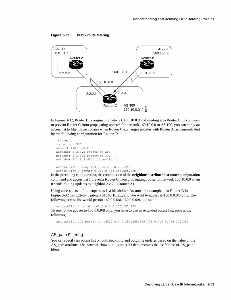
Designing Large-Scale IP Internetworks 3-53
Understanding and Defining BGP Routing Policies
Figure 3-32 Prefix route filtering.
In Figure 3-32, Router B is originating network 160.10.0.0 and sending it to Router C. If you wantto prevent Router C from propagating updates for network 160.10.0.0 to AS 100, you can apply anaccess list to filter those updates when Router C exchanges updates with Router A, as demonstratedby the following configuration for Router C:
!Router Crouter bgp 300network 170.10.0.0neighbor 3.3.3.3 remote-as 200neighbor 2.2.2.2 remote-as 100neighbor 2.2.2.2 distribute-list 1 out!access-list 1 deny 160.10.0.0 0.0.255.255access-list 1 permit 0.0.0.0 255.255.255.255
In the preceding configuration, the combination of theneighbor distribute-list router configurationcommand and access list 1 prevents Router C from propagating routes for network 160.10.0.0 whenit sends routing updates to neighbor 2.2.2.2 (Router A).
Using access lists to filter supernets is a bit trickier. Assume, for example, that Router B inFigure 3-32 has different subnets of 160.10.x.x, and you want to advertise 160.0.0.0/8 only. Thefollowing access list would permit 160.0.0.0/8, 160.0.0.0/9, and so on:
access-list 1 permit 160.0.0.0 0.255.255.255
To restrict the update to 160.0.0.0/8 only, you have to use an extended access list, such as thefollowing:
access-list 101 permit ip 160.0.0.0 0.255.255.255 255.0.0.0 0.255.255.255
AS_path FilteringYou can specify an access list on both incoming and outgoing updates based on the value of theAS_path attribute. The network shown in Figure 3-33 demonstrates the usefulness of AS_pathfilters.
AS100150.10.0.0
AS 200160.10.0.0
160.10.0.02.2.2.2
2.2.2.1
3.3.3.3
3.3.3.1
160.10.0.0
AS 300170.10.0.0
Router A Router B
Router C
1657
7

BGP Internetwork Design Guidelines
Internetwork Design Guide3-54
Figure 3-33 AS_path filtering.
!Router Cneighbor 3.3.3.3 remote-as 200neighbor 2.2.2.2 remote-as 100neighbor 2.2.2.2 filter-list 1 out!ip as-path access-list 1 deny ^200$ip as-path access-list 1 permit .*
In this example, access list 1 denies any update whose AS_path attribute starts with 200 (as specifiedby ^) and ends with 200 (as specified by $). Because Router B sends updates about 160.10.0.0 whoseAS_path attributes start with 200 and end with 200, such updates will match the access list and willbe denied. By specifying that the update must also end with 200, the access list permits updates fromAS 400 (whose AS_path attribute is 200, 400). If the access list specified ^200 as the regularexpression, updates from AS 400 would be denied.
In the second access-list statement, the period (.) symbol means any character, and the asterisk (*)symbol means a repetition of that character. Together, .* matches any value of the AS_path attribute,which in effect permits any update that has not been denied by the previous access-list statement. Ifyou want to verify that your regular expressions work as intended, use the following EXECcommand:
show ip bgp regexp regular-expression
The router displays all of the paths that match the specified regular expression.
Route Map FilteringTheneighbor route-map router configuration command can be used to apply a route map toincoming and outgoing routes. The network shown in Figure 3-34 demonstrates using route maps tofilter BGP updates.
AS100150.10.0.0
AS 200160.10.0.0 AS 400
160.10.0.02.2.2.2
2.2.2.1
3.3.3.3
3.3.3.1
160.10.0.0
AS 300170.10.0.0
Router A Router B
Router C
1657
8

Designing Large-Scale IP Internetworks 3-55
Understanding and Defining BGP Routing Policies
Figure 3-34 BGP route map filtering.
Assume that in Figure 3-34, you want Router C to learn about networks that are local to AS 200 only.(That is, you do not want Router C to learn about AS 100, AS 400, or AS 600 from AS 200.) Also,on those routes that Router C accepts from AS 200, you want the weight attribute to be set to 20. Thefollowing configuration for Router C accomplishes this goal:
!Router Crouter bgp 300network 170.10.0.0neighbor 3.3.3.3 remote-as 200neighbor 3.3.3.3 route-map STAMP in!route-map STAMP permit 10match as-path 1set weight 20!ip as-path access-list 1 permit ^200$
In the preceding configuration, access list 1 permits any update whose AS_path attribute begins with200 and ends with 200 (that is, access list 1 permits updates that originate in AS 200). The weightattribute of the permitted updates is set to 20. All other updates are denied and dropped.
Community FilteringThe network shown in Figure 3-35 demonstrates the usefulness of community filters.
AS100150.10.0.0
AS 200160.10.0.0
AS 400AS 600190.10.0.0
160.10.0.02.2.2.2
2.2.2.1
3.3.3.3
3.3.3.1
160.10.0.0
AS 300170.10.0.0
Router A Router B
Router C
1657
9

BGP Internetwork Design Guidelines
Internetwork Design Guide3-56
Figure 3-35 Community filtering.
Assume that you do not want Router C to propagate routes learned from Router B to Router A. Youcan do this by setting the community attribute on updates that Router B sends to Router C, as in thefollowing configuration for Router B:
!Router Brouter bgp 200network 160.10.0.0neighbor 3.3.3.1 remote-as 300neighbor 3.3.3.1 send-communityneighbor 3.3.3.1 route-map SETCOMMUNITY out!route-map SETCOMMUNITY permit 10match ip address 1set community no-export!route-map SETCOMMUNITY permit 20!access list 1 permit 0.0.0.0 255.255.255.255
For routes that are sent to the neighbor at IP address 3.3.3.1 (Router C), Router B applies the routemap named setcommunity. The setcommunity route map sets the community attribute of any update(by means of access list 1) destined for 3.3.3.1 to no-export. Theneighbor send-community routerconfiguration command is required to include the community attribute in updates sent to theneighbor at IP address 3.3.3.1. When Router C receives the updates from Router B, it does notpropagate them to Router A because the value of the community attribute is no-export.
Another way to filter updates based on the value of the community attribute is to use theip community-list global configuration command. Assume that Router B has been configured as follows:
!Router Brouter bgp 200network 160.10.0.0neighbor 3.3.3.1 remote-as 300neighbor 3.3.3.1 send-communityneighbor 3.3.3.1 route-map SETCOMMUNITY out!route-map SETCOMMUNITY permit 10match ip address 2set community 100 200 additiveroute-map SETCOMMUNITY permit 20!access list 2 permit 0.0.0.0 255.255.255.255
AS100150.10.0.0
AS 200160.10.0.0
2.2.2.2
2.2.2.1
3.3.3.3
3.3.3.1
AS 300170.10.0.0
Router A Router B
Router C
1658
0

Designing Large-Scale IP Internetworks 3-57
Understanding and Defining BGP Routing Policies
In the preceding configuration, Router B adds 100 and 200 to the community value of any updatedestined for the neighbor at IP address 3.3.3.1. To configure Router C to use theip community-listglobal configuration command to set the value of the weight attribute. Based on whether thecommunity attribute contains 100 or 200, use the following configuration:
!Router Crouter bgp 300neighbor 3.3.3.3 remote-as 200neighbor 3.3.3.3 route-map check-community in!route-map check-community permit 10match community 1set weight 20!route-map check-community permit 20match community 2 exactset weight 10!route-map check-community permit 30match community 3!ip community-list 1 permit 100ip community-list 2 permit 200ip community-list 3 permit internet
In the preceding configuration, any route that has 100 in its community attribute matches communitylist 1 and has its weight set to 20. Any route whose community attribute is only 200 (by virtue of theexact keyword) matches community list 2 and has its weight set to 10. In the last community list (list3), the use of theinternet keyword permits all other updates without changing the value of anattribute. (Theinternet keyword specifies all routes because all routes are members of the Internetcommunity.)
BGP Peer GroupsA BGP peer groupis a group of BGP neighbors that share the same update policies. Update policiesare usually set by route maps, distribution lists, and filter lists. Instead of defining the same policiesfor each individual neighbor, you define a peer group name and assign policies to the peer group.
Members of a peer group inherit all of the configuration options of the peer group. Peer groupmembers can also be configured to override configuration options if the options do not affectoutgoing updates. That is, you can override options that are set only for incoming updates. The useof BGP peer groups is demonstrated by the network shown in Figure 3-36
BGP Internetwork Design Guidelines
Internetwork Design Guide3-58
Figure 3-36 BGP peer groups.
The following commands configure a BGP peer group named internalmap on Router C and apply itto the other routers in AS 300:
!Router Crouter bgp 300neighbor INTERNALMAP peer-groupneighbor INTERNALMAP remote-as 300neighbor INTERNALMAP route-map INTERNAL outneighbor INTERNALMAP filter-list 1 outneighbor INTERNALMAP filter-list 2 inneighbor 5.5.5.2 peer-group INTERNALMAPneighbor 6.6.6.2 peer-group INTERNALMAPneighbor 3.3.3.2 peer-group INTERNALMAPneighbor 3.3.3.2 filter-list 3 in
The preceding configuration defines the following policies for the internalmap peer group:
A route map named INTERNAL A filter list for outgoing updates (filter list 1) A filter list for incoming updates (filter list 2)
The configuration applies the peer group to all internal neighbors—Routers E, F, and G. Theconfiguration also defines a filter list for incoming updates from the neighbor at IP address 3.3.3.2(Router E). This filter list can be used only to override options that affect incoming updates.
The following commands configure a BGP peer group named externalmap on Router C and apply itto routers in AS 100, 200, and 600:
!Router Crouter bgp 300neighbor EXTERNALMAP peer-groupneighbor EXTERNALMAP route-map SETMEDneighbor EXTERNALMAP filter-list 1 outneighbor EXTERNALMAP filter-list 2 inneighbor 2.2.2.2 remote-as 100neighbor 2.2.2.2 peer-group EXTERNALMAPneighbor 4.4.4.2 remote-as 600neighbor 4.4.4.2 peer-group EXTERNALMAPneighbor 1.1.1.2 remote-as 200neighbor 1.1.1.2 peer-group EXTERNALMAPneighbor 1.1.1.2 filter-list 3 in
AS100150.10.0.0
1.1.1.1
1.1.1.2
4.4.4.2
2.2.2.1
6.6.6.1
Router A
AS 600
175.10.0.0
170.10.0.0AS 300
Router D
AS 200
2.2.2.2
5.5.5.2
6.6.6.2
5.5.5.13.3.3.2
Router B
Router E
Router GRouter C
Router F
1658
1

Designing Large-Scale IP Internetworks 3-59
Understanding and Defining BGP Routing Policies
In the preceding configuration, theneighbor remote-as routerconfiguration commands are placedoutside of theneighbor peer-group routerconfiguration commands because different external ASshave to be defined. Also note that this configuration defines filter list 3, which can be used to overrideconfiguration options for incoming updates from the neighbor at IP address 1.1.1.2 (Router B).
CIDR and Aggregate AddressesBGP4 supports classless interdomain routing (CIDR). CIDR is a new way of looking at IP addressesthat eliminates the concept of classes (Class A, Class B, and so on). For example, network192.213.0.0, which is an illegal Class C network number, is a legal supernet when it is representedin CIDR notation as 192.213.0.0/16. The /16 indicates that the subnet mask consists of 16 bits(counting from the left). Therefore, 192.213.0.0/16 is similar to 192.213.0.0 255.255.0.0.
CIDR makes it easy to aggregate routes. Aggregation is the process of combining several differentroutes in such a way that a single route can be advertised, which minimizes the size of routing tables.Consider the network shown in Figure 3-37.
Figure 3-37 Aggregation example.
In Figure 3-37, Router B in AS 200 is originating network 160.11.0.0 and advertising it to Router Cin AS 300. To configure Router C to propagate the aggregate address 160.0.0.0 to Router A, use thefollowing commands:
!Router Crouter bgp 300neighbor 3.3.3.3 remote-as 200neighbor 2.2.2.2 remote-as 100network 160.10.0.0aggregate-address 160.0.0.0 255.0.0.0
Theaggregate-address router configuration command advertises the prefix route (in this case,160.0.0.0/8) and all of the more specific routes. If you want Router C to propagate the prefix routeonly, and you do not want it to propagate a more specific route, use the following command:
aggregate-address 160.0.0.0 255.0.0.0 summary-only
AS100150.10.0.0
160.10.0.0160.0.0.0
AS 200160.1.10.0
2.2.2.2
2.2.2.1
3.3.3.3
3.3.3.1
AS 300170.10.0.0
Router A Router B
Router C
1658
2
BGP Internetwork Design Guidelines
Internetwork Design Guide3-60
This command propagates the prefix (160.0.0.0/8) and suppresses any more specific routes that therouter may have in its BGP routing table. If you want to suppress specific routes when aggregatingroutes, you can define a route map and apply it to the aggregate. If, for example, you want Router Cin Figure 3-37 to aggregate 160.0.0.0 and suppress the specific route 160.20.0.0, but propagate route160.10.0.0, use the following commands:
!Router Crouter bgp 300neighbor 3.3.3.3 remote-as 200neighbor 2.2.2.2 remote-as 100network 160.10.0.0aggregate-address 160.0.0.0 255.0.0.0 suppress-map CHECK!route-map CHECK permit 10match ip address 1!access-list 1 deny 160.20.0.0 0.0.255.255access-list 1 permit 0.0.0.0 255.255.255.255
If you want the router to set the value of an attribute when it propagates the aggregate route, use anattribute map, as demonstrated by the following commands:
route-map SETORIGIN permit 10set origin igp!aggregate-address 160.0.0.0 255.0.0.0 attribute-map SETORIGIN
Note Aggregation and AS-SET. When aggregates are generated from more specific routes, theAS_path attributes of the more specific routes are combined to form a set called the AS-SET. Thisset is useful for preventing routing information loops.
ConfederationsA confederation is a technique for reducing the IBGP mesh inside the AS. Consider the networkshown in Figure 3-38.

Designing Large-Scale IP Internetworks 3-61
Understanding and Defining BGP Routing Policies
Figure 3-38 Example of confederations.
In Figure 3-38, AS 500 consists of nine BGP speakers (although there might be other routers that arenot configured for BGP). Without confederations, BGP would require that the routers in AS 500 befully meshed. That is, each router would need to run IBGP with each of the other eight routers, andeach router would need to connect to an external AS and run EBGP, for a total of nine peers for eachrouter.
Confederations reduce the number of peers within the AS, as shown in Figure 3-38. You useconfederations to divide the AS into multiple mini-ASs and assign the mini-ASs to a confederation.Each mini-AS is fully meshed, and IBGP is run among its members. Each mini-AS has a connectionto the other mini-ASs within the confederation. Even though the mini-ASs have EBGP peers to ASswithin the confederation, they exchange routing updates as if they were using IBGP. That is, the nexthop, MED, and local preference information is preserved. To the outside world, the confederationlooks like a single AS. The following commands configure Router C:
!Router Crouter bgp 65050bgp confederation identifier 500bgp confederation peers 65060 65070neighbor 128.213.10.1 remote-as 65050
03id
g38
5 5 5 5
5 5 5 4
129 213 10 1
129 213 301
129 210 1 1 1
ASG 5070
129 213 20 1
AS 500
ASG 5050 ASG 5060
129 210 302
AS 100
6 6 6 6
AS 600
Router A
Router DRouter C 135 212 14 1

BGP Internetwork Design Guidelines
Internetwork Design Guide3-62
neighbor 128.213.20.1 remote-as 65050neighbor 128.210.11.1 remote-as 65060neighbor 135.212.14.1 remote-as 65070neighbor 5.5.5.5 remote-as 100
Therouter bgp global configuration command specifies that Router C belongs to AS 50.
Thebgp confederation identifierrouter configuration command specifies that Router C belongs toconfederation 500. The first twoneighbor remote-as router configuration commands establishIBGP connections to the other two routers within AS 65050. The second twoneighbor remote-ascommands establish BGP connections with confederation peers 65060 and 65070. The lastneighbor remote-as command establishes an EBGP connection with external AS 100. Thefollowing commands configure Router D:
!Router Drouter bgp 65060bgp confederation identifier 500bgp confederation peers 65050 65070neighbor 129.210.30.2 remote-as 65060neighbor 128.213.30.1 remote-as 65050neighbor 135.212.14.1 remote-as 65070neighbor 6.6.6.6 remote-as 600
Therouter bgp global configuration command specifies that Router D belongs to AS 65060. Thebgp confederation identifier router configuration command specifies that Router D belongs toconfederation 500.
The firstneighbor remote-as routerconfiguration command establishes an IBGP connection to theother router within AS 65060. The second twoneighbor remote-ascommands establish BGPconnections with confederation peers 65050 and 65070. The lastneighbor remote-ascommandestablishes an EBGP connection with AS 600. The following commands configure Router A:
!Router Arouter bgp 100neighbor 5.5.5.4 remote-as 500
Theneighbor remote-as command establishes an EBGP connection with Router C. Router A isunaware of AS 65050, AS 65060, or AS 65070. Router A only has knowledge of AS 500.
Route ReflectorsRoute reflectors are another solution for the explosion of IBGP peering within an AS. As describedearlier in the section “Synchronization,” a BGP speaker does not advertise a route learned fromanother IBGP speaker to a third IBGP speaker. Route reflectors ease this limitation and allow a routerto advertise (reflect) IBGP-learned routes to other IBGP speakers, thereby reducing the number ofIBGP peers within an AS. The network shown in Figure 3-39 demonstrates how route reflectorswork.

Designing Large-Scale IP Internetworks 3-63
Understanding and Defining BGP Routing Policies
Figure 3-39 imple route reflector example.
Without a route reflector, the network shown in Figure 3-39 would require a full IBGP mesh (that is,Router A would have to be a peer of Router B). If Router C is configured as a route reflector, IBGPpeering between Routers A and B is not required because Router C will reflect updates from RouterA to Router B and from Router B to Router A. To configure Router C as a route reflector, use thefollowing commands:
!Router Crouter bgp 100neighbor 1.1.1.1 remote-as 100neighbor 1.1.1.1 route-reflector-clientneighbor 2.2.2.2 remote-as 100neighbor 2.2.2.2 route-reflector-client
The router whose configuration includesneighbor route-reflector-client router configurationcommands is the route reflector. The routers identified by theneighbor route-reflector-clientcommands are clients of the route reflector. When considered as a whole, the route reflector and itsclients are called acluster. Other IBGP peers of the route reflector that are not clients are callednonclients.
An AS can have more than one route reflector. When an AS has more than one route reflector, eachroute reflector treats other route reflectors as normal IBGP speakers. There can be more than oneroute reflector in a cluster, and there can be more than one cluster in an AS.
Route Flap DampeningRoute flap dampening (introduced in Cisco IOS Release 11.0) is a mechanism for minimizing theinstability caused by route flapping. The following terms are used to describe route flap dampening:

Summary
Internetwork Design Guide3-64
• Penalty—A numeric value that is assigned to a route when it flaps.
• Half-life time—A configurable numeric value that describes the time required to reduce thepenalty by one half.
• Suppress limit—A numeric value that is compared with the penalty. If the penalty is greater thanthe suppress limit, the route is suppressed.
• Suppressed—A route that is not advertised even though it is up. A route is suppressed if thepenalty is more than the suppressed limit.
• Reuse limit—A configurable numeric value that is compared with the penalty. If the penalty isless than the reuse limit, a suppressed route that is up will no longer be suppressed.
• History entry—An entry that is used to store flap information about a route that is down.
A route that is flapping receives a penalty of 1000 for each flap. When the accumulated penaltyreaches a configurable limit, BGP suppresses advertisement of the route even if the route is up. Theaccumulated penalty is decremented by the half-life time. When the accumulated penalty is less thanthe reuse limit, the route is advertised again (if it is still up).
Summary of BGPThe primary function of a BGP system is to exchange network reachability information with otherBGP systems. This information is used to construct a graph of AS connectivity from which routingloops are pruned and with which AS-level policy decisions are enforced. BGP provides a number oftechniques for controlling the flow of BGP updates, such as route, path, and community filtering. Italso provides techniques for consolidating routing information, such as CIDR aggregation,confederations, and route reflectors. BGP is a powerful tool for providing loop-free interdomainrouting within and between ASs.
SummaryRecall the following design implications of the Enhanced Interior Gateway Routing Protocol(IGRP), Open Shortest Path First (OSPF) protocols, and the BGP protocol:
• Network topology
• Addressing and route summarization
• Route selection
• Convergence
• Network scalability
• Security
This chapter outlined these general routing protocol issues and focused on design guidelines for thespecific IP protocols.

C H A P T E R
Designing SRB Internetworks 4-1
4
Designing SRB Internetworks
This chapter discusses source-route bridging (SRB) and remote source-route bridging (RSRB). SRBis evaluated within two contexts: Systems Network Architecture (SNA) and NetBIOS.
When IBM developed SRB technology in the mid-eighties, it was viewed as a local technology thatwould interconnect a few rings and terminate at a remote 3745. The challenge for any SRBinternetwork occurs when the scale exceeds what was originally intended by IBM. This technologyencounters problems when non-IBM protocols are required to coexist with native Token Ring traffic.Source-route bridges were intended to be the primary internetworking tool for creating acorporate-wide Token Ring internetwork. These bridges were never meant to scale to the level thatmany customers require. This chapter addresses the challenges of this environment and aims to helpnetwork designers successfully implement SRB within a large, multiprotocol topology. This chapteris grouped into the following topics:
• SRB technology and implementation overview
• Internet Protocol (IP) routing protocol selection and implementation
• SRB network design recommendations and guidelines
Note For information concerning IBM serial line connections, refer to Appendix B, “IBM SerialLink Implementation Notes.”
SRB Technology Overview and Implementation IssuesThe following discussions address SRB-related technology, features provided to support SRBrequirements, and implementation issues that can affect large-scale, router-based SRB networks.Specific topics include the following:
• Typical SRB Environments
• Multiport Bridging
• Explorer Packets and Propagation
• NetBIOS Broadcast Handling
• LAN Framing
• WAN Framing
• WAN Parallelism
• WAN Frame Sizes
• SNA Host Configuration Considerations for SRB

SRB Technology Overview and Implementation Issues
Cisco CCIE Fundamentals: Network Design4-2
Note If you have eight or fewer routers operating as SRBs, you can skip this chapter. You probablydo not need to tune your network.
Typical SRB EnvironmentsSRB is used in three types of user environments:
• Many end stations to few end stations (hierarchical)—In a hierarchical SNA network, end usersfrom multiple access sites need connectivity to a host site through a limited number of front-endprocessors (FEPs).
• Many end stations to several end stations (distributed)—Many users need to access a limitednumber of servers or a limited number of devices, such as an AS/400.
• Any-to-any (flat)—End users at one site need to access end stations at another site.
The following discussions evaluate SRB environment design issues in relation to these userenvironments.
Multiport BridgingThe fundamental design of an SRB, as initially created by IBM, was a two-port, ring-to-bridge-to-ringcombination. IBM also created a half-bridge configuration that consisted of aring-to-wide-area-network (WAN) combination followed by a second WAN-to-ring half-bridgecombination.
To support more than two rings, multiport routers adopt an implementation that allows SRBs toinclude multiple rings on a single internetworking node. This is accomplished via thevirtual ringcapability. A virtual ring is a conceptual entity that connects two or more physical rings together,locally or remotely.
Figure 4-1 illustrates the concept of multiport bridges and a virtual ring.

Designing SRB Internetworks 4-3
Multiport Bridging
Figure 4-1 Multiport bridge using virtual ring concept to permit multiple ringinterconnection.
The concept of virtual rings can be expanded across router boundaries. A large virtual ring canconnect several access points to a central router with an FEP. Figure 4-2 illustrates this expansion.
Figure 4-2 Virtual rings expanded across an IP cloud.
Routers support simple bridging, multiport bridging, and connections to both local and remotevirtual rings. A virtual ring configuration is required to communicate with remote rings. Thehalf-bridge configuration is not supported. The IBM half bridge does not use the concept of virtualrings; two IBM half bridges use two rings. The virtual ring advantage is in a topology that featuresmany SRBs. In such an arrangement, only a single unit is required at a central site.
TokenRing
TokenRing
TokenRing
TokenRing
Router
Virtual ring
IP cloud
TokenRing
TokenRing
TokenRing
TokenRing
Virtualring

SRB Technology Overview and Implementation Issues
Cisco CCIE Fundamentals: Network Design4-4
Remote virtual rings have a property not found in physical ring topologies: The logical connectivityis determined by the network administrator. Two options are available: partially meshed topologies(sometimes calledredundant star topologies) or fully meshed topologies. In a partially meshedtopology, a single central location (such as an FEP Token Ring) is connected to all access locations.Each access location is logically connected to the central FEP rings and is not connected to any otherring. Partially meshed topologies using virtual rings do not permitdirect communication betweenremote rings. However, communication is allowed from the central ring to the remote rings, whichalso allows communication among remote rings through the central ring.
In a fully meshed virtual ring topology, any ring can communicate with any other ring. Figure 4-3and Figure 4-4 illustrate partially meshed and fully meshed topologies. In the partially meshedtopology depicted in Figure 4-3, all rings are logically bridged to Token Ring 10. The access ringsare not bridged together. In the fully meshed topology illustrated in Figure 4-4, all rings are bridgedto all other rings.
Figure 4-3 Typical hierarchical topology.
In the topology illustrated in Figure 4-3, each of the access routers is a peer to the FEP router. Theyare not peers to one another. Thus, SRB is enabled between all rings and Token Ring 10 and is notenabled between token rings 20, 30, 40, 50 and 60.
Assuming this is only a hierarchical SNA environment, users connected to these rings do not haveSRB connectivity. Broadcasts are not forwarded across the lower layer rings (token rings 20through 60); broadcasts are sent only from Token Ring 10 to or from the other rings.
In the topology illustrated in Figure 4-4, each router is a peer to each other router. All rings arelogically bridged to all other rings. The actual physical topology is less important than the logicaltopology. In Figure 4-4, the same logical topology can exist even if there are no physical connectionsbetween the access routers.
Virtual ring
TokenRing 10
TokenRing 40
TokenRing 50
TokenRing 60
TokenRing 20
TokenRing 30

Designing SRB Internetworks 4-5
Explorer Packets and Propagation
Figure 4-4 Typical fully meshed (flat) topology.
Explorer Packets and PropagationOnce you build a network of ring and bridge combinations, you must have a method for the endstations to find other end stations in the network.
An IBM bridge uses a system ofexplorer packetmarkingto propagate routing information throughan SRB internetwork. The explorer packet is produced by the source end station and is marked(updated) by each bridge that it traverses. The marked field is called the Routing Information Field(RIF). Two important transactions occur in the explorer packet handling exchange: the transmissionof the explorer packet and the reply by the end station to the explorer packets that it receives.
In this environment, the source end stations must know the Token Ring Media Access Control(MAC) address of the destination end stations. Once the MAC address is understood, the source endstation produces an explorer packet.
The source-route bridge updates the explorer packet to include its bridge-ring combination in theexplorer packet’s RIF in the MAC frame. By accumulating this information, the explorer packetgathers a hop-by-hop description of a path through the SRB network. In addition, the bridgeforwards the explorer to each destination ring it encounters, therefore creating a completetopological map for each end station trying to find its way through the network.
Explorer Packet TypesThere are three types of explorer packets:local explorer packets, spanning explorer packets, andall-routes explorer packets. Note that all-routes explorer packets are also known asall-rings explorerpackets, and spanning explorer packets are also known assingle-route andlimited-route explorerpackets. Single router explorers are explorers that pass through a predetermined path constructed bya spanning tree algorithm in the bridge. A station should receive only one single router explorer fromthe network.
TokenRing 40
Virtual ring
TokenRing 30
TokenRing 20
TokenRing 50
TokenRing 60
TokenRing 10

SRB Technology Overview and Implementation Issues
Cisco CCIE Fundamentals: Network Design4-6
A local explorer packet is generated by some end systems (either NetBIOS or SNA) to find a hostconnected to the local ring. After this event has occurred without finding a local host, the end stationproduces either a spanning explorer or an all-routes explorer packet. This behavior depends on thetype of end station. SNA end stations generally produce an all-routes explorer packet. NetBIOS endstations produce a spanning explorer packet.
Note As of Cisco IOS Software Release 10.2, auto spanning tree (AST) for SRB is supported. Theimplementation of AST in Cisco IOS Software Release10.2 is based on the IEEE 802.1 standard andis fully compatible with IBM PC bridging. New global and interface configuration commands arerequired to configure a router for AST. Once configured, AST can be enabled and disabled throughLAN Network Manager (LNM). The following discussion of spanning tree explorer packets appliesto the manual spanning tree functionality available in software releases prior to Cisco IOS SoftwareRelease 10.2.
To pass a spanning explorer packet on a router, the configuration for the router’s Token Ringinterface must have thesource-bridge spanning interface configuration command for the specificring. If this interface command is not included, spanning explorer packets are discarded.
In contrast, an all-routes explorer packet can find any valid SRB ring. No specific routerconfiguration other than specification of SRB is required to pass all-routes explorer packets.
Explorer packet processing works as illustrated in Figure 4-5. If End station X sends an all-routesexplorer packet, Bridge B1 and Bridge B2 both forward the explorer packet. End station Y receivestwo all-routes explorer packets in this configuration. End station Y responds to each of the all-routesexplorer packets by sending a directed, nonbroadcast packet. In the example illustrated in Figure 4-5,four packets are generated:
• Two all-routes explorer packets inbound (to End station Y)
• Two nonbroadcast packets outbound (from End station Y)
Figure 4-5 Explorer packet processing (all-routes broadcast).
Figure 4-6 illustrates an end station sending a spanning explorer packet. Bridge B1 and Bridge B2make their respective forwarding decisions based on whether or not spanning is enabled. AssumeBridge B1 has spanning enabled and Bridge B2 does not have spanning enabled. Bridge B1 forwardsthe spanning explorer packet, and Bridge B2 does not. End station Y receives one spanning explorerpacket and returns an all-routes explorer packet for each single route received. As before, Bridge B1and Bridge B2 forward the all-routes explorer packet. In this example, the following packets aregenerated:
• One spanning explorer packet inbound (to End station Y)
• Two all-routes explorer packets outbound (to End station X)
TokenRing 1
Bridge B1
Bridge B2
End station X End station Y
Directed, nonbroadcast packetsent by End station Y
All-routes explorer packetsent by End station X
TokenRing 2

Designing SRB Internetworks 4-7
Explorer Packets and Propagation
Figure 4-6 Explorer packet processing (spanning explorer broadcast).
If spanning were enabled on Bridge B2, it would also forward the spanning explorer packet. Thefollowing packets would be generated:
• Two spanning explorer packets inbound (to End station Y)
• Four all-routes explorer packets outbound (to End station X)
Note In general, there should be only a single path through the network for spanning explorerpackets. If redundancy is required, a trade-off should be made between automatic redundancy andtolerance for additional explorer packet traffic. When redundancy is required, AST should be used.
Redundancy can be achieved in many instances within the router-based cloud as a result ofencapsulation in either TCP or IP, the latter calledFast Sequenced Transport (FST). To contrastredundancy provided by a pure SRB environment and an internetwork that combines routingcapabilities with SRBs, consider the networks illustrated in Figure 4-7, Figure 4-8, and Figure 4-9.Figure 4-7 illustrates a pure bridged network. Figure 4-8 and Figure 4-9 illustrate an SRB networkrunning over routers.
TokenRing 1
Token Ring 2
Bridge B1
Bridge B2
End station X End station Y
All-routes explorer packetsent by End station Y
Spanning explorer packetsent by End station X

SRB Technology Overview and Implementation Issues
Cisco CCIE Fundamentals: Network Design4-8
Figure 4-7 Redundancy in a pure SRB network.
In Figure 4-7, there are two SRB paths between Token Ring 10 and Token Ring 20:
• Token Ring 10 to split Bridge B3 to Token Ring 20
• Token Ring 10 to split Bridge B2 to Token Ring 30 to split Bridge B1 to Token Ring 20
If spanning is enabled on both paths, the traffic resulting from a spanning explorer broadcast fromthe server is as follows:
• Two spanning explorer packets inbound (to the server)
• Four all-routes explorer packets outbound (to the client)
In router-based networks, the same type of redundancy is achieved in a different, more efficientmanner, as illustrated in Figure 4-8 and Figure 4-9.
Figure 4-8 Redundancy in a router-based SRB network (physical router connectivity).
TokenRing 10
Bridge B2
Bridge B3
Client
TokenRing 30
Bridge B1
TokenRing 20
Bridge B1Bridge B2
Bridge B3
Server
Split Bridge B2 over serial link
Split Bridge B1 over serial link
Split Bridge B3over serial link
TokenRing 10
Client
TokenRing 30
TokenRing 20
Server
Router B
Router A Router C
Designing SRB Internetworks 4-9
Explorer Packets and Propagation
Figure 4-9 Redundancy in a router-based SRB network (logical SRB connectivity).
In Figure 4-9, there is only one SRB path between Token Ring 10 and Token Ring 20. The path isToken Ring 10 to Bridge A to Virtual ring 100 to Bridge B to Token Ring 20. When the client sendsa spanning explorer packet, the following occurs:
• One spanning explorer packet goes inbound (to the server).
• Two all-routes broadcasts go outbound—one to the client on Token Ring 10 and one to TokenRing 30.
These broadcast rules are valid even when spanning is enabled on all the routers. In this example,spanning does not affect the traffic. The redundancy is a result of router-to-router traffic handling.
Each explorer packet is modified and copied at each destination ring when a multiring bridge isconnected to more than two rings or to a virtual ring with multiple remote destinations. The virtualring in these cases operates indistinguishably from a physical ring. The RIFs are modified exactly asif the virtual ring were a physical ring. All source-route bridges are designed to forward packets, soframe copying can be a limiting factor in both large-scale bridges and topologies with many tokenrings. In these topologies, your most important job as a network designer is to prevent excessiveforwarding of explorer packets, which can disable an entire network.
Most source-route bridges do not propagate an explorer packet onto a ring from which it has justarrived. As a result, explorer packets are not copied from a virtual ring back to the same virtual ring,even in the presence of valid remote peers.
Figure 4-10 illustrates a situation in which incoming explorer packets arriving on virtual ring 1A aretransmitted to Bridge 1 but are not copied back to Virtual ring 1A, even in the presence of multipleremote peer statements pointing to Virtual ring 1A. This is desirable behavior. Bridge 2 does notforward frames that originated from Bridge 1 because the frame has been on Virtual ring 1A.
TokenRing 10
Client
TokenRing 30
TokenRing 20
Server
Virtual ring100
Bridge A Bridge B
Bridge C

SRB Technology Overview and Implementation Issues
Cisco CCIE Fundamentals: Network Design4-10
Figure 4-10 Virtual ring and explorer packet behavior.
In contrast, Figure 4-11 illustrates a topology that can result in a storm of explorer packets. In thistopology, two virtual rings are separated by physical Token Ring 2.
Figure 4-11 Virtual ring topology resulting in explorer packet storms.
An incoming explorer packet arriving on Virtual ring 1A is propagated to physical Token Ring 2through Bridge 1. This explorer packet is then propagated into Bridge 2 and copied 40 times for eachremote peer statement. Because the SRB protocol does not scale effectively, it results in this kind ofexplorer packet explosion that causes performance problems in Token Ring environments. Thebridge must modify and copy the explorer packet in the CPU, causing inefficient use of the CPU andsystem bus for copying and modifying each explorer packet bound for a new destination.
You can reduce the number of forwarded explorer packets by enabling the explorer packetprocessing queue. The queue is used to divide traffic into data frames and explorer packets, asillustrated in Figure 4-12.
Virtualring 1A
30 remotepeers
TokenRing
TokenRing
Bridge 1
Bridge 2
Explorer packet
Explorer packet not copied
IP cloud
TokenRing100
TokenRing 2
IP cloud
Bridge 1
Bridge 2
Virtual ring 2A
40 remotepeers
Token Ring
Token Ring
Token Ring
Token Ring
40 remotepeers
Explorer packet
Explorer packet copied
Virtual ring1A

Designing SRB Internetworks 4-11
Explorer Packets and Propagation
Figure 4-12 Queuing process resulting in the division of frames between real data andexplorer packets.
Reduce the number of forwarded explorer packets and improve overall efficiency by allowing theCPU to spend more cycles transmitting frames for routing and bridging and less time copying,modifying, and forwarding explorer packets. To enable the explorer packet processing queue, usethe following global configuration command (available with Software Release 9.1.8(5) andsubsequent releases):
source-bridge explorerq-depthnumber
The value ofnumberspecifies the queue depth. The default value ofnumberis 30 queue entries. Thedisadvantage of enabling the explorer packet processing queue is the potential for suboptimal paths.For most SRB networks that are plagued by excessive explorer packet, this potential is an acceptabletrade-off.
Limiting the copying of explorer packets is an important factor in designing SRB networks. Poorlydesigned SRB networks can collapse under high explorer packet copying loads and the resultingvolume of explorer packet traffic. Although good internetwork design, such as a single unified virtualring, can eliminate large-scale explorer packet copying, this solution does not scale infinitely. Forvery large internetworks, contact your technical support representative for more information aboutspecific limitations. Also, refer to the section “SRB Network Design” later in this chapter for moreinformation about how different topologies scale.
Proxy ExplorerAnother way of limiting explorer packet traffic is to use theproxy explorerfeature. The function oftheproxy explorerfeature is to create an explorer packet reply cache, the entries of which are reusedwhen subsequent explorer packets need to find the same host. The proxy explorer feature allows theSRB network designer to minimize exploding explorer packet traffic throughout the network.Routers cache the explorer packet reply and reuse it for subsequent explorer packets that aresearching for the same MAC address.
Proxy explorer functionality is very useful in traditional SNA configurations because most explorerpackets are destined for a single FEP on a single ring. However, if the host to be reached is an FEPon two rings (with a single locally administered address duplicated on both rings), this feature willselect a single path without the possibility of redundant paths from a single router. Different routerscan use different paths.
If your configuration does not involve duplicate FEPs with the same locally administered address,you can use the proxy explorer function in any SNA environment. Use the following interfaceconfiguration command:
TokenRing
Real data packets
Explorer packets
Output queue

SRB Technology Overview and Implementation Issues
Cisco CCIE Fundamentals: Network Design4-12
source-bridge proxy-explorer
NetBIOS Broadcast HandlingNetBIOS stations issue broadcasts for several reasons: to verify at startup that a station name isunique to the network, to find the route to a particular server, and to provide a heartbeat function tomaintain connectivity between servers and requesters. These broadcasts are addressed either to aspecific name, or to the NetBIOS functional address (such as C000 0000 0080). Station requests,such as a NAME QUERY frame, are sent as a spanning explorer broadcast to a unique NetBIOSname, and the corresponding response is returned as a broadcast of all-routes explorer packets.
NetBIOS is a broadcast-intensive protocol that can quickly consume lower bandwidth bridge paths.To address this problem, the router provides four different methods of preventing single andall-routes broadcast traffic from consuming your network:
• NetBIOS Name Caching
• NetBIOS Datagram Broadcast Handling
• NetBIOS Broadcast Throttling
• NetBIOS Broadcast Damping
NetBIOS Name CachingNetBIOS name caching allows the router to maintain a cache of NetBIOS names that it uses to avoidthe high overhead of transmitting many of the broadcasts used between client and server PCs in anSRB environment.
Name caching allows the router to detect when any host sends a series of duplicate query frames andto limit the host to one frame per configurable time period. The name cache includes a cache ofmappings between NetBIOS server and client names and their MAC addresses. The name cacheallows the router to send broadcast requests from clients to find servers and from servers in responseto their clients directly to their destinations. It does this rather than sending the broadcast across theentire bridged network.
In most cases, the NetBIOS name cache is best used in situations in which large amounts ofbroadcast traffic creates bottlenecks on the WAN media. However, the traffic savings of NetBIOSname caching is probably not worth the router processor overhead when two local-area network(LAN) segments are interconnected.
As NetBIOS broadcasts traverse the router, the router caches the NetBIOS name in theNAME-QUERY and NAME-RECOGNIZED broadcast frames along with the station MAC address,RIF, and the physical port from which the broadcast was received. Because the router has theNetBIOS name as well as the route to the station, it can respond locally to broadcasts and eliminatethe overhead of propagating broadcast frames throughout the network.
NetBIOS name caching can be enabled on each interface by using the following interfaceconfiguration commands:
source-bridge proxy-explorer
netbios enable-name-cache
Thesource-bridge proxy-explorercommand is a prerequisite for NetBIOS name caching. To limitproxy-explorer to NetBIOS only, use the following configuration command:
source-bridge proxy-netbios-only
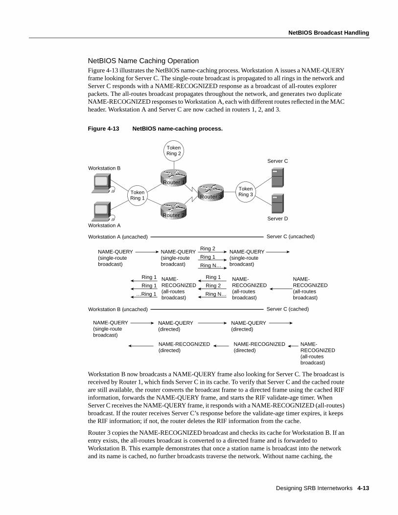
Designing SRB Internetworks 4-13
NetBIOS Broadcast Handling
NetBIOS Name Caching OperationFigure 4-13 illustrates the NetBIOS name-caching process. Workstation A issues a NAME-QUERYframe looking for Server C. The single-route broadcast is propagated to all rings in the network andServer C responds with a NAME-RECOGNIZED response as a broadcast of all-routes explorerpackets. The all-routes broadcast propagates throughout the network, and generates two duplicateNAME-RECOGNIZED responses to Workstation A, each with different routes reflected in the MACheader. Workstation A and Server C are now cached in routers 1, 2, and 3.
Figure 4-13 NetBIOS name-caching process.
Workstation B now broadcasts a NAME-QUERY frame also looking for Server C. The broadcast isreceived by Router 1, which finds Server C in its cache. To verify that Server C and the cached routeare still available, the router converts the broadcast frame to a directed frame using the cached RIFinformation, forwards the NAME-QUERY frame, and starts the RIF validate-age timer. WhenServer C receives the NAME-QUERY frame, it responds with a NAME-RECOGNIZED (all-routes)broadcast. If the router receives Server C’s response before the validate-age timer expires, it keepsthe RIF information; if not, the router deletes the RIF information from the cache.
Router 3 copies the NAME-RECOGNIZED broadcast and checks its cache for Workstation B. If anentry exists, the all-routes broadcast is converted to a directed frame and is forwarded toWorkstation B. This example demonstrates that once a station name is broadcast into the networkand its name is cached, no further broadcasts traverse the network. Without name caching, the
TokenRing 2
Workstation B
Workstation A
Server C
Server D
Workstation A (uncached)
NAME-QUERY(single-routebroadcast)
Ring 2
Ring 1
Ring N…
Server C (uncached)
NAME-RECOGNIZED(all-routesbroadcast)
Ring 1
Ring 1
…Ring 1
Ring 1
Ring 2
Ring N…
Workstation B (uncached) Server C (cached)
NAME-QUERY(directed)
NAME-RECOGNIZED(directed)
NAME-RECOGNIZED(all-routesbroadcast)
TokenRing 1
TokenRing 3
NAME-QUERY(single-routebroadcast)
NAME-QUERY(single-routebroadcast)
NAME-RECOGNIZED(all-routesbroadcast)
NAME-RECOGNIZED(all-routesbroadcast)
NAME-QUERY(single-routebroadcast)
NAME-QUERY(directed)
NAME-RECOGNIZED(directed)
Router 1
Router 2
Router 3

SRB Technology Overview and Implementation Issues
Cisco CCIE Fundamentals: Network Design4-14
broadcast activity in a network with 100 fully meshed ring segments can become a serious issue.NetBIOS name caching significantly reduces the bandwidth consumed by nonproductive broadcasttraffic.
Each NetBIOS name cache entry is aged out of the table if activity does not occur within aconfigurable period of time. Aging ensures the information in the cache is current and that the cacheis kept to a minimum size to maintain optimal performance.
The following global configuration command controls the name-caching age timer:
netbios name-cache timeoutminutes
The default is 15 minutes.
NetBIOS Datagram Broadcast HandlingThe router also checks the NetBIOS name cache when it receives NetBIOS datagram broadcasts(addressed to unique names), which allows the router to handle NetBIOS datagram broadcastslocally in a way that is similar to NAME-QUERY and NAME-RECOGNIZED broadcast handling.The difference is that datagram broadcasts are generally one-way flows with no corresponding reply.If datagram broadcasts represent a small percentage of overall broadcast traffic, you can disabledatagram handling and avoid expending additional router overhead for relatively minor effect. Thisdecision can be made only with an understanding of your broadcast traffic patterns.
NetBIOS Broadcast ThrottlingNetBIOS applications broadcast by issuing multiple successive copies of the broadcast frame intothe network. For example, IBM’s OS/2 LAN Requester sends six successive copies of aNAME-QUERY frame, with a pause of a half second between each repeated transmission. Someapplications allow you to tune this behavior, but tuning NetBIOS broadcasts is difficult to maintainif the number of NetBIOS workstations in your network is high.
As illustrated in Figure 4-14, when NetBIOS name caching is enabled, the router forwards the firstof these six broadcasts, and drops the duplicate five broadcasts. The duplicate broadcasts (whichoriginated from the same station), continue to be dropped until the dead timer expires. Two globalconfiguration commands control relevant timers:
netbios name-cache query-timeoutseconds
The default is 6 seconds.
netbios name-cache recognized-timeout seconds
The default is 1 second.

Designing SRB Internetworks 4-15
NetBIOS Broadcast Handling
Figure 4-14 Throttling NetBIOS broadcasts.
NetBIOS Broadcast DampingThe router remembers the physical port from which a NetBIOS station’s route was cached. As aresult, the router can remember where a cached station resides relative to the router. If the routerreceives a broadcast frame that is addressed to a cached NetBIOS name and if the router knows thatthe route to that station exists off of the same interface, the router does not need to forward thebroadcast to find the target station. Instead, the router drops the broadcast and prevents unnecessarybroadcast traffic from traversing the network.
As illustrated in Figure 4-15, a NetBIOS broadcast addressed to Server D is received by Router 1 oninterface T0. Router 1 finds a cached entry for Server D, which indicates that the route to Server Dis via interface T0. Because the broadcast was received on T0 and because the route to Server D isvia T0, the broadcast is prevented from continuing on the network, and the requester finds Server Dvia the local SRB topology.
TokenRing 1
TokenRing 2
TokenRing
Remote LAN WAN Central site LAN
Workstation B
Workstation A
Server C
Server D
Six NAME-QUERYsingle-routebroadcasts
NAME-QUERY NAME-QUERY
Configurabledead timerdefault=15 seconds
Router
Router Router

SRB Technology Overview and Implementation Issues
Cisco CCIE Fundamentals: Network Design4-16
Figure 4-15 NetBIOS broadcast damping.
LAN FramingFraming for SRB networks is straightforward. Using a basic IEEE 802.5 frame with Logical LinkControl type 2 (LLC2) 802.2 framing, a RIF field follows the source MAC field in the IEEE 802.5frame. The presence of a RIF field is indicated by setting the Routing Information Identifier (RII),which is the high-order bit of the source MAC field, as shown in Figure 4-16.
TokenRing 1
TokenRing 2
TokenRing 3
Workstation B
Workstation A
Server C
TokenRing 4
Server D
Cache
Name
Server D
MAC address
4000.0000.0001
RIF
R1-B1-R4
Interface
T0
T0
Source interface = Cached target interface
Workstation A
NAME-QUERYDatagram
NAME-RECOGNIZEDRECOGNIZED-STATUS-QUERY
(SRB-unique name)
TokenRing 4 Not forwarded into wide area
Router 2
Router 1 Router 3

Designing SRB Internetworks 4-17
LAN Framing
Figure 4-16 IEEE 802.5/Token Ring frame formats.
An SRB-configured router evaluates incoming frames based on IEEE 802.5 values, which is mostlya Subnetwork Access Protocol (SNAP) evaluation. Once the router determines whether the packetis to be routed, it evaluates whether to use SRB based on the value of the RII bit. If the bit is set andthe router is not configured to route a specific protocol, the router sends the frame using SRB. Figure4-17 illustrates this process.
Startdelimiter
Enddelimiter
Token
Accesscontrol
Framecontrol
Destinationaddress Source address Data PCS
4
Startdelimiter
Enddelimiter
Accesscontrol
1 11 1 6 6 20Field length,in bytes
Datacommand frame

SRB Technology Overview and Implementation Issues
Cisco CCIE Fundamentals: Network Design4-18
Figure 4-17 Process for identifying routable versus SRB packets.
IBM’s original Token Ring bridging designs use a Routing Information Field (RIF) in the TokenRing frame header. This information stored the path that the frame took to get across multiple TokenRing segments (allowing the response to be sent along the same path). The fields of the RIF are asfollows:
• Therouting control filed, which consists of the following subfields:
— Thetypesubfield in the RIF indicates whether the frame should be routed to a single node, agroup of nodes that make up a spanning tree of the internetwork, or all nodes. The first typeis called aspecifically routedframe; the second type is called aspanning-tree explorer;and thethird type is called anall paths explorer. The spanning-tree explorer can be used as a transitmechanism for multicast frames. It can also be used as a replacement for all-paths explorerin outbound route queries. In this case, the destination responds with an all-paths explorer.
— The length subfield indicates the total length (in bytes) of the RIF.
— TheD bit indicates the direction of the frame (forward or reverse).
— The largestfield indicates the largest frame that can be handled along this route.
• Theroute descriptorfield, of which there can be more than one. Each router descriptor field carriesa ring number-bridge number pair that specifies a portion of a route. Routes, then, are simplyalternating sequences of LAN and bridge numbers that start and end with LAN numbers.
Routers provide a feature calledmultiring, which provides several benefits when SRB networks aremixed with multiprotocol routers. The first benefit is realized when connecting a multiprotocolrouter to an existing pure SRB network to support routable protocols (such as Novell’s IPX). In thiscase, the multiring feature allows you to connect IPX and SRB networks seamlessly by routing IPX
LLC SNAP
indicatesroutableprotocol
RIIset
Frame arrives
Ignore frame
Source-route bridge
Send to routing process
N
N
Y
Y

Designing SRB Internetworks 4-19
WAN Framing
even in the presence of SRB framing. IPX stations can be linked via SRB networks or locallyconnected to a Token Ring with SRB framing. A router will route to the IPX station by first searchingfor the station and then framing each Token Ring frame with RII and a RIF.
The second benefit of multiring is that all outgoing packets for a specific routable protocol areframed in an SRB frame. The router creates a valid SRB frame by transmitting an explorer packet tocreate a valid RIF entry for the SRB frame of a routable network packet.
The third benefit of multiring is that it allows a smooth transition from a previously framed SRBnetwork to a routed network. For example, a locally connected Token Ring can either use an IPXframe or an SRB frame depending on what is currently in use. To leverage existing IPX servers withSRB drivers, configure the multiring for that specific Token Ring. A typicalmultiring interfaceconfiguration example might be as follows:
interface tokenring 0source-bridge 10 1 100multiring ipx spanning
WAN FramingRouters recognize two forms of SRB. The first islocal SRB, which is characterized by either thestandard single ring-to-bridge-to-ring combination, or a flexible form using a multiplering-to-bridge-to-virtual ring arrangement. The second form of SRB involves WAN connections andis calledremote SRB (RSRB).
The framing that occurs to support WAN activities is twofold. First, the SRB frame is encapsulatedin one of three ways: Transmission Control Protocol/Internet Protocol (TCP/IP) encapsulation, FastSequence Transport (FST) encapsulation, or direct High-Level Data Link Control (HDLC)encapsulation. Next, the frame is placed in the WAN frame for the appropriate WAN media, such asHDLC, Frame Relay, or Switched Multimegabit Data Service (SMDS).
If you select direct encapsulation for a WAN serial link, you avoid the overhead of encapsulating intoeither IP or TCP. The datagram is framed directly into HDLC. Direct encapsulation for WAN framesworks only for HDLC. Over a multiaccess media, such as Ethernet or Fiber Distributed DataInterface (FDDI), direct encapsulation can be used to transmit data from one router to another.
Selection of encapsulation is critical to the performance of the underlying network and affects thedegree to which the topology can scale to very large networks of token rings. Each encapsulationform is addressed in the following sections.
TCP/IP EncapsulationTCP/IP encapsulation is the most common encapsulation format. Figure 4-18 illustrates aTCP/IP-encapsulated SRB frame. The chief benefit of TCP/IP encapsulation is a robust set ofcapabilities that ensures reliable transport.
Figure 4-18 SRB frame encapsulated in TCP/IP with HDLC header.
48 bytes4 bytes
HDLCheader
TCP/IPheader
SRB frameCiscovirtualring
16bytes

SRB Technology Overview and Implementation Issues
Cisco CCIE Fundamentals: Network Design4-20
Because many tasks are involved in TCP/IP encapsulation, such as packet reordering, running timersfor retransmission, and sending acknowledgments, TCP/IP encapsulation is costly in terms of CPUoverhead. For both LANs and WANs, TCP/IP encapsulation incurs additional CPU overheadbecause all framing occurs in the CPU and the resulting IP frame is then process switched, whichincurs additional overhead. (Process switching and its associated costs are discussed in “ProcessSwitching” later in this chapter.)
Because of the high overhead associated with TCP/IP encapsulation, there is a significant upperboundary to maximum traffic forwarding. Performance is not the only constraint for using TCP/IP;fewer connections to other SRB rings can be supported using TCP/IP than any other encapsulationbecause of the processor overhead required to maintain the TCP structure. In general, you shouldlimit the maximum number of remote peers connected to a single Cisco CSC/4 or RP card usingTCP/IP encapsulation. Issues that can affect the acceptable number of remote peers include linkspeed, traffic load, number of supported protocols, routing platform implemented, and the level ofother non-SRB activity occurring in the router.
Fast Sequenced Transport (FST) EncapsulationFast Sequenced Transport (FST) encapsulation is an alternative to TCP/IP encapsulation. FSTencapsulation creates an IP frame with a sequence number; this frame is transmitted to an IPdestination. At arrival, FST encapsulation strips the IP frame. If the sequence number of the arrivingframe is greater than the sequence number of the last frame that arrived, FST encapsulation placesthe frame on the destination ring. If the sequence number of the arriving frame is less than the lastframe transmitted by FST encapsulation, the frame is discarded, and the router relies on the transportmechanism of LLC2 to request the discarded or out-of-order frames to be retransmitted.
FST encapsulation is configured on a per-remote-ring basis. A typical example of using thefstkeyword with thesource-bridge remote-peer global configuration command follows:
source-bridge remote-peer 10 fst 131.108.3.2
The benefit of FST encapsulation is sustained end-to-end performance across multiple hops. FST isfast because the IP encapsulation happens on the interface card (AGS+, Cisco 7000, MGS, and CGS)or the system memory (IGS, Cisco 2000, Cisco 2500, Cisco 3000, and Cisco 4000) while theprocessor is in interrupt mode. For WAN transmissions, once the framing occurs, you can select anIP switching mechanism, either process switching or fast switching, depending on the result youwant. Figure 4-19 illustrates the frame format of FST encapsulation.
Figure 4-19 SRB frame encapsulated in FST with HDLC header.
There is a cost to implementing FST encapsulation. Because the packet discard feature associatedwith FST encapsulation does not guarantee delivery, FST encapsulation cannot be used inconjunction with the router’s local acknowledgment feature.
20 bytes4 bytes
HDLCheader
IPheader
SRB frameCiscovirtualring
16bytes
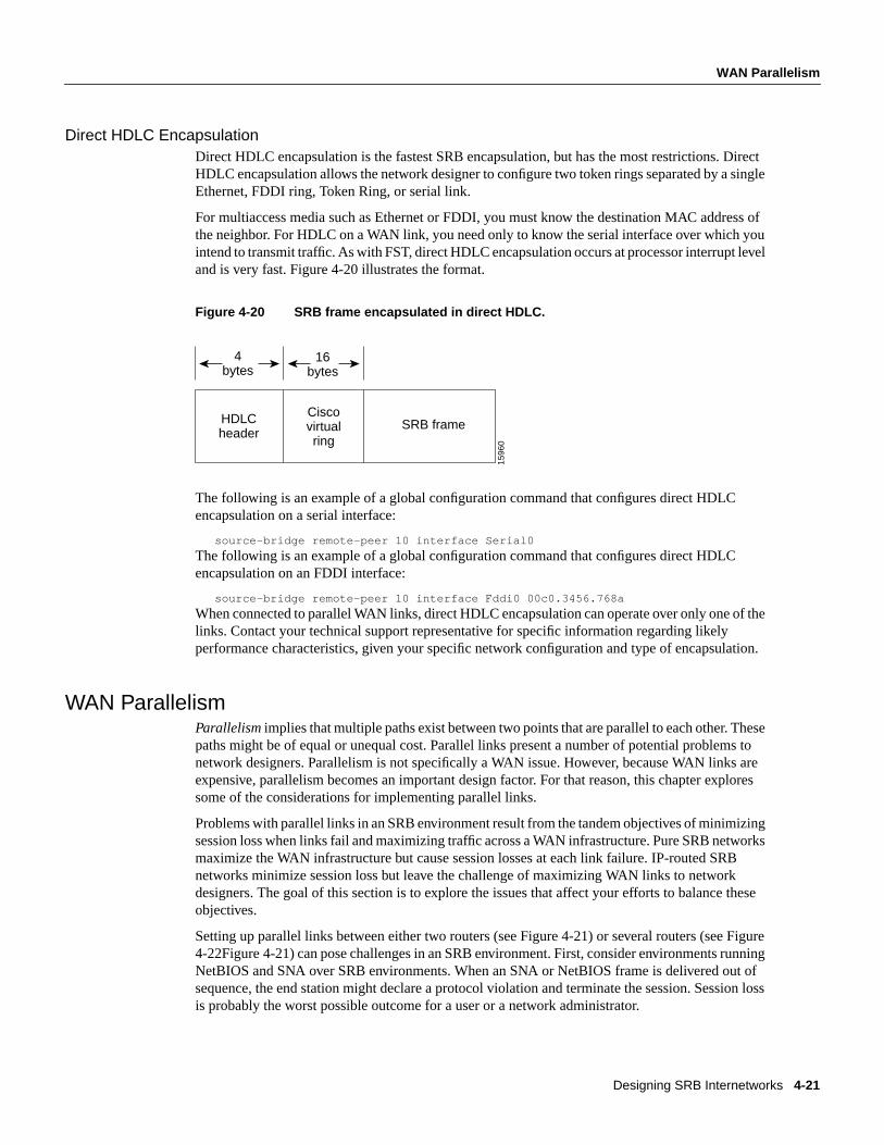
Designing SRB Internetworks 4-21
WAN Parallelism
Direct HDLC EncapsulationDirect HDLC encapsulation is the fastest SRB encapsulation, but has the most restrictions. DirectHDLC encapsulation allows the network designer to configure two token rings separated by a singleEthernet, FDDI ring, Token Ring, or serial link.
For multiaccess media such as Ethernet or FDDI, you must know the destination MAC address ofthe neighbor. For HDLC on a WAN link, you need only to know the serial interface over which youintend to transmit traffic. As with FST, direct HDLC encapsulation occurs at processor interrupt leveland is very fast. Figure 4-20 illustrates the format.
Figure 4-20 SRB frame encapsulated in direct HDLC.
The following is an example of a global configuration command that configures direct HDLCencapsulation on a serial interface:
source-bridge remote-peer 10 interface Serial0
The following is an example of a global configuration command that configures direct HDLCencapsulation on an FDDI interface:
source-bridge remote-peer 10 interface Fddi0 00c0.3456.768a
When connected to parallel WAN links, direct HDLC encapsulation can operate over only one of thelinks. Contact your technical support representative for specific information regarding likelyperformance characteristics, given your specific network configuration and type of encapsulation.
WAN ParallelismParallelismimplies that multiple paths exist between two points that are parallel to each other. Thesepaths might be of equal or unequal cost. Parallel links present a number of potential problems tonetwork designers. Parallelism is not specifically a WAN issue. However, because WAN links areexpensive, parallelism becomes an important design factor. For that reason, this chapter exploressome of the considerations for implementing parallel links.
Problems with parallel links in an SRB environment result from the tandem objectives of minimizingsession loss when links fail and maximizing traffic across a WAN infrastructure. Pure SRB networksmaximize the WAN infrastructure but cause session losses at each link failure. IP-routed SRBnetworks minimize session loss but leave the challenge of maximizing WAN links to networkdesigners. The goal of this section is to explore the issues that affect your efforts to balance theseobjectives.
Setting up parallel links between either two routers (see Figure 4-21) or several routers (see Figure4-22Figure 4-21) can pose challenges in an SRB environment. First, consider environments runningNetBIOS and SNA over SRB environments. When an SNA or NetBIOS frame is delivered out ofsequence, the end station might declare a protocol violation and terminate the session. Session lossis probably the worst possible outcome for a user or a network administrator.
HDLCheader
SRB frameCiscovirtualring
4bytes
16bytes
1596
0

SRB Technology Overview and Implementation Issues
Cisco CCIE Fundamentals: Network Design4-22
Figure 4-21 Parallel paths between two WAN routers.
Figure 4-22 Parallel WAN connections among several routers.
Delivering frames in sequence is the key objective of any SRB delivery mechanism. When youcreate parallel WAN links, you expect parallel delivery. In an SRB universe, this might not beachievable because timing differences on WAN links alone can cause packet resequencing. If therouter uses parallel links and starts one frame header ahead of a second frame header, the framesmight not arrive with the same sequencing. The second frame might arrive before the first framebecause of WAN link delays. This is particularly true of packet-switched WANs.
When selecting or applying an encapsulation strategy with parallel WAN links, other factorsinfluence the encapsulation that is used. These factors include the WAN switching technology andthe IP routing protocols. A discussion of these factors follows. Some choices are predetermined. Forexample, direct HDLC encapsulation voids all parallel connections across a single virtual ring. In amultiprotocol environment, you can place SRB traffic on a single parallel link, whereas otherprotocols are load balanced on parallel links. As an alternative, you can configure the second linkexclusively for multiprotocol (non-SRB) traffic.
WAN technologies can use two primary switching types:process switching andfast switching.Process switching provides full route evaluation and per-packet load balancing across parallel WANlinks. Fast switching associates an IP host destination to a single interface to avoid out of orderframes. The fact that the destination of a remote peer is a single IP destination can impact SRBdecisions.
Process-switching and fast-switching techniques provide different features and performancecharacteristics. Each technique must be applied in situations that can optimize its respectivecapabilities. These switching strategies are addressed in detail in the following sections, “ProcessSwitching” and “Fast Switching.” Later in this chapter, “IP Routing Protocols with Parallel Links”addresses routing and switching in the context of SRB framing options.
Process SwitchingProcess switching is the most expensive switching operation that the CPU can perform. Processswitching involves transmitting entire frames to the router CPU. Frames are then repackaged fordelivery to or from a WAN interface, and the router makes a route selection for each packet. TCP/IPframing must be process switched because switching must occur when the rings are encapsulatingor unencapsulating data, which occurs at processor level. FST framing can be process switched orfast switched.
TokenRing Token
Ring
TokenRing
TokenRing

Designing SRB Internetworks 4-23
WAN Parallelism
Process switching begins when a frame arrives on a Token Ring interface and causes an interrupt tobe transmitted to the CPU. The CPU then determines that the frame must be process switched andschedules the switch in noninterrupt mode. The frame is then transferred to the CPU and placed onan input queue, whose depth is viewable with theshow interfacesEXEC command. Once the entireframe is transferred across the system bus, the frame is reworked for appropriate TCP headers andheader compression.
Next, the IP route for the destination is examined. If multiple paths exist, the frame pointer is updatedto use the next path for the next frame that arrives. After a route is selected, the frame is transmittedacross the system bus to the output interface queue of the specific interface card from which theframe will exit. The queue entry is placed on the specific exit interface and the SCI card dequeuesand transmits the frame down the WAN link.
Fast SwitchingFast switching maximizes the volume of traffic that the router can handle by streamlining the router’squeuing mechanisms. Fast switching deals with incoming frames inprocessor interrupt mode andminimizes the number of decisions that must be applied.
Fast switching precaches routes. Once an IP destination is process switched, its route is cached andassociated with a specific interface. When an IP destination is precached, it is tied to a specific path.For either FST or TCP/IP encapsulations, a single IP destination carries all of the SRB traffic to anFEP destination. If fast switching is used with multiple IP paths, a single path exists for each ringdestination. You must use process switching to load-balance traffic across multiple paths.
Two of the SRB framing techniques are capable of being fast switched: direct HDLC encapsulationand FST encapsulation. Direct HDLC encapsulation is by definition fast switched; it cannot beprocess switched. FST can be fast switched or process switched.
Two IBM SRB WAN options do not allow fast switching of a frame: TCP header compression andpriority or custom queuing. If either of these features is invoked, the frame cannot be fast switched.The reason for these caveats is that certain frame components are modified when using fast switchingin AGS+, MGS, CGS, or Cisco 7000 interface memory and not in the CPU memory. If the frameneeds to be extensively modified, it must be done in CPU system buffers and not in buffers associatedwith individual interface cards.
In addition, fast switching uses only interface buffers that are not generally reported usingmonitoring EXEC commands, such asshow interfaces. The buffers reported in theshow interfacesEXEC command are CPU buffers for input and output that are only used during process switching.Fast switching uses preconfigured interface buffers. You can view the allocation of buffers using theshow controllers EXEC command.
For direct HDLC encapsulation, SRB frames are directly linked to an output serial port (such asinterface serial 0). When an SRB frame enters the 2R or CTR card, an interrupt is transmitted to theCPU. The CPU verifies that the frame is an SRB frame and that the buffer on either the 2R card orthe ciscoBus controller is modified to create an HDLC header. The new frame is transmitted twobytes at a time through the CPU from either the 2R card or the ciscoBus controller across the systembus to the SCI card or SIP card.
A similar process occurs for FST encapsulation; however, SRB frames are directly linked to adestination IP address. When an SRB frame enters the 2R or CTR card, an interrupt is transmittedto the CPU. The CPU verifies that the frame is an SRB frame and the buffer on either the 2R card orthe ciscoBus controller is modified to create an IP datagram with appropriate WAN framing for thedestination. The new frame is transmitted two bytes at a time through the CPU from either the 2Rcard or the ciscoBus controller across the system bus to the SCI card or SIP card.

SRB Technology Overview and Implementation Issues
Cisco CCIE Fundamentals: Network Design4-24
Use the EXEC commandshow ip route cacheto determine whether an IP destination is being fastswitched. This command lists IP destinations as well as the relevant MAC frame and destinationinterface that the specific IP address uses. If the entry is fast switched, the destination IP address ispresent. If the destination IP address is not present, the router is using process switching to reach thedestination. By default, HDLC WAN links are fast switched for IP. If the router is configured fordirect HDLC encapsulation, the only status indication is the output for theshow source-bridgeEXEC command. The bridge indicates it is using a direct serial interface and not an IP address.
IP Routing Protocols with Parallel LinksIP routing protocols play a part in the parallel SRB WAN decisions because they can create widerparallelism than two routers with parallel links. Given the parallel links shown in Figure 4-23, loadbalancing makes three critical assumptions: equal-cost paths, routing protocol support for equal-costload balancing, and process switching for a single IP destination.
Figure 4-23 Parallel WAN paths.
Process switching is discussed extensively in the section “Process Switching” earlier in this chapter.Issues relating to equal-cost path IP routing and unequal-cost path routing are discussed in thesections that follow, “IP Routing over Equal-Cost Paths” and “IP Routing over Unequal-Cost PathsUsing Variance.”
IP Routing over Equal-Cost PathsAn equal-cost path is metrically equivalent to another parallel path between two points. In RIP,equivalence is parallel WAN paths of equal hops. In Interior Gateway Routing Protocol (IGRP) andOpen Shortest Path First (OSPF), metric equivalence translates into WAN paths of equal bandwidth,where the bandwidth is declared by the network administrator. IGRP also adds the concept of delayto determine metrically equivalent links. To create parallel links for equal-cost paths and to activelyuse these paths, the router must use process switching because all frames sent from one ring toanother have the same IP destination.
The following list outlines the capability of supported IP routing technologies to create equal-costpaths:
• Static routes—For Cisco software releases prior to Software Release 9.1, static routes cannot becreated in parallel; only a single path can be selected. As of Software Release 9.1, static routescan be created in parallel.
• IGRP and Enhanced Interior Gateway Routing Protocol (Enhanced IGRP)—Can use up to fourequal-cost paths in parallel. Ensure that the bandwidth command is correctly configured on alllinks.
TokenRing
TokenRing

Designing SRB Internetworks 4-25
WAN Parallelism
• OSPF—If paths are of equal declared metrics, OSPF can use up to four equal-cost paths inparallel.
• RIP—RIP can use four equal-cost paths in parallel. Remember that this will not take into accountanything but hops, so even unequal bandwidth links will be evaluated as having equivalent cost.
IGRP, Enhanced IGRP, and OSPF can route traffic across equal-cost paths and split SRB trafficacross equal-cost links if the router is process switching. RIP will route across equal-cost paths andit will assume that all WAN links are the same speed regardless of reality. Static routes allow parallelpaths and are a tool for the advanced network designer.
A router’s capability to use parallel paths is determined in part by the encapsulation method. IfTCP/IP encapsulation is used, parallel paths are used. If FST encapsulation is used under normaloperational conditions, all traffic must use only one of the parallel links. This is because all theRSRB traffic sent to another FST peer goes to a single IP destination address. When using fastswitching, the router might alternate some traffic across parallel links based on destination address.However, because all traffic to a peer router uses only one destination IP address, all RSRB trafficflows across one link.
IP Routing over Unequal-Cost Paths Using VarianceThe only routing protocols that can handle intentional unequal-cost path balancing are IGRP andEnhanced IGRP. Using a feature calledvariance, the router can load balance over unequal-costpaths. Figure 4-24 illustrates one such configuration from A to B. In this figure, load balancing thelink from C to B is assumed to be faster than the link from A to B.
Figure 4-24 Unequal-cost load balancing with IGRP.
Variance has two rules that apply in this or any unequal-cost load balancing situation:
• Rule 1—Parallelism must exist in the topology.
• Rule 2—Packets must makeforward progresson any parallel link toward an intended destination.In other words, a router will not forward traffic to another router that has the same (or greater)relative distance metric to a destination. This rule prevents loops. The rule of forward progress isstraightforward. If the next-hop router is closer to the destination (than some other router) a paththrough it will be used as a valid alternative path.
If these rules are met and the network administrator adds variance to the IGRP configuration, therouter will load balance over parallel paths for a single IP destination when it is process switching.Figure 4-25 illustrates a case in which variance might be used.
TokenRing
TokenRing
A B
C
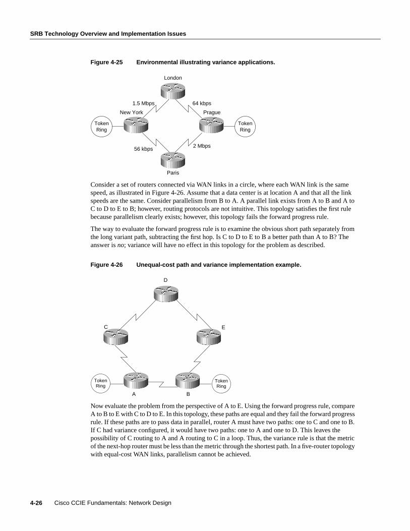
SRB Technology Overview and Implementation Issues
Cisco CCIE Fundamentals: Network Design4-26
Figure 4-25 Environmental illustrating variance applications.
Consider a set of routers connected via WAN links in a circle, where each WAN link is the samespeed, as illustrated in Figure 4-26. Assume that a data center is at location A and that all the linkspeeds are the same. Consider parallelism from B to A. A parallel link exists from A to B and A toC to D to E to B; however, routing protocols are not intuitive. This topology satisfies the first rulebecause parallelism clearly exists; however, this topology fails the forward progress rule.
The way to evaluate the forward progress rule is to examine the obvious short path separately fromthe long variant path, subtracting the first hop. Is C to D to E to B a better path than A to B? Theanswer isno; variance will have no effect in this topology for the problem as described.
Figure 4-26 Unequal-cost path and variance implementation example.
Now evaluate the problem from the perspective of A to E. Using the forward progress rule, compareA to B to E with C to D to E. In this topology, these paths are equal and they fail the forward progressrule. If these paths are to pass data in parallel, router A must have two paths: one to C and one to B.If C had variance configured, it would have two paths: one to A and one to D. This leaves thepossibility of C routing to A and A routing to C in a loop. Thus, the variance rule is that the metricof the next-hop router must be less than the metric through the shortest path. In a five-router topologywith equal-cost WAN links, parallelism cannot be achieved.
TokenRing
TokenRing
London
Paris
PragueNew York
1.5 Mbps 64 kbps
2 Mbps56 kbps
A B
EC
D
TokenRing
TokenRing

Designing SRB Internetworks 4-27
WAN Parallelism
By default, variance is not configured. If it is, it must be configured as an integer multiple of theallowable metric variance. Consider the following use of thevariance router configurationcommand:
router igrp 1343variance 2
Using this particular instance of thevariance command results in a load-balanced topology with a2:1 ratio of bandwidth. For all practical topologies, this should be an upper maximum because youshould not load balance an overly high variance of WAN links such as E1 and 64 Kbps.
Use variance carefully. Because IP fast switching links an IP destination to an interface or next hop,a single IP destination can be stuck on a 64-Kbps link while most other IP destinations are wired toa fast link such as an E1. This situation will cause users to call their network administrators todetermine why transmission is slow one day when it was fast the day before. If SRB is fast switched,all users of a destination ring can be linked to the slower path using variance.
Variance has another major benefit: If a link fails for any reason, the router immediately switches alltraffic to the parallel link without any convergence overhead. The router can do this because theparallel link is a known valid path and the router does not need to wait for the routing protocols toconverge.
Local Acknowledgment RecommendationsIf you configure your remote source-route bridge to use IP encapsulation over a TCP connection,you also can enable LLC2 Local Acknowledgment. The following explains how this feature can beuseful.
LLC2, or Logical Link Control-Type 2, an ISO standard data link level protocol used in Token Ringnetworks, was designed to ensure reliable transmission of data across LAN media with minimal orpredictable time delays. With the advent of remote source route bridging (RSRB) and wide areanetwork (WAN) backbones, LANs are now separated by wide, geographic distances spanningcountries and continents. As a result, these LANs have time delays that are longer than LLC2 allowsfor bidirectional communication between hosts. The Local Acknowledgment capability inrouter/bridges supporting remote source-route bridging addresses the problem of unpredictable timedelays, multiple retransmissions, and many user sessions.
In a typical LLC2 session, when host A sends a frame to host B, the sending host A expects host Bto respond positively or negatively in a certain amount of predefined time commonly called the T1time. If host A does not receive an acknowledgment of the frame it sent to host B within the T1 time,it will retry a few number of times (normally 8 to 10). If there is still no response from host B, hostA will drop the session.
Figure 4-27 shows how Local Acknowledgment operates in an SRB environment. With LocalAcknowledgment for LLC2 enabled in both routers, Router A acknowledges frames received fromthe 37x5. The 37x5 still thinks that the acknowledgments it receives are from the 3x74. The 3x74thinks that the acknowledgments it receives are from the 37x5. Router B looks like the 3x74 to 37x5.Because the frames no longer have to travel the WAN backbone networks to be acknowledged, butinstead are locally acknowledged by routers, the end machines do not time out, resulting in no lossof sessions.

SRB Technology Overview and Implementation Issues
Cisco CCIE Fundamentals: Network Design4-28
Figure 4-27 How Local Acknowledgment operates in an SRB environment.
The following recommendations apply to the implementation of local acknowledgment. Use localacknowledgment under the following conditions:
• When the WAN implementation must accommodate long network delays
• When the internetwork includes slow links, heavily used links, or poor quality links
• When the internetwork requires that sessions remain active during router convergence
• When WAN traffic must be minimized
• When the amount of LLC traffic on backbone needs to be reduced (when more than 50 percentof packets are LLC packets)
• When WAN costs must be reduced
• When network integrity must be improved, assuming TCP/IP encapsulation is used
• When unreliable WAN links exist that are causing frequent session loss
• When end station timer or retry modifications are difficult or costly
• When bandwidth constraints require the elimination of acknowledgment traffic
Parallel Link RecommendationsThe following recommendations apply to parallel WAN link configuration:
• Do not combine multiple CTR cards with multiple WAN links; create a separate router primarilywith WAN links. For example, do not create an 8-T1/E1 process-switched WAN solution on topof a 75-kilopackets-per-second (Kpps) Token Ring engine. You will run out of CPU bandwidth.
• Use FST encapsulation whenever possible.
• Use TCP/IP encapsulation when local acknowledgment or prioritization is required.
• Maximize fast switching.
When link speeds are primarily 64 Kbps and slower and local acknowledgment or prioritization is arequirement, use TCP/IP encapsulation with IGRP variance in meshed topologies when the topologycan take advantage of these features.
When link speeds are primarily greater than 64 Kbps and local acknowledgment is a requirement,follow this recommendation:
Router A Router B
Host
37x5 3x74
TokenRing
TokenRing
WAN
LLC2 session
SNA Session
LLC2 session
TCP Session

Designing SRB Internetworks 4-29
SNA Host Configuration Considerations for SRB
• Use TCP/IP encapsulation only on those links that have a history of session loss (localacknowledgment).
• Use FST encapsulation on the remaining links.
SNA Host Configuration Considerations for SRBWhen designing SRB-based internets that feature routers and IBM SNA entities, you must carefullyconsider the configuration of SNA nodes, as well as routing nodes. Appendix C, “SNA HostConfiguration for SRB Networks,” provides examples of SNA host configurations that focus onthree specific SNA devices:
• Front-end processors
• VTAM-switched major nodes
• 3174 cluster controllers
IP Routing Protocol Selection for SRB NetworksWhen designing large SRB networks, the goal is to optimize the underlying IP network so it cancarry SNA and NetBIOS traffic more efficiently. To do this, select your IP routing protocol carefully.You should consider the following parameters when selecting your routing protocol:
• Time to converge
• Maintainability of the internetwork routing environment
If you select a protocol using only one criterion, you might build a network that cannot be expandedand that might eventually break.
Three interior gateway routing protocols work best in an SRB environment: IGRP, Enhanced IGRP,and OSPF. In general, IGRP, Enhanced IGRP, and OSPF are the only options for building an IP SNAnetwork. You can also consider RIP. However, because RIP does not provide any consistent WANbandwidth sensitivity, it is not a good choice for redundancy or meshed topologies.
The following discussion focuses on network topology and convergence considerations.
Convergence ConsiderationsConvergence is the time it takes a router to start using a new route when an active link fails in anetwork where alternative routes are available.
Rapid convergence is critical for SNA environments, particularly when local acknowledgment is notused. Consider a 3174 failure recovery scenario—an SNA device can lose its session with the hostin 13 seconds. The result is session loss and route rediscovery for all affected units. If the 3174 hadnot just sent data to the host, the session would not be lost for somewhere between 13 and42 seconds, depending on the value of the T1 Timer Inactivity parameter when the link failed. Iflocal acknowledgment is used, the SNA session does not fail while the routers are converging.
Convergence becomes an issue when installing large meshed networks with multiple validalternative paths. Distance vector protocols such as RIP or IGRP cannot determine the source of alearned route. A route could be learned by Router A from a neighbor that had originally learned theroute from Router A. If Router A and its neighbor both use this route, they create arouting loop.Routing loops implybroadcast storms and, as a result, are widely viewed as undesirable events.

IP Routing Protocol Selection for SRB Networks
Cisco CCIE Fundamentals: Network Design4-30
Enhanced IGRP provides superior convergence properties and operating efficiencies. It uses aconvergence algorithm that eliminates routing loops throughout a route computation. Moreimportantly, convergence time with Enhanced IGRP is reduced to a level below the threshold forsession loss.
OSPF was also designed to minimize convergence time. It is good at convergence, but has sideeffects that will be discussed in the next section. For routers, total convergence time has two primarycomponents:
• Link failure detection time
• IP routing protocol convergence time
Link failure detection time is the minimum, maximum, or average time it takes the router to detectthat no frames are crossing the link. IP routing protocol convergence time is the time it takes therouting protocol to detect a failure and switch to alternative links.
Link Failure Effects on ConvergenceLinks fail in a hierarchical order of occurrence. Serial links are the most unreliable. FDDI networks,Token Ring networks, and Ethernet networks are about equal in reliability and rarely fail.
The following sections describe the significance of media-failure detection mechanisms with respectto recovery from media failure and the effects of different media failures on convergence in an IBMinternetwork.
Keepalives and ConvergenceRouters institutekeepalives to verify the stability of a link. A router transmits a packet every10 seconds by default, and when three keepalives sequentially fail to cross the link, the routerdeclares the link to be down. To recover, the router retransmits the packet every few seconds.
For IBM IP networks, keepalives should be active only on serial and Ethernet links. Ethernet linkkeepalives are acceptable because the failure rate is low, but serial links (especially those faster than64 Kbps) should be set to three seconds. Use thekeepalive interface configuration command toadjust the keepalive timer for a specific interface. For example:
interface serial 0keepalive 3
This configuration reduces the maximum failure detection for the serial interface from 30 secondsto nine seconds. (The interface is declared down after three consecutive update intervals pass withno keepalives detected.) Media-related keepalive specifics are provided in the sections that follow.
Enhanced IGRP uses small hello packets to verify link stability. Hello packets are transmitted bydefault every five seconds. When three hello packets fail to cross the link, the router immediatelyconverges. Hello packets originate from the network layer and are protocol dependent. Use theip hello-interval eigrp interface configuration command to configure a different hello packetinterval for IP. For example:
ip hello-interval eigrp 109 3
This example configures a hello packet interval of three seconds for the IP protocol on EnhancedIGRP autonomous system number 109.
Serial Link Failure EffectsSerial links are inherently unreliable because they usually extend over long distances and becausethey are subject to a variety of failures.

Designing SRB Internetworks 4-31
Convergence Considerations
In general, if a router detects loss of the carrier signal, it immediately disables the link.Unfortunately, carrier loss is not a guaranteed way of detecting a failed link, so the router must alsouse keepalives or hello packets to determine whether an interface is connected to an operationalmedium.
When the carrier signal is lost, the router detects the failure immediately. For any other serial failure,given the default keepalive timer of 10 seconds and the rule that three keepalives must be missedbefore the router declares that the interface is down, failure detection takes at least 21 seconds andcould take as long as 30 seconds, with an average detection time of 25.5 seconds. When the keepalivetimer is three seconds, the failure is detected within seven to nine seconds.
Token Ring Failure EffectsToken Ring media, whether twisted-pair or IBM media attachment units (MAUs), rarely encounterfailures. When media failures occur, the Token Ring protocol fails, causing the ring to transition,beacon, and reinitialize.
Token Ring has built-in reliability that allows the interface to determine whether the ring is up ordown: The returning token indicates an active ring. Keepalives, which provide a fail-safe mechanismin case the Token Ring protocol itself fails, are also available but can be disabled in most networksto prevent unnecessary network traffic. Any keepalive failure usually indicates that the Token Ringinterface is under tremendous load or may have already failed. The failure detection time for TokenRing is immediate.
FDDI Failure EffectsLike Token Ring, FDDI rings are reliable media. Users who turn their devices off, which causes theFDDI ring to “wrap,” are the most common cause of failure in dual-attached FDDI networks.Keepalives are available, but are not particularly useful. Enabling keepalives with FDDI can causeproblems in high-load environments because the keepalives add to the traffic. Because the routerdisables the interface when it is experiencing intolerably heavy traffic loads, detection of a keepaliveloss is usually a false error indication. The failure detection time for FDDI rings is immediate.
Ethernet Failure EffectsEthernet media is generally reliable but lacks a failure-detection protocol. Therefore, keepalives playa critical role in determining the availability of the media. The keepalive must fail three times beforethe router disables the interface. There is no indication of the location or source of the failure,whether it is from router to MAU or across the physical media.
Given the default keepalive timer of 10 seconds and the rule that three keepalives must be missedbefore the router declares that the interface is down, failure detection takes at least 21 seconds andcould take as long as 30 seconds, with an average detection time of 25.5 seconds.
Routing Protocol ConvergenceWhen analyzing routing convergence, it is assumed that a link has failed or router keepalives havenot been detected. The router waits for a link failure detection period to expire. After this waitingperiod passes, the router incurs arouting protocol convergence time. The following discussionsaddress convergence for IGRP, Enhanced IGRP, and OSPF.

IP Routing Protocol Selection for SRB Networks
Cisco CCIE Fundamentals: Network Design4-32
IGRP ConvergenceIGRP convergence is controlled by a single factor: whetherholddownis enabled (the default). Thisdiscussion focuses on determining when it is appropriate to disable holddown.
Because a router learns about routes from its neighbors, a distance vector routing protocol neveractually understands the topologies to which it is connected; instead, it approximates the topologies.When enabled, holddown, which is a property of distance vector routing protocols, specifies thatalternative paths are not used until the paths in question are determined to be actual alternativeroutes. When a failure occurs and alternative paths exists, the router holds down any routing protocolchanges until the holddown timer expires to determine that the network is now completely known.
IGRP allows you to configure the protocol so that it willnot hold down a link. The danger ofadministratively disabling holddown is that the routers might loop packets to each other for networksthat are unreachable, which would cause the receipt of high volumes of errant traffic that coulddominate low-bandwidth links. Any errant datagram would loop up to 254 times before the“counting to infinity” process causes the datagram to be dropped. The length of time associated with“counting to infinity” can be modified using themetric maximum-hopshopsrouter configurationcommand. The defaulthops value is 100; the maximum is 255.
Generally, meshed WAN bandwidth that consists of fractional T1/E1 or greater can converge fasterthan parallel WAN bandwidth that is 64 Kbps. Network topologies with high WAN bandwidth cansupport disabling holddown, so you can safely disable holddown on all routers in any network witha high WAN bandwidth.
If convergence time is worth trading off against potential bandwidth for sites with lower-speed links,you can disable holddown on these sites. However, if a loop occurs when a link is lost, the networkperformance for end systems connected to affected sites might be poor until “counting to infinity”ends. If you require faster convergence and can live with congestion for a brief period, you candisable holddown in any case. To disable holddown, enter the following router configurationcommands for all routers in the network:
router igrp autonomous-system
network network-number
no metric holddown
Including theno metric holddown router configuration command changes the convergence of IP to50 percent of neighbor update time (on average) assuming a neighbor is using this other valid route.Consider a topology as illustrated in Figure 4-28.

Designing SRB Internetworks 4-33
Convergence Considerations
Figure 4-28 Convergence topology.
Assume that all links illustrated in Figure 4-28 are of equal speed and that the link from A to B fails.If C is using A to get to B, the IGRP Flash update tells C that its route to B is probably down. WhenD sends the next IGRP update, C uses D to get to B. A knows its route to B is down, and waits fortwo updates from C (on average) to get a new route to B. Most topologies converge with a singleneighbor update.
If variance is active and there are two separate paths to a destination network, the network convergesimmediately to the remaining path when the router receives a Flash update.
Also note that the default values for IGRP timers are appropriate for general IP networks, not forIBM IP networks. It is necessary to change a few timer defaults for an IBM IP environment. Thebasic neighbor update timer is set to 90 seconds. For IBM IP networks, use 20 seconds, which resultsin an average IBM IP convergence for IGRP of 10 seconds with a Flash update. To make this change,modify the IGRP configuration of each router. The router configuration commands are as follows:
router igrp autonomous-system
network network-number
timers basicupdate invalid holddown flush[sleeptime]
Consider the following configuration for thetimers basic router configuration command:
timers basic 20 60 60 120
These values optimize IGRP convergence in an IBM IP environment. If holddown is enabled, theworst-case convergence is three update periods of 20 seconds each, for a total of 60 seconds.Although these values optimize convergence, the worst-case convergence time can break IBMsessions. Try using local acknowledgment to keep sessions up while IGRP converges.
Enhanced IGRP ConvergenceEnhanced IGRP is an advanced version of IGRP. The same distance vector technology found inIGRP is used in Enhanced IGRP, and the underlying distance information remains unchanged.Enhanced IGRP implements a new convergence algorithm that permits loop-free operationthroughout a route computation, which improves Enhanced IGRP convergence properties andoperating efficiency. Enhanced IGRP allows all routers involved in a topology change to synchronizeat the same time. Routers that are not affected by topology changes are not involved in therecomputation. The result is very fast convergence time.
A B
EC
D
TokenRing
TokenRing

IP Routing Protocol Selection for SRB Networks
Cisco CCIE Fundamentals: Network Design4-34
OSPF ConvergenceOSPF uses two mechanisms for detecting failure. The first mechanism consists of interface statuschanges, such as carrier loss on a serial link or keepalive loss. The second mechanism is failure ofOSPF to transmit and receive a hello packet within a timing window called adead timer. Once thedead timer expires, the router assumes the link is dead. Once a router running OSPF assumes a linkis dead, it produces an area-wide broadcast that causes all nodes to recompute their topology maps.
When OSPF receives an active multicast with link down information, the convergence time is lessthan one second. Suboptimal OSPF convergence occurs when a link is down but the router receivesno forward indication. In this failure situation, the router must wait for the dead timer to expire. Bydefault, the OSPF dead timer is set to 40 seconds. In most IP networks, you can set the dead timerequal to at least three OSPF hello packets.
In the IBM IP environment, the default values of the OSPF timers are too high for the session layerconvergence that SNA and NetBIOS require; therefore, you should change the dead timer to18 seconds and the hello timer to six seconds for each interface in your network. For example:
interface tokenring 0ip ospf dead-interval 18ip ospf hello-interval 6
Convergence SummaryIf you followed all the recommendations in this section, the behavior of the two routing protocols isas follows:
• IGRP provides instant convergence with carrier loss and active variant paths. Assuming thatserial keepalive = 3 andupdate = 20, convergence delays are as follows:
— Seven- to nine-second convergence (eight-second convergence on average) with serialkeepalive loss and active variant paths. This assumes that three keepalives have expired,there was no holddown, and no routing update was required.
— One- to 20-second convergence (10.5-second convergence on average) with carrier loss,Flash update, and no holddown. This assumes failure detection is immediate; therefore timefor routing update is the only factor.
— Ten- to 29-second convergence with keepalive loss, Flash update, and no holddown. Thisassumes a nine-second keepalive loss, the Flash update was immediate, and one to 20seconds for the routing update.
— Sixty-nine-second convergence worst-case scenario (nine-second keepalive loss, threeupdates of 20 seconds each).
• Enhanced IGRP provides instant convergence with carrier loss and presence of a feasiblesuccessor. Convergence delays are as follows:
— Eleven- to 15-second convergence by default for Hello packet loss in all cases.
• OSPF provides instant convergence with carrier loss and active broadcasts. Convergence delaysare as follows:
— Nine-second convergence with serial keepalive loss and active broadcasts.
— Eighteen-second convergence, worst-case scenario.
Note Assuming that OSPF is configured with realistic timer settings, the total convergence time isthe sum of the time it takes the interface to change its state from up to down, combined with the timeit takes the routing protocol to converge.

Designing SRB Internetworks 4-35
Routing Protocol Design and Maintenance Issues
Routing Protocol Design and Maintenance IssuesYou must consider two key design and maintenance factors when creating networks based on IGRP,Enhanced IGRP, or OSPF for primarily SNA traffic:
• Routing Protocol Network Design
• Routing Protocol Scalability
Routing Protocol Network DesignSome routing protocols do not require an additional topological structure to build a successfulinternetwork. Other routing protocols require a separate topological structure outside of the existingaddressing structure that must be maintained and well understood. IGRP, Enhanced IGRP, and OSPFshow how different routing protocols handle network design issues.
IGRP Routing Protocol Network DesignIGRP has no implicit network design requirements. IGRP networks can scale as nonhierarchicaltopologies to thousands of networks and hundreds of routers.
However, implementing hundreds of IGRP routers in the same autonomous system results in thetransmission of an extremely large routing update every 90 seconds (by default). The impact ofrouting update transmission is dampened by a feature of IGRP calledroute summarization, whichsummarizes unconnected network numbers into a single routing table entry.
For example, if 1000 subnets of TCP/IP are distributed evenly across 10 IP networks, a single routerwith route summarization would see the 100 subnets of its locally connected network and ninesummary routes to all other networks. Route summarization reduces the routing table of largenetworks, but can result in suboptimal routing at the border points.
Enhanced IGRP Routing Protocol Network DesignEnhanced IGRP, like IGRP, has no implicit network design requirements. Unlike IGRP,Enhanced IGRP does not make large routing table updates in a single large autonomous system,which makes the use of Enhanced IGRP even more scalable. Only routers that are directly involvedin a topology change are involved in route recomputation, which saves processor overhead andresults in minimal bandwidth utilization for routing updates.
Enhanced IGRP uses an automatic redistribution mechanism so IGRP routes are imported intoEnhanced IGRP and vice versa, for compatibility and seamless interoperation with IGRP routers.The compatibility feature allows you to take advantage of the benefits of both protocols whilemigrating from IGRP to Enhanced IGRP and allows Enhanced IGRP to be enabled in strategiclocations carefully without disrupting IGRP performance. By default, IGRP routes take precedenceover Enhanced IGRP routes, but a configuration command that does not require routing processes torestart can change the default.
OSPF Routing Protocol Network DesignOSPF has a network structure that must be maintained separately from the addressing structure ofIP. The concept in OSPF is that a single backbone of routers will communicate with several leafareas. Consider the general environment illustrated in Figure 4-29.

IP Routing Protocol Selection for SRB Networks
Cisco CCIE Fundamentals: Network Design4-36
Figure 4-29 OSPF backbone communicating with several leaf areas.
Communication between areas occurs through the backbone only. There is no interareacommunication except through the backbone, which is not an overwhelming constraint for mostSNA networks because they are already hierarchical in nature. NetBIOS networks, however, are nothierarchical in nature, which poses a potential design challenge.
A hierarchical structure limits the extent of link-state broadcasts that indicate link failures. In eachrouter, OSPF builds a full area topological database that describes each router and each link. Whenany link changes state, each router within an area recomputes the entire database and builds a newrouting table. Traffic associated with this recomputation process occurs across all links in the area.With a typical large installation (for example, 400 routers), you might expect several link updatesper second. However, link updates can occur more often, flooding the network and forcing therouters to use all active cycles maintaining routing tables instead of forwarding traffic.
To avoid these problems, create astructure of leaf areas and a unique backbone. To create thisstructure, take the square root of the number of routers and subtract one for the backbone. Forexample, 100 routers would optimally be allocated with 10 routers in the backbone and nine areaseach with 10 routers. Each area must touch the backbone, so the selection of the backbone routers iscritical.
Modifying an existing topology to add an additional 10 routers to a geographically remote locationposes a greater challenge. You must decide whether to create an unbalanced area that connects theremote location to the backbone, or to rebalance the topology by adding an OSPF backbone routerat the remote location.
Backbonearea
Leafarea
1
Leafarea(n)
Area borderrouter
Leafarea
2

Designing SRB Internetworks 4-37
Routing Protocol Design and Maintenance Issues
After you create the topology, you must impose IP addressing on it. If you do not assign a separatenetwork to each leaf area, the boundaries between the leaf areas and the backbone are meaninglessand link status changes will propagate throughout the entire network. Each backbone router thatbounds an area (called anarea border router) must summarize the routes imported to and from thebackbone. Route summarization does not occur by default, so for most IP networks you must includea common set of commands at each area border router. The following is a typical configuration forarea border routers:
router ospf 10network 192.30.0.0 0.0.0.255 area 0network 131.108.0.0 0.0.255.255 area 0.0.0.1area 0.0.0.1 range 131.108.0.0 255.255.0.0
In this example, the importation of routes into the backbone of network 131.108.0.0 is limited.Unfortunately, it specifies only a single point of entry for network 131.108.0.0. If several area borderrouters are connected to leaf area 1 using network 131.108.0.0, the router uses the nearest area borderrouter with connectivity to 131.108.0.0.
The techniques used for addressing an OSPF using multiple areas are discussed in the “Addressingand Route Summarization” section in Chapter 3, “Designing Large-Scale IP Internetworks.”
Routing Protocol ScalabilityOnly one significant design challenge exists for large scalable IBM networks using IGRP as therouting protocol: low-speed links individually connected as leaf networks in which IGRP transmitslarge routing tables. To prevent potential problems, configure the router to transmit IGRPinformation in a single direction—toward the backbone. The leaf router uses default routing to findthe backbone and all other valid routes. The leaf router will transmit IGRP information about itsroutes to the backbone. The backbone router does not transmit any IGRP information to the leaf. Thefollowing examples illustrate configurations for leaf and backbone routers:
! Leaf router configurationrouter igrp 109network 131.108.0.0ip route 0.0.0.0 Serial0ip route 131.108.0.0 Serial0
! Backbone router configurationrouter igrp 109network 131.108.0.0passive-interface Serial0
Figure 4-30 illustrates what happens when the preceding leaf and backbone router configurations areused. This configuration does not send routing information to the lower-speed leaf routers, while thebackbone retains all valid routes in the network.

SRB Network Design
Cisco CCIE Fundamentals: Network Design4-38
Figure 4-30 Effects of using the passive-interface router configuration command.
Note When designing large branch networks based on OSPF routing, OSPF has a natural limit.When link instability raises broadcast traffic and route recomputation to an unacceptable level, thenetwork is at its limit. Always contact your router technical support representative when designinglarge OSPF-based internetworks.
SRB Network DesignThe key to building predictable and scalable SRB networks is to follow the network designguidelines in this chapter. Ultimately, there is a limit to the maximum diameter of a single meshedvirtual ring, so before you begin designing a network, consider four critical questions. Answeringthese questions helps you assess the available options.
• How many routers are required? This question assesses the capability to build a simple SRBnetwork. If you are implementing a large internetwork, contact your technical supportrepresentative for specific information about virtual ring limitations.
• Are there any T1/T3, E1/E3, fractional T1/T3, or fractional E1/E3 links?This question assessesSRB WAN traffic that may reduce a meshed topology to a smaller radius. If you are using T1/T3or E1/E3 technology, you can take advantage of their increased bandwidth capabilities byincreasing traffic loads to and from the rings, which allows you to reduce the number of routers.
• Is the design for an SNA network, a NetBIOS network, or both? This question helps youdetermine whether a partially meshed topology can be used when an FEP-connected ring is a peerof each Token Ring in the network. The remote token rings are allowed to be peers only of theFEP rings, not of one another. This topology is called a partially meshed network because certainpoints can connect only to certain points. Partially meshed SRB networks are much more scalablethan fully meshed networks, in which all rings can reach all rings. Fully meshed topologies areoften required in NetBIOS environments.
TokenRing
Leaf
Local network info
Rest of topology
Backbone
TokenRing
Leaf
Local network info
Default route
Backbone
Before
After

Designing SRB Internetworks 4-39
SRB Network Design
• Is the network a multiprotocol environment? This question implicitly raises the topic ofprioritization. When dealing with a multiprotocol internetwork, you must consider your optionsfor prioritizing traffic to ensure acceptable response time for interactive traffic, while maintainingadequate internetworking resources to handle other types of traffic, such as file transfers.
In general, it is best to design a router network in a hierarchical fashion; there are typically threelogical service layers: the backbone (or core) service layer, the distribution service layer, and theaccess service layer. Figure 4-31 illustrates these basic service layers.
When designing a router network for SRB, consideration should be given to the design of virtualrings. Two key issues affect the design of virtual rings:
• The type of SRB connectivity required (hierarchical, distributed, or flat)
• The corporate organizational structure
Figure 4-31 Backbone, distribution, and access service layers in an SRB environment.
The remainder of this section focuses on network design approaches that help create scalablenetworks. The following topics are discussed:
• Hierarchical Design for SNA Environments
• Hierarchical Design for NetBIOS Environments
• Queuing and Prioritization Schemes
TokenRing
TokenRing
TokenRing
TokenRing
TokenRing
Router
WAN backbone
Virtual ring 0
Virtual ring 1 Virtual ring 2 Campus backbone
Branch offices
Access services
Distribution services
Central site
3745
Regional hubs
Backbone services
Router
Router Router Router
Router Router Router Router

SRB Network Design
Cisco CCIE Fundamentals: Network Design4-40
Hierarchical Design for SNA EnvironmentsIn SNA-only networks, all processing is hierarchical, where a single FEP or a few FEPs (one primaryand one secondary) are the target of all remote rings. The SRB topology is focused from all remoterings to a single or a few redundant rings. A topology featuring a single FEP is illustrated in Figure4-32.
Figure 4-32 Hierarchical topology featuring a single FEP.
A topology featuring duplicate FEPs on duplicate rings is illustrated in Figure 4-33.
Figure 4-33 Duplicate FEPs on duplicate rings.
The topology in Figure 4-33 is a partially meshed topology because the remote nodes cannot reacheach other; they can reach only the core of the network where the FEPs are located.
When you are designing a partially meshed topology, several options are available. SNA traffic canbe generalized as having few explorer packets and having the requirement to connect many remotesites. The suggested topology for a partially meshed topology depends on whether the link speed to
TokenRing
TokenRing
TokenRing
TokenRing
TokenRing
FEP
TokenRing
TokenRing
TokenRing
TokenRing
TokenRing
TokenRing
FEP FEP

Designing SRB Internetworks 4-41
Hierarchical Design for SNA Environments
the core is greater than 64 Kbps. Contact your technical support representative for specificlimitations and capabilities regarding the maximum number of peers for the various encapsulationimplementations and your specific network attributes.
To scale a partially meshed network to diameters of greater than 15 to 100 remote rings, you can taketwo approaches: Build a hierarchical structure of virtual rings, or build a scalable partially meshedstructure using a single virtual ring.
Proceed with caution to avoid uncontrolled growth in virtual rings, especially in parallel, becauseparallel virtual rings replicate explorer packets, which results in unnecessary explorer packet traffic.
Scalable Partially Meshed RingsWith a partially meshed ring topology, the objective is to leverage the advantage of a network thatdoes not requireany-to-any connectivity. You can use a single virtual ring to connect a series ofrouters at the FEP sites. For each additional 15 to 100 remote peers, you must add a router to thecentral site. Figure 4-34 illustrates this kind of environment. Contact your technical supportrepresentative for more information about specific limitations and recommendations that mightapply to your network specifications.
Figure 4-34 Virtual ring environment interconnecting multiple remote peers.
The network illustrated in Figure 4-34 will work for local acknowledgment because all traffic existson a single virtual ring. A potential problem with this topology is that the number of routers is relatedto the number of virtual rings, not to the LAN or WAN connectivity at the FEP site. A site with twoWAN links and a Token Ring can require several routers if it is the main FEP site.
15–30remotepeers
Ring No. 1
15–30remotepeers
FEP
Single virtual ring
TokenRing
TokenRing
TokenRing
TokenRing
TokenRing
TokenRing
TokenRing
TokenRing
TokenRing
TokenRing
15–30remotepeers
15–30remotepeers
15–30remotepeers

SRB Network Design
Cisco CCIE Fundamentals: Network Design4-42
Hierarchical Virtual RingsUsinghierarchical virtual rings, you can use physical token rings and virtual rings to create ahierarchy of virtual rings. Figure 4-35 illustrates such a hierarchy.
Figure 4-35 Hierarchical virtual ring topology.
Because the destination of all explorer packets is to the core virtual ring, you can use filters toeliminate explorer packet traffic crossing between local-access virtual rings at the point where ringsmeet. The filters would also filter out FEP traffic. As an alternative, you can use the same virtual ringnumber for each virtual ring to filter out FEP traffic that might otherwise traverse the local-accessvirtual rings.
This design is limited in that the hop count might limit Token Ring SRB connectivity. Because theconnectivity from access point to FEP uses four hops, additional local bridges at the access pointsor at the central site might not be reachable from the entire network.
Combined DesignsNetworks can be built from hierarchical designs and from scalable partially meshed designs as longas you prevent explorer packet traffic from reexploring access points. To fulfill this requirement,write access lists to prevent explorer packet traffic from entering a ring if that traffic did not originatefrom the ring that has an FEP.
Hierarchical Design for NetBIOS EnvironmentsThe challenge of NetBIOS is that applications might require unrestricted ring-to-ring connectivity.The SRB protocol was not designed to scale, and network designers often demand that routers helpscale beyond the original design of the protocol.
TokenRing
TokenRing
Mainvirtualring
Physical token rings
Clustercontroller
TokenRing
TokenRing
TokenRing
Physical token rings
Areavirtual
ring No. 1
Areavirtual
ring No. n
TokenRing
FEP
TokenRing
Physical Token Ring

Designing SRB Internetworks 4-43
Queuing and Prioritization Schemes
Limitations on the maximum number of peers mandates that your only topological option for aNetBIOS SRB network is the hierarchical environment illustrated in Figure 4-35. This design posescertain challenges because of increased explorer packet traffic. It is imperative that you create asingle-stream, spanning connection through the network to minimize explorer packets. Tosucceed, a hierarchical NetBIOS network needs three elements:
• Proxy explorer
• Aggressive explorer packet caching
• NetBIOS name caching
These features allow switching of valid NetBIOS traffic even under the worst conditions of highexplorer packet load. You might not be able to use the partially meshed network design if you haveto maintain unrestricted ring-to-ring connectivity. Contact your technical support representative todetermine any specific limitations for your network topology and design implementation. Refer tothe “Explorer Packets and Propagation” and “NetBIOS Broadcast Handling” sections earlier in thischapter for additional details concerning these topics.
Queuing and Prioritization SchemesThe following information focuses on current prioritization mechanisms. Prioritization toolsdiscussed include:
• Priority Queuing
• Custom Queuing
• SAP Prioritization
• Enhanced LU Address Prioritization
• SAP Filters on WAN Links
Note The queuing and prioritization schemes described in this section rely on process switching.If the router is configured for fast switching or for autonomous switching, the configuration of aqueuing or prioritization scheme will increase processor utilization. However, increased processorutilization is usually not a problem when the router is sending traffic over low-speed WAN links.
Priority QueuingPriority queuing (introduced in Software Release 9.1) allows packets to be prioritized. When priorityqueuing is enabled on an interface, the router maintains up to four output queues for that interface.During congestion, the packets are placed in one of the four queues according to their priority. Therouter services all packets on the highest priority queue before moving on to the next highest priorityqueue. In other words, the queuing delay of a packet on a lower priority queue is nondeterministic:An RSRB session set to normal priority might time out if, for example, IPX packet traffic is heavyand is configured for the highest priority queue.
This scheme introduces a problem in that packets configured for lower priority queues might not beserviced in a timely manner, or at all, depending on the bandwidth used by packets sent from thehigher priority queues. Priority queuing does not provide bandwidth allocation.
Priority queuing can be used when there is sufficient bandwidth to accommodate all packets destinedfor a particular interface, but where packets from certain protocols such as file transfers cause otherprotocols such as Telnet sessions to suffer from poor response.

SRB Network Design
Cisco CCIE Fundamentals: Network Design4-44
If there is insufficient bandwidth on an output interface to pass data from various sources, priorityqueuing cannot solve the limited bandwidth condition. If there is not enough bandwidth to pass allof the data destined for an interface, protocols assigned to the lower priority queues suffer packetloss.
Priority queuing introduces processor overhead that might be acceptable for slow interfaces, butmight be unacceptable for higher speed interfaces such as Ethernet, Token Ring, or FDDI. If you arecurrently fast switching packets, be aware that priority queuing requires that these packets be processswitched, which would negatively impact performance.
Use thepriority-list global configuration command to define priority lists and thepriority-groupinterface command to assign a list to an interface. Priority queuing can be configured instead of, butnot in addition to, custom queuing.
Note Priority queuing does not operate over X.25.
Custom QueuingCustom queuing (introduced in Software Release 9.21 and enhanced in Cisco IOS SoftwareRelease 11.0) allows you to allocate a percentage of bandwidth to a particular kind of traffic whenthe available bandwidth is unable to accommodate the aggregate traffic queued.
When custom queuing is enabled on an interface, the router maintains 16 output queues (numberedfrom 0 to 15) for that interface that can be used to modify queuing behavior. The router cyclesthrough queue numbers 1 to 15 in a sequential fashion, delivering packets in the current queue beforemoving on to the next. Associated with each output queue is a configurable byte count, whichspecifies how many bytes of data should be delivered from the current queue by the router before therouter moves on to the next queue.When a particular queue is being processed, packets are sent untilthe number of bytes sent exceeds the queue byte count or the queue is empty.
Queue number 0 is a system queue; its queue is emptied before any of the queues numbered 1 to 15are processed. The router queues high priority packets to this queue, such as interface keepalivepackets. Routing protocol packets are not automatically placed in the system queue.
The custom queuing implementation should not impact the performance of existing packet queuingcode. The queuing algorithm implementation is time-critical because it affects packet delivery timewhen custom queuing is in use.
When custom queuing (or priority queuing) is enabled, it should take much longer for the router toswitch packets because each packet has to be classified by the processor card.
Use thequeue-list global configuration command to define custom queue lists and thecustom-queue-list interface configuration command to assign a custom queue list to an interface.Custom queuing can be configured instead of, but not in addition to, priority queuing.
Figure 4-36 describes the syntax of thepriority-list andqueue-list commands.
Note Custom queuing does not operate over X.25.

Designing SRB Internetworks 4-45
Queuing and Prioritization Schemes
Figure 4-36 Priority and custom queuing command syntax.
SAP PrioritizationThe purpose of the SAP prioritization feature is to allow you to specify the priority (precedence andbandwidth) of a protocol over another protocol across the RSRB/SDLLC WAN. The prioritizationis based on the destination service access point (DSAP) address and source service access point(SSAP) address.
SAP prioritization can be built based on priority queuing or on custom queuing. The actual SAPclassification code can be developed regardless of the underlying prioritization mechanism. Thepriority queuing mechanism addresses only theprecedencecriteria. The custom queuing mechanismprovidesprecedence and guaranteesbandwidth. This section describes SAP prioritization usingpriority queuing.
To provide a fine granularity in the prioritization of packets, thesap priority-list globalconfiguration command (available in Software Release 9.1[9]) allows you to specify anycombination of DSAP, SSAP, destination MAC (DMAC) address, and source MAC (SMAC)address.
For example, if you want to prioritize all SNA traffic (SAP 04) over NetBIOS traffic (SAP F0), onlythe DSAP or SSAP must be configured. In contrast, if you want to give precedence to traffic on aparticular LLC2 session, you must specify four parameters: DSAP address, SSAP address, DMACaddress, and SMAC address. Use thesap-priority list interface configuration command (availablein Software Release 9.1[9]) to tie the priority list to a particular input interface.
You must also specify thepriority option in thesource-bridge remote-peer global configurationcommand to enable SAP prioritization. In addition, you must configure thepriority-list globalconfiguration command for the appropriate interfaces and use thepriority-group interfaceconfiguration command on the output interface.
Enhanced LU Address PrioritizationThe enhanced logical unit (LU) address-prioritization feature allows you to specify the physical unit(PU) on which an LU resides. This is important because multiple PUs on a Token Ring or on amultidropped SDLC line might have LUs with the same LU address. For example, Figure 4-37illustrates a situation in which LU02 on 3174-2 is a 3287 printer, and LU02 on 3174-1 is a 3278terminal. It is undesirable to assign the same priority to the printer and the terminal.
Command List Protocol QueuePriority Custom
Optional arguments
priority-listor
queue-list
apolloappletalkbridgechaosdecnetipipx puprsrbstunvinesxns
protocol
highmediumnormallow
123...
141516
12345678910
listltgttcpudpbridge list
access-list*byte-countbyte-countport-numberport-numberaccess-list
†
† In releases prior to Cisco IOS 10.0, the protocol argument is “novell”.
*Applies only to AppleTalk, bridging, IP, IPX, VINES, and XNS.

SRB Network Design
Cisco CCIE Fundamentals: Network Design4-46
Figure 4-37 LU prioritization for RSRB.
As of Software Release 9.1(9), the LU address prioritization for both RSRB and serial tunneling(STUN) allow you to prioritize the following addresses in addition to the LU address:
• In the RSRB case, you can specify the MAC and SAP address, which together uniquely identifya PU.
• In the STUN case, you can specify the SDLC address to identify a PU on a multidropped SDLCline.
SAP Filters on WAN LinksSAP filters, which are currently available for serial, Token Ring, and Ethernet interfaces, can be usedto prevent local NetBIOS and other broadcasts from traversing the RSRB/SDLLC WAN. Toimplement SAP filter logic on the RSRB/SDLLC WAN interface, it is desirable to place the code atthe RSRB level independent from the encapsulation type on the interface. The same filter codeshould work for direct HDLC encapsulation, TCP/IP encapsulation, and FST encapsulation. Inaddition to filtering by SAP address, SAP filters can also be used to filter packets by NetBIOS name.
The commands, which are available in Software Release 9.1.(9), are the same as those used for SRBon the Token Ring interface:
• Theaccess-listlist global configuration command builds the access list.
• Thersrb remote-peer ring-group interface configuration command filters by Local ServiceAccess Point (LSAP) address or by NetBIOS station name on the RSRB WAN interface.
• Thenetbios access-listhost global configuration command builds a NetBIOS access filter byhost name.
SRB Design ChecklistBefore implementing a source-route bridging (SRB) network, be sure to familiarize yourself withthe technical reference material in theRouter Products Configuration Guideand theRouter ProductsCommand Reference publications that deals with SRB internetworking.
TokenRing
TokenRingIP
Network
IBM 3090
FEP
3174-1
3174-2
LU02
LU03
LU05
LU04
LU03
LU02
Router Router

Designing SRB Internetworks 4-47
Summary
Next, read the “Multiport Bridging” through “WAN Framing” sections earlier in this chapter.Depending on your implementation, you should review the “IP Routing Protocol Selection for SRBNetworks” and “SRB Network Design” sections earlier in this chapter. If you require more than eightrouters, continue as follows:
Step 1 Evaluate the following requirements:
• Determine which protocols are to be used. Relevant options are hierarchical SystemsNetwork Architecture (SNA) and NetBIOS. If you are running hierarchical SNA,determine the link speeds to the core front end processor (FEP) sites.
• Determine whether parallel paths exist in the network either between individualrouters or in the general network. If they do, refer to the “WAN Parallelism” sectionearlier in this chapter.
• Determine whether the network requires greater than 2-kilobyte frames to be sentacross WAN links. If so, refer to the “WAN Frame Sizes” section earlier in thischapter.
Step 2 If the access ring and the FEP-connected sites exceed 15 token rings, you must addressthe following issues:
• Determine whether local acknowledgment is a requirement. Refer to the “LocalAcknowledgment Recommendations” section earlier in this chapter.
• Select an encapsulation method. Refer to the “WAN Framing” section.
• Design a network topology incorporating the rules outlined in the “SRB NetworkDesign” section.
• Select a routing protocol described in the “WAN Parallelism” and “IP RoutingProtocol Selection for SRB Networks” sections.
Step 3 If performance is important for your internetwork, review the “IP Routing ProtocolSelection for SRB Networks” section.
Step 4 Prepare each router’s configuration for the following:
• SRB (Refer to the “Explorer Packets and Propagation” and “WAN Framing”sections.)
• IP route tuning (Refer to the “IP Routing Protocol Selection for SRB Networks”section.)
Step 5 Turn on proxy explorer as needed. Refer to the “Explorer Packets and Propagation”section.
Step 6 If the network requires NetBIOS, proceed as follows:
• Turn on NetBIOS name caching.
• Limit the explorer packet processing queue to 20 entries. Refer to the “ExplorerPackets and Propagation” section.
Step 7 If you expect to exceed 250 Token Rings, contact your technical support representativefor additional information.
SummaryThis chapter discussed source-route bridging (SRB) and remote source-route bridging (RSRB). Itaddressed the challenges of this environment and helped network designers successfully implementSRB within a large, multiprotocol topology, including covering the following areas:

Summary
Cisco CCIE Fundamentals: Network Design4-48
• SRB technology and implementation overview
• Internet Protocol (IP) routing protocol selection and implementation
• SRB network design recommendations and guidelines

C H A P T E R
Designing SDLC, SDLLC, and QLLC Internetworks 5-1
5
Designing SDLC, SDLLC,and QLLC Internetworks
This chapter addresses some of the special requirements for implementing routing technology withinIBM System Network Architecture (SNA) environments. Internetworking within an SNAenvironment often involves making special accommodations for devices that were not originallydesigned for connection to meshed internetworks.
This chapter describes three techniques designed to enable internetworking capabilities forSNA-based network architectures:
• SDLC via STUN
• SDLLC Implementation
• QLLC Conversion
The sections that describe serial tunneling (STUN), Synchronous Data Link Control (SDLC) overthe Logical Link Control, type 2 (LLC) protocol (SDLLC), and Qualified Logical Link Control(QLLC) focus on the following topics:
• Technology overview and issues
• Router technology options, implementation guidelines, and configuration examples
Note For information about IBM serial lines, refer to Appendix B, “IBM Serial LinkImplementation Notes.”
SDLC via STUNSDLC via serial tunneling (STUN) encapsulates SDLC frames into Internet Protocol (IP) packetsand routes the encapsulated packets over IP-supported network media. The SDLC frame istransmitted without modification, and the information within the frame is transparent to the network.All SNA physical unit (PU) types are supported. This section focuses on the SDLC data-linkprotocol and its various configurations and then explains how to implement STUN.
Figure 5-1 illustrates elements of STUN configuration in an environment that includes front-endprocessors (FEPs) and cluster controllers.

SDLC via STUN
Cisco CCIE Fundamentals: Network Design5-2
Figure 5-1 Sample STUN network configuration.
SDLC Data LinkSDLC is the synchronous, bit-oriented protocol used by the SNA data-link control layer. As formallydefined by IBM, SDLC is a line discipline for managing synchronous, code-transparent, seriallytransmitted bit information over a data link. Transmission exchanges can be full duplex or halfduplex and can occur over switched or nonswitched links. The configuration of the link connectioncan be point-to-point, multidrop, or loop.
Common physical link-layer implementations are V.24 (EIA/TIA-232, formerly RS-232), V.35, andX.21. This section describes SDLC as it applies to STUN.
The SDLC data link allows a reliable exchange of information over a communication facilitybetween SNA devices. The protocol synchronizes receivers and transmitters and detectstransmission errors. It accomplishes these functions by acknowledging frame receipt and byperforming a cyclic redundancy check (CRC) on the data.
Supported Data-Link ConfigurationsThis section provides information related to router-specific hardware implementation. Table 5-1provides a matrix of SDLC support for V.24.
Table 5-1 SDLC Support for V.24 (EIA/TIA-232)
Product Type NRZ/NRZI DTE/DCE Full DuplexHalfDuplex
MaximumMTU
Cisco 7000 Both Both Yes Yes 4 KB
Cisco 7010 Both Both Yes Yes 4 KB
AGS+ Both Both Yes Yes 4 KB
MGS Both Both Yes Yes 4 KB
Cisco 2500 Both Both Yes Yes 8 KB
Cisco 4000 Both Both Yes 4T card only 8 KB
Cisco 4500 Both Both Yes 4T card only 8 KB
Cisco 3104 Both Both Yes Dual serial card only 8 KB
Cisco 3204 Both Both Yes Dual serial card only 8 KB
FEP tocluster controller
FEP tocluster controller
FEP to FEP
PU1 or 2
3x74 5x94
Router Router
Router

Designing SDLC, SDLLC, and QLLC Internetworks 5-3
SDLC Data Link
The following notes apply to the entries in Table 5-1:
• For the Cisco 7000, Cisco 4000, Cisco 4500, and Cisco 3000 products, support of data terminalequipment (DTE) or data communications equipment (DCE) functionality depends on whichcable is used.
• For the AGS+ and MGS, if you are using a nonreturn to zero inverted (NRZI) applique, thesystems support DCE natively. A special cable is required to support DTE mode operation. Priorto the availability of the NRZI applique, customers specifically ordered a DCE or DTE applique.
• Half-duplex support is available for the AGS+ and MGS with Software Release 9.1(7) or later.The NRZI applique, three-port SCI card, and Software Release 9.1(7) or later are all required forhalf-duplex support.
• Prior to software releases 8.3(6), 9.0(3), or 9.1(2), only 2-KB frame sizes were supported. Whenincreasing maximum transmission unit (MTU) size, consider interface card buffer memory sizeconstraints.
SDLC Frame FormatThe SDLC frame format is illustrated in Figure 5-2.
Figure 5-2 SDLC frame format.
TheFlag field starts and ends the frame and initiates and terminates error checking. When the linkis idle, the router sends streaming flags to maintain link synchronization, but this is not necessary tokeep the link up.
TheAddrfield contains the SDLC address of the secondary station regardless of whether the frameis coming from the primary or secondary station. The Addr field can contain a specific address, agroup address, or a broadcast address. Routers support specific addresses and support broadcastaddressing on a limited basis.
TheControlfield is a 1-byte field (for modulo 8 frames) or a 2-byte field (for modulo 128 frames).The extra byte is required for modulo 128 frames to accommodate larger send and receiveframecount fields. The value of the Control field identifies three different frame formats, as shown inTable 5-2.
Flag Addr Control Info FCS Flag
8 bits8 bits
8 or 16bits 16 bits
8 bits
Span of CRC
Span of zero insertion
Variable length
(must bea multipleof 8 bits)

SDLC via STUN
Cisco CCIE Fundamentals: Network Design5-4
Table 5-2 Components of the Control Field
TheInfo field is a variable-length field containing a path information unit (PIU) or exchangeidentification (XID) information. Table 5-3 lists supported PIUs.
Table 5-3 PIU Support
Theframe check sequence(FCS) field is a 2-byte field that, for transmitted data, contains the resultof a CRC performed on the first bit after the Flag field through the last bit of the Info field. If theframe format is unnumbered or supervisory, the CRC is performed through the last bit of the Controlfield. As the remote device receives the data, it performs the same CRC computation and comparesthe result with the contents of the FCS field. If the comparison fails to find a match, the frame isdiscarded and recovery procedures take place.
Hex Equivalent
Format Binary Configuration [P/F off) (P/F on) Command Name Acronym
Unnumbered 000 P1/F2 0011000 F 0111000 P 0111000 F 1111010 F 0011010 P 0111011 F 0011100 P 0011110 P 1111100 F 0111101 P/F 1111111 P/F 0011
1 P = Poll bit2 F = Final bit
0307070F43436383CF87AFE3
1317171F53537393DF97BFF3
Unnumbered InfoRequest Initialization ModeSet Initialization ModeDisconnect ModeRequest DisconnectDisconnectUnnumbered AckSet Normal Response.Set Normal Response. Mode Ex.Frame REJECTExchange IDTest
UIRIMSIMDMRDDISCUASNRMSNRMEFRMRXIDTEST
Supervisory RRR3 P/F 0001RRR P/F 0101RRR P/F 1101
3 RRR = Nr (receive count)
x14
x5x9
4 x = Any single digit hexadecimal value
x1x5x9
Receive ReadyReceive Not ReadyReject
RRRNRREJ
Information RRR P/F SSS05
5 SSS = Ns (send count)
xx xx Numbered Info Present Transfer
PIU Type Router Support
PIU FID0-bisync and start/stop (non-SNA) Not supported
PIU FID1-host channel to FEP to remote FEP Supported via STUN
PIU FID2-FEP to cluster controller (PU 2) Supported via STUN and SDLLC
PIU FID3-FEP to SNA terminal (PU 1) Supported via STUN
PIU FID4-FEP to FEP using virtual route Supported via STUN
PIU FIDF-FEP to FEP (VR SNF overflow sweep) Supported via STUN
XID 2-Contains PU parameters for PU types 1, 2, 4, and 5 PU types 2 and 4 supported via STUN and SDLLC
XID 3-APPN variable format for PU 2 and PU 2.1 Not supported

Designing SDLC, SDLLC, and QLLC Internetworks 5-5
STUN Configuration for SDLC
STUN Configuration for SDLCThe following sections provide design and implementation information for a variety ofSTUN-related configuration topics:
• Local Acknowledgment
• Virtual Multidrop
• SDLC Address Prioritization
• SDLC Two-Way Simultaneous Mode
• LU Address Prioritization
• Flow Control
• Transmission Groups and Class of Service Capabilities
• SNA Host Configuration Considerations for STUN
Local AcknowledgmentLocal termination of SDLC sessions allows frames to be locally acknowledged by the receivingrouter. By locally terminating SDLC sessions, acknowledgment and keepalive traffic is preventedfrom traversing the backbone, and SNA sessions are preserved if the network fails.
Local acknowledgment locally terminates supervisory frames, which include receiver-ready,receiver-not-ready, and reject frames. Figure 5-3 illustrates the operation of SDLC localacknowledgment.
Figure 5-3 STUN-to-SDLC local acknowledgment.
Note Local acknowledgment requires that TCP/IP sessions be maintained between the routers toprovide reliable transport.
Virtual MultidropVirtual multidrop exploits SDLC address mapping to allow an FEP to communicate with multiplecluster controllers. With a virtual multidrop configuration, the address of each SDLC frame ischecked individually. Only addresses that match the configuration are forwarded to the specifieddestination, which allows an FEP to communicate with multiple 3174s from a single serial link—amultidrop link. You can also use SDLC address mapping as a security feature to restrict access basedon SDLC address, as shown in Figure 5-4.
3x74
3x74WAN
SDLCTCP/IPSDLC
FEP
Router Router

SDLC via STUN
Cisco CCIE Fundamentals: Network Design5-6
Figure 5-4 SDLCtransport in virtual multidrop environment.
The following steps are required to establish the network configuration illustrated in Figure 5-4:
Step 1 Include a LINE definition in the Network Control Program (NCP) running in the FEP,followed by PU definitions for SDLC address 7, 9, and A. The NCP interprets thesedefinitions as a multidrop link.
Step 2 Use thestun route address tcpglobal configuration command to specify how to forwardframes.
Step 3 Determine whether priority queuing is required. If so, local acknowledgment is required.
SDLC Broadcast Across Virtual Multidrop LinesThe SDLC broadcast feature (introduced in Cisco IOS Software Release 10.2) allows SDLCbroadcast address 0xFF to be replicated for each of the STUN peers, so that each end station receivesthe broadcast frame.
In Figure 5-5, the FEP views the end stations as if they were on an SDLC multidrop link. Router Aduplicates any broadcast frames sent by the FEP and sends them to any downstream routers (in thisexample, routers B and C).
Figure 5-5 SDLC broadcast in virtual multidrop line environment.
Host
3x75
3x74SDLC
address 8
Address 7, 9, A
Address 8
3x74SDLC
address 7
Address 7
Address 9
Address A
Backbone
SDLCaddress 9
3x74
3x74SDLC
address A
Router Router
Router
IP WAN
End station 1
End station 2 End station 3
FEPRouter A Router B
Router C

Designing SDLC, SDLLC, and QLLC Internetworks 5-7
STUN Configuration for SDLC
Thesdlc virtual-multidrop interface configuration command enables SDLC broadcast and shouldbe used only on the router that is configured as the secondary station on the SDLC link. In addition,thestun route address tcpcommand for SDLC address 0xFF must be configured on the secondarystation (in this example, Router A) for each STUN peer. A sample configuration follows:
stun peername xxx.xxx.xxx.xxxstun protocol-group 1 sdlc!interface serial 1encapsulation stunstun group 1stun sdlc-role secondarysdlc virtual-multidropsdlc address 01sdlc address 02sdlc address 03stun route address 01 tcp yyy.yyy.yyy.yyy local-ackstun route address 02 tcp zzz.zzz.zzz.zzz local-ackstun route address 03 tcp zzz.zzz.zzz.zzz local-ackstun route address FF tcp yyy.yyy.yyy.yyystun route address FF tcp zzz.zzz.zzz.zzz
SDLC Address PrioritizationFor STUN prioritization of SDLC addresses over simple serial transport connections, use thepriority-list or thequeue-list global configuration command and thepriority-group interfaceconfiguration command or thecustom-queue-listinterface configuration command, respectively, onthe interface that connects to the remote router (the output interface).
For STUN prioritization of SDLC addresses over TCP/IP transport connections, you must configurethepriority-list global configuration command and use thepriority-group interface configurationcommand on the interfaces that connect to the end devices (the input interfaces). Also, you mustspecify thelocal-ack andpriority keywords of thestun route address tcp global configurationcommand.
SDLC Two-Way Simultaneous ModeTwo-way simultaneous mode (introduced in Cisco IOS Software Release 10.2) allows a router thatis configured as a primary SDLC station to utilize a full-duplex serial line more efficiently. Whentwo-way simultaneous mode is enabled in a multidrop environment, the router can poll a secondarystation and receive data from that station while it sends data to, or receives data from, a differentsecondary station on the same serial line. (See Figure 5-6.)
Figure 5-6 Two-way simultaneous mode in a multidrop environment.
Primary station
Secondarystation B
Secondarystation C
Router

SDLC via STUN
Cisco CCIE Fundamentals: Network Design5-8
Thesdlc simultaneouscommand enables two-way simultaneous mode in a multidrop environment.When two-way simultaneous mode is enabled for a point-to-point connection to a secondary station,the router can send data to the secondary station even if there is an outstanding poll, as long as thewindow size limit is not reached. Thesdlc simultaneouscommand with thesinglekeyword enablestwo-way simultaneous mode in a point-to-point link environment.
LU Address PrioritizationTo prioritize logical units, use thelocaddr-priority-list global configuration command on eachrouter. For example:
locaddr-priority-list 1 02 highlocaddr-priority-list 1 03 highlocaddr-priority-list 1 04 low
You must also assign a priority list to the STUN priority ports using thepriority-list globalcommand. For example:
priority-list 1 protocol ip high tcp 1994priority-list 1 protocol ip medium tcp 1990priority-list 1 protocol ip low tcp 1991
The serial interfaces attached to the end systems (input interfaces) must be associated with prioritylists using the locaddr-priority andpriority-group interface configuration commands. Thelocaddr-priority command links the interface to a local LU priority list (specified with thelocaddr-priority-list global configuration command). Thepriority-group command links theinterface to a TCP priority list (specified with apriority-list global configuration command). Forexample:
interface serial 1locaddr-priority 1priority-group 1
In addition, you must specify thelocal-ack andpriority keyword options of thestun route address tcp global configuration command.
The LU address prioritization feature has been enhanced to allow you to specify the PU on which anLU resides. This enhancement is important because there might be multiple PUs on a multidroppedSDLC line that have the same LU address. For example, in Figure 5-7, LU02 on 3174-2 is a3287 printer, and LU02 on 3174-1 is a 3278 terminal. Do not assign the same priority to the printerand the terminal.

Designing SDLC, SDLLC, and QLLC Internetworks 5-9
STUN Configuration for SDLC
Figure 5-7 LU prioritization for STUN.
As of Software Release 9.1(9), LU address prioritization for both remote source-route bridging(RSRB) and STUN solved this problem. In addition to the LU address, you can specify the SDLCaddress to identify a PU in a multidropped SDLC line. The syntax of thelocaddr-priority globalconfiguration command follows:
locaddr-priority list lu-addresssdlcsecondary
The keywordsdlc indicates the next byte (in hexadecimal), andsecondary is the secondary SDLCaddress.
Flow ControlSDLC-level flow control is also offered with local termination. When the router detects that the TCPqueue is 90 percent full, it blocks further SDLC frames until the TCP queue recedes to 80 percentfull. This is accomplished by transmitting receiver-not-ready frames.
There is also a flow control protocol between STUN peers. When SDLC output queues becomecongested, a router can request the remotely attached router to exert back-pressure on the SDLC link.
Transmission Groups and Class of Service CapabilitiesThis section describes the transmission group and class of service (CoS) support that NCP-to-NCPcommunications provide, including the following topics:
• Typical NCP-to-NCP Communications
• NCP-to-NCP Communications over a Routed Network
• Transmission Group and CoS Support
• Transmission Group and CoS Design Guidelines and Notes
IPnetwork
IBM 3090
FEP
3174-1
3174-2
LU02
LU03
LU05
LU04
LU03
LU02
Router Router

SDLC via STUN
Cisco CCIE Fundamentals: Network Design5-10
Typical NCP-to-NCP CommunicationsIn a typical NCP-to-NCP communications arrangement, a host is channel-attached to an FEP actingas an NCP. In Figure 5-8, NCP A is the primary SDLC station, and NCP B (remote NCP) is asecondary SDLC station. The NCPs dynamically determine their relationship; the NCP with thehigher subarea number becomes the primary SDLC station. NCP V5R4 and later allows you todetermine which NCP is the primary and which NCP is the secondary station.
Figure 5-8 Typical NCP-to-NCP multilink transmission group communicationconfiguration.
A transmission groupis defined as one or more parallel SDLC links connecting adjacent PU Type 4(NCP) nodes. Transmission groups are used to increase the reliability of the logical link connectionbetween NCPs and to provide additional bandwidth capacity. When one link fails or is congested,data is routed on one of the other links in the group. The transmission group function is implementedat the path control (PC) layer of the NCP architectural model. The PC layer encapsulatesrequest/response units in PIUs and sends them to the data-link control (DLC) layer for transmission.
The PC layer uses the transmission header of the PIU to route messages through the network. SNAdefines different transmission header formats and identifies the different formats by FormatIdentification (FID) type. A transmission header of type FID 4 is used to route data betweentype 4 nodes that support explicit and virtual routes.
The NCP assigns a sequence order number to each link in a transmission group. In later versionsof NCP, you can specify the sequence order in which an NCP should use the transmission grouplinks; otherwise, this order is determined by the order of link activation. Deactivation andreactivation of a link cause it to become the last activated link in the transmission group, and PIUtraffic will be sent on the last activated link only if all other links fail or are busy.
Traditionally, the PC layer communicates directly with the DLC layer to transmit PIUs. Whensending PIUs over a multilink transmission group, a transmission group layer exists between the PCand DLC layers. The transmission group layer contains a transmit queue. When the transmissiongroup layer gets a frame to send, it checks for the availability of a link in the transmission group inpriority (activation default) order. If the transmission group layer finds an available link (that is, alink that is not down and is not busy), it assigns the PIU the next NCP sequence number and sendsthe frame on that link. NCP sequence numbers range from 0 to 4,095 and wrap on overflow.
When all links in the transmission group are busy, PIUs are placed in the transmission group transmitqueue to await transmission. PIUs accumulate in the queue until a link becomes available. When anSDLC link becomes available, a CoS algorithm is performed on the PIUs in the transmit queue. ThePIU with the highest priority is dequeued, assigned the next NCP sequence number, and sent on theavailable link. Sequence numbering must occur when PIUs are removed from the transmit queuebecause PIUs can overtake each other on the transmit queue when CoS priority processing isperformed. PIUs are never preempted by other PIUs on the same SDLC link queue.
There are several reasons why PIUs might arrive at the receiving NCP out of transmission groupsequence: links that operate at different speeds, PIUs on different links that have different lengths,and SDLC link transmission errors that cause retransmission. Because PIUs can arrive out of order,the receiving FEP performs resequencing by queuing incoming PIUs if their sequence number is
Primary NCP
A
IBM hostSecondary
NCPB
Channel123n
Multilink NCP transmission group

Designing SDLC, SDLLC, and QLLC Internetworks 5-11
STUN Configuration for SDLC
larger than the next expected sequence number. The algorithm is not important, but the rule is thatthe receiving FEP propagates PIUs by sequence number order. PIUs with a lower sequence numberthan expected are considered duplicates and are discarded.
Later versions of NCP deviate from the SDLC standard in their use of SDLC echo addressing. TheSDLC secondary NCP sets the high-order bit of the SDLC address when sending a response. Forexample, the primary NCP sends frames with address 01, and the secondary NCP sends frames withaddress 81. This addressing scheme limits the range of SDLC addresses from 01 to 7F. Additionally,SDLC address FF is used on frames preceding and during the NCP’s XID exchange. The XID andDM frames use the broadcast address.
Another deviation from the SDLC standard occurs in NCP-to-NCP communication when a hostNCP loads a remote NCP. Normally, numbered information frames can be sent only after an SNRM(or SNRME), which resets the station counts to ensure that the two stations start with consistentcounts. When a host NCP loads a remote NCP, the host sends a Set Initialization Mode (SIM), andthe remote NCP responds with a Request Initialization Mode (RIM), which allows numberedinformation frames to flow. NCPs are allowed to violate the SDLC standard because these violations(echo addressing, broadcast addressing, and sending numbered information frames before SNMRE)occur only when an NCP communicates with another NCP.
NCP-to-NCP Communications over a Routed NetworkThere are several reasons for routers to carry NCP-to-NCP traffic. Routers allow other protocols toshare high-cost bandwidth (such as leased lines) that is set aside for SNA traffic. In the traditionalNCP-to-NCP communications, a leased line is required for each line in a transmission group.However, routers enable a number of leased lines to be collapsed into one leased line. In addition,routing capabilities enable routers to dynamically determine wide-area network paths, which canresult in a more reliable network.
Figure 5-9 illustrates NCP-to-NCP communications in a router-based internetwork.
Figure 5-9 NCP-to-NCP communications over a routed network.
Changing from STUN pass-through to STUN local acknowledgment has the following benefits:
• Keeps SDLC poll (RR) traffic off of an overutilized WAN
• Prevents NCP timers from expiring due to network delay
• Collapses multiple WAN leased lines into one leased line
• Reduces store-and-forward delays through the router network
Consider the situation illustrated in Figure 5-9. Notice that the router attached to the SDLC primaryNCP (Router A) acts as an SDLC secondary station, and vice versa for the other router (Router B).For this discussion, assume that all serial links between NCPs and routers are in the sametransmission group. This means that the NCP considers the lines to be in transmission group X, andthe router considers the lines to be in transmission group Y. There is no relationship between X andY. X is used in the NCP system generation, and Y is used in the router configuration.
S0 S1S1 S0
IBM host Primary FEP Secondary FEP
TokenRing
TokenRing
T0 T0S0 Router A S1
TOS0 Router B S1 TO
SDLC via STUN
Cisco CCIE Fundamentals: Network Design5-12
Transmission Group and CoS SupportThe following features facilitate the support of transmission groups and CoS in Cisco routers:
• SDLC address violation allowances
Two specific instances are exempt from SDLC addressing restrictions:
— Echo addressing
— Broadcast addressing
• Remote NCP load sequence
During the load sequence, the remote NCP performs minimal SDLC functions. It cannot go intoNormal Response Mode (NRM) until it is loaded. The load sequence for a remote NCP startswith a SIM/RIM exchange between NCPs, which initializes each NCP’s SDLC frame count tozero. After the SIM/RIM exchange, the NCPs pass numbered information frames; this eventnormally does not occur until after a SNRM/UA sequence. The router’s SDLC transmissiongroup local-acknowledgment support allows loading of remote NCPs when the routers passthrough all frames after a SIM/RIM sequence and before a SNRM/UA sequence. After theSNRM/UA exchange, normal local acknowledgment occurs.
• Rerouting in multilink transmission groups
When a router acknowledges an Information frame, it must ensure delivery of that frame to thereceiving NCP. If, after the frame is locally acknowledged, the corresponding link in thereceiving transmission group is lost, the receiving router reroutes the frame onto another SDLClink in the same transmission group.
• CoS
The sending NCP performs CoS. Each PIU is assigned a sequence number. The best service therouters can perform is to try to preserve the CoS as assigned by the sending NCP via sequencenumbers. Therefore, all SNA data PIUs are treated equally with the goal to preserve PIU order.However, virtual route-pacing responses flow at SNA network priority level and do not havesequence numbers (that is, they have a sequence number of 0). The router prioritizes all SNAnetwork priority PIUs higher than SNA data to achieve more efficient virtual route pacing.
Note The router cannot use the PIU to determine whether traffic is interactive or batch. Even if therouter could make this determination, prioritizing one type of traffic over another would cause thereceiving NCP to waste CPU time resequencing the PIUs. This would also degrade throughputbecause the receiving NCP would hold PIUs longer when resequencing.
• Flow control tuning for better CoS operation
Thetcp-queue-max keyword of thestun route address tcp global configuration commandallows you to tune the size of the outbound TCP queue so that when the WAN becomescongested, frames generated by an NCP can be stored in the router as well as in the NCP. Whenthe size of the outbound TCP queue is small, back-pressure via SDLC RNRs is applied to sendingNCPs sooner, causing the NCP to hold more frames. The more frames that are held by the NCP,the more frames to which the NCP’s CoS algorithm is applied. The size of the outbound TCPqueue should be configured to 70 or above.

Designing SDLC, SDLLC, and QLLC Internetworks 5-13
STUN Configuration for SDLC
Transmission Group and CoS Design Guidelines and NotesThe following guidelines should be considered when implementing transmission groups and CS:
1 Bandwidth of the WAN should be greater than, or equal to, the aggregate bandwidth of all theserial lines. If other protocols are also using the WAN, bandwidth of the WAN should be greaterthan the aggregate bandwidth of all the serial lines.
2 If the network delay associated with one line of an NCP transmission group is different from thenetwork delay associated with another line in the same NCP transmission group, the receivingNCP spends additional time resequencing PIUs. This happens when one or more of the NCPtransmission group lines is routed and one or more lines is directly connected between NCPs.
3 The Software Release 9.1 prioritizing algorithm ensures that only the highest priority traffic isguaranteed to get through. Software Release 9.21 prioritization is enhanced by the addition ofcustom queuing. Custom queuing can be used to guarantee specific bandwidth allocated toprotocols with respect to bandwidth allocated to other protocols.
If you are using Software Release 9.1 and an SNA WAN as a multiprotocol backbone, give SNAtraffic the highest priority and assign the next highest priority to other mission- critical protocols.In addition, make sure that your WAN bandwidth is significantly greater than your aggregate SNAserial line bandwidth so that your SNA traffic does not monopolize the WAN.
Table 5-4 lists equivalent commands for configuring priority queuing and custom queuing.
Table 5-4 Comparison of Priority Queuing and Custom Queuing ConfigurationCommands
4 When NCPs are directly connected, their poll-and-pause timers should be configured formaximum throughput using the NCP PAUSE statement. Configuration of this parameter dependson whether the NCP is acting as a primary or secondary SDLC station. Table 5-5 outlines thedefaults and recommendations as specified in the IBM publicationTuning and Problem Analysisfor NCP SDLC Devices.
Table 5-5 NCP PAUSE Parameter Guidelines
Adding routers with local acknowledgment creates two SDLC sessions instead of one. The result isthat the two SDLC sessions do not preserve the original characteristics of the original NCP-to-NCPSDLC session. To adapt a secondary NCP to the router environment, change its system generationPAUSE statement to a value between 0.0 and 0.1 seconds, inclusive.
Priority Queuing Custom Queuing
priority-list 4 protocol ip high tcp 1994 queue-list 2 protocol ip 1 tcp 1994
priority-list 4 protocol ip medium tcp 1992 queue-list 2 protocol ip 2 tcp 1992
priority-list 4 protocol ip normal tcp 1991 queue-list 2 protocol ip 3 tcp 1991
priority-list 4 protocol ip low tcp 1990 queue-list 2 protocol ip 4 tcp 1990
Pause Statement Parameter IBM Guideline
NCP primary PAUSE Specifies the time the NCP will wait between sending polls if it has no data tosend. (Default is 0.2 seconds; 0 is recommended.)
NCP secondary PAUSE Specifies the time that the secondary NCP will wait before returning a frame withthe final bit set. (Default is 0.2 seconds; recommended to be high –0.2 to 1.0seconds.)

SDLC via STUN
Cisco CCIE Fundamentals: Network Design5-14
SNA Host Configuration Considerations for STUNWhen designing STUN-based internetworks featuring routers and IBM SNA entities, you mustcarefully consider the configuration of SNA nodes and routing nodes. Appendix D, “SNA HostConfiguration for SDLC Networks,” provides examples of SNA host configurations that focus ontwo specific SNA devices:
• FEP configuration for SDLC links
• 3174 SDLC configuration example
STUN Implementation ChecklistBefore implementing a serial tunneling (STUN) internetwork, make sure you are familiar withSynchronous Data Link control (SDLC). Depending on your implementation, you may need toreview the “SDLC via STUN” section at the beginning of this chapter.
Use the following steps as a checklist when implementing SDLC STUN in your internetwork:
Step 1 Evaluate your current environment by answering the following questions:
• What host-attached cluster controllers or front end processors (FEPs) are being used(such as 37x5, 3172, and 3174)? The host site might be referred to as a local, core, orbackbone site, or as a data center.
• Through what media is the network connected to the host site?
— STUN: Serial connection at both ends.
— SDLLC: Token Ring at primary station and SDLC at secondary station, or Ethernet atprimary stations and SDLC at secondary station.
— Reverse SDLLC: SDLC at primary station and Token Ring or Ethernet at secondary station.
• What are the link speeds for local and remote end systems?
• What are the current SDLC line utilization measurements of those links that willattach to the router? This information will be helpful in determining the siterequirements.
• What interface types are to be used (for example, V.24 [EIA/TIA-232, formerlyRS-232], V.35, X.21)?
• What modems, data service units (DSUs), channel service units (CSUs), ormodem-sharing or line-sharing devices are to be used?
• What remote end system types are involved (for example: 3174, 3274, or AS/400)?
• What kind of emulation requirements are involved (for example: half or full duplex,NRZ or NRZI)?
• What are the current transaction response times? Consider peak load periods andcharacterize traffic patterns.
• How many PUs are in place? How many are planned? This information is importantfor router utilization sizing.
• How many LUs are in place? How many are planned? Many busy LUs attached to aPU will increase link utilization.
Step 2 Determine current host configurations. Important information includes the following:
• If the FEP is a 3745, 3725, or 3720, the Network Control Program (NCP) definitionlisting, especially the GROUP, LINE, PU, and LU definition statements.

Designing SDLC, SDLLC, and QLLC Internetworks 5-15
SDLLC Implementation
• Remote controller configuration worksheets for 3x74, 5x94.
• OS/2 Communication Manager configuration files.
• Network topology diagram.
Step 3 Determine what router-based IBM features will best suit your requirements:
• If remote devices are SDLC-attached PU type 2 devices, consider using SDLLC. Seethe following section, “SDLLC Implementation.”
• Depending on the specific situation, STUN can be used in many instances andsupports all PU types.
Step 4 Determine what FEP-to-NCP conversion changes are required:
• Are FEP lines multidrop? Is virtual multidrop required? Refer to the “VirtualMultidrop” section earlier in this chapter.
• Do PU addresses require changing if SDLC address prioritization is used? Refer to the“SDLC Address Prioritization” section earlier in this chapter.
• Does the reply timeout T1 timer need to be increased to accommodate network delaysif local acknowledgment is not used?
• Does the “Retries” parameter need to be adjusted for longer elapsed retry sequences?
Step 5 Determine how end-station controllers are configured and, if possible, configure therouter to accommodate them:
• Addresses might need to be changed if you use virtual multidrop. Refer to the “VirtualMultidrop” section earlier in this chapter.
• NRZ support might be required depending on router platform and interface used.Refer to the “Supported Data-Link Configurations” section earlier in this chapter.
• If the controller toggles RTS (assumes half-duplex mode), refer to the “SupportedData-Link Configurations” section earlier in this chapter.
SDLLC ImplementationThe SDLLC function allows serial-attached devices using the SDLC protocol to communicate withLAN-attached devices using the LLC2 protocol. The basic purpose of the SDLLC function is toconsolidate the traditionally disparate SNA/SDLC networks onto a LAN-based, multiprotocol,multimedia backbone network.
Routers use the SDLLC feature to terminate SDLC sessions, to translate SDLC to the LLC2protocol, and to forward the LLC2 traffic through remote source-route bridging (RSRB) over apoint-to-point or IP network. Because a router-based IP network can use any arbitrary media, suchas FDDI, Frame Relay, X.25, or leased lines, routers support SDLLC over all such media through IPencapsulation. Figure 5-10 illustrates a general SDLLC media translation internetwork arrangement.

SDLLC Implementation
Cisco CCIE Fundamentals: Network Design5-16
Figure 5-10 SDLLC media translation.
Note In Figure 5-10, the Token Ring connection (Token Ring 10) could also be an Ethernetsegment that connects the FEP or 3172 and router.
SDLLC ConfigurationThe following sections provide design and implementation information for the followingSDLLC-related configuration topics:
• Local Acknowledgment
• Multidrop Access
• Router Configuration
• Encapsulation Overhead
Local AcknowledgmentLocal acknowledgment of LLC2 sessions allows frames to be locally terminated by the TokenRing-attached router, which guarantees delivery to the ultimate destination through the reliabletransport services of TCP/IP. Locally terminating LLC2 sessions enables packet reception to belocally acknowledged, prevents acknowledgment and keepalive traffic from traversing the backbone,and preserves SNA sessions if the network fails. The router that is performing the media translationalways acknowledges the SDLC session in an SDLLC environment.
Local acknowledgment locally terminates supervisory frames, which include receiver-ready,receiver-not-ready, and reject frames. Figure 5-11 illustrates the operation of local acknowledgment.
TokenRing 10
IBM3278
IBM3278
IBM3x74
ArbitraryWAN
backbone
SDLCsession
LLC2session
Virtual Token Ring(MAC address)
Router Router

Designing SDLC, SDLLC, and QLLC Internetworks 5-17
SDLLC Configuration
Figure 5-11 Local acknowledgment operation.
Note Local acknowledgment requires that TCP sessions be maintained between the routers. It isnot uncommon to see high router CPU utilization at idle traffic times and then decreased utilizationas traffic increases. Polling overhead in the router may increase processor use.
Multidrop AccessThere are two ways to configure multidrop operation for the SDLC link in an SDLLC environment.The first way is to use a line-sharing device or a modem-sharing device (MSD) to connect multiplecontrollers at a single site to a single SDLC port on the router. The second way is to connect multiplecontrollers at different sites through a multidrop service provided by a telephone company. For moreinformation about multidrop connections, refer to Appendix B, “IBM Serial Link ImplementationNotes.”
Consider line speed, link utilization, and the number of controllers that will share a single line whendesigning a multidrop environment. In addition, consider the number of attached LUs associatedwith individual PUs, and determine if these LUs are being heavily used. If so, increase the bandwidthof the attached serial line. When implementing multidrop environments featuring large numbers ofPUs and LUs, contact your technical support representative for specific capabilities.
Router ConfigurationTo configure a router for SDLLC, you need certain virtual telecommunications access method(VTAM) and NCP definition statements. Figure 5-12 illustrates the required configurationinformation.
IBM3278
IBM3278
IBM3x74
ArbitraryWAN
backbone
SDLCsession
TCP/IPsession
Virtual ring 100 Virtual ring 200
LLC2session
3745
TokenRing 10 Router Router

SDLLC Implementation
Cisco CCIE Fundamentals: Network Design5-18
Figure 5-12 Required end-to-end SDLLC information.
Consider an example of two routers that implement the SDLLC functionality in an environment thatinterconnects a remote site to a host channel attached to a 3174 Token Ring gateway, as shown inFigure 5-13.
Figure 5-13 SDLLC implementation with 3174 Token Ring gateway.
Note Routers also support SDLLC implementations in environments with a 3745 Token Ringgateway.
The following conditions apply to the sample network illustrated in Figure 5-13:
• The SDLC address of the 3174R is C1.
• The device called 3174L is a 3174 Token Ring that is channel attached to an IBM mainframe.
The 3174R must be defined in the configuration of the 3174L using the virtual Token Ring MACaddress. This address is created in the router configuration; it includes the SDLC address as the lastbyte. This virtual MAC address is mapped to a host subchannel address. One host subchanneladdress is assigned for each downstream physical unit at host system generation time. PU and LUfunctions are defined to VTAM within the switched major node function. The followingconfiguration commands are required on Router 1:
• Thesdllc traddr interface configuration command with a virtual ring address for the 3174R.Note that the last byte must be 00 and that you must specify the appropriate SDLC address (inthis case, C1) for the same last byte during the 3174L customization.
IBM3x74
Addr=C1
ArbitraryWAN
backbone
Virtual ring 100 Virtual ring 2004000 0000 0100
3745FEP BAVTAM
SWMAJ node:
IDBLK=0E2, IDNUM=00001
PATH=10144000000001C1
TIC address:4000 0000 0001
sdlc address C1:
sdllc xid C1 0E200001
sdllc traddr 4000 000 0100 200 1 100
sdllc partner 4000 0000 0001 C1
TokenRing 2 Router Router
TokenRing
3174LToken Ring gateway
Leasedline
SDLClink
3174RCluster controller Channel
Router 1 Router 2
IBM host
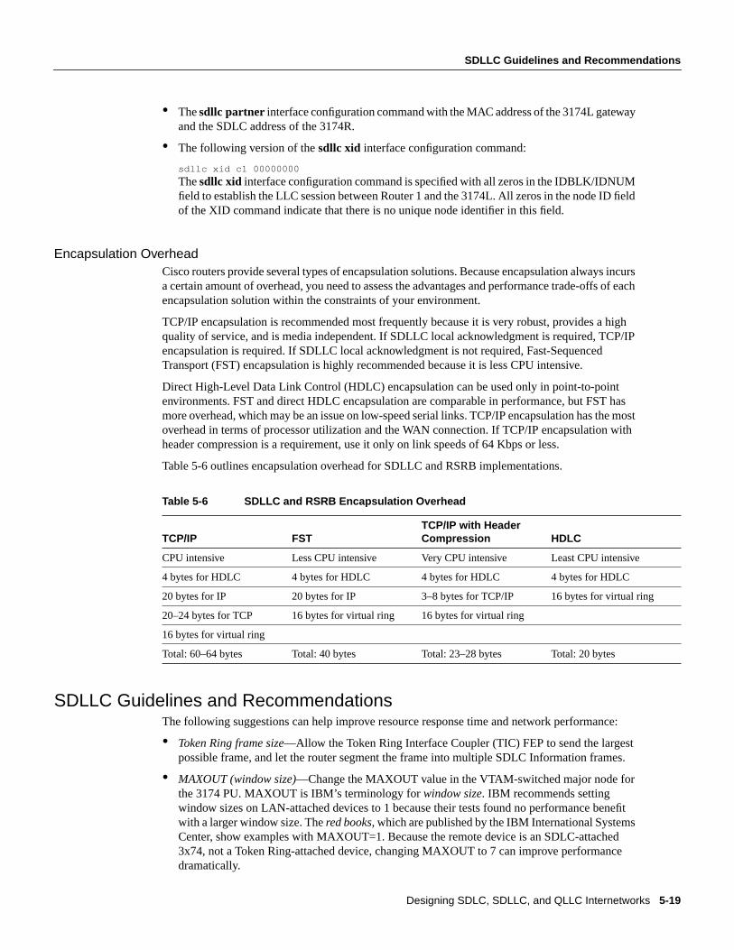
Designing SDLC, SDLLC, and QLLC Internetworks 5-19
SDLLC Guidelines and Recommendations
• Thesdllc partner interface configuration command with the MAC address of the 3174L gatewayand the SDLC address of the 3174R.
• The following version of thesdllc xid interface configuration command:
sdllc xid c1 00000000
Thesdllc xid interface configuration command is specified with all zeros in the IDBLK/IDNUMfield to establish the LLC session between Router 1 and the 3174L. All zeros in the node ID fieldof the XID command indicate that there is no unique node identifier in this field.
Encapsulation OverheadCisco routers provide several types of encapsulation solutions. Because encapsulation always incursa certain amount of overhead, you need to assess the advantages and performance trade-offs of eachencapsulation solution within the constraints of your environment.
TCP/IP encapsulation is recommended most frequently because it is very robust, provides a highquality of service, and is media independent. If SDLLC local acknowledgment is required, TCP/IPencapsulation is required. If SDLLC local acknowledgment is not required, Fast-SequencedTransport (FST) encapsulation is highly recommended because it is less CPU intensive.
Direct High-Level Data Link Control (HDLC) encapsulation can be used only in point-to-pointenvironments. FST and direct HDLC encapsulation are comparable in performance, but FST hasmore overhead, which may be an issue on low-speed serial links. TCP/IP encapsulation has the mostoverhead in terms of processor utilization and the WAN connection. If TCP/IP encapsulation withheader compression is a requirement, use it only on link speeds of 64 Kbps or less.
Table 5-6 outlines encapsulation overhead for SDLLC and RSRB implementations.
Table 5-6 SDLLC and RSRB Encapsulation Overhead
SDLLC Guidelines and RecommendationsThe following suggestions can help improve resource response time and network performance:
• Token Ring frame size—Allow the Token Ring Interface Coupler (TIC) FEP to send the largestpossible frame, and let the router segment the frame into multiple SDLC Information frames.
• MAXOUT (window size)—Change the MAXOUT value in the VTAM-switched major node forthe 3174 PU. MAXOUT is IBM’s terminology forwindow size. IBM recommends settingwindow sizes on LAN-attached devices to 1 because their tests found no performance benefitwith a larger window size. Thered books,which are published by the IBM International SystemsCenter, show examples with MAXOUT=1. Because the remote device is an SDLC-attached3x74, not a Token Ring-attached device, changing MAXOUT to 7 can improve performancedramatically.
TCP/IP FSTTCP/IP with HeaderCompression HDLC
CPU intensive Less CPU intensive Very CPU intensive Least CPU intensive
4 bytes for HDLC 4 bytes for HDLC 4 bytes for HDLC 4 bytes for HDLC
20 bytes for IP 20 bytes for IP 3–8 bytes for TCP/IP 16 bytes for virtual ring
20–24 bytes for TCP 16 bytes for virtual ring 16 bytes for virtual ring
16 bytes for virtual ring
Total: 60–64 bytes Total: 40 bytes Total: 23–28 bytes Total: 20 bytes

SDLLC Implementation
Cisco CCIE Fundamentals: Network Design5-20
• SDLC line speed—Increase the line speed of the 3x74 to 19.2 Kbps (older units) or 64 Kbps(newer units) when the controller is directly attached (as opposed to being attached through amodem) to the router. Modem and communication facilities are frequently the limiting factors indetermining the line speed in the prerouter configuration.
• SDLC frame size—Set the largest SDLC frame size to 521 on newer 3274 models (not 265, whichis required for older 3274 models).See the note that follows.
• Request To Send (RTS) control—Set the 3174 for permanent RTS if the device is not connectedvia a multidrop service through modem-sharing devices or line-sharing devices. Modem-sharingand line-sharing connections require that RTS be toggled when the device is transmitting. Settingpermanent RTS cuts down online turnaround delays and can improve link utilization by 10percent. (However, setting permanent RTS is unlikely to achieve any perceptible response timeimprovements.)
Note Changing configurations of end devices, such as terminal controllers, is not recommended.The high number of devices requiring changes and the cost and unavailability associated with thesechanges can make these modifications onerous. Modify SDLC maximum frame size and RTScontrol with discretion.
SDLLC Implementation ScenariosThe following case study shows how an internetwork can evolve from a SNA-specific SDLCenvironment featuring 3x74 controllers and 3270 terminals to a network of PCs with client-serverapplications. The most important requirement for this evolution is the protection of existing SNAinvestment.
Assume that the original network consisted of hundreds of SDLC 3x74 controllers connected to anumber of 37x5 FEPs in the data center. A disaster recovery center maintains the “mirror-image” ofthe data center. Many 3x74s are multidrop-connected to the host via 9.6- or 19.2-Kbps leased lines.The challenges facing the corporate MIS organization for this internetwork include the following:
• Reliability—When an SDLC line goes down, all the downstream users are affected. There is nonetwork redundancy.
• Leased line charges—Providing lines to multiple remote SDLC devices results in excessiveservice charges and must be minimized.
• FEP CPU use—CPU use is higher for SDLC-supported sessions than for LAN-supportedsessions.
• Maintaining VTAM and NCP—Every move and change requires system programmers toregenerate VTAM/NCP, which increases the cost of maintaining a statistically defined network.
• Supporting LAN-based applications—There is a growing need to support LAN-basedinterconnection, both PC-to-host and PC-to-PC.
• Availability and up time—To maintain a competitive advantage, the organization needs to keepSNA sessions alive even if the network fails.
A phased strategy aimed at addressing these challenges would consist of three phases. Each of thesephases is discussed in the following implementation examples.

Designing SDLC, SDLLC, and QLLC Internetworks 5-21
SDLLC Implementation Scenarios
Phase 1: Redundant Backbone Using STUN and Virtual MultidropBuild a redundant backbone network with routers and high-speed E1 or T1 links in each regionaloffice, as shown in Figure 5-14. Connect multiple SDLC devices to a router via SDLC transport withvirtual multidrop. The resulting network increases reliability and minimizes leased-line charges.
Figure 5-14 Connecting multiple SDLC devices via SDLC transport with virtual multidrop.
Phase 2: Fault-Tolerant Host FEP Token Ring and SDLLC ImplementationImplement a fault-tolerant host FEP Token Ring, as shown in Figure 5-15. Connecting existingSDLC devices to the host Token Ring via SDLLC improves response time. Because SDLC devicesappear as Token Ring-attached devices to the host, you do not need to regenerate NCP and reloadwhen you are adding or changing PUs and LUs. This can be done dynamically throughVTAM-switched major nodes. This implementation also reduces FEP CPU utilization.
Host Host Host Host
3745 3745 3745 3745
3x74 PU 1 5x94 AS400 RS6000 OS/2
T1
T1
T1
T1
56 Kbps
56 Kbps
Main data center Disaster recovery center
Router Router
Router Router
SDLLC Implementation
Cisco CCIE Fundamentals: Network Design5-22
Figure 5-15 Fault-tolerant TICs and SDLLC implementation.
Phase 3: Strategic LAN-to-WAN ImplementationImplement LAN (both Token Ring and Ethernet) internetworks in selected locations along withalternative WAN technologies, such as Frame Relay, as shown in Figure 5-16. Connect LAN-basedand remote SDLC devices to host FEP Token Ring via SDLLC, RSRB, and translational bridging,and to host FEP SDLC via reverse SDLLC (SDLC side primary). SNA session integrity ismaintained through local termination of both LLC2 and SDLC traffic. These solutions provideneeded support of LAN-based applications and improve availability and up time for SNA networkdevices.
SDLLC Implementation ChecklistBefore implementing an SDLLC-based internetwork, make sure you are familiar with theinformation that deals with SDLC. Depending on your implementation, you might need to reviewthe “SDLLC Configuration” and “SDLLC Implementation Scenarios” sections earlier in thischapter. In general, the following guidelines help you create a working, manageable network:
• Use a phased approach to implement your router network.
• Establish a test environment to initially bring up the routers.
• Plan a gradual cutover of end devices into the production environment.
• During the cutover period, observe the router’s behavior by usingshow commands.
3x74 PU 1 5x94 AS400 RS6000 OS/2
Host Host Host Host
3745 3745 3745 3745
T1
T1
T1
T1
56 Kbps
56 Kbps
Main data center Disaster recovery center
Router Router
Router Router
TokenRing
TokenRing
TokenRing
TokenRing

Designing SDLC, SDLLC, and QLLC Internetworks 5-23
SDLLC Implementation Checklist
Figure 5-16 Implementing alternative LAN-to-WAN technologies for an integratedsolution.
Strive to create a network that has predictable behavior early in the development cycle. This strategycan prevent problems as more devices are brought online. The following is a specific SDLLCimplementation checklist that you can use to identify technologies, implementations, and possiblesolutions for your internetwork:
Step 1 Evaluate the customer requirements for SDLLC support:
• Identify all host-attached controllers. Examples include 37x5, 3172, and 3174devices. The host sites might be referred to as local, core, backbone, or data centersites.
• How are the host site controllers connected to the network?
• Is Token Ring already in place? Ethernet?
• What are the link speeds for remote end systems?
• What are the current line utilization measurements? Network Performance Monitor,which makes historical data available, is typically installed in the larger SNA shops.
• What interface type is required (for example: V.24 (EIA/TIA-232, formerly RS-232),V.35, or X.21)?
• What modems, data service units, channel service units, modem-sharing devices orline-sharing devices will be used?
3745 3745 3745 3745
3274 3274
T1
T1
T1
T1
56 Kbps
Main data center Disaster recovery center
Frame Relay
TokenRing
AS/400 Host
TokenRing
AS/400 Host
SDLC
Local acknowledgment
Local acknowledgment
Local acknowledgment
Local acknowledgment
Local acknowledgment
Local acknowledgment
Host Host Host Host
Router Router
Router Router
TokenRing
TokenRing
TokenRing
TokenRing

QLLC Conversion
Cisco CCIE Fundamentals: Network Design5-24
• Is Link Problem Determination Aid (LPDA) support required? LPDA is a feature ofIBM modems and data service units that reports line quality and statistics to NetView.LPDA Version 1 is not compatible with STUN and SDLLC; LAPD Version 2 may becompatible with STUN.
• What remote end-system types are expected? Examples include 3174, 3274, andAS/400.
• Will there be end-system emulation?
• What is the current transaction response time? Is subsecond response required?
• How many PUs are there? (This information will be important for router utilizationsizing.)
• How many LUs are there? (Many busy LUs attached to a PU increases linkutilization.)
Step 2 Determine current configuration. Important information includes the following:
• NCP system generation for 3745, 3725, and 3720 devices; in particular, note theLINE, PU, and LU definition statements.
• Local controller current worksheets for 3174 and 3172 devices.
• Remote controller configuration worksheets for 3x74 and 5x94 devices.
• OS/2 Communication Manager configuration files.
• Network topology diagram.
Step 3 Determine the SDLLC features that best suit your requirements.
Confirm that devices to be attached are SDLC PU type 2 devices. Select specific featurerequirements, such as local acknowledgment and virtual multidrop.
Step 4 Determine what host conversion changes are required:
• Switched major node definitions for VTAM.
• FEP/NCP changes for Token Ring addition and SDLC link reduction.
QLLC ConversionQLLC is a data-link protocol defined by IBM that allows SNA data to be transported across X.25networks. With QLLC, each SDLC physical link is replaced by a single virtual circuit. Figure 5-17illustrates a typical QLLC topology. In this topology, both ends of the connection over the X.25network must be configured for QLLC.
Figure 5-17 Typical QLLC topology.
QLLC conversion is a feature of Cisco IOS Software Release 10.2 that causes the router to performall of the translation required to send SNA data over an X.25 network so that IBM devices that areconnected to a router donot have to be configured for QLLC.
3174
X.25 network
FEP

Designing SDLC, SDLLC, and QLLC Internetworks 5-25
QLLC Conversion
QLLC conversion allows a device (typically a FEP or an AS/400) that is attached either directly tothe router or through a Token Ring to communicate with a device (typically a 3174 terminalcontroller) that is attached to an X.25 network, as shown in Figure 5-18. In this example, only theterminal controller must be configured for QLLC and must have an X.25 interface.
Figure 5-18 Simple topology for QLLC conversion.
In some topologies, one router interface uses SDLC to communicate with the terminal controller,and another router interface uses X.25 to communicate with the remote device over the X.25network. In Figure 5-19, the router, configured for QLLC conversion, handles SNA traffic betweenthe terminal controller and the FEP.
Figure 5-19 Topology that uses SDLC and QLLC conversion.
QLLC conversion also supports multiple SDLC connections coming through an MSD, as shown inFigure 5-20.
Figure 5-20 QLLC conversion supports multidrop SDLC topology.
The router that is configured for QLLC conversion does not need to be on the same Token Ring asthe FEP. In Figure 5-21, Router A is configured for QLLC and remote source-route bridging(RSRB), and Router B is configured for RSRB only. RSRB allows the FEP to connect to Router A.If a Token Ring connected to the X.25 network communicates with the Token Ring attached to theFEP by a protocol other than SRB, RSRB can provide connectivity.
3174
X.25 network
FEPRouter
TokenRing
3174FEP
X.25 network
3174
FEP
X.25 network
3174
RouterMSD

Summary
Cisco CCIE Fundamentals: Network Design5-26
Figure 5-21 Comples QLLC conversion topology.
Figure 5-21 shows an example using local acknowledgment, which causes the LLC2 session fromthe Token Ring-attached SNA device (the FEP) to be terminated at the adjacent router (Router B).A TCP session transports the data from Router B to the router attached to the X.25 network(Router A). Only Router A is configured for QLLC conversion. When enabled, localacknowledgment applies to all QLLC connections. Thesource-bridge qllc-local-ack globalconfiguration command enables local acknowledgment and applies to all QLLC connections.
In pass-through mode, local acknowledgment is not used. Instead, the LLC2 session from the TokenRing-attached SNA device (the FEP) is terminated at the router connected to the X.25 network(Router A).
QLLC conversion also supports a configuration in which SNA end stations (3174 or equivalent)that are connected to a Token Ring reach the FEP through an X.25 connection, as shown inFigure 5-22. Inthis case, IBM Network Packet Switching Interface (NPSI) software is installed onthe FEP.
Figure 5-22 QLLC conversion supports SNA end-station connections over Token Ringand X.25 networks.
SummaryThis chapter addresses some of the special requirements for implementing routing technology withinIBM System Network Architecture (SNA) environments. It describes the three techniques designedto enable internetworking capabilities for SNA-based network architectures, as follows:
• SDLC via STUN
• SDLLC Implementation
• QLLC Conversion
3174 FEP
TokenRing
IP network
QLLC session TCP session LLC2 session
X.25 networkRouter A Router A
3174
TokenRing
FEP
X.25 networkRouter

C H A P T E R
Designing APPN Internetworks 6-1
6
Designing APPN Internetworks
Advanced peer-to-peer networking (APPN) is a second generation of the Systems NetworkArchitecture (SNA) from IBM. It moves SNA from a hierarchical, mainframe-centric environmentto a peer-to-peer environment. It provides capabilities similar to other LAN protocols, such asdynamic resource definition and route discovery.
This chapter focuses on developing the network design and planning a successful migration toAPPN. It covers the following topics:
• Evolution of SNA
• When to Use APPN as Part of a Network Design
• When to Use APPN Versus Alternative Methods of SNA Transport
• Overview of APPN
• Scalability Issues
• Backup Techniques in an APPN Network
• APPN in a Multiprotocol Environment
• Network Management
• Configuration Examples
Note Although this chapter does discuss using APPN with DLSw+, for detailed information onusing DLSw+, refer to Chapter 7, “Designing DLSw+ Internetworks.”
Evolution of SNAIntroduced in 1974, subarea SNA made the mainframe computer running AdvancedCommunications Function/Virtual Telecommunication Access Method (ACF/VTAM) the hub of thenetwork. The mainframe was responsible for establishing all sessions (a connection between tworesources over which data can be sent), activating resources, and deactivating resources. The designpoint of subarea SNA was reliable delivery of information across low-speed analog lines. Resourceswere explicitly predefined. This eliminated the need for broadcast traffic and minimized headeroverhead.
Many enterprises today maintain two networks: a traditional, hierarchical SNA subarea network andan interconnected LAN network that is based on connectionless, dynamic protocols. The advantageof the subarea SNA network is that it is manageable and provides predictable response time. Thedisadvantages are that it requires extensive system definition and does not take advantage of thecapabilities of intelligent devices (for example, the PCs and workstations).

Evolution of SNA
Cisco CCIE Fundamentals: Network Design6-2
Role of APPNWith APPN, you can consolidate the two networks (an SNA subarea network and an interconnectedLAN network) because APPN has many of the characteristics of the LAN networks and still offersthe advantages of an SNA network. The major benefits of using APPN include the following:
• Connections are peer-to-peer, allowing any end user to initiate a connection with any other enduser without the mainframe (VTAM) involvement.
• APPN supports subarea applications as well as newer peer-to-peer applications over a singlenetwork.
• APPN provides an effective routing protocol to allow SNA traffic to flow natively andconcurrently with other protocols in a single network.
• Traditional SNA class of service (COS)/transmission priority can be maintained.
As SNA has evolved, one feature has remained critical to many users: COS. This feature providestraffic prioritization on an SNA session basis on the backbone. This, in turn, allows a single user tohave sessions with multiple applications, each with a different COS. In APPN, this feature offersmore granularity and extends this capability all the way to the end node rather than just betweencommunication controllers.
Types of APPN NodesAn APPN network has three types of nodes: LEN nodes, end nodes (EN), and network nodes (NN),as shown in Figure 6-1.
Figure 6-1 Different types of APPN nodes.
Note Throughout the rest of this chapter, the abbreviations EN and NN are used in the illustrations.The full terms (end node and network node) are used within the text for clarity.
Table 6-1 describes these different types of APPN nodes. The control point (CP), which isresponsible for managing a node’s resources and adjacent node communication in APPN, is key toan APPN node. The APPN Control Point is the APPN equivalent of the SSCP.
NN
NN
LEN nodeEN = end nodeNN = network node
EN
ENNN
NN
EN
CP-CP session pair
APPN
NN

Designing APPN Internetworks 6-3
When to Use APPN as Part of a Network Design
Table 6-1 Different Types of APPN Nodes
For more background information on APPN, refer to the section “Overview of APPN” later in thischapter.
When to Use APPN as Part of a Network DesignAPPN has two key advantages over other protocols:
• Native SNA routing
• COS for guaranteed service delivery
APPN, like Transmission Control Protocol/Internet Protocol (TCP/IP), is a routable protocol inwhich routing decisions are made at the network nodes. Although only the network node adjacent tothe originator of the session selects the session path, every network node contributes to the processby keeping every other network node informed about the network topology. The network nodeadjacent to the destination also participates by providing detailed information about the destination.Only routers that are running as APPN network nodes can make routing decisions.
You need APPN in your network when a routing decision (for example, which data center or path)must be made. Figure 6-2 helps to illustrate the criteria you use to determine where APPN should beused in a network.
Type of APPN Node Description
Local Entry Networking(LEN) nodes
LEN nodes are pre-APPN, peer-to-peer nodes. They can participate in an APPN networkby using the services provided by an adjacent network node. The CP of the LEN nodemanages the local resources but does not establish a CP-CP session with the adjacentnetwork node. Session partners must be predefined to the LEN node, and the LEN nodemust be predefined to the adjacent network node. LEN nodes are also referred to as SNAnode type 2.1, physical unit (PU) type 2.1, or PU2.1.
End nodes End nodes contain a subset of full APPN functionality. They access the network throughan adjacent network node and use the adjacent network node’s routing services. An endnode establishes a CP-CP session with an adjacent network node, and then uses thatsession to register resources, request directory services, and request routing information.
Network nodes Network nodes contain full APPN functionality. The CP in a network node is responsiblefor managing the resources of the network node along with the attached end nodes andLEN nodes. The CP establishes CP-CP sessions with adjacent end nodes and networknodes. It also maintains network topology and directory databases, which are created andupdated by dynamically gathering information from adjacent network nodes and endnodes over CP-CP sessions. In an APPN environment, network nodes are connected bytransmission groups (TGs), which in the current APPN architecture refers to a single link.Consequently, the network topology is a combination of network nodes and transmissiongroups.

When to Use APPN as Part of a Network Design
Cisco CCIE Fundamentals: Network Design6-4
Figure 6-2 Determining where to use APPN in a network.
In Figure 6-2, a single link connects the branch office to the backbone. Therefore, a routing decisiondoes not need to be made at the branch office. Consequently, an APPN network node might not benecessary at those sites.
Because there are two data centers, however, the routing decision about which data center to sendthe message to must be made. This routing decision can be made either at the data center or at thebackbone routers. If you want this routing decision made at the data center, all messages are sent toa single data center using DLSw+, for example, and then routed to the correct data center usingAPPN only in the routers in the data center. If you want the routing decision to be made at thebackbone routers, place the APPN network node in the backbone routers, where alternative paths areavailable for routing decisions outside of the data center. In this example, this latter approach ispreferred because it isolates the function at the data centers routers to channel attachment, reducesthe number of hops to the second data center, and provides a path to a backup data center ifsomething catastrophic occurs.
Because APPN requires more memory and additional software, it is generally a more expensivesolution. The advantages of direct APPN routing and COS, however, often offset the added expense.In this case, the added expense to add APPN to the backbone and data center routers might bejustifiable, whereas added expense at the branch might not be justifiable.
APPN at Every BranchThere are two cases for which adding an APPN network node at every branch can be cost justified:
• When COS Is Required
• When Branch-to-Branch Routing Is Required
Datacenter
Backbone
Branch
TokenRing
TokenRing

Designing APPN Internetworks 6-5
APPN at Every Branch
When COS Is RequiredCOS implies that the user accesses multiple applications and must be able to prioritize traffic atan application level. Although other priority schemes, such as custom queuing, might be able toprioritize by end user, they cannot prioritize between applications for an individual user. If thiscapability is critical, APPN network nodes must be placed in the individual branches to consolidatethe traffic between multiple users using COS. For instance, COS can ensure that credit cardverification always gets priority over batch receipts to a retail company’s central site.
It is important to understand where COS is used in the network today. If the network is a subareaSNA network, COS is used only between front-end processors (FEPs) and ACF/VTAM on themainframe. Unless there is already an FEP at the branch office, they do not have traffic prioritizationfrom the branch, although traffic can be prioritized from the FEP out. In this case, adding an APPNnetwork node at the branch office would prioritize the traffic destined for the data center soonerrather than waiting until it reaches the FEP—adding function over what is available today.
When Branch-to-Branch Routing Is RequiredIf branch-to-branch traffic is required, you can send all traffic to the central site and let those APPNnetwork nodes route to the appropriate branch office. This is the obvious solution when both datacenter and branch-to-branch traffic are required and the branch is connected to the backbone over asingle link. However, if a separate direct link to another branch is cost-justifiable, routing all trafficto the data center is unacceptable. In this case, making the routing decision at the branch is necessary.Using an APPN network node at the branch, data center traffic is sent over the data center link andbranch-to-branch traffic is sent over the direct link.
In the example in Figure 6-3, each branch has two links to alternative routers at the data center. Thisis a case where APPN network nodes might be required at the branches so that the appropriate linkcan be selected. This can also be the design for branch-to-branch routing, adding a single hop ratherthan creating a full mesh of lines. This provides more direct routing than sending everything throughthe data center.

When to Use APPN Versus Alternative Methods of SNA Transport
Cisco CCIE Fundamentals: Network Design6-6
Figure 6-3 Sample network for which branch-to-branch routing is required.
As you also learn in this chapter, scalability issues make it advantageous to keep the number ofnetwork nodes as small as possible. Understanding where native routing and COS is needed is keyin minimizing the number of network nodes.
In summary, choosing where to implement APPN must be decided based on cost, scalability, andwhere native routing and COS are needed. Implementing APPN everywhere in your network mightseem to be an obvious solution, even when not necessary. It must be understood, however, that if youwere to deploy APPN everywhere in your network it probably would be a more costly solution thannecessary and may potentially lead to scalability problems. Consequently, the best solution is todeploy APPN only where it is truly needed in your network.
When to Use APPN Versus Alternative Methods of SNA TransportAPPN and boundary network node (BNN)/boundary access node (BAN) over Frame Relay usingRFC 1490 are the two methods of native SNA transport, where SNA is not encapsulated in anotherprotocol. BAN and BNN allow direct connection to an FEP, using the Frame Relay network to switchmessages, rather than providing direct SNA routing.
Althoughnative might seem to be the appropriate strategy, APPN comes at the price of cost andnetwork scalability, as indicated in the preceding section. With BNN/BAN additional cost is requiredto provide multiprotocol networking because the FEP does not handle multiple protocols. Thisimplies that additional routers are required in the data center for other protocols and separate virtualcircuits are required to guarantee service delivery for the SNA or APPN traffic.
DLSw+ provides encapsulation of SNA, where the entire APPN message is carried as data inside aTCP/IP message. There is often concern about the extra 40 bytes of header associated with TCP/IP.However, because Cisco offers alternatives such as Data Link Switching Lite, Fast SequencedTransport (FST), and Direct Transport, which have shorter headers, header length is deemednoncritical to this discussion.
Datacenter
Backbone
Branch
TokenRing
TokenRing
Designing APPN Internetworks 6-7
Overview of APPN
DLSw+ is attractive for those networks in which the end stations and data center will remainSNA-centric, but the backbone will be TCP/IP. This allows a single protocol across the backbone,while maintaining access to all SNA applications. DLSw+ does not provide native APPN routing,nor does it provide native COS. Consequently, DLSw+ is preferable for networks, in which cost isa key criterion, that have the following characteristics:
• A single data center or mainframe
• Single links from the branches
In general, DLSw+ is a lower-cost solution that requires less memory and software. In the vastmajority of networks, DLSw+ will be combined with APPN—using APPN only where routingdecisions are critical. With TCP/IP encapsulation, the TCP layer provides the same reliable deliveryas SNA/APPN, but does not provide the native routing and COS.
TN3270 transports 3270 data stream inside a TCP/IP packet without SNA headers. Therefore, thissolution assumes that the end station has only a TCP/IP protocol stack and no SNA. Therefore,TN3270 is not an alternative to APPN because APPN assumes the end station has an SNA protocolstack. APPN, like DLSw+, may still be required in the network to route between TN3270 serversand multiple mainframes or data centers.
In summary, APPN will frequently be used with DLSw+ in networks when a single backboneprotocol is desired. BAN/BNN provides direct connectivity to the FEP but lacks the multiprotocolcapabilities of other solutions. TN3270 is used only for TCP/IP end stations.
Overview of APPNThis section provides an overview of APPN and covers the following topics:
• Defining Nodes
• Establishing APPN Sessions
• Understanding Intermediate Session Routing
• Using Dependent Logical Unit Requester/Server
Defining NodesNodes, such as ACF/VTAM, OS/400 and Communications Server/2 (CS/2), can be defined as eithernetwork nodes or end nodes.When you have a choice, consider the following issues:
• Network size—How large is the network? Building large APPN networks can introducescalability issues. Reducing the number of network nodes is one solution for avoiding scalabilityproblems. For more information on reducing the number of network nodes, see the section“Reducing the Number of Network Nodes” later in this chapter.
• Role of the node—Is it preferable to have this node performing routing functions as well asapplication processing? A separate network node can reduce processing cycles and memoryrequirements in an application processor.
Generally, you should define a network node whenever a routing decision needs to be made.
Overview of APPN
Cisco CCIE Fundamentals: Network Design6-8
APPN Node IdentifiersAn APPN node is identified by its network-qualified CP name, which has the format netid.name. Thenetwork identifier (netid) is an eight-character name that identifies the network or subnetwork inwhich the resource is located. The network identifier and name must be a combination of uppercaseletters (A through Z), digits (0 through 9), and special characters ($,#,or @) but cannot have a digitas the first character.
Establishing APPN SessionsIn order for an APPN session to be established, the following must occur:
1 The end user requests a session with an application, which causes the end node to begin theprocess of session establishment by sending a LOCATE message to its network node server. Forsession initiation, the network node server provides the path to the destination end node, whichallows the originating end node to send messages directly to the destination.
2 The network node uses directory services to locate the destination by first checking its internaldirectories. If the destination is not included in the internal directory, the network node sends aLOCATE request to the central directory server if one is available. If a central directory server isnot available, the network node sends a LOCATE broadcast to the adjacent network nodes thatin turn propagate the LOCATE throughout the network. The network node server of thedestination returns a reply that indicates the location of the destination.
3 Based on the location of the destination, the COS requested by the originator of the session, thetopology database, and the COS tables, the network node server of the originator selects the leastexpensive path that provides the appropriate level of service.
4 The originating network node server sends a LOCATE reply to the originating end node. TheLOCATE reply provides the path to the destination.
5 The originating end node is then responsible for initiating the session. A BIND is sent from theoriginating end node to the destination end node, requesting a session. After the destinationreplies to the BIND, session traffic can flow.
Understanding Intermediate Session RoutingSession connectors are used in place of routing tables in APPN. The unique session identifier andport from one side of the node are mapped to the unique session identifier and port on the other side.As data traffic passes through the node, the unique session identifier in the header is swapped for theoutgoing identifier and sent out on the appropriate port, as shown in Figure 6-4.
Figure 6-4 Intermediate session routing label swap.
Sessionconnector
SID245
SID321
NN 1EN A
NN 4
Sessionconnector
SID321
SID 321 SID 548SID 245
Session Stage 1 Session Stage 2 Session Stage 3
SID548
EN B

Designing APPN Internetworks 6-9
Using Dependent Logical Unit Requester/Server
This routing algorithm is calledintermediate session routing (ISR). It supports dynamic routedefinition and incorporates the following legacy features:
• Node-to-node error and flow control processing—This reflects the 1970s method of packetswitching in which many line errors dictated error and flow control at each node. Given thecurrent high-quality digital facilities in many locations, this redundant processing is unnecessaryand significantly reduces end-to-end throughput. End-to-end processing provides betterperformance and still delivers the necessary reliability.
• Disruptive session switching around network failures—Whenever a network outage occurs, allsessions using the path fail and have to be restarted to use an alternative path.
Because these features are undesirable in most high-speed networks today, a newer routingalgorithm—High Performance Routing (HPR)—has been added to APPN that supportsnondisruptive rerouting around failures and end-to-end error control, flow control, andsegmentation. Cisco routers support both ISR and HPR.
Using Dependent Logical Unit Requester/ServerDependent Logical Unit Requester/Server (DLUR/DLUS) is an APPN feature that allows legacytraffic to flow on an APPN network. Prior to the introduction of this feature, the APPN architectureassumed that all nodes in a network could initiate peer-to-peer traffic (for example, sending theBIND to start the session). Many legacy terminals that are referred to as Dependent Logical Units(DLUs) cannot do this and require VTAM to notify the application, which then sends the BIND.
Getting the legacy sessions initiated requires a client-server relationship between ACF/VTAM(Dependent LU server—DLUS) and the Cisco router (Dependent LU Requester—DLUR). A pair oflogical unit (LU) type 6.2 sessions are established between the DLUR and DLUS—one session isestablished by each end point. These sessions are used to transport the legacy control messages thatmust flow to activate the legacy resources and initiate their logical unit to logical unit (LU-LU)sessions. An LU-LU session is the connection that is formed when the five steps described earlier inthe section “Establishing APPN Sessions” are completed.
For example, an activate logical unit (ACTLU) message must be sent to the LU to activate a legacyLU. Because this message is not recognized in an APPN environment, it is carried as encapsulateddata on the LU 6.2 session. DLUR then deencapsulates it, and passes it to the legacy LU. Likewise,the DLU session request is passed to the ACF/VTAM DLUS, where it is processed as legacy traffic.DLUS then sends a message to the application host, which is responsible for sending the BIND.After the legacy LU-LU session is established, the legacy data flows natively with the APPN traffic,as shown in Figure 6-5.

Cisco Implementation of APPN
Cisco CCIE Fundamentals: Network Design6-10
Figure 6-5 DLU session processing.
Cisco Implementation of APPNThis section provides an overview of Cisco’s implementation of APPN and discusses where APPNresides in the Cisco IOS software. Cisco licensed the APPN source code from IBM and then portedit to the Cisco IOS software using network services from the data-link controls (DLCs).
Applications use APPN to provide network transport. APPN runs on top of the Cisco IOS software.APPN is a higher-layer protocol stack that requires network services from DLC. Cisco’s APPNimplementation is compliant with the APPN Architecture of record. When used with other featuresin the Cisco IOS software, APPN provides the following unique features:
• APPN can use DLSw+ or RSRB as a network transport, thereby supporting APPN over a nativeTCP/IP network.
• APPN can be used with downstream physical unit concentration (DSPU) to reduce the numberof downstream PUs visible to VTAM. This reduces VTAM definition and network restart times.
• In addition to COS, priority queuing, custom queuing, and weighted fair queuing can be usedwith COS to ensure traffic prioritization and/or bandwidth reservation between protocols.
• Network management options are supported that include native SNA management services usingNative Service Point (NSP) in the Cisco router, and Simple Network Management Protocol(SNMP) management using CiscoWorks Blue applications.
• Using Channel Interface Processor (CIP) or Channel Port Adapter (CPA), the Cisco APPNnetwork node can interface directly with ACF/VTAM across the channel. VTAM can be definedeither as an end node or network node.
APPN network
Session data
Applicationhost
Dependent LUs
DLUR
Session dataLU 6.2 pipes
DLUS
Session establishment:LU 6.2 "pipes"
VTAM notifiesapplication host

Designing APPN Internetworks 6-11
Scalability Issues
Scalability IssuesAs a single-network link state architecture, the network topology is updated as changes occur. Thisresults in significant network traffic if instability occurs, and significant memory and processing tomaintain the large topology databases and COS tables. Similarly, in large networks, dynamicdiscovery of resources can consume significant bandwidth and processing. For these reasons,scalability becomes a concern as network size increases. The number of nodes that are too largedepends on the following:
• Amount of traffic
• Network stability
• The number of the techniques, which are described in this section, that are being used to controltraffic and processing
Essentially, to allow growth of APPN networks, the network design must focus on reducing thenumber of topology database updates (TDUs) and LOCATE search requests.
Topology Database Update ReductionAPPN is a link-state protocol. Like other link-state-based algorithms, it maintains a database of theentire topology information of the network. Every APPN network node in the network sends outTDU packets that describe the current state of all its links to its adjacent network nodes. The TDUcontains information that identifies the following:
• The characteristics of the sending node
• The node and link characteristics of the various resources in the network
• The sequence number of the most recent update for each described resource
A network node that receives a TDU packet propagates this information to its adjacent networknodes using a flow reduction technique. Each APPN network node maintains full knowledge of thenetwork and how the network is interconnected. Once a network node detects a change to thenetwork (either a change to the link, or the node), it floods TDUs throughout the network to ensurerapid convergence. If there is an unstable link in the network, it can potentially cause many TDUflows in a network.
As the number of network nodes and links increases, so does the number of TDU flows in yournetwork. This type of distributing topology can consume significant CPU cycles, memory, andbandwidth. Maintaining routes and a large, complete topology subnet can require a significantamount of dynamic memory.
You can use the following techniques to reduce the amount of TDU flows in the network:
• Reduce the number of links
• Reduce the number of CP-CP sessions
• Reduce the number of network nodes in the network
Reducing the Number of LinksThe first technique for reducing the amount of TDU flows in the network is to reduce the number oflinks in your network. In some configurations, it might be possible to use the concept ofconnectionnetworkto reduce the number of predefined links in your network. Because network nodes exchangeinformation about their links, the fewer links you define, the fewer TDU flows can occur.

Scalability Issues
Cisco CCIE Fundamentals: Network Design6-12
Figure 6-6 shows the physical view of an APPN network. In this network NN1, NN2, and NN3 arerouters attached to an FDDI LAN.
Figure 6-6 Physical view of an APPN network.
The network-node server (NNS), EN1, and EN2 hosts are attached to the same FDDI LAN via a CIProuter or a cluster controller. These nodes on the FDDI LAN have any-to-any connectivity. To reflectany-to-any connectivity in APPN, NN1 needs to define a link to NN2, NN3, NNS (VTAM host),EN1 (VTAM data host), and EN2 (EN data host). The transmission groups connecting networknodes are contained in the network topology database. For every link that is defined to the networknode, TDUs are broadcast.
Note Throughout the rest of this chapter, the abbreviation NNS is used in the illustrations. Whenthe text refers to an NNS icon in an illustration, the abbreviation is also used; otherwise, the full term(network-node server) is used within the text for clarity.
Figure 6-7 shows the logical view of the APPN network, shown earlier in Figure 6-6. When NN1first joins the network, NN1 activates the links to NN2, NN3, NNS, EN1, and EN2. CP-CP sessionsare established with the adjacent network nodes. Each adjacent network node sends a copy of thecurrent topology database to NN1. Similarly, NN1 creates a TDU about itself and its links to othernetwork nodes and sends this information over the CP-CP sessions to NN2, NN3 and NNS. WhenNN2 receives the TDU from NN1, it forwards the TDU to its adjacent network nodes, which areNN3 and NNS. Similarly, NN3 and NNS receive the TDU from NN1 and broadcast this TDU to theiradjacent network nodes. The result is that multiple copies of the TDU are received by every networknode.
FDDI Ring
NN1
NN2
NN3
NNS
EN1
CIP
EN2
WAN

Designing APPN Internetworks 6-13
Topology Database Update Reduction
Figure 6-7 Logical view of an APPN network without connection network deployed.
The transmission groups that connect the end nodes are not contained in the network topologydatabase. Consequently, no TDUs are broadcast for the two links to EN1 and EN2. If the number oftransmission groups connecting network nodes can be reduced, the number of TDU flows can alsobe reduced.
By using the concept of connection networks, you can eliminate the transmission group definitions,and therefore reduce TDU flows. A connection network is a single virtual routing node (VRN),which provides any-to-any connectivity for any of its attached nodes. The VRN is not a physicalnode, it is a logical entity that indicates that nodes are using a connection network and a directrouting path can be selected.
Figure 6-8 shows the APPN network shown in Figure 6-6 with connection network deployed.
Figure 6-8 Logical view of an APPN network with connection network deployed.
NN1, NN2, and NN3 define a link to the network-node server (NNS) and a link to the VRN. Whenthe link between NN1 and NNS is activated, NNS sends a copy of the current network topologydatabase to NN1. NN1 creates a TDU about itself, its link to NNS, and its link to the VRN. It thensends this information to NNS. NN1 does not have a link defined to NN2 and NN3, therefore, thereare no TDUs sent to NN2 and NN3 from NN1. When NNS receives the TDU information from NN1,NNS forwards it to NN2 and NN3. Neither NN2 nor NN3 forwards the TDU information becausethey only have a connection to NNS. This significantly reduces the number of TDU flows in thenetwork.
When a session is activated between resources on the connection network, the network-node serverrecognizes that this is a connection network and selects a direct route rather than routing through itsown network nodes. Cisco recommends that you apply the concept of connection networkswhenever possible. Not only does it reduce the number of TDU flows in the network, it also greatlyreduces system definitions.
As shown in the example, a LAN (Ethernet, Token Ring, or FDDI) can be defined as a connectionnetwork. With ATM LAN Emulation (LANE) services, you can interconnect ATM networks withtraditional LANs. From APPN’s perspective, because an ATM-emulated LAN is just another LAN,connection network can be applied. In addition to LANs, the concept of connection networks can
NNS
NN1
NN2
NN3
EN2
EN1
NNS
NN1
NN2 NN3
EN2
VRN
EN1

Scalability Issues
Cisco CCIE Fundamentals: Network Design6-14
apply to X.25, Frame Relay, and ATM networks. It should also be noted that technologies such asRSRB and DLSw appear as LANs to APPN. You can also use connection network in theseenvironments. APPN, in conjunction with DLSw+ or RSRB, provides a synergy between routingand bridging for SNA traffic.
Reducing the Number of CP-CP SessionsThe second technique for reducing the amount of TDU flows in the network is to reduce the numberof CP-CP sessions in your network. Network nodes exchange topology updates over CP-CPsessions. The number of CP-CP sessions has a direct impact on the number of TDU flows in thenetwork.
For example, in Figure 6-9, NN2, NN3, NN4, and NN5 are in a fully meshed network. Everynetwork node establishes CP-CP sessions with its adjacent network nodes. This means that NN2establishes CP-CP sessions with NN3, NN4, and NN5. NN3 establishes CP-CP sessions with NN2,NN4, NN5, and so forth.
Figure 6-9 Fully meshed CP-CP sessions.
If the link fails between NN1 and NN2, TDU updates are broadcast from NN2 to NN3, NN4, andNN5. When NN3 receives the TDU update, it resends this information to NN4 and NN5. Similarly,when NN5 receives the TDU update, it resends this information to NN3 and NN4. This means thatNN4 receives the same information three times. It is recommended that the number of CP-CPsessions are kept to a minimum so that duplicate TDU information will not be received.
In Figure 6-10, CP-CP sessions exist only between NN2 and NN3, NN2 and NN4, and NN2 andNN5; no other CP-CP sessions exist. When the link fails between NN1 and NN2, NN2 broadcaststransmission group updates to NN3, NN4, and NN5. None of the three NNs forwards thisinformation to the rest of the network because CP-CP sessions do not exist. Although this minimizesthe TDU flows, if the link between NN2 and NN3 fails, this becomes a disjointed APPN networkand NN3 is isolated.
NN1 NN2 NN4
NN3
NN5CP-CP sessions

Designing APPN Internetworks 6-15
Topology Database Update Reduction
Figure 6-10 Single pair of CP-CP sessions.
Figure 6-11 shows a more efficient design that also provides redundancy. Every network node hasCP-CP sessions with two adjacent network nodes. NN2 has CP-CP sessions with NN3 and NN5. Ifthe link between NN2 and NN3 fails, TDU updates will be sent via NN5 and NN4.
For redundancy purposes, it is recommended that each network node has CP-CP sessions to twoother network nodes if possible.
Reducing the Number of Network NodesThe third technique for reducing the amount of TDU flows in the network is to reduce the numberof network nodes by defining APPN nodes only at the edges of the network. Minimizing the numberof network nodes also reduces the size of the network topology. The following are some technologiesfor reducing the number of network nodes:
• APPN over DLSw+
• APPN over Frame Relay Access Server (FRAS)/BNN or BAN
• APPN over RSRB
Figure 6-11 Dual pair of CP-CP sessions.
NN1 NN2 NN4
NN3
NN5CP-CP sessions
CP-CP sessions
NN1 NN2 NN4
NN3
NN5

Scalability Issues
Cisco CCIE Fundamentals: Network Design6-16
APPN over DLSw+Data link switching is one way to reduce the number of network nodes in the network. DLSw+ is ameans of transporting APPN traffic across a WAN, where APPN network nodes and/or end nodesare defined only at the edges of the network. Intermediate routing is through DLSw+ and not vianative SNA.
DLSw+ defines a standard to integrate SNA/APPN and LAN internetworks by encapsulating theseprotocols within IP. Cisco’s implementation of DLSw, known as DLSw+, is a superset of the currentDLSw architecture. DLSw+ has many value-added features that are not available in other vendors’DLSw implementations. APPN, when used with DLSw, can benefit from the many scalabilityenhancements that are implemented in DLSw+, such as border peer, on-demand peers, cachingalgorithms, and explorer firewalls.
In Figure 6-12, sessions between end-node workstations and the host are transported over theDLSw+ network.
Figure 6-12 APPN with DLSw+.
VTAM acts as the network-node server for remote end-node workstations. Optionally, if multipleVTAMs or data centers exist, APPN on the channel-attached router(s) or on other routers in the datacenter can offload VTAM by providing the SNA routing capability, as shown in Figure 6-13.
Figure 6-13 APPN with DLSw+ using a channel-attached router.
TokenRing
TokenRing
EN
EN
EN
DLSw+DLSw+
NN
TokenRing
RouterRouterTokenRing
NN
DLSw+ DLSw+ EN
EN
EN

Designing APPN Internetworks 6-17
LOCATE Search Reduction
DLSw+ also brings nondisruptive rerouting in the event of a WAN failure. Using DLSw+ as atransport reduces the number of network nodes in the network. A disadvantage is that remoteend-node workstations require WAN connections for NNS services. Another disadvantage is thatwithout APPN in the routers, APPN transmission priority is lost when traffic enters the DLSw+network.
For detailed information on DLSw and DLSw+, refer to Chapter 7, “Designing DLSw+Internetworks.”
APPN over FRAS BNN/BANIf the APPN network is based on a Frame Relay network, one option is to use the FRAS/BNN or theFrame Relay BAN function for host access. Both BNN and BAN allow a Cisco router to attachdirectly to an FEP. When you use FRAS/BNN, you are assuming that the Frame Relay network isperforming the switching and that native routing is not used within the Frame Relay network. For anexample of how APPN with FRAS BNN/BAN can be used in your network design, see the section“Example of APPN with FRAS BNN” later in this chapter.
APPN over RSRBUsing RSRB, the SNA traffic can be bridged from a remote site to a data center. The use of RSRBsignificantly reduces the total number of network nodes in the network, thus reducing the number ofTDU flows in the network. Another advantage of using RSRB is that it provides nondisruptiverouting in the event of a link failure. For more information on using RSRB, refer to Chapter 4,“Designing SRB Internetworks.”
LOCATE Search ReductionThis section describes the broadcast traffic in an APPN network and how LOCATE searches canbecome a scalability issue in an APPN network. The impact of LOCATE searches in an APPNnetwork varies from one network to the other. This section first identifies some of the causes of anexcessive number of LOCATE searches, and then discusses the following four techniques you canuse to minimize them:
• Safe-Store of Directory Cache
• Partial Directory Entries
• Central Directory Server (CDS)/Client
• Central Resource Registration
An APPN network node provides dynamic location of network resources. Every network nodemaintains dynamic knowledge of the resources in its own directory database. The distributeddirectory database contains a list of all the resources in the network. The LOCATE search requestallows one network node to search the directory database of all other network nodes in the network.
When an end-node resource requests a session with a target resource that it has no knowledge of, ituses the distributed search capabilities of its network-node server to locate the target resource. If thenetwork node does not have any knowledge of the target resource, the network node forwards thelocate search request to all its adjacent network nodes requesting these nodes to assist thenetwork-node server to locate the resource. These adjacent network nodes propagate these locatesearch requests to their adjacent network nodes. This search process is known asbroadcast search.

Scalability Issues
Cisco CCIE Fundamentals: Network Design6-18
Although several mechanisms are put into place to reduce the LOCATE broadcast searches (forexample, resource registration, and resource caching), there might still be an excessive amount ofLOCATE flows in a network for such reasons as the network resources no longer exist, there is amixture of subarea networks and APPN networks, or the resources are temporarily unavailable.
Safe-Store of Directory CacheThe first technique that you can use to minimize the LOCATE flows in your APPN network is theSafe-Store of Directory Cache, which is supported by the Cisco network-node implementation.Cache entries in a network node’s directory database can be periodically written to a permanentstorage medium: a tftp host. This speeds recovery after a network-node outage or initial power loss.Resources do not have to be relearned through a LOCATE broadcast search after a router failure.This reduces spikes of broadcasts that might otherwise occur when the APPN network is restarted.
Partial Directory EntriesThe second technique that you can use to minimize the LOCATE flows in your APPN network is todefine the resources in the local directory database by identifying the end node or network nodewhere the particular resource is located.
The following is a sample configuration:
appn partner-lu-location CISCO.LU21owning-cp CISCO.CP2complete
The preceding example defines the location of an LU named CISCO.LU21 that is located with endnode or network node CISCO.CP2. This command improves network performance by allowingdirected Locate, instead of a broadcast. The disadvantage is that definitions must be created. Toalleviate this definition problem, it may be possible to use partially specified names to definemultiple resources.
The following is a sample configuration:
Sample configuration:appn partner-lu-location CISCO.LUowning-cp CISCO.CP2wildcardcomplete
The preceding example defines the location of all the LUs prefixed with the characters LU.Obviously, a naming convention is essential to the success of this type of node definition.
Central Directory Server (CDS)/ClientThe third technique that you can use to minimize the LOCATE flows in your APPN network is touse the CDS/client function. The APPN architecture specifies a CDS that allows a designatednetwork node to act as a focal point for locating network resources. In current APPN networks, everynetwork node can potentially perform a broadcast search for a resource. This is because the directoryservices database is not replicated on every network node.
The CDS function allows a network node, with central directory client support, to send a directedLOCATE search to a CDS. If the CDS has no knowledge of the resource, it performs one broadcastsearch to find the resource. After the resource is found, the CDS caches the results in its directory.Subsequently, the CDS can provide the location of the resource to other network nodes withoutperforming another broadcast search. The Cisco network-node implementation supports the centraldirectory client function. VTAM is the only product that currently implements the CDS function.
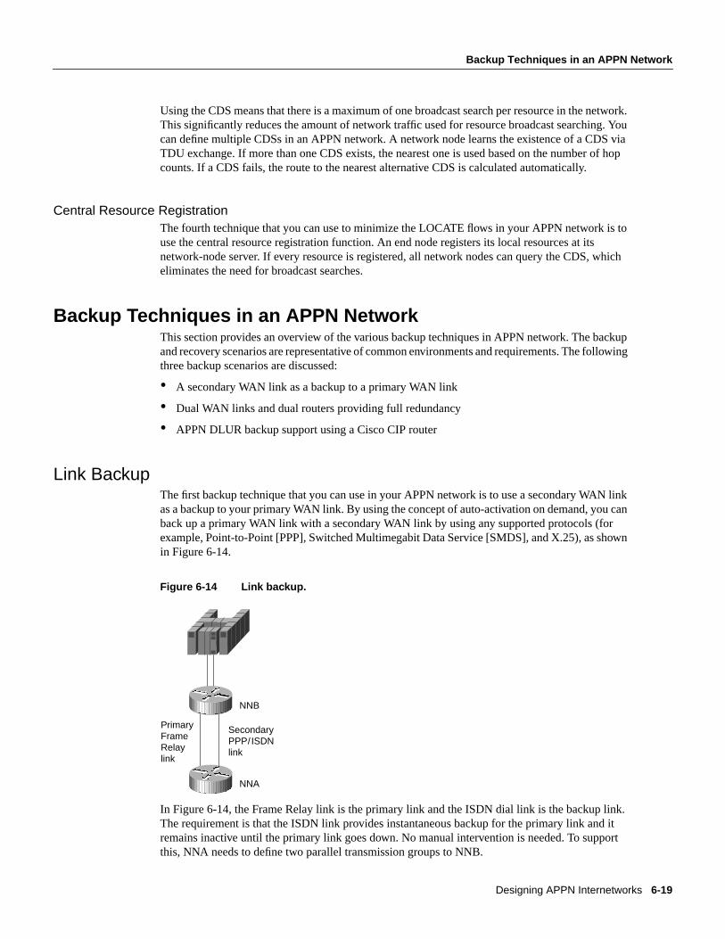
Designing APPN Internetworks 6-19
Backup Techniques in an APPN Network
Using the CDS means that there is a maximum of one broadcast search per resource in the network.This significantly reduces the amount of network traffic used for resource broadcast searching. Youcan define multiple CDSs in an APPN network. A network node learns the existence of a CDS viaTDU exchange. If more than one CDS exists, the nearest one is used based on the number of hopcounts. If a CDS fails, the route to the nearest alternative CDS is calculated automatically.
Central Resource RegistrationThe fourth technique that you can use to minimize the LOCATE flows in your APPN network is touse the central resource registration function. An end node registers its local resources at itsnetwork-node server. If every resource is registered, all network nodes can query the CDS, whicheliminates the need for broadcast searches.
Backup Techniques in an APPN NetworkThis section provides an overview of the various backup techniques in APPN network. The backupand recovery scenarios are representative of common environments and requirements. The followingthree backup scenarios are discussed:
• A secondary WAN link as a backup to a primary WAN link
• Dual WAN links and dual routers providing full redundancy
• APPN DLUR backup support using a Cisco CIP router
Link BackupThe first backup technique that you can use in your APPN network is to use a secondary WAN linkas a backup to your primary WAN link. By using the concept of auto-activation on demand, you canback up a primary WAN link with a secondary WAN link by using any supported protocols (forexample, Point-to-Point [PPP], Switched Multimegabit Data Service [SMDS], and X.25), as shownin Figure 6-14.
Figure 6-14 Link backup.
In Figure 6-14, the Frame Relay link is the primary link and the ISDN dial link is the backup link.The requirement is that the ISDN link provides instantaneous backup for the primary link and itremains inactive until the primary link goes down. No manual intervention is needed. To supportthis, NNA needs to define two parallel transmission groups to NNB.
PrimaryFrameRelaylink
SecondaryPPP/ISDNlink
NNA
NNB

Backup Techniques in an APPN Network
Cisco CCIE Fundamentals: Network Design6-20
The primary link is defined using the following configuration command:
appn link-station PRIMARYport FRAME_RELAYfr-dest-address 35retry-limit infinitecomplete
The secondary link is defined as supporting auto-activation using the following configurationcommand:
appn link-station SECONDARYport PPPno connect-at-startupadjacent-cp-name NETA.NNBactivate-on-demandcomplete
By specifyingno connect-at-startup, the secondary link is not activated upon APPN node startup.To indicate auto-activation support, specifyadjacent-cp-name andactivate-on-demand.
When the primary link fails, APPN detects the link failure and CP-CP sessions failure, which isdisruptive to any existing LU-LU sessions. Because there are multiple links from NNA to NNB,NNA attempts to re-establish the CP-CP sessions over the secondary link. The CP-CP sessionsrequest will activate the secondary dial link automatically.
To ensure that the Frame Relay link is used as primary and the dial PPP link is used as the backup,define the transmission group characteristics to reflect that. For example, use thecost-per-connect-time parameter to define the relative cost of using the dial PPP/ISDN link.
cost-per-connect-time 5
This will make the primary Frame Relay link a lower cost route. Therefore, it is a more desirableroute than the secondary dial link because the default cost-per-connect-time is zero. When theprimary link becomes active, there is no mechanism in place to automatically switch the sessionsback to the primary link. Manual intervention is required.
Full RedundancyThe second backup technique that you can use in your APPN network is dual WAN links and dualrouters for full redundancy. In some cases, for example, complete fault tolerance is required formission-critical applications across the network. You can have dual routers and dual links installedto provide protection against any kind of communications failure.
Figure 6-15 shows how you can use duplicate virtual MAC addresses via RSRB to provide fullredundancy and load sharing.
Designing APPN Internetworks 6-21
Full Redundancy
Figure 6-15 Full redundancy.
The router configuration for NNC is as follows:
source-bridge ring-group 200!interface TokenRing0 ring-speed 16 source 100 1 200!appn control-point NETA.NNC complete!appn port RSRB rsrb rsrb-virtual-station 4000.1000.2000 50 2 200 complete
The router configuration for NND is as follows:
source-bridge ring-group 300!interface TokenRing0 ring-speed 16 source 100 5 300!appn control-point NETA.NND complete!appn port RSRB rsrb rsrb-virtual-station 4000.1000.2000 60 3 300 complete
Both NNC and NND define an RSRB port with the same virtual MAC address. Every workstationwill define the RSRB virtual MAC address as its destination MAC address of its network-nodeserver. Essentially, a workstation can use either NNC or NND as its network-node server, dependingon which node answers the test explorer frame first. The route to NNC consists of the followingrouting information:
Ring 100 -> Bridge 1 -> Ring 200 -> Bridge 2 -> Ring 50
Route to NND will consist of the following routing information:
Ring 100 -> Bridge 5 -> Ring 300 -> Bridge 3 -> Ring 60
TokenRing Ring 100
NNC
NNA
NND
NNB

APPN in a Multiprotocol Environment
Cisco CCIE Fundamentals: Network Design6-22
When NND fails, sessions on NND can be re-established over NNC instantaneously. This isanalogous to the duplicate Token Ring interface coupler (TIC) support on the FEP except that nohardware is required. In Cisco’s RSRB implementation, as shown in Figure 6-15, Segment 20 andBridge 1, and Segment 30 and Bridge 2 are virtual. Duplicate MAC address can be supportedwithout the hardware in place.
SSCP TakeoverThe third backup technique is to use APPN DLUR with a Cisco CIP router to support transfer ofresource ownership from one System Services Control Point (SSCP) (VTAM) to another when afailure occurs. This includes maintaining existing sessions over the failure. DLUS/DLUR canprovide the capability to transfer SSCP ownership from the primary SSCP to the backup SSCP. Itthen examines how DLUR can provide the capability to obtain SSCP services from the backup SSCPwithout terminating LU-LU sessions that are in progress.
Figure 6-16 illustrates how the FEP can be replaced with a CIP router running CIP SNA (CSNA).
Figure 6-16 SSCP takeover with APPN and CIP.
In this example, VTAMA is the primary DLUS, VTAMB is the backup DLUS, and CIP router isconfigured as the DLUR. Assume that LUA requests to log on to an application that is residing onVTAMB. When VTAMA and the DLUS to DLUR connections fail, the DLUR node attempts toestablish a session with VTAMB, which is configured as backup DLUS. When the control sessionsto the DLUS are active, the DLUR node notifies VTAMB about all the active downstream physicaland logical units. VTAMB sends active physical unit (ACTPU) and active logical unit (ACTLU)commands to these downstream devices. This transfers the resource ownership from VTAMA toVTAMB.
After the SSCP-PU and SSCP-LU sessions are re-established with VTAMB, new LU-LU sessionsare possible. In addition, the DLUR node notifies VTAMB about all the dependent logical units thathave active sessions.
The LU-LU path between VTAMB and LUA would be VTAMB -> NNB -> NNA -> LUA. WhenVTAMA fails, LU-LU sessions are not disrupted because VTAMA is not part of the LU-LU sessionpath. In fact, LUA has no knowledge that the owning SSCP (VTAMA) failed and a new SSCPbecame the new owner. This process is transparent to LUA.
APPN in a Multiprotocol EnvironmentThe trend in internetworking is to provide network designers with greater flexibility in buildingmultiprotocol networks. Cisco provides the following two mechanisms to transport SNA traffic overan internetwork:
LUA
NNA DLURNNBCIP CSNA
VTAMA/DLUS
VTAMB
Backup DLUS LU-LU session SSCP-PU/LU sessions DLUS-DLUR LU6.2 pipe
TokenRing
TokenRing

Designing APPN Internetworks 6-23
Bandwidth Management and Queuing
• Encapsulation
• Natively via APPN
The key to building multiprotocol internetworks is to implement some kind of traffic priority orbandwidth reservation to ensure acceptable response time for mission-critical traffic whilemaintaining some internetworking resource for less delay-sensitive traffic.
Bandwidth Management and QueuingThe following are some Cisco bandwidth management and queuing features that can enhance theoverall performance of your network:
• Priority queuing
• Custom queuing
• Weighted fair queuing
• APPN buffer and memory management
For many years, the mainframe has been the dominant environment for processing business-criticalapplications. Increasingly powerful intelligent workstations, the creation of client-server computingenvironments, and higher bandwidth applications are changing network topologies. With theproliferation of LAN-based client-server applications, many corporate networks are migrating frompurely hierarchical SNA-based networks to all-purpose multiprotocol internetworks that canaccommodate the rapidly changing network requirements. This is not an easy transition. Networkdesigners must understand how well the different protocols use shared network resources withoutcausing excessive contentions among them.
Cisco has for many years provided technologies that encapsulate SNA traffic and allowconsolidation of SNA with multiprotocol networks. APPN on the Cisco router provides an additionaloption in multiprotocol internetworks where SNA traffic can now flow natively and concurrentlywith other protocols. Regardless of the technology used in a multiprotocol environment, networkperformance is the key consideration.
Some of the major factors affecting network performance in a multiprotocol environment are asfollows:
• Media access speed—The time it takes for a frame to be sent over a link. The capacityrequirement of the network must be understood. Insufficient network capacity is the primarycontributor to poor performance. Whether you have a single protocol network or a multiprotocolnetwork, sufficient bandwidth is required.
• Congestion control—The router must have sufficient buffering capacity to handle instantaneousbursts of data. In order to support a multiprotocol environment, buffer management plays animportant role to ensure that one protocol does not monopolize the buffer memory.
• Latency in the intermediate routers—This includes packet processing time while traversing arouter and queuing delay. The former constitutes a minor part of the total delay. The latter is themajor factor because client-server traffic is bursty.
Typically, subarea SNA traffic is highly predictable and has low bandwidth requirements. Comparedto SNA traffic, client-server traffic tends to be bursty in nature and has high bandwidth requirements.Unless there is a mechanism in place to protect mission-critical SNA traffic, network performancecould be impacted.

APPN in a Multiprotocol Environment
Cisco CCIE Fundamentals: Network Design6-24
Cisco provides many internetworking solutions to enterprise networks by allowing the two types oftraffic with different characteristics to coexist and share bandwidth; at the same time providingprotection for mission-critical SNA data against less delay-sensitive client-server data. This isachieved through the use of several priority queuing and/or bandwidth reservation mechanisms.
For example, interface priority output queuing provides a way to prioritize packets transmitted on aper interface basis. The four possible queues associated with priority queuing—high, medium,normal and low—are shown in Figure 6-17. Priorities can be established based upon the protocoltype, particular interface, SDLC address, and so forth.
Figure 6-17 Four queues of priority queuing.
In Figure 6-18, SNA, TCP/IP, NetBIOS and other miscellaneous traffic are sharing the media. TheSNA traffic is prioritized ahead of all other traffic, followed by TCP/IP, and then NetBIOS, andfinally other miscellaneous traffic. There is no aging algorithm associated with this type of queuing.Packets that are queued to the high priority queue are always serviced prior to the medium queue,the medium queue is always serviced before the normal queue, and so forth.
Priority queuing, however, introduces a fairness problem in that packets classified to lower priorityqueues might not get serviced in a timely manner, or at all. Custom queuing is designed to addressthis problem. Custom queuing allows more granularity than priority queuing. In fact, this feature iscommonly used in the internetworking environment in which multiple higher-layer protocols aresupported. Custom queuing reserves bandwidth for a specific protocol, thus allowing mission-criticaltraffic to receive a guaranteed minimum amount of bandwidth at any time.
The intent is to reserve bandwidth for a particular type of traffic. For example, in Figure 6-18, SNAhas 40 percent of the bandwidth reserved using custom queuing, TCP/IP 20 percent, NetBIOS20 percent, and the remaining protocols 20 percent. The APPN protocol itself has the concept ofCOS that determines the transmission priority for every message. APPN prioritizes the traffic beforesending it to the DLC transmission queue.
SNAtraffic
S S S S High
TCP/IPtraffic
T T Medium
NetBIOStraffic
N
T T S S S S
N Normal
Miscellaneoustraffic
M M M Low

Designing APPN Internetworks 6-25
Other Considerations with a Multiprotocol Environment
Figure 6-18 Example of custom queuing.
Custom queuing prioritizes multiprotocol traffic. A maximum of 16 queues can be built with customqueuing. Each queue is serviced sequentially until the number of bytes sent exceeds the configurablebyte count or the queue is empty. One important function of custom queuing is that if SNA trafficuses only 20 percent of the link, the remaining 20 percent allocated to SNA can be shared by theother traffic.
Custom queuing is designed for environments that want to ensure a minimum level of service for allprotocols. In today’s multiprotocol internetwork environment, this important feature allowsprotocols of different characteristics to share the media. For an overview of how to use the othertypes of queuing to allow multiple protocols to coexist within a router, review Chapter 2,“Internetworking Design Basics.”
Other Considerations with a Multiprotocol EnvironmentThe memory requirement to support APPN is considerably higher than other protocols because ofits large COS tables, network topology databases, and directory databases. To ensure that APPN willcoexist with other network protocols when operating in a multiprotocol environment, users candefine the maximum amount of memory available to APPN. The following is the sampleconfiguration command.
appn control-point CISCONET.EARTH maximum-memory 16 complete
S
S
S
S S S
TCP/IPtraffic
T T 20%
APPNtraffic
A A
40%
NetBIOStraffic
N
M N A T S S
N 20%
Miscellaneoustraffic
M M M 20%
H
M
H
L
N H M
N = Network priority
H = High priority
M = Medium priority
L = Low priority
S = SNA traffic
L

Network Management
Cisco CCIE Fundamentals: Network Design6-26
The preceding command specifies that APPN will not use more than 16 megabytes (MB) of memory.The memory is then managed locally by APPN. You can also specify the amount of memoryreserved for APPN by using the following command:
appn control-point CISCONET.EARTH mimimum-memory 32 complete
Note Memory that is dedicated to APPN is not available for other processing. Use this commandwith caution.
Although memory determines factors such as the number of sessions that APPN can support, buffermemory is required to regulate traffic sent to and from the router. To ensure that APPN has adequatebuffers to support the traffic flows, you can define the percentage of buffer memory that is reservedfor use by APPN. This prevents APPN from monopolizing the buffer memory available in the router.
The following is the sample configuration command.
appn control-point CISCONET.EARTH buffer-percent 60 complete
APPN uses a statistical buffering algorithm to manage the buffer usage. When buffer memory isconstrained, APPN uses various flow control mechanisms to protect itself from severe congestion ordeadlock conditions as a result of buffer shortage.
Network ManagementAs networks grow in size and complexity, there are many ways to provide network management foran enterprise. Table 6-2 summarizes Cisco’s management products.
Table 6-2 Network Management Tools Available for APPN Networks
Application Description
Show commands A common challenge in APPN networks is to understand the topology and status of theresources in the network. Show commands take advantage of the fact that all networknodes in a network (or subnetwork) have a fully replicated network topology database.Only a single network node is required to get a view of the APPN subnet, and it shouldnot matter which network node is chosen. In order to obtain more detailed information,such as attached end nodes and LEN nodes, and local ports and link stations, additionalnetwork nodes should be checked.
The Cisco router supports the RFC1593, APPN MIB, which is used by the IBM 6611router, so it can be an agent for SNMP APPN applications. Most APPN nodes can showmuch of this information in tabular form. In the Cisco router, theshow appn topocommand displays the topology database in tabular form. Theshow appn? commandlists all of the options available.
CiscoWorks Blue Maps A CiscoWorks application that shows logical maps of APPN, RSRB, and DLSw+networks. It runs on the HP/UX, SunOS, and AIX operating systems. The APPN map isa manager for APPN SNMP agents, and displays the APPN network. The applicationcan handle only a single network topology agent. If there are multiple subnets, theapplication can be started multiple times.

Designing APPN Internetworks 6-27
Configuration Examples
Configuration ExamplesThis section provides the following APPN network configuration examples:
• Simple APPN network
• APPN network with end stations
• APPN over DLSw+
It also provides the following examples of using APPN when designing your network:
• Subarea to APPN migration
• APPPN/CIP in a Sysplex environment
• APPN with FRAS BNN
As the following examples show, the minimal configuration for an APPN node includes an APPNcontrol-point statement for the node and a port statement for each interface.
Simple APPN Network ConfigurationFigure 6-19 shows an example of a simple APPN network that consists of four network nodes:Routers A, B, C, and D. Router A is responsible for initiating the connections to Routers B, C, andD. Consequently, it needs to define APPN logical links specifying the FDDI address of Router C,the ATM address of Router D, and so forth. For Routers B, C, and D, they can dynamically createthe link-station definitions when Router A connects.
Native Service Point (NSP) In SNA, a session between an SSCP and a PU is referred to as an SSCP-PU session.SSCPs use SSCP-PU sessions to send requests and receive status information fromindividual nodes. This information is then used to control the network configuration.
NSP in the router can be used to send alerts and respond to requests from NetView onthe mainframe computer. A service point allows NetView to establish a session to therouter with the help of Cisco’s applications that run on NetView. These applicationscause commands to be sent to the router, and the router returns the reply. Currently, thisis supported only over the SSCP-PU session, but DLUR can be used to accomplish thisover an APPN network.
Alerts and Traps NetView is the primary destination of alerts. It supports receiving alerts from bothAPPN and on the SSCP-PU session used by NSP. The Cisco router can send alerts oneach session. At this time, two sessions are required: one for APPN-unique alerts andone for all other alerts. The new APPN MIB allows for APPN alerts to be sent as trapsas well, with the Alert ID and affected resource included in the trap.
To send alerts to NetView, the following command must be entered at NetView:
FOCALPT CHANGE, FPCAT=ALERT, TARGET=NETA.ROUTER

Configuration Examples
Cisco CCIE Fundamentals: Network Design6-28
Figure 6-19 Example of a simple APPN network configuration.
Sample ConfigurationsThis section provides sample configurations for each of these four network nodes (Routers A, B, C,and D) shown in Figure 6-19.
FDDI Ring
CISCONET.ROUTERB
CISCONET.ROUTERC
CISCONET.ROUTERA
CISCONET.ROUTERD
A0
A0
F0 F0
S1
PPP
S0
Router B
Router A
Router D
Router C

Designing APPN Internetworks 6-29
Simple APPN Network Configuration
Router A ConfigurationThe following is a sample configuration for Router A shown in Figure 6-19. Note that all linkstations are defined in Router A and dynamically discovered by the other routers. A link stationconnects two resources and must be defined with the destination address in one of the resources:
!hostname routera!interface Serial0 ip address 10.11.1.1 255.255.255.0 encapsulation ppp no keepalive no fair-queue clockrate 4000000!interface Fddi0 no ip address no keepalive!interface ATM0 no ip address atm clock INTERNAL atm pvc 1 1 32 aal5nlpid!appn control-point CISCONET.ROUTERA complete!appn port PPP Serial0 complete!appn port FDDI Fddi0 desired-max-send-btu-size 3849 max-rcv-btu-size 3849 complete!appn port ATM ATM0 complete!appn link-station LINKTOB port PPP complete!appn link-station LINKTOC port FDDI lan-dest-address 0000.6f85.a8a5 no connect-at-startup retry-limit infinite 5 complete!appn link-station LINKTOD port ATM atm-dest-address 1 no connect-at-startup retry-limit infinite 5 complete!

Configuration Examples
Cisco CCIE Fundamentals: Network Design6-30
Router B ConfigurationThe following is a sample configuration for Router B shown in Figure 6-19:
!hostname routerb!interface Serial1 ip address 10.11.1.2 255.255.255.0 encapsulation ppp no keepalive no fair-queue!appn control-point CISCONET.ROUTERB complete!appn port PPP Serial1 complete!appn routing!end
Router C ConfigurationThe following is a sample configuration for Router C shown in Figure 6-19:
!hostname routerc!interface Fddi0 no ip address no keepalive!appn control-point CISCONET.ROUTERC complete!appn port FDDI Fddi0 desired-max-send-btu-size 3849 max-rcv-btu-size 3849 complete!appn routing!end

Designing APPN Internetworks 6-31
APPN Network Configuration with End Stations
Router D ConfigurationThe following is a sample configuration for Router D shown in Figure 6-19:
!hostname routerd!interface ATM0 ip address 100.39.15.3 255.255.255.0 atm pvc 1 1 32 aal5nlpid!appn control-point CISCONET.ROUTERD complete!appn port ATM ATM0 complete!appn routing!end
APPN Network Configuration with End StationsFigure 6-20 shows an example of an APPN network with end stations. At the remote location,Router B initiates the APPN connection to Router A at the data center.

Configuration Examples
Cisco CCIE Fundamentals: Network Design6-32
Figure 6-20 Example of an APPN network with end stations.
Sample ConfigurationsThis section provides sample configurations for Routers A, B, and C shown in Figure 6-20.
Router A
Router C
Router B
NN
TokenRing
TokenRing
TokenRing
CISCONET.NNVTAMA
CISCONET.ENCM2C
CISCONET.ROUTERC
CISCONET.ROUTERA
CISCONET.ROUTERB
CISCONET.ENA400B
CISCONET.ENCM2B
EN
EN AS/400
T0
EN
T0S0
T0
S0
S0
S1
SDLC
Frame Relay

Designing APPN Internetworks 6-33
APPN Network Configuration with End Stations
Sample Configuration for Router AThe following is a sample configuration for Router A in Figure 6-20, which is responsible forinitiating the APPN connection to the VTAM host:
hostname routera!interface TokenRing0 no ip address mac-address 4000.1000.1000 ring-speed 16!interface Serial0 mtu 4096 encapsulation frame-relay IETF keepalive 12 frame-relay lmi-type ansi frame-relay map llc2 35!appn control-point CISCONET.ROUTERA complete!appn port FR0 Serial0 complete!appn port TR0 TokenRing0 complete!appn link-station TOVTAM port TR0 lan-dest-address 4000.3745.0000 complete!end

Configuration Examples
Cisco CCIE Fundamentals: Network Design6-34
Sample Configuration for Router BThe following is a sample configuration for Router B shown in Figure 6-20. At the remote location,Router B initiates the APPN connection to Router A at the data center and EN AS/400. Because alink station is not defined in Router B for CISCONET.ENCM2B, a link station must be defined inENCM2B for Router B:
!hostname routerb!interface TokenRing0 mac-address 4000.1000.2000 no ip address ring-speed 16!interface Serial0 mtu 4096 encapsulation frame-relay IETF keepalive 12 frame-relay lmi-type ansi frame-relay map llc2 35!interface Serial2/7 no ip address encapsulation sdlc no keepalive clockrate 19200 sdlc role prim-xid-poll sdlc address 01!appn control-point CISCONET.ROUTERB complete!appn port FR0 Serial0 complete!appn port SDLC Serial1 sdlc-sec-addr 1 complete!appn port TR0 TokenRing0 complete!appn link-station AS400 port SDLC role primary sdlc-dest-address 1 complete!appn link-station ROUTERA port FR0 fr-dest-address 35 complete!end

Designing APPN Internetworks 6-35
APPN over DLSw+ Configuration Example
Sample Configuration for Router CThe following is a sample configuration for Router C shown in Figure 6-20. Router C initiates anAPPN connection to Router A. Because there is not a link station for CISCONET.ENCMC2C, onemust be defined in the configuration for ENCM2C:
hostname routerc!interface TokenRing0 mac-address 4000.1000.3000 no ip address ring-speed 16!interface Serial0 mtu 4096 encapsulation frame-relay IETF keepalive 12 frame-relay lmi-type ansi frame-relay map llc2 36!appn control-point CISCONET.ROUTERC complete!appn port FR0 Serial0 complete!appn port TR0 TokenRing0 complete!appn link-station TORTRA port FR0 fr-dest-address 36 complete!end
APPN over DLSw+ Configuration ExampleFigure 6-21 shows an example of APPN with DLSw+. ROUTER A is a DLSw+ router with noAPPN functions and ROUTERB is running DLSw+ and APPN.
Figure 6-21 Example of APPN with DLSw+.
Segment 5
CISCONET.ENCM2A
DLSw+ network
T0
DLSw+
TokenRing
CISCONET.ROUTERBCISCONET.ROUTERA
CISCONET.ENCM2B
T0
APPN over DLSw+
TokenRing

Configuration Examples
Cisco CCIE Fundamentals: Network Design6-36
Sample Configurations of DLSw+ Router AThe following section provides sample configurations for ROUTERA and ROUTERB and the twoworkstations shown in Figure 6-21.
Sample Configuration of DLSw+ ROUTERAThe following is a sample configuration for the DLSw+ ROUTERA shown in Figure 6-21:
hostname routera!source-bridge ring-group 100dlsw local-peer peer-id 10.4.21.3dlsw remote-peer 0 tcp 10.4.21.1!interface Serial0 mtu 4096 ip address 10.4.21.3 255.255.255.0 encapsulation frame-relay IETF keepalive 12 no fair-queue frame-relay lmi-type ansi frame-relay map llc2 56!interface TokenRing0 ip address 10.4.22.2 255.255.255.0 ring-speed 16 multiring all source-bridge 5 1 100!
Sample Configuration for Workstation Attached to ROUTERAThe following is a sample CS/2 configuration for the OS/2 workstation namedCISCONET.ENCM2A shown in Figure 6-21. This workstation is attached to the DLSw+ routernamed ROUTERA. The workstation is configured as an end node and it uses ROUTERB as the

Designing APPN Internetworks 6-37
APPN over DLSw+ Configuration Example
network-node server. The destination MAC address configured on this workstation is the virtualMAC address configured in ROUTERB on theappn port statement. A sample of the DLSw+ROUTERB configuration is provided in the next section.
DEFINE_LOCAL_CP FQ_CP_NAME(CISCONET.ENCM2A) CP_ALIAS(ENCM2C) NAU_ADDRESS(INDEPENDENT_LU) NODE_TYPE(EN) NODE_ID(X’05D00000’) NW_FP_SUPPORT(NONE) HOST_FP_SUPPORT(YES) MAX_COMP_LEVEL(NONE) MAX_COMP_TOKENS(0); DEFINE_LOGICAL_LINK LINK_NAME(TORTRB) ADJACENT_NODE_TYPE(LEARN) PREFERRED_NN_SERVER(YES) DLC_NAME(IBMTRNET) ADAPTER_NUMBER(0) DESTINATION_ADDRESS(X’400010001112’) ETHERNET_FORMAT(NO) CP_CP_SESSION_SUPPORT(YES) SOLICIT_SSCP_SESSION(YES) NODE_ID(X’05D00000’) ACTIVATE_AT_STARTUP(YES) USE_PUNAME_AS_CPNAME(NO) LIMITED_RESOURCE(NO) LINK_STATION_ROLE(USE_ADAPTER_DEFINITION) MAX_ACTIVATION_ATTEMPTS(USE_ADAPTER_DEFINITION) EFFECTIVE_CAPACITY(USE_ADAPTER_DEFINITION) COST_PER_CONNECT_TIME(USE_ADAPTER_DEFINITION) COST_PER_BYTE(USE_ADAPTER_DEFINITION) SECURITY(USE_ADAPTER_DEFINITION) PROPAGATION_DELAY(USE_ADAPTER_DEFINITION) USER_DEFINED_1(USE_ADAPTER_DEFINITION) USER_DEFINED_2(USE_ADAPTER_DEFINITION) USER_DEFINED_3(USE_ADAPTER_DEFINITION);DEFINE_DEFAULTS IMPLICIT_INBOUND_PLU_SUPPORT(YES) DEFAULT_MODE_NAME(BLANK) MAX_MC_LL_SEND_SIZE(32767) DIRECTORY_FOR_INBOUND_ATTACHES(*) DEFAULT_TP_OPERATION(NONQUEUED_AM_STARTED) DEFAULT_TP_PROGRAM_TYPE(BACKGROUND) DEFAULT_TP_CONV_SECURITY_RQD(NO) MAX_HELD_ALERTS(10); START_ATTACH_MANAGER;

Configuration Examples
Cisco CCIE Fundamentals: Network Design6-38
Sample Configuration for DLSw+ ROUTERBROUTERB, shown in Figure 6-21, is an APPN router that uses the APPN over DLSw+ feature. TheVDLC operand on the port statement indicates that APPN is carried over DLSw+. The following isa sample configuration for this router:
hostname routerb!source-bridge ring-group 100dlsw local-peer peer-id 10.4.21.1dlsw remote-peer 0 tcp 10.4.21.3!interface Serial2/0 mtu 4096 ip address 10.4.21.1 255.255.255.0 encapsulation frame-relay IETF keepalive 12 no fair-queue frame-relay map llc2 35!interface TokenRing0 no ip address ring-speed 16 mac-address 4000.5000.6000!appn control-point CISCONET.ROUTERB complete!appn port VDLC vdlc vdlc 100 vmac 4000.1000.1112 complete!

Designing APPN Internetworks 6-39
Example of Subarea to APPN Migration
Sample Configuration for Workstation Attached to ROUTERBThe following is a sample CS/2 configuration for the OS/2 workstation namedCISCONET.ENCM2B shown in Figure 6-21. This workstation is attached to the DLSw+ routernamed ROUTERB:
DEFINE_LOCAL_CP FQ_CP_NAME(CISCONET.ENCM2B) CP_ALIAS(ENCM2C) NAU_ADDRESS(INDEPENDENT_LU) NODE_TYPE(EN) NODE_ID(X’05D00000’) NW_FP_SUPPORT(NONE) HOST_FP_SUPPORT(YES) MAX_COMP_LEVEL(NONE) MAX_COMP_TOKENS(0); DEFINE_LOGICAL_LINK LINK_NAME(TORTRB) ADJACENT_NODE_TYPE(LEARN) PREFERRED_NN_SERVER(YES) DLC_NAME(IBMTRNET) ADAPTER_NUMBER(0) DESTINATION_ADDRESS(X’400050006000’) ETHERNET_FORMAT(NO) CP_CP_SESSION_SUPPORT(YES) SOLICIT_SSCP_SESSION(YES) NODE_ID(X’05D00000’) ACTIVATE_AT_STARTUP(YES) USE_PUNAME_AS_CPNAME(NO) LIMITED_RESOURCE(NO) LINK_STATION_ROLE(USE_ADAPTER_DEFINITION) MAX_ACTIVATION_ATTEMPTS(USE_ADAPTER_DEFINITION) EFFECTIVE_CAPACITY(USE_ADAPTER_DEFINITION) COST_PER_CONNECT_TIME(USE_ADAPTER_DEFINITION) COST_PER_BYTE(USE_ADAPTER_DEFINITION) SECURITY(USE_ADAPTER_DEFINITION) PROPAGATION_DELAY(USE_ADAPTER_DEFINITION) USER_DEFINED_1(USE_ADAPTER_DEFINITION) USER_DEFINED_2(USE_ADAPTER_DEFINITION) USER_DEFINED_3(USE_ADAPTER_DEFINITION);DEFINE_DEFAULTS IMPLICIT_INBOUND_PLU_SUPPORT(YES) DEFAULT_MODE_NAME(BLANK) MAX_MC_LL_SEND_SIZE(32767) DIRECTORY_FOR_INBOUND_ATTACHES(*) DEFAULT_TP_OPERATION(NONQUEUED_AM_STARTED) DEFAULT_TP_PROGRAM_TYPE(BACKGROUND) DEFAULT_TP_CONV_SECURITY_RQD(NO) MAX_HELD_ALERTS(10); START_ATTACH_MANAGER;
Note For more information on DLSw+, see Chapter 7, “Designing DLSw+ Internetworks.”
Example of Subarea to APPN MigrationThis section provides an overview of the implementation and conversion of the SNA network fromsubarea FEP-based to APPN router-based. It explores the use of DLSw+ as a migration technologyfrom traditional SNA to APPN, and covers the migration steps. The example involves a largeinsurance company in Europe. The company plans to replace the FEPs with Cisco routers, migratingfrom subarea to APPN routing.

Configuration Examples
Cisco CCIE Fundamentals: Network Design6-40
Figure 6-22 shows the company’s current SNA network. The network consists of two mainframesites running four VTAM images with a Communications Management Complex (CMC) host ineach data center, as shown in Figure 6-22. In every data center, four NCR Comten FEPs (IBM3745-compatible) support traffic from multiple regional offices. There are also two NCR ComtenFEPs that provide SNA Network Interconnect (SNI) support.
Figure 6-22 SNA FEP-based network.
There are 22 regional offices across the country. Every regional office has two NCR Comten FEPsinstalled, one connecting to Data Center 1 and the other connecting to Data Center 2. The remoteFEPs have dual Token Rings that are connected via a bridge; duplicate TIC address support isimplemented for backup and redundancy. This means that a PU2.0 station can connect to the hostthrough any one of the two FEPs. If one FEP fails, PU2.0 stations can access the host via the otherFEP.
In addition to the Token-Ring-attached devices (approximately 15 per regional office), the two FEPsalso run NCP Packet-Switching Interface (NPSI), supporting over 200 remotely attached devices viathe public X.25 network. The total number of LUs supported per regional office is approximately1800, with 1500 active LU-LU sessions at any one time. The estimated traffic rate is 15 transactionsper second.
The first migration step is to implement Cisco CIP routers at one of the data centers, replacing thechannel-attached FEPs. A remote router is then installed in one of the regional offices. The tworouters are connected using DLSw+, as shown in Figure 6-23.
PU 2.0
mac1 mac2
TokenRing
Data Center 2Data Center 1
Regional offices
PU 2.0
TokenRing
mac1 mac2
X.25

Designing APPN Internetworks 6-41
Example of Subarea to APPN Migration
Figure 6-23 Subarea to APPN migration—phase one.
As Figure 6-23 shows, the FEPs at the regional office continue to provide boundary functions to theToken Ring and X.25-attached devices. The two DLSw+ routers handle the traffic between the FEPat Data Center 1 and the FEP at the regional office. SNA COS is preserved in this environment.
After stability of the routers is ensured, the network designer proceeds to the next phase. As Figure6-24 shows, this phase involves installation of a second router in Data Center 2 and the regionaloffice. At this point, FEP-to-FEP communications between regional offices and data centers arehandled by the routers via DLSw+.
TokenRing
TokenRing
TokenRing
mac 1
PU 2.0 PU 2.0
mac 2 mac 1 mac 2
Regional Offices
Data Center 1 Data Center 2
DLSw+
DLSw+

Configuration Examples
Cisco CCIE Fundamentals: Network Design6-42
Figure 6-24 Subarea to APPN migration—phase two.
Continuing with the migration plan, the network designer’s next step is to install an additional CIProuter in each data center to support traffic between the two data centers. As shown in Figure 6-25,the links that are connecting the FEPs in Data Center 1 and Data Center 2 are moved one by one tothe routers.
PU 2.0
mac1
DLSw+
DLSw+
mac2
TokenRing
Data Center 2Data Center 1
Regional offices
PU 2.0
TokenRing
TokenRing
mac1 mac2
DLSw+
DLSw+
TokenRing

Designing APPN Internetworks 6-43
Example of Subarea to APPN Migration
Figure 6-25 Subarea to APPN migration—phase three.
APPN will be enabled to support the traffic between Data Center 1 and Data Center 2. Eventually,the FEP-based network will become a router-based network. The NCR Comten processors willbecome obsolete. Two of the NCR Comten processors will be kept to provide SNI support to externalorganizations. Figure 6-26 illustrates the new router-based network.
PU 2.0
mac1
DLSw+
DLSw+
mac2
TokenRing
Data Center 2Data Center 1
NN NN
Regional offices
PU 2.0
TokenRing
TokenRing
mac1 mac2
DLSw+
DLSw+
TokenRing

Configuration Examples
Cisco CCIE Fundamentals: Network Design6-44
Figure 6-26 Subarea to APPN migration—phase four.
The communication links that formerly connected the FEPs in the two data centers are now movedto the routers. The FEPs at the data centers can be eliminated. The FEPs at the regional offices aremerely providing the boundary functions for dependent LU devices, thus allowing SNA COS to bemaintained. The next phase is to migrate the SNA boundary functions support from the FEP to theremote router at the regional office by enabling APPN and DLUR. After this is complete, all theFEPs can be eliminated.
The next step is to migrate from DLSw+ to APPN between the data center routers and the regionaloffice routers. This is done region by region until stability of the network is ensured. As shown inFigure 6-27, DLUR is enabled to support the dependent PU devices in the regional offices. X.25attached dependent PU2.0 devices that are formerly connected to the FEPs using NPSI are supportedvia Qualified Logical Link Control (QLLC) in the router. QLLC is the standard for SNAencapsulation for X.25.
PU 2.0
mac1
DLSw+
DLSw+
mac2
TokenRing
Data Center 2Data Center 1
NN NN
Regional offices
PU 2.0
TokenRing
mac1 mac2
DLSw+
DLSw+
TokenRing
TokenRing

Designing APPN Internetworks 6-45
Example of APPN/CIP in a Sysplex Environment
Figure 6-27 Subarea to APPN migration—phase five.
Example of APPN/CIP in a Sysplex EnvironmentThis section examines APPN and the CIP routers in a Sysplex (system complex) environment. Itprovides an overview of the Sysplex environment and its relationship with APPN along with adescription of how to use the following three approaches to support the Sysplex environment:
• Sysplex with APPN Using Subarea Routing—Option One
• Sysplex Using Subarea/APPN Routing—Option Two
• Sysplex Using APPN Routing—Option Three
It also describes how APPN provides fault tolerance and load sharing capabilities in the data center.
Sysplex OverviewSysplex provides a means to centrally operate and manage a group of multiple virtual storage (MVS)systems by coupling hardware elements and software services. Many data processing centers havemultiple MVS systems to support their business, and these systems often share data and applications.Sysplex is designed to provide a cost-effective solution to meet a company’s expanding requirementsby allowing MVS systems to be added and managed efficiently.
A Sysplex environment consists of multiple 9672 CMOS processors, and each CMOS processorpresents a VTAM domain. The concept of multiprocessors introduces a problem. Today, users areaccustomed to single images. For example, IMS (Information Management System) running on the
TokenRing
TokenRing
mac 1
PU 2.0 PU 2.0 PU 2.0
mac 2 mac 1 mac 2
Regional Offices
TokenRing
TokenRing
Data Center 1 Data Center 2
NN NN
X25
APPNDLUR
APPNDLUR
NN NN

Configuration Examples
Cisco CCIE Fundamentals: Network Design6-46
mainframe can serve the entire organization on a single host image. With the multiprocessor concept,you would not want to instruct User A to establish the session with IMS on System A and User B toestablish the session with IMS on System B because IMS might run on either system.
To resolve this, a function calledgeneric resource was created. The generic resource functionenables multiple application programs, which provide the same function, to be known and accessedby a single generic name. This means that User A might sometimes get IMS on System A, andsometimes get IMS on System B. Because both systems have access to the same shared data in theSysplex, this switching of systems is transparent to the users. VTAM is responsible for resolving thegeneric name and determining which application program is used to establish the session. Thisfunction enables VTAM to provide workload balancing by distributing incoming session initiationsamong a number of identical application programs that are running on different processors.
Generic resource runs only on VTAM with APPN support. In order to achieve session load balancingacross the different processors, users must migrate VTAM from subarea SNA to APPN. The rest ofthis section examines three options for supporting the Sysplex environment.
Sysplex with APPN Using Subarea Routing—Option OneThe first option to support the Sysplex environment is to convert the CMC host to a compositenetwork node. Traditionally, the CMC host was the VTAM that owned all of the network’s SNAresources. With this approach, the composite network node is used to describe the combination ofVTAM and Network Control Program (NCP). This means that VTAM and NCP function togetheras a single network node. In Figure 6-28, the CMC host and the FEPs are configured as the compositenetwork node.
Figure 6-28 CMC composite network node with subarea routing—option one.
The VTAM CMC host owns the FEPs. Each FEP is connected to the 9672 CMOS processors througha parallel channel. Each 9672 CMOS processsor is configured as a migration data host and maintainsboth an APPN and subarea appearance.
Each migration data host establishes subarea connections to the FEPs using Virtual RouteTransmission Group (VRTG), which allows APPN to be transported over traditional subarea routing.CP-CP sessions between the CMC host and the 9672 migration data hosts are established usingVRTG. Generic resource function is performed in APPN, but all routing is subarea routing. This isthe most conservative way to migrate to a Sysplex.
Migration datahost A
Migration datahost B
CMC
CMOS
FID4
CMOS CMOS
Composite network node
FID4

Designing APPN Internetworks 6-47
Example of APPN/CIP in a Sysplex Environment
The disadvantage of this approach is that using subarea routing does not provide dynamicimplementation of topology changes in APPN, which is available with APPN connection. If youneed to add a CMOS processor, subarea PATH changes to every subarea node are required. Anotherdrawback of this approach is that running APPN over subarea routing introduces complexity to yournetwork.
Sysplex Using Subarea/APPN Routing—Option TwoThe second option to support the Sysplex environment is to use subarea/APPN routing. Thisapproach is similar to Option One, which was described in the preceding section. With this secondapproach, the CMC host and the FEPs are converted to a composite network node, as shown inFigure 6-29.
Figure 6-29 CMC composite network node with APPN routing—option two.
As shown in Figure 6-29, the two 9672 CMOS processors are converted to pure end nodes (EN Aand EN B). APPN connections are established between the 9672s and the FEPs. Sessions come intothe CMC in the usual way and the CMC does subarea/APPN interchange function. This means thatsessions are converted from subarea routing to APPN routing on the links between the FEPs and the9672s.
A disadvantage of this second approach is that it performs poorly because the FEPs must perform anextra conversion. This approach also requires more NCP cycles and memory. Although this is veryeasy to configure and it does not require any changes to the basic subarea routing, the cost of theNCP upgrades can be expensive.
Sysplex Using APPN Routing—Option ThreeThe third option to support the Sysplex environment is to use APPN routing. With this approach, youuse DLUR as a front end to the CMC-owned logical units. Figure 6-30 illustrates this configuration.
EN A EN BCMC
CMOS
FID2
CMOS CMOS
Composite network node
FID2
FID4

Configuration Examples
Cisco CCIE Fundamentals: Network Design6-48
Figure 6-30 Sysplex with DLUR using CIP—option three.
As shown in Figure 6-30, this is a pure APPN network with APPN routing only. Each CMOSend-node processor is attached to the DLUR routers through APPN. Note that the DLUR routerscould be remote and not directly next to the mainframe computers (for example, there could beintervening routers).
This is the preferred approach for implementing the Sysplex environment for the company used inthis sample scenario. The following section provides more details on this sample implementation.
The Company’s NetworkThe company used in this example has a very large IP backbone and a very large SNA network.Today, its multiprotocol and SNA network are separate. The company’s goal is to consolidate thetraffic across the multiprotocol Internet. The company has chosen IP as its strategic backboneprotocol of choice. To transport the SNA traffic, DLSw+ is used.
In the data center, the company plans to support five different IBM Sysplex environments. Itsobjective is to have the highest degree of redundancy and fault tolerance. The administrators decidednot to run APPN throughout their existing multiprotocol network but chose APPN in the data centerto provide the required level of redundancy.
Figure 6-31 shows the configuration of the company’s data center. The diagram on the top right inthis figure is a logical view of one Sysplex environment and how it is connected to the multiprotocolnetwork through the CIP/CSNA routers and the APPN routers. Each CIP/CSNA router has twoparallel channel adapters to each Sysplex host (Sysplex 1 and Sysplex 2) through separate ESCONDirectors. To meet the company’s high availability requirement, this configuration has no singlepoints of failure.
EN A EN BCMC
CMOS
FID2
CMOS CMOS
DLUR
FID2Router
Router

Designing APPN Internetworks 6-49
Example of APPN/CIP in a Sysplex Environment
Figure 6-31 Example of APPN in the data center.
In each Sysplex environment, there are a minimum of two network nodes per Sysplex acting as aDLUS. VTAM NNA is designated as the primary DLUS node. NNB is designated the backupDLUS. The remaining hosts are data hosts configured as end nodes. These end node data hosts useNNA as the network-node server.
There are two CIP routers to support every Sysplex environment and at least two APPN routersrunning DLUR to provide boundary functions support for remote devices. The traffic is expected toload share across the two CIP routers. Consequently, APPN provides load balancing and redundancyin this environment.
Sample ConfigurationFrom an APPN standpoint, NNA in Figure 6-31 can be configured as the primary DLUS. NNB canbe configured as the backup DLUS. The following is a configuration example for NN1. NN2 wouldbe configured similarly.
!appn control-point CISCONET.NN1 dlus CISCONET.NNA backup-dlus CISCONET.NNB dlur complete
Sysplex 1 Sysplex 2
CIP/CSNA
APPN routerNN/DLUR DLSw+
CIP/CSNA
WAN routers
9032
ENA
NN1 DLUR
Legacy SNA devices
DLSw+
MultiprotocolInternet
FDDI
TokenRing
NN2 DLUR
CIP1 CSNA CIP2 CSNA
9032
ENB NNA
DLUS
Sysplex
NNB
Router
Router
RouterRouter
Router
Router
RouterRouter
Router

Configuration Examples
Cisco CCIE Fundamentals: Network Design6-50
When the primary DLUS host goes out of service for any reason, the DLUR node is disconnectedfrom its serving DLUS. The DLUR node retries the DLUS/DLUR pipe with NNA. If unsuccessful,it tries its backup DLUS.
To achieve load balancing, every DLUR router defines two parallel APPN transmission groups withequal weights to every VTAM host using the following configuration:
!! Link to VTAM ENA via CIP router 1!appn link-station LINK1ENA port FDDI0 lan-dest-address 4000.3000.1001 complete!! Link to VTAM ENA via CIP router 2!appn link-station LINK2ENA port FDDI0 lan-dest-address 4000.3000.2001 complete!! Link to VTAM ENB via CIP router 1!appn link-station LINK1ENB port FDDI0 lan-dest-address 4000.3000.1002 complete!! Link to VTAM ENB via CIP router 2!appn link-station LINK2ENB port FDDI0 lan-dest-address 4000.3000.2002 complete!! Link to Primary DLUS NNA via CIP router 1!appn link-station LINK1NNA port FDDI0 lan-dest-address 4000.3000.1003 complete!! Link to Primary DLUS NNA via CIP router 2!appn link-station LINK2NNA port FDDI0 lan-dest-address 4000.3000.2003 complete!! Link to Backup DLUS NNB via CIP router 1!appn link-station LINK1NNB port FDDI0 lan-dest-address 4000.3000.1004 complete!! Link to Backup DLUS NNB via CIP router 2!appn link-station LINK2NNB port FDDI0 lan-dest-address 4000.3000.2004 complete

Designing APPN Internetworks 6-51
Example of APPN/CIP in a Sysplex Environment
As shown in the preceding configuration, NN1 defines two APPN transmission groups to ENA,ENB, NNA and NNB. There are two channel attachments to each host and each attachment isconnected to separate hardware (for example, a CIP card, CIP router, ESCON Director). Reasons tohave duplicate hardware include provision for the loss of any physical component; if this happensthe host is still accessible using the alternative path.
From an APPN perspective, there are two transmission groups that connect a DLUR router and everyhost. One transmission group traverses CIP Router 1 and the other traverses CIP Router 2. When onepath fails, the APPN transmission group becomes inoperative. The second transmission groupprovides an alternative route for host connection through the other path.
All the subarea SSCP/PU and SSCP/LU sessions flow on one of the transmission groups betweenthe DLUR router and the primary DLUS host. As for the LU-LU sessions, the two possible routesbetween the DLUR router and a VTAM host are available. The DLUR router and a VTAM hostselect one of these two routes at random for the LU-LU sessions. This randomization provides acertain amount of load distribution across the two CIP routers, although it might not necessarily bestatistically load balanced.
There are multiple DLUR routers that support downstream SNA devices. The following is a sampleconfiguration for DLUR router NN1:
source-bridge ring-group 100dlsw local-peer peer-id 172.18.3.111 promiscuous!interface FDDI0 ip address 172.18.3.111 255.255.255.0!appn control-point NETA.NN1 complete!appn port VDLC1 vdlc vdlc 100 4000.1000.2000 complete
The following is a sample configuration for DLUR router NN2:
source-bridge ring-group 200dlsw local-peer peer-id 172.18.3.112 promiscuous!interface FDDI0 ip address 172.18.3.112 255.255.255.0!appn control-point NETA.NN2 complete!appn port VDLC2 vdlc vdlc 200 4000.1000.2000 complete
A workstation gains access to the host through the DLUR router. A workstation defines4000.1000.2000 as the destination MAC address in the emulation software. This virtual MACaddress is defined to every DLUR router. When initiating a connection, a workstation sends anall-routes broadcast Test command frame to the MAC address to which it wants to connect. Theremote DLSw+ router sends an explorer frame to its peers. Both NN1 and NN2 respond withICANREACH . The DLSw+ router is configured to use the load balancing mode. This means thatthe DLSw+ router caches both NN1 and NN2 as peers that can reach the host. Host sessions areestablished through NN1 and NN2 in a round robin fashion. This allows the company to spread itsSNA traffic over two or more DLUR routers. If NN1 becomes unavailable, sessions that traverseNN1 are disruptive but they can be re-established through NN2 with negligible impact.

Configuration Examples
Cisco CCIE Fundamentals: Network Design6-52
This design increases overall availability by using duplicate virtual MAC address on the DLURrouter. The dual paths provide the option for a secondary path to be available for use when theprimary path is unavailable. Another advantage is that this design allows for easy scaling. Forexample, when the number of SNA devices increases, buffer memory might become a constraint onthe DLUR routers. The company can add a DLUR router to support the increased session load. Thistopology change does not require any network administration from any remote routers or the datacenter routers.
Example of APPN with FRAS BNNThis section describes the design considerations when building a large enterprise APPN network. Itlists the current technologies that allow the company in this example to build a large APPN network.Each option is discussed in detail. FRAS BNN is chosen as an interim scalability solution to reducethe number of network nodes in the network. This allows the network to scale to meet the company’sexpanding requirements.
In this example, a government agency has a network that consists of one data center andapproximately 100 remote sites. Within the next few years, its network is expected to increase to 500remote sites.
Figure 6-32 shows a simplified version of the agency’s current APPN network.
Figure 6-32 Sample APPN network for a government agency.
NN/DLUS & EN
IBM
EN or LEN
Company ACompany BCompany C
EN3BEN3A
NN3
NN2NN1
FDDI
Frame Relay
TokenRing
LU-LU session
Router Router
Router

Designing APPN Internetworks 6-53
Example of APPN with FRAS BNN
The data center consists of 20 mainframe processors from IBM and a variety of other vendors. TheIBM mainframes are MVS-based and are running VTAM. They are also configured as NN/DLUSand EN data hosts. No subarea protocol exists in this network. Other non-IBM mainframes areconfigured as either an EN or LEN node.
The user platform is OS/2 running Communications Server at all the remote sites with connectivityneeds to the data center mainframe computers. Initially, there are no any-to-any communicationrequirements in this network. The applications supported are LU type 2 and LU6.2.
APPN in the Data CenterThe host mainframes in Figure 6-32 are connected using the external communication adapter (XCA)connection over the 3172 Interconnect Controllers. The non-IBM data hosts (Companies A, B, andC) use the VTAM IBM mainframe as the network-node server. To keep the amount of TDU flows toa minimum, CP-CP sessions exist only between VTAM and the data center routers. There are noCP-CP sessions among the routers located at the data center.
To achieve the optimal route calculation without explicitly defining meshed connection definitions,every end node and network node at the data center is connected to the same connection network.This allows a session to be directly established between two data center resources without traversingthe VTAM network node. As Figure 6-32 shows, when an LU-LU session between resources atEN3A and Company A’s mainframe is set up, the optimal route is directly through the FDDI ring toNN1 and NN3.
To reduce the number of broadcast searches to a maximum of one per resource, VTAM is configuredas the CDS in this network. The CDS function is very effective in this network because the resourcesin the network require access only to resources at the host mainframes in the data center. These hostmainframes register their resources with VTAM, which is their network-node server. Consequently,VTAM always has location information for every resource at the data center. This means that VTAMnever has to perform LOCATE broadcast searches.
APPN in the Remote SiteThe network depicted in Figure 6-32 has approximately 30 to 40 CS/2 workstations in every remotesite. Every user workstation is configured as an end node. Each end node supports eight independentLU6.2 sessions and four dependent LU sessions. A Cisco router at every location forwards the trafficto the data center. The router’s network node function provides the intermediate routing nodefunction for the independent LUs. The DLUR function provides the dependent LU routing functionfor the dependent LUs.
Future ConfigurationThis network will eventually consist of 500 remote network node routers, 100 data center routers,and eight mainframe computers. Typically, a 600-node APPN network will have scalability issues.The rest of this section examines the following two options that you can use to address scalabilityissues in an APPN network:
• Implementing border node on VTAM to partition the network into smaller subnets
• Using FRAS BNN to reduce the number of network nodes in the network
Using Border Node on VTAM to Partition the Network into Smaller SubnetsBy implementing the concept of border node on VTAM, a peripheral subnetwork boundary isintroduced between NN1 and VTAM, and between NN2 and VTAM, as shown in Figure 6-33.

Configuration Examples
Cisco CCIE Fundamentals: Network Design6-54
Figure 6-33 APPN network with VTAM extended border node.
There would be no topology information exchange between VTAM and the data center NN routers.The eight mainframe computers would be in the same subnet. Every data center router would supportmultiple access routers and they would form their own subnet. Each subnet is limited to a maximumof 100 network nodes. This configuration would prevent topology information from being sent fromone subnet to another, thus allowing the network to scale to over 600 network nodes.
Although this approach addresses the TDU flow issue, there is a considerable loss of functions,however, by configuring VTAM as a border node in this environment. First, two APPN subnetworkscannot be connected through a connection network. LU-LU sessions between resources at CompanyA’s host and remote resources would be set up through an indirect route through the VTAM bordernode. This is clearly not an optimal route. Second, the central directory server function is lostbecause the VTAM border node portrays an end node image to NN1. This prevents NN1 fromdiscovering the central directory server in the network.
The next section examines an alternative approach of using FRAS BNN to reduce the number ofnetwork nodes in the network.
Using FRAS BNN to Reduce the Number of Network NodesFigure 6-34 shows how FRAS BNN can be used to reduce the number of network nodes in thecompany’s network. All the server applications are on the mainframe computers and devices onlyrequire host access. APPN routing is not essential for this company.
VTAM border node
IBM
EN or LEN
Company ACompany BCompany C
EN EN
NN3 NN4
NN2NN1
TokenRing
FDDI
TokenRing
FrameRelay
Router Router
Router Router
Subnet A Subnet B

Designing APPN Internetworks 6-55
Summary
Figure 6-34 APPN network with FRAS BNN.
Implementing FRAS BNN rather than a full APPN network node on the access routers directlyreduces the number of network nodes. This allows the network to scale without the concern of TDUflows. This is proven to be a viable solution for this company for the time being becauseLAN-to-LAN connectivity is not an immediate requirement. The remote routers can be migrated tosupport APPN border node when it becomes available.
In this environment, CP-CP sessions are supported over the Frame Relay network. The centraldirectory server and the concept of Connection Network are fully supported. LU-LU sessions can beset up using the direct route without traversing VTAM, as shown in Figure 6-34. The only functionthat is lost with FRAS BNN is COS for traffic traveling from the remote FRAS BNN router to thedata center.
SummaryRecall that this chapter discussed developing the network design and planning a successfulmigration to APPN. It covered the following topics:
• Evolution of SNA
• When to Use APPN as Part of a Network Design
• When to Use APPN Versus Alternative Methods of SNA Transport
• Overview of APPN
VTAM NN/CDS
IBM
EN or LEN
Company ACompany BCompany C
EN EN
FRAS BNN FRAS BNN
NN2NN1
LU-LU session
CP-CP session
TokenRing
FDDI
TokenRing
FrameRelay
Router Router
Router Router

Summary
Cisco CCIE Fundamentals: Network Design6-56
• Scalability Issues
• Backup Techniques in an APPN Network
• APPN in a Multiprotocol Environment
• Network Management
• Configuration Examples

C H A P T E R
Designing DLSw+ Internetworks 7-1
7
Designing DLSw+ Internetworks
This chapter contains the following information:
• Introduction to DLSw+
• Getting Started with DLSw+
• DLSw+ Advanced Features
Introduction to DLSw+This section describesData Link Switching Plus(DLSw+) and provides configuration examples toenable you to quickly design and configure simple DLSw+ networks. It reviews the key componentsof the data-link switching (DLSw+) features and describes the extensions to the standard that areincluded in DLSw+. This section also describes advanced features, tells when to use them, andincludes examples of how to use these features. It provides tuning, hierarchical design, mesheddesign, debug, and migration guidance. Finally, it recommends how to proceed with designing yournetwork. This section can be used as a reference only (for configuration examples), as a tuning guide,or as a guide to design a complete DLSw+ network.
DLSw+ DefinedDLSw+ is a means of transporting Systems Network Architecture (SNA) and NetBIOS traffic overa campus or wide-area network (WAN). The end systems can attach to the network over Token Ring,Ethernet, Synchronous Data Link Control (SDLC) protocol, Qualified Logical Link Control(QLLC), or Fiber Distributed Data Interface (FDDI). (FDDI is supported on the Cisco 7000 seriesonly and requires Cisco IOS Release11.2 or later.) DLSw+ switches between diverse media andlocally terminates the data links, keeping acknowledgments, keepalives, and polling off the WAN.Local termination of data links also eliminates data-link control timeouts that can occur duringtransient network congestion or when rerouting around failed links. Finally, DLSw+ provides amechanism for dynamically searching a network for SNA or NetBIOS resources and includescaching algorithms that minimize broadcast traffic.
In this document, DLSw+ routers are referred to as peer routers, peers, or partners. The connectionbetween two DLSw+ routers is referred to as a peer connection. A DLSw+ circuit compromises thedata-link control connection between the originating end system and the originating router, theconnection between the two routers (typically a Transport Control Protocol [TCP] connection), andthe data-link control connection between the target router and the target end system. A single peerconnection can carry multiple circuits.

Introduction to DLSw+
Cisco CCIE Fundamentals: Network Design7-2
DLSw+ supports circuits between SNA physical units (PUs) or between NetBIOS clients andservers. The SNA PU connectivity supported is PU 2.0/2.1-to-PU 4 (attached via any supporteddata-link controls), PU 1-to-PU 4 (SDLC only), PU 4-to-PU 4 (Token Ring only), and PU 2.1-to-PU 2.1 (any supported data-link control). See Appendix B, “IBM Serial Link ImplementationNotes,” for details about DLSw+ connectivity.
Note N PU 4-to-PU 4 connectivity supports only a single path between front-end processors(FEPs) because of an idiosyncrasy in how FEPs treat duplicate source-route bridged paths. Inaddition, remote load is not supported.
DLSw StandardThe DLSw standard was defined at the Advanced Peer-to-Peer Networking (APPN) ImplementersWorkshop (AIW) in the DLSw-related interest group. The current standard is Version 1, which isdocumented in RFC 1795. RFC 1795 makes obsolete RFC 1434, which described IBM’s original6611 implementation of DLSw.
The DLSw standard describes the Switch-to-Switch Protocol (SSP) used between routers (calleddata-link switches) to establish DLSw peer connections, locate resources, forward data, handle flowcontrol, and perform error recovery. RFC 1795 requires that data-link connections are terminated atthe peer routers, that is, the data-link connections are locally acknowledged and, in the case of TokenRing, the routing information field (RIF) ends at a virtual ring in the peering router.
By locally terminating data-link control connections, the DLSw standard eliminates the requirementfor link-layer acknowledgments and keepalive messages to flow across the WAN. In addition,because link-layer frames are acknowledged locally, link-layer timeouts should not occur. It is theresponsibility of the DLSw routers to multiplex the traffic of multiple data-link controls to theappropriate TCP pipe and to transport the data reliably across an IP backbone. Before any end-system communication can occur over DLSw, the following must take place:
• Establish peer connections
• Exchange capabilities
• Establish circuit
Establish Peer ConnectionsBefore two routers can switch SNA or NetBIOS traffic, they must establish two TCP connectionsbetween them. The standard allows one of these TCP connections to be dropped if it is not required.(Cisco routers will drop the extra TCP connection unless they are communicating with anothervendor’s router that requires two TCP connections.) The standard also allows additional TCPconnections to be made to allow for different levels of priority.
Exchange CapabilitiesAfter the TCP connections are established, the routers exchange their capabilities. Capabilitiesinclude the DLSw version number, initial pacing windows (receive window size), NetBIOS support,list of supported link service access points (SAPs), and the number of TCP sessions supported.Media Access Control (MAC) address lists and NetBIOS name lists can also be exchanged at thistime, and if desired, a DLSw partner can specify that it does not want to receive certain types ofsearch frames. It is possible to configure the MAC addresses and NetBIOS names of all resourcesthat will use DLSw and thereby avoid any broadcasts. After the capabilities exchange, the DLSwpartners are ready to establish circuits between SNA or NetBIOS end systems.

Designing DLSw+ Internetworks 7-3
DLSw Standard
Establish CircuitCircuit establishment between a pair of end systems includes locating the target resource (based onits destination MAC address or NetBIOS name) and setting up data-link control connectionsbetween each end system and its data-link switch (local router). SNA and NetBIOS are handleddifferently. SNA devices on a LAN find other SNA devices by sending an explorer frame (a TESTor an exchange identification [XID] frame) with the MAC address of the target SNA device. Whena DLSw router receives an explorer frame, the router sends acanureach frameto each of the DLSwpartners. If one of its DLSw partners can reach the specified MAC address, the partner replies withan icanreach frame. The specific sequence includes acanureach ex (explorer) to find the resourceand acanureach cs (circuit setup) that triggers the peering routers to establish a circuit.
At this point, the DLSw partners establish acircuit that consists of three connections: the twodata-link control connections between each router and the locally attached SNA end system, and theTCP connection between the DLSw partners. This circuit is uniquely identified by the source anddestination circuit IDs, which are carried in all steady state data frames in lieu of data-link controladdresses such as MAC addresses. Each circuit ID is defined by the destination and source MACaddresses, destination and source link service access points (LSAPs), and a data-link control port ID.The circuit concept simplifies management and is important in error processing and cleanup. Oncethe circuit is established, information frames can flow over the circuit.
NetBIOS circuit establishment is similar, but instead of forwarding a canureach frame that specifiesa MAC address, DLSw routers send a name query (NetBIOS NAME-QUERY) frame that specifiesa NetBIOS name. Instead of an icanreach frame, there is aname recognized (NetBIOSNAME-RECOGNIZED) frame.
Most DLSw implementations cache information learned as part of the explorer processing so thatsubsequent searches for the same resource do not result in the sending of additional explorer frames.
Flow ControlThe DLSw standard describes adaptive pacing between DLSw routers but does not indicate how tomap this to the native data-link control flow control on the edges. The DLSw standard specifies flowcontrol on a per-circuit basis and calls for two independent, unidirectional circuit flow-controlmechanisms. Flow control is handled by a windowing mechanism that can dynamically adapt tobuffer availability, TCP transmit queue depth, and end-station flow-control mechanisms. Windowscan be incremented, decremented, halved, or reset to zero.
The granted units (the number of units that the sender has permission to send) are incrementedwith a flow-control indication from the receiver (similar to classic SNA session-level pacing).Flow-control indicators can be one of the following types:
• RepeatIncrement granted units by the current window size
• IncrementIncrement the window size by one and increment granted units by the new windowsize
• DecrementDecrement window size by one and increment granted units by the new windowsize
• ResetDecrease window to zero and set granted units to zero to stop all transmission in onedirection until an increment flow-control indicator is sent
• HalfCut the current window size in half and increment granted units by the new window size
Flow-control indicators and flow-control acknowledgments can be piggybacked on informationframes or can be sent as independent flow-control messages, but reset indicators are always sent asindependent messages.
Introduction to DLSw+
Cisco CCIE Fundamentals: Network Design7-4
DLSw+ FeaturesDLSw+ is Cisco’s implementation of DLSw. It goes beyond the standard to include the advancedfeatures of Cisco’s current remote source-route bridging (RSRB) and provides additionalfunctionality to increase the overall scalability of DLSw. DLSw+ includes enhancements in thefollowing areas:
• ScalabilityConstructs IBM internetworks in a way that reduces the amount of broadcast trafficand therefore enhances their scalability
• AvailabilityDynamically finds alternative paths quickly, and optionally load-balances acrossmultiple active peers, ports, and channel gateways
• Transport flexibilityHigher-performance transport options when there is enough bandwidth tohandle the traffic load without risk of timeouts, and the option to use lower-overhead solutionswhen bandwidth is at a premium and nondisruptive rerouting is not required
• Modes of operationDynamically detects the capabilities of the peer router, and operatesaccording to those capabilities
DLSw+ Improved ScalabilityOne of the most significant factors that limits the size of LAN internetworks is the amount ofexplorer traffic that traverses the WAN. There are several optimizations in DLSw+ to reduce thenumber of explorers.
Peer Group ConceptPerhaps the most significant optimization in DLSw+ is a feature known aspeer groups.Peer groupsare designed to address the broadcast replication that occurs in a fully meshed network. Whenany-to-any communication is required (for example, for NetBIOS or APPN environments), RSRBor standard DLSw implementations require peer connections between every pair of routers.
This setup is not only difficult to configure, it results in branch access routers having to replicatesearch requests for each peer connection. This wastes bandwidth and router cycles. A better conceptis to group routers into clusters and designate a focal router to be responsible for broadcastreplication. This capability is included in DLSw+.
With DLSw+, a cluster of routers in a region or a division of a company can be combined into a peergroup. Within a peer group, one or more of the routers are designated to be theborder peers. Insteadof all routers peering to one another, each router within a group peers to the border peer; border peersestablish peer connections with each other (see Figure 7-1). When a DLSw+ router receives a TESTframe or NetBIOS NAME-QUERY, it sends a single explorer frame to its border peer. The borderpeer forwards the explorer on behalf of the peer group member. This setup eliminates duplicateexplorers on the access links and minimizes the processing required in access routers.

Designing DLSw+ Internetworks 7-5
DLSw+ Features
Figure 7-1 The peer group concept can be used to simplify and scale any-to-anynetworks.
Once the correct destination router is found, an end-to-end peer connection (TCP or IP) isestablished to carry end-system traffic. This connection remains active as long as there is end-systemtraffic on it, and it is dynamically torn down when not in use, permitting casual, any-to-anycommunication without the burden of specifying peer connections in advance. It also allowsany-to-any routing in large internetworks in which persistent TCP connections between every pairof routers would not be possible.
Explorer FirewallsTo further reduce the amount of explorer traffic that enters the WAN, there are a number of filter andfirewall techniques to terminate the explorer traffic at the DLSw+ router. A key feature is the explorerfirewall.
An explorer firewall permits only a single explorer for a particular destination MAC address to besent across the WAN. While an explorer is outstanding and awaiting a response from the destination,subsequent explorers for that MAC address are not propagated. After the explorer response isreceived at the originating DLSw+, all subsequent explorers receive an immediate local response.This eliminates the start-of-day explorer storm that many networks experience.
DLSw+ Enhanced AvailabilityOne way DLSw+ offers enhanced availability is by maintaining a reachability cache of multiplepaths for local and remote destination MAC addresses or NetBIOS names. For remote resources, thepath specifies the peer to use to reach this resource. For local resources, the path specifies a portnumber. If there are multiple paths to reach a resource, the router will mark one path preferred andall other paths capable. If the preferred path is not available, the next available path is promoted tothe new preferred path, and recovery over an alternative path is initiated immediately. The way thatmultiple capable paths are handled with DLSw+ can be biased to meet the needs of the network:
• Fault toleranceBiases circuit establishment over a preferred path, but also rapidly reconnectson an active alternative path if the preferred path is lost
• Load balancingDistributes circuit establishment over multiple DLSw+ peers in the network orports on the router
The default for DLSw+ is to use fault-tolerant mode. In this mode, when a DLSw+ peer receives aTEST frame for a remote resource, it checks its cache. If it finds an entry and the entry is fresh (thatis, if it is not verified within the last verify interval), the DLSw+ peer responds immediately to thetest frame and does not send a canureach frame across the network. If the cache entry is stale, theoriginating DLSw+ peer sends a canureach directly to each peer in the cache to validate the cacheentries (this is known as a directed verify). If any peer does not respond, it is deleted from the list.This may result in reordering the cache. The SNA-VERIFY-INTERVAL is configurable and is the

Introduction to DLSw+
Cisco CCIE Fundamentals: Network Design7-6
length of time a router waits before marking the cache entry stale. The SNA-CACHE-TIMEOUT isthe interval that cache entries are maintained before they are deleted. It defaults to 16 minutes and isconfigurable.
At the destination DLSw+ router, a slightly different procedure is followed using the local cacheentries. If the cache entry is fresh, the response is sent immediately. If the cache entry is stale, a singleroute broadcast test frame is sent over all the ports in the cache. If a positive response is received, anicanreach frame is sent to the originating router. Test frames are sent every 30 seconds(SNA-RETRY-INTERVAL) for a three-minute period (SNA-EXPLORER-TIMEOUT). Thesetimers are configurable.
Alternatively, when there are duplicate paths to the destination end system, you can configure loadbalancing, which causes DLSw+ to alternate new circuit requests in a round-robin fashion throughthe list of capable peers or ports.
This feature is especially attractive in SNA networks. A very common practice used in thehierarchical SNA environment is assigning the same MAC address to different mainframe channelgatewaysfor example, FEPs or Cisco routers with Channel Interface Processors (CIPs). If onechannel gateway is unavailable, alternative channel gateways are dynamically located without anyoperator intervention. Duplicate MAC addressing also allows load balancing across multiple activechannel gateways or Token Ring adapters.
DLSw+ ensures that duplicate MAC addresses are found, and it caches up to four DLSw peers orinterface ports that can be used to find the MAC address. This technique can be used for faulttolerance and load balancing. When using this technique for fault tolerance, it facilitates a timelyreconnection after circuit outages. When using this technique for load balancing, it improves overallSNA performance by spreading traffic across multiple active routers, Token Ring or FDDI adapters,or channel gateways, as shown in Figure 7-2. Load balancing not only enhances performance, it alsospeeds up recovery from the loss of any component in a path through the network because a smallerportion of the network is affected by the loss of any single component.
Figure 7-2 DLSw+ caching techniques provide load balancing across multiple centralsite routers, Token Rings, and channel gateways.
In addition to supporting multiple active peers, DLSw+ supportsbackup peers, which are onlyconnected when the primary peer is unreachable.
TokenRing
TokenRing
TokenRing
Peer B
Any DLC
Mac 1 Peer CPeer B
T1C1 Port 1Port 2Port 3
Peer A Peer C

Designing DLSw+ Internetworks 7-7
DLSw+ Features
DLSw+ Transport FlexibilityThe transport connection between DLSw+ routers can vary according to the needs of the networkand is not tied to TCP/IP as the DLSw standard is. Cisco supports four transport protocols betweenDLSw+ routers:
• TCP/IPTransports SNA and NetBIOS traffic across WANs when local acknowledgment isrequired to minimize unnecessary traffic and prevent data-link control timeouts and whennondisruptive rerouting around link failures is critical; this transport option is required whenDLSw+ is operating in DLSw standard mode.
• FST/IPTransports SNA and NetBIOS traffic across WANs with an arbitrary topology; thissolution allows rerouting around link failures, but recovery may be disruptive depending on thetime required to find an alternative path; this option does not support local acknowledgment offrames.
• DirectTransports SNA and NetBIOS traffic across a point-to-point or Frame Relay connectionwhen the benefits of an arbitrary topology are not important and when nondisruptive reroutingaround link failures is not required; this option does not support local acknowledgment of frames.
• DLSw LiteTransports SNA and NetBIOS traffic across a point-to-point connection (currentlyonly Frame Relay is supported) when local acknowledgment and reliable transport are important,but when nondisruptive rerouting around link failures is not required; DLSw Lite uses RFC 1490encapsulation of Logical Link Control type 2 (LLC2).
DLSw+ Modes of OperationCisco has been shipping IBM internetworking products for many years. There is a substantialinstalled base of Cisco routers running RSRB today. Therefore, it is essential for DLSw+ and RSRBto coexist in the same network and in the same router. In addition, because DLSw+ is based on thenew DLSw standard, it must also interoperate with other vendors’ implementations that are basedon that DLSw standard.
There are three modes of operation for DLSw+:
• Dual modeA Cisco router can communicate with some remote peers using RSRB and withothers using DLSw+, providing a smooth migration path from RSRB to DLSw+. In dual mode,RSRB and DLSw+ coexist on the same box; the local peer must be configured for both RSRBand DLSw+; and the remote peers must be configured for either RSRB or DLSw, but not both.
• Standards compliance modeDLSw+ can detect automatically (via the DLSw capabilitiesexchange) if the participating router is manufactured by another vendor, therefore operating inDLSw standard mode.
• Enhanced modeDLSw+ can detect automatically that the participating router is anotherDLSw+ router, therefore operating in enhanced mode, making all the features of DLSw+available to the SNA and NetBIOS end systems.
Some of the enhanced DLSw+ features are also available when a Cisco router is operating in standards-compliance mode with another vendor’s router. In particular, enhancements that are locallycontrolled options on a router can be accessed even though the remote router does not have DLSw+.These enhancements include load balancing, local learning (the capability to determine whether adestination is on a LAN before sending canureach frames across a WAN), explorer firewalls, andmedia conversion.

Getting Started with DLSw+
Cisco CCIE Fundamentals: Network Design7-8
How to ProceedIf you have a simple hierarchical network with a small volume of SNA traffic, read the “GettingStarted with DLSw+” section, which describes what configuration commands are required in allDLSw+ implementations and provides configuration examples for SDLC, Token Ring, Ethernet, andQLLC. After reading the “Getting Started with DLSw+” section, you can read about advancedfeatures, customization, and bandwidth management.
This chapter describes how to use DLSw+ in conjunction with downstream physical unit (DSPU)concentration, LAN Network Manager, APPN, and native client interface architecture (NCIA).
Getting Started with DLSw+This section describes the basic configuration commands required for a DLSw+ network. It beginswith a description of the minimum required configuration and then provides examples for TokenRing, Ethernet, SDLC, and QLLC environments. If you are unfamiliar with router configuration, youshould also review the examples in Appendix A, “Subnetting an IP Address Space.” These examplesillustrate how to configure not only routers, but also the attaching end systems. They show how toconfigure canonical addresses, static routes, and loopback addresses.
Minimum Required ConfigurationConfiguring DLSw+ on most networks is not difficult. Every router that supports DLSw+ must haveadlsw local-peercommand;dlsw remote-peercommands are optional, but usually at least one sideof a peer connection must configure a remote peer. If a DLSw+ peer configuration omitsdlswremote-peer commands, thedlsw local-peer command must specify thepromiscuouskeyword.Promiscuous routers will accept peer connection requests from routers that are not preconfigured.This feature allows you to minimize changes to central site routers when branch offices are added ordeleted. It also minimizes required coordination of configurations.
If you have used RSRB in the past, you need to know whatnot to configure. With DLSw+, you donot need proxy explorer, NetBIOS name caching, SDLC-to-LLC2 conversion (SDLLC), orsource-route translational bridging (SR/TLB). All of these features are built into DLSw+.
In Figure 7-3, the branch router specifies both adlsw local-peerand adlsw remote-peercommand.The headquarters router specifies only adlsw local-peercommand, but it specifiespromiscuousonthedlsw local-peer command to allow it to dynamically accept connections from branch routers.The peer ID specified on thedlsw local-peer command is the router’s IP address. It can be aloopback address configured viainterface loopback 0or the IP address associated with a specificLAN or WAN interface. However, if you use a LAN or WAN IP address, the interface must be upfor DLSw to work.
Figure 7-3 Example of dlsw local-peer and dlsw remote-peer commands.
TokenRing
TokenRing
Branch routerHeadquarters
router
Configuration for Branch router
dlsw local-peer peer-id 10.2.24.2dlsw remote-peer 0 tcp 10.2.17.1
Configuration forHeadquarters router
dlsw local-peer peer-id 10.2promiscuous

Designing DLSw+ Internetworks 7-9
Token Ring
The number followingdlsw remote-peer is the ring list number. Ring lists are an advanced topic,so for now, specify zero in this space, which indicates that ring lists are not in use. There are otheroptions on thedlsw local-peeranddlsw remote-peercommands, but they are not required. Theseoptions are covered in the “DLSw+ Advanced Features” section later in this chapter.
In addition to specifying local and remote peers, you must map the following local data-link controlsto DLSw:
• Token RingDefine a virtual ring using the source-bridge ring-group command and includea source-bridge command that tells the router to bridge from the external Token Ring to thatvirtual ring.
• EthernetMap a specific Ethernet bridge group to DLSw.
• SDLCDefine the SDLC devices and map the SDLC addresses to DLSw+ virtual MACaddresses.
• QLLCDefine the X.25 devices and map the X.25 addresses to DLSw+ virtual MAC addresses.
• FDDIDefine a virtual ring using the source-bridge ring-group command and include an SRBstatement that tells the router to bridge from the external FDDI to that virtual ring; FDDI issupported in Cisco IOS Release 11.2 on the Cisco 7000 series.
The rest of this section provides sample configurations for Token Ring, Ethernet, SDLC, and QLLC.
Token RingFigure 7-4 shows a sample DLSw+ configuration for Token Ring. Traffic that originates on TokenRing is source-route bridged from the local ring onto a source-bridge ring group and then picked upby DLSw+. You must include asource-bridge ring-group command that specifies a virtual ringnumber. In addition, you must include asource-bridgecommand that tells the router to bridge fromthe physical Token Ring to the virtual ring.
Figure 7-4 Simple Token Ring DLSw+ configuration.
TokenRing 25
TokenRing 5
Configuration for Router Asource-bridge ring-group 100dlsw local-peer peer-id 10.2.17.1dlsw remote-peer 0 tcp 10.2.24.2..interface TokenRing0ring-speed 16source-bridge active 25 1 100source-bridge spanning
Configuration for Router Bsource-bridge ring-group 200dlsw remote-peer 0 tcp 10.2.24.2promiscuous..interface TokenRing0ring-speed 16source-bridge active 5 1 100source-bridge spanning
100 200
200
Router A
Router B
Router C

Getting Started with DLSw+
Cisco CCIE Fundamentals: Network Design7-10
DLSw+ supports RIF termination, which means that all remote devices appear to be attached to thevirtual ring specified in thesource-bridge command. In Figure 7-4, from the host end, all thedevices attached to Router A appear to reside on Virtual Ring 200. Conversely, from the remote site,the FEP appears to reside on Virtual Ring 100. As illustrated in this figure, the virtual rings specifiedin peer routers do not have to match. If multiple routers are attached to the same physical ring, asshown in Routers B and C, by specifying the same ring group number in each of them, you canprevent explorers from coming in from the WAN and being forwarded back onto the WAN.
EthernetTraffic that originates on Ethernet is picked up from the local Ethernet bridge group and transportedacross the DLSw network. DLSw always transfers data in noncanonical format. In Figure 7-5, youdo not need to configure the left router for translational bridging or worry about what media resideson the other side of the WAN. DLSw will automatically make the correct MAC address conversiondepending on the destination media. When DLSw+ receives a MAC address from anEthernet-attached device, it assumes it is canonical and converts it to noncanonical for transport tothe remote peer. At the remote peer, the address is either passed unchanged to Token Ring-attachedend systems or converted back to canonical if the destination media is Ethernet. Note that when anSNA resource resides on Ethernet, if you configure a destination SNA address in that device, youmust use canonical format. For example, Ethernet-attached 3174s must specify the MAC address ofthe FEP in canonical format. If the Token Ring or noncanonical format of the MAC address of theFEP is 4000.3745.0001, the canonical format is 0200.ECA2.0080
In Figure 7-5, the data is transferred directly to a Cisco router with a Channel Interface Processor(CIP), but it can be any DLSw-compliant router, and the upstream SNA end system can reside onany supported media.
Figure 7-5 Simple Ethernet DLSw+ configuration.
dlsw local-peer peer-id 10.2.17.1dlsw remote-peer 0 tcp 10.2.24.2..dlsw bridge-group 1interface Ethernet0no ip addressbridge-group 1bridge 1 protocol ieee
source-bridge ring-group 200dlsw remote-peer 0 tcp 10.2.24.2promiscuous..interface channel 0/1csna 0100 40csna 0100 41int chan 0/2lan tokenring0source-bridge 1000 1 200adapter 0 4000.0000.0401adapter 0 4000.0000.0403
Router A

Designing DLSw+ Internetworks 7-11
SDLC
SDLCConfiguring SDLC devices is a bit more complicated. For SDLC devices, you must know whetherthe device is a PU 1, PU 2.0, or PU 2.1. For PU 2.0 devices, you must know the IDBLK and IDNUMthat was specified in the virtual telecommunications access method (VTAM) for that device becausethe router plays a greater role in XID processing when SDLC PU 2.0 is involved. You must know ifthe router is the primary or secondary end of the SDLC line. In addition, if the attachment to theupstream SNA device is over a LAN, you must configure the MAC address of the destinationupstream SNA device. In all cases, you must configure a virtual MAC address that will be mappedto an SDLC polling address.
In Figure 7-6, the SDLC-attached devices are each given a common base virtual MAC address of4000.3174.0000. The router will replace the last two digits of the virtual MAC address with theSDLC address of the device. The device at SDLC address C1 appears to have MAC address4000.3174.00C1, and the device at SDLC address C2 appears to have MAC address4000.3174.00C2. In this example, both devices are PU 2.0 devices, so their XID must be configured,and it must match what is specified as the IDBLK and IDNUM in VTAM. In addition, the routeralways assumes the primary role when attaching upstream from PU 2.0 devices.
Figure 7-6 Simple SDLC DLSw+ configuration.
The router can be the secondary end of an SDLC line (for example, when connecting to a FEP overSDLC). In this case, specifysecondaryin thesdlc rolecommand, and for PU 2.1 devices, specifyxid-passthru in thesdlc addresscommand. In Cisco IOS Release 11.0 and later, DLSw+ supportsmultidrop PU 2.0/2.1. In Figure 7-7, the multidrop PU 2.0 configuration includes ansdlc xidcommand for each PU 2.0 device.
For multidrop lines with a mix of PU 2.1 and 2.0 devices, specifyprimary in thesdlc rolecommand.For PU 2.0 devices, you must code the IDBLK and IDNUM in thesdlc xid command. For PU 2.1devices, you can omit thesdlc xid command. However, in thesdlc addresscommand, you need tospecifyxid-poll . Alternatively, when all devices on a line are PU 2.1, you can specifysdlc roleprim-xid-poll , in which case you do not need to specifyxid-poll in eachsdlc address command.
Configuration for Router Adlsw local-peer peer-id 10.2.17.1dlsw remote-peer 0 tcp 10.2.24.2Interface serial 0encapsulation sdlcsdlc role primarysdlc vmac 4000.3174.0000sdlc address c1sdlc xid c1 01712345sdlc partner 4000.3745.0001 c1sdlc dlsw c1
interface serial1encapsulation sdlcsdlc role primarysdlc vmac 4000.3174.1000sdlc address c2sdlc xid c1 01767890sdlc partner 4000.3745.0001 c2sdlc dlsw c2
TokenRing
C1
C2 Router A Router B

SDLC
Cisco CCIE Fundamentals: Network Design7-12
Figure 7-7 Multidrop SDLC DLSw+ configuration.
QLLCQLLC is the data link used by SNA devices when connecting to X.25 networks. QLLC is a legacyprotocol developed by IBM to allow the Network Control Program (NCP) to support remoteconnections over X.25. The software feature on NCP that supports QLLC is called Network PacketSwitching Interface. The QLLC protocol derives its name from using the Q-bit in the X.25 headerto identify QLLC protocol primitives. QLLC essentially emulates SDLC over X.25. Thus, DLSw+performs QLLC conversion in a manner similar to SDLC conversion. Cisco’s DLSw+implementation added support for QLLC in Cisco IOS Release 11.0. Because QLLC is morecomplicated than Token Ring, Ethernet, or SDLC, three examples are included here.
Figure 7-8 shows DLSw+ being used to allow remote devices to connect to a DLSw+ network overan X.25 public packet switched network. In this example, all QLLC traffic is addressed to destinationaddress 4000.1161.1234, which is the MAC address of the FEP. The remote X.25-attached 3174 isgiven a virtual MAC address of 1000.0000.0001. This virtual MAC address is mapped to the X.121address of the 3174 (31104150101) in the X.25 attached router.
Configuration for Router ABoth C1 and C2 are PU 2.0
dlsw local-peer peer-id 10.2.17.1dlsw remote-peer 0 tcp 10.2.24.2Interface serial 0mtu 4400no ip addressencapsulation sdlcno keepaliveclockrate 19200sdlc role primarysdlc vmac 4000.3174.0000sdlc address c1sdlc xid c1 01712345sdlc partner 4000.3745.0001 c1sdlc address c2sdlc xid c1 01767890sdlc partner 4000.3745.0001 c2sdlc dlsw c1 c2
Configuration for Router A, mixed2.0 and 2.1
interface serial 0…sdlc role primarysdlc vmac 4000.3174.0000sdlc address c1 xid pollsdlc partner 4000.3745.0001 c1sdlc address c2sdlc xid c1 01767890sdlc partner 4000.3745.0001 c2sdlc dlsw c1 c2Configuration for Router A all PL
interface serial 0…sdlc role prim-xid-pollsdlc Vamc4000.3174.000sdlc address c1sdlc partner4000.3745.000c1sdlc address c2sdlc partner4000.3745.000
TokenRing
C1
C2
MSD
Router A Router B

Designing DLSw+ Internetworks 7-13
QLLC
Figure 7-8 QLLC DSLw+ configuration to a single LAN-attached upstream device.
In Figure 7-9, a single 3174 needs to communicate with both an AS/400 and a FEP. The FEP isassociated with subaddress 150101, and the AS/400 is associated with subaddress 150102. If anX.25 call comes in for 33204150101, the call is mapped to the FEP and forwarded to MAC address4000.1161.1234. The 3174 appears to the FEP as a Token Ring-attached resource with MAC address1000.0000.0001. The 3174 uses a source SAP of 04 when communicating with the FEP.
If an X.25 call comes in for 33204150102, the call is mapped to the AS/400 and forwarded to MACaddress 4000.2034.5678. The 3174 appears to the AS/400 as a Token Ring-attached resource withMAC address 1000.0000.0001. The 3174 uses a source SAP of 08 when communicating with theAS/400.
Configuration for Router A
dlsw local-peer peer-id 10.2.17.1dlsw remote-peer 0 tcp 10.2.24.2Interface serial 0encapsulation x25x25 address 3110212011x25 map qllc 1000.0000.0001 31104150101qllc dlsw partner 4000.1161.1234
TokenRingX.25 DLSw+
4000.1161.123431104150101
3110212011
Virtual MAC addressrepresenting the 3174
1000.0000.0001
Router A

SDLC
Cisco CCIE Fundamentals: Network Design7-14
Figure 7-9 QLLC DLSw+ configuration for support of multiple upstream LAN-attacheddevices.
In Figure 7-10, two X.25 resources want to communicate over X.25 to the same FEP. In the routerattached to the X.25 network, every X.25 connection request for X.121 address 31102150101 isdirected to DLSw+. Theqllc dlsw command creates a pool of two virtual MAC addresses, startingwith 1000.0000.0001. The first switched virtual circuit (SVC) established will be mapped to virtualMAC address 1000.0000.0001. The second SVC will be mapped to virtual MAC address1000.0000.0002.
Configuration for Router A
dlsw local-peer peer-id 10.2.17.1dlsw remote-peer 0 tcp 10.2.24.2Interface serial 0encapsulation x25x25 address 31102x25 map qllc 1000.0000.0001 33204qllc dlsw subaddress 150101 partner 4000.1161.1234
sap 04 04qllc dlsw subaddress 150102 partner 4000.2034.5678
sap 08 04
TokenRing
TokenRing
X.25 DLSw+
4000.1161.1234
4000.2034.5678
AS/400
33204
31102
Virtual MAC addressrepresenting the 3174
1000.0000.0001
Router A

Designing DLSw+ Internetworks 7-15
DLSw+ Advanced Features
Figure 7-10 QLLC DLSw+ configuration for support of multiple downstream X.25-attacheddevices communicating through an upstream DLSw+ network.
DLSw+ Advanced FeaturesThis section describes advanced features of DLSw+, the benefits they provide, and a briefdescription of when and how to use them. Use this section to determine which options you want touse and to learn how to configure those options to address your requirements.
DLSw+ includes features to enhance availability (load balancing, redundancy, and backup peers),improve performance (encapsulation options), minimize broadcasts (ring lists), and build meshednetworks (border peers and peer groups). DLSw+ also provides a feature to maximize central siteresources and minimize carrier costs (dynamic peers). Advanced features are optional and do notapply in all networks. Each feature includes a description of where it should be used.
How DLSw+ Peers Establish ConnectionsTo understand load balancing, it is useful to understand how DLSw+ peers establish peerconnections and find resources. When DLSw+ routers are activated, the first thing they do isestablish peer connections with each configured remote peer (unlesspassive is specified, in whichcase a peer will wait for the remote peer to initiate a peer connection). The routers then exchangetheir capabilities. Included in the capabilities exchange are any resources configured indlswicanreachor dlsw icannotreachcommands. After the capabilities exchange, the DLSw+ peers areidle until an end system sends an explorer frame (explorer frames are SNA TEST or XID frames orNetBIOS NAME-QUERY or ADD NAME-QUERY frames). Explorer frames are forwarded toevery active peer and any local ports (other than the port it was received on). It is possible that anend system can be found through multiple remote peers or local ports. The path selected for a givencircuit depends on certain advanced configuration options described in this section.
Configuration for Router A
dlsw local-peer peer-id 10.2.17.1dlsw remote-peer 0 tcp 10.2.24.2Interface serial 0encapsulation x25x25 address 31102x25 map qllc 33204x25 map qllc 35765qllc dlsw subaddress 150101 vmacaddr
1000.0000.0001 2 partner 4000.1161.1234
TokenRingDLSw+
4000.1161.1234
35765
33204
31102
C1
C2X.25
Router A

DLSw+ Advanced Features
Cisco CCIE Fundamentals: Network Design7-16
Load Balancing and RedundancyIf you have multiple central site routers supporting DLSw+ for either load balancing or redundancy,this section contains important information. It describes how to balance traffic across multiplecentral site routers or multiple ports on a single router. Load balancing in this case does not refer tobalancing traffic across multiple WAN links or IP paths. That load balancing is done by theunderlying IP protocol and is transparent to DLSw+.
If DLSw+ gets multiple positive replies to an explorer, it will cache up to four peers that can be usedto reach a remote end system and up to four ports that can be used to reach a local end system. Howthese cache entries are used depends on whether load balancing is specified on thedlsw duplicate-path-biascommand. If load balancing is specified, each new circuit request is established over thenext path (remote peer or local port) in the cache in a round-robin fashion.
If load balancing is not specified, the peer selects the first path in the cache and sets up all circuitsvia that path unless the path is unavailable. The first path in the cache list can be one of the following:
• Peer from which the first positive response was received
• Peer with the least cost
• Port over which the first positive response was received
Cost can be specified on either adlsw local-peeror adlsw remote-peercommand. When specifiedon adlsw local-peercommand, it is exchanged with remote DLSw+ peers as part of the capabilitiesexchange. The following example shows how cost can be used to control the path that sessions use.
In Figure 7-11, there are two channel gateways and three Token Ring adapters that can be used toaccess mainframe applications. All three adapters have been assigned the same MAC address.Assigning duplicate addresses is a common technique for providing load balancing and redundancyin SRB environments. It works because SRB assumes that there are three paths to find the samedevice and not duplicate LAN addresses. (This technique does not work with transparent bridging.)

Designing DLSw+ Internetworks 7-17
Load Balancing and Redundancy
Figure 7-11 Possible configuration and the resulting cache entries created when allchannel gateways have the same MAC address.
In this example, Peer A hasdlsw remote-peer commands for both Peer B and Peer C. Peer Bspecifies a cost of four in itsdlsw local-peercommand and Peer C specifies a cost of two. This costinformation is exchanged with Peer A during the capabilities exchange.
When the SNA end system (that is, the PU) on the left sends an explorer packet, Peer A forwards theexplorer to both Peer B and Peer C. Peer B and Peer C forward the explorer on their local LAN. PeerB will receive a positive reply to the explorer and send a positive response back to Peer A. Peer Cwill receive two positive replies (one from each port) and will send a positive reply back to Peer A.Peer C records that it has two ports it can use to reach the MAC address of the channel gateway, andPeer A records that it has two peers it can use to reach the MAC address of the channel gateway.
Peer A will forward a positive response to the SNA PU and then establish an end-to-end circuit usingPeer C. Peer C is selected because it has a lower cost specified. When the next PU attempts to set upa connection to the same MAC address, it will be set up using Peer C, if available. This is the defaultmethod to handle duplicate paths in DLSw+.
At Peer C, the first circuit will be established using Port 1, but the next circuit will use Port 2. Thisis because Peer C has specified load balancing in thedlsw duplicate-path-biascommand. Each newSNA PU will use the next path in the list in a round-robin fashion.
Figure 7-11 shows how to cause all remote connections to prefer one peer over another, but thecentral site load balances traffic across all the LAN adapters on a given channel gateway.Alternatively, load balancing can be specified everywhere to load balance traffic across all centralsite routers, channel gateways, and LANs. Note that this feature does not require the end systems tobe Token Ring-attached. The remote end systems can connect over SDLC, Ethernet, or QLLC, and
TokenRing
TokenRing
TokenRing
TokenRing
TokenRing
MAC 1 Peer C (p)Peer B (c)
MAC 1Port 1 (p)Port 2 (c)
Peer A configuration
dlsw local-peer peer-id 10.2.17.1dlsw remote-peer 0 tcp 10.2.24.2dlsw remote-peer 0 tcp 10.2.24.3
Peer B configurationdlsw local-peer peer-id 10.2.24.3
promiscuous
Peer C configurationdlsw local-peer peer-id 10.2.24.2
promiscuousdlsw duplicate-path-bias load-balance
Peer A
Peer B
Peer C

DLSw+ Advanced Features
Cisco CCIE Fundamentals: Network Design7-18
this feature will still work. The central site channel gateway must be LAN-attached (preferablyToken Ring-attached). Duplicate MAC addresses for channel gateways on Ethernet will only workwhen 1) you have a unique bridged Ethernet segment and a unique DLSw+ router for each duplicateMAC address, and 2) you load balance from the remote sites. (Ethernet has no provision to preventloops, so care must be taken when building redundant networks with Ethernet LANs. Token Ringnetworks can rely on SRB for loop prevention.)
An alternative way to specify cost is to use thedlsw remote-peercommand as shown in Figure 7-12.Specifyingcostin thedlsw remote-peercommands allows different divisions or parts of the countryto favor different central site gateways. In addition, you must specifycost if you want to split SNAtraffic across multiple central site routers, but each remote site has only a single SNA PU (all logicalunit sessions flow over the same circuit that the PU session flows over). In Figure 7-12, Peer Aalways favors Peer B and Peer D always favors Peer C.
Figure 7-12 Configuration where cost is specified in the disw remote-peer commandinstead of the disw local-peer command.
Controlling Peer SelectionA higher-cost peer can be used for a connection even when the lower-cost peer is active if thehigher-cost peer responds to the explorer before the lower-cost peer. If your network configurationallows this possibility, you can prevent it by adjusting a timer.
TokenRing
TokenRing
TokenRing
TokenRing
TokenRing
Peer A configuration
dlsw local-peer peer-id 10.2.17.1dlsw remote-peer 0 tcp 10.2.24.2 cost 2dlsw remote-peer 0 tcp 10.2.24.3 cost 4
Peer D configuration
dlsw local-peer peer-id 10.2.18.6dlsw remote-peer 0 tcp 10.2.24.2 cost 4dlsw remote-peer 0 tcp 10.2.24.3 cost 2
Peer B configurationdlsw local-peer peer-id 10.2.24.2
promiscuous
Peer C configurationdlsw local-peer peer-id 10.2.24.3
promiscuousdlsw duplicate-path-bias load-balance
Peer A
Peer D
Peer B
Peer C

Designing DLSw+ Internetworks 7-19
Backup Peers
Setting thedlsw explorer-wait-time command causes DLSw+ to wait the specified amount of time(for example, one second) before selecting a peer to use for connections.This timer can be set inCisco IOS Release 11.0 and later. Prior to Cisco IOS Release 11.0, this timer did not exist.
Backup PeersHaving multiple active peers is one way to provide dynamic and immediate recovery from the lossof a central site router. However, in some configurations you may prefer the alternative peer to beactive only when required. This may be the case when the backup router resides at a disaster recoverysite, or when there are more than 300 to 400 remote sites and a single central site router is providingbackup for multiple central site routers.
In this case, use the backup peer capability (first available in Cisco IOS Release 10.3, but enhancedin Release 11.1). Figure 7-13 illustrates how to configure a backup peer. To use backup peers, theencapsulation method used to access the primary peer must be either TCP or Fast-SequencedTransport (FST).
Figure 7-13 How to use backup peers to enhance availability in a large DLSw+ network.
In this example, there are 400 remote sites. All the routers on the east coast use Router A as theprimary router, and all the routers on the west coast use Router C as the primary router. In either case,the backup router is Router B. The configuration shown is the configuration in Router D, an eastcoast router. (All the east coast routers will have the same twodlsw remote-peercommands.) Boththe primary router (Router A) and the backup router (Router B) are configured indlsw remote-peercommands. Router B is configured as a backup only, and the IP address of the router it is backing upis specified.
In the event of a failure in Router A, all SNA sessions are terminated and will reestablish throughRouter B. When Router A becomes available again, all new sessions are established through RouterA, but sessions active on Router B will remain on Router B until the linger timer expires. Omittingthe linger keyword will cause sessions on Router B to remain active until they terminate on theirown. Thelinger keyword can be used to minimize line costs if the backup peer is accessed over diallines, but will provide enough time for an operator warning to be sent to all the SNA end users.
Router D configuration
dlsw local-peer peer-id 10.2.17.1dlsw remote-peer 0 tcp 10.2.24.2dlsw remote-peer 0 tcp 10.2.24.3 backup-peer 10.2.24.2 linger 20
TokenRing
East
West
Router D
A
B
C

DLSw+ Advanced Features
Cisco CCIE Fundamentals: Network Design7-20
Note Prior to Cisco IOS Release 11.1, when the primary peer was activated again, all sessions usingthe backup peer were terminated immediately and reestablished over the primary router. If that is notthe action you want to take and you are running a level of Cisco IOS software earlier than Release11.1, consider using duplicate active peers instead (described in the previous section).
Backup Peers Compared to Multiple Active PeersBackup peers and multiple active peers (with one preferred and others capable) are two ways toensure that a capable peer can back up the failure of a primary peer. One of the key differences inbackup peers is that the peer connections are not active until they are needed. Suppose you have 1000branch offices, and you want to design a network at minimal cost that will recover dynamically fromthe failure of any single central site router. Assume four routers at the central site can handle yourtraffic load. You can install four primary routers at the central site and define 250 branches to peerto each central site router.
To address your availability requirement, one option is multiple concurrently active peerconnections. In this case, you configure each remote router to have two peer connections: one to apreferred router and one to a capable router. The preferred router is the router configured with lowercost. The capable router can be the same router for all remote sites, but in that case, it has 1,000 peerconnections. The largest number of peering routers we have seen is 400, and that was in anenvironment with extremely low traffic. Although 1,000 idle peer connections are conceivable, assoon as the capable router takes over for another router, those peer connections could put a strain onthe router. The other alternative is to have multiple central site routers as capable routers, but this isnot the most cost-effective design.
By using a backup peer statement in each remote branch instead of concurrently peering to tworouters, a single backup router at a central site can easily back up any other central site router. Thereis no work on a backup router until a primary router fails.
Encapsulation OptionsDLSw+ offers four encapsulation options. These options vary in terms of the processing path theyuse, their WAN overhead, and the media they support. The encapsulation options are TCP, FastSequenced Transport (FST), direct, and LLC2.
TCP EncapsulationTCP is the standard DLSw encapsulation method and is the only encapsulation method supportedby RFC 1795. TCP offers the most functionality of the encapsulation options. It provides reliabledelivery of frames and local acknowledgment. It is the only option that offers nondisruptivererouting around link failures. With TCP encapsulation, you can take advantage of dial-on-demandto dynamically dial additional bandwidth if primary links reach a preconfigured amount ofcongestion. In most environments, it is the recommended encapsulation because its performance isgenerally more than adequate, it offers the highest availability, and the overhead generally has nonegative impact on response time or throughput.
TCP is process switched, so it uses more cycles than FST or direct encapsulation. A Cisco 4700router running DLSw+ with TCP encapsulation can switch up to 8 Mbps of data, so TCPencapsulation addresses the processing requirements of most SNA environments. When higherthroughput is required, additional routers or alternative encapsulation options can be used.

Designing DLSw+ Internetworks 7-21
Encapsulation Options
TCP encapsulation adds the most overhead to each frame (20 bytes for TCP and 20 bytes for IP inaddition to the 16-byte DLSw header). TCP header compression or payload compression can be usedto reduce the amount of bandwidth required, if necessary. At 56 Kbps or higher line speeds, the 40bytes of overhead adds less than 5.7 ms to the round trip delay, so its impact is negligible.
DLSw+ with TCP encapsulation provides local acknowledgment and local polling and minimizeskeepalive traffic across the WAN. It supports any local media and any WAN media. Load balancingacross multiple WAN links or IP paths is possible because TCP resequences traffic beforeforwarding the traffic.
When using TCP encapsulation, you can assign different types of traffic to different TCP ports sothat queuing can be granular. LLC2 traffic can be distinguished by SAP (to distinguish NetBIOS andSNA traffic), and SNA devices can be prioritized by LOCADDR or a MAC/SAP pair. The followingis a sampledlsw remote-peer command specifying TCP encapsulation:
dlsw remote-peer 0 tcp 10.2.24.3
FST EncapsulationFST is a high-performance option used over higher-speed links (256 KB or higher) when highthroughput is required. FST uses an IP header with sequencing numbers to ensure that all frames aredelivered in sequence (out-of-order frames are discarded and the end system must retransmit them).
FST is fast-switched, not process-switched, so using this encapsulation allows DLSw+ to processmore packets per second than TCP encapsulation. FST does not use TCP, so the header is 20 bytessmaller.
FST, however, provides neither reliable delivery of frames nor local acknowledgment. All keepaliveframes flow end to end. FST is supported only when the end systems reside on Token Ring. Two FSTpeers can connect over High-Level Data Link Control (HDLC), Ethernet, Token Ring, FDDI,Asynchronous Transfer Mode (ATM), or Frame Relay. (Some transport media are not available withearly maintenance releases. See Appendix B, “IBM Serial Link Implementation Notes,” for details.)FST will reroute around link failures, but rerouting may be disruptive. In addition, load balancingacross multiple WAN links or IP paths is not recommended with FST because frames may arrive outof order and FST will discard them, causing end systems to retransmit and reducing overall networkperformance.
Finally, queuing is not as granular with FST because you cannot assign different types of traffic todifferent TCP ports. This means that when using FST encapsulation, queuing algorithms cannot bedistinguished by SAP (so NetBIOS and SNA are treated as LLC2 traffic), and they cannot bedistinguished by LOCADDR or MAC address. The following is a sampledlsw remote-peer fstcommand specifying FST encapsulation:
dlsw remote-peer 0 fst 10.2.24.3
Direct EncapsulationDirect encapsulation is a minimal-overhead option for transport across point-to-point lines whenrerouting is not required. Direct encapsulation is supported over HDLC lines and Frame Relay. Itincludes a DLSw 16-byte header and the data-link control header. Direct encapsulation isfast-switched, not process-switched, so using this encapsulation allows DLSw+ to process morepackets per second than TCP encapsulation.
Direct encapsulation provides neither reliable delivery of frames nor local acknowledgment. Allkeepalive frames flow end-to-end. Direct encapsulation is supported only when the end systemsreside on Token Ring. Direct encapsulation does not provide any rerouting.

DLSw+ Advanced Features
Cisco CCIE Fundamentals: Network Design7-22
Finally, queuing is not as granular with direct encapsulation because you cannot assign differenttypes of traffic to different TCP ports. This means that when using direct encapsulation, queuingalgorithms cannot be distinguished by SAP (so NetBIOS and SNA are treated as LLC2 traffic), andthey cannot be distinguished by SDLC or MAC address.
Direct encapsulation is sometimes considered for very low-speed lines to minimize overhead, butTCP encapsulation with payload compression may offer lower WAN overhead without thelimitations of direct encapsulation. The following is a sampledlsw remote-peer interfacecommand specifying direct encapsulation on an HDLC line:
dlsw remote-peer 0 interface serial 01
The following is a sampledlsw remote-peer frame relaycommand specifying direct encapsulationon a Frame Relay line:
dlsw remote-peer 0 frame-relay interface serial 01 33 pass-thruframe-relay map dlsw 33
In this example, data-link connection identifier (DLCI) 33 on serial interface 1 is used to transportDLSw traffic. Specifyingpass-thru implies that the traffic is not locally acknowledged. Leavingpass-thruoff causes the traffic to be locally acknowledged, which means it is transported in LLC2to ensure reliable delivery. The next section describes LLC2 encapsulation.
LLC2 Encapsulation (DLSw Lite)DLSw+ with LLC2 encapsulation is also known as DLSw Lite. It supports many DLSw+ features,including local acknowledgment, media conversion, minimizing keepalive traffic, and reliabledelivery of frames, but it uses less overhead (16 bytes of DLSw header and 4 bytes of LLC2). It iscurrently supported over Frame Relay and assumes a point-to-point configuration over Frame Relay(that is, the peering router at the central site is also the WAN router). DLSw Lite supports TokenRing-, SDLC-, QLLC-, or Ethernet-attached end systems. DLSw Lite is process-switched andprocesses approximately the same traffic volume as TCP encapsulation.
With DLSw Lite, link failures are disruptive. Availability can be achieved by having multiple activecentral site peers, which allows for dynamic, but disruptive, recovery from the loss of either a linkor a central site peer. Backup peers are not yet supported for DLSw Lite.
Queuing with DLSw Lite is not as granular as with TCP encapsulation because you cannot assigndifferent types of traffic to different TCP ports. This means that when using DLSw Lite, queuingalgorithms cannot distinguish traffic by SAP (so NetBIOS and SNA are treated as LLC2 traffic), andthey cannot distinguish traffic by SDLC or MAC address. The following is a sampledlswremote-peer frame-relay command specifying LLC2 encapsulation on a Frame Relay line:
dlsw remote-peer 0 frame-relay interface serial 01 33frame-relay map llc2 33
Note Theframe-relay map llc2 command will not work on point-to-point subinterfaces. Instead,you must provide the DLCI number in theframe-relay interface-dlci command and specify thesame DLCI number in thedlsw remote-peer frame relay command.
The following is a sampledlsw remote-peer command for point-to-point subinterfaces:
dlsw remote-peer 0 frame-relay interface serial 0.1 60interface s0.1 point-to-pointframe-relay interface-dlci 60
Designing DLSw+ Internetworks 7-23
Port Lists
Encapsulation OverheadDifferent types of encapsulation incur different amounts of overhead on a per-frame basis. But withTCP and LLC2, local acknowledgment and keepalive traffic are removed from the WAN, reducingthe number of packets. Also, such techniques as payload or header compression and packingmultiple SNA frames in a single TCP packet can further reduce the overhead. The percentage ofoverhead created by DLSw depends on the encapsulation method used.
Figure 7-14 illustrates the frame format for TCP, FST, DLSw Lite, and direct encapsulation. Thepercentage shown is the amount of overhead assuming SNA transactions of 40 in, 1920 out (a screenrefresh) and 40 in, 1200 out. With smaller transactions, the overhead is larger. The TCPencapsulation numbers are worst-case numbers because they assume that each SNA pathinformation unit (PIU) is encapsulated in a separate TCP packet. In fact, if there is more than oneSNA PIU in the output queue, multiple frames will be encapsulated in a single TCP packet, reducingthe overhead. The percentages in Figure 7-14do not take into consideration the fact that DLSw+eliminates keepalive packets and acknowledgments.
Figure 7-14 Frame format and per-packet overhead of various encapsulation types andtransaction sizes.
The effective per-packet overhead of DLSw for LAN traffic is lower than SDLC because DLSw+eliminates the need to carry MAC addresses and RIFs in every frame. DLSw does not carry this databecause the DLSw circuit ID (part of the 16-byte DLSw header) is used for circuit correlation. Theoverhead of MAC addresses and RIFs can range from 12 to 28 bytes of data. The percentages inFigure 7-14 assume the minimum overhead (no RIF).
Port ListsPort lists allow you to create virtual LANs (VLANs) or broadcast domains in a DLSw+ network.Using port lists, you can control where broadcasts are forwarded. For example, in Figure 7-15, thereare three rings at the distribution site (where Peer A resides).
All the rings have SNA end systems, but Ring 15 is the only ring with NetBIOS servers. The branchwith Peer B needs access to the NetBIOS servers on Ring 15, but does not need access to other rings.Port lists allow you keep all broadcasts from Peer B off Rings 12 and 22 (and prevent Peer B fromcommunicating with devices on Rings 12 or 22).
You can distinguish among different Token Ring ports and serial ports using port lists, but allEthernet ports are treated as a single entity (Ethernet bridge group).
Encapsulation
TCP DLC IP TCP DLSw Data 5.7% 4.5%
3.7% 2.4%
2% 1%
1.8% .6%
9% 7%
5.8% 3.9%
3.2% 1.3%
2.9% 1%
FST
Lite
Direct
40/1920SDLC LAN
40/1200SDLC LAN
DLC IP DLSw Data
FR LLC2 DLSw Data
FR DLSw Data

DLSw+ Advanced Features
Cisco CCIE Fundamentals: Network Design7-24
Figure 7-15 Ring lists used to limit broadcast domains in a DLSw+ network.
Peer Groups, Border Peers, and On-Demand PeersPeer groups and border peers can be used to minimize the number of peer connections required forany-to-any communication. Prior to the introduction of border peers, any two DLSw routers thatrequired connectivity needed a peer connection active at all times. This peer connection is used tofind resources and to carry circuit traffic. In a fully meshed network ofn routers, this requiresnx(n-1)/2 TCP connections. This is complex to configure and can result in unnecessary explorertraffic. To address this issue, DLSw+ supports the concept of peer groups and border peers. Peergroups are arbitrary groups of routers with one or more designated border peers. Border peers formpeer connections with every router in their group and with border peers in other groups. The role ofa border peer is to forward explorers on behalf of other routers.
Use peer groups and border peers only when you need branch-to-branch communication betweenNetBIOS or APPN end systems. In Figure 7-16, the “before” network shows the required TCPconnections for fully meshed connectivity without using border peers. Without border peers, anytime a router wants to find a resource that is not in its cache, it must create an explorer frame andreplicate it for each TCP connection. This creates excessive explorer traffic on the WAN links andprocessing load on the router.
TokenRing 22
TokenRing 19
TokenRing 15
TokenRing 12
Port list2
Port list 1Explorer
Peer Adlsw local-peer peer-id 10.2.17.1dlsw remote-peer 1 tcp 10.2.24.2 /* PEER B is associated with port listdlsw remote-peer 2 tcp 10.2.24.3 /* PEER C is associated with port listdlsw ring-list 1 rings 15dlsw ring-list 2 rings 22 12 15
Peer A Peer B Peer C

Designing DLSw+ Internetworks 7-25
Dynamic Peers
Figure 7-16 Using border peers and peer groups to minimize the number of required TCPconnections while maintaining full any-to-any connectivity.
After configuring border peers and peer groups, the same fully meshed connectivity is possiblewithout the overhead. In the “after” network, two peer groups are defined (West Group and EastGroup). Within each group, one or more peers is configured as border peers. Every peer within theWest Group establishes a peer connection with the west border peer (WBP). Every peer within theEast Group establishes a peer connection with east border peer (EBP). The border peers establish apeer connection with each other. When a peer in the West Group wants to find a resource, it sends asingle explorer to its border peer. The border peer forwards this explorer to every peer in its groupand to every other border peer. The EBP, after receiving this explorer, forwards it to every peer in itsgroup. When the resource is found (in this case at E1), a positive reply flows back to the origin (W1)via the two border peers. At this point, W1 establishes a direct peer connection to E1. Peerconnections that are established via border peers without the benefit of preconfiguration are calledpeer-on-demand connections. The rules for establishing on-demand peers are defined in thedlswpeer-on-demand-defaults tcpcommands in each router.
Dynamic PeersDynamic peers (available in Cisco IOS Release 11.1 and later) are configured remote peers that areconnected only when circuits use them. When adlsw remote-peercommand specifiesdynamic, theremote peer is activated only when an end system sends an explorer frame that passes all the filterconditions specified in thedlsw remote-peer command. Once the dynamic peer connection isestablished, the explorer is forwarded to the remote peer. If the resource is found, a circuit isestablished, and the remote peer will remain active until all circuits using that remote peer terminateand five minutes elapse. You can specify theno-llc keyword to modify the elapsed time to somethingother than five minutes. Optionally, the remote peer can be configured to disconnect when there isno activity on any of the circuits for a prespecified amount of time (inactivity timer).
Filters that minimize how many explorers are sent to a remote peer can be included indlswremote-peer commands. In the case of dynamic peers, these filters are also used to prevent thedynamic peer from being activated. The remote peer statement allows you to point to lists of SAPs,MAC addresses, NetBIOS names, or byte offset filters. You can also specify a MAC address on thedlsw remote-peer command for a dynamic peer, in which case that remote peer is activated onlywhen there is an explorer for the specified MAC address. Figure 7-17 shows an example of how touse this feature. In Figure 7-17, the dynamic peer is only established if an explorer frame is received
Peer W1 configurationdlsw local-peer peer-id 10.2.17.1 group Westdlsw remote-peer 0 tcp 10.2.24.1dlsw peer-on-demand-defaults tcp
Peer WBP configurationdlsw local-peer peer-id 10.2.24.1 group West
border promiscuous
Peer E1 configurationdlsw local-peer peer-id 10.2.24.3 group Eastdlsw remote-peer 0 tcp 10.2.18.2dlsw peer-on-demand-defaults tcp
Peer EBP configurationdlsw local-peer peer-id 10.2.18.2 group East
border promiscuous

DLSw+ Advanced Features
Cisco CCIE Fundamentals: Network Design7-26
that is destined for the MAC address of the FEP. After the peer connection is established, if there isno activity on this peer connection for 20 minutes, the peer connection and any circuits using theconnection are terminated becauseinactivity 20 was specified.
Figure 7-17 DLSw+ routers configure to take advantage of the dynamic peer feature.
When to Use Dynamic PeersUse dynamic peers if you have a large network, but do not require all remote sites to be connectedat the same time. By using dynamic peers, you can minimize the number of central site routersneeded to support the network. You can also use dynamic peers for occasional communicationbetween a pair of remote sites. Dynamic peers differ from on-demand peers because they must bepreconfigured. Finally, for small networks, dynamic peers can be used to dial out during errorrecovery.
SNA Dial-on-Demand RoutingSNA Dial-on-Demand Routing (DDR) refers to the capability for DLSw+ to transfer SNA data overa dial-up connection and automatically drop the dial connection when there is no data to send. TheSNA session remains active. To use SNA DDR, configure the following on thedlsw remote-peercommand:
dlsw remote-peer list-number tcp ip-address dynamic keepalive 0 timeout seconds
Thedynamic keyword is optional but recommended because it will prevent the remote peerconnection from being established unnecessarily. Thedynamic option is described in the previoussection and can be used in conjunction with thedmac-outor dmac-output-list options on thedlswremote-peer command to ensure that peer connections are only brought up when desired (forexample, when a device is trying to locate the FEP).
Thekeepalive keyword is required. DLSw+ locally acknowledges SNA (or more precisely, SDLCor LLC2) traffic, so no data-link control acknowledgments or receiver ready frames will bring up thedial connection. However, DLSw+ peers send peer keepalives to each other periodically, and thesekeepalives will bring up the dial connection. Thekeepaliveoption refers to how often DLSw+ peerssend peer keepalives to each other. If you set this to zero, no keepalives will be sent and, therefore,the peer keepalive will not keep the dial line up. You must specifykeepalive 0in bothpeers; that is,either you must specify the remote peers at both the local and remote DLSw+ routers, or you mustuse theprom-peer-default command to setkeepaliveto zero for all promiscuous peer connections.Theprom-peer-defaultcommand has the same options as thepeer-on-demand-defaultscommandand is available in the later maintenance release of all DLSw+ releases.
Peer A
Peer A configurationdlsw local-peer peer-id 10.2.17.1dlsw remote-peer 0 tcp 10.2.24.2 dynamic inactivity 20 dest-mac 4000.3745.0000
Peer B configurationdlsw local-peer peer-id 10.2.24.3
Peer B

Designing DLSw+ Internetworks 7-27
Dynamic Peers
The keepalive parameter refers to how often DLSw+ peers send peer keepalives to each other. If youset this to zero, no keepalives are sent, and the peer keepalive will not keep the dial line up. Thisparameter must be specified inbothpeers, which means that you must either specify the remote peersat both the local and remote DLSw+ routers, or you must use thedlsw prom-peer-defaultcommandto set keepalive to 0 for all promiscuous peer connections. Thedlsw prom-peer-defaultcommandis similar to thedlsw peer-on-demand-defaultscommand and is available in the later maintenancereleases of all DLSw+ releases.
Thetimeout keyword is recommended. Without peer keepalives, DLSw+ is dependent on TCPtimers to determine when the SNA session has come down. TCP will only determine that it has losta partner if it does not get an acknowledgment after it sends data. By default, TCP may wait up to15 minutes for an acknowledgment before tearing down the TCP connection. Therefore, whenkeepalive 0is specified, you should also set thetimeout keyword, which is the number of secondsthat TCP will wait for an acknowledgment before tearing down the connection. Timeout should belong enough to allow acknowledgments to get through in periods of moderate to heavy congestion,but short enough to minimize the time it takes to recover from a network outage. SNA data-linkcontrol connections typically wait 150 to 250 seconds before timing out.
Other ConsiderationsIn addition to preventing keepalive traffic from bringing up the Integrated Services Digital Network(ISDN) lines, you need to worry about routing updates. In hub and spoke environments, to preventroute table updates from bringing up the dial connections, use static routes. Alternatively, you canuse Routing Interface Protocol (RIP) Version 2 or on-demand routing for IP routing from the dial-upbranches to the central site. On-demand routing (ODR) is a mechanism that provides minimum-overhead IP routing for sub sites. Define RIP Version 2 or on-demand routing on the ISDN interfaceof the central router as passive mode. Then redistribute RIP Version 2 or ODR routes into the mainrouting protocol (Enhanced Interior Gateway Routing Protocol [IGRP] or Open Shortest Path First[OSPF]). This allows you to have multiple routers at the central site for load balancing orredundancy. Whichever router receives the call from the remote site will have the route installeddynamically. At the remote site, the routing protocol (RIP or ODR) must be denied from the dialer list.
For meshed topologies, you can minimize routing table updates by using a distance-vectorprotocol, such as RIP or IGRP, in combination with Cisco’s snapshot routing feature. Snapshotrouting prevents regular routing updates from bringing up the ISDN connection. The changes inrouting tables are sent either when the link is opened by end-user traffic or at a regular configurableinterval. Snapshot routing supports not only IP routing updates, but also Novell’s IPX routing andSAP updates.
Many NetBIOS implementations use a session keepalive (in addition to a data-link controlkeepalive) to maintain sessions, so DDR may not work with NetBIOS. (The session level keepalivewill keep the dial line up.)
Local SwitchingLocal switching (available in Cisco IOS Release 11.1 and later) allows a single router to providemedia conversion between SDLC and Token Ring and between QLLC and LAN. This is useful inenvironments that need simplified SNA network design and improved availability. For example, byconverting SDLC to Token Ring, fewer FEP expansion frames are required; moves, adds, andchanges are easier; and recovery from a FEP or Token Ring interface coupler (TIC) failure can beautomatic (by using duplicate TIC addresses). Local switching can be used to connect SDLC devicesdirectly to a Cisco router with a CIP card. Local switching can also be used over a WAN in whichthe remote branch has SNA devices on LANs, but the central site FEP still requires serial

Summary
Cisco CCIE Fundamentals: Network Design7-28
connectivity (for example, when the FEP is a Cisco 3725 router). To use local switching, omitdlswremote-peer commands. In thedlsw local-peer command, the peer ID is unnecessary. A samplenetwork and its configuration are shown in Figure 7-18.
Figure 7-18 Local switching configuration in a mixed PU 2.0 and PU 2.1 environment.
SummaryThis chapter provided an introduction to DLSw+, including a description of DLSw+ andconfiguration examples to enable you to quickly design and configure simple DLSw+ networks. Itreviewed the key components of the data-link switching (DLSw+) features and described theextensions to the standard that are included in DLSw+. Finally, advanced features of DLSw+, thebenefits they provide, and a brief description of when and how to use them were discussed.
C1
C2
PU 2.1
PU 2.0
Peer A Router Adlsw local-peerinterface serial 0…sdlc role primarysdlc vmac 4000.3174.0000sdlc address c1 xid-pollsdlc partner 4000.3745.0001 c1sdlc address c2sdlc xid c2 01767890sdlc partner 4000.3745.0001 c2sdlc dlsw c1 c2
TokenRing
MSD
Router A

C H A P T E R
Designing ATM Internetworks 8-1
8
Designing ATM Internetworks
This chapter describes current Asynchronous Transfer Mode (ATM) technologies that networkdesigners can use in their networks today. It also makes recommendations for designing non-ATMnetworks so that those networks can take advantage of ATM in the future without sacrificing currentinvestments in cable.
This chapter focuses on the following topics:
• ATM overview
• Cisco’s ATM WAN solutions
ATM DefinedATM is an evolving technology designed for the high-speed transfer of voice, video, and datathrough public and private networks in a cost-effective manner. ATM is based on the efforts of StudyGroup XVIII of the International Telecommunication Union Telecommunication StandardizationSector (ITU-T, formerly the Consultative Committee for International Telegraph and Telephone[CCITT]) and the American National Standards Institute (ANSI) to apply very large-scaleintegration (VLSI) technology to the transfer of data within public networks. Officially, the ATMlayer of the Broadband Integrated Services Digital Network (BISDN) model is defined byCCITT I.361.
Current efforts to bring ATM technology to private networks and to guarantee interoperabilitybetween private and public networks is being done by the ATM Forum, which was jointly foundedby Cisco Systems, NET/ADAPTIVE, Northern Telecom, and Sprint in 1991.
Role of ATM in InternetworksToday, 90 percent of computing power resides on desktops, and that power is growingexponentially. Distributed applications are increasingly bandwidth-hungry, and the emergence ofthe Internet is driving most LAN architectures to the limit. Voice communications have increasedsignificantly with increasing reliance on centralized voice mail systems for verbal communications.The internetwork is the critical tool for information flow. Internetworks are being pressured to costless yet support the emerging applications and higher number of users with increased performance.
To date, local and wide-area communications have remained logically separate. In the LAN,bandwidth is free and connectivity is limited only by hardware and implementation cost. The LANhas carried data only. In the WAN, bandwidth has been the overriding cost, and such delay-sensitivetraffic as voice has remained separate from data. New applications and the economics of supportingthem, however, are forcing these conventions to change.

Role of ATM in Internetworks
Cisco CCIE Fundamentals: Network Design8-2
The Internet is the first source of multimedia to the desktop and immediately breaks the rules. SuchInternet applications as voice and real-time video require better, more predictable LAN and WANperformance. In addition, the Internet also necessitates that the WAN recognize the traffic in theLAN stream, thereby driving LAN/WAN integration.
Multiservice NetworksATM has emerged as one of the technologies for integrating LANs and WANs. ATM can supportany traffic type in separate or mixed streams, delay-sensitive traffic, and nondelay-sensitive traffic,as shown in Figure 8-1.
Figure 8-1 ATM support of various traffic types.
ATM can also scale from low to high speeds. It has been adopted by all the industry’s equipmentvendors, from LAN to private branch exchange (PBX). With ATM, network designers can integrateLANs and WANs, support emerging applications with economy in the enterprise, and support legacyprotocols with added efficiency.
TDM Network MigrationIn addition to using ATM to combine multiple networks into one multiservice network, networkdesigners are deploying ATM technology to migrate from TDM networks for the following reasons:
• To reduce WAN bandwidth cost
• To improve performance
• To reduce downtime
Reduced WAN Bandwidth CostThe Cisco line of ATM switches provide additional bandwidth through the use of voice compression,silence compression, repetitive pattern suppression, and dynamic bandwidth allocation. The Ciscoimplementation of ATM combines the strengths of TDM—whose fixed time slots are used by
Cell switching
Cells
Streams
Frames
Cells
Circuit
PacketSNA
PBX
FEP
LAN
Q
ATM

Designing ATM Internetworks 8-3
Integrated Solutions
telephone companies to deliver voice without distortion—with the strengths of packet-switchingdata networks—whose variable size data units are used by computer networks, such as the Internet,to deliver data efficiently.
While building on the strengths of TDM, ATM avoids the weaknesses of TDM (which wastesbandwidth by transmitting the fixed time slots even when no one is speaking) and PSDNs (whichcannot accommodate time-sensitive traffic, such as voice and video, because PSDNs are designedfor transmitting bursty data). By using fixed-size cells, ATM combines the isochronicity of TDMwith the efficiency of PSDN.
Improved PerformanceATM offers improved performance through performance guarantees and robust WAN trafficmanagement that support the following capabilities:
• Large buffers that guarantee Quality of Service (QoS) for bursty data traffic and demandingmultimedia applications
• Per-virtual circuit (VC) queuing and rate scheduling
• Feedback—congestion notification
Reduced DowntimeATM offers high reliability, thereby reducing downtime. This high reliability is available because ofthe following ATM capabilities:
• The capability to support redundant processors, port and trunk interfaces, and power supplies
• The capability to rapidly reroute around failed trunks
Integrated SolutionsThe trend in internetworking is to provide network designers greater flexibility in solving multipleinternetworking problems without creating multiple networks or writing off existing datacommunications investments. Routers can provide a reliable, secure network and act as a barrieragainst inadvertent broadcast storms in the local networks. Switches, which can be divided into twomain categories—LAN switches and WAN switches—can be deployed at the workgroup, campusbackbone, or WAN level, as shown in Figure 8-2.

Different Types of ATM Switches
Cisco CCIE Fundamentals: Network Design8-4
Figure 8-2 The role of ATM switches in an internetwork.
Underlying and integrating all Cisco products is the Cisco IOS software.The Cisco IOS softwareenables disparate groups, diverse devices, and multiple protocols all to be integrated into a highlyreliable and scalable network.
Different Types of ATM SwitchesEven though all ATM switches perform cell relay, ATM switches differ markedly in the followingways:
• Variety of interfaces and services that are supported
• Redundancy
• Depth of ATM internetworking software
• Sophistication of traffic management mechanism
Just as there are routers and LAN switches available at various price/performance points withdifferent levels of functionality, ATM switches can be segmented into the following four distincttypes that reflect the needs of particular applications and markets:
• Workgroup ATM switches
• Campus ATM switches
• Enterprise ATM switches
• Multiservice access switches
As Figure 8-2 shows, Cisco offers a complete range of ATM switches.
LightStream 1010
CatalystLANswitches
LightStream1010
LightStream1010
LightStream1010
Service multiplexer
Multiservice Access ATM
Enterprise ATM
Campus ATM
Workgroup ATM
Cisco routers
WAN
StrataCom
StrataCom
LightStream 1010

Designing ATM Internetworks 8-5
Workgroup and Campus ATM Switches
Workgroup and Campus ATM SwitchesWorkgroup ATM switches are characterized by having Ethernet switch ports and an ATM uplink toconnect to a campus ATM switch. An example of a workgroup ATM switch is the CiscoCatalyst 5000.
The Catalyst 5500 switch provides high-performance switching between workstations, servers,switches, and routers in wiring closet, workgroup, and campus backbone environments.
The Catalyst 5500 LAN is a 13-slot switch. Slot 1 is reserved for the supervisor engine module,which provides switching, local and remote management, and dual Fast Ethernet uplinks. Slot 2 isavailable for a second, redundant supervisor engine, or any of the other supported modules. Slots3–12 support any of the supported modules.
Slot 13 can be populated only with a LightStream 1010 ATM Switch Processor (ASP). If an ASP ispresent in slot 13, slots 9–12 support any of the standard LightStream 1010 ATM switch port adaptermodules (PAMs).
The Catalyst 5500 has a 3.6-Gbps media-independent switch fabric and a 5-Gbps cell-switch fabric.The backplane provides the connection between power supplies, supervisor engine, interfacemodules, and backbone module. The 3.6-Gbps media-independent fabric supports Ethernet, FastEthernet, FDDI/CDDI, ATM LAN Emulation, and RSM modules. The 5-Gbps cell-based fabricsupports a LightStream 1010 ASP module and ATM PAMs.
Campus ATM switches are generally used for small-scale ATM backbones (for instance, to linkATM routers or LAN switches). This use of ATM switches can alleviate current backbonecongestion while enabling the deployment of such new services as virtual LANs (VLANs). Campusswitches need to support a wide variety of both local backbone and WAN types but beprice/performance optimized for the local backbone function. In this class of switches, ATM routingcapabilities that allow multiple switches to be tied together is very important. Congestion controlmechanisms for optimizing backbone performance is also important. The LightStream 1010 familyof ATM switches is an example of a campus ATM switch. For more information on deployingworkgroup and campus ATM switches in your internetwork, see Chapter 12, “Designing SwitchedLAN Internetworks.”
Enterprise ATM SwitchesEnterprise ATM switches are sophisticated multiservice devices that are designed to form the corebackbones of large, enterprise networks. They are intended to complement the role played by today’shigh-end multiprotocol routers. Enterprise ATM switches are used to interconnect campus ATMswitches. Enterprise-class switches, however, can act not only as ATM backbones but can serve asthe single point of integration for all of the disparate services and technology found in enterprisebackbones today. By integrating all of these services onto a common platform and a common ATMtransport infrastructure, network designers can gain greater manageability and eliminate the need formultiple overlay networks.
Cisco’s BPX/AXIS is a powerful broadband ATM switch designed to meet the demanding,high-traffic needs of a large private enterprise or public service provider. This chapter focuses on thiscategory of ATM switches.
Multiservice Access SwitchesBeyond private networks, ATM platforms will also be widely deployed by service providers both ascustomer premises equipment (CPE) and within public networks. Such equipment will be used tosupport multiple MAN and WAN services—for instance, Frame Relay switching, LAN

ATM Overview
Cisco CCIE Fundamentals: Network Design8-6
interconnect, or public ATM services—on a common ATM infrastructure. Enterprise ATM switcheswill often be used in these public network applications because of their emphasis on high availabilityand redundancy, their support of multiple interfaces, and capability to integrate voice and data.
ATM OverviewThis section discusses the following ATM concepts:
• Structure of an ATM Network
• ATM Functional Layers
• ATM Addressing
• ATM Media
• ATM Data Exchange Interface
Structure of an ATM NetworkATM is based on the concept of two end-point devices communicating by means of intermediateswitches. As Figure 8-3 shows, an ATM network is made up of a series of switches and end-pointdevices. The end-point devices can be ATM-attached end stations, ATM-attached servers, orATM-attached routers.
Figure 8-3 Components of an ATM network.
As Figure 8-3 shows, there are two types of interfaces in an ATM network:
• User-to-Network Interface (UNI)
• Network-to-Network Interface (NNI)
The UNI connection is made up of an end-point device and a private or public ATM switch. The NNIis the connection between two ATM switches. The UNI and NNI connections can be carried bydifferent physical connections.
In addition to the UNI and NNI protocols, the ATM Forum has defined a set of LAN Emulation(LANE) standards and a Private Network to Network Interface (PNNI) Phase 0 protocol. LANE isa technology network designers can use to internetwork legacy LANs such as Ethernet and TokenRing with ATM-attached devices. Most LANE networks consist of multiple ATM switches andtypically employ the PNNI protocol.
UNI
UNI = User-to-Network InterfaceNNI = Network-to-Network Interface
NNI

Designing ATM Internetworks 8-7
Structure of an ATM Network
The full PNNI 1.0 specification was released by the ATM Forum in May 1996. It enables extremelyscalable, full function, dynamic multi-vendor ATM networks by providing both PNNI routing andPNNI signaling. PNNI is based on UNI 3.0 signaling and static routes. The section "Role of LANE"later in this chapter discusses ATM LANE networks in detail.
General Operation on an ATM NetworkBecause ATM is connection-oriented, a connection must be established between two end pointsbefore any data transfer can occur. This connection is accomplished through a signaling protocol asshown in Figure 8-4.
Figure 8-4 Establishing a connection in an ATM network.
As Figure 8-4 shows, for Router A to connect to Router B the following must occur:
1 Router A sends a signaling request packet to its directly connected ATM switch (ATM Switch 1).
This request contains the ATM address of the Router B as well as any QoS parameters required forthe connection.
2 ATM Switch 1 reassembles the signaling packet from Router A, and then examines it.
3 If ATM Switch 1 has an entry for Router B’s ATM address in its switch table and it canaccommodate the QoS requested for the connection, it sets up the virtual connection andforwards the request to the next switch (ATM Switch 2) along the path.
4 Every switch along the path to Router B reassembles and examines the signaling packet, and thenforwards it to the next switch if the QoS parameters can be supported. Each switch also sets upthe virtual connection as the signaling packet is forwarded.
If any switch along the path cannot accommodate the requested QoS parameters, the request isrejected and a rejection message is sent back to Router A.
5 When the signaling packet arrives at Router B, Router B reassembles it and evaluates the packet.If Router B can support the requested QoS, it responds with an accept message. As the acceptmessage is propagated back to Router A, the switches set up a virtual circuit.
Note A virtual channel is equivalent to a virtual circuit—that is, both terms describe a logicalconnection between the two ends of a communications connection. Avirtual path is a logicalgrouping of virtual circuits that allows an ATM switch to perform operations on groups of virtualcircuits.
ATM switch 1 ATM switch 2
ATM switch 3
Connect to B?
Yes
Connect to B?
Yes
Connect to B?Yes
Connect to B?
Yes
Router A
Router B

ATM Overview
Cisco CCIE Fundamentals: Network Design8-8
6 Router A receives the accept message from its directly connected ATM switch (ATM Switch 1),as well as the Virtual path identifier (VPI) and Virtual channel identifier (VCI) values that itshould use for cells sent to Router B.
Note ATM cells consist of five bytes of header information and 48 bytes of payload data. The VPIand VCI fields in the ATM header are used to route cells through ATM networks. The VPI and VCIfields of the cell header identify the next network segment that a cell needs to transmit on its way toits final destination.
ATM Functional LayersJust as theOpen System Interconnection(OSI) reference model describes how two computerscommunicate over a network, the ATM protocol model describes how two end systemscommunicate through ATM switches. The ATM protocol model consists of the following threefunctional layers:
• ATM physical layer
• ATM layer
• ATM adaptation layer
As Figure 8-5 shows, these three layers correspond roughly to Layer 1 and parts of Layer 2 (such aserror control and data framing) of the OSI reference model.
Figure 8-5 Relationship of ATM functional layers to the OSI reference model.
Physical LayerThe ATM physical layer controls transmission and receipt of bits on the physical medium. It alsokeeps track of ATM cell boundaries and packages cells into the appropriate type of frame for thephysical medium being used. The ATM physical layer is divided into two parts:
• Physical medium sublayer
• Transmission convergence sublayer
ATM adapationlayers
ATM layer
ATM physical layer
ATM layers
Data Link
Physical
OSI layers
Application
Network

Designing ATM Internetworks 8-9
ATM Functional Layers
Physical Medium SublayerThe physical medium sublayer is responsible for sending and receiving a continuous flow of bitswith associated timing information to synchronize transmission and reception. Because it includesonly physical-medium-dependent functions, its specification depends on the physical medium used.ATM can use any physical medium capable of carrying ATM cells. Some existing standards that cancarry ATM cells are SONET (Synchronous Optical Network)/SDH, DS-3/E3, 100-Mbps local fiber(Fiber Distributed Data Interface [FDDI] physical layer), and 155-Mbps local fiber (Fiber Channelphysical layer). Various proposals for use over twisted-pair wire are also under consideration.
Transmission Convergence SublayerThe transmission convergence sublayer is responsible for the following:
• Cell delineation—Maintains ATM cell boundaries.
• Header error control sequence generation and verification—Generates and checks the headererror control code to ensure valid data.
• Cell rate decoupling—Inserts or suppresses idle (unassigned) ATM cells to adapt the rate of validATM cells to the payload capacity of the transmission system.
• Transmission frame adaptation—Packages ATM cells into frames acceptable to the particularphysical-layer implementation.
• Transmission frame generation and recovery—Generates and maintains the appropriatephysical-layer frame structure.
ATM LayerThe ATM layer establishes virtual connections and passes ATM cells through the ATM network. Todo this, it uses the information contained in the header of each ATM cell. The ATM layer isresponsible for performing the following four basic functions:
• Multiplexing and demultiplexing the cells of different virtual connections. These connections areidentified by their VCI and VPI values.
• Translating the values of the VCI and VPI at the ATM switches or cross connects.
• Extracting and inserting the header before or after the cell is delivered to or from the higher ATMadaptation layer.
• Handling the implementation of a flow control mechanism at the UNI.
ATM Adaptation Layer (AAL)The AAL translates between the larger service data units (SDUs) (for example, video streams anddata packets) of upper-layer processes and ATM cells. Specifically, the AAL receives packets fromupper-level protocols (such as AppleTalk, Internet Protocols [IP], and NetWare) and breaks theminto the 48-byte segments that form the payload field of an ATM cell. Several ATM adaptation layersare currently specified. Table 8-1 summarizes the characteristics of each AAL.
Table 8-1 ATM Adapter Layers
Characteristics AAL1 AAL3/4 AAL4 AAL5
Requires timing betweensource and destination
Yes No No No

ATM Overview
Cisco CCIE Fundamentals: Network Design8-10
AAL1AAL1 prepares a cell for transmission. The payload data consists of a synchronous sample (forexample, one byte of data generated at a sampling rate of 125 microseconds). The sequence numberfield (SN) and sequence number protection (SNP) fields provide the information that the receivingAAL1 needs to verify that it has received the cells in the correct order. The rest of the payload fieldis filled with enough single bytes to equal 48 bytes.
AAL1 is appropriate for transporting telephone traffic and uncompressed video traffic. It requirestiming synchronization between the source and destination and, for that reason, depends on a mediathat supports clocking, such as SONET. The standards for supporting clock recovery are currentlybeing defined.
AAL3/4AAL3/4 was designed for network service providers and is closely aligned with SwitchedMultimegabit Data Service (SMDS). AAL3/4 is used to transmit SMDS packets over an ATMnetwork. The convergence sublayer (CS) creates a protocol data unit (PDU) by prepending aBeginning/End Tag header to the frame and appending a length field as a trailer as shown in Figure8-6.
Figure 8-6 AAL3/4 cell preparation.
The segmentation and reassembly (SAR) sublayer fragments the PDU and prepends to each PDUfragment a header consisting of the following fields:
• Type—Identifies whether the cell is the beginning of a message, continuation of a message, orend of a message.
• Sequence number—Identifies the order in which cells should be reassembled.
Data rate Constant Variable Variable Variable
Connection mode Connection-oriented
Connection-oriented
Connectionless Connection-oriented
Traffic types Voice and circuit emulation Data Data Data
Characteristics AAL1 AAL3/4 AAL4 AAL5
Frame
CS PDU
SAR PDU
SAR PDU
SAR PDU
SAR PDU
PayloadHdrATM cell
PayloadATM cell
PayloadATM cell
PayloadATM cell
Convergencesublayer
SAR sublayer
Hdr
Hdr
Hdr

Designing ATM Internetworks 8-11
ATM Functional Layers
• Multiplexing identifier—Identifies cells from different traffic sources interleaved on the samevirtual circuit connection (VCC) so that the correct cells are reassembled at the destination.
The SAR sublayer also appends a CRC-10 trailer to each PDU fragment. The completed SAR PDUbecomes the payload field of an ATM cell to which the ATM layer prepends the standard ATMheader.
AAL5AAL5 prepares a cell for transmission as shown in Figure 8-7.
Figure 8-7 AAL5 cell preparation.
First, the convergence sublayer of AAL5 appends a variable-length pad and an 8-byte trailer to aframe. The pad is long enough to ensure that the resulting PDU falls on the 48-byte boundary of theATM cell. The trailer includes the length of the frame and a 32-bit CRC computed across the entirePDU, which allows AAL5 at the destination to detect bit errors and lost cells or cells that are out ofsequence.
Next, the segmentation and reassembly segments the CS PDU into 48-byte blocks. Then the ATMlayer places each block into the payload field of an ATM cell. For all cells except the last cell, a bitin the PT field is set to zero to indicate that the cell is not the last cell in a series that represents asingle frame. For the last cell, the bit in the PT field is set to one. When the cell arrives at itsdestination, the ATM layer extracts the payload field from the cell; the SAR sublayer reassemblesthe CS PDU; and the CS uses the CRC and the length field to verify that the frame has beentransmitted and reassembled correctly.
AAL5 is the adaptation layer used to transfer most non-SMDS data, such as classical IP over ATMand local-area network (LAN) emulation.
Data frame
AAL5
Frame
CS PDU
SAR PDU
Payload
ATM layer
SAR PDU
SAR PDU
SAR PDU
ATM cell 0
PayloadATM cell 0
PayloadATM cell 0
PayloadATM cell 1
Convergencesublayer
SAR sublayer

ATM Overview
Cisco CCIE Fundamentals: Network Design8-12
ATM AddressingThe ATM Forum has adapted the subnetwork model of addressing in which the ATM layer isresponsible for mapping network-layer addresses to ATM addresses. Several ATM address formatshave been developed. Public ATM networks typically use E.164 numbers, which are also used byNarrowband ISDN (N-ISDN) networks.
Figure 8-8 shows the format of private network ATM addresses. The three formats are Data CountryCode (DCC), International Code Designator (ICD), and Network Service Access Point (NSAP)encapsulated E.164 addresses.
Figure 8-8 ATM address formats.
Fields of an ATM AddressThe fields of an ATM address are as follows:
• AFI—One byte of authority and format identifier. The AFI field identifies the type ofaddress. Thedefined values are 45, 47, and 39 for E.164, ICD, and DCC addresses, respectively.
• DCC—Two bytes of data country code.
• DFI—One byte of domain specific part (DSP) format identifier.
• AA—Three bytes of administrative authority.
• RD—Two bytes of routing domain.
• Area—Two bytes of area identifier.
• ESI—Six bytes of end system identifier, which is an IEEE 802 Media Access Control (MAC)address.
• Sel—One byte of Network Service Access Point (NSAP) selector.
• ICD—Two bytes of international code designator.
• E.164—Eight bytes of Integrated Services Digital Network (ISDN) telephone number.
The ATM address formats are modeled on ISO NSAP addresses, but they identify subnetwork pointof attachment (SNPA) addresses. Incorporating the MAC address into the ATM address makes iteasy to map ATM addresses into existing LANs.
ATM MediaThe ATM Forum has defined multiple standards for encoding ATM over various types of media.Table 8-2 lists the framing type and data rates for the various media, including unshieldedtwisted-pair (UTP) and shielded twisted-pair (STP) cable.
AFI(39) DCC DFI AA Reserved RD Area ESI Sel
AFI(47) ICD DFI AA Reserved RD Area ESI Sel
AFI(45) RD Area ESI SelE.164
20 bytes
DCC Address Format
ICD Address Format
E.164 Address Format
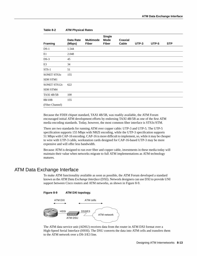
Designing ATM Internetworks 8-13
ATM Data Exchange Interface
Table 8-2 ATM Physical Rates
Because the FDDI chipset standard, TAXI 4B/5B, was readily available, the ATM Forumencouraged initial ATM development efforts by endorsing TAXI 4B/5B as one of the first ATMmedia encoding standards. Today, however, the most common fiber interface is STS3c/STM.
There are two standards for running ATM over copper cable: UTP-3 and UTP-5. The UTP-5specification supports 155 Mbps with NRZI encoding, while the UTP-3 specification supports51 Mbps with CAP-16 encoding. CAP-16 is more difficult to implement, so, while it may be cheaperto wire with UTP-3 cable, workstation cards designed for CAP-16-based UTP-3 may be moreexpensive and will offer less bandwidth.
Because ATM is designed to run over fiber and copper cable, investments in these media today willmaintain their value when networks migrate to full ATM implementations as ATM technologymatures.
ATM Data Exchange InterfaceTo make ATM functionality available as soon as possible, the ATM Forum developed a standardknown as theATM Data Exchange Interface(DXI). Network designers can use DXI to provide UNIsupport between Cisco routers and ATM networks, as shown in Figure 8-9.
Figure 8-9 ATM DXI topology.
The ATM data service unit (ADSU) receives data from the router in ATM DXI format over aHigh-Speed Serial Interface (HSSI). The DSU converts the data into ATM cells and transfers themto the ATM network over a DS-3/E3 line.
FramingData Rate(Mbps)
MultimodeFiber
SingleModeFiber
CoaxialCable UTP-3 UTP-5 STP
DS-1 1.544
E1 2.048
DS-3 45
E3 34
STS-1 51
SONET STS3c
SDH STM1
155
SONET STS12c
SDH STM4
622
TAXI 4B/5B 100
8B/10B
(Fiber Channel)
155
ATM DXI ATM cells
HSSI
ATM DSU
DS3/E3ATM networkRouter

ATM Overview
Cisco CCIE Fundamentals: Network Design8-14
ATM DXI is available in several modes:
• Mode 1a—Supports AAL5 only, a 9232 octet maximum, and a 16-bit FCS, and provides1023 virtual circuits.
• Mode 1b—Supports AAL3/4 and AAL5, a 9224 octet maximum, and a 16-bit FCS. AAL5support is the same as Mode 1a. AAL3/4 is supported on one virtual circuit.
• Mode 2—Supports AAL3/4 and AAL5 with 16,777,215 virtual circuits, a 65535 octet maximum,and 32-bit FCS.
On the router, data from upper-layer protocols is encapsulated into ATM DXI frame format. Figure8-10 shows the format of a Mode 1a ATM DXI frame.
Figure 8-10 ATM DXI frame format.
In Figure 8-11, a router configured as a data terminal equipment (DTE) device is connected to anADSU. The ADSU is configured as a data communications equipment (DCE) device. The routersends ATM DXI frames to the ADSU, which converts the frames to ATM cells by processing themthrough the AAL5 CS and the SAR sublayer. The ATM layer attaches the header, and the cells aresent out the ATM UNI interface.
Figure 8-11 ATM DXI Mode 1a and Mode 1b protocol architecture for AAL5.
ATM DXI addressing consists of a DFA, which is equivalent to a Frame Relay data link connectionidentifier (DLCI). The DSU maps the DFA into appropriate VPI and VCI values in the ATM cell.Figure 8-12 shows how the DSU performs address mapping.
Flag Header SDU FCS Flag
1 2 0-9232 2 1Field size in octets
HSSI
ATM DSU
DS3/E3ATM network
Physicallayer
Data linklayer
ATM DXIphysical
UNIphysical
AAL5 CS
AAL5 SAR
ATM layer
ATM DXI ATM UNI
Router
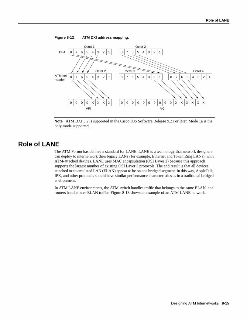
Designing ATM Internetworks 8-15
Role of LANE
Figure 8-12 ATM DXI address mapping.
Note ATM DXI 3.2 is supported in the Cisco IOS Software Release 9.21 or later. Mode 1a is theonly mode supported.
Role of LANEThe ATM Forum has defined a standard for LANE. LANE is a technology that network designerscan deploy to internetwork their legacy LANs (for example, Ethernet and Token Ring LANs), withATM-attached devices. LANE uses MAC encapsulation (OSI Layer 2) because this approachsupports the largest number of existing OSI Layer 3 protocols. The end result is that all devicesattached to an emulated LAN (ELAN) appear to be on one bridged segment. In this way, AppleTalk,IPX, and other protocols should have similar performance characteristics as in a traditional bridgedenvironment.
In ATM LANE environments, the ATM switch handles traffic that belongs to the same ELAN, androuters handle inter-ELAN traffic. Figure 8-13 shows an example of an ATM LANE network.
8 7 6 5 4 3 2 1 8 7 6 5 4 3 2 1
8 7 6 5 4 3 2 1 8 7 6 5 4 3 2 1 8 7 6 5 4 3 2 1
0 0 0 0 X X X X 0 0 0 0 0 0 0 0 0 0 X X X X X X
DFA
ATM cellheader
Octet 1 Octet 2
Octet 2 Octet 3 Octet 4
VPI VCI

Role of LANE
Cisco CCIE Fundamentals: Network Design8-16
Figure 8-13 Components of an ATM LANE network.
As Figure 8-13 shows, network designers can use the LANE technology to interconnect legacyLANs to any of the following types of ATM-attached devices:
• End stations (for example, ATM-attached servers or ATM-attached workstations)
• Edge devices that bridge the legacy LANs onto an ATM backbone (for example, theCatalyst 5000 or Catalyst 3000 switches that have an ATM uplink)
• ATM-attached routers that are used to route between ELANs
LANE ComponentsLANE components include the following:
• LAN emulation client (LEC)—End systems that support LANE, such as network interface card(NIC)-connected workstations, LAN switches with ATM uplinks (for example, the Catalystfamily of switches), and Cisco 7500, 7000, 4500, and 4000 series routers that support ATMattachment, all require the implementation of a LEC. The LEC emulates an interface to a legacyLAN to the higher-level protocols. It performs data forwarding, address resolution, andregistration of MAC addresses with the LANE server and communicates with other LECs viaATM virtual channel connections (VCCs).
• LAN emulation configuration server (LECS)—The LECS maintains a database of ELANs andthe ATM addresses of the LESs that control the ELANs. It accepts queries from LECs andresponds with the ATM address of the LES that serves the appropriate ELAN/VLAN. Thisdatabase is defined and maintained by the network administrator.
ATM Core
ATM-attached desktop
Catalyst3000
Catalyst5000
Catalyst 5000
Enterprise anddepartmental servers
LAN emulationclient
Catalyst5000
LAN emulationservices
LAN switches with ATM uplinks
LAN emulationclients
Layer 3 services
LECS, LES,BUS

Designing ATM Internetworks 8-17
How LANE Works
The following is an example of this database.
• LAN emulation server (LES)—The LES provides a central control point for all LECs. LECsmaintain a Control Direct VCC to the LES to forward registration and control information. TheLES maintains a point-to-multipoint VCC, known as theControl Distribute VCC, to all LECs.The Control Distribute VDD is used only to forward control information. As new LECs join theATM ELAN, each LEC is added as a leaf to the control distribute tree.
• Broadcast and unknown server (BUS)—The BUS acts as a central point for distributingbroadcasts and multicasts. ATM is essentially a point-to-point technology without “any-to-any”or “broadcast” support. LANE solves this problem by centralizing the broadcast support in theBUS. Each LEC must set up a Multicast Send VCC to the BUS. The BUS then adds the LEC asa leaf to its point-to-multipoint VCC (known as theMulticast Forward VCC).
The BUS also acts as a multicast server. LANE is defined on ATM adaptation layer 5 (AAL5),which specifies a simple trailer to be appended to a frame before it is broken into ATM cells. Theproblem is that there is no way to differentiate between ATM cells from different senders whenmultiplexed on a virtual channel. It is assumed that cells received will be in sequence, and whenthe End of Message (EOM) cell arrives, you should just have to reassemble all of the cells thathave already arrived.
The BUS takes the sequence of cells on each Multicast Send VCC and reassembles them intoframes. When a full frame is received, it is queued for sending to all of the LECs on the MulticastForward VCC. This way, all the cells from a particular data frame can be guaranteed to be sentin order and not interleaved with cells from any other data frames on the point-to-multipointVCC.
Note that because LANE is defined at OSI Layer 2, the LECS is the only security checkpointavailable. Once it has been told where to find the LES and it has successfully joined the ELAN, theLEC is free to send any traffic (whether malicious or not) into the bridged ELAN. The only place forany OSI Layer 3 security filters is in the router that routes this ELAN to other ELANs. Therefore,the larger the ELAN, the greater the exposure to security violations.
How LANE WorksAn ELAN provides Layer 2 communication between all users on an ELAN. One or more ELANscan run on the same ATM network. However, each ELAN is independent of the others and users onseparate ELANs cannot communicate directly. Communication between ELANs is possible onlythrough routers or bridges.
Because an ELAN provides Layer 2 communication, it can be equated to a broadcast domain.VLANs can also be thought of as broadcast domains. This makes it possible to map an ELAN to aVLAN on Layer 2 switches with different VLAN multiplexing technologies such as Inter-SwitchLink (ISL) or 802.10. In addition, IP subnets and IPX networks that are defined on Layer 3-capabledevices such as routers frequently map into broadcast domains (barring secondary addressing). Thismakes it possible to assign an IP subnetwork or an IP network to an ELAN.
An ELAN is controlled by a single LES/BUS pair and the mapping of an ELAN to its LES ATMaddress is defined in the LECS database. ELANs consists of multiple LECs and can be Ethernet orToken Ring but not both at the same time.
ELAN Name LES ATM Address
finance 47.0091.8100.0000.0800.200c.1001. 0800.200c.1001.01
marketing 47.0091.8100.0000.0800.200c.1001. 0800.200c.1001.02

Role of LANE
Cisco CCIE Fundamentals: Network Design8-18
In order for ELAN to operate properly, the LECs on that ELAN need to be operational. Each LECgoes through a boot up sequence that is described in the following sections.
LANE OperationIn a typical LANE operation, the LEC must first find the LECS to discover which ELAN it shouldjoin. Specifically, the LEC is looking for the ATM address of the LECS that serves the desiredELAN.
Finding the LECSTo find the ATM address of the LECS, the LEC does the following:
1 Queries the ATM switch via Interim Local Management Interface (ILMI). The switch has a MIBvariable set up with the ATM address of the LECS. The LEC can then use UNI signaling tocontact the LECS.
2 Looks for a fixed ATM address that is specified by the ATM Forum as the LECS ATM address.
3 Accesses permanent virtual circuit (PVC) 0/17, a “well-known” PVC.
Contacting the LECSThe LEC creates a signaling packet with the ATM address of the LECS. It signals a Configure DirectVCC and then issues an LE_CONFIGURE_REQUEST on that VCC. The information in thisrequest is compared with the data in the LECS database. The source ATM address is most commonlyused to place a LEC into a specific ELAN. If a matching entry is found, a successfulLE_CONFIGURE_RESPONSE is returned with the ATM address of the LES that serves the desiredELAN.
Configuring the LECS databaseYou can configure the LECS database in any of the following three ways:
• Configure ELAN names at the LEC—In this configuration, all the LECs are configured with anELAN name that they can embed in their Configure_Requests. This is the most basic form of theLECS database and it needs only to contain the list of ELANs and their corresponding LES ATMaddresses. In such a configuration, all LECs that specifically request to join a given ELAN arereturned the ATM address of the corresponding LES. A LEC that does not know which ELANto join can be assigned to a default ELAN if such an ELAN is configured in the LECS database.
The following is an example of LEC-to-ELAN mapping at the LEC:
lane database test-1name finance server-atm-address 47.0091.8100.0000.0800.200c.1001. 0800.200c.1001.01name marketing server-atm-address 47.0091.8100.0000.0800.200c.1001. 0800.200c.1001.02default-name finance
• Configure LEC to ELAN assignment in the LECS database—In this configuration, all theinformation is centralized in the LECS database. The LECs do not need to be intelligent, and theycan simply go to the LECS to determine which ELAN they should join. Although this is a moretime-intensive configuration, it provides tighter control over all the ELANs. Consequently, it canbe useful when security is important.

Designing ATM Internetworks 8-19
How LANE Works
With this method, the LECs are identified by their ATM addresses or MAC addresses. Becausewildcarding of ATM address prefixes is also supported, it is useful to make such relationships as“Assign any LEC joining with a prefix of A to ELAN X.” The following is an example ofLEC-to-ELAN mapping in the LECS database:
lane database test-2name finance server-atm-address 47.0091.8100.0000.0800.200c.1001. 0800.200c.1001.01name marketing server-atm-address 47.0091.8100.0000.0800.200c.1001. 0800.200c.1001.02default-name finance
client-atm-address 47.0091.8100.0000.08… name financeclient-atm-address 47.0091.8100.0000.09… name marketing
mac-address 00c0.0000.0100 name financemac-address 00c0.1111.2222 name marketing
• Hybrid combination—You can configure a combination of the preceding two methods.
Joining the LESAfter the LEC has discovered the ATM address of the desired LES, it drops the connection to theLECS, creates a signaling packet with the ATM address of the LES, and signals a Control DirectVCC. Upon successful VCC setup, the LES sends an LE_JOIN_REQUEST. This request containsthe LEC ATM address as well as a MAC address that the LEC wants to register with the ELAN. Thisinformation is maintained so that no two LECs can register the same MAC or ATM addresses.
Upon receipt of the LE_JOIN_REQUEST, the LES checks with the LECS via its own openconnection with the LECS and verifies the request, thus confirming the client’s membership. Uponsuccessful verification, the LES adds the LEC as a leaf of its point-to-multipoint Control DistributeVCC. Finally, the LES issues the LEC a successful LE_JOIN_RESPONSE that contains a LANEclient ID (LECID), which is an identifier that is unique to the new client. This ID is used by the LECto filter its own broadcasts from the BUS. Figure 8-14 shows examples of LES connections.
Figure 8-14 LAN emulation server (LES) connections.
AIP
Control Distribute VCC(Point to Multipoint)
Control Direct VCC(Unidirectional)
LAN EmulationServer (LES)

Role of LANE
Cisco CCIE Fundamentals: Network Design8-20
Finding the BUSAfter the LEC has successfully joined the LES, its first task is to find the ATM address of the BUSand join the broadcast group. The LEC creates an LE_ARP_REQUEST packet with the MACaddress 0xFFFFFFFF. This special LE_ARP packet is sent on the Control Direct VCC to the LES.The LES recognizes that the LEC is looking for the BUS, responds with the ATM address of theBUS, and forwards that response on the Control Distribute VCC.
Joining the BUSWhen the LEC has the ATM address of the BUS, its next action is to create a signaling packet withthat address and signal a Multicast Send VCC. Upon receipt of the signaling request, the BUS addsthe LEC as a leaf on its point-to-multipoint Multicast Forward VCC. At this time, the LEC hasbecome a member of the ELAN. Figure 8-15 shows examples of BUS connections.
Figure 8-15 BUS connections.
Address ResolutionThe real value of LANE is the ATM forwarding path that it provides for unicast traffic betweenLECs. When a LEC has a data packet to send to an unknown destination, it issues anLE_ARP_REQUEST to the LES on the Control Direct VCC. The LES forwards the request on theControl Distribute VCC, so all LEC stations hear it. In parallel, the unicast data packets are sent tothe BUS, to be forwarded to all endpoints. This “flooding” is not the optimal path for unicast traffic,and this transmission path is rate-controlled to 10 packets per second (per the LANE standard).Unicast packets continue using the BUS until the LE_ARP_REQUEST has been resolved.
If bridging or switching devices with LEC software participate in the ELAN, they translate andforward the ARP on their LAN interfaces. One of the LECs should issue an LE_ARP_RESPONSEand send it to the LES, which forwards it to the Control Distribute VCC so that all LECs can learnthe new MAC-to-ATM address binding.
When the requesting LEC receives the LE_ARP_RESPONSE, it has the ATM address of the LECthat represents the MAC address being sought. The LEC should now signal the other LEC directlyand set up a Data Direct VCC that will be used for unicast data between the LECs.
AIP
Bus Forward VCC(Point to Multipoint)
Bus Send VCC(Unidirectional)
Broadcast andUnknown Server

Designing ATM Internetworks 8-21
LANE Implementation
While waiting for LE_ARP resolution, the LEC forwards unicasts to the BUS. With LE_ARPresolution, a new “optimal” path becomes available. If the LEC switches immediately to the newpath, it runs the risk of packets arriving out of order. To guard against this situation, the LANEstandard provides a flush packet.
When the Data Direct VCC becomes available, the LEC generates a flush packet and sends it to theBUS. When the LEC receives its own flush packet on the Multicast Forward VCC, it knows that allpreviously sent unicasts must have already been forwarded. It is now safe to begin using the DataDirect VCC. Figure 8-16 shows an example of a fully connected ELAN.
Figure 8-16 Fully connected ELAN.
LANE ImplementationAs Table 8-3 indicates, the LANE functionality (the LECS, LEC, LES, and BUS) can beimplemented in different Cisco devices.
Table 8-3 Cisco LANE Implementation
These functions will be defined on ATM physical interfaces and subinterfaces. A subinterface canbe defined as a logical interface and is a part of a physical interface such as an Optical Carrier 3(OC-3) fiber. ATM interfaces on the Cisco routers and the ATM module on the Catalyst 5000 switchcan be logically divided into up to 255 logical subinterfaces. On the Catalyst 3000 switch, althoughthe same Cisco IOS Software code is used, the subinterface concept does not apply. The LEC can beconfigured using the menu-driven interface.
Cisco ProductAvailable LANEComponents Required Software Release
Family of Catalyst 5000 switches LECS, LES, BUS, LEC ATM Module Software Version 2.0 or later
Family of Catalyst 3000 switches LECS, LES, BUS, LEC ATM Module Software Version 2.1 or later
Family of Cisco 7000 routers LECS, LES, BUS, LEC Cisco IOS Software Release 11.0 or later
Family of Cisco 7500 routers LECS, LES, BUS, LEC Cisco IOS Software Release 11.1 or later
Family of Cisco 4500 and 4000 routers LECS, LES, BUS, LEC Cisco IOS Software Release 11.1 or later
AIP SubinterfacesLES BUS
Client Direct VCC(Bidirectional)

LANE Implementation
Cisco CCIE Fundamentals: Network Design8-22
This section examines the implementation of ATM LANE networks and covers the following topics:
• LANE Design Considerations
• LANE Redundancy
LANE Design ConsiderationsThe following are some general LANE design considerations:
• The AIP provides an interface to ATM switching fabrics for transmitting and receiving data atrates of up to 155 Mbps bidirectionally. The actual rate is determined by the Physical layerinterface module (PLIM).
• One active LECS supports all ELANs.
• In each ELAN, there is one LES/BUS pair and some number of LECs.
• The LES and BUS functionality must be defined on the same subinterface and cannot beseparated.
• There can be only one active LES/BUS pair per subinterface.
• There can be only one LES/BUS pair per ELAN.
• The current LANE Phase 1 standard does not provide for any LES/BUS redundancy.
• The LECS and LES/BUS can be different routers, bridges, or workstations.
• VCCs can be either switched virtual circuits (SVCs) or permanent virtual circuits (PVCs),although PVC design configuration and complexity might make anything more than a very smallnetwork prohibitively unmanageable and complex.
• When defining VLANs with the Catalyst 5000 switch, each VLAN should be assigned to adifferent ELAN. The LES/BUS pair for each ELAN can reside on any of the following:
— Different subinterfaces on the same AIP
— Different AIPs in the same router
— Different AIPs in different routers
• There can be only one LEC per subinterface. If a LEC and a LES/BUS pair share a subinterface,they are (by definition) in the same ELAN.
• If a LEC on a router subinterface is assigned an IP, IPX, or AppleTalk address, that protocol isroutable over that LEC. If there are multiple LECs on a router and they are assigned protocoladdresses, routing will occur between the ELANs. For routing between ELANs to functioncorrectly, an ELAN should be in only one subnet for a particular protocol.
PNNI in LANE NetworksNetwork designers can deploy PNNI as a Layer 2 routing protocol for bandwidth management,traffic distribution, and path redundancy for LANE networks. PNNI is an ATM routing protocol usedfor routing call setups and is implemented in the ATM switches. Most LANE networks consist ofmultiple ATM switches and typically employ the PNNI protocol.
Note Although PNNI is an advanced routing protocol and supports QoS-based routing, thisparticular aspect of PNNI is not discussed in this chapter because most LANE networks are basedon the best-effort traffic category.
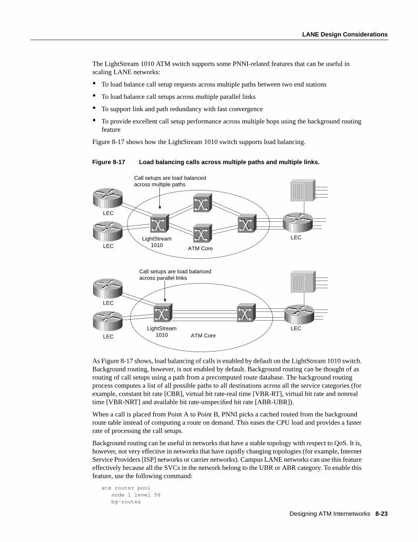
Designing ATM Internetworks 8-23
LANE Design Considerations
The LightStream 1010 ATM switch supports some PNNI-related features that can be useful inscaling LANE networks:
• To load balance call setup requests across multiple paths between two end stations
• To load balance call setups across multiple parallel links
• To support link and path redundancy with fast convergence
• To provide excellent call setup performance across multiple hops using the background routingfeature
Figure 8-17 shows how the LightStream 1010 switch supports load balancing.
Figure 8-17 Load balancing calls across multiple paths and multiple links.
As Figure 8-17 shows, load balancing of calls is enabled by default on the LightStream 1010 switch.Background routing, however, is not enabled by default. Background routing can be thought of asrouting of call setups using a path from a precomputed route database. The background routingprocess computes a list of all possible paths to all destinations across all the service categories (forexample, constant bit rate [CBR], virtual bit rate-real time [VBR-RT], virtual bit rate and nonrealtime [VBR-NRT] and available bit rate-unspecified bit rate [ABR-UBR]).
When a call is placed from Point A to Point B, PNNI picks a cached routed from the backgroundroute table instead of computing a route on demand. This eases the CPU load and provides a fasterrate of processing the call setups.
Background routing can be useful in networks that have a stable topology with respect to QoS. It is,however, not very effective in networks that have rapidly changing topologies (for example, InternetService Providers [ISP] networks or carrier networks). Campus LANE networks can use this featureeffectively because all the SVCs in the network belong to the UBR or ABR category. To enable thisfeature, use the following command:
atm router pnni node 1 level 56 bg-routes
LEC
LightStream1010LEC
LEC
ATM Core
Call setups are load balanced across multiple paths
LEC
LightStream1010LEC
LECATM Core
Call setups are load balanced across parallel links

LANE Implementation
Cisco CCIE Fundamentals: Network Design8-24
The current implementation of PNNI on the LightStream 1010 switch is full, ATM Forum-PNNIVersion 1 compliant. The LightStream default PNNI image license supports a single level ofhierarchy, where multiple peer groups can be interconnected by IISP or by other switches thatsupport full PNNI hierarchy; extra PNNI image license will support multiple levels of routinghierarchy.
The PNNI protocols have been designed to scale across all sizes of ATM networks, from smallcampus networks of a handful of switches, to the possible global ATM Internet of millions ofswitches. This level of scalability is greater than that of any existing routing protocol, and requiresvery significant complexity in the PNNI protocol. Specifically, such scalability mandates the supportof multiple levels of routing hierarchy based upon the use of prefixes of the 20-byte ATM addressspace. The lowest level of the PNNI routing hierarchy consists of a single peer group within whichall switches flood all reachability and QoS metrics to one another. This is analogous, for instance, toa single area in the OSPF protocol.
Subsequently, multiple peer groups at one level of the hierarchy are aggregated into higher-level peergroups, within which each lower-level peer group is represented by a singlepeer group leader, andso on iteratively up the PNNI hierarchy. Each level of the hierarchy is identified by a prefix of theATM address space, implying that PNNI could theoretically contain over 100 levels of routinghierarchy. However, a handful of levels would be adequate for any conceivable network. The priceto be paid for such scalability is the need for highly complex mechanisms for supporting andbringing up the multiple levels of hierarchy and for electing the peer group leaders within each peergroup at each level.
Scaling an ELAN—Spanning-Tree Protocol IssuesSpanning-Tree Protocol is implemented in Layer 2 switches/bridges to prevent temporary loops innetworks with redundant links. Because a LEC essentially bridges Ethernet/Token Ring traffic overan ATM backbone, the Spanning-Tree Bridge Protocol Data Units (BPDUs) are transmitted over theentire ELAN. The ATM network appears as a shared Ethernet/Token Ring network to thespanning-tree process at the edge of the Layer 2 switches.
The spanning-tree topology of a LANE-based network is substantially simpler than a pureframe-switched network that employs the Spanning-Tree Protocol. It follows that spanning-treeconvergence times, which can be a major issue in large frame-switched networks, can be less of anissue in LANE networks. Note that Spanning Tree must reconverge if there are failures at the edgedevices or inside the ATM network. If there is a need to tune the convergence time to a lower orhigher value, the forward delay parameter can be used.
LANE RedundancyAlthough LANE allows network designers to connect their legacy LANs to an ATM network, LANEVersion 1.0 does not define mechanisms for building redundancy and fault tolerance into the LANEservices. Consequently, this makes the LANE services a single point of failure. Moreover, routerredundancy and path/link redundancy are also issues that the network designer needs to consider.
Network designers can use the following techniques to build fault-tolerant and resilient LANEnetworks:
• Simple Server Replication Protocol (SSRP) for LANE Services redundancy that works withCisco and any third-party LECs.
• Hot Standby Router Protocol (HSRP) over LANE provides redundancy for the default routerconfigured at IP end stations.

Designing ATM Internetworks 8-25
LANE Redundancy
• Dual PHY LANE card on the Catalyst 5000 switch, or multiple ATM uplinks on the Catalyst3000 switch.
• Spanning-Tree Protocol on the Ethernet-ATM switches.
The following subsections examine these various mechanisms and highlights design rules and issuesto consider while implementing redundant LANE networks. It begins with a discussion on SSRP thatwas developed to provide redundant LANE services.
Although many vendors have implemented redundant LANE services of some fashion, they violatethe LANE 1.0 specification and therefore are not interoperable with other third-partyimplementations. SSRP, however, does not violate the LANE 1.0 specification and is interoperablewith third-party LEC implementations, which is important when implementing an interoperableATM network.
The discussion on SSRP is followed by a description of HSRP over LANE, which provides amechanism for building router redundancy. Following this is a discussion on the Spanning-TreeProtocol and other product-specific features that can be used to build link and path redundancy intoedge devices.
Issues in a LANE 1.0 NetworkThe main issue with a LANE 1.0 network is that only one set of LANE service components can beaccessed by a LEC at any given time. This results in the following limitations:
• Only a single LECS supports all ELANs.
• There can be only one LES/BUS pair per ELAN.
A failure in any of these service components has the following impact on network operation:
• LECS failure—A failed LECS impacts all the ELANs under its control because it provides accesscontrol for all the ELANs under its control. Although the existing ELANs would continue towork normally (assuming only Cisco LECs), no new LEC can join any ELAN under the controlof that LECS. Also, any LEC that needs to rejoin its ELAN or change its membership to anotherELAN cannot because the LES cannot verify any LEC trying to join an ELAN.
• LES/BUS failure—The LES/BUS pair is needed to maintain an operational ELAN. The LESprovides the LE_ARP service for ATM-MAC address mappings and the BUS provides broadcastand unknown services for a given ELAN. Therefore, a failure of either the LES or the BUSimmediately affects normal communication on the ELAN. However, a LES/BUS failure impactsonly the ELAN served by that pair.
It is clear that these issues can be limiting to networks where resiliency and robustness is arequirement and might even be a deciding factor in your design of whether to implementLANE-based ATM networks. In addition, there are other design considerations such as theplacement of the LANE service components within an ATM network that can have implications onthe overall robustness of the LANE environment.
Resiliency in LANE 1.0 NetworksIncreasing the resiliency of a LANE-based network essentially includes delivering increasedrobustness in the LANE service components such as the LECS, LES, and BUS. Such robustness isprovided by SSRP through a primary-secondary combination of the LANE services. For LECSredundancy, one primary LECS is backed up by multiple secondary LECSs. LES/BUS redundancyis also handled in a similar fashion where one primary LES/BUS pair is backed up by multiplesecondaries. Note that the LES/BUS functions are always co-located in a Cisco implementation andthe pair is handled as one unit with respect to redundancy.

LANE Implementation
Cisco CCIE Fundamentals: Network Design8-26
LECS RedundancyIn the LANE 1.0 specification, the first step for a LEC during initialization is to connect with theLECS to obtain the LES ATM address for the ELAN it wants to join. In order for the LEC to connectto the LECS, multiple mechanisms are defined. The first mechanism that a LEC should use is toquery the ATM switch it is attached to for the LECS address. This address discovery process is doneusing the ILMI protocol on VPI, VCI - 0, 16.
The following is an example of the configuration command to add a LECS address to a LightStream1010 switch:
atm lecs-address <LECS NSAP address> <index>
With SSRP, multiple LECS addresses are configured into the ATM switches. An LEC, whichrequests the LECS address from the ATM switch, gets the entire table of LECS addresses inresponse. The behavior of the LEC should be to attempt to connect to the highest ranking LECSaddress. If this fails, it should try the next one in the list and so on until it connects to the LECS.
Whereas the LEC always tries to connect to the highest ranking LECS available, SSRP ensures thatthere is only a single primary that responds to the Configure Request queries coming from the LEC.The establishment of a primary LECS and placing the others in backup goes to the heart of SSRP.The following describes the mechanism used by SSRP to establish a primary LECS. Uponinitialization, a LECS obtains the LECS address table from the switch. The LECS then tries toconnect to all the LECSs that are below itself in rank. The rank is derived from the index entry in theLECS address table.
If a LECS has a connection (VCC) from a LECS whose rank is higher than its own, it is in backupmode. The highest ranking LECS does not have any other LECS that connect to it from above andassumes the role of the primary LECS.
Figure 8-18 shows the procedure of a backup taking over in the case of a failed primary LECS. TheLANE network shown in Figure 8-18 has four LECS entities (LECS A, B, C, and D). All the ATMswitches in the network are configured with the same LECS address table. After startup, LECS Aobtains the LECS address table from the ATM switch it is attached to and finds that it has threeLECSs below itself and therefore tries to connect to LECS B, C, and D. LECS B connects to LECS Cand LECS D, and LECS C connects to LECS D. There is a downward establishment of VCCs.Because LECS A does not have any VCCs from above, it becomes the primary LECS.
Figure 8-18 LECS redundancy.
B
C
D
AVirtual circuits areestablished from ahigher ranking LECS to a lower ranking LECS.
C
D
AXLECS A losesconnectivity tothe network.
Step 1
LECS B has no connections from any LECS above itself. Becomes new PRIMARY.
Step 2a
LECS C and Dcontinue to have theconnections from B and hence remainBACKUPs.
Step 2b
(a) (b)
B

Designing ATM Internetworks 8-27
LANE Redundancy
During normal network operation, LECS A responds to all the configure requests and the backupLECS (LECS B, C and D) do not respond to any queries. If for some reason the primary LECS(LECS A) fails due to such conditions as a box failure, LECS B loses its VCC from LECS A as dothe other LECS.
At this point, LECS B does not have any VCCs from above and therefore is now the highest rankingavailable LECS in the network. LECS B now becomes the primary LECS. LECS C and LECS D stillhave connections from higher ranking LECSs and therefore continue to operate in backup mode asshown in Step 2b of Figure 8-18.
LES/BUS RedundancyThe LES/BUS redundancy portion of SSRP supports the configuration of multiple LES/BUS pairsthat work in a primary-secondary fashion. However, the mechanisms used here are different fromthose used for the LECS redundancy described in the preceding section.
Multiple LES/BUS pairs for a given ELAN are first configured into the LECS database. Within thisdatabase, each LES/BUS pair is assigned a priority. After initialization, each LES/BUS opens a VCCwith the primary LECS using the LECS address discovery mechanism. The LES/BUS pair with thehighest priority that has an open VCC to the LECS is assigned as the primary LES/BUS by theprimary LECS.
SSRP Usage GuidelinesThere are no theoretical limits on the number of LECSs that can be configured using SSRP, howevera recommended number is two (one primary plus one backup) or three LECSs (one primary plus twobackups). Any more redundancy should be implemented only after very careful considerationbecause it will add a significant amount of complexity to the network. This added complexity canresult in a substantial increase in the amount of time required to manage and troubleshoot suchnetworks.
SSRP Configuration GuidelinesTo support the LECS redundancy scheme, you must adhere to the following configuration rules.Failure to do so will result in improper operation of SSRP and a malfunctioning network.
• Each LECS must maintain the same database of ELANs. Therefore, you must maintain the sameELAN database across all the LECSs.
• You must configure the LECS addresses in the LECS address table in the same order on eachATM switch in the network.
• When using SSRP with the Well Known Address, do not place two LECSs on the same ATMswitch. If you place two LECs on the same ATM switch, only one LECS can register the WellKnown Address with the ATM switch (through ILMI) and this can cause problems duringinitialization.
SSRP Interoperability NotesSSRP can be used with independent third-party LECs if they use ILMI for LECS address discoveryand can appropriately handle multiple LECS addresses returned by the ATM switch. For example,the LEC should step through connecting to the list of LECS addresses returned by the ATM switch.The first LECS that responds to the configuration request is the master LECS.

LANE Implementation
Cisco CCIE Fundamentals: Network Design8-28
Behavior of SSRP with the Well Known LECS AddressSSRP also works with LECS Well Known Address (47.0079….) defined in the LANE 1.0specification. The Cisco LECS can listen on multiple ATM addresses at the same time. Therefore, itcan listen on the Well Known Address and the auto-configured ATM address, which can bedisplayed using theshow lane defaultcommand.
When the LECS is enabled to listen on the Well Known Address, it registers the Well KnownAddress with the ATM switch so that the ATM switches can advertise routes to the Well KnownAddress and route any call setups requests to the correct place.
Under SSRP, there are multiple LECSs in the network. If each LECS registers the Well KnownAddress to the ATM switches that it is connected to, call setups are routed to different places in thenetwork. Consequently, under SSRP you must configure an autoconfigured address so that thenegotiation of the master first takes place and then the master registers the Well Known Address withthe ATM switch. If the master fails, the Well Known Address moves with the master LECS. ThePNNI code on the LightStream 1010 switch takes care of advertising the new route to the WellKnown Address when there is a change of LECS mastership. Therefore, third-party LECs that useonly the Well Known Address can also interoperate with SSRP. SSRP is the only redundancy schemethat can be used with almost any LEC in the industry.
To implement SSRP with the Well Known Address, use the following steps:
Step 1 Configure the LECS to listen on the autoconfigured address (or if you want a separateATM address that you have predetermined). This autoconfigured (or other) addressshould be programmed into the ATM switches for the LECS address discoverymechanism.
Step 2 Configure each LECS to listen on the Well Known address using thelane configfixed-config-atm-address command. After the master LECS is determined using theLECS redundancy procedure, the master registers the Well Known Address to the ATMswitch.
Note SSRP with the Well Known Address does not work properly under certain circumstances(during failover) if two LECS are attached to the same ATM switch. This is due to the possibility ofduplicate address registration on the same switch, which ILMI does not allow. Make sure each LECSis on a separate ATM switch.
Behavior of SSRP in Network PartitionsIn the event of network partitions where two separate ATM clouds are formed due to aninterconnecting link or switch failure, each cloud has its own set of LANE services if SSRP isconfigured to handle network partitions.
When configuring SSRP, use the following guidelines to accommodate the possibility of networkpartition:
• Configure each partition with its own LANE services that can become active during a networkpartition. For example, if you are connecting two sites or campuses across a MAN and you wantthe same ELANs at both locations, configure each campus/site with its own LANE services.
• Routing behavior should be carefully examined during a network partition in the case where anELAN maps to a Layer 3 network (for example, an IP subnet or IPX network) because there arenow two routes to the same subnet (assuming there are redundant routers in the network). If thereare no redundant routers, one of the partitions will be effectively isolated from the rest of thenetwork. Intra-ELAN traffic will continue to behave properly.
Designing ATM Internetworks 8-29
Role of Stratm Technology
HSRP over LANEHSRP is a protocol that network designers can use to guard against router failures in the network.The HSRP protocol is exchanged between two routers and one of them is elected as the primaryrouter interface (or subinterface) for a given subnet. The other router acts as thehot standby router.
In HSRP, a default IP address and a default MAC address are shared between the two routersexchanging the HSRP protocol. This default IP address is used as the default gateway at all IP endstations for them to communicate with end stations outside their immediate subnet. Therefore, whenthere is a primary router failure, the hot standby router takes over the default gateway address andthe MAC address so that the end station can continue communicating with end stations that are notin their immediate subnet.
Because HSRP is a Layer 2 mechanism and needs a MAC address-based Layer 2 network, it ispossible to implement HSRP style recovery over LANE. The mechanisms used are the same as forany Ethernet interface and can be configured at a subinterface level.
Redundant ATM Port Card for the Catalyst 5000Another aspect of addressing the redundancy needs from a physical network perspective is theaddition of a redundant PHY portion of an ATM card. The Catalyst 5000 switch employs the dualPHY redundant ATM card. This redundancy is only at a physical level and is useful in cases wherethe primary link to the ATM switch goes down.
Role of Stratm TechnologyStratm Technology is a new approach to ATM switching technology that incorporates patentedstandards-based Cisco technology into custom silicon. These application-specific integrated circuits(ASICs) dramatically increase ATM efficiency and scalability and significantly lower the absolutecost of delivering ATM solutions. Stratm Technology can be implemented in switches and routersacross LANs, campus networks, and WANs, enabling the delivery of high-performance, end-to-endATM services to meet a wide range of needs.
Benefits of Stratm TechnologyThe benefits of Stratm Technology include the following:
• Dramatic improvement in network price/performance scalability
• Increased applicationgoodput
• Protection of technology investments
• Increased portability
• Guaranteed infrastructure
Each of these benefits is described in more detail in the following sections.
Improved Network Price/Performance ScalabilityStratm Technology features can dramatically improve network price/performance and scalability asfollows:
• Support of up to eight OC-3 (155-Mbps) port interfaces per card slot, and up to 12 digital signalLevel 3 T3/E3 (45-Mbps) port interfaces per card slot
• A 30 percent increase in SVC completions to more than 4,000 per second per node

Role of Stratm Technology
Cisco CCIE Fundamentals: Network Design8-30
• An increase in connection density per switch by 500 percent
• An increase in the buffering capability of each card to 200,000 cells per card, upgradable tonearly one million cells
• A reduction in the price per port for high-speed connections by up to 50 percent
• The ability to support per-virtual-connection control queuing, rate scheduling, statisticscollection, and fair sharing of network resources on an individual connection basis
Increased Application GoodputIntelligent ATM features are embodied in Stratm Technology. These features are designed toincrease application goodput dramatically through advanced features, which are distributedthroughout the BXM module in silicon.
• Distributed ATM functions—Stratm distributes such ATM services as traffic management,per-VC queuing, class of service (COS) management, SVCs, and multicasting to each card on asilicon chip. Distributed functionality ensures faster, more efficient processing, and it eliminatesthe possibility of a single point of failure disrupting the entire network.
• Highest bandwidth efficiency—Stratm delivers guaranteed bandwidth on demand, QoS, and fairsharing of network resources to each individual connection. With fast, efficient processing andguaranteed bandwidth, application performance is significantly enhanced.
• Advanced traffic management capabilities—Stratm incorporates the industry’s firstcommercially available Virtual Source/Virtual Destination (VS/VD) implementation of the fullATM Forum’s Traffic Management Specification Version 4.0. This ensures the highest efficiencyin bandwidth utilization and provides support for the multicasting capabilities required tosuccessfully deliver multimedia and switched internetworking services.
• End-to-end intelligence—With VS/VD implementation, Stratm also represents the industry’sfirst complete LAN-to-WAN ARB implementation. This feature enables ATM services to bedelivered to the desktop, ensuring high performance for the most demanding applications.
Industry-Leading Investment ProtectionStratm allows you to protect your current investments by integrating with today’s networkinfrastructures, and providing advanced features and functionality to protect investments far into thefuture. You can protect your technology investment because of the following Stratm capabilities:
• Seamlessly integrates with existing switches—Stratm Technology integrates into Cisco’s ATMswitching platforms, allowing you to enhance your investment in Cisco technology.
• Delivers unparalleled performance—Current ATM switching platforms deliver performancethat enables end-to-end delivery of high-quality, high-performance network services.
• Delivers the future—Stratm Technology extends the features and functionality of currentswitches to support next generation requirements. With this technology, you can easily delivermultiple services from a single network infrastructure and ensure the highest QoS possible.
Increases Portability and Guarantees an InfrastructureWith a modular chip set, Stratm increases the portability of standards-based ATM. ATM in siliconstabilizes the transport layer of networks, thereby guaranteeing the necessary infrastructure forefficient, high-performance delivery of emerging multimedia and Internet-based applications.

Designing ATM Internetworks 8-31
Cisco ATM WAN Products
Cisco ATM WAN ProductsAs Figure 8-19 shows, Cisco provides end-to-end network ATM solutions for internetworks.
Figure 8-19 End-to-end network solutions.
The Cisco ATM products suited for WAN deployment include the following:
• Cisco/StrataCom IGX switch, which is well suited for deployment in an enterprise WANenvironment
• Cisco/StrataCom BPX/AXIS switch, which meets the needs of high-end, enterprise WAN andservice provider environments
• Cisco AIP for the Cisco 7500 and 7000 series of routers
• Cisco ATM Network Interface Module (NIM) for the Cisco 4700 and 4500 series of routers
• Cisco edge devices such as the Catalyst 5000 and Catalyst 3000 switches, which connect legacyLANs with an ATM network
Note The LightStream 1010 is a Cisco campus ATM switch that is specifically designed forworkgroup and campus backbone deployment. However, it can also meet the needs of a low-endenterprise environment. For more information on the LightStream 1010 switch as a workgroupswitch, see Chapter 12, “Designing Switched LAN Internetworks.”
Stratm-Based Cisco WAN ProductsStratm Technology is the basis for a new class of ATM WAN switch products. These products aredesigned to take users to the next level in building the world’s most efficient and scalable ATMnetworks. High-speed, high-density products based on Stratm Technology provide advancedfeatures, such as the following:
• Standards-based traffic management
• Fair sharing of bandwidth
• Unmatched port density and switch scalability
• High-performance SVCs
• Multicast capability
BPX/AXIS IGX
DS3E3 PVCs
HSSIDS3E3
LightStream1010
Catalyst
PBX
FEP
SNA
Frame Relay
Voice

Cisco ATM WAN Products
Cisco CCIE Fundamentals: Network Design8-32
Cisco/StrataCom BPXThe Cisco/StrataCom BPX Service Node is a standards-based, multiservice ATM switch designedto deliver the highest levels of network scalability, flexibility, and efficiency. The BPX achievesmultiservice functionality, efficient use of bandwidth, high performance for all users, and guaranteedQoS for all traffic types through its advanced traffic management features. These advanced trafficmanagement capabilities are based on the first fully compliant implementation of the ATM Forum’sTraffic Management Specification V. 4.0, as well as the International Telecommunications Union(ITU) Recommendations I.371 and I.35B.
The BPX incorporates Stratm Technology, which is implemented in custom silicon ASICs. Stratmdistributes advanced ATM capabilities throughout the switch modules, resulting in unmatched portdensity, support for hundreds of thousands of connections, and new functionality. Advanced trafficmanagement features, together with an optimized hardware architecture, enable the switch tosimultaneously support ATM, Frame Relay, Internet, voice, wireless communication, video,switched internetworking, and circuit emulation services.
The BPX also offers operational ease. With the BPX’s 20-Gbps capacity of high-throughput,low-latency switching, and support for multiple classes of service, service providers can deliverinnovative revenue-generating data, voice, and video services. Large enterprises can combine LAN,Systems Network Architecture (SNA), voice, and other types of traffic over a single WAN backbone,as shown in Figure 8-20. The BPX enables organizations to migrate to a new generation of ATMnetworks and complement existing investments in routers and Frame Relay switches.
Figure 8-20 BXP multiservice platform.
As Table 8-4 indicates, Stratm allows the BPX to deliver high application performance andguaranteed network responsiveness for all users.
Table 8-4 BPX Metrics with Stratm (Continued)
Category Amount
SMDS
BBATM
CircuitEmul
NBATM
IMA
FR
LAN
SVCS
VoiceBPXBPX
BPXBPX
Internet Wireless
Video

Designing ATM Internetworks 8-33
Stratm-Based Cisco WAN Products
The BPX includes high-density, Broadband Switch Module (BXM) cards that provide standardinterfaces for connecting to cell-based customer premises equipment via ATM UNI or to non-Cisconetworks via NNI.
Cisco/StrataCom BXM Switch ModulesThe Stratm-based BXM cards are a family of highly configurable interface modules that extendtoday’s central crosspoint ATM switch architecture to highly scalable distributed architectures. Byintegrating Stratm into its ATM platforms, Cisco delivers dramatically increased connections andport density as well as new features and functionality. Equipped with these Stratm-based products,network designers can deploy the most efficient, scalable ATM networks possible.
The major functions of the BXM modules include the following:
• Available Bit Rate Engine (ABRE)
• Serial interface and multicast buffer subsystem (SIMBS)
• Routing, control, monitoring, and policing (RCMP)
• SONET/Synchronous Digital Hierarchy (SDH) UNI (SUNI)
Table 8-5 provides a summary of the BXM switch modules.
Table 8-5 BXM Family of Switch Modules
Ports/Node
• DS3/E3
• OC-3/STM-1
• OC-12/STM-4
144
96
24
SVCs/Node
• Active
• Calls/Second
384,000
4,000
Buffers/Node 22,000,000 cells
Buffers/Card 900,000 cells
Nodes/Network
• Peer group nodes
• Number of peer groups
100
Unlimited
BXM Switch Module Description
BXM-T3/E3 Broadband Switch Module A 6- or 12-port, Digital Signal 3 (DS3) (45 or 34 Mbps) ATMinterface card, which supports E3/DS3 native ATM access andtrunk ports, for the BPX switch. The interface can be configured fortrunk, public, or private UNI applications on a per-port basis toprovide a high-density, low-cost, broadband ATM networkingsolution.

Cisco ATM WAN Products
Cisco CCIE Fundamentals: Network Design8-34
The BXM cards support ATM-Frame Relay internetworking and service internetworking. They alsoallow you to configure PVCs or SVCs for the following defined service classes:
• Constant Bit Rate (CBR)
• Variable Bit Rate-Real Time (VBR-RT)
• Variable Bit Rate-Non-Real Time (VBR-NRT)
• Unspecified Bit (UBR)
• Available Bit Rate (ABR)
The BPX with Stratm architecture supports up to 16 independent classes of service, therebyprotecting your hardware investment as the industry defines additional traffic types.
AXIS Interface ShelfThe AXIS interface shelf enables the BPX Service Node to support a wide range of user services.AXIS modules adapt incoming data to 53-byte ATM cells using industry-standard ATM adaptationlayers (AALs) for transport over the ATM network.
Because the AXIS interface shelf will support a range of services from a single platform,organizations can reduce equipment costs, fully utilize their investments in existing premisesequipment, and rapidly deploy new services as required.
Services below 34 Mbps are provisioned on the AXIS shelf, and the following interfaces aresupported:
• Frame Relay
• High-speed Frame Relay
• ATM Frame UNI
• SMDS
• T1/E1 ATM UNI
• n x T1/E1 inverse multiplexing for ATM (IMATM) UNI
• Circuit emulation
• ISDN switched access
Each AXIS shelf aggregates traffic from as many as 80 T1 or E1 ports onto a single port of the multiportbroadband interface card. This high-port density maximizes use of the BPX high-capacityswitch fabric.A compact footprint minimizes the space required within central offices. Each 9-inch, rack-mountedshelf supports more than 2,000 64-Kbps users.
BXM-155 Broadband Switch Module An OC-3c/STM-1 version of the BXM interface card, whichsupports OC-3/STM-1 native ATM access and trunk ports for theBPX switch. It operates at the SONET/SDH rate of 155.520 Mbps.The card provides four or eight OC-3/STM-1 ATM ports per card,each of which can be configured for either trunk or accessapplication.
BXM-622 Broadband Switch Module An OC-12c/STM-4 version of the BXM interface card, whichsupports OC-12/STM-4 native ATM access and trunk ports for theBPX switch. It operates at the SONET/SDH rate of 622.08 Mbps.One- or two-port versions of the card are available; both can beconfigured for either trunk or access application.

Designing ATM Internetworks 8-35
Cisco/StrataCom IGX Family of Switches
Cisco/StrataCom IGX Family of SwitchesFor wide-area networking, LAN data flowing between different enterprise sites is aggregated by therouter and then mixed with voice and other legacy data streams across the corporate wide-areabackbone. Traditionally, these corporate backbones use TDM technology. However, as the use ofLAN data has exploded and older TDM equipment has been fully depreciated, newer solutions canbe cost justified. Enterprises are increasingly turning to a new public service officers (for example,VPN, Frame Relay, and intranets) and a new generation of Frame Relay/ATM-based enterpriseswitches to maximize the efficiency and minimize the cost of their networks.
The Cisco/StrataCom IGX family of switches provides the needed linkage to integrate thehigh-speed LAN data and the lower-speed voice and legacy data across the enterprise backbone inthe most cost-effective manner. The IGX family of switches is specifically designed for enterpriseintegration.
The IGX family of ATM enterprise WAN switches includes the IGX8 (8-slot switch), the IGX16(16-slot switch), and IGX32 (32-slot switch). The IGX family can provide the following enterpriseWAN support:
• Voice—UVM and CVM
• Legacy data—HDM and LDM
• ATM—ALM
• Frame Relay—UFM and FRM
• Trunks—NTM, BTM, and ALM
Benefits of the IGXWith the IGX switch, you can leverage ATM to save costs as follows:
• Apply utilization rates in your network design to source PVCs
• Combine multiple networks into one multiservice network
• Optimize the transmission network with design tools
For example, you can use StrataView+, a network management tool, for network discovery. You canalso use the Configuration Extraction Tool (CET) to populate the design data set with existingfacilities. With such design tools, incremental network design is possible.
In addition to lower costs of networks, other major benefits of deploying the IGX in an enterpriseinternetwork include the following:
• Multiband/multiservice
• Better application performance
• Reliability
• Investment protection
Sample IGX ConfigurationThis section provides an example of how IGX switches can be deployed in an enterpriseinternetwork. In this example, a postal service has 180,000 employees and 180 mail-sorting offices.The current network design, which is a TDM network, has 750 LANs, 350 routers, 220 X.25switches, and 110 PBXs. The network handles approximately 70 million voice minutes of traffic peryear.

Cisco ATM WAN Products
Cisco CCIE Fundamentals: Network Design8-36
Currently, the enterprise is confronted with the following problems with the existing network designand network requirements:
• Poor performance on the existing TDM network
• Exponential growth of LAN traffic
• Many new applications
• Inability of the existing WAN to scale up
Figure 8-21 shows an example of how the IGX switches can be deployed throughout the network toaddress these problems.
Figure 8-21 Example of an IGX deployment.
By deploying the IGX switches throughout the enterprise internetwork, the following benefits areobtained:
• Integration of the voice and data networks
• Improved performance for each type of traffic
• Better response times for new applications
• Reduced downtime
• Higher bandwidth utilization (fivefold increase in traffic using existing trunks)
• Implementation of a scalable network that supports rapid deployment of new services
• Simplification of network design with a reduction in management costs
Cisco ATM LANE ProductsCisco offers a complete ATM LANE solution by providing the following:
• Inter-ATM ELAN communication through routing
• LEC/BUS/LECS/LES on Cisco 7500, 7000, 4500, and 4000 series routers
• LEC/BUS/LECS/LES on the Catalyst 5000 and Catalyst 3000 switches
• Cisco LightStream 1010 ATM switch
10 IGXsVoice LANSNAX.25
13 IGXs
100IGXs
Core layer
Concentration layer
Access layer
IGX32
IGX8
IGX16

Designing ATM Internetworks 8-37
Cisco ATM LANE Products
Cisco 7500 Router SeriesData center consolidation, client-server architectures using centralized servers, and growth in remotesites all drive the rapidly growing need for WAN bandwidth. High-performance routing providescritical functionality in the high-speed WAN environment.
The Cisco 7500 router series extends the capabilities of the Cisco 7000 family and incorporatesdistributed switching functions. The distributed switching capability allows network designers toprovide the high-performance routing necessary to support networks using ATM, multilayer LANswitching, and VLAN technologies.
The Cisco 7500 family of routers offers a broad support of high-speed ATM and WAN interfaces.The higher port densities supported the Cisco 7500 series easily handles the large number ofinterfaces that result from more remote site connectivity. The Cisco IOS software adaptive reroutingincreases network availability, and its flexible interfaces provide support for multiple services and amigration path to ATM. Network designers can deploy the Cisco 7500 series in the WANenvironment to access multiple types of carrier service offerings as they migrate from TDMbackbones to ATM backbones. The Cisco 7500 series also provides network security and minimizesthe loss of transparency. The Cisco 7500 series running Cisco IOS Software Release 11.0 or laterprovides tools for network configuration, fault detection, and minimizing unnecessary traffic acrossexpensive wide-area links.
Note The features discussed for the Cisco 7000 series are also applicable to the Cisco 7500 series.
Cisco 7000 SeriesWith a CxBus card, the AIP can be installed in a Cisco 7000 and Cisco 7500 series routers and iscompatible with all the interface processors as well as the Route Processor (RP), the SwitchProcessor (SP), the Silicon Switch Processor (SSP), and the new Route Switch Processor (RSP). TheAIP supports the following features:
• Single, native ATM port with transmission rates up to 155 Mbps over a variety of ATM physicallayer interface media modules (PLIM), eliminating the need for an external ATM data serviceunit (DSU).
• Multiprotocol support over ATM for all the popular network operating systems and the internetprotocol: IP, AppleTalk, Novell IPX, DECnet, Banyan VINES, XNS, and OSI CLNS.
• ATM Adaptation Layers (AALs) 3/4 and 5.
• Dual RISC and dual-SAR design for high-speed cell and packet processing.
• Interim Local Management Interface (ILMI) for ATM address acquisition/registration.
Note Cisco IOS Software Release 10.0 supports AAL5 PVCs only.
Cisco IOS Software Release 10.0 and later support ATM Forum UNI Specification V3.0, whichincludes the user-to-network ATM signaling specification. The AIP card uses RFC 1483(Multiprotocol Encapsulation over AAL5) to transport data through an ATM network. RFC 1483specifies the use of an LLC/SNAP 8-byte header to identify the encapsulated protocol. It alsospecifies a null encapsulation (VC Mux) which, instead of headers, creates a separate virtual circuitper protocol.
The following physical layer interface modules (PLIMs) are available for the AIP:
• TAXI 4B/5B 100-megabits-per-second (Mbps) multimode fiber-optic cable

Cisco ATM WAN Products
Cisco CCIE Fundamentals: Network Design8-38
• SONET/SDH 155-Mbps multimode fiber-optic (STS-3c or STM1) cable
• SONET/SDH 155-Mbps single mode fiber-optic (STS-3c or STM1) cable
• E3 34-Mbps coaxial cable
• DS-3 45-Mbps cable
The total bandwidth through all the AIPs configured in a router should be limited to 200 Mbps fullduplex. For that reason, only the following combinations are supported:
• Two TAXI interfaces
• One SONET and one E3 interface
• Two SONET interfaces, one of which is lightly used
• Five E3 interfaces
The AIP includes hardware support for various traffic-shaping functions. Virtual circuits can beassigned to one of eight rate queues, each of which is programmable for a different peak rate. Eachvirtual circuit can be assigned an average rate and specific burst size. The signaling request specifiesthe size of the burst that is sent at the peak rate, and after that burst, the rest of the data is sent at theaverage rate.
The following are the configurable traffic parameters on the AIP:
• Forward peak cell rate
• Backward peak cell rate
• Forward sustainable cell rate
• Backward sustainable cell rate
• Forward maximum burst
• Backward maximum burst
Figure 8-22 shows how the routing table and address resolution table on Router A are used toforward data to a workstation behind Router C.

Designing ATM Internetworks 8-39
Cisco ATM LANE Products
Figure 8-22 AIP connects LANs to ATM fabric.
The routing table on Router A performs its usual function of determining the next hop by mappingthe network number of the destination (in this case 144.254.45 from the incoming packet) to the IPaddress of the router to which the destination network is connected (in this case, 144.254.10.3, whichis the IP address of Router C). An address resolution table maps the next-hop IP address to an ATMNSAP address (in this case, represented by ). Router A signals Router C over the ATM network toestablish a virtual connection, and Router A uses that connection to forward the packet to Router C.Figure 8-23 shows the layers through which the packet travels.
Figure 8-23 Path of an IP packet over the ATM fabric.
144.254.45.9
IP packet
144.254.10.1
ATM network
144.254.10.3
144.254.10.2
144.254.23
144.254.45.9
144.254.67
Routing Table
144.254.23144.254.45144.254.67
144.254.10.2144.254.10.3144.254.10.3
Address Resolution Table
144.254.10.2144.254.10.3
144.254.45
Next hopaddress
ATM NSAPaddress
Router A
Router B
Router C
TCP
IP
RFC 1483encapsulation
AAL5
ATM layer
Physicallayer
AAL5
ATM layer
Physicallayer
ATM layer
Physicallayer
TCP
IP
RFC 1483encapsulation
AAL5
ATM layer
Physicallayer
AAL5
ATM layer
Physicallayer
ATM layer
Physicallayer

Cisco ATM WAN Products
Cisco CCIE Fundamentals: Network Design8-40
Configuring the AIP for ATM SignalingThe following commands configure an AIP for ATM signaling:
interface atm 4/0ip address 128.24.2.1 255.255.255.0no keepaliveatm nsap-address AB.CDEF.01.234567.890A.BCDE.F012.3456.7890.1234.12atm pvc 1 0 5 qsaalmap-group shastaatm rate-queue 0 155atm rate-queue 1 45
map-list shastaip 144.222.0.0 atm-nsap BB.CDEF.01.234567.890A.BCDE.F012.3456.7890.1234.12ip 144.3.1.2 atm-nsap BB.CDEF.01.234567.890A.BCDE.F012.3456.7890.1234.12 class QOSclass
map-class QOSclassatm forward-peak-cell-rate-clp0 15000atm backward-max-burst-size-clp0 96
The following explains relevant portions of the ATM signaling configuration:
• no keepalive—Required because Cisco IOS Software Release 10.0 does not support the ILMI,an ATM Forum specification.
• atm nsap-address—Required for signaling.
• atm pvc—Sets up a PVC to carry signaling requests to the switch. In this case, the command setsup a circuit whose VPI value is 0 and whose VCI value is 5, as recommended by the ATM Forum.
• map-group—Associates a map list namedshasta to this interface.
• atm rate-queue—Sets up two rate queues. Rate queue number 0 is for 155-Mbps transfers, andrate queue number 1 is for 45-Mbps transfers.
• map-list andip 144.222.0.0—Sets up the static mapping of an IP network number to an ATMNSAP address without any QoS parameters. Theip 144.3.1.2command maps an IP host addressto an ATM NSAP address with the QoS parameters specified in the map class namedQOSclass.
• map-class, atm forward-peak-cell-rate-clp0, andatm backward-max-burst-size-clp0—Setsup QoS parameters associated with this connection. The connection must support a forward peakcell rate of 15 Kbps and a backward burst size of 96 cells.
Interoperability with DXIWhen configuring an AIP to communicate with a Cisco router that uses ATM DXI to connect to theATM network, the AIP requires Network Layer Protocol Identifier (NLPID) encapsulation, which isprovided in Cisco IOS Software Release 10.2, or the ATM DXI requires LLC/SNAP encapsulation.
Cisco 4500/4700 ATM NIMThe NIM is the midrange ATM router interface for the Cisco 4500 and Cisco 4700 series of routers.The function of this ATM module is internally much different than that of the AIP module. With theCisco 4500 and 4700 series router, the packet memory is kept in a 4-Mbps pool that is shared by allof the NIMs. The Cisco IOS software also runs on these routers so the same ATM functionality andcommands work on both the Cisco AIP and NIM. The performance of the NIM is actually better inthe NIM for process and fast-switched protocols, but the Autonomous/SSE switching available inthe Cisco 7000 series, and fast switching available on the Cisco 7500 series remain the fastest in theproduct family.

Designing ATM Internetworks 8-41
ATM Edge Devices
In this regard, network designers can deploy the Cisco 4700 series of routers to offer LANE servicesbecause the BUS is in the fast switching path. It is important to note that the NIM supports1024 VCCs and this should be taken into consideration in SVC-intensive LANE networks.
ATM Edge DevicesThe Catalyst 5000, 5500, and Catalyst 3000 switches are LAN switches that have ATM uplinks.Consequently, network designers can use these switches as edge devices to interconnect legacyLANs to an ATM network.
Catalyst 5000 as an ATM Edge DeviceThe Catalyst 5000 ATM LANE Dual PHY modules integrates high-speed, switched LANs across anATM campus network providing legacy LANs with access to ATM-based services in the backbone.The ATM module supports two (one primary and one secondary) 155-Mbps OC-3c interfaces with awide range of media options (for example, single-mode fiber, multimode fiber, and unshieldedtwisted pair [UTP Category 5]).
A maximum of three ATM LANE modules can be supported simultaneously in one Catalyst 5000switch to provide redundant, fault-tolerant connections. This module delivers redundant LANEservices through Cisco’s LANE SSRP.
The Catalyst 5000 ATM module is designed to provide Ethernet to ATM functionality by acting asa LANE client. The BUS functionality on the Catalyst 5000 ATM card was designed for very highperformance. The data path for the BUS is implemented entirely in firmware/hardware.
Catalyst 3000 as an ATM Edge DeviceThe Catalyst 3000 switch can also function as an ATM LANE edge device. Like the Catalyst 5000switch, the Catalyst 3000 switch also supports an ATM LANE module. The Catalyst 3000 ATMmodule supports a 155-Mpbs OC-3c multimode optical interface that is compliant with the ATMForum UNI 3.0 and UNI 3.1 specifications. The ATM module in conjunction with other Catalyst3000 modules can also be used to connect Fast Ethernet hubs, switches, and routers to the ATMbackbone.
Support for Cisco’s VLAN Trunking Protocol (VTP) allows multiple Catalyst 3000 and Catalyst5000 switches within a network to share ELAN or VLAN configuration information. For example,VTP will automatically map VLANs based upon Fast Ethernet trunks (ISL) to ELANs based uponATM trunks.
LightStream 1010 ATM SwitchesThe LightStream 1010 family of switches are modular switches designed for campuses orworkgroups depending upon the types of interfaces used. Its central processor is dedicated to asingle, field replaceable ATM Switch/Processor module (ASP).
Single-Switch DesignsBecause ATM can use existing multimode fiber networks, FDDI campus backbones can be easilyupgraded from 100-Mbps FDDI to 155-Mbps point-to-point ATM. If the network has spare fiber,AIPs can be installed in each router and interconnected with a LightStream 1010 switch, as shownin Figure 8-24. In this topology, each router has a 155-Mbps point-to-point connection to every otherrouter on the ring.

Cisco ATM WAN Products
Cisco CCIE Fundamentals: Network Design8-42
Figure 8-24 Parallel FDDI and ATM backbone.
The addition of the ATM switch creates a parallel subnet. During the migration to ATM, a routingprotocol, such as the Interior Gateway Routing Protocol (IGRP), can be used to force FDDI routing,as shown by the following commands:
interface fddi 1/0ip address 4.4.4.1 255.255.255.0interface atm 2/0ip address 4.4.5.1 255.255.255.0router igrp 109network 4.4.0.0distance 150 4.4.5.0 0.0.0.255
Thedistance command causes ATM to appear as a less desirable network and forces routing overFDDI. If the network does not have spare fiber, a concentrator can be installed. Later, an ATM switchcan be installed, as shown in Figure 8-25, which can be used to migrate ATM slowly throughout thenetwork, using FDDI as a backup.
Figure 8-25 FDDI topology with concentrator and ATM switch.
Broadcasting in Single-Switch ATM NetworksThere are two ways to configure broadcasting in a single-switch ATM network. First, the routers canbe configured forpseudo broadcasting over point-to-point PVCs, as shown in Figure 8-26.
FDDI 4.4.4.0
ATM4.4.5.0
Router Router
RouterRouter
Concentrator
Router Router
RouterRouter

Designing ATM Internetworks 8-43
LightStream 1010 ATM Switches
Figure 8-26 Router-based pseudo broadcasting using point-to-point PVCs.
The following commands on each router set up a PVC between each router:
atm pvc 1 1 1 aal5snapatm pvc 2 2 1 aal5snapatm pvc 3 3 1 aal5snap
The following commands on each router cause that router to replicate broadcast packets and sendthem out on each PVC:
ip 4.4.5.1 atm-vc 1 broadcastip 4.4.5.2 atm-vc 2 broadcastip 4.4.5.3 atm-vc 3 broadcast
The disadvantage of router-based broadcasting is that it places the burden of replicating packets onthe routers instead of on the switch, which has the resources to replicate packets at a lower cost tothe network.
The second way to configure broadcasting is to configure the routers forswitch-basedbroadcasting,as shown in Figure 8-27. With switch-based broadcasting, each router sets up a point-to-multipointPVC to the other routers in the network. When each router maintains a point-to-multipoint PVC toevery other router in the network, the broadcast replication burden is transferred to the switch.
Figure 8-27 Switch-based broadcasting.
The following commands configure a point-to-multipoint PVC on each router:
ip 4.4.4.1 atm-vc 1ip 4.4.4.2 atm-vc 2ip 4.4.4.3 atm-vc 3ip 4.4.4.0 atm-vc broadcast
In Figure 8-27, the routers still have full-mesh connectivity to every other router in the network, butthe connections are not set up as broadcast PVCs. Instead, each router designates thepoint-to-multipoint PVC as a broadcast PVC and lets the switch handle replication, which is afunction for which the switch is optimized.
Router 2
Router 3Router 1
Point-to-multipointPVCs for Router 2
Point-to-multipointPVCs for Router 1
Point-to-multipointPVCs for Router 3
Router 2
Router 1 Router 3 Router 1 Router 3 Router 1 Router 3
Router 2 Router 2

Summary
Cisco CCIE Fundamentals: Network Design8-44
The LightStream 1010 switch supports the ATM Forum Private Network-Network Interface (PNNI)Phase 0 protocol, which uses static maps to switch around failed links. Figure 8-28 shows the staticmaps on the switch to which Router A is connected.
Figure 8-28 Example of a multiswitch network that uses the PNNI phase 0 protocol.
When a physical link fails, the ATM switch tears down the virtual circuits for that link. When theAIP in Router A detects that a virtual circuit has been torn down, it resignals the network toreestablish the VCC. When the switch receives the new signaling packet and realizes that the primaryinterface is down, it forwards the request on the alternative interface.
SummaryATM is an efficient technology to integrate LANs and WANs as well as to combine multiplenetworks into one multiservice network. This chapter has described the current AsynchronousTransfer Mode (ATM) technologies that network designers can use in their networks. It also maderecommendations for designing non-ATM networks.
yy.yyyyy.yyyyy
xx.xxxxx.xxxxx
3
2
1Router A Router C
Router A

C H A P T E R
Designing Packet Service Internetworks 9-1
9
Designing Packet ServiceInternetworks
This chapter focuses on the implementation of packet-switching services and addresses internetworkdesign in terms of the following packet-switching service topics:
• Hierarchical internetwork design
• Topology design
• Broadcast issues
• Performance issues
Information provided in this chapter is organized around these central topics. An introductorydiscussion outlines the general issues; subsequent discussions focus on considerations for thespecific packet-switching technologies.
Note This chapter focuses on general packet-switching considerations and Frame Relayinternetworks. Frame Relay was selected as the focus for this chapter because it presents acomprehensive illustration of design considerations for interconnection to packet-switchingservices.
Understanding Packet-Switched Internetwork DesignThe chief trade-off in linking local-area networks (LANs) and private wide-area networks (WANs)into packet-switching data network (PSDN) services is between cost and performance. An idealdesign optimizes packet-services. Service optimization does not necessarily translate into pickingthe service mix that represents the lowest possible tariffs. Successful packet-serviceimplementations result from adhering to two basic rules:
• When implementing a packet-switching solution, be sure to balance cost savings derived byinstituting PSDN interconnections with your computing community’s performancerequirements.
• Build an environment that is manageable and that can scale up as more WAN links are required.
These rules recur as underlying themes in the discussions that follow. The introductory sectionsoutline the overall issues that influence the ways in which packet-switched internetworks aredesigned.
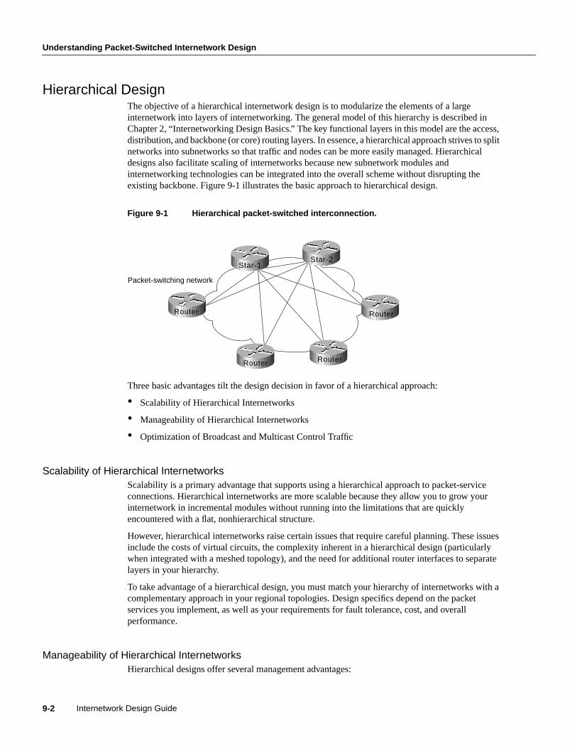
Understanding Packet-Switched Internetwork Design
Internetwork Design Guide9-2
Hierarchical DesignThe objective of a hierarchical internetwork design is to modularize the elements of a largeinternetwork into layers of internetworking. The general model of this hierarchy is described inChapter 2, “Internetworking Design Basics.” The key functional layers in this model are the access,distribution, and backbone (or core) routing layers. In essence, a hierarchical approach strives to splitnetworks into subnetworks so that traffic and nodes can be more easily managed. Hierarchicaldesigns also facilitate scaling of internetworks because new subnetwork modules andinternetworking technologies can be integrated into the overall scheme without disrupting theexisting backbone. Figure 9-1 illustrates the basic approach to hierarchical design.
Figure 9-1 Hierarchical packet-switched interconnection.
Three basic advantages tilt the design decision in favor of a hierarchical approach:
• Scalability of Hierarchical Internetworks
• Manageability of Hierarchical Internetworks
• Optimization of Broadcast and Multicast Control Traffic
Scalability of Hierarchical InternetworksScalability is a primary advantage that supports using a hierarchical approach to packet-serviceconnections. Hierarchical internetworks are more scalable because they allow you to grow yourinternetwork in incremental modules without running into the limitations that are quicklyencountered with a flat, nonhierarchical structure.
However, hierarchical internetworks raise certain issues that require careful planning. These issuesinclude the costs of virtual circuits, the complexity inherent in a hierarchical design (particularlywhen integrated with a meshed topology), and the need for additional router interfaces to separatelayers in your hierarchy.
To take advantage of a hierarchical design, you must match your hierarchy of internetworks with acomplementary approach in your regional topologies. Design specifics depend on the packetservices you implement, as well as your requirements for fault tolerance, cost, and overallperformance.
Manageability of Hierarchical InternetworksHierarchical designs offer several management advantages:
Packet-switching network
Star-1Star-2
Router
Router
Router
Router

Designing Packet Service Internetworks 9-3
Topology Design
• Internetwork simplicity—Adopting a hierarchical design reduces the overall complexity of aninternetwork by partitioning elements into smaller units. This partitioning of elements makestroubleshooting easier, while providing inherent protection against the propagation of broadcaststorms, routing loops, or other potential problems.
• Design flexibility—Hierarchical internetwork designs provide greater flexibility in the use ofWAN packet services. Most internetworks benefit from using a hybrid approach to the overallinternetwork structure. In many cases, leased lines can be implemented in the backbone, withpacket-switching services used in the distribution and access internetworks.
• Router management—With the use of a layered, hierarchical approach to router implementation,the complexity of individual router configurations is substantially reduced because each routerhas fewer neighbors or peers with which to communicate.
Optimization of Broadcast and Multicast Control TrafficThe effect of broadcasting in packet-service networks (discussed in “Broadcast Issues” later in thischapter) require you to implement smaller groups of routers. Typical examples of broadcast trafficare the routing updates and Novell Service Advertisement Protocol (SAP) updates that are broadcastbetween routers on a PSDN. An excessively high population of routers in any area or layer of theoverall internetwork might result in traffic bottlenecks brought on by broadcast replication. Ahierarchical scheme allows you to limit the level of broadcasting between regions and into yourbackbone.
Topology DesignAfter you have established your overall internetwork scheme, you must settle on an approach forhandling interconnections among sites within the same administrative region or area. In designingany regional WAN, whether it is based on packet-switching services or point-to-pointinterconnections, there are three basic design approaches that you can adopt:
• Star Topologies
• Fully Meshed Topologies
• Partially Meshed Topologies
The following discussions introduce these topologies. Technology-specific discussions presented inthis chapter address the applicability of these topologies for the specific packet-switching services.
Note Illustrations in this chapter use lines to show the interconnections of specific routers on thePSDN network. These interconnections are virtual connections, facilitated by mapping featureswithin the routers. Actual physical connections generally are made to switches within the PSDN.Unless otherwise specified, the connecting lines represent these virtual connections in the PSDN.
Star TopologiesA star topology features a single internetworking hub providing access from leaf internetworks intothe backbone and access to each other only through the core router. Figure 9-2 illustrates apacket-switched star topology for a regional internetwork.

Understanding Packet-Switched Internetwork Design
Internetwork Design Guide9-4
Figure 9-2 Star topology for a regional internetwork.
The advantages of a star approach are simplified management and minimized tariff costs. However, thedisadvantages are significant. First, the core router represents a single point of failure. Second, the corerouter limits overall performance for access to backbone resources because it is a single pipe throughwhich all traffic intended for the backbone (or for the other regional routers) must pass. Third, thistopology is not scalable.
Fully Meshed TopologiesA fully meshed topology means that each routing node on the periphery of a given packet-switchingnetwork has a direct path to every other node on the cloud. Figure 9-3 illustrates this kind ofarrangement.
Figure 9-3 Fully meshed topology.
The key rationale for creating a fully meshed environment is to provide a high level of redundancy.Although a fully meshed topology facilitates support of all network protocols, it is not tenable inlarge packet-switched internetworks. Key issues are the large number of virtual circuits required
Leaf 1
Leaf 3
Leaf 2
Leaf 4Leaf 5
Regional packet-switching networkConnectionto backbone internetwork
RouterRouter
Router
RouterRouter
Core Router
Packet-switching network
Router
RouterRouter
Router
Router Router

Designing Packet Service Internetworks 9-5
Broadcast Issues
(one for every connection between routers), problems associated with the large number ofpacket/broadcast replications required, and the configuration complexity for routers in the absenceof multicast support in nonbroadcast environments.
By combining fully meshed and star approaches into a partially meshed environment, you canimprove fault tolerance without encountering the performance and management problemsassociated with a fully meshed approach. The next section discusses the partially meshed approach.
Partially Meshed TopologiesA partially meshed topology reduces the number of routers within a region that have directconnections to all other nodes in the region. All nodes are not connected to all other nodes. For anonmeshed node to communicate with another nonmeshed node, it must send traffic through one ofthe collection point routers. Figure 9-4 illustrates such a situation.
Figure 9-4 Partially meshed topology.
There are many forms of partially meshed topologies. In general, partially meshed approaches areconsidered to provide the best balance for regional topologies in terms of the number of virtualcircuits, redundancy, and performance.
Broadcast IssuesThe existence of broadcast traffic can present problems when introduced into packet-serviceinternetworks. Broadcasts are necessary for a station to reach multiple stations with a single packetwhen the specific address of each intended recipient is not known by the sending node. Table 9-1lists common networking protocols and the general level of broadcast traffic associated with each,assuming a large-scale internetwork with many routing nodes.
Table 9-1 Broadcast Traffic Levels of Protocols in Large-Scale Internetworks(Continued)
Network Protocol Routing Protocol
RelativeBroadcastTraffic Level
AppleTalk Routing Table Maintenance Protocol (RTMP)
Enhanced Interior Gateway Routing Protocol (Enhanced IGRP)
High
Low
Novell Internetwork PacketExchange (IPX)
Routing Information Protocol (RIP)
Service Advertisement Protocol (SAP)
Enhanced IGRP
High
High
Low
Packet-switching network
Star-1Star-2
Router
Router
Router
Router

Understanding Packet-Switched Internetwork Design
Internetwork Design Guide9-6
The relative valueshigh andlow in Table 9-1 provide a general range for these protocols. Yoursituation and implementation will determine the magnitude of broadcast traffic. For example, thelevel of broadcast traffic generated in an AppleTalk Enhanced IGRP environment depends on thesetting of the Enhanced IGRP hello-timer interval. Another issue relates to the size of theinternetwork. In a small-scale internetwork, the amount of broadcast traffic generated by EnhancedIGRP nodes might behigher than with a comparable RTMP-based internetwork. However, forlarge-scaleinternetworks, Enhanced IGRP nodes generate substantially less broadcast traffic thanRTMP-based nodes.
Managing packet replication is an important design consideration when integrating broadcast-typeLANs (such as Ethernet) with nonbroadcast packet services (such as X.25). With the multiple virtualcircuits that are characteristic of connections to packet-switched environments, routers mustreplicate broadcasts for each virtual circuit on a given physical line.
With highly meshed environments, replicating broadcasts can be expensive in terms of increasedrequired bandwidth and number of CPU cycles. Despite the advantages that meshed topologies offer,they are generally impractical for large packet-switching internetworks. Nonetheless, some level ofcircuit meshing is essential to ensure fault tolerance. The key is to balance the trade-off inperformance with requirements for circuit redundancy.
Performance IssuesWhen designing a WAN around a specific packet service type, you must consider the individualcharacteristics of the virtual circuit. For example, performance under certain conditions will dependon a given virtual circuit’s capability to accommodate mixed protocol traffic. Depending on how themultiprotocol traffic is queued and streamed from one node to the next, certain protocols may requirespecial handling. One solution might be to assign specific virtual circuits to specific protocol types.
Internet Protocol (IP) RIP
Interior Gateway Routing Protocol (IGRP)
Open Shortest Path First (OSPF)
Intermediate System-to-Intermediate System (IS-IS)
Enhanced IGRP
Border Gateway Protocol (BGP)
Exterior Gateway Protocol (EGP)
High
High
Low
Low
Low
None
None
DECnet Phase IV DECnet Routing High
DECnet Phase V IS-IS Low
International Organizationfor Standardization (ISO)Connectionless NetworkService (CLNS)
IS-IS
ISO-IGRP
Low
High
Xerox Network Systems(XNS)
RIP High
Banyan Virtual IntegratedNetwork Service (VINES)
Routing Table Protocol (RTP)
Sequenced RTP
High
Low
Network Protocol Routing Protocol
RelativeBroadcastTraffic Level

Designing Packet Service Internetworks 9-7
Frame Relay Internetwork Design
Performance concerns for specific packet-switching services includecommitted information rates(CIR) in Frame Relay internetworks and window size limitations in X.25 internetworks. (The CIRcorresponds to the maximum average rate per connection [PVC] for a period of time.)
Frame Relay Internetwork DesignOne of the chief concerns when designing a Frame Relay implementation isscalability. As yourrequirements for remote interconnections grow, your internetwork must be able to grow toaccommodate changes. The internetwork must also provide an acceptable level of performance,while minimizing maintenance and management requirements. Meeting all these objectivessimultaneously can be quite a balancing act. The discussions that follow focus on several importantfactors for Frame Relay internetworks:
• Hierarchical design
• Regional topologies
• Broadcast issues
• Performance issues
The guidelines and suggestions that follow are intended to provide a foundation for constructingscalable Frame Relay internetworks that balance performance, fault tolerance, and cost.
Hierarchical Design for Frame Relay InternetworksIn general, the arguments supporting hierarchical design for packet-switching networks discussed inthe section “Hierarchical Design” earlier in this chapter apply to hierarchical design for Frame Relayinternetworks. To review, the three factors driving the recommendation for implementing ahierarchical design are the following:
• Scalability of hierarchical internetworks
• Manageability of hierarchical internetworks
• Optimization of broadcast and multicast control traffic
The method by which many Frame Relay vendors tariff services is by Data Link ConnectionIdentifier (DLCI), which identifies a Frame Relay permanent virtual connection. A Frame Relaypermanent virtual connection is equivalent to an X.25 permanent virtual circuit, which, in X.25terminology, is identified by a logical channel number (LCN). The DLCI defines the interconnectionbetween Frame Relay elements. For any given internetwork implementation, the number of FrameRelay permanent virtual connections is highly dependent on the protocols in use and actual trafficpatterns.
How many DLCIs can be configured per serial port? It varies depending on the traffic level. You canuse all of them (about 1,000), but in common use, 200–300 is a typical maximum. If you broadcaston the DLCIs, 30–50 is more realistic due to CPU overhead in generating broadcasts. Specificguidelines are difficult because overhead varies by configuration. However, on low-end boxes (4,500and below), the architecture is bound by the available I/O memory. The specific number depends onseveral factors that should be considered together:
• Protocols being routed—Any broadcast-intensive protocol constrains the number of assignableDLCIs. For example, AppleTalk is a protocol that is characterized by high levels of broadcastoverhead. Another example is Novell IPX, which sends both routing and service updatesresulting in higher broadcast bandwidth overhead. In contrast, IGRP is less broadcast intensive

Frame Relay Internetwork Design
Internetwork Design Guide9-8
because it sends routing updates less often (by default, every 90 seconds). However, IGRP canbecome broadcast intensive if its IGRP timers are modified so that updates are sent morefrequently.
• Broadcast traffic—Broadcasts, such as routing updates, are the single most importantconsideration in determining the number of DLCIs that can be defined. The amount and type ofbroadcast traffic will guide your ability to assign DLCIs within this general recommended range.Refer to Table 9-1 earlier in this chapter for a list of the relative level of broadcast trafficassociated with common protocols.
• Speed of lines—If broadcast traffic levels are expected to be high, you should consider faster linesand DLCIs with higher CIR and excess burst (Be) limits. You should also implement fewerDLCIs.
• Static routes—If static routing is implemented, you can use a larger number of DLCIs per line,because a larger number of DLCIs reduces the level of broadcasting.
• Size of routing protocol and SAP updates—The larger the internetwork, the larger the size ofthese updates. The larger the updates, the fewer the number of DLCIs that you can assign.
Two forms of hierarchical design can be implemented:
• Hierarchical Meshed Frame Relay Internetworks
• Hybrid Meshed Frame Relay Internetworks
Both designs have advantages and disadvantages. The brief discussions that follow contrast thesetwo approaches.
Hierarchical Meshed Frame Relay InternetworksThe objectives of implementing a hierarchical mesh for Frame Relay environments are to avoidimplementing excessively large numbers of DLCIs and to provide a manageable, segmentedenvironment. The hierarchical meshed environment features full meshing within the core PSDN andfull meshing throughout the peripheral internetworks. The hierarchy is created by strategicallylocating routers between internetwork elements in the hierarchy.
Figure 9-5 illustrates a simple hierarchical mesh. The internetwork illustrated in Figure 9-5illustrates a fully meshed backbone, with meshed regional internetworks and broadcast networks atthe outer periphery.
The key advantages of the hierarchical mesh are that it scales well and localizes traffic. By placingrouters between fully meshed portions of the internetwork, you limit the number of DLCIs perphysical interface, segment your internetwork, and make the internetwork more manageable.However, consider the following two issues when implementing a hierarchical mesh:
• Broadcast and packet replication—In an environment that has a large number of multiple DLCIsper router interface, excessive broadcast and packet replication can impair overall performance.With a high level of meshing throughout a hierarchical mesh, excessive broadcast and packetreplication is a significant concern. In the backbone, where traffic throughput requirements aretypically high, preventing bandwidth loss due to broadcast traffic and packet replication isparticularly important.
• Increased costs associated with additional router interfaces—Compared with a fully meshedtopology, additional routers are needed to separate the meshed backbone from the meshedperipheral internetworks. However, by using these routers, you can create much largerinternetworks that scale almost indefinitely in comparison to a fully meshed internetwork.

Designing Packet Service Internetworks 9-9
Hybrid Meshed Frame Relay Internetworks
Figure 9-5 Fully meshed hierarchical Frame Relay environment.
Hybrid Meshed Frame Relay InternetworksThe economic and strategic importance of backbone environments often force internetworkdesigners to implement a hybrid meshed approach to WAN internetworks. Hybrid meshedinternetworks feature redundant, meshed leased lines in the WAN backbone and partially (or fully)meshed Frame Relay PSDNs in the periphery. Routers separate the two elements. Figure 9-6illustrates such a hybrid arrangement.
A1 A2
MeshedRegion A
MeshedFrame Relay
backbone
C1 C2
B1
B2
MeshedRegion B
MeshedRegion C
Router
Router
Router
Router Router
Router
Router
RouterRouter
Router
Router

Frame Relay Internetwork Design
Internetwork Design Guide9-10
Figure 9-6 Hybrid hierarchical Frame Relay internetwork.
Hybrid hierarchical meshes have the advantages of providing higher performance on the backbone,localizing traffic, and simplifying scaling of the internetwork. In addition, hybrid meshedinternetworks for Frame Relay are attractive because they can provide better traffic control in thebackbone and they allow the backbone to be made of dedicated links, resulting in greater stability.
The disadvantages of hybrid hierarchical meshes include high costs associated with the leased linesas well as broadcast and packet replication that can be significant in access internetworks.
Regional Topologies for Frame Relay InternetworksYou can adopt one of three basic design approaches for a Frame Relay-based packet service regionalinternetwork:
• Star Topologies
• Fully Meshed Topologies
• Partially Meshed Topologies
Each of these is discussed in the following sections. In general, emphasis is placed on partiallymeshed topologies integrated into a hierarchical environment. Star and fully meshed topologies arediscussed for structural context.
Star TopologiesThe general form of the star topology is addressed in the section “Topology Design” earlier in thischapter. Stars are attractive because they minimize the number of DLCIs required and result in alow-cost solution. However, a star topology presents some inherent bandwidth limitations. Consideran environment where a backbone router is attached to a Frame Relay cloud at 256 Kbps, while theremote sites are attached at 56 Kbps. Such a topology will throttle traffic coming off the backboneintended for the remote sites.
A1
Point-to-pointbackbone
Partially meshed regionalinternetwork interconnected
via Frame Relay PSDN
Fully meshed backboneinterconnected with
point-to-point leased-lines
Access networks A1 and A2also feature partially
meshed topology
Frame Relayregional network
Router
Router Router
Router
Router Router
Router
Router
Router
Router
Router Router
A2

Designing Packet Service Internetworks 9-11
Regional Topologies for Frame Relay Internetworks
As suggested in the general discussion, a strict star topology does not offer the fault tolerance neededfor many internetworking situations. If the link from the hub router to a specific leaf router is lost,all connectivity to the leaf router is lost.
Fully Meshed TopologiesA fully meshed topology mandates that every routing node connected to a Frame Relay internetworkis logically linked via an assigned DLCI to every other node on the cloud. This topology is nottenable for larger Frame Relay internetworks for several reasons:
• Large, fully meshed Frame Relay internetworks require many DLCIs. One is required for eachlogical link between nodes. As shown in Figure 9-7, a fully connected topology requires theassignment of [n(n-1)]/2 DLCIs, wheren is the number of routers to be directly connected.
Figure 9-7 Fully meshed Frame Relay.
• Broadcast replication will choke internetworks in large, meshed Frame Relay topologies. Routersinherently treat Frame Relay as a broadcast medium. Each time a router sends a multicast frame(such as a routing update, spanning tree update, or SAP update), the router must copy the frameto each DLCI for that Frame Relay interface.
These problems combine to make fully meshed topologies unworkable and unscalable for all butrelatively small Frame Relay implementations.
Partially Meshed TopologiesCombining the concepts of the star topology and the fully meshed topology results in the partiallymeshed topology. Partially meshed topologies are generally recommended for Frame Relay regionalenvironments because they offer superior fault tolerance (through redundant stars) and are lessexpensive than a fully meshed environment. In general, you should implement the minimummeshing to eliminate single point-of-failure risk.
Figure 9-8 illustrates a twin-star, partially meshed approach. This arrangement is supported in FrameRelay internetworks running IP, ISO CLNS, DECnet, Novell IPX, AppleTalk, and bridging.
DLCIs
Router
Router
Router
Router

Frame Relay Internetwork Design
Internetwork Design Guide9-12
Figure 9-8 Twin-star, partially meshed Frame Relay internetwork.
A feature calledvirtual interfaces (introduced with Software Release 9.21) allows you to createinternetworks using partially meshed Frame Relay designs, as shown in Figure 9-8.
To create this type of internetwork, individual physical interfaces are split into multiple virtual(logical) interfaces. The implication for Frame Relay is that DLCIs can be grouped or separated tomaximize utility. For example, small fully meshed clouds of Frame Relay-connected routers cantravel over a group of four DLCIs clustered on a single virtual interface, whereas a fifth DLCI on aseparate virtual interface provides connectivity to a completely separate internetwork. All of thisconnectivity occurs over a single physical interface connected to the Frame Relay service.
Prior to Software Release 9.21, virtual interfaces were not available and partially meshed topologiesposed potential problems, depending on the internetwork protocols used. Consider the topologyillustrated in Figure 9-9.
Figure 9-9 Partially meshed Frame Relay internetwork.
Given a standard router configuration and router software predating Software Release 9.21, theconnectivity available in the internetwork shown in Figure 9-9 can be characterized as follows:
• Core A and Core Z can reach all the remote routers.
• Remote B, Remote C, and Remote D cannot reach each other.
Frame Relay network
Star-1Star-2
Router
Router Router
Router
Frame Relay network
DLCIs
Core ZCore A
Remote B
Remote C Remote D

Designing Packet Service Internetworks 9-13
Broadcast Issues for Frame Relay Internetworks
For Frame Relay implementations running software prior to Software Release 9.21, the only way topermit connectivity among all these routers is by using a distance vector routing protocol that candisable split horizon, such as RIP or IGRP for IP. Any other internetwork protocol, such asAppleTalk or ISO CLNS, does not work. The following configuration listing illustrates an IGRPconfiguration to support a partially meshed arrangement.
router igrp 20network 45.0.0.0!interface serial 3encapsulation frame-relayip address 45.1.2.3 255.255.255.0no ip split-horizon
This topology only works with distance vector routing protocols, assuming you want to establishconnectivity from Remote B, C, or D to Core A or Core Z, but not across paths. This topology doesnot work with link state routing protocols because the router cannot verify complete adjacencies.Note that you will see routes and services of the leaf nodes that cannot be reached.
Broadcast Issues for Frame Relay InternetworksRouters treat Frame Relay as a broadcast media, which means that each time the router sends amulticast frame (such as a routing update, spanning tree update, or SAP update), the router mustreplicate the frame to each DLCI for the Frame Relay interface. Frame replication results insubstantial overhead for the router and for the physical interface.
Consider a Novell IPX environment with multiple DLCIs configured for a single physical serialinterface. Every time a SAP update is detected, which occurs every 60 seconds, the router mustreplicate it and send it down the virtual interface associated with each DLCI. Each SAP framecontains up to seven service entries, and each update is 64 bytes. Figure 9-10 illustrates this situation.
Note One way to reduce broadcasts is to implement more efficient routing protocols, such asEnhanced IGRP, and to adjust timers on lower speed Frame Relay services.
Figure 9-10 SAP replication in Frame Relay virtual interface environment.
SAP broadcast
Novell Server
DLCI 22
DLCI 21
DLCI 23
Frame Relay network
SAP broadcast isreproduced and
retransmitted out all three DLCIsfor Interface S0
E0E0Router A S0

Frame Relay Internetwork Design
Internetwork Design Guide9-14
Creating a Broadcast Queue for an InterfaceVery large Frame Relay networks might have performance problems when many DLCIs terminatein a single router or access server that must replicate routing updates and service advertising updateson each DLCI. The updates can consume access-link bandwidth and cause significant latencyvariations in user traffic; the updates can also consume interface buffers and lead to higher packetrate loss for both user data and routing updates.
To avoid such problems, you can create a special broadcast queue for an interface. The broadcastqueue is managed independently of the normal interface queue, has its own buffers, and has aconfigurable size and service rate.
A broadcast queue is given a maximum transmission rate (throughput) limit measured in both bytesper second and packets per second. The queue is serviced to ensure that no more than this maximumis provided. The broadcast queue has priority when transmitting at a rate below the configuredmaximum, and hence has a guaranteed minimum bandwidth allocation. The two transmission ratelimits are intended to avoid flooding the interface with broadcasts. The actual transmission rate limitin any second is the first of the two rate limits that is reached.
Performance Issues for Frame Relay InternetworksTwo important performance concerns must be addressed when you are implementing a Frame Relayinternetwork:
• Packet-Switched Service Provider Tariff Metrics
• Multiprotocol Traffic Management Requirements
Each of these must be considered during the internetwork planning process. The following sectionsbriefly discuss the impact that tariff metrics and multiprotocol traffic management can have onoverall Frame Relay performance.
Packet-Switched Service Provider Tariff MetricsWhen you contract with Frame Relay packet-switched service providers for specific capabilities,CIR, measured in bits per second, is one of the key negotiated tariff metrics. CIR is the maximumpermitted traffic level that the carrier will allow on a specific DLCI into the packet-switchingenvironment. CIR can be anything up to the capacity of the physical limitation of the connecting line.
Other key metrics are committed burst (Bc) and excess burst (Be). Bc is the number of bits that theFrame Relay internetwork is committed to accept and transmit at the CIR. Be sets the absolute limitfor a DLCI in bits. This is the number of bits that the Frame Relay internetwork will attempt totransmit after Bc is accommodated. Be determines a peak or maximum Frame Relay data rate(MaxR), where MaxR = (Bc + Be)/Bc * CIR, measured in bits per second.
Consider the situation illustrated in Figure 9-11. In this environment, DLCIs 21, 22, and 23 areassigned CIRs of 56 Kbps. Assume the MaxR for each line is 112 Kbps (double the CIR). The serialline to which Router A is connected is a T1 line capable of 1.544 Mbps total throughput. Given thatthe type of traffic being sent into the Frame Relay internetwork consists of FTP file transfers, thepotential is high that the router will attempt to transmit at a rate in excess of MaxR. If this occurs,traffic might be dropped without notification if the Be buffers (allocated at the Frame Relay switch)overflow.

Designing Packet Service Internetworks 9-15
Performance Issues for Frame Relay Internetworks
Figure 9-11 Example of a CIR and CBR traffic limiting situation.
Unfortunately, there are relatively few ways to automatically prevent traffic on a line from exceedingthe MaxR. Although Frame Relay itself uses the Forward Explicit Congestion Notification (FECN)and Backward Explicit Congestion Notification (BECN) protocols to control traffic in the FrameRelay internetwork, there is no formally standardized mapping between the Frame Relay (link) leveland most upper-layer protocols. At this time, an FECN bit detected by a router is mapped to thecongestion notification byte for DECnet Phase IV or ISO CLNS. No other protocols are supported.
The actual effect of exceeding specified CIR and derived MaxR settings depends on the types ofapplication running on the internetwork. For instance, TCP/IP’s backoff algorithm will see droppedpackets as a congestion indication and sending hosts might reduce output. However, NFS has nobackoff algorithm, and dropped packets will result in lost connections. When determining the CIR,Bc, and Be for Frame Relay connection, you should consider the actual line speed and applicationsto be supported.
Most Frame Relay carriers provide an appropriate level of buffering to handle instances when trafficexceeds the CIR for a given DLCI. These buffers allow excess packets to be spooled at the CIR andreduce packet loss, given a robust transport protocol such as TCP. Nonetheless, overflows canhappen. Remember that although routers can prioritize traffic, Frame Relay switches cannot. Youcan specify which Frame Relay packets have low priority or low time sensitivity and will be the firstto be dropped when a Frame Relay switch is congested. The mechanism that allows a Frame Relayswitch to identify such packets is the discard eligibility (DE) bit.
This feature requires that the Frame Relay network be able to interpret the DE bit. Some networkstake no action when the DE bit is set. Other networks use the DE bit to determine which packets todiscard. The most desirable interpretation is to use the DE bit to determine which packets should bedropped first and also which packets have lower time sensitivity. You can define DE lists that identifythe characteristics of packets to be eligible for discarding, and you can also specify DE groups toidentify the DLCI that is affected.
You can specify DE lists based on the protocol or the interface, and on characteristics such asfragmentation of the packet, a specific TCP or User Datagram Protocol (UDP) port, an access listnumber, or a packet size.
Note To avoid packet loss, implement unacknowledged application protocols (such as packetizedvideo) carefully. With these protocols, there is a greater potential for buffer overflow.
FTP transfers
TCP/IPworkstation
DLCI 22
DLCI 21
DLCI 23
Frame Relay network
TCP/IP workstationprovides FTP serviceto remote clients onFrame Relay network
FTP service to network clientsvia DLCI 21, 22, and 23
CIR, MaxR,and Bandwidth SpecsS0 total bandwidth = 1.544 MbpsDLCI 21 CIR = 56 kbpsDLCI 22 CIR = 56 kbpsDLCI 23 CIR = 56 kbpsMaxR for each DLCI = 112 kbps
E0 S0E0 Router A

Frame Relay Internetwork Design
Internetwork Design Guide9-16
Multiprotocol Traffic Management RequirementsWith multiple protocols being transmitted into a Frame Relay internetwork through a single physicalinterface, you might find it useful to separate traffic among different DLCIs based on protocol type.To split traffic in this way, you must assign specific protocols to specific DLCIs. This can be doneby specifying static mapping on a per virtual interface basis or by defining only specific types ofencapsulations for specific virtual interfaces.
Figure 9-12 illustrates the use of virtual interfaces (assigned using subinterface configurationcommands) to allocate traffic to specific DLCIs. In this case, traffic of each configured protocol issent down a specific DLCI and segregated on a per-circuit basis. In addition, each protocol can beassigned a separate CIR and a separate level of buffering by the Frame Relay service provider.
Figure 9-12 Virtual interfaces assigned specific protocols.
Figure 9-13 provides a listing of the subinterface configuration commands needed to support theconfiguration illustrated in Figure 9-12. The command listing in Figure 9-13 illustrates the enablingof the relevant protocols and the assignment of the protocols to the specific subinterfaces andassociated Frame Relay DLCIs. Software Release 9.1 and later uses Frame Relay Inverse AddressResolution Protocol (IARP) to map protocol addresses to Frame Relay DLCIs dynamically. For thatreason, Figure 9-13 does not show Frame Relay mappings.
Novell Server
DLCI 22
DLCI 21
DLCI 23
Frame Relay network
IP traffic sent intoFrame Relay networkvia DLCI 21 only
DLCI Protocol AssignmentsDLCI 21 assigned IPDLCI 22 assigned DECnetDLCI 23 assigned IPX
TCP/IPworkstation
Mixed protocoltraffic sent torouter
Digital host
DECnet traffic sent intoFrame Relay networkvia DLCI 22 only
IPX traffic sent intoFrame Relay networkvia DLCI 23 only
E0Router C
S0

Designing Packet Service Internetworks 9-17
Configuring Frame Relay Traffic Shaping
Figure 9-13 Virtual interface configuration example.
You can use the following commands in Software Release 9.1 to achieve a configuration that issimilar to the configuration shown in Figure 9-13:
You can use the following commands in Software Release 9.1 to achieve a configuration that issimilar to the configuration shown in Figure 9-13:
Version 9.1interface serial 0ip address 131.108.3.12 255.255.255.0decnet cost 10novell network A3frame-relay map IP 131.108.3.62 21 broadcastframe-relay map DECNET 10.3 22 broadcastframe-relay map NOVELL C09845 23 broadcast
Configuring Frame Relay Traffic ShapingBeginning with Release 11.2, Cisco IOS supports Frame Relay traffic shaping, which provides thefollowing features:
interface Ethernet 0ip address 192.198.78-9 255.255.255.0ipx network ACdenet cost 4no mcp enabled!interface Serial0no ip addressencapsulation frame–realy!interface Serial0.1 point–to–pointip address 131.108.3.12.255.255.255.0frame–relay interface–dlci 21 broadcastno frame–relay inverse–arp IP 21no frame–relay inverse–arp NOVELL 21no frame–relay inverse–arp APPLETALK 21no frame–relay inverse–arp INS 21!interface Serial0.2 point–to–pointno ip addressdecnet cost 10frame–relay interface–dlci 22 broadcastno frame–relay inverse–arp IP 22no frame–relay inverse–arp NOVELL 22no frame–relay inverse–arp APPLETALK 22no frame–relay inverse–arp INS 22!interface Serial0.3 point–to–pointno ip addressipx network A3frame–relay interface–dlci 23 broadcastno frame–relay inverse–arp IP 23no frame–relay inverse–arp NOVELL 23no frame–relay inverse–arp APPLETALK 23no frame–relay inverse–arp INS 23!router igrp 109network 192.198.78.0!ip name–server 255.255.255.255!snmp–server community!line oon 0line aux 0line vty 0 4end
Subinterfacecommandconfigurationdefining FrameRelay DLCIs andassigningprotocols tospecific DLCIs

Summary
Internetwork Design Guide9-18
• Rate enforcement on a per-virtual circuit basis—The peak rate for outbound traffic can be set tothe CIR or some other user-configurable rate.
• Dynamic traffic throttling on a per-virtual circuit basis—When BECN packets indicatecongestion on the network, the outbound traffic rate is automatically stepped down; whencongestion eases, the outbound traffic rate is stepped up again. This feature is enabled by default.
• Enhanced queuing support on a per-virtual circuit basis—Either custom queuing or priorityqueuing can be configured for individual virtual circuits.
By defining separate virtual circuits for different types of traffic and specifying queuing and anoutbound traffic rate for each virtual circuit, you can provide guaranteed bandwidth for each type oftraffic. By specifying different traffic rates for different virtual circuits over the same time, you canperform virtual time division multiplexing. By throttling outbound traffic from high-speed lines incentral offices to low-speed lines in remote locations, you can ease congestion and data loss in thenetwork; enhanced queuing also prevents congestion-caused data loss. Traffic shaping applies toboth PVCs and SVCs.
SummaryThis chapter has focused on the implementation of packet-switching services and addressesinternetwork design in terms of the packet-switching service topics including hierarchicalinternetwork design, topology design, broadcast issues, and performance issues.

C H A P T E R
Designing DDR Internetworks 10-1
1 0
Designing DDR Internetworks
Dial-on-Demand Routing (DDR) provides network connections across Public Switched TelephoneNetworks (PSTNs). Dedicated wide-area networks are typically implemented on leased lines ormore modern service provider options such as Frame Relay, SMDS, or ATM. Dial-on-DemandRouting provides session control for wide-area connectivity over circuit switched networks, whichin turn provides on-demand services and decreased network costs.
DDR can be used over synchronous serial interfaces, Integrated Services Digital Network (ISDN)interfaces, or asynchronous serial interfaces. V.25bis and DTR dialing are used for Switched 56CSU/DSUs, ISDN terminal adapters (TAs), or synchronous modems. Asynchronous serial lines areavailable on the auxiliary port on Cisco routers and on Cisco communication servers for connectionsto asynchronous modems. DDR is supported over ISDN using BRI and PRI interfaces.
Introduction to DDRCisco IOS Dial-on-Demand Routing (DDR) provides several functions. First DDR spoofs routingtables to provide the image of full-time connectivity using Dialer interfaces. When the routing tableforwards a packet to a Dialer interface, DDR then filters out the interesting packets for establishing,maintaining, and releasing switched connections. Internetworking is achieved over the DDRmaintained connection using PPP or other WAN encapsulation techniques (such as HDLC, X.25,SLIP). Internetwork engineers can use the model presented in this chapter to construct scalable,DDR internetworks that balance performance, fault tolerance, and cost.
DDR Design StackSimilar to the model provided by the OSI for understanding and designing internetworking, astacked approach, shown in Figure 10-1, can be used to design DDR networks.

Traffic and Topology of DDR
Cisco CCIE Fundamentals: Network Design10-2
Figure 10-1 DDR design stack.
Dialer CloudsThe network formed by the interconnected DDR devices can generically be labeled thedialer mediaor dialer cloud. The scope of the dialer cloud includes only the intended interconnected devices anddoes not include the entire switched media (the entire ISDN spans the globe and is beyond the scopeof the dialer cloud). The exposure to the ISDN must be considered when designing security.
The fundamental characteristics of dialer clouds are as follows:
• Dialer clouds are collective bundles of potential and active point-to-point connections.
• On active connections, dialer clouds form an NBMA (non-broadcast multiaccess) media similarto Frame Relay.
• For outbound dialing on switched circuits (such as ISDN) network protocol address to directorynumber mapping must be configured.
• Inactive DDR connections are spoofed to appear as active to routing tables.
• Unwanted broadcast or other traffic causing unneeded connections can be prohibitivelyexpensive. Potential costs on Tariffed media (such as ISDN) should be closely analyzed andmonitored to prevent such loss.
The characteristics of dialer clouds affect every stage of DDR internetworking design. A solidunderstanding of network protocol addressing, routing, and filtering strategies can result in veryrobust and cost-effective internetworks.
Traffic and Topology of DDRTo determine the optimum topology, the DDR designer should perform a traffic analysis ofinternetworking applications that must be supported. This includes answering the followingquestions:
• How often does data traffic need to move between the DDR sites?
• What side of the DDR connection can establish the connection? How many remote sites?
• Is this a point-to-point solution or a multipoint solution?
Authentication
Dialer Filtering
RoutingStrategies
Dialer Interfaces
Traffic &Topology
DDR Design Stack

Designing DDR Internetworks 10-3
Topologies
TopologiesThe most important factor in selecting the topology is the number of sites that will be supported. Ifonly two sites will be involved, the point-to-point topology is used. If more than two sites are to besupported, the hub-and-spoke topology is typically used. For small numbers of sites with very lowtraffic volumes, the fully meshed topology may be the most appropriate solution.
Topologies for DDR covered in this section include:
• Point-to-point
• Fully meshed
• Hub-and-spoke
Point-to-Point TopologyIn a simple point-to-point topology (see Figure 10-2), two sites are connected to each other. Eachsite has a dialer interface and maps the other site’s address to a telephone number. If additionalbandwidth is required, multiple links can be aggregated using Multilink PPP.
Figure 10-2 Point-to-point topology.
Fully Meshed TopologyThe fully meshed configuration (see Figure 10-3) is recommended only for very small DDRnetworks. Fully meshed topologies can streamline the dialing process for any-to-any connectivity aseach site can call any other site directly, rather than having to call through a central site, which thenplaces another call to the target site. However, the configuration for each site is more complexbecause each site must have mapping information for every other site.
If load sharing is desired, interfaces can be configured for MultiLink PPP capability. In addition tothe complexity of the configuration, either sufficient interfaces must be available on each device todeal with the possibility of all of the other devices calling in, or the possibility of contention forinterfaces needs to be understood and dealt with.
Router A Router B

Traffic and Topology of DDR
Cisco CCIE Fundamentals: Network Design10-4
Figure 10-3 Fully meshed topology
Hub-and-Spoke DDR SolutionsIn a hub-and-spoke topology (see Figure 10-4), a central site is connected to several remote sites.The remote sites communicate with the central site directly; they do not call any of the other remotesites. This topology works very well for scaling large solutions.
Figure 10-4 Hub-and-spoke topology.
Hub-and-spoke topologies are easier to configure than fully meshed topologies when multipointtopologies are required because remote site dialer interfaces are mapped only to the central site. Thisallows most of the design complexity (such as addressing, routing, and authentication) to bemanaged on the DDR Hub. Configuration support of the remote sites can be greatly simplified(similar to one end of a point-to-point topology).
Router D Router B
Router C
Router A
Router A
Router B
Router C
Router D

Designing DDR Internetworks 10-5
Traffic Analysis
If any-to-any connectivity initiation is required between remote sites, routing behavior may need tobe modified depending on dialer interface behavior (that is, it may be necessary to disablesplit-horizon on distance vector routing protocols).
Multiple hubs can be used to provide further scaling of hub-and-spoke technologies. When usingMultiLink PPP, as is very common in ISDN solutions, designers can implement Cisco IOSMultiChassis MultiLink PPP to scale the dial-in rotary group between multiple Network AccessServers. MultiChassis MultiLink PPP (MMP) is discussed further in Chapter 11, “Designing ISDNInternetworks,” in the section “Designing ISDN Internetworks.”
Traffic AnalysisFor traffic analysis, develop a chart of which protocols need to be able to support DDR-based dialingfrom which devices. This will form the basis of the rest of the DDR design.
For example, Company KDT has selected a hub-and-spoke topology (to provide for scaling) and hasdeveloped the needs shown in Table 10-1 for its DDR cloud requirements.
Table 10-1 DDR Protocol Connectivity Requirements for KDT
The purpose of Table is to identify which sites and protocols require the capability to initiate theDDR connections. Once connectivity is established, each protocol requires two-way connectivity viarouting tables and dialer cloud address mapping. Dial-in versus dial-out is from the perspective ofthe hub.
Often a primary goal of a DDR network is to offer a cost improvement over WAN charges associatedwith dedicated connections. Additional traffic analysis must be performed for each protocol at thisor the Dialer Filtering design stage. Network applications use the infrastructure provided by theinternetwork in many different and often unexpected ways. It is critical to perform a thoroughanalysis of real-world network traffic that will transit the dialer media in order to determine whethera DDR network can operate in a feasible manner. Packet capture and analysis tools provide the mostvaluable tool for this analysis.
Dialer InterfacesAccess to the dialer media is via Cisco ISO Dialer interfaces. ISDN B channels, Synchronous Serialinterfaces, and Asynchronous interfaces can all be converted to dialer interfaces using dialerinterface configuration commands. To understand dialer interfaces, the following concepts arecovered:
• Supported physical interfaces
• Dialer rotary groups
• Dialer profiles
Remote Site Dial-In Protocols Dial-Out Protocols Notes
c700A IP, IPX None
c700B IP None
c1600A IP, AppleTalk IP
c2500A IP, IPX, AppleTalk IP, IPX, AppleTalk
c2500B IP, IPX IP
NAS3600A IP, IPX, AppleTalk IP, IPX, AppleTalk

Dialer Interfaces
Cisco CCIE Fundamentals: Network Design10-6
• Dialer addressing
• Dialer mapping
Dialer Interfaces also provide the basis for support of routing table spoofing and dialer filtering. Thissection focuses on lower-layer characteristics of dialer interfaces.
Supported Physical InterfacesSeveral types of physical interfaces can be enabled as dialer interfaces.
Synchronous Serial InterfacesDialing on synchronous serial lines can be initiated using V.25bis dialing or DTR dialing. V.25bis isthe ITU standard for in-band dialing. With in-band dialing, dialing information is sent over the sameconnection that carries the data. V.25bis is used with a variety of devices, including synchronousmodems, ISDN terminal adapters (TAs), and Switched 56 DSU/CSUs.
With DTR dialing, the DTR signal on the physical interface is activated, which causes some devicesto dial a number configured into that device.When using DTR dialing, the interface cannot receivecalls. But using DTR dialing allows lower-cost devices to be used in cases where only a singlenumber needs to be dialed. Synchronous Serial Lines support PPP, HDLC, and X.25 datagramencapsulation.
To convert a synchronous serial interface into a dialer interface, use the Cisco IOS commanddialerin-band or dialer dtr .
ISDN InterfacesAll ISDN devices subscribe to services provided by an ISDN service provider, usually a telephonecompany. ISDN DDR connections are made on B channels at 56 or 64 Kbps depending on the bearercapabilities of the end-to-end ISDN switching fabric. MultiLink PPP is often used to allow BRIdevices to aggregate both B channels for great bandwidth and throughput. See Chapter 11,“Designing ISDN Internetworks,” for guidance when designing ISDN internetworks.
ISDN BRI and PRI interfaces are automatically configured as dialer in-band interfaces. ISDN cansupport PPP, HDLC, X.25, and V.120 encapsulation. Typically, PPP will be used for DDR solutions.ISDN interfaces are automatically configured as dialer in-band interfaces.
For example, when examining a BRI interface on a Cisco IOS router, you can see that it is in thespoofing (pretending to be up/up so the routing table can point to this interface):
c1600A# sh int bri 0BRI0 is up, line protocol is up (spoofing)
However, the physical interfaces are the individual B (BRI0:1 and BRI0:2) channels being managedby the dialer interface (BRI0).
c1600A# sh int bri 0 1BRI0:1 is down, line protocol is down Hardware is BRI MTU 1500 bytes, BW 64 Kbit, DLY 20000 usec, rely 255/255, load 1/255 Encapsulation PPP, loopback not set, keepalive set (10 sec) LCP Closed, multilink Closed Closed: IPCP, CDPCP

Designing DDR Internetworks 10-7
Dialer Rotary Groups
Asynchronous Modem ConnectionsAsynchronous connections are used by communication servers or through the auxiliary port on arouter. Asynchronous DDR connections can be used to support multiple network layer protocols.When considering asynchronous DDR solutions, designers should consider if the internetworkingapplications can tolerate the longer call setup time and lower throughput of analog modems (incomparison with ISDN). For some design applications, DDR over asynchronous modemconnections may provide a very cost-effective option.
In order to dial out using asynchronous connections, chat scripts must be configured so that modemdialing and login commands are sent to remote systems. For design flexibility, multiple chat scriptscan be configured ondialer maps. Modem scripts can be used to configure modems for outboundcalls. Login scripts are intended to deal with logging onto remote systems and preparing the link forestablishment of PPP. Chat scripts are configured with expect-send pairs and keywords to modifysettings, as follows:
chat-script dialnum "" "atdt\T" TIMEOUT 60 CONNECT \c
If you are using asynchronous DDR and calling a system that requires a character-mode login, usethesystem-script keyword with thedialer map command.
Chat scripts often encounter problems with timing due to the fact that they are run with much greaterprecision than when a human is controlling the connection. For example, sometimes when a modemsends the CONNECT message, it is not actually ready to send data, and may even disconnect if anydata is received on the TX circuitry. To avoid such failure modes, pauses are added at the head ofsome send strings.
Each send string is terminated with a carriage return, even when it’s a null string (“”). Often the chatscript will be set up without the final “send” string. This may produce unexpected results. Ensurethat all chat scripts have complete expect-send pairs. If the final element in the chat script logic turnsout to be an expect (as in the previous example), use the\c as the final send to suppress unwantedoutput.
Use thedebug chat commands to troubleshoot chat script problems. Line-specific debugging canprovide additional details when expect-send logic is failing.
Dialer Rotary GroupsFor hub-and-spoke or fully meshed topologies that support multiple connections between sites,physical interfaces can be grouped into rotary groups with thedialer rotary-group command.Physical interfaces assigned to the dialer rotary-group inherit their configuration from thecorresponding interface dialer.
If one of the physical interfaces in a rotary group is busy, the next available interface can be used toplace or receive a call. It is not necessary to configure rotary groups for BRI or PRI interfaces asISDN B channels are automatically placed into arotary-group , however multiple BRI or PRIinterfaces can be grouped usingdialer rotary-group .
Dialer ProfilesDialer profiles introduced in Cisco IOS 11.2 offer additional design flexibility such as multisitebridging over ISDN. Dialer profiles provide an alternative methodology for designing DDRnetworks by removing the logical definition of dialer sites from the physical dialer interfaces.

Dialer Interfaces
Cisco CCIE Fundamentals: Network Design10-8
Encapsulation MethodsWhen a clear DataLink is established between two DDR peers, internetworking datagrams must beencapsulated and framed for transport across the Dialer media. The encapsulation methods availabledepend on the physical interface being used. Cisco supports Point-to-Point Protocol (PPP),High-Level Data Link Control (HDLC), Serial Line Interface Protocol (SLIP), and X.25 data-linkencapsulations for DDR:
• PPP is the recommended encapsulation method because it supports multiple protocols and isused for synchronous, asynchronous, or ISDN connections. In addition, PPP performs addressnegotiation and authentication and is interoperable with different vendors.
• HDLC is supported on synchronous serial lines and ISDN connections only. HDLC supportsmultiple protocols. However, HDLC does not provide authentication, which may be required ifusing dialer rotary groups.
• SLIP works on asynchronous interfaces only and is supported by IP only. Addresses must beconfigured manually. SLIP does not provide authentication and is interoperable only with othervendors that use SLIP.
• X.25 is supported on synchronous serial lines and a single ISDN B channel.
Addressing Dialer CloudsThere are two ways of setting up addressing on dialer clouds, as follows:
• Applying a subnet to the dialer cloud
Each site connected to the dialer cloud is given a unique node address on a shared subnet for useon its dialer interface. This method is similar to numbering a LAN or multipoint WAN andsimplifies the addressing scheme and creation of static routes.
• Using unnumbered interfaces
Similar to using unnumbered addressing on leased line point-to-point interfaces, the address ofanother interface on the router is borrowed for use on the dialer interface. Unnumberedaddressing takes advantage of the fact that there are only two devices on the point-to-point link.The routing table points to an interface (the dialer interface) and a next-hop address (which mustmatch a dialer map: static or dynamic).
Building static routes for unnumbered interfaces can be a little more complex because the routermust be configured with the interface that finds the next-hop out.
Dialer MapsSimilar to the function provided by an ARP table,dialer map statements translate next-hop protocoladdresses to telephone numbers. Without statically configured dialer maps, DDR call initiationcannot occur. When the routing table points at a dialer interface, and the next-hop address is notfound in a dialer map, the packet is dropped.
In the following example, packets received for a host on network 172.20.0.0 are routed to a next-hopaddress of 172.20.1.2, which is statically mapped to telephone number 555-1212:
interface dialer 1ip address 172.20.1.1 255.255.255.0dialer map ip 172.20.1.2 name c700A 5551212!ip route 172.20.0.0 255.255.255.0 172.20.1.2

Designing DDR Internetworks 10-9
Dialer Maps
Checks againstdialer map statements for broadcasts will fail because a broadcast packet istransmitted with a next-hop address of the broadcast address. If you want broadcast packetstransmitted to remote sites defined bydialer map statements, use thebroadcastkeyword with thedialer map command.
To configure whether calls are placed at 56 or 64 Kbps for ISDN calls, you can use the speed optionwith thedialer map command when configuring interfaces. See Chapter 11, “Designing ISDNInternetworks,” for details on ISDN media.
When setting up DDR between more than two sites, it is necessary to use PPP authentication and touse thename keyword with thedialer map command, as dialer maps for inbound calls are mapsbetween protocol addresses and authenticated user names.
To facilitate building of dialer maps, the internetwork designer should build an Address MappingTable as an aid for configuration. In Table 10-2, the dialer cloud has been assigned IP subnet172.20.1.0/24, IPX network 100, and AppleTalk cable-range 20-20. Table 10-2 forms the basis forbuilding proper dialer maps for each site.
Table 10-2 DDR Address Mapping Table for KDT
As NAS3600A forms the hub in the hub-and-spoke topology, each remote site is configured with thedialer maps to get to the central site. For example, the dialer map configuration for c1600A wouldbe as follows:
interface dialer1encapsulation pppip address 172.20.1.4 255.255.255.0appletalk cable-range 20-20 20.4appletalk zone ZZ DDRdialer in-banddialer map ip 172.20.1.1 name nas3600A speed 56 18355558661dialer map appletalk 20.1 name nas3600A speed 56 18355558661dialer-group 5ppp authentication chap callin
Remote Site Dial-In Protocols Directory# Notes
c700A IP: 172.20.1.2
IPX: 100.0000.0c00.0002
4085551212
c700B IP:172.20.1.3 4155558888 56K
c1600A IP: 172.20.1.4
AT: 20.4
5305551000
c2500A IP: 172.20.1.5
IPX: 100.0000.0c00.0005
AT: 20.5
5125558085
c2500B IP: 172.20.1.6
IPX: 100.0000.0c00.0006
2105552020
NAS3600A IP: 172.20.1.1
IPX: 100.0000.0c00.0001
8355558661 Hub

Routing Strategies
Cisco CCIE Fundamentals: Network Design10-10
The dialer map configuration for NAS3600A would be as follows:
interface dialer1encapsulation pppip address 172.20.1.1 255.255.255.0appletalk cable-range 20-20 20.1appletalk zone ZZ DDRipx network 100dialer in-banddialer map ip 172.20.1.2 name c700Adialer map ipx 100.0000.0c00.0002 c700Adialer map ip 172.20.1.3 name c700Bdialer map ip 172.20.1.4 name speed 56 c1600A 15305551000dialer map appletalk 20.4 name c1600Adialer map ip 172.20.1.5 name c2500A 15125558085dialer map ipx 100.0000.0c00.0005 name c2500A 15125558085dialer map appletalk 20.5 name c2500A 15125558085dialer map ip 172.20.1.6 name c2500B 12105552020dialer map ipx 100.0000.0c00.0006 name c2500Bdialer-group 5ppp authentication chap callin
Note that dialer maps provide mapping between remote site protocol addresses, remote site names,and remote site directory numbers. For dial-in only sites, directory numbers are not required and canbe left off to avoid inadvertent dialing. Table was used to determine which sites do not requiredial-out support. For dial-in sites, the ppp authentication name is mapped to the protocol address toensure outbound packets are placed on the correct PPP connection.
Recent Cisco IOS releases can build dynamic dialer maps using for IP (using IPCP addressnegotiation) and IPX (using IPXCP address negotiation), eliminating the need for dialer maps fordial-in only sites.
The DDR designer should familiarize themselves with the use of the Cisco IOS exec commandsshow dialerandshow dialer mapto examine the state of the DDR sites, the physical interfaces, andthe dialer map table. Usedebug dialer to troubleshoot DDR connection problems.
c1600A# sh dialerBRI0 - dialer type = ISDNDial String Successes Failures Last called Last status1835558661 0 0 never -0 incoming call(s) have been screened.BRI0:1 - dialer type = ISDNIdle timer (60 secs), Fast idle timer (20 secs)Wait for carrier (30 secs), Re-enable (5 secs)Dialer state is idleBRI0:2 - dialer type = ISDNIdle timer (60 secs), Fast idle timer (20 secs)Wait for carrier (30 secs), Re-enable (5 secs)Dialer state is idle
c1600A# sh dialer mapStatic dialer map ip 172.20.1.4 name nas (8355558661) on BRI0
Routing StrategiesThe nature of DDR networks is that routing and some directory services tables must be maintainedover idle connections. DDR designers may use a combination of static, dynamic, and snapshotrouting techniques to meet design needs. Default routing and remote node spoofing techniques (suchas Cisco 700 Series PAT and Cisco IOS EZIP) can be used to greatly simplify routing design.

Designing DDR Internetworks 10-11
Static Routing
Often the backbone at the NAS site will use a fast-converging routing protocol such as OSPF orEIGRP; however, these protocols do not operate easily on the dialer media due to their broadcast andlink-state nature. Typically, static routing and/or distance vector routing protocols are selected forthe DDR connections. Routing redistribution may be required to support propagation of routinginformation between the different routing protocols.
A complete discussion of routing redistribution techniques is beyond the scope of this chapter;however, DDR designers do need to develop and verify their routing strategy for each networkprotocol.
Static RoutingWith static routes, network protocol routes are entered manually, eliminating the need for a routingprotocol to broadcast routing updates across the DDR connection. Static routes can be effective insmall networks that do not change often. Routing protocols can generate traffic that causesconnections to be made unnecessarily.
When designing with IP unnumbered environments, older versions of Cisco IOS required multiplestatic routes for each site: one route to define the next-hop IP address and a second to define theinterface on which to find the next-hop (and dialer map). The following code:
interface Dialer1 ip unnumbered Ethernet0/0 dialer in-band dialer map ip 172.17.1.100 name kdt-NAS speed 56 5558660 dialer-group 5 ! ip classless
ip route 0.0.0.0 0.0.0.0 172.17.1.100 200 ip route 172.17.1.100 255.255.255.255 Dialer1 200 dialer-list 5 protocol ip permit
creates the following routing table:
kdt-3640# sh ip route ...<snip>... Gateway of last resort is 172.17.1.100 to network 0.0.0.0172.17.0.0/32 is subnetted, 1 subnets S 172.17.1.100 is directly connected, Dialer1 172.20.0.0/24 is subnetted, 1 subnets S* 0.0.0.0/0 [200/0] via 172.17.1.100
Recent Cisco IOS versions allow configuration of this as one route. For example, the exampleconfiguration here:
ip route 0.0.0.0 0.0.0.0 Dialer1 172.17.1.100 200 permanent
results in a simplified routing table, as follows:
kdt-3640#sh ip route ...<snip>... Gateway of last resort is 172.17.1.100 to network 0.0.0.0172.20.0.0/24 is subnetted, 1 subnets C 172.20.1.0 is directly connected, Ethernet0/0 S* 0.0.0.0/0 [200/0] via 172.17.1.100, Dialer1
It is typically necessary to configure redistribution of static routes into the backbone dynamic routingprotocol to ensure end-to-end connectivity. For example, to redistribute the static route to othernetworks in IGRP autonomous system 20, use the following configuration commands:
router igrp 20 network 172.20.0.0 redistribute static

Routing Strategies
Cisco CCIE Fundamentals: Network Design10-12
Dynamic RoutingDynamic routing can be used in DDR network design in a number of ways. Dynamic routing can beused with snapshot routing (as described in the “Snapshot Routing” section later in this chapter) tocache routes learned by dynamic routing protocols, thus allowing the automation of static routingmaintenance. Dynamic routing can be used as a trigger for routing convergence in large and complexDDR designs.
When the DDR link is connected, routing updates will flow to the peer, allowing redundant designsto converge on the physical connection by redistribution of trigger routing updates.
Selecting a Dynamic Routing ProtocolThe routing protocol selected for DDR link is typical of a Distance Vector protocol such as RIP, RIPII, EIGRP, IGRP, or RTMP. Selecting the simplest protocol that meets the needs of the internetworkdesign and thatis supported by the DDR routers is recommended.
Passive InterfacesInterfaces that are tagged as passive will not send routing updates. To prevent routing updates fromestablishing DDR connections on dialer interfaces that do not rely on dynamic routing information,configure DDR interfaces with thepassive-interfacecommand or use access lists as describedin the section “IPX Access Lists” later in this chapter. Using either thepassive-interfacecommand or an access list prevents routing updates from triggering a call. However, if you wantrouting updates to be passed when the link is active, use an access list rather than thepassive-interface command.
Split HorizonsRouters connected to broadcast-type IP networks and routers that use distance-vector routingprotocols use split horizons to reduce the possibility of routing loops. When split horizons areenabled, information about routes that comes in on an interface is not advertised out on that sameinterface.
Note If remote sites need to communicate with one another, split horizons should be disabled forhub-and-spoke topologies. In hub-and-spoke topologies, spokes learn about one another through thehub site to which they are connected by a single interface. In order for spokes to send and receiveinformation to one another, split horizons may need to be disabled so that full routing tables are builtat each site.
Dynamic Connected RoutesDynamic connected routes include the two following:
• Per-user AAA Installed Routes—AAA servers can install routes associated with users by usingAAA authorization to download and install routes as remote sites connect.
• PPP Peer Routes—IPCP address negotiation installs host-routes (/32 subnet mask) for theremote peer. This host-route can be propagated to backbone routers to provide robust routingconvergence. In most applications, the peer host-route will be beneficial (or innocuous) to theinternetwork design. If PPP peer host-routes interact poorly with existing routing strategies, theycan be turned off with the interface configuration commandno peer neighbor-route.

Designing DDR Internetworks 10-13
Snapshot Routing
Snapshot RoutingWith snapshot routing, the router is configured for dynamic routing. Snapshot routing controls theupdate interval of the routing protocols. Snapshot routing works with the following distance vectorprotocols:
• Routing Information Protocol (RIP) for IP
• Interior Gateway Routing Protocol (IGRP) for IP
• Routing Information Protocol (RIP) and Service Advertisement Protocol (SAP) for NovellInternet Packet Exchange (IPX)
• Routing Table Maintenance Protocol (RTMP) for AppleTalk
• Routing Table Protocol (RTP) for Banyan VINES
Under normal circumstances, these routing protocols broadcast updates every 10 to 60 seconds, soan ISDN link would be made every 10 to 60 seconds simply to exchange routing information. Froma cost perspective, this frequency is prohibitive. Snapshot routing solves this problem.
Note Snapshot routing is available in Cisco IOS Software Release 10.2 or later.
Snapshot ModelSnapshot routing uses the client-server design model. When snapshot routing is configured, onerouter is designated as the snapshot server and one or more routers are designated as snapshot clients.The server and clients exchange routing information during an active period. At the beginning of theactive period, the client router dials the server router to exchange routing information. At the end ofthe active period, each router takes a snapshot of the entries in its routing table. These entries remainfrozen during a quiet period. At the end of the quiet period, another active period begins, and theclient router dials the server router to obtain the latest routing information. The client routerdetermines the frequency at which it calls the server router. The quiet period can be as long as100,000 minutes (approximately 69 days).
When the client router transitions from the quiet period to the active period, the line might be downor busy. If this happens, the router would have to wait through another entire quiet period before itcould update its routing table, which might severely affect connectivity if the quiet period is verylong. To avoid having to wait through the quiet period, snapshot routing supports a retry period. Ifthe line is not available when the quiet period ends, the router waits for the amount of time specifiedby the retry period and then transitions to an active period once again.
The retry period is also useful in dial-up environments in which there are more remote sites thaninterface lines. For example, the central site might have one PRI (with 23 B channels available) butmight dial more than 23 remote sites. In this situation, there are more dialer map commands thanavailable lines. The router tries thedialer map commands in order and uses the retry time for thelines that it cannot immediately access (see Figure 10-5).

Routing Strategies
Cisco CCIE Fundamentals: Network Design10-14
Figure 10-5 Snapshot routers in action.
Enabling Snapshot RoutingSnapshot routing is enabled through interface configuration commands (see Figure 10-6). Thecentral router is configured for snapshot routing by applying thesnapshot server interfaceconfiguration command to its ISDN interfaces. Thesnapshot servercommand specifies the lengthof the active period and whether the router is allowed to dial remote sites to exchange routing updatesin the absence of regular traffic.
The remote routers are configured for snapshot routing by applying thesnapshot client commandto each ISDN interface. Thesnapshot client interface configuration command specifies thefollowing variables:
• The length of the active period (which must match the length specified on the central router)
• The length of the quiet period
• Whether the router can dial the central router to exchange routing updates in the absence ofregular traffic
• Whether connections that are established to exchange user data can be used to exchange routingupdates
When the backbone routing protocol is not supported by snapshot routing (for example, OSPF orEIGRP), standard routing redistribution techniques can be used to ensure that routing updates arepropagated between routing protocols, as required. Care should be taken to ensure redistribution ofsubnets if needed and to avoid routing loops.
Figure 10-6 AppleTalk snapshot routing.
RoutingTable
RoutingTable
RoutingTable
RoutingTable
Slave Routers
ISDN T1 T1T2
Time
Master Router
E0E0
R1R2
B0B0
Zone: WANCable-range: 700-700
Zone: BranchCable-range: 201-300
Zone: HQCable-range: 101-200

Designing DDR Internetworks 10-15
Dial Backup for Leased Lines
• R1 configuration is as follows:
username R2 password SECRET appletalk routing isdn switch-type basic-5ess ! interface BRI0 encapsulation ppp appletalk cable-range 700-700 700.1 appletalk zone WAN dialer map appletalk 700.2 name R2 speed 56 broadcast 5552222
dialer map snapshot 2 name R2 speed 56 broadcast 5552222 dialer-group 1
snapshot client 5 60 dialer isdn spid1 5550066 ppp authentication chap ! dialer-list 1 protocol appletalk permit
• R2 configuration is as follows:
username R1 password SECRET appletalk routing isdn switch-type basic-5ess interface BRI0 encapsulation ppp appletalk cable-range 700-700 700.2 appletalk zone WAN dialer wait-for-carrier-time 60 dialer map appletalk 700.1 name R1 speed 56 broadcast 5550066 dialer-group 1
snapshot server 5 dialer isdn spid1 5552222 ppp authentication chap ! dialer-list 1 protocol appletalk permit
For a further examination of snapshot routing, see Chapter 21, “Using ISDN Effectivelyin Multiprotocol Networks.”
Dial Backup for Leased LinesDial backup protects against wide-area network (WAN) downtime by allowing a dedicated serialconnection to be backed up by a circuit-switched connection. Dial backup can be performed inseveral ways: either with floating static routes or with backup interfaces.
Dial backup challenges the designer with different traffic patterns than DDR-supported SOHO andROBO sites. When designing Dial backup port densities, consider how many links might failconcurrently in a mass-failure scenario, as well as how many ports will be required on the centralsite in a worst-case scenario. Typical design involves selecting only dial-in or dial-out to avoidcontention when both sides are trying to re-establish connectivity.
Backup InterfacesA primary/dedicated serial line is configured to have a backup interface in the event of link failureor exceeded load thresholds. If the interface line or line protocol state goes down, the backupinterface is used to establish a connection to the remote site.
Once configured, the dial backup interface remains inactive until one of the following conditions ismet:
1 Line Protocol on the primary link goes down. The backup line is then activated, re-establishingthe connection between the two sites.

Routing Strategies
Cisco CCIE Fundamentals: Network Design10-16
2 The traffic load on the primary line exceeds a defined limit—The traffic load is monitored and afive-minute moving average is computed. If the average exceeds the user-defined value for theline, the backup line is activated. Depending on how the backup line is configured, some or all ofthe traffic flows onto it.
A Cisco IOS interface is placed into backup mode by applying thebackup interface command:
• Thebackup interface interface configuration command specifies the interface that is to act asthe backup.
• Thebackup loadcommand specifies the traffic threshold at which the backup interface is to beactivated and deactivated.
• Thebackup delay command specifies the amount of time that is to elapse before the backupinterface is activated or deactivated after a transition on the primary interface.
Backup interfaces traditionally lock the backup interface into BACKUP state so it is unavailable forother use. Dialer Profiles eliminates this lock and allows the physical interface to be used for multiplepurposes. Floating Static Route DDR design also eliminates this lock on the dialer interface. InFigure 10-7, a leased line connects Router A to Router B, and BRI 0 on Router B is used as a backupline.
Figure 10-7 Example of dial backup over ISDN.
Using the configuration that follows, BRI 0 is activated only when serial interface 1/0 (the primaryline) goes down. Thebackup delay command configures the backup connection to activate 30seconds after serial interface 0 goes down and to remain activated for 60 seconds after the serialinterface 1/0 comes up:
interface serial 1/0 ip address 172.20.1.4 255.255.255.0 backup interface bri 2/0 backup delay 30 60
Using the configuration that follows, BRI 2/0 is activated only when the load on serial 0 (the primaryline) exceeds 75 percent of its bandwidth. The backup line is deactivated when the aggregate loadbetween the primary and backup lines is within five percent of the primary line’s bandwidth:
interface serial 1/0 ip address 172.20.1.4 255.255.255.0 backup interface bri 2/0 backup load 75 5
Using the following configuration, BRI 2/0 is activated only when serial interface 1/00 goes downor when traffic exceeds 25 percent. If serial interface 1/0 goes down, 10 seconds will elapse beforeBRI 0 becomes active. When serial interface 1/0 comes up, BRI 2/0 will remain active for 60
ISDN
Router A Router B
171 69 158 18255 255 255 248
171 69 159 25255 255 255 249
171 69 159 26255 255 255 249
E0
171 69 159 49255 255 255 249
E0

Designing DDR Internetworks 10-17
Dialer Filtering
seconds. If BRI 2/0 is activated by the load-threshold on serial interface 1/0, BRI 2/0 is deactivatedwhen the aggregate load of serial interface 1/0 and BRI 2/0 returns to within five percent of thebandwidth of serial interface 1/0:
interface serial 1/0 ip address 172.20.1.4 255.255.255.0 backup interface bri 2/0 backup load 25 5 backup delay 10 60
Floating Static RoutesBackup interface operation is determined by the state of the line and line protocol on the primarylink. It is possible that end-to-end connectivity is lost, but line protocol stays up. For example, lineprotocol on a FrameRelay link is determined by the status of ILMI messages between the FrameRelayDCE (switch). Connectivity to the Frame Relay DCE does not guarantee end-to-end connectivity.
Designing Dial Backup with floating static routes utilizes Cisco IOS routing table maintenance anddynamic routing protocols. See Chapter 15, “Dial-on-Demand Routing,” for examples of usingFloating Static Routes to provide backup to leased lines.
IPX Static Routes and SAP UpdatesWith DDR, you need to configure static routes because routing updates are not received acrossinactive DDR connections. To create static routes to specified destinations, use theipx routecommand. You can also configure static Service Advertisement Protocol (SAP) updates with theipxsapcommand so that clients can always find a particular server. In this way, you can determine theareas on your internetwork where SAP updates will establish DDR connections.
In the following example, traffic to network 50 will always be sent to address 45.0000.0c07.00d3.Traffic to network 75 will always be sent to address 45.0000.0c07.00de. The router will respond toGNS queries with the server WALT if there are no dynamic SAPs available:
ipx route 50 45.0000.0c07.00d3ipx route 75 45.0000.0c07.00deipx sap 4 WALT 451 75.0000.0000.0001 15
Configuring AppleTalk Static ZonesStatic AppleTalk routes and zones are created using theappletalk static command as in thefollowing example:
appletalk static cable-range 110-110 to 45.2 zone Marketing
In many cases, manual configuration of static appletalk cable-ranges and zones will prove to beonerous. Snapshot routing should be investigated to provide automated route caching.
Dialer FilteringDialer filtering (see Figure 10-8) is used to classify all packets traversing the DDR connection aseitherinterestingor uninterestingusing Access Control Lists (ACLs). Only interesting packets canbring up and keep up DDR connections. It is the task of the DDR designer to determine which kindsof packets are to be deemed uninteresting and develop ACLs to prevent these uninteresting packetsfrom causing unnecessary DDR connections.

Dialer Filtering
Cisco CCIE Fundamentals: Network Design10-18
If a packet is uninteresting and there is no connection established, the packet is dropped. If the packetis uninteresting, but a connection is already established to the specified destination, the packet is sentacross the connection, but the idle timer is not reset. If the packet is interesting, and there is noconnection on the available interface, the router attempts to establish a connection.
Figure 10-8 Dialer filtering.
Each packet arriving at a dialer interface is filtered and determined to be interesting or uninterestingbased ondialer-group anddialer-list configuration. The following Cisco IOS configurationinterface dialer 1 uses dialer-group 5 to determine interesting packets, as defined by the dialer-list 5commands. Dialer-group 5 is defined by dialer-list 5 commands which in this case deems all IP, IPX,and AppleTalk packets to be interesting.
interface Dialer1dialer-group 5!dialer-list 5 protocol ip permitdialer-list 5 protocol ipx permitdialer-list 5 protocol appletalk permit!
Cisco IOS now supports many dialer-filtering protocols, as seen by the dialer-list online help:
kdt-3640(config)#dialer-list 5 protocol ? appletalk AppleTalk bridge Bridging clns OSI Connectionless Network Service clns_es CLNS End System clns_is CLNS Intermediate System decnet DECnet decnet_node DECnet node decnet_router-L1 DECnet router L1 decnet_router-L2 DECnet router L2 ip IP ipx Novell IPX llc2 LLC2 vines Banyan Vines xns XNS
To Dialer
Send
Interesting
Connected Phone #
No
NoConnected
NoNo
Yes
Yes
Yes Yes
Reset IdleTimer Dial
Dialer Filtering

Designing DDR Internetworks 10-19
Defining Interesting Packets Using ACLs
Defining Interesting Packets Using ACLsFurther dialer-filtering granularity is provided for each protocol by definition of Cisco IOS AccessControl Lists (ACLs). For example, the following configuration defines SNMP traffic as notinteresting using dialer-list 3 and extended IP ACLs:
dialer-list protocol ip 3 list 101
!access-list 101 deny udp any any eq snmpaccess-list 101 permit ip any any
Routing updates and directory services effects on Dialer interfaces can be managed by severaltechniques: static and default routing, passive-interfaces, or non-broadcast dialer maps. Forsolutions that require dynamic routing and cannot use SnapShot, routing can still be supported onthe ISDN link, and then deemed uninteresting by the dialer filtering.
For example, if the internetwork design requires IGRP routing update packets, the IGRP packets canbe filtered with access lists to prevent unwanted DDR connections as follows:
access-list 101 deny igrp 0.0.0.0 255.255.255.255 0.0.0.0 255.255.255.255access-list 101 permit ip 0.0.0.0 255.255.255.255 0.0.0.0 255.255.255.255
You can use one of the following two access lists to classify Enhanced IGRP traffic as uninteresting:
access-list 101 deny eigrp any anyaccess-list 101 deny ip any 224.0.0.10 0.0.0.0
The first access list denies all Enhanced IGRP traffic and the second access list denies the multicastaddress (224.0.0.10) that Enhanced IGRP uses for its updates. When you use access lists to controlEnhanced IGRP traffic, you need to configure static routes to create routes across the ISDN link.When the DDR link is connected, routing updates will be able to flow across the line. In the designof DDR filtering, it is important to understand where updates and service requests are useful andwhere these packet types can be safely filtered.
It is important to consider closely the directory service protocols and the internetworkingapplications that need to be supported at each site. Numerous protocols and applications can causeDDR connections to be established and maintained, and may result in extraordinary WAN chargesif not properly monitored and filtered. Don’t wait until you get a phone bill surprise to performcareful traffic and costing analysis for your network. If you are concerned about WAN costs,implement network monitoring tools to provide quick feedback on connection frequency andduration. Cost-containment issues are discussed in Chapter 11, “Designing ISDN Internetworks.”
SNMPAlthough SNMP can provide useful information about ISDN connections and how they are used,using SNMP can result in excessive uptime for ISDN links. For example, HP OpenView gathersinformation by regularly polling the network for SNMP events. These polls can cause the ISDNconnections to be made frequently in order to check that the remote routers are there, which resultsin higher ISDN usage charges. To control ISDN charges, the central site should filter SNMP packetsdestined for remote sites over ISDN. Incoming SNMP packets from remote sites can still bepermitted, which allows SNMP traps to flow to the SNMP management platform. That way, if anSNMP device fails at the remote site, the alarm will reach the SNMP management platform at thecentral site.
To control SNMP traffic, create an access list that denies SNMP packets.The following is an exampleof SNMP filtering:
access-list 101 deny tcp any any eq 161access-list 101 deny udp any any eq snmpaccess-list 101 permit ip any any!dialer-list 1 list 101

Dialer Filtering
Cisco CCIE Fundamentals: Network Design10-20
IPX PacketsOn Novell IPX internetworks, it is important to consider filtering routing updates on DDR interfacesfor the protocols listed in Table 10-3.
Table 10-3 Novell IPX Update Packet Cycles
You can use access lists to declare as uninteresting packets intended for the Novell serializationsocket (protocol number 0, socket number 457), RIP packets (protocol number 1, socket number453), SAP packets (protocol number 4, socket number 452), and diagnostic packets generated by theautodiscovery feature (protocol number 4, socket number 456). Uninteresting packets are droppedand do not cause connections to be initiated. For a sample IPX access list, see Chapter 21, “UsingISDN Effectively in Multiprotocol Networks.”
IPX sends out several types of packets that, if not controlled, cause unnecessary connections: IPXwatchdog packets and SPX keepalive packets. In addition, NetWare includes a time synchronizationprotocol that, if not controlled, causes unnecessary connections.
Novell IPX internetworks use several types of update packets that may need to be filtered with accesslists. Novell hosts broadcast serialization packets as a copy-protection precaution. RoutingInformation Protocol (RIP) routing table updates and SAP advertisements are broadcast every 60seconds. Serialization packets are sent approximately every 66 seconds.
In the following example, access list 901 classifies SAP (452), RIP (453), and serialization (457)packets as uninteresting and classifies IPX packet types unknown/any (0), any or RIP (1), any or SAP(4), SPX (5), NCP (17), and NetBIOS (20) as interesting:
access-list 901 deny 0 FFFFFFFF 452access-list 901 deny 4 FFFFFFFF 452access-list 901 deny 0 FFFFFFFF 453access-list 901 deny 1 FFFFFFFF 453access-list 901 deny 0 FFFFFFFF 457access-list 901 deny 0 FFFFFFFF 0 FFFFFFFF 452access-list 901 deny 0 FFFFFFFF 0 FFFFFFFF 453access-list 901 deny 0 FFFFFFFF 0 FFFFFFFF 457access-list 901 permit 0access-list 901 permit 1access-list 901 permit 2access-list 901 permit 4access-list 901 permit 5access-list 901 permit 17
You can permit any other type of IPX packet as needed. With Cisco IOS 10.2, the configuration ofNovell IPX access lists is improved with the support of wildcard (–1), so the previous example wouldbe as follows:
access-list 901 deny -1 FFFFFFFF 452access-list 901 deny -1 FFFFFFFF 453access-list 901 deny -1 FFFFFFFF 457access-list 901 deny -1 FFFFFFFF 0 FFFFFFFF 452access-list 901 deny -1 FFFFFFFF 0 FFFFFFFF 453access-list 901 deny -1 FFFFFFFF 0 FFFFFFFF 457access-list 901 permit -1
Packet Type Periodic Update Cycle
RIP 60 seconds
SAP 60 seconds
Serialization 66 seconds

Designing DDR Internetworks 10-21
IPX Packets
Controlling IPX Watchdog PacketsNetWare servers sendwatchdog packets to clients and disconnect any clients that do not respond.When IPX watchdog spoofing is enabled, the router local to the NetWare server responds towatchdog packets on behalf of the server’s clients. IPX watchdog spoofing allows clients to remainattached to servers without having to constantly send packets across the ISDN link to do so. Thisfeature is particularly important when trying to control ISDN link uptime. The interfaceconfiguration command for enabling IPX watchdog spoofing isipx watchdog-spoof.
Controlling SPX Keepalive PacketsSome Sequenced Packet Exchange (SPX)-based services in the Novell environment use SPXkeepalive packets. These packets are used to verify the integrity of end-to-end communications whenguaranteed and sequenced packet transmission is required. The keepalive packets are generated at arate that can be adjusted by the user from a default of one every five seconds to a minimum of oneevery 15 minutes. SPX spoofing as implemented in the Cisco IOS software receives, recognizes, andsuccessfully acknowledges keepalive packets both at the server end and the client end.
Time Server and NDS Replica PacketsNetWare 4.x includes a time synchronization protocol that causes NetWare 4.x time servers to sendan update every 10 minutes. To prevent the time server from generating update packets that wouldcause unwanted connections, you need to load a NetWare-loadable module (NLM) namedTIMESYNC.NLM that allows you to increase the update interval for these packets to several days.
A similar problem is caused by efforts to synchronize NDS replicas. NetWare 4.1 includes twoNLMs: DSFILTER.NLM and PINGFILT.NLM. They work together to control NDSsynchronization updates. Use these two modules to ensure that NDS synchronization traffic is sentto specified servers only at the specified times.
AppleTalk FilteringAppleTalk’s user-friendly directory services are based on Zone names and the Name BindingProtocol (NBP). Applications (such as the MacOS Chooser) use NBP Lookups to look for services(such as AppleShare and Printing) by zone names. Some applications may abuse NBP servicesassuming that DDR networks do not exist and send broadcasts to all zones. This in turn can causeexcessive dial-on-demand triggers. Applications such as QuarkXpress and 4D use all zone NBPbroadcasts to periodically probe the network either for licensing purposes or to provide links to othernetworked resources.Thetest appletalk:nbp lookup command combined with thedebug dialercommand monitors NBP traffic and can help you determine the kinds of packets that causeconnections to be made.
Beginning with Cisco IOS 11.0, you can filter NBP packets based on the name, type, and zone of theentity that originated the packet. AppleTalk NBP filtering allows Cisco routers to build firewalls,dial-on-demand triggers, and queuing options based on any NBP type or object. For a configurationexample, see Chapter 21, “Using ISDN Effectively in Multiprotocol Networks.” Ultimately, if theapplications that use NBP have been isolated, consult the individual vendors and ask for their adviceon how to control or eliminate NBP traffic.
Some Macintosh applications periodically send out NBP Lookup to all zones for numerous reasons;checking same serial number for copy protection, automatic search of other servers, and so on. As aresult, the ISDN link will get brought up frequently and waste usages. In 11.0(2.1) or later, Ciscorouters allow the user to configure NBP Filtering for dialer-list to prevent this problem. To do this,you should replace this line on both routers:
dialer-list 1 protocol appletalk permit

Authentication
Cisco CCIE Fundamentals: Network Design10-22
with these lines:
dialer-list 1 list 600
access-list 600 permit nbp 1 type AFPServeraccess-list 600 permit nbp 2 type LaserWriteraccess-list 600 deny other-nbpsaccess-list 600 permit other-access broadcast-deny
The previous example indicates you want to permit only two kinds of service for NBP Lookup tobring up the ISDN line. If you want to permit additional types, add to the example before thedenyother-nbpsstatement. Make sure you have a different sequence number or it will overwrite theprevious one. For example, if you want to also permit NBP Lookup for DeskWriter to bring up theline, the list will look like this:
dialer-list 1 list 600
access-list 600 permit nbp 1 type AFPServeraccess-list 600 permit nbp 2 type LaserWriteraccess-list 600 permit nbp 3 type DeskWriteraccess-list 600 deny other-nbpsaccess-list 600 permit other-access broadcast-deny
Note AppleShare servers use the Apple Filing Protocol (AFP) to send out tickles approximatelyevery 30 seconds to connected AppleShare clients. These tickles will cause DDR connections to stayup. To avoid unwanted DDR connections, you must manually unmount AppleTalk servers or installsoftware on the servers that automatically disconnects idle users after a timeout period.
Banyan VINES, DECnet IV, and OSI PacketsCisco IOS 10.3 introduced access lists for Banyan VINES, DECnet IV, and the Open SystemsIntegration (OSI) protocol. When a dialer map is configured for these protocols, access lists can beused to define interesting packets (that is, packets that will trigger the DDR link).
AuthenticationAuthentication in DDR network design provides two functions: security and dialer state. As mostDDR networks connect to the Public Switched Telephone Network, it is imperative that a strongsecurity model be implemented to prevent unauthorized access to sensitive resources.Authentication also allows the DDR code to keep track of what sites are currently connected andprovides for building of MultiLink PPP bundles. The following issues are addressed:
• PPP Authentication
• CHAP
• PAP
• ISDN Security
• DDR Callback
• IPX Access Lists

Designing DDR Internetworks 10-23
PPP Authentication
PPP AuthenticationPPP Authentication via CHAP or PAP (as described in RFC 1334) should be used to provide securityon DDR connections. PPP authentication occurs after LCP is negotiated on the DDR connection, butbefore any network protocols are allowed to flow. PPP Authentication is negotiated as an LCPoption, and is bidirectional, meaning each side can authenticate the other. In some environments, itmay be necessary to enable PPP authentication on the call-in side only (meaning the calling sidedoes not authenticate the called side).
CHAPWith CHAP, a remote device attempting to connect to the local router is presented with a CHAPchallenge containing the host name and a challenge seed. When the remote router receives thechallenge, it looks up the hostname received in the challenge and replies with the hostname and aCHAP response derived from the challenge seed and the password for that hostname. The passwordsmust be identical on the remote device and the local router. The names and passwords are configuredusing theusername command. In the following example, Router nas3600A will allow Routerc1600A to call in using the password “bubble”:
hostname nas3600Ausername c1600A password bubble!interface dialer 1ppp authentication chap callin
In the following example, Router Macduff will allow Router Macbeth to call in using the password“bubble”:
hostname c1600Ausername nas3600A password bubble!interface dialer 1encapsulation pppdialer in-banddialer-group 5dialer map ip 172.20.1.1 name nas3600A 18355558661ppp authentication chap callin
The following steps illustrate the CHAP process:
Step 1 c1600A calls nas3600A and LCP is negotiated.
Step 2 nas3600A challenges c1600A with: <nas3600A/challenge_string>.
Step 3 c1600A looks up the password for username nas3600A and generates response_string.
Step 4 c1600A sends response to c3600A: <nas1600A/response_string>.
Step 5 c3600A looks up the password for username c1600A and generates the expectedresponse_string. If the response_string received matches the response string expected,PPP authorization passes, and the PPP can negotiate the network control protocols (suchas IPCP). If it fails, the remote site is disconnected.
PAPLike CHAP, PAP is an authentication protocol used with PPP. However, PAP is less secure thanCHAP. CHAP passes an encrypted version of the password on the physical link, but PAP passes thepassword in clear text, which makes it susceptible to sniffer attack.
When being authenticated with PAP, the router looks up the username that matches the dialer mapused to initiate the call. When being authenticated with PAP on a receiving call, PAP looks up theusername associated with its hostname (because no dialer map was used to initiate the connection).

Summary
Cisco CCIE Fundamentals: Network Design10-24
In the following configuration, the NAS router will authenticate the peer with PAP when answeringthe DDR call, and compare the result to the local database:
hostname nas3600Aaaa new-modelaaa authentication ppp default localusername c2500A password freedomusername nas3600A password texas!interface Dialer1encapsualtion pppppp authentication pap
ISDN SecurityISDN DDR can use caller-ID for enhanced security by configuring ISDN caller on the incomingISDN interfaces. Incoming calls are screened to verify that the calling line ID is from an expectedorigin. However, caller-ID screening requires an end-to-end ISDN connection that can deliver thecaller-ID to the router. See Chapter 11, “Designing ISDN Internetworks,” for more information.
DDR CallbackDDR environments can be configured for callback operations. When a remote site dials into a centralsite (or the opposite), the central site can be configured to disconnect and initiate an outbound DDRconnection to the remote site.
DDR callback provides enhanced security by ensuring that the remote site can connect only from asingle location as defined by the callback number. DDR callback can also enhance administration bycentralizing billing for remote DDR connections.
IPX Access ListsAccess lists determine whether packets are interesting or uninteresting. Interesting packets activateDDR connections automatically. Uninteresting packets do not trigger DDR connections, although ifa DDR connection is already active, uninteresting packets will travel across the existing connection.
SummaryWhen designing DDR internetworks, consider the topology type: point-to-point, hub-and-spoke,and fully meshed. With the topology type, consider the type of addressing scheme used and securityissues. Keep in mind that media choice affects how packets are sent. Define where packets are sentby configuring static routes, zones, and services. Determine how packets reach their destination byconfiguring dialer interfaces and mapping addresses to telephone numbers. Finally, determine whenthe router should connect by configuring interesting versus uninteresting packets, eliminatingunwanted AppleTalk broadcasts, and spoofing IPX watchdog packets. Following these guidelineswill help you construct scalable DDR internetworks that balance performance, fault tolerance, andcost.
For further guidance on building DDR networks, including protocol-specific examples, see Chapter11, “Designing ISDN Internetworks,” Chapter 25, “Scaling Dial-on-Demand Routing,” and Chapter21, “Using ISDN Effectively in Multiprotocol Networks.”

C H A P T E R
Designing ISDN Internetworks 11-1
1 1
Designing ISDN Internetworks
The Public Switched Telephone Network (PSTN) has been transformed into an Integrated SystemsDigital Network (ISDN). Implementation of Signalling System 7 (SS7) in the PSTN backbone hasmade possible such widespread services as Caller-ID and Dialed-Number delivery, 800 DirectoryNumber lookup, Calling Card services, and Digital Data Services. Using BRI and PRI services,ISDN call switching can be extended to customer premises equipment (CPE) and provide end-to-enddigital paths.
Previous to ISDN availability, data connectivity over the Public Switched Telephone Network(PSTN) was via Plain Old Telephone Service (POTS) using analog modems. Connectivity overISDN offers the internetworking designer increased bandwidth, reduced call setup time, reducedlatency, and lower signal/noise ratios.
ISDN is now being deployed rapidly in numerous applications including Dial-on-Demand Routing,Dial Backup, SOHO and ROBO connectivity, and modem pool aggregation. This chapter covers thedesignof these applications.The purpose of this chapter is to discuss the design issues associatedwith building ISDN internetworks.
Figure 11-1 shows ISDN being used to concurrently serve ISDN and POTS (analog modem)connected remote sites in a hybrid dial solution.
Figure 11-1 ISDN can support hybrid (analog and digital) dial solutions.
Applications of ISDN in InternetworkingISDN has many applications in internetworking. The Cisco IOS has long been buildingDial-On-Demand Routing and Dial Backup solutions for Remote Office/Branch Office connectivity.Recently, ISDN has seen incredible growth in the support of mass Small Office/Home Office(SOHO) dial-up connectivity. For the purposes of this book, the ISDN calling side will be referredto as SOHO and the answering side will be referred to as the NAS (Network Access Server) unlessotherwise stated. In this section, the following issues are addressed:
• Dial-On-Demand Routing
ISDN
BRIPRI
POTS

Applications of ISDN in Internetworking
Internetwork Design Guide11-2
• Dial Backup
• SOHO Connectivity
• Modem Aggregation
Dial-On-Demand RoutingFull-time connectivity across the ISDN is spoofed by Cisco IOS routers using DDR. When qualifiedpackets arrive at a Dialer interface, connectivity is established over the ISDN. After a configuredperiod of inactivity, the ISDN connection is disconnected. Additional ISDN B channels can be addedand removed from the MultiLink PPP bundles using configurable thresholds. Figure 11-2 illustratesthe use of DDR for internetworking between ISDN connected sites.
Figure 11-2 DDR creates connectivity between ISDN sites.
Dial BackupISDN can be used as a backup service for a leased-line connection between the remote and centraloffices. If the primary connectivitygoes down, an ISDN circuit-switched connection is establishedand traffic is rerouted over ISDN. When the primary link is restored, traffic is redirected to the leasedline, and the ISDN call is released.
Dial Backup can be accomplished with floating static routes and DDR or by using the interfacebackup commands. ISDN dial backup can also be configured based on traffic thresholds as adedicated primary link. If traffic load exceeds a user-defined value on the primary link, the ISDNlink is activated to increase bandwidth between the two sites, as shown in Figure 11-3.
Figure 11-3 ISDN can back up primary connectivity between sites.
SOHO ConnectivitySmall Office and Home Office sites can be now be economically supported with ISDN BRI services.This offers to the casual or full-time SOHO sites the capability to connect to their corporate site orthe Internet at much higher speeds than available over POTS and modems.
SOHO designs typically involve dial-up only (SOHO initiated connections) and can take advantageof emerging address translation technology (such as Cisco 700 series PAT and Cisco IOS EZIP) tosimplify design and support. Using these features, the SOHO site can support multiple devices, butappears to the Cisco IOS NAS as a single IP address, as shown in Figure 11-4.
ISDN
ISDN

Designing ISDN Internetworks 11-3
Modem Aggregation
Figure 11-4 SOHO sites can appear to the Cisco IOS NAS as a single IP node.
Modem AggregationModem racking and cabling has been eliminated by integration of digital modem cards on Cisco IOSNetwork Access Servers (NAS). Digital integration of modems makes possible 56 Kbps modemtechnologies. Hybrid dial solutions can be built using a single phone number to provide analogmodem and ISDN conductivity, as shown in Figure 11-1.
Building Blocks of ISDN SolutionsISDN itself does not solve internetworking problems. By using either DDR or user-initiatedsessions, ISDN can provide the internetwork designer a clear data path over which to negotiate PPPlinks. A Public Switched Telephone Network to provide internetwork connectivity requires carefulconsideration of network security and cost containment.
This section includes overviews of the following ISDN design issues, which are then covered morefully in the following main sections of this chapter:
• ISDN Connectivity
• Datagram Encapsulation
• DDR: Dial-On-Demand Routing
• Security Issues
• Cost Containment Issues
ISDN ConnectivityConnectivity to ISDN is provided by physical PRI and BRI interfaces. A single PRI or BRI interfaceprovides a multiplexed bundle of B and D channels. The B channel provides bearer services such ashigh bandwidth data (up to 64 Kbps per B channel) or voice services. The D channel provides thesignalling and control channel and can also be used for low-bandwidth data applications.
BRI service is provided over a groomed local loop that is traditionally used for switch to analogphone service. BRI delivers to the subscriber 2 64 Kbps B channels and 1 16 Kbps D channel(2B+D).
PRI service is provided on traditional T1 & E1 leased lines between the customer premise equipment(CPE) and the ISDN switch:
• T1-based PRI provides 23 B channels and 1 D channel (23B+D).
• E1-based PRI provides 30 64 Kbps B channels and 1 64 Kbps D channel (30B+D).
Provisioning of both PRI and BRI services have very stringent requirements on the physicalequipment and cabling in the path from ISDN switch to ISDN CPE. Typical installations can requireadditional lead times as well as require working with dedicated support groups within your ISDNservice provider organizations. See Figure 11-5.
Cisco700 Cisco3600
BRIPRI
PSTN
Small Office/Home Office NAS/Central Site

Building Blocks of ISDN Solutions
Internetwork Design Guide11-4
Figure 11-5 Connectivity to ISDN using BRI and PRI.
Datagram EncapsulationWhen DDR (or a user) creates an end-to-end path over the ISDN, some method of datagramencapsulation is needed to provide data connectivity. Available encapsulations for ISDN designs arePPP, HDLC, X.25, and V.120. X.25 can also be used for datagram delivery over the D channel.
Most internetworking designs use PPP as the encapsulation. The point-to-point protocol (PPP) is apowerful and modular peer-to-peer mechanism to establish data links, provide security, andencapsulate data traffic. PPP is negotiated between the internetworking peers each time aconnection is established. PPP links can then be used by network protocols such as IP and IPX toestablish internetwork connectivity. PPP solutions can support bandwidth aggregation usingMultiLink PPP to provide greater throughput for internetworking applications.
DDR: Dial-On-Demand RoutingWhen building internetworking applications, designers must determine how ISDN connections willbe initiated, maintained, and released. DDR is a sophisticated set of Cisco IOS features thatintelligently establishes and releases circuit switched connections as needed by internetworkingtraffic. DDR can spoof internetwork routing and directory services in numerous ways to provide theillusion of full-time connectivity over circuit switched connections. Refer to Chapter 10, “DesigningDDR Internetworks,” for a discussion of DDR design.
Security IssuesBecause your internetwork devices can now be connected to over the PSTN, it is imperative todesign and confirm a robust security model for protecting your network. Cisco IOS uses the AAAmodel for implementing security. ISDN offers the use of Caller-ID and DNIS information to provideadditional security design flexibility.
Cost Containment IssuesA primary goal of selecting ISDN for your internetwork is to avoid the cost of full-time data services(such as leased lines or frame relay). As such, it is very important to evaluate your data traffic profilesand monitor your ISDN usage patterns to ensure your WAN costs are controlled. Dialer Callbackcan also be implemented to centralize billing.
Each of these building blocks of ISDN (connectivity, data encapsulation, DDR, security, and costcontainment) is discussed in further detail in the remaining sections of this chapter.
ISDN
D
23B
D
2B
CSUNT1
Basic Rate Interface Primary Rate Interface

Designing ISDN Internetworks 11-5
ISDN Connectivity Issues
ISDN Connectivity IssuesBased on application need and traffic engineering, BRI or PRI services are selected for ISDNconnectivity from each site. Traffic engineering may require multiple BRI services or multiple PRIsat some sites. Once connected to the ISDN fabric by BRI or PRI interfaces, design of ISDNend-to-end services must be implemented. This section covers the following issues related to ISDNconnectivity:
• Establishing BRI Connectivity
• Establishing ISDN Primary Rate Interface (PRI)
• ISDN End-to-End Considerations
• Datagram Encapsulation Issues
Establishing BRI ConnectivityThe BRI local loop is terminated at the customer premise at an NT1. The interface of the local loopat the NT1 is called theU reference point. On the customer premise side of the NT1 is the S/Treference point. The S/T reference point can support a multipoint bus of ISDN devices (TerminalAdapters). Figure 11-6 shows a typical BRI installation.
Figure 11-6 The BRI local loop connected to ISDN.
BRI HardwareTwo common types of ISDN CPE are available for BRI Services: ISDN routers and PC TerminalAdapters. Some BRI devices offer integrated NT1s and integrated Terminal Adapters for analogtelephones.
• LAN Routers—ISDN Routers provide routing between ISDN BRI and the LAN by usingDial-on-Demand Routing (DDR).
— DDR automatically establishes and releases circuit switched calls providing transparentconnectivity to remote sites based on internetworking traffic. DDR also controls establishingand releasing secondary B channels based on load thresholds. MultiLink PPP is used toprovide bandwidth aggregation when using multiple B channels. For more information onDDR, see Chapter 10, “Designing DDR Internetworks.”
— Some ISDN applications may require the SOHO user to take direct control over ISDN calls.Emerging Cisco IOS features can bring this control to the user desktop. New Cisco 700models provide acall button on the front of the router for direct control.
— Cisco 700 series and Cisco IOS based 1000, 1600, 2500 routers provide single BRIinterfaces. Multiple-BRI interfaces are available for the Cisco3600 and Cisco4x00 Series.
• PC Terminal Adapters (PC-TA)—These devices connect to PC workstations either by the PC Busor externally through the communications ports (such as RS-232) and can be used similar toanalog (such as V.34) internal and external modems.
ISDNNT1
S/T U
BRI

ISDN Connectivity Issues
Internetwork Design Guide11-6
— PC Terminal Adapters can provide a single PC user with direct control over ISDN sessioninitiation and release similar to using an analog modem. Automated mechanisms must beprovided to support the addition and removal of the secondary B channel. Cisco200 SeriesPC Cards can provide ISDN services to a PC.
BRI ConfigurationBRI configuration involves configuration of ISDN switch-type, and ISDN SPIDs, as follows:
• ISDN switch types—ISDN central office switches (also known aslocal exchange equipment)provide two functions at the local exchange: local termination and exchange termination. Thelocal termination function deals with the transmission facility and termination of the local loop.The exchange termination function deals with the switching portion of the local exchange. First,the exchange termination function de-multiplexes the bits on the B and D channels. Next, Bchannel information is routed to the first stage of the circuit switch, and D channel packets arerouted to D channel packet separation circuitry.
— For proper ISDN operation, it is imperative that the correct switch type is configured on theISDN device. For Cisco IOS releases up to 11.2, the configured ISDN switch-type is a globalcommand (note this also means you cannot use BRI and PRI cards in the same Cisco IOSchassis). In Cisco IOS 11.3T or later, multiple switch-types in a single Cisco IOS chassis arenow supported.
— Cisco IOS switch typesThe following Cisco IOS command helps illustrate the supported BRI switch types. In NorthAmerica, the most common types are 5ESS, DMS100, and NI-1.
kdt-3640(config)#isdn switch-type ? basic-1tr6 1TR6 switch type for Germany basic-5ess AT&T 5ESS switch type for the U.S. basic-dms100 Northern DMS-100 switch type basic-net3 NET3 switch type for UK and Europe basic-ni1 National ISDN-1 switch type basic-nwnet3 NET3 switch type for Norway basic-nznet3 NET3 switch type for New Zealand basic-ts013 TS013 switch type for Australia ntt NTT switch type for Japan vn2 VN2 switch type for France vn3 VN3 and VN4 switch types for France
— Cisco 700 switch types.On Cisco 700 Series routers, use theset switchcommand, which has the following optionswhen running the US software image:
SEt SWitch 5ESS | DMS | NI-1 | PERM64 | PERM128
• Service profile identifiers (SPIDs)—A service profile identifier (SPID) is a number provided bythe ISDN carrier to identify the line configuration of the BRI service. SPIDs allow multiple ISDNdevices, such as voice and data, to share the local loop. SPIDs are required by DMS-100 andNational ISDN-1 switches. Depending on the software version it runs, an AT&T 5ESS switchmight require SPIDs as well.
Each SPID points to line setup and configuration information. When a device attempts toconnect to the ISDN network, it performs a D channel Layer 2 initialization process thatcauses a TEI to be assigned to the device. The device then attempts D channel Layer 3initialization. If SPIDs are necessary but not configured or configured incorrectly on thedevice, the Layer 3 initialization fails, and the ISDN services cannot be used.

Designing ISDN Internetworks 11-7
Establishing BRI Connectivity
— The AT&T 5ESS switch supports up to eight SPIDs per BRI. Because multiple SPIDs canbe applied to a single B channel, multiple services can be supported simultaneously. Forexample, the first B channel can be configured for data, and the second B channel can beconfigured for both voice (using an ISDN telephone) and data.
— DMS-100 and National ISDN-1 switches support only two SPIDs per BRI: one SPID foreach B channel. If both B channels will be used for data only, configure the router for bothSPIDs (one for each B channel). You cannot run data and voice over the same B channelsimultaneously. The absence or presence of a channel's SPID in the router’s configurationdictates whether the second B channel can be used for data or voice.
Note There is no standard format for SPID numbers. As a result, SPID numbers vary depending onthe switch vendor and the carrier.
• A typical Cisco IOS SPID configuration is as follows:
interface BRI0isdn spid1 0835866201 8358662isdn spid2 0835866401 8358664
— These commands also specify the local directory number (LDN), which is the seven-digitnumber assigned by the service provider and used for call routing. The LDN is not necessaryfor establishing ISDN-based connections, but it must be specified if you want to receiveincoming calls on B channel 2. The LDN is required only when two SPIDs are configured(for example, when connecting to a DMS or NI1 switch). Each SPID is associated with anLDN. Configuring the LDN causes incoming calls to B channel 2 to be answered properly.If the LDN is not configured, incoming calls to B channel 2 may fail.
• A typical Cisco 700 Series SPID configuration is as follows:
SET 1 SPID 51255500660101SET 1 DIRECTORYNUMBER 5550066SET PHONE1 = 5550066SET 2 SPID 51255500670101
Confirming BRI OperationsTo confirm BRI operations in Cisco IOS, use theshow isdn statuscommand to inspect the status ofyour BRI interfaces. In the following example, the TEIs have been successfully negotiated and ISDNLayer3 (end-to-end) is ready to make or receive calls:
kdt-1600#sh isdn statusThe current ISDN Switchtype = basic-ni1ISDN BRI0 interface
Layer 1 Status: ACTIVE
Layer 2 Status: TEI = 109, State = MULTIPLE_FRAME_ESTABLISHED TEI = 110, State = MULTIPLE_FRAME_ESTABLISHED
Spid Status: TEI 109, ces = 1, state = 8(established)
spid1 configured, spid1 sent, spid1 valid Endpoint ID Info: epsf = 0, usid = 1, tid = 1
TEI 110, ces = 2, state = 8(established) spid2 configured, spid2 sent, spid2 valid Endpoint ID Info: epsf = 0, usid = 3, tid = 1
Layer 3 Status: 0 Active Layer 3 Call(s)
Activated dsl 0 CCBs = 0 Total Allocated ISDN CCBs = 0

ISDN Connectivity Issues
Internetwork Design Guide11-8
Troubleshooting SPID problems is done with thedebug isdn q921command. In the example thatfollows, you can see thatisdn spid1 was rejected by the ISDN switch:
kdt-1600# debug isdn q921ISDN Q921 packets debugging is onkdt-1600# clear int bri 0kdt-1600#*Mar 1 00:09:03.728: ISDN BR0: TX -> SABMEp sapi = 0 tei = 113*Mar 1 00:09:04.014: ISDN BR0: RX <- IDREM ri = 0 ai = 127*Mar 1 00:09:04.018: %ISDN-6-LAYER2DOWN:
Layer 2 for Interface BRI0, TEI 113 changed to down*Mar 1 00:09:04.022: %ISDN-6-LAYER2DOWN:
Layer 2 for Interface BR0, TEI 113 changed to down*Mar 1 00:09:04.046: ISDN BR0: TX -> IDREQ ri = 44602 ai = 127*Mar 1 00:09:04.049: ISDN BR0: RX <- IDCKRQ ri = 0 ai = 113*Mar 1 00:09:05.038: ISDN BR0: RX <- IDCKRQ ri = 0 ai = 113*Mar 1 00:09:06.030: ISDN BR0: TX -> IDREQ ri = 37339 ai = 127*Mar 1 00:09:06.149: ISDN BR0: RX <- IDREM ri = 0 ai = 113*Mar 1 00:09:06.156: ISDN BR0: RX <- IDASSN ri = 37339 ai = 114*Mar 1 00:09:06.164: ISDN BR0: TX -> SABMEp sapi = 0 tei = 114*Mar 1 00:09:06.188: ISDN BR0: RX <- UAf sapi = 0 tei = 114*Mar 1 00:09:06.188: %ISDN-6-LAYER2UP:
Layer 2 for Interface BR0, TEI 114 changed to up*Mar 1 00:09:06.200: ISDN BR0: TX ->
INFOc sapi = 0 tei = 114 ns = 0 nr = 0 i = 0x08007B3A06383932393833*Mar 1 00:09:06.276: ISDN BR0: RX <-
INFOc sapi = 0 tei = 114 ns = 0 nr = 1 i = 0x08007B080382E43A*Mar 1 00:09:06.283: ISDN BR0: TX -> RRr sapi = 0 tei = 114 nr = 1*Mar 1 00:09:06.287: %ISDN-4-INVALID_SPID: Interface BR0, Spid1 was rejected
Check the status of the Cisco 700 ISDN line with theshow status command, as follows:
kdt-776> sh statusStatus 01/04/1995 18:15:15Line Status
Line Activated Terminal Identifier Assigned SPID Accepted Terminal Identifier Assigned SPID Accepted
Port Status Interface Connection Link Ch: 1 Waiting for Call Ch: 2 Waiting for Call
BRI NotesNote the following issues regarding BRI configuration that must be addressed:
• TEI negotiation—Some switches deactivate Layer 2 of the D channel when no calls are active,so the router must be configured to perform TEI negotiation at the first call instead of at routerpower-up (the default). To enable TEI negotiation at the first call, use the followingglobalconfiguration command:
isdn tei-negotiation first-call
• ISDN Sub-Addressing—The S/T bus is a point to multipoint bus. Multiple ISDN CPE devicescan share the same S/T bus. Call routing to individual devices on an S/T bus is achieved by usingISDN Sub-Addressing.

Designing ISDN Internetworks 11-9
Establishing ISDN Primary Rate Interface (PRI)
• Voice routing—Cisco 700 Series routers can provide POTS jacks for connecting traditionalanalog telephone sets. SOHO sites can benefit from the capability to concurrently route data andvoice calls over the same ISDN BRI interface. Voice port phone numbers and voice priority mustbe configured for the needs of the SOHO site. The example that follows shows the voice routingsetup for a typical Cisco 700:
SET SWITCH NI-1SET 1 SPID 51255500660101SET 1 DIRECTORYNUMBER 5550066SET PHONE1 = 5550066SET 2 SPID 51255500670101SET 2 DIRECTORYNUMBER 5550067SET PHONE2 = 5550067SET VOICEPRIORITY INCOMING INTERFACE PHONE1 NEVERSET VOICEPRIORITY OUTGOING INTERFACE PHONE1 NEVERSET CALLWAITING INTERFACE PHONE1 OFFSET VOICEPRIORITY INCOMING INTERFACE PHONE2 ALWAYSSET VOICEPRIORITY OUTGOING INTERFACE PHONE2 ALWAYSSET CALLWAITING INTERFACE PHONE2 ONkdt-776> sh voiceroutingInterface VoicePriority VoicePriority Call Directory Ring
In Out Waiting Number CadencePHONE1 NEVER NEVER OFF 6720066PHONE2 ALWAYS ALWAYS ON 6720067DOV N/A N/A N/AUNSPECIFIED N/A N/A N/A
Establishing ISDN Primary Rate Interface (PRI)Cisco IOS routers support PRI interfaces using MultiChannel Interface Processor (MIP) cards. MIPcards can support Channelized T1/E1 or PRI timeslots. MIP cards are available for Cisco 4x000,Cisco 36x0, Cisco 5x00, and Cisco 7x00 Series routers.
To specify that the MIP card is to be used as an ISDN PRI, use thepri-group timeslots controllerconfiguration command.
Cisco IOS routers supporting PRI interfaces become Network Access Servers. Cisco 5x00 and 36x0Series routers support hybrid dial solutions (POTS and ISDN) by providing access to analogmodems over the NAS backplane.
PRI ConfigurationConfigure the ISDN switch-type for the PRI interface using theisdn switch-type command:
AS5200-2(config)#isdn switch-type ? primary-4ess AT&T 4ESS switch type for the U.S. primary-5ess AT&T 5ESS switch type for the U.S. primary-dms100 Northern Telecom switch type for the U.S. primary-net5 European switch type for NET5 primary-ntt Japan switch type primary-ts014 Australia switch type

ISDN Connectivity Issues
Internetwork Design Guide11-10
Normally, this is a global configuration command. Cisco IOS 11.3T or later will provide support formultiple switch-types in a single Cisco IOS chassis. Enable PRI services on the Cisco IOS NAS byconfiguring the T1 (or E1) controllers. The configuration that follows shows a typical T1 controllerconfiguration on a Cisco5200.
controller T1 0framing esfclock source line primarylinecode b8zspri-group timeslots 1-24
!controller T1 1
framing esfclock source line secondarylinecode b8zspri-group timeslots 1-24
!
Note that PRI channels 0–23 map to pri-group timeslots 1–24. The same +1 mapping is used onE1-based PRI.
To configure a T1-based PRI, apply the configuration commands to the PRI D channel, that is,interface Serial0:23. All B channels in an ISDN PRI (or BRI) interface are automatically bundledinto a dialer interface. When calls are made or received on the B channels, the configuration is clonedfrom the dialer interface (Serial0:23). If a NAS contains multiple PRIs, these PRIs can be groupedinto a single dialer interface by thedialer rotary-group interface command, as shown in thisexample:
interface Serial0:23dialer rotary-group 1
!interface Serial1:23
dialer rotary-group 1!interface Dialer1
ip unnumbered Ethernet0encapsulation ppppeer default ip address pool defaultdialer in-banddialer idle-timeout 120dialer-group 1no fair-queueno cdp enableppp authentication pap chapppp multilink
With this configuration, every B channel configuration or multilink PPP bundle is cloned frominterface Dialer1.
Designing ISDN Internetworks 11-11
Establishing ISDN Primary Rate Interface (PRI)
Confirming PRI OperationsThe state of the T1 controller is inspected with the Cisco IOS exec command:show controller t1,as follows:
AS5200-1# sh contr t1T1 0 is up.
No alarms detected. Version info of slot 0: HW: 2, Firmware: 14, NEAT PLD: 14, NR Bus PLD: 22 Framing is ESF, Line Code is B8ZS, Clock Source is Line Primary. Data in current interval (685 seconds elapsed):
0 Line Code Violations, 0 Path Code Violations 0 Slip Secs, 0 Fr Loss Secs, 0 Line Err Secs, 0 Degraded Mins 0 Errored Secs, 0 Bursty Err Secs, 0 Severely Err Secs, 0 Unavail Secs
Total Data (last 24 hours) 0 Line Code Violations, 0 Path Code Violations, 0 Slip Secs, 0 Fr Loss Secs, 0 Line Err Secs, 8 Degraded Mins, 0 Errored Secs, 0 Bursty Err Secs, 0 Severely Err Secs, 0 Unavail Secs
T1 1 is up. No alarms detected. Version info of slot 0: HW: 2, Firmware: 14, NEAT PLD: 14, NR Bus PLD: 22 Framing is ESF, Line Code is B8ZS, Clock Source is Line Secondary. Data in current interval (197 seconds elapsed):
0 Line Code Violations, 0 Path Code Violations 0 Slip Secs, 0 Fr Loss Secs, 0 Line Err Secs, 0 Degraded Mins 0 Errored Secs, 0 Bursty Err Secs, 0 Severely Err Secs, 0 Unavail Secs
Total Data (last 24 hours) 0 Line Code Violations, 0 Path Code Violations, 0 Slip Secs, 0 Fr Loss Secs, 0 Line Err Secs, 4 Degraded Mins, 0 Errored Secs, 0 Bursty Err Secs, 0 Severely Err Secs, 0 Unavail Secs
Excessive line code violations and other errors will cause significant performance loss. Work withyour ISDN PRI service provider to ensure that these counters show relatively clean operation. Usethe Cisco IOS exec commandshow isdn status to verify ISDN is operational, as follows:
AS5200-1# sh isdn statusThe current ISDN Switchtype = primary-dms100ISDN Serial0:23 interface
Layer 1 Status: ACTIVE
Layer 2 Status: TEI = 0, State = MULTIPLE_FRAME_ESTABLISHED
Layer 3 Status: 0 Active Layer 3 Call(s)
Activated dsl 0 CCBs = 0ISDN Serial1:23 interface
Layer 1 Status: ACTIVE
Layer 2 Status: TEI = 0, State = MULTIPLE_FRAME_ESTABLISHED
Layer 3 Status: 0 Active Layer 3 Call(s)
Activated dsl 1 CCBs = 0 Total Allocated ISDN CCBs = 0

ISDN Connectivity Issues
Internetwork Design Guide11-12
Inspect B channel status with theshow isdn service exec command, as follows:
AS5200-1# sh isdn servicePRI Channel Statistics:ISDN Se0:23, Channel (1-31)
Activated dsl 0 State (0=Idle 1=Propose 2=Busy 3=Reserved 4=Restart 5=Maint) 0 0 0 0 0 0 0 0 0 0 0 0 0 0 0 0 0 0 0 0 0 0 0 3 3 3 3 3 3 3 3 Channel (1-31) Service (0=Inservice 1=Maint 2=Outofservice) 0 0 0 0 0 0 0 0 0 0 0 0 0 0 0 0 0 0 0 0 0 0 0 0 0 0 0 0 0 0 0
ISDN Se1:23, Channel (1-31) Activated dsl 1 State (0=Idle 1=Propose 2=Busy 3=Reserved 4=Restart 5=Maint) 0 0 0 0 0 0 0 0 0 0 0 0 0 0 0 0 0 0 0 0 0 0 0 3 3 3 3 3 3 3 3 Channel (1-31) Service (0=Inservice 1=Maint 2=Outofservice) 0 0 0 0 0 0 0 0 0 0 0 0 0 0 0 0 0 0 0 0 0 0 0 0 0 0 0 0 0 0 0
ISDN End-to-End ConsiderationsThe following ISDN end-to-end considerations are covered in this section:
• Signaling System 7 (SS7)
• Data Path Speed
Signaling System 7Signaling System 7 (SS7) provides telephone switches with out-of-band signalling capabilities fortelephony trunks (switch to switch DS0 connections). End-to-End call management (such as setupand tear-down) uses ITU specification Q.931 and is extended to PRI/BRI internetworking devicesover the ISDN D channel.
Out-of-Band signalling via SS7 provides numerous benefits to internetworking design, includingreduced call setup time, bearer capability and other progress indicators, 64 Kbps data paths,caller-ID, and dialed number information (DNIS). The output that follows of Cisco IOSdebug isdnq931 shows typical ISDN Q.931 setup messages received by an NAS.
The Q.931 setup message includes a bearer capability Information Element (IE), which indicates tothe ISDN fabric and receiving side the type of application carried on the B channel. It is theresponsibility of the ISDN to provide an end-to-end channel capable of carrying the bearer service,and to provide to the receiving side progress indication to help it better utilize the ISDN connection.
The Cisco IOSdebug isdn q931output has different bearer capabilities for each incoming call type,as follows:
• Incoming 64 Kbps data call
ISDN Se0:23: RX <- SETUP pd = 8 callref = 0x0470 Bearer Capability i = 0x8890 Channel ID i = 0xA98382 Calling Party Number i = '!', 0x83, '5125558084' Called Party Number i = 0xC9, '52000'
• Incoming 56 Kbps data call
ISDN Se0:23: RX <- SETUP pd = 8 callref = 0x05DC Bearer Capability i = 0x8890218F Channel ID i = 0xA98382 Calling Party Number i = '!', 0x83, '5125558084' Called Party Number i = 0xC9, '52000'

Designing ISDN Internetworks 11-13
ISDN End-to-End Considerations
• Incoming voice call
ISDN Se0:23: RX <- SETUP pd = 8 callref = 0x015C Bearer Capability i = 0x8090A2 Channel ID i = 0xA98383 Progress Ind i = 0x8283 - Origination address is non-ISDN Called Party Number i = 0xC1, '5552000'
To support routing of voice calls to integrated modem cards, use the Cisco IOS interfaceconfiguration commandisdn incoming-voice modem. In some network designs, data calls may bemade with the Q.931 setup message indicating that it is a voice call. In some regions, ISDN tariffstructures may make this type of call more cost effective. (This design is commonly referred to asISDN data-over-voice.) However, indicating to the ISDN switching fabric that the bearer capabilityis voice allows the call to be placed through non-digital trunks. Designers, therefore, must carefullyconsider the potential risk in such a design. To support incoming ISDN data-over-voice calls on theCisco IOS, use the configuration commandisdn incoming-voice data, as follows:
NAS-522(config)#int serial 0:23NAS-522(config-if)#isdn incoming ?
data Incoming voice calls will be handled as data. modem Incoming voice calls will be handled as modems.
Data Path SpeedPrior to SS7 implementation, end-to-end call management signalling was provided in-band byrobbing bits from the DS0 trunks. Utilizing the occasional eighth and least significant bit of eachvoice byte was not detrimental to voice quality, but provided switch-to-switch signalling. End-to-endout-of-band signalling via SS7 and PRI/BRI D channels allows data calls to be placed through ISDNnetworks utilizing the full DS0 trunk (64 Kbps). Some trunks of the PSTN still do not supportout-of-band signalling, and can provide only robbed-bit trunking (Channelized T1/E1), limiting theavailable data channel to 56 Kbps.
It is the responsibility of the ISDN switching fabric to provide an end-to-end path matching therequirement of the bearer capability. If a call is made at 64 Kbps and there is not a 64 Kbps clearend-to-end path for the call, a busy signal should be received. Internetwork designers must considerthe possibility of occasional ISDN call blocking at 64 Kbps. Robust design may require that somesites be supported with 56 Kbps data calls. See Table 11-1 for outgoing speeds.
Table 11-1 Outgoing Speeds and the Cisco IOS Dialer Maps and Profiles
When originating calls are made at 64 Kbps improperly delivered to the destination by the ISDNnetwork over at 56 Kbps path, the transmitted data will be corrupted. The troubleshooting indicationwill be thatdebug isdn q931 shows the call being delivered, but no output is ever seen as receivedfrom debug ppp negotiationon one side. The packets have been corrupted and are being discarded.If calls are being delivered and PPP is not negotiating LCP, it is always a prudent idea to test outgoingcalls at 56 Kbps.
• Outgoing call speed
OutgoingSpeed Cisco IOS Dialer Maps Cisco IOS Dialer Profile Cisco 700
64 Kbps dialer map ... speed 64 (default) ?? set speed 64
56 Kbps dialer map ... speed 56 ?? set speed 56
Auto Multiple Dialer Maps ?? set speed auto (default)

ISDN Connectivity Issues
Internetwork Design Guide11-14
— Cisco IOS speed configuration—Use thespeedparameter on thedialer map configurationcommand to make outgoing calls at 56 Kbps as in the following example.
int dialer 1dialer map ip 172.20.1.1 name nas speed 56 5558084
— Cisco IOS dialer profiles speed configuration—The following example illustrates how toconfigure a Cisco IOS dialer profile to make outgoing calls at 56 Kbps:
interface dialer 1dialer remote-name nasdialer string 5558084 class unameit!map-class dialer unameitdialer isdn speed 56
— Cisco 700 speed configuration—Use the Cisco 700 seriesset speedconfiguration commandto control the speed for outgoing calls.
• Incoming call speed
— The ISDN Q.931 bearer capability and other IEs are used to determine the speed of theincoming call and in most circumstances will operate properly. However, in somecountry-to-country applications, the incoming call setup message will be delivered with abearer capability that does not match the originating call. If anisdn not end-to-endInformation Element is also received, it can be used to override the received bearer capabilityusing the Cisco IOS configuration commandisdn not end-to-end.
Datagram Encapsulation IssuesISDN can use PPP, HDLC, or X.25 for encapsulation. PPP is used most frequently as it provides anexcellent mechanism for authentication and negotiation of compatible link and protocolconfiguration.
Point-to-Point Protocol (PPP)PPP provides a standard method for transporting multiprotocol packets over point-to-point links.PPP is defined in RFC 1661. PPP consists of several components, each of which are of concern tothe internetwork designer:
• PPP framing
RFC 1662 discusses the implementation of PPP in HDLC-like framing. There are differences inthe way PPP is implemented on asynchronous and synchronous links.
When one end of the link uses synchronous PPP (such as an ISDN router) and the other usesasynchronous PPP (such as an ISDN TA connected to a PC serial port), two techniques areavailable to provide framing compatibility. The preferable method is to enable synchronous toasynchronous PPP frame conversion in the ISDN TA. If this is not available, V.120 can be usedto encapsulate the asynchronous PPP frames for transport across the ISDN.
• Link Control Protocol (LCP)
The PPP LCP provides a method of establishing, configuring, maintaining, and terminating thepoint-to-point connection. Before any network-layer datagrams (for example, IP) can beexchanged, LCP must first open the connection and negotiate configuration parameters. Thisphase is complete when a configuration acknowledgment frame has been both sent and received.
• PPP authentication

Designing ISDN Internetworks 11-15
Datagram Encapsulation Issues
The PPP authentication protocols (PAP and CHAP) are defined in RFC 1334. After LCP hasestablished the PPP connection, an optional authentication protocol can be implemented beforeproceeding to the negotiation and establishment of the Network Control Protocols. Ifauthentication is desired, it must be negotiated as an option at the LCP establishment phase.Authentication can be bidirectional (both sides authenticate the other) or unidirectional (one side,typically the called side, authenticates the other).
Most ISDN designs require the called device to authenticate the calling device. Besides theobvious security benefits, authentication also provides a sense of state for DDR and MultiLinkPPP bundling.
• Network Control Protocols (NCP)
This is a family of NCPs for establishing and configuring different network-layer protocols. PPPis designed to allow the simultaneous use of multiple network-layer protocols.
After LCP has been established and authentication has passed, the PPP nodes sends NCP framesto negotiate and establish connectivity for one or more network-layer protocols. For example, tosupport IP over a PPP connection, the IPCP is negotiated and established as per RFC 1332. OnceIPCP is successfully established, IP datagrams can be transmitted over the PPP connection.
• MultiLink PPP (MP)
Multilink PPP (MP) is a standard for aggregating multiple PPP links that allows for multivendorinteroperability, and is defined in RFC 1717. MP defines a way of sequencing and transmittingpackets over multiple physical interfaces. To reduce potential latency issues, MP also defines amethod of fragmenting and reassembling large packets. Figure 11-7 provides a conceptual viewof MP in action.
Figure 11-7 MultiLink PPP in action.
When an NCP packet arrives at an MLP master-interface for transmitting and is over 30 bytes, itis fragmented and sent on each physical link in the MLP bundle. When MLP packet fragmentsarrive on PPP destination, MLP reassembles the original packets and sequences them correctlyin the data stream.
Using MP, BRI devices can double their connection bandwidth across the link: from 56/64Kbps to 112/128 Kbps. MPPP is supported as long as all devices are part of the same dialerrotary-group or pool.
Cisco IOS and Cisco 700 DDR intelligence is used to determine when to add and remove linksfrom the MP master-interface. Cisco IOS DDR provides a load-threshold configuration todetermine when to add and remove the additional link. The load-factor can be calculated onincoming, outgoing, or two-way traffic.
NCP
LCP
Link
LCP
Link
MPPP Bundle

ISDN Connectivity Issues
Internetwork Design Guide11-16
The following partial configuration for NAS places two BRI interfaces into a dialerrotary-group, enables MP support, and defines a load-threshold for determining when to bringup additional B channels.
interface BRI2/0encapsulation pppdialer rotary-group 1isdn spid1 0835866201isdn spid2 0835866401
!interface BRI2/1
encapsulation pppdialer rotary-group 1isdn spid1 0835867201isdn spid2 0835967401
!interface Dialer1
ip unnumbered Ethernet0/0encapsulation pppdialer in-banddialer map ip 172.20.2.1 name kdt-nas 8358661dialer load-threshold 100 eitherdialer-group 1ppp authentication chap callinppp multilink
MP state and sessions can be investigated using theshow user and theshow ppp multilinkcommands:
KDT-5200# sh user Line User Host(s) Idle Location
* 51 vty 1 admin idle 00:00:00 Vi1 jack-isdn Virtual PPP (Bundle) 00:00:46 Vi9 cisco776 Virtual PPP (Bundle) 00:00:46 Se0:18 jack-isd Sync PPP 00:09:06 Se0:21 cisco776 Sync PPP 00:18:59 Se0:22 jack-isdn Sync PPP 00:08:49
KDT-AS5200# sh ppp multi
Bundle cisco776, 1 member, Master link is Virtual-Access9Dialer Interface is Dialer1
0 lost fragments, 3 reordered, 0 unassigned, sequence 0x2068/0x1A7C rcvd/sent 0 discarded, 0 lost received, 1/255 load
Member Link: 1Serial0:21
Bundle jack-isdn, 2 members, Master link is Virtual-Access1Dialer Interface is Dialer1
0 lost fragments, 8 reordered, 0 unassigned, sequence 0x5DEB/0x1D7E4 rcvd/sent 0 discarded, 0 lost received, 1/255 load
Member Links: 2Serial0:18Serial0:22
As seen previously, MP uses the PPP authentication name to build and maintain MP bundles. Toenable MP on a Cisco 700, apply the following configuration command:
set ppp multilink on
• Compression Control Protocol (CCP)

Designing ISDN Internetworks 11-17
ISDN Security
The Point-to-Point (PPP) Compression Control Protocol (CCP) is an Internet Engineering TaskForce (IETF) draft RFC that defines a method for negotiating data compression over PPP links.These links can be either leased lines or circuit-switched WAN links, including ISDN.Compression increases throughput and shortens file transfer times.
Use thecompress interface configuration command at both ends of the link to enablecompression. Use thestac keyword to enable the Stacker (LZS) compression algorithm or thepredictor keyword to enable the RAND algorithm (a predictor algorithm). The Stackeralgorithm is appropriate for LAPB and PPP encapsulation, and the RAND algorithm isappropriate for HDLC and PPP encapsulation. The Stacker algorithm is preferred for PPPencapsulation.
On the Cisco IOS, to determine what components have been negotiated (such as LCP, IPCP, CCP,and so on), use theshow interface command on the master interface. To troubleshoot PPPnegotiation problems, usedebug ppp negotiation anddebug ppp authentication.
ISDN SecurityUsing SS7, the ISDN can deliver end-to-end Information Elements such as Caller-ID and DialedNumber Information Service (DNIS). This information can be used to provide additional securitywhen designing ISDN solutions. It is recommended that PPP authentication always be implemented.
• PPP authentication
PPP authentication is used to provide primary security on ISDN and other PPP encapsulatedlinks. The authenticated username is also used by MultiLink PPP to maintain bundles and byDDR to determine which dialer sites are currently connected.
PPP authentication is enabled with theppp authentication interface command. PAP and/orCHAP can be used to authenticate the remote connection. CHAP is considered a superiorauthentication protocol since it uses a three-way handshake to avoid sending the password inclear-text on the PPP link.
Often, it may be necessary to authenticate the remote side only when receiving calls (not whenoriginating).
• Caller ID screening
The isdn caller interface configuration command configures caller ID screening. For example,the following command configures an ISDN to accept a call with a delivered caller ID having41555512 and any numbers in the last two positions.
isdn caller 41555512xx
Multiple isdn callercommands can be entered as needed. If a call is received that does notcontain a caller ID or does not match a configuredisdn caller statement, the call will be rejected.
• Dialer Callback
Callback allows a router (typically a remote router) to initiate a circuit-switched WAN link toanother device and request that device to call back. The device, such as a central site router,responds to the callback request by calling the device that made the initial call. Callback uses thePoint-to-Point Protocol (PPP) and the facilities specified in RFC 1570. Figure 11-8 shows atypical negotiation.
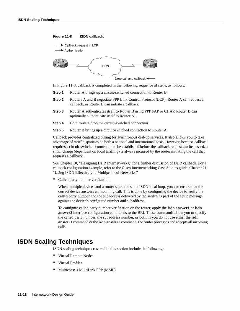
ISDN Scaling Techniques
Internetwork Design Guide11-18
Figure 11-8 ISDN callback.
In Figure 11-8, callback is completed in the following sequence of steps, as follows:
Step 1 Router A brings up a circuit-switched connection to Router B.
Step 2 Routers A and B negotiate PPP Link Control Protocol (LCP). Router A can request acallback, or Router B can initiate a callback.
Step 3 Router A authenticates itself to Router B using PPP PAP or CHAP. Router B canoptionally authenticate itself to Router A.
Step 4 Both routers drop the circuit-switched connection.
Step 5 Router B brings up a circuit-switched connection to Router A.
Callback provides centralized billing for synchronous dial-up services. It also allows you to takeadvantage of tariff disparities on both a national and international basis. However, because callbackrequires a circuit-switched connection to be established before the callback request can be passed, asmall charge (dependent on local tariffing) is always incurred by the router initiating the call thatrequests a callback.
See Chapter 10, “Designing DDR Internetworks,” for a further discussion of DDR callback. For acallback configuration example, refer to the Cisco Internetworking Case Studies guide, Chapter 21,“Using ISDN Effectively in Multiprotocol Networks.”
• Called party number verification
When multiple devices and a router share the same ISDN local loop, you can ensure that thecorrect device answers an incoming call. This is done by configuring the device to verify thecalled party number and the subaddress delivered by the switch as part of the setup messageagainst the device's configured number and subaddress.
To configure called party number verification on the router, apply theisdn answer1 or isdnanswer2 interface configuration commands to the BRI. These commands allow you to specifythe called party number, the subaddress number, or both. If you do not use either theisdnanswer1command or theisdn answer2command, the router processes and accepts all incomingcalls.
ISDN Scaling TechniquesISDN scaling techniques covered in this section include the following:
• Virtual Remote Nodes
• Virtual Profiles
• Multichassis MultiLink PPP (MMP)
Callback request in LCP
Drop call and callback
Authentication
ISDNRouter A Router B

Designing ISDN Internetworks 11-19
Virtual Remote Nodes
Virtual Remote NodesBy using Network Address Translations (NAT) features such as Cisco 700 PAT and Cisco IOS EZIP,remote sites can appear to the ISDN NAS as a single remote node IP address. This alleviates IPaddress consumption problems and the routing design complexity often associated with large-scaleISDN DDR deployment while still supporting a LAN and DDR-based connectivity from the remotesite.
These NAT features use the IP address received from the NAS during IPCP negotiation. All packetsrouted between the LAN and the PPP link have IP address and UDP/TCP port addresses translatedto appear as a single IP address. The port number translation is used to determine which packets needto be returned to which IP addresses on the LAN. The following Cisco 700 configuration commandsset NAT up for PAT.
Cisco 700 PAT and DHCPThe following configuration sets up a Cisco 700 for PAT and DHCP service:
cd internalset ip address 172.24.4.254set ip netmask 255.255.255.0set ip routing onset ip rip update offcdset user access-gw1set ip routing onset ip framing noneset number 18005552626set ip rip update offset encap pppset ip route destination 0.0.0.0 gateway 0.0.0.0set ip pat oncd lanset bridging onset encaps pppset ip routing oncdset ip pat porthandler default 172.24.4.1set ip pat porthandler http 172.24.4.1set bridging onset dhcp serverset dhcp domain cisco.comset dhcp address 172.24.1.1 10set dhcp netmask 255.255.255.0set dhcp gateway primary 172.24.4.254set dhcp dns primary 172.30.1.100set dhcp dns secondary 172.30.2.100set dhcp wins primary 172.30.1.101set dhcp wins secondary 172.30.2.101set ppp authentication incoming chapset ppp authentication outgoing chapset ppp secret client
<insert_secret><insert_secret>
set ppp secret host<insert_secret><insert_secret>

ISDN Scaling Techniques
Internetwork Design Guide11-20
If support is required for outbound initiated network connections to the remote site, port handlerconfiguration can be added so that the SOHO router knows which IP address to forward packets onto for individual connection types.
kdt-776> sh ip patDropped - icmp 0, udp 0, tcp 0, map 0, frag 0Timeout - udp 5 minutes, tcp 30 minutesPort handlers [default 172.24.4.1]:Port Handler Service-------------------------------------0 172.24.4.1 DEFAULT23 Router TELNET67 Router DHCP Server68 Router DHCP Client69 Router TFTP80 172.24.4.1 HTTP161 Router SNMP162 Router SNMP-TRAP520 Router RIP
Translation Table - 11 Entries.Inside Outside Orig. Port/ID Trans. Port/ID Timeout-------------------------------------------------------------------------172.24.4.1 172.17.190.5 0x414 0xff7d 1172.24.4.1 172.17.190.5 0x415 0xff7c 30172.24.4.1 172.17.190.26 0x40d 0xff88 27172.24.4.1 172.17.114.11 0x416 0xff7b 4172.24.4.1 172.17.114.11 0x417 0xff7a 4172.24.4.1 172.17.114.11 0x40f 0xff82 4172.24.4.1 172.17.190.19 0x418 0xff79 1172.24.4.1 172.17.190.5 0x410 0xff81 1172.24.4.1 172.17.114.11 0x411 0xff80 4172.24.4.1 172.17.114.11 0x412 0xff7f 4172.24.4.1 172.17.190.5 0x413 0xff7e 1
Virtual ProfilesVirtual Profiles (introduced in Cisco IOS 11.3) are PPP applications that create virtual-accessinterfaces for each connected user. Virtual Profiles allow additional design flexibility when buildingISDN networks for SOHO support. Using Virtual Profiles for dial-in can provide simplified nodeaddressing and address mapping that was previously provided by using DDR on ISDN interfaces.(As of Cisco IOS 11.3, Virtual Profile based dial-out is not supported.)
The virtual-access interface configuration can be cloned from a Dialer or Virtual-Template. To learnmore about virtual-access interfaces, see: http://cio.cisco.com/warp/customer/131/4.html. VirtualProfiles use Virtual Templates and can use AAA based on per-user configuration to createvirtual-access interfaces. Per-user configuration can be added to meet the specific protocol needs ofindividual users or groups.
Cisco IOS virtual-access interfaces can simplify remote node support for IPX and AppleTalk byusing the same configuration used on traditional group-async interfaces. The followingconfiguration provides peer addressing for IP, IPX, and AppleTalk using a Virtual-Templateinterface:
interface Virtual-Template1ip unnumbered Ethernet0/0appletalk client-modeipx ppp-client Loopback0peer default ip address pool default

Designing ISDN Internetworks 11-21
Multichassis MultiLink PPP (MMP)
Multichassis MultiLink PPP (MMP)When designing MultiLink PPP without Multichassis support, telco hunt-groups cannot span morethan a single Cisco IOS NAS or there exists a risk that the multiple B channels will not bereassembled. For example, an AS5300 can support up to four PRI interfaces providing a maximumof 120 B channels (E1-based) in a single dial-in hunt group. Additional NAS capacity would needto be provided by configuring a new hunt-group (with a new pilot directory number) for eachNetwork Access Server, as shown in Figure 11-9. This has the negative effect of fragmenting thedial-up pool.
Figure 11-9 MMP allows a telco hunt-group to span more than a single NAS.
Cisco recognized that no matter what size NAS they can develop, there will always be customersneeding larger pools of access ports. As such, Cisco IOS 11.2 released Multichassis MultiLinkPoint-to-Point Protocol (MMP), which extends MultiLink PPP (MLP) by providing a mechanism toaggregate B channels transparently across multiple NASs.
MMP consists of two primary components to complement MLP, as follows:
• The dial StackGroup—NASs that operate as a group when receiving MLP calls. Every MLPsession receiving any NAS is sent out to bid using the Stack Group Bidding Protocol (SGBP).Primarily, this allows secondary MLP links to be bundled to the MLP master interface. Differentbidding strategies (such as off-load and load-sharing) can be used to determine who should winmaster-interface bidding.
• Level 2 Forwarding (L2F) protocol—A draft IETF standard, L2F provides for tunneling of theMLP fragments between the MLP physical interface and the MLP master-interface.
By using MMP, MLP capacity can be easily added and removed from large dial pools as needed.CPU processing capacity can be added to dialup pools through the use of off-load servers. Tasks suchas MLP fragmentation and reassembly, PPP compression, and encryption can be intensive and maybenefit from execution in off-load servers (see Figure 11-10).
NAS1
NAS2
NAS3
MMP
ISDN
A
B
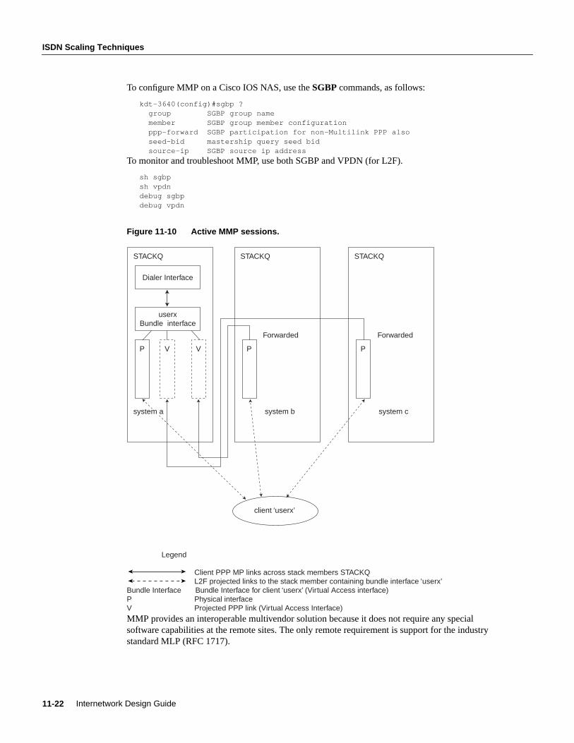
ISDN Scaling Techniques
Internetwork Design Guide11-22
To configure MMP on a Cisco IOS NAS, use theSGBP commands, as follows:
kdt-3640(config)#sgbp ? group SGBP group name member SGBP group member configuration ppp-forward SGBP participation for non-Multilink PPP also seed-bid mastership query seed bid source-ip SGBP source ip address
To monitor and troubleshoot MMP, use both SGBP and VPDN (for L2F).
sh sgbpsh vpdndebug sgbpdebug vpdn
Figure 11-10 Active MMP sessions.
MMP provides an interoperable multivendor solution because it does not require any specialsoftware capabilities at the remote sites. The only remote requirement is support for the industrystandard MLP (RFC 1717).
Dialer Interface
userxBundle interface
VP V
system a
STACKQ
P
system b
STACKQ
P
system c
STACKQ
client ‘userx’
Forwarded Forwarded
Legend
Client PPP MP links across stack members STACKQL2F projected links to the stack member containing bundle interface ‘userx’
Bundle Interface Bundle Interface for client ‘userx’ (Virtual Access interface)P Physical interfaceV Projected PPP link (Virtual Access Interface)
Designing ISDN Internetworks 11-23
ISDN Cost Containment Issues
ISDN Cost Containment IssuesAs a circuit-switched connection, ISDN is billed, or tariffed, based on usage. Given this model, theconfiguration goal is to minimize uptime by controlling the kinds of packets that bring the link up.Minimizing uptime becomes a challenge when routing protocols are used because of their need tosend regular broadcasts that contain routing information.
ISDN charges in some installations have easily exceeded $4,000/month for a single site as a resultof being poorly designed and managed. When the outrageous phone bill is received, it is too late; thecost has been occurred. Cisco highly recommends the use of proper network management to backup careful design to ensure excessive charges are not experienced. Depending on the protocols yournetwork runs, you might want to use a combination of the techniques described in this section, whichare as follows:
• Traffic Analysis
• Tariff Structure
• User Education
• Using SNMP
• Cisco Enterprise Accounting (CEA) for ISDN
• AAA Accounting
Traffic AnalysisMost ISDN solutions can remain cost effective only as long as the ISDN B channels are kept idlemost of the day. The general rule of thumb is that Frame Relay will make a more cost effectivesolution at some application-dependent number of hours per day. (The point at which it is more costeffective to use a leased-line solution depends on the cost structures for each point-to-pointapplication.)
Each internetworking application and protocol has its own set of challenges. E-mail clients may beset to periodically poll POP servers. Network Time Protocol might be desired to support clocksynchronization. To provide total control over when the DDR connections are made, the networkdesigner must carefully consider the following issues:
• Which sites can initiate connections based on traffic?
• Is dial-out required to SOHO sites? For network or workstation management?
• Which sites can terminate connections based on idle links?
• How are directory services and routing tables supported across an idle connection?
• What applications need to be supported over DDR connections? For how many users?
• What unexpected protocols might cause DDR connections? Can they be filtered?
• Are dialer filters performing as expected?
Guidelines should be provided to users as to how to avoid and/or eliminate excessive ISDN charges.These guidelines will be the result of first determining what applications are required over theseconnections. Packet-tracing tools can be used very effectivity to determine how to minimize oreliminate unnecessary DDR connections. For example,
• Sending and receiving e-mail should be manual if possible.
• Windows Networking may require periodic directory services traffic.
• AppleShare servers will need to be disconnected to avoid tickle packets.

ISDN Cost Containment Issues
Internetwork Design Guide11-24
• DB-accessing applications, such as scheduling software, may require logging out when not inuse.
Tariff StructureSome ISDN service providers charge a per-connection and per-minute charge even for local calls. Itis important to consider local and long-distance tariff charges when selecting DDR design andparameters. ISDN Callback can be used to centralize long-distance charges, which can significantlyreduce administrative overhead and provide opportunities for reduced rate structures. ISDNCallback can also enhance the security environment.
User EducationEnd users should be trained to keep their ISDN routers visible and monitor the status of their Bchannel LEDs on their BRI devices. If B channels are up when they are not using networkingapplications, they should alert network managers. User education can be very effective in helping toavoid excessive ISDN charges.
Using SNMPThe Simple Network Management Protocol (SNMP) uses management information bases (MIBs) tostore information about network events. Currently, no industry-standard ISDN MIB is available, butas of Cisco IOS Software Release 10.3(3), two Cisco ISDN MIBs are available. With these MIBs,SNMP-compliant management platforms (for example, HP OpenView or SunNet Manager) canquery Cisco routers for ISDN-related statistics.
The Cisco ISDN MIB focuses primarily on ISDN interface and neighbor information. It defines twoMIB groups: demandNbrTable and demandNbrEntry. Table 11-2 lists some of the MIB variables thatare available in the ISDN MIB. Cisco Enterprise Accounting for ISDN can provide managementaccess to Call History Data using this MIB.
Table 11-2 Cisco ISDN MIB Variables
The Cisco Call History MIB stores call information for accounting purposes. The goal is to providea historical view of an ISDN interface, including the number of calls that have been placed and calllength. Most call history MIB variables are in the ciscoCallHistory MIB group. Table 11-3 lists someof the MIB variables.
MIB Object Description
demandNbrPhysIf Index value of the physical interface that the neighbor will be called on; on anISDN interface, this is the ifIndex value of the D channel.
demandNbrMaxduration Maximum call duration in seconds.
demandNbrLastduration Duration of last call in seconds.
demandNbrAcceptCalls Number of calls accepted from the neighbor.
demandNbrRefuseCalls Number of calls from neighbor that the router has refused.

Designing ISDN Internetworks 11-25
Cisco Enterprise Accounting (CEA) for ISDN
Table 11-3 Cisco Call History Variables
The Cisco ISDN MIBs assume SNMP support on the network. If an SNMP-compliant managementplatform is present, the Cisco ISDN MIBs deliver valuable information about ISDN links. Inparticular, the Call History MIB provides critical information about ISDN uptime, which is usefulfor tracking ISDN charges.
Cisco offers a wide range of ISDN-based products in response to a variety of internetworking needs.The Cisco IOS software provides a number of features that maximize ISDN performance andminimize ISDN usage charges, such as snapshot routing, access lists, NBP filtering (for AppleTalk),and watchdog and keepalive packet control (for IPX).
Cisco Enterprise Accounting (CEA) for ISDNCEA for ISDN is a software application that runs on Windows NT. CEA for ISDN can be utilized tomonitor the ISDN Call-History-MIB and provide network managers with Call Detail Records,including cost estimates.
AAA AccountingAAA Accounting can be implemented to provide feedback of PPP Session connect times. AAAAccounting is transported to TACACS+ or RADIUS servers where the data can often be accessedwith standard SQL tools for scheduled and immediate reporting. The following command enablesAAA Accounting records for PPP sessions:
aaa accounting network stop-only
SummaryIncreasing availability and decreasing costs are making ISDN an excellent choice for manyinternetworking applications. Cisco IOS features allow the building of large and flexible ISDNsolutions. DDR is used for call initiation and termination. Virtual Profiles can be used to easily scalemass ISDN dial-in solutions. However, extra care must be taken to ensure ISDN costs are controlled.
MIB Object Description
ciscoCallHistoryStartTime The value ofsysUpTime when this call history entry was created; thisvariable can be used to retrieve all calls after a specific time.
ciscoCallHistoryCalledNumber The number that was used to place this call.
ciscoCallHistoryCallConnectionTime The value ofsysUpTime when the call was connected.
ciscoCallHistoryCallDisconnectTime The value ofsysUpTime when the call was disconnected.

Summary
Internetwork Design Guide11-26

C H A P T E R
Designing Switched LAN Internetworks 12-1
1 2
Designing Switched LANInternetworks
This chapter describes the following three technologies that network designers can use to designswitched LAN internetworks:
• LAN switching
• Virtual LANs (VLANs)
• ATM switching
Evolution from Shared to Switched NetworksIn the past, network designers had only a limited number of hardware options when purchasing atechnology for their campus networks. Hubs were for wiring closets and routers were for the datacenter or main telecommunications operations. The increasing power of desktop processors and therequirements of client-server and multimedia applications, however, have driven the need for greaterbandwidth in traditional shared-media environments. These requirements are prompting networkdesigners to replace hubs in their wiring closets with switches, as shown in Figure 12–1.
Figure 12-1 Evolution from shared to switched internetworks.
This strategy allows network managers to protect their existing wiring investments and boostnetwork performance with dedicated bandwidth to the desktop for each user. Coinciding with thewiring closet evolution is a similar trend in the network backbone. Here, the role of Asynchronous
ATM campusswitch
Cisco router
Shared hubMultilayer switch(Layers 2 and 3)
LAN switch (Layer 2) Hub
CDDI/FDDIconcentrator
Shared hubThe new backbone
The new wiring closet
Traditional backbone
Traditional wiring closet
Cisco routerRouter
RouterRouter
Si

Technologies for Building Switched LAN Internetworks
Cisco CCIE Fundamentals: Network Design12-2
Transfer Mode (ATM) is increasing as a result of standardizing protocols, such as LAN emulation(LANE), that enable ATM devices to coexist with existing LAN technologies. Network designersare collapsing their router backbones with ATM switches, which offer the greater backbonebandwidth required by high-throughput data services.
Technologies for Building Switched LAN InternetworksWith the advent of such technologies as Layer 3 switching, LAN switching, and VLANs, buildingcampus LANs is becoming more complex than in the past. Today, the following three technologiesare required to build successful campus networks:
• LAN switching technologies
— Ethernet switching—Provides Layer 2 switching and offers broadcast domain segmentationusing VLANs. This is the base fabric of the network.
— Token Ring switching—Offers the same functionality as Ethernet switching but uses TokenRing technology. You can use a Token Ring switch as either a transparent bridge orsource-route bridge.
— Copper Data Distributed Interface (CDDI)—Provides a single-attachment station (SAS) ordual-attachment station (DAS) to two Category 5 unshielded twisted-pair (UTP), 100 MbpsRJ-45 connectors.
— Fiber Distributed Data Interface (FDDI)—Provides an SAS or DAS connection to the FDDIbackbone network using two multimode, media interface connector (MIC) fiber- opticconnections.
• ATM switching technologies
ATM switching offers high-speed switching technology for voice, video, and data. Its operation issimilar to LAN switching technologies for data operations. ATM, however, offers superior voice,video, and data integration today.
• Routing technologies
Routing is a key technology for connecting LANs in a campus network. It can be either Layer 3switching or more traditional routing with Layer 3 switching features and enhanced Layer 3 softwarefeatures.
Note Switched LAN internetworks are also referred to ascampus LANs.
Role of LAN Switching Technology in Campus NetworksMost network designers are beginning to integrate switching devices into their existing shared-media networks to achieve the following goals:
• Increase the bandwidth that is available to each user, thereby alleviating congestion in theirshared-media networks.
• Employ the manageability of VLANs by organizing network users into logical workgroups thatare independent of the physical topology of wiring closet hubs. This, in turn, can reduce the costof moves, adds, and changes while increasing the flexibility of the network.
• Deploy emerging multimedia applications across different switching platforms and technologies,making them available to a variety of users.

Designing Switched LAN Internetworks 12-3
Switched Internetwork Solutions
• Provide a smooth evolution path to high-performance switching solutions, such as Fast Ethernetand ATM.
Segmenting shared-media LANs divides the users into two or more separate LAN segments,reducing the number of users contending for bandwidth. LAN switching technology, which buildsupon this trend, employsmicrosegmentation,which further segments the LAN to fewer users andultimately to a single user with a dedicated LAN segment. Each switch port provides a dedicated,10MB Ethernet segment, or dedicated 4/16MB Token Ring segment.
Segments are interconnected by internetworking devices that enable communication between LANswhile blocking other types of traffic. Switches have the intelligence to monitor traffic and compileaddress tables, which then allows them to forward packets directly to specific ports in the LAN.Switches also usually provide nonblocking service, which allows multiple conversations (trafficbetween two ports) to occur simultaneously.
Switching technology is quickly becoming the preferred solution for improving LAN traffic for thefollowing reasons:
• Unlike hubs and repeaters, switches allow multiple data streams to pass simultaneously.
• Switches have the capability through microsegmentation to support the increased speed andbandwidth requirements of emerging technologies.
• Switches deliver dedicated bandwidth to users through high-density group switched andswitched 10BaseT or 100BaseT Ethernet, flexible 10/100 BaseT Ethernet, fiber-based FastEthernet, Fast EtherChannel, Token Ring, CDDI/FDDI, and ATM LAN Emulation (LANE).
Switched Internetwork SolutionsNetwork designers are discovering, however, that many products offered as switched internetworksolutions are inadequate. Some offer a limited number of hardware platforms with little or no systemintegration with the current infrastructure. Others require complete abandonment of all investmentsin the current network infrastructure. To be successful, a switched internetwork solution mustaccomplish the following:
• Leverage strategic investments in the existing communications infrastructure while increasingavailable bandwidth.
• Reduce the costs of managing network operations.
• Offer options to support multimedia applications and other high-demand traffic across a varietyof platforms.
• Provide scalability, traffic control, and security that is at least as good or better than that of today’srouter-based internetworks.
• Provide support for embedded remote monitoring (RMON) agent.
The key to achieving these benefits is to understand the role of the internetworking softwareinfrastructure within the switched internetworks. Within today’s networks, routers allow for theinterconnection of disparate LAN and WAN technologies, while also implementing security filtersand logical firewalls. It is these capabilities that have allowed current internetworks to scale globallywhile remaining stable and robust.
As networks evolve toward switched internetworks, similar logical internetworking capabilities arerequired for stability and scalability. Although LAN and ATM switches provide great performanceimprovements, they also raise new internetworking challenges. Switched internetworks mustintegrate with existing LAN and WAN networks. Such services as VLANs, which will be deployedwith switched internetworks, also have particular internetworking requirements.

Components of the Switched Internetworking Model
Cisco CCIE Fundamentals: Network Design12-4
A true switched internetwork, therefore, is more than a collection of boxes. Rather, it consists of asystem of devices integrated and supported by an intelligent internetworking software infrastructure.Presently, this network intelligence is centralized within routers. However, with the advent ofswitched internetworks, the intelligence will often be dispersed throughout the network, reflectingthe decentralized nature of switching systems. The need for an internetworking infrastructure,however, will remain.
Components of the Switched Internetworking ModelA switched internetwork is composed of the following three basic components:
• Physical switching platforms
• A common software infrastructure
• Network management tools and applications
Cisco provides network designers with a complete, end-to-end solution for implementing andmanaging scalable, robust, switched internetworks.
Scalable Switching PlatformsThe first component of the switched internetworking model is the physical switching platform. Thiscan be an ATM switch, a LAN switch, or a router.
ATM SwitchesAlthough switched internetworks can be built with a variety of technologies, many networkdesigners will deploy ATM in order to utilize its unique characteristics. ATM provides scalablebandwidth that spans both LANs and WANs. It also promises Quality of Service (QoS)guarantees—bandwidth on demand—that can map into and support higher-level protocolinfrastructures for emerging multimedia applications and provide a common, multiservice networkinfrastructure.
ATM switches are one of the key components of ATM technology. All ATM switches, however, arenot alike. Even though all ATM switches perform cell relay, ATM switches differ markedly in thefollowing capabilities:
• Variety of interfaces and services that are supported
• Redundancy
• Depth of ATM internetworking software
• Sophistication of traffic management mechanism
• Blocking and non-blocking switching fabrics
• SVC and PVC support
Just as there are routers and LAN switches available at various price/performance points withdifferent levels of functionality, ATM switches can be segmented into the following four distincttypes that reflect the needs of particular applications and markets:
• Workgroup ATM switches
• Campus ATM switches
• Enterprise ATM switches

Designing Switched LAN Internetworks 12-5
Scalable Switching Platforms
• Multiservice access switches
As Figure 12–2 shows, Cisco offers a complete range of ATM switches.
Figure 12-2 Different types of ATM switches.
Workgroup and Campus ATM SwitchesWorkgroup ATM switches are optimized for deploying ATM to the desktop over low-cost ATMdesktop interfaces, with ATM signaling interoperability for ATM adapters and QoS support formultimedia applications.
Campus ATM switchesare generally used for small-scale ATM backbones (for example, to link ATMrouters or LAN switches). This use of ATM switches can alleviate current backbone congestionwhile enabling the deployment of such new services as VLANs. Campus switches need to supporta wide variety of both local backbone and WAN types but be price/performance optimized for thelocal backbone function. In this class of switches, ATM routing capabilities that allow multipleswitches to be tied together is very important. Congestion control mechanisms for optimizingbackbone performance is also important.
Enterprise ATM SwitchesEnterprise ATM switches are sophisticated multiservice devices that are designed to form the corebackbones of large, enterprise networks. They are intended to complement the role played by today’shigh-end multiprotocol routers. Enterprise ATM switches, much as campus ATM switches, are usedto interconnect workgroup ATM switches and other ATM-connected devices, such as LAN switches.Enterprise-class switches, however, can act not only as ATM backbones but can serve as the singlepoint of integration for all of the disparate services and technology found in enterprise backbones
LightStream 1010
CatalystLANswitches
LightStream1010
LightStream1010
LightStream1010
Service multiplexer
Multiservice Access ATM
Enterprise ATM
Campus ATM
Workgroup ATM
Cisco routers
WAN
StrataCom
StrataCom
LightStream 1010
Router

Components of the Switched Internetworking Model
Cisco CCIE Fundamentals: Network Design12-6
today. By integrating all of these services onto a common platform and a common ATM transportinfrastructure, network designers can gain greater manageability while eliminating the need formultiple overlay networks.
LAN SwitchesA LAN switch is a device that typically consists of many ports that connect LAN segments (Ethernetand Token Ring) and a high-speed port (such as 100-Mbps Ethernet, Fiber Distributed Data Interface[FDDI], or 155-Mbps ATM). The high-speed port, in turn, connects the LAN switch to other devicesin the network.
A LAN switch has dedicated bandwidth per port, and each port represents a different segment. Forbest performance, network designers often assign just one host to a port, giving that host dedicatedbandwidth of 10 Mbps, as shown in Figure 12–3, or 16 Mbps for Token Ring networks.
Figure 12-3 Sample LAN switch configuration.
When a LAN switch first starts up and as the devices that are connected to it request services fromother devices, the switch builds a table that associates the MAC address of each local device with theport number through which that device is reachable. That way, when Host A on Port 1 needs totransmit to Host B on Port 2, the LAN switch forwards frames from Port 1 to Port 2, thus sparingother hosts on Port 3 from responding to frames destined for Host B. If Host C needs to send data toHost D at the same time that Host A sends data to Host B, it can do so because the LAN switch canforward frames from Port 3 to Port 4 at the same time it forwards frames from Port 1 to Port 2.
Whenever a device connected to the LAN switch sends a packet to an address that is not in the LANswitch’s table (for example, to a device that is beyond the LAN switch), or whenever the devicesends a broadcast or multicast packet, the LAN switch sends the packet out all ports (except for theport from which the packet originated)—a technique known asflooding.
Because they work like traditional “transparent” bridges, LAN switches dissolve previouslywell-defined workgroup or department boundaries. A network built and designed only with LANswitches appears as aflat network topology consisting of a single broadcast domain. Consequently,these networks are liable to suffer the problems inherent in flat (orbridged) networks—that is, theydo not scale well. Note, however, that LAN switches that support VLANs are more scalable thantraditional bridges.
Multiservice Access SwitchesBeyond private networks, ATM platforms will also be widely deployed by service providers both ascustomer premises equipment (CPE) and within public networks. Such equipment will be used tosupport multiple MAN and WAN services—for example, Frame Relay switching, LAN
Port 1
High-speed port
Port 3
Port 4Ethernet
Ethernet
Ethernet
Ethernet
Host D
Port n
Port 2
Host A
Host B
Host C

Designing Switched LAN Internetworks 12-7
Common Software Infrastructure
interconnect, or public ATM services—on a common ATM infrastructure. Enterprise ATM switcheswill often be used in these public network applications because of their emphasis on high availabilityand redundancy, and their support of multiple interfaces.
Routing PlatformsIn addition to LAN switches and ATM switches, typically network designers use routers as one ofthe components in a switched internetwork infrastructure. While LAN switches are being added towiring closets to increase bandwidth and to reduce congestion in existing shared-media hubs,high-speed backbone technologies, such as ATM switching and ATM routers are being deployed inthe backbone. Within a switched internetwork, routing platforms also allow for the interconnectionof disparate LAN and WAN technologies while also implementing broadcast filters and logicalfirewalls. In general, if you need advanced internetworking services, such as broadcast firewallingand communication between dissimilar LANs, routers are necessary.
Common Software InfrastructureThe second level of a switched internetworking model is a common software infrastructure. Thefunction of this software infrastructure is to unify the variety of physical switching platforms: LANswitches, ATM switches, and multiprotocol routers. Specifically, the software infrastructure shouldperform the following tasks:
• Monitor the logical topology of the network
• Logically route traffic
• Manage and control sensitive traffic
• Provide firewalls, gateways, filtering, and protocol translation
Cisco offers network designers Cisco Internetwork Operating System (Cisco IOS) switchingsoftware. This subset of the Cisco IOS software is optimized for switching and provides the unifyingelement to Cisco’s line of switching platforms in a switched internetwork. The Cisco IOS softwareis found on standalone routers, router modules for shared-media hubs, PC and workstations fileservers, multiservice WAN access switches, LAN switches, ATM switches, and ATM-capablePBXs. It provides optional levels of routing and switching across a switched internetwork in additionto new capabilities, such as VLANs, ATM internetworking software services, multilayer switching,extensions to support new networked multimedia applications, and traffic management and analysistools.
VLANsA VLAN consists of several end systems, either hosts or network equipment (such as switches androuters), all of which are members of a single logical broadcast domain. A VLAN no longer hasphysical proximity constraints for the broadcast domain. This VLAN is supported on various piecesof network equipment (for example, LAN switches) that support VLAN trunking protocols betweenthem. Each VLAN supports a separate Spanning Tree (IEEE 802.1d).
First-generation VLANs are based on various OSI Layer 2 bridging and multiplexing mechanisms,such as IEEE 802.10, LAN Emulation (LANE), and Inter-Switch Link (ISL), that allow theformation of multiple, disjointed, overlaid broadcast groups on a single network infrastructure.Figure 12-4 shows an example of a switched LAN network that uses VLANs. Layer 2 of the OSIreference model provides reliable transit of data across a physical link. The data link layer isconcerned with physical addressing, network topology, line discipline, error notification, ordereddelivery frames, and flow control. The IEEE has divided this layer into two sublayers: the MACsublayer and the LLC sublayer, sometimes simply called link layer.

Components of the Switched Internetworking Model
Cisco CCIE Fundamentals: Network Design12-8
Figure 12-4 Typical VLAN topology.
In Figure 12-4, 10-Mbps Ethernet connects the hosts on each floor to switches A, B, C, and D.100-Mbps Fast Ethernet connects these to Switch E. VLAN 10 consists of those hosts on Ports 6 and8 of Switch A and Port 2 on Switch B. VLAN 20 consists of those hosts that are on Port 1 ofSwitch A and Ports 1 and 3 of Switch B.
VLANs can be used to group a set of related users, regardless of their physical connectivity. Theycan be located across a campus environment or even across geographically dispersed locations. Theusers might be assigned to a VLAN because they belong to the same department or functional team,or because data flow patterns among them is such that it makes sense to group them together. Note,however, that without a router, hosts in one VLAN cannot communicate with hosts in anotherVLAN.
Network Management Tools and ApplicationsThe third and last component of a switched internetworking model consists of network managementtools and applications. As switching is integrated throughout the network, network managementbecomes crucial at both the workgroup and backbone levels. Managing a switch-based networkrequires a radically different approach than managing traditional hub and router-based LANs.
100 Mbps
Third floor
Second floor
First floor
100 Mbps
Switch D
Switch C
Switch BVLAN 20
VLAN 10
VLAN 20
Switch E
Fourth floor
Fifth floor
Sixth floor 10 Mbps
Switch A6
VLAN 20
VLAN 10
VLAN 10
100 Mbps
100 Mbps
10 Mbps
10 Mbps
10 Mbps
10 Mbps
10 Mbps
2/2
1
8
21
3

Designing Switched LAN Internetworks 12-9
Cisco Switched Internetworking Products
As part of designing a switched internetwork, network designers must ensure that their design takesinto account network management applications needed to monitor, configure, plan, and analyzeswitched internetwork devices and services. Cisco offers such tools for emerging switchedinternetworks.
Cisco Switched Internetworking ProductsCisco offers the following products that meet the needs of a switched internetwork, all discussed inthe following sections:
• Cisco ATM Switches
• Cisco LAN Switches
• Cisco Routing Platforms
Cisco ATM SwitchesCisco’s LightStream 1010 family of ATM switches is specifically designed for workgroup andcampus backbone deployment. It incorporates support for the latest ATM Forum specifications andbuilds upon the Cisco IOS software. The LightStream 1010 is a five-slot, modular switch thatfeatures the option of dual, load-sharing, hot-swappable power supplies, 5-Gbps of shared memory,nonblocking switch fabric, and 65,536 cells of shared ATM cell buffers. It supports a wide range ofmodular, hot-swappable, desktop, backbone, and wide-area ATM interfaces. These characteristicsallow network managers to deploy it in a variety of scenarios ranging from high-density, 155-Mbpscopper UTP-5 workgroups to high-performance OC-12 backbones.
In order to support the bursty, best-effort traffic generated by LAN switches and routes, theLightStream 1010 provides advanced traffic management mechanisms. The LightStream 1010’sintelligent early packet discard mechanism allows it to discard entire packets rather than individualcells when necessary, which greatly increases performance for current protocols, such as TCP/IP andIPX. It also supports the latest ATM Forum Available Bit Rate (ABR) congestion controlspecifications, which allows the LightStream 1010 to slow traffic sources before congestion becomesexcessive. Because of its support for the ATM Forum private network-network interface (PNNI)protocols, networks of LightStream 1010s can scale to hundreds of nodes.
In addition, the LightStream 1010 offers a high degree of manageability. Advanced port snoopingand connection-steering capabilities allow the connections on any port to be directed to a monitorport for analysis by an external ATM analyzer. This capability is critical for the monitoring andtroubleshooting of ATM switching systems, which unlike shared-media LANs, cannot be monitoredeasily with external devices. Simple Network Management Protocol (SNMP) monitoring andconfiguration invoked through the CiscoView graphical user interface (GUI) device configurationapplications and the AtmDirector CiscoWorks ATM system management application, allow forcomprehensive network management.
By building on the Cisco IOS software, the LightStream 1010 switch also shares the advancedserviceability capabilities found today on Cisco’s multiprotocol routers. As with all Cisco routers,the LightStream 1010 switch supports such protocols as BOOTP, DHCP, Telnet, and Trivial FileTransfer Protocol (TFTP) for remote access and autoconfiguration. It also offers the accessprotections of the Cisco IOS software, from multiple password levels to TACACS for remote accessvalidation, to preclude unauthorized changes to the switch configuration. These capabilities areclearly essential to safeguard the operation of the mission-critical campus backbones in which theLightStream 1010 will typically be deployed.

Cisco Switched Internetworking Products
Cisco CCIE Fundamentals: Network Design12-10
The Cisco/StrataCom BPX/AXIS is a powerful broadband 9.6-Gbps ATM switch designed to meetthe demanding, high-traffic needs of a large private enterprise or public service provider. TheCisco/StrataCom IGX is a 1.2-Gbps ATM-based enterprise WAN switch that can be used to provideenterprise WAN features in your internetwork. For more information on these enterprise ATMswitches, see Chapter 8, “Designing ATM Internetworks.”
Cisco LAN SwitchesCisco’s Catalyst family is a comprehensive line of high-performance switches designed to helpnetwork managers easily migrate from traditional shared LANs to fully switched internetworks. TheCatalyst family delivers the varying levels of flexibility and cost-effectiveness required for today’sdesktop, workgroup, and backbone applications while enabling enterprise-wide switchedinternetworks. Using these LAN switches instead of traditional shared hubs increase performanceand provides new capabilities, such as VLANs.
Figure 12–5 shows an example of switches that can be used in a campus backbone. In this example,the Cisco switches are used to interconnect the four buildings that comprise the campus network.
Figure 12-5 LAN switches in a campus backbone.
Table 12–1 summarizes the LAN switches that Cisco offers.
Catalyst5000
Building 1
Catalyst5000
Building 2 Building 4
Building 3
Catalyst5000
Catalyst5000

Designing Switched LAN Internetworks 12-11
Cisco LAN Switches
Table 12-1 List of Cisco LAN Switches
Cisco LAN Switch Description
Catalyst 5500 switchingsystem
The Catalyst 5500 switch chassis has 13 slots. Slot 1 is for the Supervisor Engine II modelwhich provides switching, local and remote management, and dual Fast Ethernetinterfaces. Slot 2 contains an additional redundant Supervisor Engine II in case the firstmodule fails.A failure of the active Supervisor Engine II is detected by the standby module, which takescontrol of the Supervisor Engine II switching functions. If a redundant Supervisor EngineII is not required, slot 2 is available for any interface module.
The Catalyst 5500 has a 3.6-Gbps media-independent switch fabric anda 5-Gbps cell-switch fabric. The backplane provides the connection between powersupplies, Supervisor Engine II, interface modules, and backbone module. The 3.6-Gbpsmedia-independent fabric supports Ethernet, Fast Ethernet, FDDI/CDDI, ATM LANEmulation, and RSM modules. The 5-Gbps cell-based fabric supports an ATM switchprocessor (ASP) module and ATM port adapter modules (PAMS).
Route switch module The Cisco Catalyst 5000 series route switch module builds upon the Route SwitchProcessor (RSP) featured in Cisco’s 7500 routing platform. The route switch moduleprovides high-performance multilayer switching and routing services between switchedVirtual LANs (VLANs), emulated LANs (ELANs) within an Asynchronous TransferMode (ATM) fabric, or across mixed media via an optional Versatile Interface Processor(VIP) and port adapters.
Catalyst 5000 switchingsystem
A modular switching platform that meets high performance needs, bandwidth-intensivenetworking switching applications. It offers five slots that can be populated with anycombination of 10BaseT, 10BaseFL modules, switched 10-Mbps Fast Ethernet, FDDI, orATM modules.
It delivers high performance both for client and server connections as well as for backboneconnections. Its switching backplane operates at 1.2 Gbps and provides nonblockingperformance for all switched 10-Mbps Ethernet interfaces.
It supports enterprise-wide VLAN communications across Ethernet, Fast Ethernet,CDDI/FDDI, and ATM connections via the following protocols: ISL for Fast Ethernetinterfaces, 802.10 for FDDI interfaces, and LANE v1.0 for ATM.
Catalyst 3000 stackableswitching system
A 16-port 10BaseT switch that has two open expansion bays that can be populated with100BaseTX/FX, 10BaseFL, 10BaseT, 100VG-AnyLAN, or ATM. With the Matrixmodule, up to eight Catalyst 3000 switches can be stacked together as one logicalswitching system. The Catalyst 3000 system can also be populated with the Catalyst 3011WAN router module.
A fully loaded Catalyst 3000 system can support up to 192 10BaseT ports, or 12810BaseT ports with 16 high-speed ports. Supports up to 64 VLANs within the stack. Alsosupports ISL for Fast Ethernet, and ATM LANE.
Catalyst 2900 FastEthernet switch
A 14-port, fixed-configuration, Fast Ethernet switch that provides media-rate Fast Ethernetswitching in backbone, server cluster, and high-performance workgroup applications. Itssoftware architecture combines superior traffic throughput, complete VLAN solutions,traffic management, and fault tolerance.
Catalyst 1800 TokenRing switch
A Token Ring switch that has 16 dedicated or shared ports in the base unit plus twofeature-card slots that is designed for the workgroup switching environment. Using thefour-port Token Ring unshielded twisted-pair/shielded twisted-pair (UTP/STP) featurecards, it supports eight additional Token Ring ports.

Switched LAN Network Designs
Cisco CCIE Fundamentals: Network Design12-12
Cisco Routing PlatformsBoth the Cisco 7000 and Cisco 4000 family of multiprotocol routers are particularly well suited forswitched internetworking. In particular, the first native-mode ATM router interface, the ATMInterface Processor (AIP) for the Cisco 7000 family of routers, is a key enabler for integratingexisting LAN and WAN networks with evolving, ATM-based switched internetworks.
The sophisticated ATM signaling and traffic management capabilities of the AIP also allows it toplay a crucial role in the deployment of new services such as VLANs. The AIP, a key enabler for theproduction deployment of switched internetworks, allows VLANs to internetwork either with eachother or with external networks. The Cisco 4000 family of multiprotocol routers also support suchcapabilities, thereby providing network designers with a wide choice of price/performance points forATM-capable routers.
Because the Cisco 7000 and Cisco 4000 families support FDDI, Fast Ethernet, and ATM, theyprovide network designers with a full set of options for high-speed connectivity. Both router familiesalso support routing between VLANs on all media for ease of migration.
Switched LAN Network DesignsA successful switched internetworking solution must combine the benefits of both routers andswitches in every part of the network, as well as offer a flexible evolution path from shared-medianetworking to switched internetworks.
In general, incorporating switches in campus network designs results in the following benefits:
• High bandwidth
• Quality of Service (QoS)
• Low cost
• Easy configuration
If you need advanced internetworking services, however, routers are necessary. Routers offer thefollowing services:
• Broadcast firewalling
Catalyst 1900 andCatalyst 2820Ethernet switches
Ideally suited to replace shared 10BaseT hubs in the wiring closet with feature-richswitched Ethernet capability to the desktop. The Catalyst 1900 Ethernet switch features 25switched Ethernet ports providing attachment to individual workstations and 10BaseThubs. It also has two 100BaseT ports for high speed connectivity to servers andbackbones.
The Catalyst 2820 Ethernet switch has 25 switched Ethernet ports and two high-speedexpansion slots. Field-installable modules provide configuration, wiring, and backboneflexibility with a choice of 100BaseT, FDDI, and future ATM modules available, whichsupport Category 5 UTP or fiber-optic cabling.
Catalyst 1200workgroup switch
A multilayer switch for workgroup applications that can benefit from OSI Layer 3 as wellas Layer 2 capabilities. It offers eight 10BaseT or 10BaseFL ports and one expansion slot.The expansion slot can be populated with either one A/B CDDI interface or one A/BFDDI interface. IP routing only supports 802.10 over FDDI VLANs. In addition tomeeting a wide range of performance needs for Ethernet and FDDI, it offers such uniquefeatures as embedded Remote Monitoring (RMON) functionality, which helps networkmanagers monitor and control the growth and changes of client-server workgroups.
Cisco LAN Switch Description

Designing Switched LAN Internetworks 12-13
Comparison of LAN Switches and Routers
• Hierarchical addressing
• Communication between dissimilar LANs
• Fast convergence
• Policy routing
• QoS routing
• Security
• Redundancy and load balancing
• Traffic flow management
• Multimedia group membership
Some of these router services will be offered by switches in the future. For example, support formultimedia often requires a protocol, such as Internet Group Management Protocol (IGMP), thatallows workstations to join a group that receives multimedia multicast packets. In the future, Ciscowill allow switches to participate in this process by using the Cisco Group Management Protocol(CGMP). One router will still be necessary, but you will not need a router in each departmentbecause CGMP switches can communicate with the router to determine whether any of theirattached users are part of a multicast group.
Switching and bridging sometimes can result in nonoptimal routing of packets. This is because everypacket must go through the root bridge of the spanning tree. When routers are used, the routing ofpackets can be controlled and designed for optimal paths. Cisco now provides support for improvedrouting and redundancy in switched environments by supporting one instance of the spanning treeper VLAN.
When designing switched LAN networks, you should consider the following:
• Comparison of LAN Switches and Routers
• Benefits of LAN Switches (Layer 2 Services)
• Benefits of Routers (Layer 3 Services)
• Benefits of VLANs
• VLAN Implementation
• General Network Design Principles
• Switched LAN Network Design Principles
Comparison of LAN Switches and RoutersThe fundamental difference between a LAN switch and a router is that the LAN switch operates atLayer 2 of the OSI model and the router operates at Layer 3. This difference affects the way thatLAN switches and routers respond to network traffic. This section compares LAN switches androuters with regard to the following network design issues:
• Loops
• Convergence
• Broadcasts
• Subnetworking
• Security

Switched LAN Network Designs
Cisco CCIE Fundamentals: Network Design12-14
• Media Dependence
Note Because routers implement Layer 2 functionality and switches are beginning to implementLayer 3 functionality, the functions of a LAN switch and a router are merging.
LoopsSwitched LAN topologies are susceptible to loops, as shown in Figure 12–6.
Figure 12-6 Switched LAN topology with loops.
In Figure 12–6, it is possible for packets from Client X to be switched by Switch A and then forSwitch B to put the same packet back on to LAN 1. In this situation, packets loop and undergomultiple replications. To prevent looping and replication, topologies that may contain loops need torun the Spanning-Tree Protocol. The Spanning-Tree Protocol uses the spanning-tree algorithm toconstruct topologies that do not contain any loops. Because the spanning-tree algorithm placescertain connections in blocking mode, only a subset of the network topology is used for forwardingdata. In contrast, routers provide freedom from loops and make use of optimal paths.
ConvergenceIn transparent switching, neighboring switches make topology decisions locally based on theexchange of Bridge Protocol Data Units (BPDUs). This method of making topology decisionsmeans that convergence on an alternative path can take an order of magnitude longer than in a routedenvironment.
In a routed environment, sophisticated routing protocols, such as Open Shortest Path First (OSPF)and Enhanced Interior Gateway Routing Protocol (Enhanced IGRP), maintain concurrenttopological databases of the network and allow the network to converge quickly.
BroadcastsLAN switches do not filter broadcasts, multicasts, or unknown address frames. The lack of filteringcan be a serious problem in modern distributed networks in which broadcast messages are used toresolve addresses and dynamically discover network resources such as file servers. Broadcastsoriginating from each segment are received by every computer in the switched internetwork. Mostdevices discard broadcasts because they are irrelevant, which means that large amounts of bandwidthare wasted by the transmission of broadcasts.
In some cases, the circulation of broadcasts can saturate the network so that there is no bandwidthleft for application data. In this case, new network connections cannot be established, and existingconnections may be dropped (a situation known as abroadcast storm). The probability of broadcast
Server YLAN 1
Client X
Packet for server Y
Switch C
Switch B
Switch A
Data path

Designing Switched LAN Internetworks 12-15
Comparison of LAN Switches and Routers
storms increases as the switched internetwork grows. Routers do not forward broadcasts, and,therefore, are not subject to broadcast storms. For more information about the impact of broadcasts,see Appendix E, “Broadcasts in Switched LAN Internetworks.”
SubnetworkingTransparently switched internetworks are composed of physically separate segments, but arelogically considered to be one large network (for example, one IP subnet). This behavior is inherentto the way that LAN switches work—they operate at OSI Layer 2 and have to provide connectivityto hosts as if each host were on the same cable. Layer 2 addressing assumes a flat address space withuniversally unique addresses.
Routers operate at OSI Layer 3, so can formulate and adhere to a hierarchical addressing structure.Routed networks can associate a logical addressing structure to a physical infrastructure so that eachnetwork segment has, for example, a TCP/IP subnet or IPX network. Traffic flow on routed networksis inherently different from traffic flow on switched networks. Routed networks have more flexibletraffic flow because they can use the hierarchy to determine optimal paths depending on dynamicfactors such as network congestion.
SecurityInformation is available to routers and switches that can be used to create more secure networks.LAN switches may use custom filters to provide access control based on destination address, sourceaddress, protocol type, packet length, and offset bits within the frame. Routers can filter on logicalnetwork addresses and provide control based on options available in Layer 3 protocols. For example,routers can permit or deny traffic based on specific TCP/IP socket information for a range of networkaddresses.
Media DependenceTwo factors need to be considered with regard to mixed-media internetworks. First, the maximumtransfer unit (MTU) differs for various network media. Table 12–2 lists the maximum frame size forvarious network media.
Table 12-2 MTUs for Various Network Media
When LANs of dissimilar media are switched, hosts must use the MTU that is the lowest commondenominator of all the switched LANs that make up the internetwork. This requirement limitsthroughput and can seriously compromise performance over a relatively fast link, such as FDDI orATM. Most Layer 3 protocols can fragment and reassemble packets that are too large for a particularsubnetwork, so routed networks can accommodate different MTUs, which maximizes throughput.
Media Minimum Valid Frame Maximum Valid Size
Ethernet 64 bytes 1518 bytes
Token Ring 32 bytes 16 KB theoretical, 4 KB normal
Fast Ethernet 64 bytes 1518 bytes
FDDI 32 bytes 4400 bytes
ATM LANE 64 bytes 1518 bytes
ATM Classical IP 64 bytes 9180 bytes
Serial HDLC 14 bytes No limit, 4.5 KB normal

Switched LAN Network Designs
Cisco CCIE Fundamentals: Network Design12-16
Second, because they operate at Layer 2, switches must use a translation function to switch betweendissimilar media. The translation function can result in serious problems such as non-canonicalversus canonical Token Ring-to-Ethernet MAC format conversion. One issue with moving data froma Token Ring to a Ethernet network is Layer 2 addressing. Token Ring devices read the Layer 2 MACaddress as most significant bit starting from left to right. Ethernet devices read the Layer 2 MACaddress as most significant bit starting from right to left.
By working at Layer 3, routers are essentially independent of the properties of any physical mediaand can use a simple address resolution algorithm (such asNovell-node-address= MAC-address) ora protocol, such as the Address Resolution Protocol (ARP), to resolve differences between Layer 2and Layer 3 addresses.
Benefits of LAN Switches (Layer 2 Services)An individual Layer 2 switch might offer some or all of the following benefits:
• Bandwidth—LAN switches provide excellent performance for individual users by allocatingdedicated bandwidth to each switch port (for example, each network segment). This technique isknown asmicrosegmenting.
• VLANs—LAN switches can group individual ports into logical switched workgroups calledVLANs, thereby restricting the broadcast domain to designated VLAN member ports. VLANsare also known as switched domains and autonomous switching domains. Communicationbetween VLANs requires a router.
• Automated packet recognition and translation—Cisco’s unique Automatic Packet Recognitionand Translation (APaRT) technology recognizes and converts a variety of Ethernet protocolformats into industry-standard CDDI/FDDI formats. With no changes needed in either client orserver end stations the Catalyst solution can provide an easy migration to 100-Mbps server accesswhile preserving the user’s investment in existing shared 10Base-T LANs.
Benefits of Routers (Layer 3 Services)Because routers use Layer 3 addresses, which typically have structure, routers can use techniques(such as address summarization) to build networks that maintain performance and responsiveness asthey grow in size. By imposing structure (usually hierarchical) on a network, routers can effectivelyuse redundant paths and determine optimal routes even in a dynamically changing network. Thissection describes the router functions that are vital in switched LAN designs:
• Broadcast and Multicast Control
• Broadcast Segmentation
• Media Transition
Broadcast and Multicast ControlRouters control broadcasts and multicasts in the following ways:
• By caching the addresses of remote hosts. When a host sends a broadcast packet to obtain theaddress of a remote host that the router already knows about, the router responds on behalf of theremote host and drops the broadcast packet (sparing hosts from having to respond to it).
• By caching advertised network services. When a router learns of a new network service, it cachesthe necessary information and does not forward broadcasts related to it. When a client of thatnetwork service sends a broadcast to locate that service, the router responds on behalf of thatservice and drops the broadcast packet (sparing hosts from having to respond to it). For example,

Designing Switched LAN Internetworks 12-17
Benefits of VLANs
Novell clients use broadcasts to find local services. In a network without a router, every serverresponds to every client broadcast by multicasting its list of services. Routers manage Novellbroadcasts by collecting services not local to the switch and sending out periodic updates thatdescribe the services offered on the entire network. Each router sends out one frame for everyseven services on the network.
• By providing special protocols, such as the IGMP and Protocol Independent Multicast (PIM).These new protocols allow a multicasting application to “negotiate” with routers, switches, andclients to determine the devices that belong to a multicast group. This negotiation helps limit thescope and impact of the multicast stream on the network as a whole. For information about IPmulticasting, see Chapter 13, “Designing Internetworks for Multimedia.”
Successful network designs contain a mix of appropriately scaled switching and routing. Given theeffects of broadcast radiation on CPU performance, well-managed switched LAN designs mustinclude routers for broadcast and multicast management.
Broadcast SegmentationIn addition to preventing broadcasts from radiating throughout the network, routers are alsoresponsible for generating services to each LAN segment. The following are examples of servicesthat the router provides to the network for a variety of protocols:
• IP—Proxy ARP and Internet Control Message Protocol (ICMP)
• IPX—SAP table updates
• AppleTalk—ZIP table updates
• Network management—SNMP queries
In a flat virtual network, a single router would be bombarded by myriad requests needing replies,severely taxing its processor. Therefore, the network designer needs to consider the number ofrouters that can provide reliable services to a given subset of VLANs. Some type of hierarchicaldesign needs to be considered.
Media TransitionIn the past, routers have been used to connect networks of different media types, taking care of theOSI Layer 3 address translations and fragmentation requirements. Routers continue to perform thisfunction in switched LAN designs. Most switching is done within like media (such as Ethernet,Token Ring, and FDDI switches) with some capability of connecting to another media type.However, if a requirement for a switched campus network design is to provide high-speedconnectivity between unlike media, routers play a significant part in the design.
Benefits of VLANsIn a flat, bridged network all broadcast packets generated by any node in the network are sent to andreceived by all other network nodes. The ambient level of broadcasts generated by the higher layerprotocols in the network—known asbroadcast radiation—will typically restrict the total number ofnodes that the network can support. In extreme cases, the effects of broadcast radiation can be sosevere that an end station spends all of its CPU power on processing broadcasts.
VLANs have been designed to address the following problems inherent in a flat, bridged network:
• Scalability issues of a flat network topology
• Simplification of network management by facilitating network reconfigurations

Switched LAN Network Designs
Cisco CCIE Fundamentals: Network Design12-18
VLANs solve some of the scalability problems of large flat networks by breaking a single bridgeddomain into several smaller bridged domains, each of which is a virtual LAN. Note that each virtualLAN is itself constrained by the scalability issues described in Appendix E, “Broadcasts in SwitchedLAN Internetworks.” It is insufficient to solve the broadcast problems inherent to a flat switchednetwork by superimposing VLANs and reducing broadcast domains. VLANs without routers do notscale to large campus environments. Routing is instrumental in the building of scalable VLANs andis the only way to impose hierarchy on the switched VLAN internetwork.
VLANs offer the following features:
• Broadcast control—Just as switches isolate collision domains for attached hosts and onlyforward appropriate traffic out a particular port, VLANs refine this concept further and providecomplete isolation between VLANs. A VLAN is a bridging domain, and all broadcast andmulticast traffic is contained within it.
• Security—VLANs provide security in two ways:
— High-security users can be grouped into a VLAN, possibly on the same physical segment,and no users outside of that VLAN can communicate with them.
— Because VLANs are logical groups that behave like physically separate entities, inter-VLAN communication is achieved through a router. When inter-VLAN communicationoccurs through a router, all the security and filtering functionality that routers traditionallyprovide can be used because routers are able to look at OSI Layer 3 information. In the caseof nonroutable protocols, there can be no inter-VLAN communication. All communicationmust occur within the same VLAN.
• Performance—The logical grouping of users allows, for example, an engineer making intensiveuse of a networked CAD/CAM station or testing a multicast application to be assigned to aVLAN that contains just that engineer and the servers he or she needs. The engineer’s work doesnot affect the rest of the engineering group, which results in improved performance for theengineer (by being on a dedicated LAN) and improved performance for the rest of theengineering group (whose communications are not slowed down by the engineer’s use of thenetwork).
• Network management—The logical grouping of users, divorced from their physical orgeographic locations, allows easier network management. It is no longer necessary to pull cablesto move a user from one network to another. Adds, moves, and changes are achieved byconfiguring a port into the appropriate VLAN. Expensive, time-consuming recabling to extendconnectivity in a switched LAN environment is no longer necessary because networkmanagement can be used to logically assign a user from one VLAN to another.
VLAN ImplementationThis section describes the different methods of creating the logical groupings (or broadcast domains)that make up various types of VLANs. There are three ways of defining a VLAN:
• By port—Each port on the switch can support only one VLAN. With port-based VLANs, noLayer 3 address recognition takes place, so Internet Protocol (IP), Novell, and AppleTalknetworks must share the same VLAN definition. All traffic within the VLAN is switched, andtraffic between VLANs is routed (by an external router or by a router within the switch). Thistype of VLAN is also known as asegment-based VLAN.
• By protocol—VLANs based on network addresses (that is, OSI Layer 3 addresses) candifferentiate between different protocols, allowing the definition of VLANs to be made on aper-protocol basis. With network address-based VLANs, it will be possible to have a differentvirtual topology for each protocol, with each topology having its own set of rules, firewalls, and

Designing Switched LAN Internetworks 12-19
VLAN Implementation
so forth. Routing between VLANs comes automatically, without the need for an external routeror card. Network address-based VLANs will mean that a single port on a switch can support morethan one VLAN. This type of VLAN is also known as avirtual subnet VLAN.
• By a user-defined value—This type of VLAN is typically the most flexible, allowing VLANs tobe defined based on the value of any field in a packet. For example, VLANs could be defined ona protocol basis or could be dependent on a particular IPX or NetBIOS service. The simplest formof this type of VLAN is to group users according to their MAC addresses.
Cisco’s initial method of implementing VLANs on routers and Catalyst switches is by port. Toefficiently operate and manage protocols, such as IP, IPX, and AppleTalk, all nodes in a VLANshould be in the same subnet or network.
Cisco uses three technologies to implement VLANs:
• IEEE 802.10
• Inter-Switch Link (ISL)
• LAN Emulation
The three technologies are similar in that they are based on OSI Layer 2 bridge multiplexingmechanisms.
Note With respect to this chapter and the discussions in it, VLANs are differentiated by assigningeach VLAN a “color” (or VLAN ID). For example, Engineering might be the “blue” VLAN, andManufacturing might be the “green” VLAN.
IEEE 802.10IEEE 802.10 defines a method for secure bridging of data across a shared metropolitan area network(MAN) backbone. Cisco has initially implemented the relevant portions of the standard to allow the“coloring” of bridged traffic across high-speed backbones (FDDI, Ethernet, Fast Ethernet, TokenRing, and serial links). There are two strategies using IEEE 802.10 to implement VLANs, dependingon how traffic is handled through the backbone:
• Switched Backbone
• Routed Backbone
Switched BackboneIn the switched backbone topology shown in Figure 12-7, you want to ensure that intra-VLAN trafficgoes only between Segment A and Segment D (both in VLAN 10) and Segment B and Segment C(both in VLAN 20).
Figure 12-7 IEEE 802.10 switched backbone implementation.
FDDI 0E0Segment A
Segment C
VLAN 10
VLAN 20
Segment B
VLAN 20
Segment D
VLAN 10
FDDI 1802.10
FDDI 2Switch Switch
E1
E3E2
Switch

Switched LAN Network Designs
Cisco CCIE Fundamentals: Network Design12-20
In Figure 12-7, all Ethernet ports on Switches X, Y, and Z are in a VLAN and are to be VLANinterfaces. All FDDI interfaces in Switches X, Y, and Z are calledVLAN trunk interfaces. To ensurethat traffic from Segment A destined for Segment D on Switch Z is forwarded onto Ethernet 3 andnot onto Ethernet 2, it is colored when it leaves Switch X. Switch Z recognizes the color and knowsthat it must forward these frames onto Ethernet 3 and not onto Ethernet 2.
The coloring of traffic across the FDDI backbone is achieved by inserting a 16-byte header betweenthe source MAC address and the Link Service Access Point (LSAP) of frames leaving a switch. Thisheader contains a 4-byte VLAN ID or “color.” The receiving switch removes the header andforwards the frame to interfaces that match that VLAN color.
Routed BackboneIn the routed backbone topology shown in Figure 12–8, the goal is the same as for the switchedtopology—that is, to ensure that intra-VLAN traffic goes only between Segment A and Segment D(both in VLAN 10) and Segment B and Segment C (both in VLAN 20).
Figure 12-8 IEEE 802.10 routed backbone implementation.
It is important that a single VLAN use only one subnet. In Figure 12-8, VLAN 10 (subnet 10) is“split” and therefore must be “glued” together by maintaining a bridged path for it through thenetwork. For Switch X and nodes in VLAN 20 (subnet 20), traffic is switched locally if appropriate.If traffic is destined for a node in VLAN 30 (subnet 30) from a node in VLAN 20, Router Y routesit through the backbone to Router Z. If traffic from Segment D on VLAN 10 is destined for a nodein VLAN 20, Router Y routes it back out the FDDI interface.
Fast EtherChannelFast Ether Channel is a trunking technology based on grouping together multiple full duplex 802.3Fast Ethernets to provide fault-tolerant high-speed links between switches, routers, and servers.Fast EtherChannels can be composed of two to four industry-standard Fast Ethernet links to provideload sharing of traffic with up to 800 Mbps of usable bandwidth. Fast EtherChannels caninterconnect LAN switches, routers, servers, and clients. Since its load balancing is integrated withthe Catalyst 5000 families LAN switch architectures, there is no performance degradation for addinglinks to a channel—high throughput and low latencies can be maintained while gaining more totalavailable bandwidth. Fast EtherChannel provides link resiliency within a channel—if links shouldfail the traffic is immediately directed to the remaining links. Finally, Fast EtherChannel is not
Segment AVLAN 10
Router Y
Router Z
Routedbackbone
VLAN 20 Segment B
VLAN 10
VLAN 30 VLAN 30
Switch A1
VLAN 20Segment C
Switch X
VLAN 30
Bridging path for“gluing” VLAN 10
Segment D
RouterRouter
Router

Designing Switched LAN Internetworks 12-21
VLAN Implementation
dependent on any type of media—it can be used with Fast Ethernet running on existing UnshieldedTwisted Pair (UTP) wiring, or single mode and multimode fiber. Figure 12–9 shows a collapsedbackbone topology design using the Fast EtherChannel modules to provide links of 400 Mb betweenswitches in the wiring closets and the data center.
Figure 12-9 Collapsed backbone topology design using the Fast EtherChannel modules.
IEEE 802.10 Design Issues• Routers fast switch IEEE 802.10, which means that the fast-switching throughput of the platform
must be considered.
• VLANs must be consistent with the routed model. (That is, subnets cannot be split.)
— If subnets must be split, they must be “glued” together by a bridged path.
— Normal routed behavior needs to be maintained for end nodes to correctly achieve routingbetween VLANs.
— Networks need to be designed carefully when integrating VLANs; the simplest choice is toavoid splitting VLANs across a routed backbone.
The difference between these two strategies is subtle. Table 12–3 compares the advantages anddisadvantages of the two strategies.
Table 12-3 Advantages and Disadvantages of Switched and Routed Backbones
A VLAN interface can have only one VLAN ID, and VLAN trunk interfaces support multipleVLANs across them.
Switched Backbone Routed Backbone
Advantages Disadvantages Advantages Disadvantages
Propagates colorinformation across entirenetwork.
Backbone is runningbridging.
No bridging in backbone. Color information is notpropagated across backboneand must be configuredmanually.
Allows greater scalability byextending bridge domains.
Broadcast trafficincreases drastically onthe backbone.
Easy to integrate intoexisting internetwork.
If subnets are split, a bridgedpath has to be set upbetween switches.
Can run native protocols inthe backbone.
Data Center
400 Mb 400 Mb
400 Mb
Wiring Closets

Switched LAN Network Designs
Cisco CCIE Fundamentals: Network Design12-22
Inter-Switch LinkISL is a Cisco-proprietary protocol for interconnecting multiple switches and maintaining VLANinformation as traffic goes between switches. This technology is similar to IEEE 802.10 in that it isa method of multiplexing bridge groups over a high-speed backbone. It is defined only on FastEthernet. The discussion of routing and switching in the backbone in the section “IEEE 802.10,”earlier in this chapter, also applies to ISL.
With ISL, an Ethernet frame is encapsulated with a header that maintains VLAN IDs betweenswitches. A 30-byte header is prepended to the Ethernet frame, and it contains a two-byte VLAN ID.In Figure 12–10, Switch Y switches VLAN 20 traffic between segments A and B if appropriate.Otherwise, it encapsulates traffic with an ISL header that identifies it as traffic for VLAN 20 andsends it through the interim switch to Router X.
Figure 12-10 Inter-switch link design.
Router X routes the packet to the appropriate interface, which could be through a routed networkbeyond Router X (as in this case) out the Fast Ethernet interface to Switch Z. Switch Z receives thepacket, examines the ISL header noting that this packet is destined for VLAN 20, and switches it toall ports in VLAN 20 (if the packet is a broadcast or multicast) or the appropriate port (if the packetis a unicast).
Note Routers fast switch ISL, which means that the fast-switching throughput of the platform mustbe considered.
LAN EmulationLAN Emulation (LANE) is a service that provides interoperability between ATM-basedworkstations and devices connected to existing legacy LAN technology. The ATM Forum hasdefined a standard for LANE that provides to workstations attached via ATM the same capabilitiesthat they are used to obtaining from legacy LANs.
LANE uses MAC encapsulation (OSI Layer 2) because this approach supports the largest numberof existing OSI Layer 3 protocols. The end result is that all devices attached to an emulated LANappear to be on one bridged segment. In this way, AppleTalk, IPX, and other protocols should havesimilar performance characteristics as in a traditional bridged environment. In ATM LANEenvironments, the ATM switch handles traffic that belongs to the same emulated LAN (ELAN), androuters handle inter-ELAN traffic. For more information about LANE, see Chapter 8, “DesigningATM Internetworks.”
Router X
Switch Z
Switch Y10 Mbps Ethernet
VLAN 10
VLAN 20Segment A VLAN 20 Segment B
VLAN 10
VLAN 20
100 MbpsISL
100 MbpsISL
100 Mbps ISLSwitch X
Router

Designing Switched LAN Internetworks 12-23
VLAN Implementation
Virtual Multihomed ServersIn traditional networks, there are usually several well-known servers, such as e-mail and corporateservers, that almost everyone in an enterprise needs to access. If these servers are located in only oneVLAN, the benefits of VLANs will be lost because all of the different workgroups will be forced toroute to access this common information source.
This problem can be solved with LANE and virtual multihomed servers, as shown in Figure 12–11.Network interface cards (NICs) allow workstations and servers to join up to eight different VLANs.This means that the server will appear in eight different ELANs and that to other members of eachELAN, the server appears to be like any other member. This capability greatly increases theperformance of the network as a whole because common information is available directly throughthe optimal Data Direct VCC and does not need to be routed. This also means that the server mustprocess all broadcast traffic in each VLAN that it belongs to, which can decrease performance.
Figure 12-11 Multihomed servers in an ATM network.
To multihome servers in non-ATM environments, there are two possible choices:
• Use servers with multiple NICs (different connections into each VLAN).
• Use servers with NICs that support the VLAN trunking technology (IEEE 802.10 or ISL) usedin the backbone.
Virtual Trunk ProtocolThe Catalyst 5000 switch implements Cisco’s Virtual Trunk Protocol (VTP). VTP is the industry’sfirst protocol implementation specifically designed for large VLAN deployments. VTP enhancesVLAN deployment by providing the following:
• Integration of ISL, 802.10, and ATM LAN-based VLANs
• Auto-intelligence within the switches for configuring VLANs
• Configuration consistency across the network
• An automapping scheme for going across mixed-media backbones
ELAN 1
ATM LAN/workgroup switches
ATM switch
ELAN 2
ELAN 3
This server appearsto be a member of each ELAN by running a LEC
for each ELAN.
Router Router

Switched LAN Network Designs
Cisco CCIE Fundamentals: Network Design12-24
• Accurate tracking and monitoring of VLANs
• Dynamic reporting of added VLANs across the network
• Plug-and-play setup and configuration when adding new VLANs
General Network Design PrinciplesGood network design is based on many concepts that are summarized by the following keyprinciples:
• Examine single points of failure carefully—There should be redundancy in the network so that asingle failure does not isolate any portion of the network. There are two aspects of redundancythat need to be considered: backup and load balancing. In the event of a failure in the network,there should be an alternative or backup path. Load balancing occurs when two or more paths toa destination exist and can be utilized depending on the network load. The level of redundancyrequired in a particular network varies from network to network.
• Characterize application and protocol traffic—For example, the flow of application data willprofile client-server interaction and is crucial for efficient resource allocation, such as the numberof clients using a particular server or the number of client workstations on a segment.
• Analyze bandwidth availability—For example, there should not be an order of magnitudedifference between the different layers of the hierarchical model. It is important to remember thatthe hierarchical model refers to conceptual layers that provide functionality. The actualdemarcation between layers does not have to be a physical link—it can be the backplane of aparticular device.
• Build networks using a hierarchical or modular model—The hierarchy allows autonomoussegments to be internetworked together.
Figure 12–12 shows a high-level view of the various aspects of a hierarchical network design. Ahierarchical network design presents three layers—core, distribution, and access—with each layerproviding different functionality.
The core layer is a high-speed switching backbone and should be designed to switch packets as fastas possible. This layer of the network should not perform any packet manipulation access lists andfiltering that would slow down the switching of packets.
The distribution layer of the network is the demarcation point between the access and core layersand helps to define and differentiate the core. The purpose of this layer is to provide boundarydefinition and is the place at which packet manipulation can take place. In the campus environment,the distribution layer can include several functions, such as the following:
• Address or area aggregation
• Departmental or workgroup access
• Broadcast/multicast domain definition
• VLAN routing
• Any media transitions that need to occur
• Security

Designing Switched LAN Internetworks 12-25
General Network Design Principles
Figure 12-12 Hierarchical network design model.
In the non-campus environment, the distribution layer can be a redistribution point between routingdomains or the demarcation between static and dynamic routing protocols. It can also be the pointat which remote sites access the corporate network. The distribution layer can be summarized as thelayer that provides policy-based connectivity.
The access layer is the point at which local end users are allowed into the network. This layer mayalso use access lists or filters to further optimize the needs of a particular set of users. In the campusenvironment, access-layer functions can include the following:
• Shared bandwidth
• Switched bandwidth
• MAC layer filtering
• Microsegmentation
In the non-campus environment, the access layer can give remote sites access to the corporatenetwork via some wide-area technology, such as Frame Relay, ISDN, or leased lines.
It is sometimes mistakenly thought that the three layers (core, distribution, and access) must exist inclear and distinct physical entities, but this does not have to be the case. The layers are defined to aidsuccessful network design and to represent functionality that must exist in a network. Theinstantiation of each layer can be in distinct routers or switches, can be represented by a physicalmedia, can be combined in a single device, or can be omitted altogether. The way the layers areimplemented depends on the needs of the network being designed. Note, however, that for a networkto function optimally, hierarchy must be maintained.
With respect to the hierarchical model, traditional campus LANs have followed one of twodesigns—single router and distributed backbone—as shown in Figure 12–13.
Core
High-speed switching
Policy-based connectivity
Distribution
Access
Local and remote workgroup access

Switched LAN Network Designs
Cisco CCIE Fundamentals: Network Design12-26
Figure 12-13 Traditional campus design.
In the single-router design, the core and distribution layers are present in a single entity—the router.Core functionality is represented by the backplane of the router and distribution is represented by therouter. Access for end users is through individual- or chassis-based hubs. This design suffers fromscalability constraints because the router can be only be in one physical location, so all segments endat the same location—the router. The single router is responsible for all distribution functionality,which can cause CPU overload.
The distributed backbone design uses a high-speed backbone media, typically FDDI, to spreadrouting functionality among several routers. This also allows the backbone to traverse floors, abuilding, or a campus.
Switched LAN Network Design PrinciplesWhen designing switched LAN campus networks, the following factors must be considered:
• Broadcast radiation—Broadcast radiation can become fatal—that is, 100 percent of host CPUcycles can be consumed by processing broadcast and multicast packets. Because of delaysinherent in carrier sense multiple access collision detect (CMSA/CD) technologies, such asEthernet, any more than a small amount of broadcast traffic will adversely affect the operation ofdevices attached to a switch. Although VLANs reduce the effect of broadcast radiation on allLANs, there is still a scaling issue as to how many hosts should reside on a given VLAN. A routerallows for larger network designs because a VLAN can be subsegmented depending on trafficpatterns. However, in a nonoptimal network design, a single router can be burdened with largeamounts of traffic.
• Well-behaved VLANs—A well-behaved VLAN is a VLAN in which 80 percent or more of thetraffic is local to that VLAN. In an example in which the Marketing, MIS, and Engineeringdepartments each have an individual VLAN segment, the 80 percent rule is violated when a userin the Marketing VLAN reads mail from the MIS VLAN, mounts servers from the EngineeringVLAN, and sends e-mail to members of the Engineering VLAN.
• Available bandwidth to access routing functionality—Inter-VLAN traffic must be routed, so thenetwork design must allocate enough bandwidth to move inter-VLAN traffic from the source,through the device that provides routing functionality, and to the destination.
• Appropriate placement of administrative boundaries—Switching has the effect of flatteningnetworks, and the deployment of switching outside of your administrative boundary canadversely affect the network within your administrative boundary.
Core
Distribution
Single-router design Distributed backbone design
Access
FDDIdual ring
Router
Router Router

Designing Switched LAN Internetworks 12-27
Switched LAN Network Design Principles
Campus network designs are evolving rapidly with the deployment of switching at all levels of thenetwork—from the desktop to the backbone. Three topologies have emerged as generic networkdesigns:
• Scaled Switching
• Large Switching/Minimal Routing
• Distributed Routing/Switching
Scaled SwitchingThe scaled switching design shown in Figure 12–14 deploys switching at all levels of the networkwithout the use of routers. In this design, each layer consists of switches, with switches in the accesslayer providing 10-Mbps Ethernet or 16-Mbps Token Ring to end users.
Figure 12-14 Scaled switching design.
Scaled switching is a low-cost and easy-to-install solution for a small campus network. It does notrequire knowledge of address structure, is easy to manage, and allows all users to communicate withone another. However, this network comprises a single broadcast domain. If a scaled switchednetwork needs to grow beyond the broadcast domain, it can use VLANs to create multiple broadcastdomains. Note that when VLANs are used, end users in one VLAN cannot communicate with endusers in another VLAN unless routers are deployed.
Large Switched/Minimal RoutingThe large switched/minimal routing design deploys switching at the access layer of the network,either ATM switching or LAN switching at the distribution layer of the network, and ATM/LANswitching at the core. Figure 12–15 shows an example of this network design.
100 Mbps
Core
Distribution
Access
100 Mbps
Switches
Switches
Switches
10-Mbps Ethernetor 16-Mbps Token Ring

Switched LAN Network Designs
Cisco CCIE Fundamentals: Network Design12-28
Figure 12-15 Large switched/minimal routing design.
In the case of ATM in the distribution layer, the following key issues are relevant:
• LANE support on routers and switches.
• Support for UNI 3.X signaling (including point-to-multipoint).
• If redundancy is provided by a virtual PVC or SVC mesh, the mesh is a single point of failure.
In the case of LAN switching in the distribution layer, the following key issues are relevant:
• Support for VLAN trunking technology in each device.
• The switches in the distribution layer must run the Spanning-Tree Protocol to prevent loops,which means that some connections will be blocked and load balancing cannot occur.
To scale the large switched/minimal routing design, a logical hierarchy must be imposed. The logicalhierarchy consists of VLANs and routers that enable inter-VLAN communication. In this topology,routing is used only in the distribution layer, and the access layer depends on bandwidth through thedistribution layer to gain access to high-speed switching functionality in the core layer.
The large switched/minimal routing design scales well when VLANs are designed so that themajority of resources are available in the VLAN. Therefore, if this topology can be designed so that80 percent of traffic is intra-VLAN and only 20 percent of traffic is inter-VLAN, the bandwidthneeded for inter-VLAN routing is not a concern. However, if inter-VLAN traffic is greater than20 percent, access to routing in the core becomes a scalability issue. For optimal network operation,scalable routing content is needed at the distribution layer of the network.
Distributed Routing/SwitchingThe distributed routing/switching design deploys switching in the access layer, routing in thedistribution layer, and some form of high-speed switching in the core layer, as shown in Figure12–16.
155 Mbps
155 Mbps
Core Switches Switches
SwitchesSwitches
Switches
Distribution
Access
155 Mbps
10-Mbps Ethernetor 16-Mbps Token Ring
100 Mbps
100 Mbps
100 Mbps
RouterRouter
Router

Designing Switched LAN Internetworks 12-29
Summary
Figure 12-16 Distributed routing/switching design.
The distributed routing/switching design follows the classic hierarchical network model bothphysically and logically. Because it provides high bandwidth for access to routing functionality, thisdesign scales very well. This design is optimized for networks that do not have the 80/20 pattern rule.If servers are centralized, most traffic is inter-VLAN; therefore, high routing content is needed.
SummaryCampus LAN designs use switches to replace traditional hubs and use an appropriate mix of routersto minimize broadcast radiation. With the appropriate pieces of software and hardware in place, andadhering to good network design, it is possible to build topologies, such as the examples describedin the section “Switched LAN Network Designs” earlier in this chapter.
100 Mbps
Core
Distribution
Access
155 Mbps
Switch Switch
Switches Switches
100 Mbps
10-Mbps Ethernetor 16-Mbps Token Ring
100 Mbps
Router Router Router Router Router Router

Summary
Cisco CCIE Fundamentals: Network Design12-30

C H A P T E R
Designing Internetworks for Multimedia 13-1
1 3
Designing Internetworksfor Multimedia
Networked multimedia applications are rapidly being deployed in campus LAN and WANenvironments. From the corporate perspective, network multimedia applications, such as networkTV or videoconferencing, hold tremendous promise as the next generation of productivity tools. Theuse of digital audio and video across corporate network infrastructures has tremendous potential forinternal and external applications. The World Wide Web is a good example of network multimediaand its manifold capabilities.
More than 85 percent of personal computers sold are multimedia capable. This hardware revolutionhas initiated a software revolution that has brought a wide range of audio- and video-basedapplications to the desktop. It is not uncommon for computers to run video editing or imageprocessing applications (such as Adobe Premiere and Photoshop) in addition to basic “productivity”applications (word processing, spreadsheet, and database applications).
The proliferation of multimedia-enabled desktop machines has spawned a new class of multimediaapplications that operate in network environments. These network multimedia applications leveragethe existing network infrastructure to deliver video and audio applications to end users, such asvideoconferencing and video server applications. With these application types, video and audiostreams are transferred over the network between peers or between clients and servers.
To successfully deliver multimedia over a network, it is important to understand both multimediaand networking. Three components must be considered when deploying network multimediaapplications in campus LAN and WAN environments:
• Bandwidth—How much bandwidth do the network multimedia applications demand and howmuch bandwidth can the network infrastructure provide?
• Quality of service—What level of service does the network multimedia application require andhow can this be satisfied through the network?
• Multicasting—Does the network multimedia application utilize bandwidth-saving multicastingtechniques and how can multicasting be supported across the network?
This chapter addresses the underpinnings of effectively deploying network multimedia applications.Specifically, this chapter addresses the following topics:
• Multimedia Basics, including analog video, digital video, video compression, and digital audiostandards
• Using Networked Multimedia Applications, including bandwidth and quality of servicerequirements
• Understanding Multicasting, including Internet Group Management Protocol, Distance VectorMulticast Routing Protocol, Multicast Open Shortest Path First, Protocol Independent Multicast,and Simple Multicast Routing Protocol

Multimedia Basics
Cisco CCIE Fundamentals: Network Design13-2
• Network Designs for Multimedia Applications, including traditional LAN designs, WANdesigns, and high-speed LAN designs
Multimedia BasicsMuch of today’s video starts out as an analog signal, so a working knowledge of analog standardsand formats is essential for understanding digital video and the digitization process. The followingtopics are fundamental for understanding analog video:
• Broadcast Standards
• Video Signal Standards
• Video Storage Formats
• Digitizing Video
• Digitizing Audio
Broadcast StandardsThe principal standards for analog broadcast transmission are as follows:
• National Television Standards Committee (NTSC)—The broadcast standard in Canada, Japan,the United States, and Central America. NTSC defines 525 vertical scan lines per frame andyields 30 frames per second. The scan lines refer to the number of lines from top to bottom onthe television screen. The frames per second refer to the number of complete images that aredisplayed per second.
• Phase Alternation Line (PAL)—The broadcast standard in Europe and in the Middle East, Africa,and South America. PAL defines 625 vertical scan lines and refreshes the screen 25 times persecond.
• Système Electronique pour Couleur Avec Mémoire (SECAM)—The broadcast standard inFrance, Russia, and regions of Africa. SECAM is a variant of PAL but it delivers the samenumber of vertical scan lines as PAL and uses the same refresh rate.
To produce an image on a television screen, an electron gun scans across the television screen fromleft to right moving from top to bottom, as shown in Figure 13-1.
Figure 13-1 Television scan gun operation.
Electron gun
Side view Front view
Electrons
Screen
Left to right
Top to bottom
Screen

Designing Internetworks for Multimedia 13-3
Video Signal Standards
Early television sets used a phosphor-coated tube, which meant that by the time the gun finishedscanning all the lines that the broadcast standard required, the lines at the top were starting to fade.To combat fading, the NTSC adopted an interlace technique so that on the first pass from top tobottom, only every other line is scanned. With NTSC, this means that the first pass scans 262 lines.The second pass scans another 262 lines that are used to fill in the rest of the TV image.
A frame represents the combination of the two passes, known asfields, as Figure 13-2 indicates. ForNTSC to deliver 30 frames per second, it must generate 60 fields per second. The rate at which fieldsare delivered depends on the clocking source. NTSC clocks its refresh intervals from AC power. Inthe United States, the AC power runs at 60 hertz or 60 oscillations per second. The 60 hertz yields60 fields per second with every two fields yielding a frame. In Europe, AC power clocks at 50 hertz.This yields 50 fıelds per second or 25 frames per second.
Figure 13-2 Interlace scan process.
Video Signal StandardsBlack-and-white televisions receive one signal calledluminance (also know as theY signal). Eachscreen pixel is defined as some range of intensity between white (total intensity) and black (nointensity). In 1953, the NTSC was faced with the task of revising their standard to handle color. Tomaintain compatibility with older black-and-white sets, the NTSC set a color standard that kept theluminance signal separate and that provided the color information required for newer color televisionsets.
In the digital world, colors are typically expressed using red, green, and blue (RGB). The analogworld has also embraced the RGB standard, at least on the acquisition side, where most camerasbreak the analog signal into RGB components.
Unfortunately, the NTSC could not use RGB as the color television standard because the old black-and-white sets could not decode RGB signals. Instead, they had to send a luminance signal forblack-and-white sets and fill in the color information with other signals, called hue and saturation,(also known as theU andV signals). For this reason, digital color technology uses RGB and analogcolor technology, especially broadcast television, uses YUV (Y, U, and V signals).
Figure 13-3 traces an analog video signal from capture to NTSC output. On the far left is the RGBcapture in which storage channels are maintained for each of the three primary colors. RGB,however, is an inefficient analog video storage format for two reasons:
• First, to use RGB, all three color signals must have equal bandwidth in the system, which is ofteninefficient from a system design perspective.
• Second, because each pixel is the sum of red, green and blue values, modifying the pixel forcesan adjustment of all three values. In contrast, when images are stored as luminance and colorformats (that is, YUV format), a pixel can be altered by modifying only one value.
= 1st pass (1st field)= 2nd pass (2nd field)

Multimedia Basics
Cisco CCIE Fundamentals: Network Design13-4
Figure 13-3 RGB to NTSC encoding.
Component video maintains separate channels for each color value, both in the recording device andthe storage medium. Component video delivers the highest fidelity because it eliminates noise thatwould otherwise occur if two signals were combined in one channel.
After NTSC encoding, the hue and saturation channels (U and V signals) are combined into onechrominance channel, the C channel. A video signal, calledS-Video, carries separate channels forthe luminance and chrominance signals. S-Video is also known asY/C video.
All color and other information must be combined into one YUV channel, called thecompositesignal, to play on old black-and-white televisions. Technically, a composite signal is any signal thatcontains all the information necessary to play video. In contrast, any one individual channel ofcomponent or Y/C video is not sufficient to play video.
A video signal can be transmitted as composite, S-Video, or component video. The type of videosignal affects the connector that is used. The composite signal, which carries all the information inone electrical channel, uses a one-hole jack called theRCA Phono connector. The S-Video signal,composed of two electrical channels, uses a four-pin connector called themini-DIN connector.Finally, the component signal uses three connectors.
Video Storage FormatsThere are six video storage formats: 8 mm, Beta SP, HI-8, Laserdisc, Super VHS (SVHS), and VHS.The six formats use different signals to store color. The composite signal provides the lowest qualitybecause all signals are combined, which in turn has the highest potential for noise. The S-Videosignal produces less noise because the two signals are isolated in separate channels. The componentsignal provides the highest quality signal because all components are maintained in separatechannels. The image quality that a video capture board produces can only be as good as the signal itaccepts. Table 13-1 lists the analog capture and storage standards for video.
Table 13-1 Analog Video Storage Formats
Beta SP SVHS/HI-8 VHS/8mm Laserdisc
Color signal Component Y/C Composite Composite
Lines of resolution 750 400 200 400
Signal-to-noise ratio 50 db 47 db 47 db 47 db
Composite
HI-8/S-VHS
Component
Beta Sp
TVNTSC
encoding
NTSC output(8mm/VHS/LaserDisc)
Red
Green
Blue
Y U V
CY

Designing Internetworks for Multimedia 13-5
Digitizing Video
As Table indicates, the storage formats deliver different lines of resolution. Resolution is a measureof an image’s quality. From the viewer’s perspective, an image with higher resolution yields sharperpicture quality than a lower resolution image.
Most consumer televisions display roughly 330 lines of horizontal resolution. Broadcastenvironments typically used high-end cameras to capture video. These cameras and their associatedstorage formats can deliver horizontal resolutions of approximately 700 lines. Each time a copy ismade, the copied image loses some of its resolution. When an image is recorded in high-resolution,multiple generations of the video can be copied without a noticeable difference. When an image isrecorded in a lower resolution, there is less room to manipulate the image before the viewer noticesthe effects.
Digitizing VideoDigitizing video involves taking an analog video signal and converting it to a digital video streamusing a video capture board, as shown in Figure 13-4. Today, a variety of computer platforms,including PC, Macintosh, and UNIX workstations, offer video capture capabilities. In some cases,though, the capture equipment is a third-party add-on. The analog video source can be stored in anyvideo storage format or it can be a live video feed from a camera. The source can be connected tothe video capture card using any three connectors types (component, S-Video, or composite)depending on the connector type that the card supports.]
Figure 13-4 Analog-to-digital video conversion.
When capturing and digitizing video, the following components are critical:
• Resolution—The horizontal and vertical dimensions of the video session. A full-screen videosession is typically 640 horizontal pixels by 480 vertical pixels. Full-screen video uses thesedimensions because it yields the 4:3 aspect ratio of standard television. Of the 525 vertical scanlines in the NTSC standard, 483 lines are used to display video. The other lines are used forsignaling and are referred to as thevertical blanking interval. Because the NTSC standard uses483 vertical lines, capturing at 640 by 480 means that three lines are dropped during thedigitization process.
• Color depth—The number of bits that are used to express color. At the high end is 24-bit color,which is capable of displaying 16.7 million colors and is the aggregate of 8 bits of red, 8 bits ofgreen, and 8 bits of blue. The 8 bits are used to express color intensity from 0 to 255. Othercommon color depths are 16-bit and 8-bit, which yield roughly 65,000 and 256 colors,respectively.
• Frame rate—The number of frames that are displayed per second. To deliver NTSC-qualityvideo, 30 frames per second are displayed. PAL and SECAM display 25 frames per second.
Ethernet
PC or Macintosh
Storage
TVcamera Analog
videoDigital video at
27 MBps
Digitizer

Multimedia Basics
Cisco CCIE Fundamentals: Network Design13-6
Based on these criteria, it is a simple mathematical operation to determine how much bandwidth aparticular video stream requires. For example, to deliver uncompressed NTSC-quality digitizedvideo to the network, a bandwidth of approximately 27 megabytes per second (Mbps) is needed.This number is derived from the following calculation:
640× 480× 3 × 30 = 27.648 MBps (or 221.184 megabits per second [Mbps])
where 640 and 480 represent the resolution in pixels, 3 represents 24-bit color (3 bytes), and 30represents the number of frames per second.
As this calculation indicates, full-motion, full-color digital video requires considerably morebandwidth than today’s typical packet-based network can support. Fortunately, two techniquesreduce bandwidth consumption:
• Video Capture Manipulation
• Video Compression
Video Capture ManipulationManipulating video capture parameters involves changing resolution, color depth, and frame rate.To reduce bandwidth consumption, all three variables are often changed. For example, somemultimedia applications capture video at 320× 240 with 8-bit color and at a frame rate of 15 framesper second. With these parameters, bandwidth requirements drop to 9.216 Mbps. Although this levelof bandwidth is difficult for a 10-Mbps Ethernet network to achieve, it can be provided by 16-MbpsToken Ring, 100-Mbps Fast Ethernet, and other higher-speed technologies.
Video CompressionVideo compression is a process whereby a collection of algorithms and techniques replace theoriginal pixel-related information with more compact mathematical descriptions. Decompression isthe reverse process of decoding the mathematical descriptions back to pixels for display. At its best,video compression is transparent to the end user. The true measure of a video compression schemeis how little the end user notices its presence, or how effectively it can reduce video data rateswithout adversely affecting video quality. An example of post-digitization video compression isshown in Figure 13-5.

Designing Internetworks for Multimedia 13-7
Digitizing Video
Figure 13-5 Post-digitization video compression.
Video compression is performed using a CODEC (Coder/Decoder or Compressor/Decompressor).The CODEC, which can be implemented either in software or hardware, is responsible for taking adigital video stream and compressing it and for receiving a precompressed video stream anddecompressing it. Although most PC, Macintosh, and UNIX video capture cards include theCODEC, capture and compression remain separate processes.
There are two types of compression techniques:
• Lossless—A compression technique that creates compressed files that decompress into exactlythe same file as the original. Lossless compression is typically used for executables (applications)and data files for which any change in digital makeup renders the file useless. In general, losslesstechniques identify and utilize patterns within files to describe the content more efficiently. Thisworks well for files with significant redundancy, such as database or spreadsheet files. However,lossless compression typically yields only about 2:1 compression, which barely dentshigh-resolution uncompressed video files. Lossless compression is used by products such asSTAC and Double Space to transparently expand hard drive capacity, and by products like PKZIPto pack more data onto floppy drives. STAC and another algorithm called Predictor are supportedin the Cisco IOS software for data compression over analog and digital circuits.
• Lossy—Lossy compression, used primarily on still image and video image files, createscompressed files that decompress into images that look similar to the original but are different indigital makeup. This “loss” allows lossy compression to deliver from 2:1 to 300:1 compression.
atmSwitch(1)
portInfo(3)
portinfoTable(1)
portinfoEntry(1)
portinfoIndex(1)
portinfoLineType(6)
IsEtherMediaType(1)
atmExternalATM-AddrTable(4)
IsEtherTable(2) atmPortInfo(3)
IsEtherEntry(1)
atmPortNetPrefix-Table(1)
atmESITable(2) atmATMAddr-Table(3)
atmPortNetPrefix-Entry(1)
atmESIEntry(1) atmATMAddr-Entry(1)
atmExternalATM-AddrEntry(1)
atmExternalATM-AddrIndex(1)
atmExternalATM-AddrStatus(8)
atmPortNetPrefix-Index(1)
atmPortNetPrefix-Value(2)
atmESIIndex(1)
atmESIValue(2)
atmATMAddr-Index(1)
atmATMAddr-Value(2)

Multimedia Basics
Cisco CCIE Fundamentals: Network Design13-8
Lossy compression cannot be used on files, such as executables, that when decompressed mustmatch the original file. When lossy compression is used on a 24-bit image, it may decompresswith a few changed pixels or altered color shades that cannot be detected by the human eye.When used on video, the effect of lossy compression is further minimized because each image isdisplayed for only a fraction of a second (1/15 or 1/30 of a second, depending on the frame rate).
A wide range of lossy compression techniques is available for digital video. This simple rule appliesto all of them: the higher the compression ratio, the higher the loss. As the loss increases, so does thenumber of artifacts. (Anartifact is a portion of a video image for which there is little or noinformation.)
In addition to lossy compression techniques, video compression involves the use of two othercompression techniques:
• Interframe compression—Compression between frames (also known astemporal compressionbecause the compression is applied along the time dimension).
• Intraframe compression—Compression within individual frames (also known asspatialcompression).
Some video compression algorithms use both interframe and intraframe compression. For example,Motion Picture Experts Group (MPEG) uses Joint Photographic Experts Group (JPEG), which is anintrafame technique, and a separate interframe algorithm. Motion-JPEG (M-JPEG) uses onlyintraframe compression.
Interframe CompressionInterframe compression uses a system of key and delta frames to eliminate redundant informationbetween frames. Key frames store an entire frame, and delta frames record only changes. Someimplementations compress the key frames, and others don’t. Either way, the key frames serve as areference source for delta frames. Delta frames contain only pixels that are different from the keyframe or from the immediately preceding delta frame. During decompression, delta frames lookback to their respective reference frames to fill in missing information.
Different compression techniques use different sequences of key and delta frames. For example,most video for Windows CODECs calculate interframe differences between sequential delta framesduring compression. In this case, only the first delta frame relates to the key frame. Each subsequentdelta frame relates to the immediately preceding delta frame. In other compression schemes, such asMPEG, all delta frames relate to the preceding key frame.
All interframe compression techniques derive their effectiveness from interframe redundancy.Low-motion video sequences, such as the head and shoulders of a person, have a high degree ofredundancy, which limits the amount of compression required to reduce the video to the targetbandwidth.
Until recently, interframe compression has addressed only pixel blocks that remained static betweenthe delta and the key frame. Some new CODECs increase compression by tracking moving blocksof pixels from frame to frame. This technique is calledmotion compensation(also known asdynamiccarry forwards) because the data that is carried forward from key frames is dynamic. Consider avideo clip in which a person is waving an arm. If only static pixels are tracked between frames, nointerframe compression occurs with respect to the moving parts of the person because those partsare not located in the same pixel blocks in both frames. If the CODEC can track the motion of thearm, the delta frame description tells the decompressor to look for particular moving parts in otherpixel blocks, essentially tracking the moving part as it moves from one pixel block to another.
Although dynamic carry forwards are helpful, they cannot always be implemented. In many cases,the capture board cannot scale resolution and frame rate, digitize, and hunt for dynamic carryforwards at the same time.

Designing Internetworks for Multimedia 13-9
Digitizing Video
Dynamic carry forwards typically mark the dividing line between hardware and software CODECs.Hardware CODECs, as the name implies, are usually add-on boards that provide additionalhardware compression and decompression operations. The benefit of hardware CODECs is that theydo not place any additional burden on the host CPU in order to execute video compression anddecompression.
Software CODECs rely on the host CPU and require no additional hardware. The benefit of softwareCODECs is that they are typically cheaper and easier to install. Because they rely on the host’s CPUto perform compression and decompression, software CODECs are often limited in their capabilityto use techniques such as advanced tracking schemes.
Intraframe CompressionIntraframe compression is performed solely with reference to information within a particular frame.It is performed on pixels in delta frames that remain after interframe compression and on key frames.Although intraframe techniques are often given the most attention, overall CODEC performancerelates more to interframe efficiency than intraframe efficiency. The following are the principalintraframe compression techniques:
• Run Length Encoding (RLE)—A simple lossless technique originally designed for datacompression and later modified for facsimile. RLE compresses an image based on “runs” ofpixels. Although it works well on black-and-white facsimiles, RLE is not very efficient for colorvideo, which have few long runs of identically colored pixels.
• JPEG—A standard that has been adopted by two international standards organizations: the ITU(formerly CCITT) and the ISO. JPEG is most often used to compress still images using discretecosine transform (DCT) analysis. First, DCT divides the image into 8×8 blocks and then convertsthe colors and pixels into frequency space by describing each block in terms of the number ofcolor shifts (frequency) and the extent of the change (amplitude). Because most natural imagesare relatively smooth, the changes that occur most often have low amplitude values, so the changeis minor. In other words, images have many subtle shifts among similar colors but few dramaticshifts between very different colors.
Next, quantization and amplitude values are categorized by frequency and averaged. This is thelossy stage because the original values are permanently discarded. However, because most of thepicture is categorized in the high-frequency/low-amplitude range, most of the loss occurs amongsubtle shifts that are largely indistinguishable to the human eye.
After quantization, the values are further compressed through RLE using a special zigzag patterndesigned to optimize compression of like regions within the image. At extremely highcompression ratios, more high-frequency/low-amplitude changes are averaged, which can causean entire pixel block to adopt the same color. This causes a blockiness artifact that ischaracteristic of JPEG-compressed images. JPEG is used as the intraframe technique for MPEG.
• Vector quantization (VQ)—A standard that is similar to JPEG in that it divides the image into 8×8blocks. The difference between VQ and JPEG has to do with the quantization process. VQ is arecursive, or multistep algorithm with inherently self-correcting features. With VQ, similarblocks are categorized and a reference block is constructed for each category. The original blocksare then discarded. During decompression, the single reference block replaces all of the originalblocks in the category.
After the first set of reference blocks is selected, the image is decompressed. Comparing thedecompressed image to the original reveals many differences. To address the differences, anadditional set of reference blocks is created that fills in the gaps created during the firstestimation. This is the self-correcting part of the algorithm. The process is repeated to find a third

Multimedia Basics
Cisco CCIE Fundamentals: Network Design13-10
set of reference blocks to fill in the remaining gaps. These reference blocks are posted in a lookuptable to be used during decompression. The final step is to use lossless techniques, such as RLE,to further compress the remaining information.
VQ compression is by its nature computationally intensive. However, decompression, whichsimply involves pulling values from the lookup table, is simple and fast. VQ is apublic-domain algorithm used as the intraframe technique for both Cinepak and Indeo.
End-User Video Compression AlgorithmsThe following are the most popular end-user video compression algorithms. Note that somealgorithms require dedicated hardware.
• MPEG1—A bit stream standard for compressed video and audio optimized to fit into abandwidth of 1.5 Mbps. This rate is special because it is the data rate of uncompressed audio CDsand DATs. Typically, MPEG1 is compressed in non-real time and decompressed in real time.MPEG1 compression is typically performed in hardware; MPEG1 decompression can beperformed in software or in hardware.
• MPEG2—A standard intended for higher quality video-on-demand applications for productssuch as the “set top box.” MPEG2 runs at data rates between 4 and 9 Mbps. MPEG2 and variantsare being considered for use by regional Bell carriers and cable companies to delivervideo-on-demand to the home as well as for delivering HDTV broadcasts. MPEG2 chip sets thatperform real-time encoding are available. Real-time MPEG2 decompression boards are alsoavailable. A specification for MPEG2 adaptation over ATM AAL5 has been developed.
• MPEG4—A low-bit-rate compression algorithm intended for 64-Kbps connections. MPEG4 canbe used for a wide range of applications including mobile audio, visual applications, andelectronic newspaper sources.
• M-JPEG (Motion-JPEG)—The aggregation of a series of JPEG-compressed images. M-JPEGcan be implemented in software or in hardware.
• Cell B—Part of a family of compression techniques developed by Sun Microsystems. Cell B isdesigned for real-time applications, such as videoconferencing, that require real-time videotransmission. Cell A is a counterpart of Cell B that is intended for non-real time applicationswhere encoding does not need to take place in real time. Both Cell A and Cell B use VQ and RLEtechniques.
• Indeo—Developed by Intel. Indeo uses VQ as its intraframe engine. Intel has released threeversions of Indeo:
— Indeo 2.1—Focused on Intel’s popular capture board, the Smart Video Recorder, usingintraframe compression.
— Indeo 3.1—Introduced in late 1993 and incorporated interframe compression.
— Indeo 3.2—Requires a hardware add-on for video compression but decompression can takeplace in software on a high-end 486 or Pentium processor.
• Cinepak—Developed by SuperMatch, a division of SuperMac Technologies. Cinepak was firstintroduced as a Macintosh CODEC and then migrated to the Windows platform in 1993. LikeIndeo, Cinepak uses VQ as its intraframe engine. Of all the CODECs, Cinepak offers the widestcross-platform support, with versions for 3D0, Nintendo, and Atari platforms.
• Apple Video—A compression technique used by applications such as Apple Computer’sQuickTime Conferencing.
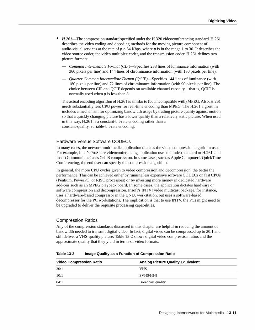
Designing Internetworks for Multimedia 13-11
Digitizing Video
• H.261—The compression standard specified under the H.320 videoconferencing standard. H.261describes the video coding and decoding methods for the moving picture component ofaudio-visual services at the rate ofp × 64 Kbps, wherep is in the range 1 to 30. It describes thevideo source coder, the video multiplex coder, and the transmission coder. H.261 defines twopicture formats:
— Common Intermediate Format (CIF)—Specifies 288 lines of luminance information (with360 pixels per line) and 144 lines of chrominance information (with 180 pixels per line).
— Quarter Common Intermediate Format (QCIF)—Specifies 144 lines of luminance (with180 pixels per line) and 72 lines of chrominance information (with 90 pixels per line). Thechoice between CIF and QCIF depends on available channel capacity—that is, QCIF isnormally used whenp is less than 3.
The actual encoding algorithm of H.261 is similar to (but incompatible with) MPEG. Also, H.261needs substantially less CPU power for real-time encoding than MPEG. The H.261 algorithmincludes a mechanism for optimizing bandwidth usage by trading picture quality against motionso that a quickly changing picture has a lower quality than a relatively static picture. When usedin this way, H.261 is a constant-bit-rate encoding rather than aconstant-quality, variable-bit-rate encoding.
Hardware Versus Software CODECsIn many cases, the network multimedia application dictates the video compression algorithm used.For example, Intel’s ProShare videoconferencing application uses the Indeo standard or H.261, andInsoft Communique! uses Cell B compression. In some cases, such as Apple Computer’s QuickTimeConferencing, the end user can specify the compression algorithm.
In general, the more CPU cycles given to video compression and decompression, the better theperformance. This can be achieved either by running less expensive software CODECs on fast CPUs(Pentium, PowerPC, or RISC processors) or by investing more money in dedicated hardwareadd-ons such as an MPEG playback board. In some cases, the application dictates hardware orsoftware compression and decompression. Insoft’s INTV! video multicast package, for instance,uses a hardware-based compressor in the UNIX workstation, but uses a software-baseddecompressor for the PC workstations. The implication is that to use INTV, the PCs might need tobe upgraded to deliver the requisite processing capabilities.
Compression RatiosAny of the compression standards discussed in this chapter are helpful in reducing the amount ofbandwidth needed to transmit digital video. In fact, digital video can be compressed up to 20:1 andstill deliver a VHS-quality picture. Table 13-2 shows digital video compression ratios and theapproximate quality that they yield in terms of video formats.
Table 13-2 Image Quality as a Function of Compression Ratio
Video Compression Ratio Analog Picture Quality Equivalent
20:1 VHS
10:1 SVHS/HI-8
04:1 Broadcast quality

Multimedia Basics
Cisco CCIE Fundamentals: Network Design13-12
As Table 13-2 indicates, fairly high video compression ratios can be used while still preservinghigh-quality video images. For example, a typical MPEG1 video stream (640×480, 30 frames persecond) runs at 1.5 Mbps.
Digitizing AudioMany of today’s multimedia applications include audio support. Some applications includehardware for digitizing audio, and other applications rely on third-party add-ons for audio support.Check with the application vendor to learn how audio is handled.
Like digital video, digital audio often begins from an analog source, so an analog-to-digitalconversion must be made. Converting an analog signal to a digital signal involves taking a series ofsamples of the analog source. The aggregation of the samples yields the digital equivalent of theanalog sound wave. A higher sampling rate delivers higher quality because it has more referencepoints to replicate the analog signal.
The sampling rate is one of three criteria that determine the quality of the digital version. The othertwo determining factors are the number of bits per sample and the number of channels.
Sampling rates are often quoted Hertz (Hz) or Kilohertz (KHz). Sampling rates are always measuredper channel, so for stereo data recorded at 8,000 samples per second (8 KHz), there would actuallybe 16,000 samples per second (16 KHz). Table lists common sampling rates.
Table 13-3 Common Audio Sampling Rates
An emerging tendency is to standardize on only a few sampling rates and encoding styles, even ifthe file formats differ. The emerging rates and styles are listed in Table 13-4.
Table 13-4 Sample Rates and Encoding Styles
Samples perSecond Description
08,000 A telephony standard that works withµ-LAW encoding.
11 K Either 11025 (a quarter of the CD sampling rate) or half the Macintosh sampling rate (perhaps themost popular rate on Macintosh computers).
16,000 Used by the G.722 compression standard
18.9 K CD-ROM/XA standard
22 K Either 22050 (half the CD sampling rate) or the Macintosh rate, which is precisely22254.545454545454.
32,000 Used in digital radio; Nearly Instantaneous Compandable Audio Matrix (NICAM)(IBA/BREMA/BB), and other TV work in the U.K.; long play Digital Audio Tape (DAT); andJapanese HDTV.
37.8 K CD-ROM/XA standard for higher quality.
44,056 Used by professional audio equipment to fit an integral number of samples in a video frame.
44,100 CD sampling rate. DAT players recording digitally from CD also use this rate.
48,000 DAT sampling rate for domestic rate.
Samples Per Second Encoding Style
08,000 8-bitµ-LAW mono
22,050 8-bit linear unsigned mono and stereo

Designing Internetworks for Multimedia 13-13
Using Networked Multimedia Applications
Audio CompressionAudio data is difficult to compress effectively. For 8-bit data, a Huffman encoding of the deltasbetween successive samples is relatively successful. Companies such as Sony and Philips havedeveloped proprietary schemes for 16-bit data. Apple Computer has an audiocompression/expansion scheme called ACE on the Apple IIGS and called MACE on the Macintosh.ACE/MACE is a lossy scheme that attempts to predict where the wave will go on the next sample.There is very little quality change on 8:4 compression, with somewhat more quality degradation at8:3 compression. ACE/MACE guarantees exactly 50 percent or 62.5 percent compression.
Public standards for voice compression using Adaptive Delta Pulse Code Modulation (ADPCM) areas follows:
• CCIU G.721 sampling at 32 Kbps
• CCIU G.723 sampling at 24 Kbps and 40 Kbps
• GSM 06.10 is a European speech encoding standard that compresses 160 13-bit samples into260 bits (33 bytes), or 1,650 bytes per second (at 8,000 samples per second).
There are also two U.S. federal standards:
• 1016 using code excited linear prediction (CELP) at 4,800 bits per second)
• 1015 (LPC-10E) at 2,400 bits per second)
Using Networked Multimedia ApplicationsThere is a wide range of network multimedia applications to choose from, so it is important tounderstand why a particular application is being deployed. Additionally, it is important to understandthe bandwidth implications of the chosen application. Table 13-5 lists some of the popular networkmultimedia applications.
Table 13-5 Popular Network Multimedia Applications
44,100 16-bit linear unsigned mono and stereo
Application Type Platform
Apple QuickTime Conferencing Videoconferencing Macintosh
AT&T Vistium Videoconferencing PC
CU-seeMe Videoconferencing Macintosh/PC/UNIX
InPerson Videoconferencing UNIX
Insoft Communique! Videoconferencing PC/UNIX
Intel CNN at Work LAN broadcast PC
Intel ProShare Videoconferencing PC
InVision Videoconferencing PC
Novell Video for NetWare Video server NetWare
PictureTel Videoconferencing PC
Starlight Starworks Video server UNIX/NetWare
Samples Per Second Encoding Style

Using Networked Multimedia Applications
Cisco CCIE Fundamentals: Network Design13-14
Types of ApplicationsNetwork multimedia applications fall into the following categories:
• Point-to-Point Bidirectional Applications
• Point-to-Multipoint Bidirectional Applications
• Point-to-Point Unidirectional Applications
• Point-to-Multipoint Unidirectional Applications
Point-to-Point Bidirectional ApplicationsPoint-to-point bidirectional applications, as shown in Figure 13-6, deliver real-time, point-to-pointcommunication. The process is bidirectional, meaning that video can be transmitted in bothdirections in real time.

Designing Internetworks for Multimedia 13-15
Types of Applications
Figure 13-6 Point-to-point bidirectional applications.
Examples of point-to-point bidirectional applications include the following:
• Audio and videoconferencing
• Shared whiteboard
atmSwitch(1)
IsPortProtocols(8)
edgePort(1) frCktInfo(3)
edgePortTable(1)
edgePortEntry(1)
frCktCtg-Table(1)
frCktInfo-Table(2)
frCkt-Entry(1)
frCktInfo-Entry(1)
sUniCktInfo(5)
sUniCktCfg-Table(1)
sUniCktInfo-Table(2)
sUniCkt-Entry(1)
sUniCktInfo-Entry(1)
mcEndptInfo(7)
mcEndptCfg-Table(1)
mcEndpt-Entry(1)
ffCktInfo(4)
ffCktCfg-Table(1)
ffCktInfo-Table(2)
ffCkt-Entry(1)
sUniInterface-Table(3)
sUniInterfaceSvc-RangeTable(4)
sUniSvcCktInfo-Table(5)
sUniSvcMckt-InfoTable(6)
sUniInterfaceSig-ExpertCfgTable(7)
sUniInterfaceSig-StatTable(8)
sUniInterface-Entry(1)
sUniInterfaceSvc-RangeEntry(1)
sUniSvcCktInfo-InfoEntry(1)
sUniSvcMckt-InfoEntry(1)
sUniInterfaceSig-ExpertCfgEntry(1)
sUniInterfaceSig-StatEntry(1 )
ffCktInfo-Entry(1)
frDceInfo(2)
frProvMi-Table(1)
frProvMi-Entry(1)
pvcInfo(6)
pvcCfg-Table(1)
pvcEntry(1)
pvcCbrInfo(8)
pvcCbrCfg-Table(1)
pvcCbr-Entry(1)
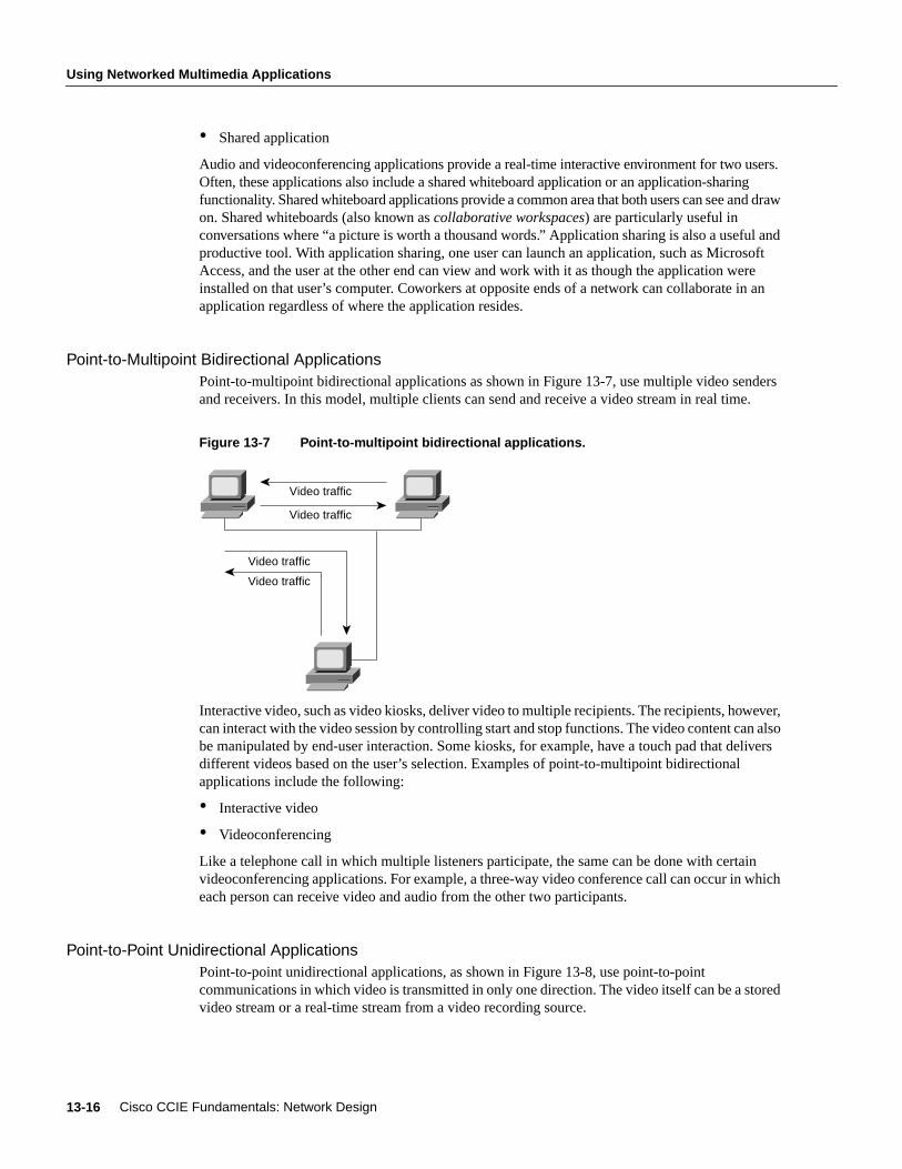
Using Networked Multimedia Applications
Cisco CCIE Fundamentals: Network Design13-16
• Shared application
Audio and videoconferencing applications provide a real-time interactive environment for two users.Often, these applications also include a shared whiteboard application or an application-sharingfunctionality. Shared whiteboard applications provide a common area that both users can see and drawon. Shared whiteboards (also known ascollaborative workspaces) are particularly useful inconversations where “a picture is worth a thousand words.” Application sharing is also a useful andproductive tool. With application sharing, one user can launch an application, such as MicrosoftAccess, and the user at the other end can view and work with it as though the application wereinstalled on that user’s computer. Coworkers at opposite ends of a network can collaborate in anapplication regardless of where the application resides.
Point-to-Multipoint Bidirectional ApplicationsPoint-to-multipoint bidirectional applications as shown in Figure 13-7, use multiple video sendersand receivers. In this model, multiple clients can send and receive a video stream in real time.
Figure 13-7 Point-to-multipoint bidirectional applications.
Interactive video, such as video kiosks, deliver video to multiple recipients. The recipients, however,can interact with the video session by controlling start and stop functions. The video content can alsobe manipulated by end-user interaction. Some kiosks, for example, have a touch pad that deliversdifferent videos based on the user’s selection. Examples of point-to-multipoint bidirectionalapplications include the following:
• Interactive video
• Videoconferencing
Like a telephone call in which multiple listeners participate, the same can be done with certainvideoconferencing applications. For example, a three-way video conference call can occur in whicheach person can receive video and audio from the other two participants.
Point-to-Point Unidirectional ApplicationsPoint-to-point unidirectional applications, as shown in Figure 13-8, use point-to-pointcommunications in which video is transmitted in only one direction. The video itself can be a storedvideo stream or a real-time stream from a video recording source.
Video traffic
Video traffic
Video traffic
Video traffic

Designing Internetworks for Multimedia 13-17
Types of Applications
Figure 13-8 Point-to-point unidirectional applications.
Examples of point-to-point unidirectional applications include the following:
• Video server applications
• Multimedia-enabled email applications
In point-to-point unidirectional applications, compressed video clips are stored centrally. The enduser initiates the viewing process by downloading the stream across the network to the videodecompressor, which decompresses the video clip for viewing.
Point-to-Multipoint Unidirectional ApplicationsPoint-to-multipoint unidirectional applications, as shown in Figure 13-9, are similar to point-to-point unidirectional applications except that the video is transmitted to a group of clients. The videois still unidirectional. The video can come from a storage device or a recording source.
Figure 13-9 Point-to-multipoint unidirectional applications.
Examples of point-to-multipoint unidirectional applications include the following:
• Video server applications
• LAN TV
Both of these applications provide unidirectional video services. Video server applications deliver tomultiple clients video streams that have already been compressed. LAN TV applications deliverstored video streams or real-time video from a camera source. Distance learning, in which classesare videotaped and then broadcast over the LAN and WAN to remote employees, is a popularexample of a point-to-multipoint unidirectional video application.
Video traffic
Server Client
Video traffic
Server Client
Client

Using Networked Multimedia Applications
Cisco CCIE Fundamentals: Network Design13-18
Quality of Service RequirementsData and multimedia applications have different quality of service requirements. Unlike traditional“best effort” data services, such as File Transfer Protocol (FTP), Simple Mail Transfer Protocol(SMTP), and X Window, in which variations in latency often go unnoticed, audio and video data areuseful only if they are delivered within a specified time period. Delayed delivery only impedes theusefulness of other information in the stream. In general,latencyandjitter are the two primary forcesworking against the timely delivery of audio and video data.
LatencyReal-time, interactive applications, such as desktop conferencing, are sensitive to accumulateddelay, which is known aslatency. Telephone networks are engineered to provide less than400 milliseconds (ms) round-trip latency. Multimedia networks that support desktop audio andvideoconferencing also must be engineered with a latency budget of less than 400 ms per round-trip.The network contributes to latency in several ways:
• Propagation delay—The length of time that information takes to travel the distance of the line.Propagation delay is mostly determined by the speed of light; therefore, the propagation delayfactor is not affected by the networking technology in use.
• Transmission delay—The length of time a packet takes to cross the given media. Transmissiondelay is determined by the speed of the media and the size of the packet.
• Store-and-forward delay—The length of time an internetworking device (such as a switch,bridge, or router) takes to send a packet that it has received.
• Processing delay—The time required by a networking device for looking up the route, changingthe header, and other switching tasks. In some cases, the packet also must be manipulated. Forexample, the encapsulation type or the hop count must be changed. Each of these steps cancontribute to the processing delay.
JitterIf a network delivers data with variable latency, it introduces jitter. Jitter is particularly disruptive toaudio communications because it can cause pops and clicks that are noticeable to the user. Manymultimedia applications are designed to minimize jitter. The most common technique is to storeincoming data in an insulating buffer from which the display software or hardware pulls data. Thebuffer reduces the effect of jitter in much the same way that a shock absorber reduces the effect ofroad irregularities on a car: Variations on the input side are smaller than the total buffer size andtherefore are not normally perceivable on the output side. Figure 13-10 shows a typical bufferingstrategy that helps to minimize latency and jitter inherent in a given network.
Figure 13-10 Hardware buffering minimizes latency and jitter.
Display
Network adapter buffer
Network
CODEC buffer VGA buffer

Designing Internetworks for Multimedia 13-19
Quality of Service Requirements
Buffering can also be performed within the network itself. Consider a client that connects to a videoserver. During the video playback session, data moving from the video server to the client can bebuffered by the network interface cards and the video decompressor. In this case, buffering acts as aregulator to offset inherent irregularities (latency/jitter) that occur during transmission. The overalleffect is that even though the traffic may be bursty coming over the network, the video image is notimpaired because the buffers store incoming data and then regulate the flow to the display card.
Buffers can play a large role in displaying video, especially over existing networks, but because theyare not large enough to accommodate the entire audio or video file, the use of buffers cannotguarantee jitter-free delivery. For that reason, multimedia networks should also make use oftechniques that minimize jitter.
One way of providing predictable performance is to increase line speeds to assure that adequatebandwidth is available during peak traffic conditions. This approach may be reasonable for backbonelinks, but it may not be cost effective for other links. A more cost-effective approach may be to uselower-speed lines and give mission-critical data priority over less critical transmissions during peaktraffic conditions through the use of queuing techniques. The Cisco IOS software offers thefollowing queuing strategies:
• Priority Queuing
• Custom Queuing
• Weighted Fair Queuing
Priority QueuingPriority queuing allows the network administrator to define four priorities of traffic—high, normal,medium, and low—on a given interface. As traffic comes into the router, it is assigned to one of thefour output queues. Packets on the highest priority queue are transmitted first. When that queueempties, packets on the next highest priority queue are transmitted, and so on.
Priority queuing ensures that during congestion, the highest-priority data is not delayed bylower-priority traffic. Note that, if the traffic sent to a given interface exceeds the bandwidth of thatinterface, lower-priority traffic can experience significant delays.
Custom QueuingCustom queuing allows the network administrator to reserve a percentage of bandwidth for specifiedprotocols. Cisco IOS Software Release 11.0 allows the definition of up to 16 output queues fornormal data (including routing packets) with a separate queue for system messages, such as LANkeepalive messages. The router services each queue sequentially, transmitting a configurablepercentage of traffic on each queue before moving on to the next queue. Custom queuing guaranteesthat mission-critical data is always assigned a certain percentage of the bandwidth but also assurespredictable throughput for other traffic. For that reason, custom queuing is recommended fornetworks that need to provide a guaranteed level of service for all traffic.
Custom queuing works by determining the number of bytes that should be transmitted from eachqueue, based on the interface speed and the configured percentage. When the calculated byte countfrom a given queue has been transmitted, the router completes transmission of the current packet andmoves on to the next queue, servicing each queue in a round-robin fashion.
With custom queuing, unused bandwidth is dynamically allocated to any protocol that requires it.For example, if SNA is allocated 50 percent of the bandwidth but uses only 30 percent, the nextprotocol in the queue can take up the extra 20 percent until SNA requires it. Additionally, customqueuing maintains the predictable throughput of dedicated lines by efficiently using packet-switching technologies such as Frame Relay.

Using Networked Multimedia Applications
Cisco CCIE Fundamentals: Network Design13-20
Weighted Fair QueuingWeighted fair queuing was introduced with Cisco IOS Software Release 11.0. Weighted fair queuingis a traffic priority management algorithm that identifies conversations (traffic streams) and thenbreaks up the streams of packets that belong to each conversation to ensure that capacity is sharedfairly between individual conversations. By examining fields in the packet header, the algorithmautomatically separates conversations.
Conversations are sorted into two categories—those that are attempting to use a lot of bandwidthwith respect to the interface capacity (for example, FTP) and those that need less (for example,interactive traffic). For streams that use less bandwidth, the queuing algorithm always attempts toprovide access with little or no queuing and shares the remaining bandwidth between the otherconversations. In other words, low-bandwidth traffic has effective priority over high-bandwidthtraffic, and high-bandwidth traffic shares the transmission service proportionally.
Weighted fair queuing provides an automatic way of stabilizing network behavior during congestionand results in increased performance and reduced retransmission. In most cases, weighted fairqueuing provides smooth end-to-end performance over a given link and, in some cases, may resolvelink congestion without an expensive increase in bandwidth.
Note Weighted fair queuing is enabled by default on most serial interfaces; priority queuing orcustom queuing can be configured instead. By default, weighted fair queuing is disabled on serialinterfaces that are configured for X.25, LAPB, and SDLC, and on all LAN interfaces.
Bandwidth RequirementsBandwidth requirements for network multimedia applications can range anywhere from 100 Kbpsto 70 or 100 Mbps. Figure 13-11 shows the amount of bandwidth that the various types of networkmultimedia applications require.
Figure 13-11 Network bandwidth usage.
SharedApplication
VideoMail
Video onDemand
Imaging VirtualReality
VideoConfer-encing
Imaging
100 kbps 1 Mbps 100 Mbps10 Mbps
Conferencing
Still video
Shared whiteboard
Speech
Distance learning
MPEG video
Virtual reality

Designing Internetworks for Multimedia 13-21
Understanding Multicasting
As Figure 13-11 indicates, the type of application has a direct impact on the amount of LAN or WANbandwidth needed. Assuming that bandwidth is limited, the choice is either to select a lower qualityvideo application that works within the available bandwidth, or consider modifying the networkinfrastructure to deliver more overall bandwidth.
Understanding MulticastingTraditional network applications, including most of today’s network multimedia applications,involve communication only between two computers. A two-user videoconferencing session usingIntel ProShare, for example, is a strictly unicast transaction. However, a new breed of networkmultimedia applications, such as LAN TV, desktop conferencing, corporate broadcasts, andcollaborative computing, requires simultaneous communication between groups of computers. Thisprocess is known generically asmultipoint communications.
When implementing multipoint network multimedia applications, it is important to understand thetraffic characteristics of the application in use. In particular, the network designer needs to knowwhether an application uses unicast, broadcast, or multicast transmission facilities, defined asfollows:
• Unicast—In a unicast design, applications can send one copy of each packet to each member ofthe multipoint group. This technique is simple to implement, but it has significant scalingrestrictions if the group is large. In addition, unicast applications require extra bandwidth,because the same information has to be carried multiple times—even on shared links.
• Broadcast—In a broadcast design, applications can send one copy of each packet and address itto a broadcast address. This technique is even simpler than unicast for the application toimplement. However, if this technique is used, the network must either stop broadcasts at theLAN boundary (a technique that is frequently used to prevent broadcast storms) or send thebroadcast everywhere. Sending the broadcast everywhere is a significant burden on networkresources if only a small number of users actually want to receive the packets.
• Multicast—In a multicast design, applications can send one copy of each packet and address itto a group of computers that want to receive it. This technique addresses packets to a group ofreceivers (at the multicast address) rather than to a single receiver (at a unicast address), and itdepends on the network to forward the packets to only those networks that need to receive them.Multicasting helps control network traffic and reduces the amount of processing that hosts haveto do.
Many network multimedia applications, such as Insoft INTV! 3.0 and Apple QuickTimeConferencing 1.0, implement multicast transmission facilities because of the added efficiency thatmulticasting offers to the network and to the client. From the network perspective, multicastdramatically reduces overall bandwidth consumption and allows for more scalable networkmultimedia applications.
Consider an MPEG-based video server. Playback of an MPEG stream requires approximately1.5 Mbps per client viewer. In a unicast environment, the video server send 1.5× n (wheren=numberof client viewers) Mbps of traffic to the network. With a 10-Mbps connection to the server, roughlysix to seven streams could be supported before the network runs out of bandwidth. In a multicastenvironment, the video server need send only one video stream to a multicast address. Any numberof clients can listen to the multicast address and receive the video stream. In this scenario, the serverrequires only 1.5 Mbps and leaves the rest of the bandwidth free for other uses.
Multicast can be implemented at both OSI Layer 2 and OSI Layer 3. Ethernet and Fiber DistributedData Interface (FDDI), for example, support unicast, multicast, and broadcast addresses. A host canrespond to a unicast address, several multicast addresses, and the broadcast address. Token Ring alsosupports the concept of multicast addressing but uses a different technique. Token Rings havefunctional addresses that can be used to address groups of receivers.

Understanding Multicasting
Cisco CCIE Fundamentals: Network Design13-22
If the scope of an application is limited to a single LAN, using an OSI Layer 2 multicast techniqueis sufficient. However, many multipoint applications are valuable precisely because they are notlimited to a single LAN.
When a multipoint application is extended to an Internet consisting of different media types, such asEthernet, Token Ring, FDDI, Asynchronous Transfer Mode (ATM), Frame Relay, SMDS, and othernetworking technologies, multicast is best implemented at OSI Layer 3. OSI Layer 3 must defineseveral parameters in order to support multicast communications:
• Addressing—There must be an OSI Layer 3 address that is used to communicate with a group ofreceivers rather than a single receiver. In addition, there must be a mechanism for mapping thisaddress onto OSI Layer 2 multicast addresses where they exist.
• Dynamic registration—There must be a mechanism for the computer to communicate to thenetwork that it is a member of a particular group. Without this capability, the network cannotknow which networks need to receive traffic for each group.
• Multicast routing—The network must be able to build packet distribution trees that allow sourcesto send packets to all receivers. A primary goal of packet distribution trees is to ensure that onlyone copy of a packet exists on any given network—that is, if there are multiple receivers on agiven branch, there should be only one copy of each packet on that branch.
IP MulticastThe Internet Engineering Task Force (IETF) has developed standards that address the parametersthat are required to support multicast communications:
• Addressing—The IP address space is divided into four sections: Class A, Class B, Class C, andClass D. Class A, B, and C addresses are used for unicast traffic. Class D addresses are reservedfor multicast traffic and are allocated dynamically.
• Dynamic registration—RFC 1112 defines the Internet Group Management Protocol (IGMP).IGMP specifies how the host should inform the network that it is a member of a particularmulticast group.
• Multicast routing—There are several standards for routing IP multicast traffic:
— Distance Vector Multicast Routing Protocol (DVMRP) as described in RFC 1075.
— Multicast Open Shortest Path First (MOSPF), which is an extension to Open Shortest PathFirst (OSPF) that allows it to support IP multicast, as defined in RFC 1584.
— Protocol Independent Multicast (PIM), which is a multicast protocol that can be used withall unicast IP routing protocols, as defined in the two Internet standards-track drafts entitledProtocol Independent Multicast (PIM): Motivation and Architecture andProtocolIndependent Multicast (PIM): Protocol Specification.
IP Multicast Group AddressingFigure 13-12 shows the format of a Class D IP multicast address.
Figure 13-12 Class D address format.
Class D
28 bits
1 1 1 0 Multicast group ID

Designing Internetworks for Multimedia 13-23
IP Multicast
Unlike Class A, B, and C IP addresses, the last 28 bits of a Class D address have no structure. Themulticast group address is the combination of the high-order 4 bits of 1110 and the multicast groupID. These are typically written as dotted-decimal numbers and are in the range 224.0.0.0 through239.255.255.255. Note that the high-order bits are 1110. If the bits in the first octet are 0, this yieldsthe 224 portion of the address.
The set of hosts that responds to a particular IP multicast address is called ahost group. A host groupcan span multiple networks. Membership in a host group is dynamic—hosts can join and leave hostgroups. For a discussion of IP multicast registration, see the section called “Internet GroupManagement Protocol” later in this chapter.
Some multicast group addresses are assigned as well-known addresses by the Internet AssignedNumbers Authority (IANA). These multicast group addresses are calledpermanent host groupsandare similar in concept to the well-known TCP and UDP port numbers. Address 224.0.0.1 means “allsystems on this subnet,” and 224.0.0.2 means “all routers on this subnet.”
Table 13-6 lists the multicast address of some permanent host groups.
Table 13-6 Example of Multicast Addresses for Permanent Host Groups
The IANA owns a block of Ethernet addresses that in hexadecimal is 00:00:5e. This is the high-order24 bits of the Ethernet address, meaning that this block includes addresses in the range00:00:5e:00:00:00 to 00:00:5e:ff:ff:ff. The IANA allocates half of this block for multicast addresses.Given that the first byte of any Ethernet address must be 01 to specify a multicast address, theEthernet addresses corresponding to IP multicasting are in the range 01:00:5e:00:00:00 through01:00:5e:7f:ff:ff.
This allocation allows for 23 bits in the Ethernet address to correspond to the IP multicast group ID.The mapping places the low-order 23 bits of the multicast group ID into these 23 bits of the Ethernetaddress, as shown in Figure 13-13. Because the upper five bits of the multicast address are ignoredin this mapping, the resulting address is not unique. Thirty-two different multicast group IDs map toeach Ethernet address.
Figure 13-13 Multicast address mapping.
Permanent Host Group Multicast Address
Network Time Protocol 224.0.1.1
RIP-2 224.0.0.9
Silicon Graphics Dogfight application 224.0.1.2
48-bit Ethernet address
Class D IP address
group ID copied to Ethernet address
Low-order 23 bits of multicast
These 5 bits in the multicastgroup ID are not used to formthe Ethernet address.
10 0 0 0 0 0 0 00 0 0 0 0 0 0 00 1 0 1 1 1 1 0
1 1 1 0
0 7 8 15 16 23 24 31

Understanding Multicasting
Cisco CCIE Fundamentals: Network Design13-24
Because the mapping is not unique and because the interface card might receive multicast frames inwhich the host is really not interested, the device driver or IP modules must perform filtering.
Multicasting on a single physical network is simple. The sending process specifies a destination IPaddress that is a multicast address, and the device driver converts this to the corresponding Ethernetaddress and sends it. The receiving processes must notify their IP layers that they want to receivedatagrams destined for a given multicast address and the device driver must somehow enablereception of these multicast frames. This process is handled by joining a multicast group.
When a multicast datagram is received by a host, it must deliver a copy to all the processes thatbelong to that group. This is different from UDP where a single process receives an incoming unicastUDP datagram. With multicast, multiple processes on a given host can belong to the same multicastgroup.
Complications arise when multicasting is extended beyond a single physical network and multicastpackets pass through routers. A protocol is needed for routers to know if any hosts on a givenphysical network belong to a given multicast group. This function is handled by the Internet GroupManagement Protocol.
Internet Group Management ProtocolThe Internet Group Management Protocol (IGMP) is part of the IP layer and uses IP datagrams(consisting of a 20-byte IP header and an 8-byte IGRP message) to transmit information aboutmulticast groups. IGMP messages are specified in the IP datagram with a protocol value of 2. Figure13-14 shows the format of the 8-byte IGMP message.
Figure 13-14 IGMP message format.
The value of theversion field is 1. The value of thetype field is 1 for a query sent by a multicastrouter and 2 for a report sent by a host. The value of thechecksumfield is calculated in the same wayas the ICMP checksum. The group address is a class D IP address. In a query, the group address isset to 0, and in a report, it contains the group address being reported.
The concept of a process joining a multicast group on a given host interface is fundamental tomulticasting. Membership in a multicast group on a given interface is dynamic (that is, it changesover time as processes join and leave the group). This means that end users can dynamically joinmulticast groups based on the applications that they execute.
Multicast routers use IGMP messages to keep track of group membership on each of the networksthat are physically attached to the router. The following rules apply:
• A host sends an IGMP report when the first process joins a group. The report is sent out the sameinterface on which the process joined the group. Note that if other processes on the same host jointhe same group, the host doesnot send another report.
• A host does not send a report when processes leave a group, even when the last process leaves agroup. The host knows that there are no members in a given group, so when it receives the nextquery, it doesn’t report the group.
• A multicast router sends an IGMP query at regular intervals to see whether any hosts still haveprocesses belonging to any groups. The router sends a query out each interface. The groupaddress in the query is 0 because the router expects one response from a host for every group thatcontains one or more members on a host.
4-bitIGMP
Version (1)
4-bitIGMP
Type (1-2)(Unused) 16-bit checksum 32-bit group address (Class D IP addres
0 3 4 7 8 15 3116

Designing Internetworks for Multimedia 13-25
IP Multicast
• A host responds to an IGMP query by sending one IGMP report for each group that still containsat least one process.
Using queries and reports, a multicast router keeps a table of its interfaces that have one or morehosts in a multicast group. When the router receives a multicast datagram to forward, it forwards thedatagram (using the corresponding multicast OSI Layer 2 address) on only those interfaces that stillhave hosts with processes belonging to that group.
The Time to Live (TTL) field in the IP header of reports and queries is set to 1. A multicast datagramwith a TTL of 0 is restricted to the same host. By default, a multicast datagram with a TTL of 1 isrestricted to the same subnet. Higher TTL field values can be forwarded by the router. By increasingthe TTL, an application can perform an expanding ring search for a particular server. The firstmulticast datagram is sent with a TTL of 1. If no response is received, a TTL of 2 is tried, and then3, and so on. In this way, the application locates the server that is closest in terms of hops.
The special range of addresses 224.0.0.0 through 224.0.0.255 is intended for applications that neverneed to multicast further than one hop. A multicast router should never forward a datagram with oneof these addresses as the destination, regardless of the TTL.
Multicast Routing ProtocolsA critical issue for delivering multicast traffic in a routed network is the choice of multicast routingprotocol. Three multicast routing protocols have been defined for this purpose:
• Distance Vector Multicast Routing Protocol
• Multicast OSPF
• Protocol Independent Multicast
The goal in each protocol is to establish paths in the network so that multicast traffic can effectivelyreach all group members.
Distance Vector Multicast Routing ProtocolDistance Vector Multicast Routing Protocol (DVMRP) uses a technique known asreverse pathforwarding. When a router receives a packet, it floods the packet out all paths except the path thatleads back to the packet’s source. Reverse path forwarding allows a data stream to reach all LANs(possibly multiple times). If a router is attached to a set of LANs that does not want to receive aparticular multicast group, the router sends a “prune” message up the distribution tree to preventsubsequent packets from traveling where there are no members.
New receivers are handled by using grafts. Consequently, only one round-trip time (RTT) from thenew receiver to the nearest active branch of the tree is required for the new receiver to start gettingtraffic.
To determine which interface leads back to the source of the data stream, DVMRP implements itsown unicast routing protocol. This unicast routing protocol is similar to RIP and is based on hopcounts. As a result, the path that the multicast traffic follows might not be the same as the path thatthe unicast traffic follows. The need to flood frequently means that DVMRP has trouble scaling. Thislimitation is exacerbated by the fact that early implementations of DVMRP did not implementpruning.
DVMRP has been used to build the MBONE—a multicast backbone across the public Internet—bybuilding tunnels between DVMRP-capable machines. The MBONE is used widely in the researchcommunity to transmit the proceedings of various conferences and to permit desktop conferencing.

Understanding Multicasting
Cisco CCIE Fundamentals: Network Design13-26
Multicast OSPFMulticast OSPF (MOSPF) is an extension of the OSPF unicast routing protocol and works only ininternetworks that use OSPF. OSPF works by having each router in a network understand all of theavailable links in the network. Each OSPF router calculates routes from itself to all possibledestinations. MOSPF works by including multicast information in OSPF link-state advertisementsso that an MOSPF router learns which multicast groups are active on which LANs.
MOSPF builds a distribution tree for each source-group pair and computes a tree for active sourcessending to the group. The tree state is cached and must be recomputed when a link state changeoccurs or when the cache times out.
MOSPF works well in environments that have relatively few source-group pairs active at any giventime. It works less well in environments that have many active sources or in environments that haveunstable links.
Protocol Independent MulticastUnlike MOSPF, which is OSPF dependent, Protocol Independent Multicast (PIM) works with allexisting unicast routing protocols. Unlike DVMRP, which has inherent scaling problems, PIM solvespotential scalability problems by supporting two different types of multipoint traffic distributionpatterns: dense mode and sparse mode. Dense mode is most useful when the following conditionsoccur:
• Senders and receivers are in close proximity to one another.
• There are few senders and many receivers.
• The volume of multicast traffic is high.
• The stream of multicast traffic is constant.
Dense-mode PIM uses reverse path forwarding and is similar to DVMRP. The most significantdifference between DVMRP and dense-mode PIM is that PIM works with whatever unicast protocolis being used—it does not require any particular unicast protocol.
In dense mode, PIM floods the network and prunes back based on multicast group memberinformation. Dense mode is effective, for example, in a LAN TV multicast environment because itis likely that there will be a group member on each subnet. Flooding the network is effective becauselittle pruning is necessary. An example of PIM dense-mode operation is shown in Figure 13-15.

Designing Internetworks for Multimedia 13-27
IP Multicast
Figure 13-15 PIM dense-mode operation.
Sparse-mode PIM is most useful when the following conditions occur:
• There are few receivers in a group.
• Senders and receivers are separated by WAN links.
• The stream of multicast traffic is intermittent.
Sparse-mode PIM is optimized for environments where there are many multipoint data streams.Each data stream goes to a relatively small number of the LANs in the internetwork. For these typesof groups, reverse path forwarding would make inefficient use of the network bandwidth.
In sparse-mode, PIM assumes that no hosts want the multicast traffic unless they specifically ask forit. It works by defining a rendezvous point (RP). The RP is used by senders to a multicast group toannounce their existence and by receivers of multicast packets to learn about new senders. When asender wants to send data, it first sends the data to the RP. When a receiver wants to receive data, itregisters with the RP. Once the data stream begins to flow from sender to RP to receiver, the routersin the path automatically optimize the path to remove any unnecessary hops. An example of PIMsparse-mode operation is shown in Figure 13-16.
Figure 13-16 PIM sparse-mode operation.
Traffic
Prune
Prune
Prune
Member of Group 1 Member of Group 1
Member of Group 1
Rendezvous point
Data
Data
Receiver
Sender
Optimizedpath

Network Designs for Multimedia Applications
Cisco CCIE Fundamentals: Network Design13-28
Note The administrators of the MBONE plan to adopt PIM because it is more efficient thanDVMRP.
Simple Multicast Routing ProtocolSimple Multicast Routing Protocol (SMRP) is a transport layer multicast protocol standard formulticast AppleTalk and IPX traffic.
Note Initial support for SMRP is provided by Cisco IOS Software Release 11.0 or later forAppleTalk only.
With SMRP, a router on each local network segment is elected as the primary node. The primarynode handles requests from local devices to create multicast groups on that segment. When it wantsto send multicast data, a device sends a Create Group Request packet to ask the primary node toassign a group address. The primary node responds by sending to the requesting device a CreateGroup Response packet that contains the assigned group address.
Devices that want to receive multicast data from this group send a Join Request packet to ask theirlocal router to join the group. The local router forwards the Join Request to the primary node thatcreated the group. The primary node responds by sending a Join Response.
Multicast data sent by the source is forwarded by router downstream interfaces toward receivers.Receivers can join and leave a group at any time, and a sender can delete the group at any time. Therouters ensure that multicast data is transmitted as efficiently as possible, without duplication, fromsenders to receivers.
Routers maintain and update SMRP multicast groups by periodically sending Creator Query andMember Query packets to poll the network for the presence of senders and receivers. A router thatdetects the disappearance of a sender deletes the group. A router that senses the disappearance of areceiver informs its upstream neighbor to stop forwarding multicast data if no other receivers existon the segment. Each router periodically informs its neighbors of its presence by sending Hellopackets.
Network Designs for Multimedia ApplicationsThis section examines network designs that work well with network multimedia applications. Thefollowing topics are covered:
• Traditional LAN Designs
• WAN Designs
• High-Speed LAN Designs
Traditional LAN DesignsSome campus LAN environments already have adequate bandwidth for running certain networkmultimedia applications, but most do not. In many cases, lack of bandwidth isnotcaused by a slowLAN medium—instead, lack of bandwidth is caused by inefficient LAN design and segmentation.A considerable amount of bandwidth can be gained by using switches to resegment the campus LANenvironment.

Designing Internetworks for Multimedia 13-29
Traditional LAN Designs
Consider three different campus designs. In Figure 13-17, Campus A has 500 users on five separate100-node shared Ethernet segments. Each of the five segments are connected via a Cisco 7x00 seriesrouter.
Figure 13-17 Shared Ethernet campus LAN design.
With 100 users per segment, the net bandwidth per user is 100 Kbps. Using the graph shown inFigure 13-17, an audio conferencing package is the most that Campus A can handle. In Figure 13-18,Campus B uses a combination of shared Ethernet hubs (repeaters) and Ethernet switches to deliversubstantially more bandwidth per user.
Figure 13-18 Shared Ethernet and switched Ethernet campus LAN design.
In Figure 13-18, ten users are connected to a shared Ethernet hub. The hub is then connected todedicated 10-Mbps Ethernet switch ports. Each of the Ethernet switches is connected together overa routed Ethernet backbone. In this scenario, each hub gets 10 Mbps, which yields roughly 1 Mbpsfor each of the ten users on the hub. Based on this network design, Campus B can run medium-quality video applications.
Hub
Hub Hub Hub
Hub
Campus A
100 users per segment100 kbps per user
Cisco 7x00 series router
HubHub
Cisco 7x00 series router
Ethernet
10 users per segment1 Mbps per user
5 hubs per switch
Catalyst 1200
Hub
Campus B
Hub Hub HubHub

Network Designs for Multimedia Applications
Cisco CCIE Fundamentals: Network Design13-30
Campus C, shown in Figure 13-19, eliminates the shared Ethernet hubs. Each user has a dedicatedl0-Mbps connection to the LAN via a direct connection to an Ethernet switch port. Like Campus B,the switches are interconnected over a routed Ethernet backbone. With 10 Mbps of bandwidth peruser, Campus C can easily support high-quality network multimedia applications.
Figure 13-19 Switched Ethernet campus LAN design.
The comparison of Campus A, Campus B, and Campus C illustrates that the first step in deliveringmore bandwidth isnot ripping out the existing Ethernet or Token Ring infrastructure and moving toa 100-Mbps technology. Instead, the proper first step is to deploy switches thereby improvingbandwidth per user by assigning a small number of users to each switch port or by assigning one userto each switch port, thereby providing dedicated 10-Mbps bandwidth to that user. This technique isknown asmicrosegmenting.
The majority of today’s network multimedia applications require less than 10 Mbps for operation,so Ethernet is still an acceptable LAN medium. The problem with Ethernet is that more of its10 Mbps needs to be delivered to each user than is delivered by the typical shared network.
Figure 13-20 shows how microsegmentation can affect per-user bandwidth, thus allowing networkmultimedia applications that have high bandwidth requirements to run.
When using LAN switches to design networks to support multimedia applications, it is important toremember the following design constraints:
• Multicast packets are basically equivalent to broadcast packets.
• Switches flatten the network and cause broadcast packets (and multicast packets) to be floodedthroughout the network.
• Virtual LANs (VLANs) can be used to control the size and scope of the broadcast domain and,therefore, the networks on which multicast packets are sent.
• Routers are required to allow VLANs to communicate with each other and to control the spreadof multicast packets.
• VLANs and routers are required for scalability in switched LAN networks.
• Because it supports IGMP, the Catalyst 1200 switch is well-suited for networks that supportnetwork multimedia applications.
Cisco 7x00 series router
S44
76
Catalyst 1200
1 user per segment10 Mbps per user
Campus C
10-Mbps client access per port
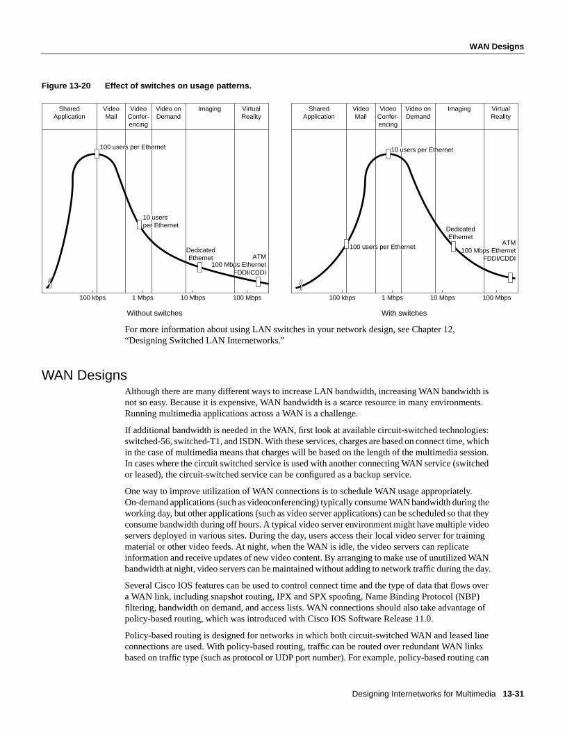
Designing Internetworks for Multimedia 13-31
WAN Designs
Figure 13-20 Effect of switches on usage patterns.
For more information about using LAN switches in your network design, see Chapter 12,“Designing Switched LAN Internetworks.”
WAN DesignsAlthough there are many different ways to increase LAN bandwidth, increasing WAN bandwidth isnot so easy. Because it is expensive, WAN bandwidth is a scarce resource in many environments.Running multimedia applications across a WAN is a challenge.
If additional bandwidth is needed in the WAN, first look at available circuit-switched technologies:switched-56, switched-T1, and ISDN. With these services, charges are based on connect time, whichin the case of multimedia means that charges will be based on the length of the multimedia session.In cases where the circuit switched service is used with another connecting WAN service (switchedor leased), the circuit-switched service can be configured as a backup service.
One way to improve utilization of WAN connections is to schedule WAN usage appropriately.On-demand applications (such as videoconferencing) typically consume WAN bandwidth during theworking day, but other applications (such as video server applications) can be scheduled so that theyconsume bandwidth during off hours. A typical video server environment might have multiple videoservers deployed in various sites. During the day, users access their local video server for trainingmaterial or other video feeds. At night, when the WAN is idle, the video servers can replicateinformation and receive updates of new video content. By arranging to make use of unutilized WANbandwidth at night, video servers can be maintained without adding to network traffic during the day.
Several Cisco IOS features can be used to control connect time and the type of data that flows overa WAN link, including snapshot routing, IPX and SPX spoofing, Name Binding Protocol (NBP)filtering, bandwidth on demand, and access lists. WAN connections should also take advantage ofpolicy-based routing, which was introduced with Cisco IOS Software Release 11.0.
Policy-based routing is designed for networks in which both circuit-switched WAN and leased lineconnections are used. With policy-based routing, traffic can be routed over redundant WAN linksbased on traffic type (such as protocol or UDP port number). For example, policy-based routing can
SharedApplication
VideoMail
Video onDemand
Imaging VirtualReality
VideoConfer-encing
100 kbps 1 Mbps 100 Mbps10 Mbps
SharedApplication
100 users per Ethernet
100 users per Ethernet
10 users per Ethernet
DedicatedEthernet
DedicatedEthernet ATM
100 Mbps EthernetFDDI/CDDI
ATM100 Mbps Ethernet
FDDI/CDDI
10 usersper Ethernet
VideoMail
Video onDemand
Imaging VirtualReality
VideoConfer-encing
100 kbps 1 Mbps
Without switches With switches
100 Mbps10 Mbps

Network Designs for Multimedia Applications
Cisco CCIE Fundamentals: Network Design13-32
be used to route email and FTP traffic over a serial link and to route Intel ProShare traffic across anISDN link. In Figure 13-21, policy-based routing is used to configure a T1 interface for regular trafficand an ISDN interface for video-conferencing traffic.
Figure 13-21 Policy-based routing.
In Figure 13-21, the multimedia gets the required bandwidth from the circuit-switched service.Because the circuit-switched service is up only when the application is in use, WAN costs arecontrolled. Traditional LAN traffic runs separately on the leased line and experiences uninterruptedservice.
Until WAN bandwidth becomes affordable at any speed, delivering bandwidth to applications overthe WAN will remain a difficult task. Wherever possible, take advantage of circuit-switchedtechnologies and Cisco IOS features such as policy-based routing and bandwidth on demand.
Note The Cisco IOS software includes two lossless data compression algorithms, STAC andPredictor, that compress data that is transmitted over WAN links. Neither algorithm should be usedto compress video because they cannot achieve the compression ratios that are achieved by videoand audio compression algorithms. In addition, do not use STAC and Predictor to compress videothat has already been compressed. In most cases, instead of decreasing the size of a video or audiotransmission, these algorithms increase it.
Additionally, take advantage of the priority queuing, custom queuing, and weighted fair queuing tooptimize WAN traffic patterns. For example, set up a queue for a particular multicast session or useweighted fair queuing to dynamically queue the multicast stream, as shown in Figure 13-22.
ISDN
ProShareclient
ProShareclient
FTP hostFTPclient
56 kbpsleased line
FTPE-mail

Designing Internetworks for Multimedia 13-33
High-Speed LAN Designs
Figure 13-22 WAN queuing techniques.
High-Speed LAN DesignsMany of today’s network multimedia applications are packet-based audio or video applications.These applications are transmitted using the traditional OSI Layer 3 protocols: IP, IPX, andAppleTalk. Stream-based applications are best exemplified in ATM environments in which audio orvideo is captured and converted directly into ATM cells and transmittednativelyusing ATM throughthe ATM switch fabric. Typically, these multimedia applications are constant bit rate (CBR) and useAAL1 and circuit emulation for transmission.
It is important to ask the following questions of each network multimedia application in use:
• Is the application packet-based or stream-based?
• What are the bandwidth requirements?
• Does the application support multicast transmission?
• Does the application support quality of service parameters?
Designing a network to support packet-based video is quite different from designing a network forstream-based applications. Packet-based video is best deployed in networks built around switchesand routers. To further tailor the network, virtual LAN (VLAN) technology can also be leveragedacross the campus LAN and WAN.
In this model, ATM can be deployed as a backbone technology to interconnect different switchesand VLANs. From an implementation standpoint, if IP is the only protocol on the network, the ATMpart of the network can run classical IP over ATM, as defined in RFC 1577. However, if the ATMnetwork needs to support additional protocols or IP multicast, the ATM network must run LANEmulation (LANE) instead.
Cisco 7x00
Cisco 7x00
Cisco 7x00
1. FTP traffic2. Video session 13. Video session 2
Static queues
Dynamic queues
T1Weighted fair queuing
T1Custom output queuing
FTP 20%SMTP 20%Video 40%Other 20%
Cisco 7x00

Network Designs for Multimedia Applications
Cisco CCIE Fundamentals: Network Design13-34
If resegmenting and microsegmenting an existing network, as described in the section “TraditionalLAN Designs” earlier in this chapter, does not yield enough bandwidth to run network multimediaapplications, or if a new network is being designed, consider the following high-speed LANtechnologies:
• Fast Ethernet
• Fiber Distributed Data Interface and Copper Distributed Data Interface (FDDI and CDDI)
• Asynchronous Transfer Mode (ATM)
The combination of switches and routers interconnected using a high-speed backbone technology(Fast Ethernet, FDDI, or ATM) provides sufficient bandwidth for most network multimediaapplications in the campus environment.
Fast EthernetFast Ethernet (IEEE 802.3u), delivers 100-Mbps bandwidth over category 5 unshielded twisted- pair(UTP) wire or fiber-optic cable. Like 10-Mbps Ethernet, Fast Ethernet uses carrier sense multipleaccess collision detection (CSMA/CD) network access method. Perhaps the two best advantages ofFast Ethernet are that it is relatively inexpensive (assuming category 5 UTP is present) and thatmigration from traditional 10-Mbps Ethernet is simple. Fast Ethernet delivers bandwidth that allowsfor a variety of different network design scenarios:
• High-speed client-server connectivity
• High-speed interswitch communication
• High-speed backbone
High-speed client-server connectivity is a popular use for Fast Ethernet. In this scenario, servers(Novell NetWare, Windows NT, and SPARC servers) are on Fast Ethernet and transmit to clientsconnected via Fast Ethernet or switched 10-Mbps Ethernet. Fast Ethernet server connectivity worksparticularly well in video server environments where the server needs to deliver multiple videostreams to its clients. The capability to take advantage of a high-speed connection is a product of theserver’s architecture and the operating system that it runs. Novell NetWare, for example, can deliversubstantial I/O caching, which in turn generates high-speed transfers. Figure 13-23 shows a designthat gives users on 10-Mbps Ethernet access to file, print, and video servers located on 100-Mbpssegments.
Figure 13-23 Fast Ethernet server access.
Cisco 4x00/7x00series router
10-Mbpsswitched Ethernet
client access
File/printserver
Videoserver
100 MbpsCatalyst 5000
100Mbps
100Mbps

Designing Internetworks for Multimedia 13-35
Fast Ethernet
Using Fast Ethernet for high-speed client connectivity is also effective. Today, reasonably pricedFast Ethernet adapters are available for PCs (EISA and PCI) and SPARCstations (S-bus). Becauseinstallation is simple, Fast Ethernet provides a straightforward migration path to 100-Mbpsbandwidth.
Fast Ethernet can also be used to interconnect Ethernet switch workgroups. In this scenario, a groupof switches is interconnected using Fast Ethernet. This is particularly useful in a microsegmentedenvironment in which each client has a dedicated 10-Mbps segment. With a Fast Ethernet connectionbetween switches, a client can communicate with a client attached to a different switch withoutsacrificing bandwidth, as shown in Figure 13-24.
Figure 13-24 Fast Ethernet interswitch connections.
Fast Ethernet connections over category 5 UTP are limited to 100 meters in length. With fiber, FastEthernet can deliver connections up to two kilometers in length, allowing Fast Ethernet over fiber tobe used as a backbone technology to interconnect various switched segments in a campusenvironment, as shown in Figure 13-25.
Figure 13-25 Fast Ethernet backbone.
In practice, Fast Ethernet is rarely used as a core backbone technology because FDDI and ATM offeradvanced features that make them more viable for backbone implementations.
Cisco 7x00series router
Catalyst 5000
100 Mbps
100 Mbps100 Mbps
Catalyst 3000 Catalyst 3000
Catalyst5000
Building 1
Catalyst5000
Building 2 Building 4
Building 3
Catalyst5000
Catalyst5000

Network Designs for Multimedia Applications
Cisco CCIE Fundamentals: Network Design13-36
The design shown in Figure 13-26 works well for low-port density switched Ethernet environments,using switches for client and server access and routers for core connectivity. This design controlsmulticast traffic by deploying IGMP at the switch port, which allows multicast traffic to be sent onlyto ports that have registered an IGMP Join.
Figure 13-26 Low-port density design.
For high-port density Ethernet or Token Ring environments, a combination of routers andCatalyst 3000, Catalyst 1600, or Catalyst 5000 switches is effective. The design relies on VLANtechnology to control multicast traffic. VLAN technology permits the creation of multiple bridgegroups within a switch or across high-speed backbones with remote switches. With VLANs,multicast transmission can be limited to only the desired ports by creating a specific VLAN thatincludes only the multicast sender and the multicast recipients.
Designing VLANs to support multicast applications hinges largely on the application in use. Figure13-27 is an example of a campus design that uses a single network TV multicast application.
Figure 13-27 Network TV multicast design.
In Figure 13-27, there is only one VLAN per switch, resulting in a large number of clients perVLAN. The video source resides on the high-speed backbone and is in its own VLAN. During themulticast transmission, the video source sends a video stream out the high-speed connection.Router A receives the video stream and sends it out its high-speed link to the VLANs on theCatalyst 5000 switches.
Cisco 7000Cisco 7000
Videoserver
Catalyst 1200
Catalyst 1200
Catalyst 1200
WAN
Catalyst 1200 Catalyst 1200
Fast Ethernet-attachedCisco 7000
Fast Ethernet-attachedvideo server
96 Ethernetclients
Catalyst5000
Catalyst 5000 Catalyst 5000
Empty IGMP table
VLAN 2
VLAN 1
VLAN 4
Router A
Router B
VLAN 3

Designing Internetworks for Multimedia 13-37
Fast Ethernet
When a VLAN receives a multicast stream from the router, it forwards it to all members of thatVLAN. Therefore, this design works well for environments in which every client tunes in to thenetwork TV transmission. If only a few clients per VLAN tune in to the broadcast and the remainingclients task the network for other services, the multicast traffic can hinder overall networkperformance.
The routers support IGMP, which limits multicast traffic to only those interfaces that have registeredIGMP Joins from clients. In Figure 13-27, Router B has no IGMP receivers in its table and thereforemulticast traffic is not forwarded out any of its interfaces.
To impose greater control over multicast transmission, a microVLAN strategy can be used. In thisscenario, a switch has multiple VLANs (thereby limiting the multicast traffic to fewer ports).MicroVLANs are best used in multipoint videoconferencing environments and environments wherethere are multiple multicast video sources. In these environments, many different multicasttransmissions may occur simultaneously, which can impose some scalability issues unless themulticast traffic can be contained.
Figure 13-28 shows a microVLAN design in which the VLANs are aligned based on multicastdemands. VLAN 1, for example, contains clients that primarily receive video from Video server 1.VLAN 1 also receives video from Video server 2, which is the corporate broadcast service.
Figure 13-28 MicroVLAN design.
The microVLAN approach minimizes the effects of multicast traffic by creating many smallbroadcast domains using VLANs.
One issue to keep in mind with the microVLAN design is that it might violate the 80/20 rule fordesigning VLANs. VLAN design is optimized when at least 80 percent of the traffic is intraVLANand at most 20 percent of the traffic is interVLAN. Essentially, performance is optimized whentraffic remains within the local VLAN. If VLANs are aligned based on multicast clients and servers,there is a good chance that access to other servers, such as the email server, will be interVLAN.Because interVLAN communication must be handled by a router, as interVLAN communicationincreases, route processing increases. Ultimately, the number of VLANs per router port should bedetermined by the multicast applications in use and their respective bandwidth requirements.
96 clientsand servers
Approximately 30VLANs per switch
Fast Ethernet-attachedCisco 7000
InterVLAN routing process
VLAN 2
VLAN 1
VLAN 2
Multicastvideo clients
Videoserver 1
Videoserver 2 Catalyst
5000
Fast Ethernet uplinksFast Ethernet
Catalyst5000
Catalyst 5000Catalyst 5000
96 clientsand servers
96 clientsand servers

Network Designs for Multimedia Applications
Cisco CCIE Fundamentals: Network Design13-38
Compared with low-bandwidth multicast applications, high-bandwidth multicast applications placea greater constraint on the number of VLANs on a router interface. For additional information aboutVLANs, see Chapter 12, “Designing Switched LAN Internetworks.”
Fiber Distributed Data Interface and Copper Distributed Data InterfaceFiber Distributed Data Interface (FDDI) and Copper Distributed Data Interface (CDDI) deliverbandwidth that allows for a variety of different network design scenarios. FDDI is particularlyattractive as a backbone technology for the following reasons:
• Distance capabilities—With multimode fiber, an FDDI connection can span 2 kilometers. Withsingle mode fiber, an FDDI connection can span 10 kilometers. This capability allowstremendous flexibility for interconnecting LAN segments in a campus environment.
• Fault tolerance and redundancy—FDDI’s inherent fault tolerance and its ability to supportdesigns such as dual-homing also make the technology attractive in backbone environments.
• Security—Optical transmission makes it more difficult for hackers to tap into compared totraditional copper transmission.
Like Fast Ethernet, FDDI and CDDI can deliver high-speed client connectivity, but most often,FDDI and CDDI are used for server and backbone connections, especially in video serverenvironments where multiple video streams are sent to video clients, as shown in Figure 13-29.
Figure 13-29 FDDI or CDDI server access.
In addition to delivering high bandwidth, FDDI and CDDI deliver better redundancy than FastEthernet. With FDDI and CDDI, a server can bedual-homed to FDDI or CDDI concentrators, asshown in Figure 13-30. Dual-homing gives a server access to two FDDI or CDDI rings. Undernormal circumstances, the server uses only one ring. If the primary ring fails, the server can fall backto the secondary ring, maintaining connectivity with no down time. Dual-homing requires that theserver FDDI or CDDI adapter be a Dual Attached Station (DAS) adapter (as opposed to a SingleAttached Station [SAS] connector, which provides a single physical connection).
FDDI
Cisco 4x00/7x00
Catalyst1200
ConcentratorCatalyst 1400
10-Mbps switchedEthernet access
Videoserver
FDDIclient
Videoserver
ConcentratorCatalyst 1400

Designing Internetworks for Multimedia 13-39
Asynchronous Transfer Mode
Figure 13-30 FDDI dual-homed design.
Clients attached to different Ethernet switch workgroups can gain high-speed intercommunication,which allows a client connected to one Ethernet switch to access a video server or initiate avideoconferencing session with a resource connected to another Ethernet switch. In this design,dual-homing can be implemented. An FDDI-equipped switch can be dual-homed to two differentconcentrators, providing greater redundancy and fault tolerance.
The design shown in Figure 13-31 works for point-to-point applications that only impose bandwidthdemands on the network, but it is vulnerable to multicast applications. The switch transmits OSILayer 2 multicast frames to all ports in the same manner as it transmits OSI Layer 2 broadcastframes. For example, if a client accesses a multicast video stream on a server, the multicasttransmission is forwarded to all switch ports, which undermines the performance benefits ofswitching.
Figure 13-31 Switch/router campus design.
Asynchronous Transfer ModeAsynchronous Transfer Mode (ATM) has gained much attention as the next-generation LAN andWAN technology. Much of the excitement about ATM centers around the fact that ATM delivers anentirely switch-based fabric and offers high-speed connectivity (100-Mbps TAXI, 155-Mbps OC-3
Cisco 4x00/7x00routerVideo serverVideo server
ConcentratorCatalyst 1400
FDDI ConcentratorCatalyst 1400
FDDI
WANservices
Videoserver

Network Designs for Multimedia Applications
Cisco CCIE Fundamentals: Network Design13-40
and in the future 622-Mbps OC-12). Besides the raw bandwidth that ATM provides, the technologyalso offers extensive support for transporting video, voice, and data. As Figure 13-32 illustrates, avariety of different design scenarios are possible using ATM equipment.
From a bandwidth perspective, ATM offers considerable flexibility for running network multimediaapplications. Although ATM provides features, such as quality of service support, that make it anattractive environment in which to run network multimedia applications, ATM is not a prerequisitefor running network multimedia applications. Rather, today’s existing LAN technologies can alsosupport many network multimedia applications.
LAN EmulationLAN Emulation (LANE) defines a service interface for Open Systems Interconnection (OSI)Layer 3 protocols that is identical to that of existing LANs and encapsulates data sent across theATM network in the appropriate LAN MAC packet format. It makes no attempt to emulate the actualmedia access control protocol of the specific LAN concerned (that is, CSMA/CD for Ethernet ortoken passing for IEEE 802.5).
Figure 13-32 Enterprise ATM network design.
Currently, LANE does not define a separate encapsulation for FDDI. FDDI packets are mapped intoEthernet or Token Ring-emulated LANs (ELANs) using existing translational bridging techniques.Because they use the same packet formats, the two most prominent new LAN standards, FastEthernet (100BaseT) and IEEE 802.12 (100VG-AnyLAN), can be mapped unchanged into either theEthernet or Token Ring LANE formats and procedures.
LANE supports a range of maximum packet (MPDU) sizes, corresponding to maximum sizeEthernet, 4-Mbps and 16-Mbps Token Ring packets, and to the value of the default MPDU for IPover ATM. Typically, the size of the MPDU depends on the type of LAN that is being emulated andon the support provided by LAN switches bridged to the ELAN. An ELAN with only native ATMhosts, however, may optionally use any of the available MPDU sizes, even if a size does notcorrespond to the actual MPDU in a real LAN of the type being emulated. All LAN Emulationclients (LECs) within a given ELAN must use the same MPDU size. Put simply, LANE makes anATM network look and behave like an Ethernet or Token Ring LAN—albeit one operating muchfaster than such a network.
100-Mbps Fast Ethernet
100-Mbps Fast Ethernet
100-MbpsFast Ethernet
155 Mbps
Distributed routing design
Route server/centralized routing design

Designing Internetworks for Multimedia 13-41
Asynchronous Transfer Mode
The advantage of LANE is that it allows higher-layer protocols to work without modification overATM networks. Because LANE presents the same service interface of existing MAC protocols tonetwork-layer drivers (for example, an NDIS- or ODI-like driver interface), no changes are requiredin those drivers. See Figure 13-33 for a representation of the LANE protocol architecture.
Figure 13-33 LANE protocol architecture.
The goal of LANE is to accelerate the deployment of ATM at the same time that work continues onthe full definition and implementation of native mode network-layer protocols.
LANE DesignsWhen designing with LANE, the primary issues typically center on the scalability of LANEmulation servers (LESs) and broadcast and unknown servers (BUSs). Currently, all multicasttransmission relies on the BUS for delivery to all LAN Emulation clients (LECs) within a givenELAN.
In a Cisco ATM network, the router operates as the BUS for a given ELAN. If the router supportsmultiple ELANs, it runs multiple BUS processes. Router performance is a function of the numberof ELANs the router is a member of and the number of BUS processes that it executes. Inenvironments in which there are a large number of ELANs, additional routers should be deployed tohandle BUS functionality for each ELAN. Essentially, BUS functionality is distributed across a setof routers in the ATM network, as shown in Figure 13-34.
Higherlayer
protocols
IP/IPX,etc.
LANE
AAL 5
ATM host withLANE NIC
ATMswitch
Layer 2LAN switch
LANhost
AAL 5
ATM
Phy
ATM
Phy
ATM
Phy
ATM
Phy Phy Phy
MAC
802.1D NDIS/ODI
MAC
UNIsignaling
UNIsignaling
NDIS/ODI
Higherlayer
protocols
IP/IPX,etc.

Network Designs for Multimedia Applications
Cisco CCIE Fundamentals: Network Design13-42
Figure 13-34 Distributed LES/BUS design.
Currently, LANE is the only ATM technology that addresses multicast packet-based video. ClassicalIP over ATM (RFC 1577) has no provision for resolving OSI Layer 2 multicast addresses into ATMaddresses. For more information about LANE, see Chapter 8, “Designing ATM Internetworks.”
Native Mode ATMNative mode ATM protocols bypass the MAC address encapsulation of LANE. In native mode,address resolution mechanisms map network-layer addresses directly into ATM addresses, and thenetwork-layer packets are then carried across the ATM network. Currently, IP is the only protocolfor which extensive native-mode work has been done.
From the perspective of running network multimedia applications, one of the most compellingreasons for running native mode protocols is quality of service support. LANE deliberately hidesATM so any network-layer protocol that operates over ATM cannot gain access to the quality ofservice properties of ATM and must therefore use unspecified bit rate (UBR) or available bit rate(ABR) connections only. Currently, this is not a major restriction because all network protocols weredeveloped for use over existing LAN and WAN technologies, none of which can deliver a guaranteedquality of service. Consequently, no existing network-layer protocol can request a specific quality ofservice from the network or deliver it to a higher-layer protocol or application. In turn, most networkapplications today do not expect to receive any guaranteed quality of service from the underlyingnetwork protocol, so they do not request it.
For a long time, IP has had optional support for type of service (TOS) indications within the IPheader that could theoretically be used to provide a rudimentary form of quality of service support.In practice, however, almost no end-system or intermediate-system IP implementations have anysupport for TOS because TOS indications cannot be mapped into any common underlyingnetworking technology. Few, if any, IP routing protocols use the TOS bits, and no applications setthem.
At best, all current network-layer protocols expect and deliver only a “best effort” service—preciselythe type of service that the ABR service was designed to offer. Just as LANE adapts theconnection-oriented nature of ATM to offer the same type of connectionless service that is expectedby network-layer protocols, so ABR hides the guaranteed quality of services features of ATM tooffer the best effort service expected by these protocols. As such, ABR and LANE perfectlycomplement each other.
Cisco 7000
Catalyst 5000Catalyst5000
Cisco 7000
Catalyst 5000
Cisco 4700 LECWAN
100 ELANs
(LES/BUS ELANs 1-50)
VLANs consist of multicastsenders/receivers
Multiple VLANsper switch
(LES/BUS ELANs 51-100)
LightStream100
ATM-attachedvideo server(ELANs 1-8)

Designing Internetworks for Multimedia 13-43
Asynchronous Transfer Mode
As ATM networks proliferate, it is likely that demand will grow to use the quality of service featuresof ATM, which will spur application development expressly designed to take advantage of ATM andATM quality of service.
Native ATM DesignsAs mentioned earlier in this chapter, LANE is best suited for “best effort” traffic (that is, ABR traffic)but is not well-suited for applications that require more predictable network service, such as CBRand VBR multimedia applications. For these applications, it is best to run native ATM. In a nativeATM environment, digital video and audio is sent to a service multiplexer that segments the audioand video streams into cells and forwards them out to ATM-attached clients that receive the streams.
MPEG2, which is a VBR application, is a good example of a native ATM application. With MPEG2,video can be digitized and compressed in real time and then put into ATM cells for delivery toATM-attached clients. Figure 13-35 shows an example of MPEG2 running over ATM.
Figure 13-35 MPEG2 over ATM.
Multimedia Applications in ATM NetworksWithin an ATM network, connections are categorized into various quality-of-service types: constantbit rate (CBR), variable bit rate (VBR), available bit rate (ABR), and unspecified bit rate (UBR). Forthe most part, network multimedia applications are CBR or VBR. CBR video applications aredesigned to run over traditional 64-Kbps or multiple 64-Kbps lines. With ATM, CBR video istransported using circuit emulation, which means that the ATM switch must support circuitemulation.
ATM switches that do not have CBR line cards must have a service multiplexer. The multiplexer hasinputs for CBR traffic at T1/E1 and T3/E3 speeds and can adapt those streams to ATM. For example,the Litton-FiberCom ATM multiplexer features real-time video encoding and provides ATMadaptation with an OC-3 (155 Mbps) ATM port.
VBR video applications, which are commonly seen in traditional LAN environments, are morebursty than CBR applications. VBR applications are often referred to aspacketized video. The videocompression algorithm, such as MPEG, generates VBR output that is packetized onto the LAN. InATM, VBR applications can run using LANE or can run natively using IP over ATM.
LightStream2020
Camera
Inputs
VCRLaserdisc
Litton-Fibercomdecompressor
Litton-Fibercomcell multiplexer
MPEG2realtimeplayback
MPEG2over ATM
LightStream2020

Network Designs for Multimedia Applications
Cisco CCIE Fundamentals: Network Design13-44
MPEG2 is a special case of VBR that can run directly on ATM, bypassing LANE and IP altogether.In this case, there is an MPEG2-to-ATM convergence layer in which MPEG2 information istranslated into ATM cells. Figure 13-36 shows how CBR and VBR map into ATM.
Figure 13-36 Video stream protocol mappings.
Depending on the type of ATM service requested, the network is expected to deliver guarantees onthe particular mix of quality of service elements (such as cell loss ratio, cell delay, and cell delayvariation) that are specified at the connection setup.
In UNI 3.0/3.1, the traffic parameters and requested quality of service for a connection cannot benegotiated at setup, nor can they be changed over the life of the connection. UNI 4.0 will supportconnection quality of service negotiation.
ATM MulticastingThere are two fundamental types of ATM connections:
• Point-to-point connections, which connect two ATM end systems. Such connections can beunidirectional or bidirectional.
• Point-to-multipoint connections, which connect a single source end system (known as therootnode) to multiple destination end systems (known asleaves). Cell replication is done within thenetwork by the ATM switches at which the connection splits into two or more branches. Suchconnections are unidirectional, permitting the root to transmit to the leaves but not permitting theleaves to transmit to the root, or to each other, on the same connection.
An analog to the multicasting or broadcasting capability common in many shared-media LANtechnologies, such as Ethernet and Token Ring, is notably missing from these types of ATMconnections. In such technologies, multicasting allows multiple end systems to receive data fromother multiple systems and to transmit data to these multiple systems. Such capabilities are easy toimplement in shared-media technologies such as LANs, where all nodes on a single LAN segmentmust necessarily process all packets sent on that segment. The obvious analog in ATM to a multicastLAN group would be a bidirectional, multipoint-to-multipoint connection. Unfortunately, thisobvious solution cannot be implemented when using ATM Adaptation Layer 5 (AAL5), the mostcommon ATM adaptation layer used to transmit data across ATM networks.
CBRstream
VBRstream
Video stream
Distance and LAN video LAN video Video on demand
IP IP
VBRstream
MPEG2stream
Circuitemulation
MACprotocols
ATM ATM ATM ATM

Designing Internetworks for Multimedia 13-45
Asynchronous Transfer Mode
Unlike AAL3/4, with its Message Identifier (MID) field, AAL5 does not have any provision withinits cell format for the interleaving of cells from different AAL5 packets on a single connection.Therefore, all AAL5 packets sent to a particular destination across a particular connection must bereceived in sequence, with no interleaving between the cells of different packets on the sameconnection, or the destination reassembly process would not be able to reconstruct the packets.
Despite the problems that AAL5 has with multicast support, it is not feasible to use AAL3/4 as analternative for data transport. AAL3/4 is a much more complex protocol than AAL5 and would leadto much more complex and expensive implementations. Indeed, AAL5 was developed specificallyto replace AAL3/4. Although the MID field of AAL3/4 could preclude cell interleaving problems,allowing for bidirectional, multipoint-to-multipoint connections, this would also require somemechanism for ensuring that all nodes in the connection use a unique MID value. There is no suchmechanism currently in existence or development; the number of possible nodes within a givenmulticast group would also be severely limited due to the small size of the MID field.
ATM AAL5 point-to-multipoint connections can be only unidirectional because if a leaf node wereto transmit an AAL5 packet onto the connection, it would be received by both the root node and allother leaf nodes. However, at these nodes, the packet sent by the leaf could be interleaved withpackets sent by the root, and possibly other leaf nodes; this would preclude the reassembly of any ofthe interleaved packets. Clearly, this is not acceptable.
Notwithstanding this problem, ATM requires some form of multicast capability because mostexisting protocols (having been developed initially for LAN technologies) rely on the existence of alow-level multicast/broadcast facility. Three methods have been proposed for solving this problem:
• VP-multicasting—With this mechanism, a multipoint-to-multipoint VP links all nodes in themulticast group, and each node is given a unique VCI value within the VP. Interleaved packetscan be identified by the unique VCI value of the source. Unfortunately, this mechanism requiresa protocol that uniquely allocates VCI values to nodes, and such a protocol does not currentlyexist. It is also not clear whether currentsegmentation and reassembly (SAR) devices could easily support such a mode of operation.Moreover, UNI 3.0/3.1 does not support switched virtual paths. UNI 4.0, however, should addthis capability.
• Multicast server—With this mechanism as illustrated in Figure 13-37, all nodes wanting totransmit onto a multicast group set up a point-to-point connection with an external device knownas a multicast server (perhaps better described as a resequencer or serializer). The multicastserver, in turn, is connected to all nodes that want to receive the multicast packets through apoint-to-multipoint connection. The multicast server receives packets across the point-to-pointconnections, and then retransmits them across the point-to-multipoint connection—but only afterensuring that the packets are serialized (that is, one packet is fully transmitted prior to the nextbeing sent). In this way, cell interleaving is precluded.

Network Designs for Multimedia Applications
Cisco CCIE Fundamentals: Network Design13-46
Figure 13-37 Multicast server operation.
• Overlaid point-to-multipoint connections—With this mechanism, all nodes in the multicastgroup establish a point-to-multipoint connection with each of the other nodes in the group, and,in turn, become a leaf in the equivalent connections of all other nodes. Therefore, as shown inFigure 13-38, all nodes can both transmit to and receive from all other nodes.
Figure 13-38 Overlaid point-to-multipoint connections.
Overlaid point-to-multipoint connections require each node to maintainn connections for eachgroup, wheren is the total number of transmitting nodes within the group. The multicast servermechanism requires only two connections. Overlaid point-to-multipoint connections also require aregistration process for telling a node that joins a group what the other nodes in the group are, so thatthe joining node can form its own point-to-multipoint connection. The other nodes also need to knowabout the new node so they can add the new node to their own point-to-multipoint connections. Themulticast server mechanism is more scalable in terms of connection resources but has the problemof requiring a centralized resequencer, which is both a potential bottleneck and a single point offailure.
In short, there is no ideal solution within ATM for multicast. Higher layer protocols within ATMnetworks use both the multicast server solution and the overlaid point-to-multipoint connectionsolution. This is one example of why using existing protocols with ATM is so complex. Most currentprotocols, particularly those developed for LANs, implicitly assume a network infrastructure similarto existing LAN technologies—that is, a shared-medium, connectionless technology with implicitbroadcast mechanisms. ATM violates all of these assumptions.
Packetsequencing
(serialization)
Multicast server
ATMnetworkpoint-to-
multipointconnection
Unidirectionalpoint-to-pointconnections
to server
ATMnetwork

Designing Internetworks for Multimedia 13-47
Work in Progress
Work in ProgressIn the case of IP, the IETF has developed the notion of an Integrated Services Internet, whichenvisages a set of enhancements to IP to allow it to support integrated or multimedia services. Theseenhancements include traffic management mechanisms that closely match the traffic managementmechanisms of ATM. For instance, protocols such as Resource Reservation Protocol (RSVP) arebeing defined to allow for resource reservation across an IP network, much as ATM signaling doeswithin ATM networks.
RSVP is an advanced method for dynamically allocating bandwidth to network-based applicationsrunning in traditional packet-based networks. RSVP will be particularly useful for CBR multimediaapplications because it will allow a network application to request a specific quality of service fromthe network. It will be the responsibility of internetworking devices (such as routers) to respond tothe RSVP request and to establish a connection through the network that can support the requestedquality of service.
The IP Version 6 (IPv6) protocol (formally known as the IP Next Generation [IPng] protocol), whichthe IETF is now developing as a replacement for the current IPv4 protocol, incorporates support fora flow ID within the packet header. The network uses the flow ID to identify flows, much as VPI/VCI(virtual path identifier/virtual channel identifier) are used to identify streams of ATM cells. Protocolssuch as RSVP will be used to associate with each flow a flow specification that characterizes thetraffic parameters of the flow, much as the ATM traffic contract is associated with an ATMconnection.
The IETF is also in the process of developing a new transport protocol, the Real-Time TransportProtocol (RTP). RTP is designed to provide end-to-end network transport functions for applicationstransmitting real-time data (such as audio, video, or simulation data) over multicast or unicastnetwork services. RTP builds on protocols like RSVP for resource reservation and on transporttechnologies such as ATM for quality of service guarantees. The services provided by RTP toreal-time applications include payload type identification, sequence numbering, time stamping, anddelivery monitoring.
The concept of a Multicast Address Resolution Server (MARS), which can be considered the analogof the ARP server in RFC 1577, is also in development. A MARS serves a group of nodes known asacluster. All end systems within the cluster are configured with the ATM address of the MARS. TheMARS supports multicast throughmulticast meshesof overlaid point-to-multipoint connections, orthrough multicast servers.
SummaryThis chapter addressed how to effectively deploy network multimedia applications. Specifically, thischapter addressed the following topics:
• Multimedia basics, including analog video, digital video, video compression, and digital audiostandards
• Using networked multimedia applications, including bandwidth and quality of servicerequirements
• Understanding multicasting, including Internet Group Management Protocol, Distance VectorMulticast Routing Protocol, Multicast Open Shortest Path First, Protocol Independent Multicast,and Simple Multicast Routing Protocol
• Network designs for multimedia applications, including traditional LAN designs, WAN designs,and high-speed LAN designs

Summary
Cisco CCIE Fundamentals: Network Design13-48

A P P E N D I X
Subnetting an IP Address Space A-1
A
Subnetting an IP Address Space
This appendix provides a partial listing of a Class B area intended to be divided into approximately500 Open Shortest Path First (OSPF) areas. For the purposes of this example, the network is assumedto be a Class B network with the address 150.100.0.0.
Note Although a 500-area OSPF internetwork is unrealistic, using an address space like this canhelp to illustrate the general methodology employed to subnet an OSPF address space.
Only the address space for two of 512 areas is shown in Table A-1. These areas are defined with thebase address 150.100.2.0. Illustrating the entire address space for 150.100.0.0 would requirehundreds of additional pages of addressing information. Each area would require the equivalentnumber of entries for each of the example areas illustrated here.
Table A-1 illustrates the assignment of 255 IP addresses that have been split between two OSPFareas. Table A-1 also illustrates the boundaries of the subnets and of the two OSPF areas shown(area 8 and area 17).
For the purposes of this discussion, consider a network that requires point-to-point serial links ineach area to be assigned a subnet mask that allows two hosts per subnet. All other subnets are to beallowed 14 hosts per subnet. The use of bit-wise subnetting and variable-length subnet masks(VLSMs) permit you to customize your address space by facilitating the division of address spacesinto smaller groupings than is allowed when subnetting along octet boundaries. The address layoutshown in Table A-1 illustrates a structured approach to assigning addresses that uses VLSM. TableA-1 presents two subnet masks: 255.255.255.240 and of 255.255.255.252. The first mask createssubnet address spaces that are four bits wide; the second mask creates subnet address spaces that aretwo bits wide.
Because of the careful assignment of addresses, each area can be summarized with a singlearearouter configuration command (used to define address range). The first set of addresses starting with150.100.2.0xxxxxxx(last octet represented here in binary) can be summarized into the backbone withthe following command:
area 8 range 150.100.2.0 255.255.255.128
This command assigns all addresses from 150.100.2.0 to 150.100.2.127 to area 8. Similarly, theaddresses from 150.100.2.128 to 150.100.2.255 for the second area can be summarized as follows:
area 17 range 150.100.2.128 255.255.255.128
This command assigns all addresses from 150.100.2.128 to 150.100.2.255 to area 17.
Allocation of subnets allows you to decide where to draw the line between the subnet and host (usinga subnet mask) within each area. Note that in this example there are only seven bits remaining to usebecause of the creation of the artificial area mask. The nine bits to the left of the area mask are

Cisco CCIE Fundamentals: Network DesignA-2
actually part of the subnet portion of the address. By keeping these nine bits the same for alladdresses in a given area, route summarization is easily achieved at area border routers, as illustratedby the scheme used in Table A-1.
Table A-1 lists individual subnets, valid IP addresses, subnet identifiers, and broadcast addresses.This method of assigning addresses for the VLSM portion of the address space guarantees that thereis no address overlap. If the requirement had been different, any number of the larger subnets mightbe chosen and divided into smaller ranges with fewer hosts, or combined into several ranges to createsubnets with more hosts.
The design approach used in this appendix allows the area mask boundary and subnet masks to beassigned to any point in the address space, which provides significant design flexibility. A change inthe specification of the area mask boundary or subnet masks may be required if a network outgrowsits initial address space design. In Table A-1, the area mask boundary is to the right of the mostsignificant bit of the last octet of the address, as shown by Figure A-1.
Figure A-1 Breakdown of the addresses assigned by the example.
With a subnet mask of 255.255.255.240, thea andb bits together represent the subnet portion of theaddress, whereas thec andd bits together provide four-bit host identifiers. When a subnet mask of255.255.255.252 (a typical subnet mask for point-to-point serial lines), thea, b, andc bits togetherrepresent the subnet portion of the address, and thed bits provide two-bit host identifiers. Asmentioned earlier, the purpose of the area mask is to keep all of thea bits constant in a given OSPFarea (independent of the subnet mask) so that route summarization is easy to apply.
The following steps outline the process used to allocate addresses:
Step 1 Determine the number of areas required for your OSPF network. A value of 500 is usedfor this example.
Step 2 Create an artificialarea mask boundary in your address space. This example uses ninebits of subnet addressing space to identify the areas uniquely. Because 29= 512, nine bitsof subnet meet our requirement of 500 areas.
Step 3 Determine the number of subnets required in each area and the maximum number of hostsrequired per subnet. This allows you to determine the placement of the subnet mask(s).In Table A-1, the requirement is for seven subnets with 14 hosts each and four subnetswith two hosts each.
150.100.aaaaaaaa.a bbb cc dd
Area mask
Alternatesubnetmask 2255.255.255.252
Subnetmask 1255.255.255.240
Fixed for alladdresses ina given area

Subnetting an IP Address Space A-3
Table A-1 Partial Example of Subnet Address Assignment Using VLSM
IP Address(Decimal)
SubnetPortion ofLast Octet(Binary)
HostPortion ofLast Octet(Binary) Subnet Number Subnet Mask Notes
150.100.2.0 0000 0000 150.100.2.0 255.255.255.240 Subnet identifier;area boundary; area8 starts
150.100.2.1 0000 0001 150.100.2.0 255.255.255.240
150.100.2.2 0000 0010 150.100.2.0 255.255.255.240
150.100.2.3 0000 0011 150.100.2.0 255.255.255.240
150.100.2.4 0000 0100 150.100.2.0 255.255.255.240
150.100.2.5 0000 0101 150.100.2.0 255.255.255.240
150.100.2.6 0000 0110 150.100.2.0 255.255.255.240
150.100.2.7 0000 0111 150.100.2.0 255.255.255.240
150.100.2.8 0000 1000 150.100.2.0 255.255.255.240
150.100.2.9 0000 1001 150.100.2.0 255.255.255.240
150.100.2.10 0000 1010 150.100.2.0 255.255.255.240
150.100.2.11 0000 1011 150.100.2.0 255.255.255.240
150.100.2.12 0000 1100 150.100.2.0 255.255.255.240
150.100.2.13 0000 1101 150.100.2.0 255.255.255.240
150.100.2.14 0000 1110 150.100.2.0 255.255.255.240
150.100.2.15 0000 1111 150.100.2.0 255.255.255.240 Subnet broadcast
150.100.2.16 0001 0000 150.100.2.16 255.255.255.240 Subnet identifier
150.100.2.17 0001 0001 150.100.2.16 255.255.255.240
150.100.2.18 0001 0010 150.100.2.16 255.255.255.240
150.100.2.19 0001 0011 150.100.2.16 255.255.255.240
150.100.2.20 0001 0100 150.100.2.16 255.255.255.240
150.100.2.21 0001 0101 150.100.2.16 255.255.255.240
150.100.2.22 0001 0110 150.100.2.16 255.255.255.240
150.100.2.23 0001 0111 150.100.2.16 255.255.255.240
150.100.2.24 0001 1000 150.100.2.16 255.255.255.240
150.100.2.25 0001 1001 150.100.2.16 255.255.255.240
150.100.2.26 0001 1010 150.100.2.16 255.255.255.240
150.100.2.27 0001 1011 150.100.2.16 255.255.255.240
150.100.2.28 0001 1100 150.100.2.16 255.255.255.240
150.100.2.29 0001 1101 150.100.2.16 255.255.255.240
150.100.2.30 0001 1110 150.100.2.16 255.255.255.240
150.100.2.31 0001 1111 150.100.2.16 255.255.255.240 Subnet broadcast
150.100.2.32 0010 0000 150.100.2.32 255.255.255.240 Subnet identifier
150.100.2.33 0010 0001 150.100.2.32 255.255.255.240
150.100.2.34 0010 0010 150.100.2.32 255.255.255.240

Cisco CCIE Fundamentals: Network DesignA-4
150.100.2.35 0010 0011 150.100.2.32 255.255.255.240
150.100.2.36 0010 0100 150.100.2.32 255.255.255.240
150.100.2.37 0010 0101 150.100.2.32 255.255.255.240
150.100.2.38 0010 0110 150.100.2.32 255.255.255.240
150.100.2.39 0010 0111 150.100.2.32 255.255.255.240
150.100.2.40 0010 1000 150.100.2.32 255.255.255.240
150.100.2.41 0010 1001 150.100.2.32 255.255.255.240
150.100.2.42 0010 1010 150.100.2.32 255.255.255.240
150.100.2.43 0010 1011 150.100.2.32 255.255.255.240
150.100.2.44 0010 1100 150.100.2.32 255.255.255.240
150.100.2.45 0010 1101 150.100.2.32 255.255.255.240
150.100.2.46 0010 1110 150.100.2.32 255.255.255.240
150.100.2.47 0010 1111 150.100.2.32 255.255.255.240 Subnet broadcast
150.100.2.48 0011 0000 150.100.2.48 255.255.255.240 Subnet identifier
150.100.2.49 0011 0001 150.100.2.48 255.255.255.240
150.100.2.50 0011 0010 150.100.2.48 255.255.255.240
150.100.2.51 0011 0011 150.100.2.48 255.255.255.240
150.100.2.52 0011 0100 150.100.2.48 255.255.255.240
150.100.2.53 0011 0101 150.100.2.48 255.255.255.240
150.100.2.54 0011 0110 150.100.2.48 255.255.255.240
150.100.2.55 0011 0111 150.100.2.48 255.255.255.240
150.100.2.56 0011 1000 150.100.2.48 255.255.255.240
150.100.2.57 0011 1001 150.100.2.48 255.255.255.240
150.100.2.58 0011 1010 150.100.2.48 255.255.255.240
150.100.2.59 0011 1011 150.100.2.48 255.255.255.240
150.100.2.60 0011 1100 150.100.2.48 255.255.255.240
150.100.2.61 0011 1101 150.100.2.48 255.255.255.240
150.100.2.62 0011 1110 150.100.2.48 255.255.255.240
150.100.2.63 0011 1111 150.100.2.48 255.255.255.240 Subnet broadcast
150.100.2.64 010000 00 150.100.2.64 255.255.255.252 Subnet identifier
150.100.2.65 010000 01 150.100.2.64 255.255.255.252
150.100.2.66 010000 10 150.100.2.64 255.255.255.252
150.100.2.67 010000 11 150.100.2.64 255.255.255.252 Subnet broadcast
150.100.2.68 010001 00 150.100.2.68 255.255.255.252 Subnet identifier
150.100.2.69 010001 01 150.100.2.68 255.255.255.252
150.100.2.70 010001 10 150.100.2.68 255.255.255.252
150.100.2.71 010001 11 150.100.2.68 255.255.255.252 Subnet broadcast
IP Address(Decimal)
SubnetPortion ofLast Octet(Binary)
HostPortion ofLast Octet(Binary) Subnet Number Subnet Mask Notes

Subnetting an IP Address Space A-5
150.100.2.72 010010 00 150.100.2.72 255.255.255.252 Subnet identifier
150.100.2.73 010010 01 150.100.2.72 255.255.255.252
150.100.2.74 010010 10 150.100.2.72 255.255.255.252
150.100.2.75 010010 11 150.100.2.72 255.255.255.252 Subnet broadcast
150.100.2.76 010011 00 150.100.2.76 255.255.255.252 Subnet identifier
150.100.2.77 010011 01 150.100.2.76 255.255.255.252
150.100.2.78 010011 10 150.100.2.76 255.255.255.252
150.100.2.79 010011 11 150.100.2.76 255.255.255.252 Subnet broadcast
150.100.2.80 0101 0000 150.100.2.80 255.255.255.240 Subnet identifier
150.100.2.81 0101 0001 150.100.2.80 255.255.255.240
150.100.2.82 0101 0010 150.100.2.80 255.255.255.240
150.100.2.83 0101 0011 150.100.2.80 255.255.255.240
150.100.2.84 0101 0100 150.100.2.80 255.255.255.240
150.100.2.85 0101 0101 150.100.2.80 255.255.255.240
150.100.2.86 0101 0110 150.100.2.80 255.255.255.240
150.100.2.87 0101 0111 150.100.2.80 255.255.255.240
150.100.2.88 0101 1000 150.100.2.80 255.255.255.240
150.100.2.89 0101 1001 150.100.2.80 255.255.255.240
150.100.2.90 0101 1010 150.100.2.80 255.255.255.240
150.100.2.91 0101 1011 150.100.2.80 255.255.255.240
150.100.2.92 0101 1100 150.100.2.80 255.255.255.240
150.100.2.93 0101 1101 150.100.2.80 255.255.255.240
150.100.2.94 0101 1110 150.100.2.80 255.255.255.240
150.100.2.95 0101 1111 150.100.2.80 255.255.255.240 Subnet broadcast
150.100.2.96 0110 0000 150.100.2.96 255.255.255.240 Subnet identifier
150.100.2.97 0110 0001 150.100.2.96 255.255.255.240
150.100.2.98 0110 0010 150.100.2.96 255.255.255.240
150.100.2.99 0110 0011 150.100.2.96 255.255.255.240
150.100.2.100 0110 0100 150.100.2.96 255.255.255.240
150.100.2.101 0110 0101 150.100.2.96 255.255.255.240
150.100.2.102 0110 0110 150.100.2.96 255.255.255.240
150.100.2.103 0110 0111 150.100.2.96 255.255.255.240
150.100.2.104 0110 1000 150.100.2.96 255.255.255.240
150.100.2.105 0110 1001 150.100.2.96 255.255.255.240
150.100.2.106 0110 1010 150.100.2.96 255.255.255.240
150.100.2.107 0110 1011 150.100.2.96 255.255.255.240
150.100.2.108 0110 1100 150.100.2.96 255.255.255.240
IP Address(Decimal)
SubnetPortion ofLast Octet(Binary)
HostPortion ofLast Octet(Binary) Subnet Number Subnet Mask Notes

Cisco CCIE Fundamentals: Network DesignA-6
150.100.2.109 0110 1101 150.100.2.96 255.255.255.240
150.100.2.110 0110 1110 150.100.2.96 255.255.255.240
150.100.2.111 0110 1111 150.100.2.96 255.255.255.240 Subnet broadcast
150.100.2.112 0111 0000 150.100.2.112 255.255.255.240 Subnet identifier
150.100.2.113 0111 0001 150.100.2.112 255.255.255.240
150.100.2.114 0111 0010 150.100.2.112 255.255.255.240
150.100.2.115 0111 0011 150.100.2.112 255.255.255.240
150.100.2.116 0111 0100 150.100.2.112 255.255.255.240
150.100.2.117 0111 0101 150.100.2.112 255.255.255.240
150.100.2.118 0111 0110 150.100.2.112 255.255.255.240
150.100.2.119 0111 0111 150.100.2.112 255.255.255.240
150.100.2.120 0111 1000 150.100.2.112 255.255.255.240
150.100.2.121 0111 1001 150.100.2.112 255.255.255.240
150.100.2.122 0111 1010 150.100.2.112 255.255.255.240
150.100.2.123 0111 1011 150.100.2.112 255.255.255.240
150.100.2.124 0111 1100 150.100.2.112 255.255.255.240
150.100.2.125 0111 1101 150.100.2.112 255.255.255.240
150.100.2.126 0111 1110 150.100.2.112 255.255.255.240
150.100.2.127 0111 1111 150.100.2.112 255.255.255.240 Subnet broad-cast; area bound-ary; area 8 ends
150.100.2.128 1000 0000 150.100.2.128 255.255.255.240 Subnet identifier;area boundary; area17 starts
150.100.2.129 1000 0001 150.100.2.128 255.255.255.240
150.100.2.130 1000 0010 150.100.2.128 255.255.255.240
150.100.2.131 1000 0011 150.100.2.128 255.255.255.240
150.100.2.132 1000 0100 150.100.2.128 255.255.255.240
150.100.2.133 1000 0101 150.100.2.128 255.255.255.240
150.100.2.134 1000 0110 150.100.2.128 255.255.255.240
150.100.2.135 1000 0111 150.100.2.128 255.255.255.240
150.100.2.136 1000 1000 150.100.2.128 255.255.255.240
150.100.2.137 1000 1001 150.100.2.128 255.255.255.240
150.100.2.138 1000 1010 150.100.2.128 255.255.255.240
150.100.2.139 1000 1011 150.100.2.128 255.255.255.240
150.100.2.140 1000 1100 150.100.2.128 255.255.255.240
150.100.2.141 1000 1101 150.100.2.128 255.255.255.240
150.100.2.142 1000 1110 150.100.2.128 255.255.255.240
IP Address(Decimal)
SubnetPortion ofLast Octet(Binary)
HostPortion ofLast Octet(Binary) Subnet Number Subnet Mask Notes

Subnetting an IP Address Space A-7
150.100.2.143 1000 1111 150.100.2.128 255.255.255.240 Subnet broadcast
150.100.2.144 1001 0000 150.100.2.144 255.255.255.240 Subnet identifier
150.100.2.145 1001 0001 150.100.2.144 255.255.255.240
150.100.2.146 1001 0010 150.100.2.144 255.255.255.240
150.100.2.147 1001 0011 150.100.2.144 255.255.255.240
150.100.2.148 1001 0100 150.100.2.144 255.255.255.240
150.100.2.149 1001 0101 150.100.2.144 255.255.255.240
150.100.2.150 1001 0110 150.100.2.144 255.255.255.240
150.100.2.151 1001 0111 150.100.2.144 255.255.255.240
150.100.2.152 1001 1000 150.100.2.144 255.255.255.240
150.100.2.153 1001 1001 150.100.2.144 255.255.255.240
150.100.2.154 1001 1010 150.100.2.144 255.255.255.240
150.100.2.155 1001 1011 150.100.2.144 255.255.255.240
150.100.2.156 1001 1100 150.100.2.144 255.255.255.240
150.100.2.157 1001 1101 150.100.2.144 255.255.255.240
150.100.2.158 1001 1110 150.100.2.144 255.255.255.240
150.100.2.159 1001 1111 150.100.2.144 255.255.255.240 Subnet broadcast
150.100.2.160 1010 0000 150.100.2.160 255.255.255.240 Subnet identifier
150.100.2.161 1010 0001 150.100.2.160 255.255.255.240
150.100.2.162 1010 0010 150.100.2.160 255.255.255.240
150.100.2.163 1010 0011 150.100.2.160 255.255.255.240
150.100.2.164 1010 0100 150.100.2.160 255.255.255.240
150.100.2.165 1010 0101 150.100.2.160 255.255.255.240
150.100.2.166 1010 0110 150.100.2.160 255.255.255.240
150.100.2.167 1010 0111 150.100.2.160 255.255.255.240
150.100.2.168 1010 1000 150.100.2.160 255.255.255.240
150.100.2.169 1010 1001 150.100.2.160 255.255.255.240
150.100.2.170 1010 1010 150.100.2.160 255.255.255.240
150.100.2.171 1010 1011 150.100.2.160 255.255.255.240
150.100.2.172 1010 1100 150.100.2.160 255.255.255.240
150.100.2.173 1010 1101 150.100.2.160 255.255.255.240
150.100.2.174 1010 1110 150.100.2.160 255.255.255.240
150.100.2.175 1010 1111 150.100.2.160 255.255.255.240 Subnet broadcast
150.100.2.176 101100 00 150.100.2.176 255.255.255.252 Subnet identifier
150.100.2.177 101100 01 150.100.2.176 255.255.255.252
150.100.2.178 101100 10 150.100.2.176 255.255.255.252
150.100.2.179 101100 11 150.100.2.176 255.255.255.252 Subnet broadcast
IP Address(Decimal)
SubnetPortion ofLast Octet(Binary)
HostPortion ofLast Octet(Binary) Subnet Number Subnet Mask Notes

Cisco CCIE Fundamentals: Network DesignA-8
150.100.2.180 101101 00 150.100.2.180 255.255.255.252 Subnet identifier
150.100.2.181 101101 01 150.100.2.180 255.255.255.252
150.100.2.182 101101 10 150.100.2.180 255.255.255.252
150.100.2.183 101101 11 150.100.2.180 255.255.255.252 Subnet broadcast
150.100.2.184 101110 00 150.100.2.184 255.255.255.252 Subnet identifier
150.100.2.185 101110 01 150.100.2.184 255.255.255.252
150.100.2.186 101110 10 150.100.2.184 255.255.255.252
150.100.2.187 101110 11 150.100.2.184 255.255.255.252 Subnet broadcast
150.100.2.188 101111 00 150.100.2.188 255.255.255.252 Subnet identifier
150.100.2.189 101111 01 150.100.2.188 255.255.255.252
150.100.2.190 101111 10 150.100.2.188 255.255.255.252
150.100.2.191 101111 11 150.100.2.188 255.255.255.252 Subnet broadcast
150.100.2.192 1100 0000 150.100.2.192 255.255.255.240 Subnet identifier
150.100.2.193 1100 0001 150.100.2.192 255.255.255.240
150.100.2.194 1100 0010 150.100.2.192 255.255.255.240
150.100.2.195 1100 0011 150.100.2.192 255.255.255.240
150.100.2.196 1100 0100 150.100.2.192 255.255.255.240
150.100.2.197 1100 0101 150.100.2.192 255.255.255.240
150.100.2.198 1100 0110 150.100.2.192 255.255.255.240
150.100.2.199 1100 0111 150.100.2.192 255.255.255.240
150.100.2.200 1100 1000 150.100.2.192 255.255.255.240
150.100.2.201 1100 1001 150.100.2.192 255.255.255.240
150.100.2.202 1100 1010 150.100.2.192 255.255.255.240
150.100.2.203 1100 1011 150.100.2.192 255.255.255.240
150.100.2.204 1100 1100 150.100.2.192 255.255.255.240
150.100.2.205 1100 1101 150.100.2.192 255.255.255.240
150.100.2.206 1100 1110 150.100.2.192 255.255.255.240
150.100.2.207 1100 1111 150.100.2.192 255.255.255.240 Subnet broadcast
150.100.2.208 1101 0000 150.100.2.208 255.255.255.240 Subnet identifier
150.100.2.209 1101 0001 150.100.2.208 255.255.255.240
150.100.2.210 1101 0010 150.100.2.208 255.255.255.240
150.100.2.211 1101 0011 150.100.2.208 255.255.255.240
150.100.2.212 1101 0100 150.100.2.208 255.255.255.240
150.100.2.213 1101 0101 150.100.2.208 255.255.255.240
150.100.2.214 1101 0110 150.100.2.208 255.255.255.240
150.100.2.215 1101 0111 150.100.2.208 255.255.255.240
150.100.2.216 1101 1000 150.100.2.208 255.255.255.240
IP Address(Decimal)
SubnetPortion ofLast Octet(Binary)
HostPortion ofLast Octet(Binary) Subnet Number Subnet Mask Notes

Subnetting an IP Address Space A-9
150.100.2.217 1101 1001 150.100.2.208 255.255.255.240
150.100.2.218 1101 1010 150.100.2.208 255.255.255.240
150.100.2.219 1101 1011 150.100.2.208 255.255.255.240
150.100.2.220 1101 1100 150.100.2.208 255.255.255.240
150.100.2.221 1101 1101 150.100.2.208 255.255.255.240
150.100.2.222 1101 1110 150.100.2.208 255.255.255.240
150.100.2.223 1101 1111 150.100.2.208 255.255.255.240 Subnet broadcast
150.100.2.224 1110 0000 150.100.2.224 255.255.255.240 Subnet identifier
150.100.2.225 1110 0001 150.100.2.224 255.255.255.240
150.100.2.226 1110 0010 150.100.2.224 255.255.255.240
150.100.2.227 1110 0011 150.100.2.224 255.255.255.240
150.100.2.228 1110 0100 150.100.2.224 255.255.255.240
150.100.2.229 1110 0101 150.100.2.224 255.255.255.240
150.100.2.230 1110 0110 150.100.2.224 255.255.255.240
150.100.2.231 1110 0111 150.100.2.224 255.255.255.240
150.100.2.232 1110 1000 150.100.2.224 255.255.255.240
150.100.2.233 1110 1001 150.100.2.224 255.255.255.240
150.100.2.234 1110 1010 150.100.2.224 255.255.255.240
150.100.2.235 1110 1011 150.100.2.224 255.255.255.240
150.100.2.236 1110 1100 150.100.2.224 255.255.255.240
150.100.2.237 1110 1101 150.100.2.224 255.255.255.240
150.100.2.238 1110 1110 150.100.2.224 255.255.255.240
150.100.2.239 1110 1111 150.100.2.224 255.255.255.240 Subnet broadcast
150.100.2.240 1111 0000 150.100.2.240 255.255.255.240 Subnet identifier
150.100.2.241 1111 0001 150.100.2.240 255.255.255.240
150.100.2.242 1111 0010 150.100.2.240 255.255.255.240
150.100.2.243 1111 0011 150.100.2.240 255.255.255.240
150.100.2.244 1111 0100 150.100.2.240 255.255.255.240
150.100.2.245 1111 0101 150.100.2.240 255.255.255.240
150.100.2.246 1111 0110 150.100.2.240 255.255.255.240
150.100.2.247 1111 0111 150.100.2.240 255.255.255.240
150.100.2.248 1111 1000 150.100.2.240 255.255.255.240
150.100.2.249 1111 1001 150.100.2.240 255.255.255.240
150.100.2.250 1111 1010 150.100.2.240 255.255.255.240
150.100.2.251 1111 1011 150.100.2.240 255.255.255.240
150.100.2.252 1111 1100 150.100.2.240 255.255.255.240
150.100.2.253 1111 1101 150.100.2.240 255.255.255.240
IP Address(Decimal)
SubnetPortion ofLast Octet(Binary)
HostPortion ofLast Octet(Binary) Subnet Number Subnet Mask Notes

Cisco CCIE Fundamentals: Network DesignA-10
150.100.2.254 1111 1110 150.100.2.240 255.255.255.240
150.100.2.255 1111 1111 150.100.2.240 255.255.255.240 Subnet broadcast;area boundary; area17 ends
IP Address(Decimal)
SubnetPortion ofLast Octet(Binary)
HostPortion ofLast Octet(Binary) Subnet Number Subnet Mask Notes

A P P E N D I X
IBM Serial Link Implementation Notes B-1
B
IBM Serial Link Implementation Notes
The following discussions clarify some common misconceptions and points of confusion associatedwith half-duplex, full-duplex, and multipoint connections.
Comparing Half Duplex and Full DuplexHalf-duplex and full-duplex serial links can often be confusing. One reason for the confusion is thatthere are several different contexts in which these two terms are used. These contexts includeasynchronous line implementations, IBM Systems Network Architecture (SNA)-specificimplementations, and data communications equipment (DCE) implementations. Each is addressedin the discussions that follow.
Asynchronous Line DefinitionsDuplex, as seen on asynchronous communication lines (and in terminal emulation softwareparameters), impliesfull duplexas it applies to the echoing of transmitted characters by a host backto a terminal. This is also referred to asechoplex mode. In this context, half-duplex mode involvesno character echo. Some common misconfigurations of terminals and hosts follow:
• Full duplex specified on a terminal when the host is set for half duplex results in typing blind atthe terminal.
• Half duplex specified on a terminal when the host is set for full duplex results in doublecharacters on the terminal. This is because the terminal displays entered characters if theterminal’s configuration indicates that the host will not echo characters.
Note This interpretation of duplex does not apply in a router context.
IBM SNA-Specific DefinitionsIBM’s master glossary for VTAM, NCP, and NetView terms definesduplex, full duplex, andhalfduplex as follows:
• Duplex—In data communications, pertaining to a simultaneous two-way independenttransmission in both directions; synonymous with full duplex; contrast with half duplex.
• Half duplex—In data communications, pertaining to an alternate, one-way-at-a-time,independent transmission; contrast with duplex.
These definitions can be applied in two contexts that are the main source of duplex definitionconfusion:

Cisco CCIE Fundamentals: Network Design
Understanding Multipoint Connections
B-2
• First, there isfull-duplexandhalf-duplex data transfer. This typically applies to the capability orinability of data terminal equipment (DTE) to support simultaneous, two-way data flow. SNA PU4 devices (front-end processors such as 3705, 3720, 3725, and 3745 devices) are capable offull-duplex data transfer. Each such device employs a separate data and control path into thecontrol program’s transmit and receive buffers.
• Some PU 2.1 devices are also capable offull duplex data mode, which is negotiable in the XID-3format frame—unless the NCP PU definition statement DATMODE=FULL is specified. IfFULL is specified, full-duplex mode is forced. PU 2s and PU 1s operate inhalf-duplex datamode.
DCE DefinitionsFinally, there isfull duplexandhalf duplexas it applies to the communication facility, or DCE. Thisis where most of the technological advancement has been achieved with respect to half and fullduplex. DCE installations primarily consist of channel service units (CSUs), data service units(DSUs), or modem devices, and a communications line. The modem can be synchronous orasynchronous and can be analog or digital. The communications line can be two-wire or four-wireand can be leased or switched (that is, dial-up).
Older modems are capable of transmitting or receiving only at a given time. When a DTE wants totransmit data using an older modem, the DTE asserts the Request To Send (RTS) signal to themodem. If the modemis notin receive mode, the modem enables its carrier signal in preparation fortransmitting data and asserts Clear To Send (CTS). If the modemis in receive mode, its Data CarrierDetect (DCD) signal (that is, the carrier signal from the remote modem) is in the active state. Themodem does not activate the CTS signal, and the DTE does not transmit, because DCD is in theactive state.
Contemporary modems are capable of transmitting and receiving simultaneously over two-wire orfour-wire and leased or switched lines. One method uses multiple carrier signals at differentfrequencies, so that the local modem’s transmit and receive signals, as well as the remote modem’stransmit and receive signals, each have their own carrier frequency.
DTE equipment in an SDLC environment have configuration options that specify which mode ofoperation is supported by DCE equipment. The default parameters for most PU 2 devices are set forhalf duplex, although they can also support full-duplex operation. If the facility is capable of fullduplex, RTS can be asserted at all times. If the facility supports half duplex or is operating in amultipoint environment using modem-sharing devices (as opposed to multipoint provided by aPostal Telephone and Telegraph [PTT] or by a telephone company), RTS must only be asserted whentransmitting. A full-duplex-capable communication facility that connects a PU 4 to a PU 2 device orto a PU 1 device (with each PU device specifying full-duplex DCE capability) experiences improvedresponse time because of reduced turnaround delays.
Older PU 2 and PU 1 devices cannot be configured for full-duplex DCE mode. Also, because olderPU 2 and PU 1 devices can only support half-duplex data transfer, transmit and receive data cannotbe on the line at the same time (in contrast to a PU 4-to-PU 4 full-duplex exchange).
Understanding Multipoint ConnectionsMultipoint operation is a method of sharing a communication facility with multiple locations. Thetelephone company or PTT communications authorities offer two-wire and four-wire multipointconfigurations for analog service (modem attachment) or four-wire for digital service (CSU/DSUattachment). Most implementations are master-polling, multiple-slave drop implementations. Themaster only connects to one drop at a time. The switching takes place at a designated local exchange

Understanding Multipoint Connections
IBM Serial Link Implementation Notes B-3
in proximity to the master DTE site. Some service providers offer analog multipoint services thatsupport two-way simultaneous communication, which allows DTEs to be configured for permanentRTS.
Modem-sharing devices and line-sharing devices also provide multipoint capability. Theseimplementations allow a single point-to-point link to be shared by multiple devices. Some of thesedevices have configurable ports for DTE or DCE operation, which allow for configurations that canaccommodate multiple sites (calledcascaded configurations). The main restriction of these devicesis that when RTS is active, other users are locked out. You cannot configure DTEs for permanentRTS and you must accept the turnaround delays associated with this mode of operation.

Cisco CCIE Fundamentals: Network Design
Understanding Multipoint Connections
B-4

A P P E N D I X
SNA Host Configuration for SRB Networks C-1
C
SNA Host Configurationfor SRB Networks
When designing source-route bridging (SRB) internetworks featuring routers and IBM SystemsNetwork Architecture (SNA) entities, you must carefully consider the configuration of SNA nodesas well as routing nodes. This appendix provides examples that focus on three specific SNA devices:
• Front-end processors (FEPs)
• Virtual Telecommunications Access Method (VTAM)-switched major nodes
• 3174 cluster controllers
Figure C-1 illustrates a typical environment. Table C-1 through Table C-6 present the definitionparameters for the devices shown in Figure C-1.
Note This material provides host-related configuration information pertinent to design materialprovided in Chapter 4, “Designing SRB Internetworks.”
Figure C-1 Typical SNA host environment.
FEP ConfigurationThe parameters listed in Table C-1 through Table C-6 illustrate input to the Network Control Program(NCP) system generation process that runs in the host processor using the Network Definition Facility(NDF). The NDF is part of the ACF/NCP/System Support Program utility. The output produced bythe generation process is aload modulethat runs in an FEP. Its typical size can be slightly under oneMB to more than three MB. The ACF/NCP/System Support Program utility is also used for loadingand dumping an FEP.
The following tables outline relevant parameters for generating Token Ring resources.
TokenRing
IBM mainframe
FEP
VTAMVTAM switchedmajor node
Cluster controller
SNA networkRouter
Router
Router

Cisco CCIE Fundamentals: Network Design
FEP Configuration
C-2
Table C-1 BUILD Definition Parameters
The LUDRPOOL definition shown in Table C-2 specifies the number of peripheral resourcesrequired for the correct amount of control block storage to be reserved for new connections.
Table C-2 LUDRPOOL Definition Parameters
The GROUP definition shown in Table C-3 specifies group definition parameters.
Table C-3 GROUP Definition Parameters
ParameterExample, ParameterValue, or Range Parameter Description and Implementation Notes
LOCALTO 1.5 Local ring acknowledgment timer (seconds).
REMOTTO 2.5 Remote ring acknowledgment timer (seconds).
MAXSESS 5000 Maximum amount of sessions for all attached resources.
MXRLINE None Maximum number of NTRI physical connections (Version 5.2.1 andearlier only).
MXVLINE None Maximum number of NTRI logical connections (Version 5.2.1 andearlier only).
T2TIMER (localt2, remott2, N3) (Version 5.R4 and later only.) Parameters specify a receiveracknowledgement/timer(T2) for local and remote Token Rings whetherfrom peripheral or subarea nodes. Acceptable values:localt2 range is 0to 2.0 seconds;remott2 range is 0 to 2.0 seconds;N3 range is 1 to 127(default is 2). The values forlocalt2andremott2should be 10.0 percentof the value of the adjacent stations’s T1 timer.N3 specifies themaximum number of I-frames received without sending anacknowledgment for subarea connections.
ParameterExample, ParameterValue, or Range Parameter Description and Implementation Notes
NUMTYP2 None Maximum is 16,000.
NUMILU None Required for LU Type 2.1 devices (independent LUs).
ParameterExample, ParameterValue, or Range Parameter Description and Implementation Notes
AUTOGEN Number Specifies the number of LINE/PU pairs for this group.
COMPOWN Y Twin FEP backup capable resource.
COMPSWP Y TIC portswap capable (hot backup).
COMPTAD Y TIC capable of IPL loading FEP.
DIAL YES or NO Applies to ECLTYPE parameter specifications.
YES required for (LOGICAL,PERIPHERAL); NO required for allother combinations indicated in ECLTYPE specification.

FEP Configuration
SNA Host Configuration for SRB Networks C-3
The LINE definition shown in Table C-4 specifies line definition parameters.
Table C-4 LINE Definition Parameters
ECLTYPE (PHYSICAL,ANY)
(PHYSICAL,PERIPHERAL)
(PHYSICAL,SUBAREA)
(LOGICAL,PERIPHERAL)
(LOGICAL,SUBAREA)
Allows PU 4 and PU 2 devices to attach.
Allows PU 2 devices only.
Allows PU 4 devices only.
Defines devices attaching as PU 2.
Defines devices attaching as PU 4.
LNCTL SDLC Required for NCP processing compatibility.
PHYPORT None Required for ECLTYPE LOGICAL only; links this to a ECLTYPEPHYSICAL.
TIMER error, ras, stap, or lstap Entry points for NTRI timer routines.
ParameterExample, ParameterValue, or Range Parameter Description and Implementation Notes
ADAPTER TIC1
TIC2
4-MB Token Ring interface
4- or 16-MB Token Ring interface
ADDRESS 1088 to1095 Range of valid addresses for TICs; only one specified per LINEdefinition
BEACTO 52 Time in seconds the ring can beacon before TIC considers it down;maximum is 600
LOCADD 4000abbbbbbb Locally administered TIC address, wherea is any value from 0 to 7;andb is any integer value from 0 to 9
LOCALTO 1.5 V5R4; same as in BUILD, but only for PU 4 (LOGICAL, SUBAREA)devices; allows granularity for individual TICs for SUBAREAconnections
REMOTTO 2.5 V5R4 parameter; same as LOCALTO; see BUILD parameters in TableC-1
T2TIMER localt2, remott2, N3 V5.4 parameter; see BUILD parameters in Table C-1; can be defined inLINE definition only if a subarea node was defined in GROUPdefinition
MAXTSL 2044 to 16732 Specifies maximum data in bytes that NTRI can transmit; TIC1maximum is 2044; TIC2 maximum at TRSPEED16 is 16732
PORTADD Number For association of physical to logical ECLTYPEs; matches physical orlogical ECLTYPE specification
RETRIES m, t, n, ml Where m = number of retries for remote ring sessions,t = pausebetween retry sequence,n = number of retry sequences, andml =number of retries in a sequence for local ring sessions
TRSPEED 4 or 16 TIC speed
ParameterExample, ParameterValue, or Range Parameter Description and Implementation Notes

Cisco CCIE Fundamentals: Network Design
VTAM-Switched Major Node Definitions
C-4
Table C-5 specifies physical unit (PU) definition parameters.
Table C-5 FEP Physical Unit (PU) Definition Parameters
Table C-6 specifies logical unit (LU) definition parameters.
Table C-6 FEP Logical Unit (LU) Definition Parameter
VTAM-Switched Major Node DefinitionsDevices that are attached to Token Ring and communicate with an IBM host application must bedefined via the VTAM access method associated with the host. These devices are seen as dial-inresources from the host side and are defined in a configuration component namedSwitched MajorNode. Some common definitions used in network configurations are outlined in Table C-7 throughTable C-9.
Table C-7 VBUILD Definition Parameter
ParameterExample, ParameterValue, or Range Parameter Description and Implementation Notes
ADDR aa4000bccccccc Destination service access point (DSAP) and MAC address for the PU of theToken Ring device in the FEP, whereaa = the DSAP and is a nonzerohexadecimal multiple of 4;b = 0 to 7;
c = 0 to 9; enter 4000 as shown; only specified if ECLTYPE defined inGROUP definition is one of the following: (LOG,SUB), (PHY,SUB),(PHY,ANY)
PUTYPE 1, 2, or 4 Depends on ECLTYPE:
• For NTRI LOGICAL resources, only PUTYPE=2 is valid; forNTRI PHYSICAL resources, only PUTYPE=1 is valid
• For NTRI PHYSICAL/SUBAREA LINES and PHYSICALPERIPHERAL LINES, only PUTYPE=1 is valid. For NTRILOGICAL PERIPHERAL LINES, only PUTYPE=2 is valid
XID YES or NO Defines the capability of a PU to receive and respond to an XID while innormal disconnected mode; for NTRI LOGICAL LINES, only YES is valid;for NTRI PHYSICAL LINES, only NO is valid
ParameterExample, ParameterValue, or Range Parameter Description and Implementation Notes
LOCADDR 0 Specify this response only
ParameterExample, ParameterValue, or Range Parameter Description and Implementation Notes
TYPE SWNET Specifies a type of resource for VTAM; SWNET indicates switchedmajor node type

3174 Cluster Controller Configuration Example
SNA Host Configuration for SRB Networks C-5
Table C-8 VTAM PU Definition Parameters
Table C-9 VTAM LU Definition Parameter
3174 Cluster Controller Configuration ExampleThe following configuration was taken from 3174-13R cluster controller serial number 45362connected to a Token Ring. These entries were used with a specific 3174 running on a 4-Mbps TokenRing. The configuration of this 3174-13R involved three specific configuration screens. Table C-10through Table C-12 list the configuration line numbers, entries used, and descriptions of theconfiguration line. When applicable, extended descriptions are included for configuration entriesthat are relevant to the requirements of the routed internetwork.
Note Of particular interest when configuring 3174 devices for a router-based SRB environment areconfiguration line items 106, 107, and 384 in configuration screen 2 (refer to Table C-9). Thesespecify the required addresses and relevant Token Ring type for the cluster controller.
Table C-10 3174-13R Screen 1 Configuration Details
ParameterExample, ParameterValue, or Range Parameter Description and Implementation Notes
IDBLK 017 Typical values:
• 017 = 3X74
• 05D = PC-base VTAM PU
• 0E2 = Cisco SDLLC (registered with IBM)
IDNUM xxxxx Unique number identifying a device
MAXOUT 1 to 7 Number of I-frames sent before acknowledgment is required
MAXDATA 265 Indicates maximum number of bytes a PU 2 device can receive; ignoredfor PU 2.1, as this value is negotiable
Default for 3174 is 521
PUTYPE 2 Only valid value
XID YES or NO YES should be used for PU 2.1 devices
NO should be specified for any other device
ParameterExample, ParameterValue, or Range Parameter Description and Implementation Notes
LOCADDR 2 through FF Logical unit (LU) addresses attached to a PU
Configuration LineNumber Sample Value Parameter Description and Implementation Notes
98 Online test password
99 TKNRNG Description field
100 13R Model number
101 7 Host attachment type

Cisco CCIE Fundamentals: Network Design
3174 Cluster Controller Configuration Example
C-6
Table C-11 3174-13R Screen 2 Configuration Details
ConfigurationLine Number Sample Value Parameter Description and Implementation Notes
106 4000 2222 4444 04 The first 12 hexadecimal digits form the source MAC address of thecluster controller (4000 2222 4444); the last two digits are the sourceSAP (SSAP) for LLC2 (0x04 = SNA).
107 4000 0037 4501 04 The first 12 hexadecimal digits form the destination MAC address of theFEP (4000 0037 4501); the last two digits are the DSAP for LLC2(0x04 for SNA).
108 0045362 Serial number of the cluster controller
110 0 MLT storage support
116 0 Individual port assignment
121 01 Keyboard language
123 0 Country extended code page support
125 00000000 Miscellaneous options (A)
126 00000000 Miscellaneous options (B)
127 0 0 RTM definition
132 0000 Alternate base keyboard selection
136 0000 Standard keyboard layout
137 0000 Modified keyboard layout
138 0 Standard keypad layout
141 A Magnetic character set
165 0 Compressed program symbols
166 A Attribute select keypad
168 0 Additional extension; mode key definition
173 0000 DFT options
175 000000 DFT password
179 000 Local format storage
213 0 Between bracket printer sharing
215 45362 PU identification
222 0 Support for command retry
382 0521 Maximum ring I-frame size; range of values is 265 to 2057.
383 2 Maximum number of I-frames 3174 will transmit before awaiting anacknowledgment (transmit window size).
384 0 Ring speed of the Token Ring network:
• 0 = 4 Mbps
• 1 = 16 Mbps normal token release
• 2 = 16 Mbps early token release

3174 Cluster Controller Configuration Example
SNA Host Configuration for SRB Networks C-7
Table C-12 3174-13R Screen 3 Configuration Details
SNA end stations implement Logical Link Control type 2 (LLC2) when attached to a local-areanetwork (LAN). LLC2 implements the following:
• Timers
• Sequencing
• Error recovery
• Windowing
• Guaranteed delivery
• Guaranteed connection
Figure C-2Figure C-2 illustrates how the T1 reply timer and error recovery operates for a 3174.Assume that the link between the two routers just failed. The following sequence characterizes theerror recovery process illustrated in Figure C-2:
1 The 3174 sends a data frame and starts its T1 timer.
2 The T1 timer expires after 1.6 seconds.
3 The 3174 goes into error recovery.
4 The 3174 sends an LLC request (a receiver ready with the poll bit on), which requests the 3745to immediately acknowledge this frame.
5 The 3174 starts its T1 timer.
6 The T1 timer expires after 1.6 seconds.
This operation is retried a total of seven times. The total elapsed time to disconnect the session iscalculated as follows:
• The first attempt plus seven retries multiplied by 1.6 seconds:
= 8 x 1.6 seconds
= 12.8 seconds
ConfigurationLine Number Sample Value Parameter Description and Implementation Notes
500 0 CSCM unique
501 TOSFNID Network identifier
503 TOSFCTLR LU name

Cisco CCIE Fundamentals: Network Design
3174 Cluster Controller Configuration Example
C-8
Figure C-2 T1 timer and error recovery process for 3174.
TokenRing
TokenRing
3174
3745
Router B
DataLLC request LLC request
LLC requestDISC
T1 timerx T1 timerxT1 timer(7 retries)xT1 timerx
•••
•
Router A

A P P E N D I X
SNA Host Configuration for SDLC Networks D-1
D
SNA Host Configuration for SDLCNetworks
This appendix outlines router implementation information related to the following topics:
• Front-end processor (FEP) configuration for SDLC links
• 3174 SDLC configuration worksheet example
Table D-1 outlines 3x74 SDLC point-to-point connection support for AGS+, MGS, and CGS DCEappliques.
Table D-1 3x74 SDLC Point-to-Point Connection Support for AGS+, MGS, and CGS DCEAppliques
Controller Type RS-232 DCE RS-232 NRZI/DCE
3274 1st Generation
• 3274-1C Supported Supported
3274 2nd Generation
• 3274-21C Not tested Supported
3274 3rd Generation
• 3274-31C• 3274-51C
Supported
Supported
Not tested
Not tested
3274 4th Generation
• 3274-41C
• 3274-61C• Telex 274• Telex 1274
Need to tie DSR and DTR together on CUside, break DSR to router
Same as 3274-41C
Supported
Supported
Not tested
Supported
Not tested
Not tested
DCA/IRMA 3274 emulation for DOSworkstations
DEC SNA gateway
RS 6000 multiprotocol adapter
Not tested
Not tested
Not tested
Supported
Supported
Supported

Cisco CCIE Fundamentals: Network Design
FEP Configuration for SDLC Links
D-2
FEP Configuration for SDLC LinksTable D-2 through Table D-5 present relevant parameter definitions for an FEP configured to operatewithin a router-based environment. These parameters are configured as part of the system generationprocess associated with the Network Control Program (NCP) on an IBM host.
Table D-2 FEP SDLC Configuration Sample GROUP Parameter Listing and Definitions
Table D-3 FEP SDLC Configuration Sample LINE Parameter Listing and Definitions
3174 Subsystem CUs
• 3174-01R
• 3174-03R• 3174-51R
Not tested
Same as 3174-01R
Same as 3174-01R
3174 ties pin 11 low, (-11VDC)which forces the applique intoDTE mode (DCE mode is setwhen pin 11 is set high)
Same as 3174-01R
Same as 3174-01R
3174 Establishment CUs
• 3174-11R• 3174-13R• 3174-61R• 3174-91R• Telex 1174
Not tested
Same as 3174-11R
Same as 3174-11R
Same as 3174-11R
Supported
Supported
Not tested
Not tested
Supported
Not tested
Parameter Sample Value Description and Implementation Notes
LNCTL SDLC Line control parameter that specifies link protocol.
REPLYTO 2 T1 timer; this timer specifies the reply timeout value for LINEs in this GROUP.
Parameter Sample Value Description and Implementation Notes
ADDRESS (001,HALF) The value 001 is the physical LINE interface address of the FEP. The secondparameter specifies whether half- or full-duplex data transfer within the FEP isused. It also effects the DUPLEX parameter: If FULL is specified here,DUPLEX defaults to FULL and attempts to modify this characteristic areignored.
DUPLEX HALF This parameter specifies whether the communication line and modem constitutea half-duplex or full-duplex facility. If HALF is specified, the RTS modemsignal is activated only when sending data. If FULL is specified, RTS alwaysremains active. Refer to the ADDRESS parameter in this table.
NRZI YES Encoding for this line; options are NRZ or NRZI.
RETRIES (6,5,3) Number of retries when REPLYTO expires. Entry options: (m, t, n) wherem =number of retries,t = pause in seconds between retry cycles, andn = number ofretry cycles to repeat. This example would retry six times—pausing the value ofthe REPLYTO between each RETRY (two seconds per Table D-2), pause fiveseconds, and repeat this sequence three times for a total of 63 seconds. At theend of this period, the session is terminated.
Controller Type RS-232 DCE RS-232 NRZI/DCE

3174 SDLC Configuration Worksheet
SNA Host Configuration for SDLC Networks D-3
Table D-4 FEP SDLC Configuration Sample PU Parameter Listing and Definitions
Table D-5 FEP SDLC Configuration Sample LU Parameter Listing and Definitions
3174 SDLC Configuration WorksheetTable D-6 through Table D-8 present a configuration taken from an SDLC-connected 3174-91Rcluster controller. The configuration of this 3174-91R involved three specific configuration screens.Table D-6 through Table D-8 list the configuration line numbers, entries used, and descriptions ofthe configuration lines for each screen. Where applicable, extended descriptions are included forconfiguration entries that are relevant to the requirements of the routed internetwork.
Table D-6 3174-91R Screen 1 Configuration Details
Note Configuration line items 104, 313, 317, and 340 in Configuration screen 2 (refer to Table D-7)are of particular interest when configuring 3174 devices for a router-based SDLC environment.These lines specify the required SDLC address and relevant SDLC options for the cluster controller.
PAUSE 2 The delay time in milliseconds between poll cycles. The cycle extends from thetime NCP polls the first entry in the service order table to the moment pollingnext begins at the same entry. During this pause, any data available to send to theend station is sent. If end stations have data to send when polled and the time tosend the data extends beyond the PAUSE parameter, the next poll cycle beginsimmediately.
Parameter Sample Value Description and Implementation Notes
ADDR C1 SDLC address of secondary end station.
MAXDATA 265 Maximum amount of data in bytes (including headers) that the UP can receive inone data transfer; that is, one entire PIU or a PIU segment.
MAXOUT 7 Maximum number of unacknowledged frames that NCP can have outstandingbefore requesting a response from the end station.
PASSLIM 7 Maximum number of consecutive PIU or PIU segments that NCP sends at onetime to the end station represented by this PU definition.
PUTYPE 2 Specifies PU type; PU type 2 and 2.1 are both specified as PUTYPE=2.
Parameter Sample Value Description and Implementation Notes
LOCADDR 2 LU address of devices connected to the end station PU.
Configuration Line Number Sample Value Parameter Description and Implementation Notes
98 Online test password
99 TKNRNG Description field
100 91R Model number
101 2 Host attachment type:
• 2 = SDLC• 5 = SNA (channel-attached)• 7 = Token Ring network
Parameter Sample Value Description and Implementation Notes

Cisco CCIE Fundamentals: Network Design
3174 SDLC Configuration Worksheet
D-4
Table D-7 3174-91R Screen 2 Configuration Details
ConfigurationLine Number Sample Value Parameter Description and Implementation Notes
104 C2 Specifies the cluster controller SDLC address. It is the same address that youconfigure on the router’s serial line interface. It also represents the PU addressof the controller. In multipoint environments, multiple SDLC addresses maybe specified on a single serial interface.
108 0045448 Serial number of the cluster controller
110 0 MLT storage support
116 0 Individual port assignment
121 01 Keyboard language
123 0 Country extended code page support
125 00000000 Miscellaneous options (A)
126 00000000 Miscellaneous options (B)
127 00 RTM definition
132 0000 Alternate base keyboard selection
136 0000 Standard keyboard layout
137 0000 Modified keyboard layout
138 0 Standard keypad layout
141 A Magnetic character set
150 0 Token Ring network gateway controller
165 0 Compressed program symbols
166 A Attribute select keypad
168 0 Additional extension; mode key definition
173 0000 DFT options
175 000000 DFT password
179 000 Local format storage
213 0 Between-bracket printer sharing
215 45448 PU identification
220 0 Alert function
310 0 Connect dataset to line operation
313 0 NRZ = 0; NRZI = 1
317 0 Telecommunications facility:
• 0 = Nonswitched• 1 = Switched (dial-up)
318 0 Full/half speed transmission; 0 = full speed, 1 = half speed. Controls speed ofmodem; can be used in areas where line conditions are poor
340 0 RTS control options:
• 0 = Controlled RTS (for LSD/MSD operation)• 1 = Permanent RTS (improves performance)• 2 = BSC (not valid for SDLC operation)
365 0 X.21 switched-host DTE connection

3174 SDLC Configuration Worksheet
SNA Host Configuration for SDLC Networks D-5
Table D-8 3174-91R Screen 3 Configuration Details
370 0 Maximum inbound I-frame size:
• 0 = 265 bytes• 1 = 521 bytes (recommended for better performance)
Configuration Line Number Sample Value Parameter Description and Implementation Notes
500 0 Central Site Change Management (CSCM) unique
501 xxxxxxxx Network identifier
503 xxxxxxxx LU name (for CSCM)
ConfigurationLine Number Sample Value Parameter Description and Implementation Notes

Cisco CCIE Fundamentals: Network Design
3174 SDLC Configuration Worksheet
D-6

A P P E N D I X
Broadcasts in Switched LAN Internetworks E-1
E
Broadcasts in Switched LANInternetworks
To communicate with all or part of the network, protocols use broadcast and multicast datagrams atLayer 2 of the Open Systems Interconnection (OSI) model. When a node needs to communicate withall of the network, it sends a datagram to MAC address 0xFFFFFFFF (abroadcast), which is anaddress to which the network interface card (NIC) of every host must respond. When a host needsto communicate with part of the network, it sends a datagram to address 0xFFFFFFFF with theleading bit of the vendor ID set to 1 (amulticast). Most NICs with that vendor ID respond to amulticast by processing the multicast to its group address.
Because switches work like bridges, they must flood all broadcast and multicast traffic. Theaccumulation of broadcast and multicast traffic from each device in the network is referred to asbroadcast radiation.
Because the NIC must interrupt the CPU to process each broadcast or multicast, broadcast radiationaffects the performance of hosts in the network. Most often, the host does not benefit fromprocessing the broadcast or multicast—that is, the host is not the destination being sought, it doesn’tcare about the service that is being advertised, or it already knows about the service. High levels ofbroadcast radiation can noticeably degrade host performance.
The following sections describe how the desktop protocols—IP, Novell, and AppleTalk—usebroadcast and multicast packets to locate hosts and advertise services, and how broadcast andmulticast traffic affects the CPU performance of hosts on the network.
Using Broadcasts with IP NetworksThere are three sources of broadcasts and multicasts in IP networks:
• Workstations—An IP workstation broadcasts an Address Resolution Protocol (ARP) requestevery time it needs to locate a new IP address on the network. For example, the commandtelnetmumble.com translates into an IP address through a Domain Name System (DNS) search, andthen an ARP request is broadcast to find the actual station. Generally, IP workstations cache 10to 100 addresses for about two hours. The ARP rate for a typical workstation might be about50 addresses every two hours or 0.007 ARPs per second. Thus, 2000 IP end stations produceabout 14 ARPs per second.
• Routers—An IP router is any router or workstation that runs RIP. Some administrators configureall workstations to run RIP as a redundancy and reachability policy. Every 30 seconds, RIP usesbroadcasts to retransmit the entire RIP routing table to other RIP routers. If 2000 workstationswere configured to run RIP and if 50 packets were required to retransmit the routing table, theworkstations would generate 3333 broadcasts per second. Most network administrators configurea small number of routers, usually five to 10, to run RIP. For a routing table that requires50 packets to hold it, 10 RIP routers would generate about 16 broadcasts per second.

Cisco CCIE Fundamentals: Network Design
Using Broadcasts with IP Networks
E-2
• Multicast applications—IP multicast applications can adversely affect the performance of large,scaled, switched networks. Although multicasting is an efficient way to send a stream ofmultimedia (video data) to many users on a shared-media hub, it affects every user on a flatswitched network. A particular packet video application can generate a seven-megabyte (MB)stream of multicast data that, in a switched network, would be sent to every segment, resulting insevere congestion.
Figure E-1 shows the results of tests that Cisco conducted on the effect of broadcast radiation on aSun SPARCstation 2 with a standard built-in Ethernet card. The SPARCstation was running SunOSversion 4.1.3 without IP multicast enabled. If IP multicast had been enabled, for example, by runningSolaris 2.x, multicast packets would have affected CPU performance.
Figure E-1 Effect of broadcast radiation on hosts in IP networks.
As indicated by the results shown in Figure E-1, an IP workstation can be effectively shut down bybroadcasts flooding the network. Although extreme, broadcast peaks of thousands of broadcasts persecond have been observed during “broadcast storms.” Testing in a controlled environment with arange of broadcasts and multicasts on the network shows measurable system degradation with as fewas 100 broadcasts or multicasts per second. Table E-1 shows the average and peak number ofbroadcasts and multicasts for IP networks ranging from 100 to 10,000 hosts per network.
Table E-1 Average Number of Broadcasts and Multicasts for IP Networks
Although the numbers in Table E-1 might appear low, they represent an average, well-designed IPnetwork that is not running RIP. When broadcast and multicast traffic peak due to “storm” behavior,peak CPU loss can be orders of magnitude greater than average. Broadcast “storms” can be causedby a device requesting information from a network that has grown too large. So many responses aresent to the original request that the device cannot process them, or the first request triggers similarrequests from other devices that effectively block normal traffic flow on the network.
Number of Hosts Average Percentage of CPU Loss per Host
100 .14
1000 .96
10,000 9.15
100%
95%
90%
85%
80%
75%0 200 400 600 800 1000
Number of background packets per second
Broadcasts
Unicasts and multicasts
SP
AR
C 2
CP
Upe
rfor
man
ce

Using Broadcasts with Novell Networks
Broadcasts in Switched LAN Internetworks E-3
Using Broadcasts with Novell NetworksMany PC-based LANs use Novell’s Network Operating System (NOS) and NetWare servers. Novelltechnology poses the following unique scaling problems:
• NetWare servers use broadcast packets to identify themselves and to advertise their services androutes to other networks.
• NetWare clients use broadcasts to find NetWare servers.
• Version 4.0 of Novell’s SNMP-based network management applications, such as NetExplorer,periodically broadcast packets to discover changes in the network.
An idle network with a single server with one shared volume and no print services generates onebroadcast packet every four seconds. A large LAN with high-end servers might have up to 150 usersper PC server. If the LAN has 900 users with a reasonably even distribution, it would have six orseven servers. In an idle state with multiple shared volumes and printers, this might average out tofour broadcasts per second, uniformly distributed. In a busy network with route and service requestsmade frequently, the rate would peak at 15 to 20 broadcasts per second.
Figure E-2 shows the results of tests that Cisco conducted on the effect of broadcast radiation on theperformance of an 80386 CPU running at 25 MHz. Performance was measured with the NortonUtilities System Information utility. Background traffic was generated with a Network GeneralSniffer and consisted of a broadcast destination packet and a multicast destination packet, with dataof all zeroes. CPU performance was measurably affected by as few as 30 broadcast or multicastpackets per second. Multicast packets had a slightly worse effect than broadcast packets.
Figure E-2 Effect of broadcast radiation on hosts in Novell networks.
Table E-2 shows the average and peak number of broadcasts and multicasts for Novell networksranging from 100 to 10,000 hosts per network.
Table E-2 Average Number of Broadcasts and Multicasts for Novell Networks
Number of Hosts Average Percentage of CPU Loss per Host
100 .12
100%
98%
96%
94%
90%
92%
88%0 200 400 600 800 1000
Number of background packets per second
Multicasts
Broadcasts
Unicasts
386
PC
CP
Upe
rfor
man
ce

Cisco CCIE Fundamentals: Network Design
Using Broadcasts with AppleTalk Networks
E-4
The results listed in Table E-2 represent multihour, average operation. Peak traffic load and CPU lossper workstation can be orders of magnitude greater than with average traffic loads. A commonscenario is that at 9 a.m. on Monday, everyone starts their computers. Normally, in circumstanceswith an average level of utilization or demand, the network can handle a reasonable number ofstations. However, in circumstances in which everyone requires service at once (a demand peak), theavailable network capacity can support a much lower number of stations. In determining networkcapacity requirements, peak demand levels and duration can be more important than averageserviceability requirements.
Using Broadcasts with AppleTalk NetworksAppleTalk uses multicasting extensively to advertise services, request services, and resolveaddresses. On startup, an AppleTalk host transmits a series of at least 20 packets aimed at resolvingits network address (a Layer 3 AppleTalk node number) and obtaining local “zone” information.Except for the first packet, which is addressed to itself, these functions are resolved throughAppleTalk multicasts.
In terms of overall network traffic, the AppleTalk Chooser is particularly broadcast intensive. TheChooser is the software interface that allows the user to select shared network services. It usesAppleTalk multicasts to find file servers, printers, and other services. When the user opens theChooser and selects a type of service (for example, a printer), the Chooser transmits 45 multicastsat a rate of one packet per second. If left open, the Chooser sends a five-packet burst with aprogressively longer delay. If left open for several minutes, the Chooser reaches its maximum delayand transmits a five-packet burst every 270 seconds. By itself, this does not pose a problem, but in alarge network, these packets add to the total amount of broadcast radiation that each host mustinterpret and then discard.
Other AppleTalk protocols, such as the Name Binding Protocol, which is used to bind a client to aserver, and the Router Discovery Protocol, a RIP implementation that is transmitted by all routersand listened to by each station, are broadcast intensive. The system in it called AutoRemounter (partof the Macintosh operating system) is also broadcast intensive.
Note The AppleTalk stack is more efficient than the Novell stack because the AppleTalk stackdiscards non-AppleTalk broadcasts earlier than the Novell stack discards non-Novell broadcasts.
Figure E-3 shows the results of tests that Cisco conducted on the effect of broadcast radiation on theperformance of a Power Macintosh 8100 and a Macintosh IIci. Both CPUs were measurably affectedby as few as 15 broadcast or multicast frames per second.
1000 .22
10,000 3.15
Number of Hosts Average Percentage of CPU Loss per Host

Using Broadcasts with Multiprotocol Networks
Broadcasts in Switched LAN Internetworks E-5
Figure E-3 Effect of broadcast radiation on hosts in AppleTalk networks.
Table E-3 shows the average and peak number of broadcasts and multicasts for AppleTalk networksranging from 100 to 10,000 hosts per network.
Table E-3 Average Number of Broadcasts and Multicasts for AppleTalk Networks
Slow LocalTalk-to-Ethernet connection devices are a major problem in large-scale AppleTalknetworks. These devices fail in large AppleTalk networks because they have limited ARP caches andcan process only a few broadcasts per second. Major broadcast storms arise when these devices losetheir capability to receive Routing Table Maintenance Protocol (RTMP) updates. After this occurs,these devices send ARP requests for all known devices, thereby accelerating the networkdegradation because they cause their neighbor devices to fail and send their own ARP requests.
Using Broadcasts with Multiprotocol NetworksThe following can be said about the interaction of AppleTalk, IPX, and IP:
• AppleTalk stacks ignore any other Layer 3 protocol.
• AppleTalk and IP broadcast and multicast packets affect the operation of IP and IPX stacks.AppleTalk and IP packets enter the stack and then are discarded, which consumes CPU resources.
These findings show that AppleTalk has a cumulative effect on IPX and IP networks.
Number ofHosts
Average Percentage of CPU Loss perHost
Peak Percentage of CPU Loss perHost
100 .28 6.00
1,000 2.10 58.00
10,000 16.94 100.00
100%
95%
90%
85%
80%0 200 400 600 800 1000
Number of background packets per second
Broadcasts
Multicasts
Unicasts
Pow
er M
acin
tosh
810
0 C
PU
perf
orm
ance

Cisco CCIE Fundamentals: Network Design
Using Broadcasts with Multiprotocol Networks
E-6

A P P E N D I X
References and Recommended Reading F-1
F
References and RecommendedReading
Books and PeriodicalsApple Computer, Inc.AppleTalk Network System Overview. Reading, Massachusetts: Addison-WesleyPublishing Company, Inc.; 1989.
Apple Computer, Inc. Planning and Managing AppleTalk Networks. Reading, Massachusetts:Addison-Wesley Publishing Company, Inc.; 1991.
Black, U.Data Networks: Concepts, Theory and Practice. Englewood Cliffs, New Jersey: PrenticeHall; 1989.
Black, U.Physical Level Interfaces and Protocols. Los Alamitos, California: IEEE ComputerSociety Press; 1988.
Case, J.D., J.R. Davins, M.S. Fedor, and M.L. Schoffstall. “Network Management and the Designof SNMP.”ConneXions: The Interoperability Report,Vol. 3: March 1989.
Case, J.D., J.R. Davins, M.S. Fedor, and M.L. Schoffstall. “Introduction to the Simple GatewayMonitoring Protocol.”IEEE Network:March 1988.
Clark, W. “SNA Internetworking.”ConneXions: The Interoperability Report, Vol. 6, No. 3: March1992.
Coltun, R. “OSPF: An Internet Routing Protocol.”ConneXions: The Interoperability Report, Vol. 3,No. 8: August 1989.
Comer, D.E.Internetworking with TCP/IP: Principles, Protocols, and Architecture, Vol. I, 2nd ed.Englewood Cliffs, New Jersey: Prentice Hall; 1991.
Davidson, J.An Introduction to TCP/IP. New York, New York: Springer-Verlag; 1992.
Ferrari, D.Computer Systems Performance Evaluation. Englewood Cliffs, New Jersey: PrenticeHall; 1978.
Garcia-Luna-Aceves, J.J. “Loop-Free Routing Using Diffusing Computations.”IEEE/ACMTransactions on Networking, Vol. 1, No. 1, 1993.
Green, J.K.Telecommunications, 2nd ed. Homewood, Illinois: Business One Irwin; 1992.
Hagans, R. “Components of OSI: ES-IS Routing.”ConneXions: The Interoperability Report, Vol. 3,No. 8: August 1989.
Hares, S. “Components of OSI: Inter-Domain Routing Protocol (IDRP).”ConneXions: TheInteroperability Report, Vol. 6, No. 5: May 1992.
Jones, N.E.H. and D. Kosiur.Macworld Networking Handbook. San Mateo, California: IDG BooksWorldwide, Inc.; 1992.

Cisco CCIE Fundamentals: Network Design
Books and Periodicals
F-2
Joyce, S.T. and J.Q. Walker II. “Advanced Peer-to-Peer Networking (APPN): An Overview.”ConneXions: The Interoperability Report, Vol. 6, No. 10: October 1992.
Kousky, K. “Bridging the Network Gap.”LAN Technology, Vol. 6, No. 1: January 1990.
LaQuey, Tracy.The Internet Companion: A Beginner’s Guide to Global Networking, Reading,Massachusetts: Addison-Wesley Publishing Company, Inc.; 1994.
Leinwand, A. and K. Fang.Network Management: A Practical Perspective. Reading,Massachusetts: Addison-Wesley Publishing Company, Inc.; 1993.
Lippis, N. “The Internetwork Decade.”Data Communications, Vol. 20, No. 14: October 1991.
McNamara, J.E.Local Area Networks. Digital Press, Educational Services, Digital EquipmentCorporation, 12 Crosby Drive, Bedford, MA 01730.
Malamud, C.Analyzing DECnet/OSI Phase V. New York, New York: Van Nostrand Reinhold; 1991.
Malamud, C.Analyzing Novell Networks. New York, New York: Van Nostrand Reinhold; 1991.
Malamud, C.Analyzing Sun Networks. New York, New York: Van Nostrand Reinhold; 1991.
Martin, J.SNA: IBM’s Networking Solution. Englewood Cliffs, New Jersey: Prentice Hall; 1987.
Martin, J., with K.K. Chapman and the ARBEN Group, Inc.Local Area Networks. Architectures andImplementations. Englewood Cliffs, New Jersey: Prentice Hall; 1989.
Medin, M. “The Great IGP Debate—Part Two: The Open Shortest Path First (OSPF) RoutingProtocol.”ConneXions: The Interoperability Report, Vol. 5, No. 10: October 1991.
Meijer, A.Systems Network Architecture: A tutorial. New York, New York: John Wiley & Sons, Inc.;1987.
Miller, M.A. LAN Protocol Handbook. San Mateo, California: M&T Books; 1990.
Miller, M.A. LAN Troubleshooting Handbook. San Mateo, California: M&T Books; 1989.
O’Reilly, T. and G. Todino.Managing UUCP and Usenet, 10th ed. Sebastopol, California: O’Reilly& Associates, Inc.; 1992.
Perlman, R.Interconnections: Bridges and Routers. Reading, Massachusetts: Addison-WesleyPublishing Company, Inc.; 1992.
Perlman, R. and R. Callon. “The Great IGP Debate—Part One: IS-IS and Integrated Routing.”ConneXions: The Interoperability Report, Vol. 5, No. 10: October 1991.
Rose, M.T.The Open Book: A Practical Perspective on OSI. Englewood Cliffs, New Jersey: PrenticeHall; 1990.
Rose, M.T.The Simple Book: An Introduction to Management of TCP/IP-based Internets.Englewood Cliffs, New Jersey: Prentice Hall; 1991.
Ross, F.E. “FDDI—A Tutorial.”IEEE Communications Magazine, Vol. 24, No. 5: May 1986.
Schlar, S.K.Inside X.25: A Manager’s Guide. New York, New York: McGraw-Hill, Inc.; 1990.
Schwartz, M.Telecommunications Networks: Protocols, Modeling, and Analysis. Reading,Massachusetts: Addison-Wesley Publishing Company, Inc.; 1987.
Sherman, K.Data Communications: A User’s Guide. Englewood Cliffs, New Jersey: Prentice Hall;1990.
Sidhu, G.S., R.F. Andrews, and A.B. Oppenheimer.Inside AppleTalk, 2nd ed. Reading,Massachusetts: Addison-Wesley Publishing Company, Inc.; 1990.

Technical Publications and Standards
References and Recommended Reading F-3
Spragins, J.D. et al.Telecommunications Protocols and Design. Reading, Massachusetts:Addison-Wesley Publishing Company, Inc.; 1991.
Stallings, W.Data and Computer Communications. New York, New York: Macmillan PublishingCompany; 1991.
Stallings, W.Handbook of Computer-Communications Standards, Vols. 1–3. Carmel, Indiana:Howard W. Sams, Inc.; 1990.
Stallings, W.Local Networks, 3rd ed. New York, New York: Macmillan Publishing Company; 1990.
Sunshine, C.A. (ed.).Computer Network Architectures and Protocols, 2nd ed. New York, New York:Plenum Press; 1989.
Tannenbaum, A.S.Computer Networks, 2nd ed. Englewood Cliffs, New Jersey: Prentice Hall; 1988.
Terplan, K.Communication Networks Management. Englewood Cliffs, New Jersey: Prentice Hall;1992.
Tsuchiya, P. “Components of OSI: IS-IS Intra-Domain Routing.”ConneXions: The InteroperabilityReport, Vol. 3, No. 8: August 1989.
Tsuchiya, P. “Components of OSI: Routing (An Overview).”ConneXions: The InteroperabilityReport, Vol. 3, No. 8: August 1989.
Zimmerman, H. “OSI Reference Model—The ISO Model of Architecture for Open SystemsInterconnection.”IEEE Transactions on Communications COM-28, No. 4: April 1980.
Technical Publications and StandardsAdvanced Micro Devices.The Supernet Family for FDDI. Technical Manual Number 09779A.Sunnyvale, California; 1989.
——— The Supernet Family for FDDI. 1989 Data Book Number 09734C. Sunnyvale, California;1989.
American National Standards Institute X3T9.5 Committee.FDDI Station Management (SMT).Rev. 6.1; March 15, 1990.
———. Revised Text of ISO/DIS 8802/2 for the Second DIS Ballot, “Information ProcessingSystems—Local Area Networks.” Part 2: Logical Link Control. 1987-01-14.
——— T1.606. Integrated Services Digital Network (ISDN)—Architectural Framework andService Description for Frame-Relaying Bearer Service. 1990.
——— T1.617. Integrated Services Digital Network (ISDN)—Signaling Specification for FrameRelay Bearer Service for Digital Subscriber Signaling System Number 1 (DSS1). 1991.
——— T1.618. Integrated Services Digital Network (ISDN)—Core Aspects of Frame Protocol forUse with Frame Relay Bearer Service. 1991.
ATM Data Exchange Interface (DXI) Specification, Version 1.0. DocumentATM_FORUM/93-590R1; August 4,1993.
Banyan Systems, Inc.VINES Protocol Definition. DA254-00, Rev. 1.0. Westboro, Massachusetts;February 1990.
Bellcore.Generic System Requirements in Support of a Switched Multi-Megabit Data Service.Technical Advisory, TA-TSY-000772; October 1989.
———. Local Access System Generic Requirements, Objectives, and Interface Support of SwitchedMulti-Megabit Data Service. Technical Advisory TA-TSY-000773, Issue 1; December 1985.

Cisco CCIE Fundamentals: Network Design
Technical Publications and Standards
F-4
———. Switched Multi-Megabit Data Service (SMDS) Operations Technology Network ElementGeneric Requirements. Technical Advisory TA-TSY-000774.
Chapman, J.T. and M. Halabi.HSSI: High-Speed Serial Interface Design Specification. Menlo Park,California and Santa Clara, California: Cisco Systems and T3Plus Networking, Inc.; 1990.
Consultative Committee for International Telegraph and Telephone.CCITT Data CommunicationsNetworks—Services and Facilities, Terminal Equipment and Interfaces, RecommendationsX.1–X.29.Yellow Book, Vol. VIII, Fascicle VIII.2; 1980.
———. CCITT Data Communications Networks—Interfaces, Recommendations X.20–X.32.RedBook, Vol. VIII, Fascicle VIII.3; 1984.
DDN Protocol Handbook. Four volumes; 1989.
Defense Communications Agency.Defense Data Network X.25 Host Interface Specification. Ordernumber AD A137 427; December 1983.
Digital Equipment Corporation.DECnet/OSI Phase V: Making the Transition from Phase IV.EK-PVTRN-BR; 1989.
———. DECserver 200 Local Area Transport (LAT) Network Concepts. AA-LD84A-TK; June1988.
———. DIGITAL Network Architecture (Phase V). EK-DNAPV-GD-001; September 1987.
Digital Equipment Corporation, Intel Corporation, Xerox Corporation.The Ethernet, A Local-AreaNetwork, Data Link Layer and Physical Layer Specifications. Ver. 2.0; November 1982.
Feinler, E.J., et al.DDN Protocol Handbook, Vols. 1–4, NIC 50004, 50005, 50006, 50007. DefenseCommunications Agency. Alexandria, Virginia; December 1985.
Garcia-Luna-Aceves, J.J. “A Unified Approach to Loop-Free Routing Using Distance Vectors orLink States.” ACM 089791-332-9/89/0009/0212, pp. 212–223; September 1989.
Hemrick, C. and L. Lang. “Introduction to Switched Multi-megabit Data Service (SMDS), an EarlyBroadband Service.”Proceedings of the XIII International Switching Symposium (ISS 90), May27–June 1, 1990.
Hewlett-Packard Company. X.25: The PSN Connection; An Explanation of Recommendation X.25.5958-3402; October 1985.
IEEE 802.2—Local Area Networks Standard, 802.2 Logical Link Control. ANSI/IEEE Standard;October 1985.
IEEE 802.3—Local Area Networks Standard, 802.3 Carrier Sense Multiple Access. ANSI/IEEEStandard; October 1985.
IEEE 802.5—Local Area Networks Standard, 802.5 Token Ring Access Method.ANSI/IEEEStandard; October 1985.
IEEE 802.6—Local & Metropolitan Area Networks Standard, 802.6 Distributed Queue Dual Bus(DQDB) Subnetwork of a Metropolitan Area Network (MAN). ANSI/IEEE Standard; December1990.
International Business Machines Corporation. ACF/NCP/VS network control program, systemsupport programs: general information. GC30-3058.
———. Advanced Communications Function for VTAM (ACF/VTAM), general information:introduction. GS27-0462.
———. Advanced Communications Function for VTAM, general information: concepts.GS27-0463.

Technical Publications and Standards
References and Recommended Reading F-5
———. Dictionary of Computing. SC20-1699-7; 1987.
———. Local Area Network Technical Reference. SC30-3883.
———. Network Problem Determination Application: general information. GC34-2010.
———. Synchronous Data Link Control: general information. GA27-3093.
———. Systems Network Architecture: concepts and products. GC30-3072.
———. Systems Network Architecture: technical overview. GC30-3073-1; 1985.
———. Token-Ring Network Architecture Reference. SC30-3374.
———. Token-Ring Problem Determination Guide. SX27-3710-04; 1990.
International Organization for Standardization. Information Processing System—Open SystemInterconnection; Specification of Abstract Syntax Notation One (ASN.1). International Standard8824; December 1987.
McGraw-Hill/Data Communications.McGraw-Hill’s Compilation of Data CommunicationsStandards. Edition III; 1986.
National Security Agency.Blacker Interface Control Document. March 21, 1989.
Novell, Inc. IPX Router Specification, Version 1.10. Part Number 107-000029-001. October 16,1992.
———. NetWare Link Services Protocol (NLSP) Specification, Revision 0.9. Part Number100-001708-001. March 1993.
StrataCom.Frame Relay Specification with Extensions. 001-208966, Rev.1.0; September 18, 1990.
Xerox Corporation.Internet Transport Protocols. XNSS 029101; January 1991.

Cisco CCIE Fundamentals: Network Design
Technical Publications and Standards
F-6