cisco internetwork troublshooting (cit) 5.1 student guide
TRANSCRIPT

Copyright © 2004, Cisco Systems, Inc. Student Guide i
CIT
Cisco Internetwork Troublshooting Version 5.1
Student Guide

ii Copyright © 2004, Cisco Systems, Inc.
Copyright 2004, Cisco Systems, Inc. All rights reserved.
Cisco Systems has more than 200 offices in the following countries and regions. Addresses, phone numbers, and fax numbers are listed on the Cisco Web site at www.cisco.com/go/offices.
Argentina • Australia • Austria • Belgium • Brazil • Bulgaria • Canada • Chile • China PRC • Colombia • Costa Rica • Croatia • Czech Republic • Denmark • Dubai, UAE • Finland • France • Germany • Greece • Hong Kong SAR • Hungary
India • Indonesia • Ireland • Israel • Italy • Japan • Korea • Luxembourg • Malaysia • Mexico • The Netherlands • New Zealand • Norway • Peru • Philippines • Poland • Portugal • Puerto Rico • Romania • Russia • Saudi Arabia • Scotland •
Singapore • Slovakia • Slovenia • South Africa • Spain • Sweden • Switzerland • Taiwan • Thailand • Turkey Ukraine • United Kingdom • United States • Venezuela • Vietnam • Zimbabwe
Copyright 2004, Cisco Systems, Inc. All rights reserved. CCIP, the Cisco Powered Network mark, the Cisco Systems Verified logo, Cisco Unity, Follow Me Browsing, FormShare, Internet Quotient, iQ
Breakthrough, iQ Expertise, iQ FastTrack, the iQ logo, iQ Net Readiness Scorecard, Networking Academy, ScriptShare, SMARTnet, TransPath, and Voice LAN are trademarks of Cisco Systems, Inc.; Changing the Way We Work, Live, Play, and Learn, Discover All That’s Possible, The Fastest Way to Increase Your Internet Quotient, and iQuick Study are service marks of Cisco Systems, Inc.; and Aironet, ASIST, BPX, Catalyst, CCDA, CCDP, CCIE, CCNA, CCNP, Cisco, the Cisco Certified Internetwork Expert logo, Cisco IOS, the Cisco IOS logo, Cisco Press, Cisco Systems, Cisco Systems Capital, the Cisco Systems logo, Empowering the Internet Generation, Enterprise/Solver, EtherChannel, EtherSwitch, Fast Step, GigaStack, IOS, IP/TV, LightStream, MGX, MICA, the Networkers logo, Network Registrar, Packet, PIX, Post-Routing, Pre-Routing, RateMUX, Registrar, SlideCast, StrataView Plus, Stratm, SwitchProbe, TeleRouter, and VCO are registered trademarks of Cisco Systems, Inc. and/or its affiliates in the U.S. and certain other countries.
All other trademarks mentioned in this document or Web site are the property of their respective owners. The use of the word partner does not imply a partnership relationship between Cisco and any other company. (0203R)

Table of Contents Course Introduction 1
Overview 1Outline 1
Course Objectives 2Cisco Certifications 3Learner Skills and Knowledge 4Learner Responsibilities 5General Administration 6Course Flow Diagram 7Icons and Symbols 8Learner Introductions 9
Establishing a Baseline 1-1Overview 1-1
Module Objectives 1-1Module Outline 1-1
Creating Network Configuration Documentation 1-3Overview 1-3
Relevance 1-3Objectives 1-3Learner Skills and Knowledge 1-4Outline 1-4
Identifying the Components of a Network Configuration Table 1-5Example: Router Network Configuration Table 1-7
Identifying the Components of a Topology Diagram 1-9Example: Network Topology Diagram 1-11
Discovering Network Configuration Information 1-13Procedure: Discovering Network Configuration of a Router 1-13Procedure: Discovering Network Configuration of a Standard Switch 1-15
Describing the Process of Creating Network Documentation 1-17Creating Network Documentation 1-19
Example: Creating Successful Network Documentation 1-20Summary 1-21
References 1-21Next Steps 1-21
Quiz 1-22Quiz Answer Key 1-23
Creating End-System Network Configuration Documentation 1-25Overview 1-25
Relevance 1-25Objectives 1-25Learner Skills and Knowledge 1-26Outline 1-26
Identifying the Components of an End-System Network Configuration Table 1-27Example: End-System Network Configuration Table 1-29
Identifying the Components of an End-System Network Topology Diagram 1-30Example: Topology Diagram with Both Network Devices and End Systems 1-32
Identifying Commands and Applications Used to Gather Information About End-System Network Configurations 1-33Discovering End-System Network Configuration Information 1-37
Procedure: Discovering End-System Network Configurations 1-37Creating End-System Network Configuration Documentation 1-39
Example: Creating Successful End-System Network Configuration Documentation 1-40Summary 1-41

ii Cisco Internetwork Troubleshooting (CIT) v5.1 Copyright © 2004, Cisco Systems, Inc.
References 1-41Next Steps 1-41
Quiz 1-42Quiz Answer Key 1-43
Determining an Effective Troubleshooting Strategy 2-1Overview 2-1
Module Objectives 2-1Module Outline 2-1
Applying a Layered Model to a Network 2-3Overview 2-3
Relevance 2-3Objectives 2-3Learner Skills and Knowledge 2-4Outline 2-4
Comparing Layered Networking Models 2-5Identifying the Encapsulated Data Flow Process 2-7Identifying the Layers of a Logical Model 2-8Summary 2-9
References 2-9Next Steps 2-9
Quiz 2-10Quiz Answer Key 2-11
Describing a General Troubleshooting Process 2-13Overview 2-13
Relevance 2-13Objectives 2-13Learner Skills and Knowledge 2-13Outline 2-14
Describing the General Troubleshooting Process 2-15Describing the Gathering Symptoms Stage 2-16Describing the Isolate the Problem Stage 2-17Describing the Correct the Problem Stage 2-18Summary 2-19
References 2-19Quiz 2-20
Quiz Answer Key 2-21Gathering Symptoms 2-23
Overview 2-23Relevance 2-23Objectives 2-23Learner Skills and Knowledge 2-23Outline 2-24
Gathering Network Symptoms 2-25Gathering User Symptoms 2-28
Example: Gathering Network Symptoms from the End User 2-29Gathering End-System Symptoms 2-30Summary 2-33
References 2-33Next Steps 2-33
Quiz 2-34Quiz Answer Key 2-35

Copyright 2004, Cisco Systems, Inc. Cisco Internetwork Troubleshooting (CIT) v5.1 iii
Selecting a Troubleshooting Approach 2-37Overview 2-37
Relevance 2-37Objectives 2-37Learner Skills and Knowledge 2-37Outline 2-38
Describing a Bottom-Up Troubleshooting Approach 2-39Describing a Top-Down Troubleshooting Approach 2-40Describing a Divide-and-Conquer Troubleshooting Approach 2-41Selecting a Troubleshooting Approach 2-42
Example: Selecting a Troubleshooting Approach 2-43Summary 2-44
References 2-44Quiz 2-45
Quiz Answer Key 2-46Lesson Assessments 2-47
Overview 2-47Outline 2-47
Quiz 2-1: Describing a General Troubleshooting Process 2-48Objectives 2-48Quiz 2-48Scoring 2-48
Quiz 2-2: Selecting a Troubleshooting Approach 2-49Objectives 2-49 Quiz 2-49Scoring 2-50Lesson Assessment Answer Key 2-51
Resolving Problems at the Physical and Data Link Layers 3-1Overview 3-1
Module Objectives 3-1Module Outline 3-1
Isolating the Problem 3-3Overview 3-3
Relevance 3-3Objectives 3-3Learner Skills and Knowledge 3-3Outline 3-4
Identifying the Symptoms of Problems Occurring at the Physical Layer 3-5Identifying the Symptoms of Problems Occurring at the Data Link Layer 3-7Analyzing Commands and Applications Used to Isolate Problems Occurring at the Physical and Data Link Layers 3-9
Example: Isolating Serial Interface Problems at the Physical Layer 3-14Example: Isolating Frame Relay Problems at the Data Link Layer 3-18Example: Isolating Ethernet Problems at the Physical and Data Link Layers 3-25Example: Isolating Fast Ethernet Problems at the Physical and Data Link Layers 3-28
Example: Isolating a Problem at the Physical and Data Link Layers 3-31Isolating Problems Occurring at the Physical and Data Link Layers 3-37
Example: Isolating Problems at the Physical and Data Link Layers 3-38Summary 3-39
References 3-39Quiz 3-40
Quiz Answer Key 3-41

iv Cisco Internetwork Troubleshooting (CIT) v5.1 Copyright © 2004, Cisco Systems, Inc.
Correcting the Problem 3-43Overview 3-43
Relevance 3-43Objectives 3-43Learner Skills and Knowledge 3-43Outline 3-44
Identifying Commands and Applications to Correct Problems Occurring at the Physical and Data Link Layers 3-45
Example: Correcting a Serial Interface Problem at the Physical Layer 3-46Example: Correcting a Frame Relay Problem at the Data Link Layer 3-50Example: Correcting an Ethernet Problem at the Physical and Data Link Layers 3-54Example: Correcting Fast Ethernet Problems at the Physical and Data Link Layers 3-56Example: Correcting a Problem at the Physical and Data Link Layers 3-59
Identifying Physical and Data Link Layer Support Resources 3-63Correcting Problems Occurring at the Physical and Data Link Layers 3-65Summary 3-67
References 3-67Next Steps 3-67
Quiz 3-68Quiz Answer Key 3-69
Resolving Problems at the Network Layer 4-1Overview 4-1
Module Objectives 4-1Module Outline 4-1
Isolating the Problem 4-3Overview 4-3
Relevance 4-3Objectives 4-3Learner Skills and Knowledge 4-4Outline 4-4
Identifying the Symptoms of Problems Occurring at the Network Layer 4-5Analyzing Cisco Commands and Applications Used to Isolate Problems Occurring at the Network Layer 4-7Identifying End-System Commands and Applications Used to Isolate Problems Occurring at the Network Layer 4-16
Example: Isolating an Access List Problem at the Network Layer 4-18Example: Isolating an IP Addressing Problem at the Network Layer 4-29Example: Isolating Problems at the Network Layer 4-35
Isolating Problems Occurring at the Network Layer 4-40Example: Isolating Problems Occurring at the Network Layer 4-41
Summary 4-42References 4-42
Quiz 4-43Quiz Answer Key 4-45
Correcting the Problem 4-47Overview 4-47
Relevance 4-47Objectives 4-47Learner Skills and Knowledge 4-47Outline 4-48
Identifying Cisco Commands Used to Correct Problems Occurring at the Network Layer 4-49Identifying End-System Commands and Applications Used to Correct Problems Occurring at the Network Layer 4-55

Copyright 2004, Cisco Systems, Inc. Cisco Internetwork Troubleshooting (CIT) v5.1 v
Example: Correcting an Access List Problem at the Network Layer 4-56Example: Correcting an IP Addressing Problem at the Network Layer 4-62Example: Correcting Problems at the Network Layer 4-67
Identifying Network Layer Support Resources 4-72Correcting Problems Occurring at the Network Layer 4-73Summary 4-75
References 4-75Next Steps 4-75
Quiz 4-76Quiz Answer Key 4-77
Resolving Problems at the Transport and Application Layers 5-1Overview 5-1
Module Objectives 5-1Module Outline 5-1
Isolating the Problem 5-3Overview 5-3
Relevance 5-3Objectives 5-3Learner Skills and Knowledge 5-4Outline 5-4
Identifying the Symptoms of Problems Occurring at the Transport Layer 5-5Identifying the Symptoms of Problems Occurring at the Application Layer 5-7Analyzing Commands and Applications Used to Isolate Problems Occurring at the Transport Layer 5-9
Example: Isolating an Extended Access List Problem at the Transport Layer 5-13Example: Isolating a Problem at the Transport Layer 5-22
Analyzing Commands and Applications Used to Isolate Problems Occurring at the Application Layer 5-32
Example: Isolating a TFTP Problem at the Application Layer 5-39Example: Isolating a Problem at the Application Layer 5-46
Isolating Problems Occurring at the Transport and Application Layers 5-53Example: Isolating a Problem Occurring at the Transport or Application Layer 5-54
Summary 5-55References 5-55
Quiz 5-56Quiz Answer Key 5-58
Correcting the Problem 5-59Overview 5-59
Relevance 5-59Objectives 5-59Learner Skills and Knowledge 5-59Outline 5-60
Identifying Commands and Applications Used to Correct Problems Occurring at the Transport Layer 5-61
Example: Correcting an Extended Access List Problem at the Transport Layer 5-62Example: Correcting a Problem at the Transport Layer 5-65
Identifying Commands and Applications Used to Correct Problems Occurring at the Application Layer 5-73
Example: Correcting a TFTP Problem at the Application Layer 5-76Example: Correcting a Problem at the Application Layer 5-79
Identifying Transport and Application Layer Support Resources 5-84Correcting Problems Occurring at the Transport and Application Layers 5-86Summary 5-88
References 5-88Next Steps 5-88

vi Cisco Internetwork Troubleshooting (CIT) v5.1 Copyright © 2004, Cisco Systems, Inc.
Quiz 5-89Quiz Answer Key 5-90
Course Glossary 1Troubleshooting Logs 1
Troubleshooting Log—Trouble Ticket B 1Troubleshooting Log—Trouble Ticket C 2Troubleshooting Log—Trouble Ticket D 3Troubleshooting Log—Trouble Ticket E 5Troubleshooting Log—Trouble Ticket F 8Troubleshooting Log—Trouble Ticket G 10Troubleshooting Log—Ticket H 12
Module 1
Establishing a Baseline
OverviewSome of the biggest challenges facing the information technology (IT) world are the expenses that are incurred as a result of network outages. The negative impact of these expenses should make it a high priority of network professionals to be able to diagnose and correct a network problem as efficiently as possible. To help accomplish this, a baseline should be established to provide a snapshot of the configuration of a network while it is performing at an acceptable level. Using baseline information as a standard reduces the time that troubleshooters need to spend learning about the structure and configuration of a network and helps them know when they have reached the goal of returning the network to its baseline operation. Without a baseline, troubleshooters are left with having to make guesses and estimates about whether they have reached their goal, and their efforts will most likely occur in a haphazard and inefficient manner.
Module Objectives Upon completing this module, you will be able to:
!" Create a network configuration table and topology diagram
!" Create an end-system configuration table and end-to-end topology diagram
Module Outline The module contains these components:
!" Creating Network Configuration Documentation
!" Creating End-System Network Configuration Documentation

1-2 Cisco Internetwork Troubleshooting (CIT) v5.1 Copyright © 2004, Cisco Systems, Inc.

Creating Network Configuration Documentation
OverviewWhen troubleshooting a network, a troubleshooter uses a baseline to efficiently diagnose and correct network problems. The baseline information for a network is captured on documentation such as network configuration tables and topology diagrams. This lesson discusses the creation of relevant and accurate network documentation as a troubleshooting tool for returning a suboptimal or failing network back to an acceptable condition. The information contained in this lesson assumes a worst-case scenario in which you are almost completely unfamiliar with a network and need to create documentation from scratch.
Relevance Useful network documentation will make you a more effective troubleshooter by saving you time and effort. When the configuration of your network is failing or performing suboptimally, a network configuration table will provide you with a saved configuration that should perform at an acceptable level. Network documentation will also prevent you from performing the time-consuming and error-prone process of creating a network configuration from scratch.
ObjectivesUpon completing this lesson, you will be able to:
!" Identify the components of a network configuration table
!" Identify the components of a topology diagram
!" Discover network configuration information
!" Describe the process of creating network documentation
!" Create network documentation

1-4 Cisco Internetwork Troubleshooting (CIT) v5.1 Copyright © 2004, Cisco Systems, Inc.
Learner Skills and Knowledge To benefit fully from this lesson, you must have these prerequisite skills and knowledge:
!" Advanced knowledge of IP addressing and routing concepts
!" Advanced understanding of network topologies
!" Advanced knowledge of Cisco IOS command syntax
The skills and knowledge can be based on experience, but should be equivalent to topics covered in the Building Scalable Cisco Internetworks (BSCI), Building Cisco Multilayer Switched Networks (BCMSN), and Building Cisco Remote Access Networks (BCRAN) courses.
OutlineThis lesson includes these topics:
!" Overview
!" Identifying the Components of a Network Configuration Table
!" Identifying the Components of a Topology Diagram
!" Discovering Network Configuration Information
!" Describing the Process of Creating Network Documentation
!" Creating Network Documentation
!" Summary
!" Quiz

Copyright © 2004, Cisco Systems, Inc. Establishing a Baseline 1-5
Identifying the Components of a Network Configuration Table
This topic identifies the components that troubleshooters should include in a network configuration table created for the purpose of troubleshooting a network.
© 2004 Cisco Systems, Inc. All rights reserved. CIT 5.1—1-5
Network Configuration Tables
When creating a network configuration table for troubleshooting, you should document the following:
The device name
Data link layer addresses and implemented features
Network layer addresses and implemented features
A network configuration table shows accurate records of the hardware and software used in a network. The components of a network configuration table are the different types of data that will comprehensively document the hardware and software components of a network.
When creating a network configuration table for troubleshooting, you should document the following:
!" The device name
!" Data link layer addresses and implemented features
!" Network layer addresses and implemented features
!" Any important information about the physical aspects of the device
Note The decision of what specific components to include on network documentation should be made by someone who has knowledge of the network being documented and has some previous experience troubleshooting that network.

1-6 Cisco Internetwork Troubleshooting (CIT) v5.1 Copyright © 2004, Cisco Systems, Inc.
© 2004 Cisco Systems, Inc. All rights reserved. CIT 5.1—1-6
Network Configuration Table Components Related to Troubleshooting
Physical Layer
• CPU Type• Flash Memory• DRAM• Media Types• Speed • Duplex • WAN Circuits• Interface Names
Data Link Layer
• Device Name• Device Model• MAC Address• Duplex• Port Identifier• STP State• STP Route Bridge• PortFast• EtherChannel• Spanning Tree• VLANs• Port Security• Encapsulation• Trunk Status
Network Layer
• IP Address• Secondary IP Address• Subnet Mask• IP Routing Protocol(s)• Access Lists• IP Addresses of
Neighboring Devices• Tunnels• Loopbacks
Because of the complex nature of most networks, there is a great deal of information that you could possibly record. To simplify things, troubleshooters can separate the components of a network configuration table related to troubleshooting into categories based on their relationship to the layers of the commonly referenced TCP/IP networking model.
Network documentation can vary, depending on the purpose of the documentation and the types of devices that are being documented. A comprehensive configuration table constructed for the purpose of troubleshooting will contain different components than one that is constructed for budgetary tracking or maintenance purposes. Some data components, such as speed, are not useful for a device, such as a router; however, these components are crucial pieces of information to record for a switch. A multilayered switch would require components pertaining to both routers and switches. Because similar types of information are contained within each device, it would be possible to combine network configuration tables for routers and switches; however, it usually makes sense to use separate tables.
Components will also vary depending on the features implemented on the devices. The Router ID (RID) number would be an important piece of information to record about a router running Open Shortest Path First (OSPF). However, if you were running only Enhanced Interior Gateway Routing Protocol (EIGRP), you would not document the RID number.

Copyright © 2004, Cisco Systems, Inc. Establishing a Baseline 1-7
Example: Router Network Configuration Table This example of a network configuration table contains information that can be used to describe a router.
© 2004 Cisco Systems, Inc. All rights reserved. CIT 5.1—1-7
Device Name, Model
InterfaceName
MAC Address
IP Address and Subnet Mask
IP Routing Protocol(s)
Etna, Cisco1760-V
Vesuvius, Cisco2611XM
fa0/0
fa0/1
s0/1
s1/1
s0/1
s1/0
0007.8580.a159
0007.8550.a160
— —
— —
— —
— —
10.2.3.1/16
10.0.1.1/16
192.168.34.1/24
172.18.1.1/16
192.168.34.2/24
172.18.2.1/16
EIGRP 10
EIGRP 10
OSPF
EIGRP 10
OSPF
EIGRP 10
An Example of a Network Configuration Table (Router)
In this example, the following categories are used to document the properties of the devices:
!" Device name, model
!" Interface name
!" MAC address
!" IP address and subnet mask
!" IP routing protocol(s)

1-8 Cisco Internetwork Troubleshooting (CIT) v5.1 Copyright © 2004, Cisco Systems, Inc.
This is an example of a network configuration table that would be used to document the characteristics of a standard switch.
© 2004 Cisco Systems, Inc. All rights reserved. CIT 5.1—1-8
An Example of a Network Configuration Table (Switch)
Catalyst Name, Model, Management
IP Address
PortName Speed
STP State (Fwd or Block)
Trunk StatusDuplex
PortFast (Yes or No)
Ether-Channel
(L2 or L3)VLANs
Burlington, WS-C3550-24-SMI,10.3.2.33/27
fa0/1
fa0/2
fa0/3
fa0/4
fa0/5
fa0/6
fa0/7
10
100
100
A-100
A-100
A-100
A-100
Full
Full
Half
A-Full
A-Full
A-Full
A-Full
Fwd
Block
Fwd
Fwd
Fwd
Fwd
Fwd
No
No
Yes
No
No
No
No
On
Off
Off
On
On
On
On
-
-
-
L2
L2
L2
L2
-
-
4
1
2
3
5
In this example, the following categories have been used to document the properties of the switch:
!" Device name and model
!" Management IP address
!" Port name
!" Speed
!" Duplex
!" STP state
!" PortFast
!" Trunk status
!" EtherChannel
!" VLANs
Copyright © 2004, Cisco Systems, Inc. Establishing a Baseline 1-9
Identifying the Components of a Topology Diagram
This topic identifies the components that make up a network topology diagram.
© 2004 Cisco Systems, Inc. All rights reserved. CIT 5.1—1-11
The Components of a Network Topology Diagram
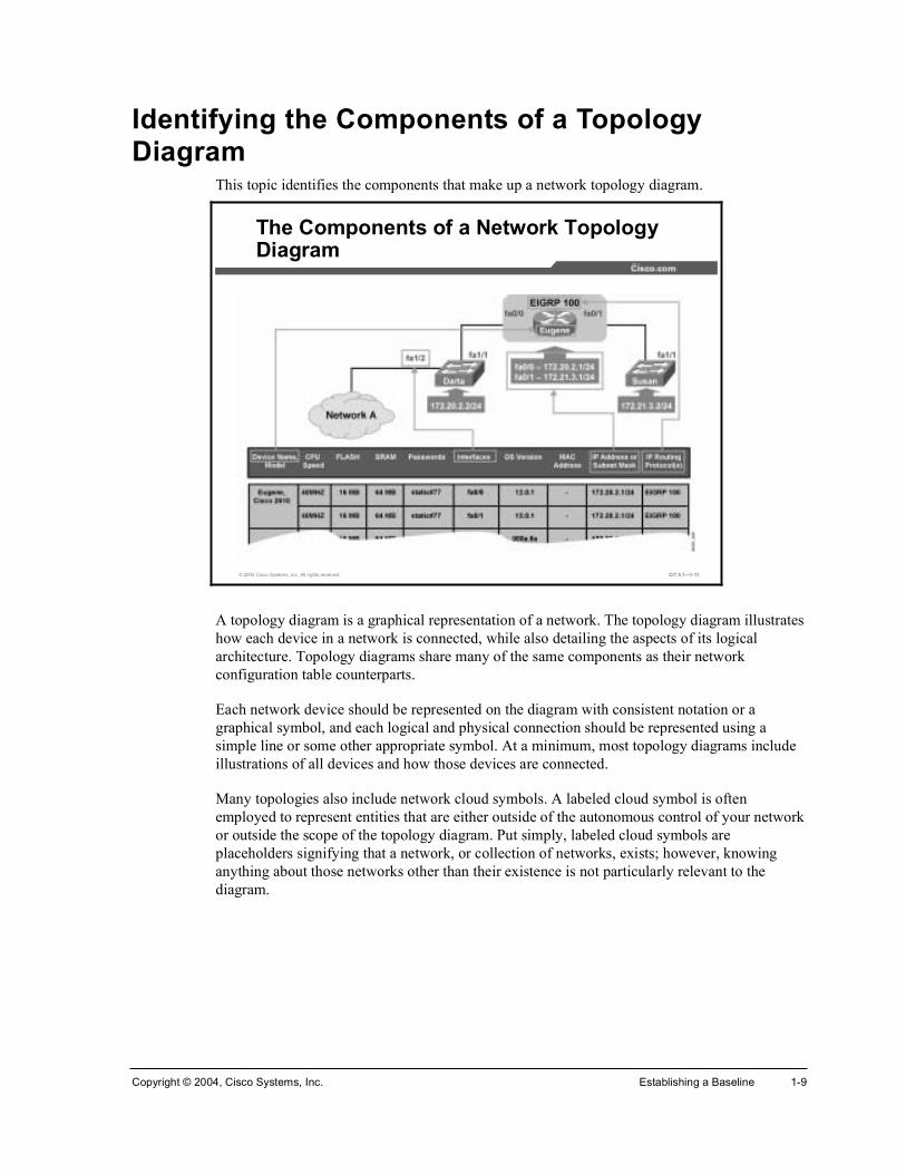
A topology diagram is a graphical representation of a network. The topology diagram illustrates how each device in a network is connected, while also detailing the aspects of its logical architecture. Topology diagrams share many of the same components as their network configuration table counterparts.
Each network device should be represented on the diagram with consistent notation or a graphical symbol, and each logical and physical connection should be represented using a simple line or some other appropriate symbol. At a minimum, most topology diagrams include illustrations of all devices and how those devices are connected.
Many topologies also include network cloud symbols. A labeled cloud symbol is often employed to represent entities that are either outside of the autonomous control of your network or outside the scope of the topology diagram. Put simply, labeled cloud symbols are placeholders signifying that a network, or collection of networks, exists; however, knowing anything about those networks other than their existence is not particularly relevant to the diagram.

1-10 Cisco Internetwork Troubleshooting (CIT) v5.1 Copyright © 2004, Cisco Systems, Inc.
© 2004 Cisco Systems, Inc. All rights reserved. CIT 5.1—1-12
Topology Diagram Components
Physical Layer
• Device Name• Media Type• Interface Name• Speed
Data Link Layer
• MAC Address• VLANs• EtherChannel• Trunk• STP Route• Encapsulation
Network Layer
• IP Address• Subnet Mask• Routing Protocol(s)
Although the components of a topology diagram can be restricted to a particular layer of the TCP/IP model, most often they are a combination of the most important components of several logical layers. To illustrate the important components of a network at the Internet TCP/IP layer, you might include IP addresses, subnet masks, and routing protocols.
Some topologies are informal hand-drawn sketches, while others are more elaborate, using detailed symbols, multiple colors, and different ways to view them. The latter are typically created using graphics applications that vary in functionality. While some applications can be used as a solution to manually create a network diagram, others can automatically create and maintain a topology of an existing network.

Copyright © 2004, Cisco Systems, Inc. Establishing a Baseline 1-11
Example: Network Topology Diagram This is an example of a topology diagram.
© 2004 Cisco Systems, Inc. All rights reserved. CIT 5.1—1-13
Network Topology Diagram (Example No. 1)
This topology diagram includes the following components:
!" Device name
!" Interface or port name
!" IP address
!" Routing protocol(s)

1-12 Cisco Internetwork Troubleshooting (CIT) v5.1 Copyright © 2004, Cisco Systems, Inc.
This is a second example of a topology diagram.
© 2004 Cisco Systems, Inc. All rights reserved. CIT 5.1—1-14
Network Topology Diagram (Example No. 2)
This example shows the following components of a network topology diagram:
!" Device name
!" Interface or port name
!" IP address
!" VLANs
!" Trunks

Copyright © 2004, Cisco Systems, Inc. Establishing a Baseline 1-13
Discovering Network Configuration Information This topic describes the procedure for discovering network configuration information.
© 2004 Cisco Systems, Inc. All rights reserved. CIT 5.1—1-15
Discovering Network Configurations on Routers and Multilayer Switches
Choose a starting point and view the name and model of the device. Also view the version of the operating system that the device is running
Determine active interfaces and their addresses
View a summary of the interfaces on the device, including the IP address/subnet mask, interface name, media type, and physical and data link operational status
View the MAC address for any interfaces or ports
Procedure: Discovering Network Configuration of a Router The following steps outline the procedure for discovering the network configuration of a router or multilayer switch:
Step 1 Choose a starting point and view the name and model of the device. Also view the version of the operating system that the device is running.
!" Enter show version.
Step 2 Determine active interfaces and their addresses.
!" Enter show ip interfaces.
Step 3 View a summary of the interfaces on the device, including the IP address or subnet mask, interface name, media type, and physical and data link operational status.
!" Enter show ip interfaces brief.
Step 4 View the MAC address for any interfaces or ports.
!" Enter show interface {interface-name} for each interface or enter showinterfaces to see a list of all interfaces at once.

1-14 Cisco Internetwork Troubleshooting (CIT) v5.1 Copyright © 2004, Cisco Systems, Inc.
© 2004 Cisco Systems, Inc. All rights reserved. CIT 5.1—1-16
Discovering Network Configurations on Routers and Multilayer Switches (Cont.)
View details about the spanning-tree status on the device
View a list of Cisco devices that are directly connected to the device that you are requesting from
View details about any connected device, such as its IP address and capabilities
View a summary of the IP routing protocols enabled for the device
Step 5 View a summary of the IP routing protocols enabled for the device.
!" Enter show ip protocols.
Step 6 View details about the spanning-tree status on the device.
!" Enter show spanning-tree summaryor show spanning-tree vlan {vlan-number}.
Step 7 View a list of Cisco devices that are directly connected to the device that you are requesting from.
!" Enter show cdp neighbors [detail] or, if cdp is disabled, enter ping.
Step 8 View details about any connected device, such as its IP address and capabilities.
!" Enter show cdp entry {device id}, show ip eigrp neighbors, or show ip ospf neighbor.
Note If CDP is disabled, you may want to enable CDP temporarily to make it easier to discover information about neighboring devices. However, enabling CDP on your devices does not guarantee that the neighboring devices will have CDP enabled.

Copyright © 2004, Cisco Systems, Inc. Establishing a Baseline 1-15
© 2004 Cisco Systems, Inc. All rights reserved. CIT 5.1—1-17
Discovering Network Configurations on Standard Switches
Choose a starting point and view the name and model of the device. Also view the version of the operating system that the device is running
Determine active ports
View a summary of the ports on the device, including port names, port status, duplex, and speed
View a summary of the EtherChannel configuration on the device
Procedure: Discovering Network Configuration of a Standard Switch
The following steps outline the procedure for discovering the network configuration of a standard switch:
Step 1 Choose a starting point and view the name and model of the device. Also view the version of the operating system that the device is running.
!" Enter show version.
Step 2 Determine active ports.
!" Enter show interfaces description.
Step 3 View a summary of the ports on the device, including port names, port status, duplex, and speed.
!" Enter show interfaces status.
Step 4 View a summary of the EtherChannel configuration on the device.
!" Enter show etherchannel summary.

1-16 Cisco Internetwork Troubleshooting (CIT) v5.1 Copyright © 2004, Cisco Systems, Inc.
© 2004 Cisco Systems, Inc. All rights reserved. CIT 5.1—1-18
Discovering Network Configurations on Standard Switches (Cont.)
View details about the spanning-tree status on the device
View a list of devices that are directly connected to the device from which you are requesting
View details about any connected device, such as its IP address and capabilities
View a summary of the trunk status of any ports that are in trunking mode
Step 5 View a summary of the trunk status of any ports that are in trunking mode.
!" Enter show interfaces trunk.
Step 6 View details about the spanning-tree status on the device.
!" Depending on the IOS version, enter either show spanning-treeor show spantree.
Step 7 View a list of devices that are directly connected to the device from which you are requesting.
!" Enter show cdp neighbors or, if CDP is disabled, enter ping.
Step 8 View details about any connected device, such as its IP address and capabilities.
!" Enter show cdp entry {entry name} or, if cdp is disabled, enter show mac-address table.
Note You can get all of this information by entering the show tech-support command, but be aware that the output from this command will give you a lot more information than you actually need.

Copyright © 2004, Cisco Systems, Inc. Establishing a Baseline 1-17
Describing the Process of Creating Network Documentation
This topic describes the process of creating network documentation.
© 2004 Cisco Systems, Inc. All rights reserved. CIT 5.1—1-19
Creating Network Documentation
Stage Description
Stage 1: Log In To start, log in to a device. If you are already in the middle of the process, log in to an undocumented neighboring device.
Stage 2: Interface Discovery Discover relevant information about the device. Relevant information is determined by the components of your network configuration table.
Stage 3: Document Document the information that you discover about the device on the network configuration table. If the information that you document is also a component of the topology diagram, proceed to Stage 4. If all of the relevant information about the device has been documented, skip Stage 4 and move on to Stage 5.
Stage 4: Diagram Transfer any information about the device from the network configuration table that corresponds with the components of your topology diagram. Once the information has been transferred, if all relevant information about the device has been documented, move on to Stage 5. Otherwise, return to Stage 2.
Stage 5: Device Discovery Determine if any devices that neighbor the device to which you are logged into are undocumented. If you determine that new neighboring devices exist, return to Stage 1. Otherwise, if there are no new neighboring devices, the network documentation is complete.

1-18 Cisco Internetwork Troubleshooting (CIT) v5.1 Copyright © 2004, Cisco Systems, Inc.
Note The process recommends that the network configuration table and topology diagram be created in concert. However, it may benefit you to create one type of document first depending on your specific needs and the amount of documentation that is already available.

Copyright © 2004, Cisco Systems, Inc. Establishing a Baseline 1-19
Creating Network Documentation This topic supplies guidelines for creating network documentation.
© 2004 Cisco Systems, Inc. All rights reserved. CIT 5.1—1-20
Guidelines for Creating Network Documentation
Determine the scope
Know your objective
Be consistent
Keep the documents accessible
Maintain the documentation!
Good network configuration documentation allows you to quickly learn specific information about network devices.
Guidelines for creating effective network documentation are as follows:
!" Determine the scope: To determine the scope of your network documentation, it is important to know which network devices are included in your domain of responsibility.
!" Know your objective: Only collect data that is relevant to your objective and provide sufficient detail for those relative pieces. Extra layers of information will only make the documentation more difficult to use.
!" Be consistent: Use consistent terminology, abbreviations, and style. Try to make the documents orderly and easy to understand. When possible, use templates and keep a library of symbols and graphic icons that you can re-use.
!" Keep the documents accessible: Store the network documentation in a location where it is readily available on the job. It is also suggested that a copy of the documentation be kept in a secure location offsite.
!" Maintain the documentation: Modify your network documentation as conditions and devices in the network change. This is especially important.
Note You may want to implement a process for handling changes to the network documentation. Factors in this process that need to be accounted for are reporting network changes, maintaining version control, and assigning responsibility for modifying and distributing updated documents.

1-20 Cisco Internetwork Troubleshooting (CIT) v5.1 Copyright © 2004, Cisco Systems, Inc.
Example: Creating Successful Network Documentation Last year, you were handed the task of documenting the network for your branch of the corporation. You completed this task on time and with compliments from your boss. One year later, troubleshooters still use the network documentation to successfully troubleshoot network problems. The following is a list of reasons why your documentation was a success:
!" You asked questions to find out exactly which network segments and devices were in your domain of responsibility.
!" You inquired about why the documentation was being created and what its uses would be. You then queried two of the most experienced network employees to learn which information would be most useful to meet those needs. As a result, you knew exactly what information to record and did not waste any time with unnecessary research.
!" You used a consistent symbology and terminology to represent the data in both graphical and tabular form.
!" You designated logical locations to store copies of the documentation and posted signage at those locations so that the networking employees could easily find them. You also employed a sign-out sheet so that the copies of the network documentation could be accounted for.
!" You implemented a reporting and system so that employees could relay information about changing conditions in the network to a central location. When a change in network conditions took place, employees knew whom to notify and that person promptly modified, dated, and distributed the updated versions to the designated locations.

Copyright © 2004, Cisco Systems, Inc. Establishing a Baseline 1-21
SummaryThis topic summarizes the key points discussed in this lesson.
© 2004 Cisco Systems, Inc. All rights reserved. CIT 5.1—1-21
Summary
• Network documentation consists of a network configuration table and topology diagram.
• The components of a network configuration table and topology diagram can be categorized by the logical layers that they are associated with in the TCP/IP networking model.
• Following a procedure, a troubleshooter can easily gather relevant configuration information about routers and switches.
• Performing the five stages in the process of creating network documentation allows a troubleshooter to create a network configuration table and topology diagram.
• Following guidelines makes it easy for a troubleshooter to create useful and effective network configuration documentation.
ReferencesFor additional information, refer to these resources:
!" http://www.cisco.com
!" Cisco IOS command reference guides
Next Steps For the associated lab exercise, refer to the following section of the course Lab Guide:
!" Lab Exercise 1-1: Network Baseline Discovery

1-22 Cisco Internetwork Troubleshooting (CIT) v5.1 Copyright © 2004, Cisco Systems, Inc.
QuizUse the practice items here to review what you have learned in this lesson. The correct answers are found in the Quiz Answer Key.
Q1) Which list only includes components of a network configuration table?
A) IP address, controller event, multipoint DLCI, map statement, interface name
B) bridge-zone, OSPF area, checksum, router ID, subnet mask
C) device name, interface name, MAC address, duplex, access lists
D) IP address, subnet mask, checksum, bytes, data flow status
Q2) At a minimum, a network topology diagram will include which components? (Choose two.)
A) devices
B) contact information
C) module firmware loaded
D) connections between devices
E) interface spanning-tree configuration
Q3) Which IOS command would you use to view a list of devices that are directly connected to the device from which you are making the request?
A) show ip interfaces
B) show spanning-tree
C) show cdp neighbors
D) show connected devices
Q4) What should be the first step when performing a network discovery?
A) determine active interfaces
B) choose a starting point
C) view interface summaries
D) view summary of IP routing protocols
Q5) Which are guidelines for creating useful network configuration documentation? (Choose three.)
A) use consistent symbols, terminology, and styles
B) know the scope of the documentation
C) update the documentation exactly once a year
D) store the documents in a logical location
E) gather all possible information

Copyright © 2004, Cisco Systems, Inc. Establishing a Baseline 1-23
Quiz Answer Key Q1) C
Relates to: Identifying the Components of a Network Configuration Table
Q2) A, D
Relates to: Identifying the Components of a Topology Diagram
Q3) C
Relates to: Discovering Network Configuration Information
Q4) B
Relates to: Describing the Process of Creating Network Documentation
Q5) A, B, D
Relates to: Creating Network Documentation

1-24 Cisco Internetwork Troubleshooting (CIT) v5.1 Copyright © 2004, Cisco Systems, Inc.
Creating End-System Network Configuration Documentation
OverviewNetwork documentation can be a valuable tool for troubleshooting. However, a network is not complete without end systems, and a misconfigured end system can have a negative impact on the overall performance of a network. This lesson discusses the creation of configuration documentation for the purposes of troubleshooting end systems connected to a network. The information contained in this lesson assumes a scenario in which network devices have already been documented and you are unfamiliar with the configuration. Therefore, you will need to create the end-system portion of the network documentation from scratch.
Relevance End-system devices, such as servers, network management consoles, and desktop workstations, play a large role in the way that a network operates; therefore, end-system devices should not be ignored. Maintaining relevant documentation about the configuration of end systems gives you a complete picture of the network and allows you to make intelligent decisions about any modifications or upgrades that end systems may require. The inclusion of end-system network configuration information in the baseline will enable you to troubleshoot problems in a timely and efficient manner.
ObjectivesUpon completing this lesson, you will be able to:
!" Identify the components of an end-system network configuration table
!" Identify the components of an end-system network topology diagram
!" Identify commands and applications used to discover information about end-system network configurations
!" Discover end-system network configuration information
!" Create an end-system network configuration table and end-to-end topology diagram

1-26 Cisco Internetwork Troubleshooting (CIT) v5.1 Copyright © 2004, Cisco Systems, Inc.
Learner Skills and Knowledge To benefit fully from this lesson, you must have these prerequisite skills and knowledge:
!" Basic knowledge of IP addressing and routing concepts on Windows 2000 devices
!" Advanced understanding of network topologies
OutlineThis lesson contains these topics:
!" Overview
!" Identifying the Components of an End-System Network Configuration Table
!" Identifying the Components of an End-System Network Topology Diagram
!" Identifying Commands and Applications Used to Gather Information About End-System Network Configurations
!" Discovering End-System Network Configuration Information
!" Creating End-System Network Configuration Documentation
!" Summary
!" Quiz

Copyright © 2004, Cisco Systems, Inc. Establishing a Baseline 1-27
Identifying the Components of an End-System Network Configuration Table
This topic identifies the components that troubleshooters should include in a network configuration table used to troubleshoot end systems.
© 2004 Cisco Systems, Inc. All rights reserved. CIT 5.1—1-5
An End-System Configuration Table
Device Name
(Purpose)
OperatingSystem/Version
IP Address/Subnet
DefaultGatewayAddress
DNS ServerAddress
WINS ServerAddress
NetworkApplications
Latency-Sensitive
Applications
An end-system network configuration table is baseline documentation that shows accurate records of the hardware and software used in end systems.
When creating an end-system network configuration table for troubleshooting, you should document the following:
!" Device name (purpose)
!" Operating system and version
!" IP address
!" Subnet mask
!" Default gateway, DNS server, and WINS server addresses
!" Any latency-sensitive network applications that the end system runs

1-28 Cisco Internetwork Troubleshooting (CIT) v5.1 Copyright © 2004, Cisco Systems, Inc.
© 2004 Cisco Systems, Inc. All rights reserved. CIT 5.1—1-6
Physical/Data Link Layer
Physical• Physical Location• Manufacturer/Model• CPU Type/Speed• RAM• Storage• Device Name• Device Purpose
Data Link• Access VLAN
Network Layer
• IP Address• Subnet Mask• Default Gateway• DNS Address• WINS Address
Application Layer
• OperatingSystem/Version
• Network Applications• High-Bandwidth
Applications• Latency-Sensitive
Applications
End-System Configuration Table Components Related to Troubleshooting
An end-system network configuration table will contain different components based on its use. Some tables are used administratively for inventory. Some simply list the physical location of the device and perhaps a note about when it needs to be backed up, while others are used as a tool for troubleshooting.
An end-system network configuration table used for troubleshooting typically varies, depending on the device being recorded. There are many different types of end systems and, therefore, there is quite a bit of information that you can record. To simplify things, it can be helpful to divide the information that you record into categories based on the relationship the component has with the layers of the TCP/IP networking model. It is important to find out which pieces of information are the most useful for troubleshooting your particular end systems.
Recording network applications that are available on an end system is useful information to include on an end-system network configuration table. It is also a good idea to record any high-bandwidth and latency-sensitive network applications that are running on the end-system, because they are likely to be a target of a troubleshooter. This is because these network applications can have a large impact on network performance. Examples of high-bandwidth applications are streaming video, such as QuickTime, and multicast applications, such as IP/TV.

Copyright © 2004, Cisco Systems, Inc. Establishing a Baseline 1-29
Example: End-System Network Configuration Table This example of a network configuration table contains information that troubleshooters can use to describe most end systems.
© 2004 Cisco Systems, Inc. All rights reserved. CIT 5.1—1-7
An Example of an End-System Network Configuration Table
Device Name
(Purpose)
OperatingSystem/Version
IP Address/Subnet
DefaultGatewayAddress
DNSAddress
WINS Address
NetworkApplications
Latency-Sensitive
Applications
Win NT
Win NT
Unix
Unix
Unix
10.32.6.2/24
10.22.1.2/24
10.22.2.2/24
10.32.3.4/24
10.32.4.1/24
10.32.6.1/24
10.22.1.1/24
10.22.2.1/24
10.32.3.1/24
10.32.4.2/24
10.100.17.10
10.100.17.10
10.100.17.10
10.100.17.10
10.100.17.10
10.32.6.100
10.22.1.100
-
-
-
Telnet, HTTP, FTP,
SMTP
Telnet, HTTP, FTP,
SMTP
Telnet, HTTP, FTP,
SMTP
Telnet, HTTP, FTP,
SMTP
Telnet, HTTP, FTP,
SMTP
-
-
-
-
-
Serve1(File
Server)
DNS01(DNS
Server)
TermA(Admin
Terminal)
DB01(Ecommerce
Database
Serve2(Web/FTPServer)
In this example, the following categories are used to document the network-related properties of a device:
!" Device name (purpose)
!" Operating system and version
!" IP address or subnet mask
!" Default gateway address
!" DNS server address
!" WINS server address
!" Network applications
!" Latency-sensitive applications

1-30 Cisco Internetwork Troubleshooting (CIT) v5.1 Copyright © 2004, Cisco Systems, Inc.
Identifying the Components of an End-System Network Topology Diagram
This topic identifies the components of a network topology diagram that pertain to end systems.
© 2004 Cisco Systems, Inc. All rights reserved. CIT 5.1—1-11
The End-System Components of a Topology Diagram
An end-system network topology is a graphical representation of the tabular data gathered in the end-system network configuration table. Topologies should illustrate how end systems are both physically and logically connected to the network. Since end systems are frequently added to existing network diagrams, topology diagrams that include end systems often also include components of network device configurations.
Like the network devices in a topology diagram, end systems in a network topology do not typically include every component of the end-system network configuration table. Minimally, the end systems on a topology diagram should include the name, and an illustration, of the device and how it is connected to the network.
Copyright © 2004, Cisco Systems, Inc. Establishing a Baseline 1-31
© 2004 Cisco Systems, Inc. All rights reserved. CIT 5.1—1-12
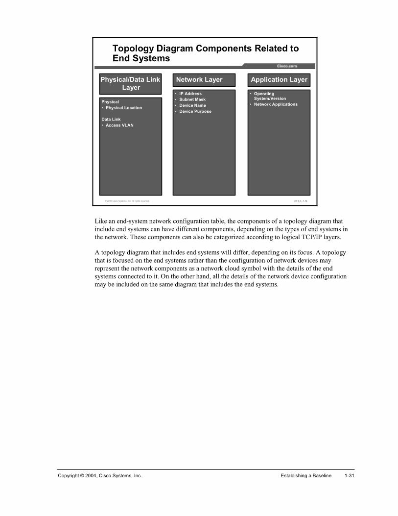
Physical/Data Link Layer
Physical• Physical Location
Data Link• Access VLAN
Network Layer
• IP Address• Subnet Mask• Device Name• Device Purpose
Application Layer
• Operating System/Version
• Network Applications
Topology Diagram Components Related to End Systems
Like an end-system network configuration table, the components of a topology diagram that include end systems can have different components, depending on the types of end systems in the network. These components can also be categorized according to logical TCP/IP layers.
A topology diagram that includes end systems will differ, depending on its focus. A topology that is focused on the end systems rather than the configuration of network devices may represent the network components as a network cloud symbol with the details of the end systems connected to it. On the other hand, all the details of the network device configuration may be included on the same diagram that includes the end systems.

1-32 Cisco Internetwork Troubleshooting (CIT) v5.1 Copyright © 2004, Cisco Systems, Inc.
Example: Topology Diagram with Both Network Devices and End Systems
This is an example of a topology diagram that includes both network devices and end systems.
© 2004 Cisco Systems, Inc. All rights reserved. CIT 5.1—1-13
A Network Topology Diagram That Includes End-Systems
This example includes the following components related to end systems:
!" Device name and purpose
!" Operating system
!" IP address

Copyright © 2004, Cisco Systems, Inc. Establishing a Baseline 1-33
Identifying Commands and Applications Used to Gather Information About End-System Network Configurations
This topic identifies commands and applications that troubleshooters use to gather information about the network configuration of end systems.
© 2004 Cisco Systems, Inc. All rights reserved. CIT 5.1—1-14
°·²¹°·²¹
• Sends an echo request packet to an address, then waits for a reply.
General Commands to Gather Information About End Systems
¿®° ó¿¿®° ó¿
• Displays the current mappings of the IP address to the MAC address in the ARP table.
¬»´²»¬¬»´²»¬
• Used to gain terminal access to devices on a network.
The table shows general commands that a troubleshooter uses to gather information about the network configuration of an end system. These commands are considered general because they can be applied on end systems running the most common operating systems.
General Commands to Gather Information About End Systems
Command Description
°·²¹ ¥¸±¬ ¤ ·°ó¿¼¼®»£
Sends an echo request packet to an address, then waits for a reply. The host | ip-address variable is the IP alias or IP address of the target system.
¿®° �¿ Displays the current mappings of the IP address to the MAC address in the Address Resolution Protocol (ARP) table.
¬»´²»¬ Used to gain terminal access to devices on a network. A successful connection is also an indication that the end system supports the TCP protocol.

1-34 Cisco Internetwork Troubleshooting (CIT) v5.1 Copyright © 2004, Cisco Systems, Inc.
© 2004 Cisco Systems, Inc. All rights reserved. CIT 5.1—1-15
Windows Commands to Gather Information About End Systems
·°½±²º·¹ ñ¿´´·°½±²º·¹ ñ¿´´
• Displays IP information for hosts running Windows NT/2000/XP.
ÝæÄâ
¬®¿½»®¬ 󼬮¿½»®¬ ó¼
• Uses ICMP to identify a path to a destination device without performing a DNS lookup.
ÝæÄâ
®±«¬» °®·²¬®±«¬» °®·²¬
• Displays the current contents of the entire IP routing table.
ÝæÄâ
© 2004 Cisco Systems, Inc. All rights reserved. CIT 5.1—1-16
Windows Commands to Gather Information About End Systems (Cont.)
©·²·°½º¹©·²·°½º¹
• Displays IP information for hosts running Windows 9x and Me.
ÝæÄâ

Copyright © 2004, Cisco Systems, Inc. Establishing a Baseline 1-35
The table shows commands that a troubleshooter uses on an end system running a Windows operating system to gather information about the network configuration of an end system.
Windows Commands to Gather Information About End Systems
Command Description
·°½±²º·¹ ñ¿´´ Displays IP information for hosts running Windows NT/2000/XP.
¬®¿½»®¬ ó¼Å¼»¬·²¿¬·±²Ã
Uses Internet Control Message Protocol (ICMP) to identify a path to a destination device for Windows hosts without performing a Domain Name System (DNS) lookup.
®±«¬» °®·²¬ Displays the current contents of the entire IP routing table.
©·²·°½º¹ Displays IP information for hosts running Windows 9x and Me.

1-36 Cisco Internetwork Troubleshooting (CIT) v5.1 Copyright © 2004, Cisco Systems, Inc.
© 2004 Cisco Systems, Inc. All rights reserved. CIT 5.1—1-17
UNIX or Mac OS X Commands to Gather Information About End Systems
·º½±²º·¹ ó¿·º½±²º·¹ ó¿
• Displays IP information.
¬»®³·²¿´û
¬®¿½»®±«¬»¬®¿½»®±«¬»
• Uses UDP to identify the path that a packet takes through the network.
¬»®³·²¿´û
®±«¬» ó²®±«¬» ó²
• Displays the current contents of the entire IP routing table.
¬»®³·²¿´û
The table shows commands that a troubleshooter uses on an end system running the UNIX or Mac OS X operating systems to gather information about the network configuration of an end system.
UNIX or Mac OS X Commands to Gather Information About End Systems
Command Description
·º½±²º·¹ ó¿ Displays IP information for UNIX and Mac OS X hosts.
¬®¿½»®±«¬»Å¼»¬·²¿¬·±²Ã
Uses User Datagram Protocol (UDP) to identify the path a packet takes through the network. The destination variable is the host name or IP address of the target system.
®±«¬» ó² Displays the current contents of the entire IP routing table.

Copyright © 2004, Cisco Systems, Inc. Establishing a Baseline 1-37
Discovering End-System Network Configuration Information
This topic describes the procedure of discovering end-system network configuration information.
© 2004 Cisco Systems, Inc. All rights reserved. CIT 5.1—1-18
Discovering End-System Network Configurations
Choose a starting point and view information about the operating system and hardware of the device.
Access a command line.
View detailed information about the TCP/IP settings of the device.
Display any active routes.
Procedure: Discovering End-System Network Configurations The following steps outline the procedure for discovering the network configuration of an end system:
Step 1 Choose a starting point and view information about the operating system and hardware of the device.
Note On a Windows end system, information about the operating system and hardware can be accessed by choosing Start>Settings>Control Panel and then double-clicking the Systems icon. On a Mac running Mac OS X, click the Apple icon and choose About ThisMac.
Step 2 Access a command line.
Note To access a command line on a Windows end system, choose MS-DOS or the command prompt from the Start menu. The command line terminal utility on Mac OS X can be found in the Utilities folder located in the Applications directory.

1-38 Cisco Internetwork Troubleshooting (CIT) v5.1 Copyright © 2004, Cisco Systems, Inc.
Step 3 View detailed information about the TCP/IP settings of a device. This is accomplished by entering the ipconfig /all or winipcfg commands in a Windows command prompt or entering ifconfig -a in a UNIX or Mac OS X command line. The important information to record includes the following: IP address/subnet mask, default gateway address, and any DNS or WINS server addresses.
Note When viewing the information returned from ipconfig /all, it is helpful to note if the IP address of a device is static or if it has been temporarily assigned through DHCP.
Step 4 Display any active routes by entering the route print command in a Windows command prompt or entering route –n in a UNIX or Mac OS X command line.
© 2004 Cisco Systems, Inc. All rights reserved. CIT 5.1—1-19
Discovering End-System Network Configurations (Cont.)
Check connectivity to remote devices.
View the route that is used to connect to a remote address, such as the default gateway.
Check that TCP is available and functioning on the end system.
View Address Resolution Protocol (ARP) information.
Step 5 View ARP information by entering the arp -a command.
Step 6 Check connectivity to remote devices by attempting to ping a device across a link.
Step 7 View the route that is used to connect to a remote address, such as the default gateway. To accomplish this, enter tracert {ip-address | hostname} in a Windows command prompt or enter traceroute {ip-address | hostname} in a UNIX or Mac OS X command line.
Step 8 Check that TCP is available and functioning on the end system by entering the telnet {ip-address | hostname} command.

Copyright © 2004, Cisco Systems, Inc. Establishing a Baseline 1-39
Creating End-System Network Configuration Documentation
This topic identifies guidelines for troubleshooters to create end-system network configuration documentation.
© 2004 Cisco Systems, Inc. All rights reserved. CIT 5.1—1-20
Guidelines for Creating Network Documentation
Determine the scope
Know your objective
Be consistent
Keep the documents accessible
Maintain the documentation!
Good end-system network configuration documentation allows you to quickly learn specific information about end systems.
Guidelines for creating effective end-system network documentation are as follows:
!" Determine the scope: To determine the scope of your end-system network documentation, it is important to know which end systems are included in your domain of responsibility.
!" Know your objective: Only collect data that is relevant to your objective and provide sufficient detail for those relative pieces. Extra layers of information will only make the documentation more difficult to use.
!" Be consistent: Use consistent terminology, abbreviations, and style. Try to make the documents orderly and easy to understand. When possible, use templates and keep a library of symbols and graphic icons that you can re-use.
!" Keep the documents accessible: Store the network documentation in a location where it is readily available on the job. It is also suggested that a copy of the documentation be kept in a secure location offsite.
!" Maintain the documentation: Modify your network documentation as conditions and devices in the network change. This is especially important.

1-40 Cisco Internetwork Troubleshooting (CIT) v5.1 Copyright © 2004, Cisco Systems, Inc.
Note You may want to implement a process for handling changes to the network documentation. Factors in this process that need to be accounted for are reporting network changes, maintaining version control, and assigning responsibility for modifying and distributing updated documents.
Example: Creating Successful End-System Network Configuration Documentation
At your company, your primary job function is to maintain and troubleshoot network servers and desktops. You and your team already do a respectable job of fixing problems, but you have been asked to create documentation of the network end systems to expedite troubleshooting efforts and cut down on costs. Your company currently has configuration tables and topology diagrams of your network configuration without end systems.
A month later, the network support staff has been using the end-system documentation for troubleshooting. Estimates have determined that the time that your department spends troubleshooting end systems in the past month has dropped considerably. Your documentation was a success for the following reasons:
!" You had a good idea of what the scope of the documentation should be because you were already familiar with the end systems on your network.
!" You recorded the appropriate types and amounts of information for each documented end system.
!" You used symbols and terminology consistent with the existing network documentation that your co-workers were already familiar with.
!" You kept the documentation current by implementing a system for employees to report changes, and updating the documentation in a timely manner has been added to your job description.
!" You stored the documentation in convenient and clearly marked locations close to each administrative terminal.

Copyright © 2004, Cisco Systems, Inc. Establishing a Baseline 1-41
SummaryThis topic summarizes the key points discussed in this lesson.
© 2004 Cisco Systems, Inc. All rights reserved. CIT 5.1—1-21
Summary
• End-system documentation consists of a configuration table and end-to-end topology diagram.
• The components of an end-system configuration table and topology diagram can be split into physical and logical categories.
• Following a procedure, a troubleshooter can easily gather relevant configuration information about a variety of end systems.
• There are several commands and applications available for discovering configuration information about an end system.
• Good end-system configuration documentation allows you to quickly learn specific information about end systems.
ReferencesFor additional information, refer to this resource:
!" http://www.cisco.com/
Next Steps For the associated lab exercise, refer to the following section of the course Lab Guide:
!" Lab Exercise 1-2: Creating End-System Baseline Discovery

1-42 Cisco Internetwork Troubleshooting (CIT) v5.1 Copyright © 2004, Cisco Systems, Inc.
QuizUse the practice items here to review what you have learned in this lesson. The correct answers are found in the Quiz Answer Key.
Q1) Which list includes only components of an end-system network configuration table?
A) PortFast, IP address, network applications, trunk status
B) IOS type/version, subnet mask, default gateway address, STP state
C) IP address, subnet mask, routing protocol, duplex, access list
D) IP address, default gateway, WINS address, networked applications
Q2) Which list includes only components of a topology diagram that are related to end systems?
A) trunk status, PortFast, subnet mask
B) MAC address, network applications, IP address
C) duplex, interface name, routing protocol
D) IP address, subnet mask, STP state
Q3) Which end-system command would be used to view the address that a host dynamically obtains from DHCP?
A) ping
B) route print
C) show ip resolve
D) ipconfig /all
Q4) Which step in the process of discovering end-system network configurations will give you a list of the active routes for a host?
A) entering the ipconfig/all command
B) entering the tracert command
C) entering the route print command
D) using Telnet to connect to a device
Q5) To reduce the amount of paperwork generated by documenting end systems, which guideline should you follow?
A) document all possible aspects of the hardware and network configuration of an end system
B) create separate end-system topology diagrams instead of adding end systems to existing network diagrams
C) determine an objective for the documentation and collect data that meets that objective
D) document desktops and laptops along with infrastructure devices such as servers and databases

Copyright © 2004, Cisco Systems, Inc. Establishing a Baseline 1-43
Quiz Answer Key Q1) D
Relates to: Identifying the Components of an End-System Network Configuration Table
Q2) B
Relates to: Identifying the Components of an End-System Network Topology Diagram
Q3) D
Relates to: Identifying Commands and Applications Used to Gather Information About End-System Network Configurations
Q4) C
Relates to: Discovering End-System Network Configuration Information
Q5) C
Relates to: Creating End-System Network Configuration Documentation

1-44 Cisco Internetwork Troubleshooting (CIT) v5.1 Copyright © 2004, Cisco Systems, Inc.
Module 2
Determining an Effective Troubleshooting Strategy
OverviewAn organization depends on its users being able to access network resources to conduct its daily business. When you determine an effective troubleshooting strategy, you can isolate problems and implement solutions quicker and more cost-effectively than without a strategy. Thus, you can quickly restore the vital network functionality on which your organization relies. If you do not have an effective troubleshooting strategy, you can lose business opportunities, profits, and end-user confidence in the competence of your organization. In this module, you will take what you already know about logical layered models and apply that knowledge to a physical network. You will then use your understanding of those layers to select a troubleshooting approach and gather symptoms from network devices, users, and end systems.
Module Objectives Upon completing this module, you will be able to:
!" Identify the layer or layers in the OSI and TCP/IP models that encapsulated data flow maps to at each component of a logical network
!" Describe a general network troubleshooting process
!" Gather information about the symptoms of a network problem
!" Select an approach for troubleshooting network problems
Module Outline The module contains these components:
!" Applying a Layered Model to a Network
!" Describing a General Troubleshooting Process
!" Gathering Symptoms
!" Selecting a Troubleshooting Approach
!" Lesson Assessments

2-2 Cisco Internetwork Troubleshooting (CIT) v5.1 Copyright © 2004, Cisco Systems, Inc.

Applying a Layered Model to a Network
OverviewIn the previous module, you focused on the physical aspects of a network. You determined which equipment was being used in your network and how those devices were connected to establish a baseline. In this lesson, you will learn how to apply a layered networking model to your network to help you troubleshoot variances off your baseline. When you apply a layered model to a network, you divide the complexity of the problem into more manageable and understandable parts. This allows you to resolve problems quickly.
Relevance Logical networking models separate network functionality into modular layers. You apply these modular layers to your network to isolate problems and even create divisions of labor. For example, if the symptoms of a communications problem suggest a physical connection problem, the telephone company service person can focus on troubleshooting the T1 circuit (operating at the physical layer). The repairperson does not have to know anything about TCP/IP (operating at the network layer) or attempt to make changes to devices operating outside of the realm of the suspected logical layer. The repairperson concentrates on the physical circuit. If the circuit checks out OK, either the repairperson or a different specialist looks at areas in another layer that could be causing the problem.
ObjectivesUpon completing this lesson, you will be able to:
!" Match the layers of the TCP/IP model to the layers of the OSI model
!" Identify the stages of data flow through a fully functioning network with interconnecting end systems using Cisco routers and switches
!" Identify the logical layer or layers that encapsulated data is at as it flows through a logical network end-to-end

2-4 Cisco Internetwork Troubleshooting (CIT) v5.1 Copyright © 2004, Cisco Systems, Inc.
Learner Skills and Knowledge To benefit fully from this lesson, you must have these prerequisite skills and knowledge:
!" Familiarity with the Cisco IOS commands covered in the Cisco Building Scalable Cisco Internetworks (BSCI), Building Cisco Multilayer Switched Networks (BCMSN), and Building Cisco Remote Access Networks (BCRAN) courses
!" An understanding of basic encapsulated data concepts
!" The ability to analyze debug information
OutlineThis lesson includes these topics:
!" Overview
!" Comparing Layered Networking Models
!" Identifying the Encapsulated Data Flow Process
!" Identifying the Layers of a Logical Model
!" Summary
!" Quiz

Copyright © 2004, Cisco Systems, Inc. Determining an Effective Troubleshooting Strategy 2-5
Comparing Layered Networking Models This topic matches the logical layers of the Open Systems Interconnection (OSI) networking model to the TCP/IP networking model.
© 2004 Cisco Systems, Inc. All rights reserved. CIT 5.1—2-8
Comparing the OSI Model with the TCP/IP Model
Similar to the OSI networking model, the TCP/IP networking model divides networking architecture into modular layers. The figure and the table show how the TCP/IP networking model maps to the layers of the OSI networking model. It is this close mapping that allows the TCP/IP suite of protocols to successfully communicate with so many networking technologies.
Describing the TCP/IP Layers and Their Relationship to the OSI Model
TCP/IP Layer In the OSI Model, Maps to Description
Network Interface Physical
Data Link
The network interface layer frames and encapsulates data and transmits the encapsulated data to the physical interface.
Internet Network This Internet layer of the TCP/IP protocol provides connectivity and path selection between two end systems. This is the layer at which routing occurs.
Transport Transport The transport layer is responsible for exchanging segments between devices on a TCP/IP network.
Application Session
Presentation
Application
The application layer provides communication between applications, such as FTP, HTTP, and Simple Mail Transfer Protocol (SMTP) on separate hosts.

2-6 Cisco Internetwork Troubleshooting (CIT) v5.1 Copyright © 2004, Cisco Systems, Inc.
Note The TCP/IP model illustrates the close relationship between the session, presentation, and application OSI layers by combining them into a single layer. Given this close relationship, this course will refer to a component of any of these three layers as part of the application layer.

Copyright © 2004, Cisco Systems, Inc. Determining an Effective Troubleshooting Strategy 2-7
Identifying the Encapsulated Data Flow Process This topic identifies the process of encapsulated data flow through an end-to-end network.
© 2004 Cisco Systems, Inc. All rights reserved. CIT 5.1—2-13
The Process of Encapsulated Data Flow on a Simple Connection
Sending data from an application in End-System A to an application in End-System B.
The table describes the stages in the process of sending encapsulated data between end systems.
Sending Encapsulated Data Between Two End Systems
Stage Description
Origination End-System A takes data from an application and converts it as needed for transmission over a physical network.
This involves the following:
Converting data into segments
Encapsulating segments with a header that includes network addressing information and converting segments into packets
Encapsulating packets with a header that includes physical addressing information and converting packets into frames
Converting frames into bits
Transport Data passes over physical medium as bits.
Forwarding When data reaches a network device, the device removes data control information as needed. Standard switches read physical addressing information and forward frames to an interface. Routers, firewalls, and multilayer switches read network addressing information and forward packets to an interface. The transport and forwarding stages alternate until the data flows through all devices that are necessary to reach the interface of the target end system.
Terminating The interface of End-System B receives the data from the physical medium, removes the data control information, and converts the data as needed for use with the target application.

2-8 Cisco Internetwork Troubleshooting (CIT) v5.1 Copyright © 2004, Cisco Systems, Inc.
Identifying the Layers of a Logical Model This topic identifies the logical layers that a troubleshooter should focus on when troubleshooting specific networking devices.
© 2004 Cisco Systems, Inc. All rights reserved. CIT 5.1—2-14
Physical Data Link Network Transport Application
Network Devices Mapped to a Logical Layered Model
Firewall X
Standard Switch X X
Multilayer Switch X X
Hub
End-System XX X
Router X XX
X X
*
*
*X
X
X X
Note Devices marked with an asterisk (*) can have some involvement with the indicated layer, but do not perform primary functions at that layer.
The ability to identify which layers pertain to a networking device gives a troubleshooter the ability to minimize the complexity of a problem by dividing the problem into manageable parts. For instance, knowing that network layer issues are of no importance to a switch (aside from multilayer switches) defines the boundaries of your task to the physical and data link layers. Given that there is still plenty to consider at only these two layers, this simple knowledge can prevent you from troubleshooting irrelevant possibilities and will significantly reduce the amount of time that you spend attempting to correct a problem. However, it is still important to note that there are network applications that are part of these devices that move into the session, presentation, and application layers.

Copyright © 2004, Cisco Systems, Inc. Determining an Effective Troubleshooting Strategy 2-9
SummaryThis topic summarizes the key points discussed in this lesson.
© 2004 Cisco Systems, Inc. All rights reserved. CIT 5.1—2-15
Summary
• In addition to the OSI model, the TCP/IP model can be used to divide networking architecture into simple and modular layers.
• The ability to identify the stages of the encapsulated data flow process enhances the ability of a troubleshooter to diagnose problems as data moves between points within an end-to-end network.
• The ability to identify which logical layers a device uses gives a troubleshooter the ability to minimize the complexity of a problem by dividing the problem into manageable parts.
ReferencesFor additional information, refer to this resource:
!" http://www.cisco.com/tac/
Next Steps For the associated lab exercise, refer to the following section of the course Lab Guide:
!" Lab Exercise 2-1: Applying a Layered Model to a Network
2-10 Cisco Internetwork Troubleshooting (CIT) v5.1 Copyright © 2004, Cisco Systems, Inc.
QuizUse the practice items here to review what you have learned in this lesson. The correct answers are found in the Quiz Answer Key.
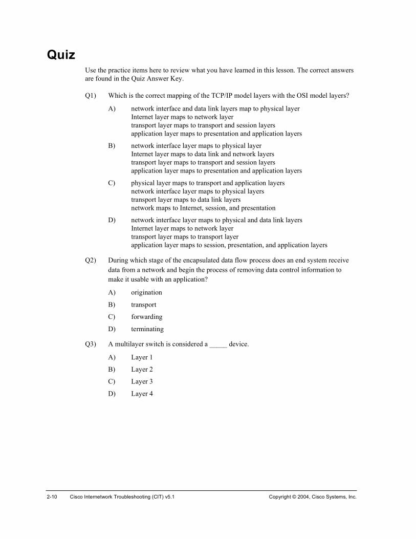
Q1) Which is the correct mapping of the TCP/IP model layers with the OSI model layers?
A) network interface and data link layers map to physical layer Internet layer maps to network layer transport layer maps to transport and session layers application layer maps to presentation and application layers
B) network interface layer maps to physical layer Internet layer maps to data link and network layers transport layer maps to transport and session layers application layer maps to presentation and application layers
C) physical layer maps to transport and application layers network interface layer maps to physical layers transport layer maps to data link layers network maps to Internet, session, and presentation
D) network interface layer maps to physical and data link layers Internet layer maps to network layer transport layer maps to transport layer application layer maps to session, presentation, and application layers
Q2) During which stage of the encapsulated data flow process does an end system receive data from a network and begin the process of removing data control information to make it usable with an application?
A) origination
B) transport
C) forwarding
D) terminating
Q3) A multilayer switch is considered a _____ device.
A) Layer 1
B) Layer 2
C) Layer 3
D) Layer 4

Copyright © 2004, Cisco Systems, Inc. Determining an Effective Troubleshooting Strategy 2-11
Quiz Answer Key Q1) D
Relates to: Comparing Layered Networking Models
Q2) D
Relates to: Identifying the Encapsulated Data Flow Process
Q3) C
Relates to: Identifying the Layers of a Logical Model

2-12 Cisco Internetwork Troubleshooting (CIT) v5.1 Copyright © 2004, Cisco Systems, Inc.

Describing a General Troubleshooting Process
OverviewYou must have a specific methodology to follow to effectively solve a problem. In this lesson, you will learn a general troubleshooting process that can be applied to any network troubleshooting situation.
Relevance Having a general troubleshooting process gives you a method to follow for any troubleshooting situation. Applying this general process helps a troubleshooter resolve problems quicker and more cost-effectively because it reduces the possibility that a troubleshooter will waste time or get confused.
ObjectivesUpon completing this lesson, you will be able to:
!" Describe the general troubleshooting process
!" Describe the Gathering Symptoms stage of the general troubleshooting process
!" Describe the Isolate the Problem stage of the general troubleshooting process
!" Describe the Correct the Problem stage of the general troubleshooting process
Learner Skills and Knowledge To benefit fully from this lesson, you must have these prerequisite skills and knowledge:
!" Familiarity with the OSI and TCP/IP networking model concepts

2-14 Cisco Internetwork Troubleshooting (CIT) v5.1 Copyright © 2004, Cisco Systems, Inc.
OutlineThis lesson includes these topics:
!" Overview
!" Describing the General Troubleshooting Process
!" Describing the Gathering Symptoms Stage
!" Describing the Isolate the Problem Stage
!" Describing the Correct the Problem Stage
!" Summary
!" Quiz

Copyright © 2004, Cisco Systems, Inc. Determining an Effective Troubleshooting Strategy 2-15
Describing the General Troubleshooting Process This topic describes the general process that a troubleshooter should use when faced with a networking problem.
© 2004 Cisco Systems, Inc. All rights reserved. CIT 5.1—2-5
The General Troubleshooting Process
The stages of the general troubleshooting process are Gather Symptoms, Isolate the Problem, and Correct the Problem. The stages are not mutually exclusive. At any point in the process, you may retrace your steps. For instance, while you are isolating a problem, you may need to gather more symptoms. Or, perhaps when you attempt to correct a problem, you cause another unidentified problem. As a result, you need to gather the symptoms, isolate, and correct the new problem.
You should establish a policy for each stage. A policy will give you a consistent manner in which to perform each stage. Part of your policy should include documenting every important piece of information.

2-16 Cisco Internetwork Troubleshooting (CIT) v5.1 Copyright © 2004, Cisco Systems, Inc.
Describing the Gathering Symptoms Stage This topic describes the Gathering Symptoms stage of the general troubleshooting process of which troubleshooters should be aware.
© 2004 Cisco Systems, Inc. All rights reserved. CIT 5.1—2-6
The Gathering Symptoms Stage of the General Troubleshooting Process
To perform the Gathering Symptoms stage of the general troubleshooting process, the troubleshooter gathers and documents symptoms from the network, end systems, or users. In addition, the troubleshooter determines what network components have been affected and how the functionality of the network has changed compared to the baseline. Symptoms may appear in many different forms. These forms include alerts from the network management system, console messages, and user complaints.
While you gather symptoms, you will use questions as a method of localizing the problem to a smaller range of possibilities. However, you have not truly isolated the problem until you have identified a single problem or a set of related problems.

Copyright © 2004, Cisco Systems, Inc. Determining an Effective Troubleshooting Strategy 2-17
Describing the Isolate the Problem Stage This topic describes the Isolate the Problem stage of the general troubleshooting process of which troubleshooters should be aware.
© 2004 Cisco Systems, Inc. All rights reserved. CIT 5.1—2-7
The Isolate the Problem Stage of the General Troubleshooting Process
To perform the Isolate the Problem stage of the general troubleshooting process, the troubleshooter identifies the characteristics of problems at the logical layers of the network so that the most likely cause can be selected. At this stage, the troubleshooter may gather and document more symptoms depending on the problem characteristics that are identified.

2-18 Cisco Internetwork Troubleshooting (CIT) v5.1 Copyright © 2004, Cisco Systems, Inc.
Describing the Correct the Problem StageThis topic describes the Correct the Problem stage of the general troubleshooting process of which troubleshooters should be aware.
© 2004 Cisco Systems, Inc. All rights reserved. CIT 5.1—2-8
The Correct the Problem Stage of the General Troubleshooting Process
To perform the Correct the Problem stage of the general troubleshooting process, the troubleshooter corrects an identified problem by implementing, testing, and documenting a solution. If corrective actions do not fix the problem, it is important that a troubleshooter reverses any changes that were made that did not create a positive result toward the solution. If, when testing the correction results, the troubleshooter determines that another problem has been created, the attempted solution is documented and the troubleshooter returns to gathering symptoms and isolating the problem.

Copyright © 2004, Cisco Systems, Inc. Determining an Effective Troubleshooting Strategy 2-19
SummaryThis topic summarizes the key points discussed in this lesson.
© 2004 Cisco Systems, Inc. All rights reserved. CIT 5.1—2-9
Summary
• The stages of the general troubleshooting process are Gathering Symptoms, Isolate the Problem, and Correct the Problem.
• At the Gathering Symptoms stage, troubleshooters gather and document symptoms from the network and end systems to determine how the state of the network has changed compared to the baseline.
• At the Isolate the Problem stage, troubleshooters identify the characteristics of problems at the logical layers of the network so that the most likely cause can be selected.
• At the Correct the Problem stage, troubleshooters correct an identified problem by implementing, testing, and documenting a solution.
ReferencesFor additional information, refer to this resource:
!" http://www.cisco.com/univercd/home/home.htm

2-20 Cisco Internetwork Troubleshooting (CIT) v5.1 Copyright © 2004, Cisco Systems, Inc.
QuizUse the practice items here to review what you have learned in this lesson. The correct answers are found in the Quiz Answer Key.
Q1) Which statements are true about the stages of the general troubleshooting process? (Choose two.)
A) The stages are mutually exclusive.
B) The steps must be followed closely to avoid retracing.
C) At any stage, more symptoms may need to be collected.
D) You must establish a blanket policy that covers all stages.
E) any policy made should include documenting every important piece of information.
Q2) Which describes the Gathering Symptoms stage of the general troubleshooting process?
A) determining what network components have been affected
B) implementing, testing, and documenting a solution
C) selecting the most likely cause
D) making configuration changes to the routing table
Q3) Which describes the Isolate the Problem stage of the general troubleshooting process?
A) implementing, testing, and documenting a solution
B) backing up the current configuration
C) determining what network components have been affected
D) selecting the most likely cause
Q4) Which describes the Correct the Problem stage of the general troubleshooting process?
A) determining what network components have been affected
B) implementing, testing, and documenting a solution
C) interviewing an end user
D) selecting the most likely cause

Copyright © 2004, Cisco Systems, Inc. Determining an Effective Troubleshooting Strategy 2-21
Quiz Answer Key Q1) C, E
Relates to: Describing the General Troubleshooting Process
Q2) A
Relates to: Describing the Gathering Symptoms Stage
Q3) D
Relates to: Describing the Isolate the Problem Stage
Q4) B
Relates to: Describing the Correct the Problem Stage

2-22 Cisco Internetwork Troubleshooting (CIT) v5.1 Copyright © 2004, Cisco Systems, Inc.

Gathering Symptoms
OverviewIn the lesson “Describing a General Troubleshooting Process,” you learned the general troubleshooting process. The first stage of the process is where the troubleshooter gathers symptoms of the problem. By gathering symptoms, a troubleshooter builds a knowledge base about potential reasons for a problem. In this lesson, you will learn how to gather symptoms from network devices, end users, and end systems.
RelevanceWhen troubleshooters jump to conclusions, their assumptions can be their worst enemy. When you gather symptoms, you create a complete description of a problem. With an incomplete view of the problem, you can jump to erroneous conclusions and spend wasted time and resources on things that have nothing to do with the problem at hand. The time you spend gathering symptoms allows you to spend less time randomly trying solutions. When you diagnose and fix problems in your network, you must gather a complete list of symptoms before attempting a correction.
ObjectivesUpon completing this lesson, you will be able to:
!" Gather symptoms from network devices to complete a list of network symptoms
!" Gather hardware and software symptoms from user feedback to complete a list of symptoms at the end system
!" Gather data at the end system to complete a list of hardware and software symptoms displayed at the end system
Learner Skills and Knowledge To benefit fully from this lesson, you must have these prerequisite skills and knowledge:
!" Familiarity with layered model troubleshooting approaches
!" Familiarity with the Cisco IOS commands covered in the Cisco Building Scalable Cisco Internetworks (BSCI), Building Cisco Multilayer Switched Networks (BCMSN), and Building Cisco Remote Access Networks (BCRAN) courses

2-24 Cisco Internetwork Troubleshooting (CIT) v5.1 Copyright © 2004, Cisco Systems, Inc.
OutlineThis lesson includes these topics:
!" Overview
!" Gathering Network Symptoms
!" Gathering User Symptoms
!" Gathering End-System Symptoms
!" Summary
!" Quiz

Copyright © 2004, Cisco Systems, Inc. Determining an Effective Troubleshooting Strategy 2-25
Gathering Network Symptoms This topic describes the process that troubleshooters use to gather symptoms from network devices.
© 2004 Cisco Systems, Inc. All rights reserved. CIT 5.1—2-5
The Process of Gathering Symptoms from a Network

2-26 Cisco Internetwork Troubleshooting (CIT) v5.1 Copyright © 2004, Cisco Systems, Inc.
The table describes each of the stages in the process of gathering network symptoms that troubleshooters can use.
The Process of Gathering Network Symptoms
Stage Description
Stage 1: Analyze Existing Symptoms To get a description of the problem, troubleshooters analyze any gathered symptoms from the trouble ticket or from any users or end systems affected by the problem.
Stage 2: Determine Ownership If the problem is in the system that troubleshooters are responsible for, they move on to Stage 3. If the problem is outside their boundary of control, troubleshooter should stop gathering network symptoms and contact an administrator for the external system.
Stage 3: Narrow Scope Troubleshooters determine if the problem is at the core, distribution, or access layer of their network. At the identified layer, troubleshooters use their analysis of existing symptoms and knowledge of the network topology to determine which piece or pieces of equipment are the most likely culprits.
Stage 4: Determine Symptoms Using a layered troubleshooting approach, troubleshooters gather hardware and software symptoms from the suspect devices. Troubleshooters start with the most likely culprit and use knowledge and experience to determine if the problem is more likely a hardware or software configuration problem.
When gathering symptoms for perceived hardware problems, troubleshooters should physically inspect the devices using their sense of hearing, sight, smell, and touch.
When gathering symptoms for perceived software configuration problems, troubleshooters should use Cisco IOS commands to check the status of various aspects of the problem devices. Troubleshooters should use what they have learned about the problem to determine which aspects of the configuration to inspect.
Stage 5: Document Symptoms Troubleshooters should document any hardware or software symptoms. If the problem can be solved using the documented symptoms, a troubleshooter will solve the problem and document the solution. If the problem cannot be solved, the troubleshooter begins the isolating phase of the general troubleshooting process.

Copyright © 2004, Cisco Systems, Inc. Determining an Effective Troubleshooting Strategy 2-27
The table lists Cisco IOS commands that a troubleshooter uses to gather symptoms about a network.
Cisco IOS Commands for Gathering Network Symptoms
Command Description
°·²¹ ¥¸±¬ ¤ ·°ó¿¼¼®»£ Sends an echo request packet to an address, then waits for a reply. The host | ip-address variable is the IP alias or IP address of the target system.
¬®¿½»®±«¬» ż»¬·²¿¬·±²Ã Identifies the path a packet takes through the network. The destination variable is the hostname or IP address of the target system.
¬»´²»¬ ¥¸±¬ ¤ ·°ó¿¼¼®»£ Connects to an IP address using the Telnet application.
¸±© ·²¬»®º¿½» ¬¿¬« Displays the status of all interfaces on a device.
¸±© ·° ·²¬»®º¿½» ¾®·»º Displays a summary of the status of all interfaces on a device.
¸±© ·° ®±«¬» Displays the current state of the IP routing table.
¸±© ®«²²·²¹ó½±²º·¹ ·²¬»®º¿½»
Displays the contents of the current running configuration file.
Ų±Ã ¼»¾«¹ á Displays a list of options for enabling or disabling debugging events on a device.
Note Be prudent with your use of the debug command on a network. It may increase CPU utilization to a level at which the performance of a network device can be noticeably affected. Be sure to disable debugging when you no longer need its capabilities.

2-28 Cisco Internetwork Troubleshooting (CIT) v5.1 Copyright © 2004, Cisco Systems, Inc.
Gathering User Symptoms This topic discusses guidelines that troubleshooters use for effectively gathering symptoms from users.
© 2004 Cisco Systems, Inc. All rights reserved. CIT 5.1—2-6
Guidelines for Gathering Symptoms from a User
Ask questions that are pertinent to the problem.
Use each question as a means to either eliminate or discover possible problems.
Speak at a technical level that the user can understand.
Ask when the user first noticed the problem.
If possible, ask the user to re-create the problem.
Determine the sequence of events that took place before the problem happened.
Match the symptoms that the user describes with common problem causes.
© 2004 Cisco Systems, Inc. All rights reserved. CIT 5.1—2-7
General Questions to Ask a User During the Gathering Symptoms Stage
What does not work?
What does work?
Are the things that do and do not work related?
Has the thing that does not work ever worked?
When did you first notice the problem?
What has changed since the last time it did work?
Did anything unusual happen since the last time it worked?
When exactly does the problem occur?
Can you reproduce the problem? If so, how do you reproduce it?

Copyright © 2004, Cisco Systems, Inc. Determining an Effective Troubleshooting Strategy 2-29
Example: Gathering Network Symptoms from the End User A user calls you claiming inability in “getting to the Internet.” Through asking questions, you learn that the user first noticed the problem within the last 20 minutes. You ask the user to try to re-create the problem by opening a browser and attempting to reach an Internet site. The connection cannot be made and the user gets a “Cannot Reach Server or DNS Error” message. The user states that this was already tried and the only site that the user can successfully reach is the site run by the department in which the user works.
Considering this a key fact, you ask if the site is on the company LAN. The user becomes confused because the user does not know what a LAN is. Trying a different approach, you ask if it is an intranet site. The user says, “Yes, at least that is what my boss calls it.” Knowing that the user can reach local servers, but not anything outside of the company network, you suspect that routing may be the issue.
Feeling confident that the gateway router is operating correctly, you try to determine the sequence of events that took place before the problem arose by asking if the user has recently accessed the network settings in the Control Panel. This is something the user, stating to you, does not know, but a little while ago was checking out the preferences for the browser and “clicked on some stuff.” The user does not think anything important was changed, though. Hearing this, you make a visit to the user and discover that the address for the default gateway has indeed been removed.
Your use of an effective interviewing technique allowed you to come up with a clear description of the problem. The next step will either be to use the gathered symptoms to correct the problem or to begin the isolating phase.

2-30 Cisco Internetwork Troubleshooting (CIT) v5.1 Copyright © 2004, Cisco Systems, Inc.
Gathering End-System Symptoms This topic describes the process that troubleshooters use for gathering symptoms from end systems.
© 2004 Cisco Systems, Inc. All rights reserved. CIT 5.1—2-8
The Process of Gathering Symptoms from an End System
Note This course focuses on troubleshooting network connectivity. You may need to seek help from external vendors or workstation and server administrators to effectively troubleshoot problems at end systems.

Copyright © 2004, Cisco Systems, Inc. Determining an Effective Troubleshooting Strategy 2-31
The table describes each of the stages in the process of gathering network symptoms.
The Process of Gathering Symptoms from End Systems
Stage Description
Stage 1: Interview User If possible, troubleshooters gather initial symptoms from the user and use those symptoms as a platform to gather at the end system.
Stage 2: Analyze Symptoms Troubleshooters will get a description of the problem by analyzing any gathered symptoms from the user.
Stage 3: Determine Symptoms Using a layered troubleshooting approach, troubleshooters gather hardware and software symptoms from the end system, starting with the most likely culprit. Troubleshooters should rely on experience to decide if the problem is more likely a hardware or software problem.
When gathering symptoms for perceived hardware problems, troubleshooters should perform a physical inspection of the end system using their sense of hearing, sight, smell, and touch, starting with the most obvious symptom. Information gathered from the user will help determine the most obvious places to begin.
When gathering symptoms for perceived software problems, troubleshooters test the network applications on the end system. Information gathered from the user helps determine the most obvious applications to test.
Stage 4: Document Symptoms Troubleshooters should document any hardware and software symptoms. If the problem can be solved using the documented symptoms, the troubleshooter solves the problem and documents the solution. If the problem cannot be solved at this point, the troubleshooter begins the isolating phase of the general troubleshooting process.

2-32 Cisco Internetwork Troubleshooting (CIT) v5.1 Copyright © 2004, Cisco Systems, Inc.
The table lists the commands that a troubleshooter uses on end systems to gather symptoms about a network.
Commands for Gathering Symptoms on End Systems
Command Description
°·²¹ ¥¸±¬ ¤ ·°ó¿¼¼®»£ Sends an echo request packet to an address, then waits for a reply. The host | ip-address variable is the IP alias or IP address of the target system.
¬»´²»¬ ¥¸±¬ ¤ ·°ó¿¼¼®»£ Connects to an IP address or host name using the Telnet application.
Windows: ¬®¿½»®¬ ż»¬·²¿¬·±²Ã
Mac/UNIX:¬®¿½»®±«¬» ż»¬·²¿¬·±²Ã
Identifies the path a packet takes through the network. The destination variable is the host name or IP address of the target system.
Windows: ·°½±²º·¹ ñ¿´´Mac/UNIX: ·º½±²º·¹ ó¿
Displays information relating to the IP configuration of an end system.
¿®° ó¿ Verifies that the declared IP address for the end system is correct.
Windows: ®±«¬» °®·²¬
Mac/UNIX: ®±«¬» ó²
Displays the contents of the entire IP routing table.
²»¬¬¿¬ ó®² Displays the status of all connected devices and links without querying a DNS server.

Copyright © 2004, Cisco Systems, Inc. Determining an Effective Troubleshooting Strategy 2-33
SummaryThis topic summarizes the key points discussed in this lesson.
© 2004 Cisco Systems, Inc. All rights reserved. CIT 5.1—2-9
Summary
• Following a logical process for gathering symptoms from network devices significantly improves the quantity and quality of symptoms that a troubleshooter discovers.
• A troubleshooter uses effective questioning techniques to attain accurate and relevant problem symptoms from an end user.
• Following a logical process for gathering symptoms from end systems significantly improves the quantity and quality of symptoms that a troubleshooter discovers.
ReferencesFor additional information, refer to this resource:
!" http://www.cisco.com/univercd/home/home.htm
Next Steps For the associated case study, refer to the following section of the course Lab Guide:
!" Case Study (Trouble Ticket A) 2-1: Gathering Symptoms

2-34 Cisco Internetwork Troubleshooting (CIT) v5.1 Copyright © 2004, Cisco Systems, Inc.
QuizUse the practice items here to review what you have learned in this lesson. The correct answers are found in the Quiz Answer Key.
Q1) Match the stage in the process of gathering network symptoms with the correct description.
A) Analyze existing symptoms
B) Determine ownership
C) Narrow scope
D) Determine symptoms
E) Document symptoms
_____ 1. Identifying whether a problem is inside or outside the boundary of control for a troubleshooter
_____ 2. Problem is either solved at this stage or troubleshooter moves on to the isolating phase
_____ 3. Determining if the problem is with the hardware or the software configuration
_____ 4. Getting a description of the problem
_____ 5. Identifying if the problem is at the core, distribution, or access layer of their network
Q2) If a user in your company network tells you that e-mail cannot be sent. What would be the most pertinent question to ask?
A) Are you using a laptop or a desktop computer?
B) Is the SMTP server correctly configured?
C) When did you first notice the problem?
D) Can you open a word processing application?
Q3) Once all of the symptoms have been gathered at an end system and the problem cannot be solved, what is the next event that should take place?
A) get a new IP address for the end system
B) replace the end system
C) begin isolating the symptoms to identify a single problem
D) reboot the end system

Copyright © 2004, Cisco Systems, Inc. Determining an Effective Troubleshooting Strategy 2-35
Quiz Answer Key Q1) 1=B, 2=E, 3=D, 4=A, 5=C
Relates to: Gathering Network Symptoms
Q2) C
Relates to: Gathering User Symptoms
Q3) C
Relates to: Gathering End-System Symptoms

2-36 Cisco Internetwork Troubleshooting (CIT) v5.1 Copyright © 2004, Cisco Systems, Inc.

Selecting a Troubleshooting Approach
OverviewTo effectively solve a problem, you must have a specific methodology to follow. In this lesson, you will learn the three main approaches to troubleshooting. You will also learn to select a suitable troubleshooting approach for the specific problem that needs to be solved based on your skill level and temperament.
Relevance Troubleshooting is both a science and an art. There are a number of ways that you can approach a networking problem. If you have a method to follow, you will resolve the problem more quickly and cost-effectively than if you approach the problem haphazardly. It is important for you to pick an approach and stay with it; otherwise, there may be confusion, wasted time, and wasted effort, resulting in a slower, less-efficient resolution of a problem.
ObjectivesUpon completing this lesson, you will be able to:
!" Describe the bottom-up approach to troubleshooting using a logical layered model
!" Describe the top-down approach to troubleshooting using a logical layered model
!" Describe the divide-and-conquer approach to troubleshooting using a logical layered model
!" Select an approach for troubleshooting network problems
Learner Skills and Knowledge To benefit fully from this lesson, you must have these prerequisite skills and knowledge:
!" Familiarity with the OSI and TCP/IP networking model concepts

2-38 Cisco Internetwork Troubleshooting (CIT) v5.1 Copyright © 2004, Cisco Systems, Inc.
OutlineThis lesson includes these topics:
!" Overview
!" Describing a Bottom-Up Troubleshooting Approach
!" Describing a Top-Down Troubleshooting Approach
!" Describing a Divide-and-Conquer Troubleshooting Approach
!" Selecting a Troubleshooting Approach
!" Summary
!" Quiz

Copyright © 2004, Cisco Systems, Inc. Determining an Effective Troubleshooting Strategy 2-39
Describing a Bottom-Up Troubleshooting Approach
This topic describes the bottom-up approach to troubleshooting a network problem.
© 2004 Cisco Systems, Inc. All rights reserved. CIT 5.1—2-5
A Bottom-Up Troubleshooting Approach
When you apply a bottom-up approach toward troubleshooting a networking problem, you start with the physical components of the network and work your way up the layers of the OSI model until you identify the cause of the problem. It is a good approach for a troubleshooter to use when the problem is suspected to be physical. Most networking problems reside at the lower levels, so implementing the bottom-up approach will often result in effective results. This approach is also appropriate when you are troubleshooting more complex problems because you are looking at the problems from a detailed view.
The downside to selecting this approach is that it requires you to check every device, interface, and so forth on the network until you find the possible cause of the problem and to document each conclusion and possibility. The challenge is to determine which devices to start with.
In many cases, you can determine if the problem lies within the first four layers by entering a simple traceroute command. If the connection is successful, the cause is likely at the application level. Otherwise, you will need to take a closer look at the lower levels to locate the problem.
Note Be sure that Internet Control Message Protocol (ICMP) is enabled on your network for commands such as ping and traceroute to work. If ICMP is not permitted, a ping or traceroute command can easily be mistaken for a loss of connectivity.

2-40 Cisco Internetwork Troubleshooting (CIT) v5.1 Copyright © 2004, Cisco Systems, Inc.
Describing a Top-Down Troubleshooting Approach
This topic describes the top-down approach to troubleshooting a network problem.
© 2004 Cisco Systems, Inc. All rights reserved. CIT 5.1—2-6
A Top-Down Troubleshooting Approach
When you apply a top-down approach toward troubleshooting a networking problem, you start with the end-user application and work your way down from the upper layers of the OSI model until you have identified the cause of the problem. When you select this approach, you are directed to test the applications of an end system before tackling the more specific networking pieces. A troubleshooter would most likely select this approach for simpler problems or when the troubleshooter thinks that the problem is with a piece of software.
The disadvantage of selecting this approach is that it requires you to check and document every network application until you find the possible cause of the problem each conclusion and possibility. Like the bottom-up approach, the challenge is to determine which application to start with.

Copyright © 2004, Cisco Systems, Inc. Determining an Effective Troubleshooting Strategy 2-41
Describing a Divide-and-Conquer Troubleshooting Approach
This topic describes the divide-and-conquer approach to troubleshooting a network problem.
© 2004 Cisco Systems, Inc. All rights reserved. CIT 5.1—2-7
A Divide-and-Conquer Troubleshooting Approach
When you apply the divide-and-conquer approach toward troubleshooting a networking problem, you select a layer and test in both directions from the starting layer. You begin the divide-and-conquer approach at a particular layer based on your experience level and the symptoms that you have gathered about the problem. The Cisco IOS command set excels at allowing you to choose an intermediate level to begin troubleshooting and at identifying a direction to work toward. Once you have identified the direction of the problem, you work in that direction until you can identify the cause of the problem.
If you can verify that a layer is functioning, it is typically a safe assumption that the layers below it are functioning, as well. If a layer is not functioning properly, you should gather symptoms of the problem at that layer and work your way down.

2-42 Cisco Internetwork Troubleshooting (CIT) v5.1 Copyright © 2004, Cisco Systems, Inc.
Selecting a Troubleshooting Approach This topic discusses guidelines for effectively selecting a troubleshooting approach.
© 2004 Cisco Systems, Inc. All rights reserved. CIT 5.1—2-8
Guidelines for Selecting an Effective Troubleshooting Approach
To select an effective troubleshooting approach, follow these guidelines:
Determine the scope of the problem
Apply your experience
Analyze the symptoms
When you select an effective troubleshooting approach to solve a network problem, you resolve the problem in a quicker, more cost-effective manner.
To select an effective troubleshooting approach, follow these guidelines:
!" Determine the scope of the problem: A troubleshooting approach is often selected based on its complexity. A bottom-up approach typically works better for complex problems. A top-down approach typically works for simple problems. Using a bottom-up approach for a simple problem may be overkill and inefficient. Typically, if symptoms come from users, you will use a top-down approach. If symptoms come from the network, a bottom-up approach will likely be more effective.
!" Apply your experience: If you have troubleshot a particular problem previously, you may know of a way to shorten the troubleshooting process. A less-experienced troubleshooter will likely implement a bottom-up approach, while a skilled troubleshooter may be able to jump into a problem at a different layer using the divide-and-conquer approach.
!" Analyze the symptoms: The more that you know about a problem, the better chance you have to solve it. You may find that you can immediately correct a problem simply by analyzing the symptoms.

Copyright © 2004, Cisco Systems, Inc. Determining an Effective Troubleshooting Strategy 2-43
Example: Selecting a Troubleshooting Approach Before attempting to solve a problem, you need to select a troubleshooting approach. You are having issues with inconsistent routing behavior on your network. The symptoms are similar to those that you have seen previously and point to a likely protocol issue. Because there is connectivity between the routers, you know that it is not likely a problem at the physical or data link layer. Based on this knowledge and your past experience, you decide to use the divide-and-conquer approach, and you begin testing the TCP/IP-related functions at the network layer.

2-44 Cisco Internetwork Troubleshooting (CIT) v5.1 Copyright © 2004, Cisco Systems, Inc.
SummaryThis topic summarizes the key points discussed in this lesson.
© 2004 Cisco Systems, Inc. All rights reserved. CIT 5.1—2-9
Summary
• A troubleshooter using the bottom-up approach starts with the physical layer and works up toward the application layer until the cause of the problem is located.
• A troubleshooter using the top-down approach starts with the application layer and works down toward the physical layer until the cause of the problem is located.
• A troubleshooter implementing a divide and conquer approach starts at a layer in the middle of the logical model and works up and down the layers.
• When a troubleshooter selects an effective troubleshooting approach to solve a network problem, the problem is resolved in a quicker and more cost-effective manner.
ReferencesFor additional information, refer to this resource:
!" http://www.cisco.com/univercd/home/home.htm

Copyright © 2004, Cisco Systems, Inc. Determining an Effective Troubleshooting Strategy 2-45
QuizUse the practice items here to review what you have learned in this lesson. The correct answers are found in the Quiz Answer Key.
Q1) What is an example of a problem that would take place at the network level of the bottom-up approach to troubleshooting?
A) An interface malfunctions.
B) A routing loop occurred.
C) A router heat sink needed to be replaced.
D) The duplex setting of a port is incorrectly set.
Q2) If you have exhausted the possibility of the problem occurring in all but the final level of the top-down troubleshooting approach, which layer are you concerned with?
A) physical
B) data link
C) transport
D) application
Q3) Using a divide-and-conquer approach, which layer would you begin with if you isolated the problem to an access list on a router?
A) physical
B) data link
C) network
D) application
Q4) The power of the Cisco IOS command set encourages which troubleshooting approach?
A) bottom-up
B) top-down
C) divide-and-conquer

2-46 Cisco Internetwork Troubleshooting (CIT) v5.1 Copyright © 2004, Cisco Systems, Inc.
Quiz Answer Key Q1) B
Relates to: Describing a Bottom-Up Troubleshooting Approach
Q2) A
Relates to: Describing a Top-Down Troubleshooting Approach
Q3) C
Relates to: Describing a Divide and Conquer Troubleshooting Approach
Q4) C
Relates to: Selecting a Troubleshooting Approach

Lesson Assessments
OverviewUse the lesson assessments here to test what you have learned in this module. The correct answers and solutions are found in the Lesson Assessment Answer Key.
OutlineThis section includes these assessments:
!" Quiz 2-1: Describing a General Troubleshooting Process
!" Quiz 2-2: Selecting a Troubleshooting Approach

2-48 Cisco Internetwork Troubleshooting (CIT) v5.1 Copyright © 2004, Cisco Systems, Inc.
Quiz 2-1: Describing a General Troubleshooting Process
Complete this quiz to assess what you learned in the lesson.
ObjectivesThis assessment tests your knowledge of how to:
!" Describe the general troubleshooting process
!" Describe the Gathering Symptoms stage of the general troubleshooting process
!" Describe the Isolate the Problem stage of the general troubleshooting process
!" Describe the Correct the Problem stage of the general troubleshooting process
QuizAnswer these questions:
Q1) Which stage of the general troubleshooting process are you in if you are testing the network to ensure that you have not introduced an additional problem? A) Gathering Symptoms B) Isolating the Problem C) Correcting the Problem
Q2) Which step in the general troubleshooting process involves interviewing a user? A) Gathering Symptoms B) Isolating the Problem C) Correcting the Problem
Q3) Given three possible causes of a network problem, you enter commands that help you decide which one is most likely the cause of the problem. Which step in the general troubleshooting process are you performing? A) Gathering Symptoms B) Isolating the Problem C) Correcting the Problem
ScoringYou have successfully completed the quiz for this lesson when you earn a score of 100 percent.

Copyright © 2004, Cisco Systems, Inc. Determining an Effective Troubleshooting Strategy 2-49
Quiz 2-2: Selecting a Troubleshooting Approach Complete this quiz to assess what you learned in the lesson.
ObjectivesThis assessment tests your knowledge of how to:
!" Describe the bottom-up approach to troubleshooting using a logical layered model
!" Describe the top-down approach to troubleshooting using a logical layered model
!" Describe the divide and conquer approach to troubleshooting using a logical layered model
!" Select an approach to troubleshooting network problems
Quiz Answer these questions:
Q1) At which layer of the OSI model does the bottom-up approach to troubleshooting begin?A) application B) data link C) network D) physical
Q2) Using the divide and conquer troubleshooting approach, you decide to begin troubleshooting a TCP/IP problem at the network layer. You determine that the network layer is working properly. Based on this knowledge, which of the following layers is not assumed to be working properly? A) physical layer B) data link layer C) transport layer
Q3) You have isolated a problem to be an encapsulation type mismatch between point-to-point serial interfaces (data link layer). Given this problem, which troubleshooting approach would be the least effective? A) bottom-up B) top-down C) divide-and-conquer
Q4) A user has reported that a certain application does not run from the user’s end system. You know that there are no filters applied that would prevent the application from working. Running a traceroute command verifies that a connection exists between the end system of the user and the application server. Applying a layered approach to troubleshooting, which layer should you troubleshoot next? A) physical B) network C) data link D) application

2-50 Cisco Internetwork Troubleshooting (CIT) v5.1 Copyright © 2004, Cisco Systems, Inc.
Q5) If you know that a user can access some resources, but not others, which layer is the least likely culprit? A) physical B) network C) transport D) application
Q6) Which troubleshooting approach is most appropriate to implement if the problem is located at the network interface? A) bottom-up B) top-down C) divide-and-conquer
Q7) Which one of the following is a problem that would occur at the first level of the top-down troubleshooting approach? A) The PortFast setting on a port is incorrectly set to OFF B) The STP state on an interface was incorrectly set to FORWARD. C) A jabbering port was identified. D) An FTP client application was found to be corrupt.
ScoringYou have successfully completed the quiz for this lesson when you earn a score of 80 percent or better.

Copyright © 2004, Cisco Systems, Inc. Determining an Effective Troubleshooting Strategy 2-51
Lesson Assessment Answer Key Quiz 2-1: The General Troubleshooting Process
Q1) C
Q2) A
Q3) B
Quiz 2-2: Selecting a Troubleshooting ApproachQ1) D
Q2) C
Q3) B
Q4) D
Q5) A
Q6) A
Q7) D

2-52 Cisco Internetwork Troubleshooting (CIT) v5.1 Copyright © 2004, Cisco Systems, Inc.

Module 3
Resolving Problems at the Physical and Data Link Layers
OverviewOnce you have gathered the symptoms of a problem and selected a troubleshooting approach, the next step is to use those symptoms to isolate the problems and perform the necessary steps to correct them. In this module, you will perform the isolation and correction phases of the general troubleshooting process to resolve network optimization and failure problems at the physical and data link layers of the Open Systems Interconnection (OSI) model.
Module Objectives Upon completing this module, you will be able to:
!" Isolate problems occurring at the physical and data link layers
!" Correct problems occurring at the physical and data link layers
Module Outline The module contains these components:
!" Isolating the Problem
!" Correcting the Problem

3-2 Cisco Internetwork Troubleshooting (CIT) v5.1 Copyright © 2004, Cisco Systems, Inc.

Isolating the Problem
OverviewAs a troubleshooter, you use symptoms to narrow problems to a single problem or to a small set of related problems. These symptoms help you to direct your troubleshooting efforts.
The physical and data link layers are very closely related. This close relationship often makes isolating a problem difficult for a troubleshooter. In this lesson, you will use specific characteristics and commands to isolate failures of media, devices, and software at the physical and data link layers of networks.
Relevance All of the upper layers of the OSI model depend on the media, devices, and software operating at the physical and data link layers to function. Effectively isolating and correcting failures and suboptimal conditions at these lower layers is vital.
ObjectivesUpon completing this lesson, you will be able to:
!" Identify the symptoms of problems occurring at the physical layer
!" Identify the symptoms of problems occurring at the data link layer
!" Analyze command and application output to isolate problems occurring at the physical and data link layers
!" Isolate problems occurring at the physical and data link layers
Learner Skills and Knowledge To benefit fully from this lesson, you must have these prerequisite skills and knowledge:
!" The ability to apply layered model troubleshooting approaches
!" Familiarity with Cisco command syntax and technologies covered in the Cisco BuildingScalable Cisco Internetworks (BSCI), Building Cisco Multilayer Switched Networks(BCMSN), and Building Cisco Remote Access Networks (BCRAN) courses

3-4 Cisco Internetwork Troubleshooting (CIT) v5.1 Copyright © 2004, Cisco Systems, Inc.
OutlineThis lesson includes these topics:
!" Overview
!" Identifying the Symptoms of Problems Occurring at the Physical Layer
!" Identifying the Symptoms of Problems Occurring at the Data Link Layer
!" Analyzing Commands and Applications Used to Isolate Problems Occurring at the Physical and Data Link Layers
!" Isolating Problems Occurring at the Physical and Data Link Layers
!" Summary
!" Quiz

Copyright © 2004, Cisco Systems, Inc. Resolving Problems at the Physical and Data Link Layers 3-5
Identifying the Symptoms of Problems Occurring at the Physical Layer
This topic identifies symptoms of problems that occur at the physical layer that troubleshooters should be able to identify.
© 2004 Cisco Systems, Inc. All rights reserved. CIT 5.1—3-5
Common Symptoms of Physical Layer Problems
No connectivity on the interface as seen from the data link layer
No component on the failing interface appears to be functional above the physical layer
The network is functional, but is operating either consistently or intermittently at …
Framing errors
Line coding errors
Synchronization errors
Troubleshooting problems at the physical layer is distinctly different from troubleshooting problems at higher layers. This is because the physical layer is the only layer with physically tangible components, such as cables, interfaces, and antennas.
When you have a physical layer failure, you experience either an intermittent or consistent loss of connectivity across that link. This condition will cause data to transfer at less than the expected data rate. After you log in to the device where the link terminates and start gathering symptoms, you will see that no network component above the physical layer is communicating with peer components on systems connected through the failed interface or media.
Other common symptoms of physical layer problems include the appearance of errors relating to framing, line coding, and synchronization.

3-6 Cisco Internetwork Troubleshooting (CIT) v5.1 Copyright © 2004, Cisco Systems, Inc.
© 2004 Cisco Systems, Inc. All rights reserved. CIT 5.1—3-6
Other Possible Symptoms of Physical Layer Problems
Increased number of interface errors
LEDs are off, flashing, or in a state other than the expected state during normal operation
Console messages
System log file messages
Management system alarms
Excessive utilization
Symptoms of a physical layer problem that you may encounter include console and management messages and system log files. Perhaps the first time you know that you have a problem is when a device shows console messages indicating that an area of the network is not functioning. For example, a console message for a failing interface may display the following:
Ú»¾ ïî çæîîæíéæ ûÔ×ÒÛÐÎÑÌÑóëóËÐÜÑÉÒæ Ô·²» °®±¬±½±´ ±² ײ¬»®º¿½» Í»®·¿´ïñðô ½¸¿²¹»¼ ¬¿¬» ¬± ¼±©²
Viewing the LEDs of a device usually gives you reliable feedback for diagnosing the operational status of a device. When troubleshooting the physical status of a device, you will find that the LEDs of a failing device are in a state other than the state that you are supposed to see during normal operation. The changed state of the LED could be off, flashing, or some variation in color.
A device may have a problem at the physical layer because more traffic is being directed to the interface than it can serve. When troubleshooting this type of problem, you may find that the interface is operating at or near the maximum capacity, and you may have an increase in the number of interface errors. As you gather information, the problematic interface reveals excessive runts, late collisions, loss of framing, or an increase in the number of buffer failures. The output from a ping or traceroute command reports excessive packet loss or latency.

Copyright © 2004, Cisco Systems, Inc. Resolving Problems at the Physical and Data Link Layers 3-7
Identifying the Symptoms of Problems Occurring at the Data Link Layer
This topic identifies the symptoms of problems a troubleshooter would look for at the data link layer.
© 2004 Cisco Systems, Inc. All rights reserved. CIT 5.1—3-7
Common Symptoms of Data Link Layer Problems
No connectivity on the link as seen from the network layer
No component on the failing link appears to be functional above the data link layer
The link is functional, but is operating either consistently or intermittently at …
Framing errors
Encapsulation errors
Address resolution errors
A data link problem occurs when the data link layer fails to manage data transfer, to correct the transmission errors of bits across a physical connection, or to properly encapsulate or de-encapsulate packets for the network layer. Troubleshooting a data link failure problem requires you to verify the operation and accuracy of hardware addresses, address resolution protocol (ARP) caches, repeaters, bridges, and switches.
Devices experiencing a problem at the data link layer have physical connectivity, but will not transfer data through the failed interface. Troubleshooting with a ping or traceroute command may produce packet loss, and no keepalives will be sent or received on the interface. No protocol operating at a layer above the data link layer will communicate with peers on systems connected only through the failed interface.
Data link optimization problems are arguably the least likely to be seen by a troubleshooter. Data link layer optimization problems occur when the physical aspects of a data connection are functioning; however, the rate of data flow is substandard because of the improper configuration or failure of data link layer components. Like suboptimal problems at the physical layer, data layer optimization issues result in either consistent or intermittent periods of degraded data flow.

3-8 Cisco Internetwork Troubleshooting (CIT) v5.1 Copyright © 2004, Cisco Systems, Inc.
© 2004 Cisco Systems, Inc. All rights reserved. CIT 5.1—3-8
Other Possible Symptoms of Data Link Layer Problems
Excessive CRC errors and frame check sequence errors
Large quantities of broadcast traffic
A MAC address cycling between ports
Console messages
System log file messages
Management system alarms
If the problem is at the data link layer, console messages on the affected device may indicate that Cisco Discovery Protocol (CDP) messages are not being sent between neighboring Cisco equipment. Also, if the problem is at the data link layer and not the physical layer, entering the show interfaces command will indicate that the interface is “up,” but the line protocol is “down.” For example, a show interfaces command for a failing interface may display one of these messages:
®±«¬»®ï⸱© ·²¬»®º¿½» Û¬¸»®²»¬ðñð · «°ô ´·²» °®±¬±½±´ · ¼±©²
®±«¬»®î⸱© ·²¬»®º¿½» Í»®·¿´ðñð · «°ô ´·²» °®±¬±½±´ · ¼±©²
Symptoms that may be present during the suboptimal performance of data link layer components include excessive cyclic redundancy check (CRC) errors and frame check sequence (FCS) errors. Through console messages, you may also discover large quantities of broadcast traffic that indicate this type of problem.

Copyright © 2004, Cisco Systems, Inc. Resolving Problems at the Physical and Data Link Layers 3-9
Analyzing Commands and Applications Used to Isolate Problems Occurring at the Physical and Data Link Layers
This topic analyzes the output of commands and applications to help troubleshooters isolate a problem at the physical or data link layer.
© 2004 Cisco Systems, Inc. All rights reserved. CIT 5.1—3-9
General Cisco Commands to Isolate Physical and Data Link Layer Problems
¬®¿½»®±«¬» ż»¬·²¿¬·±²Ã¬®¿½»®±«¬» ż»¬·²¿¬·±²Ã
®±«¬»®â
• Identifies the path a packet takes through the network.
Ų±Ã ¼»¾«¹ áŲ±Ã ¼»¾«¹ á
®±«¬»®ý
• Displays a list of options for enabling or disabling debugging events on a device.
°·²¹ ¥¸±¬ ¤ ·°ó¿¼¼®»£°·²¹ ¥¸±¬ ¤ ·°ó¿¼¼®»£
• Sends an echo request packet to an address, then waits for a reply.
®±«¬»®â
The Cisco commands listed in the table display information about several networking layers. A troubleshooter uses the information from these commands to isolate problems at the physical and data link layers.
Cisco IOS Commands to Isolate General Physical and Data Link Layer Problems
Command Description
°·²¹ ¥¸±¬ ¤ ·°ó¿¼¼®»£
(User or Privileged) Sends an echo request packet to an address, then waits for a reply. The host|ip-address variable is the IP alias or IP address of the target system.
¬®¿½»®±«¬» [protocol]ż»¬·²¿¬·±²Ã
(User or Privileged) Identifies the path a packet takes through the network. The default protocol is IP, and the default destinationvariable is the IP alias or IP address of the target system. Protocols that can be used are appletalk, clns, ip and vines.Based on the destination address or host name on the command line, the default parameters for the appropriate protocol are assumed and the tracing action begins.
Ų±Ã ¼»¾«¹ á Displays a list of options for enabling or disabling debugging events on a device.

3-10 Cisco Internetwork Troubleshooting (CIT) v5.1 Copyright © 2004, Cisco Systems, Inc.
© 2004 Cisco Systems, Inc. All rights reserved. CIT 5.1—3-10
¸±© ª»®·±²¸±© ª»®·±²
®±«¬»®â
• Displays the Cisco IOS software version and all installed hardware configurations.
Cisco Commands to Isolate Physical Layer Problems
¸±© ·° ·²¬»®º¿½» ¾®·»º¸±© ·° ·²¬»®º¿½» ¾®·»º
®±«¬»®â
• Displays a summary of the status of all interfaces on a device.
¸±© ·²¬»®º¿½» Ŭ§°» ²«³¾»®Ã¸±© ·²¬»®º¿½» Ŭ§°» ²«³¾»®Ã
®±«¬»®â
• Displays the operational status of an interface including the amount and type of traffic being sent and received.
© 2004 Cisco Systems, Inc. All rights reserved. CIT 5.1—3-11
¸±© ½¼° ²»·¹¸¾±® ¼»¬¿·´¸±© ½¼° ²»·¹¸¾±® ¼»¬¿·´
®±«¬»®â
• Displays the device type, IP address, and Cisco IOS version of neighboring devices.
Cisco Commands to Isolate Physical Layer Problems (Cont.)
¸±© ½±²¬®±´´»®¸±© ½±²¬®±´´»®
®±«¬»®â
• Displays current internal status information for the interface controller cards.
¼»¾«¹ Å¿§²½ ¤ »¬¸»®²»¬ó·²¬»®º¿½» ¤ º®¿³»ó®»´¿§ ¤ ·¼² ¤°°° ¤ »®·¿´Ã
¼»¾«¹ Å¿§²½ ¤ »¬¸»®²»¬ó·²¬»®º¿½» ¤ º®¿³»ó®»´¿§ ¤ ·¼² ¤°°° ¤ »®·¿´Ã
®±«¬»®ý
• Captures events on physical interfaces.

Copyright © 2004, Cisco Systems, Inc. Resolving Problems at the Physical and Data Link Layers 3-11
The table lists several Cisco IOS commands that a troubleshooter uses to display information about several networking layers; however, are important for isolating problems at the physical layer.
Cisco Commands to Isolate Physical Layer Problems
Command Description
¸±© ª»®·±² Displays the Cisco IOS software version and all installed hardware configurations.
¸±© ·° ·²¬»®º¿½» ¾®·»º Displays a summary of the status of all interfaces on a device.
¸±© ·²¬»®º¿½» Ŭ§°»²«³¾»®Ã
Displays the operational status of an interface and also the amount and type of traffic being sent and received.
¸±© ½¼° ²»·¹¸¾±® ¼»¬¿·´
Displays the device type and Cisco IOS version of neighboring devices.
¸±© ½±²¬®±´´»® Displays current internal status information for the interface controller cards.
¼»¾«¹ Å¿§²½ ¤ »¬¸»®²»¬ó·²¬»®º¿½» ¤ º®¿³»ó®»´¿§ ¤ ·¼² ¤ °°° ¤ »®·¿´Ã
Captures events on physical interfaces.
Note The show command displays a snapshot of the current characteristics of the network device interface or protocol. The debug command displays the events taking place from the time the command is entered until reporting is disabled. Using debug commands places more of a negative impact on the performance of a networking device than isolating a problem with show commands. Therefore, it is a good idea to isolate a problem using only show commands when possible. If the information returned from entering showcommands does not help you isolate a problem, use debug commands that target what you feel is the most likely cause of the problem.

3-12 Cisco Internetwork Troubleshooting (CIT) v5.1 Copyright © 2004, Cisco Systems, Inc.
© 2004 Cisco Systems, Inc. All rights reserved. CIT 5.1—3-12
¸±© ·° ¿®°¸±© ·° ¿®°
®±«¬»®â
• Displays entries in the Address Resolution Protocol (ARP) table.
Cisco Commands to Isolate Data Link Layer Problems
¼»¾«¹ Å¿®° ¤ »®·¿´ ¤ °°°Ã¼»¾«¹ Å¿®° ¤ »®·¿´ ¤ °°°Ã
®±«¬»®ý
• Captures events related to data link layer protocols.
The table list several Cisco IOS commands that a troubleshooter uses to display information about several networking layers; however, are important for isolating problems at the data link layer.
Cisco Commands to Isolate Data Link Layer Problems
Command Description
¸±© ·° ¿®° Displays entries in the ARP table.
¼»¾«¹ Å¿®° ¤ »®·¿´ ¤ °°°Ã
Captures events related to data link layer protocols.
Note Not all of the commands listed are available on some versions of Cisco operating systems. To determine which commands are available for use with your devices, consult the online documentation for Cisco devices at http://www.cisco.com/univercd/home/home.htm.

Copyright © 2004, Cisco Systems, Inc. Resolving Problems at the Physical and Data Link Layers 3-13
© 2004 Cisco Systems, Inc. All rights reserved. CIT 5.1—3-13
General End-System Commands to Isolate Physical and Data Link Layer Problems
·º½±²º·¹ ó¿·º½±²º·¹ ó¿
• Displays IP information.
¬»®³·²¿´û
¬®¿½»®±«¬»¬®¿½»®±«¬»
• Identifies the path that a packet takes through the network.
¬»®³·²¿´û
¿®° ó¿¿®° ó¿
• Displays the current mappings of the IP address to the MAC address in the ARP table.
ÝæÄâ
The table shows commands that a troubleshooter uses to isolate problems at the physical and data link layers. Although many of these commands display information that concerns the network layer, the commands are noteworthy at the physical and data link layers because they highlight problems in the interface between the data link and network layers. Note that the commands covered previously in the course appear in this table, but not in the related slides.
General End-System Commands to Isolate Physical and Data Link Layer Problems
Command Description
°·²¹ ¥¸±¬ ¤ ·°ó¿¼¼®»£
Sends an echo request packet to an address, then waits for a reply. The host | ip-address variable is the IP alias or IP address of the target system.
¿®° �¿ Displays the current mappings of the IP address to the MAC address in the ARP table for hosts running Windows NT/2000/XP.
²»¬¬¿¬ ó®² Displays the routing table in numeric form without querying a Domain Name System (DNS) server for hosts running Windows NT/2000/XP.
·°½±²º·¹ Åñ¿´´Ã Displays IP information for hosts running Windows NT/2000/XP.
¬®¿½»®¬ Åó¼Ãż»¬·²¿¬·±²Ã
Determines a path to a destination device for Windows hosts. The destination variable is the IP alias or IP address of the target system.
©·²·°½º¹ Displays IP information for hosts running Windows 9x and Me.
·º½±²º·¹ ó¿ Displays IP information for UNIX and Mac OS X hosts.
¬®¿½»®±«¬»Å¼»¬·²¿¬·±²Ã
Identifies the path a packet takes through the network for UNIX and Mac OS X hosts. The destination variable is the hostname or IP address of the target system.

3-14 Cisco Internetwork Troubleshooting (CIT) v5.1 Copyright © 2004, Cisco Systems, Inc.
Example: Isolating Serial Interface Problems at the Physical Layer
You and an associate are connecting a router named SanFran to a router named SanJose across a serial link. You have connectivity to the console port on SanFran through your PC, and to the console port on SanJose through a dial-up modem.
© 2004 Cisco Systems, Inc. All rights reserved. CIT 5.1—3-14
Example: Isolating a Serial Interface Problem at the Physical Layer

Copyright © 2004, Cisco Systems, Inc. Resolving Problems at the Physical and Data Link Layers 3-15
Your associate recently configured the Serial 1/0 interface on SanJose with the IP address 10.141.147.1 / 30. You need to configure the Serial 1/0 interface on SanFran with IP address 10.141.147.2 / 30. While configuring SanFran, you observe the console message in the figure.
© 2004 Cisco Systems, Inc. All rights reserved. CIT 5.1—3-15
Í¿²Ú®¿²ø½±²º·¹÷ý·²¬»®º¿½» »®·¿´ ïñð
Í¿²Ú®¿²ø½±²º·¹ó·º÷ý·° ¿¼¼®» ïðòïìïòïìéòî îëëòîëëòîëëòîëî
Í¿²Ú®¿²ø½±²º·¹ó·º÷ý²± ¸«¬¼±©²
Ü»½ ïî ïïæïëæëîæ ûÔ×ÒÕóíóËÐÜÑÉÒæ ײ¬»®º¿½» Í»®·¿´ïñðô ½¸¿²¹»¼
¬¿¬» ¬± «°
Ü»½ ïî ïïæïëæëíæ ûÔ×ÒÛÐÎÑÌÑóëóËÐÜÑÉÒæ Ô·²» °®±¬±½±´ ±²
ײ¬»®º¿½» Í»®·¿´ïñðô ½¸¿²¹»¼ ¬¿¬» ¬± «°
Í¿²Ú®¿²ø½±²º·¹ó·º÷ý
Ü»½ ïî ïïæïêæïëæ ûÔ×ÒÛÐÎÑÌÑóëóËÐÜÑÉÒæ Ô·²» °®±¬±½±´ ±²
ײ¬»®º¿½» Í»®·¿´ïñðô ½¸¿²¹»¼ ¬¿¬» ¬± ¼±©²
Í¿²Ú®¿²ø½±²º·¹ó·º÷ý
Isolating a Serial Interface Problem at the Physical Layer
The “line protocol down” message indicates that there is a problem with the interface preventing it from functioning properly.

3-16 Cisco Internetwork Troubleshooting (CIT) v5.1 Copyright © 2004, Cisco Systems, Inc.
To isolate the problem and confirm that the system message is not a transient message, you decide to use a Cisco show command that will display a summary of the status of the interface. Entering the show ip interface brief command shows that the interface named Serial 1/0 is “up,” but that the line protocol is “down.”
© 2004 Cisco Systems, Inc. All rights reserved. CIT 5.1—3-16
Í¿²Ú®¿²ý¸±© ·° ·²¬»®º¿½» ¾®·»º
ײ¬»®º¿½» ×Ðóß¼¼®» ÑÕá Ó»¬¸±¼ ͬ¿¬« Ю±¬±½±´
Ú¿¬Û¬¸»®²»¬ðñð ïðòïìïòïìèòïîç ÇÛÍ ÒÊÎßÓ «° «°
Í»®·¿´ïñð ïðòïìïòïìéòî ÇÛÍ ³¿²«¿´ «° ¼±©²
Í¿²Ú®¿²ý
Gathering Information About the Interfaces on SanFran

Copyright © 2004, Cisco Systems, Inc. Resolving Problems at the Physical and Data Link Layers 3-17
To continue isolating the problem, you use your dial-up modem to connect to the console session on SanJose. There you use the show ip interface brief command.
© 2004 Cisco Systems, Inc. All rights reserved. CIT 5.1—3-17
Í¿²Ö±»ý¸±© ·° ·²¬»®º¿½» ¾®·»º
ײ¬»®º¿½» ×Ðóß¼¼®» ÑÕá Ó»¬¸±¼ ͬ¿¬« Ю±¬±½±´
Ú¿¬Û¬¸»®²»¬ðñð ïðòïìïòïìïòï ÇÛÍ ÒÊÎßÓ «° «°
Í»®·¿´ïñð ïðòïìïòïìéòï ³¿²«¿´ ¿¼³·²·¬®¿¬·ª»´§ ¼±©²
¼±©²
Í¿²Ö±»ý
Gathering Information About the Interfaces on SanJose
The output of this command shows that interface Serial 1/0 on SanJose is “administrativelydown,” or that the interface is not configured to be active. The line protocol is also in a “down” state. For Cisco routers, the default interface state of a router with no configuration information is “shutdown.” Your associate forgot to activate the interface when it was configured. To fix this problem, you will need to activate the interface.

3-18 Cisco Internetwork Troubleshooting (CIT) v5.1 Copyright © 2004, Cisco Systems, Inc.
Example: Isolating Frame Relay Problems at the Data Link Layer
You are the network engineer for a router named Orlando. Orlando uses Frame Relay to connect to a router named Daytona. You have connectivity to the console port on Orlando through a terminal server and a dial-up modem on your PC.
© 2004 Cisco Systems, Inc. All rights reserved. CIT 5.1—3-18
Example: Isolating a Frame Relay Problem at the Data Link Layer
Your network is stable, and you have not made any changes. One night, Network Operations calls you to tell you that the link to Daytona is down. You ask if anyone had made changes to the configuration of Orlando. Network Operations says that it made no changes. Your contact also tells you that the users in Daytona are complaining that they cannot connect to anyone in Orlando.

Copyright © 2004, Cisco Systems, Inc. Resolving Problems at the Physical and Data Link Layers 3-19
Network Operations says that it saw the following console message on Orlando during a check of the logs.
© 2004 Cisco Systems, Inc. All rights reserved. CIT 5.1—3-19
Ñ®´¿²¼±ý
Ü»½ ïê îïæïìæîìæ ûÔ×ÒÛÐÎÑÌÑóëóËÐÜÑÉÒæ Ô·²» °®±¬±½±´ ±²
ײ¬»®º¿½» Í»®·¿´ïñðô ½¸¿²¹»¼ ¬¿¬» ¬± ¼±©²
Ü»½ ïê îïæïìæîìæ ûÜËßÔóëóÒÞÎÝØßÒÙÛæ ×ÐóÛ×ÙÎÐ ïðïæ Ò»·¹¸¾±®
ïéîòîïòïééòï øÍ»®·¿´ïñð÷ · ¼±©²æ ·²¬»®º¿½» ¼±©²
Ñ®´¿²¼±ý
Isolating a Frame Relay Problem at the Data Link Layer
The “line protocol down” message is an indication that there is a problem with the interface at the data link layer preventing it from functioning properly. When the line protocol goes down, Enhanced Interior Gateway Routing Protocol (EIGRP) neighbor adjacencies will become inoperable on that interface.

3-20 Cisco Internetwork Troubleshooting (CIT) v5.1 Copyright © 2004, Cisco Systems, Inc.
To start problem isolation, you connect to the console port on Orlando and use the show ip interface brief command to look for interface status. The output of this command shows that interface Serial 1/0 on Orlando is “up,” but the line protocol is “down.”
© 2004 Cisco Systems, Inc. All rights reserved. CIT 5.1—3-20
Ñ®´¿²¼±ý¸±© ·° ·²¬»®º¿½» ¾®·»º
ײ¬»®º¿½» ×Ðóß¼¼®» ÑÕá Ó»¬¸±¼ ͬ¿¬« Ю±¬±½±´
Ú¿¬Û¬¸»®²»¬ðñð ïéîòîïòïéèòïîç ÇÛÍ ÒÊÎßÓ «° «°
Í»®·¿´ïñð ïéîòîïòïééòî ÇÛÍ ÒÊÎßÓ «° ¼±©²
Ñ®´¿²¼±ý
Gathering Information About the Interfaces on Orlando

Copyright © 2004, Cisco Systems, Inc. Resolving Problems at the Physical and Data Link Layers 3-21
You call Network Operations in Daytona and ask your contact to use the show ip interface brief command to display the interface status and any recent console messages. Your contact at Network Operations reads a recent console message stating that the hold time for the EIGRP neighbor has expired.
Your contact at Network Operations tells you that the output of the show ip interface briefcommand on Daytona shows that interface Serial 1/0 on Daytona is “up” and the line protocol is “up.”
© 2004 Cisco Systems, Inc. All rights reserved. CIT 5.1—3-21
Ü¿§¬±²¿ý
Ü»½ ïê îïæïêæíêæ ûÜËßÔóëóÒÞÎÝØßÒÙÛæ ×ÐóÛ×ÙÎÐ ïðïæ Ò»·¹¸¾±®
ïéîòîïòïééòî øÍ»®·¿´ïñð÷ · ¼±©²æ ¸±´¼·²¹ ¬·³» »¨°·®»¼
Ü¿§¬±²¿ý
Ü¿§¬±²¿ý¸±© ·° ·²¬»®º¿½» ¾®·»º
ײ¬»®º¿½» ×Ðóß¼¼®» ÑÕá Ó»¬¸±¼ ͬ¿¬« Ю±¬±½±´
Ú¿¬Û¬¸»®²»¬ðñð ïéîòîïòïéïòï ÇÛÍ ÒÊÎßÓ «° «°
Í»®·¿´ïñð ïéîòîïòïééòï ÇÛÍ ÒÊÎßÓ «° «°
Ü¿§¬±²¿ý
Gathering Information About the Interfaces on Daytona

3-22 Cisco Internetwork Troubleshooting (CIT) v5.1 Copyright © 2004, Cisco Systems, Inc.
The problem appears to be on your device, so you return to your console session on Orlando for further problem isolation. You display specific interface configuration information with the show running-config interface serial 1/0 command.
© 2004 Cisco Systems, Inc. All rights reserved. CIT 5.1—3-22
Ñ®´¿²¼±ý¸±© ®«²²·²¹ó½±²º·¹ ·²¬»®º¿½» »®·¿´ ïñð
Þ«·´¼·²¹ ½±²º·¹«®¿¬·±²òòò
Ý«®®»²¬ ½±²º·¹«®¿¬·±² æ ïêî ¾§¬»
ÿ
·²¬»®º¿½» Í»®·¿´ïñð
¼»½®·°¬·±² Ú®¿³» λ´¿§ ´·²µ ¬± Ü¿§¬±²¿
·° ¿¼¼®» ïéîòîïòïééòî îëëòîëëòîëëòîëî
»²½¿°«´¿¬·±² º®¿³»ó®»´¿§
º®¿³»ó®»´¿§ ´³·ó¬§°» ¿²·
»²¼
Ñ®´¿²¼±ý
Analyzing the Running Configuration of Orlando
The configuration indicates that the interface has Frame Relay encapsulation and is expecting an American National Standards Institute (ANSI) Local Management Interface (LMI) type. This output matches your baseline configuration information.

Copyright © 2004, Cisco Systems, Inc. Resolving Problems at the Physical and Data Link Layers 3-23
You decide to look for more information on the interface with the show interface serial 1/0 command.
© 2004 Cisco Systems, Inc. All rights reserved. CIT 5.1—3-23
Analyzing Output to Isolate a Data Link Layer Problem on Orlando
Ñ®´¿²¼±ý¸±© ·²¬»®º¿½» »®·¿´ ïñðÍ»®·¿´ïñð · «°ô ´·²» °®±¬±½±´ · ¼±©² Ø¿®¼©¿®» · б©»®ÏË×ÝÝ Í»®·¿´Ü»½®·°¬·±²æ Ú®¿³» λ´¿§ ´·²µ ¬± Ü¿§¬±²¿×²¬»®²»¬ ¿¼¼®» · ïéîòîïòïééòîñíðÓÌË ïëð𠾧¬»ô ÞÉ ïîè Õ¾·¬ô ÜÔÇ îðððð «»½ô
®»´·¿¾·´·¬§ îëìñîëëô ¬¨´±¿¼ ïñîëëô ®¨´±¿¼ ïñîëëÛ²½¿°«´¿¬·±² ÚÎßÓÛóÎÛÔßÇô ´±±°¾¿½µ ²±¬ »¬Õ»»°¿´·ª» »¬ øïð »½÷ÔÓ× »²¯ »²¬ îíîô ÔÓ× ¬¿¬ ®»½ª¼ éíô ÔÓ× «°¼ ®»½ª¼ ðô ÜÌÛ ÔÓ× ¼±©²ÔÓ× »²¯ ®»½ª¼ ðô ÔÓ× ¬¿¬ »²¬ ðô ÔÓ× «°¼ »²¬ ðÔÓ× ÜÔÝ× ð ÔÓ× ¬§°» · ßÒÍ× ß²²»¨ Ü º®¿³» ®»´¿§ ÜÌ
òòò
© 2004 Cisco Systems, Inc. All rights reserved. CIT 5.1—3-24
Analyzing Output to Isolate a Data Link Layer Problem on Orlando (Cont.)
Ô¿¬ ½´»¿®·²¹ ±º þ¸±© ·²¬»®º¿½»þ ½±«²¬»® ððæíèæìçòòòçç °¿½µ»¬ ·²°«¬ô íçèì ¾§¬»ô ð ²± ¾«ºº»®Î»½»·ª»¼ ð ¾®±¿¼½¿¬ô ð ®«²¬ô ð ¹·¿²¬ô 𠬸®±¬¬´» íé ·²°«¬ »®®±®ô ð ÝÎÝô íê º®¿³»ô 𠱪»®®«²ô ð ·¹²±®»¼ô ï ¿¾±®¬îêè °¿½µ»¬ ±«¬°«¬ô ïðçê𠾧¬»ô ð «²¼»®®«²ð ±«¬°«¬ »®®±®ô ð ½±´´··±²ô ëð ·²¬»®º¿½» ®»»¬ð ±«¬°«¬ ¾«ºº»® º¿·´«®»ô 𠱫¬°«¬ ¾«ºº»® ©¿°°»¼ ±«¬ïïî ½¿®®·»® ¬®¿²·¬·±²ÜÝÜã«° ÜÍÎã«° ÜÌÎã«° ÎÌÍã«° ÝÌÍã«°
Ñ®´¿²¼±ý
Orlando is sending LMI inquiries but not receiving the same number of LMI status packets back from the Frame Relay service provider. You also notice a large number of input errors and carrier transitions. You begin to question what your Frame Relay carrier has done.

3-24 Cisco Internetwork Troubleshooting (CIT) v5.1 Copyright © 2004, Cisco Systems, Inc.
You decide to enter the debug frame-relay lmi command to gather some additional details.
© 2004 Cisco Systems, Inc. All rights reserved. CIT 5.1—3-25
Ñ®´¿²¼±ý¼»¾«¹ º®¿³»ó®»´¿§ ´³·Ú®¿³» λ´¿§ ÔÓ× ¼»¾«¹¹·²¹ · ±²Ü·°´¿§·²¹ ¿´´ Ú®¿³» λ´¿§ ÔÓ× ¼¿¬¿Ñ®´¿²¼±ýÜ»½ ïê îïæìíæïíòêëëæ Í»®·¿´ïñðø±«¬÷æ ͬ۲¯ô ³§»¯ ïéìô §±«®»»² ïçô ÜÌÛ ¼±©²Ü»½ ïê îïæìíæïíòêëëæ ¼¿¬¿¹®¿³¬¿®¬ ã ð¨íÞëÞÝïìô ¼¿¬¿¹®¿³·¦» ã ïìÜ»½ ïê îïæìíæïíòêëëæ ÚÎ »²½¿° ã ð¨ðððïðíðèÜ»½ ïê îïæìíæïíòêëëæ ðð éë çë ðï ðï ðð ðí ðî ßÛ ïí Ü»½ ïê îïæìíæïíòêëëæ Ü»½ ïê îïæìíæîíòêëêæ Í»®·¿´ïñðø±«¬÷æ ͬ۲¯ô ³§»¯ ïéëô §±«®»»² ïçô ÜÌÛ ¼±©²Ü»½ ïê îïæìíæîíòêëêæ ¼¿¬¿¹®¿³¬¿®¬ ã ð¨íçççÚëìô ¼¿¬¿¹®¿³·¦» ã ïìÜ»½ ïê îïæìíæîíòêëêæ ÚÎ »²½¿° ã ð¨ðððïðíðèÜ»½ ïê îïæìíæîíòêëêæ ðð éë çë ðï ðï ðð ðí ðî ßÚ ïí Ü»½ ïê îïæìíæîíòêëêæ Ü»½ ïê îïæìíæííòêëêæ Í»®·¿´ïñðø±«¬÷æ ͬ۲¯ô ³§»¯ ïéêô §±«®»»² ïçô ÜÌÛ ¼±©²Ü»½ ïê îïæìíæííòêëêæ ¼¿¬¿¹®¿³¬¿®¬ ã ð¨íÞëÞÛçìô ¼¿¬¿¹®¿³·¦» ã ïìÜ»½ ïê îïæìíæííòêëêæ ÚÎ »²½¿° ã ð¨ðððïðíðèÜ»½ ïê îïæìíæííòêëêæ ðð éë çë ðï ðï ðð ðí ðî Þð ïí òòòÑ®´¿²¼±ý«²¼»¾«¹ ¿´´ß´´ °±·¾´» ¼»¾«¹¹·²¹ ¸¿ ¾»»² ¬«®²»¼ ±ººÑ®´¿²¼±ý
Analyzing Output to Isolate a Data Link Layer Problem on Orlando
The result of the debug frame-relay lmi command helps you isolate the issue. If the Frame Relay service were working correctly, you would see an LMI reply from the switch for every LMI request the router sends to the switch. In addition, you should periodically see a full LMI status message from the switch that includes a description of the permanent virtual circuits (PVCs). This full LMI status message is sent in response to a status enquiry message that the router transmits after every six LMI keepalives. With the default keepalive of 10 seconds, you should see the full LMI status every minute. You would also see an incrementing counter in the Yourseen field and the data terminal equipment (DTE) status would be “up.”
Because everything used to work and no one changed anything on Orlando, you can pinpoint the issue to the Frame Relay carrier and the LMI encapsulation type. You have a defined LMI type in your interface configuration. If your service provider changed the LMI type that was offered to you, the line protocol would fail because of mismatched LMI types.

Copyright © 2004, Cisco Systems, Inc. Resolving Problems at the Physical and Data Link Layers 3-25
Example: Isolating Ethernet Problems at the Physical and Data Link Layers
You have just activated an Ethernet interface named Ethernet 0 on a router named SanFran.
© 2004 Cisco Systems, Inc. All rights reserved. CIT 5.1—3-26
Example: Isolating Ethernet Problems at the Physical and Data Link Layers

3-26 Cisco Internetwork Troubleshooting (CIT) v5.1 Copyright © 2004, Cisco Systems, Inc.
To verify the operation of the interface, you ping your default gateway through Ethernet 0 and notice that there is a 60 percent packet loss.
© 2004 Cisco Systems, Inc. All rights reserved. CIT 5.1—3-27
Í¿²Ú®¿²ý°·²¹ ïçîòïêèòïòï
̧°» »½¿°» »¯«»²½» ¬± ¿¾±®¬òÍ»²¼·²¹ ëô ïðð󾧬» ×ÝÓÐ Û½¸± ¬± ïçîòïêèòïòïô ¬·³»±«¬ · î »½±²¼æÿòòÿòÍ«½½» ®¿¬» · ìð °»®½»²¬ øîñë÷ô ®±«²¼ó¬®·° ³·²ñ¿ª¹ñ³¿¨ ã ïñíñì ³
Isolating Ethernet Problems at the Physical and Data Link Layers
The packet loss is an indication that there is a problem with the interface preventing it from functioning properly.

Copyright © 2004, Cisco Systems, Inc. Resolving Problems at the Physical and Data Link Layers 3-27
To isolate the problem to a particular interface, you enter the Cisco IOS show interfaceethernet0 command to display the status of the interface. The command output shows that interface Ethernet 0 is “up,” but other information on the screen indicates a problem.
© 2004 Cisco Systems, Inc. All rights reserved. CIT 5.1—3-28
Í¿²Ú®¿²ý¸±© ·²¬»®º¿½» »¬¸»®²»¬ ðÛ¬¸»®²»¬ð · «°ô ´·²» °®±¬±½±´ · «°
Ø¿®¼©¿®» · Ô¿²½»ô ¿¼¼®» · ððêðòìéìðòº½¾ð ø¾·¿ ððêðòìéìðòº½¾ð÷ײ¬»®²»¬ ¿¼¼®» · ïçîòïêèòïòïðíñîìÓÌË ïëð𠾧¬»ô ÞÉ ïðððð Õ¾·¬ô ÜÔÇ ïððð «»½ô ®»´§ îëëñîëëô ´±¿¼ ïñîëëÛ²½¿°«´¿¬·±² ßÎÐßô ´±±°¾¿½µ ²±¬ »¬ô µ»»°¿´·ª» »¬ øïð »½÷ßÎÐ ¬§°»æ ßÎÐßô ßÎÐ Ì·³»±«¬ ðìæððæððÔ¿¬ ·²°«¬ ððæððæððô ±«¬°«¬ ððæððæðïô ±«¬°«¬ ¸¿²¹ ²»ª»®Ô¿¬ ½´»¿®·²¹ ±º þ¸±© ·²¬»®º¿½»þ ½±«²¬»® ²»ª»®×²°«¬ ¯«»«»æ ðñéëñðñð ø·¦»ñ³¿¨ñ¼®±°ñº´«¸»÷å ̱¬¿´ ±«¬°«¬ ¼®±°æ ðÏ«»«»·²¹ ¬®¿¬»¹§æ º·º±Ñ«¬°«¬ ¯«»«» ðñìð ø·¦»ñ³¿¨÷ë ³·²«¬» ·²°«¬ ®¿¬» ð ¾·¬ñ»½ô ð °¿½µ»¬ñ»½ë ³·²«¬» ±«¬°«¬ ®¿¬» ð ¾·¬ñ»½ô ð °¿½µ»¬ñ»½
îîïè °¿½µ»¬ ·²°«¬ô íííïíêï ¾§¬»ô ð ²± ¾«ºº»®Î»½»·ª»¼ ê ¾®±¿¼½¿¬ô ð ®«²¬ô ð ¹·¿²¬ô 𠬸®±¬¬´»ð ·²°«¬ »®®±®ô ð ÝÎÝô 𠺮¿³»ô 𠱪»®®«²ô ð ·¹²±®»¼ô ð ¿¾±®¬ð ·²°«¬ °¿½µ»¬ ©·¬¸ ¼®·¾¾´» ½±²¼·¬·±² ¼»¬»½¬»¼îéíç °¿½µ»¬ ±«¬°«¬ô ííéíìë𠾧¬»ô ð «²¼»®®«²ïë ±«¬°«¬ »®®±®ô ð ½±´´··±²ô ç ·²¬»®º¿½» ®»»¬ð ¾¿¾¾´»ô ð ´¿¬» ½±´´··±²ô ð ¼»º»®®»¼ïë ´±¬ ½¿®®·»®ô ð ²± ½¿®®·»®ð ±«¬°«¬ ¾«ºº»® º¿·´«®»ô 𠱫¬°«¬ ¾«ºº»® ©¿°°»¼ ±«¬
Analyzing Command Output to Isolate an Ethernet Problem on SanFran
Note that the display shows that there were 15 output errors, 9 interface resets, and 15 instances of lost carrier. These are all indications that there might be a physical layer problem with the interface connection. Lost carrier indicates that the Ethernet interface lost its connection to the device on the other end of the Ethernet cable. The interface resets indicate that the interface has restarted itself after an error condition. One possible cause of this problem is a cable not properly seated in the router interface connector.
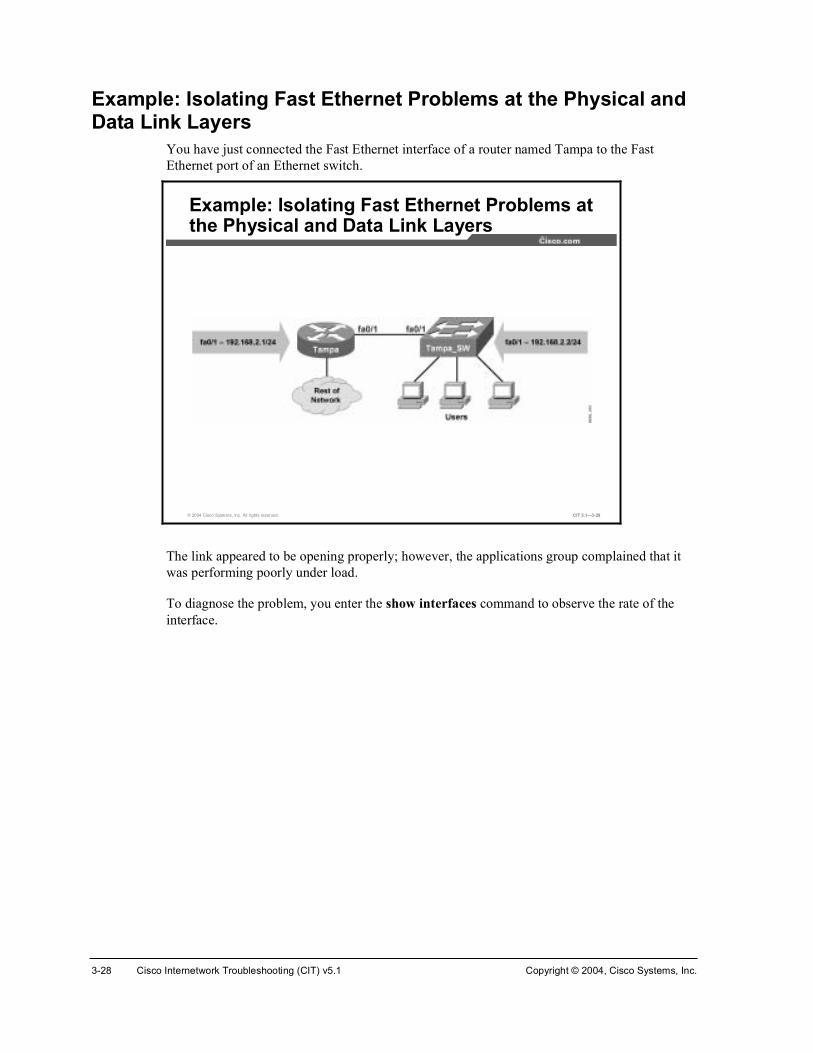
3-28 Cisco Internetwork Troubleshooting (CIT) v5.1 Copyright © 2004, Cisco Systems, Inc.
Example: Isolating Fast Ethernet Problems at the Physical and Data Link Layers
You have just connected the Fast Ethernet interface of a router named Tampa to the Fast Ethernet port of an Ethernet switch.
© 2004 Cisco Systems, Inc. All rights reserved. CIT 5.1—3-29
Example: Isolating Fast Ethernet Problems at the Physical and Data Link Layers
The link appeared to be opening properly; however, the applications group complained that it was performing poorly under load.
To diagnose the problem, you enter the show interfaces command to observe the rate of the interface.

Copyright © 2004, Cisco Systems, Inc. Resolving Problems at the Physical and Data Link Layers 3-29
© 2004 Cisco Systems, Inc. All rights reserved. CIT 5.1—3-30
Ì¿³°¿ý¸±© ·²¬»®º¿½» º¿¬»¬¸»®²»¬ ðñïÚ¿¬Û¬¸»®²»¬ðñï · «°ô ´·²» °®±¬±½±´ · «°
Ø¿®¼©¿®» · Ú¿¬ Û¬¸»®²»¬ô ¿¼¼®» · ððð¿òè¿ìêòêéèï ø¾·¿ ððð¿òè¿ìêòêéèï÷ÓÌË ïëð𠾧¬»ô ÞÉ ïððððð Õ¾·¬ô ÜÔÇ ïðð «»½ô
®»´·¿¾·´·¬§ îëëñîëëô ¬¨´±¿¼ ïñîëëô ®¨´±¿¼ ïñîëëÛ²½¿°«´¿¬·±² ßÎÐßô ´±±°¾¿½µ ²±¬ »¬Õ»»°¿´·ª» »¬ øïð »½÷Ø¿´ºó¼«°´»¨ô ïððÓ¾ñ·²°«¬ º´±©ó½±²¬®±´ · ±ººô ±«¬°«¬ º´±©ó½±²¬®±´ · ±ººßÎÐ ¬§°»æ ßÎÐßô ßÎÐ Ì·³»±«¬ ðìæððæððÔ¿¬ ·²°«¬ ððæððæïîô ±«¬°«¬ ððæððæðïô ±«¬°«¬ ¸¿²¹ ²»ª»®Ô¿¬ ½´»¿®·²¹ ±º þ¸±© ·²¬»®º¿½»þ ½±«²¬»® ²»ª»®×²°«¬ ¯«»«»æ ðñéëñðñð ø·¦»ñ³¿¨ñ¼®±°ñº´«¸»÷å ̱¬¿´ ±«¬°«¬ ¼®±°æ ðÏ«»«»·²¹ ¬®¿¬»¹§æ º·º±Ñ«¬°«¬ ¯«»«» æðñìð ø·¦»ñ³¿¨÷ë ³·²«¬» ·²°«¬ ®¿¬» ð ¾·¬ñ»½ô ð °¿½µ»¬ñ»½ë ³·²«¬» ±«¬°«¬ ®¿¬» ð ¾·¬ñ»½ô ð °¿½µ»¬ñ»½
îê °¿½µ»¬ ·²°«¬ô íîíí ¾§¬»ô ð ²± ¾«ºº»®Î»½»·ª»¼ îë ¾®±¿¼½¿¬ô ð ®«²¬ô ð ¹·¿²¬ô 𠬸®±¬¬´»ð ·²°«¬ »®®±®ô ð ÝÎÝô 𠺮¿³»ô 𠱪»®®«²ô ð ·¹²±®»¼ð ©¿¬½¸¼±¹ô îë ³«´¬·½¿¬ô ð °¿«» ·²°«¬ð ·²°«¬ °¿½µ»¬ ©·¬¸ ¼®·¾¾´» ½±²¼·¬·±² ¼»¬»½¬»¼ïíëîíé °¿½µ»¬ ±«¬°«¬ô ïëêèéçîì ¾§¬»ô ð «²¼»®®«²ð ±«¬°«¬ »®®±®ô ð ½±´´··±²ô ï ·²¬»®º¿½» ®»»¬ð ¾¿¾¾´»ô îëð ´¿¬» ½±´´··±²ô ð ¼»º»®®»¼ð ´±¬ ½¿®®·»®ô ð ²± ½¿®®·»®ô ð ÐßËÍÛ ±«¬°«¬ð ±«¬°«¬ ¾«ºº»® º¿·´«®»ô 𠱫¬°«¬ ¾«ºº»® ©¿°°»¼ ±«¬
Ì¿³°¿ý
Isolating Fast Ethernet Problems at the Physical and Data Link Layers
You note that the interface is configured in half-duplex mode and that the late collision counter is incrementing. Late collisions are an indication that there may be a mismatch in the duplex configurations of the interfaces on this connection.

3-30 Cisco Internetwork Troubleshooting (CIT) v5.1 Copyright © 2004, Cisco Systems, Inc.
To isolate the problem further, you move to the switch on the other end of the link; you issue a show interface command and observe the status of the port on the other end of the link.
© 2004 Cisco Systems, Inc. All rights reserved. CIT 5.1—3-31
Ì¿³°¿ÁÍÉý¸±© ·²¬»®º¿½» º¿¬»¬¸»®²»¬ ðñïÚ¿¬Û¬¸»®²»¬ðñï · «°ô ´·²» °®±¬±½±´ · «°
Ø¿®¼©¿®» · Ú¿¬ Û¬¸»®²»¬ô ¿¼¼®» · ðððçòé½ììòë½èï ø¾·¿ ðððçòé½ììòë½èï÷ÓÌË ïëð𠾧¬»ô ÞÉ ïððððð Õ¾·¬ô ÜÔÇ ïððð «»½ô
®»´·¿¾·´·¬§ îëëñîëëô ¬¨´±¿¼ ïñîëëô ®¨´±¿¼ ïñîëëÛ²½¿°«´¿¬·±² ßÎÐßô ´±±°¾¿½µ ²±¬ »¬Õ»»°¿´·ª» »¬ øïð »½÷Ú«´´ó¼«°´»¨ô ïððÓ¾ñ·²°«¬ º´±©ó½±²¬®±´ · ±ººô ±«¬°«¬ º´±©ó½±²¬®±´ · ±ººßÎÐ ¬§°»æ ßÎÐßô ßÎÐ Ì·³»±«¬ ðìæððæððÔ¿¬ ·²°«¬ ²»ª»®ô ±«¬°«¬ ððæððæððô ±«¬°«¬ ¸¿²¹ ²»ª»®Ô¿¬ ½´»¿®·²¹ ±º þ¸±© ·²¬»®º¿½»þ ½±«²¬»® ²»ª»®×²°«¬ ¯«»«»æ ðñéëñðñð ø·¦»ñ³¿¨ñ¼®±°ñº´«¸»÷å ̱¬¿´ ±«¬°«¬ ¼®±°æ ðÏ«»«»·²¹ ¬®¿¬»¹§æ º·º±Ñ«¬°«¬ ¯«»«» æðñìð ø·¦»ñ³¿¨÷ë ³·²«¬» ·²°«¬ ®¿¬» ð ¾·¬ñ»½ô ð °¿½µ»¬ñ»½ë ³·²«¬» ±«¬°«¬ ®¿¬» ð ¾·¬ñ»½ô ð °¿½µ»¬ñ»½
ïëèíë °¿½µ»¬ ·²°«¬ô îîïëíðë ¾§¬»ô ð ²± ¾«ºº»®Î»½»·ª»¼ ïíëè ¾®±¿¼½¿¬ô ð ®«²¬ô ð ¹·¿²¬ô 𠬸®±¬¬´»ïð ·²°«¬ »®®±®ô ïð ÝÎÝô 𠺮¿³»ô 𠱪»®®«²ô ð ·¹²±®»¼ð ©¿¬½¸¼±¹ô 𠳫´¬·½¿¬ô ð °¿«» ·²°«¬ð ·²°«¬ °¿½µ»¬ ©·¬¸ ¼®·¾¾´» ½±²¼·¬·±² ¼»¬»½¬»¼ïìéîëì °¿½µ»¬ ±«¬°«¬ô íéìïéêèë ¾§¬»ô ð «²¼»®®«²ð ±«¬°«¬ »®®±®ô ð ½±´´··±²ô î ·²¬»®º¿½» ®»»¬ð ¾¿¾¾´»ô ð ´¿¬» ½±´´··±²ô ð ¼»º»®®»¼ð ´±¬ ½¿®®·»®ô ð ²± ½¿®®·»®ô ð ÐßËÍÛ ±«¬°«¬ð ±«¬°«¬ ¾«ºº»® º¿·´«®»ô 𠱫¬°«¬ ¾«ºº»® ©¿°°»¼ ±«¬
Ì¿³°¿ÁÍÉý
Analyzing Command Output to Isolate a Fast Ethernet Problem
You note that the interface at this end of the connection is set in full-duplex mode. The duplex misconfiguration is the cause of the problem.

Copyright © 2004, Cisco Systems, Inc. Resolving Problems at the Physical and Data Link Layers 3-31
Example: Isolating a Problem at the Physical and Data Link Layers
You are the network engineer for the northeast division of Acme. Your site in Seattle (with a router named Seattle) runs a Layer 3 switch that connects the division’s resources to the corporate core in Lenexa and Elmhurst. (Note that Elmhurst is not show in the diagram.)
© 2004 Cisco Systems, Inc. All rights reserved. CIT 5.1—3-32
Example: Isolating a Problem at the Physical and Data Link Layers
One morning, Network Operations calls to tell you that Seattle no longer has connectivity outside of the division. You ask if anyone in Seattle Operations has made changes. Network Operations says that no changes were made to the production network. The users throughout the division are complaining that they cannot connect to anywhere.

3-32 Cisco Internetwork Troubleshooting (CIT) v5.1 Copyright © 2004, Cisco Systems, Inc.
To verify network connectivity, you look at the routing table with the show ip route command. You confirm that there are no routes outside of the division.
© 2004 Cisco Systems, Inc. All rights reserved. CIT 5.1—3-33
Í»¿¬¬´»ý¸±© ·° ®±«¬»�Ù¿¬»©¿§ ±º ´¿¬ ®»±®¬ · ²±¬ »¬ïéîòîëòðòðñïê · ª¿®·¿¾´§ «¾²»¬¬»¼ô é «¾²»¬ô î ³¿µÜ ïéîòîëòïëêòðñîëÅçðñíèìéêèðà ª·¿ ïéîòîëòïëèòïîçô îíæïçæìíô Ú¿¬Û¬¸»®²»¬ðñëÝ ïéîòîëòïëçòðñîë · ¼·®»½¬´§ ½±²²»½¬»¼ô Ô±±°¾¿½µðÜ ïéîòîëòïëèòðñîëÅçðñïëêïêðà ª·¿ ïéîòîëòïëèòïîçô îíæïçæìíô Ú¿¬Û¬¸»®²»¬ðñëÜ ïéîòîëòïëëòðñîëÅçðñíçéëêèðà ª·¿ ïéîòîëòïëèòïîçô îíæïçæìíô Ú¿¬Û¬¸»®²»¬ðñëÜ ïéîòîëòïëêòïîèñîëÅçðñìðëïìëêðà ª·¿ ïéîòîëòïëèòïîçô îíæïçæìíô Ú¿¬Û¬¸»®²»¬ðñëÝ ïéîòîëòïëèòïîèñîë · ¼·®»½¬´§ ½±²²»½¬»¼ô Ú¿¬Û¬¸»®²»¬ðñëÞ ïéîòîëòðòðñïê Åîððñðà ª·¿ ðòðòðòðô îíæïèæëíô Ò«´´ðÍ»¿¬¬´»ý
Gathering Information About Network Connectivity on Seattle
Next, you look at the interface status on Seattle using the show ip interface brief command.
© 2004 Cisco Systems, Inc. All rights reserved. CIT 5.1—3-34
Í»¿¬¬´»ý¸±© ·° ·²¬»®º¿½» ¾®·»º×²¬»®º¿½» ×Ðóß¼¼®» ÑÕá Ó»¬¸±¼ ͬ¿¬« Ю±¬±½±´Ê´¿²ï «²¿·¹²»¼ ÇÛÍ ÒÊÎßÓ «° «°Ê´¿²îé ïéîòîéòîîéòë ÇÛÍ ÒÊÎßÓ «° ¼±©²Ê´¿²îè ïéîòîèòïîèòë ÇÛÍ ÒÊÎßÓ «° ¼±©²Ú¿¬Û¬¸»®²»¬ðñï «²¿·¹²»¼ ÇÛÍ «²»¬ «° «°Ú¿¬Û¬¸»®²»¬ðñî «²¿·¹²»¼ ÇÛÍ «²»¬ «° «°Ú¿¬Û¬¸»®²»¬ðñí «²¿·¹²»¼ ÇÛÍ «²»¬ «° «°Ú¿¬Û¬¸»®²»¬ðñì «²¿·¹²»¼ ÇÛÍ «²»¬ «° «°Ú¿¬Û¬¸»®²»¬ðñë ïéîòîëòïëèòïíð ÇÛÍ ÒÊÎßÓ «° «°Ú¿¬Û¬¸»®²»¬ðñê «²¿·¹²»¼ ÇÛÍ ÒÊÎßÓ «° «°ò ò ò
Gathering Information About the Interfaces on Seattle
You see that interfaces VLAN27 and VLAN28 have an “up” status, but the protocol is “down.”

Copyright © 2004, Cisco Systems, Inc. Resolving Problems at the Physical and Data Link Layers 3-33
Using the show vlan command, you review the VLAN status on Seattle.
© 2004 Cisco Systems, Inc. All rights reserved. CIT 5.1—3-35
Í»¿¬¬´»ý¸±© ª´¿²ÊÔßÒ Ò¿³» ͬ¿¬« ᮬóóóó óóóóóóóóóóóóóóóóóóóóó óóóóóóóóó óóóóóóóóóóóóóóóóóóóóóóóóóóóóóóóï ¼»º¿«´¬ ¿½¬·ª» Ú¿ðñêô Ú¿ðñéô Ú¿ðñèô Ú¿ðñç
Ú¿ðñïðô Ú¿ðñïïô Ú¿ðñïîô Ú¿ðñïíÚ¿ðñïìô Ú¿ðñïëô Ú¿ðñïêô Ú¿ðñïéÚ¿ðñïèô Ú¿ðñïçô Ú¿ðñîðô Ú¿ðñîïÚ¿ðñîîô Ú¿ðñîíô Ú¿ðñîìô Ù·ðñïÙ·ðñî
î ¬»¬Á½¿®±´» ¿½¬·ª»í ¬»¬Á¶»®®§ ¿½¬·ª»ì ¬»¬Á´·¾¾§ ¿½¬·ª»ïððî º¼¼·ó¼»º¿«´¬ ¿½¬·ª»ïððí ¬±µ»²ó®·²¹ó¼»º¿«´¬ ¿½¬·ª»ò ò ò
Gathering Information About VLAN Status on Seattle
You see that VLAN27 and VLAN28 are missing, and some self-described “test” VLANs are present. You realize that if the VLAN27 and VLAN28 are not in the VLAN table, the protocol on the associated interfaces would indeed be shutdown. However, you need to determine why the VLANs are now missing.

3-34 Cisco Internetwork Troubleshooting (CIT) v5.1 Copyright © 2004, Cisco Systems, Inc.
You review the VLAN Trunking Protocol (VTP) database status on Seattle with the show vtp status command.
© 2004 Cisco Systems, Inc. All rights reserved. CIT 5.1—3-36
Í»¿¬¬´»ý¸±© ª¬° ¬¿¬«ÊÌÐ Ê»®·±² æ îݱ²º·¹«®¿¬·±² λª··±² æ ïÓ¿¨·³«³ ÊÔßÒ «°°±®¬»¼ ´±½¿´´§ æ ïððëÒ«³¾»® ±º »¨·¬·²¹ ÊÔßÒ æ èÊÌÐ Ñ°»®¿¬·²¹ Ó±¼» æ Í»®ª»®ÊÌРܱ³¿·² Ò¿³» æ Ý×ÌÊÌРЮ«²·²¹ Ó±¼» æ Ü·¿¾´»¼ÊÌÐ Êî Ó±¼» æ Ü·¿¾´»¼ÊÌÐ Ì®¿° Ù»²»®¿¬·±² æ Û²¿¾´»¼ÓÜë ¼·¹»¬ æ ð¨ðì ð¨ðí ð¨Þð ð¨ÜÞ ð¨ßð ð¨ïë ð¨Úé ð¨éÝݱ²º·¹«®¿¬·±² ´¿¬ ³±¼·º·»¼ ¾§ ïçîòïêèòïòï ¿¬ íóïóçí ððæîëæíìÔ±½¿´ «°¼¿¬»® ×Ü · ïéîòîéòîîéòë ±² ·²¬»®º¿½» Ê´îé ø´±©»¬ ²«³¾»®»¼ ÊÔßÒ ·²¬»®º¿½» º±«²¼÷Í»¿¬¬´»ý
Gathering Information about VTP Database Status on Seattle
You notice two significant items—that the VTP database was last updated by the switch with IP address 192.168.1.1, and that your switch is configured for VTP server mode. You know that 192.168.1.1 should not be changing your database, and if you were properly in VTP transparent mode, it would not. Just for fun, you will try to determine who has IP address 192.168.1.1 and how they got to your switch.

Copyright © 2004, Cisco Systems, Inc. Resolving Problems at the Physical and Data Link Layers 3-35
You look for local switches with the show cdp neighbors command.
© 2004 Cisco Systems, Inc. All rights reserved. CIT 5.1—3-37
Í»¿¬¬´»ý¸±© ½¼° ²»·¹¸¾±®Ý¿°¿¾·´·¬§ ݱ¼»æ Î ó ᫬»®ô Ì ó Ì®¿² Þ®·¼¹»ô Þ ó ͱ«®½» ᫬» Þ®·¼¹»Í ó Í©·¬½¸ô Ø ó ر¬ô × ó ×ÙÓÐô ® ó λ°»¿¬»®Ü»ª·½» ×Ü Ô±½¿´ ײ¬®º½» ر´¼¬³» Ý¿°¿¾·´·¬§ д¿¬º±®³ ᮬ ×ÜÛ´³¸«®¬ Ú¿ ðñí ïìç Î Í × ÉÍóÝíëëðóîÚ¿ ðñçÛ´³¸«®¬ Ú¿ ðñì ïìç Î Í × ÉÍóÝíëëðóîÚ¿ ðñïðÔ»²»¨¿ Ú¿ ðñï ïìè Î Í × ÉÍóÝíëëðóîÚ¿ ðñçÔ»²»¨¿ Ú¿ ðñî ïìè Î Í × ÉÍóÝíëëðóîÚ¿ ðñïðÑ´§³°·¿ Ú¿ ðñë ïëî Î ïéêð Ú¿ ðñðÜÛÊÁ¬»¬ Ú¿ ðñê ïìè Í × ÉÍóÝíëëðóîÚ¿ ðñîÍ»¿¬¬´»ý
Gathering Information about CDP Neighbors on Seattle
You do not recognize the DEV_test switch, so you will need to investigate.

3-36 Cisco Internetwork Troubleshooting (CIT) v5.1 Copyright © 2004, Cisco Systems, Inc.
With the show cdp neighbors fastethernet 0/6 detail command, you can review more information about the DEV_test switch.
© 2004 Cisco Systems, Inc. All rights reserved. CIT 5.1—3-38
Í»¿¬¬´»ý¸±© ½¼° ²»·¹¸¾±® º¿ ðñê ¼»¬¿·´óóóóóóóóóóóóóóóóóóóóóóóóóÜ»ª·½» ×Üæ ÜÛÊÁ¬»¬Û²¬®§ ¿¼¼®»ø»÷æ×Ð ¿¼¼®»æ ïçîòïêèòïòïд¿¬º±®³æ ½·½± ÉÍóÝíëëðóîìô Ý¿°¿¾·´·¬·»æ Í©·¬½¸ ×ÙÓÐײ¬»®º¿½»æ Ú¿¬Û¬¸»®²»¬ðñêô ᮬ ×Ü ø±«¬¹±·²¹ °±®¬÷æ Ú¿¬Û¬¸»®²»¬ðñïر´¼¬·³» æ ïêê »½Ê»®·±² æÝ·½± ײ¬»®²»¬©±®µ Ñ°»®¿¬·²¹ ͧ¬»³ ͱº¬©¿®»×ÑÍ ø¬³÷ Ýíëëð ͱº¬©¿®» øÝíëëðó×ëÏíÔîóÓ÷ô Ê»®·±² ïîòïøïï÷Ûßï¿ô ÎÛÔÛßÍÛ ÍÑÚÌÉßÎÛ øº½ï÷ݱ°§®·¹¸¬ ø½÷ ïçèêóîððî ¾§ ½·½± ͧ¬»³ô ײ½òݱ³°·´»¼ ̸« ïéóѽ¬óðî îíæîç ¾§ ¿²¬±²·²±¿¼ª»®¬·»³»²¬ ª»®·±²æ îЮ±¬±½±´ Ø»´´±æ ÑË×ãð¨ðððððÝô Ю±¬±½±´ ×Üãð¨ðïïîå °¿§´±¿¼ ´»²ãîéô ª¿´«»ãððððððððÚÚÚÚÚÚÚÚðïðîîïÚÚðððððððððððððððßÞéÜïÝïèðÚÚððððÊÌÐ Ó¿²¿¹»³»²¬ ܱ³¿·²æ ùÝ×ÌùÜ«°´»¨æ º«´´Í»¿¬¬´»ý
Analyzing Information About a CDP Neighbor
You determine that DEV_test has IP address 192.168.1.1 and that the switch broke your network. You have isolated the problem to a new switch overwriting your VTP database when your switch was in VTP server mode. (When you call Operations, they do admit to putting on a test switch for some experimentation.)

Copyright © 2004, Cisco Systems, Inc. Resolving Problems at the Physical and Data Link Layers 3-37
Isolating Problems Occurring at the Physical and Data Link Layers
This topic uses guidelines to help troubleshooters isolate problems at the physical and data link layers.
© 2004 Cisco Systems, Inc. All rights reserved. CIT 5.1—3-39
Guidelines for Isolating Problems at the Physical and Data Link Layers
Check operational status and data error rates
Verify proper interface configurations
Check for bad cables or connections
Check for correct cable pin-out
Use an effective and systematic technique to isolate a problem successfully at the physical or data link layer. Use the following guidelines to isolate problems at the physical and data link layers:
!" Check operational status and data error rates: Use Cisco show commands to check for statistics such as collisions, input, and output errors. The characteristics of these statistics will vary, depending on the technologies used on the network. Use debug commands for additional details when you cannot get enough information to isolate the problem using show commands.
!" Verify proper interface configurations: Check that all switch or hub ports are configured for the correct VLAN or collision domain, and that spanning tree, speed, and duplex settings are correctly configured. Confirm that any active ports or interfaces are not shut down.
!" Check for bad cables or connections: Verify that the cable from the source interface is properly connected and that it is in good condition. If you doubt the integrity of a cable, exchange the cable with a known working cable. If you doubt the connection is good, remove the cable, perform a physical inspection of both the cable and the interface, and then reconnect the cable. If a suspect cable is connected to a wall jack, use a cable tester to ensure that the jack is properly wired. A link light that is lit and displays the color indicating proper operation will also be evidence that the connection is successful.
!" Check for correct cable pin-out: Verify that the proper cable is used. A crossover or rollover cable may be required for direct connections between some devices.

3-38 Cisco Internetwork Troubleshooting (CIT) v5.1 Copyright © 2004, Cisco Systems, Inc.
Example: Isolating Problems at the Physical and Data Link Layers
A group of users has reported that their connection to the network has gone down. You examine the end-system topology diagram for the network and realize that all of the users affected are connected to the same switch and hub combination.
© 2004 Cisco Systems, Inc. All rights reserved. CIT 5.1—3-40
Example: Isolating Problems at thePhysical and Data Link Layers
This situation leads you to continue isolating the problem at the common connection. You perform an onsite inspection of the physical connection of the switch and the hub, and you note that all of the link lights are lit and are showing a color indicating correct operation. All cables appear to be of the correct type and pin-out.
After verifying that the physical connections are working, you decide to connect to the switch to check the port configurations. You note that the speed setting for one of the ports is set to 10 Mbps; however, the port speed should be set to 100 Mbps. This mismatch in speed is the likely source of your connection problem.

Copyright © 2004, Cisco Systems, Inc. Resolving Problems at the Physical and Data Link Layers 3-39
SummaryThis topic summarizes the key points discussed in this lesson.
© 2004 Cisco Systems, Inc. All rights reserved. CIT 5.1—3-41
Summary
• Problems at the physical layer have symptoms that distinguish them from problems at other layers.
• Problems at the data link layer have symptoms that distinguish them from problems at other layers.
• Analyzing the output of an appropriate command or application helps you to isolate a problem at the physical or data link layer.
• Using an effective and systematic technique allows you to successfully isolate a problem at the physical or data link layer.
ReferencesFor additional information, refer to these resources:
!" Cisco online documentation: http://www.cisco.com/univercd/home/home.htm
!" Cisco Technical Assistance Center (TAC): http://www.cisco.com/tac

3-40 Cisco Internetwork Troubleshooting (CIT) v5.1 Copyright © 2004, Cisco Systems, Inc.
QuizUse the practice items here to review what you have learned in this lesson. The correct answers are found in the Quiz Answer Key.
Q1) Which command output would you most likely see if you had a problem at the physical layer?
A) neighbor 172.10.160.2 (Serial 1/1) is down: holding time expired
B) Ethernet 0/0 is down, line protocol is down
C) Serial 1/0 is up, line protocol is administratively down
D) invalid command, no available connection
Q2) Which command output would you most likely see if you had a problem at the data link layer?
A) Serial 0/1 is down, line protocol is down
B) Ethernet 0/1 is down, line protocol is down
C) interface Serial 1/0, changed state to up
D) Serial 0/1 is up, line protocol is down
Q3) Which Cisco IOS command would you enter to view details about the Cisco IOS software and all installed hardware modules?
A) show protocols
B) show version
C) debug controllers
D) show ip interface brief
Q4) A group of users reports that their connection to the network has gone down. You suspect it to be a problem in either the physical or data link layer. You check the operational status, errors, and configuration of the affected interfaces. You still have not found the cause of the problem.
Which guideline for isolating a problem at the physical and data link layers have you omitted?
A) verifying the IP address of the default gateway
B) checking cable configuration
C) disabling spanning tree
D) viewing TCP information on a host

Copyright © 2004, Cisco Systems, Inc. Resolving Problems at the Physical and Data Link Layers 3-41
Quiz Answer Key Q1) B
Relates to: Identifying the Symptoms of Problems Occurring at the Physical Layer
Q2) D
Relates to: Identifying the Symptoms of Problems Occurring at the Data Link Layer
Q3) B
Relates to: Analyzing Commands and Applications Used to Isolate Problems Occurring at the Physical and Data Link Layers
Q4) B
Relates to: Isolating Problems Occurring at the Physical and Data Link Layers

3-42 Cisco Internetwork Troubleshooting (CIT) v5.1 Copyright © 2004, Cisco Systems, Inc.

Correcting the Problem
OverviewOnce a troubleshooter has determined the most likely cause of a problem, the next phase that needs to be considered involves correcting the problem. In this lesson, you will correct isolated problems using identified commands to configure physical and data link layer components.
Relevance A doctor is not successful unless there is a follow-up to the diagnosis of your problem with a successful solution. The same idea applies to network troubleshooters. Isolating a problem is a big step in troubleshooting. However, the process is not complete until you have solved the problem and returned the network to its baseline state.
ObjectivesUpon completing this lesson, you will be able to:
!" Identify commands and applications used to correct problems occurring at the physical and data link layers
!" Identify physical and data link layer support resources
!" Correct a problem occurring at the physical or data link layer
Learner Skills and Knowledge To benefit fully from this lesson, you must have these prerequisite skills and knowledge:
!" Ability to apply layered model troubleshooting approaches
!" Familiarity with Cisco command syntax covered in the Cisco Building Scalable Cisco Internetworks (BSCI), Building Cisco Multilayer Switched Networks (BCMSN), and Building Cisco Remote Access Networks (BCRAN) courses

3-44 Cisco Internetwork Troubleshooting (CIT) v5.1 Copyright © 2004, Cisco Systems, Inc.
OutlineThis lesson includes these topics:
!" Overview
!" Identifying Commands and Applications to Correct Problems Occurring at the Physical and Data Link Layers
!" Identifying Physical and Data Link Layer Support Resources
!" Correcting Problems Occurring at the Physical and Data Link Layers
!" Summary
!" Quiz

Copyright © 2004, Cisco Systems, Inc. Resolving Problems at the Physical and Data Link Layers 3-45
Identifying Commands and Applications to Correct Problems Occurring at the Physical and Data Link Layers
This topic lists selected commands and applications used by troubleshooters to correct problems at the physical and data link layers.
© 2004 Cisco Systems, Inc. All rights reserved. CIT 5.1—3-5
¿®° �¼ Åöÿ®° �¼ ÅöÃ
• End-system command for deleting a specific entry or the entire contents of an ARP table.
Commands Used to Correct Physical and Data Link Problems
¼«°´»¨ ¥º«´´ ¤ ¸¿´º ¤ ¿«¬±£¼«°´»¨ ¥º«´´ ¤ ¸¿´º ¤ ¿«¬±£
®±«¬»®ø½±²º·¹ó·º÷ý
• Configures the method that an interface exchanges data.
²± ¸«¬¼±©²²± ¸«¬¼±©²
®±«¬»®ø½±²º·¹ó·º÷ý
• Activates an interface.
© 2004 Cisco Systems, Inc. All rights reserved. CIT 5.1—3-6
Commands Used to Correct Physical and Data Link Problems (Cont.)
»²½¿°«´¿¬·±²»²½¿°«´¿¬·±²
®±«¬»®ø½±²º·¹ó·º÷ý
• Configures an encapsulation type on an interface.
½´±½µ ®¿¬»½´±½µ ®¿¬»
®±«¬»®ø½±²º·¹ó·º÷ý
• Configures a clock rate on an interface.
°»»¼ ¥ïð ¤ ïðð ¤ ¿«¬±£°»»¼ ¥ïð ¤ ïðð ¤ ¿«¬±£
®±«¬»®ø½±²º·¹ó·º÷ý
• Configures the speed at which an interface transmits data.

3-46 Cisco Internetwork Troubleshooting (CIT) v5.1 Copyright © 2004, Cisco Systems, Inc.
The table shows selected commands that a troubleshooter uses to correct problems that occur at the physical and data link layers.
Commands Used to Correct Physical and Data Link Problems
Command Description
¿®° ó¼ ·°ó¿¼¼®» End-system command for deleting a specific entry or the entire contents of an Address Resolution Protocol (ARP) table.
¼«°´»¨ ¥º«´´ ¤ ¸¿´º ¤ ¿«¬±£
Configures the method that an interface exchanges data.
²± ¸«¬¼±©² Activates an interface.
»²½¿°«´¿¬·±² Configures an encapsulation type on an interface.
½´±½µ ®¿¬» Configures a clock rate on an interface.
°»»¼ ¥ïð ¤ ïðð ¤ ¿«¬±£
Configures the speed at which an interface transmits data.
Example: Correcting a Serial Interface Problem at the Physical Layer
You find a problem with an inactive interface on a router named SanJose. You need to enter a Cisco IOS command that will activate the interface named Serial1/0.
© 2004 Cisco Systems, Inc. All rights reserved. CIT 5.1—3-7
Example: Correcting a Serial Interface Problem at the Physical Layer

Copyright © 2004, Cisco Systems, Inc. Resolving Problems at the Physical and Data Link Layers 3-47
To accomplish this, you enter interface configuration mode and apply the no shutdowncommand. The console messages show interface Serial1/0 going to an active state.
© 2004 Cisco Systems, Inc. All rights reserved. CIT 5.1—3-8
Í¿²Ö±»ø½±²º·¹÷ý·²¬»®º¿½» »®·¿´ïñðÍ¿²Ö±»ø½±²º·¹ó·º÷ý²± ¸«¬¼±©²Í¿²Ö±»ø½±²º·¹ó·º÷ý»¨·¬Í¿²Ö±»ýÜ»½ ïî ïìæððæìíæ ûÍÇÍóëóÝÑÒÚ×ÙÁ×æ ݱ²º·¹«®»¼ º®±³ ½±²±´» ¾§ ½±²±´»Ü»½ ïî ïìæððæììæ ûÔ×ÒÕóíóËÐÜÑÉÒæ ײ¬»®º¿½» Í»®·¿´ïñðô ½¸¿²¹»¼ ¬¿¬» ¬± «°Ü»½ ïî ïìæððæìëæ ûÔ×ÒÛÐÎÑÌÑóëóËÐÜÑÉÒæ Ô·²» °®±¬±½±´ ±² ײ¬»®º¿½» Í»®·¿´ïñðô ½¸¿²¹»¼ ¬¿¬» ¬± «°
Correcting a Serial Interface Problem at the Physical Layer
1. Enter interface configuration mode.
2. Activate the interface.
3. Exit interface configuration mode.

3-48 Cisco Internetwork Troubleshooting (CIT) v5.1 Copyright © 2004, Cisco Systems, Inc.
Next, you enter the show ip interface brief command on the SanJose router to verify the interface status.
© 2004 Cisco Systems, Inc. All rights reserved. CIT 5.1—3-9
Í¿²Ö±»ý¸±© ·° ·²¬»®º¿½» ¾®·»º
ײ¬»®º¿½» ×Ðóß¼¼®» ÑÕá Ó»¬¸±¼ ͬ¿¬« Ю±¬±½±´
Ú¿¬Û¬¸»®²»¬ðñð ïðòïìïòïìïòï ÇÛÍ ÒÊÎßÓ «° «°
Í»®·¿´ïñð ïðòïìïòïìéòï ÇÛÍ ÒÊÎßÓ «° «°
Í¿²Ö±»ý
Verifying the Correct Operation of SanJose
The line status is up and this side of the link looks operational. You return to the console session on the SanFran router to verify the interface status there.
© 2004 Cisco Systems, Inc. All rights reserved. CIT 5.1—3-10
Í¿²Ú®¿²ý¸±© ·° ·²¬»®º¿½» ¾®·»º
ײ¬»®º¿½» ×Ðóß¼¼®» ÑÕá Ó»¬¸±¼ ͬ¿¬« Ю±¬±½±´
Ú¿¬Û¬¸»®²»¬ðñð ïðòïìïòïìèòïîç ÇÛÍ ÒÊÎßÓ «° «°
Í»®·¿´ïñð ïðòïìïòïìéòî ÇÛÍ ÒÊÎßÓ «° «°
Í¿²Ú®¿²ý
Verifying the Correct Operation of SanFran

Copyright © 2004, Cisco Systems, Inc. Resolving Problems at the Physical and Data Link Layers 3-49
The line status is “up” here, as well. As a final validation, you use the ping command across the link to verify connectivity across the network, data link, and physical layers.
© 2004 Cisco Systems, Inc. All rights reserved. CIT 5.1—3-11
Í¿²Ú®¿²ý°·²¹ ïðòïìïòïìïòï
̧°» »½¿°» »¯«»²½» ¬± ¿¾±®¬ò
Í»²¼·²¹ ëô ïðð󾧬» ×ÝÓÐ Û½¸± ¬± ïðòïìïòïìïòïô ¬·³»±«¬ · î »½±²¼æ
ÿÿÿÿÿ
Í«½½» ®¿¬» · ïðð °»®½»²¬ øëñë÷ô ®±«²¼ó¬®·° ³·²ñ¿ª¹ñ³¿¨ ã ëêñëéñêð ³
Í¿²Ú®¿²ý
Verifying Connectivity Across the Network
The ping test is successful. You have resolved the physical layer issue.

3-50 Cisco Internetwork Troubleshooting (CIT) v5.1 Copyright © 2004, Cisco Systems, Inc.
Example: Correcting a Frame Relay Problem at the Data Link Layer
You have isolated a problem believed to be an incorrect LMI type on a Frame Relay interface.
© 2004 Cisco Systems, Inc. All rights reserved. CIT 5.1—3-12
Example: Correcting a Frame Relay Problem at the Data Link Layer

Copyright © 2004, Cisco Systems, Inc. Resolving Problems at the Physical and Data Link Layers 3-51
To verify the issue, you need to enter a Cisco IOS command that will allow the Cisco IOS software to auto-sense the LMI type on interface Serial1/0. You enter interface configuration mode on the Orlando router and apply the no frame-relay lmi-type ansi command.
© 2004 Cisco Systems, Inc. All rights reserved. CIT 5.1—3-13
Ñ®´¿²¼±ø½±²º·¹÷ý·²¬»®º¿½» »®·¿´ ïñðÑ®´¿²¼±ø½±²º·¹ó·º÷ý²± º®¿³»ó®»´¿§ ´³·ó¬§°» ¿²·Ñ®´¿²¼±ø½±²º·¹ó·º÷ý»¨·¬Ñ®´¿²¼±ýÜ»½ ïê îïæëêæìêæ ûÍÇÍóëóÝÑÒÚ×ÙÁ×æ ݱ²º·¹«®»¼ º®±³ ½±²±´» ¾§ ½±²±´»Ñ®´¿²¼±ýÜ»½ ïê îïæëéæïìæ ûÔ×ÒÛÐÎÑÌÑóëóËÐÜÑÉÒæ Ô·²» °®±¬±½±´ ±² ײ¬»®º¿½» Í»®·¿´ïñðô ½¸¿²¹»¼ ¬¿¬» ¬± «°Ñ®´¿²¼±ýÑ®´¿²¼±ýÜ»½ ïê îïæëéæíîæ ûÜËßÔóëóÒÞÎÝØßÒÙÛæ ×ÐóÛ×ÙÎÐ ïðïæ Ò»·¹¸¾±® ïéîòîïòïééòï øÍ»®·¿´ïñð÷ · «°æ ²»© ¿¼¶¿½»²½§Ñ®´¿²¼±ý
Correcting a Frame Relay Problem at the Data Link Layer
1. Enter interface configuration mode.
3. Exit interface configuration mode.
2. Change the LMI type to ANSI.
The console messages show interface Serial1/0 changing to an active state. Therefore, the messages validate your assumption. The line protocol comes up, and an EIGRP neighbor adjacency re-establishes with the Daytona router.

3-52 Cisco Internetwork Troubleshooting (CIT) v5.1 Copyright © 2004, Cisco Systems, Inc.
Although you know that the line protocol is up if you have an EIGRP neighbor, you verify the current interface status.
© 2004 Cisco Systems, Inc. All rights reserved. CIT 5.1—3-14
Ñ®´¿²¼±ý¸±© ·²¬»®º¿½» »®·¿´ ïñðÍ»®·¿´ïñð · «°ô ´·²» °®±¬±½±´ · «°
Ø¿®¼©¿®» · б©»®ÏË×ÝÝ Í»®·¿´Ü»½®·°¬·±²æ Ú®¿³» λ´¿§ ´·²µ ¬± Ü¿§¬±²¿×²¬»®²»¬ ¿¼¼®» · ïéîòîïòïééòîñíðÓÌË ïëð𠾧¬»ô ÞÉ ïîè Õ¾·¬ô ÜÔÇ îðððð «»½ô
®»´·¿¾·´·¬§ îëëñîëëô ¬¨´±¿¼ ïñîëëô ®¨´±¿¼ ïñîëëÛ²½¿°«´¿¬·±² ÚÎßÓÛóÎÛÔßÇô ´±±°¾¿½µ ²±¬ »¬Õ»»°¿´·ª» »¬ øïð »½÷ÔÓ× »²¯ »²¬ ìêîô ÔÓ× ¬¿¬ ®»½ª¼ ïèëô ÔÓ× «°¼ ®»½ª¼ ðô ÜÌÛ
ÔÓ× «°ÔÓ× »²¯ ®»½ª¼ ðô ÔÓ× ¬¿¬ »²¬ ðô ÔÓ× «°¼ »²¬ ðÔÓ× ÜÔÝ× ïðîí ÔÓ× ¬§°» · Ý×ÍÝÑ º®¿³» ®»´¿§ ÜÌÛ
òòòÑ®´¿²¼±ý
Verifying the LMI Type on Orlando
You see that the Cisco IOS software has auto-sensed a Cisco LMI type. The Frame Relay provider changed the LMI type, which caused your link to go down.

Copyright © 2004, Cisco Systems, Inc. Resolving Problems at the Physical and Data Link Layers 3-53
As a final validation that the data link issue has been resolved, you use the ping command across the link to verify connectivity across the network, data link, and physical layers.
© 2004 Cisco Systems, Inc. All rights reserved. CIT 5.1—3-15
Ñ®´¿²¼±ý°·²¹ ïéîòîïòïééòï
̧°» »½¿°» »¯«»²½» ¬± ¿¾±®¬ò
Í»²¼·²¹ ëô ïðð󾧬» ×ÝÓÐ Û½¸± ¬± ïéîòîïòïééòïô ¬·³»±«¬ · î »½±²¼æ
ÿÿÿÿÿ
Í«½½» ®¿¬» · ïðð °»®½»²¬ øëñë÷ô ®±«²¼ó¬®·° ³·²ñ¿ª¹ñ³¿¨ ã ëêñëéñêð ³
Ñ®´¿²¼±ý
Verifying Connectivity Across the Network
The ping test is successful. You have resolved the data link layer issue, and your network is running again. You will need to discuss unscheduled changes with your Frame Relay carrier in the morning.

3-54 Cisco Internetwork Troubleshooting (CIT) v5.1 Copyright © 2004, Cisco Systems, Inc.
Example: Correcting an Ethernet Problem at the Physical and Data Link Layers
You have isolated a problem believed to be an incorrectly seated cable in an Ethernet interface.
© 2004 Cisco Systems, Inc. All rights reserved. CIT 5.1—3-16
Example: Correcting Ethernet Problems at the Physical and Data Link Layers
Given this condition, you disconnect and reconnect both ends of the Ethernet cable, connecting to the interface named Ethernet 0 on the SanFran router. This will ensure that the cable is properly seated. Once that is done, you enter the clear counters command to reset all of the data and error counters on the interface to zero.
© 2004 Cisco Systems, Inc. All rights reserved. CIT 5.1—3-17
Í¿²Ú®¿²ý½´»¿® ½±«²¬»®
Ý´»¿® þ¸±© ·²¬»®º¿½»þ ½±«²¬»® ±² ¿´´ ·²¬»®º¿½» Ž±²º·®³Ã
Í¿²Ú®¿²ý
Correcting an Ethernet Problem at the Physical and Data Link Layers

Copyright © 2004, Cisco Systems, Inc. Resolving Problems at the Physical and Data Link Layers 3-55
You ping the interface to test if it is operating properly.
© 2004 Cisco Systems, Inc. All rights reserved. CIT 5.1—3-18
Í¿²Ú®¿²ý°·²¹ ïçîòïêèòïòï
̧°» »½¿°» »¯«»²½» ¬± ¿¾±®¬ò
Í»²¼·²¹ ëô ïðð󾧬» ×ÝÓÐ Û½¸± ¬± ïçîòïêèòïòïô ¬·³»±«¬ · î
»½±²¼æ
ÿÿÿÿÿ
Í«½½» ®¿¬» · ïðð °»®½»²¬ øëñë÷ô ®±«²¼ó¬®·° ³·²ñ¿ª¹ñ³¿¨ ã
ïñîñì ³
Í¿²Ú®¿²ý
Testing the Connection on an Ethernet Interface
The connection is made successfully. You enter the show interface command to verify that you are no longer receiving any errors on the interface.
© 2004 Cisco Systems, Inc. All rights reserved. CIT 5.1—3-19
Í¿²Ú®¿²ý¸±© ·²¬»®º¿½» »¬¸»®²»¬ ðÛ¬¸»®²»¬ð · «°ô ´·²» °®±¬±½±´ · «°
Ø¿®¼©¿®» · Ô¿²½»ô ¿¼¼®» · ððêðòìéìðòº½¾ð ø¾·¿ ððêðòìéìðòº½¾ð÷ײ¬»®²»¬ ¿¼¼®» · ïçîòïêèòïòïðíñîìÓÌË ïëð𠾧¬»ô ÞÉ ïðððð Õ¾·¬ô ÜÔÇ ïððð «»½ô ®»´§ îëëñîëëô ´±¿¼ ïñîëëÛ²½¿°«´¿¬·±² ßÎÐßô ´±±°¾¿½µ ²±¬ »¬ô µ»»°¿´·ª» »¬ øïð »½÷ßÎÐ ¬§°»æ ßÎÐßô ßÎÐ Ì·³»±«¬ ðìæððæððÔ¿¬ ·²°«¬ ððæðîæíèô ±«¬°«¬ ððæððæððô ±«¬°«¬ ¸¿²¹ ²»ª»®Ô¿¬ ½´»¿®·²¹ ±º þ¸±© ·²¬»®º¿½»þ ½±«²¬»® ððæðìæîðײ°«¬ ¯«»«»æ ðñéëñðñð ø·¦»ñ³¿¨ñ¼®±°ñº´«¸»÷å ̱¬¿´ ±«¬°«¬ ¼®±°æ ðÏ«»«»·²¹ ¬®¿¬»¹§æ º·º±Ñ«¬°«¬ ¯«»«» ðñìð ø·¦»ñ³¿¨÷ë ³·²«¬» ·²°«¬ ®¿¬» ð ¾·¬ñ»½ô ð °¿½µ»¬ñ»½ë ³·²«¬» ±«¬°«¬ ®¿¬» ð ¾·¬ñ»½ô ð °¿½µ»¬ñ»½
ë °¿½µ»¬ ·²°«¬ô ëé𠾧¬»ô ð ²± ¾«ºº»®Î»½»·ª»¼ ð ¾®±¿¼½¿¬ô ð ®«²¬ô ð ¹·¿²¬ô 𠬸®±¬¬´»ð ·²°«¬ »®®±®ô ð ÝÎÝô 𠺮¿³»ô 𠱪»®®«²ô ð ·¹²±®»¼ô ð ¿¾±®¬ð ·²°«¬ °¿½µ»¬ ©·¬¸ ¼®·¾¾´» ½±²¼·¬·±² ¼»¬»½¬»¼çî °¿½µ»¬ ±«¬°«¬ô éééì ¾§¬»ô ð «²¼»®®«²ð ±«¬°«¬ »®®±®ô ð ½±´´··±²ô ð ·²¬»®º¿½» ®»»¬ð ¾¿¾¾´»ô ð ´¿¬» ½±´´··±²ô ð ¼»º»®®»¼ð ´±¬ ½¿®®·»®ô ð ²± ½¿®®·»®ð ±«¬°«¬ ¾«ºº»® º¿·´«®»ô 𠱫¬°«¬ ¾«ºº»® ©¿°°»¼ ±«¬
Í¿²Ú®¿²ý
Verifying That the Ethernet Connection Is Functioning Properly
Note that the error counters remain at zero. The problem with the incorrectly seated cable has been corrected, and the interface is functioning properly.

3-56 Cisco Internetwork Troubleshooting (CIT) v5.1 Copyright © 2004, Cisco Systems, Inc.
Example: Correcting Fast Ethernet Problems at the Physical and Data Link Layers
Given a problem with a duplex mismatch on Fast Ethernet interfaces, you will change the configuration so that the duplex configurations match.
© 2004 Cisco Systems, Inc. All rights reserved. CIT 5.1—3-20
Example: Correcting a Fast Ethernet Problem at the Physical and Data Link Layers
Both of these devices are capable of communicating at full-duplex mode; therefore, you must change the duplex configuration of the Tampa router to match the switch.

Copyright © 2004, Cisco Systems, Inc. Resolving Problems at the Physical and Data Link Layers 3-57
© 2004 Cisco Systems, Inc. All rights reserved. CIT 5.1—3-21
Ì¿³°¿ø½±²º·¹÷ý·²¬»®º¿½» º¿¬»¬¸»®²»¬ ðñï
Ì¿³°¿ø½±²º·¹ó·º÷ý¼«°´»¨ º«´´
Ì¿³°¿ø½±²º·¹ó·º÷ýÂÆ
Ì¿³°¿ý
Ü»½ ïî ïìæððæìíæ ûÍÇÍóëóÝÑÒÚ×ÙÁ×æ ݱ²º·¹«®»¼ º®±³ ½±²±´» ¾§ ½±²±´»
Correcting a Fast Ethernet Problem at the Physical and Data Link Layers
Use the clear counters command to reset the interface counters.
© 2004 Cisco Systems, Inc. All rights reserved. CIT 5.1—3-22
Ì¿³°¿ý½´»¿® ½±«²¬»®
Ý´»¿® þ¸±© ·²¬»®º¿½»þ ½±«²¬»® ±² ¿´´ ·²¬»®º¿½» Ž±²º·®³Ã
Ì¿³°¿ý
Resetting the Counters on the Fast Ethernet Interface

3-58 Cisco Internetwork Troubleshooting (CIT) v5.1 Copyright © 2004, Cisco Systems, Inc.
You ask the operations group to test its application, and then you enter the show interface command to verify that the interface is configured properly and no longer indicating any errors.
© 2004 Cisco Systems, Inc. All rights reserved. CIT 5.1—3-23
Ì¿³°¿ý¸±© ·²¬»®º¿½» º¿¬»¬¸»®²»¬ ðñïÚ¿¬Û¬¸»®²»¬ðñï · «°ô ´·²» °®±¬±½±´ · «°
Ø¿®¼©¿®» · Ú¿¬ Û¬¸»®²»¬ô ¿¼¼®» · ððð¿òè¿ìêòêéèï ø¾·¿ ððð¿òè¿ìêòêéèï÷ÓÌË ïëð𠾧¬»ô ÞÉ ïððððð Õ¾·¬ô ÜÔÇ ïðð «»½ô
®»´·¿¾·´·¬§ îëëñîëëô ¬¨´±¿¼ ïñîëëô ®¨´±¿¼ ïñîëëÛ²½¿°«´¿¬·±² ßÎÐßô ´±±°¾¿½µ ²±¬ »¬Õ»»°¿´·ª» »¬ øïð »½÷Ú«´´ó¼«°´»¨ô ïððÓ¾ñ·²°«¬ º´±©ó½±²¬®±´ · ±ººô ±«¬°«¬ º´±©ó½±²¬®±´ · ±ºº
òòò
îïðîï °¿½µ»¬ ±«¬°«¬ô ïíèéçíì ¾§¬»ô ð «²¼»®®«²ð ±«¬°«¬ »®®±®ô ð ½±´´··±²ô ð ·²¬»®º¿½» ®»»¬ð ¾¿¾¾´»ô ð ´¿¬» ½±´´··±²ô ð ¼»º»®®»¼ð ´±¬ ½¿®®·»®ô ð ²± ½¿®®·»®ô ð ÐßËÍÛ ±«¬°«¬ð ±«¬°«¬ ¾«ºº»® º¿·´«®»ô 𠱫¬°«¬ ¾«ºº»® ©¿°°»¼ ±«¬
Ì¿³°¿ý
Verifying the Correction of the Duplex Mismatch on the Fast Ethernet Interface
The command output indicates that the interface is operating in full-duplex mode and that there are zero late collisions. The duplex mismatch on the Fast Ethernet interface has been corrected.

Copyright © 2004, Cisco Systems, Inc. Resolving Problems at the Physical and Data Link Layers 3-59
Example: Correcting a Problem at the Physical and Data Link Layers
You have isolated a problem where a new switch was overwriting the VTP database on the Seattle Layer 3 switch because Seattle was in VTP server mode.
© 2004 Cisco Systems, Inc. All rights reserved. CIT 5.1—3-24
Example: Correcting a Problem at the Physical and Data Link Layers
Given this condition, you go into configuration mode on the Seattle router to resolve the issue.

3-60 Cisco Internetwork Troubleshooting (CIT) v5.1 Copyright © 2004, Cisco Systems, Inc.
As a first step, you configure the vtp mode transparent command to set the VTP mode of the switch to transparent.
© 2004 Cisco Systems, Inc. All rights reserved. CIT 5.1—3-25
Í»¿¬¬´»ø½±²º·¹÷ýª¬° ³±¼» ¬®¿²°¿®»²¬Í»¬¬·²¹ ¼»ª·½» ¬± ÊÌÐ ÌÎßÒÍÐßÎÛÒÌ ³±¼»òÍ»¿¬¬´»ø½±²º·¹÷ý²± ª´¿² îÍ»¿¬¬´»ø½±²º·¹÷ý²± ª´¿² íÍ»¿¬¬´»ø½±²º·¹÷ý²± ª´¿² ìÍ»¿¬¬´»ø½±²º·¹÷ýª´¿² îéÍ»¿¬¬´»ø½±²º·¹óª´¿²÷ý²¿³» ݱ®»ÁîéÍ»¿¬¬´»ø½±²º·¹óª´¿²÷ýª´¿² îèÍ»¿¬¬´»ø½±²º·¹óª´¿²÷ý²¿³» ݱ®»ÁîèÍ»¿¬¬´»ø½±²º·¹óª´¿²÷ýÂÆÍ»¿¬¬´»ýÜ»½ ïè ïïæðëæìîæ ûÍÇÍóëóÝÑÒÚ×ÙÁ×æ ݱ²º·¹«®»¼ º®±³ ½±²±´» ¾§ ½±²±´»Ü»½ ïè ïïæðêæðéæ ûÔ×ÒÛÐÎÑÌÑóëóËÐÜÑÉÒæ Ô·²» °®±¬±½±´ ±² ײ¬»®º¿½» Ê´¿²îéô ½¸¿²¹»¼ ¬¿¬» ¬± «°Ü»½ ïè ïïæðêæïíæ ûÔ×ÒÛÐÎÑÌÑóëóËÐÜÑÉÒæ Ô·²» °®±¬±½±´ ±² ײ¬»®º¿½» Ê´¿²îèô ½¸¿²¹»¼ ¬¿¬» ¬± «°Í»¿¬¬´»ý
Correcting the VTP Mode on Seattle
You also remove the nonproduction VLANs, and configure VLAN27 and VLAN28. The console messages show the line protocol on interface VLAN27 and VLAN28 changing to an active state.

Copyright © 2004, Cisco Systems, Inc. Resolving Problems at the Physical and Data Link Layers 3-61
You also notice console messages showing that the Border Gateway Protocol (BGP) neighbor adjacencies are up. Although the neighbors would not be present without active VLANs, you use the show vlan command to verify the VLAN status.
© 2004 Cisco Systems, Inc. All rights reserved. CIT 5.1—3-26
Verifying VLAN Status on Seattle
Í»¿¬¬´»ýÜ»½ ïè ïïæðêæïíæ ûÞÙÐóëóßÜÖÝØßÒÙÛæ ²»·¹¸¾±® ïéîòîéòîîéòé Ë°Ü»½ ïè ïïæðêæîðæ ûÞÙÐóëóßÜÖÝØßÒÙÛæ ²»·¹¸¾±® ïéîòîèòïîèòè Ë°Í»¿¬¬´»ý¸±© ª´¿²ÊÔßÒ Ò¿³» ͬ¿¬« ᮬóóóó óóóóóóóóóóóóóóóóóóóóó óóóóóóóóó óóóóóóóóóóóóóóóóóóóóóóóóóóóóóóóï ¼»º¿«´¬ ¿½¬·ª» Ú¿ðñêô Ú¿ðñéô Ú¿ðñèô Ú¿ðñç
Ú¿ðñïðô Ú¿ðñïïô Ú¿ðñïîô Ú¿ðñïíÚ¿ðñïìô Ú¿ðñïëô Ú¿ðñïêô Ú¿ðñïéÚ¿ðñïèô Ú¿ðñïçô Ú¿ðñîðô Ú¿ðñîïÚ¿ðñîîô Ú¿ðñîíô Ú¿ðñîìô Ù·ðñïÙ·ðñî
îé ݱ®»Áîé ¿½¬·ª»îè ݱ®»Áîè ¿½¬·ª»ïððî º¼¼·ó¼»º¿«´¬ ¿½¬·ª»ïððí ¬±µ»²ó®·²¹ó¼»º¿«´¬ ¿½¬·ª»ò ò ò
You see that VLAN27 and VLAN28 are active.
You use the show ip route command to verify network connectivity out of the division.
© 2004 Cisco Systems, Inc. All rights reserved. CIT 5.1—3-27
Í»¿¬¬´»ý¸±© ·° ®±«¬»òòòÙ¿¬»©¿§ ±º ´¿¬ ®»±®¬ · ïéîòîéòîîéòé ¬± ²»¬©±®µ ðòðòðòðÞ ïéîòîïòðòðñïê Åîðñðà ª·¿ ïéîòîéòîîéòïô ððæððæîðÞ ïéîòîíòðòðñïê Åîðñðà ª·¿ ïéîòîéòîîéòíô ððæððæîðÞ ïéîòîîòðòðñïê Åîðñðà ª·¿ ïéîòîéòîîéòîô ððæððæîðÞ ïéîòîìòðòðñïê Åîðñðà ª·¿ ïéîòîéòîîéòìô ððæððæîïÞ ïéîòîêòðòðñïê Åîðñðà ª·¿ ïéîòîéòîîéòêô ððæððæîïïéîòîëòðòðñïê · ª¿®·¿¾´§ «¾²»¬¬»¼ô é «¾²»¬ô î ³¿µÜ ïéîòîëòïëêòðñîëÅçðñíèìéêèðà ª·¿ ïéîòîëòïëèòïîçô îíæïçæìíô Ú¿¬Û¬¸»®²»¬ðñëÝ ïéîòîëòïëçòðñîë · ¼·®»½¬´§ ½±²²»½¬»¼ô Ô±±°¾¿½µðÜ ïéîòîëòïëèòðñîëÅçðñïëêïêðà ª·¿ ïéîòîëòïëèòïîçô îíæïçæìíô Ú¿¬Û¬¸»®²»¬ðñëòòòÞ ïçèòïííòîïçòðñîì Åîðñðà ª·¿ ïéîòîéòîîéòéô ððæððæîîÍö ðòðòðòðñð Åïñðà ª·¿ ïéîòîéòîîéòéÍ»¿¬¬´»ý
Verifying Network Routes on Seattle
You see that BGP routes from the other divisions have reappeared in the routing table.

3-62 Cisco Internetwork Troubleshooting (CIT) v5.1 Copyright © 2004, Cisco Systems, Inc.
As a final validation, you use the ping command to verify connectivity across the network, data link, and physical layers.
© 2004 Cisco Systems, Inc. All rights reserved. CIT 5.1—3-28
Í»¿¬¬´»ý°·²¹ ïéîòîéòîîéòé
̧°» »½¿°» »¯«»²½» ¬± ¿¾±®¬ò
Í»²¼·²¹ ëô ïðð󾧬» ×ÝÓÐ Û½¸± ¬± ïéîòîéòîîéòéô ¬·³»±«¬ · î »½±²¼æ
ÿÿÿÿÿ
Í«½½» ®¿¬» · ïðð °»®½»²¬ øëñë÷ô ®±«²¼ó¬®·° ³·²ñ¿ª¹ñ³¿¨ ã ïñïñì ³
Í»¿¬¬´»ý
Verifying Connectivity Across the Network
The successful ping test verifies that network connectivity has been restored. You will now discuss with Operations adding test devices to production networks.

Copyright © 2004, Cisco Systems, Inc. Resolving Problems at the Physical and Data Link Layers 3-63
Identifying Physical and Data Link Layer Support Resources
This topic lists support resources to assist you in correcting problems at the physical and data link layers.
© 2004 Cisco Systems, Inc. All rights reserved. CIT 5.1—3-29
Cisco Systems• Cisco Systems TAC:
www.cisco.com/tac
• Internetwork Troubleshooting Handbookwww.cisco.com/univercd/cc/td/doc/cisintwk/itg_v1
• Cisco Systems technologies referencewww.cisco.com/univercd/home/home.htm
Support Resources for Correcting Physical and Data Link Layer Problems

3-64 Cisco Internetwork Troubleshooting (CIT) v5.1 Copyright © 2004, Cisco Systems, Inc.
© 2004 Cisco Systems, Inc. All rights reserved. CIT 5.1—3-30
Standards Organizations• Internet Engineering Task Force (IETF)
www.ietf.org• International Telecommunications Union (ITU-T)
www.itu.int/home• Frame Relay Forum
www.frforum.com• ATM Forum
www.atmforum.com
Support Resources for Understanding the Physical and Data Link Layer
Despite your knowledge and experience about networking, there will still be times when you will need to consult an outside resource. These support resources are commonly used as reference materials for commands and configuration procedures and research for technology-specific information and industry standards. Given the ability to use online support resources to do effective research, you save time that you may have otherwise spent on the phone with a support professional. You also save the money that you would have committed to hiring a consultant.
For command and configuration references, the Cisco Systems website has one of the largest collections of networking information on the Internet. Visit the Technical Assistance Center (TAC), Cisco.com, and technology reference pages to find information for troubleshooting Cisco Systems products. From these locations, you can search on a specific technology, such as Ethernet, Frame Relay, serial line, or ATM. It is often helpful to narrow your search by including phrases such as “configuration examples” or “troubleshooting.”
To learn more about industry standards, visit the Internet Engineering Task Force (IETF), International Telecommunication Union Telecommunication Standardization Sector (ITU-T), Frame Relay Forum, and ATM Forum. These sites contain detailed documentation about a wide array of networking technologies.

Copyright © 2004, Cisco Systems, Inc. Resolving Problems at the Physical and Data Link Layers 3-65
Correcting Problems Occurring at the Physical and Data Link Layers
This topic lists the steps troubleshooters should take to correct problems at the physical and data link layers.
© 2004 Cisco Systems, Inc. All rights reserved. CIT 5.1—3-31
Procedure for Correcting Physical and Data Link Layer Problems
Verify that you have a valid saved configuration for any device on which you intend to modify the configuration
Evaluate and document the results of each change that you make
Verify that the changes you made actually fixed theproblem without introducing any new problems
Continue making changes until the problem appears to be solved
If necessary, get input from outside resources
Make initial configuration changes
Once the problem is resolved, document the solution

3-66 Cisco Internetwork Troubleshooting (CIT) v5.1 Copyright © 2004, Cisco Systems, Inc.
The table lists the suggested steps for correcting an isolated problem at the physical and data link layers.
Procedure for Correcting Problems Occurring at the Physical and Data Link Layers
Step Description
1 Verify that you have a valid saved configuration for any device on which you intend to modify the configuration. This provides for eventual recovery to a known initial state.
2 Make initial hardware and software configuration changes. If the correction requires more than one change, make only one change at a time.
3 Evaluate and document the changes and the results of each change that you make. If you perform your problem-solving steps and the results are unsuccessful, immediately undo the changes. If the problem is intermittent, you may need to wait to see if the problem occurs again before you can evaluate the effect of your changes.
4 Verify that the changes you made actually fixed the problem without introducing any new problems. The network should be returned to the baseline operation, and no new or old symptoms should be present. If the problem is not solved, undo all the changes that you made. If you discover new or additional problems while you are making corrections, step back and modify your correction plan.
5 Continue making changes until the original problem appears to be solved.
6 If necessary, get input from outside resources. If none of your attempts to correct the problem are successful, take the problem to another person. This may be a coworker, consultant, or Cisco TAC. On some occasions, you may need to generate various crash files. This creates output that a specialist at Cisco Systems can analyze.
7 Once the problem is resolved, document the solution.

Copyright © 2004, Cisco Systems, Inc. Resolving Problems at the Physical and Data Link Layers 3-67
SummaryThis topic summarizes the key points discussed in this lesson.
© 2004 Cisco Systems, Inc. All rights reserved. CIT 5.1—3-32
Summary
• Use the appropriate end system or Cisco commands and applications to correct an isolated problem.
• Proper use of online support resources saves time and money by empowering troubleshooters to find solutions to elusive problems on their own.
• Following a systematic procedure increases the chances that you will successfully and effectively correct an isolated problem at the physical or data link layer.
ReferencesFor additional information, refer to these resources:
!" Cisco online documentation: http://www.cisco.com/univercd/home/home.htm
!" Cisco Technical Assistance Center (TAC): http://www.cisco.com/tac/
Next Steps For the associated case study and lab exercises, refer to the following sections of the course Lab Guide:
!" Case Study (Trouble Ticket B) 3-1: Isolating Physical and Data Link Layer Problems
!" Lab Exercise (Trouble Ticket B) 3-1: Correcting Problems at the Physical and Data Link Layers
!" Lab Exercise (Trouble Ticket C) 3-2: Troubleshooting Problems at the Physical and Data Link Layers

3-68 Cisco Internetwork Troubleshooting (CIT) v5.1 Copyright © 2004, Cisco Systems, Inc.
QuizUse the practice items here to review what you have learned in this lesson. The correct answers are found in the Quiz Answer Key.
Q1) Which command is used at an end system to correct problems at the data link layer related to resolving network and data link layer addresses?
A) shutdown
B) interface
C) clock rate
D) arp -d
Q2) Which website would you most likely use to find the latest detailed technical documentation about the PPP protocol?
A) www.apple.com
B) www.linux.org
C) www.sniffers.com
D) www.ietf.org
Q3) List the steps for correcting an isolated problem at the physical or data link layer in the recommended order.
_____ 1. Evaluate and document the results of each change that you make.
_____ 2. Document the solution.
_____ 3. Get input from outside resources.
_____ 4. Continue making changes until the original problem appears to be solved.
_____ 5. Verify that the changes you made actually fixed the problem without introducing any new problems.
_____ 6. Make initial changes to the configuration.

Copyright © 2004, Cisco Systems, Inc. Resolving Problems at the Physical and Data Link Layers 3-69
Quiz Answer Key Q1) D
Relates to: Identifying Commands and Applications to Correct Problems Occurring at the Physical and Data Link Layers
Q2) D
Relates to: Identifying Physical and Data Link Layer Support Resources
Q3) Correct order: 2, 6, 5, 4, 3, 1
Relates to: Correcting Problems Occurring at the Physical and Data Link Layers

3-70 Cisco Internetwork Troubleshooting (CIT) v5.1 Copyright © 2004, Cisco Systems, Inc.

Module 4
Resolving Problems at the Network Layer
OverviewNow that you have used the symptoms you gathered to isolate and correct problems at the physical and data link layers, you will find that the process is the same for correcting problems at the network layer. However, the symptoms of the problem differ as do the commands and applications that you use to successfully resolve problems. In this module, you will perform the isolation and correction phases of the general troubleshooting process to resolve failure and optimization problems at the network layer of the Open Systems Interconnection (OSI) model.
Module Objectives Upon completing this module, you will be able to:
!" Isolate problems occurring at the network layer
!" Correct problems occurring at the network layer
Module Outline The module contains these components:
!" Isolating the Problem
!" Correcting the Problem

4-2 Cisco Internetwork Troubleshooting (CIT) v5.1 Copyright © 2004, Cisco Systems, Inc.

Isolating the Problem
OverviewA troubleshooter applies the general troubleshooting process of gathering and analyzing symptoms, and then isolating and correcting problems at the network layer. The process is the same regardless of the logical layers to which the process is applied; however, the focus of this lesson is logical addressing, subnet masks, and routing protocols. In this lesson, you will analyze symptoms and use commands and applications to isolate problems at the network layer.
Relevance The primary responsibility of the network layer is to manage the movement of data between networks and to find the best path for data to travel toward a destination. If a problem arises at this layer, the data will not delivered to the destination, the data will not delivered as quickly as it should be, or the data will be delivered in deference to other higher priority traffic. This information will make you a better troubleshooter to effectively isolate problems at the network layer, thus avoiding extended or periodic loss of packet delivery and suboptimal delivery performance.
ObjectivesUpon completing this lesson, you will be able to:
!" Identify the symptoms of problems occurring at the network layer
!" Analyze Cisco command and application output to isolate problems occurring at the network layer
!" Identify end-system commands and applications used to isolate problems occurring at the network layer
!" Isolate problems occurring at the network layer

4-4 Cisco Internetwork Troubleshooting (CIT) v5.1 Copyright © 2004, Cisco Systems, Inc.
Learner Skills and Knowledge To benefit fully from this lesson, you must have these prerequisite skills and knowledge:
!" The ability to apply layered model troubleshooting approaches
!" Familiarity with Cisco command syntax and technologies covered in the Cisco BuildingScalable Cisco Internetworks (BSCI), Building Cisco Multilayer Switched Networks(BCMSN), and Building Cisco Remote Access Networks (BCRAN) courses
OutlineThis lesson includes these topics:
!" Overview
!" Identifying the Symptoms of Problems Occurring at the Network Layer
!" Analyzing Cisco Commands and Applications Used to Isolate Problems Occurring at the Network Layer
!" Identifying End-System Commands and Applications Used to Isolate Problems Occurring at the Network Layer
!" Isolating Problems Occurring at the Network Layer
!" Summary
!" Quiz

Copyright © 2004, Cisco Systems, Inc. Resolving Problems at the Network Layer 4-5
Identifying the Symptoms of Problems Occurring at the Network Layer
This topic identifies the symptoms of problems occurring at the network layer that troubleshooters should be able to identify.
© 2004 Cisco Systems, Inc. All rights reserved. CIT 5.1—4-5
Common Symptoms of Network Layer Problems
No connectivity on the link as seen from the transport layer
No component on the failing link appears to be functional above the network layer
The network is functional, but is operating either consistently or intermittently at …
The failure of a network component at the network layer has the potential to cause a loss of connectivity with peers on other devices. It may be difficult for a troubleshooter to determine the layer in which a problem is located. This is because a symptom of that problem may also be shared with physical and data link layer failure problems. If your troubleshooting efforts show that there are no problems at the physical and data link layers, you have a concrete indication that your problem resides at the network layer or higher.
You can identify a possible optimization problem on a link at the network layer because data will be transferred in a slow, sporadic, or unexpected manner compared to the data transfer rate documented in your baseline. Symptoms short of a complete failure to route packets may include misrouted packets that are ultimately lost or excessive transit delays.

4-6 Cisco Internetwork Troubleshooting (CIT) v5.1 Copyright © 2004, Cisco Systems, Inc.
© 2004 Cisco Systems, Inc. All rights reserved. CIT 5.1—4-6
Possible Symptoms of Network Layer Problems
Packets are delivered to incorrect destinations
Console messages
System log file messages
Management system alarms
Unexpected routing behavior
Empty, inconsistent, or incomplete routing tables
Pings succeed only a percentage of the time
Not all network layer problems present the same symptoms. These symptoms can include such things as misrouted packets and console messages being displayed by the system. The following example shows a console message that a troubleshooter may see if duplicate IP addresses exist on a network:
Ú»¾ ïé ïïæîïæìéæ û×ÐóìóÜËÐßÜÜÎæ Ü«°´·½¿¬» ¿¼¼®» ïéîòììòïïèòï ±² Ú¿¬Û¬¸»®²»¬ðñïô ±«®½»¼ ¾§ ððð¿òè¿ììò¼»ìð
Other messages, such as ping failures or Internet Control Message Protocol (ICMP) unreachable messages, may be present. You may also receive an alarm from the network management system or see evidence of a problem in a system log file.

Copyright © 2004, Cisco Systems, Inc. Resolving Problems at the Network Layer 4-7
Analyzing Cisco Commands and Applications Used to Isolate Problems Occurring at the Network Layer
This topic analyzes the output of Cisco commands and applications with the purpose of helping troubleshooters isolate a problem occurring at the network layer.
© 2004 Cisco Systems, Inc. All rights reserved. CIT 5.1—4-7
¸±© ®«²²·²¹ó½±²º·¹¸±© ®«²²·²¹ó½±²º·¹
®±«¬»®ý
• Displays the contents of the currently running configuration file.
General Cisco Command to Isolate Network Layer Problems

4-8 Cisco Internetwork Troubleshooting (CIT) v5.1 Copyright © 2004, Cisco Systems, Inc.
The Cisco commands listed in the table display information about several networking layers. A troubleshooter uses the information from these commands to isolate problems at the network layer. Note that the commands covered previously in the course are shown in the command tables, but not in the slides.
General Cisco Commands to Isolate Network Layer Problems
Command Description
°·²¹ ¥¸±¬ ¤ ·°ó¿¼¼®»£
Sends an echo request packet to an address, then waits for a reply. The host | ip-address variable is the IP alias or IP address of the target system.
¬®¿½»®±«¬»Å¼»¬·²¿¬·±²Ã
Identifies a path to a destination device.
Ų±Ã ¼»¾«¹ á Displays a list of options for enabling or disabling debugging events on a device.
¸±© ®«²²·²¹ó½±²º·¹ Displays the contents of the currently running configuration file.
¸±© ·° ¿®° Displays all Address Resolution Protocol (ARP) table entries in cache.
¼»¾«¹ ¿®° Displays information about ARP transactions.
¸±© ·° ·²¬»®º¿½» ž®·»ºÃ
Displays a summary of the status of an IP interface.
Note Use packet debugging with extreme caution; otherwise, you might cause the router to lock up and stop routing traffic. As a general rule, do not use packet debugging on a production router unless you have physical access to the router and are willing to risk it going down.

Copyright © 2004, Cisco Systems, Inc. Resolving Problems at the Network Layer 4-9
© 2004 Cisco Systems, Inc. All rights reserved. CIT 5.1—4-8
¸±© ·° ®±«¬»¸±© ·° ®±«¬»
®±«¬»®â
• Displays the current state of the routing table.
Cisco Commands to Isolate Routing Table Problems
¼»¾«¹ ·° ®±«¬·²¹¼»¾«¹ ·° ®±«¬·²¹
®±«¬»®ý
• Displays information on routing table updates and route-cache updates.
¸±© ·° °®±¬±½±´¸±© ·° °®±¬±½±´
®±«¬»®â
• Displays the current state of active routing protocols.
The Cisco commands listed in the table display information about routing tables. A troubleshooter uses the information from these commands to isolate problems related to routing tables at the network layer.
Note Troubleshooters can use the clear and show commands in combination to view the most current data about a device.
Cisco Commands to Isolate Routing Table Problems
Command Description
¸±© ·° ®±«¬» Displays the current state of the routing table.
¸±© ·° °®±¬±½±´ Displays the current state of the active routing protocols.
¼»¾«¹ ·° ®±«¬·²¹ Displays information on routing table updates and route-cache updates.
Note When debugging, have a vty window separate from the console window open in which an appropriate command (for instance, no debug all) is pretyped and only requires a quick hit of the Enter key. This can sometimes allow you to escape quickly from a debugging session that is providing overwhelming output.

4-10 Cisco Internetwork Troubleshooting (CIT) v5.1 Copyright © 2004, Cisco Systems, Inc.
Multiple commands can be used to troubleshoot routing protocols such as Open Shortest Path First (OSPF).
© 2004 Cisco Systems, Inc. All rights reserved. CIT 5.1—4-9
¸±© ·° ±°º¸±© ·° ±°º
®±«¬»®â
• Displays general information about the OSPF routing process.
Cisco Commands to Isolate OSPF Routing Protocol Problems
¸±© ·° ±°º ·²¬»®º¿½»¸±© ·° ±°º ·²¬»®º¿½»
®±«¬»®â
• Displays OSPF-related interface information.
¸±© ·° ±°º ²»·¹¸¾±®¸±© ·° ±°º ²»·¹¸¾±®
®±«¬»®â
• Displays information about OSPF neighbors on a per-interface basis.
The Cisco commands listed in the table display information about the OSPF routing protocol. A troubleshooter can use information from these and other commands to isolate problems related to the OSPF routing protocol at the network layer.
Cisco Commands to Isolate OSPF Routing Protocol Problems
Command Description
¸±© ·° ±°º Displays general information about the OSPF routing process.
¸±© ·° ±°º ·²¬»®º¿½» Displays OSPF-related interface information.
¸±© ·° ±°º ²»·¹¸¾±® Displays information about OSPF neighbors on a per-interface basis.

Copyright © 2004, Cisco Systems, Inc. Resolving Problems at the Network Layer 4-11
Additional commands can be used to support Enhanced Interior Gateway Routing Protocol (EIGRP).
© 2004 Cisco Systems, Inc. All rights reserved. CIT 5.1—4-10
¸±© ·° »·¹®° ²»·¹¸¾±®¸±© ·° »·¹®° ²»·¹¸¾±®
®±«¬»®â
• Displays the neighbors discovered by the EIGRP routing process.
Cisco Commands to Isolate EIGRP Routing Protocol Problems
¸±© ·° »·¹®° ·²¬»®º¿½»¸±© ·° »·¹®° ·²¬»®º¿½»
®±«¬»®â
• Displays information about interfaces configured for EIGRP.
¸±© ·° »·¹®° ¬±°±´±¹§¸±© ·° »·¹®° ¬±°±´±¹§
®±«¬»®â
• Displays entries in EIGRP topology table.
The Cisco commands listed in the table display information about the EIGRP routing protocol. A troubleshooter can use information from these and other commands to isolate problems related to the EIGRP routing protocol at the network layer.
Cisco Commands to Isolate EIGRP Routing Protocol Problems
Command Description
¸±© ·° »·¹®° ²»·¹¸¾±®
Displays information about the neighbors discovered by the EIGRP routing process.
¸±© ·° »·¹®° ·²¬»®º¿½»
Displays information about interfaces configured for EIGRP.
¸±© ·° »·¹®° ¬±°±´±¹§ Displays entries in the EIGRP topology table.

4-12 Cisco Internetwork Troubleshooting (CIT) v5.1 Copyright © 2004, Cisco Systems, Inc.
Multiple commands can be used to manage Border Gateway Protocol (BGP) routing processes.
© 2004 Cisco Systems, Inc. All rights reserved. CIT 5.1—4-11
¸±© ·° ¾¹°¸±© ·° ¾¹°
®±«¬»®â
• Displays entries in BGP routing table.
Cisco Commands to Isolate BGP Routing Protocol Problems
¸±© ·° ¾¹° «³³¿®§¸±© ·° ¾¹° «³³¿®§
®±«¬»®â
• Displays the status of all BGP connections.
¸±© ·° ¾¹° ²»·¹¸¾±®¸±© ·° ¾¹° ²»·¹¸¾±®
®±«¬»®â
• Displays information about the BGP and TCP connections to neighbors.
A troubleshooter uses the information from these commands to isolate problems related to the BGP routing protocol at the network layer.
Cisco Commands to Isolate BGP Routing Protocol Problems
Command Description
¸±© ·° ¾¹° Displays entries in BGP routing table.
¸±© ·° ¾¹° «³³¿®§ Displays the status of all BGP connections.
¸±© ·° ¾¹° ²»·¹¸¾±® Displays information about the TCP and BGP connections to neighbors.

Copyright © 2004, Cisco Systems, Inc. Resolving Problems at the Network Layer 4-13
Debugging commands can be used to isolate problems on routing protocols.
© 2004 Cisco Systems, Inc. All rights reserved. CIT 5.1—4-12
¼»¾«¹ ·° ±°º Å¿¼¶ ¤ »ª»²¬ ¤ °¿½µ»¬Ã¼»¾«¹ ·° ±°º Å¿¼¶ ¤ »ª»²¬ ¤ °¿½µ»¬Ã
®±«¬»®ý
• Displays information related to OSPF processing.
Cisco Commands to Debug Routing Protocol Problems
¼»¾«¹ ·° »·¹®° Ų»·¹¸¾±® ¤ ²±¬·º·½¿¬·±²Ã¼»¾«¹ ·° »·¹®° Ų»·¹¸¾±® ¤ ²±¬·º·½¿¬·±²Ã
®±«¬»®ý
• Displays information related to EIGRP processing.
¼»¾«¹ ·° ¾¹° ż¿³°»²·²¹ ¤ »ª»²¬ ¤ µ»»°¿´·ª» ¤ «°¼¿¬»Ã¼»¾«¹ ·° ¾¹° ż¿³°»²·²¹ ¤ »ª»²¬ ¤ µ»»°¿´·ª» ¤ «°¼¿¬»Ã
®±«¬»®ý
• Displays information related to BGP processing.
The debugging commands listed in the table can be used to provide information about routing protocol processes. A troubleshooter can use information from these and other commands to isolate problems related to network layer routing protocols.
Cisco Commands to Debug OSPF and EIGRP Routing Protocol Problems
Command Description
¼»¾«¹ ·° ±°º Å¿¼¶ ¤ »ª»²¬ ¤ °¿½µ»¬Ã
Displays information related to OSPF processing.
¼»¾«¹ ·° »·¹®° Ų»·¹¸¾±® ¤ ²±¬·º·½¿¬·±²Ã
Displays information related to EIGRP processing.
¼»¾«¹ ·° ¾¹° ż¿³°»²·²¹ ¤ »ª»²¬ ¤ µ»»°¿´·ª» ¤ «°¼¿¬»Ã
Displays information related to BGP processing.

4-14 Cisco Internetwork Troubleshooting (CIT) v5.1 Copyright © 2004, Cisco Systems, Inc.
© 2004 Cisco Systems, Inc. All rights reserved. CIT 5.1—4-13
¸±© ·° ¬®¿ºº·½¸±© ·° ¬®¿ºº·½
®±«¬»®â
• Displays statistics about IP traffic, such as format errors, bad hops, encapsulation failures, unknown routes, and probe proxy requests.
Cisco Commands to Isolate IP Traffic Problems
¼»¾«¹ ·° ·½³°¼»¾«¹ ·° ·½³°
®±«¬»®ý
• Displays information about ICMP transactions.
¼»¾«¹ ·° °¿½µ»¬ ¥¿½½»ó´·¬ ²«³¾»®£¼»¾«¹ ·° °¿½µ»¬ ¥¿½½»ó´·¬ ²«³¾»®£
®±«¬»®ý
• Displays IP debugging information and IP security option (IPSO) security transactions for a specified access list.
The Cisco commands listed in the table display information about IP traffic. A troubleshooter uses the information from these commands to isolate problems related to IP traffic at the network layer.
Cisco Commands for Gathering Information About IP Traffic
Command Description
¸±© ·° ¬®¿ºº·½ Displays statistics about IP traffic, such as format errors, bad hops, encapsulation failures, unknown routes, and probe proxy requests.
¼»¾«¹ ·° ·½³° Displays information about ICMP transactions.
¼»¾«¹ ·° °¿½µ»¬ ¥¿½½»ó´·¬ ²¿³»£
Displays IP debugging information and IP security option (IPSO) security transactions for a specified access list.

Copyright © 2004, Cisco Systems, Inc. Resolving Problems at the Network Layer 4-15
© 2004 Cisco Systems, Inc. All rights reserved. CIT 5.1—4-14
¸±© ·° ¿½½»ó´·¬ Å¿½½»ó´·¬ ²«³¾»® ¤ ¿½½»ó´·¬ó²¿³»Ã¸±© ·° ¿½½»ó´·¬ Å¿½½»ó´·¬ ²«³¾»® ¤ ¿½½»ó´·¬ó²¿³»Ã
®±«¬»®â
• Displays the contents of all access lists or for a specified numbered or named access list.
Cisco Command to Isolate Access List Problems
The command listed in the table is the Cisco command that displays information about access control lists (ACLs). A troubleshooter uses the information from this command to isolate problems related to ACLs at the network layer.
Cisco Command for Isolating Access Control List Problems
Command Description
¸±© ·° ¿½½»ó´·¬ Å¿½½»ó´·¬ó²«³¾»® ¤ ¿½½»ó´·¬ó²¿³»Ã
Displays the contents of all access lists or for a specified numbered or named access list.

4-16 Cisco Internetwork Troubleshooting (CIT) v5.1 Copyright © 2004, Cisco Systems, Inc.
Identifying End-System Commands and Applications Used to Isolate Problems Occurring at the Network Layer
This topic identifies commands and applications that a troubleshooter enters at the end system to isolate problems occurring at the network layer.
© 2004 Cisco Systems, Inc. All rights reserved. CIT 5.1—4-15
End-System Commands to Isolate Network Layer Problems
®±«¬» °®·²¬®±«¬» °®·²¬
• Displays the current IP routing table on Windows machines.
ÝæÄâ
®±«¬» ó²®±«¬» ó²
• Displays the current IP routing table in UNIX or Mac OS X operating systems.
¬»®³·²¿´û

Copyright © 2004, Cisco Systems, Inc. Resolving Problems at the Network Layer 4-17
The table shows commands that a troubleshooter may use to isolate problems at the network layer. Although many of the commands also display information that concerns the data link layer, these commands are noteworthy at the network layer because they highlight problems in the interface between the data link and network layers.
End-System Commands to Isolate Network Layer Problems
Command Description
°·²¹ ¥¸±¬ ¤ ·°ó¿¼¼®»£
Sends an echo request packet to an address, then waits for a reply. The host | ip-address variable is the IP alias or IP address of the target system.
¿®° �¿ Displays the current mappings of the IP address to the MAC address in the ARP table.
²»¬¬¿¬ ó®² Displays the status of all connected devices and links without querying a Domain Name System (DNS) server on Windows hosts.
·°½±²º·¹ Åñ¿´´Ã Displays IP information for hosts running Windows NT, 2000, or XP.
¬®¿½»®¬ Åó¼Ãż»¬·²¿¬·±²Ã
Identifies a path to a destination device for Windows hosts without querying a DNS server. The destination variable is the IP alias or IP address of the target system.
®±«¬» °®·²¬ Displays the current IP routing table fro Windows hosts.
©·²·°½º¹ Displays IP information for hosts running Windows 9x and Me.
·º½±²º·¹ �¿ Displays IP information for UNIX and Mac OS X hosts.
¬®¿½»®±«¬» ó¼ ż»¬·²¿¬·±²Ã
Identifies the path a packet takes through the network without querying a DNS server for Mac OS X or UNIX hosts. The destination variable is the host name or IP address of the target system.
®±«¬» ó² Displays the current IP routing table for Mac OS X or UNIX hosts.

4-18 Cisco Internetwork Troubleshooting (CIT) v5.1 Copyright © 2004, Cisco Systems, Inc.
Example: Isolating an Access List Problem at the Network Layer
You are the second-level network engineer for a division with locations in Washington, Baltimore, and Columbia. The networking devices at each location are named after the names of the city in which they reside. You have console access to the router named Washington, which gives you IP connectivity to all devices in your network. Your span of responsibility in the corporate network includes the 172.22.0.0/16 network.
© 2004 Cisco Systems, Inc. All rights reserved. CIT 5.1—4-16
Example: Isolating an Access List Problem at the Network Layer
One day, a new IT manager is transferred from a division that supports Daytona to the Columbia offices. The new manager calls you to mention that a route to Cisco Systems cannot be seen in the network table on Columbia. This manager used to be able to see the route in the network table on Daytona. Apparently, connectivity to Cisco Systems still exists.

Copyright © 2004, Cisco Systems, Inc. Resolving Problems at the Network Layer 4-19
You check your base configuration files. Although the route is not needed for connectivity, management policy dictates that the route 198.133.219.0/24 for Cisco Systems is supposed to be in the routing tables for all devices. You check the routing table on Columbia and confirm that the route is not on the access router.
© 2004 Cisco Systems, Inc. All rights reserved. CIT 5.1—4-17
ݱ´«³¾·¿â¸±© ·° ®±«¬»
ݱ¼»æ Ý ó ½±²²»½¬»¼ô Í ó ¬¿¬·½ô × ó ×ÙÎÐô Î ó Î×Ðô Ó ó ³±¾·´»ô Þ ó ÞÙÐ
Ü ó Û×ÙÎÐô ÛÈ ó Û×ÙÎÐ »¨¬»®²¿´ô Ñ ó ÑÍÐÚô ×ß ó ÑÍÐÚ ·²¬»® ¿®»¿
Òï ó ÑÍÐÚ ÒÍÍß »¨¬»®²¿´ ¬§°» ïô Òî ó ÑÍÐÚ ÒÍÍß »¨¬»®²¿´ ¬§°» î
Ûï ó ÑÍÐÚ »¨¬»®²¿´ ¬§°» ïô Ûî ó ÑÍÐÚ »¨¬»®²¿´ ¬§°» îô Û ó ÛÙÐ
· ó ×Íó×Íô Ôï ó ×Íó×Í ´»ª»´óïô Ôî ó ×Íó×Í ´»ª»´óîô ·¿ ó ×Íó×Í ·²¬»® ¿®»¿
ö ó ½¿²¼·¼¿¬» ¼»º¿«´¬ô Ë ó °»®ó«»® ¬¿¬·½ ®±«¬»ô ± ó ÑÜÎ
Ð ó °»®·±¼·½ ¼±©²´±¿¼»¼ ¬¿¬·½ ®±«¬»
Ù¿¬»©¿§ ±º ´¿¬ ®»±®¬ · ïéîòîîòïîêòî ¬± ²»¬©±®µ ðòðòðòð
Ü ÛÈ ïéîòîïòðòðñïê Åïéðñíèéíîèðà ª·¿ ïéîòîîòïîêòîô í¼îï¸ô Í»®·¿´ðñðæð
Ü ÛÈ ïéîòîíòðòðñïê Åïéðñíèéíîèðà ª·¿ ïéîòîîòïîêòîô í¼îï¸ô Í»®·¿´ðñðæð
ïéîòîîòðòðñïê · ª¿®·¿¾´§ «¾²»¬¬»¼ô ïí «¾²»¬ô î ³¿µ
Ü ïéîòîîòïîèòðñîê Åçðñíçéíïîðà ª·¿ ïéîòîîòïîêòîô í¼îï¸ô Í»®·¿´ðñðæð
Ü ïéîòîîòïîçòðñîê Åçðñíçéëêèðà ª·¿ ïéîòîîòïîêòîô í¼îï¸ô Í»®·¿´ðñðæð
Ý ïéîòîîòïîêòïîèñîê · ¼·®»½¬´§ ½±²²»½¬»¼ô Í»®·¿´ðñðæï
Isolating an Access List Problem at the Network Layer
© 2004 Cisco Systems, Inc. All rights reserved. CIT 5.1—4-18
Ý ïéîòîîòïîéòïîèñîê · ¼·®»½¬´§ ½±²²»½¬»¼ô Í»®·¿´ïñï
Ü ÛÈ ïéîòîîòðòðñïê Åïéðñíèéíîèðà ª·¿ ïéîòîîòïîêòîô í¼îï¸ô Í»®·¿´ðñðæð
Ü ïéîòîîòïîèòïîèñîê Åçðñíèìéêèðà ª·¿ ïéîòîîòïîêòîô í¼îï¸ô Í»®·¿´ðñðæð
Ý ïéîòîîòïîîòðñîê · ¼·®»½¬´§ ½±²²»½¬»¼ô Ú¿¬Û¬¸»®²»¬ðñðòî
Ý ïéîòîîòïîíòðñîê · ¼·®»½¬´§ ½±²²»½¬»¼ô Ú¿¬Û¬¸»®²»¬ðñðòí
Ý ïéîòîîòïîïòðñîê · ¼·®»½¬´§ ½±²²»½¬»¼ô Ú¿¬Û¬¸»®²»¬ðñðòï
Ý ïéîòîîòïîêòðñîê · ¼·®»½¬´§ ½±²²»½¬»¼ô Í»®·¿´ðñðæð
Ý ïéîòîîòïîéòðñîê · ¼·®»½¬´§ ½±²²»½¬»¼ô Í»®·¿´ïñð
Ý ïéîòîîòïîìòðñîê · ¼·®»½¬´§ ½±²²»½¬»¼ô Ú¿¬Û¬¸»®²»¬ðñðòì
Ý ïéîòîîòïîëòðñîê · ¼·®»½¬´§ ½±²²»½¬»¼ô Ô±±°¾¿½µð
Ü ÛÈ ïéîòîëòðòðñïê Åïéðñíèéíîèðà ª·¿ ïéîòîîòïîêòîô í¼îï¸ô Í»®·¿´ðñðæð
Ü ÛÈ ïéîòîìòðòðñïê Åïéðñíèéíîèðà ª·¿ ïéîòîîòïîêòîô í¼îï¸ô Í»®·¿´ðñðæð
Ü ÛÈ ïéîòîêòðòðñïê Åïéðñíèéíîèðà ª·¿ ïéîòîîòïîêòîô í¼îï¸ô Í»®·¿´ðñðæð
ÜöÛÈ ðòðòðòðñð Åïéðñíèìéçíêà ª·¿ ïéîòîîòïîêòîô í¼îï¸ô Í»®·¿´ðñðæð
ݱ´«³¾·¿â
Isolating an Access List Problem at the Network Layer (Cont.)

4-20 Cisco Internetwork Troubleshooting (CIT) v5.1 Copyright © 2004, Cisco Systems, Inc.
Not seeing the route, you ping Cisco Systems across the default route to verify connectivity.
© 2004 Cisco Systems, Inc. All rights reserved. CIT 5.1—4-19
ݱ´«³¾·¿â°·²¹ ½·½±
̧°» »½¿°» »¯«»²½» ¬± ¿¾±®¬ò
Í»²¼·²¹ ëô ïðð󾧬» ×ÝÓÐ Û½¸± ¬± ïçèòïííòîïçòîëô ¬·³»±«¬ · î
»½±²¼æ
ÿÿÿÿÿ
Í«½½» ®¿¬» · ïðð °»®½»²¬ øëñë÷ô ®±«²¼ó¬®·° ³·²ñ¿ª¹ñ³¿¨ ã
ïêñïèñîð ³
ݱ´«³¾·¿â
Verifying Connectivity to Cisco Systems Across the Default Route
The ping is successful.

Copyright © 2004, Cisco Systems, Inc. Resolving Problems at the Network Layer 4-21
You check the routing table on Baltimore and confirm that the route is not on the distribution router.
© 2004 Cisco Systems, Inc. All rights reserved. CIT 5.1—4-20
Þ¿´¬·³±®»â¸±© ·° ®±«¬»
ݱ¼»æ Ý ó ½±²²»½¬»¼ô Í ó ¬¿¬·½ô × ó ×ÙÎÐô Î ó Î×Ðô Ó ó ³±¾·´»ô Þ ó ÞÙÐ
Ü ó Û×ÙÎÐô ÛÈ ó Û×ÙÎÐ »¨¬»®²¿´ô Ñ ó ÑÍÐÚô ×ß ó ÑÍÐÚ ·²¬»® ¿®»¿
Òï ó ÑÍÐÚ ÒÍÍß »¨¬»®²¿´ ¬§°» ïô Òî ó ÑÍÐÚ ÒÍÍß »¨¬»®²¿´ ¬§°» î
Ûï ó ÑÍÐÚ »¨¬»®²¿´ ¬§°» ïô Ûî ó ÑÍÐÚ »¨¬»®²¿´ ¬§°» îô Û ó ÛÙÐ
· ó ×Íó×Íô Ôï ó ×Íó×Í ´»ª»´óïô Ôî ó ×Íó×Í ´»ª»´óîô ·¿ ó ×Íó×Í ·²¬»® ¿®»¿
ö ó ½¿²¼·¼¿¬» ¼»º¿«´¬ô Ë ó °»®ó«»® ¬¿¬·½ ®±«¬»ô ± ó ÑÜÎ
Ð ó °»®·±¼·½ ¼±©²´±¿¼»¼ ¬¿¬·½ ®±«¬»
Ù¿¬»©¿§ ±º ´¿¬ ®»±®¬ · ïéîòîîòïîèòïí𠬱 ²»¬©±®µ ðòðòðòð
Ü ÛÈ ïéîòîïòðòðñïê Åïéðñîèìïêðà ª·¿ ïéîòîîòïîèòïíðô í¼îï¸ô Ú¿¬Û¬¸»®²»¬ðñð
Ü ÛÈ ïéîòîíòðòðñïê Åïéðñîèìïêðà ª·¿ ïéîòîîòïîèòïíðô í¼îï¸ô Ú¿¬Û¬¸»®²»¬ðñð
ïéîòîîòðòðñïê · ª¿®·¿¾´§ «¾²»¬¬»¼ô ïí «¾²»¬ô î ³¿µ
Ý ïéîòîîòïîèòðñîê · ¼·®»½¬´§ ½±²²»½¬»¼ô Ô±±°¾¿½µð
Ü ïéîòîîòïîçòðñîê Åçðñïëêïêðà ª·¿ ïéîòîîòïîèòïíðô í¼îï¸ô Ú¿¬Û¬¸»®²»¬ðñð
Ý ïéîòîîòïîêòïîèñîê · ¼·®»½¬´§ ½±²²»½¬»¼ô Í»®·¿´ðñðæï
Ý ïéîòîîòïîéòïîèñîê · ¼·®»½¬´§ ½±²²»½¬»¼ô Í»®·¿´ïñï
Ü ÛÈ ïéîòîîòðòðñïê Åïéðñîèìïêðà ª·¿ ïéîòîîòïîèòïíðô í¼îï¸ô Ú¿¬Û¬¸»®²»¬ðñð
Gathering Information from the Routing Table on Baltimore
© 2004 Cisco Systems, Inc. All rights reserved. CIT 5.1—4-21
Ý ïéîòîîòïîèòïîèñîê · ¼·®»½¬´§ ½±²²»½¬»¼ô Ú¿¬Û¬¸»®²»¬ðñð
Ü ïéîòîîòïîîòðñîê Åçðñíèìéêèðà ª·¿ ïéîòîîòïîêòïô í¼îï¸ô Í»®·¿´ðñðæð
Ü ïéîòîîòïîíòðñîê Åçðñíèìéêèðà ª·¿ ïéîòîîòïîêòïô í¼îï¸ô Í»®·¿´ðñðæð
Ü ïéîòîîòïîïòðñîê Åçðñíèìéêèðà ª·¿ ïéîòîîòïîêòïô í¼îï¸ô Í»®·¿´ðñðæð
Ý ïéîòîîòïîêòðñîê · ¼·®»½¬´§ ½±²²»½¬»¼ô Í»®·¿´ðñðæð
Ý ïéîòîîòïîéòðñîê · ¼·®»½¬´§ ½±²²»½¬»¼ô Í»®·¿´ïñð
Ü ïéîòîîòïîìòðñîê Åçðñíèìéêèðà ª·¿ ïéîòîîòïîêòïô í¼îï¸ô Í»®·¿´ðñðæð
Ü ïéîòîîòïîëòðñîê Åçðñíçéíïîðà ª·¿ ïéîòîîòïîêòïô í¼îï¸ô Í»®·¿´ðñðæð
Ü ÛÈ ïéîòîëòðòðñïê Åïéðñîèìïêðà ª·¿ ïéîòîîòïîèòïíðô í¼îï¸ô Ú¿¬Û¬¸»®²»¬ðñð
Ü ÛÈ ïéîòîìòðòðñïê Åïéðñîèìïêðà ª·¿ ïéîòîîòïîèòïíðô í¼îï¸ô Ú¿¬Û¬¸»®²»¬ðñð
Ü ÛÈ ïéîòîêòðòðñïê Åïéðñîèìïêðà ª·¿ ïéîòîîòïîèòïíðô í¼îï¸ô Ú¿¬Û¬¸»®²»¬ðñð
ÜöÛÈ ðòðòðòðñð Åïéðñîèìïêà ª·¿ ïéîòîîòïîèòïíðô í¼îï¸ô Ú¿¬Û¬¸»®²»¬ðñð
Þ¿´¬·³±®»â
Gathering Information from the Routing Table on Baltimore (Cont.)

4-22 Cisco Internetwork Troubleshooting (CIT) v5.1 Copyright © 2004, Cisco Systems, Inc.
Again, you verify that you are able to use the default route on Baltimore to ping Cisco Systems.
© 2004 Cisco Systems, Inc. All rights reserved. CIT 5.1—4-22
Þ¿´¬·³±®»â°·²¹ ½·½±
̧°» »½¿°» »¯«»²½» ¬± ¿¾±®¬ò
Í»²¼·²¹ ëô ïðð󾧬» ×ÝÓÐ Û½¸± ¬± ïçèòïííòîïçòîëô ¬·³»±«¬ · î
»½±²¼æ
ÿÿÿÿÿ
Í«½½» ®¿¬» · ïðð °»®½»²¬ øëñë÷ô ®±«²¼ó¬®·° ³·²ñ¿ª¹ñ³¿¨ ã
ïñîñì ³
Þ¿´¬·³±®»â
Verifying Connectivity to Cisco Systems Across the Default Route

Copyright © 2004, Cisco Systems, Inc. Resolving Problems at the Network Layer 4-23
Finally, you check the routing table on Washington and confirm that the 198.133.219.0/24 route is not on the core router.
© 2004 Cisco Systems, Inc. All rights reserved. CIT 5.1—4-23
É¿¸·²¹¬±²â¸±© ·° ®±«¬»
ݱ¼»æ Ý ó ½±²²»½¬»¼ô Í ó ¬¿¬·½ô × ó ×ÙÎÐô Î ó Î×Ðô Ó ó ³±¾·´»ô Þ ó ÞÙÐ
Ü ó Û×ÙÎÐô ÛÈ ó Û×ÙÎÐ »¨¬»®²¿´ô Ñ ó ÑÍÐÚô ×ß ó ÑÍÐÚ ·²¬»® ¿®»¿
Òï ó ÑÍÐÚ ÒÍÍß »¨¬»®²¿´ ¬§°» ïô Òî ó ÑÍÐÚ ÒÍÍß »¨¬»®²¿´ ¬§°» î
Ûï ó ÑÍÐÚ »¨¬»®²¿´ ¬§°» ïô Ûî ó ÑÍÐÚ »¨¬»®²¿´ ¬§°» îô Û ó ÛÙÐ
· ó ×Íó×Íô Ôï ó ×Íó×Í ´»ª»´óïô Ôî ó ×Íó×Í ´»ª»´óîô ·¿ ó ×Íó×Í ·²¬»® ¿®»¿
ö ó ½¿²¼·¼¿¬» ¼»º¿«´¬ô Ë ó °»®ó«»® ¬¿¬·½ ®±«¬»ô ± ó ÑÜÎ
Ð ó °»®·±¼·½ ¼±©²´±¿¼»¼ ¬¿¬·½ ®±«¬»
Ù¿¬»©¿§ ±º ´¿¬ ®»±®¬ · ïéîòîèòïîèòè ¬± ²»¬©±®µ ðòðòðòð
Þ ïéîòîïòðòðñïê Åîðñðà ª·¿ ïéîòîèòïîèòïô ì¼ïë¸
Þ ïéîòîíòðòðñïê Åîðñðà ª·¿ ïéîòîèòïîèòíô ì¼ïë¸
ïéîòîîòðòðñïê · ª¿®·¿¾´§ «¾²»¬¬»¼ô ïï «¾²»¬ô î ³¿µ
Ü ïéîòîîòïîèòðñîê Åçðñïëêïêðà ª·¿ ïéîòîîòïîèòïîçô í¼îî¸ô Ú¿¬Û¬¸»®²»¬ðñë
Ý ïéîòîîòïîçòðñîê · ¼·®»½¬´§ ½±²²»½¬»¼ô Ô±±°¾¿½µð
Ü ïéîòîîòïîêòïîèñîê Åçðñìðëïìëêðà ª·¿ ïéîòîîòïîèòïîçô í¼îï¸ô Ú¿¬Û¬¸»®²»¬ðñë
Ý ïéîòîîòïîèòïîèñîê · ¼·®»½¬´§ ½±²²»½¬»¼ô Ú¿¬Û¬¸»®²»¬ðñë
Gathering Information from the Routing Table on Washington
© 2004 Cisco Systems, Inc. All rights reserved. CIT 5.1—4-24
Þ ïéîòîîòðòðñïê Åîððñðà ª·¿ ðòðòðòðô ì¼ïë¸ô Ò«´´ð
Ü ïéîòîîòïîîòðñîê Åçðñíèëðîìðà ª·¿ ïéîòîîòïîèòïîçô í¼îï¸ô Ú¿¬Û¬¸»®²»¬ðñë
Ü ïéîòîîòïîíòðñîê Åçðñíèëðîìðà ª·¿ ïéîòîîòïîèòïîçô í¼îï¸ô Ú¿¬Û¬¸»®²»¬ðñë
Ü ïéîòîîòïîïòðñîê Åçðñíèëðîìðà ª·¿ ïéîòîîòïîèòïîçô í¼îï¸ô Ú¿¬Û¬¸»®²»¬ðñë
Ü ïéîòîîòïîêòðñîê Åçðñíèìéêèðà ª·¿ ïéîòîîòïîèòïîçô í¼îï¸ô Ú¿¬Û¬¸»®²»¬ðñë
Ü ïéîòîîòïîìòðñîê Åçðñíèëðîìðà ª·¿ ïéîòîîòïîèòïîçô í¼îï¸ô Ú¿¬Û¬¸»®²»¬ðñë
Ü ïéîòîîòïîëòðñîê Åçðñíçéëêèðà ª·¿ ïéîòîîòïîèòïîçô í¼îï¸ô Ú¿¬Û¬¸»®²»¬ðñë
Þ ïéîòîëòðòðñïê Åîðñðà ª·¿ ïéîòîèòïîèòëô ì¼ïë¸
Þ ïéîòîìòðòðñïê Åîðñðà ª·¿ ïéîòîéòîîéòìô ì¼ïë¸
ïéîòîéòðòðñïê · ª¿®·¿¾´§ «¾²»¬¬»¼ô î «¾²»¬ô î ³¿µ
Ý ïéîòîéòîîéòðñîé · ¼·®»½¬´§ ½±²²»½¬»¼ô Ê´¿²îé
Þ ïéîòîêòðòðñïê Åîðñðà ª·¿ ïéîòîèòïîèòêô ì¼ïë¸
ïéîòîèòðòðñïê · ª¿®·¿¾´§ «¾²»¬¬»¼ô î «¾²»¬ô î ³¿µ
Ý ïéîòîèòïîèòðñîè · ¼·®»½¬´§ ½±²²»½¬»¼ô Ê´¿²îè
Íö ðòðòðòðñð Åïñðà ª·¿ ïéîòîèòïîèòè
É¿¸·²¹¬±²â
Gathering Information from the Routing Table on Washington (Cont.)

4-24 Cisco Internetwork Troubleshooting (CIT) v5.1 Copyright © 2004, Cisco Systems, Inc.
You have determined that the route 198.133.219.0/24 for Cisco Systems, which is supposed to be in the routing table for all devices, is not in the routing tables for any of the devices that you manage. To help isolate the problem, you review the status of the current routing protocols on Washington.
© 2004 Cisco Systems, Inc. All rights reserved. CIT 5.1—4-25
É¿¸·²¹¬±²â¸±© ·° °®±¬±½±´
᫬·²¹ Ю±¬±½±´ · þ»·¹®° îðî�
ò
ò
ò
λ¼·¬®·¾«¬·²¹æ ¬¿¬·½ô »·¹®° îðîô ¾¹° îï
ò
ò
ò
᫬·²¹ Ю±¬±½±´ · þ¾¹° îïþ
ò
ò
ò
᫬·²¹ ײº±®³¿¬·±² ͱ«®½»æ
Ù¿¬»©¿§ Ü·¬¿²½» Ô¿¬ Ë°¼¿¬»
ø¬¸· ®±«¬»®÷ îðð ì¼ïë¸
ïéîòîèòïîèòè îð ì¼ïë¸
ïéîòîéòîîéòé îð ì¼ïë¸
Ü·¬¿²½»æ »¨¬»®²¿´ îð ·²¬»®²¿´ îðð ´±½¿´ îðð
É¿¸·²¹¬±²â
Gathering Information to Isolate a Network Layer Problem
You see that Enhanced Interior Gateway Routing Protocol (EIGRP) 202 is running and is redistributing BGP 21. You also see that BGP 21 is running and has neighbor relationships with 172.27.227.7 and 172.28.128.8.
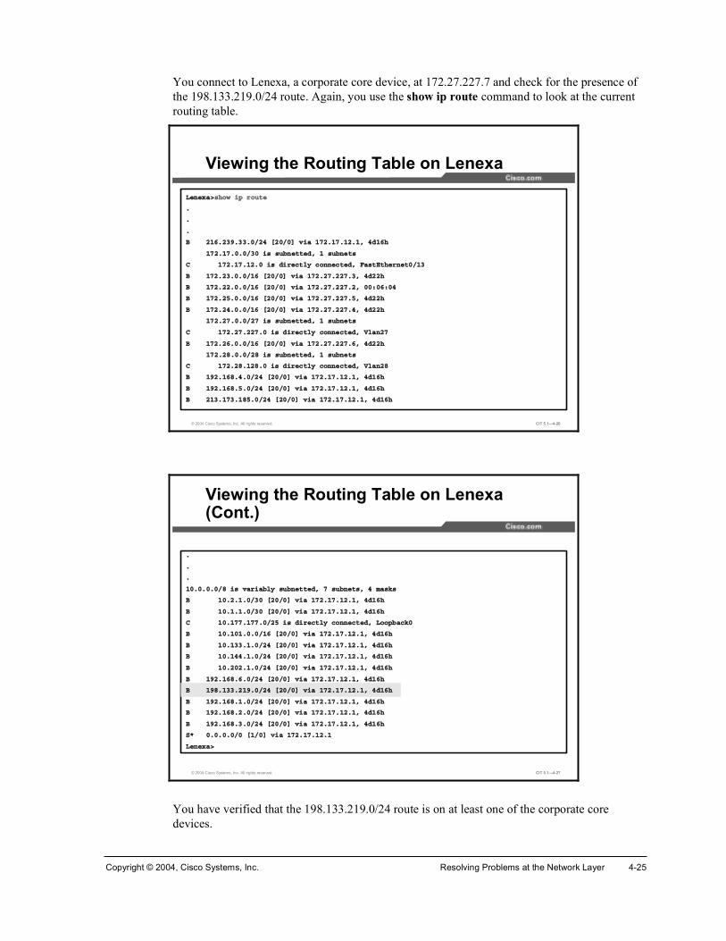
Copyright © 2004, Cisco Systems, Inc. Resolving Problems at the Network Layer 4-25
You connect to Lenexa, a corporate core device, at 172.27.227.7 and check for the presence of the 198.133.219.0/24 route. Again, you use the show ip route command to look at the current routing table.
© 2004 Cisco Systems, Inc. All rights reserved. CIT 5.1—4-26
Ô»²»¨¿â¸±© ·° ®±«¬»
ò
ò
ò
Þ îïêòîíçòííòðñîì Åîðñðà ª·¿ ïéîòïéòïîòïô ì¼ïê¸
ïéîòïéòðòðñíð · «¾²»¬¬»¼ô ï «¾²»¬
Ý ïéîòïéòïîòð · ¼·®»½¬´§ ½±²²»½¬»¼ô Ú¿¬Û¬¸»®²»¬ðñïí
Þ ïéîòîíòðòðñïê Åîðñðà ª·¿ ïéîòîéòîîéòíô ì¼îî¸
Þ ïéîòîîòðòðñïê Åîðñðà ª·¿ ïéîòîéòîîéòîô ððæðêæðì
Þ ïéîòîëòðòðñïê Åîðñðà ª·¿ ïéîòîéòîîéòëô ì¼îî¸
Þ ïéîòîìòðòðñïê Åîðñðà ª·¿ ïéîòîéòîîéòìô ì¼îî¸
ïéîòîéòðòðñîé · «¾²»¬¬»¼ô ï «¾²»¬
Ý ïéîòîéòîîéòð · ¼·®»½¬´§ ½±²²»½¬»¼ô Ê´¿²îé
Þ ïéîòîêòðòðñïê Åîðñðà ª·¿ ïéîòîéòîîéòêô ì¼îî¸
ïéîòîèòðòðñîè · «¾²»¬¬»¼ô ï «¾²»¬
Ý ïéîòîèòïîèòð · ¼·®»½¬´§ ½±²²»½¬»¼ô Ê´¿²îè
Þ ïçîòïêèòìòðñîì Åîðñðà ª·¿ ïéîòïéòïîòïô ì¼ïê¸
Þ ïçîòïêèòëòðñîì Åîðñðà ª·¿ ïéîòïéòïîòïô ì¼ïê¸
Þ îïíòïéíòïèëòðñîì Åîðñðà ª·¿ ïéîòïéòïîòïô ì¼ïê¸
Viewing the Routing Table on Lenexa
© 2004 Cisco Systems, Inc. All rights reserved. CIT 5.1—4-27
ò
ò
ò
ïðòðòðòðñè · ª¿®·¿¾´§ «¾²»¬¬»¼ô é «¾²»¬ô ì ³¿µ
Þ ïðòîòïòðñíð Åîðñðà ª·¿ ïéîòïéòïîòïô ì¼ïê¸
Þ ïðòïòïòðñíð Åîðñðà ª·¿ ïéîòïéòïîòïô ì¼ïê¸
Ý ïðòïééòïééòðñîë · ¼·®»½¬´§ ½±²²»½¬»¼ô Ô±±°¾¿½µð
Þ ïðòïðïòðòðñïê Åîðñðà ª·¿ ïéîòïéòïîòïô ì¼ïê¸
Þ ïðòïííòïòðñîì Åîðñðà ª·¿ ïéîòïéòïîòïô ì¼ïê¸
Þ ïðòïììòïòðñîì Åîðñðà ª·¿ ïéîòïéòïîòïô ì¼ïê¸
Þ ïðòîðîòïòðñîì Åîðñðà ª·¿ ïéîòïéòïîòïô ì¼ïê¸
Þ ïçîòïêèòêòðñîì Åîðñðà ª·¿ ïéîòïéòïîòïô ì¼ïê¸
Þ ïçèòïííòîïçòðñîì Åîðñðà ª·¿ ïéîòïéòïîòïô ì¼ïê¸
Þ ïçîòïêèòïòðñîì Åîðñðà ª·¿ ïéîòïéòïîòïô ì¼ïê¸
Þ ïçîòïêèòîòðñîì Åîðñðà ª·¿ ïéîòïéòïîòïô ì¼ïê¸
Þ ïçîòïêèòíòðñîì Åîðñðà ª·¿ ïéîòïéòïîòïô ì¼ïê¸
Íö ðòðòðòðñð Åïñðà ª·¿ ïéîòïéòïîòï
Ô»²»¨¿â
Viewing the Routing Table on Lenexa (Cont.)
You have verified that the 198.133.219.0/24 route is on at least one of the corporate core devices.

4-26 Cisco Internetwork Troubleshooting (CIT) v5.1 Copyright © 2004, Cisco Systems, Inc.
You now return to the console on Washington and examine the BGP routing table.
© 2004 Cisco Systems, Inc. All rights reserved. CIT 5.1—4-28
É¿¸·²¹¬±²â¸±© ·° ¾¹°
ÞÙÐ ¬¿¾´» ª»®·±² · îéô ´±½¿´ ®±«¬»® ×Ü · ïéîòîîòïîçòï
ͬ¿¬« ½±¼»æ «°°®»»¼ô ¼ ¼¿³°»¼ô ¸ ¸·¬±®§ô ö ª¿´·¼ô â ¾»¬ô · ó ·²¬»®²¿´
Ñ®·¹·² ½±¼»æ · ó ×ÙÐô » ó ÛÙÐô á ó ·²½±³°´»¬»
Ò»¬©±®µ Ò»¨¬ ر° Ó»¬®·½ Ô±½Ð®º É»·¹¸¬ п¬¸
öâ ïéîòîïòðòð ïéîòîèòïîèòï ð éé ïï ·
öâ ïéîòîîòðòð ðòðòðòð íîéêè ·
â ïéîòîîòïîïòðñîê ðòðòðòð íèëðîìð íîéêè ·
â ïéîòîîòïîîòðñîê ðòðòðòð íèëðîìð íîéêè ·
â ïéîòîîòïîíòðñîê ðòðòðòð íèëðîìð íîéêè ·
â ïéîòîîòïîìòðñîê ðòðòðòð íèëðîìð íîéêè ·
â ïéîòîîòïîëòðñîê ðòðòðòð íçéëêèð íîéêè ·
â ïéîòîîòïîêòðñîê ðòðòðòð íèìéêèð íîéêè ·
â ïéîòîîòïîêòïîèñîê
ðòðòðòð ìðëïìëêð íîéêè ·
â ïéîòîîòïîèòðñîê ðòðòðòð ïëêïêð íîéêè ·
â ïéîòîîòïîèòïîèñîê
ðòðòðòð ð íîéêè ·
Viewing the BGP Routing Table on Washington
© 2004 Cisco Systems, Inc. All rights reserved. CIT 5.1—4-29
ò
ò
ò
â ïéîòîîòïîçòðñîê ðòðòðòð ð íîéêè ·
ö ïéîòîíòðòð ïéîòîéòîîéòí ð éé íï ·
öâ ïéîòîèòïîèòí ð éé íï ·
ö ïéîòîìòðòð ïéîòîéòîîéòì ð éé ìï ·
öâ ïéîòîèòïîèòì ð éé ìï ·
Ò»¬©±®µ Ò»¨¬ ر° Ó»¬®·½ Ô±½Ð®º É»·¹¸¬ п¬¸
ö ïéîòîëòðòð ïéîòîéòîîéòë ð éé ëï ·
öâ ïéîòîèòïîèòë ð éé ëï ·
ö ïéîòîêòðòð ïéîòîéòîîéòê ð éé êï ·
öâ ïéîòîèòïîèòê ð éé êï ·
É¿¸·²¹¬±²â
Viewing the BGP Routing Table on Washington (Cont.)
You determine that the 198.133.219.0/24 route is not in the BGP table on Washington.

Copyright © 2004, Cisco Systems, Inc. Resolving Problems at the Network Layer 4-27
For further problem isolation, you again review the status of the routing protocols on Washington.
© 2004 Cisco Systems, Inc. All rights reserved. CIT 5.1—4-30
É¿¸·²¹¬±²â¸±© ·° °®±¬±½±´
᫬·²¹ Ю±¬±½±´ · þ»·¹®° îðî�
ò
ò
ò
Ò»·¹¸¾±®ø÷æ
ß¼¼®» Ú·´¬×² Ú·´¬Ñ«¬ Ü·¬×² Ü·¬Ñ«¬ É»·¹¸¬ ᫬»Ó¿°
ïéîòîéòîîéòé Ý×Ì
ïéîòîèòïîèòè Ý×Ì
Ó¿¨·³«³ °¿¬¸æ ï
᫬·²¹ º±® Ò»¬©±®µæ
᫬·²¹ ײº±®³¿¬·±² ͱ«®½»æ
Ù¿¬»©¿§ Ü·¬¿²½» Ô¿¬ Ë°¼¿¬»
ø¬¸· ®±«¬»®÷ îðð ì¼ïë¸
ïéîòîèòïîèòè îð ì¼ïë¸
ïéîòîéòîîéòé îð ì¼ïë¸
Ü·¬¿²½»æ »¨¬»®²¿´ îð ·²¬»®²¿´ îðð ´±½¿´ îðð
É¿¸·²¹¬±²â
Viewing the Status of Routing Protocols on Washington
You notice that a distribution list named CIT is applied to inbound routes from the BGP neighbors. You realize that you probably should have been more observant and noticed the distribution list earlier. In this case, BGP is using the distribution list named CIT to choose what routes it will accept from a neighbor.

4-28 Cisco Internetwork Troubleshooting (CIT) v5.1 Copyright © 2004, Cisco Systems, Inc.
You then use the show access-lists command to review the access list information.
© 2004 Cisco Systems, Inc. All rights reserved. CIT 5.1—4-31
É¿¸·²¹¬±²â¸±© ¿½½»ó´·¬
ͬ¿²¼¿®¼ ×Ð ¿½½» ´·¬ îï
°»®³·¬ ïéîòîèòïîèòé
°»®³·¬ ïéîòîèòïîèòè
°»®³·¬ ïéîòîéòîîéòé
°»®³·¬ ïéîòîéòîîéòè
°»®³·¬ ïéîòîîòðòðô ©·´¼½¿®¼ ¾·¬ ðòðòîëëòîëë
ͬ¿²¼¿®¼ ×Ð ¿½½» ´·¬ Ý×Ì
°»®³·¬ ïéîòîïòðòðô ©·´¼½¿®¼ ¾·¬ ðòðòîëëòîëë øë ³¿¬½¸»÷ ½¸»½µãîðð
°»®³·¬ ïéîòîíòðòðô ©·´¼½¿®¼ ¾·¬ ðòðòîëëòîëë øè ³¿¬½¸»÷ ½¸»½µãïçî
°»®³·¬ ïéîòîìòðòðô ©·´¼½¿®¼ ¾·¬ ðòðòîëëòîëë øïî ³¿¬½¸»÷ ½¸»½µãïèð
°»®³·¬ ïéîòîëòðòðô ©·´¼½¿®¼ ¾·¬ ðòðòîëëòîëë øï𠳿¬½¸»÷ ½¸»½µãïéð
°»®³·¬ ïéîòîêòðòðô ©·´¼½¿®¼ ¾·¬ ðòðòîëëòîëë øï𠳿¬½¸»÷ ½¸»½µãïêð
Û¨¬»²¼»¼ ×Ð ¿½½» ´·¬ ¼¸½°Á¹´»¿²Á¿½´ ø°»®ó«»®÷
°»®³·¬ «¼° ¿²§ »¯ ¾±±¬°½ ¸±¬ îëëòîëëòîëëòîëë »¯ ¾±±¬°
É¿¸·²¹¬±²â
Viewing Access List Information on Washington
You know that you need to permit all networks that are to be passed by a distribution list. You see that the Cisco Systems network 198.133.219.0/24 is not permitted with the existing access list named CIT. The issue has been isolated to the missing network address in this access list.

Copyright © 2004, Cisco Systems, Inc. Resolving Problems at the Network Layer 4-29
Example: Isolating an IP Addressing Problem at the Network Layer
You are the second-level network engineer for a division with locations in Washington, Baltimore, and Columbia. The networking devices at each location are named after the names of the city in which they reside. You have console access to the router named Washington, which gives you IP connectivity to all devices in your network. Your span of responsibility in the corporate network includes the 172.22.0.0/16 subnet.
© 2004 Cisco Systems, Inc. All rights reserved. CIT 5.1—4-32
Example: Isolating an IP Addressing Problem at the Network Layer
One day, Network Operations in Columbia calls to report that it cannot ping the switch named Columbia_SW. Network Operations does not recall changing any of the configurations, and they cannot ping Columbia_SW from Washington, either.

4-30 Cisco Internetwork Troubleshooting (CIT) v5.1 Copyright © 2004, Cisco Systems, Inc.
You check on the base configuration information and note that the Columbia router and Columbia_SW switch are connected over a 100 Mbps Fast Ethernet link. You try to ping Columbia_SW from Washington and have a 0 percent success rate. You then use Telnet to connect to the Columbia router and try to ping Columbia_SW from there.
© 2004 Cisco Systems, Inc. All rights reserved. CIT 5.1—4-33
É¿¸·²¹¬±²â°·²¹ ݱ´«³¾·¿Á©
̧°» »½¿°» »¯«»²½» ¬± ¿¾±®¬ò
Í»²¼·²¹ ëô ïðð󾧬» ×ÝÓÐ Û½¸± ¬± ïéîòîîòïîïòîô ¬·³»±«¬ · î »½±²¼æ
òòòòò
Í«½½» ®¿¬» · ð °»®½»²¬ øðñë÷
É¿¸·²¹¬±²â
É¿¸·²¹¬±²â¬»´²»¬ ½±´«³¾·¿
ò
ò
ò
ݱ´«³¾·¿â
ݱ´«³¾·¿â°·²¹ ݱ´«³¾·¿Á©
̧°» »½¿°» »¯«»²½» ¬± ¿¾±®¬ò
Í»²¼·²¹ ëô ïðð󾧬» ×ÝÓÐ Û½¸± ¬± ïéîòîîòïîïòîô ¬·³»±«¬ · î »½±²¼æ
òòòòò
Í«½½» ®¿¬» · ð °»®½»²¬ øðñë÷
ݱ´«³¾·¿â
Isolating an IP Addressing Problem at the Network Layer
You note that neither the Washington nor Columbia routers can reach the Columbia_SW switch.

Copyright © 2004, Cisco Systems, Inc. Resolving Problems at the Network Layer 4-31
You ask Network Operations in Columbia to try to ping the Columbia router from Columbia_SW.
© 2004 Cisco Systems, Inc. All rights reserved. CIT 5.1—4-34
ݱ´«³¾·¿ÁÍÉâ°·²¹ ݱ´«³¾·¿
̧°» »½¿°» »¯«»²½» ¬± ¿¾±®¬ò
Í»²¼·²¹ ëô ïðð󾧬» ×ÝÓÐ Û½¸± ¬± ïéîòîîòïîëòïô ¬·³»±«¬ · î
»½±²¼æ
òòòòò
Í«½½» ®¿¬» · ð °»®½»²¬ øðñë÷
ݱ´«³¾·¿ÁÍÉâ
Testing Connectivity to the Columbia Router
Pinging the Columbia router from Columbia_SW fails.
From the Columbia router, you try using Telnet to connect to the Columbia_SW switch.
© 2004 Cisco Systems, Inc. All rights reserved. CIT 5.1—4-35
ݱ´«³¾·¿â¬»´²»¬ ½±´«³¾·¿Á©
Ì®§·²¹ ݱ´«³¾·¿ÁÍÉ øïéîòîîòïîïòî÷òòò
û ݱ²²»½¬·±² ¬·³»¼ ±«¬å ®»³±¬» ¸±¬ ²±¬ ®»°±²¼·²¹
ݱ´«³¾·¿â
Testing Connectivity to the Columbia_SW Switch
You note that Telnet and ping traffic to the Columbia_SW switch is not being transferred.

4-32 Cisco Internetwork Troubleshooting (CIT) v5.1 Copyright © 2004, Cisco Systems, Inc.
To help isolate the problem, you review the current interface status on Columbia.
© 2004 Cisco Systems, Inc. All rights reserved. CIT 5.1—4-36
ݱ´«³¾·¿â¸±© ·° ·²¬»®º¿½» ¾®·»º
ײ¬»®º¿½» ×Ðóß¼¼®» ÑÕá Ó»¬¸±¼ ͬ¿¬«
Ю±¬±½±´
Ú¿¬Û¬¸»®²»¬ðñð «²¿·¹²»¼ ÇÛÍ ³¿²«¿´ «° «°
Ú¿¬Û¬¸»®²»¬ðñðòï ïéîòîîòïîïòï ÇÛÍ ³¿²«¿´ «° «°
Ú¿¬Û¬¸»®²»¬ðñðòî ïéîòîîòïîîòï ÇÛÍ ³¿²«¿´ «° «°
Ú¿¬Û¬¸»®²»¬ðñðòí ïéîòîîòïîíòï ÇÛÍ ³¿²«¿´ «° «°
Ú¿¬Û¬¸»®²»¬ðñðòì ïéîòîîòïîìòï ÇÛÍ ³¿²«¿´ «° «°
Í»®·¿´ïñð ïéîòîîòïîéòï ÇÛÍ ³¿²«¿´ «° «°
Í»®·¿´ïñï ïéîòîîòïîéòïîç ÇÛÍ ³¿²«¿´ «° «°
Ê·®¬«¿´óß½½»ï «²¿·¹²»¼ ÇÛÍ «²»¬ «° «°
Í»®·¿´ðñðæð ïéîòîîòïîêòï ÇÛÍ ³¿²«¿´ «° «°
Í»®·¿´ðñðæï ïéîòîîòïîêòïîç ÇÛÍ ³¿²«¿´ «° «°
Ô±±°¾¿½µð ïéîòîîòïîëòï ÇÛÍ ³¿²«¿´ «° «°
ݱ´«³¾·¿â
Viewing the Current Interface Status on Columbia
You see that the physical link to Columbia_SW on Fast Ethernet 0/0 is up.
You then check for Cisco Discovery Protocol (CDP) neighbors with the show cdp neighborscommand.
© 2004 Cisco Systems, Inc. All rights reserved. CIT 5.1—4-37
ݱ´«³¾·¿â¸±© ½¼° ²»·¹¸¾±®
Ý¿°¿¾·´·¬§ ݱ¼»æ Î ó ᫬»®ô Ì ó Ì®¿² Þ®·¼¹»ô Þ ó ͱ«®½» ᫬» Þ®·¼¹»
Í ó Í©·¬½¸ô Ø ó ر¬ô × ó ×ÙÓÐô ® ó λ°»¿¬»®
Ü»ª·½» ×Ü Ô±½¿´ ײ¬®º½» ر´¼¬³» Ý¿°¿¾·´·¬§ д¿¬º±®³ ᮬ ×Ü
Þ¿´¬·³±®» Í»® ðñðæï ïéç Î ïéêð Í»® ðñðæï
Þ¿´¬·³±®» Í»® ðñðæð ïéç Î ïéêð Í»® ðñðæð
ݱ´«³¾·¿ÁÍÉ Ú¿ ðñð ïíì Í × ÉÍóÝîçëðÌóÚ¿ ðñï
ݱ´«³¾·¿â
Viewing Information About Devices Neighboring Columbia
You see that CDP packets are being received from Columbia_SW.

Copyright © 2004, Cisco Systems, Inc. Resolving Problems at the Network Layer 4-33
You look for additional information with the show cdp neighbors detail command.
© 2004 Cisco Systems, Inc. All rights reserved. CIT 5.1—4-38
ݱ´«³¾·¿â¸±© ½¼° ²»·¹¸¾±® ¼»¬¿·´
ò
ò
ò
Ü»ª·½» ×Üæ ݱ´«³¾·¿ÁÍÉ
Û²¬®§ ¿¼¼®»ø»÷æ
×Ð ¿¼¼®»æ ïéîòîîòïîïòï
д¿¬º±®³æ ½·½± ÉÍóÝîçëðÌóîìô Ý¿°¿¾·´·¬·»æ Í©·¬½¸ ×ÙÓÐ
ײ¬»®º¿½»æ Ú¿¬Û¬¸»®²»¬ðñðô ᮬ ×Ü ø±«¬¹±·²¹ °±®¬÷æ Ú¿¬Û¬¸»®²»¬ðñï
ر´¼¬·³» æ ïëê »½
ò
ò
ò
ݱ´«³¾·¿â
Viewing Detailed Information About Devices Neighboring Columbia
You see the issue. Now it is time to illustrate the issue for Network Operations.

4-34 Cisco Internetwork Troubleshooting (CIT) v5.1 Copyright © 2004, Cisco Systems, Inc.
You call back Network Operations in Columbia to see if there are any error messages on the console of Columbia or Columbia_SW. No one at Network Operations has seen any. You ask their team to input the command show logging on Columbia to help isolate the issue. (You enter the show logging command on Columbia, as well.)
© 2004 Cisco Systems, Inc. All rights reserved. CIT 5.1—4-39
ݱ´«³¾·¿â¸±© ´±¹¹·²¹
ͧ´±¹ ´±¹¹·²¹æ »²¿¾´»¼ øð ³»¿¹» ¼®±°°»¼ô ï ³»¿¹» ®¿¬»ó´·³·¬»¼ô ð º´«¸»ô
𠱪»®®«²÷
ݱ²±´» ´±¹¹·²¹æ ¼·¿¾´»¼
ò
ò
ò
Ô±¹ Þ«ºº»® øêëëíê ¾§¬»÷æ
ò
ò
ò
Ü»½ ïé ïëæííæîçæ û×ÐóìóÜËÐßÜÜÎæ Ü«°´·½¿¬» ¿¼¼®» ïéîòîîòïîïòï ±²
Ú¿¬Û¬¸»®²»¬ðñðòïô ±«®½»¼ ¾§ ððð¿òè¿ììò¼»ìð
ò
ò
ò
ݱ´«³¾·¿â
Analyzing Console Messages on Columbia
You ask Network Operations to check if console logging is disabled. Your default practice is to have console logging enabled, because console messages can provide useful information. You then suggest that Network Operations scan the error messages for reoccurring messages. Network Operations notices that there is a duplicate IP address (172.22.121.1) on FastEthernet0/0.1. This is indeed a network layer issue.
You know from the baseline that Columbia should have IP address 172.22.121.1 on Fast Ethernet 0/0.1. However, Columbia_SW should use 172.22.121.2. If logging had been enabled, the isolation problem would have been trivial.

Copyright © 2004, Cisco Systems, Inc. Resolving Problems at the Network Layer 4-35
Example: Isolating Problems at the Network Layer You are the second-level network engineer for a division with locations in Seattle, Olympia, and Tacoma. The networking devices at each location are named after the names of the city in which they reside. You have console access to the router named Seattle, which gives you IP connectivity to all devices in your network. Your span of responsibility in the corporate network includes the 172.25.0.0/16 subnet.
© 2004 Cisco Systems, Inc. All rights reserved. CIT 5.1—4-40
Example: Isolating Problems at the Network Layer
One day, Network Operations from Olympia calls to say that it has lost all routes from the Seattle core router.
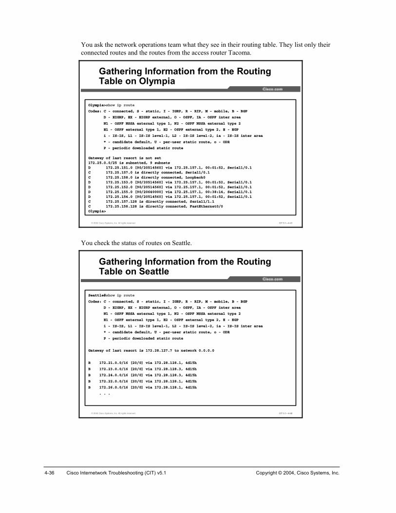
4-36 Cisco Internetwork Troubleshooting (CIT) v5.1 Copyright © 2004, Cisco Systems, Inc.
You ask the network operations team what they see in their routing table. They list only their connected routes and the routes from the access router Tacoma.
© 2004 Cisco Systems, Inc. All rights reserved. CIT 5.1—4-41
Ñ´§³°·¿â¸±© ·° ®±«¬»
ݱ¼»æ Ý ó ½±²²»½¬»¼ô Í ó ¬¿¬·½ô × ó ×ÙÎÐô Î ó Î×Ðô Ó ó ³±¾·´»ô Þ ó ÞÙÐ
Ü ó Û×ÙÎÐô ÛÈ ó Û×ÙÎÐ »¨¬»®²¿´ô Ñ ó ÑÍÐÚô ×ß ó ÑÍÐÚ ·²¬»® ¿®»¿
Òï ó ÑÍÐÚ ÒÍÍß »¨¬»®²¿´ ¬§°» ïô Òî ó ÑÍÐÚ ÒÍÍß »¨¬»®²¿´ ¬§°» î
Ûï ó ÑÍÐÚ »¨¬»®²¿´ ¬§°» ïô Ûî ó ÑÍÐÚ »¨¬»®²¿´ ¬§°» îô Û ó ÛÙÐ
· ó ×Íó×Íô Ôï ó ×Íó×Í ´»ª»´óïô Ôî ó ×Íó×Í ´»ª»´óîô ·¿ ó ×Íó×Í ·²¬»® ¿®»¿
ö ó ½¿²¼·¼¿¬» ¼»º¿«´¬ô Ë ó °»®ó«»® ¬¿¬·½ ®±«¬»ô ± ó ÑÜÎ
Ð ó °»®·±¼·½ ¼±©²´±¿¼»¼ ¬¿¬·½ ®±«¬»
Ù¿¬»©¿§ ±º ´¿¬ ®»±®¬ · ²±¬ »¬ïéîòîëòðòðñîë · «¾²»¬¬»¼ô ç «¾²»¬Ü ïéîòîëòïëïòð Åçðñîðëïìëêðà ª·¿ ïéîòîëòïëéòïô ððæðïæëîô Í»®·¿´ïñðòïÝ ïéîòîëòïëéòð · ¼·®»½¬´§ ½±²²»½¬»¼ô Í»®·¿´ïñðòï
Ý ïéîòîëòïëèòð · ¼·®»½¬´§ ½±²²»½¬»¼ô Ô±±°¾¿½µðÜ ïéîòîëòïëíòð Åçðñîðëïìëêðà ª·¿ ïéîòîëòïëéòïô ððæðïæëîô Í»®·¿´ïñðòïÜ ïéîòîëòïëîòð Åçðñîðëïìëêðà ª·¿ ïéîòîëòïëéòïô ððæðïæëîô Í»®·¿´ïñðòïÜ ïéîòîëòïëëòð Åçðñîðêìððððà ª·¿ ïéîòîëòïëéòïô ððæíèæïìô Í»®·¿´ïñðòïÜ ïéîòîëòïëìòð Åçðñîðëïìëêðà ª·¿ ïéîòîëòïëéòïô ððæðïæëîô Í»®·¿´ïñðòïÝ ïéîòîëòïëéòïîè · ¼·®»½¬´§ ½±²²»½¬»¼ô Í»®·¿´ïñïòïÝ ïéîòîëòïëèòïîè · ¼·®»½¬´§ ½±²²»½¬»¼ô Ú¿¬Û¬¸»®²»¬ðñðÑ´§³°·¿â
Gathering Information from the Routing Table on Olympia
You check the status of routes on Seattle.
© 2004 Cisco Systems, Inc. All rights reserved. CIT 5.1—4-42
Í»¿¬¬´»ý¸±© ·° ®±«¬»
ݱ¼»æ Ý ó ½±²²»½¬»¼ô Í ó ¬¿¬·½ô × ó ×ÙÎÐô Î ó Î×Ðô Ó ó ³±¾·´»ô Þ ó ÞÙÐ
Ü ó Û×ÙÎÐô ÛÈ ó Û×ÙÎÐ »¨¬»®²¿´ô Ñ ó ÑÍÐÚô ×ß ó ÑÍÐÚ ·²¬»® ¿®»¿
Òï ó ÑÍÐÚ ÒÍÍß »¨¬»®²¿´ ¬§°» ïô Òî ó ÑÍÐÚ ÒÍÍß »¨¬»®²¿´ ¬§°» î
Ûï ó ÑÍÐÚ »¨¬»®²¿´ ¬§°» ïô Ûî ó ÑÍÐÚ »¨¬»®²¿´ ¬§°» îô Û ó ÛÙÐ
· ó ×Íó×Íô Ôï ó ×Íó×Í ´»ª»´óïô Ôî ó ×Íó×Í ´»ª»´óîô ·¿ ó ×Íó×Í ·²¬»® ¿®»¿
ö ó ½¿²¼·¼¿¬» ¼»º¿«´¬ô Ë ó °»®ó«»® ¬¿¬·½ ®±«¬»ô ± ó ÑÜÎ
Ð ó °»®·±¼·½ ¼±©²´±¿¼»¼ ¬¿¬·½ ®±«¬»
Ù¿¬»©¿§ ±º ´¿¬ ®»±®¬ · ïéîòîèòïîéòé ¬± ²»¬©±®µ ðòðòðòð
Þ ïéîòîïòðòðñïê Åîðñðà ª·¿ ïéîòîèòïîèòïô ì¼ïë¸
Þ ïéîòîíòðòðñïê Åîðñðà ª·¿ ïéîòîèòïîèòíô ì¼ïë¸
Þ ïéîòîìòðòðñïê Åîðñðà ª·¿ ïéîòîèòïîèòíô ì¼ïë¸
Þ ïéîòîîòðòðñïê Åîðñðà ª·¿ ïéîòîèòïîèòïô ì¼ïë¸
Þ ïéîòîêòðòðñïê Åîðñðà ª·¿ ïéîòîèòïîèòïô ì¼ïë¸
ò ò ò
Gathering Information from the Routing Table on Seattle

Copyright © 2004, Cisco Systems, Inc. Resolving Problems at the Network Layer 4-37
© 2004 Cisco Systems, Inc. All rights reserved. CIT 5.1—4-43
ò ò ò
Ý ïéîòîëòïëçòðñîë · ¼·®»½¬´§ ½±²²»½¬»¼ô Ô±±°¾¿½µð
Ý ïéîòîëòïëèòïîèñîë · ¼·®»½¬´§ ½±²²»½¬»¼ô Ú¿¬Û¬¸»®²»¬ðñë
Þ ïéîòîëòðòðñïê Åîððñðà ª·¿ ðòðòðòðô ððæîçæðïô Ò«´´ð
ïéîòîéòðòðñîé · «¾²»¬¬»¼ô ï «¾²»¬
Ý ïéîòîéòîîéòð · ¼·®»½¬´§ ½±²²»½¬»¼ô Ê´¿²îé
ïéîòîèòðòðñîè · «¾²»¬¬»¼ô ï «¾²»¬
Ý ïéîòîèòïîèòð · ¼·®»½¬´§ ½±²²»½¬»¼ô Ê´¿²îè
ïðòðòðòðñè · ª¿®·¿¾´§ «¾²»¬¬»¼ô î «¾²»¬ô î ³¿µ
Ñ ×ß ïðòïééòïéèòðñîê Åïïðñîà ª·¿ ïéîòîèòïîèòèô ððæîëæíéô Ê´¿²îè
Åïïðñîà ª·¿ ïéîòîéòîîéòèô ððæîëæíéô Ê´¿²îé
Ñ ×ß ïðòïééòïééòðñîë Åïïðñîà ª·¿ ïéîòîèòïîèòéô ððæîëæíéô Ê´¿²îè
Åïïðñîà ª·¿ ïéîòîéòîîéòéô ððæîëæíéô Ê´¿²îé
Íö ðòðòðòðñð Åïñðà ª·¿ ïéîòîéòîîéòé
Í»¿¬¬´»ý
Gathering Information from the Routing Table on Seattle (Cont.)
You notice that you are missing the routes from the Olympia distribution router.
You verify connectivity to Olympia.
© 2004 Cisco Systems, Inc. All rights reserved. CIT 5.1—4-44
Í»¿¬¬´»ý°·²¹ Ñ´§³°·¿
̧°» »½¿°» »¯«»²½» ¬± ¿¾±®¬ò
Í»²¼·²¹ ëô ïðð󾧬» ×ÝÓÐ Û½¸± ¬± ïéîòîëòïëçòïîçô ¬·³»±«¬ · î
»½±²¼æ
ÿÿÿÿÿ
Í«½½» ®¿¬» · ïðð °»®½»²¬ øëñë÷ô ®±«²¼ó¬®·° ³·²ñ¿ª¹ñ³¿¨ ã
ïñîñì ³
Í»¿¬¬´»ý
Verifying Connectivity to Olympia
This command confirms that you have network layer connectivity to Olympia.

4-38 Cisco Internetwork Troubleshooting (CIT) v5.1 Copyright © 2004, Cisco Systems, Inc.
You check the status of OSPF neighbors on Seattle.
© 2004 Cisco Systems, Inc. All rights reserved. CIT 5.1—4-45
Í»¿¬¬´»ý¸±© ·° ±°º ²»·¹¸¾±®
Ò»·¹¸¾±® ×Ü Ð®· ͬ¿¬» Ü»¿¼ Ì·³» ß¼¼®» ײ¬»®º¿½»
ïéîòîéòîîéòè ïð ÚËÔÔñÞÜÎ ððæððæíî ïéîòîéòîîéòè Ê´¿²îé
ïéîòîéòîîéòé îð ÚËÔÔñÜÎ ððæððæíî ïéîòîéòîîéòé Ê´¿²îé
ïéîòîéòîîéòè îð ÚËÔÔñÜÎ ððæððæíð ïéîòîèòïîèòè Ê´¿²îè
ïéîòîéòîîéòé ïð ÚËÔÔñÞÜÎ ððæððæíð ïéîòîèòïîèòé Ê´¿²îè
Í»¿¬¬´»ý
Gathering Information on OSPF Neighbors
You see that there is no neighbor relationship with Olympia.
You verify that the interfaces between Seattle and Olympia have been configured for OSPF.
© 2004 Cisco Systems, Inc. All rights reserved. CIT 5.1—4-46
Í»¿¬¬´»ý¸±© ·° ±°º ·²¬»®º¿½» º¿ ðñë
Ú¿¬Û¬¸»®²»¬ðñë · «°ô ´·²» °®±¬±½±´ · «°
ײ¬»®²»¬ ß¼¼®» ïéîòîëòïëèòïíðñîëô ß®»¿ ë
Ю±½» ×Ü ëðëô ᫬»® ×Ü ïéîòîéòîîéòëô Ò»¬©±®µ ̧°» ÒÑÒÁÞÎÑßÜÝßÍÌô ݱ¬æ ï
Ì®¿²³·¬ Ü»´¿§ · ï »½ô ͬ¿¬» ÜÎô Ю·±®·¬§ ï
Ü»·¹²¿¬»¼ ᫬»® ø×Ü÷ ïéîòîéòîîéòëô ײ¬»®º¿½» ¿¼¼®» ïéîòîëòïëèòïíð
Ò± ¾¿½µ«° ¼»·¹²¿¬»¼ ®±«¬»® ±² ¬¸· ²»¬©±®µ
Ì·³»® ·²¬»®ª¿´ ½±²º·¹«®»¼ô Ø»´´± íðô Ü»¿¼ ïîðô É¿·¬ ïîðô 묮¿²³·¬ ë
Ø»´´± ¼«» ·² ððæððæðê
ײ¼»¨ ïñïô º´±±¼ ¯«»«» ´»²¹¬¸ ð
Ò»¨¬ ð¨ðøð÷ñð¨ðøð÷
Ô¿¬ º´±±¼ ½¿² ´»²¹¬¸ · îô ³¿¨·³«³ · î
Ô¿¬ º´±±¼ ½¿² ¬·³» · ð ³»½ô ³¿¨·³«³ · ð ³»½
Ò»·¹¸¾±® ݱ«²¬ · ðô ß¼¶¿½»²¬ ²»·¹¸¾±® ½±«²¬ · ð
Í«°°®» ¸»´´± º±® ð ²»·¹¸¾±®ø÷
Í»¿¬¬´»ý
Gathering Information on an OSPF Interface on Seattle

Copyright © 2004, Cisco Systems, Inc. Resolving Problems at the Network Layer 4-39
You see that the Fast Ethernet interfaces between Seattle and Olympia are OSPF interfaces without any neighbors.
© 2004 Cisco Systems, Inc. All rights reserved. CIT 5.1—4-47
Ñ´§³°·¿â¸±© ·° ±°º ·²¬»®º¿½» º¿¬ ðñð
Ú¿¬Û¬¸»®²»¬ðñð · «°ô ´·²» °®±¬±½±´ · «°
ײ¬»®²»¬ ß¼¼®» ïéîòîëòïëèòïîçñîëô ß®»¿ ë
Ю±½» ×Ü ëðëô ᫬»® ×Ü ïéîòîëòïëèòïô Ò»¬©±®µ ̧°» ÒÑÒÁÞÎÑßÜÝßÍÌô ݱ¬æ ï
Ì®¿²³·¬ Ü»´¿§ · ï »½ô ͬ¿¬» ÜÎô Ю·±®·¬§ ï
Ü»·¹²¿¬»¼ ᫬»® ø×Ü÷ ïéîòîëòïëèòïô ײ¬»®º¿½» ¿¼¼®» ïéîòîëòïëèòïîç
Ò± ¾¿½µ«° ¼»·¹²¿¬»¼ ®±«¬»® ±² ¬¸· ²»¬©±®µ
Ì·³»® ·²¬»®ª¿´ ½±²º·¹«®»¼ô Ø»´´± íðô Ü»¿¼ ïîðô É¿·¬ ïîðô 묮¿²³·¬ ë
Ø»´´± ¼«» ·² ððæððæðê
ײ¼»¨ íñíô º´±±¼ ¯«»«» ´»²¹¬¸ ð
Ò»¨¬ ð¨ðøð÷ñð¨ðøð÷
Ô¿¬ º´±±¼ ½¿² ´»²¹¬¸ · ìô ³¿¨·³«³ · ì
Ô¿¬ º´±±¼ ½¿² ¬·³» · ð ³»½ô ³¿¨·³«³ · ð ³»½
Ò»·¹¸¾±® ݱ«²¬ · ðô ß¼¶¿½»²¬ ²»·¹¸¾±® ½±«²¬ · ð
Í«°°®» ¸»´´± º±® ð ²»·¹¸¾±®ø÷
Ñ´§³°·¿â
Gathering Information on an OSPF Interface on Olympia
You may run some debugging commands on Seattle, as needed.
© 2004 Cisco Systems, Inc. All rights reserved. CIT 5.1—4-48
Í»¿¬¬´»ý¼»¾«¹ ·° ±°º ¿¼¶
ÑÍÐÚ ¿¼¶¿½»²½§ »ª»²¬ ¼»¾«¹¹·²¹ · ±²
Í»¿¬¬´»ý¼»¾«¹ ·° ±°º »ª»
Í»¿¬¬´»ý
òÜ»½ îè îïæïëæëêòïêéæ ÑÍÐÚæ νª ¸»´´± º®±³ ïéîòîéòîîéòé ¿®»¿ 𠺮±³ Ê´¿²îè ïéîòîèòïîèòé
òÜ»½ îè îïæïëæëêòïêéæ ÑÍÐÚæ Û²¼ ±º ¸»´´± °®±½»·²¹
òÜ»½ îè îïæïëæëêòîìíæ ÑÍÐÚæ νª ¸»´´± º®±³ ïéîòîéòîîéòè ¿®»¿ 𠺮±³ Ê´¿²îè ïéîòîèòïîèòè
òÜ»½ îè îïæïëæëêòîìíæ ÑÍÐÚæ Û²¼ ±º ¸»´´± °®±½»·²¹
òÜ»½ îè îïæïëæëéòçíçæ ÑÍÐÚæ νª ¸»´´± º®±³ ïéîòîéòîîéòé ¿®»¿ 𠺮±³ Ê´¿²îé ïéîòîéòîîéòé
òÜ»½ îè îïæïëæëéòçìíæ ÑÍÐÚæ Û²¼ ±º ¸»´´± °®±½»·²¹
òÜ»½ îè îïæïëæëèòðïïæ ÑÍÐÚæ νª ¸»´´± º®±³ ïéîòîéòîîéòè ¿®»¿ 𠺮±³ Ê´¿²îé ïéîòîéòîîéòè
òÜ»½ îè îïæïëæëèòðïïæ ÑÍÐÚæ Û²¼ ±º ¸»´´± °®±½»·²¹
òÜ»½ îè îïæïêæðêòïêèæ ÑÍÐÚæ νª ¸»´´± º®±³ ïéîòîéòîîéòé ¿®»¿ 𠺮±³ Ê´¿²îè ïéîòîèòïîèòé
òÜ»½ îè îïæïêæðêòïêèæ ÑÍÐÚæ Û²¼ ±º ¸»´´± °®±½»·²¹
ò ò ò
Í»¿¬¬´»ý¼»¾«¹ ¿´´
ß´´ °±·¾´» ¼»¾«¹¹·²¹ ¸¿ ¾»»² ¬«®²»¼ ±ºº
Í»¿¬¬´»ý
Gathering Information on OSPF Processes
You should see the issue. (If not, this issue will be illustrated in the Isolating Problems Occurring at the Network Layer topic).
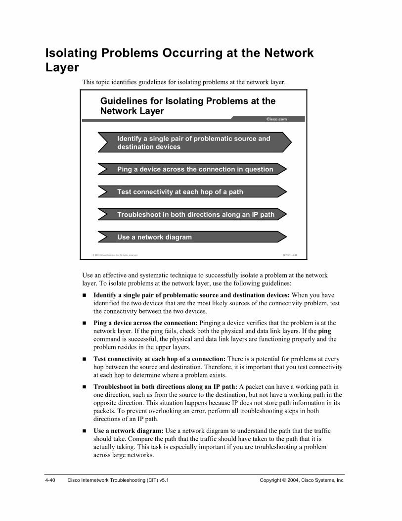
4-40 Cisco Internetwork Troubleshooting (CIT) v5.1 Copyright © 2004, Cisco Systems, Inc.
Isolating Problems Occurring at the Network Layer
This topic identifies guidelines for isolating problems at the network layer.
© 2004 Cisco Systems, Inc. All rights reserved. CIT 5.1—4-49
Guidelines for Isolating Problems at the Network Layer
Ping a device across the connection in question
Test connectivity at each hop of a path
Troubleshoot in both directions along an IP path
Use a network diagram
Identify a single pair of problematic source and destination devices
Use an effective and systematic technique to successfully isolate a problem at the network layer. To isolate problems at the network layer, use the following guidelines:
!" Identify a single pair of problematic source and destination devices: When you have identified the two devices that are the most likely sources of the connectivity problem, test the connectivity between the two devices.
!" Ping a device across the connection: Pinging a device verifies that the problem is at the network layer. If the ping fails, check both the physical and data link layers. If the pingcommand is successful, the physical and data link layers are functioning properly and the problem resides in the upper layers.
!" Test connectivity at each hop of a connection: There is a potential for problems at every hop between the source and destination. Therefore, it is important that you test connectivity at each hop to determine where a problem exists.
!" Troubleshoot in both directions along an IP path: A packet can have a working path in one direction, such as from the source to the destination, but not have a working path in the opposite direction. This situation happens because IP does not store path information in its packets. To prevent overlooking an error, perform all troubleshooting steps in both directions of an IP path.
!" Use a network diagram: Use a network diagram to understand the path that the traffic should take. Compare the path that the traffic should have taken to the path that it is actually taking. This task is especially important if you are troubleshooting a problem across large networks.

Copyright © 2004, Cisco Systems, Inc. Resolving Problems at the Network Layer 4-41
Example: Isolating Problems Occurring at the Network Layer Users on an Ethernet LAN have reported that their connection to the Internet has gone down. Examining the topology diagram for the network, you determine which networking devices are the possible problem. You use Cisco diagnostic commands to narrow down the problem to a particular path involving multiple routers. You enter the ping command from the source router that the users had been attempting to connect through to the destination router. As you expected, this test fails. You then enter the ping command from the destination router to the source router. The ping works. You test the connectivity between the source and destination routers at the physical and data link layers and determine that both layers are functioning correctly. The results indicate that you have a problem at the network layer. You execute showand debug commands on the path and discover a misconfigured static address in the routing table of one of the routers in the path.

4-42 Cisco Internetwork Troubleshooting (CIT) v5.1 Copyright © 2004, Cisco Systems, Inc.
SummaryThis topic summarizes the key points discussed in this lesson.
© 2004 Cisco Systems, Inc. All rights reserved. CIT 5.1—4-50
Summary
• Problems at the network layer have symptoms that distinguish them from problems at other layers.
• Applying commands at an end system can be a useful source of information for isolating network layer problems.
• Analyzing the output of an appropriate Cisco command or application helps you to isolate a problem at the network layer.
• Using an effective and systematic technique allows you to successfully isolate problems at the network layer.
ReferencesFor additional information, refer to these resources:
!" Cisco online documentation: http://www.cisco.com/univercd/home/home.htm
!" Cisco Technical Assistance Center (TAC): http://www.cisco.com/tac
!" Troubleshooting TCP/IP: http://www.cisco.com/univercd/cc/td/doc/cisintwk/itg_v1/tr1907.htm

Copyright © 2004, Cisco Systems, Inc. Resolving Problems at the Network Layer 4-43
QuizUse the practice items here to review what you have learned in this lesson. The correct answers are found in the Quiz Answer Key.
Q1) Users in a segment of your company LAN are complaining that access to devices on the network is much slower than usual. You check the network topology diagram to determine which devices are routing packets to that segment.
What symptom(s) would be present if this problem is located at the network layer?
A) A particular application consistently crashes; there are large amounts of broadcast traffic.
B) No devices are reachable; Layer 3 is consistently not operational.
C) There are excessive CRC/FCS errors; default routes are missing from the routing table.
D) Traffic is taking a path other than the expected path recorded in the baseline.
Q2) A NIC on an end system was faulty and replaced. However, the end system still cannot connect beyond the local network. Examine this snippet of the configuration for the default gateway for the end system and then choose a command that might solve the problem using the information given.
·²¬»®º¿½» Û¬¸»®²»¬ð ·° ¿¼¼®» ïçîòïêèòïòîëì îëëòîëëòîëëòð ²± ·° ¼·®»½¬»¼ó¾®±¿¼½¿¬
A) clear interface Ethernet0
B) clear arp-cache
C) ip directed-broadcasts
D) debug ip packet detail
Q3) What command would you enter at a Windows NT end system to display the current IP routing table for a device?
A) ipconfig /all
B) ifconfig –a
C) route print
D) arp –a

4-44 Cisco Internetwork Troubleshooting (CIT) v5.1 Copyright © 2004, Cisco Systems, Inc.
Q4) Users on a large Ethernet LAN report that their connection to the network is much slower than usual. You determine which two routers are the source and destination devices for the users of that network. You know that there is connectivity, so you run a trace instead of pinging between the devices. Running a trace from the source to the destination indicates that there is significant latency at a few of the hops along the path. You reverse the trace and verify that there is latency from the destination to the source, as well. You recognize that this latency is the cause of the problem but you are not sure why it is happening. Which guideline for isolating problems at the network layer should you practice next?
A) perform a loopback test to verify that the TCP/IP stack is loaded and functional
B) disable spanning tree on the destination device, but not the source device.
C) refer to the network diagram to verify that the devices are connecting across the expected path
D) visually inspect the serial connection between the devices

Copyright © 2004, Cisco Systems, Inc. Resolving Problems at the Network Layer 4-45
Quiz Answer Key Q1) D
Relates to: Identifying the Symptoms of Problems Occurring at the Network Layer
Q2) B
Relates to: Analyzing Cisco Commands and Applications to Isolate Problems Occurring at the Network Layer
Q3) C
Relates to: Identifying End-System Commands and Applications Used to Isolate Problems Occurring at the Network Layer
Q4) C
Relates to: Isolating Problems Occurring at the Network Layer

4-46 Cisco Internetwork Troubleshooting (CIT) v5.1 Copyright © 2004, Cisco Systems, Inc.

Correcting the Problem
OverviewOnce a troubleshooter has determined the most likely cause of the problem, the next stage of the general troubleshooting process is to correct the problem. In this lesson, you will correct network layer problems using commands and applications that configure network layer components.
Relevance Isolating a network problem is a vital step for you to perform to successfully troubleshoot a problem. However, merely isolating the problem will not bring about the types of changes that you need to make so that the network functions at the documented network baseline. To resolve the problem, you must use the tools and resources provided by Cisco and your end systems to configure the properties of your network.
ObjectivesUpon completing this lesson, you will be able to:
!" Identify Cisco commands that are used to correct problems occurring at the network layer
!" Identify end-system commands and applications that are used to correct problems occurring at the network layer
!" Identify network layer support resources
!" Correct a problem occurring at the network layer
Learner Skills and Knowledge To benefit fully from this lesson, you must have these prerequisite skills and knowledge:
!" The ability to apply layered model troubleshooting approaches
!" Familiarity with Cisco command syntax covered in the Cisco Building Scalable Cisco Internetworks (BSCI), Building Cisco Multilayer Switched Networks (BCMSN), and Building Cisco Remote Access Networks (BCRAN) courses

4-48 Cisco Internetwork Troubleshooting (CIT) v5.1 Copyright © 2004, Cisco Systems, Inc.
OutlineThis lesson includes these topics:
!" Overview
!" Identifying Cisco Commands Used to Correct Problems Occurring at the Network Layer
!" Identifying End-System Commands and Applications Used to Correct Problems Occurring at the Network Layer
!" Identifying Network Layer Support Resources
!" Correcting Problems Occurring at the Network Layer
!" Summary
!" Quiz

Copyright © 2004, Cisco Systems, Inc. Resolving Problems at the Network Layer 4-49
Identifying Cisco Commands Used to Correct Problems Occurring at the Network Layer
This topic identifies Cisco commands that troubleshooters use to correct problems at the network layer.
© 2004 Cisco Systems, Inc. All rights reserved. CIT 5.1—4-5
General Cisco Command to Correct Network Layer Problems
Ų±Ã ·° ¼±³¿·² ´±±µ«°Å²±Ã ·° ¼±³¿·² ´±±µ«°
®±«¬»®ø½±²º·¹÷ý
• This command enables the IP DNS-based host name-to-address translation. To disable, enter the no formof this command.
The general Cisco command listed in the table makes configuration changes that can be used by troubleshooters to correct problems at the network layer.
General Cisco Command to Correct Network Layer Problems
Command Description
Ų±Ã ·° ¼±³¿·² ´±±µ«° Enables the IP DNS-based host name-to-address translation. To disable, enter the no form of this command.

4-50 Cisco Internetwork Troubleshooting (CIT) v5.1 Copyright © 2004, Cisco Systems, Inc.
© 2004 Cisco Systems, Inc. All rights reserved. CIT 5.1—4-6
·²¬»®º¿½» ¥·²¬»®º¿½»ó¬§°» ²«³¾»®£·²¬»®º¿½» ¥·²¬»®º¿½»ó¬§°» ²«³¾»®£
®±«¬»®ø½±²º·¹÷ý
• Accesses a specified interface while in global configuration mode.
Cisco Commands to Correct IP Interface Problems
·° ¿¼¼®» ·°ó¿¼¼®» ³¿µ Å»½±²¼¿®§Ã·° ¿¼¼®» ·°ó¿¼¼®» ³¿µ Å»½±²¼¿®§Ã
®±«¬»®ø½±²º·¹ó·º÷ý
• Specifies a primary or secondary IP address for an interface.
Ų±Ã ·° ®»¼·®»½¬Å²±Ã ·° ®»¼·®»½¬
®±«¬»®ø½±²º·¹ó·º÷ý
• Enables or disables the sending of redirect messages through the same interface on which it was received.
© 2004 Cisco Systems, Inc. All rights reserved. CIT 5.1—4-7
¾¿²¼©·¼¬¸ ¥µ·´±¾·¬£¾¿²¼©·¼¬¸ ¥µ·´±¾·¬£
®±«¬»®ø½±²º·¹ó·º÷ý
• Communicates the bandwidth value of an interface to the higher-level protocols.
Cisco Commands to Correct IP Interface Problems (Cont.)
Ų±Ã ·° °®±¨§ó¿®°Å²±Ã ·° °®±¨§ó¿®°
®±«¬»®ø½±²º·¹ó·º÷ý
• Enables or disables proxy ARP on an interface.
®±«¬»®ø½±²º·¹ó·º÷ý
·° ³®±«¬»ó½¿½¸»·° ³®±«¬»ó½¿½¸»
• Enables IP multicast fast switching or multicast distributed switching.

Copyright © 2004, Cisco Systems, Inc. Resolving Problems at the Network Layer 4-51
Troubleshooters can use the Cisco commands listed in the table to make configuration changes to correct problems with IP interfaces that occur at the network layer.
Cisco Commands to Correct IP Interface Problems
Command Description
·²¬»®º¿½» ¥·²¬»®º¿½»ó¬§°» ²«³¾»®£
Accesses a specified interface while in global configuration mode.
·° ¿¼¼®» ·°ó¿¼¼®»³¿µ Å»½±²¼¿®§Ã
Specifies a primary or secondary IP address for an interface.
Ų±Ã ·° ®»¼·®»½¬ Enables or disables the sending of redirect messages through the same interface on which it was received.
¾¿²¼©·¼¬¸ µ·´±¾·¬ Communicates the bandwidth value of an interface to the higher-level protocols.
Ų±Ã ·° °®±¨§ó¿®° Enables or disables proxy ARP on an interface.
·° ³®±«¬»ó½¿½¸» Enables IP multicast fast switching or multicast distributed switching.

4-52 Cisco Internetwork Troubleshooting (CIT) v5.1 Copyright © 2004, Cisco Systems, Inc.
© 2004 Cisco Systems, Inc. All rights reserved. CIT 5.1—4-8
¿½½»ó´·¬ ¥¿½½»ó´·¬ó²«³¾»®£ ¥¼»²§ ¤ °»®³·¬£ °®±¬±½±´ ±«®½» ±«®½»ó©·´¼½¿®¼ ¼»¬·²¿¬·±² ¼»¬·²¿¬·±²ó©·´¼½¿®¼Å´±¹Ã
¿½½»ó´·¬ ¥¿½½»ó´·¬ó²«³¾»®£ ¥¼»²§ ¤ °»®³·¬£ °®±¬±½±´ ±«®½» ±«®½»ó©·´¼½¿®¼ ¼»¬·²¿¬·±² ¼»¬·²¿¬·±²ó©·´¼½¿®¼Å´±¹Ã
®±«¬»®ø½±²º·¹÷ý
• Defines an extended access list.
Cisco Commands to Correct Access List Problems
·° ¿½½»ó´·¬ ¥¬¿²¼¿®¼ ¤ »¨¬»²¼»¼£ ¥¿½½»ó´·¬ó²¿³»£·° ¿½½»ó´·¬ ¥¬¿²¼¿®¼ ¤ »¨¬»²¼»¼£ ¥¿½½»ó´·¬ó²¿³»£
®±«¬»®ø½±²º·¹÷ý
• Defines a standard or extended named access list.
·° ¿½½»ó¹®±«° ¥¿½½»ó´·¬ó²«³¾»® ¤ ¿½½»ó´·¬ó²¿³»£·° ¿½½»ó¹®±«° ¥¿½½»ó´·¬ó²«³¾»® ¤ ¿½½»ó´·¬ó²¿³»£
®±«¬»®ø½±²º·¹÷ý
• Applies an extended access list.
Troubleshooters can use the Cisco commands listed in the table to make configuration changes to correct problems with access lists that occur at the network layer.
Cisco Commands to Correct Access List Problems
Command Description
¿½½»ó´·¬ ¥¿½½»ó´·¬ó²«³¾»®£ ¥¼»²§ ¤ °»®³·¬£ °®±¬±½±´ ±«®½» ±«®½»ó©·´¼½¿®¼¼»¬·²¿¬·±² ¼»¬·²¿¬·±²ó©·´¼½¿®¼ Å´±¹Ã
Defines an extended access list.
·° ¿½½»ó´·¬ ¥¬¿²¼¿®¼¤ »¨¬»²¼»¼£ ¥¿½½»ó´·¬ó²¿³»£
Defines a standard or extended named access list.
·° ¿½½»ó¹®±«° ¥¿½½»ó´·¬ó²«³¾»® ¤ ¿½½»ó´·¬ó²¿³»£
Applies an extended access list.
Note Not all of the commands listed are available on some versions of Cisco operating systems. To determine which commands are available for use with your devices, consult the online documentation for Cisco devices at http://www.cisco.com/univercd/home/home.htm.

Copyright © 2004, Cisco Systems, Inc. Resolving Problems at the Network Layer 4-53
© 2004 Cisco Systems, Inc. All rights reserved. CIT 5.1—4-9
·° ®±«¬» °®»º·¨ ³¿µ ¿¼¼®» ż·¬¿²½»Ã ·° ®±«¬» °®»º·¨ ³¿µ ¿¼¼®» ż·¬¿²½»Ã
®±«¬»®ø½±²º·¹÷ý
• Configures a static route.
Cisco Commands to Correct IP Routing Problems
·° ®±«¬» ðòðòðòð ðòðòðòð ¥·°ó¿¼¼®» ¤ ·²¬»®º¿½»ó¬§°» ²«³¾»®£ ż·¬¿²½»Ã ·° ®±«¬» ðòðòðòð ðòðòðòð ¥·°ó¿¼¼®» ¤ ·²¬»®º¿½»ó¬§°» ²«³¾»®£ ż·¬¿²½»Ã
®±«¬»®ø½±²º·¹÷ý
• Configures a default route.
®±«¬»®ø½±²º·¹ó·º÷ý
·° ®±«¬»ó½¿½¸» ·° ®±«¬»ó½¿½¸»
• Enables the use of high-speed switching caches.
© 2004 Cisco Systems, Inc. All rights reserved. CIT 5.1—4-10
·° °´·¬ó¸±®·¦±² ·° °´·¬ó¸±®·¦±²
®±«¬»®ø½±²º·¹ó·º÷ý
• Enables split horizon.
Cisco Commands to Correct IP Routing Problems (Cont.)
Ų±Ã °¿·ª» ·²¬»®º¿½»Å²±Ã °¿·ª» ·²¬»®º¿½»
®±«¬»®ø½±²º·¹ó®±«¬»®÷ý
• Enables and disables the sending of routing updates on a specified interface.
®±«¬»®ø½±²º·¹ó®±«¬»®÷ý
²»¬©±®µ ²»¬©±®µó²«³¾»® ų¿µ ²»¬©±®µó³¿µÃ²»¬©±®µ ²»¬©±®µó²«³¾»® ų¿µ ²»¬©±®µó³¿µÃ
• Specifies a list of networks for a routing process.

4-54 Cisco Internetwork Troubleshooting (CIT) v5.1 Copyright © 2004, Cisco Systems, Inc.
Troubleshooters can use the Cisco commands listed in the table to make configuration changes to correct problems with IP routing that occur at the network layer.
Cisco Commands for Correcting IP Routing Problems
Command Description
·° ®±«¬» °®»º·¨ ³¿µ ¿¼¼®» ż·¬¿²½»Ã
Configures a static route.
·° ®±«¬» ðòðòðòð ðòðòðòð ¥·°ó¿¼¼®» ¤ ·²¬»®º¿½»ó¬§°» ²«³¾»®£Å¼·¬¿²½»Ã
Configures a default route.
·° ®±«¬»ó½¿½¸» Enables the use of high-speed switching caches.
·° °´·¬ó¸±®·¦±² Enables split horizon.
Ų±Ã °¿·ª»ó·²¬»®º¿½» Enables and disables the sending of routing updates on a specified interface.
²»¬©±®µ ²»¬©±®µó²«³¾»® ų¿µ ²»¬©±®µó³¿µÃ
Specifies a list of networks for a routing process.

Copyright © 2004, Cisco Systems, Inc. Resolving Problems at the Network Layer 4-55
Identifying End-System Commands and Applications Used to Correct Problems Occurring at the Network Layer
This topic identifies commands and applications applied at the end system that troubleshooters use to correct problems at the network layer.
© 2004 Cisco Systems, Inc. All rights reserved. CIT 5.1—4-11
¿®° 󼿮° ó¼
• End-system command for deleting entries from an ARP table.
General End-System Commands to Correct Problems at the Network Layer
®±«¬» ¿¼¼®±«¬» ¿¼¼
• Adds static IP routes to a routing table.
Troubleshooters can use the end-system commands listed in the table to make configuration changes to correct problems at the network layer.
End-System Commands to Correct Problems at the Network Layer
Command Description
¿®° ó¼ Deletes entries from an ARP table. This command can be wildcarded with an asterisk (*) to delete all ARP entries.
®±«¬» ¿¼¼ Adds static IP routes to a routing table.
·°½±²º·¹ Releases and renews IP address leases on hosts running Windows NT, 2000, or XP.
©·²·°½º¹ Releases and renews IP address leases on hosts running Windows 98 and Me.
·º½±²º·¹ Configures IP information on hosts running Mac OS X and UNIX.

4-56 Cisco Internetwork Troubleshooting (CIT) v5.1 Copyright © 2004, Cisco Systems, Inc.
Example: Correcting an Access List Problem at the Network Layer
You are the second-level network engineer for sites in Washington, Baltimore, and Columbia. The devices are named after the city names. You have console access to the router named Washington, and, through it, IP connectivity to all devices in your network. Your span of network responsibility in the corporation includes the 172.22.0.0/16 subnet.
© 2004 Cisco Systems, Inc. All rights reserved. CIT 5.1—4-13
Example: Correcting an Access List Problem at the Network Layer
You have determined that route 198.133.219.0/24 for Cisco Systems, which is supposed to be in the table for all devices, is not in the routing tables for any of your devices. You know from reviewing the access lists on Washington that Cisco Systems network 198.133.219.0/24 is not permitted by the distribution list in effect with your BGP neighbors.

Copyright © 2004, Cisco Systems, Inc. Resolving Problems at the Network Layer 4-57
To correct the problem, you need to expand the access list to permit route 198.133.219.0/24. You go into configuration mode and update the access list.
© 2004 Cisco Systems, Inc. All rights reserved. CIT 5.1—4-14
É¿¸·²¹¬±²ø½±²º·¹÷ý·° ¿½½»ó´·¬ ¬¿²¼¿®¼ Ý×ÌÉ¿¸·²¹¬±²ø½±²º·¹ó¬¼ó²¿½´÷ý ®»³¿®µ ײ½´«¼» Ý·½± ²»¬©±®µ ¿ ©»´´É¿¸·²¹¬±²ø½±²º·¹ó¬¼ó²¿½´÷ý °»®³·¬ ïçèòïííòîïçòð ðòðòðòîëëÉ¿¸·²¹¬±²ø½±²º·¹ó¬¼ó²¿½´÷ý»¨·¬É¿¸·²¹¬±²ýÜ»½ ïé ïìæïçæìèæ ûÍÇÍóëóÝÑÒÚ×ÙÁ×æ ݱ²º·¹«®»¼ º®±³ ½±²±´» ¾§ ½±²±´»É¿¸·²¹¬±²ý
Correcting an Access List Problem at the Network Layer
1. Enter interface configuration mode.
2. Enter the remark statement.
4. Exit interface configuration mode.
3. Enter the permit statement.
You then verify that the access list was updated.
© 2004 Cisco Systems, Inc. All rights reserved. CIT 5.1—4-15
É¿¸·²¹¬±²ý¸±© ¿½½»ó´·¬
ͬ¿²¼¿®¼ ×Ð ¿½½» ´·¬ îï
°»®³·¬ ïéîòîèòïîèòé
°»®³·¬ ïéîòîèòïîèòè
°»®³·¬ ïéîòîéòîîéòé
°»®³·¬ ïéîòîéòîîéòè
°»®³·¬ ïéîòîîòðòðô ©·´¼½¿®¼ ¾·¬ ðòðòîëëòîëë
ͬ¿²¼¿®¼ ×Ð ¿½½» ´·¬ Ý×Ì
°»®³·¬ ïéîòîïòðòðô ©·´¼½¿®¼ ¾·¬ ðòðòîëëòîëë øì ³¿¬½¸»÷ ½¸»½µãïëè
°»®³·¬ ïéîòîíòðòðô ©·´¼½¿®¼ ¾·¬ ðòðòîëëòîëë øê ³¿¬½¸»÷ ½¸»½µãïëî
°»®³·¬ ïéîòîìòðòðô ©·´¼½¿®¼ ¾·¬ ðòðòîëëòîëë øï𠳿¬½¸»÷ ½¸»½µãïìî
°»®³·¬ ïéîòîëòðòðô ©·´¼½¿®¼ ¾·¬ ðòðòîëëòîëë øè ³¿¬½¸»÷ ½¸»½µãïíì
°»®³·¬ ïéîòîêòðòðô ©·´¼½¿®¼ ¾·¬ ðòðòîëëòîëë øè ³¿¬½¸»÷ ½¸»½µãïîê
°»®³·¬ ïçèòïííòîïçòðô ©·´¼½¿®¼ ¾·¬ ðòðòðòîëë
Û¨¬»²¼»¼ ×Ð ¿½½» ´·¬ ¼¸½°Á¹´»¿²Á¿½´ ø°»®ó«»®÷
°»®³·¬ «¼° ¿²§ »¯ ¾±±¬°½ ¸±¬ îëëòîëëòîëëòîëë »¯ ¾±±¬°
É¿¸·²¹¬±²ý
Verifying the Updated Access List
You now check to see if the Cisco Systems route is in the BGP table on Washington.

4-58 Cisco Internetwork Troubleshooting (CIT) v5.1 Copyright © 2004, Cisco Systems, Inc.
© 2004 Cisco Systems, Inc. All rights reserved. CIT 5.1—4-16
É¿¸·²¹¬±²ý¸±© ·° ¾¹°
ÞÙÐ ¬¿¾´» ª»®·±² · îéô ´±½¿´ ®±«¬»® ×Ü · ïéîòîîòïîçòï
ͬ¿¬« ½±¼»æ «°°®»»¼ô ¼ ¼¿³°»¼ô ¸ ¸·¬±®§ô ö ª¿´·¼ô â ¾»¬ô · ó ·²¬»®²¿´
Ñ®·¹·² ½±¼»æ · ó ×ÙÐô » ó ÛÙÐô á ó ·²½±³°´»¬»
Ò»¬©±®µ Ò»¨¬ ر° Ó»¬®·½ Ô±½Ð®º É»·¹¸¬ п¬¸
öâ ïéîòîïòðòð ïéîòîèòïîèòï ð éé ïï ·
öâ ïéîòîîòðòð ðòðòðòð íîéêè ·
â ïéîòîîòïîïòðñîê ðòðòðòð íèëðîìð íîéêè ·
â ïéîòîîòïîîòðñîê ðòðòðòð íèëðîìð íîéêè ·
â ïéîòîîòïîíòðñîê ðòðòðòð íèëðîìð íîéêè ·
â ïéîòîîòïîìòðñîê ðòðòðòð íèëðîìð íîéêè ·
â ïéîòîîòïîëòðñîê ðòðòðòð íçéëêèð íîéêè ·
â ïéîòîîòïîêòðñîê ðòðòðòð íèìéêèð íîéêè ·
â ïéîòîîòïîêòïîèñîê
ðòðòðòð ìðëïìëêð íîéêè ·
â ïéîòîîòïîèòðñîê ðòðòðòð ïëêïêð íîéêè ·
â ïéîòîîòïîèòïîèñîê
ðòðòðòð ð íîéêè ·
Viewing the BGP Routing Table on Washington
© 2004 Cisco Systems, Inc. All rights reserved. CIT 5.1—4-17
ò
ò
ò
â ïéîòîîòïîçòðñîê ðòðòðòð ð íîéêè ·
ö ïéîòîíòðòð ïéîòîéòîîéòí ð éé íï ·
öâ ïéîòîèòïîèòí ð éé íï ·
ö ïéîòîìòðòð ïéîòîéòîîéòì ð éé ìï ·
öâ ïéîòîèòïîèòì ð éé ìï ·
Ò»¬©±®µ Ò»¨¬ ر° Ó»¬®·½ Ô±½Ð®º É»·¹¸¬ п¬¸
ö ïéîòîëòðòð ïéîòîéòîîéòë ð éé ëï ·
öâ ïéîòîèòïîèòë ð éé ëï ·
ö ïéîòîêòðòð ïéîòîéòîîéòê ð éé êï ·
öâ ïéîòîèòïîèòê ð éé êï ·
É¿¸·²¹¬±²ý
Viewing the BGP Routing Table on Washington (Cont.)
The network 198.133.219.0/24 is not yet present. You need to clear a BGP session when you change the inbound or outbound policy for the session. Changing the inbound access list will change the inbound policy for a BGP session.
You use the debug ip routing command to watch for routing updates and then clear the BGP session with the corporate core neighbors in AS 77.

Copyright © 2004, Cisco Systems, Inc. Resolving Problems at the Network Layer 4-59
© 2004 Cisco Systems, Inc. All rights reserved. CIT 5.1—4-18
É¿¸·²¹¬±²ý¼»¾«¹ ·° ®±«¬·²¹
É¿¸·²¹¬±²ý½´»¿® ·° ¾¹° éé
Ü»½ ïé ïìæîíæìêæ ûÞÙÐóëóßÜÖÝØßÒÙÛæ ²»·¹¸¾±® ïéîòîéòîîéòé ܱ©² Ë»®
®»»¬
Ü»½ ïé ïìæîíæìêæ ûÞÙÐóëóßÜÖÝØßÒÙÛæ ²»·¹¸¾±® ïéîòîèòïîèòè ܱ©² Ë»®
®»»¬
ò
ò
ò
Ü»½ ïé ïìæîìæðëæ ûÞÙÐóëóßÜÖÝØßÒÙÛæ ²»·¹¸¾±® ïéîòîéòîîéòé Ë°
Ü»½ ïé ïìæîìæðëòìéëæ ÎÌæ Ò»¨¬¸±° º±® ïçèòïííòîïçòðñîì «°¼¿¬»¼
É¿¸·²¹¬±²ý«²¼»¾«¹ ¿´´
ß´´ °±·¾´» ¼»¾«¹¹·²¹ ¸¿ ¾»»² ¬«®²»¼ ±ºº
É¿¸·²¹¬±²ý
Debugging and Clearing the BGP Table on the Washington Router
You know that the 198.133.219.0/24 route has been added when you see the following line: “RT: Nexthop for 198.133.219.0/24 updated”.
Now you verify that the Cisco Systems route is in the BGP table on Washington.
© 2004 Cisco Systems, Inc. All rights reserved. CIT 5.1—4-19
É¿¸·²¹¬±²ý¸±© ·° ¾¹°ÞÙÐ ¬¿¾´» ª»®·±² · íèô ´±½¿´ ®±«¬»® ×Ü · ïéîòîîòïîçòïͬ¿¬« ½±¼»æ «°°®»»¼ô ¼ ¼¿³°»¼ô ¸ ¸·¬±®§ô ö ª¿´·¼ô â ¾»¬ô · ó ·²¬»®²¿´Ñ®·¹·² ½±¼»æ · ó ×ÙÐô » ó ÛÙÐô á ó ·²½±³°´»¬»
Ò»¬©±®µ Ò»¨¬ ر° Ó»¬®·½ Ô±½Ð®º É»·¹¸¬ п¬¸öâ ïéîòîïòðòð ïéîòîèòïîèòï ð éé ïï ·òòòö ïçèòïííòîïçòð ïéîòîèòïîèòè ð éé îîî ïïï ·öâ ïéîòîéòîîéòé ð éé ïïï ·É¿¸·²¹¬±²ý
Checking for Routing Updates in the BGP Table
The table has been updated and the Cisco Systems address is displayed.

4-60 Cisco Internetwork Troubleshooting (CIT) v5.1 Copyright © 2004, Cisco Systems, Inc.
You verify that the Cisco Systems address is also in the IP routing table by entering the showip route command.
© 2004 Cisco Systems, Inc. All rights reserved. CIT 5.1—4-20
É¿¸·²¹¬±²ý¸±© ·° ®±«¬»Ý±¼»æ Ý ó ½±²²»½¬»¼ô Í ó ¬¿¬·½ô × ó ×ÙÎÐô Î ó Î×Ðô Ó ó ³±¾·´»ô Þ óÞÙÐ
Ü ó Û×ÙÎÐô ÛÈ ó Û×ÙÎÐ »¨¬»®²¿´ô Ñ ó ÑÍÐÚô ×ß ó ÑÍÐÚ ·²¬»® ¿®»¿ Òï ó ÑÍÐÚ ÒÍÍß »¨¬»®²¿´ ¬§°» ïô Òî ó ÑÍÐÚ ÒÍÍß »¨¬»®²¿´ ¬§°» îÛï ó ÑÍÐÚ »¨¬»®²¿´ ¬§°» ïô Ûî ó ÑÍÐÚ »¨¬»®²¿´ ¬§°» îô Û ó ÛÙз ó ×Íó×Íô Ôï ó ×Íó×Í ´»ª»´óïô Ôî ó ×Íó×Í ´»ª»´óîô ·¿ ó ×Íó×Í
·²¬»® ¿®»¿ö ó ½¿²¼·¼¿¬» ¼»º¿«´¬ô Ë ó °»®ó«»® ¬¿¬·½ ®±«¬»ô ± ó ÑÜÎÐ ó °»®·±¼·½ ¼±©²´±¿¼»¼ ¬¿¬·½ ®±«¬»
Þ ïéîòîêòðòðñïê Åîðñðà ª·¿ ïéîòîéòîîéòêô ððæðíæïëïéîòîèòðòðñîè · «¾²»¬¬»¼ô ï «¾²»¬
Ý ïéîòîèòïîèòð · ¼·®»½¬´§ ½±²²»½¬»¼ô Ê´¿²îèÞ ïçèòïííòîïçòðñîì Åîðñðà ª·¿ ïéîòîéòîîéòéô ððæðíæïëÍö ðòðòðòðñð Åïñðà ª·¿ ïéîòîèòïîèòèÉ¿¸·²¹¬±²ý
Checking for Routing Updates in the IP Routing Table
The 198.133.219.0/24 route is now present in the routing table on Washington.
As a final validation that the network layer issue has been resolved, you use the show ip route command on Baltimore and Columbia to verify that those routers also see the 198.133.219.0/24 route.
© 2004 Cisco Systems, Inc. All rights reserved. CIT 5.1—4-21
Þ¿´¬·³±®»â¸±© ·° ®±«¬»
ò
ò
ò
Ü ÛÈ ïéîòîëòðòðñïê Åïéðñîèìïêðà ª·¿ ïéîòîîòïîèòïíðô ððæðëæðêô Ú¿¬Û¬¸»®²»¬ðñð
Ü ÛÈ ïéîòîìòðòðñïê Åïéðñîèìïêðà ª·¿ ïéîòîîòïîèòïíðô ððæðëæðêô Ú¿¬Û¬¸»®²»¬ðñð
Ü ÛÈ ïéîòîêòðòðñïê Åïéðñîèìïêðà ª·¿ ïéîòîîòïîèòïíðô ððæðëæðêô Ú¿¬Û¬¸»®²»¬ðñð
Ü ÛÈ ïçèòïííòîïçòðñîì
Åïéðñîèìïêðà ª·¿ ïéîòîîòïîèòïíðô ððæðëæðêô Ú¿¬Û¬¸»®²»¬ðñð
ÜöÛÈ ðòðòðòðñð Åïéðñîèìïêà ª·¿ ïéîòîîòïîèòïíðô í¼îî¸ô Ú¿¬Û¬¸»®²»¬ðñð
Þ¿´¬·³±®»â
Checking for Routing Table Updates on Baltimore

Copyright © 2004, Cisco Systems, Inc. Resolving Problems at the Network Layer 4-61
© 2004 Cisco Systems, Inc. All rights reserved. CIT 5.1—4-22
ݱ´«³¾·¿â¸±© ·° ®±«¬»
ò
ò
ò
Ü ÛÈ ïéîòîëòðòðñïê Åïéðñíèéíîèðà ª·¿ ïéîòîîòïîêòîô ððæðêæìèô Í»®·¿´ðñðæð
Ü ÛÈ ïéîòîìòðòðñïê Åïéðñíèéíîèðà ª·¿ ïéîòîîòïîêòîô ððæðêæìèô Í»®·¿´ðñðæð
Ü ÛÈ ïéîòîêòðòðñïê Åïéðñíèéíîèðà ª·¿ ïéîòîîòïîêòîô ððæðêæìèô Í»®·¿´ðñðæð
Ü ÛÈ ïçèòïííòîïçòðñîì Åïéðñíèéíîèðà ª·¿ ïéîòîîòïîêòîô ððæðêæìèô Í»®·¿´ðñðæð
ÜöÛÈ ðòðòðòðñð Åïéðñíèìéçíêà ª·¿ ïéîòîîòïîêòîô í¼îî¸ô Í»®·¿´ðñðæð
ݱ´«³¾·¿â
Checking for Routing Table Updates on Columbia
The Cisco Systems route has been restored to all of your devices. You have resolved the network layer issue and restored your baseline configuration.

4-62 Cisco Internetwork Troubleshooting (CIT) v5.1 Copyright © 2004, Cisco Systems, Inc.
Example: Correcting an IP Addressing Problem at the Network Layer
You are the second-level network engineer for a division with locations in Washington, Baltimore, and Columbia. The networking devices at each location are named after the names of the city in which they reside. You have console access to the router named Washington, which gives you IP connectivity to all devices in your network. Your span of responsibility in the corporate network includes the 172.22.0.0/16 subnet.
© 2004 Cisco Systems, Inc. All rights reserved. CIT 5.1—4-23
Example: Correcting an IP Addressing Problem at the Network Layer
One day, Network Operations calls to report that it cannot ping the switch named Columbia_SW. Network Operations does not recall changing any of the configurations and cannot ping Columbia_SW from Washington, either.
You have determined that there is a duplicate IP address 172.22.121.1 on the Fast Ethernet between Columbia and Columbia_SW. You know from the baseline that Columbia should have IP address 172.22.121.1/26 on Fast Ethernet 0/0.1 and that Columbia_SW should use IP address 172.22.121.2/26.

Copyright © 2004, Cisco Systems, Inc. Resolving Problems at the Network Layer 4-63
To correct the problem, Network Operations needs to modify the IP address on Columbia_SW. As a good practice, Network Operations should also restore console logging. NetworkOperations goes into configuration mode and tries to update the IP address on Fast Ethernet 0/1 on Columbia_SW.
© 2004 Cisco Systems, Inc. All rights reserved. CIT 5.1—4-24
ݱ´«³¾·¿ÁÍÉ⻲¿¾´»
ݱ´«³¾·¿ÁÍÉý½±²º·¹«®» ¬»®³·²¿´
Û²¬»® ½±²º·¹«®¿¬·±² ½±³³¿²¼ô ±²» °»® ´·²»ò Û²¼ ©·¬¸ ÝÒÌÔñÆò
ݱ´«³¾·¿ÁÍÉø½±²º·¹÷ý·²¬»®º¿½» º¿¬»¬¸»®²»¬ ðñï
ݱ´«³¾·¿ÁÍÉø½±²º·¹ó·º÷ý·° ¿¼¼®» ïéîòîîòïîïòî îëëòîëëòîëëòïçî
û ×Ð ¿¼¼®»» ³¿§ ²±¬ ¾» ½±²º·¹«®»¼ ±² Ôî ´·²µò
ݱ´«³¾·¿ÁÍÉø½±²º·¹ó·º÷ý
Correcting an IP Addressing Problem at the Network Layer

4-64 Cisco Internetwork Troubleshooting (CIT) v5.1 Copyright © 2004, Cisco Systems, Inc.
Network Operations calls you back, stating that the IP address on Fast Ethernet 0/1 cannot be configured because it is a switched interface.
You agree and ask Network Operations to enter the show running-config interface FastEthernet 0/1 command from the privileged EXEC mode. After Network Operations does this, you ask your contact there to look for the native VLAN for the 2950 switch.
© 2004 Cisco Systems, Inc. All rights reserved. CIT 5.1—4-25
ݱ´«³¾·¿ÁÍÉý¸±© ®«²²·²¹ó½±²º·¹ ·²¬»®º¿½» º¿¬Û¬¸»®²»¬ ðñï
Þ«·´¼·²¹ ½±²º·¹«®¿¬·±²òòò
Ý«®®»²¬ ½±²º·¹«®¿¬·±² æ íï𠾧¬»
ÿ
·²¬»®º¿½» Ú¿¬Û¬¸»®²»¬ðñï
©·¬½¸°±®¬ ¬®«²µ ²¿¬·ª» ª´¿² çðï
©·¬½¸°±®¬ ³±¼» ¬®«²µ
²± ·° ¿¼¼®»
¼«°´»¨ º«´´
°»»¼ ïðð
¬±®³ó½±²¬®±´ ¾®±¿¼½¿¬ ´»ª»´ ïòðð ðòëð
¬±®³ó½±²¬®±´ ³«´¬·½¿¬ ´»ª»´ ïðòðð ëòðð
¬±®³ó½±²¬®±´ «²·½¿¬ ´»ª»´ ïðòðð ëòðð
¬±®³ó½±²¬®±´ ¿½¬·±² ¸«¬¼±©²
¬±®³ó½±²¬®±´ ¿½¬·±² ¬®¿°
»²¼
ݱ´«³¾·¿ÁÍÉý
Examining the Configuration of the Columbia_SW Switch
The native VLAN is VLAN901.

Copyright © 2004, Cisco Systems, Inc. Resolving Problems at the Network Layer 4-65
You ask Network Operations to enter the show ip interface brief command to confirm that this interface is active.
© 2004 Cisco Systems, Inc. All rights reserved. CIT 5.1—4-26
ݱ´«³¾·¿ÁÍÉý¸±© ·° ·²¬»®º¿½» ¾®·»º
ײ¬»®º¿½» ×Ðóß¼¼®» ÑÕá Ó»¬¸±¼ ͬ¿¬«
Ю±¬±½±´
Ê´¿²ï «²¿·¹²»¼ ÇÛÍ ³¿²«¿´ ¿¼³·²·¬®¿¬·ª»´§ ¼±©² ¼±©²
Ê´¿²çðï ïéîòîîòïîïòï ÇÛÍ ³¿²«¿´ «° «°
Ú¿¬Û¬¸»®²»¬ðñï «²¿·¹²»¼ ÇÛÍ «²»¬ «° «°
ò
ò
ò
ݱ´«³¾·¿ÁÍÉý
Verifying the Interface Status on the Columbia_SW Switch
Interface VLAN901 is active, so you direct Network Operations to change the IP address on the VLAN901 interface.
© 2004 Cisco Systems, Inc. All rights reserved. CIT 5.1—4-27
ݱ´«³¾·¿ÁÍÉø½±²º·¹÷ý´±¹¹·²¹ ½±²±´»
òÜ»½ ïé ïéæííæìíæ û×ÐóìóÜËÐßÜÜÎæ Ü«°´·½¿¬» ¿¼¼®» ïéîòîîòïîïòï ±²
Ê´¿²çðïô ±«®½»¼ ¾§ ðððéòèëèðò¿ïëé
ݱ´«³¾·¿ÁÍÉø½±²º·¹ó·º÷ý·²¬»®º¿½» ª´¿²çðï
ݱ´«³¾·¿ÁÍÉø½±²º·¹ó·º÷ý·° ¿¼¼®» ïéîòîîòïîïòî îëëòîëëòîëëòïçî
ݱ´«³¾·¿ÁÍÉø½±²º·¹ó·º÷ý»¨·¬
ݱ´«³¾·¿ÁÍÉý
òÜ»½ ïé ïéæííæëèæ ûÍÇÍóëóÝÑÒÚ×ÙÁ×æ ݱ²º·¹«®»¼ º®±³ ½±²±´» ¾§ ½±²±´»
Changing the IP Address on VLAN901

4-66 Cisco Internetwork Troubleshooting (CIT) v5.1 Copyright © 2004, Cisco Systems, Inc.
To test that the new configuration will work, Network Operations verifies that Columbia_SW can reach Columbia.
© 2004 Cisco Systems, Inc. All rights reserved. CIT 5.1—4-28
ݱ´«³¾·¿ÁÍÉâ°·²¹ ½±´«³¾·¿
̧°» »½¿°» »¯«»²½» ¬± ¿¾±®¬ò
Í»²¼·²¹ ëô ïðð󾧬» ×ÝÓÐ Û½¸± ¬± ïéîòîîòïîëòïô ¬·³»±«¬ · î »½±²¼æ
òÿÿÿÿ
Í«½½» ®¿¬» · ïðð °»®½»²¬ øëñë÷ô ®±«²¼ó¬®·° ³·²ñ¿ª¹ñ³¿¨ ã ïñîñì ³
ݱ´«³¾·¿ÁÍÉâ
Verifying Connectivity Between Columbia_SW and Columbia
You then verify that Columbia and Washington can reach Columbia_SW.
© 2004 Cisco Systems, Inc. All rights reserved. CIT 5.1—4-29
ݱ´«³¾·¿â°·²¹ ½±´«³¾·¿ÁÍÉ
̧°» »½¿°» »¯«»²½» ¬± ¿¾±®¬ò
Í»²¼·²¹ ëô ïðð󾧬» ×ÝÓÐ Û½¸± ¬± ïéîòîîòïîïòîô ¬·³»±«¬ · î »½±²¼æ
ÿÿÿÿÿ
Í«½½» ®¿¬» · ïðð °»®½»²¬ øëñë÷ô ®±«²¼ó¬®·° ³·²ñ¿ª¹ñ³¿¨ ã ïñîñì ³
ݱ´«³¾·¿â
ݱ´«³¾·¿â»¨·¬
Åݱ²²»½¬·±² ¬± ½±´«³¾·¿ ½´±»¼ ¾§ º±®»·¹² ¸±¬Ã
É¿¸·²¹¬±²â°·²¹ ½±´«³¾·¿Á©
̧°» »½¿°» »¯«»²½» ¬± ¿¾±®¬ò
Í»²¼·²¹ ëô ïðð󾧬» ×ÝÓÐ Û½¸± ¬± ïéîòîîòïîïòîô ¬·³»±«¬ · î »½±²¼æ
ÿÿÿÿÿ
Í«½½» ®¿¬» · ïðð °»®½»²¬ øëñë÷ô ®±«²¼ó¬®·° ³·²ñ¿ª¹ñ³¿¨ ã îèñíîñíê ³
É¿¸·²¹¬±²â
Verifying Connectivity Between the Three Devices
The duplicate IP address has been replaced with the proper IP address. You have resolved the network layer issue and restored your baseline configuration.

Copyright © 2004, Cisco Systems, Inc. Resolving Problems at the Network Layer 4-67
Example: Correcting Problems at the Network Layer You are the second-level network engineer for a division with locations in Seattle, Olympia, and Tacoma. The networking devices at each location are named after the names of the city in which they reside. You have console access to the router named Seattle, which gives you IP connectivity to all devices in your network. Your span of responsibility in the corporate network includes the 172.25.0.0/16 subnet.
© 2004 Cisco Systems, Inc. All rights reserved. CIT 5.1—4-30
Example: Correcting Problems at the Network Layer
You previously determined that there was an issue forming OSPF neighbor adjacencies between Seattle and Olympia.

4-68 Cisco Internetwork Troubleshooting (CIT) v5.1 Copyright © 2004, Cisco Systems, Inc.
You can verify the issue by looking at the interface configuration.
© 2004 Cisco Systems, Inc. All rights reserved. CIT 5.1—4-31
Í»¿¬¬´»ý¸±© ®«² ·²¬ º¿ ðñë
Þ«·´¼·²¹ ½±²º·¹«®¿¬·±²òòò
Ý«®®»²¬ ½±²º·¹«®¿¬·±² æ ïéë ¾§¬»
ÿ
·²¬»®º¿½» Ú¿¬Û¬¸»®²»¬ðñë
¼»½®·°¬·±² Ô·²µ ¬± Ñ´§³°·¿
²± ©·¬½¸°±®¬
·° ¿¼¼®» ïéîòîëòïëèòïíð îëëòîëëòîëëòïîè
·° ±°º ²»¬©±®µ ²±²ó¾®±¿¼½¿¬
¼«°´»¨ º«´´
°»»¼ ïðð
»²¼
Í»¿¬¬´»ý
Verifying the Network Issue on Seattle
You should also verify the OSPF network type on Olympia.
© 2004 Cisco Systems, Inc. All rights reserved. CIT 5.1—4-32
Ñ´§³°·¿ý¸±© ®«² ·²¬ º¿ ðñð
Þ«·´¼·²¹ ½±²º·¹«®¿¬·±²òòò
Ý«®®»²¬ ½±²º·¹«®¿¬·±² æ ïëê ¾§¬»
ÿ
·²¬»®º¿½» Ú¿¬Û¬¸»®²»¬ðñë
¼»½®·°¬·±² Ô·²µ ¬± Í»¿¬¬´»
²± ©·¬½¸°±®¬
·° ¿¼¼®» ïéîòîëòïëèòïíð îëëòîëëòîëëòïîè
·° ±°º ²»¬©±®µ ²±²ó¾®±¿¼½¿¬
¼«°´»¨ º«´´
°»»¼ ïðð
»²¼
Ñ´§³°·¿ý
Verifying OSPF Network Type on Olympia
You should notice that an OSPF network type of “non-broadcast” has been configured on both interfaces. If the Ethernet default OSPF network type of “broadcast” was in place, the OSPF adjacencies should occur.

Copyright © 2004, Cisco Systems, Inc. Resolving Problems at the Network Layer 4-69
You quickly resolve the issue.
© 2004 Cisco Systems, Inc. All rights reserved. CIT 5.1—4-33
Correcting an OSPF Network Type Problem at the Network Layer
Ñ´§³°·¿ý½±²º ¬
Û²¬»® ½±²º·¹«®¿¬·±² ½±³³¿²¼ô ±²» °»® ´·²»ò Û²¼ ©·¬¸ ÝÒÌÔñÆò
Ñ´§³°·¿ø½±²º·¹÷ý·²¬ º¿ ðñð
Ñ´§³°·¿ø½±²º·¹ó·º÷ý²± ·° ±°º ²»¬ ²±²
Ñ´§³°·¿ø½±²º·¹ó·º÷ýÂÆ
Ñ´§³°·¿ý
© 2004 Cisco Systems, Inc. All rights reserved. CIT 5.1—4-34
Correcting an OSPF Network Type Problem at the Network Layer (Cont.)
Í»¿¬¬´»ý½±²º ¬
Û²¬»® ½±²º·¹«®¿¬·±² ½±³³¿²¼ô ±²» °»® ´·²»ò Û²¼ ©·¬¸ ÝÒÌÔñÆò
Í»¿¬¬´»ø½±²º·¹÷ý·²¬ º¿ ðñë
Í»¿¬¬´»ø½±²º·¹ó·º÷ý²± ·° ±°º ²»¬ ²±²
Í»¿¬¬´»ø½±²º·¹ó·º÷ýÂÆ
Í»¿¬¬´»ý
òÜ»½ îè îïæïéæïðæ ûÍÇÍóëóÝÑÒÚ×ÙÁ×æ ݱ²º·¹«®»¼ º®±³ ½±²±´» ¾§ ½±²±´»
Í»¿¬¬´»ý
òÜ»½ îè îïæïéæìçæ ûÑÍÐÚóëóßÜÖÝØÙæ Ю±½» ëðëô Ò¾® ïéîòîëòïëèòï ±²
Ú¿¬Û¬¸»®²»¬ðñë º®±³ ÔÑßÜ×ÒÙ ¬± ÚËÔÔô Ô±¿¼·²¹ ܱ
Í»¿¬¬´»ý
The OSPF adjacency message on the console indicates that the neighbor adjacencies have been established.

4-70 Cisco Internetwork Troubleshooting (CIT) v5.1 Copyright © 2004, Cisco Systems, Inc.
You verify the OSPF neighbors in the network.
© 2004 Cisco Systems, Inc. All rights reserved. CIT 5.1—4-35
Verifying OSPF Neighbors on Seattle
Í»¿¬¬´»ý¸±© ·° ±°º ²»·¹¸
ïéîòîéòîîéòè ïð ÚËÔÔñÞÜÎ ððæððæíé ïéîòîéòîîéòè Ê´¿²îé
ïéîòîéòîîéòé îð ÚËÔÔñÜÎ ððæððæíé ïéîòîéòîîéòé Ê´¿²îé
ïéîòîéòîîéòè îð ÚËÔÔñÜÎ ððæððæíê ïéîòîèòïîèòè Ê´¿²îè
ïéîòîéòîîéòé ïð ÚËÔÔñÞÜÎ ððæððæíë ïéîòîèòïîèòé Ê´¿²îè
ïéîòîëòïëèòï ï ÚËÔÔñÞÜÎ ððæððæíé ïéîòîëòïëèòïîç Ú¿¬Û¬¸»®²»¬ðñë
Í»¿¬¬´»ý
© 2004 Cisco Systems, Inc. All rights reserved. CIT 5.1—4-36
Verifying OSPF Neighbors on Olympia
Ñ´§³°·¿ý¸±© ·° ±°º ²»·¹¸
Ò»·¹¸¾±® ×Ü Ð®· ͬ¿¬» Ü»¿¼ Ì·³» ß¼¼®» ײ¬»®º¿½»
ïéîòîéòîîéòë ï ÚËÔÔñÜÎ ððæððæíç ïéîòîëòïëèòïíð Ú¿¬Û¬¸»®²»¬ðñð
Ñ´§³°·¿ý
The OSPF adjacencies are established between Seattle and Olympia.

Copyright © 2004, Cisco Systems, Inc. Resolving Problems at the Network Layer 4-71
Finally, you can verify that OSPF routes are being exchanged between Seattle and Olympia.
© 2004 Cisco Systems, Inc. All rights reserved. CIT 5.1—4-37
Í»¿¬¬´»ý¸±© ·° ®±«¬» ±°º
ïéîòîëòðòðñïê · ª¿®·¿¾´§ «¾²»¬¬»¼ô ïï «¾²»¬ô î ³¿µ
Ñ Òï ïéîòîëòïëïòðñîë
Åïïðñïêèîà ª·¿ ïéîòîëòïëèòïîçô ððæðíæîìô Ú¿¬Û¬¸»®²»¬ðñë
Ñ ïéîòîëòïëéòðñîë
Åïïðñéèîà ª·¿ ïéîòîëòïëèòïîçô ððæðíæîìô Ú¿¬Û¬¸»®²»¬ðñë
Ñ ïéîòîëòïëèòðñîë Åïïðñîà ª·¿ ïéîòîëòïëèòïîçô ððæðíæîìô Ú¿¬Û¬¸»®²»¬ðñë
Ñ Òï ïéîòîëòïëíòðñîë
Åïïðñïêèîà ª·¿ ïéîòîëòïëèòïîçô ððæðíæîìô Ú¿¬Û¬¸»®²»¬ðñë
Ñ Òï ïéîòîëòïëîòðñîë
Åïïðñïêèîà ª·¿ ïéîòîëòïëèòïîçô ððæðíæîìô Ú¿¬Û¬¸»®²»¬ðñë
Ñ Òï ïéîòîëòïëëòðñîë
Åïïðñïêèîà ª·¿ ïéîòîëòïëèòïîçô ððæðíæîìô Ú¿¬Û¬¸»®²»¬ðñë
Ñ Òï ïéîòîëòïëìòðñîë
Åïïðñïêèîà ª·¿ ïéîòîëòïëèòïîçô ððæðíæîìô Ú¿¬Û¬¸»®²»¬ðñë
Ñ ïéîòîëòïëéòïîèñîë
Åïïðñïëêíà ª·¿ ïéîòîëòïëèòïîçô ððæðíæîìô Ú¿¬Û¬¸»®²»¬ðñë
òòò
Í»¿¬¬´»ý
Verifying the OSPF Routes on Seattle
The problem has been resolved.
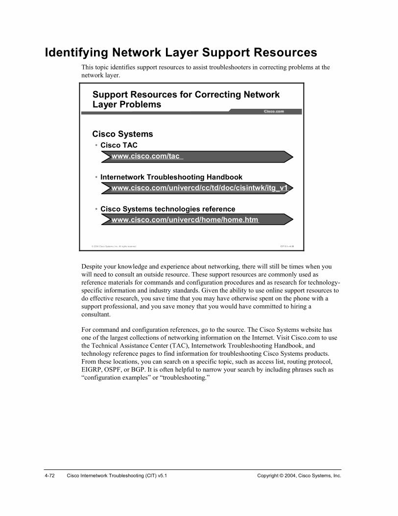
4-72 Cisco Internetwork Troubleshooting (CIT) v5.1 Copyright © 2004, Cisco Systems, Inc.
Identifying Network Layer Support Resources This topic identifies support resources to assist troubleshooters in correcting problems at the network layer.
© 2004 Cisco Systems, Inc. All rights reserved. CIT 5.1—4-38
Cisco Systems• Cisco TAC
www.cisco.com/tac
• Internetwork Troubleshooting Handbookwww.cisco.com/univercd/cc/td/doc/cisintwk/itg_v1
• Cisco Systems technologies referencewww.cisco.com/univercd/home/home.htm
Support Resources for Correcting Network Layer Problems
Despite your knowledge and experience about networking, there will still be times when you will need to consult an outside resource. These support resources are commonly used as reference materials for commands and configuration procedures and as research for technology-specific information and industry standards. Given the ability to use online support resources to do effective research, you save time that you may have otherwise spent on the phone with a support professional, and you save money that you would have committed to hiring a consultant.
For command and configuration references, go to the source. The Cisco Systems website has one of the largest collections of networking information on the Internet. Visit Cisco.com to use the Technical Assistance Center (TAC), Internetwork Troubleshooting Handbook, and technology reference pages to find information for troubleshooting Cisco Systems products. From these locations, you can search on a specific topic, such as access list, routing protocol, EIGRP, OSPF, or BGP. It is often helpful to narrow your search by including phrases such as “configuration examples” or “troubleshooting.”

Copyright © 2004, Cisco Systems, Inc. Resolving Problems at the Network Layer 4-73
Correcting Problems Occurring at the Network Layer
This topic identifies the steps to assist troubleshooters in correcting problems at the network layer.
© 2004 Cisco Systems, Inc. All rights reserved. CIT 5.1—4-39
Procedure for Correcting Network Layer Problems
Verify that you have a valid saved configuration for any device on which you intend to modify the configuration
Evaluate and document the results of each change that you make
Verify that the changes you made actually fixed theproblem without introducing any new problems
Continue making changes until the problem appears to be solved
If necessary, get input from outside resources
Make initial configuration changes
Once the problem is resolved, document the solution

4-74 Cisco Internetwork Troubleshooting (CIT) v5.1 Copyright © 2004, Cisco Systems, Inc.
The table lists suggested steps for troubleshooters to correct isolated problems at the physical and data link layers.
Correcting Network Layer Problems
Step Description
1 Ensure that you have a valid saved configuration for any device on which you intend to modify the configuration. This provides for eventual recovery to a known initial state.
2 Make initial hardware and software configuration changes. If the correction requires more than one change, make only one change at a time.
3 Evaluate and document the changes and the results of each change that you make. If you perform your problem-solving steps and the results are unsuccessful, immediately undo the changes. If the problem is intermittent, you may need to wait to see if the problem occurs again before you can evaluate the effect of your changes.
4 Verify that the changes you made actually fixed the problem without introducing any new problems. The network should be returned to the baseline operation, and no new or old symptoms should be present. If the problem is not solved, undo all the changes that you made. If you discover new or additional problems while you are making corrections, step back and modify your correction plan.
5 Stop making changes when the original problem appears to be solved.
6 If necessary, get input from outside resources. If none of your attempts to correct the problem are successful, take the problem to another person. This may be a coworker, consultant, or Cisco TAC. On rare occasions, you may need to perform a core dump, which creates output that a specialist at Cisco Systems can analyze.
7 Once the problem is resolved, document the solution.

Copyright © 2004, Cisco Systems, Inc. Resolving Problems at the Network Layer 4-75
SummaryThis topic summarizes the key points discussed in this lesson.
© 2004 Cisco Systems, Inc. All rights reserved. CIT 5.1—4-40
Summary
• Use the appropriate end system or Cisco commands and applications to correct an isolated network layer problem.
• Proper use of online support resources saves time and money by empowering troubleshooters to find solutions to elusive problems on their own.
• Following a systematic procedure increases the chances that you will successfully and effectively correct an isolated problem at the network layer.
ReferencesFor additional information, refer to these resources:
!" Cisco online documentation: http://www.cisco.com/univercd/home/home.htm
!" Cisco Technical Assistance Center (TAC): http://www.cisco.com/tac
!" Troubleshooting TCP/IP: http://www.cisco.com/univercd/cc/td/doc/cisintwk/itg_v1/tr1907.htm
Next Steps For the associated case study and lab exercises, refer to the following sections of the course Lab Guide:
!" Case Study (Trouble Ticket D) 4-1: Isolating Network Layer Problems
!" Lab Exercise (Trouble Ticket D) 4-1: Correcting Problems at the Network Layer
!" Lab Exercise (Trouble Ticket E) 4-2: Troubleshooting Problems at the Physical, Data Link, and Network Layers
!" Lab Exercise (Trouble Ticket F) 4-3: Troubleshooting Problems at the Physical, Data Link, and Network Layers

4-76 Cisco Internetwork Troubleshooting (CIT) v5.1 Copyright © 2004, Cisco Systems, Inc.
QuizUse the practice items here to review what you have learned in this lesson. The correct answers are found in the Quiz Answer Key.
Q1) Which Cisco command is used to correct a problem with the BGP exterior routing protocol?
A) passive-interface {interface-type number}
B) neighbor {ip-address | peer-group-name} update-source interface
C) ip route prefix mask address [distance]
D) ip mroute-cache
Q2) Which end-system command do you use to renew or release an IP address lease on a Windows 98 machine?
A) ipconfig
B) arp
C) winipcfg
D) route delete
Q3) Which website would you most likely use to read the latest detailed technical documentation about the EIGRP protocol?
A) http://www.itu.int/home
B) http://www.atmforum.com
C) http://www.frforum.com
D) http://www.cisco.com
Q4) While correcting a problem with a misconfigured access list, you notice that the problem is not solved despite the numerous changes you have made. Instead of making additional configuration changes, you wisely undo all of the changes that you made previously. Which step of the recommended procedure for correcting problems at the network layer are you performing?
A) make initial configuration changes
B) stop making changes when the original problem appears to be solved
C) once the problem is solved, document the solution
D) verify that the changes you made actually fixed the problem without introducing any new problems

Copyright © 2004, Cisco Systems, Inc. Resolving Problems at the Network Layer 4-77
Quiz Answer Key Q1) B
Relates to: Identifying Cisco Commands Used to Correct Problems Occurring at the Network Layer
Q2) C
Relates to: Identifying End-System Commands and Applications Used to Correct Problems Occurring at the Network Layer
Q3) D
Relates to: Identifying Network Layer Support Resources
Q4) D
Relates to: Correcting Problems Occurring at the Network Layer

4-78 Cisco Internetwork Troubleshooting (CIT) v5.1 Copyright © 2004, Cisco Systems, Inc.

Module 5
Resolving Problems at the Transport and Application Layers
OverviewThe process that troubleshooters use for isolating and correcting problems at the transport and application layers is the same as the process for isolating and correcting problems at the lower layers. What differentiates these problems are the symptoms they present and the commands, applications, and steps that you use to successfully resolve these problems. In this module, you will perform the isolation and correction phases of the general troubleshooting process to resolve failure and optimization problems at the transport and application layers of the Open Systems Interconnection (OSI) model.
Module Objectives Upon completing this module, you will be able to:
!" Isolate problems occurring at the transport and application layers
!" Correct problems occurring at the transport and application layers
Module Outline The module contains these components:
!" Isolating the Problem
!" Correcting the Problem

5-2 Cisco Internetwork Troubleshooting (CIT) v5.1 Copyright © 2004, Cisco Systems, Inc.

Isolating the Problem
OverviewTroubleshooters can apply the same general troubleshooting process for analyzing gathered symptoms to isolate problems at the transport and application layers that they would apply to isolate problems at the lower layers. The ideas stay the same, but the technological focus shifts to involve things such as refused or timed out connections, access lists, and Domain Name System (DNS) issues. In this lesson, you will analyze defined symptoms and use commands and applications to isolate problems at the transport and application layers.
Relevance The primary responsibility of the upper layers of the OSI model is providing services such as email and file transfer, and handling the transportation of the data used by those applications to the lower layers. If a problem arises at these layers, the data is not delivered to the destination or the performance is so slow that it affects productivity. You will likely hear complaints from those users who are accessing services such as email and file transfer. To avoid extended or periodic losses in the ability to transmit data and users who complain that the network is too slow, it is important for a troubleshooter to effectively isolate problems at the transport and application layers.
ObjectivesUpon completing this lesson, you will be able to:
!" Identify the symptoms of problems occurring at the transport layer
!" Identify the symptoms of problems occurring at the application layer
!" Analyze command and application output to isolate problems occurring at the transport layer
!" Analyze command and application output to isolate problems occurring at the application layer
!" Isolate problems occurring at the transport and application layers

5-4 Cisco Internetwork Troubleshooting (CIT) v5.1 Copyright © 2004, Cisco Systems, Inc.
Learner Skills and Knowledge To benefit fully from this lesson, you must have these prerequisite skills and knowledge:
!" The ability to apply layered model troubleshooting approaches
!" Familiarity with the Cisco command syntax and technologies covered in the Cisco Building Scalable Cisco Internetworks (BSCI), Building Cisco Multilayer Switched Networks(BCMSN), and Building Cisco Remote Access Networks (BCRAN) courses
!" Basic TCP and User Datagram Protocol (UDP) concepts
OutlineThis lesson includes these topics:
!" Overview
!" Identifying the Symptoms of Problems Occurring at the Transport Layer
!" Identifying the Symptoms of Problems Occurring at the Application Layer
!" Analyzing Commands and Applications Used to Isolate Problems Occurring at the Transport Layer
!" Analyzing Commands and Applications Used to Isolate Problems Occurring at the Application Layer
!" Isolating Problems Occurring at the Transport and Application Layers
!" Summary
!" Quiz

Copyright © 2004, Cisco Systems, Inc. Resolving Problems at the Transport and Application Layers 5-5
Identifying the Symptoms of Problems Occurring at the Transport Layer
This topic identifies the symptoms of transport layer problems that troubleshooters should be able to identify.
© 2004 Cisco Systems, Inc. All rights reserved. CIT 5.1—5-5
Common Symptoms of Transport Layer Problems
No connectivity on the link as seen from the application layer
A lack of connectivity and unreachable resources when thephysical, data link, and network layers are functional
The network is functional, but is operating either consistently or intermittently at …
A transport layer failure problem is a network problem that occurs at the transport layer of the OSI model when data from the upper layers is not transported to the lower layer services of a receiver. A problem at the transport layer results in a lack of connectivity and unreachable resources when the physical, data link, and network layers are functional.
Another problem at the transport layer occurs when the physical, data link, and network layers are functional, but data from the applications using the transport layer protocols does not transfer at the rate established in the baseline. For the TCP/IP protocol suite, a failure problem at the transport layer will involve either the TCP or the UDP, which moves data from a source port to a destination port.

5-6 Cisco Internetwork Troubleshooting (CIT) v5.1 Copyright © 2004, Cisco Systems, Inc.
© 2004 Cisco Systems, Inc. All rights reserved. CIT 5.1—5-6
Possible Symptoms of Transport Layer Problems
Error messages supplied by the application using the transport protocol
Console messages
System log file messages
Management system alarms
Complaints from users that the network is slow
The symptoms that a troubleshooter may encounter for a failure problem at the transport layer include console messages, system log file messages, management system alarms, or error messages supplied by the application using the transport protocol.
Other symptoms of a transport layer problem may be identified as complaints from users that the network is slow, or that there is partial or intermittent connectivity or erratic performance. This erratic performance could be due to windowing problems, long round-trip times (RTTs), retransmissions, fragmentation, or duplicates.

Copyright © 2004, Cisco Systems, Inc. Resolving Problems at the Transport and Application Layers 5-7
Identifying the Symptoms of Problems Occurring at the Application Layer
This topic identifies the symptoms of application layer problems that troubleshooters should be able to identify.
© 2004 Cisco Systems, Inc. All rights reserved. CIT 5.1—5-7
Common Symptoms of Application Layer Problems
Unreachable or unusable resources when the physical, data link, network, and transport layers are functional
Operation of a network service or application does not meet the normal expectations of a user
An application layer problem is a network problem that occurs at the session layer (Layer 5), the presentation layer (Layer 6), or the application layer (Layer 7) of the OSI model that prevents services from being provided to application programs. The application layer is the interface between an application and the transport layer. This layer deals with high-level protocols rather than segments, bytes, packets, or bits. A problem at the application layer results in unreachable or unusable resources when the physical, data link, network, and transport layers are functional. With application layer problems, it is possible to have full network connectivity, but the application simply cannot provide data.
Another type of problem at the application layer occurs when the physical, data link, network, and transport layers are functional, but the data transfer and requests for network services from a single network service or application do not meet the normal expectations of a user.

5-8 Cisco Internetwork Troubleshooting (CIT) v5.1 Copyright © 2004, Cisco Systems, Inc.
© 2004 Cisco Systems, Inc. All rights reserved. CIT 5.1—5-8
Possible Symptoms of Application Layer Problems
Error messages from the afflicted application
Console messages
System log file messages
Management system alarms
Users complain that the network or the particular application that they are working with is sluggish or slower than usual
A problem at the application layer may cause users to complain that the network or the particular application that they are working with is sluggish or slower than usual when transferring data or requesting network services. A failing application may supply various error messages that are sometimes informative and will help you isolate the problem to a particular component in the transport layer.

Copyright © 2004, Cisco Systems, Inc. Resolving Problems at the Transport and Application Layers 5-9
Analyzing Commands and Applications Used to Isolate Problems Occurring at the Transport Layer
This topic identifies the output of commands and applications with the purpose of helping troubleshooters isolate a problem at the transport layer.
© 2004 Cisco Systems, Inc. All rights reserved. CIT 5.1—5-9
²»¬¬¿¬ Åó¿Ã Åó®Ã Åó²Ã Åóò»¬¬¿¬ Åó¿Ã Åó®Ã Åó²Ã ÅóÃ
• Windows command with options to show the routing table, connections and ports, and per-protocol statistics.
Commands to Isolate Transport Layer Problems
²¾¬¬¿¬ óß²¾¬¬¿¬ óß
• Displays the NetBIOS name table of a remote host at a specified IP address.
ÝæÄâ
ÝæÄâ

5-10 Cisco Internetwork Troubleshooting (CIT) v5.1 Copyright © 2004, Cisco Systems, Inc.
The table shows commands that a troubleshooter may use to isolate problems at the transport layer. Although many of these commands also display information that concerns other layers, the commands are noteworthy at the transport layer because they highlight problems in the interface between the network and transport layers.
General Commands to Isolate Transport Layer Problems
Command Description
°·²¹ ¥¸±¬ ¤ ·°ó¿¼¼®»£
Sends an echo request packet to an address, then waits for a reply. The host | ip-address variable is the host name or IP address of the target system.
¬®¿½»®±«¬»Å¼»¬·²¿¬·±²Ã
Identifies the path a packet takes through the network. The destination variable is the host name or IP address of the target system. This command is used with Cisco IOS, UNIX, and Mac OS X.
¬®¿½»®¬ ż»¬·²¿¬·±²Ã Verifies connectivity to a destination device for Windows hosts. The destination variable is the IP alias or IP address of the target system.
²»¬¬¿¬ �Åó¿Ã Åó®Ã Åó²Ã ÅóÃ
(Windows command) Has options to show the routing table, connections and ports, and per-protocol statistics.
²¾¬¬¿¬ �ß Displays the NetBIOS name table of a remote host at a specified IP address.
¸±© ®«²²·²¹ó½±²º·¹ Shows access list rules being applied in the current configuration.

Copyright © 2004, Cisco Systems, Inc. Resolving Problems at the Transport and Application Layers 5-11
© 2004 Cisco Systems, Inc. All rights reserved. CIT 5.1—5-10
¸±© ·° ¿½½»ó´·¬¸±© ·° ¿½½»ó´·¬
®±«¬»®â
• Displays the contents of all IP access lists.
IOS Commands to Isolate Transport Layer Problems
¬»´²»¬ ¸±¬ Å°±®¬Ã¬»´²»¬ ¸±¬ Å°±®¬Ã
• Tests the functionality of any TCP port.
®±«¬»®â
¸±© ¯«»«»·²¹¸±© ¯«»«»·²¹
• Lists queueing strategies for all or selected interfaces.
®±«¬»®â
© 2004 Cisco Systems, Inc. All rights reserved. CIT 5.1—5-11
¸±© ·° ½¿½¸» º´±©¸±© ·° ½¿½¸» º´±©
®±«¬»®â
• Displays a summary of the NetFlow switching statistics.
IOS Commands to Isolate Transport Layer Problems (Cont.)
¸±© °±´·½§ó³¿°¸±© °±´·½§ó³¿°
®±«¬»®â
• Displays the configuration of all classes for a specified service policy map or all classes for all existing policy maps.

5-12 Cisco Internetwork Troubleshooting (CIT) v5.1 Copyright © 2004, Cisco Systems, Inc.
The Cisco commands listed in the table display information about transport layer issues. A troubleshooter uses the information from these commands to isolate problems at the transport layer that are related to TCP and UDP.
Commands Used to Isolate Transport Layer Problems
Command Description
¸±© ·° ¿½½»ó´·¬ Displays the contents of all IP access lists.
¸±© ·° ¬®¿ºº·½ Displays statistics about IP traffic, such as format errors, bad hops, encapsulation failures, unknown routes, and probe proxy requests.
¬»´²»¬ ¸±¬ Å°±®¬Ã Tests the functionality of any TCP port.
¸±© ¯«»«»·²¹
[custom | fair | priority | random-detect [interface atm-subinterface[vc [[vpi/] vci]]]]
Lists queueing strategies for all or selected interfaces.
¸±© ·° ½¿½¸» º´±© Displays a summary of the NetFlow switching statistics.
¸±© °±´·½§ó³¿° Displays the configuration of all classes for a specified service policy map or all classes for all existing policy maps.

Copyright © 2004, Cisco Systems, Inc. Resolving Problems at the Transport and Application Layers 5-13
Example: Isolating an Extended Access List Problem at the Transport Layer
You are the second-level network engineer for Columbia. You have console access to both the access router named Columbia and the access switch named Columbia_SW. You also have IP connectivity to all other devices in your division. Your division supports the 172.22.0.0/16 subnet.
© 2004 Cisco Systems, Inc. All rights reserved. CIT 5.1—5-12
Example: Isolating an Extended Access List Problem at the Transport Layer
The MIS department calls to report that none of the PC end users can use Telnet to connect to a server named CIT_Server. MIS reports that the end users cannot even connect to the distribution router named Baltimore from their PCs.
You know from your base configuration information that the end users connect over Columbia_SW to Columbia. Columbia and Columbia_SW are connected via a 100 Mbs Fast Ethernet link.

5-14 Cisco Internetwork Troubleshooting (CIT) v5.1 Copyright © 2004, Cisco Systems, Inc.
You connect to the console port on Columbia_SW and attempt to use Telnet to connect to Columbia.
© 2004 Cisco Systems, Inc. All rights reserved. CIT 5.1—5-13
ݱ´«³¾·¿ÁÍÉ⬻´²»¬ ݱ´«³¾·¿Ì®§·²¹ ݱ´«³¾·¿ øïéîòîîòïîëòï÷òòò Ñ°»²
Þ¿»Þ¿»Þ¿»Þ¿»Þ¿»Þ¿»Þ¿»Þ¿»Þ¿»Þ¿»Þ¿»Þ¿»Þ¿»Þ¿»
ݱ´«³¾·¿¿² ßÝÓÛ Ü·¬®·¾«¬·±² ɱ®µ¹®±«° ᫬»®
óó Þ¿»´·²» óó
Þ¿»Þ¿»Þ¿»Þ¿»Þ¿»Þ¿»Þ¿»Þ¿»Þ¿»Þ¿»Þ¿»Þ¿»Þ¿»Þ¿»
Ë»® ß½½» Ê»®·º·½¿¬·±²
п©±®¼æ ݱ´«³¾·¿â
Isolating an Extended Access List Problem at the Transport Layer
Because you can connect to Columbia from Columbia_SW, there appears to be no issues between these two devices.
Note This example uses the host names that have been configured in the standard host table mappings for the Cisco Internetwork Troubleshooting (CIT) labs.
You close the Telnet session to Columbia and try to connect to Baltimore from Columbia_SW.

Copyright © 2004, Cisco Systems, Inc. Resolving Problems at the Transport and Application Layers 5-15
© 2004 Cisco Systems, Inc. All rights reserved. CIT 5.1—5-14
ݱ´«³¾·¿â»¨·¬
Åݱ²²»½¬·±² ¬± ݱ´«³¾·¿ ½´±»¼ ¾§ º±®»·¹² ¸±¬Ãݱ´«³¾·¿ÁÍÉ⬻´²»¬ Þ¿´¬·³±®»Ì®§·²¹ Þ¿´¬·³±®» øïéîòîîòïîèòï÷òòò û Ü»¬·²¿¬·±² «²®»¿½¸¿¾´»å ¹¿¬»©¿§ ±® ¸±¬ ¼±©²Ì®§·²¹ Þ¿´¬·³±®» øïéîòîîòïîèòïîç÷òòò û Ü»¬·²¿¬·±² «²®»¿½¸¿¾´»å ¹¿¬»©¿§ ±® ¸±¬ ¼±©²Ì®§·²¹ Þ¿´¬·³±®» øïéîòîîòïîéòî÷òòò û Ü»¬·²¿¬·±² «²®»¿½¸¿¾´»å ¹¿¬»©¿§ ±® ¸±¬ ¼±©²Ì®§·²¹ Þ¿´¬·³±®» øïéîòîîòïîéòïíð÷òòò û Ü»¬·²¿¬·±² «²®»¿½¸¿¾´»å ¹¿¬»©¿§ ±® ¸±¬ ¼±©²
ݱ´«³¾·¿ÁÍÉâ
Attempting to Telnet to Baltimore
You note that the Telnet session from Columbia_SW cannot be opened on Baltimore.
To help isolate the problem, you check to see if Columbia_SW can ping Baltimore.
© 2004 Cisco Systems, Inc. All rights reserved. CIT 5.1—5-15
ݱ´«³¾·¿ÁÍÉâ°·²¹ Þ¿´¬·³±®»
̧°» »½¿°» »¯«»²½» ¬± ¿¾±®¬ò
Í»²¼·²¹ ëô ïðð󾧬» ×ÝÓÐ Û½¸± ¬± ïéîòîîòïîèòïô ¬·³»±«¬ · î
»½±²¼æ
ÿÿÿÿÿ
Í«½½» ®¿¬» · ïðð °»®½»²¬ øëñë÷ô ®±«²¼ó¬®·° ³·²ñ¿ª¹ñ³¿¨ ã
ïêñïèñîð ³
ݱ´«³¾·¿ÁÍÉâ
Checking Connectivity Between Columbia_SW and Baltimore
You see that Columbia_SW can ping Baltimore, so it appears that the physical, data link, and network layers between these devices are working. This makes you suspect that the issue is with an access list.

5-16 Cisco Internetwork Troubleshooting (CIT) v5.1 Copyright © 2004, Cisco Systems, Inc.
Next, you try to open a Telnet session from Columbia to Baltimore.
© 2004 Cisco Systems, Inc. All rights reserved. CIT 5.1—5-16
ݱ´«³¾·¿â¬»´²»¬ Þ¿´¬·³±®»Ì®§·²¹ Þ¿´¬·³±®» øïéîòîîòïîèòï÷òòò Ñ°»²
Þ¿»Þ¿»Þ¿»Þ¿»Þ¿»Þ¿»Þ¿»Þ¿»Þ¿»Þ¿»Þ¿»Þ¿»Þ¿»Þ¿»
Þ¿´¬·³±®»¿² ßÝÓÛ Ü·¬®·¾«¬·±² ɱ®µ¹®±«° ᫬»®
óó Þ¿»´·²» óó
Þ¿»Þ¿»Þ¿»Þ¿»Þ¿»Þ¿»Þ¿»Þ¿»Þ¿»Þ¿»Þ¿»Þ¿»Þ¿»Þ¿»
Ë»® ß½½» Ê»®·º·½¿¬·±²
п©±®¼æ Þ¿´¬·³±®»â
Verifying Telnet Access Between Columbia and Baltimore
You see that Columbia can open a Telnet session to Baltimore, so this tells you that Baltimore is not blocking all inbound Telnet traffic.
You look for signs of recent configuration changes on Baltimore by entering the show loggingand show clock commands.
© 2004 Cisco Systems, Inc. All rights reserved. CIT 5.1—5-17
Þ¿´¬·³±®»â¸±© ´±¹¹·²¹Í§´±¹ ´±¹¹·²¹æ »²¿¾´»¼ øð ³»¿¹» ¼®±°°»¼ô ï ³»¿¹» ®¿¬»ó´·³·¬»¼ô ð º´«¸»ô 𠱪»®®«²÷
ݱ²±´» ´±¹¹·²¹æ ´»ª»´ ¼»¾«¹¹·²¹ô ìð ³»¿¹» ´±¹¹»¼Ó±²·¬±® ´±¹¹·²¹æ ´»ª»´ ¼»¾«¹¹·²¹ô ð ³»¿¹» ´±¹¹»¼Þ«ºº»® ´±¹¹·²¹æ ´»ª»´ ¼»¾«¹¹·²¹ô ïç ³»¿¹» ´±¹¹»¼Ô±¹¹·²¹ Û¨½»°¬·±² ·¦» øìðçê ¾§¬»÷ݱ«²¬ ¿²¼ ¬·³»¬¿³° ´±¹¹·²¹ ³»¿¹»æ ¼·¿¾´»¼Ì®¿° ´±¹¹·²¹æ ´»ª»´ ·²º±®³¿¬·±²¿´ô ìê ³»¿¹» ´·²» ´±¹¹»¼
Ô±¹¹·²¹ ¬± ïéîòîéòîîéòçô ë ³»¿¹» ´·²» ´±¹¹»¼
Ô±¹ Þ«ºº»® øêëëíê ¾§¬»÷æ
Ü»½ ïí ðêæðîæîëæ ûÝÑÒÌÎÑÔÔÛÎóëóËÐÜÑÉÒæ ݱ²¬®±´´»® Ìï ðñïô ½¸¿²¹»¼ ¬¿¬» ¬± ¿¼³·²·¬®¿¬·ª»´§ ¼±©²Ü»½ ïí ðêæðîæîéæ ûÔ×ÒÕóíóËÐÜÑÉÒæ ײ¬»®º¿½» Í»®·¿´ðñðæðô ½¸¿²¹»¼ ¬¿¬» ¬± «°Ü»½ ïí ðêæðîæîéæ ûÔ×ÒÕóíóËÐÜÑÉÒæ ײ¬»®º¿½» Í»®·¿´ðñðæïô ½¸¿²¹»¼ ¬¿¬» ¬± «°Ü»½ ïí ðêæðîæîèæ ûÔ×ÒÛÐÎÑÌÑóëóËÐÜÑÉÒæ Ô·²» °®±¬±½±´ ±² ײ¬»®º¿½» Í»®·¿´ðñðæðô ½¸¿²¹»¼ ¬¿¬» ¬± «°Ü»½ ïí ðêæðîæîèæ ûÔ×ÒÛÐÎÑÌÑóëóËÐÜÑÉÒæ Ô·²» °®±¬±½±´ ±² ײ¬»®º¿½» Í»®·¿´ðñðæïô ½¸¿²¹»¼ ¬¿¬» ¬± «°Ü»½ ïí ðêæðîæëêæ ûÔ×ÒÛÐÎÑÌÑóëóËÐÜÑÉÒæ Ô·²» °®±¬±½±´ ±² ײ¬»®º¿½» Í»®·¿´ðñðæðô ½¸¿²¹»¼ ¬¿¬» ¬± ¼±©²Ü»½ ïí ðêæðîæëêæ ûÔ×ÒÛÐÎÑÌÑóëóËÐÜÑÉÒæ Ô·²» °®±¬±½±´ ±² ײ¬»®º¿½» Í»®·¿´ðñðæïô ½¸¿²¹»¼ ¬¿¬» ¬± ¼±©²òòò
Checking for Configuration Changes on Baltimore

Copyright © 2004, Cisco Systems, Inc. Resolving Problems at the Transport and Application Layers 5-17
© 2004 Cisco Systems, Inc. All rights reserved. CIT 5.1—5-18
òòòÜ»½ ïí ðêæðîæëêæ ûÔ×ÒÕóíóËÐÜÑÉÒæ ײ¬»®º¿½» Ú¿¬Û¬¸»®²»¬ðñðô ½¸¿²¹»¼ ¬¿¬» ¬± «°Ü»½ ïí ðêæðîæëêæ ûÔ×ÒÕóíóËÐÜÑÉÒæ ײ¬»®º¿½» Í»®·¿´ïñðô ½¸¿²¹»¼ ¬¿¬» ¬± «°Ü»½ ïí ðêæðîæëêæ ûÜËßÔóëóÒÞÎÝØßÒÙÛæ ×ÐóÛ×ÙÎÐ îðîæ Ò»·¹¸¾±® ïéîòîîòïîèòïíð øÚ¿¬Û¬¸»®²»¬ðñð÷ · «°æ ²»© ¿¼¶¿½»²½§Ü»½ ïí ðêæðîæëêæ ûÔ×ÒÕóíóËÐÜÑÉÒæ ײ¬»®º¿½» Í»®·¿´ïñïô ½¸¿²¹»¼ ¬¿¬» ¬± «°Ü»½ ïí ðêæðîæëéæ ûÔ×ÒÛÐÎÑÌÑóëóËÐÜÑÉÒæ Ô·²» °®±¬±½±´ ±² ײ¬»®º¿½» Ú¿¬Û¬¸»®²»¬ðñðô ½¸¿²¹»¼ ¬¿¬» ¬± «°Ü»½ ïí ðêæðîæëéæ ûÔ×ÒÛÐÎÑÌÑóëóËÐÜÑÉÒæ Ô·²» °®±¬±½±´ ±² ײ¬»®º¿½» Í»®·¿´ïñðô ½¸¿²¹»¼ ¬¿¬» ¬± «°Ü»½ ïí ðêæðíæðéæ ûÔ×ÒÛÐÎÑÌÑóëóËÐÜÑÉÒæ Ô·²» °®±¬±½±´ ±² ײ¬»®º¿½» Í»®·¿´ïñïô ½¸¿²¹»¼ ¬¿¬» ¬± «°Ü»½ ïí ðêæðìæíìæ ûÍÇÍóëóÝÑÒÚ×ÙÁ×æ ݱ²º·¹«®»¼ º®±³ ½±²±´» ¾§ ½±²±´»Ü»½ ïí ïëæëðæììæ ûÔ×ÒÛÐÎÑÌÑóëóËÐÜÑÉÒæ Ô·²» °®±¬±½±´ ±² ײ¬»®º¿½» Í»®·¿´ðñðæðô ½¸¿²¹»¼ ¬¿¬» ¬± «°Ü»½ ïí ïëæëðæììæ ûÔ×ÒÛÐÎÑÌÑóëóËÐÜÑÉÒæ Ô·²» °®±¬±½±´ ±² ײ¬»®º¿½» Í»®·¿´ðñðæïô ½¸¿²¹»¼ ¬¿¬» ¬± «°Ü»½ ïí ïëæëïæíìæ ûÜËßÔóëóÒÞÎÝØßÒÙÛæ ×ÐóÛ×ÙÎÐ îðîæ Ò»·¹¸¾±® ïéîòîîòïîêòï øÍ»®·¿´ðñðæð÷ · «°æ ²»© ¿¼¶¿½»²½§Ü»½ ïí ïëæëïæíìæ ûÜËßÔóëóÒÞÎÝØßÒÙÛæ ×ÐóÛ×ÙÎÐ îðîæ Ò»·¹¸¾±® ïéîòîîòïîêòïîç øÍ»®·¿´ðñðæï÷ · «°æ ²»© ¿¼¶¿½»²½§Þ¿´¬·³±®»âÞ¿´¬·³±®»â¸±© ½´±½µïìæëëæîìòïëç ÛÍÌ Ì¸« Ü»½ ïç îððîÞ¿´¬·³±®»â
Checking for Configuration Changes on Baltimore (Cont.)
You see that no configuration changes have been made on Baltimore for several days. Therefore, you return to the console session on Columbia.

5-18 Cisco Internetwork Troubleshooting (CIT) v5.1 Copyright © 2004, Cisco Systems, Inc.
You look for signs of recent configuration changes on Columbia with the show logging and show clock commands.
© 2004 Cisco Systems, Inc. All rights reserved. CIT 5.1—5-19
Þ¿´¬·³±®»â»¨·¬
Åݱ²²»½¬·±² ¬± ¾¿´¬·³±®» ½´±»¼ ¾§ º±®»·¹² ¸±¬Ãݱ´«³¾·¿âݱ´«³¾·¿â¸±© ´±¹¹·²¹Í§´±¹ ´±¹¹·²¹æ »²¿¾´»¼ øð ³»¿¹» ¼®±°°»¼ô ï ³»¿¹» ®¿¬»ó´·³·¬»¼ô ð º´«¸»ô 𠱪»®®«²÷
ݱ²±´» ´±¹¹·²¹æ ´»ª»´ ¼»¾«¹¹·²¹ô ïïë ³»¿¹» ´±¹¹»¼Ó±²·¬±® ´±¹¹·²¹æ ´»ª»´ ¼»¾«¹¹·²¹ô ð ³»¿¹» ´±¹¹»¼Þ«ºº»® ´±¹¹·²¹æ ´»ª»´ ¼»¾«¹¹·²¹ô ïëë ³»¿¹» ´±¹¹»¼Ô±¹¹·²¹ Û¨½»°¬·±² ·¦» øìðçê ¾§¬»÷ݱ«²¬ ¿²¼ ¬·³»¬¿³° ´±¹¹·²¹ ³»¿¹»æ ¼·¿¾´»¼Ì®¿° ´±¹¹·²¹æ ´»ª»´ ·²º±®³¿¬·±²¿´ô ïèê ³»¿¹» ´·²» ´±¹¹»¼
Ô±¹¹·²¹ ¬± ïéîòîéòîîéòçô ïíç ³»¿¹» ´·²» ´±¹¹»¼
Ô±¹ Þ«ºº»® øêëëíê ¾§¬»÷æ
Ü»½ ïç ïîæïçæïëæ ûÍÇÍóëóÝÑÒÚ×ÙÁ×æ ݱ²º·¹«®»¼ º®±³ ½±²±´» ¾§ ª¬§ð øïéîòîîòïîêòî÷Ü»½ ïç ïíæðíæðêæ ûÍÇÍóëóÝÑÒÚ×ÙÁ×æ ݱ²º·¹«®»¼ º®±³ ½±²±´» ¾§ ª¬§ð øïéîòîîòïîêòî÷Ü»½ ïç ïíæîïæðéæ ûÍÇÍóëóÝÑÒÚ×ÙÁ×æ ݱ²º·¹«®»¼ º®±³ ½±²±´» ¾§ ª¬§ð øïéîòîîòïîêòî÷ݱ´«³¾·¿âݱ´«³¾·¿â¸±© ½´±½µïëæëíæîîòîëè ÛÍÌ Ì¸« Ü»½ ïç îððîݱ´«³¾·¿â
Checking for Configuration Changes on Columbia
You notice that someone was at least in configuration mode on Columbia in the last few hours. You did not have any upgrades planned, but you need to review the details of the access lists on Columbia. Because pings to Baltimore from Columbia_SW are successful, you suspect that the problem is probably with an extended access list filtering too much traffic.

Copyright © 2004, Cisco Systems, Inc. Resolving Problems at the Transport and Application Layers 5-19
You use the show access-lists commands to review the current access lists configured on Columbia.
© 2004 Cisco Systems, Inc. All rights reserved. CIT 5.1—5-20
ݱ´«³¾·¿â¸±© ¿½½»ó´·¬Í¬¿²¼¿®¼ ×Ð ¿½½» ´·¬ îï
°»®³·¬ ïéîòîèòïîèòé°»®³·¬ ïéîòîèòïîèòè°»®³·¬ ïéîòîéòîîéòé°»®³·¬ ïéîòîéòîîéòè°»®³·¬ ïéîòîîòðòðô ©·´¼½¿®¼ ¾·¬ ðòðòîëëòîëë øïè ³¿¬½¸»÷
ͬ¿²¼¿®¼ ×Ð ¿½½» ´·¬ ß¼³·²°»®³·¬ ïéîòîîòïîïòðô ©·´¼½¿®¼ ¾·¬ ðòðòðòîëë øçë ³¿¬½¸»÷°»®³·¬ ïéîòîîòïîëòðô ©·´¼½¿®¼ ¾·¬ ðòðòðòîëë
ͬ¿²¼¿®¼ ×Ð ¿½½» ´·¬ ÛÒÜÁËÍÛÎÍ°»®³·¬ ïéîòîîòïîìòðô ©·´¼½¿®¼ ¾·¬ ðòðòðòîëë°»®³·¬ ïéîòîîòïîîòðô ©·´¼½¿®¼ ¾·¬ ðòðòïòîëë
Û¨¬»²¼»¼ ×Ð ¿½½» ´·¬ Ì®¿ºº·½°»®³·¬ ·½³° ¿²§ ¿²§ øïë ³¿¬½¸»÷°»®³·¬ ¬½° ïéîòîîòðòð ðòðòîëëòîëë ¿²§ »¯ º¬°ó¼¿¬¿°»®³·¬ ¬½° ïéîòîîòðòð ðòðòîëëòîëë ¿²§ »¯ º¬°°»®³·¬ ¬½° ïéîòîîòðòð ðòðòîëëòîëë ¿²§ »¯ ©©©°»®³·¬ «¼° ïéîòîîòðòð ðòðòîëëòîëë ¿²§ »¯ ¬º¬°
ݱ´«³¾·¿â
Checking the Access List Configuration on Columbia
The only extended access list is called “Traffic.” This access list explicitly permits Internet Control Message Protocol (ICMP), FTP, web, and TFTP traffic. However, the implicit deny at the end of the list would block Telnet traffic that came from Columbia_SW from being forwarded to Baltimore.

5-20 Cisco Internetwork Troubleshooting (CIT) v5.1 Copyright © 2004, Cisco Systems, Inc.
You also use the show ip route command to determine which interface is being used to forward traffic to Baltimore.
© 2004 Cisco Systems, Inc. All rights reserved. CIT 5.1—5-21
ݱ´«³¾·¿â¸±© ·° ®±«¬»òòòÙ¿¬»©¿§ ±º ´¿¬ ®»±®¬ · ïéîòîîòïîêòî ¬± ²»¬©±®µ ðòðòðòð
Ü ÛÈ ïéîòîïòðòðñïê Åïéðñíèéíîèðà ª·¿ ïéîòîîòïîêòîô î¼ðð¸ô Í»®·¿´ðñðæðÜ ÛÈ ïéîòîíòðòðñïê Åïéðñíèéíîèðà ª·¿ ïéîòîîòïîêòîô î¼ðð¸ô Í»®·¿´ðñðæð
ïéîòîîòðòðñïê · ª¿®·¿¾´§ «¾²»¬¬»¼ô ïí «¾²»¬ô î ³¿µÜ ïéîòîîòïîèòðñîê Åçðñíçéíïîðà ª·¿ ïéîòîîòïîêòîô ê¼ðð¸ô Í»®·¿´ðñðæðÜ ïéîòîîòïîçòðñîê Åçðñíçéëêèðà ª·¿ ïéîòîîòïîêòîô ê¼ðð¸ô Í»®·¿´ðñðæðÝ ïéîòîîòïîêòïîèñîê · ¼·®»½¬´§ ½±²²»½¬»¼ô Í»®·¿´ðñðæïÝ ïéîòîîòïîéòïîèñîê · ¼·®»½¬´§ ½±²²»½¬»¼ô Í»®·¿´ïñïÜ ÛÈ ïéîòîîòðòðñïê Åïéðñíèéíîèðà ª·¿ ïéîòîîòïîêòîô î¼ðî¸ô Í»®·¿´ðñðæðÜ ïéîòîîòïîèòïîèñîê Åçðñíèìéêèðà ª·¿ ïéîòîîòïîêòîô ê¼ðð¸ô Í»®·¿´ðñðæðÝ ïéîòîîòïîîòðñîê · ¼·®»½¬´§ ½±²²»½¬»¼ô Ú¿¬Û¬¸»®²»¬ðñðòîÝ ïéîòîîòïîíòðñîê · ¼·®»½¬´§ ½±²²»½¬»¼ô Ú¿¬Û¬¸»®²»¬ðñðòíÝ ïéîòîîòïîïòðñîê · ¼·®»½¬´§ ½±²²»½¬»¼ô Ú¿¬Û¬¸»®²»¬ðñðòïÝ ïéîòîîòïîêòðñîê · ¼·®»½¬´§ ½±²²»½¬»¼ô Í»®·¿´ðñðæðÝ ïéîòîîòïîéòðñîê · ¼·®»½¬´§ ½±²²»½¬»¼ô Í»®·¿´ïñðÝ ïéîòîîòïîìòðñîê · ¼·®»½¬´§ ½±²²»½¬»¼ô Ú¿¬Û¬¸»®²»¬ðñðòìÝ ïéîòîîòïîëòðñîê · ¼·®»½¬´§ ½±²²»½¬»¼ô Ô±±°¾¿½µðÜ ÛÈ ïéîòîëòðòðñïê Åïéðñíèéíîèðà ª·¿ ïéîòîîòïîêòîô î¼ðð¸ô Í»®·¿´ðñðæðÜ ÛÈ ïéîòîìòðòðñïê Åïéðñíèéíîèðà ª·¿ ïéîòîîòïîêòîô î¼ðð¸ô Í»®·¿´ðñðæðÜ ÛÈ ïéîòîêòðòðñïê Åïéðñíèéíîèðà ª·¿ ïéîòîîòïîêòîô î¼ðð¸ô Í»®·¿´ðñðæðÜ ÛÈ ïçèòïííòîïçòðñîì Åïéðñíèéíîèðà ª·¿ ïéîòîîòïîêòîô î¼ðð¸ô Í»®·¿´ðñðæðÜöÛÈ ðòðòðòðñð Åïéðñíèìéçíêà ª·¿ ïéîòîîòïîêòîô ê¼ðð¸ô Í»®·¿´ðñðæðݱ´«³¾·¿â
Identifying the Interface That Is Forwarding Traffic to Baltimore
You see that traffic for Baltimore is sent across the interface named Serial0/0:0.

Copyright © 2004, Cisco Systems, Inc. Resolving Problems at the Transport and Application Layers 5-21
Finally, you check that the access list named Traffic is applied to Serial 0/0:0 with the show ip interface serial 0/0:0 command.
© 2004 Cisco Systems, Inc. All rights reserved. CIT 5.1—5-22
ݱ´«³¾·¿â¸±© ·° ·²¬»®º¿½» »®·¿´ ðñðæðÍ»®·¿´ðñðæð · «°ô ´·²» °®±¬±½±´ · «°
ײ¬»®²»¬ ¿¼¼®» · ïéîòîîòïîêòïñîêÞ®±¿¼½¿¬ ¿¼¼®» · îëëòîëëòîëëòîëëß¼¼®» ¼»¬»®³·²»¼ ¾§ »¬«° ½±³³¿²¼ÓÌË · ïëð𠾧¬»Ø»´°»® ¿¼¼®» · ²±¬ »¬Ü·®»½¬»¼ ¾®±¿¼½¿¬ º±®©¿®¼·²¹ · ¼·¿¾´»¼Ó«´¬·½¿¬ ®»»®ª»¼ ¹®±«° ¶±·²»¼æ îîìòðòðòïðÑ«¬¹±·²¹ ¿½½» ´·¬ · Ì®¿ºº·½×²¾±«²¼ ¿½½» ´·¬ · ²±¬ »¬
òòòݱ´«³¾·¿â»²¿¾´»
Verifying That the Access List Is Applied to the Interface for Baltimore
You also review the access list in the running configuration.
© 2004 Cisco Systems, Inc. All rights reserved. CIT 5.1—5-23
ݱ´«³¾·¿ý¸±© ®«²²·²¹ó½±²º·¹ ¤ ¾»¹·² ·° ¿½½»ó´·¬ »¨¬»²¼»¼ Ì®¿ºº·½·° ¿½½»ó´·¬ »¨¬»²¼»¼ Ì®¿ºº·½®»³¿®µ ß´´±© ×ÝÓÐô Ì»´²»¬ ±«¬¾±«²¼ô ÚÌÐ ú ÉÉÉ°»®³·¬ ·½³° ¿²§ ¿²§°»®³·¬ ¬½° ïéîòîîòðòð ðòðòîëëòîëë ¿²§ »¯ º¬°ó¼¿¬¿°»®³·¬ ¬½° ïéîòîîòðòð ðòðòîëëòîëë ¿²§ »¯ º¬°°»®³·¬ ¬½° ïéîòîîòðòð ðòðòîëëòîëë ¿²§ »¯ ©©©°»®³·¬ «¼° ïéîòîîòðòð ðòðòîëëòîëë ¿²§ »¯ ¬º¬°
ÿ´±¹¹·²¹ ±«®½»ó·²¬»®º¿½» Ô±±°¾¿½µð´±¹¹·²¹ ïéîòîéòîîéò翽½»ó´·¬ îï °»®³·¬ ïéîòîèòïîèò鿽½»ó´·¬ îï °»®³·¬ ïéîòîèòïîèò追½»ó´·¬ îï ®»³¿®µ ß´± ¿´´±© Ô»²»¨¿ ¿²¼ Û´³¸«®¬ ¬± Ì»´²»¬ ·²¿½½»ó´·¬ îï °»®³·¬ ïéîòîéòîîéò鿽½»ó´·¬ îï °»®³·¬ ïéîòîéòîîéò追½»ó´·¬ îï ®»³¿®µ ß´´±© ¬¸· ©±®µ¹®±«° ¬± Ì»´²»¬ ·²¿½½»ó´·¬ îï °»®³·¬ ïéîòîîòðòð ðòðòîëëòîëëÿ®±«¬»ó³¿° ËÍÛÁÚßÍÌ °»®³·¬ ï𳿬½¸ ·° ¿¼¼®» ß¼³·²»¬ ·²¬»®º¿½» Í»®·¿´ðñðæï
ÿò ò òݱ´«³¾·¿ý
Viewing the Access List in the Running Configuration
You have isolated the issue. The outbound access list named Traffic does not include a permit statement for Telnet. All Telnet traffic from the access switch and end users is being filtered. The remark statement for the access list Traffic states that it should support TCP outbound.

5-22 Cisco Internetwork Troubleshooting (CIT) v5.1 Copyright © 2004, Cisco Systems, Inc.
Example: Isolating a Problem at the Transport Layer You are the second-level network engineer for Oakland. You have console access to both the access router named Oakland and the access switch named Oakland_SW. You also have IP connectivity to all other devices in your division. Your division supports the 172.24.0.0/16 subnet.
© 2004 Cisco Systems, Inc. All rights reserved. CIT 5.1—5-24
Example: Isolating a Problem at the Transport Layer
You receive a message that SanFran crashed last night, and that Network Operations had to reload SanFran this morning. Network Operations asks you to determine why the router crashed, indicating that no configuration changes have been made in weeks.
You know that SanFran is running the firewall feature set and that it is acting as the firewall to the Internet for the rest of the division.
Note This example topology does not follow the CIT lab configuration.

Copyright © 2004, Cisco Systems, Inc. Resolving Problems at the Transport and Application Layers 5-23
First, you decide to check out the software and hardware on SanFran. You log onto SanFran and use the show version command to review the basic router components.
© 2004 Cisco Systems, Inc. All rights reserved. CIT 5.1—5-25
Í¿²Ú®¿²ý¸±© ª»®·±²Ý·½± ײ¬»®²»¬©±®µ Ñ°»®¿¬·²¹ ͧ¬»³ ͱº¬©¿®»×ÑÍ ø¬³÷ Ýîêðð ͱº¬©¿®» øÝîêððó×ÑíóÓ÷ô Ê»®·±² ïîòîøïð¿÷ô ÎÛÔÛßÍÛ ÍÑÚÌÉßÎÛ øº½ï÷ݱ°§®·¹¸¬ ø½÷ ïçèêóîððî ¾§ ½·½± ͧ¬»³ô ײ½òݱ³°·´»¼ Ì«» îïóÓ¿§óðî ïíæëé ¾§ °©¿¼»×³¿¹» ¬»¨¬ó¾¿»æ ð¨èðððèðèèô ¼¿¬¿ó¾¿»æ ð¨èðßïïßêè
ÎÑÓæ ͧ¬»³ Þ±±¬¬®¿°ô Ê»®·±² ïîòïøí®÷Ìîô ÎÛÔÛßÍÛ ÍÑÚÌÉßÎÛ øº½ï÷
Í¿²Ú®¿² «°¬·³» · îè ³·²«¬»Í§¬»³ ®»¬«®²»¼ ¬± ÎÑÓ ¾§ ®»´±¿¼Í§¬»³ ·³¿¹» º·´» · þº´¿¸æ½îêððó·±íó³¦òïîîóïð¿ò¾·²þ
½·½± îêîï øÓÐÝèêð÷ °®±½»±® ø®»ª··±² ð¨îðð÷ ©·¬¸ îèêéîÕñìðçêÕ ¾§¬» ±º ³»³±®§òЮ±½»±® ¾±¿®¼ ×Ü ÖßÜðëïêðëËè øîíîèëîíëìç÷Óèêð °®±½»±®æ °¿®¬ ²«³¾»® ðô ³¿µ ìçÞ®·¼¹·²¹ ±º¬©¿®»òÈòîë ±º¬©¿®»ô Ê»®·±² íòðòðòï Û¬¸»®²»¬ñ×ÛÛÛ èðîòí ·²¬»®º¿½»ø÷î Ú¿¬Û¬¸»®²»¬ñ×ÛÛÛ èðîòí ·²¬»®º¿½»ø÷î Í»®·¿´ ²»¬©±®µ ·²¬»®º¿½»ø÷íîÕ ¾§¬» ±º ²±²óª±´¿¬·´» ½±²º·¹«®¿¬·±² ³»³±®§òèïçîÕ ¾§¬» ±º °®±½»±® ¾±¿®¼ ͧ¬»³ º´¿¸ øλ¿¼ñÉ®·¬»÷
ݱ²º·¹«®¿¬·±² ®»¹·¬»® · ð¨îïðîÍ¿²Ú®¿²â
Viewing the Router Components on SanFran
You see that SanFran is a 2600 series router running the “io3-ms.122-10a” image. SanFran has two Fast Ethernet ports, two serial ports, and an Ethernet port. The router has been up for 28 minutes and was reloaded. This all seems reasonable given what you heard from Network Operations and what you know about the network.

5-24 Cisco Internetwork Troubleshooting (CIT) v5.1 Copyright © 2004, Cisco Systems, Inc.
You decide to use the show process CPU command to review the process CPU utilization on SanFran.
© 2004 Cisco Systems, Inc. All rights reserved. CIT 5.1—5-26
Í¿²Ú®¿²ý¸±© °®±½» ½°«ÝÐË «¬·´·¦¿¬·±² º±® º·ª» »½±²¼æ îéûñèûå ±²» ³·²«¬»æ íèûå º·ª» ³·²«¬»æ îìûÐ×Ü Î«²¬·³»ø³÷ ײª±µ»¼ «Í»½ ëÍ»½ ïÓ·² ëÓ·² ÌÌÇ Ð®±½»
ï ð ï ð ðòððû ðòððû ðòððû ð ݸ«²µ Ó¿²¿¹»® î ð ëé ð ðòððû ðòððû ðòððû ð Ô±¿¼ Ó»¬»® í îìð çç îìîì ðòîìû ðòïçû ðòðëû êê Ê·®¬«¿´ Û¨»½ ì ð í ð ðòððû ðòððû ðòððû ð ÜØÝÐÜ Ì·³»® ë ïìè íï ìééì ðòððû ðòðíû ðòððû ð ݸ»½µ ¸»¿° ê ð ï ð ðòððû ðòððû ðòððû ð ݸ«²µ Ó¿²¿¹»® é íî é ìëéï ðòððû ðòððû ðòððû ð б±´ Ó¿²¿¹»® è ð î ð ðòððû ðòððû ðòððû ð Ì·³»® ç ð î ð ðòððû ðòððû ðòððû ð Í»®·¿´ Þ¿½µ¹®±«²
ïð ð íë ð ðòððû ðòððû ðòððû ð ßÔßÎÓÁÌÎ×ÙÙÛÎÁÍÝ ïï ð ïï ð ðòððû ðòððû ðòððû ð Û²ª·®±²³»²¬¿´ ³± ïî ïêè ïðè ïëëë ðòððû ðòððû ðòððû ð ßÎРײ°«¬ ïí ð ì ð ðòððû ðòððû ðòððû ð ÜÜÎ Ì·³»® ïì ð î ð ðòððû ðòððû ðòððû ð Ü·¿´»® »ª»²¬ ïë ïî í ìððð ðòððû ðòððû ðòððû ð Û²¬·¬§ Ó×Þ ßÐ× ïê ð ï ð ðòððû ðòððû ðòððû ð ÍÛÎ×ßÔ ßù¼»¬»½¬ïé ð ï ð ðòððû ðòððû ðòððû ð Ý®·¬·½¿´ Þµ¹²¼ïè ëî ïëð íìê ðòððû ðòððû ðòððû ð Ò»¬ Þ¿½µ¹®±«²¼ ïç ïê íï ëïê ðòððû ðòððû ðòððû ð Ô±¹¹»® îð ð îéí ð ðòððû ðòððû ðòððû ð ÌÌÇ Þ¿½µ¹®±«²¼ îï îè îèï çç ðòðèû ðòððû ðòððû ð л®óÍ»½±²¼ Ö±¾ îî ð î ð ðòððû ðòððû ðòððû ð Ø¿©µ»§» Þ¿½µ¹®±«
ò ò ò
Viewing the Process CPU on SanFran
© 2004 Cisco Systems, Inc. All rights reserved. CIT 5.1—5-27
Í¿²Ú®¿²ý¸±© °®±½» ½°«ÝÐË «¬·´·¦¿¬·±² º±® º·ª» »½±²¼æ îéûñèûå ±²» ³·²«¬»æ íèûå º·ª» ³·²«¬»æ îìûÐ×Ü Î«²¬·³»ø³÷ ײª±µ»¼ «Í»½ ëÍ»½ ïÓ·² ëÓ·² ÌÌÇ Ð®±½» ò ò ò
îì îð êð ííí ðòððû ðòððû ðòððû ð Ò»¬ ײ°«¬ îë ì êï êë ðòððû ðòððû ðòððû ð ݱ³°«¬» ´±¿¼ ¿ª¹îê çê ê ïêððð ðòîìû ðòðîû ðòððû ð л®ó³·²«¬» Ö±¾ îé ð ë ð ðòððû ðòððû ðòððû ð Í»®ª·½»ó³±¼«´» ¿ îè ì î îððð ðòððû ðòððû ðòððû ð ßßß Ü·½¬·±²¿®§ Î îç èíëëî ïðîèçð èïî ïéòîêû îîòëëû ïìòçêû ð ×Рײ°«¬ íð îì ëì ììì ðòððû ðòððû ðòððû ð ÝÜРЮ±¬±½±´ íï ð ï ð ðòððû ðòððû ðòððû ð Èòîë Û²½¿° Ó¿²¿íî ð ï ð ðòððû ðòððû ðòððû ð ߧ ÚÍ Ø»´°»® íí ð ï ð ðòððû ðòððû ðòððû ð ÐÐÐ ×Ð ß¼¼ ᫬» íì ìð íê ïïïï ðòððû ðòððû ðòððû ð ×Ð Þ¿½µ¹®±«²¼ íë è ïé ìéð ðòððû ðòððû ðòððû ð ×Ð Î×Þ Ë°¼¿¬» íê ð ê ð ðòððû ðòððû ðòððû ð ß¼¶ Ó¿²¿¹»® íé ð îî ð ðòððû ðòððû ðòððû ð ÌÝÐ Ì·³»® íè ì í ïííí ðòððû ðòððû ðòððû ð ÌÝРЮ±¬±½±´ íç ð ï ð ðòððû ðòððû ðòððû ð Ю±¾» ײ°«¬ ìð ð ï ð ðòððû ðòððû ðòððû ð ÎßÎРײ°«¬ ìï ð ï ð ðòððû ðòððû ðòððû ð ØÌÌÐ Ì·³»® ìî ð ï ð ðòððû ðòððû ðòððû ð ͱ½µ»¬ Ì·³»® ìí ì í ïííí ðòððû ðòððû ðòððû ð ÜØÝÐÜ Î»½»·ª» ìì ð ë ð ðòððû ðòððû ðòððû ð ×Ð Ý¿½¸» ß¹»®ìë ð ï ð ðòððû ðòððû ðòððû ð ÝÑÐÍ
ò ò ò
Viewing the Process CPU on SanFran(Cont.)
The 5-second CPU utilization is currently 27 percent. This seems reasonable.

Copyright © 2004, Cisco Systems, Inc. Resolving Problems at the Transport and Application Layers 5-25
You then use the show process memory command to review the process memory utilization on SanFran.
© 2004 Cisco Systems, Inc. All rights reserved. CIT 5.1—5-28
Í¿²Ú®¿²ý¸±© °®±½» ³»³±®§Ì±¬¿´æ ïîéëðéêðô Ë»¼æ ìíîîíêèô Ú®»»æ èìîèíçîÐ×Ü ÌÌÇ ß´´±½¿¬»¼ Ú®»»¼ ر´¼·²¹ Ù»¬¾«º λ¬¾«º Ю±½»
ð ð ïíëééî ïèìè îîèéçìð ð ð öײ·¬ö ð ð ìëê ìêìçî ìëê ð ð öͽ¸»¼ö ð ð éðíîéêð îïíîïîè îèìì ïéëíèð ð öÜ»¿¼ö ï ð ð ð êèêè ð ð ݸ«²µ Ó¿²¿¹»® î ð ïèè ïèè íèêè ð ð Ô±¿¼ Ó»¬»® í êê îêðì îïê ïëîëê ð ð Ê·®¬«¿´ Û¨»½ ì ð ð ð êèêè ð ð ÜØÝÐÜ Ì·³»® ë ð ð ð êèêè ð ð ݸ»½µ ¸»¿° ê ð ð ð êèêè ð ð ݸ«²µ Ó¿²¿¹»® é ð êêéêð ð ìçïïê îðéçê ð б±´ Ó¿²¿¹»® è ð ïèè ïèè êèêè ð ð Ì·³»® ç ð ïèè ïèè êèêè ð ð Í»®·¿´ Þ¿½µ¹®±«²
ïð ð ð ð êèêè ð ð ßÔßÎÓÁÌÎ×ÙÙÛÎÁÍÝïï ð ïèè ïèè êèêè ð ð Û²ª·®±²³»²¬¿´ ³±ïî ð êêð ëéê éíðè ð ð ßÎРײ°«¬ ïí ð ïèè ïèè êèêè ð ð ÜÜÎ Ì·³»® ïì ð ïèè ïèè ïîèêè ð ð Ü·¿´»® »ª»²¬ ïë ð èçëê ïçïî ïíçïî ð ð Û²¬·¬§ Ó×Þ ßÐ× ïê ð ð ð êèêè ð ð ÍÛÎ×ßÔ ßù¼»¬»½¬ïé ð ð ð êèêè ð ð Ý®·¬·½¿´ Þµ¹²¼ïè ð íêéêì ïëèçê ïíïíî ð ð Ò»¬ Þ¿½µ¹®±«²¼ ïç ð éçê ïèè ïîèêè ð ð Ô±¹¹»® îð ð ïèè ïèè êèêè ð ð ÌÌÇ Þ¿½µ¹®±«²¼ îï ð ð ð çèêè ð ð л®óÍ»½±²¼ Ö±¾
ò ò ò
Viewing the Process Memory on SanFran
© 2004 Cisco Systems, Inc. All rights reserved. CIT 5.1—5-29
Í¿²Ú®¿²ý¸±© °®±½» ³»³±®§Ì±¬¿´æ ïîéëðéêðô Ë»¼æ ìíîîíêèô Ú®»»æ èìîèíçîÐ×Ü ÌÌÇ ß´´±½¿¬»¼ Ú®»»¼ ر´¼·²¹ Ù»¬¾«º λ¬¾«º Ю±½»
ò ò òîî ð ïèè ïèè êèêè ð ð Ø¿©µ»§» Þ¿½µ¹®±«îì ð ð ð êèêè ð ð Ò»¬ ײ°«¬ îë ð ïèè ïèè êèêè ð ð ݱ³°«¬» ´±¿¼ ¿ª¹îê ð ð ð êèêè ð ð л®ó³·²«¬» Ö±¾ îé ð ð ð êèêè ð ð Í»®ª·½»ó³±¼«´» ¿îè ð ïèè ïèè êèêè ð ð ßßß Ü·½¬·±²¿®§ Îîç ð îëçççìì ïêìð ïìîííðè ð ð ×Рײ°«¬ íð ð éîëê ïìèì ïîëêè ð ð ÝÜРЮ±¬±½±´ íï ð ð ð êèêè ð ð Èòîë Û²½¿° Ó¿²¿íî ð ð ð êèêè ð ð ߧ ÚÍ Ø»´°»® íí ð ð ð êèêè ð ð ÐÐÐ ×Ð ß¼¼ ᫬»íì ð îìì ð ïðïïî ð ð ×Ð Þ¿½µ¹®±«²¼ íë ð ïëî ð ïððîð ð ð ×Ð Î×Þ Ë°¼¿¬» íê ð ïèè ïèè êèêè ð ð ß¼¶ Ó¿²¿¹»® íé ð ð ð ïîèêè ð ð ÌÝÐ Ì·³»® íè ð ïìíèð ð ïìíèð ð ð ÌÝРЮ±¬±½±´ íç ð ð ð êèêè ð ð Ю±¾» ײ°«¬ ìð ð ð ð êèêè ð ð ÎßÎРײ°«¬ ìï ð ð ð êèêè ð ð ØÌÌÐ Ì·³»® ìî ð ð ð êèêè ð ð ͱ½µ»¬ Ì·³»® ìí ð îçëèð íéê îîííê ð ð ÜØÝÐÜ Î»½»·ª» ìì ð ð ëíî êèêè ð ð ×Ð Ý¿½¸» ß¹»®
ò ò ò
Viewing the Process Memory on SanFran(Cont.)
SanFran is using about one-third of its memory, which is workable, as well. You consider the issues.

5-26 Cisco Internetwork Troubleshooting (CIT) v5.1 Copyright © 2004, Cisco Systems, Inc.
After a few minutes, you review the current process CPU utilization on SanFran.
© 2004 Cisco Systems, Inc. All rights reserved. CIT 5.1—5-30
Í¿²Ú®¿²ý¸±© °®±½» ½°«ÝÐË «¬·´·¦¿¬·±² º±® º·ª» »½±²¼æ ììûñïëûå ±²» ³·²«¬»æ ììûå º·ª» ³·²«¬»æ íêûÐ×Ü Î«²¬·³»ø³÷ ײª±µ»¼ «Í»½ ëÍ»½ ïÓ·² ëÓ·² ÌÌÇ Ð®±½»
ï ð ï ð ðòððû ðòððû ðòððû ð ݸ«²µ Ó¿²¿¹»® î ì ïîç íï ðòððû ðòððû ðòððû ð Ô±¿¼ Ó»¬»® í èìè ïëê ëìíë ïòìéû ðòïïû ðòðéû êê Ê·®¬«¿´ Û¨»½ ì ð ê ð ðòððû ðòððû ðòððû ð ÜØÝÐÜ Ì·³»® ë ííê éî ìêêê ðòððû ðòðíû ðòððû ð ݸ»½µ ¸»¿° ê ð ï ð ðòððû ðòððû ðòððû ð ݸ«²µ Ó¿²¿¹»® é íî é ìëéï ðòððû ðòððû ðòððû ð б±´ Ó¿²¿¹»® è ð î ð ðòððû ðòððû ðòððû ð Ì·³»® ç ð î ð ðòððû ðòððû ðòððû ð Í»®·¿´ Þ¿½µ¹®±«²
ïð ð ïðé ð ðòððû ðòððû ðòððû ð ßÔßÎÓÁÌÎ×ÙÙÛÎÁÍÝ ïï ð îí ð ðòððû ðòððû ðòððû ð Û²ª·®±²³»²¬¿´ ³± ïî íîì îêë ïîîî ðòððû ðòðîû ðòðïû ð ßÎРײ°«¬ ïí ð ì ð ðòððû ðòððû ðòððû ð ÜÜÎ Ì·³»® ïì ð î ð ðòððû ðòððû ðòððû ð Ü·¿´»® »ª»²¬ ïë ïî í ìððð ðòððû ðòððû ðòððû ð Û²¬·¬§ Ó×Þ ßÐ× ïê ð ï ð ðòððû ðòððû ðòððû ð ÍÛÎ×ßÔ ßù¼»¬»½¬ïé ð ï ð ðòððû ðòððû ðòððû ð Ý®·¬·½¿´ Þµ¹²¼ïè êè ííð îðê ðòððû ðòððû ðòððû ð Ò»¬ Þ¿½µ¹®±«²¼ ïç ïðì ïíé éëç ðòððû ðòððû ðòððû ð Ô±¹¹»® îð ì êíî ê ðòððû ðòððû ðòððû ð ÌÌÇ Þ¿½µ¹®±«²¼ îï êè êìï ïðê ðòððû ðòððû ðòððû ð л®óÍ»½±²¼ Ö±¾ îî ð î ð ðòððû ðòððû ðòððû ð Ø¿©µ»§» Þ¿½µ¹®±«
ò ò ò
Rechecking the Process CPU
© 2004 Cisco Systems, Inc. All rights reserved. CIT 5.1—5-31
Í¿²Ú®¿²ý¸±© °®±½» ½°«ÝÐË «¬·´·¦¿¬·±² º±® º·ª» »½±²¼æ ììûñïëûå ±²» ³·²«¬»æ ììûå º·ª» ³·²«¬»æ íêûÐ×Ü Î«²¬·³»ø³÷ ײª±µ»¼ «Í»½ ëÍ»½ ïÓ·² ëÓ·² ÌÌÇ Ð®±½»
ò ò òîì îè ïîè îïè ðòððû ðòððû ðòððû ð Ò»¬ ײ°«¬ îë è ïîç êî ðòððû ðòððû ðòððû ð ݱ³°«¬» ´±¿¼ ¿ª¹îê ïçê ïï ïéèïè ðòððû ðòðïû ðòððû ð л®ó³·²«¬» Ö±¾ îé ð ë ð ðòððû ðòððû ðòððû ð Í»®ª·½»ó³±¼«´» ¿ îè ì î îððð ðòððû ðòððû ðòððû ð ßßß Ü·½¬·±²¿®§ Î îç ïèìêêð îîïíëí èíì îëòèðû îêòîèû îîòêçû ð ×Рײ°«¬ íð ìì ïïð ìðð ðòððû ðòððû ðòððû ð ÝÜРЮ±¬±½±´ íï ð ï ð ðòððû ðòððû ðòððû ð Èòîë Û²½¿° Ó¿²¿íî ð ï ð ðòððû ðòððû ðòððû ð ߧ ÚÍ Ø»´°»® íí ð ï ð ðòððû ðòððû ðòððû ð ÐÐÐ ×Ð ß¼¼ ᫬» íì ëê ìî ïííí ðòððû ðòððû ðòððû ð ×Ð Þ¿½µ¹®±«²¼ íë ïî îí ëîï ðòððû ðòððû ðòððû ð ×Ð Î×Þ Ë°¼¿¬» íê ð ïî ð ðòððû ðòððû ðòððû ð ß¼¶ Ó¿²¿¹»® íé ì îé ïìè ðòððû ðòððû ðòððû ð ÌÝÐ Ì·³»® íè ì í ïííí ðòððû ðòððû ðòððû ð ÌÝРЮ±¬±½±´ íç ð ï ð ðòððû ðòððû ðòððû ð Ю±¾» ײ°«¬ ìð ð ï ð ðòððû ðòððû ðòððû ð ÎßÎРײ°«¬ ìï ð ï ð ðòððû ðòððû ðòððû ð ØÌÌÐ Ì·³»® ìî ð ï ð ðòððû ðòððû ðòððû ð ͱ½µ»¬ Ì·³»®
ò ò ò
Rechecking the Process CPU (Cont.)
You start to look closer. Your process CPU utilization has jumped to 44 percent for 5 seconds.
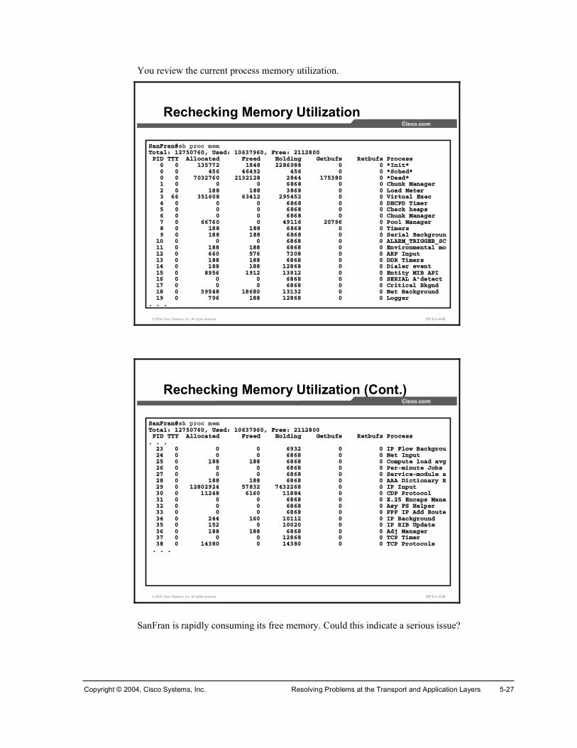
Copyright © 2004, Cisco Systems, Inc. Resolving Problems at the Transport and Application Layers 5-27
You review the current process memory utilization.
© 2004 Cisco Systems, Inc. All rights reserved. CIT 5.1—5-32
Í¿²Ú®¿²ý¸ °®±½ ³»³Ì±¬¿´æ ïîéëðéêðô Ë»¼æ ïðêíéçêðô Ú®»»æ îïïîèððÐ×Ü ÌÌÇ ß´´±½¿¬»¼ Ú®»»¼ ر´¼·²¹ Ù»¬¾«º λ¬¾«º Ю±½»
ð ð ïíëééî ïèìè îîèêçèè ð ð öײ·¬ö ð ð ìëê ìêìçî ìëê ð ð öͽ¸»¼ö ð ð éðíîéêð îïíîïîè îèìì ïéëíèð ð öÜ»¿¼ö ï ð ð ð êèêè ð ð ݸ«²µ Ó¿²¿¹»® î ð ïèè ïèè íèêè ð ð Ô±¿¼ Ó»¬»® í êê íëïêðè êíìïî îçëìëî ð ð Ê·®¬«¿´ Û¨»½ ì ð ð ð êèêè ð ð ÜØÝÐÜ Ì·³»® ë ð ð ð êèêè ð ð ݸ»½µ ¸»¿° ê ð ð ð êèêè ð ð ݸ«²µ Ó¿²¿¹»® é ð êêéêð ð ìçïïê îðéçê ð б±´ Ó¿²¿¹»® è ð ïèè ïèè êèêè ð ð Ì·³»® ç ð ïèè ïèè êèêè ð ð Í»®·¿´ Þ¿½µ¹®±«²
ïð ð ð ð êèêè ð ð ßÔßÎÓÁÌÎ×ÙÙÛÎÁÍÝïï ð ïèè ïèè êèêè ð ð Û²ª·®±²³»²¬¿´ ³±ïî ð êêð ëéê éíðè ð ð ßÎРײ°«¬ ïí ð ïèè ïèè êèêè ð ð ÜÜÎ Ì·³»® ïì ð ïèè ïèè ïîèêè ð ð Ü·¿´»® »ª»²¬ ïë ð èçëê ïçïî ïíçïî ð ð Û²¬·¬§ Ó×Þ ßÐ× ïê ð ð ð êèêè ð ð ÍÛÎ×ßÔ ßù¼»¬»½¬ïé ð ð ð êèêè ð ð Ý®·¬·½¿´ Þµ¹²¼ïè ð íçëìè ïèêèð ïíïíî ð ð Ò»¬ Þ¿½µ¹®±«²¼ ïç ð éçê ïèè ïîèêè ð ð Ô±¹¹»®
ò ò ò
Rechecking Memory Utilization
© 2004 Cisco Systems, Inc. All rights reserved. CIT 5.1—5-33
Í¿²Ú®¿²ý¸ °®±½ ³»³Ì±¬¿´æ ïîéëðéêðô Ë»¼æ ïðêíéçêðô Ú®»»æ îïïîèððÐ×Ü ÌÌÇ ß´´±½¿¬»¼ Ú®»»¼ ر´¼·²¹ Ù»¬¾«º λ¬¾«º Ю±½»
ò ò òîí ð ð ð êçíî ð ð ×Ð Ú´±© Þ¿½µ¹®±«îì ð ð ð êèêè ð ð Ò»¬ ײ°«¬ îë ð ïèè ïèè êèêè ð ð ݱ³°«¬» ´±¿¼ ¿ª¹îê ð ð ð êèêè ð ð л®ó³·²«¬» Ö±¾ îé ð ð ð êèêè ð ð Í»®ª·½»ó³±¼«´» ¿îè ð ïèè ïèè êèêè ð ð ßßß Ü·½¬·±²¿®§ Îîç ð ïîèðîçîì ëéèíî éìíîîêè ð ð ×Рײ°«¬ íð ð ïïîìè êïêð ïïèèì ð ð ÝÜРЮ±¬±½±´ íï ð ð ð êèêè ð ð Èòîë Û²½¿° Ó¿²¿íî ð ð ð êèêè ð ð ߧ ÚÍ Ø»´°»® íí ð ð ð êèêè ð ð ÐÐÐ ×Ð ß¼¼ ᫬»íì ð îìì ïêð ïðïïî ð ð ×Ð Þ¿½µ¹®±«²¼ íë ð ïëî ð ïððîð ð ð ×Ð Î×Þ Ë°¼¿¬» íê ð ïèè ïèè êèêè ð ð ß¼¶ Ó¿²¿¹»® íé ð ð ð ïîèêè ð ð ÌÝÐ Ì·³»® íè ð ïìíèð ð ïìíèð ð ð ÌÝРЮ±¬±½±´ ò ò ò
Rechecking Memory Utilization (Cont.)
SanFran is rapidly consuming its free memory. Could this indicate a serious issue?

5-28 Cisco Internetwork Troubleshooting (CIT) v5.1 Copyright © 2004, Cisco Systems, Inc.
You decide to capture the latest command output and go to Cisco.com to run it through the Output Interpreter.
© 2004 Cisco Systems, Inc. All rights reserved. CIT 5.1—5-34
Sending Results to Cisco Systems Output Interpreter
Note The actual navigation steps to get to this screen are not shown. You need to go to http://www.cisco.com and then go to the Output Interpreter tool under Support.

Copyright © 2004, Cisco Systems, Inc. Resolving Problems at the Transport and Application Layers 5-29
You review the results.
© 2004 Cisco Systems, Inc. All rights reserved. CIT 5.1—5-35
Memory CalculatorIOS Upgrade Planner
Review Results from Output Interpreter
The Output Interpreter agrees that the memory utilization on SanFran is very high. You scroll down for additional results.
© 2004 Cisco Systems, Inc. All rights reserved. CIT 5.1—5-36
Case Open Tool
Review Results from Output Interpretor(Cont.)
The Output Interpreter notes that IP input is consuming a lot of resources. The Output Interpreter also suggests that SanFran might have a memory leak. You know that SanFran has a fast leak, because memory is being quickly consumed.

5-30 Cisco Internetwork Troubleshooting (CIT) v5.1 Copyright © 2004, Cisco Systems, Inc.
You go back to your console screen and try the show ip cache flow command to review IP traffic flows on SanFran.
© 2004 Cisco Systems, Inc. All rights reserved. CIT 5.1—5-37
Í¿²Ú®¿²ý¸±© ·° ½¿½¸» º´±©×Ð °¿½µ»¬ ·¦» ¼·¬®·¾«¬·±² ø𠬱¬¿´ °¿½µ»¬÷æ
ïóíî êì çê ïîè ïêð ïçî îîì îëê îèè íîð íëî íèì ìïê ììè ìèðòððð òððð òððð òððð òððð òððð òððð òððð òððð òððð òððð òððð òððð òððð òððð
ëïî ëìì ëéê ïðîì ïëíê îðìè îëêð íðéî íëèì ìðçê ìêðèòððð òððð òððð òððð òððð òððð òððð òððð òððð òððð òððð
×Ð Ú´±© Í©·¬½¸·²¹ Ý¿½¸»ô 𠾧¬»ð ¿½¬·ª»ô ð ·²¿½¬·ª»ô ð ¿¼¼»¼ð ¿¹»® °±´´ô ð º´±© ¿´´±½ º¿·´«®»ß½¬·ª» º´±© ¬·³»±«¬ ·² íð ³·²«¬»×²¿½¬·ª» º´±© ¬·³»±«¬ ·² ïë »½±²¼´¿¬ ½´»¿®·²¹ ±º ¬¿¬·¬·½ ²»ª»®
Ю±¬±½±´ ̱¬¿´ Ú´±© п½µ»¬ Þ§¬» п½µ»¬ ß½¬·ª»øÍ»½÷ ×¼´»øÍ»½÷óóóóóóóó Ú´±© ñÍ»½ ñÚ´±© ñе¬ ñÍ»½ ñÚ´±© ñÚ´±©
Í®½×º Í®½×п¼¼®» ܬ׺ ܬ×п¼¼®» Ю Í®½Ð ܬРе¬Í¿²Ú®¿²ý
Reviewing IP Cache Flow on SanFran
Because the output does not show any packets in the packet size distribution, you realize that cache flow switching has not been configured on any interfaces.

Copyright © 2004, Cisco Systems, Inc. Resolving Problems at the Transport and Application Layers 5-31
You try to review IP traffic flows on Oakland.
© 2004 Cisco Systems, Inc. All rights reserved. CIT 5.1—5-38
Ñ¿µ´¿²¼ý¸±© ·° ½¿½¸» º´±©×Ð °¿½µ»¬ ·¦» ¼·¬®·¾«¬·±² ø𠬱¬¿´ °¿½µ»¬÷æ
ïóíî êì çê ïîè ïêð ïçî îîì îëê îèè íîð íëî íèì ìïê ììè ìèðòððð òððð òððð òððð òððð òððð òððð òððð òððð òððð òððð òððð òððð òððð òððð
ëïî ëìì ëéê ïðîì ïëíê îðìè îëêð íðéî íëèì ìðçê ìêðèòððð òððð òððð òððð òððð òððð òððð òððð òððð òððð òððð
×Ð Ú´±© Í©·¬½¸·²¹ Ý¿½¸»ô 𠾧¬»ð ¿½¬·ª»ô ð ·²¿½¬·ª»ô ð ¿¼¼»¼ð ¿¹»® °±´´ô ð º´±© ¿´´±½ º¿·´«®»ß½¬·ª» º´±© ¬·³»±«¬ ·² íð ³·²«¬»×²¿½¬·ª» º´±© ¬·³»±«¬ ·² ïë »½±²¼´¿¬ ½´»¿®·²¹ ±º ¬¿¬·¬·½ ²»ª»®
Ю±¬±½±´ ̱¬¿´ Ú´±© п½µ»¬ Þ§¬» п½µ»¬ ß½¬·ª»øÍ»½÷ ×¼´»øÍ»½÷óóóóóóóó Ú´±© ñÍ»½ ñÚ´±© ñе¬ ñÍ»½ ñÚ´±© ñÚ´±©
Í®½×º Í®½×п¼¼®» ܬ׺ ܬ×п¼¼®» Ю Í®½Ð ܬРе¬Ñ¿µ´¿²¼ý
Reviewing IP Cache Flow on Oakland
Cache flow switching has not been configured on Oakland either.
You know that you have a fast memory leak on SanFran; therefore, in the longer term, you need to upgrade the IOS image. In the very short term, you want to determine what is causing the leak.
Note A misconfigured network device does not cause this issue. This example will be continued in the next module.

5-32 Cisco Internetwork Troubleshooting (CIT) v5.1 Copyright © 2004, Cisco Systems, Inc.
Analyzing Commands and Applications Used to Isolate Problems Occurring at the Application Layer
This topic identifies the output of commands and applications with the purpose of helping troubleshooters isolate a problem at the application layer.
© 2004 Cisco Systems, Inc. All rights reserved. CIT 5.1—5-39
¸±© ¸±¬¸±© ¸±¬
®±«¬»®â
• Displays the default domain name, the style of name lookup service, a list of name server hosts, and the cached list of host names and addresses.
General Commands for Isolating Application Layer Problems
½¿¬ ñ»¬½ñ®»±´ªò½±²º½¿¬ ñ»¬½ñ®»±´ªò½±²º
• Displays the identity of the name server from hosts running UNIX.
¬»®³·²¿´û
²´±±µ«° ¥¼±³¿·² ²¿³»£²´±±µ«° ¥¼±³¿·² ²¿³»£
• Displays the identity of the name server being used.
ÝæÄâ

Copyright © 2004, Cisco Systems, Inc. Resolving Problems at the Transport and Application Layers 5-33
The table shows commands that a troubleshooter uses to isolate problems at the application layer. Although many of the commands also display information that concerns other layers, these commands are noteworthy at the application layer because they highlight problems in the interface between the transport and application layers.
General Commands for Isolating Application Layer Problems
Command Description
¸±© ¸±¬ Displays the default domain name, the style of name lookup service, a list of name server hosts, and the cached list of host names and addresses.
½¿¬ ñ»¬½ñ®»±´ªò½±²º Displays the identity of the name server from hosts running UNIX.
·º½±²º·¹ ó¿ Displays IP information for UNIX and Mac OS X hosts.
·°½±²º·¹ ñ¿´´ Displays IP information for hosts running Windows NT, 2000, or XP.
¬®¿½»®±«¬»Å¼»¬·²¿¬·±²Ã
Identifies the path that a packet takes through the network. The destination variable is the host name or IP address of the target system. This command is used with Cisco IOS, UNIX, and Mac OS X.
¬®¿½»®¬ ż»¬·²¿¬·±²Ã Verifies connectivity to a destination device for Windows hosts. The destination variable is the IP alias or IP address of the target system.
©·²·°½º¹ Displays IP information for hosts running Windows 9x and Me.
²´±±µ«° ¥¼±³¿·² ²¿³»£ Displays the identity of the name server being used.
°·²¹ ¥·°ó¿¼¼®» ¤ ¼±³¿·² ²¿³»£
Verifies connectivity and tests the functionality of address resolution services.
Note Not all of the commands listed are available on some versions of Cisco operating systems. To determine which commands are available for use with your devices, consult the online documentation for Cisco devices at http://www.cisco.com/univercd/home/home.htm.

5-34 Cisco Internetwork Troubleshooting (CIT) v5.1 Copyright © 2004, Cisco Systems, Inc.
© 2004 Cisco Systems, Inc. All rights reserved. CIT 5.1—5-40
¬»´²»¬ ¥·°ó¿¼¼®» ¤ ¸±¬£ î묻´²»¬ ¥·°ó¿¼¼®» ¤ ¸±¬£ îë
• Tests SMTP protocol functionality.
Commands Used to Isolate E-Mail Problems
¬»´²»¬ ¥·°ó¿¼¼®» ¤ ¸±¬£ ïìí ¬»´²»¬ ¥·°ó¿¼¼®» ¤ ¸±¬£ ïìí
• Tests IMAP protocol functionality.
¬»´²»¬ ¥·°ó¿¼¼®» ¤ ¸±¬£ ïï𠬻´²»¬ ¥·°ó¿¼¼®» ¤ ¸±¬£ ïïð
• Tests POP protocol functionality.
The commands listed in the table display information about the e-mail network application. A troubleshooter uses the information from these commands to isolate problems at the application layer that are related to e-mail and the Post Office Protocol – Version 3 (POP3), Simple Mail Transfer Protocol (SMTP), and Internet Message Access Protocol (IMAP) protocols.
Commands Used to Isolate E-Mail Problems
Command Description
¬»´²»¬ ¥·°ó¿¼¼®» ¤ ¸±¬£ îë
Tests SMTP protocol functionality.
¬»´²»¬ ¥·°ó¿¼¼®» ¤ ¸±¬£ ïïð
Tests POP protocol functionality.
¬»´²»¬ ¥·°ó¿¼¼®» ¤ ¸±¬£ ïìí
Tests IMAP protocol functionality.

Copyright © 2004, Cisco Systems, Inc. Resolving Problems at the Transport and Application Layers 5-35
© 2004 Cisco Systems, Inc. All rights reserved. CIT 5.1—5-41
¼»¾«¹ ²³° ®»¯«»¬¼»¾«¹ ²³° ®»¯«»¬
®±«¬»®ý
• Displays information about every SNMP request made by the SNMP manager.
Commands Used to Isolate Network Management Problems
¼»¾«¹ ²¬° »ª»²¬ ¼»¾«¹ ²¬° »ª»²¬
®±«¬»®ý
• Displays events related to the operation of NTP.
¸±© ²³°¸±© ²³°
• Displays the status of SNMP communications.
®±«¬»®â
The commands listed in the table display information about network management applications. A troubleshooter uses the information from these commands to isolate problems at the application layer that are related to the Simple Network Management Protocol (SNMP) and Network Time Protocol (NTP).
Commands Used to Isolate Network Management Problems
Command Description
¸±© ²³° Displays the status of SNMP communications.
¼»¾«¹ ²³° ®»¯«»¬ Displays information about every SNMP request made by the SNMP manager.
¼»¾«¹ ²¬° »ª»²¬ Displays events related to the operation of NTP.

5-36 Cisco Internetwork Troubleshooting (CIT) v5.1 Copyright © 2004, Cisco Systems, Inc.
© 2004 Cisco Systems, Inc. All rights reserved. CIT 5.1—5-42
½±°§ ¬º¬° º´¿¸½±°§ ¬º¬° º´¿¸
®±«¬»®ý
• Tests functionality by invoking the TFTP application.
Commands Used to Isolate File Management Problems
¬»´²»¬ ¥·°ó¿¼¼®» ¤ ¸±¬£ îï ¬»´²»¬ ¥·°ó¿¼¼®» ¤ ¸±¬£ îï
• Tests FTP protocol functionality.
¼»¾«¹ ¬º¬°¼»¾«¹ ¬º¬°
• Displays activity related to the operation of TFTP.
®±«¬»®ý
The commands listed in the table display information about file management applications. A troubleshooter uses the information from these commands to isolate problems at the application layer that are related to FTP and TFTP.
Commands Used to Isolate File Management Problems
Command Description
½±°§ ¬º¬° º´¿¸ Tests functionality by invoking the TFTP application.
¬»´²»¬ ¥·°ó¿¼¼®» ¤ ¸±¬£ îï
Tests FTP protocol functionality.
¼»¾«¹ ¬º¬° Displays activity related to the operation of TFTP.

Copyright © 2004, Cisco Systems, Inc. Resolving Problems at the Transport and Application Layers 5-37
© 2004 Cisco Systems, Inc. All rights reserved. CIT 5.1—5-43
Commands Used to Isolate Telnet Problems
¬»´²»¬ ¥·°ó¿¼¼®» ¤ ¸±¬²¿³»£ Åñ±«®½»ó·²¬»®º¿½»Ã¬»´²»¬ ¥·°ó¿¼¼®» ¤ ¸±¬²¿³»£ Åñ±«®½»ó·²¬»®º¿½»Ã
• Tests functionality of the Telnet application.
¼»¾«¹ ¬»´²»¬ ¼»¾«¹ ¬»´²»¬
• Displays events during the negotiation process of a Telnet connection.
®±«¬»®ý
The commands listed in the table display information about the Telnet application. A troubleshooter uses the information from these commands to isolate problems at the application layer that are related to the Telnet application.
Commands Used to Isolate Telnet Problems
Command Description
¬»´²»¬ ¥·°ó¿¼¼®» ¤ ¸±¬²¿³»£ Åñ±«®½»ó·²¬»®º¿½»Ã
Tests functionality of the Telnet application.
¼»¾«¹ ¬»´²»¬ Displays events during the negotiation process of a Telnet connection.

5-38 Cisco Internetwork Troubleshooting (CIT) v5.1 Copyright © 2004, Cisco Systems, Inc.
© 2004 Cisco Systems, Inc. All rights reserved. CIT 5.1—5-44
¸±© ·° ¼¸½° ¾·²¼·²¹¸±© ·° ¼¸½° ¾·²¼·²¹
®±«¬»®â
• Displays address bindings on a DHCP server.
Commands Used to Isolate DHCP Problems
¸±© ¼¸½° ´»¿»¸±© ¼¸½° ´»¿»
®±«¬»®â
• Shows DHCP addresses leased from a server.
¼»¾«¹ ·° ¼¸½° »®ª»® Å»ª»²¬ ¤ °¿½µ»¬Ã¼»¾«¹ ·° ¼¸½° »®ª»® Å»ª»²¬ ¤ °¿½µ»¬Ã
®±«¬»®ý
• Reports DHCP server events, such as address assignments and database updates, and also packet activity.
The commands listed in the table display information about the DHCP application. A troubleshooter uses the information from these commands to isolate problems at the application layer that are related to the Telnet application.
Commands Used to Isolate DHCP Problems
Command Description
¸±© ·° ¼¸½° ¾·²¼·²¹ Displays address bindings on a DHCP server.
¸±© ¼¸½° ´»¿» Shows DHCP addresses leased from a server.
¼»¾«¹ ·° ¼¸½° »®ª»® Å»ª»²¬ ¤ °¿½µ»¬Ã
Reports DHCP server events, such as address assignments and database updates, and also packet activity.

Copyright © 2004, Cisco Systems, Inc. Resolving Problems at the Transport and Application Layers 5-39
Example: Isolating a TFTP Problem at the Application Layer You are the second-level network engineer for Orlando. You have console access to the distribution router named Orlando and IP connectivity to all other devices in your division. Your division supports the 172.21.0.0/16 subnet.
© 2004 Cisco Systems, Inc. All rights reserved. CIT 5.1—5-45
Example: Isolating a TFTP Problem at the Application Layer
Juan from Network Operations stops by your office to tell you that, somehow, the Cisco IOS image has been erased from the Orlando router. He was trying to retrieve the image from Baltimore but cannot get TFTP to work.
You know from your base configuration information that there is at least a 100 Mbs Fast Ethernet link between Orlando and Baltimore. Therefore, this would be a good source to use for downloading the Cisco IOS image. You connect to the console port on Orlando to assess the situation.

5-40 Cisco Internetwork Troubleshooting (CIT) v5.1 Copyright © 2004, Cisco Systems, Inc.
First, you look at available commands from within ROMMON mode.
© 2004 Cisco Systems, Inc. All rights reserved. CIT 5.1—5-46
®±³³±² ïì â á¿´·¿ »¬ ¿²¼ ¼·°´¿§ ¿´·¿» ½±³³¿²¼¾±±¬ ¾±±¬ «° ¿² »¨¬»®²¿´ °®±½»¾®»¿µ »¬ñ¸±©ñ½´»¿® ¬¸» ¾®»¿µ°±·²¬½±²º®»¹ ½±²º·¹«®¿¬·±² ®»¹·¬»® «¬·´·¬§½±²¬ ½±²¬·²«» »¨»½«¬·²¹ ¿ ¼±©²´±¿¼»¼ ·³¿¹»½±²¬»¨¬ ¼·°´¿§ ¬¸» ½±²¬»¨¬ ±º ¿ ´±¿¼»¼ ·³¿¹»½±±µ·» ¼·°´¿§ ½±²¬»²¬ ±º ½±±µ·» ÐÎÑÓ ·² ¸»¨¼»ª ´·¬ ¬¸» ¼»ª·½» ¬¿¾´»¼·® ´·¬ º·´» ·² º·´» §¬»³¼· ¼·°´¿§ ·²¬®«½¬·±² ¬®»¿³¼²´¼ »®·¿´ ¼±©²´±¿¼ ¿ °®±¹®¿³ ³±¼«´»º®¿³» °®·²¬ ±«¬ ¿ »´»½¬»¼ ¬¿½µ º®¿³»¸»´° ³±²·¬±® ¾«·´¬·² ½±³³¿²¼ ¸»´°¸·¬±®§ ³±²·¬±® ½±³³¿²¼ ¸·¬±®§³»³·²º± ³¿·² ³»³±®§ ·²º±®³¿¬·±²®»°»¿¬ ®»°»¿¬ ¿ ³±²·¬±® ½±³³¿²¼®»»¬ §¬»³ ®»»¬»¬ ¼·°´¿§ ¬¸» ³±²·¬±® ª¿®·¿¾´»¬¿½µ °®±¼«½» ¿ ¬¿½µ ¬®¿½»§²½ ©®·¬» ³±²·¬±® »²ª·®±²³»²¬ ¬± ÒÊÎßÓ§®»¬ °®·²¬ ±«¬ ·²º± º®±³ ´¿¬ §¬»³ ®»¬«®²¬º¬°¼²´¼ ¬º¬° ·³¿¹» ¼±©²´±¿¼«²¿´·¿ «²»¬ ¿² ¿´·¿«²»¬ «²»¬ ¿ ³±²·¬±® ª¿®·¿¾´»¨³±¼»³ ¨ñ§³±¼»³ ·³¿¹» ¼±©²´±¿¼®±³³±² ïë â
Isolating a TFTP Problem at the Application Layer
You note that the ROMMON prompt is on 14 and 15, which indicates that several commands have already been issued.
Next, you enter the ROMMON boot command to try to boot the router in case the Cisco IOS image is not really missing.
© 2004 Cisco Systems, Inc. All rights reserved. CIT 5.1—5-47
®±³³±² ïë â ¾±±¬
´±¿¼°®±¹æ ¾¿¼ º·´» ³¿¹·½ ²«³¾»®æ ð¨ð
¾±±¬æ ½¿²²±¬ ´±¿¼ þº´¿¸æþ
®±³³±² ïê â
Attempting to Boot the Router in ROMMON Mode

Copyright © 2004, Cisco Systems, Inc. Resolving Problems at the Transport and Application Layers 5-41
Entering the boot command did not work. You try to reset the router to see if that will restore the IOS image.
© 2004 Cisco Systems, Inc. All rights reserved. CIT 5.1—5-48
®±³³±² ïê â ®»»¬
ͧ¬»³ Þ±±¬¬®¿°ô Ê»®·±² ïîòîøì®÷ÈÔô ÎÛÔÛßÍÛ ÍÑÚÌÉßÎÛ øº½ï÷ÌßÝ Í«°°±®¬æ ¸¬¬°æññ©©©ò½·½±ò½±³ñ¬¿½Ý±°§®·¹¸¬ ø½÷ îððï ¾§ ½·½± ͧ¬»³ô ײ½òÝïéðð °´¿¬º±®³ ©·¬¸ êëëíê Õ¾§¬» ±º ³¿·² ³»³±®§
´±¿¼°®±¹æ ¾¿¼ º·´» ³¿¹·½ ²«³¾»®æ ð¨ð¾±±¬æ ½¿²²±¬ ´±¿¼ þº´¿¸æþ
ͧ¬»³ Þ±±¬¬®¿°ô Ê»®·±² ïîòîøì®÷ÈÔô ÎÛÔÛßÍÛ ÍÑÚÌÉßÎÛ øº½ï÷ÌßÝ Í«°°±®¬æ ¸¬¬°æññ©©©ò½·½±ò½±³ñ¬¿½Ý±°§®·¹¸¬ ø½÷ îððï ¾§ ½·½± ͧ¬»³ô ײ½òÝïéðð °´¿¬º±®³ ©·¬¸ êëëíê Õ¾§¬» ±º ³¿·² ³»³±®§
´±¿¼°®±¹æ ¾¿¼ º·´» ³¿¹·½ ²«³¾»®æ ð¨ð¾±±¬æ ½¿²²±¬ ´±¿¼ þº´¿¸æþ
ͧ¬»³ Þ±±¬¬®¿°ô Ê»®·±² ïîòîøì®÷ÈÔô ÎÛÔÛßÍÛ ÍÑÚÌÉßÎÛ øº½ï÷ÌßÝ Í«°°±®¬æ ¸¬¬°æññ©©©ò½·½±ò½±³ñ¬¿½Ý±°§®·¹¸¬ ø½÷ îððï ¾§ ½·½± ͧ¬»³ô ײ½òÝïéðð °´¿¬º±®³ ©·¬¸ êëëíê Õ¾§¬» ±º ³¿·² ³»³±®§
®±³³±² ï â
Attempting to Reset the Router in ROMMON Mode
Entering the reset command did not restore the image.

5-42 Cisco Internetwork Troubleshooting (CIT) v5.1 Copyright © 2004, Cisco Systems, Inc.
You decide to look for the IOS image in the file system.
© 2004 Cisco Systems, Inc. All rights reserved. CIT 5.1—5-49
®±³³±² ï â ¼·®
«¿¹»æ ¼·® ä¼»ª·½»â
®±³³±² î â ¼·® º´¿¸æ
Ú·´» ·¦» ݸ»½µ«³ Ú·´» ²¿³»
ëèëè ¾§¬» øð¨ïê»î÷ ð¨êçç¿ ¾¿»ò½º¹
®±³³±² î â
Attempting to Locate the IOS Image in Flash Memory
Juan is correct; there is no IOS image in Flash memory. At 5858 bytes, base.cfg is not big enough to be an IOS image. You learn from Juan that the image was erased while someone was saving a backup configuration file.

Copyright © 2004, Cisco Systems, Inc. Resolving Problems at the Transport and Application Layers 5-43
You decide that you really will need to use TFTP to recover the image. You check out the commands available from the ROMMON level.
© 2004 Cisco Systems, Inc. All rights reserved. CIT 5.1—5-50
®±³³±² î â á¿´·¿ »¬ ¿²¼ ¼·°´¿§ ¿´·¿» ½±³³¿²¼¾±±¬ ¾±±¬ «° ¿² »¨¬»®²¿´ °®±½»¾®»¿µ »¬ñ¸±©ñ½´»¿® ¬¸» ¾®»¿µ°±·²¬½±²º®»¹ ½±²º·¹«®¿¬·±² ®»¹·¬»® «¬·´·¬§½±²¬ ½±²¬·²«» »¨»½«¬·²¹ ¿ ¼±©²´±¿¼»¼ ·³¿¹»½±²¬»¨¬ ¼·°´¿§ ¬¸» ½±²¬»¨¬ ±º ¿ ´±¿¼»¼ ·³¿¹»½±±µ·» ¼·°´¿§ ½±²¬»²¬ ±º ½±±µ·» ÐÎÑÓ ·² ¸»¨¼»ª ´·¬ ¬¸» ¼»ª·½» ¬¿¾´»¼·® ´·¬ º·´» ·² º·´» §¬»³¼· ¼·°´¿§ ·²¬®«½¬·±² ¬®»¿³¼²´¼ »®·¿´ ¼±©²´±¿¼ ¿ °®±¹®¿³ ³±¼«´»º®¿³» °®·²¬ ±«¬ ¿ »´»½¬»¼ ¬¿½µ º®¿³»¸»´° ³±²·¬±® ¾«·´¬·² ½±³³¿²¼ ¸»´°¸·¬±®§ ³±²·¬±® ½±³³¿²¼ ¸·¬±®§³»³·²º± ³¿·² ³»³±®§ ·²º±®³¿¬·±²®»°»¿¬ ®»°»¿¬ ¿ ³±²·¬±® ½±³³¿²¼®»»¬ §¬»³ ®»»¬»¬ ¼·°´¿§ ¬¸» ³±²·¬±® ª¿®·¿¾´»¬¿½µ °®±¼«½» ¿ ¬¿½µ ¬®¿½»§²½ ©®·¬» ³±²·¬±® »²ª·®±²³»²¬ ¬± ÒÊÎßÓ§®»¬ °®·²¬ ±«¬ ·²º± º®±³ ´¿¬ §¬»³ ®»¬«®²¬º¬°¼²´¼ ¬º¬° ·³¿¹» ¼±©²´±¿¼«²¿´·¿ «²»¬ ¿² ¿´·¿«²»¬ «²»¬ ¿ ³±²·¬±® ª¿®·¿¾´»¨³±¼»³ ¨ñ§³±¼»³ ·³¿¹» ¼±©²´±¿¼®±³³±² í â
Investigating ROMMON Commands Related to TFTP
You decide that tftpdnld is the command that you will need to download the image from Baltimore. You enter the tftpdnld command.
© 2004 Cisco Systems, Inc. All rights reserved. CIT 5.1—5-51
®±³³±² í â ¬º¬°¼²´¼
Ó··²¹ ±® ·´´»¹¿´ ·° ¿¼¼®» º±® ª¿®·¿¾´» ×ÐÁßÜÜÎÛÍÍ×´´»¹¿´ ×Ð ¿¼¼®»ò
«¿¹»æ ¬º¬°¼²´¼ Åó®ÃË» ¬¸· ½±³³¿²¼ º±® ¼·¿¬»® ®»½±ª»®§ ±²´§ ¬± ®»½±ª»® ¿² ·³¿¹» ª·¿ ÌÚÌÐòÓ±²·¬±® ª¿®·¿¾´» ¿®» «»¼ ¬± »¬ «° °¿®¿³»¬»® º±® ¬¸» ¬®¿²º»®òøͧ²¬¿¨æ þÊßÎ×ßÞÔÛÁÒßÓÛ㪿´«»þ ¿²¼ «» þ»¬þ ¬± ¸±© ½«®®»²¬ ª¿®·¿¾´»ò÷þ½¬®´ó½þ ±® þ¾®»¿µþ ¬±° ¬¸» ¬®¿²º»® ¾»º±®» º´¿¸ »®¿» ¾»¹·²ò
̸» º±´´±©·²¹ ª¿®·¿¾´» ¿®» ÎÛÏË×ÎÛÜ ¬± ¾» »¬ º±® ¬º¬°¼²´¼æ×ÐÁßÜÜÎÛÍÍæ ̸» ×Ð ¿¼¼®» º±® ¬¸· «²·¬
×ÐÁÍËÞÒÛÌÁÓßÍÕæ ̸» «¾²»¬ ³¿µ º±® ¬¸· «²·¬ÜÛÚßËÔÌÁÙßÌÛÉßÇæ ̸» ¼»º¿«´¬ ¹¿¬»©¿§ º±® ¬¸· «²·¬
ÌÚÌÐÁÍÛÎÊÛÎæ ̸» ×Ð ¿¼¼®» ±º ¬¸» »®ª»® ¬± º»¬½¸ º®±³ÌÚÌÐÁÚ×ÔÛæ ̸» º·´»²¿³» ¬± º»¬½¸
̸» º±´´±©·²¹ ª¿®·¿¾´» ¿®» ÑÐÌ×ÑÒßÔæÌÚÌÐÁÊÛÎÞÑÍÛæ Ю·²¬ »¬¬·²¹ò ð㯫·»¬ô ïã°®±¹®»ø¼»º¿«´¬÷ô î㪻®¾±»
ÌÚÌÐÁÎÛÌÎÇÁÝÑËÒÌæ 묮§ ½±«²¬ º±® ßÎÐ ¿²¼ ÌÚÌÐ ø¼»º¿«´¬ãé÷ÌÚÌÐÁÌ×ÓÛÑËÌæ Ѫ»®¿´´ ¬·³»±«¬ ±º ±°»®¿¬·±² ·² »½±²¼ ø¼»º¿«´¬ãéîðð÷
ÌÚÌÐÁÝØÛÝÕÍËÓæ л®º±®³ ½¸»½µ«³ ¬»¬ ±² ·³¿¹»ô ðã²±ô ï㧻 ø¼»º¿«´¬ãï÷
ݱ³³¿²¼ ´·²» ±°¬·±²æó®æ ¼± ²±¬ ©®·¬» º´¿¸ô ´±¿¼ ¬± ÜÎßÓ ±²´§ ¿²¼ ´¿«²½¸ ·³¿¹»
®±³³±² ì â
Attempting to Download the IOS Image from Baltimore
The attempt fails, and the command output displays messages that are symptoms of an issue with the TFTP application layer protocol.

5-44 Cisco Internetwork Troubleshooting (CIT) v5.1 Copyright © 2004, Cisco Systems, Inc.
To help isolate these issues, you first check for current variables with the set command on the Orlando router.
© 2004 Cisco Systems, Inc. All rights reserved. CIT 5.1—5-52
®±³³±² ì â »¬ÐÍïã®±³³±² ÿ â ÌÚÌÐÁÝØÛÝÕÍËÓãïÞÑÑÌãÞÍ×ãðÍßÊÛÁîÁÎÌÍãðìæëîæîì ÛÍÌ Ì¸« Ü»½ îð îððîÎÛÌÁîÁÎÌÍãïíæðìæìï ÛÍÌ Ì¸« Ü»½ îð îððîÎÛÌÁîÁÎËÌÝãïðíèêðéìèïáãð®±³³±² ë â
Checking the Variables for the ROMMON set Command

Copyright © 2004, Cisco Systems, Inc. Resolving Problems at the Transport and Application Layers 5-45
It looks as though none of the required variables are set on the Orlando router. You call Network Operations in Baltimore and ask for verification that Baltimore has been configured as a TFTP server. You ask Network Operations to use the show running-config | include tftpcommand to verify that the TFTP server is running and has the image for the 1760 router.
© 2004 Cisco Systems, Inc. All rights reserved. CIT 5.1—5-53
Þ¿´¬·³±®»ý¸±© ®«²²·²¹ó½±²º·¹ ¤ ·²½´«¼» ¬º¬°
¬º¬°ó»®ª»® º´¿¸æ½ïéððóªè§ó³¦òïîîóèòÇÔò¾·²
Þ¿´¬·³±®»ý
Verifying That Baltimore Is Configured as a TFTP Server
Network Operations in Baltimore reports that the TFTP server is running and offers flash:c1700-sv8y-mz.122-8.YL.bin for your use.
You have isolated the issue: the tftpdnld command needs the IP address and mask for the local router, the default gateway for the local router, the IP address of the TFTP server, and the name of the file to be transferred.

5-46 Cisco Internetwork Troubleshooting (CIT) v5.1 Copyright © 2004, Cisco Systems, Inc.
Example: Isolating a Problem at the Application Layer You are the second-level network engineer in Kingston. You have console access to the access router named Kingston and IP connectivity to all other devices in your division. Your division supports the 172.26.0.0/16 subnet. Early this morning, network interns Bill and Jerry configured IPSec between Kingston and Toronto to encrypt corporate traffic on the frame relay link.
© 2004 Cisco Systems, Inc. All rights reserved. CIT 5.1—5-54
Example: Isolating a Problem at the Application Layer
Now the Kingston end users are complaining that they cannot get access to devices in the corporate network, such as the CIT_Server.

Copyright © 2004, Cisco Systems, Inc. Resolving Problems at the Transport and Application Layers 5-47
You test connectivity from Kingston.
© 2004 Cisco Systems, Inc. All rights reserved. CIT 5.1—5-55
Õ·²¹¬±²ý°·²¹ ½·¬Á»®ª»®Ì§°» »½¿°» »¯«»²½» ¬± ¿¾±®¬òÍ»²¼·²¹ ëô ïðð󾧬» ×ÝÓÐ Û½¸± ¬± ïéîòîéòîîéòçô ¬·³»±«¬ · î »½±²¼æÿÿÿÿÿÍ«½½» ®¿¬» · ïðð °»®½»²¬ øëñë÷ô ®±«²¼ó¬®·° ³·²ñ¿ª¹ñ³¿¨ ã ëêñëêñëê ³Õ·²¹¬±²ý
Checking Connectivity from Kingston
Kingston has connectivity to the CIT_Server.
You open another terminal emulation window, connect to the Kingston switch, and try to connect to the CIT_Server.
© 2004 Cisco Systems, Inc. All rights reserved. CIT 5.1—5-56
Õ·²¹¬±²ÁÍÉý°·²¹ ½·¬Á»®ª»®Ì§°» »½¿°» »¯«»²½» ¬± ¿¾±®¬òÍ»²¼·²¹ ëô ïðð󾧬» ×ÝÓÐ Û½¸± ¬± ïéîòîéòîîéòçô ¬·³»±«¬ · î »½±²¼æòòòòòÍ«½½» ®¿¬» · ð °»®½»²¬ øðñë÷Õ·²¹¬±²ÁÍÉý
Checking Connectivity from the Kingston Switch
As reported, Kingston_SW cannot reach the CIT_Server. Because the IPSec configurations are new, it is time to look at them.

5-48 Cisco Internetwork Troubleshooting (CIT) v5.1 Copyright © 2004, Cisco Systems, Inc.
You return to your console session and review the crypto map on Kingston.
© 2004 Cisco Systems, Inc. All rights reserved. CIT 5.1—5-57
Õ·²¹¬±²ýÜ»½ îï ðçæîèæëéæ ûÝÎÇÐÌÑóìóÎÛÝÊÜÁÐÕÌÁÒÑÌÁ×ÐÍÛÝæ λ½ù¼ °¿½µ»¬ ²±¬ ¿² ×ÐÍÛÝ °¿½µ»¬òÕ·²¹¬±²ý¸±© ½®§°¬± ³¿°Ý®§°¬± Ó¿° þ¬»¬þ ïð ·°»½ó·¿µ³°
л»® ã ïéîòîêòïêéòîÛ¨¬»²¼»¼ ×Ð ¿½½» ´·¬ ïíí
¿½½»ó´·¬ ïíí °»®³·¬ ·° ïéîòîêòïêðòð ðòðòíòîëë ïéîòîðòðòð ðòíòîëëòîë뿽½»ó´·¬ ïíí °»®³·¬ ·° ïéîòîêòïêìòð ðòðòïòîëë ïéîòîðòðòð ðòíòîëëòîë뿽½»ó´·¬ ïíí °»®³·¬ ·° ïéîòîêòïêðòð ðòðòíòîëë ïéîòîìòðòð ðòïòîëëòîë뿽½»ó´·¬ ïíí °»®³·¬ ·° ïéîòîêòïêìòð ðòðòïòîëë ïéîòîìòðòð ðòïòîëëòîë뿽½»ó´·¬ ïíí °»®³·¬ ·° ïéîòîêòïêðòð ðòðòíòîëë ïéîòîéòðòð ðòðòîëëòîë뿽½»ó´·¬ ïíí °»®³·¬ ·° ïéîòîêòïêìòð ðòðòïòîëë ïéîòîéòðòð ðòðòîëëòîë뿽½»ó´·¬ ïíí °»®³·¬ ·° ïéîòîêòïêðòð ðòðòíòîëë ïéîòîèòðòð ðòðòîëëòîë뿽½»ó´·¬ ïíí °»®³·¬ ·° ïéîòîêòïêìòð ðòðòïòîëë ïéîòîèòðòð ðòðòîëëòîëë
Ý«®®»²¬ °»»®æ ïéîòîêòïêéòîÍ»½«®·¬§ ¿±½·¿¬·±² ´·º»¬·³»æ ìêðèððð µ·´±¾§¬»ñíêðð »½±²¼ÐÚÍ øÇñÒ÷æ ÒÌ®¿²º±®³ »¬ã¥
¿«¬¸îô£×²¬»®º¿½» «·²¹ ½®§°¬± ³¿° ¬»¬æ
Í»®·¿´ïñðÕ·²¹¬±²ý
Reviewing the Crypto Map Configuration on Kingston
The configuration looks pretty reasonable. The map is applied to interface Serial 1/0, and the current peer is 172.26.167.2. The access list picks up the local subnets on Kingston and on the corporate subnets.

Copyright © 2004, Cisco Systems, Inc. Resolving Problems at the Transport and Application Layers 5-49
You open another window for a console session to review the crypto map on Toronto.
© 2004 Cisco Systems, Inc. All rights reserved. CIT 5.1—5-58
̱®±²¬±ý¸±© ½®§°¬± ³¿°Ý®§°¬± Ó¿° þ¬»¬þ ïð ·°»½ó·¿µ³°
л»® ã ïéîòîêòïêéòïÛ¨¬»²¼»¼ ×Ð ¿½½» ´·¬ ïíí
¿½½»ó´·¬ ïíí °»®³·¬ ·° ïéîòîêòïêðòð ðòðòíòîëë ïéîòîðòðòð ðòíòîëëòîë뿽½»ó´·¬ ïíí °»®³·¬ ·° ïéîòîêòïêìòð ðòðòïòîëë ïéîòîðòðòð ðòíòîëëòîë뿽½»ó´·¬ ïíí °»®³·¬ ·° ïéîòîêòïêðòð ðòðòíòîëë ïéîòîìòðòð ðòïòîëëòîë뿽½»ó´·¬ ïíí °»®³·¬ ·° ïéîòîêòïêìòð ðòðòïòîëë ïéîòîìòðòð ðòïòîëëòîë뿽½»ó´·¬ ïíí °»®³·¬ ·° ïéîòîêòïêðòð ðòðòíòîëë ïéîòîéòðòð ðòðòîëëòîë뿽½»ó´·¬ ïíí °»®³·¬ ·° ïéîòîêòïêìòð ðòðòïòîëë ïéîòîéòðòð ðòðòîëëòîë뿽½»ó´·¬ ïíí °»®³·¬ ·° ïéîòîêòïêðòð ðòðòíòîëë ïéîòîèòðòð ðòðòîëëòîë뿽½»ó´·¬ ïíí °»®³·¬ ·° ïéîòîêòïêìòð ðòðòïòîëë ïéîòîèòðòð ðòðòîëëòîëë
Ý«®®»²¬ °»»®æ ïéîòîêòïêéòïÍ»½«®·¬§ ¿±½·¿¬·±² ´·º»¬·³»æ ìêðèððð µ·´±¾§¬»ñíêðð »½±²¼ÐÚÍ øÇñÒ÷æ ÒÌ®¿²º±®³ »¬ã¥
¿«¬¸îô£×²¬»®º¿½» «·²¹ ½®§°¬± ³¿° ¬»¬æ
Í»®·¿´ïñð̱®±²¬±ý
Reviewing the Crypto Map Configuration on Toronto
The peer is correct; the map is applied to the appropriate interface. You see the Kingston and the corporate subnets.
You try reviewing the crypto IPSec security associations.
© 2004 Cisco Systems, Inc. All rights reserved. CIT 5.1—5-59
Õ·²¹¬±²ý¸±© ½®§°¬± ·°»½ ¿
·²¬»®º¿½»æ Í»®·¿´ïñðÝ®§°¬± ³¿° ¬¿¹æ ¬»¬ô ´±½¿´ ¿¼¼®ò ïéîòîêòïêéòï´±½¿´ ·¼»²¬ ø¿¼¼®ñ³¿µñ°®±¬ñ°±®¬÷æ øïéîòîêòïêðòðñîëëòîëëòîëîòðñðñð÷®»³±¬» ·¼»²¬ ø¿¼¼®ñ³¿µñ°®±¬ñ°±®¬÷æ øïéîòîðòðòðñîëëòîëîòðòðñðñð÷½«®®»²¬Á°»»®æ ïéîòîêòïêéòî
ÐÛÎÓ×Ìô º´¿¹ã¥±®·¹·²Á·Á¿½´ô£ý°µ¬ »²½¿°æ ðô ý°µ¬ »²½®§°¬æ ðô ý°µ¬ ¼·¹»¬ ðý°µ¬ ¼»½¿°æ ðô ý°µ¬ ¼»½®§°¬æ ðô ý°µ¬ ª»®·º§ ðý°µ¬ ½±³°®»»¼æ ðô ý°µ¬ ¼»½±³°®»»¼æ ðý°µ¬ ²±¬ ½±³°®»»¼æ ðô ý°µ¬ ½±³°®ò º¿·´»¼æ ðô ý°µ¬ ¼»½±³°®» º¿·´»¼æ ðý»²¼ »®®±® ðô ý®»½ª »®®±® ð
´±½¿´ ½®§°¬± »²¼°¬òæ ïéîòîêòïêéòïô ®»³±¬» ½®§°¬± »²¼°¬òæ ïéîòîêòïêéòî°¿¬¸ ³¬« ïëððô ³»¼·¿ ³¬« ïëð𽫮®»²¬ ±«¬¾±«²¼ °·æ ð
·²¾±«²¼ »° ¿æ
·²¾±«²¼ ¿¸ ¿æ
·²¾±«²¼ °½° ¿æ
±«¬¾±«²¼ »° ¿æ
±«¬¾±«²¼ ¿¸ ¿æò ò ò
Reviewing the Crypto Configuration on Kingston

5-50 Cisco Internetwork Troubleshooting (CIT) v5.1 Copyright © 2004, Cisco Systems, Inc.
© 2004 Cisco Systems, Inc. All rights reserved. CIT 5.1—5-60
±«¬¾±«²¼ °½° ¿æ
´±½¿´ ·¼»²¬ ø¿¼¼®ñ³¿µñ°®±¬ñ°±®¬÷æ øïéîòîêòïêðòðñîëëòîëëòîëîòðñðñð÷®»³±¬» ·¼»²¬ ø¿¼¼®ñ³¿µñ°®±¬ñ°±®¬÷æ øïéîòîìòðòðñîëëòîëìòðòðñðñð÷½«®®»²¬Á°»»®æ ïéîòîêòïêéòî
ÐÛÎÓ×Ìô º´¿¹ã¥±®·¹·²Á·Á¿½´ô£ý°µ¬ »²½¿°æ ðô ý°µ¬ »²½®§°¬æ ðô ý°µ¬ ¼·¹»¬ ðý°µ¬ ¼»½¿°æ ðô ý°µ¬ ¼»½®§°¬æ ðô ý°µ¬ ª»®·º§ ðý°µ¬ ½±³°®»»¼æ ðô ý°µ¬ ¼»½±³°®»»¼æ ðý°µ¬ ²±¬ ½±³°®»»¼æ ðô ý°µ¬ ½±³°®ò º¿·´»¼æ ðô ý°µ¬ ¼»½±³°®» º¿·´»¼æ ðý»²¼ »®®±® ðô ý®»½ª »®®±® ð
´±½¿´ ½®§°¬± »²¼°¬òæ ïéîòîêòïêéòïô ®»³±¬» ½®§°¬± »²¼°¬òæ ïéîòîêòïêéòî°¿¬¸ ³¬« ïëððô ³»¼·¿ ³¬« ïëð𽫮®»²¬ ±«¬¾±«²¼ °·æ ð
·²¾±«²¼ »° ¿æ
·²¾±«²¼ ¿¸ ¿æ
·²¾±«²¼ °½° ¿æ
±«¬¾±«²¼ »° ¿æ
±«¬¾±«²¼ ¿¸ ¿æ
±«¬¾±«²¼ °½° ¿æò ò ò
Reviewing the Crypto Configuration on Kingston (Cont.)
© 2004 Cisco Systems, Inc. All rights reserved. CIT 5.1—5-61
´±½¿´ ·¼»²¬ ø¿¼¼®ñ³¿µñ°®±¬ñ°±®¬÷æ øïéîòîêòïêìòðñîëëòîëëòîëìòðñðñð÷®»³±¬» ·¼»²¬ ø¿¼¼®ñ³¿µñ°®±¬ñ°±®¬÷æ øïéîòîðòðòðñîëëòîëîòðòðñðñð÷½«®®»²¬Á°»»®æ ïéîòîêòïêéòî
ÐÛÎÓ×Ìô º´¿¹ã¥±®·¹·²Á·Á¿½´ô£ý°µ¬ »²½¿°æ ðô ý°µ¬ »²½®§°¬æ ðô ý°µ¬ ¼·¹»¬ ðý°µ¬ ¼»½¿°æ ðô ý°µ¬ ¼»½®§°¬æ ðô ý°µ¬ ª»®·º§ ðý°µ¬ ½±³°®»»¼æ ðô ý°µ¬ ¼»½±³°®»»¼æ ðý°µ¬ ²±¬ ½±³°®»»¼æ ðô ý°µ¬ ½±³°®ò º¿·´»¼æ ðô ý°µ¬ ¼»½±³°®» º¿·´»¼æ ðý»²¼ »®®±® ðô ý®»½ª »®®±® ð
´±½¿´ ½®§°¬± »²¼°¬òæ ïéîòîêòïêéòïô ®»³±¬» ½®§°¬± »²¼°¬òæ ïéîòîêòïêéòî°¿¬¸ ³¬« ïëððô ³»¼·¿ ³¬« ïëð𽫮®»²¬ ±«¬¾±«²¼ °·æ ð
·²¾±«²¼ »° ¿æ
·²¾±«²¼ ¿¸ ¿æ
·²¾±«²¼ °½° ¿æ
±«¬¾±«²¼ »° ¿æ
±«¬¾±«²¼ ¿¸ ¿æ
±«¬¾±«²¼ °½° ¿æò ò ò
Reviewing the Crypto Configuration on Kingston (Cont.)
There are certainly a lot of screens to review. You may notice that no security associations have been established. Perhaps it is time to try some debug commands.

Copyright © 2004, Cisco Systems, Inc. Resolving Problems at the Transport and Application Layers 5-51
You set up debugging on both Kingston and Toronto.
© 2004 Cisco Systems, Inc. All rights reserved. CIT 5.1—5-62
Configuring Crypto IPSec Debugging
Õ·²¹¬±²ý¼»¾«¹ ½®§°¬± ·°»½Ý®§°¬± ×ÐÍÛÝ ¼»¾«¹¹·²¹ · ±²Õ·²¹¬±²ý
̱®±²¬±ý¼»¾«¹ ½®§°¬± ·°»½Ý®§°¬± ×ÐÍÛÝ ¼»¾«¹¹·²¹ · ±²Ì±®±²¬±ý
Then you try again to connect to the CIT_server from Kingston_SW.
You start another ping test from Kingston_SW.
© 2004 Cisco Systems, Inc. All rights reserved. CIT 5.1—5-63
Õ·²¹¬±²ÁÍÉý°·²¹ ½·¬Á»®ª»®Ì§°» »½¿°» »¯«»²½» ¬± ¿¾±®¬òÍ»²¼·²¹ ëô ïðð󾧬» ×ÝÓÐ Û½¸± ¬± ïéîòîéòîîéòçô ¬·³»±«¬ · î »½±²¼æòòòòòÍ«½½» ®¿¬» · ð °»®½»²¬ øðñë÷Õ·²¹¬±²ÁÍÉý
Testing Connectivity from the Kingston Switch
As expected, the ping test fails. Did the debugging process show anything?

5-52 Cisco Internetwork Troubleshooting (CIT) v5.1 Copyright © 2004, Cisco Systems, Inc.
You review the console output on Kingston.
© 2004 Cisco Systems, Inc. All rights reserved. CIT 5.1—5-64
Õ·²¹¬±²ýÜ»½ îï çæíðæîëòíëíæ ×ÐÍÛÝøµ»§Á»²¹·²»÷æ ®»¯«»¬ ¬·³»® º·®»¼æ ½±«²¬ ã ïô
ø·¼»²¬·¬§÷ ´±½¿´ã ïéîòîêòïêéòïô ®»³±¬»ã ïéîòîêòïêéòîô´±½¿´Á°®±¨§ã ïéîòîêòïêìòðñîëëòîëëòîëìòðñðñð ø¬§°»ãì÷ô®»³±¬»Á°®±¨§ã ïéîòîéòðòðñîëëòîëëòðòðñðñð ø¬§°»ãì÷
Ü»½ îï çæíðæîëòíëíæ ×ÐÍÛÝø¿Á®»¯«»¬÷æ ôøµ»§ »²¹ò ³¹ò÷ ÑËÌÞÑËÒÜ ´±½¿´ã ïéîòîêòïêéòïô ®»³±¬»ã ïéîòîêòïêéòîô
´±½¿´Á°®±¨§ã ïéîòîêòïêìòðñîëëòîëëòîëìòðñðñð ø¬§°»ãì÷ô®»³±¬»Á°®±¨§ã ïéîòîéòðòðñîëëòîëëòðòðñðñð ø¬§°»ãì÷ô°®±¬±½±´ã ÛÍÐô ¬®¿²º±®³ã »°ó¼» »°ó¸¿ó¸³¿½ ô´·º»¼«®ã íêðð ¿²¼ ìêðèðððµ¾ô°·ã ð¨éïÞêëÞÚèøïçðéééêëðì÷ô ½±²²Á·¼ã ðô µ»§·¦»ã ðô º´¿¹ã ð¨ìððÝ
Õ·²¹¬±²ýÜ»½ îï çæíðæëëòíëëæ ×ÐÍÛÝøµ»§Á»²¹·²»÷æ ®»¯«»¬ ¬·³»® º·®»¼æ ½±«²¬ ã îô
ø·¼»²¬·¬§÷ ´±½¿´ã ïéîòîêòïêéòïô ®»³±¬»ã ïéîòîêòïêéòîô´±½¿´Á°®±¨§ã ïéîòîêòïêìòðñîëëòîëëòîëìòðñðñð ø¬§°»ãì÷ô®»³±¬»Á°®±¨§ã ïéîòîéòðòðñîëëòîëëòðòðñðñð ø¬§°»ãì÷
Õ·²¹¬±²ýÜ»½ îï çæíïæðçæ ûÝÎÇÐÌÑóìóÎÛÝÊÜÁÐÕÌÁÒÑÌÁ×ÐÍÛÝæ λ½ù¼ °¿½µ»¬ ²±¬ ¿² ×ÐÍÛÝ °¿½µ»¬ò
ø·°÷ ¼»¬Á¿¼¼®ã ïéîòîêòïêïòîô ®½Á¿¼¼®ã ïéîòîéòîîéòçô °®±¬ã ïÜ»½ îï çæíïæïðòéëíæ ×ÐÍÛÝø¿Á®»¯«»¬÷æ ô
øµ»§ »²¹ò ³¹ò÷ ÑËÌÞÑËÒÜ ´±½¿´ã ïéîòîêòïêéòïô ®»³±¬»ã ïéîòîêòïêéòîô´±½¿´Á°®±¨§ã ïéîòîêòïêìòðñîëëòîëëòîëìòðñðñð ø¬§°»ãì÷ô®»³±¬»Á°®±¨§ã ïéîòîéòðòðñîëëòîëëòðòðñðñð ø¬§°»ãì÷ô°®±¬±½±´ã ÛÍÐô ¬®¿²º±®³ã »°ó¼» »°ó¸¿ó¸³¿½ ô´·º»¼«®ã íêðð ¿²¼ ìêðèðððµ¾ô°·ã ð¨îîÝïëÜÚÞøëèíðçéèëï÷ô ½±²²Á·¼ã ðô µ»§·¦»ã ðô º´¿¹ã ð¨ìððÝ
Õ·²¹¬±²ý
Reviewing Debug Output on Kingston
You may notice that because the received packet is not encapsulated, there may be a policy setup error in the IPSec peers.
You review the console output on Toronto.
© 2004 Cisco Systems, Inc. All rights reserved. CIT 5.1—5-65
̱®±²¬±ýÜ»½ îï çæíïæïïòéðìæ ×ÐÍÛÝøª¿´·¼¿¬»Á°®±°±¿´Á®»¯«»¬÷æ °®±°±¿´ °¿®¬ ýïô
øµ»§ »²¹ò ³¹ò÷ ×ÒÞÑËÒÜ ´±½¿´ã ïéîòîêòïêéòîô ®»³±¬»ã ïéîòîêòïêéòïô´±½¿´Á°®±¨§ã ïéîòîéòðòðñîëëòîëëòðòðñðñð ø¬§°»ãì÷ô®»³±¬»Á°®±¨§ã ïéîòîêòïêìòðñîëëòîëëòîëìòðñðñð ø¬§°»ãì÷ô°®±¬±½±´ã ÛÍÐô ¬®¿²º±®³ã »°ó¼» »°ó¸¿ó¸³¿½ ô´·º»¼«®ã ð ¿²¼ ðµ¾ô°·ã ð¨ðøð÷ô ½±²²Á·¼ã ðô µ»§·¦»ã ðô º´¿¹ã ð¨ì
Ü»½ îï çæíïæïïòéðèæ ×ÐÍÛÝøª¿´·¼¿¬»Á¬®¿²º±®³Á°®±°±¿´÷æ °®±¨§ ·¼»²¬·¬·» ²±¬ «°°±®¬»¼Ü»½ îï çæíïæïïæ ûÝÎÇÐÌÑóêó×ÕÓÐÁÓÑÜÛÁÚß×ÔËÎÛæ Ю±½»·²¹ ±º Ï«·½µ ³±¼» º¿·´»¼ ©·¬¸ °»»® ¿¬ ïéîòîêòïêéòï̱®±²¬±ý̱®±²¬±ý«²¼»¾«¹ ¿´´ß´´ °±·¾´» ¼»¾«¹¹·²¹ ¸¿ ¾»»² ¬«®²»¼ ±ººÌ±®±²¬±ý
Reviewing Debug Output on Toronto
From Toronto, you see that the negotiation with the remote peer failed. You should be able to isolate the problem with the information provided up to now.

Copyright © 2004, Cisco Systems, Inc. Resolving Problems at the Transport and Application Layers 5-53
Isolating Problems Occurring at the Transport and Application Layers
This topic identifies guidelines to help troubleshooters isolate problems at the transport and application layers.
© 2004 Cisco Systems, Inc. All rights reserved. CIT 5.1—5-66
First establish whether IP connectivity exists between the source and the destination
Guidelines for Isolating Problems at the Transport and Application Layers
Test the e-mail sending and receiving functions separately
Check the RFCs to obtain detailed information about a malfunctioning transport layer protocol
Guidelines for isolating problems at the transport and applications layers are as follows:
!" First, establish whether IP connectivity exists between the source and the destination. If IP connectivity exists, the issue must be at the transport layer or above.
!" Test the e-mail sending and receiving functions separately. E-mail uses different protocols to send and receive mail.
!" Check the RFCs to obtain detailed information about a malfunctioning transport layer protocol. Depending on the problem, you can check the RFCs to determine information such as the IP protocols in use, the TCP or UDP port numbers that are used by the protocol, any inbound TCP connections or UDP packets that are required, whether the protocol embeds IP addresses in the data portion of the packet, and whether the protocol runs as a client or a server.

5-54 Cisco Internetwork Troubleshooting (CIT) v5.1 Copyright © 2004, Cisco Systems, Inc.
Example: Isolating a Problem Occurring at the Transport or Application Layer
In a fairly short period of time, a large number of network users call to report that they cannot send e-mail, but they can receive it. Your network has separate servers for sending and receiving e-mail. (An SMTP server is used to send e-mail, and a POP3 server is used to receive and save e-mail.) Because the users are receiving e-mail, you doubt that the POP3 server is malfunctioning. The problem sending e-mail can be isolated to the server running the SMTP protocol. Testing the physical, data link, and network layers shows no problems. To test the transport layer, you attempt to use Telnet to connect into the SMTP server through the port number for the SMTP protocol (25). You do not receive a hello message from the server. This isolates the problem to either the transport or application layer.

Copyright © 2004, Cisco Systems, Inc. Resolving Problems at the Transport and Application Layers 5-55
SummaryThis topic summarizes the key points discussed in this lesson.
© 2004 Cisco Systems, Inc. All rights reserved. CIT 5.1—5-67
Summary
• Problems at the transport layer have symptoms that distinguish them from problems at other layers.
• Problems at the application layer have symptoms that distinguish them from problems at other layers.
• Analyzing the output of an appropriate command or application helps you to isolate a problem at the transport or application layer.
• Using an effective and systematic technique allows you to successfully isolate a problem at the transport or application layer.
ReferencesFor additional information, refer to these resources:
!" Cisco online documentation: http://www.cisco.com/univercd/home/home.htm
!" Cisco Technical Assistance Center (TAC): http://www.cisco.com/tac
!" Troubleshooting TCP/IP: http://www.cisco.com/univercd/cc/td/doc/cisintwk/itg_v1/tr1907.htm
!" Using Test TCP (TTCP) to Test Throughput: http://www.cisco.com/warp/public/471/ttcp.html

5-56 Cisco Internetwork Troubleshooting (CIT) v5.1 Copyright © 2004, Cisco Systems, Inc.
QuizUse the practice items here to review what you have learned in this lesson. The correct answers are found in the Quiz Answer Key.
Q1) Which of the following choices describes symptoms of failure problems at the transport layer?
A) Nothing at or above Layer 4 is operational; an application consistently displays error messages.
B) Pings across the connection consistently fail; there is no connectivity at Layer 1 and Layer 2; upper layers are functioning properly.
C) Pings across the connection consistently work; an excessive number of CRC errors are reported.
D) Running a trace shows latency at two out of three hops across a connection.
Q2) The help desk receives a call from a user who states that e-mail cannot be sent. The user is unsure whether e-mail can be received. Testing shows that the end system has connectivity to the network. You narrow the source of the problem down to the e-mail application, which has been corrupted. Which symptom helps you to determine that this is a problem at the application layer?
A) Layers 5, 6, and 7 are all functioning; all layers below are not functioning.
B) All applications are running slower than normal; there is a loss of connectivity at Layer 3.
C) Layers 5, 6, and 7 are not operational; all layers below are functioning.
D) Layer 4 is not operational; all layers above Layer 4 are operational.
Q3) Which command do you enter at a UNIX end system to most quickly find the identity of the name server?
A) ttcp
B) nslookup
C) winipcfg
D) tcptrace
Q4) Which command should a troubleshooter use to test the functionality of the SMTP protocol?
A) debug ip dhcp server
B) telnet {ip-address | host} 80
C) copy tftp
D) telnet {ip-address | host} 25

Copyright © 2004, Cisco Systems, Inc. Resolving Problems at the Transport and Application Layers 5-57
Q5) A group of users on the same segment of a large Ethernet LAN report that they can connect to an FTP server, but they cannot transfer any files. No other segments appear to have this problem. You are not sure what the issue is. What should you do next?
A) ping the default gateway
B) ask the users to continue attempting to transfer files
C) check the RFC for information about the FTP protocol
D) apply the debug telnet command to determine the cause of the problem

5-58 Cisco Internetwork Troubleshooting (CIT) v5.1 Copyright © 2004, Cisco Systems, Inc.
Quiz Answer Key Q1) A
Relates to: Identifying the Symptoms of Problems Occurring at the Transport Layer
Q2) C
Relates to: Identifying the Symptoms of Problems Occurring at the Application Layer
Q3) B
Relates to: Analyzing Commands and Applications Used to Isolate Problems Occurring at the Transport Layer
Q4) D
Relates to: Analyzing Commands and Applications Used to Isolate Problems Occurring at the Application Layer
Q5) C
Relates to: Isolating Problems Occurring at the Transport and Application Layers

Correcting the Problem
OverviewOnce you have performed isolating techniques to determine the most likely cause of a problem, the next stage of the general troubleshooting process is to correct the problem. In this lesson, you will correct isolated transport and application layer problems using commands and applications that optimize transport and application layer components.
Relevance Isolation is a vital step for a troubleshooter to perform to successfully troubleshoot a problem. However, merely isolating the problem will not bring on the types of changes that you need to make so that the network functions at the documented baseline. To resolve the problem, you must use the tools and resources that Cisco and your end systems provide to configure the properties of your network.
ObjectivesUpon completing this lesson, you will be able to:
!" Identify commands and applications used to correct problems occurring at the transport layer
!" Identify commands and applications used to correct problems occurring at the application layer
!" Identify transport and application layer support resources
!" Correct problems occurring at the transport and application layers
Learner Skills and Knowledge To benefit fully from this lesson, you must have these prerequisite skills and knowledge:
!" The ability to apply layered model troubleshooting approaches
!" Familiarity with Cisco command syntax covered in the Cisco Building Scalable Cisco Internetworks (BSCI), Building Cisco Multilayer Switched Networks (BCMSN), and Building Cisco Remote Access Networks (BCRAN) courses
!" Basic TCP and UDP concepts
5-60 Cisco Internetwork Troubleshooting (CIT) v5.1 Copyright © 2004, Cisco Systems, Inc.
OutlineThis lesson includes these topics:
!" Overview
!" Identifying Commands and Applications Used to Correct Problems Occurring at the Transport Layer
!" Identifying Commands and Applications Used to Correct Problems Occurring at the Application Layer
!" Identifying Transport and Application Layer Support Resources
!" Correcting Problems Occurring at the Transport and Application Layers
!" Summary
!" Quiz

Copyright © 2004, Cisco Systems, Inc. Resolving Problems at the Transport and Application Layers 5-61
Identifying Commands and Applications Used to Correct Problems Occurring at the Transport Layer
This topic identifies selected commands and applications used by troubleshooters to correct problems occurring at the transport layer.
© 2004 Cisco Systems, Inc. All rights reserved. CIT 5.1—5-5
Commands Used to Correct Transport Layer Problems
¿½½»ó´·¬ ¥¿½½»ó´·¬ó²«³¾»®£ ¥¼»²§ ¤ °»®³·¬£ ¥¬½° ¤ «¼°£ ±«®½» ±«®½»ó©·´¼½¿®¼ ¼»¬·²¿¬·±² ¼»¬·²¿¬·±²ó©·´¼½¿®¼ Å´±¹Ã
¿½½»ó´·¬ ¥¿½½»ó´·¬ó²«³¾»®£ ¥¼»²§ ¤ °»®³·¬£ ¥¬½° ¤ «¼°£ ±«®½» ±«®½»ó©·´¼½¿®¼ ¼»¬·²¿¬·±² ¼»¬·²¿¬·±²ó©·´¼½¿®¼ Å´±¹Ã
®±«¬»®ø½±²º·¹ó·º÷ý
• Defines an extended access list.
·° ¿½½»ó´·¬ ¥¬¿²¼¿®¼ ¤ »¨¬»²¼»¼£ ¥¿½½»ó´·¬ó²¿³»£·° ¿½½»ó´·¬ ¥¬¿²¼¿®¼ ¤ »¨¬»²¼»¼£ ¥¿½½»ó´·¬ó²¿³»£
®±«¬»®ø½±²º·¹ó·º÷ý
• Defines a standard or extended named access list.
·° ¿½½»ó¹®±«° ¥¿½½»ó´·¬ó²«³¾»® ¤ ¿½½»ó´·¬ó²¿³»£·° ¿½½»ó¹®±«° ¥¿½½»ó´·¬ó²«³¾»® ¤ ¿½½»ó´·¬ó²¿³»£
®±«¬»®ø½±²º·¹÷ý
• Applies an extended access list.
Troubleshooters can use the commands listed in the table to make configuration changes to correct problems with TCP and UDP at the transport layer.
Commands Used to Correct Transport Layer Problems
Command Description
ß½½»ó´·¬ ¥¿½½»ó´·¬ó²«³¾»®£¥¼»²§ ¤ °»®³·¬£ ¥¬½° ¤ «¼°£±«®½» ±«®½»ó©·´¼½¿®¼¼»¬·²¿¬·±² ¼»¬·²¿¬·±²ó©·´¼½¿®¼Å´±¹Ã
Defines an extended access list.
·° ¿½½»ó´·¬ ¥¬¿²¼¿®¼ ¤ »¨¬»²¼»¼£ ¥¿½½»ó´·¬ó²¿³»£
Defines a standard or extended named access list.
·° ¿½½»ó¹®±«° ¥¿½½»ó´·¬ó²«³¾»® ¤ ¿½½»ó´·¬ó²¿³»£
Applies an extended access list.
Note Not all of the commands listed are available on some versions of Cisco operating systems. To determine which commands are available for use with your devices, consult the online documentation for Cisco devices at http://www.cisco.com/univercd/home/home.htm.

5-62 Cisco Internetwork Troubleshooting (CIT) v5.1 Copyright © 2004, Cisco Systems, Inc.
Example: Correcting an Extended Access List Problem at the Transport Layer
You are the second-level network engineer for Columbia. You have console access to both the console router named Columbia and the access switch named Columbia_SW. You also have IP connectivity to all other devices in your division. Your division supports the 172.22.0.0/16 subnet.
© 2004 Cisco Systems, Inc. All rights reserved. CIT 5.1—5-6
Example: Correcting an Extended Access List Problem at the Transport Layer
You know from your base configuration information that the end users connect to Columbia through Columbia_SW. Columbia and Columbia_SW are connected over a 100 MB Fast Ethernet link. You have verified that you cannot use Telnet to connect to Baltimore from Columbia_SW, but you can connect from Columbia.
You have determined that there is an incomplete extended access list that is filtering Telnet traffic from the access switch and all end users.
You need to correct the extended access list named Traffic, which is located on Columbia.

Copyright © 2004, Cisco Systems, Inc. Resolving Problems at the Transport and Application Layers 5-63
© 2004 Cisco Systems, Inc. All rights reserved. CIT 5.1—5-7
ݱ´«³¾·¿â»²¿¾´»Ý±´«³¾·¿ý½±²º ¬»®³·²¿´Û²¬»® ½±²º·¹«®¿¬·±² ½±³³¿²¼ô ±²» °»® ´·²»ò Û²¼ ©·¬¸ ÝÒÌÔñÆòݱ´«³¾·¿ø½±²º·¹÷ý·° ¿½½»ó´·¬ »¨¬»²¼»¼ Ì®¿ºº·½Ý±´«³¾·¿ø½±²º·¹ó»¨¬ó²¿½´÷ý°»®³·¬ ¬½° ïéîòîîòðòð ðòðòîëëòîë뿲§ »¯ ¬»´²»¬Ý±´«³¾·¿ø½±²º·¹ó»¨¬ó²¿½´÷ý»¨·¬Ý±´«³¾·¿ýÜ»½ ïç ïêæïêæðîæ ûÍÇÍóëóÝÑÒÚ×ÙÁ×æ ݱ²º·¹«®»¼ º®±³ ½±²±´» ¾§ ½±²±´»Ý±´«³¾·¿ý¸±© ¿½½»ó´·¬ Ì®¿ºº·½Û¨¬»²¼»¼ ×Ð ¿½½» ´·¬ Ì®¿ºº·½
°»®³·¬ ·½³° ¿²§ ¿²§ øïë ³¿¬½¸»÷°»®³·¬ ¬½° ïéîòîîòðòð ðòðòîëëòîëë ¿²§ »¯ º¬°ó¼¿¬¿°»®³·¬ ¬½° ïéîòîîòðòð ðòðòîëëòîëë ¿²§ »¯ º¬°°»®³·¬ ¬½° ïéîòîîòðòð ðòðòîëëòîëë ¿²§ »¯ ©©©°»®³·¬ «¼° ïéîòîîòðòð ðòðòîëëòîëë ¿²§ »¯ ¬º¬°°»®³·¬ ¬½° ïéîòîîòðòð ðòðòîëëòîëë ¿²§ »¯ ¬»´²»¬
ݱ´«³¾·¿ý
Correcting an Extended Access List Problem at the Transport Layer
You include a line to support Telnet in the access list named Traffic.
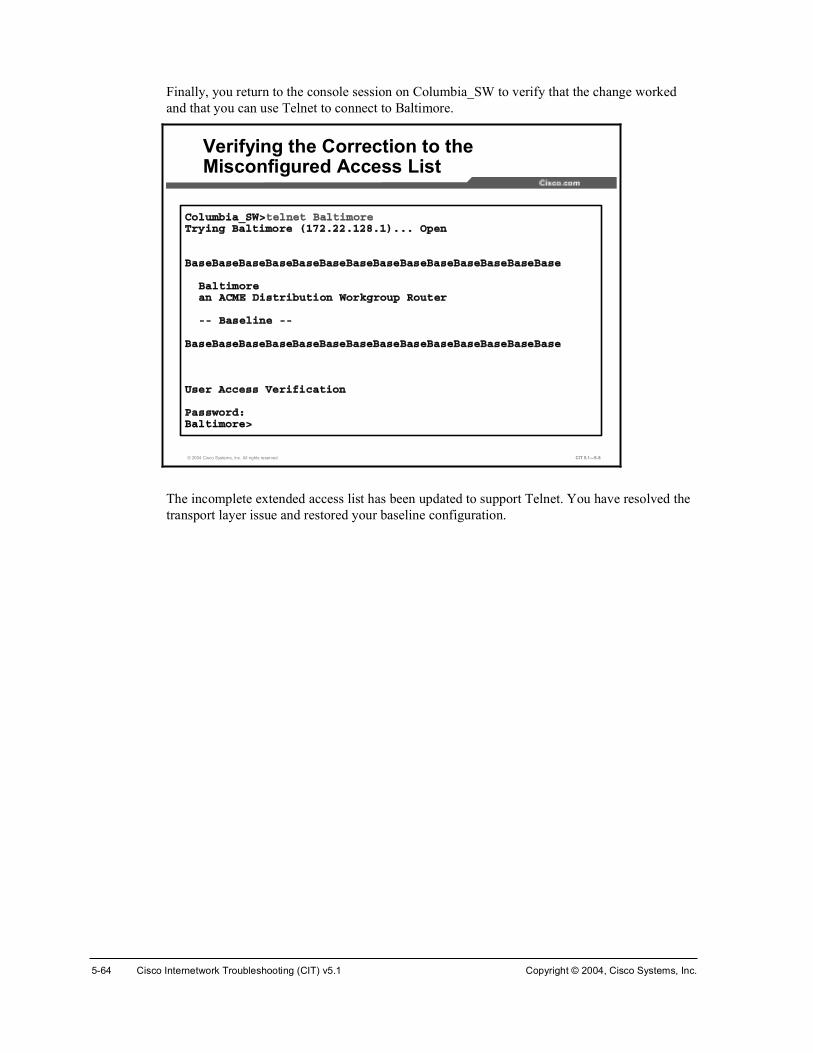
5-64 Cisco Internetwork Troubleshooting (CIT) v5.1 Copyright © 2004, Cisco Systems, Inc.
Finally, you return to the console session on Columbia_SW to verify that the change worked and that you can use Telnet to connect to Baltimore.
© 2004 Cisco Systems, Inc. All rights reserved. CIT 5.1—5-8
ݱ´«³¾·¿ÁÍÉ⬻´²»¬ Þ¿´¬·³±®»Ì®§·²¹ Þ¿´¬·³±®» øïéîòîîòïîèòï÷òòò Ñ°»²
Þ¿»Þ¿»Þ¿»Þ¿»Þ¿»Þ¿»Þ¿»Þ¿»Þ¿»Þ¿»Þ¿»Þ¿»Þ¿»Þ¿»
Þ¿´¬·³±®»¿² ßÝÓÛ Ü·¬®·¾«¬·±² ɱ®µ¹®±«° ᫬»®
óó Þ¿»´·²» óó
Þ¿»Þ¿»Þ¿»Þ¿»Þ¿»Þ¿»Þ¿»Þ¿»Þ¿»Þ¿»Þ¿»Þ¿»Þ¿»Þ¿»
Ë»® ß½½» Ê»®·º·½¿¬·±²
п©±®¼æ Þ¿´¬·³±®»â
Verifying the Correction to the Misconfigured Access List
The incomplete extended access list has been updated to support Telnet. You have resolved the transport layer issue and restored your baseline configuration.

Copyright © 2004, Cisco Systems, Inc. Resolving Problems at the Transport and Application Layers 5-65
Example: Correcting a Problem at the Transport Layer You are the second-level network engineer for Oakland. You have console access to both the access router named Oakland and the access switch named Oakland_SW. You also have IP connectivity to all other devices in your division. Your division supports the 172.24.0.0/16 subnet. The router SanFran is running the firewall feature set and is acting as the firewall to the Internet for the rest of the division.
© 2004 Cisco Systems, Inc. All rights reserved. CIT 5.1—5-9
Example: Correcting a Problem at the Transport Layer
There are some issues in the network. After SanFran crashed last night, you determined that it has a fast memory leak. You have noted that the IP input process on SanFran is consuming a lot of resources. In the short term, you would like to understand what current traffic flows are causing high IP input processing. In the longer term, you need to decide if an IOS upgrade is needed on SanFran.
Note This example topology does not follow the CIT lab configuration.

5-66 Cisco Internetwork Troubleshooting (CIT) v5.1 Copyright © 2004, Cisco Systems, Inc.
First you configure IP cache flow routing on both SanFran and Oakland.
© 2004 Cisco Systems, Inc. All rights reserved. CIT 5.1—5-10
Í¿²Ú®¿²ý½±²º ¬Í¿²Ú®¿²ø½±²º·¹ó·º÷ý·²¬»®º¿½» º¿¬»¬¸»®²»¬ ðñðÍ¿²Ú®¿²ø½±²º·¹ó·º÷ý·° ®±«¬»ó½¿½¸» º´±©Í¿²Ú®¿²ø½±²º·¹ó·º÷ý·²¬»®º¿½» º¿¬»¬¸»®²»¬ ðñïÍ¿²Ú®¿²ø½±²º·¹ó·º÷ý·° ®±«¬»ó½¿½¸» º´±©Í¿²Ú®¿²ø½±²º·¹ó·º÷ýÂÆÍ¿²Ú®¿²ý
Configuring IP Cache Flow Switching on SanFran and Oakland
Ñ¿µ´¿²¼ý½±²º ¬Ñ¿µ´¿²¼ø½±²º·¹ó·º÷ý·²¬»®º¿½» º¿¬»¬¸»®²»¬ ðñïÑ¿µ´¿²¼ø½±²º·¹ó·º÷ý·° ®±«¬»ó½¿½¸» º´±©Ñ¿µ´¿²¼ø½±²º·¹ó·º÷ý·²¬»®º¿½» º¿¬»¬¸»®²»¬ ðñðÑ¿µ´¿²¼ø½±²º·¹ó·º÷ý·° ®±«¬»ó½¿½¸» º´±©Ñ¿µ´¿²¼ø½±²º·¹ó·º÷ýÂÆÑ¿µ´¿²¼ý
After configuring IP cache flow, you decide you want to wait a few minutes for the routers to process some packets.
You decide to look for issues with the current IOS image on SanFran. First you review what image SanFran is running.
© 2004 Cisco Systems, Inc. All rights reserved. CIT 5.1—5-11
Í¿²Ú®¿²ý¸±© ª»®·±²Ý·½± ײ¬»®²»¬©±®µ Ñ°»®¿¬·²¹ ͧ¬»³ ͱº¬©¿®»×ÑÍ ø¬³÷ Ýîêðð ͱº¬©¿®» øÝîêððó×ÑíóÓ÷ô Ê»®·±² ïîòîøïð¿÷ô ÎÛÔÛßÍÛ ÍÑÚÌÉßÎÛ øº½ï÷ݱ°§®·¹¸¬ ø½÷ ïçèêóîððî ¾§ ½·½± ͧ¬»³ô ײ½òݱ³°·´»¼ Ì«» îïóÓ¿§óðî ïíæëé ¾§ °©¿¼»×³¿¹» ¬»¨¬ó¾¿»æ ð¨èðððèðèèô ¼¿¬¿ó¾¿»æ ð¨èðßïïßêè
ÎÑÓæ ͧ¬»³ Þ±±¬¬®¿°ô Ê»®·±² ïîòïøí®÷Ìîô ÎÛÔÛßÍÛ ÍÑÚÌÉßÎÛ øº½ï÷
Í¿²Ú®¿² «°¬·³» · íë ³·²«¬»Í§¬»³ ®»¬«®²»¼ ¬± ÎÑÓ ¾§ ®»´±¿¼Í§¬»³ ·³¿¹» º·´» · þº´¿¸æ½îêððó·±íó³¦òïîîóïð¿ò¾·²þ
½·½± îêîï øÓÐÝèêð÷ °®±½»±® ø®»ª··±² ð¨îðð÷ ©·¬¸ îèêéîÕñìðçêÕ ¾§¬» ±º ³»³±®§òЮ±½»±® ¾±¿®¼ ×Ü ÖßÜðëïêðëËè øîíîèëîíëìç÷Óèêð °®±½»±®æ °¿®¬ ²«³¾»® ðô ³¿µ ìçÞ®·¼¹·²¹ ±º¬©¿®»òÈòîë ±º¬©¿®»ô Ê»®·±² íòðòðòï Û¬¸»®²»¬ñ×ÛÛÛ èðîòí ·²¬»®º¿½»ø÷î Ú¿¬Û¬¸»®²»¬ñ×ÛÛÛ èðîòí ·²¬»®º¿½»ø÷î Í»®·¿´ ²»¬©±®µ ·²¬»®º¿½»ø÷íîÕ ¾§¬» ±º ²±²óª±´¿¬·´» ½±²º·¹«®¿¬·±² ³»³±®§òèïçîÕ ¾§¬» ±º °®±½»±® ¾±¿®¼ ͧ¬»³ º´¿¸ øλ¿¼ñÉ®·¬»÷
ݱ²º·¹«®¿¬·±² ®»¹·¬»® · ð¨îïðîÍ¿²Ú®¿²ý
Viewing the IOS Version on SanFran
SanFran is running the IOS image c2600-io3-mz.122-10a.

Copyright © 2004, Cisco Systems, Inc. Resolving Problems at the Transport and Application Layers 5-67
Next, you go to Cisco.com to review the IOS Release status.
© 2004 Cisco Systems, Inc. All rights reserved. CIT 5.1—5-12
Reviewing IOS Release Status on the Cisco Feature Navigator
Note The actual navigation steps to get to this screen are not shown. You needed to log onto http://www.cisco.com and go to the Cisco Feature Navigator under Products and Services.

5-68 Cisco Internetwork Troubleshooting (CIT) v5.1 Copyright © 2004, Cisco Systems, Inc.
© 2004 Cisco Systems, Inc. All rights reserved. CIT 5.1—5-13
Finding Features by IOS Image Name on the Cisco Feature Navigator
You enter the image name used by SanFran.
You work through the Feature Navigator screens.
© 2004 Cisco Systems, Inc. All rights reserved. CIT 5.1—5-14
Reviewing IOS Release Status on the Cisco Feature Navigator

Copyright © 2004, Cisco Systems, Inc. Resolving Problems at the Transport and Application Layers 5-69
You select one of the images.
© 2004 Cisco Systems, Inc. All rights reserved. CIT 5.1—5-15
Looking for Software Advisories for a Specific Image
You see that the image has software advisories associated with it, so you go review them.
You review the advisories and note that the release has been replaced by a new image.
© 2004 Cisco Systems, Inc. All rights reserved. CIT 5.1—5-16
Reviewing the Software Advisories for a Specific Image (Cont.)
You decide that you will need to upgrade the image. Because this image is several releases back, you will need to determine which most recent version supports your requirements and hardware.

5-70 Cisco Internetwork Troubleshooting (CIT) v5.1 Copyright © 2004, Cisco Systems, Inc.
Now you want to check the status of IP traffic flows in your network.
© 2004 Cisco Systems, Inc. All rights reserved. CIT 5.1—5-17
Í¿²Ú®¿²ý¸±© ·° ½¿½¸» º´±©×Ð °¿½µ»¬ ·¦» ¼·¬®·¾«¬·±² øëí ¬±¬¿´ °¿½µ»¬÷æ
ïóíî êì çê ïîè ïêð ïçî îîì îëê îèè íîð íëî íèì ìïê ììè ìèðòððð òçêî òðïè òððð òððð òððð òððð òððð òððð òððð òðïè òððð òððð òððð òððð
ëïî ëìì ëéê ïðîì ïëíê îðìè îëêð íðéî íëèì ìðçê ìêðèòððð òððð òððð òððð òððð òððð òððð òððð òððð òððð òððð
×Ð Ú´±© Í©·¬½¸·²¹ Ý¿½¸»ô îéèëìì ¾§¬»í ¿½¬·ª»ô ìðçí ·²¿½¬·ª»ô ë ¿¼¼»¼ïðë ¿¹»® °±´´ô ð º´±© ¿´´±½ º¿·´«®»ß½¬·ª» º´±© ¬·³»±«¬ ·² íð ³·²«¬»×²¿½¬·ª» º´±© ¬·³»±«¬ ·² ïë »½±²¼´¿¬ ½´»¿®·²¹ ±º ¬¿¬·¬·½ ²»ª»®
Ю±¬±½±´ ̱¬¿´ Ú´±© п½µ»¬ Þ§¬» п½µ»¬ ß½¬·ª»øÍ»½÷ ×¼´»øÍ»½÷óóóóóóóó Ú´±© ñÍ»½ ñÚ´±© ñе¬ ñÍ»½ ñÚ´±© ñÚ´±©ËÜÐ󱬸»® ï ðòð ï íîè ðòð ðòð ïëòï×ÝÓÐ ï ðòð ï èì ðòð ðòð ïëòë̱¬¿´æ î ðòð ï îðê ðòð ðòð ïëòí
Í®½×º Í®½×п¼¼®» ܬ׺ ܬ×п¼¼®» Ю Í®½Ð ܬРе¬Ú¿ðñð ïðòïòîíòïé Ô±½¿´ ïéîòîêòïìïòïð ðê ðèèé ððïé íç Ú¿ðñð ïéîòîìòïìïòï Ò«´´ îîìòðòðòïð ëè ðððð ðððð ê Ú¿ðñð ïéîòîìòïìïòç Ò«´´ îîìòðòðòïð ëè ðððð ðððð ê
Í¿²Ú®¿²ý
Reviewing IP Cache Flow on SanFran
There are not any suspicious flows on SanFran.
You look at the traffic flows on Oakland.
© 2004 Cisco Systems, Inc. All rights reserved. CIT 5.1—5-18
Ñ¿µ´¿²¼ý¸±© ·° ½¿½¸» º´±©×Ð °¿½µ»¬ ·¦» ¼·¬®·¾«¬·±² øïééçïçï ¬±¬¿´ °¿½µ»¬÷æ
ïóíî êì çê ïîè ïêð ïçî îîì îëê îèè íîð íëî íèì ìïê ììè ìèðòððð òðçê òèêì òððê òðïð òððî òððï òððê òððð òððð òððð òððð òððð òððð òððð
ëïî ëìì ëéê ïðîì ïëíê îðìè îëêð íðéî íëèì ìðçê ìêðèòððð òððð òððð òððï òððè òððð òððð òððð òððð òððð òððð
×Ð Ú´±© Í©·¬½¸·²¹ Ý¿½¸»ô îéèëìì ¾§¬»ïðìç ¿½¬·ª»ô íðìé ·²¿½¬·ª»ô ïëëççíé ¿¼¼»¼éçíìíëè ¿¹»® °±´´ô ð º´±© ¿´´±½ º¿·´«®»´¿¬ ½´»¿®·²¹ ±º ¬¿¬·¬·½ ²»ª»®
Ю±¬±½±´ ̱¬¿´ Ú´±© п½µ»¬ Þ§¬» п½µ»¬ ß½¬·ª»øÍ»½÷ ×¼´»øÍ»½÷óóóóóóóó Ú´±© ñÍ»½ ñÚ´±© ñе¬ ñÍ»½ ñÚ´±© ñÚ´±©ÌÝÐóÌ»´²»¬ îîè ðòð êé ïðï ðòð îéòð ïïòèÌÝÐóÉÉÉ èíëé ðòð í îêð ðòð íòé èòéÌÝÐóÍÓÌÐ íè ðòð ïë ïçç ðòð ìòï îòïÌÝÐ󱬸»® îëëíê ðòð ë ïèê ðòð ìòè èòêËÜÐóÜÒÍ ëêï ðòð ìî êè ðòð îçòê çòðËÜÐóÒÌÐ ïçéí ðòð ï éê ðòð ðòð ïíòèËÜÐ󱬸»® éíëî ðòð ì ïëê ðòð îòì ïíòí×ÝÓÐ ïëïìêèç ðòí ï çï ðòí ðòð ïîòé×Ð󱬸»® ïìî ðòð îé êð ðòð ïîíòð íòî̱¬¿´æ ïëëèèéê ðòí ï ïðî ðòì ðòï ïîòê
ò ò ò
Reviewing IP Cache Flow on Oakland
You notice that ICMP traffic constitutes the major percentage of the total flows and that the majority of packets are between 64 and 96 bytes. This is a very unusual traffic pattern.

Copyright © 2004, Cisco Systems, Inc. Resolving Problems at the Transport and Application Layers 5-71
© 2004 Cisco Systems, Inc. All rights reserved. CIT 5.1—5-19
Ñ¿µ´¿²¼ý¸±© ·° ½¿½¸» º´±©ò ò ò
Í®½×º Í®½×п¼¼®» ܬ׺ ܬ×п¼¼®» Ю Í®½Ð ܬРе¬Ú¿ðñï ïðòïèòïíïòïê Ú¿ðñð ïéîòîìòïìïòéð ïï ðíëè ðíïê ï Ú¿ðñð ïéîòïèòîòéð Ú¿ðñï ïðòïèòïíïòïê ïï ðíïê ðíëè ï Ú¿ðñï ïðòïèòïíïòïê Ú¿ðñð ïéîòîìòïìïòìî ïï ððíë èïéí îèî Ú¿ðñð ïéîòîìòïìïòìî Ú¿ðñï ïðòïèòïíïòïê ïï èïéí ððíë îèî Ú¿ðñð ïéîòîìòïìïòîðê Ú¿ðñï ïéîòïèòïèéòîðé ðï ðððð ðèðð ï Ú¿ðñð ïéîòîìòïìïòîðê Ú¿ðñï ïéîòïèòïèéòîðê ðï ðððð ðèðð ï Ú¿ðñð ïéîòîìòïìïòîðê Ú¿ðñï ïéîòïèòïèéòîðë ðï ðððð ðèðð ï Ú¿ðñð ïéîòîìòïìïòîðê Ú¿ðñï ïéîòïèòïèéòîðì ðï ðððð ðèðð ï Ú¿ðñð ïéîòîìòïìïòîðê Ú¿ðñï ïéîòïèòïèéòîðí ðï ðððð ðèðð ï Ú¿ðñð ïéîòîìòïìïòîðê Ú¿ðñï ïéîòïèòïèéòîðî ðï ðððð ðèðð ï Ú¿ðñð ïéîòîìòïìïòîðê Ú¿ðñï ïéîòïèòïèéòîðï ðï ðððð ðèðð ï Ú¿ðñð ïéîòîìòïìïòîðê Ú¿ðñï ïéîòïèòïèéòîðð ðï ðððð ðèðð ï Ú¿ðñð ïéîòîìòïìïòîë Ú¿ðñï ïéîòïèòïíïòïê ïï ððéÞ ððéÞ ï Ú¿ðñð ïéîòîìòïìïòîðê Ú¿ðñï ïéîòïèòïèéòïçç ðï ðððð ðèðð ï Ú¿ðñð ïéîòîìòïìïòîðê Ú¿ðñï ïéîòïèòïçðòîðð ðï ðððð ðèðð ï Ú¿ðñð ïéîòîìòïìïòîðê Ú¿ðñï ïéîòïèòïçðòïçç ðï ðððð ðèðð ï Ú¿ðñð ïéîòîìòïìïòîðê Ú¿ðñï ïéîòïèòïçðòïçè ðï ðððð ðèðð ï Ú¿ðñð ïéîòîìòïìïòîðê Ú¿ðñï ïéîòïèòïçðòïçê ðï ðððð ðèðð ï Ú¿ðñð ïéîòîìòïìïòîðê Ú¿ðñï ïéîòïèòïçðòïçë ðï ðððð ðèðð ï Ú¿ðñð ïéîòîìòïìïòîðê Ú¿ðñï ïéîòïèòïçðòïçì ðï ðððð ðèðð ï Ú¿ðñð ïéîòîìòïìïòîðê Ú¿ðñï ïéîòïèòïçðòïçí ðï ðððð ðèðð ï ò ò ò
Reviewing IP Cache Flow on Oakland (Cont.)
As you scroll through the output, you notice that many sequential flows have been attempted from device 172.24.141.206 to devices in the 172.18.190.0 network. Oakland routes this traffic to SanFran. Although you are using private addressing inside your network, SanFran has no route via the Internet to any device in the 172.18.190.0 network.

5-72 Cisco Internetwork Troubleshooting (CIT) v5.1 Copyright © 2004, Cisco Systems, Inc.
You believe that there is a virus in your network. You surmise that the IP input process on SanFran is using up a lot of resources handling traffic to which SanFran does not have a valid route.
You look for other devices with the same destination port using the show ip cache flow | include 0800 command.
© 2004 Cisco Systems, Inc. All rights reserved. CIT 5.1—5-20
Ñ¿µ´¿²¼ý¸±© ·° ½¿½¸» º´±© ¤ ·²½´«¼» ðèððÚ¿ðñð ïéîòîìòïìïòîðê Ú¿ðñï ïéîòïèòïèéòîðé ðï ðððð ðèðð ï Ú¿ðñð ïéîòîìòïìïòîðê Ú¿ðñï ïéîòïèòïèéòîðê ðï ðððð ðèðð ï ò ò òÚ¿ðñð ïéîòîìòïìïòîîè Ú¿ðñï ïéîòïëòîêòîìè ðï ðððð ðèðð ï Ú¿ðñð ïéîòîìòïìïòîíé Ú¿ðñï ïéîòïëòîëðòîìï ðï ðððð ðèðð ï Ú¿ðñð ïéîòîìòïìïòîîè Ú¿ðñï ïéîòïëòîêòîìç ðï ðððð ðèðð ï Ú¿ðñð ïéîòîìòïìïòîíé Ú¿ðñï ïéîòïëòîëðòîìð ðï ðððð ðèðð ï Ú¿ðñð ïéîòîìòïìïòîîè Ú¿ðñï ïéîòïëòîêòîëð ðï ðððð ðèðð ï Ú¿ðñð ïéîòîìòïìïòîíé Ú¿ðñï ïéîòïëòîëðòîìí ðï ðððð ðèðð ï Ú¿ðñð ïéîòîìòïìïòîîè Ú¿ðñï ïéîòïëòîêòîëï ðï ðððð ðèðð ï Ú¿ðñð ïéîòîìòïìïòîíé Ú¿ðñï ïéîòïëòîëðòîìî ðï ðððð ðèðð ï ò ò òÚ¿ðñð ïéîòîìòïìïòîðê Ú¿ðñï ïéîòïçòîìòïïî ðï ðððð ðèðð ï Ú¿ðñð ïéîòîìòïìïòîíê Ú¿ðñï ïéîòïëòìðòéç ðï ðððð ðèðð ï Ú¿ðñð ïéîòîìòïìïòîðê Ú¿ðñï ïéîòïçòîìòïïí ðï ðððð ðèðð ï Ú¿ðñð ïéîòîìòïìïòîíê Ú¿ðñï ïéîòïëòìðòìè ðï ðððð ðèðð ï Ú¿ðñð ïéîòîìòïìïòîíê Ú¿ðñï ïéîòïëòìðòìç ðï ðððð ðèðð ï Ú¿ðñð ïéîòîìòïìïòîðê Ú¿ðñï ïéîòïçòîìòïë ðï ðððð ðèðð ï Ú¿ðñð ïéîòîìòïìïòîíê Ú¿ðñï ïéîòïëòìðòëð ðï ðððð ðèðð ï Ú¿ðñð ïéîòîìòïìïòîíê Ú¿ðñï ïéîòïëòìðòëï ðï ðððð ðèðð ï ò ò òÚ¿ðñð ïéîòîìòïìïòîîç Ú¿ðñï ïéîòïçòîíçòîîç ðï ðððð ðèðð ï Ú¿ðñð ïéîòîìòïìïòîîç Ú¿ðñï ïéîòïçòîíçòîîè ðï ðððð ðèðð ï Ú¿ðñð ïéîòîìòïìïòîîç Ú¿ðñï ïéîòïçòîíçòîíï ðï ðððð ðèðð ï ò ò ò
Reviewing IP Cache Flow for ICMP on Oakland (Cont.)
You see several internal devices that appear to be infected, perhaps with some variant of the Nachi virus.
Now it is time to tell the MIS department the IP addresses of devices that you suspect to be infected. You will work with MIS to clean up the device and network issues.
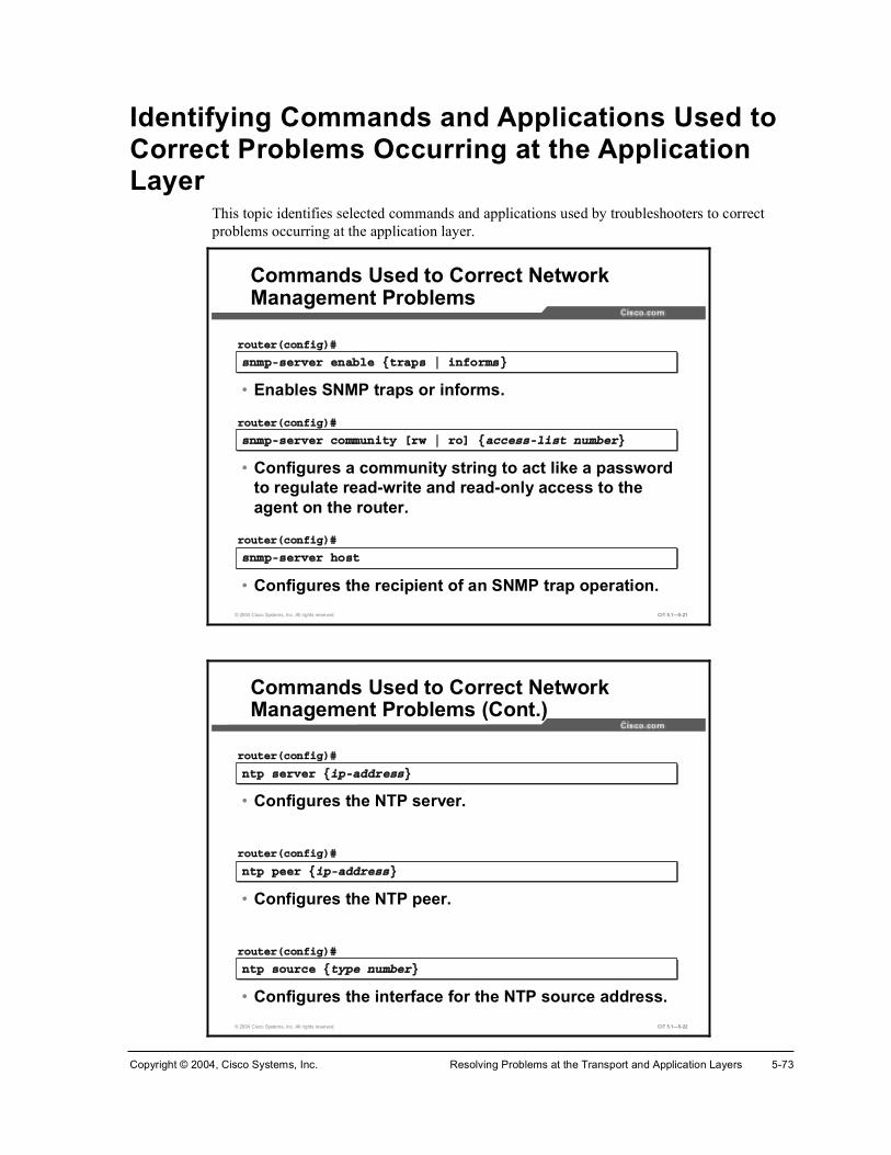
Copyright © 2004, Cisco Systems, Inc. Resolving Problems at the Transport and Application Layers 5-73
Identifying Commands and Applications Used to Correct Problems Occurring at the Application Layer
This topic identifies selected commands and applications used by troubleshooters to correct problems occurring at the application layer.
© 2004 Cisco Systems, Inc. All rights reserved. CIT 5.1—5-21
Commands Used to Correct Network Management Problems
²³°ó»®ª»® »²¿¾´» ¥¬®¿° ¤ ·²º±®³£²³°ó»®ª»® »²¿¾´» ¥¬®¿° ¤ ·²º±®³£
®±«¬»®ø½±²º·¹÷ý
• Enables SNMP traps or informs.
²³°ó»®ª»® ½±³³«²·¬§ Å®© ¤ ®±Ã ¥¿½½»ó´·¬ ²«³¾»®£²³°ó»®ª»® ½±³³«²·¬§ Å®© ¤ ®±Ã ¥¿½½»ó´·¬ ²«³¾»®£
®±«¬»®ø½±²º·¹÷ý
• Configures a community string to act like a password to regulate read-write and read-only access to the agent on the router.
²³°ó»®ª»® ¸±¬ ²³°ó»®ª»® ¸±¬
®±«¬»®ø½±²º·¹÷ý
• Configures the recipient of an SNMP trap operation.
© 2004 Cisco Systems, Inc. All rights reserved. CIT 5.1—5-22
Commands Used to Correct Network Management Problems (Cont.)
²¬° »®ª»® ¥·°ó¿¼¼®»£²¬° »®ª»® ¥·°ó¿¼¼®»£
®±«¬»®ø½±²º·¹÷ý
• Configures the NTP server.
²¬° °»»® ¥·°ó¿¼¼®»£²¬° °»»® ¥·°ó¿¼¼®»£
®±«¬»®ø½±²º·¹÷ý
• Configures the NTP peer.
²¬° ±«®½» ¥¬§°» ²«³¾»®£²¬° ±«®½» ¥¬§°» ²«³¾»®£
®±«¬»®ø½±²º·¹÷ý
• Configures the interface for the NTP source address.

5-74 Cisco Internetwork Troubleshooting (CIT) v5.1 Copyright © 2004, Cisco Systems, Inc.
© 2004 Cisco Systems, Inc. All rights reserved. CIT 5.1—5-23
Commands Used to Correct Network Management Problems (Cont.)
²± ²³°ó»®ª»® ²± ²³°ó»®ª»®
®±«¬»®ø½±²º·¹÷ý
• Disables SNMP agent operation.
»®ª·½» ¬·³»¬¿³° ´±¹ ¼¿¬»¬·³» ´±½¿´¬·³»»®ª·½» ¬·³»¬¿³° ´±¹ ¼¿¬»¬·³» ´±½¿´¬·³»
®±«¬»®ø½±²º·¹÷ý
• Configures the system to time-stamp logging messages.
»®ª·½» ¬·³»¬¿³° ¼»¾«¹ ¼¿¬»¬·³» ´±½¿´¬·³»»®ª·½» ¬·³»¬¿³° ¼»¾«¹ ¼¿¬»¬·³» ´±½¿´¬·³»
®±«¬»®ø½±²º·¹÷ý
• Configures the system to time-stamp debugging messages.
Troubleshooters can use the commands listed in the table to make configuration changes to correct problems with network management protocols at the application layer.
Commands Used to Correct Network Management Problems
Command Description
²³°ó»®ª»® »²¿¾´» ¥¬®¿° ¤ ·²º±®³£
Enables SNMP traps or informs.
²³°ó»®ª»® ½±³³«²·¬§ Å®© ¤ ®±Ã ¥¿½½»ó´·¬²«³¾»®£
Configures a community string to act like a password to regulate read-write and read-only access to the agent on the router.
²³°ó»®ª»® ¸±¬ Configures the recipient of an SNMP trap operation.
²¬° »®ª»® ¥·°ó¿¼¼®»£
Configures the NTP server.
²¬° °»»® ¥·°ó¿¼¼®»£ Configures the NTP peer.
²¬° ±«®½» ¥¬§°»²«³¾»®£
Configures the interface for the NTP source address.
²± ²³°ó»®ª»® Disables SNMP agent operation.
»®ª·½» ¬·³»¬¿³° ´±¹ ¼¿¬»¬·³» ´±½¿´¬·³»
Configures the system to time-stamp logging messages.
»®ª·½» ¬·³»¬¿³° ¼»¾«¹ ¼¿¬»¬·³» ´±½¿´¬·³»
Configures the system to time-stamp debugging messages.

Copyright © 2004, Cisco Systems, Inc. Resolving Problems at the Transport and Application Layers 5-75
© 2004 Cisco Systems, Inc. All rights reserved. CIT 5.1—5-24
Commands Used to Correct DHCP Problems
·° ¸»´°»®ó¿¼¼®» ·° ¸»´°»®ó¿¼¼®»
®±«¬»®ø½±²º·¹ó·º÷ý
• Forwards UDP broadcasts, including BOOTP, received on an interface.
Ų±Ã »®ª·½» ¼¸½°Å²±Ã »®ª·½» ¼¸½°
®±«¬»®ø½±²º·¹÷ý
• Enables and disables DHCP server and relay functionality on the router.
Troubleshooters can use the commands listed in the table to make configuration changes to correct problems with DHCP at the application layer.
Commands Used to Correct DHCP Problems
Command Description
·° ¸»´°»®ó¿¼¼®» Forwards UDP broadcasts, including Bootstrap Protocol (BOOTP), received on an interface.
Ų±Ã »®ª·½» ¼¸½° Enables and disables DHCP server and relay functionality on the router.

5-76 Cisco Internetwork Troubleshooting (CIT) v5.1 Copyright © 2004, Cisco Systems, Inc.
Example: Correcting a TFTP Problem at the Application Layer You are the second-level network engineer for Orlando. You have console access to the distribution router named Orlando and IP connectivity to all other devices in your division. Your division supports the 172.21.0.0/16 subnet.
© 2004 Cisco Systems, Inc. All rights reserved. CIT 5.1—5-25
Example: Correcting a TFTP Problem at the Application Layer
The IOS image has been accidentally erased from Orlando. Baltimore has a TFTP server running that offers an image with the file name “flash:c1700-sv8y-mz.122-8.YL.bin” for your use. You isolated the TFTP issues: the tftpdnld rommon command needs the IP address and mask for the local router, the default gateway for the local router, the IP address of the TFTP server, and the name of the file to be transferred.
You make a list of these values:
Ô±½¿´ ×Ð ¿¼¼®» ã ïéîòîïòïîèòïîç
Ô±½¿´ Ó¿µ ã îëëòîëëòîëëòïîè
Ô±½¿´ Ü»º¿«´¬ Ù¿¬»©¿§ ã ïéîòîïòïîèòïíð
ÌÚÌÐ Í»®ª»® ã ïéîòîîòïîèòïîç
Ú·´» ã ½ïéððóªè§ó³¦òïîîóèòÇÔò¾·²
You review the relevant information on Cisco.com and know that you need to enter the following command to set these variables: variable_name=variable.
Now you need to configure the TFTP variables on Orlando.

Copyright © 2004, Cisco Systems, Inc. Resolving Problems at the Transport and Application Layers 5-77
© 2004 Cisco Systems, Inc. All rights reserved. CIT 5.1—5-26
®±³³±² ë â ×ÐÁßÜÜÎÛÍÍãïéîòîïòïîèòïîç®±³³±² ê â ×ÐÁÍËÞÒÛÌÁÓßÍÕãîëëòîëëòîëëòïîè®±³³±² é â ÜÛÚßËÔÌÁÙßÌÛÉßÇãïéîòîïòïîèòïíð
³±²·¬±®æ ½±³³¿²¼ þÜÛÚßËÔÌÁÙßÌÛÉßÇãþ ²±¬ º±«²¼®±³³±² è â ÜÛÚßËÔÌÁÙßÌÛÉßÇã ïéîòîïòïîèòïíð®±³³±² ç â ÌÚÌÐÁÍÛÎÊÛÎãïéîòîîòïîèòïîç®±³³±² ïð â ÌÚÌÐÁÚ×ÔÛã½ïéððóªè§ó³¦òïîîóèòÇÔò¾·²®±³³±² ïï â
Correcting a TFTP Problem at the Application Layer
The variables have been configured after you remove an extra space.

5-78 Cisco Internetwork Troubleshooting (CIT) v5.1 Copyright © 2004, Cisco Systems, Inc.
You now invoke the TFTP program.
© 2004 Cisco Systems, Inc. All rights reserved. CIT 5.1—5-27
®±³³±² ïï â ¬º¬°¼²´¼
×ÐÁßÜÜÎÛÍÍæ ïéîòîïòïîèòïîç×ÐÁÍËÞÒÛÌÁÓßÍÕæ îëëòîëëòîëëòïîèÜÛÚßËÔÌÁÙßÌÛÉßÇæ ïéîòîïòïîèòïíð
ÌÚÌÐÁÍÛÎÊÛÎæ ïéîòîîòïîèòïîçÌÚÌÐÁÚ×ÔÛæ º´¿¸æñ½ïéððóªè§ó³¦òïîîóèòÇÔòÞ×Ò
ײª±µ» ¬¸· ½±³³¿²¼ º±® ¼·¿¬»® ®»½±ª»®§ ±²´§òÉßÎÒ×ÒÙæ ¿´´ »¨·¬·²¹ ¼¿¬¿ ·² ¿´´ °¿®¬·¬·±² ±² º´¿¸ ©·´´ ¾» ´±¬ÿܱ §±« ©·¸ ¬± ½±²¬·²«»á §ñ²æ ŲÃæ §
λ½»·ª·²¹ ½ïéððóªè§ó³¦òïîîóèòÇÔòÞ×Ò º®±³ ïéîòîîòïîèòïîç ÿÿÿÿÿÿÿÿÿÿÿÿÿÿÿÿÿÿÿÿÿÿÿÿÿÿÿÿÿÿÿÿÿÿÿÿÿÿÿÿÿÿÿÿÿÿÿÿÿÿÿÿÿÿÿÿÿÿÿÿÿÿÿÿÿÿÿÿÿÿÿÿÿÿÿÿÿÿÿÿÿÿÿÿÿÿÿÿÿÿÿÿÿÿÿÿÿÿÿÿÿÿÿÿÿÿÿÿÿÿÿÿÿÿÿÿÿÿÿÿÿÿÿÿÿÿÿÿÿÿÿÿÿÿÿÿÿÿÿÿÿÿÿÿÿÿÿÿÿÿÿÿÿÿÿÿÿÿòòòÿÿÿÿÿÿÿÿÿÿÿÿÿÿÿÿÿÿÿÿÿÿÿÿÿÿÿÿÿÿÿÿÿÿÿÿÿÿÿÿÿÿÿÿÿÿÿÿÿÿÿÿÿÿÿÿÿÿÿÿÿÿÿÿÿÿÿÿÿÿÿÿÿÿÿÿÿÿÿÿÿÿÿÿÿÿÿÿÿÿÿÿÿÿÿÿÿÿÿÿÿÿÿÿÿÿÿÿÿÿÿÿÿÿÿÿÿÿÿÿÿÿÿÿÿÿÿÿÿÿÿÿÿÿÿÿÿÿÿÿÿÿÚ·´» ®»½»°¬·±² ½±³°´»¬»¼òݱ°§·²¹ º·´» ½ïéððóªè§ó³¦òïîîóèòÇÔòÞ×Ò ¬± º´¿¸òÛ®¿·²¹ º´¿¸ ¿¬ ð¨êððððЮ±¹®¿³³·²¹ ´±½¿¬·±² êïçèðððð®±³³±² ïî â
Invoking the TFTP Server
After configuring the parameters to support TFTP, the TFTP download process appears to work. You have resolved the application layer issue of missing TFTP parameters.
You now need to boot up the router using the new image.
© 2004 Cisco Systems, Inc. All rights reserved. CIT 5.1—5-28
®±³³±² ïî â ¾±±¬°®±¹®¿³ ´±¿¼ ½±³°´»¬»ô »²¬®§ °±·²¬æ ð¨èðððèðððô ·¦»æ ð¨çè¼ìçìÍ»´º ¼»½±³°®»·²¹ ¬¸» ·³¿¹» æ ýýýýýýýýýýýýýýýýýýýýýýýýýýýýýýýýýýýýýýýýýýýýýýýýýýýýýýýýýýýýýýýýýýýýýýýýýýýýýýýýýýýýýýýýýýýýýýýýýýýýýýýýýýýýýýýýýýýýýýýýýýýýýýýýýýýýýýýýýýýýýýýýýýýýýýýýýýýýýýýýýýýýýýýýýýýýýýýýýýýýýýýýý ÅÑÕÃòòòÝ·½± ײ¬»®²»¬©±®µ Ñ°»®¿¬·²¹ ͧ¬»³ ͱº¬©¿®» ×ÑÍ ø¬³÷ Ýïéðð ͱº¬©¿®» øÝïéððóÍÊèÇóÓ÷ô Ê»®·±² ïîòîøè÷ÇÔô ÛßÎÔÇ ÜÛÐÔÑÇÓÛÒÌ ÎÛÔÛßÍÛ ÍÑÚÌÉßÎÛ øº½ï÷ͧ²½¸»¼ ¬± ¬»½¸²±´±¹§ ª»®·±² ïîòîøïðòí÷ÌïÌßÝ Í«°°±®¬æ ¸¬¬°æññ©©©ò½·½±ò½±³ñ¬¿½Ý±°§®·¹¸¬ ø½÷ ïçèêóîððî ¾§ ½·½± ͧ¬»³ô ײ½òݱ³°·´»¼ É»¼ ïéóÖ«´óðî ïìæðì ¾§ »¿´§±²×³¿¹» ¬»¨¬ó¾¿»æ ð¨èðððèïîìô ¼¿¬¿ó¾¿»æ ð¨èïîîÜìðèòòòЮ» ÎÛÌËÎÒ ¬± ¹»¬ ¬¿®¬»¼ÿ
Booting Up the Router to Restore the IOS Image
The IOS image has been restored. You finish by restoring the baseline configuration files.

Copyright © 2004, Cisco Systems, Inc. Resolving Problems at the Transport and Application Layers 5-79
Example: Correcting a Problem at the Application Layer You are the second-level network engineer in Kingston. You have console access to the access router named Kingston and IP connectivity to all other devices in your division. Your division supports the 172.26.0.0/16 subnet.
© 2004 Cisco Systems, Inc. All rights reserved. CIT 5.1—5-29
Example: Correcting a Problem at the Application Layer
You have determined that a recent IPSec configuration between Toronto and Kingston is broken. You believe there is a policy setup error in the IPSec peers. IPSec negotiation between the remote peers fails. You should have already isolated the issue.
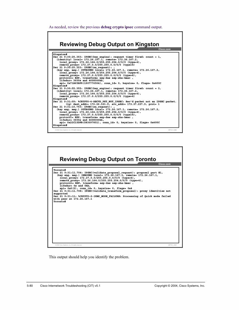
5-80 Cisco Internetwork Troubleshooting (CIT) v5.1 Copyright © 2004, Cisco Systems, Inc.
As needed, review the previous debug crypto ipsec command output.
© 2004 Cisco Systems, Inc. All rights reserved. CIT 5.1—5-30
Õ·²¹¬±²ýÜ»½ îï çæíðæîëòíëíæ ×ÐÍÛÝøµ»§Á»²¹·²»÷æ ®»¯«»¬ ¬·³»® º·®»¼æ ½±«²¬ ã ïô
ø·¼»²¬·¬§÷ ´±½¿´ã ïéîòîêòïêéòïô ®»³±¬»ã ïéîòîêòïêéòîô´±½¿´Á°®±¨§ã ïéîòîêòïêìòðñîëëòîëëòîëìòðñðñð ø¬§°»ãì÷ô®»³±¬»Á°®±¨§ã ïéîòîéòðòðñîëëòîëëòðòðñðñð ø¬§°»ãì÷
Ü»½ îï çæíðæîëòíëíæ ×ÐÍÛÝø¿Á®»¯«»¬÷æ ôøµ»§ »²¹ò ³¹ò÷ ÑËÌÞÑËÒÜ ´±½¿´ã ïéîòîêòïêéòïô ®»³±¬»ã ïéîòîêòïêéòîô
´±½¿´Á°®±¨§ã ïéîòîêòïêìòðñîëëòîëëòîëìòðñðñð ø¬§°»ãì÷ô®»³±¬»Á°®±¨§ã ïéîòîéòðòðñîëëòîëëòðòðñðñð ø¬§°»ãì÷ô°®±¬±½±´ã ÛÍÐô ¬®¿²º±®³ã »°ó¼» »°ó¸¿ó¸³¿½ ô´·º»¼«®ã íêðð ¿²¼ ìêðèðððµ¾ô°·ã ð¨éïÞêëÞÚèøïçðéééêëðì÷ô ½±²²Á·¼ã ðô µ»§·¦»ã ðô º´¿¹ã ð¨ìððÝ
Õ·²¹¬±²ýÜ»½ îï çæíðæëëòíëëæ ×ÐÍÛÝøµ»§Á»²¹·²»÷æ ®»¯«»¬ ¬·³»® º·®»¼æ ½±«²¬ ã îô
ø·¼»²¬·¬§÷ ´±½¿´ã ïéîòîêòïêéòïô ®»³±¬»ã ïéîòîêòïêéòîô´±½¿´Á°®±¨§ã ïéîòîêòïêìòðñîëëòîëëòîëìòðñðñð ø¬§°»ãì÷ô®»³±¬»Á°®±¨§ã ïéîòîéòðòðñîëëòîëëòðòðñðñð ø¬§°»ãì÷
Õ·²¹¬±²ýÜ»½ îï çæíïæðçæ ûÝÎÇÐÌÑóìóÎÛÝÊÜÁÐÕÌÁÒÑÌÁ×ÐÍÛÝæ λ½ù¼ °¿½µ»¬ ²±¬ ¿² ×ÐÍÛÝ °¿½µ»¬ò
ø·°÷ ¼»¬Á¿¼¼®ã ïéîòîêòïêïòîô ®½Á¿¼¼®ã ïéîòîéòîîéòçô °®±¬ã ïÜ»½ îï çæíïæïðòéëíæ ×ÐÍÛÝø¿Á®»¯«»¬÷æ ô
øµ»§ »²¹ò ³¹ò÷ ÑËÌÞÑËÒÜ ´±½¿´ã ïéîòîêòïêéòïô ®»³±¬»ã ïéîòîêòïêéòîô´±½¿´Á°®±¨§ã ïéîòîêòïêìòðñîëëòîëëòîëìòðñðñð ø¬§°»ãì÷ô®»³±¬»Á°®±¨§ã ïéîòîéòðòðñîëëòîëëòðòðñðñð ø¬§°»ãì÷ô°®±¬±½±´ã ÛÍÐô ¬®¿²º±®³ã »°ó¼» »°ó¸¿ó¸³¿½ ô´·º»¼«®ã íêðð ¿²¼ ìêðèðððµ¾ô°·ã ð¨îîÝïëÜÚÞøëèíðçéèëï÷ô ½±²²Á·¼ã ðô µ»§·¦»ã ðô º´¿¹ã ð¨ìððÝ
Õ·²¹¬±²ý
Reviewing Debug Output on Kingston
© 2004 Cisco Systems, Inc. All rights reserved. CIT 5.1—5-31
̱®±²¬±ýÜ»½ îï çæíïæïïòéðìæ ×ÐÍÛÝøª¿´·¼¿¬»Á°®±°±¿´Á®»¯«»¬÷æ °®±°±¿´ °¿®¬ ýïô
øµ»§ »²¹ò ³¹ò÷ ×ÒÞÑËÒÜ ´±½¿´ã ïéîòîêòïêéòîô ®»³±¬»ã ïéîòîêòïêéòïô´±½¿´Á°®±¨§ã ïéîòîéòðòðñîëëòîëëòðòðñðñð ø¬§°»ãì÷ô®»³±¬»Á°®±¨§ã ïéîòîêòïêìòðñîëëòîëëòîëìòðñðñð ø¬§°»ãì÷ô°®±¬±½±´ã ÛÍÐô ¬®¿²º±®³ã »°ó¼» »°ó¸¿ó¸³¿½ ô´·º»¼«®ã ð ¿²¼ ðµ¾ô°·ã ð¨ðøð÷ô ½±²²Á·¼ã ðô µ»§·¦»ã ðô º´¿¹ã ð¨ì
Ü»½ îï çæíïæïïòéðèæ ×ÐÍÛÝøª¿´·¼¿¬»Á¬®¿²º±®³Á°®±°±¿´÷æ °®±¨§ ·¼»²¬·¬·» ²±¬ «°°±®¬»¼Ü»½ îï çæíïæïïæ ûÝÎÇÐÌÑóêó×ÕÓÐÁÓÑÜÛÁÚß×ÔËÎÛæ Ю±½»·²¹ ±º Ï«·½µ ³±¼» º¿·´»¼ ©·¬¸ °»»® ¿¬ ïéîòîêòïêéòï̱®±²¬±ý
Reviewing Debug Output on Toronto
This output should help you identify the problem.

Copyright © 2004, Cisco Systems, Inc. Resolving Problems at the Transport and Application Layers 5-81
Verify the exact problem with the show crypto map command.
© 2004 Cisco Systems, Inc. All rights reserved. CIT 5.1—5-32
Õ·²¹¬±²ý¸±© ½®§°¬± ³¿°Ý®§°¬± Ó¿° þ¬»¬þ ïð ·°»½ó·¿µ³°
л»® ã ïéîòîêòïêéòîÛ¨¬»²¼»¼ ×Ð ¿½½» ´·¬ ïíí
¿½½»ó´·¬ ïíí °»®³·¬ ·° ïéîòîêòïêðòð ðòðòíòîëë ïéîòîðòðòð ðòíòîëëòîë뿽½»ó´·¬ ïíí °»®³·¬ ·° ïéîòîêòïêìòð ðòðòïòîëë ïéîòîðòðòð ðòíòîëëòîë뿽½»ó´·¬ ïíí °»®³·¬ ·° ïéîòîêòïêðòð ðòðòíòîëë ïéîòîìòðòð ðòïòîëëòîë뿽½»ó´·¬ ïíí °»®³·¬ ·° ïéîòîêòïêìòð ðòðòïòîëë ïéîòîìòðòð ðòïòîëëòîë뿽½»ó´·¬ ïíí °»®³·¬ ·° ïéîòîêòïêðòð ðòðòíòîëë ïéîòîéòðòð ðòðòîëëòîë뿽½»ó´·¬ ïíí °»®³·¬ ·° ïéîòîêòïêìòð ðòðòïòîëë ïéîòîéòðòð ðòðòîëëòîë뿽½»ó´·¬ ïíí °»®³·¬ ·° ïéîòîêòïêðòð ðòðòíòîëë ïéîòîèòðòð ðòðòîëëòîë뿽½»ó´·¬ ïíí °»®³·¬ ·° ïéîòîêòïêìòð ðòðòïòîëë ïéîòîèòðòð ðòðòîëëòîëë
Ý«®®»²¬ °»»®æ ïéîòîêòïêéòîÍ»½«®·¬§ ¿±½·¿¬·±² ´·º»¬·³»æ ìêðèððð µ·´±¾§¬»ñíêðð »½±²¼ÐÚÍ øÇñÒ÷æ ÒÌ®¿²º±®³ »¬ã¥
¿«¬¸îô£×²¬»®º¿½» «·²¹ ½®§°¬± ³¿° ¬»¬æ
Í»®·¿´ïñðÕ·²¹¬±²ý
Reviewing the Crypto Map on Kingston
© 2004 Cisco Systems, Inc. All rights reserved. CIT 5.1—5-33
̱®±²¬±ý¸±© ½®§°¬± ³¿°Ý®§°¬± Ó¿° þ¬»¬þ ïð ·°»½ó·¿µ³°
л»® ã ïéîòîêòïêéòïÛ¨¬»²¼»¼ ×Ð ¿½½» ´·¬ ïíí
¿½½»ó´·¬ ïíí °»®³·¬ ·° ïéîòîêòïêðòð ðòðòíòîëë ïéîòîðòðòð ðòíòîëëòîë뿽½»ó´·¬ ïíí °»®³·¬ ·° ïéîòîêòïêìòð ðòðòïòîëë ïéîòîðòðòð ðòíòîëëòîë뿽½»ó´·¬ ïíí °»®³·¬ ·° ïéîòîêòïêðòð ðòðòíòîëë ïéîòîìòðòð ðòïòîëëòîë뿽½»ó´·¬ ïíí °»®³·¬ ·° ïéîòîêòïêìòð ðòðòïòîëë ïéîòîìòðòð ðòïòîëëòîë뿽½»ó´·¬ ïíí °»®³·¬ ·° ïéîòîêòïêðòð ðòðòíòîëë ïéîòîéòðòð ðòðòîëëòîë뿽½»ó´·¬ ïíí °»®³·¬ ·° ïéîòîêòïêìòð ðòðòïòîëë ïéîòîéòðòð ðòðòîëëòîë뿽½»ó´·¬ ïíí °»®³·¬ ·° ïéîòîêòïêðòð ðòðòíòîëë ïéîòîèòðòð ðòðòîëëòîë뿽½»ó´·¬ ïíí °»®³·¬ ·° ïéîòîêòïêìòð ðòðòïòîëë ïéîòîèòðòð ðòðòîëëòîëë
Ý«®®»²¬ °»»®æ ïéîòîêòïêéòïÍ»½«®·¬§ ¿±½·¿¬·±² ´·º»¬·³»æ ìêðèððð µ·´±¾§¬»ñíêðð »½±²¼ÐÚÍ øÇñÒ÷æ ÒÌ®¿²º±®³ »¬ã¥
¿«¬¸îô£×²¬»®º¿½» «·²¹ ½®§°¬± ³¿° ¬»¬æ
Í»®·¿´ïñð̱®±²¬±ý
Reviewing the Crypto Map on Toronto
These screens should clarify the issue. The access list is duplicated on the two peers, but it should be a mirror image on one router. Which one should be replaced?

5-82 Cisco Internetwork Troubleshooting (CIT) v5.1 Copyright © 2004, Cisco Systems, Inc.
Toronto has an incorrect access list. The access list on Toronto needs to identify the subnets reachable via Fast Ethernet 0/0 (or from Montreal) as being the source of traffic to encapsulate. Based on the current network, these subnets include 172.21.0.0, 172.22.0.0, 172.23.0.0, 172.240.0, 172.25.0.0, 172.27.227.0, and 172.28.128.0. The destinations for this traffic are the remote subnets reachable via Kingston, or 172.26.161.0, 172.26.162.0, 172.26.163.0,172.26.164.0, and 172.26.165.0. Currently, access list 133 has been misconfigured and is a duplicate of the access list on Kingston. The misconfiguration reverses the proper sources and destinations for traffic.
You remove the old access list and configure the correct one to mirror the access list on Kingston.
© 2004 Cisco Systems, Inc. All rights reserved. CIT 5.1—5-34
̱®±²¬±ý½±²º ¬Û²¬»® ½±²º·¹«®¿¬·±² ½±³³¿²¼ô ±²» °»® ´·²»ò Û²¼ ©·¬¸ ÝÒÌÔñÆò̱®±²¬±ø½±²º·¹÷ý²± ¿½½»ó´·¬ ïíí̱®±²¬±ø½±²º·¹÷ý¿½½»ó´·¬ ïíí °»®³·¬ ·° ïéîòîðòðòð ðòíòîëëòîëë ïéîòîêòïêðòð ðòðòíòîëë̱®±²¬±ø½±²º·¹÷ý¿½½»ó´·¬ ïíí °»®³·¬ ·° ïéîòîðòðòð ðòíòîëëòîëë ïéîòîêòïêìòð ðòðòïòîëë̱®±²¬±ø½±²º·¹÷ý¿½½»ó´·¬ ïíí °»®³·¬ ·° ïéîòîìòðòð ðòïòîëëòîëë ïéîòîêòïêðòð ðòðòíòîëë̱®±²¬±ø½±²º·¹÷ý¿½½»ó´·¬ ïíí °»®³·¬ ·° ïéîòîìòðòð ðòïòîëëòîëë ïéîòîêòïêìòð ðòðòïòîëë̱®±²¬±ø½±²º·¹÷ý¿½½»ó´·¬ ·° ïéîòîéòðòð ðòðòîëëòîëë ïéîòîêòïêðòð ðòðòíòîëë̱®±²¬±ø½±²º·¹÷ý¿½½»ó´·¬ ·° ïéîòîéòðòð ðòðòîëëòîëë ïéîòîêòïêìòð ðòðòïòîë̱®±²¬±ø½±²º·¹÷ý¿½½»ó´·¬ ·° ïéîòîèòðòð ðòðòîëëòîëë ïéîòîêòïêðòð ðòðòíòîëë̱®±²¬±ø½±²º·¹÷ý¿½½»ó´·¬ ·° ïéîòîèòðòð ðòðòîëëòîëë ïéîòîêòïêìòð ðòðòïòîëë̱®±²¬±ø½±²º·¹÷ý»¨·¬Ì±®±²¬±ý̱®±²¬±ý¸±© ¿½½»ó´·¬ ïííÛ¨¬»²¼»¼ ×Ð ¿½½» ´·¬ ïíí
°»®³·¬ ·° ïéîòîðòðòð ðòíòîëëòîëë ïéîòîêòïêðòð ðòðòíòîëë°»®³·¬ ·° ïéîòîðòðòð ðòíòîëëòîëë ïéîòîêòïêìòð ðòðòïòîëë°»®³·¬ ·° ïéîòîìòðòð ðòïòîëëòîëë ïéîòîêòïêðòð ðòðòíòîëë°»®³·¬ ·° ïéîòîìòðòð ðòïòîëëòîëë ïéîòîêòïêìòð ðòðòïòîëë°»®³·¬ ·° ïéîòîéòðòð ðòðòîëëòîëë ïéîòîêòïêðòð ðòðòíòîëë°»®³·¬ ·° ïéîòîéòðòð ðòðòîëëòîëë ïéîòîêòïêìòð ðòðòïòîëë°»®³·¬ ·° ïéîòîèòðòð ðòðòîëëòîëë ïéîòîêòïêðòð ðòðòíòîëë°»®³·¬ ·° ïéîòîèòðòð ðòðòîëëòîëë ïéîòîêòïêìòð ðòðòïòîëë
̱®±²¬±ý
Correcting the Crypto Map Access List on Toronto
You check the new access list with the show access-list 133 command and see that the new access list now properly mirrors the access list on Kingston.

Copyright © 2004, Cisco Systems, Inc. Resolving Problems at the Transport and Application Layers 5-83
Finally, you verify that Kingston_SW has access to the CIT_Server.
© 2004 Cisco Systems, Inc. All rights reserved. CIT 5.1—5-35
Õ·²¹¬±²ÁÍÉý°·²¹ ½·¬Á»®ª»®Ì§°» »½¿°» »¯«»²½» ¬± ¿¾±®¬òÍ»²¼·²¹ ëô ïðð󾧬» ×ÝÓÐ Û½¸± ¬± ïéîòîéòîîéòçô ¬·³»±«¬ · î »½±²¼æòòÿÿÿÍ«½½» ®¿¬» · êð °»®½»²¬ øíñë÷ô ®±«²¼ó¬®·° ³·²ñ¿ª¹ñ³¿¨ ã éîñéîñéî ³Õ·²¹¬±²ÁÍÉý°·²¹ ½·¬Á»®ª»®Ì§°» »½¿°» »¯«»²½» ¬± ¿¾±®¬òÍ»²¼·²¹ ëô ïðð󾧬» ×ÝÓÐ Û½¸± ¬± ïéîòîéòîîéòçô ¬·³»±«¬ · î »½±²¼æÿÿÿÿÿÍ«½½» ®¿¬» · ïðð °»®½»²¬ øëñë÷ô ®±«²¼ó¬®·° ³·²ñ¿ª¹ñ³¿¨ ã éîñéîñéê ³Õ·²¹¬±²ÁÍÉý
Testing Connectivity from the Kingston Switch
You may notice that the first two packets did not receive a reply on the initial ping test. This is due to time delays in establishing IKE and IPsec security associations. The second ping test was 100 percent successful.
You have resolved the issue.

5-84 Cisco Internetwork Troubleshooting (CIT) v5.1 Copyright © 2004, Cisco Systems, Inc.
Identifying Transport and Application Layer Support Resources
This topic identifies support resources used to assist troubleshooters to correct problems occurring at the transport and application layers.
© 2004 Cisco Systems, Inc. All rights reserved. CIT 5.1—5-36
Cisco Systems• Cisco Systems TAC
www.cisco.com/tac
• Internetwork Troubleshooting Handbookwww.cisco.com/univercd/cc/td/doc/cisintwk/itg_v1
• Cisco Systems technologies referencewww.cisco.com/univercd/home/home.htm
Support Resources for Correcting Transport and Application Layer Problems
Even as you develop knowledge and experience in networking, there may be times when you will need to consult additional resources. These support resources are commonly used as reference materials for commands and configuration procedures and for research on technology-specific information and industry standards.
The Cisco Systems website has one of the largest collections of networking information on the Internet. Visit Cisco.com to use the Technical Assistance Center (TAC), Internetwork Troubleshooting Handbook, and technology reference pages to find information for troubleshooting Cisco Systems products. From these locations, you can search on a specific topic, such as extended access list and IPSec. It is often helpful to narrow searches by including phrases such as “configuration examples” or “troubleshooting.” You can also use the various tools on the site, such as the Output Interpreter, which will analyze command output from your network devices.

Copyright © 2004, Cisco Systems, Inc. Resolving Problems at the Transport and Application Layers 5-85
© 2004 Cisco Systems, Inc. All rights reserved. CIT 5.1—5-37
When Calling Cisco TAC for Assistance:
Have a network diagram of your network, or affected portion of your network, ready. Make sure all IP addresses and their associated network masks or prefix lengths are listed.
Have any information that you gathered thus far while troubleshooting available for the engineer.
If the problem appears to be with only a few routers (fewer than four), capture the output from the show tech command on these routers.
Before calling Cisco TAC, do the following and document the results so that you can be easily assisted:
!" Have a network diagram of your network, or affected portion of your network, ready. Make sure that all IP addresses and their associated network masks or prefix lengths are listed.
!" Have any information that you gathered thus far while troubleshooting available for the engineer.
!" If the problem appears to be with only a few routers (fewer than four), capture the output from the show tech command on these routers.
Dial-in or Telnet access also helps considerably in effective problem resolution.
Note Many problems with applications can be resolved by reading technical documentation at the website of the software vendor or developer. These sites also have patches and version updates that a troubleshooter can download to repair bugs or incompatibilities.
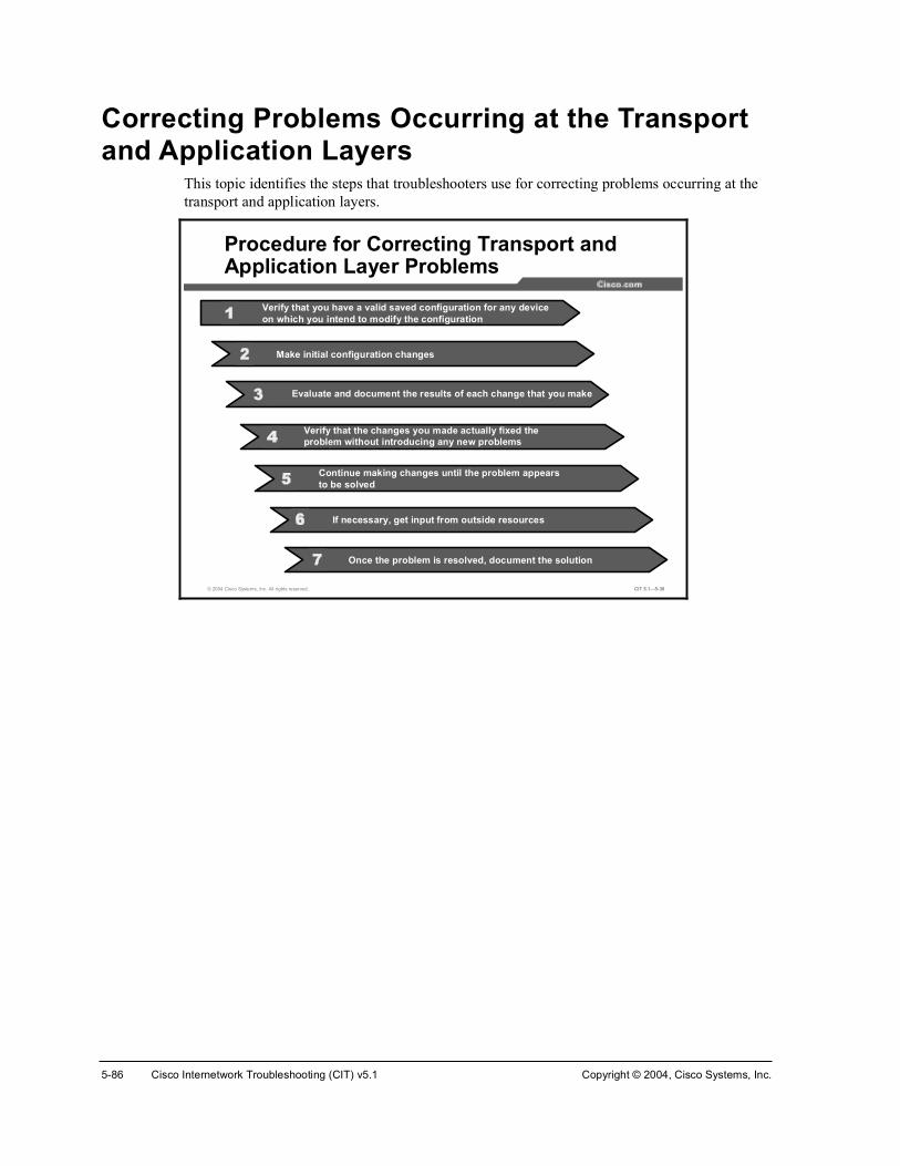
5-86 Cisco Internetwork Troubleshooting (CIT) v5.1 Copyright © 2004, Cisco Systems, Inc.
Correcting Problems Occurring at the Transport and Application Layers
This topic identifies the steps that troubleshooters use for correcting problems occurring at the transport and application layers.
© 2004 Cisco Systems, Inc. All rights reserved. CIT 5.1—5-38
Procedure for Correcting Transport and Application Layer Problems
Verify that you have a valid saved configuration for any device on which you intend to modify the configuration
Evaluate and document the results of each change that you make
Verify that the changes you made actually fixed theproblem without introducing any new problems
Continue making changes until the problem appears to be solved
If necessary, get input from outside resources
Make initial configuration changes
Once the problem is resolved, document the solution

Copyright © 2004, Cisco Systems, Inc. Resolving Problems at the Transport and Application Layers 5-87
The table lists the suggested steps that a troubleshooter uses for correcting an isolated problem at the physical and data link layers.
Table for Correcting Problems Occurring at the Transport and Application Layers
Step Description
1 Ensure that you have a valid saved configuration for any device on which you intend to modify the configuration. This provides for eventual recovery to a known initial state.
2 Make initial hardware and software configuration changes. If the correction requires more than one change, make only one change at a time.
3 Evaluate and document the changes and the results of each change that you make. If you perform your problem-solving steps and the results are unsuccessful, immediately undo the changes. If the problem is intermittent, you may need to wait to see if the problem occurs again before you can evaluate the effect of your changes.
4 Verify that the changes you made actually fixed the problem without introducing any new problems. The network should be returned to the baseline operation, and no new or old symptoms should be present. If the problem is not solved, undo all the changes that you made. If you discover new or additional problems while you are making corrections, step back and modify your correction plan.
5 Stop making changes when the original problem appears to be solved.
6 If necessary, get input from outside resources. If none of your attempts to correct the problem are successful, take the problem to another person. This may be a coworker, consultant, or Cisco TAC. On rare occasions, you may need to perform a core dump, which creates output that a specialist at Cisco Systems can analyze.
7 Once the problem is resolved, document the solution.

5-88 Cisco Internetwork Troubleshooting (CIT) v5.1 Copyright © 2004, Cisco Systems, Inc.
SummaryThis topic summarizes the key points discussed in this lesson.
© 2004 Cisco Systems, Inc. All rights reserved. CIT 5.1—5-39
Summary
• Use the appropriate commands and applications to correct an isolated transport or application layer problem.
• Proper use of online support resources saves time and money by empowering troubleshooters to find solutions to elusive problems on their own.
• Following a systematic procedure increases the chances that you will successfully and effectively correct an isolated problem at the transport or application layer.
ReferencesFor additional information, refer to these resources:
!" Cisco online documentation: http://www.cisco.com/univercd/home/home.htm
!" Cisco Technical Assistance Center (TAC): http://www.cisco.com/tac
!" Troubleshooting TCP/IP: http://www.cisco.com/univercd/cc/td/doc/cisintwk/itg_v1/tr1907.htm
!" Enabling High Performance Data Transfers: http://www.psc.edu/networking/perf_tune.html
Next Steps For the associated case study and lab exercises, refer to the following sections of the course Lab Guide:
!" Case Study (Trouble Ticket G) 5-1: Isolating Problems at the Transport and Application Layers
!" Lab Exercise (Trouble Ticket G) 5-1: Correcting Problems at the Transport and Application Layers
!" Lab Exercise (Trouble Ticket H) 5-2: Troubleshooting Problems at All Logical Layers

Copyright © 2004, Cisco Systems, Inc. Resolving Problems at the Transport and Application Layers 5-89
QuizUse the practice items here to review what you have learned in this lesson. The correct answers are found in the Quiz Answer Key.
Q1) Which command would you enter to restrict TCP traffic on a particular host?
A) outbound 3 deny tcp netmask 1
B) access-list 102 permit tcp any host 10.1.1.1 eq smtp
C) access-list 106 deny tcp any host 10.1.1.1 eq telnet
D) ip tcp window-size 2
Q2) Which Cisco configuration command does a troubleshooter enter to activate unsolicited network management alarm messages when a threshold is exceeded?
A) ip http accounting
B) snmp-server enable traps
C) ip helper-address
D) service dhcp
Q3) Which website would you most likely visit to read the latest detailed technical documentation about the SMTP protocol?
A) http://www.ietf.com
B) http://www.itu.int/home
C) http://www.cisco.com
D) http://www.sniffers.com
Q4) Your satellite link traffic is experiencing the negative effects of drastically incorrect TCP windowing. To attempt to fix the problem, you initially examine the running configuration and make a few configuration changes. Which step of the procedure for correcting problems at the transport and application layers will you perform next?
A) Make initial configuration changes.
B) Stop making changes when the original problem appears to be solved.
C) Document the solution, once the problem is solved.
D) Evaluate and document the results of each change that you make.

5-90 Cisco Internetwork Troubleshooting (CIT) v5.1 Copyright © 2004, Cisco Systems, Inc.
Quiz Answer Key Q1) C
Relates to: Identifying Commands and Applications Used to Correct Problems Occurring at the Transport Layer
Q2) B
Relates to: Identifying Commands and Applications Used to Correct Problems Occurring at the Application Layer
Q3) A
Relates to: Identifying Transport and Application Layer Support Resources
Q4) D
Relates to: Correcting Problems Occurring at the Transport and Application Layers

CIT
Course Glossary The Course Glossary for Cisco Internetwork Troubleshooting (CIT) v5.1 highlights and defines key terms and acronyms used throughout this course. Many of these terms are also described in the Cisco Internetworking Terms and Acronyms resources, available via http://www.cisco.com.

2 Cisco Internetwork Troubleshooting (CIT) v.5.1 Copyright © 2004, Cisco Systems, Inc.
Acronym or Term
Expansion of Acronym Definition of Acronym or Term
ACL access control list Access lists filter network traffic by controlling whether routed packets are forwarded or blocked at the interface of the router. Your router examines each packet to determine whether to forward or drop the packet, based on the criteria you specified within the access lists.
Access list criteria could be the source address of the traffic, the destination address of the traffic, the upper-layer protocol, or other information. Note that sophisticated users can sometimes successfully evade or fool basic access lists because no authentication is required
ANSI American National Standards Institute A voluntary organization composed of corporate, government, and other members that coordinates standards-related activities, approves U.S. national standards, and develops positions for the United States in international standards organizations. ANSI helps develop international and U.S. standards relating to, among other things, communications and networking. ANSI is a member of the IEC and the ISO.
application layer
Layer 7 of the OSI reference model. This layer provides services to application processes (such as e-mail, file transfer, and terminal emulation) that are outside the OSI model. The application layer identifies and establishes the availability of intended communication partners (and the resources required to connect with them), synchronizes cooperating applications, and establishes an agreement on the procedures for error recovery and the control of data integrity. Corresponds roughly with the transaction services layer in the SNA model.
ARP Address Resolution Protocol Internet protocol used to map an IP address to a MAC address. IETF Standard 37, it is defined in IETF RFC 826.
AS autonomous system A collection of networks under a common administration sharing a common routing strategy. Areas subdivide autonomous systems. An autonomous system must be assigned a unique 16-bit number by the IANA.
availability The amount of time that a system or device is operational—that is, how long it is performing its intended function. Availability is represented as the ratio of the total time a device is operational during a given time interval to the length of that interval.
bandwidth A term used to describe the capacity or throughput of a given network medium, interface, or protocol. In digital networks, bandwidth is usually stated in bits per second (bps). In analog media, it is the difference between the highest and lowest frequencies available for network signals. The frequency range necessary to convey a signal measured in units of hertz (Hz). For example, voice signals typically require approximately 3 kHz of bandwidth.

Copyright © 2004, Cisco Systems, Inc. Course Glossary 3
Acronym or Term
Expansion of Acronym Definition of Acronym or Term
baseline Documents network or system performance, configuration, and deployment at some defined point in time. Baselines taken at different points in time are useful in identifying changes in system load, performance degradation, and undocumented modifications to system configurations or topology.
BGP Border Gateway Protocol Interdomain exterior routing protocol that replaces EGP. BGP exchanges reachability information with other BGP systems. BGP-4 is most recently defined by RFC 1771.
CDP Cisco Discovery Protocol Media- and protocol-independent device-discovery protocol that runs on equipment manufactured by Cisco, including routers, access servers, bridges, and switches. Using CDP, a device can advertise its existence to other devices and receive information about other devices on the same LAN or on the remote side of a WAN. Runs on all media that support SNAP, including LANs, Frame Relay, and ATM media.
collision In Ethernet, the result of two nodes transmitting simultaneously. The frames from each device impact and are damaged when they meet on the physical media.
congestion A system or network condition that results when one or more network elements cannot serve the arriving traffic in a timely manner. Congestion is characterized by increased delay (latency), delay variation (jitter), and persistent queued traffic.
CRC cyclic redundancy check An error-checking technique in which the recipient calculates a value based on the frame or message content and compares the calculated value to a value stored in the frame or message of the sending node.
data flow Grouping of traffic, identified in IP by a combination of source address/mask, destination address/mask, IP protocol field, and source and destination ports, where the protocol and port fields can have any of these. In effect, all traffic matching a specific combination of these values is grouped logically into a data flow. A data flow can represent a single TCP connection between two hosts, or it can represent all of the traffic between two subnets. IPSec protection applies to data flows.
data link layer Layer 2 of the OSI reference model. Provides transit of data across a physical link. The data link layer is concerned with physical addressing and line discipline. The IEEE divided this layer into two sublayers: the MAC sublayer and the LLC sublayer. Sometimes, the data link layer is simply called the link layer. The data link layer roughly corresponds to the data link control layer of the SNA model.
DHCP Dynamic Host Configuration Protocol Provides a mechanism for allocating IP addresses dynamically so that addresses can be reused when hosts no longer need them. Defined in IETF RFC 2131 and updated by RFC 3396.

4 Cisco Internetwork Troubleshooting (CIT) v.5.1 Copyright © 2004, Cisco Systems, Inc.
Acronym or Term
Expansion of Acronym Definition of Acronym or Term
DNS Domain Name System System used on the Internet for translating names of network nodes into addresses. DNS (IETF Standard 13) is defined in IETF RFCs 1034 and 1035. The standard has been updated by a number of additional RFCs.
DTE data terminal equipment Device at the user end of a User-Network Interface that serves as a data source, destination, or both. DTE connects to a data network through a DCE device (for example, a modem) and typically uses clocking signals generated by the DCE. DTE includes devices such as computers, protocol translators, and multiplexers.
EIGRP Enhanced Interior Gateway Routing Protocol Advanced version of IGRP developed by Cisco Systems. Provides superior convergence properties and operating efficiency, and combines the advantages of link state protocols with those of distance vector protocols.
EMI electromagnetic interference Interference by electromagnetic signals that can cause reduced data integrity and increased error rates on transmission channels.
encapsulation Wrapping of data in a particular protocol header. For example, Ethernet data is wrapped in a specific Ethernet header before data link transit. In addition, when bridging dissimilar networks, the entire frame from one network is placed in the header used by the data link layer protocol of the other network.
EtherChannel Developed by Cisco Systems. Logical aggregation of multiple Ethernet interfaces used to form a single higher bandwidth routing or bridging endpoint.
FCS frame check sequence The standard 16-bit cyclic redundancy check used for HDLC and Frame Relay frames. The FCS detects bit errors occurring in the bits of the frame between the opening flag and the FCS and is only effective in detecting errors in frames no larger than 4096 octets. See also Cyclic Redundancy Check (CRC) above.
FTP File Transfer Protocol Application protocol, part of the TCP/IP protocol stack, used for transferring files between network nodes. FTP (IETF Standard 9) is defined in RFC 959.
flapping A system condition characterized by oscillation between two or more states.
HTTP Hypertext Transfer Protocol The protocol used by web browsers and web servers to transfer files, such as text and graphic files.
IANA Internet Assigned Numbers Authority Organization responsible for assigning the parameter and protocol values necessary for operation and future development of the Internet.
ICMP Internet Control Message Protocol Network layer Internet protocol that reports errors and provides other information relevant to IP packet processing. Defined in IETF RFC 2131 and updated by RFC 3396.

Copyright © 2004, Cisco Systems, Inc. Course Glossary 5
Acronym or Term
Expansion of Acronym Definition of Acronym or Term
IETF Internet Engineering Task Force Task force consisting of over 80 working groups responsible for developing Internet standards. The IETF operates under the auspices of ISOC.
IGP Interior Gateway Protocol Routing protocol used within an autonomous system in IP networks. Examples include RIP, EIGRP, OSPF, and IS-IS.
IP/TV Internet Protocol TV Protocol for viewing live streaming video over an IP network.
IS-IS Protocol Intermediate System-to-Intermediate System Protocol
OSI link-state hierarchical routing protocol based on DECnet Phase V routing, whereby ISs (routers) exchange routing information based on a single metric to determine network topology.
ISOC Internet Society The main umbrella organization for Internet governance. It is an international membership organization.
ITU-T International Telecommunication Union Telecommunication Standardization Sector
International body that develops worldwide standards for telecommunications technologies. The ITU-T carries out the functions of the former CCITT and is an organization within the United Nations System.
jabber Error condition in which a network device continually transmits random, meaningless data onto the network.
jitter The interpacket delay variance; that is, the difference between interpacket arrival and departure. Jitter is an important QoS metric for voice and video applications.
keepalive interval
Period between each keepalive message sent by a network device.
keepalive message
Message sent by a protocol instance on a network device to inform another protocol instance in the network that the virtual circuit between the two is still active.
latency Delay. Common uses of the term include the time between when a device requests access to a network and the time permission is granted to transmit, and the time from transmission at the source to reception at the destination.
LMI Local Management Interface Set of enhancements to the basic Frame Relay and ATM specifications. In Frame Relay, LMI includes support for a keepalive mechanism, which verifies that data is flowing; a multicast mechanism, which provides the network server with its local DLCI and the multicast DLCI; global addressing, which gives DLCIs global rather than local significance in Frame Relay networks; and a status mechanism, which provides an ongoing status report on the DLCIs known to the switch. Known as LMT in ANSI terminology.
multiplexing Scheme that allows multiple logical signals to transmit simultaneously across a single physical channel.

6 Cisco Internetwork Troubleshooting (CIT) v.5.1 Copyright © 2004, Cisco Systems, Inc.
Acronym or Term
Expansion of Acronym Definition of Acronym or Term
network layer Layer 3 of the OSI reference model. This layer provides connectivity and path selection between two end systems. The network layer is the layer at which routing occurs. Corresponds roughly with the path control layer of the SNA model.
NMS network management system System responsible for managing at least part of a network. A NMS host system is generally a reasonably powerful and well-equipped computer, such as an engineering workstation. NMSs communicate with agents to help keep track of network statistics and resources.
noise Undesirable communications channel signals.
OSI reference model
Open System Interconnection reference model Network architectural model developed by ISO and ITU-T. The model consists of seven layers, each of which specifies particular network functions, such as addressing, flow control, error control, encapsulation, and reliable message transfer. The lowest layer (the physical layer) is closest to the media technology. The lower two layers are usually implemented in hardware and firmware, whereas the upper three layers are implemented only in software. The highest layer (the application layer) is closest to the user. The OSI reference model is used universally as a method for teaching and understanding network functionality.
OSPF Open Shortest Path First Link-state, hierarchical IGP routing algorithm proposed as a successor to RIP in the Internet community. OSPF features include least-cost routing, multipath routing, and load balancing. OSPF was derived from an early version of the IS-IS protocol.
peak rate Maximum rate, in kilobits per second, at which a virtual circuit will transmit. Specified in a Service Level Specification, it is enforced at transport network ingress.
physical layer Layer 1 of the OSI reference model. The physical layer defines the electrical, mechanical, procedural, and functional specifications for activating, maintaining, and deactivating the physical link between end systems. Corresponds with the physical control layer in the SNA model.
POP Post Office Protocol orPoint of Presence
Protocol that client e-mail applications use to retrieve mail from a mail server. The access point to a service providers transport network.
PVC permanent virtual circuit (or connection) Virtual circuit that is permanently established. PVCs save bandwidth and CPU usage associated with circuit establishment and tear down in situations where certain virtual circuits must exist all the time. In ATM terminology, called a permanent virtual connection.
redundancy In internetworking, the duplication of devices, services, or connections so that, in the event of a failure, the redundant devices, services, or connections can perform the work of those that failed.

Copyright © 2004, Cisco Systems, Inc. Course Glossary 7
Acronym or Term
Expansion of Acronym Definition of Acronym or Term
reliability Performance within a design specification over time. Reliability is often measured by availability, mean time between failure (MTBF), and mean time to repair (MTTR).
RID Router ID Parameter used by routing protocol to identify a router. May be such things as an IP address, priority number, and so on. Varies per protocol.
RMON Remote Monitoring MIB agent specification, originally described in RFC 1271, that defines functions for the remote monitoring of networked devices. The RMON specification (IETF Standard 59) provides numerous monitoring, problem detection, and reporting capabilities. The RMON specification is defined in RFC 2819.
RTT round-trip time Time required for a network packet to travel from the source to the destination and back. RTT includes the time required for the destination to process the message from the source and generate a reply. The latency measurements taken by IPM and SAA are round-trip time latency measurements.
SMTP Simple Mail Transfer Protocol Internet protocol providing e-mail services. SMTP (IETF Standard 10) is defined in RFC 821.
SNMP Simple Network Management Protocol Network management protocol used almost exclusively in TCP/IP networks. SNMP provides a means to monitor and control network devices, and to manage configurations, statistics collection, performance, and security. SNMP (IETF Standard 62) is defined in RFC 3418.
spanning tree Loop-free subset of a network topology that provides a path to every node.
STP Spanning Tree Protocol Bridge protocol that uses a spanning-tree algorithm, enabling a learning bridge to dynamically remove loops in a network topology by creating a spanning tree. Bridges exchange BPDU messages with other bridges to detect loops, and then remove the loops by shutting down selected bridge interfaces. Refers to both the IEEE 802.1 Spanning Tree Protocol standard and the earlier Digital Equipment Corporation Spanning Tree Protocol upon which it is based. The IEEE version supports bridge domains and allows the bridge to construct a loop-free topology across an extended LAN. The IEEE version generally is preferred over the Digital Equipment version.
TCP Transmission Control Protocol Connection-oriented transport layer protocol that provides reliable full-duplex data transmission. TCP (IETF Standard 7) is part of the TCP/IP protocol stack and is defined in RFC 793 and extended by other RFCs.
TDM time-division multiplexing Technique in which information from multiple channels allocates bandwidth on a single wire based on preassigned time slots. Bandwidth is allocated to each channel regardless of whether the station has data to transmit.

8 Cisco Internetwork Troubleshooting (CIT) v.5.1 Copyright © 2004, Cisco Systems, Inc.
Acronym or Term
Expansion of Acronym Definition of Acronym or Term
TFTP Trivial File Transfer Protocol Simplified version of FTP that allows files to be transferred from one computer to another over a network, usually without the use of client authentication (for example, username and password). TFTP (IETF Standard 33) is defined in RFC 1350 and has been updated by other RFCs.
throughput Rate of information arriving at, and possibly passing through, a particular point in a network system.
topology Physical or logical arrangement of network nodes and media within an enterprise networking structure.
transport layer Layer 4 of the OSI reference model. This layer is responsible for reliable network communication between end nodes. The transport layer provides mechanisms for the establishment, maintenance, and termination of virtual circuits, transport fault detection and recovery, and information flow control. Corresponds to the transmission control layer of the SNA model.
UDP User Datagram Protocol Connectionless transport layer protocol in the TCP/IP protocol stack. UDP is a simple protocol that exchanges datagrams without acknowledgments or guaranteed delivery, requiring that error processing and retransmission be handled by other protocols. UDP (IETF Standard 6) is defined in RFC 768.

CIT
Troubleshooting Logs Use this guide to complete the lab exercises for this course. The solutions information is found in the Lab Exercise Answer Key.
Troubleshooting Log—Trouble Ticket B
Problem Solution
Core Router/Switch a) Users cannot get to server or Internet.
·²¬»®º¿½» б®¬ó½¸¿²²»´ïï
²± ¸«¬
·²¬»®º¿½» б®¬ó½¸¿²²»´ïî
²± ¸«¬
ÿ
Distribution Router No issues.
Ò±¬¸·²¹ ²»»¼»¼
Access Router Serial interfaces 0/0:1 and 0/0:0 are down.
½±²¬®±´´»® Ìï ðñð
´·²»½±¼» ¾è¦
ÿ
Access Switch Some PCs cannot connect to anything.
·²¬»®º¿½» Ú¿¬Û¬¸»®²»¬ðñî
©·¬½¸°±®¬ ¿½½» ª´¿² î
ÿ
·²¬»®º¿½» Ú¿¬Û¬¸»®²»¬ðñì
©·¬½¸°±®¬ ¿½½» ª´¿² ì
ÿ

2 Cisco Internetwork Troubleshooting (CIT) v5.1 Copyright © 2004, Cisco Systems, Inc.
Troubleshooting Log—Trouble Ticket C
Problem Solution
Core Router/Switch a) Users cannot get to server or Internet.b) No connectivity to dstr rtr
ª´¿² îé
²¿³» ݱ®»Áîé
ÿ
ª´¿² îè
²¿³» ݱ®»Áîè
ÿ
·²¬ º¿ ðñë
¼«°´»¨ º«´´
°»»¼ ïðð
ÿ
ÿ
Distribution Router Serial interfaces 0/0:0 and 0/0:1 are down (wrong channel group configured on ser 0/0:0); fixing channel group deletes “no passive interface” in EIGRP.
ÿ
½±²¬®±´´»® Ìï ðñð
²± ½¸¿²²»´ó¹®±«° ð ¬·³»´±¬ ïóî
½¸¿²²»´ó¹®±«° ð ¬·³»´±¬ ïóïî
ÿ
·²¬»®º¿½» Í»®·¿´ðñðæð
¼»½®·°¬·±² Ú¿¬ Ô·²µ ¬± Ü¿§¬±²¿
·° ¿¼¼®» ïéîòîïòïéêòî îëëòîëëòîëëòïîè
²± ¸«¬
ÿ
®±«¬»® »·¹®° ïðï
²± °¿·ª»ó·²¬»®º¿½» Í»®·¿´ðñðæð
ÿ
Access Router a) Fa 0/0 is down because of speed mismatch; users cannot get to anywhere.
b) Serial interfaces 0/0:1 and 0/0:0 are down.
ÿ
¿÷
·²¬»®º¿½» Ú¿¬Û¬¸»®²»¬ðñð
°»»¼ ïðð
¾÷
½±²¬®±´´»® Ìï ðñð
º®¿³·²¹ »º
ÿ
Access Switch No issues.
ó ó

Copyright © 2004, Cisco Systems, Inc. Troubleshooting Logs 3
Troubleshooting Log—Trouble Ticket D
Problem Solution
Core Router/Switch a) Users cannot get to server (work group network not defined in RIP). b) Users cannot get to the Internet (EIGRP not redistributing static route).
¿÷ ®±«¬»® ®·°
²»¬©±®µ ïéîòîïòðòð
¾÷ ®±«¬»® »·¹®° ïðï
®»¼·¬®·¾«¬» ¬¿¬·½
Distribution Router a) Does not form EIGRP adjacencies because of wrong AS number. b) No neighbor with Access rtr on Serial interface 0/0:0 (has IP address of ser 0/0:1 ).
¿÷
²± ®±«¬»® »·¹®° ïï
®±«¬»® »·¹®° ïðï
ÿ ¸¿¼ ©®±²¹ ßÍ ²«³¾»®
°¿·ª»ó·²¬»®º¿½» ¼»º¿«´¬
²± °¿·ª»ó·²¬»®º¿½» Í»®·¿´ðñðæð
²± °¿·ª»ó·²¬»®º¿½» Í»®·¿´ðñðæï
²± °¿·ª»ó·²¬»®º¿½» Í»®·¿´ïñðòï
²± °¿·ª»ó·²¬»®º¿½» Í»®·¿´ïñïòï
²± °¿·ª»ó·²¬»®º¿½» Ú¿¬Û¬¸»®²»¬ðñð
²»¬©±®µ ïéîòîïòïéêòð ðòðòðòïîé
²»¬©±®µ ïéîòîïòïéêòïîè ðòðòðòïîé
²»¬©±®µ ïéîòîïòïééòð ðòðòðòïîé
²»¬©±®µ ïéîòîïòïééòïîè ðòðòðòïîé
²»¬©±®µ ïéîòîïòïéèòð ðòðòðòïîé
²»¬©±®µ ïéîòîïòïéèòïîè ðòðòðòïîé
¿«¬±ó«³³¿®§
»·¹®° ´±¹ó²»·¹¸¾±®ó½¸¿²¹»
ÿ
¾÷ ·²¬»®º¿½» Í»®·¿´ðñðæð
·° ¿¼¼®» ïéîòî¨òï¨êòî îëëòîëëòîëëòïîè

4 Cisco Internetwork Troubleshooting (CIT) v5.1 Copyright © 2004, Cisco Systems, Inc.
Problem Solution
Access Router a) doesn’t form EIGRP adjacencies (passive interfaces, wrong prefixes—even pods are /36, odd pods are /25).
®±«¬»® »·¹®° ¨ð¨
²± °¿·ª»ó·²¬»®º¿½» Í»®·¿´ïñðòï
²± °¿·ª»ó·²¬»®º¿½» Í»®·¿´ïñïòï
°¿·ª»ó·²¬»®º¿½» Í»®·¿´ïñð
°¿·ª»ó·²¬»®º¿½» Í»®·¿´ïñï
ÿ
·²¬»®º¿½» Í»®·¿´ïñðòï °±·²¬ó¬±ó°±·²¬
·° ¿¼¼®» ïéîòî¨òï¨éòï îëëòîëëòîëëòÅïîè¤ïçîÃ
ÿ
·²¬»®º¿½» Í»®·¿´ïñïòï °±·²¬ó¬±ó°±·²¬
·° ¿¼¼®» ïéîòî¨òï¨éòïîç îëëòîëëòîëëò Åïîè¤ïçîÃ
ÿ
Access Switch a) PCs cannot connect to anywhere. b) PCs are getting network error messages when trying to ping.
¿÷ ·²¬»®º¿½» Ú¿¬Û¬¸»®²»¬ðñï
²± ¸«¬¼±©²
¾÷ °½ù ¸¿ª» ¬¿¬·½ ×Ð ±ª»®´¿°°·²¹ ©ñ ÜØÝÐ »®ª»® � »²¿¾´» ÜØÝÐ ±² ÐÝ

Copyright © 2004, Cisco Systems, Inc. Troubleshooting Logs 5
Troubleshooting Log—Trouble Ticket E
Problem Solution
Core Router/Switch a) No one can connect to the Internet or CIT core (or Elmhurst or Lenexa—VLANs have swapped IP addresses). b) Trunk is on wrong interface. c) No BGP neighbors (wrong AS for core).
ÿ ¿÷
·²¬»®º¿½» Ê´¿²îé
²± ·° ¿¼¼®»
ÿ
·²¬»®º¿½» Ê´¿²îè
·° ¿¼¼®» ïéîòîèòïîèòï îëëòîëëòîëëòîìð
·²¬»®º¿½» Ê´¿²îé
·° ¿¼¼®» ïéîòîéòîîéòï îëëòîëëòîëëòîîì
ÿ
ÿ ¾÷
·²¬»®º¿½» Ú¿¬Û¬¸»®²»¬ðñïë
²± ¼»½®·°¬·±² Ô·²µ ¬± Ñ®´¿²¼±
²± ·° ¿¼¼®» ïéîòîïòïéèòïíð îëëòîëëòîëëòïîè
²± °»»¼ ïðð
²± ¼«°´»¨ º«´´
©·¬½¸
¸«¬
ÿ
·²¬»®º¿½» Ú¿¬Û¬¸»®²»¬ðñë
¼»½®·°¬·±² Ô·²µ ¬± Ñ®´¿²¼±
²± ©·¬½¸°±®¬
·° ¿¼¼®» ïéîòîïòïéèòïíð îëëòîëëòîëëòïîè
°»»¼ ïðð
¼«°´»¨ º«´´
²± ¸«¬
ÿ
ÿ ½÷
®±«¬»® ¾¹° ïï
²»·¹¸¾±® ïéîòîéòîîéòé ®»³±¬»ó¿ éé
²»·¹¸¾±® ïéîòîèòïîèòè ®»³±¬»ó¿ éé
²»·¹¸¾±® ïéîòîéòîîéòé ¼·¬®·¾«¬»ó´·¬ Ý×Ì ·²
²»·¹¸¾±® ïéîòîèòïîèòè ¼·¬®·¾«¬»ó´·¬ Ý×Ì ·²
ÿ
´±¹¹·²¹ ½±²±´»
ÿ
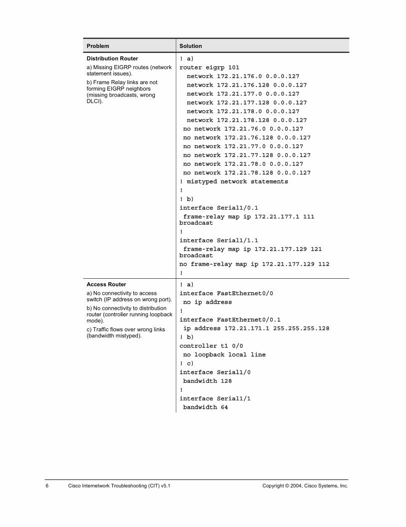
6 Cisco Internetwork Troubleshooting (CIT) v5.1 Copyright © 2004, Cisco Systems, Inc.
Problem Solution
Distribution Router a) Missing EIGRP routes (network statement issues). b) Frame Relay links are not forming EIGRP neighbors (missing broadcasts, wrong DLCI).
ÿ ¿÷
®±«¬»® »·¹®° ïðï
²»¬©±®µ ïéîòîïòïéêòð ðòðòðòïîé
²»¬©±®µ ïéîòîïòïéêòïîè ðòðòðòïîé
²»¬©±®µ ïéîòîïòïééòð ðòðòðòïîé
²»¬©±®µ ïéîòîïòïééòïîè ðòðòðòïîé
²»¬©±®µ ïéîòîïòïéèòð ðòðòðòïîé
²»¬©±®µ ïéîòîïòïéèòïîè ðòðòðòïîé
²± ²»¬©±®µ ïéîòîïòéêòð ðòðòðòïîé
²± ²»¬©±®µ ïéîòîïòéêòïîè ðòðòðòïîé
²± ²»¬©±®µ ïéîòîïòééòð ðòðòðòïîé
²± ²»¬©±®µ ïéîòîïòééòïîè ðòðòðòïîé
²± ²»¬©±®µ ïéîòîïòéèòð ðòðòðòïîé
²± ²»¬©±®µ ïéîòîïòéèòïîè ðòðòðòïîé
ÿ ³·¬§°»¼ ²»¬©±®µ ¬¿¬»³»²¬
ÿ
ÿ ¾÷
·²¬»®º¿½» Í»®·¿´ïñðòï
º®¿³»ó®»´¿§ ³¿° ·° ïéîòîïòïééòï ïïï ¾®±¿¼½¿¬
ÿ
·²¬»®º¿½» Í»®·¿´ïñïòï
º®¿³»ó®»´¿§ ³¿° ·° ïéîòîïòïééòïîç ïîï ¾®±¿¼½¿¬
²± º®¿³»ó®»´¿§ ³¿° ·° ïéîòîïòïééòïîç ïïî
ÿ
Access Router a) No connectivity to access switch (IP address on wrong port). b) No connectivity to distribution router (controller running loopback mode).c) Traffic flows over wrong links (bandwidth mistyped).
ÿ ¿÷
·²¬»®º¿½» Ú¿¬Û¬¸»®²»¬ðñð
²± ·° ¿¼¼®»
ÿ
·²¬»®º¿½» Ú¿¬Û¬¸»®²»¬ðñðòï
·° ¿¼¼®» ïéîòîïòïéïòï îëëòîëëòîëëòïîè
ÿ ¾÷
½±²¬®±´´»® ¬ï ðñð
²± ´±±°¾¿½µ ´±½¿´ ´·²»
ÿ ½÷
·²¬»®º¿½» Í»®·¿´ïñð
¾¿²¼©·¼¬¸ ïîè
ÿ
·²¬»®º¿½» Í»®·¿´ïñï
¾¿²¼©·¼¬¸ êì

Copyright © 2004, Cisco Systems, Inc. Troubleshooting Logs 7
Problem Solution
Access Switch Users cannot connect to anything (trunk on wrong port).
ÿ
·²¬»®º¿½» Ú¿¬Û¬¸»®²»¬ðñï
©·¬½¸°±®¬ ¬®«²µ ²¿¬·ª» ª´¿² çðï
©·¬½¸°±®¬ ³±¼» ¬®«²µ
¼«°´»¨ º«´´
°»»¼ ïðð
²± ¸«¬¼±©²
ÿ
·²¬»®º¿½» Ú¿¬Û¬¸»®²»¬ðñïð
²± ©·¬½¸°±®¬ ³±¼» ¬®«²µ
©·¬½¸°±®¬ ¬®«²µ ²¿¬·ª» ª´¿² çðï
²± ·° ¿¼¼®»
¸«¬
ÿ

8 Cisco Internetwork Troubleshooting (CIT) v5.1 Copyright © 2004, Cisco Systems, Inc.
Troubleshooting Log—Trouble Ticket F
Problem Solution
Core Router/Switch a) EtherChannels are down because of trunk encapsulation mismatch.b) VTP mode is server; VLANs are getting overwritten. (Instructor can do this a few times so that all pods have the issue at least once.)c) Duplicate OSPF RID with core (even pods with Elmhurst, odd pods with Lenexa).
ÿ ¿÷ »¨¿³°´» ¸±©² º±® °±¼ ì
ÿ
·²¬»®º¿½» ®¿²¹» Ú¿¬Û¬¸»®²»¬ðñï ó î
©·¬½¸°±®¬ ¬®«²µ »²½¿°«´¿¬·±² ·´
ÿ
·²¬»®º¿½» ®¿²¹» Ú¿¬Û¬¸»®²»¬ðñí ó ì
©·¬½¸°±®¬ ¬®«²µ »²½¿°«´¿¬·±² ¼±¬
¸«¬¼±©²
²± ¸«¬¼±©²
ÿ
ÿ ¾÷
ª¬° ³±¼» ¬®¿²°¿®»²¬
²± ª´¿² ïðóïè
ª´¿² îé
ª´¿² îè
ÿ
ÿ ½÷
®±«¬»® ±°º ìðì
®±«¬»®ó·¼ ïéîòîéòîîéòì
ÿ
¼± ½´»¿® ·° ±°º °®±½»
§
Distribution Router a) Area 4 is missing NSSA statement.b) OSPF routes are not redistributed because of wrong AS number. c) No EIGRP neighbors because frame subinterfaces are passive for EIGRP.
ÿ ¿÷ »¨¿³°´» ¸±©² º±® °±¼ ì
®±«¬»® ±°º ìðì
¿®»¿ ì ²¿
ÿ
ÿ ¾÷
®±«¬»® »·¹®° ìðì
®»¼·¬®·¾«¬» ±°º ìðì ³»¬®·½ ïðððð ïðð îëë ï ïëðð
²± ®»¼·¬®·¾«¬» ±°º ìì ³»¬®·½ ïðððð ïðð îëë ï ïëðð
ÿ
ÿ ½÷
®±«¬»® »·¹®° ìðì
²± °¿·ª»ó·²¬»®º¿½» Í»®·¿´ïñðòï
²± °¿·ª»ó·²¬»®º¿½» Í»®·¿´ïñïòï
°¿·ª»ó·²¬»®º¿½» Í»®·¿´ïñð
°¿·ª»ó·²¬»®º¿½» Í»®·¿´ïñï
ÿ

Copyright © 2004, Cisco Systems, Inc. Troubleshooting Logs 9
Problem Solution
Access Router a) Missing routes for two end user VLANs.b) Frame links are down; no keepalives. c) IP addresses on frame links are swapped.
ÿ ¿÷
®±«¬»® »·¹®° ìðì
²»¬©±®µ ïéîòîìòïìïòð ðòðòðòêí
²»¬©±®µ ïéîòîìòïììòð ðòðòðòêí
ÿ ¾÷
·²¬»®º¿½» Í»®·¿´ïñð
µ»»°¿´·ª»
ÿ
·²¬»®º¿½» Í»®·¿´ïñï
µ»»°¿´·ª»
ÿ
ÿ ½÷
·²¬»®º¿½» Í»®·¿´ïñðòï
²± ·° ¿¼¼
·²¬»®º¿½» Í»®·¿´ïñïòï
·° ¿¼¼®» ïéîòîìòïìéòïîç îëëòîëëòîëëòïçî
·²¬»®º¿½» Í»®·¿´ïñðòï
·° ¿¼¼®» ïéîòîìòïìéòï îëëòîëëòîëëòïçî
ÿ
Access Switch No issues here.
ÿ ²± ·«»
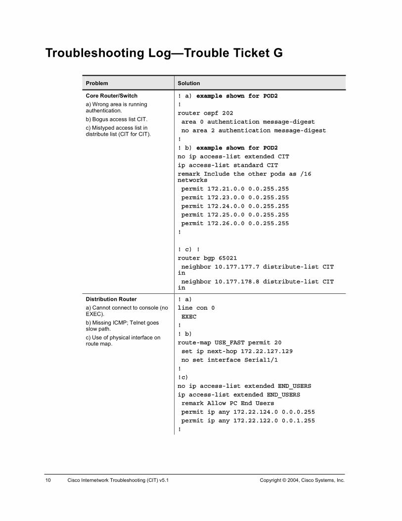
10 Cisco Internetwork Troubleshooting (CIT) v5.1 Copyright © 2004, Cisco Systems, Inc.
Troubleshooting Log—Trouble Ticket G
Problem Solution
Core Router/Switch a) Wrong area is running authentication. b) Bogus access list CIT. c) Mistyped access list in distribute list (ClT for CIT).
ÿ ¿÷ »¨¿³°´» ¸±©² º±® ÐÑÜî
ÿ
®±«¬»® ±°º îðî
¿®»¿ ð ¿«¬¸»²¬·½¿¬·±² ³»¿¹»ó¼·¹»¬
²± ¿®»¿ î ¿«¬¸»²¬·½¿¬·±² ³»¿¹»ó¼·¹»¬
ÿ
ÿ ¾÷ »¨¿³°´» ¸±©² º±® ÐÑÜî
²± ·° ¿½½»ó´·¬ »¨¬»²¼»¼ Ý×Ì
·° ¿½½»ó´·¬ ¬¿²¼¿®¼ Ý×Ì
®»³¿®µ ײ½´«¼» ¬¸» ±¬¸»® °±¼ ¿ ñïê ²»¬©±®µ
°»®³·¬ ïéîòîïòðòð ðòðòîëëòîëë
°»®³·¬ ïéîòîíòðòð ðòðòîëëòîëë
°»®³·¬ ïéîòîìòðòð ðòðòîëëòîëë
°»®³·¬ ïéîòîëòðòð ðòðòîëëòîëë
°»®³·¬ ïéîòîêòðòð ðòðòîëëòîëë
ÿ
ÿ ½÷ ÿ
®±«¬»® ¾¹° êëðîï
²»·¹¸¾±® ïðòïééòïééòé ¼·¬®·¾«¬»ó´·¬ Ý×Ì ·²
²»·¹¸¾±® ïðòïééòïéèòè ¼·¬®·¾«¬»ó´·¬ Ý×Ì ·²
Distribution Router a) Cannot connect to console (no EXEC). b) Missing ICMP; Telnet goes slow path. c) Use of physical interface on route map.
ÿ ¿÷
´·²» ½±² ð
ÛÈÛÝ
ÿ
ÿ ¾÷
®±«¬»ó³¿° ËÍÛÁÚßÍÌ °»®³·¬ îð
»¬ ·° ²»¨¬ó¸±° ïéîòîîòïîéòïîç
²± »¬ ·²¬»®º¿½» Í»®·¿´ïñï
ÿ
ÿ½÷
²± ·° ¿½½»ó´·¬ »¨¬»²¼»¼ ÛÒÜÁËÍÛÎÍ
·° ¿½½»ó´·¬ »¨¬»²¼»¼ ÛÒÜÁËÍÛÎÍ
®»³¿®µ ß´´±© ÐÝ Û²¼ Ë»®
°»®³·¬ ·° ¿²§ ïéîòîîòïîìòð ðòðòðòîëë
°»®³·¬ ·° ¿²§ ïéîòîîòïîîòð ðòðòïòîëë
ÿ

Copyright © 2004, Cisco Systems, Inc. Troubleshooting Logs 11
Problem Solution
Access Router a) Cannot connect to console (line speed).
b) Missing www statement; ICMP denies end users. c) DHCP does not provide addresses.
ÿ ¿÷
´·²» ½±² ð
°»»¼ çêðð
ÿ ²»»¼ ¬± ½±²²»½¬ ª·¿ Ì»´²»¬ ¬± º·¨
ÿ ¾÷
²± ·° ¿½½»ó´·¬ »¨¬»²¼»¼ Ì®¿ºº·½
·° ¿½½»ó´·¬ »¨¬»²¼»¼ Ì®¿ºº·½
®»³¿®µ ß´´±© ×ÝÓÐô ÌÝÐ ±«¬¾±«²¼ô ÚÌÐ ú ÉÉÉ
°»®³·¬ ·½³° ïéîòîîòðòð ðòðòîëëòîëë ¿²§
°»®³·¬ ¬½° ïéîòîîòðòð ðòðòîëëòîëë ¿²§ »¯ ¬»´²»¬
°»®³·¬ ¬½° ïéîòîîòðòð ðòðòîëëòîëë ¿²§ »¯ º¬°ó¼¿¬¿
°»®³·¬ ¬½° ïéîòîîòðòð ðòðòîëëòîëë ¿²§ »¯ º¬°
°»®³·¬ ¬½° ïéîòîîòðòð ðòðòîëëòîëë ¿²§ »¯ ©©©
°»®³·¬ «¼° ïéîòîîòðòð ðòðòîëëòîëë ¿²§ »¯ ¬º¬°
ÿ ½÷
·° ¼¸½° »¨½´«¼»¼ó¿¼¼®» ïéîòîîòïîîòï
·° ¼¸½° »¨½´«¼»¼ó¿¼¼®» ïéîòîîòïîíòï
·° ¼¸½° »¨½´«¼»¼ó¿¼¼®» ïéîòîîòïîìòï
²± ·° ¼¸½° »¨½´«¼»¼ó¿¼¼®» ïéîòîîòïîîòî
²± ·° ¼¸½° »¨½´«¼»¼ó¿¼¼®» ïéîòîîòïîíòî
²± ·° ¼¸½° »¨½´«¼»¼ó¿¼¼®» ïéîòîîòïîìòî
ÿ
Access Switch No issues.
ÿ ²± ·«»

12 Cisco Internetwork Troubleshooting (CIT) v5.1 Copyright © 2004, Cisco Systems, Inc.
Troubleshooting Log—Ticket H
Problem Solution
Core Router/Switch a) Wrong banner/host name; missing service prompt. b) No console messages. c) Reload in xxx. d) Cannot reach BGP neighbors. e) MD5 keys are messed up (extra space, wrong places).
ÿ ¿÷
²± ¾¿²²»® ³±¬¼
¸±¬²¿³» Ì¿³°¿
»®ª·½» °®±³°¬ ½±²º·¹
ÿ ¾÷
´±¹¹·²¹ ½±²±´»
ÿ ½÷
®»´±¿¼ ½¿²½»´
ÿ ¼÷
®±«¬»® ¾¹° êëðïï
²»·¹¸¾±® ïðòïééòïééòé «°¼¿¬»ó±«®½» Ô±±°¾¿½µð
²»·¹¸¾±® ïðòïééòïéèòè «°¼¿¬»ó±«®½» Ô±±°¾¿½µð
ª´¿² îé
²± ¸«¬
ª´¿² îè
²± ¸«¬
ÿ
ÿ »÷
·²¬»®º¿½» Ê´¿²îé
²± ·° ±°º ³»¿¹»ó¼·¹»¬óµ»§ îé ³¼ë ¿½³»
·° ±°º ³»¿¹»ó¼·¹»¬óµ»§ îé ³¼ë ¿½³»
ÿ
·²¬»®º¿½» Ê´¿²îè
²± ·° ±°º ³»¿¹»ó¼·¹»¬óµ»§ îé ³¼ë ¿½³»
·° ±°º ³»¿¹»ó¼·¹»¬óµ»§ îè ³¼ë ßÝÓÛ
ÿ

Copyright © 2004, Cisco Systems, Inc. Troubleshooting Logs 13
Problem Solution
Distribution Router a) Wrong banner and host name. b) Wrong prompt. c) No need for EIGRP stub. d) distribute list in OSPF is going wrong way. e) Small MTU breaks serial links for EIGRP.
ÿ ¿÷
²± ¾¿²²»® ³±¬¼
¸±¬²¿³» Ñ®´¿²¼±
ÿ
ÿ ¾÷
²± °®±³°¬ ûûûײª¿´·¼û·²°«¬û¼»¬»½¬»¼û
ÿ
ÿ ½÷
®±«¬»® »·¹®° ïðï
²± »·¹®° ¬«¾
ÿ
ÿ ¼÷
®±«¬»® ±°º ïðï
²± ¼·¬®·¾«¬»ó´·¬ ß½½»Á᫬» ·²
¼·¬®·¾«¬»ó´·¬ ß½½»Á᫬» ±«¬
ÿ
ÿ »÷
·²¬»®º¿½» »®·¿´ ïñð
²± ³¬« êì
ÿ
·²¬»®º¿½» »®·¿´ ïñï
²± ³¬« êì
ÿ

14 Cisco Internetwork Troubleshooting (CIT) v5.1 Copyright © 2004, Cisco Systems, Inc.
Problem Solution
Access Router a) Wrong banner and host name. b) route map permit / deny swapped, sends ARP from 0.0.0.0 out ser 1/1.1 c) Wrong ANSI type on Frame Relay. d) Access group applied wrong way on serial links.
ÿ ¿÷
¸±¬²¿³» Ü¿§¬±²¿
ÿ ¾÷
²± ®±«¬»ó³¿° ËÍÛÁÚßÍÌ
ÿ
®±«¬»ó³¿° ËÍÛÁÚßÍÌ °»®³·¬ ïð
³¿¬½¸ ·° ¿¼¼®» ß¼³·²
»¬ ·²¬»®º¿½» Í»®·¿´ïñïòï
ÿ
®±«¬»ó³¿° ËÍÛÁÚßÍÌ ¼»²§ îð
³¿¬½¸ ·° ¿¼¼®» Û²¼ÁË»®
ÿ
ÿ ½÷
·²¬»®º¿½» »®·¿´ ïñð
²± º®¿³»ó®»´¿§ ´³·ó¬§°» ¿²·
ÿ
·²¬»®º¿½» »®·¿´ ïñï
²± º®¿³»ó®»´¿§ ´³·ó¬§°» ¿²·
ÿ
ÿ ¼÷
·²¬»®º¿½» »®·¿´ ïñïòï
·° ¿½½»ó¹®±«° Ì®¿ºº·½ ±«¬
²± ·° ¿½½»ó¹®±«° Ì®¿ºº·½ ·²
ÿ
·²¬»®º¿½» »®·¿´ ïñðòï
·° ¿½½»ó¹®±«° Ì®¿ºº·½ ±«¬
²± ·° ¿½½»ó¹®±«° Ì®¿ºº·½ ·²
ÿ
Access Switch a) SVI shutdown. b) No trunk on VLAN1.
ÿ ¿÷
·²¬»®º¿½» Ê´¿²çðï
²± ¸«¬
ÿ
ÿ ¾÷
·²¬»®º¿½» Ú¿¬Û¬¸»®²»¬ðñï
²± ©·¬½¸°±®¬ ¿½½» ª´¿² î
©·¬½¸°±®¬ ¬®«²µ ²¿¬·ª» ª´¿² çðï
©·¬½¸°±®¬ ³±¼» ¬®«²µ
ÿ

CIT
Lab Guide
OverviewUse this guide to complete the lab exercises for this course. The solutions information is found in the Lab Exercise Answer Key.
OutlineThis Lab Guide includes these exercises:
!" Lab Exercise 1-1: Network Baseline Discovery
!" Lab Exercise 1-2: Creating End-System Baseline Discovery
!" Lab Exercise 2-1: Applying a Layered Model to a Network
!" Case Study (Trouble Ticket A) 2-1: Gathering Symptoms
!" Case Study (Trouble Ticket B) 3-1: Isolating Physical and Data Link Layer Problems
!" Lab Exercise (Trouble Ticket B) 3-1: Correcting Problems at the Physical and Data Link Layers
!" Lab Exercise (Trouble Ticket C) 3-2: Troubleshooting Problems at the Physical and Data Link Layers
!" Case Study (Trouble Ticket D) 4-1: Isolating Network Layer Problems
!" Lab Exercise (Trouble Ticket D) 4-1: Correcting Problems at the Network Layer
!" Lab Exercise (Trouble Ticket E) 4-2: Troubleshooting Problems at the Physical, Data Link, and Network Layers
!" Lab Exercise (Trouble Ticket F) 4-3: Troubleshooting Problems at the Physical, Data Link, and Network Layers
!" Case Study (Trouble Ticket G) 5-1: Isolating Problems at the Transport and Application Layers
!" Lab Exercise (Trouble Ticket G) 5-1: Correcting Problems at the Transport and Application Layers
!" Lab Exercise (Trouble Ticket H) 5-2: Troubleshooting Problems at All Logical Layers

2 Cisco Internetwork Troubleshooting (CIT) v5.1 Copyright © 2004, Cisco Systems, Inc.
Lab Exercise 1-1: Network Baseline Discovery Complete this lab exercise to practice what you learned in the related lesson.
Exercise Objective In this exercise, you will establish the baseline for the configuration and operation of the CIT (Cisco Internetwork Troubleshooting) network. You will complete the following tasks:
!" Determine network topology and device configurations
!" Complete network configuration tables
!" Update the base network diagram for your workgroup to include data link layer switch features and network layer addressing
After completing this exercise, you will be able to meet these objectives:
!" Document the topology of a network
!" Identify data link layer addresses and implemented features in a network
!" Identify network layer addresses and implemented features, including routing protocols used in a network
Required Resources These are the resources and equipment required to complete this exercise:
!" Access to the workgroup PCs and Cisco devices in the lab network
!" Familiarity with Cisco router and switch commands covered in the Cisco Building Scalable Cisco Internetworks (BSCI), Building Cisco Multilayer Switched Networks (BCMSN), and Building Cisco Remote Access Networks (BCRAN) courses

Copyright © 2004, Cisco Systems, Inc. Lab Guide 3
Command List The commands used in this exercise are described in the table here.
Helpful Network Discovery Commands
Command Description
¸±© ¿½½»ó´·¬ Shows configured access lists.
¸±© ½¼° ²»·¹¸¾±® ż»¬¿·´Ã
Displays Cisco Discovery Protocol (CDP) neighbor information.
¸±© ½±²¬®±´´»® 䬧°» ²«³¾»®â
Displays controller information and status.
¸±© »¬¸»®½¸¿²²»´ «³³¿®§
Displays EtherChannel port-channel summary status, including data link and network layer port and interface information.
¸±© º®¿³»ó®»´¿§ ³¿° Displays Frame Relay mapping status.
¸±© º®¿³»ó®»´¿§ °ª½ Displays Frame Relay permanent virtual circuit (PVC) information and status.
¸±© ·²¬»®º¿½» ¬¿¬« Displays a tabular status report of the ports on a switch.
¸±© ·²¬»®º¿½» ¬®«²µ Shows trunking interfaces.
¸±© ·° ¾¹° «³³¿®§ Shows summary Border Gateway Protocol (BGP) status.
¸±© ·° °®±¬±½±´ Displays routing protocol status.
¸±© ·° ä°®±¬±½±´â ·²¬»®º¿½»
Displays interface information for a protocol.
¸±© ·° ä°®±¬±½±´â ²»·¹¸¾±®
Displays information about neighbors for a specific routing protocol.
¸±© ·° ®±«¬» Displays IP routing table information.
¸±© °®±¬±½±´ Displays network layer addresses and interface status.
¸±© ®«²²·²¹ó½±²º·¹ Displays device configuration information.
¸±© °¿²²·²¹ó¬®»» Displays Spanning Tree Protocol (STP) information, including port status.
¸±© ¬¼³ ½´±½µ Shows time-division multiplexing (TDM)-related information.
¸±© ª»®·±² Displays general hardware and software information.
¸±© ª´¿² Displays VLAN information.
¸±© ª¬° ¬¿¬« Displays VLAN Trunking Protocol (VTP) status, including domain name and revision number.
¬»´²»¬ ¥·°ó¿¼¼®»£ Uses Telnet to connect to an IP address.
¬®¿½»®±«¬» ¥·°ó¿¼¼®»£
Runs traceroute to an IP address.
Job Aids These job aids are available to help you complete the lab exercise:
!" A base network diagram
!" Blank network configuration tables

4 Cisco Internetwork Troubleshooting (CIT) v5.1 Copyright © 2004, Cisco Systems, Inc.
Baseline Network Diagram

Copyright © 2004, Cisco Systems, Inc. Lab Guide 5
Network Configuration Table (Access Router)
Not
es/C
omm
ents
IP
Rou
ting
Prot
ocol
(s)
IP A
ddre
ss/
Subn
et M
ask
MA
C A
ddre
ss
Inte
rfac
e D
evic
e N
ame,
Mod
el

6 Cisco Internetwork Troubleshooting (CIT) v5.1 Copyright © 2004, Cisco Systems, Inc.
Network Configuration Table (Access Router) Notes:

Copyright © 2004, Cisco Systems, Inc. Lab Guide 7
Network Configuration Table (Distribution Router) N
otes
/Com
men
ts
IP R
outin
g Pr
otoc
ol(s
)IP
Add
ress
/
Subn
et M
ask
MA
C A
ddre
ss
Inte
rfac
e D
evic
e N
ame,
Mod
el

8 Cisco Internetwork Troubleshooting (CIT) v5.1 Copyright © 2004, Cisco Systems, Inc.
Network Configuration Table (Distribution Router) Notes:

Copyright © 2004, Cisco Systems, Inc. Lab Guide 9
Network Configuration Table (Access Switch) IP
Add
ress
VLA
N
Ethe
rC
hann
el
(L2
or L
3)
Port
Fast
/ Tr
unk
STP
Stat
e Fw
d/B
lock
Dup
lex
Spee
d
Port
Cat
alys
t Nam
e, M
odel
. M
anag
emen
t IP
Add
ress

10 Cisco Internetwork Troubleshooting (CIT) v5.1 Copyright © 2004, Cisco Systems, Inc.
Network Configuration Table (Access Switch) Notes:

Copyright © 2004, Cisco Systems, Inc. Lab Guide 11
Network Configuration Table (Core Router/Switch) IP
Add
ress
VLA
N
Ethe
rC
hann
el
(L2
or L
3)
Port
Fast
/ Tr
unk
STP
Stat
e Fw
d/B
lock
Dup
lex
Spee
d
Port
Cat
alys
t Nam
e, M
odel
. M
anag
emen
t IP
Add
ress

12 Cisco Internetwork Troubleshooting (CIT) v5.1 Copyright © 2004, Cisco Systems, Inc.
Network Configuration Table (Core Router/Switch) Notes:

Copyright © 2004, Cisco Systems, Inc. Lab Guide 13
Task 1: Create a Network Configuration Table and Network Topology Diagram
Coordinate with others in your workgroup to gather detailed information about all the devices within your workgroup. Complete the network configuration tables and transfer details to your topology diagram.
Exercise Procedure Complete these steps:
Step 1 Connect to the console port of one device. Note that the console password and vty password for all devices is “cisco”. No privileged passwords are configured on the work group devices. The privileged password for the corporate core devices is intentionally not provided.
Step 2 Enter the router and switch commands as needed to determine baseline information.
Step 3 Document only the active interfaces of the device in the network configuration tables, sharing the information with your workgroup.
Step 4 Connect to additional devices as needed.
Step 5 Add details to your network diagram documenting the physical connections, device names, and network layer addressing of your workgroup.
Step 6 Verify connectivity across the workgroup network to the core devices.
Step 7 Ask the instructor to verify that your documentation is complete and accurate.
Exercise Verification You have completed this exercise when you attain these results:
!" You have completed the baseline network configuration tables for your workgroup.
!" You have created a detailed network topology diagram for your workgroup.
!" Each PC in the workgroup has used Telnet to open a session on the CIT_Server at 172.27.227.9.

14 Cisco Internetwork Troubleshooting (CIT) v5.1 Copyright © 2004, Cisco Systems, Inc.
Lab Exercise 1-2: Creating End-System Baseline Discovery
Complete this lab exercise to practice what you learned in the related lesson.
Exercise ObjectiveIn this exercise, you will establish the baseline for the configuration and operation of the end systems in the CIT network. You will complete the following tasks:
!" Determine end-system network configuration
!" Determine end-system connectivity
!" Complete end-system network configuration tables
After completing this exercise, you will be able to meet these objectives:
!" Identify network layer addresses on PC end systems
!" Demonstrate connectivity between end systems and network devices
Required Resources These are the resources and equipment required to complete this exercise:
!" Access to the workgroup PCs and Cisco devices in the lab network
!" Familiarity with PC networking commands
!" Your previously completed network topology diagram
Command List The commands used in this exercise are described in the table here.
Helpful PC Discovery Commands
Command Description
¿®° �¿ Displays Address Resolution Protocol (ARP) information.
·°½±²º·¹ ñ¿´´ Displays IP information.
°·²¹ ä·°ó¿¼¼®»â Pings an IP address.
®±«¬» °®·²¬ Displays active routes.
¬»´²»¬ ä·°ó¿¼¼®»â Uses Telnet to connect to an IP address.
¬®¿½»®¬ �¼ ä·°ó¿¼¼®»â Runs tracert to an IP address.
Ý×ÌÁ»®ª»® Connect via HTTP to a web host.
Job Aids These job aids are available to help you complete the lab exercise:
!" A blank end-system network configuration table

Copyright © 2004, Cisco Systems, Inc. Lab Guide 15
End-System Network Configuration Table
DN
S Se
rver
Def
ault
Gat
eway
Stat
ic o
r
DH
CP
(with
leas
e tim
e)
IP A
ddre
ss/
Subn
et M
ask
Inte
rfac
e
Dev
ice
Nam
e,
Ope
ratin
g Sy
stem

16 Cisco Internetwork Troubleshooting (CIT) v5.1 Copyright © 2004, Cisco Systems, Inc.
End-System Network Configuration Table Notes:

Copyright © 2004, Cisco Systems, Inc. Lab Guide 17
Task 1: Create an End-System Network Configuration Table Gather detailed information about each PC within your workgroup (coordinate with others in your workgroup) and complete the end-system network configuration table.
Exercise Procedure Complete these steps:
Step 1 Enter PC commands as needed to determine baseline information about a single device.
Step 2 Document the device on the end-system network configuration table, sharing the information with your workgroup.
Step 3 Connect to additional PCs as needed.
Step 4 Add details to your workgroup network topology diagram documenting the physical connections, device names, and network layer addressing of the PCs in your workgroup.
Step 5 Verify connectivity across the workgroup network to the core devices.
Step 6 Ask your instructor to verify that your documentation is complete and accurate.
Exercise Verification You have completed this exercise when you attain these results:
!" You have completed the baseline end-system network configuration table for the PCs in your workgroup.
!" You have updated the base topology diagram to include information about the end systems in your workgroup.
!" Each PC in the workgroup has used Telnet to open a session on the CIT_Server at 172.28.128.9 (the server has network interface cards).
!" Each PC in the workgroup has used HTTP to open a session on the CIT_Server at 172.27.227.9.

18 Cisco Internetwork Troubleshooting (CIT) v5.1 Copyright © 2004, Cisco Systems, Inc.
Lab Exercise 2-1: Applying a Layered Model to a Network
Complete this lab exercise to practice what you learned in the related lesson.
Exercise Objective In this exercise, you will use various Cisco IOS commands and a protocol analyzer to map the layers in the Open Systems Interconnection (OSI) model to the encapsulated data flow in the classroom network. You will complete the following tasks:
!" Develop a logical diagram for data link layer and network layer functionality in the core
!" Map traffic flows for ping, Telnet, and HTTP traffic from the workgroup PCs
!" Capture and analyze background traffic
After completing this exercise, you will be able to meet these objectives:
!" Understand the data flow in the classroom network based on the logical network model
!" Use a protocol analyzer to review background traffic
!" Use Cisco IOS commands to analyze traffic flows in the network and correlate debug messages
Required Resources These are the resources and equipment required to complete this exercise:
!" Access to the workgroup PCs and Cisco devices in the lab network
!" Familiarity with Cisco router and switch commands covered in the Cisco Building Scalable Cisco Internetworks (BSCI), Building Cisco Multilayer Switched Networks (BCMSN), and Building Cisco Remote Access Networks (BCRAN) courses
!" Access to a protocol analyzer (either software or hardware)
!" The network diagram from a previous exercise

Copyright © 2004, Cisco Systems, Inc. Lab Guide 19
Command List The commands used in this exercise are described in the table here.
Helpful Commands
Command Description
¼»¾«¹ ·° »·¹®° Captures Enhanced Interior Gateway Routing Protocol (EIGRP) event information.
¼»¾«¹ ·° °±´·½§ Captures IP policy information.
¼»¾«¹ ·° ®±«¬·²¹ Displays information on routing table updates and route-cache updates.
¼»¾«¹ »®·¿´ ·²¬»®º¿½» Captures serial interface information.
°·²¹ ¥¸±¬ ¤ ·°ó¿¼¼®»£
Sends an echo request packet to an address, then waits for a reply. The host | ip-address variable is the IP alias or IP address of the target system.
¸±© ¿½½»ó´·¬ Displays the contents of all access lists.
¸±© ½´±½µ Displays current date and time information for the device.
¸±© »¬¸»®½¸¿²²»´ «³³¿®§
Displays EtherChannel port-channel summary status, including data link and network layer port and interface information.
¸±© ·²¬»®º¿½» ¬¿¬« Displays a tabular status report of the ports on a switch.
¸±© ·²¬»®º¿½» ¬®«²µ Shows information about trunking interfaces.
¸±© ²¬° ¿±½·¿¬·±² Displays Network Time Protocol (NTP) associations.
¸±© ²¬° ¬¿¬« Displays NTP status.
¸±© ®±«¬»ó³¿° Displays information about all configured route maps.
¸±© °¿²²·²¹ó¬®»» ª´¿² ª´¿²ó·¼
Displays STP information, including port status for a specific VLAN.
¸±© ª´¿² Displays default and defined VLAN information.
¬»´²»¬ ¥¸±¬ ¤ ·°ó¿¼¼®»£
Connects to an IP address using the Telnet application.
¬»®³·²¿´ ³±²·¬±® Displays debug command output and system error messages for the current terminal and session.
¬®¿½»®±«¬»Å¼»¬·²¿¬·±²Ã
Identifies the path that a packet takes through the network. The destination variable is the host name or IP address of the target system.

20 Cisco Internetwork Troubleshooting (CIT) v5.1 Copyright © 2004, Cisco Systems, Inc.
Job Aids These job aids are available to help you complete the lab exercises:
!" VLAN port status chart
VLAN Port Status Chart
Device Port VLAN ____ Status
(Forwarding or Blocked)
VLAN _____ Status
(Forwarding or Blocked)
VLAN _____ Status
(Forwarding or Blocked)

Copyright © 2004, Cisco Systems, Inc. Lab Guide 21
Task 1: Develop a Logical Diagram for Data Link and Network Layer Functionality in the Core
The Cisco Catalyst 3550 switches in the lab support both data link and network layer functionality. For this task, gather information about the VLANs and subnets in the core. Complete the VLAN port status chart.
Exercise Procedure Complete these steps:
Step 1 Connect to the workgroup 3550. (host name ______________________________ )
Step 2 Use the show vlan and show spanning-tree vlan vlan-id commands to determine which VLANs are active on the workgroup 3550. Use the show spanning-tree vlan vlan-id command to determine the VLAN port status (forwarding or blocked) for all switched ports. Document these results on the VLAN port status chart.
Step 3 Connect to core switches (Lenexa and Elmhurst).
Step 4 Document VLAN port status for all interfaces on the core switches.
Step 5 Sketch out the VLAN status, or add details to your network diagram documenting the logical preference for the VLANs for your workgroup.
Exercise Verification You have completed this exercise when you attain these results:
!" You have documented the VLAN status for all ports on your workgroup 3550.

22 Cisco Internetwork Troubleshooting (CIT) v5.1 Copyright © 2004, Cisco Systems, Inc.
Task 2: Capturing and Analyzing Background LAN Traffic Use a protocol analyzer to capture and review background LAN traffic.
Exercise Procedure Complete these steps:
Step 1 Start the protocol analyzer software on your PC. (This example will describe using Ethereal. If applicable, follow the directions from your instructor for a hardware protocol analyzer.)
Step 2 From the command row, choose Display>Options.
Step 3 Under Display Options, click Time Of Day. The button will appear pushed-in when it is enabled.
Step 4 From the command row, choose Capture>Start.
Step 5 Under Display Options, click Update List Of Packets In Real Time. The button will appear pushed-in when it is enabled.
Step 6 Capture a few minutes of background traffic without running any additional applications.
What kinds of traffic do you see? ________________________________________________________________ ________________________________________________________________ ________________________________________________________________ ________________________________________________________________ ________________________________________________________________ ________________________________________________________________
Step 7 At the command prompt for the PC, enter arp –a to look for current ARP mappings.
What do you see? __________________________________________________________________________________________________________________
Step 8 Enter show arp to look at the ARP table on the access router and the access switch. Enter show mac-address-table to look at the MAC addresses and VLANs on the access switch. Enable the debug ip icmp and debug arp commands on the access router and the access switch.
Step 9 Coordinate with your workgroup and ping the other PCs in the workgroup. Look for ARPs in the protocol analysis stream. Again check for ARP mappings on your PC.
What do you see? __________________________________________________________________________________________________________________
Is this what you expected? ___________________________________________
Does the access switch generate any debug messages? If so, why? ______________ ________________________________________________________________
Does the access router generate any debug messages? If so, why? ______________ ________________________________________________________________

Copyright © 2004, Cisco Systems, Inc. Lab Guide 23
Step 10 At the command prompt for the PC, ping your default gateway. Look for ARPs in the protocol analysis stream. Check your current ARP mappings.
What do you see? _________________________________________________________________________________________________________________
Step 11 Using Telnet, generate some additional traffic by connecting to a workgroup device.
What do you see in terms of data flow? ______________________________________________________________________________________________
Is this what you expected? ___________________________________________
Close this Telnet session.
Step 12 Open a browser window and connect to 172.28.128.9.
What do you see? _________________________________________________________________________________________________________________
Is this what you expected? ___________________________________________
Step 13 Exit the browser session.
Step 14 Have the learner with the console session to the 2950 switch adjust the global spanning-tree properties by entering the no spanning-tree portfast bpdufilter default global configuration command. Look for differences in the background traffic.
What do you see? _________________________________________________
Step 15 Restore the spanning tree command.
Step 16 Have the learner with the console session on the access router remove the passive interfaces under EIGRP. Look for differences in the background traffic.
What do you see? _________________________________________________
Step 17 Restore the EIGRP passive interfaces removed in the Step 16.
Step 18 In the second Ethereal window, click Stop to halt the Ethereal application.
Step 19 As needed, continue your review of the captured traffic by scrolling through the list. Choose File>Save As to save the capture file for future reference. Save the file as a baseline to the default location within the Ethereal directory. Be sure to select the Ethereal file extension.
Step 20 List all data flows you saw. _________________________________________ ________________________________________________________________ ________________________________________________________________ ________________________________________________________________ ________________________________________________________________
Step 21 Exit the Ethereal protocol analyzer software.

24 Cisco Internetwork Troubleshooting (CIT) v5.1 Copyright © 2004, Cisco Systems, Inc.
Exercise Verification You have completed this exercise when you attain these results:
!" You have used a protocol analyzer to review background traffic in the workgroup.
!" You have saved a baseline traffic file.

Copyright © 2004, Cisco Systems, Inc. Lab Guide 25
Task 3: Analyzing Background WAN Traffic Use Cisco IOS commands to review background WAN traffic.
Exercise Procedure Complete these steps:
Step 1 Return to the console sessions on the workgroup routers.
Step 2 Enable the debug ip eigrp command on both routers and the core switch. Wait for a minute or so.
Do you see any debug messages? ___________________________________________________________________________________________________
Why or why not? _________________________________________________
Step 3 Leave the debug ip eigrp event process running.
Step 4 If you are not connected to a router with active WAN interfaces, connect to the distribution router via Telnet. Configure your session so that you can also see the debug messages from the distribution router. (Coordinate entering the commands in this task with the other learners in your workgroup.)
Step 5 Enable the debug serial interface command on the distribution and access routers.
Examine the output for a minute or so.
What do you see? _________________________________________________________________________________________________________________
Compare these messages on the distribution and access routers. Do they have matching time stamps? _____________________________________________
Could NTP be useful in debugging? __________________________________
Step 6 Shut down the S1/0 interface on the access router.
What and when did the access router notice? ________________________________________________________________ ________________________________________________________________
What and when did the distribution router notice? ________________________________________________________________ ________________________________________________________________
Step 7 Activate the S1/0 interface. To halt EIGRP event debugging, enter the no debug ip eigrp command. To activate IP routing debugging, enter the debug ip routing command.

26 Cisco Internetwork Troubleshooting (CIT) v5.1 Copyright © 2004, Cisco Systems, Inc.
Step 8 On the distribution router, enter the no keepalive interface command on S1/1.
What and when does the distribution router see? ________________________________________________________________ ________________________________________________________________
What and when does the access router see? ________________________________________________________________ ________________________________________________________________
Step 9 Wait at least a minute and then restore the default keepalive with the keepaliveinterface command on S1/1.
Step 10 On the distribution router, enter the keepalive 30 interface command on the S1/1 interface.
What does the distribution router see? ________________________________________________________________ ________________________________________________________________
What does the access router see? ________________________________________________________________ ________________________________________________________________
Step 11 Restore the default keepalive with the keepalive interface command on S1/1. Halt the IP routing debug with the no debug ip routing command.
Step 12 On the distribution router, enter the no keepalive interface command on S0/0:0 on the T1.
What does the distribution router see? ________________________________________________________________ ________________________________________________________________
What does the access router see? ________________________________________________________________ ________________________________________________________________
Step 13 Apply the default keepalive with the keepalive interface command on the S0/0:0 interface.
Step 14 On the access router, enter the linecode ami controller command on the T1 0 controller.
What does the distribution router see? ________________________________________________________________ ________________________________________________________________
What does the access router see? ________________________________________________________________ ________________________________________________________________
Step 15 Restore the previous line coding with the linecode b8zs controller command.

Copyright © 2004, Cisco Systems, Inc. Lab Guide 27
Step 16 On the distribution router, enter the framing sf controller command on the T1 0 controller.
What does the distribution router see? ________________________________________________________________ ________________________________________________________________
What does the access router see? ________________________________________________________________ ________________________________________________________________
Step 17 Restore the previous framing with the framing esf controller command.
Step 18 On all routers and the core switch, halt all the debugging processes with the undebug all command.
Step 19 List all data flows that you saw. ______________________________________ ________________________________________________________________ ________________________________________________________________ ________________________________________________________________ ________________________________________________________________
Exercise Verification You have completed this exercise when you attain these results:
!" You have used Cisco IOS commands to review background WAN traffic.
!" You can state what will happen if you change or remove keepalives on a serial interface.
!" You can state what will happen if you change framing or line codes on a T1 controller.

28 Cisco Internetwork Troubleshooting (CIT) v5.1 Copyright © 2004, Cisco Systems, Inc.
Task 4: Mapping Traffic Flows Use Cisco commands to map traffic flows in the network.
Exercise Procedure Complete these steps:
Step 1 Enable the debug ip icmp command on all workgroup routers and switches.
Step 2 A learner in each workgroup should connect to the console session on the access router while the other learners in each workgroup observe. (Coordinate entering the commands in this task with the other learners in your workgroup.)
Step 3 Use the ping command from the access router to verify connectivity to the CIT_Server at 172.27.227.9.
Step 4 Use an extended ping command to verify connectivity from the Fast Ethernet 0/1.2 subinterface to the CIT_Server at 172.27.227.9.
Do you notice any differences? ______________________________________________________________________________________________________
Step 5 Use the traceroute command to verify connectivity to the core 3550 from the access router.
Step 6 Use an extended traceroute command to verify connectivity from the Fast Ethernet 0/1.2 subinterface to the core 3550.
Do you notice any differences? ______________________________________________________________________________________________________
Step 7 Use the show ip route command to review the routes to the core 3550.
Step 8 Use the show ip policy, show route-map, and show access-list commands to review policy routing on the access router.
What do you notice? _______________________________________________ ________________________________________________________________
Step 9 Enable the debug ip policy command on the access router.
Step 10 At a PC command line, ping an address on the core 3550. Review the policy routing debug output.
What do you notice? _______________________________________________ ________________________________________________________________
Step 11 From the access router, ping an address on the core 3550. Review the policy routing debug output.
What do you notice? _______________________________________________ ________________________________________________________________
Step 12 On all routers and switches, halt all the debugging processes with the undebug all command.
Step 13 List all data flows that you saw. ______________________________________ ________________________________________________________________ ________________________________________________________________

Copyright © 2004, Cisco Systems, Inc. Lab Guide 29
Exercise Verification You have completed this exercise when you attain these results:
!" You have used Cisco IOS commands to map traffic flows in the network.
!" You can state how policy routing on the access router will affect the traffic flows in the physical and data link layers.

30 Cisco Internetwork Troubleshooting (CIT) v5.1 Copyright © 2004, Cisco Systems, Inc.
Case Study (Trouble Ticket A) 2-1: Gathering Symptoms
Complete this case study to practice what you learned in the related lesson. You will be given a simple problem situation reported by the user. You must decide which questions to ask the user and which tools to use to completely document the symptoms of the problem.
Exercise Objective In this exercise, you will use the troubleshooting checklist and Cisco IOS commands to work through a troubleshooting case study. You will complete the following step:
!" Define the problem by questioning users and using Cisco IOS tools
After completing this exercise, you will be able to meet this objective:
!" Decide which questions to ask and which troubleshooting tools to use to completely document the symptoms of a network problem
Required Resources These are the resources and equipment required to complete this exercise:
!" Access to the workgroup PCs and Cisco devices in the lab network
!" Familiarity with Cisco router and switch commands covered in the Cisco Building Scalable Cisco Internetworks (BSCI), Building Cisco Multilayer Switched Networks (BCMSN), and Building Cisco Remote Access Networks (BCRAN) courses
!" The network diagram from the previous exercises

Copyright © 2004, Cisco Systems, Inc. Lab Guide 31
Command List The commands used in this exercise are described in the table here.
Helpful Commands
Command Description
°·²¹ ¥¸±¬ ¤ ·°ó¿¼¼®»£ Sends an echo request packet to an address, then waits for a reply. The host | ip-address variable is the IP alias or IP address of the target system.
¸±© ·²¬»®º¿½» ¬¿¬«
¸±© ·° ·²¬»®º¿½» ¾®·»º Displays a summary of the status of all interfaces on a device.
¸±© ·° ®±«¬» Displays the current state of the IP routing table.
¸±© ®«²²·²¹ó½±²º·¹ ·²¬»®º¿½»
Displays the contents of the currently running configuration file.
¬»´²»¬ ¥¸±¬ ¤ ·°ó¿¼¼®»£ Connects to an IP address or host name using the Telnet application.
¬®¿½»®±«¬» ż»¬·²¿¬·±²Ã Identifies the path that a packet takes through the network. The destination variable is the host name or IP address of the target system..
Exercise Setup Complete these steps, coordinating with the other learners in your workgroup:
Step 1 Connect to workgroup access router.(host name ______________________________ )
Step 2 Shut down the link to the access switch with the shutdown interface configuration command.
Job Aids This job aid is available to help you complete the lab exercises:
!" Information on Trouble Ticket A
Trouble Ticket A The end users report that they can no longer reach any devices in the network. All the end users say that this issue came up suddenly, in the last five minutes or so. According to them, the network was working fine previously.
Exercise Procedure Complete these steps, coordinating with the other learners in your workgroup.
Step 1 What additional questions would you ask the users? ________________________________________________________________ ________________________________________________________________ ________________________________________________________________

32 Cisco Internetwork Troubleshooting (CIT) v5.1 Copyright © 2004, Cisco Systems, Inc.
Step 2 What commands should the users try from their PCs? _________________________________________________________________
What information do the users discover? _________________________________________________________________ _________________________________________________________________ _________________________________________________________________
Step 3 Where should you look first to isolate the problem? ________________________________________________________________
What commands might you use to look for issues? ________________________________________________________________
Try the commands. What information do you discover? _________________________________________________________________ _________________________________________________________________ _________________________________________________________________
Step 4 Where should you look next to isolate the problem? ________________________________________________________________
What commands might you use to look for issues? ________________________________________________________________
Try the commands. What information do you discover? _________________________________________________________________ _________________________________________________________________ _________________________________________________________________
Step 5 Repeat Step 4 as needed to isolate the problem.
Exercise Verification You have completed this exercise when you attain this result:
!" You have documented the symptoms of the network problem completely by questioning the user and using troubleshooting tools.
Exercise Wrap-Up Activate the link to the access switch with the no shutdown interface configuration command on the access router.

Copyright © 2004, Cisco Systems, Inc. Lab Guide 33
Case Study (Trouble Ticket B) 3-1: Isolating Physical and Data Link Layer Problems
Complete this case study to practice what you learned in the related lesson. You will be given a problem situation escalated to Level 2 Support. You will analyze user feedback and end-system data, and use Cisco commands and applications to isolate the specific cause of any problems.
Exercise Objective In this exercise, you will use a troubleshooting methodology and Cisco commands to isolate the specific causes of any network problems.
After completing this exercise, you will be able to meet these objectives:
!" Analyze user feedback and end-system data to decide at which OSI layer to begin isolating problems
!" Select the troubleshooting tools to use to isolate the specific causes of any network problems
!" Develop a troubleshooting implementation plan for resolving any identified problems
Required Resources These are the resources and equipment required to complete this exercise:
!" Access to the workgroup PCs and Cisco devices in the lab network
!" Familiarity with Cisco router and switch commands covered in the Cisco Building Scalable Cisco Internetworks (BSCI), Building Cisco Multilayer Switched Networks (BCMSN), and Building Cisco Remote Access Networks (BCRAN) courses
!" A completed baseline topology diagram documenting the lab installation
!" Network documentation recording the configuration of the lab installation

34 Cisco Internetwork Troubleshooting (CIT) v5.1 Copyright © 2004, Cisco Systems, Inc.
Command List As you work through the case study, you may find the following list of commands helpful. The list includes router, switch, and PC commands. The commands used in this exercise should be familiar to you from previous experience or from the Cisco BSCI, BCMSN, and BCRAN courses.
Helpful Commands
Command Description
°·²¹ ¥¸±¬ ¤ ·°ó¿¼¼®»£
(User or Extended) Sends an echo request packet to an address, then waits for a reply. The host|ip-address variable is the IP alias or IP address of the target system.
¸±© ½¼° ²»·¹¸¾±® ż»¬¿·´Ã
Displays the device type, IP address, and Cisco IOS version of neighboring devices.
¸±© ½±²¬®±´´»® ¥¬§°»²«³¾»®£
Displays current internal status information for the interface controller cards.
¸±© »¬¸»®½¸¿²²»´ «³³¿®§
Displays EtherChannel port-channel summary status, including data link (Layer 2) or network (Layer 3) layer port and interface information.
¸±© º®¿³»ó®»´¿§ ³¿° Displays Frame Relay mapping status.
¸±© º®¿³»ó®»´¿§ °ª½ Displays Frame Relay PVC information and status.
¸±© ·²¬»®º¿½» °±®¬ó½¸¿²²»´ ¥·²¬»®º¿½»ó²«³¾»®£
Displays port-channel status, including Layer 2 or Layer 3 port and interface information.
¸±© ·²¬»®º¿½» ¬¿¬« Displays a tabular status report of the ports on a switch.
¸±© ·²¬»®º¿½» ¬®«²µ Shows trunking interfaces.
¸±© ·° ·²¬»®º¿½» ¾®·»º
Displays a summary of the status of all interfaces on a device.
¸±© ·° ®±«¬» Displays IP routing table information.
¸±© °®±¬±½±´ Displays network layer addresses and interface status.
¸±© ®«²²·²¹ó½±²º·¹ Displays device configuration information.
¸±© ®«²²·²¹ó½±²º·¹ ·²¬»®º¿½» ¥¬§°»²«³¾»®£
Displays configuration information for one interface.
¸±© °¿²²·²¹ó¬®»» Displays STP information, including port status.
¸±© ¬¼³ ½´±½µ Shows TDM-related information.
¸±© ª»®·±² Displays the Cisco IOS software version and all installed hardware configurations.
¸±© ª´¿² Displays VLAN configurations on a device.
¸±© ª¬° ¬¿¬« Displays VTP status, including domain name and revision number.
¬»´²»¬ ¥¸±¬ ¤ ·°ó¿¼¼®»£
Uses Telnet to connect to an IP address.
¬®¿½» ż»¬·²¿¬·±²Ã (User or Privileged) Identifies the path that a packet takes through the network. The destination variable is the IP alias or IP address of the target system.

Copyright © 2004, Cisco Systems, Inc. Lab Guide 35
Job Aids These job aids are available to help you complete the lab exercises:
!" Information on Trouble Ticket B
!" Troubleshooting Log
Trouble Ticket B You recently joined the second-level network support team for Acme. This evening you are on call for network outages. You read this report during your review of the activity log.
Network Support Activity Log
Time Log Entry
ëæíð °ò³ò One Acme user reported that access to the server seemed to be slower than usual. – Help Desk – [Assigned to Network Operations]
êæðï °ò³ò We checked and could ping the server. We scanned the configs on all the network devices. They look fine. – 2nd shift ops –
êæïë °ò³ò Multiple users started reporting that they can no longer reach anything. – Help Desk –
êæíé °ò³ò We can ping the core devices, but also noticed some network latency from the access router. Escalated to Level 1 Network Support. – 2nd shift ops – [Assigned to Mike]
êæëî °ò³ò I asked the network operations team if anyone changed anything. They do not think that anyone changed anything important. Not sure what they changed. – Mike –
éæîí °ò³ò I tried to fix up the configs to resolve the user access and resolve the network latency issues. I am not sure what to back out, but the issues are worse. The serial link on distribution router is flapping. I can no longer reach the CIT_Server from anywhere. – Mike –
éæíí °ò³ò Escalated to Level 2 Network Support.

36 Cisco Internetwork Troubleshooting (CIT) v5.1 Copyright © 2004, Cisco Systems, Inc.
Troubleshooting Log: Isolating Physical and Data Link Layer Problems
Problem Solution
Core Router/Switch
Distribution Router
Access Router
Access Switch

Copyright © 2004, Cisco Systems, Inc. Lab Guide 37
Exercise Procedure Complete these steps, coordinating with the other learners in your workgroup.
Step 1 Where should you look to isolate the specific causes of any problems? ________________________________________________________________
What commands might you use to look for issues? ________________________________________________________________ ________________________________________________________________
Step 2 Coordinate with your workgroup to isolate the specific causes of any network problems that you identified.
Step 3 On the troubleshooting log, document each identified network problem on a specific device. The troubleshooting log is divided into four possible areas of concern: core routing and switching, distribution routing, access routing, and access switching.
Step 4 Repeat Step 1 and Step 2 as needed to isolate the specific causes of all problems.
Step 5 Develop a plan to correct the identified problems and document the plan in the space provided below.
________________________________________________________________ ________________________________________________________________ ________________________________________________________________ ________________________________________________________________ ________________________________________________________________
Step 6 Assign the documented problems to members of your workgroup.
Step 7 Have the instructor review your troubleshooting log and correction plan.
Exercise Verification You have completed this exercise when you attain these results:
!" The problems that you discovered are documented in the troubleshooting log.
!" You have isolated the specific causes of all network problems.
!" Your workgroup has an implementation plan for correcting the isolated problems.

38 Cisco Internetwork Troubleshooting (CIT) v5.1 Copyright © 2004, Cisco Systems, Inc.
Lab Exercise (Trouble Ticket B) 3-1: Correcting Problems at the Physical and Data Link Layers
Complete this lab exercise by correcting the problems that you isolated in Case Study (Trouble Ticket B) 3-1: Isolating Physical and Data Link Layer Problems.
Exercise ObjectiveIn this exercise, you will use various Cisco commands to correct network problems.
You will complete the following steps:
!" Implement a troubleshooting implementation plan
!" Verify that the data flow in the network matches your network baseline
Required Resources These are the resources and equipment required to complete this exercise:
!" Access to the workgroup PCs and Cisco devices in the lab network
!" Familiarity with Cisco router and switch commands covered in the Cisco Building Scalable Cisco Internetworks (BSCI), Building Cisco Multilayer Switched Networks (BCMSN), and Building Cisco Remote Access Networks (BCRAN) courses
!" Access to a protocol analyzer (either software or hardware)
!" A network baseline documenting the lab installation
!" A troubleshooting log listing isolated physical or data link problems
!" An implementation plan for correcting documented physical and data link layer problems
Job Aids This job aid is available to help you complete the lab exercise:
!" Information on Trouble Ticket B

Copyright © 2004, Cisco Systems, Inc. Lab Guide 39
Trouble Ticket B You recently joined the second-level network support team for Acme. This evening you are on call for network outages. You read this report during your review of the activity log.
Network Support Activity Log
Time Log Entry
ëæíð °ò³ò One Acme user reported that access to the server seemed to be slower than usual. – Help Desk – [Assigned to Network Operations]
êæðï °ò³ò We checked and could ping the server. We scanned the configs on all the network devices. They look fine. – 2nd shift ops –
êæïë °ò³ò Multiple users started reporting that they are can no longer reach anything. –Help Desk –
êæíé °ò³ò We can ping the core devices, but also noticed some network latency from the access router. Escalated to Level 1 Network Support. – 2nd shift ops – [Assigned to Mike]
êæëî °ò³ò I asked the network operations team if anyone changed anything. They do not think that anyone changed anything important. Not sure what they changed. – Mike –
éæîí °ò³ò I tried to fix up the configs to resolve the user access and resolve the network latency issues. I am not sure what to back out, but the issues are worse. The serial link on distribution router is flapping. I can no longer reach the CIT_Server from anywhere. – Mike –
éæíí °ò³ò Escalated to Level 2 Network Support.

40 Cisco Internetwork Troubleshooting (CIT) v5.1 Copyright © 2004, Cisco Systems, Inc.
Task 1: Implement the Troubleshooting Plan Coordinate activities within your workgroup.
Exercise Procedure Complete these steps:
Step 1 Connect to the workgroup devices as needed.
Step 2 Carry out your troubleshooting implementation plan to correct all network problems.
Step 3 Verify that the network data flows match the network baseline and that you have not introduced any new problems onto the network.
Exercise Verification You have completed this exercise when you attain these results:
!" Your network data flows match the network baseline.
!" You can use Telnet from the pod PC to connect to the host named Cisco (simulated on ISP1).
!" You can ping the host named ISP2.
!" You can browse the web files on the CIT_Server.
!" You can use Telnet to connect to the CIT_Server from your pod PC.
!" You can use FTP to send a file from the CIT_Server to your pod PC.

Copyright © 2004, Cisco Systems, Inc. Lab Guide 41
Lab Exercise (Trouble Ticket C) 3-2: Troubleshooting Problems at the Physical and Data Link Layers
Complete this lab exercise by defining, isolating, and correcting the problems outlined in Trouble Ticket C to restore the network to baseline specifications.
Exercise Objective In this exercise, each workgroup will use a troubleshooting methodology and Cisco commands to start isolating issues.
After completing this exercise, you will be able to meet these objectives:
!" Follow a logical troubleshooting process to define, isolate, and correct problems outlined in a trouble ticket
!" Verify that the trouble ticket has been resolved
!" Verify that the data flow in the network matches your network baseline
Required Resources These are the resources and equipment required to complete this exercise:
!" Access to the workgroup PCs and Cisco devices in the lab network
!" Familiarity with Cisco router and switch commands covered in the Cisco Building Scalable Cisco Internetworks (BSCI), Building Cisco Multilayer Switched Networks (BCMSN), and Building Cisco Remote Access Networks (BCRAN) courses
!" Access to a protocol analyzer (either software or hardware)
!" A network baseline documenting the lab installation

42 Cisco Internetwork Troubleshooting (CIT) v5.1 Copyright © 2004, Cisco Systems, Inc.
Command List The commands used in this exercise are described in the table here.
Helpful Commands
Command Description
°·²¹ ¥¸±¬ ¤ ·°ó¿¼¼®»£
Pings an IP address.
¸±© ½¼° ²»·¹¸¾±® ż»¬¿·´Ã
Displays CDP neighbor information.
¸±© ½±²¬®±´´»® ¥¬§°»²«³¾»®£
Displays controller information and status.
¸±© »¬¸»®½¸¿²²»´ «³³¿®§
Displays EtherChannel port-channel summary status, including data link (Layer 2) or network (Layer 3) layer port and interface information.
¸±© º®¿³»ó®»´¿§ ³¿° Displays Frame Relay mapping status.
¸±© º®¿³»ó®»´¿§ °ª½ Displays Frame Relay PVC information and status.
¸±© ·²¬»®º¿½» ¬¿¬« Displays a tabular status report of the ports on a switch.
¸±© ·²¬»®º¿½» °±®¬ó½¸¿²²»´ ¥·²¬»®º¿½»ó²«³¾»®£
Displays port-channel status, including Layer 2 or Layer 3 port and interface information.
¸±© ·²¬»®º¿½» ¬®«²µ Shows trunking interfaces.
¸±© ·° ·²¬»®º¿½» ¾®·»º
Displays brief form of interface information.
¸±© ·° ®±«¬» Displays IP routing table information.
¸±© °®±¬±½±´ Displays network layer addresses and interface status.
¸±© ®«²²·²¹ó½±²º·¹ Displays device configuration information.
¸±© ®«²²·²¹ó½±²º·¹ ·²¬»®º¿½» ¥¬§°»²«³¾»®£
Displays configuration information for one interface.
¸±© °¿²²·²¹ó¬®»» Displays STP information, including port status.
¸±© ¬¼³ ½´±½µ Shows TDM-related information.
¸±© ª»®·±² Displays general hardware and software information.
¸±© ª´¿² Displays VLAN information.
¸±© ª¬° ¬¿¬« Displays VTP status, including domain name and revision number.
¬»´²»¬ ¥·°ó¿¼¼®»£ Uses Telnet to connect to an IP address.
¬®¿½»®±«¬» ¥·°ó¿¼¼®»£
Runs traceroute to an IP address.

Copyright © 2004, Cisco Systems, Inc. Lab Guide 43
Job Aids These job aids are available to help you complete the lab exercises:
!" Information on Trouble Ticket C
!" Troubleshooting Log Table
Trouble Ticket C You recently joined the second-level network support team for Acme. You know from baseline information you previously gathered that Acme has a hierarchy of routing and switching in the core, routing in the distribution layer, and switched LANs connecting its end users at the access layer. Last night, a contractor was supposed to perform a minor upgrade to the network core in Kansas. This morning, your team is reviewing a network outage.
Network Support Activity Log
Time Log Entry
êæìê ¿ò³ò Network errors are reported by the network management system. Not sure what the contractor was doing.
êæëï ¿ò³ò The network is not functioning. The contractor really made a mess of things. It appears that this person had no Cisco experience and does not understand WANs, either.
êæëì ¿ò³ò The network is not functioning. Using our common passwords, the contractor seems to have been logging into devices all over the network. Wish we had more details.
éæðí ¿ò³ò Record whatever configuration problems you fix—we will need those when we discuss the situation with the person from accounting who insisted on selecting the lowest-price contractor.

44 Cisco Internetwork Troubleshooting (CIT) v5.1 Copyright © 2004, Cisco Systems, Inc.
Troubleshooting Log: Troubleshooting Physical and Data Link Layer Problems
Problem Solution
Core Router/Switch
Distribution Router
Access Router
Access Switch

Copyright © 2004, Cisco Systems, Inc. Lab Guide 45
Task 1: Resolving the Trouble Ticket Coordinate activities within your workgroup.
Exercise Procedure Complete these steps, coordinating with the other learners in your workgroup.
Step 1 What questions should you ask the users? ________________________________________________________________ ________________________________________________________________
What commands should the users try from their PC? _________________________________________________________________ _________________________________________________________________
Step 2 Document the symptoms of the problem on the troubleshooting log. The troubleshooting log is divided into four possible areas of concern: core routing and switching, distribution routing, access routing, and access switching.
Step 3 Where should you look first in the network to isolate the problems? ________________________________________________________________
What commands might you use to look for issues? ________________________________________________________________ _________________________________________________________________
Step 4 Where should you look next to isolate the problems? ________________________________________________________________
What commands might you use to look for issues? ________________________________________________________________ _________________________________________________________________
Step 5 Coordinate with your workgroup to isolate the problems.
Step 6 Repeat Step 1 through Step 5 as needed to isolate all the problems.
Step 7 Develop a plan to correct the identified problems and document the plan in the space provided below.
________________________________________________________________ ________________________________________________________________ ________________________________________________________________ ________________________________________________________________ ________________________________________________________________
Step 8 Execute the plan you developed to correct the identified problems.
Step 9 Verify that the network data flows match the network baseline and that you have not introduced any new problems into the network.

46 Cisco Internetwork Troubleshooting (CIT) v5.1 Copyright © 2004, Cisco Systems, Inc.
Exercise Verification You have completed this exercise when you attain these results:
!" Your network data flows match the network baseline.
!" You can use Telnet to connect to the host named Cisco (simulated on ISP1).
!" You can ping the host named ISP2.
!" You can browse the web files on the CIT_Server.
!" You can use Telnet to connect to the CIT_Server from your pod PC.
!" You can use FTP to send a file from CIT_Server to your pod PC.

Copyright © 2004, Cisco Systems, Inc. Lab Guide 47
Case Study (Trouble Ticket D) 4-1: Isolating Network Layer Problems
Complete this case study to practice what you learned in the related lesson. You will be given a problem situation that has been escalated to Level 2 Engineering. You will analyze user feedback and end-system data, and you will use Cisco commands and applications to isolate the specific cause of any problems.
Exercise ObjectiveIn this exercise, you will use a troubleshooting methodology and Cisco commands to isolate the specific causes of any network problems. Complete these steps, coordinating with the other learners in your workgroup:
!" Implement a troubleshooting methodology to analyze user feedback and end-system data to determine at which OSI layer to begin isolating a problem
!" Isolate the specific cause of any problems using Cisco tools
!" Develop a plan for resolving problems
After completing this exercise, you will be able to meet these objectives:
!" Analyze user feedback and end-system data to decide at which OSI layer to begin isolating problems
!" Identify troubleshooting tools to use to isolate the specific causes of any network problems
!" Develop a troubleshooting implementation plan for resolving any identified problems
Required Resources These are the resources and equipment required to complete this exercise:
!" Access to the workgroup PCs and Cisco devices in the lab network
!" Familiarity with Cisco router and switch commands covered in the Cisco Building Scalable Cisco Internetworks (BSCI), Building Cisco Multilayer Switched Network (BCMSN), and Building Cisco Remote Access Networks (BCRAN) courses
!" A completed baseline topology diagram documenting the lab installation
!" Network documentation recording the configuration of the lab installation

48 Cisco Internetwork Troubleshooting (CIT) v5.1 Copyright © 2004, Cisco Systems, Inc.
Command List The commands used in this exercise are described in the table here.
Helpful Commands
Command Description
°·²¹ ¥¸±¬ ¤ ·°ó¿¼¼®»£
Pings an IP address.
¸±© ·° ¾¹° Displays entries in the BGP routing table.
¸±© ·° ¾¹° «³³¿®§ Shows summary BGP status.
¸±© ·° ·²¬»®º¿½» ¾®·»º
Displays brief form of interface information.
¸±© ·° °®±¬±½±´·²¬»®º¿½»
Displays the status and parameters of the interfaces configured for a specific protocol. The variable protocol specifies the protocol.
¸±© ·° °®±¬±½±´²»·¹¸¾±®
Displays information about neighbors for a specific routing protocol.
¸±© ·° °®±¬±½±´ Displays values about routing timers and network information associated with the entire router. Use this information to identify a router that is suspected of delivering bad router information.
¸±© ·° ®±«¬» Displays IP routing table information.
¸±© °®±¬±½±´ Displays Layer 3 addresses and interface status.
Job Aids These job aids are available to help you complete the lab exercise:
!" Information on Trouble Ticket D
!" Troubleshooting Log

Copyright © 2004, Cisco Systems, Inc. Lab Guide 49
Trouble Ticket D You are part of the second-level network support team for Acme. This morning, the network support team for Acme implemented multipoint subinterfaces for the distribution layer routers in preparation for the eventual connection of additional access routers. Network Support also implemented point-to-point subinterfaces on the access routers. You just received a page to check your e-mail for details on a network outage that was escalated to Level 2 Support. Your e-mail shows the following activity log.
Network Support Activity Log
Time Log Entry
çæïé ¿ò³ò Acme sales department can no longer connect to anything. HTTP and ping are not working.
çæìì ¿ò³ò We updated some group parameters on the server for the sales department. We believe we have resolved the issue. [MIS]
çæëí ¿ò³ò The sales department at Acme is complaining about receiving network error messages about address conflicts. Other users are reporting that they can no longer reach anything via their browsers or Telnet sessions. [Terry is working on the problem.]
ïðæðí ¿ò³ò Network connectivity errors are reported by the network management system on the distribution router. [Robin is working on the problem.]
ïðæðì ¿ò³ò Network connectivity issues are reported between the core devices and the access router. [Lynn is working on the problem.]
ïðæðç ¿ò³ò Request escalation of this ticket to Level 2 Support. The network is not functioning. In retrospect, it was probably a bad idea to have Terry, Robin, and Lynn simultaneously changing the configurations. We would look at it some more, but we need to leave for a team meeting. [From Tracy, Level 1 team lead]

50 Cisco Internetwork Troubleshooting (CIT) v5.1 Copyright © 2004, Cisco Systems, Inc.
Troubleshooting Log: Isolating Network Layer Problems
Problem Solution
Core Router/Switch
Distribution Router
Access Router
Access Switch

Copyright © 2004, Cisco Systems, Inc. Lab Guide 51
Exercise Procedure Complete these steps, coordinating with the other learners in your workgroup.
Step 1 Add the Frame Relay interfaces to your existing network diagram.
Step 2 Where should you look to isolate the specific causes of any problems? __________________________________________________________
What Cisco commands would you use to look for issues? __________________________________________________________ __________________________________________________________ __________________________________________________________ __________________________________________________________
Step 3 On the troubleshooting log, document each identified network problem on a specific device. The troubleshooting log is divided into four possible areas of concern: core routing and switching, distribution routing, access routing, and access switching. Include the problems discovered by other members of your workgroup.
Step 4 Repeat Step 1 and Step 2 as needed to isolate the specific causes of all problems.
Step 5 Develop a plan to correct the identified problems and document the plan in the space provided below.
__________________________________________________________ __________________________________________________________ __________________________________________________________ __________________________________________________________ __________________________________________________________
Step 6 Assign the documented problems to members of your workgroup.
Step 7 Have the instructor review your troubleshooting log and correction plan.
Exercise Verification You have completed this exercise when you attain these results:
!" You have recorded the Frame Relay subinterface and DLCI numbers on your network diagram.
!" The instructor has verified that you have documented all the problems in your workgroup on your troubleshooting log.
!" Every member in your workgroup has been assigned one or more problems for resolution from the troubleshooting log.
52 Cisco Internetwork Troubleshooting (CIT) v5.1 Copyright © 2004, Cisco Systems, Inc.
Lab Exercise (Trouble Ticket D) 4-1: Correcting Problems at the Network Layer
Complete this lab exercise by correcting the problems that you isolated in Case Study (Trouble Ticket D) 4-1: Isolating Network Layer Problems, and to practice what you learned in the related lesson.
Exercise Objective In this exercise, you will use various Cisco commands to correct network layer problems.
You will complete the following steps:
!" Implement the plan you developed during the case study
!" Verify that the data flow in the network matches your network baseline
Required Resources These are the resources and equipment required to complete this exercise:
!" Access to the workgroup PCs and Cisco devices in the lab network
!" Familiarity with Cisco router and switch commands covered in Building Scalable Cisco Internetworks (BSCI), Building Cisco Multilayer Switched Networks (BCMSN), and Building Cisco Remote Access Networks (BCRAN)
!" Access to a protocol analyzer (either software or hardware)
!" A network baseline documenting the lab installation
!" A troubleshooting log listing isolated physical or data link problems
!" An implementation plan for correcting documented physical and data link layer problems
Job Aids This job aid is available to help you complete the lab exercise:
!" Information on Trouble Ticket D
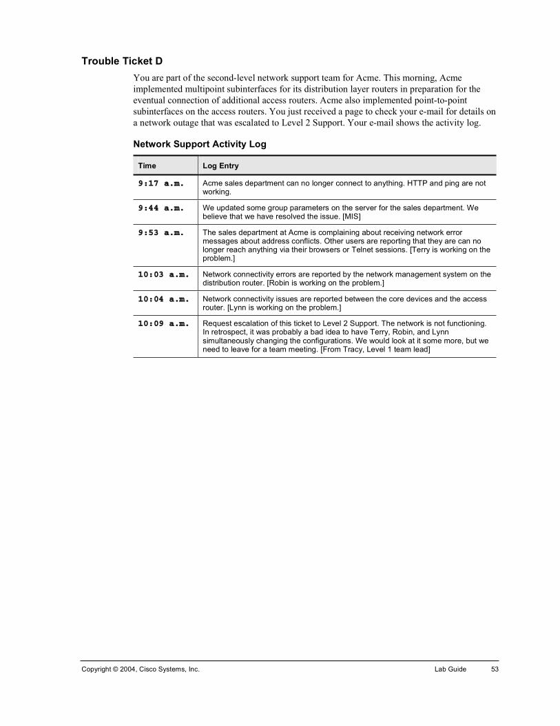
Copyright © 2004, Cisco Systems, Inc. Lab Guide 53
Trouble Ticket D You are part of the second-level network support team for Acme. This morning, Acme implemented multipoint subinterfaces for its distribution layer routers in preparation for the eventual connection of additional access routers. Acme also implemented point-to-point subinterfaces on the access routers. You just received a page to check your e-mail for details on a network outage that was escalated to Level 2 Support. Your e-mail shows the activity log.
Network Support Activity Log
Time Log Entry
çæïé ¿ò³ò Acme sales department can no longer connect to anything. HTTP and ping are not working.
çæìì ¿ò³ò We updated some group parameters on the server for the sales department. We believe that we have resolved the issue. [MIS]
çæëí ¿ò³ò The sales department at Acme is complaining about receiving network error messages about address conflicts. Other users are reporting that they are can no longer reach anything via their browsers or Telnet sessions. [Terry is working on the problem.]
ïðæðí ¿ò³ò Network connectivity errors are reported by the network management system on the distribution router. [Robin is working on the problem.]
ïðæðì ¿ò³ò Network connectivity issues are reported between the core devices and the access router. [Lynn is working on the problem.]
ïðæðç ¿ò³ò Request escalation of this ticket to Level 2 Support. The network is not functioning. In retrospect, it was probably a bad idea to have Terry, Robin, and Lynn simultaneously changing the configurations. We would look at it some more, but we need to leave for a team meeting. [From Tracy, Level 1 team lead]

54 Cisco Internetwork Troubleshooting (CIT) v5.1 Copyright © 2004, Cisco Systems, Inc.
Task 1: Implement the Troubleshooting Plan Coordinate activities within your workgroup.
Exercise Procedure Complete these steps:
(Connect to the workgroup devices as needed.)
Step 1 Carry out your troubleshooting implementation plan to correct all network problems.
Step 2 Verify that the network data flows match the network baseline and that you have not introduced any new problems into the network.
Exercise Verification You have completed this exercise when you attain these results:
!" Your network data flows match the network baseline.
!" You can use Telnet from the pod PC to connect to the host named Cisco (simulated on ISP1).
!" You can ping the host named ISP2.
!" You can browse web files on the CIT_Server.
!" You can use Telnet to connect to the CIT_Server from your pod PC.
!" You can use FTP to send a file from the CIT_Server to your pod PC.

Copyright © 2004, Cisco Systems, Inc. Lab Guide 55
Lab Exercise (Trouble Ticket E) 4-2: Troubleshooting Problems at the Physical, Data Link, and Network Layers
Complete this lab exercise by defining, isolating, and correcting the problems outlined in Trouble Ticket E to restore the network to baseline specifications.
Exercise Objective In this exercise, each workgroup will use a troubleshooting methodology and Cisco commands to define, isolate, and correct issues. You will complete the following steps:
!" Define the problem by questioning users and by using end-system tools
!" Isolate the problem by analyzing documented symptoms and using Cisco commands
!" Consider options for solving the problem
!" Develop a troubleshooting implementation plan for correcting the problems that you identified
!" Execute your troubleshooting implementation plan
!" Verify that the network is restored to baseline specifications and that you have not introduced any new problems into the network
After completing this exercise, you will be able to meet these objectives:
!" Follow a logical troubleshooting process to define, isolate, and correct problems outlined in a trouble ticket
!" Verify that the trouble ticket has been resolved
!" Verify that the data flow in the network matches your network baseline
Required Resources These are the resources and equipment required to complete this exercise:
!" Access to the workgroup PCs and Cisco devices in the lab network
!" Familiarity with Cisco router and switch commands covered in Building Scalable Cisco Internetworks (BSCI), Building Cisco Multilayer Switched Networks (BCMSN), and Building Cisco Remote Access Networks (BCRAN)
!" Access to a protocol analyzer (either software or hardware)
!" A network baseline documenting the lab installation
!" A troubleshooting log listing isolated physical or data link problems
!" An implementation plan for correcting documented physical and data link layer problems

56 Cisco Internetwork Troubleshooting (CIT) v5.1 Copyright © 2004, Cisco Systems, Inc.
Command List The commands used in this exercise are described in the table here.
Helpful Commands
Command Description
°·²¹ ¥¸±¬ ¤ ¿¼¼®»£ Pings an IP address.
¸±© ½¼° ²»·¹¸¾±® ż»¬¿·´Ã
Displays CDP neighbor information.
¸±© ½±²¬®±´´»® ¥¬§°»²«³¾»®£
Displays controller information and status.
¸±© »¬¸»®½¸¿²²»´ «³³¿®§
Displays EtherChannel port-channel summary status, including Layer 2 or Layer 3 port and interface information.
¸±© º®¿³»ó®»´¿§ ³¿° Displays Frame Relay mapping status.
¸±© º®¿³»ó®»´¿§ °ª½ Displays Frame Relay PVC information and status.
¸±© ·²¬»®º¿½» °±®¬ó½¸¿²²»´ ¥½¸¿²²»´£
Displays port-channel status, including Layer 2 or Layer 3 port and interface information.
¸±© ·²¬»®º¿½» ¬®«²µ Shows trunking interfaces.
¸±© ·° ¾¹° Displays entries in the BGP routing table.
¸±© ·° ¾¹° «³³¿®§ Shows summary BGP status.
¸±© ·° ·²¬»®º¿½» ¾®·»º Displays brief form of interface information.
¸±© ·° °®±¬±½±´·²¬»®º¿½»
Displays interface information for a protocol.
¸±© ·° °®±¬±½±´²»·¹¸¾±®
Displays information about neighbors for a specific routing protocol.
¸±© ·° °®±¬±½±´ Displays routing protocol status.
¸±© ·° ®±«¬» Displays IP routing table information.
͸±© °®±¬±½±´ Displays Layer 3 addresses and interface status.
¸±© ®«²²·²¹ó½±²º·¹ ·²¬»®º¿½» ¥¬§°» ²«³¾»®£
Displays configuration information for one interface.
¸±© °¿²²·²¹ó¬®»» Displays STP information, including port status.
¸±© ¬¼³ ½´±½µ Shows TDM-related information.
¸±© ª´¿² Displays VLAN information.
¸±© ª¬° ¬¿¬« Displays VTP status, including domain name and revision number.
¬»´²»¬ ¥·°ó¿¼¼®»£ Uses Telnet to connect to an IP address.
¬®¿½»®±«¬» ¥·°ó¿¼¼®»£
Runs traceroute to an IP address.
Copyright © 2004, Cisco Systems, Inc. Lab Guide 57
Job Aids These job aids are available to help you complete the lab exercise:
!" Information on Trouble Ticket E
Trouble Ticket E A huge lightning strike startles you on a day off from work. A few moments later, your cell phone rings. You recognize the phone number—it is for Level 1 Network Support at Acme.
“The lightning has been wild over by the office for the last hour,” Lynn tells you. “We lost power twice and also lost a router. But when we powered up our spare and loaded our backup configuration, we could not get connectivity to the core. We called around, and several of our sites have also had power interruptions. It is probably some simple issue, but we have not been able to restore operations. We need to get this resolved quickly so payroll can be run at 7:00 a.m. So we decided to call you.”
You tell Lynn that you will connect in from home and figure out what is going on.
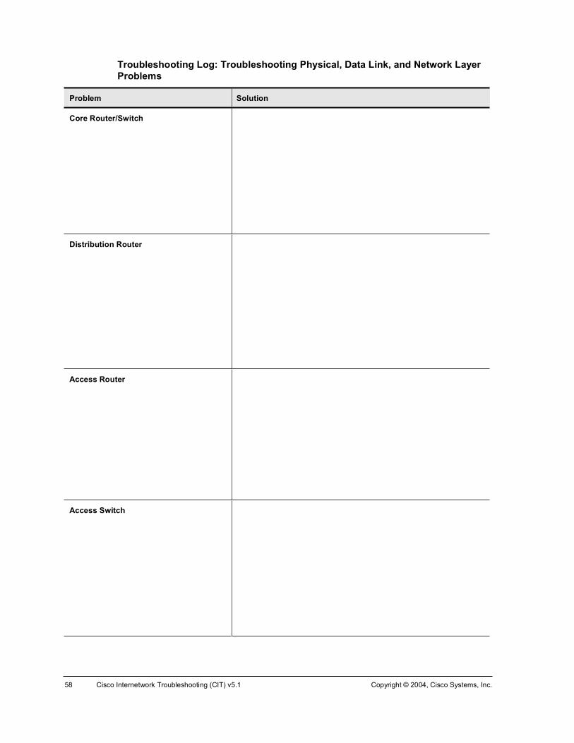
58 Cisco Internetwork Troubleshooting (CIT) v5.1 Copyright © 2004, Cisco Systems, Inc.
Troubleshooting Log: Troubleshooting Physical, Data Link, and Network Layer Problems
Problem Solution
Core Router/Switch
Distribution Router
Access Router
Access Switch

Copyright © 2004, Cisco Systems, Inc. Lab Guide 59
Task 1: Resolving the Trouble Ticket Coordinate activities within your workgroup.
Exercise Procedure Complete these steps, coordinating with the other learners in your workgroup.
Step 1 What questions should you ask the users? ________________________________________________________________ ________________________________________________________________
What commands should the users try from their PCs? _________________________________________________________________ _________________________________________________________________
Step 2 Document the symptoms of the problem on the troubleshooting log. The troubleshooting log is divided into four possible areas of concern: core routing and switching, distribution routing, access routing, and access switching.
Step 3 Where should you look first in the network to isolate the problems? ________________________________________________________________
What commands might you use to look for issues? _________________________________________________________________ _________________________________________________________________
Step 4 Where should you look next to isolate the problems? ________________________________________________________________
What commands might you use to look for issues? _________________________________________________________________ _________________________________________________________________
Step 5 Coordinate with your workgroup to isolate the problems.
Step 6 Repeat Step 1 through Step 5 as needed to isolate all the problems.
Step 7 Develop a plan to correct the identified problems and document the plan in the space provided below.
________________________________________________________________ ________________________________________________________________ ________________________________________________________________ ________________________________________________________________ ________________________________________________________________
Step 8 Carry out your troubleshooting implementation plan to correct all network errors.
Step 9 Verify that the network data flows match the network baseline and that you have not introduced any new problems into the network.

60 Cisco Internetwork Troubleshooting (CIT) v5.1 Copyright © 2004, Cisco Systems, Inc.
Exercise Verification You have completed this exercise when you attain these results:
!" Your network data flows match the network baseline.
!" You can use Telnet from the pod PC to connect to the host named Cisco (simulated on ISP1).
!" You can ping the host named ISP2.
!" You can browse the web files on the CIT_Server.
!" You can use Telnet to connect to the CIT_Server from your pod PC.
!" You can use FTP to send a file from the CIT_Server to your pod PC.

Copyright © 2004, Cisco Systems, Inc. Lab Guide 61
Lab Exercise (Trouble Ticket F) 4-3: Troubleshooting Problems at the Physical, Data Link, and Network Layers
Complete this lab exercise by defining, isolating, and correcting the problems outlined in Trouble Ticket F to restore the network to baseline specifications.
Exercise Objective In this exercise, each workgroup will use a troubleshooting methodology and Cisco commands to define, isolate, and correct issues. You will complete the following steps:
!" Define the problem by questioning users and using end-system tools
!" Isolate the problem by analyzing documented symptoms and using Cisco commands
!" Consider options for solving the problem
!" Develop a troubleshooting implementation plan for correcting the problems that you identified
!" Execute your troubleshooting implementation plan
!" Verify that the network is restored to baseline specifications and that you have not introduced any new problems into the network
After completing this exercise, you will be able to meet these objectives:
!" Follow a logical troubleshooting process to define, isolate, and correct problems outlined in a trouble ticket
!" Verify that the trouble ticket has been resolved
!" Verify that the data flow in the network matches your network baseline
Required Resources These are the resources and equipment required to complete this exercise:
!" Access to the workgroup PCs and Cisco devices in the lab network
!" Familiarity with Cisco router and switch commands covered in Building Scalable Cisco Internetworks (BSCI), Building Cisco Multilayer Switched Networks (BCMSN), and Building Cisco Remote Access Networks (BCRAN)
!" Access to a protocol analyzer (either software or hardware)
!" A network baseline documenting the lab installation
!" A troubleshooting log listing isolated physical or data link problems
!" An implementation plan for correcting documented physical and data link layer problems

62 Cisco Internetwork Troubleshooting (CIT) v5.1 Copyright © 2004, Cisco Systems, Inc.
Command List The commands used in this exercise are described in the table here.
Helpful Commands
Command Description
°·²¹ ¥¸±¬ ¤ ¿¼¼®»£ Pings an IP address.
¸±© ½¼° ²»·¹¸¾±® ż»¬¿·´Ã
Displays CDP neighbor information.
¸±© »¬¸»®½¸¿²²»´ «³³¿®§
Displays EtherChannel port-channel summary status, including Layer 2 or Layer 3 port and interface information.
¸±© º®¿³»ó®»´¿§ ³¿° Displays Frame Relay mapping status.
¸±© º®¿³»ó®»´¿§ °ª½ Displays Frame Relay PVC information and status.
¸±© ·²¬»®º¿½» °±®¬ó½¸¿²²»´ ¥½¸¿²²»´£
Displays port-channel status, including Layer 2 or Layer 3 port and interface information.
¸±© ·²¬»®º¿½» ¬®«²µ Shows trunking interfaces.
¸±© ·° ¾¹° Displays entries in the BGP routing table.
¸±© ·° ¾¹° «³³¿®§ Shows summary BGP status.
¸±© ·° ·²¬»®º¿½» ¾®·»º Displays brief form of interface information.
¸±© ·° °®±¬±½±´·²¬»®º¿½»
Displays interface information for a protocol.
¸±© ·° °®±¬±½±´²»·¹¸¾±®
Displays information about neighbors for a specific routing protocol.
¸±© ·° °®±¬±½±´ Displays routing protocol status.
¸±© ·° ®±«¬» Displays IP routing table information.
¸±© °®±¬±½±´ Displays Layer 3 addresses and interface status.
¸±© ®«²²·²¹ó½±²º·¹ ·²¬»®º¿½» ¥¬§°» ²«³¾»®£
Displays configuration information for one interface.
¸±© °¿²²·²¹ó¬®»» Displays STP information, including port status.
¸±© ª´¿² Displays VLAN information.
¸±© ª¬° ¬¿¬« Displays VTP status, including domain name and revision number.
¬»´²»¬ ¥·°ó¿¼¼®»£ Uses Telnet to connect to an IP address.
¬®¿½»®±«¬» ¥·°ó¿¼¼®»£ Runs traceroute to an IP address.
Job Aids These job aids are available to help you complete the lab exercise:
!" Information on Trouble Ticket F
!" Sketch of planned implementation

Copyright © 2004, Cisco Systems, Inc. Lab Guide 63
Trouble Ticket F You made it through your first few days as a second-level network support engineer for Acme. Nothing too striking happened; you spent most of your time documenting what was in place in the Acme backbone and troubleshooting some network issues.
Yesterday, you went to a new employee orientation class. Unfortunately, you left your new cell phone at the office to charge.
When you return to your office, you see that users and Level 1 Support have been calling. Your phone reports 27 messages since lunch yesterday. Robin, a Level 1 engineer, has appeared in person at your office door.
This engineer summarizes the situation. “We received a new management edict—no proprietary protocols in the core or distribution layer. EIGRP has to be scrapped and replaced with OSPF. And both of our ISPs complained about our ‘borrowing’ of AS numbers and recommended that we implement BGP confederations.”
You tell the engineer that you will come up with a conversion plan this morning.
“Well, management insisted that we perform the conversion yesterday,” the engineer says. “We did try calling you. When we could not reach you, Terry joined the conversion. EIGRP was left on the access routers, because Terry could not get an OK from those locations for an upgrade. Terry took out RIP in the core and completed the cutover to the frame links between the distribution and access routers. When Terry left for vacation, it was almost working.”
You realize that the users have a different opinion about whether the network is working. Robin hands you a rough sketch of the planned implementation.

64 Cisco Internetwork Troubleshooting (CIT) v5.1 Copyright © 2004, Cisco Systems, Inc.
Planned Implementation

Copyright © 2004, Cisco Systems, Inc. Lab Guide 65
Troubleshooting Log: Troubleshooting Physical, Data Link, and Network Layer Problems
Problem Solution
Core Router/Switch
Distribution Router
Access Router
Access Switch
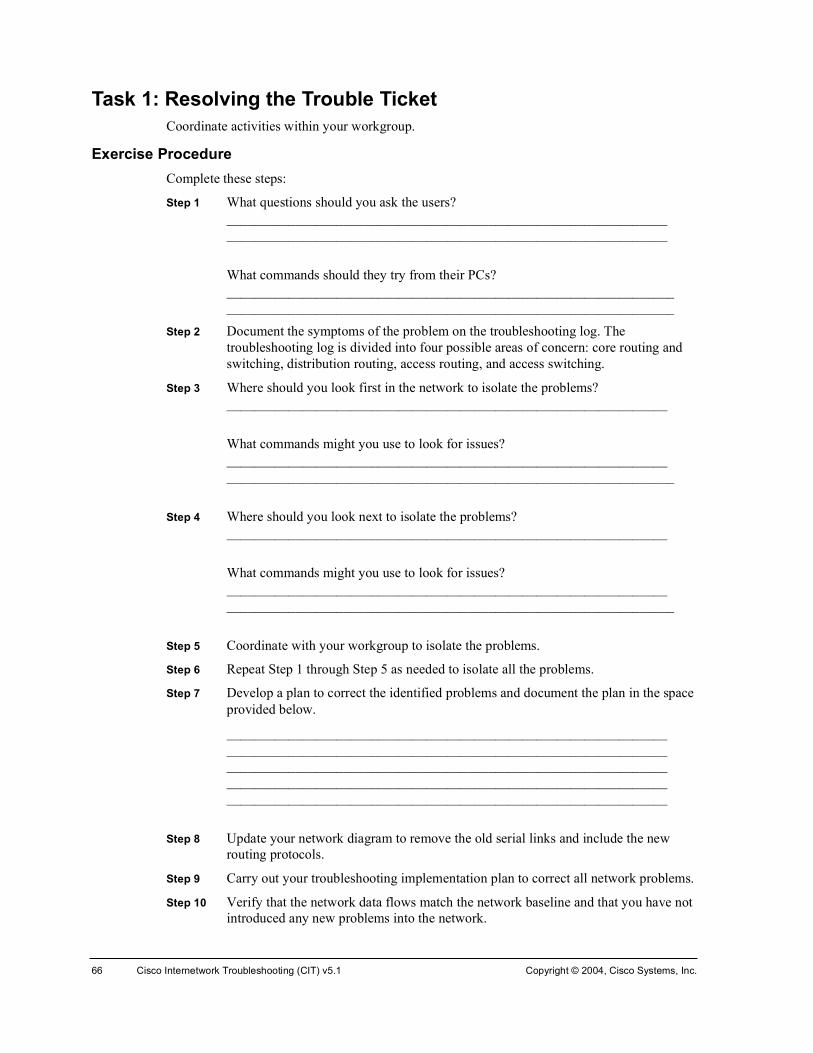
66 Cisco Internetwork Troubleshooting (CIT) v5.1 Copyright © 2004, Cisco Systems, Inc.
Task 1: Resolving the Trouble Ticket Coordinate activities within your workgroup.
Exercise Procedure Complete these steps:
Step 1 What questions should you ask the users? ________________________________________________________________ ________________________________________________________________
What commands should they try from their PCs? _________________________________________________________________ _________________________________________________________________
Step 2 Document the symptoms of the problem on the troubleshooting log. The troubleshooting log is divided into four possible areas of concern: core routing and switching, distribution routing, access routing, and access switching.
Step 3 Where should you look first in the network to isolate the problems? ________________________________________________________________
What commands might you use to look for issues? ________________________________________________________________ _________________________________________________________________
Step 4 Where should you look next to isolate the problems? ________________________________________________________________
What commands might you use to look for issues? ________________________________________________________________ _________________________________________________________________
Step 5 Coordinate with your workgroup to isolate the problems.
Step 6 Repeat Step 1 through Step 5 as needed to isolate all the problems.
Step 7 Develop a plan to correct the identified problems and document the plan in the space provided below.
________________________________________________________________ ________________________________________________________________ ________________________________________________________________ ________________________________________________________________ ________________________________________________________________
Step 8 Update your network diagram to remove the old serial links and include the new routing protocols.
Step 9 Carry out your troubleshooting implementation plan to correct all network problems.
Step 10 Verify that the network data flows match the network baseline and that you have not introduced any new problems into the network.

Copyright © 2004, Cisco Systems, Inc. Lab Guide 67
Exercise Verification You have completed this exercise when you attain these results:
!" Your network data flows match the network baseline.
!" You can use Telnet from the pod PC to connect to the host named Cisco (simulated on ISP1).
!" You can ping the host named ISP2.
!" You can browse the web files on the CIT_Server.
!" You can use Telnet to connect to the CIT_Server from your pod PC.
!" You can use FTP to send a file from the CIT_Server to your pod PC.
!" Your baseline topology diagram is updated to show the current WAN links and routing protocols.

68 Cisco Internetwork Troubleshooting (CIT) v5.1 Copyright © 2004, Cisco Systems, Inc.
Case Study (Trouble Ticket G) 5-1: Isolating Problems at the Transport and Application Layers
Complete this case study to practice what you learned in the related lesson. You will be given a problem situation escalated to Level 2 Engineering. You will analyze user feedback and end-system data and use Cisco commands and applications to isolate the specific cause of any problems.
Required Resources These are the resources and equipment required to complete this exercise:
!" Access to the workgroup PCs and Cisco devices in the lab network
!" Familiarity with Cisco router and switch commands covered in the Cisco Building Scalable Cisco Internetworks (BSCI), Building Cisco Multilayer Switched Networks (BCMSN), and Building Cisco Remote Access Networks (BCRAN) courses
!" A completed baseline topology diagram documenting the lab installation
!" Network documentation recording the configuration of the lab installation
Exercise Objective In this exercise, you will use a troubleshooting methodology and Cisco commands to isolate the specific causes of network problems. Complete these steps, coordinating with the other learners in your workgroup:
!" Analyze user feedback and end-system data to decide at which OSI layer to begin isolating a problem
!" Isolate the specific cause of any problems using Cisco tools
!" Develop a plan for resolving problems
After completing this exercise, you will be able to meet these objectives:
!" Analyze user feedback and end-system data to decide at which OSI layer to begin isolating problems
!" Select the troubleshooting tools to use to isolate the specific causes of any network problems
!" Develop a troubleshooting implementation plan for resolving any identified problems

Copyright © 2004, Cisco Systems, Inc. Lab Guide 69
Command List The commands used in this exercise are described in the table here.
Helpful Commands
Command Description
¿®° �¿ Displays ARP information.
¼»¾«¹ ·° ¼¸½° »®ª»® Displays DHCP server debugging.
¼»¾«¹ ·° »·¹®° Enables debugging of EIGRP events.
¼»¾«¹ ·° ±°º ¿¼¶ Enables debugging of Open Shortest Path First (OSPF) adjacencies.
¼»¾«¹ ·° °±´·½§ Enables debugging of the IP policy.
¼»¾«¹ ·° ®±«¬·²¹ Enables debugging of IP routing events.
·°½±²º·¹ ñ¿´´ Displays IP information for the PC.
°·²¹ ¥¸±¬ ¤ ¿¼¼®»£ Pings an IP address.
®±«¬» °®·²¬ Displays active routes for the PC.
¸±© ¿½½»ó´·¬ Displays access list information.
¸±© ·° ¾¹° Displays entries in the BGP routing table.
¸±© ·° ¾¹° «³³¿®§ Shows summary BGP status.
¸±© ·° ¼¸½° ¾·²¼·²¹ Displays address bindings on the DHCP server.
¸±© ·° ¼¸½° »®ª»® ¬¿¬·¬·½
Displays DHCP server statistics.
¸±© ·° ·²¬»®º¿½» ¾®·»º Displays brief form of interface information.
¸±© ·° °±´·½§ Displays which route map is associated with which interface.
¸±© ·° °®±¬±½±´ ·²¬»®º¿½»
Displays interface information for a protocol.
¸±© ·° °®±¬±½±´²»·¹¸¾±®
Displays information about neighbors for a specific routing protocol.
¸±© ·° °®±¬±½±´ Displays routing protocol status.
¸±© ·° ®±«¬» Displays IP routing table information.
¸±© ®±«¬»ó³¿° Displays route map information.
¸±© °¿²²·²¹ó¬®»» ª´¿² ª´¿²ó·¼
Displays STP information, including port status for a specific VLAN.
¸±© ª´¿² ª´¿²ó·¼ Displays default and defined VLAN information.
¬»´²»¬ ¥¸±¬ ¤ ·°ó¿¼¼®»£
Connects to an IP address via the Telnet application.
¬®¿½»®±«¬»Å¼»¬·²¿¬·±²Ã
Runs traceroute to an IP address.
¬®¿½»®¬ ¥·°ó¿¼¼®»£ Runs tracert from a PC to an IP address.

70 Cisco Internetwork Troubleshooting (CIT) v5.1 Copyright © 2004, Cisco Systems, Inc.
Job Aids These job aids are available to help you complete the lab exercises:
!" Information on Trouble Ticket G
!" Troubleshooting Log
Trouble Ticket G After you cleaned up the migration mess from this morning, you thought that the network was stable. Terry, the co-op student, wants to make a baseline of the Acme network for a networking class. Your boss, Lynn, tells Terry that this is OK, as long as the passwords are removed from the configurations before Terry brings them to class.
While you are out at lunch, you receive a call on your cell phone from Terry, who says that the network is down.
You ask what Terry did.
“Well, I was just running some show commands to get a baseline for my class,” Terry starts, “and I was starting to disguise the corporate passwords. Then Lynn stopped by and asked me to implement OSPF authentication in the core.”
“OK, then what?” you ask.
“I jumped right into the OSPF authentication implementation. While I was configuring OSPF, I tested a way to optimize the traffic throughout the network with our routing policy. But then I found I could not reach the Internet from the core switch, so I backed out the optimizations. Then Robin from MIS called and said that the users could not use TFTP to connect to the CIT server. Robin asked me to check the DHCP configuration. It looked OK to me. Do we have a TFTP application running on the CIT server?”
“No,” you say, “we do not.”
“So then I tried to connect to the access router,” Terry continues. “But I could not get in. I asked the network administrators to reboot the network devices. They did, but I think they first saved my changes. Then MIS and Network Operations really started calling because the users could not access anything on the Internet or on our corporate server. I did try to back out my changes, but it was hard to concentrate with a lot of people yelling at me. I could not even log into most of the network devices. That is when I called you.”
You need to isolate the cause of the problems and develop a plan to resolve them.

Copyright © 2004, Cisco Systems, Inc. Lab Guide 71
Troubleshooting Log: Isolating Transport and Application Layer Problems
Problem Solution
Core Router/Switch
Distribution Router
Access Router
Access Switch

72 Cisco Internetwork Troubleshooting (CIT) v5.1 Copyright © 2004, Cisco Systems, Inc.
Exercise Procedure Complete these steps, coordinating with the other learners in your workgroup.
Step 1 Where should you look to isolate the specific causes of any problems? ________________________________________________________________
What commands might you use to look for issues? ________________________________________________________________ _________________________________________________________________
Step 2 Coordinate with your workgroup to isolate the specific causes of any network problems that you identified.
Step 3 On the troubleshooting log, document each identified network problem on a specific device. The troubleshooting log is divided into four possible areas of concern: core routing and switching, distribution routing, access routing, and access switching.
Step 4 Repeat Step 1 and Step 2 as needed to isolate the specific causes of all problems.
Step 5 Develop a plan to correct the identified problems and document the plan in the space provided below.
________________________________________________________________ ________________________________________________________________ ________________________________________________________________ ________________________________________________________________ ________________________________________________________________
Step 6 Assign the documented problems to members of your workgroup.
Step 7 Have the instructor review your troubleshooting log and correction plan.
Exercise Verification You have completed this exercise when you attain these results:
!" The problems that you discovered are documented in the troubleshooting log.
!" You have isolated the specific causes of all network problems.
!" Your workgroup has an implementation plan for correcting the isolated problems.

Copyright © 2004, Cisco Systems, Inc. Lab Guide 73
Lab Exercise (Trouble Ticket G) 5-1: Correcting Problems at the Transport and Application Layers
Complete this lab exercise by correcting the problems that you isolated in Case Study (Trouble Ticket G) 5-1: Isolating Problems at the Transport and Application Layers.
Exercise Objective In this exercise, you will use various Cisco commands to correct network problems.
You will complete the following steps:
!" Implement the plan you developed during the related case study
!" Verify that the data flow in the network matches your network baseline
Required Resources These are the resources and equipment required to complete this exercise:
!" Access to the workgroup PCs and Cisco devices in the lab network
!" Familiarity with Cisco router and switch commands covered in the Cisco Building Scalable Cisco Internetworks (BSCI), Building Cisco Multilayer Switched Networks (BCMSN), and Building Cisco Remote Access Networks (BCRAN) courses
!" A network baseline documenting the lab installation
!" A troubleshooting log listing isolated physical or data link problems
!" An implementation plan for correcting documented physical and data link layer problems

74 Cisco Internetwork Troubleshooting (CIT) v5.1 Copyright © 2004, Cisco Systems, Inc.
Command List The commands used in this exercise are described in the table here.
Helpful Commands
Command Description
¿®° �¿ Displays ARP information.
¼»¾«¹ ·° ¼¸½° »®ª»® Displays DHCP server debugging.
¼»¾«¹ ·° »·¹®° Enables debugging of EIGRP events.
¼»¾«¹ ·° ±°º ¿¼¶ Enables debugging of OSPF adjacencies.
¼»¾«¹ ·° °±´·½§ Enables debugging of the IP policy.
¼»¾«¹ ·° ®±«¬·²¹ Enables debugging of IP routing events.
·°½±²º·¹ ñ¿´´ Displays IP information for the PC.
°·²¹ ¥¸±¬ ¤ ¿¼¼®»£ Pings an IP address.
®±«¬» °®·²¬ Displays active routes for the PC.
¸±© ¿½½»ó´·¬ Displays access list information.
¸±© ·° ¾¹° Displays entries in the BGP routing table.
¸±© ·° ¾¹° «³³¿®§ Shows summary BGP status.
¸±© ·° ¼¸½° ¾·²¼·²¹ Displays address bindings on the DHCP server.
¸±© ·° ¼¸½° »®ª»® ¬¿¬·¬·½
Displays DHCP server statistics.
¸±© ·° ·²¬»®º¿½» ¾®·»º Displays brief form of interface information.
¸±© ·° °±´·½§ Displays which route map is associated with which interface.
¸±© ·° °®±¬±½±´·²¬»®º¿½»
Displays interface information for a protocol.
¸±© ·° °®±¬±½±´²»·¹¸¾±®
Displays information about neighbors for a specific routing protocol.
¸±© ·° °®±¬±½±´ Displays routing protocol status.
¸±© ·° ®±«¬» Displays IP routing table information.
¸±© ®±«¬»ó³¿° Displays route map information.
¸±© °¿²²·²¹ó¬®»» ª´¿² ª´¿²ó·¼
Displays STP information, including port status for a specific VLAN.
¸±© ª´¿² ª´¿²ó·¼ Displays default and defined VLAN information.
¬»´²»¬ ¥¸±¬ ¤ ·°ó¿¼¼®»£
Connects to an IP address via the Telnet application.
¬®¿½»®±«¬»Å¼»¬·²¿¬·±²Ã
Runs trace to an IP address.
¬®¿½»®¬ Å·°ó¿¼¼®»Ã Runs trace from a PC to an IP address.

Copyright © 2004, Cisco Systems, Inc. Lab Guide 75
Job Aids This job aid is available to help you complete the lab exercise:
!" Information on Trouble Ticket G
Trouble Ticket G After you cleaned up the migration mess from this morning, you thought that the network was stable. Terry, the co-op student, wants to make a baseline of the Acme network for a networking class. Your boss, Lynn, tells Terry that this is OK, as long as the passwords are removed from the configs before Terry brings them to class.
While you are out at lunch, you receive a call on your cell phone from Terry, who says that the network is down. You ask what Terry did.
“Well, I was just running some show commands to get a baseline for my class,” Terry starts, “and I was starting to disguise the corporate passwords. Then Lynn stopped by and asked me to implement OSPF authentication in the core.”
“OK, then what?” you ask.
“I jumped right into the OSPF authentication implementation. While I was configuring OSPF, I tested a way to optimize the traffic throughout the network with our routing policy. But then I found I could not reach the Internet from the core switch, so I backed out the optimizations. Then Robin from MIS called and said that the users could not use TFTP to connect to the CIT server. Robin asked me to check the DHCP configuration. It looked OK to me. Do we have a TFTP application running on the CIT server?”
“No,” you say, “we do not.”
“So then I tried to connect to the access router,” Terry continues, “but I could not get in. I asked the network administrators to reboot the network devices. They did, but I think they first saved my changes. Then MIS and Network Operations really started calling because the users could not access anything on the Internet or on our corporate server. I did try to back out my changes, but it was hard to concentrate with a lot of people yelling at me. I could not even log into most of the network devices. That is when I called you.”

76 Cisco Internetwork Troubleshooting (CIT) v5.1 Copyright © 2004, Cisco Systems, Inc.
Task 1: Implement the Troubleshooting Plan Coordinate activities within your workgroup.
Exercise Procedure Complete these steps:
Step 1 Connect to the workgroup devices as needed.
Step 2 Carry out your troubleshooting implementation plan to correct all network problems.
Step 3 Verify that the network data flows match the network baseline and that you have not introduced any new problems into the network.
Exercise Verification You have completed this exercise when you attain these results:
!" Your network data flows match the network baseline.
!" You can use Telnet from the pod PC to connect to the host named Cisco (simulated on ISP1).
!" You can ping the host named ISP2.
!" You can browse the web files on the CIT_Server.
!" You can use Telnet to connect to the CIT_Server from your pod PC.
!" You can use FTP to send a file from the CIT_Server to your pod PC.

Copyright © 2004, Cisco Systems, Inc. Lab Guide 77
Lab Exercise (Trouble Ticket H) 5-2: Troubleshooting Problems at All Logical Layers
Complete this lab exercise by defining, isolating, and correcting the problems outlined in Trouble Ticket H to restore the network to baseline specifications.
Exercise Objective In this exercise, each workgroup will use a troubleshooting methodology and Cisco commands to define, isolate, and correct issues. You will complete the following steps:
!" Define the problem by questioning users and using end-system tools
!" Isolate the problem by analyzing documented symptoms and using Cisco tools
!" Consider options for solving the problem
!" Develop a troubleshooting implementation plan for correcting the problems that you identified
!" Implement your troubleshooting implementation plan
!" Verify that the network is restored to baseline specifications and that you have not introduced any new problems into the network
Required Resources These are the resources and equipment required to complete this exercise:
!" Access to the workgroup PCs and Cisco devices in the lab network
!" Familiarity with Cisco router and switch commands covered in the Cisco Building Scalable Cisco Internetworks (BSCI), Building Cisco Multilayer Switched Networks (BCMSN), and Building Cisco Remote Access Networks (BCRAN) courses
!" A network baseline documenting the lab installation

78 Cisco Internetwork Troubleshooting (CIT) v5.1 Copyright © 2004, Cisco Systems, Inc.
Command List The commands used in this exercise are described in the table here.
Helpful Commands
Command Description
¿®° �¿ Displays ARP information.
¼»¾«¹ ·° ¼¸½° »®ª»® Displays DHCP server debugging.
¼»¾«¹ ·° »·¹®° Enables debugging of EIGRP events.
¼»¾«¹ ·° ±°º ¿¼¶ Enables debugging of OSPF adjacencies.
¼»¾«¹ ·° °±´·½§ Enables debugging of the IP policy.
¼»¾«¹ ·° ®±«¬·²¹ Enables debugging of IP routing events.
·°½±²º·¹ ñ¿´´ Displays IP information for the PC.
°·²¹ ¥¸±¬ ¤ ¿¼¼®»£ Pings an IP address.
®±«¬» °®·²¬ Displays active routes for the PC.
¸±© ¿½½»ó´·¬ Displays access list information.
¸±© ·° ¾¹° Displays entries in the BGP routing table.
¸±© ·° ¾¹° «³³¿®§ Shows summary BGP status.
¸±© ·° ¼¸½° ¾·²¼·²¹ Displays address bindings on the DHCP server.
¸±© ·° ¼¸½° »®ª»® ¬¿¬·¬·½
Displays DHCP server statistics.
¸±© ·° ·²¬»®º¿½» ¾®·»º Displays brief form of interface information.
¸±© ·° °±´·½§ Displays which route map is associated with which interface.
¸±© ·° °®±¬±½±´·²¬»®º¿½»
Displays interface information for a protocol.
¸±© ·° °®±¬±½±´²»·¹¸¾±®
Displays information about neighbors for a specific routing protocol.
¸±© ·° °®±¬±½±´ Displays routing protocol status.
¸±© ·° ®±«¬» Displays IP routing table information.
¸±© ®±«¬»ó³¿° Displays route map information.
¸±© °¿²²·²¹ó¬®»» ª´¿² ª´¿²ó·¼
Displays STPl information, including port status for a specific VLAN.
¸±© ª´¿² ª´¿²ó·¼ Displays default and defined VLAN information.
¬»´²»¬ ¥¸±¬ ¤ ·°ó¿¼¼®»£
Connects to an IP address via the Telnet application.
¬®¿½»®±«¬»Å¼»¬·²¿¬·±²Ã
Runs trace to an IP address.
¬®¿½»®¬ ¥·°ó¿¼¼®»£ Runs trace from a PC to an IP address.

Copyright © 2004, Cisco Systems, Inc. Lab Guide 79
Job Aids These job aids are available to help you complete the lab exercise:
!" Information on Trouble Ticket H
!" Troubleshooting Log Table
Trouble Ticket H When you arrive at work on Friday, Tracy is standing outside your office.
“You know how HR promised to inform us about employee terminations for personnel with network access before they occur?” Tracy asks.
“Yes, why?” you ask.
“Well, last night they escorted Lynn from MIS out of the building. They did not get word to us until well after everyone up here had gone home,” Tracy says.
“So no one was here to turn off access to the devices?” you ask.
“Unfortunately, no,” Tracy says. “It appears that Lynn has been in the network making some changes, but we are not sure exactly where. We shut down access for Lynn; however, the network is not working correctly. MIS first reported that the users could not get to any host on the Internet. Now, MIS reports that the end users appear to be getting network errors when they try to connect to anything. And Network Operations is reporting issues logging into the access and distribution routers, and problems reaching the Internet. To make matters worse, we cannot connect between the divisions.”

80 Cisco Internetwork Troubleshooting (CIT) v5.1 Copyright © 2004, Cisco Systems, Inc.
Troubleshooting Log: Troubleshooting Problems at All Logical Layers
Problem Solution
Core Router/Switch
Distribution Router
Access Router
Access Switch

Copyright © 2004, Cisco Systems, Inc. Lab Guide 81
Task 1: Implement the Troubleshooting Plan Coordinate activities within your workgroup.
Exercise Procedure Complete these steps, coordinating with the other learners in your workgroup.
Step 1 What questions should you ask the users? ________________________________________________________________ ________________________________________________________________
What commands should the users try from their PC? _________________________________________________________________ _________________________________________________________________
Step 2 Document the symptoms of the problem on the troubleshooting log. The troubleshooting log is divided into four possible areas of concern: core routing and switching, distribution routing, access routing, and access switching.
Step 3 Where should you look first in the network to isolate the problems? ________________________________________________________________
What commands might you use to look for issues? ________________________________________________________________ _________________________________________________________________
Step 4 Where should you look next to isolate the problems? ________________________________________________________________
What commands might you use to look for issues? ________________________________________________________________ _________________________________________________________________
Step 5 Coordinate with your workgroup to isolate the problems.
Step 6 Repeat Step 1 through Step 5 as needed to isolate all the problems.
Step 7 Develop a plan to correct the identified problems and document the plan in the space provided below.
________________________________________________________________ ________________________________________________________________ ________________________________________________________________ ________________________________________________________________ ________________________________________________________________
Step 8 Execute the plan that you developed to correct the identified network problems.
Step 9 Verify that the network data flows match the network baseline and that you have not introduced any new problems into the network.

82 Cisco Internetwork Troubleshooting (CIT) v5.1 Copyright © 2004, Cisco Systems, Inc.
Exercise Verification You have completed this exercise when you attain these results:
!" Your network data flows match the network baseline.
!" You can use Telnet from the pod PC to connect to the host named Cisco (simulated on ISP1).
!" You can ping the host named ISP2.
!" You can browse the web files on the CIT_Server.
!" You can use Telnet to connect to the CIT_Server from your pod PC.
!" You can use FTP to send a file from the CIT_Server to your pod PC.
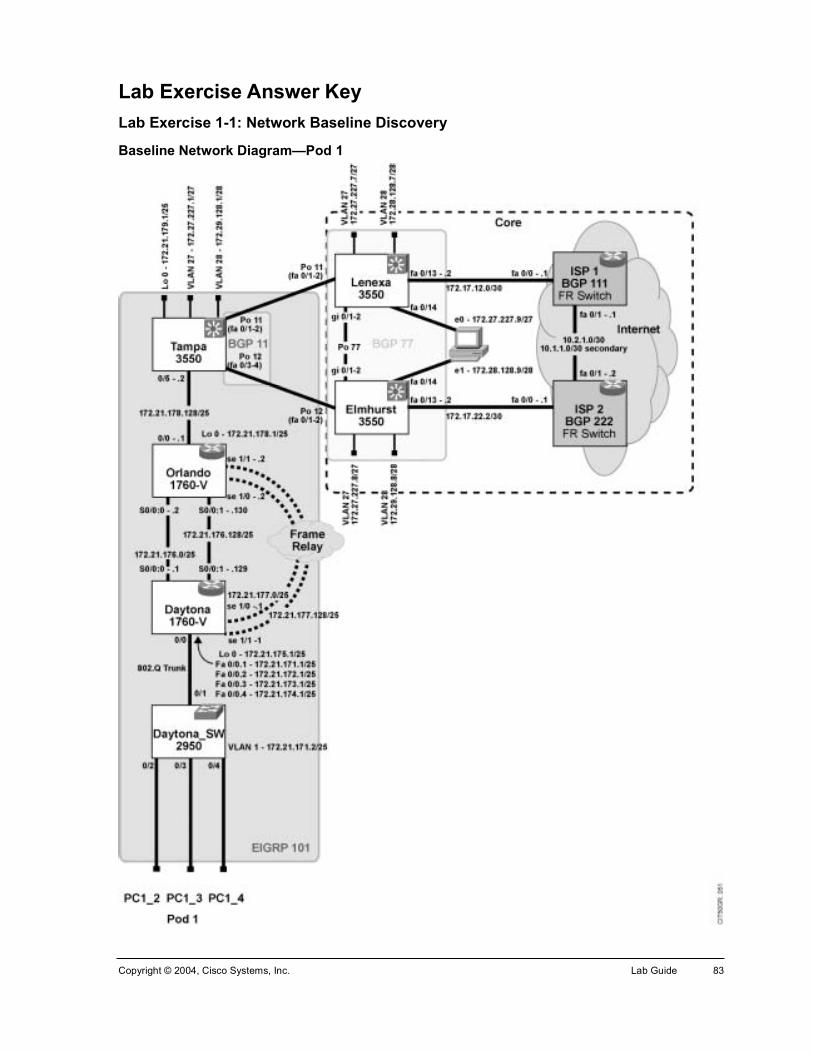
Copyright © 2004, Cisco Systems, Inc. Lab Guide 83
Lab Exercise Answer Key Lab Exercise 1-1: Network Baseline Discovery
Baseline Network Diagram—Pod 1

84 Cisco Internetwork Troubleshooting (CIT) v5.1 Copyright © 2004, Cisco Systems, Inc.
Baseline Network Diagram—Pod 2

Copyright © 2004, Cisco Systems, Inc. Lab Guide 85
Baseline Network Diagram—Pod 3

86 Cisco Internetwork Troubleshooting (CIT) v5.1 Copyright © 2004, Cisco Systems, Inc.
Baseline Network Diagram—Pod 4

Copyright © 2004, Cisco Systems, Inc. Lab Guide 87
Baseline Network Diagram—Pod 5

88 Cisco Internetwork Troubleshooting (CIT) v5.1 Copyright © 2004, Cisco Systems, Inc.
Baseline Network Diagram—Pod 6

Copyright © 2004, Cisco Systems, Inc. Lab Guide 89
Base Network Configuration Tables (All Pods)
Access Router N
otes
/Com
men
ts
768
K
64 K
Fram
e R
elay
Fram
e R
elay
VLA
N 9
01
VLA
N 2
VLA
N 3
VLA
N 4
IP R
outin
g Pr
otoc
ol(s
)
EIG
RP
x0x
EIG
RP
x0x
EIG
RP
x0x
-----
-----
EIG
RP
x0x
EIG
RP
x0x
EIG
RP
x0x
EIG
RP
x0x
IP A
ddre
ss/
Subn
et M
ask
172.
2x.1
x5.1
/2x
172.
2x.1
x5.1
/2x
172.
2x.1
x6.1
29 /2
x
172.
2x.1
x7.1
/2x
172.
2x.1
x7.1
29 /2
x
172.
2x.1
x1.1
/25
172.
2x.1
x1.2
/25
172.
2x.1
x1.3
/25
172.
2x.1
x1.4
/25
MA
C A
ddre
ss
Inte
rfac
e
Loop
back
0
Seria
l 0/0
:0
Seria
l 0/0
:1
Seria
l 1/0
Seria
l 1/1
Fast
Eth
erne
t 0/0
.1
Fast
Eth
erne
t 0/0
.2
Fast
Eth
erne
t 0/0
.3
Fast
Eth
erne
t 0/0
.4
Dev
ice
Nam
e, M
odel
Acc
ess
Rou
ter N
ame
1760
-V
Acc
ess
Rou
ter N
ame
1760
-V
Acc
ess
Rou
ter N
ame
1760
-V
Acc
ess
Rou
ter N
ame
1760
-V
Acc
ess
Rou
ter N
ame
1760
-V
Acc
ess
Rou
ter N
ame
1760
-V
Acc
ess
Rou
ter N
ame
1760
-V
Acc
ess
Rou
ter N
ame
1760
-V
Acc
ess
Rou
ter N
ame
1760
-V

90 Cisco Internetwork Troubleshooting (CIT) v5.1 Copyright © 2004, Cisco Systems, Inc.
Distribution Router N
otes
/Com
men
ts
768
K
64 K
Fram
e R
elay
Fram
e R
elay
IP R
outin
g Pr
otoc
ol(s
)
EIG
RP
x0x
EIG
RP
x0x
EIG
RP
x0x
EIG
RP
x0x
-----
-----
IP A
ddre
ss/
Subn
et M
ask
172.
2x.1
x8.1
29 /2
x
172.
2x.1
x8.1
/2x
172.
2x.1
x6.2
/2x
172.
2x.1
x6.1
30 /2
x
172.
2x.1
x7.2
/2x
172.
2x.1
x7.1
30 /2
x
MA
C A
ddre
ss
Inte
rfac
e
Fast
Eth
erne
t 0/0
Loop
back
0
Seria
l 0/0
:0
Seria
l 0/0
:1
Seria
l 1/0
Seria
l 1/1
Dev
ice
Nam
e, M
odel
Dis
tribu
tion
Rou
ter N
ame
1760
-V
Dis
tribu
tion
Rou
ter N
ame
1760
-V
Dis
tribu
tion
Rou
ter N
ame
1760
-V
Dis
tribu
tion
Rou
ter N
ame
1760
-V
Dis
tribu
tion
Rou
ter N
ame
1760
-V
Dis
tribu
tion
Rou
ter N
ame
1760
-V

Copyright © 2004, Cisco Systems, Inc. Lab Guide 91
Access Switch
IP A
ddre
ss
172.
2x.1
x1.2
/2x
VLA
N
901,
2, 3
, 4
2 3 4
Ethe
rC
hann
el
(L2
or L
3)
-----
-----
-----
-----
Port
Fast
/ Tr
unk
Trun
k
Por
tFas
t
Por
tFas
t
Por
tFas
t
STP
Stat
e Fw
d/B
lock
Fwd
VLA
N
901,
2, 3
, 4
Fwd
Fwd
Fwd
Dup
lex
Full
Full
Full
Full
Spee
d
100
100
100
100
Port
Fa 0
/1
Fa 0
/2
Fa 0
/3
Fa 0
/4
Cat
alys
t Nam
e, M
odel
M
anag
emen
t IP
Add
ress
Acc
ess
Sw
itch
Nam
e C
atal
yst 3
550
172.
2x.1
x1.2
/2x

92 Cisco Internetwork Troubleshooting (CIT) v5.1 Copyright © 2004, Cisco Systems, Inc.
Core Router/Switch IP
Add
ress
VL
AN
1, 2
7, 2
8
1, 2
7, 2
8
1, 2
7, 2
8
1, 2
7, 2
8
Ethe
rC
hann
el
(L2
or L
3)
Por
t 11
(L2)
Por
t 11
(L2)
Por
t 12
(L2)
Por
t 12
(L2)
Port
Fast
/ Tr
unk
Trun
k
Trun
k
Trun
k
Trun
k
STP
Stat
e Fw
d/B
lock
Fwd
VLAN
27
Bk
VLA
N 2
8
Fwd
VLAN
27
Bk
VLA
N 2
8
Fwd
VLAN
27
Bk
VLA
N 2
8
Fwd
VLAN
27
Bk
VLA
N 2
8
Dup
lex
Full
Full
Full
Full
Spee
d
100
100
100
100
Port
Fa 0
/1
Fa 0
/2
Fa 0
/3
Fa 0
/4
Cat
alys
t Nam
e, M
odel
. M
anag
emen
t IP
Add
ress
Cor
e R
oute
r/Sw
itch
Nam
e C
atal
yst 3
550

Copyright © 2004, Cisco Systems, Inc. Lab Guide 93
Lab Exercise 1-2: Creating End-System Baseline Discovery
Baseline Network Diagram—Pod 1

94 Cisco Internetwork Troubleshooting (CIT) v5.1 Copyright © 2004, Cisco Systems, Inc.
Baseline Network Diagram—Pod 2

Copyright © 2004, Cisco Systems, Inc. Lab Guide 95
Baseline Network Diagram—Pod 3

96 Cisco Internetwork Troubleshooting (CIT) v5.1 Copyright © 2004, Cisco Systems, Inc.
Baseline Network Diagram—Pod 4

Copyright © 2004, Cisco Systems, Inc. Lab Guide 97
Baseline Network Diagram—Pod 5

98 Cisco Internetwork Troubleshooting (CIT) v5.1 Copyright © 2004, Cisco Systems, Inc.
Baseline Network Diagram—Pod 6

Copyright © 2004, Cisco Systems, Inc. Lab Guide 99
Lab Exercise Answer Key (Cont.) Your instructor will present solutions to the following exercises:
!" Lab Exercise 2-1: Applying a Layered Model to a Network
!" Case Study (Trouble Ticket A) 2-1: Gathering Symptoms
!" Case Study (Trouble Ticket B) 3-1: Isolating Physical and Data Link Layer Problems
!" Lab Exercise (Trouble Ticket B) 3-1: Correcting Problems at the Physical and Data Link Layers
!" Lab Exercise (Trouble Ticket C) 3-2: Troubleshooting Problems at the Physical and Data Link Layers
!" Case Study (Trouble Ticket D) 4-1: Isolating Network Layer Problems
!" Lab Exercise (Trouble Ticket D) 4-1: Correcting Problems at the Network Layer
!" Lab Exercise (Trouble Ticket E) 4-2: Troubleshooting Problems at the Physical, Data Link, and Network Layers
!" Lab Exercise (Trouble Ticket F) 4-3: Troubleshooting Problems at the Physical, Data Link, and Network Layers
!" Case Study (Trouble Ticket G) 5-1: Isolating Problems at the Transport and Application Layers
!" Lab Exercise (Trouble Ticket G) 5-1: Correcting Problems at the Transport and Application Layers
!" Lab Exercise (Trouble Ticket H) 5-2: Troubleshooting Problems at All Logical Layers

100 Cisco Internetwork Troubleshooting (CIT) v5.1 Copyright © 2004, Cisco Systems, Inc.