cisco ios ip command reference, volume 3 of 3: multicast · about cisco ios software documentation...
TRANSCRIPT
Cisco IOS IPCommand Reference, Volume 3 of 3: MulticastRelease 12.2
170 West Tasman DriveSan Jose, CA 95134-1706USAhttp://www.cisco.com
Cisco Systems, Inc.Corporate Headquarters
Tel:800 553-NETS (6387)408 526-4000
Fax: 408 526-4100
Customer Order Number: DOC-7811742=Text Part Number: 78-11742-02

THE SPECIFICATIONS AND INFORMATION REGARDING THE PRODUCTS IN THIS MANUAL ARE SUBJECT TO CHANGE WITHOUT NOTICE. ALL STATEMENTS, INFORMATION, AND RECOMMENDATIONS IN THIS MANUAL ARE BELIEVED TO BE ACCURATE BUT ARE PRESENTED WITHOUT WARRANTY OF ANY KIND, EXPRESS OR IMPLIED. USERS MUST TAKE FULL RESPONSIBILITY FOR THEIR APPLICATION OF ANY PRODUCTS.
THE SOFTWARE LICENSE AND LIMITED WARRANTY FOR THE ACCOMPANYING PRODUCT ARE SET FORTH IN THE INFORMATION PACKET THAT SHIPPED WITH THE PRODUCT AND ARE INCORPORATED HEREIN BY THIS REFERENCE. IF YOU ARE UNABLE TO LOCATE THE SOFTWARE LICENSE OR LIMITED WARRANTY, CONTACT YOUR CISCO REPRESENTATIVE FOR A COPY.
The Cisco implementation of TCP header compression is an adaptation of a program developed by the University of California, Berkeley (UCB) as part of UCB’s public domain version of the UNIX operating system. All rights reserved. Copyright © 1981, Regents of the University of California.
NOTWITHSTANDING ANY OTHER WARRANTY HEREIN, ALL DOCUMENT FILES AND SOFTWARE OF THESE SUPPLIERS ARE PROVIDED “AS IS” WITH ALL FAULTS. CISCO AND THE ABOVE-NAMED SUPPLIERS DISCLAIM ALL WARRANTIES, EXPRESSED OR IMPLIED, INCLUDING, WITHOUT LIMITATION, THOSE OF MERCHANTABILITY, FITNESS FOR A PARTICULAR PURPOSE AND NONINFRINGEMENT OR ARISING FROM A COURSE OF DEALING, USAGE, OR TRADE PRACTICE.
IN NO EVENT SHALL CISCO OR ITS SUPPLIERS BE LIABLE FOR ANY INDIRECT, SPECIAL, CONSEQUENTIAL, OR INCIDENTAL DAMAGES, INCLUDING, WITHOUT LIMITATION, LOST PROFITS OR LOSS OR DAMAGE TO DATA ARISING OUT OF THE USE OR INABILITY TO USE THIS MANUAL, EVEN IF CISCO OR ITS SUPPLIERS HAVE BEEN ADVISED OF THE POSSIBILITY OF SUCH DAMAGES.
AccessPath, AtmDirector, Browse with Me, CCDA, CCDE, CCDP, CCIE, CCNA, CCNP, CCSI, CD-PAC, CiscoLink, the Cisco NetWorks logo, the Cisco Powered Network logo, Cisco Systems Networking Academy, the Cisco Systems Networking Academy logo, Fast Step, Follow Me Browsing, FormShare, FrameShare, GigaStack, IGX, Internet Quotient, IP/VC, iQ Breakthrough, iQ Expertise, iQ FastTrack, the iQ Logo, iQ Net Readiness Scorecard, MGX, the Networkers logo, Packet, PIX, RateMUX, ScriptBuilder, ScriptShare, SlideCast, SMARTnet, TransPath, Unity, Voice LAN, Wavelength Router, and WebViewer are trademarks of Cisco Systems, Inc.; Changing the Way We Work, Live, Play, and Learn, Discover All That’s Possible, and Empowering the Internet Generation, are service marks of Cisco Systems, Inc.; and Aironet, ASIST, BPX, Catalyst, Cisco, the Cisco Certified Internetwork Expert logo, Cisco IOS, the Cisco IOS logo, Cisco Systems, Cisco Systems Capital, the Cisco Systems logo, Enterprise/Solver, EtherChannel, EtherSwitch, FastHub, FastSwitch, IOS, IP/TV, LightStream, MICA, Network Registrar, Post-Routing, Pre-Routing, Registrar, StrataView Plus, Stratm, SwitchProbe, TeleRouter, and VCO are registered trademarks of Cisco Systems, Inc. or its affiliates in the U.S. and certain other countries.
All other brands, names, or trademarks mentioned in this document or Web site are the property of their respective owners. The use of the word partner does not imply a partnership relationship between Cisco and any other company. (0102R)
Cisco IOS IP Command Reference, Volume 3 of 3: MulticastCopyright © 2001–2006 Cisco Systems, Inc.All rights reserved.
Cisc
C O N T E N T S
About Cisco IOS Software Documentation v
Using Cisco IOS Software xv
IP Multicast Routing Commands IP3R-1
Multicast Source Discovery Protocol Commands IP3R-169
PGM Host and Router Assist Commands IP3R-207
Unidirectional Link Routing Commands IP3R-225
IP Multicast Tools Commands IP3R-243
INDEX
iiio IOS IP Command Reference, Volume 3 of 3: Multicast

Contents
ivCisco IOS IP Command Reference, Volume 3 of 3: Multicast
About Cisco IOS Software Documentation
This chapter discusses the objectives, audience, organization, and conventions of Cisco IOS software documentation. It also provides sources for obtaining documentation from Cisco Systems.
Documentation ObjectivesCisco IOS software documentation describes the tasks and commands necessary to configure and maintain Cisco networking devices.
AudienceThe Cisco IOS software documentation set is intended primarily for users who configure and maintain Cisco networking devices (such as routers and switches) but who may not be familiar with the tasks, the relationship between tasks, or the Cisco IOS software commands necessary to perform particular tasks. The Cisco IOS software documentation set is also intended for those users experienced with Cisco IOS software who need to know about new features, new configuration options, and new software characteristics in the current Cisco IOS software release.
Documentation OrganizationThe Cisco IOS software documentation set consists of documentation modules and master indexes. In addition to the main documentation set, there are supporting documents and resources.
Documentation ModulesThe Cisco IOS documentation modules consist of configuration guides and corresponding command reference publications. Chapters in a configuration guide describe protocols, configuration tasks, and Cisco IOS software functionality and contain comprehensive configuration examples. Chapters in a command reference publication provide complete Cisco IOS command syntax information. Use each configuration guide in conjunction with its corresponding command reference publication.
vCisco IOS IP Command Reference, Volume 3 of 3: Multicast

About Cisco IOS Software DocumentationDocumentation Organization
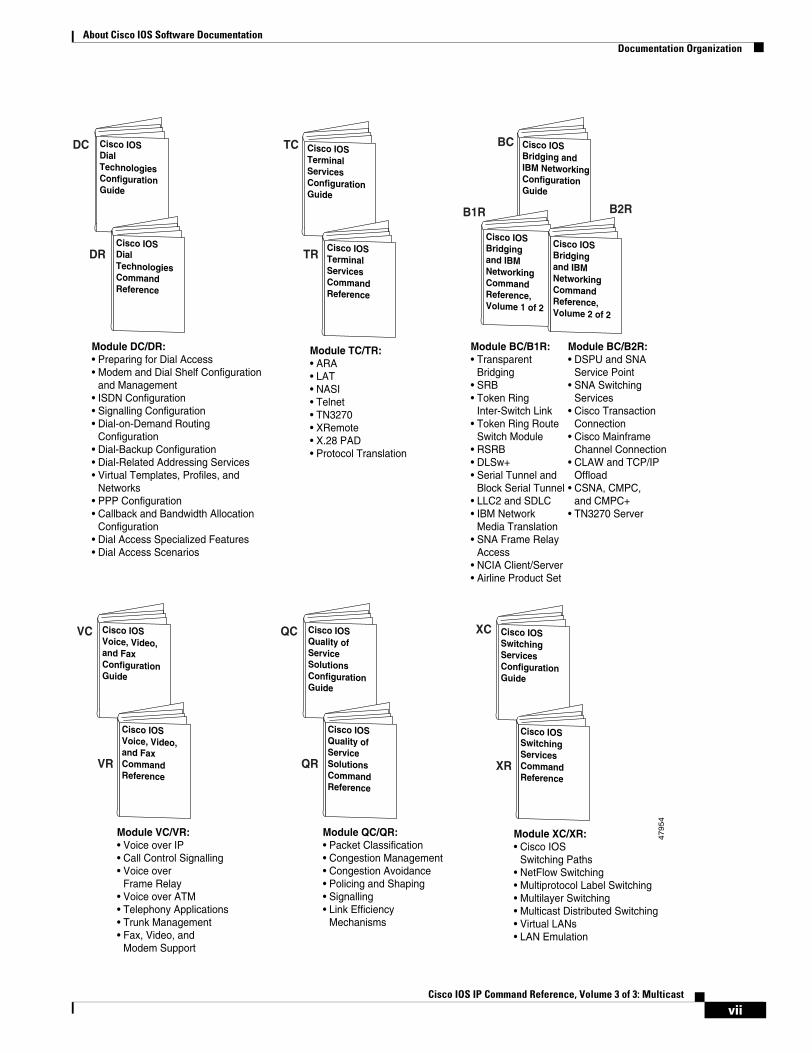
Figure 1 shows the Cisco IOS software documentation modules.
Note The abbreviations (for example, FC and FR) next to the book icons are page designators, which are defined in a key in the index of each document to help you with navigation. The bullets under each module list the major technology areas discussed in the corresponding books.
Figure 1 Cisco IOS Software Documentation Modules
Cisco IOSIP ConfigurationGuide
IPC
Cisco IOSConfigurationFundamentalsConfigurationGuide
Cisco IOSConfigurationFundamentalsCommandReference
Module FC/FR:• Cisco IOS User
Interfaces• File Management • System Management
Cisco IOSIP CommandReference,Volume 2 of 3:RoutingProtocols
Module IPC/IP1R/IP2R/IP3R:• IP Addressing and Services• IP Routing Protocols• IP Multicast
Cisco IOSAppleTalk andNovell IPXConfigurationGuide
Cisco IOSAppleTalk andNovell IPXCommandReference
Module P2C/P2R:• AppleTalk• Novell IPX
Cisco IOSApollo Domain,Banyan VINES,DECnet, ISOCLNS, and XNSConfigurationGuide
Cisco IOSApollo Domain,Banyan VINES,DECnet, ISOCLNS, and XNSCommandReference
Module P3C/P3R:• Apollo Domain• Banyan VINES• DECnet• ISO CLNS• XNS
Cisco IOSWide-AreaNetworkingConfigurationGuide
Cisco IOSWide-AreaNetworkingCommandReference
Module WC/WR:• ATM• Broadband Access• Frame Relay• SMDS• X.25 and LAPB
Cisco IOSSecurityConfigurationGuide
Cisco IOSSecurityCommandReference
Module SC/SR:• AAA Security Services• Security Server Protocols• Traffic Filtering and Firewalls• IP Security and Encryption• Passwords and Privileges• Neighbor Router Authentication• IP Security Options• Supported AV Pairs
Cisco IOSInterfaceConfigurationGuide
Cisco IOSInterfaceCommandReference
Module IC/IR:• LAN Interfaces• Serial Interfaces• Logical Interfaces
47953
FC
FR
IP2R
WC
WR
SC
SR
MWC
MWR
Cisco IOSMobileWirelessConfigurationGuide
Cisco IOSMobileWirelessCommandReference
Module MWC/MWR:• General Packet
Radio Service
IC
IR
Cisco IOSIP CommandReference,Volume 1 of 3:Addressingand Services
Cisco IOSIP CommandReference,Volume 3 of 3:Multicast
P2C
P2R
IP1R
IP3R
P3C
P3R
viCisco IOS IP Command Reference, Volume 3 of 3: Multicast
About Cisco IOS Software DocumentationDocumentation Organization
Cisco IOSVoice, Video,and FaxConfigurationGuide
Cisco IOSVoice, Video,and FaxCommandReference
Module VC/VR:• Voice over IP• Call Control Signalling• Voice over
Frame Relay• Voice over ATM• Telephony Applications• Trunk Management• Fax, Video, and
Modem Support
Cisco IOSQuality ofServiceSolutionsConfigurationGuide
Cisco IOSQuality ofServiceSolutionsCommandReference
Module QC/QR:• Packet Classification• Congestion Management• Congestion Avoidance• Policing and Shaping• Signalling• Link Efficiency
Mechanisms
Module DC/DR:• Preparing for Dial Access• Modem and Dial Shelf Configuration
and Management• ISDN Configuration• Signalling Configuration• Dial-on-Demand Routing
Configuration• Dial-Backup Configuration• Dial-Related Addressing Services• Virtual Templates, Profiles, and
Networks• PPP Configuration• Callback and Bandwidth Allocation
Configuration• Dial Access Specialized Features• Dial Access Scenarios
Module BC/B1R:• Transparent
Bridging• SRB• Token Ring
Inter-Switch Link• Token Ring Route
Switch Module• RSRB• DLSw+• Serial Tunnel and
Block Serial Tunnel• LLC2 and SDLC• IBM Network
Media Translation• SNA Frame Relay
Access• NCIA Client/Server• Airline Product Set
Module BC/B2R:• DSPU and SNA
Service Point• SNA Switching
Services• Cisco Transaction
Connection• Cisco Mainframe
Channel Connection• CLAW and TCP/IP
Offload• CSNA, CMPC,
and CMPC+• TN3270 Server
Cisco IOSSwitchingServicesConfigurationGuide
Cisco IOSSwitchingServicesCommandReference
Module XC/XR:• Cisco IOS
Switching Paths• NetFlow Switching• Multiprotocol Label Switching• Multilayer Switching• Multicast Distributed Switching• Virtual LANs• LAN Emulation
47954
Cisco IOSBridging andIBM NetworkingConfigurationGuide
Cisco IOSBridgingand IBMNetworkingCommandReference,Volume 1 of 2
Cisco IOSBridgingand IBMNetworkingCommandReference,Volume 2 of 2
XC
DC
DR
TC
TR
BC
XR
B1R B2R
QC
QR
VC
VR
Cisco IOSTerminalServicesConfigurationGuide
Cisco IOSTerminalServicesCommandReference
Module TC/TR:• ARA• LAT• NASI• Telnet• TN3270• XRemote• X.28 PAD• Protocol Translation
Cisco IOSDialTechnologiesConfigurationGuide
Cisco IOSDialTechnologiesCommandReference
viiCisco IOS IP Command Reference, Volume 3 of 3: Multicast
About Cisco IOS Software DocumentationDocumentation Organization
Master IndexesTwo master indexes provide indexing information for the Cisco IOS software documentation set: an index for the configuration guides and an index for the command references. Individual books also contain a book-specific index.
The master indexes provide a quick way for you to find a command when you know the command name but not which module contains the command. When you use the online master indexes, you can click the page number for an index entry and go to that page in the online document.
Supporting Documents and ResourcesThe following documents and resources support the Cisco IOS software documentation set:
• Cisco IOS Command Summary (two volumes)—This publication explains the function and syntax of the Cisco IOS software commands. For more information about defaults and usage guidelines, refer to the Cisco IOS command reference publications.
• Cisco IOS System Error Messages—This publication lists and describes Cisco IOS system error messages. Not all system error messages indicate problems with your system. Some are purely informational, and others may help diagnose problems with communications lines, internal hardware, or the system software.
• Cisco IOS Debug Command Reference—This publication contains an alphabetical listing of the debug commands and their descriptions. Documentation for each command includes a brief description of its use, command syntax, usage guidelines, and sample output.
• Dictionary of Internetworking Terms and Acronyms—This Cisco publication compiles and defines the terms and acronyms used in the internetworking industry.
• New feature documentation—The Cisco IOS software documentation set documents the mainline release of Cisco IOS software (for example, Cisco IOS Release 12.2). New software features are introduced in early deployment releases (for example, the Cisco IOS “T” release train for 12.2, 12.2(x)T). Documentation for these new features can be found in standalone documents called “feature modules.” Feature module documentation describes new Cisco IOS software and hardware networking functionality and is available on Cisco.com and the Documentation CD-ROM.
• Release notes—This documentation describes system requirements, provides information about new and changed features, and includes other useful information about specific software releases. See the section “Using Software Release Notes” in the chapter “Using Cisco IOS Software” for more information.
• Caveats documentation—This documentation provides information about Cisco IOS software defects in specific software releases.
• RFCs—RFCs are standards documents maintained by the Internet Engineering Task Force (IETF). Cisco IOS software documentation references supported RFCs when applicable. The full text of referenced RFCs may be obtained on the World Wide Web at http://www.rfc-editor.org/.
• MIBs—MIBs are used for network monitoring. For lists of supported MIBs by platform and release, and to download MIB files, see the Cisco MIB website on Cisco.com at http://www.cisco.com/public/sw-center/netmgmt/cmtk/mibs.shtml.
viiiCisco IOS IP Command Reference, Volume 3 of 3: Multicast
About Cisco IOS Software DocumentationNew and Changed Information
New and Changed InformationThe following is new or changed information since the last release of the Cisco IOS IP and IP routing publications:
• The title of the Cisco IOS IP and IP Routing Configuration Guide has been changed to Cisco IOS IP Configuration Guide.
• The Cisco IOS IP and IP Routing Command Reference has been divided into three separate publications with the following titles:
– Cisco IOS IP Command Reference, Volume 1 of 3: Addressing and Services
– Cisco IOS IP Command Reference, Volume 2 of 3: Routing Protocols
– Cisco IOS IP Command Reference, Volume 3 of 3: Multicast
• The following new chapters were added to the Cisco IOS IP Configuration Guide:
– “Configuring Server Load Balancing”
– “Configuring Source Specific Multicast”
– “Configuring Bidirectional PIM”
– “Configuring Router-Port Group Management Protocol”
• The following new chapter was added to the Cisco IOS IP Command Reference, Volume 1 of 3: Addressing and Services:
– “Server Load Balancing Commands”
Document ConventionsWithin Cisco IOS software documentation, the term router is generally used to refer to a variety of Cisco products (for example, routers, access servers, and switches). Routers, access servers, and other networking devices that support Cisco IOS software are shown interchangeably within examples. These products are used only for illustrative purposes; that is, an example that shows one product does not necessarily indicate that other products are not supported.
The Cisco IOS documentation set uses the following conventions:
Convention Description
^ or Ctrl The ^ and Ctrl symbols represent the Control key. For example, the key combination ^D or Ctrl-D means hold down the Control key while you press the D key. Keys are indicated in capital letters but are not case sensitive.
string A string is a nonquoted set of characters shown in italics. For example, when setting an SNMP community string to public, do not use quotation marks around the string or the string will include the quotation marks.
ixCisco IOS IP Command Reference, Volume 3 of 3: Multicast
About Cisco IOS Software DocumentationDocument Conventions
Command syntax descriptions use the following conventions:
Nested sets of square brackets or braces indicate optional or required choices within optional or required elements. For example:
Examples use the following conventions:
The following conventions are used to attract the attention of the reader:
Caution Means reader be careful. In this situation, you might do something that could result in equipment damage or loss of data.
Note Means reader take note. Notes contain helpful suggestions or references to materials not contained in this manual.
Timesaver Means the described action saves time. You can save time by performing the action described in the paragraph.
Convention Description
boldface Boldface text indicates commands and keywords that you enter literally as shown.
italics Italic text indicates arguments for which you supply values.
[x] Square brackets enclose an optional element (keyword or argument).
| A vertical line indicates a choice within an optional or required set of keywords or arguments.
[x | y] Square brackets enclosing keywords or arguments separated by a vertical line indicate an optional choice.
{x | y} Braces enclosing keywords or arguments separated by a vertical line indicate a required choice.
Convention Description
[x {y | z}] Braces and a vertical line within square brackets indicate a required choice within an optional element.
Convention Description
screen Examples of information displayed on the screen are set in Courier font.
boldface screen Examples of text that you must enter are set in Courier bold font.
< > Angle brackets enclose text that is not printed to the screen, such as passwords.
! An exclamation point at the beginning of a line indicates a comment line. (Exclamation points are also displayed by the Cisco IOS software for certain processes.)
[ ] Square brackets enclose default responses to system prompts.
xCisco IOS IP Command Reference, Volume 3 of 3: Multicast
About Cisco IOS Software DocumentationObtaining Documentation
Obtaining DocumentationThe following sections provide sources for obtaining documentation from Cisco Systems.
World Wide WebThe most current Cisco documentation is available on the World Wide Web at the following website:
http://www.cisco.com
Translated documentation is available at the following website:
http://www.cisco.com/public/countries_languages.html
Documentation CD-ROMCisco documentation and additional literature are available in a CD-ROM package, which ships with your product. The Documentation CD-ROM is updated monthly and may be more current than printed documentation. The CD-ROM package is available as a single unit or through an annual subscription.
Ordering DocumentationCisco documentation can be ordered in the following ways:
• Registered Cisco Direct Customers can order Cisco product documentation from the Networking Products MarketPlace:
http://www.cisco.com/cgi-bin/order/order_root.pl
• Registered Cisco.com users can order the Documentation CD-ROM through the online Subscription Store:
http://www.cisco.com/go/subscription
• Nonregistered Cisco.com users can order documentation through a local account representative by calling Cisco corporate headquarters (California, USA) at 408 526-7208 or, in North America, by calling 800 553-NETS(6387).
Documentation FeedbackIf you are reading Cisco product documentation on the World Wide Web, you can submit technical comments electronically. Click Feedback in the toolbar and select Documentation. After you complete the form, click Submit to send it to Cisco.
You can e-mail your comments to [email protected].
xiCisco IOS IP Command Reference, Volume 3 of 3: Multicast
About Cisco IOS Software DocumentationObtaining Technical Assistance
To submit your comments by mail, use the response card behind the front cover of your document, or write to the following address:
Cisco Systems, Inc.Document Resource Connection170 West Tasman DriveSan Jose, CA 95134-9883
We appreciate your comments.
Obtaining Technical AssistanceCisco provides Cisco.com as a starting point for all technical assistance. Customers and partners can obtain documentation, troubleshooting tips, and sample configurations from online tools. For Cisco.com registered users, additional troubleshooting tools are available from the TAC website.
Cisco.comCisco.com is the foundation of a suite of interactive, networked services that provides immediate, open access to Cisco information and resources at anytime, from anywhere in the world. This highly integrated Internet application is a powerful, easy-to-use tool for doing business with Cisco.
Cisco.com provides a broad range of features and services to help customers and partners streamline business processes and improve productivity. Through Cisco.com, you can find information about Cisco and our networking solutions, services, and programs. In addition, you can resolve technical issues with online technical support, download and test software packages, and order Cisco learning materials and merchandise. Valuable online skill assessment, training, and certification programs are also available.
Customers and partners can self-register on Cisco.com to obtain additional personalized information and services. Registered users can order products, check on the status of an order, access technical support, and view benefits specific to their relationships with Cisco.
To access Cisco.com, go to the following website:
http://www.cisco.com
Technical Assistance CenterThe Cisco TAC website is available to all customers who need technical assistance with a Cisco product or technology that is under warranty or covered by a maintenance contract.
Contacting TAC by Using the Cisco TAC Website
If you have a priority level 3 (P3) or priority level 4 (P4) problem, contact TAC by going to the TAC website:
http://www.cisco.com/tac
xiiCisco IOS IP Command Reference, Volume 3 of 3: Multicast
About Cisco IOS Software DocumentationObtaining Technical Assistance
P3 and P4 level problems are defined as follows:
• P3—Your network performance is degraded. Network functionality is noticeably impaired, but most business operations continue.
• P4—You need information or assistance on Cisco product capabilities, product installation, or basic product configuration.
In each of the above cases, use the Cisco TAC website to quickly find answers to your questions.
To register for Cisco.com, go to the following website:
http://www.cisco.com/register/
If you cannot resolve your technical issue by using the TAC online resources, Cisco.com registered users can open a case online by using the TAC Case Open tool at the following website:
http://www.cisco.com/tac/caseopen
Contacting TAC by Telephone
If you have a priority level 1 (P1) or priority level 2 (P2) problem, contact TAC by telephone and immediately open a case. To obtain a directory of toll-free numbers for your country, go to the following website:
http://www.cisco.com/warp/public/687/Directory/DirTAC.shtml
P1 and P2 level problems are defined as follows:
• P1—Your production network is down, causing a critical impact to business operations if service is not restored quickly. No workaround is available.
• P2—Your production network is severely degraded, affecting significant aspects of your business operations. No workaround is available.
xiiiCisco IOS IP Command Reference, Volume 3 of 3: Multicast

About Cisco IOS Software DocumentationObtaining Technical Assistance
xivCisco IOS IP Command Reference, Volume 3 of 3: Multicast
Using Cisco IOS Software
This chapter provides helpful tips for understanding and configuring Cisco IOS software using the command-line interface (CLI). It contains the following sections:
• Understanding Command Modes
• Getting Help
• Using the no and default Forms of Commands
• Saving Configuration Changes
• Filtering Output from the show and more Commands
• Identifying Supported Platforms
For an overview of Cisco IOS software configuration, refer to the Cisco IOS Configuration Fundamentals Configuration Guide.
For information on the conventions used in the Cisco IOS software documentation set, see the chapter “About Cisco IOS Software Documentation” located at the beginning of this book.
Understanding Command ModesYou use the CLI to access Cisco IOS software. Because the CLI is divided into many different modes, the commands available to you at any given time depend on the mode you are currently in. Entering a question mark (?) at the CLI prompt allows you to obtain a list of commands available for each command mode.
When you log in to the CLI, you are in user EXEC mode. User EXEC mode contains only a limited subset of commands. To have access to all commands, you must enter privileged EXEC mode, normally by using a password. From privileged EXEC mode you can issue any EXEC command—user or privileged mode—or you can enter global configuration mode. Most EXEC commands are one-time commands. For example, show commands show important status information, and clear commands clear counters or interfaces. The EXEC commands are not saved when the software reboots.
Configuration modes allow you to make changes to the running configuration. If you later save the running configuration to the startup configuration, these changed commands are stored when the software is rebooted. To enter specific configuration modes, you must start at global configuration mode. From global configuration mode, you can enter interface configuration mode and a variety of other modes, such as protocol-specific modes.
ROM monitor mode is a separate mode used when the Cisco IOS software cannot load properly. If a valid software image is not found when the software boots or if the configuration file is corrupted at startup, the software might enter ROM monitor mode.
xvCisco IOS IP Command Reference, Volume 3 of 3: Multicast
Using Cisco IOS SoftwareGetting Help
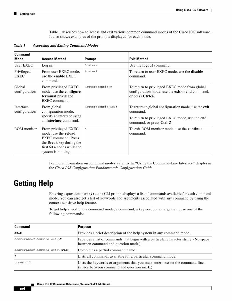
Table 1 describes how to access and exit various common command modes of the Cisco IOS software. It also shows examples of the prompts displayed for each mode.
For more information on command modes, refer to the “Using the Command-Line Interface” chapter in the Cisco IOS Configuration Fundamentals Configuration Guide.
Getting HelpEntering a question mark (?) at the CLI prompt displays a list of commands available for each command mode. You can also get a list of keywords and arguments associated with any command by using the context-sensitive help feature.
To get help specific to a command mode, a command, a keyword, or an argument, use one of the following commands:
Table 1 Accessing and Exiting Command Modes
Command Mode Access Method Prompt Exit Method
User EXEC Log in. Router> Use the logout command.
Privileged EXEC
From user EXEC mode, use the enable EXEC command.
Router# To return to user EXEC mode, use the disable command.
Global configuration
From privileged EXEC mode, use the configure terminal privileged EXEC command.
Router(config)# To return to privileged EXEC mode from global configuration mode, use the exit or end command, or press Ctrl-Z.
Interface configuration
From global configuration mode, specify an interface using an interface command.
Router(config-if)# To return to global configuration mode, use the exit command.
To return to privileged EXEC mode, use the end command, or press Ctrl-Z.
ROM monitor From privileged EXEC mode, use the reload EXEC command. Press the Break key during the first 60 seconds while the system is booting.
> To exit ROM monitor mode, use the continue command.
Command Purposehelp Provides a brief description of the help system in any command mode.
abbreviated-command-entry? Provides a list of commands that begin with a particular character string. (No space between command and question mark.)
abbreviated-command-entry<Tab> Completes a partial command name.
? Lists all commands available for a particular command mode.
command ? Lists the keywords or arguments that you must enter next on the command line. (Space between command and question mark.)
xviCisco IOS IP Command Reference, Volume 3 of 3: Multicast
Using Cisco IOS SoftwareGetting Help
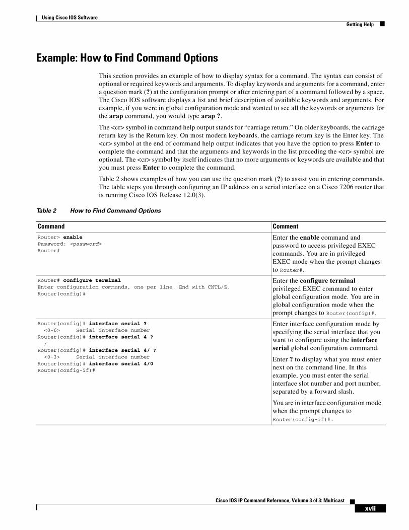
Example: How to Find Command OptionsThis section provides an example of how to display syntax for a command. The syntax can consist of optional or required keywords and arguments. To display keywords and arguments for a command, enter a question mark (?) at the configuration prompt or after entering part of a command followed by a space. The Cisco IOS software displays a list and brief description of available keywords and arguments. For example, if you were in global configuration mode and wanted to see all the keywords or arguments for the arap command, you would type arap ?.
The <cr> symbol in command help output stands for “carriage return.” On older keyboards, the carriage return key is the Return key. On most modern keyboards, the carriage return key is the Enter key. The <cr> symbol at the end of command help output indicates that you have the option to press Enter to complete the command and that the arguments and keywords in the list preceding the <cr> symbol are optional. The <cr> symbol by itself indicates that no more arguments or keywords are available and that you must press Enter to complete the command.
Table 2 shows examples of how you can use the question mark (?) to assist you in entering commands. The table steps you through configuring an IP address on a serial interface on a Cisco 7206 router that is running Cisco IOS Release 12.0(3).
Table 2 How to Find Command Options
Command Comment
Router> enablePassword: <password>Router#
Enter the enable command and password to access privileged EXEC commands. You are in privileged EXEC mode when the prompt changes to Router#.
Router# configure terminalEnter configuration commands, one per line. End with CNTL/Z.Router(config)#
Enter the configure terminal privileged EXEC command to enter global configuration mode. You are in global configuration mode when the prompt changes to Router(config)#.
Router(config)# interface serial ?<0-6> Serial interface number
Router(config)# interface serial 4 ?/
Router(config)# interface serial 4/ ?<0-3> Serial interface number
Router(config)# interface serial 4/0Router(config-if)#
Enter interface configuration mode by specifying the serial interface that you want to configure using the interface serial global configuration command.
Enter ? to display what you must enter next on the command line. In this example, you must enter the serial interface slot number and port number, separated by a forward slash.
You are in interface configuration mode when the prompt changes to Router(config-if)#.
xviiCisco IOS IP Command Reference, Volume 3 of 3: Multicast

Using Cisco IOS SoftwareGetting Help
Router(config-if)# ?Interface configuration commands:
.
.
.ip Interface Internet Protocol config commandskeepalive Enable keepalivelan-name LAN Name commandllc2 LLC2 Interface Subcommandsload-interval Specify interval for load calculation for an
interfacelocaddr-priority Assign a priority grouplogging Configure logging for interfaceloopback Configure internal loopback on an interfacemac-address Manually set interface MAC addressmls mls router sub/interface commandsmpoa MPOA interface configuration commandsmtu Set the interface Maximum Transmission Unit (MTU)netbios Use a defined NETBIOS access list or enable
name-cachingno Negate a command or set its defaultsnrzi-encoding Enable use of NRZI encodingntp Configure NTP...
Router(config-if)#
Enter ? to display a list of all the interface configuration commands available for the serial interface. This example shows only some of the available interface configuration commands.
Router(config-if)# ip ?Interface IP configuration subcommands:
access-group Specify access control for packetsaccounting Enable IP accounting on this interfaceaddress Set the IP address of an interfaceauthentication authentication subcommandsbandwidth-percent Set EIGRP bandwidth limitbroadcast-address Set the broadcast address of an interfacecgmp Enable/disable CGMPdirected-broadcast Enable forwarding of directed broadcastsdvmrp DVMRP interface commandshello-interval Configures IP-EIGRP hello intervalhelper-address Specify a destination address for UDP broadcastshold-time Configures IP-EIGRP hold time...
Router(config-if)# ip
Enter the command that you want to configure for the interface. This example uses the ip command.
Enter ? to display what you must enter next on the command line. This example shows only some of the available interface IP configuration commands.
Table 2 How to Find Command Options (continued)
Command Comment
xviiiCisco IOS IP Command Reference, Volume 3 of 3: Multicast
Using Cisco IOS SoftwareUsing the no and default Forms of Commands
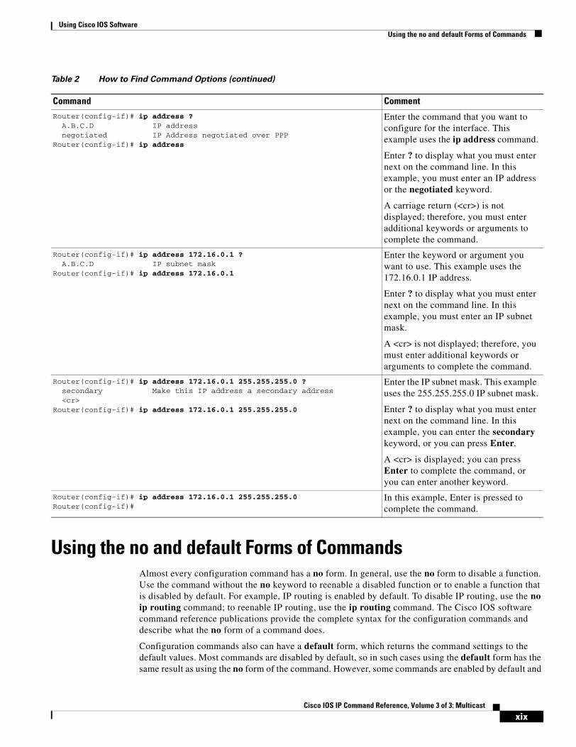
Using the no and default Forms of CommandsAlmost every configuration command has a no form. In general, use the no form to disable a function. Use the command without the no keyword to reenable a disabled function or to enable a function that is disabled by default. For example, IP routing is enabled by default. To disable IP routing, use the no ip routing command; to reenable IP routing, use the ip routing command. The Cisco IOS software command reference publications provide the complete syntax for the configuration commands and describe what the no form of a command does.
Configuration commands also can have a default form, which returns the command settings to the default values. Most commands are disabled by default, so in such cases using the default form has the same result as using the no form of the command. However, some commands are enabled by default and
Router(config-if)# ip address ?A.B.C.D IP addressnegotiated IP Address negotiated over PPP
Router(config-if)# ip address
Enter the command that you want to configure for the interface. This example uses the ip address command.
Enter ? to display what you must enter next on the command line. In this example, you must enter an IP address or the negotiated keyword.
A carriage return (<cr>) is not displayed; therefore, you must enter additional keywords or arguments to complete the command.
Router(config-if)# ip address 172.16.0.1 ?A.B.C.D IP subnet mask
Router(config-if)# ip address 172.16.0.1
Enter the keyword or argument you want to use. This example uses the 172.16.0.1 IP address.
Enter ? to display what you must enter next on the command line. In this example, you must enter an IP subnet mask.
A <cr> is not displayed; therefore, you must enter additional keywords or arguments to complete the command.
Router(config-if)# ip address 172.16.0.1 255.255.255.0 ?secondary Make this IP address a secondary address<cr>
Router(config-if)# ip address 172.16.0.1 255.255.255.0
Enter the IP subnet mask. This example uses the 255.255.255.0 IP subnet mask.
Enter ? to display what you must enter next on the command line. In this example, you can enter the secondary keyword, or you can press Enter.
A <cr> is displayed; you can press Enter to complete the command, or you can enter another keyword.
Router(config-if)# ip address 172.16.0.1 255.255.255.0Router(config-if)#
In this example, Enter is pressed to complete the command.
Table 2 How to Find Command Options (continued)
Command Comment
xixCisco IOS IP Command Reference, Volume 3 of 3: Multicast
Using Cisco IOS SoftwareSaving Configuration Changes
have variables set to certain default values. In these cases, the default form of the command enables the command and sets the variables to their default values. The Cisco IOS software command reference publications describe the effect of the default form of a command if the command functions differently than the no form.
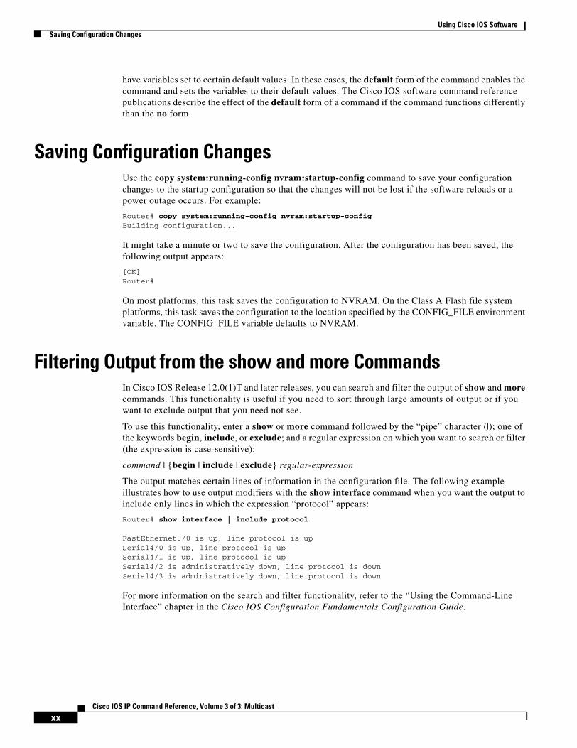
Saving Configuration ChangesUse the copy system:running-config nvram:startup-config command to save your configuration changes to the startup configuration so that the changes will not be lost if the software reloads or a power outage occurs. For example:
Router# copy system:running-config nvram:startup-configBuilding configuration...
It might take a minute or two to save the configuration. After the configuration has been saved, the following output appears:
[OK]Router#
On most platforms, this task saves the configuration to NVRAM. On the Class A Flash file system platforms, this task saves the configuration to the location specified by the CONFIG_FILE environment variable. The CONFIG_FILE variable defaults to NVRAM.
Filtering Output from the show and more CommandsIn Cisco IOS Release 12.0(1)T and later releases, you can search and filter the output of show and more commands. This functionality is useful if you need to sort through large amounts of output or if you want to exclude output that you need not see.
To use this functionality, enter a show or more command followed by the “pipe” character (|); one of the keywords begin, include, or exclude; and a regular expression on which you want to search or filter (the expression is case-sensitive):
command | {begin | include | exclude} regular-expression
The output matches certain lines of information in the configuration file. The following example illustrates how to use output modifiers with the show interface command when you want the output to include only lines in which the expression “protocol” appears:
Router# show interface | include protocol
FastEthernet0/0 is up, line protocol is upSerial4/0 is up, line protocol is upSerial4/1 is up, line protocol is upSerial4/2 is administratively down, line protocol is downSerial4/3 is administratively down, line protocol is down
For more information on the search and filter functionality, refer to the “Using the Command-Line Interface” chapter in the Cisco IOS Configuration Fundamentals Configuration Guide.
xxCisco IOS IP Command Reference, Volume 3 of 3: Multicast
Using Cisco IOS SoftwareIdentifying Supported Platforms
Identifying Supported PlatformsCisco IOS software is packaged in feature sets consisting of software images that support specific platforms. The feature sets available for a specific platform depend on which Cisco IOS software images are included in a release. To identify the set of software images available in a specific release or to find out if a feature is available in a given Cisco IOS software image, see the following sections:
• Using Feature Navigator
• Using Software Release Notes
Using Feature NavigatorFeature Navigator is a web-based tool that enables you to quickly determine which Cisco IOS software images support a particular set of features and which features are supported in a particular Cisco IOS image.
Feature Navigator is available 24 hours a day, 7 days a week. To access Feature Navigator, you must have an account on Cisco.com. If you have forgotten or lost your account information, e-mail the Contact Database Administration group at [email protected]. If you do not have an account on Cisco.com, go to http://www.cisco.com/register and follow the directions to establish an account.
To use Feature Navigator, you must have a JavaScript-enabled web browser such as Netscape 3.0 or later, or Internet Explorer 4.0 or later. Internet Explorer 4.0 always has JavaScript enabled. To enable JavaScript for Netscape 3.x or Netscape 4.x, follow the instructions provided with the web browser. For JavaScript support and enabling instructions for other browsers, check with the browser vendor.
Feature Navigator is updated when major Cisco IOS software releases and technology releases occur. You can access Feature Navigator at the following URL:
http://www.cisco.com/go/fn
Using Software Release NotesCisco IOS software releases include release notes that provide the following information:
• Platform support information
• Memory recommendations
• Microcode support information
• Feature set tables
• Feature descriptions
• Open and resolved severity 1 and 2 caveats for all platforms
Release notes are intended to be release-specific for the most current release, and the information provided in these documents may not be cumulative in providing information about features that first appeared in previous releases.
xxiCisco IOS IP Command Reference, Volume 3 of 3: Multicast

Using Cisco IOS SoftwareIdentifying Supported Platforms
xxiiCisco IOS IP Command Reference, Volume 3 of 3: Multicast
IP Multicast Routing Commands
This chapter describes the commands used to configure and monitor IP multicast routing. For IP multicast routing configuration information and examples, refer to the “Configuring IP Multicast Routing” chapter of the Cisco IOS IP Configuration Guide.
IP3R-1Cisco IOS IP Command Reference, Volume 3 of 3: Multicast
IP Multicast Routing Commandsclear ip cgmp
clear ip cgmpTo clear all group entries from the caches of Catalyst switches, use the clear ip cgmp command in EXEC mode.
clear ip cgmp [type number]
Syntax Description
Command Modes EXEC
Command History
Usage Guidelines This command sends a Cisco Group Management Protocol (CGMP) leave message with a group address of 0000.0000.0000 and a unicast address of 0000.0000.0000. This message instructs the switches to clear all group entries they have cached.
If an interface type and number are specified, the leave message is sent only on that interface. Otherwise, it is sent on all CGMP-enabled interfaces.
Examples The following example clears the CGMP cache:
Router# clear ip cgmp
Related Commands
type number (Optional) Interface type and number.
Release Modification
11.1 This command was introduced.
Command Description
ip cgmp Enables CGMP on an interface of a router connected to a Catalyst 5000 switch.
IP3R-2Cisco IOS IP Command Reference, Volume 3 of 3: Multicast

IP Multicast Routing Commandsclear ip dvmrp route
clear ip dvmrp routeTo delete routes from the Distance Vector Multicast Routing Protocol (DVMRP) routing table, use the clear ip dvmrp route command in EXEC mode.
clear ip dvmrp route {* | route}
Syntax Description
Command Modes EXEC
Command History
Examples The following example deletes route 10.1.1.1 from the DVMRP routing table:
Router# clear ip dvmrp route 10.1.1.1
* Clears all routes from the DVMRP table.
route Clears the longest matched route. Can be an IP address, a network number, or an IP Domain Name System (DNS) name.
Release Modification
11.0 This command was introduced.
IP3R-3Cisco IOS IP Command Reference, Volume 3 of 3: Multicast
IP Multicast Routing Commandsclear ip igmp group
clear ip igmp groupTo delete entries from the Internet Group Management Protocol (IGMP) cache, use the clear ip igmp group command in EXEC mode.
clear ip igmp group [group-name | group-address | type number]
Syntax Description
Defaults When this command is used with no arguments, all entries are deleted from the IGMP cache.
Command Modes EXEC
Command History
Usage Guidelines The IGMP cache contains a list of the multicast groups of which hosts on the directly connected LAN are members. If the router has joined a group, it is also listed in the cache.
To delete all entries from the IGMP cache, specify the clear ip igmp group command with no arguments.
Examples The following example clears entries for the multicast group 224.0.255.1 from the IGMP cache:
Router# clear ip igmp group 224.0.255.1
Related Commands
group-name (Optional) Name of the multicast group, as defined in the Domain Name System (DNS) hosts table or with the ip host command.
group-address (Optional) Address of the multicast group. This is a multicast IP address in four-part, dotted notation.
type number (Optional) Interface type and number.
Release Modification
10.0 This command was introduced.
Command Description
ip host Defines a static host name-to-address mapping in the host cache.
show ip igmp groups Displays the multicast groups that are directly connected to the router and that were learned through IGMP.
show ip igmp interface Displays multicast-related information about an interface.
IP3R-4Cisco IOS IP Command Reference, Volume 3 of 3: Multicast
IP Multicast Routing Commandsclear ip mroute
clear ip mrouteTo delete entries from the IP multicast routing table, use the clear ip mroute command in EXEC mode.
clear ip mroute {* | group-name [source-name | source-address] | group-address [source-name | source-address]}
Syntax Description
Command Modes EXEC
Command History
Examples The following example deletes all entries from the IP multicast routing table:
Router# clear ip mroute *
The following example deletes from the IP multicast routing table all sources on the 10.3.0.0 subnet that are sending to the multicast group 224.2.205.42. Note that this example deletes all sources on network 10.3, not individual sources.
Router# clear ip mroute 224.2.205.42 10.3.0.0
Related Commands
* Deletes all entries from the IP multicast routing table.
group-name Name of the multicast group, as defined in the Domain Name System (DNS) hosts table or with the ip host command.
group-address IP address of the multicast group. This is a multicast IP address in four-part, dotted notation.
source-name | source-address
(Optional) If you specify a group name or address, you can also specify a name or address of a multicast source that is sending to the group. A source need not be a member of the group.
Release Modification
10.0 This command was introduced.
Command Description
ip host Defines a static host name-to-address mapping in the host cache.
show ip mroute Displays the contents of the IP multicast routing table.
IP3R-5Cisco IOS IP Command Reference, Volume 3 of 3: Multicast

IP Multicast Routing Commandsclear ip pim auto-rp
clear ip pim auto-rpThe clear ip pim auto-rp command is replaced by the clear ip pim rp-mapping command. See the clear ip pim rp-mapping command for more information.
IP3R-6Cisco IOS IP Command Reference, Volume 3 of 3: Multicast

IP Multicast Routing Commandsclear ip pim rp-mapping
clear ip pim rp-mappingTo delete group-to-rendezvous point (RP) mapping entries from the RP mapping cache, use the clear ip pim rp-mapping command in privileged EXEC mode.
clear ip pim [vrf vrf-name] rp-mapping [rp-address]
Syntax Description
Command Modes Privileged EXEC
Command History
Usage Guidelines The clear ip pim rp-mapping command replaces the clear ip pim auto-rp command.
The clear ip pim rp-mapping command deletes group-to-RP mapping entries learned by Auto-RP or by a bootstrap router (BSR) from the RP mapping cache.
Use the show ip pim rp command to display active RPs that are cached with associated multicast routing entries.
Examples The following example shows how to clear all group-to-RP entries from the RP mapping cache:
Router# clear ip pim rp-mapping
Related Commands
vrf (Optional) Supports the multicast VPN routing and forwarding (VRF) instance.
vrf-name (Optional) Name assigned to the VRF.
rp-address (Optional) IP address of the RP about which to clear associated group-to-RP mappings. If this argument is omitted, all group-to-RP mapping entries are cleared.
Release Modification
11.3 This command was introduced.
12.1 The clear ip pim auto-rp command was deprecated and replaced by the clear ip pim rp-mapping command.
12.0(23)S The vrf keyword and vrf-name argument were added.
Command Description
show ip pim rp Displays active RPs that are cached with associated multicast routing entries.
IP3R-7Cisco IOS IP Command Reference, Volume 3 of 3: Multicast
IP Multicast Routing Commandsclear ip rtp header-compression
clear ip rtp header-compressionTo clear Real-Time Transport Protocol (RTP) header compression structures and statistics, use the clear ip rtp header-compression command in EXEC mode.
clear ip rtp header-compression [type number]
Syntax Description
Command Modes EXEC
Command History
Usage Guidelines If this command is used without an interface type and number, it clears all RTP header compression structures and statistics.
Examples The following example clears RTP header compression structures and statistics for serial interface 0:
Router# clear ip rtp header-compression serial 0
Related Commands
type number (Optional) Interface type and number.
Release Modification
11.3 This command was introduced.
Command Description
ip rtp header-compression Enables RTP header compression.
IP3R-8Cisco IOS IP Command Reference, Volume 3 of 3: Multicast
IP Multicast Routing Commandsclear ip sap
clear ip sapTo delete a Session Announcement Protocol (SAP) cache entry or the entire SAP cache, use the clear ip sap command in EXEC mode.
clear ip sap [group-address | “session-name”]
Syntax Description
Command Modes EXEC
Command History
Usage Guidelines If no arguments or keywords are used with this command, the system deletes the entire SAP cache.
Examples The following example clears the SAP cache:
Router# clear ip sap “Sample Session”
Related Commands
group-address (Optional) Deletes all sessions associated with the IP group address.
“session-name” (Optional) Deletes only the SAP cache entry with the specified session name. The session name is enclosed in quotation marks (“ ”) that the user must enter.
Release Modification
11.1 The clear ip sdr command was introduced.
12.2 The clear ip sdr command was replaced by the clear ip sap command.
Command Description
ip sap cache-timeout Limits how long a SAP cache entry stays active in the cache.
ip sap listen Enables the Cisco IOS software to listen to session directory announcements.
show ip sap Displays the SAP cache.
IP3R-9Cisco IOS IP Command Reference, Volume 3 of 3: Multicast

IP Multicast Routing Commandsclear ip sdr
clear ip sdrThe clear ip sdr command is replaced by the clear ip sap command. See the description of the clear ip sap command in this chapter for more information.
IP3R-10Cisco IOS IP Command Reference, Volume 3 of 3: Multicast
IP Multicast Routing Commandsframe-relay ip rtp compression-connections
frame-relay ip rtp compression-connectionsTo specify the maximum number of Real-Time Transport Protocol (RTP) header compression connections that can exist on a Frame Relay interface, use the frame-relay ip rtp compression-connections command in interface configuration mode. To restore the default, use the no form of this command.
frame-relay ip rtp compression-connections number
no frame-relay ip rtp compression-connections
Syntax Description
Defaults No default behavior or values.
Command Modes Interface configuration
Command History
Usage Guidelines Before you can configure the maximum number of connections, RTP header compression must be configured on the interface using the frame-relay ip rtp header-compression command.
The number of RTP header compression connections must be set to the same value at each end of the connection.
Examples The following example shows the configuration of a maximum of 150 RTP header compression connections on serial interface 0:
interface serial 0encapsulation frame-relayframe-relay ip rtp header-compressionframe-relay ip rtp compression-connections 150
number Maximum number of RTP header compression connections. The range is from 3 to 256.
Release Modification
12.1(2)T This command was introduced.
IP3R-11Cisco IOS IP Command Reference, Volume 3 of 3: Multicast
IP Multicast Routing Commandsframe-relay ip rtp compression-connections
Related Commands Command Description
frame-relay ip rtp header-compression Enables RTP header compression for all Frame Relay maps on a physical interface.
frame-relay map ip compress Enables both RTP and TCP header compression on a link.
frame-relay map ip rtp header-compression Enables RTP header compression per DLCI.
show frame-relay ip rtp header-compression Displays RTP header compression statistics for Frame Relay.
IP3R-12Cisco IOS IP Command Reference, Volume 3 of 3: Multicast
IP Multicast Routing Commandsframe-relay ip rtp header-compression
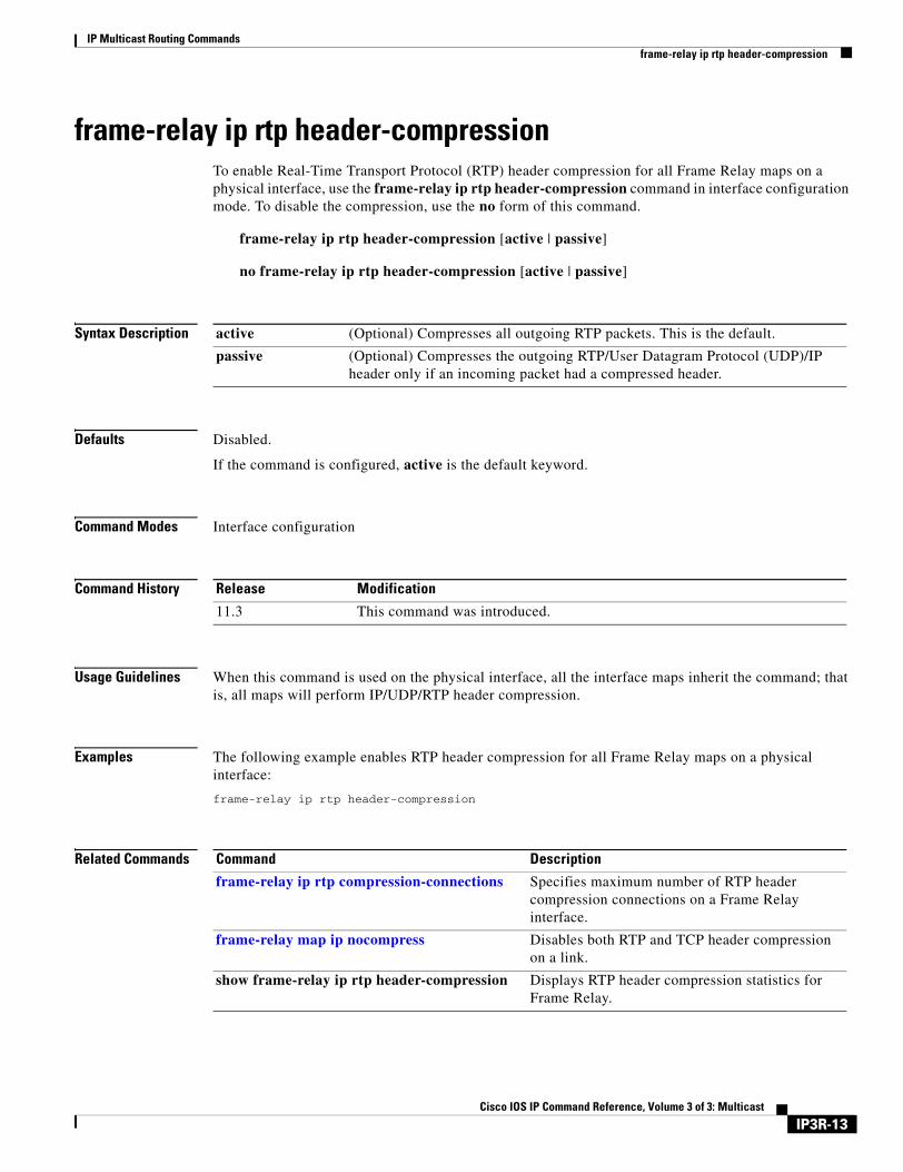
frame-relay ip rtp header-compressionTo enable Real-Time Transport Protocol (RTP) header compression for all Frame Relay maps on a physical interface, use the frame-relay ip rtp header-compression command in interface configuration mode. To disable the compression, use the no form of this command.
frame-relay ip rtp header-compression [active | passive]
no frame-relay ip rtp header-compression [active | passive]
Syntax Description
Defaults Disabled.
If the command is configured, active is the default keyword.
Command Modes Interface configuration
Command History
Usage Guidelines When this command is used on the physical interface, all the interface maps inherit the command; that is, all maps will perform IP/UDP/RTP header compression.
Examples The following example enables RTP header compression for all Frame Relay maps on a physical interface:
frame-relay ip rtp header-compression
Related Commands
active (Optional) Compresses all outgoing RTP packets. This is the default.
passive (Optional) Compresses the outgoing RTP/User Datagram Protocol (UDP)/IP header only if an incoming packet had a compressed header.
Release Modification
11.3 This command was introduced.
Command Description
frame-relay ip rtp compression-connections Specifies maximum number of RTP header compression connections on a Frame Relay interface.
frame-relay map ip nocompress Disables both RTP and TCP header compression on a link.
show frame-relay ip rtp header-compression Displays RTP header compression statistics for Frame Relay.
IP3R-13Cisco IOS IP Command Reference, Volume 3 of 3: Multicast
IP Multicast Routing Commandsframe-relay map ip compress
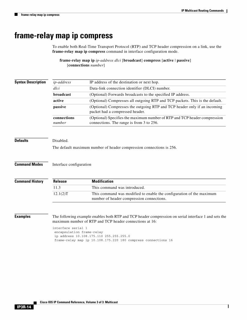
frame-relay map ip compressTo enable both Real-Time Transport Protocol (RTP) and TCP header compression on a link, use the frame-relay map ip compress command in interface configuration mode.
frame-relay map ip ip-address dlci [broadcast] compress [active | passive] [connections number]
Syntax Description
Defaults Disabled.
The default maximum number of header compression connections is 256.
Command Modes Interface configuration
Command History
Examples The following example enables both RTP and TCP header compression on serial interface 1 and sets the maximum number of RTP and TCP header connections at 16:
interface serial 1encapsulation frame-relayip address 10.108.175.110 255.255.255.0frame-relay map ip 10.108.175.220 180 compress connections 16
ip-address IP address of the destination or next hop.
dlci Data-link connection identifier (DLCI) number.
broadcast (Optional) Forwards broadcasts to the specified IP address.
active (Optional) Compresses all outgoing RTP and TCP packets. This is the default.
passive (Optional) Compresses the outgoing RTP and TCP header only if an incoming packet had a compressed header.
connections number
(Optional) Specifies the maximum number of RTP and TCP header compression connections. The range is from 3 to 256.
Release Modification
11.3 This command was introduced.
12.1(2)T This command was modified to enable the configuration of the maximum number of header compression connections.
IP3R-14Cisco IOS IP Command Reference, Volume 3 of 3: Multicast
IP Multicast Routing Commandsframe-relay map ip compress
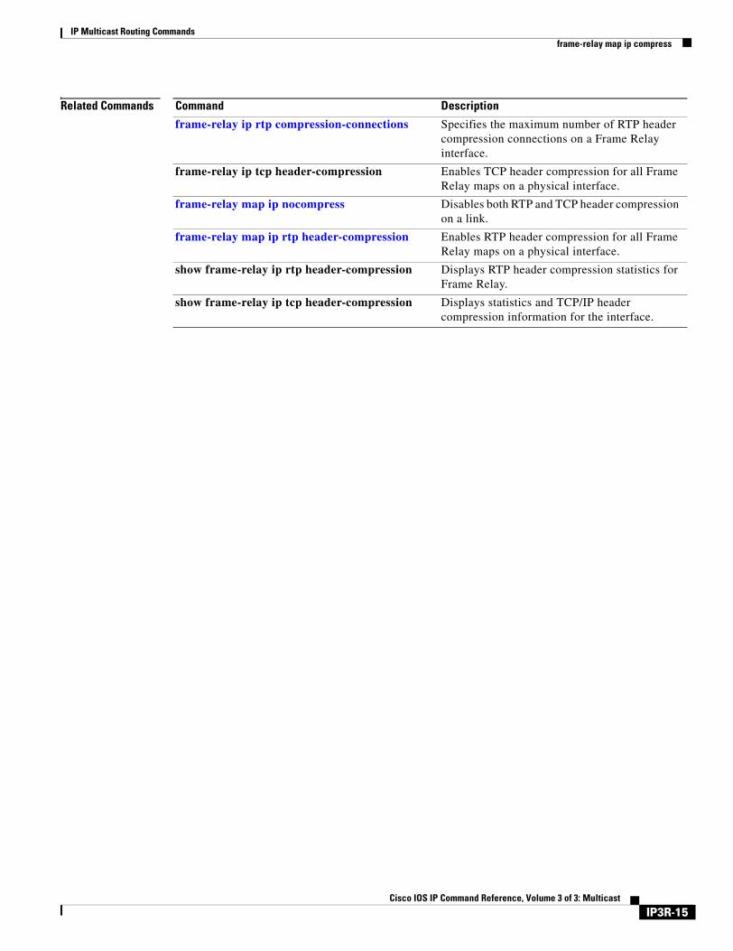
Related Commands Command Description
frame-relay ip rtp compression-connections Specifies the maximum number of RTP header compression connections on a Frame Relay interface.
frame-relay ip tcp header-compression Enables TCP header compression for all Frame Relay maps on a physical interface.
frame-relay map ip nocompress Disables both RTP and TCP header compression on a link.
frame-relay map ip rtp header-compression Enables RTP header compression for all Frame Relay maps on a physical interface.
show frame-relay ip rtp header-compression Displays RTP header compression statistics for Frame Relay.
show frame-relay ip tcp header-compression Displays statistics and TCP/IP header compression information for the interface.
IP3R-15Cisco IOS IP Command Reference, Volume 3 of 3: Multicast
IP Multicast Routing Commandsframe-relay map ip nocompress
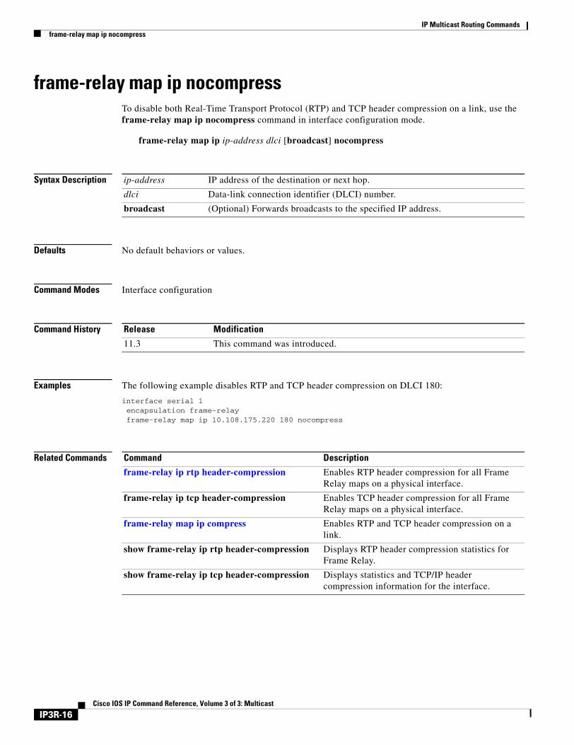
frame-relay map ip nocompressTo disable both Real-Time Transport Protocol (RTP) and TCP header compression on a link, use the frame-relay map ip nocompress command in interface configuration mode.
frame-relay map ip ip-address dlci [broadcast] nocompress
Syntax Description
Defaults No default behaviors or values.
Command Modes Interface configuration
Command History
Examples The following example disables RTP and TCP header compression on DLCI 180:
interface serial 1encapsulation frame-relayframe-relay map ip 10.108.175.220 180 nocompress
Related Commands
ip-address IP address of the destination or next hop.
dlci Data-link connection identifier (DLCI) number.
broadcast (Optional) Forwards broadcasts to the specified IP address.
Release Modification
11.3 This command was introduced.
Command Description
frame-relay ip rtp header-compression Enables RTP header compression for all Frame Relay maps on a physical interface.
frame-relay ip tcp header-compression Enables TCP header compression for all Frame Relay maps on a physical interface.
frame-relay map ip compress Enables RTP and TCP header compression on a link.
show frame-relay ip rtp header-compression Displays RTP header compression statistics for Frame Relay.
show frame-relay ip tcp header-compression Displays statistics and TCP/IP header compression information for the interface.
IP3R-16Cisco IOS IP Command Reference, Volume 3 of 3: Multicast
IP Multicast Routing Commandsframe-relay map ip rtp header-compression
frame-relay map ip rtp header-compressionTo enable Real-Time Transport Protocol (RTP) header compression per data-link connection identifier (DLCI), use the frame-relay map ip rtp header-compression command in interface configuration mode.
frame-relay map ip ip-address dlci [broadcast] rtp header-compression [active | passive][connections number]
Syntax Description
Defaults Disabled.
If the command is configured, active is the default keyword.
The default maximum number of header compression connections is 256.
Command Modes Interface configuration
Command History
Usage Guidelines When this command is configured, the specified maps inherit RTP header compression. You can have multiple Frame Relay maps, with and without RTP header compression. If you do not specify the number of RTP header compression connections, the map will inherit the current value from the interface.
Examples The following example enables RTP header compression on serial interface 1 and sets the maximum number of RTP header compression connections at 64:
interface serial 1encapsulation frame-relayip address 10.108.175.110 255.255.255.0frame-relay map ip 10.108.175.220 180 rtp header-compression connections 64
ip-address IP address of the destination or next hop.
dlci DLCI number.
broadcast (Optional) Forwards broadcasts to the specified IP address.
active (Optional) Compresses outgoing RTP packets. This is the default.
passive (Optional) Compresses the outgoing RTP/UDP/IP header only if an incoming packet had a compressed header.
connections number
(Optional) Specifies the maximum number of RTP header compression connections. The range is from 3 to 256.
Release Modification
11.3 This command was introduced.
12.1(2)T This command was modified to enable the configuration of the maximum number of header compression connections.
IP3R-17Cisco IOS IP Command Reference, Volume 3 of 3: Multicast
IP Multicast Routing Commandsframe-relay map ip rtp header-compression
Related Commands Command Description
frame-relay ip rtp compression-connections Specifies the maximum number of RTP header compression connections on a Frame Relay interface.
frame-relay ip rtp header-compression Enables RTP header compression for all Frame Relay maps on a physical interface.
frame-relay map ip compress Enables both RTP and TCP header compression on a link.
show frame-relay ip rtp header-compression Displays RTP header compression statistics for Frame Relay.
IP3R-18Cisco IOS IP Command Reference, Volume 3 of 3: Multicast
IP Multicast Routing Commandsip cgmp
ip cgmpTo enable Cisco Group Management Protocol (CGMP) on an interface of a router connected to a Cisco Catalyst 5000 family switch, use the ip cgmp command in interface configuration mode. To disable CGMP routing, use the no form of this command.
ip cgmp [proxy | router-only]
no ip cgmp
Syntax Description
Defaults CGMP is disabled.
Command Modes Interface configuration
Command History
Usage Guidelines When enabled on an interface, this command triggers a CGMP join message. This command should be used only on 802 media (that is, Ethernet, FDDI, or Token Ring) or ATM. When a no ip cgmp command is issued, a triggered CGMP leave message is sent for the MAC address on the interface for group 0000.0000.0000 (all groups). CGMP can run on an interface only if Protocol Independent Multicast (PIM) is configured on the same interface.
A Cisco router will send CGMP join messages in response to receiving Internet Group Management Protocol (IGMP) reports from IGMP-capable members. Only the CGMP querier Cisco router sends these CGMP join messages on behalf of hosts.
The ip cgmp router-only command enables the routers in a VLAN to send only CGMP self-join and CGMP self-leave messages—no other types of CGMP messages will be sent. This feature allows other CGMP-capable routers to learn about multicast router ports. If the ip cgmp router-only command is not available on any of the external routers in the network, the ip cgmp command can be used instead. Issuing the ip cgmp command on a router enables that router to send CGMP self-join and CGMP self-leave messages as well as other types of CGMP messages.
When the proxy keyword is specified, the CGMP proxy function is also enabled. That is, any router that is not CGMP-capable will be advertised by the proxy router. The proxy router advertises the existence of other non-CGMP-capable routers by sending a CGMP join message with the MAC address of the non-CGMP-capable router and a group address of 0000.0000.0000.
proxy (Optional) Enables CGMP and the CGMP proxy function.
router-only (Optional) Enables the router to send only CGMP self-join and CGMP self-leave messages.
Release Modification
11.1 This command was introduced.
12.2 The router-only keyword was added.
IP3R-19Cisco IOS IP Command Reference, Volume 3 of 3: Multicast
IP Multicast Routing Commandsip cgmp
Initially supported is Distance Vector Multicast Routing Protocol (DVMRP) proxying. If a DVMRP report is received from a router that is not a PIM router, a Cisco IGMP querier will advertise the MAC address of the DVMRP router in a CGMP join message with the group address 0000.0000.0000.
To perform CGMP proxy, a Cisco router must be the IGMP querier. If you configure the ip cgmp proxy command, you must manipulate the IP addresses so that a Cisco router will be the IGMP querier, which might be the highest or lowest IP address, depending on which version of IGMP is being run on the network. An IGMP Version 2 querier is selected based on the lowest IP addressed router on the interface. An IGMP Version 1 querier is selected based on the multicast routing protocol used on the interface.
When multiple Cisco routers are connected to a switched network and the ip cgmp proxy command is needed, we recommend that all routers be configured in the following manner:
• With the same CGMP option.
• To have precedence of becoming IGMP querier over non-Cisco routers.
Examples The following example enables CGMP:
ip cgmp
The following example enables CGMP and CGMP proxy:
ip cgmp proxy
IP3R-20Cisco IOS IP Command Reference, Volume 3 of 3: Multicast
IP Multicast Routing Commandsip dvmrp accept-filter
ip dvmrp accept-filterTo configure an acceptance filter for incoming Distance Vector Multicast Routing Protocol (DVMRP) reports, use the ip dvmrp accept-filter command in interface configuration mode. To disable this filter, use the no form of this command.
ip dvmrp accept-filter access-list [distance | neighbor-list access-list]
no ip dvmrp accept-filter access-list [distance | neighbor-list access-list]
Syntax Description
Defaults All destination reports are accepted with a distance of 0. Default settings accept reports from all neighbors.
Command Modes Interface configuration
Command History
Usage Guidelines Any sources that match the access list are stored in the DVMRP routing table with the distance argument.
The distance value is used to compare with the same source in the unicast routing table. The route with the lower distance (either the route in the unicast routing table or that in the DVMRP routing table) takes precedence when computing the Reverse Path Forwarding (RPF) interface for a source of a multicast packet.
By default, the administrative distance for DVMRP routes is 0, which means that they always take precedence over unicast routing table routes. If you have two paths to a source, one through unicast routing (using Protocol Independent Multicast [PIM] as the multicast routing protocol) and another path using DVMRP (unicast and multicast routing), and if you want to use the PIM path, use the ip dvmrp accept-filter command to increase the administrative distance for DVMRP routes.
access-list Access list number or name. A value of 0 means that all sources are accepted with the configured distance.
distance (Optional) Administrative distance to the destination.
neighbor-list access-list (Optional) Number of a neighbor list. DVMRP reports are accepted only by those neighbors on the list.
Release Modification
10.0 This command was introduced.
11.2 The neighbor-list keyword and access-list-number argument were added.
IP3R-21Cisco IOS IP Command Reference, Volume 3 of 3: Multicast
IP Multicast Routing Commandsip dvmrp accept-filter
Examples The following example shows how to apply an access list such that the RPF interface used to accept multicast packets will be through an Enhanced Interior Gateway Routing Protocol (IGRP)/PIM path. The Enhanced IGRP unicast routing protocol has a default administrative distance of 90.
ip dvmrp accept-filter 1 100access-list 1 permit 0.0.0.0 255.255.255.255
The following example applies access list 57 to the interface and sets a distance of 4:
access-list 57 permit 131.108.0.0 0.0.255.255access-list 57 permit 198.92.37.0 0.0.0.255access-list 57 deny 0.0.0.0 255.255.255.255ip dvmrp accept-filter 57 4
Related Commands Command Description
distance (IP) Defines an administrative distance.
ip dvmrp metric Configures the metric associated with a set of destinations for DVMRP reports.
show ip dvmrp route Displays the contents of the DVMRP routing table.
tunnel mode Sets the encapsulation mode for the tunnel interface.
IP3R-22Cisco IOS IP Command Reference, Volume 3 of 3: Multicast
IP Multicast Routing Commandsip dvmrp auto-summary
ip dvmrp auto-summaryTo enable Distance Vector Multicast Routing Protocol (DVMRP) automatic summarization if it was disabled, use the ip dvmrp auto-summary command in interface configuration mode. To disable the feature, use the no form of this command.
ip dvmrp auto-summary
no ip dvmrp auto-summary
Syntax Description This command has no arguments or keywords.
Defaults Enabled
Command Modes Interface configuration
Command History
Usage Guidelines DVMRP automatic summarization occurs when a unicast subnet route is collapsed into a classful network number route. This situation occurs when the subnet is a different network number than the IP address of the interface (or tunnel) over which the advertisement is sent. If the interface is unnumbered, the network number of the numbered interface the unnumbered interface points to is compared to the subnet.
Disable this feature if the information you want to send using the ip dvmrp summary-address command is the same as the information that would be sent using DVMRP automatic-summarization.
Examples The following example disables DVMRP automatic summarization:
no ip dvmrp auto-summary
Related Commands
Release Modification
11.2 This command was introduced.
Command Description
ip dvmrp summary-address Configures a DVMRP summary address to be advertised out the interface.
IP3R-23Cisco IOS IP Command Reference, Volume 3 of 3: Multicast

IP Multicast Routing Commandsip dvmrp default-information
ip dvmrp default-informationTo advertise network 0.0.0.0 to Distance Vector Multicast Routing Protocol (DVMRP) neighbors on an interface, use the ip dvmrp default-information command in interface configuration mode. To prevent the advertisement, use the no form of this command.
ip dvmrp default-information {originate | only}
no ip dvmrp default-information {originate | only}
Syntax Description
Defaults Disabled
Command Modes Interface configuration
Command History
Usage Guidelines This command should only be used when the router is a neighbor to mrouted version 3.6 devices. The mrouted protocol is a public domain implementation of DVMRP.
You can use the ip dvmrp metric command with the ip dvmrp default-information command to tailor the metric used when advertising the default route 0.0.0.0. By default, metric 1 is used.
Examples The following example configures the Cisco IOS software to advertise network 0.0.0.0, in addition to other networks, to DVMRP neighbors:
ip dvmrp default-information originate
Related Commands
originate Other routes more specific than 0.0.0.0 may be advertised.
only No DVMRP routes other than 0.0.0.0 are advertised.
Release Modification
10.3 This command was introduced.
Command Description
ip dvmrp metric Configures the metric associated with a set of destinations for DVMRP reports.
IP3R-24Cisco IOS IP Command Reference, Volume 3 of 3: Multicast
IP Multicast Routing Commandsip dvmrp metric
ip dvmrp metricTo configure the metric associated with a set of destinations for Distance Vector Multicast Routing Protocol (DVMRP) reports, use the appropriate form of the ip dvmrp metric command in interface configuration mode. To disable this function, use the appropriate no form of this command.
ip dvmrp metric metric [list access-list] [route-map map-name] [mbgp] [protocol process-id]
no ip dvmrp metric metric [list access-list] [route-map map-name] [mbgp] [protocol process-id]
Syntax Description
Defaults No metric is preconfigured. Only directly connected subnets and networks are advertised to neighboring DVMRP routers.
Command Modes Interface configuration
Command History
metric Metric associated with a set of destinations for DVMRP reports. It can be a value from 0 to 32. A value of 0 means that the route is not advertised. A value of 32 is equivalent to infinity (unreachable).
list access-list (Optional) Number name of an access list. If you specify this argument, only the multicast destinations that match the access list are reported with the configured metric. Any destinations not advertised because of split horizon do not use the configured metric.
route-map map-name (Optional) Name of the route map. Only the destinations that match the route map are reported with the configured metric. Unicast routes are subject to route map conditions before being injected into DVMRP. Route maps cannot be used for DVMRP routes.
mbgp (Optional) Configures redistribution of only IP version 4 (IPv4) multicast routes into DVMRP.
protocol (Optional) Name of unicast routing protocol, such as bgp, eigrp, igrp, isis, ospf, rip, static, or dvmrp.
If you specify these arguments, only routes learned by the specified routing protocol are advertised in DVMRP report messages.
process-id (Optional) Process ID number of the unicast routing protocol.
Release Modification
10.2 This command was introduced.
11.1 The route-map keyword was added.
12.1 The mbgp keyword was added.
IP3R-25Cisco IOS IP Command Reference, Volume 3 of 3: Multicast
IP Multicast Routing Commandsip dvmrp metric
Usage Guidelines When Protocol Independent Multicast (PIM) is configured on an interface and DVMRP neighbors are discovered, the Cisco IOS software sends DVMRP report messages for directly connected networks. The ip dvmrp metric command enables DVMRP report messages for multicast destinations that match the access list. Usually, the metric for these routes is 1. Under certain circumstances, you might want to tailor the metric used for various unicast routes. This command lets you configure the metric associated with a set of destinations for report messages sent out this interface.
You can use the access-list-number argument in conjunction with the protocol process-id arguments to selectively list the destinations learned from a given routing protocol.
To display DVMRP activity, use the debug ip dvmrp command.
Examples The following example connects a PIM cloud to a DVMRP cloud. Access list 1 permits the sending of DVMRP reports to the DVMRP routers advertising all sources in the 198.92.35.0 network with a metric of 1. Access list 2 permits all other destinations, but the metric of 0 means that no DVMRP reports are sent for these destinations.
access-list 1 permit 198.92.35.0 0.0.0.255access-list 1 deny 0.0.0.0 255.255.255.255access-list 2 permit 0.0.0.0 255.255.255.255interface tunnel 0ip dvmrp metric 1 list 1ip dvmrp metric 0 list 2
The following example redistributes IPv4 multicast routes into DVMRP neighbors with a metric of 1:
interface tunnel 0ip dvmrp metric 1 mbgp
Related Commands Command Description
debug ip dvmrp Displays information on DVMRP packets received and sent.
ip dvmrp accept-filter Configures an acceptance filter for incoming DVMRP reports.
IP3R-26Cisco IOS IP Command Reference, Volume 3 of 3: Multicast
IP Multicast Routing Commandsip dvmrp metric-offset
ip dvmrp metric-offsetTo change the metrics of advertised Distance Vector Multicast Routing Protocol (DVMRP) routes and thus favor or not favor a certain route, use the ip dvmrp metric-offset command in interface configuration mode. To restore the default values, use the no form of this command.
ip dvmrp metric-offset [in | out] increment
no ip dvmrp metric-offset
Syntax Description
Defaults If neither in nor out is specified, in is the default.
The default for in is 1.
The default for out is 0.
Command Modes Interface configuration
Command History
Usage Guidelines Use this command to influence which routes are used, as you prefer. The DVMRP metric is in hop count.
Examples The following example adds 10 to the incoming DVMRP reports:
ip dvmrp metric-offset 10
in (Optional) The increment value is added to incoming DVMRP reports and is reported in mrinfo replies. The default for in is 1.
out (Optional) The increment value is added to outgoing DVMRP reports for routes from the DVMRP routing table. The default for out is 0.
increment Value added to the metric of a DVMRP route advertised in a report message.
Release Modification
11.0 This command was introduced.
IP3R-27Cisco IOS IP Command Reference, Volume 3 of 3: Multicast

IP Multicast Routing Commandsip dvmrp output-report-delay
ip dvmrp output-report-delayTo configure an interpacket delay of a Distance Vector Multicast Routing Protocol (DVMRP) report, use the ip dvmrp output-report-delay command in interface configuration mode. To restore the default values, use the no form of this command.
ip dvmrp output-report-delay milliseconds [burst]
no ip dvmrp output-report-delay milliseconds [burst]
Syntax Description
Defaults milliseconds: 100 milliseconds
burst: 2 packets
Command Modes Interface configuration
Command History
Usage Guidelines The delay is the number of milliseconds that elapse between transmissions of sets of packets that constitute a report. The number of packets in the set is determined by the burst value.
You might want to change the default values, depending on the CPU and buffering of the mrouted machine.
Examples The following example sets the interpacket delay to 200 milliseconds and the burst size to 3 packets. Therefore, at the periodic DVMRP report interval, if six packets are built, three packets will be sent, then a delay of 200 milliseconds will occur, and then the next three packets will be sent.
ip dvmrp output-report-delay 200 3
milliseconds Number of milliseconds that elapse between transmissions of a set of DVMRP report packets. The number of packets in the set is determined by the burst argument. The default number of milliseconds is 100 milliseconds.
burst (Optional) The number of packets in the set being sent. The default is 2 packets.
Release Modification
11.3 This command was introduced.
IP3R-28Cisco IOS IP Command Reference, Volume 3 of 3: Multicast
IP Multicast Routing Commandsip dvmrp reject-non-pruners
ip dvmrp reject-non-prunersTo configure the router so that it will not peer with a Distance Vector Multicast Routing Protocol (DVMRP) neighbor if that neighbor does not support DVMRP pruning or grafting, use the ip dvmrp reject-non-pruners command in interface configuration mode. To disable the function, use the no form of this command.
ip dvmrp reject-non-pruners
no ip dvmrp reject-non-pruners
Syntax Description This command has no arguments or keywords.
Defaults Disabled
Command Modes Interface configuration
Command History
Usage Guidelines By default, the router accepts all DVMRP neighbors as peers, regardless of their DVMRP capability or lack thereof.
Use this command to prevent a router from peering with a DVMRP neighbor if that neighbor does not support DVMRP pruning or grafting. If the router receives a DVMRP probe or report message without the Prune-Capable flag set, the router logs a syslog message and discards the message.
Note that this command prevents peering with neighbors only. If there are any nonpruning routers multiple hops away (downstream toward potential receivers) that are not rejected, then a nonpruning DVMRP network might still exist.
Examples The following example configures the router not to peer with DVMRP neighbors that do not support pruning or grafting:
ip dvmrp reject-non-pruners
Release Modification
11.0 This command was introduced.
IP3R-29Cisco IOS IP Command Reference, Volume 3 of 3: Multicast
IP Multicast Routing Commandsip dvmrp routehog-notification
ip dvmrp routehog-notificationTo change the number of Distance Vector Multicast Routing Protocol (DVMRP) routes allowed before a syslog warning message is issued, use the ip dvmrp routehog-notification command in global configuration mode. To restore the default value, use the no form of this command.
ip dvmrp routehog-notification route-count
no ip dvmrp routehog-notification
Syntax Description
Defaults 10,000 routes
Command Modes Global configuration
Command History
Usage Guidelines This command configures how many DVMRP routes are accepted on each interface within an approximate one-minute period before a syslog message is issued, warning that there might be a route surge occurring. The warning is typically used to detect quickly when routers have been misconfigured to inject a large number of routes into the multicast backbone (MBONE).
The show ip igmp interface command displays a running count of routes. When the count is exceeded, an “*** ALERT ***” is appended to the line.
Examples The following example lowers the threshold to 8000 routes:
ip dvmrp routehog-notification 8000
Related Commands
route-count Number of routes allowed before a syslog message is triggered. The default is 10,000 routes.
Release Modification
10.2 This command was introduced.
Command Description
show ip igmp interface Displays multicast-related information about an interface.
IP3R-30Cisco IOS IP Command Reference, Volume 3 of 3: Multicast
IP Multicast Routing Commandsip dvmrp route-limit
ip dvmrp route-limitTo change the limit on the number of Distance Vector Multicast Routing Protocol (DVMRP) routes that can be advertised over an interface enabled to run DVMRP, use the ip dvmrp route-limit command in global configuration mode. To configure no limit, use the no form of this command.
ip dvmrp route-limit count
no ip dvmrp route-limit
Syntax Description
Defaults 7000 routes
Command Modes Global configuration
Command History
Usage Guidelines Interfaces enabled to run DVMRP include a DVMRP tunnel, an interface where a DVMRP neighbor has been discovered, and an interface configured to run the ip dvmrp unicast-routing command.
The ip dvmrp route-limit command is automatically generated to the configuration file when at least one interface is enabled for multicast routing. This command is necessary to prevent misconfigured ip dvmrp metric commands from causing massive route injection into the multicast backbone (MBONE).
Examples The following example changes the limit to 5000 DVMRP routes allowed to be advertised:
ip dvmrp route-limit 5000
Related Commands
count Number of DVMRP routes that can be advertised. The default is 7000 routes.
Release Modification
11.0 This command was introduced.
Command Description
ip dvmrp unicast-routing Enables DVMRP unicast routing on an interface.
IP3R-31Cisco IOS IP Command Reference, Volume 3 of 3: Multicast
IP Multicast Routing Commandsip dvmrp summary-address
ip dvmrp summary-addressTo configure a Distance Vector Multicast Routing Protocol (DVMRP) summary address to be advertised out the interface, use the ip dvmrp summary-address command in interface configuration mode. To remove the summary address, use the no form of this command.
ip dvmrp summary-address summary-address mask [metric value]
no ip dvmrp summary-address summary-address mask [metric value]
Syntax Description
Defaults metric value: 1
Command Modes Interface configuration
Command History
Usage Guidelines If there is at least a single, more specific route in the unicast routing table that matches the specified address and mask arguments, the summary is advertised. Routes in the DVMRP routing table are not candidates for summarization.
When the metric keyword is specified, the summary is advertised with that metric value.
Multiple summary address can be configured on an interface. When multiple overlapping summary addresses are configured on an interface, the one with the longest mask takes preference.
Examples The following example configures the DVMRP summary address 171.69.0.0 to be advertised out the interface:
ip dvmrp summary-address 171.69.0.0 255.255.0.0 metric 1
Related Commands
summary-address Summary IP address that is advertised instead of the more specific route.
mask Mask on the summary IP address.
metric value (Optional) Metric that is advertised with the summary address. The default is 1.
Release Modification
11.2 This command was introduced.
Command Description
ip dvmrp auto-summary Enables DVMRP automatic summarization if it was disabled.
IP3R-32Cisco IOS IP Command Reference, Volume 3 of 3: Multicast
IP Multicast Routing Commandsip dvmrp unicast-routing
ip dvmrp unicast-routingTo enable Distance Vector Multicast Routing Protocol (DVMRP) unicast routing on an interface, use the ip dvmrp unicast-routing command in interface configuration mode. To disable the feature, use the no form of this command.
ip dvmrp unicast-routing
no ip dvmrp unicast-routing
Syntax Description This command has no arguments or keywords.
Defaults Disabled
Command Modes Interface configuration
Command History
Usage Guidelines Enabling DVMRP unicast routing means that routes in DVMRP report messages are cached by the router in a DVMRP routing table. When Protocol Independent Multicast (PIM) is running, these routes may get preference over routes in the unicast routing table. This capability allows PIM to run on the multicast backbone (MBONE) topology when it is different from the unicast topology.
DVMRP unicast routing can run on all interfaces, including generic routing encapsulation (GRE) tunnels. On DVMRP tunnels, it runs by virtue of DVMRP multicast routing. This command does not enable DVMRP multicast routing among Cisco routers. However, if there is a DVMRP-capable multicast router, the Cisco router will do PIM/DVMRP multicast routing interaction.
Examples The following example enables DVMRP unicast routing:
ip dvmrp unicast-routing
Related Commands
Release Modification
10.3 This command was introduced.
Command Description
ip dvmrp route-limit Changes the limit on the number of DVMRP routes that can be advertised over an interface enabled to run DVMRP.
IP3R-33Cisco IOS IP Command Reference, Volume 3 of 3: Multicast
IP Multicast Routing Commandsip igmp access-group
ip igmp access-groupTo control the multicast groups that hosts on the subnet serviced by an interface can join, use the ip igmp access-group command in interface configuration mode. To disable groups on an interface, use the no form of this command.
ip igmp access-group access-list version
no ip igmp access-group access-list version
Syntax Description
Defaults All groups are allowed on an interface.
Command Modes Interface configuration
Command History
Examples In the following example, hosts serviced by Ethernet interface 0 can join the group 225.2.2.2 only:
access-list 1 225.2.2.2 0.0.0.0interface ethernet 0ip igmp access-group 1
Related Commands
access-list Number or name of a standard IP access list. The access list can be a number from 1 to 99.
version Changes Internet Group Management Protocol (IGMP) version. Default is version 2.
Release Modification
10.0 This command was introduced.
Command Description
ip igmp join-group Causes the router to join a multicast group.
IP3R-34Cisco IOS IP Command Reference, Volume 3 of 3: Multicast
IP Multicast Routing Commandsip igmp helper-address
ip igmp helper-addressTo cause the system to forward all Internet Group Management Protocol (IGMP) host reports and leave messages received on the interface to the specified IP address, use the ip igmp helper-address command in interface configuration mode. To disable such forwarding, use the no form of this command.
ip igmp helper-address ip-address
no ip igmp helper-address
Syntax Description
Defaults Disabled
Command Modes Interface configuration
Command History
Usage Guidelines This command and the ip pim neighbor-filter command together enable stub multicast routing. The IGMP host reports and leave messages are forwarded to the IP address specified. The reports are re-sent out the next hop interface toward the IP address, with the source address of that interface. This command enables a type of “dense-mode” join, allowing stub sites not participating in Protocol Independent Multicast (PIM) to indicate membership in IP multicast groups.
Examples The following example enables stub multicast routing on Router A, which has an outgoing interface with IP address 10.0.0.1. Router B is a central router with an incoming interface with address 10.0.0.2. Access list 1 filters PIM messages from the source (stub Router A).
Router A Configurationip multicast-routingip pim dense-modeip igmp helper-address 10.0.0.2
Router B Configurationip multicast-routingip pim dense-mode : or ip pim sparse-modeip pim neighbor-filter 1
access-list 1 deny 10.0.0.1
ip-address IP address to which IGMP host reports and leave messages are forwarded. Specify the IP address of an interface on the central router.
Release Modification
11.2 F This command was introduced.
IP3R-35Cisco IOS IP Command Reference, Volume 3 of 3: Multicast

IP Multicast Routing Commandsip igmp helper-address
Related Commands Command Description
ip pim neighbor-filter Prevents a router from participating in PIM (for example, to configure stub multicast routing).
IP3R-36Cisco IOS IP Command Reference, Volume 3 of 3: Multicast
IP Multicast Routing Commandsip igmp immediate-leave
ip igmp immediate-leaveTo minimize the leave latency of Internet Group Management Protocol (IGMP) memberships when IGMP Version 2 is used and only one receiver host is connected to each interface, use the ip igmp immediate-leave command in global or interface configuration mode. To disable this feature, use the no form of this command.
ip igmp immediate-leave group-list access-list
no ip igmp immediate-leave
Syntax Description
Defaults Disabled
Command Modes Global configurationInterface configuration
Command History
Usage Guidelines You cannot configure this command in both interface and global configuration mode.
When this command is not configured, the router will send an IGMP group-specific query message upon receipt of an IGMP Version 2 (IGMPv2) group leave message. The router will stop forwarding traffic for that group only if no host replies to the query within the timeout period. The timeout period is determined by the ip igmp last-member-query-interval command and the IGMP robustness variable, which is defined by the IGMP specification. By default, the timeout period in Cisco IOS is approximately 2.5 seconds.
If this command is configured, the router assumes that only one host has joined the group and stops forwarding the group’s traffic immediately upon receipt of an IGMPv2 group leave message.
Global Configuration Mode
When this command is configured in global configuration mode, it applies to all IGMP-enabled interfaces. Any existing configuration of this command in interface configuration mode will be removed from the configuration. Also, any new configuration of this command in interface configuration mode will be ignored.
Interface Configuration Mode
When this command is configured in interface configuration mode, it applies to an individual interface. Configure this command on an interface if only one IGMP-enabled neighbor is connected to the interface. The neighbor can be either a host or switch running IGMP Snooping. When the ip igmp immediate-leave command is enabled on an interface, the router will not send IGMP group-specific host
group-list access-list Standard access list number or name that defines multicast groups in which the immediate leave feature is enabled.
Release Modification
12.1 This command was introduced.
IP3R-37Cisco IOS IP Command Reference, Volume 3 of 3: Multicast
IP Multicast Routing Commandsip igmp immediate-leave
queries when an IGMP Version 2 leave group message is received from that interface. Instead, the router will immediately remove the interface from the IGMP cache for that group and send Protocol Independent Multicast (PIM) prune messages toward sources if this interface was the last one to join that group.
Examples The following example shows how to enable the immediate leave feature on all interfaces for all multicast groups:
ip multicast-routingigmp immediate-leave group-list all-groups
interface ethernet 0ip address 10.0.10.1 255.255.255.0ip pim sparse-dense mode
ip access-list standard all-groupspermit 224.0.0.0 15.255.255.255
The following example shows how to enable the immediate leave feature on an interface for a specific range of multicast groups. In this example, the router assumes that the tv-groups access list consists of groups that have only one host membership at a time per interface:
ip multicast-routing
interface ethernet 0ip address 10.0.10.1 255.255.255.0ip pim sparse-dense-modeigmp immediate-leave group-list tv-groups
ip access-list standard tv-groupspermit 239.192.20.0 0.0.0.255
Related Commands Command Description
ip igmp last-member-query-interval Configures the frequency at which the router sends IGMP group-specific host query messages.
IP3R-38Cisco IOS IP Command Reference, Volume 3 of 3: Multicast
IP Multicast Routing Commandsip igmp join-group
ip igmp join-groupTo have the router join a multicast group, use the ip igmp join-group command in interface configuration mode. To cancel membership in a multicast group, use the no form of this command.
ip igmp join-group group-address
no ip igmp join-group group-address
Syntax Description
Defaults No multicast group memberships are predefined.
Command Modes Interface configuration
Command History
Usage Guidelines IP packets that are addressed to the group address are passed to the IP client process in the Cisco IOS software.
If all the multicast-capable routers and access servers that you administer are members of a multicast group, pinging that group causes all routers to respond, which can be a useful administrative and debugging tool.
Another reason to have a router join a multicast group is when other hosts on the network have a bug in Interior Gateway Routing Protocol (IGRP) that prevents them from correctly answering IGMP queries. Having the router join the multicast group causes upstream routers to maintain multicast routing table information for that group and keep the paths for that group active.
Examples In the following example, the router joins multicast group 225.2.2.2:
ip igmp join-group 225.2.2.2
group-address Address of the multicast group. This is a multicast IP address in four-part, dotted notation.
Release Modification
10.0 This command was introduced.
IP3R-39Cisco IOS IP Command Reference, Volume 3 of 3: Multicast
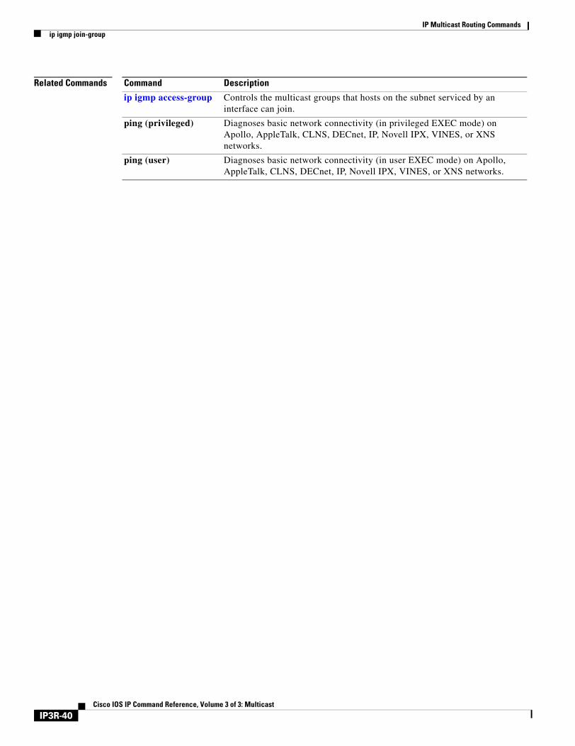
IP Multicast Routing Commandsip igmp join-group
Related Commands Command Description
ip igmp access-group Controls the multicast groups that hosts on the subnet serviced by an interface can join.
ping (privileged) Diagnoses basic network connectivity (in privileged EXEC mode) on Apollo, AppleTalk, CLNS, DECnet, IP, Novell IPX, VINES, or XNS networks.
ping (user) Diagnoses basic network connectivity (in user EXEC mode) on Apollo, AppleTalk, CLNS, DECnet, IP, Novell IPX, VINES, or XNS networks.
IP3R-40Cisco IOS IP Command Reference, Volume 3 of 3: Multicast
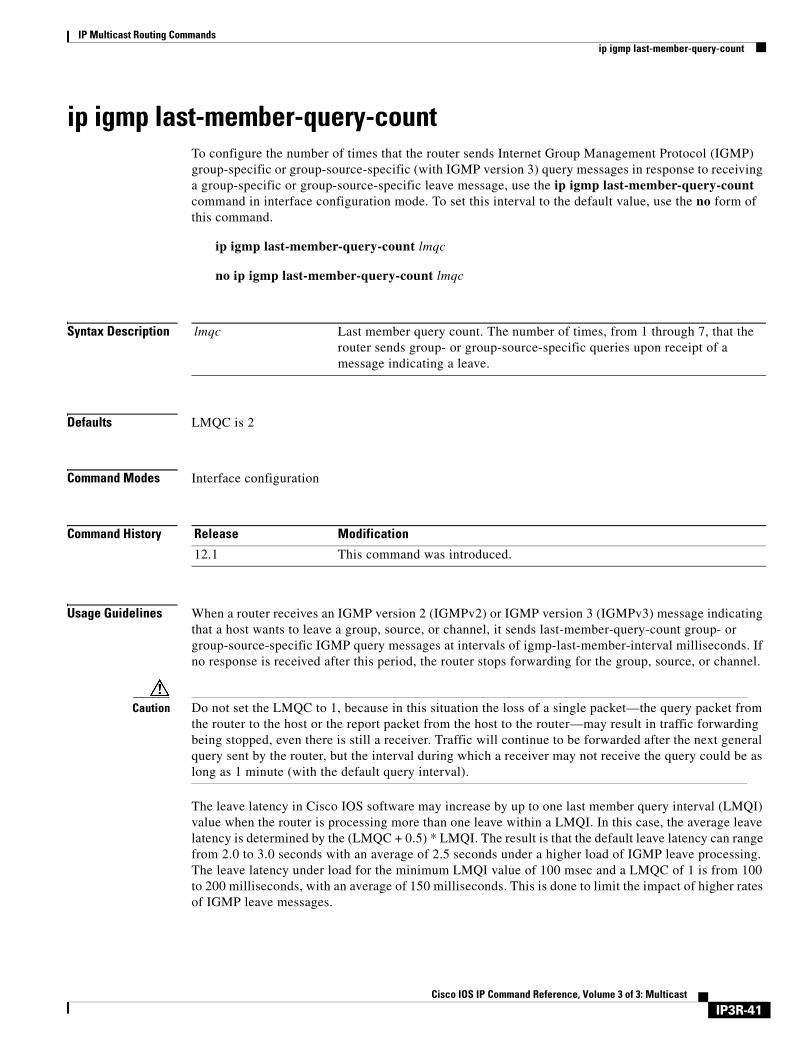
IP Multicast Routing Commandsip igmp last-member-query-count
ip igmp last-member-query-countTo configure the number of times that the router sends Internet Group Management Protocol (IGMP) group-specific or group-source-specific (with IGMP version 3) query messages in response to receiving a group-specific or group-source-specific leave message, use the ip igmp last-member-query-count command in interface configuration mode. To set this interval to the default value, use the no form of this command.
ip igmp last-member-query-count lmqc
no ip igmp last-member-query-count lmqc
Syntax Description
Defaults LMQC is 2
Command Modes Interface configuration
Command History
Usage Guidelines When a router receives an IGMP version 2 (IGMPv2) or IGMP version 3 (IGMPv3) message indicating that a host wants to leave a group, source, or channel, it sends last-member-query-count group- or group-source-specific IGMP query messages at intervals of igmp-last-member-interval milliseconds. If no response is received after this period, the router stops forwarding for the group, source, or channel.
Caution Do not set the LMQC to 1, because in this situation the loss of a single packet—the query packet from the router to the host or the report packet from the host to the router—may result in traffic forwarding being stopped, even there is still a receiver. Traffic will continue to be forwarded after the next general query sent by the router, but the interval during which a receiver may not receive the query could be as long as 1 minute (with the default query interval).
The leave latency in Cisco IOS software may increase by up to one last member query interval (LMQI) value when the router is processing more than one leave within a LMQI. In this case, the average leave latency is determined by the (LMQC + 0.5) * LMQI. The result is that the default leave latency can range from 2.0 to 3.0 seconds with an average of 2.5 seconds under a higher load of IGMP leave processing. The leave latency under load for the minimum LMQI value of 100 msec and a LMQC of 1 is from 100 to 200 milliseconds, with an average of 150 milliseconds. This is done to limit the impact of higher rates of IGMP leave messages.
lmqc Last member query count. The number of times, from 1 through 7, that the router sends group- or group-source-specific queries upon receipt of a message indicating a leave.
Release Modification
12.1 This command was introduced.
IP3R-41Cisco IOS IP Command Reference, Volume 3 of 3: Multicast
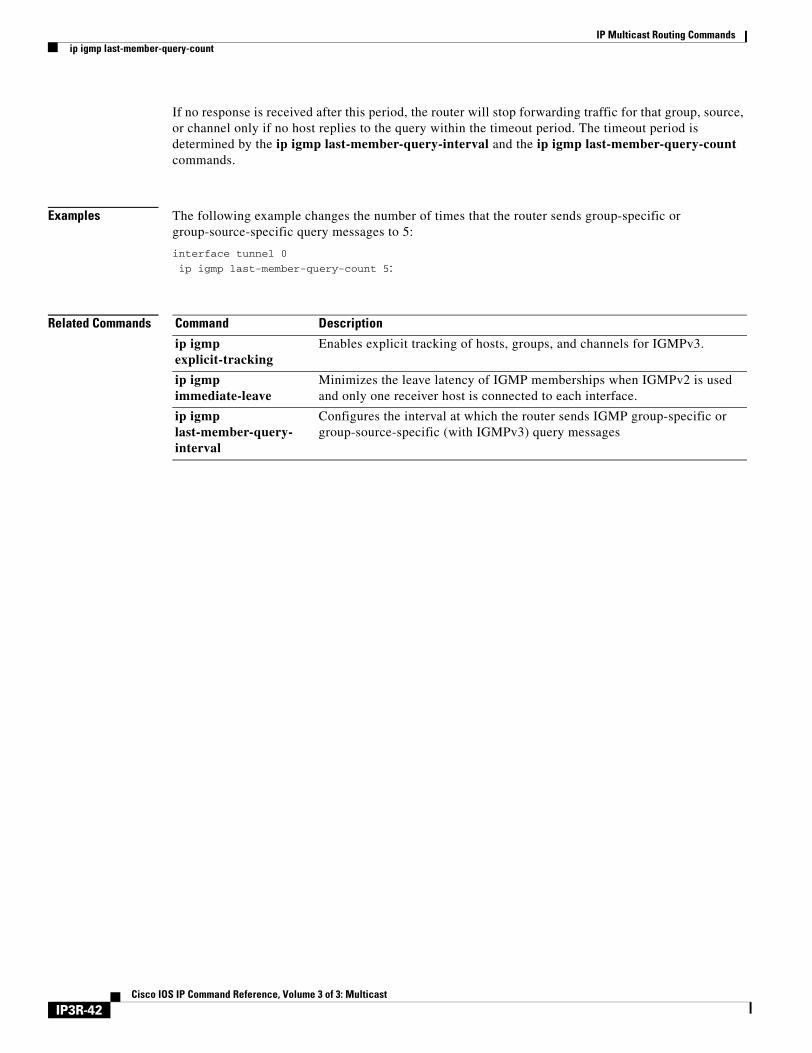
IP Multicast Routing Commandsip igmp last-member-query-count
If no response is received after this period, the router will stop forwarding traffic for that group, source, or channel only if no host replies to the query within the timeout period. The timeout period is determined by the ip igmp last-member-query-interval and the ip igmp last-member-query-count commands.
Examples The following example changes the number of times that the router sends group-specific or group-source-specific query messages to 5:
interface tunnel 0
ip igmp last-member-query-count 5:
Related Commands Command Description
ip igmp explicit-tracking
Enables explicit tracking of hosts, groups, and channels for IGMPv3.
ip igmp immediate-leave
Minimizes the leave latency of IGMP memberships when IGMPv2 is used and only one receiver host is connected to each interface.
ip igmp last-member-query-interval
Configures the interval at which the router sends IGMP group-specific or group-source-specific (with IGMPv3) query messages
IP3R-42Cisco IOS IP Command Reference, Volume 3 of 3: Multicast
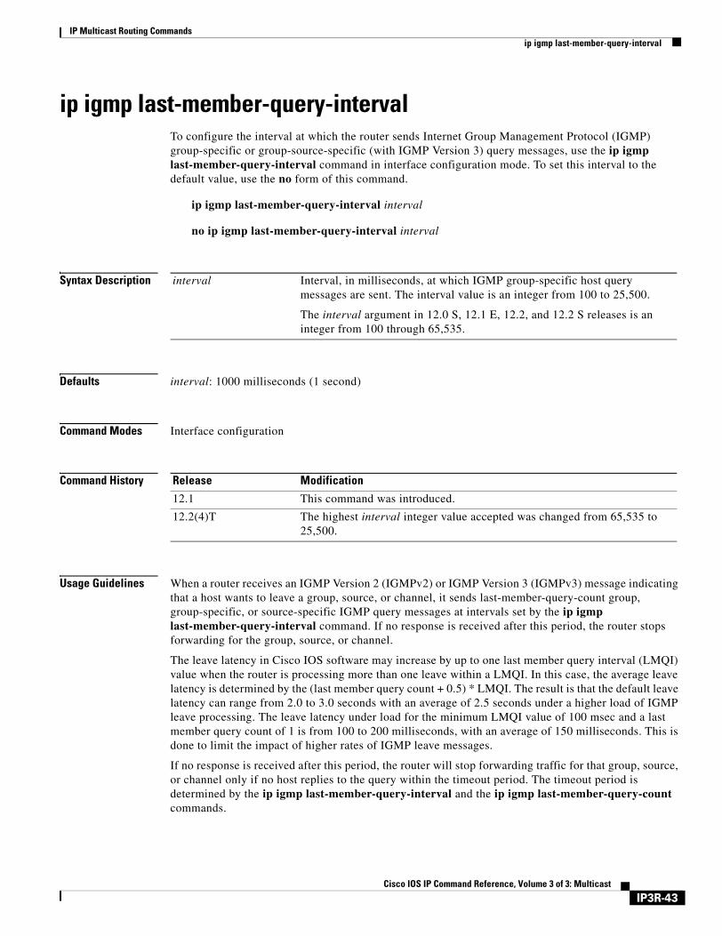
IP Multicast Routing Commandsip igmp last-member-query-interval
ip igmp last-member-query-intervalTo configure the interval at which the router sends Internet Group Management Protocol (IGMP) group-specific or group-source-specific (with IGMP Version 3) query messages, use the ip igmp last-member-query-interval command in interface configuration mode. To set this interval to the default value, use the no form of this command.
ip igmp last-member-query-interval interval
no ip igmp last-member-query-interval interval
Syntax Description
Defaults interval: 1000 milliseconds (1 second)
Command Modes Interface configuration
Command History
Usage Guidelines When a router receives an IGMP Version 2 (IGMPv2) or IGMP Version 3 (IGMPv3) message indicating that a host wants to leave a group, source, or channel, it sends last-member-query-count group, group-specific, or source-specific IGMP query messages at intervals set by the ip igmp last-member-query-interval command. If no response is received after this period, the router stops forwarding for the group, source, or channel.
The leave latency in Cisco IOS software may increase by up to one last member query interval (LMQI) value when the router is processing more than one leave within a LMQI. In this case, the average leave latency is determined by the (last member query count + 0.5) * LMQI. The result is that the default leave latency can range from 2.0 to 3.0 seconds with an average of 2.5 seconds under a higher load of IGMP leave processing. The leave latency under load for the minimum LMQI value of 100 msec and a last member query count of 1 is from 100 to 200 milliseconds, with an average of 150 milliseconds. This is done to limit the impact of higher rates of IGMP leave messages.
If no response is received after this period, the router will stop forwarding traffic for that group, source, or channel only if no host replies to the query within the timeout period. The timeout period is determined by the ip igmp last-member-query-interval and the ip igmp last-member-query-count commands.
interval Interval, in milliseconds, at which IGMP group-specific host query messages are sent. The interval value is an integer from 100 to 25,500.
The interval argument in 12.0 S, 12.1 E, 12.2, and 12.2 S releases is an integer from 100 through 65,535.
Release Modification
12.1 This command was introduced.
12.2(4)T The highest interval integer value accepted was changed from 65,535 to 25,500.
IP3R-43Cisco IOS IP Command Reference, Volume 3 of 3: Multicast
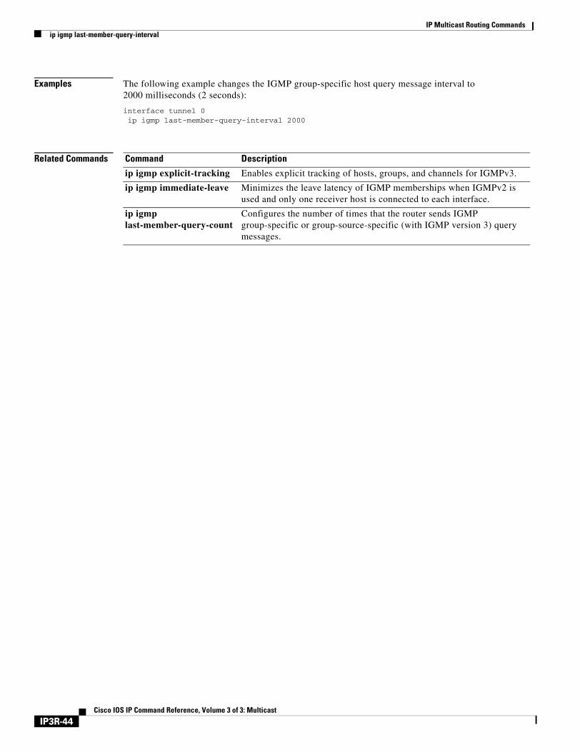
IP Multicast Routing Commandsip igmp last-member-query-interval
Examples The following example changes the IGMP group-specific host query message interval to 2000 milliseconds (2 seconds):
interface tunnel 0ip igmp last-member-query-interval 2000
Related Commands Command Description
ip igmp explicit-tracking Enables explicit tracking of hosts, groups, and channels for IGMPv3.
ip igmp immediate-leave Minimizes the leave latency of IGMP memberships when IGMPv2 is used and only one receiver host is connected to each interface.
ip igmp last-member-query-count
Configures the number of times that the router sends IGMP group-specific or group-source-specific (with IGMP version 3) query messages.
IP3R-44Cisco IOS IP Command Reference, Volume 3 of 3: Multicast
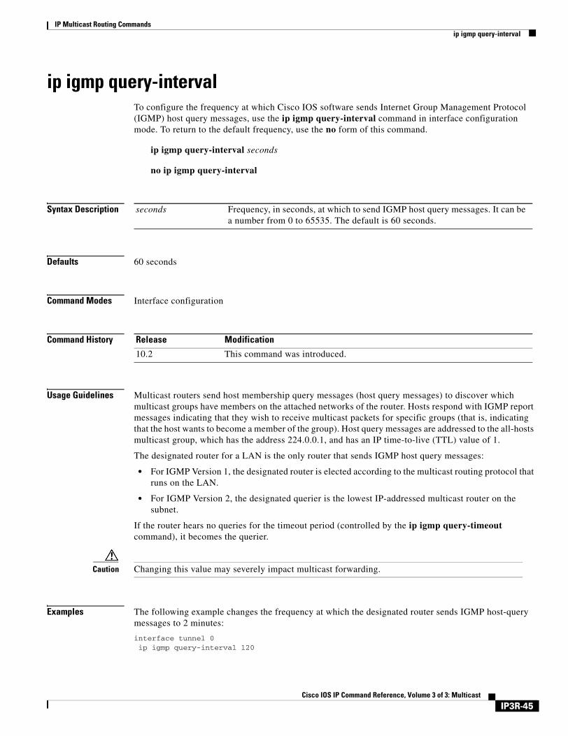
IP Multicast Routing Commandsip igmp query-interval
ip igmp query-intervalTo configure the frequency at which Cisco IOS software sends Internet Group Management Protocol (IGMP) host query messages, use the ip igmp query-interval command in interface configuration mode. To return to the default frequency, use the no form of this command.
ip igmp query-interval seconds
no ip igmp query-interval
Syntax Description
Defaults 60 seconds
Command Modes Interface configuration
Command History
Usage Guidelines Multicast routers send host membership query messages (host query messages) to discover which multicast groups have members on the attached networks of the router. Hosts respond with IGMP report messages indicating that they wish to receive multicast packets for specific groups (that is, indicating that the host wants to become a member of the group). Host query messages are addressed to the all-hosts multicast group, which has the address 224.0.0.1, and has an IP time-to-live (TTL) value of 1.
The designated router for a LAN is the only router that sends IGMP host query messages:
• For IGMP Version 1, the designated router is elected according to the multicast routing protocol that runs on the LAN.
• For IGMP Version 2, the designated querier is the lowest IP-addressed multicast router on the subnet.
If the router hears no queries for the timeout period (controlled by the ip igmp query-timeout command), it becomes the querier.
Caution Changing this value may severely impact multicast forwarding.
Examples The following example changes the frequency at which the designated router sends IGMP host-query messages to 2 minutes:
interface tunnel 0ip igmp query-interval 120
seconds Frequency, in seconds, at which to send IGMP host query messages. It can be a number from 0 to 65535. The default is 60 seconds.
Release Modification
10.2 This command was introduced.
IP3R-45Cisco IOS IP Command Reference, Volume 3 of 3: Multicast

IP Multicast Routing Commandsip igmp query-interval
Related Commands Command Description
ip pim query-interval Configures the frequency of PIM router query messages.
show ip igmp groups Displays the multicast groups that are directly connected to the router and that were learned through IGMP.
IP3R-46Cisco IOS IP Command Reference, Volume 3 of 3: Multicast
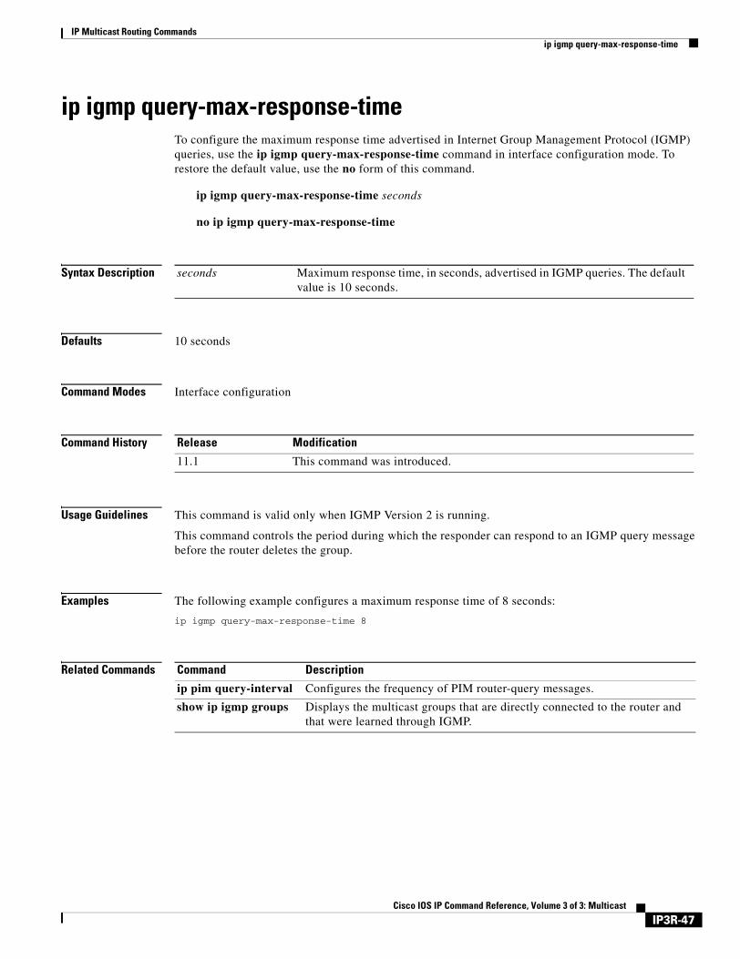
IP Multicast Routing Commandsip igmp query-max-response-time
ip igmp query-max-response-timeTo configure the maximum response time advertised in Internet Group Management Protocol (IGMP) queries, use the ip igmp query-max-response-time command in interface configuration mode. To restore the default value, use the no form of this command.
ip igmp query-max-response-time seconds
no ip igmp query-max-response-time
Syntax Description
Defaults 10 seconds
Command Modes Interface configuration
Command History
Usage Guidelines This command is valid only when IGMP Version 2 is running.
This command controls the period during which the responder can respond to an IGMP query message before the router deletes the group.
Examples The following example configures a maximum response time of 8 seconds:
ip igmp query-max-response-time 8
Related Commands
seconds Maximum response time, in seconds, advertised in IGMP queries. The default value is 10 seconds.
Release Modification
11.1 This command was introduced.
Command Description
ip pim query-interval Configures the frequency of PIM router-query messages.
show ip igmp groups Displays the multicast groups that are directly connected to the router and that were learned through IGMP.
IP3R-47Cisco IOS IP Command Reference, Volume 3 of 3: Multicast
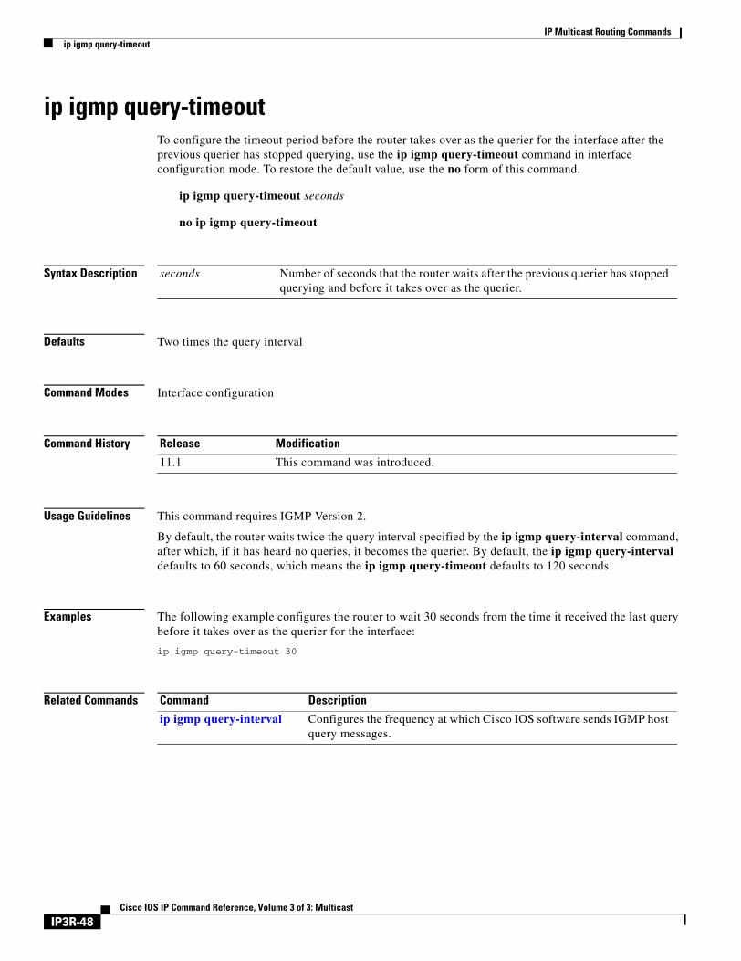
IP Multicast Routing Commandsip igmp query-timeout
ip igmp query-timeoutTo configure the timeout period before the router takes over as the querier for the interface after the previous querier has stopped querying, use the ip igmp query-timeout command in interface configuration mode. To restore the default value, use the no form of this command.
ip igmp query-timeout seconds
no ip igmp query-timeout
Syntax Description
Defaults Two times the query interval
Command Modes Interface configuration
Command History
Usage Guidelines This command requires IGMP Version 2.
By default, the router waits twice the query interval specified by the ip igmp query-interval command, after which, if it has heard no queries, it becomes the querier. By default, the ip igmp query-interval defaults to 60 seconds, which means the ip igmp query-timeout defaults to 120 seconds.
Examples The following example configures the router to wait 30 seconds from the time it received the last query before it takes over as the querier for the interface:
ip igmp query-timeout 30
Related Commands
seconds Number of seconds that the router waits after the previous querier has stopped querying and before it takes over as the querier.
Release Modification
11.1 This command was introduced.
Command Description
ip igmp query-interval Configures the frequency at which Cisco IOS software sends IGMP host query messages.
IP3R-48Cisco IOS IP Command Reference, Volume 3 of 3: Multicast
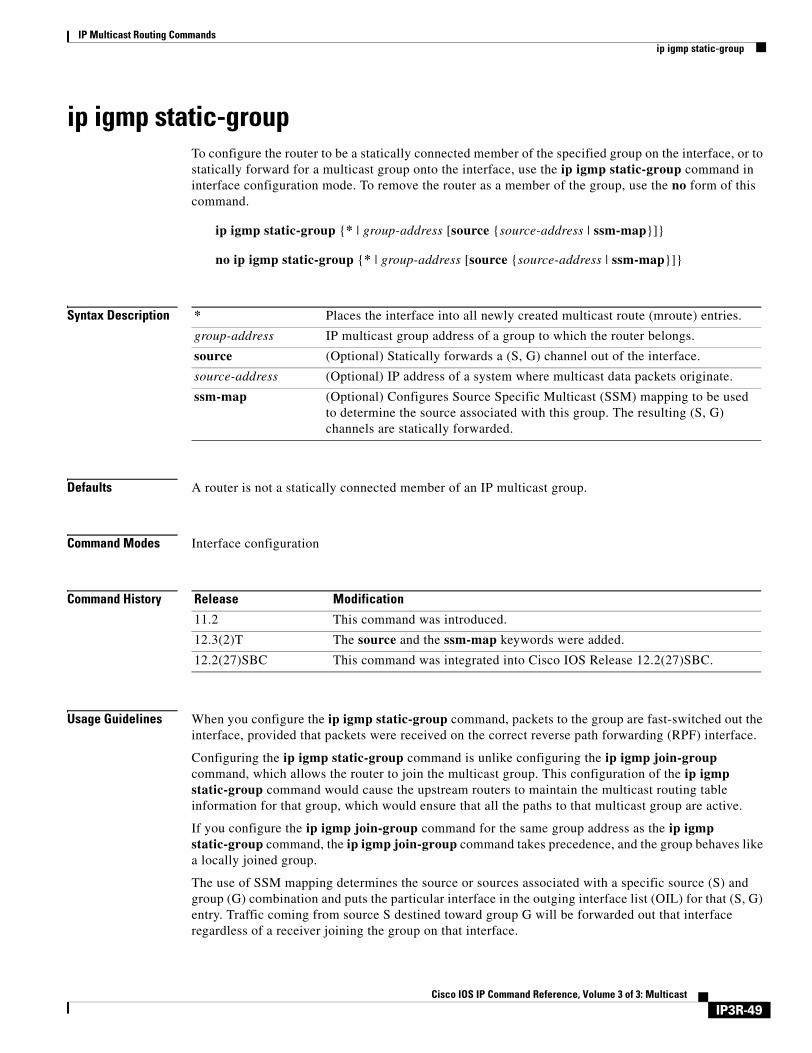
IP Multicast Routing Commandsip igmp static-group
ip igmp static-groupTo configure the router to be a statically connected member of the specified group on the interface, or to statically forward for a multicast group onto the interface, use the ip igmp static-group command in interface configuration mode. To remove the router as a member of the group, use the no form of this command.
ip igmp static-group {* | group-address [source {source-address | ssm-map}]}
no ip igmp static-group {* | group-address [source {source-address | ssm-map}]}
Syntax Description
Defaults A router is not a statically connected member of an IP multicast group.
Command Modes Interface configuration
Command History
Usage Guidelines When you configure the ip igmp static-group command, packets to the group are fast-switched out the interface, provided that packets were received on the correct reverse path forwarding (RPF) interface.
Configuring the ip igmp static-group command is unlike configuring the ip igmp join-group command, which allows the router to join the multicast group. This configuration of the ip igmp static-group command would cause the upstream routers to maintain the multicast routing table information for that group, which would ensure that all the paths to that multicast group are active.
If you configure the ip igmp join-group command for the same group address as the ip igmp static-group command, the ip igmp join-group command takes precedence, and the group behaves like a locally joined group.
The use of SSM mapping determines the source or sources associated with a specific source (S) and group (G) combination and puts the particular interface in the outging interface list (OIL) for that (S, G) entry. Traffic coming from source S destined toward group G will be forwarded out that interface regardless of a receiver joining the group on that interface.
* Places the interface into all newly created multicast route (mroute) entries.
group-address IP multicast group address of a group to which the router belongs.
source (Optional) Statically forwards a (S, G) channel out of the interface.
source-address (Optional) IP address of a system where multicast data packets originate.
ssm-map (Optional) Configures Source Specific Multicast (SSM) mapping to be used to determine the source associated with this group. The resulting (S, G) channels are statically forwarded.
Release Modification
11.2 This command was introduced.
12.3(2)T The source and the ssm-map keywords were added.
12.2(27)SBC This command was integrated into Cisco IOS Release 12.2(27)SBC.
IP3R-49Cisco IOS IP Command Reference, Volume 3 of 3: Multicast
IP Multicast Routing Commandsip igmp static-group
Examples The following example configures group address 192.168.2.2 on Ethernet interface 0:
interface ethernet 0ip igmp static-group 192.168.2.2
The following example shows how to configure group address 192.168.2.3 to use SSM mapping for statically forwarded groups on Ethernet interface 0:
interface ethernet 0ip igmp static-group 192.168.2.3 source ssm-map
Related Commands Command Description
ip igmp join-group Causes the router to join a multicast group.
ip igmp ssm-map enable Enables SSM mapping for groups in a configured SSM range.
ip igmp ssm-map query dns Configures DNS-based SSM mapping.
ip igmp ssm-map static Enables static SSM mapping.
ip pim ssm Defines the SSM range of IP multicast addresses.
IP3R-50Cisco IOS IP Command Reference, Volume 3 of 3: Multicast
IP Multicast Routing Commandsip igmp v3lite
ip igmp v3liteTo enable acceptance and processing of Internet Group Management Protocol Version 3 lite (IGMP v3lite) membership reports on an interface, use the ip igmp v3lite command in interface configuration mode. To disable IGMP v3lite, use the no form of this command.
ip igmp v3lite
no ip igmp v3lite
Syntax Description This command has no arguments or keywords.
Defaults Disabled
Command Modes Interface configuration
Command History
Usage Guidelines To use this command, you must define a Source Specific Multicast (SSM) range of IP addresses using the ip pim ssm global configuration command. When IGMP v3lite is enabled, it is supported in the SSM range of addresses only.
Examples The following example shows how to configure IGMP v3lite on Ethernet interface 3/1:
interface ethernet 3/1ip igmp v3lite
Related Commands
Release Modification
12.1(3)T This command was introduced.
Command Description
ip pim ssm Defines the SSM range of IP multicast addresses.
IP3R-51Cisco IOS IP Command Reference, Volume 3 of 3: Multicast
IP Multicast Routing Commandsip igmp version
ip igmp versionTo configure which version of Internet Group Management Protocol (IGMP) the router uses, use the ip igmp version command in interface configuration mode. To restore the default value, use the no form of this command.
ip igmp version {1 | 2 | 3}
no ip igmp version
Syntax Description
Defaults Version 2
Command Modes Interface configuration
Command History
Usage Guidelines All routers on the subnet must support the same version. The router does not automatically detect Version 1 routers and switch to Version 1 as did earlier releases of the Cisco IOS software. Hosts can have any IGMP version (1, 2, or 3) and the router will correctly detect their presence and query them appropriately.
Some commands require IGMP Version 2 or 3, such as the ip igmp query-max-response-time and ip igmp query-timeout commands.
Examples The following example configures the router to use IGMP Version 3:
ip igmp version 3
1 IGMP Version 1.
2 IGMP Version 2.
3 IGMP Version 3.
Release Modification
11.1 This command was introduced.
12.1(5)T The 3 keyword was added.
IP3R-52Cisco IOS IP Command Reference, Volume 3 of 3: Multicast
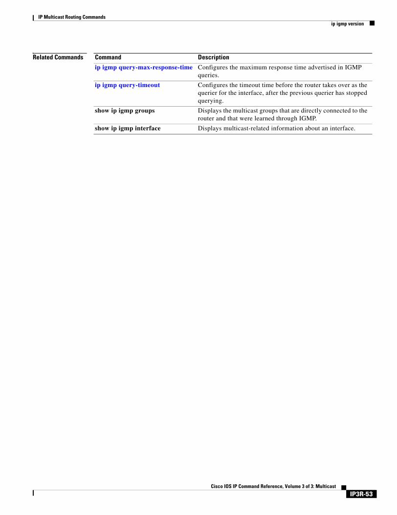
IP Multicast Routing Commandsip igmp version
Related Commands Command Description
ip igmp query-max-response-time Configures the maximum response time advertised in IGMP queries.
ip igmp query-timeout Configures the timeout time before the router takes over as the querier for the interface, after the previous querier has stopped querying.
show ip igmp groups Displays the multicast groups that are directly connected to the router and that were learned through IGMP.
show ip igmp interface Displays multicast-related information about an interface.
IP3R-53Cisco IOS IP Command Reference, Volume 3 of 3: Multicast
IP Multicast Routing Commandsip mroute
ip mrouteTo configure a multicast static route (mroute), use the ip mroute command in global configuration mode. To remove the route, use the no form of this command.
ip mroute source-address mask [protocol as-number] {rpf-address | type number} [distance]
no ip mroute source mask [protocol as-number] {rpf-address | type number} [distance]
Syntax Description
Defaults distance: 0
Command Modes Global configuration
Command History
Usage Guidelines This command allows you to statically configure where multicast sources are located (even though the unicast routing table shows something different).
When a source range is specified, the rpf-address argument applies only to those sources.
Examples The following example configures all sources via a single interface (in this case, a tunnel):
ip mroute 0.0.0.0 0.0.0.0 tunnel0
source-address IP address of the multicast source.
mask Mask on the IP address of the multicast source.
protocol (Optional) Unicast routing protocol that you are using.
as-number (Optional) Autonomous system number of the routing protocol you are using, if applicable.
rpf-address Incoming interface for the mroute. If the Reverse Path Forwarding (RPF) address rpf-address is a Protocol Independent Multicast (PIM) neighbor, PIM join, graft, and prune messages are sent to it. The rpf-address argument can be a host IP address of a directly connected system or a network/subnet number. When it is a route, a recursive lookup is done from the unicast routing table to find a directly connected system. If the rpf-address argument is not specified, the interface type number value is used as the incoming interface.
type number Interface type and number for the mroute.
distance (Optional) Determines whether a unicast route, a Distance Vector Multicast Routing Protocol (DVMRP) route, or a static mroute should be used for the RPF lookup. The lower distances have better preference. If the static mroute has the same distance as the other two RPF sources, the static mroute will take precedence. The default is 0.
Release Modification
11.0 This command was introduced.
IP3R-54Cisco IOS IP Command Reference, Volume 3 of 3: Multicast

IP Multicast Routing Commandsip mroute
The following example configures all specific sources within a network number to be reachable through 172.30.10.13:
ip mroute 172.16.0.0 255.255.0.0 172.30.10.13
The following example causes this multicast static route to take effect if the unicast routes for any given destination go away:
ip mroute 0.0.0.0 0.0.0.0 serial0 200
IP3R-55Cisco IOS IP Command Reference, Volume 3 of 3: Multicast
IP Multicast Routing Commandsip mroute-cache
ip mroute-cacheTo configure IP multicast fast switching or multicast distributed switching (MDS), use the ip mroute-cache command in interface configuration mode. To disable either of these features, use the no form of this command.
ip mroute-cache [distributed]
no ip mroute-cache [distributed]
Syntax Description
Defaults On the RSP, IP multicast fast switching is enabled; MDS is disabled.
On the GSR, MDS is disabled.
Command Modes Interface configuration
Command History
Usage Guidelines On the RSP
If multicast fast switching is disabled on an incoming interface for a multicast routing table entry, the packet will be sent at process level for all interfaces in the outgoing interface list.
If multicast fast switching is disabled on an outgoing interface for a multicast routing table entry, the packet is process-level switched for that interface, but may be fast switched for other interfaces in the outgoing interface list.
When multicast fast switching is enabled (like unicast routing), debug messages are not logged. If you want to log debug messages, disable fast switching.
If MDS is not enabled on an incoming interface that is capable of MDS, incoming multicast packets will not be distributed switched; they will be fast switched at the Route Processor (RP) as before. Also, if the incoming interface is not capable of MDS, packets will get fast switched or process-switched at the RP as before.
If MDS is enabled on the incoming interface, but at least one of the outgoing interfaces cannot fast switch, packets will be process-switched. We recommend that you disable fast switching on any interface when MDS is enabled.
On the GSR
On the GSR, all interfaces should be configured for MDS because that is the only switching mode.
distributed (Optional) Enables MDS on the interface. In the case of RSP, this keyword is optional; if it is omitted, fast switching occurs. On the GSR, this keyword is required because the GSR does only distributed switching.
Release Modification
10.0 This command was introduced.
11.2(11)GS The distributed keyword was added.
IP3R-56Cisco IOS IP Command Reference, Volume 3 of 3: Multicast
IP Multicast Routing Commandsip mroute-cache
Examples The following example enables IP multicast fast switching on the interface:
ip mroute-cache
The following example disables IP multicast fast switching on the interface:
no ip mroute-cache
The following example enables MDS on the interface:
ip mroute-cache distributed
The following example disables MDS and IP multicast fast switching on the interface:
no ip mroute-cache distributed
IP3R-57Cisco IOS IP Command Reference, Volume 3 of 3: Multicast
IP Multicast Routing Commandsip msdp cache-rejected-sa
ip msdp cache-rejected-saTo track rejected Source-Active (SA) request messages from a Multicast Source Discovery Protocol (MSDP) peer, use the ip msdp cache-rejected-sa command in global configuration mode. To stop tracking SA request messages, use the no form of this command.
ip msdp cache-rejected-sa number-of-entries
no ip msdp cache-rejected-sa number-of-entries
Syntax Description
Defaults Rejected SA request messages are not tracked.
Command Modes Global configuration
Command History
Usage Guidelines The ip msdp cache-rejected-sa command displays the history of SA messages that have been recently received from an MSDP peer but were rejected by the local router. If the cache overflows, entries are overwritten, starting from the first entry.
Examples The following example enables the MSDP peer to track rejected MSDP SA request messages:
Router(config)# ip msdp cache-rejected-sa 200
Related Commands
number-of-entries Number of entries that need to be cached. The range is from 1 to 32766.
Release Modification
12.0(22)S This command was introduced.
12.1E This command was integrated into Cisco IOS Release 12.1E.
12.2 This command was integrated into Cisco IOS Release 12.2.
Command Description
show snmp engineID Displays the identification of the local SNMP engine and all remote engines that have been configured on the router.
snmp-server host Specifies the recipient (SNMP manager) of an SNMP trap notification.
IP3R-58Cisco IOS IP Command Reference, Volume 3 of 3: Multicast
IP Multicast Routing Commandsip multicast boundary
ip multicast boundaryTo configure an administratively scoped boundary, use the ip multicast boundary command in interface configuration mode. To remove the boundary, use the no form of this command.
ip multicast boundary access-list [filter-autorp]
no ip multicast boundary [filter-autorp]
Syntax Description
Defaults There is no boundary.
Command Modes Interface configuration
Command History
Usage Guidelines Use this command to configure an administratively scoped boundary on an interface to filter multicast group addresses in the range defined by the access-list argument. A standard access list defines the range of addresses affected. When this command is configured, no multicast data packets are allowed to flow across the boundary from either direction. Restricting multicast data packet flow enables reuse of the same multicast group address in different administrative domains.
If you configure the filter-autorp keyword, the administratively scoped boundary also examines Auto-RP discovery and announcement messages and removes any Auto-RP group range announcements from the Auto-RP packets that are denied by the boundary ACL. An Auto-RP group range announcement is permitted and passed by the boundary only if all addresses in the Auto-RP group range are permitted by the boundary ACL. If any address is not permitted, the entire group range is filtered and removed from the Auto-RP message before the Auto-RP message is forwarded.
Examples The following example sets up a boundary for all administratively scoped addresses:
access-list 1 deny 239.0.0.0 0.255.255.255access-list 1 permit 224.0.0.0 15.255.255.255interface ethernet 0
access-list Number or name identifying an access list that controls the range of group addresses affected by the boundary.
filter-autorp (Optional) Filters Auto-RP messages denied by the boundary access control list (ACL).
Release Modification
11.1 This command was introduced.
12.0(22)S The filter-autorp keyword was added.
12.1(12c)E The filter-autorp keyword was integrated into Cisco IOS Release 12.1(12c)E.
12.2(11) The filter-autorp keyword was integrated into Cisco IOS Release 12.2(11).
12.2(13)T The filter-autorp keyword was integrated into Cisco IOS Release 12.2(13)T.
IP3R-59Cisco IOS IP Command Reference, Volume 3 of 3: Multicast

IP Multicast Routing Commandsip multicast boundary
ip multicast boundary 1
Related Commands Command Description
access-list (IP standard) Defines a standard IP access list.
IP3R-60Cisco IOS IP Command Reference, Volume 3 of 3: Multicast

IP Multicast Routing Commandsip multicast cache-headers
ip multicast cache-headersTo allocate a circular buffer to store IP multicast packet headers that the router receives, use the ip multicast cache-headers command in global configuration mode. To remove the buffer, use the no form of this command.
ip multicast [vrf vrf-name] cache-headers [rtp]
no ip multicast [vrf vrf-name] cache-headers [rtp]
Syntax Description
Defaults The command is disabled.
Command Modes Global configuration
Command History
Usage Guidelines You can store IP multicast packet headers in a cache and then display them to determine the following information:
• Who is sending IP multicast packets to which groups
• Interpacket delay
• Duplicate IP multicast packets (if any)
• Multicast forwarding loops in your network (if any)
• Scope of the group
• User Datagram Protocol (UDP) port numbers
• Packet length
Note This command allocates a circular buffer of approximately 32 KB. Do not configure this command if you are low on memory.
Use the show ip mpacket command to display the buffer.
vrf (Optional) Supports the multicast Virtual Private Network (VPN) routing and forwarding (VRF) instance.
vrf-name (Optional) Name assigned to the VRF.
rtp (Optional) Caches Real-Time Transport Protocol (RTP) headers.
Release Modification
11.1 This command was introduced.
12.1 The rtp keyword was added.
12.0(23)S The vrf keyword and vrf-name argument were added.
12.2(13)T The vrf keyword and vrf-name argument were added.
IP3R-61Cisco IOS IP Command Reference, Volume 3 of 3: Multicast
IP Multicast Routing Commandsip multicast cache-headers
Examples The following example allocates a buffer to store IP multicast packet headers:
ip multicast cache-headers
Related Commands Command Description
show ip mpacket Displays the contents of the circular cache header buffer.
show ip mpacket quality Displays an RTP data quality based on packets captured in the IP multicast cache header buffer.
IP3R-62Cisco IOS IP Command Reference, Volume 3 of 3: Multicast
IP Multicast Routing Commandsip multicast heartbeat
ip multicast heartbeatTo monitor the health of multicast delivery and be alerted when the delivery fails to meet certain parameters, use the ip multicast heartbeat command in global configuration mode. To disable the heartbeat, use the no form of the command.
ip multicast heartbeat group-address minimum-number window-size interval
no ip multicast heartbeat group-address minimum-number window-size interval
Syntax Description
Defaults Disabled
Command Modes Global configuration
Command History
Usage Guidelines The subject group is joined at the subject interface so that multicast data for the subject group will be attracted toward the subject router.
The router monitors multicast packets destined to the group address at the interval value. This is a binary decision. That is, the number of packets seen in this period is not as important as whether any packet for the group is seen.
If multicast packets were observed in less than the minimum-number value out of the last window-size value intervals, a Simple Network Management Protocol (SNMP) trap would be sent from this router to a network management station to indicate a loss of heartbeat exception. This trap will be defined in CISCO-IPMROUTE-MIB.my.
The interval value must be a multiple of 10. In multicast distributed switching (MDS), statistics from the Versatile Interface Processor (in the Route Switch Processor) or the Label Controller (in the Gigabit Switch Router) are passed to the routing processor once every 10 seconds. Monitoring packets not in intervals of multiple of 10 seconds may lead to incorrect decisions.
group-address A multicast group address (Class D address, from 224.0.0.0 to 239.255.255.255)
minimum-number Minimal number of intervals where the heartbeats must be seen. The number must be less than or equal to the window size.
window-size Number of intervals to monitor for the heartbeat.
interval Number of seconds interval to receive packet. Value must be a multiple of 10.
Release Modification
12.1(3)T This command was introduced.
IP3R-63Cisco IOS IP Command Reference, Volume 3 of 3: Multicast
IP Multicast Routing Commandsip multicast heartbeat
This command does not create any multicast routing entries that are necessary for the monitoring of the heartbeat packets. These entries can be created by either the downstream members of the group, or with the ip pim join-group or ip pim static-group command. If a multicast routing entry corresponding to a group address expires due to lack of interest from the downstream members, the monitoring for the subject group would not work; that is, no more SNMP traps would be sent.
Examples The following is an example configuration of the ip multicast heartbeat command:
snmp-server enable traps ipmulticast-heartbeatip multicast heartbeat 224.0.1.53 1 1 10
In this example, multicast packets forwarded through this router to group address 224.0.1.53 will be monitored. If no packet for this group is received in a 10-second interval, an SNMP trap will be sent to a designated SNMP management station.
Note It may take about 20 seconds of losing the multicast feed before the SNMP trap is sent.
Related Commands Command Description
debug ip mhbeat Monitors the action of the heartbeat trap.
snmp-server enable traps Enables the router to send SNMP traps.
IP3R-64Cisco IOS IP Command Reference, Volume 3 of 3: Multicast
IP Multicast Routing Commandsip multicast helper-map
ip multicast helper-mapTo allow IP multicast routing in a multicast-capable internetwork between two broadcast-only internetworks, use the ip multicast helper-map command in interface configuration mode. To disable this function, use the no form of this command.
ip multicast helper-map {group-address broadcast-address | broadcast multicast-address} access-list
no ip multicast helper-map {group-address broadcast-address | broadcast multicast-address} access-list
Syntax Description
Defaults No conversion between broadcast and multicast occurs.
Command Modes Interface configuration
Command History
Usage Guidelines When a multicast-capable internetwork is between two broadcast-only internetworks, you can convert broadcast traffic to multicast at the first hop router, and convert it back to broadcast at the last hop router before delivering the packets to the broadcast clients. However, broadcast packets with the IP source address of 0.0.0.0 (such as a Dynamic Host Configuration Protocol [DHCP] request) will not be translated to any multicast group.
Thus, you can take advantage of the multicast capability of the intermediate multicast internetwork. This feature prevents unnecessary replication at the intermediate routers and allows multicast fast switching in the multicast internetwork.
If you need to send a directed broadcast to the subnet, the outgoing interface of the last hop router can be configured with an IP broadcast address of x.x.x.255, where x.x.x.0 is the subnet that you are trying to reach; otherwise the packet will be converted to 255.255.255.255.
group-address Multicast group address of traffic to be converted to broadcast traffic. Use this with the broadcast-address value.
broadcast-address Address to which broadcast traffic is sent. Use this with the group-address value.
broadcast Specifies the traffic is being converted from broadcast to multi-cast. Use this with the multicast-address value.
multicast-address IP multicast address to which the converted traffic is directed. Use this with the broadcast keyword.
access-list IP extended access list number or name that controls which broadcast packets are translated, based on the User Datagram Protocol (UDP) port number.
Release Modification
11.1 This command was introduced.
IP3R-65Cisco IOS IP Command Reference, Volume 3 of 3: Multicast
IP Multicast Routing Commandsip multicast helper-map
Examples The following example illustrates how a helper address on two routers converts from broadcast to multicast and back to broadcast.
The configuration on the first hop router converts a broadcast stream arriving at incoming interface Ethernet interface 0 destined to UDP port 4000 to a multicast stream. The access list denies other traffic from being forwarded into the multicast cloud. The traffic is sent to group address 224.5.5.5. Because fast switching does not perform such a conversion, the ip forward-protocol command causes the proper process level to perform the conversion.
The configuration on the last hop router converts the multicast stream at incoming interface Ethernet interface 1 back to broadcast. All multicast traffic emerging from the multicast cloud should not be converted to broadcast, only the traffic destined for UDP port 4000.
First Hop Router Configurationinterface ethernet 0ip directed-broadcastip multicast helper-map broadcast 224.5.5.5 120ip pim dense-mode
!access-list 120 permit any any udp 4000access-list 120 deny any any udpip forward-protocol udp 4000
Last Hop Router Configurationinterface ethernet 1ip directed-broadcastip broadcast-address 172.16.0.0ip multicast helper-map 224.5.5.5 172.16.0.0ip pim dense-mode
!access-list 135 permit any any udp 4000access-list 135 deny any any udpip forward-protocol udp 4000
Related Commands Command Description
ip directed-broadcast Enables the translation of directed broadcast to physical broadcasts.
ip forward-protocol Specifies which protocols and ports the router forwards when forwarding broadcast packets.
IP3R-66Cisco IOS IP Command Reference, Volume 3 of 3: Multicast

IP Multicast Routing Commandsip multicast multipath
ip multicast multipathTo enable load splitting of IP multicast traffic across multiple equal-cost paths, use the ip multicast multipath command in global configuration mode. To disable this configuration, use the no form of this command.
ip multicast [vrf vrf-name] multipath
no ip multicast [vrf vrf-name] multipath
Syntax Description
Defaults By default, if multiple equal-cost paths exist, multicast traffic will not be load split across these paths.
Command Modes Global configuration
Command History
Usage Guidelines If the ip multicast multipath command is configured and multiple equal-cost paths exist, load splitting will occur across the equal-cost paths for multicast traffic from different sources to the same multicast group, but not for traffic from the same source to different multicast groups. Because this command changes the way a Reverse Path Forwarding (RPF) neighbor is selected, it must be configured consistently on all routers in a redundant topology to avoid looping.
Examples The following example shows how to configure the ip multicast multipath command:
ip multicast multipath
Related Commands
vrf (Optional) Supports the multicast VPN routing and forwarding (VRF) instance.
vrf-name (Optional) Name assigned to the VRF.
Release Modification
12.0(8)T This command was introduced.
12.0(5)S This command was integrated into Cisco IOS Release 12.0(5)S.
12.0(23)S The vrf keyword and vrf-name argument were added.
12.2(13)T The vrf keyword and vrf-name argument were added.
Command Description
show ip rpf Displays how IP multicast routing does RPF.
IP3R-67Cisco IOS IP Command Reference, Volume 3 of 3: Multicast
IP Multicast Routing Commandsip multicast rate-limit
ip multicast rate-limitTo control the rate a sender from the source list can send to a multicast group in the group list, use the ip multicast rate-limit command in interface configuration mode. To remove the control, use the no form of this command.
ip multicast rate-limit {in | out} [video | whiteboard] [group-list access-list] [source-list access-list] kbps
no ip multicast rate-limit {in | out} [video | whiteboard] [group-list access-list] [source-list access-list] kbps
Syntax Description
Defaults If this command is not configured, there is no rate limit.If this command is configured, the kbps value defaults to 0, meaning that no traffic is permitted.
Command Modes Interface configuration
Command History
Usage Guidelines If a router receives a packet the user has sent over the limit, the packet is dropped; otherwise, it is forwarded.
For the video or whiteboard keyword to work, the ip sap listen command must be enabled so that the port number can be obtained from the SAP cache. If the ip sap listen command is not enabled, or the group address is not in the SAP cache, no rate-limiting is done for the group.
in Accepts only packets at the rate of the kbps value or slower on the interface.
out Sends only a maximum of the kbps value on the interface.
video (Optional) Performs rate limiting based on the User Datagram Protocol (UDP) port number used by video traffic. Video traffic is identified by consulting the Session Announcement Protocol (SAP) cache.
whiteboard (Optional) Performs rate limiting based on the UDP port number used by whiteboard traffic. Whiteboard traffic is identified by consulting the SAP cache.
group-list access-list (Optional) Specifies the access list number or name that controls which multicast groups are subject to the rate limit.
source-list access-list (Optional) Specifies the access list number or name that controls which senders are subject to the rate limit.
kbps Transmission rate (in kbps). Any packets sent at greater than this value are silently discarded. The default value is 0, meaning that no traffic is permitted. Therefore, set this to a positive value.
Release Modification
11.0 This command was introduced.
IP3R-68Cisco IOS IP Command Reference, Volume 3 of 3: Multicast
IP Multicast Routing Commandsip multicast rate-limit
Examples In the following example, packets to any group from sources in network 172.16.0.0 will have their packets rate-limited to 64 kbps:
interface serial 0ip multicast rate-limit out group-list 1 source-list 2 64
access-list 1 permit 0.0.0.0 255.255.255.255access-list 2 permit 172.16.0.0 0.0.255.255
Related Commands Command Description
ip sap listen Enables the Cisco IOS software to listen to session directory advertisements.
IP3R-69Cisco IOS IP Command Reference, Volume 3 of 3: Multicast
IP Multicast Routing Commandsip multicast ttl-threshold
ip multicast ttl-thresholdTo configure the time-to-live (TTL) threshold of packets being forwarded out an interface, use the ip multicast ttl-threshold command in interface configuration mode. To return to the default TTL threshold, use the no form of this command.
ip multicast ttl-threshold ttl-value
no ip multicast ttl-threshold ttl-value
Syntax Description
Defaults The default TTL value is 0, which means that all multicast packets are forwarded out the interface.
Command Modes Interface configuration
Command History
Usage Guidelines Only multicast packets with a TTL value greater than the threshold are forwarded out the interface.
You should configure the TTL threshold only on border routers. Conversely, routers on which you configure a TTL threshold value automatically become border routers.
This command replaces the ip multicast-threshold command.
Examples The following example sets the TTL threshold on a border router to 200, which is a very high value. In this example multicast packets must have a TTL greater than 200 in order to be forwarded out this interface. Multicast applications generally set this value well below 200. Therefore, setting a value of 200 means that no packets will be forwarded out the interface.
interface tunnel 0ip multicast ttl-threshold 200
ttl-value Time-to-live value, in hops. It can be a value from 0 to 255. The default value is 0, which means that all multicast packets are forwarded out the interface.
Release Modification
11.0 This command was introduced.
IP3R-70Cisco IOS IP Command Reference, Volume 3 of 3: Multicast
IP Multicast Routing Commandsip multicast use-functional
ip multicast use-functionalTo enable the mapping of IP multicast addresses to the Token Ring functional address 0xc000.0004.0000, use the ip multicast use-functional command in interface configuration mode. To disable the function, use the no form of this command.
ip multicast use-functional
no ip multicast use-functional
Syntax Description This command has no arguments or keywords.
Defaults IP multicast address are mapped to the MAC-layer address 0xFFFF.FFFF.FFFF.
Command Modes Interface configuration
Command History
Usage Guidelines This command is accepted only on a Token Ring interface.
Neighboring devices on the Token Ring on which this feature is used should also use the same functional address for IP multicast traffic.
Because there are a limited number of Token Ring functional addresses, other protocols may be assigned to the Token Ring functional address 0xc000.0004.0000. Therefore, not every frame sent to the functional address is necessarily an IP multicast frame.
Examples The following example configures any IP multicast packets going out Token Ring interface 0 to be mapped to MAC address 0xc000.0004.0000:
interface token 0ip address 1.1.1.1 255.255.255.0ip pim dense-modeip multicast use-functional
Release Modification
11.1 This command was introduced.
IP3R-71Cisco IOS IP Command Reference, Volume 3 of 3: Multicast
IP Multicast Routing Commandsip pim
ip pimTo enable Protocol Independent Multicast (PIM) on an interface, use the ip pim command in interface configuration mode. To disable PIM on the interface, use the no form of this command.
ip pim {sparse-mode | sparse-dense-mode | dense-mode [proxy-register {list access-list | route-map map-name}]}
no ip pim {sparse-mode | sparse-dense-mode | dense-mode [proxy-register {list access-list | route-map map-name}]}
Syntax Description
Defaults IP multicast routing is disabled on all interfaces.
Command Modes Interface configuration
Command History
Usage Guidelines Enabling PIM on an interface also enables Internet Group Management Protocol (IGMP) operation on that interface. An interface can be configured to be in dense mode, sparse mode, or sparse-dense mode. The mode describes how the Cisco IOS software populates its multicast routing table and how the software forwards multicast packets it receives from its directly connected LANs. Dense mode interfaces are always added to the table when the multicast routing table is populated. Sparse mode interfaces are added to the table only when periodic join messages are received from downstream routers, or there is a directly connected member on the interface.
sparse-mode Enables sparse mode of operation.
sparse-dense-mode Treats the interface in either sparse mode or dense mode of operation, depending on which mode the multicast group operates in.
dense-mode Enables dense mode of operation.
proxy-register (Optional) Enables proxy registering on the interface of a designated router (DR) (leading toward the bordering dense mode region) for multicast traffic from sources not connected to the DR.
list access-list (Optional) Defines the extended access list number or name.
route-map map-name (Optional) Defines the route map.
Release Modification
10.0 This command was introduced.
11.1 The sparse-dense-mode keyword was added.
12.0 S The following keywords and arguments were added:
• proxy-register
• list access-list
• route-map map-name
IP3R-72Cisco IOS IP Command Reference, Volume 3 of 3: Multicast
IP Multicast Routing Commandsip pim
Dense Mode
Initially, a dense mode interface forwards multicast packets until the router determines that there are group members or downstream routers, or until a prune message is received from a downstream router. Then, the dense mode interface periodically forwards multicast packets out the interface until the same conditions occur. Dense mode assumes that multicast group members are present. Dense mode routers never send a join message. They do send prune messages as soon as they determine they have no members or downstream PIM routers. A dense mode interface is subject to multicast flooding by default.
Dense Mode with Proxy Registering
For a router in a PIM sparse mode (PIM-SM) domain configured to operate in sparse mode or sparse-dense mode, the ip pim dense-mode proxy-register command must be configured on the interface leading toward the bordering dense mode region. This configuration will enable the router to register traffic from the dense mode region with the rendezvous point (RP) in the sparse mode domain.
Prior to Cisco IOS Release 12.0 S, an RP needed to be running on the border router leading toward a dense mode region so that the RP could learn about traffic from sources in the dense mode region.
This command requires an extended access list or route map argument specifying which traffic the router needs to register with the RP. This command applies only to sources reachable through a PIM router. Cisco IOS software will always register traffic from remote sources if it arrives on a dense mode interface and if the Reverse Path Forwarding (RPF) neighbor leading toward the source is a Distance Vector Multicast Routing Protocol (DVMRP) but not a PIM router. This functionality has existed since Cisco IOS Release 10.0 and cannot be modified (restricted) with an access list or route map.
Sparse Mode
A sparse mode interface is used for multicast forwarding only if a join message is received from a downstream router or if group members are directly connected to the interface. Sparse mode assumes that no other multicast group members are present. When sparse mode routers want to join the shared path, they periodically send join messages toward the RP. When sparse mode routers want to join the source path, they periodically send join messages toward the source; they also send periodic prune messages toward the RP to prune the shared path.
Sparse-Dense Mode
An alternative to choosing just dense mode or just sparse mode is to run PIM in a single region in sparse mode for some groups and dense mode for other groups.
In sparse-dense mode, if the group is in dense mode, the interface will be treated as dense mode. If the group is in sparse mode, the interface will be treated in sparse mode. The group is “sparse” if the router knows about an RP for that group.
When an interface is treated in dense mode, it is populated in the outgoing interface list of the multicast routing table when either of the following conditions is true:
• Members or DVMRP neighbors are on the interface.
• Any of the PIM neighbors on the interface have not pruned for the group.
When an interface is treated in sparse mode, it is populated in the outgoing interface list of the multicast routing table when either of the following conditions is true:
• Members or DVMRP neighbors are on the interface.
• A PIM neighbor on the interface has received an explicit join message.
IP3R-73Cisco IOS IP Command Reference, Volume 3 of 3: Multicast
IP Multicast Routing Commandsip pim
Examples The following example shows how to enable PIM-SM on tunnel interface 0 and set the address of the RP router to 226.0.0.8:
ip pim rp-address 226.0.0.8interface tunnel 0
ip pim sparse-mode
The following example shows how to enable PIM dense mode (PIM-DM) on Ethernet interface 1:
interface ethernet 1ip pim dense-mode
The following example shows how to enable PIM sparse-dense mode on Ethernet interface 1:
interface ethernet 1ip pim sparse-dense-mode
The following example shows how to register the multicast traffic for any source and any multicast group:
interface ethernet 0ip address 172.16.0.0 255.255.255.0description Ethernet interface towards the PIM sparse-mode domainip pim sparse-dense-mode
!interface ethernet 1
ip address 192.44.81.5 255.255.255.0description Ethernet interface towards the PIM dens-mode regionip pim dense-mode proxy-register list 100
!access-list 100 permit ip any any
Related Commands Command Description
ip multicast-routing Enables IP multicast routing or multicast distributed switching.
ip pim rp-address Configures the address of a PIM RP for a particular group.
show ip pim interface Displays information about interfaces configured for PIM.
IP3R-74Cisco IOS IP Command Reference, Volume 3 of 3: Multicast
IP Multicast Routing Commandsip pim accept-register
ip pim accept-registerTo configure a candidate rendezvous point (RP) router to filter Protocol Independent Multicast (PIM) register messages, use the ip pim accept-register command in global configuration mode. To disable this function, use the no form of this command.
ip pim [vrf vrf-name] accept-register {list access-list | route-map map-name}
no ip pim [vrf vrf-name] accept-register {list access-list | route-map map-name}
Syntax Description
Defaults The command is disabled.
Command Modes Global configuration
Command History
Usage Guidelines Use this command to prevent unauthorized sources from registering with the RP. If an unauthorized source sends a register message to the RP, the RP will immediately send back a register-stop message.
Examples The following example shows how to restrict the RP from allowing sources in the Source Specific Multicast (SSM) range of addresses to register with the RP. These statements need to be configured only on the RP.
ip pim accept-register list no-ssm-range
ip access-list extended no-ssm-range deny ip any 232.0.0.0 0.255.255.255 permit ip any any
vrf (Optional) Supports the multicast Virtual Private Network (VPN) routing and forwarding (VRF) instance.
vrf-name (Optional) Name assigned to the VRF.
list access-list Defines the extended access list number or name.
route-map map-name Defines the route map.
Release Modification
12.0(7)T This command was introduced.
12.0(23)S The vrf keyword and vrf-name argument were added.
12.2(13)T The vrf keyword and vrf-name argument were added.
IP3R-75Cisco IOS IP Command Reference, Volume 3 of 3: Multicast
IP Multicast Routing Commandsip pim accept-rp
ip pim accept-rpTo configure a router to accept join or prune messages destined for a specified rendezvous point (RP) and for a specific list of groups, use the ip pim accept-rp command in global configuration mode. To remove that check, use the no form of this command.
ip pim [vrf vrf-name] accept-rp {rp-address | auto-rp} [access-list]
no ip pim [vrf vrf-name] accept-rp {rp-address | auto-rp} [access-list]
Syntax Description
Defaults The command is disabled, so all join messages and prune messages are processed.
Command Modes Global configuration
Command History
Usage Guidelines This command causes the router to accept only (*, G) join messages destined for the specified RP address. Additionally, the group address must be in the range specified by the access list.
When the rp-address argument is one of the addresses of the system, the system will be the RP only for the specified group range specified by the access list. When the group address is not in the group range, the RP will not accept join or register messages and will respond immediately to register messages with register-stop messages.
Examples The following example states that the router will accept join or prune messages destined for the RP at address 172.17.1.1 for the multicast group 224.2.2.2:
ip pim accept-rp 172.17.1.1 3access-list 3 permit 224.2.2.2
vrf (Optional) Supports the multicast Virtual Private Network (VPN) routing and forwarding (VRF) instance.
vrf-name (Optional) Name assigned to the VRF.
rp-address RP address of the RP allowed to send join messages to groups in the range specified by the group access list.
auto-rp Accepts join and register messages only for RPs that are in the Auto-RP cache.
access-list (Optional) Access list number or name that defines which groups are subject to the check.
Release Modification
10.2 This command was introduced.
12.0(23)S The vrf keyword and vrf-name argument were added.
12.2(13)T The vrf keyword and vrf-name argument were added.
IP3R-76Cisco IOS IP Command Reference, Volume 3 of 3: Multicast

IP Multicast Routing Commandsip pim accept-rp
Related Commands Command Description
access-list (IP standard) Defines a standard IP access list.
IP3R-77Cisco IOS IP Command Reference, Volume 3 of 3: Multicast
IP Multicast Routing Commandsip pim autorp listener
ip pim autorp listenerTo cause IP multicast traffic for the two Auto-RP groups 224.0.1.39 and 224.0.1.40 to be Protocol Independent Multicast (PIM) dense mode flooded across interfaces operating in PIM sparse mode, use the ip pim autorp listener command in global configuration mode. To disable this feature, use the no form of this command.
ip pim autorp listener
no ip pim autorp listener
Syntax Description This command has no arguments or keywords.
Defaults Disabled
Command Modes Global configuration
Command History
Usage Guidelines Use the ip pim autorp listener command with interfaces configured for PIM sparse mode operation in order to establish a network configuration where Auto-RP operates in PIM dense mode and multicast traffic can operate in sparse mode, bidirectional mode, or source specific multicast (SSM) mode.
Examples The following example enables IP multicast routing and the Auto-RP listener feature on a router. It also configures the router as a Candidate RP for the multicast groups 239.254.2.0 through 239.254.2.255.
ip multicast-routingip pim autorp listener
ip pim send-rp-announce Loopback0 scope 16 group-list 1ip pim send-rp-discovery Loopback1 scope 16access-list 1 permit 239.254.2.0 0.0.0.255
Release Modification
12.2(7) This command was introduced.
IP3R-78Cisco IOS IP Command Reference, Volume 3 of 3: Multicast
IP Multicast Routing Commandsip pim bidir-enable
ip pim bidir-enableTo enable bidirectional Protocol Independent Multicast (bidir-PIM), use the ip pim bidir-enable command in global configuration mode. To disable bidir-PIM, use the no form of this command.
ip pim [vrf vrf-name] bidir-enable
no ip pim [vrf vrf-name] bidir-enable
Syntax Description
Defaults The command is enabled.
Command Modes Global configuration
Command History
Usage Guidelines Bidir-PIM is disabled by default to ensure complete backward compatibility when upgrading a router to Cisco IOS Release 12.0(18)ST or a later release.
When bidir-PIM is disabled, the router will behave similarly to a router without bidir-PIM support. The following conditions will apply:
• PIM hello messages sent by the router will not contain the bidirectional mode option.
• The router will not send designated forwarder (DF) election messages and will ignore DF election messages it receives.
• The ip pim rp-address, ip pim send-rp-announce, and ip pim rp-candidate global configuration commands will be treated as follows:
– If these commands are configured when bidir-PIM is disabled, bidirectional mode will not be a configuration option.
– If these commands are configured with the bidirectional mode option when bidir-PIM is enabled and then bidir-PIM is disabled, these commands will be removed from the command-line interface (CLI). In this situation, these commands must be configured again with the bidirectional mode option when bidir-PIM is reenabled.
• The df keyword for the show ip pim interface user EXEC or privileged EXEC command and debug ip pim privileged EXEC command is not supported.
vrf (Optional) Supports the multicast Virtual Private Network (VPN) routing and forwarding (VRF) instance.
vrf-name (Optional) Name assigned to the VRF.
Release Modification
12.0(18)ST This command was introduced.
12.0(23)S The vrf keyword and vrf-name argument were added.
12.2 This command was integrated into Cisco IOS Release 12.2.
12.2(13)T This command was integrated into Cisco IOS Release 12.2(13)T.
IP3R-79Cisco IOS IP Command Reference, Volume 3 of 3: Multicast
IP Multicast Routing Commandsip pim bidir-enable
Examples The following example shows how to configure a rendezvous point (RP) for both sparse mode and bidirectional mode groups: 224/8 and 227/8 are bidirectional groups, 226/8 is sparse mode, and 225/8 is dense mode. The RP must be configured to use different IP addresses for the sparse mode and bidirectional mode operations. Two loopback interfaces are used to allow this configuration. The addresses of these loopback interfaces must be routed throughout the PIM domain such that the other routers in the PIM domain can receive Auto-RP announcements and communicate with the RP.
ip multicast-routing !Enable IP multicast routingip pim bidir-enable !Enable bidir-PIM!interface loopback 0description One Loopback adddress for this routers Bidir Mode RP functionip address 10.0.1.1 255.255.255.0 ip pim sparse-dense-mode!interface loopback 1 description One Loopback adddress for this routers Sparse Mode RP function ip address 10.0.2.1 255.255.255.0 ip pim sparse-dense-mode ip pim send-rp-announce Loopback0 scope 10 group-list 45 bidirip pim send-rp-announce Loopback1 scope 10 group-list 46ip pim send-rp-discovery scope 10 access-list 45 permit 224.0.0.0 0.255.255.255access-list 45 permit 227.0.0.0 0.255.255.255access-list 45 deny 225.0.0.0 0.255.255.255 access-list 46 permit 226.0.0.0 0.255.255.255
Related Commands Command Description
debug ip pim Displays PIM packets received and sent, and to display PIM-related events.
ip pim rp-address Configures the address of a PIM RP for a particular group.
ip pim rp-candidate Configures the router to advertise itself as a PIM Version 2 candidate RP to the BSR.
ip pm send-rp-announce Uses Auto-RP to configure for which groups the router is willing to act as RP.
IP3R-80Cisco IOS IP Command Reference, Volume 3 of 3: Multicast

IP Multicast Routing Commandsip pim border
ip pim borderThe ip pim border command is replaced by the ip pim bsr-border command. See the description of the ip pim bsr-border command in this chapter for more information.
IP3R-81Cisco IOS IP Command Reference, Volume 3 of 3: Multicast
IP Multicast Routing Commandsip pim bsr-border
ip pim bsr-borderTo prevent bootstrap router (BSR) messages from being sent or received through an interface, use the ip pim bsr-border command in interface configuration mode. To disable this configuration, use the no form of this command.
ip pim bsr-border
no ip pim bsr-border
Syntax Description This command has no arguments or keywords.
Defaults Disabled
Command Modes Interface configuration
Command History
Usage Guidelines When this command is configured on an interface, no PIM Version 2 BSR messages will be sent or received through the interface. Configure an interface bordering another PIM domain with this command to avoid BSR messages from being exchanged between the two domains. BSR messages should not be exchanged between different domains, because routers in one domain may elect rendezvous points (RPs) in the other domain, resulting in protocol malfunction or loss of isolation between the domains.
Note This command does not set up multicast boundaries. It only sets up a PIM domain BSR message border.
Examples The following example configures the interface to be the PIM domain border:
interface ethernet 1ip pim bsr-border
Related Commands
Release Modification
11.3 T The ip pim border command was introduced.
12.0(8) The ip pim border command was replaced by the ip pim bsr-border command.
Command Description
ip multicast boundary Configures an administratively scoped boundary.
ip pim bsr-candidate Configures the router to announce its candidacy as a BSR.
IP3R-82Cisco IOS IP Command Reference, Volume 3 of 3: Multicast
IP Multicast Routing Commandsip pim bsr-candidate
ip pim bsr-candidateTo configure the router to announce its candidacy as a bootstrap router (BSR), use the ip pim bsr-candidate command in global configuration mode. To remove this router as a candidate for being a bootstrap router, use the no form of this command.
ip pim [vrf vrf-name] bsr-candidate interface-type interface-number [hash-mask-length] [priority]
no ip pim [vrf vrf-name] bsr-candidate interface-type interface-number [hash-mask-length] [priority]
Syntax Description
Defaults The command is disabled.priority: 0
Note The Cisco IOS implementation of PIM BSR uses the value 0 as the default priority for candidate RPs and BSRs. This implementation predates the draft-ietf-pim-sm-bsr IETF draft, the first IETF draft to specify 192 as the default priority value. The Cisco IOS implementation, thus, deviates from the IETF draft. To comply with the default priority value specified in the draft, you must explicitly set the priority value to 192.
Command Modes Global configuration
Command History
vrf (Optional) Supports the multicast Virtual Private Network (VPN) routing and forwarding (VRF) instance.
vrf-name (Optional) Name assigned to the VRF.
interface-type interface-number
Interface type and number on this router from which the BSR address is derived, to make it a candidate. This interface must be enabled with Protocol Independent Multicast (PIM).
hash-mask-length (Optional) Length of a mask (32 bits maximum) that is to be ANDed with the group address before the hash function is called. All groups with the same seed hash (correspond) to the same RP. For example, if this value is 24, only the first 24 bits of the group addresses matter. This fact allows you to get one RP for multiple groups.
priority (Optional) Priority of the candidate BSR. Integer from 0 to 255. The BSR with the larger priority is preferred. If the priority values are the same, the router with the larger IP address is the BSR. The default value is 0.
Release Modification
11.3 T This command was introduced.
12.0(23)S The vrf keyword and vrf-name argument were added.
12.2(13)T The vrf keyword and vrf-name argument were added.
IP3R-83Cisco IOS IP Command Reference, Volume 3 of 3: Multicast
IP Multicast Routing Commandsip pim bsr-candidate
Usage Guidelines This command causes the router to send bootstrap messages to all its PIM neighbors, with the address of the designated interface as the BSR address. Each neighbor compares the BSR address with the address it had from previous bootstrap messages (not necessarily received on the same interface). If the current address is the same or higher address, it caches the current address and forwards the bootstrap message. Otherwise, it drops the bootstrap message.
This router continues to be the BSR until it receives a bootstrap message from another candidate BSR saying that it has a higher priority (or if the same priority, a higher IP address).
Use this command only in backbone routers that have good connectivity to all parts of the PIM domain. That is, a stub router that relies on an on-demand dialup link to connect to the rest of the PIM domain is not a good candidate BSR.
Examples The following example shows how to configure the IP address of the router on Ethernet interface 0/0 to be a candidate BSR with priority of 192:
ip pim bsr-candidate ethernet 0/0 192
Related Commands Command Description
ip pim border Configures the interface to be the PIM domain border.
ip pim rp-candidate Configures the router to advertise itself as a PIM Version 2 candidate RP to the BSR.
ip pim send-rp-discovery Configures the router to be an RP-mapping agent.
show ip pim bsr Displays the BSR information.
show ip pim rp Displays active RPs that are cached with associated multicast routing entries.
IP3R-84Cisco IOS IP Command Reference, Volume 3 of 3: Multicast
IP Multicast Routing Commandsip pim dr-priority
ip pim dr-priorityTo set the priority for which a router is elected as the designated router (DR), use the ip pim dr-priority command in interface configuration mode. To disable this function, use the no form of this command.
ip pim dr-priority priority-value
no ip pim dr-priority priority-value
Syntax Description
Defaults Disabled
Command Modes Interface configuration
Command History
Usage Guidelines When a DR is elected, the following conditions apply:
• The router with the highest priority value configured on an interface will be elected as the DR. If this priority value is the same on multiple routers, then the router with the highest IP address configured on an interface will be elected as the DR.
• If a router does not advertise a priority value in its hello messages, the router is regarded as having the highest priority and will be elected as the DR. If there are multiple routers with this priority status, then the router with the highest IP address configured on an interface will be elected as the DR.
Examples The following example sets the DR priority value of the Ethernet0 interface to 200:
interface Ethernet0 ip address 10.0.1.2 255.255.255.0 ip pim dr-priority 200
priority-value Value in the range from 0 to 4294967294 used to determine the priority of the router to be selected as the DR.
Release Modification
12.1(2)T This command was introduced.
IP3R-85Cisco IOS IP Command Reference, Volume 3 of 3: Multicast
IP Multicast Routing Commandsip pim minimum-vc-rate
ip pim minimum-vc-rateTo configure the minimum traffic rate to keep virtual circuits (VCs) from being idled, use the ip pim minimum-vc-rate command in interface configuration mode. To restore the default value, use the no form of this command.
ip pim minimum-vc-rate pps
no ip pim minimum-vc-rate [pps]
Syntax Description
Defaults 0 pps, which indicates all VCs are eligible for idling.
Command Modes Interface configuration
Command History
Usage Guidelines This command applies to an ATM interface only and also requires IP Protocol Independent Multicast sparse mode (PIM-SM).
An idling policy uses the ip pim vc-count number command to limit the number of VCs created by PIM. When the router stays at or below this number, no idling policy is in effect. When the next VC to be opened will exceed the number, an idling policy is exercised. Any virtual circuits with a traffic rate lower than the ip pim minimum-vc-rate command are subject to the idling policy, which is described in the section “Limit the Number of Virtual Circuits” in the “Configuring IP Multicast Routing” chapter of the Cisco IOS IP Configuration Guide.
Examples The following example configures a minimum rate of 2500 pps over a VC, below which the VC is eligible for idling:
ip pim minimum-vc-rate 2500
Related Commands
pps Rate, in packets per second, below which a VC is eligible for idling. The default value is 0, which means all VCs are eligible for idling. The range is from 0 to 4294967295.
Release Modification
11.3 This command was introduced.
Command Description
ip pim vc-count Changes the maximum number of VCs that PIM can open.
IP3R-86Cisco IOS IP Command Reference, Volume 3 of 3: Multicast
IP Multicast Routing Commandsip pim multipoint-signalling
ip pim multipoint-signallingTo enable Protocol Independent Multicast (PIM) to open ATM multipoint switched virtual circuits (VCs) for each multicast group that a receiver joins, use the ip pim multipoint-signalling command in interface configuration mode. To disable the feature, use the no form of this command.
ip pim multipoint-signalling
no ip pim multipoint-signalling
Syntax Description This command has no arguments or keywords.
Defaults Disabled.
All multicast traffic goes to the static map multipoint VC as long as the atm multipoint-signalling command is configured.
Command Modes Interface configuration
Command History
Usage Guidelines This command is accepted only on an ATM interface. It allows optimal multicast trees to be built down to ATM switch granularity. This command can enhance router performance and link utilization because packets are not replicated and sent multiple times over the ATM interface.
Examples The following example enables PIM to open ATM multipoint switched VCs for each multicast group that is joined:
ip pim multipoint-signalling
Related Commands
Release Modification
11.3 This command was introduced.
Command Description
atm multipoint-signalling Enables point-to-multipoint signalling to the ATM switch.
ip pim minimum-vc-rate Configures the minimum traffic rate to keep VCs from being idled.
ip pim vc-count Changes the maximum number of VCs that PIM can open.
show ip pim vc Displays ATM virtual circuit status information for multipoint VCs opened by PIM.
IP3R-87Cisco IOS IP Command Reference, Volume 3 of 3: Multicast

IP Multicast Routing Commandsip pim nbma-mode
ip pim nbma-modeTo configure a multiaccess WAN interface to be in nonbroadcast multiaccess (NBMA) mode, use the ip pim nbma-mode command in interface configuration mode. To disable this function, use the no form of this command.
ip pim nbma-mode
no ip pim nbma-mode
Syntax Description This command has no arguments or keywords.
Defaults Disabled
Command Modes Interface configuration
Command History
Usage Guidelines Use this command on Frame Relay, Switched Multimegabit Data Service (SMDS), or ATM only, especially when these media do not have native multicast available. Do not use this command on multicast-capable LANs such as Ethernet or FDDI.
When this command is configured, each Protocol Independent Multicast (PIM) join message is tracked in the outgoing interface list of a multicast routing table entry. Therefore, only PIM WAN neighbors that have joined for the group will get packets sent as data-link unicasts. This command should only be used when the ip pim sparse-mode command is configured on the interface. This command is not recommended for LANs that have natural multicast capabilities.
Examples The following example configures an interface to be in NBMA mode:
ip pim nbma-mode
Related Commands
Release Modification
11.0 This command was introduced.
Command Description
ip pim Enables PIM on an interface.
IP3R-88Cisco IOS IP Command Reference, Volume 3 of 3: Multicast
IP Multicast Routing Commandsip pim neighbor-filter
ip pim neighbor-filterTo prevent a router from participating in Protocol Independent Multicast (PIM) (for example, to configure stub multicast routing), use the ip pim neighbor-filter command in interface configuration mode. To remove the restriction, use the no form of this command.
ip pim neighbor-filter access-list
no ip pim neighbor-filter access-list
Syntax Description
Defaults Disabled
Command Modes Interface configuration
Command History
Examples The following example enables stub multicast routing on Router A, which has an outgoing interface with IP address 10.0.0.1. Router B is a central router with an incoming interface with address 10.0.0.2. Access list 1 filters PIM messages from the source (stub Router A).
Router A Configurationip multicast-routingip pim dense-modeip igmp helper-address 10.0.0.2
Router B Configurationip multicast-routingip pim dense-mode : or ip pim sparse-modeip pim neighbor-filter 1
access-list 1 deny 10.0.0.1
Related Commands
access-list Number or name of a standard IP access list that denies PIM packets from a source.
Release Modification
11.3 This command was introduced.
Command Description
access-list (IP standard) Defines a standard IP access list.
ip igmp helper-address Causes the system to forward all IGMP host reports and leave messages received on the interface to the specified IP address.
IP3R-89Cisco IOS IP Command Reference, Volume 3 of 3: Multicast
IP Multicast Routing Commandsip pim query-interval
ip pim query-intervalTo configure the frequency of Protocol Independent Multicast (PIM) router query messages, use the ip pim query-interval command in interface configuration mode. To return to the default interval, use the no form of this command.
ip pim query-interval seconds
no ip pim query-interval [seconds]
Syntax Description
Defaults 30 seconds
Command Modes Interface configuration
Command History
Usage Guidelines Routers configured for IP multicast send PIM router query messages to determine which router will be the designated router for each LAN segment (subnet). The designated router is responsible for sending Internet Group Management Protocol (IGMP) host query messages to all hosts on the directly connected LAN. When operating in sparse mode, the designated router is responsible for sending source registration messages to the RP. The designated router is the router with the largest IP address.
Examples The following example changes the PIM router query message interval to 45 seconds:
interface tunnel 0ip pim query-interval 45
Related Commands
seconds Interval, in seconds, at which periodic PIM router query messages are sent. It can be a number from 1 to 65535. The default is 30 seconds.
Release Modification
10.0 This command was introduced.
Command Description
ip igmp query-interval Configures the frequency at which the Cisco IOS software sends IGMP host query messages.
IP3R-90Cisco IOS IP Command Reference, Volume 3 of 3: Multicast
IP Multicast Routing Commandsip pim register-rate-limit
ip pim register-rate-limitTo set a limit on the maximum number of Protocol Independent Multicast sparse mode (PIM-SM) register messages sent per second for each (S, G) routing entry, use the ip pim register-rate-limit command in global configuration mode. To disable this limit, use the no form of this command.
ip pim [vrf vrf-name] register-rate-limit rate
no ip pim [vrf vrf-name] register-rate-limit rate
Syntax Description
Defaults No limit is defined.
Command Modes Global configuration
Command History
Usage Guidelines Use this command to limit the number of register messages that the designated router (DR) will allow for each (S, G) entry. Enabling this command will limit the load on the DR and RP at the expense of dropping those register messages that exceed the set limit. Receivers may experience data packet loss within the first second in which register messages are sent from bursty sources.
If the ip pim dense-mode proxy-register command is configured, then the ip pim register-rate-limit command must be configured because of the potentially large number of sources from the dense mode area that may send data into the sparse mode region (and thus need registering in the border router).
This command applies only to sparse mode (S, G) multicast routing entries.
Examples The following example shows how to configure the ip pim register-rate-limit command with a maximum rate of two register messages per second:
ip pim register-rate-limit 2
vrf (Optional) Supports the multicast Virtual Private Network (VPN) routing and forwarding (VRF) instance.
vrf-name (Optional) Name assigned to the VRF.
rate Maximum number of register messages sent per second by the router. If no limit is defined, the router will not limit the rate of register messages sent.
Release Modification
11.3 T This command was introduced.
12.0(23)S The vrf keyword and vrf-name argument were added.
12.2(13)T The vrf keyword and vrf-name argument were added.
IP3R-91Cisco IOS IP Command Reference, Volume 3 of 3: Multicast

IP Multicast Routing Commandsip pim register-rate-limit
Related Commands Command Description
ip pim Enables PIM on an interface.
IP3R-92Cisco IOS IP Command Reference, Volume 3 of 3: Multicast
IP Multicast Routing Commandsip pim register-source
ip pim register-sourceTo configure the IP source address of a register message to an interface address other than the outgoing interface address of the designated router (DR) leading toward the rendezvous point (RP), use the ip pim register-source command in global configuration mode. To disable this configuration, use the no form of this command.
ip pim [vrf vrf-name] register-source interface-type interface-number
no ip pim [vrf vrf-name] register-source interface-type interface-number
Syntax Description
Defaults By default, the IP address of the outgoing interface of the DR leading toward the RP is used as the IP source address of a register message.
Command Modes Global configuration
Command History
Usage Guidelines This command is required only when the IP source address of a register message is not a uniquely routed address to which the RP can send packets. This situation may occur if the source address is filtered such that packets sent to it will not be forwarded or if the source address is not unique to the network. In these cases, the replies sent from the RP to the source address will fail to reach the DR, resulting in Protocol Independent Multicast sparse mode (PIM-SM) protocol failures.
If no IP source address is configured or if the configured source address is not in service, the IP address of the outgoing interface of the DR leading toward the RP is used as the IP source address of the register message. Therefore, we recommend using a loopback interface with an IP address that is uniquely routed throughout the PIM-SM domain.
Examples The following example shows how to configure the IP source address of the register message to the loopback 3 interface of a DR:
ip pim register-source loopback 3
vrf (Optional) Supports the multicast Virtual Private Network (VPN) routing and forwarding (VRF) instance.
vrf-name (Optional) Name assigned to the VRF.
interface-type interface-number
Interface type and interface number that identify the IP source address of a register message.
Release Modification
12.0(8)T This command was introduced.
12.0(23)S The vrf keyword and vrf-name argument were added.
12.2(13)T The vrf keyword and vrf-name argument were added.
IP3R-93Cisco IOS IP Command Reference, Volume 3 of 3: Multicast
IP Multicast Routing Commandsip pim rp-address
ip pim rp-addressTo configure the address of a Protocol Independent Multicast (PIM) rendezvous point (RP) for a particular group, use the ip pim rp-address command in global configuration mode. To remove an RP address, use the no form of this command.
ip pim rp-address rp-address [access-list] [override] [bidir]
no ip pim rp-address rp-address [access-list] [override] [bidir]
Syntax Description
Defaults No PIM RPs are preconfigured.
Command Modes Global configuration
Command History
Usage Guidelines In the Cisco IOS implementation of PIM, each multicast group individually operates in one of the following modes: dense mode, sparse mode, or bidirectional mode. Groups in sparse mode or bidirectional mode need to have the IP address of one router to operate as the RP for the group. All routers in a PIM domain need to have a consistent configuration for the mode and RP addresses of the multicast groups.
The Cisco IOS software learns the mode and RP addresses of multicast groups via the following three mechanisms: static configuration, Auto-RP, and bootstrap router (BSR). Use the ip pim rp-address command to statically define the mode of operations and RP address for multicast groups that are to operate in sparse mode or bidirectional mode. By default, groups will operate in dense mode. No commands explicitly define groups to operate in dense mode.
rp-address IP address of a router to be a PIM RP. This is a unicast IP address in four-part dotted-decimal notation.
access-list (Optional) Number or name of an access list that defines for which multicast groups the RP should be used.
override (Optional) Indicates that if there is a conflict, the RP configured with this command prevails over the RP learned by Auto-RP.
bidir (Optional) Indicates that the multicast groups specified by the access-list argument are to operate in bidirectional mode. If the command is configured without this option, the groups specified will operate in PIM sparse mode.
Release Modification
10.2 This command was introduced.
11.1 The override keyword was added.
12.1(2)T The bidir keyword was added.
IP3R-94Cisco IOS IP Command Reference, Volume 3 of 3: Multicast
IP Multicast Routing Commandsip pim rp-address
You can configure the Cisco IOS software to use a single RP for more than one group. The conditions specified by the access list determine for which groups the RP can be used. If no access list is configured, the RP is used for all groups. A PIM router can use multiple RPs, but only one per group.
If multiple ip pim rp-address commands are configured, the following rules apply to a multicast group:
• Highest RP IP address selection: If a group is matched by the access list of more than one ip pim rp-address command whose prefix masks are all the same lengths, then the mode and RP for the group are determined by the ip pim rp-address command with the highest RP address parameter.
• Static evaluation: The mode and RP selection for a group are static and do not depend on the reachability of the individual RPs. The router will not start using an RP with a lower IP address or a shorter prefix length match if the better RP is not reachable. Use Auto-RP, BSR, or Anycast-RP to configure redundancy.
• One IP address per command: An IP address can be used as a parameter for only one ip pim rp-address command. If an ip pim rp-address command is configured with an IP address parameter that was previously used to configure an older ip pim rp-address command, then this old command will be replaced with the newly configured command. This restriction also means that only one IP address can be used to provide RP functions for either sparse mode or bidirectional mode groups. Use different IP addresses of the same router to provide RP functions for both sparse mode and bidirectional mode from the same router.
• One access list per command: A specific access list can be used as a parameter for only one ip pim rp-address command. If an ip pim rp-address command is configured with an access list parameter that was previously used to configure an older ip pim rp-address command, then this old command will be replaced with the newly configured command.
Static definitions for the group mode and RP address of the ip pim rp-address command may be used together with dynamically learned group mode and RP address mapping through Auto-RP or BSR. The following rules apply to a multicast group:
• Group mode and RP address mappings learned through Auto-RP and BSR take precedence over mappings statistically defined by the ip pim rp-address command without the override keyword. Commands with the override keyword take precedence over dynamically learned mappings.
• If you are using Auto-RP to distribute group-to-RP mappings, use the bidir keyword with the ip pim send-rp-announce command.
• If you are using the PIM Version 2 bootstrap mechanism to distribute group-to-RP mappings, use the bidir keyword with the ip pim rp-candidate command.
Examples The following example sets the PIM RP address to 192.168.0.0 for all multicast groups and defines all groups to operate in sparse mode:
ip pim rp-address 192.168.0.0
Note The same RP cannot be used for both bidirectional and sparse mode groups.
The following example sets the PIM RP address to 172.16.0.0 for the multicast group 225.2.2.2 only:
access list 1 225.2.2.2 0.0.0.0ip pim rp-address 172.16.0.0
IP3R-95Cisco IOS IP Command Reference, Volume 3 of 3: Multicast

IP Multicast Routing Commandsip pim rp-address
Related Commands Command Description
access-list (IP standard) Defines a standard IP access list.
ip pim rp-candidate Configures the router to advertise itself as a PIM Version 2 candidate RP to the bootstrap router.
ip pim send-rp-announce Uses Auto-RP to configure for which groups the router is willing to act as RP.
IP3R-96Cisco IOS IP Command Reference, Volume 3 of 3: Multicast
IP Multicast Routing Commandsip pim rp-announce-filter
ip pim rp-announce-filterTo filter incoming Auto-RP announcement messages coming from the rendezvous point (RP), use the ip pim rp-announce-filter command in global configuration mode. To remove the filter, use the no form of this command.
ip pim [vrf vrf-name] rp-announce-filter rp-list access-list group-list access-list
no ip pim [vrf vrf-name] rp-announce-filter rp-list access-list group-list access-list
Syntax Description
Defaults All RP announcements are accepted.
Command Modes Global configuration
Command History
Usage Guidelines Configure this command on the Protocol Independent Multicast (PIM) RP mapping agent. We recommend that if you use more than one RP mapping agent, make the filters among them consistent so that there are no conflicts in mapping state when the announcing agent goes down.
Examples The following example configures the router to accept RP announcements from RPs in access list 1 for group ranges described in access list 2:
ip pim rp-announce-filter rp-list 1 group-list 2access-list 1 permit 10.0.0.1access-list 1 permit 10.0.0.2access-list 2 permit 224.0.0.0 192.168.255.255
vrf (Optional) Supports the multicast Virtual Private Network (VPN) routing and forwarding (VRF) instance.
vrf-name (Optional) Name assigned to the VRF.
rp-list access-list Specifies the number or name of a standard access list of RP addresses that are allowable for the group ranges supplied in the group-list access-list combination.
group-list access-list Specifies the number or name of a standard access list that describes the multicast groups the RPs serve.
Release Modification
11.1 This command was introduced.
12.0(23)S The vrf keyword and vrf-name argument were added.
12.2(13)T The vrf keyword and vrf-name argument were added.
IP3R-97Cisco IOS IP Command Reference, Volume 3 of 3: Multicast

IP Multicast Routing Commandsip pim rp-announce-filter
Related Commands Command Description
access-list (IP standard) Defines a standard IP access list.
IP3R-98Cisco IOS IP Command Reference, Volume 3 of 3: Multicast
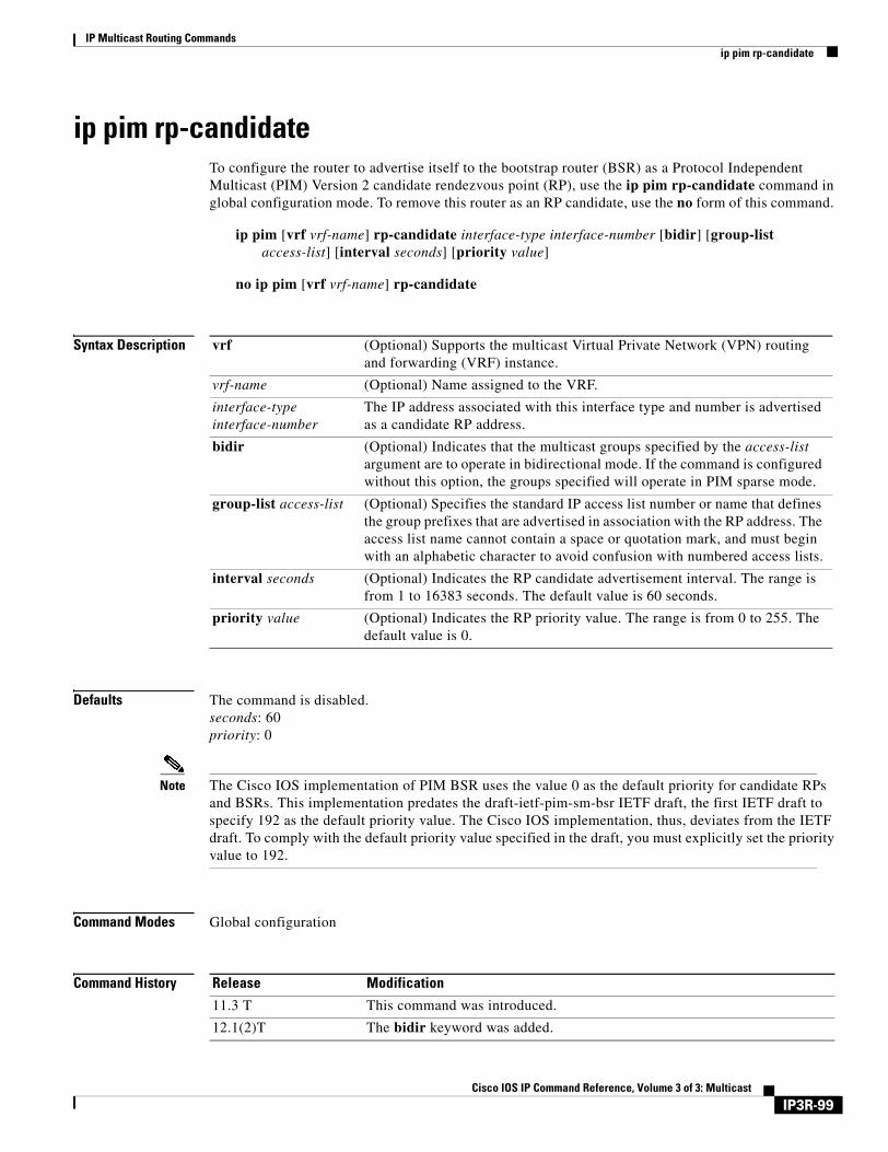
IP Multicast Routing Commandsip pim rp-candidate
ip pim rp-candidateTo configure the router to advertise itself to the bootstrap router (BSR) as a Protocol Independent Multicast (PIM) Version 2 candidate rendezvous point (RP), use the ip pim rp-candidate command in global configuration mode. To remove this router as an RP candidate, use the no form of this command.
ip pim [vrf vrf-name] rp-candidate interface-type interface-number [bidir] [group-list access-list] [interval seconds] [priority value]
no ip pim [vrf vrf-name] rp-candidate
Syntax Description
Defaults The command is disabled.seconds: 60 priority: 0
Note The Cisco IOS implementation of PIM BSR uses the value 0 as the default priority for candidate RPs and BSRs. This implementation predates the draft-ietf-pim-sm-bsr IETF draft, the first IETF draft to specify 192 as the default priority value. The Cisco IOS implementation, thus, deviates from the IETF draft. To comply with the default priority value specified in the draft, you must explicitly set the priority value to 192.
Command Modes Global configuration
Command History
vrf (Optional) Supports the multicast Virtual Private Network (VPN) routing and forwarding (VRF) instance.
vrf-name (Optional) Name assigned to the VRF.
interface-type interface-number
The IP address associated with this interface type and number is advertised as a candidate RP address.
bidir (Optional) Indicates that the multicast groups specified by the access-list argument are to operate in bidirectional mode. If the command is configured without this option, the groups specified will operate in PIM sparse mode.
group-list access-list (Optional) Specifies the standard IP access list number or name that defines the group prefixes that are advertised in association with the RP address. The access list name cannot contain a space or quotation mark, and must begin with an alphabetic character to avoid confusion with numbered access lists.
interval seconds (Optional) Indicates the RP candidate advertisement interval. The range is from 1 to 16383 seconds. The default value is 60 seconds.
priority value (Optional) Indicates the RP priority value. The range is from 0 to 255. The default value is 0.
Release Modification
11.3 T This command was introduced.
12.1(2)T The bidir keyword was added.
IP3R-99Cisco IOS IP Command Reference, Volume 3 of 3: Multicast

IP Multicast Routing Commandsip pim rp-candidate
Usage Guidelines This command causes the router to send a PIM Version 2 message advertising itself as a candidate RP to the BSR. The addresses allowed by the access list, together with the router identified by the type and number, constitute the RP and its range of addresses for which it is responsible.
Use this command only in backbone routers that have good connectivity to all parts of the PIM domain. That is, a stub router that relies on an on-demand dialup link to connect to the rest of the PIM domain is not a good candidate RP.
Use this command with the bidir keyword when you want bidirectional forwarding and you are using the PIM Version 2 BSR mechanism to distribute group-to-RP mappings. Other options are as follows:
• If you are using Auto-RP to distribute group-to-RP mappings, use the bidir keyword with the ip pim send-rp-announce command.
• If you are not distributing group-to-RP mappings using either Auto-RP or the PIM Version 2 BSR mechanism, use the bidir keyword with the ip pim rp-address command.
When the interval keyword is specified, the candidate RP advertisement interval is set to a value specified by the seconds argument. The default interval is 60 seconds. Reducing this interval to a time of less than 60 seconds can reduce the time required to fail over to a secondary RP at the expense of generating more PIM Version 2 messages.
Examples The following example shows how to configure the router to advertise itself as a candidate RP to the BSR in its PIM domain. Standard access list number 4 specifies the group prefix associated with the RP that has the address identified by Ethernet interface 2. That RP is responsible for the groups with the prefix 239.
ip pim rp-candidate ethernet 2 group-list 4access-list 4 permit 239.0.0.0 0.255.255.255
Related Commands
12.0(23)S The vrf keyword and vrf-name argument were added.
12.2(13)T The vrf keyword and vrf-name argument were added.
Release Modification
Command Description
ip pim bsr-candidate Configures the router to announce its candidacy as a BSR.
ip pim rp-address Configures the address of a PIM RP for a particular group.
ip pim rp-announce-filter Filters incoming Auto-RP announcement messages coming from the RP.
ip pim send-rp-announce Uses Auto-RP to configure for which groups the router is willing to act as RP.
IP3R-100Cisco IOS IP Command Reference, Volume 3 of 3: Multicast
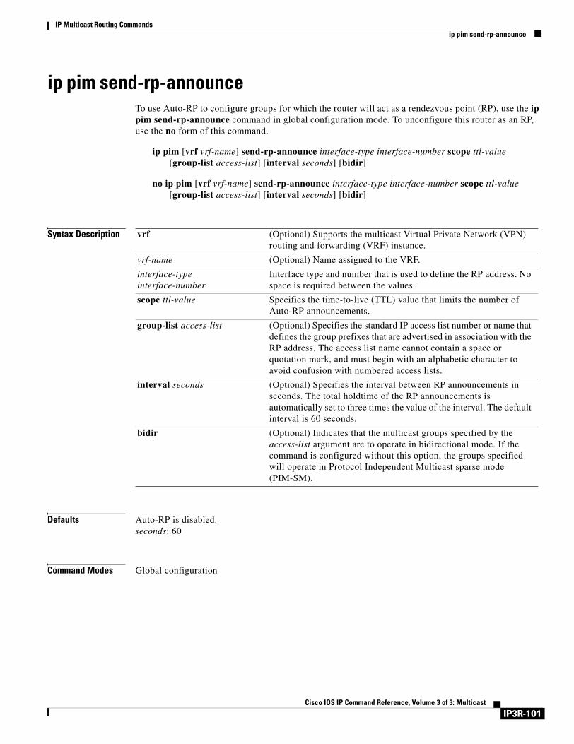
IP Multicast Routing Commandsip pim send-rp-announce
ip pim send-rp-announceTo use Auto-RP to configure groups for which the router will act as a rendezvous point (RP), use the ip pim send-rp-announce command in global configuration mode. To unconfigure this router as an RP, use the no form of this command.
ip pim [vrf vrf-name] send-rp-announce interface-type interface-number scope ttl-value [group-list access-list] [interval seconds] [bidir]
no ip pim [vrf vrf-name] send-rp-announce interface-type interface-number scope ttl-value [group-list access-list] [interval seconds] [bidir]
Syntax Description
Defaults Auto-RP is disabled.seconds: 60
Command Modes Global configuration
vrf (Optional) Supports the multicast Virtual Private Network (VPN) routing and forwarding (VRF) instance.
vrf-name (Optional) Name assigned to the VRF.
interface-type interface-number
Interface type and number that is used to define the RP address. No space is required between the values.
scope ttl-value Specifies the time-to-live (TTL) value that limits the number of Auto-RP announcements.
group-list access-list (Optional) Specifies the standard IP access list number or name that defines the group prefixes that are advertised in association with the RP address. The access list name cannot contain a space or quotation mark, and must begin with an alphabetic character to avoid confusion with numbered access lists.
interval seconds (Optional) Specifies the interval between RP announcements in seconds. The total holdtime of the RP announcements is automatically set to three times the value of the interval. The default interval is 60 seconds.
bidir (Optional) Indicates that the multicast groups specified by the access-list argument are to operate in bidirectional mode. If the command is configured without this option, the groups specified will operate in Protocol Independent Multicast sparse mode (PIM-SM).
IP3R-101Cisco IOS IP Command Reference, Volume 3 of 3: Multicast
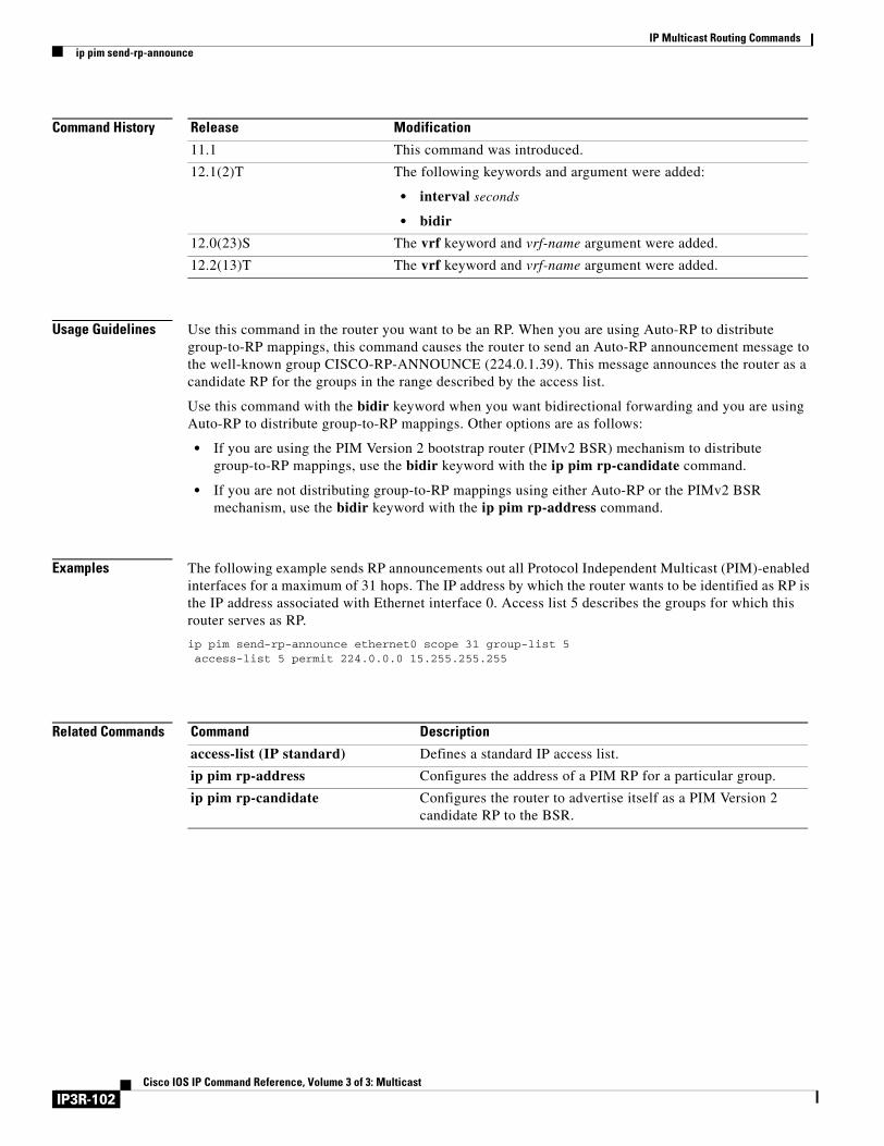
IP Multicast Routing Commandsip pim send-rp-announce
Command History
Usage Guidelines Use this command in the router you want to be an RP. When you are using Auto-RP to distribute group-to-RP mappings, this command causes the router to send an Auto-RP announcement message to the well-known group CISCO-RP-ANNOUNCE (224.0.1.39). This message announces the router as a candidate RP for the groups in the range described by the access list.
Use this command with the bidir keyword when you want bidirectional forwarding and you are using Auto-RP to distribute group-to-RP mappings. Other options are as follows:
• If you are using the PIM Version 2 bootstrap router (PIMv2 BSR) mechanism to distribute group-to-RP mappings, use the bidir keyword with the ip pim rp-candidate command.
• If you are not distributing group-to-RP mappings using either Auto-RP or the PIMv2 BSR mechanism, use the bidir keyword with the ip pim rp-address command.
Examples The following example sends RP announcements out all Protocol Independent Multicast (PIM)-enabled interfaces for a maximum of 31 hops. The IP address by which the router wants to be identified as RP is the IP address associated with Ethernet interface 0. Access list 5 describes the groups for which this router serves as RP.
ip pim send-rp-announce ethernet0 scope 31 group-list 5access-list 5 permit 224.0.0.0 15.255.255.255
Related Commands
Release Modification
11.1 This command was introduced.
12.1(2)T The following keywords and argument were added:
• interval seconds
• bidir
12.0(23)S The vrf keyword and vrf-name argument were added.
12.2(13)T The vrf keyword and vrf-name argument were added.
Command Description
access-list (IP standard) Defines a standard IP access list.
ip pim rp-address Configures the address of a PIM RP for a particular group.
ip pim rp-candidate Configures the router to advertise itself as a PIM Version 2 candidate RP to the BSR.
IP3R-102Cisco IOS IP Command Reference, Volume 3 of 3: Multicast
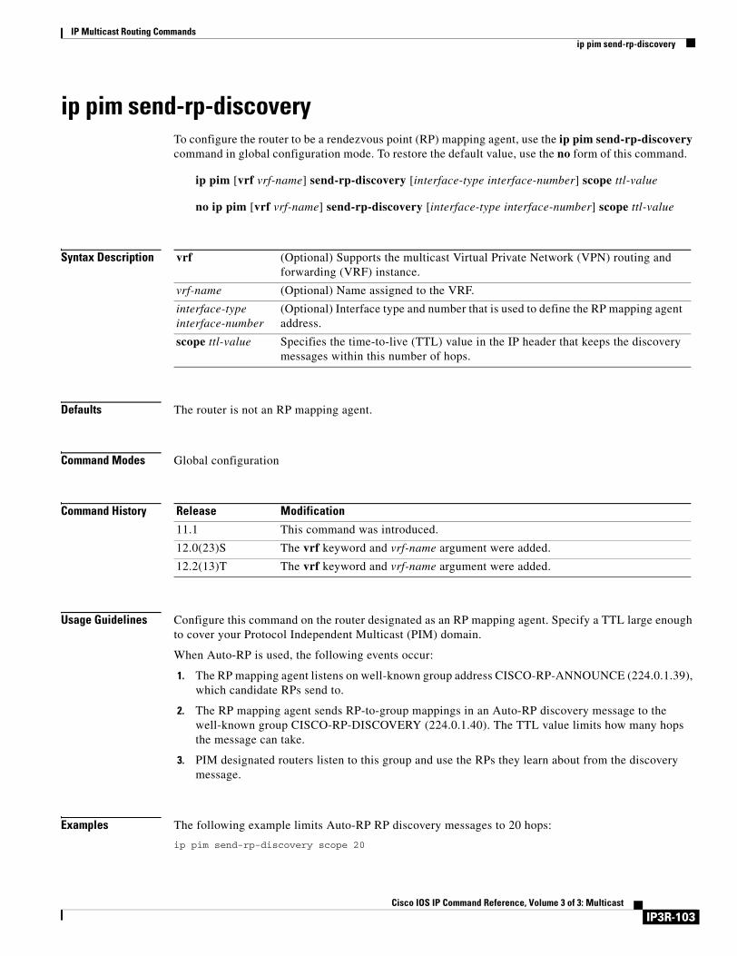
IP Multicast Routing Commandsip pim send-rp-discovery
ip pim send-rp-discoveryTo configure the router to be a rendezvous point (RP) mapping agent, use the ip pim send-rp-discovery command in global configuration mode. To restore the default value, use the no form of this command.
ip pim [vrf vrf-name] send-rp-discovery [interface-type interface-number] scope ttl-value
no ip pim [vrf vrf-name] send-rp-discovery [interface-type interface-number] scope ttl-value
Syntax Description
Defaults The router is not an RP mapping agent.
Command Modes Global configuration
Command History
Usage Guidelines Configure this command on the router designated as an RP mapping agent. Specify a TTL large enough to cover your Protocol Independent Multicast (PIM) domain.
When Auto-RP is used, the following events occur:
1. The RP mapping agent listens on well-known group address CISCO-RP-ANNOUNCE (224.0.1.39), which candidate RPs send to.
2. The RP mapping agent sends RP-to-group mappings in an Auto-RP discovery message to the well-known group CISCO-RP-DISCOVERY (224.0.1.40). The TTL value limits how many hops the message can take.
3. PIM designated routers listen to this group and use the RPs they learn about from the discovery message.
Examples The following example limits Auto-RP RP discovery messages to 20 hops:
ip pim send-rp-discovery scope 20
vrf (Optional) Supports the multicast Virtual Private Network (VPN) routing and forwarding (VRF) instance.
vrf-name (Optional) Name assigned to the VRF.
interface-type interface-number
(Optional) Interface type and number that is used to define the RP mapping agent address.
scope ttl-value Specifies the time-to-live (TTL) value in the IP header that keeps the discovery messages within this number of hops.
Release Modification
11.1 This command was introduced.
12.0(23)S The vrf keyword and vrf-name argument were added.
12.2(13)T The vrf keyword and vrf-name argument were added.
IP3R-103Cisco IOS IP Command Reference, Volume 3 of 3: Multicast
IP Multicast Routing Commandsip pim spt-threshold
ip pim spt-thresholdTo configure when a Protocol Independent Multicast (PIM) leaf router should join the shortest path source tree for the specified group, use the ip pim spt-threshold command in global configuration mode. To restore the default value, use the no form of this command.
ip pim [vrf vrf-name] spt-threshold {kbps | infinity} [group-list access-list]
no ip pim [vrf vrf-name] spt-threshold {kbps | infinity} [group-list access-list]
Syntax Description
Defaults When this command is not used, the PIM leaf router joins the shortest path tree immediately after the first packet arrives from a new source.
Command Modes Global configuration
Command History
Usage Guidelines If a source sends at a rate greater than or equal to traffic rate (the kbps value), a PIM join message is triggered toward the source to construct a source tree.
If the infinity keyword is specified, all sources for the specified group will use the shared tree. Specifying a group list access list indicates the groups to which the threshold applies.
If the traffic rate from the source drops below the threshold traffic rate, the leaf router will switch back to the shared tree and send a prune message toward the source.
Examples The following example sets a threshold of 4 kbps, above which traffic to a group from a source will cause the router to switch to the shortest path tree to that source:
ip pim spt-threshold 4
vrf (Optional) Supports the multicast Virtual Private Network (VPN) routing and forwarding (VRF) instance.
vrf-name (Optional) Name assigned to the VRF.
kbps Traffic rate (in kbps).
infinity Causes all sources for the specified group to use the shared tree.
group-list access-list (Optional) Indicates which groups the threshold applies to. Must be an IP standard access list number or name. If the value is 0 or is omitted, the threshold applies to all groups.
Release Modification
11.1 This command was introduced.
12.0(23)S The vrf keyword and vrf-name argument were added.
12.2(13)T The vrf keyword and vrf-name argument were added.
IP3R-104Cisco IOS IP Command Reference, Volume 3 of 3: Multicast
IP Multicast Routing Commandsip pim ssm
ip pim ssmTo define the Source Specific Multicast (SSM) range of IP multicast addresses, use the ip pim ssm command in global configuration mode. To disable the SSM range, use the no form of this command.
ip pim [vrf vrf-name] ssm {default | range access-list}
no ip pim [vrf vrf-name] ssm {default | range access-list}
Syntax Description
Defaults The command is disabled.
Command Modes Global configuration
Command History
Usage Guidelines When an SSM range of IP multicast addresses is defined by the ip pim ssm command, no Multicast Source Discovery Protocol (MSDP) Source-Active (SA) messages will be accepted or originated in the SSM range.
Examples The following example shows how to configure SSM service for the IP address range defined by access list 4:
access-list 4 permit 224.2.151.141ip pim ssm range 4
vrf (Optional) Supports the multicast Virtual Private Network (VPN) routing and forwarding (VRF) instance.
vrf-name (Optional) Name assigned to the VRF.
default Defines the SSM range access list to 232/8.
range access-list Specifies the standard IP access list number or name defining the SSM range.
Release Modification
12.1(3)T This command was introduced.
12.0(23)S The vrf keyword and vrf-name argument were added.
12.2(13)T The vrf keyword and vrf-name argument were added.
IP3R-105Cisco IOS IP Command Reference, Volume 3 of 3: Multicast

IP Multicast Routing Commandsip pim ssm
Related Commands Command Description
ip igmp v3lite Enables the acceptance and processing of IGMP v3lite membership reports on an interface.
ip urd Enables interception of TCP packets sent to the reserved URD port 659 on an interface and processing of URD channel subscription reports.
IP3R-106Cisco IOS IP Command Reference, Volume 3 of 3: Multicast
IP Multicast Routing Commandsip pim state-refresh disable
ip pim state-refresh disableTo disable the processing and forwarding of PIM dense mode state refresh control messages on a Protocol Independent Multicast (PIM) router, use the ip pim state-refresh disable command in global configuration mode. To reenable the processing and forwarding of PIM dense mode state refresh control messages, use the no form of this command.
ip pim [vrf vrf-name] state-refresh disable
no ip pim [vrf vrf-name] state-refresh disable
Syntax Description
Defaults The processing and forwarding of PIM dense mode state refresh control messages is enabled on PIM routers that are running a Cisco IOS software release that supports the PIM dense mode state refresh feature.
Command Modes Global configuration
Command History
Usage Guidelines Configuring this command removes PIM dense mode state refresh information from PIM hello messages.
Examples The following example disables the periodic forwarding of the PIM dense mode state refresh control message down a source-based IP multicast distribution tree:
ip pim state-refresh disable
Related Commands
vrf (Optional) Supports the multicast Virtual Private Network (VPN) routing and forwarding (VRF) instance.
vrf-name (Optional) Name assigned to the VRF.
Release Modification
12.1(5)T This command was introduced.
12.0(23)S The vrf keyword and vrf-name argument were added.
12.2(13)T The vrf keyword and vrf-name argument were added.
Command Description
ip pim state-refresh origination-interval
Configures the origination of and the interval for the PIM dense mode state refresh control messages on a PIM router.
show ip pim interface Displays information about interfaces configured for PIM.
show ip pim neighbor Lists the PIM neighbors discovered by the Cisco IOS software.
IP3R-107Cisco IOS IP Command Reference, Volume 3 of 3: Multicast
IP Multicast Routing Commandsip pim state-refresh origination-interval
ip pim state-refresh origination-intervalTo configure the origination of and the interval for PIM dense mode state refresh control messages on a Protocol Independent Multicast (PIM) router, use the ip pim state-refresh origination-interval command in interface configuration mode. To stop the origination of the PIM dense mode state refresh control message, use the no form of this command.
ip pim state-refresh origination-interval [interval]
no ip pim state-refresh origination-interval [interval]
Syntax Description
Defaults PIM dense mode state refresh control message origination is disabled. By default, all PIM routers that are running a Cisco IOS software release that supports PIM dense mode state refresh process and forward PIM dense mode state refresh control messages.
Command Modes Interface configuration
Command History
Usage Guidelines Configure this command on the interfaces of the first hop, PIM dense mode routers that are directly connected to sources for PIM-DM multicast groups.
By default, the processing and forwarding of PIM dense mode state refresh control messages is enabled on PIM routers that are running a Cisco IOS software release that supports PIM dense mode state refresh.
Examples The following example configures the origination of the state refresh control message on Ethernet interface 0 of a PIM dense mode router with an interval of 80 seconds:
interface ethernet 0ip pim state-refresh origination-interval 80
Related Commands
interval (Optional) The number of seconds between PIM dense mode state refresh control messages. The default is 60 seconds. The available interval range is from 4 to 100 seconds.
Release Modification
12.1(5)T This command was introduced.
Command Description
ip pim state-refresh disable Disables the processing and forwarding of PIM dense mode state refresh feature control messages on a PIM router.
show ip pim interface Displays information about interfaces configured for PIM.
show ip pim neighbor Lists the PIM neighbors discovered by the Cisco IOS software.
IP3R-108Cisco IOS IP Command Reference, Volume 3 of 3: Multicast
IP Multicast Routing Commandsip pim vc-count
ip pim vc-countTo change the maximum number of virtual circuits (VCs) that Protocol Independent Multicast (PIM) can open, use the ip pim vc-count command in interface configuration mode. To restore the default value, use the no form of this command.
ip pim vc-count number
no ip pim vc-count
Syntax Description
Defaults 200 VCs per ATM interface or subinterface
Command Modes Interface configuration
Command History
Examples The following example allows PIM to open a maximum of 250 VCs:
ip pim vc-count 250
Related Commands
number Maximum number of VCs that PIM can open. The default is 200 VCs. The range is from 1 to 65535.
Release Modification
11.3 This command was introduced.
Command Description
ip pim minimum-vc-rate Configures the minimum traffic rate to keep VCs from being idled.
ip pim multipoint-signalling Enables PIM to open ATM multipoint switched VCs for each multicast group that a receiver joins.
ip pim Enables PIM on an interface.
show ip pim vc Displays ATM VCs status information for multipoint VCs opened by PIM.
IP3R-109Cisco IOS IP Command Reference, Volume 3 of 3: Multicast
IP Multicast Routing Commandsip pim version
ip pim versionTo configure the Protocol Independent Multicast (PIM) version of the interface, use the ip pim version command in interface configuration mode. To restore the default value, use the no form of this command.
ip pim version [1 | 2]
no ip pim version
Syntax Description
Defaults Version 2
Command Modes Interface configuration
Command History
Usage Guidelines An interface in Version 2 mode automatically downgrades to Version 1 mode if that interface has a PIM Version 1 neighbor. The interface returns to Version 2 mode after all Version 1 neighbors disappear (that is, they are shut down or upgraded).
Examples The following example configures the interface to operate in PIM Version 1 mode:
interface ethernet 0ip address 1.1.1.1 255.0.0.0ip pim sparse-dense-modeip pim version 1
1 (Optional) Configures PIM Version 1.
2 (Optional) Configures PIM Version 2.
Release Modification
11.3 T This command was introduced.
IP3R-110Cisco IOS IP Command Reference, Volume 3 of 3: Multicast
IP Multicast Routing Commandsip rgmp
ip rgmpTo enable the Router-Port Group Management Protocol (RGMP) on Ethernet, Fast Ethernet, and Gigabit Ethernet interfaces, use the ip rgmp command in interface configuration mode. To disable RGMP on the interfaces, use the no form of this command.
ip rgmp
no ip rgmp
Syntax Description This command has no arguments or keywords.
Defaults RGMP is not enabled.
Command Modes Interface configuration
Command History
Usage Guidelines RGMP is supported only on Ethernet, Fast Ethernet, and Gigabit Ethernet interfaces.
Before enabling RGMP, the following features must be enabled on your router:
• IP routing
• IP multicast
• PIM in sparse mode, sparse-dense mode, source specific mode, or bidirectional mode
If your router is in a bidirectional group, make sure to enable RGMP only on interfaces that do not function as a designated forwarder (DF). If you enable RGMP on an interface that functions as a DF, the interface will not forward multicast packets up the bidirectional shared tree to the rendezvous point (RP).
The following features must be enabled on your switch:
• IP multicast
• IGMP snooping
Examples The following example enables RGMP on Ethernet interface 1/0:
interface ethernet 1/0ip rgmp
Release Modification
12.0(10)S This command was introduced.
12.1(1)E This command was integrated into Cisco IOS Release 12.1(1)E.
12.1(5)T This command was integrated into Cisco IOS Release 12.1(5)T.
IP3R-111Cisco IOS IP Command Reference, Volume 3 of 3: Multicast

IP Multicast Routing Commandsip rgmp
Related Commands Command Description
debug ip rgmp Logs debug messages sent by an RGMP-enabled router.
show ip igmp interface Displays multicast-related information about an interface.
IP3R-112Cisco IOS IP Command Reference, Volume 3 of 3: Multicast
IP Multicast Routing Commandsip rtp compression-connections
ip rtp compression-connectionsTo specify the total number of Real-Time Transport Protocol (RTP) header compression connections that can exist on an interface, use the ip rtp compression-connections command in interface configuration mode. To restore the default value, use the no form of this command.
ip rtp compression-connections number
no ip rtp compression-connections
Syntax Description
Defaults 32 connections
Command Modes Interface configuration
Command History
Examples The following example changes the number of RTP header compression connections supported to 150:
interface serial 0encapsulation pppip rtp header-compressionip rtp compression-connections 150
Related Commands
number Number of RTP header compression connections the cache supports, in the range from 3 to 1000. The default is 32 connections (16 calls).
Release Modification
11.3 This command was introduced.
12.0(7)T For PPP and High-Level Data Link Control (HDLC) encapsulation, the maximum number of connections increased from 256 to 1000.
For Frame Relay encapsulation, the maximum number of connections increased to 256. The maximum value for Frame Relay is fixed, not configurable.
Command Description
frame-relay ip rtp header-compression
Enables RTP header compression for all Frame Relay maps on a physical interface.
frame-relay map ip rtp header-compression
Enables RTP header compression per DLCI.
ip rtp header-compression Enables RTP header compression.
ip tcp header-compression Enables TCP header compression.
show ip rtp header-compression Displays RTP header compression statistics.
IP3R-113Cisco IOS IP Command Reference, Volume 3 of 3: Multicast

IP Multicast Routing Commandsip rtp header-compression
ip rtp header-compressionTo enable Real-Time Transport Protocol (RTP) header compression, use the ip rtp header-compression command in interface configuration mode. To disable RTP header compression, use the no form of this command.
ip rtp header-compression [passive]
no ip rtp header-compression [passive]
Syntax Description
Defaults Disabled
Command Modes Interface configuration
Command History
Usage Guidelines If you use this command without the passive keyword, the software compresses all RTP traffic.
You can compress IP/User Datagram Protocol (UDP)/RTP headers to reduce the size of your packets. Compressing headers is especially useful for RTP, because RTP payload size can be as small as 20 bytes, and the uncompressed header is 40 bytes.
RTP header compression is supported on serial lines using Frame Relay, High-Level Data Link Control (HDLC), or PPP encapsulation. You must enable compression on both ends of a serial connection.
This command can compress unicast or multicast RTP packets, and hence multicast backbone (MBONE) traffic can also be compressed over slow links. The compression scheme is beneficial only when you have small payload sizes, as in audio traffic.
Examples The following example enables RTP header compression on serial interface 0 and limits the number of RTP header compression connections to 10:
interface serial 0encapsulation pppip rtp header-compressionip rtp compression-connections 10
passive (Optional) Compresses outgoing RTP packets only if incoming RTP packets on the same interface are compressed.
Release Modification
11.3 This command was introduced.
IP3R-114Cisco IOS IP Command Reference, Volume 3 of 3: Multicast

IP Multicast Routing Commandsip rtp header-compression
Related Commands Command Description
clear ip rtp header-compression Clears RTP header compression structures and statistics.
ip rtp compression-connections Specifies the total number of RTP header compression connections that can exist on an interface.
show ip rtp header-compression Displays RTP header compression statistics.
IP3R-115Cisco IOS IP Command Reference, Volume 3 of 3: Multicast
IP Multicast Routing Commandsip sap cache-timeout
ip sap cache-timeoutTo limit how long a Session Announcement Protocol (SAP) cache entry stays active in the cache, use the ip sap cache-timeout command in global configuration mode. To restore the default value, use the no form of this command.
ip sap cache-timeout minutes
no ip sap cache-timeout
Syntax Description
Defaults By default, session announcements remain for 1440 minutes (24 hours) in the cache.
Command Modes Global configuration
Command History
Usage Guidelines This command defines how long session announcements are cached by the router. Active session announcements are periodically re-sent by the originating site, refreshing the cached state in the router. The minimum interval between announcements for a single group is 5 minutes. Setting the cache timeout to a value less than 30 minutes is not recommended. Set the cache timeout to 0 to keep entries in the cache indefinitely.
Examples The following example causes SAP cache entries to remain in the cache for 30 minutes:
ip sap cache-timeout 30
Related Commands
minutes Time (in minutes) that a SAP cache entry is active in the cache.
Release Modification
11.2 The ip sdr cache-timeout command was introduced.
12.2 The ip sdr cache-timeout command was replaced by the ip sap cache-timeout command.
Command Description
clear ip sap Deletes a SAP cache entry or the entire SAP cache.
show ip sap Displays the SAP cache.
IP3R-116Cisco IOS IP Command Reference, Volume 3 of 3: Multicast
IP Multicast Routing Commandsip sap listen
ip sap listenTo enable the Cisco IOS software to listen to session directory announcements, use the ip sap listen command in interface configuration mode. To disable the function, use the no form of this command.
ip sap listen
no ip sap listen
Syntax Description This command has no arguments or keywords.
Defaults Disabled
Command Modes Interface configuration
Command History
Usage Guidelines Cisco IOS software can receive and store Session Description Protocol (SDP) and Session Announcement Protocol (SAP) session announcements.
SAP is a protocol used to announce multicast multimedia conferences and other multicast sessions, and it is used to communicate session setup information to prospective participants. A SAP announcer periodically sends an announcement packet to a well-known multicast address and port. The announcement is sent via multicast with the same scope as the session it is announcing to ensure that the recipients of the announcement can also be recipients of the session the announcement describes. SAP should be used for sessions of public interest where participants are not known in advance.
When the ip sap listen command is configured on an interface, the well-known session directory groups on that interface can receive and store session announcements. Each announcer listens to other announcements in order to determine the total number of sessions being announced on a particular group, and the interfaces are put into the outgoing interface list for the IP SAP group. The announcements can be displayed with the show ip sap command. The ip multicast rate-limit command uses stored session announcements. To configure the period of time after which received announcements will expire, use the ip sap cache-timeout command.
When the no ip multicast routing command is configured, announcements are only stored if they are received on an interface configured with the ip sap listen command. When a system is configured as a multicast router, it is sufficient to configure the ip sap listen command on only a single multicast-enabled interface. The well-known session directory groups are handled as local joined groups after the ip sap listen command is first configured. (See the L flag of the show ip mroute command.) This configuration causes announcements received from all multicast-enabled interfaces to be routed and stored within the system.
Release Modification
11.1 The ip sdr listen command was introduced.
12.2 The ip sdr listen command was replaced by the ip sap listen command.
IP3R-117Cisco IOS IP Command Reference, Volume 3 of 3: Multicast
IP Multicast Routing Commandsip sap listen
Examples The following example shows how to enable a router to listen to session directory announcements:
ip routing
interface loopback 0ip address 10.0.0.51 255.255.255.0ip pim sparse-dense modeip sap listen
Related Commands Command Description
clear ip sap Deletes a SAP cache entry or the entire SAP cache.
ip multicast rate-limit Controls the rate a sender from the source list can send to a multicast group in the group list.
ip sap cache-timeout Limits how long a SAP cache entry stays active in the cache.
show ip sap Displays the SAP cache.
IP3R-118Cisco IOS IP Command Reference, Volume 3 of 3: Multicast

IP Multicast Routing Commandsip sdr cache-timeout
ip sdr cache-timeoutThe ip sdr cache-timeout command is replaced by the ip sap cache-timeout command. See the description of the ip sap cache-timeout command in this chapter for more information.
IP3R-119Cisco IOS IP Command Reference, Volume 3 of 3: Multicast

IP Multicast Routing Commandsip sdr listen
ip sdr listenThe ip sdr listen command is replaced by the ip sap listen command. See the description of the ip sap listen command in this chapter for more information.
IP3R-120Cisco IOS IP Command Reference, Volume 3 of 3: Multicast
IP Multicast Routing Commandsip urd
ip urdTo enable interception of TCP packets sent to the reserved URL Rendezvous Directory (URD) port 465 on an interface and processing of URD channel subscription reports, use the ip urd command in interface configuration mode. To disable URD on an interface, use the no form of this command.
ip urd [proxy]
no ip urd [proxy]
Syntax Description
Defaults Disabled
Command Modes Interface configuration
Command History
Usage Guidelines To use this command, you must first define a Source Specific Multicast (SSM) range of IP addresses using the ip pim ssm global configuration command. When URD is enabled, it is supported in the SSM range of addresses only. We recommend that you not enable URD on backbone interfaces, but only on interfaces connecting to hosts.
URD functionality is available for multicast process switching, fast switching, and distributed fast-switching paths.
Examples The following example shows how to configure URD on Ethernet interface 3/3:
interface ethernet 3/3ip urd
Related Commands
proxy (Optional) Allows an interface to accept URL requests from any TCP connection sent to that interface. If the proxy keyword is not configured, the interface will accept URL requests from TCP connections only if the requests originated from directly connected hosts.
The proxy option must be enabled on an interface if it is unnumbered or if it has downstream routers configured with Internet Group Managment Protocol (IGMP) proxy routing. To prevent users on the backbone from creating URD state on your router, do not enable the proxy option on a backbone interface of your router.
Release Modification
12.1(3)T This command was introduced.
Command Description
ip pim ssm Defines the SSM range of IP multicast addresses.
IP3R-121Cisco IOS IP Command Reference, Volume 3 of 3: Multicast
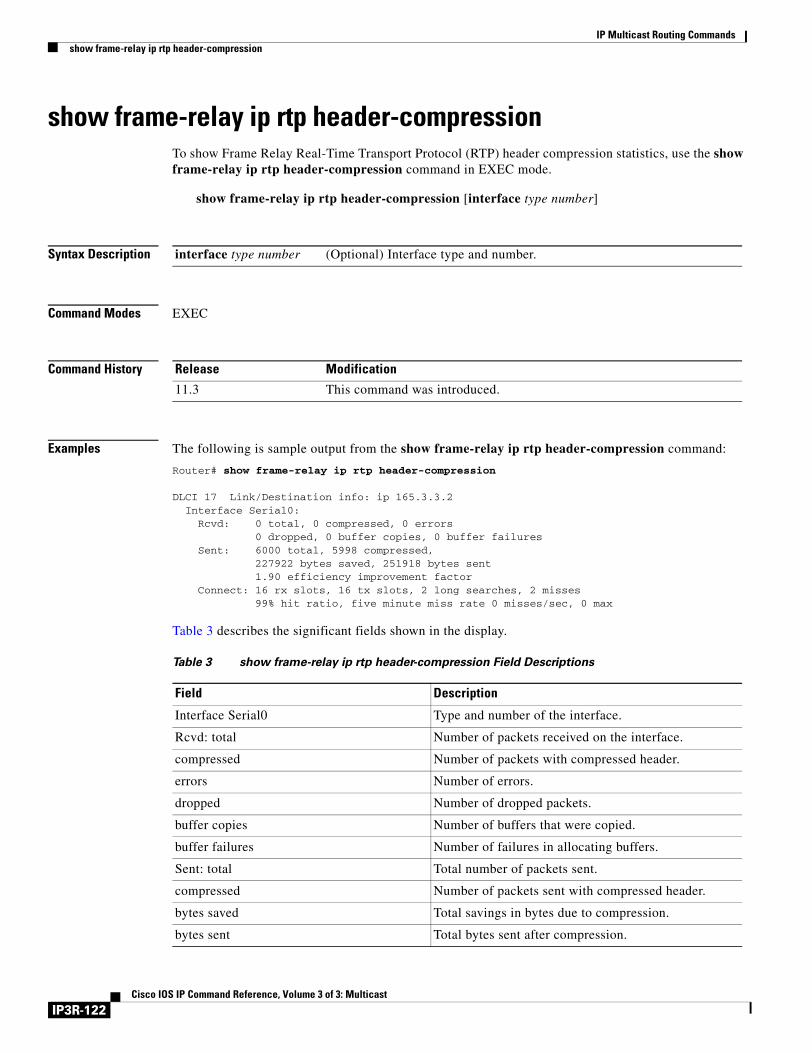
IP Multicast Routing Commandsshow frame-relay ip rtp header-compression
show frame-relay ip rtp header-compression To show Frame Relay Real-Time Transport Protocol (RTP) header compression statistics, use the show frame-relay ip rtp header-compression command in EXEC mode.
show frame-relay ip rtp header-compression [interface type number]
Syntax Description
Command Modes EXEC
Command History
Examples The following is sample output from the show frame-relay ip rtp header-compression command:
Router# show frame-relay ip rtp header-compression
DLCI 17 Link/Destination info: ip 165.3.3.2 Interface Serial0: Rcvd: 0 total, 0 compressed, 0 errors 0 dropped, 0 buffer copies, 0 buffer failures Sent: 6000 total, 5998 compressed, 227922 bytes saved, 251918 bytes sent 1.90 efficiency improvement factor Connect: 16 rx slots, 16 tx slots, 2 long searches, 2 misses 99% hit ratio, five minute miss rate 0 misses/sec, 0 max
Table 3 describes the significant fields shown in the display.
interface type number (Optional) Interface type and number.
Release Modification
11.3 This command was introduced.
Table 3 show frame-relay ip rtp header-compression Field Descriptions
Field Description
Interface Serial0 Type and number of the interface.
Rcvd: total Number of packets received on the interface.
compressed Number of packets with compressed header.
errors Number of errors.
dropped Number of dropped packets.
buffer copies Number of buffers that were copied.
buffer failures Number of failures in allocating buffers.
Sent: total Total number of packets sent.
compressed Number of packets sent with compressed header.
bytes saved Total savings in bytes due to compression.
bytes sent Total bytes sent after compression.
IP3R-122Cisco IOS IP Command Reference, Volume 3 of 3: Multicast
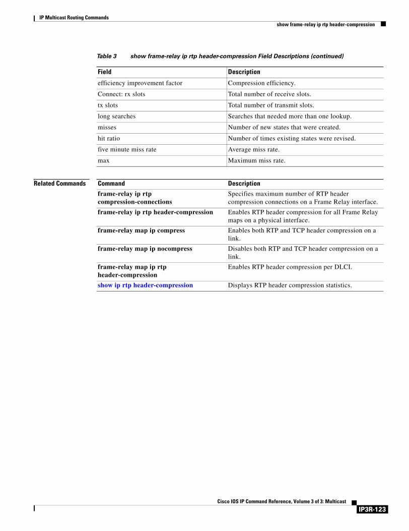
IP Multicast Routing Commandsshow frame-relay ip rtp header-compression
Related Commands
efficiency improvement factor Compression efficiency.
Connect: rx slots Total number of receive slots.
tx slots Total number of transmit slots.
long searches Searches that needed more than one lookup.
misses Number of new states that were created.
hit ratio Number of times existing states were revised.
five minute miss rate Average miss rate.
max Maximum miss rate.
Table 3 show frame-relay ip rtp header-compression Field Descriptions (continued)
Field Description
Command Description
frame-relay ip rtp compression-connections
Specifies maximum number of RTP header compression connections on a Frame Relay interface.
frame-relay ip rtp header-compression Enables RTP header compression for all Frame Relay maps on a physical interface.
frame-relay map ip compress Enables both RTP and TCP header compression on a link.
frame-relay map ip nocompress Disables both RTP and TCP header compression on a link.
frame-relay map ip rtp header-compression
Enables RTP header compression per DLCI.
show ip rtp header-compression Displays RTP header compression statistics.
IP3R-123Cisco IOS IP Command Reference, Volume 3 of 3: Multicast
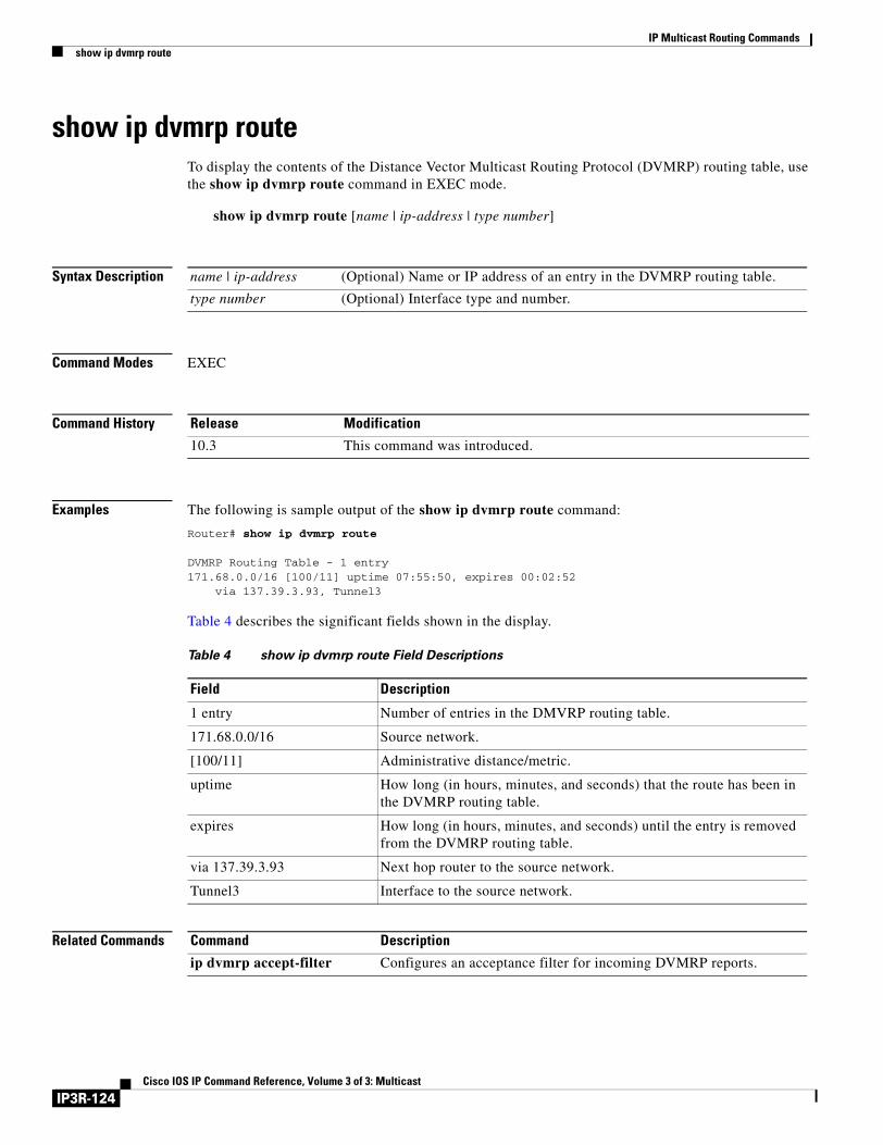
IP Multicast Routing Commandsshow ip dvmrp route
show ip dvmrp routeTo display the contents of the Distance Vector Multicast Routing Protocol (DVMRP) routing table, use the show ip dvmrp route command in EXEC mode.
show ip dvmrp route [name | ip-address | type number]
Syntax Description
Command Modes EXEC
Command History
Examples The following is sample output of the show ip dvmrp route command:
Router# show ip dvmrp route
DVMRP Routing Table - 1 entry171.68.0.0/16 [100/11] uptime 07:55:50, expires 00:02:52 via 137.39.3.93, Tunnel3
Table 4 describes the significant fields shown in the display.
Related Commands
name | ip-address (Optional) Name or IP address of an entry in the DVMRP routing table.
type number (Optional) Interface type and number.
Release Modification
10.3 This command was introduced.
Table 4 show ip dvmrp route Field Descriptions
Field Description
1 entry Number of entries in the DMVRP routing table.
171.68.0.0/16 Source network.
[100/11] Administrative distance/metric.
uptime How long (in hours, minutes, and seconds) that the route has been in the DVMRP routing table.
expires How long (in hours, minutes, and seconds) until the entry is removed from the DVMRP routing table.
via 137.39.3.93 Next hop router to the source network.
Tunnel3 Interface to the source network.
Command Description
ip dvmrp accept-filter Configures an acceptance filter for incoming DVMRP reports.
IP3R-124Cisco IOS IP Command Reference, Volume 3 of 3: Multicast
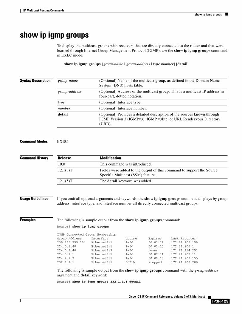
IP Multicast Routing Commandsshow ip igmp groups
show ip igmp groupsTo display the multicast groups with receivers that are directly connected to the router and that were learned through Internet Group Management Protocol (IGMP), use the show ip igmp groups command in EXEC mode.
show ip igmp groups [group-name | group-address | type number] [detail]
Syntax Description
Command Modes EXEC
Command History
Usage Guidelines If you omit all optional arguments and keywords, the show ip igmp groups command displays by group address, interface type, and interface number all directly connected multicast groups.
Examples The following is sample output from the show ip igmp groups command:
Router# show ip igmp groups
IGMP Connected Group MembershipGroup Address Interface Uptime Expires Last Reporter239.255.255.254 Ethernet3/1 1w0d 00:02:19 172.21.200.159224.0.1.40 Ethernet3/1 1w0d 00:02:15 172.21.200.1224.0.1.40 Ethernet3/3 1w0d never 171.69.214.251224.0.1.1 Ethernet3/1 1w0d 00:02:11 172.21.200.11224.9.9.2 Ethernet3/1 1w0d 00:02:10 172.21.200.155232.1.1.1 Ethernet3/1 5d21h stopped 172.21.200.206
The following is sample output from the show ip igmp groups command with the group-address argument and detail keyword:
Router# show ip igmp groups 232.1.1.1 detail
group-name (Optional) Name of the multicast group, as defined in the Domain Name System (DNS) hosts table.
group-address (Optional) Address of the multicast group. This is a multicast IP address in four-part, dotted notation.
type (Optional) Interface type.
number (Optional) Interface number.
detail (Optional) Provides a detailed description of the sources known through IGMP Version 3 (IGMPv3), IGMP v3lite, or URL Rendezvous Directory (URD).
Release Modification
10.0 This command was introduced.
12.1(3)T Fields were added to the output of this command to support the Source Specific Multicast (SSM) feature.
12.1(5)T The detail keyword was added.
IP3R-125Cisco IOS IP Command Reference, Volume 3 of 3: Multicast
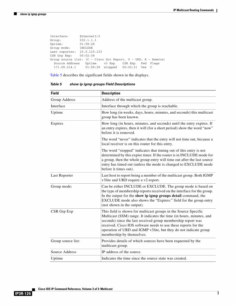
IP Multicast Routing Commandsshow ip igmp groups
Interface: Ethernet3/2Group: 232.1.1.1Uptime: 01:58:28Group mode: INCLUDELast reporter: 10.0.119.133CSR Grp Exp: 00:02:38Group source list: (C - Cisco Src Report, U - URD, R - Remote)
Source Address Uptime v3 Exp CSR Exp Fwd Flags 171.69.214.1 01:58:28 stopped 00:02:31 Yes C
Table 5 describes the significant fields shown in the displays.
Table 5 show ip igmp groups Field Descriptions
Field Description
Group Address Address of the multicast group.
Interface Interface through which the group is reachable.
Uptime How long (in weeks, days, hours, minutes, and seconds) this multicast group has been known.
Expires How long (in hours, minutes, and seconds) until the entry expires. If an entry expires, then it will (for a short period) show the word “now” before it is removed.
The word “never” indicates that the entry will not time out, because a local receiver is on this router for this entry.
The word “stopped” indicates that timing out of this entry is not determined by this expire timer. If the router is in INCLUDE mode for a group, then the whole group entry will time out after the last source entry has timed out (unless the mode is changed to EXCLUDE mode before it times out).
Last Reporter Last host to report being a member of the multicast group. Both IGMP v3lite and URD require a v2-report.
Group mode: Can be either INCLUDE or EXCLUDE. The group mode is based on the type of membership reports received on the interface for the group. In the output for the show ip igmp groups detail command, the EXCLUDE mode also shows the “Expires:” field for the group entry (not shown in the output).
CSR Grp Exp This field is shown for multicast groups in the Source Specific Multicast (SSM) range. It indicates the time (in hours, minutes, and seconds) since the last received group membership report was received. Cisco IOS software needs to use these reports for the operation of URD and IGMP v3lite, but they do not indicate group membership by themselves.
Group source list: Provides details of which sources have been requested by the multicast group.
Source Address IP address of the source.
Uptime Indicates the time since the source state was created.
IP3R-126Cisco IOS IP Command Reference, Volume 3 of 3: Multicast
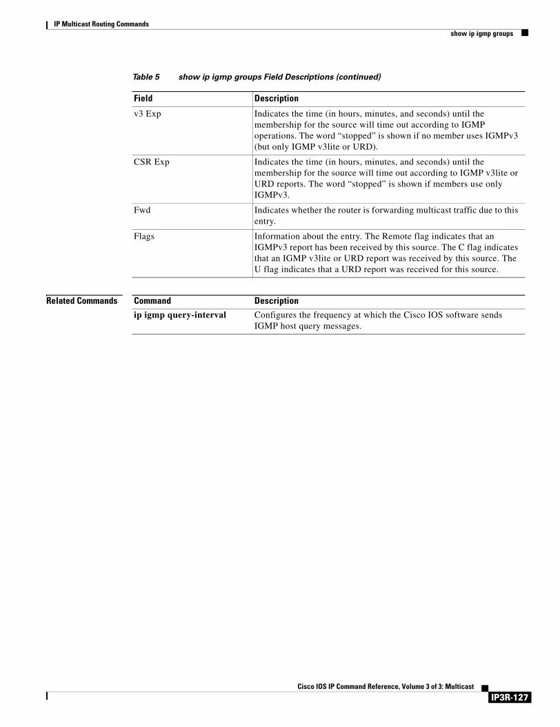
IP Multicast Routing Commandsshow ip igmp groups
Related Commands
v3 Exp Indicates the time (in hours, minutes, and seconds) until the membership for the source will time out according to IGMP operations. The word “stopped” is shown if no member uses IGMPv3 (but only IGMP v3lite or URD).
CSR Exp Indicates the time (in hours, minutes, and seconds) until the membership for the source will time out according to IGMP v3lite or URD reports. The word “stopped” is shown if members use only IGMPv3.
Fwd Indicates whether the router is forwarding multicast traffic due to this entry.
Flags Information about the entry. The Remote flag indicates that an IGMPv3 report has been received by this source. The C flag indicates that an IGMP v3lite or URD report was received by this source. The U flag indicates that a URD report was received for this source.
Table 5 show ip igmp groups Field Descriptions (continued)
Field Description
Command Description
ip igmp query-interval Configures the frequency at which the Cisco IOS software sends IGMP host query messages.
IP3R-127Cisco IOS IP Command Reference, Volume 3 of 3: Multicast
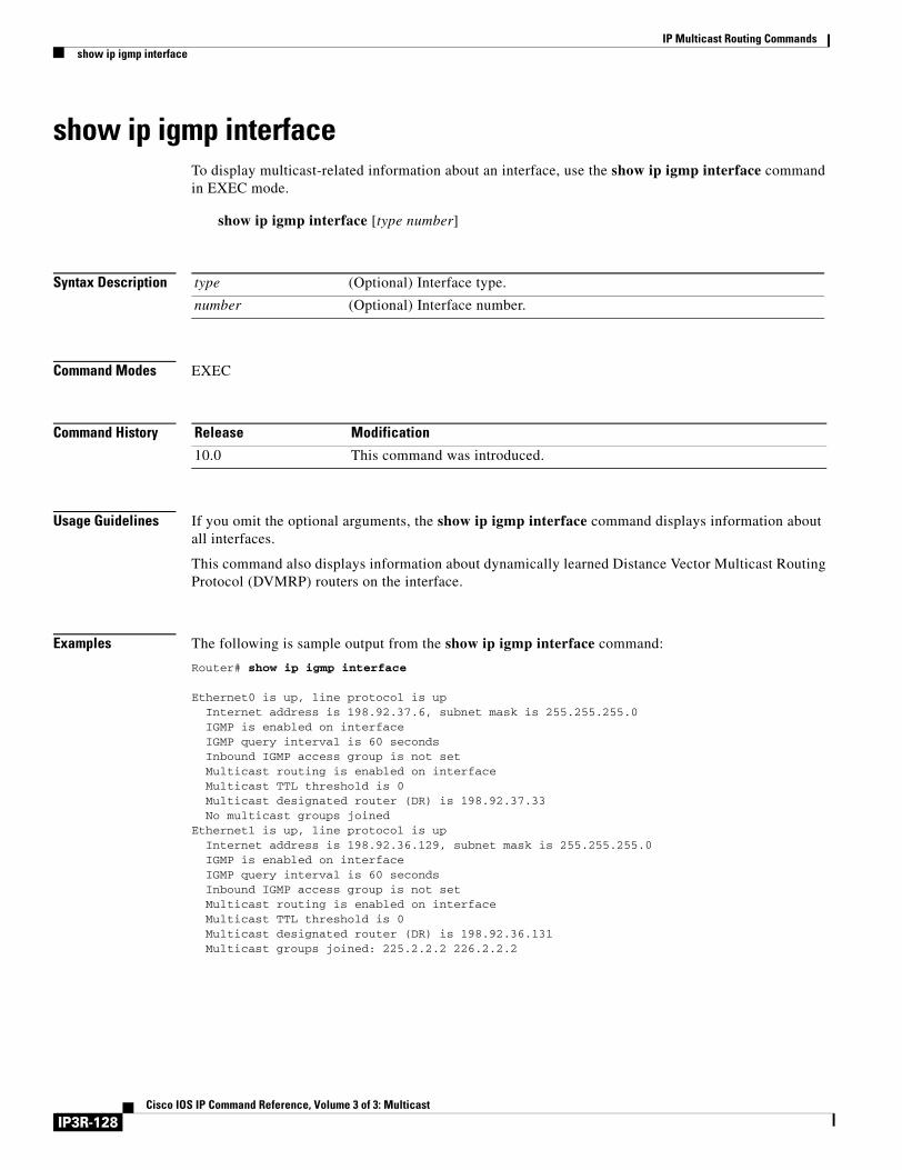
IP Multicast Routing Commandsshow ip igmp interface
show ip igmp interfaceTo display multicast-related information about an interface, use the show ip igmp interface command in EXEC mode.
show ip igmp interface [type number]
Syntax Description
Command Modes EXEC
Command History
Usage Guidelines If you omit the optional arguments, the show ip igmp interface command displays information about all interfaces.
This command also displays information about dynamically learned Distance Vector Multicast Routing Protocol (DVMRP) routers on the interface.
Examples The following is sample output from the show ip igmp interface command:
Router# show ip igmp interface
Ethernet0 is up, line protocol is up Internet address is 198.92.37.6, subnet mask is 255.255.255.0 IGMP is enabled on interface IGMP query interval is 60 seconds Inbound IGMP access group is not set Multicast routing is enabled on interface Multicast TTL threshold is 0 Multicast designated router (DR) is 198.92.37.33 No multicast groups joinedEthernet1 is up, line protocol is up Internet address is 198.92.36.129, subnet mask is 255.255.255.0 IGMP is enabled on interface IGMP query interval is 60 seconds Inbound IGMP access group is not set Multicast routing is enabled on interface Multicast TTL threshold is 0 Multicast designated router (DR) is 198.92.36.131 Multicast groups joined: 225.2.2.2 226.2.2.2
type (Optional) Interface type.
number (Optional) Interface number.
Release Modification
10.0 This command was introduced.
IP3R-128Cisco IOS IP Command Reference, Volume 3 of 3: Multicast

IP Multicast Routing Commandsshow ip igmp interface
Tunnel0 is up, line protocol is up Internet address is 10.1.37.2, subnet mask is 255.255.0.0 IGMP is enabled on interface IGMP query interval is 60 seconds Inbound IGMP access group is not set Multicast routing is enabled on interface Multicast TTL threshold is 0 No multicast groups joined
Table 6 describes the significant fields shown in the display.
Related Commands
Table 6 show ip igmp interface Field Descriptions
Field Description
Ethernet0 is up, line protocol is up
Interface type, number, and status.
Internet address is... subnet mask is...
Internet address of the interface and subnet mask being applied to the interface, as specified with the ip address command.
IGMP is enabled on interface Indicates whether IGMP has been enabled on the interface with the ip pim command.
IGMP query interval is 60 seconds
Interval at which the Cisco IOS software sends Protocol Independent Multicast (PIM) router query messages, as specified with the ip igmp query-interval command.
Inbound IGMP access group is not set
Indicates whether an IGMP access group has been configured with the ip igmp access-group command.
Multicast routing is enabled on interface
Indicates whether multicast routing has been enabled on the interface with the ip pim command.
Multicast TTL threshold is 0 Packet time-to-threshold, as specified with the ip multicast ttl-threshold command.
Multicast designated router (DR) is...
IP address of the designated router for this LAN segment (subnet).
No multicast groups joined Indicates whether this interface is a member of any multicast groups and, if so, lists the IP addresses of the groups.
Command Description
ip address Sets a primary or secondary IP address for an interface.
ip igmp access-group Controls the multicast groups that hosts on the subnet serviced by an interface can join.
ip igmp query-interval Configures the frequency at which the Cisco IOS software sends IGMP host query messages.
ip multicast ttl-threshold Configures the TTL threshold of packets being forwarded out an interface.
ip pim Enables PIM on an interface.
IP3R-129Cisco IOS IP Command Reference, Volume 3 of 3: Multicast
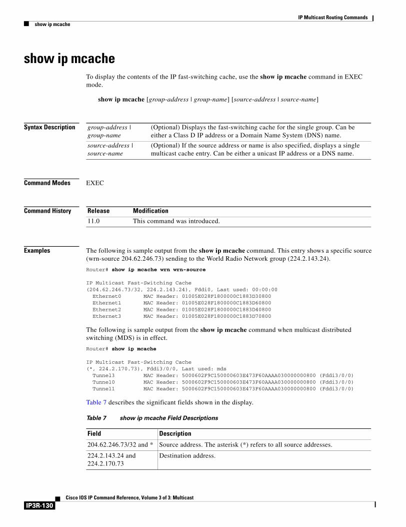
IP Multicast Routing Commandsshow ip mcache
show ip mcacheTo display the contents of the IP fast-switching cache, use the show ip mcache command in EXEC mode.
show ip mcache [group-address | group-name] [source-address | source-name]
Syntax Description
Command Modes EXEC
Command History
Examples The following is sample output from the show ip mcache command. This entry shows a specific source (wrn-source 204.62.246.73) sending to the World Radio Network group (224.2.143.24).
Router# show ip mcache wrn wrn-source
IP Multicast Fast-Switching Cache (204.62.246.73/32, 224.2.143.24), Fddi0, Last used: 00:00:00 Ethernet0 MAC Header: 01005E028F1800000C1883D30800 Ethernet1 MAC Header: 01005E028F1800000C1883D60800 Ethernet2 MAC Header: 01005E028F1800000C1883D40800 Ethernet3 MAC Header: 01005E028F1800000C1883D70800
The following is sample output from the show ip mcache command when multicast distributed switching (MDS) is in effect.
Router# show ip mcache
IP Multicast Fast-Switching Cache(*, 224.2.170.73), Fddi3/0/0, Last used: mds Tunnel3 MAC Header: 5000602F9C150000603E473F60AAAA030000000800 (Fddi3/0/0) Tunnel0 MAC Header: 5000602F9C150000603E473F60AAAA030000000800 (Fddi3/0/0) Tunnel1 MAC Header: 5000602F9C150000603E473F60AAAA030000000800 (Fddi3/0/0)
Table 7 describes the significant fields shown in the display.
group-address | group-name
(Optional) Displays the fast-switching cache for the single group. Can be either a Class D IP address or a Domain Name System (DNS) name.
source-address | source-name
(Optional) If the source address or name is also specified, displays a single multicast cache entry. Can be either a unicast IP address or a DNS name.
Release Modification
11.0 This command was introduced.
Table 7 show ip mcache Field Descriptions
Field Description
204.62.246.73/32 and * Source address. The asterisk (*) refers to all source addresses.
224.2.143.24 and 224.2.170.73
Destination address.
IP3R-130Cisco IOS IP Command Reference, Volume 3 of 3: Multicast
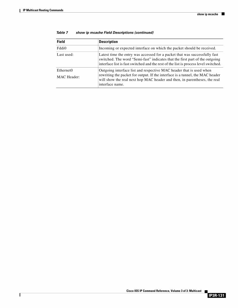
IP Multicast Routing Commandsshow ip mcache
Fddi0 Incoming or expected interface on which the packet should be received.
Last used: Latest time the entry was accessed for a packet that was successfully fast switched. The word “Semi-fast” indicates that the first part of the outgoing interface list is fast switched and the rest of the list is process level switched.
Ethernet0
MAC Header:
Outgoing interface list and respective MAC header that is used when rewriting the packet for output. If the interface is a tunnel, the MAC header will show the real next hop MAC header and then, in parentheses, the real interface name.
Table 7 show ip mcache Field Descriptions (continued)
Field Description
IP3R-131Cisco IOS IP Command Reference, Volume 3 of 3: Multicast
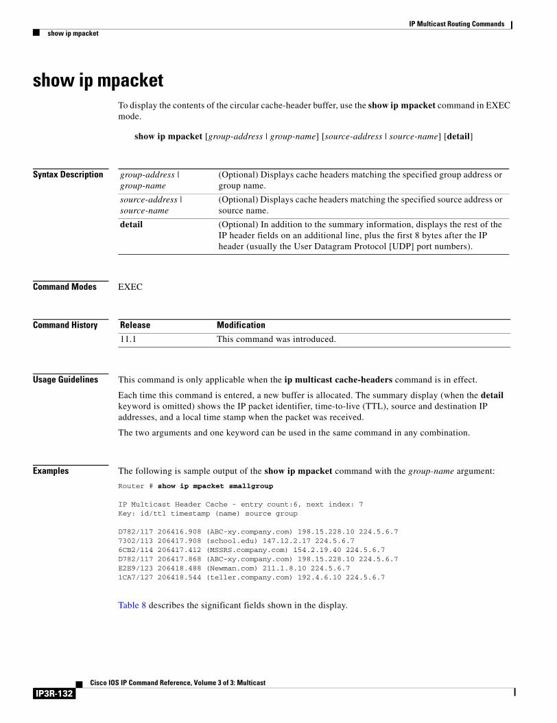
IP Multicast Routing Commandsshow ip mpacket
show ip mpacketTo display the contents of the circular cache-header buffer, use the show ip mpacket command in EXEC mode.
show ip mpacket [group-address | group-name] [source-address | source-name] [detail]
Syntax Description
Command Modes EXEC
Command History
Usage Guidelines This command is only applicable when the ip multicast cache-headers command is in effect.
Each time this command is entered, a new buffer is allocated. The summary display (when the detail keyword is omitted) shows the IP packet identifier, time-to-live (TTL), source and destination IP addresses, and a local time stamp when the packet was received.
The two arguments and one keyword can be used in the same command in any combination.
Examples The following is sample output of the show ip mpacket command with the group-name argument:
Router # show ip mpacket smallgroup
IP Multicast Header Cache - entry count:6, next index: 7Key: id/ttl timestamp (name) source group
D782/117 206416.908 (ABC-xy.company.com) 198.15.228.10 224.5.6.77302/113 206417.908 (school.edu) 147.12.2.17 224.5.6.76CB2/114 206417.412 (MSSRS.company.com) 154.2.19.40 224.5.6.7D782/117 206417.868 (ABC-xy.company.com) 198.15.228.10 224.5.6.7E2E9/123 206418.488 (Newman.com) 211.1.8.10 224.5.6.71CA7/127 206418.544 (teller.company.com) 192.4.6.10 224.5.6.7
Table 8 describes the significant fields shown in the display.
group-address | group-name
(Optional) Displays cache headers matching the specified group address or group name.
source-address | source-name
(Optional) Displays cache headers matching the specified source address or source name.
detail (Optional) In addition to the summary information, displays the rest of the IP header fields on an additional line, plus the first 8 bytes after the IP header (usually the User Datagram Protocol [UDP] port numbers).
Release Modification
11.1 This command was introduced.
IP3R-132Cisco IOS IP Command Reference, Volume 3 of 3: Multicast
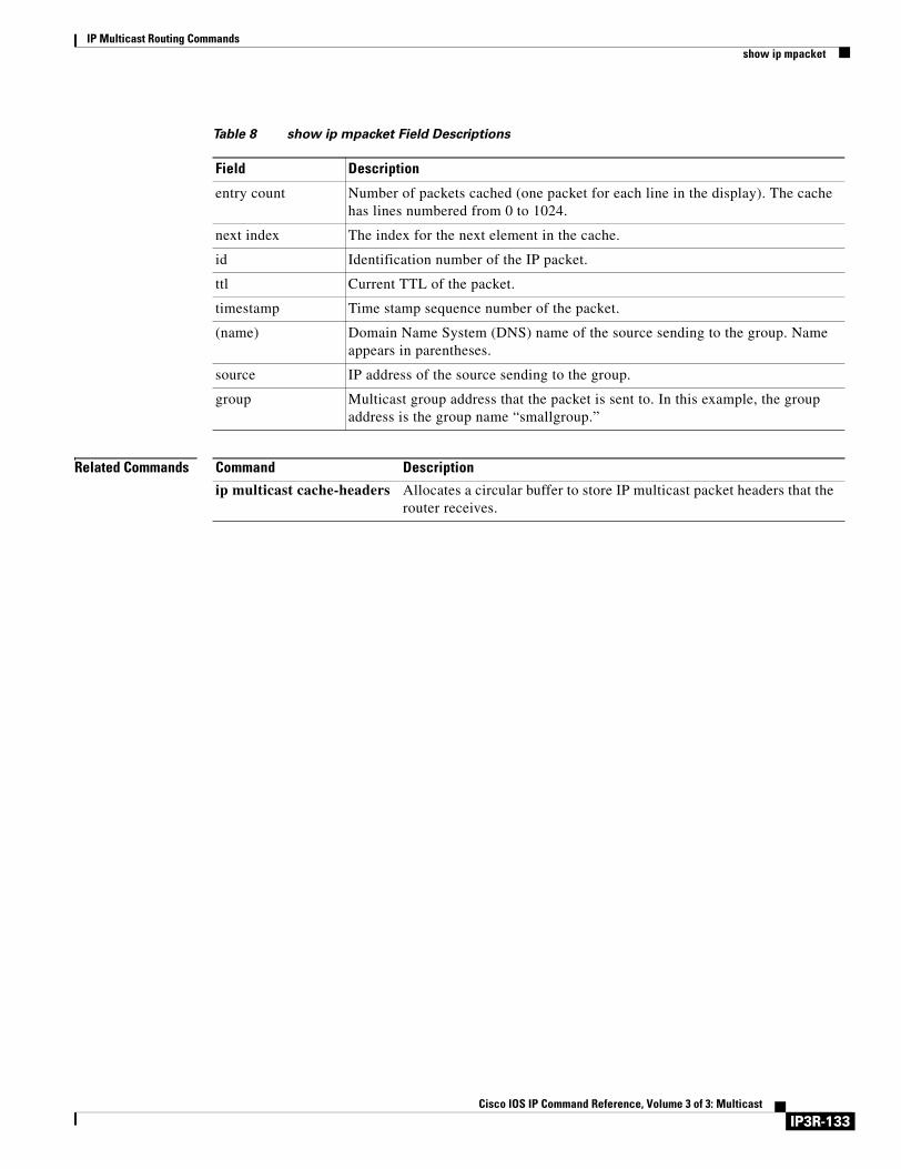
IP Multicast Routing Commandsshow ip mpacket
Related Commands
Table 8 show ip mpacket Field Descriptions
Field Description
entry count Number of packets cached (one packet for each line in the display). The cache has lines numbered from 0 to 1024.
next index The index for the next element in the cache.
id Identification number of the IP packet.
ttl Current TTL of the packet.
timestamp Time stamp sequence number of the packet.
(name) Domain Name System (DNS) name of the source sending to the group. Name appears in parentheses.
source IP address of the source sending to the group.
group Multicast group address that the packet is sent to. In this example, the group address is the group name “smallgroup.”
Command Description
ip multicast cache-headers Allocates a circular buffer to store IP multicast packet headers that the router receives.
IP3R-133Cisco IOS IP Command Reference, Volume 3 of 3: Multicast
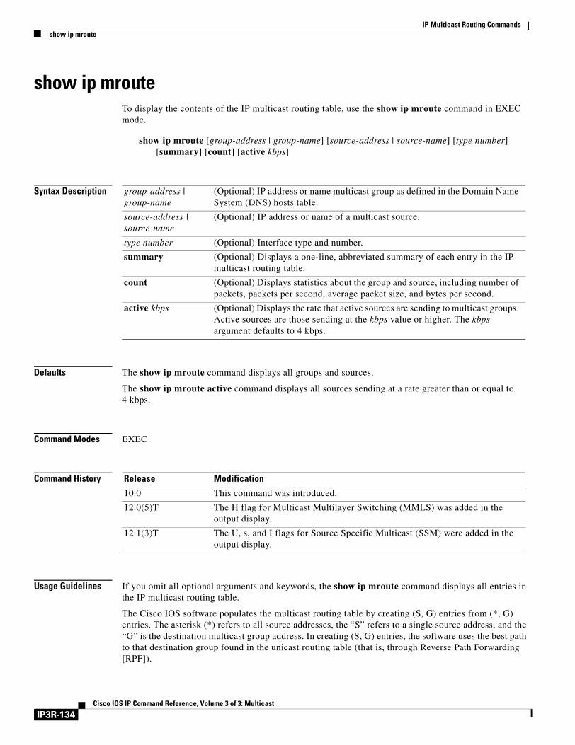
IP Multicast Routing Commandsshow ip mroute
show ip mrouteTo display the contents of the IP multicast routing table, use the show ip mroute command in EXEC mode.
show ip mroute [group-address | group-name] [source-address | source-name] [type number] [summary] [count] [active kbps]
Syntax Description
Defaults The show ip mroute command displays all groups and sources.
The show ip mroute active command displays all sources sending at a rate greater than or equal to 4 kbps.
Command Modes EXEC
Command History
Usage Guidelines If you omit all optional arguments and keywords, the show ip mroute command displays all entries in the IP multicast routing table.
The Cisco IOS software populates the multicast routing table by creating (S, G) entries from (*, G) entries. The asterisk (*) refers to all source addresses, the “S” refers to a single source address, and the “G” is the destination multicast group address. In creating (S, G) entries, the software uses the best path to that destination group found in the unicast routing table (that is, through Reverse Path Forwarding [RPF]).
group-address | group-name
(Optional) IP address or name multicast group as defined in the Domain Name System (DNS) hosts table.
source-address | source-name
(Optional) IP address or name of a multicast source.
type number (Optional) Interface type and number.
summary (Optional) Displays a one-line, abbreviated summary of each entry in the IP multicast routing table.
count (Optional) Displays statistics about the group and source, including number of packets, packets per second, average packet size, and bytes per second.
active kbps (Optional) Displays the rate that active sources are sending to multicast groups. Active sources are those sending at the kbps value or higher. The kbps argument defaults to 4 kbps.
Release Modification
10.0 This command was introduced.
12.0(5)T The H flag for Multicast Multilayer Switching (MMLS) was added in the output display.
12.1(3)T The U, s, and I flags for Source Specific Multicast (SSM) were added in the output display.
IP3R-134Cisco IOS IP Command Reference, Volume 3 of 3: Multicast
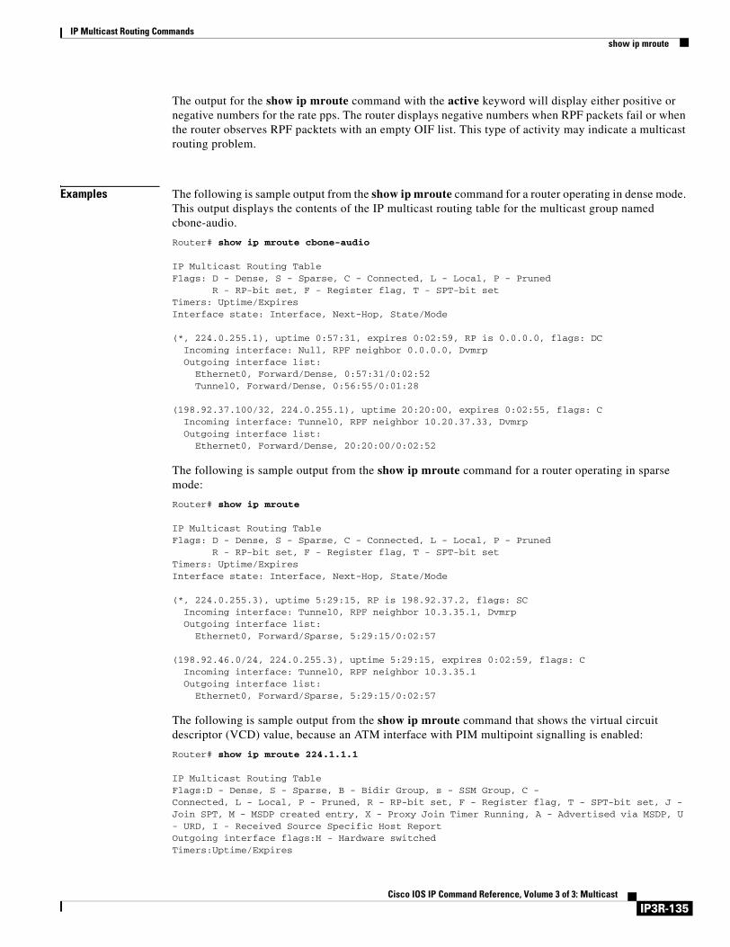
IP Multicast Routing Commandsshow ip mroute
The output for the show ip mroute command with the active keyword will display either positive or negative numbers for the rate pps. The router displays negative numbers when RPF packets fail or when the router observes RPF packtets with an empty OIF list. This type of activity may indicate a multicast routing problem.
Examples The following is sample output from the show ip mroute command for a router operating in dense mode. This output displays the contents of the IP multicast routing table for the multicast group named cbone-audio.
Router# show ip mroute cbone-audio
IP Multicast Routing TableFlags: D - Dense, S - Sparse, C - Connected, L - Local, P - Pruned
R - RP-bit set, F - Register flag, T - SPT-bit setTimers: Uptime/ExpiresInterface state: Interface, Next-Hop, State/Mode
(*, 224.0.255.1), uptime 0:57:31, expires 0:02:59, RP is 0.0.0.0, flags: DC Incoming interface: Null, RPF neighbor 0.0.0.0, Dvmrp Outgoing interface list: Ethernet0, Forward/Dense, 0:57:31/0:02:52 Tunnel0, Forward/Dense, 0:56:55/0:01:28
(198.92.37.100/32, 224.0.255.1), uptime 20:20:00, expires 0:02:55, flags: C Incoming interface: Tunnel0, RPF neighbor 10.20.37.33, Dvmrp Outgoing interface list: Ethernet0, Forward/Dense, 20:20:00/0:02:52
The following is sample output from the show ip mroute command for a router operating in sparse mode:
Router# show ip mroute
IP Multicast Routing TableFlags: D - Dense, S - Sparse, C - Connected, L - Local, P - Pruned
R - RP-bit set, F - Register flag, T - SPT-bit setTimers: Uptime/ExpiresInterface state: Interface, Next-Hop, State/Mode
(*, 224.0.255.3), uptime 5:29:15, RP is 198.92.37.2, flags: SC Incoming interface: Tunnel0, RPF neighbor 10.3.35.1, Dvmrp Outgoing interface list: Ethernet0, Forward/Sparse, 5:29:15/0:02:57
(198.92.46.0/24, 224.0.255.3), uptime 5:29:15, expires 0:02:59, flags: C Incoming interface: Tunnel0, RPF neighbor 10.3.35.1 Outgoing interface list: Ethernet0, Forward/Sparse, 5:29:15/0:02:57
The following is sample output from the show ip mroute command that shows the virtual circuit descriptor (VCD) value, because an ATM interface with PIM multipoint signalling is enabled:
Router# show ip mroute 224.1.1.1
IP Multicast Routing TableFlags:D - Dense, S - Sparse, B - Bidir Group, s - SSM Group, C -Connected, L - Local, P - Pruned, R - RP-bit set, F - Register flag, T - SPT-bit set, J - Join SPT, M - MSDP created entry, X - Proxy Join Timer Running, A - Advertised via MSDP, U - URD, I - Received Source Specific Host ReportOutgoing interface flags:H - Hardware switchedTimers:Uptime/Expires
IP3R-135Cisco IOS IP Command Reference, Volume 3 of 3: Multicast
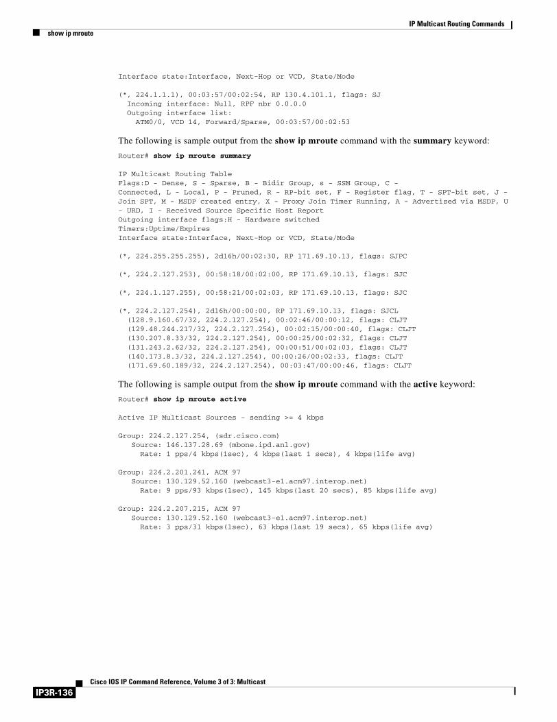
IP Multicast Routing Commandsshow ip mroute
Interface state:Interface, Next-Hop or VCD, State/Mode
(*, 224.1.1.1), 00:03:57/00:02:54, RP 130.4.101.1, flags: SJ Incoming interface: Null, RPF nbr 0.0.0.0 Outgoing interface list: ATM0/0, VCD 14, Forward/Sparse, 00:03:57/00:02:53
The following is sample output from the show ip mroute command with the summary keyword:
Router# show ip mroute summary
IP Multicast Routing TableFlags:D - Dense, S - Sparse, B - Bidir Group, s - SSM Group, C -Connected, L - Local, P - Pruned, R - RP-bit set, F - Register flag, T - SPT-bit set, J - Join SPT, M - MSDP created entry, X - Proxy Join Timer Running, A - Advertised via MSDP, U - URD, I - Received Source Specific Host ReportOutgoing interface flags:H - Hardware switchedTimers:Uptime/ExpiresInterface state:Interface, Next-Hop or VCD, State/Mode
(*, 224.255.255.255), 2d16h/00:02:30, RP 171.69.10.13, flags: SJPC
(*, 224.2.127.253), 00:58:18/00:02:00, RP 171.69.10.13, flags: SJC
(*, 224.1.127.255), 00:58:21/00:02:03, RP 171.69.10.13, flags: SJC
(*, 224.2.127.254), 2d16h/00:00:00, RP 171.69.10.13, flags: SJCL (128.9.160.67/32, 224.2.127.254), 00:02:46/00:00:12, flags: CLJT (129.48.244.217/32, 224.2.127.254), 00:02:15/00:00:40, flags: CLJT (130.207.8.33/32, 224.2.127.254), 00:00:25/00:02:32, flags: CLJT (131.243.2.62/32, 224.2.127.254), 00:00:51/00:02:03, flags: CLJT (140.173.8.3/32, 224.2.127.254), 00:00:26/00:02:33, flags: CLJT (171.69.60.189/32, 224.2.127.254), 00:03:47/00:00:46, flags: CLJT
The following is sample output from the show ip mroute command with the active keyword:
Router# show ip mroute active
Active IP Multicast Sources - sending >= 4 kbps
Group: 224.2.127.254, (sdr.cisco.com) Source: 146.137.28.69 (mbone.ipd.anl.gov) Rate: 1 pps/4 kbps(1sec), 4 kbps(last 1 secs), 4 kbps(life avg)
Group: 224.2.201.241, ACM 97 Source: 130.129.52.160 (webcast3-e1.acm97.interop.net) Rate: 9 pps/93 kbps(1sec), 145 kbps(last 20 secs), 85 kbps(life avg)
Group: 224.2.207.215, ACM 97 Source: 130.129.52.160 (webcast3-e1.acm97.interop.net) Rate: 3 pps/31 kbps(1sec), 63 kbps(last 19 secs), 65 kbps(life avg)
IP3R-136Cisco IOS IP Command Reference, Volume 3 of 3: Multicast
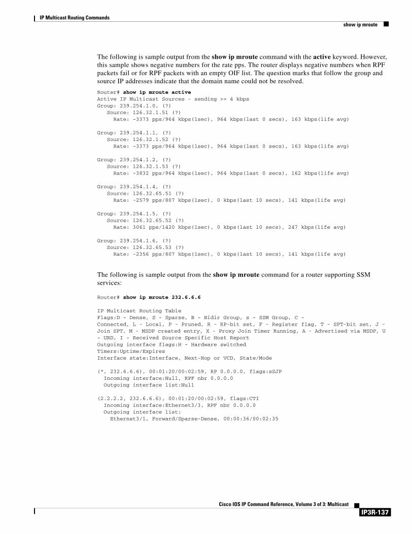
IP Multicast Routing Commandsshow ip mroute
The following is sample output from the show ip mroute command with the active keyword. However, this sample shows negative numbers for the rate pps. The router displays negative numbers when RPF packets fail or for RPF packets with an empty OIF list. The question marks that follow the group and source IP addresses indicate that the domain name could not be resolved.
Router# show ip mroute activeActive IP Multicast Sources - sending >= 4 kbpsGroup: 239.254.1.0, (?) Source: 126.32.1.51 (?) Rate: -3373 pps/964 kbps(1sec), 964 kbps(last 0 secs), 163 kbps(life avg)
Group: 239.254.1.1, (?) Source: 126.32.1.52 (?) Rate: -3373 pps/964 kbps(1sec), 964 kbps(last 0 secs), 163 kbps(life avg)
Group: 239.254.1.2, (?) Source: 126.32.1.53 (?) Rate: -3832 pps/964 kbps(1sec), 964 kbps(last 0 secs), 162 kbps(life avg)
Group: 239.254.1.4, (?) Source: 126.32.65.51 (?) Rate: -2579 pps/807 kbps(1sec), 0 kbps(last 10 secs), 141 kbps(life avg) Group: 239.254.1.5, (?) Source: 126.32.65.52 (?) Rate: 3061 pps/1420 kbps(1sec), 0 kbps(last 10 secs), 247 kbps(life avg) Group: 239.254.1.6, (?) Source: 126.32.65.53 (?) Rate: -2356 pps/807 kbps(1sec), 0 kbps(last 10 secs), 141 kbps(life avg)
The following is sample output from the show ip mroute command for a router supporting SSM services:
Router# show ip mroute 232.6.6.6
IP Multicast Routing TableFlags:D - Dense, S - Sparse, B - Bidir Group, s - SSM Group, C -Connected, L - Local, P - Pruned, R - RP-bit set, F - Register flag, T - SPT-bit set, J - Join SPT, M - MSDP created entry, X - Proxy Join Timer Running, A - Advertised via MSDP, U - URD, I - Received Source Specific Host ReportOutgoing interface flags:H - Hardware switchedTimers:Uptime/ExpiresInterface state:Interface, Next-Hop or VCD, State/Mode (*, 232.6.6.6), 00:01:20/00:02:59, RP 0.0.0.0, flags:sSJP Incoming interface:Null, RPF nbr 0.0.0.0 Outgoing interface list:Null (2.2.2.2, 232.6.6.6), 00:01:20/00:02:59, flags:CTI Incoming interface:Ethernet3/3, RPF nbr 0.0.0.0 Outgoing interface list: Ethernet3/1, Forward/Sparse-Dense, 00:00:36/00:02:35
IP3R-137Cisco IOS IP Command Reference, Volume 3 of 3: Multicast
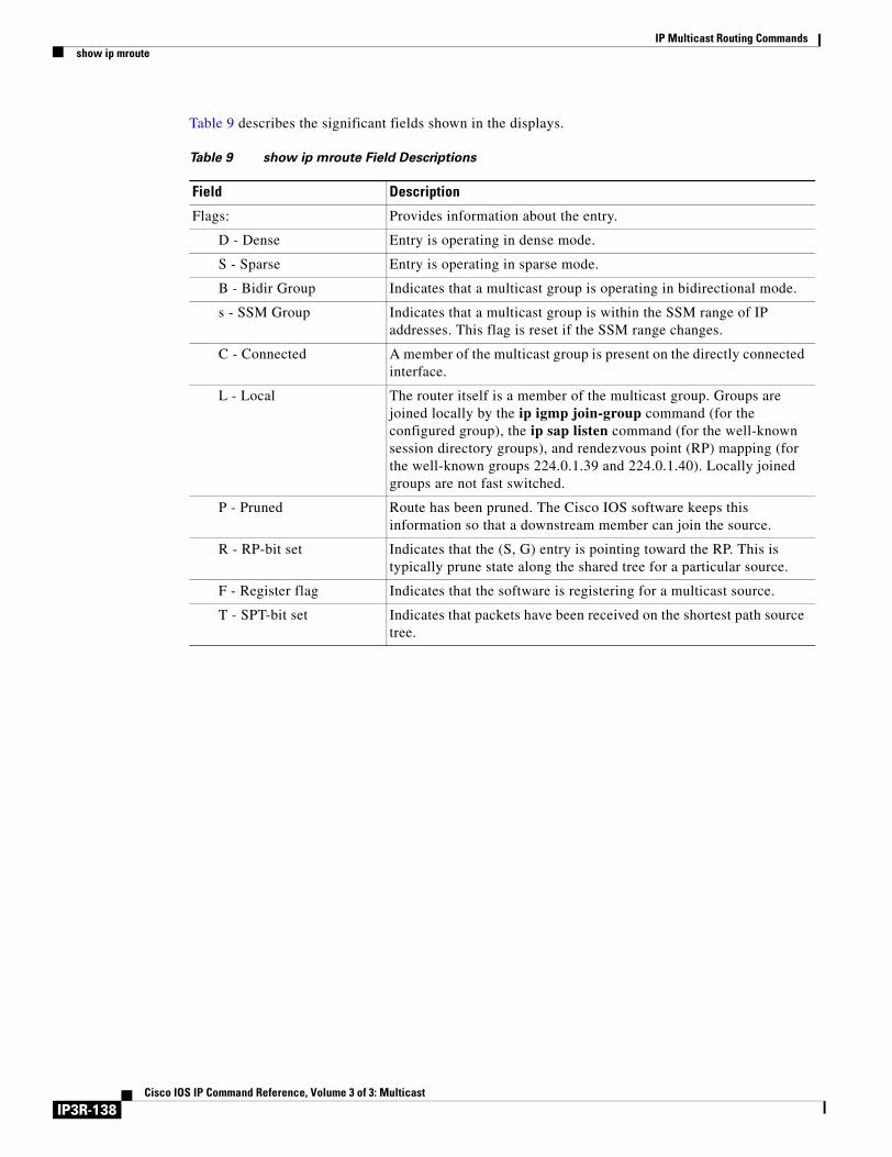
IP Multicast Routing Commandsshow ip mroute
Table 9 describes the significant fields shown in the displays.
Table 9 show ip mroute Field Descriptions
Field Description
Flags: Provides information about the entry.
D - Dense Entry is operating in dense mode.
S - Sparse Entry is operating in sparse mode.
B - Bidir Group Indicates that a multicast group is operating in bidirectional mode.
s - SSM Group Indicates that a multicast group is within the SSM range of IP addresses. This flag is reset if the SSM range changes.
C - Connected A member of the multicast group is present on the directly connected interface.
L - Local The router itself is a member of the multicast group. Groups are joined locally by the ip igmp join-group command (for the configured group), the ip sap listen command (for the well-known session directory groups), and rendezvous point (RP) mapping (for the well-known groups 224.0.1.39 and 224.0.1.40). Locally joined groups are not fast switched.
P - Pruned Route has been pruned. The Cisco IOS software keeps this information so that a downstream member can join the source.
R - RP-bit set Indicates that the (S, G) entry is pointing toward the RP. This is typically prune state along the shared tree for a particular source.
F - Register flag Indicates that the software is registering for a multicast source.
T - SPT-bit set Indicates that packets have been received on the shortest path source tree.
IP3R-138Cisco IOS IP Command Reference, Volume 3 of 3: Multicast
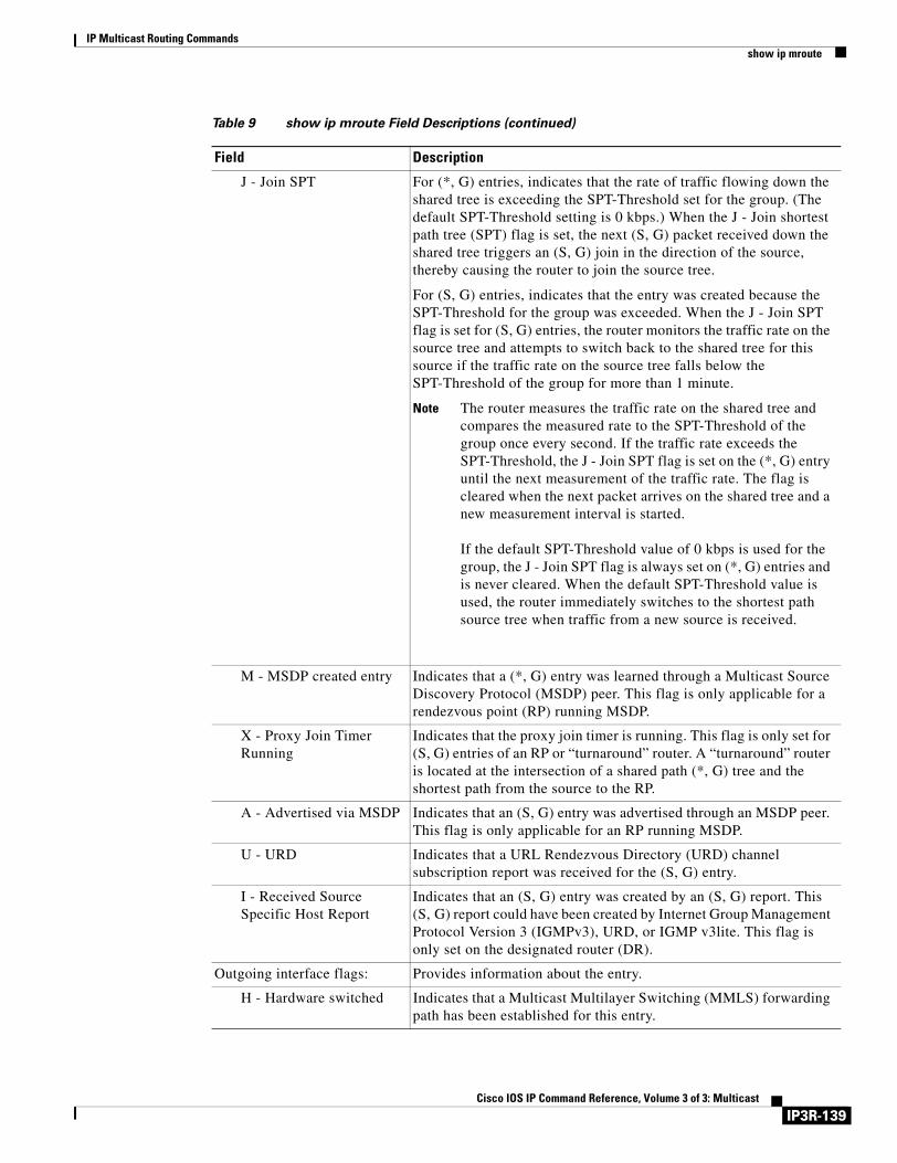
IP Multicast Routing Commandsshow ip mroute
J - Join SPT For (*, G) entries, indicates that the rate of traffic flowing down the shared tree is exceeding the SPT-Threshold set for the group. (The default SPT-Threshold setting is 0 kbps.) When the J - Join shortest path tree (SPT) flag is set, the next (S, G) packet received down the shared tree triggers an (S, G) join in the direction of the source, thereby causing the router to join the source tree.
For (S, G) entries, indicates that the entry was created because the SPT-Threshold for the group was exceeded. When the J - Join SPT flag is set for (S, G) entries, the router monitors the traffic rate on the source tree and attempts to switch back to the shared tree for this source if the traffic rate on the source tree falls below the SPT-Threshold of the group for more than 1 minute.
Note The router measures the traffic rate on the shared tree and compares the measured rate to the SPT-Threshold of the group once every second. If the traffic rate exceeds the SPT-Threshold, the J - Join SPT flag is set on the (*, G) entry until the next measurement of the traffic rate. The flag is cleared when the next packet arrives on the shared tree and a new measurement interval is started.
If the default SPT-Threshold value of 0 kbps is used for the group, the J - Join SPT flag is always set on (*, G) entries and is never cleared. When the default SPT-Threshold value is used, the router immediately switches to the shortest path source tree when traffic from a new source is received.
M - MSDP created entry Indicates that a (*, G) entry was learned through a Multicast Source Discovery Protocol (MSDP) peer. This flag is only applicable for a rendezvous point (RP) running MSDP.
X - Proxy Join Timer Running
Indicates that the proxy join timer is running. This flag is only set for (S, G) entries of an RP or “turnaround” router. A “turnaround” router is located at the intersection of a shared path (*, G) tree and the shortest path from the source to the RP.
A - Advertised via MSDP Indicates that an (S, G) entry was advertised through an MSDP peer. This flag is only applicable for an RP running MSDP.
U - URD Indicates that a URL Rendezvous Directory (URD) channel subscription report was received for the (S, G) entry.
I - Received Source Specific Host Report
Indicates that an (S, G) entry was created by an (S, G) report. This (S, G) report could have been created by Internet Group Management Protocol Version 3 (IGMPv3), URD, or IGMP v3lite. This flag is only set on the designated router (DR).
Outgoing interface flags: Provides information about the entry.
H - Hardware switched Indicates that a Multicast Multilayer Switching (MMLS) forwarding path has been established for this entry.
Table 9 show ip mroute Field Descriptions (continued)
Field Description
IP3R-139Cisco IOS IP Command Reference, Volume 3 of 3: Multicast

IP Multicast Routing Commandsshow ip mroute
Timers:Uptime/Expires “Uptime” indicates per interface how long (in hours, minutes, and seconds) the entry has been in the IP multicast routing table. “Expires” indicates per interface how long (in hours, minutes, and seconds) until the entry will be removed from the IP multicast routing table.
Interface state: Indicates the state of the incoming or outgoing interface.
Interface Indicates the type and number of the interface listed in the incoming or outgoing interface list.
Next-Hop or VCD “Next-hop” specifies the IP address of the downstream neighbor. “VCD” specifies the virtual circuit descriptor number. “VCD0” means the group is using the static map virtual circuit.
State/Mode “State” indicates that packets will either be forwarded, pruned, or null on the interface depending on whether there are restrictions due to access lists or a Time To Live (TTL) threshold. “Mode” indicates whether the interface is operating in dense, sparse, or sparse-dense mode.
(*, 224.0.255.1) and (198.92.37.100/32, 224.0.255.1)
Entry in the IP multicast routing table. The entry consists of the IP address of the source router followed by the IP address of the multicast group. An asterisk (*) in place of the source router indicates all sources.
Entries in the first format are referred to as (*, G) or “star comma G” entries. Entries in the second format are referred to as (S, G) or “S comma G” entries. (*, G) entries are used to build (S, G) entries.
RP Address of the RP router. For routers and access servers operating in sparse mode, this address is always 0.0.0.0.
flags: Information about the entry.
Incoming interface: Expected interface for a multicast packet from the source. If the packet is not received on this interface, it is discarded.
RPF neighbor or RPF nbr IP address of the upstream router to the source. Tunneling indicates that this router is sending data to the RP encapsulated in register packets. The hexadecimal number in parentheses indicates to which RP it is registering. Each bit indicates a different RP if multiple RPs per group are used. If an asterisk (*) appears after the IP address in this field, the RPF neighbor has been learned through an assert.
Dvmrp Indicates if the RPF information is obtained from the Distance Vector Multicast Routing Protocol (DVMRP) routing table. If “Mroute” is displayed, the RPF information is obtained from the static mroutes configuration.
Outgoing interface list: Interfaces through which packets will be forwarded. When the ip pim nbma-mode command is enabled on the interface, the IP address of the Protocol Independent Multicast (PIM) neighbor is also displayed.
Table 9 show ip mroute Field Descriptions (continued)
Field Description
IP3R-140Cisco IOS IP Command Reference, Volume 3 of 3: Multicast
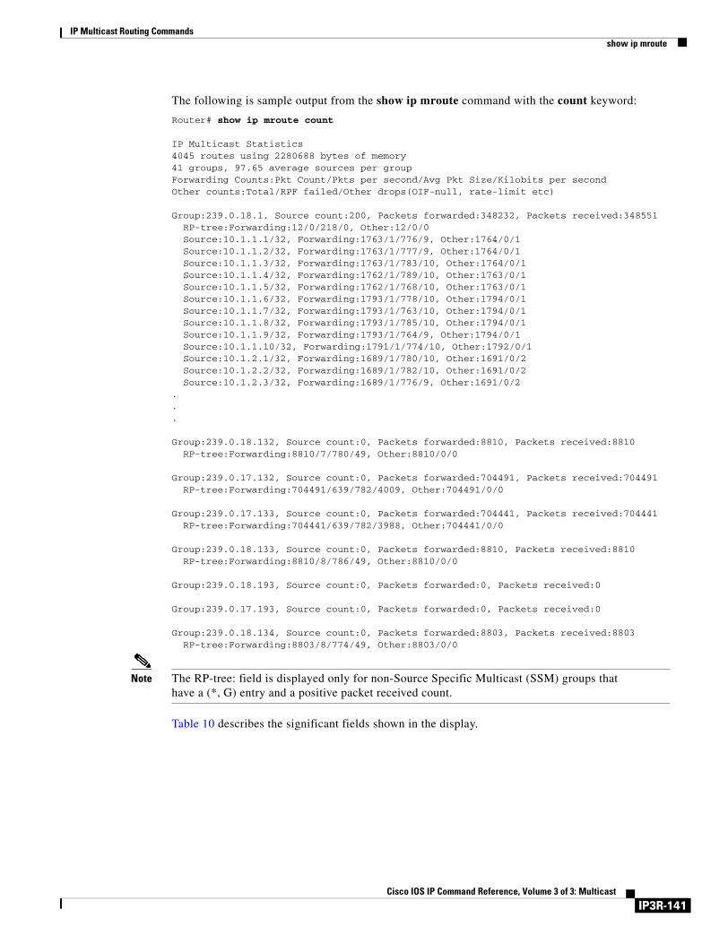
IP Multicast Routing Commandsshow ip mroute
The following is sample output from the show ip mroute command with the count keyword:
Router# show ip mroute count
IP Multicast Statistics4045 routes using 2280688 bytes of memory41 groups, 97.65 average sources per groupForwarding Counts:Pkt Count/Pkts per second/Avg Pkt Size/Kilobits per secondOther counts:Total/RPF failed/Other drops(OIF-null, rate-limit etc)
Group:239.0.18.1, Source count:200, Packets forwarded:348232, Packets received:348551 RP-tree:Forwarding:12/0/218/0, Other:12/0/0 Source:10.1.1.1/32, Forwarding:1763/1/776/9, Other:1764/0/1 Source:10.1.1.2/32, Forwarding:1763/1/777/9, Other:1764/0/1 Source:10.1.1.3/32, Forwarding:1763/1/783/10, Other:1764/0/1 Source:10.1.1.4/32, Forwarding:1762/1/789/10, Other:1763/0/1 Source:10.1.1.5/32, Forwarding:1762/1/768/10, Other:1763/0/1 Source:10.1.1.6/32, Forwarding:1793/1/778/10, Other:1794/0/1 Source:10.1.1.7/32, Forwarding:1793/1/763/10, Other:1794/0/1 Source:10.1.1.8/32, Forwarding:1793/1/785/10, Other:1794/0/1 Source:10.1.1.9/32, Forwarding:1793/1/764/9, Other:1794/0/1 Source:10.1.1.10/32, Forwarding:1791/1/774/10, Other:1792/0/1 Source:10.1.2.1/32, Forwarding:1689/1/780/10, Other:1691/0/2 Source:10.1.2.2/32, Forwarding:1689/1/782/10, Other:1691/0/2 Source:10.1.2.3/32, Forwarding:1689/1/776/9, Other:1691/0/2... Group:239.0.18.132, Source count:0, Packets forwarded:8810, Packets received:8810 RP-tree:Forwarding:8810/7/780/49, Other:8810/0/0
Group:239.0.17.132, Source count:0, Packets forwarded:704491, Packets received:704491 RP-tree:Forwarding:704491/639/782/4009, Other:704491/0/0
Group:239.0.17.133, Source count:0, Packets forwarded:704441, Packets received:704441 RP-tree:Forwarding:704441/639/782/3988, Other:704441/0/0
Group:239.0.18.133, Source count:0, Packets forwarded:8810, Packets received:8810 RP-tree:Forwarding:8810/8/786/49, Other:8810/0/0
Group:239.0.18.193, Source count:0, Packets forwarded:0, Packets received:0
Group:239.0.17.193, Source count:0, Packets forwarded:0, Packets received:0
Group:239.0.18.134, Source count:0, Packets forwarded:8803, Packets received:8803 RP-tree:Forwarding:8803/8/774/49, Other:8803/0/0
Note The RP-tree: field is displayed only for non-Source Specific Multicast (SSM) groups that have a (*, G) entry and a positive packet received count.
Table 10 describes the significant fields shown in the display.
IP3R-141Cisco IOS IP Command Reference, Volume 3 of 3: Multicast
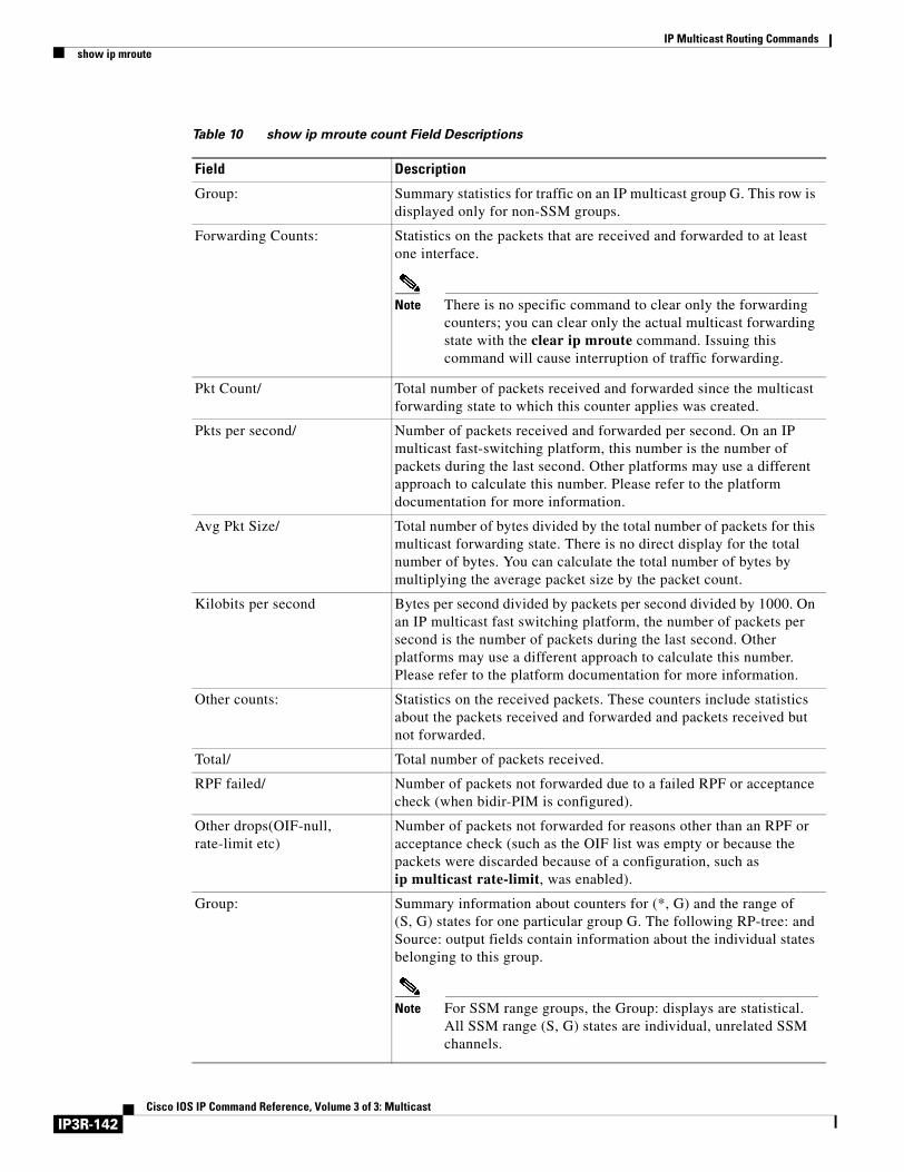
IP Multicast Routing Commandsshow ip mroute
Table 10 show ip mroute count Field Descriptions
Field Description
Group: Summary statistics for traffic on an IP multicast group G. This row is displayed only for non-SSM groups.
Forwarding Counts: Statistics on the packets that are received and forwarded to at least one interface.
Note There is no specific command to clear only the forwarding counters; you can clear only the actual multicast forwarding state with the clear ip mroute command. Issuing this command will cause interruption of traffic forwarding.
Pkt Count/ Total number of packets received and forwarded since the multicast forwarding state to which this counter applies was created.
Pkts per second/ Number of packets received and forwarded per second. On an IP multicast fast-switching platform, this number is the number of packets during the last second. Other platforms may use a different approach to calculate this number. Please refer to the platform documentation for more information.
Avg Pkt Size/ Total number of bytes divided by the total number of packets for this multicast forwarding state. There is no direct display for the total number of bytes. You can calculate the total number of bytes by multiplying the average packet size by the packet count.
Kilobits per second Bytes per second divided by packets per second divided by 1000. On an IP multicast fast switching platform, the number of packets per second is the number of packets during the last second. Other platforms may use a different approach to calculate this number. Please refer to the platform documentation for more information.
Other counts: Statistics on the received packets. These counters include statistics about the packets received and forwarded and packets received but not forwarded.
Total/ Total number of packets received.
RPF failed/ Number of packets not forwarded due to a failed RPF or acceptance check (when bidir-PIM is configured).
Other drops(OIF-null, rate-limit etc)
Number of packets not forwarded for reasons other than an RPF or acceptance check (such as the OIF list was empty or because the packets were discarded because of a configuration, such as ip multicast rate-limit, was enabled).
Group: Summary information about counters for (*, G) and the range of (S, G) states for one particular group G. The following RP-tree: and Source: output fields contain information about the individual states belonging to this group.
Note For SSM range groups, the Group: displays are statistical. All SSM range (S, G) states are individual, unrelated SSM channels.
IP3R-142Cisco IOS IP Command Reference, Volume 3 of 3: Multicast
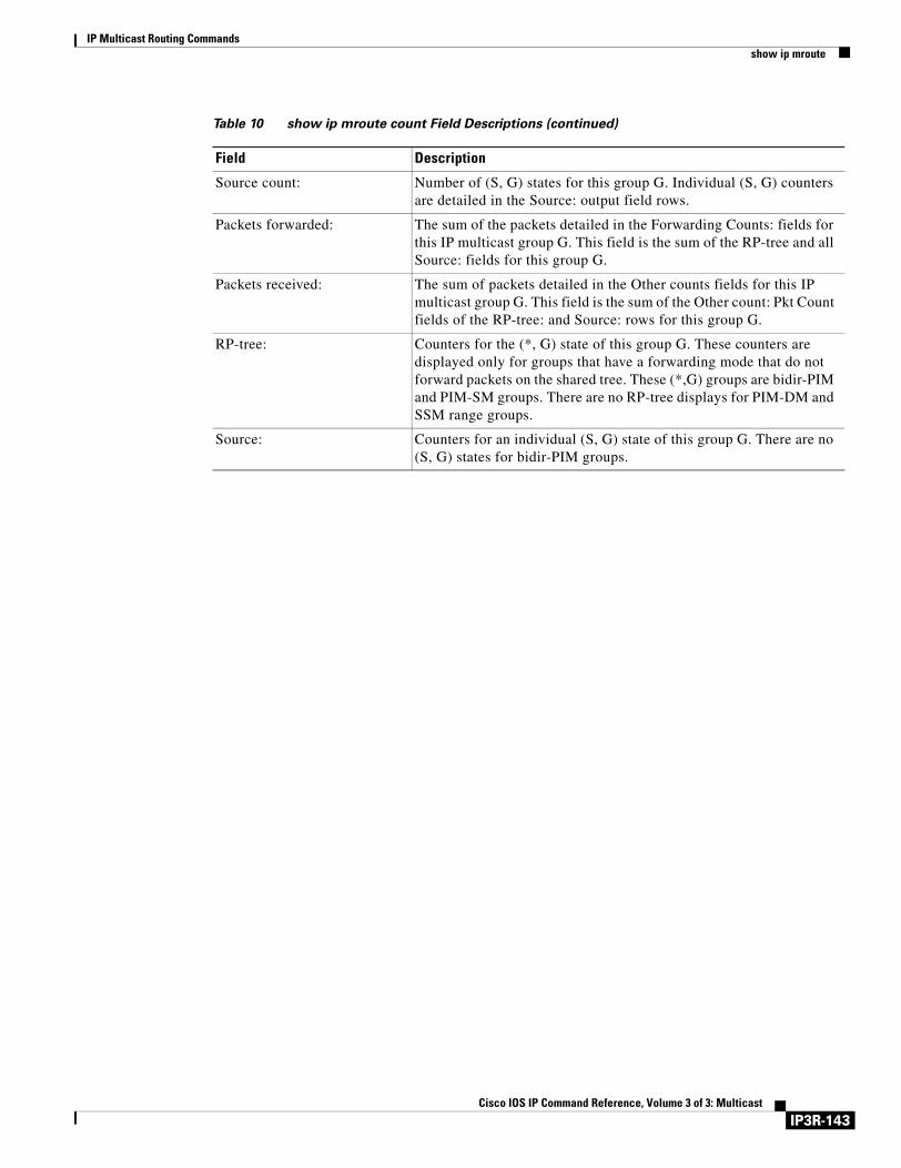
IP Multicast Routing Commandsshow ip mroute
Source count: Number of (S, G) states for this group G. Individual (S, G) counters are detailed in the Source: output field rows.
Packets forwarded: The sum of the packets detailed in the Forwarding Counts: fields for this IP multicast group G. This field is the sum of the RP-tree and all Source: fields for this group G.
Packets received: The sum of packets detailed in the Other counts fields for this IP multicast group G. This field is the sum of the Other count: Pkt Count fields of the RP-tree: and Source: rows for this group G.
RP-tree: Counters for the (*, G) state of this group G. These counters are displayed only for groups that have a forwarding mode that do not forward packets on the shared tree. These (*,G) groups are bidir-PIM and PIM-SM groups. There are no RP-tree displays for PIM-DM and SSM range groups.
Source: Counters for an individual (S, G) state of this group G. There are no (S, G) states for bidir-PIM groups.
Table 10 show ip mroute count Field Descriptions (continued)
Field Description
IP3R-143Cisco IOS IP Command Reference, Volume 3 of 3: Multicast

IP Multicast Routing Commandsshow ip mroute
Related Commands Command Description
ip multicast-routing Enables IP multicast routing or multicast distributed switching.
ip pim Enables PIM on an interface.
ip pim ssm Defines the SSM range of IP multicast addresses.
IP3R-144Cisco IOS IP Command Reference, Volume 3 of 3: Multicast
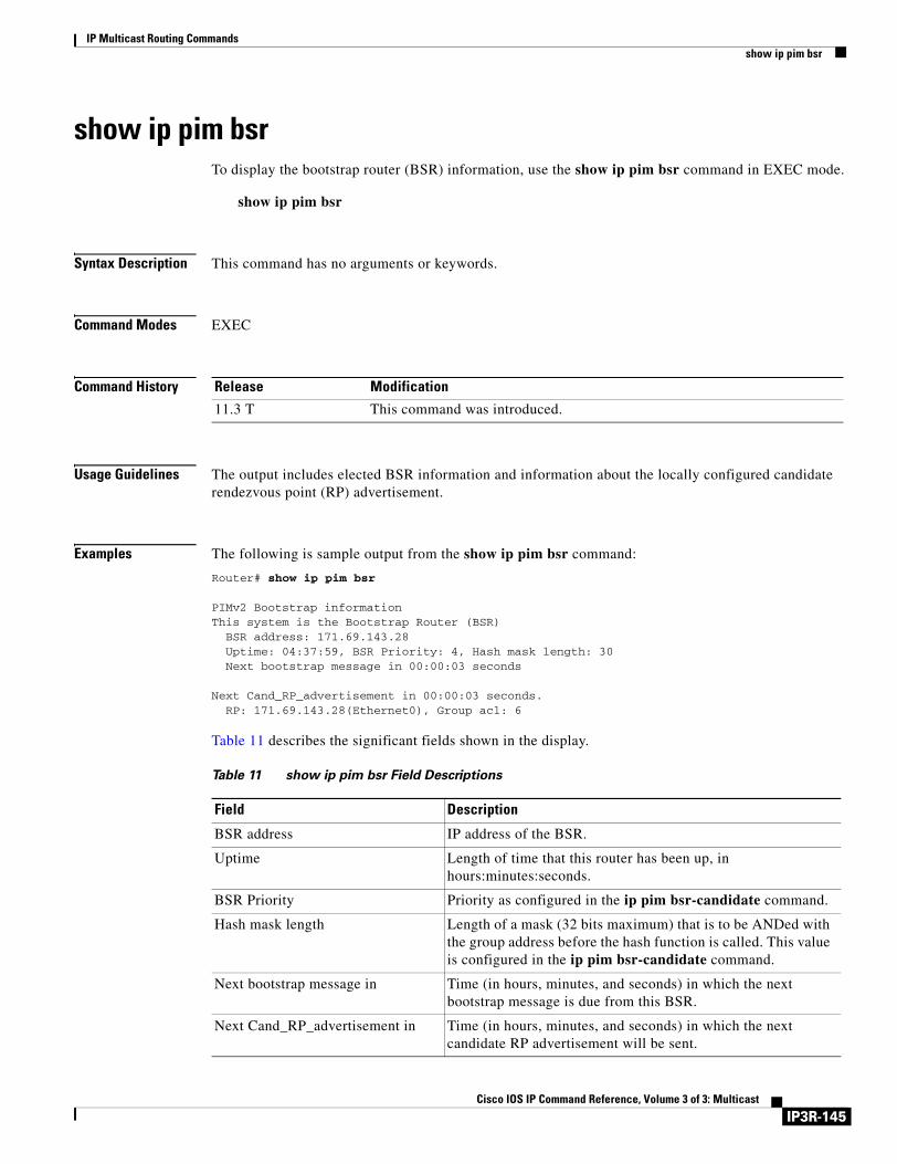
IP Multicast Routing Commandsshow ip pim bsr
show ip pim bsrTo display the bootstrap router (BSR) information, use the show ip pim bsr command in EXEC mode.
show ip pim bsr
Syntax Description This command has no arguments or keywords.
Command Modes EXEC
Command History
Usage Guidelines The output includes elected BSR information and information about the locally configured candidate rendezvous point (RP) advertisement.
Examples The following is sample output from the show ip pim bsr command:
Router# show ip pim bsr
PIMv2 Bootstrap informationThis system is the Bootstrap Router (BSR)
BSR address: 171.69.143.28 Uptime: 04:37:59, BSR Priority: 4, Hash mask length: 30Next bootstrap message in 00:00:03 seconds
Next Cand_RP_advertisement in 00:00:03 seconds. RP: 171.69.143.28(Ethernet0), Group acl: 6
Table 11 describes the significant fields shown in the display.
Release Modification
11.3 T This command was introduced.
Table 11 show ip pim bsr Field Descriptions
Field Description
BSR address IP address of the BSR.
Uptime Length of time that this router has been up, in hours:minutes:seconds.
BSR Priority Priority as configured in the ip pim bsr-candidate command.
Hash mask length Length of a mask (32 bits maximum) that is to be ANDed with the group address before the hash function is called. This value is configured in the ip pim bsr-candidate command.
Next bootstrap message in Time (in hours, minutes, and seconds) in which the next bootstrap message is due from this BSR.
Next Cand_RP_advertisement in Time (in hours, minutes, and seconds) in which the next candidate RP advertisement will be sent.
IP3R-145Cisco IOS IP Command Reference, Volume 3 of 3: Multicast
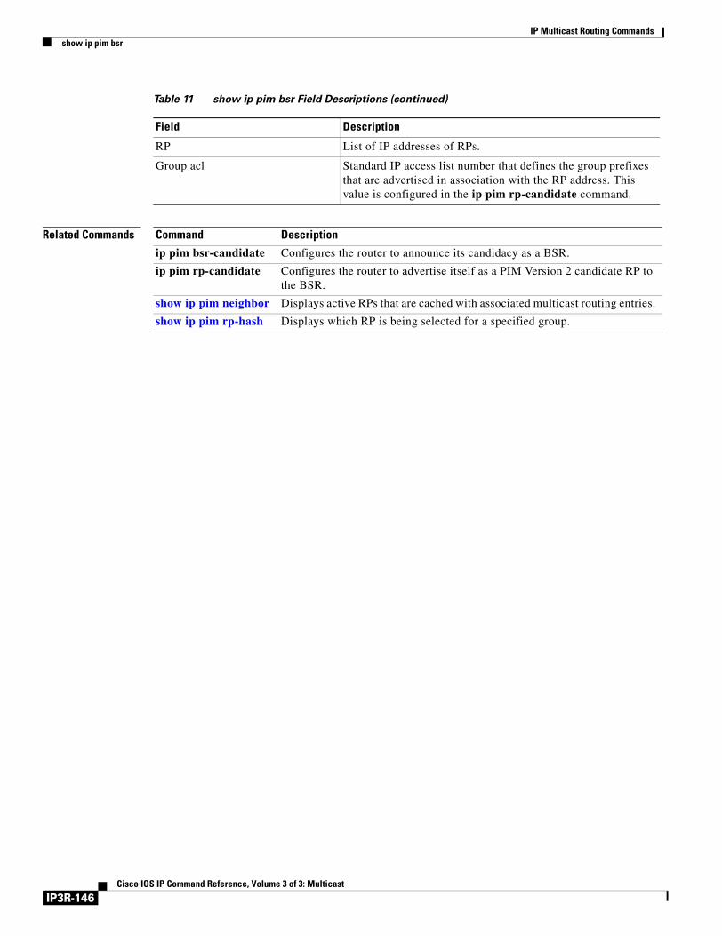
IP Multicast Routing Commandsshow ip pim bsr
Related Commands
RP List of IP addresses of RPs.
Group acl Standard IP access list number that defines the group prefixes that are advertised in association with the RP address. This value is configured in the ip pim rp-candidate command.
Table 11 show ip pim bsr Field Descriptions (continued)
Field Description
Command Description
ip pim bsr-candidate Configures the router to announce its candidacy as a BSR.
ip pim rp-candidate Configures the router to advertise itself as a PIM Version 2 candidate RP to the BSR.
show ip pim neighbor Displays active RPs that are cached with associated multicast routing entries.
show ip pim rp-hash Displays which RP is being selected for a specified group.
IP3R-146Cisco IOS IP Command Reference, Volume 3 of 3: Multicast
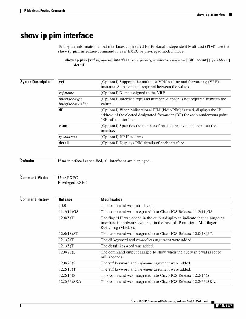
IP Multicast Routing Commandsshow ip pim interface
show ip pim interfaceTo display information about interfaces configured for Protocol Independent Multicast (PIM), use the show ip pim interface command in user EXEC or privileged EXEC mode.
show ip pim [vrf vrf-name] interface [interface-type interface-number] [df | count] [rp-address] [detail]
Syntax Description
Defaults If no interface is specified, all interfaces are displayed.
Command Modes User EXECPrivileged EXEC
Command History
vrf (Optional) Supports the multicast VPN routing and forwarding (VRF) instance. A space is not required between the values.
vrf-name (Optional) Name assigned to the VRF.
interface-type interface-number
(Optional) Interface type and number. A space is not required between the values.
df (Optional) When bidirectional PIM (bidir-PIM) is used, displays the IP address of the elected designated forwarder (DF) for each rendezvous point (RP) of an interface.
count (Optional) Specifies the number of packets received and sent out the interface.
rp-address (Optional) RP IP address.
detail (Optional) Displays PIM details of each interface.
Release Modification
10.0 This command was introduced.
11.2(11)GS This command was integrated into Cisco IOS Release 11.2(11)GS.
12.0(5)T The flag “H” was added in the output display to indicate that an outgoing interface is hardware-switched in the case of IP multicast Multilayer Switching (MMLS).
12.0(18)ST This command was integrated into Cisco IOS Release 12.0(18)ST.
12.1(2)T The df keyword and rp-address argument were added.
12.1(5)T The detail keyword was added.
12.0(22)S The command output changed to show when the query interval is set to milliseconds.
12.0(23)S The vrf keyword and vrf-name argument were added.
12.2(13)T The vrf keyword and vrf-name argument were added.
12.2(14)S This command was integrated into Cisco IOS Release 12.2(14)S.
12.2(33)SRA This command was integrated into Cisco IOS Release 12.2(33)SRA.
IP3R-147Cisco IOS IP Command Reference, Volume 3 of 3: Multicast
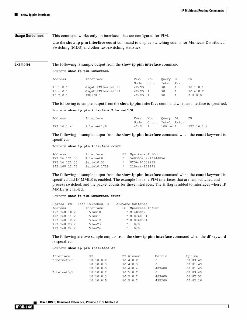
IP Multicast Routing Commandsshow ip pim interface
Usage Guidelines This command works only on interfaces that are configured for PIM.
Use the show ip pim interface count command to display switching counts for Multicast Distributed Switching (MDS) and other fast-switching statistics.
Examples The following is sample output from the show ip pim interface command:
Router# show ip pim interface
Address Interface Ver/ Nbr Query DR DR Mode Count Intvl Prior10.1.0.1 GigabitEthernet0/0 v2/SD 0 30 1 10.1.0.110.6.0.1 GigabitEthernet0/1 v2/SD 1 30 1 10.6.0.210.2.0.1 ATM1/0.1 v2/SD 1 30 1 0.0.0.0
The following is sample output from the show ip pim interface command when an interface is specified:
Router# show ip pim interface Ethernet1/0
Address Interface Ver/ Nbr Query DR DR Mode Count Intvl Prior172.16.1.4 Ethernet1/0 v2/S 1 100 ms 1 172.16.1.4
The following is sample output from the show ip pim interface command when the count keyword is specified:
Router# show ip pim interface count
Address Interface FS Mpackets In/Out172.16.121.35 Ethernet0 * 548305239/13744856172.16.121.35 Serial0.33 * 8256/67052912192.168.12.73 Serial0.1719 * 219444/862191
The following is sample output from the show ip pim interface command when the count keyword is specified and IP MMLS is enabled. The example lists the PIM interfaces that are fast switched and process switched, and the packet counts for these interfaces. The H flag is added to interfaces where IP MMLS is enabled.
Router# show ip pim interface count
States: FS - Fast Switched, H - Hardware SwitchedAddress Interface FS Mpackets In/Out192.168.10.2 Vlan10 * H 40886/0192.168.11.2 Vlan11 * H 0/40554192.168.12.2 Vlan12 * H 0/40554192.168.23.2 Vlan23 * 0/0192.168.24.2 Vlan24 * 0/0
The following are two sample outputs from the show ip pim interface command when the df keyword is specified:
Router# show ip pim interface df
Interface RP DF Winner Metric UptimeEthernet3/3 10.10.0.2 10.4.0.2 0 00:03:49
10.10.0.3 10.4.0.3 0 00:01:4910.10.0.5 10.4.0.4 409600 00:01:49
Ethernet3/4 10.10.0.2 10.5.0.2 0 00:03:4910.10.0.3 10.5.0.2 409600 00:02:3210.10.0.5 10.5.0.2 435200 00:02:16
IP3R-148Cisco IOS IP Command Reference, Volume 3 of 3: Multicast
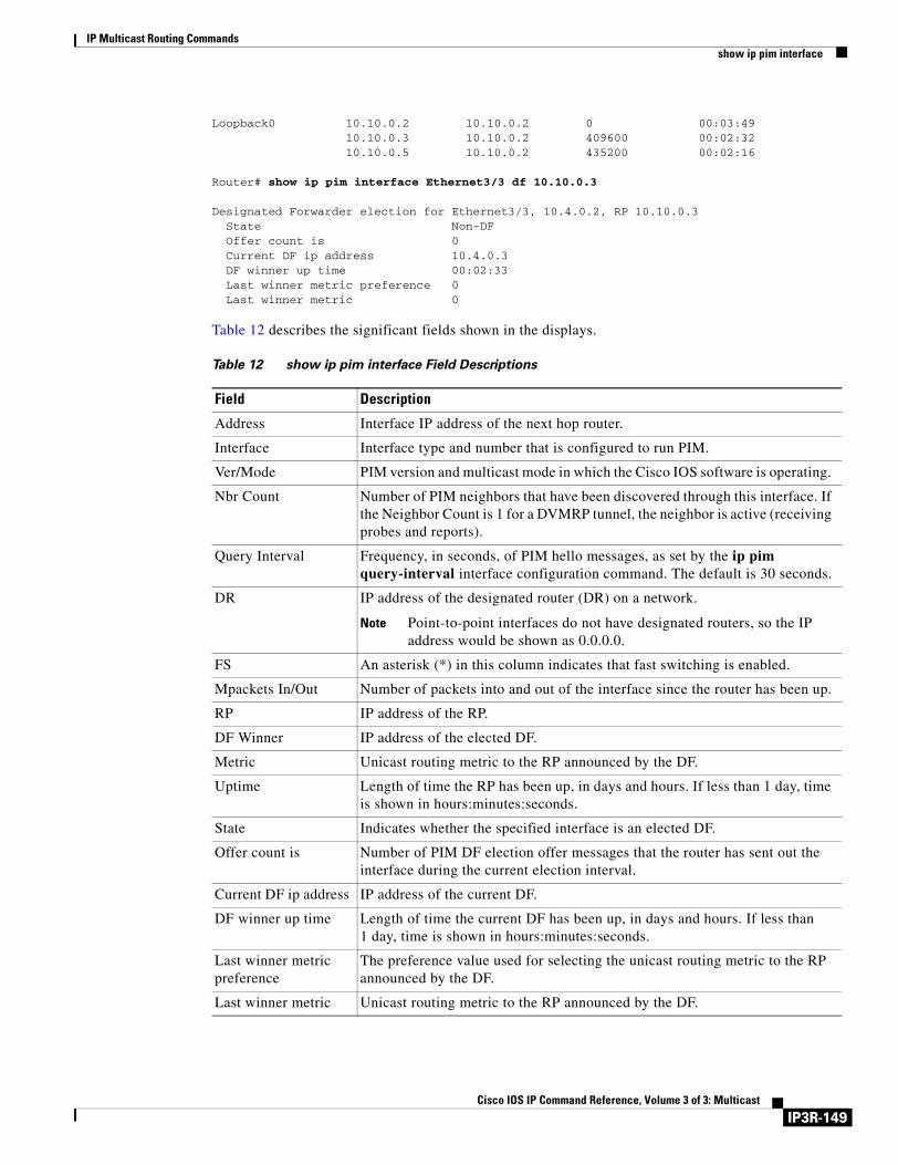
IP Multicast Routing Commandsshow ip pim interface
Loopback0 10.10.0.2 10.10.0.2 0 00:03:4910.10.0.3 10.10.0.2 409600 00:02:3210.10.0.5 10.10.0.2 435200 00:02:16
Router# show ip pim interface Ethernet3/3 df 10.10.0.3
Designated Forwarder election for Ethernet3/3, 10.4.0.2, RP 10.10.0.3 State Non-DF Offer count is 0 Current DF ip address 10.4.0.3 DF winner up time 00:02:33 Last winner metric preference 0 Last winner metric 0
Table 12 describes the significant fields shown in the displays.
Table 12 show ip pim interface Field Descriptions
Field Description
Address Interface IP address of the next hop router.
Interface Interface type and number that is configured to run PIM.
Ver/Mode PIM version and multicast mode in which the Cisco IOS software is operating.
Nbr Count Number of PIM neighbors that have been discovered through this interface. If the Neighbor Count is 1 for a DVMRP tunnel, the neighbor is active (receiving probes and reports).
Query Interval Frequency, in seconds, of PIM hello messages, as set by the ip pim query-interval interface configuration command. The default is 30 seconds.
DR IP address of the designated router (DR) on a network.
Note Point-to-point interfaces do not have designated routers, so the IP address would be shown as 0.0.0.0.
FS An asterisk (*) in this column indicates that fast switching is enabled.
Mpackets In/Out Number of packets into and out of the interface since the router has been up.
RP IP address of the RP.
DF Winner IP address of the elected DF.
Metric Unicast routing metric to the RP announced by the DF.
Uptime Length of time the RP has been up, in days and hours. If less than 1 day, time is shown in hours:minutes:seconds.
State Indicates whether the specified interface is an elected DF.
Offer count is Number of PIM DF election offer messages that the router has sent out the interface during the current election interval.
Current DF ip address IP address of the current DF.
DF winner up time Length of time the current DF has been up, in days and hours. If less than 1 day, time is shown in hours:minutes:seconds.
Last winner metric preference
The preference value used for selecting the unicast routing metric to the RP announced by the DF.
Last winner metric Unicast routing metric to the RP announced by the DF.
IP3R-149Cisco IOS IP Command Reference, Volume 3 of 3: Multicast
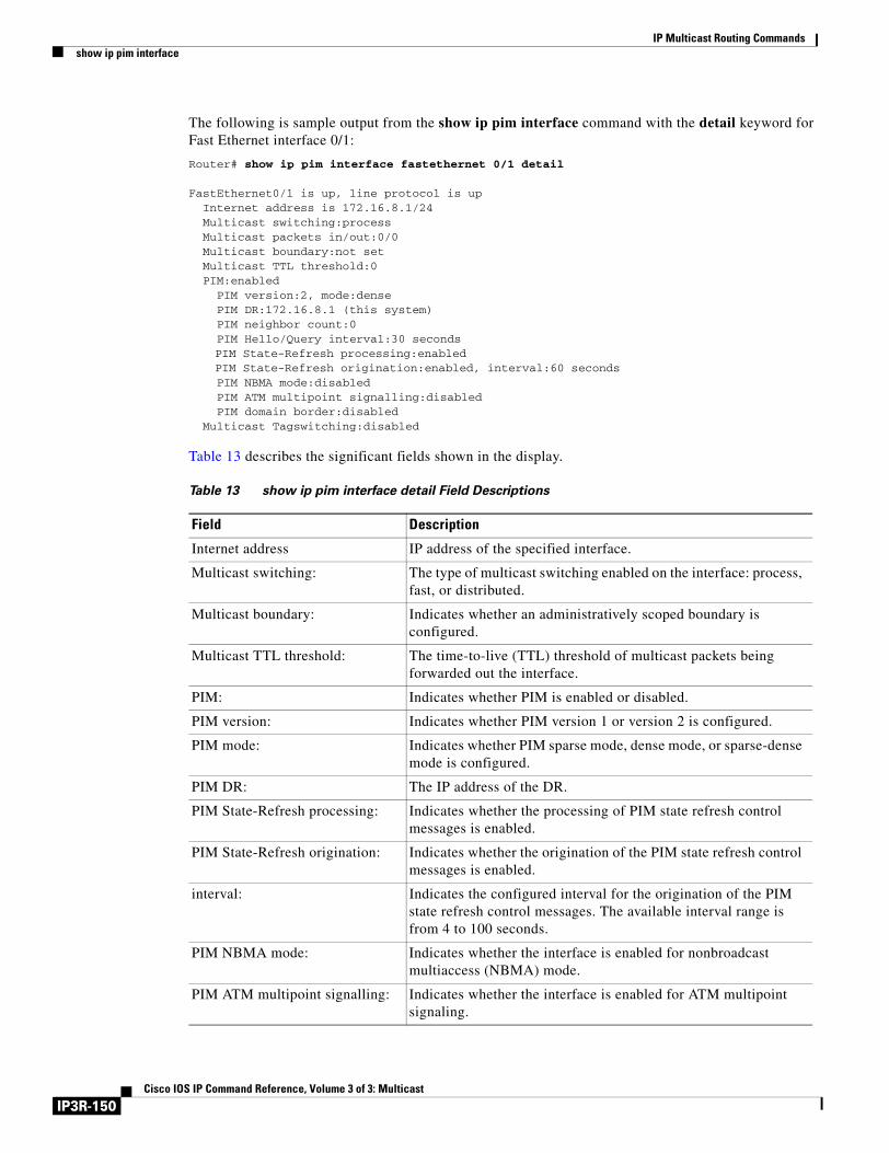
IP Multicast Routing Commandsshow ip pim interface
The following is sample output from the show ip pim interface command with the detail keyword for Fast Ethernet interface 0/1:
Router# show ip pim interface fastethernet 0/1 detail
FastEthernet0/1 is up, line protocol is up Internet address is 172.16.8.1/24 Multicast switching:process Multicast packets in/out:0/0 Multicast boundary:not set Multicast TTL threshold:0 PIM:enabled PIM version:2, mode:dense PIM DR:172.16.8.1 (this system) PIM neighbor count:0 PIM Hello/Query interval:30 seconds
PIM State-Refresh processing:enabledPIM State-Refresh origination:enabled, interval:60 seconds
PIM NBMA mode:disabled PIM ATM multipoint signalling:disabled PIM domain border:disabled Multicast Tagswitching:disabled
Table 13 describes the significant fields shown in the display.
Table 13 show ip pim interface detail Field Descriptions
Field Description
Internet address IP address of the specified interface.
Multicast switching: The type of multicast switching enabled on the interface: process, fast, or distributed.
Multicast boundary: Indicates whether an administratively scoped boundary is configured.
Multicast TTL threshold: The time-to-live (TTL) threshold of multicast packets being forwarded out the interface.
PIM: Indicates whether PIM is enabled or disabled.
PIM version: Indicates whether PIM version 1 or version 2 is configured.
PIM mode: Indicates whether PIM sparse mode, dense mode, or sparse-dense mode is configured.
PIM DR: The IP address of the DR.
PIM State-Refresh processing: Indicates whether the processing of PIM state refresh control messages is enabled.
PIM State-Refresh origination: Indicates whether the origination of the PIM state refresh control messages is enabled.
interval: Indicates the configured interval for the origination of the PIM state refresh control messages. The available interval range is from 4 to 100 seconds.
PIM NBMA mode: Indicates whether the interface is enabled for nonbroadcast multiaccess (NBMA) mode.
PIM ATM multipoint signalling: Indicates whether the interface is enabled for ATM multipoint signaling.
IP3R-150Cisco IOS IP Command Reference, Volume 3 of 3: Multicast
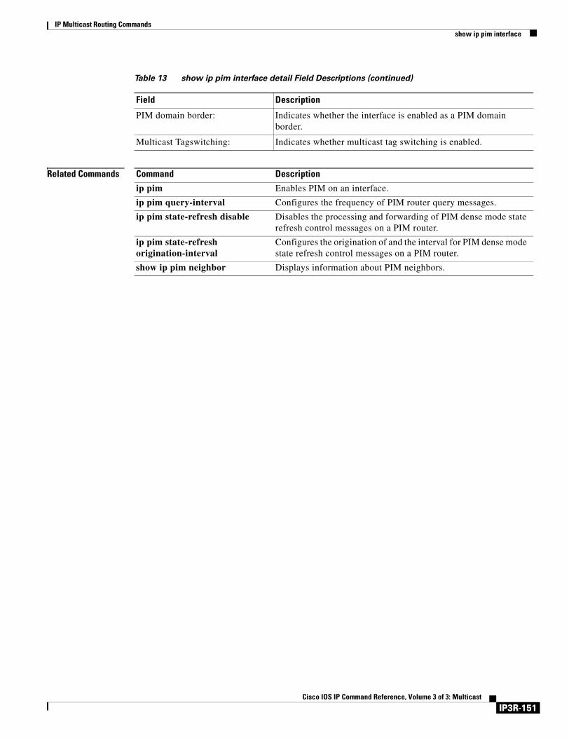
IP Multicast Routing Commandsshow ip pim interface
Related Commands
PIM domain border: Indicates whether the interface is enabled as a PIM domain border.
Multicast Tagswitching: Indicates whether multicast tag switching is enabled.
Table 13 show ip pim interface detail Field Descriptions (continued)
Field Description
Command Description
ip pim Enables PIM on an interface.
ip pim query-interval Configures the frequency of PIM router query messages.
ip pim state-refresh disable Disables the processing and forwarding of PIM dense mode state refresh control messages on a PIM router.
ip pim state-refresh origination-interval
Configures the origination of and the interval for PIM dense mode state refresh control messages on a PIM router.
show ip pim neighbor Displays information about PIM neighbors.
IP3R-151Cisco IOS IP Command Reference, Volume 3 of 3: Multicast
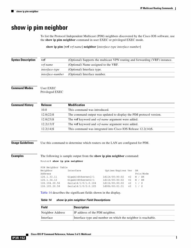
IP Multicast Routing Commandsshow ip pim neighbor
show ip pim neighborTo list the Protocol Independent Multicast (PIM) neighbors discovered by the Cisco IOS software, use the show ip pim neighbor command in user EXEC or privileged EXEC mode.
show ip pim [vrf vrf-name] neighbor [interface-type interface-number]
Syntax Description
Command Modes User EXECPrivileged EXEC
Command History
Usage Guidelines Use this command to determine which routers on the LAN are configured for PIM.
Examples The following is sample output from the show ip pim neighbor command:
Router# show ip pim neighbor
PIM Neighbor TableNeighbor Interface Uptime/Expires Ver DRAddress Prio/Mode126.1.33.11 GigabitEthernet2/1 1d11h/00:00:02 v2 N / DR126.1.34.12 GigabitEthernet2/1 1d11h/00:00:02 v2 N / DR126.104.20.56 Serial4/1/0/1:0.104 1d11h/00:00:02 v2 1 / S126.105.20.58 Serial4/1/0/2:0.105 1d00h/00:01:31 v2 1 / S
Table 14 describes the significant fields shown in the display.
vrf (Optional) Supports the multicast VPN routing and forwarding (VRF) instance.
vrf-name (Optional) Name assigned to the VRF.
interface-type (Optional) Interface type.
interface-number (Optional) Interface number.
Release Modification
10.0 This command was introduced.
12.0(22)S The command output was updated to display the PIM protocol version.
12.0(23)S The vrf keyword and vrf-name argument were added.
12.2(13)T The vrf keyword and vrf-name argument were added.
12.2(14)S This command was integrated into Cisco IOS Release 12.2(14)S.
Table 14 show ip pim neighbor Field Descriptions
Field Description
Neighbor Address IP address of the PIM neighbor.
Interface Interface type and number on which the neighbor is reachable.
IP3R-152Cisco IOS IP Command Reference, Volume 3 of 3: Multicast
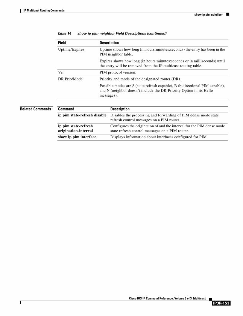
IP Multicast Routing Commandsshow ip pim neighbor
Related Commands
Uptime/Expires Uptime shows how long (in hours:minutes:seconds) the entry has been in the PIM neighbor table.
Expires shows how long (in hours:minutes:seconds or in milliseconds) until the entry will be removed from the IP multicast routing table.
Ver PIM protocol version.
DR Prio/Mode Priority and mode of the designated router (DR).
Possible modes are S (state refresh capable), B (bidirectional PIM capable), and N (neighbor doesn’t include the DR-Priority Option in its Hello messages).
Table 14 show ip pim neighbor Field Descriptions (continued)
Field Description
Command Description
ip pim state-refresh disable Disables the processing and forwarding of PIM dense mode state refresh control messages on a PIM router.
ip pim state-refresh origination-interval
Configures the origination of and the interval for the PIM dense mode state refresh control messages on a PIM router.
show ip pim interface Displays information about interfaces configured for PIM.
IP3R-153Cisco IOS IP Command Reference, Volume 3 of 3: Multicast
IP Multicast Routing Commandsshow ip pim rp
show ip pim rpTo display active rendezvous points (RPs) that are cached with associated multicast routing entries, use the show ip pim rp command in EXEC mode.
show ip pim rp [mapping | [elected | in-use] | metric] [rp-address]
Syntax Description
Defaults If no RP is specified, all active RPs are displayed.
Command Modes EXEC
Command History
Usage Guidelines The Protocol Independent Multicast (PIM) version known for an RP influences the type of PIM register messages (version 1 or version 2) that the router sends when acting as the designated router (DR) for an active source. If an RP is statically configured, the PIM version of the RP is not set and the router, if required to send register packets, first tries to send PIM version 2 register packets. If that fails, the router sends PIM version 1 register packets.
The version of the RP displayed in the show ip pim rp command output can change according to the operations of the router. When the group is created, the version shown is for the RP in the RP mapping cache. Later, the version displayed by this command may change. If this router is acting as a DR for an active source, the router sends PIM register messages. The PIM register messages are answered by the RP with PIM register stop messages. The router learns from these PIM register stop messages the actual PIM version of the RP. Once the actual PIM version of the RP is learned, this command displays only this version. If the router is not acting as a DR for active sources on this group, then the version shown for the RP of the group does not change. In this case, the PIM version of the RP is irrelevant to the router because the version of the RP influences only the PIM register messages that this router must send.
When you enter the show ip pim rp mapping command, the version of the RP displayed in the output is determined only by the method through which an RP is learned. If the RP is learned from Auto-RP then the RP displayed is either “v1” or “v2, v1.” If the RP is learned from a static RP definition, the RP version is undetermined and no RP version is displayed in the output. If the RP is learned from the BSR, the RP version displayed is “v2.”
mapping (Optional) Displays all group-to-RP mappings of which the router is aware (either configured or learned from Auto-RP).
elected (Optional) Displays only the elected Auto RPs.
in-use (Optional) Displays the learned RPs in use.
metric (Optional) Displays the unicast routing metric to the RPs configured statically or learned via Auto-RP or the bootstrap router (BSR).
rp-address (Optional) RP IP address.
Release Modification
10.2 This command was introduced.
12.1(2)T The metric keyword and rp-address argument were added.
IP3R-154Cisco IOS IP Command Reference, Volume 3 of 3: Multicast
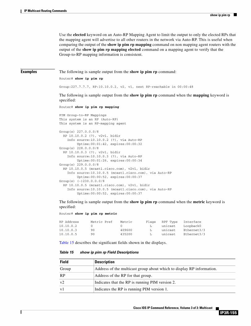
IP Multicast Routing Commandsshow ip pim rp
Use the elected keyword on an Auto-RP Mapping Agent to limit the output to only the elected RPs that the mapping agent will advertise to all other routers in the network via Auto-RP. This is useful when comparing the output of the show ip pim rp mapping command on non mapping agent routers with the output of the show ip pim rp mapping elected command on a mapping agent to verify that the Group-to-RP mapping information is consistent.
Examples The following is sample output from the show ip pim rp command:
Router# show ip pim rp
Group:227.7.7.7, RP:10.10.0.2, v2, v1, next RP-reachable in 00:00:48
The following is sample output from the show ip pim rp command when the mapping keyword is specified:
Router# show ip pim rp mapping
PIM Group-to-RP MappingsThis system is an RP (Auto-RP)This system is an RP-mapping agent
Group(s) 227.0.0.0/8RP 10.10.0.2 (?), v2v1, bidir
Info source:10.10.0.2 (?), via Auto-RPUptime:00:01:42, expires:00:00:32
Group(s) 228.0.0.0/8RP 10.10.0.3 (?), v2v1, bidir
Info source:10.10.0.3 (?), via Auto-RPUptime:00:01:26, expires:00:00:34
Group(s) 229.0.0.0/8RP 10.10.0.5 (mcast1.cisco.com), v2v1, bidir
Info source:10.10.0.5 (mcast1.cisco.com), via Auto-RPUptime:00:00:52, expires:00:00:37
Group(s) (-)230.0.0.0/8RP 10.10.0.5 (mcast1.cisco.com), v2v1, bidir
Info source:10.10.0.5 (mcast1.cisco.com), via Auto-RPUptime:00:00:52, expires:00:00:37
The following is sample output from the show ip pim rp command when the metric keyword is specified:
Router# show ip pim rp metric
RP Address Metric Pref Metric Flags RPF Type Interface10.10.0.2 0 0 L unicast Loopback010.10.0.3 90 409600 L unicast Ethernet3/310.10.0.5 90 435200 L unicast Ethernet3/3
Table 15 describes the significant fields shown in the displays.
Table 15 show ip pim rp Field Descriptions
Field Description
Group Address of the multicast group about which to display RP information.
RP Address of the RP for that group.
v2 Indicates that the RP is running PIM version 2.
v1 Indicates the RP is running PIM version 1.
IP3R-155Cisco IOS IP Command Reference, Volume 3 of 3: Multicast
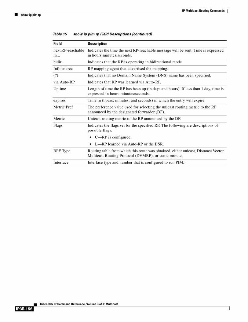
IP Multicast Routing Commandsshow ip pim rp
next RP-reachable in...
Indicates the time the next RP-reachable message will be sent. Time is expressed in hours:minutes:seconds.
bidir Indicates that the RP is operating in bidirectional mode.
Info source RP mapping agent that advertised the mapping.
(?) Indicates that no Domain Name System (DNS) name has been specified.
via Auto-RP Indicates that RP was learned via Auto-RP.
Uptime Length of time the RP has been up (in days and hours). If less than 1 day, time is expressed in hours:minutes:seconds.
expires Time in (hours: minutes: and seconds) in which the entry will expire.
Metric Pref The preference value used for selecting the unicast routing metric to the RP announced by the designated forwarder (DF).
Metric Unicast routing metric to the RP announced by the DF.
Flags Indicates the flags set for the specified RP. The following are descriptions of possible flags:
• C—RP is configured.
• L—RP learned via Auto-RP or the BSR.
RPF Type Routing table from which this route was obtained, either unicast, Distance Vector Multicast Routing Protocol (DVMRP), or static mroute.
Interface Interface type and number that is configured to run PIM.
Table 15 show ip pim rp Field Descriptions (continued)
Field Description
IP3R-156Cisco IOS IP Command Reference, Volume 3 of 3: Multicast
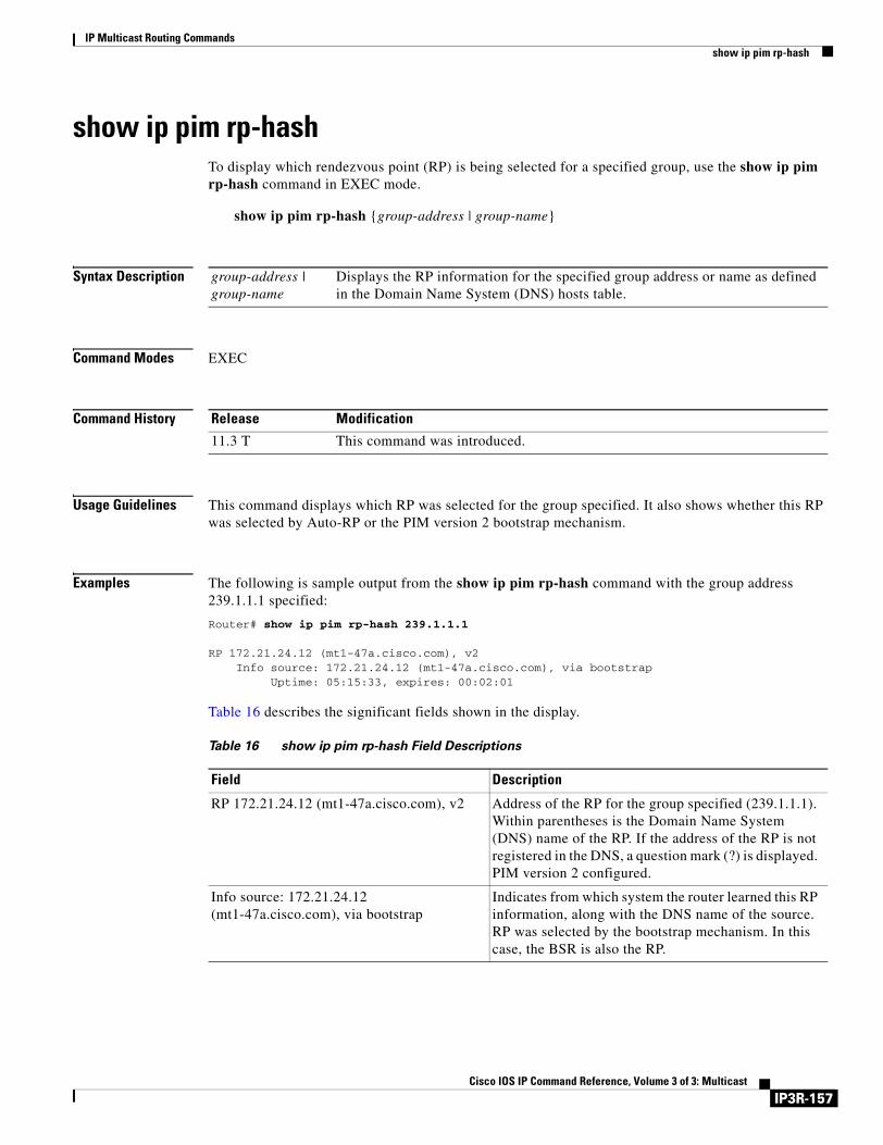
IP Multicast Routing Commandsshow ip pim rp-hash
show ip pim rp-hashTo display which rendezvous point (RP) is being selected for a specified group, use the show ip pim rp-hash command in EXEC mode.
show ip pim rp-hash {group-address | group-name}
Syntax Description
Command Modes EXEC
Command History
Usage Guidelines This command displays which RP was selected for the group specified. It also shows whether this RP was selected by Auto-RP or the PIM version 2 bootstrap mechanism.
Examples The following is sample output from the show ip pim rp-hash command with the group address 239.1.1.1 specified:
Router# show ip pim rp-hash 239.1.1.1
RP 172.21.24.12 (mt1-47a.cisco.com), v2 Info source: 172.21.24.12 (mt1-47a.cisco.com), via bootstrap Uptime: 05:15:33, expires: 00:02:01
Table 16 describes the significant fields shown in the display.
group-address | group-name
Displays the RP information for the specified group address or name as defined in the Domain Name System (DNS) hosts table.
Release Modification
11.3 T This command was introduced.
Table 16 show ip pim rp-hash Field Descriptions
Field Description
RP 172.21.24.12 (mt1-47a.cisco.com), v2 Address of the RP for the group specified (239.1.1.1). Within parentheses is the Domain Name System (DNS) name of the RP. If the address of the RP is not registered in the DNS, a question mark (?) is displayed. PIM version 2 configured.
Info source: 172.21.24.12 (mt1-47a.cisco.com), via bootstrap
Indicates from which system the router learned this RP information, along with the DNS name of the source. RP was selected by the bootstrap mechanism. In this case, the BSR is also the RP.
IP3R-157Cisco IOS IP Command Reference, Volume 3 of 3: Multicast
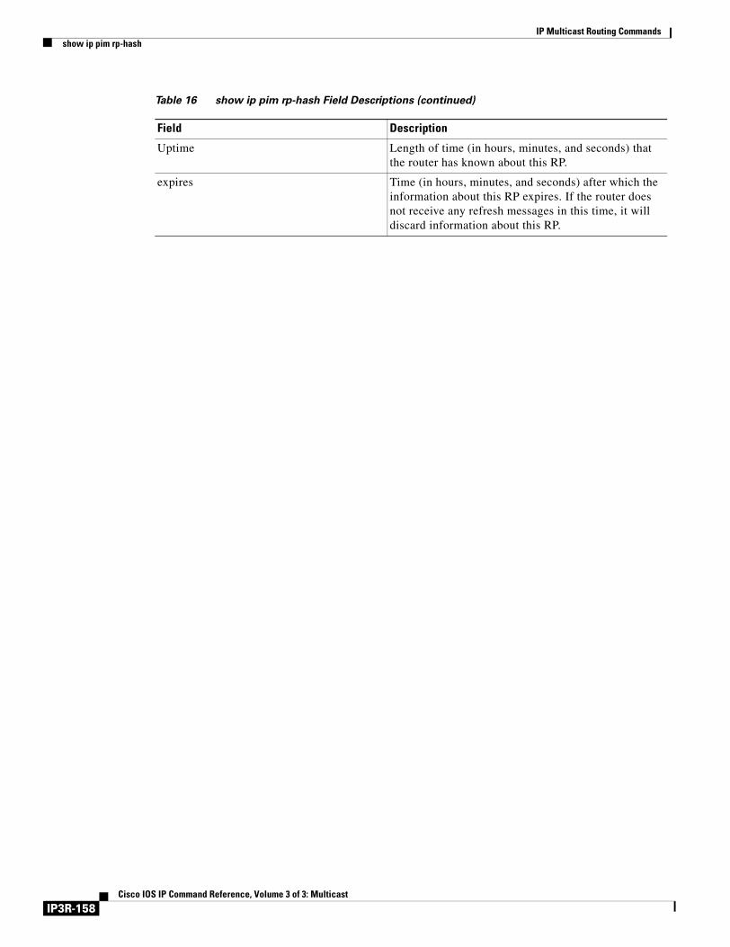
IP Multicast Routing Commandsshow ip pim rp-hash
Uptime Length of time (in hours, minutes, and seconds) that the router has known about this RP.
expires Time (in hours, minutes, and seconds) after which the information about this RP expires. If the router does not receive any refresh messages in this time, it will discard information about this RP.
Table 16 show ip pim rp-hash Field Descriptions (continued)
Field Description
IP3R-158Cisco IOS IP Command Reference, Volume 3 of 3: Multicast
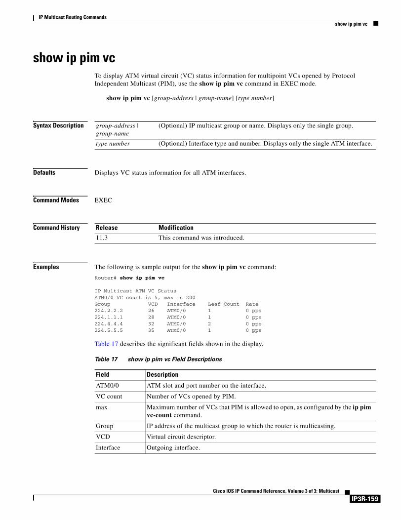
IP Multicast Routing Commandsshow ip pim vc
show ip pim vcTo display ATM virtual circuit (VC) status information for multipoint VCs opened by Protocol Independent Multicast (PIM), use the show ip pim vc command in EXEC mode.
show ip pim vc [group-address | group-name] [type number]
Syntax Description
Defaults Displays VC status information for all ATM interfaces.
Command Modes EXEC
Command History
Examples The following is sample output for the show ip pim vc command:
Router# show ip pim vc
IP Multicast ATM VC StatusATM0/0 VC count is 5, max is 200Group VCD Interface Leaf Count Rate224.2.2.2 26 ATM0/0 1 0 pps224.1.1.1 28 ATM0/0 1 0 pps224.4.4.4 32 ATM0/0 2 0 pps224.5.5.5 35 ATM0/0 1 0 pps
Table 17 describes the significant fields shown in the display.
group-address | group-name
(Optional) IP multicast group or name. Displays only the single group.
type number (Optional) Interface type and number. Displays only the single ATM interface.
Release Modification
11.3 This command was introduced.
Table 17 show ip pim vc Field Descriptions
Field Description
ATM0/0 ATM slot and port number on the interface.
VC count Number of VCs opened by PIM.
max Maximum number of VCs that PIM is allowed to open, as configured by the ip pim vc-count command.
Group IP address of the multicast group to which the router is multicasting.
VCD Virtual circuit descriptor.
Interface Outgoing interface.
IP3R-159Cisco IOS IP Command Reference, Volume 3 of 3: Multicast
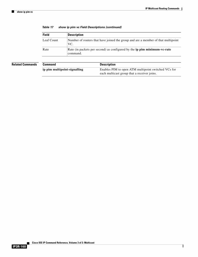
IP Multicast Routing Commandsshow ip pim vc
Related Commands
Leaf Count Number of routers that have joined the group and are a member of that multipoint VC.
Rate Rate (in packets per second) as configured by the ip pim minimum-vc-rate command.
Table 17 show ip pim vc Field Descriptions (continued)
Field Description
Command Description
ip pim multipoint-signalling Enables PIM to open ATM multipoint switched VCs for each multicast group that a receiver joins.
IP3R-160Cisco IOS IP Command Reference, Volume 3 of 3: Multicast

IP Multicast Routing Commandsshow ip rpf
show ip rpfTo display how IP multicast routing does Reverse Path Forwarding (RPF), use the show ip rpf command in EXEC mode.
show ip rpf {source-address | source-name} [metric]
Syntax Description
Defaults If no source is specified, all sources are displayed.
Command Modes EXEC
Command History
Usage Guidelines The router can reverse path forward from multiple routing tables (that is, the unicast routing table, Distance Vector Multicast Routing Protocol (DVMRP) routing table, or static mroutes). This command tells you from where the information is retrieved.
Examples The following is sample output of the show ip rpf command:
Router# show ip rpf 171.69.10.13
RPF information for sj-eng-mbone.cisco.com (171.69.10.13) RPF interface: BRI0 RPF neighbor: eng-isdn-pri3.cisco.com (171.69.121.10) RPF route/mask: 171.69.0.0/255.255.0.0 RPF type: unicast
RPF recursion count: 0Doing distance-preferred lookups across tables
The following is sample output of the show ip rpf command when the metric keyword is specified:
Router# show ip rpf 171.69.10.13 metric
RPF information for sj-eng-mbone.cisco.com (171.69.10.13)RPF interface: BRI0RPF neighbor: eng-isdn-pri3.cisco.com (171.69.121.10)RPF route/mask: 171.69.0.0/255.255.0.0RPF type: unicastRPF recursion count: 0Doing distance-preferred lookups across tablesMetric preference: 110Metric: 11
source-address | source-name
Displays the RPF information for the specified source address or name.
metric (Optional) Displays the unicast routing metric.
Release Modification
11.0 This command was introduced.
12.1(2)T The metric keyword was added.
IP3R-161Cisco IOS IP Command Reference, Volume 3 of 3: Multicast
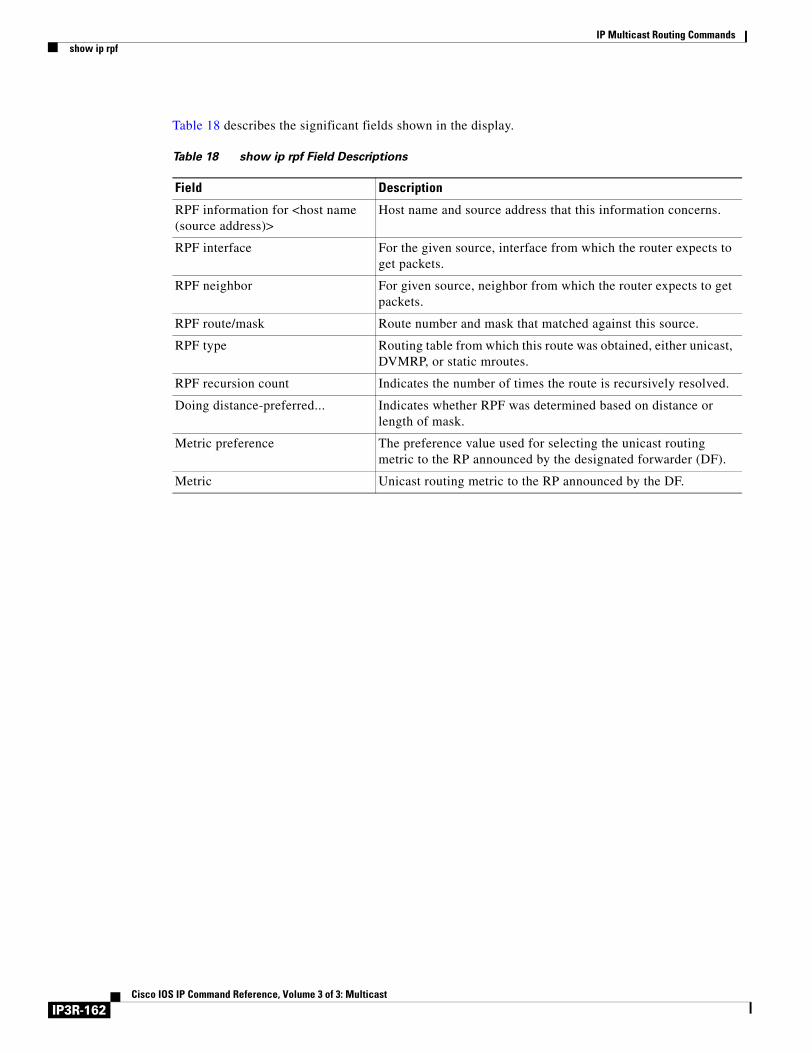
IP Multicast Routing Commandsshow ip rpf
Table 18 describes the significant fields shown in the display.
Table 18 show ip rpf Field Descriptions
Field Description
RPF information for <host name (source address)>
Host name and source address that this information concerns.
RPF interface For the given source, interface from which the router expects to get packets.
RPF neighbor For given source, neighbor from which the router expects to get packets.
RPF route/mask Route number and mask that matched against this source.
RPF type Routing table from which this route was obtained, either unicast, DVMRP, or static mroutes.
RPF recursion count Indicates the number of times the route is recursively resolved.
Doing distance-preferred... Indicates whether RPF was determined based on distance or length of mask.
Metric preference The preference value used for selecting the unicast routing metric to the RP announced by the designated forwarder (DF).
Metric Unicast routing metric to the RP announced by the DF.
IP3R-162Cisco IOS IP Command Reference, Volume 3 of 3: Multicast
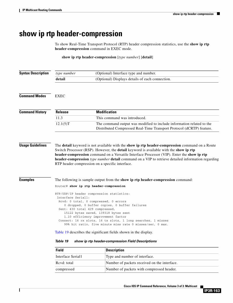
IP Multicast Routing Commandsshow ip rtp header-compression
show ip rtp header-compressionTo show Real-Time Transport Protocol (RTP) header compression statistics, use the show ip rtp header-compression command in EXEC mode.
show ip rtp header-compression [type number] [detail]
Syntax Description
Command Modes EXEC
Command History
Usage Guidelines The detail keyword is not available with the show ip rtp header-compression command on a Route Switch Processor (RSP). However, the detail keyword is available with the show ip rtp header-compression command on a Versatile Interface Processor (VIP). Enter the show ip rtp header-compression type number detail command on a VIP to retrieve detailed information regarding RTP header compression on a specific interface.
Examples The following is sample output from the show ip rtp header-compression command:
Router# show ip rtp header-compression
RTP/UDP/IP header compression statistics:Interface Serial1:Rcvd: 0 total, 0 compressed, 0 errors
0 dropped, 0 buffer copies, 0 buffer failuresSent: 430 total 429 compressed,
15122 bytes saved, 139318 bytes sent1.10 efficiency improvement factor
Connect: 16 rx slots, 16 tx slots, 1 long searches, 1 misses99% hit ratio, five minute miss rate 0 misses/sec, 0 max.
Table 19 describes the significant fields shown in the display.
type number (Optional) Interface type and number.
detail (Optional) Displays details of each connection.
Release Modification
11.3 This command was introduced.
12.1(5)T The command output was modified to include information related to the Distributed Compressed Real-Time Transport Protocol (dCRTP) feature.
Table 19 show ip rtp header-compression Field Descriptions
Field Description
Interface Serial1 Type and number of interface.
Rcvd: total Number of packets received on the interface.
compressed Number of packets with compressed header.
IP3R-163Cisco IOS IP Command Reference, Volume 3 of 3: Multicast
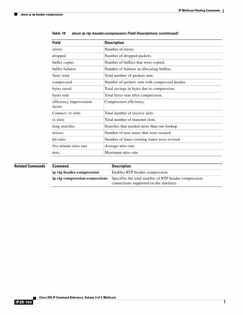
IP Multicast Routing Commandsshow ip rtp header-compression
Related Commands
errors Number of errors.
dropped Number of dropped packets.
buffer copies Number of buffers that were copied.
buffer failures Number of failures in allocating buffers.
Sent: total Total number of packets sent.
compressed Number of packets sent with compressed header.
bytes saved Total savings in bytes due to compression.
bytes sent Total bytes sent after compression.
efficiency improvement factor
Compression efficiency.
Connect: rx slots Total number of receive slots.
tx slots Total number of transmit slots.
long searches Searches that needed more than one lookup.
misses Number of new states that were created.
hit ratio Number of times existing states were revised.
five minute miss rate Average miss rate.
max. Maximum miss rate.
Table 19 show ip rtp header-compression Field Descriptions (continued)
Field Description
Command Description
ip rtp header-compression Enables RTP header compression.
ip rtp compression-connections Specifies the total number of RTP header compression connections supported on the interface.
IP3R-164Cisco IOS IP Command Reference, Volume 3 of 3: Multicast
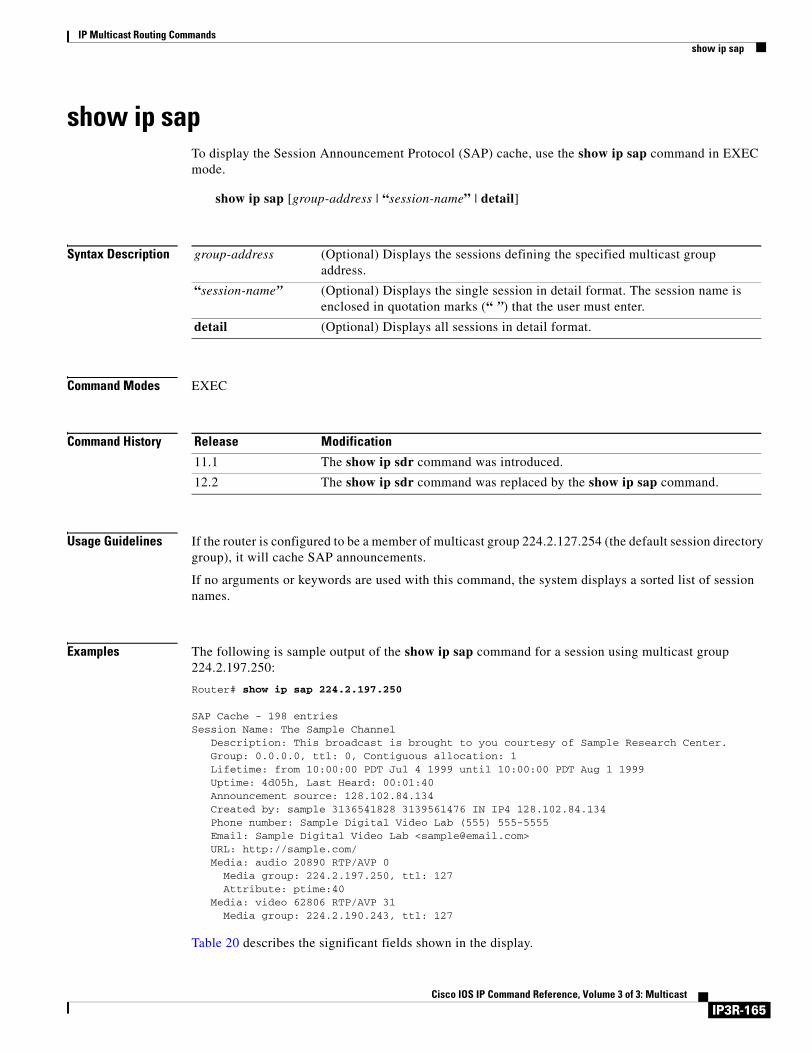
IP Multicast Routing Commandsshow ip sap
show ip sapTo display the Session Announcement Protocol (SAP) cache, use the show ip sap command in EXEC mode.
show ip sap [group-address | “session-name” | detail]
Syntax Description
Command Modes EXEC
Command History
Usage Guidelines If the router is configured to be a member of multicast group 224.2.127.254 (the default session directory group), it will cache SAP announcements.
If no arguments or keywords are used with this command, the system displays a sorted list of session names.
Examples The following is sample output of the show ip sap command for a session using multicast group 224.2.197.250:
Router# show ip sap 224.2.197.250
SAP Cache - 198 entriesSession Name: The Sample Channel Description: This broadcast is brought to you courtesy of Sample Research Center. Group: 0.0.0.0, ttl: 0, Contiguous allocation: 1 Lifetime: from 10:00:00 PDT Jul 4 1999 until 10:00:00 PDT Aug 1 1999 Uptime: 4d05h, Last Heard: 00:01:40 Announcement source: 128.102.84.134 Created by: sample 3136541828 3139561476 IN IP4 128.102.84.134 Phone number: Sample Digital Video Lab (555) 555-5555 Email: Sample Digital Video Lab <[email protected]> URL: http://sample.com/ Media: audio 20890 RTP/AVP 0 Media group: 224.2.197.250, ttl: 127 Attribute: ptime:40 Media: video 62806 RTP/AVP 31 Media group: 224.2.190.243, ttl: 127
Table 20 describes the significant fields shown in the display.
group-address (Optional) Displays the sessions defining the specified multicast group address.
“session-name” (Optional) Displays the single session in detail format. The session name is enclosed in quotation marks (“ ”) that the user must enter.
detail (Optional) Displays all sessions in detail format.
Release Modification
11.1 The show ip sdr command was introduced.
12.2 The show ip sdr command was replaced by the show ip sap command.
IP3R-165Cisco IOS IP Command Reference, Volume 3 of 3: Multicast
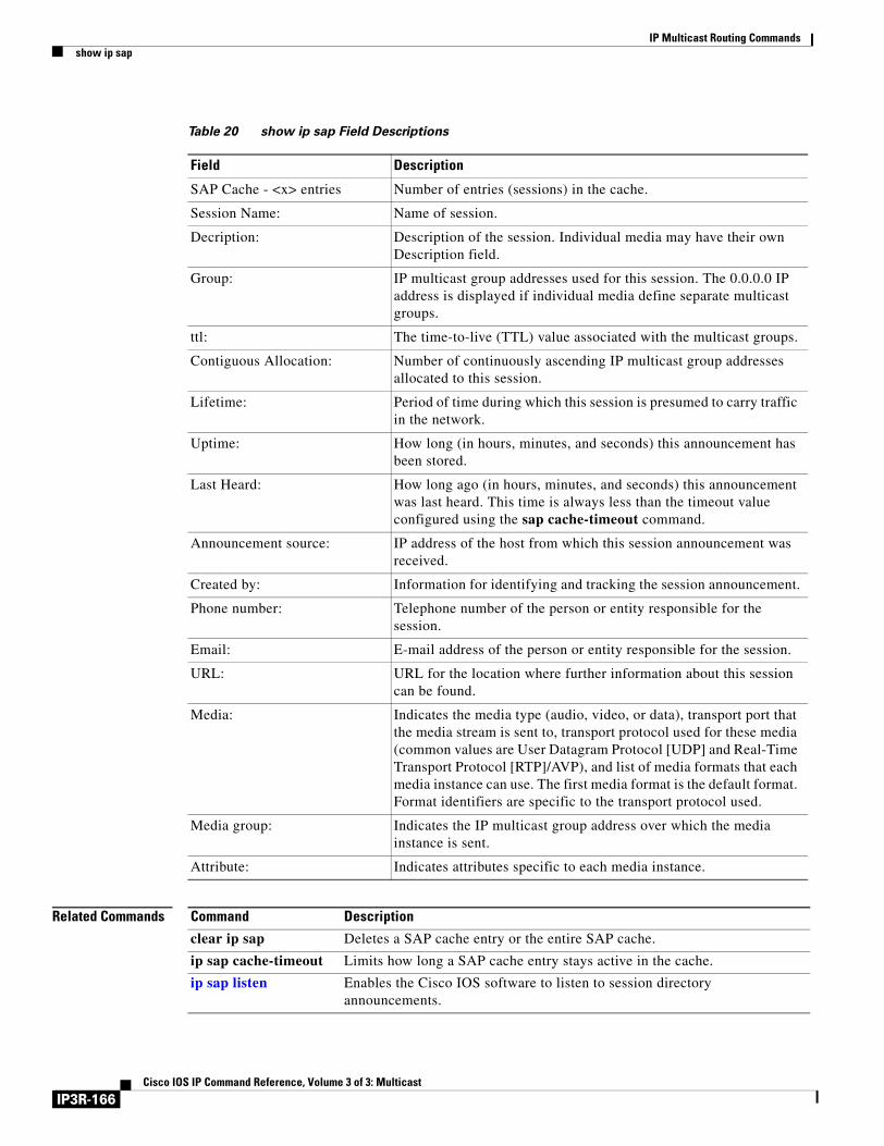
IP Multicast Routing Commandsshow ip sap
Related Commands
Table 20 show ip sap Field Descriptions
Field Description
SAP Cache - <x> entries Number of entries (sessions) in the cache.
Session Name: Name of session.
Decription: Description of the session. Individual media may have their own Description field.
Group: IP multicast group addresses used for this session. The 0.0.0.0 IP address is displayed if individual media define separate multicast groups.
ttl: The time-to-live (TTL) value associated with the multicast groups.
Contiguous Allocation: Number of continuously ascending IP multicast group addresses allocated to this session.
Lifetime: Period of time during which this session is presumed to carry traffic in the network.
Uptime: How long (in hours, minutes, and seconds) this announcement has been stored.
Last Heard: How long ago (in hours, minutes, and seconds) this announcement was last heard. This time is always less than the timeout value configured using the sap cache-timeout command.
Announcement source: IP address of the host from which this session announcement was received.
Created by: Information for identifying and tracking the session announcement.
Phone number: Telephone number of the person or entity responsible for the session.
Email: E-mail address of the person or entity responsible for the session.
URL: URL for the location where further information about this session can be found.
Media: Indicates the media type (audio, video, or data), transport port that the media stream is sent to, transport protocol used for these media (common values are User Datagram Protocol [UDP] and Real-Time Transport Protocol [RTP]/AVP), and list of media formats that each media instance can use. The first media format is the default format. Format identifiers are specific to the transport protocol used.
Media group: Indicates the IP multicast group address over which the media instance is sent.
Attribute: Indicates attributes specific to each media instance.
Command Description
clear ip sap Deletes a SAP cache entry or the entire SAP cache.
ip sap cache-timeout Limits how long a SAP cache entry stays active in the cache.
ip sap listen Enables the Cisco IOS software to listen to session directory announcements.
IP3R-166Cisco IOS IP Command Reference, Volume 3 of 3: Multicast

IP Multicast Routing Commandsshow ip sdr
show ip sdrThe show ip sdr command is replaced by the show ip sap command. See the description of the show ip sap command in this chapter for more information.
IP3R-167Cisco IOS IP Command Reference, Volume 3 of 3: Multicast

IP Multicast Routing Commandsshow ip sdr
IP3R-168Cisco IOS IP Command Reference, Volume 3 of 3: Multicast
Multicast Source Discovery Protocol Commands
Use the commands in this chapter to configure and monitor Multicast Source Discovery Protocol (MSDP). For configuration information and examples of MSDP, refer to the “Configuring Multicast Source Discovery Protocol” chapter of the Cisco IOS IP Configuration Guide.
IP3R-169Cisco IOS IP Command Reference, Volume 3 of 3: Multicast
Multicast Source Discovery Protocol Commandsclear ip msdp peer
clear ip msdp peerTo clear the TCP connection to the specified Multicast Source Discovery Protocol (MSDP) peer, use the clear ip msdp peer command in EXEC mode.
clear ip msdp peer {peer-address | peer-name}
Syntax Description
Command Modes EXEC
Command History
Usage Guidelines This command closes the TCP connection to the peer, resets all the MSDP peer statistics, and clears the input and output queues to and from the MSDP peer.
Examples The following example clears the TCP connection to the MSDP peer at 10.3.32.154:
Router# clear ip msdp peer 10.3.32.154
Related Commands
peer-address | peer-name IP address or name of the MSDP peer to which the TCP connection is cleared.
Release Modification
12.0(7)T This command was introduced.
Command Description
ip msdp peer Configures an MSDP peer.
IP3R-170Cisco IOS IP Command Reference, Volume 3 of 3: Multicast
Multicast Source Discovery Protocol Commandsclear ip msdp sa-cache
clear ip msdp sa-cacheTo clear Multicast Source Discovery Protocol (MSDP) Source-Active (SA) cache entries, use the clear ip msdp sa-cache command in EXEC mode.
clear ip msdp sa-cache [group-address | group-name]
Syntax Description
Command Modes EXEC
Command History
Usage Guidelines In order to have any SA entries in the cache to clear, SA caching must have been enabled with the ip msdp cache-sa-state command
If no multicast group is identified by group address or name, all SA cache entries are cleared.
Examples The following example clears the SA entries for the multicast group 10.3.53.154 from the cache:
Router# clear ip msdp sa-cache 10.3.53.154
Related Commands
group-address | group-name (Optional) Multicast group address or name for which Source-Active entries are cleared from the Source-Active cache.
Release Modification
12.0(7)T This command was introduced.
Command Description
ip msdp cache-sa-state Enables the router to create SA state.
show ip msdp sa-cache Displays (S,G) state learned from MSDP peers.
IP3R-171Cisco IOS IP Command Reference, Volume 3 of 3: Multicast
Multicast Source Discovery Protocol Commandsclear ip msdp statistics
clear ip msdp statisticsTo clear statistics counters for one or all of the Multicast Source Discovery Protocol (MSDP) peers without resetting the sessions, use the clear ip msdp statistics command in EXEC mode.
clear ip msdp statistics [peer-address | peer-name]
Syntax Description
Command Modes EXEC
Command History
Examples The following example clears the counters for the peer named sanjose:
Router# clear ip msdp statistics sanjose
peer-address | peer-name (Optional) Address or name of the MSDP peers whose statistics counters, reset count, and input/output count are cleared.
Release Modification
12.0(7)T This command was introduced.
IP3R-172Cisco IOS IP Command Reference, Volume 3 of 3: Multicast

Multicast Source Discovery Protocol Commandsip msdp border
ip msdp border To configure a router that borders a Protocol Independent Multicast (PIM) sparse mode region and dense mode region to use Multicast Source Discovery Protocol (MSDP), use the ip msdp border command in global configuration mode. To prevent this action, use the no form of this command.
ip msdp border sa-address type number
no ip msdp border sa-address type number
Syntax Description
Defaults The active sources in the dense mode region will not participate in MSDP.
Command Modes Global configuration
Command History
Usage Guidelines Use this command if you want the router to send SA messages for sources active in the PIM dense mode region to MSDP peers.
Note We recommend configuring the border router in the sparse mode domain to proxy-register sources in the dense mode domain, and have the sparse mode domain use standard MSDP procedures to advertise these sources.
Note If you use this command, you MUST constrain the sources advertised by using the ip msdp redistribute command. Configure the ip msdp redistribute command to apply to only local sources. Be aware that this configuration can result in (S, G) state remaining long after a source in the dense mode domain has stopped sending.
Note The ip msdp originator-id command also identifies an interface type and number to be used as the RP address. If both the ip msdp border and the ip msdp originator-id command are configured, the latter command prevails. That is, the address derived from the ip msdp originator-id command determines the address of the RP.
sa-address Active source IP address.
type number Interface type and number from which the IP address is derived and used as the rendezvous point (RP) address in Source-Active (SA) messages. Thus, MSDP peers can forward SA messages away from this border. The IP address of the interface is used as the originator ID, which is the RP field in the MSDP SA message.
Release Modification
12.0(7)T This command was introduced.
IP3R-173Cisco IOS IP Command Reference, Volume 3 of 3: Multicast
Multicast Source Discovery Protocol Commandsip msdp border
Examples In the following example, the local router is not an RP. It borders a PIM sparse mode region with a dense mode region. It uses the IP address of Ethernet interface 0 as the “RP” address in SA messages.
ip msdp border sa-address ethernet0
Related Commands Command Description
ip msdp originator-id Allows an MSDP speaker that originates an SA message to use the IP address of its interface as the RP address in the SA message.
ip msdp redistribute Configures which (S,G) entries from the multicast routing table are advertised in SA messages originated to MSDP peers.
IP3R-174Cisco IOS IP Command Reference, Volume 3 of 3: Multicast
Multicast Source Discovery Protocol Commandsip msdp cache-rejected-sa
ip msdp cache-rejected-saTo cache Source-Active (SA) request messages rejected from Multicast Source Discovery Protocol (MSDP) peers, use the ip msdp cache-rejected-sa command in global configuration mode. To stop tracking SA request messages, use the no form of this command.
ip msdp cache-rejected-sa number-of-entries
no ip msdp cache-rejected-sa number-of-entries
Syntax Description
Defaults Rejected SA request messages are not stored.
Command Modes Global configuration
Command History
Usage Guidelines Use the ip msdp cache-rejected-sa command to configure the router to store SA messages that have been recently received from an MSDP peer but were rejected. Once this command is enabled, the router will maintain a rejected SA cache that stores the most recent rejected SA messages. The number of rejected SA message entries to be stored in the rejected SA cache is configured with the number-of-entries argument. If the rejected SA cache overflows, entries are overwritten, starting from the first entry.
Note Enabling the ip msdp cache-rejected-sa command will not impact the performance of MSDP.
Use the show ip msdp sa-cache command with the rejected-sa keyword to display SA messages rejected from MSDP peers.
Examples The following example shows how to enable the router to store a maximum of 200 messages rejected from MSDP peers:
Router(config)# ip msdp cache-rejected-sa 200
Related Commands
number-of-entries Number of entries to be cached. The range is from 1 to 32766.
Release Modification
12.0(22)S This command was introduced.
12.1E This command was integrated into Cisco IOS Release 12.1E.
12.2 This command was integrated into Cisco IOS Release 12.2.
Command Description
show ip msdp sa-cache Displays the (S, G) state learned from MSDP peers.
IP3R-175Cisco IOS IP Command Reference, Volume 3 of 3: Multicast
Multicast Source Discovery Protocol Commandsip msdp cache-sa-state
ip msdp cache-sa-stateTo have the router create Source-Active (SA) state, use the ip msdp cache-sa-state command in global configuration mode.
ip msdp cache-sa-state [vrf vrf-name]
Syntax Description
Defaults The router creates SA state for all Multicast Source Discovery Protocol (MSDP) SA messages it receives.
Command Modes Global configuration
Command History
Usage Guidelines This command is automatically configured if at least one MSDP peer is configured. It cannot be disabled.
If you are running a version of Cisco IOS software prior to Release 12.1(7), we recommend enabling the ip msdp cache-sa-state command.
Examples The following example shows how the ip msdp cache-sa-state command is enabled when an MSDP peer is configured:
.
.
.ip classlessip msdp peer 192.168.1.2 connect-source Loopback0ip msdp peer 192.169.1.7ip msdp mesh-group outside-test 192.168.1.2ip msdp cache-sa-stateip msdp originator-id Loopback0...
vrf (Optional) Supports the multicast VPN routing and forwarding (VRF) instance.
vrf-name (Optional) Name assigned to the VRF.
Release Modification
12.0(7)T This command was introduced.
12.1(7) This command was modified such that it is enabled by default and cannot be disabled.
12.0(23)S The vrf keyword and vrf-name argument were added.
12.2(13)T The vrf keyword and vrf-name argument were added.
IP3R-176Cisco IOS IP Command Reference, Volume 3 of 3: Multicast

Multicast Source Discovery Protocol Commandsip msdp cache-sa-state
Related Commands Command Description
clear ip msdp sa-cache Clears MSDP SA cache entries.
ip msdp sa-request Configures the router to send SA request messages to the MSDP peer when a new joiner from the group becomes active.
show ip msdp sa-cache Displays (S, G) state learned from MSDP peers.
IP3R-177Cisco IOS IP Command Reference, Volume 3 of 3: Multicast
Multicast Source Discovery Protocol Commandsip msdp default-peer
ip msdp default-peerTo define a default peer from which to accept all Multicast Source Discovery Protocol (MSDP) Source-Active (SA) messages, use the ip msdp default-peer command in global configuration mode. To remove the default peer, use the no form of this command.
ip msdp default-peer {peer-address | peer-name} [prefix-list list]
no ip msdp default-peer
Syntax Description
Defaults No default MSDP peer exists.
Command Modes Global configuration
Command History
Usage Guidelines Use the ip msdp default-peer command if you do not want to configure your MSDP peer to be a BGP peer also.
If only one MSDP peer is configured (with the ip msdp peer command), it will be used as a default peer. Therefore, you need not configure a default peer with this command.
If the prefix-list list keyword and argument are not specified, all SA messages received from the configured default peer are accepted.
Remember to configure a BGP prefix list if you intend to configure the prefix-list list keyword and argument with the ip msdp default-peer command.
If the prefix-list list keyword and argument are specified, SA messages originated from rendezvous points (RPs) covered by the prefix-list list keyword and argument will be accepted from the configured default peer. If the prefix-list list keyword and argument are specified but no prefix list is configured, the default peer will be used for all prefixes.
peer-address | peer-name IP address or Domain Name System (DNS) name of the MSDP default peer.
prefix-list list (Optional) Border Gateway Protocol (BGP) prefix list that specifies the peer will be a default peer only for the prefixes listed in the list specified by the list argument. A BGP prefix list must be configured for this prefix-list list keyword and argument to have any effect.
Release Modification
12.0(7)T This command was introduced.
IP3R-178Cisco IOS IP Command Reference, Volume 3 of 3: Multicast
Multicast Source Discovery Protocol Commandsip msdp default-peer
You can enter multiple ip msdp default-peer commands, with or without the prefix-list keyword, as follows. However, all commands must either have the keyword or all must not have the keyword.
• When you use multiple ip msdp default-peer commands with the prefix-list keyword, you use all the default peers at the same time for different RP prefixes. This syntax is typically used in a service provider cloud that connects stub site clouds.
• When you use multiple ip msdp default-peer commands without the prefix-list keyword, you use a single active peer to accept all SA messages. If that peer goes down, then you move to the next configured default peer to accept all SA messages. This syntax is typically used at a stub site.
Examples The following example configures the router at IP address 192.168.1.3 as the default peer to the local router:
ip msdp peer 192.168.1.3ip msdp peer 192.168.3.5ip msdp default-peer 192.168.1.3
The following example configures two default peers:
ip msdp peer 172.18.2.3ip msdp peer 172.19.3.5ip msdp default-peer 172.18.2.3 prefix-list site-cip prefix-list site-a permit 172.18.0.0/16ip msdp default-peer 172.19.3.5 prefix-list site-aip prefix-list site-c permit 172.19.0.0/16
Related Commands Command Description
ip msdp peer Configures an MSDP peer.
ip prefix-list Creates a prefix list.
IP3R-179Cisco IOS IP Command Reference, Volume 3 of 3: Multicast
Multicast Source Discovery Protocol Commandsip msdp description
ip msdp descriptionTo add descriptive text to the configuration for a Multicast Source Discovery Protocol (MSDP) peer, use the ip msdp description command in global configuration mode. To remove the description, use the no form of this command.
ip msdp description {peer-name | peer-address} text
no ip msdp description {peer-name | peer-address}
Syntax Description
Defaults No description is associated with an MSDP peer.
Command Modes Global configuration
Command History
Usage Guidelines Configure a description to make the MSDP peer easier to identify. This description is visible in the output of the show ip msdp peer command.
Examples The following example configures the router at the IP address 172.17.1.2 with a description indicating it is a router at customer A:
ip msdp description 172.17.1.2 router at customer a
peer-name | peer-address Peer name or address to which this description applies.
text Description of the MSDP peer.
Release Modification
12.0(7)T This command was introduced.
IP3R-180Cisco IOS IP Command Reference, Volume 3 of 3: Multicast
Multicast Source Discovery Protocol Commandsip msdp filter-sa-request
ip msdp filter-sa-requestTo configure the router to send Source-Active (SA) request messages to the Multicast Source Discovery Protocol (MSDP) peer when a new joiner from a group becomes active, use the ip msdp filter-sa-request command in global configuration mode. To prevent this action, use the no form of this command.
ip msdp filter-sa-request {peer-address | peer-name} [list access-list]
no ip msdp filter-sa-request {peer-address | peer-name}
Syntax Description
Defaults If this command is not configured, all SA request messages are honored. If this command is configured but no access list is specified, all SA request messages are ignored.
Command Modes Global configuration
Command History
Usage Guidelines By default, the router honors all SA request messages from peers. Use this command if you want to control exactly which SA request messages the router will honor.
If no access list is specified, all SA request messages are ignored. If an access list is specified, only SA request messages from those groups permitted will be honored, and all others will be ignored.
Examples The following example configures the router to filter SA request messages from the MSDP peer at 172.16.2.2. SA request messages from sources on the network 192.168.22.0 pass access list 1 and will be honored; all others will be ignored.
ip msdp filter sa-request 172.16.2.2 list 1access-list 1 permit 192.4.22.0 0.0.0.255
Related Commands
peer-address | peer-name IP address or name of the MSDP peer from which the local router requests SA messages when a new joiner for the group becomes active.
list access-list (Optional) Standard IP access list number or name that describes a multicast group address. If no access list is specified, all SA request messages are ignored.
Release Modification
12.0(7)T This command was introduced.
Command Description
ip msdp peer Configures an MSDP peer.
IP3R-181Cisco IOS IP Command Reference, Volume 3 of 3: Multicast
Multicast Source Discovery Protocol Commandsip msdp mesh-group
ip msdp mesh-groupTo configure a Multicast Source Discovery Protocol (MSDP) peer to be a member of a mesh group, use the ip msdp mesh-group command in global configuration mode. To remove an MSDP peer from a mesh group, use the no form of this command.
ip msdp mesh-group mesh-name {peer-address | peer-name}
no ip msdp mesh-group mesh-name {peer-address | peer-name}
Syntax Description
Defaults The MSDP peers do not belong to a mesh group.
Command Modes Global configuration
Command History
Usage Guidelines A mesh group is a group of MSDP speakers that have fully meshed MSDP connectivity among themselves. Source-Active (SA) messages received from a peer in a mesh group are not forwarded to other peers in the same mesh group.
Mesh groups can be used to achieve two goals:
• To reduce SA message flooding
• To simplify peer-Reverse Path Forwarding (RPF) flooding (no need to run Border Gateway Protocol [BGP] or multiprotocol BGP among MSDP peers)
Examples The following example configures the MSDP peer at address 192.168.1.3 to be a member of the mesh group named internal:
ip msdp mesh-group internal 192.168.1.3
mesh-name Name of the mesh group.
peer-address | peer-name IP address or name of the MSDP peer to be a member of the mesh group.
Release Modification
12.0(7)T This command was introduced.
IP3R-182Cisco IOS IP Command Reference, Volume 3 of 3: Multicast
Multicast Source Discovery Protocol Commandsip msdp originator-id
ip msdp originator-idTo allow a Multicast Source Discovery Protocol (MSDP) speaker that originates a Source-Active (SA) message to use the IP address of the interface as the rendezvous point (RP) address in the SA message, use the ip msdp originator-id command in global configuration mode. To prevent the RP address from being derived in this way, use the no form of this command.
ip msdp originator-id type number
no ip msdp originator-id type number
Syntax Description
Defaults The RP address is used as the originator ID.
Command Modes Global configuration
Command History
Usage Guidelines The ip msdp originator-id command identifies an interface type and number to be used as the RP address in an SA message.
Use this command if you want to configure a logical RP. Because only RPs and MSDP border routers originate SAs, there are times when it is necessary to change the ID used for this purpose.
If both the ip msdp border and the ip msdp originator-id commands are configured, the latter command prevails. That is, the address derived from the ip msdp originator-id command determines the address of the RP to be used in the SA message.
Examples The following example configures the IP address of Ethernet interface 1 as the RP address in SA messages:
ip msdp originator-id ethernet1
Related Commands
type number Interface type and number on the local router, whose IP address is used as the RP address in SA messages.
Release Modification
12.0(7)T This command was introduced.
Command Description
ip msdp border Configures a router that borders a PIM sparse mode region and dense mode region to use MSDP.
IP3R-183Cisco IOS IP Command Reference, Volume 3 of 3: Multicast
Multicast Source Discovery Protocol Commandsip msdp peer
ip msdp peerTo configure a Multicast Source Discovery Protocol (MSDP) peer, use the ip msdp peer command in global configuration mode. To remove the peer relationship, use the no form of this command.
ip msdp peer {peer-name | peer-address} [connect-source type number] [remote-as as-number]
no ip msdp peer {peer-name | peer-address}
Syntax Description
Defaults No MSDP peer is configured.
Command Modes Global configuration
Command History
Usage Guidelines The router specified should also be configured as a BGP neighbor.
If you are also BGP peering with this MSDP peer, you should use the same IP address for MSDP as you do for BGP. However, you are not required to run BGP or multiprotocol BGP with the MSDP peer, as long as there is a BGP or MBGP path between the MSDP peers. If there is no path, you must configure the ip msdp default-peer command.
Examples The following example configures the router at the IP address 192.168.1.2 as an MSDP peer to the local router. The neighbor belongs to autonomous system 109.
ip msdp peer 192.168.1.2 connect-source ethernet 0/0router bgp 110network 192.168.0.0neighbor 192.168.1.2 remote-as 109
peer-name | peer-address Domain Name System (DNS) name or IP address of the router that is to be the MSDP peer.
connect-source type number (Optional) Interface type and number whose primary address becomes the source IP address for the TCP connection. This interface is on the router being configured.
remote-as as-number (Optional) Autonomous system number of the MSDP peer. This is used for display purposes only.
There are cases where a peer might appear to be in another autonomous system (other than the one it really resides in) when you have an MSDP peering session but do not have a BGP peer session with that peer. In this case, if the prefix of the peer is injected by another autonomous system, it is displayed as the autonomous system number of the peer (and is misleading).
Release Modification
12.0(7)T This command was introduced.
IP3R-184Cisco IOS IP Command Reference, Volume 3 of 3: Multicast
Multicast Source Discovery Protocol Commandsip msdp peer
neighbor 192.168.1.2 update-source ethernet 0/0
The following example configures the router at the IP address 192.168.1.3 as an MSDP peer to the local router:
ip msdp peer 192.168.1.3
The following example configures the router at the IP address 192.168.1.4 to be an MSDP peer in autonomous system 109. The primary address of Ethernet interface 0/0 is used as the source address for the TCP connection.
ip msdp peer 192.168.1.4 connect-source ethernet 0/0 remote-as 109
Related Commands Command Description
neighbor remote-as Adds an entry to the BGP neighbor table.
IP3R-185Cisco IOS IP Command Reference, Volume 3 of 3: Multicast
Multicast Source Discovery Protocol Commandsip msdp redistribute
ip msdp redistributeTo configure which (S, G) entries from the multicast routing table are advertised in Source-Active (SA) messages originated to Multicast Source Discovery Protocol (MSDP) peers, use the ip msdp redistribute command in global configuration mode. To remove the filter, use the no form of this command.
ip msdp redistribute [list access-list] [asn as-access-list] [route-map map-name]
no ip msdp redistribute
Syntax Description
Defaults If no portion of this command is configured, only local sources are advertised, provided they send to groups for which the router is a rendezvous point (RP).
If no portion of this command is configured and if the ip msdp border sa-address command is configured, all local sources are advertised.
If the ip msdp redistribute command is configured with no keywords, no multicast sources are advertised.
Command Modes Global configuration
Command History
Usage Guidelines This command affects SA message origination, not SA message forwarding. If you want to filter which SA messages are forwarded to MSDP peers, use the ip msdp sa-filter in or ip msdp sa-filter out command.
list access-list (Optional) Standard or extended IP access list number or name that controls which local sources are advertised and to which groups they send.
asn as-access-list (Optional) Standard or extended IP access list number in the range from 1 to 199. This access list number must also be configured in the ip as-path command.
route-map map-name (Optional) Defines the route map.
Release Modification
12.0(7)T This command was introduced.
IP3R-186Cisco IOS IP Command Reference, Volume 3 of 3: Multicast
Multicast Source Discovery Protocol Commandsip msdp redistribute
The ip msdp redistribute command controls which (S, G) pairs the router advertises from the multicast routing table. By default, only sources within the local domain are advertised. Use the following guidelines for the ip msdp redistribute command:
• If you specify the list access-list-name keyword and argument only, you filter which local sources are advertised and to what groups they send. The access list specifies a source address, source mask, group address, and group mask.
• If you specify the asn aspath-access-list-number keyword and argument only, you advertise all sources sending to any group which pass through the autonomous system path access list. The autonomous system path access list number refers to the ip as-path command, which specifies an access list. If the asn 0 keyword is specified, sources from all autonomous systems are advertised. The asn 0 keyword is useful when connecting dense mode domains to a sparse mode domain running MSDP, or when using MSDP in a router that is not configured with Border Gateway Protocol (BGP). In these cases, you do not know if a source is local.
• If you specify the route-map map keyword and argument only, you advertise all sources that satisfy the match criteria in the route map map argument.
• If you specify all three keywords (list, asn, and route-map), all conditions must be true before any multicast source is advertised in an SA message.
• If you specify the ip multicast redistribute command with no other keywords or arguments, no multicast sources are advertised.
Examples The following example configures which (S, G) entries from the multicast routing table are advertised in SA messages originated to MSDP peers:
ip msdp redistribute route-map customer-sources
route-map customer-sources permitmatch as-path customer-as
ip as-path access-list ^109$
Related Commands Command Description
ip as-path Defines a BGP-related access list.
ip msdp border Configures a router that borders a PIM sparse mode region and dense mode region to use MSDP.
IP3R-187Cisco IOS IP Command Reference, Volume 3 of 3: Multicast
Multicast Source Discovery Protocol Commandsip msdp sa-filter in
ip msdp sa-filter inTo configure an incoming filter list for Source-Active (SA) messages received from the specified Multicast Source Discovery Protocol (MSDP) peer, use the ip msdp sa-filter in command in global configuration mode. To remove the filter, use the no form of this command.
ip msdp sa-filter in {peer-address | peer-name} [list access-list] [route-map map-name]
no ip msdp sa-filter in {peer-address | peer-name} [list access-list] [route-map map-name]
Syntax Description
Defaults If this command is not configured, no incoming messages are filtered; all SA messages are accepted from the peer.
If the command is configured, but no access list or route map is specified, all source/group pairs from the peer are filtered.
If both the list and the route-map keywords are used, all conditions must be true to pass any (S, G) pair in incoming SA messages.
Command Modes Global configuration
Command History
Examples The following example configures the router to filter all SA messages from the peer at 192.168.1.3:
ip msdp peer 192.168.1.3 connect-source Ethernet0/0ip msdp sa-filter in 192.168.1.3
peer-address | peer-name IP address or name of the MSDP peer from which the SA messages are filtered.
list access-list (Optional) IP access list number or name. If no access list is specified, all source/group pairs from the peer are filtered.
route-map map-name (Optional) Route map name. From the specified MSDP peer, passes only those SA messages that meet the match criteria in the route map map-name argument.
If all match criteria are true, a permit keyword from the route map will pass routes through the filter. A deny keyword will filter routes.
Release Modification
12.0(7)T This command was introduced.
IP3R-188Cisco IOS IP Command Reference, Volume 3 of 3: Multicast

Multicast Source Discovery Protocol Commandsip msdp sa-filter in
Related Commands Command Description
ip msdp peer Configures an MSDP peer.
ip msdp sa-filter out Configures an outgoing filter list for SA messages sent to the specified MSDP peer.
IP3R-189Cisco IOS IP Command Reference, Volume 3 of 3: Multicast
Multicast Source Discovery Protocol Commandsip msdp sa-filter out
ip msdp sa-filter outTo configure an outgoing filter list for Source-Active (SA) messages sent to the specified Multicast Source Discovery Protocol (MSDP) peer, use the ip msdp sa-filter out command in global configuration mode. To remove the filter, use the no form of this command.
ip msdp sa-filter out {peer-address | peer-name} [list access-list] [route-map map-name]
no ip msdp sa-filter out {peer-address | peer-name} [list access-list] [route-map map-name]
Syntax Description
Defaults If this command is not configured, no outgoing messages are filtered; all SA messages received are forwarded to the peer.
If the command is configured, but no access list or route map is specified, all source/group pairs are filtered.
If both the list and the route-map keywords are used, all conditions must be true to pass any (S, G) pairs in outgoing SA messages.
Command Modes Global configuration
Command History
Examples The following example allows only (S, G) pairs that pass access list 100 to be forwarded in an SA message to the peer at the IP address 192.168.1.5:
ip msdp peer 192.168.1.5 connect-source ethernet 0/0ip msdp sa-filter out 192.168.1.5 list 100access-list 100 permit ip 172.1.0.0 0.0.255.255 224.2.0.0 0.0.255.255
peer-address | peer-name IP address or DNS name of the MSDP peer to which the SA messages are filtered.
list access-list (Optional) Extended IP access list number or name. If no access list is specified, all source/group pairs are filtered. To the specified MSDP peer, passes only those SA messages that pass the extended access list.
If both the list and the route-map keywords are used, all conditions must be true to pass any (S, G) pairs in outgoing SA messages.
route-map map-name (Optional) Route map name. To the specified MSDP peer, passes only those SA messages that meet the match criteria in the route map map-name argument.
If all match criteria are true, a permit keyword from the route map will pass routes through the filter. A deny keyword will filter routes.
Release Modification
12.0(7)T This command was introduced.
IP3R-190Cisco IOS IP Command Reference, Volume 3 of 3: Multicast

Multicast Source Discovery Protocol Commandsip msdp sa-filter out
Related Commands Command Description
ip msdp peer Configures an MSDP peer.
ip msdp sa-filter in Configures an incoming filter list for SA messages received from the specified MSDP peer.
IP3R-191Cisco IOS IP Command Reference, Volume 3 of 3: Multicast
Multicast Source Discovery Protocol Commandsip msdp sa-limit
ip msdp sa-limitTo limit the number of Source-Active (SA) messages from a Multicast Source Discovery Protocol (MSDP) peer that the router will allow in the SA cache, use the ip msdp sa-limit command in global configuration mode. To remove this limit, use the no form of this command.
ip msdp sa-limit {peer-name | peer-address} sa-limit
no ip msdp sa-limit {peer-name | peer-address} sa-limit
Syntax Description
Defaults By default, no SA message limit is set.
Command Modes Global configuration
Command History
Usage Guidelines Use this command to prevent distributed denial of service attacks. We recommend configuring this command on all MSDP peer connections.
The output of the show ip msdp count, show ip msdp peer, and show ip msdp summary commands will display the number of SA messages from each MSDP peer that is in the SA cache. If the ip msdp sa-limit command is configured, the output of the show ip msdp peer command will also display the value of the SA message limit for each MSDP peer.
Examples The following example configures the SA message limit to 100 for the MSDP peer with IP address 172.16.10.2:
ip msdp sa-limit 172.16.10.2 100
Related Commands
peer-name | peer-address
Domain Name System (DNS) name or IP address of the router that is to be the MSDP peer.
sa-limit Maximum number of SA messages from an MSDP peer allowed in the SA cache.
Release Modification
12.1(7) This command was introduced.
Command Description
show ip msdp count Displays the number of sources and groups originated in MSDP SA messages.
show ip msdp peer Displays detailed information about the MSDP peer.
show ip msdp summary Displays MSDP peer status.
IP3R-192Cisco IOS IP Command Reference, Volume 3 of 3: Multicast
Multicast Source Discovery Protocol Commandsip msdp sa-request
ip msdp sa-requestTo configure the router to send Source-Active (SA) request messages to the Multicast Source Discovery Protocol (MSDP) peer when a new joiner from the group becomes active, use the ip msdp sa-request command in global configuration mode. To prevent this action, use the no form of this command.
ip msdp sa-request {peer-address | peer-name}
no ip msdp sa-request {peer-address | peer-name}
Syntax Description
Defaults The router does not send SA request messages to the MSDP peer.
Command Modes Global configuration
Command History
Usage Guidelines By default, the router does not send any SA request messages to its MSDP peers when a new member joins a group and wants to receive multicast traffic. The new member waits to receive any SA messages that eventually arrive.
Use this command if you want a new member of a group to learn the current, active multicast sources in a connected Protocol Independent Multicast sparse mode (PIM-SM) domain that are sending to a group. The router will send SA request messages to the specified MSDP peer when a new member joins a group. The peer replies with the information in its SA cache. If the peer does not have a cache configured, this command provides nothing.
An alternative to this command is using the ip msdp cache-sa-state command to have the router cache messages.
Examples The following example configures the router to send SA request messages to the MSDP peer at 172.16.10.2:
ip msdp sa-request 172.16.10.2
peer-address | peer-name IP address or name of the MSDP peer from which the local router requests SA messages when a new joiner for the group becomes active.
Release Modification
12.0(7)T This command was introduced.
IP3R-193Cisco IOS IP Command Reference, Volume 3 of 3: Multicast

Multicast Source Discovery Protocol Commandsip msdp sa-request
Related Commands Command Description
ip msdp cache-sa-state Enables the router to create SA state.
ip msdp peer Configures an MSDP peer.
IP3R-194Cisco IOS IP Command Reference, Volume 3 of 3: Multicast
Multicast Source Discovery Protocol Commandsip msdp shutdown
ip msdp shutdownTo administratively shut down a configured Multicast Source Discovery Protocol (MSDP) peer, use the ip msdp shutdown command in global configuration mode. To bring the peer back up, use the no form of this command.
ip msdp shutdown {peer-address | peer-name}
no ip msdp shutdown {peer-address | peer-name}
Syntax Description
Defaults No action is taken to shut down an MSDP peer.
Command Modes Global configuration
Command History
Examples The following example shuts down the MSDP peer at IP address 192.168.7.20:
ip msdp shutdown 192.168.7.20
Related Commands
peer-address | peer-name IP address or name of the MSDP peer to shut down.
Release Modification
12.0(7)T This command was introduced.
Command Description
ip msdp peer Configures an MSDP peer.
IP3R-195Cisco IOS IP Command Reference, Volume 3 of 3: Multicast
Multicast Source Discovery Protocol Commandsip msdp ttl-threshold
ip msdp ttl-thresholdTo limit which multicast data packets are sent in Source-Active (SA) messages to a Multicast Source Discovery Protocol (MSDP) peer, use the ip msdp ttl-threshold command in global configuration mode. To restore the default value, use the no form of this command.
ip msdp ttl-threshold {peer-address | peer-name} ttl-value
no ip msdp ttl-threshold {peer-address | peer-name}
Syntax Description
Defaults ttl-value: 0
Command Modes Global configuration
Command History
Usage Guidelines This command limits which multicast data packets are sent in data-encapsulated SA messages. Only multicast packets with an IP header TTL greater than or equal to the ttl argument are sent to the MSDP peer specified by the IP address or name.
Use this command if you want to use TTL to scope your multicast data traffic. For example, you could limit internal traffic to a TTL of 8. If you want other groups to go to external locations, you would need to send those packets with a TTL greater than 8.
Examples The following example configures a TTL threshold of 8 hops:
ip msdp ttl-threshold 192.168.1.5 8
Related Commands
peer-address | peer-name IP address or name of the MSDP peer to which the ttl argument applies.
ttl-value Time-to-live (TTL) value. The default value of the ttl argument is 0, meaning all multicast data packets are forwarded to the peer until the TTL is exhausted.
Release Modification
12.0(7)T This command was introduced.
Command Description
ip msdp peer Configures an MSDP peer.
IP3R-196Cisco IOS IP Command Reference, Volume 3 of 3: Multicast
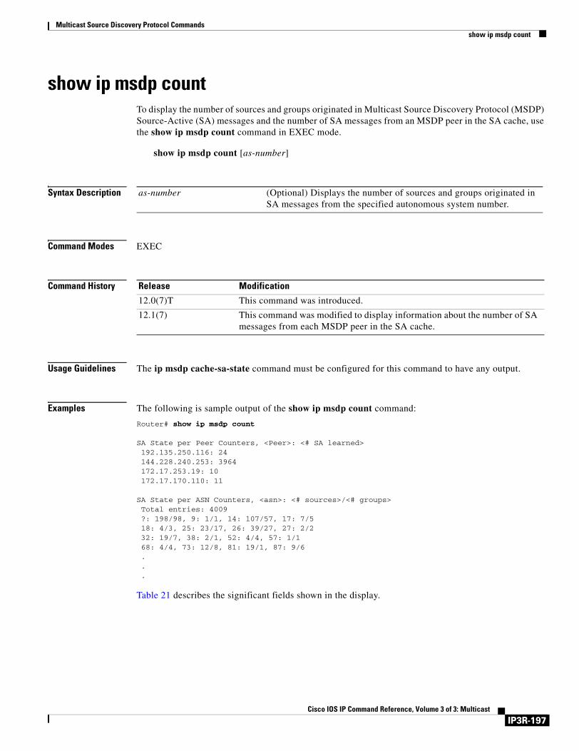
Multicast Source Discovery Protocol Commandsshow ip msdp count
show ip msdp countTo display the number of sources and groups originated in Multicast Source Discovery Protocol (MSDP) Source-Active (SA) messages and the number of SA messages from an MSDP peer in the SA cache, use the show ip msdp count command in EXEC mode.
show ip msdp count [as-number]
Syntax Description
Command Modes EXEC
Command History
Usage Guidelines The ip msdp cache-sa-state command must be configured for this command to have any output.
Examples The following is sample output of the show ip msdp count command:
Router# show ip msdp count
SA State per Peer Counters, <Peer>: <# SA learned>192.135.250.116: 24144.228.240.253: 3964172.17.253.19: 10172.17.170.110: 11
SA State per ASN Counters, <asn>: <# sources>/<# groups>Total entries: 4009?: 198/98, 9: 1/1, 14: 107/57, 17: 7/518: 4/3, 25: 23/17, 26: 39/27, 27: 2/232: 19/7, 38: 2/1, 52: 4/4, 57: 1/168: 4/4, 73: 12/8, 81: 19/1, 87: 9/6...
Table 21 describes the significant fields shown in the display.
as-number (Optional) Displays the number of sources and groups originated in SA messages from the specified autonomous system number.
Release Modification
12.0(7)T This command was introduced.
12.1(7) This command was modified to display information about the number of SA messages from each MSDP peer in the SA cache.
IP3R-197Cisco IOS IP Command Reference, Volume 3 of 3: Multicast

Multicast Source Discovery Protocol Commandsshow ip msdp count
Related Commands
Table 21 show ip msdp count Field Descriptions
Field Description
192.135.250.116: 24 MSDP peer with IP address 192.135.250.116: 24 SA messages from the MSDP peer in the SA cache.
Total entries Total number of SA entries in the SA cache.
9: 1/1 Autonomous system 9: 1 source/1 group
Command Description
ip msdp cache-sa-state Enables the router to create SA state.
IP3R-198Cisco IOS IP Command Reference, Volume 3 of 3: Multicast
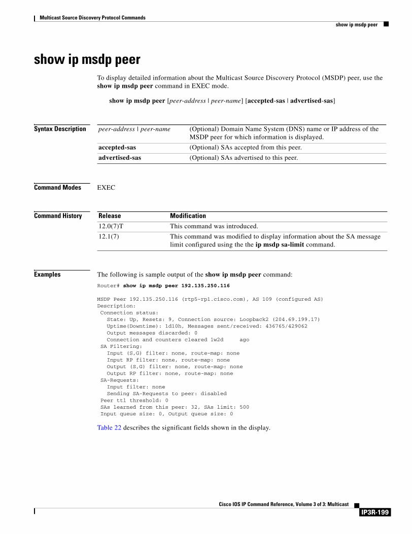
Multicast Source Discovery Protocol Commandsshow ip msdp peer
show ip msdp peerTo display detailed information about the Multicast Source Discovery Protocol (MSDP) peer, use the show ip msdp peer command in EXEC mode.
show ip msdp peer [peer-address | peer-name] [accepted-sas | advertised-sas]
Syntax Description
Command Modes EXEC
Command History
Examples The following is sample output of the show ip msdp peer command:
Router# show ip msdp peer 192.135.250.116
MSDP Peer 192.135.250.116 (rtp5-rp1.cisco.com), AS 109 (configured AS)Description:Connection status:
State: Up, Resets: 9, Connection source: Loopback2 (204.69.199.17)Uptime(Downtime): 1d10h, Messages sent/received: 436765/429062Output messages discarded: 0Connection and counters cleared 1w2d ago
SA Filtering:Input (S,G) filter: none, route-map: noneInput RP filter: none, route-map: noneOutput (S,G) filter: none, route-map: noneOutput RP filter: none, route-map: none
SA-Requests:Input filter: noneSending SA-Requests to peer: disabled
Peer ttl threshold: 0SAs learned from this peer: 32, SAs limit: 500Input queue size: 0, Output queue size: 0
Table 22 describes the significant fields shown in the display.
peer-address | peer-name (Optional) Domain Name System (DNS) name or IP address of the MSDP peer for which information is displayed.
accepted-sas (Optional) SAs accepted from this peer.
advertised-sas (Optional) SAs advertised to this peer.
Release Modification
12.0(7)T This command was introduced.
12.1(7) This command was modified to display information about the SA message limit configured using the the ip msdp sa-limit command.
IP3R-199Cisco IOS IP Command Reference, Volume 3 of 3: Multicast
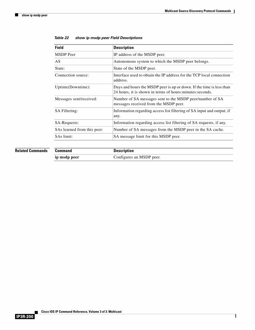
Multicast Source Discovery Protocol Commandsshow ip msdp peer
Related Commands
Table 22 show ip msdp peer Field Descriptions
Field Description
MSDP Peer IP address of the MSDP peer.
AS Autonomous system to which the MSDP peer belongs.
State: State of the MSDP peer.
Connection source: Interface used to obtain the IP address for the TCP local connection address.
Uptime(Downtime): Days and hours the MSDP peer is up or down. If the time is less than 24 hours, it is shown in terms of hours:minutes:seconds.
Messages sent/received: Number of SA messages sent to the MSDP peer/number of SA messages received from the MSDP peer.
SA Filtering: Information regarding access list filtering of SA input and output, if any.
SA-Requests: Information regarding access list filtering of SA requests, if any.
SAs learned from this peer: Number of SA messages from the MSDP peer in the SA cache.
SAs limit: SA message limit for this MSDP peer.
Command Description
ip msdp peer Configures an MSDP peer.
IP3R-200Cisco IOS IP Command Reference, Volume 3 of 3: Multicast
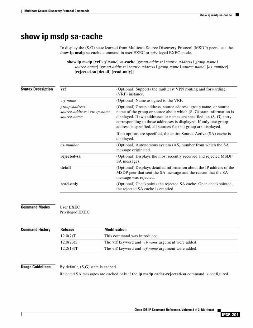
Multicast Source Discovery Protocol Commandsshow ip msdp sa-cache
show ip msdp sa-cacheTo display the (S,G) state learned from Multicast Source Discovery Protocol (MSDP) peers, use the show ip msdp sa-cache command in user EXEC or privileged EXEC mode.
show ip msdp [vrf vrf-name] sa-cache [group-address | source-address | group-name | source-name] [group-address | source-address | group-name | source-name] [as-number] [rejected-sa [detail] [read-only]]
Syntax Description
Command Modes User EXECPrivileged EXEC
Command History
Usage Guidelines By default, (S,G) state is cached.
Rejected SA messages are cached only if the ip msdp cache-rejected-sa command is configured.
vrf (Optional) Supports the multicast VPN routing and forwarding (VRF) instance.
vrf-name (Optional) Name assigned to the VRF.
group-address | source-address | group-name | source-name
(Optional) Group address, source address, group name, or source name of the group or source about which (S, G) state information is displayed. If two addresses or names are specified, an (S, G) entry corresponding to those addresses is displayed. If only one group address is specified, all sources for that group are displayed.
If no options are specified, the entire Source-Active (SA) cache is displayed.
as-number (Optional) Autonomous system (AS) number from which the SA message originated.
rejected-sa (Optional) Displays the most recently received and rejected MSDP SA messages.
detail (Optional) Displays detailed information about the IP address of the MSDP peer that sent the SA message and the reason that the SA message was rejected.
read-only (Optional) Checkpoints the rejected SA cache. Once checkpointed, the rejected SA cache is emptied.
Release Modification
12.0(7)T This command was introduced.
12.0(23)S The vrf keyword and vrf-name argument were added.
12.2(13)T The vrf keyword and vrf-name argument were added.
IP3R-201Cisco IOS IP Command Reference, Volume 3 of 3: Multicast
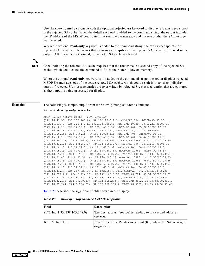
Multicast Source Discovery Protocol Commandsshow ip msdp sa-cache
Use the show ip msdp sa-cache with the optional rejected-sa keyword to display SA messages stored in the rejected SA cache. When the detail keyword is added to the command string, the output includes the IP address of the MSDP peer router that sent the SA message and the reason that the SA message was rejected.
When the optional read-only keyword is added to the command string, the router checkpoints the rejected SA cache, which ensures that a consistent snapshot of the rejected SA cache is displayed in the output. After being checkpointed, the rejected SA cache is cleared.
Note Checkpointing the rejected SA cache requires that the router make a second copy of the rejected SA cache, which could cause the command to fail if the router is low on memory.
When the optional read-only keyword is not added to the command string, the router displays rejected MSDP SA messages out of the active rejected SA cache, which could result in inconsistent display output if rejected SA message entries are overwritten by rejected SA message entries that are captured as the output is being processed for display.
Examples The following is sample output from the show ip msdp sa-cache command:
Router# show ip msdp sa-cache
MSDP Source-Active Cache - 2398 entries(172.16.41.33, 238.105.148.0), RP 172.16.3.111, MBGP/AS 704, 2d10h/00:05:33(172.16.112.8, 224.2.0.1), RP 192.168.200.65, MBGP/AS 10888, 00:03:21/00:02:38(172.16.10.13, 227.37.32.1), RP 192.168.3.92, MBGP/AS 704, 05:22:20/00:03:32(172.16.66.18, 233.0.0.1), RP 192.168.3.111, MBGP/AS 704, 2d10h/00:05:35(172.16.66.148, 233.0.0.1), RP 192.168.3.111, MBGP/AS 704, 2d10h/00:05:35(172.16.10.13, 227.37.32.2), RP 192.168.3.92, MBGP/AS 704, 00:44:30/00:01:31(172.16.70.203, 224.2.236.2), RP 192.168.253.7, MBGP/AS 3582, 02:34:16/00:05:49(172.18.42.104, 236.195.56.2), RP 192.168.3.92, MBGP/AS 704, 04:21:13/00:05:22(172.16.10.13, 227.37.32.3), RP 192.168.3.92, MBGP/AS 704, 00:44:30/00:02:31(172.18.15.43, 224.0.92.3), RP 192.168.200.65, MBGP/AS 10888, 6d09h/00:05:35(172.18.15.111, 224.0.92.3), RP 192.168.200.65, MBGP/AS 10888, 16:18:08/00:05:35(172.18.21.45, 224.0.92.3), RP 192.168.200.65, MBGP/AS 10888, 16:18:08/00:05:35(172.18.15.75, 224.0.92.3), RP 192.168.200.65, MBGP/AS 10888, 08:40:52/00:05:35(172.18.15.100, 224.0.92.3), RP 192.168.200.65, MBGP/AS 10888, 08:40:52/00:05:35(172.16.10.13, 227.37.32.6), RP 192.168.3.92, MBGP/AS 704, 00:45:30/00:05:31(172.18.41.33, 224.247.228.10), RP 192.168.3.111, MBGP/AS 704, 2d10h/00:05:35(172.18.222.210, 224.2.224.13), RP 192.168.3.92, MBGP/AS 704, 01:51:53/00:05:22(172.18.41.33, 229.231.124.13), RP 192.168.3.111, MBGP/AS 704, 2d10h/00:05:33(172.18.32.138, 224.2.200.23), RP 192.168.253.7, MBGP/AS 3582, 21:33:40/00:05:49(172.18.75.244, 224.2.200.23), RP 192.168.253.7, MBGP/AS 3582, 21:33:40/00:05:49
Table 23 describes the significant fields shown in the display.
Table 23 show ip msdp sa-cache Field Descriptions
Field Description
(172.16.41.33, 238.105.148.0) The first address (source) is sending to the second address (group).
RP 172.16.3.111 IP address of the Rendezvous point (RP) where the SA message originated.
IP3R-202Cisco IOS IP Command Reference, Volume 3 of 3: Multicast

Multicast Source Discovery Protocol Commandsshow ip msdp sa-cache
The following is sample output from the show ip msdp sa-cache command with the rejected, detail, and read-only keywords specified:
Router# show ip msdp sa-cache rejected detail read-only
MSDP Rejected SA Cache 35 rejected SAs received over 02:50:01, cache size: 50 entries Timestamp (source, group) 2832.248, (10.10.10.4, 227.7.7.12), RP: 10.10.10.4, Peer: 10.10.10.4, Reason: sa-limit-exceeded 2915.232, (10.10.10.8, 224.1.1.1), RP: 10.11.11.11, Peer: 10.10.10.8, Reason: in-filter 3509.584, (10.12.12.2, 225.5.5.5), RP: 10.15.15.1, Peer: 10.12.12.2, Reason: rpf-fail . . .
Table 24 describes the significant fields shown in the display.
MBGP/AS 704 The RP from which the SA message originated is in AS 704 according to multiprotocol Border Gateway Protocol (BGP).
2d10h/00:05:33 The route has been cached for 2 days and 10 hours. If no SA message is received in 5 minutes and 33 seconds, the route will be removed from the SA cache.
Table 23 show ip msdp sa-cache Field Descriptions (continued)
Field Description
Table 24 show ip msdp sa-cache rejected detail read-only Field Descriptions
Field Description
35 rejected SAs received over 02:50:01
The number of rejected SA message entries received in the length of time indicated in HH:MM:SS.
cache size: Indicates the size of the rejected SA cache. This field is controlled by the ip msdp rejected-sa-cache command. If the rejected SA cache overflows, entries are overwritten, starting from the first entry.
Timestamp Indicates the router uptime in seconds.milliseconds.
(source, group) The (S, G) information advertised in the rejected SA message.
RP: Indicates the IP address of the Rendezvous Point (RP) that originated the SA message.
IP3R-203Cisco IOS IP Command Reference, Volume 3 of 3: Multicast
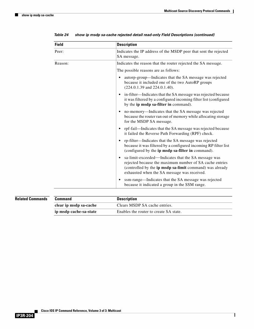
Multicast Source Discovery Protocol Commandsshow ip msdp sa-cache
Related Commands
Peer: Indicates the IP address of the MSDP peer that sent the rejected SA message.
Reason: Indicates the reason that the router rejected the SA message.
The possible reasons are as follows:
• autorp-group—Indicates that the SA message was rejected because it included one of the two AutoRP groups (224.0.1.39 and 224.0.1.40).
• in-filter—Indicates that the SA message was rejected because it was filtered by a configured incoming filter list (configured by the ip msdp sa-filter in command).
• no-memory—Indicates that the SA message was rejected because the router ran out of memory while allocating storage for the MSDP SA message.
• rpf-fail—Indicates that the SA message was rejected because it failed the Reverse Path Forwarding (RPF) check.
• rp-filter—Indicates that the SA message was rejected because it was filtered by a configured incoming RP filter list (configured by the ip msdp sa-filter in command).
• sa-limit-exceeded—Indicates that the SA message was rejected because the maximum number of SA cache entries (controlled by the ip msdp sa-limit command) was already exhausted when the SA message was received.
• ssm-range—Indicates that the SA message was rejected because it indicated a group in the SSM range.
Table 24 show ip msdp sa-cache rejected detail read-only Field Descriptions (continued)
Field Description
Command Description
clear ip msdp sa-cache Clears MSDP SA cache entries.
ip msdp cache-sa-state Enables the router to create SA state.
IP3R-204Cisco IOS IP Command Reference, Volume 3 of 3: Multicast
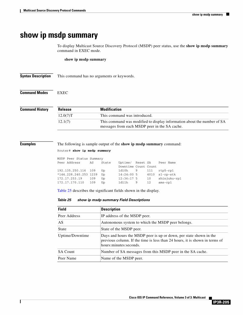
Multicast Source Discovery Protocol Commandsshow ip msdp summary
show ip msdp summaryTo display Multicast Source Discovery Protocol (MSDP) peer status, use the show ip msdp summary command in EXEC mode.
show ip msdp summary
Syntax Description This command has no arguments or keywords.
Command Modes EXEC
Command History
Examples The following is sample output of the show ip msdp summary command:
Router# show ip msdp summary
MSDP Peer Status SummaryPeer Address AS State Uptime/ Reset SA Peer Name
Downtime Count Count192.135.250.116 109 Up 1d10h 9 111 rtp5-rp1*144.228.240.253 1239 Up 14:24:00 5 4010 sl-rp-stk172.17.253.19 109 Up 12:36:17 5 10 shinjuku-rp1172.17.170.110 109 Up 1d11h 9 12 ams-rp1
Table 25 describes the significant fields shown in the display.
Release Modification
12.0(7)T This command was introduced.
12.1(7) This command was modified to display information about the number of SA messages from each MSDP peer in the SA cache.
Table 25 show ip msdp summary Field Descriptions
Field Description
Peer Address IP address of the MSDP peer.
AS Autonomous system to which the MSDP peer belongs.
State State of the MSDP peer.
Uptime/Downtime Days and hours the MSDP peer is up or down, per state shown in the previous column. If the time is less than 24 hours, it is shown in terms of hours:minutes:seconds.
SA Count Number of SA messages from this MSDP peer in the SA cache.
Peer Name Name of the MSDP peer.
IP3R-205Cisco IOS IP Command Reference, Volume 3 of 3: Multicast

Multicast Source Discovery Protocol Commandsshow ip msdp summary
IP3R-206Cisco IOS IP Command Reference, Volume 3 of 3: Multicast
PGM Host and Router Assist Commands
Use the commands in this chapter to configure and monitor the Pragmatic General Multicast (PGM) Host and Router Assist features. For configuration information and examples of PGM Host and Router Assist, refer to the “Configuring PGM Host and Router Assist” chapter in the Cisco IOS IP Configuration Guide.
IP3R-207Cisco IOS IP Command Reference, Volume 3 of 3: Multicast
PGM Host and Router Assist Commandsclear ip pgm host
clear ip pgm host
Note Support for the PGM Host feature has been removed. Use of this command is not recommended.
To reset Pragmatic General Multicast (PGM) Host connections to their default values and to clear traffic statistics, use the clear ip pgm host command in privileged EXEC mode.
clear ip pgm host {defaults | traffic}
Syntax Description
Defaults No default behavior or values.
Command Modes Privileged EXEC
Command History
Usage Guidelines This command should be used only in rare cases or during debugging. A reason to reset all PGM Host connections to their default values is to eliminate configuration errors in one step. A reason to clear traffic statistics is to make diagnostic testing easier.
Examples The following example resets all PGM Host connections to their default values:
Router# clear ip pgm host defaults
The following example clears all PGM Host traffic statistics:
Router# clear ip pgm host traffic
Related Commands
defaults Resets all PGM Host connections to their default values.
traffic Clears all PGM Host traffic statistics.
Release Modification
12.1(1)T This command was introduced.
Command Description
ip pgm host Enables PGM Host.
show ip pgm host defaults Displays default values for PGM Host traffic.
show ip pgm host traffic Displays PGM Host traffic statistics.
IP3R-208Cisco IOS IP Command Reference, Volume 3 of 3: Multicast
PGM Host and Router Assist Commandsclear ip pgm router
clear ip pgm routerTo clear Pragmatic General Multicast (PGM) traffic statistics, use the clear ip pgm router command in EXEC mode.
clear ip pgm router [[traffic [type number]] | [rtx-state [group-address]]]
Syntax Description
Command Modes EXEC
Command History
Usage Guidelines This command should be used only in rare cases or during debugging. Normally, the resend state memory is freed automatically when the information is no longer useful. Also, using this command briefly affects the normal PGM behavior.
A reason to clear traffic statistics is to make diagnostic testing easier.
A reason to clear state might be to free the memory consumed by such state. PGM resend state times out if no traffic keeps it alive.
Examples The following example clears all PGM resend state from the router:
Router# clear ip pgm router rtx-state
Related Commands
traffic [type number] (Optional) Interface type and number whose PGM traffic statistics are cleared. If no interface type and number are provided, all traffic statistics are cleared.
rtx-state [group-address] (Optional) IP address of the multicast group whose PGM resend state is cleared. If no group address is provided, all resend state is cleared. Clearing resend state means the router will not forward any retransmissions corresponding to that state.
Release Modification
12.0(5)T This command was introduced.
Command Description
ip pgm router Enables PGM Router Assist and thereby allows PGM to operate more efficiently on the router.
show ip pgm router Displays PGM Reliable Transport Protocol state and statistics.
IP3R-209Cisco IOS IP Command Reference, Volume 3 of 3: Multicast
PGM Host and Router Assist Commandsip pgm host
ip pgm host
Note Support for the PGM Host feature has been removed. Use of this command is not recommended.
To enable Pragmatic General Multicast (PGM) Host, use the ip pgm host command in global configuration mode. To disable PGM Host and close all open PGM Host traffic sessions, use the no form of this command.
ip pgm host [source-interface {type number} | connection-parameter]
no ip pgm host
Syntax Description
Defaults PGM Host is not enabled.
Command Modes Global configuration
Command History
Usage Guidelines Using the ip pgm host command without a keyword or an argument enables PGM Host on the router and configures the router to source PGM packets through a virtual host interface (vif).
Specifying a physical or logical interface type (for example, an Ethernet, serial, or loopback interface) with the ip pgm host source-interface command configures the router to source PGM packets out of the physical or logical interface.
Note You must first enable PGM Host globally on the router using the ip pgm host command before sourcing PGM packets out of a physical or logical interface using the ip pgm host source-interface command.
Sourcing PGM packets through a vif enables the router to send and receive PGM packets through any router interface. The vif also serves as the interface to the multicast applications that reside at the PGM network layer.
Sourcing IP multicast traffic out a specific physical or logical interface configures the router to send PGM packets out that interface only and to receive packets on any router interface.
source-interface type number (Optional) Interface type and number on which to run PGM Host.
connection-parameter (Optional) Configures advanced PGM Host connection parameters. The optional configuration parameters should only be configured by experts in PGM technology. See Table 26 for a comprehensive list of the optional connection parameters and their definitions.
Release Modification
12.1(1)T This command was introduced.
IP3R-210Cisco IOS IP Command Reference, Volume 3 of 3: Multicast
PGM Host and Router Assist Commandsip pgm host
When both PGM Host and Router Assist are enabled on the router, the router can process received PGM packets as a virtual PGM Host, originate PGM packets and serve as its own first hop PGM network element, and forward received PGM packets. Refer to the “Configuring PGM Host and Router Assist” chapter of the Cisco IOS IP Configuration Guide for more information about PGM Router Assist.
Table 26 lists the available parameters for the connection-parameter argument. The parameters should be configured only by experts in PGM technology. Use the no ip pgm host connection-parameter command to return a parameter to its default value.
Table 26 ip pgm host Connection Parameters
Parameter Definition
ihb-max milliseconds (Optional) Sets the source path message (SPM) interheartbeat timer maximum. The default is 10000 milliseconds (ms).
ihb-min milliseconds (Optional) Sets the SPM interheartbeat timer minimum. The default is 1000 ms.
join milliseconds (Optional) Sets the amount of time the PGM Host waits, when running in router mode, for client requests. The default is 0 ms.
nak-gen-ivl milliseconds (Optional) Sets the amount of time the PGM Host waits for a PGM negative acknowledgment (NAK) data packet. The default is 60000 ms.
nak-rb-ivl milliseconds (Optional) Sets the amount of time the PGM Host waits before sending a PGM NAK data packet. The default is 500 ms.
nak-rdata-ivl milliseconds (Optional) Sets the amount of time the PGM Host waits for a re-sent PGM NAK (NAK RDATA) data packet. The default is 2000 ms.
nak-rpt-ivl milliseconds (Optional) Sets the amount of time the PGM Host waits for a PGM NAK confirmation (NAK NCF) data packet. The default is 2000 ms.
ncf-max packets-per-second (Optional) Sets the maximum number of PGM NAK confirmation data packets (NAK NCFs) the PGM Host sends per second. The default is infinite.
rx-buffer-mgmt {full | minimum} (Optional) Sets the type of receive data buffers (full or minimum) for the PGM Host. The default is minimum.
spm-ambient-ivl milliseconds (Optional) Sets the amount of time the PGM Host waits for a PGM SPM ambient data packet. The default is 6000 ms.
spm-rpt-ivl milliseconds (Optional) Sets the amount of time the PGM Host waits for a PGM SPM repeat data packet. The default is 3000 ms.
stream-type {apdu | byte} (Optional) Sets the data stream type (apdu or byte) for the PGM Host. The default is apdu.
tpdu-size number (Optional) Sets the size of the source transport data unit (TPDU) for the PGM Host. The available range is 41 through 16384 bytes. The default is 1400 bytes.
IP3R-211Cisco IOS IP Command Reference, Volume 3 of 3: Multicast
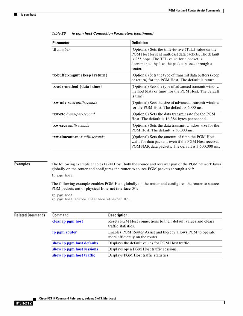
PGM Host and Router Assist Commandsip pgm host
Examples The following example enables PGM Host (both the source and receiver part of the PGM network layer) globally on the router and configures the router to source PGM packets through a vif:
ip pgm host
The following example enables PGM Host globally on the router and configures the router to source PGM packets out of physical Ethernet interface 0/1:
ip pgm hostip pgm host source-interface ethernet 0/1
Related Commands
ttl number (Optional) Sets the time-to-live (TTL) value on the PGM Host for sent multicast data packets. The default is 255 hops. The TTL value for a packet is decremented by 1 as the packet passes through a router.
tx-buffer-mgmt {keep | return} (Optional) Sets the type of transmit data buffers (keep or return) for the PGM Host. The default is return.
tx-adv-method {data | time} (Optional) Sets the type of advanced transmit window method (data or time) for the PGM Host. The default is time.
txw-adv-secs milliseconds (Optional) Sets the size of advanced transmit window for the PGM Host. The default is 6000 ms.
txw-rte bytes-per-second (Optional) Sets the data transmit rate for the PGM Host. The default is 16,384 bytes per second.
txw-secs milliseconds (Optional) Sets the data transmit window size for the PGM Host. The default is 30,000 ms.
txw-timeout-max milliseconds (Optional) Sets the amount of time the PGM Host waits for data packets, even if the PGM Host receives PGM NAK data packets. The default is 3,600,000 ms.
Table 26 ip pgm host Connection Parameters (continued)
Parameter Definition
Command Description
clear ip pgm host Resets PGM Host connections to their default values and clears traffic statistics.
ip pgm router Enables PGM Router Assist and thereby allows PGM to operate more efficiently on the router.
show ip pgm host defaults Displays the default values for PGM Host traffic.
show ip pgm host sessions Displays open PGM Host traffic sessions.
show ip pgm host traffic Displays PGM Host traffic statistics.
IP3R-212Cisco IOS IP Command Reference, Volume 3 of 3: Multicast
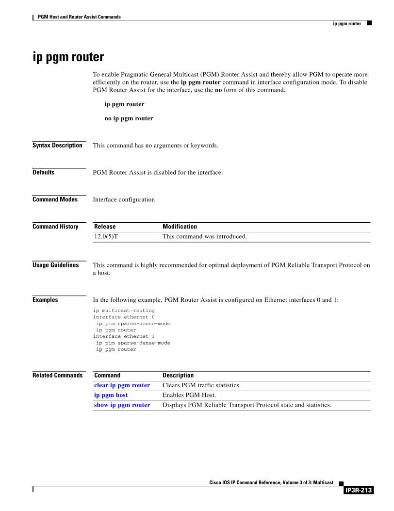
PGM Host and Router Assist Commandsip pgm router
ip pgm routerTo enable Pragmatic General Multicast (PGM) Router Assist and thereby allow PGM to operate more efficiently on the router, use the ip pgm router command in interface configuration mode. To disable PGM Router Assist for the interface, use the no form of this command.
ip pgm router
no ip pgm router
Syntax Description This command has no arguments or keywords.
Defaults PGM Router Assist is disabled for the interface.
Command Modes Interface configuration
Command History
Usage Guidelines This command is highly recommended for optimal deployment of PGM Reliable Transport Protocol on a host.
Examples In the following example, PGM Router Assist is configured on Ethernet interfaces 0 and 1:
ip multicast-routinginterface ethernet 0ip pim sparse-dense-modeip pgm router
interface ethernet 1ip pim sparse-dense-modeip pgm router
Related Commands
Release Modification
12.0(5)T This command was introduced.
Command Description
clear ip pgm router Clears PGM traffic statistics.
ip pgm host Enables PGM Host.
show ip pgm router Displays PGM Reliable Transport Protocol state and statistics.
IP3R-213Cisco IOS IP Command Reference, Volume 3 of 3: Multicast
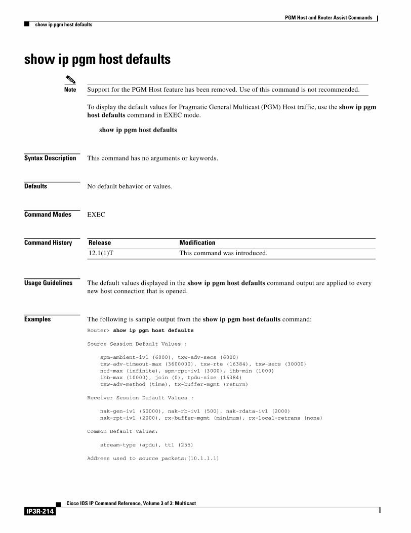
PGM Host and Router Assist Commandsshow ip pgm host defaults
show ip pgm host defaults
Note Support for the PGM Host feature has been removed. Use of this command is not recommended.
To display the default values for Pragmatic General Multicast (PGM) Host traffic, use the show ip pgm host defaults command in EXEC mode.
show ip pgm host defaults
Syntax Description This command has no arguments or keywords.
Defaults No default behavior or values.
Command Modes EXEC
Command History
Usage Guidelines The default values displayed in the show ip pgm host defaults command output are applied to every new host connection that is opened.
Examples The following is sample output from the show ip pgm host defaults command:
Router> show ip pgm host defaults
Source Session Default Values : spm-ambient-ivl (6000), txw-adv-secs (6000) txw-adv-timeout-max (3600000), txw-rte (16384), txw-secs (30000) ncf-max (infinite), spm-rpt-ivl (3000), ihb-min (1000) ihb-max (10000), join (0), tpdu-size (16384) txw-adv-method (time), tx-buffer-mgmt (return) Receiver Session Default Values : nak-gen-ivl (60000), nak-rb-ivl (500), nak-rdata-ivl (2000) nak-rpt-ivl (2000), rx-buffer-mgmt (minimum), rx-local-retrans (none) Common Default Values: stream-type (apdu), ttl (255)
Address used to source packets:(10.1.1.1)
Release Modification
12.1(1)T This command was introduced.
IP3R-214Cisco IOS IP Command Reference, Volume 3 of 3: Multicast
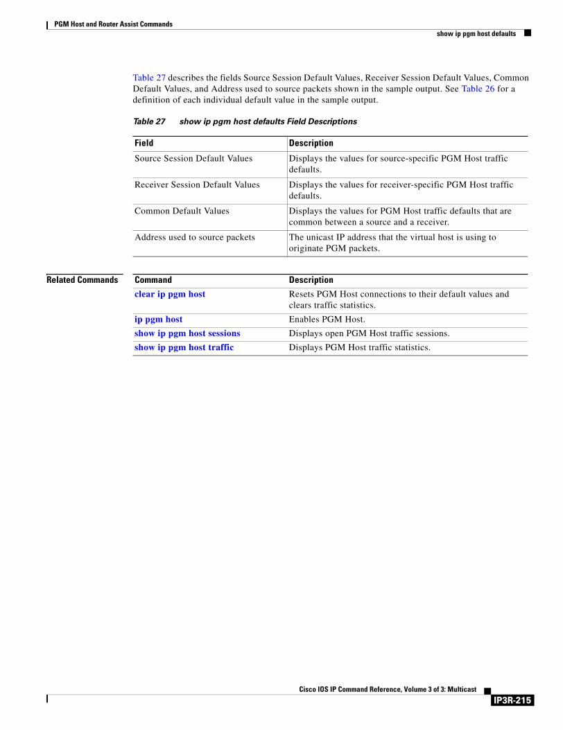
PGM Host and Router Assist Commandsshow ip pgm host defaults
Table 27 describes the fields Source Session Default Values, Receiver Session Default Values, Common Default Values, and Address used to source packets shown in the sample output. See Table 26 for a definition of each individual default value in the sample output.
Related Commands
Table 27 show ip pgm host defaults Field Descriptions
Field Description
Source Session Default Values Displays the values for source-specific PGM Host traffic defaults.
Receiver Session Default Values Displays the values for receiver-specific PGM Host traffic defaults.
Common Default Values Displays the values for PGM Host traffic defaults that are common between a source and a receiver.
Address used to source packets The unicast IP address that the virtual host is using to originate PGM packets.
Command Description
clear ip pgm host Resets PGM Host connections to their default values and clears traffic statistics.
ip pgm host Enables PGM Host.
show ip pgm host sessions Displays open PGM Host traffic sessions.
show ip pgm host traffic Displays PGM Host traffic statistics.
IP3R-215Cisco IOS IP Command Reference, Volume 3 of 3: Multicast
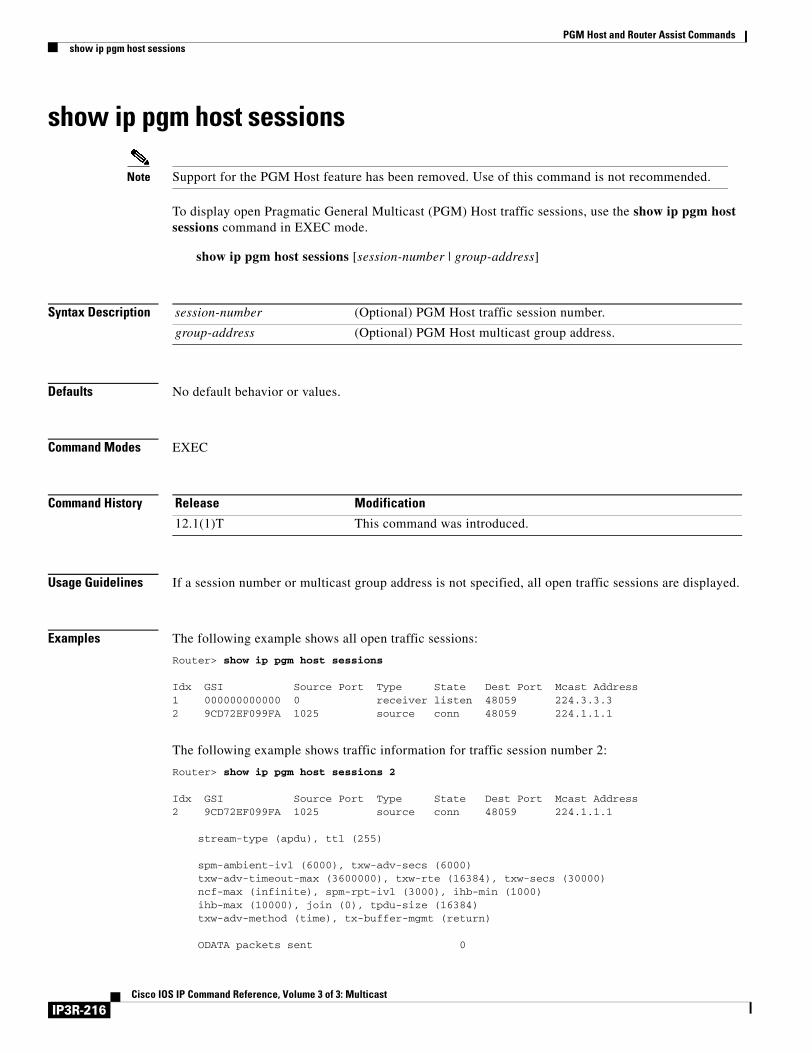
PGM Host and Router Assist Commandsshow ip pgm host sessions
show ip pgm host sessions
Note Support for the PGM Host feature has been removed. Use of this command is not recommended.
To display open Pragmatic General Multicast (PGM) Host traffic sessions, use the show ip pgm host sessions command in EXEC mode.
show ip pgm host sessions [session-number | group-address]
Syntax Description
Defaults No default behavior or values.
Command Modes EXEC
Command History
Usage Guidelines If a session number or multicast group address is not specified, all open traffic sessions are displayed.
Examples The following example shows all open traffic sessions:
Router> show ip pgm host sessions
Idx GSI Source Port Type State Dest Port Mcast Address1 000000000000 0 receiver listen 48059 224.3.3.32 9CD72EF099FA 1025 source conn 48059 224.1.1.1
The following example shows traffic information for traffic session number 2:
Router> show ip pgm host sessions 2
Idx GSI Source Port Type State Dest Port Mcast Address2 9CD72EF099FA 1025 source conn 48059 224.1.1.1 stream-type (apdu), ttl (255) spm-ambient-ivl (6000), txw-adv-secs (6000) txw-adv-timeout-max (3600000), txw-rte (16384), txw-secs (30000) ncf-max (infinite), spm-rpt-ivl (3000), ihb-min (1000) ihb-max (10000), join (0), tpdu-size (16384) txw-adv-method (time), tx-buffer-mgmt (return) ODATA packets sent 0
session-number (Optional) PGM Host traffic session number.
group-address (Optional) PGM Host multicast group address.
Release Modification
12.1(1)T This command was introduced.
IP3R-216Cisco IOS IP Command Reference, Volume 3 of 3: Multicast
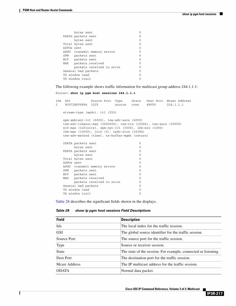
PGM Host and Router Assist Commandsshow ip pgm host sessions
bytes sent 0 RDATA packets sent 0 bytes sent 0 Total bytes sent 0 ADPUs sent 0 APDU transmit memory errors 0 SPM packets sent 6 NCF packets sent 0 NAK packets received 0 packets received in error 0 General bad packets 0 TX window lead 0 TX window trail 0
The following example shows traffic information for multicast group address 244.1.1.1:
Router> show ip pgm host sessions 244.1.1.1
Idx GSI Source Port Type State Dest Port Mcast Address2 9CD72EF099FA 1025 source conn 48059 224.1.1.1 stream-type (apdu), ttl (255) spm-ambient-ivl (6000), txw-adv-secs (6000) txw-adv-timeout-max (3600000), txw-rte (16384), txw-secs (30000) ncf-max (infinite), spm-rpt-ivl (3000), ihb-min (1000) ihb-max (10000), join (0), tpdu-size (16384) txw-adv-method (time), tx-buffer-mgmt (return) ODATA packets sent 0 bytes sent 0 RDATA packets sent 0 bytes sent 0 Total bytes sent 0 ADPUs sent 0 APDU transmit memory errors 0 SPM packets sent 6 NCF packets sent 0 NAK packets received 0 packets received in error 0 General bad packets 0 TX window lead 0 TX window trail 0
Table 28 describes the significant fields shown in the displays.
Table 28 show ip pgm host sessions Field Descriptions
Field Description
Idx The local index for the traffic session.
GSI The global source identifier for the traffic session.
Source Port The source port for the traffic session.
Type Source or receiver session.
State The state of the session. For example, connected or listening.
Dest Port The destination port for the traffic session.
Mcast Address The IP multicast address for the traffic session.
ODATA Normal data packet.
IP3R-217Cisco IOS IP Command Reference, Volume 3 of 3: Multicast
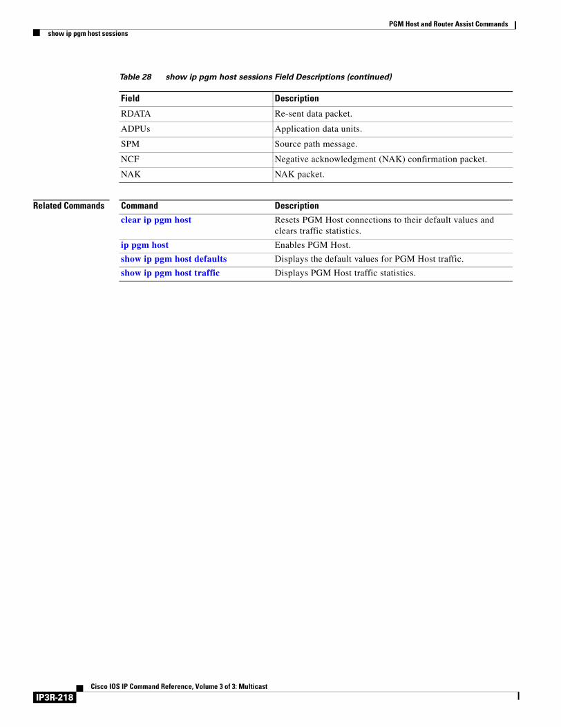
PGM Host and Router Assist Commandsshow ip pgm host sessions
Related Commands
RDATA Re-sent data packet.
ADPUs Application data units.
SPM Source path message.
NCF Negative acknowledgment (NAK) confirmation packet.
NAK NAK packet.
Table 28 show ip pgm host sessions Field Descriptions (continued)
Field Description
Command Description
clear ip pgm host Resets PGM Host connections to their default values and clears traffic statistics.
ip pgm host Enables PGM Host.
show ip pgm host defaults Displays the default values for PGM Host traffic.
show ip pgm host traffic Displays PGM Host traffic statistics.
IP3R-218Cisco IOS IP Command Reference, Volume 3 of 3: Multicast
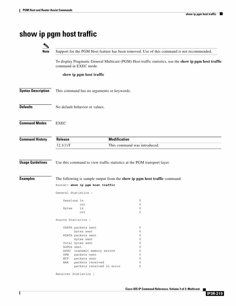
PGM Host and Router Assist Commandsshow ip pgm host traffic
show ip pgm host traffic
Note Support for the PGM Host feature has been removed. Use of this command is not recommended.
To display Pragmatic General Multicast (PGM) Host traffic statistics, use the show ip pgm host traffic command in EXEC mode.
show ip pgm host traffic
Syntax Description This command has no arguments or keywords.
Defaults No default behavior or values.
Command Modes EXEC
Command History
Usage Guidelines Use this command to view traffic statistics at the PGM transport layer.
Examples The following is sample output from the show ip pgm host traffic command:
Router> show ip pgm host traffic
General Statistics : Sessions in 0 out 0 Bytes in 0 out 0 Source Statistics : ODATA packets sent 0 bytes sent 0 RDATA packets sent 0 bytes sent 0 Total bytes sent 0 ADPUs sent 0 APDU transmit memory errors 0 SPM packets sent 0 NCF packets sent 0 NAK packets received 0 packets received in error 0 Receiver Statistics :
Release Modification
12.1(1)T This command was introduced.
IP3R-219Cisco IOS IP Command Reference, Volume 3 of 3: Multicast
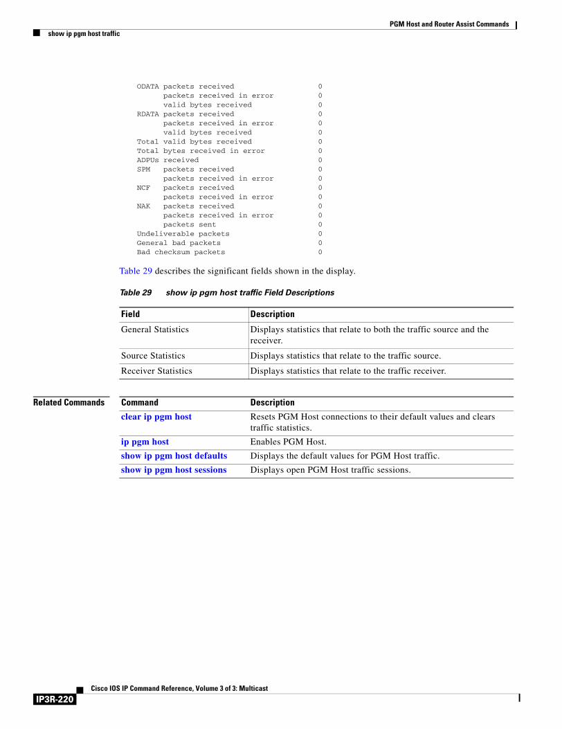
PGM Host and Router Assist Commandsshow ip pgm host traffic
ODATA packets received 0 packets received in error 0 valid bytes received 0 RDATA packets received 0 packets received in error 0 valid bytes received 0 Total valid bytes received 0 Total bytes received in error 0 ADPUs received 0 SPM packets received 0 packets received in error 0 NCF packets received 0 packets received in error 0 NAK packets received 0 packets received in error 0 packets sent 0 Undeliverable packets 0 General bad packets 0 Bad checksum packets 0
Table 29 describes the significant fields shown in the display.
Related Commands
Table 29 show ip pgm host traffic Field Descriptions
Field Description
General Statistics Displays statistics that relate to both the traffic source and the receiver.
Source Statistics Displays statistics that relate to the traffic source.
Receiver Statistics Displays statistics that relate to the traffic receiver.
Command Description
clear ip pgm host Resets PGM Host connections to their default values and clears traffic statistics.
ip pgm host Enables PGM Host.
show ip pgm host defaults Displays the default values for PGM Host traffic.
show ip pgm host sessions Displays open PGM Host traffic sessions.
IP3R-220Cisco IOS IP Command Reference, Volume 3 of 3: Multicast
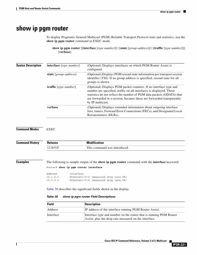
PGM Host and Router Assist Commandsshow ip pgm router
show ip pgm routerTo display Pragmatic General Multicast (PGM) Reliable Transport Protocol state and statistics, use the show ip pgm router command in EXEC mode.
show ip pgm router [[interface [type number]] | [state [group-address]] | [traffic [type number]]] [verbose]
Syntax Description
Command Modes EXEC
Command History
Examples The following is sample output of the show ip pgm router command with the interface keyword:
Router# show ip pgm router interface
Address Interface10.1.0.2 Ethernet1/0/0 (measured drop rate 0%)10.3.0.2 Ethernet1/0/4 (measured drop rate 0%)
Table 30 describes the significant fields shown in the display.
interface [type number] (Optional) Displays interfaces on which PGM Router Assist is configured.
state [group-address] (Optional) Displays PGM resend state information per transport session identifier (TSI). If no group address is specified, resend state for all groups is shown.
traffic [type number] (Optional) Displays PGM packet counters. If no interface type and number are specified, traffic on all interfaces is displayed. These statistics do not reflect the number of PGM data packets (ODATA) that are forwarded in a session, because these are forwarded transparently by IP multicast.
verbose (Optional) Displays extended information about outgoing interface lists, timers, Forward Error Connections (FECs), and Designated Local Retransmitters (DLRs).
Release Modification
12.0(5)T This command was introduced.
Table 30 show ip pgm router Field Descriptions
Field Description
Address IP address of the interface running PGM Router Assist.
Interface Interface type and number on the router that is running PGM Router Assist, plus the drop rate measured on the interface.
IP3R-221Cisco IOS IP Command Reference, Volume 3 of 3: Multicast
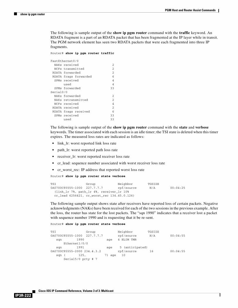
PGM Host and Router Assist Commandsshow ip pgm router
The following is sample output of the show ip pgm router command with the traffic keyword. An RDATA fragment is a part of an RDATA packet that has been fragmented at the IP layer while in transit. The PGM network element has seen two RDATA packets that were each fragmented into three IP fragments.
Router# show ip pgm router traffic
FastEthernet0/0 NAKs received 2 NCFs transmitted 2 RDATA forwarded 2 RDATA frags forwarded 6 SPMs received 4 used 4 SPMs forwarded 33Serial0/0 NAKs forwarded 2 NAKs retransmitted 2 NCFs received 4 RDATA received 2 RDATA frags received 6 SPMs received 33 used 33
The following is sample output of the show ip pgm router command with the state and verbose keywords. The timer associated with each session is an idle timer; the TSI state is deleted when this timer expires. The measured loss rates are indicated as follows:
• link_lr: worst reported link loss rate
• path_lr: worst reported path loss rate
• receiver_lr: worst reported receiver loss rate
• cr_lead: sequence number associated with worst receiver loss rate
• cr_worst_rec: IP address that reported worst loss rate
Router# show ip pgm router state verbose
TSI Group Neighbor TGSIZE0A0700C85555-1000 227.7.7.7 rpf/source N/A 00:04:25
(link_lr 7%, path_lr 4%, receiver_lr 10%cr_lead 6256421, cr_worst_rec 134.45.0.126)
The following sample output shows state after receivers have reported loss of certain packets. Negative acknowledgments (NAKs) have been received for each of the two sessions in the previous example. After the loss, the router has state for the lost packets. The “sqn 1990” indicates that a receiver lost a packet with sequence number 1990 and is requesting that it be re-sent.
Router# show ip pgm router state verbose
TSI Group Neighbor TGSIZE0A0700C85555-1000 227.7.7.7 rpf/source N/A 00:04:55 sqn 1990 age 4 ELIM TMR Ethernet1/0/0 sqn 1991 age 5 (anticipated)0A0700C85555-2000 234.4.3.2 rpf/source 16 00:04:55 sqn ( 125, 7) age 10 Serial5/0 prty # 7
IP3R-222Cisco IOS IP Command Reference, Volume 3 of 3: Multicast
PGM Host and Router Assist Commandsshow ip pgm router
For the selective TSI, the output shows resend state for sequence number 1990. This state was created by a NAK received on Ethernet interface 1/0/0. “ELIM TMR” indicates that the state is currently eliminating duplicates of any NAK that is pending and any new NAKs for this sequence number will not be forwarded.
State shown for sequence 1991 is anticipated state, indicating that it was created by a NAK confirmation (NCF) for a NAK sent by some other PGM router with the same PGM upstream neighbor as this router.
For the TSI with parity, the state shown was created by a parity NAK for seven packets of the Transmission Group 125. This state was received on Serial interface 5/0; “# 7” indicates that seven parity packets must be forwarded out this interface.
Related Commands Command Description
clear ip pgm router Clears PGM traffic statistics.
ip pgm router Enables PGM Router Assist and thereby allows PGM to operate more efficiently on the router.
IP3R-223Cisco IOS IP Command Reference, Volume 3 of 3: Multicast

PGM Host and Router Assist Commandsshow ip pgm router
IP3R-224Cisco IOS IP Command Reference, Volume 3 of 3: Multicast
Unidirectional Link Routing Commands
Use the commands in this chapter to configure and monitor unidirectional link routing (UDLR). For configuration information and examples of UDLR, refer to the “Configuring Unidirectional Link Routing” chapter of the Cisco IOS IP Configuration Guide.
IP3R-225Cisco IOS IP Command Reference, Volume 3 of 3: Multicast
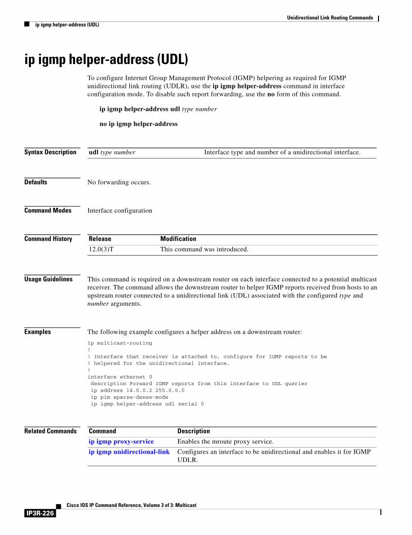
Unidirectional Link Routing Commandsip igmp helper-address (UDL)
ip igmp helper-address (UDL)To configure Internet Group Management Protocol (IGMP) helpering as required for IGMP unidirectional link routing (UDLR), use the ip igmp helper-address command in interface configuration mode. To disable such report forwarding, use the no form of this command.
ip igmp helper-address udl type number
no ip igmp helper-address
Syntax Description
Defaults No forwarding occurs.
Command Modes Interface configuration
Command History
Usage Guidelines This command is required on a downstream router on each interface connected to a potential multicast receiver. The command allows the downstream router to helper IGMP reports received from hosts to an upstream router connected to a unidirectional link (UDL) associated with the configured type and number arguments.
Examples The following example configures a helper address on a downstream router:
ip multicast-routing!! Interface that receiver is attached to, configure for IGMP reports to be ! helpered for the unidirectional interface.!interface ethernet 0description Forward IGMP reports from this interface to UDL querierip address 14.0.0.2 255.0.0.0ip pim sparse-dense-modeip igmp helper-address udl serial 0
Related Commands
udl type number Interface type and number of a unidirectional interface.
Release Modification
12.0(3)T This command was introduced.
Command Description
ip igmp proxy-service Enables the mroute proxy service.
ip igmp unidirectional-link Configures an interface to be unidirectional and enables it for IGMP UDLR.
IP3R-226Cisco IOS IP Command Reference, Volume 3 of 3: Multicast
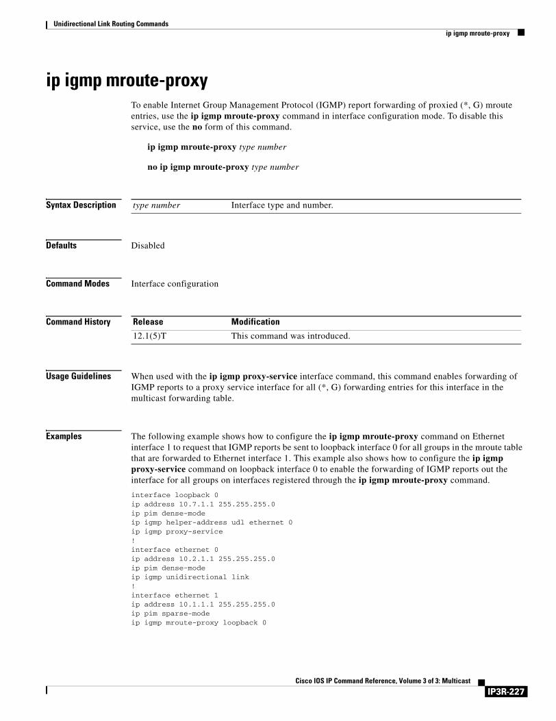
Unidirectional Link Routing Commandsip igmp mroute-proxy
ip igmp mroute-proxyTo enable Internet Group Management Protocol (IGMP) report forwarding of proxied (*, G) mroute entries, use the ip igmp mroute-proxy command in interface configuration mode. To disable this service, use the no form of this command.
ip igmp mroute-proxy type number
no ip igmp mroute-proxy type number
Syntax Description
Defaults Disabled
Command Modes Interface configuration
Command History
Usage Guidelines When used with the ip igmp proxy-service interface command, this command enables forwarding of IGMP reports to a proxy service interface for all (*, G) forwarding entries for this interface in the multicast forwarding table.
Examples The following example shows how to configure the ip igmp mroute-proxy command on Ethernet interface 1 to request that IGMP reports be sent to loopback interface 0 for all groups in the mroute table that are forwarded to Ethernet interface 1. This example also shows how to configure the ip igmp proxy-service command on loopback interface 0 to enable the forwarding of IGMP reports out the interface for all groups on interfaces registered through the ip igmp mroute-proxy command.
interface loopback 0ip address 10.7.1.1 255.255.255.0ip pim dense-modeip igmp helper-address udl ethernet 0ip igmp proxy-service!interface ethernet 0ip address 10.2.1.1 255.255.255.0ip pim dense-modeip igmp unidirectional link!interface ethernet 1ip address 10.1.1.1 255.255.255.0ip pim sparse-modeip igmp mroute-proxy loopback 0
type number Interface type and number.
Release Modification
12.1(5)T This command was introduced.
IP3R-227Cisco IOS IP Command Reference, Volume 3 of 3: Multicast

Unidirectional Link Routing Commandsip igmp mroute-proxy
Related Commands Command Description
ip igmp proxy-service Enables the mroute proxy service.
ip igmp unidirectional-link Configures an interface to be unidirectional and enables it for IGMP UDLR.
IP3R-228Cisco IOS IP Command Reference, Volume 3 of 3: Multicast
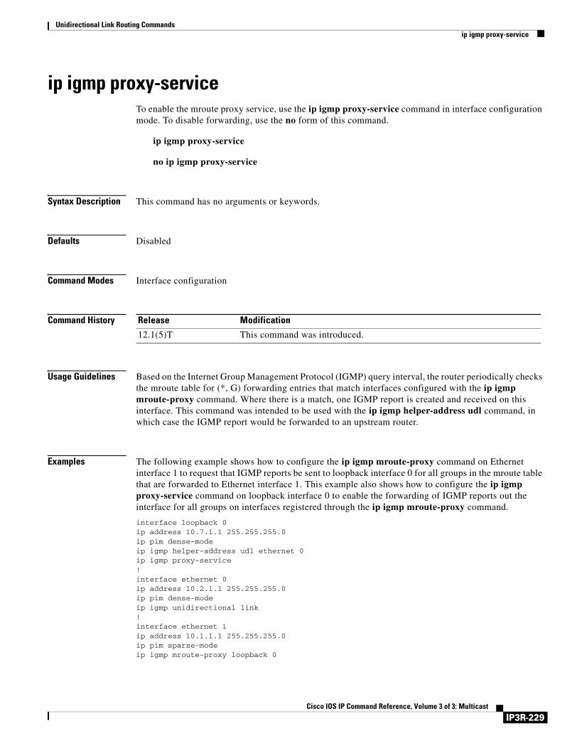
Unidirectional Link Routing Commandsip igmp proxy-service
ip igmp proxy-serviceTo enable the mroute proxy service, use the ip igmp proxy-service command in interface configuration mode. To disable forwarding, use the no form of this command.
ip igmp proxy-service
no ip igmp proxy-service
Syntax Description This command has no arguments or keywords.
Defaults Disabled
Command Modes Interface configuration
Command History
Usage Guidelines Based on the Internet Group Management Protocol (IGMP) query interval, the router periodically checks the mroute table for (*, G) forwarding entries that match interfaces configured with the ip igmp mroute-proxy command. Where there is a match, one IGMP report is created and received on this interface. This command was intended to be used with the ip igmp helper-address udl command, in which case the IGMP report would be forwarded to an upstream router.
Examples The following example shows how to configure the ip igmp mroute-proxy command on Ethernet interface 1 to request that IGMP reports be sent to loopback interface 0 for all groups in the mroute table that are forwarded to Ethernet interface 1. This example also shows how to configure the ip igmp proxy-service command on loopback interface 0 to enable the forwarding of IGMP reports out the interface for all groups on interfaces registered through the ip igmp mroute-proxy command.
interface loopback 0ip address 10.7.1.1 255.255.255.0ip pim dense-modeip igmp helper-address udl ethernet 0ip igmp proxy-service!interface ethernet 0ip address 10.2.1.1 255.255.255.0ip pim dense-modeip igmp unidirectional link!interface ethernet 1ip address 10.1.1.1 255.255.255.0ip pim sparse-modeip igmp mroute-proxy loopback 0
Release Modification
12.1(5)T This command was introduced.
IP3R-229Cisco IOS IP Command Reference, Volume 3 of 3: Multicast

Unidirectional Link Routing Commandsip igmp proxy-service
Related Commands Command Description
ip igmp helper-address (UDL) Configures IGMP helpering as required for IGMP UDLR.
ip igmp mroute-proxy Enables IGMP report forwarding of proxied (*, G) mroute entries.
ip igmp unidirectional-link Configures an interface to be unidirectional and enables it for IGMP UDLR.
IP3R-230Cisco IOS IP Command Reference, Volume 3 of 3: Multicast
Unidirectional Link Routing Commandsip igmp unidirectional-link
ip igmp unidirectional-linkTo configure an interface to be unidirectional and enable it for Internet Group Management Protocol (IGMP) unidirectional link routing (UDLR), use the ip igmp unidirectional-link command in interface configuration mode. To disable the unidirectional link (UDL), use the no form of this command.
ip igmp unidirectional-link
no ip igmp unidirectional-link
Syntax Description This command has no arguments or keywords.
Defaults No UDLR occurs.
Command Modes Interface configuration
Command History
Usage Guidelines One example of when you might configure this command is if you have traffic traveling via a satellite.
If you have a small number of receivers, another way to achieve UDLR is to configure a UDLR tunnel. See the descriptions of the tunnel udlr receive-only and tunnel udlr send-only commands later in this chapter.
Examples The following example configures an upstream router with UDLR on serial interface 0:
ip multicast-routing!! Unidirectional link!interface serial 0description Unidirectional to downlink-rtrip address 10.0.0.1 255.0.0.0ip pim sparse-dense-modeip igmp unidirectional-linkno keepalive
Release Modification
12.0(3)T This command was introduced.
IP3R-231Cisco IOS IP Command Reference, Volume 3 of 3: Multicast
Unidirectional Link Routing Commandsip igmp unidirectional-link
Related Commands Command Description
ip igmp helper-address (UDL) Configures IGMP helpering as required for IGMP UDLR.
ip igmp mroute-proxy Enables IGMP report forwarding of proxied (*, G) mroute entries.
ip igmp proxy-service Enables the mroute proxy service.
ip multicast default-rpf-distance Changes the distance given to the default RPF interface when configuring IGMP UDLR.
show ip igmp udlr Displays UDLR information for directly connected multicast groups on interfaces that have a UDL helper address configured.
tunnel udlr receive-only Configures a unidirectional, GRE tunnel to act as a back channel that can receive messages, when another interface is configured for UDLR to send messages.
tunnel udlr send-only Configures a unidirectional, GRE tunnel to act as a back channel that can send messages, when another interface is configured for UDLR to receive messages.
IP3R-232Cisco IOS IP Command Reference, Volume 3 of 3: Multicast
Unidirectional Link Routing Commandsip multicast default-rpf-distance
ip multicast default-rpf-distanceWhen configuring Internet Group Management Protocol (IGMP) unidirectional link routing (UDLR), to change the distance given to the default Reverse Path Forwarding (RPF) interface, use the ip multicast default-rpf-distance command in global configuration mode. To restore the default value, use the no form of this command.
ip multicast default-rpf-distance distance
no ip multicast default-rpf-distance
Syntax Description
Defaults The distance default value is 15.
Command Modes Global configuration
Command History
Usage Guidelines This command is optional. If you want to receive all multicast traffic from all sources on the unidirectional link (UDL), as long as 15 is the lowest distance, you need not change the value of 15.
The default RPF interface is selected when an IGMP query message is received on a UDL and indicates to the router that all sources will use RPF to reach the UDL interface.
Any explicit sources learned by routing protocols will take preference as long as their distance is less than the distance argument configured with the ip multicast default-rpf-distance command.
You might consider changing the default value for one of the following reasons:
• To make IGMP prefer the UDL.
• To configure a value less than existing routing protocols.
• If you want to receive multicast packets from sources on interfaces other than the UDL interface. Configure a value greater than the distances of the existing routing protocols to make IGMP prefer the nonunidirectional link.
Examples The following example configures a distance of 20:
ip multicast default-rpf-distance 20
distance Distance given to the default RPF interface. The default value is 15.
Release Modification
12.0(3)T This command was introduced.
IP3R-233Cisco IOS IP Command Reference, Volume 3 of 3: Multicast

Unidirectional Link Routing Commandsip multicast default-rpf-distance
Related Commands Command Description
ip igmp unidirectional-link Configures an interface to be unidirectional and enables it for IGMP UDLR.
IP3R-234Cisco IOS IP Command Reference, Volume 3 of 3: Multicast
Unidirectional Link Routing Commandsshow ip igmp udlr
show ip igmp udlrTo display unidirectional link routing (UDLR) information for directly connected multicast groups on interfaces that have a unidirectional link (UDL) helper address configured, use the show ip igmp udlr command in EXEC mode.
show ip igmp udlr [group-name | group-address | type number]
Syntax Description
Command Modes EXEC
Command History
Usage Guidelines This command displays which groups are being forwarded and received over the UDL.
On the upstream router, this command shows which interface is a UDL interface and which IP multicast groups are being forwarded out that interface. The UDL Reporter is the IP address of the downstream interface on the receiving router. If there is more than one downstream router, this field shows which downstream router forwarded the IGMP host report to the upstream router over the ground-based network. This report is forwarded over the UDL so that all downstream routers know which groups have already have been requested by other downstream routers, so that additional IGMP host reports are suppressed.
On the downstream router, this command (in the Interface field) shows which local interface received an IGMP host report (from a directly connected host for a specific group). The UDL Reporter is the IP address of the router that had forwarded the IGMP host report to the upstream router over the ground-based network. The UDL Interfaces column shows the interface on which IP multicast packets are being received.
Examples The following is sample output of the show ip igmp udlr command on an upstream router:
upstream-rtr# show ip igmp udlr
IGMP UDLR Status, UDL Interfaces: Serial0Group Address Interface UDL Reporter Reporter Expires224.2.127.254 Serial0 10.0.0.2 00:02:12224.0.1.40 Serial0 10.0.0.2 00:02:11225.7.7.7 Serial0 10.0.0.2 00:02:15
The following is sample output of the show ip igmp udlr command on a downstream router:
downstream-rtr# show ip igmp udlr
group-name | group-address (Optional) Name or address of the multicast group for which to show UDLR information.
type number (Optional) Interface type and number for which to show UDLR information.
Release Modification
12.0(3)T This command was introduced.
IP3R-235Cisco IOS IP Command Reference, Volume 3 of 3: Multicast
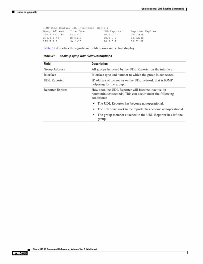
Unidirectional Link Routing Commandsshow ip igmp udlr
IGMP UDLR Status, UDL Interfaces: Serial0Group Address Interface UDL Reporter Reporter Expires224.2.127.254 Serial0 10.0.0.2 00:02:49224.0.1.40 Serial0 10.0.0.2 00:02:48225.7.7.7 Serial0 10.0.0.2 00:02:52
Table 31 describes the significant fields shown in the first display.
Table 31 show ip igmp udlr Field Descriptions
Field Description
Group Address All groups helpered by the UDL Reporter on the interface.
Interface Interface type and number to which the group is connected.
UDL Reporter IP address of the router on the UDL network that is IGMP helpering for the group.
Reporter Expires How soon the UDL Reporter will become inactive, in hours:minutes:seconds. This can occur under the following conditions:
• The UDL Reporter has become nonoperational.
• The link or network to the reporter has become nonoperational.
• The group member attached to the UDL Reporter has left the group.
IP3R-236Cisco IOS IP Command Reference, Volume 3 of 3: Multicast
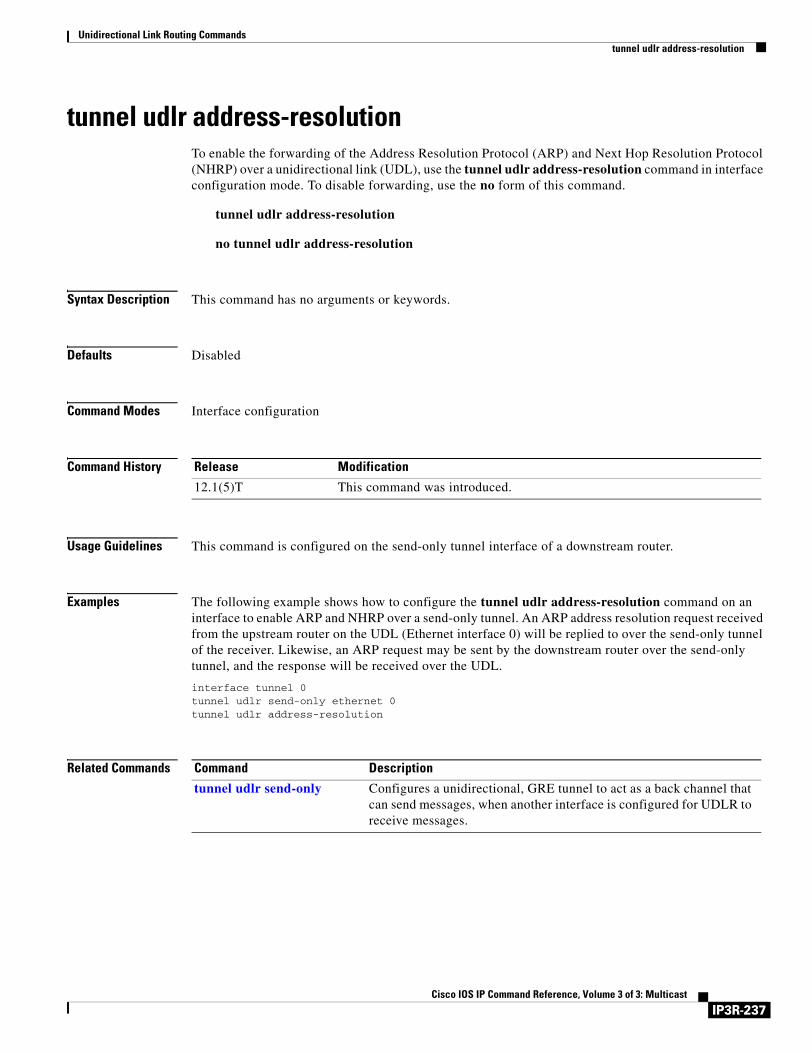
Unidirectional Link Routing Commandstunnel udlr address-resolution
tunnel udlr address-resolutionTo enable the forwarding of the Address Resolution Protocol (ARP) and Next Hop Resolution Protocol (NHRP) over a unidirectional link (UDL), use the tunnel udlr address-resolution command in interface configuration mode. To disable forwarding, use the no form of this command.
tunnel udlr address-resolution
no tunnel udlr address-resolution
Syntax Description This command has no arguments or keywords.
Defaults Disabled
Command Modes Interface configuration
Command History
Usage Guidelines This command is configured on the send-only tunnel interface of a downstream router.
Examples The following example shows how to configure the tunnel udlr address-resolution command on an interface to enable ARP and NHRP over a send-only tunnel. An ARP address resolution request received from the upstream router on the UDL (Ethernet interface 0) will be replied to over the send-only tunnel of the receiver. Likewise, an ARP request may be sent by the downstream router over the send-only tunnel, and the response will be received over the UDL.
interface tunnel 0tunnel udlr send-only ethernet 0tunnel udlr address-resolution
Related Commands
Release Modification
12.1(5)T This command was introduced.
Command Description
tunnel udlr send-only Configures a unidirectional, GRE tunnel to act as a back channel that can send messages, when another interface is configured for UDLR to receive messages.
IP3R-237Cisco IOS IP Command Reference, Volume 3 of 3: Multicast

Unidirectional Link Routing Commandstunnel udlr receive-only
tunnel udlr receive-onlyTo configure a unidirectional, generic routing encapsulation (GRE) tunnel to act as a back channel that can receive messages, when another interface is configured for unidirectional link routing (UDLR) to send messages, use the tunnel udlr receive-only command in interface configuration mode. To remove the tunnel, use the no form of this command.
tunnel udlr receive-only type number
no tunnel udlr receive-only type number
Syntax Description
Defaults No UDLR tunnel is configured.
Command Modes Interface configuration
Command History
Usage Guidelines Use this command to configure a router that has a unidirectional interface with send-only capabilities. One example of when you might configure this command is if you have traffic traveling via a satellite.
The type and number arguments must match the send-only interface type and number specified by the interface command.
You must configure the tunnel udlr send-only command at the opposite end of the tunnel.
If you have a large number of receivers, you should configure UDLR by an alternative means: Internet Group Management Protocol (IGMP) UDLR. See the description of the ip igmp unidirectional-link command earlier in this chapter.
Examples In the following example, Router A (the upstream router) is configured with Open Shortest Path First (OSPF) and Protocol Independent Multicast (PIM). Serial interface 0 has send-only capability. Therefore, the UDLR tunnel is configured as receive-only, and points to serial interface 0.
type number Interface type and number. The type and number arguments must match the unidirectional send-only interface type and number specified by the interface command. Thus, when packets are received over the tunnel, the upper layer protocols will treat the packets as if they are received over the unidirectional send-only interface.
Release Modification
12.0(3)T This command was introduced.
IP3R-238Cisco IOS IP Command Reference, Volume 3 of 3: Multicast
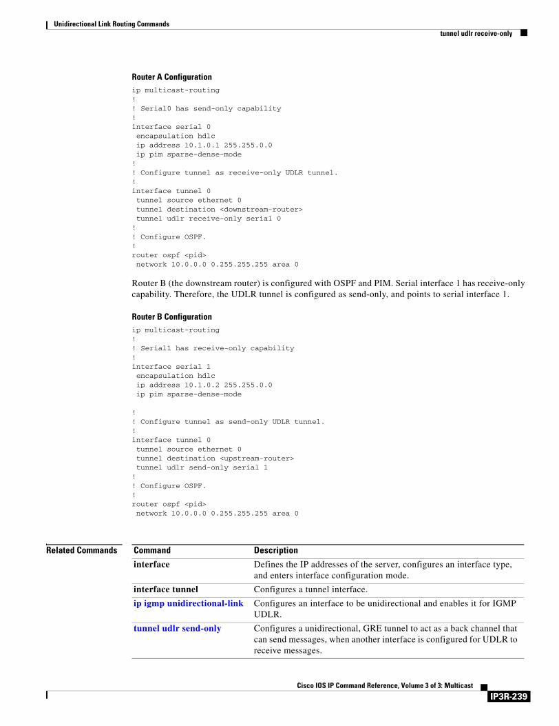
Unidirectional Link Routing Commandstunnel udlr receive-only
Router A Configurationip multicast-routing!! Serial0 has send-only capability!interface serial 0encapsulation hdlcip address 10.1.0.1 255.255.0.0ip pim sparse-dense-mode
! ! Configure tunnel as receive-only UDLR tunnel.!interface tunnel 0tunnel source ethernet 0tunnel destination <downstream-router>tunnel udlr receive-only serial 0
!! Configure OSPF.!router ospf <pid>network 10.0.0.0 0.255.255.255 area 0
Router B (the downstream router) is configured with OSPF and PIM. Serial interface 1 has receive-only capability. Therefore, the UDLR tunnel is configured as send-only, and points to serial interface 1.
Router B Configurationip multicast-routing!! Serial1 has receive-only capability!interface serial 1encapsulation hdlcip address 10.1.0.2 255.255.0.0ip pim sparse-dense-mode
! ! Configure tunnel as send-only UDLR tunnel.!interface tunnel 0tunnel source ethernet 0tunnel destination <upstream-router>tunnel udlr send-only serial 1
!! Configure OSPF.!router ospf <pid>network 10.0.0.0 0.255.255.255 area 0
Related Commands Command Description
interface Defines the IP addresses of the server, configures an interface type, and enters interface configuration mode.
interface tunnel Configures a tunnel interface.
ip igmp unidirectional-link Configures an interface to be unidirectional and enables it for IGMP UDLR.
tunnel udlr send-only Configures a unidirectional, GRE tunnel to act as a back channel that can send messages, when another interface is configured for UDLR to receive messages.
IP3R-239Cisco IOS IP Command Reference, Volume 3 of 3: Multicast
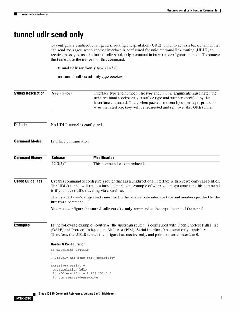
Unidirectional Link Routing Commandstunnel udlr send-only
tunnel udlr send-onlyTo configure a unidirectional, generic routing encapsulation (GRE) tunnel to act as a back channel that can send messages, when another interface is configured for unidirectional link routing (UDLR) to receive messages, use the tunnel udlr send-only command in interface configuration mode. To remove the tunnel, use the no form of this command.
tunnel udlr send-only type number
no tunnel udlr send-only type number
Syntax Description
Defaults No UDLR tunnel is configured.
Command Modes Interface configuration
Command History
Usage Guidelines Use this command to configure a router that has a unidirectional interface with receive-only capabilities. The UDLR tunnel will act as a back channel. One example of when you might configure this command is if you have traffic traveling via a satellite.
The type and number arguments must match the receive-only interface type and number specified by the interface command.
You must configure the tunnel udlr receive-only command at the opposite end of the tunnel.
Examples In the following example, Router A (the upstream router) is configured with Open Shortest Path First (OSPF) and Protocol Independent Multicast (PIM). Serial interface 0 has send-only capability. Therefore, the UDLR tunnel is configured as receive-only, and points to serial interface 0.
Router A Configurationip multicast-routing!! Serial0 has send-only capability!interface serial 0encapsulation hdlcip address 10.1.0.1 255.255.0.0ip pim sparse-dense-mode
type number Interface type and number. The type and number arguments must match the unidirectional receive-only interface type and number specified by the interface command. Thus, when packets are sent by upper layer protocols over the interface, they will be redirected and sent over this GRE tunnel.
Release Modification
12.0(3)T This command was introduced.
IP3R-240Cisco IOS IP Command Reference, Volume 3 of 3: Multicast
Unidirectional Link Routing Commandstunnel udlr send-only
! ! Configure tunnel as receive-only UDLR tunnel.!interface tunnel 0tunnel source ethernet 0tunnel destination <downstream-router>tunnel udlr receive-only serial 0
Router B (the downstream router) is configured with OSPF and PIM. Serial interface 1 has receive-only capability. Therefore, the UDLR tunnel is configured as send-only, and points to serial interface 1.
Router B Configurationip multicast-routing!! Serial1 has receive-only capability!interface serial 1encapsulation hdlcip address 10.1.0.2 255.255.0.0ip pim sparse-dense-mode
! ! Configure tunnel as send-only UDLR tunnel.!interface tunnel 0tunnel source ethernet 0tunnel destination <upstream-router>tunnel udlr send-only serial 1
Related Commands Command Description
interface Defines the IP addresses of the server, configures an interface type, and enters interface configuration mode.
interface tunnel Configures a tunnel interface.
ip igmp unidirectional-link Configures an interface to be unidirectional and enables it for IGMP UDLR.
tunnel udlr address-resolution Enables the forwarding of ARP and NHRP over a UDL.
tunnel udlr receive-only Configures a unidirectional, GRE tunnel to act as a back channel that can receive messages, when another interface is configured for UDLR to send messages.
IP3R-241Cisco IOS IP Command Reference, Volume 3 of 3: Multicast

Unidirectional Link Routing Commandstunnel udlr send-only
IP3R-242Cisco IOS IP Command Reference, Volume 3 of 3: Multicast
IP Multicast Tools Commands
Use the commands in this chapter to configure and use IP multicast tools such as Multicast Routing Monitor (MRM), mrinfo, mstat, and mtrace. For configuration information and examples of IP multicast tools, refer to the “Using IP Multicast Tools” chapter of the Cisco IOS IP Configuration Guide.
IP3R-243Cisco IOS IP Command Reference, Volume 3 of 3: Multicast
IP Multicast Tools Commandsbeacon
beaconTo change the frequency, duration, or scope of beacon messages that the Manager sends to Test Senders and Test Receivers during a multicast routing monitor test, use the beacon command in manager configuration mode. To restore the default value, use the no form of this command.
beacon [interval seconds] [holdtime seconds] [ttl ttl-value]
no beacon [interval seconds] [holdtime seconds] [ttl ttl-value]
Syntax Description
Defaults interval seconds: 60.
holdtime seconds: 86400 (1 day).
ttl hops: 32.
Command Modes Manager configuration
Command History
Usage Guidelines The beacon message functions like a keepalive message. The Manager multicasts beacon messages to the Test Sender and Test Receiver. Beacon messages include the sender requests and receiver requests to start the test, thus providing redundancy in case the Test Sender or Test Receiver goes down.
You can increase the default interval keyword to reduce beacon traffic.
You can decrease the holdtime keyword to shorten the test time.
You can change the default number of TTL hops if your network is large and the beacon needs more than 32 hops to get from the Manager to the Test Sender or Test Receiver.
Examples The following example customizes the Manager to send beacon messages every 30 minutes (1800 seconds), for a test period of 12 hours (43,200 seconds), with a TTL of 40 hops:
beacon interval 1800 holdtime 43200 ttl 40
interval seconds (Optional) Frequency of beacon messages (in seconds). The default value is 60 seconds, meaning one beacon message every 60 seconds.
holdtime seconds (Optional) Length of the test period in seconds. The Test Sender and Test Receiver are respectively sending and receiving test data constantly during the hold time. The default value is 1 day (86,400 seconds).
ttl ttl-value (Optional) Time-to-live (TTL) value of the beacon messages. The default value is 32 hops.
Release Modification
12.0(5)S This command was introduced.
IP3R-244Cisco IOS IP Command Reference, Volume 3 of 3: Multicast

IP Multicast Tools Commandsbeacon
Related Commands Command Description
manager Specifies that an interface is the Manager for MRM, and specifies the multicast group address the Test Receiver will listen to.
IP3R-245Cisco IOS IP Command Reference, Volume 3 of 3: Multicast
IP Multicast Tools Commandsclear ip mrm status-report
clear ip mrm status-reportTo clear the status report cache buffer, use the clear ip mrm status-report command in EXEC mode.
clear ip mrm status-report [ip-address]
Syntax Description
Command Modes EXEC
Command History
Usage Guidelines You typically need not clear this circular cache buffer.
Examples The following example clears status reports from the Test Receiver at 175.2.3.4:
Router# clear ip mrm status-report 175.2.3.4
Related Commands
ip-address (Optional) Address of the Test Receiver. Clears only those status reports received from the Test Receiver that has this IP address. If no address is specified, all status reports are cleared from the cache buffer.
Release Modification
12.0(5)S This command was introduced.
Command Description
show ip mrm status-report Displays MRM status reports of errors in the circular cache buffer.
IP3R-246Cisco IOS IP Command Reference, Volume 3 of 3: Multicast
IP Multicast Tools Commandsip mrm
ip mrmTo configure an interface to operate as a Test Sender or Test Receiver, or both, for Multicast Routing Monitor (MRM), use the ip mrm command in interface configuration mode. To remove the interface as a Test Sender or Test Receiver, use the no form of this command.
ip mrm {test-sender | test-receiver | test-sender-receiver}
no ip mrm {test-sender | test-receiver | test-sender-receiver}
Syntax Description
Defaults The interface is neither a Test Sender nor a Test Receiver.
Command Modes Interface configuration
Command History
Usage Guidelines The Test Sender and Test Receiver can be either a router or a host.
If a router (or host) belongs to more than one test group, it can be a Test Sender for one group and a Test Receiver for the other group. It cannot be the Test Sender and Test Receiver for the same group.
Examples The following example configures Ethernet interface 0 to be a Test Sender:
interface ethernet 0ip mrm test-sender
Related Commands
test-sender Configures the interface to be a Test Sender.
test-receiver Configures the interface to be a Test Receiver.
test-sender-receiver Configures the interface to be both a Test Sender and Test Receiver (for different groups).
Release Modification
12.0(5)S This command was introduced.
Command Description
receivers Establishes Test Receivers for MRM.
senders Configures Test Sender parameters used in MRM.
IP3R-247Cisco IOS IP Command Reference, Volume 3 of 3: Multicast
IP Multicast Tools Commandsip mrm accept-manager
ip mrm accept-managerTo configure a Test Sender or Test Receiver to accept requests only from Managers that pass an access list, use the ip mrm accept-manager command in global configuration mode. To remove the restriction, use the no form of this command.
ip mrm accept-manager {access-list} [test-sender | test-receiver]
no ip mrm accept-manager {access-list}
Syntax Description
Defaults If neither the test-sender nor test-receiver keyword is configured, the access list applies to both.
Command Modes Global configuration
Command History
Usage Guidelines Use this command to control which Managers a Test Sender or Test Receiver must respond to.
Examples The following example configures the Test Sender to respond only to Managers that pass the access list named supervisor:
ip access-list standard supervisorremark Permit only the Manager from Central Officepermit 172.18.2.4
ip mrm accept-manager supervisor test-sender
Related Commands
access-list Number or name of IP access list applied to the Managers.
test-sender (Optional) The access list applies only to the Test Sender.
test-receiver (Optional) The access list applies only to the Test Receiver.
Release Modification
12.0(5)S This command was introduced.
Command Description
ip mrm Configures an interface to operate as a Test Sender or Test Receiver, or both, for MRM.
IP3R-248Cisco IOS IP Command Reference, Volume 3 of 3: Multicast
IP Multicast Tools Commandsip mrm manager
ip mrm managerTo identify a Multicast Routing Monitor (MRM) test and enter the mode in which you specify the test parameters, use the ip mrm manager command in global configuration mode. To remove the test, use the no form of this command.
ip mrm manager test-name
no ip mrm manager test-name
Syntax Description
Defaults There is no MRM test.
Command Modes Global configuration
Command History
Usage Guidelines The test-name argument identifies a test so that you can start, stop, or monitor the test.
After you enter this command, the router is in manager configuration mode and you must set the test parameters.
Examples The following example identifies an MRM test named test1 and causes the system to enter manager configuration mode:
ip mrm manager test1manager ethernet 0 group 239.1.1.1senders 1
Related Commands
test-name Name of the group of MRM test parameters that follow.
Release Modification
12.0(5)S This command was introduced.
Command Description
mrm Starts or stops an MRM test.
show ip mrm manager Displays test information for MRM.
IP3R-249Cisco IOS IP Command Reference, Volume 3 of 3: Multicast
IP Multicast Tools Commandsmanager
managerTo specify that an interface is the Manager for Multicast Routing Monitor (MRM), and to specify the multicast group address the Test Receiver will listen to, use the manager command in manager configuration mode. To remove the Manager or group address, use the no form of this command.
manager type number group ip-address
no manager type number group ip-address
Syntax Description
Defaults There is no MRM Manager.
Command Modes Manager configuration
Command History
Usage Guidelines This command identifies the interface that acts as the Manager, and therefore is required in order to run MRM.
Examples The following example configures Ethernet interface 0 as the Manager. It also configures the Test Receiver to listen to multicast group 239.1.1.1.
ip mrm manager test1manager ethernet 0 group 239.1.1.1
Related Commands
type number Interface type and number of the Manager. The IP address associated with this interface is the source address of the Manager.
group ip-address IP multicast group address that the Test Receiver will listen to.
Release Modification
12.0(5)S This command was introduced.
Command Description
beacon Changes the frequency, duration, or scope of beacon messages that the Manager sends to Test Senders and Test Receivers during an MRM test.
ip mrm accept-manager Configures a Test Sender or Test Receiver to accept requests only from Managers that pass an access list.
show ip mrm manager Displays test information for MRM.
IP3R-250Cisco IOS IP Command Reference, Volume 3 of 3: Multicast
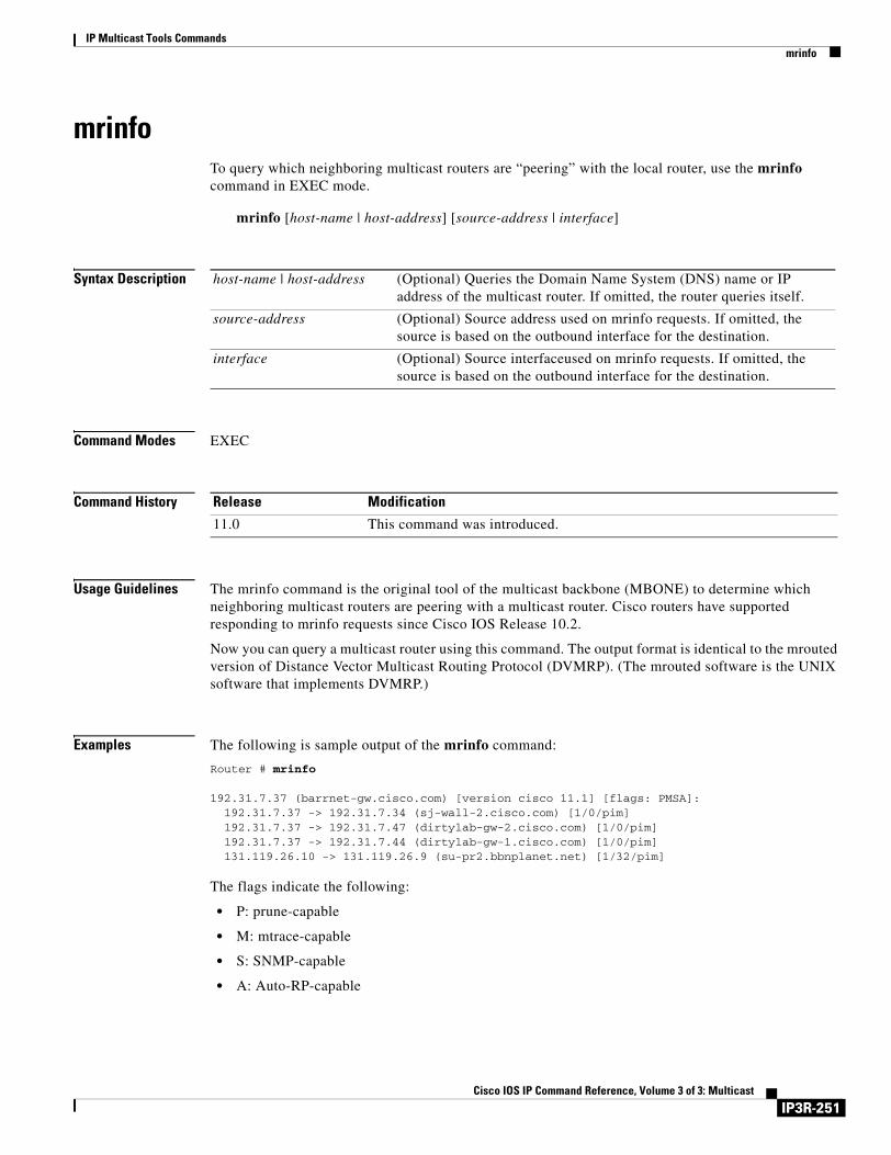
IP Multicast Tools Commandsmrinfo
mrinfoTo query which neighboring multicast routers are “peering” with the local router, use the mrinfo command in EXEC mode.
mrinfo [host-name | host-address] [source-address | interface]
Syntax Description
Command Modes EXEC
Command History
Usage Guidelines The mrinfo command is the original tool of the multicast backbone (MBONE) to determine which neighboring multicast routers are peering with a multicast router. Cisco routers have supported responding to mrinfo requests since Cisco IOS Release 10.2.
Now you can query a multicast router using this command. The output format is identical to the mrouted version of Distance Vector Multicast Routing Protocol (DVMRP). (The mrouted software is the UNIX software that implements DVMRP.)
Examples The following is sample output of the mrinfo command:
Router # mrinfo
192.31.7.37 (barrnet-gw.cisco.com) [version cisco 11.1] [flags: PMSA]: 192.31.7.37 -> 192.31.7.34 (sj-wall-2.cisco.com) [1/0/pim] 192.31.7.37 -> 192.31.7.47 (dirtylab-gw-2.cisco.com) [1/0/pim] 192.31.7.37 -> 192.31.7.44 (dirtylab-gw-1.cisco.com) [1/0/pim] 131.119.26.10 -> 131.119.26.9 (su-pr2.bbnplanet.net) [1/32/pim]
The flags indicate the following:
• P: prune-capable
• M: mtrace-capable
• S: SNMP-capable
• A: Auto-RP-capable
host-name | host-address (Optional) Queries the Domain Name System (DNS) name or IP address of the multicast router. If omitted, the router queries itself.
source-address (Optional) Source address used on mrinfo requests. If omitted, the source is based on the outbound interface for the destination.
interface (Optional) Source interfaceused on mrinfo requests. If omitted, the source is based on the outbound interface for the destination.
Release Modification
11.0 This command was introduced.
IP3R-251Cisco IOS IP Command Reference, Volume 3 of 3: Multicast
IP Multicast Tools Commandsmrm
mrmTo start or stop a Multicast Routing Monitor (MRM) test, use the mrm command in EXEC mode.
mrm test-name {start | stop}
Syntax Description
Command Modes EXEC
Command History
Usage Guidelines You must use this command to run an MRM test. When the test runs, the Test Sender sends User Datagram Protocol (UDP) or UDP/Real-Time Transport Protocol (RTP) packets (depending on the senders command) to the Test Receiver.
Examples The following example starts the MRM test named test1:
Router# mrm test1 start
Related Commands
test-name Name of the MRM test, as defined by the ip mrm manager command.
start Starts the MRM test specified by the test-name argument.
stop Stops the MRM test specified by the test-name argument.
Release Modification
12.0(5)S This command was introduced.
Command Description
ip mrm manager Identifies an MRM test and enters the mode in which you specify the test parameters.
show ip mrm status-report Displays MRM status reports of errors in the circular cache buffer.
IP3R-252Cisco IOS IP Command Reference, Volume 3 of 3: Multicast
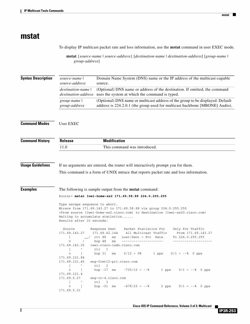
IP Multicast Tools Commandsmstat
mstatTo display IP multicast packet rate and loss information, use the mstat command in user EXEC mode.
mstat {source-name | source-address} [destination-name | destination-address] [group-name | group-address]
Syntax Description
Command Modes User EXEC
Command History
Usage Guidelines If no arguments are entered, the router will interactively prompt you for them.
This command is a form of UNIX mtrace that reports packet rate and loss information.
Examples The following is sample output from the mstat command:
Router> mstat lwei-home-ss2 171.69.58.88 224.0.255.255
Type escape sequence to abort.Mtrace from 171.69.143.27 to 171.69.58.88 via group 224.0.255.255>From source (lwei-home-ss2.cisco.com) to destination (lwei-ss20.cisco.com)Waiting to accumulate statistics......Results after 10 seconds:
Source Response Dest Packet Statistics For Only For Traffic171.69.143.27 171.69.62.144 All Multicast Traffic From 171.69.143.27 | __/ rtt 48 ms Lost/Sent = Pct Rate To 224.0.255.255 v / hop 48 ms --------------------- --------------------171.69.143.25 lwei-cisco-isdn.cisco.com | ^ ttl 1 v | hop 31 ms 0/12 = 0% 1 pps 0/1 = --% 0 pps171.69.121.84 171.69.121.45 eng-frmt12-pri.cisco.com | ^ ttl 2 v | hop -17 ms -735/12 = --% 1 pps 0/1 = --% 0 pps171.69.121.4 171.69.5.27 eng-cc-4.cisco.com | ^ ttl 3 v | hop -21 ms -678/23 = --% 2 pps 0/1 = --% 0 pps171.69.5.21
source-name | source-address
Domain Name System (DNS) name or the IP address of the multicast-capable source.
destination-name | destination-address
(Optional) DNS name or address of the destination. If omitted, the command uses the system at which the command is typed.
group-name | group-address
(Optional) DNS name or multicast address of the group to be displayed. Default address is 224.2.0.1 (the group used for multicast backbone [MBONE] Audio).
Release Modification
11.0 This command was introduced.
IP3R-253Cisco IOS IP Command Reference, Volume 3 of 3: Multicast
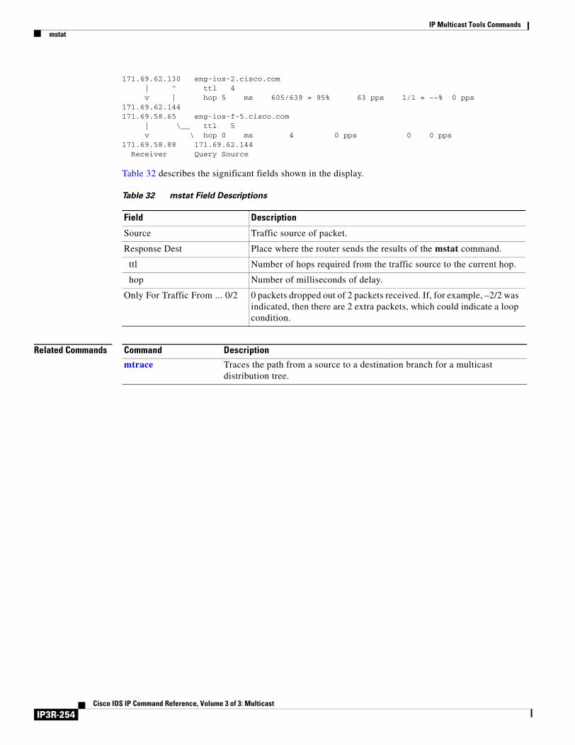
IP Multicast Tools Commandsmstat
171.69.62.130 eng-ios-2.cisco.com | ^ ttl 4 v | hop 5 ms 605/639 = 95% 63 pps 1/1 = --% 0 pps171.69.62.144 171.69.58.65 eng-ios-f-5.cisco.com | \__ ttl 5 v \ hop 0 ms 4 0 pps 0 0 pps171.69.58.88 171.69.62.144 Receiver Query Source
Table 32 describes the significant fields shown in the display.
Related Commands
Table 32 mstat Field Descriptions
Field Description
Source Traffic source of packet.
Response Dest Place where the router sends the results of the mstat command.
ttl Number of hops required from the traffic source to the current hop.
hop Number of milliseconds of delay.
Only For Traffic From ... 0/2 0 packets dropped out of 2 packets received. If, for example, –2/2 was indicated, then there are 2 extra packets, which could indicate a loop condition.
Command Description
mtrace Traces the path from a source to a destination branch for a multicast distribution tree.
IP3R-254Cisco IOS IP Command Reference, Volume 3 of 3: Multicast
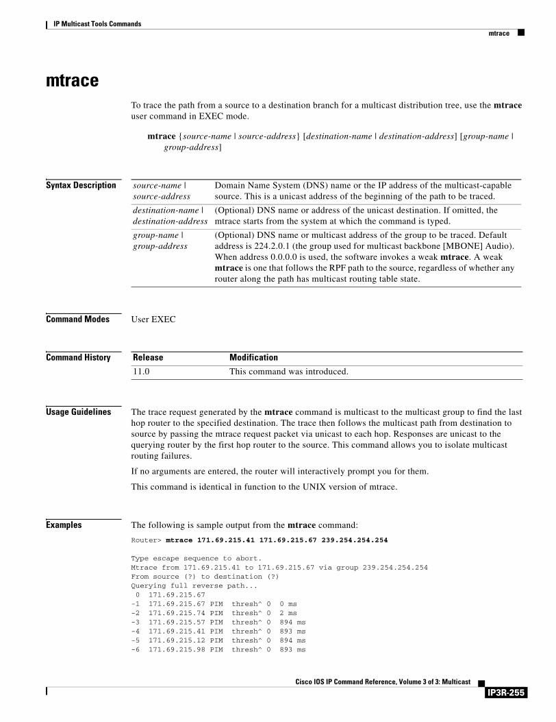
IP Multicast Tools Commandsmtrace
mtraceTo trace the path from a source to a destination branch for a multicast distribution tree, use the mtrace user command in EXEC mode.
mtrace {source-name | source-address} [destination-name | destination-address] [group-name | group-address]
Syntax Description
Command Modes User EXEC
Command History
Usage Guidelines The trace request generated by the mtrace command is multicast to the multicast group to find the last hop router to the specified destination. The trace then follows the multicast path from destination to source by passing the mtrace request packet via unicast to each hop. Responses are unicast to the querying router by the first hop router to the source. This command allows you to isolate multicast routing failures.
If no arguments are entered, the router will interactively prompt you for them.
This command is identical in function to the UNIX version of mtrace.
Examples The following is sample output from the mtrace command:
Router> mtrace 171.69.215.41 171.69.215.67 239.254.254.254
Type escape sequence to abort.Mtrace from 171.69.215.41 to 171.69.215.67 via group 239.254.254.254From source (?) to destination (?)Querying full reverse path... 0 171.69.215.67-1 171.69.215.67 PIM thresh^ 0 0 ms -2 171.69.215.74 PIM thresh^ 0 2 ms -3 171.69.215.57 PIM thresh^ 0 894 ms -4 171.69.215.41 PIM thresh^ 0 893 ms -5 171.69.215.12 PIM thresh^ 0 894 ms -6 171.69.215.98 PIM thresh^ 0 893 ms
source-name | source-address
Domain Name System (DNS) name or the IP address of the multicast-capable source. This is a unicast address of the beginning of the path to be traced.
destination-name | destination-address
(Optional) DNS name or address of the unicast destination. If omitted, the mtrace starts from the system at which the command is typed.
group-name | group-address
(Optional) DNS name or multicast address of the group to be traced. Default address is 224.2.0.1 (the group used for multicast backbone [MBONE] Audio). When address 0.0.0.0 is used, the software invokes a weak mtrace. A weak mtrace is one that follows the RPF path to the source, regardless of whether any router along the path has multicast routing table state.
Release Modification
11.0 This command was introduced.
IP3R-255Cisco IOS IP Command Reference, Volume 3 of 3: Multicast
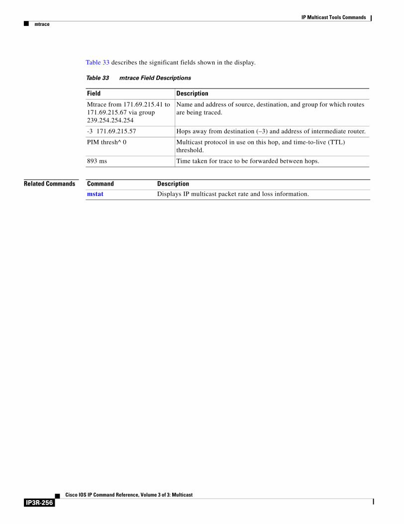
IP Multicast Tools Commandsmtrace
Table 33 describes the significant fields shown in the display.
Related Commands
Table 33 mtrace Field Descriptions
Field Description
Mtrace from 171.69.215.41 to 171.69.215.67 via group 239.254.254.254
Name and address of source, destination, and group for which routes are being traced.
-3 171.69.215.57 Hops away from destination (–3) and address of intermediate router.
PIM thresh^ 0 Multicast protocol in use on this hop, and time-to-live (TTL) threshold.
893 ms Time taken for trace to be forwarded between hops.
Command Description
mstat Displays IP multicast packet rate and loss information.
IP3R-256Cisco IOS IP Command Reference, Volume 3 of 3: Multicast
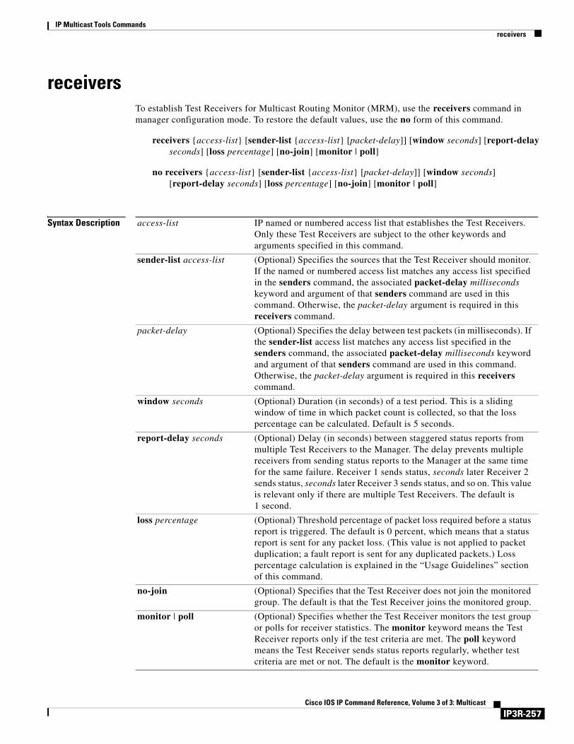
IP Multicast Tools Commandsreceivers
receiversTo establish Test Receivers for Multicast Routing Monitor (MRM), use the receivers command in manager configuration mode. To restore the default values, use the no form of this command.
receivers {access-list} [sender-list {access-list} [packet-delay]] [window seconds] [report-delay seconds] [loss percentage] [no-join] [monitor | poll]
no receivers {access-list} [sender-list {access-list} [packet-delay]] [window seconds] [report-delay seconds] [loss percentage] [no-join] [monitor | poll]
Syntax Description access-list IP named or numbered access list that establishes the Test Receivers. Only these Test Receivers are subject to the other keywords and arguments specified in this command.
sender-list access-list (Optional) Specifies the sources that the Test Receiver should monitor. If the named or numbered access list matches any access list specified in the senders command, the associated packet-delay milliseconds keyword and argument of that senders command are used in this command. Otherwise, the packet-delay argument is required in this receivers command.
packet-delay (Optional) Specifies the delay between test packets (in milliseconds). If the sender-list access list matches any access list specified in the senders command, the associated packet-delay milliseconds keyword and argument of that senders command are used in this command. Otherwise, the packet-delay argument is required in this receivers command.
window seconds (Optional) Duration (in seconds) of a test period. This is a sliding window of time in which packet count is collected, so that the loss percentage can be calculated. Default is 5 seconds.
report-delay seconds (Optional) Delay (in seconds) between staggered status reports from multiple Test Receivers to the Manager. The delay prevents multiple receivers from sending status reports to the Manager at the same time for the same failure. Receiver 1 sends status, seconds later Receiver 2 sends status, seconds later Receiver 3 sends status, and so on. This value is relevant only if there are multiple Test Receivers. The default is 1 second.
loss percentage (Optional) Threshold percentage of packet loss required before a status report is triggered. The default is 0 percent, which means that a status report is sent for any packet loss. (This value is not applied to packet duplication; a fault report is sent for any duplicated packets.) Loss percentage calculation is explained in the “Usage Guidelines” section of this command.
no-join (Optional) Specifies that the Test Receiver does not join the monitored group. The default is that the Test Receiver joins the monitored group.
monitor | poll (Optional) Specifies whether the Test Receiver monitors the test group or polls for receiver statistics. The monitor keyword means the Test Receiver reports only if the test criteria are met. The poll keyword means the Test Receiver sends status reports regularly, whether test criteria are met or not. The default is the monitor keyword.
IP3R-257Cisco IOS IP Command Reference, Volume 3 of 3: Multicast
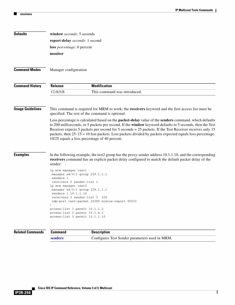
IP Multicast Tools Commandsreceivers
Defaults window seconds: 5 seconds
report-delay seconds: 1 second
loss percentage: 0 percent
monitor
Command Modes Manager configuration
Command History
Usage Guidelines This command is required for MRM to work; the receivers keyword and the first access list must be specified. The rest of the command is optional.
Loss percentage is calculated based on the packet-delay value of the senders command, which defaults to 200 milliseconds, or 5 packets per second. If the window keyword defaults to 5 seconds, then the Test Receiver expects 5 packets per second for 5 seconds = 25 packets. If the Test Receiver receives only 15 packets, then 25–15 = 10 lost packets. Lost packets divided by packets expected equals loss percentage. 10/25 equals a loss percentage of 40 percent.
Examples In the following example, the test2 group has the proxy-sender address 10.1.1.10, and the corresponding receivers command has an explicit packet delay configured to match the default packet delay of the sender:
ip mrm manager test1 manager e4/0/1 group 239.1.1.1 senders 1 receivers 2 sender-list 1ip mrm manager test2 manager e4/0/1 group 239.1.1.1 senders 1 10.1.1.10 receivers 2 sender-list 3 200 udp-port test-packet 16386 status-report 65533!access-list 1 permit 10.1.1.2access-list 2 permit 10.1.4.2access-list 3 permit 10.1.1.10
Related Commands
Release Modification
12.0(5)S This command was introduced.
Command Description
senders Configures Test Sender parameters used in MRM.
IP3R-258Cisco IOS IP Command Reference, Volume 3 of 3: Multicast
IP Multicast Tools Commandssenders
sendersTo configure Test Sender parameters used in Multicast Routing Monitor (MRM), use the senders command in manager configuration mode. To restore the default values, use the no form of this command.
senders {access-list} [packet-delay milliseconds] [rtp | udp] [target-only | all-multicasts | all-test-senders] [proxy_src]
no senders {access-list} [packet-delay milliseconds] [rtp | udp] [target-only | all-multicasts | all-test-senders] [proxy_src]
Syntax Description
Defaults packet-delay milliseconds: 200 milliseconds (that is, 5 packets per second)
rtp
all-multicasts
Command Modes Manager configuration
Command History
access-list IP named or numbered access list that defines which Test Senders are involved in the test and which Test Senders these parameters apply to.
packet-delay milliseconds (Optional) Specifies the delay between test packets (in milliseconds). The default is 200 milliseconds, which results in 5 packets per second.
rtp | udp (Optional) Encapsulation of test packets, either Real-Time Transport Protocol (RTP-encapsulated or User Datagram Protocol (UDP)-encapsulated. The default is RTP-encapsulated.
target-only (Optional) Specifies that test packets are sent out on the targeted interface only (that is, the interface with the IP address that is specified in the Test Sender request target field). By default, test packets are sent as described in the all-multicasts keyword.
all-multicasts (Optional) Specifies that the test packets are sent out on all interfaces that are enabled with IP multicast. This is the default way that test packets are sent.
all-test-senders (Optional) Specifies that test packets are sent out on all interfaces that have test-sender mode enabled. By default, test packets are sent as described in the all-multicasts keyword.
proxy_src (Optional) Source IP address for which the Test Sender will proxy test packets. Use this if you want to test, for a specific source, whether the multicast distribution tree is working.
Release Modification
12.0(5)S This command was introduced.
IP3R-259Cisco IOS IP Command Reference, Volume 3 of 3: Multicast
IP Multicast Tools Commandssenders
Usage Guidelines Use this command to specify which Test Senders are involved in the test and are affected by these parameters.
Examples In the following example, the test2 group has the proxy-sender address 10.1.1.10, and the corresponding receivers command has an explicit packet delay configured to match the default packet delay of the sender:
ip mrm manager test1 manager e4/0/1 group 239.1.1.1 senders 1 receivers 2 sender-list 1ip mrm manager test2 manager e4/0/1 group 239.1.1.1 senders 1 10.1.1.10 receivers 2 sender-list 3 200 udp-port test-packet 16386 status-report 65533!access-list 1 permit 10.1.1.2access-list 2 permit 10.1.4.2access-list 3 permit 10.1.1.10
Related Commands Command Description
receivers Establishes Test Receivers for MRM.
IP3R-260Cisco IOS IP Command Reference, Volume 3 of 3: Multicast
IP Multicast Tools Commandsshow ip mrm interface
show ip mrm interfaceTo display Test Sender or Test Receiver information about Multicast Routing Monitor (MRM), use the show ip mrm interface command in EXEC mode.
show ip mrm interface [type number]
Syntax Description
Command Modes EXEC
Command History
Usage Guidelines Use this command to see which interfaces are participating in MRM in which roles, and whether the interfaces are up or down.
Examples The following example is sample output for the show ip mrm interface command:
Router# show ip mrm interface
Interface Address Mode StatusEthernet0 1.1.1.1 Test-Sender UpEthernet1 2.2.2.2 Test-Receiver Up
Table 34 describes the significant fields showh in the display.
Related Commands
type number (Optional) Displays Test Sender or Test Receiver information for the specified interface type and number. If no interface is specified, information about all Test Senders and Test Receivers is displayed.
Release Modification
12.0(5)S This command was introduced.
Table 34 show ip mrm interface Field Descriptions
Field Description
Interface List of interfaces on this router that serve as a Test Sender or Test Receiver.
Address IP address of the interface.
Mode Role that the interface plays in MRM, either Test Sender or Test Receiver.
Status Status of the interface.
Command Description
ip mrm Configures an interface to operate as a Test Sender or Test Receiver, or both, for MRM.
IP3R-261Cisco IOS IP Command Reference, Volume 3 of 3: Multicast
IP Multicast Tools Commandsshow ip mrm manager
show ip mrm managerTo display test information for Multicast Routing Monitor (MRM), use the show ip mrm manager command in EXEC mode.
show ip mrm manager [test-name]
Syntax Description
Command Modes EXEC
Command History
Usage Guidelines Use this command to see information about the Manager.
Examples The following example is sample output for the show ip mrm manager command executed at two different times:
Router# show ip mrm manager test
Manager:test/1.1.1.1 is running, expire:1d00h Beacon interval/holdtime/ttl:60/86400/32 Group:239.1.2.3, UDP port test-packet/status-report:16384/65535 Test senders: 2.2.2.2 /Ack Test receivers: 3.3.3.3 /Ack
Router# show ip mrm manager test
Manager:test/1.1.1.1 is not running Beacon interval/holdtime/ttl:60/86400/32 Group:239.1.2.3, UDP port test-packet/status-report:16384/65535 Test senders: 2.2.2.2 Test receivers: 3.3.3.3
Table 35 describes the significant fields shown in the display.
test-name (Optional) Name of the MRM test (as specified in the ip mrm manager command) for which to display information. If no name is specified, information about all Managers is displayed.
Release Modification
12.0(5)S This command was introduced.
IP3R-262Cisco IOS IP Command Reference, Volume 3 of 3: Multicast
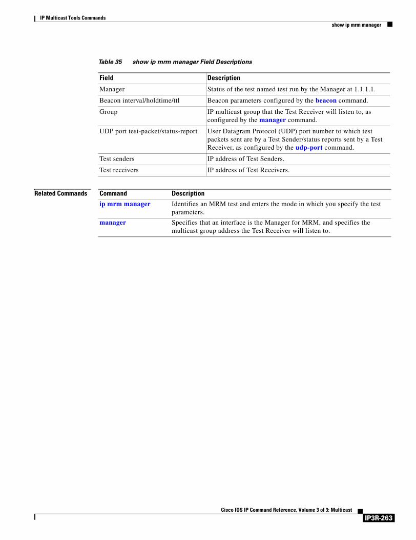
IP Multicast Tools Commandsshow ip mrm manager
Related Commands
Table 35 show ip mrm manager Field Descriptions
Field Description
Manager Status of the test named test run by the Manager at 1.1.1.1.
Beacon interval/holdtime/ttl Beacon parameters configured by the beacon command.
Group IP multicast group that the Test Receiver will listen to, as configured by the manager command.
UDP port test-packet/status-report User Datagram Protocol (UDP) port number to which test packets sent are by a Test Sender/status reports sent by a Test Receiver, as configured by the udp-port command.
Test senders IP address of Test Senders.
Test receivers IP address of Test Receivers.
Command Description
ip mrm manager Identifies an MRM test and enters the mode in which you specify the test parameters.
manager Specifies that an interface is the Manager for MRM, and specifies the multicast group address the Test Receiver will listen to.
IP3R-263Cisco IOS IP Command Reference, Volume 3 of 3: Multicast
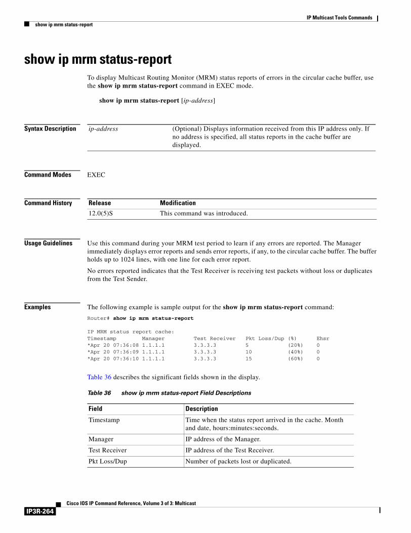
IP Multicast Tools Commandsshow ip mrm status-report
show ip mrm status-reportTo display Multicast Routing Monitor (MRM) status reports of errors in the circular cache buffer, use the show ip mrm status-report command in EXEC mode.
show ip mrm status-report [ip-address]
Syntax Description
Command Modes EXEC
Command History
Usage Guidelines Use this command during your MRM test period to learn if any errors are reported. The Manager immediately displays error reports and sends error reports, if any, to the circular cache buffer. The buffer holds up to 1024 lines, with one line for each error report.
No errors reported indicates that the Test Receiver is receiving test packets without loss or duplicates from the Test Sender.
Examples The following example is sample output for the show ip mrm status-report command:
Router# show ip mrm status-report
IP MRM status report cache:Timestamp Manager Test Receiver Pkt Loss/Dup (%) Ehsr*Apr 20 07:36:08 1.1.1.1 3.3.3.3 5 (20%) 0*Apr 20 07:36:09 1.1.1.1 3.3.3.3 10 (40%) 0*Apr 20 07:36:10 1.1.1.1 3.3.3.3 15 (60%) 0
Table 36 describes the significant fields shown in the display.
ip-address (Optional) Displays information received from this IP address only. If no address is specified, all status reports in the cache buffer are displayed.
Release Modification
12.0(5)S This command was introduced.
Table 36 show ip mrm status-report Field Descriptions
Field Description
Timestamp Time when the status report arrived in the cache. Month and date, hours:minutes:seconds.
Manager IP address of the Manager.
Test Receiver IP address of the Test Receiver.
Pkt Loss/Dup Number of packets lost or duplicated.
IP3R-264Cisco IOS IP Command Reference, Volume 3 of 3: Multicast
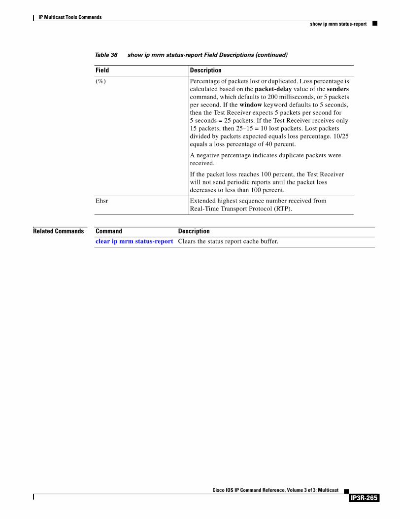
IP Multicast Tools Commandsshow ip mrm status-report
Related Commands
(%) Percentage of packets lost or duplicated. Loss percentage is calculated based on the packet-delay value of the senders command, which defaults to 200 milliseconds, or 5 packets per second. If the window keyword defaults to 5 seconds, then the Test Receiver expects 5 packets per second for 5 seconds = 25 packets. If the Test Receiver receives only 15 packets, then 25–15 = 10 lost packets. Lost packets divided by packets expected equals loss percentage. 10/25 equals a loss percentage of 40 percent.
A negative percentage indicates duplicate packets were received.
If the packet loss reaches 100 percent, the Test Receiver will not send periodic reports until the packet loss decreases to less than 100 percent.
Ehsr Extended highest sequence number received from Real-Time Transport Protocol (RTP).
Table 36 show ip mrm status-report Field Descriptions (continued)
Field Description
Command Description
clear ip mrm status-report Clears the status report cache buffer.
IP3R-265Cisco IOS IP Command Reference, Volume 3 of 3: Multicast
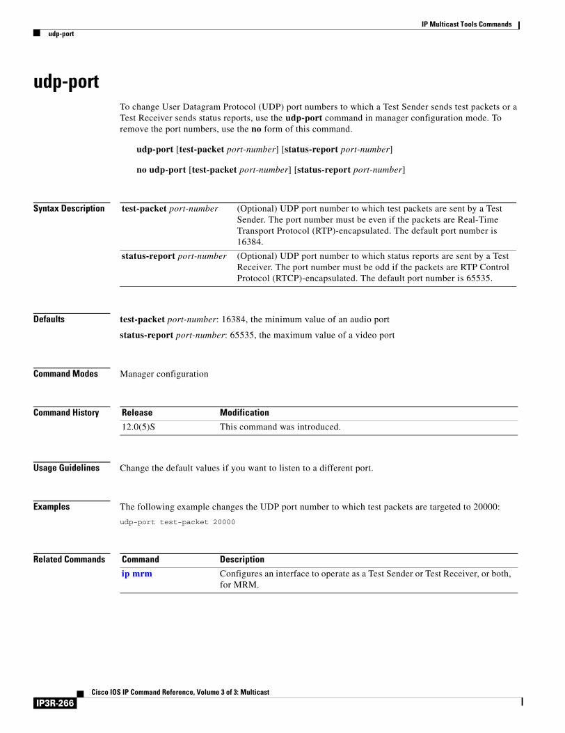
IP Multicast Tools Commandsudp-port
udp-portTo change User Datagram Protocol (UDP) port numbers to which a Test Sender sends test packets or a Test Receiver sends status reports, use the udp-port command in manager configuration mode. To remove the port numbers, use the no form of this command.
udp-port [test-packet port-number] [status-report port-number]
no udp-port [test-packet port-number] [status-report port-number]
Syntax Description
Defaults test-packet port-number: 16384, the minimum value of an audio port
status-report port-number: 65535, the maximum value of a video port
Command Modes Manager configuration
Command History
Usage Guidelines Change the default values if you want to listen to a different port.
Examples The following example changes the UDP port number to which test packets are targeted to 20000:
udp-port test-packet 20000
Related Commands
test-packet port-number (Optional) UDP port number to which test packets are sent by a Test Sender. The port number must be even if the packets are Real-Time Transport Protocol (RTP)-encapsulated. The default port number is 16384.
status-report port-number (Optional) UDP port number to which status reports are sent by a Test Receiver. The port number must be odd if the packets are RTP Control Protocol (RTCP)-encapsulated. The default port number is 65535.
Release Modification
12.0(5)S This command was introduced.
Command Description
ip mrm Configures an interface to operate as a Test Sender or Test Receiver, or both, for MRM.
IP3R-266Cisco IOS IP Command Reference, Volume 3 of 3: Multicast

Index

Cisco IOS IP Command
I N D E X
Symbols
<cr> xvii
? command xvi
A
ATM
SVC, point-to-multipoint IP3R-87
VC status, displaying IP3R-159
B
beacon command IP3R-244
C
carriage return (<cr>) xvii
cautions, usage in text x
CGMP (Cisco Group Management Protocol)
See IP multicast routing, CGMP
changed information in this release ix
Cisco IOS configuration changes, saving xx
clear ip cgmp command IP3R-2
clear ip dvmrp route command IP3R-3
clear ip eigrp neighbors command IP3R-3
clear ip igmp group command IP3R-4
clear ip mrm status-report command IP3R-246
clear ip mroute command IP3R-5
clear ip msdp peer command IP3R-170
clear ip msdp sa-cache command IP3R-171
clear ip msdp statistics command IP3R-172
clear ip pgm host command IP3R-208
clear ip pgm router command IP3R-209
clear ip pim auto-rp command IP3R-6, IP3R-7
clear ip rtp header-compression command IP3R-8
clear ip sap command IP3R-9
clear ip sdr command IP3R-10
command modes, understanding xv to xvi
commands
context-sensitive help for abbreviating xvi
default form, using xix
no form, using xix
command syntax
conventions x
displaying (example) xvii
configurations, saving xx
D
documentation
conventions ix
feedback, providing xi
modules v to vii
online, accessing xi
ordering xi
Documentation CD-ROM xi
documents and resources, supporting viii
DVMRP (Distance Vector Multicast Routing Protocol)
See IP multicast routing, DVMRP
F
Feature Navigator
See platforms, supported
filtering output, show and more commands xx
IN-269Reference, Volume 3 of 3: Multicast
Index
Frame Relay
RTP header compression
per DLCI, enabling IP3R-13, IP3R-17
statistics, displaying IP3R-122
with TCP header compression, enabling IP3R-14
frame-relay ip rtp compression-connections IP3R-11
frame-relay ip rtp header-compression command IP3R-13
frame-relay map ip compress command IP3R-14, IP3R-16
frame-relay map ip nocompress command IP3R-16
frame-relay map ip rtp header-compression command IP3R-17
functional addresses IP3R-71
G
global configuration mode, summary of xvi
H
hardware platforms
See platforms, supported
help command xvi
I
IGMP (Internet Group Management Protocol)
See IP multicast routing, IGMP
indexes, master viii
interface configuration mode, summary of xvi
ip cgmp command IP3R-19
ip dvmrp accept-filter command IP3R-21
ip dvmrp auto-summary command IP3R-23
ip dvmrp default-information command IP3R-24
ip dvmrp metric command IP3R-25
ip dvmrp metric-offset command IP3R-27
ip dvmrp output-report-delay command IP3R-28
ip dvmrp reject-non-pruners command IP3R-29
ip dvmrp routehog-notification command IP3R-30
ip dvmrp route-limit command IP3R-31
IN-270Cisco IOS IP Command Reference, Volume 3 of 3: Multicast
ip dvmrp summary-address command IP3R-32
ip dvmrp unicast-routing command IP3R-33
ip igmp access-group command IP3R-34
ip igmp helper-address (UDL) command IP3R-226
ip igmp helper-address command IP3R-35
ip igmp immediate-leave command IP3R-37
ip igmp join-group command IP3R-39
ip igmp last-member-query-count command IP3R-41
ip igmp last-member-query-interval command IP3R-43
ip igmp mroute-proxy command IP3R-227
ip igmp proxy-service command IP3R-229
ip igmp query-interval command IP3R-45
ip igmp query-max-response-time command IP3R-47
ip igmp query-timeout command IP3R-48
ip igmp static-group command IP3R-49
ip igmp unidirectional-link command IP3R-231
ip igmp v3lite command IP3R-51
ip igmp version command IP3R-52
ip mrm accept-manager command IP3R-248
ip mrm command IP3R-247
ip mrm manager command IP3R-249
ip mroute-cache command IP3R-56
ip mroute command IP3R-54
ip msdp border command IP3R-173
ip msdp cache-rejected-sa command IP3R-58, IP3R-175
ip msdp cache-sa-state command IP3R-176
ip msdp default-peer command IP3R-178
ip msdp description command IP3R-180
ip msdp filter-sa-request command IP3R-181
ip msdp mesh-group command IP3R-182
ip msdp originator-id command IP3R-183
ip msdp peer command IP3R-184
ip msdp redistribute command IP3R-186
ip msdp sa-filter in command IP3R-188
ip msdp sa-filter out command IP3R-190
ip msdp sa-limit command IP3R-192
ip msdp sa-request command IP3R-193
ip msdp shutdown command IP3R-195
ip msdp ttl-threshold command IP3R-196
Index
ip multicast boundary command IP3R-59
ip multicast default-rpf-distance command IP3R-233
ip multicast heartbeat command IP3R-63
ip multicast multipath command IP3R-67
IP multicast routing
access lists IP3R-34
CGMP
clearing IP3R-2
proxy IP3R-19
DVMRP
automatic summarization IP3R-23
delay between reports IP3R-28
neighbors, advertising to IP3R-24
reject nonpruning neighbors IP3R-29
route hog notification IP3R-30
route threshold IP3R-30
summary address IP3R-32
unicast routing IP3R-33
heartbeat, monitoring IP3R-63
IGMP
cache IP3R-4
helper address IP3R-35
host query message interval IP3R-45
query response time IP3R-47
query timeout IP3R-48
statically connected router member IP3R-49
IP multicast routing table, clearing IP3R-5
MDS
enabling on interface IP3R-56
mrinfo IP3R-251
MRM
beacon messages IP3R-244
errors IP3R-264
Manager IP3R-250
Manager restrictions IP3R-248
RTP IP3R-265
status report, displaying IP3R-264
status report cache buffer, clearing IP3R-246
test, conducting IP3R-252
test information, displaying IP3R-262
test name IP3R-249
Test Receiver information, displaying IP3R-261
Test Receiver interface IP3R-247
Test Receiver parameters IP3R-257
Test Sender information, displaying IP3R-261
Test Sender interface IP3R-247
Test Sender parameters IP3R-259
UDP port numbers IP3R-263, IP3R-266
mroute, configuring IP3R-54
multicast groups
hosts joining IP3R-34
joining IP3R-39
multicast information, displaying IP3R-128
multicast tree, tracing IP3R-253, IP3R-255
packet headers, storing IP3R-61
PIM
dense mode, enabling IP3R-72
filtering IP3R-89
NBMA mode IP3R-88
neighbors, displaying IP3R-152
preventing IP3R-89
shortest path tree, delaying use IP3R-104
sparse-dense mode, enabling IP3R-72
sparse mode, enabling IP3R-72
PIM sparse mode
router query messages IP3R-90
RP
address, configuring IP3R-76, IP3R-94
Auto-RP, groups covered IP3R-101
Auto-RP, mapping agent IP3R-103
displaying IP3R-154
filter RP announcements IP3R-97
groups, assigning to IP3R-94
PIM Version 2 candidate, advertising IP3R-99
RPF, displaying IP3R-161
static route, configuring IP3R-54
stub multicast routing IP3R-35, IP3R-89
Token Ring MAC address mapping IP3R-71
IN-271Cisco IOS IP Command Reference, Volume 3 of 3: Multicast
Index
TTL, configuring IP3R-70
ip multicast use-functional command IP3R-71
ip pgm host command IP3R-210
ip pgm router command IP3R-213
ip pim accept-register command IP3R-75
ip pim accept-rp command IP3R-79
ip pim autorp listener command IP3R-78
ip pim bidir-enable command IP3R-79
ip pim border command IP3R-81
ip pim bsr-border command IP3R-82
ip pim bsr-candidate command IP3R-83
ip pim dr-priority command IP3R-85
ip pim minimum-vc-rate command IP3R-86
ip pim multipoint-signalling command IP3R-87
ip pim nbma-mode command IP3R-88
ip pim neighbor-filter command IP3R-89
ip pim query-interval command IP3R-90
ip pim register-rate-limit command IP3R-92
ip pim register-source command IP3R-93
ip pim rp-candidate command IP3R-99
ip pim ssm command IP3R-106
ip pim vc-count command IP3R-109
ip pim version command IP3R-110
ip rgmp command IP3R-111
ip rtp compression-connections command IP3R-113
ip rtp header-compression command IP3R-114
ip sap cache-timeout command IP3R-116
ip sap listen command IP3R-117
ip sdr cache-timeout command IP3R-119
ip sdr listen command IP3R-120
ip urd command IP3R-121
M
manager command IP3R-250
MDS
See IP multicast routing, MDS
MIB, descriptions online viii
modes
IN-272Cisco IOS IP Command Reference, Volume 3 of 3: Multicast
See command modes
mrinfo command IP3R-251
MRM (Multicast Routing Monitor)
See IP multicast routing, MRM
mrm command IP3R-252
mstat command IP3R-253
mtrace command IP3R-255
multicast distributed switching
See IP multicast routing, MDS
multicast group, joining IP3R-39
N
new information in this release ix
notes, usage in text x
P
platforms, supported
Feature Navigator, identify using xxi
release notes, identify using xxi
privileged EXEC mode, summary of xvi
prompts, system xvi
Q
question mark (?) command xvi
R
receivers command IP3R-257
release notes
See platforms, supported
RFC
full text, obtaining viii
ROM monitor mode, summary of xvi
RTP header compression
and TCP header compression, enabling IP3R-14

Index
connections supported IP3R-113
enabling IP3R-114
Frame Relay, enabling for maps IP3R-13
Frame Relay encapsulation, using IP3R-17
Frame Relay statistics, displaying IP3R-122
number of connections on interface, setting IP3R-11
statistics
clearing IP3R-8
displaying IP3R-163
Frame Relay IP3R-122
S
senders command IP3R-259
show frame-relay ip rtp header-compression command IP3R-122
show ip dvmrp route command IP3R-124
show ip igmp groups command IP3R-125
show ip igmp interface command IP3R-128
show ip igmp udlr command IP3R-235
show ip mcache command IP3R-130
show ip mpacket command IP3R-132
show ip mrm interface command IP3R-261
show ip mrm manager command IP3R-262
show ip mrm status-report command IP3R-264
show ip mroute command IP3R-134
show ip msdp count command IP3R-197
show ip msdp peer command IP3R-199
show ip msdp sa-cache command IP3R-201
show ip msdp summary command IP3R-205
show ip pgm host defaults command IP3R-214
show ip pgm host sessions command IP3R-216
show ip pgm host traffic command IP3R-219
show ip pgm router command IP3R-221
show ip pim bsr command IP3R-145
show ip pim interface command IP3R-147
show ip pim neighbor command IP3R-152
show ip pim rp command IP3R-154
show ip pim rp-hash command IP3R-157
show ip pim vc command IP3R-159
show ip rpf command IP3R-161
show ip rtp header-compression command IP3R-163
show ip sap command IP3R-165
show ip sdr command IP3R-167
stub IP multicast routing IP3R-35
T
Tab key, command completion xvi
Token Ring
functional address IP3R-71
IP multicast routing over IP3R-71
tunnel udlr address-resolution command IP3R-237
tunnel udlr receive-only command IP3R-238
tunnel udlr send-only command IP3R-240
U
udp-port command IP3R-266
user EXEC mode, summary of xvi
IN-273Cisco IOS IP Command Reference, Volume 3 of 3: Multicast

Index
IN-274Cisco IOS IP Command Reference, Volume 3 of 3: Multicast