cisco ip phone 7800 series administration guide for cisco ... · cisco ip phone 7800 series...
TRANSCRIPT

Cisco IP Phone 7800 Series Administration Guide for Cisco UnifiedCommunications ManagerFirst Published: 2015-05-05
Last Modified: 2018-05-31
Americas HeadquartersCisco Systems, Inc.170 West Tasman DriveSan Jose, CA 95134-1706USAhttp://www.cisco.comTel: 408 526-4000
800 553-NETS (6387)Fax: 408 527-0883

THE SPECIFICATIONS AND INFORMATION REGARDING THE PRODUCTS IN THIS MANUAL ARE SUBJECT TO CHANGE WITHOUT NOTICE. ALL STATEMENTS,INFORMATION, AND RECOMMENDATIONS IN THIS MANUAL ARE BELIEVED TO BE ACCURATE BUT ARE PRESENTED WITHOUT WARRANTY OF ANY KIND,EXPRESS OR IMPLIED. USERS MUST TAKE FULL RESPONSIBILITY FOR THEIR APPLICATION OF ANY PRODUCTS.
THE SOFTWARE LICENSE AND LIMITED WARRANTY FOR THE ACCOMPANYING PRODUCT ARE SET FORTH IN THE INFORMATION PACKET THAT SHIPPED WITHTHE PRODUCT AND ARE INCORPORATED HEREIN BY THIS REFERENCE. IF YOU ARE UNABLE TO LOCATE THE SOFTWARE LICENSE OR LIMITED WARRANTY,CONTACT YOUR CISCO REPRESENTATIVE FOR A COPY.
The following information is for FCC compliance of Class A devices: This equipment has been tested and found to comply with the limits for a Class A digital device, pursuant to part 15of the FCC rules. These limits are designed to provide reasonable protection against harmful interference when the equipment is operated in a commercial environment. This equipmentgenerates, uses, and can radiate radio-frequency energy and, if not installed and used in accordance with the instruction manual, may cause harmful interference to radio communications.Operation of this equipment in a residential area is likely to cause harmful interference, in which case users will be required to correct the interference at their own expense.
The following information is for FCC compliance of Class B devices: This equipment has been tested and found to comply with the limits for a Class B digital device, pursuant to part 15 ofthe FCC rules. These limits are designed to provide reasonable protection against harmful interference in a residential installation. This equipment generates, uses and can radiate radiofrequency energy and, if not installed and used in accordance with the instructions, may cause harmful interference to radio communications. However, there is no guarantee that interferencewill not occur in a particular installation. If the equipment causes interference to radio or television reception, which can be determined by turning the equipment off and on, users areencouraged to try to correct the interference by using one or more of the following measures:
• Reorient or relocate the receiving antenna.
• Increase the separation between the equipment and receiver.
• Connect the equipment into an outlet on a circuit different from that to which the receiver is connected.
• Consult the dealer or an experienced radio/TV technician for help.
Modifications to this product not authorized by Cisco could void the FCC approval and negate your authority to operate the product
The Cisco implementation of TCP header compression is an adaptation of a program developed by the University of California, Berkeley (UCB) as part of UCB’s public domain version ofthe UNIX operating system. All rights reserved. Copyright © 1981, Regents of the University of California.
NOTWITHSTANDING ANY OTHERWARRANTY HEREIN, ALL DOCUMENT FILES AND SOFTWARE OF THESE SUPPLIERS ARE PROVIDED "AS IS" WITH ALL FAULTS.CISCO AND THE ABOVE-NAMED SUPPLIERS DISCLAIM ALL WARRANTIES, EXPRESSED OR IMPLIED, INCLUDING, WITHOUT LIMITATION, THOSE OFMERCHANTABILITY, FITNESS FOR A PARTICULAR PURPOSE AND NONINFRINGEMENT OR ARISING FROM A COURSE OF DEALING, USAGE, OR TRADE PRACTICE.
IN NO EVENT SHALL CISCO OR ITS SUPPLIERS BE LIABLE FOR ANY INDIRECT, SPECIAL, CONSEQUENTIAL, OR INCIDENTAL DAMAGES, INCLUDING, WITHOUTLIMITATION, LOST PROFITS OR LOSS OR DAMAGE TO DATA ARISING OUT OF THE USE OR INABILITY TO USE THIS MANUAL, EVEN IF CISCO OR ITS SUPPLIERSHAVE BEEN ADVISED OF THE POSSIBILITY OF SUCH DAMAGES.
Any Internet Protocol (IP) addresses and phone numbers used in this document are not intended to be actual addresses and phone numbers. Any examples, command display output, networktopology diagrams, and other figures included in the document are shown for illustrative purposes only. Any use of actual IP addresses or phone numbers in illustrative content is unintentionaland coincidental.
Cisco and the Cisco logo are trademarks or registered trademarks of Cisco and/or its affiliates in the U.S. and other countries. To view a list of Cisco trademarks, go to this URL:https://www.cisco.com/go/trademarks. Third-party trademarks mentioned are the property of their respective owners. The use of the word partner does not imply a partnership relationshipbetween Cisco and any other company. (1721R)
© 2018 Cisco Systems, Inc. All rights reserved.

C O N T E N T S
Preface xiiiP R E F A C E
Overview xiii
Audience xiii
Guide Conventions xiii
Related Documentation xv
Cisco IP Phone 7800 Series Documentation xv
Cisco Unified Communications Manager Documentation xv
Cisco Business Edition 6000 Documentation xv
Documentation, Support, and Security Guidelines xv
Cisco Product Security Overview xv
New and Changed Information 1C H A P T E R 1
New Information for Firmware Release 12.1(1)SR1 1
New Information for Firmware Release 12.1(1) 1
New Information for Firmware Release 12.0(1) 1
New Information for Firmware Release 11.7(1) 2
New Information for Firmware Release 11.5(1)SR1 2
New Information for Firmware Release 11.5(1) 2
New Information for Firmware Release 11.0 3
About the Cisco IP Phone 5P A R T I
Technical Details 7C H A P T E R 2
Physical and Operating Environment Specifications 7
Cable Specifications 8
Network and Computer Port Pinouts 9
Cisco IP Phone 7800 Series Administration Guide for Cisco Unified Communications Manageriii
Network Port Connector 9
Computer Port Connector 9
Phone Power Requirements 10
Power Outage 11
Power Reduction 11
Power Negotiation Over LLDP 12
Network Protocols 12
VLAN Interaction 16
Cisco Unified Communications Manager Interaction 17
Cisco Unified Communications Manager Express Interaction 18
External Devices 18
Phone Behavior During Times of Network Congestion 19
Cisco IP Phone Hardware 21C H A P T E R 3
Cisco IP Phone Hardware Overview 21
Cisco IP Phone 7811 23
Phone Connections 23
Cisco IP Phone 7821 24
Phone Connections 24
Cisco IP Phone 7841 25
Phone Connections 25
Cisco IP Phone 7861 26
Phone Connections 26
Buttons and Hardware 27
Softkey, Line, and Feature Buttons 28
Terminology Differences 29
Cisco IP Phone Installation 31P A R T I I
Cisco IP Phone Installation 33C H A P T E R 4
Verify the Network Setup 33
Enable Autoregistration for Phones 34
Install the Cisco IP Phone 35
Set Up the Phone from the Setup Menus 37
Cisco IP Phone 7800 Series Administration Guide for Cisco Unified Communications Manageriv
Contents

Apply a Phone Password 38
Text and Menu Entry From the Phone 38
Configure Network Settings 39
Network Setup 39
IPv4 Fields 43
IPv6 Fields 49
Verify Phone Startup 51
Configure Phone Services for Users 52
Cisco Unified Communications Manager Phone Setup 53C H A P T E R 5
Set Up a Cisco IP Phone 53
Determine the Phone MAC Address 58
Phone Addition Methods 58
Add Phones Individually 58
Add Phones with a BAT Phone Template 59
Add Users to Cisco Unified Communications Manager 59
Add a User from an External LDAP Directory 60
Add a User Directly to Cisco Unified Communications Manager 60
Add a User to an End User Group 61
Associate Phones with Users 62
Surviveable Remote Site Telephony 62
Self Care Portal Management 65C H A P T E R 6
Self Care Portal Overview 65
Set Up User Access to the Self Care Portal 65
Customize the Self Care Portal Display 66
Hardware and Accessory Installation 67P A R T I I I
Cisco IP Phone Accessories 69C H A P T E R 7
Supported Accessories 69
Connect the Footstand 70
Third Party Headsets 70
Audio Quality 71
Cisco IP Phone 7800 Series Administration Guide for Cisco Unified Communications Managerv
Contents

Analog Headsets 71
Enable Wideband on Analog Headsets on the Phone 71
Enable the Wideband for Analog Headsets on the Cisco Unified Communications Manager 71
Wired Headsets 72
Connect Wired Headset 72
Disable a Wired Headset 72
Wireless Headset 73
Enable Electronic Hookswitch 73
Wall Mounts 75C H A P T E R 8
Wall Mount Kits 75
Non-Lockable Wall Mount Components for 7811 76
Install the Non-Lockable Wall Mount Kit for 7811 77
Remove the Phone from the Non-Lockable Wall Mount for 7811 81
Non-Lockable Wall Mount Components 83
Install the Non-Lockable Wall Mount Kit 85
Remove the Phone from the Non-Lockable Wall Mount 89
Non-Lockable Wall Mount Components for 7861 91
Install the Non-Lockable Wall Mount Kit for 7861 93
Remove the Phone from the Non-Lockable Wall Mount 97
Adjust the Handset Rest 99
Cisco IP Phone Administration 101P A R T I V
Cisco IP Phone Security 103C H A P T E R 9
Cisco IP Phone Security Overview 103
Security Enhancements for Your Phone Network 104
View the Current Security Features on the Phone 104
View Security Profiles 105
Supported Security Features 105
Set Up a Locally Significant Certificate 108
Enable FIPS Mode 109
Phone Call Security 109
Secure Conference Call Identification 110
Cisco IP Phone 7800 Series Administration Guide for Cisco Unified Communications Managervi
Contents

Secure Phone Call Identification 111
802.1x Authentication 112
Cisco IP Phone Customization 115C H A P T E R 1 0
Custom Phone Ringtones 115
Set Up Wideband Codec 115
Set Up Handset for 7811 116
Set Up Idle Display 116
Customize the Dial Tone 117
Phone Features and Setup 119C H A P T E R 1 1
Cisco IP Phone User Support 119
Telephony Features for the Cisco IP Phone 119
Feature Buttons and Softkeys 135
Phone Feature Configuration 136
Set Up Phone Features for all Phones 137
Set Up Phone Features for a Group of Phones 137
Set Up Phone Features for a Single Phone 138
Product Specific Configuration 138
Feature Configuration Best Practices 151
High Call Volume Environments 151
Multiline Environments 151
Field: Always Use Prime Line 152
Schedule Power Save for Cisco IP Phone 152
Schedule EnergyWise on Cisco IP Phone 154
Set up AS-SIP 157
Set Up Do Not Disturb 159
Enable Agent Greeting 159
Set Up Monitoring and Recording 160
Set Up Call Forward Notification 161
Enable BLF for Call Lists 162
Enable Device Invoked Recording 162
UCR 2008 Setup 162
Set Up UCR 2008 in Common Device Configuration 163
Cisco IP Phone 7800 Series Administration Guide for Cisco Unified Communications Managervii
Contents

Set Up UCR 2008 in Common Phone Profile 163
Set Up UCR 2008 in Enterprise Phone Configuration 164
Set Up UCR 2008 in Phone 164
Set Up RTP/sRTP Port Range 165
Mobile and Remote Access Through Expressway 166
Deployment Scenarios 166
Phone Features Available for Mobile and Remote Access Through Expressway 167
Problem Report Tool 169
Configure a Customer Support Upload URL 170
Set the Label for a Line 171
Assured Services SIP 171
Multilevel Precedence and Preemption 172
Set Up Softkey Template 172
Phone Button Templates 175
Modify Phone Button Template 175
Set Up PAB or Speed Dial as IP Phone Service 175
Corporate and Personal Directory Setup 177C H A P T E R 1 2
Corporate Directory Setup 177
Personal Directory Setup 177
User Personal Directory Entries Setup 178
Download Cisco IP Phone Address Book Synchronizer 178
Cisco IP Phone Address Book Synchronizer Deployment 178
Install Synchronizer 179
Set Up Synchronizer 179
Cisco IP Phone Troubleshooting 181P A R T V
Monitoring Phone Systems 183C H A P T E R 1 3
Monitoring Phone Systems Overview 183
Cisco IP Phone Status 183
Display the Phone Information Window 184
Display Status Menu 184
Display Status Messages Window 184
Cisco IP Phone 7800 Series Administration Guide for Cisco Unified Communications Managerviii
Contents
Display Network Information Screen 190
Display Network Statistics Window 190
Display Call Statistics Window 194
Display Security Setup Window 196
Cisco IP Phone Web Page 197
Access the Phone Web Page 197
Device Information 198
Network Setup 199
Network Statistics 207
Device Logs 210
Streaming Statistics 210
Request Information from the Phone in XML 213
Sample CallInfo Output 214
Sample LineInfo Output 215
Sample ModeInfo Output 215
Troubleshooting 217C H A P T E R 1 4
General Troubleshooting Information 217
Startup Problems 219
Cisco IP Phone Does Not Go Through the Normal Startup Process 219
Cisco IP Phone Does Not Register with Cisco Unified Communications Manager 220
Phone Displays Error Messages 220
Phone Cannot Connect to TFTP Server or to Cisco Unified Communications Manager 221
Phone Cannot Connect to TFTP Server 221
Phone Cannot Connect to Server 221
Phone Cannot Connect Using DNS 221
Cisco Unified Communications Manager and TFTP Services Are Not Running 222
Configuration File Corruption 222
Cisco Unified Communications Manager Phone Registration 222
Cisco IP Phone Cannot Obtain IP Address 223
Phone Reset Problems 223
Phone Resets Due to Intermittent Network Outages 223
Phone Resets Due to DHCP Setting Errors 223
Phone Resets Due to Incorrect Static IP Address 224
Cisco IP Phone 7800 Series Administration Guide for Cisco Unified Communications Managerix
Contents
Phone Resets During Heavy Network Usage 224
Phone Resets Due to Intentional Reset 224
Phone Resets Due to DNS or Other Connectivity Issues 224
Phone Does Not Power Up 225
Phone Cannot Connect to LAN 225
Cisco IP Phone Security Problems 225
CTL File Problems 225
Authentication Error, Phone Cannot Authenticate CTL File 225
Phone Cannot Authenticate CTL File 226
CTL File Authenticates but Other Configuration Files Do Not Authenticate 226
ITL File Authenticates but Other Configuration Files Do Not Authenticate 226
TFTP Authorization Fails 226
Phone Does Not Register 227
Signed Configuration Files Are Not Requested 227
Audio Problems 227
No Speech Path 227
Choppy Speech 228
Troubleshooting Procedures 228
Check TFTP Settings 228
Determine DNS or Connectivity Issues 229
Check DHCP Settings 229
Create a New Phone Configuration File 230
Verify DNS Settings 231
Start Service 231
Control Debug Information from Cisco Unified Communications Manager 231
Additional Troubleshooting Information 233
Maintenance 235C H A P T E R 1 5
Basic Reset 235
Perform a Factory Reset with the Phone Keypad 235
Perform Reset All Settings from Phone Menu 236
Perform Factory Reset from Phone Menu 236
Perform Custom Reset from Phone Menu 237
Remove CTL File 237
Cisco IP Phone 7800 Series Administration Guide for Cisco Unified Communications Managerx
Contents

Voice Quality Monitoring 237
Voice Quality Troubleshooting Tips 238
Cisco IP Phone Cleaning 238
International User Support 239C H A P T E R 1 6
Unified Communications Manager Endpoints Locale Installer 239
International Call Logging Support 239
Language Limitation 240
Cisco IP Phone 7800 Series Administration Guide for Cisco Unified Communications Managerxi
Contents

Cisco IP Phone 7800 Series Administration Guide for Cisco Unified Communications Managerxii
Contents

Preface
• Overview, on page xiii• Audience, on page xiii• Guide Conventions, on page xiii• Related Documentation, on page xv• Documentation, Support, and Security Guidelines, on page xv
OverviewCisco IP Phone 7800 Administration Guide for Cisco Unified Communications Manager (SIP) provides theinformation you need to understand, install, configure, manage, and troubleshoot the phones on a VoIP network.
Because of the complexity of an IP telephony network, this guide does not provide complete and detailedinformation for procedures that you need to perform in Cisco Unified Communications Manager or othernetwork devices.
AudienceNetwork engineers, system administrators, and telecom engineers should review this guide to learn the stepsthat are required to set up Cisco IP Phones. The tasks described in this document involve configuring networksettings that are not intended for phone users. The tasks in this manual require a familiarity with Cisco UnifiedCommunications Manager.
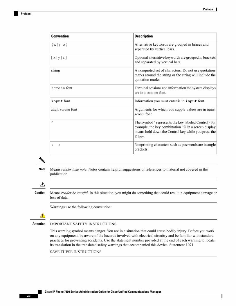
Guide ConventionsThis document uses the following conventions:
DescriptionConvention
Commands and keywords are in boldface.boldface font
Arguments for which you supply values are in italics.italic font
Elements in square brackets are optional.[ ]
Cisco IP Phone 7800 Series Administration Guide for Cisco Unified Communications Managerxiii
DescriptionConvention
Alternative keywords are grouped in braces andseparated by vertical bars.
{ x | y | z }
Optional alternative keywords are grouped in bracketsand separated by vertical bars.
[ x | y | z ]
A nonquoted set of characters. Do not use quotationmarks around the string or the string will include thequotation marks.
string
Terminal sessions and information the system displaysare in screen font.
screen font
Information you must enter is in input font.input font
Arguments for which you supply values are in italicscreen font.
italic screen font
The symbol ^ represents the key labeled Control - forexample, the key combination ^D in a screen displaymeans hold down the Control key while you press theD key.
^
Nonprinting characters such as passwords are in anglebrackets.
< >
Means reader take note. Notes contain helpful suggestions or references to material not covered in thepublication.
Note
Means reader be careful. In this situation, you might do something that could result in equipment damage orloss of data.
Caution
Warnings use the following convention:
IMPORTANT SAFETY INSTRUCTIONS
This warning symbol means danger. You are in a situation that could cause bodily injury. Before you workon any equipment, be aware of the hazards involved with electrical circuitry and be familiar with standardpractices for preventing accidents. Use the statement number provided at the end of each warning to locateits translation in the translated safety warnings that accompanied this device. Statement 1071
SAVE THESE INSTRUCTIONS
Attention
Cisco IP Phone 7800 Series Administration Guide for Cisco Unified Communications Managerxiv
PrefacePreface

Related DocumentationUse the following sections to obtain related information.
Cisco IP Phone 7800 Series DocumentationSee the publications that are specific to your language, phone model, and multiplatform firmware release.Navigate from the following Uniform Resource Locator (URL):
https://www.cisco.com/c/en/us/products/collaboration-endpoints/unified-ip-phone-7800-series/index.html
Cisco Unified Communications Manager DocumentationSee theCisco Unified CommunicationsManager Documentation Guide and other publications that are specificto your Cisco Unified Communications Manager release. Navigate from the following documentation URL:
https://www.cisco.com/c/en/us/support/unified-communications/unified-communications-manager-callmanager/tsd-products-support-series-home.html
Cisco Business Edition 6000 DocumentationRefer to the Cisco Business Edition 6000 Documentation Guide and other publications that are specific toyour Cisco Business Edition 6000 release. Navigate from the following URL:
https://www.cisco.com/c/en/us/support/unified-communications/business-edition-6000/tsd-products-support-series-home.html
Documentation, Support, and Security GuidelinesFor information on obtaining documentation, obtaining support, providing documentation feedback, reviewingsecurity guidelines, and also recommended aliases and general Cisco documents, see the monthlyWhat’s Newin Cisco Product Documentation, which also lists all new and revised Cisco technical documentation, at:
http://www.cisco.com/c/en/us/td/docs/general/whatsnew/whatsnew.html
Subscribe to theWhat’s New in Cisco Product Documentation as a Really Simple Syndication (RSS) feedand set content to be delivered directly to your desktop using a reader application. The RSS feeds are a freeservice and Cisco currently supports RSS Version 2.0.
Cisco Product Security OverviewThis product contains cryptographic features and is subject to U.S. and local country laws that govern import,export, transfer, and use. Delivery of Cisco cryptographic products does not imply third-party authority toimport, export, distribute, or use encryption. Importers, exporters, distributors, and users are responsible forcompliance with U.S. and local country laws. By using this product, you agree to comply with applicablelaws and regulations. If you are unable to comply with U.S. and local laws, return this product immediately.
Further information regarding U.S. export regulations can be found at https://www.bis.doc.gov/policiesandregulations/ear/index.htm.
Cisco IP Phone 7800 Series Administration Guide for Cisco Unified Communications Managerxv
PrefaceRelated Documentation

Cisco IP Phone 7800 Series Administration Guide for Cisco Unified Communications Managerxvi
PrefaceCisco Product Security Overview

C H A P T E R 1New and Changed Information
• New Information for Firmware Release 12.1(1)SR1, on page 1• New Information for Firmware Release 12.1(1), on page 1• New Information for Firmware Release 12.0(1), on page 1• New Information for Firmware Release 11.7(1), on page 2• New Information for Firmware Release 11.5(1)SR1, on page 2• New Information for Firmware Release 11.5(1), on page 2• New Information for Firmware Release 11.0, on page 3
New Information for Firmware Release 12.1(1)SR1No updates were required for firmware release 12.1(1)SR1.
New Information for Firmware Release 12.1(1)All references into Cisco Unified Communications Manager documentation have been updated to support allCisco Unified Communications Manager releases.
Table 1: Cisco IP Phone 7800 Administration Guide Revisions for Firmware Release 12.1(1)
Updated SectionRevision
Product Specific Configuration, on page 138Enabling or disabling TLS 1.2 for web server accessis now supported.
Cisco IP Phone Hardware Overview, on page 21TheG722.2 AMR-WB audio codec is now supported.
Call Statistics Fields, on page 194
New Information for Firmware Release 12.0(1)No updates were required for firmware release 12.0(1).
Cisco IP Phone 7800 Series Administration Guide for Cisco Unified Communications Manager1
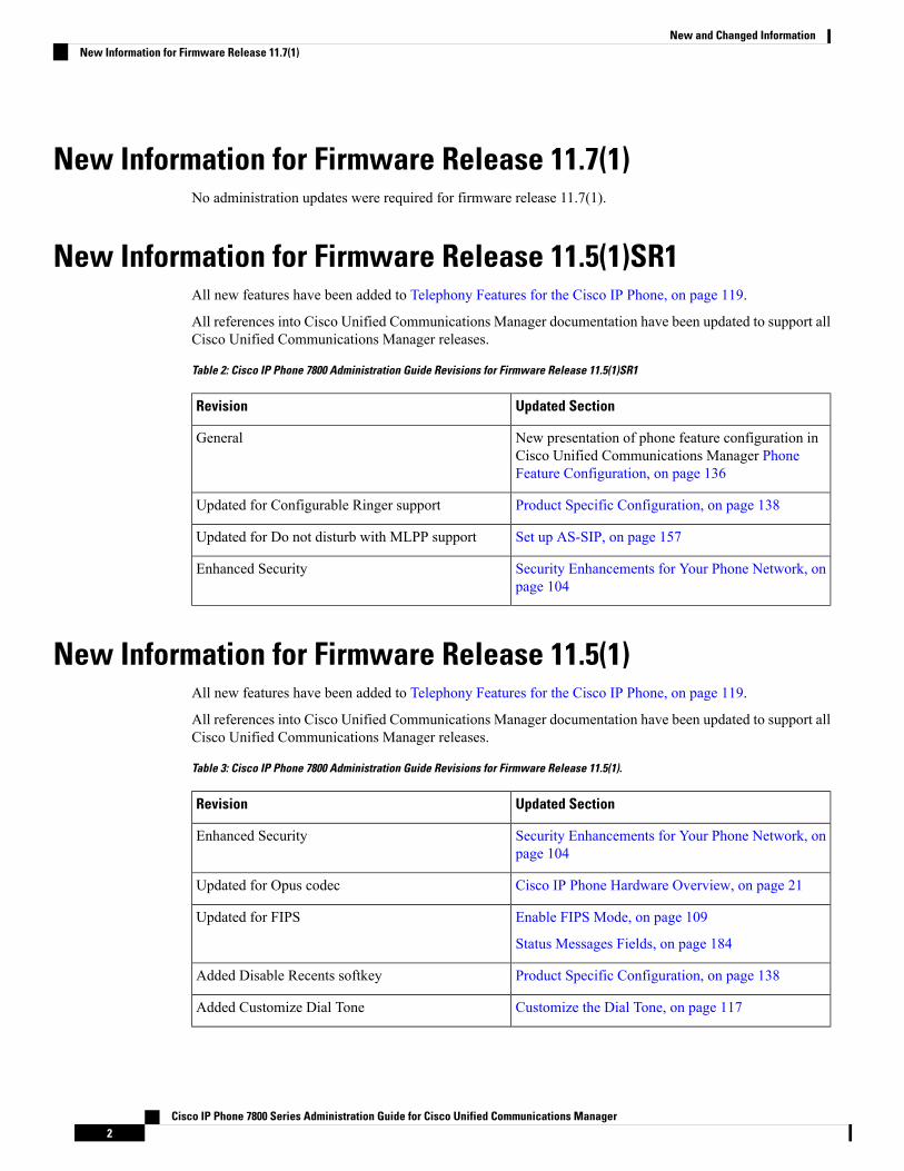
New Information for Firmware Release 11.7(1)No administration updates were required for firmware release 11.7(1).
New Information for Firmware Release 11.5(1)SR1All new features have been added to Telephony Features for the Cisco IP Phone, on page 119.
All references into Cisco Unified Communications Manager documentation have been updated to support allCisco Unified Communications Manager releases.
Table 2: Cisco IP Phone 7800 Administration Guide Revisions for Firmware Release 11.5(1)SR1
Updated SectionRevision
New presentation of phone feature configuration inCisco Unified Communications Manager PhoneFeature Configuration, on page 136
General
Product Specific Configuration, on page 138Updated for Configurable Ringer support
Set up AS-SIP, on page 157Updated for Do not disturb with MLPP support
Security Enhancements for Your Phone Network, onpage 104
Enhanced Security
New Information for Firmware Release 11.5(1)All new features have been added to Telephony Features for the Cisco IP Phone, on page 119.
All references into Cisco Unified Communications Manager documentation have been updated to support allCisco Unified Communications Manager releases.
Table 3: Cisco IP Phone 7800 Administration Guide Revisions for Firmware Release 11.5(1).
Updated SectionRevision
Security Enhancements for Your Phone Network, onpage 104
Enhanced Security
Cisco IP Phone Hardware Overview, on page 21Updated for Opus codec
Enable FIPS Mode, on page 109
Status Messages Fields, on page 184
Updated for FIPS
Product Specific Configuration, on page 138Added Disable Recents softkey
Customize the Dial Tone, on page 117Added Customize Dial Tone
Cisco IP Phone 7800 Series Administration Guide for Cisco Unified Communications Manager2
New and Changed InformationNew Information for Firmware Release 11.7(1)

Updated SectionRevision
Display Network Information Screen, on page 190Added Display Network Info Screen
New Information for Firmware Release 11.0All new features have been added to Telephony Features for the Cisco IP Phone, on page 119.
All references into Cisco Unified Communications Manager documentation have been updated to support allCisco Unified Communications Manager releases.
Table 4: Cisco IP Phone 7800 Administration Guide Revisions for Firmware Release 11.0.
Updated SectionRevision
Telephony Features for the Cisco IP Phone, on page119
Feature Buttons and Softkeys, on page 135
Updated these sections for improved cBarge support
Problem Report Tool, on page 169.
Configure a Customer Support Upload URL, on page170
Updated these section for improved Problem ReportTool(PRT) support:
Set the Label for a Line, on page 171.Added for Line Text Label
Cisco IP Phone 7800 Series Administration Guide for Cisco Unified Communications Manager3
New and Changed InformationNew Information for Firmware Release 11.0

Cisco IP Phone 7800 Series Administration Guide for Cisco Unified Communications Manager4
New and Changed InformationNew Information for Firmware Release 11.0

P A R T IAbout the Cisco IP Phone
• Technical Details, on page 7• Cisco IP Phone Hardware, on page 21


C H A P T E R 2Technical Details
• Physical and Operating Environment Specifications, on page 7• Cable Specifications, on page 8• Network and Computer Port Pinouts, on page 9• Phone Power Requirements, on page 10• Network Protocols, on page 12• VLAN Interaction, on page 16• Cisco Unified Communications Manager Interaction, on page 17• Cisco Unified Communications Manager Express Interaction, on page 18• External Devices, on page 18• Phone Behavior During Times of Network Congestion, on page 19
Physical and Operating Environment SpecificationsThe following table shows the physical and operating environment specifications for the Cisco IP Phone 7800Series.
Table 5: Physical and Operating Specifications
Value or RangeSpecification
32° to 104°F (0° to 40°C)Operating temperature
10% to 90% (noncondensing)Operating relative humidity
14° to 140°F (–10° to 60°C)Storage temperature
8.14 in. (207 mm)Height
• Cisco IP Phone 7811— 7.67 in. (195 mm)
• Cisco IP Phone 7821 — 8.11 in. (206 mm)
• Cisco IP Phone 7841 — 8.11 in. (206 mm)
• Cisco IP Phone 7861— 10.42 in. (264.91 mm)
Width
1.1 in. (28 mm)Depth
Cisco IP Phone 7800 Series Administration Guide for Cisco Unified Communications Manager7

Value or RangeSpecification
• Cisco IP Phone 7811— 0.84 kg
• Cisco IP Phone 7821 — 0.867 kg• Cisco IP Phone 7841 — 0.868 kg• Cisco IP Phone 7861— 1.053 kg
Weight
• 100-240 VAC, 50-60 Hz, 0.5 A—When usingthe AC adapter
• 48 VDC, 0.2 A—When using the in-line powerover the network cable
Power
Cisco IP Phone 7811, 7821, 7841, and 7861:
• Category 3/5/5e/6 for 10-Mbps cables with 4pairs
• Category 5/5e/6 for 100-Mbps cables with 4 pairs
Cisco IP Phone 7841: Category 5/5e/6 for 1000-Mbpscables with 4 pairs
Cables have 4 pairs of wires for a total of8 conductors.
Note
Cables
As supported by the Ethernet Specification, it isassumed that the maximum cable length between eachCisco IP Phone and the switch is 100 meters(330 feet).
Distance Requirements
Cable Specifications• RJ-9 jack (4-conductor) for handset and headset connection.
The Cisco IP Phone 7811 does not contain a headset jack.Note
• RJ-45 jack for the LAN 10/100BaseT connection (on Cisco IP Phones 7811, 7821, and 7861) and theLAN 1000BaseT connection (on the Cisco IP Phone 7841).
• RJ-45 jack for a second 10/100BaseT compliant connection (on Cisco IP Phones 7811, 7821, and 7861)and the LAN 1000BaseT connection (on the Cisco IP Phone 7841).
• 48-volt power connector.
Cisco IP Phone 7800 Series Administration Guide for Cisco Unified Communications Manager8
About the Cisco IP PhoneCable Specifications
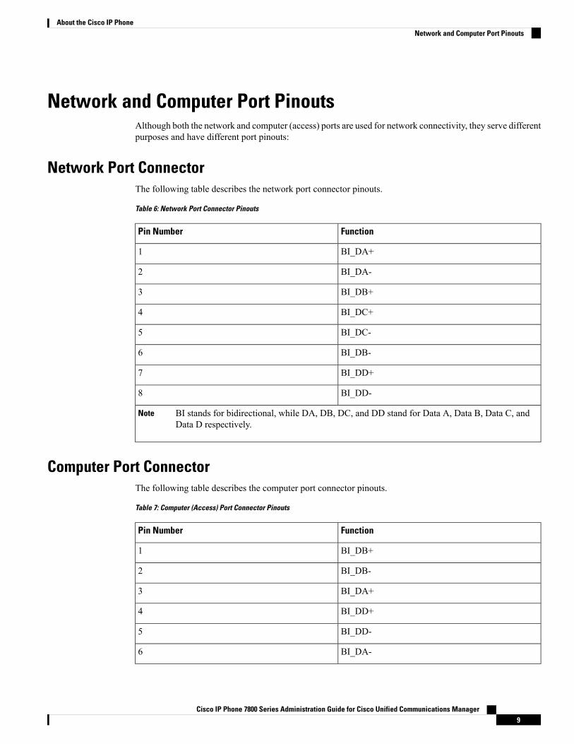
Network and Computer Port PinoutsAlthough both the network and computer (access) ports are used for network connectivity, they serve differentpurposes and have different port pinouts:
Network Port ConnectorThe following table describes the network port connector pinouts.
Table 6: Network Port Connector Pinouts
FunctionPin Number
BI_DA+1
BI_DA-2
BI_DB+3
BI_DC+4
BI_DC-5
BI_DB-6
BI_DD+7
BI_DD-8
BI stands for bidirectional, while DA, DB, DC, and DD stand for Data A, Data B, Data C, andData D respectively.
Note
Computer Port ConnectorThe following table describes the computer port connector pinouts.
Table 7: Computer (Access) Port Connector Pinouts
FunctionPin Number
BI_DB+1
BI_DB-2
BI_DA+3
BI_DD+4
BI_DD-5
BI_DA-6
Cisco IP Phone 7800 Series Administration Guide for Cisco Unified Communications Manager9
About the Cisco IP PhoneNetwork and Computer Port Pinouts
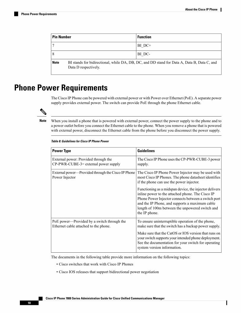
FunctionPin Number
BI_DC+7
BI_DC-8
BI stands for bidirectional, while DA, DB, DC, and DD stand for Data A, Data B, Data C, andData D respectively.
Note
Phone Power RequirementsThe Cisco IP Phone can be powered with external power or with Power over Ethernet (PoE). A separate powersupply provides external power. The switch can provide PoE through the phone Ethernet cable.
When you install a phone that is powered with external power, connect the power supply to the phone and toa power outlet before you connect the Ethernet cable to the phone. When you remove a phone that is poweredwith external power, disconnect the Ethernet cable from the phone before you disconnect the power supply.
Note
Table 8: Guidelines for Cisco IP Phone Power
GuidelinesPower Type
TheCisco IP Phone uses the CP-PWR-CUBE-3 powersupply.
External power: Provided through theCP-PWR-CUBE-3= external power supply
The Cisco IP Phone Power Injector may be used withmost Cisco IP Phones. The phone datasheet identifiesif the phone can use the power injector.
Functioning as a midspan device, the injector deliversinline power to the attached phone. The Cisco IPPhone Power Injector connects between a switch portand the IP Phone, and supports a maximum cablelength of 100m between the unpowered switch andthe IP phone.
External power—Provided through the Cisco IP PhonePower Injector
To ensure uninterruptible operation of the phone,make sure that the switch has a backup power supply.
Make sure that the CatOS or IOS version that runs onyour switch supports your intended phone deployment.See the documentation for your switch for operatingsystem version information.
PoE power—Provided by a switch through theEthernet cable attached to the phone.
The documents in the following table provide more information on the following topics:
• Cisco switches that work with Cisco IP Phones
• Cisco IOS releases that support bidirectional power negotiation
Cisco IP Phone 7800 Series Administration Guide for Cisco Unified Communications Manager10
About the Cisco IP PhonePhone Power Requirements
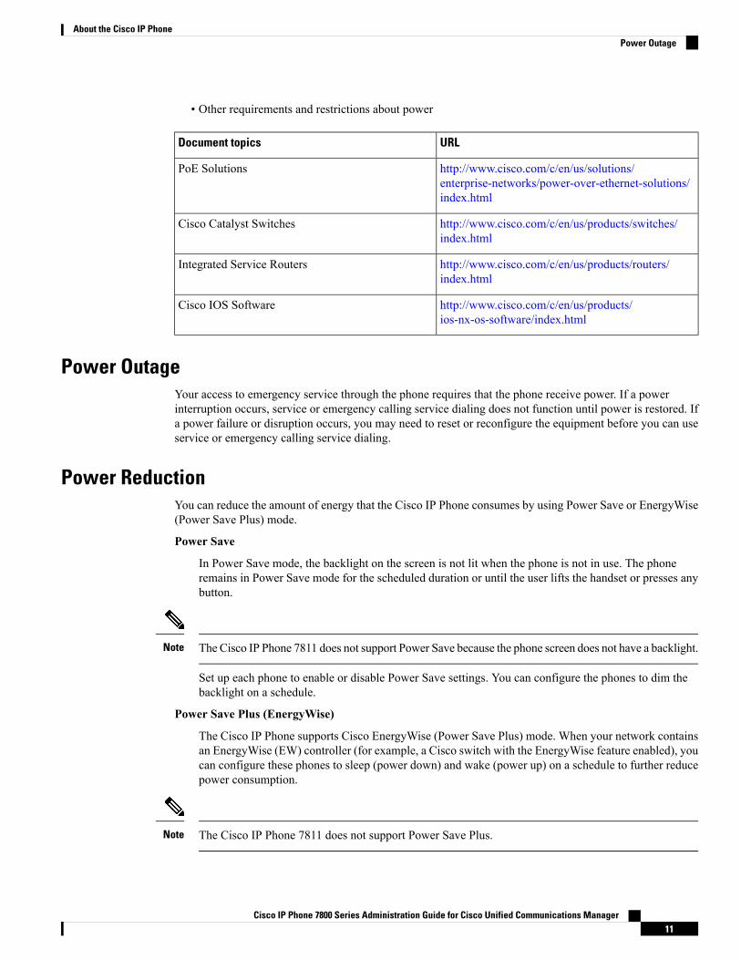
• Other requirements and restrictions about power
URLDocument topics
http://www.cisco.com/c/en/us/solutions/enterprise-networks/power-over-ethernet-solutions/index.html
PoE Solutions
http://www.cisco.com/c/en/us/products/switches/index.html
Cisco Catalyst Switches
http://www.cisco.com/c/en/us/products/routers/index.html
Integrated Service Routers
http://www.cisco.com/c/en/us/products/ios-nx-os-software/index.html
Cisco IOS Software
Power OutageYour access to emergency service through the phone requires that the phone receive power. If a powerinterruption occurs, service or emergency calling service dialing does not function until power is restored. Ifa power failure or disruption occurs, you may need to reset or reconfigure the equipment before you can useservice or emergency calling service dialing.
Power ReductionYou can reduce the amount of energy that the Cisco IP Phone consumes by using Power Save or EnergyWise(Power Save Plus) mode.
Power Save
In Power Save mode, the backlight on the screen is not lit when the phone is not in use. The phoneremains in Power Save mode for the scheduled duration or until the user lifts the handset or presses anybutton.
The Cisco IP Phone 7811 does not support Power Save because the phone screen does not have a backlight.Note
Set up each phone to enable or disable Power Save settings. You can configure the phones to dim thebacklight on a schedule.
Power Save Plus (EnergyWise)
The Cisco IP Phone supports Cisco EnergyWise (Power Save Plus) mode. When your network containsan EnergyWise (EW) controller (for example, a Cisco switch with the EnergyWise feature enabled), youcan configure these phones to sleep (power down) and wake (power up) on a schedule to further reducepower consumption.
The Cisco IP Phone 7811 does not support Power Save Plus.Note
Cisco IP Phone 7800 Series Administration Guide for Cisco Unified Communications Manager11
About the Cisco IP PhonePower Outage
Set up each phone to enable or disable the EnergyWise settings. If EnergyWise is enabled, configure asleep and wake time, as well as other parameters. These parameters are sent to the phone as part of thephone configuration XML file.
Power Negotiation Over LLDPThe phone and the switch negotiate the power that the phone consumes. Cisco IP Phone operates at multiplepower settings, which lowers power consumption when less power is available.
After a phone reboots, the switch locks to one protocol (CDP or LLDP) for power negotiation. The switchlocks to the first protocol (containing a power Threshold Limit Value [TLV]) that the phone transmits. If thesystem administrator disables that protocol on the phone, the phone cannot power up any accessories becausethe switch does not respond to power requests in the other protocol.
Cisco recommends that Power Negotiation always be enabled (default) when connecting to a switch thatsupports power negotiation.
If Power Negotiation is disabled, the switch may disconnect power to the phone. If the switch does not supportpower negotiation, disable the Power Negotiation feature before you power up accessories over PoE. Whenthe Power Negotiation feature is disabled, the phone can power the accessories up to the maximum that theIEEE 802.3af-2003 standard allows.
When CDP and Power Negotiation are disabled, the phone can power the accessories up to 15.4W.Note
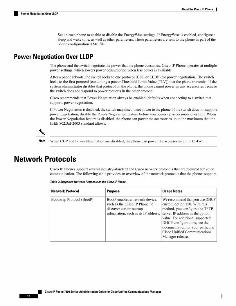
Network ProtocolsCisco IP Phones support several industry-standard and Cisco network protocols that are required for voicecommunication. The following table provides an overview of the network protocols that the phones support.
Table 9: Supported Network Protocols on the Cisco IP Phone
Usage NotesPurposeNetwork Protocol
We recommend that you use DHCPcustom option 150. With thismethod, you configure the TFTPserver IP address as the optionvalue. For additional supportedDHCP configurations, see thedocumentation for your particularCisco Unified CommunicationsManager release.
BootP enables a network device,such as the Cisco IP Phone, todiscover certain startupinformation, such as its IP address.
Bootstrap Protocol (BootP)
Cisco IP Phone 7800 Series Administration Guide for Cisco Unified Communications Manager12
About the Cisco IP PhonePower Negotiation Over LLDP

Usage NotesPurposeNetwork Protocol
The Cisco IP Phone uses CAST asan interface between CUVA andCisco Unified CommunicationsManager using the Cisco IP Phoneas a SIP proxy.
The CAST protocol allows IPphones and associated applicationsbehind the phone to discover andcommunicate with the remoteendpoints without requiringchanges to the traditional signalingcomponents like Cisco UnifiedCommunications Manager andgateways. The CAST protocolallows separate hardware devicesto synchronize related media and itallows PC applications to augmentnonvideo-capable phones tobecome video enabled using the PCas the video resource.
Cisco Audio Session Tunneling(CAST)
The Cisco IP Phone uses CDP tocommunicate information such asauxiliary VLAN ID, per port powermanagement details, and Qualityof Service (QoS) configurationinformation with the Cisco Catalystswitch.
CDP is a device-discovery protocolthat runs on all Cisco-manufacturedequipment.
A device can use CDP to advertiseits existence to other devices andreceive information about otherdevices in the network.
Cisco Discovery Protocol (CDP)
Cisco IP Phones have a DNS clientto translate domain names into IPaddresses.
DNS translates domain names toIP addresses.
Domain Name Server (DNS)
DHCP is enabled by default. Ifdisabled, you must manuallyconfigure the IP address, subnetmask, gateway, and a TFTP serveron each phone locally.
We recommend that you use DHCPcustom option 150. With thismethod, you configure the TFTPserver IP address as the optionvalue. For additional supportedDHCP configurations, see thedocumentation for your particularCisco Unified CommunicationsManager release.
If you cannot use option150, use DHCP option66.
Note
DHCP dynamically allocates andassigns an IP address to networkdevices.
DHCP enables you to connect anIP phone into the network and havethe phone become operationalwithout the need tomanually assignan IP address or to configureadditional network parameters.
Dynamic Host ConfigurationProtocol (DHCP)
Cisco IP Phone 7800 Series Administration Guide for Cisco Unified Communications Manager13
About the Cisco IP PhoneNetwork Protocols
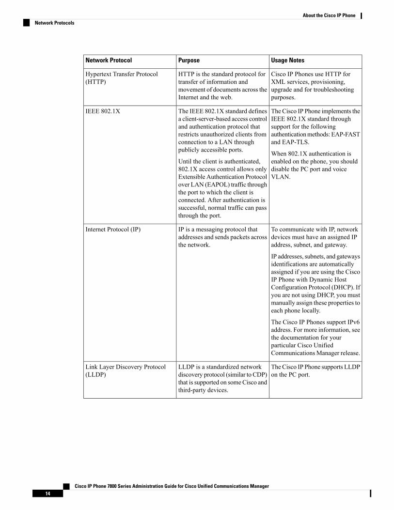
Usage NotesPurposeNetwork Protocol
Cisco IP Phones use HTTP forXML services, provisioning,upgrade and for troubleshootingpurposes.
HTTP is the standard protocol fortransfer of information andmovement of documents across theInternet and the web.
Hypertext Transfer Protocol(HTTP)
The Cisco IP Phone implements theIEEE 802.1X standard throughsupport for the followingauthenticationmethods: EAP-FASTand EAP-TLS.
When 802.1X authentication isenabled on the phone, you shoulddisable the PC port and voiceVLAN.
The IEEE 802.1X standard definesa client-server-based access controland authentication protocol thatrestricts unauthorized clients fromconnection to a LAN throughpublicly accessible ports.
Until the client is authenticated,802.1X access control allows onlyExtensible Authentication Protocolover LAN (EAPOL) traffic throughthe port to which the client isconnected. After authentication issuccessful, normal traffic can passthrough the port.
IEEE 802.1X
To communicate with IP, networkdevices must have an assigned IPaddress, subnet, and gateway.
IP addresses, subnets, and gatewaysidentifications are automaticallyassigned if you are using the CiscoIP Phone with Dynamic HostConfiguration Protocol (DHCP). Ifyou are not using DHCP, you mustmanually assign these properties toeach phone locally.
The Cisco IP Phones support IPv6address. For more information, seethe documentation for yourparticular Cisco UnifiedCommunicationsManager release.
IP is a messaging protocol thataddresses and sends packets acrossthe network.
Internet Protocol (IP)
The Cisco IP Phone supports LLDPon the PC port.
LLDP is a standardized networkdiscovery protocol (similar to CDP)that is supported on someCisco andthird-party devices.
Link Layer Discovery Protocol(LLDP)
Cisco IP Phone 7800 Series Administration Guide for Cisco Unified Communications Manager14
About the Cisco IP PhoneNetwork Protocols

Usage NotesPurposeNetwork Protocol
The Cisco IP Phone supportsLLDP-MED on the SW port tocommunicate information such as:
• Voice VLAN configuration• Device discovery• Power management• Inventory management
For more information aboutLLDP-MED support, see theLLDP-MED and Cisco DiscoveryProtocol white paper at this URL:http://www.cisco.com/en/US/tech/tk652/tk701/technologies_white_paper0900aecd804cd46d.shtml
LLDP-MED is an extension of theLLDP standard developed for voiceproducts.
Link Layer DiscoveryProtocol-Media Endpoint Devices(LLDP-MED)
Cisco IP Phones have anNTP clientintegrated into the software.
NTP is a networking protocol forclock synchronization betweencomputer systems overpacket-switched, variable-latencydata networks.
Network Transport Protocol (NTP)
Cisco IP Phones use the RTPprotocol to send and receivereal-time voice traffic from otherphones and gateways.
RTP is a standard protocol fortransporting real-time data, such asinteractive voice and video, overdata networks.
Real-Time Transport Protocol(RTP)
RTCP is enabled by default.RTCP works in conjunction withRTP to provide QoS data (such asjitter, latency, and round trip delay)on RTP streams.
Real-Time Control Protocol(RTCP)
Like other VoIP protocols, SIP isdesigned to address the functionsof signaling and sessionmanagement within a packettelephony network. Signalingallows call information to becarried across network boundaries.Session management provides theability to control the attributes ofan end-to-end call.
SIP is the Internet EngineeringTask Force (IETF) standard formultimedia conferencing over IP.SIP is an ASCII-basedapplication-layer control protocol(defined in RFC 3261) that can beused to establish, maintain, andterminate calls between two ormore endpoints.
Session Initiation Protocol (SIP)
Cisco IP Phones use SRTP formedia encryption.
SRTP is an extension of theReal-Time Protocol (RTP)Audio/Video Profile and ensuresthe integrity of RTP and Real-TimeControl Protocol (RTCP) packetsproviding authentication, integrity,and encryption of media packetsbetween two endpoints.
Secure Real-TimeTransfer protocol(SRTP)
Cisco IP Phone 7800 Series Administration Guide for Cisco Unified Communications Manager15
About the Cisco IP PhoneNetwork Protocols
Usage NotesPurposeNetwork Protocol
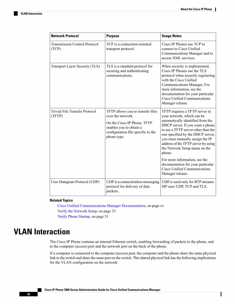
Cisco IP Phones use TCP toconnect to Cisco UnifiedCommunications Manager and toaccess XML services.
TCP is a connection-orientedtransport protocol.
Transmission Control Protocol(TCP)
When security is implemented,Cisco IP Phones use the TLSprotocol when securely registeringwith the Cisco UnifiedCommunications Manager. Formore information, see thedocumentation for your particularCisco Unified CommunicationsManager release.
TLS is a standard protocol forsecuring and authenticatingcommunications.
Transport Layer Security (TLS)
TFTP requires a TFTP server inyour network, which can beautomatically identified from theDHCP server. If you want a phoneto use a TFTP server other than theone specified by the DHCP server,you must manually assign the IPaddress of the TFTP server by usingthe Network Setup menu on thephone.
For more information, see thedocumentation for your particularCisco Unified CommunicationsManager release.
TFTP allows you to transfer filesover the network.
On the Cisco IP Phone, TFTPenables you to obtain aconfiguration file specific to thephone type.
Trivial File Transfer Protocol(TFTP)
UDP is used only for RTP streams.SIP uses UDP, TCP and TLS.
UDP is a connectionless messagingprotocol for delivery of datapackets.
User Datagram Protocol (UDP)
Related TopicsCisco Unified Communications Manager Documentation, on page xvVerify the Network Setup, on page 33Verify Phone Startup, on page 51
VLAN InteractionThe Cisco IP Phone contains an internal Ethernet switch, enabling forwarding of packets to the phone, andto the computer (access) port and the network port on the back of the phone.
If a computer is connected to the computer (access) port, the computer and the phone share the same physicallink to the switch and share the same port on the switch. This shared physical link has the following implicationsfor the VLAN configuration on the network:
Cisco IP Phone 7800 Series Administration Guide for Cisco Unified Communications Manager16
About the Cisco IP PhoneVLAN Interaction

• The current VLANs might be configured on an IP subnet basis. However, additional IP addresses mightnot be available to assign the phone to the same subnet as other devices that connect to the same port.
• Data traffic present on the VLAN supporting phones might reduce the quality of VoIP traffic.
• Network security may indicate a need to isolate the VLAN voice traffic from the VLAN data traffic.
You can resolve these issues by isolating the voice traffic onto a separate VLAN. The switch port to whichthe phone connects would be configured for separate VLANs for carrying:
• Voice traffic to and from the IP phone (auxiliary VLAN on the Cisco Catalyst 6000 series, for example)
• Data traffic to and from the PC that connects to the switch through the computer (access) port of the IPphone (native VLAN)
Isolating the phones on a separate, auxiliary VLAN increases the quality of the voice traffic and allows a largenumber of phones to be added to an existing network that does not have enough IP addresses for each phone.
For more information, see the documentation that is included with a Cisco switch. You can also access switchinformation at this URL:
http://cisco.com/en/US/products/hw/switches/index.html
Cisco Unified Communications Manager InteractionCisco Unified Communications Manager is an open, industry-standard call processing system. Cisco UnifiedCommunications Manager software sets up and tears down calls between phones, integrating traditional PBXfunctionality with the corporate IP network. Cisco Unified CommunicationsManager manages the componentsof the IP telephony system, such as the phones, the access gateways, and the resources necessary for featuressuch as call conferencing and route planning. Cisco Unified Communications Manager also provides:
• Firmware for phones
• Certificate Trust List (CTL) and Identity Trust List (ITL) files using the TFTP and HTTP services
• Phone registration
• Call preservation, so that a media session continues if signaling is lost between the primaryCommunications Manager and a phone
For information about configuring Cisco Unified Communications Manager to work with the IP phonesdescribed in this chapter, see the documentation for your particular Cisco Unified Communications Managerrelease.
If the Cisco IP Phone model that you want to configure does not appear in the Phone Type drop-down list inCisco Unified Communications Manager Administration, install the latest support patch for your version ofCisco Unified Communications Manager from Cisco.com.
Note
Related TopicsCisco Unified Communications Manager Documentation, on page xv
Cisco IP Phone 7800 Series Administration Guide for Cisco Unified Communications Manager17
About the Cisco IP PhoneCisco Unified Communications Manager Interaction
Cisco Unified Communications Manager Express InteractionWhen the Cisco IP Phone works with the Cisco Unified Communications Manager Express, the phones mustgo into CME mode.
When a user invokes the conference feature, the tag allows the phone to use either a local or network hardwareconference bridge.
The Cisco IP Phones do not support the following actions:
Transfer
Only supported in the connected call transfer scenario.
Conference
Only supported in the connected call transfer scenario.
Join
Supported using the Conference button or Hookflash access.
Hold
Supported using the Hold button or Hold softkey.
Barge
Not supported.
Direct Transfer
Not supported.
Select
Not supported.
Users cannot create conference and transfer calls across different lines.
External DevicesWe recommend that you use good-quality external devices that are shielded against unwanted radio frequency(RF) and audio frequency (AF) signals. External devices include headsets, cables, and connectors.
Depending on the quality of these devices and their proximity to other devices, such as mobile phones ortwo-way radios, some audio noise may still occur. In these cases, we recommend that you take one or moreof these actions:
• Move the external device away from the source of the RF or AF signals.
• Route the external device cables away from the source of the RF or AF signals.
• Use shielded cables for the external device, or use cables with a better shield and connector.
• Shorten the length of the external device cable.
• Apply ferrites or other such devices on the cables for the external device.
Cisco IP Phone 7800 Series Administration Guide for Cisco Unified Communications Manager18
About the Cisco IP PhoneCisco Unified Communications Manager Express Interaction

Cisco cannot guarantee the performance of external devices, cables, and connectors.
In European Union countries, use only external speakers, microphones, and headsets that are fully compliantwith the EMC Directive [89/336/EC].
Caution
Phone Behavior During Times of Network CongestionAnything that degrades network performance can affect phone voice and video quality, and in some cases,can cause a call to drop. Sources of network degradation can include, but are not limited to, the followingactivities:
• Administrative tasks, such as an internal port scan or security scan
• Attacks that occur on your network, such as a Denial of Service attack
Cisco IP Phone 7800 Series Administration Guide for Cisco Unified Communications Manager19
About the Cisco IP PhonePhone Behavior During Times of Network Congestion

Cisco IP Phone 7800 Series Administration Guide for Cisco Unified Communications Manager20
About the Cisco IP PhonePhone Behavior During Times of Network Congestion
C H A P T E R 3Cisco IP Phone Hardware
• Cisco IP Phone Hardware Overview, on page 21• Cisco IP Phone 7811, on page 23• Cisco IP Phone 7821, on page 24• Cisco IP Phone 7841, on page 25• Cisco IP Phone 7861, on page 26• Buttons and Hardware, on page 27• Terminology Differences, on page 29
Cisco IP Phone Hardware OverviewThe Cisco IP Phone 7811, 7821, 7841, and 7861 provides voice communication over an Internet Protocol(IP) network. The Cisco IP Phone functions much like a digital business phone, allowing you to place andreceive phone calls and to access features such as mute, hold, transfer, speed dial, call forward, and more. Inaddition, because the phone connects to your data network, it offers enhanced IP telephony features, includingaccess to network information and services, and customizable features and services.
The Cisco IP Phone 7841 supports Gigabit ethernet connectivity.
When adding features to the phone line keys, you are limited by the number of line keys available. You cannotadd more features than the number of line keys on your phone.
Table 10: Cisco IP Phone 7800 Series and Supported Line Keys
Supported Line KeysPhone
0Cisco IP Phone 7811
2Cisco IP Phone 7821
4Cisco IP Phone 7841
16Cisco IP Phone 7861
A Cisco IP Phone, like other network devices, must be configured and managed. These phones encode thefollowing codecs:
• G.711 a-law
Cisco IP Phone 7800 Series Administration Guide for Cisco Unified Communications Manager21

• G.711 mu-law
• G.722
• G722.2 AMR-WB
• G.729a
• G.729ab
• iLBC
• Opus
These phones decode the following codecs:
• G.711 a-law
• G.711 mu-law
• G.722
• G.729
• G.729a
• G.729b
• G.729ab
• iLBC
• Opus
Use of a cell, mobile, or GSM phone, or two-way radio in close proximity to a Cisco IP Phone might causeinterference. For more information, see the manufacturer documentation of the interfering device.
As with other network devices, you must configure Cisco IP Phones to prepare them to access Cisco UnifiedCommunicationsManager and the rest of the IP network. By using DHCP, you have fewer settings to configureon a phone. If your network requires it, however, you can manually configure information such as: an IPaddress, TFTP server, and subnet information.
Cisco IP Phones can interact with other services and devices on your IP network to provide enhancedfunctionality. For example, you can integrate Cisco Unified Communications Manager with the corporateLightweight Directory Access Protocol 3 (LDAP3) standard directory to enable users to search for coworkercontact information directly from their IP phones. You can also use XML to enable users to access informationsuch as weather, stocks, quote of the day, and other web-based information.
Caution
Cisco IP Phone 7800 Series Administration Guide for Cisco Unified Communications Manager22
About the Cisco IP PhoneCisco IP Phone Hardware Overview

Cisco IP Phone 7811
Phone ConnectionsUse an Ethernet cable to connect your phone to your LAN and enable the phone's full functionality. If yourEthernet port is equipped with Power over Ethernet (PoE), you can power the phone through the LAN port.Do not extend the LAN Ethernet cable outside the building. For your phone to work, it must be connected tothe IP telephony network.
Network port (10/100 SW) connection.IEEE 802.3af power enabled.
4DC adapter port (DC48V).1
Access port (10/100 PC) connection(optional).
5AC-to-DC power supply (optional).2
Handset connection.6AC power wall plug (optional).3
Cisco IP Phone 7800 Series Administration Guide for Cisco Unified Communications Manager23
About the Cisco IP PhoneCisco IP Phone 7811

Cisco IP Phone 7821
Phone ConnectionsConnect your Cisco IP phone to your LAN with an Ethernet cable to enable full functionality of your CiscoIP phone. If your Ethernet port is equipped with Power over Ethernet (PoE), you can power the Cisco IPphone through the LAN port. Do not extend the LAN Ethernet cable outside the building. For your phone towork, it must be connected to the IP telephony network.
Access port (10/100 PC) connection(optional).
5DC adaptor port (DC48V) (optional).1
Auxiliary port (optional).6AC-to-DC power supply (optional).2
Handset connection.7AC power wall plug (optional).3
Analog headset connection (optional).8Network port (10/100 SW) connection.IEEE 802.3af power enabled.
4
Cisco IP Phone 7800 Series Administration Guide for Cisco Unified Communications Manager24
About the Cisco IP PhoneCisco IP Phone 7821
Cisco IP Phone 7841
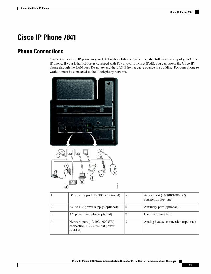
Phone ConnectionsConnect your Cisco IP phone to your LAN with an Ethernet cable to enable full functionality of your CiscoIP phone. If your Ethernet port is equipped with Power over Ethernet (PoE), you can power the Cisco IPphone through the LAN port. Do not extend the LAN Ethernet cable outside the building. For your phone towork, it must be connected to the IP telephony network.
Access port (10/100/1000 PC)connection (optional).
5DC adaptor port (DC48V) (optional).1
Auxiliary port (optional).6AC-to-DC power supply (optional).2
Handset connection.7AC power wall plug (optional).3
Analog headset connection (optional).8Network port (10/100/1000 SW)connection. IEEE 802.3af powerenabled.
4
Cisco IP Phone 7800 Series Administration Guide for Cisco Unified Communications Manager25
About the Cisco IP PhoneCisco IP Phone 7841
Cisco IP Phone 7861
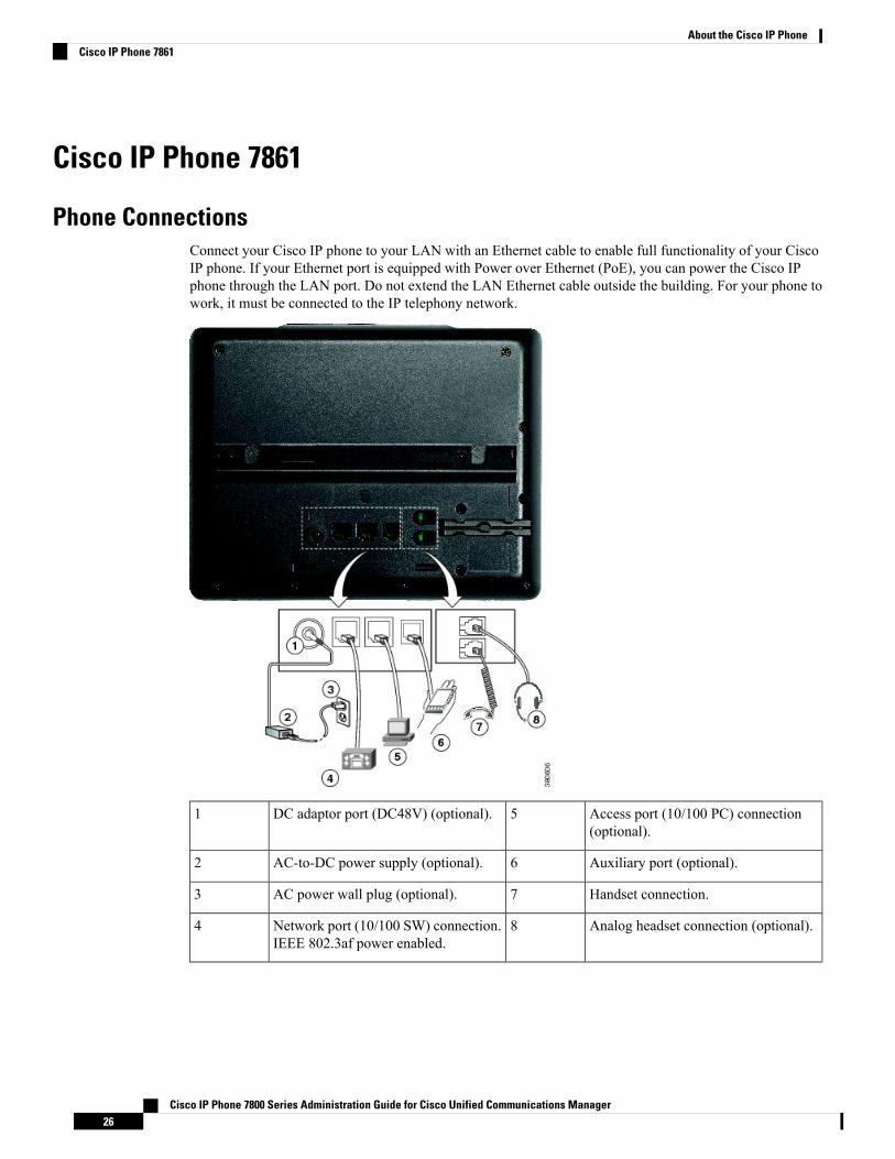
Phone ConnectionsConnect your Cisco IP phone to your LAN with an Ethernet cable to enable full functionality of your CiscoIP phone. If your Ethernet port is equipped with Power over Ethernet (PoE), you can power the Cisco IPphone through the LAN port. Do not extend the LAN Ethernet cable outside the building. For your phone towork, it must be connected to the IP telephony network.
Access port (10/100 PC) connection(optional).
5DC adaptor port (DC48V) (optional).1
Auxiliary port (optional).6AC-to-DC power supply (optional).2
Handset connection.7AC power wall plug (optional).3
Analog headset connection (optional).8Network port (10/100 SW) connection.IEEE 802.3af power enabled.
4
Cisco IP Phone 7800 Series Administration Guide for Cisco Unified Communications Manager26
About the Cisco IP PhoneCisco IP Phone 7861

Buttons and HardwareThe Cisco IP Phone 7800 Series has distinct hardware types:
• Cisco IP Phone 7811 No buttons on either side of the screen
• Cisco IP Phone 7821 Two buttons on the left side of the screen
• Cisco IP Phone 7841 Two buttons on either side of the screen
• Cisco IP Phone 7861 16 buttons at the right edge of the phone
Figure 1: Cisco IP Phone 7800 Series Buttons and Features
Indicates whether you have an incoming call (flashing red)or a new voice message (steady red).
Handset and Handset light strip1
Access your phone lines, features, and call sessions.
For more information, see Softkey, Line, and FeatureButtons, on page 28.
The Cisco IP Phone 7811 does not have programmablefeature buttons or line buttons.
Programmable feature buttons and linebuttons
2
Access functions and services.
For more information, see Softkey, Line, and FeatureButtons, on page 28.
Softkey buttons3
Navigation ring and Select button. Scroll throughmenus, highlight items, and select the highlighted item.
Navigation cluster4
Cisco IP Phone 7800 Series Administration Guide for Cisco Unified Communications Manager27
About the Cisco IP PhoneButtons and Hardware
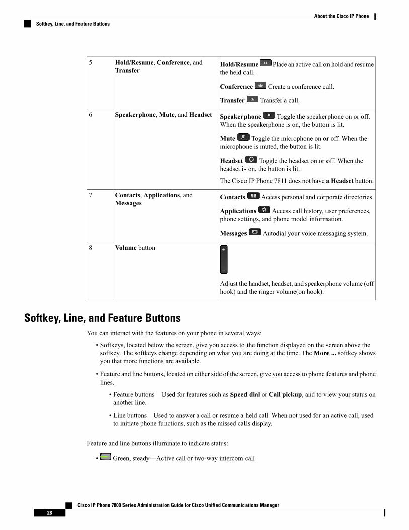
Hold/Resume Place an active call on hold and resumethe held call.
Conference Create a conference call.
Transfer Transfer a call.
Hold/Resume, Conference, andTransfer
5
Speakerphone Toggle the speakerphone on or off.When the speakerphone is on, the button is lit.
Mute Toggle the microphone on or off. When themicrophone is muted, the button is lit.
Headset Toggle the headset on or off. When theheadset is on, the button is lit.
The Cisco IP Phone 7811 does not have aHeadset button.
Speakerphone,Mute, and Headset6
Contacts Access personal and corporate directories.
Applications Access call history, user preferences,phone settings, and phone model information.
Messages Autodial your voice messaging system.
Contacts, Applications, andMessages
7
Adjust the handset, headset, and speakerphone volume (offhook) and the ringer volume(on hook).
Volume button8
Softkey, Line, and Feature ButtonsYou can interact with the features on your phone in several ways:
• Softkeys, located below the screen, give you access to the function displayed on the screen above thesoftkey. The softkeys change depending on what you are doing at the time. TheMore ... softkey showsyou that more functions are available.
• Feature and line buttons, located on either side of the screen, give you access to phone features and phonelines.
• Feature buttons—Used for features such as Speed dial or Call pickup, and to view your status onanother line.
• Line buttons—Used to answer a call or resume a held call. When not used for an active call, usedto initiate phone functions, such as the missed calls display.
Feature and line buttons illuminate to indicate status:
• Green, steady—Active call or two-way intercom call
Cisco IP Phone 7800 Series Administration Guide for Cisco Unified Communications Manager28
About the Cisco IP PhoneSoftkey, Line, and Feature Buttons
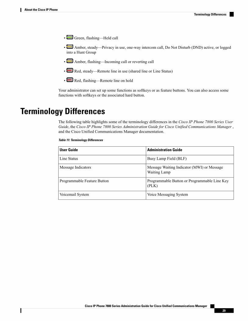
• Green, flashing—Held call
• Amber, steady—Privacy in use, one-way intercom call, Do Not Disturb (DND) active, or loggedinto a Hunt Group
• Amber, flashing—Incoming call or reverting call
• Red, steady—Remote line in use (shared line or Line Status)
• Red, flashing—Remote line on hold
Your administrator can set up some functions as softkeys or as feature buttons. You can also access somefunctions with softkeys or the associated hard button.
Terminology DifferencesThe following table highlights some of the terminology differences in the Cisco IP Phone 7800 Series UserGuide, the Cisco IP Phone 7800 Series Administration Guide for Cisco Unified Communications Manager ,and the Cisco Unified Communications Manager documentation.
Table 11: Terminology Differences
Administration GuideUser Guide
Busy Lamp Field (BLF)Line Status
Message Waiting Indicator (MWI) or MessageWaiting Lamp
Message Indicators
Programmable Button or Programmable Line Key(PLK)
Programmable Feature Button
Voice Messaging SystemVoicemail System
Cisco IP Phone 7800 Series Administration Guide for Cisco Unified Communications Manager29
About the Cisco IP PhoneTerminology Differences

Cisco IP Phone 7800 Series Administration Guide for Cisco Unified Communications Manager30
About the Cisco IP PhoneTerminology Differences

P A R T IICisco IP Phone Installation
• Cisco IP Phone Installation, on page 33• Cisco Unified Communications Manager Phone Setup, on page 53• Self Care Portal Management, on page 65


C H A P T E R 4Cisco IP Phone Installation
• Verify the Network Setup, on page 33• Enable Autoregistration for Phones, on page 34• Install the Cisco IP Phone, on page 35• Set Up the Phone from the Setup Menus, on page 37• Configure Network Settings, on page 39• Verify Phone Startup, on page 51• Configure Phone Services for Users, on page 52
Verify the Network SetupAs they deploy a new IP telephony system, system administrators and network administrators must completeseveral initial configuration tasks to prepare the network for IP telephony service. For information and achecklist for setting up and configuring a Cisco IP telephony network, see the documentation for your particularCisco Unified Communications Manager release.
For the phone to operate successfully as an endpoint in your network, your network must meet specificrequirements. One requirement is the appropriate bandwidth. The phones require more bandwidth than therecommended 32 kbps when they register to Cisco Unified Communications Manager. Consider this higherbandwidth requirement when you configure your QoS bandwidth. For more information, refer to CiscoCollaboration System 12.x Solution Reference Network Designs (SRND) or later ( https://www.cisco.com/c/en/us/td/docs/voice_ip_comm/cucm/srnd/collab12/collab12.html ).
The phone displays the date and time from Cisco Unified Communications Manager. The time displayed onthe phone can differ from the Cisco Unified Communications Manager time by up to 10 seconds.
Note
Procedure
Step 1 Configure a VoIP Network to meet the following requirements:
• VoIP is configured on your routers and gateways.
• Cisco Unified Communications Manager is installed in your network and is configured to handle callprocessing.
Cisco IP Phone 7800 Series Administration Guide for Cisco Unified Communications Manager33
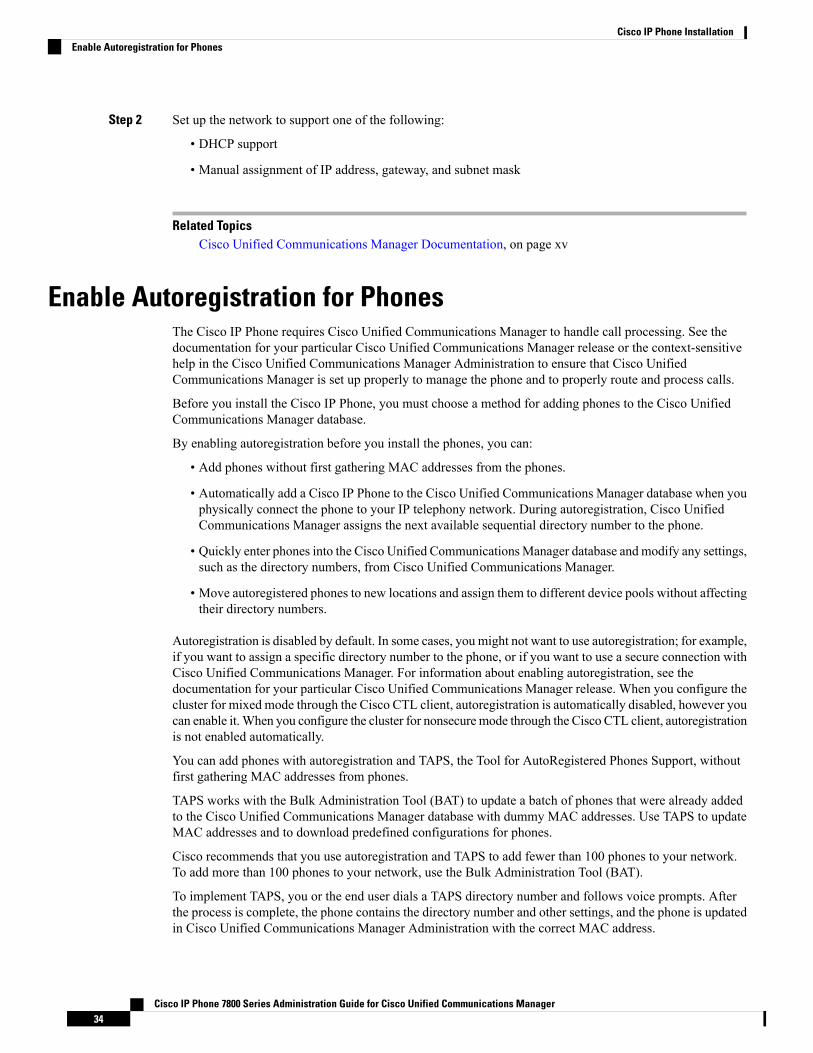
Step 2 Set up the network to support one of the following:
• DHCP support
• Manual assignment of IP address, gateway, and subnet mask
Related TopicsCisco Unified Communications Manager Documentation, on page xv
Enable Autoregistration for PhonesThe Cisco IP Phone requires Cisco Unified Communications Manager to handle call processing. See thedocumentation for your particular Cisco Unified Communications Manager release or the context-sensitivehelp in the Cisco Unified Communications Manager Administration to ensure that Cisco UnifiedCommunications Manager is set up properly to manage the phone and to properly route and process calls.
Before you install the Cisco IP Phone, you must choose a method for adding phones to the Cisco UnifiedCommunications Manager database.
By enabling autoregistration before you install the phones, you can:
• Add phones without first gathering MAC addresses from the phones.
• Automatically add a Cisco IP Phone to the Cisco Unified Communications Manager database when youphysically connect the phone to your IP telephony network. During autoregistration, Cisco UnifiedCommunications Manager assigns the next available sequential directory number to the phone.
• Quickly enter phones into the Cisco Unified CommunicationsManager database andmodify any settings,such as the directory numbers, from Cisco Unified Communications Manager.
• Move autoregistered phones to new locations and assign them to different device pools without affectingtheir directory numbers.
Autoregistration is disabled by default. In some cases, you might not want to use autoregistration; for example,if you want to assign a specific directory number to the phone, or if you want to use a secure connection withCisco Unified Communications Manager. For information about enabling autoregistration, see thedocumentation for your particular Cisco Unified Communications Manager release. When you configure thecluster for mixed mode through the Cisco CTL client, autoregistration is automatically disabled, however youcan enable it.When you configure the cluster for nonsecuremode through the Cisco CTL client, autoregistrationis not enabled automatically.
You can add phones with autoregistration and TAPS, the Tool for AutoRegistered Phones Support, withoutfirst gathering MAC addresses from phones.
TAPS works with the Bulk Administration Tool (BAT) to update a batch of phones that were already addedto the Cisco Unified Communications Manager database with dummy MAC addresses. Use TAPS to updateMAC addresses and to download predefined configurations for phones.
Cisco recommends that you use autoregistration and TAPS to add fewer than 100 phones to your network.To add more than 100 phones to your network, use the Bulk Administration Tool (BAT).
To implement TAPS, you or the end user dials a TAPS directory number and follows voice prompts. Afterthe process is complete, the phone contains the directory number and other settings, and the phone is updatedin Cisco Unified Communications Manager Administration with the correct MAC address.
Cisco IP Phone 7800 Series Administration Guide for Cisco Unified Communications Manager34
Cisco IP Phone InstallationEnable Autoregistration for Phones
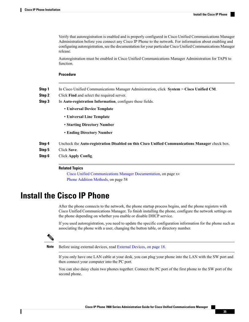
Verify that autoregistration is enabled and is properly configured in Cisco Unified Communications ManagerAdministration before you connect any Cisco IP Phone to the network. For information about enabling andconfiguring autoregistration, see the documentation for your particular CiscoUnified CommunicationsManagerrelease.
Autoregistration must be enabled in Cisco Unified Communications Manager Administration for TAPS tofunction.
Procedure
Step 1 In Cisco Unified Communications Manager Administration, click System > Cisco Unified CM.Step 2 Click Find and select the required server.Step 3 In Auto-registration Information, configure these fields.
• Universal Device Template
• Universal Line Template
• Starting Directory Number
• Ending Directory Number
Step 4 Uncheck the Auto-registration Disabled on this Cisco Unified Communications Manager check box.Step 5 Click Save.Step 6 Click Apply Config.
Related TopicsCisco Unified Communications Manager Documentation, on page xvPhone Addition Methods, on page 58
Install the Cisco IP PhoneAfter the phone connects to the network, the phone startup process begins, and the phone registers withCisco Unified Communications Manager. To finish installing the phone, configure the network settings onthe phone depending on whether you enable or disable DHCP service.
If you used autoregistration, you need to update the specific configuration information for the phone such asassociating the phone with a user, changing the button table, or directory number.
Before using external devices, read External Devices, on page 18.Note
If you only have one LAN cable at your desk, you can plug your phone into the LAN with the SW port andthen connect your computer into the PC port.
You can also daisy chain two phones together. Connect the PC port of the first phone to the SW port of thesecond phone.
Cisco IP Phone 7800 Series Administration Guide for Cisco Unified Communications Manager35
Cisco IP Phone InstallationInstall the Cisco IP Phone
Do not connect the SW and PC ports into the LAN.Caution
Procedure
Step 1 Choose the power source for the phone:
• Power over Ethernet (PoE)
• External power supply
For more information, see Phone Power Requirements, on page 10.
Step 2 Connect the handset to the handset port and press the cable into the cable channel.
The wideband-capable handset is designed especially for use with a Cisco IP Phone. The handset includes alight strip that indicates incoming calls and waiting voice messages.
Failure to press the cable into the channel in the phone can lead to cable damage.Caution
Step 3 Connect a headset to the headset port and press the cable into the cable channel. You can add a headset laterif you do not connect one now.
The Cisco IP Phone 7811 does not have a headset port.Note
Failure to press the cable into the channel in the phone can lead to cable damage.Caution
Step 4 Connect a wireless headset. You can add a wireless headset later if you do not want to connect one now. Formore information, see your wireless headset documentation.
The Cisco IP Phone 7811 does not support a headset.Note
Step 5 Connect a straight-through Ethernet cable from the switch to the network port labeled 10/100 SW on the CiscoIP Phone (10/100/1000 SW on Cisco IP Phone 7841). Each Cisco IP Phone ships with one Ethernet cable inthe box.
Use Category 3, 5, 5e, or 6 cabling for 10 Mbps connections; Category 5, 5e, or 6 for 100 Mbps connections;and Category 5e or 6 for 1000 Mbps connections. For more information, see Network and Computer PortPinouts, on page 9.
Step 6 Connect a straight-through Ethernet cable from another network device, such as a desktop computer, to thecomputer port on the Cisco IP Phone. You can connect another network device later if you do not connectone now.
Use Category 3, 5, 5e, or 6 cabling for 10 Mbps connections; Category 5, 5e, or 6 for 100 Mbps connections;and Category 5e or 6 for 1000 Mbps connections. For more information, see Network and Computer PortPinouts, on page 9 for guidelines.
Step 7 If the phone is on a desk, adjust the footstand. With a wall-mounted phone, you might need to adjust thehandset rest to ensure that the receiver cannot slip out of the cradle.
You cannot adjust the Cisco IP Phone 7811 footstand.Note
Cisco IP Phone 7800 Series Administration Guide for Cisco Unified Communications Manager36
Cisco IP Phone InstallationInstall the Cisco IP Phone

Step 8 Monitor the phone startup process. This step verifies that the phone is configured properly.Step 9 If you are configuring the network settings on the phone, you can set up an IP address for the phone by either
using DHCP or manually entering an IP address.Step 10 Upgrade the phone to the current firmware image.Step 11 Make calls with the Cisco IP Phone to verify that the phone and features work correctly.
See the Cisco IP Phone 7800 Series User Guide.
Step 12 Provide information to end users about how to use their phones and how to configure their phone options.This step ensures that users have adequate information to successfully use their Cisco IP Phones.
Related TopicsCisco IP Phone Hardware, on page 21Verify Phone Startup, on page 51Verify the Network Setup, on page 33
Set Up the Phone from the Setup MenusThe phone includes many configurable network settings that you may need to modify before the phone isfunctional for your users. You can access these settings, and change some of them, through menus on thephone.
The phone includes the following setup menus:
• Network Setup: Provides options for viewing and configuring a variety of network settings.
• IPv4 Setup: This submenu provides additional network options.
• IPv6 Setup: This submenu provides additional network options.
• Security Setup: Provides options for viewing and configuring a variety of security settings.
You can control whether a phone has access to the Settings menu or to options on this menu. Use the SettingsAccess field in the Cisco Unified Communications Manager Administration Phone Configuration window tocontrol access. The Settings Access field accepts these values:
• Enabled: Allows access to the Settings menu.
• Disabled: Prevents access to most entries in the Settings menu. The user can still access Settings > Status.
• Restricted: Allows access to the User Preferences and Status menu items and allows volume changes tobe saved. Prevents access to other options on the Settings menu.
If you cannot access an option on the Admin Settings menu, check the Settings Access field.
Note
You configure settings that are display-only on the phone in Cisco Unified Communications ManagerAdministration.
Cisco IP Phone 7800 Series Administration Guide for Cisco Unified Communications Manager37
Cisco IP Phone InstallationSet Up the Phone from the Setup Menus
Procedure
Step 1 Press Applications .Step 2 Select Admin Settings.Step 3 Enter password if required, then click Sign-In.Step 4 Select Network Setup or Security Setup.Step 5 Perform one of these actions to display the desired menu:
• Use the navigation arrows to select the desired menu and then press Select.• Use the keypad on the phone to enter the number that corresponds to the menu.
Step 6 To display a submenu, repeat step 5.
Step 7 To exit a menu, press Back .
Apply a Phone PasswordYou can apply a password to the phone. If you do, no changes can be made to the administrative options onthe phone without password entry on the Admin Settings phone screen.
Procedure
Step 1 In Cisco Unified Communications Manager Administration, navigate to the Common Phone ProfileConfiguration window (Device > Device Settings > Common Phone Profile).
Step 2 Enter a password in the Local Phone Unlock Password option.Step 3 Apply the password to the common phone profile that the phone uses.
Text and Menu Entry From the PhoneWhen you edit the value of an option setting, follow these guidelines:
• Use the arrows on the navigation pad to highlight the field that you wish to edit. Press Select in thenavigation pad to activate the field. After the field is activated, you can enter values.
• Use the keys on the keypad to enter numbers and letters.
• To enter letters by using the keypad, use a corresponding number key. Press the key one or more timesto display a particular letter. For example, press the 2 key once for “a,” twice quickly for “b,” and threetimes quickly for “c.” After you pause, the cursor automatically advances to allow you to enter the nextletter.
• Press the softkey if you make a mistake. This softkey deletes the character to the left of the cursor.
• Press Revert before pressing Apply to discard any changes that you made.
• To enter a period (for example, in an IP address), press * on the keypad.
Cisco IP Phone 7800 Series Administration Guide for Cisco Unified Communications Manager38
Cisco IP Phone InstallationApply a Phone Password
• To enter a colon for an IPv6 address, press * on the keypad.
The Cisco IP Phone provides several methods to reset or restore option settings, if necessary.Note
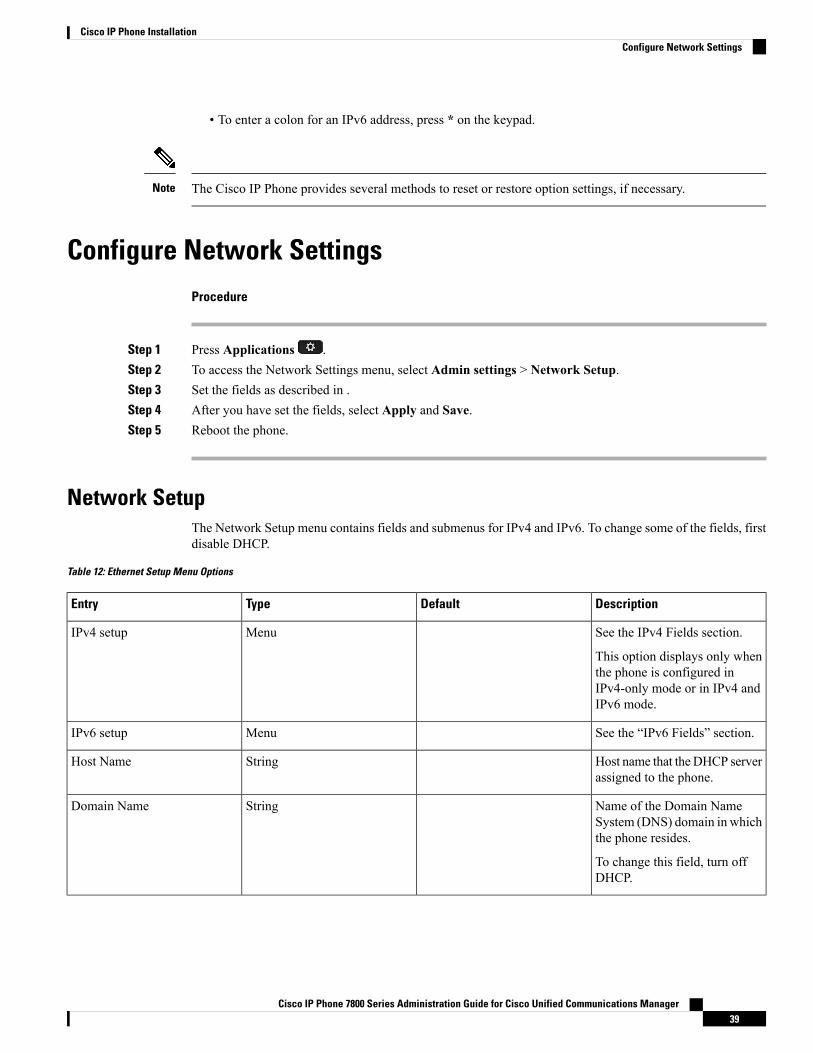
Configure Network SettingsProcedure
Step 1 Press Applications .Step 2 To access the Network Settings menu, select Admin settings > Network Setup.Step 3 Set the fields as described in .Step 4 After you have set the fields, select Apply and Save.Step 5 Reboot the phone.
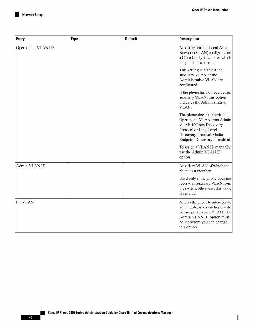
Network SetupThe Network Setup menu contains fields and submenus for IPv4 and IPv6. To change some of the fields, firstdisable DHCP.
Table 12: Ethernet Setup Menu Options
DescriptionDefaultTypeEntry
See the IPv4 Fields section.
This option displays only whenthe phone is configured inIPv4-only mode or in IPv4 andIPv6 mode.
MenuIPv4 setup
See the “IPv6 Fields” section.MenuIPv6 setup
Host name that the DHCP serverassigned to the phone.
StringHost Name
Name of the Domain NameSystem (DNS) domain in whichthe phone resides.
To change this field, turn offDHCP.
StringDomain Name
Cisco IP Phone 7800 Series Administration Guide for Cisco Unified Communications Manager39
Cisco IP Phone InstallationConfigure Network Settings
DescriptionDefaultTypeEntry
Auxiliary Virtual Local AreaNetwork (VLAN) configured ona Cisco Catalyst switch of whichthe phone is a member.
This setting is blank if theauxiliary VLAN or theAdministrative VLAN areconfigured.
If the phone has not received anauxiliary VLAN, this optionindicates the AdministrativeVLAN.
The phone doesn't inherit theOperational VLAN fromAdminVLAN if Cisco DiscoveryProtocol or Link LevelDiscovery Protocol MediaEndpoint Discovery is enabled.
To assign a VLAN IDmanually,use the Admin VLAN IDoption.
Operational VLAN ID
Auxiliary VLAN of which thephone is a member.
Used only if the phone does notreceive an auxiliaryVLAN fromthe switch; otherwise, this valueis ignored.
Admin VLAN ID
Allows the phone to interoperatewith third-party switches that donot support a voice VLAN. TheAdmin VLAN ID option mustbe set before you can changethis option.
PC VLAN
Cisco IP Phone 7800 Series Administration Guide for Cisco Unified Communications Manager40
Cisco IP Phone InstallationNetwork Setup
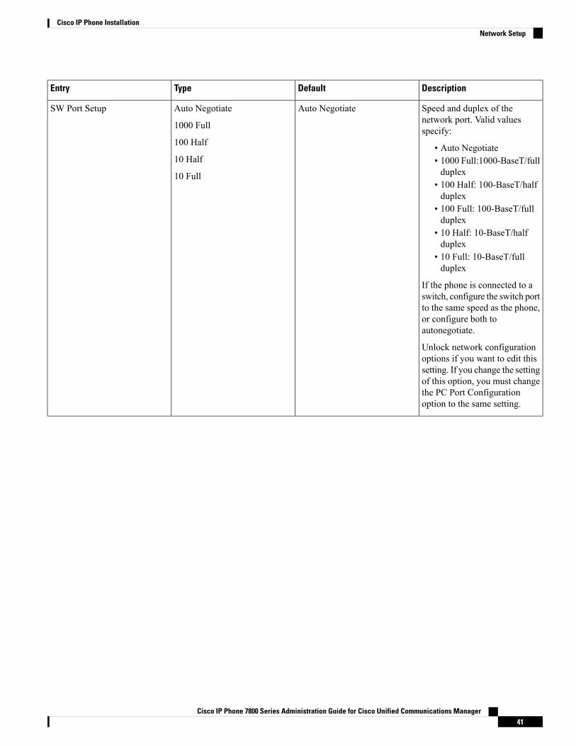
DescriptionDefaultTypeEntry
Speed and duplex of thenetwork port. Valid valuesspecify:
• Auto Negotiate• 1000 Full:1000-BaseT/fullduplex
• 100 Half: 100-BaseT/halfduplex
• 100 Full: 100-BaseT/fullduplex
• 10 Half: 10-BaseT/halfduplex
• 10 Full: 10-BaseT/fullduplex
If the phone is connected to aswitch, configure the switch portto the same speed as the phone,or configure both toautonegotiate.
Unlock network configurationoptions if you want to edit thissetting. If you change the settingof this option, you must changethe PC Port Configurationoption to the same setting.
Auto NegotiateAuto Negotiate
1000 Full
100 Half
10 Half
10 Full
SW Port Setup
Cisco IP Phone 7800 Series Administration Guide for Cisco Unified Communications Manager41
Cisco IP Phone InstallationNetwork Setup

DescriptionDefaultTypeEntry
Speed and duplex of theComputer (access) port. Validvalues:
• Auto Negotiate• 1000 Full: 1000-BaseT/fullduplex
• 100 Half: 100-BaseT/halfduplex
• 100 Full: 100-BaseT/fullduplex
• 10 Half: 10-BaseT/halfduplex
• 10 Full: 10-BaseT/fullduplex
If the phone is connected to aswitch, configure the port on theswitch to the same speed as thephone, or configure both toautonegotiate.
Unlock network configurationoptions if you want to changethis field. If you change thesetting, youmust change the SWPort Configuration option to thesame setting.
To configure the setting onmultiple phones simultaneously,enable Remote PortConfiguration in the EnterprisePhone Configuration window(System > Enterprise PhoneConfiguration).
If the ports are configured forRemote Port Configuration inCisco Unified CommunicationsManager Administration, thedata cannot be changed on thephone.
Auto NegotiateAuto Negotiate
1000 Full
100 Half
10 Half
10 Full
PC Port Setup
UDP-MED
Cisco IP Phone 7800 Series Administration Guide for Cisco Unified Communications Manager42
Cisco IP Phone InstallationNetwork Setup

IPv4 FieldsTable 13: IPv4 Setup Menu Options
DescriptionDefaultTypeEntry
Indicates whether the phone hasDHCP enabled or disabled.
When DHCP is enabled, theDHCP server assigns the phonean IP address. When DHCP isdisabled, the administrator mustmanually assign an IP addressto the phone.
DHCP Enabled
Internet Protocol (IP) address ofthe phone.
If you assign an IP address withthis option, youmust also assigna subnet mask and defaultrouter. See the SubnetMask andDefault Router options in thistable.
IP Address
Subnet mask used by the phone.Subnet Mask
Default router used by thephone.
Default Router
Primary Domain Name System(DNS) server (DNS Server 1)that the phone uses.
DNS Server 1
Indicates whether the phone isusing an alternate TFTP server.
Alternate TFTP
Cisco IP Phone 7800 Series Administration Guide for Cisco Unified Communications Manager43
Cisco IP Phone InstallationIPv4 Fields

DescriptionDefaultTypeEntry
TFTP Server 1
Cisco IP Phone 7800 Series Administration Guide for Cisco Unified Communications Manager44
Cisco IP Phone InstallationIPv4 Fields
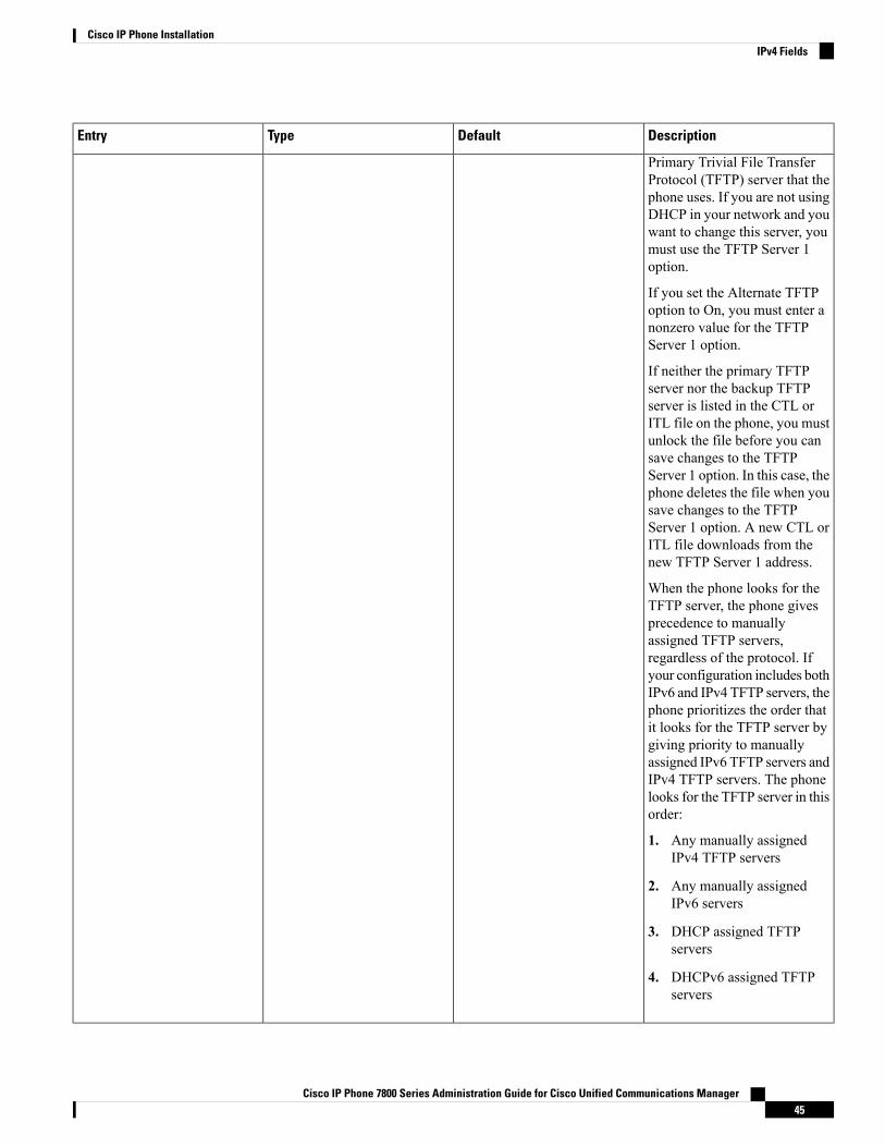
DescriptionDefaultTypeEntry
Primary Trivial File TransferProtocol (TFTP) server that thephone uses. If you are not usingDHCP in your network and youwant to change this server, youmust use the TFTP Server 1option.
If you set the Alternate TFTPoption to On, you must enter anonzero value for the TFTPServer 1 option.
If neither the primary TFTPserver nor the backup TFTPserver is listed in the CTL orITL file on the phone, you mustunlock the file before you cansave changes to the TFTPServer 1 option. In this case, thephone deletes the file when yousave changes to the TFTPServer 1 option. A new CTL orITL file downloads from thenew TFTP Server 1 address.
When the phone looks for theTFTP server, the phone givesprecedence to manuallyassigned TFTP servers,regardless of the protocol. Ifyour configuration includes bothIPv6 and IPv4 TFTP servers, thephone prioritizes the order thatit looks for the TFTP server bygiving priority to manuallyassigned IPv6 TFTP servers andIPv4 TFTP servers. The phonelooks for the TFTP server in thisorder:
1. Any manually assignedIPv4 TFTP servers
2. Any manually assignedIPv6 servers
3. DHCP assigned TFTPservers
4. DHCPv6 assigned TFTPservers
Cisco IP Phone 7800 Series Administration Guide for Cisco Unified Communications Manager45
Cisco IP Phone InstallationIPv4 Fields

DescriptionDefaultTypeEntry
Note For informationabout the CTL andITL files, see theCisco UnifiedCommunicationsManager SecurityGuide.
Cisco IP Phone 7800 Series Administration Guide for Cisco Unified Communications Manager46
Cisco IP Phone InstallationIPv4 Fields

DescriptionDefaultTypeEntry
TFTP Server 2
Cisco IP Phone 7800 Series Administration Guide for Cisco Unified Communications Manager47
Cisco IP Phone InstallationIPv4 Fields
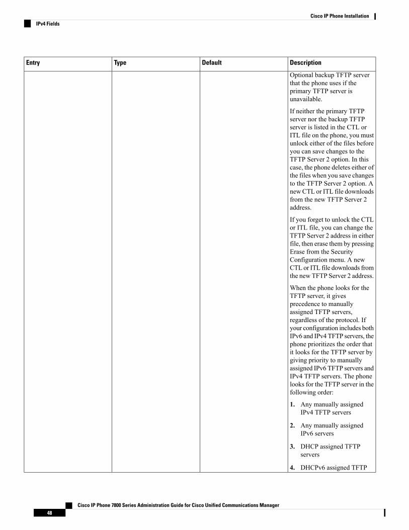
DescriptionDefaultTypeEntry
Optional backup TFTP serverthat the phone uses if theprimary TFTP server isunavailable.
If neither the primary TFTPserver nor the backup TFTPserver is listed in the CTL orITL file on the phone, you mustunlock either of the files beforeyou can save changes to theTFTP Server 2 option. In thiscase, the phone deletes either ofthe files when you save changesto the TFTP Server 2 option. AnewCTL or ITL file downloadsfrom the new TFTP Server 2address.
If you forget to unlock the CTLor ITL file, you can change theTFTP Server 2 address in eitherfile, then erase them by pressingErase from the SecurityConfiguration menu. A newCTL or ITL file downloads fromthe new TFTP Server 2 address.
When the phone looks for theTFTP server, it givesprecedence to manuallyassigned TFTP servers,regardless of the protocol. Ifyour configuration includes bothIPv6 and IPv4 TFTP servers, thephone prioritizes the order thatit looks for the TFTP server bygiving priority to manuallyassigned IPv6 TFTP servers andIPv4 TFTP servers. The phonelooks for the TFTP server in thefollowing order:
1. Any manually assignedIPv4 TFTP servers
2. Any manually assignedIPv6 servers
3. DHCP assigned TFTPservers
4. DHCPv6 assigned TFTP
Cisco IP Phone 7800 Series Administration Guide for Cisco Unified Communications Manager48
Cisco IP Phone InstallationIPv4 Fields
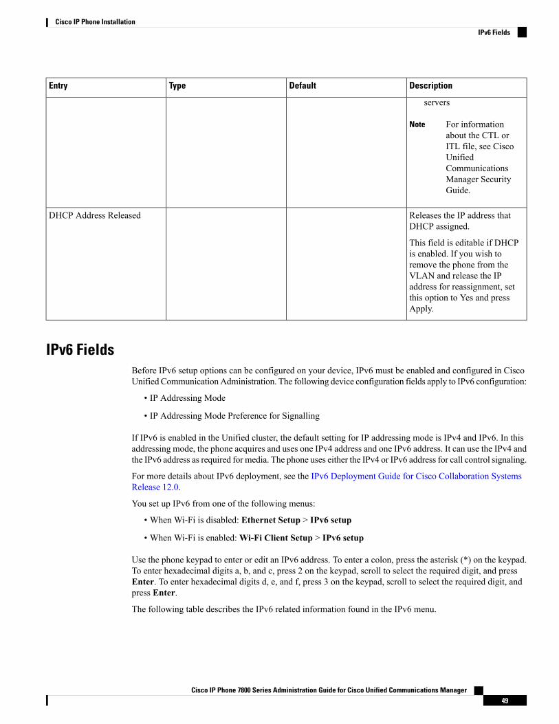
DescriptionDefaultTypeEntry
servers
For informationabout the CTL orITL file, see CiscoUnifiedCommunicationsManager SecurityGuide.
Note
Releases the IP address thatDHCP assigned.
This field is editable if DHCPis enabled. If you wish toremove the phone from theVLAN and release the IPaddress for reassignment, setthis option to Yes and pressApply.
DHCP Address Released
IPv6 FieldsBefore IPv6 setup options can be configured on your device, IPv6 must be enabled and configured in CiscoUnified CommunicationAdministration. The following device configuration fields apply to IPv6 configuration:
• IP Addressing Mode
• IP Addressing Mode Preference for Signalling
If IPv6 is enabled in the Unified cluster, the default setting for IP addressing mode is IPv4 and IPv6. In thisaddressing mode, the phone acquires and uses one IPv4 address and one IPv6 address. It can use the IPv4 andthe IPv6 address as required for media. The phone uses either the IPv4 or IPv6 address for call control signaling.
For more details about IPv6 deployment, see the IPv6 Deployment Guide for Cisco Collaboration SystemsRelease 12.0.
You set up IPv6 from one of the following menus:
• When Wi-Fi is disabled: Ethernet Setup > IPv6 setup
• When Wi-Fi is enabled:Wi-Fi Client Setup > IPv6 setup
Use the phone keypad to enter or edit an IPv6 address. To enter a colon, press the asterisk (*) on the keypad.To enter hexadecimal digits a, b, and c, press 2 on the keypad, scroll to select the required digit, and pressEnter. To enter hexadecimal digits d, e, and f, press 3 on the keypad, scroll to select the required digit, andpress Enter.
The following table describes the IPv6 related information found in the IPv6 menu.
Cisco IP Phone 7800 Series Administration Guide for Cisco Unified Communications Manager49
Cisco IP Phone InstallationIPv6 Fields
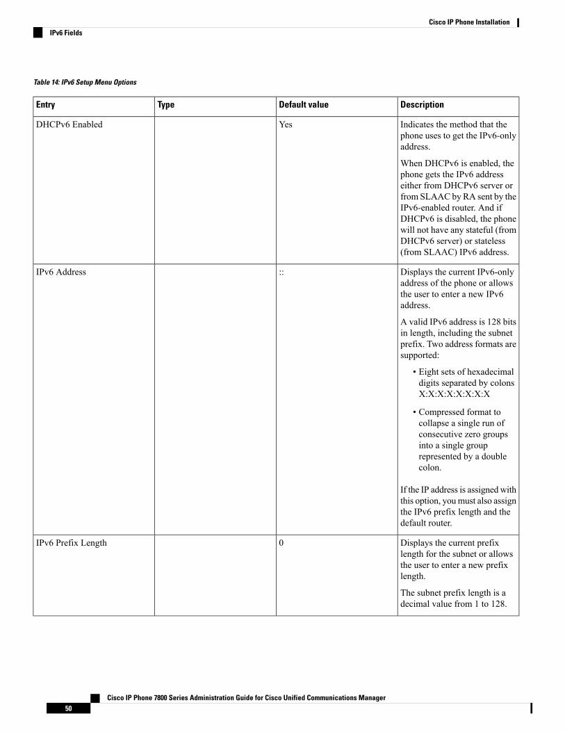
Table 14: IPv6 Setup Menu Options
DescriptionDefault valueTypeEntry
Indicates the method that thephone uses to get the IPv6-onlyaddress.
When DHCPv6 is enabled, thephone gets the IPv6 addresseither from DHCPv6 server orfrom SLAAC by RA sent by theIPv6-enabled router. And ifDHCPv6 is disabled, the phonewill not have any stateful (fromDHCPv6 server) or stateless(from SLAAC) IPv6 address.
YesDHCPv6 Enabled
Displays the current IPv6-onlyaddress of the phone or allowsthe user to enter a new IPv6address.
A valid IPv6 address is 128 bitsin length, including the subnetprefix. Two address formats aresupported:
• Eight sets of hexadecimaldigits separated by colonsX:X:X:X:X:X:X:X
• Compressed format tocollapse a single run ofconsecutive zero groupsinto a single grouprepresented by a doublecolon.
If the IP address is assignedwiththis option, youmust also assignthe IPv6 prefix length and thedefault router.
::IPv6 Address
Displays the current prefixlength for the subnet or allowsthe user to enter a new prefixlength.
The subnet prefix length is adecimal value from 1 to 128.
0IPv6 Prefix Length
Cisco IP Phone 7800 Series Administration Guide for Cisco Unified Communications Manager50
Cisco IP Phone InstallationIPv6 Fields

DescriptionDefault valueTypeEntry
Displays the default router usedby the phone or allows the userto enter a new IPv6-only defaultrouter.
::IPv6 Default Router
Displays the primary DNSv6server used by the phone orallows the user to enter a newserver.
::IPv6 DNS Server 1
Allows the user to enable theuse of an alternate (secondary)IPv6 TFTP server.
NoIPv6 Alternate TFTP
Displays the primary IPv6 TFTPserver used by the phone orallows the user to set a newprimary TFTP server.
::IPv6 TFTP Server 1
(Optional) Displays thesecondary IPv6 TFTP serverused if the primary IPv6 TFTPserver is unavailable or allowsthe user to set a new secondaryTFTP server.
::IPv6 TFTP Server 2
Allows the user to releaseIPv6-related information.
NoIPv6 Address Released
Verify Phone StartupAfter the Cisco IP Phone has power connected to it, the phone automatically cycles through a startup diagnosticprocess.
Procedure
Step 1 If you are using Power over Ethernet, plug the LAN cable into the Network port.Step 2 If you are using the power cube, connect the cube to the phone and plug the cube into an electrical outlet.
The buttons flash amber and then green in sequence during the various stages of bootup as the phone checksthe hardware.
If the phone completes these stages successfully, it has started up properly.
Related TopicsStartup Problems, on page 219
Cisco IP Phone 7800 Series Administration Guide for Cisco Unified Communications Manager51
Cisco IP Phone InstallationVerify Phone Startup
Cisco IP Phone Does Not Go Through the Normal Startup Process, on page 219
Configure Phone Services for UsersYou can give users access to Cisco IP Phone Services on the IP phone. You can also assign a button to differentphone services. The IP phone manages each service as a separate application.
Before a user can access any service:
• You must use Cisco Unified Communications Manager Administration to configure services that are notpresent by default.
• The user must subscribe to services by using the Cisco Unified Communications Self Care Portal. Thisweb-based application provides a graphical user interface (GUI) for limited, end-user configuration ofIP phone applications. However, a user cannot subscribe to any service that you configure as an enterprisesubscription.
For more information, see the documentation for your particular Cisco Unified Communications Managerrelease.
Before you set up services, gather the URLs for the sites that you want to set up and verify that users canaccess those sites from your corporate IP telephony network. This activity is not applicable for the defaultservices that Cisco provides.
Procedure
Step 1 In Cisco Unified Communications Manager Administration, choose Device > Device Settings > PhoneServices.
Step 2 Verify that your users can access the Cisco Unified Communications Self Care Portal, from which they canselect and subscribe to configured services.
See Self Care Portal Management, on page 65 for a summary of the information that you must provide toend users.
Related TopicsCisco Unified Communications Manager Documentation, on page xv
Cisco IP Phone 7800 Series Administration Guide for Cisco Unified Communications Manager52
Cisco IP Phone InstallationConfigure Phone Services for Users
C H A P T E R 5Cisco Unified Communications Manager PhoneSetup
• Set Up a Cisco IP Phone, on page 53• Determine the Phone MAC Address, on page 58• Phone Addition Methods, on page 58• Add Users to Cisco Unified Communications Manager, on page 59• Add a User to an End User Group, on page 61• Associate Phones with Users , on page 62• Surviveable Remote Site Telephony, on page 62
Set Up a Cisco IP PhoneIf autoregistration is not enabled and the phone does not exist in the Cisco Unified Communications Managerdatabase, you must manually configure the Cisco IP Phone in Cisco Unified Communications ManagerAdministration. Some tasks in this procedure are optional, depending on your system and user needs.
For more information on any of the steps, see the documentation for your particular Cisco UnifiedCommunications Manager release.
Perform the configuration steps in the following procedure using Cisco Unified Communications ManagerAdministration.
Procedure
Step 1 Gather the following information about the phone:
• Phone model
• MAC address: see Determine the Phone MAC Address, on page 58
• Physical location of the phone
• Name or user ID of phone user
• Device pool
• Partition, calling search space, and location information
Cisco IP Phone 7800 Series Administration Guide for Cisco Unified Communications Manager53
• Number of lines and associated directory numbers (DNs) to assign to the phone
• Cisco Unified Communications Manager user to associate with the phone
• Phone usage information that affects the phone button template, softkey template, phone features, IPPhone services, or phone applications
For more information, see the documentation for your particular Cisco Unified Communications Managerrelease and see the related links.
Step 2 Verify that you have sufficient unit licenses for your phone.
For more information, see the licensing document for your particular Cisco Unified CommunicationsManagerrelease.
Step 3 Define the phone button templates that determine the configuration of buttons on a phone. Select Device >Device Settings > Phone Button Template to create and update the templates.
For more information, see the documentation for your particular Cisco Unified Communications Managerrelease and the related links.
Step 4 Define the Device Pools. Select System > Device Pool.
Device Pools define common characteristics for devices, such as region, date/time group, softkey template,and MLPP information.
Step 5 Define the Common Phone Profile. Select Device > Device settings > Common Phone Profile.
Common phone profiles provide data that the Cisco TFTP server requires, as well as common phone settings,such as Do Not Disturb and feature control options.
Step 6 Define a Calling Search Space. In Cisco Unified Communications Manager Administration, click CallRouting > Class of Control > Calling Search Space.
A Calling Search Space is a collection of partitions that are searched to determine how a dialed number isrouted. The calling search space for the device and the calling search space for the directory number are usedtogether. The directory number CSS takes precedence over the device CSS.
Step 7 Configure a security profile for the device type and protocol. Select System > Security > Phone SecurityProfile.
Step 8 Set up the phone. Select Device > Phone.a) Locate the phone you want to modify, or add a new phone.b) Configure the phone by completing the required fields in the Device Information pane of the Phone
Configuration window.
• MAC Address (required): Make sure that the value comprises 12 hexadecimal characters.
• Description: Enter a useful description to help you if you need to search on information about thisuser.
• Device Pool (required)
• Phone Button Template: The phone button template determines the configuration of buttons on aphone.
• Common Phone Profile
• Calling Search Space
Cisco IP Phone 7800 Series Administration Guide for Cisco Unified Communications Manager54
Cisco IP Phone InstallationSet Up a Cisco IP Phone
• Location
• Owner User ID
The device with its default settings is added to the Cisco Unified Communications Manager database.
For information about Product Specific Configuration fields, see the “?” Button Help in the PhoneConfiguration window.
If you want to add both the phone and user to the Cisco Unified Communications Managerdatabase at the same time, see the documentation for your particular Cisco UnifiedCommunications Manager release.
Note
c) In the Protocol Specific Information area of this window, choose a Device Security Profile and set thesecurity mode.
Choose a security profile based on the overall security strategy of the company. If the phonedoes not support security, choose a nonsecure profile.
Note
d) In the Extension Information area, check the Enable Extension Mobility check box if this phone supportsCisco Extension Mobility.
e) Click Save.
Step 9 Select Device > Device Settings > SIP Profile to set up parameters such as Multilevel Precedence andPreemption (MLPP).
Step 10 Select Device > Phone to configure directory numbers (lines) on the phone by completing the required fieldsin the Directory Number Configuration window.a) Find the phone.b) In the Phone Configuration window, click Line 1 on the left pane of the window.c) In the Directory Number field, enter a valid number that can be dialed.
This field should contain the same number that appears in the Telephone Number field in theEnd User Configuration window.
Note
d) From the Route Partition drop-down list, choose the partition to which the directory number belongs. Ifyou do not want to restrict access to the directory number, choose <None> for the partition.
e) From the Calling Search Space drop-down list, choose the appropriate calling search space. The valuethat you choose applies to all devices that are using this directory number.
f) In the Call Forward and Call Pickup Settings area, choose the items (for example, Forward All, ForwardBusy Internal) and corresponding destinations to which calls should be sent.
Example:
If you want incoming internal and external calls that receive a busy signal to forward to the voice mailfor this line, check the VoiceMail check box next to the Forward Busy Internal and Forward Busy Externalitems in the left column of the Call Pickup and Call Forward Settings area.
g) In the Line 1 on Device pane, configure the following fields:
• Display (Internal Caller ID field): You can enter the first name and last name of the user of thisdevice so that this name displays for all internal calls. Leave this field blank to have the systemdisplay the phone extension.
• External Phone Number Mask: Indicate phone number (or mask) that is used to send Caller IDinformation when a call is placed from this line. You can enter a maximum of 24 numeric and “X”characters. The Xs represent the directory number and must appear at the end of the pattern.
Cisco IP Phone 7800 Series Administration Guide for Cisco Unified Communications Manager55
Cisco IP Phone InstallationSet Up a Cisco IP Phone

Example:
If you specify a mask of 408902XXXX, an external call from extension 6640 displays a caller ID numberof 4089026640.
This setting applies only to the current device unless you check the check box at the right (Update SharedDevice Settings) and click Propagate Selected. The check box at the right displays only if other devicesshare this directory number.
h) Select Save.
For more information about directory numbers, see the documentation for your particular Cisco UnifiedCommunications Manager release and the related links.
Step 11 Associate the user with a phone. ClickAssociate EndUsers at the bottom of the Phone Configuration windowto associate a user to the line that is being configured.a) Use Find in conjunction with the Search fields to locate the user.b) check the box next to the user name, and click Add Selected.
The user name and user ID appears in the Users Associated With Line pane of the Directory NumberConfiguration window.
c) Select Save.
The user is now associated with Line 1 on the phone.
d) If the phone has a second line, configure Line 2.
Step 12 Associate the user with the device:a) Choose User Management > End User.b) Use the search boxes and Find to locate the user you have added.c) Click on the user ID.d) In the Directory Number Associations area of the screen, set the Primary Extension from the drop-down
list.e) (Optional) In the Mobility Information area, check the Enable Mobility box.f) In the Permissions Information area, use the Add to Access Control Group buttons to add this user to
any user groups.
For example, you may want to add the user to a group that is defined as a Standard CCM End UserGroup.
g) To view the details of a group, select the group and click View Details.h) In the Extension Mobility area, check the Enable Extension Mobility Cross Cluster box if the user can
use for Extension Mobility Cross Cluster service.i) In the Device Information area, click Device Associations.j) Use the Search fields and Find to locate the device that you want to associate to the user.k) Select the device, and click Save Selected/Changes.l) Click Go next to the “Back to User” Related link in the upper right corner of the screen.m) Select Save.
Step 13 Customize the softkey templates. Select Device > Device Settings > Softkey Template.
Use the page to add, delete, or change the order of softkey features that display on the user’s phone to meetfeature usage needs.
Step 14 Configure speed-dial buttons and assign speed-dial numbers. Select Device > Phone.
Cisco IP Phone 7800 Series Administration Guide for Cisco Unified Communications Manager56
Cisco IP Phone InstallationSet Up a Cisco IP Phone
Users can change speed-dial settings on their phones using their Self Care Portal.Note
a) Find the phone you want to set up.b) In the Association Information area, click Add a new SD.c) Set up the speed dial information.d) Select Save.
Step 15 Configure Cisco IP Phone services and assign services. Select Device > Device Settings > Phone Services.
Provides IP Phone services to the phone.
Users can add or change services on their phones using the Cisco Unified Communications SelfCare Portal.
Note
Step 16 (Optional) Assign services to programmable buttons. Select Device > Device Settings > Phone buttontemplate.
Provides access to an IP phone service or URL.
Step 17 Add user information to the global directory for Cisco Unified Communications Manager. Select UserManagement > End User, and then click Add New and configure the required fields. Required fields areindicated by an asterisk (*).
If your company uses a Lightweight Directory Access Protocol (LDAP) directory to store informationon users, you can install and configure Cisco Unified Communications to use your existing LDAPdirectory, see Corporate Directory Setup, on page 177. After the Enable Synchronization from theLDAP Server field is enabled, you will not be able to add additional users from Cisco UnifiedCommunications Manager Administration.
Note
a) Set the User ID and last name fields.b) Assign a password (for Self Care Portal).c) Assign a PIN (for Cisco Extension Mobility and Personal Directory).d) Associate the user with a phone.
Provides users with control over their phone such as forwarding calls or adding speed-dial numbers orservices.
Some phones, such as those in conference rooms, do not have an associated user.Note
Step 18 Associate a user with a user group. Select User Management > User Settings > Access Control Group.
Assigns users a common list of roles and permissions that apply to all users in a user group. Administratorscan manage user groups, roles, and permissions to control the level of access (and, therefore, the level ofsecurity) for system users. For more information, see Add a User to an End User Group, on page 61.
In order for end users to access the Cisco Unified Communications Self Care Portal, you must add users tothe standard Cisco Communications Manager End Users group.
Related TopicsCisco Unified Communications Manager Documentation, on page xv
Cisco IP Phone 7800 Series Administration Guide for Cisco Unified Communications Manager57
Cisco IP Phone InstallationSet Up a Cisco IP Phone
Determine the Phone MAC AddressTo add phones to Cisco Unified Communications Manager, you must determine the MAC address of a phone.
Procedure
Perform one of the following actions:
• On the phone, press Applications , select Phone Information and look at the MAC Address field.
• Look at the MAC label on the back of the phone.
• Display the web page for the phone and click Device Information.
Phone Addition MethodsAfter you install the Cisco IP Phone, you can choose one of the following options to add phones to the CiscoUnified Communications Manager database.
• Add phones individually with Cisco Unified Communications Manager Administration
• Add multiple phones with the Bulk Administration Tool (BAT)
• Autoregistration
• BAT and the Tool for Auto-Registered Phones Support (TAPS)
Before you add phones individually or with BAT, you need the MAC address of the phone. For moreinformation, see Determine the Phone MAC Address, on page 58.
For more information about the Bulk Administration Tool, see the documentation for your particular CiscoUnified Communications Manager release.
Related TopicsCisco Unified Communications Manager Documentation, on page xvEnable Autoregistration for Phones, on page 34
Add Phones IndividuallyCollect the MAC address and phone information for the phone that you will add to the Cisco UnifiedCommunications Manager.
Procedure
Step 1 In Cisco Unified Communications Manager Administration, choose Device > Phone.Step 2 Click Add New.
Cisco IP Phone 7800 Series Administration Guide for Cisco Unified Communications Manager58
Cisco IP Phone InstallationDetermine the Phone MAC Address
Step 3 Select the phone type.Step 4 Select Next.Step 5 Complete the information about the phone including the MAC Address.
For complete instructions and conceptual information about Cisco Unified Communications Manager, seethe documentation for your particular Cisco Unified Communications Manager release.
Step 6 Select Save.
Related TopicsCisco Unified Communications Manager Documentation, on page xv
Add Phones with a BAT Phone TemplateThe Cisco Unified Communications Bulk Administration Tool (BAT) enables you to perform batch operations,including registration of multiple phones.
To add phones using BAT only (not in conjunction with TAPS), you must obtain the appropriateMAC addressfor each phone.
For more information about using BAT, see the documentation for your particular Cisco UnifiedCommunications Manager release.
Procedure
Step 1 From Cisco Unified Communications Administration, choose Bulk Administration > Phones > PhoneTemplate.
Step 2 Click Add New.Step 3 Choose a Phone Type and click Next.Step 4 Enter the details of phone-specific parameters, such as Device Pool, Phone Button Template, and Device
Security Profile.Step 5 Click Save.Step 6 Select Device > Phone > Add New to add a phone using the BAT phone template.
Related TopicsCisco Unified Communications Manager Documentation, on page xv
Add Users to Cisco Unified Communications ManagerYou can display and maintain information about the users registered in Cisco Unified CommunicationsManager. Cisco Unified Communications Manager also allows each user to perform these tasks:
• Access the corporate directory and other customized directories from a Cisco IP Phone.
• Create a personal directory.
• Set up speed dial and call forwarding numbers.
Cisco IP Phone 7800 Series Administration Guide for Cisco Unified Communications Manager59
Cisco IP Phone InstallationAdd Phones with a BAT Phone Template
• Subscribe to services that are accessible from a Cisco IP Phone.
Procedure
Step 1 To add users individually, see Add a User Directly to Cisco Unified Communications Manager, on page 60.Step 2 To add users in batches, use the Bulk Administration Tool. This method also enables you to set an identical
default password for all users.
For more information, see the documentation for your particular Cisco Unified Communications Managerrelease.
Related TopicsCisco Unified Communications Manager Documentation, on page xv
Add a User from an External LDAP DirectoryIf you added a user to an LDAP Directory (a non-Cisco Unified Communications Server directory), you canimmediately synchronize the LDAP directory to the Cisco Unified Communications Manager on which youare adding the user and the user phone.
If you do not synchronize the LDAP Directory to the Cisco Unified Communications Manager immediately,the LDAP Directory Synchronization Schedule on the LDAP Directory window determines when the nextautosynchronization is scheduled. Synchronization must occur before you can associate a new user to a device.
Note
Procedure
Step 1 Sign into Cisco Unified Communications Manager Administration.Step 2 Select System > LDAP > LDAP Directory.Step 3 Use Find to locate your LDAP directory.Step 4 Click on the LDAP directory name.Step 5 Click Perform Full Sync Now.
Add a User Directly to Cisco Unified Communications ManagerIf you are not using a Lightweight Directory Access Protocol (LDAP) directory, you can add a user directlywith Cisco Unified Communications Manager Administration by following these steps.
If LDAP is synchronized, you cannot add a user with Cisco Unified CommunicationsManager Administration.Note
Cisco IP Phone 7800 Series Administration Guide for Cisco Unified Communications Manager60
Cisco IP Phone InstallationAdd a User from an External LDAP Directory

Procedure
Step 1 From Cisco Unified Communications Manager Administration, choose User Management > End User.Step 2 Click Add New.Step 3 In the User Information pane, enter the following:
• User ID: Enter the end user identification name. Cisco Unified CommunicationsManager does not permitmodifying the user ID after it is created. You may use the following special characters: =, +, <, >, #, ;,\, , “”, and blank spaces. Example: johndoe
• Password and Confirm Password: Enter five or more alphanumeric or special characters for the end userpassword. You may use the following special characters: =, +, <, >, #, ;, \, , “”, and blank spaces.
• Last Name: Enter the end user last name. You may use the following special characters: =, +, <, >, #, ;,\, , “”, and blank spaces. Example: doe
• Telephone Number: Enter the primary directory number for the end user. End users can have multiplelines on their phones. Example: 26640 (John Doe’s internal company telephone number)
Step 4 Click Save.
Add a User to an End User GroupTo add a user to the Cisco Unified Communications Manager Standard End User group, perform these steps:
Procedure
Step 1 FromCiscoUnified CommunicationsManager Administration, chooseUserManagement >User Settings >Access Control Group.
The Find and List Users window displays.
Step 2 Enter the appropriate search criteria and click Find.Step 3 Select the Standard CCM End Users link. The User Group Configuration window for the Standard CCM
End Users appears.Step 4 Select Add End Users to Group. The Find and List Users window appears.Step 5 Use the Find User drop-down list boxes to find the users that you want to add and click Find.
A list of users that matches your search criteria appears.
Step 6 In the list of records that appear, click the check box next to the users that you want to add to this user group.If the list is long, use the links at the bottom to see more results.
The list of search results does not display users that already belong to the user group.Note
Step 7 Choose Add Selected.
Cisco IP Phone 7800 Series Administration Guide for Cisco Unified Communications Manager61
Cisco IP Phone InstallationAdd a User to an End User Group

Associate Phones with UsersYou associate phones with users from the Cisco Unified Communications Manager End User window.
Procedure
Step 1 From Cisco Unified Communications Manager Administration, choose User Management > End User.
The Find and List Users window appears.
Step 2 Enter the appropriate search criteria and click Find.Step 3 In the list of records that appear, select the link for the user.Step 4 Select Device Association.
The User Device Association window appears.
Step 5 Enter the appropriate search criteria and click Find.Step 6 Choose the device that you want to associate with the user by checking the box to the left of the device.Step 7 Choose Save Selected/Changes to associate the device with the user.Step 8 From the Related Links drop-down list in the upper, right corner of the window, select Back to User, and
click Go.
The EndUser Configurationwindow appears and the associated devices that you chose display in the ControlledDevices pane.
Step 9 Choose Save Selected/Changes.
Surviveable Remote Site TelephonySurvivable Remote Site Telephony (SRST) ensures that basic phone functions remain accessible whencommunications with the controlling Cisco Unified Communications Manager are broken. In this scenario,the phone can keep an in-progress call active, and the user can access a subset of the features available. Whenfailover occurs, the user receives an alert message on the phone.
The following table describes the availability of features during failover.
Table 15: SRST feature support
NotesSupportedFeature
YesNew Call
YesEnd Call
YesRedial
YesAnswer
Cisco IP Phone 7800 Series Administration Guide for Cisco Unified Communications Manager62
Cisco IP Phone InstallationAssociate Phones with Users

NotesSupportedFeature
YesHold
YesResume
3 way only and local mixing only.YesConference
NoConference List
Consult only.YesTransfer
NoTransfer to Active Calls (DirectTransfer)
YesAuto Answer
YesCall Waiting
YesCaller ID
Conference is the only feature supported dueto other feature limitations.
YesUnified Session Presentation
Voicemail will not be synchronized with otherusers in the Cisco Unified CommunicationsManager cluster.
YesVoicemail
Forward state is only available on the phonethat sets the forward because there are noshared line appearances in SRST mode. TheCall Forward All settings are not preservedon failover to SRST from the Cisco UnifiedCommunications Manager, or from SRSTfail-back to the Communications Manager.Any original Call Forward All still active onthe Communications Manager should beindicated when the device reconnects to theCommunications Manager after failover.
YesCall Forward All
YesSpeed Dial
The iDivert softkey does not display.NoTo Voicemail (iDivert)
Lines are supported but cannot be shared.PartialLine Filters
The Park softkey does not display.NoPark Monitoring
Message count badges do not appear on thephone screen.
Only the Message Waiting icon displays.
NoEnhanced Message WaitingIndication
The softkey does not display.NoDirected Call Park
Cisco IP Phone 7800 Series Administration Guide for Cisco Unified Communications Manager63
Cisco IP Phone InstallationSurviveable Remote Site Telephony

NotesSupportedFeature
BLF feature key works like Speed Dial keys.PartialBLF
Calls remain on hold indefinitely.NoHold Reversion
Calls appear as Local Hold calls.NoRemote Hold
The Meet Me softkey does not display.NoMeet Me
The softkey causes no action.NoPickUp
The softkey causes no action.NoGroup PickUp
The softkey causes no action.NoOther PickUp
The softkey causes no action.NoMalicious Call ID
The softkey causes no action.NoQRT
The softkey causes no action.NoHunt Group
The softkey causes no action.NoIntercom
The softkey causes no action.NoMobility
The softkey causes no action.NoPrivacy
The Call Back softkey does not display.NoCall Back
Cisco IP Phone 7800 Series Administration Guide for Cisco Unified Communications Manager64
Cisco IP Phone InstallationSurviveable Remote Site Telephony
C H A P T E R 6Self Care Portal Management
• Self Care Portal Overview, on page 65• Set Up User Access to the Self Care Portal, on page 65• Customize the Self Care Portal Display, on page 66
Self Care Portal OverviewFrom the Cisco Unified Communications Self Care Portal, users can customize and control phone featuresand settings.
As the administrator, you control access to the Self Care Portal. You must also provide information to yourusers so that they can access the Self Care Portal.
Before a user can access the Cisco Unified Communications Self Care Portal, you must use Cisco UnifiedCommunications Manager Administration to add the user to a standard Cisco Unified CommunicationsManager End User group.
You must provide end users with the following information about the Self Care Portal:
• The URL to access the application. This URL is:
https://<server_name:portnumber>/ucmuser/, where server_name is the host on whichthe web server is installed and portnumber is the port number on that host.
• A user ID and default password to access the application.
• An overview of the tasks that users can accomplish with the portal.
These settings correspond to the values that you entered when you added the user to Cisco UnifiedCommunications Manager.
For more information, see the documentation for your particular Cisco Unified Communications Managerrelease.
Related TopicsCisco Unified Communications Manager Documentation, on page xv
Set Up User Access to the Self Care PortalBefore a user can access the Self Care Portal, you need to authorize the access.
Cisco IP Phone 7800 Series Administration Guide for Cisco Unified Communications Manager65
Procedure
Step 1 In Cisco Unified Communications Manager Administration, select User Management > End User.Step 2 Search for the user.Step 3 Click the user ID link.Step 4 Ensure that the user has a password and PIN configured.Step 5 In the Permission Information section, ensure that the Groups list includes Standard CCM End Users.Step 6 Select Save.
Customize the Self Care Portal DisplayMost options display on the Self Care Portal. However, you must set the following options by using EnterpriseParameters Configuration settings in Cisco Unified Communications Manager Administration:
• Show Ring Settings
• Show Line Label Settings
The settings apply to all Self Care Portal pages at your site.Note
Procedure
Step 1 In Cisco Unified Communications Manager Administration, select System > Enterprise Parameters.Step 2 In the Self Care Portal area, set the Self Care Portal Default Server field.Step 3 Enable or disable the parameters that the users can access in the portal.Step 4 Select Save.
Cisco IP Phone 7800 Series Administration Guide for Cisco Unified Communications Manager66
Cisco IP Phone InstallationCustomize the Self Care Portal Display

P A R T IIIHardware and Accessory Installation
• Cisco IP Phone Accessories, on page 69• Wall Mounts, on page 75


C H A P T E R 7Cisco IP Phone Accessories
• Supported Accessories, on page 69• Connect the Footstand, on page 70• Third Party Headsets, on page 70
Supported AccessoriesYou can use your phone with different types of accessories, such as headsets, microphones, and speakers.This table shows you which ones you can use with your particular phone.
In the following table, an X indicates support for an accessory by a particular phone model and a dash (-)indicates no support.
To check which phone model you have, press Applications and select Phone information. TheModelnumber field shows your phone model.
When you add features to your phone, some features require a line button. But each line button on your phonecan support only one function (a line, a speed dial, or a feature). If your phone's line buttons are already inuse, your phone won't display any additional features.
Table 16: Accessory Support for the Cisco IP Phone 7811, 7821, 7841, and 7861
Cisco IP PhoneTypeAccessory
7861784178217811
Cisco Accessory
XXXXWall Mount Kit
Third-Party Accessories
XXX-AnalogHeadsets
XXX-AnalogWideband
----ExternalMicrophone
----ExternalSpeakers
Cisco IP Phone 7800 Series Administration Guide for Cisco Unified Communications Manager69
Connect the FootstandIf your phone is placed on a table or desk, connect the footstand to the back of the phone.
Procedure
Step 1 Insert the curved connectors into the lower slots.Step 2 Lift the footstand until the connectors snap into the upper slots.
You may need to exert more force than you expect to connect or disconnect the footstand.
Step 3 Adjust the angle of the phone.
You cannot adjust the Cisco IP Phone 7811 footstand.Note
Third Party HeadsetsCisco Systems performs internal testing of third-party headsets for use with Cisco IP Phones. But Cisco doesnot certify or support products from headset or handset vendors.
The Cisco IP Phone 7811 does not support a headset.Note
Headsets connect to your phone using either the USB or the auxiliary port. Depending upon your headsetmodel, you have to adjust your phone's audio settings for the best audio experience, including the headsetsidetone setting.
If you have a third party headset, and you apply a new sidetone setting, then wait one minute and reboot thephone so the setting is stored in flash.
The phone reduces some background noise that a headset microphone detects. You can use a noise cancelingheadset to further reduce the background noise and improve the overall audio quality.
If you are considering a third part headset, we recommend the use of good quality external devices; for example,headsets that are screened against unwanted radio frequency (RF) and audio frequency (AF) signals. Dependingon the quality of headsets and their proximity to other devices, such as mobile phones and two-way radios,some audio noise or echo may still occur. Either the remote party or both the remote party and the Cisco IPPhone user may hear an audible hum or buzz. A range of outside sources can cause humming or buzzingsounds; for example, electric lights, electric motors, or large PC monitors.
Sometimes, use of a local power cube or power injector may reduce or eliminate hum.Note
Environmental and hardware inconsistencies in the locations where Cisco IP Phones are deployed mean thatno single headset solution is optimal for all environments.
Cisco IP Phone 7800 Series Administration Guide for Cisco Unified Communications Manager70
Hardware and Accessory InstallationConnect the Footstand
We recommend that customers test headsets in the intended environment to determine performance beforemaking a purchasing decision to deploy on a large scale.
You can use only one headset at a time. The most-recently connected headset is the active headset.
Audio QualityBeyond physical, mechanical, and technical performance, the audio portion of a headset must sound good tothe user and to the party on the far end. Sound quality is subjective, and we cannot guarantee the performanceof any headsets. However, various headsets from leading headset manufacturers are reported to perform wellwith Cisco IP Phones.
For additional information, see https://www.cisco.com/c/en/us/products/unified-communications/uc_endpoints_accessories.html
Analog HeadsetsAnalog headsets are supported on the Cisco IP Phone 7821, 7841, and 7861. However, the Cisco IP Phone7821, 7841, and 7861 cannot detect when an analog headset is plugged in. For this reason, the analog headsetdisplays by default in the Accessories window on the phone screen.
Displaying the analog headset as the default allows users to enable wideband for the analog headset.
Enable Wideband on Analog Headsets on the PhoneAlthough analog headsets are supported on the phone, the phones cannot detect when an analog headset isplugged in. For this reason, by default, the analog headset is displayed in the Accessories window on thephone screen.
Displaying the analog headset as the default allows users to enable wideband for the analog headset.
The phone is unable to detect whether the headset supports the wideband codec, but the user can enablewideband on analog headsets by following these steps:
Procedure
Step 1 On the Cisco IP Phone, press Applications .Step 2 Select Accessories.Step 3 Highlight the analog headset, then press Setup.Step 4 Press On to turn on the wideband. Press Off to turn off the wideband.
Enable the Wideband for Analog Headsets on the Cisco Unified Communications ManagerAlthough analog headsets are supported on the phone, the phones cannot detect when an analog headset isplugged in. For this reason, by default, the analog headset displays in the Accessories window on the phonescreen.
Display of the analog headset as the default allows users to enable wideband for the headset.
Cisco IP Phone 7800 Series Administration Guide for Cisco Unified Communications Manager71
Hardware and Accessory InstallationAudio Quality
If the screen doesn't display an On or Off softkey, follow these steps to ensure that you can enable widebandon an analog headset:
Procedure
Step 1 In Cisco Unified Communications Manager Administration, choose Device > Phone.Step 2 In the Find and List Phones window, enter the search criteria for the phone to which you want to add the
analog headset, then click Find.Step 3 Click the Device Name that you want. The Phone Configuration window is displayed.Step 4 On the Product Specific Configuration Layout portion of the Phone Configuration window, ensure that the
Wideband Headset UI Control option is enabled. This option is enabled by default.Step 5 In the Product Specific Configuration Layout portion of the Phone Configuration window, you can set the
Wideband Headset option. This option is also enabled by default.Step 6 Click Save.
Wired HeadsetsA wired headset works with all Cisco IP Phone features, including the Volume and Mute buttons. Thesebuttons adjust the earpiece volume and mute the audio from the headset microphone.
When you install a wired headset, make sure you press the cable into the channel in the phone.
Failure to press the cable into the channel in the phone can lead to cable damage.Caution
Connect Wired HeadsetTo connect a wired headset to the Cisco IP Phone, perform these steps:
Procedure
Step 1 Plug the headset into the Headset port on the back of the phone.Step 2 Press the Headset button on the phone to place and answer calls using the headset.
Disable a Wired HeadsetYou can use Cisco Unified Communications Manager Administration to disable your wired headset andspeakerphone.
Procedure
Step 1 In Cisco Unified Communications Manager Administration, choose Device > Phone.
Cisco IP Phone 7800 Series Administration Guide for Cisco Unified Communications Manager72
Hardware and Accessory InstallationWired Headsets
Step 2 In the Find and List Phones window, enter the search criteria for the phone and click Find.Step 3 Click the Device Name that you want. The Phone Configuration window is displayed.Step 4 In the Product Specific Configuration Layout portion of the Phone Configuration window, select Disable
Speakerphone and Headset.Step 5 Click Save.
Wireless HeadsetThe Cisco IP Phone 7821, 7841, and 7861 support a wireless analog headset. To use a wireless headset, usersconnect a base station to the auxiliary port. The base station communicates with the wireless headset.
The Electronic Hookswitch feature enables users to remotely control basic IP phone functionality from thewireless headset. Basic IP phone functionality includes off-hook and on-hook, ring indication, audio volumecontrol, and mute.
Enable Electronic HookswitchFor more information about wireless headsets that work in conjunction with the Electronic Hookswitch feature,go to the following URL:
http://www.cisco.com/en/US/prod/voicesw/ucphone_headsets.html
To enable or disable the Electronic Hookswitch feature for a Cisco IP Phone 7821, 7841, and 7861, performthese steps:
Procedure
Step 1 From the Cisco Unified Communications Manager Administration, choose Device > Phone.Step 2 Scroll to the Wireless Headset Hookswitch Control section.Step 3 To enable Electronic Hookswitch, choose Enabled.Step 4 To disable Electronic Hookswitch, choose Disabled.
Cisco IP Phone 7800 Series Administration Guide for Cisco Unified Communications Manager73
Hardware and Accessory InstallationWireless Headset

Cisco IP Phone 7800 Series Administration Guide for Cisco Unified Communications Manager74
Hardware and Accessory InstallationEnable Electronic Hookswitch
C H A P T E R 8Wall Mounts
• Wall Mount Kits, on page 75• Non-Lockable Wall Mount Components for 7811, on page 76• Non-Lockable Wall Mount Components, on page 83• Non-Lockable Wall Mount Components for 7861, on page 91• Adjust the Handset Rest, on page 99
Wall Mount KitsEach wall mount is unique to your phone model and cannot be used for another phone. If you are planningto attach your phone to a wall, purchase the wall mount kit specific to your phone.
For part numbers and other additional information, refer to the phone model data sheet. The Cisco IP Phone8800 Series data sheets can be found here https://www.cisco.com/c/en/us/products/collaboration-endpoints/unified-ip-phone-8800-series/datasheet-listing.html. The Cisco IP Phone 7800 Series data sheets can be foundhere https://www.cisco.com/c/en/us/products/collaboration-endpoints/unified-ip-phone-7800-series/datasheet-listing.html.
To check which phone model you have, press Applications and select Phone information. TheModelnumber field shows your phone model.
Table 17: Wall Mount Kits
NotesCisco Wall Mount KitCisco IP Phone
Spare Wallmount Kit for Cisco IP Phone 7811
(CP-7811-WMK=)
Cisco IP Phone 7811
Spare Wallmount Kit for Cisco IP Phone 7800 Series
(CP-7800-WMK=)
Cisco IP Phone 7821 and 7841
Spare Wallmount Kit for Cisco IP Phone 7861
(CP-7861-WMK=)
Cisco IP Phone 7861
Cisco IP Phone 7800 Series Administration Guide for Cisco Unified Communications Manager75
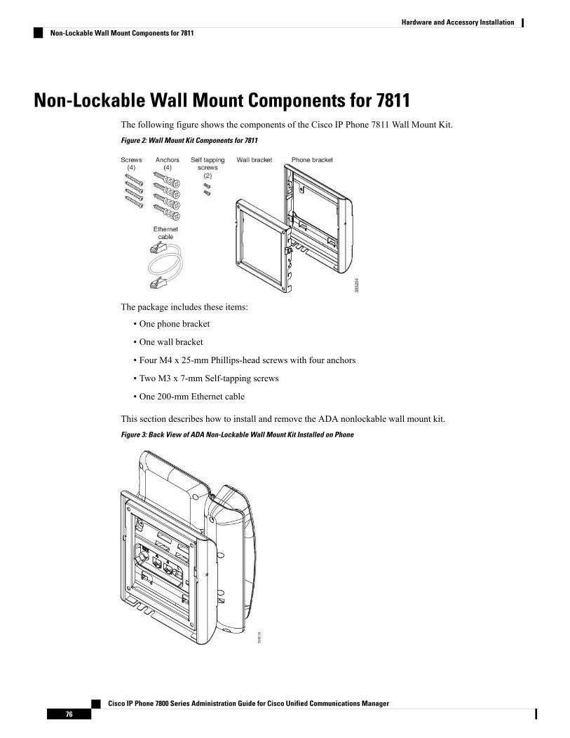
Non-Lockable Wall Mount Components for 7811The following figure shows the components of the Cisco IP Phone 7811 Wall Mount Kit.Figure 2: Wall Mount Kit Components for 7811
The package includes these items:
• One phone bracket
• One wall bracket
• Four M4 x 25-mm Phillips-head screws with four anchors
• Two M3 x 7-mm Self-tapping screws
• One 200-mm Ethernet cable
This section describes how to install and remove the ADA nonlockable wall mount kit.Figure 3: Back View of ADA Non-Lockable Wall Mount Kit Installed on Phone
Cisco IP Phone 7800 Series Administration Guide for Cisco Unified Communications Manager76
Hardware and Accessory InstallationNon-Lockable Wall Mount Components for 7811

Figure 4: Side View of ADA Non-Lockable Wall Mount Kit Installed on Phone
Install the Non-Lockable Wall Mount Kit for 7811The wall mount kit can be mounted on most surfaces, including concrete, brick, and similar hard surfaces.To mount the kit on concrete, brick, or similar hard surfaces, you must provide the appropriate screws andanchors for your wall surface.
Before you begin
You need these tools to install the bracket:
• #1 and #2 Phillips-head screwdrivers
• Level
• Pencil
Youmust also install an Ethernet jack for the phone in the desired location if an Ethernet jack does not currentlyexist. This jack must be wired appropriately for an Ethernet connection. You cannot use a regular phone jack.
Procedure
Step 1 Mount the wall bracket in the desired location. You can install the bracket over an Ethernet jack, or you canrun the Ethernet network cable to a nearby jack.
If the jack is to be placed behind the phone, the Ethernet jack must be flush to the wall or recessed.Note
a) Hold the bracket on the wall and place it so that the arrow on the back of the bracket points up.b) Use the level to ensure that the bracket is level and use a pencil to mark the screw holes.c) Using a #2 Phillips-head screwdriver, carefully center the anchor over the pencil mark and press the anchor
into the wall.d) Screw the anchor clockwise into the wall until it is seated flush.e) Use the included screws and a #2 Phillips-head screwdriver to attach the bracket to the wall.
Cisco IP Phone 7800 Series Administration Guide for Cisco Unified Communications Manager77
Hardware and Accessory InstallationInstall the Non-Lockable Wall Mount Kit for 7811
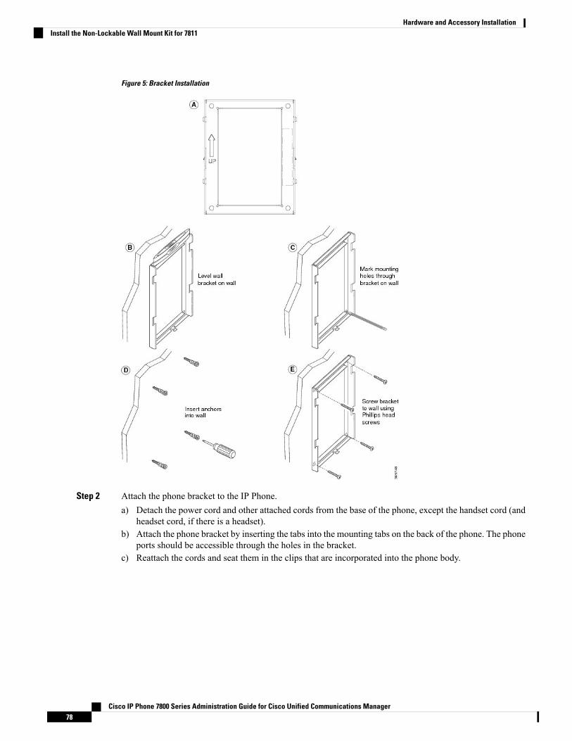
Figure 5: Bracket Installation
Step 2 Attach the phone bracket to the IP Phone.a) Detach the power cord and other attached cords from the base of the phone, except the handset cord (and
headset cord, if there is a headset).b) Attach the phone bracket by inserting the tabs into the mounting tabs on the back of the phone. The phone
ports should be accessible through the holes in the bracket.c) Reattach the cords and seat them in the clips that are incorporated into the phone body.
Cisco IP Phone 7800 Series Administration Guide for Cisco Unified Communications Manager78
Hardware and Accessory InstallationInstall the Non-Lockable Wall Mount Kit for 7811

Figure 6: Phone Bracket Attachment
Screw holes1
Step 3 Attach the cables to the phone:a) Attach the Ethernet cable to the 10/100/1000 SW network port and wall jack.b) (Optional) If you are connecting a network device (such as a computer) to the phone, attach the cable to
the 10/100/1000 Computer (PC access) port.c) (Optional) If you use an external power supply, plug the power cord into the phone. Dress the cord by
clipping it into the clips that are incorporated into the phone body next to the PC port.d) (Optional) If the cables terminate inside the wall bracket, connect the cables to the jacks.
Cisco IP Phone 7800 Series Administration Guide for Cisco Unified Communications Manager79
Hardware and Accessory InstallationInstall the Non-Lockable Wall Mount Kit for 7811
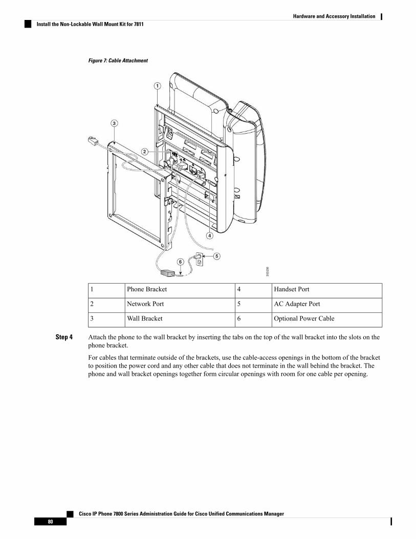
Figure 7: Cable Attachment
Handset Port4Phone Bracket1
AC Adapter Port5Network Port2
Optional Power Cable6Wall Bracket3
Step 4 Attach the phone to the wall bracket by inserting the tabs on the top of the wall bracket into the slots on thephone bracket.
For cables that terminate outside of the brackets, use the cable-access openings in the bottom of the bracketto position the power cord and any other cable that does not terminate in the wall behind the bracket. Thephone and wall bracket openings together form circular openings with room for one cable per opening.
Cisco IP Phone 7800 Series Administration Guide for Cisco Unified Communications Manager80
Hardware and Accessory InstallationInstall the Non-Lockable Wall Mount Kit for 7811
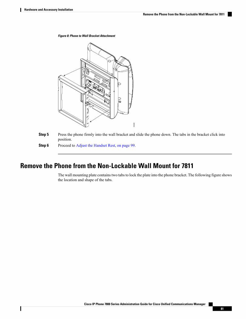
Figure 8: Phone to Wall Bracket Attachment
Step 5 Press the phone firmly into the wall bracket and slide the phone down. The tabs in the bracket click intoposition.
Step 6 Proceed to Adjust the Handset Rest, on page 99.
Remove the Phone from the Non-Lockable Wall Mount for 7811The wall mounting plate contains two tabs to lock the plate into the phone bracket. The following figure showsthe location and shape of the tabs.
Cisco IP Phone 7800 Series Administration Guide for Cisco Unified Communications Manager81
Hardware and Accessory InstallationRemove the Phone from the Non-Lockable Wall Mount for 7811
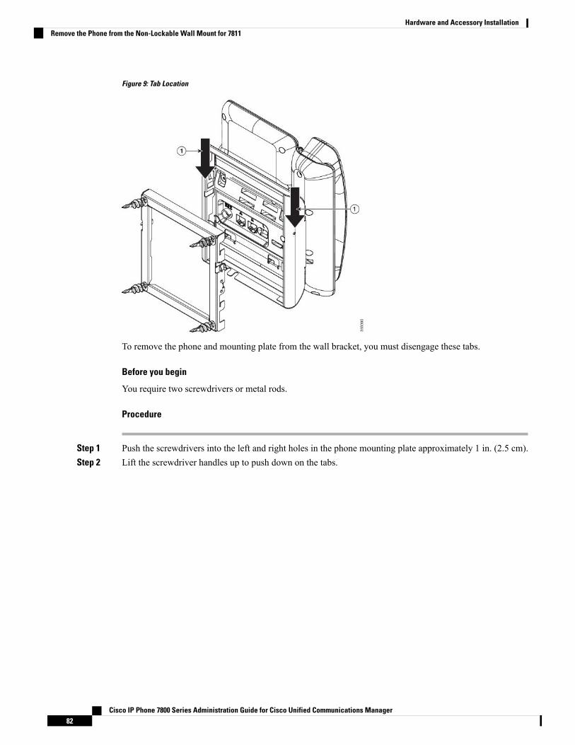
Figure 9: Tab Location
To remove the phone and mounting plate from the wall bracket, you must disengage these tabs.
Before you begin
You require two screwdrivers or metal rods.
Procedure
Step 1 Push the screwdrivers into the left and right holes in the phone mounting plate approximately 1 in. (2.5 cm).Step 2 Lift the screwdriver handles up to push down on the tabs.
Cisco IP Phone 7800 Series Administration Guide for Cisco Unified Communications Manager82
Hardware and Accessory InstallationRemove the Phone from the Non-Lockable Wall Mount for 7811
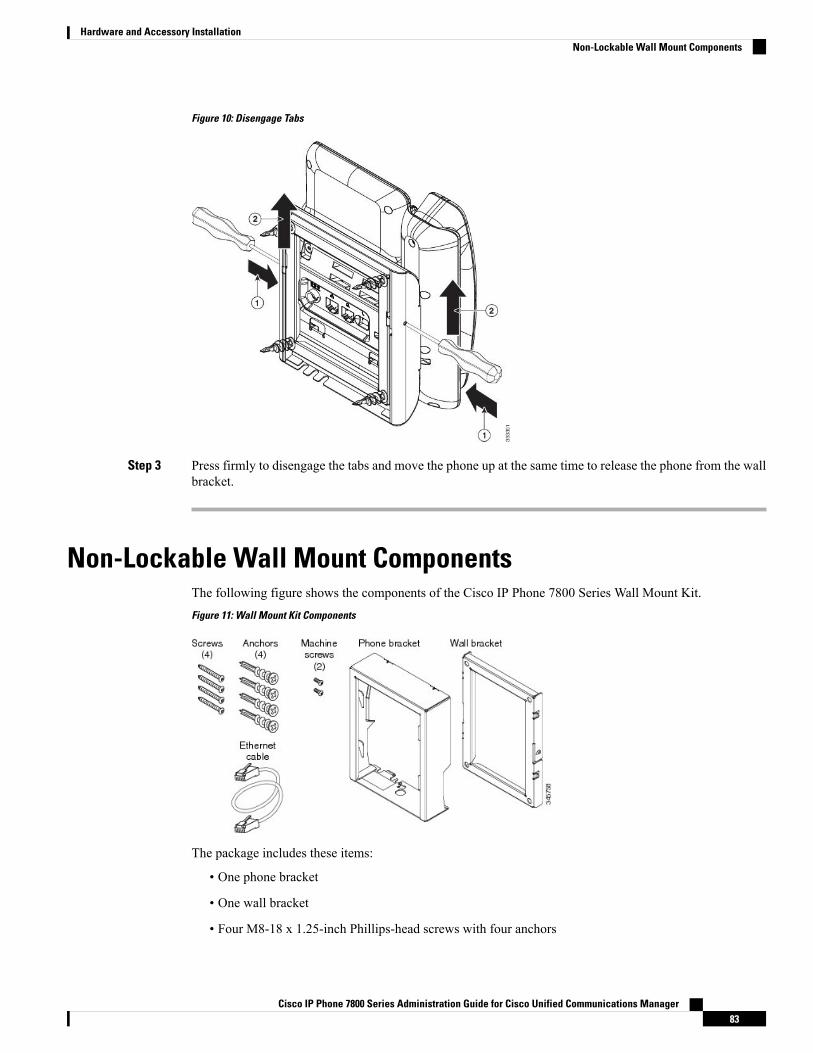
Figure 10: Disengage Tabs
Step 3 Press firmly to disengage the tabs and move the phone up at the same time to release the phone from the wallbracket.
Non-Lockable Wall Mount ComponentsThe following figure shows the components of the Cisco IP Phone 7800 Series Wall Mount Kit.Figure 11: Wall Mount Kit Components
The package includes these items:
• One phone bracket
• One wall bracket
• Four M8-18 x 1.25-inch Phillips-head screws with four anchors
Cisco IP Phone 7800 Series Administration Guide for Cisco Unified Communications Manager83
Hardware and Accessory InstallationNon-Lockable Wall Mount Components

• Two M2.5 x 6-mm machine screws
• One 6-inch Ethernet cable
This section describes how to install and remove the ADA nonlockable wall mount kit.Figure 12: Back View of ADA Non-Lockable Wall Mount Kit Installed on Phone
Figure 13: Side View of ADA Non-Lockable Wall Mount Kit Installed on Phone
Cisco IP Phone 7800 Series Administration Guide for Cisco Unified Communications Manager84
Hardware and Accessory InstallationNon-Lockable Wall Mount Components
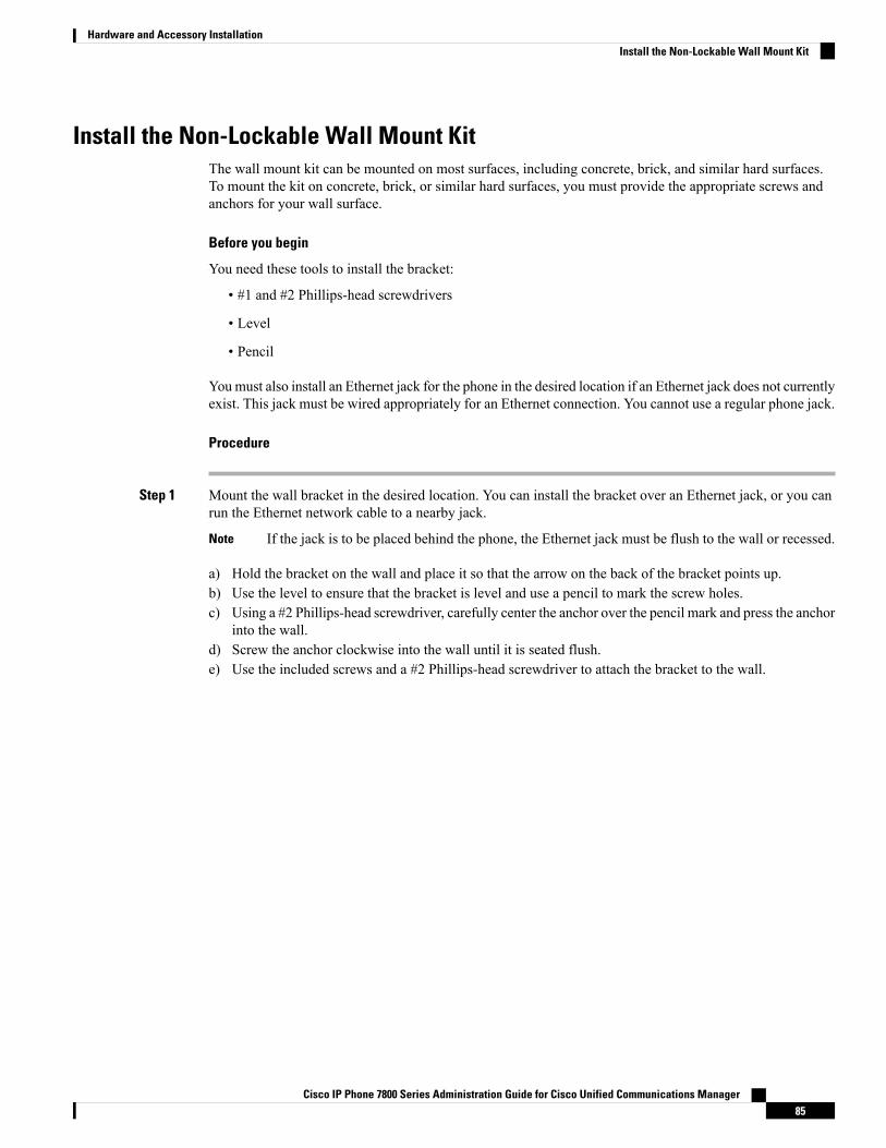
Install the Non-Lockable Wall Mount KitThe wall mount kit can be mounted on most surfaces, including concrete, brick, and similar hard surfaces.To mount the kit on concrete, brick, or similar hard surfaces, you must provide the appropriate screws andanchors for your wall surface.
Before you begin
You need these tools to install the bracket:
• #1 and #2 Phillips-head screwdrivers
• Level
• Pencil
Youmust also install an Ethernet jack for the phone in the desired location if an Ethernet jack does not currentlyexist. This jack must be wired appropriately for an Ethernet connection. You cannot use a regular phone jack.
Procedure
Step 1 Mount the wall bracket in the desired location. You can install the bracket over an Ethernet jack, or you canrun the Ethernet network cable to a nearby jack.
If the jack is to be placed behind the phone, the Ethernet jack must be flush to the wall or recessed.Note
a) Hold the bracket on the wall and place it so that the arrow on the back of the bracket points up.b) Use the level to ensure that the bracket is level and use a pencil to mark the screw holes.c) Using a #2 Phillips-head screwdriver, carefully center the anchor over the pencil mark and press the anchor
into the wall.d) Screw the anchor clockwise into the wall until it is seated flush.e) Use the included screws and a #2 Phillips-head screwdriver to attach the bracket to the wall.
Cisco IP Phone 7800 Series Administration Guide for Cisco Unified Communications Manager85
Hardware and Accessory InstallationInstall the Non-Lockable Wall Mount Kit
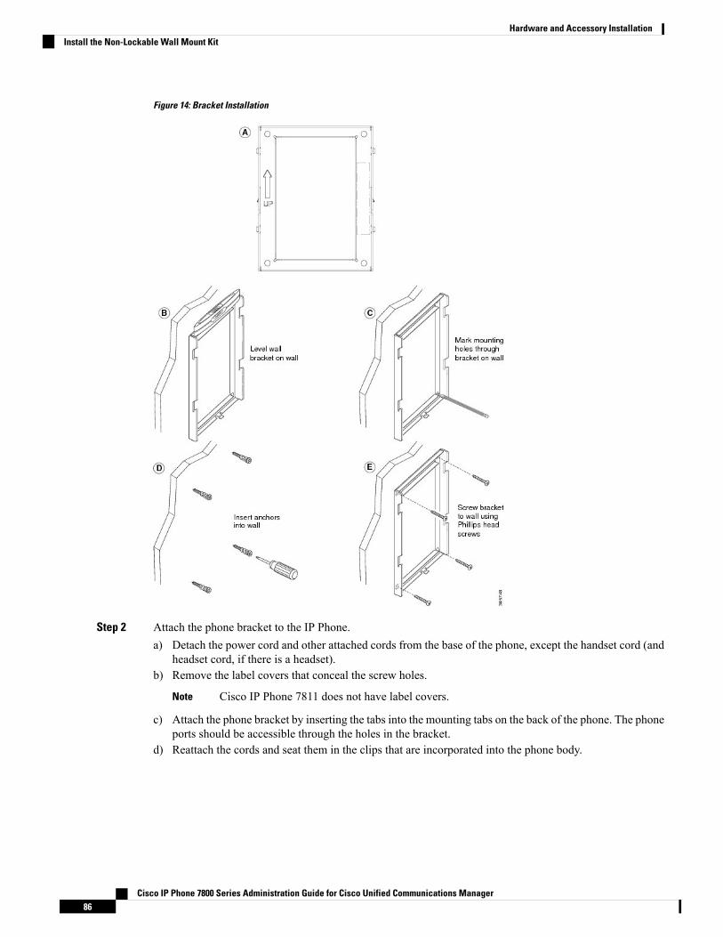
Figure 14: Bracket Installation
Step 2 Attach the phone bracket to the IP Phone.a) Detach the power cord and other attached cords from the base of the phone, except the handset cord (and
headset cord, if there is a headset).b) Remove the label covers that conceal the screw holes.
Cisco IP Phone 7811 does not have label covers.Note
c) Attach the phone bracket by inserting the tabs into the mounting tabs on the back of the phone. The phoneports should be accessible through the holes in the bracket.
d) Reattach the cords and seat them in the clips that are incorporated into the phone body.
Cisco IP Phone 7800 Series Administration Guide for Cisco Unified Communications Manager86
Hardware and Accessory InstallationInstall the Non-Lockable Wall Mount Kit
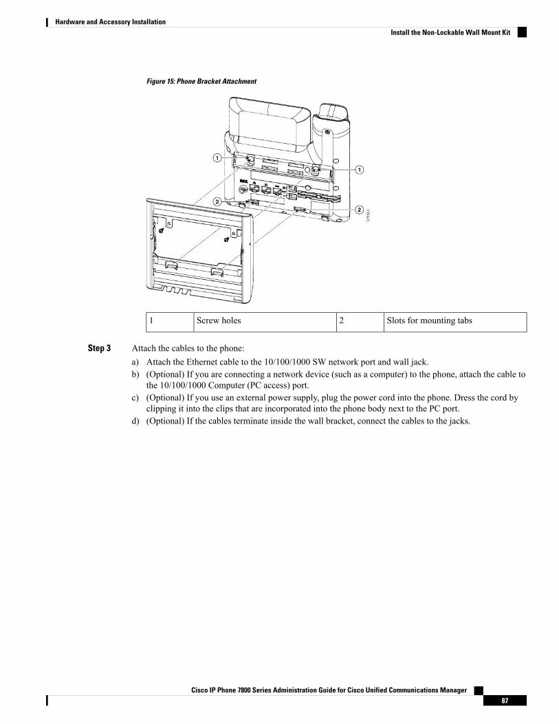
Figure 15: Phone Bracket Attachment
Slots for mounting tabs2Screw holes1
Step 3 Attach the cables to the phone:a) Attach the Ethernet cable to the 10/100/1000 SW network port and wall jack.b) (Optional) If you are connecting a network device (such as a computer) to the phone, attach the cable to
the 10/100/1000 Computer (PC access) port.c) (Optional) If you use an external power supply, plug the power cord into the phone. Dress the cord by
clipping it into the clips that are incorporated into the phone body next to the PC port.d) (Optional) If the cables terminate inside the wall bracket, connect the cables to the jacks.
Cisco IP Phone 7800 Series Administration Guide for Cisco Unified Communications Manager87
Hardware and Accessory InstallationInstall the Non-Lockable Wall Mount Kit

Figure 16: Cable Attachment
Handset Port4Phone Bracket1
AC Adapter Port5Network Port2
Optional Power Cable6Wall Bracket3
Step 4 Attach the phone to the wall bracket by inserting the tabs on the top of the wall bracket into the slots on thephone bracket.
For cables that terminate outside of the brackets, use the cable-access openings in the bottom of the bracketto position the power cord and any other cable that does not terminate in the wall behind the bracket. Thephone and wall bracket openings together form circular openings with room for one cable per opening.
Cisco IP Phone 7800 Series Administration Guide for Cisco Unified Communications Manager88
Hardware and Accessory InstallationInstall the Non-Lockable Wall Mount Kit
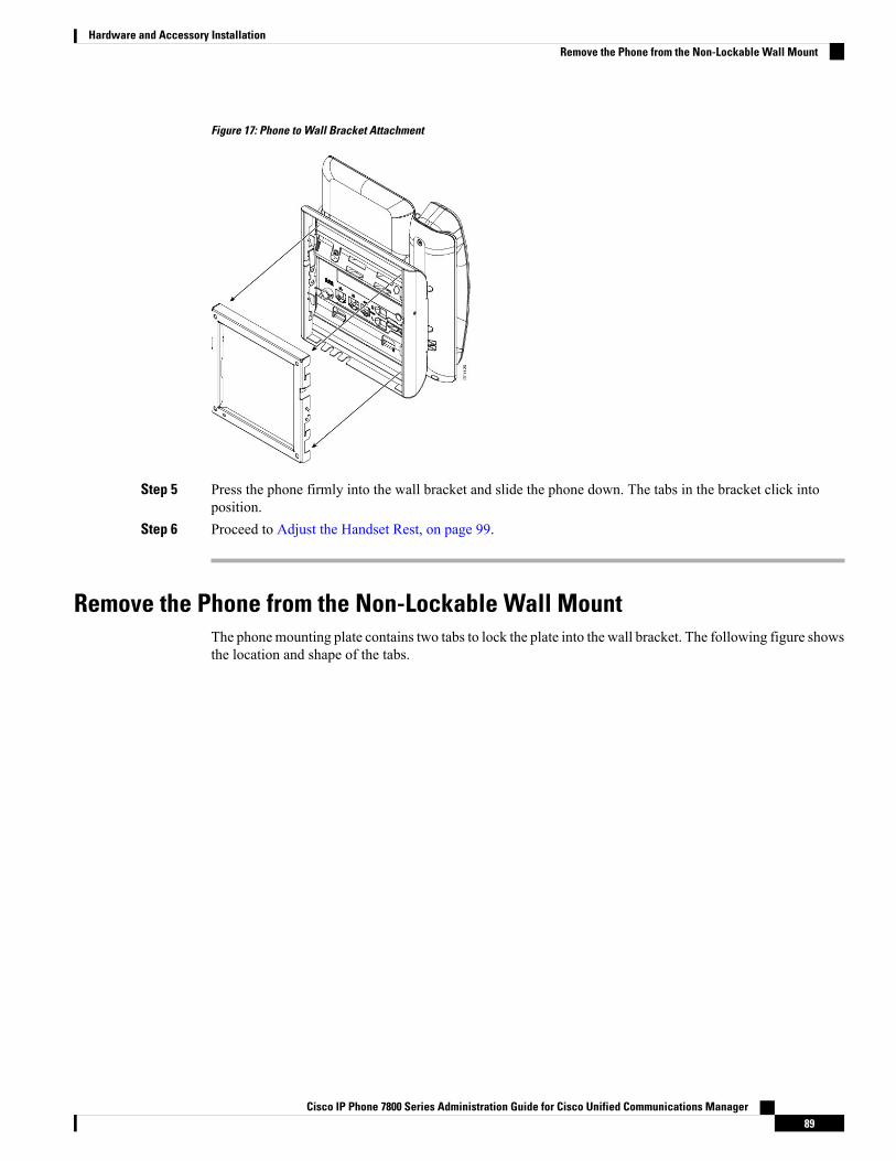
Figure 17: Phone to Wall Bracket Attachment
Step 5 Press the phone firmly into the wall bracket and slide the phone down. The tabs in the bracket click intoposition.
Step 6 Proceed to Adjust the Handset Rest, on page 99.
Remove the Phone from the Non-Lockable Wall MountThe phonemounting plate contains two tabs to lock the plate into the wall bracket. The following figure showsthe location and shape of the tabs.
Cisco IP Phone 7800 Series Administration Guide for Cisco Unified Communications Manager89
Hardware and Accessory InstallationRemove the Phone from the Non-Lockable Wall Mount
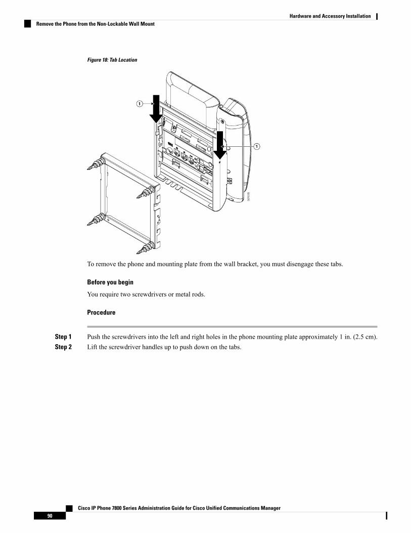
Figure 18: Tab Location
To remove the phone and mounting plate from the wall bracket, you must disengage these tabs.
Before you begin
You require two screwdrivers or metal rods.
Procedure
Step 1 Push the screwdrivers into the left and right holes in the phone mounting plate approximately 1 in. (2.5 cm).Step 2 Lift the screwdriver handles up to push down on the tabs.
Cisco IP Phone 7800 Series Administration Guide for Cisco Unified Communications Manager90
Hardware and Accessory InstallationRemove the Phone from the Non-Lockable Wall Mount
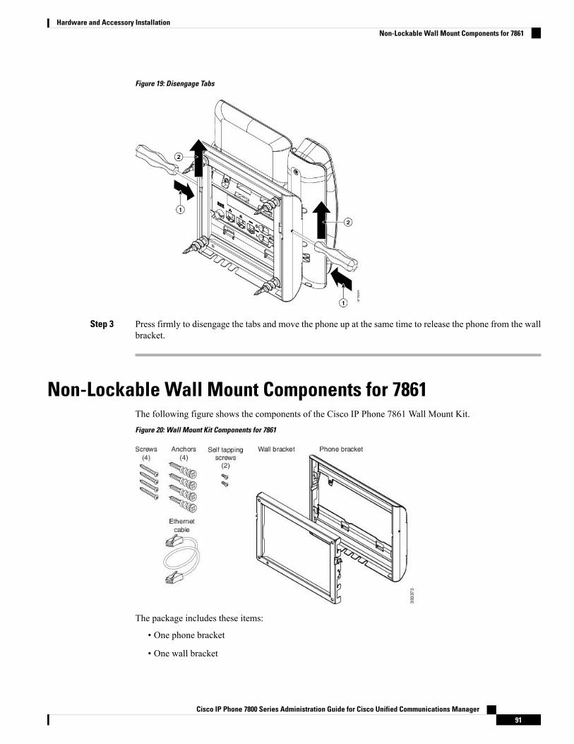
Figure 19: Disengage Tabs
Step 3 Press firmly to disengage the tabs and move the phone up at the same time to release the phone from the wallbracket.
Non-Lockable Wall Mount Components for 7861The following figure shows the components of the Cisco IP Phone 7861 Wall Mount Kit.Figure 20: Wall Mount Kit Components for 7861
The package includes these items:
• One phone bracket
• One wall bracket
Cisco IP Phone 7800 Series Administration Guide for Cisco Unified Communications Manager91
Hardware and Accessory InstallationNon-Lockable Wall Mount Components for 7861
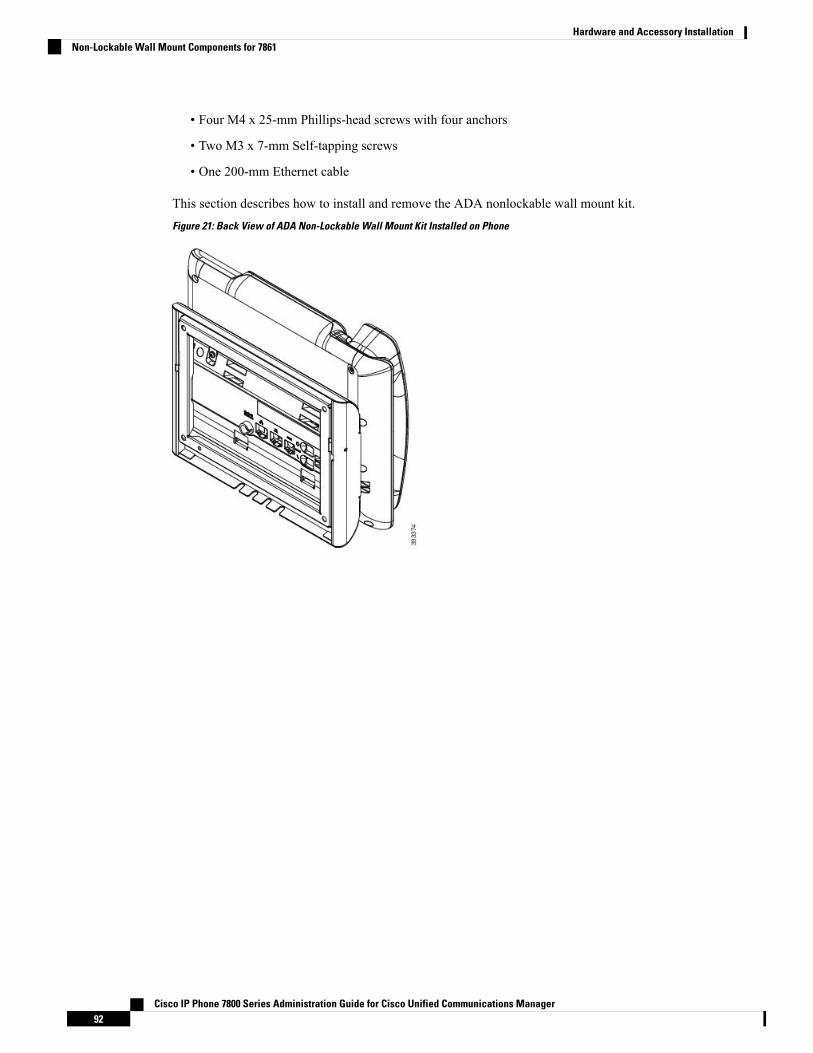
• Four M4 x 25-mm Phillips-head screws with four anchors
• Two M3 x 7-mm Self-tapping screws
• One 200-mm Ethernet cable
This section describes how to install and remove the ADA nonlockable wall mount kit.Figure 21: Back View of ADA Non-Lockable Wall Mount Kit Installed on Phone
Cisco IP Phone 7800 Series Administration Guide for Cisco Unified Communications Manager92
Hardware and Accessory InstallationNon-Lockable Wall Mount Components for 7861

Figure 22: Side View of ADA Non-Lockable Wall Mount Kit Installed on Phone
Install the Non-Lockable Wall Mount Kit for 7861The wall mount kit can be mounted on most surfaces, including concrete, brick, and similar hard surfaces.To mount the kit on concrete, brick, or similar hard surfaces, you must provide the appropriate screws andanchors for your wall surface.
Before you begin
You need these tools to install the bracket:
• #1 and #2 Phillips-head screwdrivers
• Level
• Pencil
Youmust also install an Ethernet jack for the phone in the desired location if an Ethernet jack does not currentlyexist. This jack must be wired appropriately for an Ethernet connection. You cannot use a regular phone jack.
Procedure
Step 1 Mount the wall bracket in the desired location. You can install the bracket over an Ethernet jack, or you canrun the Ethernet network cable to a nearby jack.
If the jack is to be placed behind the phone, the Ethernet jack must be flush to the wall or recessed.Note
Cisco IP Phone 7800 Series Administration Guide for Cisco Unified Communications Manager93
Hardware and Accessory InstallationInstall the Non-Lockable Wall Mount Kit for 7861
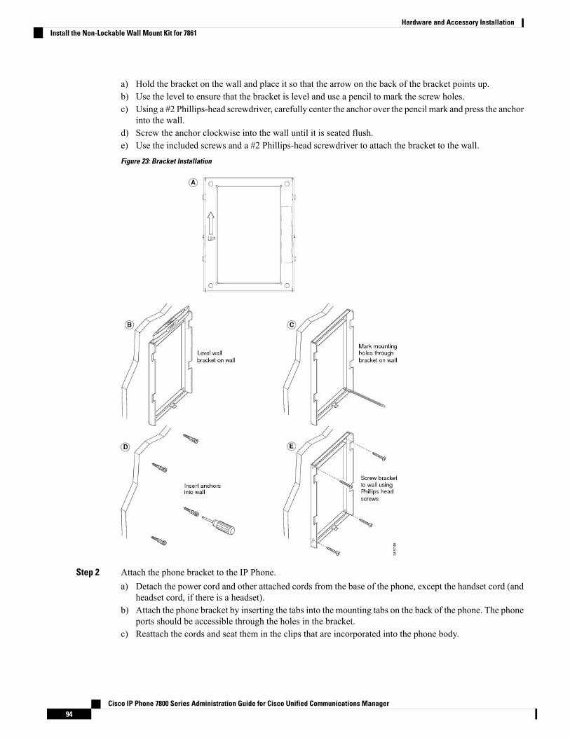
a) Hold the bracket on the wall and place it so that the arrow on the back of the bracket points up.b) Use the level to ensure that the bracket is level and use a pencil to mark the screw holes.c) Using a #2 Phillips-head screwdriver, carefully center the anchor over the pencil mark and press the anchor
into the wall.d) Screw the anchor clockwise into the wall until it is seated flush.e) Use the included screws and a #2 Phillips-head screwdriver to attach the bracket to the wall.Figure 23: Bracket Installation
Step 2 Attach the phone bracket to the IP Phone.a) Detach the power cord and other attached cords from the base of the phone, except the handset cord (and
headset cord, if there is a headset).b) Attach the phone bracket by inserting the tabs into the mounting tabs on the back of the phone. The phone
ports should be accessible through the holes in the bracket.c) Reattach the cords and seat them in the clips that are incorporated into the phone body.
Cisco IP Phone 7800 Series Administration Guide for Cisco Unified Communications Manager94
Hardware and Accessory InstallationInstall the Non-Lockable Wall Mount Kit for 7861
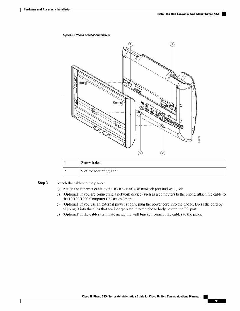
Figure 24: Phone Bracket Attachment
Screw holes1
Slot for Mounting Tabs2
Step 3 Attach the cables to the phone:a) Attach the Ethernet cable to the 10/100/1000 SW network port and wall jack.b) (Optional) If you are connecting a network device (such as a computer) to the phone, attach the cable to
the 10/100/1000 Computer (PC access) port.c) (Optional) If you use an external power supply, plug the power cord into the phone. Dress the cord by
clipping it into the clips that are incorporated into the phone body next to the PC port.d) (Optional) If the cables terminate inside the wall bracket, connect the cables to the jacks.
Cisco IP Phone 7800 Series Administration Guide for Cisco Unified Communications Manager95
Hardware and Accessory InstallationInstall the Non-Lockable Wall Mount Kit for 7861
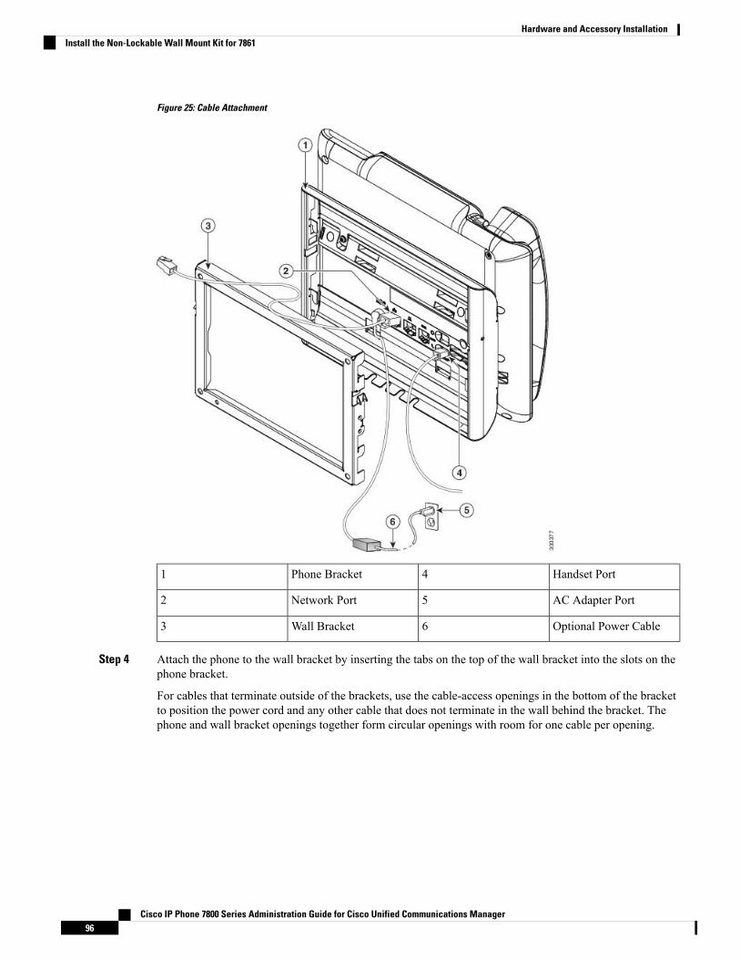
Figure 25: Cable Attachment
Handset Port4Phone Bracket1
AC Adapter Port5Network Port2
Optional Power Cable6Wall Bracket3
Step 4 Attach the phone to the wall bracket by inserting the tabs on the top of the wall bracket into the slots on thephone bracket.
For cables that terminate outside of the brackets, use the cable-access openings in the bottom of the bracketto position the power cord and any other cable that does not terminate in the wall behind the bracket. Thephone and wall bracket openings together form circular openings with room for one cable per opening.
Cisco IP Phone 7800 Series Administration Guide for Cisco Unified Communications Manager96
Hardware and Accessory InstallationInstall the Non-Lockable Wall Mount Kit for 7861

Figure 26: Phone to Wall Bracket Attachment
Step 5 Press the phone firmly into the wall bracket and slide the phone down. The tabs in the bracket click intoposition.
Step 6 Proceed to Adjust the Handset Rest, on page 99.
Remove the Phone from the Non-Lockable Wall MountThe wall mounting plate contains two tabs to lock the plate into the phone bracket. The following figure showsthe location and shape of the tabs.
Cisco IP Phone 7800 Series Administration Guide for Cisco Unified Communications Manager97
Hardware and Accessory InstallationRemove the Phone from the Non-Lockable Wall Mount
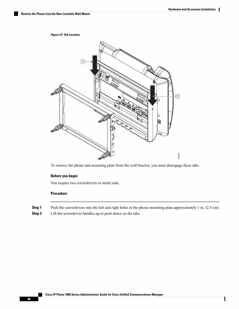
Figure 27: Tab Location
To remove the phone and mounting plate from the wall bracket, you must disengage these tabs.
Before you begin
You require two screwdrivers or metal rods.
Procedure
Step 1 Push the screwdrivers into the left and right holes in the phone mounting plate approximately 1 in. (2.5 cm).Step 2 Lift the screwdriver handles up to push down on the tabs.
Cisco IP Phone 7800 Series Administration Guide for Cisco Unified Communications Manager98
Hardware and Accessory InstallationRemove the Phone from the Non-Lockable Wall Mount

Figure 28: Disengage Tabs
Step 3 Press firmly to disengage the tabs and move the phone up at the same time to release the phone from the wallbracket.
Adjust the Handset RestIf your phone is wall-mounted or if the handset slips out of the cradle too easily, you may need to adjust thehandset rest to ensure that the receiver does not slip out of the cradle.
Cisco IP Phone 7800 Series Administration Guide for Cisco Unified Communications Manager99
Hardware and Accessory InstallationAdjust the Handset Rest
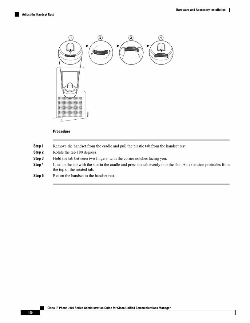
Procedure
Step 1 Remove the handset from the cradle and pull the plastic tab from the handset rest.Step 2 Rotate the tab 180 degrees.Step 3 Hold the tab between two fingers, with the corner notches facing you.Step 4 Line up the tab with the slot in the cradle and press the tab evenly into the slot. An extension protrudes from
the top of the rotated tab.Step 5 Return the handset to the handset rest.
Cisco IP Phone 7800 Series Administration Guide for Cisco Unified Communications Manager100
Hardware and Accessory InstallationAdjust the Handset Rest

P A R T IVCisco IP Phone Administration
• Cisco IP Phone Security, on page 103• Cisco IP Phone Customization, on page 115• Phone Features and Setup , on page 119• Corporate and Personal Directory Setup, on page 177

C H A P T E R 9Cisco IP Phone Security
• Cisco IP Phone Security Overview, on page 103• Security Enhancements for Your Phone Network, on page 104• View the Current Security Features on the Phone, on page 104• View Security Profiles, on page 105• Supported Security Features, on page 105
Cisco IP Phone Security OverviewThe Security features protect against several threats, including threats to the identity of the phone and to data.These features establish and maintain authenticated communication streams between the phone and the CiscoUnified Communications Manager server, and ensure that the phone uses only digitally signed files.
Cisco Unified CommunicationsManager Release 8.5(1) and later includes Security by Default, which providesthe following security features for Cisco IP Phones without running the CTL client:
• Signing of the phone configuration files
• Phone configuration file encryption
• HTTPS with Tomcat and other Web services
Secure signaling and media features still require you to run the CTL client and use hardware eTokens.Note
For more information about the security features, see the documentation for your particular Cisco UnifiedCommunications Manager release.
A Locally Significant Certificate (LSC) installs on phones after you perform the necessary tasks that areassociated with the Certificate Authority Proxy Function (CAPF). You can use Cisco Unified CommunicationsManager Administration to configure an LSC. For more information, see the documentation for your particularCisco Unified Communications Manager release.
Alternatively, you can initiate the installation of an LSC from the Security Setup menu on the phone. Thismenu also lets you update or remove an LSC.
The Cisco IP Phone 7800 Series complies with Federal Information Processing Standard (FIPS). To functioncorrectly, FIPS mode requires an RSA key size of 2048 bits or greater. If the RSA server certificate is not
Cisco IP Phone 7800 Series Administration Guide for Cisco Unified Communications Manager103
2048 bits or greater, the phone will not register with Cisco Unified Communications Manager and Phonefailed to register. Cert key size is not FIPS compliant displays on the phone.
You cannot use private keys (LSC or MIC) in FIPS mode.
If the phone has an existing LSC that is smaller than 2048 bits, you need to update the LSC key size to 2048bits or greater before enabling FIPS.
Related TopicsCisco Unified Communications Manager Documentation, on page xvSet Up a Locally Significant Certificate, on page 108
Security Enhancements for Your Phone NetworkYou can enable Cisco Unified Communications Manager 11.5(1) and later to operate in an enhanced securityenvironment. With these enhancements, your phone network operates under a set of strict security and riskmanagement controls to protect you and your users.
These security enhancements include:
• Contact search authentication.
• TCP as the default protocol for remote audit logging.
• FIPS mode.
• An improved credentials policy.
• Support for the SHA-2 family of hashes for digital signatures.
• Support for a RSA key size of 3072 and 4096 bits.
For additional information about working with and enabling these security requirements, see the “FIPS 140-2Mode Setup” chapter of the Security Guide for Cisco Unified Communications Manager .
The phone can only store a limited number of Identity Trust List (ITL) files. You need to limit the number ofITL files that the Cisco Unified Communications Manager can push to the phone. For more information, seethe Security Guide for Cisco Unified Communications Manager .
Note
View the Current Security Features on the PhoneFor more information about the security features and about Cisco Unified Communications Manager andCisco IP Phone security, see the documentation for your particular Cisco Unified Communications Managerrelease.
Procedure
Step 1 Press Applications .
Cisco IP Phone 7800 Series Administration Guide for Cisco Unified Communications Manager104
Cisco IP Phone AdministrationSecurity Enhancements for Your Phone Network

Step 2 Select Admin Settings > Security Setup.
Most security features are available only if a certificate trust list (CTL) is installed on the phone.
Related TopicsCisco Unified Communications Manager Documentation, on page xv
View Security ProfilesAll Cisco IP Phones that support Cisco Unified CommunicationsManager use a security profile, which defineswhether the phone is nonsecure, authenticated, or encrypted. For information about configuring the securityprofile and applying the profile to the phone, see the documentation for your particular Cisco UnifiedCommunications Manager release.
Procedure
Step 1 In Cisco Unified Communications Manager Administration, select System > Security > Phone SecurityProfile.
Step 2 Look at the Security Mode setting.
Related TopicsCisco Unified Communications Manager Documentation, on page xv
Supported Security FeaturesThe following table provides an overview of the security features that the Cisco IP Phone 7800 Series support.For more information about these features, Cisco Unified Communications Manager and Cisco IP Phonesecurity, see the documentation for your particular Cisco Unified Communications Manager release.
Table 18: Overview of Security Features
DescriptionFeature
Signed binary files (with the extension .sbn) preventtampering with the firmware image before it is loadedon a phone. Tamperingwith the image causes a phoneto fail the authentication process and reject the newimage.
Image authentication
Cisco IP Phone 7800 Series Administration Guide for Cisco Unified Communications Manager105
Cisco IP Phone AdministrationView Security Profiles
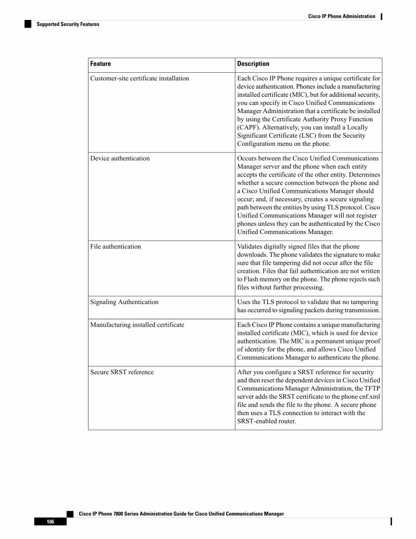
DescriptionFeature
Each Cisco IP Phone requires a unique certificate fordevice authentication. Phones include amanufacturinginstalled certificate (MIC), but for additional security,you can specify in Cisco Unified CommunicationsManager Administration that a certificate be installedby using the Certificate Authority Proxy Function(CAPF). Alternatively, you can install a LocallySignificant Certificate (LSC) from the SecurityConfiguration menu on the phone.
Customer-site certificate installation
Occurs between the Cisco Unified CommunicationsManager server and the phone when each entityaccepts the certificate of the other entity. Determineswhether a secure connection between the phone anda Cisco Unified Communications Manager shouldoccur; and, if necessary, creates a secure signalingpath between the entities by using TLS protocol. CiscoUnified Communications Manager will not registerphones unless they can be authenticated by the CiscoUnified Communications Manager.
Device authentication
Validates digitally signed files that the phonedownloads. The phone validates the signature to makesure that file tampering did not occur after the filecreation. Files that fail authentication are not writtento Flashmemory on the phone. The phone rejects suchfiles without further processing.
File authentication
Uses the TLS protocol to validate that no tamperinghas occurred to signaling packets during transmission.
Signaling Authentication
Each Cisco IP Phone contains a uniquemanufacturinginstalled certificate (MIC), which is used for deviceauthentication. The MIC is a permanent unique proofof identity for the phone, and allows Cisco UnifiedCommunications Manager to authenticate the phone.
Manufacturing installed certificate
After you configure a SRST reference for securityand then reset the dependent devices in Cisco UnifiedCommunicationsManager Administration, the TFTPserver adds the SRST certificate to the phone cnf.xmlfile and sends the file to the phone. A secure phonethen uses a TLS connection to interact with theSRST-enabled router.
Secure SRST reference
Cisco IP Phone 7800 Series Administration Guide for Cisco Unified Communications Manager106
Cisco IP Phone AdministrationSupported Security Features

DescriptionFeature
Uses SRTP to ensure that the media streams betweensupported devices proves secure and that only theintended device receives and reads the data. Includescreating a media master key pair for the devices,delivering the keys to the devices, and securing thedelivery of the keys while the keys are in transport.
Media encryption
Implements parts of the certificate generationprocedure that are too processing-intensive for thephone, and interacts with the phone for key generationand certificate installation. The CAPF can beconfigured to request certificates fromcustomer-specified certificate authorities on behalf ofthe phone, or it can be configured to generatecertificates locally.
CAPF (Certificate Authority Proxy Function)
Defines whether the phone is nonsecure or encrypted.Security profiles
Lets you ensure the privacy of phone configurationfiles.
Encrypted configuration files
You can prevent access to a phone web page, whichdisplays a variety of operational statistics for thephone.
Optional disabling of the web server functionality fora phone
Additional security options, which you control fromCisco Unified Communications ManagerAdministration:
• Disable PC port• Disable PC Voice VLAN access• Disable access to web pages for a phone
You can view current settings for the PCPort Disabled, GARP Enabled, and VoiceVLAN enabled options by looking at thephone Configuration menu.
Note
Phone hardening
The Cisco IP Phone can use 802.1X authentication torequest and gain access to the network.
802.1X Authentication
Cisco IP Phone 7800 Series Administration Guide for Cisco Unified Communications Manager107
Cisco IP Phone AdministrationSupported Security Features

DescriptionFeature
When connected to Cisco Unified CommunicationsManager Release 10.5(2) and later, the phones supportAES 256 encryption support for TLS and SIP forsignaling and media encryption. This enables phonesto initiate and support TLS 1.2 connections usingAES-256 based ciphers that conform to SHA-2(Secure Hash Algorithm) standards and are FederalInformation Processing Standards (FIPS) compliant.The new ciphers are:
• For TLS connections:
• TLS_ECDHE_RSA_WITH_AES_256_GCM_SHA384• TLS_ECDHE_RSA_WITH_AES_128_GCM_SHA256
• For sRTP:
• AEAD_AES_256_GCM• AEAD_AES_128_GCM
For more information, see the Cisco UnifiedCommunications Manager documentation.
AES 256 Encryption
Related TopicsCisco Unified Communications Manager Documentation, on page xvCisco IP Phone Security, on page 103802.1x Authentication, on page 112View Security Profiles, on page 105
Set Up a Locally Significant Certificate
Before you begin
Make sure that the appropriate Cisco Unified Communications Manager and the Certificate Authority ProxyFunction (CAPF) security configurations are complete:
• The CTL or ITL file has a CAPF certificate.
• In Cisco Unified Communications Operating System Administration, verify that the CAPF certificate isinstalled.
• The CAPF is running and configured.
For more information about these settings, see the documentation for your particular Cisco UnifiedCommunications Manager release.
Procedure
Step 1 Obtain the CAPF authentication code that was set when the CAPF was configured.
Cisco IP Phone 7800 Series Administration Guide for Cisco Unified Communications Manager108
Cisco IP Phone AdministrationSet Up a Locally Significant Certificate
Step 2 From the phone, press Applications .Step 3 Choose Admin Settings > Security Setup.
You can control access to the Settings menu by using the Settings Access field in the Cisco UnifiedCommunications Manager Administration Phone Configuration window.
Note
Step 4 Choose LSC and press Select or Update.
The phone prompts for an authentication string.
Step 5 Enter the authentication code and press Submit.
The phone begins to install, update, or remove the LSC, depending on how the CAPF is configured. Duringthe procedure, a series of messages appears in the LSC option field in the Security Configuration menu, soyou can monitor progress. When the procedure is complete, Installed or Not Installed displays on the phone.
The LSC install, update, or removal process can take a long time to complete.
When the phone installation procedure is successful, the Installedmessage displays. If the phone displaysNot Installed, then the authorization string may be incorrect or the phone upgrade may not be enabled.If the CAPF operation deletes the LSC, the phone displays Not Installed to indicate that the operationsucceeded. The CAPF server logs the error messages. See the CAPF server documentation to locate the logsand to understand the meaning of the error messages.
Related TopicsCisco Unified Communications Manager Documentation, on page xv
Enable FIPS Mode
Procedure
Step 1 In Cisco Unified Communications Manager Administration, select Device > Phone and locate the phone.Step 2 Navigate to the Product Specific Configuration area.Step 3 Set the FIPS Mode field to Enabled.Step 4 Select Apply Config.Step 5 Select Save.Step 6 Restart the phone.
Phone Call SecurityWhen security is implemented for a phone, you can identify secure phone calls by icons on the phone screen.You can also determine whether the connected phone is secure and protected if a security tone plays at thebeginning of the call.
Cisco IP Phone 7800 Series Administration Guide for Cisco Unified Communications Manager109
Cisco IP Phone AdministrationEnable FIPS Mode

In a secure call, all call signaling and media streams are encrypted. A secure call offers a high level of security,providing integrity and privacy to the call. When a call in progress is encrypted, the call progress icon to the
right of the call duration timer in the phone screen changes to the following icon: .
If the call is routed through non-IP call legs, for example, PSTN, the call may be nonsecure even though it isencrypted within the IP network and has a lock icon associated with it.
Note
In a secure call, a security tone plays at the beginning of a call to indicate that the other connected phone isalso receiving and transmitting secure audio. If your call connects to a nonsecure phone, the security tonedoes not play.
Secure calling is supported between two phones. Secure conference, Cisco Extension Mobility, and sharedlines can be configured by a secure conference bridge.
Note
When a phone is configured as secure (encrypted and trusted) in Cisco Unified Communications Manager, itcan be given a “protected” status. After that, if desired, the protected phone can be configured to play anindication tone at the beginning of a call:
• Protected Device: To change the status of a secure phone to protected, check the Protected Device checkbox in the Phone Configuration window in Cisco Unified Communications Manager Administration(Device > Phone).
• Play Secure Indication Tone: To enable the protected phone to play a secure or nonsecure indicationtone, set the Play Secure Indication Tone setting to True. By default, Play Secure Indication Tone is setto False. You set this option in Cisco Unified Communications Manager Administration (System >Service Parameters). Select the server and then the Unified Communications Manager service. In theService Parameter Configuration window, select the option in the Feature - Secure Tone area. The defaultis False.
Secure Conference Call IdentificationYou can initiate a secure conference call and monitor the security level of participants. A secure conferencecall is established by using this process:
1. A user initiates the conference from a secure phone.
2. Cisco Unified Communications Manager assigns a secure conference bridge to the call.
3. As participants are added, Cisco Unified Communications Manager verifies the security mode of eachphone and maintains the secure level for the conference.
4. The phone displays the security level of the conference call. A secure conference displays the secure icon
to the right of Conference on the phone screen.
Secure calling is supported between two phones. For protected phones, some features, such as conferencecalling, shared lines, and Extension Mobility, are not available when secure calling is configured.
Note
Cisco IP Phone 7800 Series Administration Guide for Cisco Unified Communications Manager110
Cisco IP Phone AdministrationSecure Conference Call Identification
The following table provides information about changes to conference security levels depending on the initiatorphone security level, the security levels of participants, and the availability of secure conference bridges.
Table 19: Security Restrictions with Conference Calls
Results of ActionSecurity Level ofParticipants
Feature UsedInitiator Phone SecurityLevel
Nonsecure conferencebridge
Nonsecure conference
SecureConferenceNonsecure
Secure conference bridge
Nonsecure conference
At least one member isnonsecure.
ConferenceSecure
Secure conference bridge
Secure encrypted levelconference
SecureConferenceSecure
Initiator receives messageDoes not meetSecurity Level,call rejected.
Minimum security levelis encrypted.
Meet MeNonsecure
Secure conference bridge
Conference accepts allcalls.
Minimum security levelis nonsecure.
Meet MeSecure
Secure Phone Call IdentificationA secure call is established when your phone, and the phone on the other end, is configured for secure calling.The other phone can be in the same Cisco IP network, or on a network outside the IP network. Secured callscan only be made between two phones. Conference calls should support secure call after secure conferencebridge set up.
A secured call is established using this process:
1. A user initiates the call from a secured phone (secured security mode).
2. The phone displays the secure icon on the phone screen. This icon indicates that the phone is configuredfor secure calls, but this does not mean that the other connected phone is also secured.
3. The user hears a security tone if the call connects to another secured phone, indicating that both ends ofthe conversation are encrypted and secured. If the call connects to a nonsecure phone, the user does nothear the security tone.
Secure calling is supported between two phones. For protected phones, some features, such as conferencecalling, shared lines, and Extension Mobility, are not available when secure calling is configured.
Note
Cisco IP Phone 7800 Series Administration Guide for Cisco Unified Communications Manager111
Cisco IP Phone AdministrationSecure Phone Call Identification

Only protected phones play these secure or nonsecure indication tones. Nonprotected phones never play tones.If the overall call status changes during the call, the indication tone changes and the protected phone playsthe appropriate tone.
A protected phone plays a tone or not under these circumstances:
• When the Play Secure Indication Tone option is enabled:
• When end-to-end secure media is established and the call status is secure, the phone plays the secureindication tone (three long beeps with pauses).
• When end-to-end nonsecure media is established and the call status is nonsecure, the phone playsthe nonsecure indication tone (six short beeps with brief pauses).
If the Play Secure Indication Tone option is disabled, no tone plays.
Secure calling is supported between two phones. For protected phones, some features, such as conferencecalling, shared lines, and Extension Mobility, are not available when secure calling is configured.
Note
802.1x AuthenticationThe Cisco IP Phones support 802.1X Authentication.
Cisco IP Phones and Cisco Catalyst switches traditionally use Cisco Discovery Protocol (CDP) to identifyeach other and determine parameters such as VLAN allocation and inline power requirements. CDP does notidentify locally attached workstations. Cisco IP Phones provide an EAPOL pass-through mechanism. Thismechanism allows a workstation attached to the Cisco IP Phone to pass EAPOL messages to the 802.1Xauthenticator at the LAN switch. The pass-through mechanism ensures that the IP phone does not act as theLAN switch to authenticate a data endpoint before accessing the network.
Cisco IP Phones also provide a proxy EAPOL Logoff mechanism. In the event that the locally attached PCdisconnects from the IP phone, the LAN switch does not see the physical link fail, because the link betweenthe LAN switch and the IP phone is maintained. To avoid compromising network integrity, the IP phone sendsan EAPOL-Logoff message to the switch on behalf of the downstream PC, which triggers the LAN switch toclear the authentication entry for the downstream PC.
Support for 802.1X authentication requires several components:
• Cisco IP Phone: The phone initiates the request to access the network. Phones contain an 802.1Xsupplicant. This supplicant allows network administrators to control the connectivity of IP phones to theLAN switch ports. The current release of the phone 802.1X supplicant uses the EAP-FAST and EAP-TLSoptions for network authentication.
• Cisco Catalyst Switch (or other third-party switch): The switch must support 802.1X, so it can act as theauthenticator and pass the messages between the phone and the authentication server. After the exchangecompletes, the switch grants or denies the phone access to the network.
You must perform the following actions to configure 802.1X.
• Configure the other components before you enable 802.1X Authentication on the phone.
• Configure PC Port—The 802.1X standard does not consider VLANs and thus recommends that only asingle device should be authenticated to a specific switch port. However, some switches (including Cisco
Cisco IP Phone 7800 Series Administration Guide for Cisco Unified Communications Manager112
Cisco IP Phone Administration802.1x Authentication

Catalyst switches) support multidomain authentication. The switch configuration determines whetheryou can connect a PC to the PC port of the phone.
• Enabled—If you are using a switch that supports multidomain authentication, you can enable thePC port and connect a PC to it. In this case, Cisco IP Phones support proxy EAPOL-Logoff tomonitor the authentication exchanges between the switch and the attached PC. For more informationabout IEEE 802.1X support on the Cisco Catalyst switches, see the Cisco Catalyst switchconfiguration guides at:
http://www.cisco.com/en/US/products/hw/switches/ps708/tsd_products_support_series_home.html
• Disabled—If the switch does not support multiple 802.1X-compliant devices on the same port, youshould disable the PC Port when 802.1X authentication is enabled. If you do not disable this portand subsequently attempt to attach a PC to it, the switch denies network access to both the phoneand the PC.
• Configure Voice VLAN—Because the 802.1X standard does not account for VLANs, you shouldconfigure this setting based on the switch support.
• Enabled—If you are using a switch that supports multidomain authentication, you can continue touse the voice VLAN.
• Disabled—If the switch does not support multidomain authentication, disable the Voice VLAN andconsider assigning the port to the native VLAN.
Related TopicsCisco Unified Communications Manager Documentation, on page xv
Cisco IP Phone 7800 Series Administration Guide for Cisco Unified Communications Manager113
Cisco IP Phone Administration802.1x Authentication

Cisco IP Phone 7800 Series Administration Guide for Cisco Unified Communications Manager114
Cisco IP Phone Administration802.1x Authentication
C H A P T E R 10Cisco IP Phone Customization
• Custom Phone Ringtones, on page 115• Set Up Wideband Codec, on page 115• Set Up Handset for 7811, on page 116• Set Up Idle Display, on page 116• Customize the Dial Tone, on page 117
Custom Phone RingtonesThe Cisco IP Phone ships with two default ringtones that are implemented in hardware: Chirp1 and Chirp2.Cisco Unified Communications Manager also provides a default set of additional phone ringtones that areimplemented in software as pulse code modulation (PCM) files. The PCM files, along with an XML file thatdescribes the ring list options that are available at your site, exist in the TFTP directory on each Cisco UnifiedCommunications Manager server.
All file names are case sensitive. If you use the wrong case for the file name, the phone will not apply yourchanges.
Attention
For more information, see the "Custom Phone Rings and Backgrounds" chapter, Feature Configuration Guidefor Cisco Unified Communications Manager.
Related TopicsCisco Unified Communications Manager Documentation, on page xv
Set Up Wideband CodecBy default, the G.722 codec is enabled for the phone. If Cisco Unified CommunicationsManager is configuredto use G.722 and if the far endpoint supports G.722, the call connects using the G.722 codec in place of G.711.
This situation occurs regardless of whether the user has enabled a wideband headset or wideband handset,but if either the headset or handset is enabled, the user may notice greater audio sensitivity during the call.Greater sensitivity means improved audio clarity but also means that the far endpoint can hear more backgroundnoise: noise such as rustling papers or nearby conversations. Even without a wideband headset or handset,
Cisco IP Phone 7800 Series Administration Guide for Cisco Unified Communications Manager115
some users may prefer the additional sensitivity of G.722 distracting. Other users may prefer the additionalsensitivity of G.722.
The Advertise G.722 Codec service parameter affects whether wideband support exists for all devices thatregister with this Cisco Unified Communications Manager server or for a specific phone, depending on theCisco Unified Communications Manager Administration window where the parameter is configured:
Procedure
Step 1 In Cisco Unified Communications Manager Administration, choose System > Enterprise Parameters.Step 2 Set the Advertise G.722 Codec field.
The default value of this enterprise parameter is Enabled, which means that all Cisco IP Phones that registerto this Cisco Unified Communications Manager advertise G.722 to Cisco Unified Communications Manager.If each endpoint in the attempted call supports G.722 in the capabilities set, Cisco Unified CommunicationsManager chooses that codec for the call whenever possible.
Set Up Handset for 7811The Cisco IP Phone 7811 ships with a narrowband or wideband handset. The administrator must configurethe type of the handset for the phone to work.
Procedure
Step 1 In Cisco Unified Communications Manager Administration, choose Device > Phone.Step 2 Locate the phone that you need to set up.Step 3 In the Phone Configuration window set theWideband Handset field:
a) For narrowband handset, set the field to Disabled or Use Phone Default.b) For wideband handset, set the field to Enabled.
Step 4 Select Save.
Set Up Idle DisplayYou can specify an idle display (text only; text file size should not exceed 1M bytes) that appears on the phonescreen. The idle display is an XML service that the phone invokes when the phone is idle (not in use) for adesignated period and no feature menu is open.
For detailed instructions about creating and displaying the idle display, see Creating Idle URL Graphics onCisco IP Phone at this URL:
http://www.cisco.com/en/US/products/sw/voicesw/ps556/products_tech_note09186a00801c0764.shtml
Cisco IP Phone 7800 Series Administration Guide for Cisco Unified Communications Manager116
Cisco IP Phone AdministrationSet Up Handset for 7811
In addition, see the documentation for your particular Cisco Unified Communications Manager release forthe following information:
• Specifying the URL of the idle display XML service:
• For a single phone: Idle field in the Phone Configuration window in Cisco Unified CommunicationsManager Administration.
• For multiple phones simultaneously: URL Idle field in the Enterprise Parameters Configurationwindow, or the Idle field in the Bulk Administration Tool (BAT)
• Specifying the length of time that the phone is not used before the idle display XML service is invoked:
• For a single phone: Idle Timer field in the Phone configuration window in Cisco UnifiedCommunications Manager Administration.
• For multiple phones simultaneously: URL Idle Time field in the Enterprise Parameters Configurationwindow, or the Idle Timer field in the Bulk Administration Tool (BAT)
Procedure
Step 1 In Cisco Unified Communications Manager Administration, select Device > PhoneStep 2 In the Idle field, enter the URL to the idle display XML Service.Step 3 In the Idle Timer field, enter the time that the idle phone waits before displaying the idle display XML service.Step 4 Select Save.
Related TopicsCisco Unified Communications Manager Documentation, on page xv
Customize the Dial ToneYou can set up your phones so that users hear different dial tones for internal and external calls. Dependingupon your needs, you can choose from three dial tone options:
• Default: A different dial tone for inside and outside calls.
• Inside: The inside dial tone is used for all calls.
• Outside: The outside dial tone is used for all calls.
Always Use Dial Tone is a required field on Cisco Unified Communications Manager.
Procedure
Step 1 In Cisco Unified Communications Manager Administration, select System > Service Parameters.Step 2 Select the appropriate Server.Step 3 Select Cisco CallManager as the Service.
Cisco IP Phone 7800 Series Administration Guide for Cisco Unified Communications Manager117
Cisco IP Phone AdministrationCustomize the Dial Tone

Step 4 Scroll to the Clusterwide Parameters pane.Step 5 Set Always Use Dial Tone to one of the following:
• Outside• Inside• Default
Step 6 Select Save.Step 7 Restart your phones.
Cisco IP Phone 7800 Series Administration Guide for Cisco Unified Communications Manager118
Cisco IP Phone AdministrationCustomize the Dial Tone

C H A P T E R 11Phone Features and Setup
• Cisco IP Phone User Support, on page 119• Telephony Features for the Cisco IP Phone, on page 119• Feature Buttons and Softkeys, on page 135• Phone Feature Configuration, on page 136• Set Up Softkey Template, on page 172• Phone Button Templates, on page 175
Cisco IP Phone User SupportIf you are a system administrator, you are likely the primary source of information for Cisco IP Phone usersin your network or company. It is important to provide current and thorough information to end users.
To successfully use some of the features on the Cisco IP Phone (including Services and voice message systemoptions), users must receive information from you or from your network team or must be able to contact youfor assistance. Make sure to provide users with the names of people to contact for assistance and withinstructions for contacting those people.
We recommend that you create a web page on your internal support site that provides end users with importantinformation about their Cisco IP Phones.
Consider including the following types of information on this site:
• User guides for all Cisco IP Phone models that you support
• Information on how to access the Cisco Unified Communications Self Care Portal
• List of features supported
• User guide or quick reference for your voicemail system
Telephony Features for the Cisco IP PhoneAfter you add Cisco IP Phones to Cisco Unified Communications Manager, you can add functionality to thephones. The following table includes a list of supported telephony features, many of which you can configureby using Cisco Unified Communications Manager Administration.
Cisco IP Phone 7800 Series Administration Guide for Cisco Unified Communications Manager119

For information about using most of these features on the phone, see the Cisco IP Phone 7800 Series UserGuide. See Feature Buttons and Softkeys, on page 135 for a list of features that can be configured asprogrammable buttons and dedicated softkeys and feature buttons.
When adding features to the phone line keys, you are limited by the number of line keys available. You cannotadd more features than the number of line keys on your phone.
Cisco Unified Communications Manager Administration also provides several service parameters that youcan use to configure various telephony functions. For more information on accessing and configuring serviceparameters, see the documentation for your particular Cisco Unified Communications Manager release.
For more information on the functions of a service, select the name of the parameter or the question mark (?)help button in the Product Specific Configuration window.
Note
Description and More InformationFeature
Allows users to speed dial a phone number by entering an assigned index code (1-199) on thephone keypad.
You can use Abbreviated Dialing while on-hook or off-hook.Note
Users assign index codes from the Self Care Portal.
Abbreviated Dialing
Provides different options to control the incoming call alerts. You can disable or enable thecall alert. You can also activate or deactivate the caller ID display.
Because the Cisco IP Phone 7811 does not have line key, it enables the call alertby default but cannot disable it.
Note
See Actionable Incoming Call Alert, Product Specific Configuration, on page 138.
Actionable Incoming Call Alert
Enhances security by supporting TLS 1.2 and new ciphers. Formore information, see SupportedSecurity Features, on page 105.
AES 256 Encryption Support forPhones
Allows an agent to create and update a prerecorded greeting that plays at the beginning of acustomer call, before the agent begins the conversation with the caller. The agent can prerecorda single greeting or multiple ones as needed.
See Enable Agent Greeting, on page 159.
Agent Greeting
Allows users to pick up a call on any line in their call pickup group, regardless of how thecall was routed to the phone.
See call park information in the documentation for your particular Cisco UnifiedCommunications Manager release.
Any Call Pickup
Enables users to park a call by pressing only one button using the Direct Park feature.Administrators must configure a Busy Lamp Field (BLF) Assisted Directed Call Park button.When users press an idle BLF Assisted Directed Call Park button for an active call, the activecall is parked at the Direct Park slot associated with the Assisted Directed Call Park button.
See the call park information in the documentation for your particular Cisco UnifiedCommunications Manager release.
Assisted Directed Call Park
Cisco IP Phone 7800 Series Administration Guide for Cisco Unified Communications Manager120
Cisco IP Phone AdministrationTelephony Features for the Cisco IP Phone
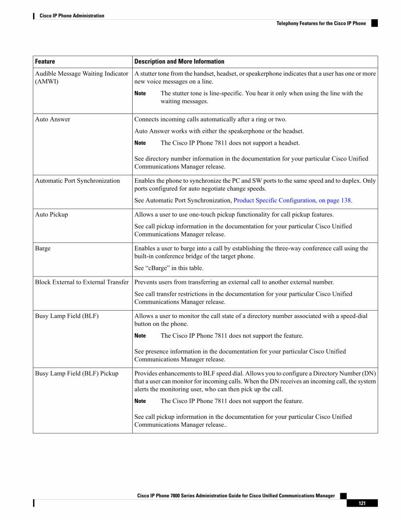
Description and More InformationFeature
A stutter tone from the handset, headset, or speakerphone indicates that a user has one or morenew voice messages on a line.
The stutter tone is line-specific. You hear it only when using the line with thewaiting messages.
Note
Audible Message Waiting Indicator(AMWI)
Connects incoming calls automatically after a ring or two.
Auto Answer works with either the speakerphone or the headset.
The Cisco IP Phone 7811 does not support a headset.Note
See directory number information in the documentation for your particular Cisco UnifiedCommunications Manager release.
Auto Answer
Enables the phone to synchronize the PC and SW ports to the same speed and to duplex. Onlyports configured for auto negotiate change speeds.
See Automatic Port Synchronization, Product Specific Configuration, on page 138.
Automatic Port Synchronization
Allows a user to use one-touch pickup functionality for call pickup features.
See call pickup information in the documentation for your particular Cisco UnifiedCommunications Manager release.
Auto Pickup
Enables a user to barge into a call by establishing the three-way conference call using thebuilt-in conference bridge of the target phone.
See “cBarge” in this table.
Barge
Prevents users from transferring an external call to another external number.
See call transfer restrictions in the documentation for your particular Cisco UnifiedCommunications Manager release.
Block External to External Transfer
Allows a user to monitor the call state of a directory number associated with a speed-dialbutton on the phone.
The Cisco IP Phone 7811 does not support the feature.Note
See presence information in the documentation for your particular Cisco UnifiedCommunications Manager release.
Busy Lamp Field (BLF)
Provides enhancements to BLF speed dial. Allows you to configure a Directory Number (DN)that a user can monitor for incoming calls. When the DN receives an incoming call, the systemalerts the monitoring user, who can then pick up the call.
The Cisco IP Phone 7811 does not support the feature.Note
See call pickup information in the documentation for your particular Cisco UnifiedCommunications Manager release..
Busy Lamp Field (BLF) Pickup
Cisco IP Phone 7800 Series Administration Guide for Cisco Unified Communications Manager121
Cisco IP Phone AdministrationTelephony Features for the Cisco IP Phone
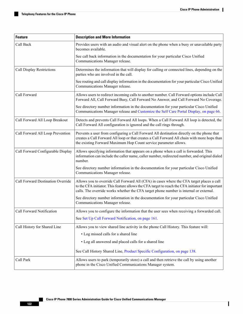
Description and More InformationFeature
Provides users with an audio and visual alert on the phone when a busy or unavailable partybecomes available.
See call back information in the documentation for your particular Cisco UnifiedCommunications Manager release.
Call Back
Determines the information that will display for calling or connected lines, depending on theparties who are involved in the call.
See routing and call display information in the documentation for your particular Cisco UnifiedCommunications Manager release.
Call Display Restrictions
Allows users to redirect incoming calls to another number. Call Forward options include CallForward All, Call Forward Busy, Call Forward No Answer, and Call Forward No Coverage.
See directory number information in the documentation for your particular Cisco UnifiedCommunications Manager release and Customize the Self Care Portal Display, on page 66.
Call Forward
Detects and prevents Call Forward All loops. When a Call Forward All loop is detected, theCall Forward All configuration is ignored and the call rings through.
Call Forward All Loop Breakout
Prevents a user from configuring a Call Forward All destination directly on the phone thatcreates a Call Forward All loop or that creates a Call Forward All chain with more hops thanthe existing Forward Maximum Hop Count service parameter allows.
Call Forward All Loop Prevention
Allows specifying information that appears on a phone when a call is forwarded. Thisinformation can include the caller name, caller number, redirected number, and original dialednumber.
See directory number information in the documentation for your particular Cisco UnifiedCommunications Manager release.
Call Forward Configurable Display
Allows you to override Call Forward All (CFA) in cases where the CFA target places a callto the CFA initiator. This feature allows the CFA target to reach the CFA initiator for importantcalls. The override works whether the CFA target phone number is internal or external.
See directory number information in the documentation for your particular Cisco UnifiedCommunications Manager release.
Call Forward Destination Override
Allows you to configure the information that the user sees when receiving a forwarded call.
See Set Up Call Forward Notification, on page 161.
Call Forward Notification
Allows you to view shared line activity in the phone Call History. This feature will:
• Log missed calls for a shared line
• Log all answered and placed calls for a shared line
See Call History Shared Line, Product Specific Configuration, on page 138.
Call History for Shared Line
Allows users to park (temporarily store) a call and then retrieve the call by using anotherphone in the Cisco Unified Communications Manager system.
Call Park
Cisco IP Phone 7800 Series Administration Guide for Cisco Unified Communications Manager122
Cisco IP Phone AdministrationTelephony Features for the Cisco IP Phone

Description and More InformationFeature
Allows users to redirect a call that is ringing on another phone within their pickup group totheir phone.
You can configure an audio and visual alert for the primary line on the phone. This alertnotifies the users that a call is ringing in their pickup group.
Call Pickup
Allows a supervisor to record an active call. The user might hear a recording audible alerttone during a call when it is being recorded.
When a call is secured, the security status of the call is displayed as a lock icon on Cisco IPPhones. The connected parties might also hear an audible alert tone that indicates the call issecured and is being recorded.
When an active call is being monitored or recorded, the user can receive or placeintercom calls; however, if the user places an intercom call, the active call is puton hold, which causes the recording session to terminate and the monitoring sessionto suspend. To resume the monitoring session, the party whose call is beingmonitored must resume the call.
Note
Call Recording
Indicates (and allows users to answer) an incoming call that rings while on another call.Incoming call information appears on the phone display.
See directory number information in the documentation for your particular Cisco UnifiedCommunications Manager release.
Call Waiting
Provides Call Waiting users with the option of an audible ring instead of the standard beep.
Options are Ring, Ring Once, Flash Only, and Beep Only.
See directory number information in the documentation for your particular Cisco UnifiedCommunications Manager release.
Call Waiting Ring
Caller identification such as a phone number, name, or other descriptive text appear on thephone display.
See routing, call display, and directory number information in the documentation for yourparticular Cisco Unified Communications Manager release.
Caller ID
Allows a user to block their phone number or name from phones that have caller identificationenabled.
See routing and directory number information in the documentation for your particular CiscoUnified Communications Manager release.
Caller ID Blocking
Calling party normalization presents phone calls to the user with a dialable phone number.Any escape codes are added to the number so that the user can easily connect to the calleragain. The dialable number is saved in the call history and can be saved in the Personal AddressBook.
Calling Party Normalization
Establishes communication between the Cisco Unified Video Advantage (CUVA) and theCisco IP phones to support video on the PC even if the IP phone does not have video capability.The main software supported is Cisco Jabber.
CAST for SIP
Cisco IP Phone 7800 Series Administration Guide for Cisco Unified Communications Manager123
Cisco IP Phone AdministrationTelephony Features for the Cisco IP Phone

Description and More InformationFeature
Allows a user to join a nonprivate call on a shared phone line. cBarge adds a user to a calland converts it into a conference, allowing the user and other parties to access conferencefeatures .
For more information, refer to the "Barge" chapter, Feature Configuration Guide for CiscoUnified Communications Manager.
cBarge
Allows users to temporarily access their Cisco IP Phone configuration such as line appearances,services, and speed dials from shared Cisco IP Phone by logging into the Cisco ExtensionMobility service on that phone when they log into the Cisco Extension Mobility service onthat phone.
Cisco Extension Mobility can be useful if users work from a variety of locations within yourcompany or if they share a workspace with coworkers.
Cisco Extension Mobility
Enables a user configured in one cluster to log into a Cisco IP Phone in another cluster. Usersfrom a home cluster log into a Cisco IP Phone at a visiting cluster.
Configure Cisco Extension Mobility on Cisco IP Phones before you configureEMCC.
Note
Cisco Extension Mobility CrossCluster (EMCC)
Provides support for the Cisco IP Phone 7811. The phone does not support headset, displaybacklight, intercom, AUX Port, programmable feature button, and line keys.
Cisco IP Phone 7811 Support
Introduces the Cisco Sans 2.0 font for all Latin characters in the Call Display.Cisco Sans 2.0 Latin Font Support
The Cisco Unified Communication Manager Express uses a special tag in the informationsent to the phone to identify itself. This tag enables the phone to provide services to the userthat the switch supports.
See:
• Cisco Unified Communications Manager Express System Administrator Guide
• Cisco Unified Communications Manager Express Interaction.
Cisco Unified CommunicationsManager Express (Unified CME)Version Negotiation
Allows users to make video calls by using a Cisco IP Phone, a personal computer, and anexternal video camera.
Configure the Video Capabilities parameter in the Product Specific ConfigurationLayout section in Phone Configuration.
Note
See the Cisco Unified Video Advantage documentation.
Cisco Unified Video Advantage(CUVA)
Allows users to make calls from web and desktop applications.Cisco WebDialer
Supports narrowband and wideband ringtones. The feature makes the available ringtonescommon with other Cisco IP Phones.
See Custom Phone Ringtones, on page 115.
Classic Ringtone
Cisco IP Phone 7800 Series Administration Guide for Cisco Unified Communications Manager124
Cisco IP Phone AdministrationTelephony Features for the Cisco IP Phone
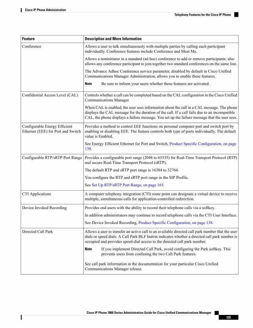
Description and More InformationFeature
Allows a user to talk simultaneously with multiple parties by calling each participantindividually. Conference features include Conference and Meet Me.
Allows a noninitiator in a standard (ad hoc) conference to add or remove participants; alsoallows any conference participant to join together two standard conferences on the same line.
The Advance Adhoc Conference service parameter, disabled by default in Cisco UnifiedCommunications Manager Administration, allows you to enable these features.
Be sure to inform your users whether these features are activated.Note
Conference
Controls whether a call can be completed based on the CAL configuration in the Cisco UnifiedCommunications Manager.
When CAL is enabled, the user sees information about the call in a CAL message. The phonedisplays the CAL message for the duration of the call. If a call fails due to an incompatibleCAL, the phone displays a failure message. You set up the failure message that the user sees.
Confidential Access Level (CAL)
Provides a method to control EEE functions on personal computer port and switch port byenabling or disabling EEE. The feature controls both type of ports individually. The defaultvalue is Enabled.
See Energy Efficient Ethernet for Port and Switch, Product Specific Configuration, on page138.
Configurable Energy EfficientEthernet (EEE) for Port and Switch
Provides a configurable port range (2048 to 65535) for Real-Time Transport Protocol (RTP)and secure Real-Time Transport Protocol (sRTP).
The default RTP and sRTP port range is 16384 to 32764.
You configure the RTP and sRTP port range in the SIP Profile.
See Set Up RTP/sRTP Port Range, on page 165.
Configurable RTP/sRTP Port Range
A computer telephony integration (CTI) route point can designate a virtual device to receivemultiple, simultaneous calls for application-controlled redirection.
CTI Applications
Provides end users with the ability to record their telephone calls via a softkey.
In addition administrators may continue to record telephone calls via the CTI User Interface.
See Device Invoked Recording, Product Specific Configuration, on page 138.
Device Invoked Recording
Allows a user to transfer an active call to an available directed call park number that the userdials or speed dials. A Call Park BLF button indicates whether a directed call park number isoccupied and provides speed-dial access to the directed call park number.
If you implement Directed Call Park, avoid configuring the Park softkey. Thisprevents users from confusing the two Call Park features.
Note
See call park information in the documentation for your particular Cisco UnifiedCommunications Manager release.
Directed Call Park
Cisco IP Phone 7800 Series Administration Guide for Cisco Unified Communications Manager125
Cisco IP Phone AdministrationTelephony Features for the Cisco IP Phone

Description and More InformationFeature
The softkeys are controlled by configuration in the Cisco Unified Communications Manager.The Line Key Barge parameter in the Administration window has the following options:
• Default: Press Line Key can conference into the call.
• Off: Press Line Key Barge a new call.
• Turn on softkey: Press Line Key turns on softkeys configured in remote-in-use and usercan conference into the call through cBarge.
The Cisco IP Phone 7811 does not support the feature.Note
Disable Line Key Barge
Allows users to hear different ring types depending on whether the call was originated froman internal station or external call coming from a trunk. Internal calls generate one ring, whileexternal calls generate two rings with a very short pause between the rings. No configurationis required.
See call pickup information in the documentation for your particular Cisco UnifiedCommunications Manager release.
Distinctive Ring
Allows a user to transfer a ringing, connected, or held call directly to a voice-messagingsystem. When a call is diverted, the line becomes available to make or receive new calls.
Divert
When DND is turned on, either no audible rings occur during the ringing-in state of a call, orno audible or visual notifications of any type occur.
See Set Up Do Not Disturb, on page 159.
Do Not Disturb (DND)
Enables an IP Phone to sleep (power down) and wake (power up) at predetermined times, topromote energy savings.
The Cisco IP Phone 7811 does not support this feature.Note
See Power Save Plus (EnergyWise), Product Specific Configuration, on page 138 .
EnergyWise
Improves the Secure Extension Mobility Cross Cluster (EMCC) feature by preserving thenetwork and security configurations on the login phone. By so doing, security policies aremaintained, network bandwidth is preserved and network failure is avoided within the visitingcluster (VC).
Enhanced Secure ExtensionMobilityCross Cluster (EMCC)
With Feature Safe, your phone can use any phone button template that has the same numberof line buttons that the phone model supports.
Size Safe allows your phone to use any phone button template that is configured on the system.
Extension Mobility Size Safe andFeature Safe
Allows a user to enter a Fast Dial code to place a call. Fast Dial codes can be assigned tophone numbers or Personal Address Book entries. See “Services” in this table.
Fast Dial Service
Allows an administrator to set the sidetone level of a wired headset.
The Cisco IP Phone 7811 does not support a headset.Note
Headset Sidetone Control
Cisco IP Phone 7800 Series Administration Guide for Cisco Unified Communications Manager126
Cisco IP Phone AdministrationTelephony Features for the Cisco IP Phone

Description and More InformationFeature
Allows a user to answer a call that is ringing on a directory number in another group.
See call pickup information in the documentation for your particular Cisco UnifiedCommunications Manager release.
Group Call Pickup
Limits the amount of time that a call can be on hold before reverting back to the phone thatput the call on hold and alerting the user.
Reverting calls are distinguished from incoming calls by a single ring (or beep, depending onthe new call indicator setting for the line). This notification repeats at intervals if not resumed.
A call that triggers Hold Reversion also displays an animated icon in the call bubble. You canconfigure call focus priority to favor incoming or reverting calls.
Hold Reversion
Enables phones with a shared line to distinguish between the local and remote lines that placeda call on hold.
Hold Status
Allows the user to move a connected call from an active state to a held state.
• No configuration required unless you want to use Music On Hold. See “Music On Hold”in this table for information.
• See “Hold Reversion” in this table.
Hold/Resume
Enhances the file download process to the phone to use HTTP by default. If the HTTPdownload fails, the phone reverts to using the TFTP download.
HTTP Download
Increases security by requiring communication using HTTPS.
IP Phones can be HTTPS clients; they cannot be HTTPS servers.Note
See HTTPS for Phone Services, Product Specific Configuration, on page 138.
HTTPS for Phone Services
Provides load sharing for calls to a main directory number. A hunt group contains a series ofdirectory numbers that can answer the incoming calls. When the first directory number in thehunt group is busy, the system hunts in a predetermined sequence for the next availabledirectory number in the group and directs the call to that phone.
See hunt groups and routing plans in the documentation for your particular Cisco UnifiedCommunications Manager release.
Hunt Group
Improves the display of caller names and numbers. If the Caller Name is known then theCaller Number is displayed instead of unknown.
Improve Caller Name and NumberDisplay
Allows you to set the length of time that an incoming call toast (notification) appears on thephone screen.
See Incoming Call Toast Timer, Product Specific Configuration, on page 138 .
Incoming Call Toast Timer
Cisco IP Phone 7800 Series Administration Guide for Cisco Unified Communications Manager127
Cisco IP Phone AdministrationTelephony Features for the Cisco IP Phone
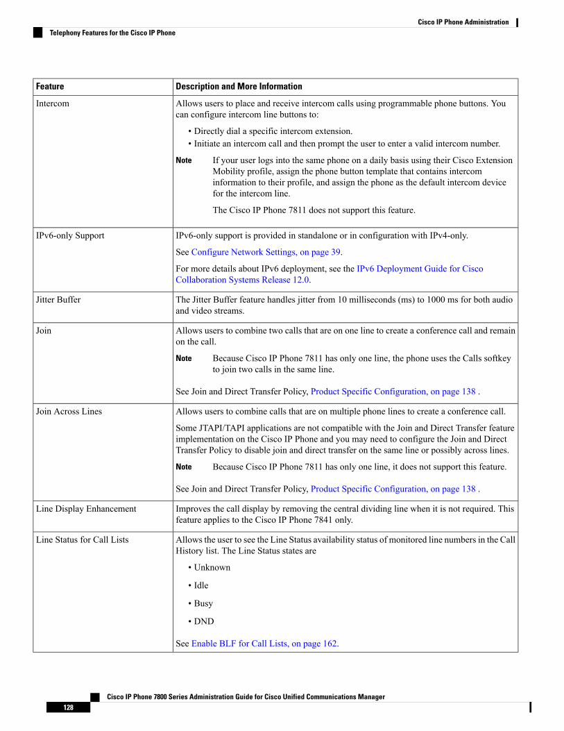
Description and More InformationFeature
Allows users to place and receive intercom calls using programmable phone buttons. Youcan configure intercom line buttons to:
• Directly dial a specific intercom extension.• Initiate an intercom call and then prompt the user to enter a valid intercom number.
If your user logs into the same phone on a daily basis using their Cisco ExtensionMobility profile, assign the phone button template that contains intercominformation to their profile, and assign the phone as the default intercom devicefor the intercom line.
The Cisco IP Phone 7811 does not support this feature.
Note
Intercom
IPv6-only support is provided in standalone or in configuration with IPv4-only.
See Configure Network Settings, on page 39.
For more details about IPv6 deployment, see the IPv6 Deployment Guide for CiscoCollaboration Systems Release 12.0.
IPv6-only Support
The Jitter Buffer feature handles jitter from 10 milliseconds (ms) to 1000 ms for both audioand video streams.
Jitter Buffer
Allows users to combine two calls that are on one line to create a conference call and remainon the call.
Because Cisco IP Phone 7811 has only one line, the phone uses the Calls softkeyto join two calls in the same line.
Note
See Join and Direct Transfer Policy, Product Specific Configuration, on page 138 .
Join
Allows users to combine calls that are on multiple phone lines to create a conference call.
Some JTAPI/TAPI applications are not compatible with the Join and Direct Transfer featureimplementation on the Cisco IP Phone and you may need to configure the Join and DirectTransfer Policy to disable join and direct transfer on the same line or possibly across lines.
Because Cisco IP Phone 7811 has only one line, it does not support this feature.Note
See Join and Direct Transfer Policy, Product Specific Configuration, on page 138 .
Join Across Lines
Improves the call display by removing the central dividing line when it is not required. Thisfeature applies to the Cisco IP Phone 7841 only.
Line Display Enhancement
Allows the user to see the Line Status availability status of monitored line numbers in the CallHistory list. The Line Status states are
• Unknown
• Idle
• Busy
• DND
See Enable BLF for Call Lists, on page 162.
Line Status for Call Lists
Cisco IP Phone 7800 Series Administration Guide for Cisco Unified Communications Manager128
Cisco IP Phone AdministrationTelephony Features for the Cisco IP Phone
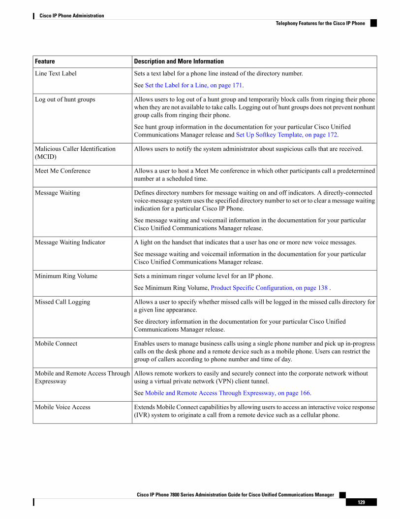
Description and More InformationFeature
Sets a text label for a phone line instead of the directory number.
See Set the Label for a Line, on page 171.
Line Text Label
Allows users to log out of a hunt group and temporarily block calls from ringing their phonewhen they are not available to take calls. Logging out of hunt groups does not prevent nonhuntgroup calls from ringing their phone.
See hunt group information in the documentation for your particular Cisco UnifiedCommunications Manager release and Set Up Softkey Template, on page 172.
Log out of hunt groups
Allows users to notify the system administrator about suspicious calls that are received.Malicious Caller Identification(MCID)
Allows a user to host a Meet Me conference in which other participants call a predeterminednumber at a scheduled time.
Meet Me Conference
Defines directory numbers for message waiting on and off indicators. A directly-connectedvoice-message system uses the specified directory number to set or to clear a message waitingindication for a particular Cisco IP Phone.
See message waiting and voicemail information in the documentation for your particularCisco Unified Communications Manager release.
Message Waiting
A light on the handset that indicates that a user has one or more new voice messages.
See message waiting and voicemail information in the documentation for your particularCisco Unified Communications Manager release.
Message Waiting Indicator
Sets a minimum ringer volume level for an IP phone.
See Minimum Ring Volume, Product Specific Configuration, on page 138 .
Minimum Ring Volume
Allows a user to specify whether missed calls will be logged in the missed calls directory fora given line appearance.
See directory information in the documentation for your particular Cisco UnifiedCommunications Manager release.
Missed Call Logging
Enables users to manage business calls using a single phone number and pick up in-progresscalls on the desk phone and a remote device such as a mobile phone. Users can restrict thegroup of callers according to phone number and time of day.
Mobile Connect
Allows remote workers to easily and securely connect into the corporate network withoutusing a virtual private network (VPN) client tunnel.
See Mobile and Remote Access Through Expressway, on page 166.
Mobile and Remote Access ThroughExpressway
ExtendsMobile Connect capabilities by allowing users to access an interactive voice response(IVR) system to originate a call from a remote device such as a cellular phone.
Mobile Voice Access
Cisco IP Phone 7800 Series Administration Guide for Cisco Unified Communications Manager129
Cisco IP Phone AdministrationTelephony Features for the Cisco IP Phone

Description and More InformationFeature
Allows a supervisor to silently monitor an active call. The supervisor cannot be heard byeither party on the call. The user might hear a monitoring audible alert tone during a call whenit is being monitored.
When a call is secured, the security status of the call is displayed as a lock icon on Cisco IPPhones. The connected parties might also hear an audible alert tone that indicates the call issecured and is being monitored.
When an active call is being monitored or recorded, the use can receive or placeintercom calls; however, if the user place an intercom call, the active call will beput on hold, which causes the recording session to terminate and the monitoringsession to suspend. To resume the monitoring session, the party whose call is beingmonitored must resume the call.
Note
See Set Up Monitoring and Recording, on page 160.
Monitoring and Recording
Enables the user to make and receive urgent or critical calls in some specialized environments,such as military or government offices.
See Multilevel Precedence and Preemption, on page 172.
Multilevel Precedence andPreemption
Each line can support multiple calls. By default, the phone supports two active calls per line,and a maximum of six active calls per line. Only one call can be connected at any time; othercalls are automatically placed on hold.
The system allows you to configure maximum calls/busy trigger not more than 6/6. Anyconfiguration more than 6/6 is not officially supported.
See directory number information in the documentation for your particular Cisco UnifiedCommunications Manager release.
Multiple Calls Per Line Appearance
Plays music while callers are on hold.Music On Hold
Mutes the handset or headset microphone.Mute
Provides updated hardware versions of the Cisco IP Phone 7821, 7841, and 7861. The newphones do not support firmware releases prior to 10.3(1).
New Phone Hardware
Makes it easier for end users to identify transferred calls by displaying the original caller’sphone number. The call appears as an Alert Call followed by the caller’s telephone number.
No Alert Name
Allows a user to dial a number without going off hook. The user can then either pick up thehandset or press Dial.
Onhook Dialing
Allows a user to answer a call ringing on a phone in another group that is associated with theuser's group.
See call pickup information in the documentation for your particular Cisco UnifiedCommunications Manager release.
Other Group Pickup
Cisco IP Phone 7800 Series Administration Guide for Cisco Unified Communications Manager130
Cisco IP Phone AdministrationTelephony Features for the Cisco IP Phone

Description and More InformationFeature
Allows users to make a call when the number of calls for a line exceeds the maximum numberof calls (MNC).
This feature is configured on Cisco Unified Communication Manager by navigating Device> Phone. It is disabled by default.
The Cisco IP Phone 7811 does not support this feature.Note
Outbound Roll Over
Users can set up the speed-dial feature to reach destinations that require Forced AuthorizationCode (FAC) or Client Matter Code (CMC), dialing pauses, and additional digits (such as auser extension, a meeting access code, or a voicemail password) without manual intervention.When the user presses the speed dial, the phone establishes the call to the specified DN andsends the specified FAC, CMC, and DTMF digits to the destination and inserts the necessarydialing pauses.
Pause in Speed Dial
Provides the following advantages in high-speed campus LAN settings:
• Limits congestion on TFTP transfers to centralized remote TFTP servers
• Eliminates the need to manually control firmware upgrades
• Reduces phone downtime during upgrades when large numbers of devices are resetsimultaneously
Peer Firmware Sharingmay also aid in firmware upgrades in branch/remote office deploymentscenarios that run over bandwidth-limited WAN links.
See Peer Firmware Sharing, Product Specific Configuration, on page 138 .
Peer Firmware Sharing
This feature enhances the phone interface for the ExtensionMobility user by providing friendlymessages.
Phone Display Message forExtension Mobility Users
The PLK Support for Queue Statistics feature enables the users to query the call queue statisticsfor hunt pilots and the information appears on phone screen.
The Cisco IP Phone 7811 does not support this feature.Note
See Set Up Softkey Template, on page 172.
PLK Support for Queue Statistics
Allows the user to dial E.164 numbers prefixed with a plus (+) sign.
To dial the + sign, the user needs to press and hold the star (*) key for at least 1 second. Thisapplies to dialing the first digit for an on-hook (including edit mode) or off-hook call.
Plus Dialing
Prevents users who share a line from adding themselves to a call and from viewing informationon their phone display about the call of the other user.
The Cisco IP Phone 7811 does not support privacy.Note
See barge information in the documentation for your particular Cisco Unified CommunicationsManager release.
Privacy
Cisco IP Phone 7800 Series Administration Guide for Cisco Unified Communications Manager131
Cisco IP Phone AdministrationTelephony Features for the Cisco IP Phone
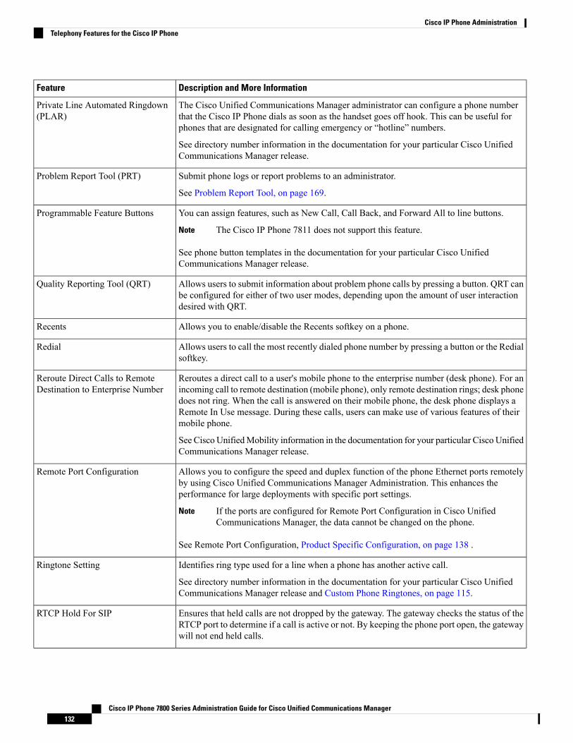
Description and More InformationFeature
The Cisco Unified Communications Manager administrator can configure a phone numberthat the Cisco IP Phone dials as soon as the handset goes off hook. This can be useful forphones that are designated for calling emergency or “hotline” numbers.
See directory number information in the documentation for your particular Cisco UnifiedCommunications Manager release.
Private Line Automated Ringdown(PLAR)
Submit phone logs or report problems to an administrator.
See Problem Report Tool, on page 169.
Problem Report Tool (PRT)
You can assign features, such as New Call, Call Back, and Forward All to line buttons.
The Cisco IP Phone 7811 does not support this feature.Note
See phone button templates in the documentation for your particular Cisco UnifiedCommunications Manager release.
Programmable Feature Buttons
Allows users to submit information about problem phone calls by pressing a button. QRT canbe configured for either of two user modes, depending upon the amount of user interactiondesired with QRT.
Quality Reporting Tool (QRT)
Allows you to enable/disable the Recents softkey on a phone.Recents
Allows users to call the most recently dialed phone number by pressing a button or the Redialsoftkey.
Redial
Reroutes a direct call to a user's mobile phone to the enterprise number (desk phone). For anincoming call to remote destination (mobile phone), only remote destination rings; desk phonedoes not ring. When the call is answered on their mobile phone, the desk phone displays aRemote In Use message. During these calls, users can make use of various features of theirmobile phone.
See Cisco UnifiedMobility information in the documentation for your particular Cisco UnifiedCommunications Manager release.
Reroute Direct Calls to RemoteDestination to Enterprise Number
Allows you to configure the speed and duplex function of the phone Ethernet ports remotelyby using Cisco Unified Communications Manager Administration. This enhances theperformance for large deployments with specific port settings.
If the ports are configured for Remote Port Configuration in Cisco UnifiedCommunications Manager, the data cannot be changed on the phone.
Note
See Remote Port Configuration, Product Specific Configuration, on page 138 .
Remote Port Configuration
Identifies ring type used for a line when a phone has another active call.
See directory number information in the documentation for your particular Cisco UnifiedCommunications Manager release and Custom Phone Ringtones, on page 115.
Ringtone Setting
Ensures that held calls are not dropped by the gateway. The gateway checks the status of theRTCP port to determine if a call is active or not. By keeping the phone port open, the gatewaywill not end held calls.
RTCP Hold For SIP
Cisco IP Phone 7800 Series Administration Guide for Cisco Unified Communications Manager132
Cisco IP Phone AdministrationTelephony Features for the Cisco IP Phone
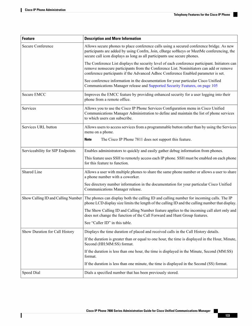
Description and More InformationFeature
Allows secure phones to place conference calls using a secured conference bridge. As newparticipants are added by using Confrn, Join, cBarge softkeys or MeetMe conferencing, thesecure call icon displays as long as all participants use secure phones.
The Conference List displays the security level of each conference participant. Initiators canremove nonsecure participants from the Conference List. Noninitiators can add or removeconference participants if the Advanced Adhoc Conference Enabled parameter is set.
See conference information in the documentation for your particular Cisco UnifiedCommunications Manager release and Supported Security Features, on page 105
Secure Conference
Improves the EMCC feature by providing enhanced security for a user logging into theirphone from a remote office.
Secure EMCC
Allows you to use the Cisco IP Phone Services Configuration menu in Cisco UnifiedCommunications Manager Administration to define and maintain the list of phone servicesto which users can subscribe.
Services
Allows users to access services from a programmable button rather than by using the Servicesmenu on a phone.
The Cisco IP Phone 7811 does not support this feature.Note
Services URL button
Enables administrators to quickly and easily gather debug information from phones.
This feature uses SSH to remotely access each IP phone. SSHmust be enabled on each phonefor this feature to function.
Serviceability for SIP Endpoints
Allows a user with multiple phones to share the same phone number or allows a user to sharea phone number with a coworker.
See directory number information in the documentation for your particular Cisco UnifiedCommunications Manager release.
Shared Line
The phones can display both the calling ID and calling number for incoming calls. The IPphone LCD display size limits the length of the calling ID and the calling number that display.
The Show Calling ID and Calling Number feature applies to the incoming call alert only anddoes not change the function of the Call Forward and Hunt Group features.
See “Caller ID” in this table.
ShowCalling ID andCallingNumber
Displays the time duration of placed and received calls in the Call History details.
If the duration is greater than or equal to one hour, the time is displayed in the Hour, Minute,Second (HH:MM:SS) format.
If the duration is less than one hour, the time is displayed in the Minute, Second (MM:SS)format.
If the duration is less than one minute, the time is displayed in the Second (SS) format.
Show Duration for Call History
Dials a specified number that has been previously stored.Speed Dial
Cisco IP Phone 7800 Series Administration Guide for Cisco Unified Communications Manager133
Cisco IP Phone AdministrationTelephony Features for the Cisco IP Phone

Description and More InformationFeature
Allows you to enable or disable the SSHAccess setting using Cisco Unified CommunicationsManager Administration. Enabling the SSH server allows the phone to accept the SSHconnections. Disabling the SSH server functionality of the phone blocks the SSH access tothe phone.
See SSH Access, Product Specific Configuration, on page 138 .
SSH Access
Restricts access to specified telephony features by time period.
See time and date information in the documentation for your particular Cisco UnifiedCommunications Manager release.
Time-of-Day Routing
Updates the Cisco IP Phone with time zone changes.
See time and date information in the documentation for your particular Cisco UnifiedCommunications Manager release..
Time Zone Update
Allows users to redirect connected calls from their phones to another number.
Some JTAPI/TAPI applications are not compatible with the Join and Direct Transfer featureimplementation on the Cisco IP Phone and you may need to configure the Join and DirectTransfer Policy to disable join and direct transfer on the same line or possibly across lines.
See Join and Direct Transfer Policy, Product Specific Configuration, on page 138 .
Transfer
Trust Verification Services (TVS) enables phones to authenticate signed configurations andauthenticate other servers or peers without increasing the size of the Certificate Trust List(CTL) or requiring the downloading of an updated CTL file to the phone. TVS is enabled bydefault.
The Security Setting menu on the phone displays the TVS information.
TVS
The Cisco IP Phones support Unified Capabilities Requirements (UCR) 2008 by providingthe following functions:
• Support for Federal Information Processing Standard (FIPS) 140-2• Support for 80-bit SRTCP Tagging
As an IP Phone administrator, you must set up specific parameters in Cisco UnifiedCommunications Manager Administration.
See UCR 2008 Setup, on page 162.
UCR 2008
Enables callers to leave messages if calls are unanswered.Voice Message System
Enhances security by disabling access to all web services, such as HTTP. Users can onlyaccess web services if you enable web access.
See UCR 2008 Setup, on page 162.
Web Access Disabled by Default
Cisco IP Phone 7800 Series Administration Guide for Cisco Unified Communications Manager134
Cisco IP Phone AdministrationTelephony Features for the Cisco IP Phone

Description and More InformationFeature
Plays a brief, prerecorded message to an agent just before the agent connects with each caller.The announcement plays only to the agent; the caller hears ringing (based on existing ringtone patterns) while the announcement plays.
The content of the announcement can contain information about the caller that helps preparethe agent to handle the call. The information can include caller language preference, choicesthe caller made from a menu (Sales, Service), customer status (Platinum, Gold, Regular), andso on.
Whisper Announcement
An enhancement to silent call monitoring feature that allows supervisors to talk to agentsduring a monitoring session. This feature provides applications the ability to change the currentmonitoring mode of a monitoring call from Silent Monitoring to Whisper Coaching and viceversa.
Whisper Coaching
Related TopicsCisco Unified Communications Manager Documentation, on page xv
Feature Buttons and SoftkeysThe following table provides information about features that are available on softkeys, features that areavailable on dedicated feature buttons, and features that you need to configure as programmable featurebuttons. An “X” in the table indicates that the feature is supported for the corresponding button type or softkey.Of the two button types and softkeys, only programmable feature buttons require configuration in Cisco IPPhone administration.
The Cisco IP Phone 7811 does not have programmable feature buttons.Note
For information about configuring programmable feature buttons, see Phone Button Templates, on page 175.
Table 20: Features with Corresponding Buttons and Softkeys
SoftkeyProgrammable FeatureButton
Dedicated Feature ButtonFeature Name
XXAnswer
XBarge
XXCall Back
XXCall Forward All
XXCall Park
XCall Park Line Status
XXCall Pickup (Pick Up)
XCall Pickup Line Status
Cisco IP Phone 7800 Series Administration Guide for Cisco Unified Communications Manager135
Cisco IP Phone AdministrationFeature Buttons and Softkeys
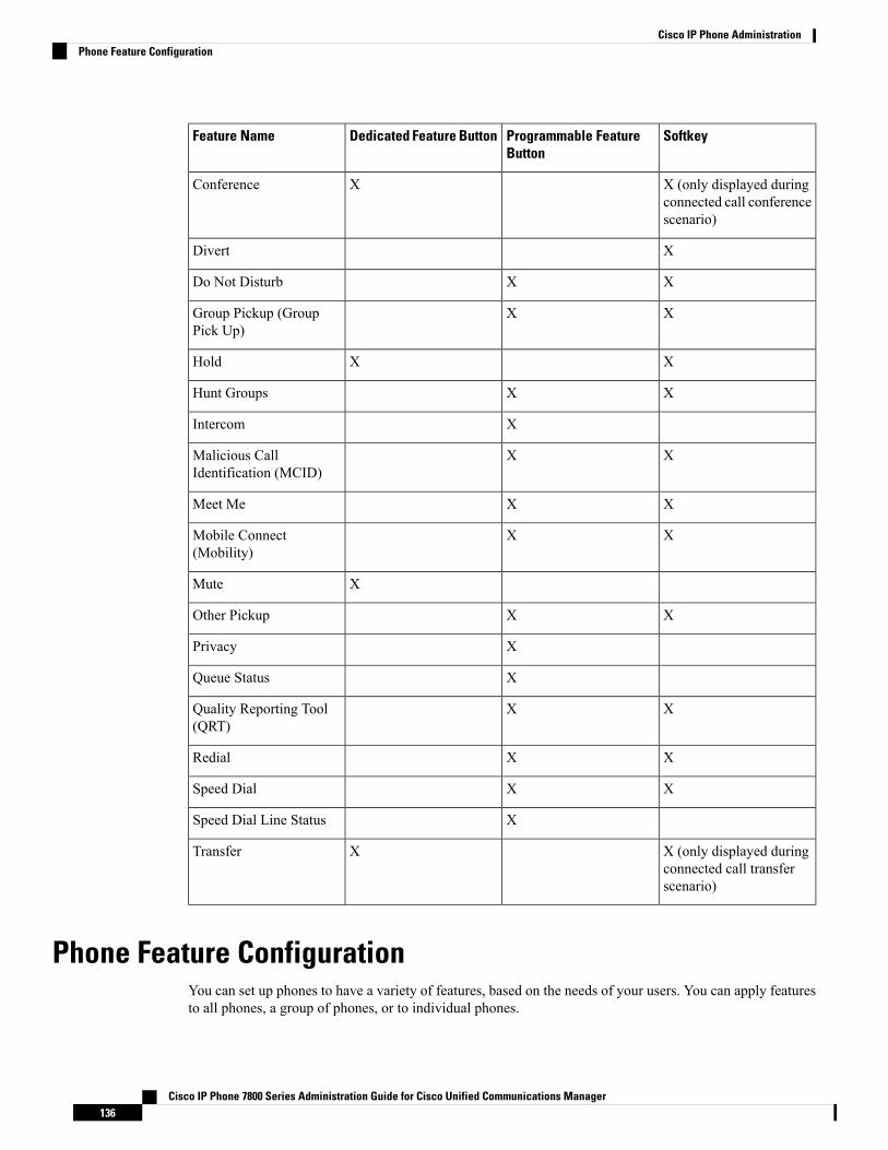
SoftkeyProgrammable FeatureButton
Dedicated Feature ButtonFeature Name
X (only displayed duringconnected call conferencescenario)
XConference
XDivert
XXDo Not Disturb
XXGroup Pickup (GroupPick Up)
XXHold
XXHunt Groups
XIntercom
XXMalicious CallIdentification (MCID)
XXMeet Me
XXMobile Connect(Mobility)
XMute
XXOther Pickup
XPrivacy
XQueue Status
XXQuality Reporting Tool(QRT)
XXRedial
XXSpeed Dial
XSpeed Dial Line Status
X (only displayed duringconnected call transferscenario)
XTransfer
Phone Feature ConfigurationYou can set up phones to have a variety of features, based on the needs of your users. You can apply featuresto all phones, a group of phones, or to individual phones.
Cisco IP Phone 7800 Series Administration Guide for Cisco Unified Communications Manager136
Cisco IP Phone AdministrationPhone Feature Configuration
When you set up features, the Cisco Unified Communications Manager Administration window displaysinformation that is applicable to all phones and information that is applicable to the phone model. Theinformation that is specific to the phone model is in the Product Specific Configuration Layout area of thewindow.
For information on the fields applicable to all phone models, see the Cisco Unified CommunicationsManagerdocumentation.
When you set a field, the window that you set the field in is important because there is a precedence to thewindows. The precedence order is:
1. Individual phones (highest precedence)
2. Group of phones
3. All phones (lowest precedence)
For example, if you don't want a specific set of users to access the phoneWeb pages, but the rest of your userscan access the pages, you:
1. Enable access to the phone web pages for all users.
2. Disable access to the phone web pages for each individual user, or set up a user group and disable accessto the phone web pages for the group of users.
3. If a specific user in the user group did need access to the phone web pages, you could enable it for thatparticular user.
Set Up Phone Features for all Phones
Procedure
Step 1 Sign into Cisco Unified Communications Manager Administration as an administrator.Step 2 Select Device > Device Settings > Common Phone ProfileStep 3 Locate the phones.Step 4 Navigate to the Product Specific Configuration Layout pane and set the fields.Step 5 Check the Override Enterprise Settings check box for any changed fields.Step 6 Click Save.Step 7 Click Apply Config.Step 8 Restart the phones.
Set Up Phone Features for a Group of Phones
Procedure
Step 1 Sign into Cisco Unified Communications Manager Administration as an administrator.
Cisco IP Phone 7800 Series Administration Guide for Cisco Unified Communications Manager137
Cisco IP Phone AdministrationSet Up Phone Features for all Phones

Step 2 Select Device > Device Settings > Common Phone ProfileStep 3 Locate the group of users.Step 4 Navigate to the Product Specific Configuration Layout pane and set the fields.Step 5 Check the Override Enterprise Settings check box for any changed fields.Step 6 Click Save.Step 7 Click Apply Config.Step 8 Restart the phones.
Set Up Phone Features for a Single Phone
Procedure
Step 1 Sign into Cisco Unified Communications Manager Administration as an administrator.Step 2 Select Device > PhoneStep 3 Locate the phone associated with the user.Step 4 Navigate to the Product Specific Configuration Layout pane and set the fields.Step 5 Check the Override Common Settings check box for any changed fields.Step 6 Click Save.Step 7 Click Apply Config.Step 8 Restart the phone.
Product Specific ConfigurationThe following table describes the fields in the Product Specific Configuration Layout pane.
Table 21: Product Specific Configuration Fields
Description and Usage GuidelinesDefaultField Type
or Choices
Field Name
Turns off the speakerphone capability of the phone.UncheckedCheckboxDisable Speakerphone
Turns off the speakerphone and headset capability of the phone.UncheckedCheckboxDisable Speakerphoneand Headset
Controls the ability to use the PC port to connect a computerinto the LAN.
EnabledDisabled
Enabled
PC Port
Cisco IP Phone 7800 Series Administration Guide for Cisco Unified Communications Manager138
Cisco IP Phone AdministrationSet Up Phone Features for a Single Phone

Description and Usage GuidelinesDefaultField Type
or Choices
Field Name
Enables, disables, or restricts access to local phoneconfiguration settings in the Settings app.
• Disabled—The Settings menu does not display anyoptions.
• Enabled—All entries in the Settings menu are accessible.
• Restricted—Only the Phone settings menu is accessible.
EnabledDisabled
Enabled
Restricted
Settings Access
Enables or disables the ability for the phone to learn MACaddresses from Gratuitous ARP. This capability is required tomonitor or record voice streams.
DisabledDisabled
Enabled
Gratuitous ARP
Indicates whether the phone will allow a device attached to thePC (access) port to access the Voice VLAN.
• Disabled—The computer can't send and receive data onthe Voice VLAN or from the phone.
• Enabled—The computer can send and receive data fromthe Voice VLAN or from the phone. Set this field toEnabled if an application is being run on the computerthat to monitor phone traffic. These applications couldinclude monitoring and recording applications, and theuse of networkmonitoring software for analysis purposes.
EnabledDisabled
Enabled
PC Voice VLANAccess
Allows users to make video calls by using a Cisco IP Phone,a personal computer, and a video camera.
DisabledDisabled
Enabled
Video Capabilities
Enables or disables access to the phone web pages through aweb browser.
DisabledDisabled
Enabled
Web Access
Controls the use of TLS 1.2 for a web server connection.
• Disabled—A phone configured for TLS1.0, TLS 1.1, orTLS1.2 can function as a HTTPs server.
• Enabled—Only a phone configured for TLS1.2 canfunction as a HTTPs server.
DisabledDisabled
Enabled
Disable TLS 1.0 andTLS 1.1 for WebAccess
Defines the days that the backlight does not turn onautomatically at the time specified in the Backlight On Timefield.
Choose the day or days from the drop-down list. To choosemore than one day, Ctrl+click each day that you want.
Days of the weekDays Backlight NotActive
Cisco IP Phone 7800 Series Administration Guide for Cisco Unified Communications Manager139
Cisco IP Phone AdministrationProduct Specific Configuration
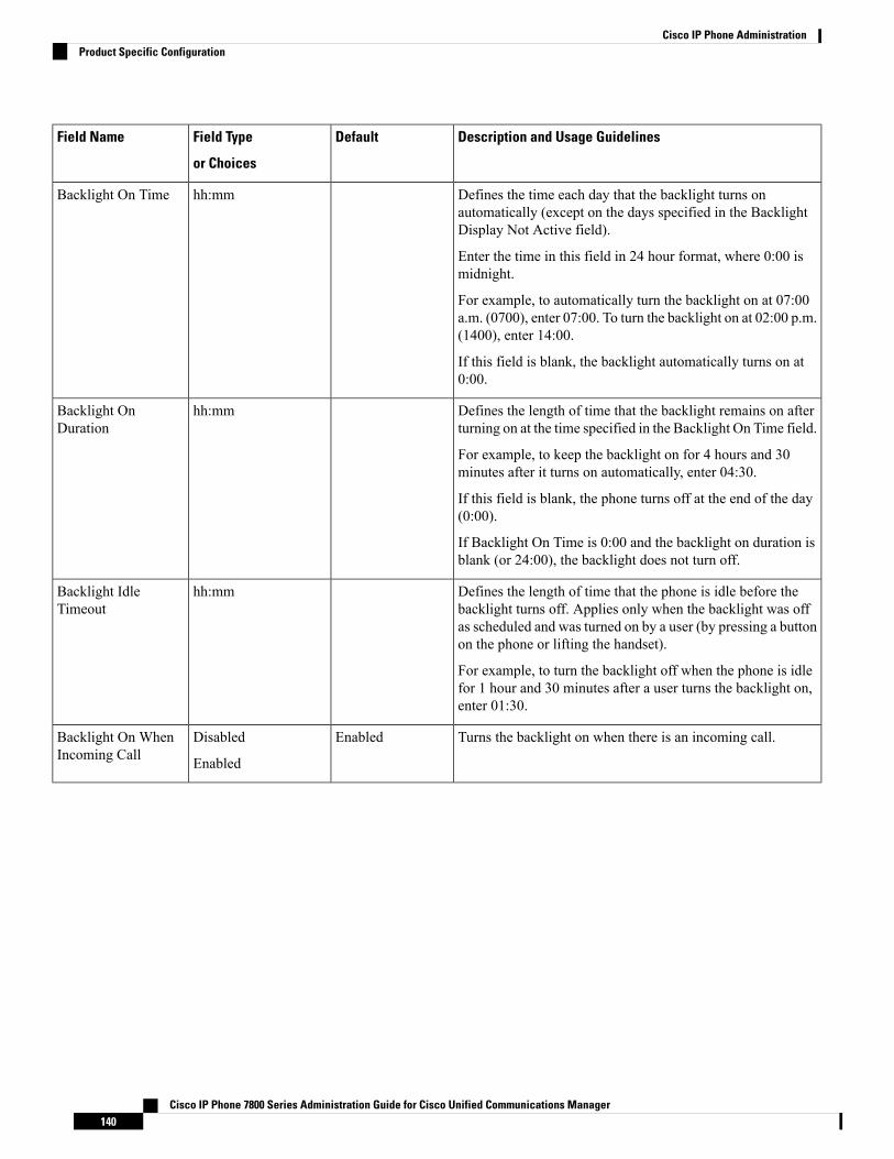
Description and Usage GuidelinesDefaultField Type
or Choices
Field Name
Defines the time each day that the backlight turns onautomatically (except on the days specified in the BacklightDisplay Not Active field).
Enter the time in this field in 24 hour format, where 0:00 ismidnight.
For example, to automatically turn the backlight on at 07:00a.m. (0700), enter 07:00. To turn the backlight on at 02:00 p.m.(1400), enter 14:00.
If this field is blank, the backlight automatically turns on at0:00.
hh:mmBacklight On Time
Defines the length of time that the backlight remains on afterturning on at the time specified in the Backlight On Time field.
For example, to keep the backlight on for 4 hours and 30minutes after it turns on automatically, enter 04:30.
If this field is blank, the phone turns off at the end of the day(0:00).
If Backlight On Time is 0:00 and the backlight on duration isblank (or 24:00), the backlight does not turn off.
hh:mmBacklight OnDuration
Defines the length of time that the phone is idle before thebacklight turns off. Applies only when the backlight was offas scheduled and was turned on by a user (by pressing a buttonon the phone or lifting the handset).
For example, to turn the backlight off when the phone is idlefor 1 hour and 30 minutes after a user turns the backlight on,enter 01:30.
hh:mmBacklight IdleTimeout
Turns the backlight on when there is an incoming call.EnabledDisabled
Enabled
Backlight On WhenIncoming Call
Cisco IP Phone 7800 Series Administration Guide for Cisco Unified Communications Manager140
Cisco IP Phone AdministrationProduct Specific Configuration

Description and Usage GuidelinesDefaultField Type
or Choices
Field Name
Defines the schedule of days for which the phone powers off.
Choose the day or days from the drop-down list. To choosemore than one day, Ctrl+click each day that you want.
When Enable Power Save Plus is turned on, you receive amessage that warns about emergency (e911) concerns.
While Power Save Plus Mode (the “Mode”) is ineffect, endpoints that are configured for the modeare disabled for emergency calling and fromreceiving inbound calls. By selecting this mode, youagree to the following: (i) You take fullresponsibility for providing alternate methods foremergency calling and receiving calls while themode is in effect; (ii) Cisco has no liability inconnection with your selection of the mode and allliability in connection with enabling the mode isyour responsibility; and (iii) You fully inform usersof the effects of the mode on calls, calling andotherwise.
Caution
To disable Power Save Plus, you must uncheck the AllowEnergyWise Overrides check box. If the Allow EnergyWiseOverrides remains checked but no days are selected in theEnable Power Save Plus field, Power Save Plus is not disabled.
Days of the weekEnable Power SavePlus
Determines when the phone automatically turns on for the daysthat are in the Enable Power Save Plus field.
Enter the time in this field in 24-hour format, where 00:00 ismidnight.
For example, to automatically power up the phone at 07:00a.m. (0700), enter 07:00. To power up the phone at 02:00 p.m.(1400), enter 14:00.
The default value is blank, which means 00:00.
The Phone On Time must be at least 20 minutes later than thePhone Off Time. For example, if the Phone Off Time is 07:00,the Phone On Time must be no earlier than 07:20.
hh:mmPhone On Time
Cisco IP Phone 7800 Series Administration Guide for Cisco Unified Communications Manager141
Cisco IP Phone AdministrationProduct Specific Configuration
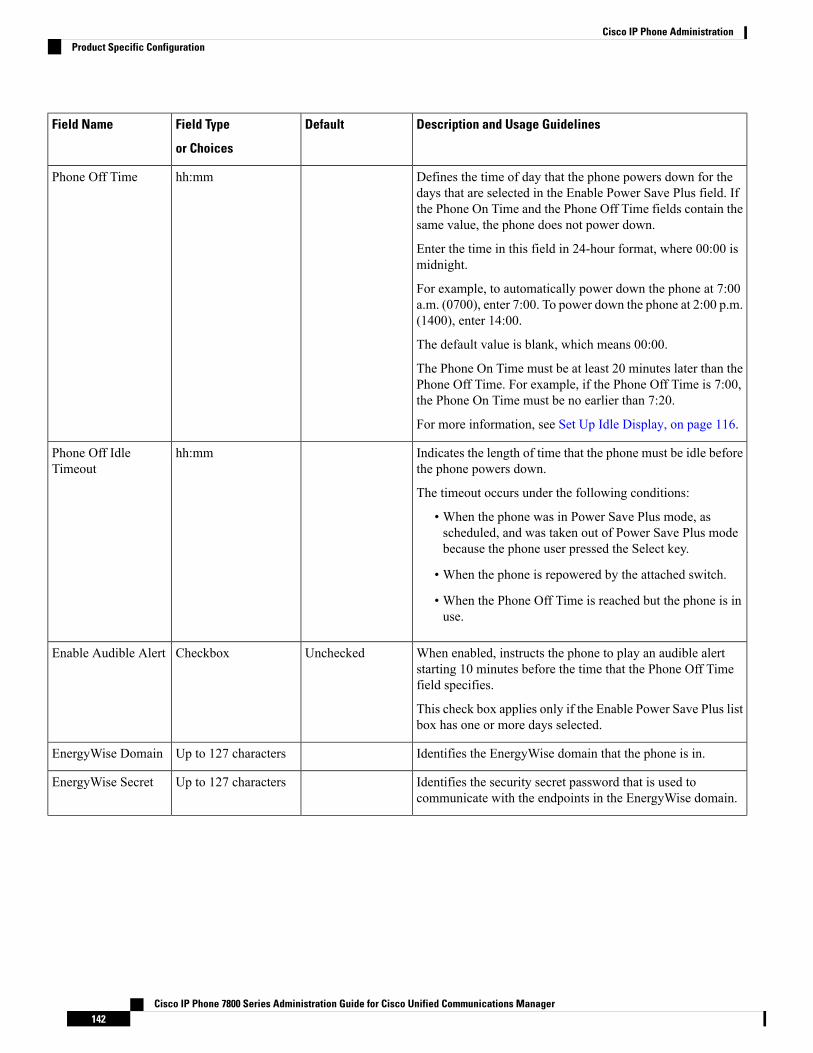
Description and Usage GuidelinesDefaultField Type
or Choices
Field Name
Defines the time of day that the phone powers down for thedays that are selected in the Enable Power Save Plus field. Ifthe Phone On Time and the Phone Off Time fields contain thesame value, the phone does not power down.
Enter the time in this field in 24-hour format, where 00:00 ismidnight.
For example, to automatically power down the phone at 7:00a.m. (0700), enter 7:00. To power down the phone at 2:00 p.m.(1400), enter 14:00.
The default value is blank, which means 00:00.
The Phone On Time must be at least 20 minutes later than thePhone Off Time. For example, if the Phone Off Time is 7:00,the Phone On Time must be no earlier than 7:20.
For more information, see Set Up Idle Display, on page 116.
hh:mmPhone Off Time
Indicates the length of time that the phone must be idle beforethe phone powers down.
The timeout occurs under the following conditions:
• When the phone was in Power Save Plus mode, asscheduled, and was taken out of Power Save Plus modebecause the phone user pressed the Select key.
• When the phone is repowered by the attached switch.
• When the Phone Off Time is reached but the phone is inuse.
hh:mmPhone Off IdleTimeout
When enabled, instructs the phone to play an audible alertstarting 10 minutes before the time that the Phone Off Timefield specifies.
This check box applies only if the Enable Power Save Plus listbox has one or more days selected.
UncheckedCheckboxEnable Audible Alert
Identifies the EnergyWise domain that the phone is in.Up to 127 charactersEnergyWise Domain
Identifies the security secret password that is used tocommunicate with the endpoints in the EnergyWise domain.
Up to 127 charactersEnergyWise Secret
Cisco IP Phone 7800 Series Administration Guide for Cisco Unified Communications Manager142
Cisco IP Phone AdministrationProduct Specific Configuration
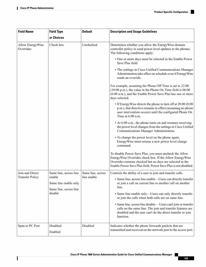
Description and Usage GuidelinesDefaultField Type
or Choices
Field Name
Determines whether you allow the EnergyWise domaincontroller policy to send power level updates to the phones.The following conditions apply:
• One or more days must be selected in the Enable PowerSave Plus field.
• The settings in Cisco Unified Communications ManagerAdministration take effect on schedule even if EnergyWisesends an override.
For example, assuming the Phone Off Time is set to 22:00(10:00 p.m.), the value in the Phone On Time field is 06:00(6:00 a.m.), and the Enable Power Save Plus has one or moredays selected.
• If EnergyWise directs the phone to turn off at 20:00 (8:00p.m.), that directive remains in effect (assuming no phoneuser intervention occurs) until the configured Phone OnTime at 6:00 a.m.
• At 6:00 a.m., the phone turns on and resumes receivingthe power level changes from the settings in Cisco UnifiedCommunications Manager Administration.
• To change the power level on the phone again,EnergyWise must reissue a new power level changecommand.
To disable Power Save Plus, you must uncheck the AllowEnergyWise Overrides check box. If the Allow EnergyWiseOverrides remains checked but no days are selected in theEnable Power Save Plus field, Power Save Plus is not disabled.
UncheckedCheck boxAllow EnergyWiseOverrides
Controls the ability of a user to join and transfer calls.
• Same line, across line enable—Users can directly transferor join a call on current line to another call on anotherline.
• Same line enable only—Users can only directly transferor join the calls when both calls are on same line.
• Same line, across line disable—Users can't join or transfercalls on the same line. The join and transfer features aredisabled and the user can't do the direct transfer or joinfunction.
Same line, acrossline enable
Same line, across lineenable
Same line enable only
Same line, across linedisable
Join and DirectTransfer Policy
Indicates whether the phone forwards packets that aretransmitted and received on the network port to the access port.
DisabledDisabled
Enabled
Span to PC Port
Cisco IP Phone 7800 Series Administration Guide for Cisco Unified Communications Manager143
Cisco IP Phone AdministrationProduct Specific Configuration
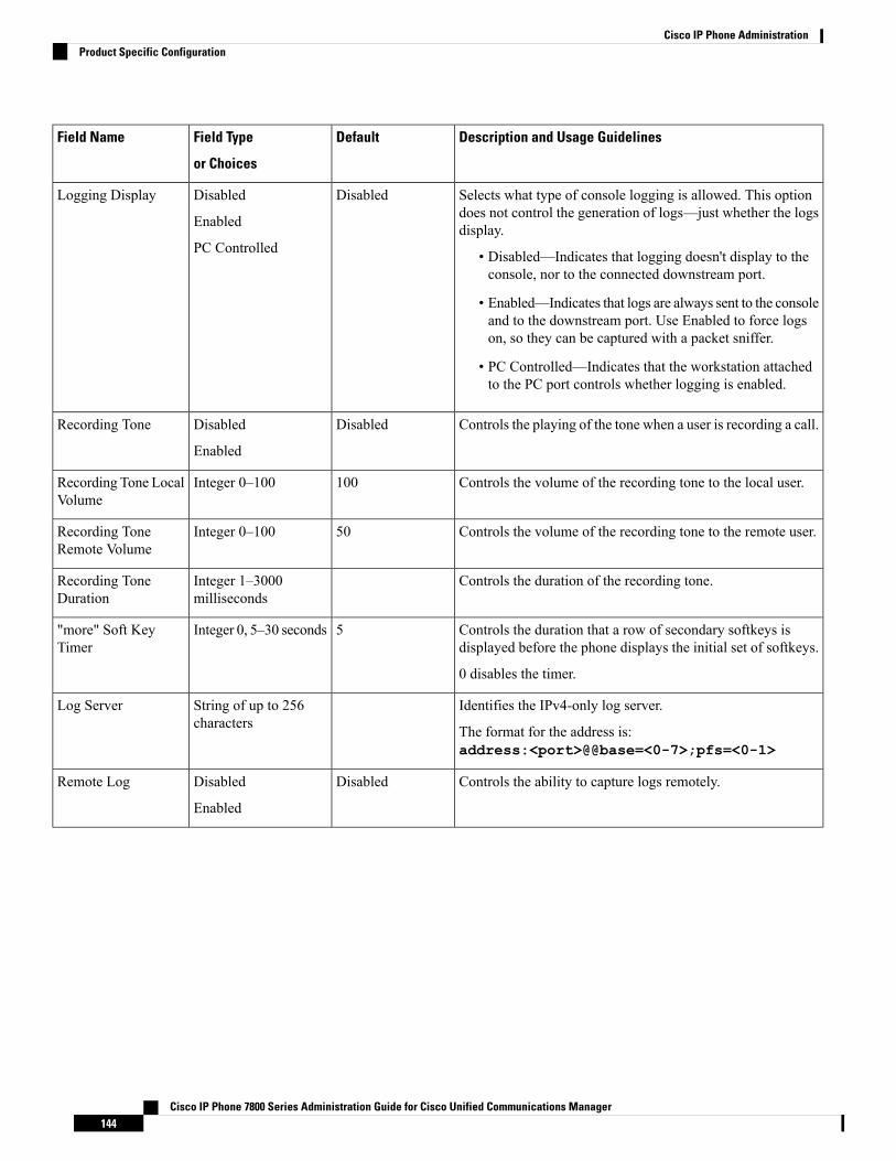
Description and Usage GuidelinesDefaultField Type
or Choices
Field Name
Selects what type of console logging is allowed. This optiondoes not control the generation of logs—just whether the logsdisplay.
• Disabled—Indicates that logging doesn't display to theconsole, nor to the connected downstream port.
• Enabled—Indicates that logs are always sent to the consoleand to the downstream port. Use Enabled to force logson, so they can be captured with a packet sniffer.
• PC Controlled—Indicates that the workstation attachedto the PC port controls whether logging is enabled.
DisabledDisabled
Enabled
PC Controlled
Logging Display
Controls the playing of the tone when a user is recording a call.DisabledDisabled
Enabled
Recording Tone
Controls the volume of the recording tone to the local user.100Integer 0–100Recording Tone LocalVolume
Controls the volume of the recording tone to the remote user.50Integer 0–100Recording ToneRemote Volume
Controls the duration of the recording tone.Integer 1–3000milliseconds
Recording ToneDuration
Controls the duration that a row of secondary softkeys isdisplayed before the phone displays the initial set of softkeys.
0 disables the timer.
5Integer 0, 5–30 seconds"more" Soft KeyTimer
Identifies the IPv4-only log server.
The format for the address is:address:<port>@@base=<0-7>;pfs=<0-1>
String of up to 256characters
Log Server
Controls the ability to capture logs remotely.DisabledDisabled
Enabled
Remote Log
Cisco IP Phone 7800 Series Administration Guide for Cisco Unified Communications Manager144
Cisco IP Phone AdministrationProduct Specific Configuration

Description and Usage GuidelinesDefaultField Type
or Choices
Field Name
Specifies the predefined logging profile.
• Default—Default debug logging level
• Preset—Does not overwrite the phone local debug loggingsetting
• Telephony—Logs information about Telephony or callfeatures
• SIP—Logs information about SIP signaling
• UI—Logs information about the phone user interface
• Network—Logs network information
• Media—Logs media information
• Upgrade—Logs upgrade information
• Accessory—Logs accessory information
• Security—Logs security information
• Wi-Fi—Logs Wi-Fi information
• VPN—Logs virtual private network information
• Energywise—Logs energy-savings information
• MobileRemoteAC—Logs Mobile and Remote Accessthrough Expressway information
PresetDefault
Preset
Telephony
SIP
UI
Network
Media
Upgrade
Accessory
Security
Wi-Fi
VPN
Energywise
MobileRemoteAc
Log Profile
Identifies the IPv6-only log server.
The format for the address is:[address]:<port>@@base=<0-7>;pfs=<0-1>
String of up to 256characters
IPv6 Log Server
Allows users to make a call when the number of calls for a lineexceeds the maximum number of calls (MNC).
The Cisco IP Phone 7811 does not support this field.
DisabledDisabled
Enabled
Outbound Rollover
Controls Cisco Discovery Protocol on the SW port of thephone.
EnabledDisabled
Enabled
Cisco DiscoveryProtocol (CDP):Switch Port
Controls Cisco Discovery Protocol on the PC port of the phone.EnabledDisabled
Enabled
Cisco DiscoveryProtocol (CDP): PCPort
Cisco IP Phone 7800 Series Administration Guide for Cisco Unified Communications Manager145
Cisco IP Phone AdministrationProduct Specific Configuration
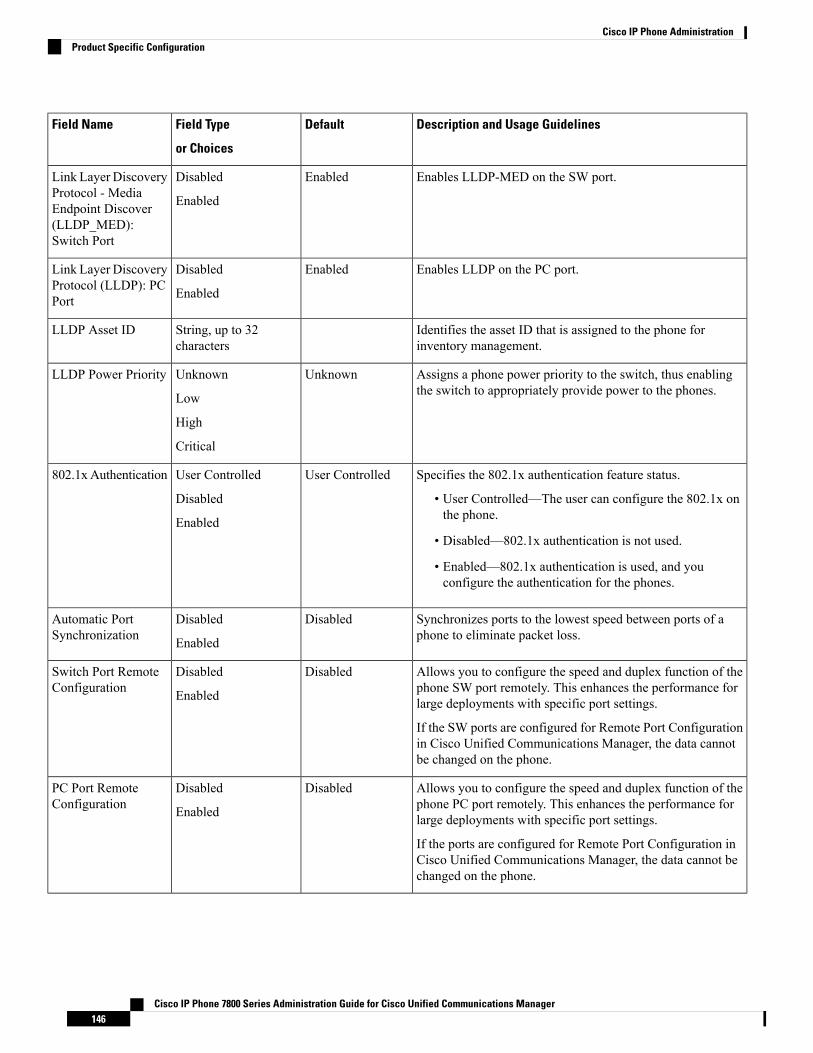
Description and Usage GuidelinesDefaultField Type
or Choices
Field Name
Enables LLDP-MED on the SW port.EnabledDisabled
Enabled
Link Layer DiscoveryProtocol - MediaEndpoint Discover(LLDP_MED):Switch Port
Enables LLDP on the PC port.EnabledDisabled
Enabled
Link Layer DiscoveryProtocol (LLDP): PCPort
Identifies the asset ID that is assigned to the phone forinventory management.
String, up to 32characters
LLDP Asset ID
Assigns a phone power priority to the switch, thus enablingthe switch to appropriately provide power to the phones.
UnknownUnknown
Low
High
Critical
LLDP Power Priority
Specifies the 802.1x authentication feature status.
• User Controlled—The user can configure the 802.1x onthe phone.
• Disabled—802.1x authentication is not used.
• Enabled—802.1x authentication is used, and youconfigure the authentication for the phones.
User ControlledUser Controlled
Disabled
Enabled
802.1xAuthentication
Synchronizes ports to the lowest speed between ports of aphone to eliminate packet loss.
DisabledDisabled
Enabled
Automatic PortSynchronization
Allows you to configure the speed and duplex function of thephone SW port remotely. This enhances the performance forlarge deployments with specific port settings.
If the SW ports are configured for Remote Port Configurationin Cisco Unified Communications Manager, the data cannotbe changed on the phone.
DisabledDisabled
Enabled
Switch Port RemoteConfiguration
Allows you to configure the speed and duplex function of thephone PC port remotely. This enhances the performance forlarge deployments with specific port settings.
If the ports are configured for Remote Port Configuration inCisco Unified Communications Manager, the data cannot bechanged on the phone.
DisabledDisabled
Enabled
PC Port RemoteConfiguration
Cisco IP Phone 7800 Series Administration Guide for Cisco Unified Communications Manager146
Cisco IP Phone AdministrationProduct Specific Configuration

Description and Usage GuidelinesDefaultField Type
or Choices
Field Name
Controls the access to the SSH daemon through port 22.Leaving port 22 open leaves the phone vulnerable to Denialof Service (DoS) attacks.
DisabledDisabled
Enabled
SSH Access
Gives the time, in seconds, that the toast displays. The timeincludes the fade-in and fade-out times for the window.
5Integer 3, 4, 5, 6, 7, 8,9, 10, 15, 30, 60seconds
Incoming Call ToastTimer
Controls the ability for a user to join a nonprivate call on ashared phone line.
• cBarge—Enables a user to add another person to a call.The call automatically converts to a conference, allowingthe user and other parties to access conference features.
• Turn on Softkey—Enables a user to conference into a callon a shared line using cBarge.
• Barge—Enables a user to add another user to a call butdoes not convert the call into a conference.
• Off—Disables barge. A new call initiates when the userpresses the line key.
cBargecBarge
Turn on Softkey
Barge
Off
Line Key Barge
Controls the ringing pattern.DefaultDefault
Japan
Ring Locale
Controls the ability to resume a TLS session without repeatingthe entire TLS authentication process. If the field is set to 0,then the TLS session resumption is disabled.
3600Integer 0–3600 secondsTLS ResumptionTimer
Enables or disables the Federal Information ProcessingStandards (FIPS) mode on the phone.
DisabledDisabled
Enabled
FIPS Mode
Controls the text for the Hold softkey.
• HOLD/RESUME Key—The softkey displaysHold/Resume.
• HOLD Key—The softkey displays Hold.
HOLD/RESUMEKey
HOLD/RESUME Key
HOLD Key
HOLD/RESUMEKey
Specifies whether to record a shared line call in the call log.DisabledDisabled
Enabled
Record Call Log fromShared Line
Controls the minimum ring volume for the phone.
You can set a phone so that the ringer cannot be turned off.
0-Silent0-Silent
Volume level 1–15
Minimum RingVolume
Cisco IP Phone 7800 Series Administration Guide for Cisco Unified Communications Manager147
Cisco IP Phone AdministrationProduct Specific Configuration
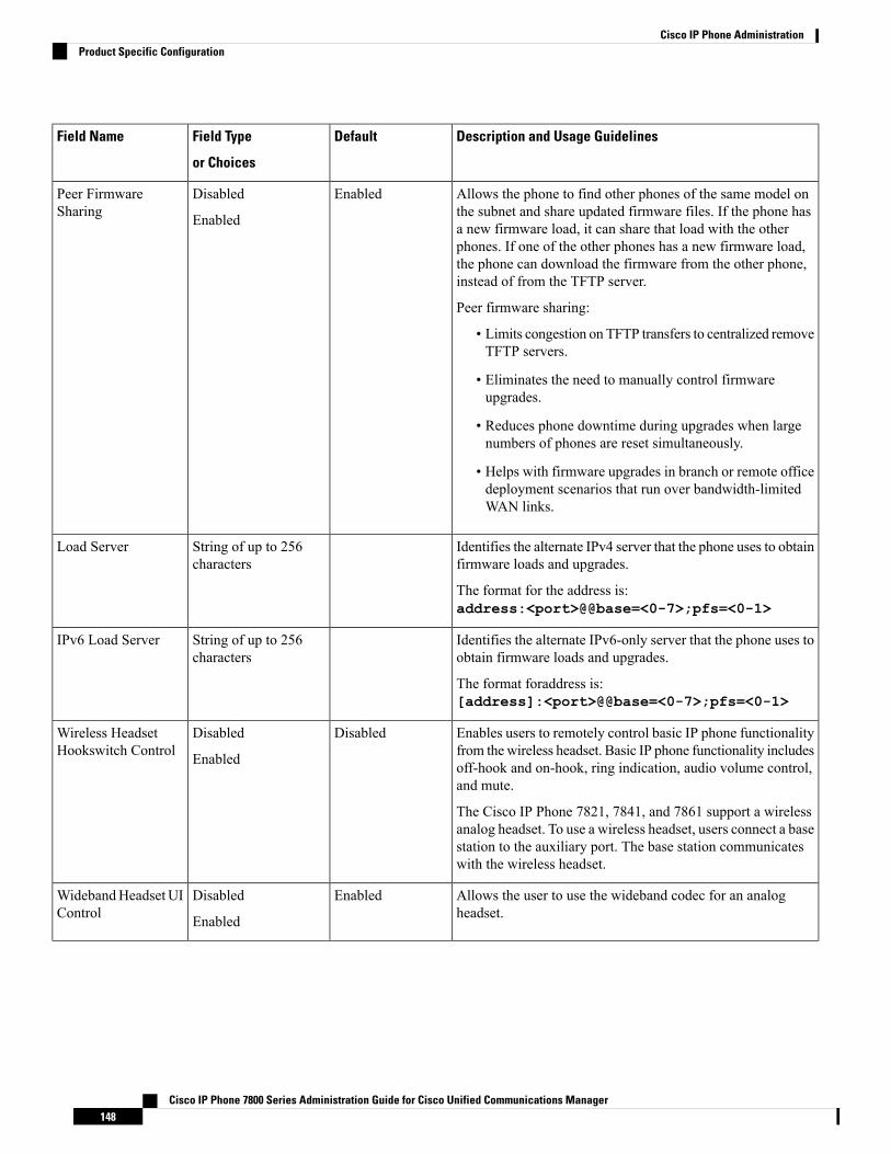
Description and Usage GuidelinesDefaultField Type
or Choices
Field Name
Allows the phone to find other phones of the same model onthe subnet and share updated firmware files. If the phone hasa new firmware load, it can share that load with the otherphones. If one of the other phones has a new firmware load,the phone can download the firmware from the other phone,instead of from the TFTP server.
Peer firmware sharing:
• Limits congestion on TFTP transfers to centralized removeTFTP servers.
• Eliminates the need to manually control firmwareupgrades.
• Reduces phone downtime during upgrades when largenumbers of phones are reset simultaneously.
• Helps with firmware upgrades in branch or remote officedeployment scenarios that run over bandwidth-limitedWAN links.
EnabledDisabled
Enabled
Peer FirmwareSharing
Identifies the alternate IPv4 server that the phone uses to obtainfirmware loads and upgrades.
The format for the address is:address:<port>@@base=<0-7>;pfs=<0-1>
String of up to 256characters
Load Server
Identifies the alternate IPv6-only server that the phone uses toobtain firmware loads and upgrades.
The format foraddress is:[address]:<port>@@base=<0-7>;pfs=<0-1>
String of up to 256characters
IPv6 Load Server
Enables users to remotely control basic IP phone functionalityfrom thewireless headset. Basic IP phone functionality includesoff-hook and on-hook, ring indication, audio volume control,and mute.
The Cisco IP Phone 7821, 7841, and 7861 support a wirelessanalog headset. To use a wireless headset, users connect a basestation to the auxiliary port. The base station communicateswith the wireless headset.
DisabledDisabled
Enabled
Wireless HeadsetHookswitch Control
Allows the user to use the wideband codec for an analogheadset.
EnabledDisabled
Enabled
WidebandHeadset UIControl
Cisco IP Phone 7800 Series Administration Guide for Cisco Unified Communications Manager148
Cisco IP Phone AdministrationProduct Specific Configuration

Description and Usage GuidelinesDefaultField Type
or Choices
Field Name
Enables or disables the use of a Wideband Headset on thephone. Used in conjunction with User Control WidebandHeadset.
For more information, see Set Up Wideband Codec, on page115
EnabledDisabled
Enabled
Wideband Headset
Determines the sensitivity that the phone has for detecting aconnection failure to CiscoUnified CommunicationsManager(Unified CM), which is the first step before device failover toa backup Unified CM/SRST occurs.
• Normal—Detection of a Unified CM connection failureoccurs at the standard system rate. Choose this value forfaster recognition of a Unified CM connection failure.
• Delayed—Detection of a Unified CM connection failoveroccurs approximately four times slower than Normal.Choose this value if you prefer failover to be delayedslightly to give the connection the opportunity toreestablish
The precise time difference between Normal and Delayedconnection failure detection depends on many variables thatare constantly changing.
NormalNormal
Delayed
Detect Unified CMConnection Failure
Controls custom features from Engineering Special (ES) loads.StringSpecial RequirementID
Specifies whether the serial console is enabled or disabled.DisabledDisabled
Enabled
Console Access
Controls the type of incoming call alert that displays on thephone screen.
• Disabled—The actionable incoming call alert is disabledand the user sees the traditional incoming call pop-upalert.
• Show for all Incoming Call—The actionable incomingcall alert displays for all calls regardless of visibility.
• Show for Invisible Incoming Call—The actionableincoming call alert displays for calls not shown on thephone. This parameter behaves similarly to the incomingcall alert pop-up notification.
Show for allIncoming Call
Disabled
Show for all IncomingCall
Show for InvisibleIncoming Call
Actionable IncomingCall Alert
Controls EEE on the PC port.DisabledDisabled
Enabled
Energy EfficientEthernet(EEE): PCPort
Cisco IP Phone 7800 Series Administration Guide for Cisco Unified Communications Manager149
Cisco IP Phone AdministrationProduct Specific Configuration
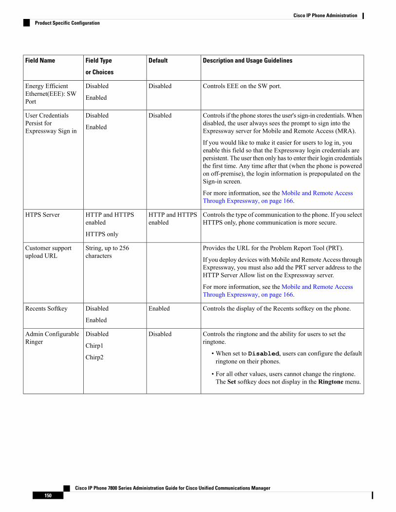
Description and Usage GuidelinesDefaultField Type
or Choices
Field Name
Controls EEE on the SW port.DisabledDisabled
Enabled
Energy EfficientEthernet(EEE): SWPort
Controls if the phone stores the user's sign-in credentials.Whendisabled, the user always sees the prompt to sign into theExpressway server for Mobile and Remote Access (MRA).
If you would like to make it easier for users to log in, youenable this field so that the Expressway login credentials arepersistent. The user then only has to enter their login credentialsthe first time. Any time after that (when the phone is poweredon off-premise), the login information is prepopulated on theSign-in screen.
For more information, see the Mobile and Remote AccessThrough Expressway, on page 166.
DisabledDisabled
Enabled
User CredentialsPersist forExpressway Sign in
Controls the type of communication to the phone. If you selectHTTPS only, phone communication is more secure.
HTTP and HTTPSenabled
HTTP and HTTPSenabled
HTTPS only
HTPS Server
Provides the URL for the Problem Report Tool (PRT).
If you deploy devices withMobile and Remote Access throughExpressway, you must also add the PRT server address to theHTTP Server Allow list on the Expressway server.
For more information, see the Mobile and Remote AccessThrough Expressway, on page 166.
String, up to 256characters
Customer supportupload URL
Controls the display of the Recents softkey on the phone.EnabledDisabled
Enabled
Recents Softkey
Controls the ringtone and the ability for users to set theringtone.
• When set to Disabled, users can configure the defaultringtone on their phones.
• For all other values, users cannot change the ringtone.The Set softkey does not display in the Ringtone menu.
DisabledDisabled
Chirp1
Chirp2
Admin ConfigurableRinger
Cisco IP Phone 7800 Series Administration Guide for Cisco Unified Communications Manager150
Cisco IP Phone AdministrationProduct Specific Configuration

Codec negotiation involves two steps:
1. The phone advertises the supported codec to the Cisco Unified CommunicationsManager. Not all endpointssupport the same set of codecs.
2. When the Cisco Unified Communications Manager gets the list of supported codecs from all phonesinvolved in the call attempt, it chooses a commonly supported codec based on various factors, including
the region pair setting.
Note
Feature Configuration Best PracticesYou can set up the phone features to suit your users' needs. But we have some recommendations for certainsituations and deployments that might help you.
High Call Volume EnvironmentsIn a high call volume environment, we recommend that you set up some features in a specific way.
Recommended SettingAdministration AreaField
Off or On
For more information, see Field:Always Use Prime Line, on page152.
Device InformationAlways Use Prime Line
Show for all Incoming CallProduct Specific ConfigurationLayout
Actionable Incoming Call Alert
EnabledProduct Specific ConfigurationLayout
Show All Calls on Primary Line
EnabledProduct Specific ConfigurationLayout
Revert to All Calls
Multiline EnvironmentsIn a multiline environment, we recommend that you set up some features in a specific way.
Recommended SettingAdministration AreaField
Off
For more information, see Field:Always Use Prime Line, on page152.
Device InformationAlways Use Prime Line
Show for all Incoming CallProduct Specific ConfigurationLayout
Actionable Incoming Call Alert
Cisco IP Phone 7800 Series Administration Guide for Cisco Unified Communications Manager151
Cisco IP Phone AdministrationFeature Configuration Best Practices
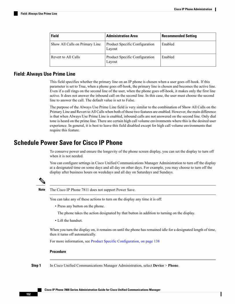
Recommended SettingAdministration AreaField
EnabledProduct Specific ConfigurationLayout
Show All Calls on Primary Line
EnabledProduct Specific ConfigurationLayout
Revert to All Calls
Field: Always Use Prime LineThis field specifies whether the primary line on an IP phone is chosen when a user goes off-hook. If thisparameter is set to True, when a phone goes off-hook, the primary line is chosen and becomes the active line.Even if a call rings on the second line of the user, when the phone goes off-hook, it makes only the first lineactive. It does not answer the inbound call on the second line. In this case, the user must choose the secondline to answer the call. The default value is set to False.
The purpose of the Always Use Prime Line field is very similar to the combination of Show All Calls on thePrimary Line and Revert to All Calls when both of those two features are enabled. However, the main differenceis that when Always Use Prime Line is enabled, inbound calls are not answered on the second line. Only dialtone is heard on the prime line. There are certain high call volume environments where this is the desired userexperience. In general, it is best to leave this field disabled except for high call volume environments thatrequire this feature.
Schedule Power Save for Cisco IP PhoneTo conserve power and ensure the longevity of the phone screen display, you can set the display to turn offwhen it is not needed.
You can configure settings in Cisco Unified Communications Manager Administration to turn off the displayat a designated time on some days and all day on other days. For example, you may choose to turn off thedisplay after business hours on weekdays and all day on Saturdays and Sundays.
The Cisco IP Phone 7811 does not support Power Save.Note
You can take any of these actions to turn on the display any time it is off:
• Press any button on the phone.
The phone takes the action designated by that button in addition to turning on the display.
• Lift the handset.
When you turn the display on, it remains on until the phone has remained idle for a designated length of time,then it turns off automatically.
For more information, see Product Specific Configuration, on page 138
Procedure
Step 1 In Cisco Unified Communications Manager Administration, select Device > Phone.
Cisco IP Phone 7800 Series Administration Guide for Cisco Unified Communications Manager152
Cisco IP Phone AdministrationField: Always Use Prime Line

Step 2 Locate the phone that you need to set up.Step 3 Navigate to the Product Specific Configuration area and set the following fields:
• Days Display Not Active
• Display On Time
• Display On Duration
• Display Idle Timeout
Table 22: PowerSave Configuration Fields
DescriptionField
Days that the display does not turn on automaticallyat the time specified in the Display On Time field.
Choose the day or days from the drop-down list. Tochoose more than one day, Ctrl-click each day thatyou want.
Days Display Not Active
Time each day that the display turns on automatically(except on the days specified in the Days Display NotActive field).
Enter the time in this field in 24-hour format, where0:00 is midnight.
For example, to automatically turn the display on at07:00 a.m., (0700), enter 07:00. To turn the displayon at 02:00 p.m. (1400), enter 14:00.
If this field is blank, the display will automaticallyturn on at 0:00.
Display On Time
Length of time that the display remains on afterturning on at the time specified in the Display OnTime field.
Enter the value in this field in the formathours:minutes.
For example, to keep the display on for 4 hours and30minutes after it turns on automatically, enter 04:30.
If this field is blank, the phone will turn off at the endof the day (0:00).
If Display On Time is 0:00 and the displayon duration is blank (or 24:00), the displaywill remain on continuously.
Note
Display On Duration
Cisco IP Phone 7800 Series Administration Guide for Cisco Unified Communications Manager153
Cisco IP Phone AdministrationSchedule Power Save for Cisco IP Phone

DescriptionField
Length of time that the phone is idle before the displayturns off. Applies only when the display was off asscheduled and was turned on by a user (by pressinga button on the phone or lifting the handset).
Enter the value in this field in the formathours:minutes.
For example, to turn the display off when the phoneis idle for 1 hour and 30 minutes after a user turns thedisplay on, enter 01:30.
The default value is 01:00.
Display Idle Timeout
Step 4 Select Save.Step 5 Select Apply Config.Step 6 Restart the phone.
Schedule EnergyWise on Cisco IP PhoneTo reduce power consumption, configure the phone to sleep (power down) and wake (power up) if your systemincludes an EnergyWise controller.
The Cisco IP Phone 7811 does not support Power Save Plus.Note
You configure settings in Cisco Unified Communications Manager Administration to enable EnergyWise andconfigure sleep andwake times. These parameters are closely tied to the phone display configuration parameters.
When EnergyWise is enabled and a sleep time is set, the phone sends a request to the switch to wake it up atthe configured time. The switch returns either an acceptance or a rejection of the request. If the switch rejectsthe request or if the switch does not reply, the phone does not power down. If the switch accepts the request,the idle phone goes to sleep, thus reducing the power consumption to a predetermined level. A phone that isnot idle sets an idle timer and goes to sleep after the idle timer expires.
To wake up the phone, press Select. At the scheduled wake time, the system restores power to the phone,waking it up.
For more information, see Product Specific Configuration, on page 138
Procedure
Step 1 From the Cisco Unified Communications Manager Administration, select Device > Phone.Step 2 Locate the phone that you need to set up.Step 3 Navigate to the Product Specific Configuration area and set the following fields.
• Enable Power Save Plus
Cisco IP Phone 7800 Series Administration Guide for Cisco Unified Communications Manager154
Cisco IP Phone AdministrationSchedule EnergyWise on Cisco IP Phone
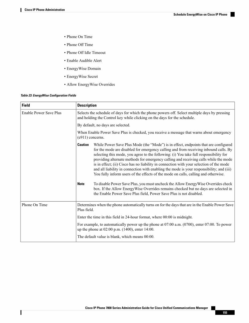
• Phone On Time
• Phone Off Time
• Phone Off Idle Timeout
• Enable Audible Alert
• EnergyWise Domain
• EnergyWise Secret
• Allow EnergyWise Overrides
Table 23: EnergyWise Configuration Fields
DescriptionField
Selects the schedule of days for which the phone powers off. Select multiple days by pressingand holding the Control key while clicking on the days for the schedule.
By default, no days are selected.
When Enable Power Save Plus is checked, you receive a message that warns about emergency(e911) concerns.
While Power Save Plus Mode (the “Mode”) is in effect, endpoints that are configuredfor the mode are disabled for emergency calling and from receiving inbound calls. Byselecting this mode, you agree to the following: (i) You take full responsibility forproviding alternate methods for emergency calling and receiving calls while the modeis in effect; (ii) Cisco has no liability in connection with your selection of the modeand all liability in connection with enabling the mode is your responsibility; and (iii)You fully inform users of the effects of the mode on calls, calling and otherwise.
Caution
To disable Power Save Plus, you must uncheck the Allow EnergyWise Overrides checkbox. If the Allow EnergyWise Overrides remains checked but no days are selected inthe Enable Power Save Plus field, Power Save Plus is not disabled.
Note
Enable Power Save Plus
Determines when the phone automatically turns on for the days that are in the Enable Power SavePlus field.
Enter the time in this field in 24-hour format, where 00:00 is midnight.
For example, to automatically power up the phone at 07:00 a.m. (0700), enter 07:00. To powerup the phone at 02:00 p.m. (1400), enter 14:00.
The default value is blank, which means 00:00.
Phone On Time
Cisco IP Phone 7800 Series Administration Guide for Cisco Unified Communications Manager155
Cisco IP Phone AdministrationSchedule EnergyWise on Cisco IP Phone

DescriptionField
The time of day that the phone powers down for the days that are selected in the Enable PowerSave Plus field. If the Phone On Time and the Phone Off Time fields contain the same value, thephone does not power down.
Enter the time in this field in 24-hour format, where 00:00 is midnight.
For example, to automatically power down the phone at 7:00 a.m. (0700), enter 7:00. To powerdown the phone at 2:00 p.m. (1400), enter 14:00.
The default value is blank, which means 00:00.
The Phone On Time must be at least 20 minutes later than the Phone Off Time. Forexample, if the Phone Off Time is 7:00, the Phone On Time must be no earlier than7:20.
Note
Phone Off Time
The length of time that the phone must be idle before the phone powers down.
The timeout occurs under the following conditions:
• When the phone was in Power Save Plus mode, as scheduled, and was taken out of PowerSave Plus mode because the phone user pressed the Select key.
• When the phone is repowered by the attached switch.
• When the Phone Off Time is reached but the phone is in use.
The range of the field is 20 to 1440 minutes.
The default value is 60 minutes.
Phone Off Idle Timeout
When enabled, instructs the phone to play an audible alert starting 10 minutes before the timethat the Phone Off Time field specifies.
The audible alert uses the phone ringtone, which briefly plays at specific times during the 10-minutealerting period. The alerting ringtone plays at the user-designated volume level. The audible alertschedule is:
• At 10 minutes before power down, play the ringtone four times.
• At 7 minutes before power down, play the ringtone four times.
• At 4 minutes before power down, play the ringtone four times.
• At 30 seconds before power down, play the ringtone 15 times or until the phone powers off.
This check box applies only if the Enable Power Save Plus list box has one or more days selected.
Enable Audible Alert
The EnergyWise domain that the phone is in.
The maximum length of this field is 127 characters.
EnergyWise Domain
The security secret password that is used to communicate with the endpoints in the EnergyWisedomain.
The maximum length of this field is 127 characters.
EnergyWise Secret
Cisco IP Phone 7800 Series Administration Guide for Cisco Unified Communications Manager156
Cisco IP Phone AdministrationSchedule EnergyWise on Cisco IP Phone
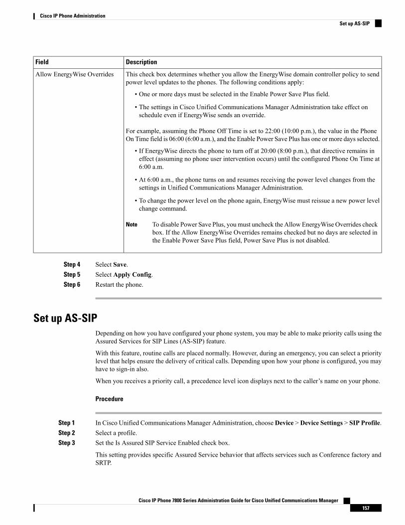
DescriptionField
This check box determines whether you allow the EnergyWise domain controller policy to sendpower level updates to the phones. The following conditions apply:
• One or more days must be selected in the Enable Power Save Plus field.
• The settings in Cisco Unified Communications Manager Administration take effect onschedule even if EnergyWise sends an override.
For example, assuming the Phone Off Time is set to 22:00 (10:00 p.m.), the value in the PhoneOn Time field is 06:00 (6:00 a.m.), and the Enable Power Save Plus has one or more days selected.
• If EnergyWise directs the phone to turn off at 20:00 (8:00 p.m.), that directive remains ineffect (assuming no phone user intervention occurs) until the configured Phone On Time at6:00 a.m.
• At 6:00 a.m., the phone turns on and resumes receiving the power level changes from thesettings in Unified Communications Manager Administration.
• To change the power level on the phone again, EnergyWise must reissue a new power levelchange command.
To disable Power Save Plus, you must uncheck the Allow EnergyWise Overrides checkbox. If the Allow EnergyWise Overrides remains checked but no days are selected inthe Enable Power Save Plus field, Power Save Plus is not disabled.
Note
Allow EnergyWise Overrides
Step 4 Select Save.Step 5 Select Apply Config.Step 6 Restart the phone.
Set up AS-SIPDepending on how you have configured your phone system, you may be able to make priority calls using theAssured Services for SIP Lines (AS-SIP) feature.
With this feature, routine calls are placed normally. However, during an emergency, you can select a prioritylevel that helps ensure the delivery of critical calls. Depending upon how your phone is configured, you mayhave to sign-in also.
When you receives a priority call, a precedence level icon displays next to the caller’s name on your phone.
Procedure
Step 1 In Cisco Unified Communications Manager Administration, chooseDevice >Device Settings > SIP Profile.Step 2 Select a profile.Step 3 Set the Is Assured SIP Service Enabled check box.
This setting provides specific Assured Service behavior that affects services such as Conference factory andSRTP.
Cisco IP Phone 7800 Series Administration Guide for Cisco Unified Communications Manager157
Cisco IP Phone AdministrationSet up AS-SIP

Step 4 Enable MLPP Authorization for a device by checking the MLPP User Authorization check box.
When the MLPP User Authorization check box is enabled, the system challenges the AS-SIP phone for theuser’s credentials when a precedence call is made.
Step 5 Set the Resource Priority namespace.
An AS-SIP phone is associated with a single Resource Priority namespace.
If <None> is left as the namespace in the SIP profile, then the default namespace is used.
All devices using this profile must be restarted.
Step 6 Select Apply.Step 7 Choose Device > Phone.Step 8 Locate the phone that you are setting up.Step 9 Navigate to the MLPP section and set the following fields:
• MLPP Indication:
• Set the MLPP Indication to On to enable MLPP regardless of the enterprise or common configsettings.
• Set the MLPP Indication toDefault andMLPP is enabled for a device at the common device configor enterprise parameter levels.
• When MLPP Indication is set to Off, MLPP is disabled for the device regardless of the commondevice or enterprise parameter configuration.
• MLPP Preemption: Determines whether preemption for reuse can be performed on the device. This typeof preemption is used to remove an existing call and offer a higher precedence call to the user of thedevice.
• When set to Disabled, only preemption ‘not for reuse’ can be performed on the device. This typeof preemption occurs when the user is not the called party but is in a call with the called party or isusing a preempted network resource. For example, a trunk channel or reserved bandwidth allocation.
• When set to Forceful, preempt for reuse is enabled. Existing calls may be preempted to offer ahigher precedence call to the user.
• When set to Default, the setting from the common configuration or enterprise level is used.
Step 10 Choose User Management > End User and select a user.Step 11 Navigate to the MLPP Authorization section and configure MLPP Authorization for a user.
The MLPP User Identification number must be composed of 6 to 20 numeric characters.
The MLPP Password must be composed of 4 to 20 numeric (0-9) characters
The Precedence Authorization level can be set to any standard precedence level from Routine to ExecutiveOverride
Step 12 Select Save.Step 13 Set up the MLPP DSCP for an End User.
The DSCP values for video streams can be configured for each precedence level in the QoS section of theService Parameters. All DSCP values include the decimal value in the setting.
Cisco IP Phone 7800 Series Administration Guide for Cisco Unified Communications Manager158
Cisco IP Phone AdministrationSet up AS-SIP
Step 14 To add a third-party AS-SIP phone, choose Device > Phone > Add New
The phone Add list displays the third-party AS-SIP phone as an available choice.
The device configuration fields are the same as those for Cisco phones.
Set Up Do Not DisturbWhen Do Not Disturb (DND) is turned on, either no audible rings occur during the ringing-in state of a call,or no audible or visual notifications of any type occur.
You can configure the phone with a phone-button template with DND as one of the selected features.
For more information, see the do not disturb information in the documentation for your particular CiscoUnified Communications Manager release.
Procedure
Step 1 In Cisco Unified Communications Manager Administration, select Device > Phone.Step 2 Locate the phone to be configured.Step 3 Set the following parameters.
• Do Not Disturb: This check box allows you to enable DND on the phone.
• DND Option: Ring Off, Call Reject, or Use Common Phone Profile Setting.
• DND Incoming Call Alert: Choose the type of alert, if any, to play on a phone for incoming calls whenDND is active.
This parameter is located on in the Common Phone Profile window and the Phone Configurationwindow. The Phone Configuration window value takes precedence.
Note
Step 4 Select Save.
Related TopicsCisco Unified Communications Manager Documentation, on page xv
Enable Agent GreetingThe Agent Greeting feature allows an agent to create and update a prerecorded greeting that plays at thebeginning of a call, such as a customer call, before the agent begins the conversation with the caller. The agentcan prerecord a single greeting or multiple greetings, as needed, and create and update the greetings.
When a customer calls, the agent and the caller hear the prerecorded greeting. The agent can remain on muteuntil the greeting ends or the agent can answer the call over the greeting.
All codecs supported for the phone are supported for Agent Greeting calls.
For more information, see the barge and privacy information in the documentation for your particular CiscoUnified Communications Manager release.
Cisco IP Phone 7800 Series Administration Guide for Cisco Unified Communications Manager159
Cisco IP Phone AdministrationSet Up Do Not Disturb
Procedure
Step 1 From Cisco Unified Communications Manager Administration, select Device > Phone.Step 2 Locate the IP phone that you want to configure.Step 3 Scroll to the Device Information Layout pane and set Built In Bridge to On or Default.Step 4 Select Save.Step 5 Check the setting of the bridge:
a) Choose System > Service Parameters.b) Select the appropriate Server and Service.c) Scroll to the Clusterwide Parameters (Device - Phone) pane and set Builtin Bridge Enable to On.d) Select Save.
Related TopicsCisco Unified Communications Manager Documentation, on page xv
Set Up Monitoring and RecordingThe Monitoring and Recording feature allows a supervisor to monitor an active call silently. Neither party onthe call can hear the supervisor. The user may receive an audible alert during a call when it is being monitored.
When a call is secure, a lock icon displays. Callers may also receive an audible alert to indicate that the callis being monitored. The connected parties may also receive an audible alert that indicates that the call is secureand is being monitored.
When an active call is being monitored or recorded, the user can receive or place intercom calls; however, ifthe user places an intercom call, the active call is put on hold. This action causes the recording session toterminate and the monitoring session to suspend. To resume the monitoring session, the person beingmonitoredmust resume the call.
For more information, see the monitoring and recording information in the documentation for your particularCisco Unified Communications Manager release.
The following procedure adds a user to the standard monitoring user groups.
Before you begin
The Cisco Unified Communications Manager must be configured to support Monitoring and Recording.
Procedure
Step 1 In Cisco Unified Communications Manager Administration, select User Management > Application User.Step 2 Check the Standard CTI Allow Call Monitoring user group and the Standard CTI Allow Call Recording user
groups.Step 3 Click Add Selected.Step 4 Click Add to User Group.Step 5 Add the user phones to the list of Application Users controlled devices.
Cisco IP Phone 7800 Series Administration Guide for Cisco Unified Communications Manager160
Cisco IP Phone AdministrationSet Up Monitoring and Recording

Step 6 Select Save.
Related TopicsCisco Unified Communications Manager Documentation, on page xv
Set Up Call Forward NotificationYou can control the call forward settings.
Procedure
Step 1 In Cisco Unified Communications Manager Administration, select Device > Phone.Step 2 Locate the phone to be set up.Step 3 Configure the Call Forward Notification fields.
DescriptionField
When this check box is checked, the caller name displays in the notificationwindow.
By default, this check box is checked.
Caller Name
When this check box is checked, the caller number displays in the notificationwindow.
By default, this check box is not checked.
Caller Number
When this check box is checked, the information about the caller who lastforwarded the call displays in the notification window.
Example: If Caller A calls B, but B has forwarded all calls to C and C hasforwarded all calls to D, the notification box that D sees contains the phoneinformation for caller C.
By default, this check box is not checked.
Redirected Number
When this check box is checked, the information about the original recipientof the call displays in the notification window.
Example: If Caller A calls B, but B has forwarded all calls to C and C hasforwarded all calls to D, then the notification box that D sees contains thephone information for caller B.
By default, this check box is checked.
Dialed Number
Step 4 Select Save.
Cisco IP Phone 7800 Series Administration Guide for Cisco Unified Communications Manager161
Cisco IP Phone AdministrationSet Up Call Forward Notification
Enable BLF for Call Lists
Procedure
Step 1 In the Cisco Unified Communications Manager Administration, select System > Enterprise Parameters.Step 2 From the BLF for Call Lists drop-down list box, choose the applicable profile.
By default, the feature is disabled.
Parameters that you set in the Product Specific Configuration area may also appear in the Device Configurationwindow for various devices and in the Enterprise Phone Configurationwindow. If you set these same parametersin these other windows as well, the setting that takes precedence is determined in the following order:
1. Device Configuration window settings
2. Common Phone Profile window settings
3. Enterprise Phone Configuration window settings
Step 3 Select Save.
Enable Device Invoked RecordingConfigure theDevice Invoked Recording feature fromCiscoUnified CommunicationsManager Administration.For more information, see the documentation for your particular Cisco Unified Communications Managerrelease.
Procedure
Step 1 Set the IP Phone Built In Bridge parameter to On.Step 2 In the Line Configuration page, set Recording Option to Selective Call Recording Enabled and select the
appropriate Recording profile.
Related TopicsCisco Unified Communications Manager Documentation, on page xv
UCR 2008 SetupThe parameters that support UCR 2008 reside in Cisco Unified Communications Manager Administration.The following table describes the parameters and indicates the path to change the setting.
Cisco IP Phone 7800 Series Administration Guide for Cisco Unified Communications Manager162
Cisco IP Phone AdministrationEnable BLF for Call Lists
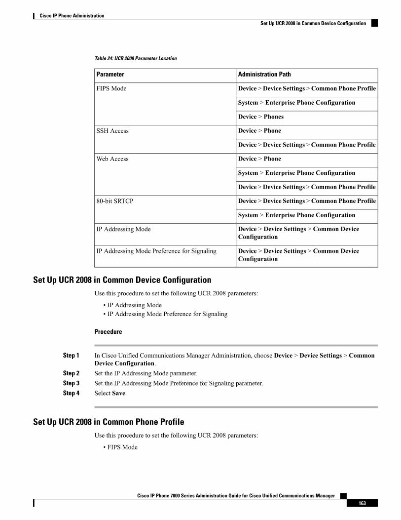
Table 24: UCR 2008 Parameter Location
Administration PathParameter
Device >Device Settings >Common Phone ProfileFIPS Mode
System > Enterprise Phone Configuration
Device > Phones
Device > PhoneSSH Access
Device >Device Settings >Common Phone Profile
Device > PhoneWeb Access
System > Enterprise Phone Configuration
Device >Device Settings >Common Phone Profile
Device >Device Settings >Common Phone Profile80-bit SRTCP
System > Enterprise Phone Configuration
Device > Device Settings > Common DeviceConfiguration
IP Addressing Mode
Device > Device Settings > Common DeviceConfiguration
IP Addressing Mode Preference for Signaling
Set Up UCR 2008 in Common Device ConfigurationUse this procedure to set the following UCR 2008 parameters:
• IP Addressing Mode• IP Addressing Mode Preference for Signaling
Procedure
Step 1 In Cisco Unified Communications Manager Administration, choose Device > Device Settings > CommonDevice Configuration.
Step 2 Set the IP Addressing Mode parameter.Step 3 Set the IP Addressing Mode Preference for Signaling parameter.Step 4 Select Save.
Set Up UCR 2008 in Common Phone ProfileUse this procedure to set the following UCR 2008 parameters:
• FIPS Mode
Cisco IP Phone 7800 Series Administration Guide for Cisco Unified Communications Manager163
Cisco IP Phone AdministrationSet Up UCR 2008 in Common Device Configuration
• SSH Access
• 80-bit SRTCP
• Web Access
Procedure
Step 1 In Cisco Unified Communications Manager Administration, choose Device > Device Settings > CommonPhone Profile.
Step 2 Set the FIPS Mode parameter to Enabled.Step 3 Set the SSH Access parameter to Disabled.Step 4 Set the Web Access parameter to Disabled.Step 5 Set the 80-bit SRTCP parameter to Enabled.Step 6 Select Save.
Set Up UCR 2008 in Enterprise Phone ConfigurationUse this procedure to set the following UCR 2008 parameters:
• FIPS Mode
• 80-bit SRTCP
• Web Access
Procedure
Step 1 In Cisco Unified Communications Manager Administration, choose System > Enterprise PhoneConfiguration.
Step 2 Set the FIPS Mode parameter to Enabled.Step 3 Set the 80-bit SRTCP parameter to Enabled.Step 4 Set the Web Access parameter to Disabled.Step 5 Select Save.
Set Up UCR 2008 in PhoneUse this procedure to set the following UCR 2008 parameters:
• FIPS Mode• SSH Access• Web Access
Cisco IP Phone 7800 Series Administration Guide for Cisco Unified Communications Manager164
Cisco IP Phone AdministrationSet Up UCR 2008 in Enterprise Phone Configuration

Procedure
Step 1 In Cisco Unified Communications Manager Administration, choose Device > Phone.Step 2 Set the SSH Access parameter to Disabled.Step 3 Set the FIPS Mode parameter to Enabled.Step 4 Set the Web Access parameter to Disabled.Step 5 Select Save.
Set Up RTP/sRTP Port RangeYou configure the Real-Time Transport Protocol (RTP) and secure Real-Time Transport Protocol (sRTP)port values in the SIP profile. RTP and sRTP port values range from 2048 to 65535, with a default range of16384 to 32764. Some port values within the RTP and sRTP port range are designated for other phone services.You cannot configure these ports for RTP and sRTP.
For more information, see SIP Profile information in the documentation for your particular Cisco UnifiedCommunications Manager release.
Procedure
Step 1 Select Device > Device Settings > SIP ProfileStep 2 Choose the search criteria to use and click Find.Step 3 Select the profile to modify.Step 4 Set the Start Media Port and Stop Media Port to contain the start and end of the port range.
The following list identifies the UDP ports that are used for other phone services and thus not available forRTP and sRTP use:
port 4051
used for the Peer Firmware Sharing (PFS) feature
port 5060
used for SIP over UDP transport
port range 49152 to 53247
used for local ephemeral ports
port range 53248 to 65535
used for the VxC single tunnel VPN feature
Step 5 Click Save.Step 6 Click Apply Config.
Related TopicsCisco Unified Communications Manager Documentation, on page xv
Cisco IP Phone 7800 Series Administration Guide for Cisco Unified Communications Manager165
Cisco IP Phone AdministrationSet Up RTP/sRTP Port Range
Mobile and Remote Access Through ExpresswayMobile and Remote Access Through Expressway lets remote workers easily and securely connect into thecorporate network without using a virtual private network (VPN) client tunnel. Expressway uses TransportLayer Security (TLS) to secure network traffic. For a phone to authenticate an Expressway certificate andestablish a TLS session, a public Certificate Authority that the phone firmware trusts must sign the Expresswaycertificate. It is not possible to install or trust other CA certificates on phones for authenticating an Expresswaycertificate.
The list of CA certificates embedded in the phone firmware is available athttp://www.cisco.com/c/en/us/support/collaboration-endpoints/unified-ip-phone-7800-series/products-technical-reference-list.html.
Mobile and Remote Access Through Expressway works with Cisco Expressway. You must be familiar withthe Cisco Expressway documentation, including the Cisco Expressway Administrator Guide and the CiscoExpressway Basic Configuration Deployment Guide. Cisco Expressway documentation is available athttp://www.cisco.com/c/en/us/support/unified-communications/expressway-series/tsd-products-support-series-home.html.
Only the IPv4 protocol is supported for Mobile and Remote Access Through Expressway users.
For additional information about working with Mobile and Remote Access Through Expressway, see:
• Cisco Preferred Architecture for Enterprise Collaboration, Design Overview
• Cisco Preferred Architecture for Enterprise Collaboration, CVD
• Unified Communications Mobile and Remote Access via Cisco VCS Deployment Guide
• Cisco TelePresence Video Communication Server (VCS), Configuration Guides
During the phone registration process, the phone synchronizes the displayed date and time with the NetworkTime Protocol (NTP) server. With Mobile and Remote Access Through Expressway, the DHCP option 42tag is used to locate the IP addresses of the NTP servers designated for time and date synchronization. If theDHCP option 42 tag is not found in the configuration information, the phone looks for the0.tandberg.pool.ntp.org tag to identify the NTP servers.
After registration, the phone uses information from the SIP message to synchronize the displayed date andtime unless an NTP server is configured in the Cisco Unified Communications Manager phone configuration.
If the phone security profile for any of your phones has TFTP Encrypted Config checked, you cannot use thephone withMobile and Remote Access. TheMRA solution does not support device interaction with CertificateAuthority Proxy Function (CAPF).
Note
Deployment Scenarios
The following table shows various deployment scenarios forMobile and Remote Access Through Expressway.
ActionsScenario
The enterprise network is detected, and the phoneregisters with Cisco Unified CommunicationsManager as it would normally.
On-premises user logs in to the enterprise network,after deploying Mobile and Remote Access ThroughExpressway.
Cisco IP Phone 7800 Series Administration Guide for Cisco Unified Communications Manager166
Cisco IP Phone AdministrationMobile and Remote Access Through Expressway
ActionsScenario
The phone detects that it is in off-premises mode, theMobile and Remote Access Through ExpresswaySign-In window appears, and the user connects to thecorporate network.
Users must have a valid service name, username, andpassword to connect to the network.
Users must also reset the service mode to clear theAlternate TFTP setting before they can access thecompany network. This clears the Alternate TFTPServer setting so the phone detects the off-premisesnetwork.
If a phone is being deployed out of the box, users mayskip the reset Network Settings requirement.
If users have DHCP option 150 or option 66 enabledon their network router, they may not be able to signin to the corporate network. Users should disable theseDHCP settings or configure their static IP addressdirectly.
Off-premises user logs in to the enterprise networkwith Mobile and Remote Access ThroughExpressway.
Phone Features Available for Mobile and Remote Access Through ExpresswayMobile and Remote Access Through Expressway provides secure VPN-less access to collaboration servicesfor Cisco mobile and remote users. But to preserve network security, it limits access to some phone features.
The following list shows the phone features available with Mobile and Remote Access Through Expressway.
Table 25: Feature Support and Mobile and Remote Access Through Expressway
Firmware ReleaseFeature
10.3(1) and laterAbbreviated Dialing
11.5(1)SR1 and laterAnswer Oldest
10.3(1) and laterAssisted Directed Call Park
11.5(1)SR1 and laterAuto Answer
11.5(1)SR1 and laterBarge and cBarge
10.3(1) and laterBusy Lamp Field (BLF)
10.3(1) and laterBusy Lamp Field (BLF) Pickup
10.3(1) and laterBusy Lamp Field (BLF) Speed Dial
10.3(1) and laterCall Back
10.3(1) and laterCall Forward
Cisco IP Phone 7800 Series Administration Guide for Cisco Unified Communications Manager167
Cisco IP Phone AdministrationPhone Features Available for Mobile and Remote Access Through Expressway
Firmware ReleaseFeature
10.3(1) and laterCall Forward Notification
10.3(1) and laterCall Park
10.3(1) and laterCall Pickup
11.5(1)SR1 and laterCisco Unified Serviceability
11.5(1)SR1 and laterClient Access License (CAL)
10.3(1) and laterConference
11.5(1)SR1 and laterConference List / Remove Participant
11.5(1)SR1 and laterCorporate Directory
11.5(1)SR1 and laterCTI Applications (CTI Controlled)
10.3(1) and laterDirected Call Park
11.5(1)SR1 and laterDistinctive Ring
10.3(1) and laterDivert
10.3(1) and laterDivert
11.5(1)SR1 and laterForced Access Codes and Client Matter Codes
10.3(1) and laterGroup Call Pickup
10.3(1) and laterHold/Resume
10.3(1) and laterHold Reversion
10.3(1) and laterImmediate Divert
10.3(1) and laterJoin
11.5(1)SR1 and laterMalicious Caller Identification (MCID)
10.3(1) and laterMeet Me Conference
10.3(1) and laterMessage Waiting Indicator
10.3(1) and laterMobile Connect
10.3(1) and laterMobile Voice Access
11.5(1)SR1 and laterMultilevel Precedence and Preemption (MLPP)
11.5(1)SR1 and laterMultiline
10.3(1) and laterMusic On Hold
10.3(1) and laterMute
Cisco IP Phone 7800 Series Administration Guide for Cisco Unified Communications Manager168
Cisco IP Phone AdministrationPhone Features Available for Mobile and Remote Access Through Expressway
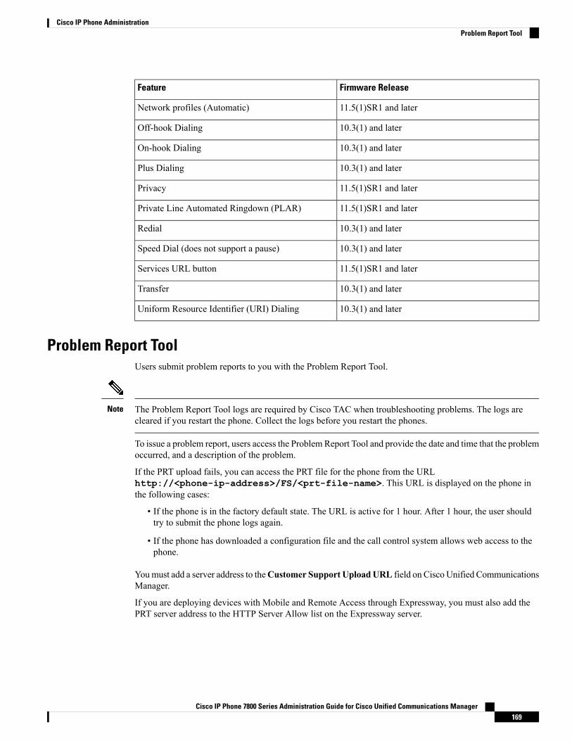
Firmware ReleaseFeature
11.5(1)SR1 and laterNetwork profiles (Automatic)
10.3(1) and laterOff-hook Dialing
10.3(1) and laterOn-hook Dialing
10.3(1) and laterPlus Dialing
11.5(1)SR1 and laterPrivacy
11.5(1)SR1 and laterPrivate Line Automated Ringdown (PLAR)
10.3(1) and laterRedial
10.3(1) and laterSpeed Dial (does not support a pause)
11.5(1)SR1 and laterServices URL button
10.3(1) and laterTransfer
10.3(1) and laterUniform Resource Identifier (URI) Dialing
Problem Report ToolUsers submit problem reports to you with the Problem Report Tool.
The Problem Report Tool logs are required by Cisco TAC when troubleshooting problems. The logs arecleared if you restart the phone. Collect the logs before you restart the phones.
Note
To issue a problem report, users access the Problem Report Tool and provide the date and time that the problemoccurred, and a description of the problem.
If the PRT upload fails, you can access the PRT file for the phone from the URLhttp://<phone-ip-address>/FS/<prt-file-name>. This URL is displayed on the phone inthe following cases:
• If the phone is in the factory default state. The URL is active for 1 hour. After 1 hour, the user shouldtry to submit the phone logs again.
• If the phone has downloaded a configuration file and the call control system allows web access to thephone.
Youmust add a server address to theCustomer Support UploadURL field on Cisco Unified CommunicationsManager.
If you are deploying devices with Mobile and Remote Access through Expressway, you must also add thePRT server address to the HTTP Server Allow list on the Expressway server.
Cisco IP Phone 7800 Series Administration Guide for Cisco Unified Communications Manager169
Cisco IP Phone AdministrationProblem Report Tool

Configure a Customer Support Upload URLYou must use a server with an upload script to receive PRT files. The PRT uses an HTTP POST mechanism,with the following parameters included in the upload (utilizing multipart MIME encoding):
• devicename (example: “SEP001122334455”)• serialno (example: “FCH12345ABC”)• username (the username configured in CUCM, the device owner)• prt_file (example: “probrep-20141021-162840.tar.gz”)
A sample script is shown below. This script is provided for reference only. Cisco does not provide supportfor the upload script installed on a customer's server.<?php
// NOTE: you may need to edit your php.ini file to allow larger// size file uploads to work.// Modify the setting for upload_max_filesize// I used: upload_max_filesize = 20M
// Retrieve the name of the uploaded file$filename = basename($_FILES['prt_file']['name']);
// Get rid of quotes around the device name, serial number and username if they exist$devicename = $_POST['devicename'];$devicename = trim($devicename, "'\"");
$serialno = $_POST['serialno'];$serialno = trim($serialno, "'\"");
$username = $_POST['username'];$username = trim($username, "'\"");
// where to put the file$fullfilename = "/var/prtuploads/".$filename;
// If the file upload is unsuccessful, return a 500 error and// inform the user to try again
if(!move_uploaded_file($_FILES['prt_file']['tmp_name'], $fullfilename)) {header("HTTP/1.0 500 Internal Server Error");die("Error: You must select a file to upload.");
}
?>
Procedure
Step 1 Set up a server that can run your PRT upload script.Step 2 Write a script that can handle the parameters listed above, or edit the provided sample script to suit your needs.Step 3 Upload your script to your server.Step 4 In Cisco Unified Communications Manager, go to the Product Specific Configuration Layout area of the
individual device configuration window, Common Phone Profile window, or Enterprise Phone Configurationwindow.
Step 5 Check Customer support upload URL and enter your upload server URL.
Example:
Cisco IP Phone 7800 Series Administration Guide for Cisco Unified Communications Manager170
Cisco IP Phone AdministrationConfigure a Customer Support Upload URL
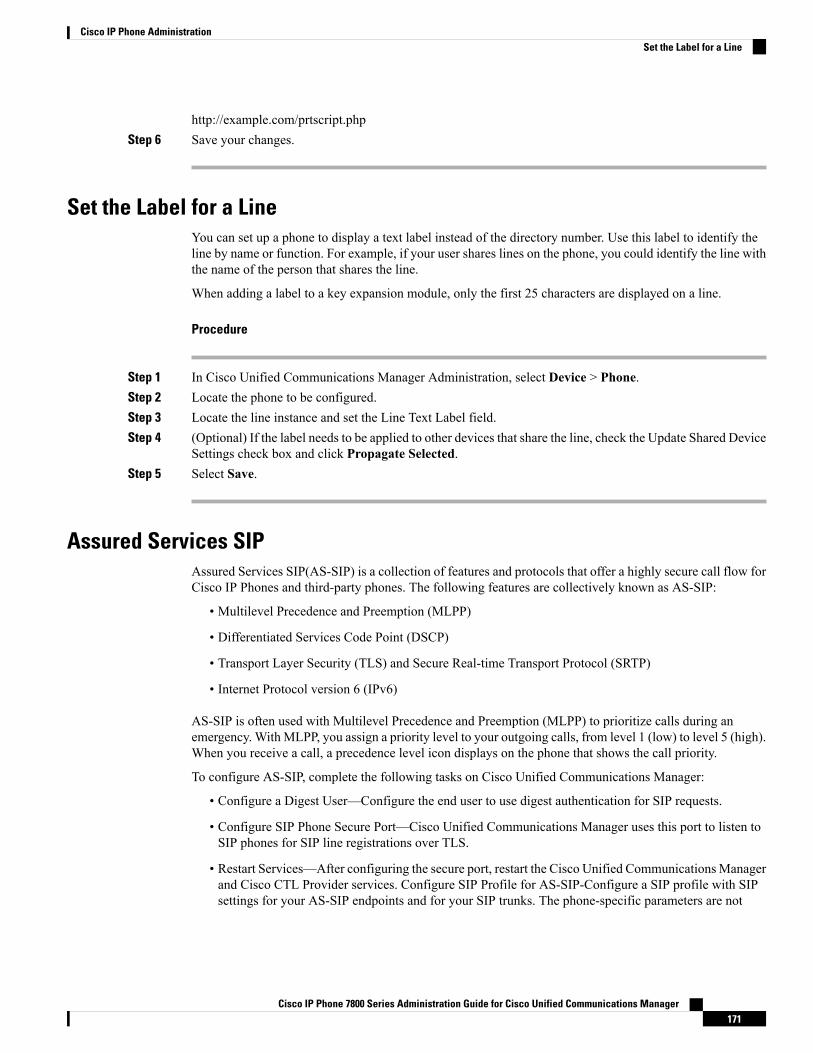
http://example.com/prtscript.phpStep 6 Save your changes.
Set the Label for a LineYou can set up a phone to display a text label instead of the directory number. Use this label to identify theline by name or function. For example, if your user shares lines on the phone, you could identify the line withthe name of the person that shares the line.
When adding a label to a key expansion module, only the first 25 characters are displayed on a line.
Procedure
Step 1 In Cisco Unified Communications Manager Administration, select Device > Phone.Step 2 Locate the phone to be configured.Step 3 Locate the line instance and set the Line Text Label field.Step 4 (Optional) If the label needs to be applied to other devices that share the line, check the Update Shared Device
Settings check box and click Propagate Selected.Step 5 Select Save.
Assured Services SIPAssured Services SIP(AS-SIP) is a collection of features and protocols that offer a highly secure call flow forCisco IP Phones and third-party phones. The following features are collectively known as AS-SIP:
• Multilevel Precedence and Preemption (MLPP)
• Differentiated Services Code Point (DSCP)
• Transport Layer Security (TLS) and Secure Real-time Transport Protocol (SRTP)
• Internet Protocol version 6 (IPv6)
AS-SIP is often used with Multilevel Precedence and Preemption (MLPP) to prioritize calls during anemergency. With MLPP, you assign a priority level to your outgoing calls, from level 1 (low) to level 5 (high).When you receive a call, a precedence level icon displays on the phone that shows the call priority.
To configure AS-SIP, complete the following tasks on Cisco Unified Communications Manager:
• Configure a Digest User—Configure the end user to use digest authentication for SIP requests.
• Configure SIP Phone Secure Port—Cisco Unified Communications Manager uses this port to listen toSIP phones for SIP line registrations over TLS.
• Restart Services—After configuring the secure port, restart the Cisco Unified CommunicationsManagerand Cisco CTL Provider services. Configure SIP Profile for AS-SIP-Configure a SIP profile with SIPsettings for your AS-SIP endpoints and for your SIP trunks. The phone-specific parameters are not
Cisco IP Phone 7800 Series Administration Guide for Cisco Unified Communications Manager171
Cisco IP Phone AdministrationSet the Label for a Line

downloaded to a third-party AS-SIP phone. They are used only by Cisco Unified Manager. Third-partyphones must locally configure the same settings.
• Configure Phone Security Profile for AS-SIP—You can use the phone security profile to assign securitysettings such as TLS, SRTP, and digest authentication.
• Configure AS-SIP Endpoint—Configure a Cisco IP Phone or a third-party endpoint with AS-SIP support.
• Associate Device with End Use—Associate the endpoint with a user.
• Configure SIP Trunk Security Profile for AS-SIP—You can use the sip trunk security profile to assignsecurity features such as TLS or digest authentication to a SIP trunk.
• Configure SIP Trunk for AS-SIP—Configure a SIP trunk with AS-SIP support.
• Configure AS-SIP Features—Configure additional AS-SIP features such as MLPP, TLS, V.150, andIPv6.
For detailed information about configuring AS-SIP, see the "Configure AS-SIP Endpoints" chapter, SystemConfiguration Guide for Cisco Unified Communications Manager.
Multilevel Precedence and PreemptionMultilevel Precedence and Preemption (MLPP) allows you to prioritize calls during emergencies or othercrisis situations. You assign a priority to your outgoing calls that range from 1 to 5. Incoming calls displayan icon that shows the call priority. Authenticated users can preempt calls either to targeted stations or throughfully subscribed TDM trunks.
This capability assures high-ranking personnel of communication to critical organizations and personnel.
MLPP is often used with Assured Services SIP(AS-SIP). For detailed information about configuring MLPP,see the "Configure Multilevel Precedence and Preemption" chapter, System Configuration Guide for CiscoUnified Communications Manager.
Set Up Softkey TemplateYou can associate up to 18 softkeys with applications that are supported by the Cisco IP Phone. An applicationthat supports softkeys can have one or more standard softkey templates associated with it.
Cisco Unified Communications Manager supports the Standard User and Standard Feature softkey template.You can modify a standard softkey template by making a copy of it, giving it a new name, and making updatesto that copied softkey template. You can also modify a nonstandard softkey template.
For more information, see the documentation for your particular Cisco Unified Communications Managerrelease.
The phones do not support all the softkeys that are configurable in Softkey Template Configuration on CiscoUnified Communications Manager Administration. The following table lists the features, softkeys that canbe configured on a softkey template, and note whether it is supported on the Cisco IP Phone.
Cisco IP Phone 7800 Series Administration Guide for Cisco Unified Communications Manager172
Cisco IP Phone AdministrationMultilevel Precedence and Preemption

Table 26: Configurable Softkeys
NotesSupportstatus
Configurable softkeysin the SoftkeyTemplate configuration
Feature
-YesAnswer (Answer)Answer
Cisco IP Phone 7811, 7821, 7841, and 7861support cBarge only.
NoBarge (Barge)Barge
Configure as a programmable line key or as asoftkey.
YesCall Back (CallBack)Call Back
Phone displays Fwd ALL or Fwd Off.YesForward All (cfwdAll)Call Forward All
Configure as a programmable line key or as asoftkey.
YesCall Park (Park)Call Park
Configure as a programmable line key or as asoftkey.
YesPick Up (Pickup)Call Pickup
Configure as a programmable line key or as asoftkey.
YesConference Barge(cBarge)
cBarge
Configure as a softkey only.YesConference (Conf)Conference
Phone displays Details.YesDetailsConference List
Phone displays Divert.
Starting with Firmware Release 10.3(1), thephone displays Decline for the softkey.
YesImmediateDivert(iDivert)
Divert
Configure as a programmable line button orsoftkey.
YesToggle Do Not Disturb(DND)
Do Not Disturb
YesEnd Call (EndCall)End Call
Configure as a programmable line button orsoftkey
YesGroup PickUp(GPickUp)
Group Pickup
Hold is a dedicated button.YesHold (Hold)Hold
Configure as a programmable line button orsoftkey.
YesHLog (HLog)Hunt Group
NoJoin (Join)Join
Configure as a programmable feature buttonor softkey.
YesToggle Malicious CallIdentification (MCID)
Malicious CallIdentification
Configure as a programmable feature buttonor softkey.
YesMeet Me (MeetMe)Meet Me
Cisco IP Phone 7800 Series Administration Guide for Cisco Unified Communications Manager173
Cisco IP Phone AdministrationSet Up Softkey Template

NotesSupportstatus
Configurable softkeysin the SoftkeyTemplate configuration
Feature
Configure as a programmable feature buttonor softkey.
YesMobility (Mobility)Mobile Connect
Phone displays New Call.YesNew Call (NewCall)New Call
Configure as a programmable feature buttonor softkey.
YesOther Pickup (oPickup)Other Pickup
-YesQueue StatusPLK Support forQueue Statistics
Configure as a programmable feature buttonor softkey.
YesQuality Reporting Tool(QRT)
Quality ReportingTool
Enables/Disables the softkey.YesRecentsRecents
-YesRedial (Redial)Redial
Phone displays Remove when a participant isselected.
YesRemove LastConference Participant(Remove)
Remove LastConferenceParticipant
Resume is a dedicated button.YesResume (Resume)Resume
Phone displays SpeedDial.YesAbbreviated Dial(AbbrDial)
Speed Dial
This feature is supported as a soft key or adedicated button.
YesDirect Transfer(DirTrfr)
Transfer
-NoVideoModeCommand(VidMode)
Video ModeCommand
Cisco Unified Communications Manager allows you to configure any softkey in a softkey template, butunsupported softkeys do not display on the phone.
Procedure
Step 1 In Cisco Unified Communications Manager, select Device > Device Settings > Softkey Template.Step 2 Locate the template that you want to change.Step 3 Select Configure Softkey Layout from the Related Links list and click Go.Step 4 Configure the softkey positions.Step 5 Select Save to save the layout, template, and modificationStep 6 Select Apply Config to apply the template to the phones.
Related TopicsCisco Unified Communications Manager Documentation, on page xv
Cisco IP Phone 7800 Series Administration Guide for Cisco Unified Communications Manager174
Cisco IP Phone AdministrationSet Up Softkey Template
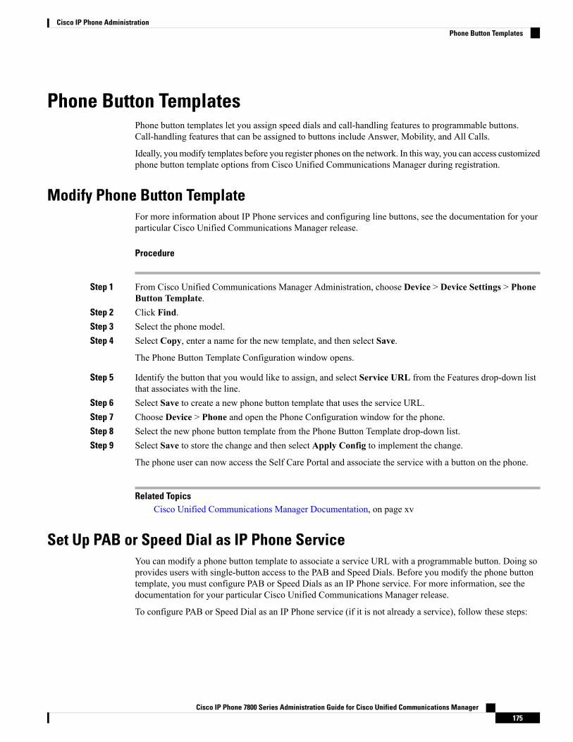
Phone Button TemplatesPhone button templates let you assign speed dials and call-handling features to programmable buttons.Call-handling features that can be assigned to buttons include Answer, Mobility, and All Calls.
Ideally, youmodify templates before you register phones on the network. In this way, you can access customizedphone button template options from Cisco Unified Communications Manager during registration.
Modify Phone Button TemplateFor more information about IP Phone services and configuring line buttons, see the documentation for yourparticular Cisco Unified Communications Manager release.
Procedure
Step 1 From Cisco Unified Communications Manager Administration, choose Device > Device Settings > PhoneButton Template.
Step 2 Click Find.Step 3 Select the phone model.Step 4 Select Copy, enter a name for the new template, and then select Save.
The Phone Button Template Configuration window opens.
Step 5 Identify the button that you would like to assign, and select Service URL from the Features drop-down listthat associates with the line.
Step 6 Select Save to create a new phone button template that uses the service URL.Step 7 Choose Device > Phone and open the Phone Configuration window for the phone.Step 8 Select the new phone button template from the Phone Button Template drop-down list.Step 9 Select Save to store the change and then select Apply Config to implement the change.
The phone user can now access the Self Care Portal and associate the service with a button on the phone.
Related TopicsCisco Unified Communications Manager Documentation, on page xv
Set Up PAB or Speed Dial as IP Phone ServiceYou can modify a phone button template to associate a service URL with a programmable button. Doing soprovides users with single-button access to the PAB and Speed Dials. Before you modify the phone buttontemplate, you must configure PAB or Speed Dials as an IP Phone service. For more information, see thedocumentation for your particular Cisco Unified Communications Manager release.
To configure PAB or Speed Dial as an IP Phone service (if it is not already a service), follow these steps:
Cisco IP Phone 7800 Series Administration Guide for Cisco Unified Communications Manager175
Cisco IP Phone AdministrationPhone Button Templates
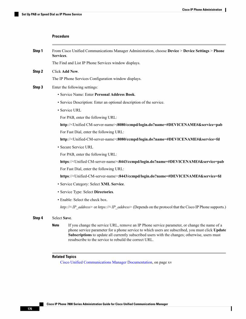
Procedure
Step 1 From Cisco Unified Communications Manager Administration, choose Device > Device Settings > PhoneServices.
The Find and List IP Phone Services window displays.
Step 2 Click Add New.
The IP Phone Services Configuration window displays.
Step 3 Enter the following settings:
• Service Name: Enter Personal Address Book.
• Service Description: Enter an optional description of the service.
• Service URL
For PAB, enter the following URL:
http://<Unified CM-server-name>:8080/ccmpd/login.do?name=#DEVICENAME#&service=pab
For Fast Dial, enter the following URL:
http://<Unified-CM-server-name>:8080/ccmpd/login.do?name=#DEVICENAME#&service=fd
• Secure Service URL
For PAB, enter the following URL:
https://<Unified CM-server-name>:8443/ccmpd/login.do?name=#DEVICENAME#&service=pab
For Fast Dial, enter the following URL:
https://<Unified-CM-server-name>:8443/ccmpd/login.do?name=#DEVICENAME#&service=fd
• Service Category: Select XML Service.
• Service Type: Select Directories.
• Enable: Select the check box.
http://<IP_address> or https://<IP_address> (Depends on the protocol that the Cisco IP Phone supports.)
Step 4 Select Save.
If you change the service URL, remove an IP Phone service parameter, or change the name of aphone service parameter for a phone service to which users are subscribed, you must click UpdateSubscriptions to update all currently subscribed users with the changes; otherwise, users mustresubscribe to the service to rebuild the correct URL.
Note
Related TopicsCisco Unified Communications Manager Documentation, on page xv
Cisco IP Phone 7800 Series Administration Guide for Cisco Unified Communications Manager176
Cisco IP Phone AdministrationSet Up PAB or Speed Dial as IP Phone Service
C H A P T E R 12Corporate and Personal Directory Setup
• Corporate Directory Setup, on page 177• Personal Directory Setup, on page 177• User Personal Directory Entries Setup, on page 178
Corporate Directory SetupThe Corporate Directory allows a user to look up phone numbers for coworkers. To support this feature, youmust configure corporate directories.
Cisco Unified Communications Manager uses a Lightweight Directory Access Protocol (LDAP) directory tostore authentication and authorization information about users of Cisco Unified Communications Managerapplications that interface with Cisco Unified Communications Manager. Authentication establishes userrights to access the system. Authorization identifies the telephony resources that a user is permitted to use,such as a specific phone extension.
For more information, see the documentation for your particular Cisco Unified Communications Managerrelease.
After you complete the LDAP directory configuration, users can use the Corporate Directory service on theirphone to look up users in the corporate directory.
Related TopicsCisco Unified Communications Manager Documentation, on page xv
Personal Directory SetupThe Personal Directory allows a user to store a set of personal numbers.
Personal Directory consists of the following features:
• Personal Address Book (PAB)
• Speed Dials
• Address Book Synchronization Tool (TABSynch)
Users can use these methods to access Personal Directory features:
Cisco IP Phone 7800 Series Administration Guide for Cisco Unified Communications Manager177
• From a web browser: Users can access the PAB and Speed Dials features from the Cisco UnifiedCommunications Self Care Portal.
• From the Cisco IP Phone: Choose Contacts to search the corporate directory or the user personal directory.
• From a Microsoft Windows application: Users can use the TABSynch tool to synchronize their PABswith Microsoft Windows Address Book (WAB). Customers who want to use the Microsoft OutlookAddress Book (OAB) should begin by importing the data from the OAB into the WAB. TabSync canthen be used to synchronize the WAB with Personal Directory. For instructions about TABSync, seeDownload Cisco IP Phone Address Book Synchronizer, on page 178 and Set Up Synchronizer, on page179.
To ensure that Cisco IP Phone Address Book Synchronizer users access only their end-user data, activate theCisco UXL Web Service in Cisco Unified Serviceability.
To configure Personal Directory from a web browser, users must access their Self Care Portal. You mustprovide users with a URL and sign-in information.
User Personal Directory Entries SetupUsers can configure personal directory entries on the Cisco IP Phone. To configure a personal directory, usersmust have access to the following:
• Self Care Portal: Make sure that users know how to access their Self Care Portal. See Set Up User Accessto the Self Care Portal, on page 65 for details.
• Cisco IP Phone Address Book Synchronizer: Make sure to provide users with the installer. See DownloadCisco IP Phone Address Book Synchronizer, on page 178.
Download Cisco IP Phone Address Book SynchronizerTo download a copy of the synchronizer to send to your users, follow these steps:
Procedure
Step 1 To obtain the installer, choose Application > Plugins from Cisco Unified Communications ManagerAdministration.
Step 2 Select Download, which is located next to the Cisco IP Phone Address Book Synchronizer plugin name.Step 3 When the file download dialog box displays, select Save.Step 4 Send the TabSyncInstall.exe file and the instructions in Cisco IP Phone Address Book Synchronizer
Deployment, on page 178 to all users who require this application.
Cisco IP Phone Address Book Synchronizer DeploymentThe Cisco IP Phone Address Book Synchronizer synchronizes data that is stored in your Microsoft Windowsaddress book with the Cisco Unified Communications Manager directory and the Self Care Portal PersonalAddress Book.
Cisco IP Phone 7800 Series Administration Guide for Cisco Unified Communications Manager178
Cisco IP Phone AdministrationUser Personal Directory Entries Setup

To successfully synchronize theWindows address bookwith the Personal Address Book, allWindows addressbook users should be entered in the Windows address book before you perform the following procedures.
Tip
Install SynchronizerTo install the Cisco IP Phone Address Book Synchronizer, follow these steps:
Procedure
Step 1 Get the Cisco IP Phone Address Book Synchronizer installer file from your system administrator.Step 2 Double-click the TabSyncInstall.exe file that your administrator provided.Step 3 Select Run.Step 4 Select Next.Step 5 Read the license agreement information, and select the I Accept. Select Next.Step 6 Choose the directory in which you want to install the application and select Next.Step 7 Select Install.Step 8 Select Finish.Step 9 To complete the process, follow the steps in Set Up Synchronizer, on page 179.
Set Up SynchronizerTo configure the Cisco IP Phone Address Book Synchronizer, perform these steps:
Procedure
Step 1 Open the Cisco IP Phone Address Book Synchronizer.
If you accepted the default installation directory, you can open the application by choosing Start > AllPrograms > Cisco Systems > TabSync.
Step 2 To configure user information, select User.Step 3 Enter the Cisco IP Phone user name and password and select OK.Step 4 To configure Cisco Unified Communications Manager server information, select Server.Step 5 Enter the IP address or host name and the port number of the Cisco Unified Communications Manager server
and select OK.
If you do not have this information, contact your system administrator.
Step 6 To start the directory synchronization process, select Synchronize.
The Synchronization Status window provides the status of the address book synchronization. If you chose theuser intervention for duplicate entries rule and you have duplicate address book entries, the Duplicate Selectionwindow displays.
Cisco IP Phone 7800 Series Administration Guide for Cisco Unified Communications Manager179
Cisco IP Phone AdministrationInstall Synchronizer

Step 7 Choose the entry that you want to include in your Personal Address Book and select OK.Step 8 When synchronization is complete, select Exit to close the Cisco Unified CallManager Address Book
Synchronizer.Step 9 To verify whether the synchronization worked, sign in to your Self Care Portal and choose Personal Address
Book. The users from your Windows address book should be listed.
Cisco IP Phone 7800 Series Administration Guide for Cisco Unified Communications Manager180
Cisco IP Phone AdministrationSet Up Synchronizer

P A R T VCisco IP Phone Troubleshooting
• Monitoring Phone Systems, on page 183• Troubleshooting, on page 217• Maintenance, on page 235• International User Support, on page 239


C H A P T E R 13Monitoring Phone Systems
• Monitoring Phone Systems Overview, on page 183• Cisco IP Phone Status, on page 183• Cisco IP Phone Web Page, on page 197• Request Information from the Phone in XML, on page 213
Monitoring Phone Systems OverviewYou can view a variety of information about the phone using the phone status menu on the phone and thephone web pages. This information includes:
• Device information
• Network setup information
• Network statistics
• Device logs
• Streaming statistics
This chapter describes the information that you can obtain from the phone web page. You can use thisinformation to remotely monitor the operation of a phone and to assist with troubleshooting.
Cisco IP Phone StatusThe following sections describes how to view model information, status messages, and network statistics onthe Cisco IP Phone.
• Model Information: Displays hardware and software information about the phone.
• Status menu: Provides access to screens that display the status messages, network statistics, and statisticsfor the current call.
You can use the information that displays on these screens to monitor the operation of a phone and to assistwith troubleshooting.
You can also obtain much of this information, and obtain other related information, remotely through thephone web page.
Cisco IP Phone 7800 Series Administration Guide for Cisco Unified Communications Manager183
Display the Phone Information Window
Procedure
Step 1 Press Applications .Step 2 Select Phone Information.
If the user is connected to a secure or authenticated server, a corresponding icon (lock or certificate) displaysin the Phone Information Screen to the right of the server option. If the user is not connected to a secure orauthenticated server, no icon appears.
Step 3 To exit the Model Information screen, press .
Display Status Menu
Procedure
Step 1 To display the Status menu, press Applications .Step 2 Select Admin Settings > Status.
Step 3 To exit the Status menu, press Back .
Display Status Messages Window
Procedure
Step 1 Press Applications .Step 2 Select Admin Settings > Status > Status Messages.Step 3 To remove current status messages, press Clear.
Step 4 To exit the Status menu, press Back .
Related TopicsPhone Displays Error Messages, on page 220
Status Messages Fields
The following table describes the status messages that display on the Status Messages screen of the phone.
For more information about trust lists, see the documentation for your particular Cisco Unified CommunicationsManager release.
Cisco IP Phone 7800 Series Administration Guide for Cisco Unified Communications Manager184
Cisco IP Phone TroubleshootingDisplay the Phone Information Window

Table 27: Status Messages on the Cisco IP Phone
Possible Explanation and ActionDescriptionMessage
Confirm that the DHCP server is availableand that an IP address is available for thephone.
The phone has not previously obtained anIP address from a DHCP Server. This canoccur when you perform an out of box orfactory reset.
Could not acquire an IP address fromDHCP
Power cycle the phone.The configuration file is too large for filesystem on the phone.
TFTP Size Error
Obtain a new copy of the phone firmwareand place it in the TFTPPath directory. Youshould only copy files into this directorywhen the TFTP server software is shutdown; otherwise, the files may becorrupted.
Downloaded software file is corrupted.ROM Checksum Error
If the phone has a static IP address, verifythat you did not assigned a duplicate IPaddress.
If you are using DHCP, check the DHCPserver configuration.
Another device is using the IP address thatis assigned to the phone.
Duplicate IP
None. This message is informational only.Erasing CTL or ITL file.Erasing CTL and ITL files
From Cisco Unified Operating SystemAdministration, check that the followingfiles are located within subdirectories in theTFTP File Management:
• Located in subdirectory with samename as network locale:
• tones.xml
• Located in subdirectory with samename as user locale:
• glyphs.xml
• dictionary.xml
• kate.xml
One or more localization files could not befound in the TFTP Path directory or werenot valid. The locale was not changed.
Error Updating Locale
Cisco IP Phone 7800 Series Administration Guide for Cisco Unified Communications Manager185
Cisco IP Phone TroubleshootingStatus Messages Fields

Possible Explanation and ActionDescriptionMessage
The configuration file for a phone is createdwhen the phone is added to the CiscoUnified Communications Managerdatabase. If the phone does not exist in theCisco Unified Communications Managerdatabase, the TFTP server generates a CFGFile Not Found response.
• Phone is not registered with CiscoUnified Communications Manager.
You must manually add the phone toCisco Unified CommunicationsManager if you are not allowingphones to autoregister.
• If you are using DHCP, verify that theDHCP server is pointing to the correctTFTP server.
• If you are using static IP addresses,check configuration of the TFTPserver.
The name-based and default configurationfile was not found on the TFTP Server.
File not found <Cfg File>
No impact; the phone can still register toCisco Unified Communications Manager.
This message displays on the phone whenthe Cisco Unified CommunicationsManager cluster is not in secure mode.
File Not Found <CTLFile.tlv>
The phone remains idle until it is powercycled or until you reset the DHCP address.
The phone is configured to release the IPaddress.
IP Address Released
Network is busy: The errors should resolvethemselves when the network load reduces.
No network connectivity between the IPv4DHCP server and the phone: Verify thenetwork connections.
IPv4 DHCP server is down: Checkconfiguration of IPv4 DHCP server.
Errors persist: Consider assigning a staticIPv4 address.
IPv4 DHCP server did not respond.IPv4 DHCP Timeout
Cisco IP Phone 7800 Series Administration Guide for Cisco Unified Communications Manager186
Cisco IP Phone TroubleshootingStatus Messages Fields

Possible Explanation and ActionDescriptionMessage
Network is busy - The errors should resolvethemselves when the network load reduces.
No network connectivity between the IPv6DHCP server and the phone: Verify thenetwork connections.
IPv6 DHCP server is down: Checkconfiguration of IPv6 DHCP server.
Errors persist: Consider assigning a staticIPv6 address.
IPv6 DHCP server did not respond.IPv6 DHCP Timeout
Network is busy: The errors should resolvethemselves when the network load reduces.
No network connectivity between the IPv4DNS server and the phone: Verify thenetwork connections.
IPv4 DNS server is down: Checkconfiguration of the IPv4 DNS server.
IPv4 DNS server did not respond.IPv4 DNS Timeout
Network is busy: The errors should resolvethemselves when the network load reduces.
No network connectivity between the IPv6DNS server and the phone: Verify thenetwork connections.
IPv6 DNS server is down: Checkconfiguration of the IPv6 DNS server.
IPv6 DNS server did not respond.IPv6 DNS Timeout
Verify that the host names of the TFTPserver or Cisco Unified CommunicationsManager are configured properly in IPv4DNS.
Consider using IPv4 addresses rather thanhost names
IPv4 DNS could not resolve the name ofthe TFTP server or Cisco UnifiedCommunications Manager.
DNS unknown IPv4 Host
Verify that the host names of the TFTPserver or Cisco Unified CommunicationsManager are configured properly in IPv6DNS.
Consider using IPv6 addresses rather thanhost names
IPv6 DNS could not resolve the name ofthe TFTP server or Cisco UnifiedCommunications Manager.
DNS unknown IPv6 Host
Cisco IP Phone 7800 Series Administration Guide for Cisco Unified Communications Manager187
Cisco IP Phone TroubleshootingStatus Messages Fields
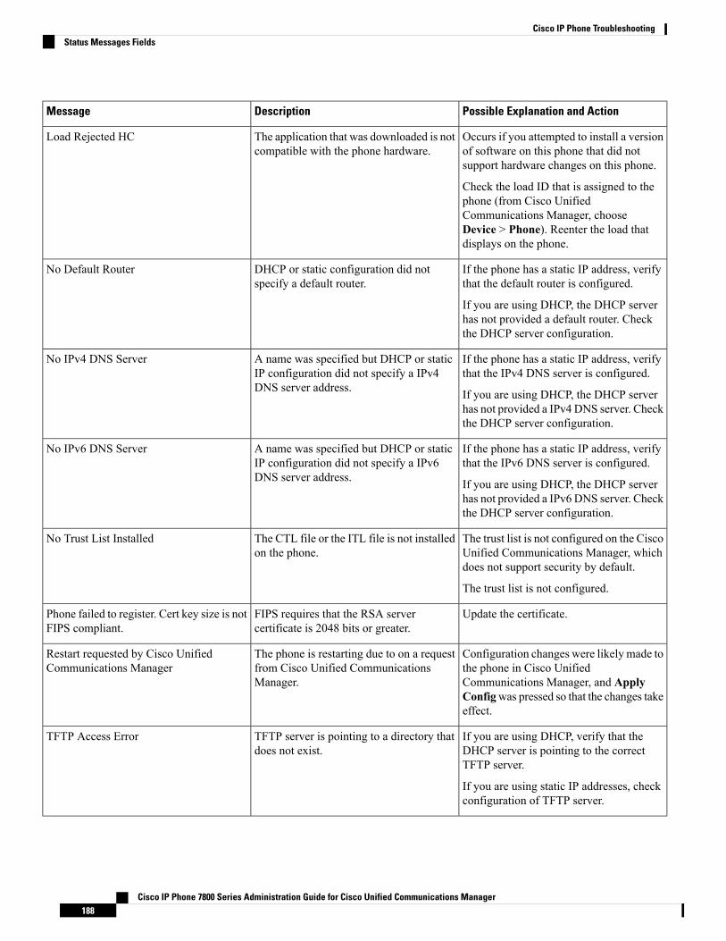
Possible Explanation and ActionDescriptionMessage
Occurs if you attempted to install a versionof software on this phone that did notsupport hardware changes on this phone.
Check the load ID that is assigned to thephone (from Cisco UnifiedCommunications Manager, chooseDevice > Phone). Reenter the load thatdisplays on the phone.
The application that was downloaded is notcompatible with the phone hardware.
Load Rejected HC
If the phone has a static IP address, verifythat the default router is configured.
If you are using DHCP, the DHCP serverhas not provided a default router. Checkthe DHCP server configuration.
DHCP or static configuration did notspecify a default router.
No Default Router
If the phone has a static IP address, verifythat the IPv4 DNS server is configured.
If you are using DHCP, the DHCP serverhas not provided a IPv4 DNS server. Checkthe DHCP server configuration.
A name was specified but DHCP or staticIP configuration did not specify a IPv4DNS server address.
No IPv4 DNS Server
If the phone has a static IP address, verifythat the IPv6 DNS server is configured.
If you are using DHCP, the DHCP serverhas not provided a IPv6 DNS server. Checkthe DHCP server configuration.
A name was specified but DHCP or staticIP configuration did not specify a IPv6DNS server address.
No IPv6 DNS Server
The trust list is not configured on the CiscoUnified Communications Manager, whichdoes not support security by default.
The trust list is not configured.
The CTL file or the ITL file is not installedon the phone.
No Trust List Installed
Update the certificate.FIPS requires that the RSA servercertificate is 2048 bits or greater.
Phone failed to register. Cert key size is notFIPS compliant.
Configuration changes were likely made tothe phone in Cisco UnifiedCommunications Manager, and ApplyConfigwas pressed so that the changes takeeffect.
The phone is restarting due to on a requestfrom Cisco Unified CommunicationsManager.
Restart requested by Cisco UnifiedCommunications Manager
If you are using DHCP, verify that theDHCP server is pointing to the correctTFTP server.
If you are using static IP addresses, checkconfiguration of TFTP server.
TFTP server is pointing to a directory thatdoes not exist.
TFTP Access Error
Cisco IP Phone 7800 Series Administration Guide for Cisco Unified Communications Manager188
Cisco IP Phone TroubleshootingStatus Messages Fields
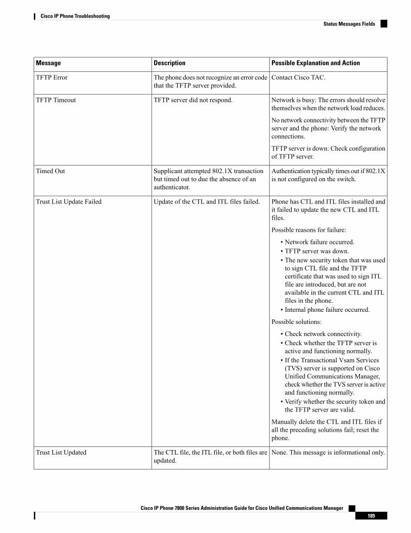
Possible Explanation and ActionDescriptionMessage
Contact Cisco TAC.The phone does not recognize an error codethat the TFTP server provided.
TFTP Error
Network is busy: The errors should resolvethemselves when the network load reduces.
No network connectivity between the TFTPserver and the phone: Verify the networkconnections.
TFTP server is down: Check configurationof TFTP server.
TFTP server did not respond.TFTP Timeout
Authentication typically times out if 802.1Xis not configured on the switch.
Supplicant attempted 802.1X transactionbut timed out to due the absence of anauthenticator.
Timed Out
Phone has CTL and ITL files installed andit failed to update the new CTL and ITLfiles.
Possible reasons for failure:
• Network failure occurred.• TFTP server was down.• The new security token that was usedto sign CTL file and the TFTPcertificate that was used to sign ITLfile are introduced, but are notavailable in the current CTL and ITLfiles in the phone.
• Internal phone failure occurred.
Possible solutions:
• Check network connectivity.• Check whether the TFTP server isactive and functioning normally.
• If the Transactional Vsam Services(TVS) server is supported on CiscoUnified Communications Manager,checkwhether the TVS server is activeand functioning normally.
• Verify whether the security token andthe TFTP server are valid.
Manually delete the CTL and ITL files ifall the preceding solutions fail; reset thephone.
Update of the CTL and ITL files failed.Trust List Update Failed
None. This message is informational only.The CTL file, the ITL file, or both files areupdated.
Trust List Updated
Cisco IP Phone 7800 Series Administration Guide for Cisco Unified Communications Manager189
Cisco IP Phone TroubleshootingStatus Messages Fields
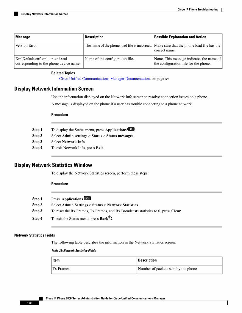
Possible Explanation and ActionDescriptionMessage
Make sure that the phone load file has thecorrect name.
The name of the phone load file is incorrect.Version Error
None. This message indicates the name ofthe configuration file for the phone.
Name of the configuration file.XmlDefault.cnf.xml, or .cnf.xmlcorresponding to the phone device name
Related TopicsCisco Unified Communications Manager Documentation, on page xv
Display Network Information ScreenUse the information displayed on the Network Info screen to resolve connection issues on a phone.
A message is displayed on the phone if a user has trouble connecting to a phone network.
Procedure
Step 1 To display the Status menu, press Applications .Step 2 Select Admin settings > Status > Status messages.Step 3 Select Network Info.Step 4 To exit Network Info, press Exit.
Display Network Statistics WindowTo display the Network Statistics screen, perform these steps:
Procedure
Step 1 Press Applications .Step 2 Select Admin Settings > Status > Network Statistics.Step 3 To reset the Rx Frames, Tx Frames, and Rx Broadcasts statistics to 0, press Clear.
Step 4 To exit the Status menu, press Back .
Network Statistics Fields
The following table describes the information in the Network Statistics screen.
Table 28: Network Statistics Fields
DescriptionItem
Number of packets sent by the phoneTx Frames
Cisco IP Phone 7800 Series Administration Guide for Cisco Unified Communications Manager190
Cisco IP Phone TroubleshootingDisplay Network Information Screen

DescriptionItem
Number of broadcast packets sent by the phoneTx broadcast
Total number of unicast packets transmitted by thephone
Tx unicast
Number of packets received by the phoneRx Frames
Number of broadcast packets received by the phoneRx broadcast
Total number of unicast packets received by the phoneRx unicast
Identifier of a device connected to this port discoveredby CDP protocol.
CDP Neighbor Device ID
Identifier of a device connected to this port discoveredby CDP protocol using IP.
CDP Neighbor IP Address
Identifier of a device connected to this port discoveredby CDP protocol using IPv6.
CDP Neighbor IPv6 Address
Identifier of a device connected to this port discoveredby CDP protocol.
CDP Neighbor Port
Cause of the last reset of the phoneRestart Cause: One of these values:
• Hardware Reset (Power-on reset)• Software Reset (memory controller also reset)• Software Reset (memory controller not reset)• Watchdog Reset• Unknown
Link state and connection of the PC port (for example,Auto 100 Mb Full-Duplexmeans that the PCport is in a link-up state and has auto-negotiated afull-duplex, 100-Mbps connection)
Port 1
Link state and connection of the Network portPort 2
Cisco IP Phone 7800 Series Administration Guide for Cisco Unified Communications Manager191
Cisco IP Phone TroubleshootingNetwork Statistics Fields
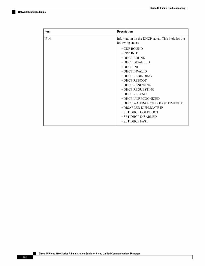
DescriptionItem
Information on the DHCP status. This includes thefollowing states:
• CDP BOUND• CDP INIT• DHCP BOUND• DHCP DISABLED• DHCP INIT• DHCP INVALID• DHCP REBINDING• DHCP REBOOT• DHCP RENEWING• DHCP REQUESTING• DHCP RESYNC• DHCP UNRECOGNIZED• DHCP WAITING COLDBOOT TIMEOUT• DISABLED DUPLICATE IP• SET DHCP COLDBOOT• SET DHCP DISABLED• SET DHCP FAST
IPv4
Cisco IP Phone 7800 Series Administration Guide for Cisco Unified Communications Manager192
Cisco IP Phone TroubleshootingNetwork Statistics Fields
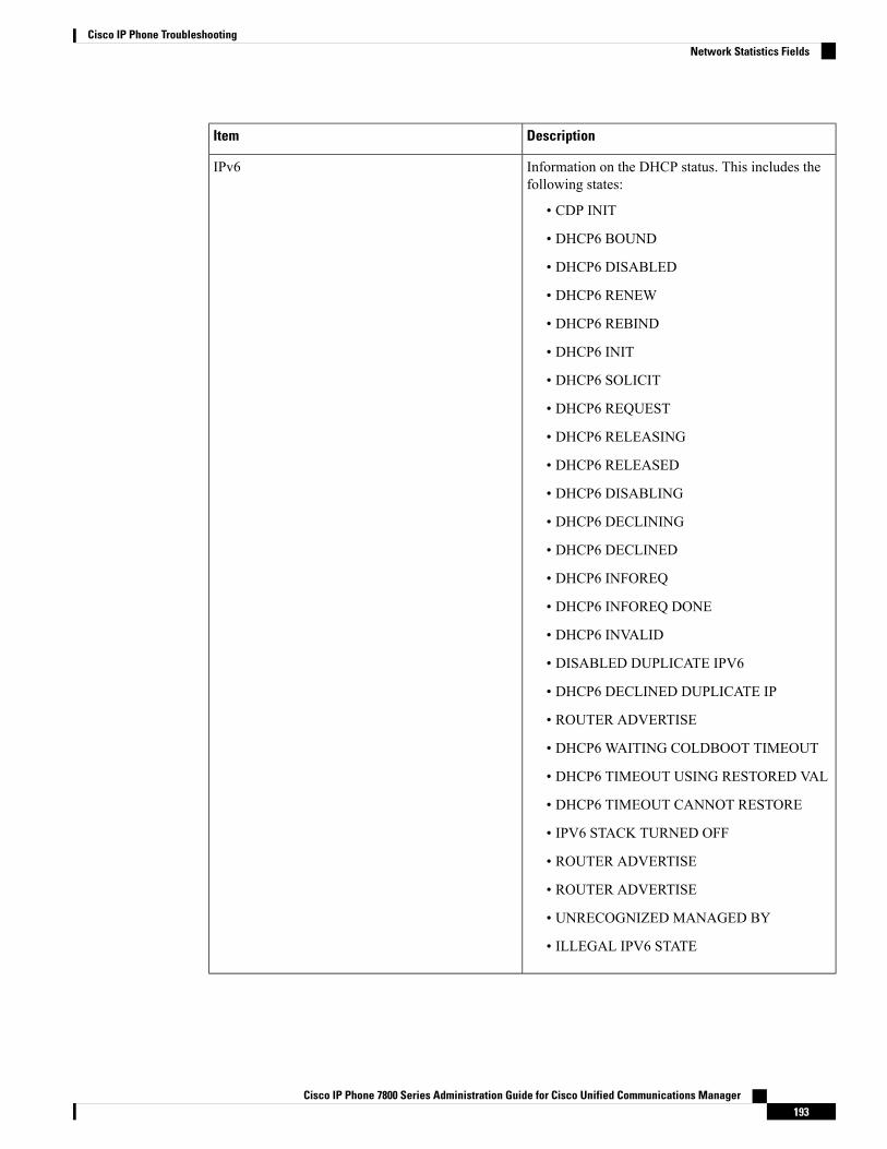
DescriptionItem
Information on the DHCP status. This includes thefollowing states:
• CDP INIT
• DHCP6 BOUND
• DHCP6 DISABLED
• DHCP6 RENEW
• DHCP6 REBIND
• DHCP6 INIT
• DHCP6 SOLICIT
• DHCP6 REQUEST
• DHCP6 RELEASING
• DHCP6 RELEASED
• DHCP6 DISABLING
• DHCP6 DECLINING
• DHCP6 DECLINED
• DHCP6 INFOREQ
• DHCP6 INFOREQ DONE
• DHCP6 INVALID
• DISABLED DUPLICATE IPV6
• DHCP6 DECLINED DUPLICATE IP
• ROUTER ADVERTISE
• DHCP6 WAITING COLDBOOT TIMEOUT
• DHCP6 TIMEOUT USING RESTORED VAL
• DHCP6 TIMEOUT CANNOT RESTORE
• IPV6 STACK TURNED OFF
• ROUTER ADVERTISE
• ROUTER ADVERTISE
• UNRECOGNIZED MANAGED BY
• ILLEGAL IPV6 STATE
IPv6
Cisco IP Phone 7800 Series Administration Guide for Cisco Unified Communications Manager193
Cisco IP Phone TroubleshootingNetwork Statistics Fields

Display Call Statistics WindowYou can access the Call Statistics screen on the phone to display counters, statistics, and voice-quality metricsof the most recent call.
You can also remotely view the call statistics information by using a web browser to access the StreamingStatistics web page. This web page contains additional RTCP statistics that are not available on the phone.
Note
A single call can use multiple voice streams, but data is captured for only the last voice stream. A voice streamis a packet stream between two endpoints. If one endpoint is put on hold, the voice stream stops even thoughthe call is still connected. When the call resumes, a new voice packet stream begins, and the new call dataoverwrites the former call data.
To display the Call Statistics screen for information about the latest voice stream, follow these steps:
Procedure
Step 1 Press Applications .Step 2 Select Admin Settings > Status > Call Statistics.
Step 3 To exit the Status menu, press Back .
Call Statistics Fields
The following table describes the items on the Call Statistics screen.
Table 29: Call Statistics Items for the Cisco IP Phone
DescriptionItem
Type of received voice stream (RTP streaming audiofrom codec):
• G.729
• G.722
• G722.2 AMR-WB
• G.711 mu-law
• G.711 A-law
• OPUS
• iLBC
Receiver Codec
Cisco IP Phone 7800 Series Administration Guide for Cisco Unified Communications Manager194
Cisco IP Phone TroubleshootingDisplay Call Statistics Window
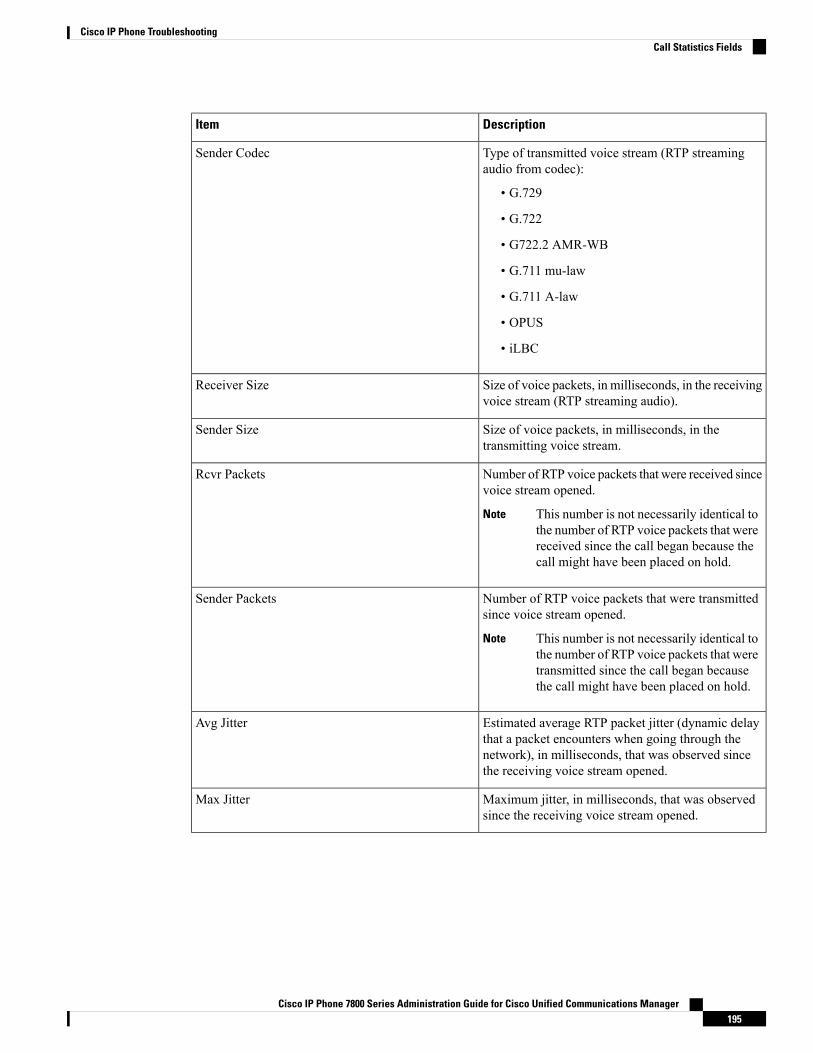
DescriptionItem
Type of transmitted voice stream (RTP streamingaudio from codec):
• G.729
• G.722
• G722.2 AMR-WB
• G.711 mu-law
• G.711 A-law
• OPUS
• iLBC
Sender Codec
Size of voice packets, in milliseconds, in the receivingvoice stream (RTP streaming audio).
Receiver Size
Size of voice packets, in milliseconds, in thetransmitting voice stream.
Sender Size
Number of RTP voice packets that were received sincevoice stream opened.
This number is not necessarily identical tothe number of RTP voice packets that werereceived since the call began because thecall might have been placed on hold.
Note
Rcvr Packets
Number of RTP voice packets that were transmittedsince voice stream opened.
This number is not necessarily identical tothe number of RTP voice packets that weretransmitted since the call began becausethe call might have been placed on hold.
Note
Sender Packets
Estimated average RTP packet jitter (dynamic delaythat a packet encounters when going through thenetwork), in milliseconds, that was observed sincethe receiving voice stream opened.
Avg Jitter
Maximum jitter, in milliseconds, that was observedsince the receiving voice stream opened.
Max Jitter
Cisco IP Phone 7800 Series Administration Guide for Cisco Unified Communications Manager195
Cisco IP Phone TroubleshootingCall Statistics Fields
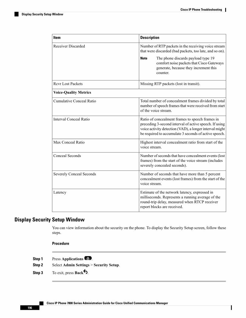
DescriptionItem
Number of RTP packets in the receiving voice streamthat were discarded (bad packets, too late, and so on).
The phone discards payload type 19comfort noise packets that Cisco Gatewaysgenerate, because they increment thiscounter.
Note
Receiver Discarded
Missing RTP packets (lost in transit).Rcvr Lost Packets
Voice-Quality Metrics
Total number of concealment frames divided by totalnumber of speech frames that were received from startof the voice stream.
Cumulative Conceal Ratio
Ratio of concealment frames to speech frames inpreceding 3-second interval of active speech. If usingvoice activity detection (VAD), a longer interval mightbe required to accumulate 3 seconds of active speech.
Interval Conceal Ratio
Highest interval concealment ratio from start of thevoice stream.
Max Conceal Ratio
Number of seconds that have concealment events (lostframes) from the start of the voice stream (includesseverely concealed seconds).
Conceal Seconds
Number of seconds that have more than 5 percentconcealment events (lost frames) from the start of thevoice stream.
Severely Conceal Seconds
Estimate of the network latency, expressed inmilliseconds. Represents a running average of theround-trip delay, measured when RTCP receiverreport blocks are received.
Latency
Display Security Setup WindowYou can view information about the security on the phone. To display the Security Setup screen, follow thesesteps.
Procedure
Step 1 Press Applications .Step 2 Select Admin Settings > Security Setup.
Step 3 To exit, press Back .
Cisco IP Phone 7800 Series Administration Guide for Cisco Unified Communications Manager196
Cisco IP Phone TroubleshootingDisplay Security Setup Window

Security Setup Fields
The Security Setup screen displays these items.
Table 30: Security Setup items
DescriptionItem
Displays the security mode that is set for the phone.Security Mode
Indicates whether a locally significant certificate (usedfor the security features) is installed on the phone oris not installed on the phone.
LSC
The Trust List is a top-level menu that providessubmenus for the CTL Signature and Callmanager/TFTP Server.
Trust List
Allows you to enable 802.1X authentication for thephone.
802.1x Authentication
Cisco IP Phone Web PageEach Cisco IP Phone has a web page from which you can view a variety of information about the phone,including:
• Device Information: Displays device settings and related information for the phone.
• Network Setup: Displays network setup information and information about other phone settings.
• Network Statistics: Displays hyperlinks that provide information about network traffic.
• Device Logs: Displays hyperlinks that provide information that you can use for troubleshooting.
• Streaming Statistic: Displays hyperlinks to a variety of streaming statistics.
This section describes the information that you can obtain from the phone web page. You can use thisinformation to remotely monitor the operation of a phone and to assist with troubleshooting.
You can also obtain much of this information directly from a phone.
Access the Phone Web Page
If you cannot access the web page, it may be disabled by default.Note
Procedure
Step 1 Obtain the IP address of the Cisco IP Phone by using one of these methods:
Cisco IP Phone 7800 Series Administration Guide for Cisco Unified Communications Manager197
Cisco IP Phone TroubleshootingSecurity Setup Fields
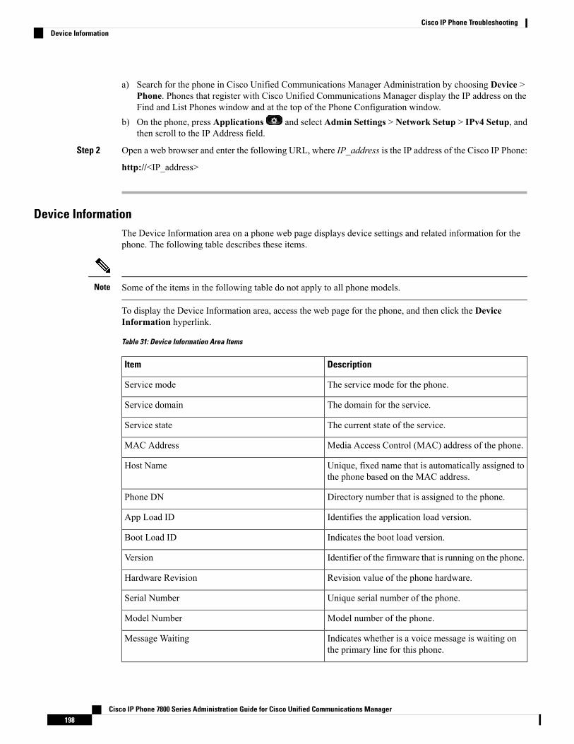
a) Search for the phone in Cisco Unified Communications Manager Administration by choosing Device >Phone. Phones that register with Cisco Unified Communications Manager display the IP address on theFind and List Phones window and at the top of the Phone Configuration window.
b) On the phone, press Applications and select Admin Settings > Network Setup > IPv4 Setup, andthen scroll to the IP Address field.
Step 2 Open a web browser and enter the following URL, where IP_address is the IP address of the Cisco IP Phone:
http://<IP_address>
Device InformationThe Device Information area on a phone web page displays device settings and related information for thephone. The following table describes these items.
Some of the items in the following table do not apply to all phone models.Note
To display the Device Information area, access the web page for the phone, and then click the DeviceInformation hyperlink.
Table 31: Device Information Area Items
DescriptionItem
The service mode for the phone.Service mode
The domain for the service.Service domain
The current state of the service.Service state
Media Access Control (MAC) address of the phone.MAC Address
Unique, fixed name that is automatically assigned tothe phone based on the MAC address.
Host Name
Directory number that is assigned to the phone.Phone DN
Identifies the application load version.App Load ID
Indicates the boot load version.Boot Load ID
Identifier of the firmware that is running on the phone.Version
Revision value of the phone hardware.Hardware Revision
Unique serial number of the phone.Serial Number
Model number of the phone.Model Number
Indicates whether is a voice message is waiting onthe primary line for this phone.
Message Waiting
Cisco IP Phone 7800 Series Administration Guide for Cisco Unified Communications Manager198
Cisco IP Phone TroubleshootingDevice Information

DescriptionItem
Displays the following CiscoUniqueDevice Identifier(UDI) information about the phone:
• Device Type: Indicates hardware type. Forexample, phone displays for all phone models.
• Device Description: Displays the name of thephone associated with the indicated model type.
• Product Identifier: Specifies the phone model.• Serial Number: Displays the unique serialnumber of the phone.
UDI
Time for the Date/Time Group to which the phonebelongs. This information comes from Cisco UnifiedCommunications Manager.
Time
Time zone for the Date/Time Group to which thephone belongs. This information comes from CiscoUnified Communications Manager.
Time Zone
Date for the Date/Time Group to which the phonebelongs. This information comes from Cisco UnifiedCommunications Manager.
Date
Amount of available system memory.System Free Memory
Amount of free memory for the Java heap.Java Heap Free Memory
Amount of free memory for the Java pool.Java Pool Free Memory
Indicates if the Federal Information processingStandard (FIPS) Mode is enabled.
FIPS Mode Enabled
Network SetupThe Network Setup area on a phone web page displays network setup information and information aboutother phone settings. The following table describes these items.
You can view and set many of these items from the Network Setup menu on the Cisco IP Phone.
To display the Network Setup area, access the web page for the phone, and then click the Network Setuphyperlink.
Table 32: Network Setup Area Items
DescriptionItem
Media Access Control (MAC) address of the phone.MAC Address
Host name that the DHCP server assigned to thephone.
Host Name
Cisco IP Phone 7800 Series Administration Guide for Cisco Unified Communications Manager199
Cisco IP Phone TroubleshootingNetwork Setup

DescriptionItem
Name of the Domain Name System (DNS) domainin which the phone resides.
Domain Name
IP address of the Dynamic Host ConfigurationProtocol (DHCP) server fromwhich the phone obtainsthe IP address.
DHCP Server
Indicates whether the phone obtains the configurationfrom a Bootstrap Protocol (BootP) server.
BOOTP Server
Indicates whether the phone uses DHCP.DHCP
Internet Protocol (IP) address of the phone.IP Address
Subnet mask that the phone uses.Subnet Mask
Default router used that the phone uses.Default Router 1
Primary Domain Name System (DNS) server (DNSServer 1) and optional backup DNS servers (DNSServer 2 and 3) that the phone uses.
DNS Server 1–3
Indicates whether the phone is using an alternativeTFTP server.
Alternate TFTP
Primary Trivial File Transfer Protocol (TFTP) serverused that the phone uses.
TFTP Server 1
Backup Trivial File Transfer Protocol (TFTP) serverused that the phone uses.
TFTP Server 2
Indicates the setting of the DHCP Address Releasedoption.
DHCP Address Released
Operational Virtual Local Area Network (VLAN) thatis configured on a Cisco Catalyst switch in which thephone is a member.
Operational VLAN ID
Auxiliary VLAN in which the phone is a member.Admin VLAN ID
Cisco IP Phone 7800 Series Administration Guide for Cisco Unified Communications Manager200
Cisco IP Phone TroubleshootingNetwork Setup
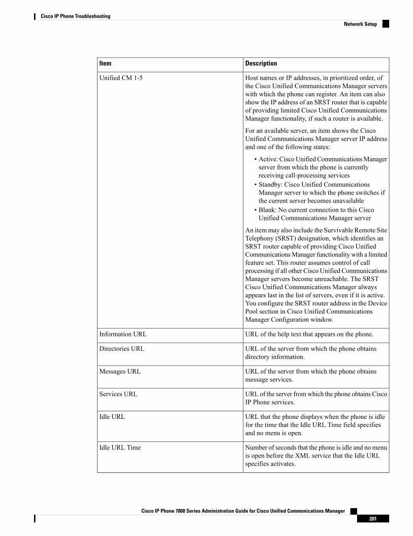
DescriptionItem
Host names or IP addresses, in prioritized order, ofthe Cisco Unified Communications Manager serverswith which the phone can register. An item can alsoshow the IP address of an SRST router that is capableof providing limited Cisco Unified CommunicationsManager functionality, if such a router is available.
For an available server, an item shows the CiscoUnified Communications Manager server IP addressand one of the following states:
• Active: CiscoUnified CommunicationsManagerserver from which the phone is currentlyreceiving call-processing services
• Standby: Cisco Unified CommunicationsManager server to which the phone switches ifthe current server becomes unavailable
• Blank: No current connection to this CiscoUnified Communications Manager server
An itemmay also include the Survivable Remote SiteTelephony (SRST) designation, which identifies anSRST router capable of providing Cisco UnifiedCommunicationsManager functionality with a limitedfeature set. This router assumes control of callprocessing if all other Cisco Unified CommunicationsManager servers become unreachable. The SRSTCisco Unified Communications Manager alwaysappears last in the list of servers, even if it is active.You configure the SRST router address in the DevicePool section in Cisco Unified CommunicationsManager Configuration window.
Unified CM 1-5
URL of the help text that appears on the phone.Information URL
URL of the server from which the phone obtainsdirectory information.
Directories URL
URL of the server from which the phone obtainsmessage services.
Messages URL
URL of the server fromwhich the phone obtains CiscoIP Phone services.
Services URL
URL that the phone displays when the phone is idlefor the time that the Idle URL Time field specifiesand no menu is open.
Idle URL
Number of seconds that the phone is idle and nomenuis open before the XML service that the Idle URLspecifies activates.
Idle URL Time
Cisco IP Phone 7800 Series Administration Guide for Cisco Unified Communications Manager201
Cisco IP Phone TroubleshootingNetwork Setup
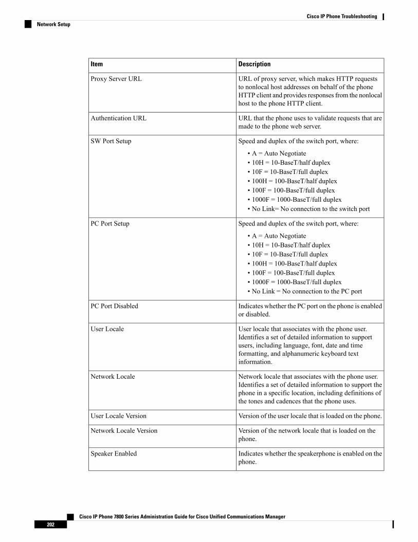
DescriptionItem
URL of proxy server, which makes HTTP requeststo nonlocal host addresses on behalf of the phoneHTTP client and provides responses from the nonlocalhost to the phone HTTP client.
Proxy Server URL
URL that the phone uses to validate requests that aremade to the phone web server.
Authentication URL
Speed and duplex of the switch port, where:
• A = Auto Negotiate• 10H = 10-BaseT/half duplex• 10F = 10-BaseT/full duplex• 100H = 100-BaseT/half duplex• 100F = 100-BaseT/full duplex• 1000F = 1000-BaseT/full duplex• No Link= No connection to the switch port
SW Port Setup
Speed and duplex of the switch port, where:
• A = Auto Negotiate• 10H = 10-BaseT/half duplex• 10F = 10-BaseT/full duplex• 100H = 100-BaseT/half duplex• 100F = 100-BaseT/full duplex• 1000F = 1000-BaseT/full duplex• No Link = No connection to the PC port
PC Port Setup
Indicates whether the PC port on the phone is enabledor disabled.
PC Port Disabled
User locale that associates with the phone user.Identifies a set of detailed information to supportusers, including language, font, date and timeformatting, and alphanumeric keyboard textinformation.
User Locale
Network locale that associates with the phone user.Identifies a set of detailed information to support thephone in a specific location, including definitions ofthe tones and cadences that the phone uses.
Network Locale
Version of the user locale that is loaded on the phone.User Locale Version
Version of the network locale that is loaded on thephone.
Network Locale Version
Indicates whether the speakerphone is enabled on thephone.
Speaker Enabled
Cisco IP Phone 7800 Series Administration Guide for Cisco Unified Communications Manager202
Cisco IP Phone TroubleshootingNetwork Setup

DescriptionItem
Indicates whether the group listen feature is enabledon the phone. Group listen enables you to talk usingthe handset and listen on the speaker at the same time.
Group Listen
Indicates whether the phone learns MAC addressesfrom Gratuitous ARP responses.
GARP Enabled
Indicates whether the phone forwards packets that aretransmitted and received on the network port to theaccess port.
Span to PC Port
Indicates whether the phone can participate in videocalls when it connects to an appropriately equippedcamera.
Video Capability Enabled
Indicates whether the phone allows a device that isattached to the PC port to access the Voice VLAN.
Voice VLAN Enabled
VLAN that identifies and removes 802.1P/Q tags frompackets that are sent to the PC.
PC VLAN
Indicates whether the phone shifts the call focus toincoming calls on all lines.
Auto Line Select Enabled
DSCP IP classification for call control signaling.DSCP for Call Control
DSCP IP classification for any phone configurationtransfer.
DSCP for Configuration
DSCP IP classification for phone-based services.DSCP for Services
Security mode that is set for the phone.Security Mode
Indicates whether web access is enabled (Yes) ordisabled (No) for the phone.
Web Access Enabled
Indicates whether the phone accepts or blocks theSSH connections.
SSH Access Enabled
Cisco IP Phone 7800 Series Administration Guide for Cisco Unified Communications Manager203
Cisco IP Phone TroubleshootingNetwork Setup

DescriptionItem
Indicates whether CDP support exists on the switchport (default is enabled).
Enable CDP on the switch port for VLAN assignmentfor the phone, power negotiation, QoS management,and 802.1x security.
Enable CDP on the switch port when the phoneconnects to a Cisco switch.
When CDP is disabled in Cisco UnifiedCommunications Manager, a warning is presented,indicating that CDP should be disabled on the switchport only if the phone connects to a non-Cisco switch.
The current PC and switch port CDP values are shownon the Settings menu.
CDP: SW Port
Indicates whether CDP is supported on the PC port(default is enabled).
When CDP is disabled in Cisco UnifiedCommunications Manager, a warning is displays toindicate that disabling CDP on the PC port preventsCVTA from working.
The current PC and switch port CDP values are shownin the Settings menu.
CDP: PC Port
Indicates whether Link Layer Discovery ProtocolMedia Endpoint Discovery (LLDP-MED) is enabledon the switch port.
LLDP-MED: SW Port
Indicates whether Link Layer Discovery Protocol(LLDP) is enabled on the PC port.
LLDP: PC Port
Advertises the phone power priority to the switch,thus enabling the switch to appropriately providepower to the phones. Settings include:
• Unknown: This is the default value.• Low• High• Critical
LLDP Power Priority
Identifies the asset ID that is assigned to the phonefor inventory management.
LLDP Asset ID
Identifies the CTL file.CTL File
The ITL file contains the initial trust list.ITL File
Enhances security by using the secure hash algorithm(SHA-1) in the CTL and ITL files.
ITL Signature
Cisco IP Phone 7800 Series Administration Guide for Cisco Unified Communications Manager204
Cisco IP Phone TroubleshootingNetwork Setup
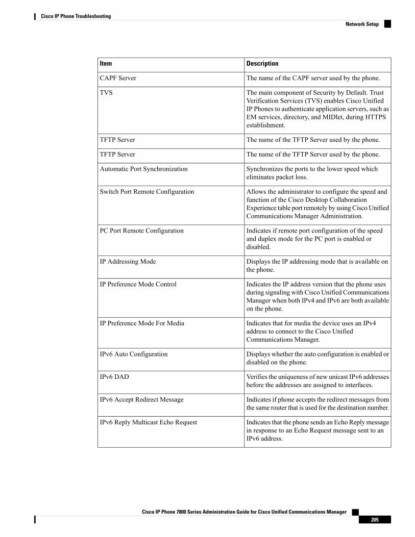
DescriptionItem
The name of the CAPF server used by the phone.CAPF Server
The main component of Security by Default. TrustVerification Services (TVS) enables Cisco UnifiedIP Phones to authenticate application servers, such asEM services, directory, and MIDlet, during HTTPSestablishment.
TVS
The name of the TFTP Server used by the phone.TFTP Server
The name of the TFTP Server used by the phone.TFTP Server
Synchronizes the ports to the lower speed whicheliminates packet loss.
Automatic Port Synchronization
Allows the administrator to configure the speed andfunction of the Cisco Desktop CollaborationExperience table port remotely by using Cisco UnifiedCommunications Manager Administration.
Switch Port Remote Configuration
Indicates if remote port configuration of the speedand duplex mode for the PC port is enabled ordisabled.
PC Port Remote Configuration
Displays the IP addressing mode that is available onthe phone.
IP Addressing Mode
Indicates the IP address version that the phone usesduring signaling with Cisco Unified CommunicationsManager when both IPv4 and IPv6 are both availableon the phone.
IP Preference Mode Control
Indicates that for media the device uses an IPv4address to connect to the Cisco UnifiedCommunications Manager.
IP Preference Mode For Media
Displays whether the auto configuration is enabled ordisabled on the phone.
IPv6 Auto Configuration
Verifies the uniqueness of new unicast IPv6 addressesbefore the addresses are assigned to interfaces.
IPv6 DAD
Indicates if phone accepts the redirect messages fromthe same router that is used for the destination number.
IPv6 Accept Redirect Message
Indicates that the phone sends an Echo Replymessagein response to an Echo Request message sent to anIPv6 address.
IPv6 Reply Multicast Echo Request
Cisco IP Phone 7800 Series Administration Guide for Cisco Unified Communications Manager205
Cisco IP Phone TroubleshootingNetwork Setup
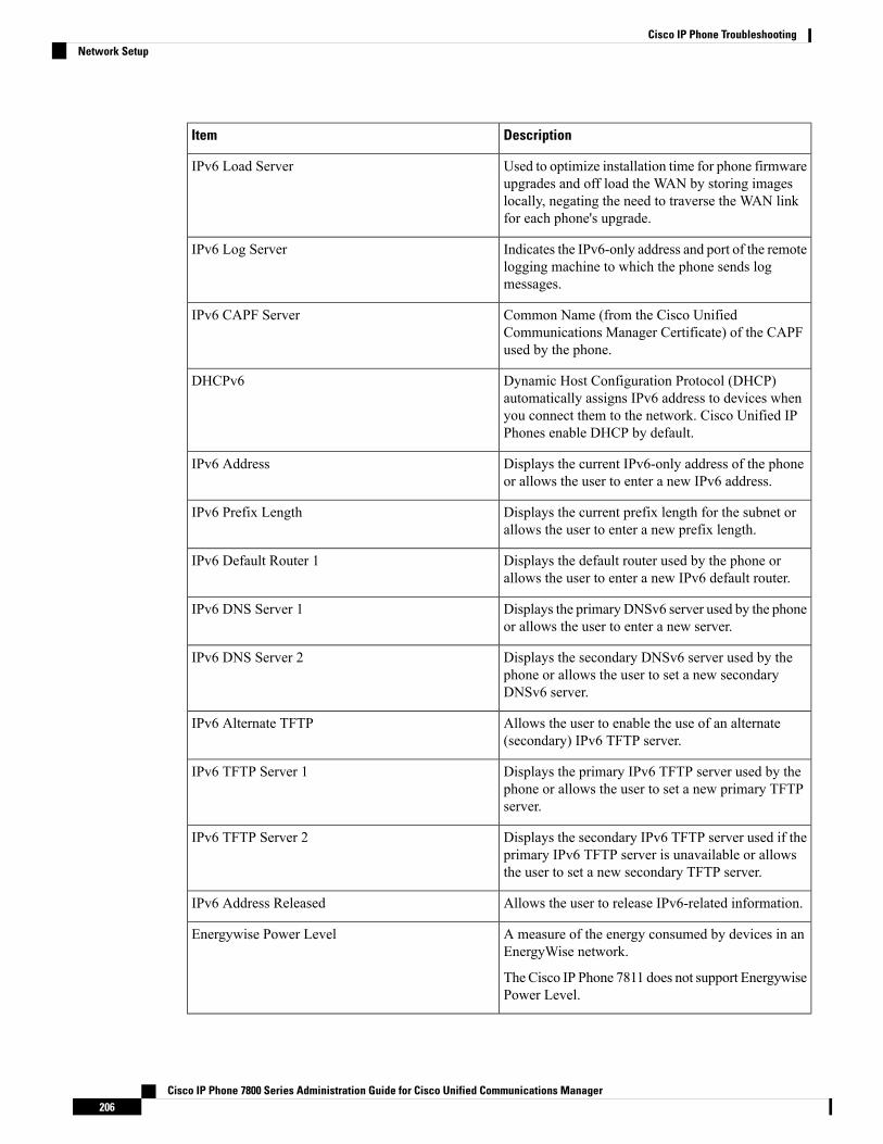
DescriptionItem
Used to optimize installation time for phone firmwareupgrades and off load the WAN by storing imageslocally, negating the need to traverse the WAN linkfor each phone's upgrade.
IPv6 Load Server
Indicates the IPv6-only address and port of the remotelogging machine to which the phone sends logmessages.
IPv6 Log Server
Common Name (from the Cisco UnifiedCommunications Manager Certificate) of the CAPFused by the phone.
IPv6 CAPF Server
Dynamic Host Configuration Protocol (DHCP)automatically assigns IPv6 address to devices whenyou connect them to the network. Cisco Unified IPPhones enable DHCP by default.
DHCPv6
Displays the current IPv6-only address of the phoneor allows the user to enter a new IPv6 address.
IPv6 Address
Displays the current prefix length for the subnet orallows the user to enter a new prefix length.
IPv6 Prefix Length
Displays the default router used by the phone orallows the user to enter a new IPv6 default router.
IPv6 Default Router 1
Displays the primary DNSv6 server used by the phoneor allows the user to enter a new server.
IPv6 DNS Server 1
Displays the secondary DNSv6 server used by thephone or allows the user to set a new secondaryDNSv6 server.
IPv6 DNS Server 2
Allows the user to enable the use of an alternate(secondary) IPv6 TFTP server.
IPv6 Alternate TFTP
Displays the primary IPv6 TFTP server used by thephone or allows the user to set a new primary TFTPserver.
IPv6 TFTP Server 1
Displays the secondary IPv6 TFTP server used if theprimary IPv6 TFTP server is unavailable or allowsthe user to set a new secondary TFTP server.
IPv6 TFTP Server 2
Allows the user to release IPv6-related information.IPv6 Address Released
A measure of the energy consumed by devices in anEnergyWise network.
The Cisco IP Phone 7811 does not support EnergywisePower Level.
Energywise Power Level
Cisco IP Phone 7800 Series Administration Guide for Cisco Unified Communications Manager206
Cisco IP Phone TroubleshootingNetwork Setup
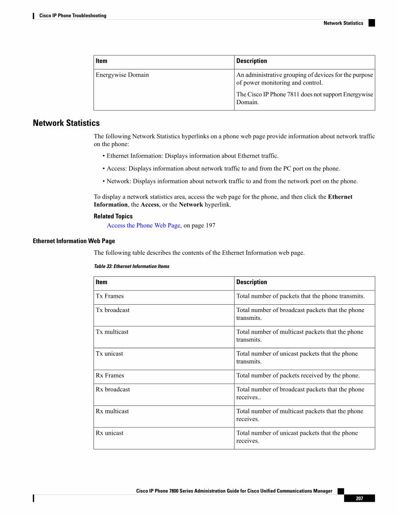
DescriptionItem
An administrative grouping of devices for the purposeof power monitoring and control.
The Cisco IP Phone 7811 does not support EnergywiseDomain.
Energywise Domain
Network StatisticsThe following Network Statistics hyperlinks on a phone web page provide information about network trafficon the phone:
• Ethernet Information: Displays information about Ethernet traffic.
• Access: Displays information about network traffic to and from the PC port on the phone.
• Network: Displays information about network traffic to and from the network port on the phone.
To display a network statistics area, access the web page for the phone, and then click the EthernetInformation, the Access, or the Network hyperlink.
Related TopicsAccess the Phone Web Page, on page 197
Ethernet Information Web Page
The following table describes the contents of the Ethernet Information web page.
Table 33: Ethernet Information Items
DescriptionItem
Total number of packets that the phone transmits.Tx Frames
Total number of broadcast packets that the phonetransmits.
Tx broadcast
Total number of multicast packets that the phonetransmits.
Tx multicast
Total number of unicast packets that the phonetransmits.
Tx unicast
Total number of packets received by the phone.Rx Frames
Total number of broadcast packets that the phonereceives..
Rx broadcast
Total number of multicast packets that the phonereceives.
Rx multicast
Total number of unicast packets that the phonereceives.
Rx unicast
Cisco IP Phone 7800 Series Administration Guide for Cisco Unified Communications Manager207
Cisco IP Phone TroubleshootingNetwork Statistics

DescriptionItem
Total number of shed packets that the no DirectMemory Access (DMA) descriptor causes.
Rx PacketNoDes
Access Area and Network Area Web Pages
The following table describes the information in the Access Area and Network Area web pages.
Table 34: Access Area and Network Area items
DescriptionItem
Total number of packets that the phone received.Rx totalPkt
Total number of packets that were received with CRCfailed.
Rx crcErr
Total number of packets between 64 and 1522 bytesin length that were received and that have a bad FrameCheck Sequence (FCS).
Rx alignErr
Total number of multicast packets that the phonereceived.
Rx multicast
Total number of broadcast packets that the phonereceived.
Rx broadcast
Total number of unicast packets that the phonereceived.
Rx unicast
Total number of received FCS error packets or Alignerror packets that are less than 64 bytes in size.
Rx shortErr
Total number of received good packets that are lessthan 64 bytes size.
Rx shortGood
Total number of received good packets that are greaterthan 1522 bytes in size.
Rx longGood
Total number of received FCS error packets or Alignerror packets that are greater than 1522 bytes in size.
Rx longErr
Total number of received packets, including badpackets, that are between 0 and 64 bytes in size.
Rx size64
Total number of received packets, including badpackets, that are between 65 and 127 bytes in size.
Rx size65to127
Total number of received packets, including badpackets, that are between 128 and 255 bytes in size.
Rx size128to255
Total number of received packets, including badpackets, that are between 256 and 511 bytes in size.
Rx size256to511
Cisco IP Phone 7800 Series Administration Guide for Cisco Unified Communications Manager208
Cisco IP Phone TroubleshootingAccess Area and Network Area Web Pages

DescriptionItem
Total number of received packets, including badpackets, that are between 512 and 1023 bytes in size.
Rx size512to1023
Total number of received packets, including badpackets, that are between 1024 and 1518 bytes in size.
Rx size1024to1518
Total number of packets that were dropped due tolack of resources (for example, FIFO overflow).
Rx tokenDrop
Total number of packets that were delayed fromtransmitting due to busy medium.
Tx excessDefer
Number of times that collisions occurred later than512 bit times after the start of packet transmission.
Tx lateCollision
Total number of good packets (multicast, broadcast,and unicast) that the phone received.
Tx totalGoodPkt
Total number of collisions that occurred while apacket was transmitted.
Tx Collisions
Total number of packets that were not transmittedbecause the packet experienced 16 transmissionattempts.
Tx excessLength
Total number of broadcast packets that the phonetransmitted.
Tx broadcast
Total number of multicast packets that the phonetransmitted.
Tx multicast
Total number of LLDP frames that the phone sent out.LLDP FramesOutTotal
Total number of LLDP frames that timed out in thecache.
LLDP AgeoutsTotal
Total number of LLDP frames that were discardedwhen any of the mandatory TLVs is missing, out oforder, or contains out of range string length.
LLDP FramesDiscardedTotal
Total number of LLDP frames that were received withone or more detectable errors.
LLDP FramesInErrorsTotal
Total number of LLDP frames that the phone receives.LLDP FramesInTotal
Total number of LLDP TLVs that are discarded.LLDP TLVDiscardedTotal
Total number of LLDP TLVs that are not recognizedon the phone.
LLDP TLVUnrecognizedTotal
Identifier of a device connected to this port that CDPdiscovered.
CDP Neighbor Device ID
Cisco IP Phone 7800 Series Administration Guide for Cisco Unified Communications Manager209
Cisco IP Phone TroubleshootingAccess Area and Network Area Web Pages
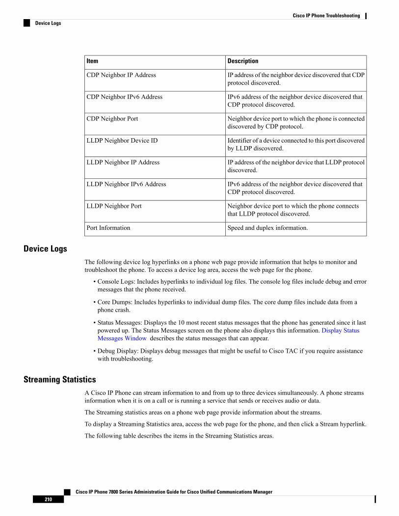
DescriptionItem
IP address of the neighbor device discovered that CDPprotocol discovered.
CDP Neighbor IP Address
IPv6 address of the neighbor device discovered thatCDP protocol discovered.
CDP Neighbor IPv6 Address
Neighbor device port to which the phone is connecteddiscovered by CDP protocol.
CDP Neighbor Port
Identifier of a device connected to this port discoveredby LLDP discovered.
LLDP Neighbor Device ID
IP address of the neighbor device that LLDP protocoldiscovered.
LLDP Neighbor IP Address
IPv6 address of the neighbor device discovered thatCDP protocol discovered.
LLDP Neighbor IPv6 Address
Neighbor device port to which the phone connectsthat LLDP protocol discovered.
LLDP Neighbor Port
Speed and duplex information.Port Information
Device LogsThe following device log hyperlinks on a phone web page provide information that helps to monitor andtroubleshoot the phone. To access a device log area, access the web page for the phone.
• Console Logs: Includes hyperlinks to individual log files. The console log files include debug and errormessages that the phone received.
• Core Dumps: Includes hyperlinks to individual dump files. The core dump files include data from aphone crash.
• Status Messages: Displays the 10 most recent status messages that the phone has generated since it lastpowered up. The Status Messages screen on the phone also displays this information. Display StatusMessages Window describes the status messages that can appear.
• Debug Display: Displays debug messages that might be useful to Cisco TAC if you require assistancewith troubleshooting.
Streaming StatisticsA Cisco IP Phone can stream information to and from up to three devices simultaneously. A phone streamsinformation when it is on a call or is running a service that sends or receives audio or data.
The Streaming statistics areas on a phone web page provide information about the streams.
To display a Streaming Statistics area, access the web page for the phone, and then click a Stream hyperlink.
The following table describes the items in the Streaming Statistics areas.
Cisco IP Phone 7800 Series Administration Guide for Cisco Unified Communications Manager210
Cisco IP Phone TroubleshootingDevice Logs
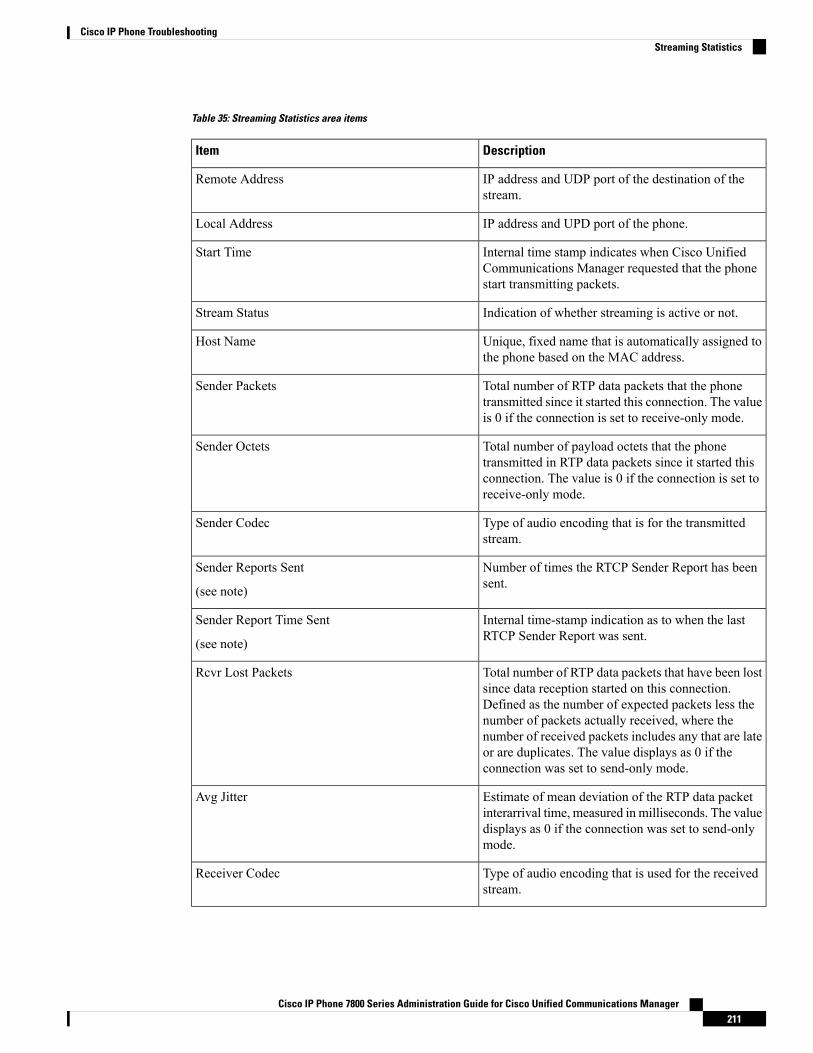
Table 35: Streaming Statistics area items
DescriptionItem
IP address and UDP port of the destination of thestream.
Remote Address
IP address and UPD port of the phone.Local Address
Internal time stamp indicates when Cisco UnifiedCommunications Manager requested that the phonestart transmitting packets.
Start Time
Indication of whether streaming is active or not.Stream Status
Unique, fixed name that is automatically assigned tothe phone based on the MAC address.
Host Name
Total number of RTP data packets that the phonetransmitted since it started this connection. The valueis 0 if the connection is set to receive-only mode.
Sender Packets
Total number of payload octets that the phonetransmitted in RTP data packets since it started thisconnection. The value is 0 if the connection is set toreceive-only mode.
Sender Octets
Type of audio encoding that is for the transmittedstream.
Sender Codec
Number of times the RTCP Sender Report has beensent.
Sender Reports Sent
(see note)
Internal time-stamp indication as to when the lastRTCP Sender Report was sent.
Sender Report Time Sent
(see note)
Total number of RTP data packets that have been lostsince data reception started on this connection.Defined as the number of expected packets less thenumber of packets actually received, where thenumber of received packets includes any that are lateor are duplicates. The value displays as 0 if theconnection was set to send-only mode.
Rcvr Lost Packets
Estimate of mean deviation of the RTP data packetinterarrival time, measured in milliseconds. The valuedisplays as 0 if the connection was set to send-onlymode.
Avg Jitter
Type of audio encoding that is used for the receivedstream.
Receiver Codec
Cisco IP Phone 7800 Series Administration Guide for Cisco Unified Communications Manager211
Cisco IP Phone TroubleshootingStreaming Statistics

DescriptionItem
Number of times the RTCP Receiver Reports havebeen sent.
Receiver Reports Sent
(see note)
Internal time-stamp indication as to when a RTCPReceiver Report was sent.
Receiver Report Time Sent
(see note)
Total number of RTP data packets that the phone hasreceived since data reception started on thisconnection. Includes packets that were received fromdifferent sources if this call is a multicast call. Thevalue displays as 0 if the connection was set tosend-only mode.
Rcvr Packets
Total number of payload octets that the devicereceived in RTP data packets since reception startedon the connection. Includes packets that were receivedfrom different sources if this call is a multicast call.The value displays as 0 if the connection was set tosend-only mode.
Rcvr Octets
Total number of concealment frames divided by totalnumber of speech frames that were received from thestart of the voice stream.
Cumulative Conceal Ratio
Ratio of concealment frames to speech frames in thepreceding 3-second interval of active speech. If voiceactivity detection (VAD) is in use, a longer intervalmight be required to accumulate three seconds ofactive speech.
Interval Conceal Ratio
Highest interval concealment ratio from the start ofthe voice stream.
Max Conceal Ratio
Number of seconds that have concealment events (lostframes) from the start of the voice stream (includesseverely concealed seconds).
Conceal Seconds
Number of seconds that have more than five percentconcealment events (lost frames) from the start of thevoice stream.
Severely Conceal Seconds
Estimate of the network latency, expressed inmilliseconds. Represents a running average of theround-trip delay, measured when RTCP receiverreport blocks are received.
Latency
(see note)
Maximum value of instantaneous jitter, inmilliseconds.
Max Jitter
Cisco IP Phone 7800 Series Administration Guide for Cisco Unified Communications Manager212
Cisco IP Phone TroubleshootingStreaming Statistics
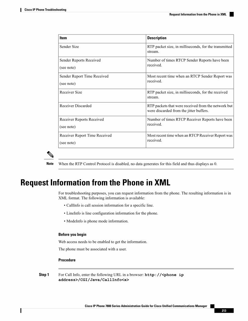
DescriptionItem
RTP packet size, in milliseconds, for the transmittedstream.
Sender Size
Number of times RTCP Sender Reports have beenreceived.
Sender Reports Received
(see note)
Most recent time when an RTCP Sender Report wasreceived.
Sender Report Time Received
(see note)
RTP packet size, in milliseconds, for the receivedstream.
Receiver Size
RTP packets that were received from the network butwere discarded from the jitter buffers.
Receiver Discarded
Number of times RTCP Receiver Reports have beenreceived.
Receiver Reports Received
(see note)
Most recent time when an RTCPReceiver Report wasreceived.
Receiver Report Time Received
(see note)
When the RTP Control Protocol is disabled, no data generates for this field and thus displays as 0.Note
Request Information from the Phone in XMLFor troubleshooting purposes, you can request information from the phone. The resulting information is inXML format. The following information is available:
• CallInfo is call session information for a specific line.
• LineInfo is line configuration information for the phone.
• ModeInfo is phone mode information.
Before you begin
Web access needs to be enabled to get the information.
The phone must be associated with a user.
Procedure
Step 1 For Call Info, enter the following URL in a browser: http://<phone ipaddress>/CGI/Java/CallInfo<x>
Cisco IP Phone 7800 Series Administration Guide for Cisco Unified Communications Manager213
Cisco IP Phone TroubleshootingRequest Information from the Phone in XML
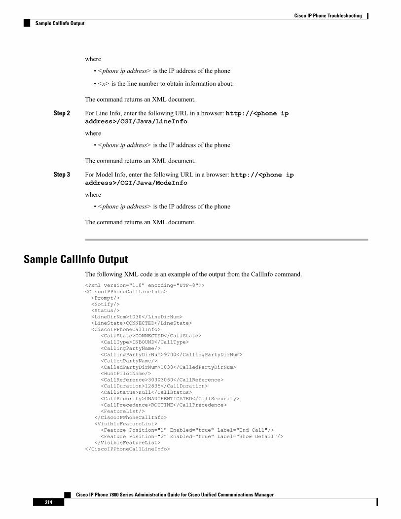
where
• <phone ip address> is the IP address of the phone
• <x> is the line number to obtain information about.
The command returns an XML document.
Step 2 For Line Info, enter the following URL in a browser: http://<phone ipaddress>/CGI/Java/LineInfo
where
• <phone ip address> is the IP address of the phone
The command returns an XML document.
Step 3 For Model Info, enter the following URL in a browser: http://<phone ipaddress>/CGI/Java/ModeInfo
where
• <phone ip address> is the IP address of the phone
The command returns an XML document.
Sample CallInfo OutputThe following XML code is an example of the output from the CallInfo command.<?xml version="1.0" encoding="UTF-8"?><CiscoIPPhoneCallLineInfo><Prompt/><Notify/><Status/><LineDirNum>1030</LineDirNum><LineState>CONNECTED</LineState><CiscoIPPhoneCallInfo>
<CallState>CONNECTED</CallState><CallType>INBOUND</CallType><CallingPartyName/><CallingPartyDirNum>9700</CallingPartyDirNum><CalledPartyName/><CalledPartyDirNum>1030</CalledPartyDirNum><HuntPilotName/><CallReference>30303060</CallReference><CallDuration>12835</CallDuration><CallStatus>null</CallStatus><CallSecurity>UNAUTHENTICATED</CallSecurity><CallPrecedence>ROUTINE</CallPrecedence><FeatureList/>
</CiscoIPPhoneCallInfo><VisibleFeatureList><Feature Position="1" Enabled="true" Label="End Call"/><Feature Position="2" Enabled="true" Label="Show Detail"/>
</VisibleFeatureList></CiscoIPPhoneCallLineInfo>
Cisco IP Phone 7800 Series Administration Guide for Cisco Unified Communications Manager214
Cisco IP Phone TroubleshootingSample CallInfo Output
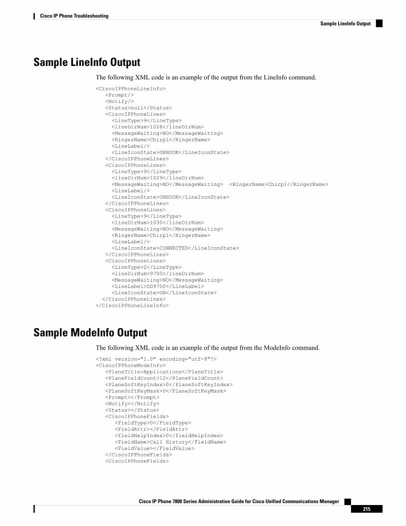
Sample LineInfo OutputThe following XML code is an example of the output from the LineInfo command.<CiscoIPPhoneLineInfo>
<Prompt/><Notify/><Status>null</Status><CiscoIPPhoneLines><LineType>9</LineType><lineDirNum>1028</lineDirNum><MessageWaiting>NO</MessageWaiting><RingerName>Chirp1</RingerName><LineLabel/><LineIconState>ONHOOK</LineIconState>
</CiscoIPPhoneLines><CiscoIPPhoneLines><LineType>9</LineType><lineDirNum>1029</lineDirNum><MessageWaiting>NO</MessageWaiting> <RingerName>Chirp1</RingerName><LineLabel/><LineIconState>ONHOOK</LineIconState>
</CiscoIPPhoneLines><CiscoIPPhoneLines><LineType>9</LineType><lineDirNum>1030</lineDirNum><MessageWaiting>NO</MessageWaiting><RingerName>Chirp1</RingerName><LineLabel/><LineIconState>CONNECTED</LineIconState>
</CiscoIPPhoneLines><CiscoIPPhoneLines><LineType>2</LineType><lineDirNum>9700</lineDirNum><MessageWaiting>NO</MessageWaiting><LineLabel>SD9700</LineLabel><LineIconState>ON</LineIconState>
</CiscoIPPhoneLines></CiscoIPPhoneLineInfo>
Sample ModeInfo OutputThe following XML code is an example of the output from the ModeInfo command.<?xml version="1.0" encoding="utf-8"?><CiscoIPPhoneModeInfo>
<PlaneTitle>Applications</PlaneTitle><PlaneFieldCount>12</PlaneFieldCount><PlaneSoftKeyIndex>0</PlaneSoftKeyIndex><PlaneSoftKeyMask>0</PlaneSoftKeyMask><Prompt></Prompt><Notify></Notify><Status></Status><CiscoIPPhoneFields>
<FieldType>0</FieldType><FieldAttr></FieldAttr><fieldHelpIndex>0</fieldHelpIndex><FieldName>Call History</FieldName><FieldValue></FieldValue>
</CiscoIPPhoneFields><CiscoIPPhoneFields>
Cisco IP Phone 7800 Series Administration Guide for Cisco Unified Communications Manager215
Cisco IP Phone TroubleshootingSample LineInfo Output

<FieldType>0</FieldType><FieldAttr></FieldAttr><fieldHelpIndex>0</fieldHelpIndex><FieldName>Preferences</FieldName><FieldValue></FieldValue>
</CiscoIPPhoneFields>...
</CiscoIPPhoneModeInfo>
Cisco IP Phone 7800 Series Administration Guide for Cisco Unified Communications Manager216
Cisco IP Phone TroubleshootingSample ModeInfo Output
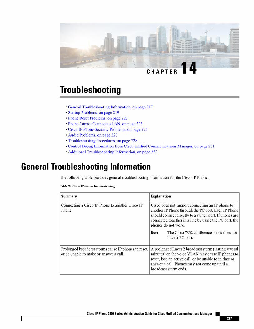
C H A P T E R 14Troubleshooting
• General Troubleshooting Information, on page 217• Startup Problems, on page 219• Phone Reset Problems, on page 223• Phone Cannot Connect to LAN, on page 225• Cisco IP Phone Security Problems, on page 225• Audio Problems, on page 227• Troubleshooting Procedures, on page 228• Control Debug Information from Cisco Unified Communications Manager, on page 231• Additional Troubleshooting Information, on page 233
General Troubleshooting InformationThe following table provides general troubleshooting information for the Cisco IP Phone.
Table 36: Cisco IP Phone Troubleshooting
ExplanationSummary
Cisco does not support connecting an IP phone toanother IP Phone through the PC port. Each IP Phoneshould connect directly to a switch port. If phones areconnected together in a line by using the PC port, thephones do not work.
The Cisco 7832 conference phone does nothave a PC port.
Note
Connecting a Cisco IP Phone to another Cisco IPPhone
A prolonged Layer 2 broadcast storm (lasting severalminutes) on the voice VLANmay cause IP phones toreset, lose an active call, or be unable to initiate oranswer a call. Phones may not come up until abroadcast storm ends.
Prolonged broadcast storms cause IP phones to reset,or be unable to make or answer a call
Cisco IP Phone 7800 Series Administration Guide for Cisco Unified Communications Manager217

ExplanationSummary
If you power your phone through the networkconnection, you must be careful if you decide tounplug the network connection of the phone and plugthe cable into a desktop computer.
The network card in the computer cannotreceive power through the networkconnection; if power comes through theconnection, the network card can bedestroyed. To protect a network card, wait10 seconds or longer after unplugging thecable from the phone before plugging itinto a computer. This delay gives theswitch enough time to recognize that thereis no longer a phone on the line and to stopproviding power to the cable.
Caution
Moving a network connection from the phone to aworkstation
By default, the administrator password settings arelocked to prevent users from making changes thatcould impact their network connectivity. You mustunlock the administrator password settings before youcan configure them.
See Apply a Phone Password, on page 38 for details.
If the administrator password is not set incommon phone profile, then user canmodify the network settings.
Note
Changing the telephone configuration
The RxType and the TxType statistics show the codecthat is used for a conversation between this Cisco IPPhone and the other device. The values of thesestatistics should match. If they do not, verify that theother device can handle the codec conversation, orthat a transcoder is in place to handle the service. SeeDisplay Call Statistics Window, on page 194 fordetails.
Codec mismatch between the phone and anotherdevice
The RxSize and the TxSize statistics show the size ofthe voice packets that are used in a conversationbetween this Cisco IP Phone and the other device.The values of these statistics should match. SeeDisplay Call Statistics Window, on page 194 fordetails.
Sound sample mismatch between the phone andanother device
Cisco IP Phone 7800 Series Administration Guide for Cisco Unified Communications Manager218
Cisco IP Phone TroubleshootingGeneral Troubleshooting Information

ExplanationSummary
A loopback condition can occur when the followingconditions are met:
• The SW Port Configuration option on the phoneis set to 10 Half (10-BaseT/half duplex).
• The phone receives power from an externalpower supply.
• The phone is powered down (the power supplyis disconnected).
In this case, the switch port on the phone can becomedisabled and the following message appears in theswitch console log:
HALF_DUX_COLLISION_EXCEED_THRESHOLD
To resolve this problem, reenable the port from theswitch.
Loopback condition
Startup ProblemsAfter you install a phone into your network and add it to Cisco Unified Communications Manager, the phoneshould start up as described in the related topic below.
If the phone does not start up properly, see the following sections for troubleshooting information.
Related TopicsVerify Phone Startup, on page 51
Cisco IP Phone Does Not Go Through the Normal Startup Process
Problem
When you connect a Cisco IP Phone to the network port, the phone does not go through the normal startupprocess as described in the related topic and the phone screen does not display information.
Cause
If the phone does not go through the startup process, the cause may be faulty cables, bad connections, networkoutages, lack of power, or the phone may not be functional.
Solution
To determine whether the phone is functional, use the following suggestions to eliminate other potentialproblems.
• Verify that the network port is functional:
• Exchange the Ethernet cables with cables that you know are functional.
Cisco IP Phone 7800 Series Administration Guide for Cisco Unified Communications Manager219
Cisco IP Phone TroubleshootingStartup Problems

• Disconnect a functioning Cisco IP Phone from another port and connect it to this network port toverify that the port is active.
• Connect the Cisco IP Phone that does not start up to a different network port that is known to begood.
• Connect the Cisco IP Phone that does not start up directly to the port on the switch, eliminating thepatch panel connection in the office.
• Verify that the phone is receiving power:
• If you are using external power, verify that the electrical outlet is functional.
• If you are using in-line power, use the external power supply instead.
• If you are using the external power supply, switch with a unit that you know to be functional.
• If the phone still does not start up properly, power up the phone by pressing #*2. When the phone ispowered up in this way, it attempts to launch a backup software image.
• If the phone still does not start up properly, perform a factory reset of the phone.
• After you attempt these solutions, if the phone screen on the Cisco IP Phone does not display any charactersafter at least five minutes, contact a Cisco technical support representative for additional assistance.
Related TopicsVerify Phone Startup, on page 51
CiscoIPPhoneDoesNotRegisterwithCiscoUnifiedCommunicationsManagerIf the phone proceeds past the first stage of the startup process (LED buttons flashing on and off) but continuesto cycle through the messages that displays on the phone screen, the phone is not starting up properly. Thephone cannot successfully start up unless it connects to the Ethernet network and it registers with a CiscoUnified Communications Manager server.
In addition, problems with security may prevent the phone from starting up properly. See TroubleshootingProcedures, on page 228 for more information.
Phone Displays Error Messages
Problem
Status messages display errors during startup.
Solution
While the phone cycles through the startup process, you can access status messages that might provide youwith information about the cause of a problem. See the “Display Status Messages Window” section forinstructions about accessing status messages and for a list of potential errors, their explanations, and theirsolutions.
Related TopicsDisplay Status Messages Window , on page 184
Cisco IP Phone 7800 Series Administration Guide for Cisco Unified Communications Manager220
Cisco IP Phone TroubleshootingCisco IP Phone Does Not Register with Cisco Unified Communications Manager

Phone Cannot Connect to TFTP Server or to Cisco Unified Communications Manager
Problem
If the network is down between the phone and either the TFTP server or Cisco Unified CommunicationsManager, the phone cannot start up properly.
Solution
Ensure that the network is currently running.
Phone Cannot Connect to TFTP Server
Problem
The TFTP server settings may not be correct.
Solution
Check the TFTP settings.
Related TopicsCheck TFTP Settings, on page 228
Phone Cannot Connect to Server
Problem
The IP addressing and routing fields may not be configured correctly.
Solution
You should verify the IP addressing and routing settings on the phone. If you are using DHCP, the DHCPserver should provide these values. If you have assigned a static IP address to the phone, you must enter thesevalues manually.
Related TopicsCheck DHCP Settings, on page 229
Phone Cannot Connect Using DNS
Problem
The DNS settings may be incorrect.
Solution
If you use DNS to access the TFTP server or Cisco Unified Communications Manager, you must ensure thatyou specify a DNS server.
Related TopicsVerify DNS Settings, on page 231
Cisco IP Phone 7800 Series Administration Guide for Cisco Unified Communications Manager221
Cisco IP Phone TroubleshootingPhone Cannot Connect to TFTP Server or to Cisco Unified Communications Manager

Cisco Unified Communications Manager and TFTP Services Are Not Running
Problem
If the Cisco Unified Communications Manager or TFTP services are not running, phones may not be able tostart up properly. In such a situation, it is likely that you are experiencing a systemwide failure, and otherphones and devices are unable to start up properly.
Solution
If the Cisco Unified Communications Manager service is not running, all devices on the network that rely onit to make phone calls are affected. If the TFTP service is not running, many devices cannot start up successfully.For more information, see Start Service, on page 231.
Configuration File Corruption
Problem
If you continue to have problems with a particular phone that other suggestions in this chapter do not resolve,the configuration file may be corrupted.
Solution
Create a new phone configuration file.
Cisco Unified Communications Manager Phone Registration
Problem
The phone is not registered with the Cisco Unified Communications Manager
Solution
A Cisco IP Phone can register with a Cisco Unified Communications Manager server only if the phone isadded to the server or if autoregistration is enabled. Review the information and procedures in Phone AdditionMethods, on page 58 to ensure that the phone is added to the Cisco Unified Communications Managerdatabase.
To verify that the phone is in the Cisco Unified Communications Manager database, choose Device > Phonefrom Cisco Unified Communications Manager Administration. Click Find to search for the phone based ontheMACAddress. For information about determining aMAC address, see Determine the PhoneMACAddress,on page 58.
If the phone is already in the Cisco Unified Communications Manager database, the configuration file maybe damaged. See Configuration File Corruption, on page 222 for assistance.
Cisco IP Phone 7800 Series Administration Guide for Cisco Unified Communications Manager222
Cisco IP Phone TroubleshootingCisco Unified Communications Manager and TFTP Services Are Not Running
Cisco IP Phone Cannot Obtain IP Address
Problem
If a phone cannot obtain an IP address when it starts up, the phone may not be on the same network or VLANas the DHCP server, or the switch port to which the phone connects may be disabled.
Solution
Ensure that the network or VLAN to which the phone connects has access to the DHCP server, and ensurethat the switch port is enabled.
Phone Reset ProblemsIf users report that their phones are resetting during calls or while the phones are idle, you should investigatethe cause. If the network connection and Cisco Unified Communications Manager connection are stable, aphone should not reset.
Typically, a phone resets if it has problems in connecting to the network or to Cisco Unified CommunicationsManager.
Phone Resets Due to Intermittent Network Outages
Problem
Your network may be experiencing intermittent outages.
Solution
Intermittent network outages affect data and voice traffic differently. Your network might be experiencingintermittent outages without detection. If so, data traffic can resend lost packets and verify that packets arereceived and transmitted. However, voice traffic cannot recapture lost packets. Rather than retransmitting alost network connection, the phone resets and attempts to reconnect to the network. Contact the systemadministrator for information on known problems in the voice network.
Phone Resets Due to DHCP Setting Errors
Problem
The DHCP settings may be incorrect.
Solution
Verify that you have properly configured the phone to use DHCP. Verify that the DHCP server is set upproperly. Verify the DHCP lease duration. We recommend that you set the lease duration to 8 days.
Related TopicsCheck DHCP Settings, on page 229
Cisco IP Phone 7800 Series Administration Guide for Cisco Unified Communications Manager223
Cisco IP Phone TroubleshootingCisco IP Phone Cannot Obtain IP Address

Phone Resets Due to Incorrect Static IP Address
Problem
The static IP address assigned to the phone may be incorrect.
Solution
If the phone is assigned a static IP address, verify that you have entered the correct settings.
Phone Resets During Heavy Network Usage
Problem
If the phone appears to reset during heavy network usage, it is likely that you do not have a voice VLANconfigured.
Solution
Isolating the phones on a separate auxiliary VLAN increases the quality of the voice traffic.
Phone Resets Due to Intentional Reset
Problem
If you are not the only administrator with access to Cisco Unified Communications Manager, you shouldverify that no one else has intentionally reset the phones.
Solution
You can check if a Cisco IP Phone received a command from Cisco Unified Communications Manager toreset by pressing Applications on the phone and choosing Admin Settings > Status > Network Statistics.
• If the Restart Cause field displays Reset-Reset, the phone receives a Reset/Reset from Cisco UnifiedCommunications Manager Administration.
• If the Restart Cause field displaysReset-Restart, the phone closed because it received a Reset/Restartfrom Cisco Unified Communications Manager Administration.
Phone Resets Due to DNS or Other Connectivity Issues
Problem
The phone reset continues and you suspect DNS or other connectivity issues.
Solution
If the phone continues to reset, eliminate DNS or other connectivity errors by following the procedure inDetermine DNS or Connectivity Issues, on page 229.
Cisco IP Phone 7800 Series Administration Guide for Cisco Unified Communications Manager224
Cisco IP Phone TroubleshootingPhone Resets Due to Incorrect Static IP Address
Phone Does Not Power Up
Problem
The phone does not appear to be powered up.
Solution
In most cases, a phone restarts if it powers up by using external power but loses that connection and switchesto PoE. Similarly, a phone may restart if it powers up by using PoE and then connects to an external powersupply.
Phone Cannot Connect to LANProblem
The physical connection to the LAN may be broken.
Solution
Verify that the Ethernet connection to which the Cisco IP Phone connects is up. For example, check whetherthe particular port or switch to which the phone connects is down and that the switch is not rebooting. Alsoensure that no cable breaks exist.
Cisco IP Phone Security ProblemsThe following sections provide troubleshooting information for the security features on the Cisco IP Phone.For information about the solutions for any of these issues, and for additional troubleshooting informationabout security, see Cisco Unified Communications Manager Security Guide.
CTL File ProblemsThe following sections describe troubleshooting problems with the CTL file.
Authentication Error, Phone Cannot Authenticate CTL File
Problem
A device authentication error occurs.
Cause
CTL file does not have a Cisco Unified Communications Manager certificate or has an incorrect certificate.
Solution
Install a correct certificate.
Cisco IP Phone 7800 Series Administration Guide for Cisco Unified Communications Manager225
Cisco IP Phone TroubleshootingPhone Does Not Power Up

Phone Cannot Authenticate CTL File
Problem
Phone cannot authenticate the CTL file.
Cause
The security token that signed the updated CTL file does not exist in the CTL file on the phone.
Solution
Change the security token in the CTL file and install the new file on the phone.
CTL File Authenticates but Other Configuration Files Do Not Authenticate
Problem
Phone cannot authenticate any configuration files other than the CTL file.
Cause
A bad TFTP record exists, or the configuration file may not be signed by the corresponding certificate in thephone Trust List.
Solution
Check the TFTP record and the certificate in the Trust List.
ITL File Authenticates but Other Configuration Files Do Not Authenticate
Problem
Phone cannot authenticate any configuration files other than the ITL file.
Cause
The configuration file may not be signed by the corresponding certificate in the phone Trust List.
Solution
Re-sign the configuration file by using the correct certificate.
TFTP Authorization Fails
Problem
Phone reports TFTP authorization failure.
Cause
The TFTP address for the phone does not exist in the CTL file.
Cisco IP Phone 7800 Series Administration Guide for Cisco Unified Communications Manager226
Cisco IP Phone TroubleshootingPhone Cannot Authenticate CTL File

If you created a new CTL file with a new TFTP record, the existing CTL file on the phone may not containa record for the new TFTP server.
Solution
Check the configuration of the TFTP address in the phone CTL file.
Phone Does Not Register
Problem
Phone does not register with Cisco Unified Communications Manager.
Cause
The CTL file does not contain the correct information for the Cisco Unified CommunicationsManager server.
Solution
Change the Cisco Unified Communications Manager server information in the CTL file.
Signed Configuration Files Are Not Requested
Problem
Phone does not request signed configuration files.
Cause
The CTL file does not contain any TFTP entries with certificates.
Solution
Configure TFTP entries with certificates in the CTL file.
Audio ProblemsThe following sections describe how to resolve audio problems.
No Speech Path
Problem
One or more people on a call do not hear any audio.
Solution
When at least one person in a call does not receive audio, IP connectivity between phones is not established.Check the configuration of routers and switches to ensure that IP connectivity is properly configured.
Cisco IP Phone 7800 Series Administration Guide for Cisco Unified Communications Manager227
Cisco IP Phone TroubleshootingPhone Does Not Register
Choppy Speech
Problem
A user complains of choppy speech on a call.
Cause
There may be a mismatch in the jitter configuration.
Solution
Check the AvgJtr and the MaxJtr statistics. A large variance between these statistics might indicate a problemwith jitter on the network or periodic high rates of network activity.
Troubleshooting ProceduresThese procedures can be used to identify and correct problems.
Check TFTP Settings
Procedure
Step 1 On the phone, press Applications .Step 2 Select Admin Settings > Network Setup > IPv4 Setup.Step 3 Check the TFTP Server 1 field.
If you have assigned a static IP address to the phone, you must manually enter a setting for the TFTP Server1 option.
If you are using DHCP, the phone obtains the address for the TFTP server from the DHCP server. Check thatthe IP address is configured in Option 150.
Step 4 You can also enable the phone to use an alternate TFTP server. Such a setting is particularly useful if thephone recently moved from one location to another.
Step 5 If the local DHCP does not offer the correct TFTP address, enable the phone to use an alternate TFTP server.
This is often necessary in VPN scenarios.
Related TopicsPhone Cannot Connect to TFTP Server, on page 221
Cisco IP Phone 7800 Series Administration Guide for Cisco Unified Communications Manager228
Cisco IP Phone TroubleshootingChoppy Speech
Determine DNS or Connectivity Issues
Procedure
Step 1 Use the Reset Settings menu to reset phone settings to their default values.Step 2 Modify DHCP and IP settings:
a) Disable DHCP.b) Assign static IP values to the phone. Use the same default router setting that other functioning phones
use.c) Assign a TFTP server. Use the same TFTP server that other functioning phones use.
Step 3 On the Cisco Unified Communications Manager server, verify that the local host files have the correct CiscoUnified Communications Manager server name mapped to the correct IP address.
Step 4 From Cisco Unified Communications Manager, choose System > Server and verify that reference to theserver is made by the IP address and not by the DNS name.
Step 5 From Cisco Unified Communications Manager, chooseDevice > Phone. Click Find to search for this phone.Verify that you have assigned the correct MAC address to this Cisco IP Phone.
Step 6 Power cycle the phone.
Related TopicsBasic Reset, on page 235Determine the Phone MAC Address, on page 58
Check DHCP Settings
Procedure
Step 1 On the phone, press Applications .Step 2 Select Admin Settings > Network Setup > IPv4 Setup.Step 3 Check the DHCP server field.
If you have assigned a static IP address to the phone, you do not need to enter a value for the DHCP Serveroption. However, if you are using a DHCP server, this option must have a value. If no value is found, checkyour IP routing and VLAN configuration. See the Troubleshooting Switch Port and Interface Problemsdocument, available at this URL:
https://www.cisco.com/en/US/customer/products/hw/switches/ps708/prod_tech_notes_list.html
Step 4 Check the IP Address, Subnet Mask, and Default Router fields.
If you assign a static IP address to the phone, you must manually enter settings for these options.
Step 5 If you are using DHCP, check the IP addresses that your DHCP server distributes.
See the Understanding and Troubleshooting DHCP in Catalyst Switch or Enterprise Networks document,available at this URL:
Cisco IP Phone 7800 Series Administration Guide for Cisco Unified Communications Manager229
Cisco IP Phone TroubleshootingDetermine DNS or Connectivity Issues
https://www.cisco.com/en/US/tech/tk648/tk361/technologies_tech_note09186a00800f0804.shtml
Related TopicsPhone Cannot Connect to Server, on page 221Phone Resets Due to DHCP Setting Errors, on page 223
Create a New Phone Configuration FileWhen you remove a phone from the Cisco Unified Communications Manager database, the configuration fileis deleted from the Cisco Unified Communications Manager TFTP server. The phone directory number ornumbers remain in the Cisco Unified Communications Manager database. They are called unassigned DNsand can be used for other devices. If unassigned DNs are not used by other devices, delete these DNs fromthe Cisco Unified Communications Manager database. You can use the Route Plan Report to view and deleteunassigned reference numbers. For more information, see the documentation for your particular Cisco UnifiedCommunications Manager release.
Changing the buttons on a phone button template, or assigning a different phone button template to a phone,may result in directory numbers that are no longer accessible from the phone. The directory numbers are stillassigned to the phone in the Cisco Unified Communications Manager database, but the phone has no buttonon the phone with which calls can be answered. These directory numbers should be removed from the phoneand deleted if necessary.
Procedure
Step 1 From Cisco Unified Communications Manager, choose Device > Phone and click Find to locate the phonethat is experiencing problems.
Step 2 Choose Delete to remove the phone from the Cisco Unified Communications Manager database.
When you remove a phone from the Cisco Unified Communications Manager database, theconfiguration file is deleted from the Cisco Unified Communications Manager TFTP server. Thephone directory number or numbers remain in the Cisco Unified CommunicationsManager database.They are called unassigned DNs and can be used for other devices. If unassigned DNs are not usedby other devices, delete these DNs from the Cisco Unified Communications Manager database.You can use the Route Plan Report to view and delete unassigned reference numbers.
Note
Step 3 Add the phone back to the Cisco Unified Communications Manager database.Step 4 Power cycle the phone.
Related TopicsCisco Unified Communications Manager Documentation, on page xvPhone Addition Methods, on page 58
Cisco IP Phone 7800 Series Administration Guide for Cisco Unified Communications Manager230
Cisco IP Phone TroubleshootingCreate a New Phone Configuration File
Verify DNS Settings
Procedure
Step 1 On the phone, press Applications .Step 2 Select Admin Settings > Network Setup > IPv4 SetupStep 3 Check that the DNS Server 1 field is set correctly.Step 4 You should also verify that a CNAME entry was made in the DNS server for the TFTP server and for the
Cisco Unified Communications Manager system.
You must also ensure that DNS is configured to do reverse lookups.
Related TopicsPhone Cannot Connect Using DNS, on page 221
Start ServiceA service must be activated before it can be started or stopped.
Procedure
Step 1 From Cisco Unified Communications Manager Administration, choose Cisco Unified Serviceability fromthe Navigation drop-down list and click Go.
Step 2 Choose Tools > Control Center - Feature Services.Step 3 Choose the primary Cisco Unified Communications Manager server from the Server drop-down list.
The window displays the service names for the server that you chose, the status of the services, and a servicecontrol panel to start or stop a service.
Step 4 If a service has stopped, click the corresponding radio button and then click Start.
The Service Status symbol changes from a square to an arrow.
Control Debug Information from Cisco Unified CommunicationsManager
If you are experiencing phone problems that you cannot resolve, Cisco TAC can assist you. You will need toturn debugging on for the phone, reproduce the problem, turn debugging off, and send the logs to TAC foranalysis.
Because debugging captures detailed information, the communication traffic can slow down the phone, makingit less responsive. After you capture the logs, you should turn debugging off to ensure phone operation.
Cisco IP Phone 7800 Series Administration Guide for Cisco Unified Communications Manager231
Cisco IP Phone TroubleshootingVerify DNS Settings

The debug information may include a single digit code that reflects the severity of the situation. Situationsare graded as follows:
• 0 - Emergency
• 1 - Alert
• 2 - Critical
• 3 - Error
• 4 - Warn
• 5 - Notification
• 6 - Information
• 7 - Debugging
Contact Cisco TAC for more information and assistance.
Procedure
Step 1 In the Cisco Unified Communications Manager Administration, select one of the following windows:
• Device > Device settings > Common Phone Profile
• System > Enterprise Phone Configuration
• Device > Phone
Step 2 Set the following parameters:
• Log Profile - values: Preset (default), Default, Telephony, SIP, UI, Network, Media, Upgrade, Accessory,Security, Wi-Fi, VPN, Energywise, MobileRemoteAccess
To implement multilevel and multi-section support of the parameters, check the Log Profilecheck box.
Note
• Remote Log - values: Disable (default), Enable• IPv6 Log Server or Log Server - IP address (IPv4 or IPv6 address)
When the Log Server cannot be reached, the phone stops sending debug messages.Note
• The format for the IPv4 Log Server address is address:<port>@@base=<0-7>;pfs=<0-1>
• The format for the IPv6 Log Server address is [address]:<port>@@base=<0-7>;pfs=<0-1>
• Where:
• the IPv4 address is separated with dot (.)
• the IPv6 address is separated with colon (:)
Cisco IP Phone 7800 Series Administration Guide for Cisco Unified Communications Manager232
Cisco IP Phone TroubleshootingControl Debug Information from Cisco Unified Communications Manager

Additional Troubleshooting InformationIf you have additional questions about troubleshooting your phone, go to the following Cisco website andnavigate to the desired phone model:
https://www.cisco.com/cisco/web/psa/troubleshoot.html
Cisco IP Phone 7800 Series Administration Guide for Cisco Unified Communications Manager233
Cisco IP Phone TroubleshootingAdditional Troubleshooting Information

Cisco IP Phone 7800 Series Administration Guide for Cisco Unified Communications Manager234
Cisco IP Phone TroubleshootingAdditional Troubleshooting Information

C H A P T E R 15Maintenance
• Basic Reset, on page 235• Remove CTL File, on page 237• Voice Quality Monitoring, on page 237• Cisco IP Phone Cleaning, on page 238
Basic ResetPerforming a basic reset of a Cisco IP Phone provides a way to recover when the phone experiences an error.The reset provides a way to reset or restore various configuration and security settings.
The following table describes the ways to perform a basic reset. You can reset a phone with any of theseoperations after the phone has started up. Choose the operation that is applicable for your situation.
Table 37: Basic Reset Methods
ExplanationActionOperation
Resets any user and network setupchanges that you have made, butthat the phone has not written to itsFlash memory, to previously savedsettings, then restarts the phone.
Press Services,Applications ,or Directories and then press**#**.
Restart phone
Restores phone configuration orsettings to factory default.
Reset settings
Restores phone configuration orsettings to noncustomized default.
To reset settings, pressApplications > AdminSettings > Custom Reset.
Related TopicsDetermine DNS or Connectivity Issues, on page 229
Perform a Factory Reset with the Phone KeypadUse these steps to reset the phone to factory default settings using the phone keypad.
Cisco IP Phone 7800 Series Administration Guide for Cisco Unified Communications Manager235

Procedure
Step 1 Unplug the phone:
• If using PoE, unplug the LAN cable.• If using the power cube, unplug the power cube.
Step 2 Wait 5 seconds.Step 3 Press and hold # and plug the phone back in.Step 4 When the phone boots up, the headset button, the speaker button, and the mute button light up. When the light
on the Mute button turns off, press the 123456789*0# keys in sequence.Step 5 When you press 1, the lights on the headset button turns off. The light on the Select button flashes when a
button is pressed.
After you press these buttons, the phone goes through the factory reset process.
If you press the buttons out of sequence, the phone powers on normally.
Do not power down the phone until it completes the factory reset process, and the main screenappears.
Caution
Perform Reset All Settings from Phone MenuTo perform a factory reset of a phone,
Procedure
Step 1 Press Applications.Step 2 Choose Admin Settings > Reset Settings > All.
If required, unlock the phone options.
Related TopicsApply a Phone Password, on page 38
Perform Factory Reset from Phone Menu
Procedure
Step 1 Press Applications .Step 2 Scroll to Admin Settings > Reset settings and select All.Step 3 To restore phone configuration or settings to factory default, press OK.
Cisco IP Phone 7800 Series Administration Guide for Cisco Unified Communications Manager236
Cisco IP Phone TroubleshootingPerform Reset All Settings from Phone Menu
Perform Custom Reset from Phone Menu
Procedure
Step 1 Press Applications .Step 2 Scroll to Admin Settings and select Custom Reset.Step 3 To restore phone configuration or settings to noncustomized default, press Ok.
Remove CTL FileDeletes only the CTL file from the phone.
Procedure
Step 1 From the Admin Settings menu, if required, unlock phone options.Step 2 Choose Reset Settings > Security .
Related TopicsApply a Phone Password, on page 38
Voice Quality MonitoringTo measure the voice quality of calls that are sent and received within the network, Cisco IP Phones use thesestatistical metrics that are based on concealment events. The DSP plays concealment frames to mask frameloss in the voice packet stream.
• Concealment Ratio metrics—Show the ratio of concealment frames over total speech frames. An intervalconceal ratio is calculated every 3 seconds.
• Concealed Second metrics—Show the number of seconds in which the DSP plays concealment framesdue to lost frames. A severely “concealed second” is a second in which the DSP plays more than fivepercent concealment frames.
Concealment ratio and concealment seconds are primary measurements based on frame loss. A Conceal Ratioof zero indicates that the IP network is delivering frames and packets on time with no loss.
Note
You can access voice quality metrics from the Cisco IP Phone using the Call Statistics screen or remotely byusing Streaming Statistics.
Cisco IP Phone 7800 Series Administration Guide for Cisco Unified Communications Manager237
Cisco IP Phone TroubleshootingPerform Custom Reset from Phone Menu
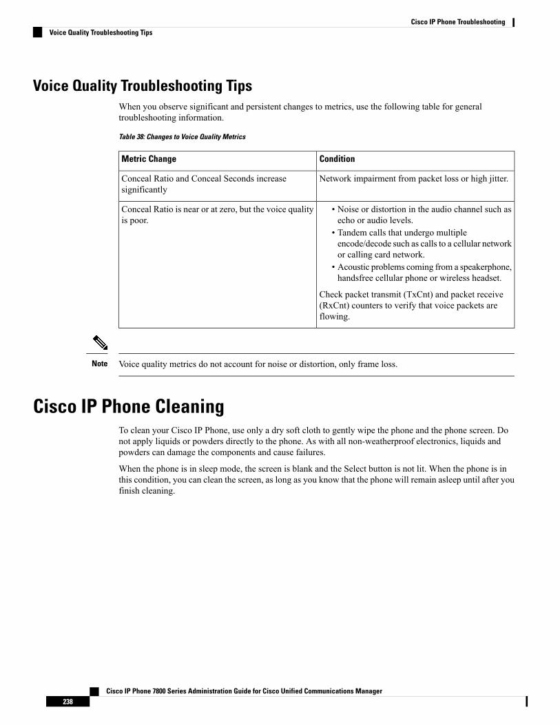
Voice Quality Troubleshooting TipsWhen you observe significant and persistent changes to metrics, use the following table for generaltroubleshooting information.
Table 38: Changes to Voice Quality Metrics
ConditionMetric Change
Network impairment from packet loss or high jitter.Conceal Ratio and Conceal Seconds increasesignificantly
• Noise or distortion in the audio channel such asecho or audio levels.
• Tandem calls that undergo multipleencode/decode such as calls to a cellular networkor calling card network.
• Acoustic problems coming from a speakerphone,handsfree cellular phone or wireless headset.
Check packet transmit (TxCnt) and packet receive(RxCnt) counters to verify that voice packets areflowing.
Conceal Ratio is near or at zero, but the voice qualityis poor.
Voice quality metrics do not account for noise or distortion, only frame loss.Note
Cisco IP Phone CleaningTo clean your Cisco IP Phone, use only a dry soft cloth to gently wipe the phone and the phone screen. Donot apply liquids or powders directly to the phone. As with all non-weatherproof electronics, liquids andpowders can damage the components and cause failures.
When the phone is in sleep mode, the screen is blank and the Select button is not lit. When the phone is inthis condition, you can clean the screen, as long as you know that the phone will remain asleep until after youfinish cleaning.
Cisco IP Phone 7800 Series Administration Guide for Cisco Unified Communications Manager238
Cisco IP Phone TroubleshootingVoice Quality Troubleshooting Tips
C H A P T E R 16International User Support
• Unified Communications Manager Endpoints Locale Installer, on page 239• International Call Logging Support, on page 239• Language Limitation, on page 240
Unified Communications Manager Endpoints Locale InstallerBy default, Cisco IP Phones are set up for the English (United States) locale. To use the Cisco IP Phones inother locales, you must install the locale-specific version of the Unified Communications Manager EndpointsLocale Installer on every Cisco Unified Communications Manager server in the cluster. The Locale Installerinstalls the latest translated text for the phone user interface and country-specific phone tones on your systemso that they are available for the Cisco IP Phones.
To access the Locale Installer required for a release, access https://software.cisco.com/download/navigator.html?mdfid=286037605&flowid=46245, navigate to your phone model, and select the UnifiedCommunications Manager Endpoints Locale Installer link.
For more information, see the documentation for your particular Cisco Unified Communications Managerrelease.
The latest Locale Installer may not be immediately available; continue to check the website for updates.Note
Related TopicsCisco Unified Communications Manager Documentation, on page xv
International Call Logging SupportIf your phone system is configured for international call logging (calling party normalization), the call logs,redial, or call directory entries may display a plus (+) symbol to represent the international escape code foryour location. Depending on the configuration for your phone system, the + may be replaced with the correctinternational dialing code, or you may need to edit the number before dialing to manually replace the + withthe international escape code for your location. In addition, while the call log or directory entry may displaythe full international number for the received call, the phone display may show the shortened local version ofthe number, without international or country codes.
Cisco IP Phone 7800 Series Administration Guide for Cisco Unified Communications Manager239

Language LimitationThere is no localized Keyboard Alphanumeric Text Entry (KATE) support for the following Asian locales:
• Chinese (China)
• Chinese (Hong Kong)
• Chinese (Taiwan)
• Japanese (Japan)
• Korean (Korea Republic)
The default English (United States) KATE is presented to the user instead.
For example, the phone screen will show text in Korean, but the 2 key on the keypad will display a b c 2A B C.
Cisco IP Phone 7800 Series Administration Guide for Cisco Unified Communications Manager240
Cisco IP Phone TroubleshootingLanguage Limitation