cisco kinetic edge & fog processing module · 21 cisco and/or its aliates all rights reserved...
TRANSCRIPT
© 2018 Cisco and/or its affiliates. All rights reserved. This document is Cisco Public Information.
W H I T E P A P E R EDGE & FOG PROCESSING MODULE
Cisco Kinetic Edge & Fog Processing ModuleEnabling computing at every level of the network, improving the value of data as it is transported
© 2018 Cisco and/or its affiliates. All rights reserved. This document is Cisco Public Information.
Table of Contents
. . . . . . . . . . . . . . . . . . . . . . . . . . . . . . . . . . . . . . . . . . . . . . . . . . . . . . . . . . . . . . . . . 3
.. . . . . . . . . . . . . . . . . . . . . . . . . . . . . . . . . . . . 5
.. . . . . . . . . . . . . . . . . . . . . . . . . . . . . . . . . . . . . . . 7
.. . . . . . . . . . . . . . . . . . . . . . . . . . . . . . . . . . . . . . . . . . . . . . . . . . . . . . . . . . . . . . . . . 6
.. . . . . . . . . . . . . . . . . . . . . . . . . . . . . . . . . . . . . . . . . . . . . . . . . . . . . . . . . 8
.. . . . . . . . . . . . . . . . . . . . . . . . . . . . . . . . . . . . . . . . . . . . . . . . . . . . . . . . . . . . . 8
.. . . . . . . . . . . . . . . . . . . . . . . . . . . . . . . . . . . . . . . . . . . . . . . . . . . . . . . . . . . . . . . . . . . . . . 10
.. . . . . . . . . . . . . . . . . . . . . . . . . . . . . . . . . . . . . . . . . . . . . . . . . 12
Executive summary
IoT Industry Standard Reference Model
IoT System Basics
IoT System Flexibi l i ty and Scalabi l i ty
Deal ing with Complexity
IoT System Structure
Microservices
Microservice Implementat ion
The Message Router
Edge/Fog Database
Intermediate Processing Between Microservices
Tight Coupl ing
Development and Management Tools
Data Leverage
Control
Conclusion
.. . . . . . . . . . . . . . . . . . . . . . . . . . . . . . . . . . . . . . . . . . . . . . . . . . . . . . . . . . . . . . 14
.. . . . . . . . . . . . . . . . . . . . . . 21
.. . . . . . . . . . . . . . . . . . . . . . . . . . . . . . . . . . . . . . . . . . . . . . . . . . . . . . . . . . . . . . 20
.. . . . . . . . . . . . . . . . . . . . . . . . . . . . . . . . . . . . . . . . . . . . . . . . . . . . . . . . . . . . . . . . . . . . . 22
.. . . . . . . . . . . . . . . . . . . . . . . . . . . . . . . . . . . . . . 22
.. . . . . . . . . . . . . . . . . . . . . . . . . . . . . . . . . . . . . . . . . . . . . . . . . . . . . . . . . . . . . . . . . . . . . 24
.. . . . . . . . . . . . . . . . . . . . . . . . . . . . . . . . . . . . . . . . . . . . . . . . . . . . . . . . . . . . . . . . . . . . . . . . . . . . . . . 25
.. . . . . . . . . . . . . . . . . . . . . . . . . . . . . . . . . . . . . . . . . . . . . . . . . . . . . . . . . . . . . . . . . . . . . . . . . . 26
© 2018 Cisco and/or its affiliates. All rights reserved. This document is Cisco Public Information.
Executive Summary
The Internet of Things (IoT) has dramatically increased the volume and variety of data being produced, opening the door to a wave of new possibilities. Companies can use that data to grow revenue, increase efficiency, enhance customer experience, decrease downtime, reduce costs, and in countless other ways.
The key is being able to unlock data from it source, process it to make is usable, and programmatically and securely move the right data to the right application to put it to work.
Cisco Kinetic is the cornerstone of the Cisco® IoT portfolio. With this platform, Cisco is not only fulfilling the need for IoT technology and products, but is also revolutionizing our understanding of networking. Instead of simply providing connectivity, the network will host computation, improving the value of data as it is transported. The network is now smarter. Instead of viewing “the cloud” as a destination, modern IoT networks will pass data through clouds as well as to clouds. Instead of simply enabling connectivity, the Kinetic platform will control the distribution of data, providing far reaching distribution while maintaining and restricting access to data. In numerous ways, Cisco is advancing the state of the art in both IoT and networking.
This white paper describes the Edge & Fog Processing Module (EFM) in the Kinetic platform, which provides a framework for processing data at the edge and fog layers of the network. It dramatically simplifies the task of creating sophisticated IoT systems.
Optimize IoT systems with maximum control for edge and fog data processing

© 2018 Cisco and/or its affiliates. All rights reserved. This document is Cisco Public Information.
The key capabilities of EFM include:
• A framework for edge and fog data processing
• High performance
• Reusable microservices for collecting data from, and providing control over, devices and machines, as well as processing the data prior to delivery to its destination
• Different options for reliable transport of data through the system, encompassing both batch and real-time streaming options
• Flexible mechanisms for integration with IT systems, reporting, and analytics
• An architectural framework to extend fog processing to multiple tiers: east-west (fog to fog) and north-south (hierarchical processing leveraging network topology)
• Easy-to-use GUI tools to simplify development, deployment, and operation for all aspects of the system
• A pervasive control paradigm and flow of information back to microservices, devices and machines for management, control, optimization and specific actions
• A completely open and polyglot system, where third parties can provide devices, processing storage, software modules, analytics, applications, or any combination thereof
This is the technology that makes IoT approachable, and leads to much faster industry adoption of the vision of IoT.
© 2018 Cisco and/or its affiliates. All rights reserved. This document is Cisco Public Information.
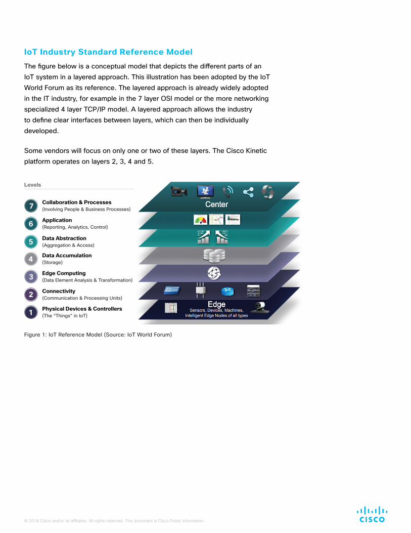
IoT Industry Standard Reference Model
The figure below is a conceptual model that depicts the different parts of an IoT system in a layered approach. This illustration has been adopted by the IoT World Forum as its reference. The layered approach is already widely adopted in the IT industry, for example in the 7 layer OSI model or the more networking specialized 4 layer TCP/IP model. A layered approach allows the industry to define clear interfaces between layers, which can then be individually developed.
Some vendors will focus on only one or two of these layers. The Cisco Kinetic platform operates on layers 2, 3, 4 and 5.
Levels
Collaboration & Processes(Involving People & Business Processes)7
Application(Reporting, Analytics, Control)6
Data Abstraction(Aggregation & Access)5
Data Accumulation(Storage)4
Edge Computing(Data Element Analysis & Transformation)3
Connectivity(Communication & Processing Units)2
Physical Devices & Controllers(The “Things” in IoT)1
Figure 1: IoT Reference Model (Source: IoT World Forum)
© 2018 Cisco and/or its affiliates. All rights reserved. This document is Cisco Public Information.
IoT System Basics
To meet the rapidly evolving demands of IoT, Cisco has created a software platform that complements its advanced networking and computing hardware. This system is driven by a complex set of requirements:
• Flexible: It handles a wide variety of IoT needs.
• Repeatable: Once configured to handle a manufacturing cell, an oil well, parking lot lighting or other systems, it can be easily replicated.
• Scalable: Some IoT systems generate more data than Big Data. Many terabytes of data can be generated quickly. The ability to effectively handle this load requires sophisticated engineering.
• Robust: Many industrial IoT systems must be monitored, managed, secure, and highly available. Using a well-tested system, a validated design, and a proven methodology yields better results.
• Control and action: Most industrial IoT solutions today are focused on data collection and actuation. The system described here accomplishes those tasks in a unique, flexible, and repeatable manner. Furthermore, control and automation can be implemented with a pre-defined policy architecture.
• Multi-purpose: The value and use of data changes over time. Initially collected data is valuable for monitoring and controlling where latency and responsiveness may be crucial, later analytics can create optimization and production improvements or cost savings, and in the long term IoT data may be required for compliance assurance.
The platform described in this document is the backbone for Cisco IoT solutions, is used by Cisco Advanced Services for custom implementations, and is available to Cisco partners and third parties to enable them to convert their IoT concepts into reality in record time.
© 2018 Cisco and/or its affiliates. All rights reserved. This document is Cisco Public Information.
IoT System Flexibility and Scalability
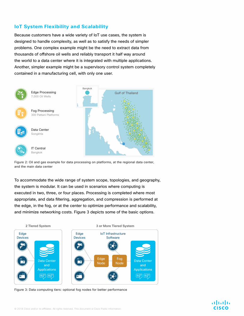
Because customers have a wide variety of IoT use cases, the system is designed to handle complexity, as well as to satisfy the needs of simpler problems. One complex example might be the need to extract data from thousands of offshore oil wells and reliably transport it half way around the world to a data center where it is integrated with multiple applications. Another, simpler example might be a supervisory control system completely contained in a manufacturing cell, with only one user.
To accommodate the wide range of system scope, topologies, and geography, the system is modular. It can be used in scenarios where computing is executed in two, three, or four places. Processing is completed where most appropriate, and data filtering, aggregation, and compression is performed at the edge, in the fog, or at the center to optimize performance and scalability, and minimize networking costs. Figure 3 depicts some of the basic options.
Figure 3: Data computing tiers: optional fog nodes for better performance
2 Tiered System
Edge Devices
Edge Devices
3 or More Tiered System
Edge Node
Fog Node
IoT InfrastructureSoftware
Data Centerand
ApplicationsApp App
Data Centerand
ApplicationsApp App
Figure 2: Oil and gas example for data processing on platforms, at the regional data center, and the main data center
Edge Processing7,000 Oil Wells
Fog Processing300 Pattani Platforms
Data CenterSongkhla
IT CentralBangkok
Gulf of ThailandBangkok

© 2018 Cisco and/or its affiliates. All rights reserved. This document is Cisco Public Information.
Dealing with Complexity
Implementing a solution quickly, with a solid scalable architecture and in a minimum amount of time, is a significant accomplishment. To accelerate the widespread adoption of IoT systems, the time required to create complex systems must be reduced from years to weeks. The system contains not only a sophisticated infrastructure that meets the requirements previously listed, but also a set of GUI tools that replace coding, dramatically decreases skill requirements, dramatically shortens the time to operation, and dramatically increases the quality of the resulting system. These tools achieve several objectives:
• Ease of development and operation provided by these tools is a major improvement over pure open source products
• Flexibility to adjust a solution quickly to changing needs is critical
• Incremental complexity of a growing system that changes over time and is contained using tools that support incremental changes and allow monitoring of the entire system
Example development and management tools are shown later in Figures 9-10.
IoT System Structure
Different scenarios require different approaches. The system is built with different hardware and software modules. With modularity in mind, the system is divided into different functional subsystems (Figure 4):
• Data acquisition: Interacting with devices (many times through a non-IP protocol), receiving data from the device, and handling the initial processing of the data.
• Data retention: Data can be stored, transformed, and retrieved on demand from all locations within the system.
• Data transport: Reliable delivery and transformation of data, assuring that the data is delivered to the destination application and/or data repository guaranteed, exactly once, in order.
• Data processing: Trade-offs are made regarsding the location of the processing of telemetry data obtained from devices. In some cases, edge processing is required. In other cases, aggregation of data from a wide variety of sources is necessary. And in other cases, the data cannot be fully leveraged until it reaches a data center or a cloud. All options are available with this system.
Reduce time to deploy complex IoT systems with a flexible solution you can easily adapt as your needs change over time
© 2018 Cisco and/or its affiliates. All rights reserved. This document is Cisco Public Information.
• Data leverage: Enabling the consumer of the data to leverage it quickly and effectively. Examples include: reporting or business intelligence; creating an environment for analytics; responding appropriately to an event; or providing data to existing IT systems. Each of these four categories requires different data manipulation. A single system may encompass more than one of these categories, and they may occur in different tiers.
• Control: The system must be secure, extensible over time, changeable while running, and it must be monitored as it operates. All of these aspects are implemented or enabled by the system.
The modularity of the system provides independence, and adds great value to the customer through the lifetime of the system by allowing for growth using new modules from Cisco or third parties, or combining Cisco software with other third-party software as needed. This is an open system supporting both proprietary and standard interfaces, with metadata management throughout the system.
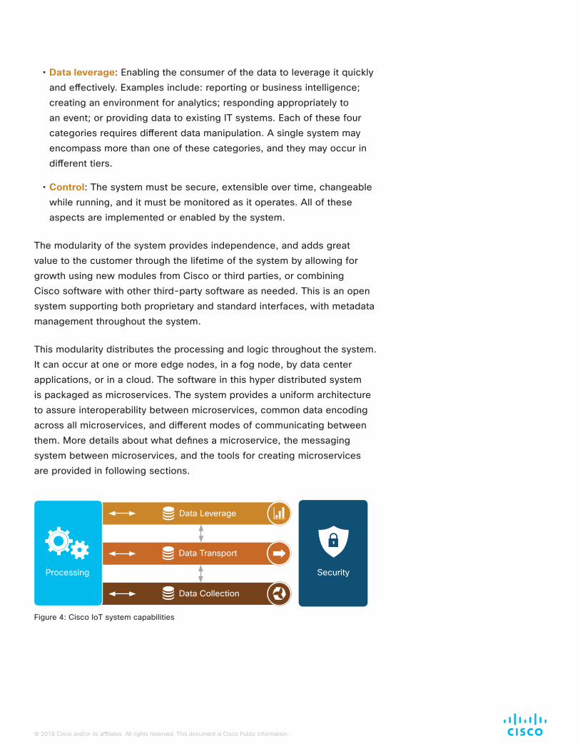
This modularity distributes the processing and logic throughout the system. It can occur at one or more edge nodes, in a fog node, by data center applications, or in a cloud. The software in this hyper distributed system is packaged as microservices. The system provides a uniform architecture to assure interoperability between microservices, common data encoding across all microservices, and different modes of communicating between them. More details about what defines a microservice, the messaging system between microservices, and the tools for creating microservices are provided in following sections.
Figure 4: Cisco IoT system capabilities
Security
Data Leverage
Data Collection
Data Transport
Processing
© 2018 Cisco and/or its affiliates. All rights reserved. This document is Cisco Public Information.
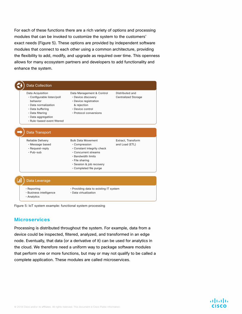
For each of these functions there are a rich variety of options and processing modules that can be invoked to customize the system to the customers’ exact needs (Figure 5). These options are provided by independent software modules that connect to each other using a common architecture, providing the flexibility to add, modify, and upgrade as required over time. This openness allows for many ecosystem partners and developers to add functionality and enhance the system.
Microservices
Processing is distributed throughout the system. For example, data from a device could be inspected, filtered, analyzed, and transformed in an edge node. Eventually, that data (or a derivative of it) can be used for analytics in the cloud. We therefore need a uniform way to package software modules that perform one or more functions, but may or may not qualify to be called a complete application. These modules are called microservices.
Data Transport
Reliable Delivery• Message based• Request-reply• Pub-sub
Bulk Data Movement• Compression• Constant integrity check• Concurrent streams• Bandwidth limits• File sharing• Session & job recovery• Completed file purge
Extract, Transform and Load (ETL)
Data Acquisition• Configurable listen/poll
behavior• Data normalization• Data buffering• Data filtering• Data aggregation• Rule-based event filtered
Data Management & Control• Device discovery• Device registration
& rejection• Device control• Protocol conversions
Data Collection
Distributed and Centralized Storage
Data Leverage
• Reporting • Business intelligence• Analytics
• Providing data to existing IT system• Data virtualization
Figure 5: IoT system example: functional system processing
© 2018 Cisco and/or its affiliates. All rights reserved. This document is Cisco Public Information.
Some key motivations for running microservices at the edge include:
• Reduce the data at the edge: Filter and reduce data before being sent to a cloud or on-premises data center. Sometimes this is required due to massive volumes of data and limited network bandwidth.
• Analyze the data at the edge: If the consumer of the data is local to the data generating device, such as in a factory control-loop feedback system, analysis of the data is best done local to where it is generated.
• Time series capture: If time precision is required as to when the measurement or sensing occurred, the data is typically captured, time-stamped, and stored as close to the edge as possible, usually in a historian database.
Some microservices run at the edge, such as in an edge router or an IoT gateway. Some run in a fog node, perhaps to aggregate data generated by many edge processing nodes. And some run in a data center or cloud. Regardless of location, all microservices in the system need to have certain attributes in common, including:
• Interaction with each other through a common communication system. This system is called a message router system and is described in detail in the Message Router section of this paper.
• Adherence to common data structures and encoding, so as data is passed between them, the value of the data points remains unchanged.
• Share certain capabilities. For example, if one microservice publishes data on a certain topic, all subscribers to that topic will receive copies.
• Compliance with a common security system.
• Can be monitored the same way so the entire system can be monitored.
• Common deployment model, so the complexity of the system grows at a much slower rate than the size of the system.
• Common infrastructure to interact in the same way to system GUI tools that are provided by Cisco as part of the system.
The framework for building and deploying compatible microservices is a major aspect of the Cisco IoT system.
Easily develop and deploy compatible microservices to run at the edge or fog

© 2018 Cisco and/or its affiliates. All rights reserved. This document is Cisco Public Information.
Microservice Implementation
Cisco’s microservices framework is designed to be extremely flexible:
• There is no size or structural requirements for a microservice other than its interface to the message router system. A microservice could be a few lines of code, an interface to a database, a user interface, or an application of any size.
• Microservices are not limited to specific functionality. A service could be a Modbus communication service, a data transformation service, a data analytic service, a bridge to move data in or out of a data storage system, or a complete application.
• Services can be developed in a variety of languages, such as C, C#, Java, JavaScript, Ruby, Python, and Dart.
• Services can be developed using familiar software design patterns.
• All services can interact and pass messages to each other.
• Communication between services is typically loosely coupled (asynchronous), enabling unlimited scalability.
The following sections describe the key design aspects of service development.
Service Description
A service description captures the details of service capabilities in a declarative fashion. It includes the RPC/Pub-Sub endpoints, associated message schemas and models. The idea behind this is two-fold. One, we would like to have certain common service infrastructure (registration, invocation etc.) aspects, while hiding the service implementations from the framework implementation choices (e.g., router implementation). Second, this helps service developers focus on one interface to expose their capabilities. The framework and tools can use this service description to generate various interfaces.
Gain granular control with microservices to manage message routing, bundling, dependencies, metrics and more
© 2018 Cisco and/or its affiliates. All rights reserved. This document is Cisco Public Information.
Service Dependency
Services can indicate other services they depend on, and there are two kinds of dependencies. One kind is a hard dependency. In this case, a service cannot function unless the dependent services are in place. Typically, this kind of dependency is limited to core services the framework provides.
The second kind is a soft dependency. This means that service startup is not affected by the dependency. Service A can start even when service B (on which it depends) is not running at that instant. To locate a service B, service A could leverage the discovery capabilities provided by the message router.
Service Development
Services can be developed in a variety of programming languages. Various language-specific software development kits (SDKs) are provided, along with tutorials, code samples, and best practices. This provides the services with a common infrastructure.
Common Microservice Infrastructure
The SDK provides the following capabilities to service developers:
• Service container: This is a logical container to host the service code. It provides the necessary bootstrapping to enable the service to connect to the message router and use the service description to register the service capabilities with the router on startup. Services can be bundled in different ways. On smaller compute nodes, some services can be bundled into a single package and run as a single process. On larger compute nodes, services can be bundled separately and run as independent processes. Service containers provide the necessary abstraction layers such that service code is independent of the deployment aspects previously referenced.
• Service registration and discovery: The SDK provides software to enable services to connect and register with the message router automatically.
• Service invocation: The SDK provides wrapper APIs to invoke other services, using either remote procedure call (RPC) and/or publish/subscribe.
• Logging and metrics: A common infrastructure is provided to collect service specific metrics and expose information to management layers in a consistent way.
Microservice Lifecycle Management
Since the microservices are interdependent upon each other, management of the lifecycle of the associated services is required.

© 2018 Cisco and/or its affiliates. All rights reserved. This document is Cisco Public Information.
The Message Router
When a system is composed of one or more components, those components must communicate in order to complete a process. Without an intermediate message router, a component would directly communicate with another component by a direct connection(s). These connections between components tend to become component-to-component interaction specific. As the system and components evolve, these connections result in a full mesh topology, with every component tightly coupled with every other component, as shown in Figure 5. This impedes scaling and manageability.
Figure 6: Components in a full mesh topology
Introduction of new components into the system results in more connections and more component-to-component specific interactions. Over time, components become interdependent and the system as a whole becomes brittle and rigid, making it difficult to evolve. The alternative, which provides better scaling, is a message router. It provides a messaging infrastructure for different services to communicate with each other in a common way. Figure 7 shows how using a message router results in N connections, instead of exponentially increasing connections.
Figure 7: Connections using a message router
Service A Service B
Service C Service D
Service E
Service A Service B
Service C Service D Service E
Message Router
© 2018 Cisco and/or its affiliates. All rights reserved. This document is Cisco Public Information.
The message router enables services to be loosely coupled and evolve independent of other services. It achieves the loose coupling between services by providing the following primary constructs:
• Messages and message exchange patterns (MEPs): This is the ability to define language-independent messages and exchange them using a well-defined set of patterns. These patterns can provide a richer set of interaction options than the basic transmit/receive or get/put capabilities. Options such as publish/subscribe are available.
• Message transport: A transport mechanism on which messages are routed between services can provide additional capabilities and quality of services (QoS) beyond those available using TCP or HTTP protocols. These are described in more detail in the Message Router Quality of Service section of this paper.
• Control messages: A set of control/command messages to facilitate services to register and declare their capabilities with the router so that services can communicate with each other.
Microservices expose their service capabilities to the message router, who can then broker communications between compatible interfaces of the participating microservices.
Connectivity from the edge to the fog, data center, or cloud is always IP based. The messaging capabilities described herein are layered on top of TCP/IP.
Message Router Quality of Service
There are many possible failure modes in complex systems: network connectivity might be intermittent, bit error rates might interfere with communications fidelity, power outages or glitches might occur, hardware fails, operating systems crash, or an application might simply be off-line. A robust IoT system requires reliability beyond networking protocols and involves handshaking the information between microservices and applications to guarantee end-to-end delivery and availability to the desired service level. This is a primary requirement of the data transport subsystem.
The data transport subsystem provides protection against two categories of failure modes: failure of a message router (or its communications links); and failure of a microservice (or connected application) that is dependent upon the message router (or its communications link) to deliver information to it.
A robust IoT system requires reliability between microservices and applications to guarantee end-to-end delivery and availability

© 2018 Cisco and/or its affiliates. All rights reserved. This document is Cisco Public Information.
• Guaranteed delivery guarantees delivery of every message (even in the event of a network or message router failure), providing a higher level of service than TCP or HTTP. This deals with a failure of a message broker.
• Durable connection options assure that a consuming microservice or application receives every message it should receive, even if the application or its connectivity fails intermittently. This deals with a failure of an application or microservice.
Message Router Scalability
A single message router can handle hundreds of thousands of messages per second; in most cases this is sufficient. However, in a few very high volume data scenarios, multiple message routers can be clustered and share the load. With this option, load balancing, high availability (through automatic fail-over), and fault tolerance is achieved. This is an example of horizontal scalability.
There are many systems where message routing is desired in an edge node(s), in a fog node(s), in one or more data centers, and in a cloud(s). In this scenario, there may be multiple message routers. A microservice or application should not have to be aware of how many routers are in a system, or to which routers other microservices are connected, and may need to subscribe to messages from multiple sources that are being routed through different message routers. The system’s message routers can be connected together and the multi-router protocol between them will cause them to act as one. A publisher of data can connect to one router, a subscriber to another, and the delivery QoS will be the same as if both were connected to the same router. Traffic can be partitioned amongst multiple brokers when the ability to vertically scale a single broker is exhausted.
Message Router IoT Features
There are numerous special features present in Cisco’s IoT message router system that are not available in other messaging systems. Examples include:
• IoT systems typically involve nodes with limited processor and memory capabilities. An IoT message router can run on a very small footprint. For example, the message router described in this paper can run in less than 50MB of RAM.
• IoT systems are frequently geographically dispersed. The multi-router routing capability supports scalability in both the number of systems and their geographic dispersal.
Scale efficiently with multi-router clusters to support multiple systems and geographic locations

© 2018 Cisco and/or its affiliates. All rights reserved. This document is Cisco Public Information.
• The communication links within an IoT system are frequently limited. The message router compresses the data as it sends it across network links.
• The physical location of devices connected to an IoT system is sometimes difficult to determine. The message routers can obtain, propagate, and provide meta-data about the devices, including their location.
• Some devices have interfaces that provide many data points. This could result in a very large set of unneeded data being transported across the network. Unlike other systems, this system supports subscription to a very fine granularity — down to individual data elements. For example, a 500 cell battery may provide 500 data points with every request. If a subscriber is interested in only three of these data points, it can subscribe to only those points, resulting in a much more efficient use of the available network bandwidth.
In summary, enhancements to the state-of-the-art in message brokering have been made to handle the unique properties of IoT systems.
Application/Microservice Interactions
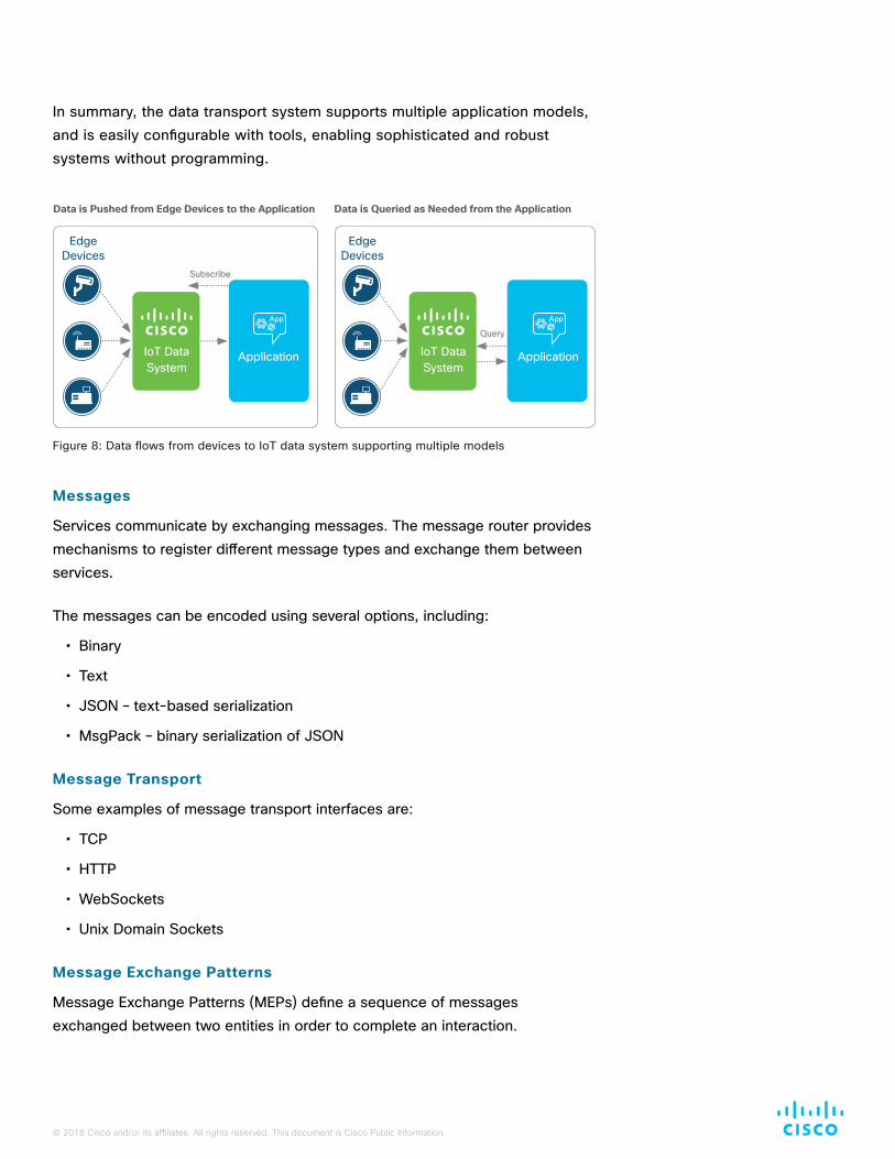
There are multiple computing models which require different approaches of the data transport subsystem. A detailed treatment of this topic is very technical and beyond the scope of this document. A simplified explanation is that sometimes the data is pushed to the application and sometimes the application pulls the data (Figure 8).
When the data is pushed through the system to the application, the assumption is made that the application can keep up with the stream of data. To use this model, an analysis is required to assure that the timing always works and that data is not lost. The data transport/storage system supports both real-time streaming processing (enabling event stream processing and analytics by an appropriate microservice), as well as periodic transfer of bulk data supporting batch processing and/or analytics on at rest data.
When the data is pulled, it is first captured from the device using the data collection subsystem. Then it must be stored until the consuming microservice or application requests it. There are options for storing the data in its interim state, as it is being transported. This is covered in more detail in the next section.
Optimize network usage with state-of-the-art, granular message brokering for IoT data
© 2018 Cisco and/or its affiliates. All rights reserved. This document is Cisco Public Information.
In summary, the data transport system supports multiple application models, and is easily configurable with tools, enabling sophisticated and robust systems without programming.
Messages
Services communicate by exchanging messages. The message router provides mechanisms to register different message types and exchange them between services.
The messages can be encoded using several options, including:
• Binary
• Text
• JSON – text-based serialization
• MsgPack – binary serialization of JSON
Message Transport
Some examples of message transport interfaces are:
• TCP
• HTTP
• WebSockets
• Unix Domain Sockets
Message Exchange Patterns
Message Exchange Patterns (MEPs) define a sequence of messages exchanged between two entities in order to complete an interaction.
Figure 8: Data flows from devices to IoT data system supporting multiple models
Data is Pushed from Edge Devices to the Application
Edge Devices
IoT Data System
Subscribe
Application
App
Query
Data is Queried as Needed from the Application
Edge Devices
Application
App
IoT Data System
© 2018 Cisco and/or its affiliates. All rights reserved. This document is Cisco Public Information.
There are two common MEPs that are of interest:
• Request-Reply: An interaction in this pattern consists of two messages, request and reply. This MEP is commonly used with RPC style applications, where a client sends a request to a server and the server responds with a reply.
• Publish-Subscribe: An interaction in this pattern consists of more than one message. An initial message (subscription request) from a subscriber expressing the interest to receive one or more messages that are published by one or more publishers. This MEP is typically used when two or more entities need to exchange a set of messages.
Microservices Decoupling
There are cases where data is generated by devices so quickly that the consuming microservice or application across the network cannot keep up. This could be a limitation in either network bandwidth or application processing performance. In these cases, the producer and the consumer of the data must be de-coupled so they can each run at their own performance level.
Note that no amount of decoupling will solve the problem where the consumer/network cannot keep up with the average publish rate. In this case, the queue grows over time and eventually exhausts system resources.
Decoupling/queueing provides two capabilities: the ability to overcome burst scenarios when message volumes are temporarily greater than the ability of the network to transmit them or the microservices to consume them; and the ability to provide resilience when the receiving microservice is temporarily unavailable. Decoupling is accomplished by storing the data temporarily until the consumer can pull the data (refer to previous section on the pull model). This is accomplished in the message router embedded queue, acting on behalf of all of the data generation sources.
There are alternative QoS options that can be used with the message router. If the guaranteed delivery option is used, the message router provides temporary storage (referred to as queuing) on a disk to handle the flow control of data. Persisting the data in this manner, plus logging and recovery routines in the event of a router failure or a power outage, provides very high reliability. The message router guarantees that all data will be delivered, to all subscribers, at least once, in the order the router receives the data.
This option is handled entirely within the router. Microservices are not encumbered with any additional complexity to take advantage of this capability.
Decoupling helps ensure resiliency when high message volumes make it hard for the network or applications to keep up

© 2018 Cisco and/or its affiliates. All rights reserved. This document is Cisco Public Information.
Edge/Fog Database
There are several excellent reasons why you might need a specialized database at the edge to temporarily store captured data:
• Leverage of the data might also be at the edge, as in a local closed-loop supervisory system. In this case, the data never needs to leave the local domain.
• Data from the devices may need to be cleaned prior to being moved away from the data-generating device.
• Filtering the data may be dependent on previous samples of the data, such as in the case of filtering for outliers, where outliers are defined by a deviation from normal.
• Data might need to be time stamped to perform a time series analysis. Time accuracy is best achieved if the time stamp is recorded as close to the generating device as possible. An example is where a time line is created from the telemetry so a trend (over time) can be understood. As the devices themselves may not provide a time stamp, this is accomplished by the historian database.
IoT places very demanding requirements on this database. Examples include:
• It must support very fast insert rates. It cannot let queries interfere with insertions, since devices may not hold new data while waiting for the database to free up for an insert.
• It must be more flexible than a typical relational database management system (RDBMS) database, with regard to the structure of the data from devices. For example, if we have a battery with 500 cells, the desired database schema would have 500 columns. High column count with sparse data is typical in IoT settings, and leads to poor retrieval performance with standard RDBMS products.
• It must support standard American National Standards Institute (ANSI) SQL for compatibility with data consuming products.
• Given the volume of data present in some installations, it must process queries very quickly. The Cisco ParStream database has been measured as responding to queries against one billion rows of data in less than one second.
Optimize your system with a fast, flexible database at the edge to temporarily store IoT device data
© 2018 Cisco and/or its affiliates. All rights reserved. This document is Cisco Public Information.
In a fog node, the requirements may differ. One of the typical functions of a fog node, which sits between the edge nodes and a data center or cloud, is that it has to gather and union data from multiple edge nodes, and prepare the data for northbound transmission. Thus, the database could be located in the fog in addition to or instead of the edge node. A fog node has unique requirements, including:
• If a fog node has not already collected and aggregated the data from the edge nodes, gathering this data from multiple edge nodes upon request can be cumbersome, and result in low performance. The alternative is a single query that expands to a geo-distributed query, resulting in the fog node propagating the query to all of the edge nodes (or other fog nodes), quickly executing the query at the edge nodes on the locally stored data, gathering the intermediate result sets from all relevant edge nodes with a union, and returning a single result set to the requester.
• Data coming from the devices is not in the desired format for the consumer of the data. In many cases, the best place to transform the data is in the fog node. The database should have the capabilities to run data transformation, data reduction, and even data analysis, inside the database to provide optimum performance and simplicity in an easily deployable software package.
Regardless of the location of the historian database, it is implemented in the system as a special form of a microservice, and interacts with other microservices through the message router, taking advantage of the router’s features.
Intermediate Processing Between Microservices
In some cases, microservices can be simplified if the system inserts processing between them. This event stream processing enhances the overall system by offloading processing from many microservices and centralizing it into a software module designed to execute streaming processing very effectively.
This processing can become complicated, and is best completed by a special purpose engine designed to handle all of the unique requirements, such as:
• Evaluating streaming data against rules
• Comparing streaming data with stored data (to compute trend lines or identify outliers)
Improve performance with a database in the fog node to transform, reduce and analyze data before distribution
© 2018 Cisco and/or its affiliates. All rights reserved. This document is Cisco Public Information.
• Comparing data across multiple different streams
• Executing complex algorithms against data in motion
The EFM Data Flow Editor GUI tool can easily accomplish these, and other similar tasks, with a visual tool that does not require any programming.
Tight Coupling
As an alternative to the edge and fog processing previously described, the data transport subsystem could deliver the data directly from the device to the center (data center or cloud) where it is immediately processed by an application or stored in a repository and made available for query by an application, BI reporting tool, or analytic tool.
Note the system supports Kafka, RDBMS, ParStream, and Hadoop based repositories, the selection of which is dependent upon the format and data type, volume of data, and query response time requirements. This simpler pattern, where the device is tightly coupled with processing in the data center or cloud, is used when the amount of data is limited and protection against some of the failure modes is not required.
Development and Management Tools
Productivity in developing the IoT system, flexibility in adjusting it after deployment, monitoring the system over its lifetime, and managing the different aspects of a running system, are all important aspects to consider. It is important that the system is designed so that exceptional skills are not required to develop and manage it.
The system contains several graphical tools that can be used in both the development and operational phases of the system (Figures 91).
Development tools include:
• A software design kit (SDK) and a development toolchain to build microservices and applications from scratch in multiple languages.
• Ability to find all of the microservices and applications connected to the system.
• Ability to introspect the interfaces of these microservices.
• Ability to chain microservices together, defining the data flow between the microservices.
Insert sidebar hereEasily build IoT microservices and applications with an SDK and graphical tools for development and operations
© 2018 Cisco and/or its affiliates. All rights reserved. This document is Cisco Public Information.
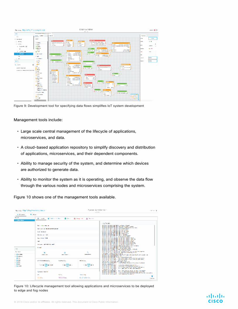
Management tools include:
• Large scale central management of the lifecycle of applications, microservices, and data.
• A cloud-based application repository to simplify discovery and distribution of applications, microservices, and their dependent components.
• Ability to manage security of the system, and determine which devices are authorized to generate data.
• Ability to monitor the system as it is operating, and observe the data flow through the various nodes and microservices comprising the system.
Figure 10 shows one of the management tools available.
Figure 9: Development tool for specifying data flows simplifies IoT system development
Figure 10: Lifecycle management tool allowing applications and microservices to be deployed to edge and fog nodes

© 2018 Cisco and/or its affiliates. All rights reserved. This document is Cisco Public Information.
Data Leverage
Once the data has gone through edge processing and has been reliably delivered to a destination where more serious computation can occur, optional complementary products from Cisco assist in preparing the data, transforming and storing the data, and presenting it in the optimal way for it to be used.
There are different models and activities that can occur at this point; here are some common examples.
Business Intelligence (Reporting)
Once the data transport subsystem has delivered the data, and it is stored in an RDBMS or Hadoop system, reporting tools can be used to visualize the data. However, these tools work better if the data is structured to minimize the number of tables and joins required. Organizing the data appropriately is yet another requirement for leveraging the IoT system.
Many times the report compares the new IoT data (such as today’s factory output) to other data (such as the planned output) to gain a perspective. This other (non-IoT) data is typically available in the IT system. In our example, it would come from the Manufacturing Execution System (MES) or the Enterprise Resource Planning (ERP) system.
Analytics
Ad Hoc Analytics
Ad hoc analytics are performed by data analysts and data scientists. Since their work is iterative and unplanned, data is many times isolated in a sandbox. The system includes microservices and data transformation capabilities that can create sandboxes and assist with data preparation prior to statistical analysis. As with other parts of the system, the work is done with a graphical tool.
Following the data preparation phase, analytics and statistics can be done with any industry standard analytics product.
Embedded Analytics
Embedded analytics occurs when the analytics are embedded in an application. Cisco provides several embedded analytic applications/systems in areas where it has special expertise. Examples include network analytics, call center analytics, wireless system and location analytics, and event management analytics.
It is straightforward to add an interface to these, and other third party applications, so that the system interacts with them as a microservice.
© 2018 Cisco and/or its affiliates. All rights reserved. This document is Cisco Public Information.
Integration with IT
Almost all IoT systems are put in place by organizations and companies that have invested heavily in IT systems for many years. It is a common objective to integrate the data from IoT sources into these IT systems.
To meet this requirement, the IoT data generated by devices or machines is transported to the destination location and passed to one or more IT applications, typically using a database or Hadoop as a semaphore. In this case, the IoT system must restructure and reformat the data and insert it into the target application’s database in the schema defined by the application. Relational, Hadoop key value pairs, XML, SAP, and other data structures can all be converted to that which is needed, without programming.
Control
In the emerging IoT world, automation and control is a key paradigm. Once data is acquired, transported, and leveraged for business improvement, operational insight, and situational awareness, a complete IoT system should provide the agility to take automated actions to alter characteristics of machines/devices, or how their data is processed, based on these data insights. Customers need a control framework to enforce their operational parameters and run books.
Broad categories of control types include:
• Control set by an administrator with predefined knowledge, such as operational run book parameters. An example of this control type is a machine running at a certain temperature or torque level; if the settings are changed by a local operator, then the IoT control system should enforce the characteristics defined. Similarly, administrators can enforce more efficient energy modes when machines are in idle state.
• Rules and control based on the data collection and consuming applications. Although data collection is independent of the control paradigm, there can be a higher-priority control flow based on real time device and machines monitoring and their surroundings. A real-time change in temperature or humidity in a pipeline could signal a leak or other critical situation. At this instant, this control paradigm should supersede data flow to execute immediate corrective action or alter pipeline characteristics.
The system contains facilities for control and parameter setting of microservices, both during setup as well as during runtime.

© 2018 Cisco and/or its affiliates. All rights reserved. This document is Cisco Public Information.
Americas HeadquartersCisco Systems, Inc.San Jose, CA
Europe HeadquartersCisco Systems International BV Amsterdam, The Netherlands
WP-CK-EFM-03302018
Conclusion
Cisco has made significant investments over a period of years, and is well prepared to address the many processing and data needs of the emerging hyper distributed world. The objective is to bring forward a new form of system for distributed systems, such as IoT, that meets the scalability and quality requirements, is flexible to meet the customers’ exacting needs, comprehensive from the smallest device to the largest Information Technology system, and open so that everyone can extend the system.
We look forward to working with you and helping you advance your business and achieve desired outcomes.
For More Information
For more information about the Cisco Kinetic Platform and the Edge & Fog Processing Module, contact your Cisco account representative, and visit http://www.cisco.com/go/kinetic.
Grow your business with the IoT solution that delivers the control, flexibility and scalability to optimize the value of your data