cisco labs practical2
TRANSCRIPT
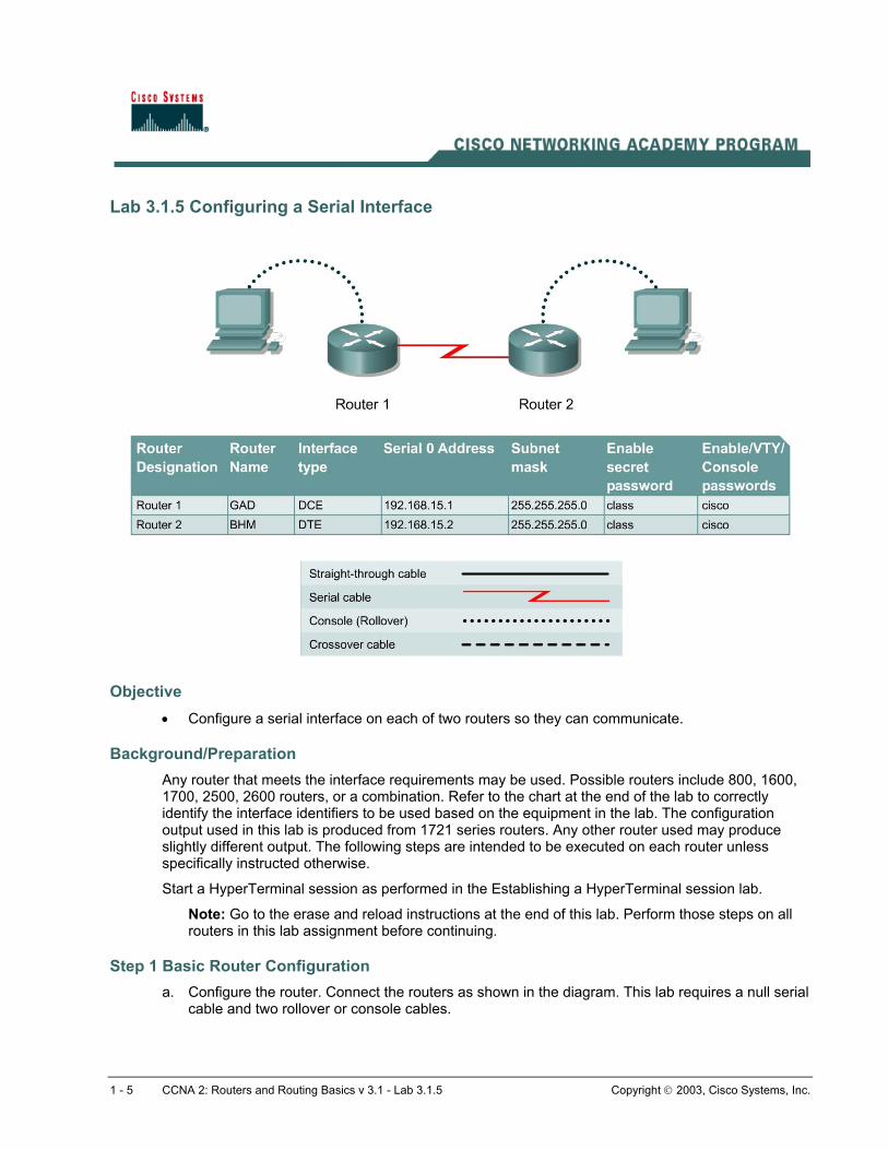
Lab 3.1.5 Configuring a Serial Interface
Objective • Configure a serial interface on each of two routers so they can communicate.
Background/Preparation Any router that meets the interface requirements may be used. Possible routers include 800, 1600, 1700, 2500, 2600 routers, or a combination. Refer to the chart at the end of the lab to correctly identify the interface identifiers to be used based on the equipment in the lab. The configuration output used in this lab is produced from 1721 series routers. Any other router used may produce slightly different output. The following steps are intended to be executed on each router unless specifically instructed otherwise.
Start a HyperTerminal session as performed in the Establishing a HyperTerminal session lab.
Note: Go to the erase and reload instructions at the end of this lab. Perform those steps on all routers in this lab assignment before continuing.
Step 1 Basic Router Configuration a. Configure the router. Connect the routers as shown in the diagram. This lab requires a null serial
cable and two rollover or console cables.
1 - 5 CCNA 2: Routers and Routing Basics v 3.1 - Lab 3.1.5 Copyright 2003, Cisco Systems, Inc.

Step 2 Configure the name and passwords for Router 1 a. On Router 1, enter the global configuration mode and configure the hostname as shown in the
chart.
b. Configure the console, virtual terminal and enable passwords. If there are any problems, refer to the Lab 3.1.3 Configuring Router Passwords.
Step 3 Configure serial interface Serial 0 From global configuration mode, configure serial interface Serial 0 on Router GAD. Refer to Interface Summary.
GAD(config)#interface serial 0 GAD(config-if)#ip address 192.168.15.1 255.255.255.0 GAD(config-if)#clock rate 56000 GAD(config-if)#no shutdown GAD(config-if)#exit GAD(config)#exit
Note: Once the interface configuration mode is entered, note the IP address of the interface. Enter the subnet mask. Enter the clock rate only on the DCE side of the device. The command no shutdown turns on the interface. Shutdown is when the interface is off.
Step 4 Save the running configuration Save the running configuration to the startup configuration at the privileged EXEC mode:
GAD#copy running-config startup-config
Note: Save the running configuration for the next time that the router is restarted. The router can be restarted either by a software reload command or a power shutdown. The running configuration will be lost if the running configuration is not saved. The router uses the startup configuration when the router is started.
Step 5 Display information about Serial interface 0 on GAD a. Enter the command show interface serial 0 on GAD. Refer to interface chart.
GAD#show interface serial 0
This will show the details of interface serial 0.
b. List at least three details discovered by issuing this command.
c. Serial 0 is ___________________. Line protocol is___________________ .
d. Internet address is _____________________.
e. Encapsulation _________________________
f. To what OSI layer is the “Encapsulation” referring? _______________________________
g. If the Serial interface was configured, why did the show interface serial 0 say that the interface is down?
__________________________________________________________________________
2 - 5 CCNA 2: Routers and Routing Basics v 3.1 - Lab 3.1.5 Copyright 2003, Cisco Systems, Inc.

Step 6 Configure the name and passwords for Router 2 a. On the Birmingham router, enter the global configuration mode. Configure hostname, console,
virtual terminal and enable passwords as shown in the previous chart.
Step 7 Configure serial interface Serial 0 From the global configuration mode, configure serial interface Serial 0 on Router BHM. Refer to interface chart.
BHM(config)#interface serial 0 BHM(config-if)#ip address 192.168.15.2 255.255.255.0 BHM(config-if)#no shutdown BHM(config-if)#exit BHM(config)#exit
Step 8 Save the running configuration Save the running configuration to the startup configuration at the privileged EXEC mode:
BHM#copy running-config startup-config
Step 9 Display information about Serial interface 0 on BHM a. Enter the command show interface serial 0 on BHM. Refer to interface chart.
BHM#show interface serial 0
This will show the details of interface serial 0.
b. List at least three details discovered by issuing this command.
c. Serial 0 is ___________________, line protocol is ___________________ .
d. Internet address is ___________________ .
e. Encapsulation ___________________
f. What is the difference in the Line and Protocol status recorded on GAD earlier? Why?
__________________________________________________________________________
Step 10 Verify that the serial connection is functioning a. ping the serial interface of the other router.
BHM#ping 192.168.15.1 GAD#ping 192.168.15.2
b. From GAD, ping the BHM router serial interface. Does the ping work? _________________
c. From BHM, ping the GAD router serial interface. Does the ping work? _________________
d. If the answer is no for either question, troubleshoot the router configurations to find the error. Then ping the interfaces again until the answer to both questions is yes.
Upon completion of the previous steps, logoff by typing exit. Turn the router off. Remove and store the cables and adapter.
3 - 5 CCNA 2: Routers and Routing Basics v 3.1 - Lab 3.1.5 Copyright 2003, Cisco Systems, Inc.

Lab 3.1.6 Making Configuration Changes
Objective • Configure some basic router settings.
• Bring interfaces up and down.
• Make changes to the router configuration.
Background/Preparation Any router that meets the interface requirements may be used. Possible routers include 800, 1600, 1700, 2500, 2600 routers, or a combination. Refer to the chart at the end of the lab to correctly identify the interface identifiers to be used based on the equipment in the lab. The configuration output used in this lab is produced from 1721 series routers. Any other router used may produce slightly different output. The following steps are intended to be executed on each router unless specifically instructed otherwise.
Start a HyperTerminal session as performed in the Establishing a HyperTerminal session lab.
Note: Go to the erase and reload instructions at the end of this lab. Perform those steps on all routers in this lab assignment before continuing.
1 - 5 CCNA 2: Routers and Routing Basics v 3.1 - Lab 3.1.6 Copyright 2003, Cisco Systems, Inc.
Step 1 Basic router configuration a. Connect the router as shown in the diagram. This lab requires a console (rollover) and a serial
cable.
Step 2 Configure hostname and passwords a. On the GAD router, enter the global configuration mode. Configure the hostname as shown in
the chart. Configure the console, virtual terminal and enable passwords.
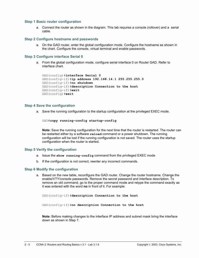
Step 3 Configure interface Serial 0 a. From the global configuration mode, configure serial interface 0 on Router GAD. Refer to
interface chart.
GAD(config)#interface Serial 0 GAD(config-if)#ip address 192.168.14.1 255.255.255.0 GAD(config-if)#no shutdown GAD(config-if)#description Connection to the host GAD(config-i exit f)#GAD(config)#exit
Step 4 Save the configuration a. Save the running configuration to the startup configuration at the privileged EXEC mode.
GAD#copy running-config startup-config
Note: Save the running configuration for the next time that the router is restarted. The router can be restarted either by a software reload command or a power shutdown. The running configuration will be lost if the running configuration is not saved. The router uses the startup configuration when the router is started.
Step 5 Verify the configuration a. Issue the show running-config command from the privileged EXEC mode
b. If the configuration is not correct, reenter any incorrect commands.
Step 6 Modify the configuration a. Based on the new table, reconfigure the GAD router. Change the router hostname. Change the
enable/VTY/console passwords. Remove the secret password and interface description. To remove an old command, go to the proper command mode and retype the command exactly as it was entered with the word no in front of it. For example:
GAD(config-if)#description Connection to the host
GAD(config-if)#no description Connection to the host
Note: Before making changes to the interface IP address and subnet mask bring the interface down as shown in Step 7.
2 - 5 CCNA 2: Routers and Routing Basics v 3.1 - Lab 3.1.6 Copyright 2003, Cisco Systems, Inc.
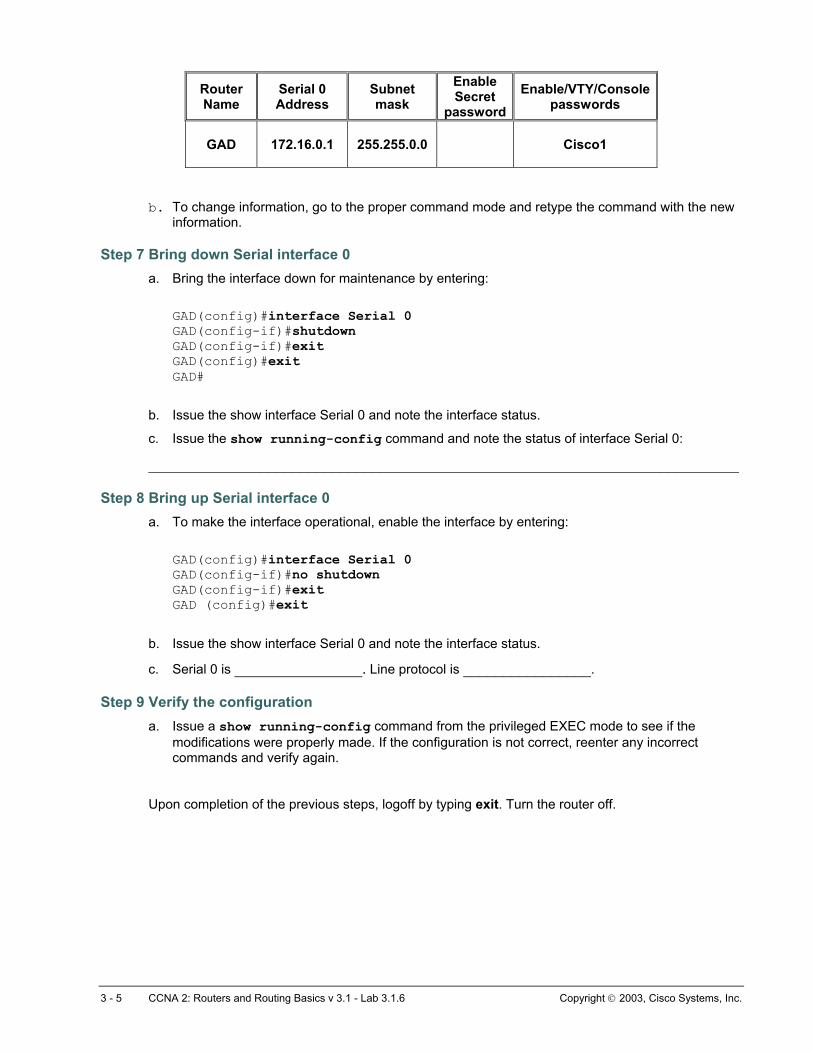
Router Name
Serial 0 Address
Subnet mask
Enable Secret
passwordEnable/VTY/Console
passwords
GAD
172.16.0.1 255.255.0.0 Cisco1
b. To change information, go to the proper command mode and retype the command with the new information.
Step 7 Bring down Serial interface 0 a. Bring the interface down for maintenance by entering:
GAD(config)#interface Serial 0 GAD(config-if)#shutdown GAD(config-if)#exit GAD(config)#exit GAD#
b. Issue the show interface Serial 0 and note the interface status.
c. Issue the show running-config command and note the status of interface Serial 0:
__________________________________________________________________________
Step 8 Bring up Serial interface 0 a. To make the interface operational, enable the interface by entering:
GAD(config)#interface Serial 0 GAD(config-if)#no shutdown GAD(config-if)#exit G AD (config)#exit
b. Issue the show interface Serial 0 and note the interface status.
c. Serial 0 is ________________. Line protocol is ________________.
Step 9 Verify the configuration a. Issue a show running-config command from the privileged EXEC mode to see if the
modifications were properly made. If the configuration is not correct, reenter any incorrect commands and verify again.
Upon completion of the previous steps, logoff by typing exit. Turn the router off.
3 - 5 CCNA 2: Routers and Routing Basics v 3.1 - Lab 3.1.6 Copyright 2003, Cisco Systems, Inc.

Lab 3.1.7 Configuring an Ethernet Interface
Objective • Configure an Ethernet interface on the router with an IP address and a subnet mask.
Background/Preparation In this lab, students configure an Ethernet interface on the router with an IP address and a subnet mask.
Any router that meets the interface requirements may be used. Possible routers include 800, 1600, 1700, 2500, 2600 routers, or a combination. Refer to the chart at the end of the lab to correctly identify the interface identifiers to be used based on the equipment in the lab. The configuration output used in this lab is produced from 1721 series routers. Any other router used may produce slightly different output. The following steps are intended to be executed on each router unless specifically instructed otherwise.
Start a HyperTerminal session as performed in the Establishing a HyperTerminal session lab.
Note: Go to the erase and reload instructions at the end of this lab. Perform those steps on all routers in this lab assignment before continuing.
Step 1 Configure the hostname and passwords on the GAD router a. On the router, enter the global configuration mode and configure the hostname as shown in the
chart. Then configure the console, virtual terminal and enable passwords.
1 - 4 CCNA 2: Routers and Routing Basics v 3.1 - Lab 3.1.7 Copyright 2003, Cisco Systems, Inc.

Step 2 Configure the FastEthernet 0 interface Note: The designation for the first Ethernet interface on the router will vary. It may be ethernet 0, fastethernet 0 or fastethernet 0/0 depending on the type of router.
GAD(config)#interface fastEthernet 0 GAD(config-if)#ip address 192.168.14.1 255.255.255.0 GAD(config-if)#no shutdown GAD(config-if)#exit GAD (config)#exit
Step 3 Save the configuration a. Save the running configuration to the startup configuration at the privileged EXEC mode:
GAD#copy running-config startup-config
Step 4 Display the FastEthernet 0 configuration information GAD#show interface fastethernet 0
Note: This will show the details of the Ethernet interface.
a. List at least three details discovered by issuing this command.
b. FastEthernet0 is __________________. Line protocol is ____________________.
c. Internet address is ___________________________.
d. Encapsulation _________________________________
e. To what OSI layer is the “Encapsulation” referring? ______________________
Upon completion of the previous steps, logoff by typing exit. Turn the router off.
2 - 4 CCNA 2: Routers and Routing Basics v 3.1 - Lab 3.1.7 Copyright 2003, Cisco Systems, Inc.
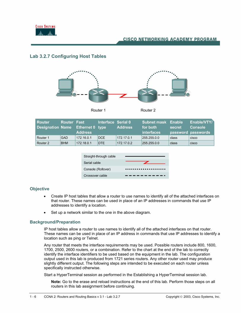
Lab 3.2.7 Configuring Host Tables
Objective • Create IP host tables that allow a router to use names to identify all of the attached interfaces on
that router. These names can be used in place of an IP addresses in commands that use IP addresses to identify a location.
• Set up a network similar to the one in the above diagram.
Background/Preparation IP host tables allow a router to use names to identify all of the attached interfaces on that router. These names can be used in place of an IP address in commands that use IP addresses to identify a location such as ping or Telnet.
Any router that meets the interface requirements may be used. Possible routers include 800, 1600, 1700, 2500, 2600 routers, or a combination. Refer to the chart at the end of the lab to correctly identify the interface identifiers to be used based on the equipment in the lab. The configuration output used in this lab is produced from 1721 series routers. Any other router used may produce slightly different output. The following steps are intended to be executed on each router unless specifically instructed otherwise.
Start a HyperTerminal session as performed in the Establishing a HyperTerminal session lab.
Note: Go to the erase and reload instructions at the end of this lab. Perform those steps on all routers in this lab assignment before continuing.
1 - 6 CCNA 2: Routers and Routing Basics v 3.1 - Lab 3.2.7 Copyright 2003, Cisco Systems, Inc.

Step 1 Configure the hostname and passwords on the GAD router a. On the router, enter the global configuration mode. Configure the hostname as shown in the
chart. Then configure the console, virtual terminal and enable passwords. If there are any difficulties, refer to the Configuring Router Passwords lab.
Step 2 Configure the interfaces and routing protocol on the GAD router a. Go to the proper command mode and enter the following text:
GAD(config)#interface fastethernet 0 GAD(config-if)#ip address 172.16.0.1 255.255.0.0 GAD(config-if)#no shutdown GAD(config-i exitf)# GAD(config)#interface serial 0 GAD(config-if)#ip address 172.17.0.1 255.255.0.0 GAD(config-if)#clock rate 56000 GAD(config-if)#no shutdown GAD(config-if)#exit GAD(config)#router rip GAD(config-router)#network 172.16.0.0 GAD(config-router)#network 172.17.0.0 GAD(config-router)#exit GAD(config)#exit
Step 3 Save the GAD router configuration GAD#copy running-config startup-config
Step 4 Configure the hostname and passwords on the BHM router a. On the BHM router, enter the global configuration mode. Configure the hostname as shown in
the chart. Then configure the console, virtual terminal and enable passwords. If there are any difficulties, refer to the Configuring Router Passwords lab.
Step 5 Configure the interfaces and routing protocol on the BHM router a. Go to the proper command mode and enter the following:
BHM(config)#interface fastethernet 0 BHM(config-if)#ip address 172.18.0.1 255.255.0.0 BHM(config-if)#no shutdown BHM(config-if)#exit BHM(config)#interface serial 0 BHM(config-if)#ip address 172.17.0.2 255.255.0.0 BHM(config-if)#no shutdown BHM(config-if)#exit BHM(config)#router rip BHM(config-router)#network 172.17.0.0 BHM(config-router)#network 172.18.0.0 BHM(config-router)#exit BHM(config)#exit
2 - 6 CCNA 2: Routers and Routing Basics v 3.1 - Lab 3.2.7 Copyright 2003, Cisco Systems, Inc.

Step 6 Save the BHM router configuration BHM#copy running-config startup-config
Step 7 Verify that the internetwork is functioning Verify that the internetwork is functioning. Ping the FastEthernet interface of the other router.
a. From GAD, ping the BHM router FastEthernet interface. Does the ping work?
__________________________________________________________________________
b. From BHM, ping the GAD router FastEthernet interface. Does the ping work?
__________________________________________________________________________
c. If the answer is no for either question troubleshoot the router configurations to find the error. Then do the pings again until the answer to both questions is yes.
Step 8 Configure the IP host table for the network a. Create a name for each router in the network lab. Enter that name along with the IP addresses
of the routers interfaces. This is a local name and can be anything that is comfortable. Although the name does not have to match the configured hostname of the router, that would be the normal procedure.
Router Name IP Address Ethernet 0 IP Address Interface Serial 0
b. From the global configuration mode, enter the command ip host followed by the name of each
router in the network, as well as all of the IP addresses of the interfaces on each of the routers.
For example to name the GAD router accessible from BHM by the name “G”, enter:
BHM(conf)#ip host G 172.16.0.1 172.17.0.1
c. What commands did you enter on GAD?
__________________________________________________________________________ d. What commands did you enter on BHM?
__________________________________________________________________________
Step 9 Exit configuration mode and test a. Go to the enable, or privileged EXEC mode.
b. Examine the host table entries, using the show hosts command on each router.
c. Are the host entries that were configured in the previous steps visible?
GAD _____________________ BHM ______________________
d. If there are no IP host entries go back and repeat Step 8.
3 - 6 CCNA 2: Routers and Routing Basics v 3.1 - Lab 3.2.7 Copyright 2003, Cisco Systems, Inc.
e. Now ping the other router by host name. From the enable prompt type ping host. The “host” is the ip host name that was configured in the previous steps. For example for a host name of “G”, enter:
BHM#ping G
f. Was the ping successful? ______________________
g. If the ping was not successful, check the accuracy of the IP host table entries.
h. From the enable prompt, enter the host name. Press Enter. For example for a host name of “G”, enter:
BHM#G
i. What happened? ________________________________________________________
Upon completion of the previous steps, logoff by typing exit. Turn the router off.
4 - 6 CCNA 2: Routers and Routing Basics v 3.1 - Lab 3.2.7 Copyright 2003, Cisco Systems, Inc.

Lab 4.2.5a Connectivity Tests – Ping
Objective • Use the ping command to send ICMP datagrams to target host.
• Verify that the network layer between source and destination is working properly.
• Retrieve information to evaluate the path-to-host reliability.
• Determine delays over the path and whether the host can be reached or is functioning.
• Use the extended ping command to increase number of packets.
Background/Preparation The ping command is a good tool for troubleshooting Layers 1 though 3 of the OSI model and diagnosing basic network connectivity. Using ping sends an ICMP packet to the specified device (workstation, server, router or switch) and then waits for a reply. The IP address or host name can be pinged. In order to ping the host name of a router, there must be a static host lookup table in the router or a DNS server for name resolution to IP addresses.
Cable a network similar to the one in the diagram. Any router that meets the interface requirements may be used. Possible routers include 800, 1600, 1700, 2500, 2600 routers, or a combination. Refer to the chart at the end of the lab to correctly identify the interface identifiers to be used based on the equipment in the lab. The configuration output used in this lab is produced from 1721 series routers.
1 - 6 CCNA 2: Routers and Routing Basics v 3.1 - Lab 4.2.5a Copyright 2003, Cisco Systems, Inc.

Any other router used may produce slightly different output. The following steps are intended to be executed on each router unless specifically instructed otherwise.
Start a HyperTerminal session as performed in the Establishing a HyperTerminal session lab.
Note: Go to the erase and reload instructions at the end of this lab. Perform those steps on all routers in this lab assignment before continuing.
Step 1 Configure the GAD and BHM routers a. If there are any difficulties configuring hostname or passwords, refer to the Configuring Router
Passwords lab. If there are any difficulties configuring interfaces or the routing protocol, refer to the Configuring Host Tables lab.
b. This lab requires that IP hostnames are configured.
c. Verify the routers configurations by performing a show running-config on each router. If not correct, fix any configuration errors and verify.
Step 2 Login to Router 1 and verify the connection to Router 2 a. Login to the GAD router.
b. Verify the connection between the two routers. Ping the Serial 0 interface of the BHM router. If the ping is not successful, return to Step 1 and troubleshoot the configuration.
Step 3 Display information about host to Layer 3 address mappings a. Enter show host at the router prompt.
The router will display information about host to Layer 3 (IP) address mappings, how this information was acquired, and the age of the entry.
b. List host names and the IP addresses listed for each one.
Host name IP Address
Step 4 Use the ping command a. Enter ping xxx.xxx.xxx.xxx where xxx.xxx.xxx.xxx is the previous listed IP address.
b. Repeat with all IP addresses listed.
c. The router sends an Internet Control Message Protocol (ICMP) packet to verify the hardware connection and network layer address. The PC is acting as the console to the router, pinging from one router to another router.
d. Did the IP addresses ping? ___________________________________
e. List four important pieces of information received back from issuing the ping command.
__________________________________________________________________________
__________________________________________________________________________
__________________________________________________________________________
__________________________________________________________________________
2 - 6 CCNA 2: Routers and Routing Basics v 3.1 - Lab 4.2.5a Copyright 2003, Cisco Systems, Inc.
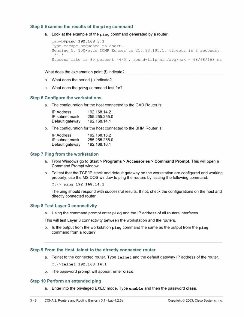
Step 5 Examine the results of the ping command a. Look at the example of the ping command generated by a router.
lab-b#ping 192.168.3.1 Type escape sequence to abort. Sending 5, 100-byte ICMP Echoes to 210.93.105.1, timeout is 2 seconds: .!!!! Success rate is 80 percent (4/5), round-trip min/avg/max = 68/68/168 ms
What does the exclamation point (!) indicate? ________________________________________
b. What does the period (.) indicate? _____________________________________________
c. What does the ping command test for? _________________________________________
Step 6 Configure the workstations a. The configuration for the host connected to the GAD Router is:
IP Address 192.168.14.2 IP subnet mask 255.255.255.0 Default gateway 192.168.14.1
b. The configuration for the host connected to the BHM Router is:
IP Address 192.168.16.2 IP subnet mask 255.255.255.0 Default gateway 192.168.16.1
Step 7 Ping from the workstation a. From Windows go to Start > Programs > Accessories > Command Prompt. This will open a
Command Prompt window.
b. To test that the TCP/IP stack and default gateway on the workstation are configured and working properly, use the MS DOS window to ping the routers by issuing the following command: C:\> ping 192.168.14.1 The ping should respond with successful results. If not, check the configurations on the host and directly connected router.
Step 8 Test Layer 3 connectivity a. Using the command prompt enter ping and the IP address of all routers interfaces.
This will test Layer 3 connectivity between the workstation and the routers.
b. Is the output from the workstation ping command the same as the output from the ping command from a router?
__________________________________________________________________________
Step 9 From the Host, telnet to the directly connected router a. Telnet to the connected router. Type telnet and the default gateway IP address of the router.
C:\>telnet 192.168.14.1 b. The password prompt will appear, enter cisco.
Step 10 Perform an extended ping a. Enter into the privileged EXEC mode. Type enable and then the password class.
3 - 6 CCNA 2: Routers and Routing Basics v 3.1 - Lab 4.2.5a Copyright 2003, Cisco Systems, Inc.

Type ping and press Enter. Fill out the rest of the prompts as shown following:
Protocol [ip]: Target IP address: 192.168.16.1 Repeat count [5]: 50 Datagram size [100]: Timeout in seconds [2]: Extended commands [n]: Sweep range of sizes [n]: Type escape sequence to abort. Sending 50, 100-byte ICMP Echos to 192.168.16.1, timeout is 2 seconds: !!!!!!!!!!!!!!!!!!!!!!!!!!!!!!!!!!!!!!!!!!!!!!!!!! Success rate is 100 percent (50/50), round-trip min/avg/max = 32/32/40 ms GAD#
b. Notice how fast the ping response is. What was the average response time? _____________
Step 11 Perform another extended ping a. Type ping and press Enter. Fill out the rest of the prompts as shown following.
During the ping, remove the crossover cable from the BHM FastEthernet port after 10 pings have responded.
Protocol [ip]: Target IP address: 192.168.16.1 Repeat count [5]: 50 Datagram size [100]: 1500 Timeout in seconds [2]: Extended commands [n]: Sweep range of sizes [n]: Type escape sequence to abort. Sending 50, 1500-byte ICMP Echos to 192.168.16.1, timeout is 2 seconds: !!!!!!!!!!!!!!!U.U...........!!!!!!!!!!!!!!!!!!!!! Success rate is 72 percent (36/50), round-trip min/avg/max = 432/434/464 ms GAD#
b. What does the output from this extended ping say? _________________________________
c. Try doing this with a standard ping, can the cable be removed before the ping is over?
__________________________________________________________________________
d. What was the result of increasing the datagram size in the extended ping? _______________
Step 12 Perform an extended ping from the host a. Exit the Telnet session and return to the host MS-DOS prompt. Type ping and press Enter.
b. Does the extended ping work the same way on the router as on the host? _______________
At the MS-dos prompt type: C:\>ping 192.168.16.1 –n 25
There should be 25 responses from the command.
c. Experiment with other combinations of the extended ping commands on both the router and the host.
Upon completion of the previous steps, logoff by typing exit. Turn the router off.
4 - 6 CCNA 2: Routers and Routing Basics v 3.1 - Lab 4.2.5a Copyright 2003, Cisco Systems, Inc.

1 - 5 CCNA 4: WAN Technologies v 3.1 - Lab 3.3.2 Copyright 2003, Cisco Systems, Inc.
Lab 3.3.2 Configuring PPP Encapsulation
Objective • Configure the serial interfaces on two routers with the PPP protocol.
• Test the link for connectivity.
Background/Preparation Cable a network similar to the one in the diagram above. Any router that meets the interface requirements displayed on the above diagram may be used. This includes the following and any of their possible combinations:
• 800 series routers
• 1600 series routers
• 1700 series routers
• 2500 series routers
• 2600 series routers
Please refer to the chart at the end of the lab to correctly identify the interface identifiers to be used based on the equipment in the lab. The configuration output used in this lab is produced from 1721 series routers. Any other router used may produce slightly different output. Conduct the following steps on each router unless specifically instructed otherwise.
Start a HyperTerminal session.
Note: Refer to the erase and reload instructions sheet. Perform those steps on all routers in this lab assignment before continuing.

2 - 5 CCNA 4: WAN Technologies v 3.1 - Lab 3.3.2 Copyright 2003, Cisco Systems, Inc.
Step 1 Configure the routers Configure all of the following according to the chart:
• The hostname
• The console password
• The virtual terminal password
• The enable secret password
If problems occur during this configuration, refer to Lab 1.1.4a Configuring NAT.
Step 2 Configure the Dublin interface as shown Configure the Dublin router serial interface as follows:
Dublin(config)#interface serial 0 Dublin(config-if)#ip address 192.168.15.2 255.255.255.0 Dublin(config-if)#no shutdown Dublin(config-if)#exit Dublin(config)#exit
Step 3 Configure the Washington interface as shown Configure the Washington router serial interface as follows:
Washington(config)#interface serial 0 Washington(config-if)#ip address 192.168.15.1 255.255.255.0 Washington(config-if)#clock rate 64000 Washington(config-if)#no shutdown Washington(config-if)#exit Washington(config)#exit
Step 4 Save the configuration Washington#copy running-config startup-config Dublin#copy running-config startup-config
Step 5 Enter the command show interface serial 0 (refer to interface chart) on Washington
Washington#show interface serial 0
a. This will show the details of interface serial 0.
b. Serial 0 is _____________, line protocol is_____________. c. Internet address is _____________________. d. Encapsulation _________________________
3 - 5 CCNA 4: WAN Technologies v 3.1 - Lab 3.3.2 Copyright 2003, Cisco Systems, Inc.
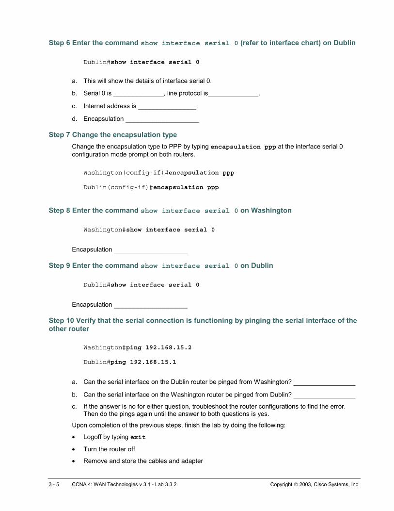
Step 6 Enter the command show interface serial 0 (refer to interface chart) on Dublin Dublin#show interface serial 0
a. This will show the details of interface serial 0.
b. Serial 0 is _____________, line protocol is_____________.
c. Internet address is _______________.
d. Encapsulation ___________________
Step 7 Change the encapsulation type Change the encapsulation type to PPP by typing encapsulation ppp at the interface serial 0 configuration mode prompt on both routers.
Washington(config-if)#encapsulation ppp Dublin(config-if)#encapsulation ppp
Step 8 Enter the command show interface serial 0 on Washington Washington#show interface serial 0
Encapsulation ___________________
Step 9 Enter the command show interface serial 0 on Dublin Dublin#show interface serial 0
Encapsulation ___________________
Step 10 Verify that the serial connection is functioning by pinging the serial interface of the other router
Washington#ping 192.168.15.2 Dublin#ping 192.168.15.1
a. Can the serial interface on the Dublin router be pinged from Washington? ________________
b. Can the serial interface on the Washington router be pinged from Dublin? ________________
c. If the answer is no for either question, troubleshoot the router configurations to find the error. Then do the pings again until the answer to both questions is yes.
Upon completion of the previous steps, finish the lab by doing the following:
• Logoff by typing exit
• Turn the router off
• Remove and store the cables and adapter

4 - 5 CCNA 4: WAN Technologies v 3.1 - Lab 3.3.2 Copyright 2003, Cisco Systems, Inc.
Erasing and reloading the router Enter into the privileged EXEC mode by typing enable.
If prompted for a password, enter class (if that does not work, ask the instructor).
Router>enable
At the privileged EXEC mode, enter the command erase startup-config.
Router#erase startup-config
The responding line prompt will be:
Erasing the nvram filesystem will remove all files! Continue? [confirm]
Press Enter to confirm.
The response should be:
Erase of nvram: complete
Now at the privileged EXEC mode, enter the command reload.
Router(config)#reload
The responding line prompt will be:
System configuration has been modified. Save? [yes/no]:
Type n and then press Enter.
The responding line prompt will be:
Proceed with reload? [confirm]
Press Enter to confirm.
In the first line of the response will be:
Reload requested by console.
After the router has reloaded the line prompt will be:
Would you like to enter the initial configuration dialog? [yes/no]:
Type n and then press Enter.
The responding line prompt will be:
Press RETURN to get started!
Press Enter.
Now the router is ready for the assigned lab to be performed.
5 - 5 CCNA 4: WAN Technologies v 3.1 - Lab 3.3.2 Copyright 2003, Cisco Systems, Inc.
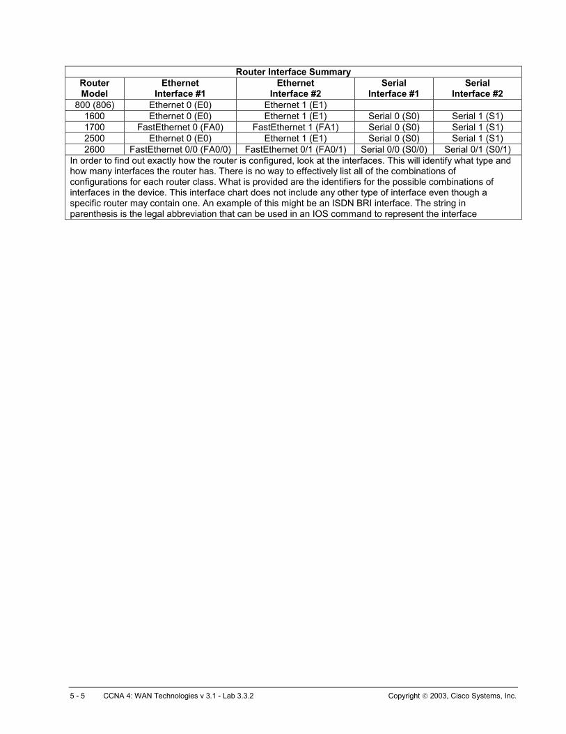
Router Interface Summary Router Model
Ethernet Interface #1
Ethernet Interface #2
Serial Interface #1
Serial Interface #2
800 (806) Ethernet 0 (E0) Ethernet 1 (E1) 1600 Ethernet 0 (E0) Ethernet 1 (E1) Serial 0 (S0) Serial 1 (S1) 1700 FastEthernet 0 (FA0) FastEthernet 1 (FA1) Serial 0 (S0) Serial 1 (S1) 2500 Ethernet 0 (E0) Ethernet 1 (E1) Serial 0 (S0) Serial 1 (S1) 2600 FastEthernet 0/0 (FA0/0) FastEthernet 0/1 (FA0/1) Serial 0/0 (S0/0) Serial 0/1 (S0/1)
In order to find out exactly how the router is configured, look at the interfaces. This will identify what type and how many interfaces the router has. There is no way to effectively list all of the combinations of configurations for each router class. What is provided are the identifiers for the possible combinations of interfaces in the device. This interface chart does not include any other type of interface even though a specific router may contain one. An example of this might be an ISDN BRI interface. The string in parenthesis is the legal abbreviation that can be used in an IOS command to represent the interface