cisco mds 9000 family user guide
TRANSCRIPT

8/7/2019 cisco MDS 9000 family user guide
http://slidepdf.com/reader/full/cisco-mds-9000-family-user-guide 1/151
S e n d d o c u m e n t a t i o n c o m m e n t s t o m d sf e e d b a ck -d o c @c i sc o . c o m
Corporate Headquarters
Cisco Systems, Inc.170 West Tasman DriveSan Jose, CA 95134-1706USAhttp://www.cisco.comTel: 408 526-4000
800 553-NETS (6387)Fax: 408 526-4100
Cisco M DS 9 0 0 0 Family
Fabric Manager User’s Guide
Cisco M DS SAN-OS Release 1.2(2a)
October, 2003
Customer Order Number : DOC-7815800=
Customer Order Number: 278-15800-02

8/7/2019 cisco MDS 9000 family user guide
http://slidepdf.com/reader/full/cisco-mds-9000-family-user-guide 2/151
S e n d d o c u m e n t a t i o n c o m m e n t s t o m d sf e e d b a ck -d o c @c i sc o . c o m
THE SPECIFICATIONS AND INFORMATION REGARDING THE PRODUCTS IN THIS M ANUAL ARE SUBJECT TO CHANGE WITHOUT NOTICE. ALL
STATEMENTS, INFORMATION, AND RECOMMENDATIONS IN THIS MANUAL ARE BELIEVED TO BE ACCURATE BUT ARE PRESENTED WITHOUT
WARRANTY OF ANY KIND, EXPRESS OR IMPLIED. USERS MUST TAKE FULL RESPONSIBILITY FOR THEIR APPLICATION OF ANY PRODUCTS.
THE SOFTWARE LICENSE AND LIMITED WARRANTY FOR THE ACCOMPANYING PRODUCT ARE SET FORTH IN THE INFORMATION PACKET THAT
SHIPPED WITH THE PRODUCT AND ARE INCORPORATED HEREIN BY THIS REFERENCE. IF YOU ARE U NABLE TO LOCATE THE SOFTWARE LICENSEOR LIMITED WARRANTY, CONTACT YOUR CISCO REPRESENTATIVE FOR A COPY.
The Cisco implementation of TCP header compression is an adaptation of a program developed by the University of California, Berkeley (U CB) as part of UCB’s public
domain version of the UNIX operating system. All rights reserved. Copyright © 1981, Regents of the University of California.
NOTWITHSTANDING ANY OTHER WARRANTY HEREIN, ALL DOCUMENT FILES AND SOFTWARE OF THESE SUPPLIERS ARE PROVIDED “AS IS” WITH
ALL FAULTS. CISCO AND THE ABOVE-NAMED SUPPLIERS DISCLAIM ALL WARRANTIES, EXPRESSED OR IMPLIED, INCLUDING, WITHOUT
LIMITATION, THOSE OF MERCHANTABILITY, FITNESS FOR A PARTICULAR PURPOSE AND NONINFRINGEMENT OR ARISING FROM A COURSE OF
DEALING, USAGE, OR TRADE PRACTICE.
IN NO EVENT SHALL CISCO OR ITS SUPPLIERS BE LIABLE FOR ANY IN DIRECT, SPECIAL, CONSEQUENTIAL, OR INCIDENTAL DAMAGES, INCLUDING,
WITHOUT LIMITATION, LOST PROFITS OR LOSS OR DAMAGE TO DATA ARISING OUT OF THE USE OR INABILITY TO USE THIS MANUAL, EVEN IF CISCO
OR ITS SUPPLIERS HAVE BEEN ADVISED OF THE POSSIBILITY OF SUCH DAMAG ES.
CCIP, CCSP, the Cisco Arrow logo, the Cisco Powered Network mark, Cisco Unity, Follow Me Browsing, FormShare, and StackWise are trade marks of Cisco Systems, Inc.;
Changing the Way We Work, Live, Play, and Learn, and iQuick Study are service marks of Cisco Systems, Inc.; and Aironet, ASIST, BPX, Catalyst, CCDA, CCDP, CCIE,
CCNA, CCNP, Cisco, the Cisco Certified Internetwork Expert logo, Cisco IOS, the Cisco IOS logo, Cisco Press, Cisco Systems, Cisco Systems Capital, the Cisco Systems
logo, Empowering the Internet Generation, Enterprise/Solver, EtherChannel, EtherSwitch, Fast Step, GigaStack, Internet Quotient, IOS, IP/TV, iQ Expertise, the iQ logo, iQNet Readiness Scorecard, LightStream, MGX, MICA, the Netw orkers logo, Networking Academy, Network Registrar, Packet , PIX, Post-Routing, Pre-Routing, RateMUX,
Registrar, ScriptShare, SlideCast, SMARTnet, StrataView Plus, Stratm, SwitchProbe, TeleRouter, The Fastes t Way to Increase Your Internet Q uotient, TransPath, and VCO
are registered trademarks of Cisco Systems, Inc. and/or its affiliates in the U.S. and certain other countries.
All other trademarks mentioned in this document or Web site are the property of the ir respective owners. The use of the word partner does not imply a partnership relatio nship
between Cisco and any other company. (0304R)
Cisco MDS 9000 Fabric Manager User’s Guide
Copyright © 2003, Cisco Systems, Inc.
All rights reserved.
8/7/2019 cisco MDS 9000 family user guide
http://slidepdf.com/reader/full/cisco-mds-9000-family-user-guide 3/151
S e n d d o c u m e n t a t i o n c o m m e n t s t o m d sf e e d b a ck -d o c @c i sc o . c o m .
ii i
Cisco M DS 9000 Family Fabric M anager User Guide
78-15800-02, Cisco M DS SAN- OS Rele ase 1.2(2a)
C O N T E N T S
New and Changed Information xi
Preface xiii
Audience xiii
Organization xiii
Conventions xiv
Related Documentati on xv
Obtaining Documentation xv
World Wide Web xv
Documentat ion CD-ROM xv
Ordering Documentation xvi
Documentation Feedback xvi
Obtaining Technical Assistance xvi
Cisco.com xvi
Technical Assistance Center xvii
Cisco TAC Web Site xvii
Cisco TAC Escalat ion Center xviii
Getting Started with Cisco Fabric M anager 1-1
Storage Management Solutions Architecture 1-2
Managing Cisco MDS 9000 Switches 1-2
In-Band M anagement and Out-of-Band M anagement 1-4
Using t he Local Console Port and the CLI 1-4
Discovering and Viewing the Network Fabric 1-5
Controlling Administrator Access with Users and Roles 1-7
Performing Device M anagement 1-7
Accessing Cisco Fabric M anager 1-9
Connecting to a Supervisor Module 1-9
Launching Views 1-10
Troubleshooting Install ation and Access 1-11
8/7/2019 cisco MDS 9000 family user guide
http://slidepdf.com/reader/full/cisco-mds-9000-family-user-guide 4/151
S e n d d o c u m e n t a t i o n c o m m e n t s t o m d sf e e d b a ck - d o c @c i sc o . c o m .
Contents
iv
Cisco M DS 9000 Famil y Fabric M anager User Guide
78-15800-02, Cisco M DS SAN-OS Rele ase 1.2(2a)
Using Cisco Fabric M anager and Device M anager 2-1
Using Fabric M anager 2-2
Menu Bar, Toolbars, and M essage Bar 2-3
Logical/Physical Pane 2-4
Information Pane 2-4
Map Pane 2-6
Locating Other Swi tches 2-8
Modifying Device Grouping 2-9
Managing Discovered Switches 2-9
Analyzing Switch Device Health 2-10
Analyzing End-to-End Connectivity 2-10
Analyzing Swit ch Fabric Configuration 2-11
Creating a Policy Profi le 2-12
Analyzing the Results of M erging Zones 2-12
Issuing the Show Tech Support Command 2-13
Using Traceroute and Other Troubleshooting Tools 2-14
Setting Fabric M anager Preferences 2-14
Viewing Reports in Fabric M anager 2-14
Using Device Manager 2-16
Launching Device Manager from Fabric M anager 2-16
Using Summary View 2-17
Comparing Device Manager to Fabric M anager 2-18
Managing Ports 2-19Setting Device Manager Preferences 2-19
M anaging Zones and Zone Sets 3-1
Creating Zones and Zone Sets 3-2
Setting Default Zone Policy 3-2
Creating Additi onal Zones and Zonesets 3-3
Adding Zones to a Zone Set 3-3
Cloning Zones and Zone Sets 3-4
Adding Zone M embers 3-4
Activating or Enforcing Zone Sets 3-5
Searching the Zone Database 3-5
Displaying Port Membership Information 3-6
Deleting Zones, Zone Sets, and M embers 3-6
Changing the Default Zone Policy 3-7

8/7/2019 cisco MDS 9000 family user guide
http://slidepdf.com/reader/full/cisco-mds-9000-family-user-guide 5/151
S e n d d o c u m e n t a t i o n c o m m e n t s t o m d sf e e d b a ck -d o c @c i sc o . c o m .
Contents
v
Cisco M DS 9000 Family Fabric M anager User Guide
78-15800-02, Cisco M DS SAN- OS Rele ase 1.2(2a)
Viewing Zone Statistics 3-7
M anaging VSANs 4-1
Adding and Configuring VSANs 4-3
Controll ing In-Band Management Connectivi ty 4-3
Configuring IP Routing for M anagement Traff ic 4-4
Configuring an IP Route 4-4
Managing IPFC Connectivity with Multiple VSANs 4-5
Viewing IP Address Information 4-5
Enabling or Disabling IP Forwarding 4-5
Viewing TCP Information and Statistics 4-6
Viewing UDP Information and Statistics 4-6
Viewing IP Statistics 4-6
Viewing ICMP Statisti cs 4-6
Monitoring SNM P Traff ic 4-7
M anaging Administrator Access 5-1
Viewing SNM P Users, Roles, and Communiti es 5-2
Adding a User or Communit y String 5-2
Configuring SNMP Communiti es 5-3
Configuring User Roles 5-4
Configuring Common Roles 5-4
Creating Common Roles 5-4
Editing Common Role Rules (DM Only) 5-5
Deleting Common Roles 5-6
Configuring RADIUS Authentication 5-6
Configuring RADIUS Servers 5-6
M anaging Softw are and Configuration Files 6-1
Using the Softw are Upgrade Wizard 6-2
Configuring Software Images Using Device Manager 6-3
Downloading Software Images 6-3
Copying Configuration Files 6-3
Saving Configurat ions 6-4
M anaging Interfaces 7-1
Managing General Port Attributes 7-1
Enabling or Disabling Ports 7-2
8/7/2019 cisco MDS 9000 family user guide
http://slidepdf.com/reader/full/cisco-mds-9000-family-user-guide 6/151
S e n d d o c u m e n t a t i o n c o m m e n t s t o m d sf e e d b a ck - d o c @c i sc o . c o m .
Contents
vi
Cisco M DS 9000 Famil y Fabric M anager User Guide
78-15800-02, Cisco M DS SAN-OS Rele ase 1.2(2a)
Managing Interface Attributes for Ports 7-2
Viewing FLOGI At tributes 7-2
Viewing Port ELP Att ributes 7-3
Viewing Trunking Information 7-3
Managing Physical Att ributes for a Port 7-4
Viewing Port Capabilit y At tributes 7-4
Managing PortChannel Interfaces 7-4
Managing PortChannel General At tributes 7-5
Managing PortChannel Interface Attributes 7-5
Monitoring Port Statisti cs 7-6
Monitoring and Charting Traff ic Statisti cs 7-6
Monitoring Port Traffic (Bytes) 7-6
Monitoring Port Traff ic (Frames) 7-7
Monitoring Port Discards 7-7
Monitoring Port Class 2 Errors 7-7
Monitoring Port Link Errors 7-7
Monitoring Port Sequence Errors 7-7
Monitoring Port Frame Errors 7-8
Using the PortChannel Wizard 7-8
Managing Port Security 7-9
Turning AutoLearning On or Off 7-9
Activating a Binding 7-9
Copying an Active Configuration to t he Running Configurat ion 7-10
Configuring a Binding 7-11
Deleting a Binding 7-11
Displaying Activated Bindings 7-12
Displaying Port Security Statistics 7-12
Displaying Port Security Violations 7-12
M anaging Events and Alarms 8-1
SNMP events 8-1
RMON alarms 8-1
Call Home 8-1
Syslog 8-2
Viewing the Events Log 8-3
Configuring Event Destinations 8-3
Configuring Event Security 8-4

8/7/2019 cisco MDS 9000 family user guide
http://slidepdf.com/reader/full/cisco-mds-9000-family-user-guide 7/151
S e n d d o c u m e n t a t i o n c o m m e n t s t o m d sf e e d b a ck -d o c @c i sc o . c o m .
Contents
vi i
Cisco M DS 9000 Family Fabric M anager User Guide
78-15800-02, Cisco M DS SAN- OS Rele ase 1.2(2a)
Configuring Event Filt ers 8-4
Enabling RM ON Alarms by Port 8-4
Enabling RMON A larms for VSANs 8-5
Enabling RMON Alarms f or Physical Components 8-5
Configuring RM ON Controls 8-6
Managing RMON Alarms 8-6
Managing RMON Event Severity Levels 8-7
Viewing the RMON Log 8-7
Call Home Configuration Overview 8-7
Configuring Call Home Attributes 8-9
Configuring Call Home Destination Attributes 8-9
Configuring Call Home E-M ail Addresses 8-10
Configuring Call Home Alerts 8-10
Configuring Call Home Profi les 8-10Configuring Syslog Attributes 8-11
Configuring Syslog Servers 8-11
Configuring Syslog Priori ties 8-12
M anaging the System and Components 9-1
Viewing System At tributes 9-1
Viewing Running Processes 9-2
Viewing Flash File Information 9-2
Managing Inventory Information 9-2
Managing Card Att ributes 9-3
Managing Temperature Sensor Information 9-3
Managing Power Supplies 9-4
Managing NTP 9-4
Display General NTP Statist ics for a Swit ch 9-4
Create an NTP Server or Peer 9-5
Edit an NTP Server or Peer Configuration 9-5
Delete an NTP Server or Peer 9-6
M anaging Fibre Channel Routing and FSPF 10-1Configuring Fibre Channel Routes 10-1
Configuring Fibre Channel Route Flows 10-2
Managing FSPF General A tt ributes 10-2
Configuring FSPF Interfaces 10-3

8/7/2019 cisco MDS 9000 family user guide
http://slidepdf.com/reader/full/cisco-mds-9000-family-user-guide 8/151
S e n d d o c u m e n t a t i o n c o m m e n t s t o m d sf e e d b a ck - d o c @c i sc o . c o m .
Contents
viii
Cisco M DS 9000 Famil y Fabric M anager User Guide
78-15800-02, Cisco M DS SAN-OS Rele ase 1.2(2a)
Viewing FSPF Statistics 10-3
Viewing FSPF Interface Statist ics 10-3
Viewing Link State Records 10-3
Viewing FSPF Links 10-4
M anaging IP Storage Services 5
IP Storage Services Module 5
Managing Gigabit Ethernet Interfaces 6
Managing FCIP 6
Managing iSCSI Services 6
Configuring Gigabit Ethernet Interfaces 7
Creating FCIP Tunnels with Device Manager 7
Assigning FCIP Prof iles 8
Creating Tunnels 8Verifying Interfaces 9
Verifying Extended Link Protocols 9
Checking Trunk Status 10
Checking for Interface Errors 10
Creating FCIP Tunnels with the FCIP Wizard 10
Authenticating iSCSI Targets 11
Specifying Targets 11
Specifying LUN Mappings 12
Viewing iSCSI Statistics 12
Viewing iSCSI Sessions 13
Viewing Session Statistics 13
Creating an iSCSI Initiator 13
Creating an iSCSI Virtual Target 15
Configuring IP Filters 17
Using the IP Fil ter W izard 17
Creating IP Profiles 17
Adding IP Fil ters to Profi les 18
Associating IP Profi les to Interfaces 19
Deleting IP Profi les 19
Deleting IP Fil ters 20
8/7/2019 cisco MDS 9000 family user guide
http://slidepdf.com/reader/full/cisco-mds-9000-family-user-guide 9/151
S e n d d o c u m e n t a t i o n c o m m e n t s t o m d sf e e d b a ck -d o c @c i sc o . c o m .
Contents
ix
Cisco M DS 9000 Family Fabric M anager User Guide
78-15800-02, Cisco M DS SAN- OS Rele ase 1.2(2a)
M anaging SPAN 21
Creating SPAN Sessions 21
Editing SPAN Sources 22
Deleting SPAN Sessions 22
M anaging Advanced Features 11-1
Managing World Wide Names 11-1
Managing Domain Parameters 11-2
Managing Running Attributes for Domains 11-2
Configuring Domain Attributes 11-2
Viewing Domain Information 11-3
Viewing Domain M anager Statisti cs 11-3
Configuring Domain Interfaces 11-3
Viewing Domain Areas 11-4
Configuring Persistent FCIDs 11-4
Viewing Domain Area Ports 11-5
Configuring the Name Server 11-5
Viewing General Attributes for the Name Server 11-5
Viewing Advanced Attributes for the Name Server 11-6
Proxy Ports for the Name Server 11-6
Viewing Name Server Statistics 11-6
Viewing LUN Information 11-7
Configuring LUN Discovery 11-7
Viewing Logical Unit Information 11-7
Viewing LUNs Information 11-7
Viewing RSCN Information 11-8
Viewing RSCN Nx Regist rations 11-8
Viewing RSCN Statistics 11-8
Configuring Timers 11-8
Confi guring Virtual Routing Redundancy Protocol (VRRP) 11-9
Configuring VRRP Operations Attributes 11-9
Managing IP Addresses for VRRP 11-9
Viewing VRRP Statisti cs 11-9
I N D E X

8/7/2019 cisco MDS 9000 family user guide
http://slidepdf.com/reader/full/cisco-mds-9000-family-user-guide 10/151
S e n d d o c u m e n t a t i o n c o m m e n t s t o m d sf e e d b a ck - d o c @c i sc o . c o m .
Contents
x
Cisco M DS 9000 Famil y Fabric M anager User Guide
78-15800-02, Cisco M DS SAN-OS Rele ase 1.2(2a)

8/7/2019 cisco MDS 9000 family user guide
http://slidepdf.com/reader/full/cisco-mds-9000-family-user-guide 11/151
S e n d d o c u m e n t a t i o n c o m m e n t s t o m d sf e e d b a ck -d o c @c i sc o . c o m .
xi
Cisco M DS 9000 Family Fabric M anager User Guide
78-15800-02, Cisco M DS SAN- OS Rele ase 1.2(2a)
New and Changed Information
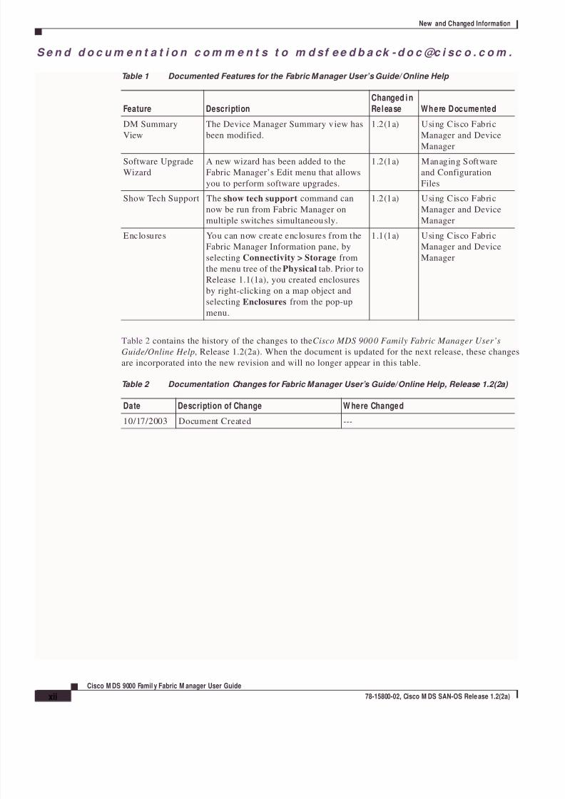
Table 1 summarizes the new and changed features for the Cisco Fabric Manager Use’s Guide/Online
Help, and tells you where they are documented. If a feature has changed in release, a brief description
of the change appears in the “Description” column, and that release is shown in the “Changed in
Release” column.
Table 1 Documented Features for the Fabric M anager User’s Guide/ Online Help
Feature Description
Changed in
Release Where Documented
Virtualization Fabric Manager now recognizes virtual
end devices and storage devices and
displays them with special icons.
1.2(2a) Getting Started with
Cisco Fabric Manager
Port Security You can now manage and configure
VSAN-based port security using Fabric
Manager.
1.2(1a) Managing Interfaces
IP Fil ter You can configure and manage IP
profiles and filters using Fabric Manager,
to control IP access to a switch.
1.2(1a) Configuring IP Profiles
Common Roles You can now set the scope of VSAN
security with Common Roles,
configurable from Fabric Manager or
Device Manager.
1 .2(1a) Managing
Administrator Access
SPAN You can now create SPAN sess ions and
sources with Fabric Manager and Device
Manager.
1.2(1a) Management Services
NTP You can now create and view NTP peers
and servers with Fabric Manager andDevice Manager.
1.2(1a) Management Services
LUN Zoning You can now allocate (centralize or pool)
storage using Fabric Manager.
1.2(1a) Managing Zones and
Zonesets
Read-only Zones Read-only zones are now configurable
and viewable.
1.2(1a) Managing Zones and
Zonesets
8/7/2019 cisco MDS 9000 family user guide
http://slidepdf.com/reader/full/cisco-mds-9000-family-user-guide 12/151
S e n d d o c u m e n t a t i o n c o m m e n t s t o m d sf e e d b a ck - d o c @c i sc o . c o m .
xii
Cisco M DS 9000 Famil y Fabric M anager User Guide
78-15800-02, Cisco M DS SAN-OS Rele ase 1.2(2a)
New and Changed Information
Table 2 contains the history of the changes to the Cisco MDS 9000 Family Fabric Manager User’s
Guide/Online Help, Release 1.2(2a). When the document is updated for the next release, these changes
are incorporated into the new revision and will no longer appear in this table.
DM Summary
View
The Device Manager Summary view has
been modified.
1.2(1a) Using Cisco Fabric
Manager and DeviceManager
Software Upgrade
Wizard
A new wizard has been added to the
Fabric Manager’s Edit menu that allows
you to perform software upgrades.
1.2(1a) Managing Software
and Configuration
Files
Show Tech Support The show tech support command can
now be run from Fabric Manager on
multiple switches simultaneously.
1.2(1a) Using Cisco Fabric
Manager and Device
Manager
Enclosures You can now create enclosures from the
Fabric Manager Information pane, by
selecting Connectivity > Storage from
the menu tree of the Physical tab. Prior to
Release 1.1(1a), you created enclosuresby right-clicking on a map object and
selecting Enclosures from the pop-up
menu.
1.1(1a) Using Cisco Fabric
Manager and Device
Manager
Table 1 Documented Features for the Fabric Manager User’s Guide/ Online Help
Feature Description
Changed i n
Release Where Documented
Table 2 Documentation Changes for Fabric Manager User’s Guide/Online Help, Release 1.2(2a)
Date Description of Change W here Changed
10/17/2003 Document Created ---

8/7/2019 cisco MDS 9000 family user guide
http://slidepdf.com/reader/full/cisco-mds-9000-family-user-guide 13/151
S e n d d o c u m e n t a t i o n c o m m e n t s t o m d sf e e d b a ck -d o c @c i sc o . c o m .
xiii
Cisco M DS 9000 Family Fabric M anager User Guide
78-15800-02, Cisco M DS SAN- OS Rele ase 1.2(2a)
Preface
This preface describes the audience, organization, and conventions of the Cisco MDS 9000 Family
Fabric Manager User Guide. It also provides information on how to obtain related documentation.
AudienceThis guide is for system administrators who intend to use the Cisco Fabric Manager to configure and
monitor the switches that build the network fabric.
You should be familiar with the basic concepts and terminology used in internetworking, and understand
your network topology and the protocols that the devices in your network can use. You should also have
a working knowledge of the operating system on which you are running Fabric Manager, such as
Microsoft Windows, Linux, or Solaris.
OrganizationThis guide contains procedural and conceptual information. For reference information (such as fielddescriptions for the windows and dialog boxes) refer to the Cisco MDS 9000 Family Fabric Manager
Online Help. This is accessible by clicking Help from the Fabric Manager or Device Manager menus.
This guide is organized as follows:
Chapter Title Description
Chapter 1 Getting Started with Cisco Fabric
Manager
Provides an overview of the Cisco Fabric
Manager system.
Chapter 2 Using Cisco Fabric Manager and Device
Manager
Describes how to use the Cisco Fabric
Manager views for performing the most
important device and fabric management
tasks.Chapter 3 Managing Zones and Zone Sets Describes how to configure zones and zone
sets.
Chapter 4 Managing VSANs Describes how to configure VSANs (virtual
storage area networks).
8/7/2019 cisco MDS 9000 family user guide
http://slidepdf.com/reader/full/cisco-mds-9000-family-user-guide 14/151
S e n d d o c u m e n t a t i o n c o m m e n t s t o
xiv
Cisco M DS 9000 Famil y Fabric M anager User Guide
78-15800-02, Cisco M DS SAN-OS Rele ase 1.2(2a)
Preface
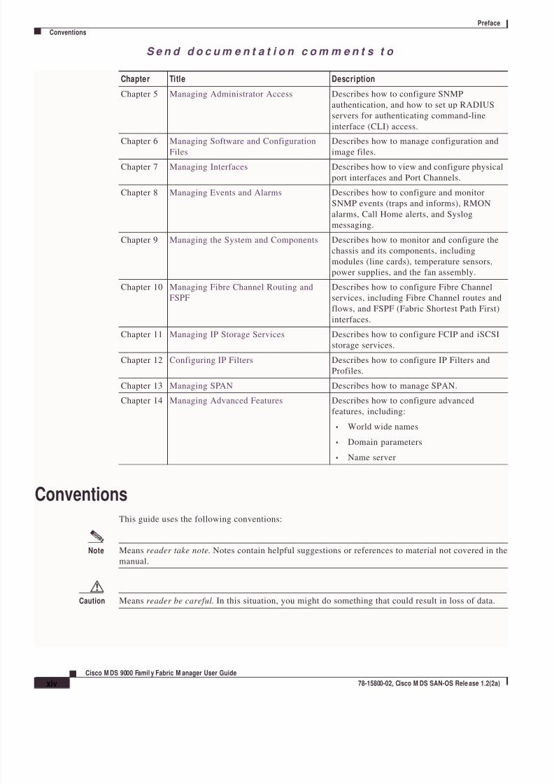
Conventions
ConventionsThis guide uses the following conventions:
Note Means reader take note. Notes contain helpful suggestions or references to material not covered in themanual.
Caution Means reader be careful. In this situation, you might do something that could result in loss of data.
Chapter 5 Managing Administrator Access Describes how to configure SNMP
authentication, and how to set up RADIUS
servers for authenticating command-line
interface (CLI) access.
Chapter 6 Managing Software and Configuration
Files
Describes how to manage configuration and
image files.
Chapter 7 Managing Interfaces Describes how to view and configure physical
port interfaces and Port Channels.
Chapter 8 Managing Events and Alarms Describes how to configure and monitor
SNMP events (traps and informs), RMON
alarms, Call Home alerts, and Syslog
messaging.
Chapter 9 Managing the System and Components Describes how to monitor and configure the
chassis and its components, including
modules (line cards), temperature sensors,
power supplies, and the fan assembly.Chapter 10 Managing Fibre Channel Routing and
FSPF
Describes how to configure Fibre Channel
services, including Fibre Channel routes and
flows, and FSPF (Fabric Shortest Path First)
interfaces.
Chapter 11 Managing IP Storage Services Describes how to configure FCIP and iSCSI
storage services.
Chapter 12 Configuring IP Filters Describes how to configure IP Filters and
Profiles.
Chapter 13 Managing SPAN Describes how to manage SPAN.
Chapter 14 Managing Advanced Features Describes how to configure advanced
features, including:
World wide names
• Domain parameters
• Name server
Chapter Title Description

8/7/2019 cisco MDS 9000 family user guide
http://slidepdf.com/reader/full/cisco-mds-9000-family-user-guide 15/151
S e n d d o c u m e n t a t i o n c o m m e n t s t o
xv
Cisco M DS 9000 Family Fabric M anager User Guide
78-15800-02, Cisco M DS SAN- OS Rele ase 1.2(2a)
Preface
Related Documentation
Related DocumentationFor Fabric Manager and Device Manager field descriptions, refer to the Cisco MDS 9000 Family Fabric
Manager Online Help. For additional information, refer to the following documents:
• Regulatory Compliance and Safety Information for the Cisco MDS 9000 Family
• Cisco MDS 9100 Series Hardware Installation Guide
• Cisco MDS 9200 Series Hardware Installation Guide
• Cisco MDS 9500 Series Hardware Installation Guide
• Cisco MDS 9000 Family Configuration Guide
• Cisco MDS 9000 Family Command Reference
• Cisco MDS 9000 Family Troubleshooting Guide
• Cisco MDS 9000 Family System Messages Guide
• Cisco MDS 9000 Family MIB Reference Guide
For information on VERITAS Storage Foundation™ for Networks 1.0, Cisco, ref er to the following
Veritas documents available at http://support.veritas.com/:
• VERITAS Storage Foundation for Networks Overview
• VERITAS Storage Foundation for Networks Installation and Configuration Guide
• VERITAS Storage Foundation for Networks Obtaining and Installing Licenses
• VERITAS Storage Foundation for Networks GUI Administrator's Guide
• VERITAS Storage Foundation for Networks CLI Administrator's Guide
• VERITAS Storage Foundation for Networks README
Obtaining DocumentationThese sections explain how to obtain documentation from Cisco Systems.
World W ide W eb
You can access the most current Cisco documentation on the World Wide Web at this URL:
http://www.cisco.com
Translated documentation is available at this URL:
http://www.cisco.com/public/countries_languages.shtml
Documentation CD-ROM
Cisco documentation and additional literature are available in a Cisco Documentation CD-ROM
package, which is shipped with your product. The Documentation CD-ROM is updated monthly and may
be more current than printed documentation. The CD-ROM package is available as a single unit or
through an annual subscription.
8/7/2019 cisco MDS 9000 family user guide
http://slidepdf.com/reader/full/cisco-mds-9000-family-user-guide 16/151
S e n d d o c u m e n t a t i o n c o m m e n t s t o
xvi
Cisco M DS 9000 Famil y Fabric M anager User Guide
78-15800-02, Cisco M DS SAN-OS Rele ase 1.2(2a)
Preface
Obtaining Technical Assistance
Ordering Documentation
You can order Cisco documentation in these ways:
• Registered Cisco.com users (Cisco direct customers) can order Cisco product documentation from
the Networking Products MarketPlace:
http://www.cisco.com/cgi-bin/order/order_root.pl
• Registered Cisco.com users can order the Documentation CD-ROM through the online Subscription
Store:
http://www.cisco.com/go/subscription
• Nonregistered Cisco.com users can order documentation through a local account representative by
calling Cisco Systems Corporate Headquarters (California, U.S.A.) at 408 526-7208 or, elsewhere
in North America, by calling 800 553-NETS (6387).
Documentation Feedback
You can submit comments electronically on Cisco.com. In the Cisco Documentation home page, click
the Fax or Email option in the “Leave Feedback” section at the bottom of the page.
You can e-mail your comments to [email protected].
You can submit your comments by mail by using the response card behind the front cover of your
document or by writing to the following address:
Cisco Systems
Attn: Document Resource Connection
170 West Tasman Drive
San Jose, CA 95134-9883
We appreciate your comments.
Obtaining Technical Assistance
Note If you purchased this product through a Cisco reseller, contact the reseller directly for technical support.
If you purchased this product directly from Cisco, contact Cisco Technical Support at this URL:
http://www.cisco.com/warp/public/687Directory/DirTAC.shtml
Cisco provides Cisco.com as a starting point for all technical assistance. Customers and partners can
obtain online documentation, troubleshooting tips, and sample configurations from online tools by using
the Cisco Technical Assistance Center (TAC) Web Site. Cisco.com registered users have complete access
to the technical support resources on the Cisco TAC Web Site.
Cisco.com
Cisco.com is the foundation of a suite of interactive, networked services that provides immediate, open
access to Cisco information, networking solutions, services, programs, and resources at any time, from
anywhere in the world.

8/7/2019 cisco MDS 9000 family user guide
http://slidepdf.com/reader/full/cisco-mds-9000-family-user-guide 17/151
S e n d d o c u m e n t a t i o n c o m m e n t s t o
xvii
Cisco M DS 9000 Family Fabric M anager User Guide
78-15800-02, Cisco M DS SAN- OS Rele ase 1.2(2a)
Preface
Obtaining Technical Assistance
Cisco.com is a highly integrated Internet application and a powerful, easy-to-use tool that provides a
broad range of features and services to help you with these tasks:
• Streamline business processes and improve productivity
• Resolve technical issues with online support
• Download and test software packages
• Order Cisco learning materials and merchandise
• Register for online skill assessment, training, and certification programs
If you want to obtain customized information and service, you can self-register on Cisco.com. To access
Cisco.com, go to this URL:
http://www.cisco.com
Technical Assistance Center
The Cisco Technical Assistance Center (TAC) is available to all customers who need technical assistance
with a Cisco product, technology, or solution. Two levels of support are available: the Cisco TACWeb Site and the Cisco TAC Escalation Center.
Cisco TAC inquiries are categorized according to the urgency of the issue:
• Priority level 4 (P4)—You need information or assistance concerning Cisco product capabilities,
product installation, or basic product configuration.
• Priority level 3 (P3)—Your network performance is degraded. Network functionality is noticeably
impaired, but most business operations continue.
• Priority level 2 (P2)—Your production network is severely degraded, affecting signi ficant aspects
of business operations. No workaround is available.
• Priority level 1 (P1)—Your production network is down, and a critical impact to business operations
will occur if service is not restored quickly. No workaround is available.
The Cisco TAC resource that you choose is based on the priority of the problem and the conditions of
service contracts, when applicable.
Cisco TAC Web Site
You can use the Cisco TAC Web Site to resolve P3 and P4 issues yourself, saving both cost and time.
The site provides around-the-clock access to online tools, knowledge bases, and software. To access the
Cisco TAC Web Site, go to this URL:
http://www.cisco.com/tac
All customers, partners, and resellers who have a valid Cisco service contract have complete access to
the technical support resources on the Cisco TAC Web Site. The Cisco TAC Web Site requires a
Cisco.com login ID and password. If you have a valid service contract but do not have a login ID orpassword, go to this URL to register:
http://www.cisco.com/register/
If you are a Cisco.com registered user, and you cannot resolve your technical issues by using the Cisco
TAC Web Site, you can open a case online by using the TAC Case Open tool at this URL:
http://www.cisco.com/tac/caseopen

8/7/2019 cisco MDS 9000 family user guide
http://slidepdf.com/reader/full/cisco-mds-9000-family-user-guide 18/151
S e n d d o c u m e n t a t i o n c o m m e n t s t o
xviii
Cisco M DS 9000 Famil y Fabric M anager User Guide
78-15800-02, Cisco M DS SAN-OS Rele ase 1.2(2a)
Preface
Obtaining Technical Assistance
If you have Internet access, we recommend that you open P3 and P4 cases through the Cisco TAC
Web Site.
Cisco TAC Escalation Center
The Cisco TAC Escalation Center addresses priority level 1 or priority level 2 issues. Theseclassifications are assigned when severe network degradation significantly impacts business operations.
When you contact the TAC Escalation Center with a P1 or P2 problem, a Cisco TAC engineer
automatically opens a case.
To obtain a directory of toll-free Cisco TAC telephone numbers for your country, go to this URL:
http://www.cisco.com/warp/public/687/Directory/DirTAC.shtml
Before calling, please check with your network operations center to determine the level of Cisco support
services to which your company is entitled: for example, SMARTnet, SMARTnet Onsite, or Network
Supported Accounts (NSA). When you call the center, please have available your service agreement
number and your product serial number.

8/7/2019 cisco MDS 9000 family user guide
http://slidepdf.com/reader/full/cisco-mds-9000-family-user-guide 19/151
C H A P T E R
S e n d d o c u m e n t a t i o n c o m m e n t s t o m d sf e e d b a ck -d o c @c i sc o . c o m .
1-1
Cisco MDS 9000 Family Fabric M anager User Guide
78-15800-02, Cisco M DS SAN- OS Rele ase 1.2(2a)
1Getting Started w ith Cisco Fabric M anager
The Cisco Fabric Manager is a set of two network management tools that supports Secure Simple
Network Management Protocol version 3 (SNMPv3) and legacy versions. It provides a graphical user
interface (GUI) that displays real-time views of your network fabric, and lets you manage the
configuration of Cisco MDS 9000 Family devices and third-party switches. The Cisco Fabric Manager
tools are:
• Fabric Manager
• Device Manager
The Fabric Manager displays a map of your network fabric, including Cisco MDS 9000 Family switches,
third-party switches, hosts, and storage devices. The Device Manager presents two views of a switch.
Device View displays a graphic representation of the switch configuration and provides access to
statistics and configuration information for a single switch. Summary View displays a summary of
xEPorts (Inter-Switch Links), Fx Ports (fabric ports), and Nx Ports (attached hosts and storage) on the
switch, as well as FC and IP neighbor devices.
The Cisco Fabric Manager is an alternative to the command-line interface (CLI) for most switch
configuration commands. For information on using the CLI to configure a Cisco MDS 9000 Family
switch, refer to the Cisco 9000 Family Configuration Guide or the Cisco 9000 Family Command
Reference.
To learn more about Fabric Manager and Device Manager, read the following topics:
• Storage Management Solutions Architecture, page 2
• Managing Cisco MDS 9000 Switches, page 2
• In-Band Management and Out-of-Band Management, page 4
• Using the Local Console Port and the CLI, page 4
• Discovering and Viewing the Network Fabric, page 5
• Controlling Administrator Access with Users and Roles, page 7
• Performing Device Management, page 7
To install Fabric Manager and Device Manager on your system, refer to:
• Accessing Cisco Fabric Manager, page 8
8/7/2019 cisco MDS 9000 family user guide
http://slidepdf.com/reader/full/cisco-mds-9000-family-user-guide 20/151
S e n d d o c u m e n t a t i o n c o m m e n t s t o m d sf e e d b a ck - d o c @c i sc o . c o m .
1-2
Cisco M DS 9000 Famil y Fabric M anager User Guide
78-15800-02, Cisco M DS SAN-OS Rele ase 1.2(2a)
Chapter 1 Getting Started w ith Cisco Fabric Manager
Storage Mana gement Solutions Architecture
Storage M anagement Solutions ArchitectureManagement services required for the storage environment can be divided into five “layers,” with the
bottom layer being closest to the physical storage network equipment, and the top layer managing the
interface between applications and storage resources.
Of these five layers of storage network management, Cisco Fabric Manager provides tools for device(element) management and fabric management. In general, the Device Manager is most useful for device
management (a single switch), while Fabric Manager is more efficient for performing fabric
management operations involving multiple switches.
Tools for “upper-layer” management tasks can be provided by Cisco or by third-party storage and
network management applications. The following summarizes the goals and function of each layer of
storage network management:
• Device management provides tools to configure and manage a device within a system or a fabric.
You use device management tools to perform tasks on one device at a time, such as initial device
configuration, setting and monitoring thresholds, and managing device system images or firmware.
• Fabric management provides a system-oriented view of a fabric and its devices. Fabric management
applications provide fabric discovery, fabric monitoring, reporting, and fabric configuration.• Resource management provides tools for managing resources such as fabric bandwidth, connected
paths, disks, I/O operations per second (IOPS), CPU, and memory. You can use Fabric Manager to
perform some of these tasks.
• Data management provides tools for ensuring the integrity, availability, and performance of data.
Data management services include redundant array of independent disks (RAID) schemes, data
replication practices, backup or recovery requirements, and data migration.
• Application management provides tools for managing the overall system consisting of devices,
fabric, resources, and data from the application. Application management integrates all these
components with the applications that use the storage network.
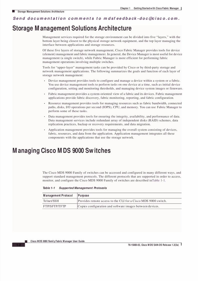
M anaging Cisco M DS 9000 Sw itches
The Cisco MDS 9000 Family of switches can be accessed and configured in many different ways, and
support standard management protocols. The different protocols that are supported in order to access,
monitor, and configure the Cisco MDS 9000 Family of switches are described in Table 1-1.
Table 1-1 Supported Management Protocols
M anagement Protocol PurposeTelnet/SSH Provides remote access to the CLI for a Cisco MDS 9000 switch.
FTP/SFTP/TFTP Copies configuration and software images between devices.

8/7/2019 cisco MDS 9000 family user guide
http://slidepdf.com/reader/full/cisco-mds-9000-family-user-guide 21/151
S e n d d o c u m e n t a t i o n c o m m e n t s t o m d sf e e d b a ck -d o c @c i sc o . c o m .
1-3
Cisco MDS 9000 Family Fabric M anager User Guide
78-15800-02, Cisco M DS SAN- OS Rele ase 1.2(2a)
Chapter 1 Getting Started w ith Cisco Fabric M anager
M anaging Cisco MDS 9000 Swi tches
SNMPv1, v2c, and v3 Includes over 50 distinct Management Information Bases (MIBs). Cisco
MDS 9000 Family switches support SNMP version 1, 2, and 3 and RMON
V1 and V2. RMON provides advanced alarm and event management,including setting thresholds and sending notifications based on changes in
device or network behavior.
By default, the Cisco Fabric Manager communicates with Cisco MDS 9000
Family switches using SNMPv3, which provides secure authentication using
encrypted user names and passwords. SNMPv3 also provides the option to
encrypt all management traffic.
HTTP HTTP is only used for the distr ibution and installation of the Cisco Fabric
Manager software. It is not used for communication between the Cisco
Fabric Manager and Cisco MDS 9000 Family switches.
ANSI T11 FC-GS3 FC-GS3 in the definition of the management servers defines the Fabric
Configuration Server (FCS), which is a standard mechanism to collect
information about platforms (end devices) and interconnecting elements(switches) building the fabric.
The Cisco MDS 9000 uses the information provided by FCS on top of the
information contained in the Name Server database and in the Fibre Channel
Shortest Path First (FSPF) topology database to build a detailed topology
view, and collect information for all the devices building the fabric.
Table 1-1 Supported Management Protocols
M anagement Protocol Purpose

8/7/2019 cisco MDS 9000 family user guide
http://slidepdf.com/reader/full/cisco-mds-9000-family-user-guide 22/151
S e n d d o c u m e n t a t i o n c o m m e n t s t o m d sf e e d b a ck - d o c @c i sc o . c o m .
1-4
Cisco M DS 9000 Famil y Fabric M anager User Guide
78-15800-02, Cisco M DS SAN-OS Rele ase 1.2(2a)
Chapter 1 Getting Started w ith Cisco Fabric Manager
In-Band M anagement and Out-of-Band Ma nagement
In-Band M anagement and Out-of-Band M anagementCisco Fabric Manager requires an out-of-band (Ethernet) connection to at least one Cisco MDS 9000
Family switch. The interface referred to as the out-of-band management connection is a 10/100 Mbps
Ethernet interface on the supervisor module, labeled mgmt0. The mgmt0 interface can be connected to
a management network to access the switch through IP over Ethernet. You must connect to at least oneCisco MDS 9000 Family switch in the fabric, through its Ethernet management port. You can then use
this connection to manage the other switches using in-band (Fibre Channel) connectivity. Otherwise, you
need to connect the mgmt0 port on each switch to your Ethernet network.
Each supervisor module has its own Ethernet connection; however, the two Ethernet connections in a
redundant supervisor system operate in active or standby mode. The active supervisor module also hosts
the active mgmt0 connection. When a failover event occurs to the standby supervisor module, the IP
address and media access control (MAC) address of the active Ethernet connection are moved to the
standby Ethernet connection.
You can also manage switches on a Fibre Channel network using an in-band IP connection (using IP over
Fibre Channel - IPFC). The Cisco MDS 9000 Family supports RFC 2625 IP over Fibre Channel (IPFC),
which defines an encapsulation method to transport IP over a Fibre Channel network.
IPFC encapsulates IP packets into Fibre Channel frames so that management information can cross the
Fibre Channel network without requiring a dedicated Ethernet connection to each switch. IP addresses
are resolved to the Fibre Channel address through Address Resolution Protocol (ARP). This feature
allows you to build a completely in-band management solution, in case of availability of servers
mounting IP-enabled host bus adapters (HBAs).
Using the Local Console Port and the CLIThe first management interface you use to manage a Cisco MDS 9000 switch is the serial RJ-45 console
connection on the supervisor module. This console connection provides access to the CLI and allows
you to run the initial setup routine when you first turn on the switch.
You can use the CLI to perform many of the tasks you can perform using the Cisco Fabric Manager.
However, complex tasks or tasks involving multiple switches may be easier to perform using the Cisco
Fabric Manager. You need to use the CLI for the following tasks:
• Run the initial setup routine to complete the initial configuration required for establishing remote
management connectivity
• Run debug and show commands for diagnostics and troubleshooting
• Write or run automated configuration scripts
For information about using the CLI, refer to the Cisco 9000 Family Configuration Guideand the Cisco
9000 Family Command Reference.
When you connect to a Cisco MDS 9000 Family switch using the local console and start the switch for
the first time, the system displays a setup routine that helps you perform the basic configuration requiredto manage and connect the switch to end nodes or other switches. The setup routine must be completed
before you can connect to the switch or manage it using the Cisco Fabric Manager.
8/7/2019 cisco MDS 9000 family user guide
http://slidepdf.com/reader/full/cisco-mds-9000-family-user-guide 23/151
S e n d d o c u m e n t a t i o n c o m m e n t s t o m d sf e e d b a ck -d o c @c i sc o . c o m .
1-5
Cisco MDS 9000 Family Fabric M anager User Guide
78-15800-02, Cisco M DS SAN- OS Rele ase 1.2(2a)
Chapter 1 Getting Started w ith Cisco Fabric M anager
Discovering and View ing the Netw ork Fabric
The setup routine prompts for the following configuration values:
• Administrator password—you have the option to create a new login account or overwrite a
pre-existing account password.
• SNMPv3 user name and authentication password. SNMP community string.
• Switch name - This is your switch prompt.
• IP address for the switch's management interface - The management interface can be an out-of-band
Ethernet interface or an in-band Fibre Channel interface.
• Subnet mask for the switch's management interface.
• The following IP addresses: destination prefix, destination prefix subnet mask, and next hop IP
address, if you want to enable IP routing. Also, provide the IP address of the default network.
Otherwise, provide an IP address of the default gateway.
• DNS IP address (optional).
• Default domain name (optional).
• SSH service on the switch-if you wish to enable this service, then select the type of SSH key
(dsa/rsa/rsa1) and number of key bits (768 to 2048).
• NTP server IP address (optional).
In addition to these settings, each Cisco MDS 9000 Family switch is configured with the following
default values:
• VSAN membership—All ports are in VSAN 1
• Switch port speed and type—Autosense
Discovering and View ing the Netw ork FabricCisco Fabric Manager collects information on the fabric topology, sends SNMP queries to the SNMP
agent running on the switch to which Fabric Manager is connected. The switch replies after havingdiscovered all devices connected to the fabric by using the information coming from its FSPF technology
database and the Name Server database, and collected using the Fabric Configuration Server’s
request/response mechanisms defined by the FC-GS3 standard. When you start the Fabric Manager, you
enter the IP address (or host name) of a “seed” switch.
After you start Fabric Manager and discovery completes, you see the Fabric Manager shown in
Figure 1-1. It provides a view of your network fabric, including all discovered switches, hosts, and
storage devices.

8/7/2019 cisco MDS 9000 family user guide
http://slidepdf.com/reader/full/cisco-mds-9000-family-user-guide 24/151
S e n d d o c u m e n t a t i o n c o m m e n t s t o m d sf e e d b a ck - d o c @c i sc o . c o m .
1-6
Cisco M DS 9000 Famil y Fabric M anager User Guide
78-15800-02, Cisco M DS SAN-OS Rele ase 1.2(2a)
Chapter 1 Getting Started w ith Cisco Fabric Manager
Discovering and View ing the Netw ork Fabric
Figure 1-1 Fabric M anager
You use the Fabric Manager to discover and view your fabric topology and to manage zones and zone
sets. It is also convenient to use the Fabric Manager to manage other kinds of configuration involving
more than one switch, such as VSANs and Port Channels. The following are some of the main fabric
management tasks that you can perform using Fabric Manager:
• Managing zones and zone sets• Managing VSANs
• Managing Port Channels
• Controlling management access with users and roles
Table 2-2shows the various icons you may see in the Fabric Manager Map pane, and describes what they
represent.

8/7/2019 cisco MDS 9000 family user guide
http://slidepdf.com/reader/full/cisco-mds-9000-family-user-guide 25/151
S e n d d o c u m e n t a t i o n c o m m e n t s t o m d sf e e d b a ck -d o c @c i sc o . c o m .
1-7
Cisco MDS 9000 Family Fabric M anager User Guide
78-15800-02, Cisco M DS SAN- OS Rele ase 1.2(2a)
Chapter 1 Getting Started w ith Cisco Fabric M anager
Controlling Administrator Access w ith Users and Roles
Controlling Administrator Access w ith Users and RolesCisco MDS 9000 Family switches support role-based management access whether using the CLI or the
Cisco Fabric Manager. This lets you assign specific management privileges to particular roles and then
assign one or more users to each role.
Cisco Fabric Manager uses SNMPv3 to establish role-based management access. After completing thesetup routine, a single role, user name, and password are established. The role assigned to this user
allows the highest level of privileges, which includes creating new users and roles. Use the Cisco Fabric
Manager to create roles and users, and to assign passwords as required for secure management access in
your network.
To enable RADIUS authentication of CLI users or to establish SNMP users and roles, see Chapter 5,
“Managing Administrator Access.”
Performing Device M anagement
Most tasks that you can perform with Device Manager can also be performed for multiple switches usingthe Fabric Manager. However, Device Manager may be more convenient to use when you are working
with a single switch. Also, the Device Manager provides more detailed information for verifying or
troubleshooting device-specific configuration than what is available from the Fabric Manager.
When you start the Device Manager, you see the Device View, shown in Figure 1-2.
Figure 1-2 Device Manager’s Device View

8/7/2019 cisco MDS 9000 family user guide
http://slidepdf.com/reader/full/cisco-mds-9000-family-user-guide 26/151
S e n d d o c u m e n t a t i o n c o m m e n t s t o m d sf e e d b a ck - d o c @c i sc o . c o m .
1-8
Cisco M DS 9000 Famil y Fabric M anager User Guide
78-15800-02, Cisco M DS SAN-OS Rele ase 1.2(2a)
Chapter 1 Getting Started w ith Cisco Fabric Manager
Accessing Cisco Fabric Manager
The Device View provides a graphic representation of a Cisco MDS 9000 switch, including the installed
switching modules, services modules, supervisor modules, and the status of each port within each
module. You can use the Device View to perform any switch-level configuration tasks including the
following:
• Manage ports, Port Channels, and trunking
• Manage SNMPv3 security access to switches
• Manage CLI security access to switches
• Manage alarms, events, and notifications
• Save and copy configuration files and software images
• View hardware configuration
• View chassis, module, and port status and statistics
Summary View provides a way of monitoring all of the ports on the switch, categorized by operative
modes (Fx-Ports and E-Ports).
When you click the Summary tab on the Device Manager window, you see the Summary View, which
provides summary information about the interfaces on a single switch.
Accessing Cisco Fabric M anagerBefore you can access the Cisco Fabric Manager, you must complete the following tasks:
• A supervisor module must be installed on each switch that you want to manage.
• The supervisor module must be configured with the following values using the setup routine or the
CLI:
– IP address assigned to the mgmt0 interface
– SNMPv3 user name and password, maintaining the same password for all the switches in the
fabric (for information about managing SNMP security with the Fabric Manager, see Chapter 5,“Managing Administrator Access” ).
Procedures you need to access the Cisco Fabric Manager include:
• Connecting to a Supervisor Module, page 1-8
• Launching Views, page 1-9
• Troubleshooting Installation and Access, page 1-10
Connecting to a Supervisor M odule
The Cisco Fabric Manager software executables reside on each supervisor module of each Cisco MDS
9000 Family switch in your network. The supervisor module provides an HTTP server that responds tobrowser requests and distributes the software to Windows or UNIX network management stations.
To install the software for the first time, or if you want to update or reinstall the software, access the
supervisor module with a web browser. When you click the Install buttons on the web page that is
displayed, the software running on your workstation is verified to make sure you are running the most
current version of the software. If it is not current, the most recent version is downloaded and installed
on your workstation.
To download and install the software on your worksta tion, follow these steps:
8/7/2019 cisco MDS 9000 family user guide
http://slidepdf.com/reader/full/cisco-mds-9000-family-user-guide 27/151
S e n d d o c u m e n t a t i o n c o m m e n t s t o m d sf e e d b a ck -d o c @c i sc o . c o m .
1-9
Cisco MDS 9000 Family Fabric M anager User Guide
78-15800-02, Cisco M DS SAN- OS Rele ase 1.2(2a)
Chapter 1 Getting Started w ith Cisco Fabric M anager
Accessing Cisco Fabric M anager
Step 1 Enter the IP address or host name of the supervisor module in the address or location field of your
browser.
When you connect to the server for the first time, it checks to see i f you have the correct Sun Java Virtual
Machine version installed on your workstation. If not, a link is provided to the appropriate web page on
Sun Microsystem’s website so you can install it.
The supervisor module HTTP server displays the window.
Step 2 Click the link to the Sun Java Virtual Machine software (if required) and install the software.
Using the instructions provided by the Sun Microsystems website to reconnect to the supervisor module
by reentering the IP address or host name in the Location or Address field of your browser.
Step 3 Click either installation link (Install Fabric Manager or Install Device Manager).
You see a prompt asking for permission to install the Java applets on your workstation.
Step 4 Click Start to begin installing the software.
The Java Web Start application is automatically downloaded and installed on your workstation. Once the
installation is complete, you can start the Cisco Fabric Manager directly from the Fabric Manager icon
or the Device Manager icon on your desktop, or from the options on the Windows Start menu.
Launching View s
To launch the Fabric Manager (Fabric View) or Fabric Device Manager (Device View and Summary
View), follow these steps:
Step 1 Double-click the Fabric Manager icon or the Device Manager icon on your desktop or select the option
from the Windows Start menu.
You see the login screen.Step 2 Enter the IP address or device name in the Device Name(s) field, or select an IP address from the list of
previously accessed devices, accessible through the drop-down arrow to the right of the Device Name(s)
field.
Step 3 Check the SNMPv3 check box to select SNMP version 3.
Note The default authentication digest used for storing user names and passwords is MD5. In case you
selected SHA instead, the relative checkbox in the Fabric Manager initial login screen should be
checked.
Step 4 Enter a user name and password.
Step 5 Enter the Privacy Password used for encrypting management traffic if the SNMPv3 Privacy option isenabled.
The Privacy option causes all management traffic to be encrypted while, with SNMPv3, user names and
passwords are always encrypted.
To enable the Privacy option, see Chapter 5, “Managing Administrator Access.”
Step 6 Click Open.

8/7/2019 cisco MDS 9000 family user guide
http://slidepdf.com/reader/full/cisco-mds-9000-family-user-guide 28/151
S e n d d o c u m e n t a t i o n c o m m e n t s t o m d sf e e d b a ck - d o c @c i sc o . c o m .
1-10
Cisco M DS 9000 Famil y Fabric M anager User Guide
78-15800-02, Cisco M DS SAN-OS Rele ase 1.2(2a)
Chapter 1 Getting Started w ith Cisco Fabric Manager
Accessing Cisco Fabric Manager
You see either the Fabric Manager (Figure 2-1 on page 2-3) or the Device Manager (Figure 2-2 on
page 2-17).
Troubleshooting Installation and AccessThe following two issues may be useful when troubleshooting Fabric Manager installation and access.
• Configuring an OUI, page 1-10
• Using a Proxy Server, page 1-10
Configuring an OUI
After upgrading from Cisco MDS SAN-OS version 1.0(x) to version 1.1(x) or 1.2(1a), you may notice
that Fabric Manager does not display information correctly, or that an error message appears in the
Fabric Manager error log. The error message looks similar to the following example:
20:00:00:0d:29:2c:a0:80 and 20:01:00:0d:29:2c:a0:81 share the same IP
Address /9.11.203.90 Ignoring 20:01:00:0d:29:2c:a0:81:this may be due
to an unknown MDS OUI
This error does not impact the availability or the functionality of the switch and/or fabric. It occurs when
two WWNs in different VSANs on the same fabric have the same IP address. To fix this issue, you will
need to specify an Organizationally Unique Ident ifier (OUI) that Fabric Manager can use to differentiate
the WWNs.
To specify an OUI, fo llow these steps:
Step 1 Using a text editor, open the file $HOME/.cisco_mds9000/site_ouis.txt. (On a Windows system, the
default pathname for this file is D:\Documents and Settings\ username\.cisco_mds9000\site_ouis.txt.)If this file is not already present on your system, create it.
Step 2 On a line by itself, add the hexadecimal equivalent of the address shown in the error message. For the
address in the example error message above, you would type the value "0x000d29" in your site_ouis.txt
file.
Step 3 Save the file and exit.
Step 4 Restart Fabric Manager.
Using a Proxy Server
If your network uses a proxy server for HTTP requests, make sure the Java Web Start Application
Manager is properly configured with the IP address of your proxy server. To configure a proxy server inthe Java Web Start Application Manager, follow these steps:
Step 1 Double-click the Java Web Start application manager icon on your Windows desktop, or Chose Program
Files > Java Web Start.
Step 2 Select File > Preferences from the Java WebStart Application Manager.
Step 3 Click the Manual radio button and enter the IP address of the proxy server in the HTTP Proxy field.

8/7/2019 cisco MDS 9000 family user guide
http://slidepdf.com/reader/full/cisco-mds-9000-family-user-guide 29/151
S e n d d o c u m e n t a t i o n c o m m e n t s t o m d sf e e d b a ck -d o c @c i sc o . c o m .
1-11
Cisco MDS 9000 Family Fabric M anager User Guide
78-15800-02, Cisco M DS SAN- OS Rele ase 1.2(2a)
Chapter 1 Getting Started w ith Cisco Fabric M anager
Accessing Cisco Fabric M anager
Step 4 Enter the HTTP port number used by your proxy service in the HTTP Port field.
Step 5 Click OK.
Note For general problems installing or using the Fabric Manager software, refer to the Release Notes for the
Cisco MDS 9000 Family.

8/7/2019 cisco MDS 9000 family user guide
http://slidepdf.com/reader/full/cisco-mds-9000-family-user-guide 30/151
S e n d d o c u m e n t a t i o n c o m m e n t s t o m d sf e e d b a ck - d o c @c i sc o . c o m .
1-12
Cisco M DS 9000 Famil y Fabric M anager User Guide
78-15800-02, Cisco M DS SAN-OS Rele ase 1.2(2a)
Chapter 1 Getting Started w ith Cisco Fabric Manager
Accessing Cisco Fabric Manager

8/7/2019 cisco MDS 9000 family user guide
http://slidepdf.com/reader/full/cisco-mds-9000-family-user-guide 31/151
C H A P T E R
S e n d d o c u m e n t a t i o n c o m m e n t s t o m d sf e e d b a ck -d o c @c i sc o . c o m .
2-1
Cisco MDS 9000 Family Fabric M anager User Guide
78-15800-02, Cisco M DS SAN- OS Rele ase 1.2(2a)
2Using Cisco Fabric M anager and DeviceManager
Table 2-1 summarizes the tasks that you can perform using Fabric Manager and Device Manager. In
general, you can perform tasks using Fabric Manager for multiple devices. Device Manager is more
convenient to use when you are working with a single switch.
Table 2-1 Fabric and Device M anagement Tasks
Task Tool See
Troubleshoot connectivity and switch
configuration.
Fabric Manager “Analyzing Switch Fabric Configuration”
section on page 2-11
Troubleshoot switch configuration Fabric Manager Issuing the Show Tech Support Command,
page 2-13
Perform fabric discovery and view
network topology
Fabric Manager Chapter 1 , “Getting Started with Cisco Fabric
Manager”
Manage zones and activate zone sets Fabric Manager Chapter 3, “Managing Zones and Zone Sets”
Manage VSANs. Fabric Manager or Device
Manager
Chapter 4, “Managing VSANs”
Enable or disable ports. Device Manager’s Device View “Managing Ports” section on page 2-19
Manage SNMP events and alarms. Fabric Manager or Device
Manager
Chapter 8, “Managing Events and Alarms”
Manage SNMP and CLI Security Fabric Manager or Device
Manager
Chapter 5, “Managing Administrator Access”
Copy and save configuration and image
files
Fabric Manager or Device
Manager
Chapter 6, “Managing Software and
Configuration Files”
View hardware configuration Fabric Manager or Device
Manager
Chapter 9, “Managing the System and
Components”
Manage Fibre Channel routing and FSPF. Fabric Manager or Device
Manager
Chapter 10, “Managing Fibre Channel
Routing and FSPF”
Managing iSCSI and FCIP features Fabric Manager or Device
Manager
Chapter 11, “Managing IP Storage Services”
Manage advanced features Fabr ic Manager or Device
Manager
Chapter 14, “Managing Advanced Features”

8/7/2019 cisco MDS 9000 family user guide
http://slidepdf.com/reader/full/cisco-mds-9000-family-user-guide 32/151
S e n d d o c u m e n t a t i o n c o m m e n t s t o m d sf e e d b a ck - d o c @c i sc o . c o m .
2-2
Cisco M DS 9000 Famil y Fabric M anager User Guide
78-15800-02, Cisco M DS SAN-OS Rele ase 1.2(2a)
Chapter 2 Using Cisco Fabric Manager and Device Manager
Using Fabric M anager
To learn more about the Fabric Manager and Device Manager user interfaces, refer to these topics:
• Using Fabric Manager, page 2
• Using Device Manager, page 16
• Comparing Device Manager to Fabric Manager, page 18
To learn about the general procedures you can perform with Fabric Manager, refer to these topics:
• Locating Other Switches, page 8
• Managing Discovered Switches, page 9
• Analyzing Switch Device Health, page 10
• Analyzing End-to-End Connectivity, page 10
• Analyzing Switch Fabric Configuration, page 11
• Creating a Policy Profile, page 12
• Analyzing the Results of Merging Zones, page 12
• Using Traceroute and Other Troubleshooting Tools, page 14
• Setting Fabric Manager Preferences, page 14
• Viewing Reports in Fabric Manager, page 14
To learn about the general procedures you can perform with Device Manager, refer to these topics:
• Managing Ports, page 19
• Setting Device Manager Preferences, page 19
Using Fabric M anagerThe Fabric Manager displays a view of your network fabric, including Cisco 9000 or third-party switches
and end devices. To launch the Fabric Manager from your desktop, double-click the Fabric Manager icon and follow the instructions described in the “Launching Views” section on page 1-9. Figure 2-1
shows the Fabric Manager main window.
Note Changes made using Fabric Manager are applied to the running configuration of the switches you are
managing and the changes may not be saved when the switch restarts. After you make a change to the
configuration or perform an operation (such as activating zones), the system prompts you to save your
changes before you exit.
8/7/2019 cisco MDS 9000 family user guide
http://slidepdf.com/reader/full/cisco-mds-9000-family-user-guide 33/151
S e n d d o c u m e n t a t i o n c o m m e n t s t o m d sf e e d b a ck -d o c @c i sc o . c o m .
2-3
Cisco MDS 9000 Family Fabric M anager User Guide
78-15800-02, Cisco M DS SAN- OS Rele ase 1.2(2a)
Chapter 2 Using Cisco Fabric M anager and Device M anager
Using Fabric M anager
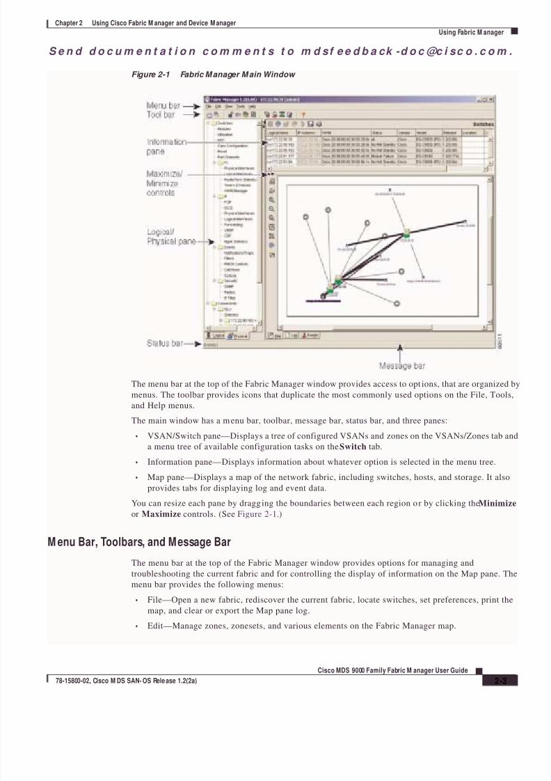
Figure 2-1 Fabric M anager M ain Window
The menu bar at the top of the Fabric Manager window provides access to opt ions, that are organized by
menus. The toolbar provides icons that duplicate the most commonly used options on the File, Tools,
and Help menus.
The main window has a menu bar, toolbar, message bar, status bar, and three panes:
• VSAN/Switch pane—Displays a tree of configured VSANs and zones on the VSANs/Zones tab and
a menu tree of available configuration tasks on the Switch tab.
• Information pane—Displays information about whatever option is selected in the menu tree.
• Map pane—Displays a map of the network fabric, including switches, hosts, and storage. It also
provides tabs for displaying log and event data.
You can resize each pane by dragging the boundaries between each region or by clicking the Minimize
or Maximize controls. (See Figure 2-1.)
M enu Bar, Toolbars, and Message BarThe menu bar at the top of the Fabric Manager window provides options for managing and
troubleshooting the current fabric and for controlling the display of information on the Map pane. The
menu bar provides the following menus:
• File—Open a new fabric, rediscover the current fabric, locate switches, set preferences, print the
map, and clear or export the Map pane log.
• Edit—Manage zones, zonesets, and various elements on the Fabric Manager map.
8/7/2019 cisco MDS 9000 family user guide
http://slidepdf.com/reader/full/cisco-mds-9000-family-user-guide 34/151
S e n d d o c u m e n t a t i o n c o m m e n t s t o m d sf e e d b a ck - d o c @c i sc o . c o m .
2-4
Cisco M DS 9000 Famil y Fabric M anager User Guide
78-15800-02, Cisco M DS SAN-OS Rele ase 1.2(2a)
Chapter 2 Using Cisco Fabric Manager and Device Manager
Using Fabric M anager
• View—Change the appearance of the map (these options are duplicated on the Map pane toolbar).
• Reports—Display summary reports, as described in the “Viewing Reports in Fabric Manager”
section on page 2-14.
• Troubleshooting—Verify and troubleshoot connectivity and configuration, as described in the
“Analyzing Switch Fabric Configuration” section on page 2-11.
• Help—Display on-line help topics for specific dialog boxes in the Information pane.
The Fabric Manager main toolbar provides buttons for accessing the most commonly used menu bar
options. The Map pane toolbar provides buttons for managing the appearance of the map. The
Information pane toolbar provides buttons for editing and managing the Information pane.
The message bar shows the last entry displayed by the discovery process, and the possible error message.
It displays a dialog stating that something has changed in the fabric and a new discovery is needed. The
status bar shows both short-term, transient messages (such as the number of rows displayed in the table),
and long-term discovery issues.
Logical/Physical Pane
Use the Logical tab on the Logical/Physical pane to manage VSANs and zones in the currentlydiscovered fabric. For information about managing VSANs see Chapter 4, “Managing VSANs.”
To manage zones, right-click one of the folders in the VSAN tree and click Edit Local Zone Database
from the pop-up menu. You see the Edit Local Zone Database dialog box. For information about
managing zones and zone sets, see Chapter 3, “Managing Zones and Zone Sets.”
Use the Physical tab on the Logical/Physical pane to display a menu tree of the options available for
managing the switches in the currently discovered fabric. You see the menu tree.
To select an option, click a folder to display the options available and then click the option. You see the
dialog box for the selected option in the Information pane. The menu tree provides the following main
folders:
• Physical—View and configure hardware components.
• Interface—View, monitor, and configure ports and PortChannel interfaces.
• FC—View and configure Fibre Channel network configurations.
• IP—View and configure TCP/IP (management) network configurations.
• Events—View and configure events, alarms, thresholds, notifications, and informs.
• Security—View and configure SNMP and CLI security.
• Admin—Download software images; copy and save configuration files.
Information Pane
The Information pane displays tables or other information associated with the option selected from the
menu tree. The Information pane toolbar provides buttons for performing one or more of the following
operations:
• Apply Changes—Apply configuration changes.
• Refresh Values—Refresh table values.
• Copy…Ctrl+C — Copy data from one row to another.
• Paste…Ctrl +V—Paste the data from one row to another.
• Undo Changes…Ctrl-Z—Undo the most recent change.

8/7/2019 cisco MDS 9000 family user guide
http://slidepdf.com/reader/full/cisco-mds-9000-family-user-guide 35/151
S e n d d o c u m e n t a t i o n c o m m e n t s t o m d sf e e d b a ck -d o c @c i sc o . c o m .
2-5
Cisco MDS 9000 Family Fabric M anager User Guide
78-15800-02, Cisco M DS SAN- OS Rele ase 1.2(2a)
Chapter 2 Using Cisco Fabric M anager and Device M anager
Using Fabric M anager
• Export—Export and save information to a tab-delimited file.
• Print Table —Print the contents of the Information pane.
Note After making changes you must save the configuration or the changes will be lost when the
device is restarted.
Note The buttons that appear on the toolbar vary according to the option you select. They are activated or
deactivated (grayed) according to the field or other object that you select in the Information pane.

8/7/2019 cisco MDS 9000 family user guide
http://slidepdf.com/reader/full/cisco-mds-9000-family-user-guide 36/151
S e n d d o c u m e n t a t i o n c o m m e n t s t o m d sf e e d b a ck - d o c @c i sc o . c o m .
2-6
Cisco M DS 9000 Famil y Fabric M anager User Guide
78-15800-02, Cisco M DS SAN-OS Rele ase 1.2(2a)
Chapter 2 Using Cisco Fabric Manager and Device Manager
Using Fabric M anager
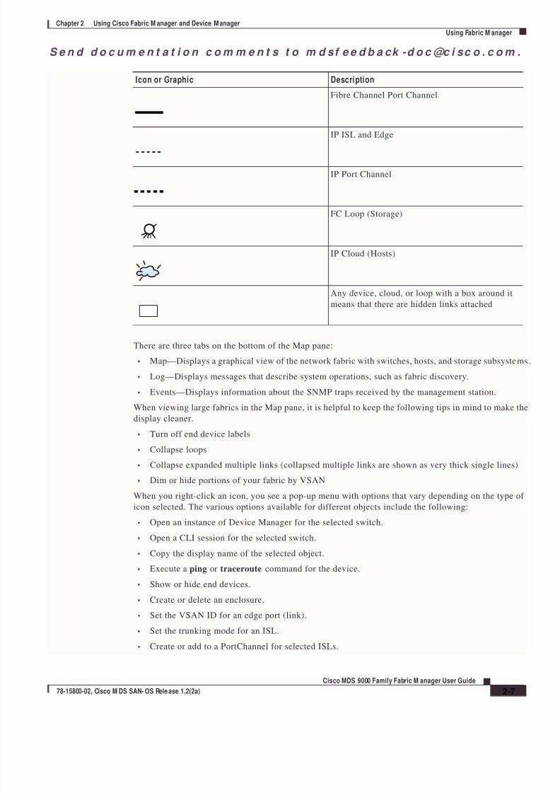
M ap Pane
The Map pane shows the graphical representation of your fabric. Table 2-2 explains the graphics you
may see displayed, depending on which devices you have in your fabric.
Table 2-2 Fabric M anager Graphics
Icon or Graphic Description
Director Class MDS 9000
Non-director Class MDS 9000
Generic FC Switch
Cisco SN5428
A line through a device indicates that the device is
not manageable
An "X" through a device or link indicates that the
device is down or that the connection is down
FC HBA (or enclosure)
iSCSI Host
Virtual Host
FC Target (or enclosure)
Virtual Enclosure
Fibre Channel ISL and Edge
iSAN
8/7/2019 cisco MDS 9000 family user guide
http://slidepdf.com/reader/full/cisco-mds-9000-family-user-guide 37/151
S e n d d o c u m e n t a t i o n c o m m e n t s t o m d sf e e d b a ck -d o c @c i sc o . c o m .
2-7
Cisco MDS 9000 Family Fabric M anager User Guide
78-15800-02, Cisco M DS SAN- OS Rele ase 1.2(2a)
Chapter 2 Using Cisco Fabric M anager and Device M anager
Using Fabric M anager
There are three tabs on the bottom of the Map pane:
• Map—Displays a graphical view of the network fabric with switches, hosts, and storage subsystems
• Log—Displays messages that describe system operations, such as fabric discovery.
• Events—Displays information about the SNMP traps received by the management station.
When viewing large fabrics in the Map pane, it is helpful to keep the following tips in mind to make the
display cleaner.
• Turn off end device labels
• Collapse loops
• Collapse expanded multiple links (collapsed multiple links are shown as very thick single lines)
• Dim or hide portions of your fabric by VSAN
When you right-click an icon, you see a pop-up menu with options that vary depending on the type of
icon selected. The various options available for different objects include the following:
• Open an instance of Device Manager for the selected switch.
• Open a CLI session for the selected switch.
• Copy the display name of the selected object.• Execute a ping or traceroute command for the device.
• Show or hide end devices.
• Create or delete an enclosure.
• Set the VSAN ID for an edge port (link).
• Set the trunking mode for an ISL.
• Create or add to a PortChannel for selected ISLs.
Fibre Channel Port Channel
IP ISL and Edge
IP Port Channel
FC Loop (Storage)
IP Cloud (Hosts)
Any device, cloud, or loop with a box around it
means that there are hidden links attached
Icon or Graphic Description

8/7/2019 cisco MDS 9000 family user guide
http://slidepdf.com/reader/full/cisco-mds-9000-family-user-guide 38/151
S e n d d o c u m e n t a t i o n c o m m e n t s t o m d sf e e d b a ck - d o c @c i sc o . c o m .
2-8
Cisco M DS 9000 Famil y Fabric M anager User Guide
78-15800-02, Cisco M DS SAN-OS Rele ase 1.2(2a)
Chapter 2 Using Cisco Fabric Manager and Device Manager
Using Fabric M anager
The Map pane has its own toolbar with options for saving, printing, and changing the appearance of the
map. When you right-click on the map, a pop-up menu appears that provides options (duplicated on the
toolbar) for changing the appearance of the map.
Note When a VSAN, zone, or zone member is selected in the VSAN tree, the map highlighting changes to
identify the selected objects. To remove this highlight ing, click the Clear Highlight button on the Mappane toolbar or choose Clear Highlight from the pop-up menu.
Locating Other Sw itches
The Locate Switches option uses SNMPv2 and discovers devices responding to SNMP requests with the
read-only community string public. To enable your Cisco MDS 9000 Family switches to respond to
SNMPv2 requests, see Chapter 5, “Managing Administrator Access.”
To locate switches that are not included in the currently discovered fabric, follow these steps:
Step 1 Choose File > Locate Switches from the Fabric Manager main window.
You see the Locate Switches dialog box.
Step 2 Enter a range of specific addresses belonging to a specific subnet which limit the research for the
switches. To look for a Cisco MDS 9000 switch belonging to subnet 192.168.199.0, use the following
string:
192.168.100.[1-254]
Multiple ranges can be specified, separated by commas. For example, to look for all the devices in the
two subnets 192.168.199.0 and 192.169.100.0, use the following string:
192.168.100.[1-254], 192.169.100.[1-254]
Step 3 Enter the appropriate read community string in the Read Community field.
The default value for this string is “public.”
Step 4 Click Display Cisco MDS 9000 Only to display only the Cisco MDS 9000 Family switches in your
network fabric.
Step 5 Click Search to discover switches and devices in your network fabric. You see the results of the
discovery in the Locate Switches window.
Note The number in the lower left corner of the screen increments as the device locator attempts to
discover the devices in your network fabric. When the discovery process is complete, the number
indicates the number of rows displayed.
Note You can access the field descriptions for the windows or dialog boxes in this procedure in the Reference
section of the Fabric Manager or Device Manager help systems.
8/7/2019 cisco MDS 9000 family user guide
http://slidepdf.com/reader/full/cisco-mds-9000-family-user-guide 39/151
S e n d d o c u m e n t a t i o n c o m m e n t s t o m d sf e e d b a ck -d o c @c i sc o . c o m .
2-9
Cisco MDS 9000 Family Fabric M anager User Guide
78-15800-02, Cisco M DS SAN- OS Rele ase 1.2(2a)
Chapter 2 Using Cisco Fabric M anager and Device M anager
Using Fabric M anager
M odifying Device Grouping
Because of not all the devices are capable of responding to FC-GS3 requests, different ports of a single
server or storage subsystem may be displayed as individual end devices on the Fabric Manager map. To
group end devices in a single enclosure in order to have them represented by a single icon on the map,
follow these steps:
Step 1 Select Storage from the Fabric Manager’s menu tree in the Physical tab.
The end devices are displayed in the Information pane.
Step 2 Clink on the Name field for one of the devices you want to be in the enclosure.
Step 3 Enter a name to identify the new enclosure’s icon on the Fabric Manager Map pane.
Step 4 Enter the IP address of the device in the IP Address field (optional).
Step 5 Click once on the Name field for that device.
Step 6 Press Ctrl-C to copy that name.
Step 7 Clink on the Name field for another of the devices you want to be in the enclosure.
Click twice if there is no name in the Name field; click three times if there is a name already in the Name
field.
Step 8 Press Ctrl-V to paste the name into the Name field for that device.
Step 9 Repeat steps 7 and 8 for each device you want to add to the enclosure.
Note To remove devices from an enclosure, click three times on the name of the device and press Delete. To
remove an enclosure, repeat this step for each device in the enclosure. To change an existing enclosure,
delete the enclosure and create a new one.
M anaging Discovered Sw itches
To manage the discovered switches, follow these steps:
Step 1 Choose File > Open Switch Fabric from the Fabric Manager menu bar.
Step 2 Enter the IP address of a switch in the Device Name field on the Open dialog box.
Step 3 Enter your user name and password in the User Name and Auth Password fields.
If the SNMPv3 Privacy feature is implemented, enter the encryption password as well.
Step 4 Check the SNMPv3 check box to select SNMP version 3.
Step 5 Click Open.
Note You can access the field descriptions for the windows or dialog boxes in this procedure in the Reference
section of the Fabric Manager or Device Manager help systems.
8/7/2019 cisco MDS 9000 family user guide
http://slidepdf.com/reader/full/cisco-mds-9000-family-user-guide 40/151
S e n d d o c u m e n t a t i o n c o m m e n t s t o m d sf e e d b a ck - d o c @c i sc o . c o m .
2-10
Cisco M DS 9000 Famil y Fabric M anager User Guide
78-15800-02, Cisco M DS SAN-OS Rele ase 1.2(2a)
Chapter 2 Using Cisco Fabric Manager and Device Manager
Using Fabric M anager
Analyzing Sw itch Device Health
The Switch Health option lets you determine the status of the components of a specific switch. To use
the Switch Health option, follow these steps:
Step 1 Click Switch Health from the Fabric Manager Tools menu.
The Switch Health Analysis window is displayed.
Step 2 Click Start to identify any problems that may currently be affecting the selected switch.
The Switch Health Analysis window displays any problems affecting the selected switches.
Step 3 Fix these problems.
Step 4 Click Clear to remove the contents of the Switch Health Analysis window.
Step 5 Click Close to close the window.
Note You can access the field descriptions for the windows or dialog boxes in this procedure in the Reference
section of the Fabric Manager or Device Manager help systems.
Analyzing End-to-End Connectivity
You can use the End to End Connectivity option to determine connectivity and routes among devices
with the switch fabric. The connectivity tool checks to see that every pair of end devices can talk to each
other, using a Ping test and by determining if they are in the same VSAN or in the same active zone. This
option uses versions of the ping and traceroute commands modified for Fibre Channel networks.
To use this option, follow these steps:
Step 1 Choose Tools > End to End Connectivity from the Fabric Manager menu bar.
The End to End Connectivity window is displayed.
Step 2 Select the VSAN in which you want to verify connectivity from the VSAN dropdown list.
Step 3 Identify any latency issues in the network fabric by clicking the option Report average latencies
greater than and entering the number of microseconds.
Step 4 Click Ensure that members can communicate to perform a Fibre Channel ping between the selected
end points.
Step 5 Identify the number of packets, the size of each packet, and the timeout in milliseconds.
Step 6 Analyze the redundant paths between endpoints by clicking Ensure that redundant paths exist
between members.
Step 7 Click Analyze.
The End to End Connectivity Analysis window displays the selected end points with the switch to which
each is attached, and the source and target ports used to connect it.
The output shows all the requests which have failed. The possible descriptions are:
• Ignoring empty zone—No requests are issued for this zone.

8/7/2019 cisco MDS 9000 family user guide
http://slidepdf.com/reader/full/cisco-mds-9000-family-user-guide 41/151
S e n d d o c u m e n t a t i o n c o m m e n t s t o m d sf e e d b a ck -d o c @c i sc o . c o m .
2-11
Cisco MDS 9000 Family Fabric M anager User Guide
78-15800-02, Cisco M DS SAN- OS Rele ase 1.2(2a)
Chapter 2 Using Cisco Fabric M anager and Device M anager
Using Fabric M anager
• Ignoring zone with single member—No requests are issued for this zone.
• Source/Target are unknown—No nameserver entries exist for the por ts or we have not discovered
the port during discovery.
• Both devices are on the same switch.
• No paths exist between the two devices.
• VSAN does not have an active zone set and the default zone is denied.
• Average time ... micro secs—The latency value was more than the threshold supplied.
Step 8 Click Clear to remove the contents of the window.
Step 9 Click Close to close the window.
Note You can access the field descriptions for the windows or dialog boxes in this procedure in the Reference
section of the Fabric Manager or Device Manager help systems.
Analyzing Switch Fabric Configuration
The Fabric Configuration option lets you analyze the configuration of a switch by comparing the current
configuration to a specific switch or to a policy file. You can save a switch configuration to a file and
then compare all switches against the configuration in the file.
To use the Fabric Configuration option to analyze the configuration of a switch, follow these steps:
Step 1 Click Fabric Configuration from the Fabric Manager Tools menu.
The Fabric Configuration window is displayed.
Step 2 Choose if you want to compare the selected switch to another switch or to a Policy File.
• If you are making a switch comparison, click Switch and then click the drop-down arrow to see a
list of switches.
• If you are making a policy comparison, click Policy File. Then the button to the right of this option
to browse your file system and select a policy file (*.XML).
Step 3 Click Rules to set the rules to apply when running the Fabric Configuration Analysis tool.
The Rules window is displayed.
Step 4 Change the default rules as required and click OK.
Step 5 Click Compare.
The system analyzes the configuration and displays issues that arise as a result of the comparison.
Step 6 Click to place a checkmark in the Resolve column for the issues you want to resolve.
Step 7 Resolve them by selecting the Resolve Issues option.
Step 8 Click Clear to remove the contents of the window.
Step 9 Click Close to close the window.
8/7/2019 cisco MDS 9000 family user guide
http://slidepdf.com/reader/full/cisco-mds-9000-family-user-guide 42/151
S e n d d o c u m e n t a t i o n c o m m e n t s t o m d sf e e d b a ck - d o c @c i sc o . c o m .
2-12
Cisco M DS 9000 Famil y Fabric M anager User Guide
78-15800-02, Cisco M DS SAN-OS Rele ase 1.2(2a)
Chapter 2 Using Cisco Fabric Manager and Device Manager
Using Fabric M anager
Note You can access the field descriptions for the windows or dialog boxes in this procedure in the Reference
section of the Fabric Manager or Device Manager help systems.
Creating a Policy ProfileYou use a policy file to define the rules to be applied when running the Fabric Configuration Analysis
tool. When you create a policy file, the system saves the rules selected for the selected switch.
To create a policy file, follow these steps:
Step 1 Choose Tools > Fabric Configuration from the Fabric Manager menu bar.
Step 2 Click Policy File and enter a name for the policy in the field provided.
Step 3 Click Create Policy and confirm the operation when prompted.
Note You can access the field descriptions for the windows or dialog boxes in this procedure in the Reference
section of the Fabric Manager or Device Manager help systems.
Analyzing the Results of M erging Zones
You can use the Zone Merge option on the Fabric Manager Tools menu to determine if two connected
switches have compatible zone configurations.
To use the Zone Merge option, follow these steps:
Step 1 Choose Zone Merge from the Fabric Manager Tools menu.
The Zone Merge Analysis window is displayed.
Step 2 Select a switch from each pull-down list.
Step 3 Identify the VSAN for which you want to perform the zone merge analysis.
Step 4 Click Analyze.
The Zone Merge Analysis window displays any inconsistencies between the zone configuration of the
two selected switches.
Step 5 Click Clear to remove the contents of the window.
Step 6 Click Close to close the window.
Note You can access the field descriptions for the windows or dialog boxes in this procedure in the Reference
section of the Fabric Manager or Device Manager help systems.
8/7/2019 cisco MDS 9000 family user guide
http://slidepdf.com/reader/full/cisco-mds-9000-family-user-guide 43/151
S e n d d o c u m e n t a t i o n c o m m e n t s t o m d sf e e d b a ck -d o c @c i sc o . c o m .
2-13
Cisco MDS 9000 Family Fabric M anager User Guide
78-15800-02, Cisco M DS SAN- OS Rele ase 1.2(2a)
Chapter 2 Using Cisco Fabric M anager and Device M anager
Using Fabric M anager
Issuing the Show Tech Support Command
You can issue a show tech support command from Fabric Manager for one or more switches in a fabric.
The results of each command are written to a text file, one file per switch, in a di rectory you specify. You
can then view these files using Fabric Manager.
You can also save the Fabric Manager map as a JPG file. The file is saved with the name of the seedswitch (for example, 172.22.94.250.jpg).
You can zip up all the files (the show tech support output and the map file image) and send the resulting
zipped file to technical support.
To use the Fabric Manager show tech support command, perform the following steps.
Step 1 Select Show Tech Support from the Tools menu.
The Show Tech Support dialog box is displayed.
Step 2 Select the switches for which you want to view Show Tech Support information, by checking the
checkboxes next to their IP addresses.
Step 3 Select the directory where you want the text files (containing the Show Tech Support information) to bewritten.
Step 4 Enter your username and password in the appropriate fields.
Note that in order for Fabric Manager to successfully issue the show tech support command on a switch,
that switch must have this username and password. Fabric Manager will be unable to log into a switch
that does not have this username and password, and an error will be returned for that switch.
Step 5 Set the timeout value.
The default is 30 seconds.
Step 6 Check the SSH checkbox if you want to use SSH to connect to the switch.
If you do not check the SSH checkbox, Telnet is used. Note that SSH is slower than Telnet, so if you are
using SSH you may want to increase the timeout value described in Step5.Step 7 Click the OK button to start issuing the show tech support command to the switches you specified, or
click the Close button to close the Show Tech Support dialog box without issuing the show tech support
command.
In the Status column next to each switch, a highlighted status is displayed. A yellow highlight indicates
that the Show Tech Support command is currently running on that switch. A red highlight indicates an
error. A green highlight indicates that the Show Tech Support command has completed successfully. On
successful completion, a button becomes available in the View column for each switch.
Step 8 To view the Show Tech Support output, click the button next to the name of the switch. The Show Tech
Support information is displayed in your default text editor.
Note If you would like to view the Show Tech Support files without using Fabric Manager, you can open themwith any text editor. Each file is named with the switch’s IP address and has a .TXT extension (for
example, 111.22.33.444.txt).

8/7/2019 cisco MDS 9000 family user guide
http://slidepdf.com/reader/full/cisco-mds-9000-family-user-guide 44/151
S e n d d o c u m e n t a t i o n c o m m e n t s t o m d sf e e d b a ck - d o c @c i sc o . c o m .
2-14
Cisco M DS 9000 Famil y Fabric M anager User Guide
78-15800-02, Cisco M DS SAN-OS Rele ase 1.2(2a)
Chapter 2 Using Cisco Fabric Manager and Device Manager
Using Fabric M anager
Using Traceroute and Other Troubleshooting Tools
You can use the following options on the Tools menu to verify connectivity to a selected object or to
open other management tools:
• Traceroute—Verify connectivity between two end devices that are currently selected on the Map
pane.
• Device Manager— Launch the Device Manager for the switch selected on the Map pane.
• Command Line Interface—Open a Telnet or SSH session for the switch selected on the Map pane.
To use the Traceroute option to verify connectivity, follow these steps:
Step 1 Select two or more endpoints on the Fabric Manager map.
Step 2 Click Traceroute from the Tools menu, or right-click one of the endpoints and click Trace Route from
the pop-up menu.
The Traceroute window is displayed.
Step 3 Change the timeout value if the default (10 seconds) is too short or too long.
Step 4 Click Start.
The results of the Traceroute operation appear in the Results box.
Note You can access the field descriptions for the windows or dialog boxes in this procedure in the Reference
section of the Fabric Manager or Device Manager help systems.
Setting Fabric M anager Preferences
To set your preferences for the behavior of the Fabric Manager, choose File > Preferences from the
Fabric Manager menu bar. The Preferences dialog box is displayed.
This dialog box has the following four tabs, which let you set your preferences for different components
of the application:
• General
• SNMP
• Discovery
• Map
View ing Reports in Fabric M anager
The Fabric Manager provides a series of reports, showing various information in tabular form. When you
select one of these options, you see the available information in tabular form in the Information pane of
the Fabric Manager main window. Table 2-3 describes the reports provided by each option.

8/7/2019 cisco MDS 9000 family user guide
http://slidepdf.com/reader/full/cisco-mds-9000-family-user-guide 45/151
S e n d d o c u m e n t a t i o n c o m m e n t s t o m d sf e e d b a ck -d o c @c i sc o . c o m .
2-15
Cisco MDS 9000 Family Fabric M anager User Guide
78-15800-02, Cisco M DS SAN- OS Rele ase 1.2(2a)
Chapter 2 Using Cisco Fabric M anager and Device M anager
Using Fabric M anager
Table 2-3 Fabric M anager Reports
Report Description
ISL Statistics Click on Connectivity > ISLs > Statistics in the
Physical tab of the Fabric Manager
Logical/Physical pane to display informationabout the Inter-Switch Links in the currently
discovered fabric. You can use the controls at the
top of the table to change the Poll Interval and
Scale parameters:
ISLs Choose Connectivity > ISLs in the Physical tab
of the Fabric Manager Logical/Physical pane to
display information about the Inter-Switch links
in the currently discovered fabric.
Switches Choose Switches in the Physical tab of the Fabric
Manager Logical/Physical pane to display
information about the switches in the currently
discovered fabric.Hosts Choose Connectivity > Hosts in the Physical tab
of the Fabric Manager Logical/Physical pane to
display information about the hosts in the
currently discovered fabric.
Storage Choose Connectivity > Storage in the Physical
tab of the Fabric Manager Logical/Physical pane
to display information about the links to hosts and
storage in the currently discovered fabric.
LUNs Choose Connectivity > Storage > LUNs in the
Physical tab of the Fabric Manager
Logical/Physical pane to display information
about the LUNs in the currently discovered fabric.

8/7/2019 cisco MDS 9000 family user guide
http://slidepdf.com/reader/full/cisco-mds-9000-family-user-guide 46/151
S e n d d o c u m e n t a t i o n c o m m e n t s t o m d sf e e d b a ck - d o c @c i sc o . c o m .
2-16
Cisco M DS 9000 Famil y Fabric M anager User Guide
78-15800-02, Cisco M DS SAN-OS Rele ase 1.2(2a)
Chapter 2 Using Cisco Fabric Manager and Device Manager
Using Device M anager
Using Device M anagerDevice Manager provides a physical representation of your switch chassis, with the modules, ports,
power supplies, and fan assemblies (Figure 2-2). The menu bar at the top of the Device Manager window
provides access to options, organized into menus that correspond to the menu tree in Fabric Manager.
The legend at the bottom right of the Device Manager indicates port status, as follows:
• Green—The port is up.
• Brown—The port is administratively down.
• Red—The port is down or has failed.
• Gray—The port is unreachable.
Launching Device M anager from Fabric M anager
Device Manager gives a graphic representation of a Cisco MDS 9000 Family switch, including the
installed switching modules, the supervisor modules, the power supplies, and the status of each port
within each module.To launch the Device Manager f rom your desktop, double-click the Device Manager icon and follow the
instructions described in the “Launching Views” section on page 1-9.
To launch Device Manager f rom Fabric Manager, right-click the switch you want to manage on the
Fabric Manager map and click Device Manager from the pop-up menu that appears. The Device
Manager main window is shown in Figure 2-2.
Device Manager can also be started by double-clicking on a switch in the Fabric Manager topology view.

8/7/2019 cisco MDS 9000 family user guide
http://slidepdf.com/reader/full/cisco-mds-9000-family-user-guide 47/151
S e n d d o c u m e n t a t i o n c o m m e n t s t o m d sf e e d b a ck -d o c @c i sc o . c o m .
2-17
Cisco MDS 9000 Family Fabric M anager User Guide
78-15800-02, Cisco M DS SAN- OS Rele ase 1.2(2a)
Chapter 2 Using Cisco Fabric M anager and Device M anager
Using Device M anager
Figure 2-2 Device Manager, Device Tab
Using Summary View
Click the Summary tab on the Device Manager main window to see a summary of xEPorts, FxPorts, and
NxPorts on a single switch, as well as FC and IP neighbor devices. All logical interfaces are shown in a
dropdown list at the top of the Summary view.
The Summary View displays attributes for a single switch, such as por t speed, link utilization, and other
traffic statistics. It has the same menu bar and toolbar buttons as the Device View.
To monitor traffic for selected objects, click the Monitor icon. To display detailed statistics for se lected
objects, click the Detailed Statistics icon.
The Summary View provides the same menus and options that are available from the Device View.
Note You can access the field descriptions for the windows or dialog boxes in this procedure in the Reference
section of the Device Manager help system.

8/7/2019 cisco MDS 9000 family user guide
http://slidepdf.com/reader/full/cisco-mds-9000-family-user-guide 48/151
S e n d d o c u m e n t a t i o n c o m m e n t s t o m d sf e e d b a ck - d o c @c i sc o . c o m .
2-18
Cisco M DS 9000 Famil y Fabric M anager User Guide
78-15800-02, Cisco M DS SAN-OS Rele ase 1.2(2a)
Chapter 2 Using Cisco Fabric Manager and Device Manager
Comparing Device M anager to Fabric M anager
Comparing Device M anager to Fabric M anagerThe menu bar at the top of the Device Manager contains the same menus as the Fabric Manager menu
tree.
For information about the options provided by these menus, see the “Logical/Physical Pane” section on
page 2-4. The Device menu, which is unique to the Device View and Summary View, provides thefollowing options:
• Open—Open the Device Manager for a different switch.
• Open Last—Open the Device Manager for the most recently managed switch.
• Preferences—Set management preferences for controlling the behavior and appearance of the
Device Manager.
• Refresh—Update the current display.
• Message Log—Display messages regarding the current operation of the Device Manager
application.
• Command Line Interface—Open a Telnet/SSH session with the current switch.
• Exit—Close the Device Manager application.
The tables in the Fabric Manager correspond to the dialog boxes that appear in Device Manager.
However, the Fabric Manager tables show values for multiple switches and so the first column identifies
the specific switch. The Device Manager dialog box shows values for a single switch, while the Fabric
Manager shows the same values for one or more switches.
The toolbar on the Device Manager dialog box provides the same options as the toolbar on the
Information pane in Fabric Manager, as summarized here:
• Create—Insert a new row into a table (if applicable).
• Delete Row—Delete the selected row from a table (if applicable).
• Copy…Ctrl+C — Copy data from one row to another.
• Paste…Ctrl +V—Paste the data from one row to another.
• Apply Changes—Apply configuration changes. (Note: After making changes you must save the
configuration. Otherwise, the changes will be lost when the device is restarted.)
• Refresh Values—Refresh table values.
• Reset Changes…Ctrl-Z—Undo the most recent change.
• Print table…— Print the contents of the Information pane.
Tip You can copy values from one cell in a table to the rest of the column. Copy the value to the clipboard,
hold down the shift key while pressing the down arrow key (or click on the bottom cell in the column).
Then paste the value to all the selected cells and click Apply.
When you click the Create button, you see a dialog box that lets you enter the values required for the
specific table. As you can see the fields and options are the same from both views, but the appearance
of the window may vary slightly. For instance, the dialog box f rom Fabric Manager may have an option
for selecting a specific switch, while the dialog box from Device Manager may have additional port-level
detail.

8/7/2019 cisco MDS 9000 family user guide
http://slidepdf.com/reader/full/cisco-mds-9000-family-user-guide 49/151
S e n d d o c u m e n t a t i o n c o m m e n t s t o m d sf e e d b a ck -d o c @c i sc o . c o m .
2-19
Cisco MDS 9000 Family Fabric M anager User Guide
78-15800-02, Cisco M DS SAN- OS Rele ase 1.2(2a)
Chapter 2 Using Cisco Fabric M anager and Device M anager
M anaging Ports
M anaging Ports
Tip You can select multiple ports in Device Manager and apply options to all the selected ports at one time.
Either select the ports by clicking the mouse and dragging it around them, or hold down the Control key
and click on each port.
To enable or disable a port, right-click the port and click Enable or Disable from the pop-up menu. To
enable or disable multiple ports, drag the mouse to select the ports and then right-click the selected ports.
Then click Enable or Disable from the pop-up menu.
To manage trunking on one or more ports, right-click the por ts and click Configure. On the dialog box
that appears, in the Trunk column, right-click the current value and click nonTrunk, trunk, or auto from
the pull-down list.
To create PortChannels using Device Manager, click PortChannels from the Interface menu. For
detailed instructions, see the “Managing PortChannel Interfaces” section on page 7-4. You can also use
Fabric Manager to conveniently create a PortChannel.
Note To create a PortChannel, all the ports on both ends of the link must have the same port speed, trunking
type, and administrative state.
Setting Device M anager PreferencesTo set your preferences for the behavior of the Device Manager application, choose Preferences from
the Device menu.
Note You can access the field descriptions for the windows or dialog boxes in this procedure in the Referencesection of the Device Manager help system.

8/7/2019 cisco MDS 9000 family user guide
http://slidepdf.com/reader/full/cisco-mds-9000-family-user-guide 50/151
S e n d d o c u m e n t a t i o n c o m m e n t s t o m d sf e e d b a ck - d o c @c i sc o . c o m .
2-20
Cisco M DS 9000 Famil y Fabric M anager User Guide
78-15800-02, Cisco M DS SAN-OS Rele ase 1.2(2a)
Chapter 2 Using Cisco Fabric Manager and Device Manager
Setting Device M anager Preferences

8/7/2019 cisco MDS 9000 family user guide
http://slidepdf.com/reader/full/cisco-mds-9000-family-user-guide 51/151
C H A P T E R
S e n d d o c u m e n t a t i o n c o m m e n t s t o m d sf e e d b a ck -d o c @c i sc o . c o m .
3-1
Cisco MDS 9000 Family Fabric M anager User Guide
78-15800-02, Cisco M DS SAN- OS Rele ase 1.2(2a)
3M anaging Zones and Zone Sets
The Fabric Manager allows you to configure and monitor zones and zone sets (groups of zones) on the
Cisco MDS 9000 Family switch. Zoning allows you to set up access control between hosts and storage
devices. You can use zones to control access between devices or user groups, and to increase network
security and prevent data loss or corruption.
Note Zones and zone sets can only be created and configured in the Fabric Manager.
To verify the compatibility of the zone configuration on two connected switches, see “Analyzing the
Results of Merging Zones” section on page 2-12. For information about zones and zone sets, and
configuring them using the command-line interface (CLI), refer to the Cisco 9000 Family Configuration
Guide.
Procedures you perform to manages zones and zonesets include:
• Creating Zones and Zone Sets, page 3-2
• Setting Default Zone Policy, page 3-2
• Adding Zones to a Zone Set, page 3-3
• Cloning Zones and Zone Sets, page 3-4
• Adding Zone Members, page 3-4
• Activating or Enforcing Zone Sets, page 3-5
• Searching the Zone Database, page 3-5
• Displaying Port Membership Information, page 3-6
• Deleting Zones, Zone Sets, and Members, page 3-6
• Changing the Default Zone Policy, page 3-7
• Viewing Zone Statistics, page 3-7
8/7/2019 cisco MDS 9000 family user guide
http://slidepdf.com/reader/full/cisco-mds-9000-family-user-guide 52/151
S e n d d o c u m e n t a t i o n c o m m e n t s t o m d sf e e d b a ck - d o c @c i sc o . c o m .
3-2
Cisco M DS 9000 Famil y Fabric M anager User Guide
78-15800-02, Cisco M DS SAN-OS Rele ase 1.2(2a)
Chapter 3 M anaging Zones and Zone Sets
Creating Zones and Zone Sets
Creating Zones and Zone SetsZones are configured within VSANs, but you can configure zones without configuring any VSANs by
configuring them within the default VSAN. The Logical tab displays the VSANs configured in the
currently discovered fabric. Note that zone information must always be identical for all the switches in
the network fabric.To create zones, zone sets, or aliases, perform the following steps.
Step 1 From the Fabric Manager, choose Zone > Edit Full Database on Switch from the Fabric Manager Edit
menu bar, or right-click a VSAN folder in the Logical tab and choose Edit Full Database on Switch
from the pop-up menu.
The Select VSAN dialog is displayed.
Step 2 Select a VSAN from the dialog box. Click OK to display information for that VSAN, or click Cancel
to close the Select VSAN dialog box.
If you click OK, you see the Edit VSANxxx Local Database dialog box for the VSAN you selected.
Step 3 Right click the Zone, Zoneset, or Alias for that VSAN to add a Zone, Zoneset, or Alias.If you have added a Zone, you can specify that the zone be a read-only zone by checking the Set Zone
as Read Only checkbox.
If you have added a ZoneSet, you can activate it by clicking the Activate button. This configuration is
distributed to the other switches in the network fabric.
Note When you confirm the activate operation, the current running configuration is saved to the startup
configuration. This permanently saves any changes made to the running configuration (not just zoning
changes).
Note You can access the field descriptions for the windows or dialog boxes in this procedure in the Reference
section of the Fabric Manager or Device Manager help systems.
Setting Default Zone PolicyEach VSAN contains a default zone, which by default, contains all connected devices assigned to the
VSAN. Storage or host devices in a default zone do not belong to any other zone and, by default, are
denied access to any other devices.
You can change the default zone policy for any VSAN by choosing VSANxxx > Default Zone from theFabric Manager menu tree and clicking the Policies tab. However, we recommend that you establish
connectivity among devices by assigning them to a nondefault zone.
The active zone set is shown in italic type. After you have made changes to the active zone set and before
you activate the changes, the zone set is shown in boldface italic type. The tooltip for each zone indicates
the activation time or modification time.
8/7/2019 cisco MDS 9000 family user guide
http://slidepdf.com/reader/full/cisco-mds-9000-family-user-guide 53/151
S e n d d o c u m e n t a t i o n c o m m e n t s t o m d sf e e d b a ck -d o c @c i sc o . c o m .
3-3
Cisco MDS 9000 Family Fabric M anager User Guide
78-15800-02, Cisco M DS SAN- OS Rele ase 1.2(2a)
Chapter 3 M anaging Zones and Zone Sets
Creating Additional Zones and Zonesets
Creating Additional Zones and ZonesetsTo create additional zones and zone sets, follow these steps:
Step 1 With the Edit Full Database on Switch dialog open, right-click the Zones folder and choose Insert
from the pop-up menu.
Step 2 Enter the zone name in the dialog box that appears and click OK to add the zone.
The zone is automatically added to the zone database.
Step 3 To create a zoneset , right-click the ZoneSets folder in the Edit Full Database on Switch dialog box,
and choose Insert.
Step 4 Enter the zoneset name in the dialog box that appears and click OK to add the zoneset.
The zoneset is automatically added to the zone database.
Note You can access the field descriptions for the windows or dialog boxes in this procedure in the Reference
section of the Fabric Manager or Device Manager help systems.
Adding Zones to a Zone SetTo add a zone to a zone se t from the Edit Full Database on Switch window, drag and drop the zone to
the folder for the zone set. Alternatively, follow these steps:
Step 1 Click the ZoneSets folder and then right-click the folder for the zone set to which you want to add a zone
and choose Insert from the pop-up menu.
You see the Zone Server Select Zone dialog box.
Step 2 Select the zone that you want to add to the zone set and click Add.
The zone is added to the zone set in the zone database.
Note You can access the field descriptions for the windows or dialog boxes in this procedure in the Reference
section of the Fabric Manager or Device Manager help systems.

8/7/2019 cisco MDS 9000 family user guide
http://slidepdf.com/reader/full/cisco-mds-9000-family-user-guide 54/151
S e n d d o c u m e n t a t i o n c o m m e n t s t o m d sf e e d b a ck - d o c @c i sc o . c o m .
3-4
Cisco M DS 9000 Famil y Fabric M anager User Guide
78-15800-02, Cisco M DS SAN-OS Rele ase 1.2(2a)
Chapter 3 M anaging Zones and Zone Sets
Cloning Zones and Zone Sets
Cloning Zones and Zone SetsAnother method of adding zones and zone sets is to clone existing zones and zone sets. To clone a zone
or zone set from the Edit Full Database on Switch window, follow these s teps:
Step 1 Click the Zones or ZoneSets folder, right-click the folder for the zone or zone set that you want to clone,
and choose Clone from the pop-up menu.
Step 2 Enter the name of the cloned zone or zone set.
By default, the dialog displays the selected zone as ClonedZone1.
Step 3 Click OK to add the cloned zone to the zone database.
Note You can access the field descriptions for the windows or dialog boxes in this procedure in the Reference
section of the Fabric Manager or Device Manager help systems.
Adding Zone M embersOnce you have created a zone, you can add members to the zone. You can add members using the
following port identification types:
• pWWN—The world wide name of the port configured on the end device (in hex format).
• Fabric port WWN—The world wide name of the fabric port on the switch (in hex format).
• FC alias—The alias name in alphabetic characters (for example, Payroll).
• LUN—The logical unit number of a disk in a disk device.
For more information about port identification types, refer to the Cisco 9000 Family Configuration
Guide.
To add members to a zone, follow these steps:
Step 1 Click the Zones folder, then right-click the folder for the zone to which you want to add members, and
choose Insert from the pop-up menu.
The Add Members to Zone dialog is displayed.
Step 2 Click the checkbox to the left of the NxPort WWN field.
Step 3 Select one of the ports in the VSAN and click Add to add it to the zone.
You see member in the Zone Server database in the lower frame.
Step 4 Repeat these steps to add other members to the zone.
Note You can access the field descriptions for the windows or dialog boxes in this procedure in the Reference
section of the Fabric Manager or Device Manager help systems.
8/7/2019 cisco MDS 9000 family user guide
http://slidepdf.com/reader/full/cisco-mds-9000-family-user-guide 55/151
S e n d d o c u m e n t a t i o n c o m m e n t s t o m d sf e e d b a ck -d o c @c i sc o . c o m .
3-5
Cisco MDS 9000 Family Fabric M anager User Guide
78-15800-02, Cisco M DS SAN- OS Rele ase 1.2(2a)
Chapter 3 M anaging Zones and Zone Sets
Activating or Enforcing Zone Sets
Activating or Enforcing Zone SetsOnce zones and zone sets have been created and popula ted with members, you must activate or enforce
the zone set. Note that only one zone se t can be activated at any time. If zoning is activated, any member
that is not assigned to an active zone belongs to the default zone. If zoning is not activated, all members
belong to the default zone.To activate a zone set, follow these steps:
Step 1 Click the zone set in the Edit Full Database on Switch dialog box.
Step 2 Click Activate.
You see the zone se t in the Active Zone Set folder.
Note If one zone set is active and you activate another zone set, the currently active zone set is automatically
deactivated.
Note You can access the field descriptions for the windows or dialog boxes in this procedure in the Reference
section of the Fabric Manager or Device Manager help systems.
Searching the Zone DatabaseTo search the zone or active zone set databases, follow these steps:
Step 1 Click the Find button on the Edit Full Database on Switch dialog box toolbar.
You see the Find in Zone Database window.Step 2 Enter the name of the member to be searched for.
Step 3 Click the From: Selection or Start radio button.
Step 4 Check either the Ignore Case or Exact Match check box.
Step 5 Click Next to launch the search.
Note You can access the field descriptions for the windows or dialog boxes in this procedure in the Reference
section of the Fabric Manager or Device Manager help systems.
8/7/2019 cisco MDS 9000 family user guide
http://slidepdf.com/reader/full/cisco-mds-9000-family-user-guide 56/151
S e n d d o c u m e n t a t i o n c o m m e n t s t o m d sf e e d b a ck - d o c @c i sc o . c o m .
3-6
Cisco M DS 9000 Famil y Fabric M anager User Guide
78-15800-02, Cisco M DS SAN-OS Rele ase 1.2(2a)
Chapter 3 M anaging Zones and Zone Sets
Displaying Port Membership Information
Displaying Port M embership InformationTo display port membership information for members assigned to zones, perform the following steps.
Step 1 From the Fabric Manager Logical/Physical pane (Logical tab), click a member within a zone.
Step 2 Click the Storage tab on the Information pane.
You see the Port Membership information displayed in the Information pane.
Note The default zone members are explicitly listed only when the default zone policy is configured as
permit. When the default zone policy is configured as deny, the members of this zone are not shown.
For more information, see the “Changing the Default Zone Policy” section on page 3-7 .
Note You can access the field descriptions for the windows or dialog boxes in this procedure in the Reference
section of the Fabric Manager or Device Manager help systems.
Deleting Zones, Zone Sets, and M embersTo delete zones, zone sets, or members, perform the following steps.
Step 1 From the Fabric Manager, click the zone or zoneset in the Logical tree of the Logical/Physical pane.
Step 2 Select Zone from the Edit menu, and choose Edit Full Database on Switch.
The Edit Full Database on Switch dialog is displayed.Step 3 Select the Zone, Zone Set, or Member you want to delete.
Step 4 Right-click the object and choose Delete from the pop-up menu.
The selected object is deleted from the zone database.
Note You can access the field descriptions for the windows or dialog boxes in this procedure in the Reference
section of the Fabric Manager or Device Manager help systems.
8/7/2019 cisco MDS 9000 family user guide
http://slidepdf.com/reader/full/cisco-mds-9000-family-user-guide 57/151
S e n d d o c u m e n t a t i o n c o m m e n t s t o m d sf e e d b a ck -d o c @c i sc o . c o m .
3-7
Cisco MDS 9000 Family Fabric M anager User Guide
78-15800-02, Cisco M DS SAN- OS Rele ase 1.2(2a)
Chapter 3 M anaging Zones and Zone Sets
Changing the Default Zone Policy
Changing the Default Zone PolicyEach member in the fabric can belong to any zone. If a member does not belong to any zone, it is part
of the default zone. If no zone has been activated in the fabric, all members belong to the default zone.
Even though a member can belong to multiple zones, a member in the default zone cannot be part of any
other zone.Traffic can be permitted and denied to members in the default zone. This information is not dis tributed
to all switches. Permission and denial must be set for each switch in the fabric.
To permit or deny traffic to members in the default zone from the Zone Server, follow these steps:
Step 1 Choose VSANxxx > Default Zone from the Fabric Manager menu tree, and click the Policies tab.
The Zone information is displayed in the Information pane.
Step 2 Click the DefaultZoneBehavior field and choose either permit or deny from the pull-down menu.
Note You can access the field descriptions for the windows or dialog boxes in this procedure in the Reference
section of the Fabric Manager or Device Manager help systems.
View ing Zone StatisticsTo monitor zone statistics from the Zone Server, choose VSANxxx > Domain Manager from the Fabric
Manager menu tree. The Zone information is displayed in the Information pane. Click on the Statistics
tab to see the statistics information for the switches in the zone.
Note You can access the field descriptions for the windows or dialog boxes in this procedure in the Reference
section of the Fabric Manager or Device Manager help systems.

8/7/2019 cisco MDS 9000 family user guide
http://slidepdf.com/reader/full/cisco-mds-9000-family-user-guide 58/151
S e n d d o c u m e n t a t i o n c o m m e n t s t o m d sf e e d b a ck - d o c @c i sc o . c o m .
3-8
Cisco M DS 9000 Famil y Fabric M anager User Guide
78-15800-02, Cisco M DS SAN-OS Rele ase 1.2(2a)
Chapter 3 M anaging Zones and Zone Sets
View ing Zone Statistics

8/7/2019 cisco MDS 9000 family user guide
http://slidepdf.com/reader/full/cisco-mds-9000-family-user-guide 59/151
C H A P T E R
S e n d d o c u m e n t a t i o n c o m m e n t s t o m d sf e e d b a ck -d o c @c i sc o . c o m .
4-1
Cisco MDS 9000 Family Fabric M anager User Guide
78-15800-02, Cisco M DS SAN- OS Rele ase 1.2(2a)
4M anaging VSANs
VSANs (virtual SANs) allow you to separate devices that are physically connected to the same fabric,
and thus provide higher security and greater scalability in the network fabric. When you create VSANs,
you are creating multiple logical SANs over a common physical infrastructure. After creating VSANs,
you must establish IP static routes between the network segments if you are using the IP over Fibre
Channel (IPFC) protocol to manage your Cisco MDS 9000 Family switches.
The Fabric Manager allows you to configure VSANs on multiple Cisco 9000 switches. The Device
Manager allows you to configure VSANs on a single Cisco 9000 switch.
Note For information about VSANs and configuring them using the command-line interface (CLI), refer to
the Cisco 9000 Family Configuration Guide.
You can manage Cisco MDS 9000 Family switches through Ethernet connections to the management
interface (mgmt 0) of each switch or by using the IPFC protocol. To use IPFC, you connect to a switch
using the Ethernet management interface and establish routes from that switch to the other switches over
the Fibre Channel network. When you segment the Fibre Channel network using VSANs, you must
establish static routes between the network segments.

8/7/2019 cisco MDS 9000 family user guide
http://slidepdf.com/reader/full/cisco-mds-9000-family-user-guide 60/151
S e n d d o c u m e n t a t i o n c o m m e n t s t o m d sf e e d b a ck - d o c @c i sc o . c o m .
4-2
Cisco M DS 9000 Famil y Fabric M anager User Guide
78-15800-02, Cisco M DS SAN-OS Rele ase 1.2(2a)
Chapter 4 M anaging VSANs
Figure 4-1 shows a physical Fibre Channel network with two VSANs. VSAN 2 is connected by dashed
lines and VSAN 7 is connected by solid lines.
Figure 4-1 Configuring VSANs
VSAN 2 includes the H1 and H2 hosts, the AS2 and AS3 application servers, and the SA1 and SA4
storage arrays. VSAN 7 connects H3, AS1, SA2, and SA3. The four switches in this network are
interconnected by trunk links that carry both VSAN 2 and VSAN 7 traffic.
VSAN 1 is the default VSAN for Cisco MDS 9000 Family switches. All ports are assigned by default to
VSAN 1. VSAN 4094 is called the isolated VSAN. When a VSAN is deleted, any ports in that VSAN
are moved to VSAN 4094.
Note We recommend that you delete or move all the ports in a VSAN before deleting the VSAN.
VSANs are enabled through trunking, which enables interconnect ports to transmit and receive frames
in more than one VSAN over a single physical link, using the Extended Inter-Switch Link (EISL)
protocol. The trunking protocol is enabled by default, and if disabled on a switch, no ports on that switch
or directly connected to the switch will support the use of VSANs.
By default, the trunk mode is enabled on all Fibre Channel interfaces, but can be disabled on a
port-by-port basis. When connected to a third-party switch, the trunk mode configuration has no
effect—the ISL is always in a trunking disabled state.

8/7/2019 cisco MDS 9000 family user guide
http://slidepdf.com/reader/full/cisco-mds-9000-family-user-guide 61/151
S e n d d o c u m e n t a t i o n c o m m e n t s t o m d sf e e d b a ck -d o c @c i sc o . c o m .
4-3
Cisco MDS 9000 Family Fabric M anager User Guide
78-15800-02, Cisco M DS SAN- OS Rele ase 1.2(2a)
Chapter 4 M anaging VSANs
Controlling In-Band M anagement Connectivity
Each Fibre Channel interface has an associated trunk-allowed VSAN list. This list determines the
VSANs that are supported on each interface. By default, the entire range of VSANs from 1 through 4093
are allowed on any interface. You can restrict an interface to the use of a specific set of VSANs, which
prevents traffic from any other VSAN being transmitted on the interface.
Procedures for managing VSANs include:
• Adding and Configuring VSANs, page 4-3
Adding and Configuring VSANs
To add and configure VSANs, perform the following steps.
Step 1 From the Fabric Manager, choose FC > VSAN from the menu tree, OR
From Device Manager, choose the VSAN option from the FC menu or click the VSAN icon on the
toolbar.
The Fabric Manager’s Information pane displays VSAN attributes for multiple switches. The VSAN
dialog box in the Device Manager displays VSAN general attributes for a single switch.
Step 2 From Fabric Manager, click Create Row on the Information pane toolbar, OR
From Device Manager, click Create on the VSAN dialog box.
You see the Create dialog box.
Step 3 Complete the fields on this dialog box and click OK to add the VSAN.
Note You can access the field descriptions for the windows or dialog boxes in this procedure in the Reference
section of the Fabric Manager or Device Manager help systems.
Controlling In-Band M anagement ConnectivityThe Fabric Manager allows you to configure and monitor IP traffic on multiple Cisco MDS 9000 Family
switches. The Device Manager allows you to configure and monitor IP traffic on a single Cisco 9000
switch.
Cisco MDS 9000 Family switches support both out-of-band and in-band management schemes. An
Ethernet connection provides out-of-band management using Telnet, SSH or SNMP access. In-band IP
management is also available using IP over Fibre Channel (IPFC). IPFC encapsulates IP packets into
Fibre Channel frames so that management information can cross the Fibre Channel network without
requiring a dedicated Ethernet connection to each switch. IP addresses are resolved to the Fibre Channel
address through the Address Resolution Protocol (ARP).Procedures for managing and viewing connectivity information include:
• Configuring IP Routing for Management Traffic, page 4-4
• Managing IPFC Connectivity with Multiple VSANs, page 4-5
• Viewing IP Address Information, page 4-5
• Enabling or Disabling IP Forwarding, page 4-5
• Viewing TCP Information and Stati stics, page 4-6

8/7/2019 cisco MDS 9000 family user guide
http://slidepdf.com/reader/full/cisco-mds-9000-family-user-guide 62/151
S e n d d o c u m e n t a t i o n c o m m e n t s t o m d sf e e d b a ck - d o c @c i sc o . c o m .
4-4
Cisco M DS 9000 Famil y Fabric M anager User Guide
78-15800-02, Cisco M DS SAN-OS Rele ase 1.2(2a)
Chapter 4 M anaging VSANs
Controlli ng In-B and Mana gement Connectivity
• Viewing UDP Information and Statistics, page 4-6
• Viewing IP Statistics, page 4-6
• Viewing ICMP Statistics, page 4-6
• Monitoring SNMP Traffic, page 4-7
Configuring IP Routing for M anagement Traffic
When using in-band network management over Fibre Channel links, you must ensure that a path exists
from the seed switch, connected to the Cisco Fabric Manager over its Ethernet interface (mgmt0), and
the other switches in the network fabric. See Figure 4-2.
Figure 4-2 IP Routing Between VSANs
To do this, make sure that the seed switch has a path to each VSAN. Each of the other switches can thenbe configured to use the seed switch as their default gateway. For example, in Figure 4-2, switch 1 is
connected to VSAN 2 and VSAN 3, while switch 2 and switch 3 are configured to use switch 1 as their
default gateway.
You can also configure static routes on a point-to-point basis from one switch to another. In this example,
you would configure a static route on both switch 2 and switch 3 to switch 1.
Configuring an IP Route
To configure an IP route or identify the default gateway, perform the following steps.
Step 1 From the Device Manager, choose Routes from the IP menu.You see the IP Routes window.
Step 2 To create a new IP route or identify the default gateway on a switch, click the Create button.
You see the Create IP Routes window.
Step 3 Complete the fields on this window and click OK to add an IP route.
Step 4 To configure a static route, enter the destination network ID and subnet mask in the Dest and Mask fields.
To configure a default gateway, enter the IP address of the seed switch in the Gateway field.
VSAN 1VSAN 2
85446
IP = 192.168.1.1VSAN 1
Switch 1
IP = 192.168.3.1VSAN 3
IP = 192.168.2.1VSAN 2
Switch 3Switch 2
Seedswitch
VSAN 1VSAN 2VSAN 3
VSAN 1VSAN 3
Ethernetmanagement
network
Cisco FabridManager
Fibre Channel network
8/7/2019 cisco MDS 9000 family user guide
http://slidepdf.com/reader/full/cisco-mds-9000-family-user-guide 63/151
S e n d d o c u m e n t a t i o n c o m m e n t s t o m d sf e e d b a ck -d o c @c i sc o . c o m .
4-5
Cisco MDS 9000 Family Fabric M anager User Guide
78-15800-02, Cisco M DS SAN- OS Rele ase 1.2(2a)
Chapter 4 M anaging VSANs
Controlling In-Band M anagement Connectivity
Note You can access the field descriptions for the windows or dialog boxes in this procedure in the Reference
section of the Fabric Manager or Device Manager help systems.
M anaging IPFC Connectivity w ith M ultiple VSANs
To configure IPFC from the Device Manager, choose VSAN from the FC menu and click the General
tab.
Note You can access the field descriptions for the windows or dialog boxes in this procedure in the Reference
section of the Fabric Manager or Device Manager help systems.
View ing IP Address InformationTo view IP addresses of the switches in the current fabric from the Fabric Manager, choose Switches
from the menu tree.
The Information pane displays IP address information for multiple switches.
Note You can access the field descriptions for the windows or dialog boxes in this procedure in the Reference
section of the Fabric Manager or Device Manager help systems.
Enabling or Disabling IP Forw arding
To view or change the IP forwarding configuration of the switches in the current fabric, perform the
following steps.
Step 1 Choose IP > Forwarding from the Fabric Manager menu tree.
Step 2 To enable IP forwarding for a specific switch, click the RoutingEnabled check box.
Note You can access the field descriptions for the windows or dialog boxes in this procedure in the Reference
section of the Fabric Manager or Device Manager help systems.

8/7/2019 cisco MDS 9000 family user guide
http://slidepdf.com/reader/full/cisco-mds-9000-family-user-guide 64/151
S e n d d o c u m e n t a t i o n c o m m e n t s t o m d sf e e d b a ck - d o c @c i sc o . c o m .
4-6
Cisco M DS 9000 Famil y Fabric M anager User Guide
78-15800-02, Cisco M DS SAN-OS Rele ase 1.2(2a)
Chapter 4 M anaging VSANs
Controlli ng In-B and Mana gement Connectivity
View ing TCP Information and Statistics
To view TCP information from the Device Manager, choose Mgmt TCP/UDP from the IP menu.
To monitor TCP statistics from the Fabric Manager, choose IP > Mgmt Statistics from the menu tree
and click the TCP tab. To monitor TCP statistics from the Device Manager, choose Statistics from the
IP menu and view the TCP tab.
Note You can access the field descriptions for the windows or dialog boxes in this procedure in the Reference
section of the Fabric Manager or Device Manager help systems.
View ing UDP Information and Statistics
To view User Datagram Protocol (UDP) information, from the Device Manager, choose Mgmt
TCP/UDP from the IP menu and click the UDP tab.
To monitor UDP traffic from the Fabric Manager , choose IP > Mgmt Statistics from the menu tree and
click the UDP tab. From Device Manager, choose Statistics from the IP menu and click the UDP tab.
The Fabric Manager Information pane displays TCP traffic information for multiple switches. The
Device Manager dialog box displays information for a single switch.
Note You can access the field descriptions for the windows or dialog boxes in this procedure in the Reference
section of the Fabric Manager or Device Manager help systems.
View ing IP Statistics
To monitor IP statistics from the Fabric Manager, choose IP >Mgmt Statistics from the menu tree and
click the IP tab. From Device Manager, select Statistics from the IP menu and click the IP tab.
The Fabric Manager Information pane displays IP statistics for multiple switches. The Device Manager
dialog box displays information for a single switch.
Note You can access the field descriptions for the windows or dialog boxes in this procedure in the Reference
section of the Fabric Manager or Device Manager help systems.
View ing ICM P Statistics
To monitor statistics for ICMP packets received, select IP > Mgmt Statistics from the menu tree andclick the ICMP In tab. To monitor statistics for ICMP packets transmitted from the Fabric Manager,
select IP > Mgmt Statistics from the menu tree and click the ICMP Out tab.
To monitor ICMP statistics f rom Device Manager, select Statistics from the IP menu and click the ICMP
tab.
The Fabric Manager Information pane displays information for multiple switches. The Device Manager
dialog box displays information for a single switch.
8/7/2019 cisco MDS 9000 family user guide
http://slidepdf.com/reader/full/cisco-mds-9000-family-user-guide 65/151
S e n d d o c u m e n t a t i o n c o m m e n t s t o m d sf e e d b a ck -d o c @c i sc o . c o m .
4-7
Cisco MDS 9000 Family Fabric M anager User Guide
78-15800-02, Cisco M DS SAN- OS Rele ase 1.2(2a)
Chapter 4 M anaging VSANs
Controlling In-Band M anagement Connectivity
In the Device Manager, a prefix (In or Out) identifies whether the packets are received or transmitted. In
the Fabric Manager, separate tabs on the Information pane are provided for incoming and outbound
ICMP traffic and this prefix is omitted.
Note You can access the field descriptions for the windows or dialog boxes in this procedure in the Reference
section of the Fabric Manager or Device Manager help systems.
M onitoring SNM P Traffic
To monitor SNMP traffic statistics from the Fabric Manager, select IP >Mgmt Statistics from the menu
tree and click on the SNMP tab. To monitor SNMP traffic from Device Manager, select Statistics from
the IP menu and click the SNMP tab.
The Fabric Manager Information pane displays information for multiple switches. The Device Manager
dialog box displays information for a single switch.
Note You can access the field descriptions for the windows or dialog boxes in this procedure in the Reference
section of the Fabric Manager or Device Manager help systems.

8/7/2019 cisco MDS 9000 family user guide
http://slidepdf.com/reader/full/cisco-mds-9000-family-user-guide 66/151
S e n d d o c u m e n t a t i o n c o m m e n t s t o m d sf e e d b a ck - d o c @c i sc o . c o m .
4-8
Cisco M DS 9000 Famil y Fabric M anager User Guide
78-15800-02, Cisco M DS SAN-OS Rele ase 1.2(2a)
Chapter 4 M anaging VSANs
Controlli ng In-B and Mana gement Connectivity
8/7/2019 cisco MDS 9000 family user guide
http://slidepdf.com/reader/full/cisco-mds-9000-family-user-guide 67/151
C H A P T E R
S e n d d o c u m e n t a t i o n c o m m e n t s t o m d sf e e d b a ck -d o c @c i sc o . c o m .
5-1
Cisco MDS 9000 Family Fabric M anager User Guide
78-15800-02, Cisco M DS SAN- OS Rele ase 1.2(2a)
5M anaging Administrator Access
The Cisco Fabric Manager lets you control management access to Cisco MDS 9000 Family switches,
whether you are using the command-line interface (CLI) or SNMP. The Cisco Fabric Manager uses
SNMP to communicate remotely with switches.
SNMP v3 provides a security model for controlling management access to managed devices in the form
of a set of users and roles. Users are assigned to specific roles, and specific administrative privileges areassigned to each role. User names are authent icated through passwords, which are stored and transmitted
in encrypted form. In addition, SNMPv3 includes the Privacy option, which encrypts all management
traffic exchanged between switches.
SNMP v1 and v2 provide a very limited authentication scheme in the form of read and write community
strings. Community strings are like user names, without passwords, and are stored and sent over the
SNMP network in clear text (unencrypted) form. For this reason, SNMPv3 should be used wherever
network security is a concern.
Procedures for managing SNMP users and roles, which allow you to control remote administrative
access to Cisco MDS 9000 Family switches, include:
• Viewing SNMP Users, Roles, and Communities, page 5-2
• Adding a User or Community String, page 5-2• Configuring SNMP Communities, page 5-3
• Configuring User Roles, page 5-4
• Configuring Common Roles, page 5-4
You can also se t up a RADIUS server to provide authentication services to CLI users. To remotely access
switches using the CLI, you use Telnet or SSH. For information about managing remote CLI access or
configuring a local database for authenticating CLI users, refer to the Cisco 9000 Family Configuration
Guide.
Procedures for setting up a RADIUS server include:
• Configuring RADIUS Authentication, page 5-6• Configuring RADIUS Servers, page 5-6
8/7/2019 cisco MDS 9000 family user guide
http://slidepdf.com/reader/full/cisco-mds-9000-family-user-guide 68/151
S e n d d o c u m e n t a t i o n c o m m e n t s t o m d sf e e d b a ck - d o c @c i sc o . c o m .
5-2
Cisco M DS 9000 Famil y Fabric M anager User Guide
78-15800-02, Cisco M DS SAN-OS Rele ase 1.2(2a)
Chapter 5 M anaging Administrator Access
View ing SNM P Users, Roles, and Communities
To view information about SNMP users, roles, and communities from Fabric Manager, choose Security
> SNMP from the menu tree and click the Users tab. The list of SNMP users, roles, and communities is
displayed in the Information pane.
To view this information f rom the Device Manager, choose SNMP from the Security menu. The SNMPdialog box is displayed.
Note You can access the field descriptions for the windows or dialog boxes in this procedure in the Reference
section of the Fabric Manager or Device Manager help systems.
Adding a User or Community String
To add a user or community string, fo llows these steps:
Step 1 Click Create on the Device Manager dialog box, or click the Create Row button on the Fabric Manager
toolbar.
The Create Community string dialog box is displayed.
The dialog box from Fabric Manager also provides check boxes to specify one or more switches.
Step 2 Enter the user name in the New User field.
Step 3 Select the role from the drop-down list.
Step 4 Enter the password for the user twice in the New Password and Confirm Password fields.
Step 5 Click the Privacy check box and complete the password fields to enable encryption of management
traffic,
Enter the Authentication password in the Clone Password field to use the same password. Enter a newpassword twice in the New Password and Confirm Password fields.
Step 6 Click Create to create the new entry or click Close to create the entry and close the dialog box.
Note You can access the field descriptions for the windows or dialog boxes in this procedure in the Reference
section of the Fabric Manager or Device Manager help systems.

8/7/2019 cisco MDS 9000 family user guide
http://slidepdf.com/reader/full/cisco-mds-9000-family-user-guide 69/151
S e n d d o c u m e n t a t i o n c o m m e n t s t o m d sf e e d b a ck -d o c @c i sc o . c o m .
5-3
Cisco MDS 9000 Family Fabric M anager User Guide
78-15800-02, Cisco M DS SAN- OS Rele ase 1.2(2a)
Chapter 5 M anaging Administrator Access
Configuring SNM P Communities
If you are running SNMPv3, you must define users (or security names), assign them to roles (or groups),
and assign system access based on those roles. If you are running SNMPv1 or SNMPv2c, you must
define communities, which are equivalent to SNMPv3 users or security names. SNMPv3 allows you to
define user access to the object level. SNMPv1 and SNMPv2c do not allow you to define system accessat the object level.
Table 5-1 shows the mapping of users (SNMPv3) and communities (SNMPv1 and SNMPv2c).
To configure users and communities from the Device Manager, choose SNMP from the Security menu.
and click the Communities tab. The SNMP dialog box with the Communities tab selected i s displayedTo configure users and communities from the Fabric Manager, choose Security > SNMP from the menu
tree and click the Communities tab. The SNMP Communities information is displayed in the Fabric
Manager Information pane.
To add a community string, follow these steps:
Step 1 Click Create on the Device Manager dialog box or click the Create Row button on the Fabric Manager
toolbar.
The Create Community string dialog box is displayed.
The dialog box from Fabric Manager also provides a check box to specify one or more switches.
Step 2 Enter the community string in the Community field.
Step 3 Select the user role from the pull-down selection list.
Step 4 Click Create.
Note You can access the field descriptions for the windows or dialog boxes in this procedure in the Reference
section of the Fabric Manager or Device Manager help systems.
Table 5-1 SNMP Mappings
SNM Pv3 SNM Pv1, SNM Pv2c
user or security name community
role role
8/7/2019 cisco MDS 9000 family user guide
http://slidepdf.com/reader/full/cisco-mds-9000-family-user-guide 70/151
S e n d d o c u m e n t a t i o n c o m m e n t s t o m d sf e e d b a ck - d o c @c i sc o . c o m .
5-4
Cisco M DS 9000 Famil y Fabric M anager User Guide
78-15800-02, Cisco M DS SAN-OS Rele ase 1.2(2a)
Chapter 5 M anaging Administrator Access
Configuring Common Roles
Configuring User Roles
User roles let you define a set of administrative permissions for a role and then assign this role to
different users.
To configure users roles, choose SNMP from the Device Manager Security menu, and click the Roles
tab.
To create a new role, follow these steps:
Step 1 Click Create.
The system displays the Create Roles dialog box.
Step 2 Enter an identifier for the role in the Role field.
Step 3 Select one of the following security levels:
authNoPrv—Authentication without encryption
AuthPriv—Authentication with encryption
Step 4 For Read access, click the All radio button to enable full read access or click List and click each check box in the list to enable read access to specific information.
Step 5 For Write access, click the All radio button to enable full read access or click List and click each check
box in the list to enable read access to specific information.
Step 6 Click Apply to create the new role or click OK to create the role and close the window.
Note You can access the field descriptions for the windows or dialog boxes in this procedure in the Reference
section of the Fabric Manager or Device Manager help systems.
Configuring Common RolesCommon Roles allow you to use a set of rules to set the scope of VSAN security. To configure Common
Roles from the Device Manager, select Common Roles from the Security menu. You can then access the
Rules dialog box to configure the set of rules. To configure Common Roles from Fabric Manager, select
Security > SNMP and click the Roles tab in the Information pane. Fabric Manager uses a default rules
set for roles; therefore, no Rules dialog box is displayed.
The list below shows the Common Roles tasks you can perform with Device Manager or Fabric Manager.
• Creating Common Roles, page 5-4
• Editing Common Role Rules (DM Only), page 5-5
• Deleting Common Roles, page 5-6
Creating Common Roles
To create a common role, perform the following steps.

8/7/2019 cisco MDS 9000 family user guide
http://slidepdf.com/reader/full/cisco-mds-9000-family-user-guide 71/151
S e n d d o c u m e n t a t i o n c o m m e n t s t o m d sf e e d b a ck -d o c @c i sc o . c o m .
5-5
Cisco MDS 9000 Family Fabric M anager User Guide
78-15800-02, Cisco M DS SAN- OS Rele ase 1.2(2a)
Chapter 5 M anaging Administrator Access
Configuring Common Role s
Step 1 From the Device Manager, choose Common Roles from the Security menu. The Common Roles dialog
box is displayed.
From Fabric Manager, select Security > SNMP from the menu tree, and click the Roles tab in the
information pane.
Step 2 Click the Create button.
The Create Common Roles dialog box is displayed.
Step 3 From Fabric Manager, select the switches for which you want to configure the Common Role. If you are
using Device Manager, skip to Step 4.
Step 4 Enter the name of the Common Role in the Name field.
Step 5 Enter the description of the Common Role in the Description field.
Step 6 From Fabric Manager, check (or uncheck) the Has Config and Exec Permission checkbox. If you are
using Device Manager, skip to Step 7.
If you check the checkbox, your role will have read, write, and create permission. If you do not check
the checkbox, your role will have read-only permission.
Step 7 Click Enable to enable the VSAN scope.
Step 8 Enter the scope in the Scope field.
Step 9 From Device Manager, click the Rules button to view the rules for the role, and select the rules you want
to enable. Then click Close to close the Rules dialog. If you are using Fabric Manager, skip to Step 10
The Rules dialog may take a few minutes to display.
Step 10 Click Create to create the common role, or click Close to close the Common Role dialog without
creating the common role.
Note You can access the field descriptions for the windows or dialog boxes in this procedure in the Reference
section of the Fabric Manager or Device Manager help systems.
Editing Common Role Rules (DM Only)
To edit the rules for a common role, perform the following steps.
Step 1 From the Device Manager, choose Common Roles from the Security menu.
The Common Roles dialog box is displayed.
Step 2 Click once on the common role for which you want to edit the rules.Step 3 Click the Rules button to view the rules for the role.
The Rules dialog may take a few minutes to display.
Step 4 Edit the rules you want to enable or disable for the common role.
Step 5 Click Apply to apply the new rules and close the Rules dialog, or click Close to close the Rules dialog
without applying the rules.

8/7/2019 cisco MDS 9000 family user guide
http://slidepdf.com/reader/full/cisco-mds-9000-family-user-guide 72/151
S e n d d o c u m e n t a t i o n c o m m e n t s t o m d sf e e d b a ck - d o c @c i sc o . c o m .
5-6
Cisco M DS 9000 Famil y Fabric M anager User Guide
78-15800-02, Cisco M DS SAN-OS Rele ase 1.2(2a)
Chapter 5 M anaging Administrator Access
Configuring Common Roles
Step 6 Click Apply to create the common role, or click Close to close the Common Role dialog without creating
the common role.
Note You can access the field descriptions for the windows or dialog boxes in this procedure in the Reference
section of the Fabric Manager or Device Manager help systems.
Deleting Common Roles
To delete a common role, perform the following steps.
Step 1 From the Device Manager, choose Common Roles from the Security menu. The Common Roles dialog
box is displayed.
From Fabric Manager, select Security > SNMP from the menu tree, and click the Roles tab in theinformation pane.
Step 2 Click once to select the common role you want to delete.
Step 3 Click the Delete button to delete the common role.
Note You can access the field descriptions for the windows or dialog boxes in this procedure in the Reference
section of the Fabric Manager or Device Manager help systems.
Configuring RADIUS Authentication
To configure RADIUS authentication from the Fabric Manager, choose Security > Radius from the
menu tree.
To configure RADIUS authentication f rom the Device Manager, choose Radius (CLI) from the Security
menu.
Note You can access the field descriptions for the windows or dialog boxes in this procedure in the Reference
section of the Fabric Manager or Device Manager help systems.
Configuring RADIUS Servers
To configure RADIUS servers, perform the following steps:
Step 1 From the Device Manager, choose Radius from the Security menu and click the Servers tab. The Radius
dialog box with the Servers tab selected is displayed.

8/7/2019 cisco MDS 9000 family user guide
http://slidepdf.com/reader/full/cisco-mds-9000-family-user-guide 73/151
S e n d d o c u m e n t a t i o n c o m m e n t s t o m d sf e e d b a ck -d o c @c i sc o . c o m .
5-7
Cisco MDS 9000 Family Fabric M anager User Guide
78-15800-02, Cisco M DS SAN- OS Rele ase 1.2(2a)
Chapter 5 M anaging Administrator Access
Configuring Common Role s
To configure RADIUS servers from the Fabric Manager, choose Security> Radius from the menu tree
and click the Servers tab. The Radius information is displayed in the Information pane.
Step 2 To add a Radius server, click Create on the Device Manager dialog box, or click the Create Row button
on the Fabric Manager toolbar.
The Create Radius Server dialog box is displayed. In Fabric Manager, you can specify the switches to
which the configuration applies
Step 3 Complete the fields, and click OK.
Note You can access the field descriptions for the windows or dialog boxes in this procedure in the Reference
section of the Fabric Manager or Device Manager help systems.

8/7/2019 cisco MDS 9000 family user guide
http://slidepdf.com/reader/full/cisco-mds-9000-family-user-guide 74/151
S e n d d o c u m e n t a t i o n c o m m e n t s t o m d sf e e d b a ck - d o c @c i sc o . c o m .
5-8
Cisco M DS 9000 Famil y Fabric M anager User Guide
78-15800-02, Cisco M DS SAN-OS Rele ase 1.2(2a)
Chapter 5 M anaging Administrator Access
Configuring Common Roles
8/7/2019 cisco MDS 9000 family user guide
http://slidepdf.com/reader/full/cisco-mds-9000-family-user-guide 75/151
C H A P T E R
S e n d d o c u m e n t a t i o n c o m m e n t s t o m d sf e e d b a ck -d o c @c i sc o . c o m .
6-1
Cisco MDS 9000 Family Fabric M anager User Guide
78-15800-02, Cisco M DS SAN- OS Rele ase 1.2(2a)
6M anaging Softw are and Configuration Files
Note For more information about managing software image and configuration files using the command-line
interface (CLI), refer to the Cisco 9000 Family Configuration Guideor the Cisco 9000 Family Command
Reference.
Each switch in the Cisco MDS 9000 Family is shipped with a Cisco Multilayer inte lligent SAN operating
system called SAN-OS, and two images:
• The kickstart image—Loads the kernel and basic drivers
• The system image—Loads the system image
To upgrade to a different software version, you need to download the new image software to your local
switch. To start running the new image files, use the CLI to change the relevant configuration variables
to point to the new images and restart the switch.
All Cisco MDS 9000 Family switches contain internal bootflash memory that resides in the supervisor
module. Cisco MDS 9500 Series directors contain an additional external CompactFlash called slot0.
Upgrading a software image does not disrupt use of the startup configuration file, which you can still
use after the upgrade. When you restart the switch, the startup configuration is converted so that it isusable by the new image.
You can manage software in two ways:
• Using the Software Upgrade Wizard, page 6-2
• Configuring Software Images Using Device Manager, page 6-3

8/7/2019 cisco MDS 9000 family user guide
http://slidepdf.com/reader/full/cisco-mds-9000-family-user-guide 76/151
S e n d d o c u m e n t a t i o n c o m m e n t s t o m d sf e e d b a ck - d o c @c i sc o . c o m .
6-2
Cisco M DS 9000 Famil y Fabric M anager User Guide
78-15800-02, Cisco M DS SAN-OS Rele ase 1.2(2a)
Chapter 6 M anaging Softw are and Configuration Files
Using the Software Upgrade Wizard
Using the Software Upgrade WizardTo use the software upgrade wizard, perform the following steps:
Step 1 Open the software upgrade wizard by clicking on its icon in the toolbar.
The Software Upgrade Wizard is displayed.
Step 2 Select the switches from the list shown, for which you want to manage images.
You must select a t least one switch in order to proceed. When finished, click Next.
Step 3 For each switch model, specify the new images to use.
Click on the edit (...) button to enter image URIs and other information. You must specify at least one
image for each switch in order to proceed. The total space required on the bootflash to copy the image
is shown in the Required Flash Space column.
To use images that are already downloaded (the file is already on the bootflash), check the "Skip Image
Download" checkbox. When you check this checkbox, you are prompted to choose an image from the
bootflash for each switch being upgraded.
Step 4 Check the active (and standby, if applicable) bootflash on each switch to see if there is enough space for
the new images.
The table on this screen shows the active (and standby, if applicable) bootflash space on each switch, and
shows the status (whether there is enough space for the new images). If any switch has insufficient
space, you cannot proceed. Free space by clicking the edit button (...), or deselect the switch by going
back to the first screen and unchecking the checkbox.
Step 5 For each switch, click the select (...) button to select images from the bootflash to use for the upgrade.
You must select at least one image for each switch in order to proceed.
Note There is no limit on the number of switches you can upgrade. However, the upgrade is a serial process;
that is, only a single switch is upgraded at a time.
Step 6 Start the upgrade.
Here you can choose to save the Running Configuration to the Startup Configuration on all selected
switches, back up the Startup Configuration to a local directory (saved as <SWITCH>_cfg.txt) and
upgrade the switch software on all selected switches.
Before the upgrade process is started, a version check is done. This check provides information about
the impact of the upgrade for each module on the switch. It also shows any HA-related incompatibilities
that might result. A final dialog box is displayed at this stage, prompting you to confirm that this check
should be performed.
Note On hosts where the TFTP server can not be started, a warning is displayed. we show a warning, TheTFTP server may not start because an existing TFTP server is running or because access to the TFTP
port 69 has been denied for security reasons (the default setting on linux). In these cases, you cannot
transfer files from the local host to the switch.

8/7/2019 cisco MDS 9000 family user guide
http://slidepdf.com/reader/full/cisco-mds-9000-family-user-guide 77/151
S e n d d o c u m e n t a t i o n c o m m e n t s t o m d sf e e d b a ck -d o c @c i sc o . c o m .
6-3
Cisco MDS 9000 Family Fabric M anager User Guide
78-15800-02, Cisco M DS SAN- OS Rele ase 1.2(2a)
Chapter 6 M anaging Softw are and Configuration Files
Configuring Softwa re Images Using Device M anager
Note Before exiting the session, be sure the upgrade process is complete. The wizard will display a status as
it goes along. Check the lower left-hand corner of the wizard for the status message "Upgrade Finished."
First, the wizard displays the message "Success 1.2(2)" followed a few seconds later by "InProgress
Polling." Then the wizard displays a second message "Success 1.2(2)" before displaying the final
"Upgrade Finished."
Configuring Softw are Images Using Device M anagerProcedures for managing software configuration files from Device Manager include:
• Downloading Software Images
• Copying Configuration Files
• Saving Configurations
Downloading Software ImagesTo download software images, perform the following steps.
Step 1 From the Device Manager, choose Software Image from the Admin menu.
The Download Software Image dialog box is displayed.
Step 2 Specify the Server Address from which you want to download the file.
Step 3 Specify the Source Name and Destination name for the file.
Step 4 Click Apply to begin downloading the image. Click Cancel to close the Download Software Image
dialog without downloading.
Note You can also use the Fabric Manager’s Software Upgrade wizard by selecting Software Upgrade f rom
the Fabric Manager’s Edit menu.
Note You can access the field descriptions for the windows or dialog boxes in this procedure in the Reference
section of the Fabric Manager or Device Manager help systems.
Copying Configuration Files
To copy configurations, perform the following steps.
Step 1 From the Device Manager, choose Copy Configuration from the Admin menu.
The Copy Configuration dialog box is displayed.
Step 2 Specify the Server Address from which you want to copy the file.
Step 3 Specify the File Name of the file you want to copy.
Step 4 Specify the protocol you want to use.
Step 5 If necessary, enter the UserName and Password for the switch from which you want to copy the file.

8/7/2019 cisco MDS 9000 family user guide
http://slidepdf.com/reader/full/cisco-mds-9000-family-user-guide 78/151
S e n d d o c u m e n t a t i o n c o m m e n t s t o m d sf e e d b a ck - d o c @c i sc o . c o m .
6-4
Cisco M DS 9000 Famil y Fabric M anager User Guide
78-15800-02, Cisco M DS SAN-OS Rele ase 1.2(2a)
Chapter 6 M anaging Softw are and Configuration Files
Configuring Software Images Using Device M anager
Step 6 Click Apply to begin copying the image. Click Cancel to close the Copy Configuration dialog without
downloading.
Note You can also use the Fabric Manager’s Software Upgrade wizard by selecting Software Upgrade from
the Fabric Manager’s Edit menu.
Note You can access the field descriptions for the windows or dialog boxes in this procedure in the Reference
section of the Fabric Manager or Device Manager help systems.
Saving Configurations
To save configurations from the Device Manager, perform the following steps.
Step 1 Choose Save Configuration from the Admin menu.
You are prompted whether you wish to copy the running configuration to the startup configuration.Step 2 Click Yes to save the configuration.
Note You can access the field descriptions for the windows or dialog boxes in this procedure in the Reference
section of the Fabric Manager or Device Manager help systems.

8/7/2019 cisco MDS 9000 family user guide
http://slidepdf.com/reader/full/cisco-mds-9000-family-user-guide 79/151
C H A P T E R
S e n d d o c u m e n t a t i o n c o m m e n t s t o m d sf e e d b a ck -d o c @c i sc o . c o m .
7-1
Cisco MDS 9000 Family Fabric M anager User Guide
78-15800-02, Cisco M DS SAN- OS Rele ase 1.2(2a)
7M anaging Interfaces
Fabric Manager allows you to configure and monitor interfaces on multiple Cisco 9000 switches. The
Device Manager allows you to configure and monitor interfaces on a single Cisco 9000 switch.
For information about interfaces and configuring them using the command-line interface (CLI), refer to
the Cisco 9000 Family Configuration Guide.
Procedures for managing interfaces fall under three general categories:
• Managing General Port Attributes, page 7-1
• Managing PortChannel Interfaces, page 7-4
• Monitoring Port Statistics, page 7-6
• Managing Port Security, page 7-9
M anaging General Port AttributesTo manage general port attributes, such as Alias, Por tVsan, and Admin Mode from the Fabric Manager,
select the Physical tab at the bottom of the screen and choose IP or FC from the menu tree.To manage these attributes from the Device Manager, select a port, and then choose that type of port
from the Interface menu. You can select FxPorts, xEPorts, Enabled Ports, All Ports, or the Mgmt Port.
The following are the different port types supported by the Cisco MDS 9000 Family.
• xE ports:
– An E_Port (expansion port) connects two switches and can carry frames between switches for
configuration and management of the fabric for a single VSAN.
– A TE_Port (trunking expansion port) allows a link between two Cisco 9000 switches to carry
traffic for multiple VSANs.
• Fx ports:
–An F_Port (fabric port) connects to an N_Port (end node port) on a host node through apoint-to-point link.
– An Fl_Port (fabric loop port) connects to an NL_Port (end node loop port) on a public loop
through a point-to-point link or an arbitrated loop.
• A TL (translative loop) port may be connected to one or more private loop devices (NL ports). TL
ports are unique to Cisco MDS 9000 Family switches and have similar properties to FL ports. The
default is Auto, so the switch will autonegotiate the port speed.
For further information about port types, refer to the Cisco 9000 Family Configuration Guide.

8/7/2019 cisco MDS 9000 family user guide
http://slidepdf.com/reader/full/cisco-mds-9000-family-user-guide 80/151
S e n d d o c u m e n t a t i o n c o m m e n t s t o m d sf e e d b a ck - d o c @c i sc o . c o m .
7-2
Cisco M DS 9000 Famil y Fabric M anager User Guide
78-15800-02, Cisco M DS SAN-OS Rele ase 1.2(2a)
Chapter 7 M anaging Interfaces
M anaging General Port Attributes
Procedures for enabling, disabling, configuring, and viewing port attributes and statistics include:
• Enabling or Disabling Ports, page 7-2
• Managing Interface Attributes for Ports, page 7-2
• Viewing FLOGI Attributes, page 7-2
• Viewing Port ELP Attributes, page 7-3
• Viewing Trunking Information, page 7-3
• Managing Physical Attributes for a Port, page 7-4
• Viewing Port Capability Attributes, page 7-4
Enabling or Disabling Ports
To enable a port, right-click on a disabled port in Device Manager and choose Enable from the pop-up
menu.
To disable a port, right-click on a enabled port in Device Manager and choose Disable from the pop-up
menu.
To enable or disable multiple ports, Ctrl-click each port or drag the mouse around a group of ports. Then
right-click any of the selected ports and click either Enable or Disable from the pop-up menu.
Note You can access the field descriptions for the windows or dialog boxes in this procedure in the Reference
section of the Fabric Manager or Device Manager help systems.
M anaging Interface Attributes for Ports
To manage port interface attributes from the Fabric Manager, choose Physical Interfaces from the menu
tree and then choose one of the following port types to be configured:
• Port Channels
• xEPorts
• FxPorts
• Other Ports
To manage port interface attributes from the Device Manager, select a port on a module, and then choose
a port type from the Interface menu.
The Fabric Manager Information pane displays interface attributes for multiple switches. The dialog box
from Device Manager displays interface attributes for a single switch.
View ing FLOGI Attributes
To view fabric login (FLOGI) attributes, such as the Fibre Channel ID (FCID), por t name, and class of
service for FxPorts from the Fabric Manager, choose FC > Physical Interfaces on the menu tree, and
click the FLOGI tab.
To view FLOGI attributes f rom the Device Manager, choose FxPorts or All Ports from the Interface
menu and click the FLOGI tab.
8/7/2019 cisco MDS 9000 family user guide
http://slidepdf.com/reader/full/cisco-mds-9000-family-user-guide 81/151
S e n d d o c u m e n t a t i o n c o m m e n t s t o m d sf e e d b a ck -d o c @c i sc o . c o m .
7-3
Cisco MDS 9000 Family Fabric M anager User Guide
78-15800-02, Cisco M DS SAN- OS Rele ase 1.2(2a)
Chapter 7 M anaging Interfaces
M anaging General Port Attributes
The Information pane in Fabric Manager displays attributes for multiple switches. The dialog box from
Device Manager displays attributes for a single switch.
Note You can access the field descriptions for the windows or dialog boxes in this procedure in the Reference
section of the Fabric Manager or Device Manager help systems.
View ing Port ELP Attributes
To monitor exchange link parameter (ELP) attributes, such as port and node world wide names and class
of service from the Fabric Manager, choose FC > Physical Interfaces from the menu tree and click the
ELP tab.
To monitor these attributes from the Device Manager, choose xEPorts or All Ports from the Interface
menu and click the ELP tab.
The Information pane in Fabric Manager displays attributes for multiple switches. The dialog box from
Device Manager displays attributes for a single switch.
Note You can access the field descriptions for the windows or dialog boxes in this procedure in the Reference
section of the Fabric Manager or Device Manager help systems.
View ing Trunking Information
To monitor trunking for ports from the Fabric Manager, choose FC > Physical Interfaces from the menu
tree, and then click the Trunk Status tab.
To view trunking for ports from the Device Manager, choose xEPorts from the Interface menu and then
click the Trunk Status tab.
The Information pane in Fabric Manager displays attributes for multiple switches. The dialog box from
Device Manager displays attributes for a single switch.
Note You can access the field descriptions for the windows or dialog boxes in this procedure in the Reference
section of the Fabric Manager or Device Manager help systems.

8/7/2019 cisco MDS 9000 family user guide
http://slidepdf.com/reader/full/cisco-mds-9000-family-user-guide 82/151
S e n d d o c u m e n t a t i o n c o m m e n t s t o m d sf e e d b a ck - d o c @c i sc o . c o m .
7-4
Cisco M DS 9000 Famil y Fabric M anager User Guide
78-15800-02, Cisco M DS SAN-OS Rele ase 1.2(2a)
Chapter 7 M anaging Interfaces
M anaging PortChannel I nterfaces
M anaging Physical Attributes for a Port
To configure beacon mode and monitor physical attributes for ports from the Fabric Manager, choose
Physical Interfaces from the menu tree and click the Physical tab.
To configure beacon mode and monitor physical attributes for ports from the Device Manager, choose
the type of port from the Interface menu and click the Physical tab.
The Information pane in Fabric Manager displays attributes for multiple switches. The dialog box from
Device Manager displays attributes for a single switch.
To enable or disable beacon mode, check the BeaconMode check box. When beacon mode is enabled,
an interface LED flashes to identify the interface.
Note You can access the field descriptions for the windows or dialog boxes in this procedure in the Reference
section of the Fabric Manager or Device Manager help systems.
View ing Port Capabili ty AttributesTo monitor port capability attributes, such as buffer-to-buffer credit, hold time, and class of service from
the Fabric Manager, choose Physical Interface from the menu tree and click the Capability tab.
To monitor these attributes from the Device Manager, choose the type of port from the Interface menu
and click the Capability tab.
The Information pane in Fabric Manager displays attributes for multiple switches. The dialog box from
Device Manager displays attributes for a single switch.
Note You can access the field descriptions for the windows or dialog boxes in this procedure in the Reference
section of the Fabric Manager or Device Manager help systems.
M anaging PortChannel InterfacesPortChanneling, also called port bundling, is the aggregation of multiple physical ports into one logical
port to provide higher bandwidth, load balancing, and link redundancy. The Fabric Manager allows you
to configure and monitor PortChannel interfaces on multiple Cisco 9000 switches. The Device Manager
allows you to configure and monitor PortChannel interfaces on a single Cisco 9000 switch.
Procedures for configuring PortChannel interfaces using the Fabric Manager and the Device Manager
include:
• Managing PortChannel General Attributes, page 7-5
• Managing PortChannel Interface Attributes, page 7-5

8/7/2019 cisco MDS 9000 family user guide
http://slidepdf.com/reader/full/cisco-mds-9000-family-user-guide 83/151
S e n d d o c u m e n t a t i o n c o m m e n t s t o m d sf e e d b a ck -d o c @c i sc o . c o m .
7-5
Cisco MDS 9000 Family Fabric M anager User Guide
78-15800-02, Cisco M DS SAN- OS Rele ase 1.2(2a)
Chapter 7 M anaging Interfaces
M anaging PortChannel Interfaces
M anaging PortChannel General Attributes
To manage PortChannels f rom the Fabric Manager, choose Switches > PortChannels from the menu
tree. The Information pane in Fabric Manager displays attributes for multiple switches.
To manage PortChannels f rom the Device View, choose PortChannels from the Interface menu. The
dialog box from Device Manager displays attributes for a single switch.
To add ports to a PortChannel, click Create. You see the Create PortChannel dialog box.
To add members to the PortChannel, enter the IP address of the switch into the MemberList field.
Identify the other options you want to use and click OK.
Note You can access the field descriptions for the windows or dialog boxes in this procedure in the Reference
section of the Fabric Manager or Device Manager help systems.
M anaging PortChannel Interface Attributes
To manage PortChannel interface attributes, such as the port mode and trunking from the Fabric
Manager, choose the Switches > PortChannels from the menu tree.
To manage PortChannel interface attributes from the Device Manager, choose PortChannels from the
Interface menu and click the Interfaces tab.
The Information pane in Fabric Manager displays attributes for multiple switches. The dialog box from
Device Manager displays attributes for a single switch.
Note You can access the field descriptions for the windows or dialog boxes in this procedure in the Reference
section of the Fabric Manager or Device Manager help systems.
8/7/2019 cisco MDS 9000 family user guide
http://slidepdf.com/reader/full/cisco-mds-9000-family-user-guide 84/151
S e n d d o c u m e n t a t i o n c o m m e n t s t o m d sf e e d b a ck - d o c @c i sc o . c o m .
7-6
Cisco M DS 9000 Famil y Fabric M anager User Guide
78-15800-02, Cisco M DS SAN-OS Rele ase 1.2(2a)
Chapter 7 M anaging Interfaces
M onitoring Port Statistics
M onitoring Port StatisticsYou can use Device Manager to monitor different types of port statistics. These options are available on
the Interface menu from Device Manager’s Device View or Summary View.
Procedures for monitoring port statistics include:
• Monitoring and Charting Traffic Statistics, page 7-6
• Monitoring Port Traffic (Bytes), page 7-6
• Monitoring Port Traffic (Frames), page 7-7
• Monitoring Port Discards, page 7-7
• Monitoring Port Class 2 Errors, page 7-7
• Monitoring Port Link Errors, page 7-7
• Monitoring Port Sequence Errors, page 7-7
• Monitoring Port Frame Errors, page 7-8
M onitoring and Charting Traffic Statistics
To monitor port traffic, discards, and errors for ports f rom the Device Manager, right-click on one or
more ports and choose Monitor Selected from the Interface menu or right-click on one or more ports
and choose Monitor from the pop-up menu. The the Monitor Traffic Statistics dialog box is displayed.
You can change the display by changing the following attributes from the Monitor Selected dialog box:
• Interval—Specifies the polling interval for the display in seconds, minutes, hours.
• AbsoluteValue—The actual counter value for the interface.
• Cumulative—The difference between the original absolute value and the last value retrieved for the
interface.
• Average/sec —The average last value since the category was first displayed.
• Minimum/sec—The smallest last value.
• Maximum/sec—The largest last value.
• LastValue/sec—The difference between the current and previous counter values, normalized to
per/second.
To display a line, area, or bar chart graph, select a traffic statistic and click one of the chart icons on the
left side of the dialog box.
Note You can access the field descriptions for the windows or dialog boxes in this procedure in the Reference
section of the Fabric Manager or Device Manager help systems.
M onitoring Port Traffic (Bytes)
To monitor port traffic bytes from the Device Manager, choose the Port Traffic (Bytes) tab from the Port
Monitor dialog box.
8/7/2019 cisco MDS 9000 family user guide
http://slidepdf.com/reader/full/cisco-mds-9000-family-user-guide 85/151
S e n d d o c u m e n t a t i o n c o m m e n t s t o m d sf e e d b a ck -d o c @c i sc o . c o m .
7-7
Cisco MDS 9000 Family Fabric M anager User Guide
78-15800-02, Cisco M DS SAN- OS Rele ase 1.2(2a)
Chapter 7 M anaging Interfaces
M onitoring Port Statistics
Note You can access the field descriptions for the windows or dialog boxes in this procedure in the Reference
section of the Fabric Manager or Device Manager help systems.
M onitoring Port Traffic (Frames)To monitor port traffic frames from the Device Manager, choose the Port Traffic (Frames) tab on the
Monitor Selected dialog box.
Note You can access the field descriptions for the windows or dialog boxes in this procedure in the Reference
section of the Fabric Manager or Device Manager help systems.
M onitoring Port Discards
To monitor port discards from the Device Manager, click the Discards tab on the Monitor Selecteddialog box.
Note You can access the field descriptions for the windows or dialog boxes in this procedure in the Reference
section of the Fabric Manager or Device Manager help systems.
M onitoring Port Class 2 Errors
To monitor port c lass 2 errors from the Device Manager, click the Class 2 Errors tab on the Monitor
Selected dialog box.
Note You can access the field descriptions for the windows or dialog boxes in this procedure in the Reference
section of the Fabric Manager or Device Manager help systems.
M onitoring Port Link Errors
To monitor port link errors from the Device Manager, click the Link Errors tab on the Monitor Selected
dialog box.
Note You can access the field descriptions for the windows or dialog boxes in this procedure in the Reference
section of the Fabric Manager or Device Manager help systems.
M onitoring Port Sequence Errors
To monitor port sequence errors from Device Manager, click the Seq Errors tab on the Monitor Selected
dialog box.

8/7/2019 cisco MDS 9000 family user guide
http://slidepdf.com/reader/full/cisco-mds-9000-family-user-guide 86/151
S e n d d o c u m e n t a t i o n c o m m e n t s t o m d sf e e d b a ck - d o c @c i sc o . c o m .
7-8
Cisco M DS 9000 Famil y Fabric M anager User Guide
78-15800-02, Cisco M DS SAN-OS Rele ase 1.2(2a)
Chapter 7 M anaging Interfaces
M onitoring Port Statistics
Note You can access the field descriptions for the windows or dialog boxes in this procedure in the Reference
section of the Fabric Manager or Device Manager help systems.
M onitoring Port Frame ErrorsTo monitor port frame errors from Device Manager, click the Frame Errors tab on the Monitor Selected
dialog box.
Note You can access the field descriptions for the windows or dialog boxes in this procedure in the Reference
section of the Fabric Manager or Device Manager help systems.
Using the PortChannel W izard
To create a PortChannel from Fabric Manager, click on the Por tChannel wizard icon in the FabricManager toolbar.
To add a link to an existing PortChannel, right-click an ISL on the Fabric Manager map and se lect Add
to PortChannel from the pop-up menu. The PortChannel wizard is displayed.
Note To create a PortChannel, all the ports on both ends of the link must have the same port speed, trunking
type, and administrative state.
Note You can access the field descriptions for the windows or dialog boxes in this procedure in the Reference
section of the Fabric Manager or Device Manager help systems.
Step 1 Select switch pair to be linked by an FC PortChannel. Then select Configure New to configure a new
PortChannel, or Edit Existing to edit existing PortChannel information.
Step 2 To configure a new PortChannel between (switch) and (switch), select one or more ISLs from the table.
or
To edit an existing PortChannel, select a PortChannel from the table below to configure between
switches (switch) and (switch).
Step 3 To finish creating the PortChannel, be sure the attributes are correct, then click Finish. The PortChannel
may take several seconds to appear in the map.
or
To complete editing the PortChannel, add or remove ISLs from (switch channel) and (switch channel).
Link changes may take several seconds to appear in the map. After they appear, you must manually purge
any deleted PortChannels.

8/7/2019 cisco MDS 9000 family user guide
http://slidepdf.com/reader/full/cisco-mds-9000-family-user-guide 87/151
S e n d d o c u m e n t a t i o n c o m m e n t s t o m d sf e e d b a ck -d o c @c i sc o . c o m .
7-9
Cisco MDS 9000 Family Fabric M anager User Guide
78-15800-02, Cisco M DS SAN- OS Rele ase 1.2(2a)
Chapter 7 M anaging Interfaces
M anaging Port Security
M anaging Port SecurityTo configure Port Security f rom the Fabric Manager, you select Port Security from one of the VSANs
shown in the Logical tab of the menu tree. Port Security is VSAN-based, and consists of the following
steps:
• Identify the WWN of the ports that need to be secured
• Bind the fWWN to an authorized nWWN or pWWN
• Activate the port binding database for the required VSAN
• Enable auto-learning
The list below shows the Port Security tasks you can perform with Fabric Manager. Port Security is not
available from Device Manager.
• Turning AutoLearning On or Off, page 7-9
• Activating a Binding, page 7-9
• Copying an Active Configuration to the Running Configuration, page 7-10
• Configuring a Binding, page 7-11
• Deleting a Binding
• Displaying Activated Bindings, page 7-12
• Displaying Port Security Statistics, page 7-12
• Displaying Port Security Violations, page 7-12
Turning AutoLearning On or Off
To turn AutoLearning on or off, perform the following steps.
Step 1 From the Fabric Manager, choose Port Security from one of the VSANs on the menu tree.
The information pane of the Fabric Manager displays Port Security information for that VSAN.
Step 2 Click the Action tab.
The switches for that VSAN are displayed.
Step 3 Click in the AutoLearn column next to the switch for which you want to enable AutoLearning.
A drop-down menu is displayed, with the selections on and off .
Step 4 Select on to turn on AutoLearning; select off to turn off AutoLearning for that switch.
Note You can access the field descriptions for the windows or dialog boxes in this procedure in the Reference
section of the Fabric Manager or Device Manager help systems.
Activating a Binding
To activate a Port Security binding, perform the following steps.

8/7/2019 cisco MDS 9000 family user guide
http://slidepdf.com/reader/full/cisco-mds-9000-family-user-guide 88/151
S e n d d o c u m e n t a t i o n c o m m e n t s t o m d sf e e d b a ck - d o c @c i sc o . c o m .
7-10
Cisco M DS 9000 Famil y Fabric M anager User Guide
78-15800-02, Cisco M DS SAN-OS Rele ase 1.2(2a)
Chapter 7 M anaging Interfaces
M anaging Port Security
Step 1 From the Fabric Manager, choose Port Security from one of the VSANs on the menu tree.
The information pane of the Fabric Manager displays Port Security information for that VSAN.
Step 2 Click the Action tab.
The switches for that VSAN are displayed.
Step 3 Click in the Action column under Activation, next to the switch for which you want to activate a
binding.
A drop-down menu is displayed, with the following selections:
activate - valid port bindings are activated
activate (TurnLearningOff) - valid port bindings are activated and autolearn turned off
forceActivate - activation is forced
forceActivate(TurnLearningOff) - activation is forced and autolearn is turned off
deactivate - deactivates all currently active port bindings
NoSelection - no action is taken
Step 4 Select the option you want to specify a binding action for that switch.
Note You can access the field descriptions for the windows or dialog boxes in this procedure in the Reference
section of the Fabric Manager or Device Manager help systems.
Copying an Active Configuration to the Running Configuration
To turn AutoLearning on or off, perform the following steps.
Step 1 From the Fabric Manager, choose Port Security from one of the VSANs on the menu tree.
The information pane of the Fabric Manager displays Port Security information for that VSAN.
Step 2 Click the Action tab.
The switches for that VSAN are displayed.
Step 3 Click in the CopyActive ToConfig checkbox next to the switch for which you want to copy the
configuration.
The active configuration is copied to the running configuration when the binding is activated.
Step 4 Uncheck the checkbox if you do not want the configuration copied when the binding is activated.
Note You can access the field descriptions for the windows or dialog boxes in this procedure in the Reference
section of the Fabric Manager or Device Manager help systems.

8/7/2019 cisco MDS 9000 family user guide
http://slidepdf.com/reader/full/cisco-mds-9000-family-user-guide 89/151
S e n d d o c u m e n t a t i o n c o m m e n t s t o m d sf e e d b a ck -d o c @c i sc o . c o m .
7-11
Cisco MDS 9000 Family Fabric M anager User Guide
78-15800-02, Cisco M DS SAN- OS Rele ase 1.2(2a)
Chapter 7 M anaging Interfaces
M anaging Port Security
Configuring a Binding
To configure a binding on a switch, perform the following steps.
Step 1 From the Fabric Manager, choose Port Security from one of the VSANs on the menu tree.
The information pane of the Fabric Manager displays Port Security information for that VSAN.
Step 2 Click the Config tab.
The Port Security configured bindings for that VSAN are displayed.
Step 3 Click the Create Row icon.
The Create Binding dialog box is displayed.
Step 4 Select the switch from the dropdown list for which you want to create the binding.
Step 5 Select the WWN DEVICE device type for that switch.
Step 6 Enter the PORT ID of the switch to bind to.
Step 7 Enter the port type.
Step 8 Enter the Interface (e.g. fc1/1)
Step 9 Click Create to creating the binding, or click Close to close the Create Binding dialog without creating
a binding.
Note You can access the field descriptions for the windows or dialog boxes in this procedure in the Reference
section of the Fabric Manager or Device Manager help systems.
Deleting a BindingTo delete a binding on a switch, perform the following steps.
Step 1 From the Fabric Manager, choose Port Security from one of the VSANs on the menu tree.
The information pane of the Fabric Manager displays Port Security information for that VSAN.
Step 2 Click the Config tab.
The Port Security configured bindings for that VSAN are displayed.
Step 3 Click the row you want to delete.
Step 4 Click the Delete Row icon.
The confirmation dialog is displayed. Click Yes to delete the row, click No to close the confirmationdialog without deleting.
Note You can access the field descriptions for the windows or dialog boxes in this procedure in the Reference
section of the Fabric Manager or Device Manager help systems.
8/7/2019 cisco MDS 9000 family user guide
http://slidepdf.com/reader/full/cisco-mds-9000-family-user-guide 90/151
S e n d d o c u m e n t a t i o n c o m m e n t s t o m d sf e e d b a ck - d o c @c i sc o . c o m .
7-12
Cisco M DS 9000 Famil y Fabric M anager User Guide
78-15800-02, Cisco M DS SAN-OS Rele ase 1.2(2a)
Chapter 7 M anaging Interfaces
M anaging Port Security
Displaying Activated Bindings
To display Port Security Active Bindings, perform the following steps.
Step 1 From the Fabric Manager, choose Port Security from one of the VSANs on the menu tree.
The information pane of the Fabric Manager displays Port Security information for that VSAN.
Step 2 Click the Active tab.
The Port Security active bindings for that VSAN are displayed.
Note You can access the field descriptions for the windows or dialog boxes in this procedure in the Reference
section of the Fabric Manager or Device Manager help systems.
Displaying Port Security StatisticsTo display Port Security Statistics, perform the following steps.
Step 1 From the Fabric Manager, choose Port Security from one of the VSANs on the menu tree.
The information pane of the Fabric Manager displays Port Security information for that VSAN.
Step 2 Click the Statistics tab.
The Port Security statistics for that VSAN are displayed.
Note You can access the field descriptions for the windows or dialog boxes in this procedure in the Reference
section of the Fabric Manager or Device Manager help systems.
Displaying Port Security Violations
Port violations are invalid login attempts (for example, login requests from unauthorized Fibre Channel
devices). You can display a list of these attempts on a per-VSAN basis, using Fabric Manager. To display
Port Security Violations, perform the following steps.
Step 1 From the Fabric Manager, choose Port Security from one of the VSANs on the menu tree.The information pane of the Fabric Manager displays Port Security information for that VSAN.
Step 2 Click the Violations tab.
The Port Security violations for that VSAN are displayed.
8/7/2019 cisco MDS 9000 family user guide
http://slidepdf.com/reader/full/cisco-mds-9000-family-user-guide 91/151
S e n d d o c u m e n t a t i o n c o m m e n t s t o m d sf e e d b a ck -d o c @c i sc o . c o m .
7-13
Cisco MDS 9000 Family Fabric M anager User Guide
78-15800-02, Cisco M DS SAN- OS Rele ase 1.2(2a)
Chapter 7 M anaging Interfaces
M anaging Port Security
Note You can access the field descriptions for the windows or dialog boxes in this procedure in the Reference
section of the Fabric Manager or Device Manager help systems.

8/7/2019 cisco MDS 9000 family user guide
http://slidepdf.com/reader/full/cisco-mds-9000-family-user-guide 92/151
S e n d d o c u m e n t a t i o n c o m m e n t s t o m d sf e e d b a ck - d o c @c i sc o . c o m .
7-14
Cisco M DS 9000 Famil y Fabric M anager User Guide
78-15800-02, Cisco M DS SAN-OS Rele ase 1.2(2a)
Chapter 7 M anaging Interfaces
M anaging Port Security

8/7/2019 cisco MDS 9000 family user guide
http://slidepdf.com/reader/full/cisco-mds-9000-family-user-guide 93/151
C H A P T E R
S e n d d o c u m e n t a t i o n c o m m e n t s t o m d sf e e d b a ck -d o c @c i sc o . c o m .
8-1
Cisco MDS 9000 Family Fabric M anager User Guide
78-15800-02, Cisco M DS SAN- OS Rele ase 1.2(2a)
8M anaging Events and Alarms
By configuring how events are reported, you can monitor those events more effectively and take
corrective action, if necessary. Cisco Fabric Manager provides the following features for reporting and
responding to network events.
SNM P eventsThese are preconfigured notifications, including SNMPv2 traps and SNMPv3 informs. Procedures for
managing SNMP events include:
• Viewing the Events Log, page 8-3
• Configuring Event Destinations, page 8-3
• Configuring Event Security, page 8-4
• Configuring Event Filters, page 8-4
RM ON a larms
These are configurable notifications that you can set based on thresholds for various network events.Procedures for managing and viewing RMON alarms include:
• Enabling RMON Alarms by Port, page 8-4
• Enabling RMON Alarms for VSANs, page 8-5
• Enabling RMON Alarms for Physical Components, page 8-5
• Configuring RMON Controls, page 8-6
• Managing RMON Alarms, page 8-6
• Managing RMON Event Severity Levels, page 8-7
• Viewing the RMON Log, page 8-7
Call Home
This is a feature that lets you configure automatically generated e-mail messages or other responses to
specific events. You can use Cal l Home for direct paging of a network support engineer, E-mail
notification to a Network Operations Center, and utilization of Cisco AutoNotify services for d irect case
generation with the Technical Assistance Center. Call Home provides the following features:
• Fixed set of predefined alerts and trigger events on the switch.
8/7/2019 cisco MDS 9000 family user guide
http://slidepdf.com/reader/full/cisco-mds-9000-family-user-guide 94/151
S e n d d o c u m e n t a t i o n c o m m e n t s t o m d sf e e d b a ck - d o c @c i sc o . c o m .
8-2
Cisco M DS 9000 Famil y Fabric M anager User Guide
78-15800-02, Cisco M DS SAN-OS Rele ase 1.2(2a)
Chapter 8 M anaging Events and Alarms
• Automatic execution and attachment of relevant command output.
• Multiple message format options:
– Short Text — Suitable for pagers or printed reports.
– Plain Text — Full formatted message information suitable for human reading.
–XML — Matching readable format using Extensible Markup Language (XML) and DocumentType Definitions (DTDs) named Messaging Markup Language (MML). The MML DTD is
published on the Cisco Connection Online (CCO) website at http://www.cisco.com/ . The XML
format enables communication with the Cisco Systems TAC group.
• Multiple concurrent message destinations. Up to 50 e-mail destination addresses are allowed for
each format type.
• Message categories include system, environment, switching module hardware, services module
hardware, supervisor module, hardware, inventory, and test.
Procedures for configuring Call Home include:
• Call Home Configuration Overview, page 8-7
• Configuring Call Home Attributes, page 8-9
• Configuring Call Home Destination Attributes, page 8-9
• Configuring Call Home E-Mail Addresses, page 8-10
• Configuring Call Home Alerts, page 8-10
• Configuring Call Home Profiles, page 8-10
Syslog
This is a standard message log that records various network and system events. Procedures for
configuring the Syslog include:
• Configuring Syslog Attributes, page 8-11
• Configuring Syslog Servers, page 8-11
• Configuring Syslog Priorities, page 8-12
Note The Fabric Manager allows you to manage events on multiple Cisco MDS 9000 Family switches. The
Device Manager allows you to manage events on a single Cisco MDS 9000 Family switch.
For information about events and configuring them using the command-line interface (CLI), refer to the
Cisco 9000 Family Configuration Guide.

8/7/2019 cisco MDS 9000 family user guide
http://slidepdf.com/reader/full/cisco-mds-9000-family-user-guide 95/151
S e n d d o c u m e n t a t i o n c o m m e n t s t o m d sf e e d b a ck -d o c @c i sc o . c o m .
8-3
Cisco MDS 9000 Family Fabric M anager User Guide
78-15800-02, Cisco M DS SAN- OS Rele ase 1.2(2a)
Chapter 8 M anaging Events and Alarms
View ing the Events Log
To view the events log f rom the Device Manager, choose SNMP Log from the Events menu. The Events
Log dialog box displays a log of events for a single switch
To manage the SNMP log, choose SNMP Log from the Events menu and click the Controls tab. The
Controls tab provides summary statistics about the SNMP log and allows you to change the defaultsettings for the log.
Caution Changing these values from different Fabric Manager workstations at the same time may cause
unpredictable results.
Note You can access the field descriptions for the windows or dialog boxes in this procedure in the Reference
section of the Fabric Manager or Device Manager help systems.
Configuring Event Destinations
Cisco MDS 9000 Family switches, like other SNMP-enabled devices, send events (traps and informs) to
configurable destinations, called trap receivers in SNMPv2.
To configure event destinations from the Fabric Manager, choose Events > Notifications/Traps on the
menu tree and click the Destinations tab. To configure event destinations from the Device Manager,
choose Destinations from the Events menu.
The Information pane from the Fabric Manager displays event destination information for multiple
switches. The dialog box for the Device Manager displays event destinations for a single switch.
To create an event des tination, click Create on the Device Manager dialog box or click the Create Row
button on the Fabric Manager toolbar.The Create Event Destinations dialog box is displayed. The dialog box from the Fabric Manager lets you
select a switch.
Complete the fields and click Apply to create the event destination or click OK to create the destination
and close the window.
Note You can access the field descriptions for the windows or dialog boxes in this procedure in the Reference
section of the Fabric Manager or Device Manager help systems.

8/7/2019 cisco MDS 9000 family user guide
http://slidepdf.com/reader/full/cisco-mds-9000-family-user-guide 96/151
S e n d d o c u m e n t a t i o n c o m m e n t s t o m d sf e e d b a ck - d o c @c i sc o . c o m .
8-4
Cisco M DS 9000 Famil y Fabric M anager User Guide
78-15800-02, Cisco M DS SAN-OS Rele ase 1.2(2a)
Chapter 8 M anaging Events and Alarms
Configuring Event Security
Caution This is an advanced function that should only be used by administrators having experience with
SNMPv3.
To configure event security from the Fabric Manager, choose Events > Notifications/Traps on the menu
tree, and click the Security tab.
To configure event security from the Device Manager, choose Destinations from the Events menu and
click the Security tab.
The Information pane from the Fabric Manager displays event security information for multiple
switches. The dialog box from Device Manager displays event security for a single switch.
Note You can access the field descriptions for the windows or dialog boxes in this procedure in the Reference
section of the Fabric Manager or Device Manager help systems.
Configuring Event Filters
To configure event filters from the Fabric Manager, choose Events > Filters on the menu tree, and click
the FC or Other tab.
To configure event filters from the Device Manager, choose Filters from the Events menu.
The Event Filters dialog box displays event filters for a single switch. The Information pane in Fabric
Manager displays two different views, which list the same event filters for multiple switches, in different
order.
To configure event filters, check the check box next to the appropriate filter name.
Note You can access the field descriptions for the windows or dialog boxes in this procedure in the Reference
section of the Fabric Manager or Device Manager help systems.
Enabling RM ON Alarms by Port
To enable alarm not ifications by port from the Device Manager, choose Threshold Manager from the
Events menu and click the Ports tab.
To configure an RMON alarm for one or more ports, follow these steps:
Step 1 Click the Selected radio button.
Step 2 Click the button to the right of the Selected field to display all ports.
Step 3 Select the ports you want to monitor.
Step 4 Click OK to accept the selection.
Alternatively, click the appropriate radio button to select ports by type - All ports, xE por ts, or Fx ports
Step 1 Click the check box for each variable that you want to monitor.

8/7/2019 cisco MDS 9000 family user guide
http://slidepdf.com/reader/full/cisco-mds-9000-family-user-guide 97/151
S e n d d o c u m e n t a t i o n c o m m e n t s t o m d sf e e d b a ck -d o c @c i sc o . c o m .
8-5
Cisco MDS 9000 Family Fabric M anager User Guide
78-15800-02, Cisco M DS SAN- OS Rele ase 1.2(2a)
Chapter 8 M anaging Events and Alarms
Step 2 Enter the threshold value in the Value column.
Step 3 Enter the sampling period in seconds.
Step 4 Select one of the following severity levels to assign to the alarm - Fatal, Warning, Critical, Error,
Information
Step 5 Click Create.
Step 6 Confirm the operation to define an alarm and a log event when the system prompts you to define a
severity event.
If you do not confirm the operation, the system only defines a log event.
Note You can access the field descriptions for the windows or dialog boxes in this procedure in the Reference
section of the Fabric Manager or Device Manager help systems.
Enabling RM ON Alarms for VSANsTo manage RMON alarm service attributes for selected VSANs f rom the Device Manager, choose
Threshold Manager from the Events menu and click the Services tab. The Threshold Manager dialog
box with the Services tab selected is displayed.
To enable an RMON alarm for one or more VSANs, follow these steps:
Step 1 Enter one or more VSANs to monitor in the VSAN Id(s) field.
Step 2 Click the check box for each variable that you want to monitor.
Step 3 Enter the threshold value in the Value column.
Step 4 Enter the sampling period in seconds.Step 5 Select a severity level to assign to the alarm:
Step 6 Click Create.
Step 7 Confirm the operation to define an alarm and a log event when the system prompts you to define a
severity event.
If you do not confirm the operation, the system only defines a log event.
Note You can access the field descriptions for the windows or dialog boxes in this procedure in the Reference
section of the Fabric Manager or Device Manager help systems.
Enabling RM ON Alarms for Physical Components
To configure RMON alarm physical attributes from the Device Manager, choose Threshold Manager
from the Events menu and click the Physical tab. The Create RMON Alarms dialog box with the
Physical tab selected is displayed.
8/7/2019 cisco MDS 9000 family user guide
http://slidepdf.com/reader/full/cisco-mds-9000-family-user-guide 98/151
S e n d d o c u m e n t a t i o n c o m m e n t s t o m d sf e e d b a ck - d o c @c i sc o . c o m .
8-6
Cisco M DS 9000 Famil y Fabric M anager User Guide
78-15800-02, Cisco M DS SAN-OS Rele ase 1.2(2a)
Chapter 8 M anaging Events and Alarms
To configure an RMON alarm for a physical component, follow these steps:
Step 1 Click the check box for each variable that you want to monitor.
Step 2 Enter the threshold value in the Value column.
Step 3 Enter the sampling period in seconds.Step 4 Select one of the following severity levels to assign to the alarm:
• Fatal
• Warning
• Critical
• Error
• Information
Step 5 Click Create.
Step 6 Confirm the operation to define an alarm and a log event when the system prompts you to define a
severity event.
If you do not confirm the operation, the system only defines a log event.
Note You can access the field descriptions for the windows or dialog boxes in this procedure in the Reference
section of the Fabric Manager or Device Manager help systems.
Configuring RM ON Controls
To change the default controls for RMON alarms, choose Threshold Manager from the Device Manager
menu. You see the Threshold Manager window.
Click More on the Threshold Manager window. You see the second Threshold Manager dialog box.
Note You can access the field descriptions for the windows or dialog boxes in this procedure in the Reference
section of the Fabric Manager or Device Manager help systems.
M anaging RM ON Alarms
To view the alarms that have already been enabled, do the following:
Step 1 Choose Threshold Manager from the Events menu and click the More button on the Threshold
Manager dialog box.
Step 2 Click the Alarms tab.
You see the RMON Alarms dialog box.
Step 3 To create a customized threshold entry, click the Create button.

8/7/2019 cisco MDS 9000 family user guide
http://slidepdf.com/reader/full/cisco-mds-9000-family-user-guide 99/151
S e n d d o c u m e n t a t i o n c o m m e n t s t o m d sf e e d b a ck -d o c @c i sc o . c o m .
8-7
Cisco MDS 9000 Family Fabric M anager User Guide
78-15800-02, Cisco M DS SAN- OS Rele ase 1.2(2a)
Chapter 8 M anaging Events and Alarms
You see the Create RMON Alarms dialog box.
Note You can access the field descriptions for the windows or dialog boxes in this procedure in the Reference
section of the Fabric Manager or Device Manager help systems.
M anaging RM ON Event Severity Levels
To define customized RMON event severity levels, do the following:
Step 1 Select Threshold Manager from the Events menu and click More on the Threshold Manager dialog
box.
Step 2 Click the Events tab on the RMON Thresholds dialog box.
You see the RMON Events dialog box.
Step 3 To create a new threshold entry, click the Create button.
You see the Create Threshold Entry dialog box.
Step 4 Configure the RMON event threshold att ributes.
Note You can access the field descriptions for the windows or dialog boxes in this procedure in the Reference
section of the Fabric Manager or Device Manager help systems.
View ing the RM ON Log
To view the RMON log from the Device Manager, do the following:
Step 1 Select Threshold Manager from the Events menu and click More on the Threshold Manager dialog
box.
Step 2 Click the Log tab on the RMON Thresholds dialog box.
You see the RMON Log dialog box.
Note You can access the field descriptions for the windows or dialog boxes in this procedure in the Reference
section of the Fabric Manager or Device Manager help systems.
Call Home Configuration Overview
When configuring Call Home, keep the following points in mind:

8/7/2019 cisco MDS 9000 family user guide
http://slidepdf.com/reader/full/cisco-mds-9000-family-user-guide 100/151
S e n d d o c u m e n t a t i o n c o m m e n t s t o m d sf e e d b a ck - d o c @c i sc o . c o m .
8-8
Cisco M DS 9000 Famil y Fabric M anager User Guide
78-15800-02, Cisco M DS SAN-OS Rele ase 1.2(2a)
Chapter 8 M anaging Events and Alarms
• You must configure at least one E-mail server and at least one destination profile. The destination
profile(s) used depends on whether the notification is sent to a pager, e-mail, or automated service
such as Cisco AutoNoti fy.
• You must configure the contact name (SNMP server contact), phone, and street address information
before enabling Call Home.
• The Cisco MDS 9000 switch must have IP connectivity to an E-mail server.
• To use Cisco AutoNotify you must obtain an active service contract for the device.
To configure Call Home, use the different tabs on the Call Home dialog box, as summarized below:
Step 1 Assign contact information and enable the Call Home feature using the General tab (see the
“Configuring Call Home Attributes” section on page 8-9). The Call Home feature is not enabled by
default, and you must enter an e-mail address that identifies the source of Call Home notifications.
Step 2 Configure the destination e-mail addresses for Call Home notifications using the Destinations tab (see
the “Configuring Call Home Destination Attributes” section on page 8-9). You can identify one more
more e-mail addresses that will receive Call Home notifications.
Step 3 Identify your SMTP server using the E-mail Setup tab (see the “Configuring Call Home E-Mail
Addresses” section on page 8-10). You need to identify a message server to which your switch has
access. This message server will forward the Call Home notifications to the destinations.
Step 4 Test Call Home by sending a test message using the Alerts tab (see the “Configuring Call Home Alerts”
section on page 8-10). You should test the Call Home feature to make sure it works.
Note You can access the field descriptions for the windows or dialog boxes in this procedure in the Reference
section of the Fabric Manager or Device Manager help systems.

8/7/2019 cisco MDS 9000 family user guide
http://slidepdf.com/reader/full/cisco-mds-9000-family-user-guide 101/151
S e n d d o c u m e n t a t i o n c o m m e n t s t o m d sf e e d b a ck -d o c @c i sc o . c o m .
8-9
Cisco MDS 9000 Family Fabric M anager User Guide
78-15800-02, Cisco M DS SAN- OS Rele ase 1.2(2a)
Chapter 8 M anaging Events and Alarms
Configuring Call Home Attributes
To assign contact information and enable the Call Home feature from the Fabric Manager, choose Events
> Call Home on the menu tree and click the General tab. The Information pane from the Fabric
Manager displays Call Home information for multiple switches.
To assign contact information and enable the Call Home feature f rom the Device Manager, choose CallHome from the Events menu and click the General tab. The Call Home Events dialog box with the
General tab selected from the Device Manager displays Call Home attributes for a single switch.
Note You can access the field descriptions for the windows or dialog boxes in this procedure in the Reference
section of the Fabric Manager or Device Manager help systems.
Configuring Call Home Destination Attributes
To configure the destination e-mail addresses for Call Home notifications from the Fabric Manager,
choose Events > Call Home on the menu tree and click the Destination tab. The Information pane fromthe Fabric Manager displays Call Home information for multiple switches.
To configure the destination e-mail addresses from the Device Manager, choose Call Home from the
Events menu and click the Destination tab. The dialog box from the Device Manager displays Call
Home attributes for a single switch.
To create a new Call Home dest ination, follow these steps:
Step 1 Click Create on the Device Manager dialog box, or click the Create Row button on the Fabric Manager
toolbar.
From the Device Manager, you see the Create Call Home Destination dialog box.
From the Fabric Manager, you can select one or more switches to which the configuration applies.
Step 2 Select the profile name from the pull-down list.
Step 3 Enter a number identifier for the destination.
Step 4 Enter the e-mail address for the destination.
Step 5 Click Create.
Note You can access the field descriptions for the windows or dialog boxes in this procedure in the Reference
section of the Fabric Manager or Device Manager help systems.
8/7/2019 cisco MDS 9000 family user guide
http://slidepdf.com/reader/full/cisco-mds-9000-family-user-guide 102/151
S e n d d o c u m e n t a t i o n c o m m e n t s t o m d sf e e d b a ck - d o c @c i sc o . c o m .
8-10
Cisco M DS 9000 Famil y Fabric M anager User Guide
78-15800-02, Cisco M DS SAN-OS Rele ase 1.2(2a)
Chapter 8 M anaging Events and Alarms
Configuring Call Home E-M ail Addresses
To identify your SMTP server from the Fabric Manager, choose Events > Call Home on the menu tree
and click the Email Setup tab. The Information pane from the Fabric Manager displays Call Home
information for multiple switches.
To identify your SMTP server from the Device Manager, choose Call Home from the Events menu andclick the Email Setup tab. The Call Home dialog box from the Device Manager displays Call Home
attributes for a single switch.
Configure the e-mail setup attributes for the Call Home features.
Note You can access the field descriptions for the windows or dialog boxes in this procedure in the Reference
section of the Fabric Manager or Device Manager help systems.
Configuring Call Home Alerts
To test Call Home from the Fabric Manager, choose Events > Call Home the menu tree and click theAlerts tab. The Information pane from the Fabric Manager displays Call Home information for multiple
switches.
To test Call Home from the Device Manager, choose Call Home from the Events menu and click the
Alerts tab. The dialog box with the Alerts tab selected from the Device Manager displays Call Home
attributes for a single switch.
Configure the alert attributes for the Call Home feature.
Note You can access the field descriptions for the windows or dialog boxes in this procedure in the Reference
section of the Fabric Manager or Device Manager help systems.
Configuring Call Home Profiles
To configure Call Home attributes from the Fabric Manager, choose Events > Call Home on the menu
tree and click the Profiles tab. The Information pane from the Fabric Manager displays Call Home
information for multiple switches.
To configure Call Home attributes from the Device Manager, choose Call Home from the Events menu
and click the Profiles tab. The dialog box with the Alerts tab selected from the Device Manager displays
Call Home attributes for a single switch.
Configure the profile attributes for the Call Home feature.
Note You can access the field descriptions for the windows or dialog boxes in this procedure in the Reference
section of the Fabric Manager or Device Manager help systems.
8/7/2019 cisco MDS 9000 family user guide
http://slidepdf.com/reader/full/cisco-mds-9000-family-user-guide 103/151
S e n d d o c u m e n t a t i o n c o m m e n t s t o m d sf e e d b a ck -d o c @c i sc o . c o m .
8-11
Cisco MDS 9000 Family Fabric M anager User Guide
78-15800-02, Cisco M DS SAN- OS Rele ase 1.2(2a)
Chapter 8 M anaging Events and Alarms
Configuring Syslog Attributes
To configure syslog attributes, do the following:
Step 1 From the Fabric Manager, choose Events > Syslog on the menu tree and click the General tab. The
Information pane from the Fabric Manager displays syslog information for multiple switches.
From the Device Manager, choose Syslog from the Events menu and click the General tab. The Syslog
dialog box with the General tab selected from the Device Manager displays syslog information for a
single switch.
Step 2 Configure the general attributes for the syslog.
Note You can access the field descriptions for the windows or dialog boxes in this procedure in the Reference
section of the Fabric Manager or Device Manager help systems.
Configuring Syslog Servers
To configure syslog servers, do the following:
Step 1 From the Fabric Manager, choose Events > Syslog on the menu tree and click the Servers tab. The
Information pane from the Fabric Manager displays syslog information for multiple switches.
From the Device Manager, choose Syslog from the Events menu and click the Servers tab. The Syslog
dialog box with the Servers tab selected from the Device Manager displays syslog information for a
single switch.
Step 2 Configure the server attributes for the syslog.
Step 3 To add a syslog server, click Create.
You see the Create Syslog Server dialog box.
Step 4 Complete the fields on this dialog box and click OK.
Note You can access the field descriptions for the windows or dialog boxes in this procedure in the Reference
section of the Fabric Manager or Device Manager help systems.
8/7/2019 cisco MDS 9000 family user guide
http://slidepdf.com/reader/full/cisco-mds-9000-family-user-guide 104/151
S e n d d o c u m e n t a t i o n c o m m e n t s t o m d sf e e d b a ck - d o c @c i sc o . c o m .
8-12
Cisco M DS 9000 Famil y Fabric M anager User Guide
78-15800-02, Cisco M DS SAN-OS Rele ase 1.2(2a)
Chapter 8 M anaging Events and Alarms
Configuring Syslog Priorities
To configure syslog priorit ies, do the following:
Step 1 From the Fabric Manager, choose Events > Syslog on the menu tree and click the Priorities tab. The
Information pane from the Fabric Manager displays syslog information for multiple switches.
From the Device Manager, choose Syslog from the Events menu and click the Priorities tab. To
configure syslog attributes The Syslog dialog box with the Servers tab selected from the Device Manager
displays syslog information for a single switch.
Step 2 Configure the priorities for the syslog.
Note You can access the field descriptions for the windows or dialog boxes in this procedure in the Reference
section of the Fabric Manager or Device Manager help systems.

8/7/2019 cisco MDS 9000 family user guide
http://slidepdf.com/reader/full/cisco-mds-9000-family-user-guide 105/151
C H A P T E R
S e n d d o c u m e n t a t i o n c o m m e n t s t o m d sf e e d b a ck -d o c @c i sc o . c o m .
9-1
Cisco MDS 9000 Family Fabric M anager User Guide
78-15800-02, Cisco M DS SAN- OS Rele ase 1.2(2a)
9M anaging the System and Components
The Fabric Manager allows you to configure and monitor modules on multiple Cisco MDS 9000
switches. The Device Manager allows you to configure and monitor modules on a single Cisco MDS
9000 switch.
Note For information about configuring the chassis and its components using the command-line interface(CLI), refer to the Cisco 9000 Family Configuration Guide.
Procedures for managing the system and components include:
• Viewing System Attributes, page 9-1
• Viewing Running Processes, page 9-2
• Viewing Flash File Information, page 9-2
• Managing Inventory Information, page 9-2
• Managing Card Attributes, page 9-3
• Managing Temperature Sensor Information, page 9-3
• Managing Power Supplies, page 9-4
• Managing NTP, page 9-4
View ing System AttributesTo manage system attributes, perform the following steps.
Step 1 From the Fabric Manager, choose Switches on the menu tree, OR
From the Device Manager, choose System from the Admin menu.
The Fabric Manager Information pane displays system attributes for multiple switches. The dialog boxfrom the Device Manager displays system attributes for a single switch.
Step 2 Configure the system attributes for the chassis.

8/7/2019 cisco MDS 9000 family user guide
http://slidepdf.com/reader/full/cisco-mds-9000-family-user-guide 106/151
S e n d d o c u m e n t a t i o n c o m m e n t s t o m d sf e e d b a ck - d o c @c i sc o . c o m .
9-2
Cisco M DS 9000 Famil y Fabric M anager User Guide
78-15800-02, Cisco M DS SAN-OS Rele ase 1.2(2a)
Chapter 9 M anagi ng the System and Components
View ing Running Processes
Note You can access the field descriptions for the windows or dialog boxes in this procedure in the Reference
section of the Fabric Manager or Device Manager help systems.
View ing Running ProcessesTo view information about the processes currently running on a switch, perform the following step.
Step 1 From the Device Manager, choose Running Processes from the Admin menu.
You see the Running Processes dialog box.
Note You can access the field descriptions for the windows or dialog boxes in this procedure in the Reference
section of the Fabric Manager or Device Manager help systems.
View ing Flash File InformationTo view information about the files currently stored in flash memory on the switch, perform the
following step.
Step 1 From the Device Manager, choose Flash Files from the Admin menu.
You see the Flash Files dialog box.
Note You can access the field descriptions for the windows or dialog boxes in this procedure in the Reference
section of the Fabric Manager or Device Manager help systems.
M anaging Inventory InformationTo manage inventory attributes, perform the following steps.
Step 1 From the Fabric Manager, choose Switches > Modules on the menu tree and click the Inventory tab, OR
From the Device Manager, choose Inventory from the Physical menu.
The Fabric Manager Information pane displays system attributes for multiple switches. The dialog box
from the Device Manager displays system attributes for a single switch.
Step 2 Configure the inventory attributes for the module.

8/7/2019 cisco MDS 9000 family user guide
http://slidepdf.com/reader/full/cisco-mds-9000-family-user-guide 107/151
S e n d d o c u m e n t a t i o n c o m m e n t s t o m d sf e e d b a ck -d o c @c i sc o . c o m .
9-3
Cisco MDS 9000 Family Fabric M anager User Guide
78-15800-02, Cisco M DS SAN- OS Rele ase 1.2(2a)
Chapter 9 M anaging the System and Components
M anaging Card Attributes
Note You can access the field descriptions for the windows or dialog boxes in this procedure in the Reference
section of the Fabric Manager or Device Manager help systems.
M anaging Card AttributesTo manage card status attributes, perform the following steps.
Step 1 From the Fabric Manager, choose Switches > Modules on the menu tree and click the Card Status tab,
OR
From the Device Manager, choose Modules from the Physical menu.
The Information pane from the Fabric Manager displays card attributes for multiple switches. The dialog
box from the Device Manager view displays attributes for a single switch.
Step 2 Configure the status attributes for the module.
Note You can access the field descriptions for the windows or dialog boxes in this procedure in the Reference
section of the Fabric Manager or Device Manager help systems.
M anaging Temperature Sensor Information
To monitor sensor temperature attributes, perform the following steps.
Step 1 From the Fabric Manager, choose Switches > Modules on the menu tree and click the Temperature
Sensors tab, OR
From the Device Manager, choose Temperature Sensors from the Physical menu.
The Information pane from the Fabric Manager displays sensor temperature attributes for multiple
switches. The Sensors dialog box from the Device Manager displays sensor temperature a ttributes for a
single switch.
Step 2 Configure the sensor attributes.
Note You can access the field descriptions for the windows or dialog boxes in this procedure in the Reference
section of the Fabric Manager or Device Manager help systems.

8/7/2019 cisco MDS 9000 family user guide
http://slidepdf.com/reader/full/cisco-mds-9000-family-user-guide 108/151
S e n d d o c u m e n t a t i o n c o m m e n t s t o m d sf e e d b a ck - d o c @c i sc o . c o m .
9-4
Cisco M DS 9000 Famil y Fabric M anager User Guide
78-15800-02, Cisco M DS SAN-OS Rele ase 1.2(2a)
Chapter 9 M anagi ng the System and Components
Managing Power Supplies
M anaging Pow er SuppliesTo manage power supply power attributes, perform the following steps.
Step 1 From the Fabric Manager, choose Switches > Modules on the menu tree and click the Power Supplies
tab, OR
From the Device Manager, choose Power Supplies from the Physical menu.
The Information pane from the Fabric Manager displays power supply power attributes for multiple
switches. The dialog box from the Device Manager displays power supply power attributes for a single
switch.
Step 2 Configure the power attributes for the power supply.
Note You can access the field descriptions for the windows or dialog boxes in this procedure in the Reference
section of the Fabric Manager or Device Manager help systems.
M anaging NTPYou can create or view NTP peers and servers from the Fabric Manager or Device Manager. You do not
need to specifically enable NTP on a peer or server. If there is an entry, then "enabled" is implied.
The list below shows the NTP tasks you can perform.
• Display General NTP Statistics for a Switch, page 9-4
• Create an NTP Server or Peer, page 9-5
• Edit an NTP Server or Peer Configuration, page 9-5
• Delete an NTP Server or Peer, page 9-6
Display General NTP Statistics for a Sw itch
To display general NTP statistics for a switch, perform the following steps.
Step 1 From the Fabric Manager, select Switches > NTP from the Physical pane of the menu tree, OR
From Device Manager, choose NTP from the Admin menu.
The NTP dialog box is displayed.
Step 2 Click the General tab.The general NTP statistics for that switch are displayed.
Note You can access the field descriptions for the windows or dialog boxes in this procedure in the Reference
section of the Fabric Manager or Device Manager help systems.
8/7/2019 cisco MDS 9000 family user guide
http://slidepdf.com/reader/full/cisco-mds-9000-family-user-guide 109/151
S e n d d o c u m e n t a t i o n c o m m e n t s t o m d sf e e d b a ck -d o c @c i sc o . c o m .
9-5
Cisco MDS 9000 Family Fabric M anager User Guide
78-15800-02, Cisco M DS SAN- OS Rele ase 1.2(2a)
Chapter 9 M anaging the System and Components
M anaging NTP
Create an NTP Server or Peer
To create an NTP server or peer, perform the following steps.
Step 1 From the Fabric Manager, select Switches > NTP from the Physical pane of the menu tree, OR
From Device Manager, choose NTP from the Admin menu.
The NTP dialog box is displayed.
Step 2 Click the Peer tab.
A list of NTP peers and servers for that switch is displayed.
Step 3 Click the Create button.
The Create NTP Peer dialog box is displayed.
Step 4 Enter the peer address in the Peer Address field.
Step 5 Select the mode (peer or server).
Step 6 Click the PrefPeer checkbox if you want this peer to be a Preferred Peer.
Step 7 Click the Create button to create the peer or server; click the Close button to close the Create NTP Peerdialog box without creating the peer or server.
The newly created peer or server is listed under the Peer tab.
Note You can access the field descriptions for the windows or dialog boxes in this procedure in the Reference
section of the Fabric Manager or Device Manager help systems.
Edit an NTP Server or Peer ConfigurationTo create an NTP server or peer, perform the following steps.
Step 1 From the Fabric Manager, select Switches > NTP from the Physical pane of the menu tree, OR
From Device Manager, choose NTP from the Admin menu.
The NTP dialog box is displayed.
Step 2 Click the Peer tab.
A list of NTP peers and servers for that switch is displayed.
Step 3 To change the peer address, double click on the IP address in the Peer Address column, and change the
numbers. Alternatively, you can triple click on the IP address and type in a new address.
Step 4 To change the mode from peer to server, click on the mode in the Mode column next to the address of
the switch for which you want to change the mode.
A dropdown list is displayed with the options peer or server. Select the mode you want for your switch
Step 5 To change the Preferred Peer status to Preferred Peer, check the PrefPeer checkbox next to the address
of the switch for which you want to change the status. To remove this status, uncheck the box.
Step 6 Click the Apply button to apply your changes to the switch, or click the Close button to close the NTP
Peer dialog box without saving your changes.
8/7/2019 cisco MDS 9000 family user guide
http://slidepdf.com/reader/full/cisco-mds-9000-family-user-guide 110/151
S e n d d o c u m e n t a t i o n c o m m e n t s t o m d sf e e d b a ck - d o c @c i sc o . c o m .
9-6
Cisco M DS 9000 Famil y Fabric M anager User Guide
78-15800-02, Cisco M DS SAN-OS Rele ase 1.2(2a)
Chapter 9 M anagi ng the System and Components
Managing NTP
Note You can access the field descriptions for the windows or dialog boxes in this procedure in the Reference
section of the Fabric Manager or Device Manager help systems.
Delete an NTP Server or Peer
To delete an NTP server or peer, perform the following steps.
Step 1 From the Fabric Manager, select Switches > NTP from the Physical pane of the menu tree, OR
From Device Manager, choose NTP from the Admin menu.
The NTP dialog box is displayed.
Step 2 Click the Peer tab.
A list of NTP peers and servers for that switch is displayed.
Step 3 To delete a server or peer, click on the IP address in the Peer Address column.
Step 4 The Delete button is enabled.
Step 5 Click the Delete button to delete the peer or server, or click the Close button to close the NTP Peer dialog
box without deleting the peer.
Note You can access the field descriptions for the windows or dialog boxes in this procedure in the Reference
section of the Fabric Manager or Device Manager help systems.
8/7/2019 cisco MDS 9000 family user guide
http://slidepdf.com/reader/full/cisco-mds-9000-family-user-guide 111/151
C H A P T E R
S e n d d o c u m e n t a t i o n c o m m e n t s t o m d sf e e d b a ck -d o c @c i sc o . c o m .
10-1
Cisco MDS 9000 Family Fabric M anager User Guide
78-15800-02, Cisco M DS SAN- OS Rele ase 1.2(2a)
10M anaging Fibre Channel Routing and FSPF
Fabric Shortest Path First (FSPF) is the standard path selection process used by Fibre Channel fabrics.
FSPF automatically calculates the best path between any two switches in the fabric. All routes across the
fabric are established when switches are powered up. These routes do not change unless there is a failure
or unless a new ISL (or EISL) is created that offers a path equal to or better than an existing path.
The Fabric Manager allows you to configure and monitor these routing services on multiple Cisco 9000switches. The Device Manager allows you to configure and monitor Fibre Channel routing and FSPF on
a single Cisco 9000 switch. For information about Fibre Channel routing and how to configure routing
and FSPF using the command line interface (CLI), refer to the Cisco 9000 Family Configuration Guide.
Procedures for configuring Fibre Channel Routing include:
• Configuring Fibre Channel Routes, page 10-1
• Configuring Fibre Channel Route Flows, page 10-2
Procedures for configuring FSPF include:
• Managing FSPF General Attributes, page 10-2
• Configuring FSPF Interfaces, page 10-3
• Viewing FSPF Statistics, page 10-3• Viewing FSPF Interface Statistics, page 10-3
• Viewing Link State Records, page 10-3
• Viewing FSPF Links, page 10-4
Configuring Fibre Channel Routes
To configure Fibre Channel routes, do the fol lowing:
Step 1 From the Device Manager, choose Routes from the FC menu. The dialog box displays routes for a single
switch.
Step 2 Configure the attributes for the route.
Step 3 To add a route from Device Manager, click Create on the dialog box.
You see the Create Route dialog box.
Step 4 Click the button to the right of the Interface field and select the interface on which to configure the Fibre
Channel route.
Step 5 Complete the other fields on this window and click OK to add a route.

8/7/2019 cisco MDS 9000 family user guide
http://slidepdf.com/reader/full/cisco-mds-9000-family-user-guide 112/151
S e n d d o c u m e n t a t i o n c o m m e n t s t o m d sf e e d b a ck - d o c @c i sc o . c o m .
10-2
Cisco M DS 9000 Famil y Fabric M anager User Guide
78-15800-02, Cisco M DS SAN-OS Rele ase 1.2(2a)
Chapter 10 M anaging Fibre Channel Routing and FSPF
Note You can access the field descriptions for the windows or dialog boxes in this procedure in the Reference
section of the Fabric Manager or Device Manager help systems.
Configuring Fibre Channel Route Flow s
To view Fibre Channel flows, do the following:
Step 1 From the Fabric Manager, choose FC > Route Flow Statistics on the menu tree. The Information pane
from Fabric Manager displays flows for multiple switches.
From the Device View, choose Routes from the FC menu and click the Flow Statistics tab. The dialog
box from the Device Manager displays flows for a single switch.
Step 2 Configure the flow attributes for the route.Step 3 To add a route flow from Fabric Manager, click Create Row on the toolbar.
To add a route flow from Device Manager, click Create on the dialog box.
The Create Route flow dialog is displayed.
Step 4 Complete the fields on this window and click Create to add a route flow.
Note You can access the field descriptions for the windows or dialog boxes in this procedure in the Reference
section of the Fabric Manager or Device Manager help systems.
M anaging FSPF General Attributes
To manage FSPF general attributes, do the following:
Step 1 From the Fabric Manager, choose FC > FSPF on the menu tree and click the General tab.
From the Device Manager, choose FSPF from the FC menu and click the General tab.
The Information pane from the Fabric Manager displays information for multiple switches. The dialog
box from the Device Manager displays FSPF information for a single switch.
Step 2 Configure the FSPF general attributes.
Note You can access the field descriptions for the windows or dialog boxes in this procedure in the Reference
section of the Fabric Manager or Device Manager help systems.
8/7/2019 cisco MDS 9000 family user guide
http://slidepdf.com/reader/full/cisco-mds-9000-family-user-guide 113/151
S e n d d o c u m e n t a t i o n c o m m e n t s t o m d sf e e d b a ck -d o c @c i sc o . c o m .
10-3
Cisco MDS 9000 Family Fabric M anager User Guide
78-15800-02, Cisco M DS SAN- OS Rele ase 1.2(2a)
Chapter 10 M anaging Fibre Channel Routing and FSPF
Configuring FSPF Interfaces
To configure FSPF interfaces, do the following:
Step 1 From the Fabric Manager, choose FC > FSPF on the menu tree and click the Interfaces tab.
To configure FSPF interfaces from the Device Manager, choose FSPF from the FC menu and click the
Interfaces tab.
Step 2 Configure the attributes for the FSPF interfaces.
Note You can access the field descriptions for the windows or dialog boxes in this procedure in the Reference
section of the Fabric Manager or Device Manager help systems.
View ing FSPF StatisticsTo monitor FSPF statistics from the Fabric Manager, choose FC > FSPF on the menu tree and click the
Statistics tab.
To monitor FSPF statistics from the Device Manager, choose FSPF from the FC menu and click the
Statistics tab.
Note You can access the field descriptions for the windows or dialog boxes in this procedure in the Reference
section of the Fabric Manager or Device Manager help systems.
View ing FSPF Interface Statistics
To monitor FSPF interface statistics from the Fabric Manager, choose FC > FSPF on the menu tree and
click the Interface Stats tab.
To monitor FSPF interface stati stics from the Device Manager, choose FSPF from the FC menu and click
the Interface Stats tab.
Note You can access the field descriptions for the windows or dialog boxes in this procedure in the Reference
section of the Fabric Manager or Device Manager help systems.
View ing Link State Records
To monitor FSPF LSRs from the Device Manager, choose FSPF from the FC menu and click the LSDB
LSRs tab.
Note You can access the field descriptions for the windows or dialog boxes in this procedure in the Reference
section of the Fabric Manager or Device Manager help systems.

8/7/2019 cisco MDS 9000 family user guide
http://slidepdf.com/reader/full/cisco-mds-9000-family-user-guide 114/151
8/7/2019 cisco MDS 9000 family user guide
http://slidepdf.com/reader/full/cisco-mds-9000-family-user-guide 115/151
C H A P T E R
S e n d d o c u m e n t a t i o n c o m m e n t s t o m d sf e e d b a ck -d o c @c i sc o . c o m .
11-5
Cisco MDS 9000 Family Fabric M anager User Guide
78-15800-02, Cisco M DS SAN- OS Rele ase 1.2(2a)
11M anaging IP Storage Services
Cisco MDS 9000 Family switches can route FCIP and iSCSI IP storage services independently, allowing
servers to connect to a storage network using Fibre Channel or IP. Using open-standard IP-based
technology, the Cisco MDS 9000 Family IP storage services enable you to consolidate remote SAN
islands using FCIP, and to extend SAN connectivity to IP-enabled servers using iSCSI protocols.
Fabric Manager allows you to configure and monitor FCIP and iSCSI storage services on multiple Cisco9000 switches. Device Manager allows you to configure and monitor these services on a single Cisco
9000 switch.
For information about configuring FCIP and iSCSI storage services using the command-line interface
(CLI), refer to the Cisco 9000 Family Configuration Guide.
To learn more about managing IP storage services, refer to the following topics:
• IP Storage Services Module, page 11-5
• Managing Gigabit Ethernet Interfaces, page 11-6
• Managing FCIP, page 11-6
• Managing iSCSI Services, page 11-6
IP Storage Services M oduleThe IP Storage Services (IPS) module must be installed in your Cisco MDS 9000 Family switch before
you can manage FCIP and iSCSI services on that switch. It integrates seamlessly into the Cisco MDS
9000 Family, and supports the full range of services available on the switching modules, including
VSANs, security, and traffic management. Traffic can be forwarded between any IP storage port and any
other port on a Cisco MDS 9000 Family switch.
The IPs module can be used in any Cisco MDS 9500 or 9200 series switch, and has eight SFP Gigabit
Ethernet (Gig-E) ports, and it is hot-swappable. Each port can run FCIP and iSCSI protocols
simultaneously.
• FCIP — FCIP transports Fibre Channel frames transparently over an IP network between two CiscoMDS 9000 Family switches or other FCIP standards-compliant devices.
• iSCSI — The IPS module provides IP hosts access to Fibre Channel storage devices. The IP
host-initiated SCSI commands are encapsulated in IP and sent to a Cisco MDS 9000 port. At this
point, the commands are routed from the IP network into a Fibre Channel network and forwarded to
the intended target.
8/7/2019 cisco MDS 9000 family user guide
http://slidepdf.com/reader/full/cisco-mds-9000-family-user-guide 116/151
S e n d d o c u m e n t a t i o n c o m m e n t s t o m d sf e e d b a ck - d o c @c i sc o . c o m .
11-6
Cisco M DS 9000 Famil y Fabric M anager User Guide
78-15800-02, Cisco M DS SAN-OS Rele ase 1.2(2a)
Chapter 11 M anaging IP Storage Services
M anaging Gigabit Ethernet Interfaces
M anaging Gigabit Ethernet InterfacesThe Gigabit Ethernet ports on the IPS module can only be used to perform IP storage services like iSCSI
and FCIP. This port does not bridge ethernet frames or route IP packets. A new port mode option, IPS
mode, is defined for Gigabit Ethernet ports. IP storage ports are implicitly set to IPS mode (so they only
perform IP storage functionality). You can use an IPS module to perform either iSCSI or FCIP storageservices.
The Gigabit Ethernet interface must be configured with an IP address before it can perform IP storage
services functions. When one Cisco MDS 9000 Family switch connects to another Cisco MDS 9000
Family switch via the IPS modules, the following apply:
• The two switches are connected through a virtual ISL running on the FCIP tunnel. The endpoints of
the virtual ISL are two virtual E ports.
• The virtual E ports become virtual TE ports if trunking is enabled, and the connecting link is a
virtual EISL.
Refer to the Cisco 9000 Family Configuration Guide if there are problems.
Procedures for configuring Gigabit Ethernet interfaces include:
• Configuring Gigabit Ethernet Interfaces, page 11-7
M anaging FCIPFibre Channel over TCP/IP (FCIP) is a service that allows islands of Fibre Channel SANs to be
interconnected over IP networks to form a unified SAN — a single Fibre Channel fabric. These
connections are referred to as “FCIP tunnels.”
This section describes two ways to create FCIP tunnels. You can use the Device Manager, or you can use
the FCIP Wizard to create tunnels using the Fabric Manager. See the “Creating FCIP Tunnels with the
FCIP Wizard” section on page 11-10 for this information.
Procedures for creating and managing FCIP include:
• Assigning FCIP Profiles, page 11-8
• Creating Tunnels, page 11-8
• Verifying Interfaces, page 11-9
• Verifying Extended Link Protocols, page 11-9
• Checking Trunk Status, page 11-10
• Checking for Interface Errors, page 11-10
M anaging iSCSI ServicesCisco MDS 9000 Family iSCSI storage services provide IP hosts with access to Fibre Channel storage
devices as if each storage device were directly attached to the hosts. The switch transparently presents
each IP host to the storage device as if each host were an Fibre Channel host. iSCSI services create
virtual iSCSI targets and maps them to physical Fibre Channel targets available in the Fibre Channel
SAN. It presents the iSCSI targets to IP hosts as if the physical targets were directly attached to the hosts.

8/7/2019 cisco MDS 9000 family user guide
http://slidepdf.com/reader/full/cisco-mds-9000-family-user-guide 117/151
S e n d d o c u m e n t a t i o n c o m m e n t s t o m d sf e e d b a ck -d o c @c i sc o . c o m .
11-7
Cisco MDS 9000 Family Fabric M anager User Guide
78-15800-02, Cisco M DS SAN- OS Rele ase 1.2(2a)
Chapter 11 M anaging IP Storage Services
Managing iSCSI Services
In conjunction with presenting iSCSI targets to hosts, iSCSI Service presents each IP host as an Fibre
Channel host, i.e. Host Bus Adaptor (HBA) to the storage device. The storage device is aware of each
IP host and responds to each IP host as if it were an Fibre Channel host connected to the storage device
For more information on iSCSI services, see the Cisco 9000 Family Configuration Guide.
Procedures for managing iSCSI include:
• Specifying Targets, page 11-11
• Specifying LUN Mappings, page 11-12
• Viewing iSCSI Statistics, page 11-12
• Viewing iSCSI Sessions, page 11-13
• Viewing Session Statistics, page 11-13
• Creating an iSCSI Initiator, page 11-13
Configuring Gigabit Ethernet Interfaces
Each port or interface on the IPS module is displayed in the Ethernet Port dialog.
To configure Ethernet port in terfaces, do the following:
Step 1 Be sure you are connected to a switch that contains an IPS module.
Step 2 Open Device Manager.
Step 3 Select any Ethernet port by clicking on it once.
Step 4 Select Gigabit Ethernet Ports from the Interfaces menu. All Gigabit Ethernet ports for the switch are
displayed in a table.
Step 5 To configure the alias, state, or IP address for a particular port, double-click on the appropria te table cell
Step 6 Enter the alias, IP address, or state for the port.
Step 7 Click Apply.
Note You can access the field descriptions for the windows or dialog boxes in this procedure in the Reference
section of the Fabric Manager or Device Manager help systems.
Creating FCIP Tunnels w ith Device M anager
To create and manage FCIP tunnels with Device Manager, first verify that the IPS module is inserted in
the required Cisco MDS 9000 Family switches, and that the switches’ Gigabit Ethernet interfaces are
connected and the connectivity verified using the ping command. The steps in creating FCIP tunnels are
• Assigning FCIP Profiles, page 11-8
• Creating Tunnels, page 11-8
• Verifying Interfaces, page 11-9

8/7/2019 cisco MDS 9000 family user guide
http://slidepdf.com/reader/full/cisco-mds-9000-family-user-guide 118/151
S e n d d o c u m e n t a t i o n c o m m e n t s t o m d sf e e d b a ck - d o c @c i sc o . c o m .
11-8
Cisco M DS 9000 Famil y Fabric M anager User Guide
78-15800-02, Cisco M DS SAN-OS Rele ase 1.2(2a)
Chapter 11 M anaging IP Storage Services
M anaging iSCSI Services
Assigning FCIP Profiles
You can use Device Manager to configure FCIP tunnels between switches. First , you must create FCIP
profiles, and then bind the interfaces to the profile. To bind an FCIP profile to an interface, use the IP
address of the interface in the FCIP profile’s IP address configuration. Profile numbers range from 1 to
255. The interface associated with a profile can be either of the following:• EtherChannel
• Ethernet subinterface slot and port (or slot, port, and VLAN ID)
To create and bind profiles on a Gigabit Ethernet interface, follow these steps.
Step 1 Be sure you are connected to a switch that contains an IPS module.
Step 2 Open Device Manager.
Step 3 Select FCIP from the IP menu.
Step 4 Click the Profiles tab if it is not already selected. The FCIP Profiles dialog is displayed. Any profiles
already bound, are listed in the table along with their IP addresses.
Step 5 To add a new profile, click Create. The Create FCIP Profiles dialog is displayed.
Step 6 Enter the profile ID in the ID field.
Step 7 Select an IP address of the interface to which you want to bind the profile from the IP Address dropdown
list.
Step 8 Enter all the optional information, if desired.
Step 9 When finished, click Create to add this profile to the table. Click Close to exit the Create FCIP profiles
dialog without adding the profile.
Note You can access the field descriptions for the windows or dialog boxes in this procedure in the Reference
section of the Fabric Manager or Device Manager help systems.
Creating Tunnels
Each Gigabit Ethernet interface can have 3 active FCIP tunnels on it at one time. To create these tunnels,
do the following:
Step 1 Be sure you are connected to a switch that contains an IPS module.
Step 2 Open Device Manager.Step 3 Select FCIP from the IP menu.
Step 4 Click the Tunnels tab if it is not already selected. The FCIP Tunnels dialog is displayed.
This table lists the remote IP address of the interface together with optional attributes.
Step 5 Click the Create button. The Create FCIP Tunnels dialog is displayed.
Step 6 Enter the entity ID in the ID field.
Step 7 Enter a remote IP address as the endpoint to which you want to link.

8/7/2019 cisco MDS 9000 family user guide
http://slidepdf.com/reader/full/cisco-mds-9000-family-user-guide 119/151
S e n d d o c u m e n t a t i o n c o m m e n t s t o m d sf e e d b a ck -d o c @c i sc o . c o m .
11-9
Cisco MDS 9000 Family Fabric M anager User Guide
78-15800-02, Cisco M DS SAN- OS Rele ase 1.2(2a)
Chapter 11 M anaging IP Storage Services
Managing iSCSI Services
Step 8 Enter all the optional information, if desired.
Step 9 When finished, click Create to add this tunnel to the table. Click Close to exit the Create FCIP Tunnels
dialog without adding the tunnel.
NoteYou can access the field descriptions for the windows or dialog boxes in this procedure in the Referencesection of the Fabric Manager or Device Manager help systems.
Verifying Interfaces
To verify the interfaces, do the following:
Step 1 Be sure you are connected to a switch that contains an IPS module.
Step 2 Open Device Manager.
Step 3 Select FCIP from the IP menu.
Step 4 Click the Interfaces tab if it is not already selected. The FCIP Interfaces dialog is displayed.
Note You can access the field descriptions for the windows or dialog boxes in this procedure in the Reference
section of the Fabric Manager or Device Manager help systems.
Verifying Extended Link Protocols
To verify the extended link protocol, do the following:
Step 1 Be sure you are connected to a switch that contains an IPS module.
Step 2 Open Device Manager.
Step 3 Select FCIP from the IP menu.
Step 4 Click the ELP tab if it is not already selected. The FCIP ELP dialog is displayed.
Note You can access the field descriptions for the windows or dialog boxes in this procedure in the Reference
section of the Fabric Manager or Device Manager help systems.
8/7/2019 cisco MDS 9000 family user guide
http://slidepdf.com/reader/full/cisco-mds-9000-family-user-guide 120/151
S e n d d o c u m e n t a t i o n c o m m e n t s t o m d sf e e d b a ck - d o c @c i sc o . c o m .
11-10
Cisco M DS 9000 Famil y Fabric M anager User Guide
78-15800-02, Cisco M DS SAN-OS Rele ase 1.2(2a)
Chapter 11 M anaging IP Storage Services
M anaging iSCSI Services
Checking Trunk Status
To check the trunk status, do the following:
Step 1 Be sure you are connected to a switch that contains an IPS module.
Step 2 Open Device Manager.
Step 3 Select FCIP from the IP menu.
Step 4 Click the Trunk Status tab if it is not already selected. The FCIP Trunk Status dialog is displayed.
Note You can access the field descriptions for the windows or dialog boxes in this procedure in the Reference
section of the Fabric Manager or Device Manager help systems.
Checking for Interface ErrorsTo check for interface errors, do the following:
Step 1 Be sure you are connected to a switch that contains an IPS module.
Step 2 Open Device Manager.
Step 3 Select FCIP from the IP menu.
Step 4 Click the Interface Errors tab if it is not already selected. The FCIP Interface Errors dialog is displayed,
listing FCIP-specific end-point/interface errors.
Note You can access the field descriptions for the windows or dialog boxes in this procedure in the Referencesection of the Fabric Manager or Device Manager help systems.
Creating FCIP Tunnels w ith the FCIP W izard
To create and manage FCIP tunnels wi th Fabric Manager, you use the FCIP Wizard. First verify that the
IPS module is inserted in the required Cisco MDS 9000 Family switches, and that the switches’ Gigabit
Ethernet interfaces are connected and the connectivity verified. The steps in creating FCIP tunnels using
the FCIP Wizard are:
• select the endpoints
• choose the interfaces’ IP addresses
• specify link attributes
To open the wizard, access it from the toolbar. To create FCIP tunnels using the FCIP Wizard, follow
these steps:
8/7/2019 cisco MDS 9000 family user guide
http://slidepdf.com/reader/full/cisco-mds-9000-family-user-guide 121/151
S e n d d o c u m e n t a t i o n c o m m e n t s t o m d sf e e d b a ck -d o c @c i sc o . c o m .
11-11
Cisco MDS 9000 Family Fabric M anager User Guide
78-15800-02, Cisco M DS SAN- OS Rele ase 1.2(2a)
Chapter 11 M anaging IP Storage Services
Managing iSCSI Services
Step 1 Type in the IP addresses of two MDS 9000 switches (or select them from the dropdown lists below) to
be connected via FCIP. Each switch must have an Ethernet port connected to an IP network.
Step 2 Fill in the fields below and click Finish to create the FCIP ISL. The newly created link may take several
seconds to appear in the map.
Authenticating iSCSI Targets
To authenticate iSCSI targets, first specify the initiators. To specify initiators, perform the following
steps:
Step 1 Be sure you are connected to a switch that contains an IPS module.
Step 2 Open Device Manager.
Step 3 Select iSCSI from the IP menu. The iSCSI dialog is displayed.
Step 4 Select the Initiators tab if it is not already selected.
This table lists iSCSI initiators, VSAN membership, and, if applicable, persistent node and port WWN
addresses. Use the Create dialog is used to assign the VSAN and addresses.
Step 5 Click the Create button. The Create iSCSI Initiators dialog is displayed.
Step 6 Enter the initiator name in the Name field.
Step 7 Enter the VSAN membership number in the VSAN Membership field.
Step 8 Enter all the node and port information.
Step 9 When finished, click Create to add this initiator to the table. Click Close to exit the Create iSCSI
initiators dialog without adding the initiator. Like physical N ports, iSCSI Initiators will appear in the
Fabric Login Table.
Note You can access the field descriptions for the windows or dialog boxes in this procedure in the Reference
section of the Fabric Manager or Device Manager help systems.
Specifying Targets
To specify targets, perform the following steps:
Step 1 Be sure you are connected to a switch that contains an IPS module.
Step 2 Open Device Manager.
Step 3 Select iSCSI from the IP menu. The iSCSI dialog is displayed.
Step 4 Select the Targets tab if it is not already selected.
This table lists both statically assigned as well as dynamically discovered Fiber Channel targets. Use the
import button to automatically discover and populate this table with existing targets. Use the Create
button to assign port address or control iSCSI access to certain targets.

8/7/2019 cisco MDS 9000 family user guide
http://slidepdf.com/reader/full/cisco-mds-9000-family-user-guide 122/151
S e n d d o c u m e n t a t i o n c o m m e n t s t o m d sf e e d b a ck - d o c @c i sc o . c o m .
11-12
Cisco M DS 9000 Famil y Fabric M anager User Guide
78-15800-02, Cisco M DS SAN-OS Rele ase 1.2(2a)
Chapter 11 M anaging IP Storage Services
M anaging iSCSI Services
Step 5 Click the Create button. The Create iSCSI Targets dialog is displayed.
Step 6 Enter the target name in the Name field.
Step 7 Enter the Port WWN, node access information, and advertised in terfaces information in the appropriate
fields.
Step 8 When finished, click Create to add this target to the table. Click Close to exit the Create iSCSI Targets
dialog without adding the target.
Note You can access the field descriptions for the windows or dialog boxes in this procedure in the Reference
section of the Fabric Manager or Device Manager help systems.
Specifying LUN M appings
To specify LUN mappings, perform the following steps:
Step 1 Be sure you are connected to a switch that contains an IPS module.
Step 2 Open Device Manager.
Step 3 Select iSCSI from the IP menu. The iSCSI dialog is displayed.
Step 4 Select the LUN Mappings tab if it is not already selected.
Step 5 Click the Create button. The Create iSCSI LUN Mappings dialog is displayed. Use this dialog to map
Fiber Channel LUNs to iSCSI LUNs:
Step 6 Enter the iSCSI LUN name in the Name field.
Step 7 Enter the iSCSI LUN, Port WWN, and FC LUN information in the appropriate fields.
Step 8 When finished, click Create to add this LUN to the table. Click Close to exit the Create iSCSI LUNMappings dialog without adding the LUN.
Note You can access the field descriptions for the windows or dialog boxes in this procedure in the Reference
section of the Fabric Manager or Device Manager help systems.
View ing iSCSI Statistics
To view iSCSI statistics, perform the following steps:
Step 1 Be sure you are connected to a switch that contains an IPS module.
Step 2 Open Device Manager.
Step 3 Select iSCSI from the IP menu. The iSCSI dialog is displayed.
Step 4 Select the Statistics tab if it is not already selected.

8/7/2019 cisco MDS 9000 family user guide
http://slidepdf.com/reader/full/cisco-mds-9000-family-user-guide 123/151
S e n d d o c u m e n t a t i o n c o m m e n t s t o m d sf e e d b a ck -d o c @c i sc o . c o m .
11-13
Cisco MDS 9000 Family Fabric M anager User Guide
78-15800-02, Cisco M DS SAN- OS Rele ase 1.2(2a)
Chapter 11 M anaging IP Storage Services
Managing iSCSI Services
Note You can access the field descriptions for the windows or dialog boxes in this procedure in the Reference
section of the Fabric Manager or Device Manager help systems.
View ing iSCSI Sessions
To view iSCSI sessions, perform the following steps:
Step 1 Be sure you are connected to a switch that contains an IPS module.
Step 2 Open Device Manager.
Step 3 Select iSCSI from the IP menu. The iSCSI dialog is displayed.
Step 4 Select the Sessions tab if it is not already selected.
Note You can access the field descriptions for the windows or dialog boxes in this procedure in the Reference
section of the Fabric Manager or Device Manager help systems.
View ing Session Statistics
To view session statistics, perform the following steps:
Step 1 Be sure you are connected to a switch that contains an IPS module.Step 2 Open Device Manager.
Step 3 Select iSCSI from the IP menu. The iSCSI dialog is displayed.
Step 4 Select the Session Statistics tab if it is not already selected.
Note You can access the field descriptions for the windows or dialog boxes in this procedure in the Reference
section of the Fabric Manager or Device Manager help systems.
Creating an iSCSI Initiator
To create an iSCSI Initiator using Device Manager, follow these steps:
Step 1 Select iSCSI from the IP menu.
Step 2 Click the Initiators tab.
Step 3 Click the Create button.

8/7/2019 cisco MDS 9000 family user guide
http://slidepdf.com/reader/full/cisco-mds-9000-family-user-guide 124/151
S e n d d o c u m e n t a t i o n c o m m e n t s t o m d sf e e d b a ck - d o c @c i sc o . c o m .
11-14
Cisco M DS 9000 Famil y Fabric M anager User Guide
78-15800-02, Cisco M DS SAN-OS Rele ase 1.2(2a)
Chapter 11 M anaging IP Storage Services
M anaging iSCSI Services
The Create Initiators dialog is displayed.
Step 4 Enter the IP address, or the IQN name created from the iSCSI driver running on the initiator. The IQN
name must be at least 16 characters.
Step 5 Assign names for the node WWN and port WWN fields.
There are three options. The Auto option assigns the WWN from a pool of about 440,000 WWNs per
switch and is returned to pool when you log out. The Persistent option also assigns the WWN from a
pool. However, when you log out of the switch, the WWIN is not returned to the pool but is saved for
the initiator. The third option is to statically assign the WWN by manually entering WWN that the
initiator will use.
Step 6 Select Create when all fields are complete, to create the initiator
Note You can access the field descriptions for the windows or dialog boxes in this procedure in the Reference
section of the Fabric Manager or Device Manager help systems.
8/7/2019 cisco MDS 9000 family user guide
http://slidepdf.com/reader/full/cisco-mds-9000-family-user-guide 125/151
S e n d d o c u m e n t a t i o n c o m m e n t s t o m d sf e e d b a ck -d o c @c i sc o . c o m .
11-15
Cisco MDS 9000 Family Fabric M anager User Guide
78-15800-02, Cisco M DS SAN- OS Rele ase 1.2(2a)
Chapter 11 M anaging IP Storage Services
Managing iSCSI Services
Creating an iSCSI Virtual Target
To create an iSCSI Initiator using Device Manager, follow these steps:
Step 1 Select iSCSI from the IP menu.
Step 2 Click the Targets tab.
Step 3 Click the Create button.
The Create Targets dialog is d isplayed.
Step 4 Enter the logical name to give to this virtual target.
Step 5 Click the drop-down button to the right of the pWWN field.
Step 6 Select the pWWN of the FC target that will be advertised as an iSCSI virtual target.
The drop-down list shows all pWWNs that are logged into the name server.
Step 7 Select the iSCSI initiators that will access this virtual target.
Select All if you want all the initiators to access the target. Select None, and then enter in the numbers
by hand (separated by commas) if you want only certain initiators to access the target.
Step 8 Select Create when all fields are complete, to create the virtual target.
Note You can access the field descriptions for the windows or dialog boxes in this procedure in the Reference
section of the Fabric Manager or Device Manager help systems.

8/7/2019 cisco MDS 9000 family user guide
http://slidepdf.com/reader/full/cisco-mds-9000-family-user-guide 126/151
S e n d d o c u m e n t a t i o n c o m m e n t s t o m d sf e e d b a ck - d o c @c i sc o . c o m .
11-16
Cisco M DS 9000 Famil y Fabric M anager User Guide
78-15800-02, Cisco M DS SAN-OS Rele ase 1.2(2a)
Chapter 11 M anaging IP Storage Services
M anaging iSCSI Services

8/7/2019 cisco MDS 9000 family user guide
http://slidepdf.com/reader/full/cisco-mds-9000-family-user-guide 127/151
C H A P T E R
S e n d d o c u m e n t a t i o n c o m m e n t s t o m d sf e e d b a ck -d o c @c i sc o . c o m .
12-17
Cisco MDS 9000 Family Fabric M anager User Guide
78-15800-02, Cisco M DS SAN- OS Rele ase 1.2(2a)
12Configuring IP Filters
You can use Fabric Manager to configure IP filters and profiles. The general procedure is to create an IP
profile, add a filter to the profile, and then associated that profile to one or more interfaces. Filters can
only be created if their associated filter profiles already exist in the ProfileTable.
Deleting any profile in the Profile Table will also delete all the associated filters in the FilterTable and
cause the state of the associated 'active' filter profile in the ProfileTable to be changed to 'notReady'.The list below shows the IP Filter tasks you can perform with Fabric Manager. IP Filter is not available
from Device Manager.
• Using the IP Filter Wizard, page 12-17
• Creating IP Profiles, page 12-17
• Adding IP Filters to Profiles, page 12-18
• Associating IP Profiles to Interfaces, page 12-19
• Deleting IP Profiles, page 12-19
• Deleting IP Filters, page 12-20
Using the IP Filter WizardTo use the IP filter wizard, access it from the toolbar. Then follow these steps:
Step 1 Enter a filter name, then enter the host IP addresses and application pairs to be filtered on the switches.
If a host and application pair don't match, access to the switch is denied. You can use wildcards (*) in
the IP addresses. The match order is significant.
Step 2 Enter the management interface, and then select the switches to which you want to apply this filter. The
filter applies only to inbound traffic. You can have only one active filter on an interface.
Creating IP Profiles
To create an IP profile, perform the following steps.
Step 1 From the Fabric Manager, choose Security > IP Filter from the menu tree.
The information pane of the Fabric Manager displays IP Filter information.
Step 2 Click the Profiles tab.

8/7/2019 cisco MDS 9000 family user guide
http://slidepdf.com/reader/full/cisco-mds-9000-family-user-guide 128/151
S e n d d o c u m e n t a t i o n c o m m e n t s t o m d sf e e d b a ck - d o c @c i sc o . c o m .
12-18
Cisco M DS 9000 Famil y Fabric M anager User Guide
78-15800-02, Cisco M DS SAN-OS Rele ase 1.2(2a)
Chapter 12 Configuring IP Filters
Using the IP Filter W izard
A list of profiles is displayed.
Step 3 Click the Create Row icon.
The Create Profile dialog box is displayed.
Step 4 Select the switches you want to include in the profile, by checking the checkboxes next to the switch’s
address.
Step 5 Enter a profile name in the Name field.
Step 6 Click the Create button to create the profile, or click the Close button to close the Create Profile dialog
box without creating a profile.
The newly created profile is displayed in the list of profiles.
Step 7 To create additional profiles, repeat Step 6. Otherwise, click the Close button to close the Create Profile
dialog box.
Note You can access the field descriptions for the windows or dialog boxes in this procedure in the Reference
section of the Fabric Manager or Device Manager help systems.
Adding IP Filters to Profiles
To add an IP filter to a profile, perform the following steps.
Step 1 From the Fabric Manager, choose Security > IP Filter from the menu tree.
The information pane of the Fabric Manager displays IP Filter information.
Step 2 Click the Profiles tab.
A list of switches and associated profiles is displayed.
Step 3 Click on the IP address of the switch to which you want to add a filter.
The Rules button becomes available.
Step 4 Click the Rules button.
The IP Filter Edit dialog box is displayed.
Step 5 Click the Create Row button.
The Create IP Filter dialog box is displayed.
Step 6 Complete the fields in the Create IP Filter dialog box.
Step 7 Click the Create button to create the filter, or click the Close button to close the Create IP Filter dialog
box without creating a filter.The newly created filter is displayed in the list of filters.
Step 8 Repeat Step 7 to create additional filters, or click the Close button to close the Create IP Filter dialog
box.
Step 9 Click the Apply Changes button to add the newly created filters to the profile.
8/7/2019 cisco MDS 9000 family user guide
http://slidepdf.com/reader/full/cisco-mds-9000-family-user-guide 129/151
S e n d d o c u m e n t a t i o n c o m m e n t s t o m d sf e e d b a ck -d o c @c i sc o . c o m .
12-19
Cisco MDS 9000 Family Fabric M anager User Guide
78-15800-02, Cisco M DS SAN- OS Rele ase 1.2(2a)
Chapter 12 Configuring IP Filters
Using the IP Filter Wi zard
Note You can access the field descriptions for the windows or dialog boxes in this procedure in the Reference
section of the Fabric Manager or Device Manager help systems.
Associating IP Profiles to Interfaces
To associate the profile to an interface, perform the following steps.
Step 1 From the Fabric Manager, choose Security > IP Filter from the menu tree.
The information pane of the Fabric Manager displays IP Filter information.
Step 2 Click the Interfaces tab.
A list of interfaces and associated profiles is displayed.
Step 3 Click the Create Row icon.The Create Interface dialog box is displayed.
Step 4 Select the switches you want to include in the profile, by checking the checkboxes next to the switch’s
address.
Step 5 Enter an interface name in the Name field.
Step 6 Select the profile direction (either inbound or outbound).
Step 7 Enter the profile name in the Profile Name field. (Note, this profile name must already have been created
using the Create Profiles dialog. If not, no filters will be enabled until you to go to the Create Profiles
dialog and create the profile.
Step 8 Click the Create button to associate the profile, or click the Close button to close the Create Interfaces
dialog box without associating a profile.The newly associated profile is displayed in the list of profiles.
Step 9 Repeat Step 8 to create additional associations, or click the Close button to close the Create Interfaces
dialog box.
Note You can access the field descriptions for the windows or dialog boxes in this procedure in the Reference
section of the Fabric Manager or Device Manager help systems.
Deleting IP ProfilesTo delete an IP profile, perform the following steps.
Step 1 From the Fabric Manager, choose Security > IP Filter from the menu tree.
The information pane of the Fabric Manager displays IP Filter information.
Step 2 Click the Profiles tab.

8/7/2019 cisco MDS 9000 family user guide
http://slidepdf.com/reader/full/cisco-mds-9000-family-user-guide 130/151
S e n d d o c u m e n t a t i o n c o m m e n t s t o m d sf e e d b a ck - d o c @c i sc o . c o m .
12-20
Cisco M DS 9000 Famil y Fabric M anager User Guide
78-15800-02, Cisco M DS SAN-OS Rele ase 1.2(2a)
Chapter 12 Configuring IP Filters
Using the IP Filter W izard
A list of switches, profile names, and profile types is displayed.
Step 3 Select the row you want to delete. If you want to delete multiple rows, hold down the Shift key while
selecting rows.
Step 4 Click the Delete Row icon.
The profiles are deleted.
Note You can access the field descriptions for the windows or dialog boxes in this procedure in the Reference
section of the Fabric Manager or Device Manager help systems.
Deleting IP Filters
To delete an IP filter, perform the following steps.
Step 1 From the Fabric Manager, choose Security > IP Filter from the menu tree.
The information pane of the Fabric Manager displays IP Filter information.
Step 2 Click the Interfaces tab.
A list of switches, filters, and profile names is displayed.
Step 3 Select the row you want to delete. If you want to delete multiple rows, hold down the Shift key while
selecting rows.
Step 4 Click the Delete Row icon.
The filters are deleted from the profile.
Note You can access the field descriptions for the windows or dialog boxes in this procedure in the Reference
section of the Fabric Manager or Device Manager help systems.

8/7/2019 cisco MDS 9000 family user guide
http://slidepdf.com/reader/full/cisco-mds-9000-family-user-guide 131/151
C H A P T E R
S e n d d o c u m e n t a t i o n c o m m e n t s t o m d sf e e d b a ck -d o c @c i sc o . c o m .
13-21
Cisco MDS 9000 Family Fabric M anager User Guide
78-15800-02, Cisco M DS SAN- OS Rele ase 1.2(2a)
13M anaging SPAN
You can configure SPAN sessions using Device Manager. Each SPAN session represents an association
of one destination with a set of source(s). The sources can be FC ports or the supervisor’s FC0 port, and
the destination can be either an FC port or an FCIP tunnel. You can configure up to 16 SPAN sessions
in a switch.
The list below shows the SPAN tasks you can perform with Device Manager. SPAN is not configurablefrom Fabric Manager.
• Creating SPAN Sessions, page 13-21
• Editing SPAN Sources, page 13-22
• Deleting SPAN Sessions, page 13-22
Creating SPAN Sessions
To create a SPAN session, perform the following steps.
Step 1 From the Device Manager, choose SPAN from the Interface menu.
The SPAN dialog box is displayed.
Step 2 Select the Sessions tab.
Step 3 Click the Create button.
The Create SPAN Session dialog i s displayed.
Step 4 Select the session ID (from 1-16) using the up or down arrows, and click the Create button.
Step 5 Repeat Step 4 for each session you want to create.
Step 6 Click the Close button to close the Create SPAN Session dialog.
Step 7 Specify the destination interface by clicking once in the Dest Interface field for the appropriate session
Step 8 Specify the filter VSAN list by clicking once in the Filter VSAN List field for the appropriate session.
Step 9 Choose active or inactive admin status by clicking the Admin dropdown menu and selecting the
appropriate status.
Step 10 Click the Apply button to save your changes, or click the Close button to close the SPAN Sessions dialog
without saving your changes.
8/7/2019 cisco MDS 9000 family user guide
http://slidepdf.com/reader/full/cisco-mds-9000-family-user-guide 132/151
S e n d d o c u m e n t a t i o n c o m m e n t s t o m d sf e e d b a ck - d o c @c i sc o . c o m .
13-22
Cisco M DS 9000 Famil y Fabric M anager User Guide
78-15800-02, Cisco M DS SAN-OS Rele ase 1.2(2a)
Chapter 13 M anaging SPAN
Note You can access the field descriptions for the windows or dialog boxes in this procedure in the Reference
section of the Fabric Manager or Device Manager help systems.
Editing SPAN Sources
To edit a SPAN source, perform the following steps.
Step 1 From the Device Manager, choose SPAN from the Interface menu.
The SPAN dialog box is displayed.
Step 2 Select the Sources tab.
Step 3 Click once on the VSAN List field, and enter the VSAN list name.
Step 4 Click on the Edit FC Source button.The Edit FC Interface Source dialog box is displayed.
Step 5 Click the Create button.
The Create FC Interface Source dialog is displayed.
Step 6 Click the ... button to display the list of available FC ports. Select a port and click OK.
Step 7 Click the direction (receive or transmit) you want.
Step 8 Click the Create button to create the FC interface source, or click the Close button to close the Create
FC Interface Source dialog without creating the interface source.
Step 9 Click the Close button. The new FC interface source is listed in the FC Interface Source dialog box list.
Note You can access the field descriptions for the windows or dialog boxes in this procedure in the Reference
section of the Fabric Manager or Device Manager help systems.
Deleting SPAN Sessions
To delete a SPAN session, perform the following steps.
Step 1 From the Device Manager, choose SPAN from the Interface menu.
The SPAN dialog box is displayed.
Step 2 Select the Sessions tab.
Step 3 Click once to select the SPAN session you want to delete.
Step 4 Click the Delete button.
The SPAN session is deleted.

8/7/2019 cisco MDS 9000 family user guide
http://slidepdf.com/reader/full/cisco-mds-9000-family-user-guide 133/151
S e n d d o c u m e n t a t i o n c o m m e n t s t o m d sf e e d b a ck -d o c @c i sc o . c o m .
13-23
Cisco MDS 9000 Family Fabric M anager User Guide
78-15800-02, Cisco M DS SAN- OS Rele ase 1.2(2a)
Chapter 13 M anaging SPAN
Note You can access the field descriptions for the windows or dialog boxes in this procedure in the Reference
section of the Fabric Manager or Device Manager help systems.

8/7/2019 cisco MDS 9000 family user guide
http://slidepdf.com/reader/full/cisco-mds-9000-family-user-guide 134/151
S e n d d o c u m e n t a t i o n c o m m e n t s t o m d sf e e d b a ck - d o c @c i sc o . c o m .
13-24
Cisco M DS 9000 Famil y Fabric M anager User Guide
78-15800-02, Cisco M DS SAN-OS Rele ase 1.2(2a)
Chapter 13 M anaging SPAN

8/7/2019 cisco MDS 9000 family user guide
http://slidepdf.com/reader/full/cisco-mds-9000-family-user-guide 135/151
C H A P T E R
S e n d d o c u m e n t a t i o n c o m m e n t s t o m d sf e e d b a ck -d o c @c i sc o . c o m .
14-1
Cisco MDS 9000 Family Fabric M anager User Guide
78-15800-02, Cisco M DS SAN- OS Rele ase 1.2(2a)
14M anaging Advanced Features
Cisco MDS 9000 Family switches support advanced features, such as world wide names, domains, and
name server. The Fabric Manager allows you to configure these features on multiple Cisco MDS 9000
switches. The Device Manager allows you to configure these features on a single Cisco MDS 9000
switch.
Note For information about configuring these advanced features using the command-line interface (CLI),
refer to the Cisco 9000 Family Configuration Guide.
Procedures for managing advanced features include:
• Managing World Wide Names, page 14-1
• Managing Domain Parameters, page 14-2
• Configuring the Name Server, page 14-5
• Viewing RSCN Information, page 14-8
• Configuring Timers, page 14-8
• Configuring Virtual Routing Redundancy Protocol (VRRP), page 14-9
M anaging World Wide NamesEach port on a Cisco MDS 9000 Family switch is uniquely identified by its world wide names (WWNs),
which include the switch MAC address and an identifier for each port. The principal switch selection
and the allocation of domain IDs use the WWN to identify a specific port.
To add WWNs, perform the following steps.
Step 1 From the Fabric Manager, choose FC > WWN Manager on the menu tree, OR
From the Device Manager, choose WWN Manager from the FC menu.
The information pane of the Fabric Manager displays WWN information for multiple switches. The
dialog box from the Device Manager displays WWN information for a single switch.
Step 2 Configure the BaseMacAddress and MacAddressRange attributes for the WWN(s).
Step 3 In the Fabric Manager information pane, the information is updated. In the Device Manager dialog, click
Apply to accept the changes; click Close to close the WWWN Manager dialog without saving changes
8/7/2019 cisco MDS 9000 family user guide
http://slidepdf.com/reader/full/cisco-mds-9000-family-user-guide 136/151
S e n d d o c u m e n t a t i o n c o m m e n t s t o m d sf e e d b a ck - d o c @c i sc o . c o m .
14-2
Cisco M DS 9000 Famil y Fabric M anager User Guide
78-15800-02, Cisco M DS SAN-OS Rele ase 1.2(2a)
Chapter 14 M anaging Advanced Features
M anaging Domain Parameters
Note You can access the field descriptions for the windows or dialog boxes in this procedure in the Reference
section of the Fabric Manager or Device Manager help systems.
M anaging Domain ParametersProcedures for managing domain parameters include:
• Managing Running Attributes for Domains, page 14-2
• Viewing Domain Information, page 14-3
• Configuring Domain Attributes, page 14-2
• Viewing Domain Information, page 14-3
• Viewing Domain Manager Statistics, page 14-3
• Configuring Domain Interfaces, page 14-3
• Configuring Persistent FCIDs, page 14-4
• Viewing Domain Areas, page 14-4
• Viewing Domain Area Ports , page 14-5
M anaging Running Attributes for Domains
To view running domain at tributes from the Fabric Manager, choose FC > Domain Manager on the
menu tree and click the Running tab. The Information pane from the Fabric Manager displays domain
attributes for multiple switches.
To view running domain at tributes from the Device Manager, choose Domain Manager from the FC
menu and click the Running tab. The Domain Manager dialog box, with the Running tab selected,
displays domain attributes for a single switch.
Note You can access the field descriptions for the windows or dialog boxes in this procedure in the Reference
section of the Fabric Manager or Device Manager help systems.
Configuring Domain Attributes
From this dialog box you can specify a fabric name for fabric logins on the VSAN and set the priorityfor the switch used in the principal switch selection process.
Configure the principal attributes for the domain.
To manage domain attributes from the Fabric Manager, choose FC > Domain Manager on the menu tree
and click the Configuration tab. The Information pane from the Fabric Manager lets you manage
domain attributes for multiple switches.
8/7/2019 cisco MDS 9000 family user guide
http://slidepdf.com/reader/full/cisco-mds-9000-family-user-guide 137/151
S e n d d o c u m e n t a t i o n c o m m e n t s t o m d sf e e d b a ck -d o c @c i sc o . c o m .
14-3
Cisco MDS 9000 Family Fabric M anager User Guide
78-15800-02, Cisco M DS SAN- OS Rele ase 1.2(2a)
Chapter 14 M anaging Advanced Features
M anaging Domain Parameters
To manage domain attributes from the Device Manager, choose Domain Manager from the FC menu
and click the Configuration tab. The Device Manager dialog box displays domain attributes for a single
switch.
Configure the attributes for the domain.
Note You can access the field descriptions for the windows or dialog boxes in this procedure in the Reference
section of the Fabric Manager or Device Manager help systems.
View ing Domain Information
To view domain information from the Device Manager, choose Domain Manager from the FC menu
and click the Domains tab. The dialog box displays domain information for a single switch
Note You can access the field descriptions for the windows or dialog boxes in this procedure in the Reference
section of the Fabric Manager or Device Manager help systems.
View ing Domain M anager Statistics
To monitor domain manager statistics from the Fabric Manager, choose FC > Domain Manager on the
menu tree and click the Statistics tab. The Information pane from the Fabric Manager displays domain
statistics for multiple switches.
To monitor domain manager statistics from the Device Manager, choose Domain Manager from the FC
menu and click the Statistics tab. The Domain Manager dialog box, with the Statistics tab selected,
displays domain statistics for a single switch.
Note You can access the field descriptions for the windows or dialog boxes in this procedure in the Reference
section of the Fabric Manager or Device Manager help systems.
Configuring Domain Interfaces
To configure domain interfaces from the Fabric Manager, choose FC > Domain Manager on the menu
tree and click the Interfaces tab. The Information pane from the Fabric Manager displays domain
interfaces for multiple switches.
To configure domain interfaces from the Device Manager, choose Domain Manager from the FC menu
and click the Interfaces tab. The Domain Manager dialog box, with the Interfaces tab selected, displays
domain interfaces for a single switch.Configure the attributes for domain interfaces.
Note You can access the field descriptions for the windows or dialog boxes in this procedure in the Reference
section of the Fabric Manager or Device Manager help systems.

8/7/2019 cisco MDS 9000 family user guide
http://slidepdf.com/reader/full/cisco-mds-9000-family-user-guide 138/151
S e n d d o c u m e n t a t i o n c o m m e n t s t o m d sf e e d b a ck - d o c @c i sc o . c o m .
14-4
Cisco M DS 9000 Famil y Fabric M anager User Guide
78-15800-02, Cisco M DS SAN-OS Rele ase 1.2(2a)
Chapter 14 M anaging Advanced Features
M anaging Domain Parameters
View ing Domain Areas
To monitor domain areas from the Device Manager, choose Domain Manager from the FC menu and
click the Areas tab. The Domain Manager dialog box, with the Areas tab selected, displays domain areas
for a single switch.
Note You can access the field descriptions for the windows or dialog boxes in this procedure in the Reference
section of the Fabric Manager or Device Manager help systems.
Configuring Persistent FCIDs
To configure persistent FCIDs from the Fabric Manager, choose FC > Domain Manager on the menu
tree and click the Persistent FCIDs tab. The Information pane from the Fabric Manager displays
persistent FCIDs for multiple switches.
To configure persistent FCIDs f rom the Device Manager, choose Domain Manager from the FC menu
and click the Persistent FCIDs tab. The Domain Manager dialog box, with the Persistent FCIDs tabselected, displays persistent FCIDs for a single switch.
Configure the attributes for persistent FCIDs.
Before you can create persistent FCIDs, you must:
• Configure a static domain ID in that VSAN
• Ascertain that the static configured domain and the runtime domain are the same. You can verify this
using the show fcdomain command. For information about using the command line interface (CLI),
refer to the Cisco 9000 Family Configuration Guide.
Note If you connect to the switch from an AIX or HP-UX host, be sure to create the persistent FC ID in the
VSAN that connects these hosts.
Note Persistent FC IDs with loop-attache devices (FL ports) need to remain connected to the same port in
which they were configured.
To create a new persistent FCID, do the following:
Step 1 Click the Create button.
The Create Domain Manager Persistent FCIDs dialog is displayed.
Step 2 Enter the VSAN ID.
Step 3 Enter the WWN.
Step 4 Enter the FCID.
Step 5 Select the Mask.
This is the number of FC IDs which are assigned either statically or dynamically for this WWN on this
VSAN. Possible values are Single, meaning just one FCI ID is assigned, or Area, meaning all of the FC
IDs in the area that is specified are assigned.
Step 6 Select the Assignment.

8/7/2019 cisco MDS 9000 family user guide
http://slidepdf.com/reader/full/cisco-mds-9000-family-user-guide 139/151
S e n d d o c u m e n t a t i o n c o m m e n t s t o m d sf e e d b a ck -d o c @c i sc o . c o m .
14-5
Cisco MDS 9000 Family Fabric M anager User Guide
78-15800-02, Cisco M DS SAN- OS Rele ase 1.2(2a)
Chapter 14 M anaging Advanced Features
Configuring the Name Server
This is the type of persistency of this FC ID (static or dynamic).
Step 7 Click Create to create the persistent FCID; click Close to return to the Domain Manager without creating
the FCID.
To delete a persistent FCID, do the following.
Step 1 Select the persistent FCID you want to delete.
The Delete button is enabled.
Step 2 Click the Delete button to delete the FCID.
Note You can access the field descriptions for the windows or dialog boxes in this procedure in the Reference
section of the Fabric Manager or Device Manager help systems.
View ing Domain Area Ports
To monitor area ports for domains from the Device Manager, choose Domain Manager from the FC
menu and click the Area Ports tab. The Domain Manager dialog box, with the Area Ports tab, displays
area ports for domains for a single switch.
Note You can access the field descriptions for the windows or dialog boxes in this procedure in the Reference
section of the Fabric Manager or Device Manager help systems.
Configuring the Name ServerConfiguring the Name Server includes the following tasks.
• Viewing General Attributes for the Name Server, page 14-5
• Viewing Advanced Attributes for the Name Server, page 14-6
• Proxy Ports for the Name Server, page 14-6
• Viewing Name Server Statistics, page 14-6
View ing General Attributes for the Name ServerTo view general name server attributes from the Device Manager, choose Name Server from the FC
menu. The Name Server dialog box, with the General tab selected, displays name server attributes for a
single switch.
Note You can access the field descriptions for the windows or dialog boxes in this procedure in the Reference
section of the Fabric Manager or Device Manager help systems.
8/7/2019 cisco MDS 9000 family user guide
http://slidepdf.com/reader/full/cisco-mds-9000-family-user-guide 140/151
S e n d d o c u m e n t a t i o n c o m m e n t s t o m d sf e e d b a ck - d o c @c i sc o . c o m .
14-6
Cisco M DS 9000 Famil y Fabric M anager User Guide
78-15800-02, Cisco M DS SAN-OS Rele ase 1.2(2a)
Chapter 14 M anaging Advanced Features
Configuring the Name Server
View ing Advanced Attributes for the Name Server
To monitor advanced name server attributes from the Device Manager, choose Name Server from the
FC menu and click the Advanced tab. The Name Server dialog box, with the Advanced tab selected,
displays advanced name server attributes for a single switch.
Note You can access the field descriptions for the windows or dialog boxes in this procedure in the Reference
section of the Fabric Manager or Device Manager help systems.
Proxy Ports for the Name Server
To configure proxy por ts for the name server from Fabric Manager, choose FC > Name Server on the
menu tree and click the Proxies tab. The Information pane from the Fabric Manager displays name server
proxy ports for multiple switches.
To configure proxy ports for the name server from the Device Manager, choose Name Server from the
FC menu and click the Proxy tab. The Name Server dialog box, with the Proxy tab selected, displaysname server proxies for a single switch.
Configure proxy attributes for the name server.
Note You can access the field descriptions for the windows or dialog boxes in this procedure in the Reference
section of the Fabric Manager or Device Manager help systems.
View ing Name Server Statistics
To monitor name server statistics from the Fabric Manager, choose FC > Name Server on the menu tree
and click the Statistics tab. The Information pane from the Fabric Manager displays name serverstatistics for multiple switches.
To monitor name server statistics from the Device Manager, choose Name Server from the FC menu and
click the Statistics tab. The Name Server dialog box, with the Statistics tab selected, displays name
server statistics for a single switch.
Note You can access the field descriptions for the windows or dialog boxes in this procedure in the Reference
section of the Fabric Manager or Device Manager help systems.
8/7/2019 cisco MDS 9000 family user guide
http://slidepdf.com/reader/full/cisco-mds-9000-family-user-guide 141/151
S e n d d o c u m e n t a t i o n c o m m e n t s t o m d sf e e d b a ck -d o c @c i sc o . c o m .
14-7
Cisco MDS 9000 Family Fabric M anager User Guide
78-15800-02, Cisco M DS SAN- OS Rele ase 1.2(2a)
Chapter 14 M anaging Advanced Features
View ing LUN Information
View ing LUN InformationThis section describes how to manage LUN information and includes the following topics:
• Configuring LUN Discovery, page 14-7
• Viewing Logical Unit Information, page 14-7• Viewing LUNs Information, page 14-7
Configuring LUN Discovery
To view logical unit number (LUN) information from the Device Manager, choose LUN from the FC
menu.
Note You can access the field descriptions for the windows or dialog boxes in this procedure in the Reference
section of the Fabric Manager or Device Manager help systems.
View ing Logical Unit Information
To view logical unit number (LUN) information from the Device Manager, choose LUN from the FC
menu and click the Logical Units tab.
Note You can access the field descriptions for the windows or dialog boxes in this procedure in the Reference
section of the Fabric Manager or Device Manager help systems.
View ing LUNs InformationTo view LUNs information from the Device Manager, choose LUN from the FC menu and click the
LUNs tab.
Note You can access the field descriptions for the windows or dialog boxes in this procedure in the Reference
section of the Fabric Manager or Device Manager help systems.
8/7/2019 cisco MDS 9000 family user guide
http://slidepdf.com/reader/full/cisco-mds-9000-family-user-guide 142/151
S e n d d o c u m e n t a t i o n c o m m e n t s t o m d sf e e d b a ck - d o c @c i sc o . c o m .
14-8
Cisco M DS 9000 Famil y Fabric M anager User Guide
78-15800-02, Cisco M DS SAN-OS Rele ase 1.2(2a)
Chapter 14 M anaging Advanced Features
View ing RSCN Information
View ing RSCN InformationThis section describes how to view RSCN information and includes the following topics:
• Viewing RSCN Nx Registrations, page 14-8
• Viewing RSCN Statistics, page 14-8
View ing RSCN Nx Registrations
To view Nx registrations for RSCN from the Fabric Manager, choose FC > RSCN on the menu tree, and
click the Registrations tab. The Information pane from the Fabric Manager displays Nx registrations for
RSCN for multiple switches.
To monitor Nx registrations for RSCN from the Device Manager, choose RSCN from the FC menu. The
RSCN dialog box, with the Nx Registrations tab selected, displays Nx registrations for RSCN for a
single switch.
Note You can access the field descriptions for the windows or dialog boxes in this procedure in the Reference
section of the Fabric Manager or Device Manager help systems.
View ing RSCN Statistics
To monitor registered state change notification (RSCN) statistics from the Fabric Manager, choose FC
> RSCN on the menu tree and click the Statistics tab. The Information pane from the Fabric Manager
displays RSCN statistics for multiple switches.
To monitor RSCN from the Device Manager, choose RSCN from the FC menu and click the Statistics
tab. The RSCN dialog box, with the Statistics tab selected, displays RSCN statistics for a single switch.
Note You can access the field descriptions for the windows or dialog boxes in this procedure in the Reference
section of the Fabric Manager or Device Manager help systems.
Configuring TimersTo configure timers from the Fabric Manager, choose FC > Timers & Policies on the menu tree. The
Information pane from the Fabric Manager displays timers for multiple switches.
To configure timers from the Device Manager, choose Timers/Policies from the FC menu. The dialog
box from the Device Manager displays timers for a single switch.
Configure the timer attributes.
Note You can access the field descriptions for the windows or dialog boxes in this procedure in the Reference
section of the Fabric Manager or Device Manager help systems.
8/7/2019 cisco MDS 9000 family user guide
http://slidepdf.com/reader/full/cisco-mds-9000-family-user-guide 143/151
S e n d d o c u m e n t a t i o n c o m m e n t s t o m d sf e e d b a ck -d o c @c i sc o . c o m .
14-9
Cisco MDS 9000 Family Fabric M anager User Guide
78-15800-02, Cisco M DS SAN- OS Rele ase 1.2(2a)
Chapter 14 M anaging Advanced Features
Configuring Virtual Routing Redundancy Protocol (VRRP)
Configuring Virtual Routing Redundancy Protocol (VRRP)Cisco MDS 9000 Family switches support the Virtual Router Redundancy Protocol (VRRP), as
described in RFC 2338. VRRP provides redundant paths to a gateway switch. For further information
about VRRP, refer to the Cisco MDS 9000 Family Configuration Guide.
This section describes how to use Device Manager to configure VRRP and includes the followinginformation:
• Configuring VRRP Operations Attributes, page 14-9
• Managing IP Addresses for VRRP, page 14-9
• Viewing VRRP Statistics, page 14-9
Configuring VRRP Operations Attributes
To configure VRRP operations attributes from Device Manager, choose VRRP option from the IP menu.
The VRRP dialog box with the Operations tab selected is displayed.
Configure Operations attributes for the virtual router.
To create a new VRRP entry, click the Create button. You see the Create VRRP Entry window.
Complete the fields on this window to create a new VRRP entry, and click OK or Apply.
Note You can access the field descriptions for the windows or dialog boxes in this procedure in the Reference
section of the Fabric Manager or Device Manager help systems.
M anaging IP Addresses for VRRP
To manage IP addresses for virtual routers f rom Device Manager, click the IP Addresses tab on theVRRP dialog box.
The VRRP dialog box with the IP Addresses tab selected is displayed.
To create a new VRRP entry, click the Create button. You see the Create VRRP IP Addresses window
Complete the fields on this window to create a new VRRP IP Address, and click OK or Apply.
Note You can access the field descriptions for the windows or dialog boxes in this procedure in the Reference
section of the Fabric Manager or Device Manager help systems.
View ing VRRP StatisticsTo monitor VRRP statistics, click the Statistics tab on the VRRP dialog box. The VRRP dialog box with
the Statistics tab selected is displayed.
Note You can access the field descriptions for the windows or dialog boxes in this procedure in the Reference
section of the Fabric Manager or Device Manager help systems.

8/7/2019 cisco MDS 9000 family user guide
http://slidepdf.com/reader/full/cisco-mds-9000-family-user-guide 144/151
S e n d d o c u m e n t a t i o n c o m m e n t s t o m d sf e e d b a ck - d o c @c i sc o . c o m .
14-10
Cisco M DS 9000 Famil y Fabric M anager User Guide
78-15800-02, Cisco M DS SAN-OS Rele ase 1.2(2a)
Chapter 14 M anaging Advanced Features
Configuring Virtual Routing Redundancy Protocol (VRRP)
8/7/2019 cisco MDS 9000 family user guide
http://slidepdf.com/reader/full/cisco-mds-9000-family-user-guide 145/151
S e n d d o c u m e n t a t i o n c o m m e n t s t o m d sf e e d b a ck -d o c @c i sc o . c o m .
IN-1
Cisco M DS 9000 Family Fabric M anager User Guide
78-15800-02, Cisco M DS SAN- OS Rele ase 1.2(2a)
I N D E X
A
access control 5-1
accessing Cisco Fabric Manager 1-9
activating
zone sets 3-5
active zone set 3-2
adding
Fibre Channel routes 10-1
IP route 4-4
PortChannels 7-5
RADIUS servers 5-6
route flows 10-2
SNMP communities 5-2
SNMP user 5-2
syslog servers 8-11
VSANs 4-2
zone members 3-4
zones 3-3
administrator access
configuring 5-1
users and roles 1-7
advanced features 11-1
alarms
RMON attributes 8-6
See RMON
alerts
configuring Call Home 8-10
ANSI T11 FC-GS-3 1-3
application management 1-2
authentication
See SNMP authentication
authentication digest 1-10
B
beacon mode
disabling 7-4
enabling 7-4
bytes, monitoring 7-6
C
Call Home 8-9
alerts 8-10
destinations 8-9
e-mail 8-10
events 8-1
profiles 8-10
capability attributes 7-4
charting
from Summary View 2-17
Class 2 errors, monitoring 7-7
class of service
See CoS
CLI
launching from Fabric View 2-14
security 5-6
using 1-4
community strings
required for discovery 2-8
SNMP 5-1
configuration file
startup 6-1
connecting to supervisor module 1-9
connectivity
controlling in-band management 4-3

8/7/2019 cisco MDS 9000 family user guide
http://slidepdf.com/reader/full/cisco-mds-9000-family-user-guide 146/151
S e n d d o c u m e n t a t i o n c o m m e n t s t o m d sf e e d b a ck - d o c @c i sc o . c o m .
Index
IN-2
Cisco MD S 9000 Family Fabric M anager User Guide
78-15800-02, Cisco M DS SAN-OS Rele ase 1.2(2a)
verifying 2-10
copying
zones 3-4
CoS
displaying for Fx ports 7-2
displaying for xE ports 7-2
creating
PortChannels 2-19
D
data management 1-2
default configuration 1-5
default gateway 4-4
default zone 3-2
default zone policy 3-7
defining, user roles 5-4
deleting zones 3-6
destinations, Call Home 8-9
device
status, legend 2-16
devices
managing 1-2
Device View
described 1-1, 1-7
launching 1-10, 2-16
disabling, ports 2-19, 7-2
discards
monitoring 7-7
discovering network fabric 1-5
Domain Manager
viewing statistics 11-3domains
configuring interfaces 11-3, 11-4
managing attributes 11-2
viewing information 11-3
downloading
Cisco Fabric Manager software 1-9
switch software 6-3
E
editing zone information 3-2
ELP attributes 7-3
e-mail, Call Home 8-10
attributes 8-9
enabling
PortChannels 7-8
ports 2-19, 7-2
trunking 2-19, 7-8
encryption, SNMPv3 1-10
end node loop ports
See NL ports
end-to-end connectivity
See connectivity
entering IP addresses 1-10
errors
See Class 2 errors
See frame errors
events
configuring filters 8-4
configuring RMON 8-7
viewing RMON 8-7viewing SNMP 8-3
Events tab 2-7
exchange link parameter attributes
See ELP attributes
expansion ports
See xEports
F
fabric
login attributes 7-2
management 1-2
fabric configuration, analyzing 2-11
fabric login attributes
See FLOGI attributes
fabric loop ports
8/7/2019 cisco MDS 9000 family user guide
http://slidepdf.com/reader/full/cisco-mds-9000-family-user-guide 147/151
S e n d d o c u m e n t a t i o n c o m m e n t s t o m d sf e e d b a ck -d o c @c i sc o . c o m .
Index
IN-3
Cisco M DS 9000 Family Fabric M anager User Guide
78-15800-02, Cisco M DS SAN- OS Rele ase 1.2(2a)
See Fx ports
fabric ports
See Fx ports
Fabric Shortest Path First
See FSPF
Fabric View 1-1
launching 1-10
main window described 2-2
Fibre Channel routes 10-1
File Transfer Protocol
See FTP
FLOGI attributes 7-2
frames
monitoring 7-7
FSPF
described 10-1
interfaces 10-3
interface statistics 10-3
links 10-4
link state records 10-3
statistics 10-3
FTP 1-2
Fx portsdefined 7-1
managing interface attributes 7-2
managing physical attributes 7-4
viewing FLOGI attributes 7-2
G
GS3
of ANSI T11 1-3
H
health
See switch health
hosts, viewing 2-15
HTTP
identifying port number 1-11
server 1-10
used by Fabric Manager 1-3
Hyptertext Transfer Protocol
See HTTP
I
ICMP statistics 4-6
images, downloading
See downloading images
in-band management
routing 4-3
Information pane
defined 2-3
described 2-4
initial setup 1-4
installing
Cisco Fabric Manager software 1-9
switch software 6-3
Inter-Switch Links
See ISL statistics
See ISL trunks
IP addresses
seed switch 1-10
viewing 4-5
IPFC
defined 1-4
managing connectivity 4-5
IP over Fibre Channel
See IPFCIP routing 4-3
ISL trunks 2-15
J
Java Virtual Machine
8/7/2019 cisco MDS 9000 family user guide
http://slidepdf.com/reader/full/cisco-mds-9000-family-user-guide 148/151
S e n d d o c u m e n t a t i o n c o m m e n t s t o m d sf e e d b a ck - d o c @c i sc o . c o m .
Index
IN-4
Cisco MD S 9000 Family Fabric M anager User Guide
78-15800-02, Cisco M DS SAN-OS Rele ase 1.2(2a)
See SunJava Virtual Machine
Java Web Start 1-10
K
kickstart image
function 6-1
L
launching
Cisco Fabric Manager 1-10
CLI 2-14
Device View 2-16
link errors, monitoring 7-7
links
FSPF 10-4
link state records 10-3
local console port 1-4
logical unit numbers
See LUNs
login screen 1-10
logs
configuring syslog 8-11
viewing RMON 8-7
viewing SNMP 8-3
Log tab 2-7
LSRs viewing 10-3
LUNs, viewing 2-15
M
management access 1-7
management traffic, routing 4-3
managing ports 2-19
Map pane
defined 2-3
described 2-7
MD5 1-10
members
adding to zones 3-4
deleting 3-7
displaying zones 3-6
menu bar
Fabric View 2-3
options 2-3
merging zones 2-12
message bar
Fabric View 2-3
monitoring
bytes 7-6
Class 2 errors 7-7
discards 7-7
frame errors 7-8
port sequence errors 7-7
port statistics 7-6
SNMP traffic 4-7
traffic 2-17
multiple switches
managing with Fabric View 1-2
N
name server
advanced attributes 11-6
general attributes 11-5
proxy ports 11-6
statistics 11-6
NL ports 7-1
Nx registrationsviewing 11-8
O
of 5-1
opening, fabric 2-8

8/7/2019 cisco MDS 9000 family user guide
http://slidepdf.com/reader/full/cisco-mds-9000-family-user-guide 149/151
S e n d d o c u m e n t a t i o n c o m m e n t s t o m d sf e e d b a ck -d o c @c i sc o . c o m .
Index
IN-5
Cisco M DS 9000 Family Fabric M anager User Guide
78-15800-02, Cisco M DS SAN- OS Rele ase 1.2(2a)
P
panes
See Information pane
See Map pane
See VSAN/Switches pane
physical alarms, RMON 8-5
policies
default zone 3-2
setting for default zone 3-7
PortChannels
creating from Device View 2-19
interface attributes 7-5
managing 7-4, 7-8
ports
enabling 7-2
FLOGI attributes 7-2
link errors 7-7
managing general attributes 7-1
managing interface attributes 7-2
monitoring bytes 7-6
monitoring frames 7-7
monitoring statistics 7-6PortChannels 7-4
sequence errors 7-7
trunking information 7-3
types defined 7-1
viewing capability attributes 7-4
viewing ELP attributes 7-3
viewing FLOGI attributes 7-2
principal attributes 11-2
priorities
syslog 8-12
Privacy option 1-10
private loop devices 7-1
profiles, Call Home 8-10
proxy ports, name server 11-6
proxy servers
using with Java WebStart 1-11
R
RADIUS
authentication 5-6
registered state change notification
see RSCN
remote access 1-2
remote monitoring
See RMON logs
reports, Fabric View 2-14
resizing panes 2-3
resource management 1-2
RMON alarms
attributes 8-6
by port 8-4
defined 8-1
for VSANs 8-5
physical 8-5
RMON events 8-7
RMON logs 8-7
roles
configuring SNMP 5-4
described 5-1routing
FSPF 10-2
IP management traffic 4-3
RSCN
viewing Nx Registration 11-8
viewing statistics 11-8
S
SAN operating system
See SAN-OS 6-1
SAN-OS 6-1
searching zones 3-5
Secure File Transfer Protocol
See SFTP
Secure Shell Protocol

8/7/2019 cisco MDS 9000 family user guide
http://slidepdf.com/reader/full/cisco-mds-9000-family-user-guide 150/151

8/7/2019 cisco MDS 9000 family user guide
http://slidepdf.com/reader/full/cisco-mds-9000-family-user-guide 151/151
S e n d d o c u m e n t a t i o n c o m m e n t s t o m d sf e e d b a ck -d o c @c i sc o . c o m .
Index
creating 5-4
users, SNMP 5-1
V
verifying
fabric configuration 2-11
zone configuration 2-12
viewing
domain information 11-3
hosts 2-15
ICMP statistics 4-6
IP addresses 4-5
IPFC information 4-5
ISL trunks 2-15
LUNs 2-15
network fabric 1-5
port capability 7-4
SNMP events 8-3
storage 2-15
i h 2 15
X
xE ports
managing general attributes 7-1
managing interface attributes 7-2
managing physical attributes 7-4
viewing ELP attributes 7-3
viewing port capability attributes 7-4
viewing trunking information 7-3
Z
zones
adding members 3-4
cloning 3-4
deleting 3-6
managing 3-1
merging 2-12
statistics 3-7
zone sets
ti ti 3 5