cisco r-series rack and rp-series pdu installation guide · iii cisco ucs c3160 rack server...
TRANSCRIPT

Cisco R-Series Rack and RP-Series PDU Installation GuideNovember 18, 2014
Americas HeadquartersCisco Systems, Inc.170 West Tasman DriveSan Jose, CA 95134-1706 USAhttp://www.cisco.comTel: 408 526-4000
800 553-NETS (6387)Fax: 408 527-0883

THE SPECIFICATIONS AND INFORMATION REGARDING THE PRODUCTS IN THIS MANUAL ARE SUBJECT TO CHANGE WITHOUT NOTICE. ALL STATEMENTS, INFORMATION, AND RECOMMENDATIONS IN THIS MANUAL ARE BELIEVED TO BE ACCURATE BUT ARE PRESENTED WITHOUT WARRANTY OF ANY KIND, EXPRESS OR IMPLIED. USERS MUST TAKE FULL RESPONSIBILITY FOR THEIR APPLICATION OF ANY PRODUCTS.
THE SOFTWARE LICENSE AND LIMITED WARRANTY FOR THE ACCOMPANYING PRODUCT ARE SET FORTH IN THE INFORMATION PACKET THAT SHIPPED WITH THE PRODUCT AND ARE INCORPORATED HEREIN BY THIS REFERENCE. IF YOU ARE UNABLE TO LOCATE THE SOFTWARE LICENSE OR LIMITED WARRANTY, CONTACT YOUR CISCO REPRESENTATIVE FOR A COPY.
The following information is for FCC compliance of Class A devices: This equipment has been tested and found to comply with the limits for a Class A digital device, pursuant to part 15 of the FCC rules. These limits are designed to provide reasonable protection against harmful interference when the equipment is operated in a commercial environment. This equipment generates, uses, and can radiate radio-frequency energy and, if not installed and used in accordance with the instruction manual, may cause harmful interference to radio communications. Operation of this equipment in a residential area is likely to cause harmful interference, in which case users will be required to correct the interference at their own expense.
The following information is for FCC compliance of Class B devices: This equipment has been tested and found to comply with the limits for a Class B digital device, pursuant to part 15 of the FCC rules. These limits are designed to provide reasonable protection against harmful interference in a residential installation. This equipment generates, uses and can radiate radio frequency energy and, if not installed and used in accordance with the instructions, may cause harmful interference to radio communications. However, there is no guarantee that interference will not occur in a particular installation. If the equipment causes interference to radio or television reception, which can be determined by turning the equipment off and on, users are encouraged to try to correct the interference by using one or more of the following measures:
• Reorient or relocate the receiving antenna.
• Increase the separation between the equipment and receiver.
• Connect the equipment into an outlet on a circuit different from that to which the receiver is connected.
• Consult the dealer or an experienced radio/TV technician for help.
Modifications to this product not authorized by Cisco could void the FCC approval and negate your authority to operate the product.
The Cisco implementation of TCP header compression is an adaptation of a program developed by the University of California, Berkeley (UCB) as part of UCB’s public domain version of the UNIX operating system. All rights reserved. Copyright © 1981, Regents of the University of California.
NOTWITHSTANDING ANY OTHER WARRANTY HEREIN, ALL DOCUMENT FILES AND SOFTWARE OF THESE SUPPLIERS ARE PROVIDED “AS IS” WITH ALL FAULTS. CISCO AND THE ABOVE-NAMED SUPPLIERS DISCLAIM ALL WARRANTIES, EXPRESSED OR IMPLIED, INCLUDING, WITHOUT LIMITATION, THOSE OF MERCHANTABILITY, FITNESS FOR A PARTICULAR PURPOSE AND NONINFRINGEMENT OR ARISING FROM A COURSE OF DEALING, USAGE, OR TRADE PRACTICE.
IN NO EVENT SHALL CISCO OR ITS SUPPLIERS BE LIABLE FOR ANY INDIRECT, SPECIAL, CONSEQUENTIAL, OR INCIDENTAL DAMAGES, INCLUDING, WITHOUT LIMITATION, LOST PROFITS OR LOSS OR DAMAGE TO DATA ARISING OUT OF THE USE OR INABILITY TO USE THIS MANUAL, EVEN IF CISCO OR ITS SUPPLIERS HAVE BEEN ADVISED OF THE POSSIBILITY OF SUCH DAMAGES.
Cisco and the Cisco logo are trademarks or registered trademarks of Cisco and/or its affiliates in the U.S. and other countries. To view a list of Cisco trademarks, go to this URL: www.cisco.com/go/trademarks. Third-party trademarks mentioned are the property of their respective owners. The use of the word partner does not imply a partnership relationship between Cisco and any other company. (1110R)
Any Internet Protocol (IP) addresses and phone numbers used in this document are not intended to be actual addresses and phone numbers. Any examples, command display output, network topology diagrams, and other figures included in the document are shown for illustrative purposes only. Any use of actual IP addresses or phone numbers in illustrative content is unintentional and coincidental.
Cisco R-Series Rack and RP-Series PDU Installation Guide© 2014 Cisco Systems, Inc. All rights reserved.

Contents
C O N T E N T S
Preface v
Conventions 1-v
Documentation Feedback xi
Obtaining Documentation and Submitting a Service Request xii
C H A P T E R 1 Overview 1-1
Cisco R-Series Racks 1-1
Platform Support and Compatibility 1-2
Specifications 1-2
Cisco RP-Series Power Distribution Units 1-2
Specifications 1-3
C H A P T E R 2 Site Preparation 2-1
General Site Requirements and Recommendations 2-1
Tools Required 2-1
Prepare the Subflooring (optional) 2-3
Space and Clearances 2-4
Safety Recommendations 2-5
Moving the Unit Safely 2-5
Safety with Electricity 2-6
Preventing Electrostatic Discharge Damage 2-7
Plant Wiring 2-8
Planning Considerations 2-8
Environment Required 2-8
Dust and Particles 2-9
Corrosion 2-9
Electromagnetic and Radio Frequency Interference 2-9
Grounding 2-10
Power Source 2-10
Power Requirements 2-10
Site Preparation Checklist 2-10
C H A P T E R 3 Unpacking the Cisco R-Series Rack 3-1
Unpacking a Cisco R-Series Rack 3-1
Remove the Packaging 3-1
Remove the Cisco R-Series Rack from the Pallet 3-2
iCisco UCS C3160 Rack Server Installation and Service Guide
OL-32062-01

Contents
C H A P T E R 4 Installing the Cisco R-Series Rack 4-1
Securing the Cisco R-Series Rack to the Floor 4-1
Joining Cisco R42610 Racks into a Suite 4-3
Installing Devices in the Rack 4-4
C H A P T E R 5 Installing a Cisco RP-Series PDU (Optional) 5-1
Preparing to Install an RP-Series PDU 5-1
Installing a Cisco RP230-32-1P-U-2 or RP208-30-1P-U-2 PDU 5-2
Installing an Cisco RP230-32-U-1 or RP208-30-U-1 PDU 5-6
Installing in a Tower Configuration 5-7
Installing in a 1RU Configuration 5-9
C H A P T E R 6 Replacing Components 6-1
Removing and Installing Side Panels (if included) 6-2
Removing and Installing Cisco R-Series Rack Doors 6-3
Removing and Installing a Front Door 6-3
Reversing a Front Door 6-4
Removing and Installing Rear Doors 6-6
Using the Cabling Portholes 6-7
Using the Rear Cable Access Bar 6-8
C H A P T E R A Specifications A-1
Rack Specifications A-1
PDU Specifications A-2
C H A P T E R B Translated Safety Warnings B-1
Statement 25—Warning for Norway and Sweden B-1
Statement 219—Bolted Rack Warning B-1
Statement 220—Rack Ventilation Warning B-2
Statement 250—Rack Stabilization Warning B-2
Statement 252—Chassis Installation Warning B-3
Statement 328—Main Ground Connection Warning B-4
Statement 333—Rack Lifting Warning B-5
Statement 334—Rack Lifting Warning B-6
Statement 1001—Work During Lightning Activity B-7
Statement 1004—Installation Instructions B-8
Statement 1005—Circuit Breaker B-10
Statement 1006—Chassis Warning for Rack-Mounting and Servicing B-11
iiCisco UCS C3160 Rack Server Installation and Service Guide
OL-32062-01

Contents
Statement 1017—Restricted Area B-16
Statement 1024—Ground Conductor B-19
Statement 1030—Equipment Installation B-21
iiiCisco UCS C3160 Rack Server Installation and Service Guide
OL-32062-01

Contents
ivCisco UCS C3160 Rack Server Installation and Service Guide
OL-32062-01

Preface
ConventionsThis document uses the following conventions:
Note Means reader take note.
Tip Means the following information will help you solve a problem.
Caution Means reader be careful. In this situation, you might perform an action that could result in equipment damage or loss of data.
Convention Indication
bold font Commands and keywords and user-entered text appear in bold font.
italic font Document titles, new or emphasized terms, and arguments for which you supply values are in italic font.
[ ] Elements in square brackets are optional.
{x | y | z } Required alternative keywords are grouped in braces and separated by vertical bars.
[ x | y | z ] Optional alternative keywords are grouped in brackets and separated by vertical bars.
string A nonquoted set of characters. Do not use quotation marks around the string or the string will include the quotation marks.
courier font Terminal sessions and information the system displays appear in courier font.
< > Non printing characters such as passwords are in angle brackets.
[ ] Default responses to system prompts are in square brackets.
!, # An exclamation point (!) or a pound sign (#) at the beginning of a line of code indicates a comment line.
vCisco R Series Rack and RP Series PDU Installation Guide
OL-23865-01

Preface Conventions
Timesaver Means the described action saves time. You can save time by performing the action described in the paragraph.
Warning Means reader be warned. In this situation, you might perform an action that could result in bodily injury.
Safety warnings appear throughout this publication in procedures that, if performed incorrectly, can cause physical injuries. A warning symbol precedes each warning statement.
Warning IMPORTANT SAFETY INSTRUCTIONS
This warning symbol means danger. You are in a situation that could cause bodily injury. Before you work on any equipment, be aware of the hazards involved with electrical circuitry and be familiar with standard practices for preventing accidents. Use the statement number provided at the end of each warning to locate its translation in the translated safety warnings that accompanied this device. Statement 1071
SAVE THESE INSTRUCTIONS
Waarschuwing BELANGRIJKE VEILIGHEIDSINSTRUCTIES
Dit waarschuwingssymbool betekent gevaar. U verkeert in een situatie die lichamelijk letsel kan veroorzaken. Voordat u aan enige apparatuur gaat werken, dient u zich bewust te zijn van de bij elektrische schakelingen betrokken risico's en dient u op de hoogte te zijn van de standaard praktijken om ongelukken te voorkomen. Gebruik het nummer van de verklaring onderaan de waarschuwing als u een vertaling van de waarschuwing die bij het apparaat wordt geleverd, wilt raadplegen.
BEWAAR DEZE INSTRUCTIES
Varoitus TÄRKEITÄ TURVALLISUUSOHJEITA
Tämä varoitusmerkki merkitsee vaaraa. Tilanne voi aiheuttaa ruumiillisia vammoja. Ennen kuin käsittelet laitteistoa, huomioi sähköpiirien käsittelemiseen liittyvät riskit ja tutustu onnettomuuksien yleisiin ehkäisytapoihin. Turvallisuusvaroitusten käännökset löytyvät laitteen mukana toimitettujen käännettyjen turvallisuusvaroitusten joukosta varoitusten lopussa näkyvien lausuntonumeroiden avulla.
SÄILYTÄ NÄMÄ OHJEET
viCisco R Series Rack and RP Series PDU Installation Guide
OL-23865-01

Preface Conventions
Attention IMPORTANTES INFORMATIONS DE SÉCURITÉ
Ce symbole d'avertissement indique un danger. Vous vous trouvez dans une situation pouvant entraîner des blessures ou des dommages corporels. Avant de travailler sur un équipement, soyez conscient des dangers liés aux circuits électriques et familiarisez-vous avec les procédures couramment utilisées pour éviter les accidents. Pour prendre connaissance des traductions des avertissements figurant dans les consignes de sécurité traduites qui accompagnent cet appareil, référez-vous au numéro de l'instruction situé à la fin de chaque avertissement.
CONSERVEZ CES INFORMATIONS
Warnung WICHTIGE SICHERHEITSHINWEISE
Dieses Warnsymbol bedeutet Gefahr. Sie befinden sich in einer Situation, die zu Verletzungen führen kann. Machen Sie sich vor der Arbeit mit Geräten mit den Gefahren elektrischer Schaltungen und den üblichen Verfahren zur Vorbeugung vor Unfällen vertraut. Suchen Sie mit der am Ende jeder Warnung angegebenen Anweisungsnummer nach der jeweiligen Übersetzung in den übersetzten Sicherheitshinweisen, die zusammen mit diesem Gerät ausgeliefert wurden.
BEWAHREN SIE DIESE HINWEISE GUT AUF.
Avvertenza IMPORTANTI ISTRUZIONI SULLA SICUREZZA
Questo simbolo di avvertenza indica un pericolo. La situazione potrebbe causare infortuni alle persone. Prima di intervenire su qualsiasi apparecchiatura, occorre essere al corrente dei pericoli relativi ai circuiti elettrici e conoscere le procedure standard per la prevenzione di incidenti. Utilizzare il numero di istruzione presente alla fine di ciascuna avvertenza per individuare le traduzioni delle avvertenze riportate in questo documento.
CONSERVARE QUESTE ISTRUZIONI
Advarsel VIKTIGE SIKKERHETSINSTRUKSJONER
Dette advarselssymbolet betyr fare. Du er i en situasjon som kan føre til skade på person. Før du begynner å arbeide med noe av utstyret, må du være oppmerksom på farene forbundet med elektriske kretser, og kjenne til standardprosedyrer for å forhindre ulykker. Bruk nummeret i slutten av hver advarsel for å finne oversettelsen i de oversatte sikkerhetsadvarslene som fulgte med denne enheten.
TA VARE PÅ DISSE INSTRUKSJONENE
Aviso INSTRUÇÕES IMPORTANTES DE SEGURANÇA
Este símbolo de aviso significa perigo. Você está em uma situação que poderá ser causadora de lesões corporais. Antes de iniciar a utilização de qualquer equipamento, tenha conhecimento dos perigos envolvidos no manuseio de circuitos elétricos e familiarize-se com as práticas habituais de prevenção de acidentes. Utilize o número da instrução fornecido ao final de cada aviso para localizar sua tradução nos avisos de segurança traduzidos que acompanham este dispositivo.
GUARDE ESTAS INSTRUÇÕES
viiCisco R Series Rack and RP Series PDU Installation Guide
OL-23865-01

Preface Conventions
¡Advertencia! INSTRUCCIONES IMPORTANTES DE SEGURIDAD
Este símbolo de aviso indica peligro. Existe riesgo para su integridad física. Antes de manipular cualquier equipo, considere los riesgos de la corriente eléctrica y familiarícese con los procedimientos estándar de prevención de accidentes. Al final de cada advertencia encontrará el número que le ayudará a encontrar el texto traducido en el apartado de traducciones que acompaña a este dispositivo.
GUARDE ESTAS INSTRUCCIONES
Varning! VIKTIGA SÄKERHETSANVISNINGAR
Denna varningssignal signalerar fara. Du befinner dig i en situation som kan leda till personskada. Innan du utför arbete på någon utrustning måste du vara medveten om farorna med elkretsar och känna till vanliga förfaranden för att förebygga olyckor. Använd det nummer som finns i slutet av varje varning för att hitta dess översättning i de översatta säkerhetsvarningar som medföljer denna anordning.
SPARA DESSA ANVISNINGAR
viiiCisco R Series Rack and RP Series PDU Installation Guide
OL-23865-01

Preface Conventions
Aviso INSTRUÇÕES IMPORTANTES DE SEGURANÇA
Este símbolo de aviso significa perigo. Você se encontra em uma situação em que há risco de lesões corporais. Antes de trabalhar com qualquer equipamento, esteja ciente dos riscos que envolvem os circuitos elétricos e familiarize-se com as práticas padrão de prevenção de acidentes. Use o número da declaração fornecido ao final de cada aviso para localizar sua tradução nos avisos de segurança traduzidos que acompanham o dispositivo.
GUARDE ESTAS INSTRUÇÕES
Advarsel VIGTIGE SIKKERHEDSANVISNINGER
Dette advarselssymbol betyder fare. Du befinder dig i en situation med risiko for legemesbeskadigelse. Før du begynder arbejde på udstyr, skal du være opmærksom på de involverede risici, der er ved elektriske kredsløb, og du skal sætte dig ind i standardprocedurer til undgåelse af ulykker. Brug erklæringsnummeret efter hver advarsel for at finde oversættelsen i de oversatte advarsler, der fulgte med denne enhed.
GEM DISSE ANVISNINGER
ixCisco R Series Rack and RP Series PDU Installation Guide
OL-23865-01

Preface Conventions
xCisco R Series Rack and RP Series PDU Installation Guide
OL-23865-01

Preface Conventions
Documentation FeedbackTo provide technical feedback on this document, or to report an error or omission, please send your comments to [email protected]. We appreciate your feedback.
xiCisco R Series Rack and RP Series PDU Installation Guide
OL-23865-01

Preface Obtaining Documentation and Submitting a Service Request
Obtaining Documentation and Submitting a Service RequestFor information on obtaining documentation, using the Cisco Bug Search Tool (BST), submitting a service request, and gathering additional information, see What’s New in Cisco Product Documentation at: http://www.cisco.com/c/en/us/td/docs/general/whatsnew/whatsnew.html.
Subscribe to What’s New in Cisco Product Documentation, which lists all new and revised Cisco technical documentation, as an RSS feed and deliver content directly to your desktop using a reader application. The RSS feeds are a free service.
xiiCisco R Series Rack and RP Series PDU Installation Guide
OL-23865-01

Cisco ROL-23865-02
C H A P T E R 1
OverviewCisco R-Series RacksCisco R-Series Racks are an ideal solution for mission-critical environments, which require the highest levels of reliability, structural integrity, and security. The modern design delivers exceptional power, cooling, and cable management features as well as the strength and stability required in today’s rack enclosures, offering peace of mind for the most important infrastructure elements. The Cisco R-Series Racks (shown in Figure 1-1) are certified for use with the Cisco Unified Computing System and allow Cisco to offer a complete infrastructure solution, including computing, networking, rack, power, and services.
Figure 1-1 Cisco R-Series Rack
2814
23
1-1 Series Rack and RP Series PDU Installation Guide

Chapter 1 Overview Cisco RP-Series Power Distribution Units
These industry standard, EIA-310-D racks have been optimized for the Cisco Unified Computing System (UCS) but will work with most equipment meant to mount in a square-holed rack. Standard and expansion racks are available for single-rack or multiple-rack UCS deployments.
The front and rear doors have 80% perforation to maximize air flow. Locks are included for added security. The doors also feature tool less removal for convenient servicing. Split rear doors minimize the clearance required at the rear of rack, and the adjustable front door can swing from right to left or left to right.
The lightweight, 2-piece side panels are easy to install and remove, and locks provide extra security. The ventilated top panel has optional cutouts for large cables.
The sidewall spaces and PDU trays allow quick installation of 0RU and 1RU PDUs. Integrated PDU trays enable tool less mounting for the optional 0RU Cisco RP-Series PDUs.
Front and side stabilizer brackets are included with the racks. A joining kit connects adjacent expansion racks within a row. Casters permit mobility if needed. A removable rear cable access bar speeds cable routing. RU markings on all rack rails simplify equipment installation.
Platform Support and CompatibilityA list of Cisco products that have been tested with Cisco R-Series Racks is maintained on an internal Cisco website. Please contact your Cisco representative to access the most recent information.
SpecificationsTable A-1 lists the specifications for Cisco R-Series Racks.
Cisco RP-Series Power Distribution Units Cisco RP-Series Power Distribution Units (PDUs) offer flexible, reliable, easy-to-deploy power distribution with branch circuit protection.
Cisco RP-Series PDU models cost effectively and efficiently distribute power to up to 24 outlets. The ready-to-use architecture organizes power distribution, simplifies cable management, and enables you to move, add, and change rack equipment without an electrician.
With a Cisco RP-Series PDU in the rack, you can replace up to two dozen input power cords with just one. The fixed input cord connects to the power source from overhead or under-floor distribution. Your IT equipment is then powered by PDU outlets in the rack using short, easy-to-manage power cords. With far fewer cables between the power source and the rack, these PDUs alleviate clutter, improve airflow, and simplify power distribution.
Lightweight Cisco RP-Series PDU models are easy to install and display. Zero-rack-unit (0RU, see Figure 1-3) and 1RU (see Figure 1-2) designs preserve valuable rack space for IT equipment.
Cisco RP-Series PDU models provide two 20-ampere (A) circuit breakers for groups of receptacles. The effects of a tripped circuit are limited to a receptacle group. Simply press a button to reset that circuit.
Designed, tested, and approved for use with Cisco solutions, budget-friendly Cisco PDUs can extend the value of your existing power systems while improving system reliability and availability.
1-2Cisco R Series Rack and RP Series PDU Installation Guide
OL-23865-02

Chapter 1 Overview Cisco RP-Series Power Distribution Units
Figure 1-2 1 RU PDU (RP208-30-1P-U-1or Cisco RP230-32-U-1)
Figure 1-3 Zero-RU PDU (RP208-30-2P-U-2 or Cisco RP230-30-U-2)
SpecificationsTable A-2 lists the specifications for Cisco RP-Series PDUs.
1 C19 Plug
2 Breaker reset
3 C13 Plug
2814
11
223 3
1
1
1 Breakers 3 C19 plugs
2 Ground connection 4 C13 plugs
20A 20ACB2 CB1
2814
00
20A 20ACB2 CB1
1 2
3
4
3
4
1-3Cisco R Series Rack and RP Series PDU Installation Guide
OL-23865-02

Chapter 1 Overview Cisco RP-Series Power Distribution Units
1-4Cisco R Series Rack and RP Series PDU Installation Guide
OL-23865-02

Cisco ROL-23865-01
C H A P T E R 2
Site PreparationGeneral Site Requirements and RecommendationsConsider the following issues when planning your installation site for the Cisco R-Series Rack:
• The unpacking and installation process requires 3 logistical steps:
– Unloading the unit from the vehicle in which it is shipped
– Using a forklift or similar device to move the unit to an unpacking site
– Moving the unpacked unit to the installation site
• Select an unpacking location with adequate surrounding space for the unloading process. You must allow for the pallet.
• Choose an installation site that can accommodate your Cisco R-Series Rack. To provide for future installation of a joined configuration, you should plan enough space for additional cabinets that occupy the same amount of space as the initial cabinet.
• Make sure you have enough people to help you safely unload and install the system. A fully loaded cabinet can weigh over 2000 lbs (907 kilograms); even an empty cabinet is approximately 300 pounds (136 kilograms) and moving it can present dangers to both personnel and the incorporated equipment.
• Plan a smooth and unobstructed route from the off-loading site to the installation site. You should only move the rack when it is empty of all equipment.
Imperfections or obstructions in the floor between the unloading and installation site might hamper the movement of the unit. If you encounter an obstacle such as a sill or carpet, exercise care in navigating over it.
• Verify that you have adequate standard tools on hand. See the “Tools Required” section.
• Ensure that your site contains an adequate power infrastructure
Tools RequiredYou may need the following tools and equipment to install the Cisco R-Series Rack:
• Documentation for the devices you plan to install in the rack
• ESD-preventive wrist straps for each person
• Phillips head screwdriver (#2)
• 4mm Hex driver
2-1 Series Rack and RP Series PDU Installation Guide

Chapter 2 Site Preparation General Site Requirements and Recommendations
• Pozidriv screwdriver (#3)
• 3/8” or 1/2” flat-head screwdriver (to lower and raise stabilizers)
• Adjustable wrench (for unbolting system)
• Allen wrench (to disassemble caster assembly after unit is sited)
• Standard clippers or knife (to cut packaging binding)
• Tape measure
• Level
• Anchoring bolts
• Rotary hammer drill
• Fork lift
• Chain hoist
2-2Cisco R Series Rack and RP Series PDU Installation Guide
OL-23865-01

Chapter 2 Site Preparation General Site Requirements and Recommendations
Prepare the Subflooring (optional)To prepare your site for installation of the Cisco R-Series Rack you may need to reinforce the floor to support the Cisco R-Series Rack when fully loaded with equipment. Refer to Figure 2-1 to assure that the reinforcement will have secure anchoring for the rack.
Figure 2-1 Anchoring Pattern for the Cisco R-Series Rack
Note It is your responsibility to fulfill local seismic safety standards.
Hole diameter: 0.709 in (18mm)
Hole depth: 4.33 in
(110 mm)
2814
25
26.38 in(66.9 cm)
19.68 in(50 cm)
19.68 in (50 cm)
24.33 in (61.8 cm)
2-3Cisco R Series Rack and RP Series PDU Installation Guide
OL-23865-01

Chapter 2 Site Preparation Space and Clearances
Space and ClearancesFigure 2-2 shows the dimensions and space requirements for the Cisco R-Series Rack.
Figure 2-2 Space Footprint.
Plan for at least 3 feet of clearance in front of the Cisco R-Series Rack to install servers or networking equipment. Refer to the documentation for the equipment you plan to use to find out how much clearance is needed at the rear for ventilation or other uses.
2814
24
26.69 in (67.8 cm)
23.85 in (60.6 cm)
48.97 in(124.4cm)
Door openingclearanceFront: 3’Rear: 18”
43.38 in(110.2 cm)
19.68 in (50 cm)
15.75 in (40 cm)4.29 in
(10.9 cm)
78.74 in(200 cm)
2-4Cisco R Series Rack and RP Series PDU Installation Guide
OL-23865-01

Chapter 2 Site Preparation Space and Clearances
Safety RecommendationsThe following guidelines will help to ensure your safety and protect the equipment. This list does not cover all potentially hazardous situations, so be alert.
• Review the safety warnings listed in Appendix B, “Translated Safety Warnings” of this guide before installing, configuring, troubleshooting, or maintaining the Cisco R-Series Rack.
• Keep the area clear and dust free during and after installation.
• Keep tools and components away from areas where people might accidentally step on or kick them.
• Do not wear loose clothing, jewelry (including rings and chains), or other items that might become trapped in the chassis. Fasten your tie or scarf and roll up your sleeves.
• The Cisco PDUs ship with locking 3-wire electrical grounding-type plugs, which will only fit into grounding-type power outlets. This is a safety feature. The equipment grounding should be in accordance with national and local electrical codes.
• Be sure to use the installed products in accordance with their marked electrical ratings and product usage instructions to guarantee safe operation.
Moving the Unit Safely
Note Before you install the system, make sure that your site is properly prepared so you can avoid having to move the Cisco R-Series Rack later. Specifically, choose your installation site to accommodate existing power sources and network connections.
Whenever you move the Cisco R-Series Rack or any heavy object, follow these guidelines:
• Always disconnect all external cables before moving the Cisco R-Series Rack.
• Do not attempt to move the unit by yourself. Never attempt to lift an object that might be too heavy for 1 person to lift alone. If you are not sure how much a particular object or device weighs, refer to the appropriate device specifications.
• Ensure that your footing is solid, and balance the weight of the object between your feet. (See Figure 2-3.)
Figure 2-3 Unsafe Lifting Practices
2814
01
2-5Cisco R Series Rack and RP Series PDU Installation Guide
OL-23865-01

Chapter 2 Site Preparation Space and Clearances
• Move the system slowly; never move suddenly or twist your body as you push.
• Keep your back straight and push with your legs, not your back. If you must bend down to move the Cisco R-Series Rack, bend at the knees and not at the waist to reduce the strain on your lower back muscles.
• Move the rack from the middle. Grasp the middle of the Cisco R-Series Rack exterior with both hands.
Safety with ElectricityMost networking and data center devices are designed to be removed and replaced without presenting an electrical hazard or damage. Refer to the documentation for individual components for the few procedures that require completely removing power to a component, but in those situations you should always remove the plug on the component side first, and unplug all components connected to a PDU before unplugging a PDU.
Follow these basic guidelines when working with any electrical equipment:
• The installation of your Cisco R-Series Rack should be in compliance with national and local electrical codes. In the United States, the relevant code is National Fire Protection Association (NFPA) 70, United States National Electrical Code. In Canada, it is Canadian Electrical Code, part I, CC22.1. In other countries, you should observe the standards of the International Electrotechnical Commission (IEC) 364, part 1 through part 7.
• Before working on equipment that is connected to power lines, remove jewelry (including rings, necklaces, and watches). Metal objects will heat up when connected to power and ground and can cause serious burns or weld the metal object to the terminals.
• Before beginning any procedures requiring access to the Cisco R-Series Rack interior, locate the emergency power-off or breaker switch for the room in which you are working.
• Disconnect all power and external cables before installing or removing a PDU or Cisco R-Series Rack.
• Do not work alone when potentially hazardous conditions exist.
• Never assume that power has been disconnected from a circuit; always check.
• Do not perform any action that creates a potential hazard to people or makes the equipment unsafe.
• Never install equipment that appears damaged.
• Carefully examine your work area for possible hazards such as moist floors, ungrounded power extension cables, and missing safety grounds.
In addition, use the following guidelines when working with any equipment that is disconnected from a power source, but still connected to network cabling.
• Never install network wiring during a lightning storm.
• Never install network jacks in wet locations unless the jack is specifically designed for wet locations.
• Never touch non insulated wires or terminals unless the line has been disconnected at the network interface.
• Use caution when installing or modifying lines.
• Read the installation instructions before you connect the system to its power source.
2-6Cisco R Series Rack and RP Series PDU Installation Guide
OL-23865-01

Chapter 2 Site Preparation Space and Clearances
Warning Connect the device to a grounded power outlet. Statement 25
Warning For Nordic countries (Norway, Finland, Sweden and Denmark) this system must be installed in a Restricted Access Location, where the voltage of the main ground connection of all equipment is the same (equipotential earth) and the system is connected to a grounded electrical outlet. Statement 328
Warning Do not work on the system or connect or disconnect cables during periods of lightning activity. Statement 1001
Warning Read the installation instructions before connecting the system to the power source. Statement 1004
Warning This product relies on the building’s installation for short-circuit (overcurrent) protection. Ensure that the protective device is rated not greater than: 30 A in the US and Canada and 32 A International. Statement 1005
Warning This equipment must be grounded. Never defeat the ground conductor or operate the equipment in the absence of a suitably installed ground conductor. Contact the appropriate electrical inspection authority or an electrician if you are uncertain that suitable grounding is available. Statement 1024
Preventing Electrostatic Discharge DamageElectronic components are sensitive to Electrostatic discharge (ESD). ESD precautions should always be taken when handling electronic components. Electrostatic discharge (ESD) damage occurs when electronic cards or components are improperly handled and can result in complete or intermittent system failures. Use an antistatic strap whenever handling electronic components. carrier edges only; never touch the boards or connector pins.
Note Always tighten the captive installation screws when present. These screws prevent accidental removal, provide proper grounding for the system, and help ensure that the bus connectors are properly seated.
Following are guidelines for preventing ESD damage:
• Always use an ESD wrist strap or ankle strap and ensure that it makes good skin contact.
• When handling a removed component, make sure the equipment end of your ESD strap is attached to an unfinished chassis surface of the device in which it is housed. Do not touch the printed circuit board, and avoid contact between the printed circuit board and your clothing.
• Always place the component side up on an antistatic surface or in a static shielding bag. If you are returning the item to the factory, immediately place it in a static shielding bag.
• Ensure that any plug in devices are fully inserted and their captive installation screws are tightened. The captive installation screws prevent accidental removal and provide proper grounding for the system.
2-7Cisco R Series Rack and RP Series PDU Installation Guide
OL-23865-01

Chapter 2 Site Preparation Environment Required
Note For safety, periodically check the resistance value of the antistatic strap. The measurement should be between 1 and 10 megaohms (Mohms).
Plant WiringWhen setting up the plant wiring and cabling at the site of the new system, consider the distance limitations imposed by power cable lengths and connector compatibility.
Planning Considerations When planning your rack installation, consider the following guidelines:
• Make sure that the system has adequate ventilation.
• Always install heaviest equipment as low as possible in the Cisco R-Series Rack to maintain a low center of gravity and prevent the Cisco R-Series Rack from falling over.
• Use the cable management brackets and straps orderable for use with this system to keep cables organized and out of the way of the exhaust fans.
• Make sure that cables do not impair access to the fabric extenders and expansion modules or require you to disconnect cables unnecessarily to perform equipment maintenance or upgrades.
• To prevent device overheating, never install networking devices in a room that is not properly ventilated or air conditioned.
Environment RequiredThe Cisco R-Series Rack and PDUs are operable well beyond the specifications of the servers or networking equipment you are likely to install in them. Refer to the user documentation of the devices you will install to determine the required environment for those devices.
Cisco PDU specifications are in Table 2-1:
Table 2-1 Environmental Specifications for the Cisco PDUs
Item Specification
Shipping or storage temperature –40 to 60° C
Operating temperature 10 to 50° C
Shipping or storage relative humidity 5 to 95% (including condensing) with no droplets of liquid
Operating relative humidity 5 to 90% (including condensing)
Shipping or storage elevation 0 to 50,000 feet (0 to 15,240 meters)
Operating elevation 0 to 10,000 feet (0 to 3048 meters.)
Acoustics The unit does not produce significant sound.
2-8Cisco R Series Rack and RP Series PDU Installation Guide
OL-23865-01

Chapter 2 Site Preparation Environment Required
Most compute and networking equipment is designed to operate within the conditions as specified by The American Society of Heating, Refrigerating and Air-Conditioning Engineers (ASHRAE).
ASHRAE has published a common set of guidelines for equipment manufacturers and data center designers to standardize on the following issues relating to a data center site:
• Operating environments for classes of equipment
• Equipment placement for optimum reliability and airflow
• Tests of performance and the operational health of the data center
• Equipment installation evaluations
• Methodology for reporting power, cooling, and environmental specifications
These guidelines were developed by an industry consortium as part of the ASHRAE Technical Committee 9.9 and are presented in the 2004 report Thermal Guidelines for Data Processing Environment. These guidelines were updated in 2008 by the ASHRAE Environmental Guidelines for Datacom Equipment.
For information about ASHRAE and the report, refer to the ASHRAE website (http://www.ashrae.org).
Dust and ParticlesExhaust fans cool power supplies and system fan trays cool equipment by drawing in air and exhausting air out through various openings in the chassis. However, fans also ingest dust and other particles, causing contaminant buildup in the equipment and increased internal chassis temperature. A clean operating environment can greatly reduce the negative effects of dust and other particles, which act as insulators and interfere with the mechanical components in the equipment.
CorrosionThe corrosion of equipment connectors is a gradual process that can eventually lead to intermittent failures of electrical circuits. The oil from your fingers or prolonged exposure to high temperature or humidity can corrode the gold-plated edge connectors and pin connectors on various components in the equipment. To prevent corrosion, avoid touching contacts on modules and protect the equipment from extreme temperatures and moist, salty environments.
Electromagnetic and Radio Frequency InterferenceTo reduce the possibility of EMI and RFI, follow these guidelines:
• Cover all open slots with a metal filler.
• Always use shielded cables with metal connector shells for attaching peripherals to the equipment.
Note To predict and prevent strong EMI, you might need to consult experts in radio frequency interference (RFI).
2-9Cisco R Series Rack and RP Series PDU Installation Guide
OL-23865-01

Chapter 2 Site Preparation Grounding
GroundingElectronic equipment is sensitive to variations in voltage supplied by the AC-power source. Over-voltage, under voltage, and transients (or spikes) can erase data from the memory or cause components to fail. To protect against these types of problems, you should always make sure that the racks that hold the servers or networking devices are grounded. When the racks are grounded, the equipment installed in them are automatically grounded. Refer to the instructions specific to the products you install in the rack for grounding steps.
Power SourceYou should use dedicated power circuits (rather than sharing circuits with other heavy electrical equipment) for each PDU you install in the Cisco R-Series Rack. The circuits must be rated for 30 A or 32 A, 200 to 250 VAC. The receptacles for these circuits should be within 6 feet (1.8 m) of each PDU unit when it is installed in the Cisco R-Series Rack. Check the power at your site before installation and periodically after installation to ensure that you are receiving clean power. Install a power conditioner if necessary.
Power RequirementsRefer to the documentation for the devices you plan to install in the Cisco R-Series Rack.
Site Preparation ChecklistPlanning the location and layout of your equipment rack or wiring closet is essential for successful network operation, ventilation, and accessibility. Table 2-2 lists the site planning tasks that we recommend completing before installing a Cisco R-Series Rack or PDU.
2-10Cisco R Series Rack and RP Series PDU Installation Guide
OL-23865-01

Chapter 2 Site Preparation Site Preparation Checklist
Table 2-2 Site Planning Checklist
Task No. Planning Activity Verified By Time Date
1 Space evaluation:
• Space and layout
• Floor covering
• Impact and vibration
• Lighting
• Maintenance access
2 Environmental evaluation:
• Ambient temperature
• Humidity
• Altitude
• Atmospheric contamination
• Air flow
3 Power evaluation:
• Input power type
• Power receptacles1
• Receptacle proximity to the equipment
• Dedicated circuit for power supply
• Dedicated (separate) circuits for redundant power supplies
• UPS2 for power failures
1. Verify that the power supply installed in the chassis has a dedicated AC source circuit.
2. UPS: uninterruptable power supply.
4 Grounding evaluation:
• Circuit breaker size
• Ground
5 Cable and interface equipment evaluation:
• Cable type
• Connector type
• Cable distance limitations
• Interface equipment (transceivers)
6 EMI3 evaluation:
• Distance limitations for signaling
• Site wiring
• RFI4 levels
3. EMI: electromagnetic interference.
4. RFI: radio frequency interference.
2-11Cisco R Series Rack and RP Series PDU Installation Guide
OL-23865-01

Chapter 2 Site Preparation Site Preparation Checklist
2-12Cisco R Series Rack and RP Series PDU Installation Guide
OL-23865-01

Cisco ROL-23865-01
C H A P T E R 3
Unpacking the Cisco R-Series RackUnpacking a Cisco R-Series Rack This section describes how to unpack and prepare a Cisco R-Series Rack to be moved to its installation site. The Cisco R-Series Rack ships on a wooden pallet with cardboard and plastic covering the rack.
Note You will most likely need to perform this procedure in the loading dock of the building. A fork lift or chain hoist may be needed.
Remove the Packaging To remove the protective packaging from the Cisco R-Series Rack, complete the following steps:
Step 1 Remove the nylon straps securing the cardboard sheathing.
Step 2 Remove the cardboard top piece.
Step 3 Remove the plastic latches holding the cardboard sheathing together as shown in Figure 3-1.
Figure 3-1 Plastic Latches on Cardboard Sheathing28
1402
3-1 Series Rack and RP Series PDU Installation Guide

Chapter 3 Unpacking the Cisco R-Series Rack Unpacking a Cisco R-Series Rack
Step 4 Remove the clear plastic covering the rack and pallet as shown in Figure 3-2.
Figure 3-2 Remove the Packing Materials
Step 5 Remove the four cardboard corner frames and other packaging material that covers the Cisco R-Series Rack.
Step 6 For pre installed systems, the packaging will include a two piece ramp. Set these pieces aside until they are needed,
Remove the Cisco R-Series Rack from the Pallet Before you move the Cisco R-Series Rack cabinet off the pallet and to its final location, read the following important safety guidelines.
I
2817
80
Warning To prevent bodily injury when mounting or servicing this unit in a rack, you must take special precautions to ensure that the system remains stable. The following guidelines are provided to ensure your safety:
• This unit should be mounted at the bottom of the rack if it is the only unit in the rack.
• When mounting this unit in a partially filled rack, load the rack from the bottom to the top with the heaviest component at the bottom of the rack.
• If the rack is provided with stabilizing devices, install the stabilizers before mounting or servicing the unit in the rack. Statement 1006
3-2Cisco R Series Rack and RP Series PDU Installation Guide
OL-23865-01

Chapter 3 Unpacking the Cisco R-Series Rack Unpacking a Cisco R-Series Rack
Warning Stability hazard. The rack stabilizing mechanism must be in place, or the rack must be bolted to the floor before you slide the unit out for servicing. Failure to stabilize the rack can cause the rack to tip over. Statement 250
Warning If you are installing more than one chassis, install the slide assemblies so that the first chassis is installed in the lowest available position in the rack. Statement 252
Warning Make sure that your equipment rack is properly ventilated. Statement 220
Warning After installing system components in a rack, never pull more than one component out of the rack on its slide assemblies at one time. The weight of more than one extended component could cause the rack to tip over and injure someone. Statement 249
Warning Make sure that your rack is bolted to the floor. Statement 219
Warning Three people are required to lift the rack. Grasp the rack underneath the lower edge and lift with both hands. To prevent injury, keep your back straight and lift with your legs, not your back. Statement 334
Warning Never attempt to lift the rack with the handles on the power supplies or the modules. These handles are not designed to support the weight of the rack. Using them to lift or support the rack can result in severe damage to the equipment and serious bodily injury. Statement 333
Caution The Cisco R-Series Rack weighs over 300 pounds. You will need a forklift, chain hoist, or professional movers to remove the rack from the pallet and move it to the installation location.
Caution If you must move the Cisco R-Series Rack after installation, remove UCS and other installed components and move them separately.
Caution Install the heaviest devices at the bottom of the Cisco R-Series Rack.
Caution If you have multiple cabinets joined together, they must be disconnected before moving.
Table 3-1 lists the contents of a Cisco R-Series Rack accessory kit.
3-3Cisco R Series Rack and RP Series PDU Installation Guide
OL-23865-01

Chapter 3 Unpacking the Cisco R-Series Rack Unpacking a Cisco R-Series Rack
To remove the Cisco R-Series Rack from the pallet, complete the following steps:
Step 1 Read the safety information before you move the Cisco R-Series Rack off the pallet.
Step 2 The weight of the empty or populated Cisco R-Series Rack cabinet is significant, be sure to have enough trained movers to move the cabinet off the pallet and to its installation site.
Step 3 Use a 3/8” or 1/2” flat headed screwdriver to raise the four leveling feet (one per corner) shown in Figure 3-3 to their highest position so that you can roll the rack on its casters.
Figure 3-3 Raising the Leveling Feet
Table 3-1 Contents of Hardware Accessory Kit
Quantity Item
50 M6 Cage nuts
1 Cage nut insert tool
50 M6 mounting screws
1 4mm Allen key
2 M6 socket head screws
20 Velcro cable management straps
2814
27
3-4Cisco R Series Rack and RP Series PDU Installation Guide
OL-23865-01

Chapter 3 Unpacking the Cisco R-Series Rack Unpacking a Cisco R-Series Rack
Step 4 Open the doors and remove the bolts that hold the rack-retaining brackets to the pallet and the Cisco R-Series Rack. Save the brackets and the bolts. (See Figure 3-4.)
Figure 3-4 Removing the Brackets
Step 5 (Optional) To reduce the weight of the rack for easier handling, remove the side panels (if included). See Removing and Installing Side Panels (if included), page 6-2.
Step 6 (Optional) To reduce the weight of the rack for easier handling, remove the front door. See Removing and Installing a Front Door, page 6-3.
Step 7 (Optional) To reduce the weight of the rack for easier handling, remove the rear doors. See Removing and Installing Rear Doors, page 6-6.
2814
26
3-5Cisco R Series Rack and RP Series PDU Installation Guide
OL-23865-01

Chapter 3 Unpacking the Cisco R-Series Rack Unpacking a Cisco R-Series Rack
Step 8 For racks with pre installed equipment, use the four bolts from the front of the rack set aside in Step 4 to secure the two ramps to the pallet at the rear of the rack. Pre drilled holes and hardware are provided there. See Figure 3-5.
Figure 3-5 Installing the Ramps
Step 9 Remove the rack from the pallet.
For racks with pre installed equipment, roll the rack to the rear of the pallet and down the ramps.
3313
77
3-6Cisco R Series Rack and RP Series PDU Installation Guide
OL-23865-01
Chapter 3 Unpacking the Cisco R-Series Rack Unpacking a Cisco R-Series Rack
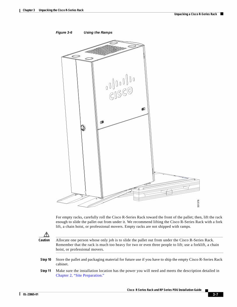
Figure 3-6 Using the Ramps
For empty racks, carefully roll the Cisco R-Series Rack toward the front of the pallet; then, lift the rack enough to slide the pallet out from under it. We recommend lifting the Cisco R-Series Rack with a fork lift, a chain hoist, or professional movers. Empty racks are not shipped with ramps.
Caution Allocate one person whose only job is to slide the pallet out from under the Cisco R-Series Rack. Remember that the rack is much too heavy for two or even three people to lift; use a forklift, a chain hoist, or professional movers.
Step 10 Store the pallet and packaging material for future use if you have to ship the empty Cisco R-Series Rack cabinet.
Step 11 Make sure the installation location has the power you will need and meets the description detailed in Chapter 2, “Site Preparation.”
3313
78
3-7Cisco R Series Rack and RP Series PDU Installation Guide
OL-23865-01

Chapter 3 Unpacking the Cisco R-Series Rack Unpacking a Cisco R-Series Rack
Step 12 Verify that the doors along the route to the installation location are wide and tall enough to accommodate the Cisco R-Series Rack on its wheels.
Step 13 Verify that the flooring is ready. Refer to Figure 2-1 on page 2-3.
Step 14 Roll the Cisco R-Series Rack to the location where it will be installed.
3-8Cisco R Series Rack and RP Series PDU Installation Guide
OL-23865-01

Cisco ROL-23865-01
C H A P T E R 4
Installing the Cisco R-Series RackSecuring the Cisco R-Series Rack to the FloorFor information about how to unpack and place the Cisco R-Series Rack, refer to Unpacking a Cisco R-Series Rack, page 3-1. Once the Cisco R-Series Rack is off the pallet, roll it to the desired location. To assure you have enough room at the intended location, refer to the footprint diagram (Figure 2-2).
Complete the following steps to lower the leveling feet and install the front stabilizer bracket:
Step 1 Use a flat-head screwdriver to lower each of the leveling feet so that they touch the floor (refer to Figure 3-3 if needed). The rack casters support the weight of the rack, while the leveling feet prevent the rack from rolling.
Caution Unless you are moving the Cisco R-Series Rack, the leveling feet should always be extended.
Step 2 Remove the stabilizer plate from the bottom floor of the rack.
Step 3 Attach the stabilizer plate to the front of the Cisco R-Series Rack with the bolts in the accessory kit. (Refer to Figure 4-1, callout 1.)
4-1 Series Rack and RP Series PDU Installation Guide

Chapter 4 Installing the Cisco R-Series Rack Securing the Cisco R-Series Rack to the Floor
Figure 4-1 Attaching the Rack to the Floor
Step 4 If this is a stand-alone rack that will be loaded with less than 68 kg (150 lb.) of equipment, complete the following steps:
a. Remove the side panels.
b. Attach the side stabilizer brackets to the center cage nut on each side of the rack using the provided hex bolts and washers. (Refer to Figure 4-1, callout 2.)
Step 5 Bolt the Cisco R-Series Rack to the floor surface through the holes in the front and side stabilizer brackets and reinstall the side panels.
The Cisco R-Series Rack itself is now installed. You may now:
• Join additional racks to the installed rack as described in “Joining Cisco R42610 Racks into a Suite”
• Install optional Cisco PDUs as described in Chapter 5, “Installing a Cisco RP-Series PDU (Optional)”
• Install devices in the rack as described in their documentation.
2814
04
1
2
4-2Cisco R Series Rack and RP Series PDU Installation Guide
OL-23865-01

Chapter 4 Installing the Cisco R-Series Rack Joining Cisco R42610 Racks into a Suite
Joining Cisco R42610 Racks into a SuiteAvailable for your Cisco R42610 Racks is an optional rack joining kit (RACK-JOIN-001) with all the hardware required for you to attach two or more racks together. You do not have to remove the doors to attach the racks together. Joining racks into a suite will remove the need for the side stabilizers.
Before you join racks together in a suite, make sure that the floor will support the weight of all the equipment and the racks themselves.
To attach Cisco R42610 Racks together, follow these steps:
Step 1 Install the first rack as described in “Securing the Cisco R-Series Rack to the Floor”.
Step 2 Remove all doors as described in “Removing and Installing a Front Door” and “Removing and Installing Rear Doors”.
Step 3 Secure the racks together using the bracket as shown in Figure 4-2. Use two brackets in the front and two in the rear of the rack.
Figure 4-2 Connecting Two Racks
Step 4 Install the front stabilizer for the rack you have just added as described in “Securing the Cisco R-Series Rack to the Floor”.
Step 5 Repeat this procedure to attach additional racks to the suite.
2814
16
4-3Cisco R Series Rack and RP Series PDU Installation Guide
OL-23865-01

Chapter 4 Installing the Cisco R-Series Rack Joining Cisco R42610 Racks into a Suite
Installing Devices in the RackInstallation instructions on the optional Cisco PDUs are located in Chapter 5, “Installing a Cisco RP-Series PDU (Optional).”
Refer to the documentation for the devices you intend to install. Always observe the following guidelines:
• A list of Cisco products that have been tested with Cisco R-Series Racks is maintained on an internal Cisco website. Please contact your Cisco representative to access the latest information.
• Prior to the certification of components to ship pre racked, a component must be shipped in its original packaging. The shipment of a non-certified component in a rack will void the warranty. Please contact your Cisco representative to determine whether a component has been certified to ship pre racked.
• Always install devices in the bottom of the rack first, heaviest devices in the lowest possible RU space. A top heavy rack can be extremely dangerous.
• If installed devices can slide forward, only extend one device at a time. Never extend any device that weighs over 176 pounds (80 kilograms).
• Never install devices that are not approved by independent national safety labs appropriate for your country.
• Do not use the top of a rack-mounted device as a shelf unless it is intended for that use.
4-4Cisco R Series Rack and RP Series PDU Installation Guide
OL-23865-01

Cisco ROL-23865-01
C H A P T E R 5
Installing a Cisco RP-Series PDU (Optional)The Cisco PDUs are engineered to be conveniently installed in a Cisco R-Series Rack, though other racks may be used with the provided they are square-hole racks. All illustrations assume an installation in the Cisco R-Series Rack.
Preparing to Install an RP-Series PDUBefore you install a PDU, plan how to route the power cable, which can be routed through the bottom of the Cisco R-Series Rack (refer to “Using the Rear Cable Access Bar”), or through the four knockout cabling portholes on the top of the Cisco R-Series Rack enclosure (refer to “Using the Cabling Portholes”).
5-1 Series Rack and RP Series PDU Installation Guide

Chapter 5 Installing a Cisco RP-Series PDU (Optional) Preparing to Install an RP-Series PDU
Installing a Cisco RP230-32-1P-U-2 or RP208-30-1P-U-2 PDUThe Cisco RP230-32-U-2 Single Phase PDU (EUR) and the Cisco RP208-30-U-2 Single Phase PDU (US) has 20 C13 connectors and 4 C19 connectors (see Figure 5-1). They differ in the cord used to plug into facility power and in voltage and amperage specification (see Figure 5-2 and Figure 5-3). These PDUs are intended to be installed on the plates to the rear of the Cisco R-Series Rack without requiring any RU spaces, so they are also referred to as zero-RU PDUs.
Figure 5-1 Zero-RU PDUs
Figure 5-2 US Plug (NEMA L6-30P)
Figure 5-3 European Plug (IEC309-32)
Warning No user-serviceable parts inside. Do not open. Statement 1073
1 Breakers 3 C19
2 Grounding point 4 C13
20A 20ACB2 CB1
2814
00
20A 20ACB2 CB1
1 2
3
4
3
4
2814
1028
1422
5-2Cisco R Series Rack and RP Series PDU Installation Guide
OL-23865-01

Chapter 5 Installing a Cisco RP-Series PDU (Optional) Preparing to Install an RP-Series PDU
Warning Do not work on the system or connect or disconnect cables during periods of lightning activity. Statement 1001
Warning Read the installation instructions before connecting the system to the power source. Statement 1004
Warning This product relies on the building’s installation for short-circuit (overcurrent) protection. Ensure that the protective device is rated not greater than: 30 A Statement 1005
Warning This equipment must be grounded. Never defeat the ground conductor or operate the equipment in the absence of a suitably installed ground conductor. Contact the appropriate electrical inspection authority or an electrician if you are uncertain that suitable grounding is available. Statement 1024
Warning For Nordic countries (Norway, Finland, Sweden and Denmark) this system must be installed in a Restricted Access Location, where the voltage of the main ground connection of all equipment is the same (equipotential earth) and the system is connected to a grounded electrical outlet. Statement 328
Warning Connect the device to a grounded power outlet. Statement 25
You can install up to six zero-RU PDUs in the Cisco R-Series Rack. No tools are required. To install a zero-RU PDU, follow these steps:
Step 1 Open the rear of the rack, and as appropriate for your situation, route the PDU power cable either through the top porthole or the bottom utilizing the cable access bar.
Step 2 Insert the two studs on the rear of the PDU into a pair of slots on the sides of the rack. See Figure 5-4. The PDU breakers can either be on the top or bottom of the rack, as appropriate for how you route the power cable. If necessary for equipment clearances, use the alternate 90 degree mounting position shown in Figure 5-4 for one of the PDUs.
5-3Cisco R Series Rack and RP Series PDU Installation Guide
OL-23865-01

Chapter 5 Installing a Cisco RP-Series PDU (Optional) Preparing to Install an RP-Series PDU
Figure 5-4 Zero-RU PDUs Mounted (Top Installation Shown)
2814
09
5-4Cisco R Series Rack and RP Series PDU Installation Guide
OL-23865-01

Chapter 5 Installing a Cisco RP-Series PDU (Optional) Preparing to Install an RP-Series PDU
Figure 5-5 Alternate 90 Degree Mounting Position
Step 3 Slide the PDU down slightly so that the PDU can hang in place within the Cisco R-Series Rack.
Step 4 Secure the PDU to the Cisco R-Series Rack using one of the provided cable ties. If necessary, remove the side panels to make access easier.
Step 5 Loosen the ground connector and either wrap around it the end of a a 10 AWG wire with 1” of the end stripped, or attach a wire that has a ring connector attached.
Step 6 Connect the other end of the grounding wire to the Cisco R-Series Rack.
Step 7 Connect the PDU power cord to the AC source.
2814
29
5-5Cisco R Series Rack and RP Series PDU Installation Guide
OL-23865-01

Chapter 5 Installing a Cisco RP-Series PDU (Optional) Installing an Cisco RP230-32-U-1 or RP208-30-U-1 PDU
Installing an Cisco RP230-32-U-1 or RP208-30-U-1 PDUThe Cisco RP230-32-U-1 Single Phase PDU (Eur) and the Cisco RP208-30-U-1 Single Phase PDU (US) both have 2 C13 connectors and 4 C19 connectors (see Figure 5-6). They differ in the cord used to plug into facility power (see Figure 5-2 and Figure 5-3). These PDUs can be installed inside the side walls of the Cisco R-Series Rack in a tower configuration without requiring any RU spaces, or in one of the available RU spaces.
Figure 5-6 1-RU PDU Front Panel
Warning No user-serviceable parts inside. Do not open. Statement 1073
Warning Do not work on the system or connect or disconnect cables during periods of lightning activity. Statement 1001
Warning Read the installation instructions before connecting the system to the power source. Statement 1004
Warning This product relies on the building’s installation for short-circuit (overcurrent) protection. Ensure that the protective device is rated not greater than: 30 A Statement 1005
Warning This equipment must be grounded. Never defeat the ground conductor or operate the equipment in the absence of a suitably installed ground conductor. Contact the appropriate electrical inspection authority or an electrician if you are uncertain that suitable grounding is available. Statement 1024
1 C19 (4) 3 C13 (2)
2 Breaker reset (2)
2814
11
223 3
1
1
5-6Cisco R Series Rack and RP Series PDU Installation Guide
OL-23865-01

Chapter 5 Installing a Cisco RP-Series PDU (Optional) Installing an Cisco RP230-32-U-1 or RP208-30-U-1 PDU
Warning For Nordic countries (Norway, Finland, Sweden and Denmark) this system must be installed in a Restricted Access Location, where the voltage of the main ground connection of all equipment is the same (equipotential earth) and the system is connected to a grounded electrical outlet. Statement 328
Warning Connect the device to a grounded power outlet. Statement 25
Installing in a Tower ConfigurationTo install the Cisco PDU in a Cisco R-Series Rack in a tower configuration. follow these steps:
Step 1 Prepare for installation:
a. Place the PDU on the floor or on a sturdy table as close as possible to the Cisco R-Series Rack. Leave enough clearance to allow you to move around the chassis.
b. Open the rack-mount kit, and refer to the component checklist to verify that all parts are included.
Step 2 Attach the left and right L brackets using four of the M4 Phillips pan-head screws provided in the rack-mount kit. (See Figure 5-7.)
Figure 5-7 Attaching the Brackets to the Cisco PDU for a Tower Mount
Step 3 Install the PDU in the Cisco R-Series Rack with the outlets facing the rear of the rack. (See Figure 5-8.)
a. Position the PDU in the rack at either the top or bottom of the rack:
Table 5-1 Rack-Mount Kit Checklist
Quantity Part Description Received
2 Front L brackets (I RU install)
4 Rear L brackets (static and sliding for 1 RU install)
2 Tower brackets (tower install)
8 M4 Phillips pan-head screws
4 12-24 x 3/4-inch Phillips binder-head screws
4 10-32 x 3/4-inch Phillips binder-head screws
2814
12
5-7Cisco R Series Rack and RP Series PDU Installation Guide
OL-23865-01

Chapter 5 Installing a Cisco RP-Series PDU (Optional) Installing an Cisco RP230-32-U-1 or RP208-30-U-1 PDU
b. Align the mounting holes in the L brackets with the mounting holes in the rack supports.
c. Secure the PDU using four (two on each side) no. 12 self-tapping screws through the holes in the L bracket and rack frame.
Figure 5-8 Tower Mounting a Cisco 1-RU PDU
Step 4 Ground the Cisco PDU to the Cisco R-Series Rack as shown in Figure 5-9. This example shows a connection to the frame using a no. 12 self-tapping screw.
2814
13
5-8Cisco R Series Rack and RP Series PDU Installation Guide
OL-23865-01

Chapter 5 Installing a Cisco RP-Series PDU (Optional) Installing an Cisco RP230-32-U-1 or RP208-30-U-1 PDU
Figure 5-9 Grounding a 1-RU Tower Mount
Step 5 Connect the PDU power cord to the AC source.
Installing in a 1RU ConfigurationThe 1 RU configuration will work in most square hole rack cabinets, and does not require a Cisco R-Series Rack. Follow these steps to install the Cisco PDU in a rack in a 1 RU configuration:
Step 1 Prepare for installation:
a. Place the PDU on the floor or on a sturdy table as close as possible to the rack. Leave enough clearance to allow you to move around the chassis.
b. Open the rack-mount kit, and refer to the component checklist to verify that all parts are included.
2814
14
5-9Cisco R Series Rack and RP Series PDU Installation Guide
OL-23865-01

Chapter 5 Installing a Cisco RP-Series PDU (Optional) Installing an Cisco RP230-32-U-1 or RP208-30-U-1 PDU
Note Some equipment racks provide a power strip along the length of one of the rear posts. If the rack has this feature, consider the position of the strip when planning fastener points. Before installing the L brackets on the chassis, determine whether to install the chassis from the front or the rear of the rack.
Step 2 Attach the left and right brackets using eight of the M4 Phillips pan-head screws provided in the rack-mount kit. (See Figure 5-10.)
Figure 5-10 Attaching the Brackets to the Cisco PDU for a 1 RU Mount
Step 3 Slide the rear L bracket onto the rear bracket.
Step 4 Install 8 cage nuts as needed into the square holes in the desired RU of the rack.
Step 5 Install the PDU in the rack with the outlets facing the rear of the rack as shown in Figure 5-11 and Figure 5-12.
a. Position the PDU in the rack at either the top or bottom of the rack:
b. Align the mounting holes in the L brackets with the mounting holes in the rack. Slide the rear L bracket to the length needed.
c. Secure the PDU using eight (two on each bracket) 12-24 x 3/4-inch screws through the elongated holes in the L bracket and into the cage nuts in the mounting post.
Table 5-2 Rack-Mount Kit Checklist
Quantity Part Description Received
2 Front L brackets (I RU install)
4 Rear L brackets (static and sliding for 1 RU install)
2 Tower brackets (tower install)
8 M4 Phillips pan-head screws
4 12-24 x 3/4-inch Phillips binder-head screws
4 10-32 x 3/4-inch Phillips binder-head screws
2814
18
5-10Cisco R Series Rack and RP Series PDU Installation Guide
OL-23865-01

Chapter 5 Installing a Cisco RP-Series PDU (Optional) Installing an Cisco RP230-32-U-1 or RP208-30-U-1 PDU
Figure 5-11 RU Mounting a Cisco 1-RU PDU
Step 6 Ground the Cisco PDU to the rack as shown in Figure 5-12. This example shows a connection to the frame using a no. 12 self-tapping screw.
2814
20
5-11Cisco R Series Rack and RP Series PDU Installation Guide
OL-23865-01

Chapter 5 Installing a Cisco RP-Series PDU (Optional) Installing an Cisco RP230-32-U-1 or RP208-30-U-1 PDU
Figure 5-12 Grounding a 1-RU Mount
Step 7 Connect the PDU power cord to the AC source.
2814
21
5-12Cisco R Series Rack and RP Series PDU Installation Guide
OL-23865-01

Cisco ROL-23865-01
C H A P T E R 6
Replacing ComponentsThe Cisco R-Series Rack has several replaceable components, and the following procedures are possible:
• Removing and Installing a Front Door
• Reversing a Front Door
• Removing and Installing Rear Doors
• Removing and Installing Side Panels (if included)
• Using the Cabling Portholes
• Using the Rear Cable Access Bar
6-1 Series Rack and RP Series PDU Installation Guide

Chapter 6 Replacing Components Removing and Installing Side Panels (if included)
Removing and Installing Side Panels (if included)The Cisco R-Series Racks may come with side panels installed. You may find it easier to remove the panels as you are unpacking the rack or before installing PDUs, servers, and other devices.
Installation of the panels is the reverse of the removal. Complete the following steps to remove the side panels from a Cisco R-Series Rack:
Step 1 Unlock both button locks with the provided key and then slide the latches toward each other as shown in Figure 6-1, upper callout 1.
Figure 6-1 Removing Side Panels
Step 2 Holding it by the sides, pull the bottom of the top panel slightly toward you (as shown in Figure 6-1, upper callout 2); then, lift the side panel and pull it away from the ridge on the top of the rack (as shown in Figure 6-1, upper callout 3).
Step 3 Holding it by the sides, pull the bottom of the bottom panel slightly up (as shown in Figure 6-1, lower callout 1), then lift the bottom panel and pull it away from the ridge on the middle of the rack (as shown in Figure 6-1, lower callout 2).
Note After removing a side panel, store it in an upright position against a flat surface.
2814
03
1
2
1
2
3
6-2Cisco R Series Rack and RP Series PDU Installation Guide
OL-23865-01

Chapter 6 Replacing Components Removing and Installing Cisco R-Series Rack Doors
Cisco R Series Rack and RP Series PDU Installation Guide
Removing and Installing Cisco R-Series Rack Doors All Cisco R42610 Racks come with front and rear doors installed. Removing the doors when installing and removing devices in the rack is only required if part of the rack is obstructed by the door as you install the device. Most devices can be installed without removing the doors.
Removing and Installing a Front Door Installing a front door is the reverse of removal. Complete the following steps to remove a front door from the Cisco R42610 Rack.
Step 1 Unlock and open the door by pulling the handle bottom out and rotating the handle 90° clockwise.
Step 2 While holding the door steady, lift both captive hinge pin(s) until they unlock (see Figure 6-2).
Figure 6-2 Removing the Front Door
Timesaver One person should be able to remove a front door unassisted, but having one person hold the door while the other slides the pins will be slightly quicker.
Step 3 Hold the door with both hands and pull it away from the hinges (see Figure 6-2), then store it in an upright position against a flat surface.
Step 4 If you are replacing the front door, you might have to remove the old lock latch (see Figure 6-3, callout 5) and replace it with the new lock latch that comes with the new door (see Figure 6-4, callout 2).
2814
05
6-3OL-23865-01

Chapter 6 Replacing Components Removing and Installing Cisco R-Series Rack Doors
Reversing a Front Door To reverse a front door on a Cisco R42610 Rack so that it opens in the opposite direction, follow these steps:
Step 1 Remove the door as described in “Removing and Installing a Front Door”.
Step 2 Use a 4 mm hex wrench to remove the top and bottom hinges from the rack. See callout 1 in Figure 6-3.
Step 3 Install the hinges on the other side of the rack. See callout 2 and callout 3 in Figure 6-3.
Step 4 Remove the front door latch. See callout 4 in Figure 6-3.
Step 5 Attach the front door latch to the other side of the rack. See callout 5 in Figure 6-3 or Figure 6-4.
Figure 6-3 Reversing Front Door Hinges and Door Latch
1 Starting position of hinges 4 Starting position of door latch
2 Moved position of hinges on opposite post 5 Moved position of door latch on opposite post
3 Close-up view of hinge
2814
06
1
3
54
2
2
6-4Cisco R Series Rack and RP Series PDU Installation Guide
OL-23865-01

Chapter 6 Replacing Components Removing and Installing Cisco R-Series Rack Doors
Figure 6-4 Door Latch on Right-Front Rack Post
Step 6 Rotate the door 180°; then install the door on the other side of the rack.
Step 7 Remove the Cisco logo from the bottom of the door; then snap it into the holes near the top of the door.
1 Door latch on right-front rack post 2 Enlarged view of door latch and screws
3049
29
2
1
6-5Cisco R Series Rack and RP Series PDU Installation Guide
OL-23865-01

Chapter 6 Replacing Components Removing and Installing Cisco R-Series Rack Doors
Removing and Installing Rear Doors Installing the rear doors is the reverse of removal. Complete the following steps to remove the rear doors from the Cisco R42610 Rack.
Step 1 Unlock and open the right-side door.
Step 2 While holding the right door steady, lift both captive hinge pins until they unlock (as shown in Figure 6-5).
Step 3 Hold the door steady with both hands and pull it away from the hinges; then store it in an upright position against a flat surface.
Step 4 Open the left-side door.
Step 5 Hold the left-side door steady with one hand, then lift both captive hinge pins until they unlock (as shown in Figure 6-5).
Step 6 Hold the door steady with both hands and pull it away from the hinges, then store it in an upright position against a flat surface.
Figure 6-5 Removing the Rear Doors
2814
07
6-6Cisco R Series Rack and RP Series PDU Installation Guide
OL-23865-01

Chapter 6 Replacing Components Using the Cabling Portholes
Using the Cabling PortholesTo use knockout cabling portholes on the top panel:
Step 1 Use a flat-blade screwdriver to pry a knockout cabling porthole off the Cisco R-Series Rack top panel. (See Figure 6-6, callout 1.)
Step 2 Snap out and discard the center of the cabling porthole. (See Figure 6-6, callout 2.)
Step 3 Replace the grommet ring of the cabling porthole in the opening. (See Figure 6-6, callout 3.)
Figure 6-6 Access Ports on the Cisco R-Series Rack Top
Caution Failing to replace the ring may lead to damaged power or network cables.
2814
08
2
3
1
6-7Cisco R Series Rack and RP Series PDU Installation Guide
OL-23865-01

Chapter 6 Replacing Components Using the Rear Cable Access Bar
Using the Rear Cable Access BarTo use the rear cable access bar in the bottom of the Cisco R-Series Rack:
Step 1 Release the two swell latches securing the cable access bar to the rear of the rack. (See the Arrows and callout 1 in Figure 6-7.)
Step 2 Pull the bar away from the rack as shown in callout 2 of Figure 6-7.
Figure 6-7 Removing the Cable Access Bar
Step 3 Route the cables through the opening.
Step 4 Reattach the rear cable access bar to the rack by pressing it into place and tightening the swell latches. Make sure that you do not pinch or cut any cables.
228
14281
6-8Cisco R Series Rack and RP Series PDU Installation Guide
OL-23865-01

Cisco R SerieOL-23865-01
A
P P E N D I X A SpecificationsRack SpecificationsTable A-1 lists the specifications for Cisco R-Series Racks.
Table A-1 Specifications
Cisco R42610 Rack Standard Expansion Dynamic
Dimensions (H x W x D) 78.74 x 24 x 43.38 in.(2000 x 610 x 1102 mm)
78.74 x 23.58 x 43.38 in. (2000 x 599 x 1102 mm)
78.74 x 24 x 43.38 in.(2000 x 610 x 1102 mm)
Dimensions (H x W x D) with packaging
89 x 33 x 47 in. (2261 x 838 x 1194 mm)
89 x 33 x 47 in. (2261 x 838 x 1194 mm)
85 x 39 x 47 in. (2169 x 992 x 1200 mm)
Distance from front mounting rail to rear mounting rail
29.2 in (741 mm) 29.2 in (741 mm) 29.2 in (741 mm)
Weight 299.83 lb. (136 kg) 231. 49 lb. (105 kg) 299.83 lb. (136 kg)
Weight with packaging 354 lb. (161 kg) 284 lb. (129 kg) 473 lb. (215 kg)
Side panels included Yes No Yes
Equipment mounting capacity
42RU 42RU 42RU
Static load capacity 3000 lb. (1360 kg)
3000 lb. (1360 kg)
3000 lb. (1360 kg)
Dynamic load capacity Not applicable Not applicable 2150 lb.(975 kg)
A-1s Rack and RP Series PDU Installation Guide

Appendix A Specifications PDU Specifications
PDU SpecificationsTable A-2 toTable A-4 list the specifications for Cisco RP-Series PDUs.
Table A-2 PDU Specifications
Description 0RU strip PDU 20 C13 and 4 C19 1RU PDU 2 C13 and 4 C19
Cisco option part number
RP208-30-1P-U-2 (US) or
RP230-30-U-2 (EU)
RP208-30-1P-U-1 (US) or
RP230-32-U-1 (EU)
RU size 0 0 or 1
Input voltage 200 to 240 VAC ±10% 200 to 240 VAC ±10%
Frequency 50 to 60 Hz 50 to 60 Hz
Amperage 30 A (US) or 32 A (EU)
30 A (US) or 32 A (EU)
UL rating 24 A 24 A
Input plug NEMA L6-30P (US) or IEC309-32 EU NEMA L6-30P (US) or IEC309-32 (EU)
Cord length 3m 3m
Output voltage
200 to 240 VAC 200 to 240 VAC
Receptacles 20 IEC 320 C13
4 IEC 320 C19
2 IEC 320 C13
4 IEC 320 C19
Circuit breakers1 2
2 two-pole 30A (UL 489/CSA C22.2 No. 5.1)
2 two-pole 30A (UL 489/CSA C22.2 No. 5.1)
Safety and Environmental
Operating temperature
50 to 122° F (10 to 50° C)
Operating relative humidity
5 to 90% (non-condensing)
Operating elevation
0 to 10,000 ft. (0 to 3048m)
Storage temperature
-40 to 140°F (-40 to 60° C)
Storage relative humidity
5 to 95% (including condensing)
Storage elevation
0 to 50,000 ft. (0 to 15,240m)
Acoustics No fan; measure 1m from surface of PDU.
Safety IEC 60950-1EN 60950-1UL/CSA 60950-1
IEC 60950-1EN 60950-1UL/CSA 60950-1
A-2Cisco R Series Rack and RP Series PDU Installation Guide
OL-23865-01

Appendix A Specifications PDU Specifications
This symbol indicates that you should not discard waste electrical or electronic equipment (WEEE) in the trash. For proper disposal, contact your local recycling/reuse or hazardous waste center.
Safety Earthing Terminal This symbol indicates the primary safety ground.
The PDU requires a dedicated branch circuit that meets the diagram in Figure A-1 and the PDU specifications:
Figure A-1 PDU Circuit
Unit dimensions (L x W x H)
60.6 x 17.4 x 3.4 in. (1540 x 44 x 85 mm)
17.6 x 13.8 x 18 x 11.1 (447 x 350 x 45 x 5 mm)
Unit weight 12.1 lb. (5.5 kg) 11.1 lb. (5 kg)
Packaging size (H x W x D)
170 x 170 x 1720 mm 180 x 495 x 565 mm
Total weight with packaging
15.5 lb. (7 kg) 18.3 lb. (8.3 kg)
1. To reduce the risk of fire, connect only to a circuit provided with branch circuit overcurrent protection with an ampere rating in accordance with the National Electrical Code (NEC). ANSI/NFPA 70 or your local electrical code.
2. The circuit breaker must be wall mounted and easily accessible to the operator.
Table A-2 PDU Specifications (continued)
Description 0RU strip PDU 20 C13 and 4 C19 1RU PDU 2 C13 and 4 C19
Table A-3 PDU Power Efficiency
Current (A) 1U Power loss (W) 0U Power loss (W)
0 >0.3 >0.2
5 3 4
32 100 80
2 PolesBreaker
Line
Neutral
PDUAC Mains
2379
72
A-3Cisco R Series Rack and RP Series PDU Installation Guide
OL-23865-01

Appendix A Specifications PDU Specifications
Table A-4 Connector Specifications
Connector Server Inlet Rated Continuous Current
C13 C14 10 A
C19 C20 16 A
A-4Cisco R Series Rack and RP Series PDU Installation Guide
OL-23865-01
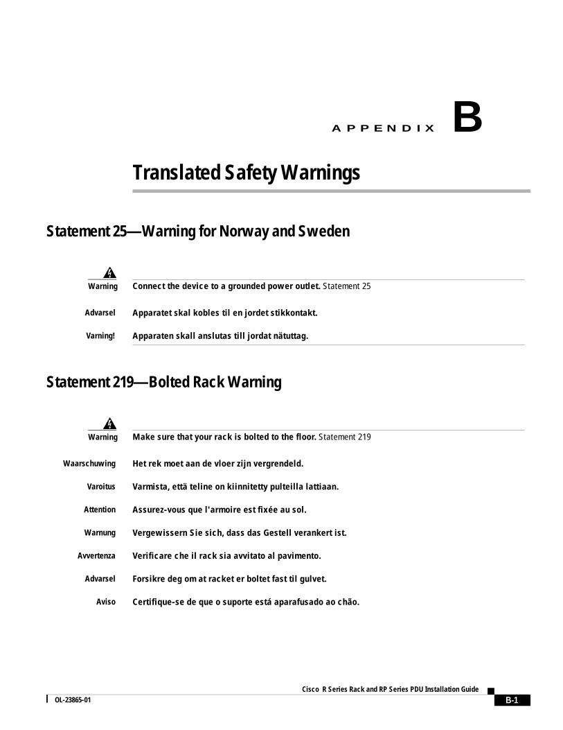
Cisco R SerieOL-23865-01
A
P P E N D I X B Translated Safety WarningsStatement 25—Warning for Norway and Sweden
Statement 219—Bolted Rack Warning
Warning Connect the device to a grounded power outlet. Statement 25
Advarsel Apparatet skal kobles til en jordet stikkontakt.
Varning! Apparaten skall anslutas till jordat nätuttag.
Warning Make sure that your rack is bolted to the floor. Statement 219
Waarschuwing Het rek moet aan de vloer zijn vergrendeld.
Varoitus Varmista, että teline on kiinnitetty pulteilla lattiaan.
Attention Assurez-vous que l'armoire est fixée au sol.
Warnung Vergewissern Sie sich, dass das Gestell verankert ist.
Avvertenza Verificare che il rack sia avvitato al pavimento.
Advarsel Forsikre deg om at racket er boltet fast til gulvet.
Aviso Certifique-se de que o suporte está aparafusado ao chão.
B-1s Rack and RP Series PDU Installation Guide

Appendix B Translated Safety Warnings
Statement 220—Rack Ventilation Warning
Statement 250—Rack Stabilization Warning
¡Advertencia! Asegúrese de el soporte de su equipo está bien fijado al suelo.
Varning! Kontrollera att stativet är fastsatt i golvet.
Warning Make sure that your equipment rack is properly ventilated. Statement 220
Waarschuwing Het apparatuurrek moet voldoende ventilatie krijgen.
Varoitus Varmista, että laitteistoteline on kunnolla ilmastoitu.
Attention Assurez-vous que l'armoire de votre équipement est correctement ventilée.
Warnung Vergewissern Sie sich, dass das Gerätegestell ausreichend belüftet ist.
Avvertenza Verificare che l'apparecchiatura sia ventilata in modo adeguato.
Advarsel Forsikre deg om at utstyrsracket er grundig ventilert.
Aviso Certifique-se de que o suporte do equipamento é devidamente ventilado.
¡Advertencia! Asegúrese de que el soporte de su equipo posee una ventilación adecuada.
Varning! Kontrollera att utrustningen har tillräcklig ventilation.
Warning Stability hazard. The rack stabilizing mechanism must be in place, or the rack must be bolted to the floor before you slide the unit out for servicing. Failure to stabilize the rack can cause the rack to tip over. Statement 250
Waarschuwing Kantelgevaar. Als u een eenheid uitschuift ten behoeve van service-werkzaamheden, moet het rek met de speciaal daarvoor bedoelde voorzieningen zijn gestabiliseerd of met bouten in de vloer zijn vastgezet. Het rek kan kantelen als het niet afdoende is gestabiliseerd.
Varoitus Stabiiliusvaara. Telineen stabilointimekanismin on oltava paikallaan tai telineen on oltava ruuvattu lattiaan, ennen kuin liu'utat yksikön ulos huoltoa varten. Ellei telinettä stabiloida, se voi kaatua.
B-2Cisco R Series Rack and RP Series PDU Installation Guide
OL-23865-01

Appendix B Translated Safety Warnings
Statement 252—Chassis Installation Warning
Attention Stabilisation de l'armoire : le mécanisme de stabilisation doit être installé correctement ou l'armoire doit être solidement fixée au sol avant d'être utilisée. Sans cette précaution, elle risque de basculer.
Warnung Umstürzgefahr. Bevor Sie die Einheit zur Wartung hinausziehen, sollten Sie die Stabilisierungsvorrichtung des Gestells aktivieren oder das Gestell am Boden festschrauben. Wenn das Gestell nicht entsprechend gesichert ist, kann es umkippen.
Avvertenza Pericolo di stabilità. Prima di estrarre l’unità per la manutenzione, accertarsi che il meccanismo di stabilizzazione del rack sia in funzione oppure che il rack sia affrancato al pavimento. La mancata stabilità del rack può causarne il rovesciamento.
Advarsel Stabilitetsfare. Stabiliseringsmekanismen for stativet må være på plass, eller stativet må være skrudd fast i gulvet, før du drar ut enheten for å utføre service. Hvis du ikke stabiliserer stativet, kan det hende at stativet velter.
Aviso Risco de estabilidade. O mecanismo de estabilização da prateleira tem de estar colocado no devido lugar ou, então, a prateleira tem de estar aparafusada ao chão antes de fazer deslizar a unidade para fora, para reparação. A falha na estabilização da prateleira pode fazê-la virar.
¡Advertencia! Equilibrio inestable. El mecanismo de equilibrio del bastidor debe estar colocado en su lugar correcto; de lo contrario, atornille el bastidor al suelo antes de deslizar la unidad para su manipulación. Si no equilibra el bastidor, éste podrá volcarse.
Varning! Stabilitetsfara. Rackets stabiliseringsmekanism måste sitta på plats, eller också måste racket skruvas fast i golvet innan du drar ut en enhet för underhåll. Om racket inte stabiliseras, kan det välta.
Warning If you are installing more than one chassis, install the slide assemblies so that the first chassis is installed in the lowest available position in the rack. Statement 252
Waarschuwing Plaats de uitschuifmechanismen bij het installeren van meer dan één chassis zodanig dat het als eerste te installeren chassis in de laagst mogelijke positie wordt aangebracht.
Varoitus Jos asennat useamman kuin yhden asennuspohjan, asenna kiskot niin, että ensimmäinen asennuspohja asetetaan telineen alimpaan mahdolliseen paikkaan.
Attention Si vous installez plusieurs châssis, commencez par utiliser la partie la plus basse de l'armoire.
Warnung Wenn Sie mehr als ein Chassis installieren, sollten die Führungsschienen so angebracht werden, daß das erste Chassis in der untersten Position des Gestells montiert wird.
Avvertenza Se si installa più di un telaio, installare gli alloggiamenti per il montaggio in modo che il primo telaio venga installato all’estremità inferiore del rack.
B-3Cisco R Series Rack and RP Series PDU Installation Guide
OL-23865-01

Appendix B Translated Safety Warnings
Statement 328—Main Ground Connection Warning
Advarsel Hvis du installerer mer enn ett kabinett, må du installere skinnene slik at det første kabinettet kan installeres lavest mulig på stativet.
Aviso Se pretende instalar mais do que um chassis, instale os conjuntos deslizantes de modo a que o primeiro chassis seja instalado na posição mais baixa na prateleira.
¡Advertencia! Si instala más de un chasis, comience por la ranura de ensamblaje de forma que el primer chasis esté instalado en el lugar más inferior que se encuentre libre en el bastidor.
Varning! Om du monterar mer än ett chassi, ska du montera skenfästena så att det första chassit monteras i den nedersta lediga platsen i racket.
Warning For Nordic countries (Norway, Finland, Sweden and Denmark) this system must be installed in a Restricted Access Location, where the voltage of the main ground connection of all equipment is the same (equipotential earth) and the system is connected to a grounded electrical outlet. Statement 328
Waarschuwing Voor de Noord-Europese landen (Noorwegen, Finland, Zweden en Denemarken) dient dit systeem geïnstalleerd te worden in een locatie met beperkte toegang, waarbij het voltage van de hoofdaardingsaansluiting van alle apparatuur hetzelfde is (equipotentiale aarding) en het systeem aangesloten is op een geaarde elektrische contactdoos.
Varoitus Pohjoismaissa (Norja, Ruotsi, Suomi ja Tanska) tämä järjestelmä on asennettava paikkaan, johon on rajoitettu pääsy ja jossa kaikkien laitteiden päämaadoituksen jännite on sama (tasapotentiaalinen maa) ja järjestelmä on kytketty maadoitettuun pistorasiaan.
Attention Dans les pays scandinaves (Norvège, Finlande, Suède et Danemark), ce système doit être installé dans un local à accès restreint, où le voltage de la prise de terre principale de tous les appareils est le même (" terre équipotentielle ") et où le système est connecté à une prise électrique mise à la terre.
Warnung In nordischen Ländern (Norwegen, Finnland, Schweden und Dänemark) muss dieses System an einem Standort mit beschränktem Zugang installiert werden, an dem die Spannung der Haupterdungsverbindung aller Geräte gleich ist (Äquipotential-Erdung) und das System an eine geerdete Steckdose angeschlossen ist.
Avvertenza In Scandinavia (Norvegia, Finlandia, Svezia e Danimarca) questo sistema deve essere installato in un'Area ad Accesso Limitato, in cui il livello di tensione della connessione di terra della rete è lo stesso per tutti gli apparecchi (terra equipotenziale) e il sistema è connesso ad un impianto di messa a terra.
Advarsel I de nordiske land (Norge, Finland, Sverige og Danmark) må dette systemet installeres på et sted merket begrenset adgang, der spenningen i apparatjordforbindelsen for alt utstyr er den samme (ekvipotensial jord) og der systemet er koblet til et jordet elektrisk uttak.
B-4Cisco R Series Rack and RP Series PDU Installation Guide
OL-23865-01

Appendix B Translated Safety Warnings
Statement 333—Rack Lifting Warning
Aviso Para países Nórdicos (Noruega, Finlândia, Suécia e Dinamarca) este sistema deve ser instalado em um local de acesso restrito onde a voltagem do aterramento principal de todos os equipamento é o mesmo (equipotential earth) e o sistema está conectado a uma tomada elétrica aterrada.
¡Advertencia! En los países nórdicos (Noruega, Finlandia, Suecia y Dinamarca), este sistema debe ser instalado en una ubicación de acceso restringido donde el voltaje de la conexión principal a tierra de todo el equipamiento sea el mismo (tierra equipotencial) y el sistema se conecte a un enchufe con descarga a tierra.
Varning! I de nordiska länderna (Norge, Finland, Sverige och Danmark) måste detta system installeras på en plats med begränsad åtkomst, där spänningen i huvudjordningsanslutningen för all utrustning är densamma (ekvipotentiell jordning) och där systemet är anslutet till ett jordat eluttag.
Warning Never attempt to lift the rack with the handles on the power supplies or the modules. These handles are not designed to support the weight of the rack. Using them to lift or support the rack can result in severe damage to the equipment and serious bodily injury. Statement 333
Waarschuwing Het rek mag nooit met de hendels aan de voedingsbronnen of modules opgetild worden. Deze hendels zijn niet ontworpen om het gewicht van het rek te kunnen dragen. Als de hendels gebruikt worden om het rek op te tillen of te ondersteunen, kan dit ernstige beschadiging van de apparatuur en zwaar lichamelijk letsel veroorzaken.
Varoitus Älä yritä milloinkaan nostaa telinettä virtalähteiden tai moduulien kahvoista. Näitä kahvoja ei ole suunniteltu kestämään telineen painoa. Niiden käyttö telineen nostamiseen tai kannattamiseen voi aiheuttaa vakavan laitevaurion ja vakavan ruumiinvamman.
Attention N'essayez jamais de lever le rack à l'aide des poignées du module d'alimentation ou de commutation. Ces poignées ne sont pas conçues pour résister à de fortes charges. Les utiliser pour lever le rack risque de provoquer des dommages importants à l'appareil et des blessures corporelles graves.
Warnung Das Rack niemals an den Griffen der Stromversorgung oder der Module anheben. Diese Griffe können das Gewicht des Racks nicht tragen. Wenn sie zum Anheben oder Stützen des Racks benutzt werden, besteht Gefahr schwerer Geräteschäden und Personenverletzungen.
Avvertenza Non tentare mai di sollevare il rack utilizzando i manici degli alimentatori o dei moduli. Questi manici non sono stati progettati per sostenere il peso del rack e il loro utilizzo per sollevare o sostenere il rack può causare gravi lesioni e danni all'apparecchio.
Advarsel Forsøk aldri å løfte stativet ved hjelp av håndtakene på strømforsyningsenhetene eller omkoblingsmodulene. Disse håndtakene er ikke konstruert for å tåle vekten av stativet. Ved å bruke disse til å løfte eller støtte opp stativet, kan du forårsake alvorlig skade på mennesker og utstyr.
B-5Cisco R Series Rack and RP Series PDU Installation Guide
OL-23865-01

Appendix B Translated Safety Warnings
Statement 334—Rack Lifting Warning
Aviso Nunca tente levantar o bastidor pelas alças das fontes de energia ou dos módulos. As alças não foram projetadas para sustentar o peso do bastidor. Usá-las para erguer ou sustentar o bastidor poderá danificar significativamente o equipamento e causar lesão física grave.
¡Advertencia! No intentar nunca levantar el soporte por las asas de las fuentes de alimentación o de los módulos. Las asas no han sido diseñadas para sostener el peso del soporte. Si se usan para levantar o sostener el soporte pueden producirse serios daños a los equipos y lesiones físicas graves.
Varning! Försök inte lyfta racket i handtagen på strömförsörjningsaggregaten eller modulerna. Dessa handtag är inte konstruerade för rackets vikt. Om de används för att lyfta eller stödja racket kan allvarliga materiella skador samt kroppsskador uppstå.
Warning Three people are required to lift the rack. Grasp the rack underneath the lower edge and lift with both hands. To prevent injury, keep your back straight and lift with your legs, not your back. Statement 334
Waarschuwing Er zijn drie personen nodig om het rek op te tillen. Het rek dient onder de onderrand vastgegrepen en met beide handen opgetild te worden. Om te voorkomen dat u letsel oploopt, dient u uw rug recht te houden en met uw benen in plaats van met uw rug te tillen.
Varoitus Telineen nostamiseen tarvitaan kolme henkilöä. Ota kiinni telineen alareunan alta ja nosta molemmin käsin. Pidä selkäsi suorana ja nosta jalkojen (ei selän) avulla loukkaantumisen välttämiseksi.
Attention Il faut trois personnes pour soulever le rack. Le saisir par son rebord inférieur et sou lever des deux mains. Pour éviter tout traumatisme de la région lombaire, garder le dos droit et soulever la charge en redressant les jambes.
Warnung Zum Anheben des Racks werden drei Personen benötigt. Fassen Sie das Rack unterhalb der unteren Kante an und heben es mit beiden Händen an. Um Verletzungen zu vermeiden, ist der Rücken aufrecht zu halten und das Gewicht mit den Beinen, nicht mit dem Rücken, anzuheben.
Avvertenza Il rack va sollevato da tre persone. Afferrare il rack al di sotto del bordo inferiore e sollevare con entrambe le mani. Per evitare infortuni, tenere la schiena dritta e sollevare facendo forza sulle gambe, non sulla schiena.
Advarsel Det er nødvendig at tre personer løfter stativet. Ta tak under den nedre kanten på stativet og løft det med begge hender. Hold ryggen rett og løft med beina - ikke ryggen - for å unngå personskade. Unngå skade på kabinettet og komponentene.
Aviso São necessárias três pessoas para levantar o bastidor. Segure o bastidor por baixo da borda inferior, e levante-o usando as duas mãos. Para evitar lesão física, mantenha as costas retas e levante o peso usando as duas pernas, sem forçar as costas.
B-6Cisco R Series Rack and RP Series PDU Installation Guide
OL-23865-01

Appendix B Translated Safety Warnings
Statement 1001—Work During Lightning Activity
¡Advertencia! Se necesitan tres personas para levantar el soporte. Sujete el soporte con las dos manos por debajo del borde inferior y levántela. Para evitar lesiones, mantenga la espalda recta y levántela con la fuerza de las piernas y no de la espalda.
Varning! Det krävs tre personer för att lyfta racket. Fatta tag i racket under den nedre kanten och lyft med båda händerna. För att undvika skador skall du hålla ryggen rak och lyfta med benen, inte ryggen.
Warning Do not work on the system or connect or disconnect cables during periods of lightning activity. Statement 1001
Waarschuwing Tijdens onweer dat gepaard gaat met bliksem, dient u niet aan het systeem te werken of kabels aan te sluiten of te ontkoppelen.
Varoitus Älä työskentele järjestelmän parissa äläkä yhdistä tai irrota kaapeleita ukkosilmalla.
Attention Ne pas travailler sur le système ni brancher ou débrancher les câbles pendant un orage.
Warnung Arbeiten Sie nicht am System und schließen Sie keine Kabel an bzw. trennen Sie keine ab, wenn es gewittert.
Avvertenza Non lavorare sul sistema o collegare oppure scollegare i cavi durante un temporale con fulmini.
Advarsel Utfør aldri arbeid på systemet, eller koble kabler til eller fra systemet når det tordner eller lyner.
Aviso Não trabalhe no sistema ou ligue e desligue cabos durante períodos de mau tempo (trovoada).
¡Advertencia! No operar el sistema ni conectar o desconectar cables durante el transcurso de descargas eléctricas en la atmósfera.
Varning! Vid åska skall du aldrig utföra arbete på systemet eller ansluta eller koppla loss kablar.
B-7Cisco R Series Rack and RP Series PDU Installation Guide
OL-23865-01

Appendix B Translated Safety Warnings
Statement 1004—Installation Instructions
Advarsel Der må ikke arbejdes på systemet eller til-/frakobles kabler ved risiko for torden eller lynnedslag.
Warning Read the installation instructions before connecting the system to the power source. Statement 1004
Waarschuwing Raadpleeg de installatie-instructies voordat u het systeem op de voedingsbron aansluit.
B-8Cisco R Series Rack and RP Series PDU Installation Guide
OL-23865-01

Appendix B Translated Safety Warnings
Varoitus Lue asennusohjeet ennen järjestelmän yhdistämistä virtalähteeseen.
Attention Avant de brancher le système sur la source d'alimentation, consulter les directives d'installation.
Warnung Vor dem Anschließen des Systems an die Stromquelle die Installationsanweisungen lesen.
Avvertenza Consultare le istruzioni di installazione prima di collegare il sistema all'alimentatore.
Advarsel Les installasjonsinstruksjonene før systemet kobles til strømkilden.
Aviso Leia as instruções de instalação antes de ligar o sistema à fonte de energia.
¡Advertencia! Lea las instrucciones de instalación antes de conectar el sistema a la red de alimentación.
Varning! Läs installationsanvisningarna innan du kopplar systemet till strömförsörjningsenheten.
B-9Cisco R Series Rack and RP Series PDU Installation Guide
OL-23865-01

Appendix B Translated Safety Warnings
Statement 1005—Circuit Breaker
Warning This product relies on the building’s installation for short-circuit (overcurrent) protection. Ensure that the protective device is rated not greater than: 30 A in the US and Canada and 32 A International. Statement 1005
Waarschuwing Dit product is afhankelijk van de installatie van het gebouw voor beveiliging tegen kortsluiting (overstroom). Controleer of de beschermingsinrichting niet meer dan: 30 A in the US and Canada and 32 A International. is.
Varoitus Tämä tuote on riippuvainen rakennukseen asennetusta oikosulkusuojauksesta (ylivirtasuojauksesta). Varmista, että suojalaitteen mitoitus ei ole yli: 30 A in the US and Canada and 32 A International.
Attention Pour ce qui est de la protection contre les courts-circuits (surtension), ce produit dépend de l'installation électrique du local. Vérifiez que le courant nominal du dispositif de protection n'est pas supérieur à : 30 A in the US and Canada and 32 A International.
Warnung Dieses Produkt ist darauf angewiesen, dass im Gebäude ein Kurzschluss- bzw. Überstromschutz installiert ist. Stellen Sie sicher, dass der Nennwert der Schutzvorrichtung nicht mehr als: 30 A in the US and Canada and 32 A International. beträgt.
Avvertenza Questo prodotto dipende dall'impianto dell'edificio per quanto riguarda la protezione contro cortocircuiti (sovracorrente). Assicurarsi che il dispositivo di protezione non abbia un rating superiore a: 30 A in the US and Canada and 32 A International.
Advarsel Dette produktet er avhengig av bygningens installasjoner av kortslutnings (overstrøm)-beskyttelse. Påse at verneenheten ikke er merket høyere enn: 30 A in the US and Canada and 32 A International.
Aviso Este produto depende das instalações existentes para proteção contra curto-circuito (sobrecarga). Assegure-se de que o fusível ou disjuntor não seja superior a: 30 A in the US and Canada and 32 A International.
¡Advertencia! Este equipo utiliza el sistema de protección contra cortocircuitos (o sobrecorrientes) del edificio. Asegúrese de que el dispositivo de protección no sea superior a: 30 A in the US and Canada and 32 A International.
B-10Cisco R Series Rack and RP Series PDU Installation Guide
OL-23865-01

Appendix B Translated Safety Warnings
Statement 1006—Chassis Warning for Rack-Mounting and Servicing
Varning! Denna produkt är beroende av i byggnaden installerat kortslutningsskydd (överströmsskydd). Kontrollera att skyddsanordningen inte har högre märkvärde än: 30 A in the US and Canada and 32 A International.
30 A in the US and Canada and 32 A International.
30 A in the US and Canada and 32 A International.
30 A in the US and Canada and 32 A International.
30 A in the US and Canada and 32 A International.
Warning To prevent bodily injury when mounting or servicing this unit in a rack, you must take special precautions to ensure that the system remains stable. The following guidelines are provided to ensure your safety:
• This unit should be mounted at the bottom of the rack if it is the only unit in the rack.
• When mounting this unit in a partially filled rack, load the rack from the bottom to the top with the heaviest component at the bottom of the rack.
• If the rack is provided with stabilizing devices, install the stabilizers before mounting or servicing the unit in the rack. Statement 1006
Waarschuwing Om lichamelijk letsel te voorkomen wanneer u dit toestel in een rek monteert of het daar een servicebeurt geeft, moet u speciale voorzorgsmaatregelen nemen om ervoor te zorgen dat het toestel stabiel blijft. De onderstaande richtlijnen worden verstrekt om uw veiligheid te verzekeren:
• Dit toestel dient onderaan in het rek gemonteerd te worden als het toestel het enige in het rek is.
• Wanneer u dit toestel in een gedeeltelijk gevuld rek monteert, dient u het rek van onderen naar boven te laden met het zwaarste onderdeel onderaan in het rek.
• Als het rek voorzien is van stabiliseringshulpmiddelen, dient u de stabilisatoren te monteren voordat u het toestel in het rek monteert of het daar een servicebeurt geeft.
B-11Cisco R Series Rack and RP Series PDU Installation Guide
OL-23865-01
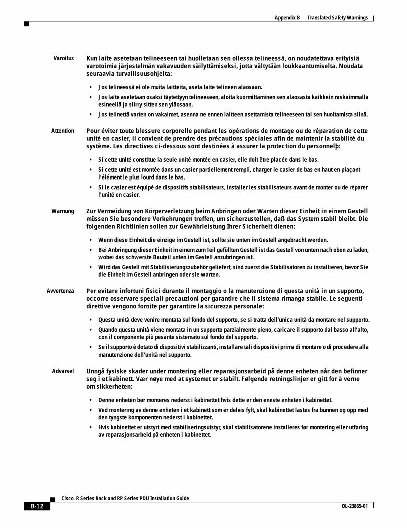
Appendix B Translated Safety Warnings
Varoitus Kun laite asetetaan telineeseen tai huolletaan sen ollessa telineessä, on noudatettava erityisiä varotoimia järjestelmän vakavuuden säilyttämiseksi, jotta vältytään loukkaantumiselta. Noudata seuraavia turvallisuusohjeita:
• Jos telineessä ei ole muita laitteita, aseta laite telineen alaosaan.
• Jos laite asetetaan osaksi täytettyyn telineeseen, aloita kuormittaminen sen alaosasta kaikkein raskaimmalla esineellä ja siirry sitten sen yläosaan.
• Jos telinettä varten on vakaimet, asenna ne ennen laitteen asettamista telineeseen tai sen huoltamista siinä.
Attention Pour éviter toute blessure corporelle pendant les opérations de montage ou de réparation de cette unité en casier, il convient de prendre des précautions spéciales afin de maintenir la stabilité du système. Les directives ci-dessous sont destinées à assurer la protection du personnelþ:
• Si cette unité constitue la seule unité montée en casier, elle doit être placée dans le bas.
• Si cette unité est montée dans un casier partiellement rempli, charger le casier de bas en haut en plaçant l'élément le plus lourd dans le bas.
• Si le casier est équipé de dispositifs stabilisateurs, installer les stabilisateurs avant de monter ou de réparer l'unité en casier.
Warnung Zur Vermeidung von Körperverletzung beim Anbringen oder Warten dieser Einheit in einem Gestell müssen Sie besondere Vorkehrungen treffen, um sicherzustellen, daß das System stabil bleibt. Die folgenden Richtlinien sollen zur Gewährleistung Ihrer Sicherheit dienen:
• Wenn diese Einheit die einzige im Gestell ist, sollte sie unten im Gestell angebracht werden.
• Bei Anbringung dieser Einheit in einem zum Teil gefüllten Gestell ist das Gestell von unten nach oben zu laden, wobei das schwerste Bauteil unten im Gestell anzubringen ist.
• Wird das Gestell mit Stabilisierungszubehör geliefert, sind zuerst die Stabilisatoren zu installieren, bevor Sie die Einheit im Gestell anbringen oder sie warten.
Avvertenza Per evitare infortuni fisici durante il montaggio o la manutenzione di questa unità in un supporto, occorre osservare speciali precauzioni per garantire che il sistema rimanga stabile. Le seguenti direttive vengono fornite per garantire la sicurezza personale:
• Questa unità deve venire montata sul fondo del supporto, se si tratta dell’unica unità da montare nel supporto.
• Quando questa unità viene montata in un supporto parzialmente pieno, caricare il supporto dal basso all’alto, con il componente più pesante sistemato sul fondo del supporto.
• Se il supporto è dotato di dispositivi stabilizzanti, installare tali dispositivi prima di montare o di procedere alla manutenzione dell’unità nel supporto.
Advarsel Unngå fysiske skader under montering eller reparasjonsarbeid på denne enheten når den befinner seg i et kabinett. Vær nøye med at systemet er stabilt. Følgende retningslinjer er gitt for å verne om sikkerheten:
• Denne enheten bør monteres nederst i kabinettet hvis dette er den eneste enheten i kabinettet.
• Ved montering av denne enheten i et kabinett som er delvis fylt, skal kabinettet lastes fra bunnen og opp med den tyngste komponenten nederst i kabinettet.
• Hvis kabinettet er utstyrt med stabiliseringsutstyr, skal stabilisatorene installeres før montering eller utføring av reparasjonsarbeid på enheten i kabinettet.
B-12Cisco R Series Rack and RP Series PDU Installation Guide
OL-23865-01

Appendix B Translated Safety Warnings
Aviso Para se prevenir contra danos corporais ao montar ou reparar esta unidade numa estante, deverá tomar precauções especiais para se certificar de que o sistema possui um suporte estável. As seguintes directrizes ajudá-lo-ão a efectuar o seu trabalho com segurança:
• Esta unidade deverá ser montada na parte inferior da estante, caso seja esta a única unidade a ser montada.
• Ao montar esta unidade numa estante parcialmente ocupada, coloque os itens mais pesados na parte inferior da estante, arrumando-os de baixo para cima.
• Se a estante possuir um dispositivo de estabilização, instale-o antes de montar ou reparar a unidade.
¡Advertencia! Para evitar lesiones durante el montaje de este equipo sobre un bastidor, o posteriormente durante su mantenimiento, se debe poner mucho cuidado en que el sistema quede bien estable. Para garantizar su seguridad, proceda según las siguientes instrucciones:
• Colocar el equipo en la parte inferior del bastidor, cuando sea la única unidad en el mismo.
• Cuando este equipo se vaya a instalar en un bastidor parcialmente ocupado, comenzar la instalación desde la parte inferior hacia la superior colocando el equipo más pesado en la parte inferior.
• Si el bastidor dispone de dispositivos estabilizadores, instalar éstos antes de montar o proceder al mantenimiento del equipo instalado en el bastidor.
Varning! För att undvika kroppsskada när du installerar eller utför underhållsarbete på denna enhet på en ställning måste du vidta särskilda försiktighetsåtgärder för att försäkra dig om att systemet står stadigt. Följande riktlinjer ges för att trygga din säkerhet:
• Om denna enhet är den enda enheten på ställningen skall den installeras längst ned på ställningen.
• Om denna enhet installeras på en delvis fylld ställning skall ställningen fyllas nedifrån och upp, med de tyngsta enheterna längst ned på ställningen.
• Om ställningen är försedd med stabiliseringsdon skall dessa monteras fast innan enheten installeras eller underhålls på ställningen.
•
••
•
••
B-13Cisco R Series Rack and RP Series PDU Installation Guide
OL-23865-01
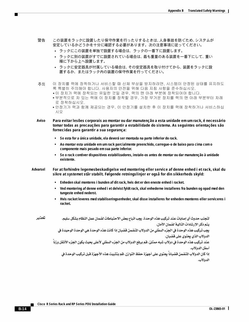
Appendix B Translated Safety Warnings
Aviso Para evitar lesões corporais ao montar ou dar manutenção a esta unidade em um rack, é necessário tomar todas as precauções para garantir a estabilidade do sistema. As seguintes orientações são fornecidas para garantir a sua segurança:
• Se esta for a única unidade, ela deverá ser montada na parte inferior do rack.
• Ao montar esta unidade em um rack parcialmente preenchido, carregue-o de baixo para cima com o componente mais pesado em sua parte inferior.
• Se o rack contiver dispositivos estabilizadores, instale-os antes de montar ou dar manutenção à unidade existente.
Advarsel For at forhindre legemesbeskadigelse ved montering eller service af denne enhed i et rack, skal du sikre at systemet står stabilt. Følgende retningslinjer er også for din sikkerheds skyld:
• Enheden skal monteres i bunden af dit rack, hvis det er den eneste enhed i racket.
• Ved montering af denne enhed i et delvist fyldt rack, skal enhederne installeres fra bunden og opad med den tungeste enhed nederst.
• Hvis racket leveres med stabiliseringsenheder, skal disse installeres for enheden monteres eller serviceres i racket.
•
•
•
B-14Cisco R Series Rack and RP Series PDU Installation Guide
OL-23865-01

Appendix B Translated Safety Warnings
B-15Cisco R Series Rack and RP Series PDU Installation Guide
OL-23865-01

Appendix B Translated Safety Warnings
Statement 1017—Restricted Area
Warning This unit is intended for installation in restricted access areas. A restricted access area can be accessed only through the use of a special tool, lock and key, or other means of security. Statement 1017
Waarschuwing Deze eenheid is bestemd voor installatie in plaatsen met beperkte toegang. Toegang tot een dergelijke plaats kan alleen verkregen worden door middel van een speciaal instrument, een slot en sleutel of een ander veiligheidsmiddel.
Varoitus Tämä laite on tarkoitettu asennettavaksi paikkaan, johon pääsy on rajoitettua. Tällaiseen paikkaan pääsee vain erikoistyökalua, lukkoon sopivaa avainta tai jotakin muuta turvalaitetta käyttämällä.
Attention Cet appareil est à installer dans des zones d'accès réservé. L'accès à une zone d'accès réservé n'est possible qu'en utilisant un outil spécial, un mécanisme de verrouillage et une clé, ou tout autre moyen de sécurité.
B-16Cisco R Series Rack and RP Series PDU Installation Guide
OL-23865-01

Appendix B Translated Safety Warnings
Warnung Diese Einheit ist zur Installation in Bereichen mit beschränktem Zutritt vorgesehen. Der Zutritt zu derartigen Bereichen ist nur mit einem Spezialwerkzeug, Schloss und Schlüssel oder einer sonstigen Sicherheitsvorkehrung möglich.
Avvertenza Questa unità è prevista per essere installata in un'area ad accesso limitato, vale a dire un'area accessibile solo mediante l'uso di un attrezzo speciale, come lucchetto e chiave, o altri dispositivi di sicurezza.
Advarsel Denne enheten er beregnet på installasjon i områder med begrenset tilgang. Et begrenset tilgangsområde kan bare nås ved hjelp av et spesielt verktøy, lås og nøkkel, eller andre sikkerhetsanordninger.
Aviso Esta unidade foi concebida para instalação em áreas de acesso restrito. Uma área de acesso restrito é uma área à qual apenas tem acesso o pessoal de serviço autorizado, que possua uma ferramenta, chave e fechadura especial, ou qualquer outra forma de segurança.
¡Advertencia! Esta unidad ha sido diseñada para instalación en áreas de acceso restringido. Sólo puede obtenerse acceso a una de estas áreas mediante la utilización de una herramienta especial, cerradura con llave u otro medio de seguridad.
Varning! Denna enhet är avsedd för installation i områden med begränsat tillträde. Ett område med begränsat tillträde kan endast tillträdas med hjälp av specialverktyg, lås och nyckel eller annan säkerhetsanordning.
Aviso Esta unidade deve ser instalada em áreas de acesso restrito. Uma área de acesso restrito só pode ser acessada com o uso de uma ferramenta especial, cadeado e chave ou outros meios de segurança.
Advarsel Denne enhed er beregnet til installation i områder med begrænset adgang. Der kan kun opnås adgang til et begrænset område ved at bruge et særligt stykke værktøj, lås og nøgle, eller en anden form for sikkerhed.
B-17Cisco R Series Rack and RP Series PDU Installation Guide
OL-23865-01

Appendix B Translated Safety Warnings
B-18Cisco R Series Rack and RP Series PDU Installation Guide
OL-23865-01

Appendix B Translated Safety Warnings
Statement 1024—Ground Conductor
Warning This equipment must be grounded. Never defeat the ground conductor or operate the equipment in the absence of a suitably installed ground conductor. Contact the appropriate electrical inspection authority or an electrician if you are uncertain that suitable grounding is available. Statement 1024
Waarschuwing Deze apparatuur dient geaard te zijn. De aardingsleiding mag nooit buiten werking worden gesteld en de apparatuur mag nooit bediend worden zonder dat er een op de juiste wijze geïnstalleerde aardingsleiding aanwezig is. Neem contact op met de bevoegde instantie voor elektrische inspecties of met een elektricien als u er niet zeker van bent dat er voor passende aarding gezorgd is.
Varoitus Laitteiden on oltava maadoitettuja. Älä koskaan ohita maajohdinta tai käytä laitteita ilman oikein asennettua maajohdinta. Ota yhteys sähkötarkastusviranomaiseen tai sähköasentajaan, jos olet epävarma maadoituksen sopivuudesta.
Attention Cet équipement doit être mis à la masse. Ne jamais rendre inopérant le conducteur de masse ni utiliser l'équipement sans un conducteur de masse adéquatement installé. En cas de doute sur la mise à la masse appropriée disponible, s'adresser à l'organisme responsable de la sécurité électrique ou à un électricien.
Warnung Dieses Gerät muss geerdet sein. Auf keinen Fall den Erdungsleiter unwirksam machen oder das Gerät ohne einen sachgerecht installierten Erdungsleiter verwenden. Wenn Sie sich nicht sicher sind, ob eine sachgerechte Erdung vorhanden ist, wenden Sie sich an die zuständige Inspektionsbehörde oder einen Elektriker.
Avvertenza Questa apparecchiatura deve essere dotata di messa a terra. Non escludere mai il conduttore di protezione né usare l'apparecchiatura in assenza di un conduttore di protezione installato in modo corretto. Se non si è certi della disponibilità di un adeguato collegamento di messa a terra, richiedere un controllo elettrico presso le autorità competenti o rivolgersi a un elettricista.
Advarsel Dette utstyret må jordes. Omgå aldri jordingslederen og bruk aldri utstyret uten riktig montert jordingsleder. Ta kontakt med fagfolk innen elektrisk inspeksjon eller med en elektriker hvis du er usikker på om det finnes velegnet jordning.
Aviso Este equipamento deve ser aterrado. Nunca anule o fio terra nem opere o equipamento sem um aterramento adequadamente instalado. Em caso de dúvida com relação ao sistema de aterramento disponível, entre em contato com os serviços locais de inspeção elétrica ou um eletricista qualificado.
¡Advertencia! Este equipo debe estar conectado a tierra. No inhabilite el conductor de tierra ni haga funcionar el equipo si no hay un conductor de tierra instalado correctamente. Póngase en contacto con la autoridad correspondiente de inspección eléctrica o con un electricista si no está seguro de que haya una conexión a tierra adecuada.
Varning! Denna utrustning måste jordas. Koppla aldrig från jordledningen och använd aldrig utrustningen utan en på lämpligt sätt installerad jordledning. Om det föreligger osäkerhet huruvida lämplig jordning finns skall elektrisk besiktningsauktoritet eller elektriker kontaktas.
B-19Cisco R Series Rack and RP Series PDU Installation Guide
OL-23865-01

Appendix B Translated Safety Warnings
B-20Cisco R Series Rack and RP Series PDU Installation Guide
OL-23865-01

Appendix B Translated Safety Warnings
Statement 1030—Equipment Installation
Warning Only trained and qualified personnel should be allowed to install, replace, or service this equipment. Statement 1030
Waarschuwing Deze apparatuur mag alleen worden geïnstalleerd, vervangen of hersteld door bevoegd geschoold personeel.
Varoitus Tämän laitteen saa asentaa, vaihtaa tai huoltaa ainoastaan koulutettu ja laitteen tunteva henkilökunta.
Attention Il est vivement recommandé de confier l'installation, le remplacement et la maintenance de ces équipements à des personnels qualifiés et expérimentés.
Warnung Das Installieren, Ersetzen oder Bedienen dieser Ausrüstung sollte nur geschultem, qualifiziertem Personal gestattet werden.
Avvertenza Questo apparato può essere installato, sostituito o mantenuto unicamente da un personale competente.
Advarsel Bare opplært og kvalifisert personell skal foreta installasjoner, utskiftninger eller service på dette utstyret.
Aviso Apenas pessoal treinado e qualificado deve ser autorizado a instalar, substituir ou fazer a revisão deste equipamento.
¡Advertencia! Solamente el personal calificado debe instalar, reemplazar o utilizar este equipo.
Varning! Endast utbildad och kvalificerad personal bör få tillåtelse att installera, byta ut eller reparera denna utrustning.
B-21Cisco R Series Rack and RP Series PDU Installation Guide
OL-23865-01

Appendix B Translated Safety Warnings
Aviso Somente uma equipe treinada e qualificada tem permissão para instalar, substituir ou dar manutenção a este equipamento.
Advarsel Kun uddannede personer må installere, udskifte komponenter i eller servicere dette udstyr.
B-22Cisco R Series Rack and RP Series PDU Installation Guide
OL-23865-01

Appendix B Translated Safety Warnings
B-23Cisco R Series Rack and RP Series PDU Installation Guide
OL-23865-01

Appendix B Translated Safety Warnings
B-24Cisco R Series Rack and RP Series PDU Installation Guide
OL-23865-01