cisco router configuration
TRANSCRIPT
Preface and Scope
This document is intended to instruct in the basics of Cisco router configuration and
maintenance. It is by no means complete or authoritative. This document purposely omits many topics and assumes a foreknowledge of others. It is assumed that the reader has a preexisting knowledge of Internet protocols and an understanding of TCP/IP networking. Prior experience
with Cisco router products will make this document easier to understand but is not required.
The commands and procedures detailed in this writing are consistent with Cisco's Internetwork Operating Software (IOS) version 11.0, 11.1, and 11.2. Cisco endeavors to maintain backwards
compatability in their software however, there is no guarantee of such. Hence, the commands and procedures outlined herein should only be used as a guide when working with latter releases
of IOS. References within this writing to IOS documentation refer to the manual set for IOS version 11.0.
Description of Cisco Router Products
There are several varieties of cisco routers. The relevant router models are the 2500, 4000, 7000,
and 7500 series. Physically, each is as follows:
The 2501 (which is about the only router out of the 2500 series we use) has a console port and an aux port in the form of rj45 type connectors. There is one 10 megabit ethernet AUI type
connector, and two high density 60 pin serial connectors. The serial connectors are used for the WAN connections.
The 4000 is the next step up in Cisco's product line. It has a console port and an aux port in the form of two db25 connectors. There are slots for various interfaces, however, they are not
presented in a card/slot format, rather each card adds interfaces to those already in existance so it becomes possible to have, for example, interfaces Serial0 through Serial11 by using three cards.
One of the more recent generations of backbone routers is Cisco's 7000 series router. This router
is quite large. It has room for a primary and redundant power supply. In the backplane, there are 7 slots that are used as follows. All the way on the right-hand side is a slot labeled for the Route processor (which holds two db25 connectors for console and aux.) It utilizes a Motorola 68040
for its processor and has internal slots for two flash modules and 4 30 pin simms. There is also a bank of pins for various jumpers. These control certain default settings that are read when the
router is powered up. Factory default is almost ALWAYS correct and these jumpers should NOT be moved. To the left of this card is the switch processor. This card handles "fast switching" in this model router. "fast switching" will be explained later in this document. Finally,
there are slots labeled 0 through 4. These are for interface cards.
There is also an upgraded processor card for the 7000 as well. The primary difference is the processor is MIPS based and the flash slots have been made external to accommodate a single
removable PCMCIA flash module.
Finally, is the 7500 series. This is Cisco's latest router model. The processor is MIPS based and the backplane has been greatly enhanced. The 7505, which is our most common router, has a
single power supply, a slot for the route/switch processor with two PCMCIA slots for flash cards (they are one card here instead of 2 because of changes made in the way that fast switching is done), and interface slots labeled 0 through 3. The on board memory is 4 72 pin simm slots using
paritied RAM. The 7507 adds a redundant power supply and an additional interface slot, and room for a redundant processor card. The 7513 adds a blower for additional cooling and contains
a route processor, switch processor, and can hold up to 11 interface cards in addition to the processors.
Cisco Interface Cards
There are several cards for use with the cisco 4000, 7000, 7200, and 7500 series routers. The
2500 series are fixed configurations. This section only describes the cards used with 7000 and 7500 series routers.
The first is the Fast Serial Interface Processor (FSIP) card. The FSIP is available with 4 or 8
serial ports. These are used for synchronous data connections such as T1s which are used in Wide Area Networks (WANs).
Ethernet Interface Processor (EIP) cards contain 2, 4 or 6 AUI type connectors for 10 megabit
ethernet and are used for connecting the router to the low speed Local Area Network (LAN).
Fast Ethernet Interface processor (FEIP) cards contain two rj45 type modular connectors used for 100baseT connections.
ATM Interface Processor (AIP) cards are used for Asynchronous Transfer Mode (ATM) connections. There are a couple of varieties of ATM cards. Most commonly used is a DS3
interface which has two BNC type coaxial connectors (one for transmit and one for receive). This interface operates at 45 Mbps. In our Phoenix POP, we have installed a SONET interface
card which makes use of a fiber optic connection to a lightstream 100 (which is an ATM switch essentially). This connection operates at OC3c speeds (155 Mbps).
Fiber Distributed Data Interface (FDDI) Processors (FIP) are used in These cards have two fiber
optic connectors and may be connected by one or the other, or both connectors may be utilized to create a fiber ring for redundancy. This interface operates at 90 Mbps.
High Speed Serial Interface (HSSI) Processors (HIP) are used for DS3 level connections. These cards have a single connector for one T3.
Channelized T3 Interface Processors (CIP) are used to connect a muxed T3 into a router. This card has two BNC connectors for the transmit and receive of the T3. It also has 3 db9 connectors
for T1 output and one db9 for output to a test set. Using this card, it is possible to configure 28 full or fractional T1 circuits in one slot within the router. This is a significant advantage over the
use of external CSUs and multiple FSIP cards which occupy valuable rack and bus space, respectively. Built using the second generation Versatile Interface Processor design (VIP2), this card also supports distributed switching and can actually handle the same conventional load
while using less of the router's primary processor. The outputs can be used to feed T1s to external devices of for connecting to a MIP card for channelized T1 processing.
Pack Over SONET Interface Processors (POSIP) are used to provide Point-To-Point connectivity
between locations at the OC3 level. This interface operates at 155 Mbps, full duplex. It has one optical connection to receive an OC3 circuit.
Preparing for Configuration
There are several steps involved in commissioning a new router. The first is to determine
physical configuration. Although any interface card may be placed in any slot, thought should go into how cards are arranged. For example, if you intend to have a large group of routers with
more or less identical types and quantities of cards, it is easier to place the cards in a "standard" order. This way, there is no searching to find what card is in which slot. it is simply assumed that a given card will be in a given slot. This leaves less to remember and can cut critical time off
diagnosing network problems.
Initial configuration is done from the console. There are a few caveats which will be explained later. The console should be connected via a straight through rs232 interface using either a
standard rs232 cable or one of the appropriate adaptors provided with the 2501 (Note: the adaptors for the 2500 series routers are proprietary to cisco and do NOT contain standard pin-outs.) The connection operates at 9600 baud, 8 data bits, 1 stop bit and no parity. Boot the router
and wait for the "press return to get started" prompt. When the router boots for the first time after being shipped from the manufacturer, you may enter the "setup" dialogue. In general, you don't
want to use setup to initialize your router. You may exit out of this when prompts or you can type C-^ (caret), which is the cisco interrupt character, to break out of it.
You should end up at a "Router>" prompt. This is an unprivileged access mode known as "User
EXEC Mode". There are several levels of access that can be configured within the router. This mode is privilege level 1. (You may use the "show privilege" command to find out what your current privilege level is.)
To enter a higher privilege mode, use "enable". The default privilege level is 15. If a password
has been set, you will be prompted to enter it at this time. If no password has yet been set, you will not be prompted for a password, and instead immediately gain privileged access. Your
prompt will now become "Router#".
At that point, you may prepare to enter configuration commands by typing "configure terminal". Your prompt will change to "Router (config)#". To exit the configuration, type "exit" or C-z.
Once you are done, you need to store your configuration changes in non-volatile memory. Type "write" from the privileged EXEC prompt (Router#). It will take a few moments to build the
configuration file and store it in memory.
As mentioned above, there are a few things to watch for when configuring cisco routers. Once logged into a router via a network connection, you cannot "enable" from the network connection if no enable password has been set. One of the most important things to remember is that ALL
changes are IMMEDIATE. If you attempt to restart an interface by shutting it down and then turning it back up, if it is the interface you are coming in over, you will never be able to turn the
interface back up unless you come in via an alternate path (such as logging in on console or by dialing up to a POP) or power cycle the router. Likewise, when configuring a packet filter, it is a good idea to remove the filter from the associated interface while updating it if at all feasible.
This saves you from filtering yourself out of the router and possibly causing significant interruption of services for others. Also, for any given command, with only a few exceptions,
placing a "no" in front of the command has the effect of "undoing" that operation.
Configuring the Router
The Cisco Internetwork Operating System (IOS) is extremely flexible and powerful. Hence, there are many subtleties to configuring certain services and many things that the router can do
that you will never use. For the full description of the options that can be used with each of these commands, refer to the router configuration guide and command reference. These documents are
available in printed form and via the World Wide Web as http://www.cisco.com/univercd/data/doc/software.htm. (hint: This is a good bookmark to place in Netscape.) From there, you may select the appropriate version of IOS to find the section you
are looking for.
Cisco interfaces are named according to interface type and interface number. The 7000, 7200, and 7500 series routers also add a slot number. All interfaces and slots are indexed at zero. The
first ethernet port on a model 2501 router would be identified as Ethernet0. The fourth serial port on a 7000 with a serial card in slot 2 would be Serial2/3.
* For the remainder of this section, it is assumed that the reader has entered the terminal
configuration mode within the router via "configure terminal" from the privileged EXEC prompt.
I. Set a Hostname
The first order of business in configuring a router is to choose a hostname for the router. This name is not used by the router itself and is entirely for human consumption. The
hostname you set replaces "Router" in the prompt and can be useful in distinguishing which router you are connected to when telnetting among several routers. This line also
appears within the first 20 lines of the configuration file and can be used to distinguish saved configurations of one router from another. The form of this command is
hostname <name>
II. Establishing Enable Password Protection
Before connecting the router to your network it is also a good idea to set the enable password. This password is used to gain privileged access to the router so it should not be an obvious password. The format of this command is as follows:
enable password <password>
This password may contain any alphanumeric characters up to 80 including spaces but MUST NOT START with a number or a space. The password is stored in an unencrypted (plain text) format in the configuration file. Obviously, it is desirable to have the password encrypted before it is saved. To do this, use:
service password-encryption
This will cause all passwords in the system to be encrypted before being stored in a saved configuration using Cisco's proprietary encryption algorithm.
NOTE: There is no way to recover a lost encrypted password.
III. Optionally Enable UDP and TCP network services
Cisco routers support standard network services for TCP and UDP such as echo, discard,
daytime, and so forth. These services are enabled with the commands
service tcp-small-servers
service udp-small-servers
It should be noted that these package all standard network services in one bundle. Without creating access lists, it is not possible to disallow any of the services these create.
Cisco also supports a finger daemon to give information about who is connected to a
given router. This service is enabled by default. Finger may be disabled as follows
no service finger
IV. Configure Console and Network Access
Initialy, the only device setup for access is the console. When placed in the field, it is more convenient to program and maintain the routers through a telnet connection than it
is to dial up into each router to configure or monitor the system. In order to do this,
virtual ttys (vtys) must be configured. Generally, 5 vtys should be configured however, the router will support up to 100. Each should be given a timeout to avoid all vtys being
in use. If all vtys are in use, further connection attempts will result in a "connection refused". It is probably a good idea to force the user to enter a password before he can
login to the router through a vty as well. An example of this configuration is shown below.
line vty 0 4
exec-timeout 30 0
login
password steamboat
This creates 5 vtys numbered 0 through 4. Each vty has a timeout of 30 minutes and 0
seconds. These vtys require a password for login. This password is "steamboat". Note: If password-encryption is enabled, this password is encrypted before being stored in the router's configuration. The minimum number of vtys that may be enabled is 5.
Usually you do not want to require a password for console access but you would like to
specify a timeout.
line con 0
exec-timeout 15 0
For a full description of how each vty may be configured, refer to chapter 4 of the router configuration guide.
V. Configure Serial and Ethernet Interfaces
By far, the easiest interfaces to configure are ethernet interfaces. To bring up an ethernet interface, all that is necessary is to assign it an IP address, associate a netmask with that address, and turn up the interface. For example, to bring online the ethernet interface on a
2501 and assign it the IP address 150.151.152.1 with a class C netmask (255.255.255.0), the following commands would be used:
interface Ethernet0
ip address 150.151.152.1 255.255.255.0
no shutdown
and thats it. It should be noted that this has the side effect of placing a route for 150.151.152.0 in the 2501's routing tables since this is a network that is directly "Connected" via ethernet0. As a result, you can immediately connect to any system on that network from the router. Routing and types of routes will be discussed later in this
document.
Configuring serial interfaces for point to point connections is not too different.
interface serial0/3
ip address 203.142.253.33 255.255.255.252
encapsulation ppp
mtu 1500
no shutdown
This gives serial0/3 the address 203.142.253.33 and makes it part of a subnet of 2 ip addresses (plus broadcast/network number) of 203.142.253.32-35. Again, a connected
route is placed in the routing tables. These routes can be useful when configuring BGP or OSPF or some other routing protocol as discussed later. IP subnetting, as used in the
above example, is not covered within the scope of this document.
The preceeding example also assigned a link encapsulation of PPP to the interface and gives it an MTU of 1500 bytes, which is the default if no MTU is specified. This is correct for most instances, but when connecting to another cisco, it will be slightly more
efficient to make use of Cisco's HDLC protocol. This is the default encapsulation for all serial interfaces. To make use of this, either omit the encapsulation or specify "no
encapsulation" to remove a previous setting.
There is a third encapsulation for serial interfaces, frame relay, which will be discussed in its own section later on.
VI. Configuring the CIP card and the virtual interfaces
The CIP card appears to the router as a controller instead of a standard interface. T1 channels may be defined, modified, or deleted without any external configuration to the card. CSU loops may be initiated and released from within software and testing patterns
run to these loops from the router. The advantages of full management is well known to anyone who has spent any time at all performing work as a network operations
technician. The ability to quickly determine CSU states, attempt quick fixes, and obtain a full diagnostic of the problem is invaluable when reporting an outage to a carrier. The more information that can be provided to them during the initial problem report can often
greatly speed the diagnostic and repair processes.
The T3 controller, since it is built on VIP2 technology introduces a third level to the card designation. Instead of simply slot/port, it not introduces a port adaptor number. Since
there is only one CT3IP per card, the port and port adaptor numbers will always be zero. An interface in slot 2 will be identified as 2/0/0. T1 channels are designated by a colon and a channel number after the interface identifier (numbering 1 through 28 to coincide
with belcore designations). In the previous example, the 17th T1 channel would be 2/0/0:17.
The first step in configuring this interface is the configuration of the T3. Settings required
are T3 framing, clock source, and cable distance (which is used in determining the LBO to use). The default cable length is 224 feet. This should be acceptable for most applications. The framing types availible are cbit and m23. It is possible to configure the
router to auto-detect framing but in many instances, auto detection can lead to future problems so it is best to use this only when you are uncertain of the framing being used.
Once the framing has been identified, it can then be set staticly in the router's configuration.
For most muxed T3s, the framing type will be m23. cbit is used, for example, in a clear
channel T3 into an ATM network.
controller t3 0/0/0
framing m23
clock source line
cablelength 224
Once the T3 has been configured, T1 channels may be assigned. The T1 channels need to be configured for the number of slots on the T1 in use, the framing and encoding being
used, the speed of the underlying DS0s (56K or 64K), and the clock source for the T1.
controller t3 0/0/0
t1 1 timeslots 1-24 speed 64
t1 1 clock source line
t1 1 framing esf
t1 1 linecone b8zs
T1 default parameters are clock source line, esf, b8zs, and 64K DS0s. If this is the desired configuration, the only command necessary is "t1 1 timeslots 1-24".
The first three channels on the T3 may also be output to the connectors on the outside of the card. This is accomplished by configuring that T1 as external.
controller t3 0/0/0
t1 external 1
After the T1 is configured, the router creates a virtual serial interface. This interface does not appear until the T1 has been created and is identified in the same manner described
above. For example, to refference the serial interface for the first t1, it would be identified as Serial0/0/0:1. This interface may beconfigured as any other serial interface.
Loopbacks and tests are initiated from the interface level. The T3 may also be looped
back from the controller configuration. It is important to note that the T1s may NOT be looped from the controller configuration.
interface Serial0/0/0:1
loopback network
The loop is removed by specifying "no loopback network" in the interface configuration.
VII. Add IP Routes and Set a Default Route
Obviously, the internet is not centered around one router. Usually, to get to another
system requires passing through at least one other router (probably several). It is also
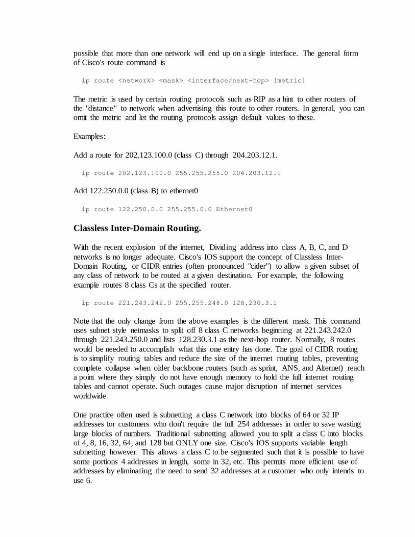
possible that more than one network will end up on a single interface. The general form of Cisco's route command is
ip route <network> <mask> <interface/next-hop> [metric]
The metric is used by certain routing protocols such as RIP as a hint to other routers of the "distance" to network when advertising this route to other routers. In general, you can omit the metric and let the routing protocols assign default values to these.
Examples:
Add a route for 202.123.100.0 (class C) through 204.203.12.1.
ip route 202.123.100.0 255.255.255.0 204.203.12.1
Add 122.250.0.0 (class B) to ethernet0
ip route 122.250.0.0 255.255.0.0 Ethernet0
Classless Inter-Domain Routing.
With the recent explosion of the internet, Dividing address into class A, B, C, and D
networks is no longer adequate. Cisco's IOS support the concept of Classless Inter-Domain Routing, or CIDR entries (often pronounced "cider") to allow a given subset of any class of network to be routed at a given destination. For example, the following
example routes 8 class Cs at the specified router.
ip route 221.243.242.0 255.255.248.0 128.230.3.1
Note that the only change from the above examples is the different mask. This command uses subnet style netmasks to split off 8 class C networks beginning at 221.243.242.0 through 221.243.250.0 and lists 128.230.3.1 as the next-hop router. Normally, 8 routes
would be needed to accomplish what this one entry has done. The goal of CIDR routing is to simplify routing tables and reduce the size of the internet routing tables, preventing
complete collapse when older backbone routers (such as sprint, ANS, and Alternet) reach a point where they simply do not have enough memory to hold the full internet routing tables and cannot operate. Such outages cause major disruption of internet services
worldwide.
One practice often used is subnetting a class C network into blocks of 64 or 32 IP addresses for customers who don't require the full 254 addresses in order to save wasting
large blocks of numbers. Traditional subnetting allowed you to split a class C into blocks of 4, 8, 16, 32, 64, and 128 but ONLY one size. Cisco's IOS supports variable length subnetting however. This allows a class C to be segmented such that it is possible to have
some portions 4 addresses in length, some in 32, etc. This permits more efficient use of addresses by eliminating the need to send 32 addresses at a customer who only intends to
use 6.
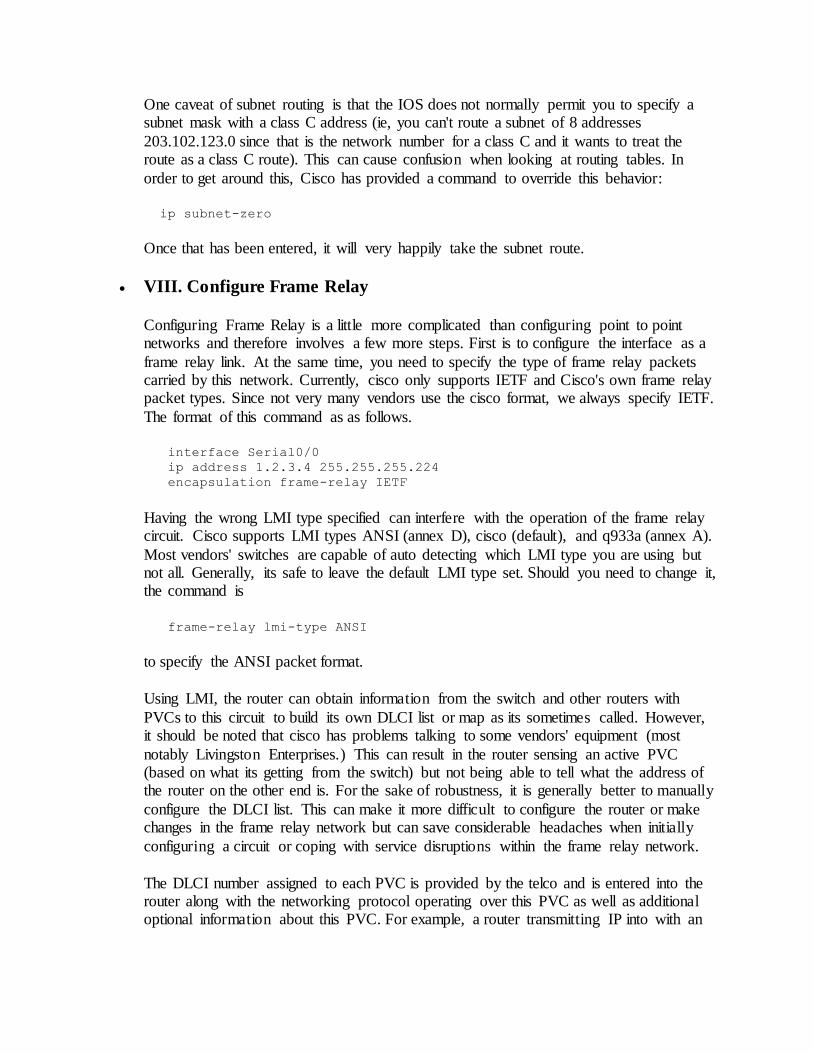
One caveat of subnet routing is that the IOS does not normally permit you to specify a subnet mask with a class C address (ie, you can't route a subnet of 8 addresses
203.102.123.0 since that is the network number for a class C and it wants to treat the route as a class C route). This can cause confusion when looking at routing tables. In
order to get around this, Cisco has provided a command to override this behavior:
ip subnet-zero
Once that has been entered, it will very happily take the subnet route.
VIII. Configure Frame Relay
Configuring Frame Relay is a little more complicated than configuring point to point networks and therefore involves a few more steps. First is to configure the interface as a
frame relay link. At the same time, you need to specify the type of frame relay packets carried by this network. Currently, cisco only supports IETF and Cisco's own frame relay packet types. Since not very many vendors use the cisco format, we always specify IETF.
The format of this command as as follows.
interface Serial0/0
ip address 1.2.3.4 255.255.255.224
encapsulation frame-relay IETF
Having the wrong LMI type specified can interfere with the operation of the frame relay circuit. Cisco supports LMI types ANSI (annex D), cisco (default), and q933a (annex A).
Most vendors' switches are capable of auto detecting which LMI type you are using but not all. Generally, its safe to leave the default LMI type set. Should you need to change it, the command is
frame-relay lmi-type ANSI
to specify the ANSI packet format.
Using LMI, the router can obtain information from the switch and other routers with
PVCs to this circuit to build its own DLCI list or map as its sometimes called. However, it should be noted that cisco has problems talking to some vendors' equipment (most
notably Livingston Enterprises.) This can result in the router sensing an active PVC (based on what its getting from the switch) but not being able to tell what the address of the router on the other end is. For the sake of robustness, it is generally better to manually
configure the DLCI list. This can make it more difficult to configure the router or make changes in the frame relay network but can save considerable headaches when initially
configuring a circuit or coping with service disruptions within the frame relay network.
The DLCI number assigned to each PVC is provided by the telco and is entered into the router along with the networking protocol operating over this PVC as well as additional optional information about this PVC. For example, a router transmitting IP into with an
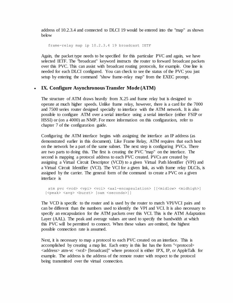
address of 10.2.3.4 and connected to DLCI 19 would be entered into the "map" as shown below
frame-relay map ip 10.2.3.4 19 broadcast IETF
Again, the packet type needs to be specified for this particular PVC and again, we have selected IETF. The "broadcast" keyword instructs the router to forward broadcast packets over this PVC. This can assist with broadcast routing protocols, for example. One line is needed for each DLCI configured. You can check to see the status of the PVC you just
setup by entering the command "show frame-relay map" from the EXEC prompt.
IX. Configure Asynchronous Transfer Mode (ATM)
The structure of ATM draws heavily from X.25 and frame relay but is designed to
operate at much higher speeds. Unlike frame relay, however, there is a card for the 7000 and 7500 series router designed specially to interface with the ATM network. It is also possible to configure ATM over a serial interface using a serial interface (either FSIP or
HSSI) or (on a 4000) an NMP. For more information on this configuration, refer to chapter 7 of the configuration guide.
Configuring the ATM interface begins with assigning the interface an IP address (as
demonstrated earlier in this document). Like Frame Relay, ATM requires that each host on the network be a part of the same subnet. The next step is configuring PVCs. There
are two parts to doing this. The first is creating the PVC "map" on the interface. The second is mapping a protocol address to each PVC created. PVCs are created by assigning a Virtual Circuit Descriptor (VCD) to a given Virtual Path Identifier (VPI) and
a Virtual Circuit Identifier (VCI). The VCI for a given link, as with frame relay DLCIs, is assigned by the carrier. The general form of the command to create a PVC on a given
interface is
atm pvc <vcd> <vpi> <vci> <aal-encapsulation> [[<midlow> <midhigh>]
[<peak> <avg> <burst> [oam <seconds>]]
The VCD is specific to the router and is used by the router to match VPI/VCI pairs and can be different than the numbers used to identify the VPI and VCI. It is also necessary to specify an encapsulation for the ATM packets over this VCI. This is the ATM Adaptation
Layer (AAL). The peak and average values are used to specify the bandwidth at which this PVC will be permitted to connect. When these values are omitted, the highest possible connection rate is assumed.
Next, it is necessary to map a protocol to each PVC created on an interface. This is accomplished by creating a map list. Each entry in this list has the form "<protocol> <address> atm-vc <vcd> [broadcast]" where protocol is either IPX, IP, or AppleTalk for
example. The address is the address of the remote router with respect to the protocol being transmitted over the virtual connection.
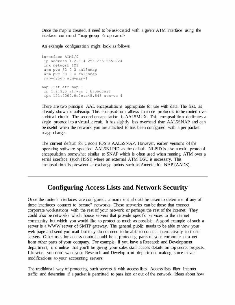
Once the map is created, it need to be associated with a given ATM interface using the interface command "map-group <map name>
An example configuration might look as follows
interface ATM1/0
ip address 1.2.3.4 255.255.255.224
ipx network 121
atm pvc 32 0 3 aal5snap
atm pvc 33 0 4 aal5snap
map-group atm-map-1
map-list atm-map-1
ip 1.2.3.5 atm-vc 3 broadcast
ipx 121.0000.0c7e.a45.546 atm-vc 4
There are two principle AAL encapsulations appropriate for use with data. The first, as already shown is aal5snap. This encapsulation allows multiple protocols to be routed over a virtual circuit. The second encapsulation is AAL5MUX. This encapsulation dedicates a single protocol to a virtual circuit. It has slightly less overhead than AAL5SNAP and can
be useful when the network you are attached to has been configured with a per packet usage charge.
The current default for Cisco's IOS is AAL5SNAP. However, earlier versions of the
operating software specified AAL5NLPID as the default. NLPID is also a multi protocol encapsulation somewhat similar to SNAP which is often used when running ATM over a serial interface (such HSSI) where an external ATM DSU is necessary. This
encapsulation is prevalent at exchange points such as Ameritech's NAP (AADS).
Configuring Access Lists and Network Security
Once the router's interfaces are configured, a momment should be taken to determine if any of
these interfaces connect to "secure" networks. These networks can be those that connect corporate workstations with the rest of your network or perhaps the rest of the internet. They could also be networks which house servers that provide specific services to the internet
community but which you would like to protect as much as possible. A good example of such a server is a WWW server of SMTP gateway. The general public needs to be able to view your
web page and send you mail but they do not need to be able to connect interractively to those servers. Other uses for access control could be in protecting parts of your corporate intra-net from other parts of your company. For example, if you have a Research and Development
department, it is unlike that you'll be giving your sales staff access details on top secret projects. Likewise, you don't want your Research and Development department making some clever
modifications to your accounting servers.
The traditional way of protecting such servers is with access lists. Access lists filter Internet traffic and determine if a packet is permitted to pass into or out of the network. Ideas about how
access lists should be designed, where they should be placed, and how physical networks should be structured to allow propper filtering without overloading network links and the routers they
connect varry considerably. Some corporations choose to invest in commercial "fire wall" products while others will implement minimal access controls at all. Still others will invest in the
hardware necessary to service access lists at two levels (one router that blocks access to itself and the interrior router and a second, the interrior router, that blocks access to itself, is only accessible from inside or even only from its console, and provides primary access list control.
This router generally does nothing else besides filtering packets and sending them to its default router or a local host.)
Which method you choose depends on your needed level of security, your budget, and the
particular application for which the protection is needed. The decisions that lead to the various scenarios are beyond the scope of this document, however. This section intends to focus solely on access list design and implementation for the general case.
Cisco has created two different classes of access lists within its routers. The first, the standard access list, filters only on source address. If numbered access lists are being used (IOS 11.1 and earlier did not support named access lists), than these lists would be numbered from 1 to 99. The
second type of access list, the extended access list, is numberes from 100 to 199 and is capable of filtering based on source address, destination address, protocol, protocol port number, and a
myriad of other features not necessarily applicable to general IP traffic.
Once an access list is created, it must be tied to an interface in order to be used. The interface configuration considers a filter list to be an "access group". The access group can be applied either inbound or outbound with respect to the interface. For example:
Interface Serial0
ip access-group 101 in
ip access-group 6 out
This group of commands specifies that traffic coming into Serial0 must be processed through extended access list number 101 and that outbound traffic must pass through standard access list 10 before leaving the interface.
Standard access lists are configured by specifying a list number, wether a match on this entry
will result in traffic being permitted or denied, and the host or network which is being filtered and the mask associated with it (if it is a network or subnet).
access-list 10 permit 234.5.6.12
access-list 10 deny 5.10.10.32 0.0.0.31
access-list 10 permit 5.10.0.0 0.0.255.255
access-list 10 permit 123.234.0.0 0.0.0.255
The above example creates access list 10 and configured 4 entries. The first line permit all traffic with a source IP address of 234.5.6.12. Note that when a host IP address is listed, no mask needs to be associated with it. The second line denies all traffic from the subnet 5.10.10.32/27. One thing to observe about access lists is that instead of netmasks, they use what Cisco calls
"wildcard masks." These masks function very similarly to netmasks with one important
difference. Network masks operate from left to right. Wildcard masks operate from right to left. Therefore, when looking at the above configuration line, what the wildcard mask is matching is
the 32 addresses that begin at 5.10.10.32. (Since zero is a valid mask, it counts as one address. Hence 31 is used in the mask instead of 32.)
The remaining two lines permit traffic from 5.10.10.0.0/16 and 123.234.0.0/24 respectively. On
first glance, a newcommer to access lists might think that the only thing getting denied to this network is the second line and that the permit lines are unnecessary. Access lists, though, are designed to be selectively permissive, not to selectively deny traffic. As a result, an implicit deny
exists at the end of this access list. (More propperly, anything that does not explicitly match an entry in the access list is dropped.)
There are a couple of other important things to consider when creating access lists. First, order is
extremely important. Since access lists function through "short circuit" processing (bail out when a match is found), those entries that are most likely to match traffic should be listed first. IP
access list processing is very processor intensive. By listing frequent matches first, processor utilization is kept to a minimum. Note also lines 2 and 3 of the above example. They state, collectively, that all traffic from 5.10.0.0/16 is to be permitted EXCEPT for those hosts in
5.10.10.32/27. If line 2 (the deny statement) were listed AFTER line 3, than the denial would have no effect. The traffic would be permitted as a result of line 3 and those hosts you intended
to block would be allowed access. When you create access lists, you should review them very carefully to be certain that no mis-ordering has occured.
The second thing to watch for when creating access lists is the fact that changes to a cisco router take effect immediately upon entry. It is a fact that most access lists are not the stagnant,
unchanging creatures we would like them to be. From time to time, they will require modification. Modifying an access list means deleting the existing list and recreating it with the
appropriate changes. When an interface is configured to refference an access list that does not exist, the traffic will, by default, be permitted through. However, when you create that access list, the implicit denial at the end can result in your configuration session being filtered out. As a
matter of policy, it is good practice to remove the refference to the access list from the interface before modifying the access list. (via "no ip access-group 123" or whatever access list you intend
to refference.)
Building extended access lists is somewhat more complicated and requires a few more steps. Since extended access lists filter based on both the source and destination IP address, two parts to each entry are needed. The following is a brief example of an extended access list for IP.
access-list 101 permit tcp any any established
access-list 101 permit tcp any 204.34.5.25 host eq 80
access-list 101 permit ip 203.45.34.0 0.0.0.255 204.34.5.0 0.0.0.255
access-list 101 permit tcp 203.44.32.0 0.0.0.31 204.34.5.0 0.0.0.255 eq
telnet
access-list 101 permit tcp any 204.34.5.10 eq smtp
This access list allows all TCP connections with the established flag, allows any user to get to the host 204.34.5.25, tcp port 80 (which is the http port), all IP protocols from 203.45.34.0/24 to
reach any host within the 204.34.5.0 class C, all hosts within 203.44.32.0/27 can telnet into any host on the 204.34.5.0, and allows all hosts to connect to the smtp port on host 204.34.5.10.
A few notes about this access list. The first line is important. It allows all packets which have had
the TCP established flag set. This means two things. First, all outbound connections will be able to have the return traffic pass back through the access list. This is important. Since outbound tcp
connections come from random ports above 1024, it is not possible to filter explicitly for outbound connections. The established field takes care of that. Second, an inbound TCP connection only needs to have the first packet pass beyond this point in the access list. Once the
connection has been opened, the remaining traffic will have the established flag set and will not have to again pass through the entire access list.
The second line also demonstrates that when a source or destination is used, the wildcard mask
can be replaced with the word "host" to indicate this. It also gives an example of filtering based on a destination port. The third line matches all IP protocols (TCP, UDP, ICMP, etc. Everything
that gets encapsulated in an IP packet.) The source and destination network number and wildcard mask pairs function the same as in standard access lists. The fourth line shows that, on well known services, the port number can be replaced with the name of the service.
There is one last important thing to consider when creating access lists however. Many services
depend on other services in order to function. For example, you can't just permit telnet connections without permitting DNS packets to get through as well. You often won't be able to
telnet out unless telnet ident requests can come back into your network. If you wish to synchronize the clocks on your computer systems to other systems, you likely need to permit NTP packets (both TCP and UDP) to pass through. For this reason, carefull consideration is
needed when creating access lists. It is all too easy to overlook one or two key services when creating lists. As network administrators gain experience with access controls, these omissions
become more rare, but they still occur with annoying frequency. Access lists should be tested throroughly once they are in place. Both to be certain that necessary traffic is permitted through the list as well as to be certain that unwanted traffic does not.
Configuring Routing Protocols
Routing protocols serve one function: To let nearby routers know how to get to them and the networks they serve. There are two basic types of routing protocols: distance vector protocols
and link state protocols.
The simplest protocols are perhaps those that classify as Distance Vector protocols. They base their routing decisions on the number of intermediate routers along a given path. This has the advantage of taking very few resources but has the disadvantages of not considering bandwidth
or the load of the available link. They also suffer limitations when long distances are present. The path may be valid but because of the high metric, the routers decide that the remote host or
network is unreachable. In addition, these types of protocols usually broadcast their entire
routing tables at preset intervals. This can take quite a bit of time and consume considerable bandwidth. Protocols that fall under this classification are RIP, IGRP, and BGP.
Link State protocols function by maintaining a database of advertisements they have received
from other routers called the link state database. This means that each router is wholly responsible for determining the best path to a given location from its point of view and already
has an idea of an alternate path, if any, should the first path become unavailable.
I. Configuring RIP
The Routing Information Protocol (RIP) is perhaps the simplest of routing protocols. It functions by broadcasting its entire routing table to all participating networks once every
60 seconds for IP or once every 90 seconds for IPX. When a route is heard from a remote router, the metric is increased by one. This number cannot exceed 15. A metric of 16
describes an unreachable network.
The simplicity of this protocol means that there is very little that the router must do each update. This allows the processor to perform other tasks. At the same time, there is no
database being maintained. Its all contained in the routing tables. This simplicity, however, requires increased bandwidth as the entire routing table must be sent across the network. In a large network, this can take considerable time. In addition, It is not
uncommon for networks to be more than 15 hops apart. This means that end nodes will not be able to contact each other because the metrics surpass the "unreachable" point.
Configuration is a 3 step procedure. First, create a RIP process and determine if any other
routing process (such as IGRP or OSPF) is to redistribute its routes into this one. Second, specify which networks will receive RIP broadcasts. Third, configure any non-broadcast neighbors.
A sample configuration might look like
router rip
redistribute igrp 1000
network 2.3.4.0
network 4.5.3.0
neighbor 4.5.5.2
neighbor 4.5.5.3
II. Configuring IGRP
The Interior Gateway Routing Protocol (IGRP) is a dynamic distance-vector routing
protocol designed by Cisco Systems in the mid-1980s. The advantages of IGRP over RIP include the maximum diameter of the network. Networks over 15 hops are unreachable in a RIP controlled network. IGRP allows up to 100 hops by default and can be set to accept
paths as far away as 255 hops.
IGRP uses a combination of user-configurable metrics including internetwork delay, bandwidth, reliability, and load. Unlike RIP, IGRP routes are shared in proportion to their
cost to provide equal or unequal cost load balancing with up to 4 paths to a given destination. Equal or unequal cost can be specified with a variance factor. The variance
determines how unequal paths can be when performing load balancing. A variance of 1 (the default) specifies load balancing only when all paths are of an equal cost. This behavior can be overridden with the "traffic-share" command. To permit only the path
with the lowest cost to be used, specify "traffic-share min". "traffic-share balanced" is the default.
Basic IGRP configuration is very similar to that of RIP. An IGRP routing process must
be created on the router and given a list of participating networks. IGRP also accepts an optional Autonomous System number. When running IGRP over a non-broadcast network, systems which will accept updates can be entered individually with the
"neighbor" command, as in RIP. Interfaces included in the range of addresses specified with a network statement that should not participate in IGRP (an example would be if
that interface is managed through some other protocol such as OSPF), it can be designated passive with the "passive-interface" statement.
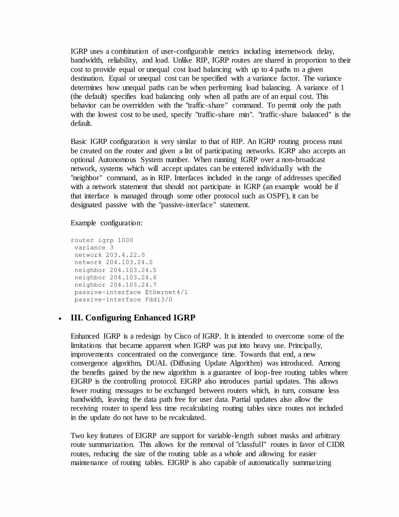
Example configuration:
router igrp 1000
variance 3
network 203.4.22.0
network 204.103.24.0
neighbor 204.103.24.5
neighbor 204.103.24.6
neighbor 204.103.24.7
passive-interface Ethernet4/1
passive-interface Fddi3/0
III. Configuring Enhanced IGRP
Enhanced IGRP is a redesign by Cisco of IGRP. It is intended to overcome some of the
limitations that became apparent when IGRP was put into heavy use. Principally, improvements concentrated on the convergance time. Towards that end, a new convergence algorithm, DUAL (Diffusing Update Algorithm) was introduced. Among
the benefits gained by the new algorithm is a guarantee of loop-free routing tables where EIGRP is the controlling protocol. EIGRP also introduces partial updates. This allows
fewer routing messages to be exchanged between routers which, in turn, consume less bandwidth, leaving the data path free for user data. Partial updates also allow the receiving router to spend less time recalculating routing tables since routes not included
in the update do not have to be recalculated.
Two key features of EIGRP are support for variable-length subnet masks and arbitrary route summarization. This allows for the removal of "classfull" routes in favor of CIDR
routes, reducing the size of the routing table as a whole and allowing for easier maintenance of routing tables. EIGRP is also capable of automatically summarizing
routes into common routes when possible. This feature can be disabled by specifying "no auto-summary" in the EIGRP configuration. Additional summarization can be performed
within the router configuration on a per interface basis by placing "ip summary-address eigrp" statements in the interface configuration commands to advertise a specific
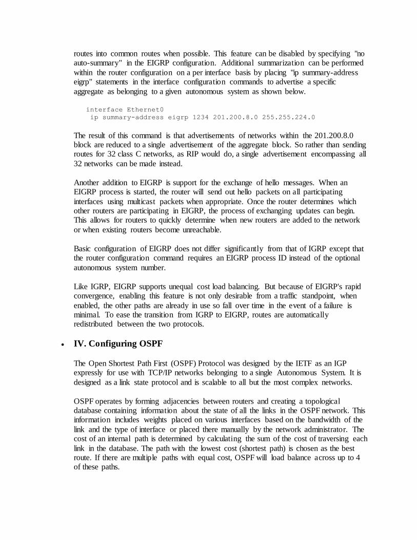
aggregate as belonging to a given autonomous system as shown below.
interface Ethernet0
ip summary-address eigrp 1234 201.200.8.0 255.255.224.0
The result of this command is that advertisements of networks within the 201.200.8.0 block are reduced to a single advertisement of the aggregate block. So rather than sending routes for 32 class C networks, as RIP would do, a single advertisement encompassing all
32 networks can be made instead.
Another addition to EIGRP is support for the exchange of hello messages. When an EIGRP process is started, the router will send out hello packets on all participating
interfaces using multicast packets when appropriate. Once the router determines which other routers are participating in EIGRP, the process of exchanging updates can begin. This allows for routers to quickly determine when new routers are added to the network
or when existing routers become unreachable.
Basic configuration of EIGRP does not differ significantly from that of IGRP except that the router configuration command requires an EIGRP process ID instead of the optional
autonomous system number.
Like IGRP, EIGRP supports unequal cost load balancing. But because of EIGRP's rapid convergence, enabling this feature is not only desirable from a traffic standpoint, when
enabled, the other paths are already in use so fall over time in the event of a failure is minimal. To ease the transition from IGRP to EIGRP, routes are automatically redistributed between the two protocols.
IV. Configuring OSPF
The Open Shortest Path First (OSPF) Protocol was designed by the IETF as an IGP expressly for use with TCP/IP networks belonging to a single Autonomous System. It is
designed as a link state protocol and is scalable to all but the most complex networks.
OSPF operates by forming adjacencies between routers and creating a topological database containing information about the state of all the links in the OSPF network. This information includes weights placed on various interfaces based on the bandwidth of the
link and the type of interface or placed there manually by the network administrator. The cost of an internal path is determined by calculating the sum of the cost of traversing each
link in the database. The path with the lowest cost (shortest path) is chosen as the best route. If there are multiple paths with equal cost, OSPF will load balance across up to 4 of these paths.
This database is updated whenever an adjacency is formed or dropped. Because a complete picture of the network is maintained by every router, when an adjacency drops
and the corrosponding link is no longer availible, a new path can quickly be chosen from information the router already has. However, because it must hold a complete copy of the
topological database, the memory requirements are quite substantial.
On large networks, the number of links in the database can grow to immense proportions. In these cases, a single link change can have a significant impact on every router in the system. A link that is intermittantly availible and unavailible can lead to high processor
use for all routers, diminishing the performance of the network. OSPF provides a method of segmenting the network into several areas. These areas act as described above and are
connected to a "backbone" area (area 0). The area boundry routers, rather than propegating every link state advertizement (LSA) into the backbone, only propegate "summary" advertizements describing the area they are linked to. This summary
advertizement describes the entire area database in a single message, thus reducing the computational overhead and memory usage. Dividing the network into areas also reduces
the impact of a single router or interface changing states on the rest of the network. only the attached area must recalculate the paths through that router or interface.
Use of stub areas and route summarization between areas can also help to reduce the
number of entries in the topological database and reduce the memory requirements and CPU requirements for recalculating paths when changes occur in the network even further. Stub areas do not receive external LSAs (those injected into OSPF via
redistribution from another protocol, such as RIP) and do not have to maintain any link state records except those within the stub area.
Routers configured with OSPF discover other OSPF routers by multicasting or unicasting
hello packets to all SPF routers (multicast address 224.0.0.5). These hello packets are used to form and maintain adjacencies between routers.
Adjacencies are formed automatically across point to point links. On multiaccess networks such as ethernet, a "Designated Router" (DR) is elected. This router forms
adjacencies with all other routers on the multi-access network and is responsible for synchronizing the topological database. In addition, a backup designated router (BDR) is
also selected. In the event of a failure which disconnects the DR from the network, the BDR takes over and a new BDR is elected. This reduces traffic across the network since each router does not have to form an adjacency with every other router. This also reduces
the CPU usage on all other routers connected to this network when a router becomes unavailable. Which routers are DR and BDR can be determined with either "show ip ospf
neighbors" or "show ip ospf interface <interface>".
OSPF is enabled by creating an OSPF routing process and specifying a process ID. Which networks OSPF operates over is controlled by "network" statements (as in RIP or IGRP). At the same time, these networks are assigned an area number. Neighbors can be
hinted at by using the "neighbor" statement. Note that a neighbor does not necessarily form an adjacency. The exec command "show ip ospf neighbor" can be used to determine
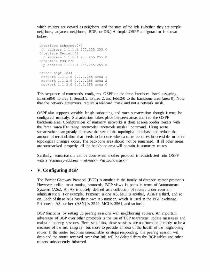
which routers are viewed as neighbors and the state of the link (whether they are simple neighbors, adjacent neighbors, BDR, or DR.) A simple OSPF configuration is shown
below.
Interface Ethernet0/0
ip address 1.1.1.1 255.255.255.0
Interface Serial1/2
ip address 1.1.2.1 255.255.255.0
Interface Fddi2/0
ip address 1.1.3.1 255.255.255.0
router ospf 1234
network 1.1.1.0 0.0.0.255 area 1
network 1.1.2.0 0.0.0.255 area 2
network 1.1.3.0 0.0.0.255 area 0
This sequence of commands configures OSPF on the three interfaces listed assigning Ethernet0/0 to area 1, Serial1/2 to area 2, and Fddi2/0 to the backbone area (area 0). Note that the network statements require a wildcard mask and not a network mask.
OSPF also supports variable length subnetting and route sumarization though it must be configured manualy. Sumarization takes place between areas and into the OSPF backbone area. Configuration of summary networks is done at area border routers with
the "area <area ID> range <network> <network mask>" command. Using route sumarization can greatly decrease the size of the topological database and reduce the
amount of recalculation that needs to be done when a route becomes inaccessible or other topological changes occur. The backbone area should not be sumarized. If all other areas are summarized properly, all the backbone area will contain is summary routes.
Similarly, sumarization can be done when another protocol is redistributed into OSPF
with a "summary-address <network> <network mask>"
V. Configuring BGP
The Border Gateway Protocol (BGP) is another in the family of distance vector protocols.
However, unlike most routing protocols, BGP views its paths in terms of Autonomous Systems (ASs). An AS is loosely defined as a collection of routers under common administration. For example, Primenet is one AS, MCI is another, AT&T a third, and so
on. Each of these ASs has their own AS number, which is used in the BGP exchange. Primenet's AS number (ASN) is 3549, MCI is 3561, and so forth.
BGP functions by setting up peering sessions with neighboring routers. An important
advantage of BGP over other protocols is the use of TCP to transmit update messages and maintain peering sessions. Because of this, these sessions are not intended directly to be a measure of the link integrity, but more to provide an idea of the health of the neighboring
router. If the router becomes unreachable or stops responding, the peering session will drop and the routes received over that link will be deleted from the BGP tables and other
routers subsequently informed.
This loss of conectivity can be caused by the router going down due to a failure or loss of power, a problem with the link the session is transmitting over, or simply congestion
which causes BGP information packets to be dropped. With the explosion of the internet over the last several years, routers which experience repeated BGP or EGP neighbor state
changes have become more problematic. This is usually caused by the router rebooting multiple times or by an intermittant link. Most recently, a cause of such problems has been routers simply being overwhelemd by update messages and being unable to
maintain peering sessions as a result. The term coined to describe this repeated advertizement and deletion of routes is "route flap" or a router "flapping". The result is
that neighboring routers (and quite probably routers two or three links downstream) being overwhelemd with these messages and spending all their time recalculating paths. The effect of this is that those routers' services are degraded until stability returns. It can even
cause those routers to begin to "flap" as well as the number of updates goes beyond what that router is capable of processing, creating a cascade failure. A great deal of research
and development is being done by many companies at a feverish rate to produce routers capable of handling these updates and many service providers have instituted policies designed to reduce the size of the routing tables to reduce flap or to protect themselves
from flap by "dampening" routes that flap repeatedly in a given interval.
A BGP route contains only a few pieces of information. The first is the network that the route describes. Second, the AS path necessary to get to that destination. Third, the origin
of the route (External BGP or EBGP, Internal BGP or IBGP, another Interior Gateway Protocol or IGP, or incomplete.) Fourth, the router ID of the advertizing router, and finally, the BGP next hop address.
BGP provides a simple, yet effective loop detection method. Simply, the AS path of the
learned route is checked against the router's own AS number. If this number apears anywhere in the path, the route is unusable and is discarded.
There are also a few weights and metrics associated with a BGP route which are used to
aid in the path selection process. The first is litterally known as a "weight" and is used only by the router which sets it. This weight is not propegated to other routers. The
second is a "local prefference" value. This is propegated to all routers belonging to a single AS. The last value availible is a "metric" or "Multi Exit Descriminator" (MED). MEDs are advertized to EBGP neighbors and is used to hint at the best path into an AS.
The MED is reset when the route is readvertized to a third AS.
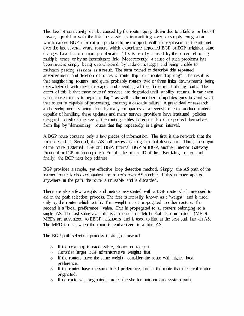
The BGP path selection process is straight forward.
o If the next hop is inaccessible, do not consider it. o Consider larger BGP administrative weights first.
o If the routers have the same weight, consider the route with higher local preference.
o If the routes have the same local preference, prefer the route that the local router
originated. o If no route was originated, prefer the shorter autonomous system path.
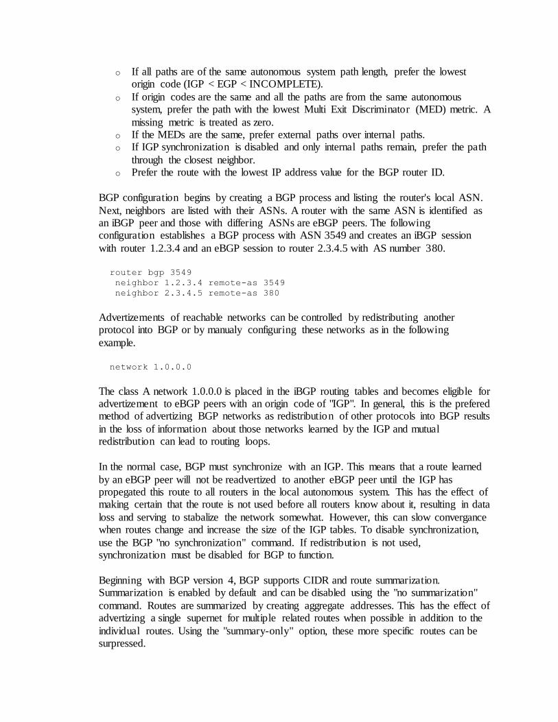
o If all paths are of the same autonomous system path length, prefer the lowest origin code (IGP < EGP < INCOMPLETE).
o If origin codes are the same and all the paths are from the same autonomous system, prefer the path with the lowest Multi Exit Discriminator (MED) metric. A
missing metric is treated as zero. o If the MEDs are the same, prefer external paths over internal paths. o If IGP synchronization is disabled and only internal paths remain, prefer the path
through the closest neighbor. o Prefer the route with the lowest IP address value for the BGP router ID.
BGP configuration begins by creating a BGP process and listing the router's local ASN.
Next, neighbors are listed with their ASNs. A router with the same ASN is identified as an iBGP peer and those with differing ASNs are eBGP peers. The following configuration establishes a BGP process with ASN 3549 and creates an iBGP session
with router 1.2.3.4 and an eBGP session to router 2.3.4.5 with AS number 380.
router bgp 3549
neighbor 1.2.3.4 remote-as 3549
neighbor 2.3.4.5 remote-as 380
Advertizements of reachable networks can be controlled by redistributing another protocol into BGP or by manualy configuring these networks as in the following
example.
network 1.0.0.0
The class A network 1.0.0.0 is placed in the iBGP routing tables and becomes eligible for advertizement to eBGP peers with an origin code of "IGP". In general, this is the prefered method of advertizing BGP networks as redistribution of other protocols into BGP results
in the loss of information about those networks learned by the IGP and mutual redistribution can lead to routing loops.
In the normal case, BGP must synchronize with an IGP. This means that a route learned
by an eBGP peer will not be readvertized to another eBGP peer until the IGP has propegated this route to all routers in the local autonomous system. This has the effect of making certain that the route is not used before all routers know about it, resulting in data
loss and serving to stabalize the network somewhat. However, this can slow convergance when routes change and increase the size of the IGP tables. To disable synchronization,
use the BGP "no synchronization" command. If redistribution is not used, synchronization must be disabled for BGP to function.
Beginning with BGP version 4, BGP supports CIDR and route summarization. Summarization is enabled by default and can be disabled using the "no summarization"
command. Routes are summarized by creating aggregate addresses. This has the effect of advertizing a single supernet for multiple related routes when possible in addition to the
individual routes. Using the "summary-only" option, these more specific routes can be surpressed.
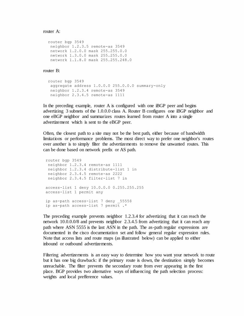
router A:
router bgp 3549
neighbor 1.2.3.5 remote-as 3549
network 1.2.0.0 mask 255.255.0.0
network 1.3.0.0 mask 255.255.0.0
network 1.1.8.0 mask 255.255.248.0
router B:
router bgp 3549
aggregate address 1.0.0.0 255.0.0.0 summary-only
neighbor 1.2.3.4 remote-as 3549
neighbor 2.3.4.5 remote-as 1111
In the preceding example, router A is configured with one iBGP peer and begins advertizing 3 subnets of the 1.0.0.0 class A. Router B configures one iBGP neighbor and one eBGP neighbor and summarizes routes learned from router A into a single
advertizement which is sent to the eBGP peer.
Often, the closest path to a site may not be the best path, either because of bandwidth limitations or performance problems. The most direct way to prefer one neighbor's routes over another is to simply filter the advertizements to remove the unwanted routes. This
can be done based on network prefix or AS path.
router bgp 3549
neighbor 1.2.3.4 remote-as 1111
neighbor 1.2.3.4 distribute-list 1 in
neighbor 2.3.4.5 remote-as 2222
neighbor 2.3.4.5 filter-list 7 in
access-list 1 deny 10.0.0.0 0.255.255.255
access-list 1 permit any
ip as-path access-list 7 deny _5555$
ip as-path access-list 7 permit .*
The preceding example prevents neighbor 1.2.3.4 for advertizing that it can reach the network 10.0.0.0/8 and prevents neighbor 2.3.4.5 from advertizing that it can reach any
path where ASN 5555 is the last ASN in the path. The as-path regular expressions are documented in the cisco documentation set and follow general regular expression rules. Note that access lists and route maps (as illustrated below) can be applied to either
inbound or outbound advertizements.
Filtering advertizements is an easy way to determine how you want your network to route but it has one big drawback: if the primary route is down, the destination simply becomes
unreachable. The filter prevents the secondary route from ever appearing in the first place. BGP provides two alternative ways of influencing the path selection process: weights and local prefference values.
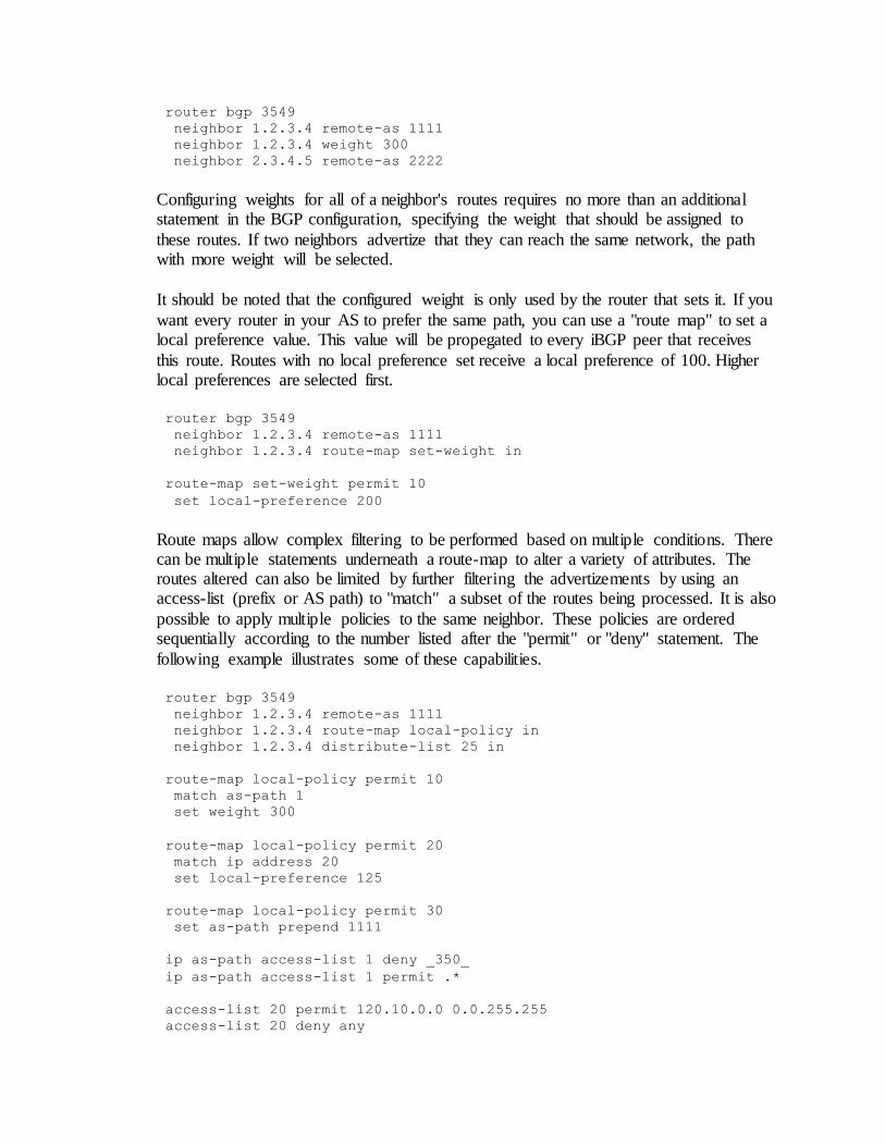
router bgp 3549
neighbor 1.2.3.4 remote-as 1111
neighbor 1.2.3.4 weight 300
neighbor 2.3.4.5 remote-as 2222
Configuring weights for all of a neighbor's routes requires no more than an additional statement in the BGP configuration, specifying the weight that should be assigned to
these routes. If two neighbors advertize that they can reach the same network, the path with more weight will be selected.
It should be noted that the configured weight is only used by the router that sets it. If you
want every router in your AS to prefer the same path, you can use a "route map" to set a local preference value. This value will be propegated to every iBGP peer that receives
this route. Routes with no local preference set receive a local preference of 100. Higher local preferences are selected first.
router bgp 3549
neighbor 1.2.3.4 remote-as 1111
neighbor 1.2.3.4 route-map set-weight in
route-map set-weight permit 10
set local-preference 200
Route maps allow complex filtering to be performed based on multiple conditions. There can be multiple statements underneath a route-map to alter a variety of attributes. The routes altered can also be limited by further filtering the advertizements by using an access-list (prefix or AS path) to "match" a subset of the routes being processed. It is also
possible to apply multiple policies to the same neighbor. These policies are ordered sequentially according to the number listed after the "permit" or "deny" statement. The
following example illustrates some of these capabilities.
router bgp 3549
neighbor 1.2.3.4 remote-as 1111
neighbor 1.2.3.4 route-map local-policy in
neighbor 1.2.3.4 distribute-list 25 in
route-map local-policy permit 10
match as-path 1
set weight 300
route-map local-policy permit 20
match ip address 20
set local-preference 125
route-map local-policy permit 30
set as-path prepend 1111
ip as-path access-list 1 deny _350_
ip as-path access-list 1 permit .*
access-list 20 permit 120.10.0.0 0.0.255.255
access-list 20 deny any
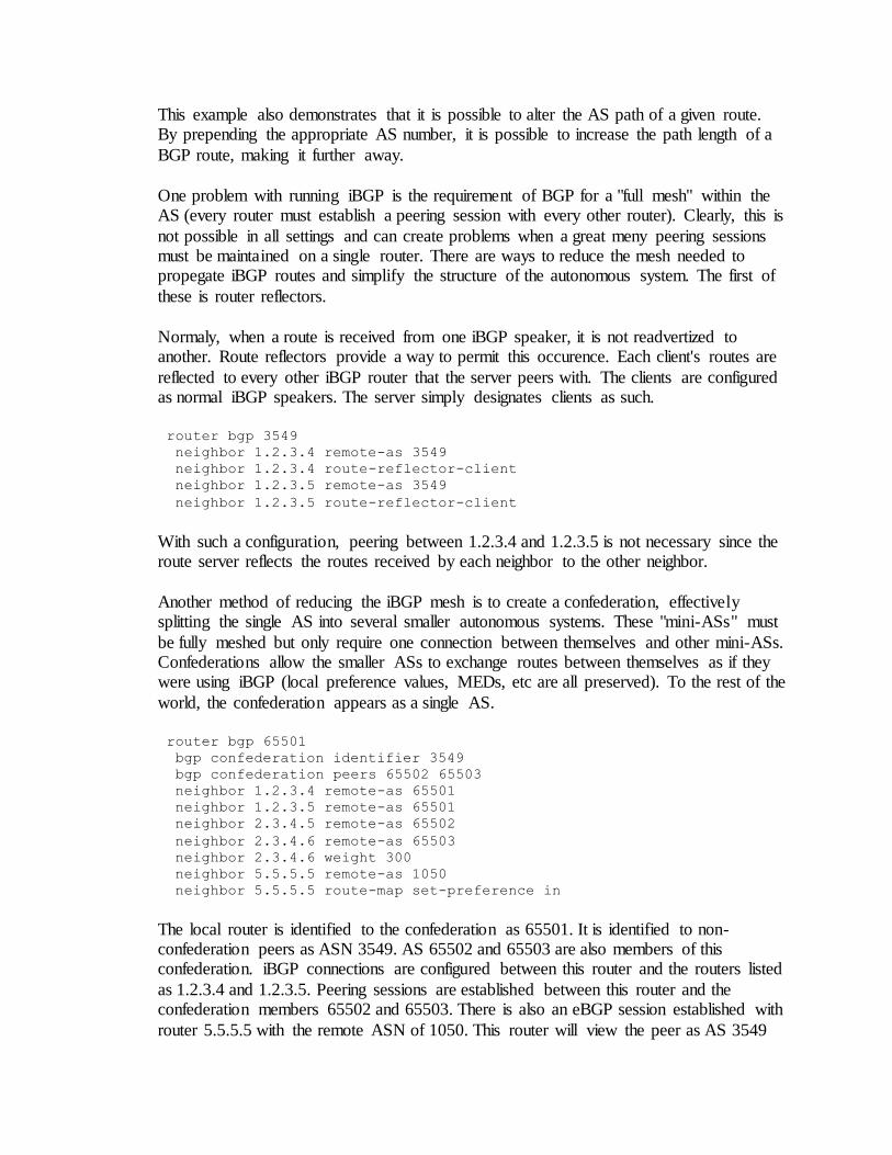
This example also demonstrates that it is possible to alter the AS path of a given route. By prepending the appropriate AS number, it is possible to increase the path length of a
BGP route, making it further away.
One problem with running iBGP is the requirement of BGP for a "full mesh" within the AS (every router must establish a peering session with every other router). Clearly, this is
not possible in all settings and can create problems when a great meny peering sessions must be maintained on a single router. There are ways to reduce the mesh needed to propegate iBGP routes and simplify the structure of the autonomous system. The first of
these is router reflectors.
Normaly, when a route is received from one iBGP speaker, it is not readvertized to another. Route reflectors provide a way to permit this occurence. Each client's routes are
reflected to every other iBGP router that the server peers with. The clients are configured as normal iBGP speakers. The server simply designates clients as such.
router bgp 3549
neighbor 1.2.3.4 remote-as 3549
neighbor 1.2.3.4 route-reflector-client
neighbor 1.2.3.5 remote-as 3549
neighbor 1.2.3.5 route-reflector-client
With such a configuration, peering between 1.2.3.4 and 1.2.3.5 is not necessary since the route server reflects the routes received by each neighbor to the other neighbor.
Another method of reducing the iBGP mesh is to create a confederation, effectively splitting the single AS into several smaller autonomous systems. These "mini-ASs" must
be fully meshed but only require one connection between themselves and other mini-ASs. Confederations allow the smaller ASs to exchange routes between themselves as if they were using iBGP (local preference values, MEDs, etc are all preserved). To the rest of the
world, the confederation appears as a single AS.
router bgp 65501
bgp confederation identifier 3549
bgp confederation peers 65502 65503
neighbor 1.2.3.4 remote-as 65501
neighbor 1.2.3.5 remote-as 65501
neighbor 2.3.4.5 remote-as 65502
neighbor 2.3.4.6 remote-as 65503
neighbor 2.3.4.6 weight 300
neighbor 5.5.5.5 remote-as 1050
neighbor 5.5.5.5 route-map set-preference in
The local router is identified to the confederation as 65501. It is identified to non-confederation peers as ASN 3549. AS 65502 and 65503 are also members of this confederation. iBGP connections are configured between this router and the routers listed
as 1.2.3.4 and 1.2.3.5. Peering sessions are established between this router and the confederation members 65502 and 65503. There is also an eBGP session established with
router 5.5.5.5 with the remote ASN of 1050. This router will view the peer as AS 3549
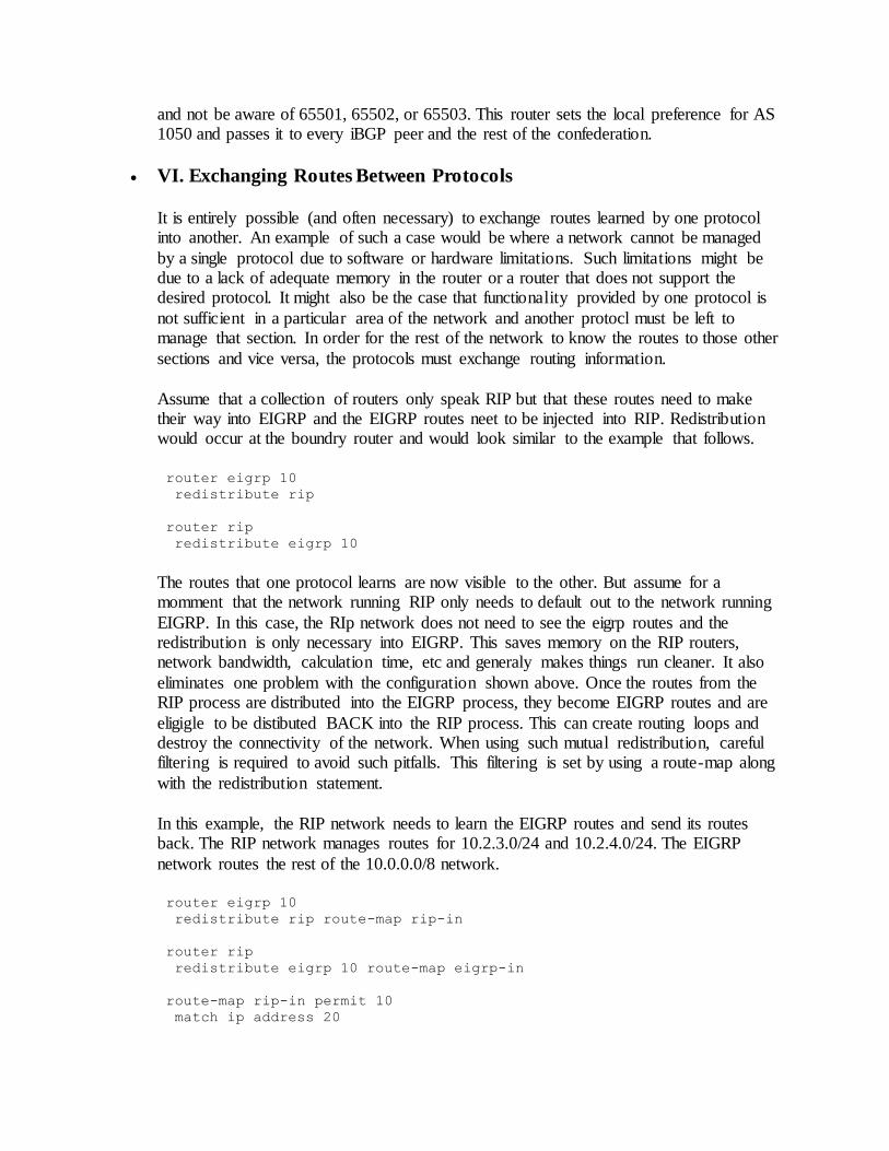
and not be aware of 65501, 65502, or 65503. This router sets the local preference for AS 1050 and passes it to every iBGP peer and the rest of the confederation.
VI. Exchanging Routes Between Protocols
It is entirely possible (and often necessary) to exchange routes learned by one protocol into another. An example of such a case would be where a network cannot be managed
by a single protocol due to software or hardware limitations. Such limitations might be due to a lack of adequate memory in the router or a router that does not support the desired protocol. It might also be the case that functionality provided by one protocol is
not sufficient in a particular area of the network and another protocl must be left to manage that section. In order for the rest of the network to know the routes to those other
sections and vice versa, the protocols must exchange routing information.
Assume that a collection of routers only speak RIP but that these routes need to make their way into EIGRP and the EIGRP routes neet to be injected into RIP. Redistribution would occur at the boundry router and would look similar to the example that follows.
router eigrp 10
redistribute rip
router rip
redistribute eigrp 10
The routes that one protocol learns are now visible to the other. But assume for a momment that the network running RIP only needs to default out to the network running
EIGRP. In this case, the RIp network does not need to see the eigrp routes and the redistribution is only necessary into EIGRP. This saves memory on the RIP routers, network bandwidth, calculation time, etc and generaly makes things run cleaner. It also
eliminates one problem with the configuration shown above. Once the routes from the RIP process are distributed into the EIGRP process, they become EIGRP routes and are
eligigle to be distibuted BACK into the RIP process. This can create routing loops and destroy the connectivity of the network. When using such mutual redistribution, careful filtering is required to avoid such pitfalls. This filtering is set by using a route-map along
with the redistribution statement.
In this example, the RIP network needs to learn the EIGRP routes and send its routes back. The RIP network manages routes for 10.2.3.0/24 and 10.2.4.0/24. The EIGRP
network routes the rest of the 10.0.0.0/8 network.
router eigrp 10
redistribute rip route-map rip-in
router rip
redistribute eigrp 10 route-map eigrp-in
route-map rip-in permit 10
match ip address 20
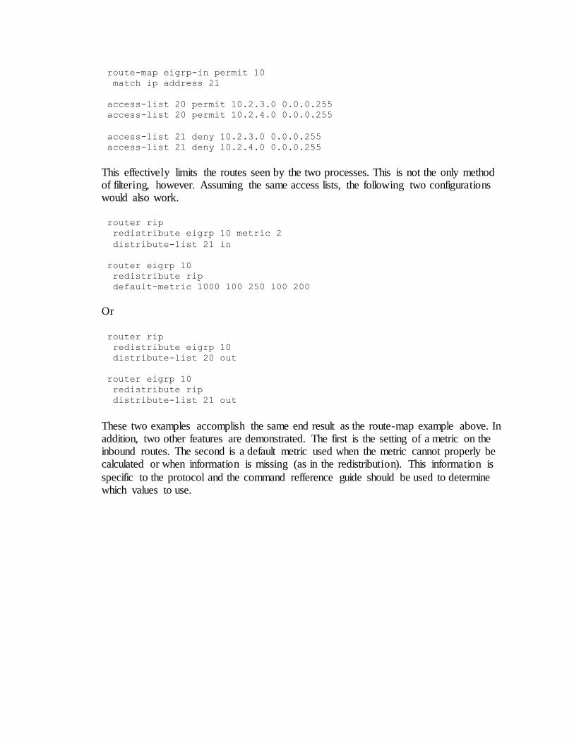
route-map eigrp-in permit 10
match ip address 21
access-list 20 permit 10.2.3.0 0.0.0.255
access-list 20 permit 10.2.4.0 0.0.0.255
access-list 21 deny 10.2.3.0 0.0.0.255
access-list 21 deny 10.2.4.0 0.0.0.255
This effectively limits the routes seen by the two processes. This is not the only method of filtering, however. Assuming the same access lists, the following two configurations would also work.
router rip
redistribute eigrp 10 metric 2
distribute-list 21 in
router eigrp 10
redistribute rip
default-metric 1000 100 250 100 200
Or
router rip
redistribute eigrp 10
distribute-list 20 out
router eigrp 10
redistribute rip
distribute-list 21 out
These two examples accomplish the same end result as the route-map example above. In addition, two other features are demonstrated. The first is the setting of a metric on the inbound routes. The second is a default metric used when the metric cannot properly be calculated or when information is missing (as in the redistribution). This information is
specific to the protocol and the command refference guide should be used to determine which values to use.