cisco’s disaster recovery as a service virtualized ...techhubly.com/quest/files/cisco draas...
TRANSCRIPT
Cisco’s Disaster Recovery as a ServiceVirtualized Multiservice Data Center and Zerto Virtual ReplicationJanuary 27, 2014
CCDE, CCENT, CCSI, Cisco Eos, Cisco Explorer, Cisco HealthPresence, Cisco IronPort, the Cisco logo, Cisco Nurse Connect, Cisco Pulse, Cisco SensorBase, Cisco StackPower, Cisco StadiumVision, Cisco TelePresence, Cisco TrustSec, Cisco Unified Computing System, Cisco WebEx, DCE, Flip Channels, Flip for Good, Flip Mino, Flipshare (Design), Flip Ultra, Flip Video, Flip Video (Design), Instant Broadband, and Welcome to the Human Network are trademarks; Changing the Way We Work, Live, Play, and Learn, Cisco Capital, Cisco Capital (Design), Cisco:Financed (Stylized), Cisco Store, Flip Gift Card, and One Million Acts of Green are service marks; and Access Registrar, Aironet, AllTouch, AsyncOS, Bringing the Meeting To You, Catalyst, CCDA, CCDP, CCIE, CCIP, CCNA, CCNP, CCSP, CCVP, Cisco, the Cisco Certified Internetwork Expert logo, Cisco IOS, Cisco Lumin, Cisco Nexus, Cisco Press, Cisco Systems, Cisco Systems Capital, the Cisco Systems logo, Cisco Unity, Collaboration Without Limitation, Continuum, EtherFast, EtherSwitch, Event Center, Explorer, Follow Me Browsing, GainMaker, iLYNX, IOS, iPhone, IronPort, the IronPort logo, Laser Link, LightStream, Linksys, MeetingPlace, MeetingPlace Chime Sound, MGX, Networkers, Networking Academy, PCNow, PIX, PowerKEY, PowerPanels, PowerTV, PowerTV (Design), PowerVu, Prisma, ProConnect, ROSA, SenderBase, SMARTnet, Spectrum Expert, StackWise, WebEx, and the WebEx logo are registered trademarks of Cisco and/or its affiliates in the United States and certain other countries.
All other trademarks mentioned in this document or website are the property of their respective owners. The use of the word partner does not imply a partnership relationship between Cisco and any other company. (1002R)
THE SOFTWARE LICENSE AND LIMITED WARRANTY FOR THE ACCOMPANYING PRODUCT ARE SET FORTH IN THE INFORMATION PACKET THAT SHIPPED WITH THE PRODUCT AND ARE INCORPORATED HEREIN BY THIS REFERENCE. IF YOU ARE UNABLE TO LOCATE THE SOFTWARE LICENSE OR LIMITED WARRANTY, CONTACT YOUR CISCO REPRESENTATIVE FOR A COPY.
The Cisco implementation of TCP header compression is an adaptation of a program developed by the University of California, Berkeley (UCB) as part of UCB’s public domain version of the UNIX operating system. All rights reserved. Copyright © 1981, Regents of the University of California.
NOTWITHSTANDING ANY OTHER WARRANTY HEREIN, ALL DOCUMENT FILES AND SOFTWARE OF THESE SUPPLIERS ARE PROVIDED “AS IS” WITH ALL FAULTS. CISCO AND THE ABOVE-NAMED SUPPLIERS DISCLAIM ALL WARRANTIES, EXPRESSED OR IMPLIED, INCLUDING, WITHOUT LIMITATION, THOSE OF MERCHANTABILITY, FITNESS FOR A PARTICULAR PURPOSE AND NONINFRINGEMENT OR ARISING FROM A COURSE OF DEALING, USAGE, OR TRADE PRACTICE.
IN NO EVENT SHALL CISCO OR ITS SUPPLIERS BE LIABLE FOR ANY INDIRECT, SPECIAL, CONSEQUENTIAL, OR INCIDENTAL DAMAGES, INCLUDING, WITHOUT LIMITATION, LOST PROFITS OR LOSS OR DAMAGE TO DATA ARISING OUT OF THE USE OR INABILITY TO USE THIS MANUAL, EVEN IF CISCO OR ITS SUPPLIERS HAVE BEEN ADVISED OF THE POSSIBILITY OF SUCH DAMAGES.
Cisco’s Disaster Recovery as a Service: Virtualized Multiservice Data Center and Zerto Virtual Replication© 2014 Cisco Systems, Inc. All rights reserved.
Virtualized Multiservice Data Center and Zerto Virtual Replic
C O N T E N T S
C H A P T E R 1 System Overview 1-1
Adoption Challenges to DR and DRaaS 1-3
Cisco/Zerto DRaaS Solution Changes Traditional Capability 1-3
Disparate Hardware Increases Costs 1-3
Complexity 1-4
Zerto Virtual Replication 1-4
Hardware Agnostic 1-4
Simplicity 1-4
Built for Service Providers 1-4
Connect Customers Regardless of their Equipment 1-5
Efficient and Rapid Customer Onboarding 1-5
Centralized Management and Reporting 1-5
Standardization of the Service Provider Infrastructure 1-5
Reduced Costs 1-5
Business Agility 1-6
Simplification 1-6
C H A P T E R 2 System Architecture 2-1
Provider Cloud 2-2
WAN Connectivity 2-2
Partner Solution for Providing Disaster Recovery 2-2
System Logical Topology 2-3
End-to-End Architecture 2-4
DRaaS Operational Workflows 2-5
Network Deployment Considerations Supporting Recovery Environment 2-6
Zerto Virtual Replication Architecture 2-7
Helping the CSP Provide a Dynamic DR Platform 2-8
Enablement for Cloud DR Resource Management: Zerto Cloud Manager 2-9
ZCM Features 2-10
Interface 2-10
Global Resource Management 2-10
Centralized Billing and Resource Planning 2-11
Centralized Reporting 2-12
Service Profiles 2-12
iCisco’s Disaster Recovery as a Service
ation
Contents
Enablement for Cloud DR Resource Consumption: Zerto Self Service Portal 2-13
ZSSP Features 2-14
ZCM and ZSSP Feature Summary 2-15
VMDC Cloud Infrastructure 2-16
VMDC 2.3 Architecture 2-17
VMDC 2.3 Modular Components 2-19
Point of Delivery (PoD) 2-19
ICS 2-19
VMDC 2.3 Network Containers 2-20
Modifications in VMDC Network Containers for DRaaS 2-24
VMDC Orchestration using BMC CLM 2-27
Deployment Considerations 2-28
Journal Sizing 2-28
Failover Testing and Journal Size 2-29
Storage 2-29
Compression 2-31
External Cisco Products 2-32
Zerto Virtual Replication 2-32
Encryption 2-32
Compute Over-Subscription 2-33
C H A P T E R 3 Implementation and Configuration 3-1
Disaster Recovery To the Cloud and In the Cloud 3-1
Zerto Virtual Manager 3-2
Zerto Cloud Manager 3-2
ZCM Resource Management 3-4
Cloud Service Provider Resources 3-4
Customers 3-5
Preseeding 3-5
Role Based Permissions For Customers 3-6
Service Profiles 3-6
Zerto Component Configuration 3-7
License Management 3-7
Zerto Virtual Replication Appliances (VRA) 3-8
Installing a VRA 3-8
Virtual Protection Groups 3-9
The Journal 3-10
Zerto Cloud Connector 3-11
iiCisco’s Disaster Recovery as a Service
Virtualized Multiservice Data Center and Zerto Virtual Replication
Contents
DRaaS Customer Connection 3-13
Zerto Self Service Portal—In Cloud Customer Connection 3-13
Live Environment Status 3-14
VMDC 2.3 Integrated Compute and Storage Stack 3-14
UCS Implementation 3-15
ESXi Implementation 3-17
Nexus 1000v 3-20
Mapping of DR Components to VMDC 2.3 Containers 3-21
Tenant Configuration—IPsec 3-22
VMDC Container Modifications 3-23
Connectivity Across the WAN 3-27
Storage Configuration 3-29
SAN Implementation Overview 3-29
VNX5500 Configuration Overview 3-31
BMC Cloud Lifecycle Management 3-35
C H A P T E R 4 Disaster Recovery Workflow 4-1
The Move Operation 4-1
The Failover Operation 4-2
Failback after the Original Site is Operational 4-3
The Failover Test Operation 4-4
The Clone Operation 4-5
Verification—User Traffic Not Run Against Recovered VMs 4-6
Using a Failover Test Operation 4-6
Using an Uncommitted Move Operation 4-7
Run User Traffic against the Recovered VMs 4-7
Using a Move Operation 4-8
Using a Failover Operation 4-8
Using a Clone Operation 4-9
C H A P T E R 5 Monitoring, Best Practices, Caveats and Troubleshooting 5-1
Disaster Recovery Workflow 5-1
Best Practices 5-2
Monitoring a Virtual Protection Group 5-2
Audit of VPG Recent Activities 5-3
Monitoring Protected Virtual Machines 5-4
Determining Which Columns and Order to Display 5-6
Filtering Information 5-6
iiiCisco’s Disaster Recovery as a Service
Virtualized Multiservice Data Center and Zerto Virtual Replication
Contents
Upgrades 5-6
Upgrading or Reinstalling a vCenter Server 5-7
Upgrading a vCenter Server 5-7
Reinstalling a vCenter Server 5-7
A P P E N D I X A References A-1
ivCisco’s Disaster Recovery as a Service
Virtualized Multiservice Data Center and Zerto Virtual Replication
Virtualized Multiservice Data Center and Zerto Virtual Replication
C H A P T E R 1
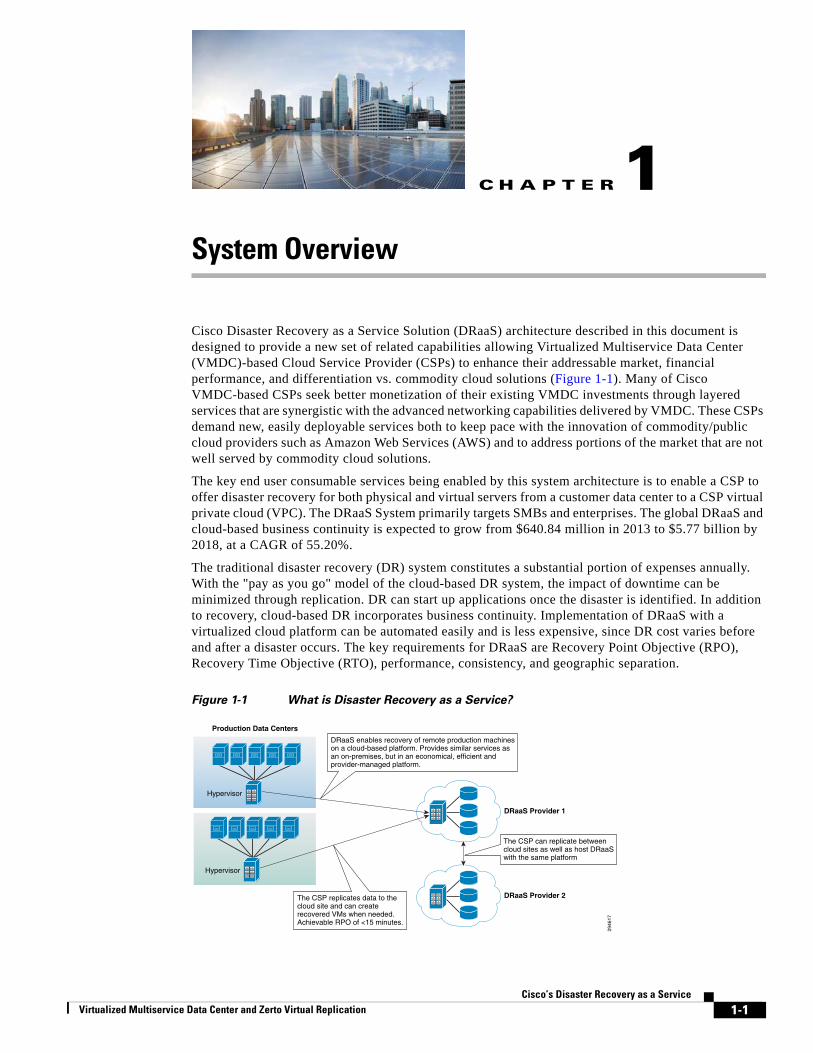
System OverviewCisco Disaster Recovery as a Service Solution (DRaaS) architecture described in this document is designed to provide a new set of related capabilities allowing Virtualized Multiservice Data Center (VMDC)-based Cloud Service Provider (CSPs) to enhance their addressable market, financial performance, and differentiation vs. commodity cloud solutions (Figure 1-1). Many of Cisco VMDC-based CSPs seek better monetization of their existing VMDC investments through layered services that are synergistic with the advanced networking capabilities delivered by VMDC. These CSPs demand new, easily deployable services both to keep pace with the innovation of commodity/public cloud providers such as Amazon Web Services (AWS) and to address portions of the market that are not well served by commodity cloud solutions.
The key end user consumable services being enabled by this system architecture is to enable a CSP to offer disaster recovery for both physical and virtual servers from a customer data center to a CSP virtual private cloud (VPC). The DRaaS System primarily targets SMBs and enterprises. The global DRaaS and cloud-based business continuity is expected to grow from $640.84 million in 2013 to $5.77 billion by 2018, at a CAGR of 55.20%.
The traditional disaster recovery (DR) system constitutes a substantial portion of expenses annually. With the "pay as you go" model of the cloud-based DR system, the impact of downtime can be minimized through replication. DR can start up applications once the disaster is identified. In addition to recovery, cloud-based DR incorporates business continuity. Implementation of DRaaS with a virtualized cloud platform can be automated easily and is less expensive, since DR cost varies before and after a disaster occurs. The key requirements for DRaaS are Recovery Point Objective (RPO), Recovery Time Objective (RTO), performance, consistency, and geographic separation.
Figure 1-1 What is Disaster Recovery as a Service?
2946
17
DRaaS Provider 1
DRaaS enables recovery of remote production machineson a cloud-based platform. Provides similar services as an on-premises, but in an economical, efficient and provider-managed platform.
The CSP replicates data to the cloud site and can createrecovered VMs when needed.Achievable RPO of <15 minutes.
DRaaS Provider 2
The CSP can replicate betweencloud sites as well as host DRaaSwith the same platform
Production Data Centers
Hypervisor
Hypervisor
1-1Cisco’s Disaster Recovery as a Service
Chapter 1 System Overview
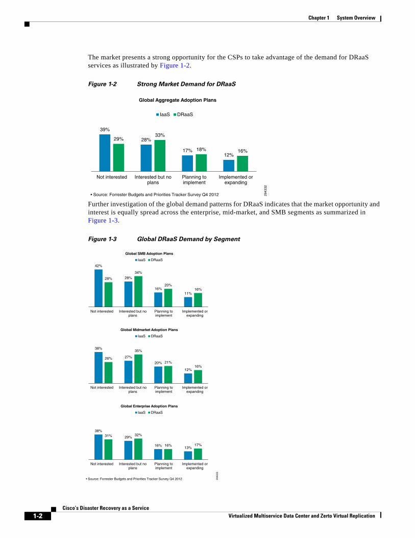
The market presents a strong opportunity for the CSPs to take advantage of the demand for DRaaS services as illustrated by Figure 1-2.
Figure 1-2 Strong Market Demand for DRaaS
Further investigation of the global demand patterns for DRaaS indicates that the market opportunity and interest is equally spread across the enterprise, mid-market, and SMB segments as summarized in Figure 1-3.
Figure 1-3 Global DRaaS Demand by Segment
2943
32
• Source: Forrester Budgets and Priorities Tracker Survey Q4 2012
39%
28%
17% 12%
29% 33%
18% 16%
Not interested Interested but noplans
Planning toimplement
Implemented orexpanding
Global Aggregate Adoption Plans
IaaS DRaaS
2943
33
• Source: Forrester Budgets and Priorities Tracker Survey Q4 2012
Not interested Interested but noplans
Planning toimplement
Implemented orexpanding
Global SMB Adoption Plans
IaaS DRaaS
42%
28%
16% 11%
28%
34%
20% 16%
38%
27%
20%
12%
26%
35%
21% 16%
38%
29%
16% 13%
31% 32%
16% 17%
Not interested Interested but noplans
Planning toimplement
Implemented orexpanding
Global Midmarket Adoption Plans
IaaS DRaaS
Not interested Interested but noplans
Planning toimplement
Implemented orexpanding
Global Enterprise Adoption Plans
IaaS DRaaS
1-2Cisco’s Disaster Recovery as a Service
Virtualized Multiservice Data Center and Zerto Virtual Replication
Chapter 1 System Overview Adoption Challenges to DR and DRaaS
Adoption Challenges to DR and DRaaSLooking at the Forrester results, the majority of the respondents are either not interested or have no plans of implementing a disaster recovery solution.
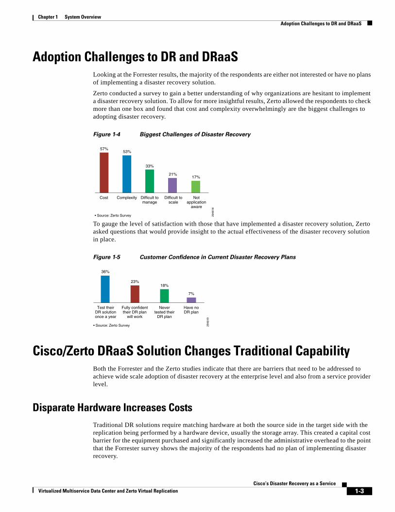
Zerto conducted a survey to gain a better understanding of why organizations are hesitant to implement a disaster recovery solution. To allow for more insightful results, Zerto allowed the respondents to check more than one box and found that cost and complexity overwhelmingly are the biggest challenges to adopting disaster recovery.
Figure 1-4 Biggest Challenges of Disaster Recovery
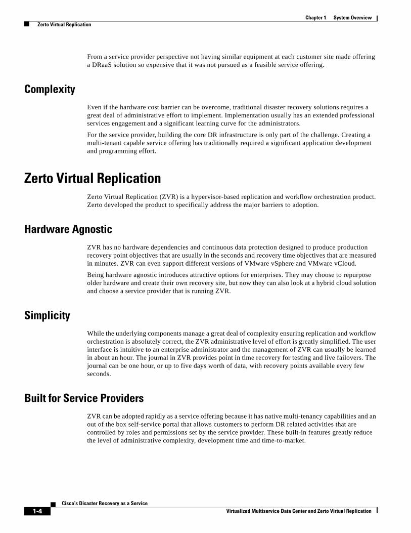
To gauge the level of satisfaction with those that have implemented a disaster recovery solution, Zerto asked questions that would provide insight to the actual effectiveness of the disaster recovery solution in place.
Figure 1-5 Customer Confidence in Current Disaster Recovery Plans
Cisco/Zerto DRaaS Solution Changes Traditional CapabilityBoth the Forrester and the Zerto studies indicate that there are barriers that need to be addressed to achieve wide scale adoption of disaster recovery at the enterprise level and also from a service provider level.
Disparate Hardware Increases CostsTraditional DR solutions require matching hardware at both the source side in the target side with the replication being performed by a hardware device, usually the storage array. This created a capital cost barrier for the equipment purchased and significantly increased the administrative overhead to the point that the Forrester survey shows the majority of the respondents had no plan of implementing disaster recovery.
2946
18• Source: Zerto Survey
57%
Cost
53%
33%
21%17%
Complexity Difficult tomanage
Difficult toscale
Notapplication
aware
Have noDR plan
2946
19
• Source: Zerto Survey
23%
7%
Fully confidenttheir DR plan
will work
36%
18%
Test theirDR solutiononce a year
Nevertested their
DR plan
1-3Cisco’s Disaster Recovery as a Service
Virtualized Multiservice Data Center and Zerto Virtual Replication
Chapter 1 System Overview Zerto Virtual Replication
From a service provider perspective not having similar equipment at each customer site made offering a DRaaS solution so expensive that it was not pursued as a feasible service offering.
ComplexityEven if the hardware cost barrier can be overcome, traditional disaster recovery solutions requires a great deal of administrative effort to implement. Implementation usually has an extended professional services engagement and a significant learning curve for the administrators.
For the service provider, building the core DR infrastructure is only part of the challenge. Creating a multi-tenant capable service offering has traditionally required a significant application development and programming effort.
Zerto Virtual ReplicationZerto Virtual Replication (ZVR) is a hypervisor-based replication and workflow orchestration product. Zerto developed the product to specifically address the major barriers to adoption.
Hardware AgnosticZVR has no hardware dependencies and continuous data protection designed to produce production recovery point objectives that are usually in the seconds and recovery time objectives that are measured in minutes. ZVR can even support different versions of VMware vSphere and VMware vCloud.
Being hardware agnostic introduces attractive options for enterprises. They may choose to repurpose older hardware and create their own recovery site, but now they can also look at a hybrid cloud solution and choose a service provider that is running ZVR.
SimplicityWhile the underlying components manage a great deal of complexity ensuring replication and workflow orchestration is absolutely correct, the ZVR administrative level of effort is greatly simplified. The user interface is intuitive to an enterprise administrator and the management of ZVR can usually be learned in about an hour. The journal in ZVR provides point in time recovery for testing and live failovers. The journal can be one hour, or up to five days worth of data, with recovery points available every few seconds.
Built for Service ProvidersZVR can be adopted rapidly as a service offering because it has native multi-tenancy capabilities and an out of the box self-service portal that allows customers to perform DR related activities that are controlled by roles and permissions set by the service provider. These built-in features greatly reduce the level of administrative complexity, development time and time-to-market.
1-4Cisco’s Disaster Recovery as a Service
Virtualized Multiservice Data Center and Zerto Virtual Replication
Chapter 1 System Overview Standardization of the Service Provider Infrastructure
Connect Customers Regardless of their EquipmentA major barrier to DRaaS adoption has been the challenge of the customer equipment being completely different than the service providers. When the replication between sites is completely dependent upon hardware devices, the devices must match vendor, firmware and software. Further, all of these must be planned and upgraded at the same time. Hardware-based replication has traditionally been very unforgiving to different versions when site to site replication is involved. With ZVR, VMware vSphere is the only requirement, and replication is possible between different versions of VMware vSphere. Replication is possible between vSphere and vCloud environments. This is very important to a service provider because customers update their infrastructure versions on different schedules.
Efficient and Rapid Customer OnboardingWith a hypervisor-based replication solution, customers can be added very quickly. Only VMs and VMDKs are replicating, not LUNs. Regardless of the location of the host or storage the source VM or group of VMs reside, they can be replicated to the CSP datacenter. This results in reduced customer onboarding time while offering a solution that fully supports the critical VMware features such as DRS, vCloud Director, VMotion, Storage VMotion.
Centralized Management and ReportingThe Zerto Cloud Manager (ZCM) centralizes management of the entire infrastructure. The service provider has one view of all customers leveraging cloud resources. The ability to manage from one pane of glass, greatly simplifies management. For example, reports are automatically created showing the usage of customer assets across sites. This dramatically simplifies the relationship between the customer and the CSP. These detailed resource usage reports can be used to generate invoices and imported into the service providers billing system.
Standardization of the Service Provider InfrastructureCisco’s Disaster Recovery as a Service Solution (DRaaS) architecture is based on Virtualized Multiservice Data Center (VMDC) and Cisco Unified Computing System (UCS). Virtualized Multiservice Data Center (VMDC) is a reference architecture for building a fabric-based infrastructure providing design guidelines that demonstrate how customers can integrate key Cisco and partner technologies, such as networking, computing, integrated compute stacks, security, load balancing, and system management. Cisco UCS is a next-generation data center platform that unites compute, network, storage access, and virtualization into a cohesive system designed to reduce total cost of ownership (TCO) and increase business agility.
Reduced CostsCisco VMDC and UCS reduce infrastructure expenditures (CAPEX) and operational expenses (OPEX) to increase profitability by reduce the number of devices that must be purchased, cabled, configured, powered, cooled, and secured. The unified architecture uses industry-standard technologies to provide interoperability and investment protection.
1-5Cisco’s Disaster Recovery as a Service
Virtualized Multiservice Data Center and Zerto Virtual Replication
Chapter 1 System Overview Standardization of the Service Provider Infrastructure
Business AgilityCisco VMDC and UCS enable business agility through faster provisioning of IT infrastructure and delivery of IT as a service. Deployment time and cost is more predictable through the use of an end-to-end validated, scalable and modular architecture. The unified architecture supports multiple applications, services, and tenants.
SimplificationCisco VMDC and UCS simplify IT management to support scalability, further control costs, and facilitate automation — key to delivering IT as a service and cloud applications. The architecture enhances the portability of both physical and virtual machines with server identity, LAN and SAN addressing, I/O configurations, firmware, and network connectivity profiles that dynamically provision and integrate server and network resources.
1-6Cisco’s Disaster Recovery as a Service
Virtualized Multiservice Data Center and Zerto Virtual Replication
Virtualized Multiservice Data Center and Zerto Virtual Replication
C H A P T E R 2
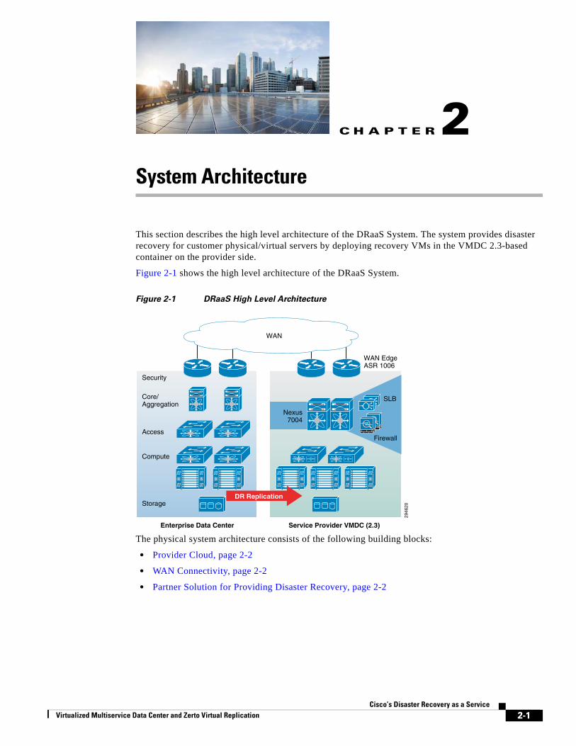
System ArchitectureThis section describes the high level architecture of the DRaaS System. The system provides disaster recovery for customer physical/virtual servers by deploying recovery VMs in the VMDC 2.3-based container on the provider side.
Figure 2-1 shows the high level architecture of the DRaaS System.
Figure 2-1 DRaaS High Level Architecture
The physical system architecture consists of the following building blocks:
• Provider Cloud, page 2-2
• WAN Connectivity, page 2-2
• Partner Solution for Providing Disaster Recovery, page 2-2
2946
20
Enterprise Data Center
Core/Aggregation
Security
Access
Compute
Storage
WAN EdgeASR 1006
Firewall
Nexus7004
SLB
Service Provider VMDC (2.3)
WAN
DR Replication
2-1Cisco’s Disaster Recovery as a Service
Chapter 2 System Architecture Provider Cloud
Provider CloudThe provider cloud within the DRaaS System is based on VMDC 2.3. The VMDC 2.3 design is based on the earlier VMDC 2.2 design, with changes to optimize the design for lower cost, fewer layers, and increased tenancy scale. The Cisco VMDC System provides vPC-based L3 hierarchical virtual routing and forwarding (VRF)-Lite DC design, multi-tenancy, secure separation, differentiated service tiers, and high availability in a data center environment. It also provides secure separation between replicated workloads and provides shared network services for customers in DRaaS.
The VMDC 2.3 architecture works with Vblock, FlexPod, or any other integration stack. Integrated stacks can be added as required to scale the CSP cloud environment.
Based on the customer's production environment and needs, a specific tenancy model can be selected to provide similar services in the cloud-matching production environment. VMDC architecture and deployment models will be covered in detail in this chapter.
Enterprise Data Center
The DR solutions should address enterprise customer requirements for various vertical industries and geographies. The enterprise data center design is therefore expected to vary from customer to customer. The intent of the DRaaS System is to keep the enterprise DC architecture generic so as to provide the greatest coverage. While the DC architecture is almost irrelevant and the solution supports heterogeneous replication across any-to-any infrastructure, a typical three tier (core/aggregation and access) DC architecture is suggested in the system.
WAN ConnectivityThe WAN connectivity design principles provided by VMDC are maintained and supported without requiring any additional components and technologies. The replicated data between the enterprise and CSP data center can be encrypted with the help of Cisco technologies like IPsec VPN based on Cisco ASA firewalls.
To support partial failover of customer's environment, technologies like Overlay Transport Virtualization (OTV) can be used for L2 extension between the customer's data center and the cloud. L2 connectivity allows customers to use the same IP from enterprise network in the cloud without the need to change for accessing workloads in the cloud after recovery.
Partner Solution for Providing Disaster RecoveryZVR provides a business continuity (BC) and disaster recovery (DR) solution in a virtual environment, enabling the replication of mission-critical applications and data as quickly as possible and with minimal data loss. When devising a recovery solution, these two objectives, minimum time to recover and maximum data to recover, are assigned target values: the RTO and the RPO. ZVR enables a virtual-aware recovery with low values for both the RTO and RPO.
ZVR is installed in both the protected and the disaster recovery (DR) sites. Administrators can manage the replication from within a standalone UI in a browser, enabling DR management from anywhere or from a vSphere Client console. All recovery that does not rely on native replication functionality can be managed from the vSphere Client console. Recovery that does rely on native replication functionality, such as recovery available with Microsoft Active Directory or SQL Server, can also be replicated using
2-2Cisco’s Disaster Recovery as a Service
Virtualized Multiservice Data Center and Zerto Virtual Replication
Chapter 2 System Architecture System Logical Topology
ZVR, and whether the native replication functionality is used or not is determined by site considerations, such as increased complexity of having multiple points of control and possible additional costs incurred when using vendor native replication.
Replication is configured by first pairing the site with virtual machines to be protected with a recovery site. Then define the virtual machines that need protected into groups, where the virtual machines in the group comprise the application and data that needs to be recovered together. Different virtual machines can be grouped together or kept separated. Creating more granular replication affinity groups allows for optimal recovery operations.
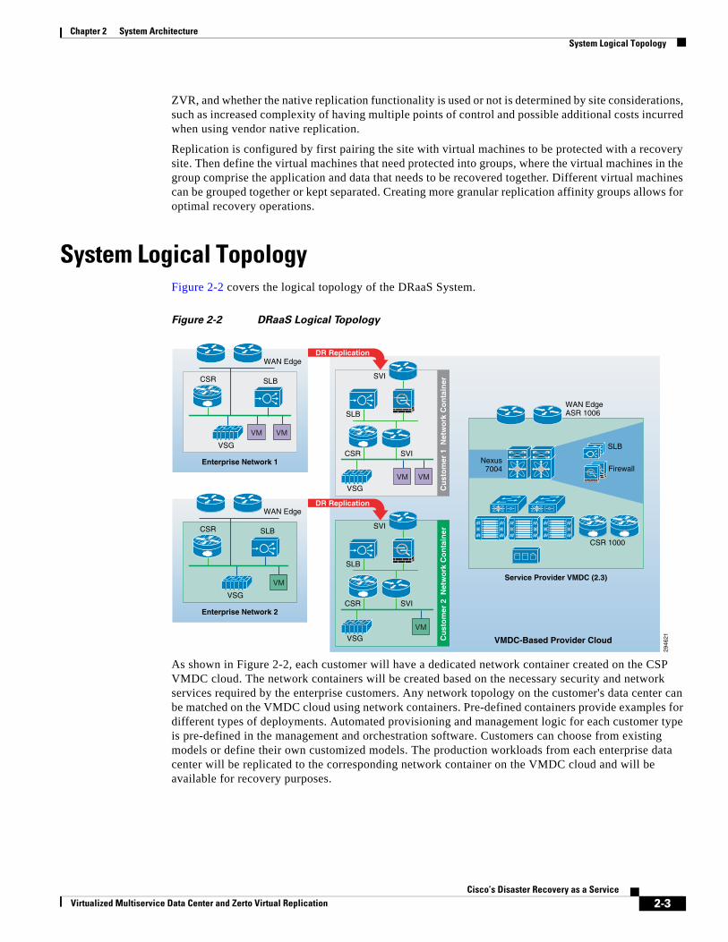
System Logical TopologyFigure 2-2 covers the logical topology of the DRaaS System.
Figure 2-2 DRaaS Logical Topology
As shown in Figure 2-2, each customer will have a dedicated network container created on the CSP VMDC cloud. The network containers will be created based on the necessary security and network services required by the enterprise customers. Any network topology on the customer's data center can be matched on the VMDC cloud using network containers. Pre-defined containers provide examples for different types of deployments. Automated provisioning and management logic for each customer type is pre-defined in the management and orchestration software. Customers can choose from existing models or define their own customized models. The production workloads from each enterprise data center will be replicated to the corresponding network container on the VMDC cloud and will be available for recovery purposes.
2946
21VMDC-Based Provider Cloud
Cu
sto
mer
1 N
etw
ork
Co
nta
iner
VSG
SLB
CSR SVI
SVI
Enterprise Network 2
CSR
VSG
SLB
WAN Edge
VM
Cu
sto
mer
2 N
etw
ork
Co
nta
iner
VSG
SLB
CSR SVI
SVI
WAN EdgeASR 1006
FirewallNexus
7004
SLB
Service Provider VMDC (2.3)
VM VM
VM
CSR 1000
DR Replication
DR Replication
Enterprise Network 1
CSR
VSG
SLB
WAN Edge
VM VM
2-3Cisco’s Disaster Recovery as a Service
Virtualized Multiservice Data Center and Zerto Virtual Replication
Chapter 2 System Architecture End-to-End Architecture
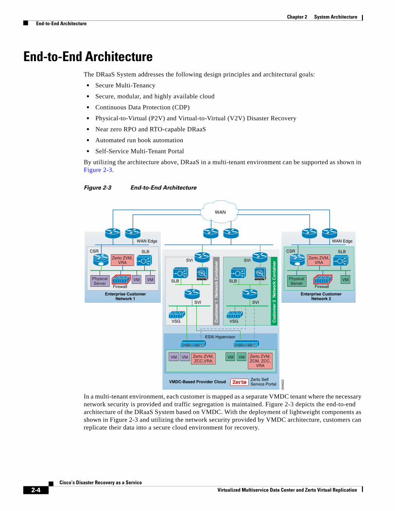
End-to-End ArchitectureThe DRaaS System addresses the following design principles and architectural goals:
• Secure Multi-Tenancy
• Secure, modular, and highly available cloud
• Continuous Data Protection (CDP)
• Physical-to-Virtual (P2V) and Virtual-to-Virtual (V2V) Disaster Recovery
• Near zero RPO and RTO-capable DRaaS
• Automated run book automation
• Self-Service Multi-Tenant Portal
By utilizing the architecture above, DRaaS in a multi-tenant environment can be supported as shown in Figure 2-3.
Figure 2-3 End-to-End Architecture
In a multi-tenant environment, each customer is mapped as a separate VMDC tenant where the necessary network security is provided and traffic segregation is maintained. Figure 2-3 depicts the end-to-end architecture of the DRaaS System based on VMDC. With the deployment of lightweight components as shown in Figure 2-3 and utilizing the network security provided by VMDC architecture, customers can replicate their data into a secure cloud environment for recovery.
2946
22
Enterprise CustomerNetwork 1
VMDC-Based Provider Cloud
Firewall
WAN
WAN Edge
VMPhysicalServer
VM
VM VM
Cu
sto
mer
1 N
etw
ork
Co
nta
iner
VSG
SLB
SVI
SVI
Enterprise CustomerNetwork 2
CSR
Firewall
SLB
WAN Edge
PhysicalServer
Zerto ZVM,VRA
Zerto ZVM,ZCM, ZCC,
VRA
Zerto ZVM,ZCC,VRA
VM
CSR SLB
Zerto ZVM,VRA
Cu
sto
mer
2 N
etw
ork
Co
nta
iner
VSG
SLB
SVI
SVI
ESXi Hypervisor
Zerto SelfService Portal
VM VM
2-4Cisco’s Disaster Recovery as a Service
Virtualized Multiservice Data Center and Zerto Virtual Replication
Chapter 2 System Architecture DRaaS Operational Workflows
Data changes are collected from the production servers as they occur, directly in memory before they are written to disk, and sent to a software appliance within an enterprise data center. Because of this approach, absolutely no additional I/O load is induced on production servers due to replication. The appliance is responsible for further offloading compute-intensive tasks from production systems, such as compression, encryption, WAN acceleration, and consolidated bandwidth management.
The system provides the journal for the customer's production servers. The customers will be able to recover their environments to any point in time before the disaster occurred. The servers are not only protected from the physical disasters, but also from logical disasters due to the journal.
Application consistency is enforced at regular intervals through VSS integration on Windows and native application-specific mechanisms on Linux and Solaris systems. Application consistency is also enforced at the guest level in virtual environments running VMware vSphere. These application-consistent points are tagged by a ZVR checkpoint and journaled as part of the journal data. They can be leveraged to perform application consistent recoveries within stringent recovery time objectives.
The following use cases are covered as part of the DRaaS System and will be discussed in more detail in the following sections.
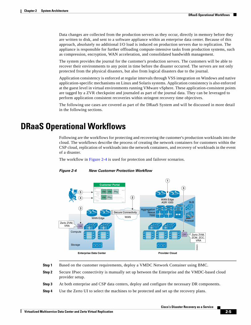
DRaaS Operational WorkflowsFollowing are the workflows for protecting and recovering the customer's production workloads into the cloud. The workflows describe the process of creating the network containers for customers within the CSP cloud, replication of workloads into the network containers, and recovery of workloads in the event of a disaster.
The workflow in Figure 2-4 is used for protection and failover scenarios.
Figure 2-4 New Customer Protection Workflow
Step 1 Based on the customer requirements, deploy a VMDC Network Container using BMC.
Step 2 Secure IPsec connectivity is manually set up between the Enterprise and the VMDC-based cloud provider setup.
Step 3 At both enterprise and CSP data centers, deploy and configure the necessary DR components.
Step 4 Use the Zerto UI to select the machines to be protected and set up the recovery plans.
2946
23
Enterprise Data Center
Compute
Storage
WAN EdgeASR 1000
WAN EdgeFirewall
AggregationNexus
7000
SLB
Provider Cloud
Customer Portal
WAN
Secure Connectivity
3
2
1
5
4
VM
DR
DR
VM Phy
VM Phy
Zerto ZVM, VRA
Zerto ZVM, ZCM, ZCC,
VRA
3
2-5Cisco’s Disaster Recovery as a Service
Virtualized Multiservice Data Center and Zerto Virtual Replication
Chapter 2 System Architecture DRaaS Operational Workflows
Step 5 Allow customers to monitor the status of DR and RPO/RTO utilizing the Partner Product portals.
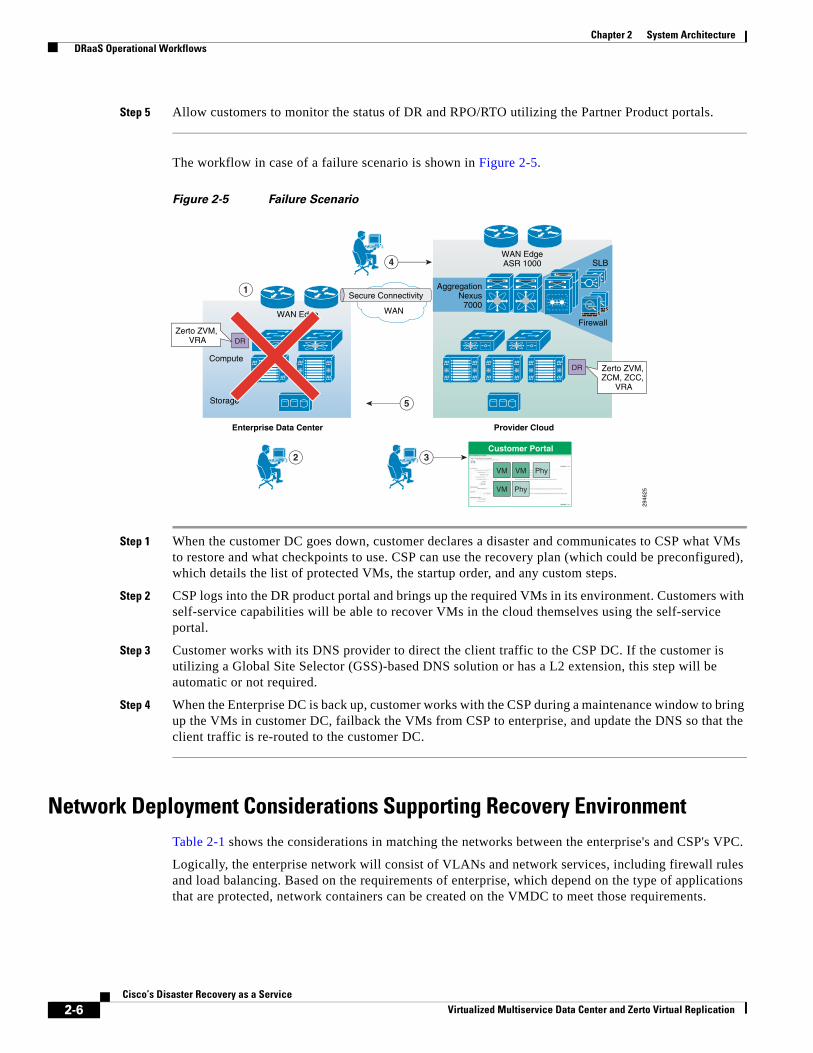
The workflow in case of a failure scenario is shown in Figure 2-5.
Figure 2-5 Failure Scenario
Step 1 When the customer DC goes down, customer declares a disaster and communicates to CSP what VMs to restore and what checkpoints to use. CSP can use the recovery plan (which could be preconfigured), which details the list of protected VMs, the startup order, and any custom steps.
Step 2 CSP logs into the DR product portal and brings up the required VMs in its environment. Customers with self-service capabilities will be able to recover VMs in the cloud themselves using the self-service portal.
Step 3 Customer works with its DNS provider to direct the client traffic to the CSP DC. If the customer is utilizing a Global Site Selector (GSS)-based DNS solution or has a L2 extension, this step will be automatic or not required.
Step 4 When the Enterprise DC is back up, customer works with the CSP during a maintenance window to bring up the VMs in customer DC, failback the VMs from CSP to enterprise, and update the DNS so that the client traffic is re-routed to the customer DC.
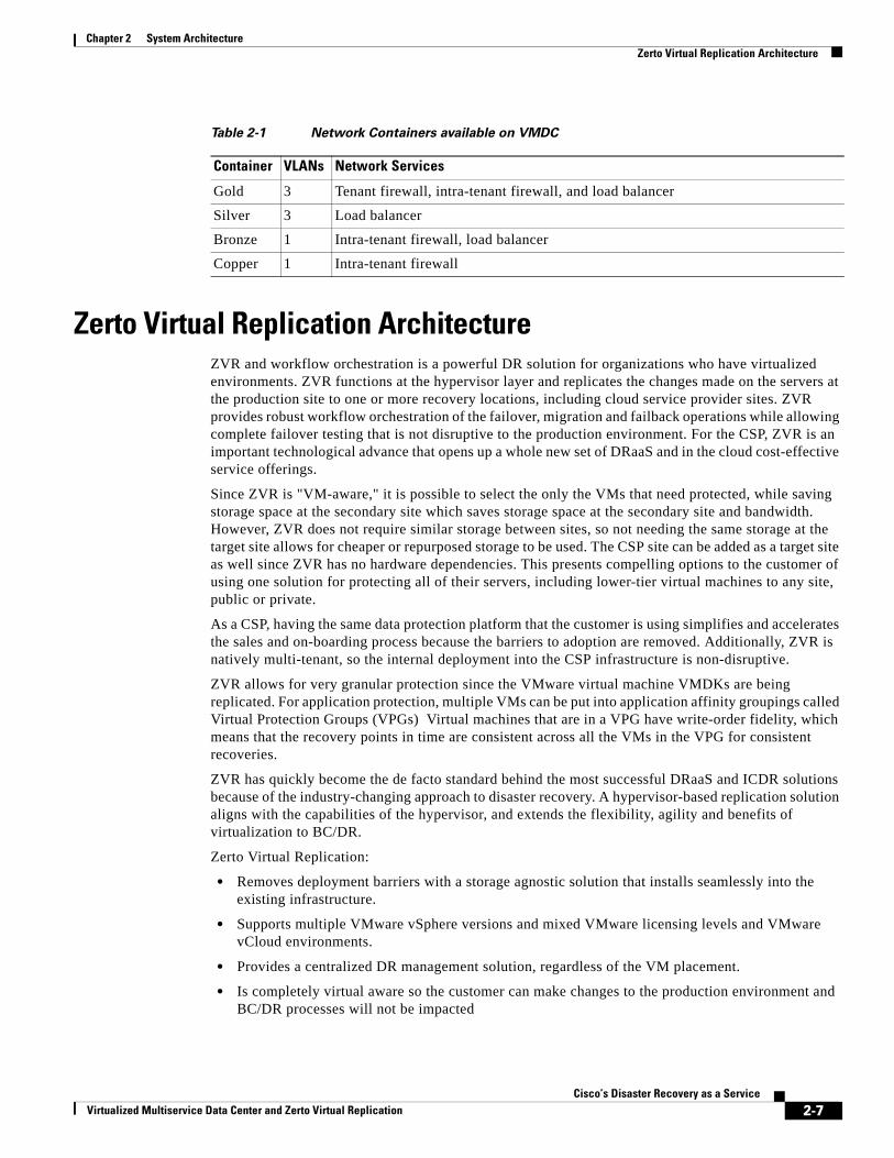
Network Deployment Considerations Supporting Recovery EnvironmentTable 2-1 shows the considerations in matching the networks between the enterprise's and CSP's VPC.
Logically, the enterprise network will consist of VLANs and network services, including firewall rules and load balancing. Based on the requirements of enterprise, which depend on the type of applications that are protected, network containers can be created on the VMDC to meet those requirements.
2946
25
Enterprise Data Center
Compute
Storage
WAN EdgeFirewall
AggregationNexus
7000
SLB
Provider Cloud
WAN
Secure Connectivity1
4
5
DR
DR
Customer Portal32
VM VM Phy
VM Phy
WAN EdgeASR 1000
Zerto ZVM, VRA
Zerto ZVM, ZCM, ZCC,
VRA
2-6Cisco’s Disaster Recovery as a Service
Virtualized Multiservice Data Center and Zerto Virtual Replication
Chapter 2 System Architecture Zerto Virtual Replication Architecture
Zerto Virtual Replication ArchitectureZVR and workflow orchestration is a powerful DR solution for organizations who have virtualized environments. ZVR functions at the hypervisor layer and replicates the changes made on the servers at the production site to one or more recovery locations, including cloud service provider sites. ZVR provides robust workflow orchestration of the failover, migration and failback operations while allowing complete failover testing that is not disruptive to the production environment. For the CSP, ZVR is an important technological advance that opens up a whole new set of DRaaS and in the cloud cost-effective service offerings.
Since ZVR is "VM-aware," it is possible to select the only the VMs that need protected, while saving storage space at the secondary site which saves storage space at the secondary site and bandwidth. However, ZVR does not require similar storage between sites, so not needing the same storage at the target site allows for cheaper or repurposed storage to be used. The CSP site can be added as a target site as well since ZVR has no hardware dependencies. This presents compelling options to the customer of using one solution for protecting all of their servers, including lower-tier virtual machines to any site, public or private.
As a CSP, having the same data protection platform that the customer is using simplifies and accelerates the sales and on-boarding process because the barriers to adoption are removed. Additionally, ZVR is natively multi-tenant, so the internal deployment into the CSP infrastructure is non-disruptive.
ZVR allows for very granular protection since the VMware virtual machine VMDKs are being replicated. For application protection, multiple VMs can be put into application affinity groupings called Virtual Protection Groups (VPGs) Virtual machines that are in a VPG have write-order fidelity, which means that the recovery points in time are consistent across all the VMs in the VPG for consistent recoveries.
ZVR has quickly become the de facto standard behind the most successful DRaaS and ICDR solutions because of the industry-changing approach to disaster recovery. A hypervisor-based replication solution aligns with the capabilities of the hypervisor, and extends the flexibility, agility and benefits of virtualization to BC/DR.
Zerto Virtual Replication:
• Removes deployment barriers with a storage agnostic solution that installs seamlessly into the existing infrastructure.
• Supports multiple VMware vSphere versions and mixed VMware licensing levels and VMware vCloud environments.
• Provides a centralized DR management solution, regardless of the VM placement.
• Is completely virtual aware so the customer can make changes to the production environment and BC/DR processes will not be impacted
Table 2-1 Network Containers available on VMDC
Container VLANs Network Services
Gold 3 Tenant firewall, intra-tenant firewall, and load balancer
Silver 3 Load balancer
Bronze 1 Intra-tenant firewall, load balancer
Copper 1 Intra-tenant firewall
2-7Cisco’s Disaster Recovery as a Service
Virtualized Multiservice Data Center and Zerto Virtual Replication
Chapter 2 System Architecture Zerto Virtual Replication Architecture
• Enables hybrid cloud services. Virtual machine portability between private and public clouds is simple with very low recovery times when using ZVR.
• Provides the technical infrastructure for secure and segmented multi-tenant DR access
However, providing disaster recovery services is different from providing other cloud-based services.
• In a DRaaS scenario, the customer may manage and have complete control over the production data or the CSP may provide a partial or complete managed service. In either case, the CSP must ensure the availability of the data and adapt as the customers infrastructure changes.
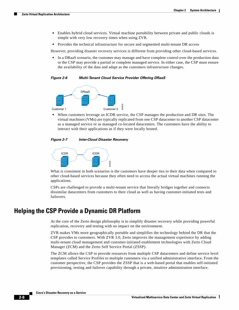
Figure 2-6 Multi-Tenant Cloud Service Provider Offering DRaaS
• When customers leverage an ICDR service, the CSP manages the production and DR sites. The virtual machines (VMs) are typically replicated from one CSP datacenter to another CSP datacenter as a managed service or as managed co-located datacenters. The customers have the ability to interact with their applications as if they were locally hosted.
Figure 2-7 Inter-Cloud Disaster Recovery
What is consistent in both scenarios is the customers have deeper ties to their data when compared to other cloud-based services because they often need to access the actual virtual machines running the applications.
CSPs are challenged to provide a multi-tenant service that literally bridges together and connects dissimilar datacenters from customers to their cloud as well as having customer-initiated tests and failovers.
Helping the CSP Provide a Dynamic DR PlatformAt the core of the Zerto design philosophy is to simplify disaster recovery while providing powerful replication, recovery and testing with no impact on the environment.
ZVR makes VMs more geographically portable and simplifies the technology behind the DR that the CSP provides to customers. With ZVR 3.0, Zerto improves the management experience by adding multi-tenant cloud management and customer-initiated enablement technologies with Zerto Cloud Manager (ZCM) and the Zerto Self Service Portal (ZSSP).
The ZCM allows the CSP to provide resources from multiple CSP datacenters and define service level templates called Service Profiles to multiple customers via a unified administrative interface. From the customer perspective, the CSP provides the ZSSP that is a web-based portal that enables self-initiated provisioning, testing and failover capability through a private, intuitive administration interface.
2946
34
DRaaS
Customer 1 Customer 229
4635
ICDR ICDR
2-8Cisco’s Disaster Recovery as a Service
Virtualized Multiservice Data Center and Zerto Virtual Replication
Chapter 2 System Architecture Zerto Virtual Replication Architecture
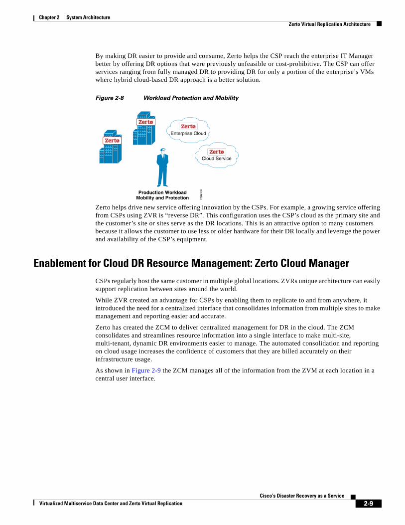
By making DR easier to provide and consume, Zerto helps the CSP reach the enterprise IT Manager better by offering DR options that were previously unfeasible or cost-prohibitive. The CSP can offer services ranging from fully managed DR to providing DR for only a portion of the enterprise’s VMs where hybrid cloud-based DR approach is a better solution.
Figure 2-8 Workload Protection and Mobility
Zerto helps drive new service offering innovation by the CSPs. For example, a growing service offering from CSPs using ZVR is “reverse DR”. This configuration uses the CSP’s cloud as the primary site and the customer’s site or sites serve as the DR locations. This is an attractive option to many customers because it allows the customer to use less or older hardware for their DR locally and leverage the power and availability of the CSP’s equipment.
Enablement for Cloud DR Resource Management: Zerto Cloud ManagerCSPs regularly host the same customer in multiple global locations. ZVRs unique architecture can easily support replication between sites around the world.
While ZVR created an advantage for CSPs by enabling them to replicate to and from anywhere, it introduced the need for a centralized interface that consolidates information from multiple sites to make management and reporting easier and accurate.
Zerto has created the ZCM to deliver centralized management for DR in the cloud. The ZCM consolidates and streamlines resource information into a single interface to make multi-site, multi-tenant, dynamic DR environments easier to manage. The automated consolidation and reporting on cloud usage increases the confidence of customers that they are billed accurately on their infrastructure usage.
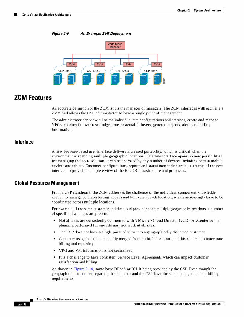
As shown in Figure 2-9 the ZCM manages all of the information from the ZVM at each location in a central user interface.
2946
36Production WorkloadMobility and Protection
Enterprise Cloud
Cloud Service
2-9Cisco’s Disaster Recovery as a Service
Virtualized Multiservice Data Center and Zerto Virtual Replication
Chapter 2 System Architecture Zerto Virtual Replication Architecture
Figure 2-9 An Example ZVR Deployment
ZCM FeaturesAn accurate definition of the ZCM is it is the manager of managers. The ZCM interfaces with each site’s ZVM and allows the CSP administrator to have a single point of management.
The administrator can view all of the individual site configurations and statuses, create and manage VPGs, conduct failover tests, migrations or actual failovers, generate reports, alerts and billing information.
Interface
A new browser-based user interface delivers increased portability, which is critical when the environment is spanning multiple geographic locations. This new interface opens up new possibilities for managing the ZVR solution. It can be accessed by any number of devices including certain mobile devices and tablets. Customer configurations, reports and status monitoring are all elements of the new interface to provide a complete view of the BC/DR infrastructure and processes.
Global Resource Management
From a CSP standpoint, the ZCM addresses the challenge of the individual component knowledge needed to manage common testing; moves and failovers at each location, which increasingly have to be coordinated across multiple locations.
For example, if the same customer and the cloud provider span multiple geographic locations, a number of specific challenges are present.
• Not all sites are consistently configured with VMware vCloud Director (vCD) or vCenter so the planning performed for one site may not work at all sites.
• The CSP does not have a single point of view into a geographically dispersed customer.
• Customer usage has to be manually merged from multiple locations and this can lead to inaccurate billing and reporting.
• VPG and VM information is not centralized.
• It is a challenge to have consistent Service Level Agreements which can impact customer satisfaction and billing
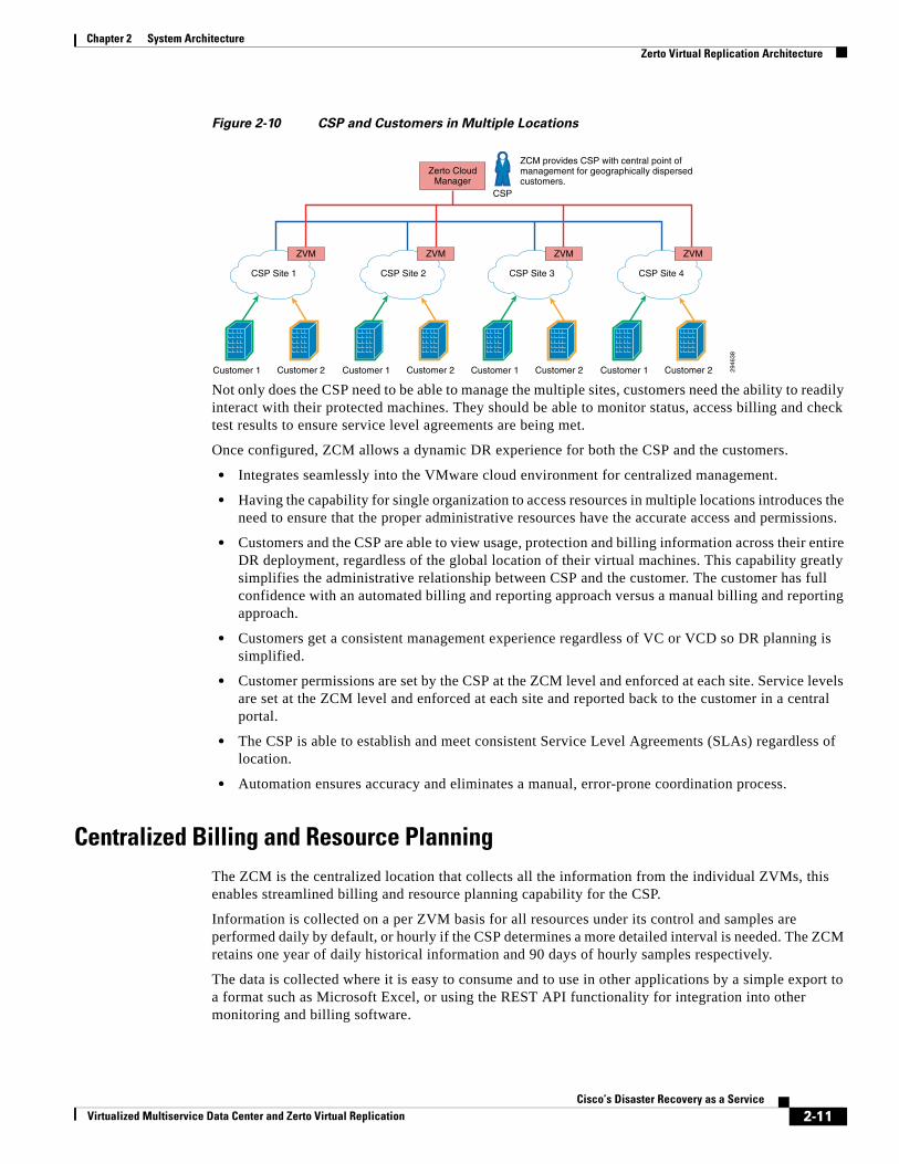
As shown in Figure 2-10, some have DRaaS or ICDR being provided by the CSP. Even though the geographic locations are separate, the customer and the CSP have the same management and billing requirements.
2946
37
CSP Site 1 CSP Site 2 CSP Site 3 CSP Site 4
ZVM ZVM ZVM
Zerto CloudManager
ZVM
2-10Cisco’s Disaster Recovery as a Service
Virtualized Multiservice Data Center and Zerto Virtual Replication
Chapter 2 System Architecture Zerto Virtual Replication Architecture
Figure 2-10 CSP and Customers in Multiple Locations
Not only does the CSP need to be able to manage the multiple sites, customers need the ability to readily interact with their protected machines. They should be able to monitor status, access billing and check test results to ensure service level agreements are being met.
Once configured, ZCM allows a dynamic DR experience for both the CSP and the customers.
• Integrates seamlessly into the VMware cloud environment for centralized management.
• Having the capability for single organization to access resources in multiple locations introduces the need to ensure that the proper administrative resources have the accurate access and permissions.
• Customers and the CSP are able to view usage, protection and billing information across their entire DR deployment, regardless of the global location of their virtual machines. This capability greatly simplifies the administrative relationship between CSP and the customer. The customer has full confidence with an automated billing and reporting approach versus a manual billing and reporting approach.
• Customers get a consistent management experience regardless of VC or VCD so DR planning is simplified.
• Customer permissions are set by the CSP at the ZCM level and enforced at each site. Service levels are set at the ZCM level and enforced at each site and reported back to the customer in a central portal.
• The CSP is able to establish and meet consistent Service Level Agreements (SLAs) regardless of location.
• Automation ensures accuracy and eliminates a manual, error-prone coordination process.
Centralized Billing and Resource PlanningThe ZCM is the centralized location that collects all the information from the individual ZVMs, this enables streamlined billing and resource planning capability for the CSP.
Information is collected on a per ZVM basis for all resources under its control and samples are performed daily by default, or hourly if the CSP determines a more detailed interval is needed. The ZCM retains one year of daily historical information and 90 days of hourly samples respectively.
The data is collected where it is easy to consume and to use in other applications by a simple export to a format such as Microsoft Excel, or using the REST API functionality for integration into other monitoring and billing software.
2946
38
CSP Site 1
ZVM ZVM ZVM ZVM
Customer 1 Customer 2
ZCM provides CSP with central point of management for geographically dispersed customers.
CSP Site 2
Customer 1 Customer 2
CSP Site 3
Customer 1 Customer 2
CSP Site 4
Customer 1 Customer 2
CSP
Zerto CloudManager
2-11Cisco’s Disaster Recovery as a Service
Virtualized Multiservice Data Center and Zerto Virtual Replication
Chapter 2 System Architecture Zerto Virtual Replication Architecture
Detailed information is available, such as the number of protected VMs, the exact storage and bandwidth consumed by the VMs on an ongoing basis, and if SLAs are being met. Other information such as if the CSP is billing based on resource reservations or consumption such as memory and CPU is also available. Using the monitoring and billing metrics assists in accurate capacity planning by tracking the historical growth rate of the customer resource usage.
Centralized Reporting
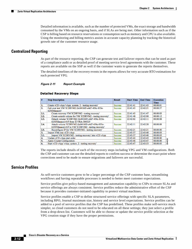
As part of the resource reporting, the CSP can generate test and failover reports that can be used as part of a compliance audit or as detailed proof of meeting service level agreements with the customer. These reports are available on the SSP as well if the customer wants to generate the reports themselves.
The detailed timelines of the recovery events in the reports allows for very accurate RTO estimations for each protected VPG.
Figure 2-11 Report Example
The reports include details of each of the recovery steps including VPG and VM configurations. Both the CSP and customer can use the detailed reports to confirm success or determine the exact point where corrections need to be made to ensure migrations and failovers are successful.
Service Profiles
As self-service customers grow to be a larger percentage of the CSP customer base, streamlining workflows and having repeatable processes is needed to better meet customer expectations.
Service profiles give policy-based management and automation capability to CSPs to ensure SLAs and service offerings are always consistent. Service profiles reduce the administrative effort of the CSP because it provides customer-initiated capability to protect virtual machines.
Service profiles enable a CSP to define structured service offerings with specific SLA parameters, including RPO, Journal maximum size, history and service level expectations. Service profiles can be added to a pool of service profiles that the CSP has predefined. These profiles make self-service much simpler, so cloud customers do not need to be educated on all these settings; they just select a profile from a drop-down list. Customers will be able to choose or update the service profile selection at the VPG creation stage if they have the proper permissions.
2-12Cisco’s Disaster Recovery as a Service
Virtualized Multiservice Data Center and Zerto Virtual Replication
Chapter 2 System Architecture Zerto Virtual Replication Architecture
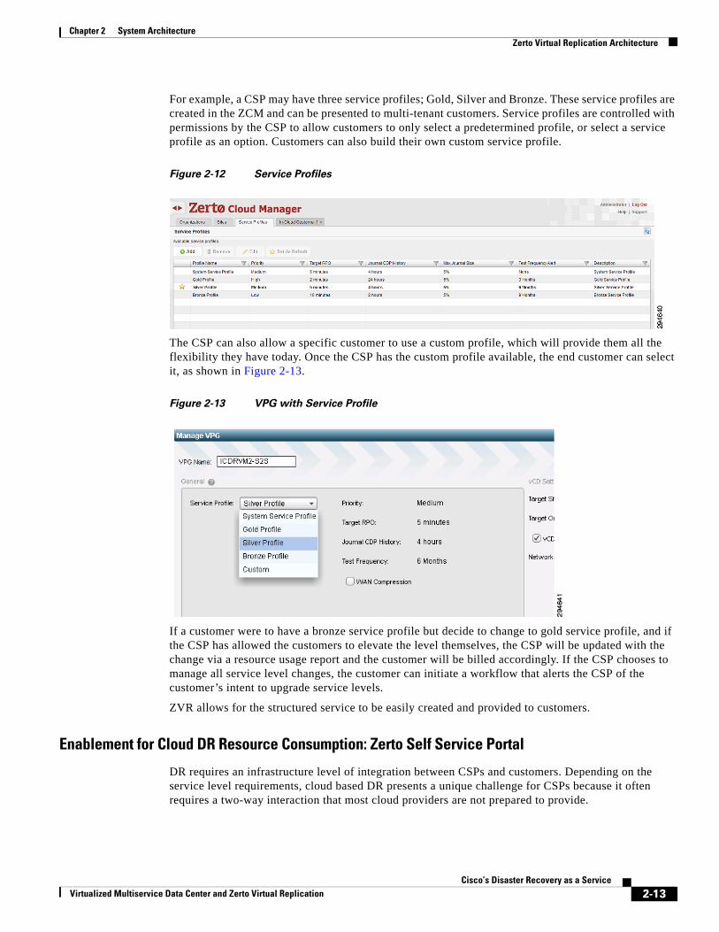
For example, a CSP may have three service profiles; Gold, Silver and Bronze. These service profiles are created in the ZCM and can be presented to multi-tenant customers. Service profiles are controlled with permissions by the CSP to allow customers to only select a predetermined profile, or select a service profile as an option. Customers can also build their own custom service profile.
Figure 2-12 Service Profiles
The CSP can also allow a specific customer to use a custom profile, which will provide them all the flexibility they have today. Once the CSP has the custom profile available, the end customer can select it, as shown in Figure 2-13.
Figure 2-13 VPG with Service Profile
If a customer were to have a bronze service profile but decide to change to gold service profile, and if the CSP has allowed the customers to elevate the level themselves, the CSP will be updated with the change via a resource usage report and the customer will be billed accordingly. If the CSP chooses to manage all service level changes, the customer can initiate a workflow that alerts the CSP of the customer’s intent to upgrade service levels.
ZVR allows for the structured service to be easily created and provided to customers.
Enablement for Cloud DR Resource Consumption: Zerto Self Service Portal
DR requires an infrastructure level of integration between CSPs and customers. Depending on the service level requirements, cloud based DR presents a unique challenge for CSPs because it often requires a two-way interaction that most cloud providers are not prepared to provide.
2-13Cisco’s Disaster Recovery as a Service
Virtualized Multiservice Data Center and Zerto Virtual Replication
Chapter 2 System Architecture Zerto Virtual Replication Architecture
When customers want a fully managed service, the CSP manages both sides of the DR as their own administrative resources can readily meet that need. However, when customers want a more interactive hybrid DR service that requires both CSP and the customer having infrastructure level administrative access, the CSP often has to create a customized DR portal to meet the customer access needs.
To help CSPs overcome the challenge of having to develop a custom portal just for DR, Zerto created the Zerto Self Service Portal (ZSSP). The ZSSP gives customers streamlined access to administrative functions and provides CSPs a way to quickly deploy a complete cloud-based DR solution.
The ZSSP is designed to be an out-of-the-box DR portal solution. Having a fully functioning browser-based service portal available without a great deal of coding or scripting enables CSPs to quickly introduce DR as part of their existing portal or as a stand-alone portal. CSPs are able to quickly offer a robust DR service for faster ROI.
ZSSP Features
The ZSSP incorporates all of the APIs that were commonly requested by CSPs in production. Providing these APIs enables the CSP to rapidly roll out a more automated client experience.
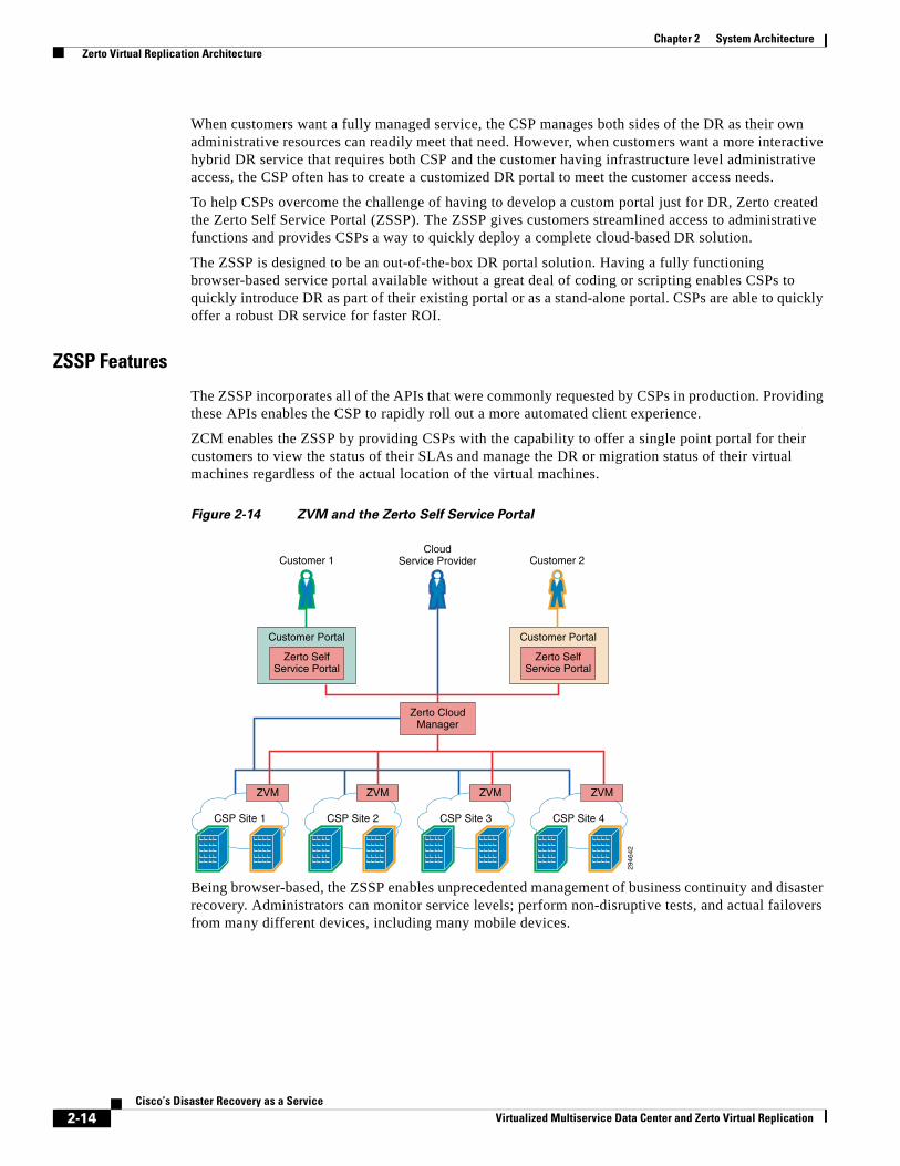
ZCM enables the ZSSP by providing CSPs with the capability to offer a single point portal for their customers to view the status of their SLAs and manage the DR or migration status of their virtual machines regardless of the actual location of the virtual machines.
Figure 2-14 ZVM and the Zerto Self Service Portal
Being browser-based, the ZSSP enables unprecedented management of business continuity and disaster recovery. Administrators can monitor service levels; perform non-disruptive tests, and actual failovers from many different devices, including many mobile devices.
2946
42
CSP Site 1 CSP Site 2 CSP Site 3 CSP Site 4
ZVM ZVM ZVM
Zerto CloudManager
Zerto SelfService Portal
Customer Portal
Zerto SelfService Portal
Customer Portal
Customer 1 Customer 2Cloud
Service Provider
ZVM
2-14Cisco’s Disaster Recovery as a Service
Virtualized Multiservice Data Center and Zerto Virtual Replication
Chapter 2 System Architecture ZCM and ZSSP Feature Summary
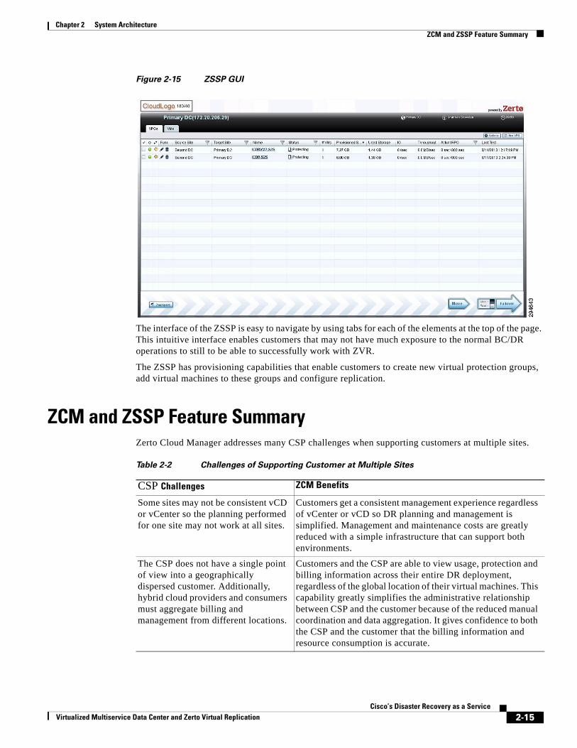
Figure 2-15 ZSSP GUI
The interface of the ZSSP is easy to navigate by using tabs for each of the elements at the top of the page. This intuitive interface enables customers that may not have much exposure to the normal BC/DR operations to still to be able to successfully work with ZVR.
The ZSSP has provisioning capabilities that enable customers to create new virtual protection groups, add virtual machines to these groups and configure replication.
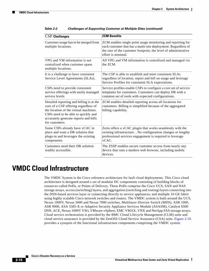
ZCM and ZSSP Feature SummaryZerto Cloud Manager addresses many CSP challenges when supporting customers at multiple sites.
Table 2-2 Challenges of Supporting Customer at Multiple Sites
CSP Challenges ZCM Benefits
Some sites may not be consistent vCD or vCenter so the planning performed for one site may not work at all sites.
Customers get a consistent management experience regardless of vCenter or vCD so DR planning and management is simplified. Management and maintenance costs are greatly reduced with a simple infrastructure that can support both environments.
The CSP does not have a single point of view into a geographically dispersed customer. Additionally, hybrid cloud providers and consumers must aggregate billing and management from different locations.
Customers and the CSP are able to view usage, protection and billing information across their entire DR deployment, regardless of the global location of their virtual machines. This capability greatly simplifies the administrative relationship between CSP and the customer because of the reduced manual coordination and data aggregation. It gives confidence to both the CSP and the customer that the billing information and resource consumption is accurate.
2-15Cisco’s Disaster Recovery as a Service
Virtualized Multiservice Data Center and Zerto Virtual Replication
Chapter 2 System Architecture VMDC Cloud Infrastructure
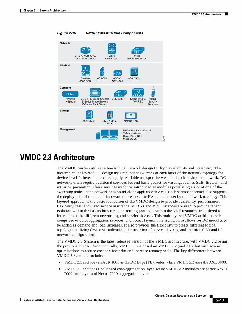
VMDC Cloud InfrastructureThe VMDC System is the Cisco reference architecture for IaaS cloud deployments. This Cisco cloud architecture is designed around a set of modular DC components consisting of building blocks of resources called PoDs, or Points of Delivery. These PoDs comprise the Cisco UCS, SAN and NAS storage arrays, access (switching) layers, and aggregation (switching and routing) layers connecting into the DSN-based services layer or connecting directly to service appliances; and multiple 10 GE fabric using highly scalable Cisco network switches and routers. The VMDC system is built around the UCS, Nexus 1000V, Nexus 5000 and Nexus 7000 switches, Multilayer Director Switch (MDS), ASR 1000, ASR 9000, ASA 5585-X or Adaptive Security Appliance Services Module (ASASM), Catalyst 6500 DSN, ACE, Nexus 1000V VSG, VMware vSphere, EMC VMAX, VNX and NetApp FAS storage arrays. Cloud service orchestration is provided by the BMC Cloud Lifecycle Management (CLM) suite and cloud service assurance is provided by the ZenOSS Cloud Service Assurance (CSA) suite. Figure 2-16 provides a synopsis of the functional infrastructure components comprising the VMDC system.
Customer usage has to be merged from multiple locations.
ZCM enables single point usage monitoring and reporting for each customer that has a multi-site deployment. Regardless of the size of the customer footprint, the level of administrative effort is minimal.
VPG and VM information is not centralized when customer spans multiple locations.
All VPG and VM information is centralized and managed via the ZCM.
It is a challenge to have consistent Service Level Agreements (SLAs).
The CSP is able to establish and meet consistent SLAs regardless of location, report and bill on usage and leverage Service Profiles for consistent SLA expectations.
CSPs need to provide consistent service offerings with easily managed service levels
Service profiles enable CSPs to configure a core set of service templates for customers. Customers can deploy DR with a common set of tools with expected configurations.
Detailed reporting and billing is at the core of a CSP offering regardless of the location of the virtual machines. CSPs need to be able to quickly and accurately generate reports and bills for customers.
ZCM enables detailed reporting across all locations for customers. Billing is simplified because of the aggregated billing capability.
Some CSPs already have vCAC in place and want a DR solution that plugs-in and leverages the existing components.
Zerto offers a vCAC plugin that works seamlessly with the existing infrastructure. . No configuration changes or lengthy professional services engagement is required to leverage vCAC.
Customers need their DR solution readily accessible.
The ZSSP enables secure customer access from nearly any device that runs a modern web browser, including mobile devices.
Table 2-2 Challenges of Supporting Customer at Multiple Sites (continued)
CSP Challenges ZCM Benefits
2-16Cisco’s Disaster Recovery as a Service
Virtualized Multiservice Data Center and Zerto Virtual Replication
Chapter 2 System Architecture VMDC 2.3 Architecture
Figure 2-16 VMDC Infrastructure Components
VMDC 2.3 ArchitectureThe VMDC System utilizes a hierarchical network design for high availability and scalability. The hierarchical or layered DC design uses redundant switches at each layer of the network topology for device-level failover that creates highly available transport between end nodes using the network. DC networks often require additional services beyond basic packet forwarding, such as SLB, firewall, and intrusion prevention. These services might be introduced as modules populating a slot of one of the switching nodes in the network or as stand-alone appliance devices. Each service approach also supports the deployment of redundant hardware to preserve the HA standards set by the network topology. This layered approach is the basic foundation of the VMDC design to provide scalability, performance, flexibility, resiliency, and service assurance. VLANs and VRF instances are used to provide tenant isolation within the DC architecture, and routing protocols within the VRF instances are utilized to interconnect the different networking and service devices. This multilayered VMDC architecture is comprised of core, aggregation, services, and access layers. This architecture allows for DC modules to be added as demand and load increases. It also provides the flexibility to create different logical topologies utilizing device virtualization, the insertion of service devices, and traditional L3 and L2 network configurations.
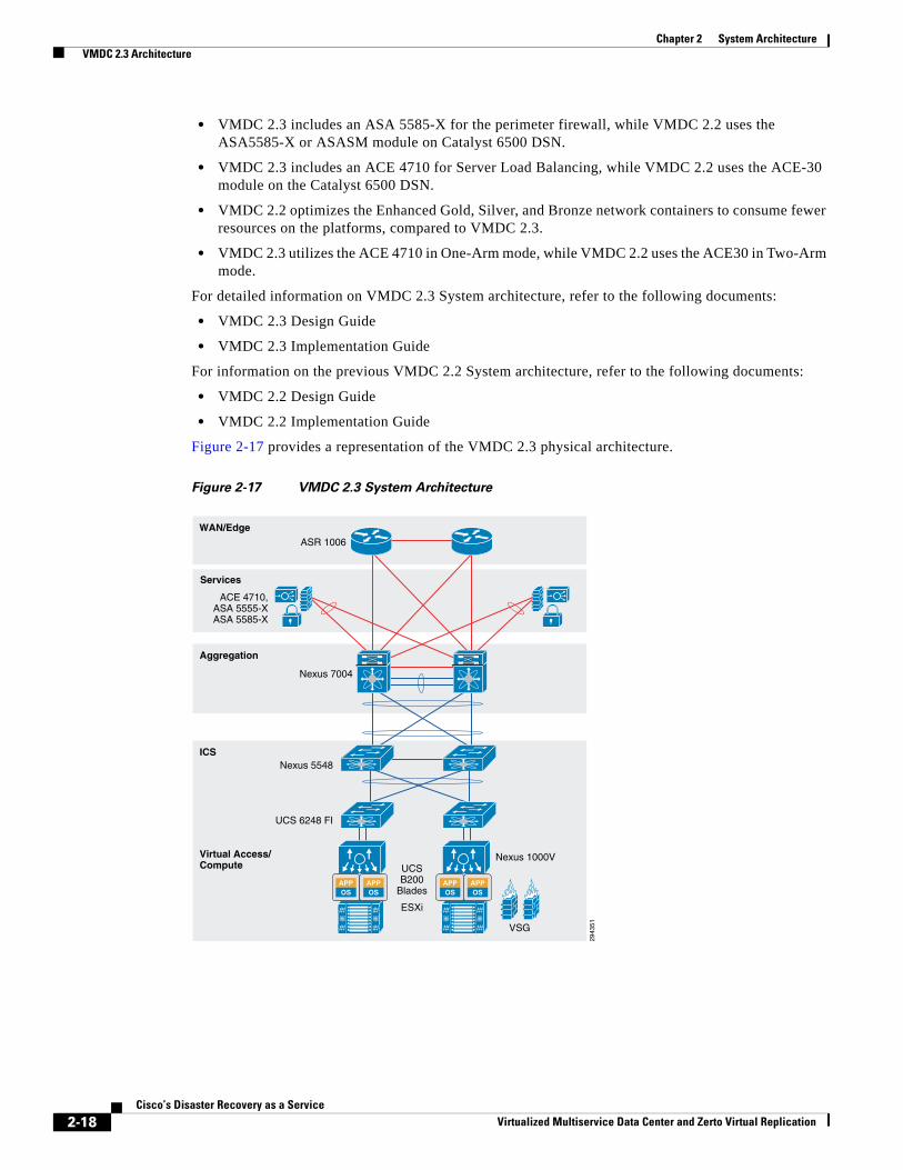
The VMDC 2.3 System is the latest released version of the VMDC architecture, with VMDC 2.2 being the previous release. Architecturally, VMDC 2.3 is based on VMDC 2.2 (and 2.0), but with several optimizations to reduce cost and footprint and increase tenancy scale. The key differences between VMDC 2.3 and 2.2 include:
• VMDC 2.3 includes an ASR 1000 as the DC Edge (PE) router, while VMDC 2.2 uses the ASR 9000.
• VMDC 2.3 includes a collapsed core/aggregation layer, while VMDC 2.2 includes a separate Nexus 7000 core layer and Nexus 7000 aggregation layers.
Services
Network
Management
Storage
CiscoNexus 7000
CRS-1, ASR 9000,ASR 1000, C7600
CiscoNexus 5000/5500
Catalyst6500 DSN
ASA-SM ACE30ACE 4700
ASA 5500
Compute
2943
50
VMwarevSphere
EMC VMAX,VNX
MDS 9500 NetApp FAS
UCS 5100 Blade ChassisB-Series Blade ServersC-Series Rack Servers
BMC CLM, ZenOSS CSA,VMware vCenter,Cisco Prime NSC,Cisco UCSM
UCS 6200 FI Nexus 1000V,VM-FEX
VirtualSecurityGateway
vSphere
2-17Cisco’s Disaster Recovery as a Service
Virtualized Multiservice Data Center and Zerto Virtual Replication
Chapter 2 System Architecture VMDC 2.3 Architecture
• VMDC 2.3 includes an ASA 5585-X for the perimeter firewall, while VMDC 2.2 uses the ASA5585-X or ASASM module on Catalyst 6500 DSN.
• VMDC 2.3 includes an ACE 4710 for Server Load Balancing, while VMDC 2.2 uses the ACE-30 module on the Catalyst 6500 DSN.
• VMDC 2.2 optimizes the Enhanced Gold, Silver, and Bronze network containers to consume fewer resources on the platforms, compared to VMDC 2.3.
• VMDC 2.3 utilizes the ACE 4710 in One-Arm mode, while VMDC 2.2 uses the ACE30 in Two-Arm mode.
For detailed information on VMDC 2.3 System architecture, refer to the following documents:
• VMDC 2.3 Design Guide
• VMDC 2.3 Implementation Guide
For information on the previous VMDC 2.2 System architecture, refer to the following documents:
• VMDC 2.2 Design Guide
• VMDC 2.2 Implementation Guide
Figure 2-17 provides a representation of the VMDC 2.3 physical architecture.
Figure 2-17 VMDC 2.3 System Architecture
APPOS
APPOS
Services
WAN/EdgeASR 1006
Nexus 7004
Nexus 5548
UCS 6248 FI
Nexus 1000VUCSB200
Blades
ESXi
VSG
ACE 4710,ASA 5555-XASA 5585-X
Aggregation
ICS
Virtual Access/Compute
2943
51
APPOS
APPOS
2-18Cisco’s Disaster Recovery as a Service
Virtualized Multiservice Data Center and Zerto Virtual Replication
Chapter 2 System Architecture VMDC 2.3 Architecture
VMDC 2.3 Modular Components The VMDC System architecture provides a scalable solution that can address the needs of Enterprise and CSP data centers. This architecture enables customers to select the design that best suits their immediate needs while providing a solution that can scale to meet future needs without retooling or redesigning the DC. This scalability is achieved using a hierarchical design with two different modular building blocks, Point of Delivery (PoD), and ICS.
Point of Delivery (PoD)
The modular DC design starts with a basic infrastructure module called a PoD. A PoD is a repeatable, physical construct with predictable infrastructure characteristics and deterministic functions. A PoD identifies a modular unit of DC components and enables customers to add network, compute, and storage resources incrementally. This modular architecture provides a predictable set of resource characteristics (network, compute, and storage resource pools, power and space consumption) per unit that are added repeatedly as needed.
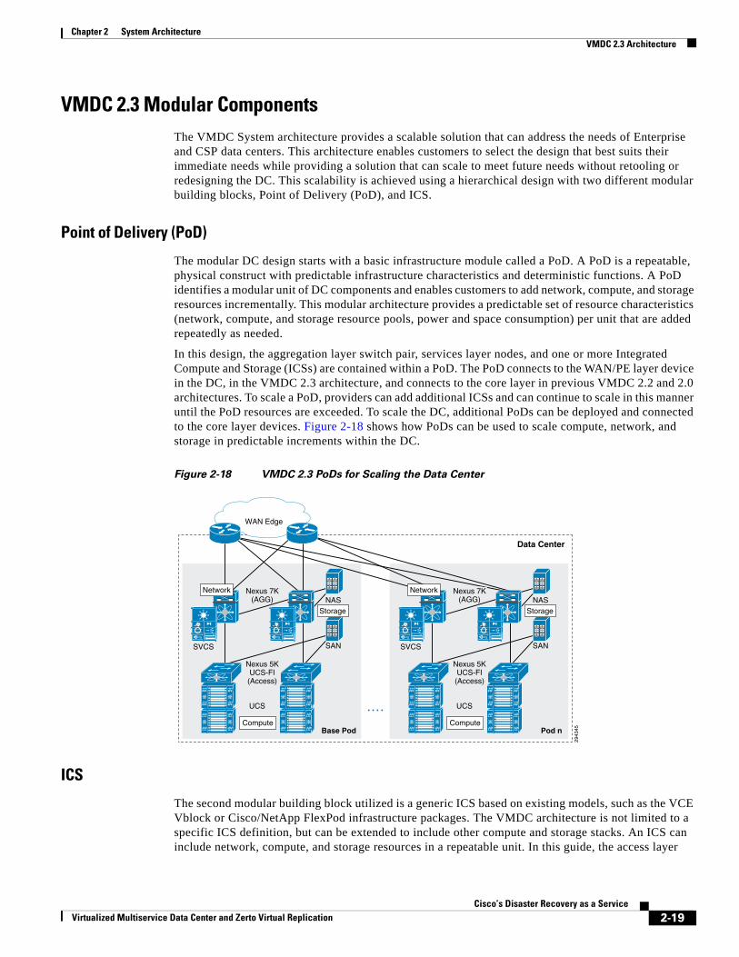
In this design, the aggregation layer switch pair, services layer nodes, and one or more Integrated Compute and Storage (ICSs) are contained within a PoD. The PoD connects to the WAN/PE layer device in the DC, in the VMDC 2.3 architecture, and connects to the core layer in previous VMDC 2.2 and 2.0 architectures. To scale a PoD, providers can add additional ICSs and can continue to scale in this manner until the PoD resources are exceeded. To scale the DC, additional PoDs can be deployed and connected to the core layer devices. Figure 2-18 shows how PoDs can be used to scale compute, network, and storage in predictable increments within the DC.
Figure 2-18 VMDC 2.3 PoDs for Scaling the Data Center
ICS
The second modular building block utilized is a generic ICS based on existing models, such as the VCE Vblock or Cisco/NetApp FlexPod infrastructure packages. The VMDC architecture is not limited to a specific ICS definition, but can be extended to include other compute and storage stacks. An ICS can include network, compute, and storage resources in a repeatable unit. In this guide, the access layer
Base Pod
Data Center
2943
45
SANSVCS
UCS
Nexus 5KUCS-FI(Access)
Nexus 7K(AGG)
WAN Edge
NAS
Compute
Storage
Network
Pod n
SANSVCS
UCS
Nexus 5KUCS-FI
(Access)
Nexus 7K(AGG) NAS
Compute
Storage
Network
2-19Cisco’s Disaster Recovery as a Service
Virtualized Multiservice Data Center and Zerto Virtual Replication
Chapter 2 System Architecture VMDC 2.3 Network Containers
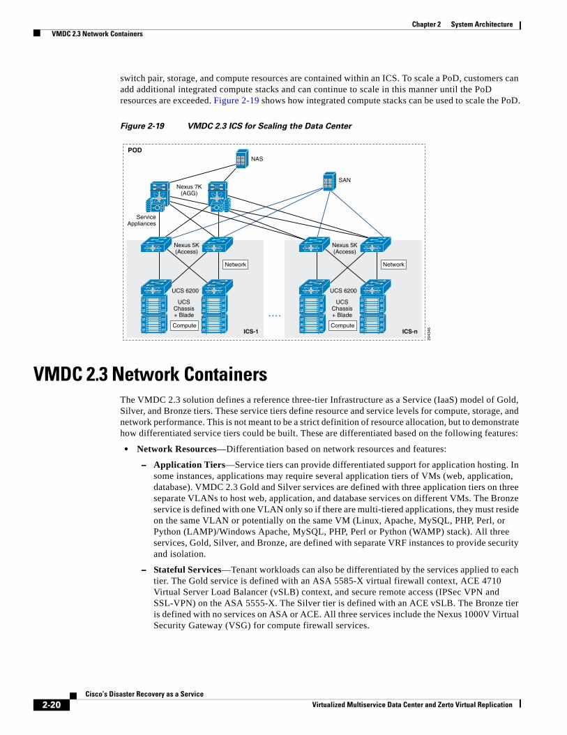
switch pair, storage, and compute resources are contained within an ICS. To scale a PoD, customers can add additional integrated compute stacks and can continue to scale in this manner until the PoD resources are exceeded. Figure 2-19 shows how integrated compute stacks can be used to scale the PoD.
Figure 2-19 VMDC 2.3 ICS for Scaling the Data Center
VMDC 2.3 Network Containers The VMDC 2.3 solution defines a reference three-tier Infrastructure as a Service (IaaS) model of Gold, Silver, and Bronze tiers. These service tiers define resource and service levels for compute, storage, and network performance. This is not meant to be a strict definition of resource allocation, but to demonstrate how differentiated service tiers could be built. These are differentiated based on the following features:
• Network Resources—Differentiation based on network resources and features:
– Application Tiers—Service tiers can provide differentiated support for application hosting. In some instances, applications may require several application tiers of VMs (web, application, database). VMDC 2.3 Gold and Silver services are defined with three application tiers on three separate VLANs to host web, application, and database services on different VMs. The Bronze service is defined with one VLAN only so if there are multi-tiered applications, they must reside on the same VLAN or potentially on the same VM (Linux, Apache, MySQL, PHP, Perl, or Python (LAMP)/Windows Apache, MySQL, PHP, Perl or Python (WAMP) stack). All three services, Gold, Silver, and Bronze, are defined with separate VRF instances to provide security and isolation.
– Stateful Services—Tenant workloads can also be differentiated by the services applied to each tier. The Gold service is defined with an ASA 5585-X virtual firewall context, ACE 4710 Virtual Server Load Balancer (vSLB) context, and secure remote access (IPSec VPN and SSL-VPN) on the ASA 5555-X. The Silver tier is defined with an ACE vSLB. The Bronze tier is defined with no services on ASA or ACE. All three services include the Nexus 1000V Virtual Security Gateway (VSG) for compute firewall services.
ICS-1
POD
2943
46
SAN
UCSChassis+ Blade
UCS 6200
Nexus 7K(AGG)
Nexus 5K(Access)
ServiceAppliances
NAS
Compute
Network
UCSChassis+ Blade
UCS 6200
Nexus 5K(Access)
Compute
Network
ICS-n
2-20Cisco’s Disaster Recovery as a Service
Virtualized Multiservice Data Center and Zerto Virtual Replication
Chapter 2 System Architecture VMDC 2.3 Network Containers
– Quality of Service (QoS)—Bandwidth control during periods of network congestion can be a key differentiator. QoS policies can provide different traffic classes to different tenant types and prioritize bandwidth by service tier. The Gold tier supports VoIP/real-time traffic, call signalling and data class, while the Silver, Bronze, and Copper tiers have only data class. Additionally, Gold and Silver tenants are given bandwidth guarantee with Gold getting more bandwidth (2x) than Silver.
• VM Resources—Service tiers can vary based on the size of specific VM attributes, such as CPU, memory, and storage capacity. The Gold service tier is defined with VM characteristics of four vCPUs and 16 GB memory. The Silver tier is defined with VMs of two vCPUs and 8 GB, while the Bronze tier VMs have one vCPU and 4 GB.
• Storage Resources—To meet data store performance objectives, service tiers can vary based on provided storage features, such as redundant array of independent disks (RAID) levels, disk types and speeds, and backup and snapshot capabilities. The Gold service is defined with 15k FC disks, Silver tier on 10k FC disks, and Bronze tier on SATA disks.
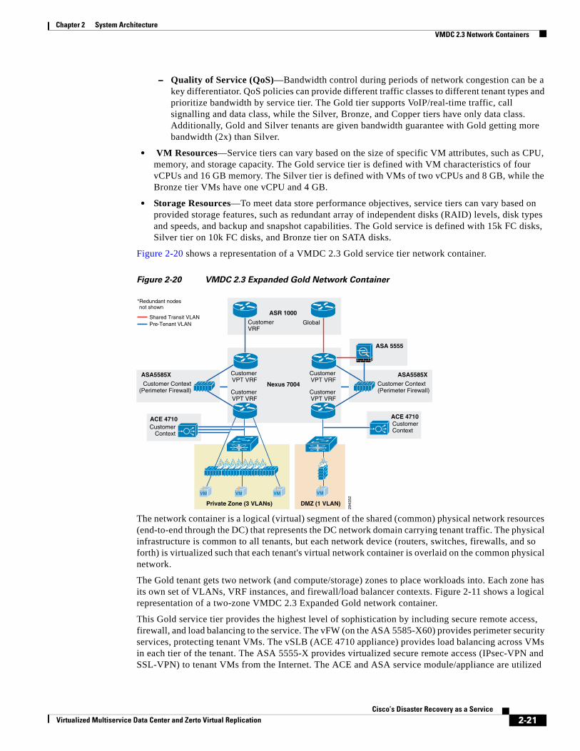
Figure 2-20 shows a representation of a VMDC 2.3 Gold service tier network container.
Figure 2-20 VMDC 2.3 Expanded Gold Network Container
The network container is a logical (virtual) segment of the shared (common) physical network resources (end-to-end through the DC) that represents the DC network domain carrying tenant traffic. The physical infrastructure is common to all tenants, but each network device (routers, switches, firewalls, and so forth) is virtualized such that each tenant's virtual network container is overlaid on the common physical network.
The Gold tenant gets two network (and compute/storage) zones to place workloads into. Each zone has its own set of VLANs, VRF instances, and firewall/load balancer contexts. Figure 2-11 shows a logical representation of a two-zone VMDC 2.3 Expanded Gold network container.
This Gold service tier provides the highest level of sophistication by including secure remote access, firewall, and load balancing to the service. The vFW (on the ASA 5585-X60) provides perimeter security services, protecting tenant VMs. The vSLB (ACE 4710 appliance) provides load balancing across VMs in each tier of the tenant. The ASA 5555-X provides virtualized secure remote access (IPsec-VPN and SSL-VPN) to tenant VMs from the Internet. The ACE and ASA service module/appliance are utilized
2943
52
Customer VPT VRF
Customer VPT VRF
Customer VPT VRF
Customer VPT VRF
CustomerVRF
Global
*Redundant nodesnot shown
ASR 1000
Nexus 7004
DMZ (1 VLAN)
VM
CustomerContext
ACE 4710
Customer Context(Perimeter Firewall)
ASA5585X
Customer Context(Perimeter Firewall)
ASA5585X
Shared Transit VLANPre-Tenant VLAN
CustomerContext
ACE 4710
Private Zone (3 VLANs)
VM VMVM
ASA 5555
2-21Cisco’s Disaster Recovery as a Service
Virtualized Multiservice Data Center and Zerto Virtual Replication
Chapter 2 System Architecture VMDC 2.3 Network Containers
in routed (L3) virtual mode in the VMDC 2.3 design. The Gold service tier also includes the Nexus 1000V VSG for providing virtual security services to the VMs. The Gold service provides higher QoS SLA and three traffic classes - real-time (VoIP), call signaling, and premium data.
The two zones can be used to host different types of applications, to be accessed through different network paths. The two zones are discussed in detail below.
• PVT Zone—The Private Zone (PVT) and its VMs can be used for cloud services to be accessed through the customer MPLS-VPN network.
– The customer sites connect to the provider MPLS-core and the customer has their own MPLS-VPN (Cust-VRF).
– The VMDC DC ASR 1000 PE connects to the customer sites through the MPLS-VPN (Cust-VRF in Figure 2-11).
– This Cust-VRF is extended through the VMDC network to the Nexus 7004 aggregation switch.
– On the agg/access Nexus 7004, the Cust-VRF connects to the ASA Cust-vFW, and then is connected back into a Cust-PVT-VRF on the Nexus 7004 agg/access device (VRF sandwich to insert service nodes), and then to the compute layer on the UCS.
– For the VMDC 2.3 Gold tenant, the PVT zone is defined with three server VLANs.
– In addition, each tenant is assigned a separate Nexus 1000V VSG instance. The tenant is defined as an ORG in the VSG (PNSC), with the three VLANs placed into separate VSG sub-zones.
– The VSG is used to provide security policies to monitor and protect traffic between the VLANs (sub-zones).
• DMZ Zone—The VMDC 2.3 Gold container supports a DMZ Zone for tenants to place VMs into a DMZ area, for isolating and securing the DMZ workloads from the PVT workloads, and also to enable users on the Internet to access the DMZ-based cloud services.
– The ASR 1000 PE WAN router is also connected to the Internet and a shared (common) VRF (usually global routing table) exists for all Gold tenants to connect to (either encrypted or unencrypted).
– Encrypted (SSL or IPsec Remote Access VPN) traffic is sent to an ASA 5555-X, and based on the VPN policy, is mapped to a particular tenant and the corresponding tenant VPN VLAN.
– The tenant VPN VLAN then connects to the tenant DMZ-vFW (different vFW context on the ASA 5585-X than the tenant PVT-vFW), then to the tenant DMZ-VRF (different VRF on the Nexus 7004 agg/access than the tenant PVT-VRF), and then to the Compute layer for the DMZ Zone.
– Similarly, unencrypted traffic from the Internet, based on the destination VM/VIP address, is sent to the tenant DMZ-vFW, then to the DMZ-vSLB, DMZ-VRF, and the DMZ Compute Zone.
– The DMZ Zone can be used to host applications like proxy servers, Internet-facing web servers, email servers, etc. The DMZ Zone consists of one server VLAN in this implementation.
In VMDC 2.3, a Gold tenant can choose to have only the PVT Zone, or both the PVT and DMZ Zones. If the tenant has both PVT and DMZ Zones, then the Gold tenant will consume three VRF instances (Cust, Cust-PVT, and Cust-DMZ) on the Nexus 7004 Agg, two VFW instances, two vSLB instances, two VSGs, and four server VLANs. To facilitate traffic flows between the DMZ and PVT Zones (for example, proxy or web servers in the DMZ Zone, application and database servers in the PVT Zone), the DMZ-vFW and PVT-vFW are interconnected. Configuring appropriate security policies (routing, NAT, firewall rule, ACLs) on the DMZ-vFW and PVT-vFW can allow or disallow communication between the two zones.
Load-balanced traffic for all tiers of Gold tenants is implemented using the ACE 4710, which has one interface in each of the tiers.
2-22Cisco’s Disaster Recovery as a Service
Virtualized Multiservice Data Center and Zerto Virtual Replication
Chapter 2 System Architecture VMDC 2.3 Network Containers
The following cloud traffic services flows can be enabled in the VMDC 2.3 two-zone Enhanced Gold service tier:
• MPLS-VPN to PVT Zone
• Unsecured (clear) Internet to DMZ Zone
• Secure (Remote Access SSL/IPsec VPN) Internet to DMZ Zone
• DMZ to PVT Zone
• MPLS-VPN to DMZ Zone
• PVT to Internet Zone is via an HTTP proxy hosted in the DMZ Zone
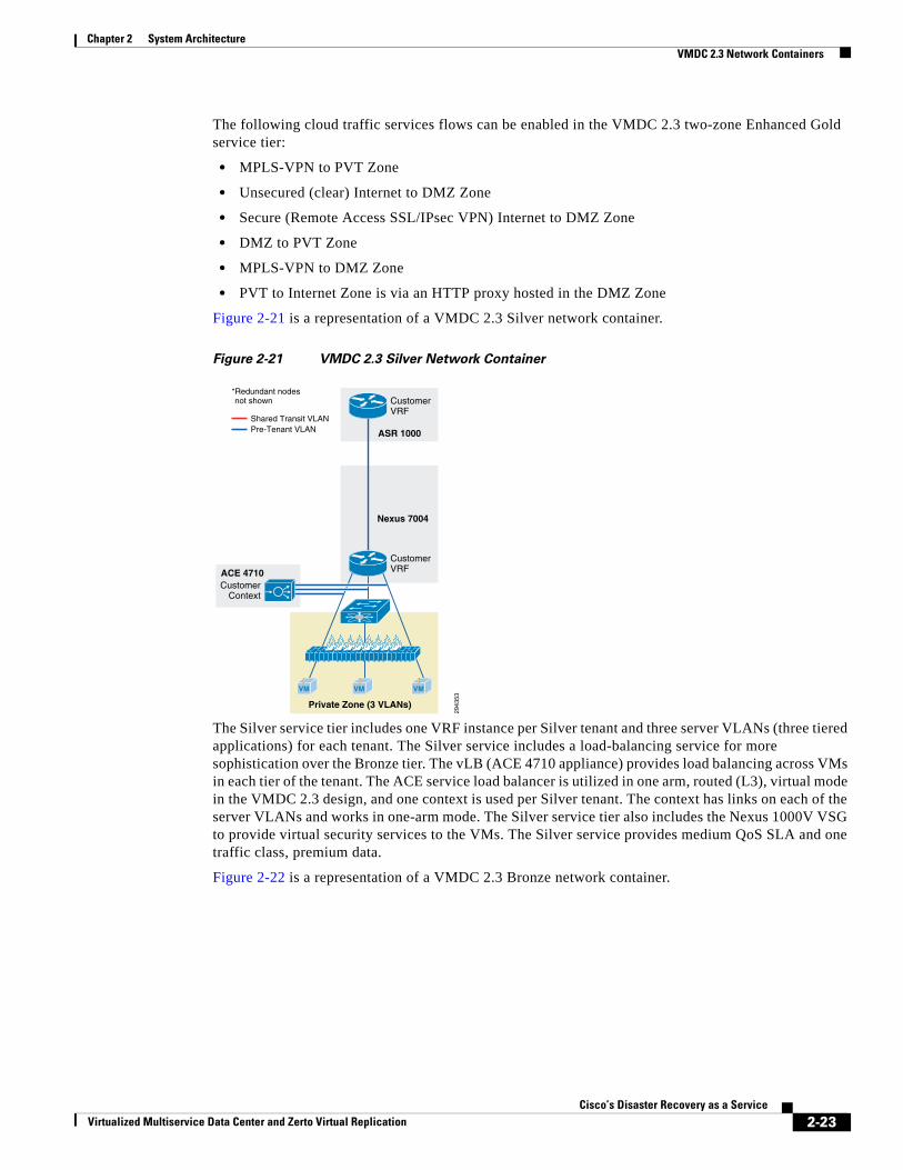
Figure 2-21 is a representation of a VMDC 2.3 Silver network container.
Figure 2-21 VMDC 2.3 Silver Network Container
The Silver service tier includes one VRF instance per Silver tenant and three server VLANs (three tiered applications) for each tenant. The Silver service includes a load-balancing service for more sophistication over the Bronze tier. The vLB (ACE 4710 appliance) provides load balancing across VMs in each tier of the tenant. The ACE service load balancer is utilized in one arm, routed (L3), virtual mode in the VMDC 2.3 design, and one context is used per Silver tenant. The context has links on each of the server VLANs and works in one-arm mode. The Silver service tier also includes the Nexus 1000V VSG to provide virtual security services to the VMs. The Silver service provides medium QoS SLA and one traffic class, premium data.
Figure 2-22 is a representation of a VMDC 2.3 Bronze network container.
CustomerContext
ACE 4710
2943
53
CustomerVRF
CustomerVRF
Private Zone (3 VLANs)
*Redundant nodesnot shown
Shared Transit VLAN
ASR 1000
Nexus 7004
VM VMVM
Pre-Tenant VLAN
2-23Cisco’s Disaster Recovery as a Service
Virtualized Multiservice Data Center and Zerto Virtual Replication
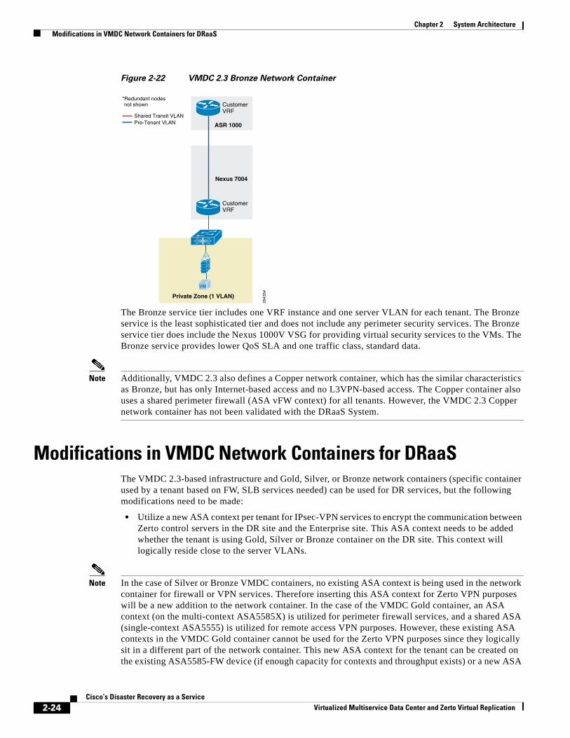
Chapter 2 System Architecture Modifications in VMDC Network Containers for DRaaS
Figure 2-22 VMDC 2.3 Bronze Network Container
The Bronze service tier includes one VRF instance and one server VLAN for each tenant. The Bronze service is the least sophisticated tier and does not include any perimeter security services. The Bronze service tier does include the Nexus 1000V VSG for providing virtual security services to the VMs. The Bronze service provides lower QoS SLA and one traffic class, standard data.
Note Additionally, VMDC 2.3 also defines a Copper network container, which has the similar characteristics as Bronze, but has only Internet-based access and no L3VPN-based access. The Copper container also uses a shared perimeter firewall (ASA vFW context) for all tenants. However, the VMDC 2.3 Copper network container has not been validated with the DRaaS System.
Modifications in VMDC Network Containers for DRaaSThe VMDC 2.3-based infrastructure and Gold, Silver, or Bronze network containers (specific container used by a tenant based on FW, SLB services needed) can be used for DR services, but the following modifications need to be made:
• Utilize a new ASA context per tenant for IPsec-VPN services to encrypt the communication between Zerto control servers in the DR site and the Enterprise site. This ASA context needs to be added whether the tenant is using Gold, Silver or Bronze container on the DR site. This context will logically reside close to the server VLANs.
Note In the case of Silver or Bronze VMDC containers, no existing ASA context is being used in the network container for firewall or VPN services. Therefore inserting this ASA context for Zerto VPN purposes will be a new addition to the network container. In the case of the VMDC Gold container, an ASA context (on the multi-context ASA5585X) is utilized for perimeter firewall services, and a shared ASA (single-context ASA5555) is utilized for remote access VPN purposes. However, these existing ASA contexts in the VMDC Gold container cannot be used for the Zerto VPN purposes since they logically sit in a different part of the network container. This new ASA context for the tenant can be created on the existing ASA5585-FW device (if enough capacity for contexts and throughput exists) or a new ASA
2943
54
CustomerVRF
CustomerVRF
Private Zone (1 VLAN)
*Redundant nodesnot shown
Shared Transit VLAN
ASR 1000
Nexus 7004
VM
Pre-Tenant VLAN
2-24Cisco’s Disaster Recovery as a Service
Virtualized Multiservice Data Center and Zerto Virtual Replication
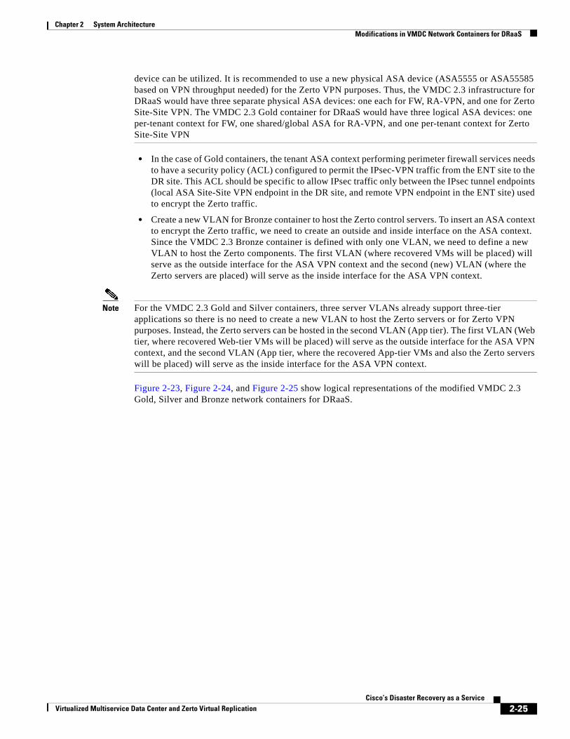
Chapter 2 System Architecture Modifications in VMDC Network Containers for DRaaS
device can be utilized. It is recommended to use a new physical ASA device (ASA5555 or ASA55585 based on VPN throughput needed) for the Zerto VPN purposes. Thus, the VMDC 2.3 infrastructure for DRaaS would have three separate physical ASA devices: one each for FW, RA-VPN, and one for Zerto Site-Site VPN. The VMDC 2.3 Gold container for DRaaS would have three logical ASA devices: one per-tenant context for FW, one shared/global ASA for RA-VPN, and one per-tenant context for Zerto Site-Site VPN
• In the case of Gold containers, the tenant ASA context performing perimeter firewall services needs to have a security policy (ACL) configured to permit the IPsec-VPN traffic from the ENT site to the DR site. This ACL should be specific to allow IPsec traffic only between the IPsec tunnel endpoints (local ASA Site-Site VPN endpoint in the DR site, and remote VPN endpoint in the ENT site) used to encrypt the Zerto traffic.
• Create a new VLAN for Bronze container to host the Zerto control servers. To insert an ASA context to encrypt the Zerto traffic, we need to create an outside and inside interface on the ASA context. Since the VMDC 2.3 Bronze container is defined with only one VLAN, we need to define a new VLAN to host the Zerto components. The first VLAN (where recovered VMs will be placed) will serve as the outside interface for the ASA VPN context and the second (new) VLAN (where the Zerto servers are placed) will serve as the inside interface for the ASA VPN context.
Note For the VMDC 2.3 Gold and Silver containers, three server VLANs already support three-tier applications so there is no need to create a new VLAN to host the Zerto servers or for Zerto VPN purposes. Instead, the Zerto servers can be hosted in the second VLAN (App tier). The first VLAN (Web tier, where recovered Web-tier VMs will be placed) will serve as the outside interface for the ASA VPN context, and the second VLAN (App tier, where the recovered App-tier VMs and also the Zerto servers will be placed) will serve as the inside interface for the ASA VPN context.
Figure 2-23, Figure 2-24, and Figure 2-25 show logical representations of the modified VMDC 2.3 Gold, Silver and Bronze network containers for DRaaS.
2-25Cisco’s Disaster Recovery as a Service
Virtualized Multiservice Data Center and Zerto Virtual Replication
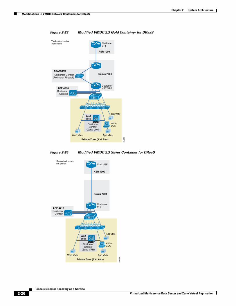
Chapter 2 System Architecture Modifications in VMDC Network Containers for DRaaS
Figure 2-23 Modified VMDC 2.3 Gold Container for DRaaS
Figure 2-24 Modified VMDC 2.3 Silver Container for DRaaS
2946
28
Customer VPT VRF
CustomerContext
(Zerto VPN)
Web VMs
ZertoZCC
CustomerVRF
Private Zone (3 VLANs)
*Redundant nodesnot shown
ASR 1000
ASA5555
Nexus 7004
VM
App VMs
VM
DB VMs
VM
CustomerContext
ACE 4710
Customer Context(Perimeter Firewall)
ASA5585X
CustomerContext
ACE 4710
2946
29
CustomerVRF
CustomerContext
(Zerto VPN)
Web VMs
ZertoZCC
Cust VRF
Private Zone (3 VLANs)
*Redundant nodesnot shown
ASR 1000
ASA5555
Nexus 7004
VM
App VMs
VM
DB VMs
VM
2-26Cisco’s Disaster Recovery as a Service
Virtualized Multiservice Data Center and Zerto Virtual Replication
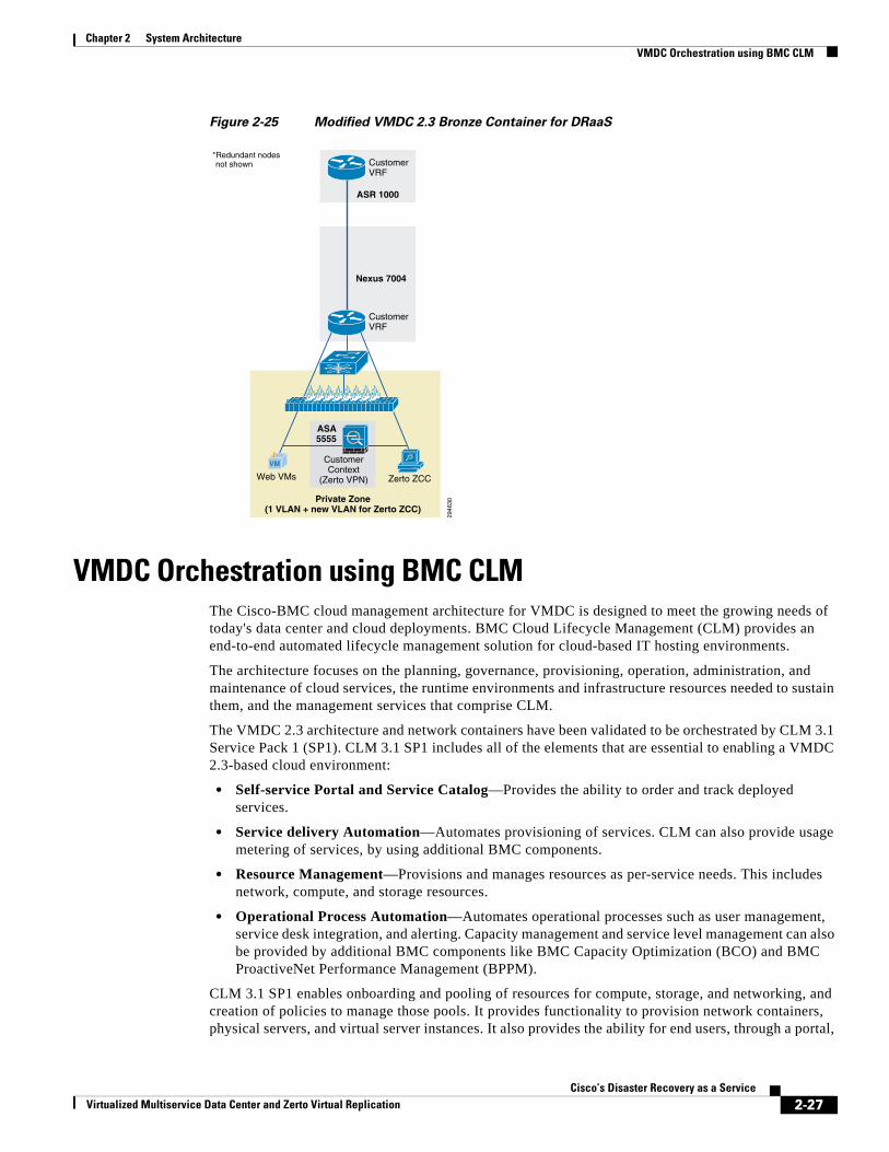
Chapter 2 System Architecture VMDC Orchestration using BMC CLM
Figure 2-25 Modified VMDC 2.3 Bronze Container for DRaaS
VMDC Orchestration using BMC CLMThe Cisco-BMC cloud management architecture for VMDC is designed to meet the growing needs of today's data center and cloud deployments. BMC Cloud Lifecycle Management (CLM) provides an end-to-end automated lifecycle management solution for cloud-based IT hosting environments.
The architecture focuses on the planning, governance, provisioning, operation, administration, and maintenance of cloud services, the runtime environments and infrastructure resources needed to sustain them, and the management services that comprise CLM.
The VMDC 2.3 architecture and network containers have been validated to be orchestrated by CLM 3.1 Service Pack 1 (SP1). CLM 3.1 SP1 includes all of the elements that are essential to enabling a VMDC 2.3-based cloud environment:
• Self-service Portal and Service Catalog—Provides the ability to order and track deployed services.
• Service delivery Automation—Automates provisioning of services. CLM can also provide usage metering of services, by using additional BMC components.
• Resource Management—Provisions and manages resources as per-service needs. This includes network, compute, and storage resources.
• Operational Process Automation—Automates operational processes such as user management, service desk integration, and alerting. Capacity management and service level management can also be provided by additional BMC components like BMC Capacity Optimization (BCO) and BMC ProactiveNet Performance Management (BPPM).
CLM 3.1 SP1 enables onboarding and pooling of resources for compute, storage, and networking, and creation of policies to manage those pools. It provides functionality to provision network containers, physical servers, and virtual server instances. It also provides the ability for end users, through a portal,
2946
30
CustomerVRF
CustomerContext
(Zerto VPN)Web VMs Zerto ZCC
CustomerVRF
Private Zone(1 VLAN + new VLAN for Zerto ZCC)
*Redundant nodesnot shown
ASR 1000
ASA5555
Nexus 7004
VM
2-27Cisco’s Disaster Recovery as a Service
Virtualized Multiservice Data Center and Zerto Virtual Replication
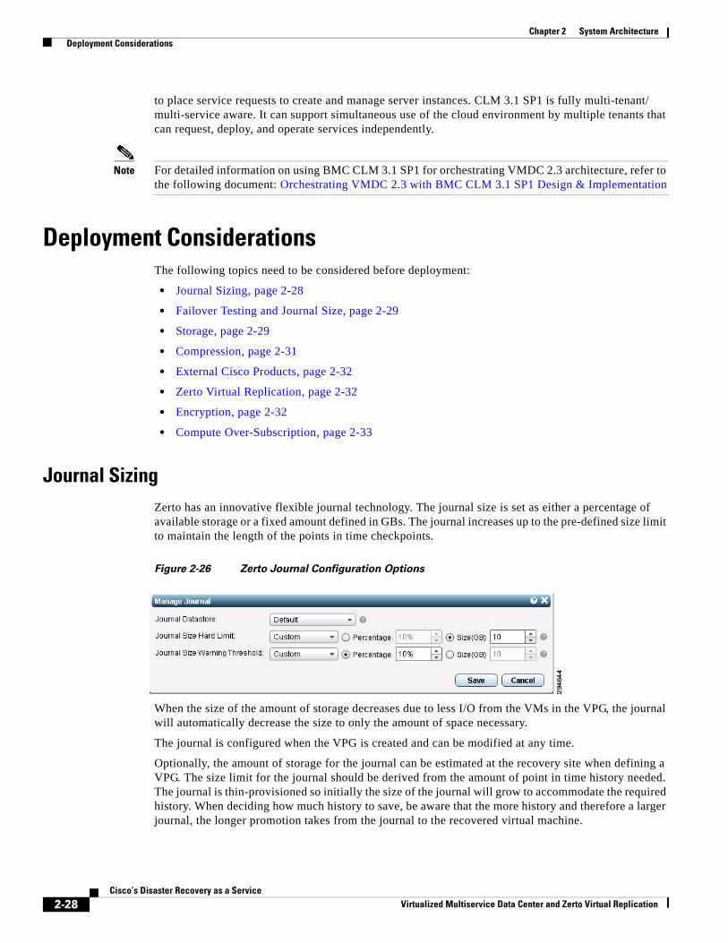
Chapter 2 System Architecture Deployment Considerations
to place service requests to create and manage server instances. CLM 3.1 SP1 is fully multi-tenant/ multi-service aware. It can support simultaneous use of the cloud environment by multiple tenants that can request, deploy, and operate services independently.
Note For detailed information on using BMC CLM 3.1 SP1 for orchestrating VMDC 2.3 architecture, refer to the following document: Orchestrating VMDC 2.3 with BMC CLM 3.1 SP1 Design & Implementation
Deployment ConsiderationsThe following topics need to be considered before deployment:
• Journal Sizing, page 2-28
• Failover Testing and Journal Size, page 2-29
• Storage, page 2-29
• Compression, page 2-31
• External Cisco Products, page 2-32
• Zerto Virtual Replication, page 2-32
• Encryption, page 2-32
• Compute Over-Subscription, page 2-33
Journal SizingZerto has an innovative flexible journal technology. The journal size is set as either a percentage of available storage or a fixed amount defined in GBs. The journal increases up to the pre-defined size limit to maintain the length of the points in time checkpoints.
Figure 2-26 Zerto Journal Configuration Options
When the size of the amount of storage decreases due to less I/O from the VMs in the VPG, the journal will automatically decrease the size to only the amount of space necessary.
The journal is configured when the VPG is created and can be modified at any time.
Optionally, the amount of storage for the journal can be estimated at the recovery site when defining a VPG. The size limit for the journal should be derived from the amount of point in time history needed. The journal is thin-provisioned so initially the size of the journal will grow to accommodate the required history. When deciding how much history to save, be aware that the more history and therefore a larger journal, the longer promotion takes from the journal to the recovered virtual machine.
2-28Cisco’s Disaster Recovery as a Service
Virtualized Multiservice Data Center and Zerto Virtual Replication
Chapter 2 System Architecture Deployment Considerations
For example, assuming the same change rate per day, a required history of four hours requires a journal size half of what is required for a history of eight hours. Thus, the larger the history, the bigger the journal size and the longer promotion take for a move or failover operation, impacting performance. If more space is required over time than available, warnings and then errors are issued, and the journal size hard limit can be increased.
The default journal size per virtual machine is unlimited. A limit of 15GB is approximately enough storage to support a virtual machine with 1TB of storage, assuming a 10% change rate per day with four hours of journal history saved. ZVR provides a Journal Sizing Tool to make a better estimation in order to more accurately define the journal size hard limit per virtual machine.
Failover Testing and Journal SizeWhen a VPG is tested, either during a failover test or before committing a Move or Failover operation, a scratch volume is created for each virtual machine being tested, with the same size limit that is defined for the journal for that virtual machine. The size limit of the scratch volume determines the length of time that you can test for. The limit for the scratch volume cannot be increased during testing. The larger the limit, the longer the testing can continue, assuming the same rate of change being tested. If the journal history required is small, for example two or three hours, and a small size hard limit is set for this amount of history, the scratch volume that is created for testing will be limited as well, limiting the time available for testing. Thus, when considering the journal size limit consider the length of time to test the VPG and specify a limit for the journal accordingly, or leave the default, which is unlimited.
StorageStorage is the main component in the DRaaS System. Proper storage sizing and deployment is very critical for delivering optimized service to customers. The following storage efficiency feature is recommended at the CSP recovery site:
• Thin Provisioning—Thin provisioning is a good method for optimizing utilization of available storage. It relies on on-demand allocation of blocks of data versus the traditional method of allocating all the blocks up front. This method eliminates all the unused space, which helps avoid poor utilization rates. The best practice is to enable thin provisioning at the storage level or at the hypervisor level to avoid management challenges. In the DRaaS System, as Zerto is capable of creating VMs using thin provisioning in the cloud, it is recommended to implement it on the hypervisor layer.
The following storage efficiency features are specific to EMC VNX when using vBlock as the ICS:
• FAST Cache—FAST Cache technology is an extension of your DRAM cache where it allocates certain flash drives to serve as FAST Cache. The benefit is that hotter data from applications running inside the VM will be copied to FAST Cache. Hence, these applications will see improved response time and throughput since the I/O is now serviced from flash drives. In DRaaS environments, FAST Cache will be useful during concurrent customer site failovers and during the on-boarding of new customers. In general, FAST Cache should be used in cases where storage performance needs to improve immediately for I/O that is burst-prone in nature.
• FAST VP—Data has a lifecycle. As data progresses through its lifecycle, it experiences varying levels of activity. When data is created, it is typically heavily used. As it ages, it is accessed less often. This is often referred to as being temporal in nature. FAST VP is a simple and elegant solution for dynamically matching storage requirements with changes in the frequency of data access. FAST
2-29Cisco’s Disaster Recovery as a Service
Virtualized Multiservice Data Center and Zerto Virtual Replication
Chapter 2 System Architecture Deployment Considerations
VP segregates disk drives into the following three tiers: Extreme Performance Tier — Flash drives; Performance Tier - Serial Attached SCSI (SAS) drives for VNX; and Capacity Tier - Near-Line SAS (NL-SAS) drives for VNX platforms.
– You can use FAST VP to aggressively reduce TCO and/or to increase performance. A target workload that requires a large number of Performance Tier drives can be serviced with a mix of tiers and a much lower drive count. In some cases, an almost two-thirds reduction in drive count is achieved. In other cases, performance throughput can double by adding less than 10 percent of a pool's total capacity in flash drives.
– FAST VP and FAST Cache can be used together to improve storage system performance. Customers with a limited number of flash drives can create FAST Cache and storage pools consisting of performance and capacity drives. For performance, FAST Cache will provide immediate benefits for any burst-prone data, while FAST VP will move warmer data to performance drives and colder data to capacity drives.
– FAST Cache is storage system aware where storage system resources are not wasted by unnecessarily copying data to FAST Cache if it is already on flash drives. If FAST VP moves a slice of data to the extreme performance tier, FAST Cache will not promote that slice into FAST Cache - even if the FAST Cache criteria is met for promotion.
– When initially deploying flash drives in a storage system, use them for FAST Cache. FAST Cache will track I/Os smaller than 128 KB and requires multiple cache hits to 64 KB chunks. This will initiate promotions from performance or capacity drives to Flash Cache and as a result, I/O profiles that do not meet this criteria are better served by flash drives in a pool or RAID group.
The following storage efficiency features are specific to NetApp when using FlexPod as an integrated stack within VMDC:
• Flash Cach—Flash Cache speeds access to data through real-time intelligent caching of recently read user data and NetApp metadata. It is effective for random read-intensive workloads, including databases, e-mail, and file services. The combination of intelligent caching and NetApp data storage efficiency technologies enables the virtual storage tier, which promotes hot data to performance media in real time without moving the data, allowing you to scale performance and capacity while achieving the highest level of storage efficiency in the industry.
• Flash Pool—Flash Pool is a technology that allows flash technology in the form of solid-state disks (SSDs) and traditional hard disk drives (HDDs) to be combined to form a single Data onTap aggregate. When SSD and HDD technologies are combined in a Data onTap aggregate, the NetApp storage system takes advantage of the latency and throughput benefits of SSD while maintaining the mass storage capacity of HDD.
– A Flash Pool is built from a Data onTap aggregate in a two-step process. Essentially, it is the addition of SSDs into an aggregate to provide a high-bandwidth, low-latency location that is capable of caching random reads and random overwrites. ** The feature does not require a license and works with any NetApp SSDs and one type of HDD per Flash Pool. That is, SSD and SAS performance drives can be combined to make a Flash Pool or SSD and SATA capacity drives can be combined to make a Flash Pool. You cannot combine SSD, SAS, and SATA into a single Flash Pool.
– As a key component of the NetApp Virtual Storage Tier, Flash Pool offers a real-time, highly efficient implementation of automated storage tiering. Fine-grain promotion of hot data elements, combined with data deduplication and thin cloning, enables optimal performance and optimal use of Flash technology.
2-30Cisco’s Disaster Recovery as a Service
Virtualized Multiservice Data Center and Zerto Virtual Replication
Chapter 2 System Architecture Deployment Considerations
• Deduplication—NetApp deduplication is an integral part of the NetApp Data onTap operating environment and the WAFL file system, which manages all data on NetApp storage systems. Deduplication works "behind the scenes," regardless of what applications you run or how you access data, and its overhead is low.
– NetApp deduplication is a key component of NetApp's storage efficiency technologies, which enable users to store the maximum amount of data for the lowest possible cost.
– NetApp deduplication is a process that can be triggered when a threshold is reached, scheduled to run when it is most convenient, or run as part of an application. It will remove duplicate blocks in a volume or LUN.
• Steady State Storage Considerations:
– FAST VP from EMC.
– Flash Pool from NetApp.
– During the steady state replication, the target storage will have the information about the I/ O characteristics and about the data blocks.
• Summary:
– Flash Cache and FAST Cache are useful in dealing with unpredicted I/O needs that can be observed during the recovery of multiple customer environments during a disaster.
– Flash Pool and FAST VP are useful efficiency features which helps the CSP to use storage space efficiently during steady state replication scenario. Warmer data gets moved to the faster drives and cold data gets moved to the capacity disks automatically.
– Deduplication and thin provisioning reduces the total storage foot print required to support customer workloads.
CompressionTo ensure efficient use of the WAN Network between sites, replication data sent from one site to another should be compressed before it is sent. This helps in reducing the WAN bandwidth required for data replication. This can be accomplished by using a dedicated external device or by the disaster recovery solution, such as the integrated compression capability available in ZVR.
ZVR can perform compression of data. This is a good option for customers who do not want to have a dedicated device for this functionality and this would be an ideal choice for customers who have fewer servers being protected.
The advantages of going with external dedicated compression appliance include:
• Provides better handling of data compression and management as it will be used only for this functionality. This offloads the processing load from disaster recovery component that does the compression.
• Dedicated compression hardware can also compress non-DR related traffic to optimize the overall WAN bandwidth usage.
• Troubleshooting of contention issues will become easier.
2-31Cisco’s Disaster Recovery as a Service
Virtualized Multiservice Data Center and Zerto Virtual Replication
Chapter 2 System Architecture External Cisco Products
External Cisco ProductsNetwork links and WAN circuits can have high latency and/or packet loss as well as limited capacity. WAN optimization devices can be used to maximize the amount of replicated data that can be transmitted over a link.
A WAN Optimization Controller (WOC) is an appliance that can be placed in-line or out-of-path to reduce and optimize the data that is to be transmitted over the WAN. These devices are designed to help mitigate the effects of packet loss, network congestion, and latency while reducing the overall amount of data to be transmitted over the network. In general, the technologies utilized in accomplishing this are TCP acceleration, data deduplication, and compression. WAN and data optimization can occur at varying layers of the OSI stack, whether they be at the network and transport layer, the session, presentation, and application layers, or just to the data (payload) itself.
Cisco wide area application services (WAAS) devices can be used for data optimization. The WAAS system consists of a set of devices called wide area application engines (WAE) that work together to optimize TCP traffic over your network. Cisco WAAS uses a variety of transport flow optimization (TFO) features to optimize TCP traffic intercepted by the WAAS devices. TFO protects communicating devices from negative WAN conditions, such as bandwidth constraints, packet loss, congestion, and retransmission. TFO includes optimization features such as compression, windows scaling, Selective ACK, increased buffering, BIC TCP, and TCP Initial Window Size Maximization.
Cisco WAAS uses Data Redundancy Elimination (DRE) and LZ compression technologies to help reduce the size of data transmitted over the WAN. These compression technologies reduce the size of transmitted data by removing redundant information before sending the shortened data stream over the WAN. By reducing the amount of transferred data, WAAS compression can reduce network utilization and application response times.
When a WAE uses compression to optimize TCP traffic, it replaces repeated data in the stream with a much shorter reference and then sends the shortened data stream out across the WAN. The receiving WAE uses its local redundancy library to reconstruct the data stream before passing it along to the destination. The WAAS compression scheme is based on a shared cache architecture where each WAE involved in compression and decompression shares the same redundancy library. When the cache that stores the redundancy library on a WAE becomes full, WAAS uses a FIFO algorithm (first in, first out) to discard old data and make room for new.
Zerto Virtual ReplicationCompression is enabled by a simple checkbox when configuring the VPG. Zerto and Cisco tested the Zerto compression capability and the results exceeded an average of at least a 50% bandwidth savings between sites, depending on the compressibility of the data. Each VRA that operates on each host in the VMware cluster is responsible for the compression. Having this distributed model of compression minimizes the CPU and RAM impact on the host system.
EncryptionEncryption of data-in-transit and data-at-rest is the best method to enforce the security and privacy of data, regardless of where it resides. Data-in-transit encryption is necessary to keep the data secure while in transit. The network connection between sites must be secure and the data must be protected. The use of IPsec or SSL to encrypt WAN connections ensures that no visibility occurs at the packet level if any of the datagrams are intercepted in transit.
2-32Cisco’s Disaster Recovery as a Service
Virtualized Multiservice Data Center and Zerto Virtual Replication
Chapter 2 System Architecture Compute Over-Subscription
ZVR does not support encryption natively. Encryption of data-in-transit between the sites can be accomplished using an external device, such as the Cisco Adaptive Security Appliance (ASA). The Cisco ASA 55xx Series is a purpose-built platform that combines superior security and VPN services for enterprise applications. The Cisco ASA 55xx Series enables customization for specific deployment environments and options, with special product editions for secure remote access (SSL/IPSec VPN).
The Cisco ASA 55xx Series SSL/IPsec VPN Edition uses network-aware IPsec site-to-site VPN capabilities. This allows customers to securely extend their networks across low-cost Internet connections to the service provider cloud.
Encryption of data-at-rest can add further security to the storage environment on the CSP's data center. Any external key manager can be used in conjunction with SAN fabrics and storage arrays to secure data-at-rest.
In the control plane, ZVR uses HTTPS to encrypt communications with other components in the system:
• Access to the ZVR management UI via the vSphere Client console.
• Communication between the Zerto Virtual Manager and the vCenter Server.
• Communication between the Zerto Virtual Manager and vCloud Connector.
• Communication between the Zerto Virtual Manager and the ESX/ESXi hosts.
Compute Over-SubscriptionDRaaS utilizes shared resources on the recovery site. Since resources at failover site sit idle most of the time, DR enables high over-subscription ratios, making it ideal for cloud environments.
The SP can have fewer compute resources compared to the customer's production environments. The compute within the CSP cloud is based on Cisco UCS servers, which can be rapidly deployed with the help of the service profiles to meet any unexpected or rare scenario where all the customers fail over to the cloud. In this scenario, new UCS servers can be deployed and added to the existing compute clusters for additional compute resource needs.
Every server that is provisioned in the Cisco UCS is specified by a service profile, which is a software definition of a server and its LAN and SAN network connectivity. In other words, a service profile defines a single server and its storage and networking characteristics. Service profiles are stored in the Cisco UCS 6xxx Series Fabric Interconnects. When a service profile is deployed to a server, UCS Manager automatically configures the server, adapters, fabric extenders, and fabric interconnects to match the configuration specified in the service profile. This automation of device configuration reduces the number of manual steps required to configure servers, network interface cards (NICs), host bus adapters (HBAs), and LAN and SAN switches.
2-33Cisco’s Disaster Recovery as a Service
Virtualized Multiservice Data Center and Zerto Virtual Replication
Chapter 2 System Architecture Compute Over-Subscription
2-34Cisco’s Disaster Recovery as a Service
Virtualized Multiservice Data Center and Zerto Virtual Replication
Virtualized Multiservice Data Center and Zerto Virtual Replication
C H A P T E R 3
Implementation and ConfigurationZVR implementation consists of configuring appropriate Zerto Components.
Before installing ZVR in the environment be sure to use the pre-installation checklists and tools provided by Zerto.
WAN Sizing Tool
When preparing a ZVM and ZCM deployment, make sure that the connectivity between the two sites has bandwidth capacity that can handle the data to be replicated between the sites.
ZVR employs sophisticated compression algorithms to reduce the bandwidth required between the sites. While compression can be very effective in reducing the bandwidth requirements, its efficiency is highly dependent on data characteristics. There are three steps to determine the WAN bandwidth requirements.
1. Enable vCenter Server data collection.
2. Collect data characteristics for VMs.
3. Use the Zerto WAN Sizing Estimator to calculate the estimated bandwidth requirements.
Disaster Recovery To the Cloud and In the CloudA CSP uses Zerto Cloud Manager to manage all the cloud sites offering disaster recovery:
• To the cloud, DR as a service (DRaaS), replicating from the customer organization to the CSP site.
• In the cloud, (ICDR) where the CSP hosts the customer’s production servers and the CSP offers disaster recover to another site or uses the customer’s site as the failover site.
Both the ZVM and ZCM must be configured. Initial configuration of Zerto Virtual Manager involves the following tasks at the cloud sites, for both DRaaS and ICDR:
1. Licensing the use of ZVR.
2. Installing Zerto VRA.
3. Set up vCloud Director, if it is being used. If DRaaS is offered, the following additional configuration of the Zerto Virtual Manager might be required.
4. Set up static routes. After completing these tasks, the CSP sets up the Zerto Cloud Manager.
5. Set up cloud sites providing DR capabilities.
6. Set up the organizations using the cloud DR services, either DRaaS or ICDR.
7. Set up service profiles, which are templates for protection.
3-1Cisco’s Disaster Recovery as a Service
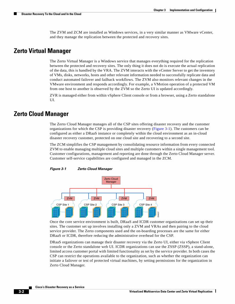
Chapter 3 Implementation and Configuration Disaster Recovery To the Cloud and In the Cloud
The ZVM and ZCM are installed as Windows services, in a very similar manner as VMware vCenter, and they manage the replication between the protected and recovery sites.
Zerto Virtual ManagerThe Zerto Virtual Manager is a Windows service that manages everything required for the replication between the protected and recovery sites. The only thing it does not do is execute the actual replication of the data, this is handled by the VRA. The ZVM interacts with the vCenter Server to get the inventory of VMs, disks, networks, hosts and other relevant information needed to successfully replicate data and conduct automated failover and failback workflows. The ZVM also monitors relevant changes in the VMware environment and responds accordingly. For example, a VMotion operation of a protected VM from one host to another is observed by the ZVM so the Zerto UI is updated accordingly.
ZVR is managed either from within vSphere Client console or from a browser, using a Zerto standalone UI.
Zerto Cloud ManagerThe Zerto Cloud Manager manages all of the CSP sites offering disaster recovery and the customer organizations for which the CSP is providing disaster recovery (Figure 3-1). The customers can be configured as either a DRaaS instance or completely within the cloud environment as an in-cloud disaster recovery customer, protected on one cloud site and recovering to a second site.
The ZCM simplifies the CSP management by consolidating resource information from every connected ZVM to enable managing multiple cloud sites and multiple customers within a single management tool. Customer configurations, management and reporting are done through the Zerto Cloud Manager server. Customer self-service capabilities are configured and managed in the ZCM.
Figure 3-1 Zerto Cloud Manager
Once the core service environment is built, DRaaS and ICDR customer organizations can set up their sites. The customer set up involves installing only a ZVM and VRAs and then pairing to the cloud service provider. The Zerto components used and the on-boarding processes are the same for either DRaaS or ICDR, therefore reducing the administrative overhead for the CSP.
DRaaS organizations can manage their disaster recovery via the Zerto UI, either via vSphere Client console or the Zerto standalone web UI. ICDR organizations can use the ZSSP (ZSSP), a stand-alone, limited access customer portal with limited functionality as set by the service provider. In both cases the CSP can restrict the operations available to the organization, such as whether the organization can initiate a failover or test of protected virtual machines, by setting permissions for the organization in Zerto Cloud Manager.
2946
37
CSP Site 1 CSP Site 2 CSP Site 3 CSP Site 4
ZVM ZVM ZVM
Zerto CloudManager
ZVM
3-2Cisco’s Disaster Recovery as a Service
Virtualized Multiservice Data Center and Zerto Virtual Replication
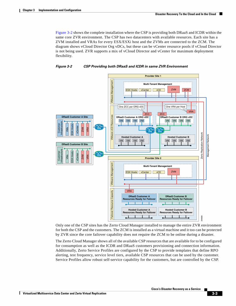
Chapter 3 Implementation and Configuration Disaster Recovery To the Cloud and In the Cloud
Figure 3-2 shows the complete installation where the CSP is providing both DRaaS and ICDR within the same core ZVR environment. The CSP has two datacenters with available resources. Each site has a ZVM installed and VRAs for every ESX/ESXi host and the ZVMs are connected to the ZCM. The diagram shows vCloud Director Org vDCs, but these can be vCenter resource pools if vCloud Director is not being used. ZVR supports a mix of vCloud Director and vCenter for maximum deployment flexibility.
Figure 3-2 CSP Providing both DRaaS and ICDR in same ZVR Environment
Only one of the CSP sites has the Zerto Cloud Manager installed to manage the entire ZVR environment for both the CSP and the customers. The ZCM is installed as a virtual machine and it too can be protected by ZVR since the core failover capability does not require the ZCM to be online during a disaster.
The Zerto Cloud Manager shows all of the available CSP resources that are available for to be configured for consumption as well as the ICDR and DRaaS customers provisioning and connection information. Additionally, Zerto Service Profiles are configured by the CSP to provide templates that define RPO alerting, test frequency, service level tiers, available CSP resources that can be used by the customer. Service Profiles allow robust self-service capability for the customers, but are controlled by the CSP.
Fai
love
r R
esou
rce
Cap
acity
VPNVPN
DRaaS Customer A Site DRaaS Customer A ORG vDC
Multi-Tenant Management
DRaaS Customer B ORG vDC
Hosted Customer A
Provider Site 1
Provider Site 2
Cus
tom
erIn
fras
truc
ture
VM
war
e vC
D R
esou
rces
VM
war
e M
anag
emen
t
VM
s
VM VM VM VM VM VM VM VM
VM VM VM VM
Hosted Customer B
VM VM VM VM
Hosted Customer AResources Ready for Failover
Hosted Customer BResources Ready for Failover
DRaaS Customer AResources Ready for Failover
DRaaS Customer BResources Ready for Failover
ZV
M
vCen
ter
ES
X H
osts
ESX Hosts
One VRA per HostOne ZCC per ORG vDC
vCenter vCD
VM
war
e M
anag
emen
t
ESX Hosts vCenter vCD
VR
A
DRaaS Customer B Site
Cus
tom
erIn
fras
truc
ture
VM
s
ZV
M
vCen
ter
ES
X H
osts
VR
A
Multi-Tenant Management
Man
agem
ent N
etw
ork
Zer
to R
eplic
atio
n N
etw
ork
2946
66
ZCC ZCCVRA
VRA
VPN
VPN
ZCMZVM
ZVM
3-3Cisco’s Disaster Recovery as a Service
Virtualized Multiservice Data Center and Zerto Virtual Replication
Chapter 3 Implementation and Configuration Disaster Recovery To the Cloud and In the Cloud
ZCM Resource ManagementSince the ZCM provides a single administration point for the CSP, both vCenter and vCloud resources can be provisioned for customer use.
Cloud Service Provider Resources ZCM enables the CSP to provision both vCloud Director and vCenter resources to customers. For vCenter, the CSP uses the vCenter Cloud Resources tab. The tab displays the vCenter resources available to the organization in editable format. When the customer connects to the provisioned resources, they are only able to use the resources allocated by the CSP.
The process is the same for both vCenter and vCloud Director to ease administrative effort for the CSP. Each cloud site is provisioned specific vCenter datastore, network and resource pools. For vCloud Director, the CSP would allocate specific ORG vDCs created for the customer in the same manner as vCenter resources. Since vCloud Director handles the specific granular vCenter resource allocation, the CSP only has to select the Org vDC in ZCM.
When configuring the CSP resources for customer use, the selected resources are displayed in a table. The following information is an example of the options available in the vCenter Cloud Resources tab:
• Cloud Site—A link to open the details of the cloud site.
• Org Name—The vCD organization name.
• Org vDC—The organization vDC.
• Max VMs—The maximum number of virtual machines the organization can recover.
• Max Storage—The maximum amount of storage the organization can recover.
In the Properties tab the site details are displayed, as described above, the Host Name and Port values can be modified. In addition, the Contact Email and Contact Phone values are also displayed. These values are defined for the site in the Zerto Virtual Manager and are useful for the customer to have readily available in the Zerto UI.
The CSP can rename the information to something useful to the organization, while hiding the internal naming conventions of the cloud site. The CSP can also limit the number of virtual machines and storage that the organization is able to protect. Figure 3-3 shows CSP resources provisioned from New York and Dallas for use by the customer. Note only specific vCenter resources are being allocated to the customer.
3-4Cisco’s Disaster Recovery as a Service
Virtualized Multiservice Data Center and Zerto Virtual Replication
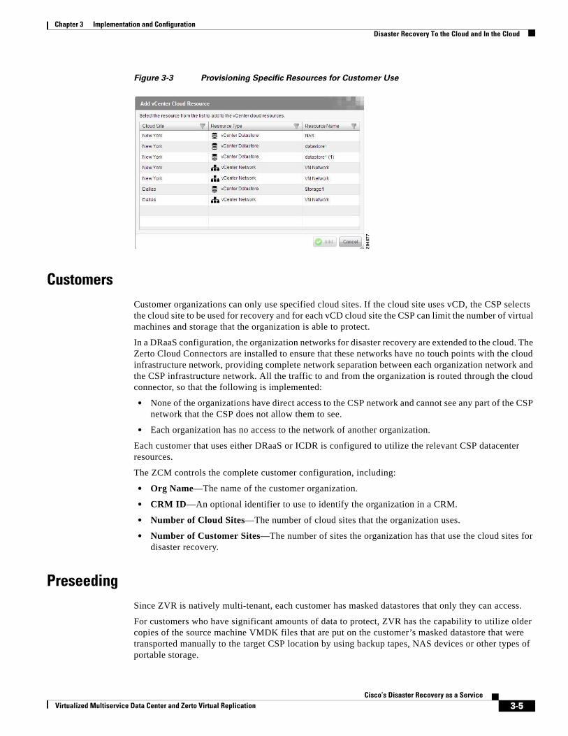
Chapter 3 Implementation and Configuration Disaster Recovery To the Cloud and In the Cloud
Figure 3-3 Provisioning Specific Resources for Customer Use
CustomersCustomer organizations can only use specified cloud sites. If the cloud site uses vCD, the CSP selects the cloud site to be used for recovery and for each vCD cloud site the CSP can limit the number of virtual machines and storage that the organization is able to protect.
In a DRaaS configuration, the organization networks for disaster recovery are extended to the cloud. The Zerto Cloud Connectors are installed to ensure that these networks have no touch points with the cloud infrastructure network, providing complete network separation between each organization network and the CSP infrastructure network. All the traffic to and from the organization is routed through the cloud connector, so that the following is implemented:
• None of the organizations have direct access to the CSP network and cannot see any part of the CSP network that the CSP does not allow them to see.
• Each organization has no access to the network of another organization.
Each customer that uses either DRaaS or ICDR is configured to utilize the relevant CSP datacenter resources.
The ZCM controls the complete customer configuration, including:
• Org Name—The name of the customer organization.
• CRM ID—An optional identifier to use to identify the organization in a CRM.
• Number of Cloud Sites—The number of cloud sites that the organization uses.
• Number of Customer Sites—The number of sites the organization has that use the cloud sites for disaster recovery.
PreseedingSince ZVR is natively multi-tenant, each customer has masked datastores that only they can access.
For customers who have significant amounts of data to protect, ZVR has the capability to utilize older copies of the source machine VMDK files that are put on the customer’s masked datastore that were transported manually to the target CSP location by using backup tapes, NAS devices or other types of portable storage.
3-5Cisco’s Disaster Recovery as a Service
Virtualized Multiservice Data Center and Zerto Virtual Replication
Chapter 3 Implementation and Configuration Disaster Recovery To the Cloud and In the Cloud
This process is called preseeding and saves a substantial amount of time and WAN bandwidth usage.
When using a preseeded VMDK, select the datastore and exact location, folder and name, of the preseeded disk. ZVR takes ownership of the preseeded disk, moving it from its source folder to the folder used by the VRA. Only disks with the same size as the protected disk can be selected when browsing for a preseeded disk. The datastore where the preseeded disk is placed is also used as the recovery datastore for the replicated data.
Role Based Permissions For CustomersThe ZCM controls the Roles and Permissions that the CSP allows for customers. The Permissions tab displays the permissions assigned by the CSP for the organization in editable format. The organization is only able to perform one of the listed actions is it is selected. If it is not selected the option to perform the action by the organization is disabled.
The following options are displayed in the permissions tab:
• Manage VPGs—When selected, the organization can create and edit virtual protection groups (VPGs) to protect groups of virtual machines together.
• Failover Test—When selected, the organization can test the failover of VPGs to verify that the disaster recovery that you have planned is the one being implemented.
• Live Failover—When selected, the organization can recover the virtual machines in a VPG after an unforeseen disaster.
• Move—When selected, the organization can migrate the virtual machines in the VPG to theremote site in a planned operation and clone VPGs. When this option is checked, organizations using the Zerto UI, either via the vSphere Client console or Zerto standalone UI can also create offsite clones. Organizations using the
• Offsite clones—Zerto Self Service Portal (ZSSP) cannot create offsite clones.
• Custom Profile—When selected, the organization can specify general settings for a VPG instead ofusing one of the provided sets of default properties when a VPG is created or edited.
Note: This permission is only relevant if the Manage VPGs permission is checked.
Service ProfilesA service profile provides a predefined set of default properties to use when VPGs are defined or edited. ZVR provides a default service profile and the option for the organization to specify their own requirements. The CSP can define service profiles to manage specific service level agreements (SLAs) with their customers.
Cloud service providers can create different service profiles for different situations and can assign one of the service profiles as the default, to be displayed when a VPG is created.
The CSP can set permissions for a customer to set their own values for the general VPG properties or limited to use a predefined Service Profile.
Service Profile values include:
1. Priority—Used to determine the priority for transferring data from the protected site to the recovery site when there is limited bandwidth and more than one VPG is defined on the protected site.
3-6Cisco’s Disaster Recovery as a Service
Virtualized Multiservice Data Center and Zerto Virtual Replication
Chapter 3 Implementation and Configuration Zerto Component Configuration
2. Target RPO—The maximum desired time in seconds between each automatic checkpoint being written to the journal. In reality checkpoints are written more frequently. During recovery, you can recover to a specific checkpoint.
3. Journal CDP History—The time for which all write commands are saved in the journal. When specifying a checkpoint to recover to, the checkpoint must still be in the journal. For example, if the value specified here is 24 hours then recovery can be specified to any checkpoint up to24 hours. After the time specified, the mirror virtual disk volumes maintained by the VRA are updated. The more time saved the more space is required for each journal in the VPG to store the information saved. If the journal is not big enough to store all the data for the time specified, as defined in the Max Journal Size field, the time frame for storing data is reduced. Note that during the start of protection, up to the configured history time, a warning is issued if the amount of history falls significantly below the time the VPG virtual machines have been protected. After the protection has continued past the configured history time, if the history falls below the configured value so that it is less than 75%, a warning is issued and if it is less than one hour, an error is issued, unless the amount of history defined is only one hour, in which case an error is issued if it is less than 45 minutes.
4. Max Journal Size—Each virtual machine in a VPG has its own journal and you can specify the maximum size allowed for each journal as a percentage of the amount of storage protected for the virtual machine rounded up to the first equal-or-higher value in the following list, all in GBs: 10, 15, 20, 25, 30, 35, 40, 45, 50, 75, 100, 150, 200, 250, 300, 400, 500 750, 1000. Thus, a value of 12%, when the virtual machine has 100GB being protected, means 12GB for the journal, which is then rounded up to 15GB. The minimum is journal size is 10GB. Each journal is defined as thin-provisioned and cannot be thick-provisioned, even SAN disk, which is natively thin-provisioned, is used.
5. Test Frequency—The time recommended between testing the integrity of the VPG. A warning is issued if a test is not done within this time frame.
6. Description—A description of the service profile.
Service profiles can be edited; however, the VPGs using the old Service Profile will use the old settings. This can be changed at the VPG level to use the new settings.
CSPs select the desired Service Profile as the default service profile to be displayed when creating a VPG. Further, if the default Service profile is the only one the CSP wants the customer to use, the CSP needs to change the customer’s permissions. The yellow star next to it identifies the default service profile.
Zerto Component ConfigurationZerto includes the following configuration components:
• License Management , page 3-7
• Zerto Virtual Replication Appliances (VRA), page 3-8
License Management To help keep customer onboarding operations as simple as possible, ZVR allows the CSP to add customers without exposing ZVR license keys to them. Since the CSP retains the Zerto license keys, a customer using a CSP to manage the disaster recovery, pairs their site to the CSP using the IP address supplied by the CSP and does not have to enter a license key. ZVR tracks the licenses being used and provides a summary in the resource usage report.
3-7Cisco’s Disaster Recovery as a Service
Virtualized Multiservice Data Center and Zerto Virtual Replication
Chapter 3 Implementation and Configuration Zerto Component Configuration
Zerto Virtual Replication Appliances (VRA)The ZVR installation includes the installation package for Virtual Replication Appliances. A VRA is a ZVR virtual machine that manages the replication of virtual machines across sites. A VRA must be installed on every ESX/ESXi which hosts virtual machines that require protecting in the protected site and on every ESX/ESXi that will host the replicated virtual machines in the recovery site.
It is recommended to install a VRA on every ESX/ESXi host in every site so that if protected virtual machines are moved from one host in the cluster to another host in the cluster there is always a VRA to protect the moved virtual machines. If you are protecting a vApp, you must install a VRA on every ESX/ESXi host in the cluster on both the protected and recovery sites and ensure that DRS is enabled for these clusters.
Zerto Virtual Manager requires specific ports to be open to install VRAs. The port list is available on the Zerto support website.
Hosts—When installing a VRA on an ESX/ESXi host, communication between the ZVM and the ESX/ESXi host IP must be available. Also, for ongoing communication between the ZVM and vCenter Server and vCloud Director, the proper ports must be open. If the ESX/ESXi hosts are given names, make sure that the Zerto Virtual Manager can resolve these names in DNS.
Installing a VRA requires that SSH is enabled on the host during the installation. After the installation SSH can be disabled. Also, before installing a VRA on an ESX/ESXi 4.0 host, make sure that the Bios UUID are set for the host.
The VRAs are installed on each host, so the host root password needed to access the host for the root user. The host passwords are used by the Zerto Virtual Manager when deploying and upgrading the VRA on a single host or all of the hosts in a cluster. Also, root access is required in case the Zerto host component is down and needs an automatic restart. The Zerto Virtual Manager checks the password is valid once a day. If the password was changed, an alert is triggered, requesting the user enter the new password.
Datastore—The datastore that the VRA will use for mirror virtual machines and for its journal. You can install more than one VRA on the same datastore.
Installing a VRA
The VRA can only be installed on ESX/ESXi hosts version 4.1 and higher. Basic information needed to install a VRA:
The network used to access the VRA in the protected site.
• If a static IP is used instead of DHCP, the IP address, subnet mask and default gateway to be used by the VRA.
• The network settings to access the peer site; either the default gateway or the IP address, subnet mask and gateway.
• A 12.5GB datastore space is required
• Allocate 3GB RAM to the VRA on the CSP side
Network—The network used to access the VRA. Zerto functions much like the VMware infrastructure by depending on the underlying network connectivity. The VMDC network connectivity is detailed in the VMDC section of this document.
Amount of VRA RAM—The amount of memory to allocate to the VRA. The amount to specify is dependent on the number of volumes being protected or recovered. Use the following table as a guideline to understand the sizing relationship of volumes and RAM for customers:
3-8Cisco’s Disaster Recovery as a Service
Virtualized Multiservice Data Center and Zerto Virtual Replication
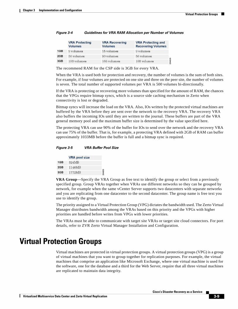
Chapter 3 Implementation and Configuration Virtual Protection Groups
Figure 3-4 Guidelines for VRA RAM Allocation per Number of Volumes
The recommend RAM for the CSP side is 3GB for every VRA.
When the VRA is used both for protection and recovery, the number of volumes is the sum of both sites. For example, if four volumes are protected on one site and three on the peer site, the number of volumes is seven. The total number of supported volumes per VRA is 500 volumes bi-directionally.
If the VRA is protecting or recovering more volumes than specified for the amount of RAM, the chances that the VPGs require bitmap syncs, which is a source side caching mechanism in Zerto when connectivity is lost or degraded.
Bitmap syncs will increase the load on the VRA. Also, IOs written by the protected virtual machines are buffered by the VRA before they are sent over the network to the recovery VRA. The recovery VRA also buffers the incoming IOs until they are written to the journal. These buffers are part of the VRA general memory pool and the maximum buffer size is determined by the value specified here.
The protecting VRA can use 90% of the buffer for IOs to send over the network and the recovery VRA can use 75% of the buffer. That is, for example, a protecting VRA defined with 2GB of RAM can buffer approximately 1033MB before the buffer is full and a bitmap sync is required.
Figure 3-5 VRA Buffer Pool Size
VRA Group—Specify the VRA Group as free text to identify the group or select from a previously specified group. Group VRAs together when VRAs use different networks so they can be grouped by network, for example when the same vCenter Server supports two datacenters with separate networks and you are replicating from one datacenter to the second datacenter. The group name is free text you use to identify the group.
The priority assigned to a Virtual Protection Group (VPG) dictates the bandwidth used. The Zerto Virtual Manager distributes bandwidth among the VRAs based on this priority and the VPGs with higher priorities are handled before writes from VPGs with lower priorities.
The VRAs must be able to communicate with target site VRAs or target site cloud connectors. For port details, refer to ZVR Zerto Virtual Manager Installation and Configuration.
Virtual Protection GroupsVirtual machines are protected in virtual protection groups. A virtual protection groups (VPG) is a group of virtual machines that you want to group together for replication purposes. For example, the virtual machines that comprise an application like Microsoft Exchange, where one virtual machine is used for the software, one for the database and a third for the Web Server, require that all three virtual machines are replicated to maintain data integrity.
3-9Cisco’s Disaster Recovery as a Service
Virtualized Multiservice Data Center and Zerto Virtual Replication
Chapter 3 Implementation and Configuration The Journal
Once a virtual machine is protected, all changes made on the machine are replicated in the remote site. The synchronization between the protected site and remote site takes time, depending on the size of the virtual machine but after that, only the writes to disk from the virtual machine in the protected site are sent to the remote site. These writes are stored by the VRA in the remote site in a journal for a specified period, after which, the old writes are promoted to the mirror virtual disk managed by the VRA.
The CSP should determine the Recovery Point Objective and Recovery Time Objective from the customer.
While ZVR will meet even the most aggressive requirements, the CSP should be aware that the customer needs to specify which one is more important, in relative terms.
The number of VPGs directly impacts the RTO due to a feature in ZVR that protects the vCenter from being overwhelmed in case of a complete site failover. If the customer needs to failover several VPGs at once, ZVR considers it a bulk operation and reduces the number of simultaneous volumes per VPG created. While this protects the vCenter from being overloaded, it adds to the recovery time. It is important to note that every environment is unique and there are tools available from Zerto and Cisco that will assist in the design planning, but as a general guideline, there are expected characteristics for failover times.
If the customer requirement is RPO focused:
• VPGs can be created to reflect the application affinity groupings.
• Larger VPGs can be created for administrative ease of use.
If the customer requirement is RTO focused:
• Fewer VPGs will recover relatively quicker than more VPGs in the case of a simultaneous failover of multiple VPGs.
• There are other considerations, such as application affinity grouping write-order fidelity to consider when designing VPGs.
VPGs can have dozens of VMs in them, with no actual limit on the number of VMs VPG, but other factors, such as application affinity grouping requirements, usually keep the number of VMs in a VPG to fewer than 50.
The JournalEvery write to a protected virtual machine is intercepted by VRA and a copy of the write is sent, asynchronously, to the recovery site, while the write continues to be processed on the protected site. On the recovery site the write is written to a journal managed by the VRA. Each protected virtual machine has its own journal.
Every few seconds, a checkpoint is also written to the journals. These checkpoints ensure write order fidelity and crash-consistency to each checkpoint. During recovery you pick one of these crash-consistent checkpoints and recover to this point. Thus, you can recover the environment to the point before any corruption and ignore the later writes in the journal that were corrupted. A corruption can be caused for example, by a crash in the protected site or for other reasons, such as a virus.
During recovery, the virtual machines at the recovery site are created and attached to the recovery disks. The information in the journal is then promoted to the virtual machines to bring them up to date. To improve the RTO during recovery, the user is able to start working even before the journal data has been fully promoted to the virtual machine volumes on the recovery. Every request is analyzed and the response returned either from the virtual machine directly or from the journal if the information in the
3-10Cisco’s Disaster Recovery as a Service
Virtualized Multiservice Data Center and Zerto Virtual Replication
Chapter 3 Implementation and Configuration Zerto Cloud Connector
journal is more up-to-date. This continues until the recovery site virtual environment is fully restored, up until, either the last checkpoint, or an earlier checkpoint, when the integrity of the protected site was assured.
A dedicated journal volume for each replicated virtual machine within a VPG allows journal data to be maintained, even when changing the target host for the recovery.
The recovery datastore should be accessible by all the target hosts and not just one of the hosts.
The journal resides on the same datastore as the recovery disk. If the datastore where the journal resides drops below 30GB or 15% of the total datastore size, whichever is the smaller of these two values, the datastore itself is considered full and an error alert is issued and all writes to journal volumes on that datastore are blocked. Replication is halted, but CDP history is not lost. As such, the RPO begins to steadily increase until space is made available on the datastore.
The Zerto Journal Sizing Tool is available from the Zerto support site and is used for the following:
• To estimate the journal size that is required.
• To estimate the total datastore size that is required for each datastore used on the recovery site.
The journal is not only tracking the individual virtual machine points in time, but is also tracking the write-order fidelity between virtual machines in a VPG. Some operations disrupt the write-order fidelity between the virtual machines where the write-order fidelity is substantially impacted. In these cases, the journal is reset. The following situations result in the journal being recreated, losing all the history:
Changing any of the following:
• The recovery datastore of a volume.
• The VPG journal datastore.
• The virtual machine recovery datastore.
Adding any of the following:
• A virtual machine to the VPG.
• A volume to a virtual machine in a VPG.
Removing any of the following:
• A virtual machine from the VPG.
• A volume from a virtual machine in a VPG.
In all these cases the journal is reset, starting with no history.
Zerto Cloud ConnectorWhen providing DRaaS, the CSP needs to ensure complete separation between the organization network and the CSP network. The CSP needs to be able to route traffic between an organization network and the cloud replication network, in a secure manner without going through complex network and routing setups.
A Zerto Cloud Connector (ZCC) is a virtual machine appliance installed on the cloud side, one for each customer organization replication network (Figure 3-6). The ZCC allows the CSP to securely isolate the replication traffic and administrative accessibility per customer.
In the Zerto Cloud Manager the CSP defines a ZCC per organization site that has two Ethernet interfaces, one to the organization’s network and one to the cloud service provider's network. Within the ZCC, a bidirectional connection is created between the customer and the CSP networks.
3-11Cisco’s Disaster Recovery as a Service
Virtualized Multiservice Data Center and Zerto Virtual Replication
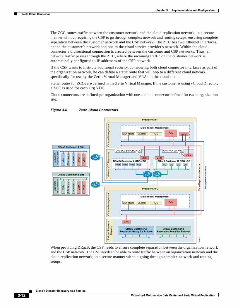
Chapter 3 Implementation and Configuration Zerto Cloud Connector
The ZCC routes traffic between the customer network and the cloud replication network, in a secure manner without requiring the CSP to go through complex network and routing setups, ensuring complete separation between the customer network and the CSP network. The ZCC has two Ethernet interfaces, one to the customer’s network and one to the cloud service provider's network. Within the cloud connector a bidirectional connection is created between the customer and CSP networks. Thus, all network traffic passes through the ZCC, where the incoming traffic on the customer network is automatically configured to IP addresses of the CSP network.
If the CSP wants to institute additional security, considering both cloud connector interfaces as part of the organization network, he can define a static route that will hop to a different cloud network, specifically for use by the Zerto Virtual Manager and VRAs in the cloud site.
Static routes for ZCCs are defined in the Zerto Virtual Manager. If the customer is using vCloud Director, a ZCC is used for each Org VDC.
Cloud connectors are defined per organization with one a cloud connector defined for each organization site.
Figure 3-6 Zerto Cloud Connectors
When providing DRaaS, the CSP needs to ensure complete separation between the organization network and the CSP network. The CSP needs to be able to route traffic between an organization network and the cloud replication network, in a secure manner without going through complex network and routing setups.
Fai
love
r R
esou
rce
Cap
acity
VPNVPN
DRaaS Customer A Site
DRaaS Customer A ORG vDC
Multi-Tenant Management
DRaaS Customer B ORG vDC
Provider Site 1
Provider Site 2
Cus
tom
erIn
fras
truc
ture
VM
war
e vC
D R
esou
rces
VM
war
e M
anag
emen
t
VM
s
VM VM VM VM VM VM VM VM
DRaaS Customer AResources Ready for Failover
DRaaS Customer BResources Ready for Failover
ZV
M
vCen
ter
ES
X H
osts
ESX Hosts vCenter vCD
VM
war
e M
anag
emen
t
ESX Hosts vCenter vCD
VR
A
DRaaS Customer B Site
Cus
tom
erIn
fras
truc
ture
VM
s
ZV
M
vCen
ter
ES
X H
osts
VR
A
Multi-Tenant Management29
4685
ZCC ZCCVRA
VRA
VPN
VPN
ZCMZVM
ZVM
One VRA per Host
Man
agem
ent N
etw
ork
Zer
to R
eplic
atio
n N
etw
ork
One ZCC per ORG vDC
3-12Cisco’s Disaster Recovery as a Service
Virtualized Multiservice Data Center and Zerto Virtual Replication
Chapter 3 Implementation and Configuration DRaaS Customer Connection
In the ZCM, the CSP can define a connector per organization site that has two Ethernet interfaces, one to the organization’s network and one to the cloud service provider's network. Within the connector a bidirectional connection is created between the organization and CSP networks. Thus, all network traffic passes through the cloud connector, where the incoming traffic on the customer network is automatically configured to IP addresses of the CSP network.
For the CSP to institute additional security, considering both cloud connector interfaces as part of the organization network, define a static route that will hop to a different cloud network, specifically for use by the Zerto Virtual Manager and VRAs in the cloud site. The hop to the Zerto Virtual Manager and VRAs in the cloud site is specified as a static route.
Use the group in the definition of a connector to reuse network settings. If the Zerto Virtual Manager network or VRA network is modified, changing the static route settings for a group to the new network changes the access for all connectors with the specified group.
DRaaS Customer ConnectionThe organization must install ZVR on a machine per vCenter where they have virtual machines that need protecting and then install VRAs and pair to the cloud service provider, using an IP address provided by the CSP.
For details refer to ZVR Zerto Virtual Manager Installation and Configuration guide on the Zerto support website.
The organization can manage their disaster recovery in one of the following ways:
• Via the Zerto standalone UI or in vSphere Client console via the Zerto tab, described in ZVR Administration Guide for Zerto Virtual Manager.
Zerto Self Service Portal—In Cloud Customer ConnectionThe ZSSP is an out-of-the-box DR portal solution with a fully functioning browser-based service portal to enable cloud service providers to quickly introduce DR as part of their portal offering.
The ZSSP is accessed by a URL that is session dependent and the connection is terminated at the end of the session and cannot be reused.
The ZSSP URL session is unique to each organization and requires the established SSL connection before it can be created. These combined requirements effectively provide multiple layers of security to ensure customer isolation.
Each organization has access to a portal specific to them (Figure 3-7). To connect to the Zerto Self Service Portal, the organization needs the following:
• An established SSL session between the cloud portal and the organization device accessing the portal.
• A unique ZSSP URL.
• In addition, if the CSP does not have a portal, it is recommended to provide an authentication wrapper on top of the ZSSP so that each organization requires a username and password to login to the Zerto Self Service Portal.
3-13Cisco’s Disaster Recovery as a Service
Virtualized Multiservice Data Center and Zerto Virtual Replication
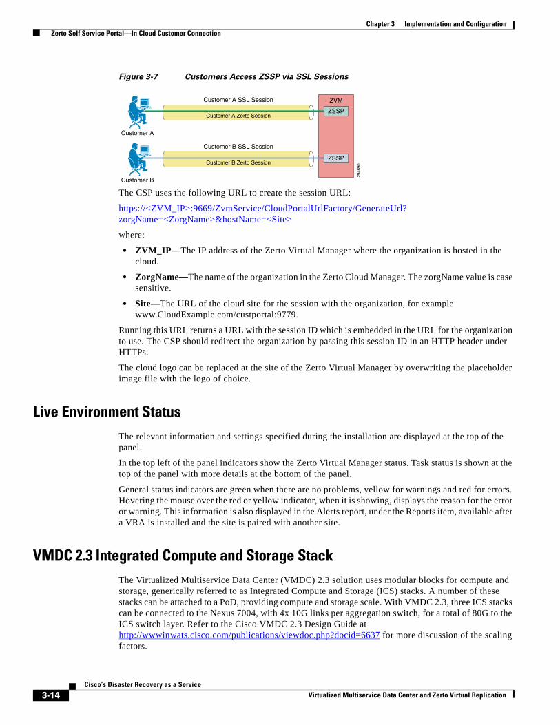
Chapter 3 Implementation and Configuration Zerto Self Service Portal—In Cloud Customer Connection
Figure 3-7 Customers Access ZSSP via SSL Sessions
The CSP uses the following URL to create the session URL:
https://<ZVM_IP>:9669/ZvmService/CloudPortalUrlFactory/GenerateUrl? zorgName=<ZorgName>&hostName=<Site>
where:
• ZVM_IP—The IP address of the Zerto Virtual Manager where the organization is hosted in the cloud.
• ZorgName—The name of the organization in the Zerto Cloud Manager. The zorgName value is case sensitive.
• Site—The URL of the cloud site for the session with the organization, for example www.CloudExample.com/custportal:9779.
Running this URL returns a URL with the session ID which is embedded in the URL for the organization to use. The CSP should redirect the organization by passing this session ID in an HTTP header under HTTPs.
The cloud logo can be replaced at the site of the Zerto Virtual Manager by overwriting the placeholder image file with the logo of choice.
Live Environment StatusThe relevant information and settings specified during the installation are displayed at the top of the panel.
In the top left of the panel indicators show the Zerto Virtual Manager status. Task status is shown at the top of the panel with more details at the bottom of the panel.
General status indicators are green when there are no problems, yellow for warnings and red for errors. Hovering the mouse over the red or yellow indicator, when it is showing, displays the reason for the error or warning. This information is also displayed in the Alerts report, under the Reports item, available after a VRA is installed and the site is paired with another site.
VMDC 2.3 Integrated Compute and Storage StackThe Virtualized Multiservice Data Center (VMDC) 2.3 solution uses modular blocks for compute and storage, generically referred to as Integrated Compute and Storage (ICS) stacks. A number of these stacks can be attached to a PoD, providing compute and storage scale. With VMDC 2.3, three ICS stacks can be connected to the Nexus 7004, with 4x 10G links per aggregation switch, for a total of 80G to the ICS switch layer. Refer to the Cisco VMDC 2.3 Design Guide at http://wwwinwats.cisco.com/publications/viewdoc.php?docid=6637 for more discussion of the scaling factors.
2946
90
Customer A
Customer B
Customer A SSL Session
Customer A Zerto Session
Customer B Zerto Session
Customer B SSL Session
ZVM
ZSSP
ZSSP
3-14Cisco’s Disaster Recovery as a Service
Virtualized Multiservice Data Center and Zerto Virtual Replication
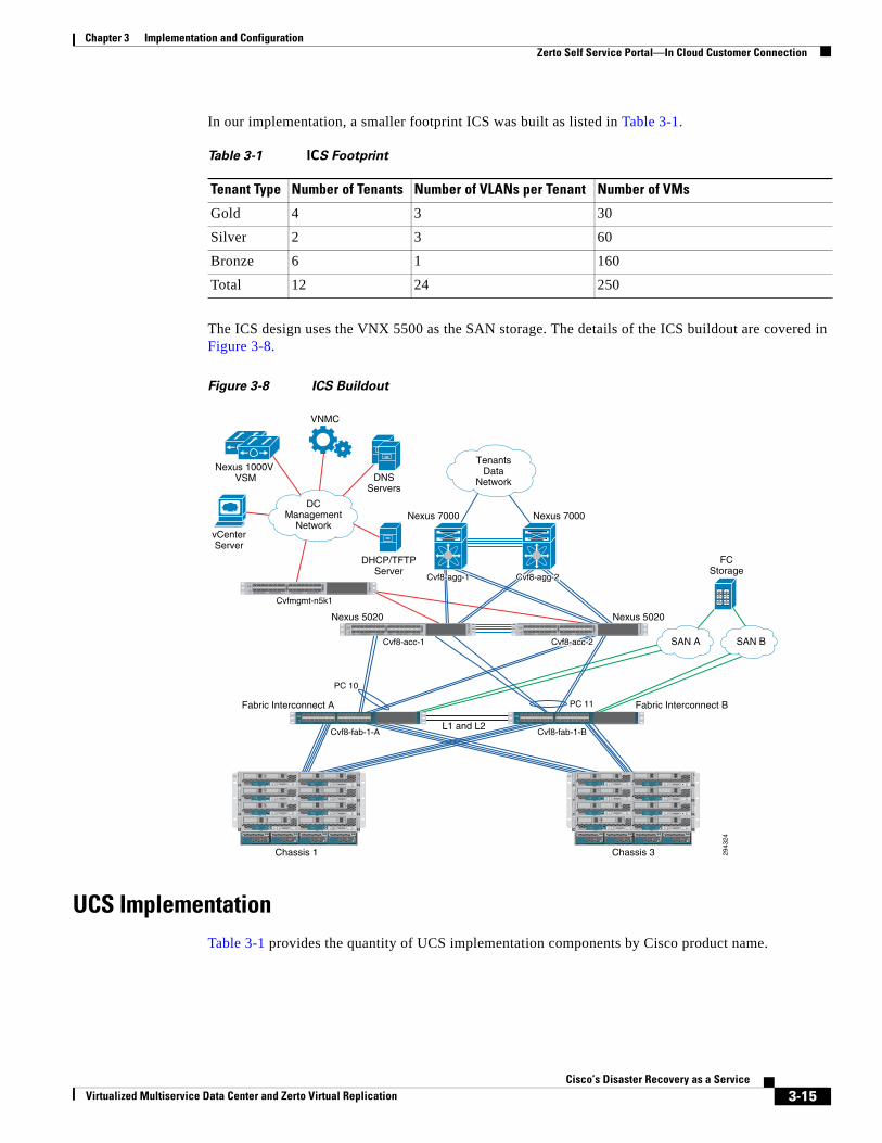
Chapter 3 Implementation and Configuration Zerto Self Service Portal—In Cloud Customer Connection
In our implementation, a smaller footprint ICS was built as listed in Table 3-1.
The ICS design uses the VNX 5500 as the SAN storage. The details of the ICS buildout are covered in Figure 3-8.
Figure 3-8 ICS Buildout
UCS ImplementationTable 3-1 provides the quantity of UCS implementation components by Cisco product name.
Table 3-1 ICS Footprint
Tenant Type Number of Tenants Number of VLANs per Tenant Number of VMs
Gold 4 3 30
Silver 2 3 60
Bronze 6 1 160
Total 12 24 250
2943
24
CISCO UCS 6248UP 1 2 3 4 5 6 7 8 9 10 11 12 13 14 15 16 17 18 19 20 21 22 23 24 25 26 27 28 29 30 31 32
STAT
ID
CISCO UCS 6248UP 1 2 3 4 5 6 7 8 9 10 11 12 13 14 15 16 17 18 19 20 21 22 23 24 25 26 27 28 29 30 31 32
STAT
ID
SLOT
1
SLOT
5
SLOT
3
SLOT7
SLOT
2
SLOT6
SLOT
4
SLOT
8
!
UCS 5108
OK FAIL OK FAIL OK FAIL OK FAIL
! ResetConsole
! !
UCS B200 M 1
! ResetConsole
! !
UCS B200 M 1
! ResetConsole
! !
UCS B200 M 1
! ResetConsole
! !
UCS B200 M 1
! ResetConsole
! !
UCS B200 M 1
! ResetConsole
! !
UCS B200 M 1
! ResetConsole
! !
UCS B200 M 1
! ResetConsole
! !
UCS B200 M 1
SLOT
1
SLOT
5
SLOT
3
SLOT7
SLOT
2
SLOT6
SLOT
4
SLOT
8
!
UCS 5108
OK FAIL OK FAIL OK FAIL OK FAIL
! ResetConsole
! !
UCS B200 M 1
! ResetConsole
! !
UCS B200 M 1
! ResetConsole
! !
UCS B200 M 1
! ResetConsole
! !
UCS B200 M 1
! ResetConsole
! !
UCS B200 M 1
! ResetConsole
! !
UCS B200 M 1
! ResetConsole
! !
UCS B200 M 1
! ResetConsole
! !
UCS B200 M 1
3
CISCO NEXUS N5548P 1 2 3 4 5 6 7 8 9 10 11 12 13 14 15 16 17 18 19 20 21 22 23 24 25 26 27 28 29 30 31 32
STAT
ID
3
CISCO NEXUS N5548P 1 2 3 4 5 6 7 8 9 10 11 12 13 14 15 16 17 18 19 20 21 22 23 24 25 26 27 28 29 30 31 32
STAT
ID
3
CISCO NEXUS N5548P 1 2 3 4 5 6 7 8 9 10 11 12 13 14 15 16 17 18 19 20 21 22 23 24 25 26 27 28 29 30 31 32
STAT
ID
L1 and L2
Fabric Interconnect A
DHCP/TFTPServer
DNSServers
VNMC
vCenterServer
Fabric Interconnect B
FCStorage
Nexus 5020Nexus 5020
Nexus 7000
Nexus 1000V VSM
Nexus 7000
Cvf8-fab-1-A
Cvf8-acc-1
Cvf8-agg-1Cvf8-agg-1Cvf8-agg-1 Cvf8-agg-2Cvf8-agg-2Cvf8-agg-2
Cvfmgmt-n5k1
Cvf8-acc-2
PC 11
PC 10
Cvf8-fab-1-B
Chassis 1 Chassis 3
DCManagement
Network
TenantsData
Network
SAN A SAN B
3-15Cisco’s Disaster Recovery as a Service
Virtualized Multiservice Data Center and Zerto Virtual Replication
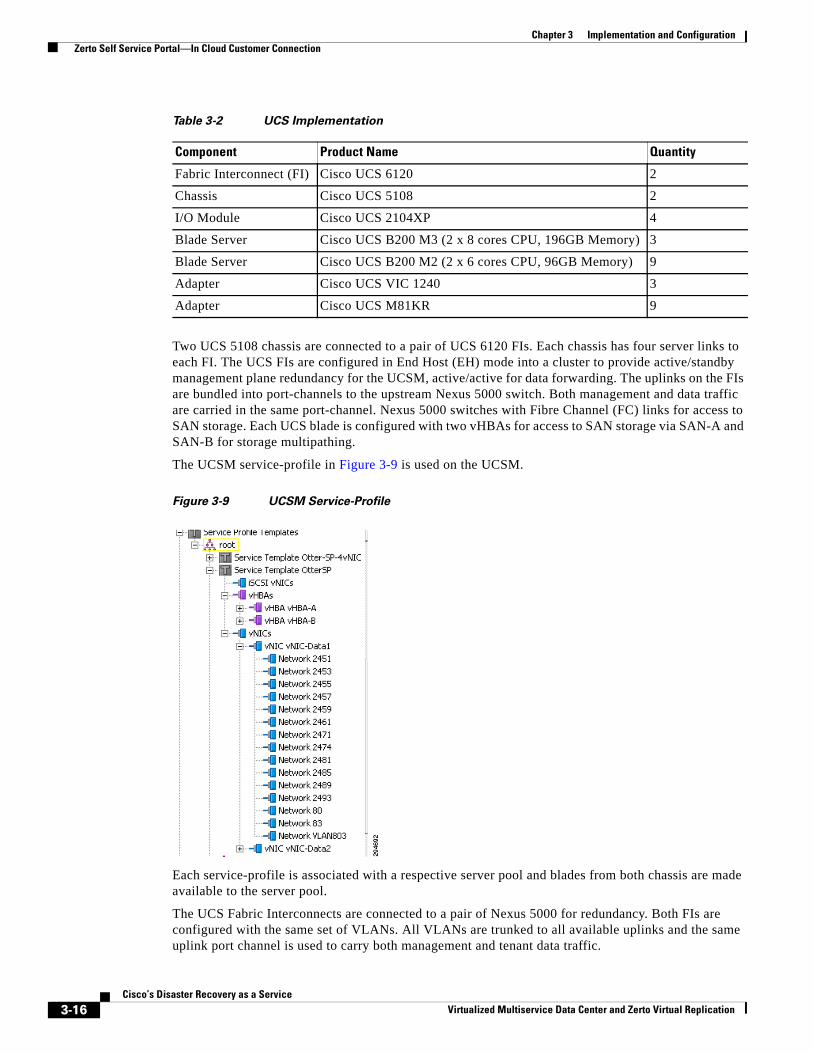
Chapter 3 Implementation and Configuration Zerto Self Service Portal—In Cloud Customer Connection
Two UCS 5108 chassis are connected to a pair of UCS 6120 FIs. Each chassis has four server links to each FI. The UCS FIs are configured in End Host (EH) mode into a cluster to provide active/standby management plane redundancy for the UCSM, active/active for data forwarding. The uplinks on the FIs are bundled into port-channels to the upstream Nexus 5000 switch. Both management and data traffic are carried in the same port-channel. Nexus 5000 switches with Fibre Channel (FC) links for access to SAN storage. Each UCS blade is configured with two vHBAs for access to SAN storage via SAN-A and SAN-B for storage multipathing.
The UCSM service-profile in Figure 3-9 is used on the UCSM.
Figure 3-9 UCSM Service-Profile
Each service-profile is associated with a respective server pool and blades from both chassis are made available to the server pool.
The UCS Fabric Interconnects are connected to a pair of Nexus 5000 for redundancy. Both FIs are configured with the same set of VLANs. All VLANs are trunked to all available uplinks and the same uplink port channel is used to carry both management and tenant data traffic.
Table 3-2 UCS Implementation
Component Product Name Quantity
Fabric Interconnect (FI) Cisco UCS 6120 2
Chassis Cisco UCS 5108 2
I/O Module Cisco UCS 2104XP 4
Blade Server Cisco UCS B200 M3 (2 x 8 cores CPU, 196GB Memory) 3
Blade Server Cisco UCS B200 M2 (2 x 6 cores CPU, 96GB Memory) 9
Adapter Cisco UCS VIC 1240 3
Adapter Cisco UCS M81KR 9
3-16Cisco’s Disaster Recovery as a Service
Virtualized Multiservice Data Center and Zerto Virtual Replication
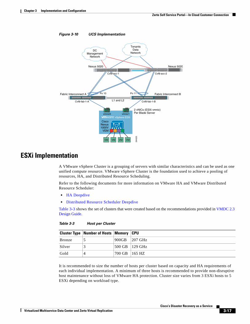
Chapter 3 Implementation and Configuration Zerto Self Service Portal—In Cloud Customer Connection
Figure 3-10 UCS Implementation
ESXi ImplementationA VMware vSphere Cluster is a grouping of servers with similar characteristics and can be used as one unified compute resource. VMware vSphere Cluster is the foundation used to achieve a pooling of resources, HA, and Distributed Resource Scheduling.
Refer to the following documents for more information on VMware HA and VMware Distributed Resource Scheduler:
• HA Deepdive
• Distributed Resource Scheduler Deepdive
Table 3-3 shows the set of clusters that were created based on the recommendations provided in VMDC 2.3 Design Guide.
It is recommended to size the number of hosts per cluster based on capacity and HA requirements of each individual implementation. A minimum of three hosts is recommended to provide non-disruptive host maintenance without loss of VMware HA protection. Cluster size varies from 3 ESXi hosts to 5 ESXi depending on workload type.
L1 and L2
2943
25
Fabric Interconnect A Fabric Interconnect B
2 vNICs (ESXi vmnic)Per Blade Server
Nexus 5020 Nexus 5020
Cvf8-acc-2
Po 11Po 10
Cvf8-fab-1-A Cvf8-fab-1-B
CISCO UCS 6248UP 1 2 3 4 5 6 7 8 9 10 11 12 13 14 15 16 17 18 19 20 21 22 23 24 25 26 27 28 29 30 31 32
STAT
ID
CISCO UCS 6248UP 1 2 3 4 5 6 7 8 9 10 11 12 13 14 15 16 17 18 19 20 21 22 23 24 25 26 27 28 29 30 31 32
STAT
ID
3
CISCO NEXUS N5548P 1 2 3 4 5 6 7 8 9 10 11 12 13 14 15 16 17 18 19 20 21 22 23 24 25 26 27 28 29 30 31 32
STAT
ID
3
CISCO NEXUS N5548P 1 2 3 4 5 6 7 8 9 10 11 12 13 14 15 16 17 18 19 20 21 22 23 24 25 26 27 28 29 30 31 32
STAT
ID
DCManagement
Network
TenantsData
Network
Cvf8-acc-1
CiscoNexus1000V
VEM
vSphere ESXivmnic0 vmnic1
VMVMVMVM
Table 3-3 Host per Cluster
Cluster Type Number of Hosts Memory CPU
Bronze 5 900GB 207 GHz
Silver 3 500 GB 129 GHz
Gold 4 700 GB 165 HZ
3-17Cisco’s Disaster Recovery as a Service
Virtualized Multiservice Data Center and Zerto Virtual Replication
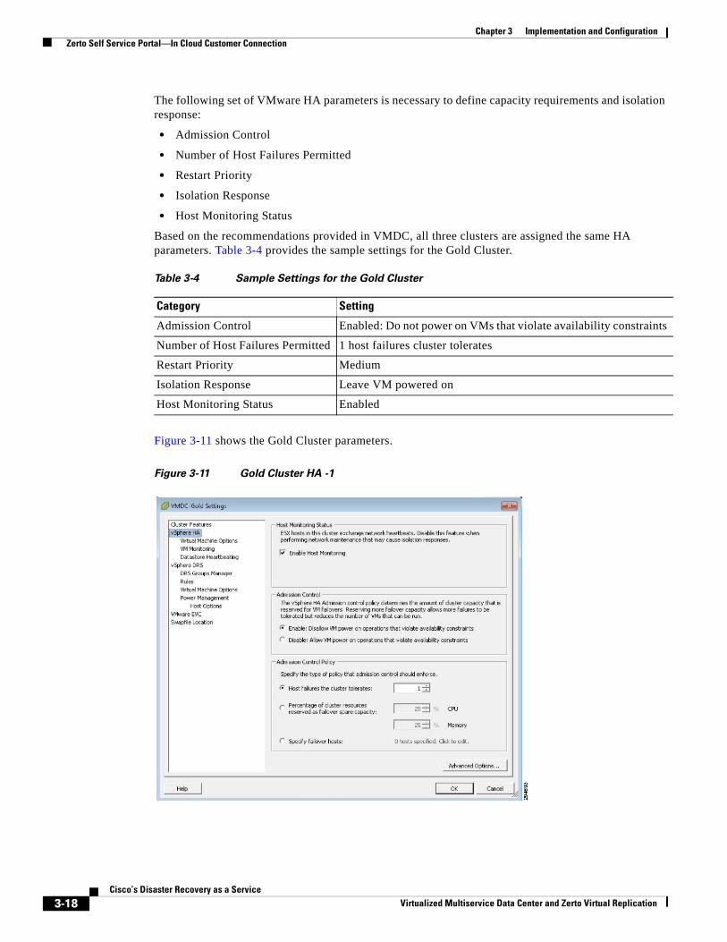
Chapter 3 Implementation and Configuration Zerto Self Service Portal—In Cloud Customer Connection
The following set of VMware HA parameters is necessary to define capacity requirements and isolation response:
• Admission Control
• Number of Host Failures Permitted
• Restart Priority
• Isolation Response
• Host Monitoring Status
Based on the recommendations provided in VMDC, all three clusters are assigned the same HA parameters. Table 3-4 provides the sample settings for the Gold Cluster.
Figure 3-11 shows the Gold Cluster parameters.
Figure 3-11 Gold Cluster HA -1
Table 3-4 Sample Settings for the Gold Cluster
Category Setting
Admission Control Enabled: Do not power on VMs that violate availability constraints
Number of Host Failures Permitted 1 host failures cluster tolerates
Restart Priority Medium
Isolation Response Leave VM powered on
Host Monitoring Status Enabled
3-18Cisco’s Disaster Recovery as a Service
Virtualized Multiservice Data Center and Zerto Virtual Replication
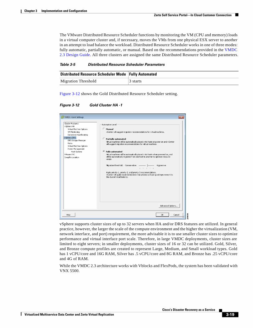
Chapter 3 Implementation and Configuration Zerto Self Service Portal—In Cloud Customer Connection
The VMware Distributed Resource Scheduler functions by monitoring the VM (CPU and memory) loads in a virtual computer cluster and, if necessary, moves the VMs from one physical ESX server to another in an attempt to load balance the workload. Distributed Resource Scheduler works in one of three modes: fully automatic, partially automatic, or manual. Based on the recommendations provided in the VMDC 2.3 Design Guide. All three clusters are assigned the same Distributed Resource Scheduler parameters.
Figure 3-12 shows the Gold Distributed Resource Scheduler setting.
Figure 3-12 Gold Cluster HA -1
vSphere supports cluster sizes of up to 32 servers when HA and/or DRS features are utilized. In general practice, however, the larger the scale of the compute environment and the higher the virtualization (VM, network interface, and port) requirement, the more advisable it is to use smaller cluster sizes to optimize performance and virtual interface port scale. Therefore, in large VMDC deployments, cluster sizes are limited to eight servers; in smaller deployments, cluster sizes of 16 or 32 can be utilized. Gold, Silver, and Bronze compute profiles are created to represent Large, Medium, and Small workload types. Gold has 1 vCPU/core and 16G RAM, Silver has .5 vCPU/core and 8G RAM, and Bronze has .25 vCPU/core and 4G of RAM.
While the VMDC 2.3 architecture works with Vblocks and FlexPods, the system has been validated with VNX 5500.
Table 3-5 Distributed Resource Scheduler Parameters
Distributed Resource Scheduler Mode Fully Automated
Migration Threshold 3 starts
3-19Cisco’s Disaster Recovery as a Service
Virtualized Multiservice Data Center and Zerto Virtual Replication
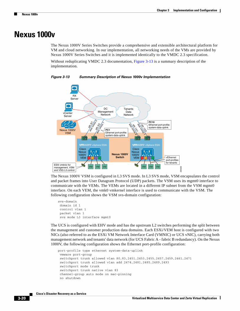
Chapter 3 Implementation and Configuration Nexus 1000v
Nexus 1000vThe Nexus 1000V Series Switches provide a comprehensive and extensible architectural platform for VM and cloud networking. In our implementation, all networking needs of the VMs are provided by Nexus 1000V Series Switches and it is implemented identically to the VMDC 2.3 specification.
Without reduplicating VMDC 2.3 documentation, Figure 3-13 is a summary description of the implementation.
Figure 3-13 Summary Description of Nexus 1000v Implementation
The Nexus 1000V VSM is configured in L3 SVS mode. In L3 SVS mode, VSM encapsulates the control and packet frames into User Datagram Protocol (UDP) packets. The VSM uses its mgmt0 interface to communicate with the VEMs. The VEMs are located in a different IP subnet from the VSM mgmt0 interface. On each VEM, the vmk0 vmkernel interface is used to communicate with the VSM. The following configuration shows the VSM svs-domain configuration:
svs-domain domain id 1 control vlan 1 packet vlan 1 svs mode L3 interface mgmt0
The UCS is configured with EHV mode and has the upstream L2 switches performing the split between the management and customer production data domains. Each ESXi/VEM host is configured with two NICs (also referred to as the ESXi VM Network Interface Card (VMNIC) or UCS vNIC), carrying both management network and tenants' data network (for UCS Fabric A - fabric B redundancy). On the Nexus 1000V, the following configuration shows the Ethernet port-profile configuration:
port-profile type ethernet system-data-uplink vmware port-group switchport trunk allowed vlan 80,83,2451,2453,2455,2457,2459,2461,2471 switchport trunk allowed vlan add 2474,2481,2485,2489,2493 switchport mode trunk switchport trunk native vlan 83 channel-group auto mode on mac-pinning no shutdown
CiscoNexus1000V
VEM
vSphere ESXi
VMVMVM
vCenterServer
RXServer
Nexus 1000V VSM
2943
26
eth 13/2
esxi vmnic 1
eth 13/1
esxi vmnic 0
eth
3/1
esxi
vm
nic
0et
h 3/
2es
xi v
mni
c 1
CiscoNexus1000V
VEM
vSphere ESXi
VMVMVM
DCManagement
Network
TenantsData
Network
Nexus 1000VSwitch
PC10Ethernet port-profile: system-data-uplink
ESXi vmknic for management, VSM and VSG L3 control
vEthernet port-profiles for tenants
PC1Ethernet port-profile: system-data-uplink
3-20Cisco’s Disaster Recovery as a Service
Virtualized Multiservice Data Center and Zerto Virtual Replication
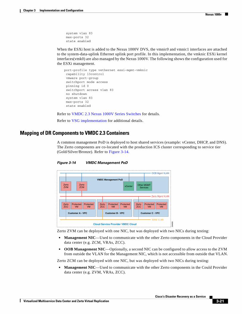
Chapter 3 Implementation and Configuration Nexus 1000v
system vlan 83 max-ports 32 state enabled
When the ESXi host is added to the Nexus 1000V DVS, the vmnic0 and vmnic1 interfaces are attached to the system-data-uplink Ethernet uplink port profile. In this implementation, the vmknic ESXi kernel interfaces(vmk0) are also managed by the Nexus 1000V. The following shows the configuration used for the ESXi management.
port-profile type vethernet esxi-mgmt-vmknic capability l3control vmware port-group switchport mode access pinning id 0 switchport access vlan 83 no shutdown system vlan 83 max-ports 32 state enabled
Refer to VMDC 2.3 Nexus 1000V Series Switches for details.
Refer to VSG implementation for additional details.
Mapping of DR Components to VMDC 2.3 Containers
A common management PoD is deployed to host shared services (example: vCenter, DHCP, and DNS). The Zerto components are co-located with the production ICS cluster corresponding to service tier (Gold/Silver/Bronze). Refer to Figure 3-14.
Figure 3-14 VMDC Management PoD
Zerto ZVM can be deployed with one NIC, but was deployed with two NICs during testing:
• Management NIC—Used to communicate with the other Zerto components in the Cloud Provider data center (e.g. ZCM, VRAs, ZCC).
• OOB Management NIC—Optionally, a second NIC can be configured to allow access to the ZVM from outside the VLAN for the Management NIC, which is not accessible from outside that VLAN.
Zerto ZCM can be deployed with one NIC, but was deployed with two NICs during testing:
• Management NIC—Used to communicate with the other Zerto components in the Could Provider data center (e.g. ZVM, VRAs, ZCC).
2946
95
VMDC Management PoD
Cloud Service Provider VMDC Cloud
Customer A - VPC
ZertoZVM
ZertoZCM
ZertoZCC
ProtectedVM
ProtectedVM
Customer B - VPC
ZertoZCC
ProtectedVM
ProtectedVM
Customer C - VPC
ZertoZCC
ProtectedVM
ProtectedVM
vCenter
OOB Mgmt VLAN
Zerto Mgmt VLAN
WAN VLAN
Other MGMTServices
3-21Cisco’s Disaster Recovery as a Service
Virtualized Multiservice Data Center and Zerto Virtual Replication
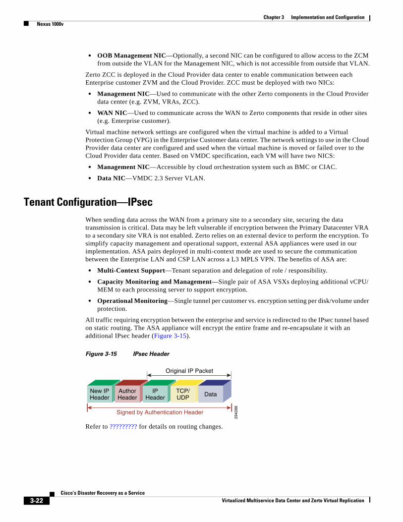
Chapter 3 Implementation and Configuration Nexus 1000v
• OOB Management NIC—Optionally, a second NIC can be configured to allow access to the ZCM from outside the VLAN for the Management NIC, which is not accessible from outside that VLAN.
Zerto ZCC is deployed in the Cloud Provider data center to enable communication between each Enterprise customer ZVM and the Cloud Provider. ZCC must be deployed with two NICs:
• Management NIC—Used to communicate with the other Zerto components in the Cloud Provider data center (e.g. ZVM, VRAs, ZCC).
• WAN NIC—Used to communicate across the WAN to Zerto components that reside in other sites (e.g. Enterprise customer).
Virtual machine network settings are configured when the virtual machine is added to a Virtual Protection Group (VPG) in the Enterprise Customer data center. The network settings to use in the Cloud Provider data center are configured and used when the virtual machine is moved or failed over to the Cloud Provider data center. Based on VMDC specification, each VM will have two NICS:
• Management NIC—Accessible by cloud orchestration system such as BMC or CIAC.
• Data NIC—VMDC 2.3 Server VLAN.
Tenant Configuration—IPsecWhen sending data across the WAN from a primary site to a secondary site, securing the data transmission is critical. Data may be left vulnerable if encryption between the Primary Datacenter VRA to a secondary site VRA is not enabled. Zerto relies on an external device to perform the encryption. To simplify capacity management and operational support, external ASA appliances were used in our implementation. ASA pairs deployed in multi-context mode are used to secure the communication between the Enterprise LAN and CSP LAN across a L3 MPLS VPN. The benefits of ASA are:
• Multi-Context Support—Tenant separation and delegation of role / responsibility.
• Capacity Monitoring and Management—Single pair of ASA VSXs deploying additional vCPU/ MEM to each processing server to support encryption.
• Operational Monitoring—Single tunnel per customer vs. encryption setting per disk/volume under protection.
All traffic requiring encryption between the enterprise and service is redirected to the IPsec tunnel based on static routing. The ASA appliance will encrypt the entire frame and re-encapsulate it with an additional IPsec header (Figure 3-15).
Figure 3-15 IPsec Header
Refer to ????????? for details on routing changes.
2942
86
New IPHeader
AuthorHeader
IPHeader
TCP/UDP Data
Signed by Authentication Header
Original IP Packet
3-22Cisco’s Disaster Recovery as a Service
Virtualized Multiservice Data Center and Zerto Virtual Replication
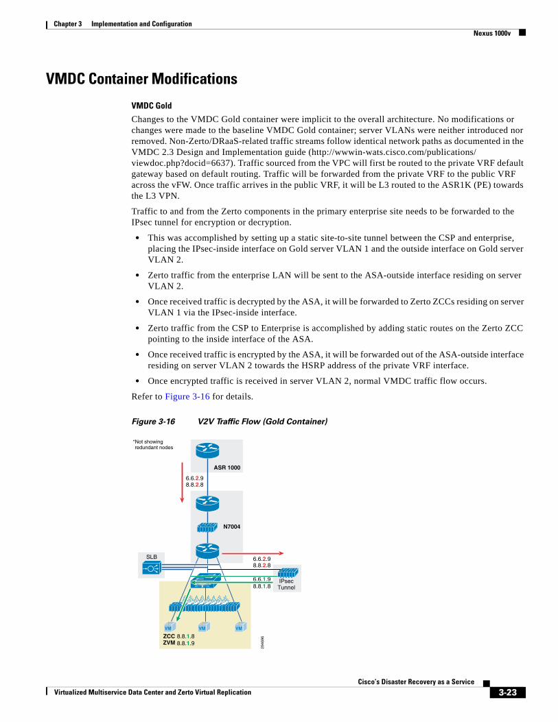
Chapter 3 Implementation and Configuration Nexus 1000v
VMDC Container Modifications
VMDC Gold
Changes to the VMDC Gold container were implicit to the overall architecture. No modifications or changes were made to the baseline VMDC Gold container; server VLANs were neither introduced nor removed. Non-Zerto/DRaaS-related traffic streams follow identical network paths as documented in the VMDC 2.3 Design and Implementation guide (http://wwwin-wats.cisco.com/publications/ viewdoc.php?docid=6637). Traffic sourced from the VPC will first be routed to the private VRF default gateway based on default routing. Traffic will be forwarded from the private VRF to the public VRF across the vFW. Once traffic arrives in the public VRF, it will be L3 routed to the ASR1K (PE) towards the L3 VPN.
Traffic to and from the Zerto components in the primary enterprise site needs to be forwarded to the IPsec tunnel for encryption or decryption.
• This was accomplished by setting up a static site-to-site tunnel between the CSP and enterprise, placing the IPsec-inside interface on Gold server VLAN 1 and the outside interface on Gold server VLAN 2.
• Zerto traffic from the enterprise LAN will be sent to the ASA-outside interface residing on server VLAN 2.
• Once received traffic is decrypted by the ASA, it will be forwarded to Zerto ZCCs residing on server VLAN 1 via the IPsec-inside interface.
• Zerto traffic from the CSP to Enterprise is accomplished by adding static routes on the Zerto ZCC pointing to the inside interface of the ASA.
• Once received traffic is encrypted by the ASA, it will be forwarded out of the ASA-outside interface residing on server VLAN 2 towards the HSRP address of the private VRF interface.
• Once encrypted traffic is received in server VLAN 2, normal VMDC traffic flow occurs.
Refer to Figure 3-16 for details.
Figure 3-16 V2V Traffic Flow (Gold Container)
2946
968.8.1.88.8.1.9
6.6.2.98.8.2.8
6.6.2.98.8.2.8
SLB
6.6.1.98.8.1.8
ZCCZVM
*Not showingredundant nodes
ASR 1000
N7004
VM VMVM
IPsecTunnel
3-23Cisco’s Disaster Recovery as a Service
Virtualized Multiservice Data Center and Zerto Virtual Replication
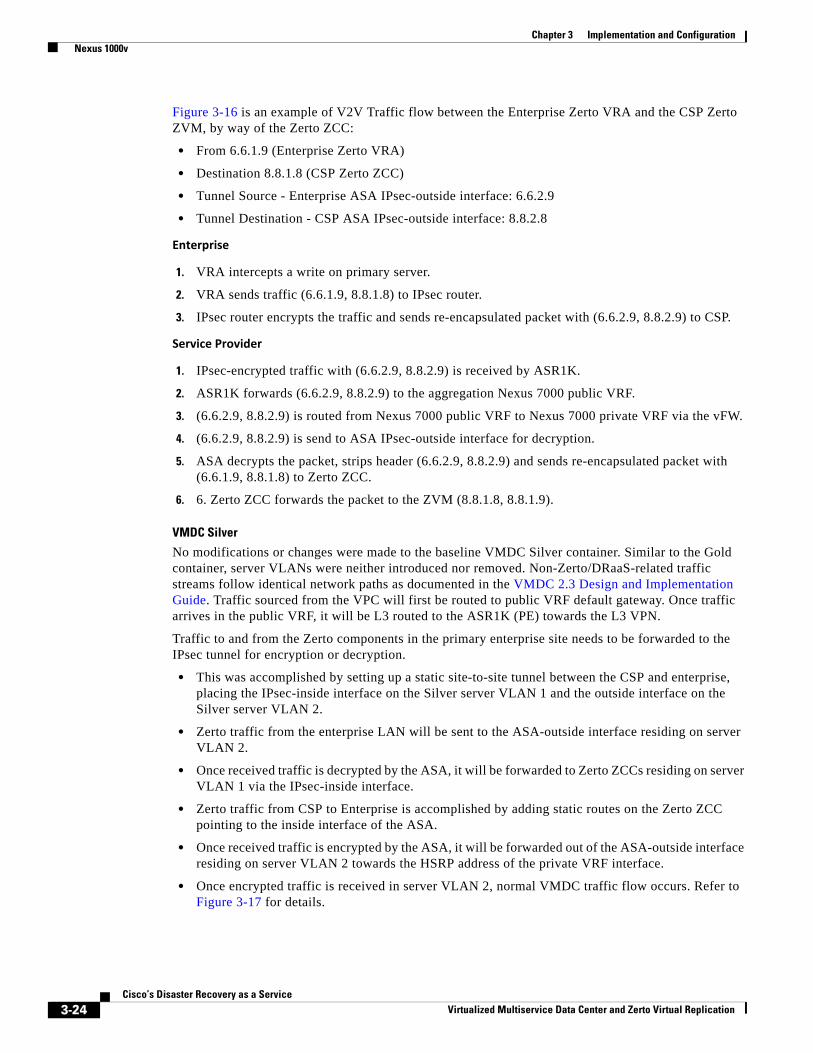
Chapter 3 Implementation and Configuration Nexus 1000v
Figure 3-16 is an example of V2V Traffic flow between the Enterprise Zerto VRA and the CSP Zerto ZVM, by way of the Zerto ZCC:
• From 6.6.1.9 (Enterprise Zerto VRA)
• Destination 8.8.1.8 (CSP Zerto ZCC)
• Tunnel Source - Enterprise ASA IPsec-outside interface: 6.6.2.9
• Tunnel Destination - CSP ASA IPsec-outside interface: 8.8.2.8
Enterprise
1. VRA intercepts a write on primary server.
2. VRA sends traffic (6.6.1.9, 8.8.1.8) to IPsec router.
3. IPsec router encrypts the traffic and sends re-encapsulated packet with (6.6.2.9, 8.8.2.9) to CSP.
Service Provider
1. IPsec-encrypted traffic with (6.6.2.9, 8.8.2.9) is received by ASR1K.
2. ASR1K forwards (6.6.2.9, 8.8.2.9) to the aggregation Nexus 7000 public VRF.
3. (6.6.2.9, 8.8.2.9) is routed from Nexus 7000 public VRF to Nexus 7000 private VRF via the vFW.
4. (6.6.2.9, 8.8.2.9) is send to ASA IPsec-outside interface for decryption.
5. ASA decrypts the packet, strips header (6.6.2.9, 8.8.2.9) and sends re-encapsulated packet with (6.6.1.9, 8.8.1.8) to Zerto ZCC.
6. 6. Zerto ZCC forwards the packet to the ZVM (8.8.1.8, 8.8.1.9).
VMDC Silver
No modifications or changes were made to the baseline VMDC Silver container. Similar to the Gold container, server VLANs were neither introduced nor removed. Non-Zerto/DRaaS-related traffic streams follow identical network paths as documented in the VMDC 2.3 Design and Implementation Guide. Traffic sourced from the VPC will first be routed to public VRF default gateway. Once traffic arrives in the public VRF, it will be L3 routed to the ASR1K (PE) towards the L3 VPN.
Traffic to and from the Zerto components in the primary enterprise site needs to be forwarded to the IPsec tunnel for encryption or decryption.
• This was accomplished by setting up a static site-to-site tunnel between the CSP and enterprise, placing the IPsec-inside interface on the Silver server VLAN 1 and the outside interface on the Silver server VLAN 2.
• Zerto traffic from the enterprise LAN will be sent to the ASA-outside interface residing on server VLAN 2.
• Once received traffic is decrypted by the ASA, it will be forwarded to Zerto ZCCs residing on server VLAN 1 via the IPsec-inside interface.
• Zerto traffic from CSP to Enterprise is accomplished by adding static routes on the Zerto ZCC pointing to the inside interface of the ASA.
• Once received traffic is encrypted by the ASA, it will be forwarded out of the ASA-outside interface residing on server VLAN 2 towards the HSRP address of the private VRF interface.
• Once encrypted traffic is received in server VLAN 2, normal VMDC traffic flow occurs. Refer to Figure 3-17 for details.
3-24Cisco’s Disaster Recovery as a Service
Virtualized Multiservice Data Center and Zerto Virtual Replication
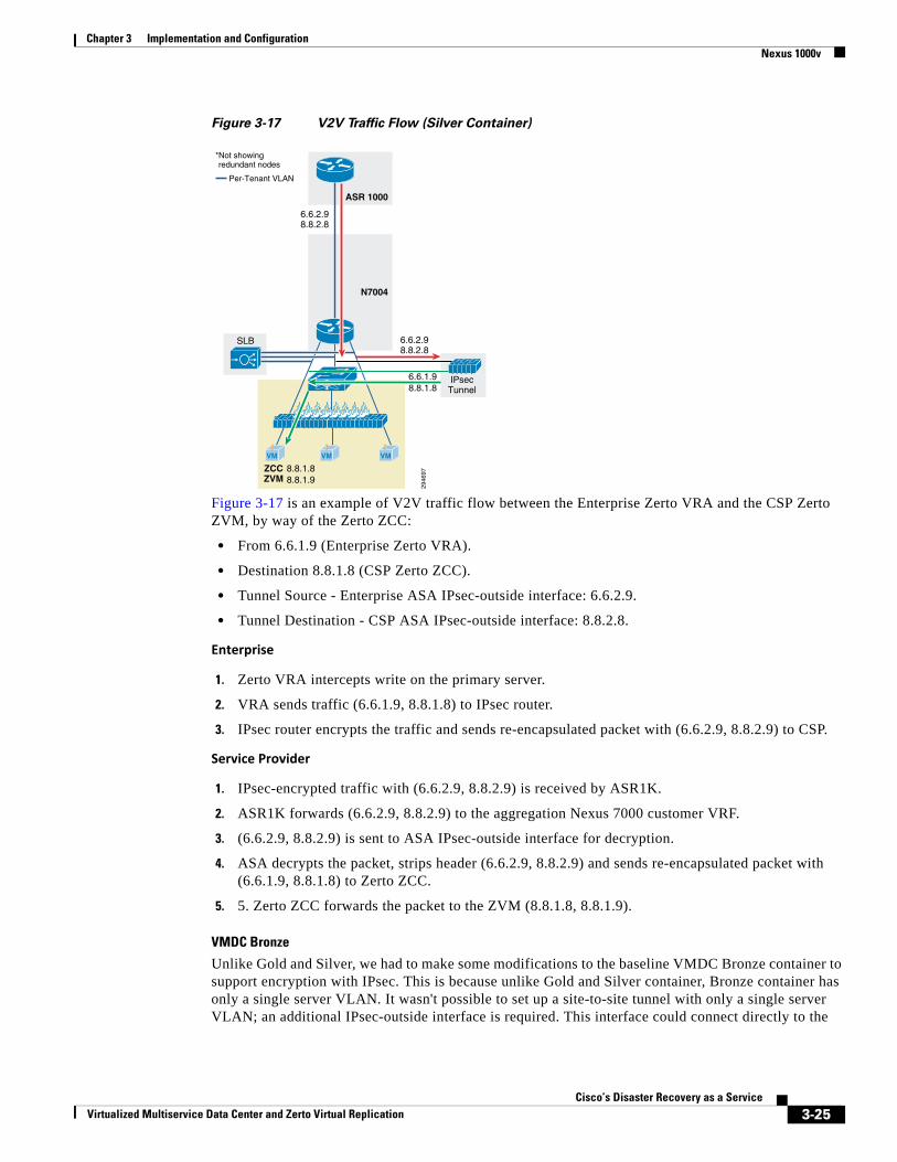
Chapter 3 Implementation and Configuration Nexus 1000v
Figure 3-17 V2V Traffic Flow (Silver Container)
Figure 3-17 is an example of V2V traffic flow between the Enterprise Zerto VRA and the CSP Zerto ZVM, by way of the Zerto ZCC:
• From 6.6.1.9 (Enterprise Zerto VRA).
• Destination 8.8.1.8 (CSP Zerto ZCC).
• Tunnel Source - Enterprise ASA IPsec-outside interface: 6.6.2.9.
• Tunnel Destination - CSP ASA IPsec-outside interface: 8.8.2.8.
Enterprise
1. Zerto VRA intercepts write on the primary server.
2. VRA sends traffic (6.6.1.9, 8.8.1.8) to IPsec router.
3. IPsec router encrypts the traffic and sends re-encapsulated packet with (6.6.2.9, 8.8.2.9) to CSP.
Service Provider
1. IPsec-encrypted traffic with (6.6.2.9, 8.8.2.9) is received by ASR1K.
2. ASR1K forwards (6.6.2.9, 8.8.2.9) to the aggregation Nexus 7000 customer VRF.
3. (6.6.2.9, 8.8.2.9) is sent to ASA IPsec-outside interface for decryption.
4. ASA decrypts the packet, strips header (6.6.2.9, 8.8.2.9) and sends re-encapsulated packet with (6.6.1.9, 8.8.1.8) to Zerto ZCC.
5. 5. Zerto ZCC forwards the packet to the ZVM (8.8.1.8, 8.8.1.9).
VMDC Bronze
Unlike Gold and Silver, we had to make some modifications to the baseline VMDC Bronze container to support encryption with IPsec. This is because unlike Gold and Silver container, Bronze container has only a single server VLAN. It wasn't possible to set up a site-to-site tunnel with only a single server VLAN; an additional IPsec-outside interface is required. This interface could connect directly to the
2946
97
6.6.2.98.8.2.8
6.6.2.98.8.2.8
SLB
6.6.1.98.8.1.8
*Not showingredundant nodes
Per-Tenant VLAN
ASR 1000
N7004
VM VMVM
IPsecTunnel
8.8.1.88.8.1.9
ZCCZVM
3-25Cisco’s Disaster Recovery as a Service
Virtualized Multiservice Data Center and Zerto Virtual Replication
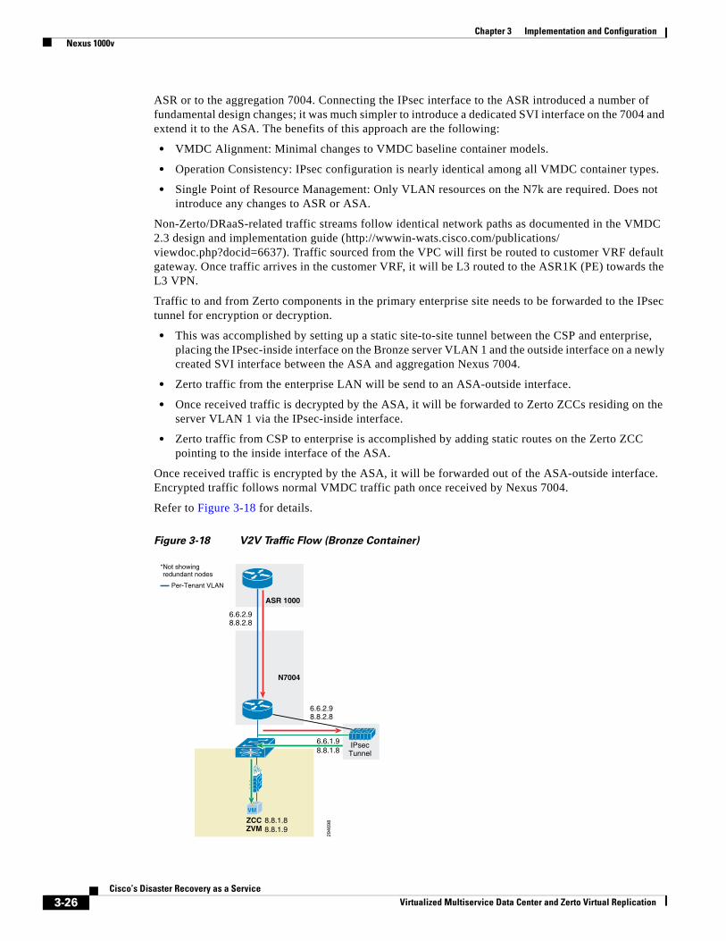
Chapter 3 Implementation and Configuration Nexus 1000v
ASR or to the aggregation 7004. Connecting the IPsec interface to the ASR introduced a number of fundamental design changes; it was much simpler to introduce a dedicated SVI interface on the 7004 and extend it to the ASA. The benefits of this approach are the following:
• VMDC Alignment: Minimal changes to VMDC baseline container models.
• Operation Consistency: IPsec configuration is nearly identical among all VMDC container types.
• Single Point of Resource Management: Only VLAN resources on the N7k are required. Does not introduce any changes to ASR or ASA.
Non-Zerto/DRaaS-related traffic streams follow identical network paths as documented in the VMDC 2.3 design and implementation guide (http://wwwin-wats.cisco.com/publications/ viewdoc.php?docid=6637). Traffic sourced from the VPC will first be routed to customer VRF default gateway. Once traffic arrives in the customer VRF, it will be L3 routed to the ASR1K (PE) towards the L3 VPN.
Traffic to and from Zerto components in the primary enterprise site needs to be forwarded to the IPsec tunnel for encryption or decryption.
• This was accomplished by setting up a static site-to-site tunnel between the CSP and enterprise, placing the IPsec-inside interface on the Bronze server VLAN 1 and the outside interface on a newly created SVI interface between the ASA and aggregation Nexus 7004.
• Zerto traffic from the enterprise LAN will be send to an ASA-outside interface.
• Once received traffic is decrypted by the ASA, it will be forwarded to Zerto ZCCs residing on the server VLAN 1 via the IPsec-inside interface.
• Zerto traffic from CSP to enterprise is accomplished by adding static routes on the Zerto ZCC pointing to the inside interface of the ASA.
Once received traffic is encrypted by the ASA, it will be forwarded out of the ASA-outside interface. Encrypted traffic follows normal VMDC traffic path once received by Nexus 7004.
Refer to Figure 3-18 for details.
Figure 3-18 V2V Traffic Flow (Bronze Container)
2946
98
6.6.2.98.8.2.8
6.6.2.98.8.2.8
6.6.1.98.8.1.8
*Not showingredundant nodes
Per-Tenant VLAN
ASR 1000
N7004
VM
IPsecTunnel
8.8.1.88.8.1.9
ZCCZVM
3-26Cisco’s Disaster Recovery as a Service
Virtualized Multiservice Data Center and Zerto Virtual Replication
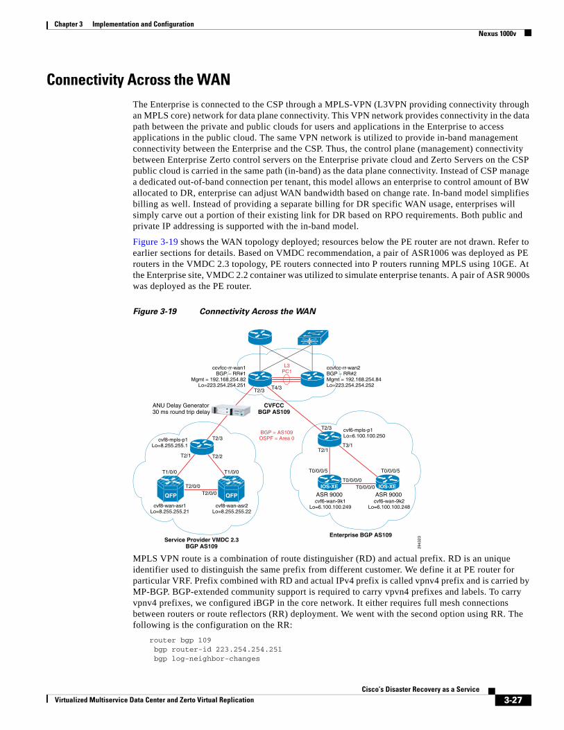
Chapter 3 Implementation and Configuration Nexus 1000v
Connectivity Across the WANThe Enterprise is connected to the CSP through a MPLS-VPN (L3VPN providing connectivity through an MPLS core) network for data plane connectivity. This VPN network provides connectivity in the data path between the private and public clouds for users and applications in the Enterprise to access applications in the public cloud. The same VPN network is utilized to provide in-band management connectivity between the Enterprise and the CSP. Thus, the control plane (management) connectivity between Enterprise Zerto control servers on the Enterprise private cloud and Zerto Servers on the CSP public cloud is carried in the same path (in-band) as the data plane connectivity. Instead of CSP manage a dedicated out-of-band connection per tenant, this model allows an enterprise to control amount of BW allocated to DR, enterprise can adjust WAN bandwidth based on change rate. In-band model simplifies billing as well. Instead of providing a separate billing for DR specific WAN usage, enterprises will simply carve out a portion of their existing link for DR based on RPO requirements. Both public and private IP addressing is supported with the in-band model.
Figure 3-19 shows the WAN topology deployed; resources below the PE router are not drawn. Refer to earlier sections for details. Based on VMDC recommendation, a pair of ASR1006 was deployed as PE routers in the VMDC 2.3 topology, PE routers connected into P routers running MPLS using 10GE. At the Enterprise site, VMDC 2.2 container was utilized to simulate enterprise tenants. A pair of ASR 9000s was deployed as the PE router.
Figure 3-19 Connectivity Across the WAN
MPLS VPN route is a combination of route distinguisher (RD) and actual prefix. RD is an unique identifier used to distinguish the same prefix from different customer. We define it at PE router for particular VRF. Prefix combined with RD and actual IPv4 prefix is called vpnv4 prefix and is carried by MP-BGP. BGP-extended community support is required to carry vpvn4 prefixes and labels. To carry vpnv4 prefixes, we configured iBGP in the core network. It either requires full mesh connections between routers or route reflectors (RR) deployment. We went with the second option using RR. The following is the configuration on the RR:
router bgp 109 bgp router-id 223.254.254.251 bgp log-neighbor-changes
2943
23
Enterprise BGP AS109
CVFCCBGP AS109
Service Provider VMDC 2.3BGP AS109
T0/0/0/0
T0/0/0/5T1/0/0 T1/0/0
T2/1T2/1
T0/0/0/5
T3/1
T2/2
T4/3
T2/3
T2/3
T2/3
cvf6-wan-9k1Lo=6.100.100.249cvf8-wan-asr1
Lo=8.255.255.21cvf8-wan-asr2
Lo=8.255.255.22
cvf8-mpls-p1Lo=8.255.255.1
cvf6-wan-9k2Lo=6.100.100.248
cvf6-mpls-p1Lo=6.100.100.250
ccvfcc-rr-wan2BGP – RR#2Mgmt = 192.168.254.84Lo=223.254.254.252
ccvfcc-rr-wan1BGP – RR#1
Mgmt = 192.168.254.82Lo=223.254.254.251
T0/0/0/0
ASR 9000
ANU Delay Generator30 ms round trip delay
ASR 9000IOS-XE IOS-XET2/0/0
T2/0/0
L3PC1
BGP = AS109OSPF = Area 0
QFPQFP
3-27Cisco’s Disaster Recovery as a Service
Virtualized Multiservice Data Center and Zerto Virtual Replication
Chapter 3 Implementation and Configuration Nexus 1000v
neighbor RRCC peer-group neighbor RRCC remote-as 109 neighbor RRCC description ibgp-to-RR neighbor RR peer-group neighbor RR remote-as 109 neighbor RR description CVFCC-WAN-6k1-to-CVFCC-WAN-6k2 neighbor RR update-source Loopback0 neighbor 6.100.100.248 remote-as 109 neighbor 6.100.100.248 peer-group RRCC neighbor 6.100.100.249 remote-as 109 neighbor 6.100.100.249 peer-group RRCC neighbor 6.100.100.250 remote-as 109 neighbor 6.100.100.250 peer-group RRCC neighbor 8.255.255.1 remote-as 109 neighbor 8.255.255.1 peer-group RRCC neighbor 8.255.255.21 remote-as 109 neighbor 8.255.255.21 peer-group RRCC neighbor 8.255.255.22 remote-as 109 neighbor 8.255.255.22 peer-group RRCC neighbor 223.254.254.252 remote-as 109 neighbor 223.254.254.252 peer-group RR ! address-family ipv4 neighbor RRCC send-community neighbor RRCC route-reflector-client neighbor RR send-community both neighbor 6.100.100.248 activate neighbor 6.100.100.249 activate neighbor 6.100.100.250 activate neighbor 8.255.255.1 activate neighbor 8.255.255.21 activate neighbor 8.255.255.22 activate neighbor 223.254.254.252 activate no auto-summary no synchronization network 223.254.0.0 mask 255.255.0.0 exit-address-family ! address-family vpnv4 neighbor RRCC send-community both neighbor RRCC route-reflector-client neighbor RRCC next-hop-self neighbor RR send-community both neighbor 6.100.100.248 activate neighbor 6.100.100.249 activate neighbor 6.100.100.250 activate neighbor 8.255.255.1 activate neighbor 8.255.255.21 activate neighbor 8.255.255.22 activate neighbor 223.254.254.252 activate exit-address-family
PE routers are configured to import prefix from remote PE as well as export local prefix. The following is an example of a Gold tenant:
vrf definition tenant11-gold-pub rd 3486:3486 route-target export 3486:3486 route-target import 3486:3486 route-target import 3040:3040 ! address-family ipv4 exit-address-family!
3-28Cisco’s Disaster Recovery as a Service
Virtualized Multiservice Data Center and Zerto Virtual Replication
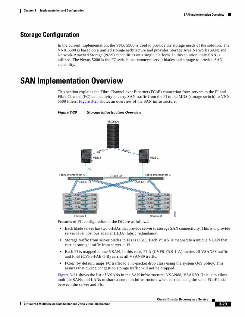
Chapter 3 Implementation and Configuration SAN Implementation Overview
Storage ConfigurationIn the current implementation, the VNX 5500 is used to provide the storage needs of the solution. The VNX 5500 is based on a unified storage architecture and provides Storage Area Network (SAN) and Network-Attached Storage (NAS) capabilities on a single platform. In this solution, only SAN is utilized. The Nexus 5000 is the FC switch that connects server blades and storage to provide SAN capability.
SAN Implementation OverviewThis section explains the Fibre Channel over Ethernet (FCoE) connection from servers to the FI and Fibre Channel (FC) connectivity to carry SAN traffic from the FI to the MDS (storage switch) to VNX 5500 Filers. Figure 3-20 shows an overview of the SAN infrastructure.
Figure 3-20 Storage Infrastructure Overview
Features of FC configuration in the DC are as follows:
• Each blade server has two vHBAs that provide server to storage SAN connectivity. This is to provide server level host bus adapter (HBA) fabric redundancy.
• Storage traffic from server blades to FIs is FCoE. Each VSAN is mapped to a unique VLAN that carries storage traffic from server to FI.
• Each FI is mapped to one VSAN. In this case, FI-A (CVF8-FAB-1-A) carries all VSAN88 traffic and FI-B (CVF8-FAB-1-B) carries all VSAN89 traffic.
• FCoE, by default, maps FC traffic to a no-packet drop class using the system QoS policy. This assures that during congestion storage traffic will not be dropped.
Figure 3-21 shows the list of VSANs in the SAN infrastructure: VSAN88, VSAN89. This is to allow multiple SANs and LANs to share a common infrastructure when carried using the same FCoE links between the server and FIs.
L1 and L2Fabric Interconnect A Fabric Interconnect B
VNX5500
FC
Cvf8-fab-1-A Cvf8-fab-1-B
MDS-1 MDS-2
2943
27
Chassis 1 Chassis 3
CISCO UCS 6248UP 1 2 3 4 5 6 7 8 9 10 11 12 13 14 15 16 17 18 19 20 21 22 23 24 25 26 27 28 29 30 31 32
STAT
ID
SLOT
1
SLOT
5
SLOT
3
SLOT7
SLOT
2
SLOT6
SLOT
4
SLOT
8
!
UCS 5108
OK FAIL OK FAIL OK FAIL OK FAIL
! ResetConsole
! !
UCS B200 M 1
! ResetConsole
! !
UCS B200 M 1
! ResetConsole
! !
UCS B200 M 1
! ResetConsole
! !
UCS B200 M 1
! ResetConsole
! !
UCS B200 M 1
! ResetConsole
! !
UCS B200 M 1
! ResetConsole
! !
UCS B200 M 1
! ResetConsole
! !
UCS B200 M 1
SLOT
1
SLOT
5
SLOT
3
SLOT7
SLOT
2
SLOT6
SLOT
4
SLOT
8
!
UCS 5108
OK FAIL OK FAIL OK FAIL OK FAIL
! ResetConsole
! !
UCS B200 M 1
! ResetConsole
! !
UCS B200 M 1
! ResetConsole
! !
UCS B200 M 1
! ResetConsole
! !
UCS B200 M 1
! ResetConsole
! !
UCS B200 M 1
! ResetConsole
! !
UCS B200 M 1
! ResetConsole
! !
UCS B200 M 1
! ResetConsole
! !
UCS B200 M 1
CISCO UCS 6248UP 1 2 3 4 5 6 7 8 9 10 11 12 13 14 15 16 17 18 19 20 21 22 23 24 25 26 27 28 29 30 31 32
STAT
ID
M
8GFC8GFC
3-29Cisco’s Disaster Recovery as a Service
Virtualized Multiservice Data Center and Zerto Virtual Replication
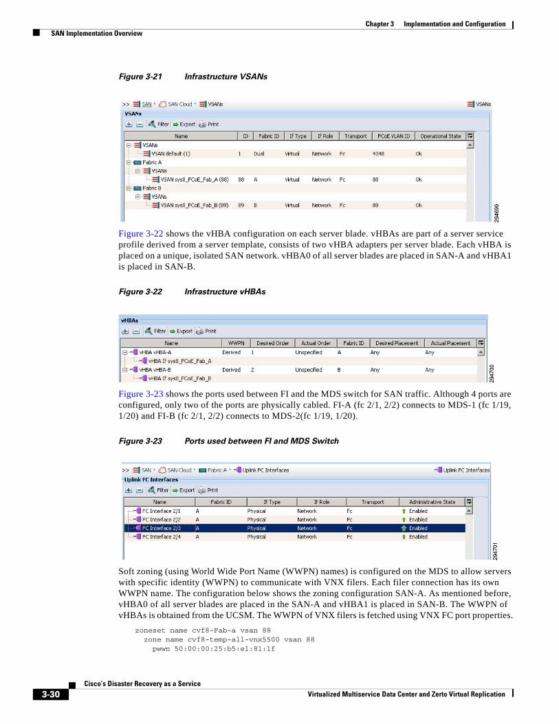
Chapter 3 Implementation and Configuration SAN Implementation Overview
Figure 3-21 Infrastructure VSANs
Figure 3-22 shows the vHBA configuration on each server blade. vHBAs are part of a server service profile derived from a server template, consists of two vHBA adapters per server blade. Each vHBA is placed on a unique, isolated SAN network. vHBA0 of all server blades are placed in SAN-A and vHBA1 is placed in SAN-B.
Figure 3-22 Infrastructure vHBAs
Figure 3-23 shows the ports used between FI and the MDS switch for SAN traffic. Although 4 ports are configured, only two of the ports are physically cabled. FI-A (fc 2/1, 2/2) connects to MDS-1 (fc 1/19, 1/20) and FI-B (fc 2/1, 2/2) connects to MDS-2(fc 1/19, 1/20).
Figure 3-23 Ports used between FI and MDS Switch
Soft zoning (using World Wide Port Name (WWPN) names) is configured on the MDS to allow servers with specific identity (WWPN) to communicate with VNX filers. Each filer connection has its own WWPN name. The configuration below shows the zoning configuration SAN-A. As mentioned before, vHBA0 of all server blades are placed in the SAN-A and vHBA1 is placed in SAN-B. The WWPN of vHBAs is obtained from the UCSM. The WWPN of VNX filers is fetched using VNX FC port properties.
zoneset name cvf8-Fab-a vsan 88 zone name cvf8-temp-all-vnx5500 vsan 88 pwwn 50:00:00:25:b5:e1:81:1f
3-30Cisco’s Disaster Recovery as a Service
Virtualized Multiservice Data Center and Zerto Virtual Replication
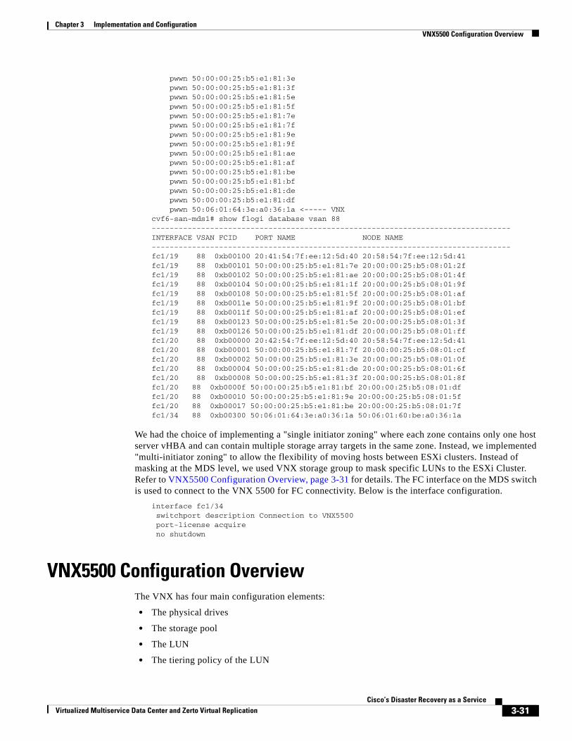
Chapter 3 Implementation and Configuration VNX5500 Configuration Overview
pwwn 50:00:00:25:b5:e1:81:3e pwwn 50:00:00:25:b5:e1:81:3f pwwn 50:00:00:25:b5:e1:81:5e pwwn 50:00:00:25:b5:e1:81:5f pwwn 50:00:00:25:b5:e1:81:7e pwwn 50:00:00:25:b5:e1:81:7f pwwn 50:00:00:25:b5:e1:81:9e pwwn 50:00:00:25:b5:e1:81:9f pwwn 50:00:00:25:b5:e1:81:ae pwwn 50:00:00:25:b5:e1:81:af pwwn 50:00:00:25:b5:e1:81:be pwwn 50:00:00:25:b5:e1:81:bf pwwn 50:00:00:25:b5:e1:81:de pwwn 50:00:00:25:b5:e1:81:df pwwn 50:06:01:64:3e:a0:36:1a <----- VNXcvf6-san-mds1# show flogi database vsan 88--------------------------------------------------------------------------------INTERFACE VSAN FCID PORT NAME NODE NAME--------------------------------------------------------------------------------fc1/19 88 0xb00100 20:41:54:7f:ee:12:5d:40 20:58:54:7f:ee:12:5d:41fc1/19 88 0xb00101 50:00:00:25:b5:e1:81:7e 20:00:00:25:b5:08:01:2ffc1/19 88 0xb00102 50:00:00:25:b5:e1:81:ae 20:00:00:25:b5:08:01:4ffc1/19 88 0xb00104 50:00:00:25:b5:e1:81:1f 20:00:00:25:b5:08:01:9ffc1/19 88 0xb00108 50:00:00:25:b5:e1:81:5f 20:00:00:25:b5:08:01:affc1/19 88 0xb0011e 50:00:00:25:b5:e1:81:9f 20:00:00:25:b5:08:01:bffc1/19 88 0xb0011f 50:00:00:25:b5:e1:81:af 20:00:00:25:b5:08:01:effc1/19 88 0xb00123 50:00:00:25:b5:e1:81:5e 20:00:00:25:b5:08:01:3ffc1/19 88 0xb00126 50:00:00:25:b5:e1:81:df 20:00:00:25:b5:08:01:fffc1/20 88 0xb00000 20:42:54:7f:ee:12:5d:40 20:58:54:7f:ee:12:5d:41fc1/20 88 0xb00001 50:00:00:25:b5:e1:81:7f 20:00:00:25:b5:08:01:cffc1/20 88 0xb00002 50:00:00:25:b5:e1:81:3e 20:00:00:25:b5:08:01:0ffc1/20 88 0xb00004 50:00:00:25:b5:e1:81:de 20:00:00:25:b5:08:01:6ffc1/20 88 0xb00008 50:00:00:25:b5:e1:81:3f 20:00:00:25:b5:08:01:8ffc1/20 88 0xb0000f 50:00:00:25:b5:e1:81:bf 20:00:00:25:b5:08:01:dffc1/20 88 0xb00010 50:00:00:25:b5:e1:81:9e 20:00:00:25:b5:08:01:5ffc1/20 88 0xb00017 50:00:00:25:b5:e1:81:be 20:00:00:25:b5:08:01:7ffc1/34 88 0xb00300 50:06:01:64:3e:a0:36:1a 50:06:01:60:be:a0:36:1a
We had the choice of implementing a "single initiator zoning" where each zone contains only one host server vHBA and can contain multiple storage array targets in the same zone. Instead, we implemented "multi-initiator zoning" to allow the flexibility of moving hosts between ESXi clusters. Instead of masking at the MDS level, we used VNX storage group to mask specific LUNs to the ESXi Cluster. Refer to VNX5500 Configuration Overview, page 3-31 for details. The FC interface on the MDS switch is used to connect to the VNX 5500 for FC connectivity. Below is the interface configuration.
interface fc1/34 switchport description Connection to VNX5500 port-license acquire no shutdown
VNX5500 Configuration OverviewThe VNX has four main configuration elements:
• The physical drives
• The storage pool
• The LUN
• The tiering policy of the LUN
3-31Cisco’s Disaster Recovery as a Service
Virtualized Multiservice Data Center and Zerto Virtual Replication
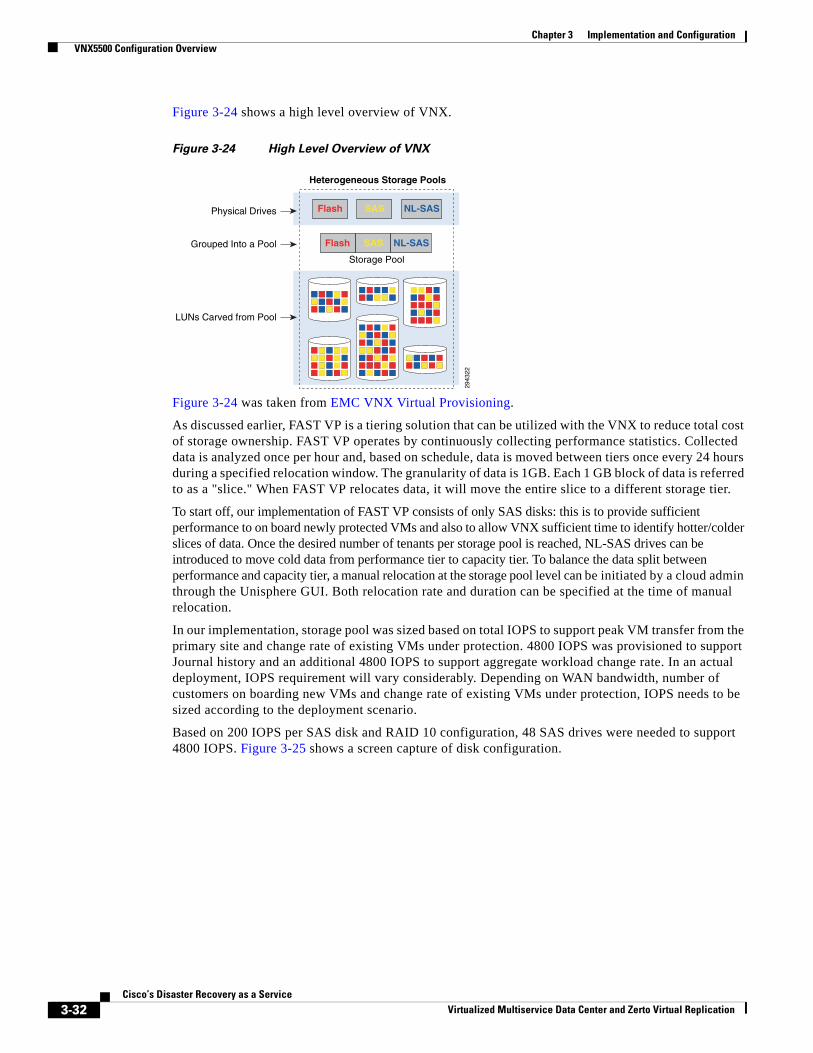
Chapter 3 Implementation and Configuration VNX5500 Configuration Overview
Figure 3-24 shows a high level overview of VNX.
Figure 3-24 High Level Overview of VNX
Figure 3-24 was taken from EMC VNX Virtual Provisioning.
As discussed earlier, FAST VP is a tiering solution that can be utilized with the VNX to reduce total cost of storage ownership. FAST VP operates by continuously collecting performance statistics. Collected data is analyzed once per hour and, based on schedule, data is moved between tiers once every 24 hours during a specified relocation window. The granularity of data is 1GB. Each 1 GB block of data is referred to as a "slice." When FAST VP relocates data, it will move the entire slice to a different storage tier.
To start off, our implementation of FAST VP consists of only SAS disks: this is to provide sufficient performance to on board newly protected VMs and also to allow VNX sufficient time to identify hotter/colder slices of data. Once the desired number of tenants per storage pool is reached, NL-SAS drives can be introduced to move cold data from performance tier to capacity tier. To balance the data split between performance and capacity tier, a manual relocation at the storage pool level can be initiated by a cloud admin through the Unisphere GUI. Both relocation rate and duration can be specified at the time of manual relocation.
In our implementation, storage pool was sized based on total IOPS to support peak VM transfer from the primary site and change rate of existing VMs under protection. 4800 IOPS was provisioned to support Journal history and an additional 4800 IOPS to support aggregate workload change rate. In an actual deployment, IOPS requirement will vary considerably. Depending on WAN bandwidth, number of customers on boarding new VMs and change rate of existing VMs under protection, IOPS needs to be sized according to the deployment scenario.
Based on 200 IOPS per SAS disk and RAID 10 configuration, 48 SAS drives were needed to support 4800 IOPS. Figure 3-25 shows a screen capture of disk configuration.
Storage Pool
Heterogeneous Storage Pools
Flash SAS NL-SAS
Flash SAS NL-SAS
2943
22
Physical Drives
Grouped Into a Pool
LUNs Carved from Pool
3-32Cisco’s Disaster Recovery as a Service
Virtualized Multiservice Data Center and Zerto Virtual Replication
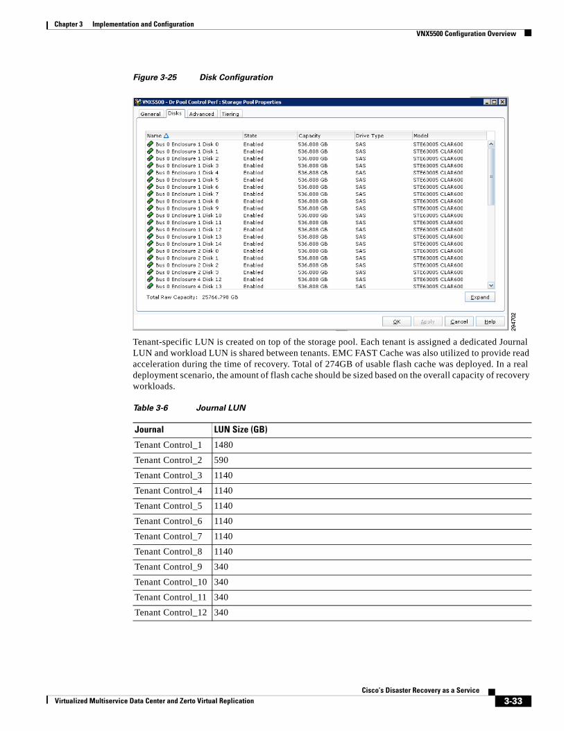
Chapter 3 Implementation and Configuration VNX5500 Configuration Overview
Figure 3-25 Disk Configuration
Tenant-specific LUN is created on top of the storage pool. Each tenant is assigned a dedicated Journal LUN and workload LUN is shared between tenants. EMC FAST Cache was also utilized to provide read acceleration during the time of recovery. Total of 274GB of usable flash cache was deployed. In a real deployment scenario, the amount of flash cache should be sized based on the overall capacity of recovery workloads.
Table 3-6 Journal LUN
Journal LUN Size (GB)
Tenant Control_1 1480
Tenant Control_2 590
Tenant Control_3 1140
Tenant Control_4 1140
Tenant Control_5 1140
Tenant Control_6 1140
Tenant Control_7 1140
Tenant Control_8 1140
Tenant Control_9 340
Tenant Control_10 340
Tenant Control_11 340
Tenant Control_12 340
3-33Cisco’s Disaster Recovery as a Service
Virtualized Multiservice Data Center and Zerto Virtual Replication
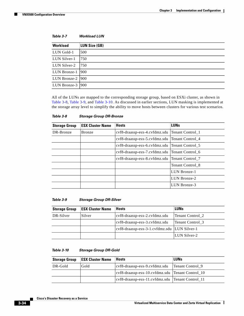
Chapter 3 Implementation and Configuration VNX5500 Configuration Overview
All of the LUNs are mapped to the corresponding storage group, based on ESXi cluster, as shown in Table 3-8, Table 3-9, and Table 3-10. As discussed in earlier sections, LUN masking is implemented at the storage array level to simplify the ability to move hosts between clusters for various test scenarios.
Table 3-7 Workload LUN
Workload LUN Size (GB)
LUN Gold-1 500
LUN Silver-1 750
LUN Silver-2 750
LUN Bronze-1 900
LUN Bronze-2 900
LUN Bronze-3 900
Table 3-8 Storage Group DR-Bronze
Storage Group ESX Cluster Name Hosts LUNs
DR-Bronze Bronze cvf8-draassp-esx-4.cvfdmz.sdu Tenant Control_1
cvf8-draassp-esx-5.cvfdmz.sdu Tenant Control_4
cvf8-draassp-esx-6.cvfdmz.sdu Tenant Control_5
cvf8-draassp-esx-7.cvfdmz.sdu Tenant Control_6
cvf8-draassp-esx-8.cvfdmz.sdu Tenant Control_7
Tenant Control_8
LUN Bronze-1
LUN Bronze-2
LUN Bronze-3
Table 3-9 Storage Group DR-Silver
Storage Group ESX Cluster Name Hosts LUNs
DR-Silver Silver cvf8-draassp-esx-2.cvfdmz.sdu Tenant Control_2
cvf8-draassp-esx-3.cvfdmz.sdu Tenant Control_3
cvf8-draassp-esx-3-1.cvfdmz.sdu LUN Silver-1
LUN Silver-2
Table 3-10 Storage Group DR-Gold
Storage Group ESX Cluster Name Hosts LUNs
DR-Gold Gold cvf8-draassp-esx-9.cvfdmz.sdu Tenant Control_9
cvf8-draassp-esx-10.cvfdmz.sdu Tenant Control_10
cvf8-draassp-esx-11.cvfdmz.sdu Tenant Control_11
3-34Cisco’s Disaster Recovery as a Service
Virtualized Multiservice Data Center and Zerto Virtual Replication
Chapter 3 Implementation and Configuration BMC Cloud Lifecycle Management
BMC Cloud Lifecycle ManagementDRaaS 1.0 leverages existing capabilities of Cloud Orchestration for VMDC with BMC Cloud Lifecycle Management 3.1 SP1. Initial workflows of onboarding tenants, network container creation, firewall policy changes, and server load balancer updates align with VMDC 2.3 operational method and procedures. This is well documented by the SDU BMC-CLM team. Refer to the BMC Design and Implementation Guide for additional details.
cvf8-draassp-esx-12.cvfdmz.sdu Tenant Control_12
LUN Gold-1
Table 3-10 Storage Group DR-Gold (continued)
Storage Group ESX Cluster Name Hosts LUNs
3-35Cisco’s Disaster Recovery as a Service
Virtualized Multiservice Data Center and Zerto Virtual Replication
Chapter 3 Implementation and Configuration BMC Cloud Lifecycle Management
3-36Cisco’s Disaster Recovery as a Service
Virtualized Multiservice Data Center and Zerto Virtual Replication
Virtualized Multiservice Data Center and Zerto Virtual Replication
C H A P T E R 4
Disaster Recovery WorkflowZerto Virtual Replication provides a number of operations to recover virtual machines at the peer site, as follows:
• The Move Operation, page 4-1
• The Failover Operation, page 4-2
• Failback after the Original Site is Operational, page 4-3
• The Failover Test Operation, page 4-4
• The Clone Operation, page 4-5
The Move OperationUse the Move operation to migrate protected virtual machines from the protected (source) site to the recovery (target) site in a planned migration.
When you perform a planned migration of the virtual machines to the recovery site, Zerto Virtual Replication assumes that both sites are healthy and that you planned to relocate the virtual machines in an orderly fashion without loss of data.
The Move operation has the following basic steps:
Step 1 Gracefully shutdown the protected virtual machines. This ensures data integrity. If the machines cannot be gracefully shut down, for example, when VMware Tools is not available, you can manually shut down the machines before starting the Move operation or you specify as part of the operation to forcibly power off the virtual machines. If the machines cannot be gracefully shut down automatically and are not manually shut down and the Move operation is not set to forcibly power them off, the Move operation stops and Zerto Virtual Replication rolls back the virtual machines to their original status.
Step 2 Insert a clean checkpoint. This avoids potential data-loss since the virtual machines are not on and the new checkpoint is after all I/Os have been written to disk.
Step 3 Transfer all the latest changes to the recovery site that are still being queued to pass to the recovery site, including the new checkpoint.
Step 4 Create the virtual machines at the remote site in the production network and attach each virtual machine to its relevant disks, based on the checkpoint inserted in step 2.
Step 5 Power on the virtual machines making them available to the user. If applicable, the boot order defined in the VPG settings to power on the machines in a specified order is used.
4-1Cisco’s Disaster Recovery as a Service
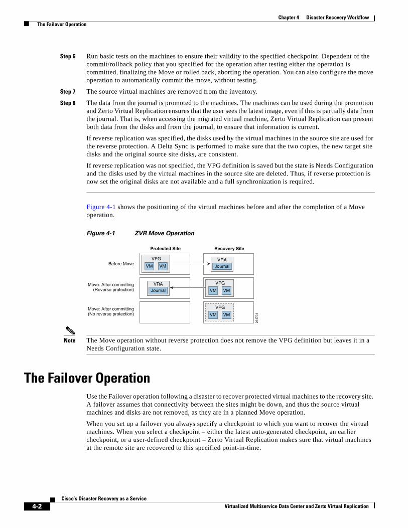
Chapter 4 Disaster Recovery Workflow The Failover Operation
Step 6 Run basic tests on the machines to ensure their validity to the specified checkpoint. Dependent of the commit/rollback policy that you specified for the operation after testing either the operation is committed, finalizing the Move or rolled back, aborting the operation. You can also configure the move operation to automatically commit the move, without testing.
Step 7 The source virtual machines are removed from the inventory.
Step 8 The data from the journal is promoted to the machines. The machines can be used during the promotion and Zerto Virtual Replication ensures that the user sees the latest image, even if this is partially data from the journal. That is, when accessing the migrated virtual machine, Zerto Virtual Replication can present both data from the disks and from the journal, to ensure that information is current.
If reverse replication was specified, the disks used by the virtual machines in the source site are used for the reverse protection. A Delta Sync is performed to make sure that the two copies, the new target site disks and the original source site disks, are consistent.
If reverse replication was not specified, the VPG definition is saved but the state is Needs Configuration and the disks used by the virtual machines in the source site are deleted. Thus, if reverse protection is now set the original disks are not available and a full synchronization is required.
Figure 4-1 shows the positioning of the virtual machines before and after the completion of a Move operation.
Figure 4-1 ZVR Move Operation
Note The Move operation without reverse protection does not remove the VPG definition but leaves it in a Needs Configuration state.
The Failover OperationUse the Failover operation following a disaster to recover protected virtual machines to the recovery site. A failover assumes that connectivity between the sites might be down, and thus the source virtual machines and disks are not removed, as they are in a planned Move operation.
When you set up a failover you always specify a checkpoint to which you want to recover the virtual machines. When you select a checkpoint – either the latest auto-generated checkpoint, an earlier checkpoint, or a user-defined checkpoint – Zerto Virtual Replication makes sure that virtual machines at the remote site are recovered to this specified point-in-time.
2947
04
Protected Site
JournalVRA
JournalVRA
Recovery Site
Before Move
Move: After committing(Reverse protection)
Move: After committing(No reverse protection)
VM
VPG
VM
VM
VPG
VM
VM
VPG
VM
4-2Cisco’s Disaster Recovery as a Service
Virtualized Multiservice Data Center and Zerto Virtual Replication
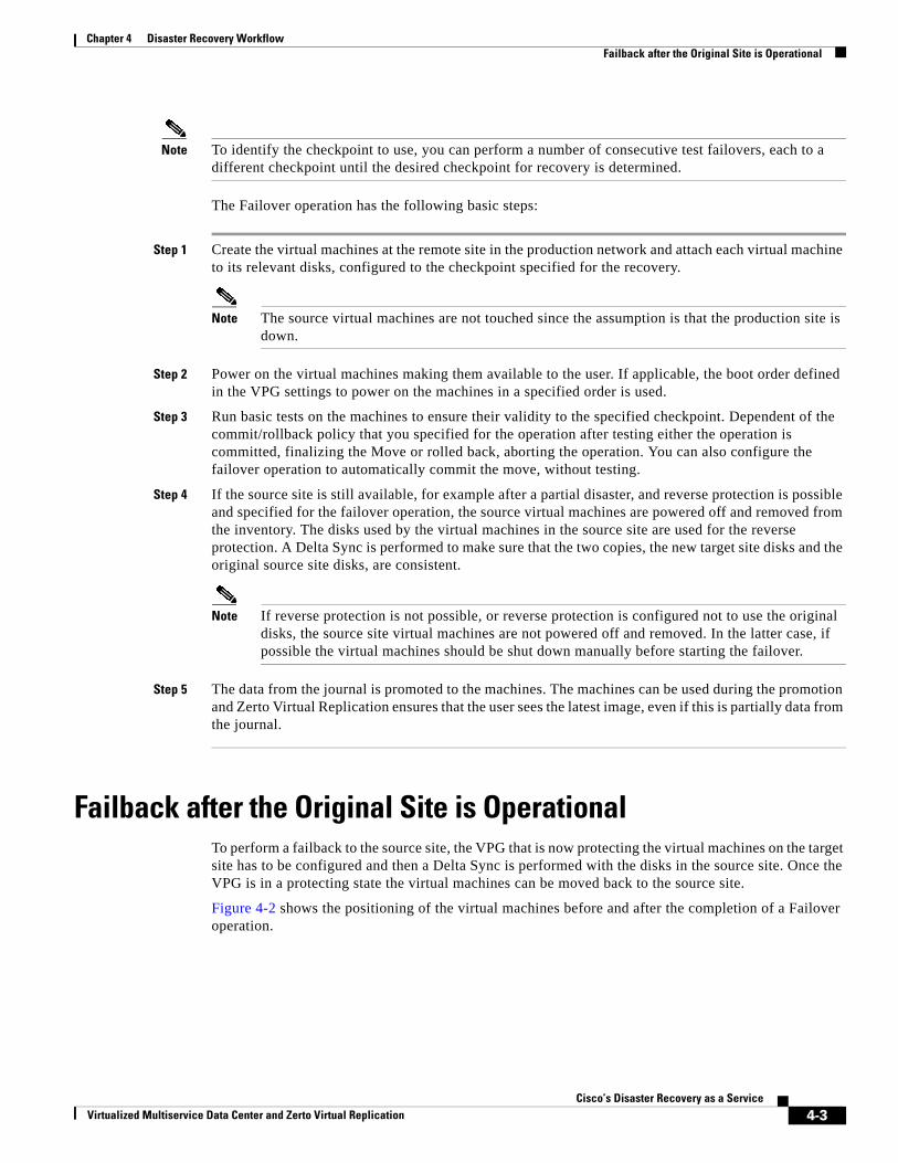
Chapter 4 Disaster Recovery Workflow Failback after the Original Site is Operational
Note To identify the checkpoint to use, you can perform a number of consecutive test failovers, each to a different checkpoint until the desired checkpoint for recovery is determined.
The Failover operation has the following basic steps:
Step 1 Create the virtual machines at the remote site in the production network and attach each virtual machine to its relevant disks, configured to the checkpoint specified for the recovery.
Note The source virtual machines are not touched since the assumption is that the production site is down.
Step 2 Power on the virtual machines making them available to the user. If applicable, the boot order defined in the VPG settings to power on the machines in a specified order is used.
Step 3 Run basic tests on the machines to ensure their validity to the specified checkpoint. Dependent of the commit/rollback policy that you specified for the operation after testing either the operation is committed, finalizing the Move or rolled back, aborting the operation. You can also configure the failover operation to automatically commit the move, without testing.
Step 4 If the source site is still available, for example after a partial disaster, and reverse protection is possible and specified for the failover operation, the source virtual machines are powered off and removed from the inventory. The disks used by the virtual machines in the source site are used for the reverse protection. A Delta Sync is performed to make sure that the two copies, the new target site disks and the original source site disks, are consistent.
Note If reverse protection is not possible, or reverse protection is configured not to use the original disks, the source site virtual machines are not powered off and removed. In the latter case, if possible the virtual machines should be shut down manually before starting the failover.
Step 5 The data from the journal is promoted to the machines. The machines can be used during the promotion and Zerto Virtual Replication ensures that the user sees the latest image, even if this is partially data from the journal.
Failback after the Original Site is OperationalTo perform a failback to the source site, the VPG that is now protecting the virtual machines on the target site has to be configured and then a Delta Sync is performed with the disks in the source site. Once the VPG is in a protecting state the virtual machines can be moved back to the source site.
Figure 4-2 shows the positioning of the virtual machines before and after the completion of a Failover operation.
4-3Cisco’s Disaster Recovery as a Service
Virtualized Multiservice Data Center and Zerto Virtual Replication
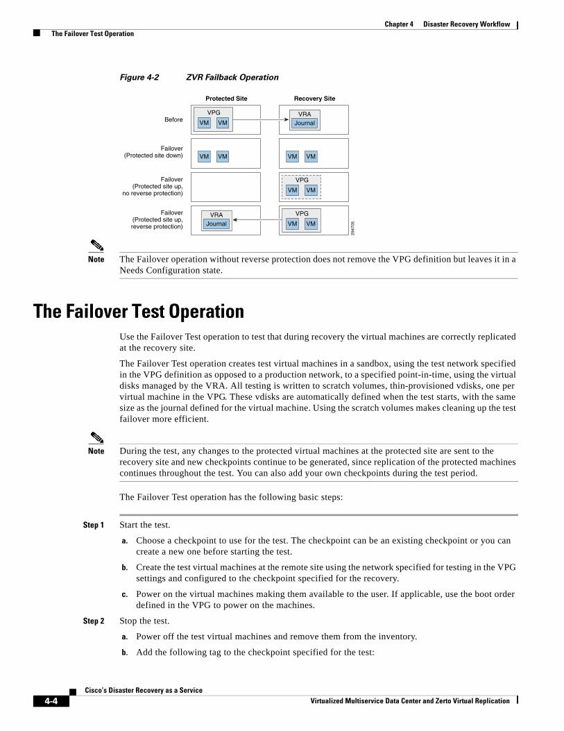
Chapter 4 Disaster Recovery Workflow The Failover Test Operation
Figure 4-2 ZVR Failback Operation
Note The Failover operation without reverse protection does not remove the VPG definition but leaves it in a Needs Configuration state.
The Failover Test OperationUse the Failover Test operation to test that during recovery the virtual machines are correctly replicated at the recovery site.
The Failover Test operation creates test virtual machines in a sandbox, using the test network specified in the VPG definition as opposed to a production network, to a specified point-in-time, using the virtual disks managed by the VRA. All testing is written to scratch volumes, thin-provisioned vdisks, one per virtual machine in the VPG. These vdisks are automatically defined when the test starts, with the same size as the journal defined for the virtual machine. Using the scratch volumes makes cleaning up the test failover more efficient.
Note During the test, any changes to the protected virtual machines at the protected site are sent to the recovery site and new checkpoints continue to be generated, since replication of the protected machines continues throughout the test. You can also add your own checkpoints during the test period.
The Failover Test operation has the following basic steps:
Step 1 Start the test.
a. Choose a checkpoint to use for the test. The checkpoint can be an existing checkpoint or you can create a new one before starting the test.
b. Create the test virtual machines at the remote site using the network specified for testing in the VPG settings and configured to the checkpoint specified for the recovery.
c. Power on the virtual machines making them available to the user. If applicable, use the boot order defined in the VPG to power on the machines.
Step 2 Stop the test.
a. Power off the test virtual machines and remove them from the inventory.
b. Add the following tag to the checkpoint specified for the test:
2947
05
Protected Site
JournalVRA
Recovery Site
Before
Failover(Protected site down)
Failover(Protected site up,
no reverse protection)
Failover(Protected site up,reverse protection)
VM
VPG
VM
VM VM VM VM
JournalVRA
VM
VPG
VM
VM
VPG
VM
4-4Cisco’s Disaster Recovery as a Service
Virtualized Multiservice Data Center and Zerto Virtual Replication
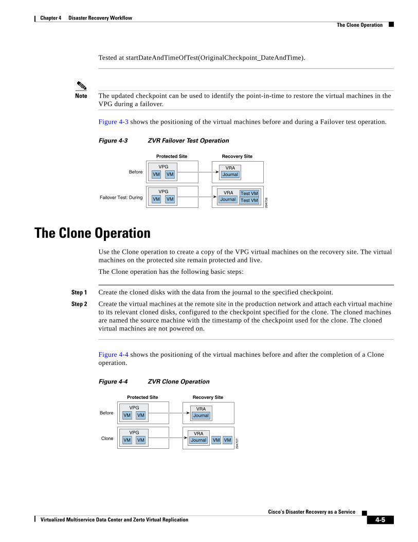
Chapter 4 Disaster Recovery Workflow The Clone Operation
Tested at startDateAndTimeOfTest(OriginalCheckpoint_DateAndTime).
Note The updated checkpoint can be used to identify the point-in-time to restore the virtual machines in the VPG during a failover.
Figure 4-3 shows the positioning of the virtual machines before and during a Failover test operation.
Figure 4-3 ZVR Failover Test Operation
The Clone OperationUse the Clone operation to create a copy of the VPG virtual machines on the recovery site. The virtual machines on the protected site remain protected and live.
The Clone operation has the following basic steps:
Step 1 Create the cloned disks with the data from the journal to the specified checkpoint.
Step 2 Create the virtual machines at the remote site in the production network and attach each virtual machine to its relevant cloned disks, configured to the checkpoint specified for the clone. The cloned machines are named the source machine with the timestamp of the checkpoint used for the clone. The cloned virtual machines are not powered on.
Figure 4-4 shows the positioning of the virtual machines before and after the completion of a Clone operation.
Figure 4-4 ZVR Clone Operation
2947
06
Protected Site
JournalVRA
Recovery Site
Before
Failover Test: During
VM
VPG
VM
Journal Test VM
Test VMVRAVM
VPG
VM
2947
07
Protected Site
JournalVRA
JournalVRA
Recovery Site
Before
Clone
VM
VPG
VM
VM
VPG
VM VM VM
4-5Cisco’s Disaster Recovery as a Service
Virtualized Multiservice Data Center and Zerto Virtual Replication
Chapter 4 Disaster Recovery Workflow Verification—User Traffic Not Run Against Recovered VMs
Verification—User Traffic Not Run Against Recovered VMsBasic testing that the virtual machines can recover is done using either a Failover Test operation or an uncommitted Move operation, using the Rollback setting.
Using a Failover Test OperationYou use a Failover Test operation if recovering the virtual machines in a sandbox, using the test network specified in the VPG definition for network isolation, is sufficient for the test.
The Failover Test operation is described in the Zerto Virtual Replication Administration Guide.
Failover Test Considerations
• You don’t have to shut down the production virtual machines and changes from the test phase are not kept or applied to the source applications.
• You can recover to a specific point-in-time.
• You can use an isolated network to enable testing in a sandbox environment and not a live DR environment. This is the recommended practice.
• During the testing period, every change is recorded in a scratch volume. The longer the test period the bigger the scratch volume, limiting the length of time of the test to the size of the volume.
• You can also use a Failover Test operation if you want to simulate an actual disaster for around an hour or less and do not want to save any changes on the recovery site.
Procedure
Step 1 Change the VPG Failover Test Network to the production network used at the recovery site.
Step 2 Manually shutdown the virtual machines in the VPG.
Step 3 Insert a new checkpoint. This avoids potential data-loss since the virtual machines are shut down and the new checkpoint is added after all I/Os have been written to disk.
Step 4 Optionally simulate a disaster, for example by disconnecting the connectivity between the two sites.
Step 5 Perform a test failover on the VPG, choosing the checkpoint you added in the second step.
Step 6 Verify that the test machines are recovered as expected.
Step 7 Run user traffic against the virtual machines.
Step 8 Stop the failover test.
Step 9 Reconnect the sites.
Failover Test Considerations
• You can recover to a specific point-in-time.
• At the end of the test, you can power on the virtual machines in the protected site and continue to work without the need to save or replicate back any data changed during the test.
4-6Cisco’s Disaster Recovery as a Service
Virtualized Multiservice Data Center and Zerto Virtual Replication
Chapter 4 Disaster Recovery Workflow Verification—User Traffic Not Run Against Recovered VMs
Using an Uncommitted Move Operation
You use a Move operation with the commit/rollback policy set to rollback after the test period, if recovering the virtual machines needs testing in the production environment.
Note Committing the Move operation will necessitate failing the migrated virtual machines back to the production site after a Delta Sync has been performed on the committed machines in the recovery site.
Procedure
The Move operation is described above and in the Zerto Virtual Replication Administration Guide. The following procedure highlights specific steps to enable using the Move functionality for a DR test.
Step 1 In the Move Wizard Configure dialog, uncheck the commit policy checkbox.
Step 2 Either power off the relevant virtual machines or check the Force Shutdown checkbox to make sure that the virtual machines are shut down, if they cannot be powered off using VMware Tools.
Step 3 After testing the machines in the recovery site you can roll back the Move operation, which will return the virtual machines to their pre-test state.
Move Considerations
• Changes from the pre-commit phase are not kept or applied to the source applications.
• The virtual machines are allocated disks and connected to the network for a full test of the environment.
• The production machines are turned off until the end of the test, ensuring that there are no conflicts between the production site and recovery site.
• During the testing period, every change is recorded in a scratch volume to enable rolling back. Thus, since both the scratch volume and virtual machines being moved are on the same site, performance can be impacted by the increased IOs during the testing period. Also, the longer the test period the larger the scratch volume grows, until the maximum size is reached, at which point no more testing can be done.
• You can only recover to the last checkpoint written to the journal, at the start of the Move operation.
Run User Traffic against the Recovered VMs
To test actual user traffic against the recovered virtual machines can be done using a Clone, Move or Failover operation, as follows:
• Using a Move Operation, page 4-8 when you can shut down the source virtual machines but you don’t want or need to simulate an actual disaster.
• Using a Failover Operation, page 4-8 when you want to simulate an actual disaster.
• Using a Clone Operation, page 4-9 when the source application has to continue throughout the test.
4-7Cisco’s Disaster Recovery as a Service
Virtualized Multiservice Data Center and Zerto Virtual Replication
Chapter 4 Disaster Recovery Workflow Verification—User Traffic Not Run Against Recovered VMs
Using a Move Operation
You use a Move operation when you can shut down the source virtual machines but you don’t want to simulate an actual disaster. After the virtual machines have been recovered in the target site they are used as the production machines for as long as the test lasts.
Procedure
The Move operation is described above and in the Zerto Virtual Replication Administration Guide. To enable using the Move functionality for a DR test, in the Move Wizard Configure dialog uncheck the commit policy checkbox.
Ending the Test
Move the VPG back to the source site. A Delta Sync is performed to copy the new transactions performed on the virtual machines in the target site back to the source site.
Move Considerations
• You can test the moved machines before they are committed.
• You can test for as long as you want.
• The virtual machines are allocated disks and connected to the network for a full test of the environment.
• The originally protected disks are maintained for a faster failback when reverse replication is specified.
• The production machines are turned off until they are committed and then removed from the production site. This ensures that there are no conflicts between the production site and recovery site.
• You cannot test to any checkpoint you want but only to the last checkpoint, taken after the production virtual machines are shutdown.
• An actual disaster is not simulated.
• During the testing period, if reverse replication is not specified, there is no protection for the recovered machines.
Using a Failover Operation
You use a Failover operation when you can shut down the source virtual machines and you want to simulate an actual disaster. After the virtual machines have been recovered in the target site they are used as the production machines for as long as the test lasts.
Using a Failover operation to test DR requires specific steps to ensure that the virtual machines are gracefully migrated to the target site, similar to a Move operation and that, like a Move operation, they can be verified prior to committing the failover.
Procedure
The Failover operation is described above and in the Zerto Virtual Replication Administration Guide. The following procedure highlights specific steps for a DR test.
Step 1 Optionally simulate a disaster, for example by disconnecting the connectivity between the two sites.
Step 2 Perform a live failover on the VPG, and in the Live Failover wizard Configure dialog, uncheck the commit policy checkbox.
4-8Cisco’s Disaster Recovery as a Service
Virtualized Multiservice Data Center and Zerto Virtual Replication
Chapter 4 Disaster Recovery Workflow Verification—User Traffic Not Run Against Recovered VMs
Step 3 Either power off the relevant virtual machines or check the Force option to make sure that the virtual machines are shut down, if they cannot be powered off using VMware Tools.
Step 4 After testing the machines in the recovery site, Reconnect the sites.
Step 5 Roll back the Failover operation, which will return the virtual machines to their pre-test state.
The VMs are recovered at the source site, and the VPG enters a Delta Sync phase before it enters a Protecting state.
Failover Considerations
• Non-intuitive use of the failover procedure.
• During the testing period, there is no protection for the recovered machines.
Using a Clone Operation
You use the Clone operation when the source application has to continue throughout the test. You can create a clone of the virtual machines in a VPG on the peer site to a specific point-in-time. The clone is a copy of the protected virtual machines on the recovery site, while the virtual machines on the protected site remain protected and live.
Procedure
The Clone operation is described above and in the in the Zerto Virtual Replication Administration Guide.
The cloned virtual machines are independent of Zerto Virtual Replication. At the end of the test you can remove these machines or leave them.
Clone Considerations
• You can clone to a specific point-in-time.
• There is no protection for the cloned machines.
• After use of the clone ends, none of the changes to the clone are kept.
• The original virtual machines on the source site are live and online throughout the test.
4-9Cisco’s Disaster Recovery as a Service
Virtualized Multiservice Data Center and Zerto Virtual Replication
Chapter 4 Disaster Recovery Workflow Verification—User Traffic Not Run Against Recovered VMs
4-10Cisco’s Disaster Recovery as a Service
Virtualized Multiservice Data Center and Zerto Virtual Replication
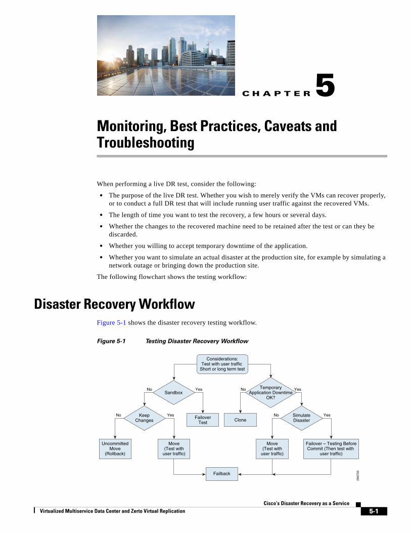
Virtualized Multiservice Data Center and Zerto Virtual Replication
C H A P T E R 5
Monitoring, Best Practices, Caveats and TroubleshootingWhen performing a live DR test, consider the following:
• The purpose of the live DR test. Whether you wish to merely verify the VMs can recover properly, or to conduct a full DR test that will include running user traffic against the recovered VMs.
• The length of time you want to test the recovery, a few hours or several days.
• Whether the changes to the recovered machine need to be retained after the test or can they be discarded.
• Whether you willing to accept temporary downtime of the application.
• Whether you want to simulate an actual disaster at the production site, for example by simulating a network outage or bringing down the production site.
The following flowchart shows the testing workflow:
Disaster Recovery WorkflowFigure 5-1 shows the disaster recovery testing workflow.
Figure 5-1 Testing Disaster Recovery Workflow
2947
03
Sandbox
KeepChanges
FailoverTest
Failback
UncommittedMove
(Rollback)
Move(Test with
user traffic)
YesNo YesNo
No Yes No Yes
TemporaryApplication Downtime
OK?
SimulateDisasterClone
Failover – Testing BeforeCommit (Then test with
user traffic)
Move(Test with
user traffic)
Considerations:Test with user traffic
Short or long term test
5-1Cisco’s Disaster Recovery as a Service
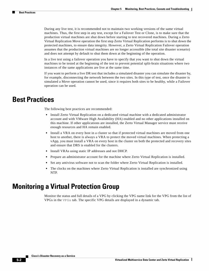
Chapter 5 Monitoring, Best Practices, Caveats and Troubleshooting Best Practices
During any live test, it is recommended not to maintain two working versions of the same virtual machines. Thus, the first step in any test, except for a Failover Test or Clone, is to make sure that the production virtual machines are shut down before starting to test recovered machines. During a Zerto Virtual Replication Move operation the first step Zerto Virtual Replication performs is to shut down the protected machines, to ensure data integrity. However, a Zerto Virtual Replication Failover operation assumes that the production virtual machines are no longer accessible (the total site disaster scenario) and does not attempt by default to shut them down at the beginning of the operation.
In a live test using a failover operation you have to specify that you want to shut down the virtual machines to be tested at the beginning of the test to prevent potential split-brain situations where two instances of the same applications are live at the same time.
If you want to perform a live DR test that includes a simulated disaster you can simulate the disaster by, for example, disconnecting the network between the two sites. In this type of test, once the disaster is simulated a Move operation cannot be used, since it requires both sites to be healthy, while a Failover operation can be used.
Best PracticesThe following best practices are recommended:
• Install Zerto Virtual Replication on a dedicated virtual machine with a dedicated administrator account and with VMware High Availability (HA) enabled and no other applications installed on this machine. If other applications are installed, the Zerto Virtual Manager service must receive enough resources and HA remain enabled.
• Install a VRA on every host in a cluster so that if protected virtual machines are moved from one host to another, there is always a VRA to protect the moved virtual machines. When protecting a vApp, you must install a VRA on every host in the cluster on both the protected and recovery sites and ensure that DRS is enabled for the clusters.
• Install VRAs using static IP addresses and not DHCP.
• Prepare an administrator account for the machine where Zerto Virtual Replication is installed.
• Set any antivirus software not to scan the folder where Zerto Virtual Replication is installed.
• The clocks on the machines where Zerto Virtual Replication is installed are synchronized using NTP.
Monitoring a Virtual Protection GroupMonitor the status and full details of a VPG by clicking the VPG name link for the VPG from the list of VPGs in the VPGs tab. The specific VPG details are displayed in a dynamic tab.
5-2Cisco’s Disaster Recovery as a Service
Virtualized Multiservice Data Center and Zerto Virtual Replication
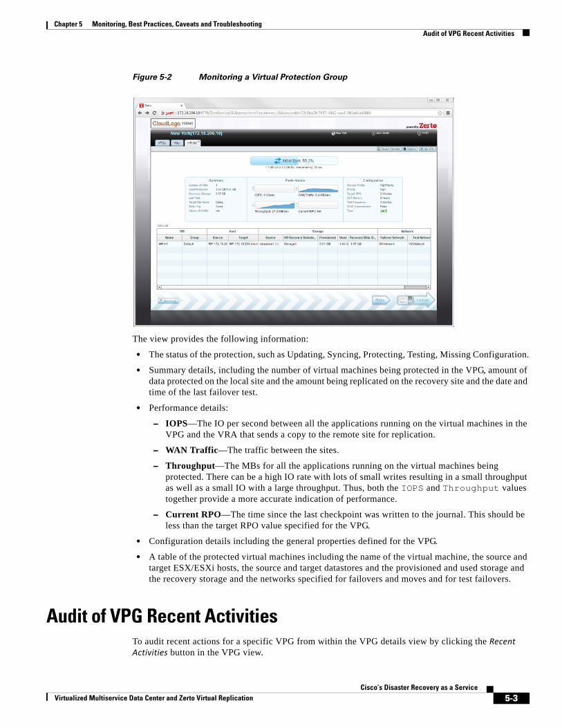
Chapter 5 Monitoring, Best Practices, Caveats and Troubleshooting Audit of VPG Recent Activities
Figure 5-2 Monitoring a Virtual Protection Group
The view provides the following information:
• The status of the protection, such as Updating, Syncing, Protecting, Testing, Missing Configuration.
• Summary details, including the number of virtual machines being protected in the VPG, amount of data protected on the local site and the amount being replicated on the recovery site and the date and time of the last failover test.
• Performance details:
– IOPS—The IO per second between all the applications running on the virtual machines in the VPG and the VRA that sends a copy to the remote site for replication.
– WAN Traffic—The traffic between the sites.
– Throughput—The MBs for all the applications running on the virtual machines being protected. There can be a high IO rate with lots of small writes resulting in a small throughput as well as a small IO with a large throughput. Thus, both the IOPS and Throughput values together provide a more accurate indication of performance.
– Current RPO—The time since the last checkpoint was written to the journal. This should be less than the target RPO value specified for the VPG.
• Configuration details including the general properties defined for the VPG.
• A table of the protected virtual machines including the name of the virtual machine, the source and target ESX/ESXi hosts, the source and target datastores and the provisioned and used storage and the recovery storage and the networks specified for failovers and moves and for test failovers.
Audit of VPG Recent ActivitiesTo audit recent actions for a specific VPG from within the VPG details view by clicking the Recent Activities button in the VPG view.
5-3Cisco’s Disaster Recovery as a Service
Virtualized Multiservice Data Center and Zerto Virtual Replication
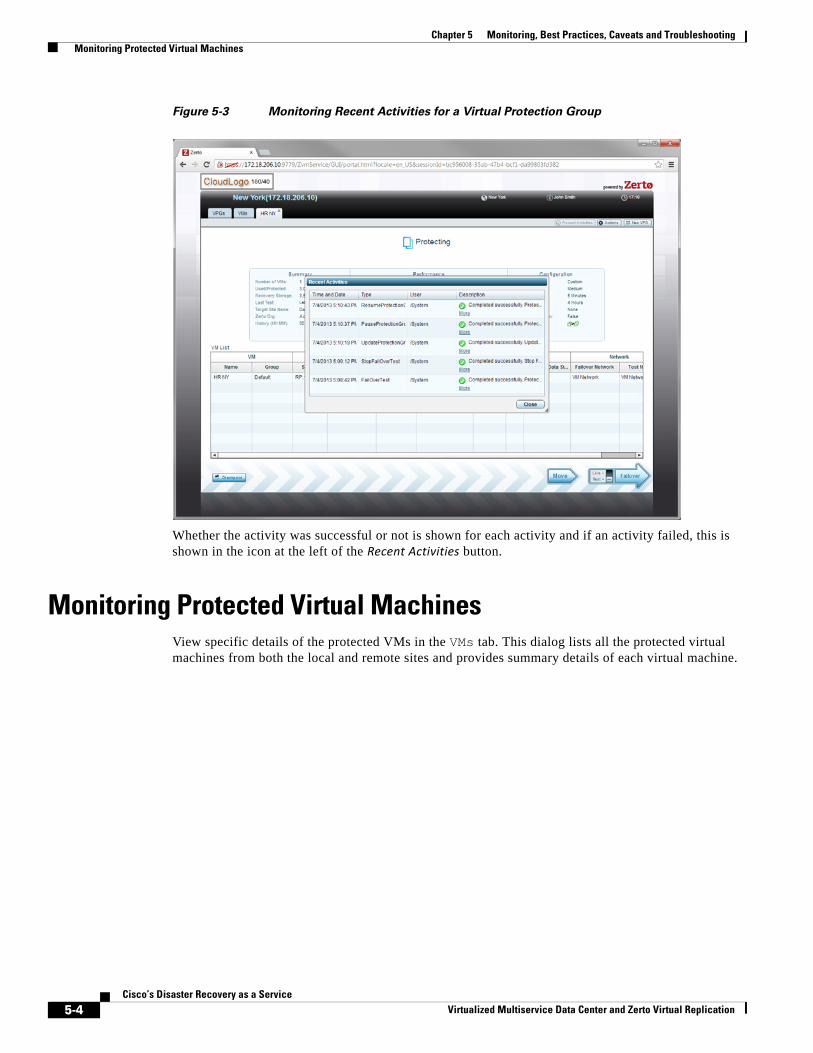
Chapter 5 Monitoring, Best Practices, Caveats and Troubleshooting Monitoring Protected Virtual Machines
Figure 5-3 Monitoring Recent Activities for a Virtual Protection Group
Whether the activity was successful or not is shown for each activity and if an activity failed, this is shown in the icon at the left of the Recent Activities button.
Monitoring Protected Virtual MachinesView specific details of the protected VMs in the VMs tab. This dialog lists all the protected virtual machines from both the local and remote sites and provides summary details of each virtual machine.
5-4Cisco’s Disaster Recovery as a Service
Virtualized Multiservice Data Center and Zerto Virtual Replication
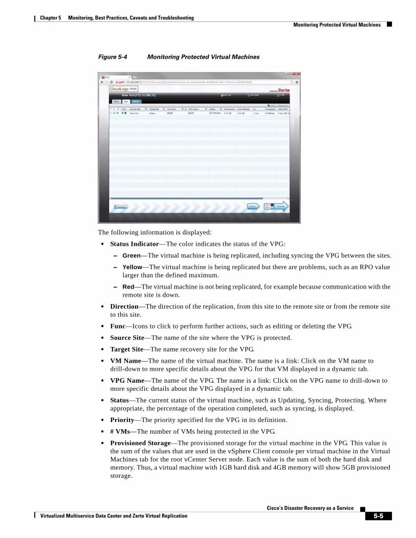
Chapter 5 Monitoring, Best Practices, Caveats and Troubleshooting Monitoring Protected Virtual Machines
Figure 5-4 Monitoring Protected Virtual Machines
The following information is displayed:
• Status Indicator—The color indicates the status of the VPG:
– Green—The virtual machine is being replicated, including syncing the VPG between the sites.
– Yellow—The virtual machine is being replicated but there are problems, such as an RPO value larger than the defined maximum.
– Red—The virtual machine is not being replicated, for example because communication with the remote site is down.
• Direction—The direction of the replication, from this site to the remote site or from the remote site to this site.
• Func—Icons to click to perform further actions, such as editing or deleting the VPG.
• Source Site—The name of the site where the VPG is protected.
• Target Site—The name recovery site for the VPG.
• VM Name—The name of the virtual machine. The name is a link: Click on the VM name to drill-down to more specific details about the VPG for that VM displayed in a dynamic tab.
• VPG Name—The name of the VPG. The name is a link: Click on the VPG name to drill-down to more specific details about the VPG displayed in a dynamic tab.
• Status—The current status of the virtual machine, such as Updating, Syncing, Protecting. Where appropriate, the percentage of the operation completed, such as syncing, is displayed.
• Priority—The priority specified for the VPG in its definition.
• # VMs—The number of VMs being protected in the VPG.
• Provisioned Storage—The provisioned storage for the virtual machine in the VPG. This value is the sum of the values that are used in the vSphere Client console per virtual machine in the Virtual Machines tab for the root vCenter Server node. Each value is the sum of both the hard disk and memory. Thus, a virtual machine with 1GB hard disk and 4GB memory will show 5GB provisioned storage.
5-5Cisco’s Disaster Recovery as a Service
Virtualized Multiservice Data Center and Zerto Virtual Replication
Chapter 5 Monitoring, Best Practices, Caveats and Troubleshooting Upgrades
• Used Storage—The storage used by the virtual machine in the VPG. This value is the sum of the values that are used in the vSphere Client console per virtual machine in the Virtual Machines tab for the root vCenter Server node.
• IO—The IO per second between all the applications running on the virtual machine in the VPG and the VRA that sends a copy to the remote site for replication.
• Throughput—The MBs for all the applications running on the virtual machine being protected. There can be a high IO rate with lots of small writes resulting in a small throughput as well as a small IO with a large throughput. Thus, both the IOPS and Throughput values together provide a more accurate indication of performance.
• Actual RPO—The time since the last checkpoint was written to the journal. This should be less than the target RPO value specified for the VPG.
• Last Test—The date and time of the last failover test performed on the VPG protecting this virtual machine.
Determining Which Columns and Order to DisplayWhen moving the mouse pointer over the list, a configuration cog is displayed on the right of the list. Clicking the cog icon opens the Edit Columns dialog, where it can be specified to what columns to display in the list.
Drag-and-drop column headers to rearrange the order the columns are displayed. A thick vertical bar shows where a column can be dragged and dropped.
Reset the display to the default display by clicking the Reset Columns link.
The ability to reset the columns and to open the Edit Columns dialog is also available by right-clicking in the list.
Filtering InformationFilter the list so that to easily identify the VPGs and virtual machines to monitor.
Filter columns by clicking the filter icon and then either by typing part of the value only, for example with the Source Site field, filter using actual values, for example with the Priority field. The filter changes color from grey to blue when a filter is applied. A link in the filter area enables clearing the filter.
UpgradesYou can only upgrade to the next major version or any upgrade within the version. All versions prior to version 3.0 are considered major versions: 2.0, 2.0U1, 2.0U2, etc.
• As of version 3.0, upgrade versions, 3.0U1, 3.0U2, etc., are considered, for upgrade purposes, as the same version. Thus, Zerto Virtual Replication 2.0U4 and 2.0U5 are major versions while Zerto Virtual Replication 3.0, 3.0U1, 3.0U2, etc. are all considered one version.
• Before upgrading Zerto Virtual Replication, clear the Microsoft Internet Explorer cache of temporary internet files. Not clearing the cache of temporary files can result in problems when accessing the Zerto Virtual Manager via the vSphere Client console.
5-6Cisco’s Disaster Recovery as a Service
Virtualized Multiservice Data Center and Zerto Virtual Replication
Chapter 5 Monitoring, Best Practices, Caveats and Troubleshooting Upgrades
• If a newer version of the installed Virtual Replication Appliances (VRAs) exists, you can continue to use these VRAs with the new version or upgrade these VRAs from within the Zerto Virtual Replication user interface, via the Zerto standalone UI, vSphere Client console or vSphere Web Client. Zerto recommends to upgrade the VRAs.
Upgrading or Reinstalling a vCenter ServerWhen changing the version of the vCenter Server, you can upgrade the vCenter Server or reinstall it.
Upgrading a vCenter Server When you upgrade a vCenter Server, preserving the vCenter database, the Zerto Virtual Replication components are not affected and protection continues without needing to perform any additional procedures.
The Zerto best practice is to upgrade a vCenter Server in preference to reinstalling it.
Reinstalling a vCenter Server If the vCenter is unable to be upgraded, contact Zerto for help throughout the vCenter reinstallation.
5-7Cisco’s Disaster Recovery as a Service
Virtualized Multiservice Data Center and Zerto Virtual Replication
Chapter 5 Monitoring, Best Practices, Caveats and Troubleshooting Upgrades
5-8Cisco’s Disaster Recovery as a Service
Virtualized Multiservice Data Center and Zerto Virtual Replication
Virtualized Multiservice Data Center and Zerto Virtual Replication
A
P P E N D I X A ReferencesThe following reference documents are available.
Cisco VMDC 2.2
• Cisco VMDC 2.2 Design Guide
• Cisco VMDC 2.2 Implementation Guide
• Cisco VMDC Documentation on Cisco.com Design Zone
• Cloud Ready Infrastructure Smart Solutions Kits Accelerate Design and Deployment of Unified DC
Cisco VMDC 2.3
• VMDC 2.3 Design Guide
• VMDC 2.3 Implementation Guide
• VMDC 2.3 Test Results Report
• SP Cloud Smart Solutions with VMDC
• Cloud Service Assurance for VMDC Design and Implementation Guide
• Cloud Orchestration for VMDC with BMC Cloud Lifecycle Management 3.1 SP1 Design and Implementation Guide
A-1Cisco’s Disaster Recovery as a Service
Appendix A References
A-2Cisco’s Disaster Recovery as a Service
Virtualized Multiservice Data Center and Zerto Virtual Replication