city center a-
TRANSCRIPT

Structural analysis & design Chapter 4
52
Chapter 4
Structural Analysis & Design
City Center "A"-
4.1 Introduction.
4.2 Factored Loads.
4.3 Slabs Thickness calculation.
4.4 Load Calculation.
4.5 Design of Topping.
4.6 Design of Rib (R1-(09)).
4.7 Design of Beam (B2-(04)).
4.8 Design of Column (C32 )
4.9 Design of Stair
4.10 Design of Basement Wall
4.11 Design of Isolated Footing (F5-C50)
4

Structural analysis & design Chapter 4
53
City Center "B"-
4.12Design of flat slab
4.13Design of Column (C44 )
4.14 Design of Shear Wall
4.15Design of Mat Foundation
4.16 Design of Spherical Shell

Structural analysis & design Chapter 4
54
4.1 Introduction:
Many structures are built of reinforced concrete: bridges, buildings,retaining walls, tunnels, and others.
Reinforced concrete is logical union of two materials: plain concrete,which possesses high compressive strength but little tensile strength, andsteel bars embedded in the concrete, which can provide the needed strengthin tension.
4.1.1 Design method and requirements:
The design strength provided by a member is calculated in accordancewith the requirements and assump ons of ACI_code (318M_14).
4.1.2 Strength design method:
In ultimate strength design method, the service loads are increased byfactors to obtain the load at which failure is considered to be occur.
This load called factored load or factored service load. The structure orstructural element is then proportioned such that the strength is reachedwhen factored load is acting. The computation of this strength takes intoaccount the nonlinear stress-strain behavior of concrete.
The strength design method is expressed by the following,
Strength provided ≥ strength required to carry factored loads.

Structural analysis & design Chapter 4
55
4.2 Factored loads: -
The factored loads for members in our project are determined by:
Wu = 1.4 DLACI-code-318-14(9.2.1).
Wu = 1.2 DL + 1.6 LL ACI-code-318-14(9.2.2).
Materials:-
Concrete B300, Fc' = 0.8*30 = 24 N/mm2 =24Mpa
Reinforcement Steel, fy = 420 N/mm2 =420 Mpa
420 , will be used in design and calculations.
4.3Slabs Thickness calculation:-According to ACI-Code-318-14 table 9.5(a), the minimum thickness of
non- prestressed beams or one way, slabs unless deflections are computed forone end continuous for one-way rib slabb given as following:
Fig (4-1):Rib(R2-(17)) at the First floor
Fig (4-2): spans of rib (R2-(17))

Structural analysis & design Chapter 4
56
Hminfor two end continuous beam
Hmin = L/21 longest two end con nuous supported is 6.78m
Hmin =6780/21 = 322.85 mm
For First floor slab, use thickness of slab 35cm.
4.4 Load Calculation:-
For the one-way ribbed slabs, the total dead load to be used in theanalysis and design is calculated as follows:
Fig (4-3) Typical section in ribbed slab

Structural analysis & design Chapter 4
57
Fig (4-4) Typical section in topping
table (4-1) calcula on of total load ofR1-09
4.5 Design of Topping:-
4.5.1 Calculation of Dead load For 1m strip
الرقم
المتسلسلUnit weight(kN/m3)Material
123tile
222mortar
316sand
425toppting
510block
625rib
722plaster
82.3(KN/m2)partion
table (4-2) calculation of dead load for topping.
Material Unitweight
(KN/m³)
Thickness(cm)
load
Tile 23 3 0.69
Mortar 22 2 0.44
Sand 16 7 1.12
Topping slab 25 8 2
partition 2.3KN/m2 2.3
D.Ltot 6.55

Structural analysis & design Chapter 4
58
4.5.2 Calculation of live loadFrom Jordan's Code
L.L total = 4KN/m
Wu = 1.2D.L + 1.6L.L
= 1.2*6.55 + 1.6*4 = 14.3 KN/m
Design of shear :-
Used fy = 420 MPa& cf = 24MPa
* Vc =*N86.249001.0801000
6
12475.0 kKN
No shear reinforcement is required.
CheckΦMn> Mu
mkNlw
Mu u .19.012
4.0*3.14
12
* 22
sfcMn *'42.0
6
2bhS
6*'42.0
2bhfcMn
mkNMn .19.2106
80*10002442.0 6
2
Ø=0.55 for plain concrete
..195.0.204.1
..205.119.2*55.0
mkNMumkNMn
mkNMn

Structural analysis & design Chapter 4
59
No reinforcement is required according to ACI-Code -318M-14, so As min forslabs as Shrinkage and temperature reinforcement .
Shrinkage and temperature reinforcement must be provided.
For the shrinkage and temperature reinforcement:
0018.0
ACI-318-14 (7.12.2)
As = * b * h = 0.0018 * 1000 * 80 = 144 mm2/ m
As (ɸ8) =50.27mm2
So number of bars =144/50.27 = 2.86
1/N =350 mm
The step is the smallest of :-
1_ S=3*h = 240mm. control
2_ S =380(fs
280 )2.5Cc= 380(420)3/2(
280
)-2.5*20
= 330
select mesh ɸ8/20cm, As.prov = 2.51 cm²/m >Asmin=1.44 cm²/m
Then use Ф 8 @ 20cm for prac cal purposes in both direc ons.
From practical consideration, the secondary reinforcement parallel to the ribshall be placed in the slab and spaced at distance not more than half of thespacings between ribs (usually two bars upon each 40 cm width block).

Structural analysis & design Chapter 4
60
4.6 Design of Rib (R1-(09)):-
Fig (4-5):Rib(R1-(09)) at the First floor
4.6.1 Design constant:-- Eb For T- section is the smallest of the following:
Eb =Ln/4= 4.83/ 4 =1.21m
Eb = bw + 16 tf = 12 + 16 (8) = 1.4 m
Eb = c/c spacing between adjacent ribs =0.52 m
Control … 52cm
- Requirements for Slab Floor According to ACI- (318M-14).
bw ≥ 10cm……………………………………………ACI(8.13.2)
Select bw=12cm
h ≤ 3.5*bw ……………………………….…….. ACI (8.13.2)
Select h=35cm<3.5*12=42cm
tf ≥ Ln/12≥50mm ………………………………….ACI(8.13.6.1)
Select =8cm

Structural analysis & design Chapter 4
61
4.6.2 Calculation of Dead load:-
Dead load Calculation
Tiles 23*0.03*0.52 = 0.3588 KN/m
Mortar 22*0.02*0.52 = 0.2288 KN/m
Sand 16*0.07*0.52 = 0.5824 KN/m
Topping 25*0.08*0.52 = 1.04 KN/m
Block 10*0.27*0.4 = 1.08 KN/m
Rib 25*0.27*0.12 = 0.81KN/m
Plastering 22*0.02*0.52 =0.2288 KN/m
Partition 2.3*0.52 =1.196 KN/m
Table (4-3) calculation of the total load for (R1-(09)).
Total dead load = 5.584 KN/m/rib
4.6.3 Calculation of Live load:-`From Jordanian live loads table live load for malls is 4 KN/m²
Total live load = 4*0.52 = 2.08 KN/m/rib
Material :-
concrete B300 Fc' = 24 N/mm2
Reinforcement Steel fy = 420 N/mm2
Section :-
b =12cm bf=52 cm
h =35cmTf=8 cm
Structural analysis & design Chapter 4
62
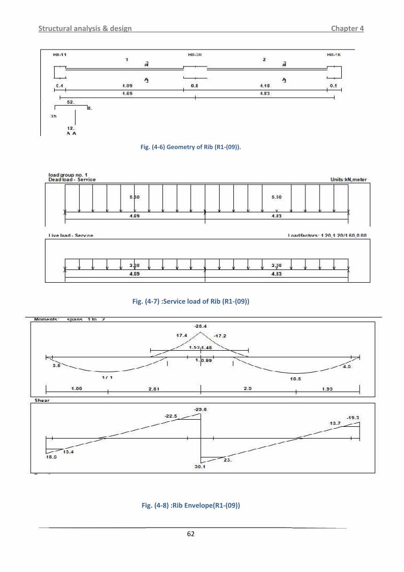
Fig. (4-6) Geometry of Rib (R1-(09)).
Fig. (4-7) :Service load of Rib (R1-(09))
Fig. (4-8) :Rib Envelope(R1-(09))
Structural analysis & design Chapter 4
62
Fig. (4-6) Geometry of Rib (R1-(09)).
Fig. (4-7) :Service load of Rib (R1-(09))
Fig. (4-8) :Rib Envelope(R1-(09))
Structural analysis & design Chapter 4
62
Fig. (4-6) Geometry of Rib (R1-(09)).
Fig. (4-7) :Service load of Rib (R1-(09))
Fig. (4-8) :Rib Envelope(R1-(09))

Structural analysis & design Chapter 4
63
Fig. (4-9) :RibReactions(R1-(09))
4.6.4 Design of flexure:-
4.6.4.1 Design of Negative moment of rib (R1-(09)):
1) Maximum negative moment Mu (-) =17.4KN.m.
d = depth - cover – diameter of stirrups – (diameter of bar/ 2)
= 350 – 20 – 10 – = 315 mm.
Mn = Mu /ф =17.4 / 0.9 = 19.33KN.m
= . ′ = . = 20.6
= =.. . = 1.623MPa
= 1 1= . 1 1 . .
= 0.00403
→As = * b *d = 0.00403 * 120 *315= 152.334 mm2.

Structural analysis & design Chapter 4
64
. …………(ACI-10.5.1)
= √ 120 315 . 120 315= 110.23 mm2<126 mm2 …………. Larger value is control.
→Asmin = 126 mm2<Asreq = 152.334 mm2.
As = 152.334 mm2.
2 Ф10 = 157.08 mm2>Asreq = 152.334mm2 . OK.
Use 2 Ф10
→ Check for strain:- ( . )
Tension = Compression
As * fy = 0.85 * * b * a
157.08 * 420 = 0.85 * 24 * 120 * a
a = 26.95 mm.
=.. = 31.7 mm. * Note: = 24MPa< 28 MPa→ = 0.85
* 0.003
=.. * 0.003 = 0.027> 0.005 ф =0.9 OK
4.6.4.2Design of Positive moment of rib (R1-(09))
d = depth - cover – diameter of stirrups – (diameter of bar/ 2)
= 350– 20 – 10 – = 315 mm.
→Mu max = 18.5KN.m
bE ≤ Distance center to center between ribs = 520 mm………… Controlled.
≤ Span/4 =4830/4 = 1207.5 mm.
≤ (16* tf) + bw =(16* 80) +120 =1400 mm.

Structural analysis & design Chapter 4
65
→bE= 520 mm.
→ 0.85 ′
= 0.85 24 0.52 0.08 0.315 . 10 233.37 .фMnf = 0.9 * 233.37 = 210.0KN.m
→фMnf =210.0KN.m> Mu max= 18.5KN.m.
Design as rectangular section.
1) Maximum positive moment Mu (+) = 18.5KN.m
Mn = Mu /ф =18.5 / 0.9 = 20.56KN.m
= . ′ = . = 20.6
= =.. . = 0.398MPa
= 1 1= . 1 1 . .
= 0.00096
→As = * b *d = 0.00096 * 520 *315 = 157.248 mm2.
. …………(ACI-10.5.1)
= √ 120 315 . 120 315= 110.22 mm2<126 mm2 …………. Larger value is control.
→Asmin = 126 mm2<Asreq = 157. mm2.
As = 157.248 mm2.
2 Ф10= 157.1 mm2>Asreq = 157 mm2 . OK.
Use 2 Ф10

Structural analysis & design Chapter 4
66
→ Check for strain:- ( . )
Tension = Compression
As * fy = 0.85 * * b * a
157.1* 420 = 0.85 * 24 * 520 * a
a = 6.22 mm.
=.. = 7.3 mm. * Note: = 24MPa< 28 MPa→ = 0.85
* 0.003
=.. * 0.003 = 0.126> 0.005 ф =0.9 OK
2) Maximum positive moment Mu (+) =17.1KN.m
Mn = Mu /ф =17.1 / 0.9 =19KN.m
= . = . = 20.6
= =.. . = 0.33MPa
= 1 1= . 1 1 . .
= 0.00079
→As = * b *d = 0.00079* 120 *315 = 29.86mm2.
. …………(ACI-10.5.1)
= √ 120 315 . 120 315= 110.2mm2126 mm2 …………. Larger value is control.
→Asmin = 126mm2>Asreq29.86 mm2.
As = 126mm2.
2 Ф10 = 157 mm2>Asreq = 126 mm2 . OK.
Use 2 Ф10
→ Check for strain:- ( . )
Tension = Compression
As * fy = 0.85 * * b * a

Structural analysis & design Chapter 4
67
157* 420 = 0.85 * 24 * 520* a
a = 6.216mm.
=. . = 7.313 mm. * Note: = 24 MPa< 28 MPa→ = 0.85
* 0.003
=.. * 0.003 = 0.126> 0.005 ф =0.9 OK
4.6.4.3Design of shear of rib (R1-(09))
1) Vu = 13.7 KN.
фVc = ф * * bw * d
= 0.75 * √ * 0.12 * 0.315*103 = 23.1 KN.
1.1* фVc = 1.1 * 23.1= 25.6 KN.
→Check for items:-
1- Item 1 : Vu ≤ ф.
13.7 ≤ .= 12.8…....Not satisfy
2- Item 2 :ф
< Vu ≤ фVc
12.8 ≤ 13.7 ≤ ≤ 600 mm.
Item (2) is satisfy → minimum shear reinforcement is required.
( )min ≥ * bw = √ *0.12= 8.75*10-5.
≥ =.
= 9.52*10-5…………….Control.
Try Ф8 (2 Legs):
= 9.52*10-5 → S = 1.05 m
S ≤ = = 157.5 mm.
≤ 600 mm.
Use Ф8 @ 10 Cm

Structural analysis & design Chapter 4
68
2) Vu = 23 KN.
фVc = ф * * bw * d
= 0.75 * √ * 0.12 * 0.315 *103 = 23.15 KN.
1.1* фVc = 1.1 * 23.15 = 25.6 KN.
→Check for items:-
1- Item 1 : Vu ≤ ф.
23 ≤ .= 12.8…....Not satisfy
2- Item 2 :ф
< Vu ≤ фVc
12.8 ≤ 23 ≤ 25.6 … …. Satisfy.
Item (2) is satisfy → minimum shear reinforcement is required.
( )min ≥ * bw = √ *0.12= 8.75*10-5.
≥ =.
= 9.52*10-5…………….Control.
Try Ф8 (2 Legs):
= 9.52*10-5 → S = 1.05 m
S ≤ = = 157.5 mm.
≤ 600 mm
.Use Ф8 @ 10 Cm

Structural analysis & design Chapter 4
69
Fig (4-10): Reinforcement of Rib(R1-(09))
4.7 Design of Beam (B1-(17)):
Fig (4-11) Location of beam (B1-(17))
Structural analysis & design Chapter 4
69
Fig (4-10): Reinforcement of Rib(R1-(09))
4.7 Design of Beam (B1-(17)):
Fig (4-11) Location of beam (B1-(17))
Structural analysis & design Chapter 4
69
Fig (4-10): Reinforcement of Rib(R1-(09))
4.7 Design of Beam (B1-(17)):
Fig (4-11) Location of beam (B1-(17))

Structural analysis & design Chapter 4
70
Material :-
concrete B300 Fc' = 24N/mm2
Reinforcement Steel fy = 420 N/mm2
Section :-
B =50cm
h =35cm
Fig (4-12) : Beam Geometry (B1-(17)).
Fig (4-13) : Service Load of Beam (B1-(17))
Structural analysis & design Chapter 4
70
Material :-
concrete B300 Fc' = 24N/mm2
Reinforcement Steel fy = 420 N/mm2
Section :-
B =50cm
h =35cm
Fig (4-12) : Beam Geometry (B1-(17)).
Fig (4-13) : Service Load of Beam (B1-(17))
Structural analysis & design Chapter 4
70
Material :-
concrete B300 Fc' = 24N/mm2
Reinforcement Steel fy = 420 N/mm2
Section :-
B =50cm
h =35cm
Fig (4-12) : Beam Geometry (B1-(17)).
Fig (4-13) : Service Load of Beam (B1-(17))

Structural analysis & design Chapter 4
71
Fig (4-14) : Beam Envelop (B1-(17)).
Structural analysis & design Chapter 4
71
Fig (4-14) : Beam Envelop (B1-(17)).
Structural analysis & design Chapter 4
71
Fig (4-14) : Beam Envelop (B1-(17)).

Structural analysis & design Chapter 4
72
4.7.1 Check whether the section will be act as singly or doublyreinforcement section:
→Mumax = 28.6KN.m .
bw = 50Cm. , h =35 Cm.
d = depth - cover – diameter of stirrups – (diameter of bar/ 2)
= 350– 40 – 10 – = 294 mm.
Cmax = * d = * 294 = 126 mm.
amax = 1* Cmax = 0.85 * 126= 107.1 mm. *Note: = 24MPa< 28 MPa→ 1 = 0.85
Mnmax = 0.85 * * b * a * (d - )
= 0.85 * 24 * 0.5 * 0.1071 * ( 0.294 – .) * 103
= 262.67KN.m .ф=0.65+3
250 *(0.004-0.002) = 0.816
→фMnmax = 0.82 * 262.67 = 215.39KN.m . * Note: s = 0.004 → ф = 0.82
→фMnmax = 215.39KN.m> Mu =28.6KN.m .
Singly reinforced concrete section.
4.7.2 Flexure design:4.7.2.1 Design of Positive moment:-
1) Maximum negative moment Mu (-) = 28.6KN.m .фMnmax = 215.39KN.m> Mu = 28.6KN.m → Singly reinforced concrete section
Mn = Mu /ф= 28.9 / 0.9 = 32.11KN.m .
= . ′ = . = 20.6
= =.. . = 0.74MPa.
= 1 1

Structural analysis & design Chapter 4
73
= . 1 1 . .= 0.0017
→As = * bw *d = 0.0017 * 500 *294 =249.9 mm2.
. …………(ACI-10.5.1)
= √ 500 294 . 500 294= 428.66 mm2<490 mm2 …………. Larger value is control.
→Asmin = 490 mm2>Asreq =249.9 mm2.
As = 490.9 mm2.
# 0f Ф12 = =.. =4.3→ # of bars = 5 bars.
Use 4Ф12 → As =5* 113.09 = 565.45 mm2>Asreq = 490.9 mm2 .
→ Check for strain:- ( . )
Tension = Compression
As * fy = 0.85 * * b * a
565.45* 420 = 0.85 * 24 * 500* a
a = 23.3mm.
=.. = 27.4 mm. * Note: = 24 MPa< 28 MPa→ = 0.85
* 0.003
=.. * 0.003 = 0.029> 0.005 ф =0.9 OK
Use 4Ф12.
4.7.2.3Design of shear:-
1) Vu = 30.7KN .
фVc = ф * * bw * d
= 0.75 * √ * 0.5 * 0.294 * 103 = 90 KN.

Structural analysis & design Chapter 4
74
Check for section dimensions:фVc + ( * ф * * bw * d) = 119.4 + ( * 0.75 *√24 * 0.5 * 0.294 * 103 )
= 119.4 + 360.1= 479.47KN >>>Vu = 30.7 KN.
Dimension is big enough.
4.7.2.4 Check for the case of shear:1- Item 1 : Vu ≤ ф
.
30.7 ≤ = 45….... satisfy.
Item (1) is satisfy → minimum shear reinforcement is required.
( )min ≥ * bw = √ *0.12= 8.75*10-5.
≥ =.
= 9.52*10-5…………….Control.
Try Ф8 (2 Legs):
= 9.52*10-5 → S = 1.05 m
S ≤ = = 147 mm. ≤ 600 mm.
Use Ф8 @ 10 Cm
Fig. (4-15) Detail of Beamandsection(B1-(17)).
4.8 Design of Column(C32):-

Structural analysis & design Chapter 4
75
4.8.1 Load calculation:
DL= 2933.68 KN LL= 993.66 KN
Pu = 5110.275 KN Pn,req=5110.275/0.65 7862 KN
Assume rectangular section with= 2.38%
Pn = 0.8× Ag× (0.85× fc'+g×( fy - 0.85 fc'))
7862 = 0.8× Ag×(0.85× 24 + 0.0238× (420 - 0.85× 24))
Ag = 3285.6 cm2
Use 60*55 cm with Ag = 3300cm² >Ag,req = 3285.6 cm2
4.8.2 Check slenderness effect:
Lu: Actual unsupported (unbraced) length.
K: effective length factor (K= 1 for braced frame).
R: radius of gyration =√ / 0.3Lu = 2.76 m
M1/M2 =1
In 60cm -Direction/ < 34- 12 ( 1/ 2 ) < 401 2.76 / 0.3 0.6 = 15.33<22 =>Short
In 55cm -Direction/ < 34- 12 ( 1/ 2 )1 3.78 / 0.3 0.55 = 16.73 > 22 => Short
Short in Both Direction
→Here we can solve this column as short tied column

Structural analysis & design Chapter 4
76
Pn = 0.8× Ag× (0.85× fc' +g×( fy - 0.85 fc'))
Pn = 0.8× 600×550× (0.85× 24 + 0.0238 × (420 - 0.85× 24))
=7896.4 KN >Pn,req=7862 KN …….OK
4.8.4 Design of the tie reinforcement :
S ≤16 db (longitudinal bar diameter)
S≤ 48dt (tie bar diameter).
S ≤ Least dimension.
spacing ≤16×db=16×2.5=40 cm …. control
spacing ≤48×dt=48×1.0 = 48 cm
spacing ≤ least.dim=55 cm
Use10@20 cm
For UingSbCoulmn We have using 1625 .
1625 .
Fig. (4-16) Detail of Reinforcement of Coulmn (C32)
4.9 Design of Stair.

Structural analysis & design Chapter 4
77
Figure 4-17: Details of stair .
4-9-1 Minimum slab:
= = 20.5 thickness for deflection (for simply supported one way
solid 250 .
Figure 4-18: loads of the flight .
4-9-2Loads Calculation of stair case (1):

Structural analysis & design Chapter 4
78
Flight Dead Load computations:
1 1 1730 29.54°
material Quality Density
KN/m3
/Tiles 23 27( . .. ) 0.03 1 1.403Mortar 22 22*( . .. ) 0.02 1 1.034Stair steps 25 . *( . . 1 2.125R.C solid slab 25 . . ° = 7.184Plaster 22 . . =0.76Total Dead Load ∑ 12.506
Table 4-4: Dead load calculation for flight of stair .
Landing Dead load computation:

Structural analysis & design Chapter 4
79
Material Quality Density
KN/m3
/Tiles 23 23 0.03 1 0.69Mortar 22 22 0.02 1 0.44R.C solid slab 25 25 0.25 1 6.25Plaster 22 22 0.03 1 0.66Total Dead load ∑ 8.04
Table 4-5: Dead load calculation for landing of stair.
4 /Total factored load: 1.2 1.61.2 12.506 1.6 4 21.41 /1.2 8.04 1.6 4 16.05 /4-9-3Design of flight (Slab S1 is supported at the centerline of beam andL1).
The reaction at point A: 21.41 3.32 35.32 Check for shear strength:
Assume bar diameter 14 for main reinforcement.

Structural analysis & design Chapter 4
80
20 2 250 20 142 223Take the maximum shear as the support reaction35.32 29.54 28.27
6√246 1000 223 10 182.1 .ф 0.75 182.1 136.55 /1, 28.27 12 ф 68.27 . . . . . .
Calculate the maximum bending moment and steel reinforcement:35.32 2.05 21.41 1.65 1.652 43.26 ./ф 43.26/ 0.9 48.067 .– – 2300 – 20 – 142 223 .
= . = . 20.6= = . 0.97
= 1 1= . 1 1 . . 0.00240.0024 1000 223 535.2 ., 0.0018 1000 250 450535.2 , 45014@20 .. 3.47 4 , 4 0.250 .

Structural analysis & design Chapter 4
81
Step is smallest of:
1- 3 3 300 9002- 4503- 380 2. 5 380 2.5 20 330
300 280 300 280420 300200 300
Select s=300 mm
Temperature and shrinkage reinforcement.Temperature and shrinkage 0.0018 1000 250 [email protected] 5.7 6 1 16 0.16
Take 150 mm
Step Temperature and shrinkage reinforcement is the smallest of:
1. 5 5 250 12502. 450150 450
Select s=450 mm
4-9-4 Design of slab L1 (landing): 16.05 23.32 51.37 /The reaction at each end

Structural analysis & design Chapter 4
82
Figure 4-19: loads of landing51.37 3.452 88.61Check for shear strength:Assume bar diameter 14 for main reinforcement.
20 2 25 20 142 223Take the maximum shear as the support reaction 88.61 51.37 .323 72.07
6 √246 1000 223 10 182.1 .ф 0.75 182.1 136.56 /1ф 136.56 , 72.07. . . . . .25Calculate the maximum bending moment and steel reinforcement:51.37 3.458 76.43 ./ф 76.43/ 0.9 84.92 .– – / 2250 – 20 – 142 223 .
= . = . 20.6

Structural analysis & design Chapter 4
83
= = . 1.71= 1 1
= . 1 1 . . 0.004260.00426 1000 223 950 ., 0.0018 1000 250 450950 , 45014 950153.93 6.2 7 , 1 0.16Step is smallest of:
1- 3 3 300 9002- 4503- 380 2. 5 380 2.5 20 330
300 280 300 280420 300150 300 Temperature and shrinkage reinforcement.Temperature and shrinkage 0.0018 1000 250 450450153.93 2.9, 1 13 0.333 .300
Step Temperature and shrinkage reinforcement is the smallest of:
1- 5 5 250 12502- 450 300 450Select s=450 mm

Structural analysis & design Chapter 4
84
4.10 Design of basement wall :-
4.10.1 Load Calculation:-2442018 ⁄ Figure 4-20: Basement wall
30°4 ⁄ 20 , 4The design will be for 1m width
- Analysis:- Loads
Neglect the axial load, since its low value.
1 sinSo, 1 sin 30 1 0.5 0.5 0.5 18 2.935 26.415 /26.415 2.9352 38.76 /0.5 4 2 /2 2.935 5.87 /
Support reactions:21.025

Structural analysis & design Chapter 4
85
38.6250 ?21.025 2 2 026.4152.935 9
21.025 9 2 2 04.5 2 21.025 02, 21.025 2 9 2 23 22 2 2 22 26.05 .
Factored internal forces1.6 1.6 38.625 61.81.6 1.6 26.05 41.68- Design
Design of shear200 40 8 15261.8ф 0.75 6 ф 0.75 √246 1000 152 93 61.8The thickness of Wall is Adequate Enough
Design of flexure

Structural analysis & design Chapter 4
86
Vertical reinforcement of Tension face 41.68 ./ф 41.68/ 0.9 46.31 .= . = . 20.6= = . 2.0
= 1 1= . 1 1 . 0.005, 0.005 1000 152 760, 0.0012 1000 200 240
, 760 , 240 … ., 760
, 791.68 , 760 … . OKVertical reinforcement of Compression face
, 0.25 0.25 √24420 1000 152 443 /, 1.4 1.4420 1000 152 506.67 /
, 565.5 , 506.67 2/For inside wall 12@15 cm =7.91cm2> 7.60 cm2
For outside wall 12@20 cm =5.65cm2> 5.1 cm2

Structural analysis & design Chapter 4
87
Horizontal Reinforcement due to Cracking:0.002 0.002 100 20 4 /For one side 2 /Select for one side horizontal reinforcement 10@20 3.93 2
Figure 4-21: reinforcement of Basement wall
Structural analysis & design Chapter 4
87
Horizontal Reinforcement due to Cracking:0.002 0.002 100 20 4 /For one side 2 /Select for one side horizontal reinforcement 10@20 3.93 2
Figure 4-21: reinforcement of Basement wall
Structural analysis & design Chapter 4
87
Horizontal Reinforcement due to Cracking:0.002 0.002 100 20 4 /For one side 2 /Select for one side horizontal reinforcement 10@20 3.93 2
Figure 4-21: reinforcement of Basement wall

Structural analysis & design Chapter 4
88
4.11 Design of Isolated Footing ( F5 C50).
Fig. (4-22) : Footing geometry
Structural analysis & design Chapter 4
88
4.11 Design of Isolated Footing ( F5 C50).
Fig. (4-22) : Footing geometry
Structural analysis & design Chapter 4
88
4.11 Design of Isolated Footing ( F5 C50).
Fig. (4-22) : Footing geometry

Structural analysis & design Chapter 4
89
From column group5:-
DL= 1823.96 KN
LL= 818.37KN
Factored load = 3498.14kN .
Soil weight = 18 kN/m3.
Allowable soil pressure = 400kN/m2.
Fc' = 24 Mpa
Fy = 420 Mpa
Cover = 7.5 cm
4.11.1Determine the net soil pressure:use steel bar ∅14
Assume h = 70 cm ………d = 700-75-14 = 611 mm
Weight of footing= 0.7*25= 17.5 KN/ ^2Weight of soil= 1*18 = 18 KN/ ^2Total surcharge load foundation:
W= 17.5+18 = 35.5KN/ ^2qall.net = 400 –35.5= 364.5 KN/ ^24.11.2 : Design of the footing area:
A= Pn/ qall. net = 2642.33 / 364.5 = 7.25m^2A= b*l
Take b= 2.80 m
l= 7.25/2.80= 2.6, take l= 2.80m
qu= 3498/ 2.80 2.80 = 446.2 KN/m

Structural analysis & design Chapter 4
90
4.11.3 Check for one way shear:
For X- direction:
Vu ((2.800.50)*0.5 0.611)446.22.80Vu 673.4 KNFor Y- direction:Vu ((L a)*0.5 d)qubVu ((2.800.5)*0.5 0.611)446.22.80Vu 673.4 KNVc,x= √ fc *bw*d) / 6= 0.75 * √24 * 2800*611*10-3 / 6
= 1047.6 KN >Vux = 673.4 KN => OK
Vc,y= √ fc *bw*d) / 6= 0.75 * √24 * 2800*611*10^-3/ 6= 1047.6 Kn>Vuy = 673.4 KN => OK4.11.4 Check for two way shear:
Vu,x = qu*(b*l - (a+d ) (c + d))
446.2(2.80*2.80 - (0.5) (0.5 + 0.611))= 2506.7 KN.s = 40 for interior column
= 50/ 50 = 1.0bo = Perimeter of critical section taken at (d/2) from the loaded area
bo= 2* (a+d+c+d)
= 2 *(0.50+0.611*2+0.5)
= 4.444 m

Structural analysis & design Chapter 4
91
Vc the smallest of:Vc =1/6 1 2/B √ fc b d . . where 1/6 1 2/B 1/6 1 2/1.0 0.50Vc 1/12 αsd /b 2 √ fc′ b d ..where1/12 αsd /b 2 1/12 40 0.611 /4.444 2 0.625V_c=1/3 √ fc′ b d where 1/3 0.333 … … … … controlTake V_c=1/3 √ fc b d = 1/3 √24 4444 611 〖10〗^ 3 4434.04 KNV_c 0.75 7057.8 3325.5 KNV_c 3325.5 V_u 2506.7KN … … … ok4.11.5Design for bending moment:
4.11.5.1 Design flexure for long And Short direction:
use steel bar ∅14
b =2.8m , h =700mm , d 611mmM_u 446.2 2.80 0.5 ^2/2 156.17 KN. mm = f_y/ 0.85 fc′ = 420/ 0.85 24 = 20.59.R_n = M_u/ b d^2 = 156.17 〖10〗^6 / 0.9 2800 〖 611 〗^2 = 0.17MPa.
ρ = 1/m 1 √ 1 2 R_n m /f_y= 1/20.59 1 √ 1 2 20.59 0.17 /420 = 0.00041As = ρ * b *d = 0.00041 * 2800 * 611 = 701.428mm2.As_min 0.0018 b h 0.0018 2800 700 3528mm2Asmin = 3528 mm2 Asreq = 701.428 mm2.As = Asmin = 3528 mm2.n= As_req/ A_bar 14 = 3528 /153.94 = 25 .2Use 26Ф14S 2800 75 2 26 14 /25 91.44mmStep S is the smallest of

Structural analysis & design Chapter 4
92
3h = 3*700=2100mm450………controlS = 91.44 _ 450 … … … .

Structural analysis & design Chapter 4
93
CITY CENTER (B) DESIGN4.12 Design of Flat slab :
The design done by using SAFE program.
4.12.1 Load calculation:
Assume slab thickness 30cm.
Calculation
QualityDensity
KN/m3
Thicknesscm
MaterialNo.
0.30×25 = 7.52530Slab١
0.07×17 = 1.19177Sand٢
0.02×22 =0.44222Mortar٣
0.03×23 =0.69233Tile٤
0.02×22 =0.44222Plaster٥
2.38Partitions6
KN/m212.64∑ =
Table (4 – 6) Calculation of the total dead load for flat slab.
Structural analysis & design Chapter 4
94
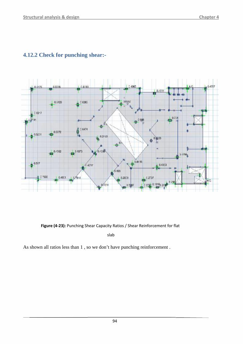
4.12.2 Check for punching shear:-
As shown all ratios less than 1 , so we don’t have punching reinforcement .
Figure (4-23): Punching Shear Capacity Ratios / Shear Reinforcement for flat
slab
Structural analysis & design Chapter 4
94
4.12.2 Check for punching shear:-
As shown all ratios less than 1 , so we don’t have punching reinforcement .
Figure (4-23): Punching Shear Capacity Ratios / Shear Reinforcement for flat
slab
Structural analysis & design Chapter 4
94
4.12.2 Check for punching shear:-
As shown all ratios less than 1 , so we don’t have punching reinforcement .
Figure (4-23): Punching Shear Capacity Ratios / Shear Reinforcement for flat
slab

Structural analysis & design Chapter 4
95
4.12.3 Design for bending moment:
Figure (4-24): moment distribution in x-direction
Structural analysis & design Chapter 4
95
4.12.3 Design for bending moment:
Figure (4-24): moment distribution in x-direction
Structural analysis & design Chapter 4
95
4.12.3 Design for bending moment:
Figure (4-24): moment distribution in x-direction

Structural analysis & design Chapter 4
96
The design of flat slab done by using Finite Element method.
Selected 14/15cm in both direction for top reinforcementSelected 14/15cm in both direction for bottom reinforcement
Figure (4-25): moment distribution in y-direction

Structural analysis & design Chapter 4
97
Figure (4-26): Reinforcement for flat.
4.13 Design of column (C44):-
4.13.1 Load calculation:
DL= 845 KN LL= 200 KN
Pu = 1333 KN Pn,req=1333/0.65 2050.76 KN
Assume rectangular section with ρ= 1.67% > 1%
Pn = 0.8× Ag× (0.85× fc'+ρg×(fy - 0.85 fc'))
2050.76 = 0.8× Ag×(0.85× 28 + 0.0167 × (420 - 0.85× 28))
Ag = 842.78 cm2

Structural analysis & design Chapter 4
98
Use 25×60 cm with Ag = 1500 cm² >Ag,req = 842.78 cm2
4.13.2 Check slenderness effect:
Lu: Actual unsupported (unbraced) length.
K: effective length factor (K= 1 for braced frame).
R: radius of gyration =√ / 0.3Lu = 4.3 m
M1/M2 =1
In 25 cm -Direction
/ < 34- 12 ( 1/ 2) < 40
1 4.3 / 0.3 0.25 =57.33>22 =>long
In 60cm -Direction
/ < 34- 12 ( 1/ 2 )
1 4.3 / 0.3 0.6 = 23.89> 22 =>Long
Long in x direction
Long in y direction
4.13.3 Calculation for reinforcement:
In 25 cm -Direction
Ec= 4700 × √28 =24870.1MPa

Structural analysis & design Chapter 4
99
&dns= 1.2 / = 1.2 845 /1333 = 0.76
Ig= 〗^3/12= 60 25〗^3/12 = 0.00781 m4
EI = 0.4 / 1 0.4 24870.1 0.00781 / 1 0.76 44.14 MN.m2
Pc = ^2 /〖 〗^2= ^2 44.1 /〖 1.0 4.3 〗^2= 23.6 MN
Cm = 0.6 + 0.4×( 1/ 2 ) = 1
&ns= / 1 / 0.75 = 1/ 1 1333 / 0.75 23.6 1000 = 1.1< 1.4
emin = 15 + 0.03 h = 15+ 0.03 × 250 = 22.5mm
e = emin × &ns=22.5× 1.15 =25.875 mm
/ 25.875/250 0.099< 0.1…….(e = 0.082h < 0.1h)
In 60 cm -Direction
Ec= 4700 × √28 =24870.1MPa
&dns= 1.2 / = 1.2 845 /1333 = 0.76
Ig= 〗^3/12= 25 60〗^3/12 = 0.0045 m4
EI = 0.4 / 1 0.4 24870.1 0.0045 / 1 0.76 25.44 MN.m2
Pc = ^2 /〖 〗^2= ^2 25.44 /〖 1.0 4.3 〗^2= 13.57 MN
Structural analysis & design Chapter 4
100
Cm = 0.6 + 0.4×( 1/ 2 ) = 1
&ns= / 1 / 0.75 = 1/ 1 1333 / 0.75 13.57 1000 = 1.15< 1.4
emin = 15 + 0.03 h = 15+ 0.03 × 600 = 33 mm
e = emin × &ns = 33× 1.15 =37.95 mm
/ 37.95/600 0.063< 0.1…….(e = 0.082h < 0.1h)
→Here we can solve this column as short tied column
Pn = 0.8× Ag× (0.85× fc' +g×( fy - 0.85 fc'))
Pn = 0.8× 250×600× (0.85× 28 + 0.0167 × (420 - 0.85× 28))
=3649.9 KN >Pn,req=2050.76 KN …….OK
4.13.4 Design of the tie reinforcement :
S ≤16 db (longitudinal bar diameter)
S≤ 48dt (tie bar diameter).
S ≤ Least dimension.
spacing ≤16×db=16×2.0=32 cm
spacing ≤48×dt=48×1.0 = 48 cm
spacing ≤least.dim=25 cm…. control
20cm ≤ 25cm…..ok
Use10@20 cm
For column 5(c44)

Structural analysis & design Chapter 4
101
Fig. 4–27 :Reinforcement of column 44
4.14:-Design of Shear wall.(sw15)
(Figure 4-28:Moment and shear diagram )
Structural analysis & design Chapter 4
101
Fig. 4–27 :Reinforcement of column 44
4.14:-Design of Shear wall.(sw15)
(Figure 4-28:Moment and shear diagram )
Structural analysis & design Chapter 4
101
Fig. 4–27 :Reinforcement of column 44
4.14:-Design of Shear wall.(sw15)
(Figure 4-28:Moment and shear diagram )

Structural analysis & design Chapter 4
102
Fc = 28MPa
Fy = 420 MPa
t =25cm .shear wall thickness
Lw = 6.20m ,shear wall width
Hw1 for one wall = 3.00 m
Hw2for one wall = 5.1 m story height
Hw3for one wall = 3.3 m story height
4.14.1: Design of shear
KNVuFx 374
4.14.2: Design of the Horizontal reinforcement:
The critical Section is the smaller of:
mlwd
controlmHwstoryheigh
mhw
mlw
96.420.68.08.0
30.3)(
65.102
30.21
2
10.32
20.6
2
560.75 0.83 √28 250 4960 10 4084.5is the smallest of :1 16 16 √28 250 4960 10 1093.58
2 0.27 4 0.27√28 250 4960 10 0 1771.63 0.05 0.1 0.2
0.05√28 6.20 0.1√28 06.70 250 4960 935.25 … cont

Structural analysis & design Chapter 4
103
2 2308.8374 6.202 3.07Vu = 374KN< 2
1
*0.75*935.25 = 380.8 KN No need reinforcement
- Minimum shear reinforcementis required:Take = 0.0025
- Maximum spacing is the least of :
5
Lw
=5
6200= 1240mm
3*h = 3*250 = 750mm450 mm ……. Control
Try ϕ 12 (As = 113.1 mm2) for two layers
= 2* Sh
Avh
=2*250
1.113*2
S= 0.0025
S2 = 455.1mm , ϕ 12@250 mm
→useϕ 12 @250mm in two layer
4.14.3: Design for Vertical reinforcement:-
343020.6
30.21
w
w
L
hmm
3Lw
=3
6200= 2066.67mm
450 mm ……. Control
3*h = 3*250 = 750mm
Anv=0.0025*S*h
Try Ф 12 (As = 113.1 mm2)
113.1*2=0.0025*S*250
S=452.4
Select Ф 12 @250mm In tow layer.

Structural analysis & design Chapter 4
104
4.14.4: Design of bending moment ( uniformly distribution flexural
reinforcement) :
6200250 2 113.1 5609.765609.76200 250 42028 0.050
2 0.85 0.05 02 0.05 0.85 0.85 0.060.5 1 10.9 0.5 5609.7 420 6200 1 0 1 0.0806 6043 .Select Ф 12 @250mm for vertical reinforcement .
4.15 Design of the Mat Foudation reinforcement :-
Design done by using SAFE.
4.15.1 Load calculation:
Density of soil = 18KN/Allowable soil pressure = 400kN/mFc'= 28MpaFy= 420 MpaCover= 7.5 cmTake the reaction of columns and walls from ETABS.
4.15.2 Determine the soil pressure:
Subgrade Modulus of soil = 120*400 = 48000KN/

Structural analysis & design Chapter 4
105
Max pressure KN/ <400KN/
4.15.3 Check for punching shear:-
As shown all ratios less than 1 , so we don’t have punching reinforcement .
Figure (4-29): Soil pressure diagram
Figure (4-30): Punching Shear Capacity Ratios / Shear Reinforcement for flat
slab
Structural analysis & design Chapter 4
105
Max pressure KN/ <400KN/
4.15.3 Check for punching shear:-
As shown all ratios less than 1 , so we don’t have punching reinforcement .
Figure (4-29): Soil pressure diagram
Figure (4-30): Punching Shear Capacity Ratios / Shear Reinforcement for flat
slab
Structural analysis & design Chapter 4
105
Max pressure KN/ <400KN/
4.15.3 Check for punching shear:-
As shown all ratios less than 1 , so we don’t have punching reinforcement .
Figure (4-29): Soil pressure diagram
Figure (4-30): Punching Shear Capacity Ratios / Shear Reinforcement for flat
slab

Structural analysis & design Chapter 4
106
4.15.4 Design for bending moment:
Figure (4-31): moment distribution in x-direction
Structural analysis & design Chapter 4
106
4.15.4 Design for bending moment:
Figure (4-31): moment distribution in x-direction
Structural analysis & design Chapter 4
106
4.15.4 Design for bending moment:
Figure (4-31): moment distribution in x-direction

Structural analysis & design Chapter 4
107
.
Figure (4-33): reinforcement of mat foundation .
Figure (4-32): moment distribution in y-direction
Structural analysis & design Chapter 4
107
.
Figure (4-33): reinforcement of mat foundation .
Figure (4-32): moment distribution in y-direction
Structural analysis & design Chapter 4
107
.
Figure (4-33): reinforcement of mat foundation .
Figure (4-32): moment distribution in y-direction

Structural analysis & design Chapter 4
108
The design of mat foundation by using Finite Element method
Selected basic mesh ∅16/10cm for top reinforcementSelected basic mesh ∅16/10cm for bottom reinforcement

Structural analysis & design Chapter 4
109

Structural analysis & design Chapter 4
110

Structural analysis & design Chapter 4
111

Structural analysis & design Chapter 4
112

Structural analysis & design Chapter 4
113

Structural analysis & design Chapter 4
114

Structural analysis & design Chapter 4
115
4.16.4 :Design of weld:The calculation of weld based on the following :
1) Fillet weld is used.2) The plates are A36(fy=36 ksi,Fu=58 ksi)3) The plat thickness is (t=0.5 in)4) The electrodes having FExx=70 ksi5) The shielded metal arc welding (SMAW) is used.
1st) Design of weld between the vertical member and the Gusset plate in the corners of thetruss:The section of the vertical member is angle (L3*3*3/8 ) , Ag=2.11 in2 ,y=0.884.The value of Max. compression in the vertical member is Vu=20.662Kips.
Max. weld size (amax)=
Min . Weld size(amin)=
Use weld size (a)=
Design strength of weld :Ø×Rnw= Ø× te×0.6×FExx
Ø×Rnw=0.75 0.707 1 4 0.6 70 5.57 kips Design strength of base material :
Ø×Rn= Ø× (0.6×fy)×t=1.0×0.6×36× = 8.1 kips >5.57 kips….ok
Or
Ø×Rn= Ø× (0.6×fu)×t=0.75×0.6×58× = 9.79kips >5.57 kips….ok1=5.57*3=16.71 kips2=20.662-16.71=3.952 kips2 2Ø Rnw 3.9525.57 0.71 … … 1.02nd) Design of weld between the diagonal member and the gusset plate:- The section of the diagonal member is angel ( L3*3*3/8 )
- For the vertical member use the same size and dimension of weld for theprevious vertical member.
The value if Max. Tension in the diagonal member is Tu = 51.1 kip.Max. weld size (amax)=
Min = Weld size(amin)=
Use weld size (a)=
(Figure 4- 40) weld betweenvertical member and gussetplate)
(Figure 4- 41:weldbetween diagonalmember and gussetplate)

Structural analysis & design Chapter 4
116
Design strength of weld :Ø×Rnw= Ø× te×0.6×FExx
Ø×Rnw=0.75 0.707 1 4 0.6 70 5.57 kips Design strength of base material :
Ø×Rn= Ø× (0.6×fy)×t=1.0×0.6×36× =8.1kip >5.57 kip….ok
Or
Ø×Rn= Ø× (0.6×fu)×t=0.75×0.6×58× =9.79kip >5.57 kip….ok
3 3 5.57 16.71∑ 1 016.71 1.5 2 3 51.1 3 0.884 0F2=27.69 kips
F1=51.1-16.71-27.69=6.7 kips1 1Ø Rnw 6.75.57 1.21 … … 1.52 2Ø Rnw 27.695.57 4.97 … … 5
Check for rupture 5 1.52 3.251 1 0.8843.25 0.728Ø 0.75Ø 0.75 58 0.728 2.11 66.82 51.1 … . .
3rd) Design of weld between the bottom member and the gusset plate:The section of the bottom member is angel (W6*12)
11 /2.54= 4.33 in
020.66214.76 2 0.7 /2 . 535.93 in3 (Figure 4- 42weld between gust
plate and bottom member)

Structural analysis & design Chapter 4
117
0 … . 020.662 .535.93 0.1
0 0.1 0.7 0 0.71 /Ø0.75*(0.707a)*0.6*70=0.71……a=0.032 in

Structural analysis & design Chapter 4
118