city college of san francisco (ccsf) building information ... · city college of san francisco...
TRANSCRIPT

CITY COLLEGE OF SAN FRANCISCO (CCSF)
Building Information Modeling (BIM) Standards for Design-Bid Build Projects
CCSFBIMS Version 1.0
Prepared by: CCSF Facilities Planning & Construction (FPC) Department
May 2011

CCSF Building Information Modeling Standards V1.0
May 2011
1
Table of Contents page
1 Introduction 3 1.1 CCSF̀s Total Cost of Ownership and Building Information Lifecycle Vision
1.2 Objectives of CCSF BIM Standards
2 BIM Process & Implementation 4 2.1 General
2.2 Design Phase BIM Workflow
2.3 Bidding Phase BIM Workflow
2.4 Construction Phase BIM Workflow
2.5 Design BEP (BIM Execution Plan)
2.6 Construction BEP (BIM Execution Plan)
3 BIM Roles & Responsibilities 7 3.1 Owner̀s Virtual / BIM Project Manager
3.2 Design Team BIM Manager
3.3 Technical Discipline (Design) or Trade (Construction) Lead BIM Coordinators
3.4 Construction BIM Manager
3.5 BIM Assignment Matrix
3.6 BIM Deliverable Schedule
4 Project Team Collaboration Procedures 11 4.1 Model Sharing
4.2 Shared File Server
4.3 Project Kickoff BIM Standards Orientation
4.4 BIM Work Room(s)
4.5 Spatial Coordination & Clash Detection
5 CCSF Requirements for Using BIM 16 5.1 Design-Bid-Build Workflow
5.2 Space Validation (Pre-Design & Programming - Fusion)
5.3 Site Conditions (Existing & New Construction)
5.4 Architectural (Spatial & Material Design) Models
5.5 Building System Models (Structural, MEPF and Interiors)
5.6 Energy & Life-Cycle Cost Analysis
5.7 Cost Estimation
5.8 4D Scheduling & Sequencing
5.9 Communication of Construction Scheduling and Phasing
5.10 5D Estimation 5.11 Design Visualization 5.12 COBIE (Handover to FM) / Commissioning 5.13 Clash Detection / Coordination 5.14 Virtual Testing & Balancing 5.15 Additional BIM Uses

CCSF Building Information Modeling Standards V1.0
May 2011
2
page 5.16 California Community College Process 5.17 Agency 5.18 As-builts 5.19 Closeout
6 BIM Modeling Requirements 23 6.1 General & Model Ownership
6.2 Types of Model Elements
6.3 Model-based Quantity Take-off & Specifications
6.4 Model Geographic Location
6.5 Requirements for Modeling Space
6.6 Space Naming and Coding
6.7 Mechanical and other Equipment Coding
6.8 Final BIM Deliverables
6.9 Modeling Standards
6.9.1 General Requirements 6.9.2 Site, Civil & Terrain Models 6.9.3 Utility Model 6.9.4 Architectural Models 6.9.5 Building Systems Models 6.9.6 Technology Platform & Software Interoperability 6.9.7 Model Progression Specification (MPS) & Level of Development (LOD)
7 Files, Security & Achieving 37 7.1 Project Folder Structure
7.2 Data Security
7.3 Archiving Milestone Submittals
8 Information Delivery Manual (IDM) 40
9 Drawing Requirements for Paper (2D) Printing 42
Facilities Operations & Management (Forthcoming)
10 Real Property Inventory (RPI) and Asset Management (Forthcoming)
11 Emergency Management (Forthcoming)
12 Glossary & Abbreviations 46
13 References 51

CCSF Building Information Modeling Standards V1.0
February 2014
1
CCSF B I M Standards
1 Introduction
1.1 CCSF̀s Building Information Lifecycle Vision The National Building Information Modeling Standards (NBIMS) Committee defines Building Information Modeling (BIM) as:
“…a digital representation of physical and functional characteristics of a facility. A BIM is a shared knowledge resource for information about a facility forming a reliable basis for decisions during its life-cycle; defined as existing from earliest conception to demolition. A basic premise of BIM is collaboration by different stakeholders at different phases of the life of a facility to insert, extract, update or modify information in the BIM to support and reflect the roles of that stakeholder.”
Building Information Modeling (BIM) goes well beyond geometry, spatial relationships, light analysis, geographic information, quantities and properties of building systems, assemblies and components. BIM spans all aspects of the entire building life cycle, including but not limited to Needs Analysis, Capital Planning and Management, Construction Delivery Methods Design, Procurement, Construction, Repair, Maintenance, Sustainability, Renovation, Operations, Space Management, Deconstruction/Reuse. It addresses not only form, fit and function but activities that are traditionally not addressed with 2D or 3D CAD/Visualization.
The California Community College Chancellor’s Office has committed to integrating Building Information Modeling (BIM), Facility Management and Geographic Information Systems (GIS) with the implementation by connecting 71 million square feet of facilities through BIM, FM and GIS using the ONUMA Planning System. The Foundation for CCC is also initiating other open standard systems: Facility Management, Computerized Maintenance Management (CMMS), BAS (Building Automation Systems), EMS (Energy Management Systems) and classroom scheduling that take advantage of this technology.
The City College of San Francisco (CCSF) is committed to adopting Building Information Modeling (BIM) incrementally and utilizing this enhanced technology to improve the design and management of CCSF`s new and existing buildings across their lifecycles—from concept to design to construction to operations to reuse and eventual demolition. The goal of conversion to BIM is to reduce the Total Cost of Ownership at CCSF and, deliver higher value and maximize lifecycle building performance to support CCSF`s mission to deliver excellent educational service to the Community. The CCSF BIM Standards for Design-Bid-Build Projects have been developed to define a process and establish requirements, procedures and protocol for the utilization of BIM in the various stages of our projects. These Standards are based upon the National Building Information Standards (NBIMS) and reference the current technology Standards developed by the General Services Administration (GSA), the US Department of Veterans Affairs (VA), and Industry Foundation Class (IFC) by the International Alliance for Interoperability (IAI) and OmniClass Construction Classification (OmniClass) as developed by the Construction Specifications Institute (CSI) and the United States National CAD Standard (NCS).

CCSF Building Information Modeling Standards V1.0
February 2014
2
Additionally, as guidance and reference, in preparation of its first BIM Standards, City College of San Francisco (CCSF) has adapted information developed for Los Angeles and San Diego Community College Districts` BIM Standards. 1.2 Objectives of CCSF BIM Standards CCSF BIM Standards` intent is to facilitate the use of BIM technologies and workflow process to achieve the following: • Facilitate a collaborative project environment between all parties, with better information
and visualization for better intelligence and better decisions at any stage of the building lifecycle by integration of computer models into project coordination, simulation and optimization.
• Define BIM modeling and analysis requirements through development of open and shared standards for BIM process.
• Establish a technology platform to support incorporation of future technologies. • Improve the quality of the design solutions and exchange of information between parties
to obtain coordinated project documents through use of parametric and 3D BIM model. • Improve systems coordination and the execution of design intent in the field for
streamlined fabrication and construction processes, and minimized change orders. • Utilize 4D BIM technologies for virtual simulation of construction processes with various
trade contractors to better manage design-to-construction transition to avoid conflicts and improve efficiencies in the field.
• Utilize 5D BIM technology and processes to implement a Total Cost of Ownership Model and develop building life-cycle cost projections and accurate project cost estimates.
• Incorporate as-built BIMs, including infrastructure and building systems, into District wide Geographical Information System (GIS)
• Use BIM as Information and Communication tools for shared governance, students, facility managers and staff, and the Community.
• Enable the long term viability and usage of the BIM database through facilities, energy management and other lifecycle solutions software.
2 BIM Process & Implementation
2.1 General CCSF requires development of a BIM Execution Plan (BEP) at project initiation to provide a master information / data management plan and assignment of roles and responsibilities for model creation and data integration. This is for use as a guideline to incorporate BIM as an integral part of CCSF's design, construction and facilities management processes. Through this process, the team members and CCSF project management shall jointly agree on how, when, why, to what level, and for which project outcomes BIM will be used in DBB (Design-Bid-Build) projects. This document contains guidelines for implementation of certain BIM processes that may be new to the Project Team. Any deviations to the guidelines outlined herein must be documented by the Project Team, and then reviewed and approved by CCSF prior to commencement. As technology progresses CCSF will work with project teams to update these requirements accordingly.

CCSF Building Information Modeling Standards V1.0
February 2014
3
2.2 Design Phase BIM Workflow a. Lead designer, Architect or Engineer, shall assign a Design Team BIM Manager to
coordinate BIM workflow per section 3 (BIM Roles & Responsibilities) of the CCSF BIM Standards.
b. Designers shall use trade specific analytic and authoring tools and software for creation of 3D models to meet predefined project requirements.
c. BIM Manager will integrate the design discipline and trade specific models into a design (composite) model for spatial coordination, using coordination software (Navisworks, Bentley, etc.). The composite model will be used for assembling the various design and system models and generating a report and view list of design coordination issues.
d. Spatial conflicts during the design phase will take place during coordination meetings, where the Design Team will electronically identify, track and publish interference/clash reports between all trades. The coordination software will be used to resolve all interferences interactively by the design team.
e. Spatial Coordination Sign-off shall occur once all spatial conflicts, identified during the trade coordination and clash detection steps, have been resolved by the design team and the architectural, structural, MEP-F and Civil systems have been fully coordinated. Each consultant then shall provide fully annotated drawings of their respective systems in PDF format for submission to the Architect or Engineer of Record for review and approval.
f. Fully coordinated design model shall serve as reference model for the construction team to coordinate fabrication models compliance with design intent, and shall be updated in a timely manner to reflect design changes in the field.
g. Design Team shall regularly update building performance and energy models using BIM data as reference. Information generated from Design Energy models shall be integrated into design models as appropriate to achieve building performance and energy efficiency goals of the project.
h. Currently it is not required to submit a BIM model to DSA; however CCSF will support development of DSA review and use of digital models in the future.
2.3 Bidding Phase BIM Workflow a. Design Team and CCSF, as part of traditional 2D documents delivered, shall provide to
potential bidders non-editable version of the fully coordinated BIM for reference and visualization of the building.
b. After contract award, the coordinated Design BIM and all native BIM files will be provided to the General Contractor.
2.4 Construction Phase BIM Workflow a. Applicable Construction Trades (or subcontractors) shall generate digital fabrication
models for spatial coordination and shop drawing development. b. Contractor’s Fabrication models shall be coordinated with the design model. Any
conflicts to the design model that need to be made prior fabrication and construction shall be reported to Design Team in the form of an RFI. CCSF recommends that clash reports General Contractor issues clash reports as background information for RFIs and submittals.
c. As part of the record deliverable requirements Design and Construction Teams shall continually update the Federated (Record) BIM with as-built conditions, and shall incorporate documented design changes in the field.

CCSF Building Information Modeling Standards V1.0
February 2014
4
2.5 Design BEP (BIM Execution Plan) The Design Team shall submit their BIM Execution Plan to CCSF for review and approval as part of their proposal. The BMP shall contain the following at the minimum:
1. Strategy as to how Design BIM will support the DBB project delivery activity. 2. Overall plan for compliance with CCSF BIM requirements. 3. Proposed BIM Software to be used by each technical discipline team member. 4. Proposed schedule aligned to BIM development and progress submittals per CCSF
Submission Standards. Schedule to include: a. Software compatibility testing (if required) b. Proposed BIM workshops and training as needed c. Progress BIMs per Design Document Submission
5. File formats used for project submittal and file exchange. 6. File exchange protocol. 7. Strategy for establishing and managing shared file server, if any (if a CCSF project
not using a shared file server, provide the strategy for model exchange & handover) 8. Strategy for import of space and equipment information (i.e. from FUSION) and
export for Facility Management and Operations. 9. Strategy for COBIE integration. 10. Energy modeling and sustainable strategies, analysis and verification. 11. Strategy for updating and coordinating design changes during construction using BIM. 12. Documentation of any proposed deviation from BIM Standards for THE DISTRICT
consideration. 13. Legal status of the Design Model for construction (Binding, Informational,
Reference, Reuse) 14. BIM qualifications, contact information of the project team, and a list of individuals
with relevant experience assigned to the following roles: • Design BIM Manager (ref. Section 3.3.1) • Mechanical System BIM Coordinator (ref. Section 3.3.2) • Lead BIM Technicians for all major trades (i.e. Architect, Civil, MEPF,
Structural) • Senior Project Designer(s) and Engineer(s) • BIM and IT Managers for all applicable trades
2.6 Construction BEP (BIM Execution Plan) Contractor shall submit a Construction BIM Execution Plan in the bid outlining their strategy for utilizing BIM technology to execute construction related activities and project coordination. The Construction BEP shall address the following:
1. Proposed strategy as to how the Construction BIM will be utilized during the
construction phase to support the DBB project delivery activity including: • Specific strategy for the Design BIM reuse. • Constructability analysis with BIM: Trade coordination strategy (clash
detection) and use of digital fabrication. • Utilization of 4D scheduling and sequencing / phasing technology. • Updating as-built conditions in Federated (Record) BIM during Construction. • Strategy for updating and coordinating changes during construction into the
final BIM deliverable. 2. List of sub-contractors using digital fabrication. 3. Proposed BIM Workshops and Training integrated into project schedule.
Comment [f1]: LACCD requires BEP after bid and contract award

CCSF Building Information Modeling Standards V1.0
February 2014
5
4. Integration of construction changes and commissioning data into BIM. 5. Strategy for COBIE integration and submittals. 6. Documentation of any proposed deviation from BIM Standards for the District’s
consideration. 7. Identification of the legal status of the Design Model to construction: Binding,
Informational, Reference, Reuse 8. BIM qualifications, contact information of the construction, and a list of individuals
with relevant experience assigned to the following roles: • Construction BIM Manager (ref. Section 3.4) • Lead Fabrication Modelers for all trades in Section 3.3.
CCSF Building Information Modeling Standards V1.0
February 2014
6
3 BIM Roles & Responsibilities
3.1 Owner̀s Virtual / BIM Project Manager The Owner will direct and oversee the building information modeling efforts of the project during design and construction, via its virtual project (BIM) as part of CCSF`s Facility Planning and Construction (FPC) Department. This individual will have knowledge of BIM technology and how it can support the needs of the owner organization; from setting standards for BIM knowledge (for project team`s use) to knowledge of how to use model for facilities management and operations, and to contracts for integrated practice. Owner`s virtual project / BIM manager will serve as the main point of owner contact for the Design and Construction Teams for BIM related issues. It is the responsibility of all Design Consultants and Contractors to have or obtain, at their cost the trained personnel, hardware, and software needed to successfully complete the BIM coordination phase of the project. Equipment used by the subcontractors during the onsite coordination meetings must meet the requirements of the software being implemented so as not to cause delays in modeling or redraw. Individuals assigned to the following project roles shall have the below outlined minimum qualifications and responsibilities:
3.2 Design Team BIM Manager As part of the Design BEP, the Design Team shall assign an individual to the role of Design Team BIM Manager. The individual shall have sufficient BIM experience (minimum 3 years preferably) for the size and complexity of the project and shall have relevant proficiency in the proposed BIM authoring and coordination software. This individual and his/her qualifications shall be approved by CCSF and shall serve as the main point of contact with CCSF and the Project Team for BIM related issues. Assigned responsibilities shall be as follows:
1. Ensure compliance with the approved Design BEP (BIM Execution Plan). 2. Coordinate project-wide training sessions with CCSF Virtual Project (BIM) Manager 3. Coordinate software training and team file management. 4. Provides specifications for “BIM Work Room” to CCSF for approval. 5. Facilitates BIM Technical meetings with Lead BIM Technicians. 6. Ensure Design Team understands, supports, and meets CCSF Vision and Main
Objectives for BIM (ref. Section 1) 7. Coordinates the set up of shared file server with Design Team IT staff. This shall
include interfacing with Design Team IT staff to set up web portal, permissions, etc. If there is a District wide portal, individual shall coordinate with District wide IT Administrator for permissions and set up.
8. Ensure the shared geo-reference points noted in Section 6.4 are distributed to and used by all team members.
9. Assembles composite design model for coordination meetings. 10. Provide Modeling Quality Control / Quality Assurance Check of Design BIMs. 11. Facilities use of composite design model in design coordination / clash detection
meetings and provides detection reports by the identification of all hard and soft collisions.
12. Ensure that BIMs are used appropriately to test design requirements and functionality criteria.

CCSF Building Information Modeling Standards V1.0
February 2014
7
13. Interface with Project Team BIM and IT Managers to ensure software is installed and operating properly.
14. Interface with software developers to provide feedback and bug reports. 15. Interface with CCSF`s Department of Facilities Planning and Construction for data
and file exchange as needed. 16. Assure that the design deliverables specified in the contract are provided in
accordance with the formats specified. 17. Coordinate BIM File Exchange and archiving of Milestone Submittals. 18. Assure COBIE information provided at milestone submittals and for the contractor. 19. Assure proper BIM-derived 2D information for paper printing is as required and
conforms to the United States National CAD Standard (NCS). 20. Coordinate with the General Contractor / Builder to assure the proper creation of
final deliverables.
3.3 Technical Discipline (Design) or Trade (Construction) Lead BIM Coordinators All major design trades (architectural, structural, MEPF, etc.) shall assign an individual to the role of lead BIM Coordinator to coordinate their work with the entire Design / Construction Team. These individuals shall have relevant BIM experience (minimum 2 years preferably) and shall have the following responsibilities:
1. Coordinate technical discipline BIM development, standards, data requirements,
etc. as required with the Design Team BIM Manager. 2. Lead the technical project team internally with their BIM documentation and analysis
efforts. 3. Interface with Design Team BIM Manager for BIM related meetings, clash detection
and resolution activities, and issues. 4. Coordinate internal and external BIM training as required.
3.4 Construction BIM Manager As part of the Construction BEP, the General Contractor shall assign an individual to the role of Construction Team BIM Manager. The individual shall have sufficient BIM experience (minimum 3 years preferably) for the size and complexity of the project and shall have the ability to utilize the BIM software to help identify constructability issues. This individual and his/her qualifications shall be approved by CCSF and shall serve as the main point of contact between CCSF Virtual (BIM) Project Manager and Construction Team for BIM related issues. His / her assigned responsibilities should include the following: 1. Overall responsibility for the Construction BIM model creation and information
developed during construction. 2. Prior to and during the Construction, coordinate the set up of shared file server with
Campus IT to set up web portal, permissions, etc. If there is a District wide portal, individual shall coordinate with District wide IT Administrator for permissions and set up.
3. Ensure compliance with the approved Construction BEP (BIM Execution Plan). 4. Coordinate software training and establishes protocol software for Construction
Team for efficient delivery of project. 5. Provides specifications for General Contractor`s “BIM Work Room” to CCSF for
approval. Ensure that the Construction Team has necessary hardware and BIM Software properly installed and accessible for project use.

CCSF Building Information Modeling Standards V1.0
February 2014
8
6. Prior to commencing construction, coordinate construction sequencing and scheduling activities, and assure they are integrated with the Construction BIM.
7. Ensure Construction Team understands, supports, and meets CCSF Vision and Main Objectives for BIM (ref. Section 1)
8. Facilities use of composite trade models in construction coordination / clash detection meetings and provides detection reports by the identification of all hard and soft collisions.
9. Communicate with the Design Team, coordinate the data extraction sets required by the construction trades and ensure that these requests are met.
10. Coordinate with the Design Team to facilitate design changes in the field have been documented and are updated in the Design Record BIM in a timely manner.
11. Prior to approval and installation, work with Lead Fabrication Modelers to integrate 3D fabrication models with updated design composite model to ensure compliance with design intent.
12. Coordinate update of as-constructed conditions in the Final BIM Model deliverable submittal to CCSF.
13. Ensure record documentation noted in Document Submission Standards are properly linked to Construction Record BIM for final submittal to CCSF.
14. Coordinate with Design Team and Commissioning Agent to assure COBIE information is complete.
3.5 BIM Assignment Matrix A form to layout BIM Roles and Responsibilities Matrix shall be included in the BEP as an Appendix with the suggested information at the minimum, as follow: • Project Name and Number • School • College Project Manager • Firm / Company • Discipline(s) • Project BIM Manager (one per team) • Lead BIM Coordinator Contact Info (one per firm/company) • Software and version to be used • Native and Exchange file formats to be used • Other
CCSF Building Information Modeling Standards V1.0
February 2014
9
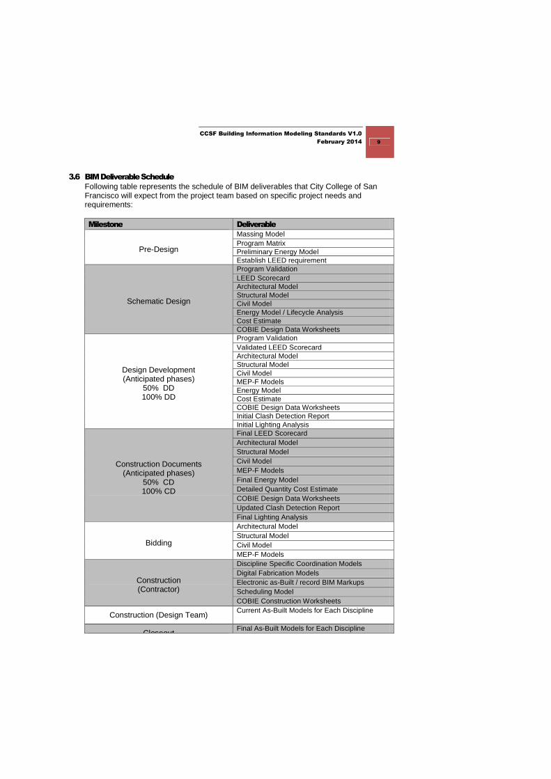
3.6 BIM Deliverable Schedule Following table represents the schedule of BIM deliverables that City College of San Francisco will expect from the project team based on specific project needs and requirements: Milestone Deliverable
Pre-Design
Massing Model Program Matrix Preliminary Energy Model Establish LEED requirement
Schematic Design
Program Validation LEED Scorecard Architectural Model Structural Model Civil Model Energy Model / Lifecycle Analysis Cost Estimate COBIE Design Data Worksheets
Design Development (Anticipated phases)
50% DD 100% DD
Program Validation Validated LEED Scorecard Architectural Model Structural Model Civil Model MEP-F Models Energy Model Cost Estimate COBIE Design Data Worksheets Initial Clash Detection Report Initial Lighting Analysis
Construction Documents (Anticipated phases)
50% CD 100% CD
Final LEED Scorecard Architectural Model Structural Model Civil Model MEP-F Models Final Energy Model Detailed Quantity Cost Estimate COBIE Design Data Worksheets Updated Clash Detection Report Final Lighting Analysis
Bidding
Architectural Model Structural Model Civil Model MEP-F Models
Construction (Contractor)
Discipline Specific Coordination Models Digital Fabrication Models Electronic as-Built / record BIM Markups Scheduling Model COBIE Construction Worksheets
Construction (Design Team) Current As-Built Models for Each Discipline
Closeout Final As-Built Models for Each Discipline

CCSF Building Information Modeling Standards V1.0
February 2014
1 0
Final COBIE Construction Worksheets
4 Project Team Collaboration Procedures The success of a BIM enabled project delivery process is highly dependent upon the level at which the entire project team can communicate and work collaboratively for the duration of the project. This section documents collaboration procedures for effectively managing this process:
4.1 Model Sharing
Design
• Qualifications, experience and previous success in BIM coordination of the proposed BIM Manager and the Design Team shall be part of the evaluation of the AE selection.
• The Design Team shall be responsible for providing a fully coordinated and assemble BIM in a collaborative software format (Navisworks or equal) as well as separate copies of each technical discipline model in the original software authoring tool, as well as a 2d plan set, derived from the assembled BIM, for contract bidding.
Construction Bidding
• Qualifications, experience and previous success in BIM coordination and fabrication of the proposed Construction BIM Manager, General Contractor, and major sub-contractors to achieve CCSF`s BIM objective shall be part of the evaluation of the Contractor selection.
• During bidding, the use of BIM Standards will be announced and reviewed with potential bidders, and then reviewed with the selected GC and major sub-contractors prior to the construction start.
• The Contractor shall have access to the Design BIM during bidding and construction phases of the project. The solicitation for bids shall define the legal status of the model to the bidders (binding, informational, reference, etc) by determining the Contract Record Document (the BIM Model(s) or the extracted 2D plan set). This decision will be made on the basis of CCSF business interests, the maturity of the market for BIM use, and other factors.
• Regardless of whether or not the Design BIM Model(s) is the Contract Record Document, after a contract is awarded for construction the coordinated design BIM and all native BIM files shall be provided to the appropriate contractor entities as needed.
Construction Phase
• It is the Contractor`s responsibility to assure that all major trades are modeled and used for clash detection, construction phasing, and installation coordination.
• Contractor`s fabrication models shall be coordinated with the design model. Any conflicts/changes to the design model that need to be made prior to fabrication and construction shall be reported to the Design Team in the form of a Request for Information (RFI). Clash reports may also be issued by the General Contractor (GC) as background info for RFI`s and Submittals.
4.2 Shared File Server Prior to start of the design, it is required that Design Team establish a single shared project server for the upload and exchange of digital models, and the collection of project deliverables at pre-determined milestones. The same shared server shall continue to be used for the same purposes during Construction. Models on this shared server will be fully accessible web-based to all project team members via assigned site

CCSF Building Information Modeling Standards V1.0
February 2014
1 1
user names and passwords. If a CCSF provided shared file server is available, Project Team shall coordinate with the District to establish access and user permissions. 1. Upload Models to Shared Project Server: During the Design Phases, design
engineers and architects will upload their discipline-specific authoring and analysis BIM models to the shared Project Server for scheduled coordination meetings and milestone submittals.
2. Design: BIM Design Models uploaded for clash detection and systems coordination should be saved in an optimal interoperable format agreed upon by project team. (Navisworks accepts several file types but dwg, nwd/nwc, and ifc are file formats that are operable across multiple software platforms)
4.3 Project Kickoff BIM Standards Orientation Meeting
After the project is awarded to the Project Team, CCSF shall facilitate a BIM Standards Kickoff Orientation with the Design Team to review the following:
• It is the Contractor`s responsibility to assure that all major trades are modeled and
used for clash detection, construction phasing, and installation coordination. • CCSF BIM Standards and Workflow Process • Statement of Owner`s Project Requirements • All data developed during the project validation phase • Project Model Template
Use of BIM Standards will be announced to potential bidders during bidding phase, and then reviewed with the selected GC prior to construction start.
4.4 BIM Workroom(s)
A BIM Workroom or Coordination room shall be provided and utilized as a collaborative work environment during design and construction for facilitating BIM design review and clash detection/coordination where all team members can meet to discuss technical discipline coordination issues using the BIM Models. Alternatively, collaboration using web conference (i.e. WebEx, GoToMeeting) is acceptable for facilitating these meetings. During the Design phases, the Design Team Prime Consultant will provide the BIM Workroom for facilitating the collaboration. During Construction, Contractor will provide and set up a BIM Collaboration room located at or near the construction site to coordinate fabrication models with respective trades. Smart boards may be used to view 2D and 3D documentation, create mark-ups interactively, archive the latter, and convert them to RFI (Request for Information) `s or other relevant reference documents.
4.5 Spatial Coordination & Clash Detection
To facilitate spatial coordination and clash detection in a 3D environment, in addition to authoring and analysis tools specialized coordination software such as Navisworks, Bentley Navigator and etc. will be needed. Following page represents City College of San Francisco`s BIM Collaboration Workflow for Design-Bid-Build Projects:

CCSF Building Information Modeling Standards V1.0
February 2014
1 2

CCSF Building Information Modeling Standards V1.0
February 2014
1 3
a. 3D Models, Formats and Model Structures: The BIM(s) shall consist of 3D-Solids (not lines or wire frames) that represent the actual dimensions of the building elements and the equipment that will be installed on the project. Reasonable abstractions can be made (i.e. pipe fittings do not need to be modeled) in the Design Model, and these abstractions shall be coordinated later on with the Constructor to ensure meaningful coordination and clash detection. Before modeling begins, BIM Manager will work with the team to develop a structure and features of the files that are to be submitted: File Structure, Modeling Scope Matrix. Typically, BIM Coordination requires the following model structures and features: 1. Project team shall follow CCSF File Naming requirements as described in CCSF
BIM Standards Section 7.1. 2. The BIM Manager shall establish the floor elevation protocol so that the Technical
Discipline/Trade BIMs will be modeled at the correct elevation. 3. Clearance Reservations: All models shall include separate 3D representation of
required clearances for all mechanical equipment for repair, maintenance, and replacement, light fixture access, overhead cable tray access, etc. These clearances/access models should be in a separate layer(s) for each trade clearly labeled as such.
4. All elements of the building must be represented in only one file and should be modeled by their specific trade. For example, the architectural model provided for 3D coordination should not include any of the structural elements contained in the structural model. Light fixtures should be modeled by the electrical engineer, not the Architect.
5. Architectural ceilings should contain openings for lights, registers, etc. as required. 6. The granularity of elements in the model shall reflect the proposed sequence of the
installation at the site (e.g. not one single wall element for the entire floor). This will also support the 4D visual sequencing of the construction.
7. All 3D model files submitted for clash detection must be “clean”; all extraneous 2D references and/or 3D elements must be stripped from the models.
8. When emailing notifications of file uploads or for any other email correspondence pertaining to the project, all email subject line headings must be prefaced with the acronym for the Project Name.
9. For ease of identification during the 3D Coordination process, the following trades will be represented in these assigned colors (for the Coordination Software:
• Architectural: White • Communication Conduit: Light blue • Electrical Conduits: Light yellow • Electrical Cable Tray: Dark Orange • Electrical Equipment: Dark yellow • Electrical Lighting: Yellow • Fire Protection: Red • HVAC Equipment: Gold • HVAC Supply Duct/Diffuser: Light blue • HVAC Return Duct/Diffuser: Magenta • HVAC Pipe: Gold • Structural Steel: Gray • Structural Concrete: Gray • Plumbing Water: Cyan

CCSF Building Information Modeling Standards V1.0
February 2014
1 4
• Plumbing Sewer: Magenta • Plumbing Storm Drain: Green • Pneumatic Tube: Dark green
b. Subcontractor Coordination: When planning the installation process, prior to
installation, the Contractor shall hold trade coordination meetings with subcontractors, where the coordinated model will be used to review and optimize field installation. Subcontractors will be expected to have individuals attend who can actively engage in the planning process and make schedule commitments.
c. Digital Fabrication: The collaborative process will ensure that the deep knowledge and associated efficiencies of the fabricator are embedded into the Construction Model(s). The following construction trades (at a minimum) shall provide models with parametric model objects:
• Structural Steel • Curtain Wall • Mechanical System Duct (MEP subs to incorporate vendor models if
available) • Building Envelope Systems (i.e. sun / rain screens, pre-cast panels) • Casework and furniture systems • Any additional fabrication models generated by subcontractor
d. Coordination of entire building:
BIM Manager will assemble a composite model from all the model parts of each design discipline for the purpose of performing a visual check of the building design for spatial and system coordination. Vertical shafts should also be reviewed to ensure that adequate space has been allocated for all of the vertical mechanical systems and that all of the shafts line up floor to floor.
e. Floor by floor coordination: On a multi-level project, the models may need to be split on a level by level basis for MEP coordination. If a floor is particularly large, it may also need to be split by zone to reduce file size. Each floor shall be created as a separate level in the coordination software, and all trades shall reference a shared and documented insertion point and methodology for developing these files. Typically, 3D coordination continues single floor until building systems are fully coordinated, and then continues on the next floor up.
f. Clash detection and reporting: 1. Coordination software will be used for assembling the various design models
and for providing a report and view list of design coordination issues. The Design Team, including Team BIM Manager and discipline BIM Lead Modelers, will review the model and the Clash Reports in coordination meetings on a regular (weekly) basis.
2. The report will be reviewed by the team members and agreed upon solutions will be implemented per an agreed upon schedule. This process will be repeated throughout the design phases until all spatial and system coordination issues have been resolved.
3. During the construction phase, the Contractor shall utilize the fully coordinated and consolidated design model to verify the accuracy of certain fabrication models. Prior to each fabrication submittal for approval, fabrication contractors

CCSF Building Information Modeling Standards V1.0
February 2014
1 5
shall submit their models to the Contractor`s BIM Manager for integration with Design Model.
4. Internal Clash Resolution: Design Consultants and Subcontractors who are responsible for multiple scopes of work are expected to coordinate the clashes between those scopes prior to providing those models to the BIM Manager for spatial and system coordination.
5 CCSF Requirements for Using BIM BIM can be utilized in a variety of ways to provide stakeholders with a greater understand of how a building is to be used, designed, constructed and maintained. Following are the various applications in which BIM shall be utilized for all CCSF BIM projects: 5.1 Design-Bid-Build (DBB) Workflow
In the traditional DBB project delivery method, when there is no contractor or subcontractor in the design process, an Integrated Design Process shall be implemented. This process integrates people, systems, and business practices into a collaborative process (utilizing previously described project team collaboration tools and procedures) that optimizes efficiency through all phases of the project. The team includes disciplines and stakeholders who remain involved from start to completion. • A Design Team BIM Manager and BEP (BIM Execution Plan) should be developed
prior to modeling. • Architectural and building systems models will be developed by Design Team • The Design BIM Manager will integrate discipline models into a composite file which
will be used for coordination and clash detection. • Interferences will be resolved interactively during the coordination meetings as
described further in Section 4.5 of the CCSF BIM Standards. • Construction documents will be printed for agency (DSA) approval once all conflicts
are resolved. • Models will be made available to bidders for reference only.
5.2 Space Validation (Pre-Design & Programming) Programming requirements defining area, adjacencies, building systems and furnishings shall be integrated into the BIM Authoring Software. These requirements shall be based on City College of San Francisco Standards, the campus Education Master Plan and Facility Master Plan, and shall reference the applicable District Basis of Design and Sustainable Design Guideline Documents, if available. BIM shall be used for reference and verification purposes throughout the design process. As-built records of existing facilities, and BIM / GIS mapping of campus shall be included in this document and provided to project teams for their use during RFP phase, if applicable. Where possible, all programming and as built data provided by the campus shall be in a format that is translatable to an IFC Compliant BIM Authoring Tool and shall be expected to be incorporated by the teams in their design processes for reference and verification purposes.
5.3 Site Conditions (Existing & New Construction)
Modeling of the project site and the existing structures shall be part of the BIM requirements for new and renovation projects. Depending on the project site, a model of the site may already be available and obtained from the CCSF Vault or

CCSF Building Information Modeling Standards V1.0
February 2014
1 6
commissioned by an external BIM consultant using an approved IFC compliant, 3D site and utility modeling tool. The modeling of existing buildings shall be performed based on CCSF provided as-built information, with field verification or electronic measurements conducted by Project team to validate the level of accuracy. For existing conditions to be directly impacted, altered, or to be demolished by a proposed renovation, Project Designers shall model those conditions to the appropriate level of detail that will clearly demonstrate the design intent to building user and other stakeholders, other Project Team Members, and construction trades directly involved with executing the alteration.
5.4 Architectural (Spatial & Material Design) Models The Architectural Spatial model evolves during the design process, and the information modeled in BIM shall be further refined as a project progresses toward construction. In the early phases of design, an Architectural BIM Model may be as simple as a massing model validating program requirements, basic geometries, and building orientation to climate and site conditions. Design options shall develop and need to be clearly documented and delineated in the BIM model as the design progresses. Likewise, as materials and components are selected, generic assemblies shall be assigned material properties, sizes, track LEED values, and other specific component information to clearly define various building features such as walls, floors, roofs, doors and windows. Program space requirements shall be modeled in the spatial model and validated using schedules and other validation tools designated by CCSF for the specific project. The timing of the Level of Development (LOD) required for element(s) or system(s) will be dependent entirely upon the project execution strategy used for the project, as the deliverables and their timing will be different for DBB than for DB or IDP (Integrated Project Delivery). LOD`s and the Model Progression Specification (MPS) that they are established by will be further discussed in section 6 of CCSFBIMS.
5.5 Building System Models (Structural, MEP-F and Interiors) Design information for the above is required to be developed in BIM as current technology allows building systems to be organized as separate BIM models linked to a common campus benchmark for efficient and accurate coordination purposes. Similar to the spatial models, the level of detail in these models shall evolve as design progresses such that these systems are accurately modeled, and include sufficient performance, clearance, and LEED requirements as part of the BIM.
5.6 Energy & Life-Cycle Cost Analysis All new construction shall need to be designed in a way that energy and material use can be greatly reduced and then measured and verified by a building`s users and facility management and operation teams once it is occupied. BIM provides the opportunity to simulate energy consumption of the building based on different scenarios and allow life-cycle cost calculations based on the information extracted directly from BIM model.
Comment [f2]: 1.1Energy Modeling
Requirements
The Design Team shall work with the District to establish project specific energy goals and energy use targets. The Design Team shall also establish an energy modeling methodology that will be included within the BIM Execution Plan that will detail how energy modeling will be accomplished for the project. At a minimum, the required software to perform the energy modeling for the project shall be any software as listed acceptable by the US Department of Energy, Energy Efficiency and Renewable Energy. A list of approved software can be found at the following link: http://www1.eere.energy.gov/buildings/qualified_software.html. In addition to this list, the designer may also use the following DOE 2 based software: Green Building Studios, Ecotect, eQuest. Local weather data shall be obtained from TMY2 or TMY3 weather data tables. Weather files can be downloaded from the National Renewable Energy Laboratory website at the following link: http://rredc.nrel.gov/solar/old_data/nsrdb/tmy2/. The energy model is developed in two parts. The preliminary (conceptualization) energy model is prepared as a part of Schematic Design. The preliminary energy model’s purpose is to narrow down design strategies from the multitude of design possibilities to those that are in line with and will achieve the projects energy goals and targets. The second part of the energy model is developed in the Design Development phase. The Design Development phase energy model shall build upon the model developed in the Schematic Design phase. This energy model shall be complete enough to use for additional submissions, such as LEED EA Credit 1 calculations, should the building apply for LEED certification. This model shall be detailed and finalized enough to use as an indicator of approximate building energy use after occupancy. This model shall also serve as a baseline for future comparisons. After building completion and occupancy of a minimum of one year, actual building performance shall be evaluated against this model. This model shall be used as a tool to facilitate post-occupancy commissioning should discrepancies between modeled and actual energy use arise. Caution is advised in this, as deviations from design in weather, occupancy, plug loads, schedules, electric and fuel costs, etc. will affect actual energy use, and these factors must be taken into account.
CCSF Building Information Modeling Standards V1.0
February 2014
1 7
The Design Team shall work with CCSF to establish project specific energy goals and targets. The purpose is to narrow down design options to those that achieve the project`s energy goals and target.
1. Schematic Design: Energy model at this phase shall be used to evaluate design strategies and improve the long term energy performance of the building. The schematic design energy model shall include and incorporate at the minimum: floors, roofs, exterior and interior walls defining zones of similar use, ceilings, openings, doors, overhangs and sunshades; building function and occupancy, operating schedule, lighting information, HVAC equipment information, plug / process loads, local weather info and building envelope components. Below are the analysis requirements:
• Energy calculations via use of eQuest, EnergyPlus or other energy calculation software.
• Building lifecycle estimate of energy consumption for the projected life of the project (40 years based on year of occupancy and escalate at the current CPI rate, including first cost, estimated service life, annual maintenance cost and operating cost.
• Massing studies to enable whole building energy analysis to make decisions about how the building is placed on the site and spaces are configured. Design team shall submit to CCSF, in spread sheet format, the list of design options and comparison results with annual energy usage in kWh and cost in dollars.
• Energy performance evaluation of construction elements including walls, roofs and windows. Design team shall submit to CCSF, in spread sheet format, the list of design option and comparison results (via iterations by changing one component at a time), and shall include annual energy usage in kWh and in cost dollars.
2. Design Development: Energy model at this phase shall be based on the schematic model. Accuracy obtained at this level should be enough for energy calculations and for use as an indicator of approximate energy usage after occupancy. Building data shall be extracted from the BIM Model directly and be utilized for below analysis:
• Assess space and building energy performance for compliance with regulations and targets.
• Perform more advances analysis to evaluate daylight design options to achieve maximized energy savings over the building lifecycle.
3. Construction Documents: Energy model at this phase shall reflect the final design, and be complete enough to use for final energy calculations for submittal and be used as an indicator of approximate building energy usage after occupancy. As analysis requirement, building energy performance shall be confirmed as in compliance with regulations and targets.
5.7 Cost Estimation Area, system information and quantity takeoff information generated from the Project BIM, via authoring software and other BIM integrated tools, shall be used for estimating

CCSF Building Information Modeling Standards V1.0
February 2014
1 8
purposes at project milestones as defined by the contract. At the completion of Construction Documentation Phase, the Design Team shall provide to potential bidders a copy of the fully assembled and coordinated BIM in a non-editable format.
5.8 4D Scheduling & Sequencing The construction planning process requires the sequencing of activities in time and space and accounting for constraints such as resources, spatial constraints, logistics and similar. Because traditional scheduling methods do not address the spatial aspect of construction nor are they linked to a design or building model directly. Traditional bar charts and CPM network diagrams can be difficult to understand or interpret. BIM, on the other hand, allows linkage of the model with an external schedule, and will allow the Construction Team to visualize the construction virtually, giving the team improved accuracy in construction sequencing and coordination (build before building). The main elements that CCSF requires for 4D simulation and sequencing shall be as follow: • Site work and ground level: Excavation work, footings, foundations, slab-on-grade • Structural System: Entire system inc. foundation, grade beams, columns, load
bearing walls, floor and roof decks and support • Exterior Building Shell: Walls /curtain walls, openings, glazing, panel assemblies • Interior Core: Walls, main plumbing walls and wall assemblies • Roof System: Roof assembly, major equipment and openings • Mechanical System: Main ductwork and equipment separated by floors • Plumbing: Main connection lines from site, main plumbing lines
5.9 Communication of Construction Scheduling and Phasing
The optimal way in 4D scheduling is to import schedule activity data from scheduling software as Primavera P3 or P6 into a dedicated 4D scheduling application and “link” the activity data to the associated object in a 3D model. The result is a 4D model which provides a value advantage to the Project Team for better visualization and coordination of the construction sequence for respective trades. For design work that includes sequencing of renovation swing space or master planning for long-term build-out, BIM 4D shall be used to illustrate the phasing plan to interact, communicate and get approval of the final design and spatial sequencing with the educational staff. The Contractor shall link BIM to the project schedule also to animate the phasing plans to address issues like shut downs of required/impacted facilities (inc. adjacent neighborhood, cities and agency coordination), swing space during construction, parking interruptions, and re-routing of pedestrian and vehicular traffic, or any other construction work that could affect the daily operations of the school and campus-life.
5.10 5D Estimation CCSF will not require BIM based 5D Estimation at this time; but will address this requirement in later versions of its standards as technology progresses.

CCSF Building Information Modeling Standards V1.0
February 2014
1 9
5.11 Design Visualization Design visualization tools refer to animations, fly-throughs, static 32D renderings, 4D, and 3D Physical Models exported directly from a BIM Authoring Tool. Design teams shall participate in providing the quality design visualizations that illustrate building spaces, their use and organization to assist end-users and other project stakeholders in making decisions throughout the project duration. Visualization models may be developed by the Contractor during the Construction to help simulate and sequence construction of a single room or a floor or the whole building before it is built. Further refinement in specific animation and visualization software may be needed to accomplish needed results even though BIMs will contain most of the source information.
5.12 COBIE (Handover to FM) / Commissioning CCSF has adopted COBIE or “Construction Operations Building Information Exchange” as the methodology to electronically transfer building information after construction is complete for facilities management and operations. The data required by COBie is the same information as is currently required by project handover specifications. With COBie approach data is created during the design, construction and commissioning process, see following.
(Source: http://www.wbdg.org/resources/cobie.php) The COBie spreadsheet is part of the U.S. National Building Information Model Standard (NBIMS). Third-party utilities facilitate the automatic creation and transfer of some data between BIM and a COBie spreadsheet via IFC files as an intermediate stage, and some BIM software may include creation of and data transfer to the spreadsheet directly without making use of intermediate IFC files. Where possible, automatic means should be used to create and fill in the COBie spreadsheet. CCSF will use the COBie2 specification (DOC) which provides a vendor-neutral, non-agency specific, open standard specification clause for use within the existing contract specification. This specification requires the delivery of COBie2 data in the Spreadsheet XML 2003 format at each appropriate stage of the project's life-cycle. The COBie2 specification will be implemented, not as a stand-alone or BIM-based specification, but within the context of the existing specifications.

CCSF Building Information Modeling Standards V1.0
February 2014
2 0
As with all design related information, the lead Architect/Engineer firm is responsible to coordinate the compilation of all COBie2 information into a single COBie2 deliverable file when the deliverable is required during design. In the case of construction related information, the prime contractor is responsible for the delivery of a single COBie2 deliverable file when the deliverable is required during construction. The Design / Construction Team are encouraged to provide as much information in COBie as is known at the time of the deliverable. The required worksheets in COBie will be filled out in step with the LOD and Design Phases. The following shows COBie2 worksheets that shall be provided with required submittals:
Project Phase Required COBie2 Worksheets Schematic Design • (1) Contact Worksheet
• (2) Facility Worksheet • (3) Floor Worksheet • (4) Space Worksheet • (5) System Worksheet
Design Development • Updated Worksheets (1-5) • (6) Register Worksheet • (7) Component Worksheet
Construction Documents • COBie data shall be updated and provided at the CD submittal
Construction Operational Planning Set to be provided at 75% completion or three (3) months prior to substantial completion, whichever is earlier. This set shall be an update to the design team COBIE worksheets and include the following COBIE worksheets: • Updated Worksheets (1-7) • Document Worksheet (11) • Component Worksheet (7) • Installation Worksheet (14) • Manual Worksheet (15) • Warranty Worksheet (16) • Spare Worksheet (17)
Beneficial Occupancy This set shall be an update to the Operations Planning Set and include the following COBIE worksheets: • Instruction Worksheets (18) • Test Worksheet (19) • Certification Worksheet (20) • Material Worksheet (21) • Tool Worksheet (22) • Training Worksheet (23) • PM Worksheet (24) • Safety Worksheet (25) • Trouble Worksheet (26) • Start-Up Worksheet (27) • Shut-Down Worksheet (28) • Emergency Worksheet (29)
Fiscal Completion updated previous phase information, as needed
(Source: Adapted from Building Smart Alliance and San Diego CCD BIM Standards)

CCSF Building Information Modeling Standards V1.0
February 2014
2 1
5.13 Clash Detection / Coordination Clash detection provides great opportunity to the project team for effective identification, inspection and reporting of interferences in a 3D project model. BIM Models are required to be clash free, and success of this process depends upon the level of team collaboration and open line of communication. It is the Design / Construction Team`s responsibility to conduct and manage an adequate and through Clash Detection process so that all major interferences between building components will have been detected and resolved before construction. It shall be the goal of the Design/Construction Teams to reduce the number of changes during construction due to major interferences to zero.
5.14 Virtual Testing & Balancing The CCSF requires virtual testing and balancing of the architectural model to support sustainable building systems design and analysis. Room data can be read from the linked architectural model to create mechanical spaces (each space is the same as the room in the architectural model). Multiple spaces are joined to create zones. This data can be used to calculate native heating and cooling analysis that is built into the MEP-F software or exported using gbXML to an external analysis application such as eQuest, Trane/Trace, or DOE based analysis programs. Architect / Engineers can then bring this data back within the data to check their work. One of the methods is to create a Space/Room schedule that will show calculated air flow versus actual air flow. All air flows can be checked for load balance to the terminal box and all the way back to the air handling units. MEP-F modeling software companies should be contacted for more information.
5.15 Additional BIM Uses The CCSF is interested in and encourages bold steps toward trying new ways to improve business process efficiency, design, and project outcomes. Following are some of the discretionary areas that CCSF supports for further development and the use of BIM; other ideas may also be proposed by the AEC teams: • Evaluating physical security and survivability • Early MEP-F design • Creating a interactive virtual workspace for the Design Team to achieve integrated
design goals • 3D Virtual functionality viewing and testing of the design • 5D Model based material quantity take-offs & cost estimating • Integrating information such as electronic specifications that are tied to the BIM • Automated code checking • Modular construction and off-site fabrication • Repeatable modular construction components to speed erection time
5.16 California Community College Process
Where applicable, BIM modeling efforts shall comply with requirements of the California Education Code, Title 5 of the California Code of Regulations, the California Community Colleges Taxonomy of Programs Manual, Sixth Edition, and the State.

CCSF Building Information Modeling Standards V1.0
February 2014
2 2
5.17 Agency DSA currently does not require submittal of a Project BIM model. However, the CCSF supports the adoption of this practice as time progress and technology advances. Submittal of BIM model for review and reference will be beneficial as it will improve the collaboration effort and expedite the plan review and approval process.
5.18 As-builts The BIM model must be updated continuously throughout the construction phase and must document all built conditions, RFI`s, etc. GC shall have modeler(s) on site continuously to update constructed changes accordingly. Design Team shall update design changes coordinated with the contractor via RFI`s and change orders. Upon substantial completion, the Design / Construction Teams must submit the As-built BIM to the CCSF. The as-built BIM shall include the following: • All as-built information • Native file formats and all associated and linked files (if applicable) • All digital fabrication models generated by Contractor and Sub-contractors.
5.19 Closeout
CCSF shall be submitted to following closeout deliverables within 30 days of substantial completion: • As-built model (.rvt format) • 2D As-built documents (bound .dwg format) • Electronic field set as-builts (.pdf format) • O&M Manuals (hard copy and .pdf format) • COBie construction worksheets (.xls format) • Coordination models in native / authoring format • FUSION Space Inventory Schedules (.xls format)
6 BIM Modeling Requirements
6.1 General & Model Ownership In contributing content to the Model, the Model Element Author does not convey any ownership right in the content provided or in the software used to generate the content. Unless otherwise granted in a separate license, any subsequent Model Element Author`s and Model User`s right to use, or further transmit the Model is specifically limited to the design and construction of the Project, and nothing contained in this document conveys any other right to use the Model for another purpose. a. BIM shall be used for all building systems design, development, and analysis,
including but not limited to architectural, structural, mechanical, electrical, plumbing, and fire suppression, etc.
b. During SD and DD Phases, BIM technology shall be used to develop and establish building performance and the basis of design in accordance with CCSF Standards. The model shall be interoperable with analytic tools including but not limited to envelope, orientation, daylighting, energy consumption, building management system (BMS), building automation systems (BAS), renewable energy strategies, life cycle cost analysis, and spatial requirements.
Comment [ub3]: San Diego CCD language re Model ownership: “With the exception of matters or things that are subject to a patent or copyright issued by the U.S. Government, all building models that are prepared by prime designer, design consultant, prime contractor, trade contractor or supplier for use in connection with the project, shall be deemed the sole and exclusive property of the District, whether work is commenced or completed.”

CCSF Building Information Modeling Standards V1.0
February 2014
2 3
c. Use BIM authoring software element libraries when creating model objects. Model objects shall contain parts and components as opposed to simple 3D Geometry (e.g. walls, doors, windows, railings, stairs, and furniture, etc.)
d. Model objects shall contain IFC (Industry Foundation Class) parameters and associated data applicable to building systems requirements. These elements shall support the analytic process including size, material, location, mounting heights, and system information where applicable. As an example, a light fixture may contain several parameters such as energy output requirements, user illumination levels, make, model, manufacturer, and bulb life.
e. Sustainable design principles and LEED credit documentation shall be included in the BIM to analyze, document, and verify project LEED goals (if within project scope)
f. For DBB (Design-Bid-Build) projects, Design Team shall provide (via CCSF) awarded General Contractor a copy of the fully coordinated and assembled BIM (in Navisworks or equal as approved), as well as the Authoring BIMs for each trade. These authoring BIMs shall be used as basis of fabrication models generated by subcontractors. It is recommended that Design Team and Contractor establish a protocol for digital data exchange (i.e. interoperable file formats) prior to providing these models.
g. The Contractor shall utilize model geometry and extract graphical information for generating construction administration documents from the Project BIM (RFI`s, Directives, Bulletins, and Change Orders, etc.). The Contractor shall record as-built conditions in BIM as part of final delivery to BIM.
h. DSA submittal drawings, calculations and analysis shall be extracted from the Project BIM.
i. Elements, objects and equipment shall be tagged with unique identifiers (GUIDs). 6.2 Types of Model Elements
BIM Model elements shall be derived from the following sources:
a. Manufacturer`s Model Elements: These elements that are created by and acquired from manufacturers often have more information than is prudent to keep in the BIM model; appropriate level of detail should be retained for the design element. However, embedded performance data shall remain for analysis and specification purposes.
b. Custom Created Model Elements : These custom created elements must utilize appropriate BIM Authoring tool templates to create custom elements. Custom models components need to be assigned as a part and part of a family or group.
c. District Provided Model Elements (District Standard s): These are created by district appointed specialists, containing the minimum standards set forth in this document.
6.3 Model-based Quantity Take-off & Specifications The Design Team shall extract square foot and system information using BIM Authoring Software and other BIM integrated tools to support comparative costs analysis of options studied. Outputs shall be converted to spreadsheets and submitted as part of the deliverable at end of the design development phase.
Comment [f4]: Though CAD-based QTO is common these days, LACCD is not requiring model based quantity take offs (QTO) at this time. They say that they will address this requirement in later versions of this Standard as technology progresses. Otherwise Innovaya or equal would be the software to reference. Same applies to Model-based specifications.

CCSF Building Information Modeling Standards V1.0
February 2014
2 4
6.4 Model Geographic Location The spatial coordinates of the master BIM file shall be set at the beginning of the project. Once established, spatial coordinates shall only be changed by mutual consent of the team and the CCSF project manager, with the matter recorded in the meeting minutes and the BEP. Once the design coordinate system is agreed upon, any model(s) of existing buildings relevant to the project shall be converted into the coordinate system used of each designed building. The CCSF requires that a building within a BIM file shall include a geo-reference to accurately locate that building within the site and to give it a physical location context at larger scales. The BIM Manager shall geo-reference site plans and building models for site layout surveying and future GIS use in accordance with the State Plane Coordinate system where the project is located. The BIM file point shall be located at the SW corner of the structural grid (The USGS Reference will always read as 0.0.0 – the project base pint will read whatever the distance is from the USGS Reference to the lowest left hand point of the building structural grid).
6.5 Requirements for Modeling Space a. Space information imported from Fusion or the Onuma Planning System (OPS) in
.xls. format shall be the source for space creation in BIM. Other sources are program narrative, CCSF Design Guides, and other directives as applicable.
b. Spatial data should be generated and associated with bounding elements (walls, doors, windows, floors, ceilings)
c. Space/area schedules and diagrams must be dynamically updated from the model geometry.
d. CCSF spatial requirements must be validated using BIM.
6.6 Space Naming and Coding Each space (area of four square feet or greater) shall include the following attributes throughout the Design and Construction BIM models:
• Building • Wing • Floor • Department / sub-department • Space name (English name and Abbreviation) • Room number(s) (if CCSF way finding room no. and construction document
number are different • Space code (CCSF Room Code) • Unique space number (GUID – Globally Unique Identifier automatically
assigned by BIM software and preserved through generation and regeneration of IFC deliverables)
• Space type (OmniClass) • Space measurement (Net Square Footage (NSF), Department Net Square
Footage (DNSF), Department Gross Square Footage (DGSF), and Building Gross Square Footage (BGSF))

CCSF Building Information Modeling Standards V1.0
February 2014
2 5
6.7 Mechanical and other Equipment Coding Each individual piece of special equipment (educational or other) and building mechanical equipment shall include the following attributes and be maintained throughout the Design and Construction BIM models:
• Item name (English name and Abbreviation) • Item code • Unique item number (GUID – Globally Unique Identifier automatically
assigned by BIM software and preserved through generation and regeneration of IFC deliverables)
• Item type (OmniClass) • Item tracking number • Other data available from FUSION or Onuma Planning System (OPS) that
is accommodated by the COBie spreadsheet and is appropriate to the LOD for the submission phase
6.8 Final BIM Deliverables It is CCSF`s intention to use the BIM model for Facilities Operations and Management upon occupancy. Information that matures during the construction process is to be captured in the appropriate models on an on-going basis throughout the construction phase. The use of these models is a developing methodology, and presently, multiple formats of information are required. Upon Substantial Completion, BIM files shall be summated to the CCSF, and shall be clean of extraneous “scrap” or “working space” layers, stories, abandoned designs, object creation and testing places, empty layers, and other content which is typically produced in BIM production. Unless the project acquisition strategy realigns these responsibilities, CCSF shall receive the following as final BIM deliverables: 3D Geometric Deliverables – Construction Coordinati on Model The Contractor shall be responsible for providing CCSF consolidated as-built Model(s) for building systems. The Model(s) shall be fully coordinated and align with the Design Model for architecture and structure; the required instructions on file/folder setup shall also be included:
1. Contractor – Native file formats of the final consolidated as-built Model(s) for
building systems used in the multi-discipline coordination process (version as agreed in BIM Execution Plan)
2. Contractor – IFC file format of the consolidated building systems models (version as agreed in BIM Execution Plan)
3D Geometric Deliverables – Design Intent Model The Design Team is to ensure that the “Design Intent model” remains current with all approved bulletins for overall scope. It is not expected that product specific information will be added to this model. Provide the Model information for architecture and structure and the required instructions on file/folder setup:
1. Design Team – Native file format(s) of Design Model (version as agreed in
BIM Execution Plan) 2. Design Team – IFC file format (version as agreed in BIM Execution Plan)

CCSF Building Information Modeling Standards V1.0
February 2014
2 6
Data Deliverables 1. Contractor – Provide COBIE database file containing room and product data
information described in previous sections of this document. 2. Design Team – Provide room/space data in COBIE format to be included in
Contractor COBIE database.
2D Deliverables 1. Contractor – Provide As-built drawings in PDF format with fully bookmarked
pages. 2. Design Team – Provide one printed set of final documents generated from the
Design Intent model in a) PDF format with fully bookmarked pages b) DWG format (latest current version) with bound views to each sheet.
Digital Deliverables All digital deliverables are to be submitted on DVD/CD with the data clearly organized and software version(s) labeled.
6.9 Modeling Standards 6.9.1 General Requirements
BIM models shall be dimensionally accurate. Details and components that are not represented in the BIM model must be obtained from the 2D drawings. In BIM, components that are not dimensionally located per the construction documents shall show the true representation of actual as-built condition, and all dimensions are to be computer generated. Measurement accuracy must be 1/64”. 6.9.2 Site, Civil and Terrain Models
As described in Section 5.3 of this document, modeling of the project site and the existing structures shall be part of the BIM requirements for new and renovation projects. Modeling of existing buildings shall be performed based on CCSF provided as-built information, with field verification or electronic measurements conducted by Project team to validate the level of accuracy. Proposed site conditions shall reference campus benchmarks, and reference existing surveys and GIS mapping systems for accuracy. New site and utility conditions shall be modeled in 3D, and shall coordinate system and spatial models three dimensionally. Where other system are directly impacted by landscape features such as vegetation, irrigation those elements shall be modeled with correct size and clearance requirements in BIM. The Civil discipline deliverable model shall be developed to include systems as defined by the BIM Standards. BIM authoring software shall be used to model parametric components and objects not provided by the District. Model objects shall contain parameters and associated data applicable to the building system. The level of detail shall evolve as established by the model progression specification, but at minimum must include all features that would be included on a 1”=20” scale drawing. BIM terrain model shall show actual site conditions and proposed grading, vertical elevation changes at walls, and building pads for use in joining 3D utility and building models into a common vertical and horizontal datum. The elevations in the 3D surface model shall be based on available topography received from record drawings or survey.
Comment [f5]: CCSF graphic standards for drawing production shall apply, if available (SDCCC and LACCD has these). Otherwise the U.S. National CAD Standards (NCS) shall apply.

CCSF Building Information Modeling Standards V1.0
February 2014
2 7
The surface will show detailed features such as existing walkways, roads, curbs, ramps, parking lot striping, sportive fields (with striping), and site walls with detailed elevation information for each feature. These components should be modeled to produce grading plans and site sections.
6.9.3 Utility Model
All existing and new/proposed utilities to point-of-connection and within project boundary to 5 feet of the building footprint shall be incorporated in a BIM model, including fire hydrants, fire department connections (FDC) and backflow preventers. The modeled utility pipe systems must contain the following database information to produce accurate plans and details for the project site:
• Material type • Size • Slope • Elevation • Year installed
CCSF will pothole the following utilities for accurate depth whenever this information for existing utilities are missing or unknown:
• Storm Water • Sanitary Sewer • Domestic Potable Water • Fire Service Water • Irrigation Main(s) • Cold/Hot water Return and Supply • Gas • Electrical • Communications
6.9.4 Architectural Models
If available, the District`s Revit template shall be incorporated as part of the BIM model. The deliverable model shall include the systems as defined by the BIM Standards. Parametric components not provided by the District shall be modeled by the BIM authoring software. The level of detail shall evolve as established by the model progression specification, but at minimum must include all features to accurately represent the design solution. The building systems models shall be linked into the architectural model and be displayed when producing SD, DD and CD documents. Modeling of existing structures shall be included in the BIM requirements for new construction and renovation projects. If available and depending on the project, a model may be obtained from CDCC. For all projects, the modeling of existing buildings and structures shall be based on District-provided as-built information, with field verification conducted by the project team to validate the level of accuracy. Model components shall contain parameters and associated data applicable to the building systems, including: Phase Created, Dimensions, Model,

CCSF Building Information Modeling Standards V1.0
February 2014
2 8
Manufacturer, Assembly Code – UniFormat Code, Specification Number, OmniClass Number and OmniClass Title. The object attribute information that is entered in during design will be used throughout the building lifecycle and integrated into the final as-built database. Minimum Architectural Model Requirements
Model shall be documented in the BIM Authoring software. Parametric links shall be maintained within the model to enable automatic generation of all plans, sections, elevations and schedules.
• Architectural Site Plan: Site amenities and other architectural elements
typically included on enlarged scale site plans • Rooms / Spaces: Room names and numbers, accurate net square footage,
finish properties, programmatic information and space inventory information • Walls and Curtain Walls: Interior and exterior walls shall be modeled to
exact height, length, width, finish and rating (thermal, acoustic and fire) to properly reflect wall types. Curtain wall systems to have mullions and window panes according to their true profile.
• Doors, Windows and Louvers: These shall be modeled to represent actual size, type and location, both interior and exterior.
• Ceilings: Ceiling system, soffits, openings, slopes and accessories • Roof: The Model shall include the roof with overall thickness including
insulation, drainage system, major penetrations, access ladders and other specialties.
• Vertical Circulation: Elevator, escalator, stairs, handrails and guardrails • Architectural Specialties and Casework: All architectural specialties
including toilet partitions, grab bars, lockers, display case, shelving and other interior architectural elements. Casework shall be modeled and include dimensions, WI number and additional information as defined for model components.
• Fixtures and Equipment: They should be modeled to meet layout requirements.
• Schedules: Door, window and finish schedules shall be provided and information must be extracted from the model components.
• Signage: All signage components should be modeled.
6.9.5 Building Systems Models
System models shall be developed as separate BIM models on a floor-by-floor basis. Deliverables shall be developed to include systems as defined by this document, CCSF BIM Standards. Modeled objects shall contain parameters and associated data applicable to the building system. The level of detail shall evolve per the model progression specification. System models are required for structural, mechanical, electrical/telecommunication/security, plumbing and fire protection. Model components shall contain parameters and associated data applicable to the building systems, including: Phase Created, Dimensions, Model, Manufacturer, Assembly Code – UniFormat Code, Specification Number, OmniClass Number and OmniClass Title. Light fixture components shall include lamp type and photometric information including light loss factor, initial intensity,

CCSF Building Information Modeling Standards V1.0
February 2014
2 9
initial color and color filter. The object attribute information that is entered in during design will be used throughout the building lifecycle and integrated into the final as-built database.
Minimum Structural Model Requirements
Model shall be documented in the BIM Authoring software. Parametric links shall be maintained within the model to enable automatic generation of all plans, sections, elevations and schedules.
• Foundations; All foundation and footing elements should be modeled • Floor Slabs: Structural floor slabs including recesses, curbs, pads and major
penetrations. • Structural Steel Framing and Decking: All steel framing including columns,
primary and secondary framing members, bracing, roof deck and floor deck. • Cast-in-Place Concrete: All retaining walls, columns and beams • Pre-cast Concrete: All primary and secondary elements • Expansion Joints: Joints shall be accurately depicted • Stairs: Stair framing members and necessary openings for stair system • Shafts and Pits: All shafts, pits and openings
Minimum Mechanical Model Requirements
Model shall be documented in the BIM Authoring software. Parametric links shall be maintained within the model to enable automatic generation of all plans, sections, elevations and schedules.
• HVAC Equipment; Air handling units (AHU), Fans, VAV boxes, compressors, cooling towers, chillers, air handlers, heat pumps, boilers, hoods and other major equipment
• HVAC Distribution: Air distribution ducts for supply, return, ventilation and exhaust ducts, duct hangers, seismic bracing, fire smoke dampers, control systems, registers, diffusers, grills and louvers. Ducting to be modeled to outside face dimension.
• Mechanical Piping: All piping ¾” diameter and greater shall be modeled to outside diameter of pipe or pipe insulation, whichever is greater.
• Equipment clearances: Clearances shall be modeled for use in clash detection process and maintenance access requirements. Minimum Plumbing Model Requirements
Model shall be documented in the BIM Authoring software. Parametric links shall be maintained within the model to enable automatic generation of all plans, sections, elevations and schedules.
• Fixtures and Equipment: All plumbing fixtures, sinks, toilets, floor and roof drains, leaders, sumps, booster pumps, grease interceptors, sediment separators and other major equipment.
• Piping: All piping to five feet outside building footprint, including hot and cold water piping, sewer piping, storm drain piping, gas piping, pipe hangers, seismic bracing, cleanouts and valves. Piping shall be modeled to outside diameter of pipe or pipe insulation, whichever is greater.
CCSF Building Information Modeling Standards V1.0
February 2014
3 0
• Equipment clearances: Clearances shall be modeled for use in clash detection process and maintenance access requirements. Minimum Electrical/Telecommunications/Security Model Requirements
Model shall be documented in the BIM Authoring software. Parametric links shall be maintained within the model to enable automatic generation of all plans, sections, elevations and schedules.
• Power: Transformers, emergency generators, main and distribution panels, switchgear, outlets, switches and junction boxes. Electrical feeders and conduits larger than ¾” shall be modeled, including underground.
• Lighting: Permanently mounted light fixtures, lighting controls, switches and junction boxes.
• Communications: All existing and new communications service controls, audio equipment, speakers, phone and data ports and connections, both above ground and underground. Cable tray routing with hanger supports and seismic bracing. Communications conduit ¾” and greater shall be modeled.
• Security: all security devices, keypads, cameras and motion sensors. • Equipment clearances: Clearances shall be modeled for use in clash detection
process and maintenance access requirements.
Minimum Fire Protection Model Requirements
Model shall be documented in the BIM Authoring software. Parametric links shall be maintained within the model to enable automatic generation of all plans, sections, elevations and schedules.
• Fire Protection System: All fire protection components including main lines, branch piping, sprinkler heads, valves, drains, pumps, tanks, sensors, heat and smoke detectors, notification devices, control panels, fire annunciation panels and related equipment.
6.9.6 Technology Platform & Software Interoperability
CCSF shall accept true 3D solid modeling, object oriented software applications that comply with current industry interoperability standards and are able to be used in a collaborative environment. All software platforms used for CCSF shall be compliant with: • The most current version of Industry Foundation Classes (IFC) file format • Commercially available collaboration software that provides interoperability
between the different software applications (see next page) • Software other than those listed in next page may be used subject to the
above compliance requirements and approval by CCSF Staff. • Traditional 2D documentation shall be prepared with approved IFC compliant
BIM authoring software and plans, elevations, sections, schedules, and details shall be derived and fully coordinated with the coordinated building model. All other documents shall be submitted per the CCSF contract documents.

CCSF Building Information Modeling Standards V1.0
February 2014
3 1
Software Type Available Planning/ Preliminary Cost Estimates Onuma Planning System (OPS), DProfiler,
Tokmo, CodeBook Authoring – Design (Architecture, Structural)
Revit Architecture, Bentley BIM, ArchiCAD, Tekla or equal
Authoring – MEP-F (Engineering & Construction)
Revit MEP, ArchiCAD MEP, AutoCAD MEP, Bentley BIM, CAD-Duct, CAD-Pipe, AutoSprink, PipeDesigner #D or equal
Authoring – Civil Autodesk Civil 3D, Bentley Inroads & Geopak Coordination (spatial conflict, clash detection)
Horizontal Glue , Navisworks Manage, Bentley Navigator & Solibri Model Checker
4D Scheduling Synchro, Vico, Navisworks Simulate, Primavera, MS Project & Bentley Navigator
5D Cost Estimate Innovaya, Vico or equal Energy Analysis EcoDesigner, Ecotect, eQuest, Green Building
Studio, IES, Hevacomp, TAS or equal Model Checking Validation, IFC File Optimizer
Solibri or equal
COBie EcoDomus/Tokmo COBie Exchange, Onuma Systems
Water Management Bentley WaterGem
6.9.7 Model Progression Specification (MPS) & Level of Development (LOD)
To facilitate BIM development, the design and construction teams shall follow the Model Progression Specification and Level of Detail (LOD) definitions as CCSF adapted from AIA. Project Teams should also refer to the Object Element Matrix developed by VA (Veterans Administrations), that defines object and element properties and attributes by UniFormat / OmniClass classification. Model Progression Specification for BIM
Model Progression Specification (MPS) addresses the need for a framework for defining a BIM’s precision and suitability for specific uses during various stages of the model development. This approach was adopted by AIA and incorporated it into the new E202, an exhibit which formalizes the processes for development and use of BIM’s for a specific project, to aid teams in agreeing on the purposes for which the project BIM(s) will be used, the level of detail to which specific elements of the BIM(s) will be brought at the conclusion of each phase, and who will develop specific elements of the BIM(s) to the specific levels of detail. Level of Detail (LOD)
The core of the MPS is the Level of Development (LOD) definitions—descriptions of the steps through which a BIM element can logically progress from the lowest level of conceptual approximation (LOD Level 100 - conceptual) to the highest level of representational precision (LOD Level 500 – as-built), identifying the specific content requirements for each model element at each phase of a project. There are (5) five progressively detailed levels of completeness and each subsequent level builds on the previous level. Following LOD`s shall be used to complete the model element table required at each phase of a project:

CCSF Building Information Modeling Standards V1.0
February 2014
3 2
1. LOD 100: This is the “programming” level. Buildings and/or structures shall be modeled as overall masses indicative of area, height, volume, spatial location, and orientation. The model at this level of detail may be analyzed based on volume, area and orientation by application of performance analysis software. The model may be used to develop conceptual cost estimate, preliminary energy modeling project scheduling, project phasing and overall duration for master-level planning purposes.
2. LOD 200: This is the “planning” level. Buildings and/or structures including major architectural, structural, mechanical, electrical, and plumbing objects shall be modeled as generalized systems or assemblies with approximate quantities, approximate configuration, spatial location, and orientation. Non-geometric information shall be attached to the model elements. The model at this level may be analyzed for performance of selected systems by application of performance analysis software. The model may used to show sequenced, time-scaled appearance of major elements and systems.
3. LOD 300: This is the “design” level. Buildings and/or structures including all objects shall be modeled as specific systems or assemblies with accurate quantities, recognizable configuration, spatial location, and orientation. Non-geometric information shall be attached to the model elements. The model at this level of detail is suitable for the generation of traditional construction documents and shop drawings. The model may be analyzed for performance and coordination of selected system by application of performance analysis and clash/interference detection software. The model may used to show sequenced, time-scaled appearance of detailed elements and systems.
4. LOD 400: This is the “construction” level. Buildings and/or structures including all objects shall be modeled as specific systems or assemblies with accurate quantities, recognizable configuration, spatial location, and orientation, with complete fabrication, assembly, and detailing information. Non-geometric information may be attached to the model elements. Model elements at this level of development are visual representations of the proposed element and are suitable for bidding and construction. The model may be analyzed for performance and coordination of selected system by application of performance analysis and clash/interference detection software. The model may be used to show sequenced, time-scaled appearance of detailed specific elements and systems including construction means and methods.
5. LOD 500: This is the “as-built” level. Buildings and/or structures including all objects will be modeled as constructed systems or assemblies with accurate quantities, shape, spatial location, and orientation, with complete fabrication, assembly, and detailing information. Non-geometric information may be attached to the model elements. The model may be utilized for maintenance, operation, renovation and addition or new construction purposes after completion of the building construction.

CCSF Building Information Modeling Standards V1.0
February 2014
3 3
Model Progression Specification
There is a significant amount of information that can be linked to an element in a BIM, and this information may be provided by a variety of individuals involved in a project. The model progression specification identifies the LOD required for each model element at the end of each project phase and the model element author (MEA) who is responsible for creating and developing the model element, its 3-dimensional representation of the component, but not necessarily for other discipline-specific information linked to it. CCSF expects that each project team will validate and adjusts the contents to align with the scope of the project and the capabilities of the project team. Abbreviations for each MEA to be used and Phases are as in the following: PD Prime Designer DC Design Consultant PC Prime (General) Contractor TC Trade Contractor S Supplier SD Schematic Design DD Design Development CD Construction Documents CON Construction FOM Facilities Operation & Management

CCSF Building Information Modeling Standards V1.0
February 2014
3 4
Example of Model Element Table, adapted from AIA E202 - 2008
LOD MEA LOD MEA LOD MEA LOD MEA LOD MEA
A SUBSTRUCTURE A10 Foundations A1010 Standard Foundations 100 PD 200 DC 300 TC 400 TC 500 TC
A1020 Special Foundations 100 PD 100 DC 300 TC 400 TC 500 TC
A1030 Slab on Grade 100 PD 200 DC 300 TC 400 TC 500 TC
A20 Basement Construction A2010 Basement Excavation 100 PD 200 DC 300 TC 300 TC 500 TC
A2020 Basement Walls 100 PD 200 DC 300 TC 400 TC 500 TC
B SHELL B10 Superstructure B1010 Floor Construction 100 PD 200 PD 300 PD 300 PC 500 PC
B1020 Roof Construction 100 PD 200 PD 300 PD 300 PC 500 PC
B20 Exterior Enclosure B2010 Exterior Walls 100 PD 200 PD 300 TC 400 TC 500 TC
B2020 Exterior Windows 100 PD 200 PD 300 TC 400 TC 500 TC
B2030 Exterior Doors 100 PD 200 PD 300 TC 400 TC 500 TC
B30 Roofing B3010 Roof Coverings 100 PD 200 PD 300 TC 300 TC 500 TC
B3020 Roof Openings 100 PD 200 PD 300 TC 300 TC 500 TC
C INTERIORS C10 Interior Construction C1010 Partitions 100 PD 200 PD 300 PD 400 TC 500 TC
C1020 Interior Doors 100 PD 200 PD 300 PD 400 TC 500 TC
C1030 Fittings 100 PD 100 PD 300 PD 400 TC 500 TC
C20 Stairs C2010 Stair Construction 100 PD 200 PD 300 TC 400 TC 500 TC
C2020 Stair Finishes 100 PD 100 PD 100 TC 100 TC 100 TC
C30 Interior Finishes C3010 Wall Finishes 100 PD 100 PD 100 PD 100 TC 100 TC
C3020 Floor Finishes 100 PD 100 PD 100 PD 100 TC 100 TC
C3030 Ceiling Finishes 100 PD 100 PD 100 PD 100 TC 100 TC
D SERVICES D10 Conveying D1010 Elevators & Lifts 100 PD 200 PD 300 DC 400 TC 500 TC
D1020 Escalators & Moving Walks 100 PD 200 PD 300 DC 400 TC 500 TC
D1030 Other Conveying Systems 100 PD 200 PD 300 DC 400 TC 500 TC
D20 Plumbing D2010 Plumbing Fixtures 100 PD 100 DC 300 TC 400 TC 500 TC
D2020 Domestic Water Distribution 100 PD 100 DC 300 TC 400 TC 500 TC
D2030 Sanitary Waste 100 PD 100 DC 300 TC 400 TC 500 TC
D2040 Rain Water Drainage 100 PD 100 DC 300 TC 400 TC 500 TC
D2090 Other Plumbing Systems 100 PD 100 DC 300 TC 400 TC 500 TC
D30 HVAC D3010 Energy Supply 100 PD 100 DC 300 TC 400 TC 500 TC
D3020 Heat Generating Systems 100 PD 200 DC 300 TC 400 TC 500 TC
D3030 Cooling Generating Systems 100 PD 200 DC 300 TC 400 TC 500 TC
D3040 Distribution Systems 100 PD 100 DC 300 TC 400 TC 500 TC
D3050 Terminal & Package Units 100 PD 100 DC 300 TC 400 TC 500 TC
D3060 Controls & Instrumentation 100 PD 100 DC 100 TC 100 TC 100 TC
D3070 Systems Testing & Balancing 100 PD 100 DC 100 TC 100 TC 100 TC
D3090 Other HVAC Systems & Equipment 100 PD 100 DC 300 TC 400 TC 500 TC
D40 Fire Protection D4010 Sprinklers 100 PD 100 DC 300 TC 400 TC 500 TC
D4020 Standpipes 100 PD 100 DC 300 TC 400 TC 500 TC
D4030 Fire Protection Specialties 100 PD 100 DC 300 TC 400 TC 500 TC
D4090 Other Fire Protection Systems 100 PD 100 DC 300 TC 400 TC 500 TC
D50 Electrical D5010 Electrical Service & Distribution 100 PD 100 DC 300 TC 400 TC 500 TC
D5020
Lighting and Branch Wiring * (Common current practice is to model
lighting f ixtures for coordination purposes, but not to model branch w iring.)
100 PD 100 DC 300/100* TC 400/100* TC 500/100* TC
D5030 Communications & Security 100 PD 100 DC 100 TC 100 TC 100 TC
D5090 Other Electrical Systems 100 PD 100 DC 100 TC 100 TC 100 TC
Facilities Operation &
Management (FOM)
Project Phase, Level of Detail (LOD) & Model Elemen t Author (MEA)
Model Elements (CSI UniFormat II Classification) Schematic Design (SD)
Design Development
(DD)
Construction Documents
(CD)
Construction (CON)
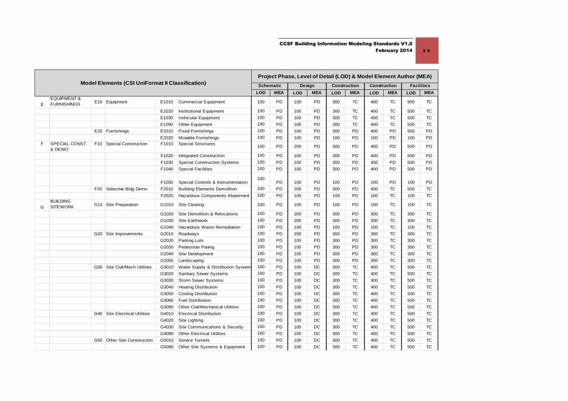
CCSF Building Information Modeling Standards V1.0
February 2014
3 5
LOD MEA LOD MEA LOD MEA LOD MEA LOD MEA
EEQUIPMENT & FURNISHINGS E10 Equipment E1010 Commercial Equipment 100 PD 100 PD 300 TC 400 TC 500 TC
E1020 Institutional Equipment 100 PD 100 PD 300 TC 400 TC 500 TC
E1030 Vehicular Equipment 100 PD 100 PD 300 TC 400 TC 500 TC
E1090 Other Equipment 100 PD 100 PD 300 TC 400 TC 500 TC
E20 Furnishings E2010 Fixed Furnishings 100 PD 100 PD 300 PD 400 PD 500 PD
E2020 Movable Furnishings 100 PD 100 PD 100 PD 100 PD 100 PDF SPECIAL CONST.
& DEMOF10 Special Construction F1010 Special Structures
100 PD 200 PD 300 PD 400 PD 500 PD
F1020 Integrated Construction 100 PD 100 PD 300 PD 400 PD 500 PD
F1030 Special Construction Systems 100 PD 100 PD 300 PD 400 PD 500 PD
F1040 Special Facilities 100 PD 100 PD 300 PD 400 PD 500 PD
F1050 Special Controls & Instrumentation100
PD 100 PD 100 PD 100 PD 100 PD
F20 Selective Bldg Demo F2010 Building Elements Demolition 100 PD 200 PD 300 PD 400 TC 500 TC
F2020 Hazardous Components Abatement 100 PD 100 PD 100 PD 100 TC 100 TC
GBUILDING SITEWORK G10 Site Preparation G1010 Site Clearing 100 PD 100 PD 100 PD 100 TC 100 TC
G1020 Site Demolition & Relocations 100 PD 200 PD 300 PD 300 TC 300 TC
G1030 Site Earthwork 100 PD 200 PD 300 PD 300 TC 300 TC
G1040 Hazardous Waste Remediation 100 PD 100 PD 100 PD 100 TC 100 TC
G20 Site Improvements G2010 Roadways 100 PD 200 PD 300 PD 300 TC 300 TC
G2020 Parking Lots 100 PD 100 PD 300 PD 300 TC 300 TC
G2030 Pedestrian Paving 100 PD 100 PD 300 PD 300 TC 300 TC
G2040 Site Development 100 PD 100 PD 300 PD 300 TC 300 TC
G2050 Landscaping 100 PD 100 PD 300 PD 300 TC 300 TC
G30 Site Civil/Mech Utilities G3010 Water Supply & Distribution Systems 100 PD 100 DC 300 TC 400 TC 500 TC
G3020 Sanitary Sewer Systems 100 PD 100 DC 300 TC 400 TC 500 TC
G3030 Storm Sewer Systems 100 PD 100 DC 300 TC 400 TC 500 TC
G3040 Heating Distribution 100 PD 100 DC 300 TC 400 TC 500 TC
G3050 Cooling Distribution 100 PD 100 DC 300 TC 400 TC 500 TC
G3060 Fuel Distribution 100 PD 100 DC 300 TC 400 TC 500 TC
G3090 Other Civil/Mechanical Utilities 100 PD 100 DC 300 TC 400 TC 500 TC
G40 Site Electrical Utilities G4010 Electrical Distribution 100 PD 100 DC 300 TC 400 TC 500 TC
G4020 Site Lighting 100 PD 100 DC 300 TC 400 TC 500 TC
G4030 Site Communications & Security 100 PD 100 DC 300 TC 400 TC 500 TC
G4090 Other Electrical Utilities 100 PD 100 DC 300 TC 400 TC 500 TC
G50 Other Site Construction G5010 Service Tunnels 100 PD 100 DC 300 TC 400 TC 500 TC
G5090 Other Site Systems & Equipment 100 PD 100 DC 300 TC 400 TC 500 TC
Model Elements (CSI UniFormat II Classification)Project Phase, Level of Detail (LOD) & Model Elemen t Author (MEA)
Schematic Design (SD)
Design Development
Construction Documents
Construction (CON)
Facilities Operation &

CCSF Building Information Modeling Standards V1.0
February 2014
3 6
7 Files, Security & Achieving
7.1 Project Folder Structure It is critical to maintain a consistent file naming and structure for referenced (linked) files to function across Design and Construction Teams and for end users such as facilities operators and managers to retrieve files quickly once the project is complete. For this reason, City College of San Francisco has developed a filing protocol for the team when the BEPs are developed. Sample Folder Type
Project Folder
Discipline Folders

CCSF Building Information Modeling Standards V1.0
February 2014
3 7
The root location (drive letter) of the Project folders may differ between offices. However, all CCSF project data should be independent of the root drive letter in order to allow sharing between differing office server structures. The Root project Directory (CCSF) must reside directly below the Drive letter. a. Campus Codes
CCSF currently has one campus and “01” as Campus code and shall be used with the Project Number, to be placed directly below the “CCSF” folder.
b. Project Number Prior to work start, project teams shall be assigned a CCSF Project Number by the District’s Project Manager. This number shall be used for organizing the project files, and should include the common name on the file name project. (Example: City College of San Francisco assigns the LRC (Learning Resource Center) project a project number of 0213. Therefore project folder shall be named 01-0213_Learning_Resource_Center)
c. Discipline Folders Each discipline shall be assigned a folder corresponding to a Discipline Designator as listed in below table. All project files received and referenced from each discipline shall be organized in this folder. As a project progresses, the contents within these discipline folders will expand, and each deliverable should be clearly organized in its own folder.
Discipline Designations Discipline (in alphabetical order)
Designator
Architectural A Geotechnical B Civil C Process D Electrical E Fire Protection F General G Hazardous Material H Interiors I Landscape L Mechanical M Facilities / Operations O Plumbing P Equipment / Specialty Design Q Structural S Telecommunication T Security TY Survey V Civil Works W Other Disciplines X Contractor / Shop Drawings Z

CCSF Building Information Modeling Standards V1.0
February 2014
3 8
d. BIM Folder
BIM Files shall be sorted by model files and sheet files.
• Model Files - Original files from other disciplines should be linked from their discipline folder location and relative path to models. Model file names shall follow file naming convention in the BEP.
• Sheet Files – PDF and native file formats of the most current sheets shall be maintained in this folder and organized with sheet file naming outlined in File Naming Section of the U.S. CAD Standards (NCS)
e. Support Files
Standard items needed for the project, such as project specific symbols, applications (lisp, script, etc.), logos and graphics. Project Specific Model Content can also be placed here.
f. Coordination Files
Files for Construction coordination (clash detection) shall be managed by the BIM Manager, and organized by date as the project progresses.
g. Other Folders Renderings, analyses, LEED, etc. will have their own folders which will be populated as the project progresses.
7.2 Variant Folder Tree
For projects that require multiple buildings, create building folders below the discipline directories.
7.3 Data Security Project Teams (Design / Construction) shall establish a data security protocol to prevent any possible data corruption, virus “infections” and data misuse or deliberate damage by their own employees or outside sources. Both teams shall establish adequate user access rights to prevent data loss or damage during file exchange, maintenance and archiving.
7.4 Archiving Milestone Submittals All documentation pertaining to Milestone Submittals shall be archived and stored within the project file structure with a heading corresponding to the submittal; for instance “100% Construction Documents” with its related sub-folders (“_LEED”, “_Renderings and Animations”, “_Sheet Set_PDF”, “_Specifications” and “_Support”.

CCSF Building Information Modeling Standards V1.0
February 2014
3 9
8 Information Delivery Manual (IDM) To use BIM effectively and for benefits to be unlocked, the quality of communication between different participants in the construction process needs significant improvement. If the information required is available when it is needed and the quality of information is satisfactory, the construction process will itself be significantly improved. For this to happen, there must be a common understanding of the building processes and of the information that is needed for and results from their execution.
(Source: http://www.iai.no/idm/idm_resources/idm_methods_guides/IDMC_004_1_2.pdf) IDM is a methodology to document the exchange of information using BIM tools to support the sustainable building design solutions with a process map that can be reused to support future project design. IDM captures (and progressively integrates) business process whilst at the same time providing detailed specifications of the information that a user fulfilling a particular role would need to provide at a particular point within a project. CCSF requires Design Teams to provide IDMs for executing energy analysis, verification of geospatial requirements and other analysis (e.g. project water management and daylight harvesting) in compliance with the Information Delivery Model (IDM) published by the Building Smart Alliance (http://idm.buildingsmart.no/confluence/display/IDM/Home). Next page is a sample IDM process map:

CCSF Building Information Modeling Standards V1.0
February 2014
4 0
Sample IDM Process Map
(Source: http://www.iai.no/idm/idm_resources/idm_methods_guides/IDMC_004_1_2.pdf)

CCSF Building Information Modeling Standards V1.0
February 2014
4 1
9 Drawing Requirements for Paper (2D) Printing
9.1 General BIM model(s) shall be utilized to the fullest extent for the purposes of deriving 2D CAD information and assembling a printed set of plans. All BIM information shall be fully parametric so that all applicable information regarding fixtures and/or other building elements can be generated for the schedules. Where required by CCSF, editable text files shall be attached to the fixtures / elements to assist with calculations. The U.S. National CAD Standards (NCS) shall apply with the following exceptions:
9.2 Diffuser Symbols Either graphical arrows or blank-off panels can be used to represent air flow direction for diffusers.
9.3 Font Arial font typeface shall be used. Font sizes shall comply with NCS; however, the use of 3/32” type is allowed. 3/32” scale is allowed where large elevations or footplates would extend over more than one sheet, but 1/8” or larger scale information shall also be provided for those areas where detail cannot be discerned at the smaller scale.
9.4 Line Styles and Line Weights The internal software BIM Line Styles defaults shall be used instead of the NCS linetype definitions. The Design / Engineer Team has the discretion and responsibility to edit the default line weight values of the BIM software so printed documents reflect the graphic intent of NCS.
9.5 MEP-F Details Where generating 2D MEP-F details from the BIM model is difficult, tagged definitions of the object based elements shall be provided.
9.6 Room Naming Abbreviations Room names on 2D drawing sheets shall be abbreviated for legibility.
9.7 Title blocks The CCSF CAD Title Block (if available) and Information shall be adapted for BIM use by the Design Team.
9.8 Uniform Parameters for Objects The Veteran Administration (VA)`s “Object Element Matrix” can be used to assure that all model object parameters follow a consistent naming convention and be a reflection of industry standards.
9.9 CCSF Standard Details When available in the future CCSF Standard Details will be valid as to the information the details contain, and shall be used for information regarding material and constructability content. In lieu of pulling the source images directly into the model, Design Team shall generate this information within the BIM model allowing for object-based recognition.

CCSF Building Information Modeling Standards V1.0
February 2014
4 2
9.10 Uniform Parameters for Objects The Veteran Administration (VA)`s “Object Element Matrix” can be used to assure that all model object parameters follow a consistent naming convention and be a reflection of industry standards.
9.11 Casework / Millwork Finishes & Legend Finishes shall be assigned to the properties of the pieces of casework that is inserted into the room area. Parameters are created and added to the casework properties for finish assignments. Finishes that are assigned to the piece of casework properties shall be formatted into a Casework / Millwork Schedule to be placed on the sheet. Only rooms that have casework or millwork inserted into them will be generated in the schedule. Material finish code and product information shall be entered into the casework properties and identified in the schedule generated from the Finish Legend.
9.12 Doors Similar to partition types, door types are to be created to accurately reflect each kind of door in regards to type, size and information. The 2D door symbol is a result of the view that is created from the BIM model. Because of this, 3D doors shall be used throughout the construction documents for 2D representations. Multiple doors require the room number with a “1”, “2”, etc. All doors are to be communicated in construction documents by schedule. Door schedule parameters built within doors in the BIM model shall have: Door number, Door width, Door Height, Door Material, Type, Frame Material, Frame Type, Fire Rating, Hardware Code, Head/Sill and Jamb Detail Numbers and Remarks for links to “Remarks and Abbreviations” Legend.
9.13 Interior Partition Types A different partition type is to be created for each type of wall used in the project with each layer constructed in 3D form. The following system is an example used to classify, organize and manage partition types within the BIM model. It`s used to help project teams establish a naming convention for cataloging all partition types in BIM model. Partition type code example (BIM Model Catalog Number): “09P4107b” – 09 (Specification Category) P (Detail Type Category) 4 (Nominal Size) 1 (Partition Category) 07 (Sequence Number) b (Fire/Smoke Rating)

CCSF Building Information Modeling Standards V1.0
February 2014
4 3
Partition type code legend (Character exemplifies to define other wall types): SPECIFICATION CATEGORY 03 CONCRETE PARTITION 04 MASONRY PARTITION 09 METAL STUD PARTITION DETAIL TYPE CATEGORY P PARTITIONS NOMINAL SIZE 1 SIZE 1” CORE 2 SIZE 2” CORE 4 SIZE 4” CORE 6 SIZE 6” CORE 8 SIZE 8” CORE
PARTITION CATEGORY 1 PATRITIONS W/NO INSULATION 2 PARTITIONS W/ INSULATION 3 PARTITIONS W/ TILE 4 PATRIRIONS W/ LEAD LINING 5 PARTITIONS W/ SECURITY MESH The “Wall – Interior Partition” in the U.S. Veterans Administration (VA)’s Object Element Matrix defines the elements appropriate for each stage of the project development and shall be included as required. Partition information shall have the ability to be scheduled. Each partition type shall hold parameters containing descriptions of its components and its construction which is shown in the schedule. Fire rating fill patterns are to be constructed within 3D wall type so that the partition`s respective rating is shown through all scales and through all types of views (plans, sections, isometric/axonometric views, etc). The fill patterns shall be graphically represented.
9.14 Model Integrated Text BIM General Notations & Sheet Notes: Any notation that will populate multiple sheets shall be put on views that allow duplication of the notations on multiple sheets. Element-based schedules shall be used for notation that is specific per sheet. BIM Material Notation: Rather than using loose text, BIM software allows model objects to be linked from the object`s parameters to an editable text file that holds specification data for Construction Document notation purpose. This notation has the ability to be shown by either numeric specification section or object description.
9.15 Room Finishes Room finishes shall be assigned to the room areas through the room properties, with parameters defining finish assignments. Finishes assigned to the room properties shall be formatted into a Room Finish Schedule to be placed on a sheet.

CCSF Building Information Modeling Standards V1.0
February 2014
4 4
9.16 Finish Legend Material Codes in the Room Finish Schedule that were entered in the room properties are identified in a Finish Legend. Product Information entered into the established parameters to specify finishes. Finish codes and their description shall be associated with the room properties.
9.17 Room Numbering Room numbers shall be assigned to the properties of each individual room. Room tag types can be modified throughout the course of the project so that the appropriate room number is visible on the (submitted) documents.
9.18 Wayfinding The CCSF Wayfinding Number shall be scheduled data within room schedules as per the Signage / Message Schedule.

CCSF Building Information Modeling Standards V1.0
February 2014
4 5
10 Glossary & Abbreviations
4D
Building Information Model with the addition of time (virtual building model with scheduling) 5D
Building Information Model with the addition of time and construction cost information. AE, AEC, AECFM
Abbreviations for Architect/Engineer, Architect/Engineer/Contractor and Architect/Engineer/Contractor/Facility Manager.
As-Built Model A Federated Model incorporating all construction phase modifications to a LOD 400 or better.
BIM Execution Plan (BEP)
Defines the BIM roles and responsibilities within the project team.
Building Information Model (BIM)
A Building Information Model (BIM) is a digital representation of physical and functional characteristics of a facility. As such it serves as a shared knowledge resource for information about a facility forming a reliable basis for decisions during its lifecycle from inception onward.
Building Information Modeling
The process and technology used to create the building information model.
BuildingSMART
An international membership organization with representation in North America, Europe, Asia and Australasia. It brings together architects, engineers, constructors, product manufacturers and facility managers, along with software vendors.
Bid Model
The term used to describe the Federated Model that is established by the City College of San Francisco as part of the Contract Documents and can be used for Bid and/or Negotiation purposes.
CAD
Abbreviation for Computer Aided Design. A geometric/symbol based computer drawing system that replicated hand drawing techniques.
CCSF (or City College of San Francisco)
Abbreviation for City College of San Francisco.

CCSF Building Information Modeling Standards V1.0
February 2014
4 6
COBIE (or COBie) The model and facility data for commission, operations, and maintenance of the project shall satisfy the Construction Operations Building Information Exchange (COBIE) requirements, and be submitted in compliance with the commissioning requirements. The data expected from BIM for facility handover shall conform to the following standards: CCSF Spatial Requirements (via Fusion / Onuma Planning System), Uniformat, OmniClass, Geospatial, NBIMS, COBIE, NCS, and IFC standards for building information. COBIE data in the form of the COBIE Excel Spreadsheet and related commissioning information shall be delivered electronically in formats suitable for integration into current and future CAFM systems.
Construction Team Prime/General Contractor and all of the trade contractors, fabricators, and suppliers that provide construction services for a project.
Collaboration Model
The term to describe the Federated Model used during the trade coordination phase. Design Team
The Design Team is considered to be the Architect and all of the consultants that provide design services for a project
Digital Data
Digital Data is defined as information, communications, drawings, or designs created or stored for the Project in digital form.
DSA
Division of State Architect
Facility Model The term used to describe a 3D model that incorporates all major equipment and components that require service and maintenance.
Federated Model
The Federated Model combines different modeled elements or assemblies through the process of linking files from their native platforms, maintaining their native properties. It is a virtual representation of the entire Project developed to a specified LOD.
FF & E
Furniture, Fixtures and Equipment GSA
General Services Administration
IAI International Alliance for Interoperability software companies, building product manufacturers, information publishers, owners, designers, and builders – in AEC and other industries whose goal is to develop a universal standard for information sharing.

CCSF Building Information Modeling Standards V1.0
February 2014
4 7
IDM Information Delivery Manual provides an approach to providing an integrated reference for process and data required for BIM. It describes how to identify and describe processes undertaken within construction, the information required for their execution and the results. It also describes how the information can be further detailed to support solutions provided by building information system providers in a form that enables its reuse and how it can be configured to meet national, local and project needs.
Industry Foundation Class (IFC)
An object oriented file format with a data model developed by BuildingSMART (International Alliance for Interoperability-IAI) to facilitate interoperability among BIM tools, cost estimation systems, and other construction-related applications in a way that preserves ability to perform analysis on those objects as they move from one BIM system to another. IFC`s are data elements that represents parts of buildings, or elements of the process, and contain the relevant information about those parts. IFC`s are used by computer applications to assemble a computer-readable model of facility that contains all the information of the parts and their relationships to be shared among project participants. The project model constitutes an object-oriented database of the information shared among project participants and continues to grow as the project goes through design, construction, and operation.
Interoperability
Refers to the exchange of information among project participants throughout the lifecycle of a facility by direct communication between software applications.
IPD
Abbreviation for Integrated Project Delivery
Linking Files A process of externally reference a native file into the Federated Model.
Level of Development (LOD) Abbreviation for Level of Detail as it pertains to BIM. It used to describe the fullness and definitiveness of the Model. The LOD definition is based on the AIA E 202 – 2008 document and expanded in the Section 6.9.7.
MEP-F Mechanical, Electrical, Plumbing and Fire Protection Systems.
Model The term used to describe the 3D virtual representation of a Project and its Objects.
Model Element
A portion of the building information model representing a component, system or assembly within a building or site.
Model Element Author (MEA) The party responsible for developing the content of a specific model element.
CCSF Building Information Modeling Standards V1.0
February 2014
4 8
Model File In the BIM process, the Model File contains a referenced Extraction and model file- specific information. It is recommended that Extractions not serve directly as Model Files, since if Extractions have to be regenerated, all model-specific information added to the Extractions will be lost.
Native Model
A Model created in a specific CAD platform. For example, a model made in Revit. NBIMS
Abbreviation for National Building Information Modeling Standard Object
The term used to describe the 3D virtual representation of each of the separate sub-parts of Model such as doors, walls, equipment etc. If an Object is, in itself, comprised of several sub-elements, the sub-elements will be grouped into one virtual representation of that Object.
OmniClass (or OCCS)
The OmniClass Construction Classification System is a classification system for the construction industry, developed by the Construction Standards Institute (CSI) and is used as a classification structure for electronic databases. As the basis of its tables, OmniClass incorporates other existing systems currently in use, including Master Format for work results, UniFormat for elements, and EPIC (Electronic Product Information Cooperation) for structuring products.
Owner Model The term used as the final Federated model deliverable integrating the as-built model, collaboration model, and the facility model.
Parametric
Objects that reflect real-world behaviors and attributes.
Phase A portion of work that arises from sequencing work in accordance with a predetermined portion of a stage.
Room The term used to describe any space within the enclosing walls of the building. The space may be rectangular or more complex
SDSFIE
Spatial Data Standards for Facilities, Infrastructure, and Environment. The SDFIE Steering Group, made up of members from the Armed Forces and the U.S. Army Corps of Engineers, has set an ambitious goal of creating the Department of Defense Standard for facilities, infrastructure, environment, and civil works.
Record Drawing
Documenting as-built conditions in a drawing format.

CCSF Building Information Modeling Standards V1.0
February 2014
4 9
Record Modeling Documenting as-built conditions in a model format.
Sheet File
A CAD file or Model that shows a selected view or portion of a Model File within a referenced border sheet. Sheet files are used to generate the plotted construction sheets.
Simple Building Information Model A concept of producing a simplified model used for simulating the building performance early in the design process.
Transferred Model
The term used to describe the Native Model(s) and/or Federated Model that are/is provided to the District for District’s agreed utilization.

CCSF Building Information Modeling Standards V1.0
February 2014
5 0
11 References
National Building Information Modeling Standards, V ersion 1 – Part 1 Overview, Principles and Methodologies , National Institute of Building Sciences, December 2007 GSA BIM Guide For Spatial Program Validation, Volum e 2, The U.S. General Services Administration, May 2007 The VA BIM Guide, Version 1.0 , The U.S. Department of Veterans Affairs, April 2010 LACCD Building Information Modeling Standards, Inte rim Version 2.0 - DBB , BuildLACCD, September 2009 San Diego Community College District, BIM Standards for Architects, Engineers 7 Contractors, Version 1.0 , SDCC, 2010 AIA E202 – 2008 BIM Protocol Exhibit , American Institute of Architects, 2008 Construction Operations Building Information Exchan ge (COBIE): Means and Methods , BuildingSMARTalliance (http://www.buildingsmartalliance.org/index.php/projects/cobie) U.S. National CAD Standards 4.0 , National Institute of Building Sciences, January 2008