city multi s-series system designmeus1.mylinkdrive.com/files/30_pumy-p-nhmur4_-nkmu... ·...
TRANSCRIPT
PUMY-P-NHMUR4, -NKMU SYSTEM DESIGN (March 2015) SSD-1© 2015 Mitsubishi Electric US, Inc.
CITY MULTI® S-SERIES System Design
1. ELECTRICAL WORK ................................................................................................................................................ SSD-21-1. General Cautions ............................................................................................................................................. SSD-21-2. Power Supply for Indoor Unit and Outdoor Unit ............................................................................................... SSD-3
2. M-NET CONTROL ..................................................................................................................................................... SSD-62-1. Transmission Cable Length Limitations ........................................................................................................... SSD-62-2. Transmission Cable Specifications .................................................................................................................. SSD-72-3. System Configuration Restrictions ................................................................................................................... SSD-82-4. Address Setting ...............................................................................................................................................SSD-11
3. PIPING DESIGN ..................................................................................................................................................... SSD-193-1. R410A Piping Material.................................................................................................................................... SSD-193-2. Piping Design ................................................................................................................................................. SSD-203-3. Refrigerant Charge Calculation ...................................................................................................................... SSD-22
4. INSTALLATION ....................................................................................................................................................... SSD-244-1. Installation Site Requirements ....................................................................................................................... SSD-244-2. Installation Clearance Space ......................................................................................................................... SSD-254-3. Piping direction............................................................................................................................................... SSD-26
5. INSTALLATION INFORMATION ............................................................................................................................. SSD-275-1. General precautions ....................................................................................................................................... SSD-275-2. Precautions for Indoor unit ............................................................................................................................. SSD-285-3. Precautions for Fresh air intake type indoor unit ........................................................................................... SSD-295-4. Precautions for Outdoor unit/Heat source unit ............................................................................................... SSD-295-5. Precautions for Control-related items............................................................................................................. SSD-30
6. STANDARD AND SEACOAST (-BS) TREATMENT ................................................................................................ SSD-316-1. S-Series ......................................................................................................................................................... SSD-31
7. CAUTIONS .............................................................................................................................................................. SSD-327-1. Refrigerant Leakage Considerations ............................................................................................................. SSD-32

SSD-2 PUMY-P-NHMUR4, -NKMU SYSTEM DESIGN (March 2015)© 2015 Mitsubishi Electric US, Inc.
1-1. General Cautions
OK NO
Follow ordinance of your governmental organization for technical standard related to electrical equipment, wiringregulations, and guidance of each electric power company.Wiring for control (hereinafter referred to as transmission ) shall be (50mm[1-5/8in] or more) apart from power source
source wire in the same conduit.)Be sure to provide designated grounding work to outdoor unit.Give some allowance to wiring for electrical part box of indoor and outdoor units, because the box is sometimes removedat the time of service work.Never connect 208~230V power source to terminal block of transmission . If connected,electrical parts will be burntout.
Use 2-core shield cable for transmission . If transmission of different systems are wired with the same multiplecore cable, the resultant poor transmitting and receiving will cause erroneous operations.
Outdoorunit
Indoor unit
Remote
BC controllercontroller
2-core shield cable
2-core shield cable
Outdoorunit
Remotecontroller
Indoor unit
Multiple-core cable
BC controller
wiring so that it is not influenced by electric noise from power source wiring. (Do not insert transmission and power cable
cable
cable cables
cable
Outdoorunit Outdoor
unit
Indoor unit Indoor unit
RemotecontrollerRemote
controller
1. ELECTRICAL WORK

PUMY-P-NHMUR4, -NKMU SYSTEM DESIGN (March 2015) SSD-3© 2015 Mitsubishi Electric US, Inc.
1-2. Power Supply for Indoor Unit and Outdoor Unit1-2-1. Electrical Characteristics of the Indoor Units
Symbols: MCA : Min.Circuit Amps (=1.25xFLA) FLA : Full Load AmpsIFM :Indoor Fan Motor
ModelIndoor Unit IFM
Hz Volts Voltage range MCA(A) FLA(A)PLFY-P08NCMU-ER4
60Hz 208 / 230V 198 to 253V
0.29 / 0.29 0.23 / 0.23PLFY-P12NCMU-ER4 0.35 / 0.35 0.28 / 0.28PLFY-P15NCMU-ER4 0.35 / 0.35 0.28 / 0.28PLFY-P12NBMU-ER2 0.64 / 0.64 0.51 / 0.51PLFY-P15NBMU-ER2 0.64 / 0.64 0.51 / 0.51PLFY-P18NBMU-ER2 0.64 / 0.64 0.51 / 0.51PLFY-P24NBMU-ER2 0.64 / 0.64 0.51 / 0.51PLFY-P30NBMU-ER2 0.64 / 0.64 0.51 / 0.51PLFY-P36NBMU-ER2 1.25 / 1.25 1.00 / 1.00
PMFY-P06NBMU-ER5
60Hz 208 / 230V 188 to 253V
0.25 / 0.25 0.20 / 0.20PMFY-P08NBMU-ER5 0.25 / 0.25 0.20 / 0.20PMFY-P12NBMU-ER5 0.26 / 0.26 0.21 / 0.21PMFY-P15NBMU-ER5 0.33 / 0.33 0.26 / 0.26
PEFY-P06NMAU-E3
60Hz 208 / 230V 188 to 253V
1.05 / 1.05 0.84 / 0.84PEFY-P08NMAU-E3 1.05 / 1.05 0.84 / 0.84PEFY-P12NMAU-E3 1.20 / 1.20 0.96 / 0.96PEFY-P15NMAU-E3 1.45 / 1.45 1.16 / 1.16PEFY-P18NMAU-E3 1.56 / 1.56 1.25 / 1.25PEFY-P24NMAU-E3 2.73 / 2.73 2.18 / 2.18PEFY-P27NMAU-E3 2.73 / 2.73 2.18 / 2.18PEFY-P30NMAU-E3 2.73 / 2.73 2.18 / 2.18PEFY-P36NMAU-E3 3.32 / 3.32 2.66 / 2.66PEFY-P48NMAU-E3 3.41 / 3.41 2.73 / 2.73PEFY-P54NMAU-E3 3.31 / 3.31 2.65 / 2.65
PEFY-P06NMSU-ER2
60Hz 208 / 230V
188 to 253V
0.47 / 0.50 0.32 / 0.31PEFY-P08NMSU-ER2 0.47 / 0.50 0.41 / 0.39PEFY-P12NMSU-ER2 0.68 / 0.74 0.46 / 0.43PEFY-P15NMSU-ER2 1.20 / 1.33 0.47 / 0.45PEFY-P18NMSU-ER2 1.20 / 1.33 0.64 / 0.60PEFY-P24NMSU-ER2 1.57 / 1.73 0.88 / 0.83PEFY-P15NMHU-E2 1.63 / 1.50 1.30 / 1.20PEFY-P18NMHU-E2 1.63 / 1.50 1.30 / 1.20PEFY-P24NMHU-E2 2.11 / 1.83 1.69 / 1.46PEFY-P27NMHU-E2 2.35 / 2.13 1.88 / 1.70PEFY-P30NMHU-E2 2.70 / 2.45 2.16 / 1.96PEFY-P36NMHU-E2 4.16 / 3.67 3.32 / 2.94PEFY-P48NMHU-E2 4.16 / 3.67 3.32 / 2.94PEFY-P54NMHU-E2 4.18 / 3.69 3.34 / 2.95PEFY-P72NMHSU-E
187 to 253V7.7 6.2
PEFY-P96NMHSU-E 8.2 6.6
1. ELECTRICAL WORK
SSD-4 PUMY-P-NHMUR4, -NKMU SYSTEM DESIGN (March 2015)© 2015 Mitsubishi Electric US, Inc.
1. ELECTRICAL WORK
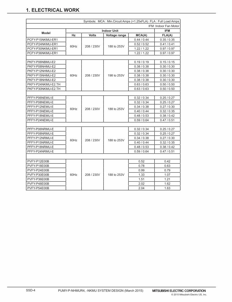
Symbols: MCA : Min.Circuit Amps (=1.25xFLA) FLA : Full Load AmpsIFM :Indoor Fan Motor
ModelIndoor Unit IFM
Hz Volts Voltage range MCA(A) FLA(A)PCFY-P15NKMU-ER1
60Hz 208 / 230V 188 to 253V
0.44 / 0.44 0.35 / 0.35PCFY-P24NKMU-ER1 0.52 / 0.52 0.41 / 0.41PCFY-P30NKMU-ER1 1.22 / 1.22 0.97 / 0.97PCFY-P36NKMU-ER1 1.22 / 1.22 0.97 / 0.97
PKFY-P06NBMU-E2
60Hz 208 / 230V 198 to 253V
0.19 / 0.19 0.15 / 0.15PKFY-P08NHMU-E2 0.38 / 0.38 0.30 / 0.30PKFY-P12NHMU-E2 0.38 / 0.38 0.30 / 0.30PKFY-P15NHMU-E2 0.38 / 0.38 0.30 / 0.30PKFY-P18NHMU-E2 0.38 / 0.38 0.30 / 0.30PKFY-P24NKMU-E2.TH 0.63 / 0.63 0.50 / 0.50PKFY-P30NKMU-E2.TH 0.63 / 0.63 0.50 / 0.50
PFFY-P06NEMU-E
60Hz 208 / 230V 188 to 253V
0.32 / 0.34 0.25 / 0.27PFFY-P08NEMU-E 0.32 / 0.34 0.25 / 0.27PFFY-P12NEMU-E 0.34 / 0.38 0.27 / 0.30PFFY-P15NEMU-E 0.40 / 0.44 0.32 / 0.35PFFY-P18NEMU-E 0.48 / 0.53 0.38 / 0.42PFFY-P24NEMU-E 0.59 / 0.64 0.47 / 0.51
PFFY-P06NRMU-E
60Hz 208 / 230V 188 to 253V
0.32 / 0.34 0.25 / 0.27PFFY-P08NRMU-E 0.32 / 0.34 0.25 / 0.27PFFY-P12NRMU-E 0.34 / 0.38 0.27 / 0.30PFFY-P15NRMU-E 0.40 / 0.44 0.32 / 0.35PFFY-P18NRMU-E 0.48 / 0.53 0.38 / 0.42PFFY-P24NRMU-E 0.59 / 0.64 0.47 / 0.51
PVFY-P12E00B
60Hz 208 / 230V 188 to 253V
0.52 0.42PVFY-P18E00B 0.78 0.63PVFY-P24E00B 0.99 0.79PVFY-P30E00B 1.33 1.07PVFY-P36E00B 1.51 1.21PVFY-P48E00B 2.02 1.62PVFY-P54E00B 2.04 1.63

PUMY-P-NHMUR4, -NKMU SYSTEM DESIGN (March 2015) SSD-5© 2015 Mitsubishi Electric US, Inc.
1. ELECTRICAL WORK
To size breakers, see “Recommended Fuse/Breaker Size” in the Specifications table.
1-2-1. Electrical Characteristics of the Outdoor Unit at a Cooling Mode
Symbols : MCA : Min. Circuit AmpsPUMY-P-NHMUR4, NKMU SC : Starting Current
Model
Outdoor units Compressor
Hz Volts Voltage range RLA(A) MCA(A)
Maximum Fuse /
Breaker Size (A)
SC(A)
PUMY-P36NHMUR4(-BS)60Hz 208V 198 to 228V 24.0 26 40
1460Hz 230V 207 to 253V 21.7 26 40
PUMY-P48NHMUR4(-BS)60Hz 208V 198 to 228V 24.0 26 40
1460Hz 230V 207 to 253V 21.7 26 40
PUMY-P60NKMU(-BS)60Hz 208V 198 to 228V 19.9 35 42
760Hz 230V 207 to 253V 18.0 35 42

SSD-6 PUMY-P-NHMUR4, -NKMU SYSTEM DESIGN (March 2015)© 2015 Mitsubishi Electric US, Inc.
Applicable to Outdoor as follows PUMY-P-NHMUPUMY-P-NKMU
Long transmission cable causes voltage down, therefore, the length limitation should be obeyed to secure proper transmission.Max. length via Outdoor (M-NET cable) L1+L2+L3+L4, L1+L2+L6+L7, L3+L4+L6+L7 <=500m[1640ft] 1.25mm2 [AWG16] or thickerMax. length to Outdoor (M-NET cable) L1, L3+L4, L6, L2+L6, L7 <=200m[656ft] 1.25mm2 [AWG16] or thickerMax. length from MA to Indoor a1+a2, a1+a2+a3+a4 <=200m[656ft] - 24VDC to AG-150A-A n <=50m[164ft] 0.75-2.0 mm2 [AWG18-14]
Applicable to Outdoor as follows PUMY-P-NHMUPUMY-P-NKMU
Long transmission cable causes voltage down, therefore, the length limitation should be obeyed to secure proper transmission.Max. length via Outdoor (M-NET cable) L1+L2+L3+L4, L1+L2+L6+L7,L1+L2+L3+L5, L3+L4+L6+L7 <=500m[1640ft] 1.25mm2 [AWG16] or thickerMax. length to Outdoor (M-NET cable) L1, L3+L4, L6, L2+L6, L7, L3+L5 <=200m[656ft] 1.25mm2 [AWG16] or thickerMax. length from ME to Indoor e1,e2,e3,e4 <=10m[32ft] *1 0.3-1.25 mm2[AWG22-16] *124VDC to AG-150A-A n <=50m[164ft] 0.75-2.0 mm2 [AWG18-14] *1. If the length from ME to Indoor exceed 10m, use 1.25 mm2[AWG16] shielded cable, but the total length should be counted into Max. length via Outdoor.
OC: Outdoor unit; IC: Indoor unit; MA: MA remote controller
OC: Outdoor unit; IC: Indoor unit; ME: ME remote controller
M1 M2M1 M2 STB7
TB3
IC(51)
M1 M2 1 2STB5 TB15
1 2TB15
1 2TB15
1 2TB15
1 2TB15
1 2TB 15
1 2TB15
MA
(01)
IC
M1 M2 STB5
(02)
IC
M1 M2 STB5
(04)
IC
M1 M2 STB5
(03)
IC
M1 M2 STB5
(05)
IC
M1 M2 STB5
(07)
IC
M1 M2 STB5
(06)
L2
L1
MA
MA
OC
M1 M2
M1 M2 STB7
TB3
(52)
OC
a1
a3
L3 L4
a2
A BA B
A B
a2
a1
a1
MA
A B
a4
a2
Group1 Group3 Group5
Shieldedwire
S
Power Supply Unit
A B S
AG-150A-A
PAC-SC51KUAL6L7
A BV+V-FG
n
V+V-FG
M1 M2
M1 M2 STB7
TB3
(52)
OC
M1 M2M1 M2 STB7
TB3
IC
Group1 Group3 Group5
(51)
M1 M2 STB5
ME
(01)
IC
M1 M2 STB5
(02)
IC
M1 M2 STB5
(04)
IC
M1 M2 STB5
(03)
IC
M1 M2 STB5
(05)
IC
M1 M2 STB5
(07)
IC
M1 M2 STB5
(06)
L2
L1
(101)
ME
(105)
ME
(103)
ME
(155)
OC
Shieldedwire
A B S
A B S
AG-150A-A
L3
L6L7
L4
L5
e2 e3
e4
e1
A B A B A B
A B
V+V-FG
n
V+V-FG
Power Supply UnitPAC-SC51KUA
2-1-2. Using ME Remote controller
2-1-1. Using MA Remote controller
ME remote controller refers to Smart ME controller.
NOTEDo not daisy-chain remote controllers.
MA remote controller refers to Simple MA remote controller and wireless remote controller.
NOTEDo not daisy-chain remote controllers.
2-1. Transmission Cable Length Limitations
2. M-NET CONTROL
PUMY-P-NHMUR4, -NKMU SYSTEM DESIGN (March 2015) SSD-7© 2015 Mitsubishi Electric US, Inc.
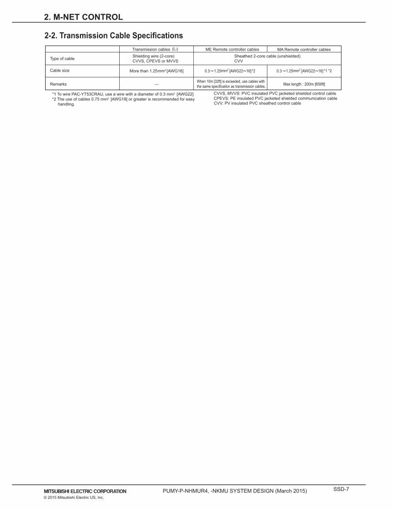
2-2. Transmission Cable Specifications
Type of cable
Cable size
Remarks
Sheathed 2-core cable (unshielded)CVV
Shielding wire (2-core)CVVS, CPEVS or MVVS
Transmission cables ME Remote controller cables
CVVS, MVVS: PVC insulated PVC jacketed shielded control cableCPEVS: PE insulated PVC jacketed shielded communication cable
*1 To wire PAC-YT53CRAU, use a wire with a diameter of 0.3 mm2 [AWG22]*2 The use of cables 0.75 mm2 [AWG18] or greater is recommended for easy handling. CVV: PV insulated PVC sheathed control cable
— Max length : 200m [656ft]
(Li) MA Remote controller cables
When 10m [32ft] is exceeded, use cables withthe same specification as transmission cables.
More than 1.25 [AWG16] 2 0.3 1.25 [AWG22 16] *1 *22 0.3 1.25 [AWG22 16]*2
2. M-NET CONTROL
SSD-8 PUMY-P-NHMUR4, -NKMU SYSTEM DESIGN (March 2015)© 2015 Mitsubishi Electric US, Inc.
2. M-NET CONTROL
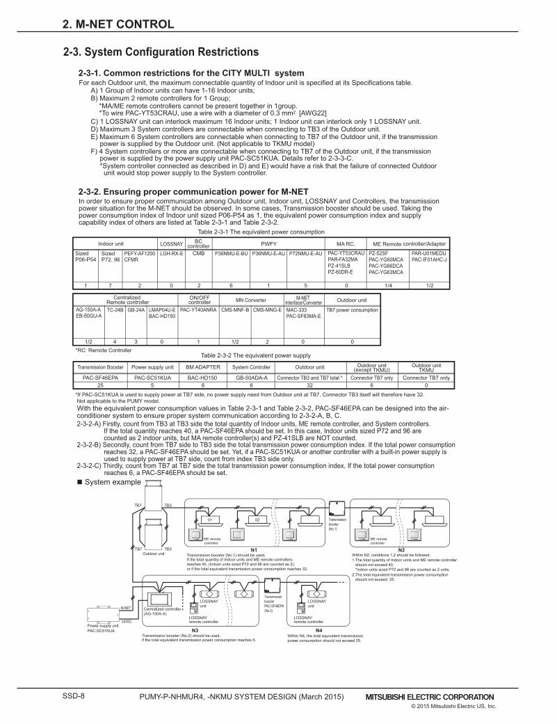
2-3. System Configuration Restrictions
For each Outdoor unit, the maximum connectable quantity of Indoor unit is specified at its Specifications table. A) 1 Group of Indoor units can have 1-16 Indoor units;
C) 1 LOSSNAY unit can interlock maximum 16 Indoor units; 1 Indoor unit can interlock only 1 LOSSNAY unit. D) Maximum 3 System controllers are connectable when connecting to TB3 of the Outdoor unit.E) Maximum 6 System controllers are connectable when connecting to TB7 of the Outdoor unit, if the transmission
power is supplied by the Outdoor unit. (Not applicable to TKMU model) F) 4 System controllers or more are connectable when connecting to TB7 of the Outdoor unit, if the transmission
power is supplied by the power supply unit PAC-SC51KUA. Details refer to 2-3-3-C.*System controller connected as described in D) and E) would have a risk that the failure of connected Outdoor unit would stop power supply to the System controller.
2-3-1. Common restrictions for the CITY MULTI system
Transmission Booster
25PAC-SF46EPA
Power supply unit
5PAC-SC51KUA
Outdoor unit
32Connector TB3 and TB7 total *
Outdoor unitTKMU
Outdoor unit(except TKMU)
0Connector TB7 only
6Connector TB7 only
BM ADAPTER
6BAC-HD150
System Controller
6GB-50ADA-A
*If PAC-SC51KUA is used to supply power at TB7 side, no power supply need from Outdoor unit at TB7, Connector TB3 itself will therefore have 32. Not applicable to the PUMY model.
Table 2-3-2 The equivalent power supply
With the equivalent power consumption values in Table 2-3-1 and Table 2-3-2, PAC-SF46EPA can be designed into the air-conditioner system to ensure proper system communication according to 2-3-2-A, B, C.2-3-2-A) Firstly, count from TB3 at TB3 side the total quantity of Indoor units, ME remote controller, and System controllers. If the total quantity reaches 40, a PAC-SF46EPA should be set. In this case, Indoor units sized P72 and 96 are counted as 2 indoor units, but MA remote controller(s) and PZ-41SLB are NOT counted. 2-3-2-B) Secondly, count from TB7 side to TB3 side the total transmission power consumption index. If the total power consumption reaches 32, a PAC-SF46EPA should be set. Yet, if a PAC-SC51KUA or another controller with a built-in power supply is used to supply power at TB7 side, count from index TB3 side only.2-3-2-C) Thirdly, count from TB7 at TB7 side the total transmission power consumption index, If the total power consumption reaches 6, a PAC-SF46EPA should be set.
2-3-2. Ensuring proper communication power for M-NETIn order to ensure proper communication among Outdoor unit, Indoor unit, LOSSNAY and Controllers, the transmission power situation for the M-NET should be observed. In some cases, Transmission booster should be used. Taking the power consumption index of Indoor unit sized P06-P54 as 1, the equivalent power consumption index and supply capability index of others are listed at Table 2-3-1 and Table 2-3-2.
LOSSNAY remote controller
LOSSNAY remote controller
LOSSNAYunit
LOSSNAYunit
Outdoor unit
M-NET
0201
if the total quantity of Indoor units and ME remote controllers reaches 40, (Indoor units sized P72 and 96 are counted as 2); or if the total equivalent transmission power consumption reaches 32.
N1
N3
N2Transmission booster (No.1) should be used,
1.The total quantity of Indoor units and ME remote controller should not exceed 40. *Indoor units sized P72 and 96 are counted as 2 units.2.The total equivalent transmission power consumption should not exceed 25.
Within N2, conditions 1,2 should be followed.
N4Within N4, the total equivalent transmission power consumption should not exceed 25.
TB7 TB3
TB7 TB3
if the total equivalent transmission power consumption reaches 5. Transmission booster (No.2) should be used,
PAC-SF46EPA
TRANSMISSION BOOSTER
3.4kg
220-240V:0.7A ~/N
WEIGHT
POWER RATING
MODEL
MADE IN JAPAN
50
UP
PAC-SF46EPA
TRANSMISSION BOOSTER
3.4kg
220-240V:0.7A ~/N
WEIGHT
POWER RATING
MODEL
MADE IN JAPAN
50
UP
Transmissionbooster(No.1)
TransmissionboosterPAC-SF46EPA(No.2)
System example
Power supply unitPAC-SC51KUA
24VDC
Centralized controller(AG-150A-A)
CENTRALIZED CONTROLLER AG-150A
B) Maximum 2 remote controllers for 1 Group;*MA/ME remote controllers cannot be present together in 1group.*To wire PAC-YT53CRAU, use a wire with a diameter of 0.3 mm2 [AWG22]
Table 2-3-1 The equivalent power consumption
*RC: Remote Controller
Indoor unit PWFY ME Remote controller/Adapter
1 7 622 0 1 5 0 1/4 1/2
Sized P06-P54
Sized P72, 96
P36NMU-E-BUCMB P36NMU-E-AU
LOSSNAY
LGH-RX-EPEFY-AF1200CFMR
P72NMU-E-AU
MA RC.
PAC-YT53CRAUPAR-FA32MAPZ-41SLBPZ-60DR-E
PZ-52SFPAC-YG60MCAPAC-YG66DCAPAC-YG63MCA
PAR-U01MEDUPAC-IF01AHC-J
Centralized Remote controller
1/2 1 1/2 2
AG-150A-AEB-50GU-A
ON/OFFcontroller
PAC-YT40ANRA CMS-MNF-B CMS-MNG-E
MN Converter Outdoor unitM-NET Interface/Converter
3 0 0 0
GB-24A LMAP04U-EBAC-HD150
MAC-333PAC-SF83MA-E
TB7 power consumption
4
TC-24B
BCcontroller
ME remotecontroller
ME remotecontroller
PUMY-P-NHMUR4, -NKMU SYSTEM DESIGN (March 2015) SSD-9© 2015 Mitsubishi Electric US, Inc.
2. M-NET CONTROL
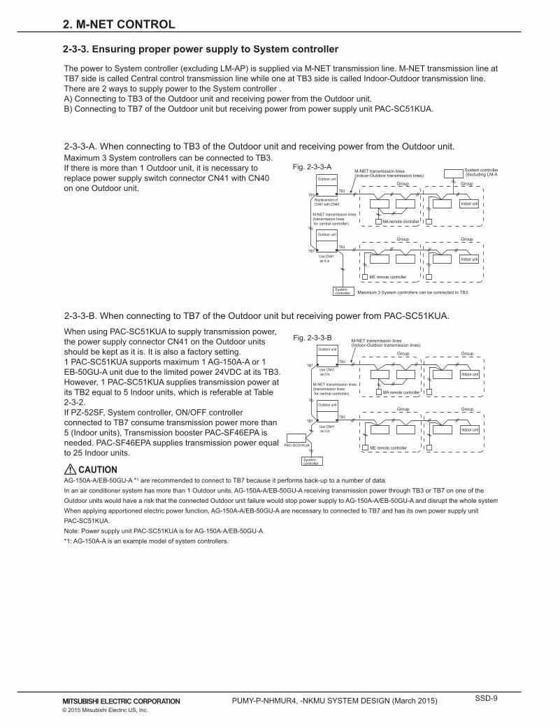
The power to System controller (excluding LM-AP) is supplied via M-NET transmission line. M-NET transmission line at TB7 side is called Central control transmission line while one at TB3 side is called Indoor-Outdoor transmission line. There are 2 ways to supply power to the System controller .A) Connecting to TB3 of the Outdoor unit and receiving power from the Outdoor unit.B) Connecting to TB7 of the Outdoor unit but receiving power from power supply unit PAC-SC51KUA.
Maximum 3 System controllers can be connected to TB3. If there is more than 1 Outdoor unit, it is necessary to replace power supply switch connector CN41 with CN40 on one Outdoor unit.
2-3-3-A. When connecting to TB3 of the Outdoor unit and receiving power from the Outdoor unit.
2-3-3-B. When connecting to TB7 of the Outdoor unit but receiving power from PAC-SC51KUA.
2-3-3. Ensuring proper power supply to System controller
Outdoor unit
MA remote controller
Group Group
Indoor unit
M-NET transmission lines(transmission lines for central controller)
Outdoor unit
ME remote controller
Group Group
Indoor unit
Replacement of CN41 with CN40
Use CN41 as it is.
TB7TB3
System controller (excluding LM-AP)
M-NET transmission lines (Indoor-Outdoor transmission lines)
TB7TB3
System controller Maximum 3 System controllers can be connected to TB3.
Fig. 2-3-3-A
PAC-SC51KUA
M-NET transmission lines(transmission lines for central controller) MA remote controller
ME remote controller
Group Group
Group Group
Indoor unit
Indoor unit
TB3
Outdoor unit
Outdoor unit
Use CN41 as it is.
Use CN41 as it is.
System controller
TB7
TB7TB3
CAUTION
M-NET transmission lines (Indoor-Outdoor transmission lines)
Fig. 2-3-3-BWhen using PAC-SC51KUA to supply transmission power, the power supply connector CN41 on the Outdoor units should be kept as it is. It is also a factory setting. 1 PAC-SC51KUA supports maximum 1 AG-150A-A or 1 EB-50GU-A unit due to the limited power 24VDC at its TB3. However, 1 PAC-SC51KUA supplies transmission power at its TB2 equal to 5 Indoor units, which is referable at Table 2-3-2.If PZ-52SF, System controller, ON/OFF controller connected to TB7 consume transmission power more than 5 (Indoor units), Transmission booster PAC-SF46EPA is needed. PAC-SF46EPA supplies transmission power equal to 25 Indoor units.
AG-150A-A/EB-50GU-A *1 are recommended to connect to TB7 because it performs back-up to a number of data. In an air conditioner system has more than 1 Outdoor units, AG-150A-A/EB-50GU-A receiving transmission power through TB3 or TB7 on one of the Outdoor units would have a risk that the connected Outdoor unit failure would stop power supply to AG-150A-A/EB-50GU-A and disrupt the whole system. When applying apportioned electric power function, AG-150A-A/EB-50GU-A are necessary to connected to TB7 and has its own power supply unit PAC-SC51KUA.Note: Power supply unit PAC-SC51KUA is for AG-150A-A/EB-50GU-A.*1: AG-150A-A is an example model of system controllers.
SSD-10 PUMY-P-NHMUR4, -NKMU SYSTEM DESIGN (March 2015)© 2015 Mitsubishi Electric US, Inc.
2. M-NET CONTROL
1-phase 208-230V AC power supply is needed.The power supply unit PAC-SC51KUA is not necessary when connecting only the LM-AP. Yet, make sure to change the power supply changeover connector CN41 to CN40 on the LM-AP.
2-3-4. Power supply to LM-AP
1-phase 100-240VAC power supply is needed.The power supply unit PAC-SC51KUA is not necessary when only BM ADAPTER is connected.Yet, make sure to move the power jumper from CN41 to CN40 on the BM ADAPTER.
2-3-5. Power supply to BM ADAPTER
2-3-6. Power supply to GB-50ADA-A1-phase 100-240VAC power supply is needed.The power supply unit PAC-SC51KUA is not necessary.GB-50ADA-A supplies power through TB3, which equals 6 indoor units. (refer to Table 2-3-2)
PUMY-P-NHMUR4, -NKMU SYSTEM DESIGN (March 2015) SSD-11© 2015 Mitsubishi Electric US, Inc.
2-4. Address Setting
BranchNo. setting Unit address No. setting
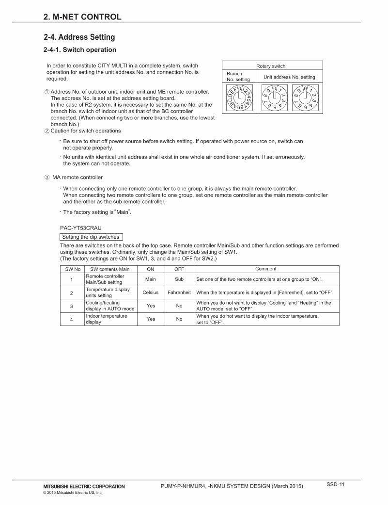
Rotary switchIn order to constitute CITY MULTI in a complete system, switch operation for setting the unit address No. and connection No. is required.
Address No. of outdoor unit, indoor unit and ME remote controller.The address No. is set at the address setting board. In the case of R2 system, it is necessary to set the same No. at the branch No. switch of indoor unit as that of the BC controller connected. (When connecting two or more branches, use the lowest branch No.)Caution for switch operations
MA remote controller
Be sure to shut off power source before switch setting. If operated with power source on, switch can not operate properly.
When connecting only one remote controller to one group, it is always the main remote controller.When connecting two remote controllers to one group, set one remote controller as the main remote controller and the other as the sub remote controller.
No units with identical unit address shall exist in one whole air conditioner system. If set erroneously, the system can not operate.
2-4-1. Switch operation
0 1 2 3 4 5 6 7 8 9 A B C D
E F 0 1 2 3 4 5 6 7
8
9 0 1 2 3 4 5 6 7
8
9
The factory setting is Main .
Setting the dip switchesThere are switches on the back of the top case. Remote controller Main/Sub and other function settings are performed using these switches. Ordinarily, only change the Main/Sub setting of SW1.(The factory settings are ON for SW1, 3, and 4 and OFF for SW2.)
SW No
1
2
4
SW contents MainRemote controllerMain/Sub settingTemperature displayunits setting
Indoor temperature display
ON
Main
Celsius
Yes
OFF
Sub
Fahrenheit
No
Comment
Set one of the two remote controllers at one group to “ON”.
When the temperature is displayed in [Fahrenheit], set to “OFF”.
When you do not want to display the indoor temperature, set to “OFF”.
AUTO mode, set to “OFF”.3Cooling/heating display in AUTO mode Yes No When you do not want to display “Cooling” and “Heating” in the
PAC-YT53CRAU
2. M-NET CONTROL

SSD-12 PUMY-P-NHMUR4, -NKMU SYSTEM DESIGN (March 2015)© 2015 Mitsubishi Electric US, Inc.
2-4-2. Rule of setting addressUnit
Indoor unit
ME, LOSSNAYRemote controller(Main)
ME, LOSSNAYRemote controller(Sub)
Address setting
01 ~ 50
52 ~ 99, 100
101 ~ 150
151 ~ 199, 200
NoteExample
The address of outdoor unit + 1
Please reset one of them to an address between 51 and 99 when two addresses overlap.
The address automatically becomes "100" if it is set as "01~ 50"
The smallest address of indoor unit in the group + 100
The place of "100" is fixed to "1"
ON/OFF remote controller 000, 201 ~ 250
Loca
l rem
ote
cont
rolle
rS
yste
m c
ontro
ller
The address of main remote controller + 50
The address automatically becomes "200" if it is set as "00"
10 1
10 1
0 1 2 3 4 5 6 7
8
9 0 1 2 3 4 5 6 7
8
9
10 1
10 1
0 1 2 3 4 5 6 7
8
9 0 1 2 3 4 5 6 7
8
9
0 1 2 3 4 5 6 7
8
9 0 1 2 3 4 5 6 7
8
9
10 1
0 1 2 3 4 5 6 7
8
90 1 2 3 4 5 6 7
8
9 0 1 2 3 4 5 6 7
8
9
10 1100
LMAP04U-E 201 ~ 250
1
1
Fixed
Fixed
2Fixed
Outdoor unit
BC controller(Main)
52 ~ 99, 100Lowest address within the indoor units connected to the BC controller (Sub) plus 50.
10 1
BC controller(Sub)
51 ~ 99, 100
The smallest address of indoor unit in same refrigerant system + 50Assign sequential address numbers to the outdoor units in one refrigerant circuit system. OC and OS are automatically detected. (Note 2) Please reset one of them to an address between 51
and 99 when two addresses overlap. The address automatically becomes "100" if it is set
as "01~ 50"
Use the most recent address within the same group of indoor units. Make the indoor units address connected to the BC controller (Sub) larger than the indoor units address connected to the BC controller (Main).If applicable, set the sub BC controllers in an PURY system in the following order: (1) Indoor unit to be connected to the BC controller (Main) (2) Indoor unit to be connected to the BC controller (No.1 Sub) (3) Indoor unit to be connected to the BC controller (No.2 Sub)Set the address so that (1)<(2)<(3)
0 1 2 3 4 5 6 7
8
9 0 1 2 3 4 5 6 7
8
9
0 1 2 3 4 5 6 7
8
9 0 1 2 3 4 5 6 7
8
9
0 1 2 3 4 5 6 7
8
9 0 1 2 3 4 5 6 7
8
9
0 1 2 3 4 5 6 7
8
9 0 1 2 3 4 5 6 7
8
9
10 1(Note1)
The smallest group No. to be managed is changeable.
The smallest group No. to be managed + 200
Note1: To set the address to "100", set it to "50"Note2: Outdoor units OC and OS in one refrigerant circuit system are automatically detected. OC and OS are ranked in descending order of capacity. If units are the same capacity, they are ranked in ascending order of their address.
AG-150A-AGB-50ADA-AGB-24AEB-50GU-A
000, 201 ~ 25010 1100
0 0 0
BAC-HD150 000, 201 ~ 250
10 1100
Settings are made with setting tool of BM ADAPTER.0 0 0
2. M-NET CONTROL
PUMY-P-NHMUR4, -NKMU SYSTEM DESIGN (March 2015) SSD-13© 2015 Mitsubishi Electric US, Inc.
Outdoor unit(PUMY)
Indoor unit
MA R/C MA R/C MA R/C(Main) (Sub)
MA R/C
00
DipSW2-1OFF
TB3
MA R/C: PAC-YT53CRAU
00 00 00 00 00TB15TB5 TB5TB5 TB5 TB5
MA R/C
TB15 TB15 TB15 TB15
Group 2Group 1 Group 3 Group 4
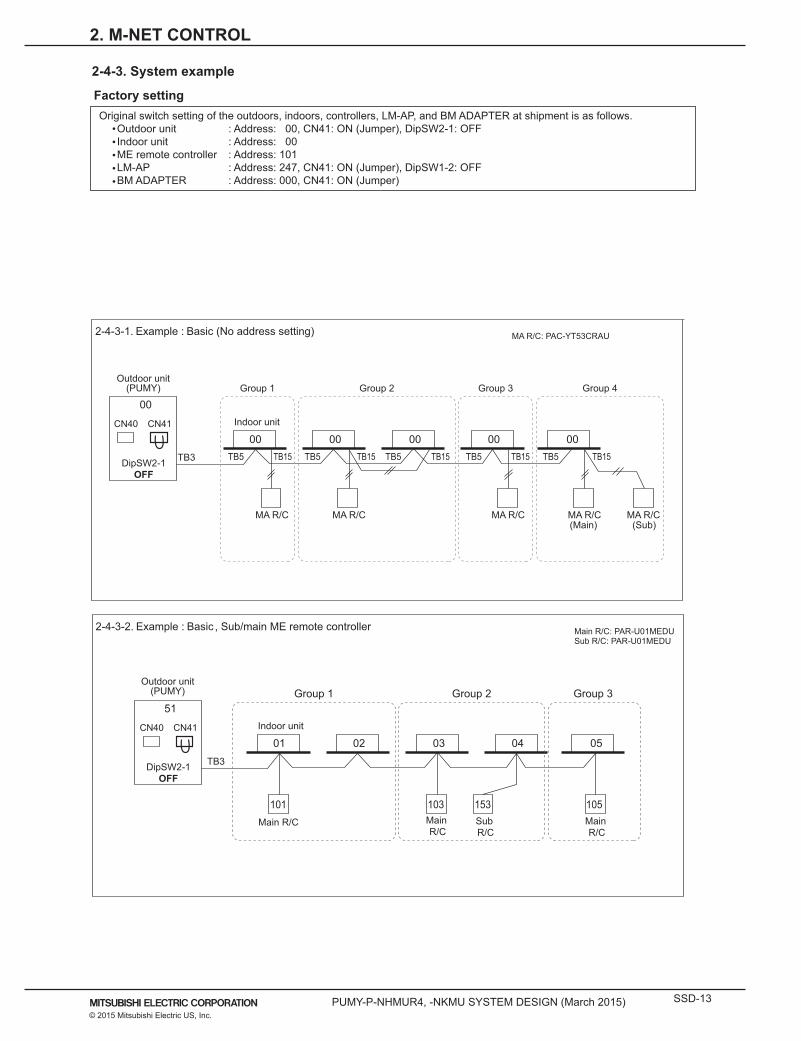
2-4-3-1. Example : Basic (No address setting)
2-4-3. System example
Main R/C: PAR-U01MEDUSub R/C: PAR-U01MEDU
Indoor unit
Sub R/C
Main R/C
Main R/C
Main R/C
51
DipSW2-1OFF
TB3
01 02 03 04 05
153103101 105
Group 1 Group 2 Group 3
2-4-3-2. Example : Basic , Sub/main ME remote controller
Outdoor unit(PUMY)
CN40 CN41
CN40 CN41
Factory settingOriginal switch setting of the outdoors, indoors, controllers, LM-AP, and BM ADAPTER at shipment is as follows.
Outdoor unit : Address: 00, CN41: ON (Jumper), DipSW2-1: OFF Indoor unit : Address: 00 ME remote controller : Address: 101 LM-AP : Address: 247, CN41: ON (Jumper), DipSW1-2: OFF BM ADAPTER : Address: 000, CN41: ON (Jumper)
2. M-NET CONTROL

SSD-14 PUMY-P-NHMUR4, -NKMU SYSTEM DESIGN (March 2015)© 2015 Mitsubishi Electric US, Inc.
51
TB3
TB2
DipSW2-1*1
ONTB3TB7TB7
NOTE It is necessary to turn on the DipSW 2-1 on the outdoor unit control board when the central controller is connected. GB-50ADA-A doesn’t need DC24V. TB3 on power supply unit doesn’t need to be connected to GB-50ADA-A.*1 On PUHY and PURY (YKM) units, set DipSW5-1 to ON instead of DipSW2-1.
01 02 03 04 05
101 102 103 104 105
000AG-150A-AGB-50ADA-A
DC30V
DC24V
Power supply unit(PAC-SC51KUA)
Group 1 Group 2 Group 3 Group 4 Group 5
2-4-3-3. Example : AG-150A-A/GB-50ADA-A, TB7Outdoor unit
Heat source unit(PUHY, PQHY, PUMY)
51
DipSW2-1*1
OFFTB3TB7
TB7
Group 1
Group 3Group 4
Group 2
NOTE It is necessary to change the connecter to CN40 on the outdoor unit control board (only one Outdoor unit / Heat source unit) when the group is set
between other refrigerant systems. It is necessary to set on the remote controller by manual when group sets on the different refrigerant system. Please refer to remote controller
installation manual.
01 02 03 04 05
101 105
56
DipSW2-1*1
OFFTB3
0910 08 07 06
110 107
2-4-3-4. Example : Grouping in different refrigerant system
Outdoor unitHeat source unit
(PUHY, PQHY, PUMY)
Outdoor unitHeat source unit
(PUHY,PQHY,PUMY)
000
CN40 CN41
CN40 CN41
CN40 CN41
CN40 CN41
*1 On PUHY and PURY (YKM) units, set DipSW5-1 to ON instead of DipSW2-1.
2. M-NET CONTROL
PUMY-P-NHMUR4, -NKMU SYSTEM DESIGN (March 2015) SSD-15© 2015 Mitsubishi Electric US, Inc.
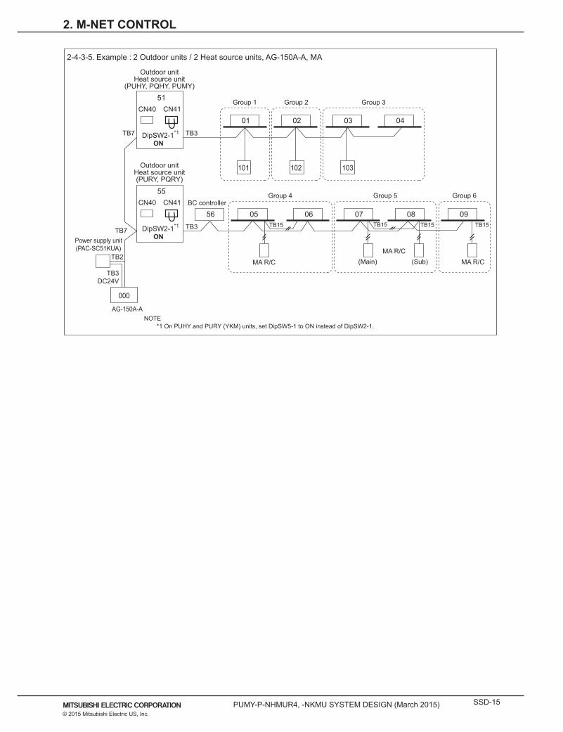
51
DipSW2-1*1
ONTB3TB7
TB7
TB2
TB3DC24V
01 02 03 04
101 102 103
55
DipSW2-1*1
ONTB3
56 05 06 07 08 09
000
AG-150A-A
BC controller
Power supply unit(PAC-SC51KUA)
MA R/C
MA R/CMA R/C(Main) (Sub)
TB15 TB15 TB15
Group 4 Group 5 Group 6
Group 2Group 1 Group 3
2-4-3-5. Example : 2 Outdoor units / 2 Heat source units, AG-150A-A, MA
TB15
Outdoor unitHeat source unit
(PUHY, PQHY, PUMY)
Outdoor unitHeat source unit(PURY, PQRY)
CN40 CN41
CN40 CN41
*1 On PUHY and PURY (YKM) units, set DipSW5-1 to ON instead of DipSW2-1.NOTE
2. M-NET CONTROL

SSD-16 PUMY-P-NHMUR4, -NKMU SYSTEM DESIGN (March 2015)© 2015 Mitsubishi Electric US, Inc.
NOTE
AG-150A-A*1 can control maximum 50 indoor units. It is planned that GB-50ADA-A will be supported on TG-2000A Ver. 6.3* or later.
TG-2000A can control maximum 40 AG-150A-A*1. TG-2000A can control maximum 2000 indoor units.
51
ON
TB3
01 02 03
101 151 103
54
ONTB3
TB3
55 04 05 06
104 105 106
107 108 158
BC controller
51
ONTB3TB7
TB7
TB7
TB7
52 01 02 03
101 151 103
BC controller
57
ON
07 08 09
107 108
54
ONTB3
04 05 06
104 105 106 156
57
ONTB3
58 07 08 09BC controller
LOSSNAY
HUB
TG-2000A
LAN
GB-50ADA-A
000
Group 1 Group 2
Group 4Group 3 Group 5
Group 6 Group 7
Group 3 Group 4 Group 5
Group 1 Group 2
Group 6 Group 7
Outdoor unitHeat source unit
(PUHY, PUMY, PQHY)
Outdoor unitHeat source unit
(PURY, PQRY)
Outdoor unitHeat source unit
(PUHY, PUMY, PQHY)
Outdoor unitHeat source unit
(PURY, PQRY)
Outdoor unitHeat source unit
(PUHY, PUMY, PQHY)
Outdoor unitHeat source unit
(PURY, PQRY)
*1 Only AG-150A-A that are not connected to expansion controllers. AG-150A-A (Ver. 1 series) does not support the expansion controller (EC).*2 TG-2000A (Ver. 5.5 or later) supports AG-150A-A (Ver. 1 series). AG-150A-A connected with PAC-YG50ECA is compatible with TG-2000A Ver. 6.1* or later.*3 On PUHY and PURY (YKM) units, set DipSW5-1 to ON instead of DipSW2-1.
*2
Power supply unit(PAC-SC51KUA)
2-4-3-6. Example : TG-2000A
CN40 CN41
CN40 CN41
CN40 CN41
CN40 CN41
CN40 CN41
CN40 CN41
DipSW2-1*3
DipSW2-1*3
DipSW2-1*3
DipSW2-1*3
DipSW2-1*3
DipSW2-1*3
AG-150A-A
000
24VDC
TB3 TB2
2. M-NET CONTROL

PUMY-P-NHMUR4, -NKMU SYSTEM DESIGN (March 2015) SSD-17© 2015 Mitsubishi Electric US, Inc.
NOTE LM-AP can control 50 indoor units. It is necessary to turn on the DipSW1-2 on the LM-AP control board and the DipSW2-1*1 on the outdoor unit control board with central controllers
(Power supply unit). It is necessary to change the connector to CN40 on the LM-AP control board without central controllers (Power supply unit).
51
DipSW2-1*1
DipSW2-1*1
DipSW2-1*1
DipSW2-1*1
DipSW2-1*1
DipSW2-1*1
ONTB3
01 02 03
101 151 103
54
ONTB3
TB3
55 04 05 06
104 105 106
101 102 152
BC controller
51
OFFTB3TB7
TB7
TB7
TB7
TB7
TB7
52 01 02 03
101 151 103
BC controller
51
OFF
01 02 03
101 102
51
OFFTB3
01 02 03
101 102 103 153
51
OFFTB3
52 01 02 03BC controller
LM-AP
LM-AP
LM-AP
LM-AP
LM-AP
PC
LONWORKS® card
Other equipments (lighting, security, elevator etc.)
DipSW1-2ON
247
DipSW1-2OFF
247
247
LONW
ORKS
®
P/S
000
AG-150A-A
Power supply unit(PAC-SC51KUA)
LOSSNAY
Group 1 Group 2
Group 1 Group 2 Group 3
Group 1 Group 2
Group 3 Group 4 Group 5
Group 1 Group 2
Group 1 Group 2
2-4-3-7. LM-AP Outdoor unitHeat source unit
(PUHY, PQHY, PUMY)
Outdoor unitHeat source unit(PURY, PQRY)
Outdoor unitHeat source unit
(PUHY, PQHY, PUMY)
Outdoor unitHeat source unit(PURY, PQRY)
Outdoor unitHeat source unit
(PUHY, PQHY, PUMY)
Outdoor unitHeat source unit(PURY, PQRY)
LONWORKS® card
LONWORKS® card
CN40 CN41
CN40 CN41
CN40 CN41
CN40 CN41
CN40 CN41
DipSW1-2OFF
DipSW1-2OFF
DipSW1-2OFF
CN40 CN41
CN40 CN41
CN40 CN41
CN40 CN41
CN40 CN41
CN40 CN41
247
247
*1 On PUHY and PURY (YKM) units, set DipSW5-1 to ON instead of DipSW2-1.
2. M-NET CONTROL
SSD-18 PUMY-P-NHMUR4, -NKMU SYSTEM DESIGN (March 2015)© 2015 Mitsubishi Electric US, Inc.
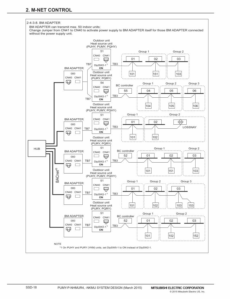
2-4-3-8. BM ADAPTER
HUB
BACn
et®
Outdoor unitHeat source unit
(PUHY, PUMY, PQHY)
Outdoor unitHeat source unit
(PUHY, PUMY, PQHY)
Outdoor unitHeat source unit
(PUHY, PUMY, PQHY)
51
DipSW2-1*1
ONTB3
01 02 03
101 151 103Outdoor unitHeat source unit(PURY, PQRY)
54
DipSW2-1*1
ONTB3
TB3
55 04 05 06
104 105 106
101 102 152
BC controller
Outdoor unitHeat source unit(PURY, PQRY)
51
DipSW2-1*1
ONTB3TB7
TB7
TB7
TB7
TB7
TB7
52 01 02 03
101 151 103
BC controller
51
DipSW2-1*1
ON
01 02 03
101 102
51
DipSW2-1*1
ONTB3
01 02 03
101 102 103 153Outdoor unit
Heat source unit(PURY, PQRY)
51
DipSW2-1*1
ONTB3
52 01 02 03BC controller
BM ADAPTER
BM ADAPTER
BM ADAPTER
BM ADAPTER
BM ADAPTER
000
000
000
000
000
LOSSNAY
Group 1 Group 2
Group 1 Group 2 Group 3
Group 1 Group 2
Group 1 Group 2 Group 3
Group 1 Group 2
Group 1 Group 2
BM ADAPTER can transmit max. 50 indoor units;Change Jumper from CN41 to CN40 to activate power supply to BM ADAPTER itself for those BM ADAPTER connected without the power supply unit.
CN40 CN41
CN40 CN41
CN40 CN41
CN40 CN41
CN40 CN41
CN40 CN41
CN40 CN41
CN40 CN41
CN40 CN41
CN40 CN41
CN40 CN41
NOTE*1 On PUHY and PURY (YKM) units, set DipSW5-1 to ON instead of DipSW2-1.
2. M-NET CONTROL
PUMY-P-NHMUR4, -NKMU SYSTEM DESIGN (March 2015) SSD-19© 2015 Mitsubishi Electric US, Inc.
3. PIPING DESIGN
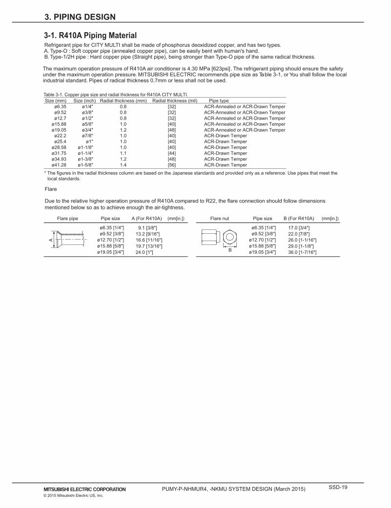
3-1. R410A Piping Material Refrigerant pipe for CITY MULTI shall be made of phosphorus deoxidized copper, and has two types. A. Type-O : Soft copper pipe (annealed copper pipe), can be easily bent with human's hand. B. Type-1/2H pipe : Hard copper pipe (Straight pipe), being stronger than Type-O pipe of the same radical thickness. The maximum operation pressure of R410A air conditioner is 4.30 MPa [623psi] . The refrigerant piping should ensure the safety under the maximum operation pressure. MITSUBISHI ELECTRIC recommends pipe size as Table 3-1, or You shall follow the local industrial standard. Pipes of radical thickness 0.7mm or less shall not be used.
* The figures in the radial thickness column are based on the Japanese standards and provided only as a reference. Use pipes that meet the local standards.
Size (mm) Size (inch) Radial thickness (mm) Pipe typeø6.35 ø1/4" 0.8 ACR-Annealed or ACR-Drawn Temperø9.52 ø3/8" 0.8 ACR-Annealed or ACR-Drawn Temperø12.7 ø1/2" 0.8 ACR-Annealed or ACR-Drawn Temper
ø15.88 ø5/8" 1.0 ACR-Annealed or ACR-Drawn Temperø19.05 ø3/4" 1.2 ACR-Annealed or ACR-Drawn Temper
ø22.2 ø7/8" 1.0 ACR-Drawn Temperø25.4 ø1" 1.0 ACR-Drawn Temper
ø28.58 ø1-1/8" 1.0 ACR-Drawn Temperø31.75 ø1-1/4" 1.1 ACR-Drawn Temperø34.93 ø1-3/8" 1.2 ACR-Drawn Temperø41.28 ø1-5/8" 1.4
Radial thickness (mil)[32][32][32][40][48][40][40][40][44][48][56] ACR-Drawn Temper
Table 3-1. Copper pipe size and radial thickness for R410A CITY MULTI.
Flare
Due to the relative higher operation pressure of R410A compared to R22, the flare connection should follow dimensions mentioned below so as to achieve enough the air-tightness.
Flare pipe Pipe size A (For R410A) Flare nut Pipe size (mm[in.]) (mm[in.]) B (For R410A)
ø6.35 [1/4"]ø9.52 [3/8"]
ø12.70 [1/2"]ø15.88 [5/8"]ø19.05 [3/4"] 24.0 [1"]
16.6 [11/16"]19.7 [13/16"]
9.1 [3/8"]13.2 [9/16"]
ø6.35 [1/4"]ø9.52 [3/8"]
ø12.70 [1/2"]ø15.88 [5/8"]ø19.05 [3/4"] 36.0 [1-7/16"]
17.0 [3/4"]22.0 [7/8"]26.0 [1-1/16"]29.0 [1-1/8"]
A
B
SSD-20 PUMY-P-NHMUR4, -NKMU SYSTEM DESIGN (March 2015)© 2015 Mitsubishi Electric US, Inc.
3. PIPING DESIGN
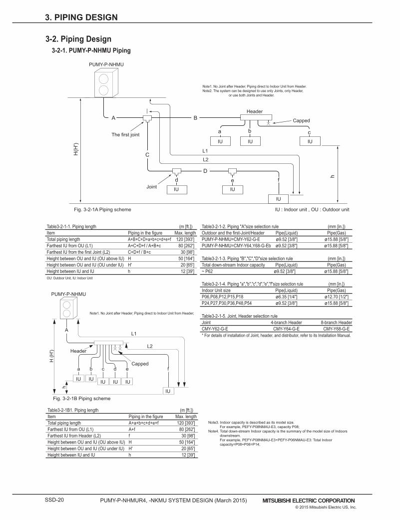
Table3-2-1-1. Piping length (m [ft.])Item Piping in the figure Max. lengthTotal piping length A+B+C+D+a+b+c+d+e+f 120 [393']Farthest IU from OU (L1) A+C+D+f / A+B+c 80 [262']Farthest IU from the first Joint (L2) C+D+f / B+c 30 [98']Height between OU and IU (OU above IU) H 50 [164']Height between OU and IU (OU under IU) H' 20 [65']Height between IU and IU h 12 [39']OU: Outdoor Unit, IU: Indoor Unit
Table3-2-1B1. Piping length (m [ft.])Item Piping in the figure Max. lengthTotal piping length A+a+b+c+d+e+f 120 [393']Farthest IU from OU (L1) A+f 80 [262']Farthest IU from Header (L2) f 30 [98']Height between OU and IU (OU above IU) H 50 [164']Height between OU and IU (OU under IU) H' 20 [65']Height between IU and IU h 12 [39']
Table3-2-1-2. Piping "A"size selection rule (mm [in.]) Outdoor and the first-Joint/Header Pipe(Liquid) Pipe(Gas)PUMY-P-NHMU=CMY-Y62-G-E ø9.52 [3/8"] ø15.88 [5/8"] PUMY-P-NHMU=CMY-Y64,Y68-G-Eb ø9.52 [3/8"] ø15.88 [5/8"]
Table3-2-1-3. Piping "B","C","D"size selection rule (mm [in.]) Total down-stream Indoor capacity Pipe(Liquid) Pipe(Gas)~ P62 ø9.52 [3/8"] ø15.88 [5/8"]
Table3-2-1-4. Piping "a","b","c","d","e","f"size selection rule (mm [in.]) Indoor Unit size Pipe(Liquid) Pipe(Gas)P06,P08,P12,P15,P18 ø6.35 [1/4"] ø12.70 [1/2"]P24,P27,P30,P36,P48,P54 ø9.52 [3/8"] ø15.88 [5/8"]
Table3-2-1-5. Joint, Header selection ruleJoint 4-branch Header 8-branch HeaderCMY-Y62-G-E CMY-Y64-G-E CMY-Y68-G-E* For details of installation of Joint, header, and distributor, refer to its Installation Manual.
Header
A
a b c dCapped
e f
H (H
')
h
L1
L2
IU IU IU IU IU
IUFig. 3-2-1B Piping scheme
Note3. Indoor capacity is described as its model size.For example, PEFY-P08NMAU-E3, capacity P08;
Note4. Total down-stream Indoor capacity is the summary of the model size of Indoors downstream.For example, PEFY-P08NMAU-E3+PEFY-P06NMAU-E3: Total Indoor capacity=P08+P06=P14;
Capped
Header
IU IU IU
IU
IUIU
The first joint
H(H
')
h
Joint
B
C
A
D
a b c
d e f
L2
L1
PUMY-P-NHMU
3-2-1. PUMY-P-NHMU Piping
PUMY-P-NHMU
IU : Indoor unit , OU : Outdoor unit
Note1. No Joint after Header; Piping direct to Indoor Unit from Header;
Fig. 3-2-1A Piping scheme
Note1. No Joint after Header; Piping direct to Indoor Unit from Header.Note2. The system can be designed to use only Joints, only Header, or use both Joints and Header.
3-2. Piping Design
PUMY-P-NHMUR4, -NKMU SYSTEM DESIGN (March 2015) SSD-21© 2015 Mitsubishi Electric US, Inc.
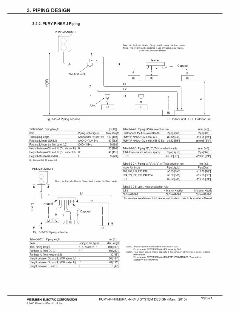
Table3-2-2-1. Piping length (m [ft.])Item Piping in the figure Max. lengthTotal piping length A+B+C+D+a+b+c+d+e+f 150 [492']Farthest IU from OU (L1) A+C+D+f / A+B+c 80 [262']Farthest IU from the first Joint (L2) C+D+f / B+c 30 [98']Height between OU and IU (OU above IU) H 50 [164']Height between OU and IU (OU under IU) H' 40 [131']Height between IU and IU h 15 [49']OU: Outdoor Unit, IU: Indoor Unit
Table3-2-2B1. Piping length (m [ft.])Item Piping in the figure Max. lengthTotal piping length A+a+b+c+d+e+f 150 [492']Farthest IU from OU (L1) A+f 80 [262']Farthest IU from Header (L2) f 30 [98']Height between OU and IU (OU above IU) H 50 [164']Height between OU and IU (OU under IU) H' 40 [131']Height between IU and IU h 15 [49']
Table3-2-2-2. Piping "A"size selection rule (mm [in.]) Outdoor and the first-Joint/Header Pipe(Liquid) Pipe(Gas)PUMY-P-NKMU=CMY-Y62-G-E ø9.52 [3/8"] ø19.05 [3/4"] PUMY-P-NKMU=CMY-Y64,Y68-G-Eb ø9.52 [3/8"] ø19.05 [3/4"]
Table3-2-2-3. Piping "B","C","D"size selection rule (mm [in.]) Total down-stream Indoor capacity Pipe(Liquid) Pipe(Gas)~ P78 ø9.52 [3/8"] ø19.05 [3/4"]
Table3-2-2-4. Piping "a","b","c","d","e","f"size selection rule (mm [in.]) Indoor Unit size Pipe(Liquid) Pipe(Gas)P06,P08,P12,P15,P18 ø6.35 [1/4"] ø12.70 [1/2"]P24,P27,P30,P36,P48,P54 ø9.52 [3/8"] ø15.88 [5/8"]P72 ø9.52 [3/8"] ø19.05 [3/4"]
Table3-2-2-5. Joint, Header selection ruleJoint 4-branch Header 8-branch HeaderCMY-Y62-G-E CMY-Y64-G-E CMY-Y68-G-E* For details of installation of Joint, header, and distributor, refer to its Installation Manual.
Header
A
a b c dCapped
e f
H (H
')
h
L1
L2
IU IU IU IU IU
IUFig. 3-2-2B Piping scheme
Note3. Indoor capacity is described as its model size.For example, PEFY-P08NMAU-E3, capacity P08;
Note4. Total down-stream Indoor capacity is the summary of the model size of Indoors downstream.For example, PEFY-P08NMAU-E3+PEFY-P06NMAU-E3: Total Indoor capacity=P08+P06=P14;
Capped
Header
IU IU IU
IU
IUIU
The first joint
H(H
')
h
Joint
B
C
A
D
a b c
d e f
L2
L1
PUMY-P-NKMU
3-2-2. PUMY-P-NKMU Piping
PUMY-P-NKMU
IU : Indoor unit , OU : Outdoor unit
Note1. No Joint after Header; Piping direct to Indoor Unit from Header;
Fig. 3-2-2A Piping scheme
Note1. No Joint after Header; Piping direct to Indoor Unit from Header.Note2. The system can be designed to use only Joints, only Header, or use both Joints and Header.
3. PIPING DESIGN
SSD-22 PUMY-P-NHMUR4, -NKMU SYSTEM DESIGN (March 2015)© 2015 Mitsubishi Electric US, Inc.
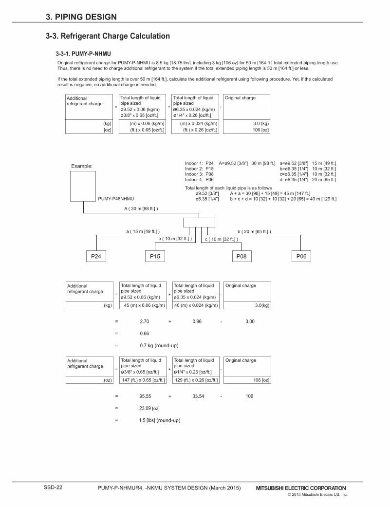
Example:
PUMY-P48NHMU
Original refrigerant charge for PUMY-P-NHMU is 8.5 kg [18.75 lbs], including 3 kg [106 oz] for 50 m [164 ft.] total extended piping length use. Thus, there is no need to charge additional refrigerant to the system if the total extended piping length is 50 m [164 ft.] or less.
If the total extended piping length is over 50 m [164 ft.], calculate the additional refrigerant using following procedure. Yet, if the calculated result is negative, no additional charge is needed.
3-3-1. PUMY-P-NHMU
P24 P15 P08 P06
A ( 30 m [98 ft.] )
b ( 10 m [32 ft.] )b ( 20 m [65 ft.] )
c ( 10 m [32 ft.] )
a ( 15 m [49 ft.] )
= + -
[oz] (ft.) x 0.65 [oz/ft.]
Additionalrefrigerant charge
Total length of liquidpipe sized
ø3/8" x 0.65 [oz/ft.]
(ft.) x 0.26 [oz/ft.]
Total length of liquidpipe sized
ø1/4" x 0.26 [oz/ft.]ø9.52 x 0.06 (kg/m) ø6.35 x 0.024 (kg/m)
106 [oz](kg) (m) x 0.06 (kg/m) (m) x 0.024 (kg/m) 3.0 (kg)
Original charge
Indoor 1: P24 A=ø9.52 [3/8"] 30 m [98 ft.] a=ø9.52 [3/8"] 15 m [49 ft.]Indoor 2: P15 b=ø6.35 [1/4"] 10 m [32 ft.]Indoor 3: P08 c=ø6.35 [1/4"] 10 m [32 ft.]Indoor 4: P06 d=ø6.35 [1/4"] 20 m [65 ft.]
Total length of each liquid pipe is as follows ø9.52 [3/8"] A + a = 30 [98] + 15 [49] = 45 m [147 ft.] ø6.35 [1/4"] b + c + d = 10 [32] + 10 [32] + 20 [65] = 40 m [129 ft.]
= + -
+ -
(kg) 45 (m) x 0.06 (kg/m)
Additionalrefrigerant charge
= 2.70
= 0.66
0.7 kg (round-up)
0.96 3.00
Total length of liquidpipe sizedø9.52 x 0.06 (kg/m)
40 (m) x 0.024 (kg/m)
Total length of liquidpipe sized
ø6.35 x 0.024 (kg/m)
3.0(kg)
Original charge
= + -
+ -
(oz) 147 (ft.) x 0.65 [oz/ft.]
Additionalrefrigerant charge
= 95.55
= 23.09 [oz]
1.5 [lbs] (round-up)
33.54 106
Total length of liquidpipe sizedø3/8" x 0.65 [oz/ft.]
129 (ft.) x 0.26 [oz/ft.]
Total length of liquidpipe sized
ø1/4" x 0.26 [oz/ft.]
106 [oz]
Original charge
3-3. Refrigerant Charge Calculation
3. PIPING DESIGN

PUMY-P-NHMUR4, -NKMU SYSTEM DESIGN (March 2015) SSD-23© 2015 Mitsubishi Electric US, Inc.
Example:
PUMY-P60NKMU
Additional refrigerant chargeRefrigerant for the extended piping is not included in the outdoor unit when the unit is shipped from the factory. Therefore, charge each refrigerant piping system with additional refrigerant at the installation site. In addition, in order to carry out service, enter the size and length of each liquid pipe and additional refrigerant charge amounts in the spaces provided on the “Refrigerant amount” plate on the outdoor unit.
Calculation of additional refrigerant charge• Calculate the additional charge using the liquid pipe size and length of the extended piping.• Calculate the additional refrigerant charge using the procedure shown to the right, and charge with the additional refrigerant.• For amounts less than 0.1 kg, round up the calculated additional refrigerant charge. (For example, if the calculated charge is 32.92 kg, round up the charge to 33.0 kg.)
3-3-2. PUMY-P-NKMU
P24 P15 P08 P06 P06
A ( 30 m [98 ft.] )
b ( 10 m [32 ft.] )
d ( 20 m [65 ft.] )
e ( 15 m [49 ft.] )
c ( 10 m [32 ft.] )
a ( 15 m [49 ft.] )
= + +
[oz]
Additionalrefrigerant charge
Pipe sizeLiquid pipe ø6.35
Pipe sizeLiquid pipe ø9.52
(kg)(m) × 0.027 (kg/m)
0.29 (oz/ft)(m) × 0.07 (kg/m)
0.75 (oz/ft)
– 42 2.0 kg (71 oz)
43 – 60 2.5 kg (88 oz)
61 – 78 3.0 kg (106 oz)
Total capacity ofconnected indoor units
Amount for theindoor units
Indoor 1: P24 A=ø9.52 [3/8"] 30 m [98 ft.] a=ø9.52 [3/8"] 15 m [49 ft.]Indoor 2: P15 b=ø6.35 [1/4"] 10 m [32 ft.]Indoor 3: P08 c=ø6.35 [1/4"] 10 m [32 ft.]Indoor 4: P06 d=ø6.35 [1/4"] 20 m [65 ft.]Indoor 5: P06 e=ø6.35 [1/4"] 15 m [49 ft.]
Total length of each liquid pipe is as follows ø9.52 [3/8"] A + a = 30 [98] + 15 [49] = 45 m [147 ft.] ø6.35 [1/4"] b + c + d + e = 10 [32] + 10 [32] + 20 [65] + 15 [49] = 55 m [180 ft.]
= + +
+ +
(kg) 45 (m) x 0.07 (kg/m)
Additionalrefrigerant charge
= 3.15
= 7.14
7.2 kg (round-up)
1.49 2.5
Total length of liquidpipe sizedø9.52 x 0.07 (kg/m)
55 (m) x 0.027 (kg/m)
Total length of liquidpipe sized
ø6.35 x 0.027 (kg/m)
= + +
+ +
(oz) 147 (ft.) x 0.75 [oz/ft.]
Additionalrefrigerant charge
= 110.25
= 250.45 [oz]
251 [oz] (round-up)
52.2 88
Total length of liquidpipe sizedø3/8" x 0.75 [oz/ft.]
180 (ft.) x 0.29 [oz/ft.]
Total length of liquidpipe sized
ø1/4" x 0.29 [oz/ft.]
– 42 2.0 kg (71 oz)43 – 60 2.5 kg (88 oz)61 – 78 3.0 kg (106 oz)
Total capacity ofconnected indoor units
Amount for theindoor units
– 42 2.0 kg (71 oz)43 – 60 2.5 kg (88 oz)61 – 78 3.0 kg (106 oz)
Total capacity ofconnected indoor units
Amount for theindoor units
3. PIPING DESIGN

SSD-24 PUMY-P-NHMUR4, -NKMU SYSTEM DESIGN (March 2015)© 2015 Mitsubishi Electric US, Inc.
4-1-2. Installation at windy location.
4-1-1. General caution
4-1-3. Foundation
A. Avoid locations exposed to direct sunlight or other sources of heat.B. Select a location from which noise emitted by the unit will not inconvenience the neighbors.C. Select a location permitting easy wiring and pipe access to the power source and indoor unit.D. Avoid locations where combustible gases may leak, be produced, flow, or accumulate.E. Note that water may drain from the unit during operation.F. Select a level location that can bear the weight and vibration of the unit.G. Avoid locations where the unit can be covered by snow. In areas where heavy snow fall is anticipated, special precautions
such as raising the installation location or installing a hood on the air intake must be taken to prevent the snow from blocking the air intake or blowing directly against it. This can reduce the airflow and a malfunction may result.
H. Avoid locations exposed to oil, steam, or sulfuric gas. I . Use the transportation handles of the outdoor unit to transport the unit. If the unit is carried from the bottom, hands or
fingers may be pinched.
When installing the outdoor unit on a rooftop or other location unprotected from the wind, situate the air outlet of the unit so that it is not directly exposed to strong winds.Strong wind entering the air outlet may impede the normal airflow and a malfunction may result.The following shows two examples of precautions against strong winds. Install an optional air guide if the unit is installed in a
location where strong winds from a typhoon, etc. may directly enter the air outlet. (Fig. 4-1-2a) Air guide
Position the unit so that the air outlet blows perpendicularly to the seasonal wind direction, if possible. (Fig. 4-1-2b) Wind direction
A. Be sure to install the unit in a sturdy, level surface to prevent rattling noises during operation. (see Fig. 4-1-3)B. Foundation specifications are as follows. Thickness of concrete Weight-bearing capacity Foundation bolt Bolt length 120 [4-3/4"] 320 kg [706lbs] M10 [3/8"] 70 [2-25/32"]C. Make sure that the length of the foundation bolt is within 30 mm [1-3/16"] of the bottom surface of the base.D. Secure the base of the unit firmly with four-M10 [3/8"] foundation bolts in sturdy locations.
Warning:A. The foundation base should be strong enough to support the outdoor unit, otherwise, it may fall down and cause
damage or injures.B. The unit must be installed according to the instructions in order to minimize the risk of damage from earthquakes,
typhoons, or strong winds.
mm [in.]
Min. 460[18-1/8"]
1050[41-11/32"]
Fig. 4-1-2a Fig. 4-1-2b
(mm [in.])600[23-5/8"]
600[23-5/8"]
Min. 360[14-3/16"]
175[6-29/32"]
175[6-29/32"]
Min. 10[13/32"]
950[37-13/32"]
25 [1"]
330
[13"
]
370
[14-
9/16
"]
25 [1"]
330
[13"
]
370
[14-
9/16
"]
Fig. 4-1-3
PUMY-P-NHMU
PUMY-P-NKMU
M10 (3/8") bolt Base As long as possible. Vent
Max
.30[
1-3/
16"]
600[23-5/8"]
600[23-5/8"]
Min. 10[13/32"]
225[8-7/8"]
225[8-7/8"]
4-1. Installation Site Requirements
4. INSTALLATION
PUMY-P-NHMUR4, -NKMU SYSTEM DESIGN (March 2015) SSD-25© 2015 Mitsubishi Electric US, Inc.
4. INSTALLATION
External dimension.
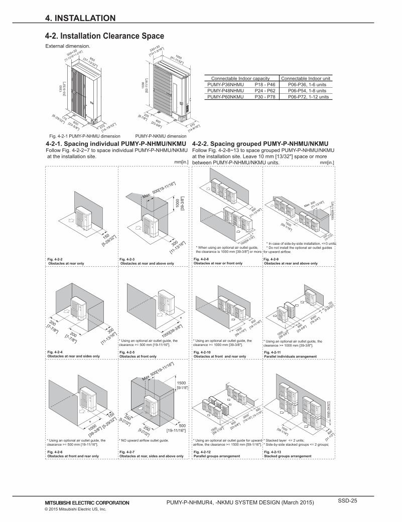
* In case of side-by-side installation, <=3 units;* Do not install the optional air outlet guides
for upward airflow.
Fig. 4-2-9Obstacles at rear and above only
* When using an optional air outlet guide, the clearance is 1000 mm [39-3/8"] or more.
Fig. 4-2-8Obstacles at rear or front only
Fig. 4-2-2 Obstacles at rear only
Fig. 4-2-3 Obstacles at rear and above only
Fig. 4-2-4Obstacles at rear and sides only
* Using an optional air outlet guide, the clearance >= 500 mm [19-11/16"].
Fig. 4-2-5Obstacles at front only
* Using an optional air outlet guide, the clearance >= 1000 mm [39-3/8"].
Fig. 4-2-10Obstacles at front and rear only
* Using an optional air outlet guide, the clearance >= 1000 mm [39-3/8"].
Fig. 4-2-11Parallel individuals arrangement
* Using an optional air outlet guide, the clearance >= 500 mm [19-11/16"].
Fig. 4-2-6Obstacles at front and rear only
* NO upward airflow outlet guide.
Fig. 4-2-7Obstacles at rear, sides and above only
* Using an optional air outlet guide for upward airflow, the clearance >= 1500 mm [59-1/16"].
Fig. 4-2-12Parallel groups arrangement
* Stacked layer <= 2 units;* Side-by-side stacked groups <= 2 groups;
Fig. 4-2-13Stacked groups arrangement
4-2-1. Spacing individual PUMY-P-NHMU/NKMU Follow Fig. 4-2-2~7 to space individual PUMY-P-NHMU/NKMU at the installation site.
4-2-2. Spacing grouped PUMY-P-NHMU/NKMUFollow Fig. 4-2-8~13 to space grouped PUMY-P-NHMU/NKMU at the installation site. Leave 10 mm [13/32"] space or more between PUMY-P-NHMU/NKMU units.
Fig. 4-2-1 PUMY-P-NHMU dimension PUMY-P-NKMU dimension
mm[in.] mm[in.]
300
[11-13/16"]
1000
[39-
3/8"
]Max. 500[19-11/16"]
200[7-7/8"] 300
[11-13/16"]200[7-7/8"]
1000[39-3/8"]
150
[5-29/32"]
1000
[39-3/8"]
250[9-27/32"] 250[9-27/32"]
1500[59-1/16"]
500[19-11/16"]
Max. 500[19-11/16"]
1500[59-1/16"]
500[19-11/16"]
1500
[59-
1/16
"]
Max. 300
[11-13/16"]
1500
[59-1/16"]
500
[19-11/16"]
1000
[39-3/8"]
600
[23-5/8"]
2000
[78-3/4"]
150
[5-29/32"]
1500
[59-1/16"]600
[23-5/8"]
3000
[118-1/8"]
500
[19-11/16"]
1500[59-1/16"] 800
[31-1/2"]
150[
5-29
/32"
]
300
[11-13/16"]
1500[59-1/16"]150
[5-29/32"]
950[37-13/32"]
300+30
[11-13/16"+1-3/16"]
1350
[53-
5/32
"]
175[6-29/32"] 600[23-5/8"] 370
[14-19/32"]
Connectable Indoor capacity Connectable Indoor unit PUMY-P36NHMU P18 - P46 P06-P36, 1-6 units PUMY-P48NHMU P24 - P62 P06-P54, 1-8 units PUMY-P60NKMU P30 - P78 P06-P72, 1-12 units
330+30
[13+1-3/16"]
370
[14-9/16"]
1050[41-11/32"]
225[8-7/8"] 600[23-5/8"]
1338
[52-
11/1
6 "]
4-2. Installation Clearance Space

SSD-26 PUMY-P-NHMUR4, -NKMU SYSTEM DESIGN (March 2015)© 2015 Mitsubishi Electric US, Inc.
4. Outdoor Installation DATA U9
SYSTEM DESIGN 4 - 30
Syst
em S 4-3. Piping direction
4-3-1. PUMY-P-NHMU
4-3-2. PUMY-P-NKMU
Front piping coverPiping coverStop valveService panelBend radius : 100 mm [3-15/16"] - 150 mm [5-29/32"]
Bottom piping
Front pipingRight piping
Rear piping
Front piping coverPiping coverStop valveService panelBend radius : 100 mm [3-15/16"] - 150 mm [5-29/32"]
4. INSTALLATION
4-3. Piping direction4. Outdoor Installation DATA U9
SYSTEM DESIGN 4 - 30
Syst
em S 4-3. Piping direction
4-3-1. PUMY-P-NHMU
4-3-2. PUMY-P-NKMU
Front piping coverPiping coverStop valveService panelBend radius : 100 mm [3-15/16"] - 150 mm [5-29/32"]
Bottom piping
Front pipingRight piping
Rear piping
Front piping coverPiping coverStop valveService panelBend radius : 100 mm [3-15/16"] - 150 mm [5-29/32"]
Front piping coverPiping coverStop valveService panelBend radius : 100 mm [3-15/16"] - 150 mm [5-29/32"]
Bottom piping
Front pipingRight piping
Rear piping
Front piping coverPiping coverStop valveService panelBend radius : 100 mm [3-15/16"] - 150 mm [5-29/32"]
PUMY-P-NHMUR4, -NKMU SYSTEM DESIGN (March 2015) SSD-27© 2015 Mitsubishi Electric US, Inc.
5. INSTALLATION INFORMATION
5-1. General precautions
• The air-conditioning system described in this Data Book is designed for human comfort.• This product is not designed for preservation of food, animals, plants, precision equipment, or art objects. To prevent quality loss, do
not use the product for purposes other than what it is designed for.• To reduce the risk of water leakage and electric shock, do not use the product for air-conditioning vehicles or vessels.
5-1-1. Usage
• Do not install any unit other than the dedicated unit in a place where the voltage changes a lot, large amounts of mineral oil (e.g., cutting oil) are present, cooking oil may splash, or a large quantity of steam can be generated such as a kitchen.
• Do not install the unit in acidic or alkaline environment.• Installation should not be performed in the locations exposed to chlorine or other corrosive gases. Avoid near a sewer.• To reduce the risk of fire, do not install the unit in a place where flammable gas may be leaked or inflammable material is present.• This air conditioning unit has a built-in microcomputer. Take the noise effects into consideration when deciding the installatioposition.
Especially in a place where antenna or electronic device are installed, it is recommended that the air conditioning unit be installed away from them.
• Install the unit on a solid foundation according to the local safety measures against typhoons, wind gusts, and earthquakes• to prevent the unit from being damaged, toppling over, and falling.
5-1-2. Installation environment
• In a place where air conditioner’s malfunctions may exert crucial influence, it is recommended to have two or more systems of single outdoor units with multiple indoor units.
5-1-3. Backup system
• Heat pump efficiency depends on outdoor temperature. In the heating mode, performance drops as the outside air temperature drops. In cold climates, performance can be poor. Warm air would continue to be trapped near the ceiling and the floor level would continue to stay cold. In this case, heat pumps require a supplemental heating system or air circulator.
• Before purchasing them, consult your local distributor for selecting the unit and system.• When the outdoor temperature is low and the humidity is high, the heat exchanger on the outdoor unit side tends to collect frost,
which reduces its heating performance. To remove the frost, Auto-defrost function will be activated and the heating mode will temporarily stop for 3-10 minutes. Heating mode will automatically resume upon completion of defrost process.
• Air conditioner with a heat pump requires time to warm up the whole room after the heating operation begins, because the system circulates warm air in order to warm up the whole room.
• The sound levels were obtained in an anechoic room. The sound levels during actual operation are usually higher than the simulated values due to ambient noise and echoes. Refer to the section on “SOUND LEVELS” for the measurement location.
• The total capacity of the connected indoor units can be greater than the capacity of the outdoor unit. However, when the connected indoor units operate simultaneously, each unit’s capacity may become smaller than the rated capacity.
• When the unit is started up for the first time within 12 hours after power on or after power failure, it performs initial startup operation (capacity control operation) to prevent damage to the compressor.
5-1-4. Unit characteristics
• Use an earth leakage breaker (ELB) with medium sensitivity, and an activation speed of 0.1 second or less.• Consult your local distributor or a qualified technician when installing an earth leakage breaker.• If the unit is inverter type, select an earth leakage breaker for handling high harmonic waves and surges.• Leakage current is generated not only through the air conditioning unit but also through the power wires. Therefore, the leakage
current of the main power supply is greater than the total leakage current of each unit. Take into consideration the capacity of the earth leakage breaker or leakage alarm when installing one at the main power supply. To measure the leakage current simply on site, use a measurement tool equipped with a filter, and clamp all the four power wires together. The leakage current measured on the ground wire may not accurate because the leakage current from other systems may be included to the measurement value.
• Do not install a phase advancing capacitor on the unit connected to the same power system with an inverter type unit and its equipment.
• If a large current flows due to the product malfunctions or faulty wiring, both the earth leakage breaker on the product side and the upstream overcurrent breaker may trip almost at the same time. Separate the power system or coordinate all the breakers depending on the system’s priority level.
5-1-5. Relevant equipment
• Your local distributor or a qualified technician must read the Installation Manual that is provided with each unit carefully before performing installation work.
• Consult your local distributor or a qualified technician when installing the unit. Improper installation by an unqualified person may result in water leakage, electric shock, or fire.
• Ensure there is enough space around each unit.
5-1-6. Unit installation

SSD-28 PUMY-P-NHMUR4, -NKMU SYSTEM DESIGN (March 2015)© 2015 Mitsubishi Electric US, Inc.
5. INSTALLATION INFORMATION
5-2. Precautions for Indoor unit
• Only use accessories recommended by Mitsubishi Electric. Consult your local distributor or a qualified technician when installing them. Improper installation by an unqualified person may result in water leakage, electric leakage, system breakdown, or fire.
• Some optional accessories may not be compatible with the air conditioning unit to be used or may not suitable for the installation conditions. Check the compatibility when considering any accessories.
• Note that some optional accessories may affect the air conditioner’s external form, appearance, weight, operating sound, and other characteristics.
5-1-7. Optional accessories
• Read the Instruction Book that is provided with each unit carefully prior to use.• Maintenance or cleaning of each unit may be risky and require expertise. Read the Instruction Book to ensure safety.• Consult your local distributor or a qualified technician when special expertise is required such as when the indoor unit needs to be
cleaned.
5-1-8. Operation/Maintenance
• The refrigerant (R410A) used for air conditioner is non-toxic and nonflammable. However, if the refrigerant leaks, the oxygen level may drop to harmful levels. If the air conditioner is installed in a small room, measures must be taken to prevent the refrigerant concentration from exceeding the safety limit even if the refrigerant should leak.
• If the units operate in the cooling mode at the humidity above 80%, condensation may collect and drip from the indoor units.
5-2-1. Operating environment
• The return air temperature display on the remote controller may differ from the ones on the other thermometers.• The clock on the remote controller may be displayed with a time lag of approximately one minute every month.• The temperature using a built-in temperature sensor on the remote controller may differ from the actual room temperature due to the
effect of the wall temperature.• Use a built-in thermostat on the remote controller or a separately-sold thermostat when indoor units installed on or in the ceiling
operate the automatic cooling/heating switchover.• The room temperature may rise drastically due to Thermo OFF in the places where the air conditioning load is large such as
computer rooms.• Be sure to use a regular filter. If an irregular filter is installed, the unit may not operate properly, and the operation noise may
increase.• The room temperature may rise over the preset temperature in the environment where the heating air conditioning load is small.
5-2-2. Unit characteristics
• For simultaneous cooling/heating operation type air conditioners (R2, WR2 series), the G-type BC controller cannot be connected to the P144 outdoor unit model or above, and the G- and GA-type BC controllers cannot be connected to the
• P264 model or above. The GB- and HB-type BC controllers (sub) cannot be connected to the outdoor unit directly, and be sure to use them with GA- and HA-type BC controllers (main).
• The insulation for low pressure pipe between the BC controller and outdoor unit shall be at least 20 mm thick. If the unit is installed on the top floor or in a high-temperature, high-humidity environment, thicker insulation may be necessary.
• Do not have any branching points on the downstream of the refrigerant pipe header.• When a field-supplied external thermistor is installed or when a device for the demand control is used, abnormal stop of the unit or
damage of the electromagnetic contactor may occur. Consult your local distributor for details.• When indoor units operate a fresh air intake, install a filter in the duct (field-supplied) to remove the dust from the air.• The 4-way or 2-way Airflow Ceiling Cassette Type units that have an outside air inlet can be connected to the duct, but need a
booster fan to be installed at site. Refer to the chapter “Indoor Unit” for the available range for fresh air intake volume
5-2-3. Unit installation

PUMY-P-NHMUR4, -NKMU SYSTEM DESIGN (March 2015) SSD-29© 2015 Mitsubishi Electric US, Inc.
5. INSTALLATION INFORMATION
5-3. Precautions for Fresh air intake type indoor unit
5-4. Precautions for Outdoor unit/Heat source unit
• This unit mainly handles the outside air load, and is not designed to maintain the room temperature. Install other air conditioners for handling the air conditioning load in the room.
5-3-1. Usage
• This unit cannot perform the drying operation. The unit will continue the fan operation and blow fresh air (air that is not air-conditioned) when the Heating Thermo-OFF or Cooling Thermo-OFF mode is selected.
• The fan may stop tentatively when the unit is connected to the simultaneous cooling/heating operation type outdoor unit (R2, WR2 series) or during the defrost cycle.
• This unit switches the Thermo ON or OFF depending on the room temperature. The outside air is directly supplied into the room during Thermo OFF. Take caution of the cold supply air due to low outside air temperature and of condensation in the room due to high humidity of the outside air.
• Outside air temperature ranges for the operation must be as follows: Cooling: 21ºC D.B./15.5º C W.B. ~ 43º C D.B./35º C W.B. Heating: -10ºC D.B.~ 20º C D.B. The unit is forced to operate Thermo OFF (fan operation) when the outside air temperature is as follows. Cooling: 21ºC D.B or below; Heating: 20ºC D.B or above
• Either a remote controller (sold separately) or a remote sensor (sold separately) must be installed to monitor the room temperature.• If only this unit is used as an indoor unit, condensation may form at the supply air grill while the unit is operated in the cooling mode.
This unit cannot operate dehumidifying.• Use the unit in the way that the airflow rate will not exceed the 110% of the rated airflow.
5-3-2. Unit characteristics
• Outdoor unit with salt-resistant specification is recommended to use in a place where it is subject to salt air.• Even when the unit with salt-resistant specification is used, it is not completely protected against corrosion. Be sure to follow the
directions or precautions described in Instructions Book and Installation Manual for installation and maintenance. The salt-resistant specification is referred to the guidelines published by JRAIA (JRA9002).
• Install the unit in a place where the flow of discharge air is not obstructed. If not, the short-cycling of discharge air may occur.• Provide proper drainage around the unit base, because the condensation may collect and drip from the outdoor units.
Provide water-proof protection to the floor when installing the units on the rooftop.• In a region where snowfall is expected, install the unit so that the outlet faces away from the direction of the wind, and install a snow
guard to protect the unit from snow. Install the unit on a base approximately 50 cm higher than the expected snowfall. Close the openings for pipes and wiring, because the ingress of water and small animals may cause equipment damage. If SUS snow guard is used, refer to the Installation Manual that comes with the snow guard and take caution for the installation to avoid the risk of corrosion.
• When the unit is expected to operate continuously for a long period of time at outside air temperatures of below 0º C, take appropriate measures, such as the use of a unit base heater, to prevent icing on the unit base. (Not applicable to the PUMY-P-NHMU series)
• Install the snow guard so that the outlet/inlet faces away from the direction of the wind.• When the snow accumulates approximately 50 cm or more on the snow guard, remove the snow from the guard. Install a roof that
is strong enough to withstand snow loads in a place where snow accumulates.• Provide proper protection around the outdoor units in places such as schools to avoid the risk of injury.
5-4-1. Installation environment
• When the Thermo ON and OFF is frequently repeated on the indoor unit, the operation status of outdoor units may become unstable.
5-4-2. Unit characteristics
• Provide grounding in accordance with the local regulations.5-4-3. Relevant equipment

SSD-30 PUMY-P-NHMUR4, -NKMU SYSTEM DESIGN (March 2015)© 2015 Mitsubishi Electric US, Inc.
5. INSTALLATION INFORMATION
5-5. Precautions for Control-related items
• To introduce the MELANS system, a consultation with us is required in advance. Especially to introduce the electricity charge apportioning function or energy-save function, further detailed consultation is required. Consult your local distributor for details.
• Billing calculation for AG-150A, GB-50ADA, TG-2000A, or the billing calculation unit is unique and based on our original method. (Backup operation is included.) It is not based on the metering method, and do not use it for official business purposes. It is not the method that the amount of electric power consumption (input) by air conditioner is calculated. Note that the electric power consumption by air conditioner is apportioned by using the ratio corresponding to the operation status (output) for each air conditioner (indoor unit) in this method.
• In the apportioned billing function for AG-150A and GB-50ADA, use separate watthour meters for A-control units, Kcontrol units, and packaged air conditioner for City Multi air conditioners. It is recommended to use an individual watthour meter for the large-capacity indoor unit (with two or more addresses).
• When using the peak cut function on the AG-150A or GB-50ADA, note that the control is performed once every minute and it takes time to obtain the effect of the control. Take appropriate measures such as lowering the criterion value. Power consumption may exceed the limits if AG-150A or GB-50ADA malfunctions or stops. Provide a back-up remedy as necessary.
• The controllers cannot operate while the indoor unit is OFF. (No error) Turn ON the power to the indoor unit when operating the controllers.
• When using the interlocked control function on the AG-150A, GB-50ADA, PAC-YG66DCA, or PAC-YG63MCA, do not use it for the control for the fire prevention or security. (This function should never be used in the way that would put people’s lives at risk.) Provide any methods or circuit that allow ON/OFF operation using an external switch in case of failure.
5-5-1. Product specification
• The surge protection for the transmission line may be required in areas where lightning strikes frequently occur.• A receiver for a wireless remote controller may not work properly due to the effect of general lighting. Leave a space of at least 1 m
between the general lighting and receiver.• When the Auto-elevating panel is used and the operation is made by using a wired remote controller, install the wired remote
controller to the place where all air conditioners controlled (at least the bottom part of them) can be seen from the wired remote controller. If not, the descending panel may cause damage or injury, and be sure to use a wireless remote controller designed for use with elevating panel (sold separately).
• Install the wired remote controller (switch box) to the place where the following conditions are met. - Where installation surface is flat - Where the remote controller can detect an accurate room temperature The temperature sensors that detect a room temperature are installed both on the remote controller and indoor unit. When a room temperature is detected using the sensor on the remote controller, the main remote controller is used to detect a room temperature. In this case, follow the instructions below. - Install the controller in a place where it is not subject to the heat source. (If the remote controller faces direct sunlight or supply air flow direction, the remote controller cannot detect an accurate room temperature.) - Install the controller in a place where an average room temperature can be detected. - Install the controller in a place where no other wires are present around the temperature sensor. (If other wires are present, the remote controller cannot detect an accurate room temperature.)
• To prevent unauthorized access, always use a security device such as a VPN router when connecting AG-150A, GB-50ADA, or TG-2000A to the Internet.
5-5-2. Installation environment
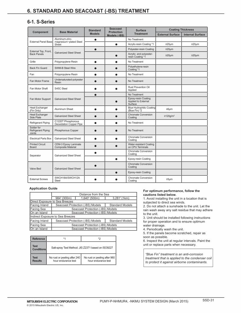
PUMY-P-NHMUR4, -NKMU SYSTEM DESIGN (March 2015) SSD-31© 2015 Mitsubishi Electric US, Inc.
Component Base Material Standard Models
Seacoast Protection
Models (-BS)
Surface Treatment
Coating Thickness
External Surface Internal Surface
External Panel BaseAluminum-zinc-magnesium−plated Steel Sheet
● No Treatment
● Acrylic-resin Coating *1 ≥20μm ≥20μm
External Top, Front, Back Panels Galvanized Steel Sheet
● Polyester-resin Coating ≥20μm
● Acrylic- and polyester-resin Coating *1 ≥20μm ≥20μm
Grille Polypropylene Resin ● ● No Treatment
Back Fin Guard SWM-B Steel Wire ● ● Polyethylene-resin Coating *1
Fan Polypropylene Resin ● ● No Treatment
Fan Motor Frame Undersaturated-polyester Resin ● ● No Treatment
Fan Motor Shaft S45C Steel ● ● Rust Prevention Oil Applied
Fan Motor Support Galvanized Steel Sheet● No Treatment
●Epoxy-resin Coating Applied to External Surface
Heat Exchanger (Fin Only) Aluminum Sheet ● ● Blue Hydrophilic Coating
(Blue Fin) *2 ≥6μm
Heat Exchanger Side Plate Galvanized Steel Sheet ● ● Chromate Conversion
Coating ≥120g/m2
Refrigerant Piping C1220T Phosphorous Deoxidation Copper Pipe ● ● No Treatment
Solder for Refrigerant Piping Joints
Phosphorous Copper ● ● No Treatment
Electrical Parts Box Galvanized Steel Sheet ● ● Chromate Conversion Coating
Printed Circuit Board
CEM-3 Epoxy Laminate Composite Material ● ● Water-resistant Coating
on CPU Terminals
Separator Galvanized Steel Sheet● Chromate Conversion
Coating
● Epoxy-resin Coating
Valve Bed Galvanized Steel Sheet● Chromate Conversion
Coating
● Epoxy-resin Coating
External Screws SWCH18A/SWCH12A Steel ● ● Chromate Conversion
Coating ≥5μm
Application Guide
Distance from the Sea984′ (300m) 1,640′ (500m) 3,281′ (1km)
Direct Exposure to Sea BreezesFacing Inland Seacoast Protection (-BS) Models Standard ModelsFacing Sea Seacoast Protection (-BS) ModelsOn an Island Seacoast Protection (-BS) ModelsIndirect Exposure to Sea BreezesFacing Inland Seacoast Protection (-BS) Models Standard ModelsFacing Sea Seacoast Protection (-BS) ModelsOn an Island Seacoast Protection (-BS) Models
For optimum performance, follow the cautions listed below.1. Avoid installing the unit in a location that is subjected to direct sea winds.2. Do not attach a sunshade to the unit. Let the rain wash away any salt residue that may adhere to the unit.3. Unit should be installed following instructions for proper operation and to ensure optimum water drainage.4. Periodically wash the unit.5. If the panels become scratched, repair as soon as possible.6. Inspect the unit at regular intervals. Paint the unit or replace parts when necessary.
Reference *1 *2
Test Conditions Salt-spray Test Method: JIS Z2371 based on ISO9227
Test Results
No rust or peeling after 240 hour endurance test
No rust or peeling after 960 hour endurance test
“Blue Fin” treatment is an anti-corrosion treatment that is applied to the condenser coil to protect it against airborne contaminants.
6. STANDARD AND SEACOAST (-BS) TREATMENT
6-1. S-Series

SSD-32 PUMY-P-NHMUR4, -NKMU SYSTEM DESIGN (March 2015)© 2015 Mitsubishi Electric US, Inc.
7. CAUTIONS
7-1. Refrigerant Leakage Considerations
In the United States safety classification of refrigerants is governed by ASHRAE Standard 34. Standard 34 prescribes safety group and flammability classifications for refrigerants. These groups are shown below:
Mitsubishi VRF systems utilize R410A refrigerant. ASHRAE Standard 34 assigns a classification of A1 to this refrigerant, placing it in the lowest toxicity and no flame propagation category.
ASHRAE Standard 34 also prescribes maximum permissible concentration levels of any such refrigerant in an occupied space to protect the occupants from asphyxiation and or toxicity. ASHRAE Standard 34-2010, Addendum l sets the concentrations level to 26lbs/Mcf for R410A refrigerant.
ASHRAE Standard 15 prescribes safe design practices for refrigeration systems and references Standard 34 within when establishing where additional measures must be taken when refrigerant concentration level limits prescribed by Standard 34 are exceeded. Most state codes reference the International Mechanical Code (IMC). Chapter 11 of the IMC governs the safe design and install of refrigeration systems and references ASHRAE 15 & 34 for requirements of allowable concentration levels and other safety measures for designing refrigeration systems.
In any VRF design, it is imperative that the designer ensures that in the event of a major leakage of all system refrigerant into a single enclosed occupied space, that these concentration limits are not exceeded in order to protect the occupants.
ASHRAE Standard 15 specifies that the smallest occupied space volume to consider in event of a major leakage is that space volume which does not connect through permanent openings such as transfer openings or HVAC ducts. In any event the following must be evaluated for each smallest enclosed area:
Area Leakage Concentration Level (lbs/Mcf) = Total VRF System Charge (lbs) / [Area Volume (ft3)/1000] Total VRF System Charge = Factory Charge + Trim Charge In Field
If a particular space, per this calculation, exceeds the concentration limit of 26 lbs/Mcf, the volume must be increased through connectivity to maintain the leakage concentration level below the threashold.
When determining smallest space volume when spaces are connected, ASHRAE 15 does not specifically address how much free area is required to claim connectivity of spaces. The Japanese Refrigeration Standard, JRA GL-13;2012, specifies that 0.15% of the floor area must be provided for a transfer opening to claim connectivity to an adjacent space. This can be used as guide, but again is not referenced to any specific US recognized codes / standard. Always consult the local code / jurisdiction for requirements with regard to refrigerant leakage in any event.
An example of a countermeasure to claim connectivity of spaces is shown below. In this example a dedicated outdoor air / or ventilation system is continuously supplying fresh air to the smallest occupied space. A transfer opening or a door under cut is provided so that the space is communicating with an adjacent space. A low wall exhaust could also be provided equal to the fresh air delivery amount to promote the capture of any leaked refrigerant. Utilizing a low wall exhaust in areas where space occupants are sleeping would be beneficial since R410A is heavier than air and will tend to migrate towards the floor.
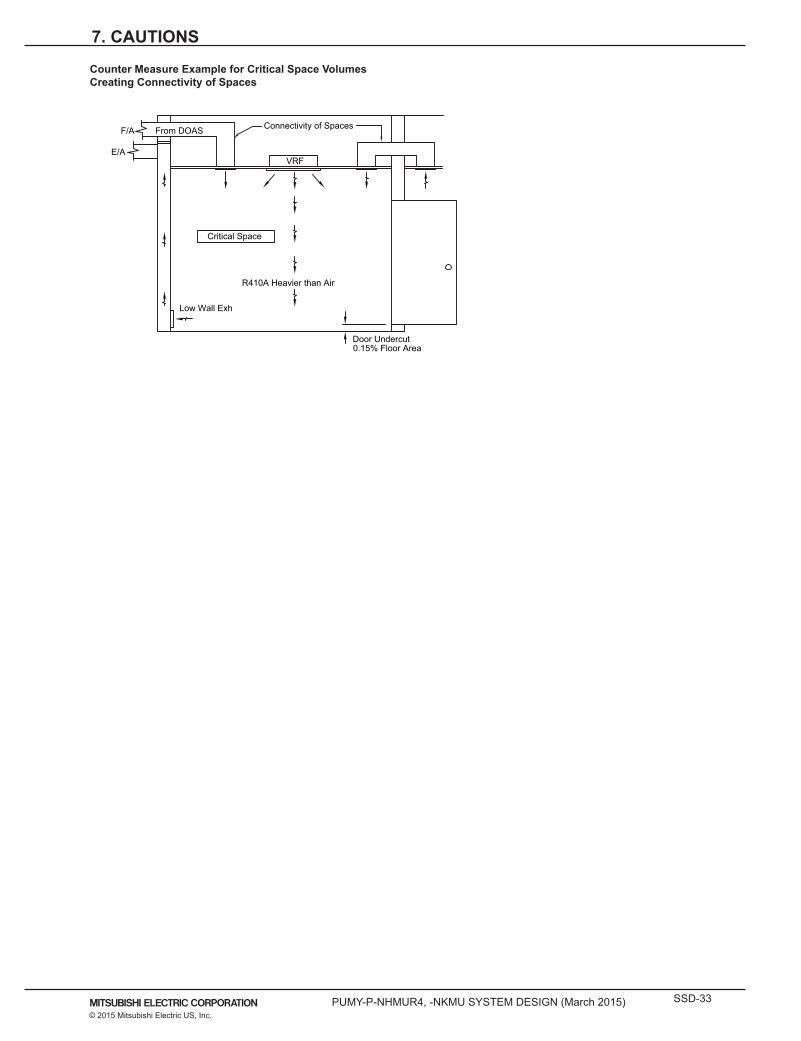
PUMY-P-NHMUR4, -NKMU SYSTEM DESIGN (March 2015) SSD-33© 2015 Mitsubishi Electric US, Inc.
7. CAUTIONS
Counter Measure Example for Critical Space VolumesCreating Connectivity of Spaces
E/AVRF
F/A From DOAS
Low Wall Exh
Door Undercut0.15% Floor Area
R410A Heavier than Air
Connectivity of Spaces
Critical Space

SSD-34 PUMY-P-NHMUR4, -NKMU SYSTEM DESIGN (March 2015)© 2015 Mitsubishi Electric US, Inc.