city of ashland electrical service requirements esr manual 12-28-09.pdf · city of ashland...
TRANSCRIPT
City of Ashland
Electrical Service Requirements
Service and Metering Requirements for
Residential, Commercial, Agricultural and Industrial Customers
City of Ashland Ashland, Oregon

City of Ashland | Electric Department i
Table of Contents
1 General Requirements 1.1 Customer and Electric Department Defined.................................................................................4 1.2 Consulting the Electric Department .............................................................................................4 1.3 Booklet Purpose and Organization...............................................................................................4 1.4 Changes or Conflicts in Requirements .........................................................................................4 1.5 Maximum Available Fault Current ..............................................................................................4 1.6 Customer’s Responsibility for Safety...........................................................................................4 1.7 Work Activity Near High-Voltage Overhead Power Lines (Over 600 volts) ..............................4 1.8 Temporary Interruption................................................................................................................5 1.9 Grounding and Bonding...............................................................................................................5 1.10 Vegetation and Accessibility........................................................................................................5 1.11 Customer Equipment on Electric Department Poles ....................................................................5 1.12 Call Before You Dig ....................................................................................................................5 1.13 Power Quality ..............................................................................................................................5 1.14 Motors ..........................................................................................................................................6 1.15 Customer Generation ...................................................................................................................6
2 Permits and Applications 2.1 Codes and Ordinances..................................................................................................................8 2.2 Rights-of-Way..............................................................................................................................8 2.3 Application for Service ................................................................................................................8 2.4 Electric Service Requirement Agreement ....................................................................................8 2.5 Permits .........................................................................................................................................9
3 Services and Meter Installations 3.1 Types of Service Furnished..........................................................................................................10 3.2 Load Requirements ......................................................................................................................10 3.3 Permanent Service Connection ....................................................................................................11 3.4 General Meter Installations ..........................................................................................................11 3.5 Connection, Disconnection and Re-establishment of Service......................................................12 3.6 Relocation of Services and Facilities ...........................................................................................13
4 Temporary Construction Service 4.1 General .........................................................................................................................................14 4.2 Construction Criteria for Temporary Service...............................................................................14 4.3 Meter Socket Requirements for Temporary Construction Services .............................................17
5 Clearances 5.1 Meter Clearances and Locations ..................................................................................................18 5.2 Clearances for Services ................................................................................................................22 5.3 Conductors Near Pools, Spas or Hot Tubs ...................................................................................24 5.4 Clearance from Underground Gasoline Storage Tanks................................................................25 5.5 Clearance from Padmounted Equipment......................................................................................25
6 Underground Requirements 6.1 General .........................................................................................................................................27 6.2 Conduit Requirements..................................................................................................................27 6.3 Trench and Back Fill Requirements.............................................................................................29 6.4 Vaults for Padmounted Transformers ..........................................................................................32

City of Ashland | Electric Department ii
7 Single Family Service 7.1 General .........................................................................................................................................34 7.2 Customer Responsibilities............................................................................................................34 7.3 Maximum Available Fault Current ..............................................................................................34 7.4 Residential Meter Sockets............................................................................................................34 7.5 Residential Meter Socket Location ..............................................................................................37 7.6 Underground Service ...................................................................................................................39 7.7 Overhead Service .........................................................................................................................44
8 Multiple Family Service 8.1 General .........................................................................................................................................50 8.2 Customer Responsibilities............................................................................................................50 8.3 Maximum Available Fault Current ..............................................................................................50 8.4 Multiple Residential Meter Sockets .............................................................................................50 8.5 Pull Box Requirements ................................................................................................................52 8.6 Multiple Family Meter Location, Underground Service ..............................................................53 8.7 Multiple Family Meter Location, Overhead Service....................................................................54
9 Mobile Home Service 9.1 General .........................................................................................................................................55 9.2 Customers Responsibilities ..........................................................................................................55 9.3 Maximum Available Fault Current ..............................................................................................55 9.4 Residential Meter Sockets for Mobile Homes..............................................................................55 9.5 Meter Socket Location for Mobile Residences ............................................................................55 9.6 Underground Service to Mobile Homes.......................................................................................56 9.7 Overhead Service to Mobile Homes ............................................................................................59
10 Non-Residential Services 10.1 Service Point Location for Meter and Equipment ........................................................................62 10.2 General Descriptions....................................................................................................................62 10.3 Direct Connect Services ...............................................................................................................62 10.4 Direct-Connect Metering Services ...............................................................................................67 10.5 Pull Box........................................................................................................................................69 10.6 Current Transformer Metering- 600 Volts, 800 Amps Maximum ...............................................71 10.7 Clearances ....................................................................................................................................79 10.8 Current Transformer Metering Conduit .......................................................................................79 10.9 Current Transformer Metering for Free-Standing Installations....................................................79 10.10 Current Transformer Enclosure Bonding .....................................................................................81 10.11 Combination Self-Contained and Current Transformer Metering................................................82 10.12 Switchboard Metering..................................................................................................................82 10.13 Primary Voltage Service (Over 600 Volts) ..................................................................................93 10.14 Primary Metering Requiring Switchgear Enclosure.....................................................................96 10.15 Primary Metering- Customer Owned Substation .........................................................................96

City of Ashland | Electric Department 1
Definitions ANSI - American National Standards Institute. Bushings -P la s t i c or nylon rings that attach to the ends of conduit to protect the electrical cable from sharp edges. Bypass - A method which allows for service continuity to the customer while the meter is removed for test or inspection. Current transformer - A set of coils that reduce the primary current to the customer by a known ratio to an amount within the current capacity of the meter.
Current transformer meter - A meter that requires current transformers because its current capacity is not as large as the customer's current load. Direct-connect meter - A meter energized to line voltage that carries all the load current. Also called a self-contained meter. No current transformer or voltage interface is used. Direct-connect socket - A meter socket connected to service wires, energized to line voltage and in series with the customer's load without external instrument transformers. A self-contained meter is used in a direct-connect socket. Drip loop - The loop formed by the customer conductors that connects to the Electric Department service drop. The conductors are formed in a downward "loop" so water will not enter the customer's service mast (weatherhead). Electric Department – City of Ashland, division responsible for electrical service. EUSERC (Electric Utility Service Equipment Requirements Committee) - An association of electric utilities and manufacturers that creates standard designs for the interface between the electric utility's service and the customer's facility. Fault current - Maximum available current under bolted short circuit conditions. Grounding - Grounding in accordance with latest issue of NEC (Article 250, Grounding). Code enforcement agencies may require the ground connection to be visible when inspection is made. For safety reasons, the top of the ground rod should be flush or below ground level in permanent applications. The requirement for grounding per NEC Article 250 is displayed in this book with the following symbol: IMC - Intermediate metallic conduit. Living space - An area within a structure where the environment is controlled for cooking, cleaning, entertaining or sleeping. A garage is not considered living space. Mandrel - A non-flexible wooden cylinder, with pulling eyes at each end, pulled through conduit to confirm the conduit's integrity by testing for obstructions and/or flattening. Manual link bypass - A bypass facility requiring the physical act of placing links across the line and load bypass studs, for the purposes of removing the meter and preventing an outage while maintaining service continuity. Manufactured home - A factory-assembled structure or structures, site specific and transportable in one or more sections, designed to be used as a dwelling with a permanent foundation. Meter - A device that measures and records the summation of electrical quantity over a period of time. Meter socket continuous rating - The rating, in amperes, that a meter socket will continuously carry for three hours or more under stated conditions without exceeding the allowable temperature rise. Typical continuous duty ratings of sockets include 80, 160 and 320 Amps (ANSI C12.7). Meter socket maximum rating - The maximum rating of a meter socket in amperes; 125% of the continuous rating (EUSERC Section 300). Maximum ratings include 100, 200, and 400 Amps. Meter base - The mounting device consisting of jaws, connectors, and enclosure for socket-type meters. A mounting device may be either single or trough. The meter base is also referred to as a meter socket.

City of Ashland | Electric Department 2
Definitions (Continued) Meter base ring - A metallic ring secured to the meter base that can be sealed by the Electric Department. Meter pedestal - A commercially-built pedestal that contains a meter base and customer disconnect switches. Metered service conductor - A conductor carrying customer load that is recorded by the Electric Department's billing meter. Mobile home - A factory-assembled structure or structures transportable in one or more sections, built on a permanent chassis and designed to be used as a dwelling without a permanent foundation. Modular home -A factory-assembled structure or structures transportable in one or more sections, built on a permanent chassis and designed to be used as a dwelling with a permanent foundation. NEC - The most recent publication of the National Electrical Code adopted by the state. NEMA - National Electrical Manufacturers' Association. NESC - The most recent publication of the National Electrical Safety Code adopted by the state. NFGC - The most recent publication of the National Fuel Gas Code. Net metering - The difference between the electricity supplied by the company and the electricity generated by an eligible customer's generator. Net metering tariffs are available upon request. Network metering - Single-phase service obtained from two of the phase wires and the neutral of a 4-wire system. OSHA - Occupational Safety and Health Administration. Overhead service - See Service drop. Phase converter - Any machine, circuit or device used to create additional phases for operating poly-phase motors or multi-phase devices from a single phase source. Plumb - (In this book, this term refers to the meter base.) Having the sides and front of the meter base perfectly vertical from both the front and side views. Point of delivery - See Service point. Post - A 4" x 4" (minimum size) pressure or thermally treated wooden structure that supports an underground service meter base. Primary voltage - Over 600 volts. Power factor - The cosine of the angle, expressed as a percent, between voltage and current. Also, the ratio of the active power to the apparent power. PVC conduit - A gray-colored plastic pipe approved for use in electrical installations. Commonly referred to as polyvinylchloride pipe. Residential service - Service furnished to customers for domestic purposes in single-family dwellings. Safety socket - A device consisting of a manual link bypass facility and a circuit closing nut and bolt assembly which will de-energize the meter socket while the meter is removed for test or inspection. Secondary voltage - 600 volts and under. Self-contained meter - A watt-hour meter connected directly to the supply voltage that is in series with the customer's load without external instrument transformers. Select backfill material - Material used to bed and cover direct-burial cables or conduits, consisting of screened native soil or sand free of sharp or foreign objects. Service - The conductors and equipment for delivering energy from the electric supply system to the wiring system of the premises served. Service drop - The overhead service conductors from the utility's pole, including the splices that connect to the customer's service entrance conductors. Service drop attachment point – The location where the service drop conductors connect to the customer’s residence, building or structure.

City of Ashland | Electric Department 3
Definitions (Continued) Service entrance conductors, overhead system (customer-owned) - The conductors between the terminals of the service equipment connecting to the utility's splices. The customer owns and installs the wires from the meter lugs through the riser conduit to the utility's splice. Service entrance conductors, underground system - The conductors between the service equipment terminals and the Electric Department's source. The Electric Department owns and installs the conductors from the service entrance equipment to the Electric Department's source. Service lateral - See service entrance conductors, underground system. Service point - T h e point of connection between the facilities of the serving utility and the premises' wiring. Service trench - A trench provided by the customer for a service lateral. Socket - A mounting device consisting of jaws, connectors, and enclosure for socket-type meters. Sweeps - PVC, fiberglass or steel bends that change the direction of the conduit. Switchboard - A large panel or assembly of panels which contains buses, current transformers, meters, switches, and protective devices. Test block (TBF) - An assembly used to de-energize a self-contained meter socket without discontinuing electric service to the customer. Test switch - A device used by the Electric Department to isolate the meter from current transformers. Timber - A 6" x 6" pressure or thermally treated wooden structure that supports an overhead service. Length depends upon the type of installation; see Section 7.7.3 for permanent construction and Section 4.2 for temporary construction. UL - Underwriters' Laboratory. Underground cable - Electrical cable suitable (approved by a nationally recognized testing laboratory) for direct burial in the ground or in conduit. Underground service - Electric service supplied to the customer from the Electric Department utilizing underground conductors. Unmetered service conductor - A conductor carrying customer load that is not measured by the Electric Department's billing meter.

City of Ashland | Electric Department 4
1 General Requirements
1.1 Customer and Electric Department Defined The term Electric Department in this book refers to the City of Ashland
Electric Department. The term customer is the party requesting electrical service from the Electric Department or their authorized agent.
1.2 Consulting the Electric Department
The instruction “consult the Electric Department” indicates that the customer shall obtain written Electric Department approval for special situations, meter base locations and metering equipment locations prior to installation. Failure to receive written approval will result in denial of service until the installation meets the Electric Department’s approval.
1.3 Booklet Purpose and Organization
This booklet was prepared to aid customers in obtaining service from the Electric Department. This booklet applies to relocated services, rewired services, house relocations, and new services. If additional information is required, please contact the Electric Department at 541-488-5357. This book shall be distributed and interpreted in its entirety. (Photocopies of individual pages will not represent all the requirements necessary for an installation.)
1.4 Changes or Conflicts in Requirements
These requirements are issued with the intent of complying with all applicable codes, ordinances, and tariffs. These requirements may change if governing codes, ordinances, or tariffs change. Where this publication differs with the appropriate, code, or ordinance, the most stringent shall prevail. The Electric Department intends to reflect current requirements in this book, but should be consulted when questions arise on the applicability of any item.
1.5 Maximum Available Fault Current
The customer shall furnish equipment to withstand and interrupt maximum bolted fault currents. Upon request, the Electric Department will supply information on the maximum available fault current at the transformer that will serve the new service entrance.
1.6 Customer’s Responsibility for Safety
The customer shall comply with federal, state, and local laws and regulations concerning activities in the vicinity of the Electric Department’s electrical lines and equipment. The customer shall comply with all laws and regulations to protect themselves, their family, their employees, the Electric Department and its employees, contractors and all third parties from injury, loss, or damage.
1.7 Work Activity Near High-Voltage Overhead Power Lines
(Over 600 Volts) State statute and Federal OSHA laws require that no work take place within 10 feet of any high-voltage overhead power line in any direction. Some lines require even greater clearance. Minimally, the following requirements apply: 1. The customer, or their authorized agent shall notify the Electric Department of the
intended work activity a minimum for three working days prior to construction work. More lead time may be required, depending on the type of work to be done.

City of Ashland | Electric Department 5
2. The customer or authorized agent and the Electric Department shall agree upon a
mutually satisfactory method of accomplishing the activity safely.
1.8 Temporary Interruption Safe work practice on a customer service may require an interruption of the Electric Department facilities; please contact the Electric Department to coordinate disconnection. To safely maintain or upgrade the Electric Department facilities, a temporary interruption may be initiated by the Electric Department. Outages are normally scheduled at least 48 hours in advance.
1.9 Grounding and bonding
Grounding and bonding is critical for safety and electrical reliability. The customer is responsible for ensuring that the electrical wiring and service equipment is grounded and bonded in accordance with applicable NEC requirements.
1.10 Vegetation and Accessibility
The customer shall prepare the premises such that trees, shrubs, or other vegetation does not interfere with Electric Department access to the meter, meter operation, maintenance or reading (see Section 5, Clearances).
1.11 Customer Equipment on Electric Department Poles
Customer-owned metering equipment, switching devices, conduits, conductors, luminaires, etc., may not be mounted on an Electric Department pole.
1.12 Call Before You Dig
State laws require the customer/excavator to call for underground utility cable locations. Excavation shall not start until locations have been marked or the utilities have informed the excavator that they have no facilities in the area. Excavations require a prior notice of at least 48 hours.
1.13 Power Quality
1.13.1 General The characteristics of the customer’s electrical equipment and devices must allow the Electric Department’s distribution system to operate efficiently without undue interference to the Electric Department’s service or to other customers. When a customer’s equipment has characteristics which cause undue interference with Electric Department’s service to other customers, the customer shall make equipment changes or provide, at customer expense, additional equipment to eliminate the interference. To eliminate the possibility for equipment interference, the customer should submit to the Electric Department all information regarding equipment which might cause power quality problems prior to installation.
1.13.2 Voltage Performance
Electric service supplied by the Electric Department may be subjected to voltage disturbances which do not normally affect the performance for typical electrical equipment. These disturbances may result in the improper operation for voltage-sensitive equipment, such as computers or microprocessors. The customer shall provide any power-conditioning devices needed to obtain the quality of power necessary for optimum performance of voltage-sensitive equipment. Devices between

City of Ashland | Electric Department 6
the meter and the socket may be allowed at the sole discretion of the Electric Department. Consult the Electric Department for specific policies.
1.13.3 Harmonics
The effects of the design and operation of high-frequency equipment such as electronic heating systems, spark discharge devices, radio transmitting equipment, etc., and equipment that generates harmonics, such as an induction furnace, shall not create disturbances on the Electric Department’s electrical system which interfere with any other customer’s proper operation of communication, radio, television, remote control, or other equipment. Devices which can produce harmonic distortion (such as adjustable speed drives, electronic ballasts for fluorescent lighting, and switching power supplies for computers and electric vehicles) shall be filtered such that the harmonic distortion caused by these devices is kept within the limits specified in The Institute of Electrical and Electronics Engineers ( IEEE) Standard 519-1992, Section 10. Compliance with this requirement is judged upon the Electric Department’s measurement at the service point, otherwise know as “the point of common coupling.” The customer can more easily stay within harmonic distortion limits by requiring their supplier to provide “low harmonic current distortion” equipment.
1.14 Motors
1.14.1 Protection To ensure adequate safety to personnel and equipment, the customer is
responsible for providing and maintaining code-approved protective devices to protect motors against overloading, short circuits, ground faults, low voltage, and single-phasing of three-phase motors.
1.14.2 Starting Motor starts may cause unacceptable voltage dips to adjacent customers or on the customer’s premises. Frequently started motors, three-phase motors rated larger than 35 hp served from a three-phase system, or single-phase motors larger than 3 hp may require reduced voltage starters. Three-phase motors on a single phase system with a phase converter may have special requirements to perform properly or reliably in some locations. Motors that meet any of these criteria require consultation with the Electric Department. The Electric Department will furnish permitted starting currents which are dependent upon motor size, starting amperage, frequency of starts and impedance of the distribution system. When the customer’s motor creates unacceptable voltage dips, the customer is responsible for correcting the issue. This may include modifications to the Electric Department facilities at the customer’s expense, in compliance with current local and state tariffs.
1.15 Customer Generation
1.15.1 Emergency or Standby Generators An emergency or standby generator is permanently connected to the customer’s
wiring system and provides energy when the normal source is lost. This type of generator typically has a “break-before-make” transfer switch that disconnects
ungrounded conductors from the Electric Department’s system prior to connection to the generator. The transfer switch prevents connection of the

City of Ashland | Electric Department 7
generator to the Electric Department’s system during any mode of operation. The customer should contact the Electric Department prior to installing the unit. The customer shall comply with the following requirements and all applicable electrical codes to prevent accidents or serious incidents: Requirements: 1. A closed transition switch (make-before-break type) may be approved for this type
of installation, but the requirements for parallel generation shall be met. Written approval and operating agreements from the Electric Department shall be obtained prior to installation.
2. NEVER connect portable generators to a permanent wiring system unless the interconnection uses a permanently installed transfer switch. This could produce a hazardous situation for the Electric Department or other service personnel.
3. Governmental electrical inspectors must approve all transfer switches and/or transfer operating schemes.
1.15.2 Parallel Generation and Cogeneration
Parallel generation is defined as customer-owned production of electric energy connected to the Electric Department system for distribution. Cogeneration is defined as the joint production of electric energy and useful thermal energy in a combined process. The Electric Department must approve operation of the customer’s parallel generation or cogeneration system. The Electric Department will also designate the metering type and location, and the method of interconnection between the customer’s system and the Electric Departments system. Please contact the Electric Department for additional information on this topic.
1.15.3 Net Metering Net metering is a debit and credit metering process in an account in which the customer owns and operates a qualified generating device that interconnects with the Electric Department’s electrical facilities. Interconnection requirements vary from system to system, contact the Electric Department at (541) 488-5357 to determine the requirements for interconnection prior to acquiring equipment.
Customers requesting net metering service shall complete and submit an Interconnection Agreement for Net Metering Service Application.
Local and/or other applicable government inspection authorities must approve the net
metering design prior to installation, and must approve the installation of the customer’s parallel generation system prior to energizing.
1.15.4 Inverters for Net Metering Inverters for net metering shall be UL (Underwriters’ Laboratories) 1741-approved and shall meet IEEE (institute of Electrical and Electronics Engineers) Standards 929 and 1547. If the generating unit is solar-based, the unit must also meet the IEEE (Institute of Electrical and Electronics Engineers) standard 929-2000, Utility Interface of Photovoltaic (PV) or Solar Systems.

City of Ashland | Electric Department 8
2 Permits and Applications
2.1 Codes and Ordinances The construction of new or remodeled installations and the maintenance of electrical facilities shall conform to applicable codes, provisions, rules, ordinances and requirements set forth by governments, agencies and the City of Ashland Electric Department. The following is a partial list of known references; the customer is responsible for researching and following the requirements of each area. National Electrical code (NEC) Occupational Safety and Health Administration (OSHA) National Fuel Gas Code (NFGC) State rules and regulations City and county ordinances City of Ashland Electric Department’s Electrical Service Requirements (ESR) Oregon Administrative Rules (OAR) 918-305
2.2 Rights-of-Way
The applicant shall provide, without cost to the Electric Department, all permits, rights-of-ways, and easements required for the installation and maintenance of the electrical facilities that serve the applicant. In new subdivisions, a Public Utility Easement (PUE), 10 feet wide, is typically required. Safe, unobstructed access shall be provided to the Electric Department at all times. The Electric Department may install, maintain, and operate their equipment above and below ground within Public Utility Easements (PUE’s). This allowance includes the right of access and the right to require removal of any obstructions including structures, trees and vegetation. The Electric Department may require the lot owner to remove structures within the PUE at the lot owner’s expense, or the Electric Department may remove such structures at the lot owner’s expense. At no time may a permanent structure or obstruction be placed within the PUE without the prior written approval of the Electric Department and other utilities with facilities in the PUE.
2.3 Application for Service
The applicant shall provide accurate load information and the requested service date to the Electric Department in a timely manner. Requests for service to commercial and industrial customers normally require advanced planning by the Electric Department. All applicants should give a 60-day minimum lead time. Commercial and industrial customers, and other installations requiring special transformers or other equipment not in stock, may require a six-month lead time or longer. Application for new service can be completed by calling (541) 488-5357. A site address and billing address are required at the time the application is made. An application form will be provided and must be completed by the customer.
2.4 Electric Service Requirement Agreement Following the application for service, an Electric Department representative will contact the customer to coordinate a site meeting and complete an Electric Service Requirement Agreement. The Customer should be prepared to supply a plot plan which shows the preferred service and meter location with requests for service. Commercial or industrial applicants shall provide all load information including lighting, water heating, cooking, space heating, air conditioning, and motor load. Sufficient information on equipment operations that estimate the kilowatt demand should also be included.

City of Ashland | Electric Department 9
Upon request, the Electric Department will provide assistance with service requirements and problems relative to electric energy utilization for new, existing, and reconstructed installations. If changes in the Electric Service Requirement Agreement are required, applicants should contact the Electric Department.
2.5 Permits
Local ordinances or state laws require applicants to obtain appropriate permits before the Electric Department establishes service. This may include approval of an electrical installation by the electrical inspection authority. Approval for service will be granted only after all necessary permits have been obtained.

City of Ashland | Electric Department 10
3 Services and Meter Installations
3.1 Types of Service Furnished Available electric services include 60-hertz, alternating current, single-phase or three-phase. The nominal secondary voltages are listed below: Single-phase, 120-volt, two-wire grounded Single-phase, 120/240-volt, three-wire, grounded Three-phase, 208Y/120-volt, four-wire, grounded, wye Three-phase, 480Y/277-volt, four-wire, grounded, wye If other service voltages are desired, contact the Electric Department to determine if such voltages can be provided.
3.2 Load Requirements
3.2.1 Single-phase Service Large single-phase loads can have operational problems or may cause objectionable
voltage dips to neighboring customers. For this reason, the following requirements apply to equipment connected to single-phase services.
Requirements: 1. Equipment with a rating of 2 kilowatts or more shall be operated at 208 volts or
more. 2. Consult the Electric Department regarding the use of motors larger than 3
horsepower. Large motors have special requirements. 3. Air conditioners and heat pumps larger than 5 tons require prior written approval
from the Electric Company. 4. Space or water heaters must be designed and controlled such that no more than 48
amps (11 ½ kilowatts) of load switches on or off at any one time. 5. The Electric Department will require the customer to use three-phase service if, in
the Electric Department’s judgment, the customer’s load is excessive or the customer’s motors, equipment or operating characteristics could cause objectionable voltage dips to neighboring customers.
6. Loads greater than 100 kVA through one service point require three-phase service. 7. Single-phase service over 400 amps requires current transformer metering as
described in Section 10.6.
3.2.2 Three-phase Service For qualifying requests, three-phase services will be provided to customers by the Electric Department. The following requirements and criteria apply to three-phase services.
Requirements: 1. Three-phase service over 200 amps requires current transformer metering as
described in Section 10.6. 2. Three-phase service is not offered for loads less than 10 kW through a single point
of delivery, unless the largest motor is 3 horsepower or greater. 3. At the time of installation, services larger than 500 kVA shall be supplied at
480Y/277V. 4. Loads larger than 2500 kVA have special requirements. Consult the Electric
Department.

City of Ashland | Electric Department 11
5. The customer’s connection of single-phase loads to a three-phase system should follow guidelines to prevent overloading or a single-phasing condition which could damage the customer’s three-phase equipment. For 208Y/120V or 480Y/277V three-phase services, the single-phase load should be split evenly among the three phases.
6. Direct-connect meter sockets serving continuous duty motors are limited to: 60hp at 208Y/120V or 240/120V, three-phase Motor loads greater than the horsepower values listed above and all 480V loads shall be metered with current transformers as described in Section 10.6.
3.3 Permanent Service Connection
Only authorized Electric Department employees shall make the permanent connection or disconnection of the Electric Department’s electric service. Services shall not be jumpered prior to local inspection and permanent connection by the Electric Department. Services shall not be energized without properly secured, ANSI-approved covers.
3.4 General Meter Installations Meter location is subject to Electric Department approval. The Electric Department’s service requires delivery through one meter to one customer at one location. Avoid installations near windows or exterior walls that are likely to be fenced in. Never install the meter over window wells, steps in stairways, or in other unsafe or inconvenient locations. Keep shrubs and landscaping from obstructing access to the meter. Meters shall be accessible for reading, maintenance and emergencies. The customer or the contractor will be held liable for any personal injury or property damage if inadequate installation notice or information was given to the Electric Department or if meter location approval by the Electric Department was not granted. CAUTION: Improper handling of a meter is not safe. Removal of an installed meter does not always de-energize a service entrance. Customers or contractors are not authorized to relocate or remove any meter belonging to the Electric Department or interfere in any way with the meter or its connection. The customer must contact the Electric Department for any work that involves relocation, rewiring, removal or installation of a meter. The customer or contractor shall notify the electric Department promptly upon completion of repairs or modifications, so the Electric Department can inspect, reinstall, and re-seal the meter (see Sealing Provisions below and Section 1, General Requirements, concerning customer liabilities). 3.4.1 Acceptable Meter Sockets
Acceptable meter sockets are manufactured in accordance with the current EUSERC requirements for Safety Meter Sockets, as well as ANSI-C12 and UL/ANSI-414. The customer must provide and install the meter socket, complete with terminal lugs, meter jaws, manual link bypasses or safety sockets (when required), and sealing means for all sections. All sockets shall be ring-type with screw-type sealing rings. Consult the Electric Department for approved meter socket types.

City of Ashland | Electric Department 12
3.4.2 Sealing Provisions The Electric Department uses screw-type meter ring seals and associated service equipment to prevent injury and/or tampering. Sealing provisions for service equipment require a stud/wing-nut assembly or clip suitable for use with a seal.
Cabinets and gutters containing unmetered conductors (other than those required for
mainline switches) must have sealing provisions. Removable sections of conduit may only be installed when approved and sealed by the Electric Department. Unmetered service conductors that pass through a service disconnect compartment for a mobile home service pedestal must be run in conduit, and arrangements must be made for sealing the unmetered side of the socket.
3.4.3 Meter Socket Mounting Meter socket mounts must meet the following requirements:
Requirements: 1. Sockets must be plumb in all directions and securely mounted to a rigid surface. 2. Conductors must be securely fastened to their respective terminals and arranged in
a manner which will not interfere with the installation of the Electric Department conductors, the meter or cover, or with the operation of manual link bypasses.
3. The National Electric Safety Code requires adequate clear working space in front of energized parts. Locate meter sockets and other metering equipment at least 36 inches horizontally from a gas meter, gas valve, or exposed gas line.
4. Meter clearances must comply with Section 5 of the book. 5. The unmetered service conductor and the metered service conductor shall not be
run in the same conduit, raceway, or gutter. 6. The Electric Department must approve the installation of meters in enclosures. If
such installations are permitted, the meter must be accessible for meter reading or re-sealing, without requiring the use of tools or the removal for the enclosure. The enclosure shall be hinged on one side. Permission to enclose the meter will remain in effect as long as the customer maintains the enclosure in good working condition.
7. Adequate protection for meters subject to physical damage must be provided. Barrier posts are required when metering equipment is exposed to vehicle traffic.
3.4.4 Flush Mount If the meter cabinet is recessed into a building’s exterior wall, a flush-type box or meter
cabinet designed specifically for that purpose shall be installed such that the face of the meter cabinet projects beyond the building’s exterior surface.
3.4.5 Location of Service Entrance Panel
If a service entrance panel is inside a building and the metering point is on the exterior, the customer’s service entrance panel with breakers or fuses shall be within 96 inches of the metering point. An exterior service entrance panel shall be visible and not more than 30 feet from the metering point. Multiple service entrance panels supplied by a single meter shall be visible for the metering point and the total service entrance cable length shall not exceed 30 feet.
3.5 Connection, Disconnection and Re-establishment of Service
Connection and disconnection of any service shall be coordinated with the Electric Department. The customer will be billed according to the fee schedule in effect.

City of Ashland | Electric Department 13
If a service has been removed due to abandonment, or has been removed at the customer’s request for a period considered to be abandonment, it must be upgraded to current Electric Department requirements if re-established. A re-established service requires a new application for service and will require inspection prior to reconnection. The definition of abandonment is 15 months. Services not using power are not considered abandoned if the facility remains in place and the customer is registered for service, paying applicable rate fees. If the Electric Department finds the facility unsafe, the service will be disconnected and may be subject to re-establishment requirements.
3.6 Relocation of Services and Facilities A fee will be charged if the customer requests or requires relocation of existing Electric Department facilities.

City of Ashland | Electric Department 14
4 Temporary Construction Service
4.1 General Upon request, the Electric Department will supply temporary service at a location adjacent to the Electric Department’s facilities as provided for in appropriate rules. The Electric Department will not energize a temporary service if the customer-provided service pole does not meet the requirements listed in Section 4.2. Always locate temporary services for construction work to protect the meter from accidental damage, and when practical, in a location usable throughout the entire construction period. When the Electric Department must relocate a temporary service, the contractor or customer must bear the relocation cost in accordance with the Electric Department’s schedule of charges.
4.2 Construction Criteria For Temporary Service
Figures 4.2.1 and 4.2.2 show typical installations for overhead and underground temporary construction service. Following is a list of requirements these structures must meet before the Electric Department will provide service. Requirements: 1. To ensure strength, the pole or post must be free of any defects that weaken the wood, such
as sucker knots and spike knots larger than 1/3 of any face. Checks greater than ½-inch wide is not permitted, and no visible wood decay is allowed.
2. Overhead temporary construction service poles and timbers shall be pressure or thermally treated with an approved preservative.
3. The pole or timber shall be no less than 20’ long. A pole shall be no less than 5 ½ inches in diameter at the top; a timber shall be 6” x 6”. The pole or timber shall be set no less than 5’ below ground level with suitable backfill. Pole or timber length minimum is 25’ if the service drop crosses a road or traffic area. The pole or timber shall be pressure or thermally treated with an approved preservative.
4. The Code-enforcing agency may require the grounding connection to be visible when an electrical inspection is made.
5. Installations in unstable soil shall require guying or bracing. Installations in stable soil shall adhere to the conductor length limits listed in Table 4.2.1.
Table 4.2.1 – Acceptable Temporary Service Conductor Lengths Without Guying and Mid-Span Support
Service Size Utility Service Length 100 Amp service or less 80’Max. 101 – 200 Amp Service 60’ Max.
Above 200 Amps Contact the Electric Department
Note: Contact the Electric Department for longer temporary service length and guying requirements.

City of Ashland | Electric Department 15
Figure 4.2.1- Overhead Temporary Construction Service- Pole
Additional Requirements: 1. The meter socket and service equipment shall be NEMA type 3R (rainproof), in good condition with no open holes, dents or damage, and plumb in all directions. Safety sockets with bypass provisions are required for direct-connect 480 V single-phase and all three- phase temporary services. 2. Minimum conductor size is No. 8 copper or No. 6 aluminum. The conductor must be 24" in length outside the weatherhead. 3. The temporary service pole or timber shall be accessible by Electric Department aerial equipment.
Power Company NESC
Customer NEC
Allow 24” tails for connection to service
See Section 5 for Clearances
6’ Max 4’ Min
2
1
5’ Min
Suitable backfill
Grounding per NEC Article 250 Anchor rod
To anchor
Electrical label or permit must be displayed on the meter base.
The customer shall provide 5/16” steel cable galvanized guy as specified in Table 4.2.1, or if other conditions require guying.
Guy strain insulator
A 12” maximum conduit extension from the top of the pole is allowed.
6” Max
12” to 18” from pole to top to point of attachment
12” Max
3/8” Eye-bolt (customer provides)

City of Ashland | Electric Department 16
Figure 4.2.2- Underground Temporary Construction Service- Post
Additional Requirements: 1. The meter socket and service equipment shall be NEMA type 3R (rainproof), in good
condition with no holes, dents or damage, and plumb in all directions. Safety sockets with bypass provisions are required for direct-connect 480 V single-phase and all three-phase temporary services.
2. The customer's minimum conductor size is No. 8 copper or No. 6 aluminum. The customer- supplied conductor shall, at minimum, be long enough to connect to the Electric Department terminals.
3. Conduit must be rigidly fastened to the post. 4. The post is customer-owned and shall be made of pressure or thermally treated wood with a
minimum size of 4"×4". 5. A main breaker is required in post installations.
Note: The customer also owns the conduit, conductor and meter socket.
1
3
Electrical label or permit must be displayed on the meter base.
6’ Max 4’ Min.
Metal pedestals are acceptable (see Figure 9.6.1)
Ground in accordance with the latest issue of NEC Article 250. Use a minimum no. 6 copper wire for grounding.
24” Min 3’ Min post depth
Grade
Service
Do not locate customer conductor within 12” of utility conductor or conduit.
The meter base shall be a minimum of 6 feet, and a maximum of 25 feet from a transformer or other metallic equipment.
The meter base shall be a minimum of 3 feet, and a maximum of 25 feet from non-metallic equipment (such as secondary boxes).
See Figure 5.5 for access clearance requirements.
6’ Min 25’ Max
3’ Min 25’ Max
Metallic equipment
Non-metallic equipment
24” Min

City of Ashland | Electric Department 17
4.3 Meter Socket Requirements for Temporary Construction Services The following table outlines meter socket requirements for various temporary construction
services.
Table 4.3 – Meter Socket Types
Temporary Construction Service Meter Socket Type Single-phase, 120/208V, 200 Amps or less 5-Jaw Single-phase, 120/240V, 200 Amps or less 4-Jaw All other temporary construction services Consult the Electric Department

City of Ashland | Electric Department 18
5 Clearances This section provides information on required clearances for meter sockets, clear working space, overhead services and underground services.
5.1 Meter Clearances and Locations
The customer must provide suitable space and provisions for mounting a meter base at a location approved by the Electric Department. Both the customer and the Electric Department share an interest in providing a location of the utmost convenience to both parties for reading, testing, repairing, disconnecting and replacing meters. All metering equipment shall be located so as to be accessible to Electric Department employees and their equipment. The Electric Department will not install meters on mobile structures such as trailers. 5.1.1 Meter Clearance Dimensions
The minimum unobstructed working space required in front of a single meter is 78” high, 36” wide, and 36” deep. The minimum working space required with use of current transformers is 78” high, 70” wide and 48” deep. Meters installed in a cabinet require a minimum space of 48” deep to open the cabinet door. For further detail, see NEC 110.26 A. Locate all meters and metering equipment at least 36” horizontally from a gas meter. The center of any meter socket shall be set no more than 6’ or no less than 4’ above the finished grade or floor immediately in front of the meter, except for the center of meter sockets in pedestals set with a 42” minimum clearance above the finished grade. In installations with vertical three-or four-gang meter bases, the center of the lowest meter socket shall not be set less than 36” above the final grade. Figures 5.1.1 and 5.1.2 illustrate the proper working space for meter installations.
5.1.2 Residential Meters Install residential meters outdoors at a location acceptable to the Electric Department. Locate the meter within 5 feet of the front (street) side of the residence, on the side of the residence closest to the Electric Department’s source, avoiding locations behind fences. Avoid installations near windows (see Figure 5.2.1 for clearance requirements). Never install the meter over window wells, steps in stairways, or in other unsafe or inconvenient locations. Keep shrubs and landscaping from obstructing access to the meter.
5.1.3 Non-Residential Meters
Locate Non-residential meters outdoors. Any alternative location must have prior written approval by the Electric Department and must allow for Electric Department access to the meter during daytime working hours. Locked meter rooms or gated entries are not considered accessible. If prior approval is granted by the Electric Department, a locked meter room or gated entry keyed for a Electric Department lock or equipped with a Electric Department provided lock box is required. Doors of entryways to meter rooms shall open outward.
5.1.4 Access
If a customer makes a meter inaccessible (in the opinion of the Electric Department), for example, by installing a deck, fence or enclosure, the customer shall, at their expense, either modify the area to provide safe, unobstructed access to the meter, or move the meter socket to a location acceptable to the Electric Department.
Devices mounted below the meter, with the exception of junction boxes, are not acceptable.

City of Ashland | Electric Department 19
5.1.5 Adjustment of Meter Location The Electric Department reserves the right to request a reasonable relocation of the meter from the location proposed by the customer in order to provide better access, improve safety or resolve radio reception issues related to automated meter reading systems.

City of Ashland | Electric Department 20
Figure 5.1.1- Meter Socket Clearance Requirements
Requirement: The minimum unobstructed working space required in front of a single meter is 78” high, 36” wide, and 36” deep (NEC 110.26 A). For CT and switchboard installations, see Section 10.
Note: Dimensions do not refer to meters housed in EUSERC-approved switchboards or enclosures such as EUSERC 354.
36” Min Clear wall space
10” Min (typical. See 10.4 for exception.)
Wall or obstruction
HORIZONTAL CLEARANCE Flush or surface mount
Ceiling or obstruction
9” Min
78” Min head room
No obstructions are allowed directly below the meter.
Finished grade, established prior to setting the meter
VERTICAL CLEARANCE Flush or surface mount
FLUSH MOUNT METER SURFACE MOUNT METER
Building surface shall not project beyond face of box.
36” working space
36” working space
4’ Min 6’ Max
2x4 block between studs or 5/16” molly bolt
Finished grade, established prior to setting the meter

City of Ashland | Electric Department 21
Figure 5.1.2- Meter Working Space
Requirements: 1. In a multiple meter socket installation, a minimum unobstructed working space is needed. For
side clearance, see Figures 5.1.2 and 8.6.2 for additional clearances. 2. The minimum unobstructed working space required in front of a single meter is 78” high, 36”
wide, and 36” deep (NEC 110.26 A). For CT and switchboard installations see Section 10. 3. All doors shall open outward from rooms that contain Electric Department metering and
termination equipment. 4. The current transformer cabinet door shall be hinged. The meter socket shall be located on the
non-hinged side of the current transformer cabinet door.
Note: Dimensions do not refer to meters housed in EUSERC-approve switchboards or enclosures, such as EUSERC 354.
CLEARANCES IN CONFINED AREA Plan View
CLEARANCES OUTDOORS OR IN A CONFINED AREA WORKING SPACE IN FRONT OF METER
16” Min
16” Min 10” Min
10” Min
hinge
10” Min
4”
48” Min
36”/48” (three-phase) 24” (single-phase) 4” to 12”
26” Min
Wall or obstruction
See 10.4 for multiple meter installations. 90 Degree Min.
(Clear open space)
Opening of current transformer cabinet door shall not block egress.
36”
36”
78”

City of Ashland | Electric Department 22
5.2 Clearances for Services The clearances listed in Table 5.2.1 below are required for overhead installations. Table 5.2.1– NESC Clearances for Service Drops and Drip Loops
750 Volts and Below (Distances in Feet) The customer shall provide a point of attachment which allows NESC minimum clearances to be met in all conditions. A two-foot addition to certain NESC values is required by the Electric Department to ensure minimum clearances in extreme conditions. These required heights are noted as “clearance required at time of construction” in the table below and are marked with asterisks. Long services or other special cases may require clearance additions greater than two feet. Consult the Electric Department for services crossing uneven or sloped terrain, or if the service length exceeds 45 feet. NESC Minimum Clearance Clearance Required at Time of Construction Service drop clearance (NESC Table 232-1) 16’ Over roads, streets, and other areas subject to truck traffic………………..……………….…………....….….…...18’* 16’ Over or along alleys, parking lots, and nonresidential driveways………………………..…………………....……18’* 16’ Over land traveled by vehicles………………………………………………………………………….……….......18’* Clearances over residential driveways (NESC Table 232-1) 16’ If height of building or installation will permit………………………………..………………………………….…18’* If height of building or installation will not permit and is not subject to truck traffic: 12’ - For service drops 120/240 & 208Y/120 volt………………………………………………………………….….. 14’* 10’ - For drip loops of service drops 120/240 and 208/120 volts…………………………………………………...…..12’* Clearances over spaces and ways subject to pedestrians/restricted traffic only (see note b. on page 21, NESC Table 232-1) 12’ If height of building or installation will permit……………………………………………….………….……….…14’* If height of building or installation will not permit, drip loop clearances may be reduced: 10.5’ - For 480Y/277V (see Note 8-b of NESC Table 232-1)…………………………………….……………………....10.5” 10’ - For 120/240 and 208Y/120 volt (see Note 8-d of NESC Table 232-1)…………………….………….……….….10’ Clearances from building s for service drops not attached to the building (NESC Table 234-1) Vertical clearance over or under balconies and roofs: 11’ -Accessible to pedestrians, if cabled with a grounded bare neutral (not available in coastal areas)………………...13’* 11.5’ -Accessible to pedestrians, if open wire or cabled with an insulated neutral (not available in coastal areas) ……...13.5’* 3.5’ - Not accessible to pedestrians, if cabled with a grounded bare neutral (not available in coastal areas). ………...….5.5’* 10.5’ - Not accessible to pedestrians, if open wire or cabled with an insulated neutral (not available in coastal areas)….12.5’* Horizontal clearance to walls, projections, windows, balconies and areas accessible to pedestrians: 5” - If cables with grounded bare neutral (not available in coastal areas) ……………………………………………...5’ 5.5’ - If open wire or cabled with an insulated neutral (coastal areas only)…………………………………………..…..5.5’ Clearances for service drops attached to a building or other installation (over or along the installation to which they are
attached; service cable with an effectively grounded bare neutral, NESC 230.C) From the highest point of roofs, decks or balconies over which they pass: 8’ If readily accessible (see NESC 234.C.3d.1)………………………………………….……………………..……….10’* 3’ If not readily accessible (see NESC 234.C.3.d.1, exception 1)………………………………………..…..……….….5’* 1.5’ Above a not-readily-accessible roof and terminating at a (through-the-roof) service conduit or approved support,
the service and its drip loops set no less than eighteen inches above the roof. No more than six feet of the service cable passes over the roof or within four feet of the roof edge (see NESC 234.C.3.d.1)…… ..………..…..1.5’
3’ In any direction from windows designed to open (does not apply to service cable above the top level of a window; see NESC 234.C.3.d.2)…………………..…………………………………………………………….….....3’
3’ In any direction from doors, porches, fire escape, etc. (see NESC 234.C.3.d.2)…………………………...…………3’ * Two additional feet have been included above NESC minimums; see the introductory paragraph above. Also see notes on the following page. Contact the Electric Department regarding situations not listed above.

City of Ashland | Electric Department 23
The following figures illustrate the required clearances for overhead and underground services.
Figure 5.2.1- Clearances for Buildings Supporting an Overhead Service
Requirements: 1. A five–foot maximum distance from the front corner of a residence to the far side of the service
is allowed. 2. Table 5.2.1 lists the minimum drip loop and service drop clearance requirements. 3. The cable and drip loop (lowest point) shall be at least 18” above a non-accessible roof
(NESC 234.C.3.d, Exceptions 1 and 2). 4. The three-foot distance between windows and the electric meter is not required if the window
does not have a view of a living space. 5. The meter location must be approved by the Electric Department prior to installation. 6. Buildings should not be constructed under or adjacent to lines.
Notes for Clearance Tables 5.2.1:
a. A truck is any vehicle exceeding eight feet in height. Areas not subject to truck traffic include places where truck traffic normally doesn’t occur or is not reasonably anticipated.
b. Spaces and ways subject to pedestrians or restricted traffic only include those areas where equestrians, vehicles, or other mobile units that exceed 8 feet in height are prohibited by regulations, permanent terrain configurations, or are otherwise not normally encountered or anticipated.
c. The Electric Department considers a roof, balcony, or area to be readily accessible to pedestrians if it can be casually accessed through a doorway, ramp, window, stairway, or permanently mounted ladder, and by a person on foot who neither exerts extraordinary physical effort nor employs special tools or devices
Optional location for gable end installations 3/8” Eye Bolt
(customer provides) Mast shall be within 4’ of the eave
3
6’ maximum service run over roof`
3’ Min
5’ Max (residential)
6’ Max 4’ Min
3’ Min 3’ Min
Grounding per NEC Article 250
Front of house

City of Ashland | Electric Department 24
to gain entry. The Electric Department does not consider a permanently-mounted ladder as a means of access if its bottom rung is eight feet or more from the ground or other permanently-installed accessible surface) NESC 234.C.3.d, Exception 1).
Figure 5.2.2- Clearances for Buildings Supporting an Overhead Service
Requirements: 1. A five-foot maximum distance from the front corner of a residence to the far side of the service
is allowed. 2. The three-foot distance between windows and the electric meter is not required if the window
does not have a view of a living space. 3. The meter location must be approved by the Electric Department prior to installation. 4. 36” of backfill above the underground conduit is required.
5.3 Conductors Near Pools, Spas or Hot Tubs
5.3.1 Overhead The Electric Department recommends that conductors do not pass over pools, spas or hot
tubs. Contact the Electric Department before construction.
5.3.2 Underground Never locate underground conductors under or within 5 horizontal feet of the inside wall of a pool or spa. Service conductors shall be run with the Electric Department approved conduit installed by the customer. For trench depth, cover, and conduit requirements, see Section 6.
3’ Min
5’ Max (residential)
6’ Max 4’ Min
3’ Min 3’ Min
Grounding per NEC Article 250 Front of house

City of Ashland | Electric Department 25
5.4 Clearance from Underground Gasoline Storage Tanks 5.4.1 Overhead Clearances
Overhead conductors of 22 kV and below shall not be located within 7.5 horizontal feet and 13.5 vertical feet from storage tanks when conductors are under extreme loading and weather conditions (NESC 234-1). Conductors shall be installed outside the hazardous zone of storage tanks in accordance with applicable sections of NFPA 30-2008, NFPA 59- 2008 and the latest NEC based on the type of material stored inside the tanks.
5.4.2 Underground Clearances
Underground service conduits shall be located at least 10 feet from the fill opening of underground tanks containing flammable liquids. Where the fill opening is a tight connection, a 5-foot distance shall be maintained.
5.5 Clearance from Padmounted Equipment The Electric Department requires 10 feet of clear space in front of all access doors. See Figure 5.5 below for further details. The customer shall also comply with state and local requirements. See Section 2.1, Codes and Ordinances, for more information.

City of Ashland | Electric Department 26
Figure 5.5- Padmounted Equipment Clearances
Requirements: 1. Locate Padmounted equipment with access doors away from building walls or other barriers to
allow safe working practices. If the equipment access side must face a wall, allow 10 feet for working clearance. No vegetation or trip hazards in this work space are permitted.
2. Consult the Electric Department for any additional required clearances from building fire escapes, air vents, gas meters, etc. The clearance from windows is a minimum of 10 feet. Doors require clearances up to 20 feet (10’minimum to the side of a door, 20’ minimum in front of a door)
3. Where exposed to motorized vehicles, the customer must install and maintain a Electric Department-approved barrier to protect Pad-mounted transformers and other equipment. (See Figure 6.4.4).
4. For installations adjacent to a temporary service, see Figure 4.2.2 for clearance requirements.
Z
Z Z
X X
X
yy
No access
Access door
Front
Top view with access door closed
(See No. 2)
Front view with access doors closed (See No. 1)
3 ft. clear area on non-access sides of the equipment to allow work space. See dimensions in the drawing above.
z =
8 ft. from any structure or roof overhang consisting of combustible material. 3 ft. to non-combustible structures having no openings closer than 10 ft.
y =
10 ft. clear area in front of any equipment access door or opening to allow the use of hot sticks (See dimensions in the drawing above and in requirement 1 below)
x =
MINIMUM DISTANCE REQUIRED FROM PAD

City of Ashland | Electric Department 27
6 Underground Requirements
6.1 General The customer is responsible for providing all trenches, backfill, compaction, conduit and equipment bases. The customer shall meet the requirements described in this section to complete construction for underground installation. This section is divided into these general categories:
Conduit requirements Trench and Backfill Requirements: Service trench- underground systems less than 600 V (delivery to
the customer from the Electric Department Source) Main trench- primary conductor greater than 600V and secondary conductor less than 600 V (no direct service to the customer).
Vaults for Padmounted Transformers (equipment support and protection)
The customer is responsible for ensuring that all conduit complies with Electric Department requirements at the time of the cable installation. Conduit systems installed prior to written approval from the Electric Department shall be subject to Electric Department acceptance and the requirements of this manual. Prior written approval is required from the Electric Department for conduit systems that exceed the conditions listed in table 6.2.1.1, Conduit Sizes, Run Lengths and Bend Limits. A larger conduit size or sweep radius may be required for longer runs or more bends.
6.2 Conduit Requirements
The Electric Department owns and maintains the customer-installed conduit and the service lateral to the service point. The Electric Department will install the underground cable from the Electric Department’s source to the service point. All services shall be installed in conduit. Requirements: The following list of requirements applies to all conduit installations: 1. The customer shall ensure that Electric Department conduit is located away from (and never
underneath) building, building foundations or other structures (including retaining walls). 2. The customer is responsible for recognizing potential surface and subgrade water flows and
coordinating with the Electric Department to minimize potential runoff problems. 3. All raceways and conduit shall be sealed to prevent the infiltration of water into the
electrical equipment. 4. The customer shall install rigid steel, fiberglass or electrical grade Schedule 40 gray PVC
pipe. 5. The customer shall provide and install conduit including long radius sweeps. See Table
6.2.1, Sweep Specifications. All sweeps shall be factory-quality steel, PVC or fiberglass. 6. When conduit terminates at Electric Department equipment, the customer shall consult the
Electric Department for the exact conduit location. The customer shall not install conduit within two feet of the equipment, unless requested by the Electric Department.
7. When a conduit extends vertically through a paved or concrete surface, a sleeve should be placed around the conduit to prevent direct contact with the pavement. This helps prevent damage to conductors and service equipment caused by soil settling.
8. The customer shall keep conduit free of dirt and debris during installation. 9. The customer shall provide backfill, compaction, and surface restoration. The customer is
responsible for repairing crushed conduit, including the cost for the crew to return to the job site.

City of Ashland | Electric Department 28
10. The customer shall provide a flat pull line (preferred) or poly rope (alternative) capable of withstanding 500 lbs. of tension, installed with 6 feet of extra line able to extend from each end of the conduit. Secure the pull line inside the ends of the conduit and cap both ends.
11. The customer shall proof conduit systems with a mandrel that confirms 80% of the nominal conduit diameter. See Table 6.2.2, Required Mandrel Sizes for Conduit Proofing.
12. The customer shall not install customer-owned conductors in the same conduit/vault system with Electric Department conductors.
TABLE 6.2.1 – Sweep Specifications
Diameter (inches)
Long Radius Sweep
(Inches)
Minimum Fiberglass Wall Thickness
(inches) 3 36 .070 4 36 .096 5 48 .110 6 48 or 60 .110
Additional Requirements for Fiberglass Sweeps:
1. Each sweep requires two factory-attached PVC, extra-deep, fabricated expanded bell-ends. 2. Sweeps must meet UL 1684.
Table 6.2.2 – Required Mandrel Sizes for conduit Proofing
Conduit Nominal
Diameter (inches)
Mandrel Diameter (inches)
Mandrel Length (inches)
Proof
(Percentage) 3 2.5 3.25 83 4 3.5 4.25 87 5 4.75 5.25 92 6 5.5 6.25 92
6.2.1 Service Conduit Requirements
The customer shall meet the following requirements when preparing a service conduit system: 1. A stronger conduit material, larger conduit size or larger sweep radius may be
required for long runs or more than three bends. The customer shall obtain written approval from the Electric Department for exceptions.
2. The customer must meet minimum conduit size requirements. Table 6.2.1.1 below lists the minimum acceptable conduit sizes for Electric Department service lateral conductors.
3. Provide trenching to a depth of 36”of minimum cover over conduit is required for secondary services.
4. Conduit reducers (swedges) shall be smooth-walled. 5. Trench depth requirements as shown in Figures 6.3.3 and 6.3.4 shall be met. 6. An aerial extension to connect a new underground service is not allowed, unless
the following conditions exist: a. Physical obstacles such as large culverts or sewer lines prohibit boring
or trenching. b. Boring is prohibited by the municipal county or state authority c. Geological barriers such as deep canyons, water ways, solid rock, steep
slopes or unstable soil conditions prohibit trenching or boring.

City of Ashland | Electric Department 29
Table 6.2.1.1 – Conduit Sizes, Run Lengths and Bend Limits Note: Sizes or quantities greater than those listed in this table require prior written approval from the
Electric Department and may require steel or fiberglass sweeps.
Phase Load Conduit Size Run Length (Feet)
Bend Size (degrees)
Maximum Cable Size
Single 200 amps or less One 3-inch 150’ 270 4/0 Single 201 to 400 amps One 3-inch 150’ 270 350KCM Single 401 amps or more Two 4-inch 100’ 270 500 KCM Three 200 amps or less One 3-inch 150’ 270 4/0 Three 201 to 800 amps Two 4-inch 150’ 270 500 KCM Three 401 to 800 amps Two 4-inch 100’ 270 500KCM Three 801 amps and up Consult
Electric Department
50’ Consult Electric
Department
Consult Electric
Department
6.3 Trench and Back fill Requirements
The customer shall provide all trenching. OSHA requires that the trench be shored when the combination of trench depth plus the spoil exceeds five feet. To comply with OSHA rules when not shoring a trench, the customer shall keep the spoil at least two feet away from the open trench. To the extent possible, trench bottoms shall be level and made of well-tamped earth or selected backfill without sharp rises and drops in elevation. Rock spurs or ridges shall not project into the trench. If trenching is left open overnight, the customer is responsible for cleaning prior to conduit installation. If state or local regulations are more stringent than Electric Departments requirements, the more stringent requirements shall be followed.
6.3.1 Backfill Requirements The following list of requirements applies to all installations requiring backfill:
1. The customer shall provide trench backfill and site restoration. 2. The utility-recommended backfill material within 6” of the conduit shall be backfill
sand. The remainder of the backfill shall be free of materials that may damage the conduit system.
3. The Electric Department will not energize conductors until the customer completes the backfill to the Electric Department’s satisfaction.
Extra caution should be taken when refilling trenches. The cost to repair a conduit and the Electric Departments crew costs are at the expense of the customer/developer. 6.3.2 Call Before You Dig
State laws require the customer or excavator to call for underground utility locations. Excavation may not be started until locations have been marked or the utilities have informed the excavator that there are no facilities in the area. Refer to Section 1 for state specifics.
6.3.3 Service Trench
When installing only service cable in the trench, follow the dimensions and requirements in Figure 6.3.3 below.

City of Ashland | Electric Department 30
Figure 6.3.3- Service Trench (only)
6.3.4 Joint Use Service Trench
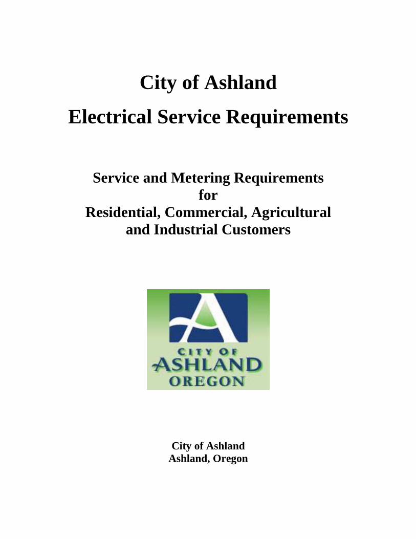
Joint use trenching requirements may vary by area; consult the Electric Department for requirements before installation. The customer may be able to place communication, signal and other electrical conductors in the same trench as Electric Department’s conductors, provided that the installation meets the Electric Department specifications and all concerned parties agree on such placement. The Electric Department will not install electrical conductors in a common trench with non-electric utilities such as sewer and other drainage lines. For joint trench with gas lines, contact the Electric Department for acceptability. When installing service cable in a joint use trench, follow the dimensions in Figure 6.3.4.
12” Min 24” Min
Spoil (typical)
Final grade
Backfill
The utility-recommended backfill material within 12” of the conduit shall be sand.
Service conduit/cable
Service (Conduit/Cable)
Backfill
Select Backfill
Undisturbed Earth
LEGEND
36” Min 48” Max
See Section 6.3.1 for backfill requirements
City of Ashland | Electric Department 31
Figure 6.3.4 – Joint Use Service Trench
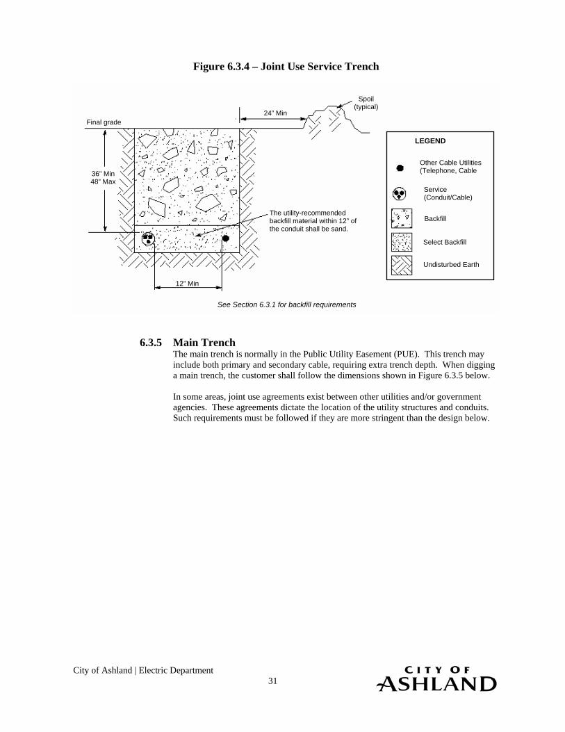
6.3.5 Main Trench
The main trench is normally in the Public Utility Easement (PUE). This trench may include both primary and secondary cable, requiring extra trench depth. When digging a main trench, the customer shall follow the dimensions shown in Figure 6.3.5 below. In some areas, joint use agreements exist between other utilities and/or government agencies. These agreements dictate the location of the utility structures and conduits. Such requirements must be followed if they are more stringent than the design below.
See Section 6.3.1 for backfill requirements
Service (Conduit/Cable)
Backfill
Select Backfill
Undisturbed Earth
LEGEND
Other Cable Utilities (Telephone, Cable 36” Min
48” Max
Final grade
Spoil (typical)
The utility-recommended backfill material within 12” of the conduit shall be sand.
24” Min
12” Min

City of Ashland | Electric Department 32
Figure 6.3.5 – Main Trench
6.4 Vaults for Padmounted Transformers
The customer shall consult the Electric Department to obtain requirements for concrete vaults for Padmounted equipment.
Pre-cast vaults are required. Consult the Electric Department for specifications and/or a list for suppliers.
6.4.1 Vaults The Electric Department requires vaults under cable compartments. Consult the Electric Department for transformer vault dimensions. The vault lid is typically installed 3” above the finished grade. Vaults shall be located within 15 feet of a graveled or paved surface suitable for incidental heavy truck access.
6.4.2 Clearances
Equipment bases must not be placed within 15 feet of any valve or within 25 feet of any pumping or storage facility containing flammable material. Do not place the equipment base within 10 feet of a window or door (see Figure 5.5, Requirement 2.). No walls,
36” Min (see table)
Primary conduit/cable
Backfill
Select Backfill
Undisturbed Earth
LEGEND
Other Cable Utilities (Telephone, Cable
Final grade
Spoil (typical)
The utility-recommended backfill material within 12” of the conduit shall be sand.
24” Min
12” Min 12” Min
12” Min
Secondary/Service (Conduit/Cable)
12” Min
36” Min (see table)
See Section 6.3.1 for backfill requirements
48” 12” below conduit/cable
36” Secondary/Service
48” 12” below conduit/cable
36” Primary
Max Burial Depth
Min. TrenchDepth
MinimumCover
Conduit/Cable

City of Ashland | Electric Department 33
Final Grade (after backfill)
3” Typical
6” Gravel fill
Excavated grade (shore as req. per OSHA)
fences or other obstructions may be placed within these clearances. For other special applications, the customer must contact the Electric Department for a suitable location.
6.4.3 Excavation and Backfill
Excavate the entire area beneath the vault base to allow the depth requirements illustrated below. All soil beneath the vault base shall be compacted and level prior to setting or pouring the base, to prevent settling. Beneath the vault, the customer shall provide 6 inches of 3/4 –inch-minus gravel backfill compacted to 90 percent of dry density, placed over undisturbed earth.
Figure 6.4.3 – Vault Depth and Excavation Requirements

City of Ashland | Electric Department 34
6.4.4 Barrier Post Install a 6” diameter steel, permanent or removable concrete-filled barrier post (or posts) around the Electric Department equipment in areas where the equipment is exposed to vehicle traffic. For additional specifications and other options, contact the local Electric Department.
Figure 6.4.4 – Barrier Post
Additional Requirements: 1. For barrier post height and placement locations, contact the Electric Department. 2. If a barrier post is placed in stable soil, a 6” concrete foundation is required. If the soil is
sand, or otherwise unstable, a 12” concrete foundation is required. 3. Concrete must be domed at the top of the barrier post. Remove any sharp edges or burrs.
Dome concrete
6” steel pipe (concrete filled)
42” (or as required)
Undisturbed soil Final grade
24” Min Concrete
foundation
(See No. 2)

City of Ashland | Electric Department 34
7 Single Family Service
7.1 General This section covers the requirements for permanent service for single family homes and manufactured homes on permanent foundations. Any exceptions to the requirements in this section must be approved in writing by the Electric Department prior to installation.
7.2 Customer Responsibilities The customer: 1. Shall provide, install, and maintain all service equipment (including overhead service
entrance conductors, conduit, enclosures, and meter sockets) to include rights-of-way and space for the installation and maintenance of Electric Department facilities.
2. Should understand the content of Section 1, General Requirements. 3. Should understand the content of Section 2, Permits and Applications. 4. Shall have necessary permits and ruling government approvals. Permanent power will not
be connected until all approvals are obtained. 5. Should understand the content of Section 3, Services and Meter Installations. 6. Should understand the content of Section 5, Clearances. 7. When applicable, should understand the content of Section 6, Underground Requirements. 8. Shall install the meter socket per the requirements of this section. Permanent power will not
be connected if the requirements listed in this section are not met. The customer should consult the Electric Department with questions about these requirements.
7.3 Maximum Available Fault Current The maximum available fault current depends on the type of service being provided. The
customer shall furnish equipment to withstand maximum bolted fault currents. Upon request, the Electric Department will supply information on the maximum available fault current at the lugs of the transformer.
7.3.1 Single Family Residential (200 Amperes or Less)
For single family residences with services of 200 amperes or less, the customer shall furnish equipment capable for withstanding available fault current.
7.3.2 Single Family Residential (Larger than 200 Amperes)
For single family residences with services larger than 200 amperes, the customer shall install equipment that will withstand the maximum fault current available from the Electric Department Upon request, the Electric Department will supply information on the maximum available fault current at the lugs of the transformer.
7.4 Residential Meter Sockets All residential meter sockets shall meet the following criteria:
Requirements: 1. Meter sockets rated less than 125 amps require prior written approval by the Electric
Department. 2. Meter sockets shall be EUSERC-approved. 3. Meter sockets shall be ring-type. 4. Meter sockets shall be furnished with screw-type sealing rings. 5. Meter sockets shall not be used as junction boxes.

City of Ashland | Electric Department 35
Manual link by pass meter sockets are approved but not required, for residential services of 200 amps or less. A manual link bypass meter socket should be considered if interruption of power during routine meter service would create a problem. Approved residential meter sockets are shown in Figures 7.4.1 and Figure 7.4.2. Figure 7.4.1 – Residential Overhead Approved Meter Sockets (Overhead Only)
(A) 100 and 200-Amp maximum Single-phase service meter socket
(EUSERC 301)
(B) 400-Amp maximum single-phase service meter socket with manual-
link bypass (EUSERC 302B)
(C) 100 and 200-Amp maximum single-phase service meter socket
only (ANSI socket)
Distribution section with disconnecting facilities (location optional)
= Utility Compartment
4” Min
15” Min
8” Min
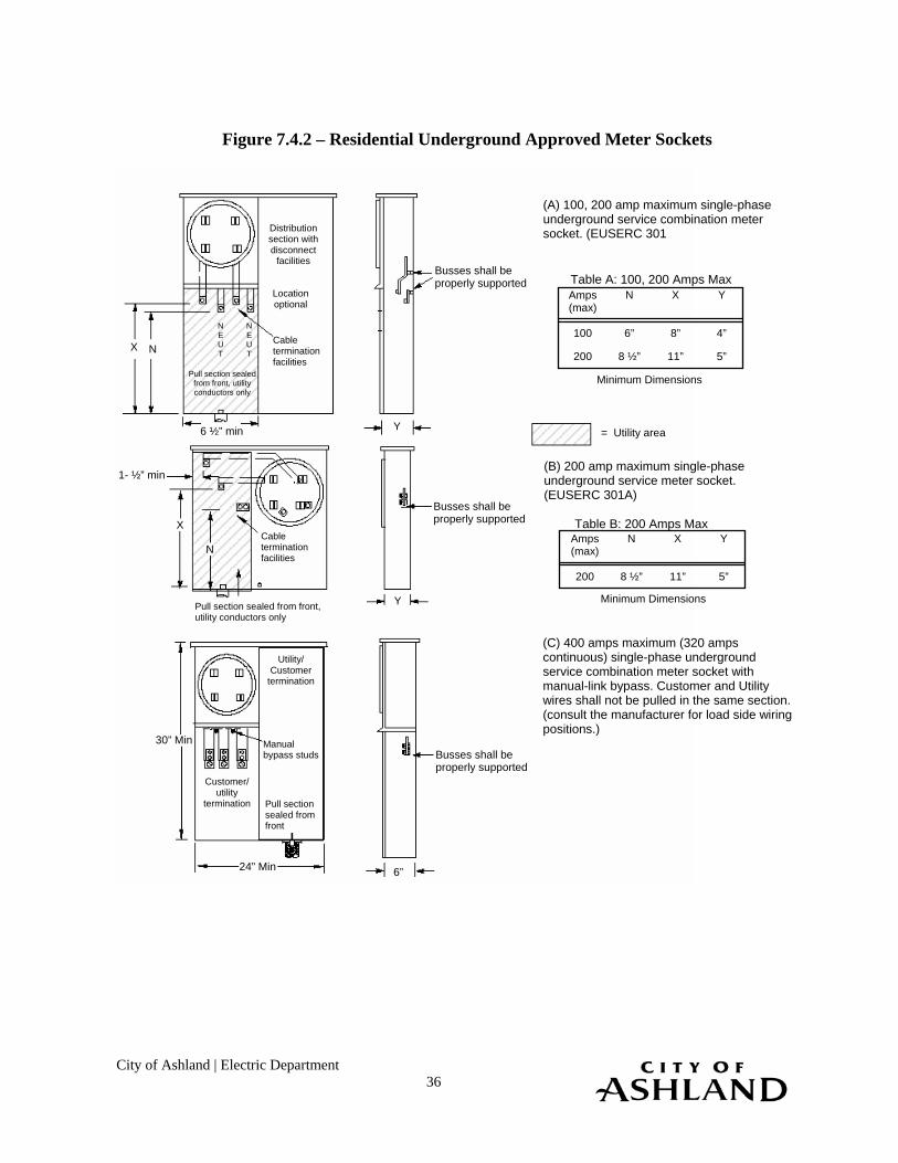
City of Ashland | Electric Department 36
Figure 7.4.2 – Residential Underground Approved Meter Sockets
Distribution section with disconnect
facilities
Location optional
Cable termination facilities
NEUT
NEUT
X N
6 ½” min
Pull section sealed from front, utility conductors only
Busses shall be properly supported
Busses shall be properly supported
Busses shall be properly supported
Y
N
X
Y
Cable termination facilities
Pull section sealed from front, utility conductors only
1- ½” min
Utility/ Customer
termination
Manual bypass studs
Pull section sealed from front
Customer/ utility
termination
30” Min
24” Min 6”
(A) 100, 200 amp maximum single-phase underground service combination meter socket. (EUSERC 301
(B) 200 amp maximum single-phase underground service meter socket. (EUSERC 301A)
(C) 400 amps maximum (320 amps continuous) single-phase underground service combination meter socket with manual-link bypass. Customer and Utility wires shall not be pulled in the same section. (consult the manufacturer for load side wiring positions.)
= Utility area
Table A: 100, 200 Amps Max
Table B: 200 Amps Max
5” 11” 8 ½” 200
4” 8” 6” 100
Y X N Amps (max)
Minimum Dimensions
5” 11” 8 ½” 200
Y X N Amps (max)
Minimum Dimensions
City of Ashland | Electric Department 37
Manual link by pass meter sockets are approved, but not required, for residential services of 200 amps or less. A manual link bypass meter socket should be considered if interruption of power during routine meter service would create a problem.
7.4.1 Special Residential Meter Socket Requirements
Occasionally, customers have equipment or needs that call for additional requirements for the residential meter socket. Some of these instances are listed below.
1. Meter sockets rated less than 125 amps require prior written approval by the
Electric Department. 2. Single-phase, 400-amps-maximum sockets (320-amps-continuous) shall have an
approved manual link bypass. 3. Code-calculated loads greater than 400-amps-maximum require current
transformer metering. The customer shall contact the Electric Department for specific requirements.
7.4.2 Connection and Energizing
Before being energized, the meter socket and meter base shall be properly wired and grounded, and all appropriate permits shall be in place. The customer should be aware of the following conditions that often delay the installation of a meter in the meter socket:
1. The grounding conductor is connected to the Electric Department’s neutral in the
meter socket. 2. Customer wires installed in meter bases impede the installation of the Electric
Departments wires. Customer wires should allow clear space for the installation of Electric Department wires.
3. Panel covers are not properly secured. 4. Hubs are used on the concentric knock-out of an underground socket enclosure.
Approved bushings, or other conductor protectors are required for these enclosures. 5. Connecting Lugs provided by customer.
Any work required to correct these problems will be at the customer’s expense. The customer may also be billed for the Electric Department’s expenses.
7.5 Residential Meter Socket Location
The Electric Department will determine the exact location of metes that do not meet the criteria established in this manual. If the customer is unsure whether the meter location is acceptable, the Electric Department should be contacted.
The location of the service entrance on the customer’s premises is an important consideration. For clearance information see Section 5, Clearances. Consult the Electric Department to determine the point of attachment for overhead service drops and underground service laterals.
Install residential meters outdoors at a location acceptable to the Electric Department Locate the meter within 5 feet of the street side (front side) of the residence, on the side of the residence closest to the Electric Department source. Avoid installations near windows or exterior walls that are likely to be fenced in. Never install the meter over window wells, steps in stairways, or in other unsafe or inconvenient locations. Keep shrubs and landscaping from obstructing access to the meter.
Written approval from the Electric Department is required, prior to installation, for alternative meter socket locations when: 1. Conditions prohibit placing the meter base within 5 feet of the front of the building.

City of Ashland | Electric Department 38
2. Alley-fed services have access for meter reading. 3. Metering pedestals or poles are used. 4. Other special conditions exist. Figure 7.5.1 below shows where an overhead residential meter socket should be located. Clearances shall meet appropriate code as detailed in Figure 7.5.1 below and Section 5. Figure 7.5.1 – Residential Meter Socket Location for Overhead Service
3/8” Eye Bolt (customer provides) Mast shall
be within 4’ of the eave
6’ maximum service run over roof`
3’ Min
5’ Max
6’ Max 4’ Min
3’ Min 3’ Min
Grounding per NEC Article 250
Front of house
A three-foot minimum distance between the edge of the electric meter and the gas meter, gas coupling valve or connection is required

City of Ashland | Electric Department 39
Figure 7.5.2 – Residential Meter Socket Location for Underground Service
7.6 Underground Service
7.6.1 General Underground service can be provided to the customer from either an overhead distribution system or an underground distribution system.
All residential underground services shall be installed in the Electric Department approved, customer-installed conduit per Section 6 of this book. The Electric Department will install the appropriate size service conductor from its distribution line to the service point.
The Electric Department owns and maintains the underground service lateral from its distribution line to the customer’s service point. The Electric Department also owns and maintains the meter. The Customer owns the meter socket, the meter base, and all wiring beyond the meter socket.
Special rules may apply in some areas for the City where local ordinances specify underground service. Customers in these areas should consult the Electric Department.
3’ Min
5’ Max
6’ Max 4’ Min
3’ Min 3’ Min
Grounding per NEC Article 250
Front of house
A three-foot minimum distance between the edge of the electric meter and the gas meter, gas coupling valve or connection is required

City of Ashland | Electric Department 40
7.6.2 Customer responsibilities – Single-Family Underground Service Requirements: The customer: 1. Shall furnish and install the meter socket (underground type) per Section 7.4,
Residential Meter Sockets. 2. Shall provide the trench, backfill, compaction, and, where required, surface
restoration as defined in Section 6. 3. Shall arrange for an appropriate underground facility location before trenching. 4. Shall provide and install all conduits from the meter socket to the Electric
Department’s point of attachment. The conduit shall be Schedule 40 gray PVC or fiberglass a defined in Table 6.2.1.1, Fiberglass Sweep Specifications. The conduit shall be properly glued.
5. Shall provide all sweeps, with a minimum 36-inch radius. 6. Shall install all conduit to a minimum depth of 36:. 7. Shall limit the length of the conduit to 150 feet, with no more than 270 degrees of
total bend in the conduit. 8. Shall install a 500 lb. test (or greater) pull line in the conduit. Flat pull lines are
preferred. At least 6 feet of pull line shall extend from each end. 9. Shall locate the meter base/meter socket per Section 7.5, Residential Meter Socket
location. 10. Is responsible for identifying and remediation of potential surface or subsurface
problems that may damage the Electric Department’s facilities including, but not limited to, surface or sub-grade water flows or frost heaves.
Figure 7.6.2, Single-Family Underground Service, shows the installation of an underground service extension from the transformer to the house. The customer shall consult the Electric Department to determine the conduit location adjacent to a Electric Department’s pole, transformer or junction box. The customer shall not install conduit within two feet of the Electric Department’s equipment, unless requested by the Electric Department. Figure 7.6.3, Underground Service Direct-Connect Metering, shows a typical installation of a meter and associated hardware for surface and flush meter mounting methods.

City of Ashland | Electric Department 41
Figure 7.6.2 – Single-Family Underground Service
Additional Requirements: 1. Install residential meters outdoors at a location acceptable to the Electric Department.
Locate the meter within 5 feet of the front (street) side of the residence, on the side of the residence closest to the Electric Department’s source, avoiding locations behind fences. Avoid installations near windows (see Figure 5.2.1 for clearance requirements). Never install the meter over window wells, steps in stairways, or in other unsafe or inconvenient locations. Keep shrubs and landscaping from obstructing access to the meter.
2. See Section 5, Clearances, for other requirements. 3. When the conduit delivery is a Electric Department pole, vault, or junction box, consult the
Electric Department for the exact conduit location. The customer shall not install any conduit within two feet from the pole, unless requested by the Electric Department.
4. See Section 6, Underground Requirements, for underground and conduit requirements. 5. The Electric Department reserves the right to connect the service lateral at the meter base or
to make a connection in the junction box. 6. Display the electrical label or permit on the meter base.
Contact the appropriate parties in Table 1.12 before you dig.
All above-ground conduit shall meet the more stringent requirement of local building codes or the criteria in this book.
5’ Max
3’ Min 6’ Max 4’ Min
36” Min
The customer provides trench, conduit and sweeps
Meter to Overhead Transformer
Meter to Underground Transformer Meter to Secondary Junction Box
The sweep is provided by the customer and installed as directed by the Electric Department
The sweep is provided by the customer and installed by the Electric Department
The sweep is provided by the customer and installed by the Electric Department
Junction box
36” Min
36” Min
Customer installed conduit
Electric Department installed equipment
Customer installed conduit
Electric Department installed equipment
Customer installed conduit
Electric Department installed equipment

City of Ashland | Electric Department 42
7.6.3 Underground Service Preferred Meter Base Mounting The following condition shall be met when installing the meter base:
Requirements: 1. The meter base and conduit must be securely attached to the structure. The meter socket
must be plumb when inspected. 2” x 4” back supports or 5/16” molly screws are required. 2. Conduit and sleeve are required when passing through a paved area adjacent to building
foundations. 3. Manufactured or field bends made of PVC matching the quality of factory bends may be
used directly under the meter enclosure to align the ground riser sweep with the meter socket. Field bends shall be free of flattening, cracks or burns. The minimum bending radius shall be 36”. The contractor is responsible for proofing all conduit systems.
4. For brick veneer or concrete block, use ¼” x 3 ¼” lead sleeve expansion bolt in the joint, in place of lag screws on anchor straps.
5. Ensure that the meter enclosure knockout diameter will receive the conduit riser. When 3” conduit is required and a flush-mount meter enclosure is installed, a 2” x 6” stud wall must be constructed. See Section 6 for conduit requirements.
6. Display the electrical label or permit on the meter base.
Figure 7.6.3, Underground Service Preferred Meter Base Mounting, shows a typical installation of a meter and associated hardware for surface and flush meter mounting methods.
Figure 7.6.3 – Underground Service Preferred meter Base Mounting
Surface Mount Installation
Flush Mount Installation
SWEDGE: 2 ½” x 3” Smooth wall reducer (when needed, at top or bottom of sweep.)
Strap
Electrical label or permit must be displayed on the meter base.
6’ Max 4’ Min
Final grade
36” Min Ground in accordance with the latest issue of NEC (Article 250)
Final grade
36” Min
SIDE VIEW FRONT VIEW (veneer removed)
The customer is responsible for installing the meter base and riser between studs

City of Ashland | Electric Department 43
7.6.4 Underground Service, Free Standing Meter Base Mounting, Alternative When meter bases cannot be mounted on the home using the criteria established in this manual, the Electric Department allows free standing meter base mounting configurations.
The following conditions shall be met when installing the meter base:
1. Written approval shall be obtained from the Electric Department before
installation. 2. The meter pedestal:
a. Shall be located adjacent to, or in, the Electric Department’s Easement. b. Shall not be encumbered by vegetation or structures. c. Shall meet all local ordinance requirements.
3. To avoid bonding with the Electric Department equipment, the pedestal shall be at least six feet from such equipment.
4. The unmetered service conductor and the metered service conductor shall not be run in the same conduit, raceway, or gutter.
5. Service conduit shall be plumb in all directions. 6. The electrical label or permit shall be displayed on the meter base.
Figure 7.6.4, Free Standing Residential Meter Pedestal, shows a typical residential meter pedestal installation. Decorative meter pedestals are allowed.

City of Ashland | Electric Department 44
Figure 7.6.4 – Free Standing Residential Meter Pedestal (Post Mounted)
Additional Requirements: 1. Written approval from the Electric Department must be obtained before installing a free-
standing pedestal. 2. The meter pedestal is typically located adjacent to, or in, the easement close to the
driveway. The exact location of the meter must be specified and/or approved by the Electric Department.
3. Refer to Section 6 for underground and conduit requirements. 4. The construction shown in Figure 9.6.2, Alternate Underground Service, is acceptable for
residential meter pedestals. 5. Service conduit must be plumb in all directions.
7.7 Overhead Service Overhead service can be provided to the customer from an overhead distribution system.
For a customer near an overhead line, the Electric Department will install a service drop from the line to the attachment point on the customer’s building. The Electric Department will install the appropriate size service conductor from its distribution line to the service point.
The Electric Department owns and maintains the overhead service lateral from its distribution line to the connection point at the weatherhead. The Electric Department also owns and maintains the meter. The customer owns the meter socket, the meter base, all wiring from the meter socket to the service point and all wiring beyond the meter socket.
Underground meter socket
Provisions for main disconnect
Electrical label or permit must be displayed on the meter base.
6’ Max 4’Min
Conduit for ground conductor
The ground connection must be visible when an electrical inspection is made. For safety reasons, the ground rod shall be flush with or below the surface
Long sweeps
Conduit strap
Meter
2” Min grid galvanized
capped post
Conduit for service conductor
Unistrut
24” Min
Customer will furnish and Install:Meter socket enclosure (underground type) Pedestal Hardware Conduit (see Section 6.2.1) Right-of-way Trench excavation and backfill Grounding per NEC Concrete Pad, 24”x24”x6” depth Long radius sweep 36” sweep
6” Min
Unistrut

City of Ashland | Electric Department 45
7.7.1 Customer Responsibilities for Single-Family Overhead Service The customer shall: 1. Furnish and install the meter socket (overhead type) per Section 7.4, Residential
Meter Sockets. 2. Locate the meter base and meter socket per Section 7.5, Residential Meter Socket
Location. 3. Meet all clearances specified in Section 5, Clearances.
If the meter location is not within the specifications of this book, it must be approved in writing by the Electric Department prior to installation.
7.7.2 Single Family Overhead Service Attachment
The following conditions shall be met by the customer when installing an overhead service. Requirements: 1. The overhead service must be free of obstruction by building, trees or other
objects. 2. The Electric Department installed service shall not cross adjacent property without
a recorded easement obtained by the customer. 3. The mast shall be guyed if the point of attachment is more than 26” above the
support. Flashing and roofing material are not considered support. Guying is required if a coupling is within 8 feet of the weatherhead.
4. If the service length is greater than the values in Table 7.7.2, the Electric Department shall be consulted before the mast is installed.
5. A 24” conductor lead shall be provided for attachment to the service conductor. 6. The meter base shall be grounded per NEC 250, Grounding. 7. The service entrance mast shall meet the requirements of NEC, state, and/or local
codes. Additionally, if the mast has service cable attached to it, the mast shall be rigid steel.
8. Mast guying shall meet the requirements of Figure 7.7.4, Mast Guying and Anchoring.
9. A rigid metal pipe clamp shall be used for the point of attachment on guy wire for a service mast. A 3/8-inch eyebolt shall be connected to a significant structural member for the point of attachment on a building.
10. On surface mount installations, the mast shall be securely attached to the building with lag screws and anchor straps. For brick veneer or concrete block walls, ¼” x 3 ¼” lead sleeve expansion bolts and anchor straps should be used.
11. The service mast shall be extended through the roof on a typical single-story building, unless adequate clearance exists at the gable end of the building.
12. The electrical label or permit shall be displayed on the meter base. 13. For service minimum heights, see the NESC clearances listed in Table 5.2.1.
The following is a partial list of exceptions in which the installations shall be coordinated with the Electric Department prior to installation:
1. The service runs over a road or street. 2. The service runs over or along an alley, parking lot, or non-residential driveway. 3. The service runs over an area traveled by agricultural equipment. 4. The service runs over exceptionally uneven ground. 5. A service of 480Y/277V.
Figure 7.7.2, Single-Family Overhead Service, shows the installation of a typical overhead service extension.
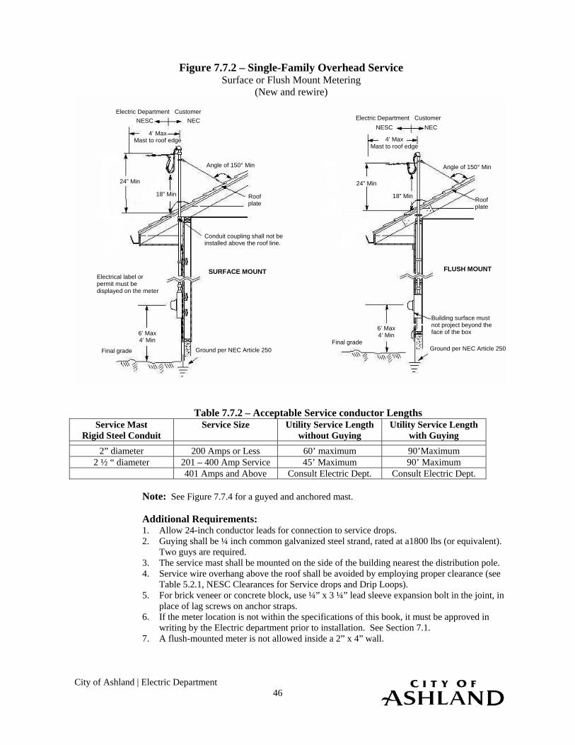
City of Ashland | Electric Department 46
Figure 7.7.2 – Single-Family Overhead Service Surface or Flush Mount Metering
(New and rewire)
Table 7.7.2 – Acceptable Service conductor Lengths
Service Mast Rigid Steel Conduit
Service Size Utility Service Length without Guying
Utility Service Length with Guying
2” diameter 200 Amps or Less 60’ maximum 90’Maximum 2 ½ “ diameter 201 – 400 Amp Service 45’ Maximum 90’ Maximum
401 Amps and Above Consult Electric Dept. Consult Electric Dept.
Note: See Figure 7.7.4 for a guyed and anchored mast.
Additional Requirements: 1. Allow 24-inch conductor leads for connection to service drops. 2. Guying shall be ¼ inch common galvanized steel strand, rated at a1800 lbs (or equivalent).
Two guys are required. 3. The service mast shall be mounted on the side of the building nearest the distribution pole. 4. Service wire overhang above the roof shall be avoided by employing proper clearance (see
Table 5.2.1, NESC Clearances for Service drops and Drip Loops). 5. For brick veneer or concrete block, use ¼” x 3 ¼” lead sleeve expansion bolt in the joint, in
place of lag screws on anchor straps. 6. If the meter location is not within the specifications of this book, it must be approved in
writing by the Electric department prior to installation. See Section 7.1. 7. A flush-mounted meter is not allowed inside a 2” x 4” wall.
Electric Department Customer NESC NEC
4’ Max Mast to roof edge
18” Min
Angle of 150° Min
Roof plate
24” Min
Conduit coupling shall not be installed above the roof line.
Electrical label or permit must be displayed on the meter
6’ Max 4’ Min
Final grade Ground per NEC Article 250
NESC NEC
4’ Max Mast to roof edge
18” Min
Angle of 150° Min
Roof plate
24” Min
6’ Max 4’ Min
Final gradeGround per NEC Article 250
Building surface must not project beyond the face of the box
SURFACE MOUNT FLUSH MOUNT
Electric Department Customer
City of Ashland | Electric Department 47
7.7.3 Single Family Overhead Service, Pole Attachment When overhead service meter bases cannot be mounted on the home using the criteria established in this book, the Electric Department allows meters to be installed on customer-owned poles. See Section 3.4.5 for required disconnects and protective devices.
The following conditions shall be met when installing the meter base on a customer-owned pole.
Requirements: 1. The pole shall be no less than 25’ long and 5 ½ “ in diameter at the top, or a 6” x
6” x 25’ timber, set not less than 5’ below ground level, with gravel backfill. The pole or timber shall be pressure or thermally treated with an approved preservative.
2. The overhead service must be free of obstruction by buildings, trees or other objects.
3. The Electric Department installed service shall not cross adjacent property without a recorded easement obtained by the customer.
4. The customer shall provide 24” of conductor lead for attachment to the service conductor.
5. The meter base shall be grounded per NEC article 250. 6. The service entrance mast shall meet the requirements of NEC, state, and/or local
codes. Additionally, if the mast has service cable attached to it, the mast shall be rigid steel.
7. The unmetered service conductor and the metered service conductor shall not be run in the same conduit, raceway, or gutter.
8. Installations require guying or bracing. Installations in stable soil shall adhere to the conductor length limits listed in Table 7.7.3.
9. The electrical label or permit shall be displayed on the meter base. 10. The pole or timber shall be accessible by the Electric Department aerial equipment.

City of Ashland | Electric Department 48
Figure 7.7.3 – Single Family Overhead Service, Pole Attachment
Table 7.7.3 – Acceptable Service conductor Lengths without Guying (For Single-Family Overhead Service Pole Attachment)
Service Size Utility Service Length
0-200 Amp Service 60’ Max 201- 400 Amp Service 45’ Max
Note: Contact the Electric Department regarding longer service lengths and guying requirements. Guying may be required at these lengths in unstable soil conditions.
Gravel backfill 5’ Min
Allow 24” tails for connection to drops
Guy strain insulator
6’ Max 4’ Min
Ground per NEC Article 250
NEC NESC
Electrical label or permit must be displayed on the meter base.
6” Max
12” Max
A 12” maximum conduit extension from the top of the pole is allowed.
12” to 18” from pole to top to point of attachment
3/8” Eye-bolt (customer provides)
40” min between power and communications
(shall not attach to mast)
3/8” Eye-bolt (customer provides)
Point of guy attachment 12’ Min to ground
See Section 5 for clearances
Refer to Table 5.2 For minimum drip Loop clearances
Meter
2
1
Minimum height per NEC
Secure anchor (customer provides)
Guying where appropriate, see Table 7.7.3.
5/16” steel cable, galvanized
Electric Department Customer
2

City of Ashland | Electric Department 49
7.7.4 Single Family Overhead Service - Mast Guying and Anchoring
The mast shall be guyed.
Figure 7.7.4 – Mast Guying and Anchoring
Additional Requirements: 1. The service mast shall be mounted such that it is within 5 feet of the front of the building, on
the side nearest the utility source. Consult the Electric Department regarding rear lot service lines. Refer to Section 5, Clearances, to provide the required clearance over the roof.
2. A rigid steel pipe clamp shall be used for the point of attachment on guy wire for a service mast. A 3/8-inch eyebolt shall be connected to a significant structural member for the point of attachment on a building.
Horiz. ∡ 30° to 45°
GUYING and BRACING 1800 lb 1/4” galvanized steel strand
1/4” Bolts to rafters Plate between shingles
16” or 24”
Rafter Service alignment Roof plate
The roof plate must be installed such that the service alignment extension falls within the angle of guys.
MAST ANCHOR
PUSH BRACE (OR EQUAL) (2 REQ’D)
18” Max to weatherhead
2” TYP
3/16”x 1-1/2”x 1/2” ∡ All holes 7/16”
2’-6”
2’-6”
6”
4”
C L Brace Shoe 3/16”x 1-1/2”x 1/2” ∡
1/2” Bolt 9/16” Hole
33°
2 1/2”
18” or 26”
16” or 24” 4 1/2”
5”
METAL BRACKET (OR EQUAL)
ANCHOR STRAP NO. 1 (OR EQUAL)
ROOF PLATE (OR EQUAL)
ANCHOR STRAP NO. 2 (OR EQUAL)
1/4”x3” Lag screwor 1/4” Bolt
3/16” x 1” Galv. strap
Set screw
2 3/8” Dia
Double 2” x 4” studs
2 3/8” Dia Double 2” x 4” studs
1/4”x3” Lag screwor 1/4” Bolt
3/16” x 1” Galv. strap
Set screw

City of Ashland | Electric Department 50
8 Multiple Family Service
8.1 General This section describes services with separate metered services for multi-family units such as duplexes or apartments. The electric Department requires grouping of service entrance conductors at a common location.
8.2 Customer Responsibilities When installing multiple services, the customer shall follow the following general requirements. Requirements: The customer: 1. Shall provide, install, and maintain all service equipment (including overhead service
entrance conductors, conduit, enclosures, and meter sockets) to include rights-of-way and space for the installation and maintenance of Electric Department facilities.
2. Should understand the content of Section 1, General Requirements. 3. Should understand the content of Section 2, Permits and Applications. 4. Shall have necessary permits and ruling government approvals. Permanent power will not
be connected until all approvals are obtained. 5. Should understand the content of Section 3, Services. 6. Should understand the content of Section 5, Clearances. 7. When applicable, should understand the content of Section 6, Underground Requirements. 8. Shall install the meter socket per the requirements of this section. Permanent power will
not be connected if the requirements listed in this section are not met. The customer should consult the Electric Department with questions about these requirements.
8.3 Maximum Available Fault Current The maximum available fault current depends on the type of service being provided. The
customer shall furnish equipment to withstand the maximum bolted fault currents. Upon request, the Electric Department will supply information on the maximum available fault current at the transformer lugs.
8.4 Multiple Residential Meter Sockets All Multiple Residential meter sockets shall meet the following requirements. Requirements: 1. Meter sockets shall not be used as junction boxes. 2. Meter sockets shall be EUSERC-approved. 3. Meter sockets shall be ring-type and furnished with screw-type sealing rings. 4. Customer conductors installed in meter bases shall be kept separate from Electric
Department conductors. The figure below shows two different styles of banked meters. The top half of the figure shows a meter bank with the cable pull section, main disconnect and meter bank as three separate sections. The lower half of the figure shows a meter socket module in which these sections can be bolted together into one expandable unit.

City of Ashland | Electric Department 51
Figure 8.4 – Multiple Meter socket Installations Overhead and Underground
Additional Requirements: 1. The cable pulling section must be sized for the Electric Department service termination
EUISERC 343, and must have a bus extension drilled for landing lugs per EUSERC 347 (see Section 8.5). NEC requires a main disconnect when more than six services are connected. When the sum of distribution section ampacities exceeds the pulling section ampacities, the customer is responsible for providing NEC-approved load calculations (see NEC Article 220, Branch-Circuit, Feeder, and Service calculations).
2. Locate the main disconnect handle to allow for meter clearance. 3. Panel covers must be secured prior to energization. 4. Each metered service shall be permanently labeled to identify the dwelling unit address by
means of a metal or hard plastic engraved label. Service will not be connected until a permanent label is attached.
5. It is the responsibility of the customer or designated agent to ensure that the meter bases are correctly labeled. These labels shall be kept current during the life of the facility.
TBF
Cable pulling section
Main disconnect (if required)
Main switch
pull box
Test bypass facilities for non-residential installations
Sealable enclosure
See 1 and 2 below
Address labels 7 1/2” Min
8 1/2” Min
72” Max
36” Min
Typical combination service termination enclosure and meter socket panels for multi-unit applications.
See 1 and 2 below 36” Min
72” Max
Final grade
Address labels
Residential
Meter Socket
Customer’s service entrance bus
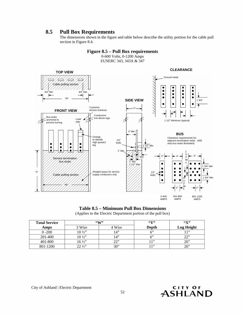
City of Ashland | Electric Department 52
8.5 Pull Box Requirements The dimensions shown in the figure and table below describe the utility portion for the cable pull section in Figure 8.4.
Figure 8.5 – Pull Box requirements 0-600 Volts, 0-1200 Amps EUSERC 343, 343A & 347
Table 8.5 – Minimum Pull Box Dimensions
(Applies to the Electric Department portion of the pull box)
“W” Total Service Amps 3 Wire 4 Wire
“Y” Depth
“X” Lug Height
0 -200 10 ½” 14” 6” 11” 201-400 10 ½” 14” 6” 22” 401-800 16 ½” 22” 11” 26”
801-1200 22 ½” 30” 11” 26”
TOP VIEW CLEARANCE
FRONT VIEW
SIDE VIEW
BUS
Cable pulling section
Cable pulling section
Service termination bus stubs
3/4” Min 3/4” Min
“W”
Customer service entrance
Conductors exit above lugs Bus stubs
anchored to prevent turning
Load side
“W”
“Y”
“X”
Orange to identify high (power) leg
Shaded space for service supply conductors only
4” Min
1 1/2” Min
1/2” bolts
1” Min
1” Min
2” Min 2 1/2” Max
Ground metal
1 3/4”
1 1/2” Minimum (typical)
1 1/2” Min
1 1/2” Min
1 3/4” Min
1 3/4” Min
1/2” bolts
2” 4” 6”
2” 2”
0-400 AMPS
401-800 AMPS
801-1200 AMPS
Clearance requirements for adjacent termination stubs (400 amp bus stubs illustrated)

City of Ashland | Electric Department 53
8.6 Multiple Family Meter Location, Underground Service The location of the service entrance on the customer’s premises is an important consideration. For clearance information see Section 5, Clearances. Consult the Electric Department to determine the point of attachment for underground service laterals. Requirements: 1. The service entrance and meter shall be accessible and convenient for the installation,
reading and maintenance of the Electric Department meters. 2. Meter banks shall be installed on the side of the building closest to the utility source. 3. Meter banks shall be installed at least three feet from windows and gas meters. 4. All raceways and conduit shall be sealed to prevent the infiltration of water into the
electrical equipment. 5. Conduit is required for multiple family underground services. Refer to Section 6 for
underground and conduit requirements. For conduit size, see Table 6.2.1.1. The Electric Department will determine the exact location of meters that do not meet the criteria established in this manual. If the customer is unsure whether the meter location is acceptable, the Electric Department should be contacted.
Figure 8.6 – Multi-Unit Underground Service
Unit 3 Unit 1
Unit 4 Unit 2
4’ Min 6’ Max
Typical two-story, multi-family dwelling
36” Min
Customer-provided conduits
Conduit must be rigidly supported to the building, straight and plumb to sweep.

City of Ashland | Electric Department 54
8.7 Multiple Family Meter Location, Overhead Service The location of the service entrance on the customer’s premises is an important
consideration. Consult the Electric Department to determine the point of attachment for overhead service drops. The customer is responsible for bringing the service entrance conductor from the meter base to the service point. The Electric Department will not extend conductor from the service point to individual service heads. The exception is when a parallel service mast is required for ampacity purposes to a common gutter/meter bank. The Electric Department will not extend conductor from the service point to individual service heads. Requirements: 1. The service entrance and meter shall be accessible and convenient for the installation,
reading and maintenance of the Electric Department’s meters. 2. Meter banks shall be installed on the side of the building closest to the utility source. 3. Meter banks shall be installed at least 3 feet from windows and gas meters. 4. All meters shall be at a common location. 5. All raceways and conduit shall be sealed to prevent the infiltration of water into the
electrical equipment. 6. All raceways and gutters containing un-metered conductors must have sealing provisions. 7. See Figure 7.7.4 for mast guying details 8. For clearance requirements see Section 5. 9. All services greater than 400 amps shall be guyed.

City of Ashland | Electric Department
55
9 Mobile Home Service
9.1 General This section covers the requirements for permanent service to mobile single-family unites, including but not limited to mobile homes, and manufactured homes on temporary foundations.
9.2 Customer Responsibilities The customer: 1. Shall provide, install, and maintain all service equipment (including overhead service
entrance conductors, conduit, enclosures, and meter sockets) to include rights-of-way and space for the installation and maintenance of Electric Department facilities.
2. Should understand the content of Section 1, General Requirements. 3. Should understand the content of Section 2, Permits and Applications. 4. Shall have necessary permits and ruling government approvals. Permanent power will not
be connected until all approvals are obtained. 5. Should understand the content of Section 3, Service and Meter Installations. 6. Should understand the content of Section 5, Clearances. 7. When applicable, should understand the content of Section 6, Underground Requirements. 8. Shall install the meter socket per the requirements of this section. Permanent power will not
be connected if the requirements listed in this section are not met. The customer should consult the Electric Department with questions about these requirements.
9.3 Maximum Available Fault Current The maximum available fault current depends on the type of service being provided. The
customer shall furnish equipment to withstand maximum bolted fault currents. Upon request, the Electric Department will supply information on the maximum available fault current at the transformer lugs.
For single family residences with services of 200 amperes or less, the customer shall furnish equipment that will withstand the available fault current.
9.4 Residential Meter Sockets for Mobile Homes All residential meter sockets shall meet the following criteria: Requirements: 1. Meter sockets shall be EUSERC-approved.. 2. Meter sockets shall be ring type. 3. Meter sockets shall be furnished with screw-type sealing rings. 4. Meter sockets shall not be used as junction boxes. Manual link bypass meter sockets are approved, but not required, for residential services of 200 amps or less. A manual link bypass meter socket should be considered if interruption for power during routine meter service would create a problem. Approved residential meter sockets are shown in Figures 7.4.1 and Figure 7.4.2.
9.5 Meter Socket Location for Mobile Residences The meter socket shall not be attached to a mobile residence. The customer shall comply with the following requirements when installing a meter socket for a mobile residence.

City of Ashland | Electric Department
56
Requirements: 1. The meter socket shall be installed on a pedestal or pole. 2. The meter socket shall be located at least 3’ from gas meters. 3. The meter socket shall be protected from damage by being located away from vehicle
traffic, or by the use of barrier posts or other suitable protection approved by the Electric Department.
4. The meter socket enclosure shall be permanently labeled with the space or berth number. 5. The Electric Department will determine the exact location of meters that do not meet the
criteria established in this manual. If the customer is unsure if the meter location is acceptable, the Electric Department should be contacted.
9.6 Underground Service to Mobile Homes
9.6.1 General Underground service can be provided to the customer from either an overhead or
underground distribution system. If the system is underground, all conductors shall be run in the Electric Department’s approved, customer-installed conduit. The Electric Department will install an appropriately sized service conductor from its distribution line to the meter socket. Special rules may apply in some areas of the City where local ordinances require underground service. Customers in these areas should consult the Electric Department.
9.6.2 Requirements The customer shall:
1. Furnish and install the meter socket (underground type) per Section 9.4, Residential Meter Sockets for Mobile Homes.
2. Furnish, install and maintain an approved pedestal, pole, or wood post. If a wood post is used, it shall be no less than 6” x 6” and pressure-treated with an American Wood Preservative Association-approved preservative rated for ground contact.
3. Provide the trench, backfill, compaction and, where required, surface restoration. 4. Arrange for an appropriate underground facility location before trenching. 5. Provide and install all conduit from the meter socket to the Electric Department’s
point of attachment. The conduit shall be rigid steel, fiberglass or Schedule 40 gray PVC (see Section 6.2, Conduit Requirements). The conduit shall be properly glued.
6. Install all conduit to NESC code depth (36” below the final grade). 7. See Table 6.2.1.1 for conduit run and bend limits. 8. Install a 500 lb. (or greater) test pull line in the conduit. Flat pull lines are
preferred. At least 6 feet of pull line shall extend from each end. 9. Locate the meter base and meter socket per Section 9.5, Meter Socket Location for
Mobile Homes. The Electric Department will determine the exact location of meters that do not meet the criteria established in this manual. If the customer is unsure whether the meter location is acceptable the Electric Department should be contacted.
10. In pedestal installations, keep the access door to the Electric Department connections free of obstructions a minimum of 6” above the final grade, with a sealable provision for the Electric Department.
11. See Section 6 for trenching and underground requirements. 12. Ensure that Electric Department conduit and conductor trenches are located away
from (and never underneath) the pad, foundation, or area provided for the mobile home.
Figures 9.6.1, 9.6.2 and 9.6.3 show typical underground installations to mobile residences.

City of Ashland | Electric Department
57
6’ Max 4’ Min
Grounding per NEC
Electrical label or permit must be displayed on the meter base.
24” Min
24” Min 36” Min
Meter
Use protective bushings on conduit, as well as blocks and straps to support conduit.
Figure 9.6.1 – Underground Service for Mobile Homes, Pedestal Installation EUSERC 307
Note: this pedestal shall not be used for other applications.
Figure 9.6.2 – Underground Service, Post-Mounted Installation
Electrical label or permit must be displayed on the meter base. Set a 1/8”x1”x1” steel angle-drive into the ground and attach it to each side of the pedestal with 1/4” or larger bolts. Grounding per NEC Article 250
Final grade
18”-24”
48” Min
Meter
Circuit breakers
72” Max 42” Min
6” Min
24” Min
Final grade
To Electric Department To mobile home
Grounding per NEC Article 250
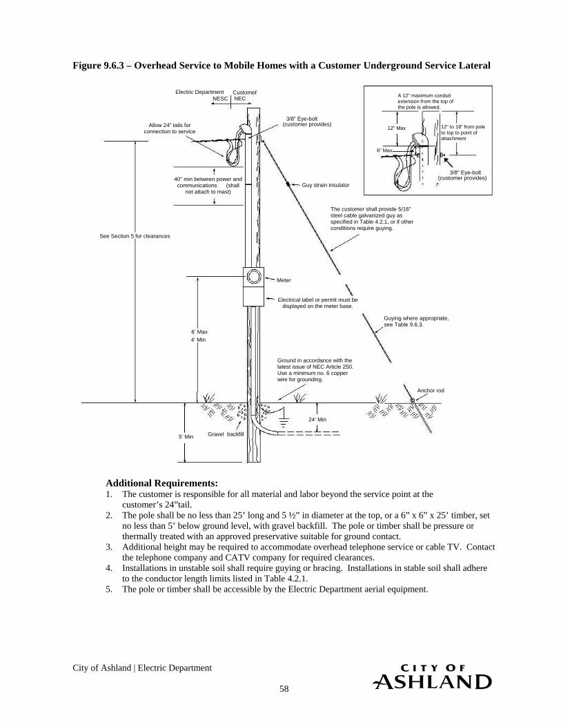
City of Ashland | Electric Department
58
Figure 9.6.3 – Overhead Service to Mobile Homes with a Customer Underground Service Lateral
Additional Requirements: 1. The customer is responsible for all material and labor beyond the service point at the
customer’s 24”tail. 2. The pole shall be no less than 25’ long and 5 ½” in diameter at the top, or a 6” x 6” x 25’ timber, set
no less than 5’ below ground level, with gravel backfill. The pole or timber shall be pressure or thermally treated with an approved preservative suitable for ground contact.
3. Additional height may be required to accommodate overhead telephone service or cable TV. Contact the telephone company and CATV company for required clearances.
4. Installations in unstable soil shall require guying or bracing. Installations in stable soil shall adhere to the conductor length limits listed in Table 4.2.1.
5. The pole or timber shall be accessible by the Electric Department aerial equipment.
Gravel backfill 5’ Min
Allow 24” tails for connection to service
Guy strain insulator
24’ Min
Ground in accordance with the latest issue of NEC Article 250. Use a minimum no. 6 copper wire for grounding.
NEC Customer
NESC Electric Department
Electrical label or permit must be displayed on the meter base.
6” Max
12” Max
A 12” maximum conduit extension from the top of the pole is allowed.
12” to 18” from pole to top to point of attachment
40” min between power and communications (shall
not attach to mast)
See Section 5 for clearances
Meter
Anchor rod
Guying where appropriate, see Table 9.6.3.
The customer shall provide 5/16” steel cable galvanized guy as specified in Table 4.2.1, or if other conditions require guying.
3/8” Eye-bolt (customer provides)
6’ Max 4’ Min
3/8” Eye-bolt (customer provides)

City of Ashland | Electric Department
59
Table 9.63 – Acceptable Service Conductor Lengths Required (For Single-Family Overhead Service Pole Attachment)
Service Size Utility Service Length
0-200 Amp Service 60’ Max. 201-400 Amp Service 45’ Max
Note: Contact the Electric Department regarding longer service lengths and guying requirements. Guying may be required at these lengths in unstable soil conditions.
9.7 Overhead Service to Mobile Homes 9.7.1 General Overhead service can be provided to the customer from an overhead distribution
system.
For a customer near an overhead line, the Electric Department will install a service drop from the Electric Department line to the pole with a meter enclosure attached. The Electric Department will install an appropriately-sized service conductor from its distribution line to the point of attachment.
The Electric Department owns and maintains the overhead service lateral from the utility source to the connection point at the weatherhead. The Electric Department also owns and maintains the meter. The customer owns the meter socket, the meter base, the pole, all wiring from the meter socket to the point of attachment, and all wiring beyond the meter socket.
9.7.2 Single-Family Mobile Home Overhead Service
Requirements: 1. The customer shall furnish and install the meter socket (overhead type) per Section
7.4, Residential Meter Sockets. 2. The meter base and meter socket shall be located per Section 7.5, Residential
Meter Socket Location. 3. Clearances specified in Section 5 shall be provided. 4. The overhead service shall be free of obstruction by building, vegetation or other
objects. 5. The Electric Department installed service shall not cross adjacent property without
a recorded easement obtained by the customer. 6. The customer shall provide a 24” conductor lead for attachment to the service
conductor. 7. The unmetered service conductor and the metered service conductor shall not be
run in the same conduit, raceway, or gutter. 8. The customer shall ground the installation in accordance with NEC Article 250. 9. The electrical label or permit shall be displayed on the meter base. 10. The customer shall install the meter base and service equipment on a wood pole.
The pole must be pressure or thermally treated with an American Wood Preservative Association-approved preservative rated for ground contact.
11. Installations in unstable soil shall require guying or bracing. Installations in stable soil shall adhere to the conductor length limits listed in Table 4.2.1.
12. The pole height must provide required clearance for the Electric Department service drop and any telephone, cable TV or other attachments (see Section 5).
The Electric Department will not energize the service if the customer-provided service pole is not safe in the Electric Department’s opinion.

City of Ashland | Electric Department
60
If the meter location is not within the specifications of this book, it must be approved in writing by the Electric Department prior to installation.
Table 9.7.2 – Acceptable Service Conductor Lengths Guying Required (For Single-Family Overhead Service Pole Attachment)
Note: Contact the Electric Department regarding longer service lengths and guying requirements, guying may be required at these lengths in unstable soil conditions.
Figure 9.7.2 shows the installation of an overhead service extension to a mobile residence.
The service and meter base enclosure shall not be directly connected to the mobile residence.
Service Size Utility Service Length w/o Guying 0-200 Amp service 60’ Max.
201-400 Amp Service 45’ Max.

City of Ashland | Electric Department
61
Figure 9.7.2 – Overhead Service to Mobile Homes (Customer Overhead Service Drop)
Additional Requirements: 1. The customer is responsible for all material and labor beyond the service point at the
customer’s 24” tail. 2. The pole shall be no less than 25’ long, and 5 ½” in diameter at the top, or a 6” x 6” x 25’
timber, set no less than 5’ below ground level, with gravel backfill. The pole or timber shall be pressure or thermally treated with an approved preservative.
3. Additional height may be required to accommodate overhead telephone service or cable TV. Contact the Telephone Company and CATV Co. for required clearances.
4. The location of the meter must be specified and/or approved by the Electric Department. 5. The pole or timber shall be accessible by the Electric Department aerial equipment.
Gravel backfill
5’ Min
Allow 24” tails for connection to service
Guy strain insulator
Grounding NEC Article 250
NEC Customer
NESC Electric Department
Electrical label or permit must be displayed on the meter base.
6” Max
12” Max
A 12” maximum conduit extension from the top of the pole is allowed.
12” to 18” from pole to top to point of attachment
40” min between power and communications
(shall not attach to mast)
See Section 5 for clearances
Meter
Secure anchor (customer provides)
The customer shall provide 5/16” steel cable galvanized guy as specified in Table 4.2.1, or if other conditions require guying.
3/8” Eye-bolt (customer provides)`
6’ Max 4’ Min
(customer provides)3/8” Eye-bolt
Point of guy attachment 12’ Min to ground
1
Minimum height per NEC
5/16” steel cable, galvanized
2

City of Ashland | Electric Department 62
10 Non-Residential Services (Commercial, Industrial, and Agricultural) This section describes the Electric Department requirements for non-residential services. This section covers single-phase and three-phase services for direct-connect and transformer rated sockets for meters. All non-residential customers are responsible for coordinating service requirements with the Electric Department prior to material purchase and installation.
Any exceptions to the metering requirements must be approved in writing by the Electric Department prior to installation.
10.1 Service Point Location for Meter and Equipment
The service point for non-residential customers refers to the location where the Electric Department circuit connects to the customer’s system. Meters and metering equipment shall be located outdoors. If prior written approval to locate the meters and/or metering equipment indoors (in a meter room) is granted by the Electric Department, the meter and equipment shall be installed at the main level or entry floor of the customer’s building. Meter rooms should be located on the side of the building that is closest to the distribution transformer. The Electric Department requires a ground floor location for the termination of load-carrying conductors and meters. Entry doors to service equipment rooms which contain the Electric Departments metering or termination equipment shall open outward and shall be accessible from the outside, fitted with an Electric Department supplied lock box for the Electric Department’s use. Meters shall not be installed on a drive-though service entrance side of a non-residential building. When vehicles or other equipment may be near the Electric Department equipment, barrier posts are required (see Figure 6.4.4). The customer is responsible for providing barrier posts for the protection of electrical equipment. Refer to Section 5 for additional clearance and location information.
10.2 General Descriptions Direct Connect Services (120 to 240 volts) are: (a) Single-phase services of 400 amps or less (320 amps continuous). (b) Three-phase services of 200 amps or less (160 amps continuous). Instrument Rated Services (120 to 480 volts) require current transformer metering and are: (a) Single-phase services over 400 amps (320 amps continuous). (b) Three-phase services over 200 amps (160 amps continuous). (c) All 480 volt services (also require voltage transformers) Secondary Voltage Switchboard Metering (120 to 480 volts) is required whenever a service exceeds 800 amps. Primary Services are services with delivery voltages greater than 600 volts. Test block Facility (TBF) is manual-link bypass.
10.3 Direct Connect Services The Electric Department requires a direct-connect meter socket when the ampacity of a single-phase service entrance is 400 amps (320 amps continuous) or less, or when the ampacity of a three-phase service is 200 amps (160 amps continuous) or less. No direct-connect meter sockets

City of Ashland | Electric Department 63
are provided for new 480/277 volt services. Current and voltage transformers are required for all 480/277 volt services. Meter sockets for direct-connect services shall be furnished, installed, and wired by the customer. Required types are summarized in Table 10.3. Typical socket connections are shown in Figures 103.5 and 103.6. Non-Residential, Direct-Connect Socket Requirements: 1. All meter sockets shall be EUSERC-approved. 2. All meter sockets shall be ring-type. 3. All meter sockets shall be furnished with screw-type sealing rings. 4. All meter sockets (other than the type described in number 8 below) shall have manual link
bypasses. This maintains service to the customer while the meter is removed for testing, inspection or other required work.
5. All three-phase meter sockets shall have safety sockets. 6. Safety sockets are approved but not required for single-phase 120/240-volt meter sockets. 7. Manual link bypasses are recommended but not required for single-phase, 120/240 volt,
services of 100 amps or less that serve government-owned sprinkler systems. 8. The unmetered service conductor and the metered service conductor shall not be run in the
same conduit, raceway, or gutter. Refer to the Electric Department meter socket List for specific manufacturer approved socket types. The following table summarizes the socket requirements for new construction. Table 10.3 – Non-residential, Direct-Connect Socket Requirements
Voltage # Wires Phase Amps No. of Terminals
Manual Link Bypass
Required?
Safety Socket
Required?
EUSERC No.
120/240
3
1
0-100 Overhead 0-100 Underground
4
Yes
No
304, B-Line U264304, or equal
120/240 3 1 0-200 Overhead 4 Yes No 305, B-line U264 or equal
120/240 3 1 101-200 Underground 4 Yes No 305, of B-Line U264 with a junction box,
or equal 120/240 3 1 201-400 Overhead 4 Yes N/A 302 B 120/240 3 1 101-400 Underground 4 Yes N/A See Figure 10.3.2 (c)
120/208Y 4 3 0-100 7 Yes Yes 304 120/208Y 120/240
4 3 101-200 7 Yes Yes 305
120/208Y 4 3 Greater than 200 Not approved for direct-connect installations. Requires instrument rated metering
Note: If replacing the socket of an existing three-phase, direct-connect, 3-wire service, EUSERC7-jaw safety
socket configured for a three-phase, 3-wire meter is required (see EUSERC 304-305, note 12). This type for service is not approved for new construction.
10.3.1 Sealable Junction Box
The junction box provides a means of terminating the utility’s service conductors when required (for instance, if voltage drop requires a larger utility conductor—350 KCM—this box allows the use of a 200A service, rather than 400A). The use of this junction box shall be coordinated with the Electric Department prior to installation. The

City of Ashland | Electric Department 64
customer is responsible for providing the junction box, connectors and connections from the junction box to the line side of the metering equipment.
The junction box must be weatherproof NEMA 3R minimum rated, and must have sealing provisions.
Figure 10.3.1 – Sealable Junction Box with Distribution Blocks
Table 10.3.1 – Junction Box Depths
Conduit Size Junction Box Depth 3-inch 6 inches
4-inch and greater Consult Electric Department Figure 10.3.2 – Non-Residential Single-phase, Direct-Connect sockets
With Required Manual-link Bypass
Note: For 101-200 amp underground, an alternate socket that meets the requirements in Table 10.3,
Non-residential, Direct-Connect Socket Requirements, may be used.
See Table 10.3.1 for junction box depth.
24”
12”
23” Min
Bypass facilities
12” Min 4 5/8” Min 14” Min
30” Min
Meter socket
Manual bypass studs
Neutral bonded to enclosure
Sealing provisions
6” Min
30” Min
Customer/ Utility
termination
Manual bypass studs
24” Min
Customer/ Utility
termination
Pull section sealed
from front
Customer and Utility wires shall not be pulled in the same section. (Consult the
manufacturer for load side wiring positions.)
(A) 0-200 Amps- Overhead
0-100 Amps- Underground (B-Line U 264 or equal)
(B) 201-400 Max Amps- Overhead
only
(C) 101-400 Max Amps- Underground

City of Ashland | Electric Department 65
Figure 10.3.3 – Non residential Single-Phase, Direct-Connect Socket for 480-Volt Services, with Required Safety Socket
Figure 10.3.4 – Three-Phase, Direct-Connect Socket with required Safety Socket
Additional Three-Phase Service Requirements: 1. For 4-wire delta services, the high leg (power) conductor shall be identified by orange
marking, and shall be located on the right side of the test block. The test block shall also be marked and readily identified.
2. A EUSERC-approved safety socket with test blocks is required. This maintains service to the customer if the meter is removed for test or inspection.
3. Three-phase, 400-amp-maximum direct-connect sockets are not approved. 4. All 480/277V services require current transformers and voltage transformers.
11 1/2” Min
30” Min 24” Min
4 1/2” Min 11 1/2” Min
6” Min
100 Amp (EUSERC 304) 200 Amp (EUSERC 305)
L I N E
L O A D
L I N E
L O A D
LI N E
LOAD
LI N E
LOAD
11 1/2” Min
30” Min 24” Min
4 1/2” Min
13 1/2” Min 6” Min
100 Amp (EUSERC 304) 200 Amp (EUSERC 305)
3”
Test blocksL I N E
L O A D
L I N E
L O A D
L I N E
L O A D
LI NE
LOAD
LI NE
LOAD
LI NE
LOAD

City of Ashland | Electric Department 66
The figures below show typical service connections.
Figure 10.3.5 – Single -Phase Socket Connection Diagram Front View
Figure 10.3.6 – Three-Phase Socket Connection Diagram
Front View
Line
Neutral
Load
Line
Neutral
Load
Line
Neutral
Load
120V- 2 Wire 120/240V- 3 Wire 120/208V- 3 Wire WYENetwork Meter
5th terminal in 9 o’clock position
Line
Neutral
Load
Line
Neutral
Load
Line A
Load
120/208V- 4 Wire WYE 120/240V- 4 Wire Delta(Not for new construction)
240 or 480V, 3-Wire Delta(Not for new construction)
Configured per EUSERC 304/305 Note 12
Hi-leg, marked with orange, and located on the right side of the test block
C B
City of Ashland | Electric Department 67
Figure 10.3.7 – Free Standing Streetlight Disconnect (Post Mounted)
Additional Requirements: 1. The streetlight disconnect provides a means of terminating the utility’s service conductors
when required. 2. The use of this disconnect junction shall be coordinated with the Electric Department prior
to installation. 3. The customer is responsible for providing the sealable/lockable disconnect, connectors and
connections from disconnect to the streetlight equipment. 4. The customer is responsible to ensure construction conforms to applicable provisions of the
NEC, state and local rules and codes. 5. The construction assembly shall be plumb in all directions.
10.4 Direct-Connect Multiple Metering Services This section describes the additional requirements for direct-connect, non-residential,
single-phase and three-phase installations with more than one metered service. The three styles of metering socket equipment approved for use are ganged, modular, and switchboard. Requirements: 1. Each metered service must have a permanently engraved metal or hard plastic label to
identify the customer’s address. The label must be permanently attached to the top half of the meter enclosure. The service will not energized until the label is permanently attached.
2. Vacant meter positions shall be securely sealed, or the meter shall be in position before the panel is energized.
3. All removable panels and covers to compartments used for metering shall be sealable. 4. Metering conductors shall not pass through adjacent metering compartments except in
enclosed wireways.
Streetlight Disconnect
Electrical label must be displayed on the Panelboard Enclosure base.
4’-6” Max 4’-0” Min
Conduit for ground conductor
The ground connection must be visible when an electrical inspection is made. For safety reasons, the ground rod shall be flush with or below the surface
24” conduit sweeps
Conduit strap
3” Min grid galvanized
capped post
Conduit for service conductor
Unistrut
24” Min
Customer will furnish and Install: Outdoor disconnect enclosure Pedestal Hardware Conduit (see Section 6.2.1) Right-of-way Trench excavation and backfill Grounding per NEC Concrete Pad, 24”x24”x6” depth 24” Conduit radius sweep
6” Min
Unistrut
Electric Department Service Conductors, 2” conduit
Streetlight Load conductors, 2” conduit
Outdoor 100A Main, 12 Circuit, 120/240v, Sealable and lockable disconnect

City of Ashland | Electric Department 68
5. A test block facility (TBF) with rigid insulating barriers shall be furnished, installed, and wired or bussed to the meter sockets. TBF cover panels shall be sealable and fitted with a lifting handle.
6. NEC requires a main disconnect when more than six services are connected. If an existing installation expands beyond six services, a main disconnect shall be installed.
7. When the sum of distribution section ampacities exceeds the pulling section ampacities, the customer is responsible for providing NEC-approved load calculations as requested.
8. The cable pulling (pull box) section is required and must be sized for the Electric Department service termination (EUSERC 343 ). Refer to Section 10.5 for more details pertaining to the pull box.
9. For ganged meters, where the face of a cabinet exceeds the depth of the adjacent meter cabinet, clearances shall be in accordance with EUSERC 353.
Figure 10.4.1 – Non-Residential Ganged Meter Socket Installation
Note: A single-phase configuration is approved. Figure 10.4.2 – Non-residential modular Meter socket Installation
Note: A single –phase configuration is approved.
Customer’s service entrance bus
Cable pulling section
Sealable enclosure
Permanent address labels
Main disconnect (if required)
TBF TBF TBF TBF TBF TBF TBF
Sealable gutter
Test bypass facilities
Customer distribution section
final grade
72” Max48” Min
Customer’s service entrance bus
Cable pulling section
Sealable enclosure
Permanent address labels
Main disconnect (if required)
TBF
final grade
72” Max48” Min
L L I O N A E D
L L I O N A E D
L L I O N A E D TBF TBF
Meter module
Meter module
Meter module
Meter module
Test blocks
Breaker (optional)
Breaker (optional)
Breaker (optional)Breaker
(optional)

City of Ashland | Electric Department 69
Figure 10.4.3 – Non-Residential Switchboard Metering (Direct-Connect, Floor Mounted)
EUSERC 306
Notes: a. The customer must provide a concrete pad for switchboard metering service sections and
pull boxes. b. A single-phase configuration is acceptable.
10.5 Pull Box This section illustrates and lists pull box requirements as follows: Requirements: 1. The termination pull box for the Electric Department conductors shall meet the
requirements of EUSERC 343, 343A, or 347. 2. When the sum of distribution section ampacities exceeds the pulling section ampacities, the
customer is responsible for providing NEC-approved load calculations as requested. 3. The customer shall provide an approved method by which to make multiple taps. 4. Customer-owned devices (such as limiters, fuses, etc.) shall not be installed in pull boxes. 5. The customer shall supply all terminal blocks and pull all conductors to Electric Department
point of service.
Permanent address labels
TBF
TBF
TBF
TBF
TBF
TBF
TBF
TBF
TBF
TBF
TBF
TBF
TBF
TBF
TBF
TBF
TBF
TBF
TBF
TBF
TBF
TBF
TBF
TBF
Concrete pad
75” Max
36” Min
12” Min
Multiple Meter Section Multiple Meter Section Pull Section

City of Ashland | Electric Department 70
Figure 10.5 – Pull Box 0-600 volts, 0-1200 Amps EUERC 343, 343A & 347
Table 10.5 – Minimum Pull Box Dimensions (Applies to the Electric Department Portion of the Pull Box )
“W” Total Service
Amps 3 Wire 4 Wire “Y”
Depth “X”
Lug Height 0-200 10 ½” 14” 6” 11”
201-400 10 ½” 14” 6” 22” 401-800 16 ½ “ 22” 11” 26”
801-1200 22 ½” 30” 11” 26’
TOP VIEW CLEARANCE
FRONT VIEW
SIDE VIEW
BUS
Cable pulling section
Cable pulling section
Service termination bus stubs
3/4” Min 3/4” Min
“W”
Customer service entrance
Conductors exit above lugs Bus stubs
anchored to prevent turning
Load side
“W”
“Y”
“X”
Orange to identify high (power) leg
Shaded space for service supply conductors only
4” Min
1 1/2” Min
1/2” bolts
1” Min
1” Min
2” Min 2 1/2” Max
Ground metal
1 3/4”
1 1/2” Minimum (typical)
1 1/2” Min
1 1/2” Min
1 3/4” Min
1 3/4” Min
1/2” bolts
2” 4” 6”
2” 2”
0-400 AMPS
401-800 AMPS
801-1200 AMPS
Clearance requirements for adjacent termination stubs
(400 amp bus stubs illustrated)

City of Ashland | Electric Department 71
10.6 Current Transformer Metering – 600 Volts, 800 Amps Maximum Current transformer (CT) metering is required when a 208/120V three-phase service exceeds 200 amperes, (for all 480/277V services, and when a single-phase service exceeds 400 amperes. For services over 800 amps, see Section 10.12, Switchboard Metering (also approved for smaller loads). Two types of CT mounting configurations are approved by the Electric Department:
(a) Current Transformer Metering, Post-Mounted. (b) Current Transformer Metering, Wall-Mounted
Figure 10.6.1 – Current Transformer Metering Mounting Configurations
The CT cabinet and meter shall be mounted outside the building as approved by the Electric Department. Where metering equipment is installed in a location susceptible to being struck by a vehicle, the customer shall install and maintain barrier posts approved by the Electric Department. (see Figure 6.4.4). The customer shall provide and install: 1. A EUSERC-approved meter socket enclosure. The socket shall be mounted plumb in both
directions, drilled and tapped for the Electric Department meter test switch. 2. A current transformer cabinet. The cabinet must be a weather-tight, NEMA 3R-rated,
metallic cabinet securely mounted on a rigid surface. The door shall be hinged and capable of being sealed. The cabinet shall be sized in accordance with Table 10.6.2, Current Transformer Cabinet Requirements, and shall be in compliance with EUSERC.
3. A EUSERC-approved current transformer mounting base (refer to Section 10.6.3 for details). All mounting bases shall be rated for 50,000-amp fault duty. Cable termination can only be made on the manufacturer-supplied studs/connectors of the transformer mounting base. No alteration of the transformer mounting base is allowed.
4. The conduit between the meter socket enclosure and the current transformer cabinet. 5. Connectors terminating the load conductors to the current transformer mounting base. 6. Bonding per Section 10.10 for all meter and CT enclosures.
14” Min
Customer-supplied 3” galvanized rigidConduit (capped)
(A) POST-MOUNTED, SIDE VIEW (B) WALL-MOUNTED

City of Ashland | Electric Department 72
The customer shall not terminate their principal grounding conductor in the Electric Department sealed termination pull box. The principal grounding conductor is not the Electric Department supplied neutral; it is the customer’s grounding conductor. The Electric Department will provide and install: 1. The meter 2. A meter test switch. 3. Instrument current transformer. 4. Instrument voltage transformer. Note: The customer shall consult the Electric Department for specifications on instrument transformers, secondary-side wiring of instrument transformers, and the meter test switch prior to ordering the metering enclosure. 10.6.1 Meter Socket Enclosure Requirements:
1. All meter socket enclosures shall be EUSERC-approved (see EUSERC 339). 2. All meter socket enclosures shall be ring-type. 3. The meter socket enclosure must be provided with a space reserved below the
socket for a Electric Department test switch 9 ½ inches in length. 4. The meter socket enclosure shall contain a mounting perch, drilled and tapped, for
a test switch. The Electric Department will furnish and install the test switch. 5. All unused openings must be covered and secured by the customer. 6. Meter socket enclosures with circuit closers or bypass clips are not acceptable. 7. All 48” cabinets must have two sealable, hinged doors with a handle in the center.
Figure 10.6.1 – Meter Socket Enclosure for Current Transformer Meters Except 480/277V
EUSERC 339
20”
11”
12” Min 4 1/2” Min
9”
Single Phase, 6-Jaw
20”
12” Min 4 1/2” Min
9”
Three Phase, 13-Jaw
9 1/2”
11”

City of Ashland | Electric Department 73
Figure 10.6.2 – Meter Socket Enclosure for 480/277V Meters
Note: Meter Enclosure to be Brooks Flash Sentry or approved equal. Catalog# 622-8085-C13
Table 10.6.1 – Current Transformer Meter Socket types EUSERC 339
Type of Service Socket Type 120/240 volt, single-phase, 3 wire 6 jaw 120/208 volt, three-phase, 4 Wire 13 jaw* 277/480 volt, three-phase, 4 Wire 13 jaw* 240/120 volt, three-phase, 4 Wire 13 jaw
*15 jaw sockets are approved but not required. 10.6.2 Current Transformer Cabinet Requirements
Table 10.6.2 – Current Transformer (CT) Cabinet Requirements
Current Transformer Cabinet: Wall- and Post Mounted Installations Minimum
Cabinet Dimensions CT Mounting
Base Type of Service CT
Enclosure EUSERC# Width Height Depth EUSERC #
Single-phase, 3 Wire 401-800 Amps EUSERC 316 AND 317 24” 48” 11” 328A, 328B Three-phase, 4-Wire 201-800 Amps EUSERC 316 and 318 36” 48” 11” 329A, 329B A larger cabinet is required if both the line and load conductors enter and exit from the bottom of the can. Note: These cabinet dimensions are greater than EUSERC 317 and 318 minimums.
316, 317 and 318 48” 48” 14” 318A, 328B for 3W. 329A, 329B for 3PH, 3W or 4W.
Above 800 amps: see Section 10.12, Switchboard Metering.
20 1/2”
24 5/8”
6 1/2”
Test Switch
480 V PT
Section
13-terminal Meter Base

City of Ashland | Electric Department 74
10.6.3 Transformer Mounting Base Requirements for Installation in a Current Transformer Cabinet Requirements for the current transformer mounting base for installation in the current transformer cabinet are as follows:
1. The mounting base for CT’s shall meet the ratings for the available fault current
(50,000A minimum.) 2. For 4 wire delta services, the high (power) leg conductor must be identified by
orange marking, and located on the right hand side of the CDT mounting base. The CT mounting base must also be marked and readily identified.
3. The mounting base shall accept bar-type current transformers only.
Cable Termination: 4. Line and load-side terminations on EUSERC 328A or 329A CT landing pads
require two bolts per connector. (EUSERC 328B and 329B CT landing pads do not require 2-bolt connectors.)
5. For underground service, the customer will provide connectors and conductor and terminate the line and load side service conductor directly on the current transformer mounting side. The customer needs to connect the load side and line side. The customer must furnish all lugs and connect conductors to the load terminals.
6. On overhead services, the customer must furnish all lugs and connect conductors to the line and load terminals of the current transformer mounting base. The customer is responsible for bringing the service entrance conductor to the connection of the utility service drop.
7. Cable termination can only be made on the manufacturer-supplied studs of the transformer mounting base. No alteration of the transformer mounting base is allowed.

City of Ashland | Electric Department 75
Figure 10.6.3.1 – Transformer Mounting Base For Installation in a Current Transformer Enclosure
(Single-Phase, Three-Wire, 800-Amp Max. EUSERC 328A, 328B)
5” 3/4”
1 3/4”
1 3/8”
7/8”
1 1/2”
1 1/2”
3/4”
1 3/4”
CT mounting bolts, 4 places
CT CT
8 1/8”
8” Min
Cable termination bolts, 4 places
Bus marking, “CT”; 2 places
Insulating supports
Insulating barrier
2”
1/4”
3 1/2”

City of Ashland | Electric Department 76
Figure 10.6.3.2 – Transformer Mounting Base For Installation in a Current Transformer Enclosure
(Three-Phase, Four-Wire, 800 Amp Max., EUSERC 329A, 329B)
10.6.4 Additional Requirements for Current Transformer Metering, Wall/Post Mounted
1. The customer service entrance conduits must exit the enclosure on the load side of the current transformer.
2. Only conductors and equipment associated with the Electric Department metering shall be permitted in the current transformer enclosure.
3. The current transformer enclosure must not be used as a load distribution center. For multiple metered circuits, a separate terminating pull box must be provided for the Electric Department service lateral. See Section 10.5 for pull box requirements.
4. Customer conductors are not permitted in the Electric Department terminating and pull space.
5. Customer conductors shall exit the enclosure on the load side of the current transformers.
6. Meter sockets shall not be located above or below CT enclosures. 7. The top of the CT mounting bracket shall not be more than 6 feet above floor level.
The cover shall have factory-installed hinges for side opening, with sealing provisions, and shall hold the cover in the open position at 90 degrees or more.
8. The meter shall be located on the non-hinged side of all current transformer cabinets (except 48” x 48” cabinets). The meter must be mounted such that it will not interfere with the opening of the cabinet doors.
5” 3/4”
1 3/4”
1 3/8”
7/8”
1 1/2”
1 1/2”
3/4” 1 3/4”
CT mounting bolts, 6 places. See No. 3
8 1/8”
7” Min Cable termination bolts, 6
6 places. See No. 3
Bus marking, “CT”; 3 places
Insulating support
2” Min 2 1/2” Max
1/4”
3 1/2”
7” Min
Insulating support, See No.1
10-32 machine screw and washer, drilled and tapped into bus
1 3/8”

City of Ashland | Electric Department 77
9. The cabinet must have two sealable, hinged doors with a handle in the center for 48” x 48” cabinets. The meter enclosure can be mounted on either side of the 48” x 48” CT cabinet, but not above or below it.
10. Exposed conduit for the Electric Department service lateral should not extend more than 5’6” (or less than one foot into the building if indoors).
11. Grounding and bonding must be in accordance with current NEC requirements (see Section 10.10). The code enforcing agency may require the ground connection to be visible when electrical inspection is made.
12. Refer to Section 10.7 for clearance requirements and Section 6 for underground conduit requirements.
Figure 10.6.4.1 – Current Transformer Metering, Wall Mounted
Service Below 600 Volts, 800 Amps Max.
Notes: a. This cabinet size may also be post-mounted. b. A larger cabinet (48” x 48”) is required if both the line and load conductors enter and exit
from the bottom of the cabinet.
Reserved for Electric Department conductors if overhead
Refer to Table 10.6.2 for cabinet size
Remote socket EUSERC 339
4”- 12”
12” 6’ Max4’Min
12” Min 6’ Max
See section 5 for clearance requirements
Finished grade
Grounding as required
Hinged side
Mounting base for current transformers (customer provides; see EUSERC 329A or 329B)
Reserved for Electric Department conductors if underground
Based on NEC 312.6
18” Min
Conduit 1” Min

City of Ashland | Electric Department 78
The following figure illustrates the cabinet requirements when the line and load conductors enter and exit from the bottom of the cabinet.
Figure 10.6.4.2 – Current Transformer Metering, Post Mounted Service Below 600 Volts, 800 Amps Max.
Note: This size cabinet may also be wall-mounted.
Reserved for Electric Department conductors
6’ Max
48” Min
20” Min 48” Min
Electric Departmentservice conductors
Conduit and sweep supplied by customer
Customer load conductors
13 1/4” Min
Mount meter socket on side of compartment
Meter
4 5/8” Min CT mounting base
6’ Max 4’ Min
Concrete pad
Customer-supplied 3” galvanized rigid conduit (capped)
FRONT VIEW
SIDE VIEW

City of Ashland | Electric Department 79
10.7 Clearances The following portion of Figure 5.1.2 illustrates metering clearance requirements: Figure 10.7 – Metering Clearances Outdoors or in a Confined Area
Requirements: 1. The CT cabinet and meter should be mounted outside the building. 2. A clear work space is required in front of the cabinet. The hinged door, when open, shall
not block ingress and egress, and shall open outward. 3. To minimize water drainage into the customer’s equipment, the Electric Department
equipment transformers and vaults shall not be located higher than the CT cabinets.
10.8 Current Transformer Metering Conduit The customer must provide conduit between the meter socket and the current transformer cabinet. When installing conduit, the following requirements shall be met: Requirements (Meter within 4” to 12” of CT cabinet): 1. 1” minimum conduit of rigid steel or IMC. 2. Proper fittings and bushings to protect metering conductors. 3. Schedule 40 PVC/EMT may be allowed when a bonding lug is provided in both the CT
cabinet and the meter base. Requirements (Meter and CT cabinet greater than 12” apart): This arrangement requires written approval from the Electric Department prior to installation, and shall adhere to the following requirements: 1. 1 ¼” minimum conduit. 2. Conduit runs may not have more than three bends totaling 270 degrees. No single bend
greater than 90 degrees is allowed. Conduit runs must be 50 feet or less. 3. Pull lines are required in all conduit. 4. Removable conduit fittings shall have sealing provisions. (LB connectors are not allowed
outside the enclosure without prior written Electric Department approval.)
10.9 Current Transformer Metering for Free-Standing Installations This section defines the additional metering requirements for free-standing current transformer metering installations typically used in irrigation fields. Installing CT’s inside the padmounted distribution transformer compartment is not allowed.
Hinge
36”/48” (three-phase)
24” (single-phase)
4” to 12”
10” Min
26” Min 90 Degree Min.
(clear open space)
Opening of current transformer cabinet door must not block egress
Wall or obstruction
48” Min
4”
CLEARANCES OUTDOORS OR IN A CONFINED AREA

City of Ashland | Electric Department 80
Figure 10.9 – Current Transformer Metering for Free-Standing Installations For 600 Volt, 800 Amps Maximum
Additional Requirements: 1. The customer shall consult the Electric Department prior to construction for installation-
specific details and shall follow the guidelines defined in the figure above. 2. Refer to Section 6 for conduit requirements.
14”48”
1” to 3” Space
Meter
13 1/4” Min
Reserved for Electric Department conductors
6’ Max6’ Max 4’ Min
CT Mounting
Base
48”
3’ Min
3” post w/ cap (customer provides)
Padmounted transformer
High voltage
area
Low voltage
area
To Electric Department Distances less than 6’ require bonding to Electric Department equipment. Also see Section 5.5 for clearances, and Section 3.4.5 for distances to the service entrance panel.
Contact the Electric Department for vault requirements
Customer will furnish and install: Meter socket enclosure (underground type) Pedestal Hardware Conduit (see Section 6.2.1) Right-of-way Trench excavation and backfill Grounding per NEC Concrete Pad, 24” x 24” x 6” depth Long radius sweep 36” sweep

City of Ashland | Electric Department 81
10.10 Current Transformer Enclosure Bonding This section defines the bonding requirements for all CT enclosures.
Figure 10.10.1 – NEC Accepted
Current Transformer Enclosure Bonding For 600 Volt, 800 Amps Maximum
Figure 10.10.2 – Alternative Method Current Transformer Enclosure Bonding
For 600 Volt, 800 Amps Maximum
CT cabinet Service entrance equipment
neutral PVC
Load side (equipment)
Ground per NEC (Article 250, Grounding)
Remote meter option
Line side (supply)
NEUTRAL
NEUTRAL
GROUND
CT cabinet Service entrance equipment
neutral PVC
Load side (equipment)
Ground per NEC (Article 250, Grounding)
Remote meter option
Line side (supply)
GROUND
NEUTRAL
NEUTRAL

City of Ashland | Electric Department 82
10.11 Combination Self-Contained and Current Transformer Metering Installations requiring both self-contained and current transformer metering services shall meet the requirements of both types of services as described in the previous section. Shown below is a wall-mounted equipment installation approved for this service. Switchboard combination units are also approved. Refer to Section 10.12, Switchboard Metering for requirements. Figure 10.11 – Combination Current Transformer Compartment
(Direct-Connect, Wall-Mounted)
Requirements: 1. Bonding jumpers shall be used around knockouts. 2. Grounding and bonding per current NEC requirements is required (see Section 10.10). 3. The pull section shall be rated at the sum of the maximum service ampacities. 4. NEC requires a main disconnect when more than six services are connected. If an existing
installation expands beyond six services, a main disconnect shall be installed.
10.12 Switchboard Metering A EUSERC –approved switchboard metering section is required when the service entrance rating is greater than 800 amps. Switchboard metering may also be used for three-phase services over 200 amps and single-phase services over 400 amps. Services greater than 800 amps shall be three-phase. Switchboards shall be located outdoors unless written approval is received from the Electric Department prior to installation. The Electric Department reserves the right to refuse indoor installations.
TBF TBF 6’ Max 4’ Min
42” Min 72” Max
Entrance Bus Main disconnect
(if required; see no. 4 below) Sealable gutter
Cable pulling section
EUSERC 343
Sealable enclosure
Mounting base for current transformers
6’ Max
4” to 12”12” Min
CT CT CT
Finished grade
Utility test
switch 18” Min

City of Ashland | Electric Department 83
Meter shall be located outdoors in separate meter enclosure. Customer shall run 1¼” conduit, minimum, from switchboard metering, per Section 10.8. Requirements: 1. The metering current transformers shall be located in the current transformer compartment. 2. For a single service, the meter and test switch shall be mounted outside the cabinet
(remotely). Mounting the meter and test switch on the switchboard meter panel requires written approval by the Electric Department.
3. Single-service metering compartments shall be located on the supply side of the main switch or breaker.
4. If written approval is obtained for an indoor installation, the service point shall be located no more than five feet inside the perimeter of the building.
5. Multiple metering services require meters to be mounted on the compartment’s hinged meter panels.
6. Remote meter enclosure shall meet requirements of Section 10.6.
The following table shows applicable EUSERC documents:
Table 10.12 – EUSERC Switchboard References
EUSERC No. Book Reference Switchboard Preferred and Alternate 325 10.12.1 Termination Underground Service 345 10.12.5 Overhead Service 348 10.12.6 Instrument Transformer Compartment
0 to 1000 Amps 319 320
10.12.3.1 10.12.3.2
1001 to 3000 Amps 322 10.12.1 Above 3000 Amps 324 10.12.1
The customer shall provide and install: 1. The switchboard enclosure, instrument transformer mounting base, bus bars, panels, and
meter socket with provisions for a test switch. 2. Locking equipment for the metering enclosure allowing independent access by the Electric
Department 3. A clear work space 78” high, 36” wide and 48” deep in front of distribution metering
equipment as required by NEC. 4. A concrete mounting pad for the switchboard metering enclosure. 5. Conduit and pull wire from switchboard to remote meter. The Electric Department will provide and install: 1. The meter 2. A meter test switch. 3. Instrument current transformers. Note: The customer shall consult the Electric Department for specifications on instrument transformers, secondary-side wiring of instrument transformers, and the meter test switch prior to ordering the metering enclosure. Enclosure drawings shall be provided to the Electric Department for approval. 10.12.1 Switchboard with Remote Meter Socket, Preferred Method Shown below is the preferred method for outdoor and indoor single-service
switchboard metering installations.

City of Ashland | Electric Department 84
Figure 10.12.1 – Remote Switchboard Metering Enclosure, Preferred Method (For Indoor and Outdoor Applications)
EUSERC 325 and 354
Requirements: 1. The service termination and metering equipment shall be located outdoors, within 50 feet of
the transformer. If the Electric Department allows the service termination to be located inside the building, the meter socket must be located outside the building.
2. The metering conduit in the switchboard section shall be PVC flex tubing and shall terminate in the current transformer compartment in front of the current transformers. Ninety-degree sweeps, LB’s or similar devices are not permitted inside the enclosure.
3. The customer must provide and install the remote meter socket, metering switchboard section and 1¼” minimum conduit for the metering secondary conductors. Refer to Section 10.8, Current Transformer Metering Conduit, for conduit requirements.
10.12.2 Switchboard with Meter Socket, Alternate Method
Shown below is the alternate method for single services in which the meter is mounted on the switchboard meter panel. This method, for both indoor and outdoor installations, is to be used only when a suitable remote meter location can not be found. This type of installation requires prior written approval by the Electric Department.
10”
15”
15”
Blank panel (sealable)
Blank panel (sealable)
Blank panel (sealable)
Test Switch
Door (In outdoor installations)
12” Min Per Section 10.6
Conduit (See Section 10.8)
6’ Max4’ Min
Current Transformer compartment
Barrier

City of Ashland | Electric Department 85
Figure 10.12.2 – Switchboard Metering, Alternate Method Outdoor Switchboards, EUSERC 354
10”
15”
15”
Blank panel
11” Min
6’ Max 4’ Min
Current Transformer compartment
Barrier
Blank panel (sealable)
Meter socket
Utility test switch
Pull section raceway
Exterior Door (sealable)
CT section
11” Min
Hinged meter panel, capable of being opened 90 ° with meter in place
FRONT VIEW SIDE VIEW TOP VIEW

City of Ashland | Electric Department 86
Indoor Switchboards, EUSERC 325/326
Additional Switchboard Requirements: 1. Exterior doors on outdoor switchboards shall be sealable and shall hold securely at
a 90-degree minimum when open. 2. Meter panels shall not be hinged to a filler panel. 3. Prior written approval from the Electric Department is required if the metering
switchboard is to be installed indoors. 4. If an indoor switchboard installation is approved, the meter shall be located
outdoors.
FRONT VIEW SIDE VIEW
10”
15”
15”
Blank panel
6’ Max4’ Min
Barrier
Blank panel (sealable)
Meter socket
Utility test switch
Instrument Transformer compartment

City of Ashland | Electric Department 87
10.12.3 Current Transformer Compartment for Switchboards A current transformer compartment is required for all switchboard enclosures. EUSERC 319 (three-phase, three-wire) and EUSERC 320 (three-phase, three-and four-wire) are both approved for services up to 1000 amps. Since this requires bar-type CT’s, the Electric Department shall be contacted for approval prior to installation. The following three figures illustrate Electric Department approved switchboard equipment.
Figure 10.12.3.1 – Current Transformer Metering for Switchboards,
0-1000 Amps, Three-Phase, Three-Wire

City of Ashland | Electric Department 88
Figure 10.12.3.2 – Current Transformer Metering for Switchboards, 0-1000 Amps, Three-Phase, Three-and Four-Wire

City of Ashland | Electric Department 89
Figure 10.12.3.3 – Current Transformer Compartment for Switchboards 1001 - 3000 Amps, 0-600 Volts
Three-Phase, 4-Wire Service, EUSERC 322
Requirements: 1. Busways shall remain in position when the removable section “B” is out. 2. The direction of the feed shall be set from the top or bottom. No other conductors shall pass
through this compartment. When horizontal-cross busways supply the service section phase buses, a neutral bus bar extension shall be provided in the instrument transformer compartment above the lower CT bus support.

City of Ashland | Electric Department 90
Figure 10.12.3.4 – Current Transformer Compartment for Switchboards, 3001 – Amps and Above, 0-600 Volts Three-Phase, 4-Wire Service, EUSERC 324
Requirements: 1. Bus units may be supplied from the top or bottom. 2. Bus units shall be anchored such that busses will remain in position when section “B” is
removed. Consult the Electric Department for the use of busses larger than 5 inches. Bus supports shall be constructed of a continuous bar of insulating material.
3. When the compartment is supplied from horizontal cross-bussing, the bussing shall pass through the compartment, or in the sealed area above the compartment. No other conductors shall pass through the compartment.
Alternate location of neutral bus
FRONT VIEW SIDE VIEW
TOP VIEW
8” Min
8” Min
8” Min`
7” to 11”
14 1/2” 14 1/2”
Test transformer support bar
30”
7”
2” 1”
14 1/2”“B” See
Note 1
2 13/16”
2”
7” Min 11” Max
2 13/16”

City of Ashland | Electric Department 91
10.12.4 Termination Requirements for Switchboard Compartments: 1. For underground service, the Electric Department will terminate the line side
service conductors using Electric Department provided connectors on lug landings in the pull section.
2. Terminating bolts, provided by the customer, shall be secure and augmented by nuts, a flat washer and a spring washer. All parts shall be plated to prevent corrosion. Bus bars are required from the pull section into the service section.
3. Bonding shall meet current NEC requirements. Lugs for terminating the customer’s ground wire (or other grounding conductors) shall be located outside the sealable section and shall be designed to permit the customer’s neutral system to be readily accessible for inspection.
4. All removable panels and covers to compartments used for terminating or routing conductors shall have sealing provisions.
5. All pull and termination sections shall have full front access. All cover panels shall be removable and sealable, provided with two lifting handles, and limited to a maximum size of nine square feet.
6. Customer locking equipment for the metering enclosure must provide for independent access by the Electric Department.
City of Ashland | Electric Department 92
Separate Termination Enclosure
Bottom (Reverse) Feed Service Section
Switchboard Pull Section
Typical Top View
1200 Amps Maximum 2000 Amps Maximum 4000 Amps Maximum
Service entrance conductors
Sealable termination enclosure (EUSERC 343)
Service Service
Service
To
To
To
90” service section
Bus/cable termination (EUSERC 347)
Barrier
90” service section Barrier
W
W
X
42” Min
W
Barrier
Standing surface
Standing surface
3/4” Min
10.12.5 Underground Service Termination Requirements: A separate termination enclosure, bottom-feed service section or switchboard pull section shall e provided for all switchboard underground services.
Figure 10.12.5 – Underground Service Termination Switchboard Service Section
400 to 4000 Amps, 0-600 Volts EUSERC 345
Additional Requirements: 1. The customer shall provide the Electric Department with a drawing of the proposed
service equipment showing dimensions. 2. Bus bars, with provisions for termination lugs per EUSERC 347, are required from
the pull section into the service section when the main switch is rated above 1000 amps, or when multiple metering is to be supplied.
3. Side or rear entry of the service cable into the pull section may require a greater dimension than that shown in the table.
Minimum Pull Section Dimensions Minimum Width “W” Switchboard
Rating – Amps 3-Wire 4-Wire “X” Minimum
Dimension
400-800 801-1200 1201-2000 2001-3000 3001-4000
24” 24” 30”
- -
24” 30” 35” 42” 48”
42” 42” 42” 60” 60”

City of Ashland | Electric Department 93
10.12.6 Overhead Service Termination Requirements: A switchboard service section or service section with extension shall be provided for all switchboard overhead services.
Figure 10.12.6 – Overhead Service Termination
Switchboard Service Section 0-600 volts
EUSERC 348
Requirements:
1. The service entrance conductors, cable and bus bar are furnished and installed by the customer in the following manner: a. When the switchboards are served with bus bar conductors, the conductors shall enter through the top, side or back in the upper 10” section. b. When switchboards are served with cable conductors, the conductors shall only enter the top of the switchboard.
2. When conduits enter from the side or rear, an extension may be required. 3. The direction of feed is from top to bottom in the switchboard service section.
Load conductors shall exit below the metering compartment and may not be routed back through the current transformer compartment in order to exit the service section.
10.13 Primary Voltage Service (Over 600 Volts)
10.13.1 General
High-voltage instrument transformers and transformer-rated meters are required for customers taking service at primary voltage. To establish a mutually satisfactory location for the service point and metering details, the customer shall consult the Electric Department before construction begins.
Service Section
Service entrance conductors
To load
90” service section (EUSERC 325 & 326)
To load
Service Section with Extension
Switchboard extension
Service supply conductors
Current transformer compartment

City of Ashland | Electric Department 94
The Electric Department will provide primary voltage delivery to qualified customers directly, without transformation, from the high voltage or “primary” distribution system standard for the location in which service is requested, if the following conditions apply: 1. Service at primary voltage will not, in the Electric Department’s judgment,
adversely affect the operation of the Electric Department distribution system or service to other customers.
2. The service supplied is distributed in a safe and reliable manner.
10.13.2 Customer Equipment The customer receiving service at primary voltage may own poles, conductors, cables, transformers, switches, and associated protective devices in accordance. The customer is responsible for the operation and maintenance of all customer-owned equipment. The Electric Department does not maintain replacement stock for customer-owned equipment. The Electric Department will not accept some transformer configurations because of disruptive operating characteristics. The customer shall submit specifications for protective devices and transformers, including core types and winding configurations with associated wiring for written approval by the Electric Department. Contact the Electric Department before installation for details and limitations.
Figure 10.13.2 – Interconnection Diagrams, Primary Delivery
OPTION 1 Primary Service Point Protected by Reclosing Device
OPTION 2 Primary Service Point Protected by Fuses
Electric Department Customer
Electric Department Customer
M
Primary meter
Installation according to NEC
Recloser
Disconnect devices
Visible air break device (loadbreak)
NEC requires switch
Fuse
M
Primary meter

City of Ashland | Electric Department 95
10.13.3 Electric Department Equipment The Electric Department will normally provide the pole or (at customer expense) a padmounted enclosure containing the primary metering equipment in accordance with the current filed Electric Service Regulations and tariff. The Electric Department may, at is discretion, provide a disconnecting means at or near the service point to separate the customer system from the Electric Department’s system (for the Electric Department’s use only); this is in addition to any disconnects or switches provided by the customer, on customer facilities. The Electric Department will provide one span of overhead primary conductors from the primary metering pole to the customer’s facility. When the service is underground, the service point is at the padmounted primary metering enclosure or the pole.
Figure 10.13.3 – Primary Metering Station for Underground 15kV Services
Typical Metering Enclosure Dimensions
15 kV AMPS
X Y W 200 48” 72” 48” 600 54” 84” 54”
X= Height Y= Width W=Depth
Requirements:
1. The meter may be located on the metering station or on a post as shown (optional). The Electric Department will supply the primary metering enclosure at the customer’s expense, or the customer will provide the metering enclosure as approved by the Electric Department.
2. The Electric Department may require the customer to mount the meter socket enclosure on an optional customer-provided post. The location must be approved by the Electric Department.
3. The vault or basement, its size and location must be approved by the Electric Department.
Primary meter section
Y 3” Post
3’ Min
Optional meter location
1- 1/4” conduit 6’ Max
4’ Min
Meter location
X Distances less than 6’ require bonding to Electric Department equipment. Also see Section 5.5 for clearances and Section 10.8 for conduit requirements.
Undisturbed soil
To Electric Department
Vault
To customer
Backfill
Ground rods

City of Ashland | Electric Department 96
4. The Electric Department will provide the instrument current and voltage transformers, meter, and test switch.
5. The Electric Department may require a disconnect means at the primary meter. Consult the Electric Department and NEC for details.
10.14 Primary Metering Requiring Switchgear Enclosure
Prior to construction, the customer shall consult the Electric Department regarding primary services greater than 600 V. Customers shall meet the requirements of EUSERC Section 400 when switchgear enclosures are required to meter medium voltage delivery services. The customer shall submit approval drawings of the metering equipment to the Electric Department prior to fabrication. Such drawings shall indicate the company’s name, the job address, the contact address, and the telephone number of the manufacturer’s representative. The customer shall provide and install: 1. All necessary hardware per EUSERC Section 400. 2. A clear work space 78” high, 36” wide and 48” deep in front of distribution metering
equipment (per current NEC requirements). 3. A concrete mounting pad for the switchgear metering enclosure, a minimum of 4” thick. The Electric Department will provide: 1. The meter. 2. A meter test switch. 3. Instrument current transformers. 4. Instrument voltage transformers. Note: The customer shall consult the Electric Department for specifications on instrument transformers, the meter test switch and secondary-side wiring of instrument transformers prior to ordering the meter enclosure. Enclosure drawings shall be provided to the Electric Department for approval prior to installation.
10.15 Primary Metering – Customer Owned Substation Prior to construction design, the customer shall consult the Electric Department. The customer shall submit approval drawings of the metering equipment to the Electric Department prior to fabrication. Such drawings shall indicate the company’s name, the job address, the contact address, and telephone number. The Electric Department will specify proper metering equipment and placement according to current standards and specifications. Metering equipment installations will not be permitted without written permission from the Electric Department.