city of houston department of public works … · 02441 microtunneling and pipe-jacked tunnels ......
TRANSCRIPT

CITY OF HOUSTON DEPARTMENT OF PUBLIC WORKS AND ENGINEERING
ENGINEERING AND CONSTRUCTION DIVISION
PROJECT MANUAL 108-inch Water Line along City Easements from Willis Street to Imperial Valley Drive
WBS No. S-000900-0167-4 Contract No. 99E-1
60% Submittal
VOLUME 1 of 1
Divisions 00 through 16
March 2018
Jones|Carter 6330 West Loop South, Suite 150 Bellaire, Texas 77401 713-777-5337 TBPE Registration No. F-439
THIS DOCUMENT IS BEING ISSUED FOR REVIEW BY PUBLIC AGENCIES AND FOR
OTHER PRELIMINARY PURPOSES. WHEN ISSUED IN FINAL FORM, IT WILL BE SEALED
WITH SIGNATURE BY THE RESPONSIBLE ENGINEER:
JAMES C. JONES, P.E.
TEXAS REGISTRATION NO.: 105038
JONES & CARTER, INC. (F-439)
DATE: MARCH 2018

108-inch Water Line along City Easements from Willis Street to Imperial Valley Drive WBS No. S-000900-0167-4 SWIFT TABLE OF CONTENTS
00010-1
05-19-2017
Document 00010-CSP
TABLE OF CONTENTS NOTE: Capitalized Specification Sections are included in http://documents.publicworks.houstontx.gov/document-center/cat_view/88-engineering-and-construction/92-specifications.html; and are incorporated in Project Manuals by reference as if copied verbatim. Documents listed "for filing" are to be provided by Bidder and are not included in this Project Manual unless indicated for example only. The Document numbers and titles hold places for actual documents to be submitted by Contractor during Bid, post-bid, or construction phase of the Project. Specification Sections marked with an asterisk (*) are amended by a supplemental specification, printed on blue paper and placed in front of the Specification it amends. Documents in the 200, 300 and 400 series of Division 00, except for Document 00410B CSP – Bid Form, Part B, are not part of the Contract.
Doc. No. Document Title Doc. Date
INTRODUCTORY INFORMATION
00010-CSP SWIFT Table of Contents ............................................................ 05-19-2017 00015 List of Drawings ............................................................................... 02-01-2004 00041 List of Pre-Qualified Asbestos & Lead Abatement Contractors ....... 09-01-2004 00042 List of Designated Subcontractors and Suppliers ............................ 02-01-2004
BIDDING REQUIREMENTS INSTRUCTIONS TO BIDDERS 00200-CSP-SWIFT Instructions to Bidders ................................................... . 03-01-2014 00210-CSP-SWIFT Supplementary Instructions to Bidders .......................... . 02-01-2017 00220-CSP-SWIFT Request for Bid Information ............................................. 06-11-2004 INFORMATION AVAILABLE TO BIDDERS 00320-CSP Geotechnical Information ............................................................. 09-02-2005 00340-CSP Environmental Information ........................................................... 09-14-2005 BID FORMS AND SUPPLEMENTS 00410-CSP Bid Form, Parts A & B ................................................................. .02-01-2017 00430-CSP Bidder’s Bond (For filing; Example Form) .................................... 02-01-2004 00450-CSP Bidder's Statement of SMWBE Status ......................................... 03-09-2007 00452-CSP Contractor Submission List Campaign Finance Ordinance.......... 12-15-2016 00453-CSP Bidder’s Statement of Residency ................................................. 12-15-2016 00454 Affidavit of Non-interest ................................................................... 02-01-2004 00455 Affidavit of Ownership or Control ..................................................... 12-15-2016 00457 Conflict of Interest Questionnaire…… ..................................... ……02-28-2006 00460 Pay or Play Acknowledgement Form (POP-1) ............................... 07-03-2012 00470 Bidder’s MWSBE Participation Plan ................................................ 01-20-2017 00471 Pre-Bid Good Faith Efforts .............................................................. 08-01-2015

108-inch Water Line along City Easements from Willis Street to Imperial Valley Drive WBS No. S-000900-0167-4 TABLE OF CONTENTS Doc. No. Document Title Doc. Date
00010-2
05-19-2017
00472 Bidder’s MWSBE Goal Deviation Request ...................................... 08-01-2015 POST-BID PROCEDURES 00495 Post-bid Procedures ........................................................................ 05-05-2011
CONTRACTING REQUIREMENTS AGREEMENT 00501 Resolution of Contractor .................................................................. 02-01-2010 00520 Agreement ....................................................................................... 05-05-2017 00570 Contractor’s Revised MWSBE Participation Plan ............................ 08-01-2013 00571 Record of Post-Award Good Faith Efforts ....................................... 08-01-2013 00572 Contractor’s Request for Plan Deviation ......................................... 08-01-2013
BONDS AND CERTIFICATES 00600 List of Proposed Subcontractors and Suppliers .............................. 07-01-2013 00601 Drug Policy Compliance Agreement ................................................ 02-01-2004 00602 Contractor's Drug Free Workplace Policy (For filing) 00604 History of OSHA Actions and List of On-the-Job Injuries ................ 02-01-2004 00605 List of Safety Impact Positions ........................................................ 02-01-2004 00606 Contractor's Certification of No Safety Impact Positions in Performance of a City Contract ...................................................... 02-01-2004 00607 Certification Regarding Debarment, Suspension, and Other
Responsibility Matters ..................................................................... 02-01-2004 00610 Performance Bond .......................................................................... 05-17-2005 00611 Statutory Payment Bond ................................................................. 05-17-2005 00612 One-year Maintenance Bond .......................................................... 05-17-2005 00613 One-year Surface Correction Bond ................................................. 05-17-2005 00620 Affidavit of Insurance (with attached Certificates of Insurance) ....... 02-01-2004 00622 Name and Qualifications of Proposed Superintendent (For filing) 00623 Contractor's Act of Assurance (TWDB Form ED-103) ................. XX-XX-XXXX 00624 Affidavit of Compliance with Affirmative Action Program ................. 02-01-2004 00630 Certification of Compliance with Pay or Play Program (POP-2) ...... 07-03-2012 00631 City of Houston Pay or Play Program – List of Subcontractors ....... 07-03-2012 00633 Certification by Proposed Material Suppliers, Lessors, and Professional
Service Providers Regarding Equal Employment Opportunity ........ 07-11-2016 00636 Certificate of Interested Parties ....................................................... 03-09-2016 00642 Monthly Subcontractor Payment Reporting Form ........................... 02-01-2010 00646 Payment Notification Explanation of Withholding ............................ 02-01-2010 GENERAL CONDITIONS 00700 General Conditions .......................................................................... 05-19-2017 SUPPLEMENTARY CONDITIONS

108-inch Water Line along City Easements from Willis Street to Imperial Valley Drive WBS No. S-000900-0167-4 TABLE OF CONTENTS Doc. No. Document Title Doc. Date
00010-3
05-19-2017
00800 Supplementary Conditions .............................................................. 07-01-2016 00802 SWIFT Supplementary Conditions .............................................. XX-XX-XXXX 00805 Equal Employment Opportunity Program Requirements ................. 03-01-2016 00806 Environmental Protection Agency Disadvantaged Business
Enterprises and Wage Rate Requirements ..................................... 05-05-2017 00808 Requirements for the City of Houston Program for Minority,
Women and Small Business Enterprises (MWSBE), and Persons with Disabilities Business Enterprises (PDBE) ................................ 07-01-2016
00820 Wage Scale for Engineering Construction ...................................... 02-01-2017 00830 Trench Safety Geotechnical Information ......................................... 02-01-2004 00840 Pay or Play Program ....................................................................... 05-05-2011
ADDENDA AND MODIFICATIONS 00931 Request for Information ................................................................... 02-01-2004 TWDB SPECIAL PROVISIONS TWDB-0459 Vendor Compliance with Reciprocity on Non-Resident Bidders ........................................................... 01-01-2017
SPECIFICATIONS DIVISION 1 - GENERAL REQUIREMENTS 01110 Summary of Work ........................................................................... 06-27-2005 01145 Use of Premises .............................................................................. 01-01-2011 01255 Change Order Procedures .............................................................. 08-01-2003 01270 Measurement and Payment ............................................................ 08-01-2003 01292 Schedule of Values ......................................................................... 08-01-2003 01312 Coordination and Meetings ............................................................. 08-01-2003 01321 Construction Photographs ............................................................... 08-01-2003 01325 Construction Schedule .................................................................... 08-01-2003 01326 Construction Schedule (Bar Chart) .................................................. 08-01-2003 01330 Submittal Procedures ...................................................................... 08-01-2003 01340 Shop Drawings, Product Data, and Samples .................................. 08-01-2003 01351 Environmental Safety and Worker Protection ................................. 01-01-2011 01410 TPDES Requirements (with Attachments) ...................................... 02-01-2011 01422 Reference Standards ...................................................................... 08-01-2003 01450 Contractor's Quality Control ............................................................ 08-01-2003 01452 Inspection Services ......................................................................... 08-01-2003 01454 Testing Laboratory Services ............................................................ 08-01-2003 *01502 Mobilization ..................................................................................... 08-01-2008 01502S Mobilization...................................................................................... 08-17-2017 01504 Temporary Facilities and Controls ................................................... 01-01-2011

108-inch Water Line along City Easements from Willis Street to Imperial Valley Drive WBS No. S-000900-0167-4 TABLE OF CONTENTS Doc. No. Document Title Doc. Date
00010-4
05-19-2017
01506 Diversion Pumping .......................................................................... 08-01-2003 01520 Temporary Field Office .................................................................... 02-08-2012 01554 Traffic Control and Street Signs ..................................................... 07-01-2012 01555 Traffic Control and Regulation ......................................................... 01-01-2011 01562 Tree and Plant Protection ................................................................ 01-01-2011 01565 Protection of Migratory Birds ........................................................... 08-15-2017 01570 Storm Water Pollution Prevention Control ....................................... 01-26-2012 01575 Stabilized Construction Access ....................................................... 02-01-2011 01576 Waste Material Disposal .................................................................. 08-01-2003 *01578 Control of Ground and Surface Water ............................................. 07-01-2017 01578S Control of Ground and Surface Water ............................................. 10-05-2016 01580 Project Identification Signs .............................................................. 08-01-2003 01581 Excavation in Public Way Permit Signs ........................................... 08-01-2003 01610 Basic Product Requirements ........................................................... 01-01-2011 01630 Product Substitution Procedures ..................................................... 08-01-2003 01725 Field Surveying ................................................................................ 01-01-2011 01731 Cutting and Patching ....................................................................... 01-01-2011 01732 Procedure for Water Valve Assistance (with Attachments) ............. 08-01-2003 *01740 Site Restoration ............................................................................... 08-01-2003 01740S Site Restoration ............................................................................... 03-29-2018 01755 Starting Systems ............................................................................. 08-01-2003 01770 Closeout Procedures ....................................................................... 08-01-2003 01782(LD) Operations and Maintenance Personnel Instruction ...................... 08-01-1995 01785 Project Record Documents ............................................................. 08-01-2003
DIVISION 2 - SITE WORK 02081 CAST-IN-PLACE CONCRETE MANHOLES ................................... 01-01-2011 *02082 PRECAST CONCRETE MANHOLES ............................................. 07-01-2016 02082S PRECAST CONCRETE MANHOLES ............................................. 10-05-2016 02083 FIBERGLASS MANHOLES ............................................................. 07-01-2016 02085 VALVE BOXES, METER BOXES, AND METER VAULTS.............. 01-01-2011 02086 ADJUSTING MANHOLES, INLETS, AND VALVE BOXES
TO GRADE ...................................................................................... 01-01-2011 02105 CHEMICAL SAMPLING AND ANALYSIS ....................................... 03-18-2005 02120 OFF-SITE TRANSPORTATION AND DISPOSAL .......................... 03-18-2005 02136 WASTE MATERIAL HANDLING, TESTING AND DISPOSAL ........ 01-01-2011 02221 REMOVING EXISTING PAVEMENTS AND STRUCTURES .......... 07-01-2016 02233 CLEARING AND GRUBBING ......................................................... 01-01-2011 02260 TRENCH SAFETY SYSTEM ........................................................... 07-01-2016 02315 ROADWAY EXCAVATION .............................................................. 07-01-2009 02316 EXCAVATION AND BACKFILL FOR STRUCTURES ..................... 01-01-2011 *02317 EXCAVATION AND BACKFILL FOR UTILITIES ............................ 07-01-2016 02317S EXCAVATION AND BACKFILL FOR UTILITIES............................. 12-26-2017

108-inch Water Line along City Easements from Willis Street to Imperial Valley Drive WBS No. S-000900-0167-4 TABLE OF CONTENTS Doc. No. Document Title Doc. Date
00010-5
05-19-2017
02318 EXTRA UNIT PRICE WORK FOR EXCAVATION AND BACKFILL ............................................................................... 01-01-2011
*02320 UTILITY BACKFILL MATERIALS .................................................... 01-01-2011 02320S UTILITY BACKFILL MATERIALS .................................................... 08-06-2017 02321 CEMENT STABILIZED SAND ......................................................... 01-01-2011 02322 FLOWABLE FILL ............................................................................ 08-01-2008 02330 EMBANKMENT ............................................................................... 10-01-2002 02336 LIME-STABILIZED SUBGRADE ..................................................... 10-01-2002 02337 LIME/FLY-ASH STABILIZED SUBGRADE ..................................... 10-01-2002 02338 PORTLAND CEMENT STABILIZED SUBGRADE .......................... 10-01-2002 02371(LD) EROSION CONTROL AND VEGETATION MAT .......................... 10-15-1995 02400 TUNNEL SHAFTS ........................................................................... 01-01-2011 02401 COMMON TUNNEL SHAFTS ......................................................... 01-01-2011 *02425(LD) TUNNEL EXCAVATION AND PRIMARY LINER FOR WATER MAINS ............................................................................... 04-04-2016 02425(LD)S TUNNEL EXCAVATION AND PRIMARY LINER FOR WATER MAINS ............................................................................... 04-04-2016 02431 TUNNEL GROUT ............................................................................ 10-01-2002 02441 MICROTUNNELING AND PIPE-JACKED TUNNELS ..................... 01-01-2011 02447 AUGERING PIPE AND CONDUIT .................................................. 07-01-2016 02448 PIPE AND CASING AUGERING FOR SEWERS ............................ 10-01-2002 02465 DRILLED SHAFT FOUNDATIONS ................................................. 10-01-2002 02502 STEEL PIPE AND FITTINGS .......................................................... 07-01-2016 02506 POLYVINYL CHLORIDE PIPE ........................................................ 07-01-2016 02507 PRESTRESSED CONCRETE CYLINDER PIPE ............................ 07-01-2016 02511 WATER LINES ................................................................................ 07-01-2016 02514(LD) DISINFECTION OF WATER LINES .............................................. 08-11-2017 *02515 HYDROSTATIC TESTING OF PIPELINES ..................................... 01-01-2011 02515S HYDROSTATIC TESTING OF PIPELINES ..................................... 10-05-2016 02517 WATER LINE IN TUNNELS ............................................................ 07-01-2016 *02518 STEEL PIPE AND FITTINGS FOR LARGE-DIAMETER
WATER LINES ................................................................................ 07-01-2016 02518S STEEL PIPE AND FITTINGS FOR LARGE-DIAMETER WATER LINES ................................................................................ 08-17-2017 02522 BUTTERFLY VALVES .................................................................... 07-01-2016 *02524 AIR RELEASE AND VACUUM RELIEF VALVES ........................... 07-01-2016 02524S AIR RELEASE AND VACUUM RELIEF VALVES ........................... 01-19-2018 02527 POLYURETHANE COATINGS ON STEEL OR DUCTILE
IRON PIPE ...................................................................................... 07-01-2016 02528 POLYETHYLENE WRAP ................................................................ 01-01-2011 02529 TAPE COATINGS ON STEEL PIPE ............................................... 07-01-2016 02531 GRAVITY SANITARY SEWERS ..................................................... 07-01-2016 02533 ACCEPTANCE TESTING FOR SANITARY SEWERS ................... 01-01-2011

108-inch Water Line along City Easements from Willis Street to Imperial Valley Drive WBS No. S-000900-0167-4 TABLE OF CONTENTS Doc. No. Document Title Doc. Date
00010-6
05-19-2017
02534 SANITARY SEWER SERVICE STUBS OR RECONNECTIONS .... 07-01-2016 02553 POINT REPAIR AND OBSTRUCTION REMOVALS....................... 07-01-2017 02611 REINFORCED CONCRETE PIPE .................................................. 12-01-2014 02612 PRECAST REINFORCED CONCRETE BOX SEWERS ................ 12-01-2014 02613 BAR WRAPPED STEEL CYLINDER PIPE ..................................... 07-01-2016 02621 GEOTEXTILE .................................................................................. 10-01-2002 02631 STORM SEWERS ........................................................................... 12-01-2014 02633 PRECAST CONCRETE INLETS, HEADWALLS,
AND WINGWALLS .......................................................................... 10-01-2002 02642 CORRUGATED METAL PIPE ......................................................... 10-01-2002 02711 HOT MIX ASPHALT BASE COURSE ............................................. 07-01-2009 02712 CEMENT STABILIZED BASE COURSE ......................................... 10-01-2002 02713 RECYCLED CRUSHED CONCRETE BASE COURSE .................. 07-01-2009 02714 FLEXIBLE BASE COURSE FOR TEMPORARY DRIVEWAYS ...... 07-01-2009 02716(LD) CEMENT STABILIZED SAND BASE ............................................ 10-06-1997 02741 ASPHALTIC CONCRETE PAVEMENT ........................................... 07-01-2009 02742 PRIME COAT .................................................................................. 10-01-2002 02743 TACK COAT .................................................................................... 10-01-2002 *02751 CONCRETE PAVING ...................................................................... 07-01-2009 02751S CONCRETE PAVING ...................................................................... 10-05-2016 *02752 CONCRETE PAVEMENT JOINTS .................................................. 10-01-2002 02752S CONCRETE PAVEMENT JOINTS .................................................. 10-05-2016 02753 CONCRETE PAVEMENT CURING ................................................ 10-01-2002 02762 BLAST CLEANING OF PAVEMENT ............................................... 10-01-2002 02767 THERMOPLASTIC PAVEMENT MARKINGS ................................. 07-01-2012 02771 CURB, CURB AND GUTTER, AND HEADERS .............................. 10-01-2002 02772 CONCRETE MEDIANS AND DIRECTIONAL ISLANDS ................. 10-01-2002 02821 FENCES AND GATES .................................................................... 11-15-2016 02911 TOPSOIL ......................................................................................... 10-01-2002 02912 TREE, PLANT, AND HARDSCAPE PROTECTION ........................ 07-01-2009 02915 TREE PLANTING ............................................................................ 01-10-2011 02921 HYDROMULCH SEEDING .............................................................. 01-01-2011 02922 SODDING ........................................................................................ 07-01-2009 *02951 PAVEMENT REPAIR AND RESTORATION ................................... 07-01-2009 02951S PAVEMENT REPAIR AND RESTORATION ................................... 10-05-2016
DIVISION 3 - CONCRETE *03315 CONCRETE FOR UTILITY CONSTRUCTION................................ 10-01-2002 03315S CONCRETE FOR UTILITY CONSTRUCTION ................................ 01-18-2018

108-inch Water Line along City Easements from Willis Street to Imperial Valley Drive WBS No. S-000900-0167-4 TABLE OF CONTENTS Doc. No. Document Title Doc. Date
00010-7
05-19-2017
DIVISION 5 - METALS 05501 METAL FABRICATIONS ................................................................. 01-01-2011
DIVISION 15 – MECHANICAL 15640 JOINT BONDING AND ELECTRICAL ISOLATION ........................ 01-01-2011 15641 CORROSION CONTROL TEST STATIONS ................................... 01-01-2011
DIVISION 16 – ELECTRICAL 16640 CATHODIC PROTECTION FOR PIPELINES ................................. 01-01-2011
HARRIS COUNTY FLOOD CONTROL DISTRICT (HCFCD) NOTE: The following Bold capitalized Specification Sections are included in the HCFCD Standard Specifications and Related Drawings located here: https://www.hcfcd.org/media/1311/hcfcd_2005_specifications.pdf; and are incorporated in Project Manuals by reference as if copied verbatim, with the exception of sections on measurement and payment, which will be made according to City of Houston Specifications.
02364 FILTER DAMS ............................................................................... 08-31-2005
02376 CONCRETE CHANNEL LINING AND CONCRETE
INTERCEPTOR STRUCTURES ..................................................... 08-31-2005
HARRIS COUNTY ENGINEERING DEPARTMENT Harris County Engineering Department Specifications shall apply in Harris County controlled right-of-ways. Harris County Engineering Department Specifications may be located here: http://www.eng.hctx.net/Consultants/Standards-Specifications/Standard-Engineering-Design-Specifications; and are incorporated in Project Manuals by reference as if copied verbatim, with the exceptions of sections on measurement and payment, which will be made according to City of Houston Specifications.
HARRIS COUNTY TOLL ROAD AUTHORITY (HCTRA) HCTRA Specifications shall apply in HCTRA controlled right-of-ways. HCTRA Specifications may be located here: https://www.hctra.org/-/media/3766A2D0BC6E4581B8C77F476B0F9544.ashx; and are incorporated in Project Manuals by reference as if copied verbatim, with the exception of sections on measurement and payment, which will be made according to City of Houston Specifications. APPENDIX A – STORM WATER POLLUTION PREVENTION PROGRAM (Provided in 90% Submittal)
END OF DOCUMENT

108-inch Water Line along City Easements from Willis Street to Imperial Valley Drive WBS No. S-000900-0167-4 LIST OF DRAWINGS
00015-1 02-01-2004
Document 00015
LIST OF DRAWINGS
Sheet No. Drawing Title
1 COVER SHEET
2 INDEX OF DRAWINGS
3 LEGEND AND ABBREVIATIONS
4 GENERAL CONSTRUCTION NOTES
5 PRIVATE UTILITY NOTES
6 SHEET LAYOUT AND CORE BORING
7 FLOODPLAIN MITIGATION
8 SURVEY CONTROL MAP (SHEET 1 OF 2)
9 SURVEY CONTROL MAP (SHEET 2 OF 2)
10 SWING TIES
11 PROPOSED WL IN CITY WL EASEMENT – PLAN STA 0+00 TO STA 4+00
12 PROPOSED WL IN CITY WL EASEMENT – PROFILE STA 0+00 TO STA 4+00
13 PROPOSED WL IN CITY WL EASEMENT – PLAN STA 4+00 TO STA 7+50
14 PROPOSED WL IN CITY WL EASEMENT – PROFILE STA 4+00 TO STA 7+50
15 PROPOSED WL IN CITY WL EASEMENT – PLAN STA 7+50 TO STA 12+00
16 PROPOSED WL IN CITY WL EASEMENT – PROFILE STA 7+50 TO STA 12+00 (SHEET 1 OF 2)
17 PROPOSED WL IN CITY WL EASEMENT – PROFILE STA 7+50 TO STA 12+00 (SHEET 2 OF 2)
18 PROPOSED WL IN CITY WL EASEMENT – PLAN STA 12+00 TO STA 17+00
19 PROPOSED WL IN CITY WL EASEMENT – PROFILE STA 12+00 TO STA 17+00 (SHEET 1 OF 2)
20 PROPOSED WL IN CITY WL EASEMENT – PROFILE STA 12+00 TO STA 17+00 (SHEET 2 OF 2)
21 PROPOSED WL IN CITY WL EASEMENT – PLAN STA 17+00 TO STA 22+00
22 PROPOSED WL IN CITY WL EASEMENT – PROFILE STA 17+00 TO STA 22+00
23 PROPOSED WL IN CITY WL EASEMENT – PLAN STA 22+00 TO STA 27+00
24 PROPOSED WL IN CITY WL EASEMENT – PROFILE STA 22+00 TO STA 27+00
25 PROPOSED WL IN CITY WL EASEMENT – PLAN STA 27+00 TO STA 32+00

108-inch Water Line along City Easements from Willis Street to Imperial Valley Drive WBS No. S-000900-0167-4 LIST OF DRAWINGS
00015-2 02-01-2004
26 PROPOSED WL IN CITY WL EASEMENT – PROFILE STA 27+00 TO STA 32+00
27 PROPOSED WL IN CITY WL EASEMENT – PLAN STA 32+00 TO STA 37+00
28 PROPOSED WL IN CITY WL EASEMENT – PROFILE STA 32+00 TO STA 37+00 (SHEET 1 OF 2)
29 PROPOSED WL IN CITY WL EASEMENT – PROFILE STA 32+00 TO STA 37+00 (SHEET 2 OF 2)
30 PROPOSED WL IN CITY WL EASEMENT – PLAN STA 37+00 TO STA 41+50
31 PROPOSED WL IN CITY WL EASEMENT – PROFILE STA 37+00 TO STA 41+50
32 PROPOSED WL IN CITY WL EASEMENT – PLAN STA 41+50 TO STA 46+00
33 PROPOSED WL IN CITY WL EASEMENT – PROFILE STA 41+50 TO STA 46+00
34 PROPOSED WL IN CITY WL EASEMENT – PLAN STA 46+00 TO STA 50+50
35 PROPOSED WL IN CITY WL EASEMENT – PROFILE STA 46+00 TO STA 50+50
36 PROPOSED WL IN CITY WL EASEMENT – PLAN STA 50+50 TO STA 55+50
37 PROPOSED WL IN CITY WL EASEMENT – PROFILE STA 50+50 TO STA 55+50 (SHEET 1 OF 2)
38 PROPOSED WL IN CITY WL EASEMENT – PROFILE STA 50+50 TO STA 55+50 (SHEET 2 OF 2)
39 PROPOSED WL IN CITY WL EASEMENT – PLAN STA 55+50 TO STA END
40 PROPOSED WL IN CITY WL EASEMENT – PROFILE STA 55+50 TO STA END
41 PROPOSED WL IN CITY WL EASEMENT – PLAN STA 0+00 TO STA END
42 PROPOSED WL IN CITY WL EASEMENT – PROFILE STA 0+00 TO STA END
43 CONSTRUCTION ACCESS PLAN
44 DETENTION POND CROSS SECTIONS
45 EXTRA LARGE DIAMETER STEEL PIPE DETAILS
46 EXTRA LARGE DIAMETER TUNNEL AND CASING DETAILS
47 EXTRA LARGE DIAMETER BUTTERFLY VALVE DETAILS
48 EXTRA LARGE DIAMETER BUTTERFLY VALVE STRUCTURAL DETAILS
49 EXTRA LARGE DIAMETER ACCESS MANWAY DETAIL
50 EXTRA LARGE DIAMETER AIR AND VACUUM VALVE VAULT AND PIPING
51 EXTRA LARGE DIAMETER AIR AND VACUUM VALVE STRUCTURAL DETAILS
52 STANDARD LDWL CATHODIC PROTECTION DETAILS FOR JOINT

108-inch Water Line along City Easements from Willis Street to Imperial Valley Drive WBS No. S-000900-0167-4 LIST OF DRAWINGS
00015-3 02-01-2004
BONDING (SHEET 1 OF 2)
53 STANDARD LDWL CATHODIC PROTECTION DETAILS FOR JOINT BONDING (SHEET 2 OF 2)
54 STANDARD LDWL CATHODIC PROTECTION DETAILS FOR TEST STATIONS (SHEET 1 OF 2)
55 STANDARD LDWL CATHODIC PROTECTION DETAILS FOR TEST STATIONS (SHEET 2 OF 2)
56 STANDARD LDWL CATHODIC PROTECTION DETAILS FOR TEST STATIONS ANODES
57 STANDARD LDWL CATHODIC PROTECTION RECTIFIER & DEEP ANODE GROUND BED (SHEET 1 OF 2)
58 STANDARD LDWL CATHODIC PROTECTION RECTIFIER & DEEP ANODE GROUND BED (SHEET 2 OF 2)
59 EXCAVATION, BEDDING, AND BACKFILL DETAILS (SHEET 1 OF 2)
60 EXCAVATION, BEDDING, AND BACKFILL DETAILS (SHEET 2 OF 2)
61 NOT IN USE
62 ISOLATION VALVE DETAILS
63 DRAIN LINE VALVE DETAILS
64 LARGE DIAMETER WATER LINE MANHOLE DETAILS
65 STANDARD EXTRA DEPTH MANHOLE DETAIL
66 AIR VALVE AND MANHOLE DETAILS (SHEET 1 OF 2)
67 AIR VALVE AND MANHOLE DETAILS (SHEET 2 OF 2)
68 CONSTRUCTION SIGN
69-74 NOT IN USE
75 TRAFFIC CONTROL NOTES
76 TRAFFIC CONTROL PLAN PHASE I AND PHASE II
77 TRAFFIC CONTROL PLAN PHASE III
78 TRAFFIC CONTROL PLAN PHASE IV
79 TRAFFIC CONTROL PLAN PHASE V HARDY ST
80 PAVEMENT REPAIR DETAILS
81 CITY STANDARD STREET CUT DETAILS
82 BARRICADE STANDARD
83 STORM WATER POLLUTION PREVENTION PLAN (SHEET 1 OF 3)
84 STORM WATER POLLUTION PREVENTION PLAN (SHEET 2 OF 3)
85 STORM WATER POLLUTION PREVENTION PLAN (SHEET 3 OF 3)
86 CITY OF HOUSTON FLOOD CONTROL DISTRICT STORM WATER POLLUTION PREVENTION DETAILS
87 HARRIS COUNTY FLOOD CONTROL DISTRICT STORM WATER POLLUTION PREVENTION DETAILS
88 TREE PROTECTION PLAN (SHEET 1 OF 6)
89 TREE PROTECTION PLAN (SHEET 2 OF 6)
90 TREE PROTECTION PLAN (SHEET 3 OF 6)
91 TREE PROTECTION PLAN (SHEET 4 OF 6)

108-inch Water Line along City Easements from Willis Street to Imperial Valley Drive WBS No. S-000900-0167-4 LIST OF DRAWINGS
00015-4 02-01-2004
92 TREE PROTECTION PLAN (SHEET 5 OF 6)
93 TREE PROTECTION PLAN (SHEET 6 OF 6)
94 HARRIS COUNTY EXPRESS REVIEW SHEET
END OF DOCUMENT
108-inch Water Line along City Easements from Willis Street to Imperial Valley Drive
WBS No. S-000900-0167-4 BID FORM PART A
00410-A1 02-01-2017
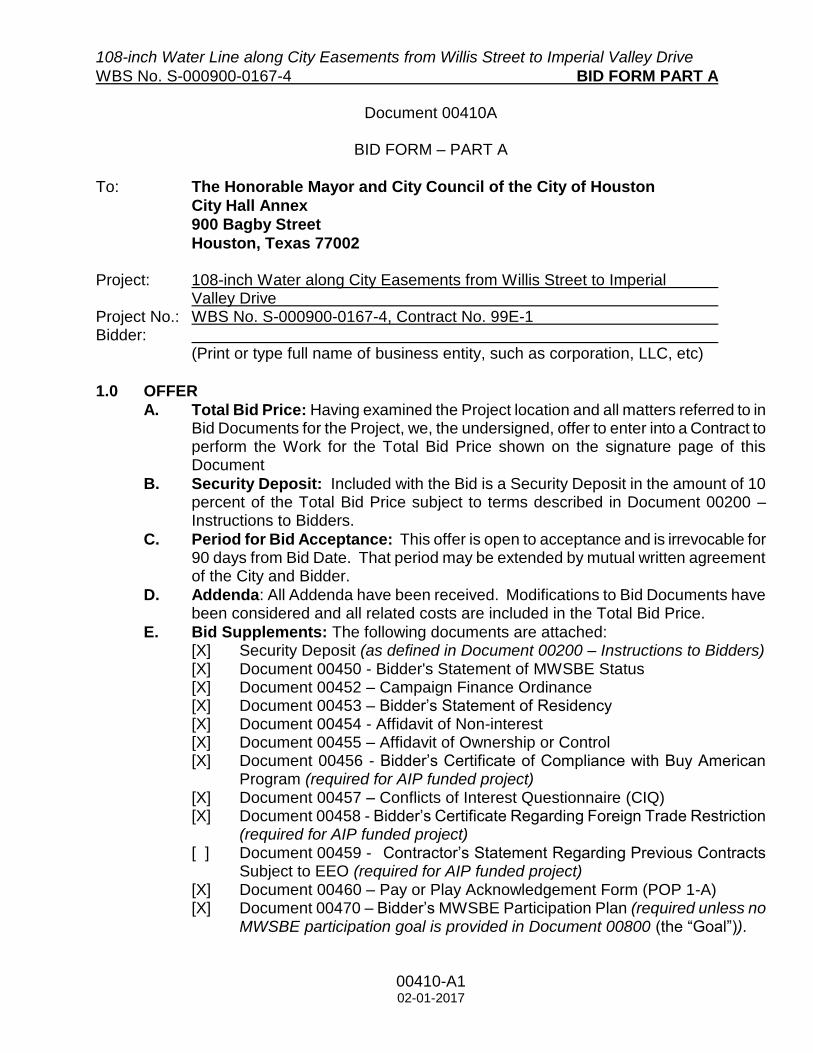
Document 00410A
BID FORM – PART A
To: The Honorable Mayor and City Council of the City of Houston
City Hall Annex
900 Bagby Street
Houston, Texas 77002 Project: 108-inch Water along City Easements from Willis Street to Imperial Valley Drive Project No.: WBS No. S-000900-0167-4, Contract No. 99E-1 Bidder:
(Print or type full name of business entity, such as corporation, LLC, etc)
1.0 OFFER
A. Total Bid Price: Having examined the Project location and all matters referred to in Bid Documents for the Project, we, the undersigned, offer to enter into a Contract to perform the Work for the Total Bid Price shown on the signature page of this Document
B. Security Deposit: Included with the Bid is a Security Deposit in the amount of 10 percent of the Total Bid Price subject to terms described in Document 00200 – Instructions to Bidders.
C. Period for Bid Acceptance: This offer is open to acceptance and is irrevocable for 90 days from Bid Date. That period may be extended by mutual written agreement of the City and Bidder.
D. Addenda: All Addenda have been received. Modifications to Bid Documents have been considered and all related costs are included in the Total Bid Price.
E. Bid Supplements: The following documents are attached: [X] Security Deposit (as defined in Document 00200 – Instructions to Bidders) [X] Document 00450 - Bidder's Statement of MWSBE Status [X] Document 00452 – Campaign Finance Ordinance [X] Document 00453 – Bidder’s Statement of Residency [X] Document 00454 - Affidavit of Non-interest [X] Document 00455 – Affidavit of Ownership or Control [X] Document 00456 - Bidder’s Certificate of Compliance with Buy American
Program (required for AIP funded project) [X] Document 00457 – Conflicts of Interest Questionnaire (CIQ) [X] Document 00458 - Bidder’s Certificate Regarding Foreign Trade Restriction
(required for AIP funded project) [ ] Document 00459 - Contractor’s Statement Regarding Previous Contracts
Subject to EEO (required for AIP funded project) [X] Document 00460 – Pay or Play Acknowledgement Form (POP 1-A) [X] Document 00470 – Bidder’s MWSBE Participation Plan (required unless no
MWSBE participation goal is provided in Document 00800 (the “Goal”)).

108-inch Water Line along City Easements from Willis Street to Imperial Valley Drive
WBS No. S-000900-0167-4 BID FORM PART A
00410-A2 02-01-2017
[ ] Document 00471 – Bidder’s Record of Good Faith Efforts (required if the goal in Bidder’s Participation Plan–Document 00470 is lower than the Goal).
[ ] Document 00472 – Bidder’s Goal Deviation Request (required if the goal in Bidder’s Participation Plan–Document 00470 is lower than the Goal).
[ ] Others as listed:
2.0 CONTRACT TIME
A. If offer is accepted, Contractor shall achieve Date of Substantial Completion within
690 days after Date of Commencement of the Work, subject to adjustments of Contract Time as provided in the Contract.

108-inch Water Line along City Easements from Willis Street to Imperial Valley Drive
WBS No. S-000900-0167-4 BID FORM PART B
00410B-1 Bidder’s Initials [ ] 08-01-2013
Document 00410B
BID FORM – PART B
1.0 TOTAL BID PRICE HAS BEEN CALCULATED BY BIDDER, USING THE
FOLLOWING COMPONENT PRICES AND PROCESS (PRINT OR TYPE
NUMERICAL AMOUNTS):
A. STIPULATED PRICE: $N/A (Total Bid Price; minus Base Unit Prices, Extra Unit Prices, Cash Allowances and All Alternates, if any)
B. BASE UNIT PRICE TABLE:
Item
No. Spec Ref. Base Unit Short Title
Unit of Measure
Estimated Quantity
Unit Price (this
column controls) Total in figures
GENERAL
1 01502 Mobilization LS 1 $945,000 (1) $945,000
2 01502 Mobilization/Demobilization
Level 1 LS 1
-----------------
$30,000.00(2)
-----------------
$30,000.00(2)
3 01502 Mobilization/Demobilization
Level 2 LS 1
------------------
$80,000.00(2)
------------------
$80,000.00(2)
4 01502 Mobilization/Demobilization
Level 3 LS 1
------------------
$10,000.00(2)
------------------
$10,000.00(2)
5 01555 Traffic Control and
Regulation LS 1
------------------
$50,000.00(2)
------------------
$50,000.00(2)
6 01555 Flagmen LS 1 ------------------
$61,000.00(2)
------------------
$61,000.00(2)
7 01555 Install Low Profile Concrete
Barriers LF 1,192
8 01555 Relocate Low Profile
Concrete Barriers LF 600
9 01555 Remove Low Profile
Concrete Barriers LF 1,192

108-inch Water Line along City Easements from Willis Street to Imperial Valley Drive
WBS No. S-000900-0167-4 BID FORM PART B
00410B-2 Bidder’s Initials [ ] 08-01-2013
Item
No. Spec Ref. Base Unit Short Title
Unit of Measure
Estimated Quantity
Unit Price (this
column controls) Total in figures
10 01562 Tree and Plant Protection LS 1
11 01565 Nest Survey LS 1
12 01565 Removal of Inactive Nests LS 1
13 01565 Temporary Fencing LF 4,000
14 01565 Netting SY 8,000
15 01570 Inlet Protection Barrier LF 36
16 01570 Hay Bale Inlet Protection LF 112
17 01570 Reinforced Filter Fabric
Barrier LF 49
18 01570 Filter Fabric Barrier LF 6,740
19 01575 Stabilized Construction Exit SY 778
20 01578 Ground Water Control for
Open-Cut Construction LF 3,520
21 01578
Ground Water Control for
Open-Cut Construction in
PPCA
LF 641
22 01740 Site Restoration LF 4,161
23 02105
Preparatory Work for
Sampling and Analysis in
PPCA
LS 1
24 02105
Handling, Sampling and
Testing of Groundwater in
PPCA
LS 1
25 02105 Handling, Sampling and
Testing of Soil in PPCA LS 1

108-inch Water Line along City Easements from Willis Street to Imperial Valley Drive
WBS No. S-000900-0167-4 BID FORM PART B
00410B-3 Bidder’s Initials [ ] 08-01-2013
Item
No. Spec Ref. Base Unit Short Title
Unit of Measure
Estimated Quantity
Unit Price (this
column controls) Total in figures
26 02105
Handling, Sampling and
Testing of Water Discharged
to HCTRA Storm Sewers
and Right-of-Ways
LS 1
27 02120
Transportation and Disposal
of Contaminated Class I
Soils at Approved Facility in
PPCA
CY 6,667
28 02120
Transportation and Disposal
of Contaminated Class II
Soils at Approved Facility in
PPCA
CY 2,830
29 02120
Transportation and Disposal
of Contaminated
Groundwater at Approved
Facility in PPCA
GAL 20,000
30 02233 Clearing and Grubbing AC 2
31 02317 6-inch Over Excavation of
Trench Bottom LF 1,760
32 02317 6-inch Over Excavation of
Trench Bottom LF 321
33 02318 Excavation Around
Obstructions CY 200
34 02318 Excavation Around
Obstructions in PPCA CY 100
35 HCFCD
2364-01 Rock Filter Dam LF 70
36 02821 Install Temporary Fence LF 1,850
37 02821
Remove 9-foot Chain Link
Fence w/ 3-Strand Barbed
Wire
LF 866

108-inch Water Line along City Easements from Willis Street to Imperial Valley Drive
WBS No. S-000900-0167-4 BID FORM PART B
00410B-4 Bidder’s Initials [ ] 08-01-2013
Item
No. Spec Ref. Base Unit Short Title
Unit of Measure
Estimated Quantity
Unit Price (this
column controls) Total in figures
38 02821 Remove 6-foot Chain-Link
Fence LF 203
39 02821 Remove 4-foot Barbed-Wire
Fence LF 781
40 02821
Install 9-foot Chain-Link
Fence w/ 3-Strand Barbed
Wire
LF 866
41 02821 Install 6-foot Chain-Link
Fence LF 203
42 02821 Install 4-foot Barbed-Wire
Fence LF 781
43 02921 Hydro Mulch Seeding AC 6
PAVING
44 02221
Removing and Disposing of
Concrete Pavements
(including all thickness, w/ or
w/o asphalt, including base
& subgrade, w/ or w/o curb,
all depths)
SY 2,010
45 02221
Remove and Dispose of
Asphaltic Surface (all
thickness, including base &
subgrade, w/ or w/o curb, all
depths)
SY 4,191
46 02336 Lime Stabilized Subgrade, 8-
inch SY 6,466
47 02336 Lime for Lime Stabilized
Subgrade (DRY WEIGHT) Ton 163
48 02713 Hot Mix Asphalt Base
Course 8-inch Ton 1,823
108-inch Water Line along City Easements from Willis Street to Imperial Valley Drive
WBS No. S-000900-0167-4 BID FORM PART B
00410B-5 Bidder’s Initials [ ] 08-01-2013
Item
No. Spec Ref. Base Unit Short Title
Unit of Measure
Estimated Quantity
Unit Price (this
column controls) Total in figures
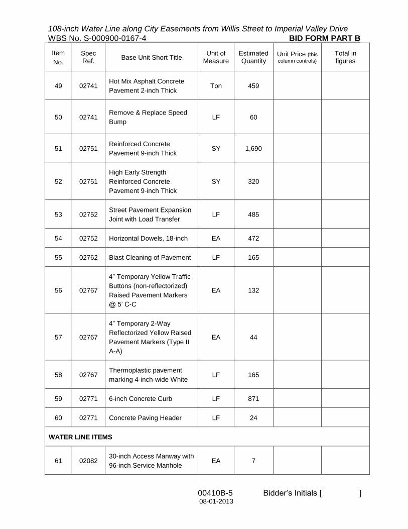
49 02741 Hot Mix Asphalt Concrete
Pavement 2-inch Thick Ton 459
50 02741 Remove & Replace Speed
Bump LF 60
51 02751 Reinforced Concrete
Pavement 9-inch Thick SY 1,690
52 02751
High Early Strength
Reinforced Concrete
Pavement 9-inch Thick
SY 320
53 02752 Street Pavement Expansion
Joint with Load Transfer LF 485
54 02752 Horizontal Dowels, 18-inch EA 472
55 02762 Blast Cleaning of Pavement LF 165
56 02767
4” Temporary Yellow Traffic
Buttons (non-reflectorized)
Raised Pavement Markers
@ 5’ C-C
EA 132
57 02767
4” Temporary 2-Way
Reflectorized Yellow Raised
Pavement Markers (Type II
A-A)
EA 44
58 02767 Thermoplastic pavement
marking 4-inch-wide White LF 165
59 02771 6-inch Concrete Curb LF 871
60 02771 Concrete Paving Header LF 24
WATER LINE ITEMS
61 02082 30-inch Access Manway with
96-inch Service Manhole EA 7

108-inch Water Line along City Easements from Willis Street to Imperial Valley Drive
WBS No. S-000900-0167-4 BID FORM PART B
00410B-6 Bidder’s Initials [ ] 08-01-2013
Item
No. Spec Ref. Base Unit Short Title
Unit of Measure
Estimated Quantity
Unit Price (this
column controls) Total in figures
62 02082 Extra Depth Manhole VF 26
63 02260 Trench Safety System for
Large Diameter Water Line LF 4,161
64 02317 Trench Dams EA 20
65 02511
Remove 108-inch Diameter
Internal Elliptical Dished
Head Plug and Connect to
Existing 108-inch Diameter
Water Line
EA 2
66 02511
Remove 66-inch Diameter
Internal Elliptical Dished
Head Plug and Connect to
Existing 66-inch Diameter
Water Liner
EA 1
67 02511
108-inch by 66-inch
Interconnection with Cast in
Place Base and Supports
LS 1
68 02511 108-inch Diameter Steel
Water Line by Open Cut LF 3,520
69 02511
108-inch Diameter Steel
Water Line by Open Cut in
PPCA limits
LF 641
70 02511 UPRR Tunnel Settlement
Mitigation Measures LS 1
71 02511
108-inch Diameter Steel
Water Line in Tunnel with
Steel Casing
Sta 50+86 to Sta 54+95
LF 416
72 02511
108-inch Diameter Steel
Water Line in Tunnel
Sta 8+08 to Sta 11+01
LF 301

108-inch Water Line along City Easements from Willis Street to Imperial Valley Drive
WBS No. S-000900-0167-4 BID FORM PART B
00410B-7 Bidder’s Initials [ ] 08-01-2013
Item
No. Spec Ref. Base Unit Short Title
Unit of Measure
Estimated Quantity
Unit Price (this
column controls) Total in figures
73 02511
108-inch Diameter Steel
Water Line in Tunnel
Sta 11+49 to Sta 14+55
LF 306
74 02511
108-inch Diameter Steel
Water Line in Tunnel
Sta 32+40 to Sta 35+97
LF 359
75 02511
108-inch Diameter Steel
Water Line in Tunnel
Sta 36+26 to Sta 39+57
LF 331
76 02511
108-inch Diameter Steel
Water Line in Tunnel
Sta 46+91 to Sta 47+58
LF 68
77 02514
(LD)
Preparation for Disinfection
for Large Diameter Water
Line
LF 7,200
78 02514
(LD) Liquid Bleach Gal 4,750
79 02514
(LD) Dechlorination Chemical Gal 3,217
80 02514
(LD)
Chemical Transfer Pumps
with Hoses EA 4
81 02522 108-inch Diameter Butterfly
Valve EA 2
82 02522 66-inch Diameter Butterfly
Valve EA 1
83 02522
96-inch Square Vault with
Cast in Place Base and
Supports around 108-inch
Diameter Water Line (STA
2+43)
EA 2

108-inch Water Line along City Easements from Willis Street to Imperial Valley Drive
WBS No. S-000900-0167-4 BID FORM PART B
00410B-8 Bidder’s Initials [ ] 08-01-2013
Item
No. Spec Ref. Base Unit Short Title
Unit of Measure
Estimated Quantity
Unit Price (this
column controls) Total in figures
84 02524
6-inch Diameter Air Inlet and
Vacuum Relief Valve
Assembly with 3 Bollards
and 72-inch Service
Manhole
EA 3
85 02524
Two 6-inch air inlet and
vacuum relief valves, 12-
inch vent piping and flushing
hydrant with cast in place
concrete vault
EA 3
STORM ITEMS
86 02221 Remove and Dispose 12-
inch PVC Storm Pipe LF 20
87 02221 Remove and Dispose 24-
inch RCP Storm Pipe LF 20
88 02221 Remove and Dispose 48-
inch CMP Storm Pipe LF 50
89 02315 Reshaping and Regrading
Existing Ditches LF 56
90 HCFCD
02378
Remove and Replace
Existing 4-inch Slope Paving SY 31
91 02631 12-inch Diameter PVC
Storm Sewer by Open-Cut LF 20
92 02631 24-inch Diameter RCP
Storm Sewer by Open-Cut LF 20
93 02631 48-inch Diameter CMP
Storm Sewer by Open-Cut LF 50

108-inch Water Line along City Easements from Willis Street to Imperial Valley Drive
WBS No. S-000900-0167-4 BID FORM PART B
00410B-9 Bidder’s Initials [ ] 08-01-2013
Item
No. Spec Ref. Base Unit Short Title
Unit of Measure
Estimated Quantity
Unit Price (this
column controls) Total in figures
SANITARY ITEMS
94 02221
Remove and Dispose of 6-
inch Diameter PVC Sanitary
Sewer
LF 35
95 02531
6-inch Diameter PVC
Sanitary Sewer (Pressure
Rated) in 12-inch Diameter
Casing
LF 35
CATHODIC PROTECTION
96 16640 Cathodic Protection LS 1
TOTAL BASE UNIT PRICES $_________

108-inch Water Line along City Easements from Willis Street to Imperial Valley Drive
WBS No. S-000900-0167-4 BID FORM PART B
00410B-10 Bidder’s Initials [ ] 08-01-2013
C. EXTRA UNIT PRICE TABLE:
Item No.
Spec Ref.
Extra Unit Short Title Unit of
Measure Estimated Quantity
Unit Price (this column
controls)
Total in figures
97 02318 Extra Hand Excavation CY 200 ----------------
$20.00(2) ----------------- $4,000.00(2)
98 02318 Extra Hand Excavation in PPCA
CY 125 ----------------
$20.00(2) ----------------- $2,500.00(2)
99 02318 Extra Machine Excavation CY 200 ----------------
$15.00(2) ----------------- $3,000.00(2)
100 02318 Extra Machine Excavation in PPCA
CY 50 ----------------
$25.00(2) ----------------- $1,250.00(2)
101 02318 Extra Placement of Backfill Material
CY 200 ----------------
$10.00(2) ----------------- $2,000.00(2)
102 02318 Extra Placement of Backfill Material in PPCA
CY 125 ----------------
$15.00(2) ----------------- $1,875.00(2)
103 02511 Extra 108-inch Fittings in Place
EA 5 ---------------- $4,000.00(2)
------------------ $20,000.00(2)
104 02821 Extra Class “A” Concrete Installed in Place
CY 5 ---------------- $400.00(2)
----------------- $2,000.00(2)
105 03315 Extra Grade 60 Reinforcing Steel in Place
LB 2,000 ----------------
$1.00(2) ------------------ $2,000.00(2)
TOTAL EXTRA UNIT PRICES
------------------ $38,625.00(2)

108-inch Water Line along City Easements from Willis Street to Imperial Valley Drive
WBS No. S-000900-0167-4 BID FORM PART B
00410B-11 Bidder’s Initials [ ] 08-01-2013
D. CASH ALLOWANCE TABLE:
REST OF PAGE INTENTIONALLY LEFT BLANK
Item No.
Spec Ref.
Cash Allowance Short Title Cash
Allowance in figures (1)
106 00700 Harris County Flood Control District Permits $10,000.00
107 00700 Harris County Engineering Departments Permits $5,000.00
108 00700 Union Pacific Railroad Inspector & Permit $189,700.00
109 00700 Lane Closure Permit $500.00
110 00700 Street Cut Permit $5,000.00
111 00700 CenterPoint Energy Electric Facilities Adjustments $200,000.00
112 00700 Telecommunication Line (Underground/Overhead) Relocation $75,000.00
TOTAL CASH ALLOWANCES
$485,200.00

108-inch Water Line along City Easements from Willis Street to Imperial Valley Drive
WBS No. S-000900-0167-4 BID FORM PART B
00410B-12 Bidder’s Initials [ ] 08-01-2013
E. ALTERNATES TABLE:
REST OF PAGE INTENTIONALLY LEFT BLANK
Item No.
Spec Ref.
Alternate Short Title Unit of
Measure Estimated Quantity
Unit Price (this column
controls)
Total Price for Alternate
in figures
113 02511
Install 66-inch Diameter
Internal Elliptical Dished Head
Plug
EA 1
114 02511
Install 108-inch Diameter
Internal Elliptical Dished Head
Plug
EA 2
TOTAL ALTERNATES $________

108-inch Water Line along City Easements from Willis Street to Imperial Valley Drive
WBS No. S-000900-0167-4 BID FORM
PART B
00410B-13 02-01-2017
F. TOTAL BID PRICE: $ (Add Totals for Stipulated Price, Base Unit Price, Extra Unit Price, Cash Allowance, and All Alternates, if any)
2.0 SIGNATURES: By signing this Document, I agree that I have received and reviewed all Addenda and considered all costs associated with the Addenda in calculating the Total Bid Price.
Bidder:
(Print or type full name of your proprietorship, partnership, corporation, or joint venture.*)
**By:
Signature Date
Name:
(Print or type name) Title
Address:
(Mailing)
(Street, if different)
Telephone and Fax Number:
(Print or type numbers)
* If Bid is a joint venture, add additional Bid Form signature sheets for each member of the
joint venture.
** Bidder certifies that the only person or parties interested in this offer as principals are those named above. Bidder has not directly or indirectly entered into any agreement, participated in any collusion, or otherwise taken any action in restraint of free competitive bidding.
Note: This document constitutes a government record, as defined by § 37.01 of the Texas Penal
Code. Submission of a false government record is punishable as provided in § 37.10 of the Texas Penal Code.
Footnotes for Tables B through E: (1) Fixed Unit Price determined prior to Bid. Cannot be adjusted by the Bidder. (2) Minimum Bid Price determined prior to Bid. Can be increased by the Bidder, but not decreased, by crossing out the
Minimum and inserting revised price on the line above. Cannot be decreased by the Bidder. (3) Maximum Bid Price determined prior to Bid. Can be decreased by the Bidder, but not increased, by crossing out the
Maximum and inserting revised price on the line above. A Bid that increases the Maximum Bid Price may be found non-
conforming and non-responsive. Cannot be increased by the Bidder. (4) Fixed Range Bid Price determined prior to Bid. Unit Price can be adjusted by Bidder to any amount within the range
defined by crossing out prices noted and noting revised price on the line above.

108-inch Water Line along City Easements from Willis Street to Imperial Valley Drive WBS No S-000900-0167-4 SUMMARY OF WORK
01110-1 Updated on 3/28/2018 06-27-2005 by Jones and Carter, Inc
Section 01110
SUMMARY OF WORK
PART 1 G E N E R A L
1.01 SECTION INCLUDES
A. Summary of the Work including work by the City of Houston (the City), City-furnished
Products, work sequence, future work, Contractor use of Premises, special conditions for
substantial completion and City occupancy.
1.02 PROJECT DESCRIPTION
A. Work of the Contract is for construction of the 108-inch Water Line along City Easements
from Willis Street to Imperial Valley Drive (WBS No. S-000900-0167-4, Contract 99E-1).
B. The Surface Water Transmission Program (SWTP) consists of major improvements to the
transmission system to transition from primary groundwater to surface water in order to
comply with the Harris-Galveston Coastal Subsidence District’s (HGCSD) regulatory plan.
Program includes transmission and distribution of surface water and associated consolidation
of groundwater plants in the City.
C. This project is part of the Northeast Transmission Water Line (NETL), a multiyear project
which will provide treated water to the George Bush Intercontinental Airport, along with the
City in general, Northwest Houston, NHCRWA, CHCRWA, WHCRWA, and NFBWA. The
NETL will carry water produced by the planned expansion of the City’s Northeast Water
Purification Plant (NEWPP). The NETL and NEWPP are needed to meet the Region’s
projected 2040 water demand, which was estimated in the Water for Texas 2012 State Water
Plan.
D. This project primarily consists of construction of 108-inch water transmission line including
but not limited to: approximately 5,900 linear feet of 108-inch water line by combination of
open cut and tunneling methods as well as removal and replacement of pavement, existing
utilities, and drainage infrastructure. This project also includes connections to other NETL
projects, including two proposed 108-inch water line projects and a proposed 66-inch water
line project.
E. Construction of the proposed 108-inch water line begins northeast of the intersection of
Imperial Valley and Harris County Flood Control District (HCFCD) Unit No. P144-03-00, at a
future junction with WBS No. S-000900-168-4 (future 108-inch water line) within easements.
The alignment continues east along commercial properties within easements, tunnels
southeasterly under HCFCD Unit No. P144-03-00, continues east to tunnel under HCFCD
Unit No. P144-00-00 and Spence Road and follows along the northern edge of Frito-Lay, Inc.
commercial property within easements. The water line continues east within easements along
HCFCD Unit No. P144-00-00 and Unit No. P144-02-00 and then tunnels northeasterly under
HCFCD Unit No. P144-02-00 and continues east within easements along the northern
property of P144-02-00 towards West Hardy Road along commercial properties. The

108-inch Water Line along City Easements from Willis Street to Imperial Valley Drive WBS No S-000900-0167-4 SUMMARY OF WORK
01110-2 Updated on 3/28/2018 06-27-2005 by Jones and Carter, Inc
proposed 108-inch will have a future junction with WBS No. S-000900-166-00 (future 66-inch
water line) at West Hardy Road. The water line continues east within easements, tunnels
under Union Pacific Railroad (UPRR) Right-Of-Way (ROW) as well as Harris County Toll
Road Authority (HCTRA) ROW and ends along the north ROW of Courtesy Street within
easements to connect with WBS No. S-000900-165-4 (future 108-inch water line).
1.03 DEFINITIONS
A. Large Diameter Water Lines: Water Lines 24-inches in diameter and larger. References to
large diameter water lines shall apply to pipe, valves and appurtenances 24-inch and larger.
B. Small Diameter Water Lines: Water Lines 20-inches in diameter and smaller. Unless
otherwise noted in the Contract Documents, requirements pertaining to large diameter water
lines do not apply to pipe, valves and appurtenances 20-inches in diameter and smaller.
1.04 WORK COVERED BY CONTRACT DOCUMENTS
This work will include, but not to be limited to, the following:
A. WATER LINES
1. Construction of 108-inch water line by combination of open cut and tunneling methods,
including valves, connections, and appurtenances within City easements from Willis
Street to Imperial Valley Drive.
2. Construction of 108-inch water line in steel liner by tunneling across HCFCD Unit No.
P144-03-00, HCFCD Unit No. P144-00-00, HCFCD Unit No. P144-02-00, Spence Road,
and West Hardy Road.
a. Submit specific monitoring instrumentation and settlement surveying plans, in
accordance with Section 02425 (LD) Tunnel Excavation and Primary Liner for Water
Mains to Project Manager for approval.
b. See Section 1.07 for additional information.
3. Construction of 108-inch water line in steel casing by tunneling across UPRR ROW and
HCTRA ROW.
a. Submit specific contingency plan to prevent loss of ground underneath UPRR ROW
and HCTRA ROW in accordance with Section 02425 (LD) – Tunnel Excavation and
Primary Liner for Water Mains to Project Manager for approval. In addition to the
above requirements, the plan shall include actions to be taken in the event of a cave-
in or other large ground-loss event. Contingency plan shall be implemented when
any settlement occurs and/or in the event of a cave-in or other large ground-loss
event occurs.

108-inch Water Line along City Easements from Willis Street to Imperial Valley Drive WBS No S-000900-0167-4 SUMMARY OF WORK
01110-3 Updated on 3/28/2018 06-27-2005 by Jones and Carter, Inc
4. Connect proposed 108-inch water line with proposed 108-inch water line in WBS No. S-
000900-168-4.
a. See Section 1.06 for additional information.
5. Connect proposed 108-inch water line with proposed 66-inch water line in WBS No. S-
000900-166-00.
a. See Section 1.06 for additional information.
6. Connect proposed 108-inch water line with proposed 108-inch water line in WBS No. S-
000900-165-4.
a. See Section 1.06 for additional information.
B. STORM SEWERS, DITCHES AND PONDS
1. Remove and replace storm sewers (all sizes and types) by open cut method.
2. Regrade existing ditches to existing or better condition as impacted by 108-inch water
line construction.
3. Regrade existing detention pond to existing or better condition as impacted by 108-inch
water line construction.
4. Maintain adequate drainage at all times and restore any drainage ditch or structure
disturbed to satisfaction of owning authority. Construction storm runoff shall comply with
the final draft of the Stormwater Management Handbook for construction activities, as
prepared by Harris County, and the City of Houston in compliance with NPDES
requirements.
5. Document conditions of storm sewers prior to beginning construction operations.
Remove silt in existing and replaced storm sewer system that result from construction
activities associated with project.
C. SANITARY SEWERS
1. Remove and replace wastewater lines as impacted by the 108-inch water line
construction.
2. Maintain service to all sewers during construction. Locate sanitary sewer service laterals
affected by construction, as necessary.
3. Contractor fully responsible for damages to existing sanitary sewer facilities as a result of
this project. Construct sanitary sewers in compliance with latest City specifications for
sanitary sewer construction, and tested as specified in City test procedure for either liquid
or air, including all amendments and revisions thereto. Place embedment and backfill for
sanitary sewers in accordance with City of Houston standard drawings unless otherwise
noted.

108-inch Water Line along City Easements from Willis Street to Imperial Valley Drive WBS No S-000900-0167-4 SUMMARY OF WORK
01110-4 Updated on 3/28/2018 06-27-2005 by Jones and Carter, Inc
4. Transfer of service stubs, as necessary, from existing to replacement of sanitary sewer
line as result of construction must be included. Remove and replace any stubs
determined to be damaged by project inspector to property line.
D. CATHODIC PROTECTION
1. Install Cathodic Protection as indicated on plans.
E. PAVEMENT REPLACEMENT
1. Remove and replace concrete pavement along West Hardy Drive according to the
drawings, and City of Houston Specifications.
a. Refer to Section 1.11 for additional information.
2. Pavement repair or replacement work along Courtesy Road, if necessary, shall be
performed according to Harris County Standards and Specifications.
3. Remove and replace concrete pavement at Hartman Income REIT Management, Inc.
property, Century Plaza Shopping Center property, and Americas Best Value Inn &
Suites property including curbs according to the drawings.
a. Refer to Section 1.11 for additional information.
4. Remove and replace concrete and asphalt pavement at Tarantino and Frito-Lay, Inc.
Properties, Inc. property including curbs according to the drawings.
F. TREE PROTECTION
1. Clear and grub proposed water line easements to limits shown on Drawings.
2. Vegetation clearing activities and construction activities in general are restricted at certain
times of the year according to Federal bird protection regulations. Demobilization will be
allowed at the direction of the Project Manager if work must stop in order to comply with
either the Migratory Bird Treaty Act or the Bald and Golden Eagle Protection Act. If
clearing activities are required during the nesting season, perform nest survey and clear
to full extent as soon as possible. Utilize netting to prevent establishment of nests in
areas to be cleared, if needed. Refer to Section 01565 for additional information.
3. Notify City of Houston Parks and Recreation Department representative Mr. Dale
Temple, City Forester, at (832) 395-2205, at least two (2) weeks in advance of clearing,
cutting, or pruning any tree.
4. Contractor’s arborist will mark locations of the new trees and obtain approval by the City
Engineer and City Forester before purchasing and planting trees.
G. SOIL CONDITIONS & ENVIRONMENTAL SITE ASSESMENTS
108-inch Water Line along City Easements from Willis Street to Imperial Valley Drive WBS No S-000900-0167-4 SUMMARY OF WORK
01110-5 Updated on 3/28/2018 06-27-2005 by Jones and Carter, Inc
1. Contractor(s) must consider soil conditions and ESA findings provided in Geotechnical
Report, and ESA Phase I & II Reports, respectively.
H. SITE RESTORATION
1. Restore site as specified in Specification 01740.
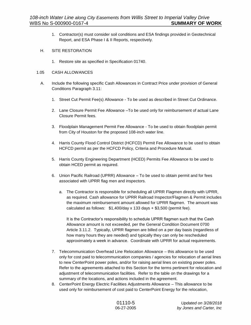
1.05 CASH ALLOWANCES
A. Include the following specific Cash Allowances in Contract Price under provision of General
Conditions Paragraph 3.11:
1. Street Cut Permit Fee(s) Allowance - To be used as described in Street Cut Ordinance.
2. Lane Closure Permit Fee Allowance –To be used only for reimbursement of actual Lane
Closure Permit fees.
3. Floodplain Management Permit Fee Allowance - To be used to obtain floodplain permit
from City of Houston for the proposed 108-inch water line.
4. Harris County Flood Control District (HCFCD) Permit Fee Allowance to be used to obtain
HCFCD permit as per the HCFCD Policy, Criteria and Procedure Manual.
5. Harris County Engineering Department (HCED) Permits Fee Allowance to be used to
obtain HCED permit as required.
6. Union Pacific Railroad (UPRR) Allowance – To be used to obtain permit and for fees
associated with UPRR flag men and inspectors.
a. The Contractor is responsible for scheduling all UPRR Flagmen directly with UPRR,
as required. Cash allowance for UPRR Railroad Inspector/Flagmen & Permit includes
the maximum reimbursement amount allowed for UPRR flagmen. The amount was
calculated as follows: $1,400/day x 133 days + $3,500 (permit fee).
It is the Contractor’s responsibility to schedule UPRR flagmen such that the Cash
Allowance amount is not exceeded, per the General Condition Document 0700
Article 3.11.2. Typically, UPRR flagmen are billed on a per day basis (regardless of
how many hours they are needed) and typically they can only be rescheduled
approximately a week in advance. Coordinate with UPRR for actual requirements.
7. Telecommunication Overhead Line Relocation Allowance – this allowance to be used
only for cost paid to telecommunication companies / agencies for relocation of aerial lines
to new CenterPoint power poles, and/or for raising aerial lines on existing power poles.
Refer to the agreements attached to this Section for the terms pertinent for relocation and
adjustment of telecommunication facilities. Refer to the table on the drawings for a
summary of the locations, and actions included in the agreement.
8. CenterPoint Energy Electric Facilities Adjustments Allowance – This allowance to be
used only for reimbursement of cost paid to CenterPoint Energy for the relocation,

108-inch Water Line along City Easements from Willis Street to Imperial Valley Drive WBS No S-000900-0167-4 SUMMARY OF WORK
01110-6 Updated on 3/28/2018 06-27-2005 by Jones and Carter, Inc
adjustment, and de-energization of electrical facilities as listed in the table below for
electrical power poles. Contact Cynthia Martinez at (713) 207-6555 and Jonathan
Villareal at (713) 945-8974 at least 84 days prior to needing relocation, adjustment,
and/or de-energization of electrical facilities. Direct CenterPoint Energy as to location to
begin work to enable access to critical areas sooner.
Utility
Owner
Facility
Type
Approximate
Station
Estimated
Clearance Date Action
CenterPoint
Electric
OH Power,
Power lines
STA 3+61, STA
5+38, STA 10+69,
STA 35+00, STA
39+50, STA 46+87,
STA 51+22, STA
56+00 to 59+53
12-weeks after
submitting the
request to the
CenterPoint
electric
Install
taller
poles
9. Fiber Optic Underground and Overhead Line Relocation Allowance – This allowance is to
be used only for cost paid to fiber optic companies/agencies for relocation of
underground and aerial lines to new CenterPoint poles, and/or for raising aerial lines on
existing poles.
a. Contractor is encouraged to coordinate with Comcast 45 days prior to construction.
b. Contractor is encouraged to coordinate with Phonoscope and PS Lightwave 30 days
prior to construction.
Utility
Owner
Facility
Type
Approximate
Station
Estimated
Clearance Date Action
Phonoscope
& PS
Lightwave
Fiber Optic
Cables
STA 1+75, STA
46+90, STA
47+92
30+ days prior to
needing lines
adjusted
Lines to be
raised
Comcast
Cables, Low
Hanging
Telephone
STA 8+65, STA
13+71, STA
37+62
6-8 weeks prior to
needing lines
adjusted
Lines to be
raised
1.06 ALTERNATES
A. Alternate construction methods may be allowed in accordance with applicable details and
specifications in Contract Documents provided City will receive substantial benefit from
alternate construction method(s). Contractor, at their sole discretion, accepts responsibility for
all additional geotechnical investigations and incidental items, including any re-design that
may be necessary. Submit the following for review by City Engineer prior to commencement
of any construction activity if such alternate construction methods are to be considered. All

108-inch Water Line along City Easements from Willis Street to Imperial Valley Drive WBS No S-000900-0167-4 SUMMARY OF WORK
01110-7 Updated on 3/28/2018 06-27-2005 by Jones and Carter, Inc
modification as listed below must be signed and sealed by a Licensed Professional Engineer
registered in State of Texas prior to submittal to City Engineer.
1. Revisions to horizontal or vertical alignment.
2. Revisions to access manhole details, if applicable.
3. Revisions to line valve, operator manhole and/or vault details, if applicable.
4. Revisions to vacuum relief valve vault details, if applicable.
5. Revisions to cathodic protection system, if applicable.
6. Proposed construction method and detailed plan of approach.
7. Location of access shafts, if applicable.
8. Proposed traffic control plan.
9. Revision to material specifications.
10. Impact of revised alignment on hydraulic surge potential on line segment in question and
all adjacent line segments, existing or proposed.
B. Failure of agreement between Contractor and Project Manager over proposed alternate
construction methods would require construction to vertical and horizontal alignments, and
details as per original Contract documents.
1.07 CITY-FURNISHED PRODUCTS
A. Contractor's Responsibilities:
1. Arrange and pay for Product delivery to the site.
2. Receive and unload Products at the site; jointly with the City, inspect for completeness or
damage.
3. Handle, store, Install, and finish Products.
4. Repair or replace damaged items.
1.08 WORK SEQUENCE
A. CRITICAL LOCATES AND SUBMITTALS
1. Perform critical locates and provide major project submittals (pipe, valves, tunneling
procedures and shafts) for water lines greater than 24-inches diameter within 30 days
from Notice to Proceed. Field verify dimensions and conditions before commencing work.
Report discrepancies to Project Manager before commencing work. Submit
documentation of work. Submit documentation of work completion to Project Manager.

108-inch Water Line along City Easements from Willis Street to Imperial Valley Drive WBS No S-000900-0167-4 SUMMARY OF WORK
01110-8 Updated on 3/28/2018 06-27-2005 by Jones and Carter, Inc
2. Prior to beginning construction, survey and photograph the site, including parking lots,
concrete pads, and roadway pavement area to establish pre-existing conditions for
purpose of restoring to existing or better conditions after construction.
B. CONSTRUCTION PHASING
1. Construct large diameter water line from Imperial Valley Drive and progress uninterrupted
east towards Hardy Street, unless otherwise approved by Project Manager. Obtain
approval of Project Manager prior to using more than one pipe laying crew for installation
of 108-inch water line.
2. Incorporate Traffic Control Plan and Traffic Control General Notes as shown on Drawings
in proposed sequence of work. Refer to Traffic Control Plans and Section 01555 for
Traffic Control Plan requirements for sequencing of paving, work across commercial lots,
and work through intersections.
a. Contractor shall place advance warning signs at least two (2) weeks in advance of
starting construction.
3. For areas with no phasing or sequencing, do not disturb more than 50% of total project
linear feet of disturbed right-of-way and easement until site restored in accordance with
Section 01740 – Site Restoration.
4. Construct the Work in Phases during the construction period, coordinate construction
schedule, and operations with the City. Refer to Document 01326 – Construction
Schedule (Bar Chart) for specific details. Coordinate with businesses as required in
Section 1.09 E of this Section.
5. Phase 1 and Phase 2:
a. Phase construction across KY17-212 to maintain access and parking for Hartman
Income REIT Management, Inc., Century Plaza Shopping Center, and Tarantino
Properties, Inc. properties.
b. For Phase 2, perform tunneling operations from shaft on north side of HCFCD Unit
No. P144-03-00.
6. Phase 3: Frito Lay Property
a. Prior to construction, contractor to coordinate with Frito Lay to ensure removal of 30”
storm sewer as seen on Sheet 21, and the storage building as seen on Sheet 23.
b. Phase construction across Frito Lay Property to maintain access and parking by
impacting only a maximum of 200 LF through the property at all times.
c. Stage equipment and materials in order to maintain full access to Frito Lay Property
along Spence Road at all times.

108-inch Water Line along City Easements from Willis Street to Imperial Valley Drive WBS No S-000900-0167-4 SUMMARY OF WORK
01110-9 Updated on 3/28/2018 06-27-2005 by Jones and Carter, Inc
7. Phase 4: America’s Best Value Inn & Suites
a. Phase construction to maintain access and parking for America’s Best Value Inn &
Suites property. Stage equipment and materials within work area at all times.
b. Perform tunneling operations from shaft on south side of HCFCD Unit No. P144-02-
00.
8. Phase 5: West Hardy Road
a. Coordinate phasing with City of Houston WBS No. S-000900-0166-00, as referenced
in Section 1.09 E of this Section, to effectively construct the proposed water line
without impact of traffic along West Hardy Road.
9. Disinfection shall be performed by Drinking Water Operations as per Document
02514(LD) – Disinfection of Water Lines.
10. Vegetation clearing activities and construction activities in general are restricted at certain
times of the year according to Federal bird protection regulations. Demobilization will be
allowed at the direction of the Project Manager if work must stop in order to comply with
either the Migratory Bird Treaty Act or the Bald and Golden Eagle Protection Act. If
clearing activities are required during the nesting season, perform nest survey and clear
to full extent as soon as possible. Utilize netting to prevent establishment of nests in
areas to be cleared, if needed. Refer to Section 01565 for additional information.
C. COORDINATION OF WORK
1. Refer to Section 01312 – Coordination and Meetings.
2. Schedule Work with any other contractors of any trade or discipline working adjacent to the project site prior to and during constructions.
a. City of Houston WBS No. S-000900-0168-4 (108-inch Water Line along City Easements from Imperial Valley Drive to Plaza Verde Drive)
i Proposed 108-inch water line in WBS No. S-000900-0168-4 is shown per
existing design drawings. Field verify the location of the proposed 108-inch water
line. If construction of the water line in WBS No. S-000900-0167-4 is complete
and ready to chlorinate and test before WBS No. S-000900-0168-4, then provide
internal dished head plug as indicated on the drawings. If work has been
completed in WBS No. S-000900-168-4, then remove existing internal dished
head plug and make connection to proposed 108-inch water line.
b. City of Houston WBS No. S-000900-0166-00 (66-inch Water Line along West Hardy
Road from Beltway 8 to Greens Road)

108-inch Water Line along City Easements from Willis Street to Imperial Valley Drive WBS No S-000900-0167-4 SUMMARY OF WORK
01110-10 Updated on 3/28/2018 06-27-2005 by Jones and Carter, Inc
i Proposed 66-inch water line in WBS No. S-000900-0166-00 is shown per
existing design drawings. Field verify the location of the proposed 66-inch water
line. If construction of the water line in WBS No. S-000900-0167-4 is complete
and ready to chlorinate and test before WBS No. S-000900-0166-00, then
provide internal dished head plug as indicated on the drawings. If work has been
completed in WBS No. S-000900-0166-00, then remove existing internal dished
head plug and make connection to proposed 66-inch water line.
ii Coordinate lane closure at West Hardy Road with WBS No. S-000900-166-00.
c. City of Houston WBS No. S-000900-165-4 (108-inch along City Easements from
Aldine Westfield Road to Willis Street).
i Proposed 108-inch water line in WBS No. S-000900-0165-4 is shown per
existing design drawings. Field verify the location of the proposed 108-inch water
line. If construction of the water line in WBS No. S-000900-0167-4 is complete
and ready to chlorinate and test before WBS No. S-000900-0165-4, then provide
internal dished head plug as indicated on the drawings. If work has been in WBS
No. S-000900-0165-4, then remove existing internal dished head plug and make
connection to proposed 108-inch water line.
3. Schedule construction operations with Project Manager, Traffic Management,
Maintenance Division, Drinking Water Operations, and private utilities.
4. Contact Traffic Management and Maintenance Division of the City of Houston Public
Works and Engineering Department or Harris County Engineering Department when
Work is scheduled near signal conduits. Call at least five working days in advance.
Contractor responsible for any damages to existing traffic signal cables as a result of
construction activities for the project.
5. Notify Utility Coordinating Committee at 1-800-669-8344 or (713) 223-4567; and City of
Houston Department of Public Works and Engineering, Civil Construction at (832) 395-
2500; and Office of the City Engineer, Department of Public Works and Engineering by
fax at 832-394-9620, at least 48 hours prior to commencement of Work.
6. Union Pacific Railroad Company (UPRR) - Contractor shall contact XXXX a minimum of
XX hours prior to initiation of construction. A representative from UPRR must be present
during installation if railroad signals are in the vicinity of the proposed construction of if
the proposed construction equipment is to be within XX feet of railroad. The execution of
the work on railroad property shall be subject to the inspection and direction of UPRR
representative.
7. Pipeline Companies: Proposed 108-inch water line crosses 12-inch Sunoco high
pressure petroleum pipeline near STA 37+65, two 6-inch Magellan pipelines near STA
50+50, and two 8-inch Sunoco high pressure petroleum pipelines near STA 51+20. Notify
the following representatives for line marking, depth probing and 72 hours prior to start of
any construction activities in vicinity of pipelines:

108-inch Water Line along City Easements from Willis Street to Imperial Valley Drive WBS No S-000900-0167-4 SUMMARY OF WORK
01110-11 Updated on 3/28/2018 06-27-2005 by Jones and Carter, Inc
a. Sunoco Representative: Justin Croney - (713) 819-6704
b. Magellan Representative: Parker Ray - (832) 691-3280
8. Private Utility Companies
a. CenterPoint Energy Gas: Underground gas facilities exist in the work zone. Refer to
the Construction Notes sheet in the Drawings for specific information regarding gas
facilities.
b. CenterPoint Energy Electric: Overhead electric lines exist in the work zone. Refer to
the Construction Notes sheets in the Drawings for specific information regarding
electrical facilities. Coordinate utility adjustments as noted in Section 1.03 – Cash
Allowances.
c. AT&T/SWBT Facility: AT&T Texas/SWBT utilities exist in the work zone. Refer to the
Construction Notes sheet in the Drawings for specific information regarding AT&T
Texas/SWBT facilities.
d. Comcast Facility: Comcast utilities exist in the work zone. Refer to the Construction
Notes sheet in the Drawings for specific information regarding Comcast facilities.
e. Phonoscope & PS Lightwave: Underground and aerial fiber optic cables exist in the
work zone. Coordinate utility adjustments as noted in Section 1.03 – Cash
Allowances.
i Phonoscope Representative: Hugo Espinosa – [email protected]
ii PS Lightwave Representative: Steve Wagner – [email protected]
f. MCI Communications Services, Inc.: MCI utilities exist in the work zone. Refer to the
Construction Notes sheet in the Drawings for specific information regarding MCI
facilities.
9. Notify HCTRA at least 48-hours prior to construction within their right-of-way. Contact
Jessie Dehn at (713) 587-7639, [email protected]. Comply with HCTRA
Specifications while performing Work in the HCTRA ROW. For TxDOT Specifications,
refer to: https://www.hctra.org//media/3766A2D0BC6E4581B8C77F476B0F9544.ashx.
Submit traffic control plans and Request for Approval of Traffic Control Plan form to
HCTRA Office. Traffic control plans must be approved by HCTRA prior to work in
HCTRA ROW, prior to placing traffic control devices in the HCTRA ROW, and prior to
utilization of traffic control devices impacting HCTRA roadways. HCTRA Office may be
contacted at: 7701 Wilshire Place Drive, Houston, TX 77040, Phone: (713) 587-7800.
10. Notify Harris County Emergency Service Districts (HCESDs) and fire stations of
construction activities at least 2 weeks prior to any construction activity which may result
in traffic impact to West Hardy Road.

108-inch Water Line along City Easements from Willis Street to Imperial Valley Drive WBS No S-000900-0167-4 SUMMARY OF WORK
01110-12 Updated on 3/28/2018 06-27-2005 by Jones and Carter, Inc
11. Notify Houston Fire Department Station 74 at least 2 weeks prior to construction activities
which may result in traffic impact to West Hardy Road. Contact Samuel Pena, Chief, at
(832) 394-6702.
12. Obtain Harris County Engineering Department (HCED) right-of-way permit prior to performing any work within Harris County) right-of-way. Notify Harris County Property Management & Engineering Department in writing at least 48 hours prior to construction. Submit the Preconstruction Notification form, approved plans and applicable permits to Harris County, 9900 Northwest Freeway, Houston, TX 77092, Attn: Property Management Dept., by hand delivery or FAX to 713-684-4212. Contractor must obtain bond covering construction facilities within Harris County Right of Way. See Attachments to this Section for Bond form. Comply with Harris County Specifications while performing Work in the Harris County ROW. For standard County Specifications, refer to: http://www.eng.hctx.net/Consultants/Standards-Specifications/Standard-Engineering-
Design-Specifications.
13. Comply with Harris County Flood Control District Specifications while performing Work in
the HCFCD ROW. Refer to
https://www.hcfcd.org/media/1311/hcfcd_2005_specifications.pdf for standard HCFCD
Specifications. Comply with notification, permit, bond, construction, and other
requirements included in the document Rules Of Harris County And The Harris County
Flood Control District For The Construction Of Facilities Within Harris County And Harris
County Flood Control District Rights Of Way. This document may be found at:
https://hcpid.org/permits/docs/notification_regs.pdf.
14. If the construction process, including loading and unloading of materials will impact bus
and/or pedestrian routes, coordinate work around existing METRO bus stops in the
project area with METRO bus operations, Shirley Mitchell at 713-615-7212 or Carl Taylor
at 713-615-7219. Provide minimum of two (2) weeks’ notice before construction begins
in this area.
15. Coordinate work around Aldine Independent School District school bus stops in the
project area with Aldine Independent School District Transportation Department, listed
below. Provide minimum of three (3) weeks’ notice before construction begins in this
area. Mr. Michael Houston, Executive Director of West Transportation, at 281-878-7809.
16. Notify the following adjacent property owners 48 hours prior to initiating construction per
Section 01145.
a. Notify Hartman Income REIT Management, Inc. property manager at XXXXXXX.
b. Notify Century Plaza Shopping Center property manager at XXXXXXX.
c. Notify Tarantino Properties, Inc. property manager at XXXXXXX.
d. Notify Frito-Lay, Inc. property manager at XXXXXXX.
e. Notify Americas Best Value Inn & Suites property manager at XXXXXXX.

108-inch Water Line along City Easements from Willis Street to Imperial Valley Drive WBS No S-000900-0167-4 SUMMARY OF WORK
01110-13 Updated on 3/28/2018 06-27-2005 by Jones and Carter, Inc
17. It is the Contractor’s sole responsibility to contact each business or property owner that is
reasonably determined to be affected by its operations. This specifically includes water
outages of any durations and limited access to streets, driveways or sidewalks.
Contractors shall attempt to speak with each such resident or business, and having tried
and failed shall place a door hanger to convey the duration of service or other
interruption. Door Hangers shall list both Contractor and Field Superintendent telephone
numbers.
18. Cathodic protection system inspection will be performed by [Cathodic Protection
Subconsultant].
a. Contractor is required to coordinate all necessary inspection during construction.
The inspection of cathodic protection system installation will be done in 3 steps.
Contractor should plan accordingly for inspection.
i Step 1: Prior to backfill
ii Step 2: After backfill prior to paving
iii Step 3: After paving
b. Contractor required to coordinate final commission with the designated inspector in
accordance with Section 16640.
c. Coordinate any issue with an existing system with DWO, David Pedersen at 832-395-
3833.
D. INTERPRETATION OF CONFLICTS
1. Should conflicts occur in Contract Documents, request interpretation before proceeding
with work. Such requests shall first be preceded by a diligent investigation into Contract
Documents. Include evidence of such investigation in requests for interpretation.
2. Should conflict occur between the City and Harris County or HCTRA Specifications, the
most stringent requirements shall apply. Payment will be according to City of Houston
Specifications in all instances.
1.09 CONTRACTOR USE OF PREMISES
A. Comply with procedures for access to the site and Contractor's use of rights-of-way as specified in Section 01145 - Use of Premises.
B. Construction Operations: Limited to the City's rights-of-way provided by the City and areas shown or described in the Contract documents.
C. Utility Outages and Shutdown: Provide a minimum of 48 hours’ notice to the City and private utility companies (when applicable), excluding weekends and holidays, in advance of required utility shutdown. Coordinate all work as required.

108-inch Water Line along City Easements from Willis Street to Imperial Valley Drive WBS No S-000900-0167-4 SUMMARY OF WORK
01110-14 Updated on 3/28/2018 06-27-2005 by Jones and Carter, Inc
D. Comply with procedures for site mobilization as specified in Section 01502 – Mobilization. If approved by Project Manager, demobilization will be granted if Migratory Bird Treaty Act or Bald and Golden Eagle Protection Act prohibit contractor from construction operations. Refer to Section 01565.
E. Accessibility to easement parcels is limited after rainfall events. Provide necessary means to
maintain access at all times. Refer to Specification 01145 – Use of Premises.
F. Limits of construction outside of City of Houston Right of Way as shown on drawings.
G. Limits of HCTRA ROW
1. Notify HCTRA at least 48 hours prior to construction within HCTRA ROW. Contact Jessie
Dehn at (713) 587-7639.
2. Maintain HCTRA ROW at all times, including keeping pavement clean and preventing
erosion to roadside ditches and other areas.
H. Tunneling Contingency Plan
1. If monitoring equipment and/or settlement surveying detects any settlement, and/or a
tunnel cave-in or large loss of ground occurs while tunneling, then Project Manager and
HCTRA shall be notified. Approved contingency plan shall be implemented to prevent
further settlement and/or ground loss.
2. Other means of restoring settled pavement as approved by HCTRA. Refer to
Specification 02425 (LD) – Tunnel Excavation and Primary Linear for Water Mains.
I. Limits of Harris County ROW.
1. Comply with Notification requirements for work within the Public Right-of-Way as shown
on the Drawings.
2. Comply with Harris County specifications while performing work in the Harris County
ROW. Refer to http;//www.eng.hctx.net/Consultants/Standards-Specifications/Standard-
Engineer-Design-Specifications for standard County
3. Harris County Soil Disposal: Refer to Section 01576 – Waste Material Disposal, and
coordinate with Harris County Public Infrastructure Department to obtain disposal permit
for proposed disposal sites in Harris County, outside the City of Houston limits.
J. Collection, storage, and transport/disposal of ground and flushing water.
1. Excess flows shall be collected and discharged when groundwater production is reduced,
or the excess water shall be hauled offsite for discharge in a legal fashion.
2. Do not discharge produced groundwater or flushing water at volume which overflows
storm sewers, roadside ditches, or floods City/County/HCTRA ROW or private property.

108-inch Water Line along City Easements from Willis Street to Imperial Valley Drive WBS No S-000900-0167-4 SUMMARY OF WORK
01110-15 Updated on 3/28/2018 06-27-2005 by Jones and Carter, Inc
3. Prevent erosion induced from discharging water.
4. If discharging produced groundwater to storm sewers, discharge piping and/or hoses
shall be fitted with a filtering sock or other device to prevent transport of sediment into
storm sewers.
5. Dechlorinate flushing water prior to discharge. Provide equipment and chemicals
necessary for the City to perform dechlorination. Refer to Specification 02514.
a. Provide erosion control measures for City/County/HCTRA ROW or private property.
K. Real Estate:
1. Temporary fence is to be installed as indicated on the drawings prior to beginning
construction operations.
2. Fence removal and reinstallation: Remove, rollup, label with ownership information, store,
and protect fence as indicated in the drawings as removal and reinstallation. Upon
completion of construction on the properties, the existing fence is to be re-installed to
match existing conditions unless indicated otherwise on the drawings. Contractor to
provide surveyor to verify fence is re-installed at the correct location.
3. Provide access to property owners at all times and ensure property is not negatively
affected.
4. The City of Houston has acquired or is in final completion of easement acquisition with
the following properties. Status of parcels should be considered in completion of this
project and application of sequencing of the project.
Parcel # Type Anticipated Date
of Acquisition
Status
1 KY17-212 Water ---------- Pending
2 KY17-210 Water ---------- Pending
3 KY17-209B Water ---------- Pending
4 KY17-209A Water ---------- Pending
5 KY17-208 Water ---------- Pending
6 KY17-207 Water ---------- Pending
7 KY17-206 Water ---------- Pending
8 KY17-199B Water ---------- Pending
9 KY17-204 Water ---------- Pending
10 KY17-203 Water ---------- Pending
11 KY17-202 Water ---------- Pending
12 KY17-200B Water ---------- Pending
13 KY17-200A Water ---------- Pending
14 KY17-199A Water ---------- Pending
15 KY17-050 Water ---------- Pending

108-inch Water Line along City Easements from Willis Street to Imperial Valley Drive WBS No S-000900-0167-4 SUMMARY OF WORK
01110-16 Updated on 3/28/2018 06-27-2005 by Jones and Carter, Inc
L. Major Haul Routes:
1. Contractor shall propose, for Engineer’s review and approval, access roads for moving construction personnel and equipment. Contractor shall comply with all ordinances and regulations of local, municipal, county and state authorities, including without limitation, limits on the type of or the gross weight of, motor vehicles or construction equipment operating on public ROW or restrictions on the use of such equipment on certain streets.
2. Contractor shall, whenever possible, keep all construction traffic out of existing
neighborhoods. Contractor shall keep haul routes clean at all times in the satisfaction of
the Engineer and the local governing body having jurisdiction over the haul routes.
Contractor shall care for existing pavement (all types), and will be held liable for any
damage to the existing pavements, which will be used by construction equipment or
suppliers while construction is in progress. On competition of the construction, the street
or route, whether paved or not, shall be restored to its original condition or better.
3. No additional payment will be made to the Contractor for maintaining and repairing the
existing road surface. Any bonds, permits or fees required for use of roadways will be the
sole obligation of the Contractor.
a. Major haul routes are limited to Beltway 8 Frontage Road, Imperial Valley Drive,
Spence Road, West Hardy Road, Hardy Toll Road Frontage Road, and Courtesy
Street
b. Access to temporary construction easements are limited to Cotillion Drive from Aldine
Bender Road (F.M. 525), Beltway 8 Frontage Road, and West Hardy Road.
c. Coordinate work around Aldine Independent School District school bus stops if the
construction process, including loading and unloading of materials will impact bus
and/or pedestrian routes. Refer to Section 1.09 for additional information.
d. Do not use residential / minor streets for hauling and transport of construction
materials, excavations, or equipment except where such items are needed on
residential / minor streets for construction.
M. Federal Aviation Administration: This project is in close proximity to George Bush
Intercontinental Airport. Maximum height of equipment is limited to 138 feet above ground
level. Equipment required for construction is expected to be less than 138 feet in height.
Contractor is responsible for coordinating approval with the FAA if maximum height is
exceeded at Contractor’s sole discretion.
N. Working multiple and separate crews during construction is allowed, as approved by Project
Manager.
O. Work will be allowed which pertains to any tunneling operation 24 hours per day, provided
above ground activities do not conflict with provisions of City of Houston Code of Ordinances,
Section No. 40-28 and work does not occur on a Sunday or holiday without prior written

108-inch Water Line along City Easements from Willis Street to Imperial Valley Drive WBS No S-000900-0167-4 SUMMARY OF WORK
01110-17 Updated on 3/28/2018 06-27-2005 by Jones and Carter, Inc
approval. No night work shall occur in residential areas. A non-inclusive list of work pertaining
to tunneling operation is as follows:
1. Multiple tunneling crews will be required to keep construction project on schedule.
2. Tunnel Excavation and incidental work such as muck removal and hauling, ventilation,
lighting, survey control of tunnel line and grade, etc.
3. Tunnel Primary Liner.
4. Monitoring plan with instrumentation as per Section 02425 (LD)
5. Ground Water Control and Ground Stabilization.
6. Pipe Installation.
7. Tunnel Grouting.
1.10 STREET CUT ORDINANCE
A. Excavations on or under pavement in the City’s right-of-way must have a permit. Comply
with City of Houston, Texas Ordinance No. 2000-1115, an ordinance amending Chapter 40 of
the Code of Ordinances, Houston, Texas, relating to excavating in the Public right-of-way and
comply with amendments provided Texas Ordinance No. 2006-0595, refer to
http://gisapps.houstongims.org/scps2/SCPS_Notice.asp for the fee schedule:
B. Comply with the latest edition of street cut New Pavement Repair and Pavement
Replacement details.
C. Quantities are included for street cut pavement repair and replacement in applicable
Specification sections for Unit Price contracts.
D. Post Permit in waterproof, see-through jacket at job site on a yellow high-intensity, reflective
background board or other rigid surface that measures 18” x 24” that will be maintained for
the life of the project. The permit must be posted in a clear view at the beginning of the work
site activity being undertaken for that day. Permit must be obtained for all excavations before
excavation begins/ cost of permit will be reimbursed upon receipt.
http://www.gims.houstontx.gov/scps2/faq.html.
1.11 WARRANTY
A. Comply with warranty requirements in accordance with Document 00700 - General
Conditions.
1.12 ADDITIONAL CONDITIONS FOR SUBSTANTIAL COMPLETION
A. In addition to requirements outlined in Document 00700 – General Conditions, for Contractor
to be substantially complete with the Work and call for inspection by Project Manager to
confirm, the following conditions must be met or completed:

108-inch Water Line along City Easements from Willis Street to Imperial Valley Drive WBS No S-000900-0167-4 SUMMARY OF WORK
01110-18 Updated on 3/28/2018 06-27-2005 by Jones and Carter, Inc
1. All Pay items complete.
2. All testing shall be completed and accepted by Project Manager.
3. Draft O&M manuals shall be delivered to Project Manager.
4. Training shall be conducted, utilizing draft O&M manuals.
5. Safety
a. All Safety related work including pavement stripping, signing and signalization
b. All safety-related systems and equipment shall be installed, accepted by
manufacturer’s representative and approved for use.
6. Completion of site restoration.
7. Approval of warranty documents.
8. Contractor shall contact Construction Project Manager to complete Texas Department of
Licensing and Regulation Post Construction Inspection of pedestrian elements for Texas
Accessibility Standards.
B. No additional condition described in Paragraph 1.08 may be included in Contractor’s punch
list. Final acceptance shall require completion of all punch list items. This completion shall be
approved by Project Manager.
PART 2 P R O D U C T S
2.01 TYPE OF PIPE FOR CONSTRUCTION OF WATER LINE
A. Drawings have been prepared based on steel pipe for large diameter water lines. No other
pipe material is allowed during construction.
B. Site accessibility should be taken into consideration when selecting pipe joint lengths.
C. Unless specifically identified on Drawings or Specifications, types of materials used are
Contractor’s option. Manufacturer and subcontractor selection are within Contractor’s control
and will not warrant time extensions due failure to produce required deliverables within
Contract Time. Extension of Contract Time due to non-delivery of Contractor’s choice of
material and or manufacturer, which affects Contractor’s schedule, will not be approved.
Contractor to submit pipe and other critical submittals in a timely manner to allow sufficient
review time by Project Manager and to maintain construction schedule.
D. Provide bends and fittings as required complying with invert elevations shown in profile view
of Drawings. Call outs for bends and fittings are not identified in profile view.

108-inch Water Line along City Easements from Willis Street to Imperial Valley Drive WBS No S-000900-0167-4 SUMMARY OF WORK
01110-19 Updated on 3/28/2018 06-27-2005 by Jones and Carter, Inc
E. Clearly identify different pipe classes of the same pipe material using colored coatings or
similar marking as approved by Project Manager.
F. Provide electrical isolation when adjoining to pipe with different material or coating, unless
directed to provide a welded connection. Coating on welded restrained portions of pipe shall
be identical to coating on adjoining pipe sections.
PART 3 E X E C U T I O N - Not Used
PART 4 A T T A C H M E N T S:
4.01 Letters of No Objections/Conflict/Hazard
(Not provided in 60% Submittal)
4.02 Approvals
(Not provided in 60% Submittal)
4.03 Permits
(Not provided in 60% Submittal)
4.04 Agreements and Schedules for Private Utility Relocations
(Not provided in 60% Submittal)
4.05 Exhibits
(Not provided in 60% Submittal)
END OF SECTION

108-inch Water Line along City Easements from Willis Street to Imperial Valley Drive WBS No. S-000900-0167-4 MOBILIZATION
01502S-1 08-17-2017
Section 01502S
MOBILIZATION
The following supplements modify Section 01502 –Mobilization Standard Specification. Where a portion of the Specification is modified or deleted by this Supplementary Specification, the unaltered portions of the Specification shall remain in effect.
1.02 MEASUREMENT AND PAYMENT: Add the following paragraph to 1.02:
D. De-Mobilization/Re-Mobilization for project delaying items are included in the
bid items for each of the Levels identified in this Section. Authorization for payment of 50 percent of that portion will be made after completely de-mobilizing from the site including, but not limited to securing the site, temporary restoration, and removal of construction equipment, personnel and construction materials. Authorization for payment of the remaining cost will be made after all construction equipment and materials are transported back to the construction site. Payment for the above will only be granted once and must be approved by Project Manager.
E. Relocation of Work area as needed to comply with the requirements of the
Migratory Bird Treaty Act (See Specification Section 01565) will be directed by Project Manager at no separate pay. Work may continue in the vacated area at the end of the breeding season for migratory birds and/or the winter season for bald eagles.
Add the following Subsection: 1.03 DE-MOBILIZATION AND RE-MOBILIZATION:
A. De-Mobilization/Re-Mobilization to be used at the direction of the Project
Manager. Contractor shall discontinue Work and return at a later date to complete the Work. Contract Time will be suspended during the demobilized period, or additional time may be added to the Contract for the demobilized period, including time to temporarily restore the site, remove equipment, and to re-mobilize.
Some Unit Price Items, identified in Document 00410, may have to be repeated
(e.g. Groundwater Control). These repeated work items shall be paid under their respective Unit Price Items the appropriate number of times the Work is performed. Contractor shall notify the Project Manager which items are anticipated to be repeated upon notice of de-mobilization and work conscientiously to minimize the repeated work.

108-inch Water Line along City Easements from Willis Street to Imperial Valley Drive WBS No. S-000900-0167-4 MOBILIZATION
01502S-2 08-17-2017
Payment also includes the effort to Re-mobilize, as directed by Project
Manager, following the demobilized period of time. All equipment and materials, including traffic control, should be returned to the site and temporary restoration measures shall be removed.
De-mobilization/Re-mobilization may be required at different phases of the
project. The Level of De-mobilization/Re-mobilization used, if required, shall be according to the following descriptions at the direction of the Project Manager:
1. Level 1: No Pipe laying work has begun in the area to be vacated
a. Remove equipment, materials, waste products, temporary facilities,
storage boxes, and other resources from the site.
b. Temporarily backfill open trenches and excavation locations. Backfill shall comply with applicable specifications, including type of materials and compaction requirements.
c. Reopen roads, driveways, sidewalks and other public facilities. Temporary restoration measures shall comply with applicable Federal, State and city regulatory requirements. Temporary restoration shall include, but not be limited to, temporary asphalt, pavement stripping, traffic control signage and street signage.
d. Remove temporary traffic control from project site area.
e. Maintain coordination with the rescheduling of proposed Work with Project Manager and sub-contractors.
f. Re-mobilize at the direction of the Project Manager within 30 days of
notification.
2. Level 2: Pipe Laying Work has begun in the area to be vacated
a. Coordinate with Project Manager for the level of completion to attain before stopping Work.
b. Cap end of pipe with plastic cover and brace with timber or other material adequate to prevent fill from entering pipe. Backfill pipe in compliance with applicable specifications.
c. Remove equipment, materials, waste products, temporary facilities, storage boxes, and other resources from the site.

108-inch Water Line along City Easements from Willis Street to Imperial Valley Drive WBS No. S-000900-0167-4 MOBILIZATION
01502S-3 08-17-2017
d. Temporarily backfill open trenches and excavation locations. Backfill shall comply with applicable specifications, including type of materials and compaction requirements.
e. Reopen roads, driveways, sidewalks and other public facilities. Temporary restoration measures shall comply with applicable Federal, State and city regulatory requirements. Temporary restoration shall include, but not be limited to, temporary asphalt, pavement stripping, traffic control signage and street signage.
f. Remove temporary traffic control from project site area.
g. Maintain coordination with the rescheduling of proposed Work with Project Manager and sub-contractors.
h. Re-mobilize at the direction of the Project Manager within 30 days of
notification.
3. Level 3: During preparation of water line for disinfection.
a. De-mobilize if City personnel are unable to begin filling the water line within 14 days of being notified as required in Specification Section 02514(LD) Exhibit A.
b. Secure all disinfection and de-chlorination chemicals.
c. Secure blow-off locations.
d. Secure any open excavations.
e. Re-mobilize at the direction of the Project Manger within 10 days of notification.
END OF SUPPLEMENT
Approved by: __________________________________ _____________________ Venus Price, P.E. Date Acting Managing Engineer Surface Water Transmission Program Capital Projects

108-inch Water Line along City Easements from Willis Street to Imperial Valley Drive PROTECTION OF WBS No. S-000900-167-4 MIGRATORY BIRDS
01565-1 08-15-2017
SECTION 01565 Protection of Migratory Birds PART 1 G E N E R A L
1.01 SECTION INCLUDES
A. Protection of migratory birds during construction.
B. Special conditions for bald and golden eagle protection during construction.
C. Minimum qualifications of biologist for migratory bird nest and bald and golden eagle nest survey.
1.02 MEASUREMENT AND PAYMENT
A. Payment for nest surveys shall be paid on a Lump Sum basis that shall include all items specified in this section. Lump sum amount includes payment for as many surveys as necessary for compliance with this Section.
B. Payment for removal of inactive nests shall be paid as a Lump Sum basis that shall include all items specified in this section.
C. Payment for temporary fencing shall be paid on a per linear foot basis.
D. Payment for netting shall be paid on a per square yard basis. Square yardage is calculated using the length of netting measured where it is attached to the ground and the average height of the netting where it is attached to the structure, tree, or other vegetation. Overlaps will not be measured.
E. Refer to Section 01270 - Measurement and Payment for Unit Price Procedures.
1.03 REFERENCES
A. 16 USC Chapter 7, Subchapter II: Migratory Bird Treaty
B. 16 USC Chapter 5A, Subchapter II: Protection of Bald and Golden Eagles
1.04 DEFINITIONS
A. MBTA: Migratory Bird Treaty Act.

108-inch Water Line along City Easements from Willis Street to Imperial Valley Drive PROTECTION OF WBS No. S-000900-167-4 MIGRATORY BIRDS
01565-2 08-15-2017
B. Take: to harass, harm, pursue, hunt, shoot, wound, kill, trap, capture, or collect any adult or juvenile migratory bird or their eggs, or attempt to take, capture, kill or possess adult or juvenile migratory birds or eggs.
C. Breeding season for migratory birds: the period beginning on March 1 and ending on September 30 of each year. In Texas, Bald Eagles breed from September to July.
D. Winter season for bald and golden eagles: the period beginning on December 1 of each year and ending on March 1 of the following year.
E. Fledge: to leave the nest and begin flying.
F. Qualified Biologist: shall have experience and expertise in Texas avian ecology and have a minimum of five years of experience in conducting migratory bird surveys or bald and golden eagle nest surveys and threatened and endangered species surveys.
G. Permitted Wildlife Rehabilitator: shall be licensed by Texas Parks and Wildlife Department and/or the U.S. Fish and Wildlife Service to take in orphaned, displaced, or injured wildlife from the general public. The rehabilitator must hold a permit specifically pertaining to handling and transporting of birds.
1.05 SUBMITTALS
A. Conform to requirements of Section 01330 – Submittal Procedures
B. Submit name and experience of qualified biologist, proposed for use on the Work, to Project Manager.
C. Submit signed nest survey report from the Qualified Biologist to the Project Manager prior to proceeding with construction in any area which may have migratory birds or bald and golden eagles.
1.06 QUALIFICATIONS
A. Biologist for Migratory Bird and Bald and Golden Eagle Nesting Survey
1. Employ Qualified Biologist to complete all migratory bird nest and bald and golden eagle nest surveys. Biologist shall be normally engaged in the field and have a minimum of 5 years experience conducting migratory bird surveys or threatened and endangered species surveys. Qualifications of the selected biologist shall be submitted for review and approval by the Project Manager and the City of Houston.
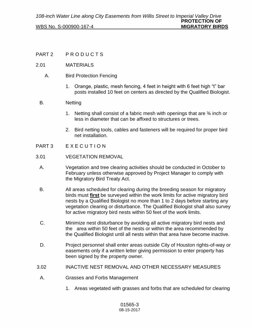
108-inch Water Line along City Easements from Willis Street to Imperial Valley Drive PROTECTION OF WBS No. S-000900-167-4 MIGRATORY BIRDS
01565-3 08-15-2017
PART 2 P R O D U C T S
2.01 MATERIALS
A. Bird Protection Fencing
1. Orange, plastic, mesh fencing, 4 feet in height with 6 feet high “t” bar posts installed 10 feet on centers as directed by the Qualified Biologist.
B. Netting
1. Netting shall consist of a fabric mesh with openings that are ¾ inch or less in diameter that can be affixed to structures or trees.
2. Bird netting tools, cables and fasteners will be required for proper bird net installation.
PART 3 E X E C U T I O N
3.01 VEGETATION REMOVAL
A. Vegetation and tree clearing activities should be conducted in October to February unless otherwise approved by Project Manager to comply with the Migratory Bird Treaty Act.
B. All areas scheduled for clearing during the breeding season for migratory birds must first be surveyed within the work limits for active migratory bird nests by a Qualified Biologist no more than 1 to 2 days before starting any vegetation clearing or disturbance. The Qualified Biologist shall also survey for active migratory bird nests within 50 feet of the work limits.
C. Minimize nest disturbance by avoiding all active migratory bird nests and the area within 50 feet of the nests or within the area recommended by the Qualified Biologist until all nests within that area have become inactive.
D. Project personnel shall enter areas outside City of Houston rights-of-way or easements only if a written letter giving permission to enter property has been signed by the property owner.
3.02 INACTIVE NEST REMOVAL AND OTHER NECESSARY MEASURES
A. Grasses and Forbs Management
1. Areas vegetated with grasses and forbs that are scheduled for clearing

108-inch Water Line along City Easements from Willis Street to Imperial Valley Drive PROTECTION OF WBS No. S-000900-167-4 MIGRATORY BIRDS
01565-4 08-15-2017
during the breeding season for migratory birds may have active ground-nesting bird nests and must be surveyed by a Qualified Biologist no more than 1 to 2 days before ground-disturbing activities.
2. Notify the Project Manager at least ten working days in advance of the need for the biologist to perform the survey.
3. Grass and forb dominated areas inside the right-of-way or easement within 50 feet of the planned disturbed area should be maintained at a height of 6 inches or less as early as possible in the fall (e.g. October) and maintained at that height through the breeding season for migratory birds, or until the end of ground disturbance work, whichever comes first.
4. If an active nest containing eggs or young birds is found, work in the immediate area should be stopped and the Qualified Biologist should be notified immediately. Vegetation around the active nest shall remain undisturbed and protected until the young have fledged (i.e. leave the nest).
5. The Qualified Biologist shall establish a buffer of 50 feet or more around the nest, if a bird nest is found within the planned disturbed area. The contractor shall install plastic fence at the perimeter of the buffer. Construction activities shall not proceed within the buffer until the young birds have fledged (i.e., left the nest) and the nests have become inactive, the Qualified Biologist will determine nest status. If the fence is knocked down or destroyed by the Contractor, the Project Manager will suspend work, wholly or in part, until the fence is satisfactorily repaired at the Contractor’s expense. Time lost due to such suspension will not be considered a basis for adjustment of time charges, but will be charged as contract time.
6. Report any “take” of a migratory bird to the Project Manager and report any bird nest encountered to the Project Manager on the form in Attachment A of this Specification. The Contractor shall be responsible for penalties levied by the U.S. Fish and Wildlife Service for “taking” a migratory bird.
B. Tree and Shrub Removal or Trimming
1. Areas vegetated with trees and shrubs that are scheduled for clearing or trimming during the breeding season for migratory birds may have active bird nests and must be surveyed by a Qualified Biologist no more than 1 to 2 days before beginning work in each area or phase of tree and shrub removal or trimming.
108-inch Water Line along City Easements from Willis Street to Imperial Valley Drive PROTECTION OF WBS No. S-000900-167-4 MIGRATORY BIRDS
01565-5 08-15-2017
2. Notify the Project Manager at least ten working days in advance of the need for the biologist to perform the survey.
3. If an active nest containing eggs or young birds is found, work in the immediate area should be stopped and the Qualified Biologist should be notified immediately. Vegetation around the active nest shall remain undisturbed and protected until the young have fledged (i.e. leave the nest).
4. The Qualified Biologist shall establish a buffer of 50 feet or more around the nest, if a bird nest is found within the planned disturbed area. The Contractor shall install plastic fence at the perimeter of the buffer. Construction activities shall not proceed within the buffer until the young birds have fledged (i.e. left the nest) and the nests have become inactive, the Qualified Biologist will determine nest status. If the fence is knocked down or destroyed by the Contractor, the Project Manager will suspend work, wholly or in part, until the fence is satisfactorily repaired at the Contractor’s expense. Time lost due to such suspension will not be considered a basis for adjustment of time charges, but will be charged as contract time.
5. Report any “take” of a migratory bird to the Project Manager and report any bird nest encountered to the Project Manager on the form in Attachment A of this Specification. The Contractor shall be responsible for penalties levied by the U.S. Fish and Wildlife Service for “taking” a migratory bird.
3.03 WORK ON STRUCTURES
A. If possible, do not work on existing structures that have eaves, exposed aerial beams, or other characteristics that can support active bird nests during the breeding season for migratory birds, while active nests are present.
B. Remove any existing bird nests before the breeding season for migratory
birds begins. Some unoccupied nests are legally protected by statues other than the Migratory Bird Treaty Act, including nests of threatened and endangered migratory bird species and bald and golden eagles, within certain parameters. If the contract is not awarded before the breeding season for migratory birds begins and the Contractor has removed existing nests, then monitoring of nest building shall become the Contractor’s responsibility upon the Notice to Proceed.

108-inch Water Line along City Easements from Willis Street to Imperial Valley Drive PROTECTION OF WBS No. S-000900-167-4 MIGRATORY BIRDS
01565-6 08-15-2017
C. All existing structures scheduled for work during the breeding season for
migratory birds must first be surveyed for active migratory bird nests by a Qualified Biologist no more than 1 to 2 days before starting any construction.
D. Monitor all existing structures for any new nesting activity at least once
every three days during the breeding season for migratory birds. If birds start to build any new nests on structures during the breeding season for migratory birds, remove the nests before they become established (i.e., before there are eggs or juvenile birds in the nests). Water shall not be used to remove the nests.
E. Netting may be installed to prevent nest building. The netting shall be
monitored and repaired or replaced as needed. Remove netting upon completion of construction.
F. If new active nests become established (i.e., there are eggs or juvenile
birds in the nests), avoid all work that could result in abandonment or destruction of the nests until the juvenile birds have fledged and the nests are unoccupied, as determined by a Qualified Biologist and approved by the Project Manager. The Contractor shall prevent construction activity from displacing birds after they have laid their eggs and before the juveniles have fledged.
G. If the project continues into successive breeding seasons for migratory
birds, the above steps shall be repeated for each successive season.
H. Report any “take” of a migratory bird to the Project Manager and report any bird nest encountered to the Project Manager on the form in Attachment A of this Specification. The Contractor shall be responsible for penalties levied by the U.S. Fish and Wildlife Service for “taking” a migratory bird.
3.04 RECORD-KEEPING FOR MIGRATORY BIRDS AND NESTS
A. A Qualified Biologist shall record, on the form provided in Attachment A of this Specification, the location of each active nest, bird species, protection method(s) implemented and date of installation. Copies of these records shall be provided to the Project Manager.
B. If a bird is killed or injured in the work area, or if an egg or active nest is
damaged or destroyed, document the incident in a report to the Project Manager. The report should include the number of adult and juvenile birds

108-inch Water Line along City Easements from Willis Street to Imperial Valley Drive PROTECTION OF WBS No. S-000900-167-4 MIGRATORY BIRDS
01565-7 08-15-2017
killed or injured, the number of destroyed eggs, the location of the nest, the bird species and the disposition of the killed or injured birds and destroyed eggs or nest. The record shall be submitted to the Project Manager for forwarding to the City of Houston and the U.S. Fish and Wildlife Service.
C. It is recommended that a Migratory Bird Treaty Act Compliance notebook be developed and be located on the project location. The notebook should include, but is not limited to the following information: important contacts such as the local U.S. Fish and Wildlife Service office, Texas Parks and Wildlife Department office and wildlife rehabilitator; Migratory Bird Nest Report form; copies of “take” permits, if any; noncompliance notification triggers and reporting requirements and any other MBTA related information such as reports of incidents of “take”.
3.05 ENVIRONMENTAL RESPONSIBILITIES
A. All construction personnel will be required to attend environmental awareness training that specifies their responsibilities regarding avoidance and minimization measures required for MBTA compliance prior to starting work on the project. The contractor shall, if requested, provide proof of environmental awareness training for all contractor personnel.
B. The Qualified Biologist should be given stop work authorization in the
event that a MBTA-related incident occurs.
C. Project personnel shall notify the City of Houston of arrival on site of any federal or state environmental regulator or enforcement agent and/or receipt of any correspondence from a federal or state environmental agency.
D. Project personnel shall immediately report any noncompliance with the
appropriate federal, state or local environmental regulations and to the City of Houston.
E. If given a verbal and/or written notice of environmental noncompliance by
a federal or state environmental regulatory agency, project personnel shall take immediate corrective action(s). This may cause all or part of the work to be stopped immediately until satisfactory corrective action has been taken.
PART 4 SPECIAL PROVISIONS FOR BALD OR GOLDEN EAGLES

108-inch Water Line along City Easements from Willis Street to Imperial Valley Drive PROTECTION OF WBS No. S-000900-167-4 MIGRATORY BIRDS
01565-8 08-15-2017
4.01 BALD AND GOLDEN EAGLE ROOSTING ACTIVITY
A. A Qualified Biologist shall determine before construction begins whether bald or golden eagle roosts may be present within the work limits during the winter season for bald and golden eagles.
B. If eagles may be present and construction is scheduled for the winter
season for bald and golden eagles, the Qualified Biologist shall conduct dusk and dawn surveys of bald and golden eagle roosts during the winter season for bald and golden eagles, or within two days before starting any construction, whichever comes later. The Qualified Biologist will prepare and submit a report of the findings to the Project Manager.
C. All bald or golden eagle sightings should be documented on the form in
Attachment B of this Specification.
D. If the Qualified Biologist identifies a bald or golden eagle roost, construction activity shall not proceed until the Project Manager notifies the U.S. Fish and Wildlife Service and primary and secondary buffer zones are established around active nocturnal roost sites. Construction may only continue if in compliance with U.S. Fish and Wildlife Service instructions within these buffer zones.
4.02 BALD EAGLE NESTING ACTIVITY
A. A Qualified Biologist shall determine before construction begins whether bald eagle nests may be present within the work limits during the breeding season for bald eagles.
B. If a Qualified Biologist determines that bald eagle nests may be present
and construction is scheduled for the breeding season for bald eagles, the Qualified Biologist shall conduct bald eagle nest surveys within ½ mile of the work limits during the breeding season for bald eagles, or no more than 2 days before starting any construction, whichever comes later. The Qualified Biologist will prepare and submit a report of findings to the Project Manager.
C. If a Qualified Biologist discovers a suspected bald eagle nest, bald eagle
nest territory occupancy confirmation should be determined utilizing the form in Attachment C of this Specification. Initial monitoring of eagles to

108-inch Water Line along City Easements from Willis Street to Imperial Valley Drive PROTECTION OF WBS No. S-000900-167-4 MIGRATORY BIRDS
01565-9 08-15-2017
determine territory occupancy should be conducted a minimum of one day per week, with nest tree observations for a minimum of two hours starting ½ hour before sunrise, followed by nest tree inspection for indirect evidence of eagle use if no adults are observed. Visits must be long enough to make a positive identification of occupancy or at least 4 consecutive hours to determine no occupancy.
D. If the Qualified Biologist identifies any bald eagle nests within 800 feet of construction activities, the Qualified Biologist shall establish appropriate buffer zones around active sites within the 800-foot radius and within work limits. The buffer zones shall be marked with fencing and signs. Work shall not proceed within a buffer zone until a Qualified Biologist has determined that the juvenile birds have fledged and the nest is unoccupied. Inactive or unoccupied bald eagles nest cannot be removed or destroyed (during or outside breeding season) without a permit from the U.S. Fish and Wildlife Service.
E. Monthly monitoring of active bald eagle nest(s) will be required to
determine nest status each month and to gauge bald eagle reaction to the disturbance created by the project.
END OF SECTION

108-inch Water Line along City Easements from Willis Street to Imperial Valley Drive PROTECTION OF WBS No. S-000900-167-4 MIGRATORY BIRDS
01565-10 08-15-2017
Attachment A to Section 01565
MIGRATORY BIRD NEST REPORT FORM

Migratory Bird Nest Report Form
Observer Name Phone E-mail
Location within or near Project Area
Date Time
Species or type of bird (if known)
Adults in attendance (number of birds)
Description of Adults
Nestlings in nest(number of
nestlings)
Description of Nestlings
Eggs in nest (number of eggs)
Description of Eggs
Behaviors observed Bird sitting on the nest Chicks or Eggs in nestDistraction Display Other
Describe what you saw the bird(s) doing in the box below
Nest substrate type live tree-nest in brancheslive tree-nest in trunkdead tree/snag-nest in trunknest in bushnest in structure/building or stump
Height of nest above ground
(in feet)
Size of nest (in inches) Across (diameter) From top to bottom (depth)
The nest is made with (check all that apply)
sticks and branches mud and dirtwoven of grasses leaves
Were photographstaken?
Yes No If yes, who has
them?
All native Migratory Birds are protected under the federal Migratory Bird Treaty Act. Notify the Project Biologist and/or Biological Monitor when an active or old Migratory Bird nest is found.

108-inch Water Line along City Easements from Willis Street to Imperial Valley Drive PROTECTION OF WBS No. S-000900-167-4 MIGRATORY BIRDS
01565-11 08-15-2017
Attachment B to Section 01565
BALD EAGLE OBSERVATION REPORT FORM

Bald Eagle Observation Report Form
Date Time
Observer Name
Phone Number
Email address
Location within or near Project Area
Adult (number of birds)
Immature (number of birds)
White head and tailAll brown back,belly and wingsMassive wing spreadMassive body size
Mottled brown and white body, head, and tailDark bellyMassive wing spreadMassive body size
Distance to birds
Type of spotting equipment used
Binoculars Spotting Scope NoneOther
Behaviors observed Flying Perched HuntingOther
Describe what you saw the bird doing in the box below

108-inch Water Line along City Easements from Willis Street to Imperial Valley Drive PROTECTION OF WBS No. S-000900-167-4 MIGRATORY BIRDS
01565-12 08-15-2017
Attachment C to Section 01565
BALD EAGLE NEST TERRITORY OCCUPANCY CONFIRMATION REPORT

Bald Eagle Nest Territory Occupancy Confirmation Report
Date Nest # Name of Biologist
Start time
End time
# AdultPresent
# Young Present
Alternate Nest Present
Yes No
INDIRECT EVIDENCE
Tree Type
Tree Status
Fresh moss or green tree branches placed or interwoven into the nest top?
Yes No
Presence of fresh droppings "whitewash" on vegetation or the ground beneath the nest tree?
Yes No
DIRECT EVIDENCE
Observation 1: Time
Temp Wind (Spd/Dir) Cloud Cover Precipt
Behavior exhibiting: (check all that apply)
flying/soaring roostingvocalizing pair bonding/courtshipperched carrying nest materialrepairing of existing nest(s) construction of new nest(s)Other
Brief description of ongoing construction:
Comments/Notes

Observation 2 Time
Temp Wind (Spd/Dir) Cloud Cover Precipt
Behavior exhibiting: (check all that apply)
flying/soaring roostingvocalizing pair bonding/courtshipperched carrying nest materialrepairing of existing nest(s) construction of new nest(s)Other
Brief description of ongoing construction:
Comments/Notes
Observation 3 Time
Temp Wind (Spd/Dir) Cloud Cover Precipt
Behavior exhibiting: (check all that apply)
flying/soaring roostingvocalizing pair bonding/courtshipperched carrying nest materialrepairing of existing nest(s) construction of new nest(s)Other
Brief description of ongoing construction:
Comments/Notes

108-inch Water Line along City Easements from Willis Street to Imperial Valley Drive PROTECTION OF WBS No. S-000900-167-4 MIGRATORY BIRDS
01565-13 08-15-2017
Attachment D to Section 01565
TAKE OF MIGRATORY BIRD OR EGG REPORT FORM

Take of Migratory Bird or Egg Report Form
Date: Project Area/Section:
GPS location:
Finder's Name Finder's Phone Number
Brief description of project activity occurring during incident of take:
Bird Species Name:
Individual(s) taken:
Adult birdJuvenile birdEgg(s)
Number of individuals taken:
1 2 3 4Other
Incident of take:
DeadInjuredBroken/cracked egg(s)
Cause of mortality or injury:
Disposition of dead or injured birds or eggs:
*Completed form should be provided to Project Manager. The United States Fish and Wildlife Service local field office should be notified within 24 hours of the incident of take.

108-inch Water Line along City Easements from Willis Street to Imperial Valley Drive WBS No. S-000900-0167-4 CONTROL OF GROUND AND SURFACE WATER
01578S-1 10-05-2016
Section 01578S
CONTROL OF GROUND AND SURFACE WATER
The following supplements modify Specification Section 01578 – Control of Ground and Surface Water Standard Specification and Details. Where a portion of the Specification or Detail is modified or deleted by this Supplementary Specification, the unaltered portions of the Specification shall remain in effect.
1.02 MEASUREMENT AND PAYMENT: Delete Paragraphs 1.02.A.4 and replace with
the following: 4. No separate payment will be made for groundwater control associated with
augering, tunnels or casing. Include cost in unit price for augering. No separate payment for groundwater and surface water control resulting from an existing leaking pipe.
1.05 PERFORMANCE REQUIREMENTS: Add the following Paragraph J:
J. Control flow rate of discharged groundwater to prevent overflow of drainage facilities.
1.07 ENVIRONMENTAL REQUIREMENTS: Delete Paragraph 1.07.D and replace with the following:
D. Monitor ground water discharge for contamination while performing pumping in the vicinity of potentially contaminated sites and when discharging to the TxDOT ROW.
Add the following Paragraph E:
E. Provide erosion control measures when discharging water to unlined or vegetation lined channels.
2.01 EQUIPMENT AND MATERIALS: Delete Paragraphs 2.01.B and replace with the following:
B. Use experienced contractors, regularly engaged in ground water control
system design, installation, and operation, to furnish and install and operate educators, well points, deep wells, or water-tight sheet pile cut-off walls, when needed.

108-inch Water Line along City Easements from Willis Street to Imperial Valley Drive WBS No. S-000900-0167-4 CONTROL OF GROUND AND SURFACE WATER
01578S-2 10-05-2016
3.03 SEDIMENT TRAPS: Delete Paragraph A and replace with the following:
A. Install sediment tanks as needed to prevent discharge of sediment into storm sewers and drainage ditches.
3.04 SEDIMENT SUMP PIT: Delete Paragraph A and replace with the following:
A. Install sediment sump pits as needed to prevent discharge of sediment into
storm sewers and drainage ditches.
END OF SUPPLEMENT
Approved by: __________________________ __________________________ Venus Price, P.E. Date Acting Managing Engineer Surface Water Transmission Program Capital Projects

108-inch Water Line along City Easements from Willis Street to Imperial Valley Drive
WBS No. S-000900-167-4 SITE RESTORATION
01740S-1 03-29-2018
Section 01740S
SITE RESTORATION
The following supplements modify Section 01740 Site Restoration. Where a portion of the
Specification is modified or deleted by this Supplementary Specification, the unaltered
portions of the Specification shall remain in effect.
PART 1 GENERAL
1.02 MEASUREMENT AND PAYMENT
A. Unit Prices: Add paragraph 6.
6. No separate payment made for removing, relocating and providing
temporary/permanent mail boxes for residences and businesses impacted by
construction activities during and after the completion of the construction. This
includes standard, special decorative and brick mail boxes. Include cost of this
work, and cost of coordination with United States Postal Service and property
owners in appropriate facility or roadway construction.
1.03 DEFINITIONS: Replace paragraph 1.03.C with the following paragraph.
C. Site Improvement: Includes pavement, curbs and gutters, esplanades,
sidewalks, driveways, fences, lawns, irrigation systems, landscaping, mail
boxes and other improvements in existence at the Project site before
commencement of construction operations.
PART 3 EXECUTION: Change heading for 3.01.D, 3.01E and add paragraph 3.05 Mail
Boxes.
3.01 Preparatory Work
D. Storm Sewer
E. Street Paving
3.05 MAIL BOXES
A. Coordinate relocation of the existing mail boxes and/or installation of the
temporary mail boxes with the United States Postal Service station serving the
project area, and the homes and businesses prior to starting construction.
B. Contractor has option to provide notification and ample time to homes and
businesses in advance of construction for the relocation of brick and special

108-inch Water Line along City Easements from Willis Street to Imperial Valley Drive
WBS No. S-000900-167-4 SITE RESTORATION
01740S-2 03-29-2018
decorative mail boxes by the property owner. Property owner’s failure to
relocate the brick or special decorative mail boxes does not relieve the
contractor from relocating the brick and special decorative mail boxes in
accordance with the Section 1.02.A.6 of this Specification and proceeding with
the proposed improvements in timely manner.
C. Upon the completion of the proposed improvements, reinstall mail boxes at
original or appropriate location approved by the United States Postal Services,
home and business owner, or Project Manager.
D. Contractor may use the existing mail box material if it is in a good condition
and is approved by the Project Manager or property owner. In case the
existing mail box material is not in a satisfactory condition to the City or a
property owner then Contractor shall provide mail box with new material in
accordance with the Section 1.02.A.6 of this Specification.
Approved by:
____________________________ ___________________
Venus Price, P.E. Date Acting Managing Engineer Surface Water Transmission Program Capital Projects

CITY OF HOUSTON OPERATIONS AND MAINTENANCE STANDARD SPECIFICATION PERSONNEL INSTRUCTION
01782(LD)-1
08/01/95
SECTION 01782 (Large Diameter) OPERATIONS AND MAINTENANCE PERSONNEL INSTRUCTION PART 1 G E N E R A L 1.01 SECTION INCLUDES
A. Requirements of services of manufacturer-approved factory-trained maintenance specialist to instruct City's operations and maintenance personnel in recommended corrective and preventive maintenance procedures for equipment as specified in respective equipment section.
1.02 MEASUREMENT AND PAYMENT
A. No separate payment will be made for work performed under this section. Include cost of such training, instruction material, submittals and resubmittals in contract unit prices for items listed in bid form for which equipment is a part.
1.03 REQUIREMENTS
A. Qualifications of specialist to be subject to approval by City's representative.
B. Responsible for coordinating these services at times acceptable to Engineer, with a minimum of 30 days' prior notice.
C. Provide combination of classroom and/or field training. Conduct all training at City of
Houston facilities in Houston, Texas.
D. Training sessions may be videotaped by City. Taped sessions are property of City and City retains right to use tapes for training of City of Houston personnel.
E. Schedule training for particular item or system after complete installation and testing for
that item or system. Submit training schedules to Engineer for approval.
F. Minimum requirements for training are as shown by item/system and unless otherwise noted elsewhere minimum number of training hours to be provided is 4 per item/system. Hours shown are actual "instruction hours" (classroom or demonstrations) irrespective of number of people attending training session. Additional training requirements may be specified in other sections of specifications.
1.04 SUBMITTALS
A. Submit all items required within this section in accordance with Section 01330 - Submittals.

CITY OF HOUSTON OPERATIONS AND MAINTENANCE STANDARD SPECIFICATION PERSONNEL INSTRUCTION
01782(LD)-2
08/01/95
B. Submit for approval a proposed Lesson Plan for instruction 30 days prior to
commencement of scheduled training.
C. Submit for approval credentials of designated maintenance instructor. Credentials will include resume and specific details of instructor's experience with maintenance of and training on items specified.
D. Operation and Maintenance Data: In addition to specific data required by various
sections of specifications, provide following information for each piece of equipment which requires periodic maintenance:
1. Manufacturer's Data:
a. Name and description.
b. Size and/or model number.
c. Manufacturer's name, address and telephone number.
d. Supplier's name, address and telephone number.
e. All equipment serial numbers.
2. Nameplate Data: Supply all applicable information for each piece of
equipment listed in paragraph above.
a. Volts.
b. Amps.
c. Watts.
d. Phases.
e. Hertz.
f. Frame.
g. Type.
h. PSI.
i. Other pertinent information.

CITY OF HOUSTON OPERATIONS AND MAINTENANCE STANDARD SPECIFICATION PERSONNEL INSTRUCTION
01782(LD)-3
08/01/95
3. Manufacturer's operations, maintenance and repair literature and other information. Provide following information as a minimum: a. Manufacturer's recommended preventive maintenance procedures and
maintenance intervals. Give maintenance intervals in terms of both calendar time and operation time.
b. Parts Information:
1) Exploded-view assembly drawing(s) of equipment. Clearly
show all parts including maintainable subassembly parts in drawing(s). Consider all subassemblies maintainable unless City acknowledges in writing that subassembly is disposable. Identify all parts with number or letter which references Parts List Table described in section 2) below.
2) A Parts List Table which includes all of the following
information:
a) Part reference number or letter from the exploded-view drawing.
b) Brief description of part.
c) Manufacturer's part number/drawing reference number.
d) Standard part description when applicable, i.e. 1/2-inch
hex head bolt.
e) Quantity of each part contained in equipment, assembly or subassembly.
f) Manufacturer's recommendation for stocking of spare
parts for each item in Parts List Table.
c. Special Tools: List any special tools and/or equipment required to comply with manufacturer's recommended maintenance instructions.
d. Overhaul Procedures: Provide step-by-step procedures by
manufacturers for complete disassembly, overhaul and reassembly of equipment.
e. Operating Procedures: Provide detailed information on following:
1) Pre-startup checkout procedure.
2) Startup procedures.

CITY OF HOUSTON OPERATIONS AND MAINTENANCE STANDARD SPECIFICATION PERSONNEL INSTRUCTION
01782(LD)-4
08/01/95
3) During operation checks and procedures.
4) Shutdown procedures for following:
a) Routine shutdown.
b) Emergency shutdown.
c) Extended shutdown.
f. Safety precautions.
g. Comprehensive troubleshooting guide.
h. Electrical and instrumentation wiring diagrams.
i. Test data and performance curves.
4. Assemble required manufacturer's information in logical format. Provide
Items 1 through 3 in tabular form for each piece of equipment. Provide cross references to manufacturer data submittals as required by Section 01340 - Shop Drawings, Product Data and Samples. All information to be 8-1/2" x 11" or 11" x 17" in size and of quality suitable for reproductions. Items submitted by the Contractor which do not produce an acceptable quality reproduction will be returned for resubmittal. All information shall be bound in a suitable hard-covered, weatherproof binder. Provide six copies of above information.
5. Contractor, by way of his bid, acknowledges that any or all of above Operation
and Maintenance submittal requirements may be more extensive and more detailed than what Contractor typically supplies. However, it is understood that, in case of any piece of equipment requiring periodic maintenance, NO PAYMENT FOR SUPPLY, DELIVERY AND INSTALLATION OF SUCH EQUIPMENT WILL BE MADE UNTIL ALL REQUIREMENTS SPECIFICALLY NOTED IN THIS TECHNICAL SPECIFICATION RELATING TO OPERATION AND MAINTENANCE DATA HAVE BEEN COMPLIED WITH.
PART 2 P R O D U C T S 2.01 INSTRUCTION LESSON PLAN
A. Proposed Lesson Plan to include elements presented in Outline of Instruction Lesson Plan in paragraph 2.01D. Specific components and procedures to be identified in proposed Lesson Plan.

CITY OF HOUSTON OPERATIONS AND MAINTENANCE STANDARD SPECIFICATION PERSONNEL INSTRUCTION
01782(LD)-5
08/01/95
B. Detail specific instruction topics in proposed Lesson Plan. Reference and attach,
where applicable to proposed Lesson Plan, training aids to be utilized in instruction. Describe "hands-on" demonstrations planned for instruction in Lesson Plan.
C. Indicate estimated duration of each segment of training Lesson Plan.
D. Outline of Instruction Lesson Plan:
1. Equipment Operation:
a. Describe equipment's operating function.
b. Describe equipment's fundamental operating principals and dynamics.
c. Identify equipment's mechanical, electrical and electronic components
and features.
d. Identify all support equipment associated with operation of subject equipment (i.e., valve operators, anodes, test stations).
2. Detailed Component Description:
a. Identify and describe in detail each component's function.
b. Where applicable, group related components into subsystem. Describe
subsystem functions and their interaction with other subsystems.
c. Identify and describe in detail equipment safeties and control interlocks.
3. Equipment Preventive Maintenance (PM):
a. Describe PM inspection procedures required to:
1) Perform an inspection of equipment in operation.
2) Spot potential trouble symptoms (anticipate breakdowns).
3) Forecast maintenance requirements (predictive maintenance).
b. Define recommended PM intervals for each component.
c. Provide lubricant and replacement part recommendations and limitations.
d. Describe appropriate cleaning practices and recommended intervals.

CITY OF HOUSTON OPERATIONS AND MAINTENANCE STANDARD SPECIFICATION PERSONNEL INSTRUCTION
01782(LD)-6
08/01/95
4. Equipment Troubleshooting:
a. Define recommended systematic troubleshooting procedures.
b. Provide component specific troubleshooting checklists.
c. Describe applicable equipment testing and diagnostic procedures to
facilitate troubleshooting.
5. Equipment Corrective Maintenance:
a. Describe recommended equipment preparation requirements.
b. Identify and describe use of any special tools required for maintenance of equipment.
c. Describe component removal/installation and disassembly/ assembly
procedures.
d. Perform at least two "hands-on" demonstrations of common corrective maintenance repairs.
e. Describe recommended measuring instruments and procedures, and
provide instruction on interpreting alignment measurements, as appropriate.
f. Define recommended torquing, mounting, calibration and/or alignment
procedures and settings, as appropriate.
g. Describe recommended procedures to check/test equipment following a corrective repair.
6. Other items as contained in operation and maintenance manual, as defined in
Section 01330 - Submittals. 2.02 TRAINING AIDS
A. Instructor shall incorporate training aids as appropriate to assist in instruction. Include text and figure handouts as a minimum in training aids. Other appropriate training aids are:
1. Audiovisual aids (e.g., films, slides, videotapes, overhead transparencies,
posters, blueprints, diagrams, catalogue sheets).
2. Equipment cutaways and samples (e.g., spare parts, damaged equipment).

CITY OF HOUSTON OPERATIONS AND MAINTENANCE STANDARD SPECIFICATION PERSONNEL INSTRUCTION
01782(LD)-7
08/01/95
3. Tools (e.g., repair tools, customized tools, measuring and calibrating
instruments).
B. Instructor shall utilize descriptive class handouts during instruction. Photocopied class handouts shall be good quality reproductions. Class handouts should accompany instruction with frequent reference made to them. Customized handouts developed especially for instruction are encouraged. Handouts planned for instruction shall be attached with manufacturer's proposed Lesson Plan.
PART 3 E X E C U T I O N 3.01 "HANDS-ON" DEMONSTRATIONS
A. Manufacturer's instructor shall present at least two "hands-on" demonstrations of common corrective maintenance repairs for each scheduled group. Manufacturer shall provide tools and equipment to conduct demonstrations. Requests for supplemental assistance and facilities should be submitted with proposed Lesson Plan. Proposed "hands-on" demonstrations should be described in proposed Lesson Plan.
END OF SECTION

108-inch Water Line along City Easements from Willis Street to Imperial Valley Drive WBS No. S-000900-0167-4 PRECAST CONCRETE MANHOLES
02082S-1 10-05-2016
Section 02082S
PRECAST CONCRETE MANHOLES
The following supplements modify Specification Section 02082 – Precast Concrete Manholes Standard Specification and Details. Where a portion of the Specification or Detail is modified or deleted by this Supplementary Specification, the unaltered portions of the Specification shall remain in effect.
1.02 MEASUREMENT AND PAYEMENT:
Delete Paragraph A.7.
3.03 MANHOLE BASE SECTIONS AND FOUNDATIONS: Delete Paragraphs 3.03.A
and B and replace with the following:
A. Place precast base on 12-inch-thick (minimum) foundation of cement stabilized sand. Compact cement-sand in accordance with requirements of Section 02321 – Cement Stabilized Sand. For Manholes over large diameter waterlines, see 3.03.C.
B. Unstable Subgrade Treatment: When unstable subgrade is encountered, notify
Project Manager for examination of subgrade to determine if subgrade has heaved upwards after being excavated. When heaving has not occurred, over-excavate subgrade to allow for 24-inch-thick layer of cement stabilized sand as foundation material under manhole base. When there is evidence of heaving, provide pile-supported concrete foundation, as detailed on Drawings, under manhole base.
3.11 BACKFILL: Delete Paragraph A and replace with the following Paragraph A:
A. Place and compact backfill materials in area of excavation surrounding manholes
in accordance with the requirements of Section 02317 – Excavation and Backfill for Utilities.
END OF SUPPLEMENT
Approved by: _____________________________ _________________________ Venus Price, P.E. Date Acting Managing Engineer Surface Water Transmission Program Capital Projects

108-inch Water Line along City Easements from Willis Street to Imperial Valley Drive
WBS No. S-000900-0167-4 EXCAVATION AND
BACKFILL FOR UTILITIES
02317S-1 12-26-2017
Section 02317S
EXCAVATION AND BACKFILL FOR UTILITIES The following supplements modify Section 02317 – Excavation and Backfill for Utilities Standard Specification. Where a portion of the Specification is modified or deleted by this Supplementary Specification, the unaltered portions of the Specification shall remain in effect. 1.02 MEASUREMENT AND PAYMENT
Delete Paragraph 1.02.A.1 and replace with the following Paragraph 1.02.A.1
1. Except for trench dams, no additional payment will be made for trench excavation, embedment, backfill, and geotextile fabric under this Section. Include cost in unit price for installed underground piping, sewer, conduit, or duct work. Trench dams will be paid on a unit price basis for each trench dam installed.
1.03 DEFINITIONS Delete Paragraph 1.03.G.3 and replace with the following Paragraph 1.03.G.3
3. Materials that contain clay clods greater than 4 inches in any dimension, aggregates, stones greater than 4 inches in any dimension, debris, vegetation, waste, or any other deleterious materials.
Delete Paragraph 1.03.Q and replace with the following Paragraph 1.03.Q Q. Foundation Bedding: Natural soil or manufactured aggregate of controlled
gradation and geotextile filter fabrics as required to control drainage and material separation and migration. Foundation bedding is placed as backfill and compacted (where required) to provide stable support for bedding. Foundation bedding materials may include concrete seal slabs.
1.04 REFERENCES: Delete Paragraphs 1.04.G and 1.04.H and replace with the following Paragraph
1.04.G. Renumber the remaining paragraphs. G. ASTM D 6938-17 – Standard Test Methods for In-Place Density and Water
Content of Soil and Soil-Aggregate by Nuclear Methods (Shallow Depth). Add the following Paragraphs 1.04. M, N, O M. ASTM D 4253 - Standard Test Methods for Maximum Index Density and Unit
Weight of Soils Using a Vibratory Table

108-inch Water Line along City Easements from Willis Street to Imperial Valley Drive
WBS No. S-000900-0167-4 EXCAVATION AND
BACKFILL FOR UTILITIES
02317S-2 12-26-2017
N. ASTM D 7382 - Standard Test Methods for Determination of Maximum Dry Unit
Weight and Water Content Range for Effective Compaction of Granular Soils Using a Vibrating Hammer
O. ASTM D 4914 - Standard Test Methods for Density of Soil and Rock in Place by
the Sand Replacement Method in a Test Pit 1.06 SUBMITTALS: Delete Paragraph 1.06.D and replace with the following: D. Include designs for special shoring meeting requirements defined in Paragraph
1.08, Special Shoring Design Requirements contained herein. Where Special Shoring is required, limits are shown on Drawings. Contractor to submit special shoring design signed and sealed by a Professional Engineer, licensed in the State of Texas. Design and installation of special shoring for all excavations will be the responsibility of the Contractor. Refer to Contract Drawings and related specifications.
Add the following Paragraphs 1.06.H, 1.06.I, and 1.06.J
H. Submit proposed trench dam locations for approval according the requirements of
this Section if trench dam locations differ from those specified in the Drawings. I. Submit orange fencing to be placed in the trench zone backfill, if required in the
Drawings. J. Submit utility warning tape to be placed in the trench zone backfill, if required in
the Drawings. 1.07 TESTS
Delete Paragraphs 1.07.A and 1.07.B and replace with the following: A. Testing and analysis of pipe foundation, bedding, haunching, initial backfill, and
backfill for soil classification and compaction during construction will be performed by an independent laboratory provided by City in accordance with requirements of Section 01454 – Testing Laboratory Services and as specified in this Section.
B. Perform pipe foundation, bedding, haunching, initial backfill, and backfill material source qualification testing in accordance with requirements of Section 02320 – Utility Backfill Materials.

108-inch Water Line along City Easements from Willis Street to Imperial Valley Drive
WBS No. S-000900-0167-4 EXCAVATION AND
BACKFILL FOR UTILITIES
02317S-3 12-26-2017
1.08 SPECIAL SHORING DESIGN REQUIREMENTS: Delete Paragraph 1.08.A and replace with the following:
A. Special shoring is designed to prevent ground movements and protect adjacent installations or improvements such as structures, pavements or utilities. Special shoring may be interlocking steel sheet piling or other system shown on Drawings and approved by Project Manager. Where limits of special shoring are shown on Contract Drawings, provide system designed by Contractor’s professional engineer and submitted in accordance with Section 02464 – Special Shoring. Refer to related specifications for specific requirements and payment information. In areas where special shoring is shown, Contractor must also provide trench safety system under Section 02260 – Trench Safety System.
2.02 MATERIAL CLASSIFICATION Add the following Paragraphs 2.02.E and 2.02.F
E. Orange Fencing for Backfill Zone: conform to the following requirements
1. Material: high density polyethylene 2. Maximum mesh size: 3.5 inch longitudinal, 2.0 inch transverse
3. Minimum tensile strength: 200 lb/ft longitudinal, 100 lb/ft transverse
F. Utility Warning Tape for Backfill Zone: conform to the following requirements
1. Strip width: 6-inches 2. Thickness: minimum 4.0 mil 3. Chemically inert plastic film and ink 4. Include metal detectable core when used over non-metallic pipe 5. Background color:
a. Water line applications: Blue b. Sanitary or storm sewer applications: Green
6. Include the following label (or similar) printed in black ink along the tape:
a. Water line applications: CAUTION WATER LINE

108-inch Water Line along City Easements from Willis Street to Imperial Valley Drive
WBS No. S-000900-0167-4 EXCAVATION AND
BACKFILL FOR UTILITIES
02317S-4 12-26-2017
b. Sanitary or storm sewer applications: CAUTION SEWER LINE
7. Terra Tape, Seton, or Approved Equal
3.05 EXCAVATION.
Delete Paragraph 3.05.F.1 and replace with the following:
1. Comply with Specification Section 02260 – Trench Safety System.
Add the following Paragraph 3.05.F.2, and renumber the remaining Paragraphs under 3.05.F:
2. Where Special Shoring is required, install in advance of trench excavation or
simultaneously with trench excavation, so that soils within full height of trench excavation walls will remain laterally supported at all times.
3.07 TRENCH FOUNDATION: Delete Paragraph 3.07.A and replace with the following:
A. Excavate bottom of trench to uniform grade to achieve stable conditions and satisfactory compaction of foundation or bedding materials, when compaction is required.
3.08 PIPE EMBEDMENT, PLACEMENT, AND COMPACTION:
Delete Paragraphs 3.08. B, E, F, G, I, J, and M and replace with the following Paragraphs 3.08. B, E, F, G, I, J, and M: B. Place embedment including bedding, haunching, and initial backfill as shown on
the Drawings. When uncompacted bedding is required, place bedding to a depth slightly above the bottom of pipe grade, and lay pipe on this material to the indicated grade. Adjust bedding depth as needed so that pipe will settle to indicated grade. Provide bell holes to permit the pipe to rest on the full length of the barrel and to permit joint make-up and coating.
E. Place geotextile to prevent particle migration from in-situ soil into embedment
material when the following are used for embedment:
1. Open-graded (Class I) embedment materials or drainage layers.
2. Well or poor-graded gravels, well or poor-graded gravel-sand mixtures, well or poor-graded crushed stone, pea gravel, and well or poor-graded crushed concrete with less than 5 percent passing the number 200 sieve.

108-inch Water Line along City Easements from Willis Street to Imperial Valley Drive
WBS No. S-000900-0167-4 EXCAVATION AND
BACKFILL FOR UTILITIES
02317S-5 12-26-2017
When required, geotextile shall wrap the entirety of the embedment and have a minimum 12-inch overlap with adjoining sections. In cases where embedment does not extend over top of pipe, wrap embedment and exposed pipe with geotextile.
F. Do not damage coatings or wrappings of pipes during backfilling and compacting
operations. Avoid dropping embedment and backfill materials directly onto pipe. Notify Project Manager if any damage occurs and obtain approval for repair procedures. Repair any damage which occurs.
G. Place haunching material manually around pipe and compact it to provide uniform
bearing and side support. Take care to ensure material is fully placed and compacted under the haunches. If necessary, hold small-diameter or lightweight pipe in place during compaction of haunch areas and placement beside pipe with sand bags or other suitable means.
I. Compact cohesionless (Class I and II) soils using vibratory methods. Compact
Class III and IV materials using impact or kneading methods. For dual classification soils, utilize and utilize most effective method to achieve maximum compaction. Compact each lift before proceeding with placement of next lift. Water tamping is not allowed.
J. For less than 36-inch diameter water lines construction embedment, use bank run
sand, concrete sand, gem sand, pea gravel, or crushed limestone as specified in Section 02320 - Utility Backfill Materials. Adhere to the following subparagraph numbers 1-4. 1. Class I and II (Cohesionless) Embedment Materials:
a. Maximum 6 inches compacted lift thickness.
b. Compact to achieve minimum of 95 percent of maximum density as
determined according to ASTM D 4253 or ASTM D 7382.
c. For materials that contain 10% or more particles passing the number 200 sieve and dual classification materials, determine maximum density and optimum moisture according to ASTM D 698. If maximum density determined using ASTM D 698 is greater than that determined using ASTM D 4253 or ASTM D 7382, compact embedment material to achieve a minimum of 95% of maximum dry density according to ASTM D 698. Keep moisture content to within -3 percent to +5 percent of optimum as determined according to ASTM D 698.
2. Class III Embedment Materials

108-inch Water Line along City Easements from Willis Street to Imperial Valley Drive
WBS No. S-000900-0167-4 EXCAVATION AND
BACKFILL FOR UTILITIES
02317S-6 12-26-2017
a. Maximum 6 inches compacted lift thickness.
b. Compact to achieve minimum of 95 percent of maximum dry density as determined according to ASTM D 698.
c. Moisture content to be within -3 percent to +5 percent of optimum as determined according to ASTM D 698, unless otherwise approved by Project Manager.
3. Cement Stabilized Sand (where required for special installations):
a. Maximum 6 inches compacted lift thickness.
b. Compact to achieve minimum of 95 percent maximum dry density as
determined according to ASTM D 558.
c. Moisture content to be on dry side of optimum as determined according to ASTM D 558 but sufficient for effective hydration.
4. Flowable Fill (where required for special installations):
a. Pour flowable fill from one side of trench and allow to flow underneath pipe to opposite side. Provide supports under pipe at sufficient intervals to support pipe and allow flowable fill to cross underneath to opposite side of trench.
b. Do not apply flowable fill if water is present in trench. Dewater trench
and groundwater sufficiently to provide dry conditions.
M. For all utilities except water lines 36-inches diameter and above, place trench dams in Class I embedment in line segments longer than 100 feet between manholes, and not less than one in every 500 feet of pipe placed. Install additional dams as needed to achieve workable construction conditions. Do not place trench dams closer than 5 feet from manholes. Trench dams for water lines 36-inches diameter and above shall comply with Paragraph 3.08.N in Section 02317S.
Add Paragraph 3.08.N: N. For 36-inch diameter and greater water lines construction embedment, use
concrete sand or crushed limestone aggregate as specified in Section 02320 – Utility Backfill Materials. Adhere to the following subparagraph numbers 1-7.
1. Only concrete sand or cement stabilized sand (where required for special
installations) shall be used for embedment of tape coated pipe. Do not use crushed limestone for embedment of tape coated pipe.

108-inch Water Line along City Easements from Willis Street to Imperial Valley Drive
WBS No. S-000900-0167-4 EXCAVATION AND
BACKFILL FOR UTILITIES
02317S-7 12-26-2017
2. Use the same embedment material for the entire project extents, with the
exception of cement stabilized sand or flowable fill where required for special installations or as required per the Drawings.
3. Pipe bedding and embedment shall be the same materials, with the exception of cement stabilized sand and flowable fill. Do not use cement stabilized sand or flowable fill as bedding material, unless indicated otherwise on the Drawings.
4. Embedment Materials: a. Lift thickness
i. All materials: maximum 6 inches compacted lift thickness for
placement of all embedment materials in the zone between the pipe invert and to a height of 0.3 times the outside diameter of the pipe, measured from the invert.
ii. Concrete sand: maximum 6 inches compacted lift thickness in the entirety of the embedment zone.
iii. Crushed limestone: maximum 12 inches compacted lift thickness in the zone between a height of 0.3 times the outside diameter of the pipe, measured from the pipe invert, and the top of embedment zone.
b. Compact to achieve minimum of 95 percent of maximum density as
determined according to ASTM D 4253 or ASTM D 7382.
c. For materials that contain 10% or more particles passing the number 200 sieve and dual classification materials, determine maximum density and optimum moisture according to ASTM D 698. If maximum density determined using ASTM D 698 is greater than that determined using ASTM D 4253 or ASTM D 7382, compact embedment material to achieve a minimum of 95% of maximum dry density according to ASTM D 698. Keep moisture content to within -3 percent to +5 percent of optimum as determined according to ASTM D 698.
5. Cement Stabilized Sand (where required for special installations):
a. Maximum 6 inches compacted lift thickness.
b. Compact to achieve minimum of 95 percent maximum dry density as

108-inch Water Line along City Easements from Willis Street to Imperial Valley Drive
WBS No. S-000900-0167-4 EXCAVATION AND
BACKFILL FOR UTILITIES
02317S-8 12-26-2017
determined according to ASTM D 558.
c. Moisture content to be on dry side of optimum as determined according to ASTM D 558 but sufficient for effective hydration.
6. Flowable Fill (where required for special installations): a. Pour flowable fill from one side of trench and allow to flow underneath
pipe to opposite side. Provide supports under pipe at sufficient intervals to support pipe and allow flowable fill to cross underneath pipe to opposite side of trench.
b. Do not apply flowable fill if water is present in trench. Dewater trench
and groundwater sufficiently to provide dry conditions.
7. Trench Dams: Place trench dams in the following locations: a. Within 5 feet of vertical alignment changes on the high side. b. At property lines when property contains limits of potentially
petroleum contaminated areas (PPCAs) or other contaminants are present anywhere on the property.
c. At property lines when pipeline crosses from road right-of-way into
easement or private property, and when the road right-of-way is in the limits of PPCA or contains other contaminants.
d. At each boundary of PPCA per Specification 02105. e. At maximum 100 foot spacing when pipeline is set at a slope greater
than or equal to 1%.
f. At maximum 500 foot spacing when pipeline is set at a slope less than 1%.
g. 20 feet upstream and downstream of petroleum and gas pipeline
crossings.
h. As otherwise shown in Drawings.
i. As required to control groundwater in trench during pipeline installation and as otherwise needed to achieve workable construction conditions.

108-inch Water Line along City Easements from Willis Street to Imperial Valley Drive
WBS No. S-000900-0167-4 EXCAVATION AND
BACKFILL FOR UTILITIES
02317S-9 12-26-2017
j. Do not place trench dams closer than 5 feet from manholes.
k. Trench sections backfilled with cement stabilized sand or flowable fill shall meet the definition of a trench dam under this specification.
l. Refer to the Drawings for trench dam construction details.
m. Show trench dam locations on As-Built Drawings.
3.09 TRENCH ZONE BACKFILL PLACEMENT AND COMPACTION: Delete Paragraph 3.09.B.2 and replace with the following Paragraph 3.09.B.2:
2. For water lines 24-inches in diameter and larger, use bank run sand or select backfill materials from top of pipe embedment up to pavement base or subgrade.
3.11 FIELD QUALITY CONTROL:
Delete Paragraphs 3.11. D and E and replace with the following: D. At least three tests for moisture-density relationships will be performed initially for
Class III, Class IV, and Class II (with amount passing the number 200 sieve greater than 10%) embedment and backfill materials in accordance with ASTM D 698, and for cement-stabilized sand in accordance with ASTM D 558. At least three tests for maximum index density and unit weight in accordance with ASTM D 4253 or for maximum dry unit weight and water content range for effective compaction in accordance with ASTM D 7382 will be initially performed for cohesionless (Class I and Class II) embedment and backfill materials. Perform additional tests once a month or whenever there is noticeable change in material gradation or plasticity.
E. In-place density tests of compacted pipe foundation, embedment and trench zone
backfill soil materials will be performed according to ASTM D 1556, ASTM D 4914, or ASTM D 6938 as appropriate, and at the following frequencies and conditions.
1. For open cut construction projects, auger pits, and tunnel shafts: Unless
otherwise approved by Project Manager, successful compaction to be measured according to the following frequencies for every 50 linear feet measured along the pipe: a. For pipe 48-inch in diameter and less: At least two tests of compacted
embedment materials.
b. For pipes over 48-inches in diameter: At least one test of compacted

108-inch Water Line along City Easements from Willis Street to Imperial Valley Drive
WBS No. S-000900-0167-4 EXCAVATION AND
BACKFILL FOR UTILITIES
02317S-10 12-26-2017
embedment materials for each 12-inch thickness of embedment materials
c. At least two tests for compacted trench zone backfill material.
d. Length of auger pits and tunnel shafts to be measured to arrive at 50 linear feet. Testing frequencies in auger pits and tunnel shafts to comply with requirements of subparagraphs a, b, and c above.
2. A minimum of three density tests for each full shift of Work for each section
of pipe being backfilled. 3. Density tests will be distributed among placement areas. Placement areas
are: foundation, bedding, haunching, initial backfill and trench zone. 4. The number of tests will be increased if inspection determines that soil type
or moisture content are not uniform or if compacting effort is variable and not considered sufficient to attain uniform density, as specified.
5. Density tests may be performed at various depths below fill surface by pit
excavation. Material in previously placed lifts may therefore be subject to acceptance/rejection.
6. Two verification tests will be performed adjacent to in-place tests showing
density less than acceptance criteria. Placement will be rejected unless both verification tests show acceptable results.
7. Recompacted placement will be retested at same frequency as first test
series, including verification tests. 8. Identify elevation of test with respect to natural ground or pavement along
with station location and offset distance.
END OF SUPPLEMENT Approved by: Venus Price, P.E. Date Acting Managing Engineer Surface Water Transmission Program Capital Projects

108-inch Water Line along City Easements from Willis Street to Imperial Valley Drive
WBS No. S-000900-0167-4 UTILITY BACKFILL MATERIALS
02320S-1 08-06-2017
Section 02320S
UTILITY BACKFILL MATERIALS
The following supplements modify Section 02320 – Utility Backfill Materials Standard Specification. Where a portion of the Specification is modified or deleted by this Supplementary Specification, the unaltered portions of the Specification shall remain in effect. 2.02 PRODUCT DESCRIPTIONS: Replace Paragraph 2.02.H with the following:
H. Crushed Aggregates: Crushed aggregates consist of durable particles obtained from an approved source and meeting the following requirements for each Option listed below:
1. Option 1: Material meeting TxDOT Item 247, Grade 1, Type A that also
meets the requirements of Paragraphs a. through e. from Option 2 below. Refer to the Attachment to this Section.
2. Option 2: Materials meeting the following requirements:
a. Materials of one product delivered for same construction activity from single source, unless otherwise approved by Project Manager.
b. Non-plastic fines. Plasticity testing (ASTM D 4318) on the material passing the No. 200 sieve shall be “non-plastic”.
c. Crushed aggregate shall have a minimum of 90 percent of particles retained on No. 4 sieve with 2 or more crush faces as determined by Tex-460-A, Part I.
d. Crushed Stone: Produced from oversize plant processed stone or gravel, sized by crushing to predominantly angular particles from naturally occurring single source. Uncrushed gravel is not acceptable materials for embedment where crushed stone is shown on applicable utility embedment drawing details.
e. Crushed concrete and asphalt pavement: Not allowed.
f. Los Angeles abrasion test wear not exceeding 45 percent when tested in accordance with ASTM C 131.

108-inch Water Line along City Easements from Willis Street to Imperial Valley Drive
WBS No. S-000900-0167-4 UTILITY BACKFILL MATERIALS
02320S-2 08-06-2017
g. Gradations, as determined in accordance with Tex-110-E:
Sieve
Percent Passing by Weight for Pipe Embedment
By Ranges of Nominal Pipe Sizes
36” Diam. and Greater Less than 36” Diam.
1” 100 -
3/4” 90-100 100
1/2" 60 - 90 90 - 100
3/8” - 50 - 70
No. 4 30 - 50 30 - 50
No. 8 - -
No. 16 10 - 30 10 - 30
No. 200 5 - 7 5 - 7
3. Refer to Section 02317 for geotextile requirements around embedment.
END OF SUPPLEMENT Approved by: __________________________________ _____________________ Venus Price, P.E. Date Acting Managing Engineer Surface Water Transmission Program Capital Projects

108-inch Water Line along City Easements from Willis Street to Imperial Valley Drive
WBS No. S-000900-0167-4 UTILITY BACKFILL MATERIALS
02320S-3 08-06-2017
Attachment to Section 02320
TxDOT Item 247 Material Requirements
247.2. Materials. Furnish uncontaminated materials of uniform quality that meet the requirements of the plans and specifications. Notify the Engineer of the proposed material sources and of changes to material sources. The Engineer may sample and test project materials at any time before compaction throughout the duration of the project to assure specification compliance. Use Tex-100-E material definitions.
A. Aggregate. Furnish aggregate of the type and grade shown on the plans and conforming to the requirements of Table 1. Each source must meet Table 1 requirements for liquid limit, plasticity index, and wet ball mill for the grade specified. Do not use additives such as but not limited to lime, cement, or fly ash to modify aggregates to meet the requirements of Table 1, unless shown on the plans.
Table 1 Material Requirements
Property Test Method Grade 1
Master gradation sieve size
(% retained)
Tex-110-E
2-1/2 in. –
1-3/4 in. 0
7/8 in. 10–35
3/8 in. 30–50
No. 4 45–65
No. 40 70–85
Liquid limit, % max.1 Tex-104-E 35
Plasticity index, max.1 Tex-106-E
10
Plasticity index, min.1 0
Wet ball mill, % max.2
Tex-116-E
40
Wet ball mill, % max. increase
passing the No. 40 sieve 20
Classification3
Tex-117-E
1.0
Min. compressive strength3, psi
lateral pressure 0 psi
lateral pressure 15 psi
45
175
1. Material Types. Do not use fillers or binders. Furnish the type in accordance with the following.
a. Type A. Crushed stone produced and graded from oversize quarried aggregate that originates from a single, naturally occurring source. Do not use gravel or multiple sources.

CITY OF HOUSTON EROSION CONTROL STANDARD SPECIFICATION AND VEGETATION MAT
02371(LD)-1
10/15/95
SECTION 02371(Large Diameter) EROSION CONTROL AND VEGETATION MAT PART 1 G E N E R A L
1.01 SECTION INCLUDES
A. Installation of erosion control and vegetation mat for disturbed areas that are seeded.
1.02 PAYMENT
A. No separate payment will be made for erosion control and vegetation mat.
Include cost in unit price for regrading existing ditches.
1.03 DESCRIPTION
A. Mat shall cover newly seeded and fertilized ground, and shall be held in place with netting and staples driven into ground.
B. Mat shall assist in germination of grass seedlings and protect seedlings and
establish vegetation.
C. Mat shall be specifically designed for use on steep slopes and other hard-to-hold problem areas.
D. Mat shall help ground retain moisture, control surface temperature
fluctuations of soil, conform to terrain, protect seedlings against sun burnout, and break up raindrops to prevent erosion.
E. Wood fibers of blanket ultimately shall attach to soil, stabilize terrain, and act
as mulch after vegetation has started.
F. Netting shall degrade in time in sunlight. PART 2 P R O D U C T S
2.01 MATERIALS
A. Erosion Blanket: 1. Machine produced mat consisting of 100 percent wood with 80
percent 6-inch or longer fiber length, with consistent thickness and fiber evenly distributed over entire area of blanket.

CITY OF HOUSTON EROSION CONTROL STANDARD SPECIFICATION AND VEGETATION MAT
02371(LD)-2
10/15/95
2. Topside of blanket shall be covered with 3/4-inch by 3/4-inch mesh of biodegradable netting.
3. Blanket shall be made smolder-resistant with use of chemical additives.
B. Staples:
1. 11-gauge biodegradable steel. 2. "U" shaped with legs 6 inches in length and 1-inch crown.
2.02 ACCEPTABLE PRODUCT
A. Standard Excelsior Erosion Control Blanket; Erosion Control Systems, Inc.
PART 3 E X E C U T I O N
3.01 PREPARATION
A. Properly cultivate, seed and fertilize area to be covered in compliance with Section 02921 - Hydromulch Seeding.
B. Apply blanket immediately over prepared ground.
3.02 APPLICATION
A. Unroll blanket over prepared area; keep netting on top and fibers in contact
with soil over entire area.
B. Apply blankets in ditches in direction of water flow.
C. Butt edges snugly (overlap maximum 2 inches) and fasten to ground with staples driven into ground.
D. Engage portion of netting with staple and set flush with soil surface.
E. Use average of 1 to 1-1/2 staples per yard and maximum of 1-1/2 feet
distance between staples at ends. Follow stapling procedure as recommended by manufacturer.
F. Individual blanket size: 7.5 feet by 96 feet (80 square yards) with weight of
68 pounds plus or minus 1 pound. END OF SECTION
CITY OF HOUSTON TUNNEL EXCAVATION AND
STANDARD SPECIFICATION PRIMARY LINER FOR WATER MAINS
02425(LD)-1 04/04/2016
Section 02425(Large Diameter) TUNNEL EXCAVATION AND PRIMARY LINER FOR WATER MAINS PART 1 G E N E R A L 1.01 SECTION INCLUDES
A. Tunnel construction operation with primary lined tunnel installed during tunnel drive followed by placement of water line inside tunnel after completion of tunnel construction. This Specification is intended to be primarily functional in nature and to define in general terms work to be accomplished. Contractor granted full discretion to select method of tunnel construction, subject to review by Project Manager.
1.02 MEASUREMENT AND PAYMENT
A. No separate payment will be made for other work performed under this Specification such as excavation, liner, grouting, or instrumentation. Include cost of such other work in contract unit prices for items listed in bid form for Section 02517 - Water Main in Tunnels.
B. Where such effort is necessary, cost for ground water control during course of tunnel
work included in unit prices for water main in tunnel.
C. Ground water control required during course of Project to lower water table for other utility installation, to remove standing water, surface drainage seepage, or to protect ongoing work against rising waters or floods considered incidental to work being performed.
1.03 REFERENCE STANDARDS
A. The publications listed below form part of this specification to extent referenced. Publications are referred to in text by abbreviations only.
1. AREMA Manual for Railway Engineering (Applicable sections).
2. American Association of State Highway and Transportation Officials
(AASHTO).
3. American Society for Testing and Materials (ASTM).
a. ASTM A36 - Standard Specifications for Carbon Structural Steel.
b. ASTM A82 - Standard Specifications for Steel Wire, Plain, for Concrete Reinforcement.

CITY OF HOUSTON TUNNEL EXCAVATION AND
STANDARD SPECIFICATION PRIMARY LINER FOR WATER MAINS
02425(LD)-2 04/04/2016
c. ASTM A185 - Standard Specifications for Steel Welded Wire Fabric for
Concrete Reinforcement.
d. ASTM A283 - Standard Specifications for Low and Intermediate Tensile Strength Carbon Steel Plates.
e. ASTM A307 - Standard Specifications for Carbon Steel Bolts and
Studs, 60,000 PSI Tensile Strength.
f. ASTM A328 - Standard Specifications for Steel Sheet Piling.
g. ASTM A496 - Standard Specifications for Steel Wire, Deformed, for Concrete Reinforcement.
h. ASTM A615 - Standard Specifications for Deformed and Plain Billet-
Steel Bars for Concrete Reinforcement.
i. ASTM C33 - Standard Specification for Concrete Aggregates.
j. ASTM C150 - Standard Specifications for Portland Cement.
4. American Water Works Association (AWWA)
a. AWWA C200 - Steel Water Pipe 6-inches and Larger.
5. Occupational Safety and Health Administration (OSHA): Particular attention is called to Subpart S of OSHA Standards (29 CFR 1926/1920), published as U.S. Department of Labor Publication 2207, Revised Oct. 1, 1979. Second revision dated August 1, 1989. See Federal Register dated June 2, 1989 for revised standard and commentary.
1.04 DEFINITION
A. Tunneling Work Plan defined as written description together with sketches, drawings, schedules, and other documents defining Contractor's planned methods and procedures to construct referenced item. Contractor's Construction Drawings defined as drawings by which Contractor proposes to furnish, construct, install, and operate referenced item. Submission of Tunneling Work Plans, including construction drawings, required for providing Project Manager sufficient details to verify that Contractor's planned work and work in progress is in accordance with intent of design and specification requirements.
B. Primary Liner defined as Contractor's initial construction liner and tunnel support
installed by Contractor for ground stability and safety during construction preparatory to installation of water line. Contractor chooses method of construction in

CITY OF HOUSTON TUNNEL EXCAVATION AND
STANDARD SPECIFICATION PRIMARY LINER FOR WATER MAINS
02425(LD)-3 04/04/2016
accordance with this Specification. Inclusion of various methods in specification or reviews by Project Manager of Contractor's submittals shall not be construed by Contractor as endorsement by Project Manager that all such methods are constructible or will work for specific subsurface soils encountered.
C. Carrier Pipe is referred to as water line or permanent (secondary) liner. Such water
line/permanent liner defined and installed in accordance with Section 02517 - Water Main in Tunnels or Section 02511 - Water Mains.
1.05 SUBMITTALS
A. Review: Conform to requirements of Section 01330 - Submittals Procedures. Project Manager will review submitted plans, details and data for compliance with requirements of Specification. Such review shall not be construed to relieve Contractor of responsibilities under Contract. Contractor shall not commence work on items requiring Contractor's work plan, construction drawings or other submittals until submittals have been reviewed and accepted by Project Manager. Structural designs and other engineered components signed and sealed by Professional Engineer registered in the State of Texas.
B. Tunneling: Submit for review Tunneling Work Plan with complete construction
drawings, complete written description identifying details of proposed method of construction and sequence of operations to be performed during construction, as required by method of tunnel excavation and liner installation. Sufficiently detail construction drawings and descriptions detailed to demonstrate to Project Manager whether proposed materials and procedures will meet requirements of Specification.
1. Depending on Contractor's method of construction, submit Contractor's work
plan and construction drawings on following items:
a. If use of mechanized excavating equipment (such as TBM or shielded excavators) is proposed, submit arrangement drawings and technical specifications of machine and trailing equipment (included modifications), experience record with this type of machine of both Contractor and proposed operator and copy of manufacturer's operation manual for machine.
b. The Contractor may elect to use tunnel shield that is separate from
mechanized excavation equipment or for use with hand excavation. When use of tunnel shield is proposed, submit arrangement drawings, design criteria, dimensional data and method of excavation and operation of shield, including acceptable method for supporting, controlling and closing face of heading.
c. Complete details of equipment, methods and procedures to be used for
ground support, including but not limited to primary liner installation,

CITY OF HOUSTON TUNNEL EXCAVATION AND
STANDARD SPECIFICATION PRIMARY LINER FOR WATER MAINS
02425(LD)-4 04/04/2016
timing of installation in relation to excavation plan, bulkheads and equipment.
d. Grouting techniques meeting requirements this Section and Section
02431 - Tunnel Grout.
e. Procedures for measuring excavation quantities versus forward progress during tunneling operation (for earth pressure balance TBM only).
f. Method of controlling line and grade of excavation.
g. Details of muck removal, including equipment type, number and
disposal location.
h. Description of ventilation system, lighting system, and electrical system.
i. Proposed contingency plans for critical phases and areas of tunneling.
2. Submit for review design criteria established by Contractor's Engineer for primary liner, including design calculations and installation details, and certification by qualified Engineer Registered in the State of Texas that structural design of primary tunnel meets criteria and specified requirements for range of field conditions.
3. Include in work plan special activities at critical utility crossings, or for work
potentially affecting other facilities and existing installations, where special precautions must be taken during construction.
4. Submit for review layout and design of proposed access shafts and shafts for
permanent installations in accordance with Section 02400 - Tunnel Shafts.
5. Ground water control system per requirements in this Section and in accordance with Section 01578 - Control of Ground Water and Surface Water, as required by construction method.
6. All structural designs and other engineered items signed and sealed by
qualified Professional Engineer Registered in the State of Texas unless otherwise specified.
C. Quality Control Methods: At least 30 days prior to start of tunneling, submit
description of quality control methods he proposes to use in this operation to Project Manager. Include in submittal:

CITY OF HOUSTON TUNNEL EXCAVATION AND
STANDARD SPECIFICATION PRIMARY LINER FOR WATER MAINS
02425(LD)-5 04/04/2016
1. Supervision: Supervisory control to ensure that work is performed in accordance with Drawings and Specifications and Contractor's work plan and construction drawings.
2. Line and Grade: Procedures for surveying, controlling and checking line and
grade, including field forms for establishing and checking line, and grade.
3. Tunneling Observation and Monitoring: Procedures for preparing and submitting daily logs of tunneling operations, including field forms, to meet requirement of Paragraphs 3.06, Tunneling Data and Paragraph 3.07, Control of Tunnel Line and Grade.
4. Monitoring Instrumentation: Conform to requirements of Paragraph 3.09A,
Monitoring Instrumentation.
a. Name of instrument installation subcontractors.
b. Layout of instrumentation points.
c. Procedures, forms and schedules for periodic submittals of readings.
5. Settlement Survey Plan, to meet requirements of Paragraph 3.09C, Settlement Surveying. This plan may be submitted as part of Instrumentation Monitoring Plan.
6. Building Condition/Assessment Plans: Conform to requirements of Paragraph
3.09B, Buildings and Structures Assessment.
D. Geotechnical and Environmental Investigation: Include results of geotechnical and environmental investigations performed by Contractor as relevant to tunneling in Work Plan.
E. Safety: Submit procedures to meet all applicable OSHA requirements including the
following as minimum: Submit these procedures for record purpose only and they will not be subject to approval by Project Manager.
1. Protection against soil instability and ground water inflow.
2. Safety for shaft access and exit including ladders, stairs, walkways, and
hoists.
3. Protection against mechanical and hydraulic equipment operations, and for lifting and hoisting equipment and material.
4. Ventilation, lighting, and communication systems.

CITY OF HOUSTON TUNNEL EXCAVATION AND
STANDARD SPECIFICATION PRIMARY LINER FOR WATER MAINS
02425(LD)-6 04/04/2016
5. Monitoring for hazardous gases.
6. Protection against flooding.
7. Means for emergency evacuation.
8. Protection of shaft including traffic barriers, accidental or unauthorized entry, and falling objects.
9. Emergency protection equipment and self-rescue equipment.
10. Safety supervising responsibilities.
1.06 DESIGN CRITERIA
A. Design primary liner for appropriate loading conditions, including but not limited to: overburden and lateral earth pressures, handling and installation stresses, loads imposed by tunnel shield or tunnel boring machine thrust jacks, subsurface soil and water loads, grouting, and all other conditions of service. Contractor responsible for design of primary liner to carry thrust of jacking or other construction forces or loads anticipated.
B. Use Cooper E-80 locomotive loading distributions in accordance with AREMA
specifications for culverts for criteria at railroad crossings. Account for additive loadings for multiple tracks in design. Provide liner type for railroad crossings as specified or as otherwise required by railroad authority. Acceptable monitoring devices, such as closed circuit television, which permit continuous monitoring of conditions at face by qualified observers, from outside tunnel, may be used.
C. Use HS-20 vehicle loading distributions for truck loading criteria in accordance with
AASHTO.
D. Compatibility of Methods:
1. Use compatible methods of excavation, liner, and ground stabilization and ground water control.
2. Design primary lining, when used to provide thrust for propulsion of shield, to
withstand this thrust without damage or distortion. Configure propulsion jacks on shield so that thrust is uniformly distributed and will not damage or distort primary liner.
3. Use compatible tunneling method with possible restrictions on work, such as
influence on existing installations or potential ground water contamination. 1.07 JOB CONDITIONS

CITY OF HOUSTON TUNNEL EXCAVATION AND
STANDARD SPECIFICATION PRIMARY LINER FOR WATER MAINS
02425(LD)-7 04/04/2016
A. Safety Requirements:
1. Perform work in manner to maximize safety and avoid exposure of men and
equipment to hazardous and potentially hazardous conditions, in accordance with applicable safety standards and Contractor's safety procedures.
2. Whenever there is emergency or stoppage of work which is likely to endanger
tunnel excavation or adjacent structures, operate full work force for 24 hours day, including weekends and holidays, without intermission until potentially hazardous conditions no longer exist or jeopardize stability and safety of work or existing installations.
3. Perform tunnel construction in manner that will minimize movement of ground
in front and surrounding tunnel. Prevent significant subsidence of surface and protect structures and utilities above, and in vicinity of, tunnel from damage.
4. Support ground continuously in manner to prevent loss of ground and keep
perimeters and faces of tunnel and bottoms of shafts stable. Use filter-fabric and other means as necessary behind primary liner to prevent soil migration into tunnel.
B. Surveillance of Headings: When Contractor is not able to close face of machine
because of maintenance requirements, maintain qualified personnel on duty to observe conditions that might threaten stability of heading whenever tunnel excavation is suspended or shut down. Equip personnel with approved contingency plan to take appropriate action to prevent or limit damage should conditions which threaten stability of heading occur.
C. Air Quality:
1. Conduct tunneling operations by methods and with equipment which will
positively control dust, fumes, vapors, gases or other atmospheric impurities in accordance with OSHA, Federal, State and City requirements.
2. Provide approved mining instrumentation for testing quality of tunnel
atmosphere and obtain samples, under working conditions, at prescribed intervals in accordance with above referenced requirements. Submit results of air quality tests to Project Manager.
D. Ground Conditions: Perform sufficient exploration by geotechnical and environmental
borings in advance of construction to define necessary parameters for design of primary tunnel liner, planning and designing ground water control system, and for selection of tunneling method and equipment to successfully complete each tunnel reach. Present results of Contractor's geotechnical and environmental investigations in related work plans.

CITY OF HOUSTON TUNNEL EXCAVATION AND
STANDARD SPECIFICATION PRIMARY LINER FOR WATER MAINS
02425(LD)-8 04/04/2016
PART 2 P R O D U C T S 2.01 GENERAL
A. Use of various construction methods for tunnel excavation and ground support, such as by tunnel boring machine (TBM), hand tunneling or shield will be allowed, provided it can be demonstrated to Project Manager that proposed method will complete Project in accordance with Specifications, this Section, applicable safety codes, and Project schedules.
1. Contractor's Engineer responsible for design of primary tunnel liner system.
2. Contractor responsible for final constructed product, materials and tools used,
and for furnishing labor and qualified superintendents necessary for selected method of construction.
3. Demonstrate that chosen method will prevent flow of water or soil into tunnel
and provide stability of face under anticipated conditions.
B. Use tunnel liner or casing of size so that minimum clearance between bottom of carrier pipe and inside of liner is minimum 4 inches, and minimum clearance between top of pipe and inside of liner or casing is in accordance with following:
Carrier Pipe Minimum Net I.D. Clearance to Top
> 48" 9" 42" 7" 36" 5" < 30" 3"
This clearance also applies to distance between carrier pipe and electrical conducting pipe support system.
C. Furnish all items, such as TBM or shield with excavation equipment, spoil disposal
systems, muck trains, hoist, grouting, signal systems, ventilation, safety equipment, and survey controls necessary to excavate and advance tunnel and construct primary tunnel liner by selected method.
2.02 LINER AND SUPPORTS
A. The primary tunnel liner may consist of steel ribs and lagging, steel liner plates, precast concrete segments, steel casing pipe, or combinations of these. Lagging may be timber or steel. Box tunnels with timber supports or steel sets with timber

CITY OF HOUSTON TUNNEL EXCAVATION AND
STANDARD SPECIFICATION PRIMARY LINER FOR WATER MAINS
02425(LD)-9 04/04/2016
lagging may be constructed when ground conditions are suitable. Utilize additional support elements including shotcrete, additional steel sets, breasting, spilling, forepoling, crown bars, soil anchors, or fabrics, as required to provide safe, stable excavation.
B. Use steel liner plates, steel casing or steel lagging with steel ring beams as primary
liner for tunneling under Texas Department of Transportation rights-of-way. Use steel casing as primary liner for tunneling under railroad rights-of-way. Timber lagging or timber falsework permitted in tunnels at other locations as shown on Drawings.
C. Use steel casing as primary liner for tunneling in fault zone crossings.
2.03 MATERIALS
A. Where use of following materials is required, conform to requirements of following minimum standards:
Material Reference Standards
Cement ASTM C150 Structural Concrete See Section 03300 Reinforcing Steel Wire ASTM A82 or A496 Reinforcing Steel Wire Fabric ASTM A185 or A497 Reinforcing Steel Bars ASTM A615, Grade 60 Sand and Aggregate ASTM C33 Structural Steel ASTM A36 Steel Piles, Sheets ASTM A328 Rings and Ribs ASTM A36 Steel Plates ASTM A36 and A283 Lumber and Timber Hardwood, sound or better, as defined by
Commercial Standard C560 Steel Casing Pipe AWWA C200
2.04 STEEL LINER PLATES
A. Except as otherwise specified, furnish materials according to applicable requirements of AREMA Manual for Railway Engineering.
B. Bolts and nuts: Conform to ASTM A307, Grade A. Use bolts no less than 1/2 inch in
diameter for plate gauge 7 or thinner and no less than 5/8 inch in diameter for greater plate thicknesses.
C. Punch plates for bolting on both longitudinal and circumferential seams and fabricate
to permit complete erection from inside tunnel. Use plates of uniform fabrication and use interchangeable plates for those intended for one size tunnel.

CITY OF HOUSTON TUNNEL EXCAVATION AND
STANDARD SPECIFICATION PRIMARY LINER FOR WATER MAINS
02425(LD)-10 04/04/2016
D. Use new material for construction of liner plates. Project Manager, at his option, may
allow used plates provided that thickness of used plates after removal of rust is, at minimum, equal to thickness of new plates suitable for use on this Project; shape and dimensions meet acceptance tolerance for new plates; and used plates are free from other defects. Project Manager will determine acceptability of used plates.
E. Provide steel liner plates manufactured by Contech Construction Products (2-flange),
DSI Underground Systems, Inc. (4-flange), or approved equal, and certified by manufacturer of compliance with specifications. Provide tensile strength, yield strength and minimum elongation of liner plates. Also, provide design calculations for either 2-or 4-flange liner plates, as appropriate for Contractor's method of construction. All steel liner plate designs shall meet following minimum factors of safety:
Seam Strength = 3 Buckling = 2 Maximum Deflection = 2% (of normal tunnel diameter)
F. Maintain minimum thickness of metal for these steel plates as shown on drawings,
allowing for standard mill tolerances.
G. Equip steel liner plates with approximately 2-inch-diameter grout holes furnished with plugs. Locate holes near plate centers, such that when plates are installed there will be one line of holes along crown and along each side of tunnel, not more than 18 inches above invert. Locate holes in each line at no more than every other plate and stagger.
H. Protective coating not required for steel liner plates, unless otherwise specified or
shown on Drawings.
I. Install gaskets between liner plates when required to control seepage, or as specified or shown in Drawings.
J. Steel ribs used with liner plates: Conform to requirements of Paragraph 2.06, Steel
Beams and Lagging. 2.05 STEEL CASING PIPE
A. Casing pipe: 1. Provide new uncoated welded steel pipe, manufactured in accordance with
AWWA C200.
2. Casing pipe with interlocking joints may be provided in lieu of welded joints as follows:

CITY OF HOUSTON TUNNEL EXCAVATION AND
STANDARD SPECIFICATION PRIMARY LINER FOR WATER MAINS
02425(LD)-11 04/04/2016
a. Provide ASTM A36, ASTM A515, Grade 60, or ASTM A572, Grade 42
for pipe, and provide minimum ASTM A36 for connections.
b. Maintain pipe roundness to within 1 percent of specified diameter.
c. Maintain outside circumference to within 1% of nominal specified circumference, or ¾ inches, minimum.
d. Maintain wall thickness to within 5% of specified thickness.
e. Maintain straightness to within 1/8 inch over 10 feet. Maximum
deviation: 3/8 inch over 40 feet.
f. Provide rolled and welded cylinder method utilizing the DSAW process in sections not less than 8 feet long, except as needed to achieve the final finished length of pipe.
g. Provide complete penetration butt-welded connectors square to ends of
pipe sections.
h. Perform welding in accordance with ANSI/AWS D1.1.
i. Examine connections at time of shipment. Reject sections with defects.
j. Mark all sections with manufacturer’s name, job number, customer
name, outside diameter, wall thickness, and weight per foot.
k. Ship pipe with protective wax coating over machined surfaces.
l. Provide Permalok or approved equal.
B. Design stress in pipe wall shall be 50 percent of minimum yield point of steel or
18,000 psi, whichever is less when subjected to loading conditions.
C. Design deflection to be used in determining wall thickness shall not exceed 3 percent of nominal casing pipe size.
D. Bedding constant to be used in determining wall thickness shall be 0.10. Lag factors
shall be 1.0 for all live loads.
E. Minimum thickness of steel casing shall be as shown on drawing. When casing is installed without benefit of protective coating, and said casing is not cathodically protected, increase wall thickness shown on drawings to nearest standard size,

CITY OF HOUSTON TUNNEL EXCAVATION AND
STANDARD SPECIFICATION PRIMARY LINER FOR WATER MAINS
02425(LD)-12 04/04/2016
which is minimum of 0.0633 inches greater than thickness shown except for diameters under 12-3/4 inches.
F. Casing pipe design shall also include stresses due to jacking forces when pipe is to
be installed by jacking method.
G. Equip casing pipe with approximately 2-inch diameter grout holes furnished with plugs. Place holes in pattern so that each succeeding hole from top dead center is 60 degrees right, then 60 degrees left, then top dead center. Locate holes in each line no more than 9 feet apart.
H. Conform casing pipe used in fault zones to welding and weld testing requirements
specified in Section 02502 - Steel Pipe and Fittings.
I. Casing pipe used in fault zones must be plugged at each end with clay bricks around O.D. of pipe minimum of one foot thickness measured into casing to prevent infiltration of soil into annular space.
2.06 STEEL BEAMS AND LAGGING
A. Steel ribs and auxiliary structural members shall be free of defects which may impair or reduce their structural integrity. Ribs shall be accurately curved to proper radius of tunnel section (or shaft section) and rib segments shall fit closely for bolted connections at segmental and transverse joints. Provide steel appurtenances required for installation of ribs such as tie road, bolts, splice plates, dutchmen and drift pins, with ribs.
B. Minimum factors of safety:
Buckling = 2 Stiffness = 3
2.07 FILTER FABRIC
A. See Section 02621 - Geotextile for requirements of material and minimum installation requirements. Install fabric, and backer rods, as required to prevent loss of fine-soil sediments into tunnel.
2.08 TIMBER
A. Use new timber for primary liner ground support without defects, of true dimensions and of quality grade and wood type defined by Contractor's Engineer.
PART 3 E X E C U T I O N

CITY OF HOUSTON TUNNEL EXCAVATION AND
STANDARD SPECIFICATION PRIMARY LINER FOR WATER MAINS
02425(LD)-13 04/04/2016
3.01 PREPARATION
A. Contractor shall be responsible for his means and methods of tunneling construction and shall ensure safety of work, Contractor's employees, public, and adjacent property, whether public or private.
B. Execute work of excavating, lining, grouting, and construction of tunnel so that
ground settlement or loss will be minimized. Completed primary tunnel lining shall have full bearing against earth with no voids or pockets left in work. Fill peripheral space between support elements and excavated surface no less frequently than after each shore or close by expanding support elements against ground as shield advances.
C. Maintain clean working conditions inside tunnel and remove muck, debris, material
spills, unusable supports, and other material not required for tunneling.
D. Be aware that various existing soil borings, piezometers, or instrument wells may coincide with proposed tunnel alignment. These may or may not have been backfilled with grout and therefore caution should be used in tunneling through these existing borings. Take mitigating measures to counter effect these boreholes, piezometers, or instrument wells may have on tunneling operations.
E. Perform tunneling under railroad embankments, highways, or streets to prevent
interference with operation of railroad, highways, or streets.
F. Do not perform any surface activities pertaining to water line construction within a tunnel area unless otherwise approved by Project Manager.
3.02 GROUND WATER CONTROL AND GROUND STABILIZATION
A. Provide necessary ground water control measures to perform work and to provide safe working conditions. Prevent excessive inflow of water into excavation during construction of tunnel and installation of carrier pipe and grouting of annular space. Ground water control method shall provide means to prevent piping of fines into shafts or tunnel and other adverse effects due to ground water inflow. Additional requirements are included in Section 01578 - Control of Ground Water and Surface Water. Other methods of construction, including tunnel work under compressed air, may be considered when Contractor is able to demonstrate that it will prevent flow of materials or water into tunnel excavation and allows construction of work to meet requirements of drawings and specifications. Additional requirements are included in Section 01578 - Control of Ground Water and Surface Water.
B. Anticipate that portions of tunnel excavation may be below ground water table and in
cohesionless soils, even when not indicated on soil borings, and in conditions which may require ground water control system for tunneling operations. Install filter fabrics, backer-rods and other means as necessary to prevent piping of fines into

CITY OF HOUSTON TUNNEL EXCAVATION AND
STANDARD SPECIFICATION PRIMARY LINER FOR WATER MAINS
02425(LD)-14 04/04/2016
tunnel. Remove water that may be encountered during course of work by pumping, well pointing, deep well pumping, or other means determined by Contractor as necessary to achieve stable conditions and applied in manner as described in Section 01578 - Control of Ground Water and Surface Water. Standing water not permitted at face, in tunnel or shafts.
C. The ground water control method used shall not cause damage to adjacent
structures or property due to lowering of water table and subsequent ground settlement. In event damage does occur, correct damage and settle claims arising from damage.
D. If Contractor chooses pumping installations to control ground water level or installs
pervious liner through water bearing layers, install and maintain instrumentation system to monitor water level and to detect movement in adjacent structures and property. Monitor water level by recording initial water level before dewatering is started and thereafter on weekly basis. Remove water monthly from piezometers to demonstrate that they are operable. Submit weekly reports of water levels to Project Manager. Provide access to piezometers for Project Manager to perform independent measurements.
E. Maintain dewatering system for tunnels in continuous operation until minimum of 48
hours after carrier pipe has been installed and annular space is fully grouted, or until watertight liner designed for hydrostatic pressures is installed.
F. If eductors, well points or deep wells are used, space them adequately to provide
necessary dewatering. Use sand packing, and other means to prevent pumping of fine sands or silts from subsurface and to minimize ground subsidence. Check continuously to ensure that subsurface soil is not being removed by ground water control operation or subsurface drainage into shafts or through pervious liner. Before operations begin, maintain availability of pumping equipment and other machinery on site to assure that operation of dewatering system can be maintained.
G. When groundwater control is necessary, do not begin tunneling operations until
monitoring data shows that it is safe to do so. When dewatering is sole means of ground water control, draw piezometric level at least down below elevation of invert of tunnel, or to lower elevation as required for excavation face and tunnel stability.
3.03 EQUIPMENT
A. Tunneling method or equipment which Contractor can demonstrate based on past experience will produce specified results for soils encountered will be considered. However, use tunneling method, whether hand or machine, with full-face closure capabilities.
B. Diesel, electrical, hydraulic, or air-powered equipment will be acceptable, subject to
applicable Federal and State regulations. Diesel engines equipped with scrubbers

CITY OF HOUSTON TUNNEL EXCAVATION AND
STANDARD SPECIFICATION PRIMARY LINER FOR WATER MAINS
02425(LD)-15 04/04/2016
are acceptable only when tunneling in free air with adequate ventilation. Provide compressed air and electricity for Contractor's operations from source outside tunnel.
C. Tunnel Boring Machine: When tunnel boring machine is used, employ equipment
that will be capable of handling various anticipated ground conditions. In addition, TBM shall:
1. Be capable of minimizing loss of ground ahead of and around machine and
providing satisfactory support of excavated face. Use TBM with, when necessary for ground control, earth-pressure balance or slurry-shield capabilities.
2. Conform to shape of tunnel with uniform perimeter that is free of projections
that could produce over-excavation or voids. TBM shield shall be continuous around its full perimeter; open-bottom shield is not acceptable.
3. Have tail section long enough to enable setting of initial supports within
machine, while still providing at least 12-inches of overlap beyond last installed support elements when thrusting jacks are extended to fullest extent possible.
4. Have propulsion jacks capable of moving machine in forward direction while
maintaining construction tolerances with respect to line and grade, without damage to previously-installed tunnel supports. Design propulsion system so that in event of failure of any element of system, there is no movement backward and there is no overstressing or distortion of tunnel supports.
5. Incorporate seal in TBM tail shield to prevent leakage of grout between shield
and liner into tunnel space, when grout is required immediately behind shield.
6. Have motors and operating controls protected against water inflow.
7. Provide bi-directional drive on cutter head wheel, or fins or grippers to control roll due to rotation.
8. Provide means for maintaining tunnel face under wet and adverse soil
conditions. Use closure doors on cutter wheel or other means, such as earth-pressure balance or slurry shield, acceptable to Project Manager.
D. Tunnel Shield: tunnel shield is used (with or without attached mechanized
excavating equipment), employ shield that will be capable of handling various anticipated ground conditions. In addition, shield shall:
1. Conform to shape of tunnel with uniform perimeter that is free of projections
that could produce over excavation or voids. Appropriately sized overcutting bead or taper along length of shield may be provided to facilitate steering.

CITY OF HOUSTON TUNNEL EXCAVATION AND
STANDARD SPECIFICATION PRIMARY LINER FOR WATER MAINS
02425(LD)-16 04/04/2016
Shield shall be continuous around its full perimeter; open bottom shield is not acceptable. Although it is recognized that capability to over excavate beyond perimeter of shield may be necessary under certain conditions, make provisions to prevent accidental over excavation.
2. Have hood, poling or breasting plates, shelves and breast jacks, breast tables,
and combinations of these and other bracing as necessary to fully support face of tunnel excavation without loss of ground.
3. Have tail section long enough to enable setting of initial supports within shield
while still providing at least 12-inches of overlap beyond last-installed support elements when shield has been pushed forward to fullest extent possible.
4. Have propulsion system for moving shield in forward direction, while
maintaining construction tolerances with respect to line and grade, without damage to previously-installed tunnel support. Design propulsion system so that in event of failure of any element of system, there is no movement backward and there is no overstressing or distortion of tunnel supports.
5. Have motors and operating controls protected against water inflow.
6. Incorporate seal in tail of shield to prevent leakage of grout between shield
and liner into tunnel space, when grout is required immediately behind shield.
E. Air Quality: Provide equipment to adequately ventilate entire tunnel operation during construction.
1. Provide portable testing equipment for carbon monoxide gas, hydrogen sulfide
gas, oxygen deficiency, and explosive gases. Monitoring for other constituents may be required while tunneling in potentially contaminated areas as defined in Contractor's safety plan.
2. Provide audible automatic gas alarm on TBM to detect explosive gases
Locate alarm near tunnel face.
3. Equip motors and controls with automatic shutoff methane monitoring system.
F. Lighting: Provide adequate lighting with lights at 50 feet, maximum spacing in tunnel. Fixtures shall be in watertight enclosures with suitable guards. Provide separate circuits for lighting and for electrical equipment.
G. Electrical: Equip electrical systems utilized on TBM with appropriate ground fault
system. Electrical systems are to be insulated, not permitting bare-wire exposures.
H. Access: Provide safe access through tunnel to TBM.

CITY OF HOUSTON TUNNEL EXCAVATION AND
STANDARD SPECIFICATION PRIMARY LINER FOR WATER MAINS
02425(LD)-17 04/04/2016
1. Provide walkway in tunnels greater than 10 feet in diameter which is separate from tracks used by spoil removal equipment.
2. Equip locomotives or cars used for transport of personnel with necessary
safety devices.
I. Necessary equipment for tunnel excavation includes telephones, signal systems, fire extinguishers, safety equipment, and other equipment required by Contractor's method of construction, work plan and safety plan. Maintain equipment in good repair, and readily available at place of work.
3.04 SHAFTS
A. Construction of Shafts: Conform work for all shafts, with or without permanent structures in them, to requirements of Section 02400 - Tunnel Shafts. Contractor responsible for selecting shaft locations in agreement with his planned method of tunneling and for sizing shafts.
3.05 TUNNEL EXCAVATION AND PRIMARY LINER INSTALLATION
A. Tunnel Excavation:
1. Methods of tunnel excavation at Contractor's option, subject to review of Project Manager.
2. Conduct tunneling operations in accordance with applicable safety rules and
regulations, and Contractor's safety plan. Use methods which include due regard for safety of workmen, adjacent structures, utilities, and public.
3. Limit tunnel excavation to within easements and rights-of-way indicated on
Drawings, and to lines and grades designated on Drawings. Perform excavation of sufficient size to allow installation of water line to lines and grades indicated on Drawings.
4. Locate equipment powered by combustible fuels at suitable distances from
shafts to prevent possibility of explosion and fire in shafts or tunnel.
5. During open-face excavation:
a. Excavate face commencing at crown and proceed down to invert. Excavate both sides of heading simultaneously. Keep hood buried in soil ahead where soils include sands and silts.
b. Keep face breasted or otherwise supported; employ other means as
necessary to maintain face stability and prevent falls, excessive

CITY OF HOUSTON TUNNEL EXCAVATION AND
STANDARD SPECIFICATION PRIMARY LINER FOR WATER MAINS
02425(LD)-18 04/04/2016
ravelling, or erosion. Maintain standby face supports for immediate use when needed.
c. During shut-down periods, support face of excavation by positive
means; do not rely solely on hydraulic pressure for support. When face is untouched for more than 24 hours, and when required by Project Manager, fully breast face and shove shield tight against it.
6. During closed-face excavation:
a. Carefully control and monitor volume of spoil removed. For earth-
pressure balance TBM, balance spoil removed with advance rate and excavation rate.
b. When cutting face is withdrawn, keep excavated face stabilized as
required.
7. Advancing Shield: During forward movement of shield, provide sufficient support at excavation face to prevent movement of materials except materials as are physically displaced by elements of shield itself.
B. Size of Tunnel: Determine adequate tunnel size and section to match construction
methods described in work plan. Build tunnels of sufficient size to permit efficient excavation operations, to provide sufficient working space for placing primary tunnel liner, and to allow for installation of water line as shown on Drawings or indicated in Specifications. Dimensions shown on Drawings represent minimum dimensions acceptable to Project Manager and do not necessarily represent size or section suitable for construction methods or operational procedures as may be proposed or conducted by Contractor.
C. Primary Liner:
1. Provide primary liner for tunnel which is capable of supporting ground, and
hydrostatic forces until permanent water pipe has been installed and grouted in place, and to resist construction loads.
2. Use methods that ensure full bearing of soil against primary liner without
significant settlement or movement of surrounding soil. To fill void behind primary liner, either expandable liner (e.g., ring beams and timber lagging) or nonexpandable liner (e.g., bolted steel liner plates) may be used provided grout is placed behind nonexpandable liner. Box tunnel where ground is excavated to true shape may be ungrouted. Grout excavation not to true shape as result of careless excavation or loss of ground.
3. The primary liner's seepage inflow for each 100-foot length of tunnel shall not
exceed 3 gallons per minute, including inflow through face or shield.

CITY OF HOUSTON TUNNEL EXCAVATION AND
STANDARD SPECIFICATION PRIMARY LINER FOR WATER MAINS
02425(LD)-19 04/04/2016
Localized inflow shall not exceed 0.5 gallons per minute. Provide drainage facilities to remove inflow of water from tunnels and shafts. Provide means to prevent inflow of soil fines associated with water inflow by use of filter fabrics or other approved methods.
4. Expandable liner shall be continuous and shall be expanded to limits of
excavation promptly after it is out of shield.
5. During excavation of tunnel, advance TBM or shield only far enough to permit construction of one primary liner ring beam set, or rings of bolted steel liner plates that can be assembled entirely within tail shield of TBM.
6. Install filter fabric around exterior of primary liner when using non-watertight
liner and when tunneling through sandy or silty ground conditions. Install backer rods at ribs as required to control migration of fines. Close windows in lagging.
7. Provide hog rods, struts or similar members when required to maintain
roundness. After grouting liner shall be no more than 3 percent out of round as measured by difference between maximum and minimum measured diameter divided by average diameter.
D. Hand Jacking of Casing:
1. Provide heavy-duty jacks of capacity suitable for forcing casing pipe through
ground. Construct operating jacks so that even pressure is applied to all jacks used. Provide suitable jacking head, (timber, etc.), and suitable bracing between jacks and jacking head. Provide suitable jacking frame and/or back stop. Set casing pipe to be jacked on guides, (timber, etc.), properly braced together, to support section of pipe and direct it to proper line and grade. Place whole jacking assembly so as to line up with direction and grade of casing pipe.
2. Excavate ground material just ahead of casing pipe by use of air-powered
tools, excavating machine or other acceptable means, and remove through casing pipe. Then force casing pipe through ground with jacks, into space thus provided. Dispose excavated material as specified.
3. Trim excavation in manner so that at least one third of circumference of
excavation conforms to contour and grade of casing pipe. Provide clearance of not more than 2 inches for upper half of casing pipe with clearance tapering off to zero at point where excavation conforms to contour of casing pipe. cutting edge of steel plate installed around head end of casing pipe extending short distance beyond end of casing pipe with inside angles or lugs to keep cutting edge from slipping back onto casing pipe may be used.

CITY OF HOUSTON TUNNEL EXCAVATION AND
STANDARD SPECIFICATION PRIMARY LINER FOR WATER MAINS
02425(LD)-20 04/04/2016
4. In addition to requirements set for in this specification, Contractor shall:
a. Excavate face commencing at crown and proceed down to invert. Excavate heading so that both sides of heading are excavated simultaneously.
b. At all times maintain standby face supports to allow for immediate use
when needed.
c. At end of each shift and whenever excavation is suspended or shut down, install breast boards, or other approved methods, across full face of heading.
5. Distance that excavation extends beyond end of casing pipe shall not exceed
three feet. Decrease this distance as directed by Engineer, or due to character of material being excavated.
6. The casing pipe, insofar as practical, jack from low or downstream end.
Lateral or vertical variation in final position of casing pipe from line and grade as established by Engineer will be permitted only to extent of 1 inch in 10 feet, provided that variation is regular and only in one direction and that final grade of flow line is in direction indicated on plans. Remedy overcutting by pressure grouting entire length of installation. Use of grout mix immediately behind shield tail shall have efficient tail seal to prevent flow of grout into shield.
7. Depending on character of soil encountered during jacking operation, carry on
operation without interruption, insofar as practical, to prevent casing pipe from becoming firmly set in ground.
8. Remove and replace casing pipe damaged in jacking operations by Contractor
at no additional cost to Owner.
9. Backfill pits or trenches which have been excavated to aid jacking operations as soon as casing pipe is complete in place, equipment and appurtenances have been removed and structure, which is to be built in excavated zone, is in place. In no case shall pits remain open without appropriate safety barricades, concrete traffic barriers (CTB's), railing or plates.
10. When jacking casing pipe, water jetting of casing pipe bedding or backfill is
not allowed. In unconsolidated soil formations, use gel-forming colloidal drilling fluid consisting of at least 10 percent of high grade fully hydrated bentonite to seal voids outside walls and furnish lubrication for installation of casing pipe.
E. Interlocking Casing Pipe:

CITY OF HOUSTON TUNNEL EXCAVATION AND
STANDARD SPECIFICATION PRIMARY LINER FOR WATER MAINS
02425(LD)-21 04/04/2016
1. Install in accordance with manufacturer’s recommendations.
2. Remove protective film from connecting surfaces prior to mating using a petroleum-based solvent.
3. Prepare ends by cleaning with a firm bristle or wire brush and
petroleum-based solvent. Wipe clean and dry with shop towel or rag. Machine surface must be dry, clean, smooth, and free of rust and dirt.
4. Prior to application of RTV Silicone Sealant, read label carefully.
5. Apply RTV Silicone to male and female connectors, making sure that a
continuous bead of silicone encircles the circumference. Spreading or troweling silicone is optional. Align pipe straight and mate the connectors.
6. After the joint is mated most of the silicone will be squeezed out of the
joint, some inside, some outside. There is no need to wait for silicone to cure. Installation may proceed.
F. Grouting:
1. Furnish and operate suitable equipment for grouting operations to effectively
and completely fill voids outside of primary tunnel liner as quickly as possible.
2. Additional requirements pertaining to grout mix design and tunnel grouting are provided in Section 02431 - Tunneling Grout.
3. Provide in tunneling work plan description of primary liner grouting operations,
including:
a. Arrangement of grouting equipment including mixer, pumps, piping and hoses, valves, pressure gauges and injection fixtures.
b. Location, spacing and size of grout ports and vents.
c. Grouting sequence for initial backfill of voids between liner and ground,
and for second stage back grouting.
d. Grout injection pressures and estimated volumes.
e. Procedure to check for remaining voids.
f. Sampling procedures and locations for quality control testing.

CITY OF HOUSTON TUNNEL EXCAVATION AND
STANDARD SPECIFICATION PRIMARY LINER FOR WATER MAINS
02425(LD)-22 04/04/2016
g. Grout production and quality shall be in accordance with Contractor's mix design and grout production plan as required by Section 02431 - Tunneling Grout.
4. Use care in grouting operations to prevent damage to adjacent utilities or
other properties. Ensure that pressure used in grouting is not great enough to distort or imperil work.
5. Fill voids behind nonexpandable primary liner with sand-cement grout
promptly after liner is out of shield. Grout pressure shall not exceed value that may cause damage or distortion to installed liner plate rings. Grout from bottom up and plug each grout hole promptly after grout has been placed. Provide seals on tail of TBM which will prevent grout from moving into shield.
6. Liner requiring grout shall be back grouted (second stage grouting) once each
shift, or more often when required to ensure that all voids are filled.
7. Place grout behind tunnel liner at end of each day or at every 10 feet of tunnel installed, whichever is less, unless in opinion of Engineer, ground conditions are such as to require each ring to be grouted immediately after erection. Upon completion of each grouting operation, sound primary liner and immediately correct voids discovered by necessary means as approved by Engineer. After all voids are successfully filled, grout holes will be packed, when necessary, with dry mortar mix and threaded taps securely placed in holes.
8. Completely and immediately fill voids outside limits of tunnel excavation
created by caving or collapse of earth cover over excavation, or by other cause, with sand cement grout. Perform second grouting to fill soft spots or voids which may be detected, no later than 24 hours after initial grouting of primary liner.
9. Perform quality control sampling and testing of grout.
a. Grout production shall be in accordance with Section 02431 -
Tunneling Grout.
b. Measure density of grout throughout placement procedure as directed by Project Manager. Measure grout density at discharge point and discharge grout until density is within 0.3 pounds per gallon of input density.
c. Take samples of well-mixed grout for 28-day compressive strength
tests at beginning, middle and end of each grouting operation. 3.06 TUNNELING DATA

CITY OF HOUSTON TUNNEL EXCAVATION AND
STANDARD SPECIFICATION PRIMARY LINER FOR WATER MAINS
02425(LD)-23 04/04/2016
A. Submit shift logs of construction events and observations within 24 hours of
operation on at least following:
1. Location of face by station and progress of tunnel drive during shift.
2. Observation of lost ground and other signs of ground movement.
3. Location and elevation of significant soil strata boundaries and brief soil descriptions.
4. Ground water control operations, piezometric levels, ground water inflow
location and rates.
5. Completed field forms for establishing and checking line and grade and achieved tolerance relative to design alignment.
6. Operation shut-down periods or other interruptions in work, and reason.
7. Any unusual condition or event.
B. Clearly mark primary liner every 20 feet along tunnel with distance in feet from
centerline of preceding shaft. 3.07 CONTROL OF TUNNEL LINE AND GRADE
A. Construction Control:
1. The Project Manager will establish baseline and benchmarks indicated on Drawings. Check these baseline and benchmarks at beginning of work and report errors or discrepancies to Project Manager.
2. Use baseline and benchmarks established by Project Manager to furnish and
maintain reference lines and grades for construction. Use these lines and grades to establish location of tunnel, water line, and structures.
3. Establish and be fully responsible for accuracy of controls for construction of
Project, including access shaft locations, structures, tunnel line, and grade. Utilize laser to insure line and grade are maintained during tunneling process.
4. Establish control points sufficiently removed from tunnel operation not to be
affected by potential ground movement.
5. Maintain daily surveying records of alignment and grade and submit three copies of records to Project Manager by end of day after work performed. Locate points at top, bottom and each side of springline.

CITY OF HOUSTON TUNNEL EXCAVATION AND
STANDARD SPECIFICATION PRIMARY LINER FOR WATER MAINS
02425(LD)-24 04/04/2016
6. Check tunnel survey control against aboveground undisturbed reference at least once each week and once for each 250 feet of tunnel constructed, or more often as needed or directed by Project Manager.
B. Earth Movement: Contractor responsible for damages due to settlement from
construction-induced activities or occurrences.
1. Take precautions to avoid damage or settlement to buildings, structures, roads, and utilities to work in proximity of tunnel. Minimum precautions to include use of construction methods and equipment to minimize loss of earth at tunnel face and settlement of soil around primary tunnel liner.
2. Refer to Paragraph 3.09, Monitoring for detecting earth movement.
3. In event movement of ground is detected, Project Manager may order work
stopped and secured. Before proceeding, correct problems causing or resulting from movement.
4. Be aware that when settlement of ground surface should occur during
construction of tunnel which will affect accuracy of temporary benchmarks established by Project Manager, detect and report movement. Locations of permanent City of Houston monumentation benchmarks are indicated on Drawings; Contractor may use these to verify temporary benchmark accuracy. Advise Project Manager of settlement affecting permanent monumentation benchmarks. Upon completion, submit field books pertaining to monitoring of permanent monumentation benchmarks to Project Manager.
C. Tunnel Line and Grade:
1. Survey crown, invert, and springline on each side of primary liner at 50-foot
intervals, or minimum of once per shift, or more frequently when line and grade tolerances have been exceeded, to ensure alignment is within tolerances specified. Conduct survey immediately behind tunnel excavation to allow immediate correction of misalignment.
2. When excavation is off line and grade, make corrections to plan line and
grade at rate of 3 inches per 100 feet.
3. Control excavation of tunnel and construction of primary liner to allow construction of carrier pipe within 6 inches on line and 4 inches on grade and to maintain circular shape of tunnel.
4. Alignment adjustments between primary tunnel liner and water main shall not
encroach on minimum required clearance of 4 inches defined in Section 02517 - Water Main in Tunnels.

CITY OF HOUSTON TUNNEL EXCAVATION AND
STANDARD SPECIFICATION PRIMARY LINER FOR WATER MAINS
02425(LD)-25 04/04/2016
5. If unable to maintain specified tolerances, bear full responsibility and expense of correction (redesign, easement acquisition, etc.). When these tolerances are exceeded and redesign of structures is required, obtain services of qualified Professional Engineer registered in the State of Texas for redesign. Submit plans showing changes to Project Manager for review.
6. Backfill (grout) and reconstruct tunnel built outside tolerance or which is
outside City's right-of-way to be within tolerance when so directed by Project Manager.
3.08 TUNNEL CONNECTIONS, TERMINATIONS, AND TEMPORARY BULKHEADS
A. Connect new tunnels to existing structures by removing existing bulkheads, when necessary, and sealing junction as shown on Drawings.
B. Seal terminations of tunnels, which are not connected to permanent structures, by
temporary bulkhead.
C. Design temporary bulkheads where and when required and obtain Project Manager's acceptance of design prior to constructing it. Provide bulkheads capable of resisting lateral earth and hydrostatic pressures, waterproof, and capable of being removed without damaging water line or plastic liner.
3.09 MONITORING
A. Monitoring Instrumentation: This specification establishes minimum instrumentation requirements for tunneling. Additional instrumentation requirements for critical areas may be specified elsewhere in Specifications or on Drawings. Contractor may install more extensive system at Contractor's sole expense. Instrumentation specified shall be accessible at all times to Project Manager.
1. Submit for review, prior to construction, Monitoring Plan including instrument
installation design, instrumentation points location and layout, manufacturer's catalog literature, installation report formats.
2. Install and maintain system of instrumentation to monitor tunneling operation
and to detect movement in soil and adjacent structures. Instruments shall consist of no less than sufficient number of inclinometers and crack monitors at bridge and adjacent structures and sufficient piezometers. Use monuments sufficiently removed from construction to avoid errors in readings due to ground settlement.
3. Installation of instrumentation by Contractor shall not preclude Project
Manager, through independent contractor or consultant, from installing instrumentation in, on, near, or adjacent to construction work. Provide access to work for independent installations.

CITY OF HOUSTON TUNNEL EXCAVATION AND
STANDARD SPECIFICATION PRIMARY LINER FOR WATER MAINS
02425(LD)-26 04/04/2016
4. Install soil instruments such as piezometers, inclinometers, extensometers,
and crack monitors by qualified subcontractor specializing in geotechnical work.
5. Install extensometers to depth of 5 feet above crown of water line tunnel as
shown on Drawings to measure vertical movements in soils during and subsequent to tunneling. Extensometer consists typically of three-prong anchor, 1/4-inch standard stainless steel inner pipe, and 1-inch standard Schedule 80 PVC outer pipe. Pipes are assembled in sections and fastened together with standard couplings to required anchor depths. Locate top of extensometer within flush-mounted hand hole cover capable of withstanding HS-20 truck loading. Geotechnical instrumentation installation subcontractor shall provide procedures for installation of extensometers as part of Monitoring Plan.
B. Building and Structures Assessment: Submit for review prior to construction, Building
and Structures Assessment Plan. Provide preconstruction and post-construction assessment reports for buildings and structures located within distance equal to depth of tunnel but at least 50 feet in plan from proposed tunnel centerline and shafts. Include photographs or video of existing damage to structures in vicinity of water line alignment in assessment reports.
C. Settlement Surveying: This specification establishes minimum settlement survey
requirements for structures and ground surface monitoring points.
1. Submit settlement surveying and monitoring plan for review prior to construction. Plan shall identify location of settlement monitoring points, reference benchmarks, survey schedules and procedures and reporting formats.
2. Locate survey points on all structures within distance equal to depth of tunnel
but at least 50 feet in plan from tunnel centerline.
3. Record horizontal coordinates and elevations (with accuracy of 0.01 feet) for each survey point location. Reference survey points so that they may be accurately re-established when lost or destroyed.
4. Unless otherwise specified, record ground surface elevations on center line
ahead of TBM and at 20 feet either side of center line at minimum of 100-foot intervals or at least three locations per tunnel drive. Starting 100 feet ahead of TBM and continuing until TBM is 100 feet beyond measurement point or until further movement is not detected, unless otherwise directed by Project Manager. Record cross-sectional points at 10-foot spacing for distance of 50 feet each side of center line or to ROW, whichever is less.

CITY OF HOUSTON TUNNEL EXCAVATION AND
STANDARD SPECIFICATION PRIMARY LINER FOR WATER MAINS
02425(LD)-27 04/04/2016
5. Locate survey points at crossings under installations as follows:
Roads: Centerline and each shoulder.
Railroad: Track subbase at centerline of each track.
Utilities and Pipelines: Directly above and 10 feet before and after intersection.
1. For shaft settlement see Section 02400 - Tunnel Shafts.
D. Measure and maintain records of deformation of primary liner.
E. Reading Schedule and Reporting: Submit readings from various instruments and
survey points weekly to Project Manager. Take daily Readings as required by Project Manager when construction is approaching or near critical structures (structures, bridge piers, pipelines, etc., partially or entirely located within distance equal to depth of tunnel but at least 50 feet in plan from tunnel centerline). Take initial readings of surface points before excavation or construction is started.
Immediately report to Project Manager movement, cracking, or settlement which is
detected and take immediate remedial action. Contractor shall be fully responsible for damage to adjacent structures.
At end of construction after water line is installed, and dewatering is discontinued,
make final survey of control points established for instrumentation and observation. Submit final readings to Project Manager. Make visual inspection of structures adjacent to water line and report to Project Manager condition of structures, damage incurred during construction, and corrective action taken.
DISPOSAL OF EXCESS MATERIAL
Remove spoil from job site and dispose in accordance with Section 01504 - Temporary Facilities and Controls.
END OF SECTION

02514(LD)-1 08/11/2017
108-inch Water Line along City Easements from Willis Street to Imperial Valley Drive WBS No. S-000900-0167-4 DISINFECTION OF WATER LINES
Section 02514 (Large Diameter)
DISINFECTION OF WATER LINES
PART 1 G E N E R A L
1.01 SECTION INCLUDES
A. Procuring disinfection and de-chlorination agents, including handling,
transporting, and proper storing of chemicals.
B. Installing all necessary piping, fittings, plugs, and other items needed to facilitate disinfection of new water lines, including identifying water source.
C. Providing assistance to Houston Water, Drinking Water Operations (DWO)
personnel to disinfect of new potable water lines.
D. Specifications identify requirements for both small diameter water lines (less than or equal to 20 inches) and large diameter water lines (greater than 20 inches). When specifications for large diameter water lines differ from those for small diameter water lines, large diameter specifications will govern for large diameter pipe.
1.02 MEASUREMENT AND PAYMENT
A. Unit Prices.
1. Payment for liquid bleach (sodium hypochlorite) is on a per gallon
basis at the concentration specified in Part 2 of this Section for large
diameter water lines. Payment includes procurement, transportation,
delivery, staging and security of required disinfection chemical
necessary for successful test.
2. Payment for de-chlorination chemicals (calcium thiosulfate solution)
is on a per gallon basis for large diameter water lines. Payment will
include procurement, transportation, delivery, and staging of required
de-chlorination chemicals necessary for successful de-chlorination.
Payment also includes securing chemicals, and disposal of empty de-
chlorination chemical packaging. Unused de-chlorination chemicals
in in original manufacturer packaging will become property of the City.
3. Payment for disinfection preparation and piping for water lines is on a
linear foot basis for large diameter water lines being disinfected.
Payment will include the installation and removal of all piping, blow-
offs, air valves and other necessary appurtenances, including

02514(LD)-2 08/11/2017
108-inch Water Line along City Easements from Willis Street to Imperial Valley Drive WBS No. S-000900-0167-4 DISINFECTION OF WATER LINES
connections to water source, to assist the DWO on disinfecting the
line. Temporary piping to water source be routed within City’s rights-
of-way in accordance with Section 01145 – Use of Premises.
4. Payment for chemical transfer pumps is on a unit price basis for each
pump provided for disinfection of large diameter water line. Payment
for pumps includes discharge and suction hoses and fuel compatible
with pump operating specifications. Upon procurement and use,
chemical transfer pumps and hoses will become property of the City.
5. No separate payment will be made for disinfection of small diameter
water lines. Include cost in unit price of water lines being disinfected.
6. Refer to Section 01270 - Measurement and Payment for unit price
procedures.
B. Adjusting Payment for Retesting
1. Subsequent disinfection operations which may be necessary due to
nonconforming or incomplete construction will be charged to
Contractor. Charges will be deducted from retainage amounts when
construction estimates are processed for final payment.
2. Total charge will consist of base charge of $135.00 plus footage
charge based on number of feet of specified diameter pipe in construction project. Footage charge is as follows:
Size of Pipe Charge per Linear Foot
2 inch to 4 inch $0.03 6 inch $0.04 8 inch $0.05
10 inch to 12 inch $0.07 16 inch to 20 inch $0.09 24 inch to 30 inch $0.13 32 inch to 48 inch $0.16
54 inch $0.20 60 inch $0.22 66 inch $0.31
72 inch to 84 inch $0.40 90 inch to 96 inch $0.58
108 inch $0.75 120 inch or larger $1.00
C. Payment for retesting will apply only to pipeline segments installed under this

02514(LD)-3 08/11/2017
108-inch Water Line along City Easements from Willis Street to Imperial Valley Drive WBS No. S-000900-0167-4 DISINFECTION OF WATER LINES
Contract.
D. Stipulated Price (Lump Sum). If Contract is Stipulated Price Contract, payment for work in this Section is included in total Stipulated Price.
1.03 PROCEDURE FOR SMALL DIAMETER WATER LINES
A. Perform activities listed in Exhibit A attached to this Section.
1.04 SUBMITTALS
A. For small diameter water lines, submit “Request for Disinfection and
Placement in Service” in accordance with Section 01330 - Submittal Procedures.
B. For large diameter water line, submit “Request for Disinfection and Placement in Service” and submit a request for coordination meeting with DWO in accordance with Section 01330 – Submittal Procedure 30 days in advance of disinfection.
C. Project Manager will forward one set of Drawings to Drinking Water Operations, along with name of contractor and contractor’s preliminary construction schedule, upon completion of the Pre-Construction Conference.
1.05 CANCELLATION
A. Contractor, Project Manager, or Houston Water Division may cancel a scheduled disinfection appointment at no additional cost or payment to Contractor. Contractor shall notify City’s appointed Project Inspector (“Inspector”) 24 hours in advance of a cancellation. Inspector shall notify Central Operation Service (COS) immediately upon receipt of cancellation notice. Cancellation may be caused by inclement weather, preparation work taking longer than anticipated, or unforeseen delays by any of the three parties.
1.06 REFERENCES
A. AWWA C 651 - Standard for Disinfecting Water Mains.
B. CFR, Title 29, Section 1910.120 – Occupation Safety and Health
Administration, Department of Labor.
C. CFR, Title 29, Section 1926 – Occupational Safety and Health Administration, Department of Labor.
D. TAC, Title 30, Chapter 334 – Underground and Aboveground Storage

02514(LD)-4 08/11/2017
108-inch Water Line along City Easements from Willis Street to Imperial Valley Drive WBS No. S-000900-0167-4 DISINFECTION OF WATER LINES
Tanks.
E. International Fire Code (IFC) as adopted by the City of Houston with adoptive amendments.
PART 2 P R O D U C T S
2.01 CHEMICALS (FOR LARGE DIAMETER WATER LINES)
A. Chlorination Chemicals 1. Liquid bleach: 12.5% sodium hypochlorite solution in potable water
supplied in intermediate bulk container (IBC) totes. Liquid bleach solution shall be free of other additives and components.
2. Procure liquid bleach a maximum of two weeks prior to use.
3. Protect liquid bleach from exposure to sunlight and excessive heat.
B. De-chlorination Chemical 1. Calcium thiosulfate aqueous solution
a) 30% min w/v calcium thiosulfate
b) pH 6.5 – 8.0 % (full strength)
c) Crystallization temperature 24°F – 28°F
d) Manufacture in compliance with NSF 60
2. Captor® or approved equal.
C. Chemical Transfer Pumps
1. Pacer self-priming Ag chemical/water pump, Model Number SEB2PL
E4C (Northern Tool and Equipment Item Number 109607). a) 900 GPH
b) 2-inch ports
c) 127cc Briggs & Stratton 550 series OHV engine
d) EPDM-fitted stainless steel shaft seal with carbon-ceramic faces

02514(LD)-5 08/11/2017
108-inch Water Line along City Easements from Willis Street to Imperial Valley Drive WBS No. S-000900-0167-4 DISINFECTION OF WATER LINES
2. Approved equal
PART 3 E X E C U T I O N
3.01 CONDUCTING DISINFECTION
A. Promptly disinfect water lines when directed and before water lines are
connected to City water distribution or transmission systems, unless
otherwise approved by the Project Manager.
B. Water for disinfection and flushing will be furnished by City without charge.
C. Unless otherwise provided in Contract Documents, City will conduct
disinfection and de-chlorination operations assisted by Contractor.
D. For large diameter water lines.
1. Contractor shall procure disinfection agent and de-chlorination
chemicals, transport, prepare new water line with necessary piping
for injection and flushing, including blow offs, and all necessary
temporary facilities to facilitate disinfection and flushing operations.
2. Deliver disinfection agent and de-chlorination chemicals to the City of
Houston Drinking Water Operations facility located at 7000 Ardmore
Street, Houston, Texas 77054.
a) Coordinate with DWO to ensure space is available for storage
of chemicals and to confirm DWO will be present to accept
delivery.
E. Coordinate chlorination and de-chlorination operations through Project
Manager.
3.02 CONTRACTOR’S RESPONSIBILITY FOR LARGE DIAMATER WATER
LINES
A. Comply with all applicable codes for transportation of chemical agents used under this Section. This includes complying with latest International Fire Code (IFC), with adoptive amendments, adopted by the City for operational permit. Provide trained personnel who have completed minimum health and safety programs specified by the Occupational Safety and Health Administration in 29 CFR 1910.120.

02514(LD)-6 08/11/2017
108-inch Water Line along City Easements from Willis Street to Imperial Valley Drive WBS No. S-000900-0167-4 DISINFECTION OF WATER LINES
B. Maintain and operate temporary facilities and system to assure continuous disinfection services.
C. Completely remove temporary materials and equipment at completion of
disinfection and no longer required.
D. Restore existing facilities used for temporary services to specified or original condition.
E. Coordinate with DWO’s to perform disinfection assistance. This includes:
1. Meet with Project Manager, DWO, and Project Inspector to develop
plan to where to install blow offs and discharge piping, stage chemicals, and other activities associated with disinfection activities. This includes identifying water sources for filling water line and determining if hydrostatic testing should be performed before or after disinfection.
2. Schedule a date to begin disinfection and hydrostatic testing activities, which includes filling water line, hydrostatic testing, injecting disinfection agent, taking samples, and de-chlorination and flushing water line.
3. Clean and prepare water line for disinfection one week prior to
beginning disinfection and hydrostatic testing activities.
F. DWO is responsible for:
1. Operation of valves and filling the pipe.
2. Operation of equipment to inject disinfection agent and dechlorination agent.
3. Operation of valves to flush disinfection agent until concentration is reduced satisfactorily from water line system.
4. Collect samples from prescribed sample points and obtain laboratory
results. If results are found positive more than twice, DWO will re-inject disinfection agent, and repeat process. If results are found negative, DWO to advise Inspector when it is permissible to perform hydrostatic test if not yet performed. Hydrostatic test shall be performed by Contractor.
G. If disinfection activities are not completed with six (6) weeks from the time
DWO, or their designated contractor, begin filling water line, Contractor may submit a request for extension of time. Extension of time shall not be

02514(LD)-7 08/11/2017
108-inch Water Line along City Easements from Willis Street to Imperial Valley Drive WBS No. S-000900-0167-4 DISINFECTION OF WATER LINES
approved if bacteriological testing is positive and re-chlorination of the water line is required.
3.03 PREPARATION
A. Provide temporary blind flanges, cast-iron sleeves, plugs, necessary
service taps, copper service leads, risers and jumpers of sizes, location and materials, and other items needed to facilitate disinfection of new water lines prior to connection to City water distribution system. Normally, each valved section of water line requires two each 3/4-inch taps. A 2-inch minimum blow-off is required for water lines up to and including 6-inch diameter. For large diameter water lines, install a 3-inch to 6-inch blow-off, with 2-inch gate valve and female threaded outlet at grade for chlorine injection.
B. Use fire hydrants as blow-offs to flush newly constructed water lines 8 inch
diameters and above. Where fire hydrants are not available on water lines, install temporary blow-off valves as approved by Project Manager and remove promptly upon successful completion of disinfection and testing.
C. Slowly fill each section of pipe with water in manner approved by Project Manager. Open flushing hydrants at AI/VR locations and blow offs prior to filling. Average water velocity when filling pipeline shall not exceed one foot per second. Allowable filling flow rate may be significantly less based on source water supply constraints. Before beginning disinfection operations, expel air from pipeline. City personnel may perform this step. Coordinate with project manager.
D. Backfill excavations immediately after installation of risers or blow-offs.
E. Install blow-off valves at end of water line to facilitate flushing of dead-end
water lines. Install permanent blow-off valves according to drawings.
F. Install flexible quick connect hoses from blow-off and flushing hydrant locations to approved water discharge locations to properly direct and dispose of flushing water. Utilize rigid piping when needed to stay within City’s rights-of-way or easement limits and limits of construction. Provide thrust control measures and bracing of the piping as needed. Provide erosion control measures when discharging to open channels and other erodible surfaces.
G. Provide appropriate personal protective equipment (PPE) for work with
chlorination and de-chlorination chemicals.
3.04 DISINFECTION BY CITY PERSONNEL

02514(LD)-8 08/11/2017
108-inch Water Line along City Easements from Willis Street to Imperial Valley Drive WBS No. S-000900-0167-4 DISINFECTION OF WATER LINES
A. Correct problems that may prevent disinfection operations prior to advising Project Manager to perform disinfection work. When disinfection work cannot be performed due to covered up valves, missing valve stacks, inoperative fire hydrants or other nonconforming construction, charge will be levied against Contractor for each trip made by City personnel.
B. Contractor will procure, transport, and stage liquid chlorine or sodium
hypochlorite solutions for each disinfection test.
1. Tablets are not an alternative for disinfection unless approved by City
Drinking Water Operations (DWO) Engineer.
C. Notify and coordinate with Project Manager a minimum of 96 hours
(excluding weekends, holidays, inclement weather days, and the day communication is received) before disinfection work is to be performed.
D. Assist City personnel during disinfection operations.
E. Remove bleach storage containers and properly dispose of unused bleach after completion of disinfection operations.
3.05 FLUSHING WATER LINES
A. De-chlorinate flushing water prior to discharging into drainage systems. Follow local, state and federal procedures for allowable chlorine concentration. Assist during de-chlorination operations.
B. Properly dispose of empty de-chlorination chemical containers and any unused de-chlorination chemicals which have been mixed with water, or which are no longer in original manufacturer containers.
C. Monitor flushing water discharge locations to prevent overflow of drainage
facilities and prevent erosion. Reduce flow rate of flushing water as needed to comply.
3.06 BACTERIOLOGICAL TESTING
A. After disinfection and flushing of water lines, bacteriological tests will be
performed by City or testing laboratory in accordance with Section 01454 -
Testing Laboratory Services. When test results indicate need for additional
disinfection of water lines based upon Texas Department of Health
requirements, assist City with additional disinfection operations at no
separate pay.
3.07 COMPLETION

02514(LD)-9 08/11/2017
108-inch Water Line along City Easements from Willis Street to Imperial Valley Drive WBS No. S-000900-0167-4 DISINFECTION OF WATER LINES
A. Upon completion of disinfection, testing, and flushing, remove risers and
all temporary appurtenances associated with disinfection and flushing, except those approved for use in subsequent hydrostatic testing, and backfill excavation promptly.
1. Cap outlets directly at the water line. Do not leave any portion of the riser extending from the water line where it will be buried.
2. Show blow-off outlet locations on as-built drawings, and note type of cap used.
END OF SECTION

02514(LD)-10 08/11/2017
108-inch Water Line along City Easements from Willis Street to Imperial Valley Drive WBS No. S-000900-0167-4 DISINFECTION OF WATER LINES
Page 1 of 2 Exhibit A
EXHIBIT A
REQUEST FOR NEW WATER LINE DISINFECTION (FOR SMALL DIAMETER WATER LINES)
Drinking Water Operations Telephone: Disinfection Desk (832) 395-3803 ONLY EMAIL REQUESTS FOR NEW WATER LINE DISINFECTION WILL BE ACCEPTED. EMAIL ADDRESS: [email protected]. The following procedure will be used by Drinking Water Operations Branch, when receiving requests from Contractor for New Water Line Disinfection. a. When the line is ready for chlorination, forms must be completed correctly and submitted by
Email. Filling of the water line for chlorination will begin within 72 hours (excluding weekends, holidays, inclement weather days, and the day Email is received).
b. All requests for disinfection will be addressed to: Chief Engineer, Drinking Water Operations.
PHASE I - CHLORINATION OF NEW WATER LINES: Step 1. Inspector will complete the forms; Request for Disinfection and Placement in
Service of Water Mains, Disinfection of Water Mains Exhibit, and Chlorination of Water Mains Checklist; and forward to Inspector who will submit it to Drinking Water Operations. Obtain required forms from Project Manager or Drinking Water Operations.
Step 2. Contractor will mark water lines that have been disinfected on the "red line"
construction drawings, from which the Projects Record Drawings will later be prepared.
Step 3. Inspector will check for proper installation of blow-off and chlorination injection
risers. Step 4. Inspector will notify Drinking Water Operations at (832) 395-3803 if it or
Contractor have any questions. If Contractor is not ready when City crew arrives to assist with disinfecting and flushing new water main, Contractor shall reimburse the City for mobilization in the amount of $250.00 for each request.
Step 5. Contractor shall flush dirt from small diameter water lines and sweep and pressure
wash large diameter water line pipe interiors to remove all silt and debris from new water lines before chlorination. City’s crews will not flush dirt and debris from water lines. Water lines shall be installed clean.

02514(LD)-11 08/11/2017
108-inch Water Line along City Easements from Willis Street to Imperial Valley Drive WBS No. S-000900-0167-4 DISINFECTION OF WATER LINES
Page 2 of 2 Exhibit A
Step 6. Inject chlorine solution into the pipe, confirming not less than 25 ppm or more than 50 ppm.
Step 7. Chlorine shall be left in the pipe for at least 24 hours. PHASE II - FINAL FLUSHING/BACTERIOLOGICAL SAMPLING: Step 8. City crews will flush chlorine out thoroughly until chlorine concentration is reduced
satisfactorally from the system. City crews will collect samples from prescribed sample points, every 1000 feet of pipe, all dead ends, the end of the pipe, and blow-offs, if any.
Step 9. City crews will obtain sample results from laboratory. Step 10. If two consecutive samples are good (negative), Water Production Branch will
send back request form to Inspector with second part completed (Email to Inspector/Senior Inspector).
Step 11. If samples are found to be POSITIVE more than twice, re-chlorinate water line. Step 12. Send correspondence to Project Manager. Step 13. Drinking Water Operations will advise Inspector when it is permissible to perform
hydrostatic test, if not already completed. Step 14. Drinking Water Operations will receive pressure test results performed by
Contractor and verified by Inspector. If water line was opened, the City will re-chlorinate the water line at Contractor's cost and obtain samples until water tests negative. Drinking Water Operations Branch will obtain third part of request form from Inspector.
Step 15. After pressure test results are acceptable, new water line is then ready to be
PLACED IN SERVICE. Drinking Water Operations will complete fourth part of Request for Disinfection and Placement in Service of Water Mains form and Email to Inspector.

108-inch Water Line along City Easements from Willis Street to Imperial Valley Drive
WBS No. S-000900-0167-4 HYDROSTATIC TESTING OF PIPELINES
02515S-1 10-05-2016
Section 02515S
HYDROSTATIC TESTING OF PIPELINES
The following supplements modify Section 02515 – Hydrostatic Testing of Pipelines Standard Specification. Where a portion of the Specification is modified or deleted by this Supplementary Specification, the unaltered portions of the Specification shall remain in effect. 3.01 PREPARATION: Delete Paragraphs 3.01. A, B, and D and replace with the following
Paragraphs 3.08. A, B, and D:
A. Consult with Project Manager and DWO to evaluate if hydrostatic testing may be performed prior to disinfection. Perform hydrostatic testing prior to disinfection if permitted.
B. Hydrostatically test newly installed water pipelines prior to placing in service. D. Test small diameter pipelines in lengths between valves or plugs of not more
than 1,500 feet. Test large diameter pipelines in lengths between valves or plugs of not more than 4,400 feet.
3.02 TEST PROCEDURES: Add the following Paragraph 3.02.F:
F. When testing a section of pipe between valves, applying hydrostatic pressure to the opposite side of an isolation valve is not allowed, unless otherwise approved by Project Manager.
3.03 ALLOWABLE LEAKAGE FOR WATERLINES: Delete Paragraph 3.03.B and replace
with the following.
B. Maximum allowable leakage:
1. Water lines with non-welded joints: 3.19 gallons per inch nominal diameter per mile of pipe per 24 hours while testing. Welded and flanged joints shall not be included in measurement of pipe length for determining allowable leakage. For pipe sections that are welded or flanged on one side only, include half of the pipe section in the total length of pipe for allowable leakage.
2. Water lines with welded and flanged joints only: zero allowable leakage.

108-inch Water Line along City Easements from Willis Street to Imperial Valley Drive
WBS No. S-000900-0167-4 HYDROSTATIC TESTING OF PIPELINES
02515S-2 10-05-2016
3. No leakage is allowed through any resilient seated valve. Leakage through metal seated valves shall not exceed manufacturers’ maximum rated leakage.
3.04 CORRECTION FOR FAILED TESTS: Insert the following Paragraph 3.04.A, and renumber existing Paragraphs A through C:
A. Upon discovering a leak during the hydrostatic test, identify location of pipe leak. Determine magnitude and extent of impact to surrounding soil. Based on this information, Project Manager may require additional removal and replacement of surrounding pavement with no separate payment.
3.05 COMPLETION: Delete Paragraph 3.05.A and replace with the following:
A. Upon satisfactory completion of disinfection and hydrostatic testing, remove risers and cap directly at the water line. Do not leave any portion of riser extending from water line. Backfill excavation promptly. Show blow-off locations on as-built record drawings, and note the type of cap used. If blow-off location is underneath pavement, comply with the following:
1. If pavement is restored prior to completion of disinfection and hydrostatic testing, install temporary pavement over blow-off. Comply with Street Cut Ordinance for dimensions of temporary pavement.
2. Backfill excavation with select fill or cement stabilized sand in accordance with Section 02320 – Utility Backfill Materials and Section 02317 – Excavation and Backfill for Utilities.
END OF SUPPLEMENT Approved by: __________________________ __________________________ Venus Price, P.E. Date Acting Managing Engineer Surface Water Transmission Program Capital Projects

108-inch Water Line along City Easements from Willis Street to Imperial Valley Drive
WBS No. S-000900-0167-4 STEEL PIPE AND FITTINGS
FOR LARGE DIAMETER WATER LINES
02518S-1 08-17-2017
Section 02518S
STEEL PIPE AND FITTINGS FOR LARGE DIAMETER WATER LINES The following supplements modify Section 02518 – Steel Pipe and Fittings for Large Diameter Water Lines Standard Specification. Where a portion of the Specification is modified or deleted by this Supplementary Specification, the unaltered portions of the Specification shall remain in effect. 1.05 QUALITY CONTROL.
Delete Paragraph A, replace with the following Paragraphs A, B, and C, and renumber the remaining Paragraphs:
A. Provide pipe as the product from a single manufacturer who has had not less than five (5)
years successful experience manufacturing pipe, fittings and specials with coatings and linings as specified. Pipe manufacturing operations shall be performed at one location unless otherwise approved by Project Manager. Fittings may be manufactured at an alternate location, provided they are supplied under the responsible authority of the pipe manufacturer, and the fittings manufacturer has not less than five (5) years successful experience and complies with certification requirements contained herein.
B. The manufacturer of pipe and fittings shall be certified either under SPFA or ISO 9001 quality certification program for steel pipe and accessory manufacturing.
C. Approved steel pipe manufacturers are as follows:
1. American SpiralWeld 2. Northwest Pipe 3. Thompson Pipe Group 4. Jindal Tubular 5. Mid America Pipe
Add the following Paragraphs K and L: K. Owner’s Inspector shall have access to the work whenever it is in preparation or progress,
and the pipe manufacturer shall provide proper facilities for access and for inspection. The pipe manufacturer shall notify the Project Manager in writing, a minimum of two (2) weeks prior to the pipe fabrication so that the Project Manager may advise the manufacturer as to the Owner’s Inspector’s decision regarding tests to be performed by an independent testing laboratory. Material, fabricated parts, and pipe, which are discovered to be defective, or which do not conform to the requirements of this Section shall be subject to rejection at any time prior to Owner’s Inspector’s final acceptance of the product.

108-inch Water Line along City Easements from Willis Street to Imperial Valley Drive
WBS No. S-000900-0167-4 STEEL PIPE AND FITTINGS
FOR LARGE DIAMETER WATER LINES
02518S-2 08-17-2017
L. Manufacturer’s Technician Required for Pipe Installation
1. During the construction period, the pipe manufacturer shall furnish the services of a factory trained, qualified, job experienced technician to advise and instruct the Contractor and Owner’s Inspector’s as necessary to assure the proper handling, storage, joint assembly, lining and coating repair of the pipe. The technician shall advise the Contractor in his pipe laying operations and shall instruct construction personnel in proper joint assembly and joint inspection procedures. The technician shall be on-site full time during the first two weeks of pipe laying and thereafter as requested by the Owner’s Inspector’s.
2. The pipe manufacturer shall provide services of the coating manufacturer’s qualified representative and a qualified representative from the heat shrink sleeve manufacture of a period of not less than two weeks at the beginning of actual pipe laying operations to advise Contractor and Owner’s Inspector’s regarding installation including handling and storage, cleaning and inspecting, coating repairs, field applied coating, heat shrink installation procedures and general construction methods and how they may affect the pipe coating.
3. The manufacturer’s representative shall be required to return if, in the opinion of the Owner’s Inspector’s, the coating, lining, or the Contractor’s construction methods do not comply with the Contract Documents.
2.04 EXTERNAL COATING SYSTEMS FOR BURIED STEEL PIPE. Delete Paragraph B and
replace with the following:
A. Heat Shrink Joint Sleeves for Tape and Polyurethane Coating: Provide heat shrink, cross-linked polyolefin wrap or sleeve with a mastic sealant, suitable for pipeline operating temperature, in accordance with AWWA C216. Provide Aqua-Shield by Canusa-CPS, Covalence by Seal for Life, or approved equal. Where weld-after-backfill procedures are used, conform to manufacturer’s recommendations for installation.
END OF SUPPLEMENT
Approved by: __________________________________ _____________________ Venus Price, P.E. Date Acting Managing Engineer Surface Water Transmission Program Capital Projects

108-inch Water Line along City Easements from Willis Street to Imperial Valley Drive
WBS No. S-000900-0167-4 AIR RELEASE AND
VACUUM RELIEF VALVES
02524S-1 01-19-2018
Section 02524S
AIR RELEASE AND VACUUM RELIEF VALVES
The following supplements modify Section 02524 – Air Release and Vacuum Relief Valves Standard Specification. Where a portion of the Specification is modified or deleted by this Supplementary Specification, the unaltered portions of the Specification shall remain in effect. 1.02 MEASUREMENT AND PAYMENT: Delete Paragraphs 1.02 A.1. and A.2 and
replace with the following:
1. Payment for air release and vacuum relief valve in manhole is on a unit price basis for each. Payment includes valves, manhole, fittings, vent piping, bollard(s), and appurtenances necessary for complete installation of valve. Refer to Contract Drawings and conform to applicable specifications.
2. Payment for air release and vacuum relief valves in vault is on a unit price basis for each. Payment includes piping and fittings from tangential outlet, valves, vault with manhole riser and cover, pipe supports, vent piping, bollard pad, bollard(s), flushing hydrant including lead piping and appurtenances necessary. Payment also includes air release and vacuum relief valves in vault complete in place in accordance with Contract Drawings. Refer to Contract Drawings and conform to applicable specifications.
END OF SUPPLEMENT Approved by: __________________________ __________________________ Venus Price, P.E. Date Acting Managing Engineer Surface Water Transmission Program Capital Projects

CITY OF HOUSTON CEMENT STANDARD SPECIFICATION STABILIZED SAND BASE
02716-1 10/06/97
Section 02716 (Large Diameter) CEMENT STABILIZED SAND BASE PART 1 G E N E R A L 1.01. SECTION INCLUDES
A. Cement stabilized sand base material. 1.02. MEASUREMENT AND PAYMENT
A. Unit Prices.
1. Payment for work under this section will be on a square yard basis for the thickness shown on Drawings. Limits of measurement will match actual pavement replaced, but no greater than the maximum pavement replacement limits shown on Drawings. Limits for measurement will be extended to include installed cement stabilized sand base course material that extends 1 foot beyond outside edge of pavement to be replaced, except where proposed pavement section shares a common longitudinal or transverse edge with existing pavement section. No pavement will be made for cement stabilized sand base in areas beyond these limits.
2. A price reduction for deficient thickness or strength will be applied in
accordance with paragraph 3.08.
B. Stipulated Price (Lump Sum). If the Contract is a Stipulated Price Contract, payment for work in this Section is included in the total Stipulated Price.
3 REFERENCES
A. ASTM D558 - Standard Test Methods for Moisture-Density Relations of Soil-Cement Mixtures.
4 SUBMITTALS
A. Submittals shall conform to requirements of Section 01330 - Submittal Procedures.
B. Submit material qualification and mix design tests to include:
1. Three series of tests of sand or fine aggregate material from proposed source. Test procedures are defined in Paragraph 2.01.
2. Three moisture-density relationship tests prepared using the material qualified
02716 (LD)1

CITY OF HOUSTON CEMENT STANDARD SPECIFICATION STABILIZED SAND BASE
02716-2 10/06/97
by the tests of Paragraph 1.04 B.1. Test blends of fine aggregate from crushed concrete and bank run sand at ratio to be used for mix design testing.
3. Mix design report to meet design requirements of Paragraph 2.01. Include
compressive strength tests after 48-hours and 7 days curing.
C. Submit source of cement-sand material. PART 2 P R O D U C T S 2.01 MATERIALS
A. Conform to requirements of Section 02321 - Cement Stabilized Sand. 2.02 MIXING MATERIALS
A. Conform to requirements of Section 02321 - Cement Stabilized Sand. PART 3 E X E C U T I O N 3.01 FIELD QUALITY CONTROL
A. Conform to requirements of Section 02321 -Cement Stabilized Sand for performance, testing and adjustment for deficient strength.
B. Material not placed, compacted and finished within 4 hours after mixing shall be
rejected. 3.02 PREPARATION OF SUBGRADE
A. After excavation and/or fill is made to subgrade lines, remove soft or undesirable material and replace with material as specified under Section 02317 - Excavation and Backfill for Utilities. Grade and shape subgrade required to construct cement-stabilized sand base in conformance with lines, grades, thickness and typical cross section shown on Drawings.
B. Compact subgrade material as specified in Section 02317 - Excavation and
Backfill for Utilities.
02716 (LD)2

CITY OF HOUSTON CEMENT STANDARD SPECIFICATION STABILIZED SAND BASE
02716-3 10/06/97
3.03 PLACING
A. Do not exceed percentage of moisture in soil subgrade at time of cement-stabilized sand base placement that permits uniform and intimate cement sand curing during placement operations. Do not exceed specified optimum moisture content for surrounding soil.
B. Place cement-stabilized base in uniform layers to produce depth indicated on
Drawings. Place material in a single layer for depth of 6 inches or less. Place no single layer thicker than 6 inches or less than 3 inches for depth greater than 6 inches.
C. Provide material on dry side of optimum moisture content during compaction but
sufficient for hydration. D. Make vertical construction joints between new material and material placed for
more than 4 hours. Form plane of joint by a header removed immediately prior to placing new base, or cut base placed first to a vertical edge immediately prior to placing new base.
E. Do not place base when air temperature is below 40F and falling. Place when
temperature is above 35F and rising. Take temperature in shade and away from artificial heat.
3.04 COMPACTION
A. Roll loose mixture with tamping rollers in addition to plate compactors or tandem rollers. Compact with mechanical hand tampers in places inaccessible to roller
B. Compact to 95 percent ASTM D558, unless otherwise specified. C. Reconstruct sections when moisture content of uncompacted material exceeds
amount required for proper hydration of cement. 3.05. FINISHING
A. Finish surface to grade by blading and seal with pneumatic or flat wheel rollers after final course is compacted. Other means providing a dense, uniform surface and avoiding compaction planes are permitted.
B. Correct any deviation from plan surface in excess of 1/4 inch in cross section and
in length of 16 feet measured longitudinally prior to paving. Correct irregularities or weak spots by removing full depth of affected areas. Replace with suitable material as required. Reshape and compact.
C. Maintain moisture content of surface material at ±2 percent of optimum moisture.
02716 (LD)3

CITY OF HOUSTON CEMENT STANDARD SPECIFICATION STABILIZED SAND BASE
02716-4 10/06/97
Proceed with surface compaction and finishing to produce a smooth, closely knit surface, free of cracks, ridges or loose material. Conform to crown, grade and line shown on Drawings, or as required to ensure proper drainage of pavement.
3.06. CURING
A. Protect finished surface against rapid drying by maintaining a moist condition. Sprinkle for not less than 3 days or until surface or pavement is placed.
3.07. TRAFFIC AND MAINTENANCE
A. Completed section of cement-stabilized sand base may be opened to local traffic and construction equipment after curing period, provided base material has hardened sufficiently to prevent marring or distorting surface by equipment or traffic.
B. Maintain cement-stabilized base in good condition until pavement replacement
has been completed and accepted. Immediately repair defects, as often as needed to keep area intact. Repair cement-stabilized base to full depth by replacement. Do not repair by adding a thin surface layer to damaged part.
3.08. ADJUSTMENT FOR DEFICIENT BASE THICKNESS AND STRENGTH
A. Construct base to thickness and typical section shown on Drawings. Where base does not conform:
1. City may core drill base prior to final acceptance. Cores will be drilled full
thickness of section. At least three core thicknesses will be averaged to determine base thickness.
2. A base within ½ inch of required thickness will be considered as
satisfactory.
3. A base thickness between ½ inch less and 1½ inches less than required thickness will be considered deficient. Adjusted unit price will be used in payment.
a. Adjusted unit price will bear same ratio to unit price as square of
actual average thickness of base bears to square of thickness shown.
b. Length of area of such deficient thickness will be determined by
additional cores taken at 10-foot intervals in both directions until cores are obtained which are at least that required thickness less ½ inch.
02716 (LD)4

CITY OF HOUSTON CEMENT STANDARD SPECIFICATION STABILIZED SAND BASE
02716-5 10/06/97
c. Width of deficiency will be entire width of base as placed in one operation within length as determined above.
4. No payment will be made for base found more than 1½ inches deficient.
Length of unsatisfactory area will be determined by additional cores at 10-foot intervals in both directions until cores are obtained which are required thickness less ½ inch. Width will be entire base as placed in one operation within length determined as above. Remove and replace such base with base of specified thickness.
5. No additional payment over unit price will be made for thickness exceeding
that required.
6. Contractor responsible for cost of cores taken to define limits of deficient base thickness.
B. Refer to Section 02321 - Cement Stabilized Sand, paragraph 3.03 for payment
adjustment for deficient strength.
END OF SECTION
02716 (LD)5

108-inch Water Line along City Easements from Willis Street to Imperial Valley Drive
WBS No. S-000900-0167-4 CONCRETE PAVING
02751S-1 10-05-2016
Section 02751S
CONCRETE PAVING The following supplement modifies Specification Section 02751 - Concrete Paving Standard
Specification. Where a portion of the Specification is modified or deleted by this Supplementary Specification, the unaltered portions of the Specification shall remain in effect. 2.03 MIXING. Delete Paragraph B and replace with the following: B. Mix design to produce concrete which will have flexural strength of 500 psi at
7 days and 630 psi at 28 days. Minimum compressive strength shall be 3000 pounds per square inch for 7 days and 4000 pounds per square inch at 28 days when tested in accordance with ASTM C39. Slump of concrete shall be at least 2 inches but no more than 5 inches, when tested in accordance with ASTM C143.
1. Concrete pavement, including curb, curb and gutter, and saw-tooth curb,
shall contain at least 5 1/2 sacks (94 pounds per sack) of cement per cubic yard, with not more than 6.5 gallons of water, net, per sack of cement (water-cement ratio maximum 0.57). Determine cement content in accordance with ASTM C 138. Addition of mineral filler may be used to improve workability or plasticity of concrete to limits specified.
2. Coarse dry aggregate shall not exceed 85 percent of loose volume of
concrete. 3. Add air-entraining admixture to ensure uniform distribution of agent
throughout batch. Base air content of freshly mixed air-entrained concrete upon trial mixes with materials to be used in Work, adjusted to produce concrete of required plasticity and workability. Percentage of air entrainment in mix shall be 4 1/2 percent plus or minus 1 1/2 percent. Determine air content by testing in accordance with ASTM C 231.
4. Use retardant when temperature exceeds 90 degrees F. Proportion as
recommended by manufacturer. Use same brand as used for air-entraining agent. Add and batch material using same methods as used for air-entraining agent.

108-inch Water Line along City Easements from Willis Street to Imperial Valley Drive
WBS No. S-000900-0167-4 CONCRETE PAVING
02751S-2 10-05-2016
3.02 PREPARATION. Add the following Paragraph 3.02.C:
C. If the Contractor’s work results in voids under adjacent lanes of pavement, then unless otherwise directed by the City, Contractor shall remove and replace the damaged pavement in accordance with Section 02951 and Street Cut Ordinance, at no additional cost to the City.
END OF SUPPLEMENT
Approved by: __________________________ __________________________ Venus Price, P.E. Date Acting Managing Engineer Surface Water Transmission Program Capital Projects

108-inch Water Line along City Easements from Willis Street to Imperial Valley Drive
WBS No. S-000900-0167-4 CONCRETE PAVEMENT JOINTS
02752S-1 10-05-2016
Section 02752S
CONCRETE PAVEMENT JOINTS
The following supplements modify Specification Section 02752 – Concrete Pavement Joints Standard Specification. Where a portion of the Specification is modified or deleted by this Supplementary Specification, the unaltered portions of the Specification shall remain in effect. 3.01 PLACEMENT. Delete paragraphs 3.01.A and B and replace with the following:
A. When new Work is adjacent to existing concrete pavement and existing joint is an expansion joint, then place joints at same location as existing joints in adjacent pavement. Dowels at existing expansion joints shall be saw cut to eliminate possible damage to adjacent pavement that is scheduled to remain. The cost for this saw cut is incidental to the pavement removal and disposal pay item(s).
B. When new Work is adjacent to existing concrete and existing joint is a construction joint (e.g. deformed metal strip joints, tooled joints, partially saw cut joints with sealant), then unless otherwise directed by the City, provide full-depth saw cut 2-inch maximum away from pavement construction joints. Saw cut distance from joint shall be minimum necessary for a clean straight edge, and if the joint is at the crown the saw cut shall be as close to the crown as possible. Saw cut shall provide straight, smooth joint surface without chipping, spalling or cracks.
Add the following Paragraph 3.01.C:
C. If limit of removal of existing concrete or asphalt pavement does not fall on
existing joint, saw cut existing pavement minimum of 2 inches deep to provide straight, smooth joint surface without chipping, spalling or cracks.
END OF SUPPLEMENT Approved by: __________________________ __________________________ Venus Price, P.E. Date Acting Managing Engineer Surface Water Transmission Program Capital Projects

108-inch Water Line along City Easements from Willis Street to Imperial Valley Drive
WBS No. S-000900-0167-4 PAVEMENT REPAIR AND RESTORATION
02951S-1 10-05-2016
Section 02951S
PAVEMENT REPAIR AND RESTORATION The following supplements modify Section 02951 – Pavement Repair and Restoration Standard Specification. Where a portion of the Specification is modified or deleted by this Supplementary Specification, the unaltered portions of the Specification shall remain in effect. 3.01 PREPARATION: Delete paragraph 3.01.D and replace with the following:
D. When new Work is adjacent to existing concrete and existing joint is a
construction joint (e.g. deformed metal strip joints, tooled joints, partially saw cut joints with sealant), then unless otherwise directed by the City, provide full-depth saw cut 2-inch maximum away from pavement construction joints. Saw cut distance from joint shall be minimum necessary for a clean straight edge, and if the joint is at the crown the saw cut shall be as close to the crown as possible. Saw cut shall provide straight, smooth joint surface without chipping, spalling, or cracks.
Add the following paragraphs 3.01.H, I, and J: H. If existing pavement thickness is less than 7-inches, then dowels will be
deleted and the non doweled expansion joint detail will be used instead, unless directed otherwise by the City.
I. When new Work is adjacent to existing concrete pavement and existing joint is an expansion joint, then place joints at same location as existing joints in adjacent pavement. Dowels at existing expansion joints shall be saw cut to eliminate possible damage to adjacent pavement that is scheduled to remain. The cost for this saw cut is incidental to the pavement removal and disposal pay item(s).
J. If the Contractor’s work results in voids under adjacent lanes of pavement then, unless otherwise directed by the City, the Contractor shall remove and replace the damaged pavement in accordance with Section 02951 and the Street Cut Ordinance, at no additional cost to the City.
END OF SUPPLEMENT
Approved by: Venus Price, P.E. Date Acting Managing Engineer Surface Water Transmission Program Capital Projects

108-inch Water Line along City Easements from Willis Street to Imperial Valley Drive
WBS No. S-000900-0167-4 CONCRETE FOR UTLITY CONSTRUCTION
03315S-1 01/18/2018
Section 03315S
CONCRETE FOR UTILITY CONSTRUCTION
The following supplements modify Section 03315 – Concrete for Utility Construction Standard Specification. Where a portion of the Specification is modified or deleted by
this Supplementary Specification, the unaltered portions of the Specification shall remain in effect.
Insert the following paragraph:
1.02 MEASUREMENT AND PAYMENT: Delete paragraph A.1, insert the following and re-number the remaining paragraphs
1. No payment for base bid items will be made for concrete for utility construction under this Section. Include cost in applicable utility structure.
2. Extra Class “A” Concrete with or without Forms will be paid on a cubic yard basis if approved by Project Manager, and if a concrete structure is required to be built in a configuration different than that shown in the Drawings, and the resulting structure has a net increase in volume of concrete used.
3. Extra Grade 60 Reinforcing Steel in Place will be paid on a per pound basis if approved by Project Manager, and if a concrete structure is required to be built in a configuration different than that shown in the Drawings, and the resulting structure has a net increase in the weight of steel used.
2.01 CONCRETE MATERIALS: Delete Paragraph 2.01.G.1 and replace with the following:
G. Reinforcing Steel:
1. Use new billet steel bars conforming to ASTM A 615, ASTM A 767, or ASTM A 775, Grade 60, as shown on Drawings. Use deformed bars except where smooth bars are specified. When placed in work, keep steel free of dirt, scale, loose or flaky rust, paint, oil or other harmful materials.
2.05 DESIGN MIX: Delete Paragraph 2.05.B and replace with the following:
B. Proportion concrete materials based on ACI 211.1 to comply with durability and strength requirements of ACE 318, Chapters 4 and 5, and this

108-inch Water Line along City Easements from Willis Street to Imperial Valley Drive
WBS No. S-000900-0167-4 CONCRETE FOR UTLITY CONSTRUCTION
03315S-2 01/18/2018
specification. Prepare mix design of Class A concrete so minimum cementitious content is 611 pounds per cubic yard. Submit concrete mix designs to Project Manager for review.
2.05 DESIGN MIX: Delete Paragraph 2.05.D and replace with the following:
B. Classification
Class
Type
Minimum
Compressive Strength
(LBS/SQ. IN.)
Maximum
W/C Ratio
Air Content
(Percentage)
Consistency
Range in
Slump
(inches) 7-day 28-day
A Structural 3600 4500 0.45 4±1 2” to 4” *
B Pipe Block Fill,
Thrust Block --- 1500 --- 4±1 5” to 7”
* When ASTM C494, Type F or Type G admixture is used to increase workability, this range may be 6 to
9.
END OF SUPPLEMENT
Approved by:
________________________________ _____________________ Venus Price, P.E. Date
Acting Managing Engineer Surface Water Transmission Program Capital Projects