city of lakeville
TRANSCRIPT

Deck Handout Revised 2021
This handout is intended to be a guide only.
Specific code language can be found in the City Codes at: PriorLakeMN.gov Planning and Zoning - Chapter 11 & MN Dept Labor & Industry: 2020 Minnesota Residential Code
SUBMITTALS FOR PERMIT:
May be submitted online at Building Inspections/Permits | City of Prior Lake, MN
PERMIT SUBMITTAL CHECKLIST:
□ Building Permit application form.
□ Certificate of Survey accurately indicating size and location of proposed deck. Property Surveys prior
2018 can be found at Property Records post 2018 BS&A. If a survey is not in city records a current
aerial photo may be utilized and obtained via Scott County GIS.
□ Deck Plans showing proposed designs and materials. Plans and Surveys shall be scanned to a pdf
format, shall be drawn to scale with dimensions and shall include the following information:
1. A floor plan indicating the following:
□ Size and spacing of floor joists and beams.
□ Size of decking and type of material.
□ Existing house rim-board and attachment
method to existing house
□ Size, location and spacing of posts/footings.
□ Species and grade of lumber to be used.
2. Elevations indicating the following:
□ Height of structure from established grade.
□ Diameter and depth of footings.
□ Guardrail height (if any.)
□ Spacing of intermediate rails (if any.)
□ Stairs (location and size)
REQUIRED INSPECTIONS: Call 952-952-447-9850 between 8:00 A.M. and 4:30 P.M. to
schedule an inspection or email [email protected]. Provide at least 24-hour advance
notice and provide address and permit number.
□ Footings: After the holes are dug, PRIOR TO POURING CONCRETE!
(Helical or Diamond Pier locations will be verified before framing starts)
□ Framing: Required before decking board placement for decks lower than 3 feet off the ground.
□ Final: When the structure has been completed.
GENERAL NOTES:
• The stamped, City approved Plan and Survey shall be kept on the job site and accessible to the
building inspector until the final inspection has been conducted and approved.
• The Inspection Record Card shall be placed on an exterior wall of the home near the deck location
and shall remain posted until the final inspection has been conducted and approved. Cards should be
protected from the weather.
• Prior to digging, call Gopher State One Call at 811 to verify utility locations. Forty-eight-hour notice
is required, excluding weekends and holidays. www.gopherstateonecall.org/homeowners
Residential Decks
City of Prior Lake Requirements

Deck Handout Revised 2021
Examples shown are meant as a
GUIDE ONLY!!
SAMPLE SURVEY
• Draw deck on survey to scale with
dimensions showing proposed size.
• Property pins to be located by owner
if required to verify setbacks.
• Show all existing structures,
including pools and sheds.
• The Zoning Ordinance requires that
decks maintain the following minimum
setbacks in the R-1, R-2, and R-3 use
districts:
❑ Front: 25 feet
❑ Side: 10’ feet1
❑ Rear: 25 feet
❑ Shoreland: 75 feet2
❑ Wetland: 30 feet
❑ Bluff: Minimum 25 feet3
1Non-conforming lots of record in the R-1 and R-2 use
districts may have a reduced setback, but no less than
5 feet. See City Code Chapter 11 article 2 section 1123
– Nonconformities. 2Shoreland ordinance permits the use of the average
setback of those properties within 150 feet, but
setback can be no less than 50 feet. See City Code
Chapter 11 Article 3 Section 1130 - Shoreland 3Bluff setback is the upper end of a segment at least
25 feet in length having an average slope less than 18
percent.
• Replacement decks that do not meet the minimum required setbacks may be replaced provided the
deck: (1) existed on May 1, 1999, (2) is (a) the same size and (b) location, (c) constructed of wood,
and (d) not covered, and (3) not located within an easement, the public right-of-way or over a property
line. In lieu of a survey a site plan may be accepted. A Site Plan is a to-scale plan showing setbacks,
existing structures, dimensions, distance from lot lines and the proposed replacement deck.
• Decks with ¼ inch floorboard spacing are not considered impervious surface under the shoreland
ordinance.

Deck Handout Revised 2021
(Provide all lumber sizes and dimensions shown above)
Sample Floor Plan
Sample Elevation (Various guard systems shown, other systems can be used that meet code)
Post/Beam
Bracket
Min
42
”-
6”
Beam
Post
Concrete Footing or
other approved type
Min
. 3
6”
Gu
ard
Rai
l D
eck
Hei
gh
t
fro
m G
rad
e
4-inch sphere
cannot pass
Post/Footing
Bracket
Maximum 6 feet on
center for guard posts
*NOTE: 4x4 guard posts cannot
be notched due to 200-pound
horizontal force code requirement.
Tempered
Glazing
(2) ½” through-bolts with
washers or equivalent
*NOTE: Not applicable for composite
railing systems, follow manufacturer’s
installation instructions.
4-inch sphere
cannot pass
Many house designs have cantilevered
(extensions) from the main structure, which
typically contain patio doors, for future deck
additions. The reinforcement selected will be
based on the type of floor framing member
presently in the house. Requirements: Add
double joist outside of cantilever. Provide
adequate hangers for all connections. Design
center beam per chart. Lag bolt beam to
cantilever ledger board.
In your floor plan please including the
following:
Decking Material
Composite brand/type if applicable
Spacing in between posts
Beam Size
Post Size
Joist Length, Size, and Spacing
Joist Overhang (2’ Max)
Corner Footing Size
Intermediate Footing Size
Overall Deck Size
Beam Overhang
Type of Railing or Guard
Height Above Ground
If Cantilever: length and beams

Deck Handout Revised 2021
GENERAL BUILDING AND ZONING CODE REQUIREMENTS:
• Footings shall be designed and constructed below frost depth (42” minimum ground cover required
from bottom of footing to grade or side slope.)
• Approved wood of natural resistance to decay or treated wood shall be used. Plastic composite decking
and guardrails shall comply with ASTM D7032 and be installed per manufacturer’s instructions.
• Fasteners for pressure-preservative treated wood shall be of hot-dip zinc-coated galvanized per ASTM
A153, stainless steel, silicon bronze or copper.
Exceptions: One-half inch (12.7mm) diameter or larger steel bolts. Fasteners other than nails and timber
rivets shall be permitted to be of mechanically deposited zinc-coated in accordance with ASTM
B695, Class 55 minimum.
• Only joist hanger nails (16d or 10d nails, 2-1/2” minimum length, in double shear
nail holes) may be used in joist hangers with all holes filled. (Roofing nails
and screws are prohibited.)
• Floor joists or stair stringers spaced at 16 inches OC. may use 5/4-inch minimum decking. (5/4-inch
decking may be installed diagonally across 12” OC. joists, 2” decking diagonally across 16” OC
(joists). Refer to manufacturer’s install specifications for composite decking.
• Decks shall be capable of supporting 40# per square foot live load and 10# per square foot dead load
for a total load of 50# per square foot.
• A special design is required for decks attached to house cantilevers. Any beams used for framing
around cantilevers must be let into the house wall and bear on the wall framing. Beams cannot be hung
off ledger boards unless it is determined to be a marginal load such as a small stair landing.
• Posts for a deck shall be sized per this table.
• Decks built to support a future porch: Posts must be at outer portion of deck rims; beam cantilevers
are not permitted, and larger diameter footings may be required. Posts size may need to increase from
the post size table for the additional load.
• Lateral Load Connection now required by code: Decks shall be attached to address lateral loads.
Two examples are shown below:
Deck Post Size Max Height
4 x 4 8’(supporting 1&2 ply beams), 6’-9”(3 ply beam)
4 x 6 8’
6 x 6 14’
8 x 8 14’
x2, Within 24” of
each end of deck.
x4, evenly distributed within
24” of each end of deck.

Deck Handout Revised 2021
• Care should be given to properly flash the ledger board using a z-flashing installed over the top of the
deck ledger with the house wrap weather barrier extending over the top of the z-flashing. Take care to
not fasten the first deck board though the ledger flashing.
• Standard connection of a 2x ledger to a 2x Band Joist or 1” x 9-1/2” LVL is to be with 1/2” lag screws
or bolts with washers in accordance with the tables below. Band Joist shall bear fully on the primary
structure. (Other fasteners shall be pre-approved and installed per manufacturer.)
Fastener Spacing with a solid-sawn 2x or 1”x9-1/2” LVL Band Joist1
JOIST SPAN 6’ and less 6’-1” to 8’ 8’-1” to 10’ 10’-1” to 12’ 12’-1” to 14’ 14’-1” to 16’ 16’-1” to 18’
Connection Details On-center spacing of fasteners
½” diameter lag screw with 1/2”
maximum sheathing2,3 30 23 18 15 13 11 10
½” diameter bolt with 1/2”
maximum sheathing3 36 36 34 29 24 21 19
½” diameter bolt with 1” max.
sheathing4 36 36 29 24 21 18 16
1 Ledgers shall be flashed to prevent water from contacting the house band joist. 2 The tip of the lag screw shall fully extend beyond inside face of the band joist. 3 Sheathing shall be wood structural panel or solid sawn lumber. 4 Sheathing shall be permitted to be wood structural panel, gypsum board, fiberboard, lumber, or foam sheathing. Up to ½” thickness of stacked washers shall
be permitted to substitute for up to ½” of allowable sheathing thickness where combined with wood structural panel or lumber sheathing.
Placement of lag screws and bolts in deck ledgers and band joists. MINIMUM END AND EDGE DISTANCES AND SPACING BETWEEN ROWS
TOP EDGE BOTTOM EDGE ENDS ROW SPACING
Ledger 2 inches ¾ inch 2 inches 1-5/8 inches
Band Joist ¾ inches 2 inches 2 inches 1-5/8 inches a Lag screws or bolts shall be staggered from the top to the bottom along the horizontal run of the deck ledger in accordance with Figure R507.9.1.3(1). b Maximum 5 inches. c For engineered rim board, the manufacturer’s recommendations shall govern. d The minimum distance from bottom row of lag screws or bolts to the top edge of the ledger shall be in accordance with Figure R507.9.1.3(1).
Figure R507.9.1.3(1) – Placement of Lag Screws and Bolts in Ledgers
• Joists bearing on top of a multi-ply beam shall be fastened by mechanical fastener bracket or by
toenails: 4-8d box (2.5”x0.113”); or 3-8d common (2.5”x0.131”); or 3-10d box (3”x0.128”); or 3-3”x 0.131” nails.
• Joist ends and bearing locations shall be provided with lateral resistance to prevent rotation. Blocking
depth shall be at least 60% depth of joists. Rim joist to be attached with at least 3-No.10 x 3” screws.
House Wrap slit and lapped over z-flashing
Siding Material
Tape house wrap to z-flashing
Z-flashing metal
Deck Ledger board
Siding Material House Wrap
House Band Joist

Deck Handout Revised 2021
• Ends of beams shall have minimum 1.5” bearing on wood or metal, and not less than 3” on concrete.
For intermediate posts, each ply of the beam shall have full bearing on the post.
• Wood deck beams shall be permitted to cantilever at each end up to ¼ of the allowable beam span.
BEAM SPAN TABLE-(beam cantilever shown in parentheses)
Species (#2 Grade)
Size
Deck Joist length Less Than or Equal To:
6’ 8’ 10’ 12’ 14’ 16’ 18’
ft-in ft-in ft-in ft-in ft-in ft-in ft-in
Southern Pine
(2) 2x6 6-11 (1-8) 5-11 (1-5) 5-4 (1-4) 4-10 (1-2) 4-6 (1-1) 4-3 (1-0) 4-0 (1-0)
(2) 2x8 8-9 (2-2) 7-7 (1-10) 6-9 (1-8) 6-2 (1-6) 5-9 (1-5) 5-4 (1-4) 5-0 (1-3)
(2) 2x10 10-4 (2-7) 9-0 (2-3) 8-0 (2-0) 7-4 (1-10) 6-9 (1-8) 6-4 (1-7) 6-0 (1-6)
(2) 2x12 12-2 (3-0) 10-7 (2-7) 9-5 (2-4) 8-7 (2-1) 8-0 (2-0) 7-6 (1-10) 7-0 (1-9)
(3) 2x6 8-2 (2-0) 7-5 (1-10) 6-8 (1-8) 6-1 (1-6) 5-8 (1-5) 5-3 (1-3) 5-0 (1-3)
(3) 2x8 10-10 (2-8) 9-6 (2-4) 8-6 (2-1) 7-9 (1-11) 7-2 (1-9) 6-8 (1-8) 6-4 (1-7)
(3) 2x10 13-0 (3-3) 11-3 (2-9) 10-0 (2-6) 9-2 (2-3) 8-6 (2-1) 7-11 (1-11) 7-6 (1-10)
(3) 2x12 15-3 (3-9) 13-3 (3-3) 11-10 (2-11) 10-9 (2-8) 10-0 (2-6) 9-4 (2-4) 8-10 (2-2)
Doug fir-larch Hem-fir
Spruce-pine-fir Redwood
Western cedar Ponderosa pine
Red pine
(2) 2x6 5-5 (1-4) 4-8 (1-2) 4-2 (1-0) 3-10 (0-11) 3-6 (0-10) 3-1 (0-9) 2-9 (0-8)
(2) 2x8 6-10 (1-8) 5-11 (1-5) 5-4 (1-4) 4-10 (1-2) 4-6 (1-1) 4-1 (1-0) 3-8 (0-11)
(2) 2x10 8-4 (2-0) 7-3 (1-10) 6-6 (1-7) 5-11 (1-5) 5-6 (1-4) 5-1 (1-3) 4-8 (1-2)
(2) 2x12 9-8 (2-4) 8-5 (2-1) 7-6 (1-10) 6-10 (1-8) 6-4 (1-7) 5-11 (1-5) 5-7 (1-4)
(3) 2x6 7-4 (1-10) 6-8 (1-8) 6-0 (1-6) 5-6 (1-4) 5-1 (1-3) 4-9 (1-2) 4-6 (1-1)
(3) 2x8 9-8 (2-4) 8-6 (2-1) 7-7 (1-10) 6-11 (1-8) 6-5 (1-7) 6-0 (1-6) 5-8 (1-5)
(3) 2x10 12-0 (3-0) 10-5 (2-7) 9-4 (2-4) 8-6 (2-1) 7-10 (1-11) 7-4 (1-10) 6-11 (1-8)
(3) 2x12 13-11 (3-5) 12-1 (3-0) 10-9 (2-8) 9-10 (2-5) 9-1 (2-3) 8-6 (2-1) 8-1 (2-0)
If a beam is constructed with 3 plies, attach
each outside ply to the inside ply as shown.
16”
Max
2 rows, 10d-3” x 0.128” nails,
16” on center along each edge. 2 nails at each end or splice end; splices shall be
located only over intermediate posts.

Deck Handout Revised 2021
a
a b
JOIST SPAN TABLE (Design Load=40#LL+10#DL, Deflection=L/360 and wet service conditions)
Doug Fir-Larch, Spruce-Pine
–Fir(SPF), Hem-Fir #2 Southern Pine #2 (SP)
Doug Fir-Larch, Spruce-Pine
–Fir(SPF), Hem-Fir #2 Southern Pine #2 (SP)
12” o.c 16” o.c. 24” o.c. 12” o.c 16” o.c. 24” o.c. 12” o.c 16” o.c. 24” o.c. 12” o.c 16” o.c. 24” o.c.
Max Joist Span Max Cantilever a
(ft.-in.) (ft.-in.) (ft.-in.) (ft.-in.) (ft.-in.) (ft.-in.) (ft.-in.) (ft.-in.) (ft.-in.) (ft.-in.) (ft.-in.) (ft.-in.)
2x6 9-6 8-8 7-2 9-11 9-0 7-7 1-2 1-3 1-5 1-3 1-4 1-6
2x8 12-6 11-1 9-1 13-1 11-10 9-8 1-11 2-1 2-3 2-1 2-3 2-5
2x10 15-8 13-7 11-1 16-2 14-0 11-5 3-1 3-5 2-9 3-4 3-6 2-10
2x12 18-0 15-9 12-10 18-0 16-6 13-6 4-6 3-11 3-3 4-6 4-2 3-4 a Maximum allowable cantilever cannot exceed L/4 or ¼ of the actual main span.
Sample Calculations for Using Joist Span and Beam Size Tables: (Refer to tables for joist and beam size requirements)
Example: a=12’, post spacing=8’, deck width 16’
Use the Joist Span table to find acceptable joist sizes for a 12’ span:
SPF #2: minimally 2x8@12” o.c., 2x10@16” o.c., or 2x12@24” o.c.
SP #2: minimally 2x8@12” o.c., 2x10@16” o.c., or 2x12@24” o.c.
Use the Beam size table with 12’ joist span and post spacing 8’ min:
SPF #2: minimally (3)2x10
SP #2: minimally (2)2x12, (3)2x10
Use Footing size table: Center footing (6x8=48sf trib) 19” diameter base
Corner footings (6x4=24sf trib)
Use (a) to determine joist size and (a)+2(b) to determine beam size.
Example: a=8’, b=2’, post spacing=10’, deck width 20’
Use the Joist Span table to find acceptable joist size for an 8’ span/2’ cantilever:
SPF #2: minimally 2x8@24” o.c. for span and cantilever limits.
SP #2: minimally 2x8@24” o.c. for span and cantilever limits.
Use the Beam size table with joist length 8’+(2x2)=12’ and post spacing of 10’:
SPF #2: no beams work, reduce span of joists or post spacing.
SP #2: minimally (3)2x12
Use Footings size table: Center footing (4+2) x10=60 sf trib, 19” diameter base
Corner footings (4+2) x5=30 sf trib, 16” diameter base
Use (a) or (b), whichever is greater, to determine joist size. Use (a)+(b) to
determine the size of beam 1. Use (b) to determine the size of beam 2.
Example: a=6’, b=8’, post spacing=9’, deck width 18’
Use the Joist span table with the larger span of 8’:
SPF #2: minimally 2x6@16” o.c., 2x8@24” o.c.
SP #2: minimally 2x6@16” o.c., 2x8@24” o.c.
For Beam 1, use the joist length of 6’+8’=14’ and a post spacing of 9’:
SPF #2: minimally (3)2x12
SP #2: minimally (3)2x12
For Beam 2 use a joist length of 8’ and post spacing of 9’:
SPF #2: minimally (3)2x10
SP #2: minimally (2)2x10, (3)2x8
Use Footings size table: Beam 1: Center (3+4)x9=63 sf trib, 20”(interpolated)
Corners (3+4)x4.5=31.5 sf trib, 16” dia base
Beam 2: Center 4x9=36 sf trib, 16” dia base
Corners 4x4.5=18 sf trib, 14” dia base
a b
Beam 1 Beam 2
Cantilever

Deck Handout Revised 2021
FOOTING SIZE TABLE (Figures assumes a 1,500 psf soil capacity and 50 psf total deck load.)
TRIBUTARY
AREA
SQUARE
FOOTING
ROUND
FOOTING THICKNESS
20 sf 12”x12” 14” 8”
40 sf 14”x14” 16” 8”
60 sf 17”x17” 19” 10”
80 sf 20”x20” 22” 12”
100 sf 22”x22” 25” 12”
120 sf 24”x24” 27” 12”
140 sf 26”x26” 29” 12”
160 sf 28”x28” 31” 14”
*Interpolation permitted; Extrapolation not permitted
*Minimum 12” footing for 6x6 posts
Alternate Footing Types:
• Pin Piers (Ex: Diamond Piers, Handi Piers): Approved for
use but must be installed per manufacturer’s installation
instructions. Inspection cones required to be used on pins.
Caps to be sealed after final inspection so that pins can be
measured at final inspection. Have limits to maximum
load capacity.
• Helical Piers: Engineered system installed by licensed installers. Must provide
preliminary design for permit review and final installation report at final
inspection. Report will show achieved torque values for each pier and
corresponding bearing equivalency for each pier.
Deck Handout Revised 2021
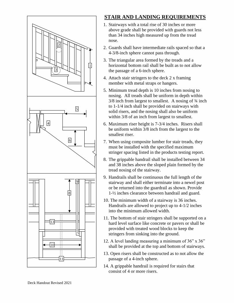
STAIR AND LANDING REQUIREMENTS
1. Stairways with a total rise of 30 inches or more
above grade shall be provided with guards not less
than 34 inches high measured up from the tread
nose.
2. Guards shall have intermediate rails spaced so that a
4-3/8-inch sphere cannot pass through.
3. The triangular area formed by the treads and a
horizontal bottom rail shall be built as to not allow
the passage of a 6-inch sphere.
4. Attach stair stringers to the deck 2 x framing
member with metal straps or hangers.
5. Minimum tread depth is 10 inches from nosing to
nosing. All treads shall be uniform in depth within
3/8 inch from largest to smallest. A nosing of ¾ inch
to 1-1/4 inch shall be provided on stairways with
solid risers, and the nosing shall also be uniform
within 3/8 of an inch from largest to smallest.
6. Maximum riser height is 7-3/4 inches. Risers shall
be uniform within 3/8 inch from the largest to the
smallest riser.
7. When using composite lumber for stair treads, they
must be installed with the specified maximum
stringer spacing listed in the products testing report.
8. The grippable handrail shall be installed between 34
and 38 inches above the sloped plain formed by the
tread nosing of the stairway.
9. Handrails shall be continuous the full length of the
stairway and shall either terminate into a newel post
or be returned into the guardrail as shown. Provide
1-½ inches clearance between handrail and guard.
10. The minimum width of a stairway is 36 inches.
Handrails are allowed to project up to 4-1/2 inches
into the minimum allowed width.
11. The bottom of stair stringers shall be supported on a
hard level surface like concrete or pavers or shall be
provided with treated wood blocks to keep the
stringers from sinking into the ground.
12. A level landing measuring a minimum of 36” x 36”
shall be provided at the top and bottom of stairways.
13. Open risers shall be constructed as to not allow the
passage of a 4-inch sphere.
14. A grippable handrail is required for stairs that
consist of 4 or more risers.
1
2
3
4
5
6
8
9
10
11
13

Deck Handout Revised 2021
GRIPPABLE HANDRAILS
What the code says:
Handrail grip size. All required handrails shall be of one of the following types or provide
equivalent grasp ability.
1. Type I. Handrails with a circular cross section shall have an outside diameter of at least 1¼
inches and not greater than 2 inches. If the handrail is not circular it shall have a perimeter
dimension of at least 4 inches and not greater than 6¼ inches with a maximum cross
section of dimension of 2¼ inches.
2. Type II. Handrails with a perimeter greater than 6¼ inches shall provide a graspable finger
recess area on both sides of the profile. The finger recess shall begin within a distance of ¾
inch measured vertically from the tallest portion of the profile and achieve a depth of at
least 5/16 inch within 7/8 inch below the widest portion of the profile. This required depth
shall continue for at least 3/8 inch to a level that is not less than 1¾ inches below the tallest
portion of the profile. The minimum width of the handrail above the recess shall be 1¼
inches to a maximum of 2¾ inches. Edges shall have a minimum radius of 0.01 inch.
What this means:
Type I:
Type II:
Instructions:
Position rail section with the
widest point of grip at line
AB and left edge touching
line AC, keeping horizontal
axis of rail parallel to line
AB.
With rail in position, it must
pass 1) thru 5) to meet the
code requirements. If profile
is asymmetrical both sides
must pass.
4) Entire black box
is visible
5) Recess continues
based on crown
height of rail
7
8 2½”
5
16
3
8
1¾”
3
4
1¼”
2¾”
A
C
B
D
1) Width not greater than
2) Width at least
3) Top of rail is not above line C-D
Reproduction check line measures 2¾”
Max
Ex
ten
t of
Co
ntr
oll
ed G
rip
Siz
e
Max
Ex
ten
t of
Rec
ess
Max
Cro
wn
To
Bott
om
of
requ
ired
rec
ess
Follow Top of rail guideline
Circular Non-circular
Diameter
Minimum 1¼
Maximum 2
Maximum 2¼ Perimeter
Min. 4”
Max. 6¼”
Maximum 2¼”

Deck Handout Revised 2021
RESIDENTIAL BUILDING PERMIT APPLICATION City of Prior Lake | Building Inspections
4646 Dakota Street SE | Prior Lake MN 55372 | Office: 952.447.9850 | [email protected]
SITE INFORMATION
Site Address Lot Block Parcel ID
Owner Subdivision Zoning
Address Phone
APPLICANT/CONTRACTOR INFORMATION Work being completed by property owner must be owner occupied
Applicant/Company Name License No
Address Email
City State Zip
Contact Person Phone
PERMIT DETAILS – call Gopher State One before you dig 811
Work Description:
TYPE OF WORK: New Alteration Addition Repair Replacement
Single Family Detached Deck Re-Roof Windows & Doors
Single Family Attached Egress Window Re-Side Fence (exceeds 6’)
Accessory Structure Garage Misc. Pre-1978 Homes
EPA Lead safe (RRP) Certification required
Lower Level Finish Porch Other #_______________________
Estimated Value of Work (Include labor)
$ Builders Deposit
$2,500 Permit Fee $
PROVIDE THE FOLLOWING (AS REQUIRED FOR PERMIT) Upload Online Attachments on BSA
Building Plans Tree Preservation Agreement Braced Wall Panel locations
Certificate of Survey Truss Specifications Energy Compliance Certificate & Data
Single Family Worksheet Erosion or Sediment Control Plan Heating and Cooling Calculations
SUBCONTRACTOR INFORMATION – (SEPARATE PERMITS ARE REQUIRED)
I hereby certify that the information contained herein is correct and agree to do the proposed work in accordance to provisions of the ordinances of the City of Prior Lake and State Building codes. I further agree that any plans and specifications submitted herein shall become part of this permit application. This permit will expire in six (6) months from the date of issue if a passing final inspection is not obtained. I further understand, this application, its materials, and final approved plans will be available electronically and publicly viewable on bsaonline.com.
Signature of Applicant Date
Printed Name of Applicant
A Certificate of Occupancy is required prior to occupancy or use of the structure. It will be issued upon completion of a satisfactory final inspection approved by the Building Department.