city of new braunfels
TRANSCRIPT

City of New Braunfels
Drainage and Erosion Control Design Manual
Revised September 2000

Drainage and Erosion Control Design Manual i
Table of Contents 1.0 Introduction ....................................................................................................... 1 1.1 Purpose and Scope....................................................................................... 1 1.2 References................................................................................................... 1 1.3 Acknowledgments ........................................................................................ 1 2.0 Drainage Policy and Criteria ...................................................................................... 2 2.1 Development Categories .............................................................................. 2 2.1.1 Type 1 Development......................................................................... 2 2.1.2 Type 2 Development......................................................................... 2 2.1.3 Type 3 Development......................................................................... 3 2.2 Water Quality............................................................................................... 4 2.3 Drainage Structure Aesthetics........................................................................ 4 2.4 Drainage Design Computations ...................................................................... 4 2.5 Criteria for Design of Drainage Facilities ......................................................... 4 2.5.1 General .............................................................................................. 4 2.5.2 Stormwater retention or detention facilities ........................................... 5 2.5.3 Culvert or bridge crossings................................................................... 6 2.5.4 Surface use of streets for drainage, and storm drain systems.................. 7 2.5.5 Storm drain systems............................................................................ 8 2.5.6 Channels ...........................................................................................10 2.6 Freeboard...................................................................................................11 2.7 Maintenance of Drainage Facilities ................................................................11 2.8 Drainage Report Requirements .....................................................................12 2.9 Erosion Hazard Setback Regulation ...............................................................15 2.10 Finished Floor Elevations..............................................................................15 3.0 City of New Braunfels Comprehensive Storm Drainage Flood Protection and Erosion Control Ordinance........................................................................................16 4.0 Design Rainfall ......................................................................................................17 4.1 Rainfall Intensity-Duration-Frequency - Ration Method ...................................17 4.2 Probable Maximum Precipitation (PMP) - Dams or Impoundments ...................17 4.3 Standard Project Precipitation (SPP)..............................................................17 4.4 Hydrographs - TR-20, TR-55 or HEC-1 ..........................................................17 4.5 Rainfall Loss Rate ........................................................................................18 5.0 Determination of Design Discharge ...........................................................................19 5.1 General .....................................................................................................19 5.2 Impact of Runoff on Downstream Facilities ....................................................19 5.3 Procedure for the Rational Method................................................................19 5.3.1 Antecedent Precipitation Coefficient ....................................................19 5.3.2 Runoff Coefficient ..............................................................................20 5.3.3 Time of Concentration ........................................................................21 5.4 Alternative Procedures .................................................................................22 5.4.1 SCS/NRCS Unit Hydrograph ................................................................22 5.4.2 Snyder's Unit Hydrograph ...................................................................24 5.5 Fully Developed Runoff Conditions ................................................................26 5.6 Hydrologic Computer Programs ....................................................................26 6.0 Street Flow ......................................................................................................28 6.1 Lot to Lot Drainage......................................................................................28 6.2 Positive Overflow.........................................................................................28 6.3 Street Flow Calculations ...............................................................................28 6.3.1 Flow Calculations for Straight Street Sections .....................................28
Drainage and Erosion Control Design Manual ii
6.3.2 Flow Calculations for Parabolic Street Sections ...................................29 6.4 Alley Flow Limitations ..................................................................................30 6.5 Alley Flow Calculations.................................................................................31 6.6 Computer Models ........................................................................................32 7.0 Inlet Design ......................................................................................................33 7.1 Inlet Design Considerations ..........................................................................33 7.2 Inlet Types and Descriptions ........................................................................34 7.3 Inlet Capacity Calculations............................................................................35 8.0 Storm Drain Design .................................................................................................41 8.1 Storm Drain Design Standards .....................................................................41 8.2 Calculation of the Hydraulic Grade Line .........................................................41 8.2.1 Starting Tailwater Conditions...............................................................42 8.2.2 Friction Losses ...................................................................................43 8.2.3 Junction Losses, Without a Manhole or Junction Box .............................44 8.2.4 Junction Losses, With a Manhole or Junction Box..................................45 8.2.5 Losses in a Bend ................................................................................46 8.2.6 Losses Due To Transitions (Sudden Expansion or Contraction) ...............46 8.3 Hydraulic Grade Line Computation Sheet .......................................................46 9.0 Open Channels ......................................................................................................48 9.1 Hydraulics.................................................................................................. 48 9.1.1 Gradually Varied Flow..........................................................................48 9.1.2 Normal Flow .......................................................................................48 9.2 Design Parameters ......................................................................................48 9.3 Supercritical Flow ........................................................................................48 9.4 Flow in Bends .............................................................................................52 9.5 Drop Structures...........................................................................................54 9.5.1 Vertical Drop Structures......................................................................54 9.5.2 Sloping Drop Structures......................................................................54 9.6 Energy Dissipators.......................................................................................55 10.0 Bridge and Culvert Design........................................................................................56 10.1 Applicable Design Criteria.............................................................................56 10.2 Design Parameters ......................................................................................56 10.3 Culvert Outlet Protection ..............................................................................56 10.4 Culvert Hydraulics .......................................................................................57 10.5 Debris Fins .................................................................................................59 10.6 Energy Dissipation.......................................................................................59 11.0 Detention Basin Design............................................................................................60 11.1 Design Criteria ............................................................................................60 11.2 Minimum Requirements for Detention Pond Design ........................................60 11.3 Outlet Structure Design ...............................................................................61 11.4 Playa Lakes.................................................................................................61 12.0 Lakes, Dams, and Levees.........................................................................................62 12.1 Lakes and Dams..........................................................................................62 12.1.1 General...........................................................................................62 12.1.2 Applicable Design Criteria .................................................................62 12.1.3 Maintenance and Liability Criteria ......................................................63 12.1.4 Natural Resource Conservation Service Lakes.....................................63 12.1.5 Design Frequencies for Dams or Impoundments.................................64 12.1.6 Additional Design Requirements........................................................65 12.2 Levees .....................................................................................................65

Drainage and Erosion Control Design Manual iii
13.0 Site Erosion Control during Construction....................................................................67 13.1 Applicable Properties or Construction Sites ....................................................67 13.2 General Guidelines for Erosion Control Plan ...................................................67 13.3 Applicable Best Management Practices ..........................................................68 13.4 Stream Bank Erosion ...................................................................................68
Drainage and Erosion Control Design Manual iv
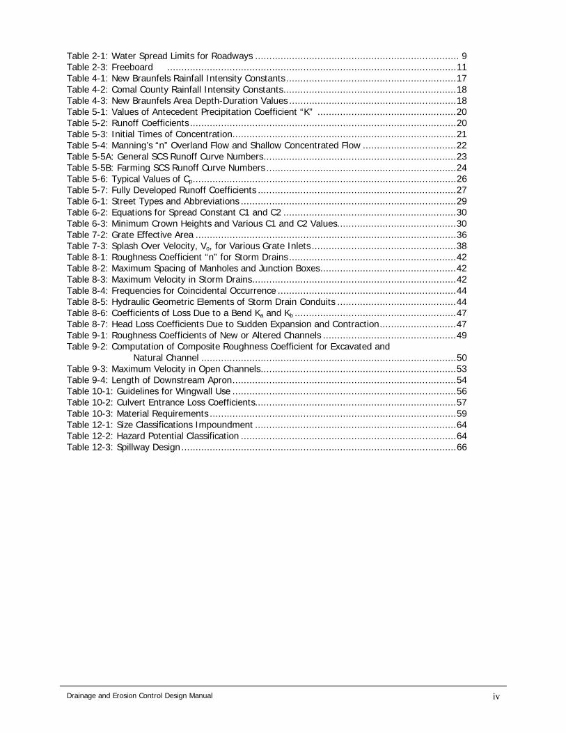
Table 2-1: Water Spread Limits for Roadways ........................................................................ 9 Table 2-3: Freeboard ......................................................................................................11 Table 4-1: New Braunfels Rainfall Intensity Constants ............................................................17 Table 4-2: Comal County Rainfall Intensity Constants.............................................................18 Table 4-3: New Braunfels Area Depth-Duration Values ...........................................................18 Table 5-1: Values of Antecedent Precipitation Coefficient “K” .................................................20 Table 5-2: Runoff Coefficients ..............................................................................................20 Table 5-3: Initial Times of Concentration...............................................................................21 Table 5-4: Manning’s “n” Overland Flow and Shallow Concentrated Flow .................................22 Table 5-5A: General SCS Runoff Curve Numbers....................................................................23 Table 5-5B: Farming SCS Runoff Curve Numbers ...................................................................24 Table 5-6: Typical Values of Cp.............................................................................................26 Table 5-7: Fully Developed Runoff Coefficients ......................................................................27 Table 6-1: Street Types and Abbreviations ............................................................................29 Table 6-2: Equations for Spread Constant C1 and C2 .............................................................30 Table 6-3: Minimum Crown Heights and Various C1 and C2 Values..........................................30 Table 7-2: Grate Effective Area ............................................................................................36 Table 7-3: Splash Over Velocity, Vo, for Various Grate Inlets ...................................................38 Table 8-1: Roughness Coefficient “n” for Storm Drains ...........................................................42 Table 8-2: Maximum Spacing of Manholes and Junction Boxes................................................42 Table 8-3: Maximum Velocity in Storm Drains........................................................................42 Table 8-4: Frequencies for Coincidental Occurrence ...............................................................44 Table 8-5: Hydraulic Geometric Elements of Storm Drain Conduits ..........................................44 Table 8-6: Coefficients of Loss Due to a Bend Ka and Kb .........................................................47 Table 8-7: Head Loss Coefficients Due to Sudden Expansion and Contraction...........................47 Table 9-1: Roughness Coefficients of New or Altered Channels ...............................................49 Table 9-2: Computation of Composite Roughness Coefficient for Excavated and Natural Channel ..........................................................................................50 Table 9-3: Maximum Velocity in Open Channels.....................................................................53 Table 9-4: Length of Downstream Apron...............................................................................54 Table 10-1: Guidelines for Wingwall Use ...............................................................................56 Table 10-2: Culvert Entrance Loss Coefficients.......................................................................57 Table 10-3: Material Requirements .......................................................................................59 Table 12-1: Size Classifications Impoundment .......................................................................64 Table 12-2: Hazard Potential Classification ............................................................................64 Table 12-3: Spillway Design .................................................................................................66

Drainage and Erosion Control Design Manual v
Appendix A: List of References........................................................................................69 Appendix B: List of Abbreviations ....................................................................................71 Appendix C: Definition of Terms......................................................................................73 Appendix D: Examples....................................................................................................85 Appendix E: Computation Sheets ...................................................................................93 Appendix F: Figures ......................................................................................................97

Drainage and Erosion Control Design Manual
69
1.0 Introduction 1.1 Purpose and Scope
A. The purpose of this design manual is to establish standard principles and practices for the design and construction of storm drainage, flood protection, and erosion control facilities within the City of New Braunfels, Texas and within its extraterritorial jurisdiction.
B. The design factors, formulas, graphs, and procedures described in the following pages
are intended to serve as guidelines for the solution of drainage problems involving the volume and rate of flow, method of collection, storage, conveyance and disposal of stormwater and erosion protection from stormwater flows. Ultimate responsibility for actual design, however, remains with the design engineer. Any deviation from the requirements of this manual shall be approved by the City Engineer of the City of New Braunfels.
C. Section 4.0 and beyond are concerned with issues related to the Drainage Plan and
Drainage Report required for a Type 3 Development. D. In cases where the owner has negotiated monies instead of on-site or off-site
drainage improvements, the development standards will be tailored within the terms of the negotiations.
1.2 References At certain points in the text, the reader will encounter numbers enclosed in parentheses, for example (1). These numbers correspond to the references listed in Appendix A. 1.3 Acknowledgments This design manual is the result of the dedication and energy of the Drainage Advisory Committee members.

Drainage and Erosion Control Design Manual
70
2.0 Drainage Policy And Criteria 2.1 Development Categories
In an effort to facilitate development while applying drainage rules, a tier system is established requiring different submittals and different development actions depending on the probable impact on the drainage basin. In all cases, properly sized easements shall be granted across all contiguous property owned by the applicant; and a comprehensive Drainage Plan and Drainage Report shall be provided for all property on the subject plat whether developed by this application or not. Best Management Practices (BMPs) shall be exercised in the design process.
2.1.1 Type 1 Development
A. A Type 1 Development is any development or redevelopment in the following categories.
1. Disturbs less than one acre of land; 2. Creates less than 1,000 square foot of additional impervious cover; or 3. Creates additions to single family or duplex residential structure.
B. Submittals for a Type 1 Development include: location and contact information (e.g. name, address, phone number, property location), site drawing for the proposed disturbance, review of applicable BMP’s and temporary erosion control techniques. For a Type 1 Development:
1. Drainage easements may be required to accommodate future or existing
development 2.1.2 Type 2 Development
A. A Type 2 Development is any development or redevelopment in the following categories:
1. Agriculture (not including feedlots), or 2. Single family or duplex residential not in a major subdivision (three or more lots)
with more than 1,000 square feet of additional impervious cover, or 3. Non-residential developments of less than 5,000 square foot of additional
impervious cover, or
4. Development not meeting criteria for a Type 3 Development.
B. Submittals for a Type 2 Development include: location and contact information, site drawing or sketch for the proposed disturbance (a scaled drawing (scale 1” = (50’ or less)) on 11” x 17” paper showing existing drainageways, flow directions, floodplain boundaries, proposed grading and development, and proposed drainage, and erosion control facilities with a copy of the survey plat showing the lot layout, streets, and utility and drainage easements), review of applicable BMP’s and temporary erosion control techniques, agreement letter specifying BMP’s to be included in the project. For a Type 2 Development: 1. If any on-site and off-site stormwater structure is known to be at or above
design capacity, the owner/developer shall be responsible for increasing the size of the structure to accommodate the development.
2. Drainage easements may be required to accommodate future or existing
development.

Drainage and Erosion Control Design Manual
71
2.1.3 Type 3 Development
A. A Type 3 Development is any development or redevelopment in the following categories. 1. Non-residential development with more than 5,000 square feet of additional
impervious cover, 2. Residential subdivision with other than single family and duplex units, 3. Major subdivisions (three or more lots), 4. Disturbs more than one acre of land, 5. Development within a FEMA designated flood hazard area or adjacent to a major
watercourse, or 6. Agricultural feedlots
B. Submittals for a Type 3 Development include: location and contact information, Drainage Report, Erosion Control Plan, agreement letter specifying BMP’s to be included in the project or other site specific requirements. For a Type 3 Development: 1. Mitigation through detention, retention, or some other technique must be
designed, constructed, and maintained to reduce the post-development discharge rate to below that of pre-development for the 10-year and 100-year design storms. Participation in neighborhood or regional mitigation is an acceptable option.
2. In cases where adequate detention is not available and an In-lieu-of negotiation
is in place, all on-site and off-site stormwater structures must be sized to convey the additional stormwater below the design level of each structure encountered from the property to the first major stream. For existing structures, see paragraph 3 below.
3. If any encountered structure is at or above design capacity, the owner/developer
shall be responsible for increasing the size of the structure to accommodate the development, at their own expense or demonstrating cause why the city should partner in the project.
4. On-site drainage easements may be required to accommodate future or existing
development. Off-site drainage easements may also be required if the increase in water quantity impacts existing water storage capacity and increases the possibility of flooding.
C. The Drainage Plan and Drainage Report containing the proposed storm drainage and
flood protection system must be submitted as part of the preliminary platting process or application for a Building Permit. A revised Drainage Plan and Drainage Report shall be submitted after all issues have been resolved with the City Engineer.

Drainage and Erosion Control Design Manual
72
2.2 Water Quality Stormwater discharge from developments will eventually be regulated for the quality of the water discharged. Standards for water quality of discharge are not currently being enforced. When the responsibilities of administering EPA/TNRCC NPDES Phase II fall to the City, additional requirements will be enforced. 2.3 Drainage Structure Aesthetics
A. Drainage design in the urban environment must also consider appearance as an integral
part of the design and structures should generally blend with the natural surroundings as much as possible to maintain the aesthetics of the natural area. The City of New Braunfels strongly encourages preservation of the natural floodplains.
B. The protection of existing trees and vegetation should be maximized during development
of drainage plans. Whenever possible, the replacement of the trees destroyed by drainage and flood protection procedures is encouraged.
2.4 Drainage Design Computations Computations to support all drainage designs shall be submitted to the City Engineer for review as part of the Drainage Report and shall be summarized in the form of the standard computation sheets contained in this manual. Computer programs used to perform computations shall be limited to those referenced in this manual unless approved by the City Engineer. On-site pre-development stormwater runoff computations shall be based upon conditions representing the existing land conditions with respect to soil type, percentage cover, and cover type as indicated in the 3-20-97 aerial photos and supporting documentation. In the event that photography is not available for the proposed site of development, undeveloped conditions must be assumed unless other documentation is presented fixing the level of development as of March 20, 1997. Design of structures shall use fully developed sub-basin conditions for the prescribed design storms. 2.5 Criteria for Design of Drainage Facilities 2.5.1 General
A. The planning and design of drainage systems should ensure that problems are not
transferred from one location to another. Grading and other construction activities may not change the terrain to cause damage to public or private property from drainage or flood problems, increased runoff, or increased erosion or sediment movement.
B. Lot to lot drainage of sheet flows should be avoided in subdivision design.
C. The City Engineer shall not approve any Drainage Report pertaining to proposed
construction, platting or other development where the proposed activity or change in the land would result in post-development discharge from the site exceeding discharge under natural conditions (prior to grading or other development), immediately downstream of the proposed site. Downstream capacity shall not be exceeded as a result of development. Exemptions from this provisions are as follows: 1. Additional drainage improvements are not required if drainage improvements
have been provided for the fully developed condition, which includes the proposed development.
2. A fee may be utilized in place of a detention/retention system, at the request of
affected persons, when it can be clearly demonstrated that detention/retention at the site does not provide off-site flood relief due to the parcel size, location, or
Drainage and Erosion Control Design Manual
73
other factors. The fees collected will be used to construct public flood control improvements, which will be designed to mitigate the potential damage of floodwaters associated with the property from which the fees are contributed. The amount of the fee shall be proportional to the cost of the otherwise required detention/retention system.
2.5.2 Stormwater retention or detention facilities
A. Stormwater retention or detention facilities must reduce peak flows from the 10-year, 24-
hour storm and the 100-year, 24-hour storm, such that these peak flows are no greater than under pre-development conditions.
B. The method(s) of retention or detention shall be appropriate to the type of development,
topography, and amount of control needed. Suggested measures include the following: 1. basins or swales – single or multiple 2. check dams in gullies to slow runoff and trap sediment 3. leach fields, infiltration chambers, dry wells, rain barrels, French drains 4. granular fill under permeable paving blocks 5. contour terracing, improved vegetation cover.
C. Detention/retention facilities may be incorporated into parks, open space areas and landscaping designs. Parking areas may be used as detention or retention facilities provided that maximum depths of ponding do not exceed eight inches, and ponding is in the areas most remotely situated from structures.
D. Stormwater infiltration systems are not permitted in any development where there is a
potential for pollutants to adversely affect ground water quality (e.g. EARZ) E. No detention or retention basin shall retain standing water longer than 36 hours unless it
is designed and constructed to be a permanent pond with appropriate health, safety, and water quality measures, and water rights requirements for such a body of water.
F. Individual lot basins within subdivisions may be approved for lots of one acre or more
with slopes under 5% (five percent). G. Specific requirements for retention/detention facilities are as follows:
1. Facilities shall be located such that the edge of the 100-year water surface is at
least 10 feet from the edge of any public road. Finished floors of adjacent structures should be a minimum of 1 foot above the 100-year water surface in the facility. Facilities should preferably be located such that the invert of the outlet structure is above the 100-year flood level in the receiving body; but in all cases facilities shall be designed to function properly during conditions where the outlet is submerged by the tailwater of the receiving stream.
2. Drainage easements or open space designations may be required for
retention/detention facilities. Easement boundaries shall contain the berms, inlet and outlet structures, access ramps, permanent erosion control facilities, the 100-year water surface and any additional area needed for access and maintenance.

Drainage and Erosion Control Design Manual
74
3. Ponding below natural grade (depressed storage) is encouraged. 4. Detention facilities shall be designed with one or more outlet structures to allow
safe passage of the 100-year post-development design storm runoff. In addition, an emergency spillway shall be provided with sufficient capacity to pass at least the 25-year design storm runoff assuming the pond is full. Spillways and outlets shall be protected from erosion with riprap, grouted riprap, or other method or erosion control to adequately protect the structure and downstream channel. Outflows shall be conveyed to an appropriate receiving drainage facility in a manner such that roadways, buildings, etc. are not damaged.
5. In the event a detention facility empties into another storage facility
downstream, the effect of the facility’s outflow hydrograph (volume and peak flow) on that facility shall be evaluated.
6. Side slopes of earthen embankments shall be designed for stability and safety,
with the following minimum requirements for facilities with unrestricted access: in facilities with ponding depths of 18 inches to 3 feet, side slopes of earthen banks shall be 2.5:1 or flatter; side slopes shall be 3:1 or flatter in facilities with maximum ponding depths over 3 feet; a benched configuration is required for facilities with ponding depths over 6 feet. Bench widths shall be at least 4 feet, spaced at least every 3 feet vertically. The above slope criteria may be waived if security barriers and erosion control measures are provided, with City Engineer approval. Barriers may consist of chain-link, masonry, wood, vegetation or other materials, but must not restrict the hydraulic capacity of drainage facilities. Minimum barrier height is 48”. Vegetative barriers must be of a width equal to or greater than the total height, with density sufficient to restrict access. All constructed stormwater structures of earthen material shall be revegetated to mature growth.
7. Maximum water depths over 6 feet shall not be allowed without prior approval
from the City Engineer. 8. All earthen drainage structures or facilities shall be compacted in lifts not to
exceed eight inches during construction to 90% Standard Proctor. 2.5.3 Culvert or bridge crossings
A. Arterial streets shall meet the stricter of the most recent Texas Department of
Transportation criteria for crossings on urban highways, or; 1. 50-year design storm runoff, with headwater one foot below the top of the
culvert structure. 2. 100-year water surface shall not encroach through half of roadway lanes 3. Minimum culvert size 24” circular pipe
B. All other streets shall meet the following criteria for crossings, as a minimum: 1. 25-year design storm runoff, with headwater one foot below the top
embankment 2. 25-year water surface shall leave at least one lane open. 3. 50-year design storm runoff no more than 6” over top of roadway

Drainage and Erosion Control Design Manual
75
4. Allowance shall be made for conveyance of the 100-year runoff across the road
and into the downstream channel without damage to the road or adjacent property
5. Minimum culvert size 18” circular pipe
C. Temporary crossings shall be designed to safely pass the 2-year design storm runoff, minimum.
D. The backwater created by a culvert or bridge during the 100-year design storm runoff
shall not cause damage to public or private property. E. Culvert outlets will be designed to minimize damage caused by erosion. F. Culverts and bridges shall be aligned with natural drainageways in grade and direction
whenever practical. Minimum slopes by culvert type must be observed to reduce sediment accumulation.
G. Larger culvert sizes, bridges and/or box culverts or smooth-walled pipe are
recommended for crossings where heavy debris or sediment accumulations are anticipated. Trash racks may be required.
H. All headwalls shall be constructed of reinforced concrete.
2.5.4 Surface use of streets and alleys for drainage
A. General requirements for streets are:
1. The roadway or paved alley must be able to contain the 100-year flow within the right of way. Runoff shall not enter private property from a street except in recorded drainage easements or rights-of-way, or in historic watercourses where easements or rights-of-way have not been obtained.
2. 100-year design storm depth of water shall not exceed 10" at any point within the street right-of-way and the product of maximum depth (feet) times average cross-section velocity (feet per second) at any point shall not exceed 6.5.
3. Rundowns shall be designed to convey and contain drainage carded by the
roadway to ensure the 100-year event is contained within the right-of-way. If a storm drain system is present, rundowns shall be designed for the difference between the storm drain capacity and the 100-year runoff, with a 25-year minimum design assuming all of the flow bypasses the storm drain system.
4. Driveways should be constructed to allow the 25-year design storm runoff to
pass under the driveway in a culvert (15" minimum) or over the driveway on a concrete apron. Concrete aprons or box culverts are preferred in areas of heavy sediment transport.
5. The side slope of a ditch or swale on the side adjacent to the road shall be no
steeper then 4:1 (6:1 TxDOT)
C. Water Spread limits for Roadways is as indicated in Table 2-1. No lowering of the standard height of street crown shall be allowed for the purposes of obtaining additional hydraulic capacity. Where additional hydraulic capacity is required, the proposed street gradient must be increased or curb inlets and storm sewers installed to remove a portion

Drainage and Erosion Control Design Manual
76
of the flow. For non-curbed streets, the 100-year frequency flows shall be contained within available rights-of-way.
2.5.5 Storm drain systems
A. General requirements for storm drain systems are: 1. Storm drain pipes, inlets, and roadside drainage swales are designed for the 25-
year design storm runoff with the design HGL of the system a minimum of 2 feet below the level of the street subgrade.
2. Pipe. If corrugated metal pipe is used, the manufacturer's design guidelines
should be followed. Concrete lining shall be used with corrugated metal pipes with diameters of 36 inches or greater. Plastic pipe can be used only if authorized by the City Engineer and in no case shall plastic be used under roadways.
3. Connections. Concrete pipe collars or manufactured transition pieces must be
used at all pipe size changes on trunk lines. For all pipe junctions other then manholes and junction boxes, manufactured wye connections should be used, and the angle of intersection shall not be greater than 45 degrees. This includes discharges into box culverts and channels. Special circumstances may require cut-ins instead of manufactured wye connections; the use of cut-ins must be approved by the City Engineer. Laterals shall be connected to trunk lines using manholes or manufactured wye connections. Special situations may require laterals to be connected to the trunk lines by a cut-in (punch-in), and such cut-ins must be approved by the City Engineer. Inlet laterals will normally connect only one inlet to the trunk line. Special circumstances requiring multiple inlets to be connected with a single lateral shall be approved by the City Engineer. Vertical curves in the conduit will not be permitted, and horizontal curves must meet manufacturer's requirements for offsetting of the joints.
4. The maximum manhole or junction box spacing for storm drain systems is shown
in Table 8-2. Junction boxes must also be located at:
a. Pick up points having three or more laterals; b. Trunk line size changes for pipes with diameter differences greater than 24
inches; c. Vertical alignment changes; d. Future collection points.
5. The cover over the crown of circular pipe should be at least three feet and
should be based on the type of pipe used, the expected loads and the supporting strength of the pipe. Box sections should normally have a minimum of one foot of cover; however, box sections may be designed for direct traffic in special situations with the approval of the City Engineer.
6. Grates for drop inlets should be designed with grate units weighing 250 to 300
pounds to facilitate removal for maintenance, but minimize vandalism. Design shall consider traffic loading and bicycle and pedestrian safety.
7. The minimum lateral storm drainpipe diameter shall be 18 inches, except in
sump areas, which shall be at least 21 inches in diameter. The minimum pipe diameter for a trunk line pipe shall be 24 inches. Manholes should be located at junctions, changes in pipe size, sharp changes in direction or grade, and at regular intervals of 300 feet, maximum. The requirement for manholes may be

Drainage and Erosion Control Design Manual
77
waived if the pipe size allows direct access into the pipe by maintenance personnel and equipment. More stringent criteria may be imposed by the City Engineer to reduce or facilitate maintenance.
8. A bypass flow of not more than 10% of the 10-year flow will be allowed on
streets with grades of three percent or greater. No bypass flow will be allowed for inlets on streets with grades less than three percent.
9. For storms of a 10-year frequency or less, water flowing in arterial streets shall
be intercepted by an inlet prior to super-elevated sections, to prevent water from flowing across the roadway. In critical circumstances, this requirement can be waived by the City Engineer.
10. All storm sewer conduits to be dedicated to the City of New Braunfels shall be
located in drainage easements dedicated to the City of New Braunfels at the time of final platting of the property. Storm sewer easements shall be at least 15 feet wide. Wider easements may be required for multiple box culverts, other multiple storm sewer designs or for extremely wide single-line storm sewers as outlined in the Drainage Design Manual.
Table 2-1
Water Spread Limits for Roadways Street Classification 1O-Year Permissible Water Spread
Arterial Streets One 11-foot traffic lane must remain open in each direction.
Collector Streets One 11-foot traffic lane must remain open.
Residential Streets Water flow must not exceed the top of either curb.
B. Connections from Buildings to Storm Sewers. Drainage from residential areas, such as
rooftops, should be allowed to flow overland before joining the storm sewer system. Seepage into basements that is pumped to ground level, seepage from springs and runoff from roof drains on nonresidential buildings that would flow onto or across driveways, sidewalks or other areas commonly crossed by pedestrians can create hazards or nuisances to pedestrians. Thus, if hazards or nuisances would be created, the basement and rooftop drains shall be tied directly to the nearest storm sewer. Pumped lines from basements shall have backflow preventers.
2.5.6 Channels
A. The City of New Braunfels encourages the preservation of natural channels and drainage patterns. Concentrated drainage flows must enter and depart from a developed area in the same manner and location as under pre-development conditions.
B. Easements or drainage right-of-ways shall be provided for all channels (artificial and
natural) and shall be labeled as drainage easements on plats for recording. For properties with existing structural development on previously platted lots, setbacks of the same dimensions may be used in place of easements. The requirement for a setback or easement may be waived by the City Engineer. Easements, setbacks and FEMA floodways shall not be encroached upon with fill materials or structures, which would reduce the channel's ability to carry the 100-year flood.

Drainage and Erosion Control Design Manual
78
1. Easement width shall be at least the width of the water surface from the 100-year design storm runoff under post-development conditions. In addition, an additional 12 feet, minimum, shall be allowed for access.
2. Additional easement width should be provided to allow for channel meandering
near bends of channels.
3. Easement width should be measured outward from the centerline of the watercourse, 1/2 of the dimension to the right and 1/2 to the left of center, additional access easement shall be 10 feet on one side and two on the other.
C. Artificial channels and swales:
1. Artificial channels and swales shall be designed to contain the 100-year design
storm runoff with the water surface at the top of the structure or within the easement whichever is more restrictive. Freeboard along the outside of channel bends shall include the increased water surface due to superelevation (refer to Section 9.6).
2. For large channels where exposure to the wind may cause wave action,
additional freeboard must be included to accommodate 75 mph winds without washover.
3. Fencing and/or warning signs shall be required to prevent public access where
flowing water would pose a safety hazard as determined by the City Engineer.
4. Unlined improved channels that contain bends shall be designed such that erosion at the bends is minimized. Erosion protection at bends shall be determined based on the velocity along the outside of the channel bend (refer to Section 9.5).
D. Flumes. Sidewalks crossing times shall be A.D.A. compatible so as to minimize danger to
pedestrians (e.g. covered, flared, or bridged times; handrails on sidewalks). Applicants shall dedicate drainage easements for times.
E. Channels shall be designed to be stable and to not create safety hazards. Lined slopes
should be no steeper than 1:1. Side slopes of artificial earthen channels should be 3:1 or flatter in channels with depths greater than 2 feet. Recommended maximum water velocities for earthen channels are given in Section 9. Erosion control or energy dissipation devices should be used to control velocities such that channel degradation does not occur. Bank stabilization measures shall not reduce channel capacity and shall follow sound engineering practices.
F. Should diversion of a natural drainageway be required, sufficient work shall be done
upstream and/or downstream to provide all affected properties at least the same level of flood protection and erosion control that existed prior to the diversion. The time length of a diversion channel must be at least as long as the segment of natural channel being replaced so that velocity is not increased.
G. Maintenance Access Requirements. Access roads and/or ramps shall be provided for all
channels to allow vehicular access for maintenance. The location and design of access roads and ramps shall be approved by the City Engineer. Access roads shall have a width of at least twelve feet and a cross slope no greater than two percent. Ramps on access roads shall have a vertical grade no steeper than ten percent.
2.6 Freeboard
Drainage and Erosion Control Design Manual
79
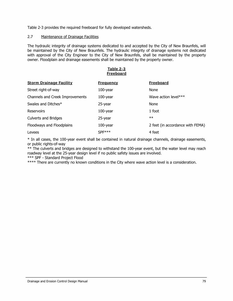
Table 2-3 provides the required freeboard for fully developed watersheds. 2.7 Maintenance of Drainage Facilities The hydraulic integrity of drainage systems dedicated to and accepted by the City of New Braunfels, will be maintained by the City of New Braunfels. The hydraulic integrity of drainage systems not dedicated with approval of the City Engineer to the City of New Braunfels, shall be maintained by the property owner. Floodplain and drainage easements shall be maintained by the property owner.
Table 2-3 Freeboard
Storm Drainage Facility Frequency Freeboard
Street right-of-way 100-year None
Channels and Creek Improvements 100-year Wave action level***
Swales and Ditches* 25-year None
Reservoirs 100-year 1 foot
Culverts and Bridges 25-year **
Floodways and Floodplains 100-year 2 feet (in accordance with FEMA)
Levees SPF*** 4 feet
* In all cases, the 100-year event shall be contained in natural drainage channels, drainage easements, or public rights-of-way ** The culverts and bridges are designed to withstand the 100-year event, but the water level may reach roadway level at the 25-year design level if no public safety issues are involved. *** SPF - Standard Project Flood **** There are currently no known conditions in the City where wave action level is a consideration.
Drainage and Erosion Control Design Manual
80
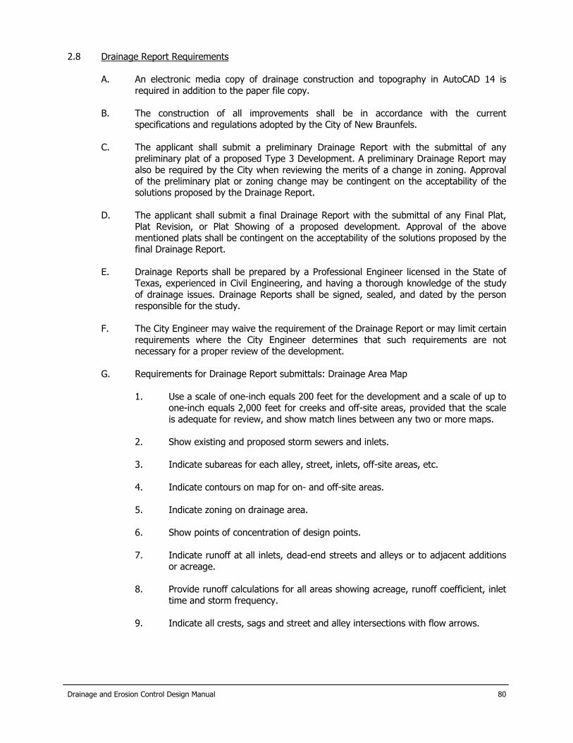
2.8 Drainage Report Requirements
A. An electronic media copy of drainage construction and topography in AutoCAD 14 is required in addition to the paper file copy.
B. The construction of all improvements shall be in accordance with the current
specifications and regulations adopted by the City of New Braunfels. C. The applicant shall submit a preliminary Drainage Report with the submittal of any
preliminary plat of a proposed Type 3 Development. A preliminary Drainage Report may also be required by the City when reviewing the merits of a change in zoning. Approval of the preliminary plat or zoning change may be contingent on the acceptability of the solutions proposed by the Drainage Report.
D. The applicant shall submit a final Drainage Report with the submittal of any Final Plat,
Plat Revision, or Plat Showing of a proposed development. Approval of the above mentioned plats shall be contingent on the acceptability of the solutions proposed by the final Drainage Report.
E. Drainage Reports shall be prepared by a Professional Engineer licensed in the State of
Texas, experienced in Civil Engineering, and having a thorough knowledge of the study of drainage issues. Drainage Reports shall be signed, sealed, and dated by the person responsible for the study.
F. The City Engineer may waive the requirement of the Drainage Report or may limit certain
requirements where the City Engineer determines that such requirements are not necessary for a proper review of the development.
G. Requirements for Drainage Report submittals: Drainage Area Map
1. Use a scale of one-inch equals 200 feet for the development and a scale of up to
one-inch equals 2,000 feet for creeks and off-site areas, provided that the scale is adequate for review, and show match lines between any two or more maps.
2. Show existing and proposed storm sewers and inlets.
3. Indicate subareas for each alley, street, inlets, off-site areas, etc.
4. Indicate contours on map for on- and off-site areas.
5. Indicate zoning on drainage area.
6. Show points of concentration of design points.
7. Indicate runoff at all inlets, dead-end streets and alleys or to adjacent additions
or acreage.
8. Provide runoff calculations for all areas showing acreage, runoff coefficient, inlet time and storm frequency.
9. Indicate all crests, sags and street and alley intersections with flow arrows.

Drainage and Erosion Control Design Manual
81
H. Requirements for Drainage Report submittals: Drainage Report
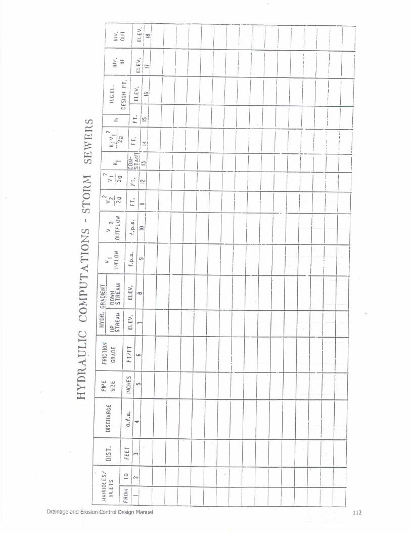
* Calculations 1. Show hydraulic grade lines with computations. 2. Provide table with input parameters for all models and formulas 3. Indicate all assumptions.
* Storm Drain Plan and Profile Sheets (or spec page) 1. Show plan and profile of all drainage elements on separate sheets from paving
plans. 2. Indicate concrete cushions where applicable. 3. Specify the type of storm drainpipe to be used. 4. Indicate property lines along storm sewer and show easements with dimensions. 5. Show all existing utilities in plan view, and show those existing utilities in profile
where possible conflicts may occur with the storm sewer. 6. Indicate existing and proposed ground line and improvements on all street, alley
and storm sewer profiles. 7. Show laterals on trunk profile with stations. 8. Number inlets according to the number designation given for the area or subarea
contributing runoff to the inlet. 9. Indicate size and type of inlet on plan view, lateral size and flow line, paving
station and top-of-curb elevation. 10. Indicate quantity and direction of flows at all inlets, stubouts, pipes and intakes. 11. Show future streets and grades, where applicable. 12. Show water surface at outfall of storm sewer, velocity and typical section of
receiving water body. 13. Where fill is proposed for trench cut in creeks or outfall ditches, specify
compacted fill and compaction criteria. 14. Show size of pipe, length of each pipe size, and stationing at 100-foot intervals in
the plan 15. Begin and end each sheet with even or 50-foot stationing. 16. Show diameter of pipes, physical grade, discharge, capacity of pipe, slope of
hydraulic grade line and velocity in the pipe in the profile view. 17. Show elevation of flow lines at 100-foot intervals on the profile. 18. Give benchmark information. 19. Show capacities, flows, velocities, etc., of the existing system into which the
proposed system is being connected. 20. Show details of all connection boxes, headwalls on storm sewer, times or any
other item not in a standard detail sheet. 21. Provide profile where existing utility is crossed. 22. Show headwalls and specify type for all storm sewers at outfall. 23. Show if curbing in alleys is needed to add extra capacity. 24. Runoff from alleys and other paved areas are not to cause street capacity to be
exceeded. 25. Show horizontal and vertical curve data for all drainage elements. 26. Tie storm sewer stationing with paving stations. 27. On all dead-end streets and alleys, show grades for drainage overflow path on
the plan and profile sheets, and show erosion controls. 28. Specify concrete strength for all structures. 29. Provide sections for road, railroad and other ditches with profiles and hydraulic
computations. Show design water surface on profile.

Drainage and Erosion Control Design Manual
82
I. Requirements for Drainage Report submittals: Bridge Plans
1. Show the elevation of the lowest member of the bridge and 100-year water surface elevation.
2. Indicate borings on plans. 3. Provide soils report. 4. Show a section at the bridge. 5. Provide hydraulic calculations on all sections. 6. Provide structural details and calculations with dead load deflection diagram. 7. Provide vertical and horizontal alignment. 8. Provide calculations and details for all erosion protection.
* Creek Alteration and Channel Plans 1. Show stationing in plan and profile. 2. Indicate flow line, banks, design water surface. Show hydraulic computations. 3. Indicate the nature of banks, such as rock, earth, etc. 4. Provide cross sections with ties to property lines and easements. 5. Show side slopes of creeks, channels, etc. 6. Specify compacted fill, where fill is proposed. 7. Indicate any adjacent alley or street elevations on creek profile. 8. Show any temporary or permanent erosion controls. 9. Indicate existing and proposed velocities. 10. Show access and/or maintenance easements. 11. Identify the datum, benchmarks and date of re-leveling the benchmarks to which
the flood and ground elevations are referenced. 12. Show existing Finished Floor (F.F.), or proposed minimum F.F. of all structures,
existing or proposed adjacent to creek or channel alternations.
* Environmental Effects and Required Regulatory Permits Report 1. The preliminary submittal of plans is to identify all permits that, in the design
engineer's opinion, will or may be required by regulatory agencies. Such permits and agencies include, but are not limited to, NPDES (addressed in this manual in chapter 13), Section 404 permit from the U.S. Army Corps of Engineers, the Environmental Protection Agency (EPA), and Texas Natural Resources Conservation Commission (TNRCC).
2. The final submittal of plans is to provide a list of all required permits necessary to construct the project and a copy of the approved permits.
* Detention and Retention Facilities 1. Show plan view of detention/retention area and outlet structure. 2. Delineate limits of conservation pool, sediment storage area, flood storage pool
and/or freeboard. 3. Indicate size, dimensions, total capacity and design discharge velocity of the
outlet structure. 4. Show erosion control features at the discharge point of the outlet structure. 5. Specify side slopes of facility and outlet structure. 6. Show existing or proposed structures or other facilities downstream of the outlet
structure and emergency spillway, and provide information sufficient to show that the adjacent facilities will not be subjected to inundation (or increased inundation) or otherwise affected by the discharge from the facility.
7. Indicate locations and quantities of all inflows to the facility. 8. State the design time to empty the facility. * Levees 1. Show location, extent, nature, dimensions, etc., of levee embankments and
associated interior and exterior drainage facilities.

Drainage and Erosion Control Design Manual
83
2. Provide engineering analysis addressing potential erosion of the levee embankments during flood events.
3. Provide engineering analysis of levee embankment stability and seepage through the levee during flood events.
4. Compaction of fill material should be performed in accordance with standard engineering practices.
5. Analyze interior drainage concerns. Identify sources of interior flooding and extent and depth of such flooding. Consider capacity of pumps and other drainage devices for evacuating interior waters.
6. Submit an operations manual which discusses the flood warning system to trigger closures; closure operations, procedures and personnel; operation plans for Interior drainage facilities; at least an annual inspection program; and maintenance plans, procedures and frequency.
7. Provide all other information requested or required by the City Engineer and/or the Federal Emergency Management Agency.
2.9 Erosion Hazard Setback Regulation Erosion hazard setback zone determination is necessary for the banks of streams in which the natural channel is to be preserved. The purpose of the setbacks is to reduce the amount of structural damage caused by the erosion of the bank. With the application of streambank erosion hazard setbacks, an easement is dedicated to the city such that no structure can be located, constructed, or maintained in the area encompassing the erosion hazard setback. The City of New Braunfels allows for streambank stabilization as an alternative to dedicating the erosion hazard setback zone. Streambank erosion hazard setbacks may extend beyond the limits of the regulatory floodplain. Recommendations by a qualified geotechnical engineer or geologist should be presented to the City Engineer for review. 2.10 Finished Floor Elevations The elevation of the lowest floor shall be at least 10 inches above the finished grade of the surrounding ground, which shall be sloped in a fashion so as to direct stormwater away from the structure. Properties adjacent to stormwater conveyance structures must have floor slab elevation or bottom of floor joists a minimum of one foot above the 100-year water flow elevation in the structure. Driveway serving houses on the downhill side of the street shall have properly sized swale before entering the garage.
Drainage and Erosion Control Design Manual
84
3.0 City of New Braunfels Comprehensive Storm Drainage Flood Protection And Erosion Control Ordinance
The City of New Braunfels' Code of Ordinances contains requirements for the design of storm drainage, flood protection, and erosion control facilities. Where there is any conflict between this manual and the current Ordinance, the Ordinance shall take precedence. Although a copy of the current Ordinance has been included in Appendix D of this Manual for reference, the design engineer is responsible for complying with the latest version of the Ordinance on record with the City. It is the intent of this Manual, in concert with the Drainage and Erosion Control Ordinance, to provide all development under its jurisdiction the options of: 1) mitigation; 2) demonstrating that no mitigation is in the best interest of the watershed; or, 3) paying a share of the cost of increased regional detention required because of the development.

Drainage and Erosion Control Design Manual
85
4.0 Design Rainfall 4.1 Rainfall Intensity-Duration-Frequency – Rational Method A. Rainfall rates for drainage design purposes shall be estimated in accordance with standard
technical information provided by U.S.G.S. Water Resources Investigations Report 98-4044(2). The information, guidelines and procedures contained in these publications should be utilized by the design engineer. Rainfall information from these sources is provided in this manual for the convenience of the Engineer. If there are any discrepancies between the data in this manual and these references, the City Engineer should be contacted for clarification.
B. Point rainfall intensities can be calculated utilizing the equations listed in Tables 4-1 and 4-2. The design of storm drainage facilities within the City of New Braunfels and Comal County shall be based on rainfall information from either of the tables depending on the location.
4.2 Probable Maximum Precipitation (PMP) – Dams or Impoundments The design rainfall for NRCS dams or impoundments is based on a percentage of the Probable Maximum Precipitation (PMP), as specified in Section 12 of this manual. PMP rainfall depths for various durations and storm sizes can be obtained from Hydro-Meteorological Reports Nos. 51(3) and 52(4), respectively. The computer calculating the basin average precipitation for each time step.
Table 4-1 New Braunfels Rainfall Intensity Constants
Intensity for Durations of 5 Min to 7 Days
I=b/(Tc+d)^e Year b d e
2 71.5 13.09 0.850 5 72.9 11.14 0.800 10 71.9 8.69 0.769 25 79.5 8.01 0.751 50 86.6 7.56 0.740 100 95.1 7.17 0.731 500 119.4 6.23 0.714
Note: I is rainfall intensity in inches per hour. 4.3 Standard Project Precipitation (SPP) The design rainfall for projects which require the Corps of Engineers’ Standard Project Flood (SPF) shall be obtained by applying 50 percent of the PMF, or the runoff developed from the PMF, as described in Section 4.2. 4.4 Hydrographs – TR-20, TR-55 or HEC-1 The model of choice for the City is HEC-1 because of its compatibility with existing City studies and FEMA. When models such as in TR-20, TR-55 or HEC-1 are used to evaluate drainage, the design storm distribution shall be the standard Type II storm defined with the data from Table 4-3.

Drainage and Erosion Control Design Manual
86
Table 4-2 Comal County Rainfall Intensity Constants
Intensity for Durations of 5 Min to 7 Days
I=b/(Tc+d)^e Year b d e
2 71.5 13.09 0.850 5 80.8 12.70 0.800 10 71.9 8.69 0.769 25 79.5 8.01 0.751 50 86.6 7.56 0.740 100 95.1 7.17 0.731 500 119.4 6.23 0.714
Note: I is rainfall intensity in inches per hour.
Table 4-3 New Braunfels Area Depth-Duration Values
Year 5-Min 15-Min 1-Hr 2-Hr 3-Hr 6-Hr 12-Hr 24-Hr 2-day 3-day
2 0.51 1.05 1.86 2.24 2.45 2.80 3.15 3.52 3.92 4.17 5 0.66 1.34 2.40 2.95 3.27 3.85 4.47 5.17 5.96 6.47 10 0.80 1.58 2.78 3.43 3.84 4.58 5.43 6.40 7.53 8.27 25 0.96 1.89 3.34 4.16 4.67 5.64 6.76 8.07 9.61 10.64 50 1.11 2.16 3.83 4.79 5.40 6.57 7.92 9.52 11.43 12.71 100 1.28 2.47 4.39 5.51 6.23 7.61 9.24 10.17 13.48 15.05
4.5 Rainfall Loss Rate The method used to calculate the rainfall losses will depend on the method used to compute the design discharge. The Rational Method accounts for rainfall losses with the C coefficient, as description in Section 5.3.2. For the unit hydrograph methods described in Section 5.4, the method used is described in the respective user manual with SCS values for selected conditions are provided for standardization.
Drainage and Erosion Control Design Manual
87
5.0 Determination of Design Discharge 5.1 General The selection of an appropriate method for calculating runoff depends upon the size and time of concentration of the drainage area contributing runoff to the most downstream point of a project. 5.2 Impact of Runoff on Downstream Facilities No proposed development shall be constructed which impedes or constricts runoff from an upstream watershed based on fully developed conditions. The developer and City have the option to partner on downstream improvements. 5.3 Procedure for the Rational Method
Rational Method equation is based on the following assumptions:
a. Rainfall intensity is constant over the time it takes to drain the watershed (time of
concentration) b. The runoff coefficient remains constant during the time of concentration. c. The watershed area does not change.
Computation of stormwater runoff for drainage areas less than 150 acres, with a time of concentration of 20 minutes or less, may be by the Rational Method. The discharge computed by the Rational Method is the peak discharge for a given frequency on the watershed in question, and is given by the following relationship:
Q=K*C*I*A (Eq. 5-1)
where: Q is the peak design discharge in cubic feet per second for a given frequency on the watershed at the desired design point.
K is a dimensionless coefficient m account for storms with recurrence intervals greater than 10-years. (See Table 5-1.)
C is a dimensionless weighted runoff coefficient, representing ground cover conditions and/or land use within the watershed area. (See Table 5-2.)
I is the average rainfall intensity in inches per hour at a rainfall duration equal to the time of concentration, associated with the desired design frequency. (See Tables 4-1 and 4-2.)
A is the drainage area in acres contributing runoff to the desired design point.
5.3.1 Antecedent Precipitation Coefficient The runoff computations should include the antecedent precipitation coefficient "K", as identified in Table 5-1. This coefficient is intended to reflect the additional runoff that results from saturated ground conditions. In no case should the product of the runoff coefficient and the antecedent precipitation coefficient exceed 1.0.
Drainage and Erosion Control Design Manual
88
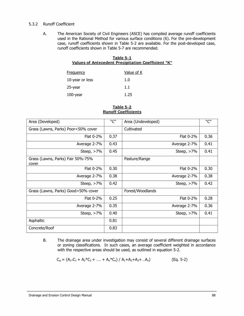
5.3.2 Runoff Coefficient A. The American Society of Civil Engineers (ASCE) has compiled average runoff coefficients
used in the Rational Method for various surface conditions (6). For the pre-development case, runoff coefficients shown in Table 5-2 are available. For the post-developed case, runoff coefficients shown in Table 5-7 are recommended.
Table 5-1
Values of Antecedent Precipitation Coefficient "K"
Frequency Value of K
10-year or less 1.0
25-year 1.1
100-year 1.25
Table 5-2
Runoff Coefficients Area (Developed) “C” Area (Undeveloped) “C”
Grass (Lawns, Parks) Poor<50% cover Cultivated
Flat 0-2% 0.37 Flat 0-2% 0.36
Average 2-7% 0.43 Average 2-7% 0.41
Steep, >7% 0.45 Steep, >7% 0.41
Grass (Lawns, Parks) Fair 50%-75% cover
Pasture/Range
Flat 0-2% 0.30 Flat 0-2% 0.30
Average 2-7% 0.38 Average 2-7% 0.38
Steep, >7% 0.42 Steep, >7% 0.42
Grass (Lawns, Parks) Good>50% cover Forest/Woodlands
Flat 0-2% 0.25 Flat 0-2% 0.28
Average 2-7% 0.35 Average 2-7% 0.36
Steep, >7% 0.40 Steep, >7% 0.41
Asphaltic 0.81
Concrete/Roof 0.83
B. The drainage area under investigation may consist of several different drainage surfaces
or zoning classifications. In such cases, an average coefficient weighted in accordance with the respective areas should be used, as outlined in equation 5-2.
Cw = (A1*C1 + A2*C2 + …. + An*Cn) / A1+A2+A3+…An) (Eq. 5-2)

Drainage and Erosion Control Design Manual
89
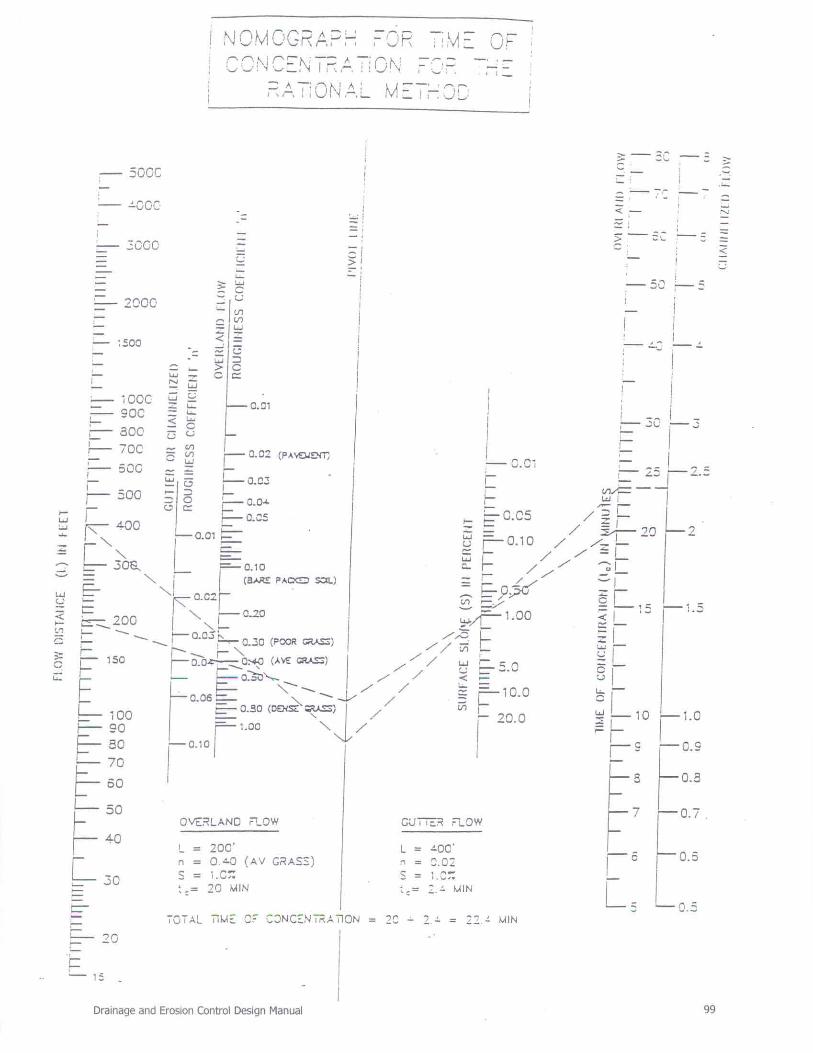
5.3.3 Time of Concentration
A. The time of concentration (tc) is the amount of time required for surface runoff to travel from the most hydraulically remote point within the drainage basin to the drainage point under consideration. The most hydraulically remote drainage point refers to the route requiring the longest drainage travel time and not necessarily the greatest linear distance. The flow routes used in determining the time of concentration must take into consideration fully developed conditions as proposed by thoroughfare plans, zoning maps, etc.
B. When computing the tc, the maximum length of overland flow shall be 300 feet, at which
point flow shall be considered shallow concentrated flow or channelized flow. Table 5-3 contains initial tc at all inlets (i.e., prior to entering a pipe systems or channel). These values are derived from initial times of concentration typically used in Rational Method calculations, and are to be used for the first 300 feet of travel distance.
Table 5-3
Initial Times of Concentration
Type of Area Minimum Inlet Time Minutes
Parks & Open Areas 20
Residential
Single Family
Multi-Family
15 10
Commercial/Business 10
Roofs & Paved Areas 5
It should be noted that when determining the time of concentration, the flow route may consist of several segments. The total time of concentration is determined as follows:
tc = Initial tc + Tt1 + … + Ttn (Eq. 5-3)
where: tc Time of concentration (min) Initial tc The initial time of concentration from Table 5-3 (min) Tt1 The travel time of Segment I (min)
Overland flow velocity can be calculated by using Table 5-4 in the following equations:
Sheet Flow Tt = (60*L*n)/(288.6*S0.4) Eq. 5-4a
Shallow Concentrated Flow
Tt = (L*n)/(60*S0.5) Eq. 5-4b
Channel or Sewer Flow Tt = (L*A)/(60*Q) Eq. 5-4c
where: Tt Segment time of concentration (min) n Manning “n” from Table 5-4 S Slope of the land over which the runoff will flow (ft/ft) V Average velocity (ft/s) Q Design discharge (cfs)

Drainage and Erosion Control Design Manual
90
A Cross-sectional area (ft) 5.4 Alternative Procedure
A. For drainage areas in excess of 150 acres, times of concentration greater than 20 minutes, or in instances of sizing large open channels, reclaiming floodplains, creating lakes or building other types of drainage-related facilities on major drainage courses where the use of the Rational Method does not provide reliable results, a unit hydrograph method shall be used.
B. FEMA’s flows shall not be used.
C. The preferred unit hydrograph in general is the Natural Resource Conservation Service
(SCS/NRCS) Dimensionless Unit Hydrograph. Details of the Snyder’s Unit Hydrograph are provided for contrast.
5.4.1 SCS/NRCS Unit Hydrograph
A. the procedures for the Soil Conservation Service (SCS) method are outlined in Section 4 of the National Engineering Handbook (13) and in numerous hydrology textbooks. The designer is responsible for obtaining a copy of the user manual for the SCS method. The SCS method uses a dimensionless unit hydrograph applied to the peak discharge computed for a given watershed.
B. Runoff Coefficient. The runoff curve number used in developing the pre-development
discharge shall be documented. The runoff curve number and contributing area shall reflect the fully developed sub-basin or watershed. Table 5-5 contains runoff curve numbers. Antecedent Moisture Condition III (AMC III) shall be used for the 100-year even (9, 14). For a listing an applicable soil types, refer to the United States Department of Agriculture, Soil Conservation Service, Soil Survey of Tom Green County, Texas (15).
Table 5-4
Manning’s “n” for Overland Flow and Shallow Concentrated Flow Condition “n”
Concrete (rough or smoothed finish) 0.016
Asphalt 0.02
0-50% vegetated ground cover, remaining bare soil or rock outcrops, minimum brush or tree cover
0.1
50-90% vegetated ground cover, remaining bare soil or rock outcrops, minimum – medium brush or tree cover
0.2
100% vegetated ground cover, medium – dense grasses (lawns, grassy fields, etc) medium brush or tree cover
0.3
100% vegetated ground cover with areas of heavy vegetation (parks, greenbelts, riparian areas, etc) dense undergrowth with medium to heavy tree growth
0.619
Table 5-5A General SCS Runoff Curve Numbers
Cover Type* CN (AMC III)
C D

Drainage and Erosion Control Design Manual
91
Open space – lawns, parks, golf courses Poor condition (grass cover <50%) 86 89
Fair condition (grass cover 50-75%) 79 84
Good condition (grass cover >75%) 74 80
Impervious Paved 98 98
Gravel 89 91
Dirt 87 89
Urban Commercial and business 94 95
Industrial 91 93
Residential ⅛ acre lot size 90 92
¼ acre lot size 83 87
½ acre lot size 80 85
1 acre lot size 79 84
2 acre lot size 77 82
Pasture, grassland, or range-continuous Poor 86 89
Forage Fair 79 84
Good 74 80
Meadow-continuous generally mowed for hay 71 78
Brush-brush, weed, grass mix Poor 77 83
Fair 70 77
Good 65 73
Woods-grass combination (orchard, tree Poor 82 86
Farm) Fair 76 82
Good 72 79
Woods Poor 77 83
Fair 73 79
Good 70 77
Farmstead 82 86
Drainage and Erosion Control Design Manual
92
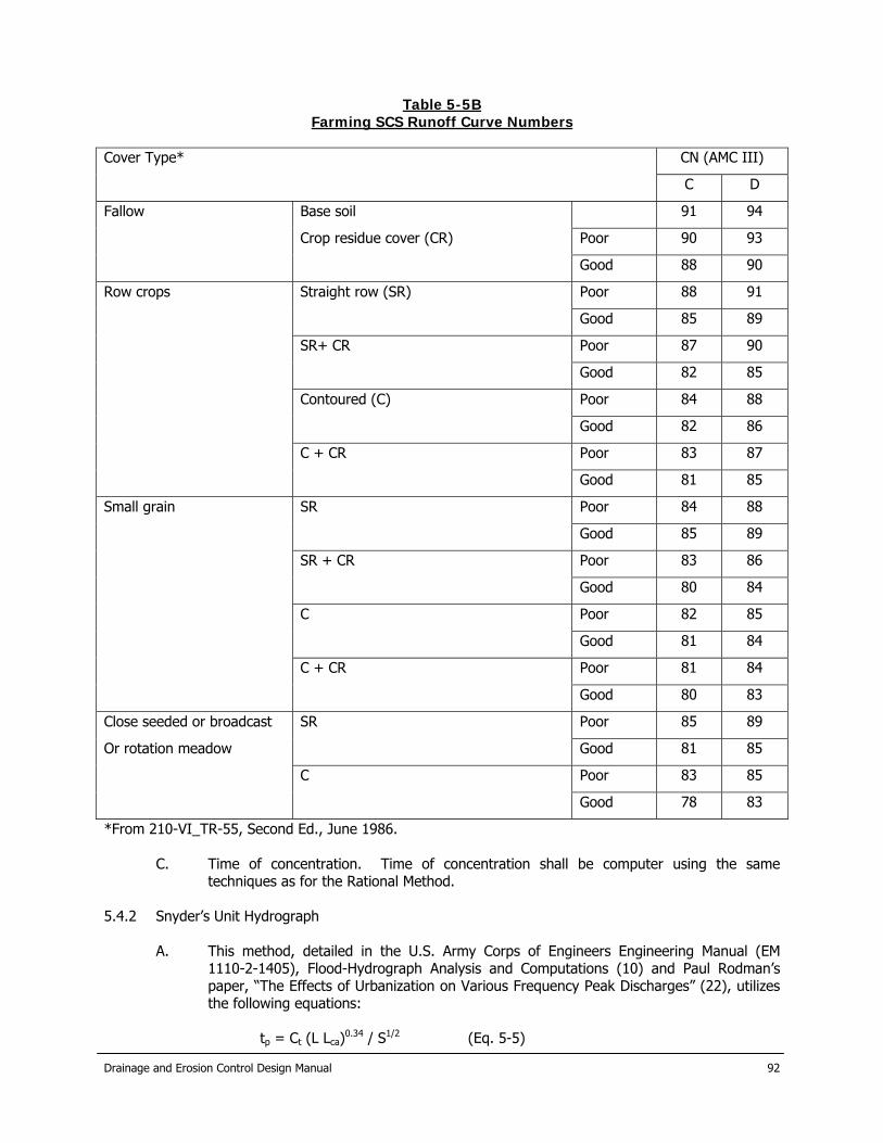
Table 5-5B
Farming SCS Runoff Curve Numbers Cover Type* CN (AMC III)
C D
Fallow Base soil 91 94
Crop residue cover (CR) Poor 90 93
Good 88 90
Row crops Straight row (SR) Poor 88 91
Good 85 89
SR+ CR Poor 87 90
Good 82 85
Contoured (C) Poor 84 88
Good 82 86
C + CR Poor 83 87
Good 81 85
Small grain SR Poor 84 88
Good 85 89
SR + CR Poor 83 86
Good 80 84
C Poor 82 85
Good 81 84
C + CR Poor 81 84
Good 80 83
Close seeded or broadcast SR Poor 85 89
Or rotation meadow Good 81 85
C Poor 83 85
Good 78 83
*From 210-VI_TR-55, Second Ed., June 1986.
C. Time of concentration. Time of concentration shall be computer using the same techniques as for the Rational Method.
5.4.2 Snyder’s Unit Hydrograph
A. This method, detailed in the U.S. Army Corps of Engineers Engineering Manual (EM 1110-2-1405), Flood-Hydrograph Analysis and Computations (10) and Paul Rodman’s paper, “The Effects of Urbanization on Various Frequency Peak Discharges” (22), utilizes the following equations:
tp = Ct (L Lca)0.34 / S1/2 (Eq. 5-5)

Drainage and Erosion Control Design Manual
93
tr = tp / 5.5 (Eq. 5-6) qp = Cp640/tp (Eq. 5-7) tpR = tp + 0.25 (tR – tr) (Eq. 5-8) qpR = Cp640 / tpR (Eq. 5-9) qpR = qp tp / tpR (Eq. 5-10) Qp = qp A (Eq. 5-11)
Where: tR Is the unit rainfall duration in hours other than standard unit, tr, adopted
in specific study. tp Is the lag time from midpoint of unit rainfall duration, tr, to peak of unit
hydrograph in hours tpR Is the lag time from midpoint of unit rainfall duration, tR, peak of unit
hydrograph in hours qp Is the peak rate of discharge of unit hydrograph for unit rainfall duration,
tr, in cfs/sq mi qpR Is the peak rate of discharge in cfs/sq mi of unit in hydrograph for unit
rainfall duration, tR Qp Is the peak rate of discharge of unit hydrograph in cfs A Is the drainage area in square miles Lca Is the river mileage from the design point to the centroid of gravity of the
drainage area L Is the river mileage from the given station to the upstream limits of the
drainage area. S Is the average slope of the streambed in ft/mi
B. The coefficient Ct is a regional coefficient for variations in slopes within the watershed.
Typical values of Ct range from about 0.5 to 2.0 and a representative value for the New Braunfels region 0.8 (11). Ct for a watershed can be estimated if the lag time, tp, stream length, L, distance to the basin central, Lca, and the streambed slope (ft/mi) are known. These values reflect no significant urbanization of the watershed.
C. The coefficient Cp is the peaking coefficient, which typically ranges from 0.3 to 1.2 with a
representative value for the New Braunfels area of 0.63 (11), and is related to the flood wave and storage conditions of the watershed. Larger values of Cp are generally associated with smaller values of Ct. Typically values of Cp are listed in Table 5-6.
D. Urbanization Curves. To account for the effects of urbanization, another method was
developed by the Corps of Engineers to adjust the tp coefficient. Urbanization curves allow for the determination of tp based on the percent urbanization and the type of soil in the study area. They were determined from the equation below (12):
Tp = 10 ((0.3833*log (L*Lca/(Sst)^.5) + log (Ip) - (BW*%Urb)/100) (Eq. 5-12) Sst = (el85% - el15%) / (0.7 * L) (Eq. 5-13)
Where: tp Is the lag time from midpoint of unit rainfall duration, tr, to peak of unit
hydrograph in hours. Lca Is the river mileage from the design point to the centroid of the drainage
area L Is the river mileage from the given station to the upstream limits of the
drainage area. Sst Is the weighted slope of the flow path (ft/mi) Ip Is the calibration point, defined as the log of tp where (L* Lca/ Sst^.5)=1
and urbanization = 0% BW Is the bandwidth, equal to the log of the width between each 20%
urbanization line.
Drainage and Erosion Control Design Manual
94
%Urb Is a value representative of the degree to which urbanization has occurred in the basin, in percent
el85% Is the elevation at a location 85% upstream of the given station el15% Is the elevation at a location 15% upstream of the given station
For the New Braunfels area, the Ip values used are 1.03 for the Comfort Soils Group,
1.12 for the Rumple/Echrant Soils Group, and 0.94 for the Hieden/Houston Black Soils Group. The bandwidth value (BW) for both of the soil types is 0.266. For a study area that is composed of more than one type of soil group, a weighted average can be used.
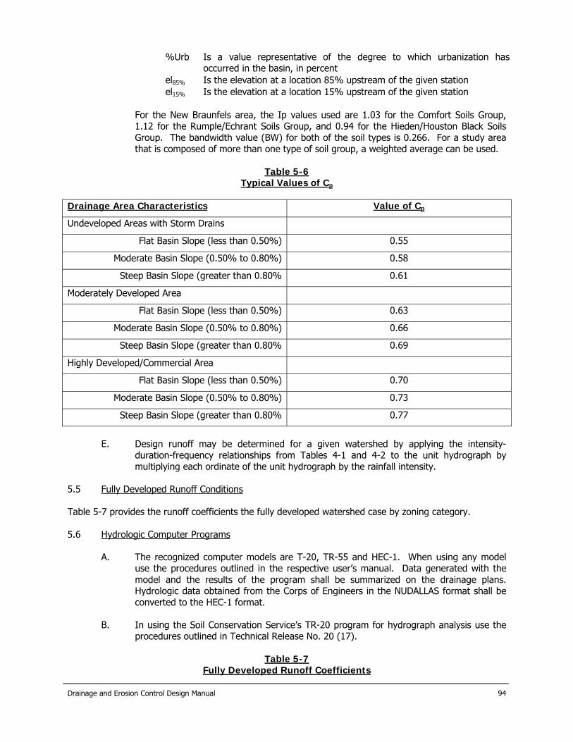
Table 5-6
Typical Values of Cp Drainage Area Characteristics Value of Cp
Undeveloped Areas with Storm Drains
Flat Basin Slope (less than 0.50%) 0.55
Moderate Basin Slope (0.50% to 0.80%) 0.58
Steep Basin Slope (greater than 0.80% 0.61
Moderately Developed Area
Flat Basin Slope (less than 0.50%) 0.63
Moderate Basin Slope (0.50% to 0.80%) 0.66
Steep Basin Slope (greater than 0.80% 0.69
Highly Developed/Commercial Area
Flat Basin Slope (less than 0.50%) 0.70
Moderate Basin Slope (0.50% to 0.80%) 0.73
Steep Basin Slope (greater than 0.80% 0.77
E. Design runoff may be determined for a given watershed by applying the intensity-
duration-frequency relationships from Tables 4-1 and 4-2 to the unit hydrograph by multiplying each ordinate of the unit hydrograph by the rainfall intensity.
5.5 Fully Developed Runoff Conditions Table 5-7 provides the runoff coefficients the fully developed watershed case by zoning category. 5.6 Hydrologic Computer Programs
A. The recognized computer models are T-20, TR-55 and HEC-1. When using any model use the procedures outlined in the respective user’s manual. Data generated with the model and the results of the program shall be summarized on the drainage plans. Hydrologic data obtained from the Corps of Engineers in the NUDALLAS format shall be converted to the HEC-1 format.
B. In using the Soil Conservation Service’s TR-20 program for hydrograph analysis use the
procedures outlined in Technical Release No. 20 (17).
Table 5-7 Fully Developed Runoff Coefficients

Drainage and Erosion Control Design Manual
95
CN (AMCII)
Zone “C” C D
R-1/R-1A Single family 0.53 83 87
R-2/R-2A Single and two family 0.59 90 92
R-3/R-3L Multi family high density 0.67 92 94
R-3/R-3H Multi family low density 0.55 90 92
B-1/B-1A Convent & mobile homes 0.53 83 87
TH/TH-A Townhouse 0.67 92 92
ZH/ZH-A Zero lot line homes 0.55 87 90
C-1/C1A Neighborhood business 0.67 92 93
C-2/C-1B General Business 0.68 93 94
C-3 Commercial 0.80 94 95
C-4/C-4A Resort commercial / PUD*
M-1/M1A Light industry 0.72 87 90
M-2/M-2A Heavy industry 0.78 94 95
*must use composite values based on % impervious.

6.0 Street Flow 6.1 Lot-to-Lot Drainage Existing drainage between developed lots will remain the responsibility of the affected property owners developments are required to drain surface runoff from an individual lot to a public right-of-way or to a drainage system contained in public easement. 6.2 Positive Overflow The approved drainage system shall provide for positive overflow at all low points. The term “positive overflow” means that, when the inlets do not function properly or when the design capacity of the conduit or roadway ditch is exceeded, the excess flow can be conveyed overland along an open course. Normally, this would mean along a street or alley, but it can be constructed on private property within the dedication of a special drainage easement. 6.3 Street Flow Calculations Evaluation of street flow is based upon open channel hydraulics theory, with the Manning’s equation modified to allow direct solution, based on the street cross section. Generally, the street will have a straight or parabolic section. Figure 6-1 has been prepared for gutter flow capacity as divided into two types, triangular and parabolic. These street flow calculations are dependent on the shape of the street. Flow calculations for inverted streets shall use the methods outlined in Section 6.6 of this manual.
a. Triangular b. Triangular with Gutter c. Parabolic
Figure 6-1. Typical Gutter Cross Sections 6.3.1 Flow Calculations for Straight Street Sections The direct solution for gutter flow depth for a given flow in straight sections (triangular channel) is based upon the following formula:
Q = 0.56 * S0.5 * y 8/3 / (n * Sx) (Eq.6-1) y = [(Q * n * Sx) / (0.56 * S1/2)]3/8 (Eq.6-2) T = y / Sx (Eq.6-3) V = (2 * Q) / (T2 * Sx) (Eq.6-4)
Is the gutter discharge (ft3/sec) Where: Q
Y Is the flow depth in the gutter (ft) Sx Is the crown slope (ft/ft) n Is Manning’s coefficient of roughness, usually 0.016 for streets S Is the slope of the gutter (ft/ft)
Drainage and Erosion Control Design Manual
96

Drainage and Erosion Control Design Manual
97
T Is the spread of flow or ponding width (ft) V Is the velocity of flow (ft/sec)
6.3.2 Flow Calculations for Parabolic Street Sections The flow capacity in parabolic street section is less than that of a triangular street section for the same slope and spread width but parabolic street sections provide a flatter driving surface for traffic toward the center of the street and are commonly used for urban streets. Depth of flow for a given flow quantity, in only one side of the street, for parabolic street sections of 26 through 100 feet of width may be determined from the equations for constants in Table 6-4 and in used in equations 6-5 through 6-9.
y = ((Q / S0.5)c2) / C1 (Eq.6-5) Q = (y * C1)(1/C2) * S0.5 (Eq.6-6) T = B – (B2 – ((B2) / ch) * y)0.5
(Eq.6-7) A = (T * y) / 3 (Eq.6-8) V = Q / A (Eq.6-9)
Where: y Is the flow depth in the gutter for one side of the street (ft) Q Is the gutter discharge for one side of the street S Is the slope of the gutter (ft/ft) C1 Is a constant for which an equation is given in table 6-4 C2 Is a constant for which an equation is given in table 6-4 T Is the spread of flow for one side of the street (ft) B Is the one half of the street width (ft) ch Is the crown height of the street (ft) A Is the cross section area of flow (ft2) V Is the velocity of the flow (ft/sec)
Table 6-1
Street Types and Abbreviations Street Type Pavement Width (Ft) Crown (in)
Arterial 65 6
64 (4ft median) 6
48 4
Collector 45 4
Local 42 4
40 4

Drainage and Erosion Control Design Manual
98
Table 6-2 Equations for Spread Constant C1 and C2
Constant and Crown Equation
C1 (4” crown) 3.676 * 10-05 * B3 – 5.594 * 10-03 * B2 + 0.4215 * B + 6.3775
C2 (5” crown) 3.321 * 10-05 * B3 – 5.077 * 10-03 * B2 + 0.3842 * B + 5.7688
C2 (6” crown) 3.056 * 10-05 * B3 – 4.690 * 10-03 * B2 + 0.3562 * B + 5.3162
C2 (7” crown) 2.848 * 10-05 * B3 – 4.386 * 10-03 * B2 + 0.3341 * B + 4.9615
C2 (8” crown) 2.679 * 10-05 * B3 – 4.138 * 10-03 * B2 + 0.3161 * B + 4.6734
C2 (9” crown) 2.546 * 10-05 * B3 – 3.938 * 10-03 * B2 + 0.3012 * B + 4.4320
C2 (10” crown) 2.420 * 10-05 * B3 – 3.755 * 10-03 * B2 + 0.2881 * B + 4.2287
C2 (11” crown) 2.315 * 10-05 * B3 – 3.601 * 10-03 * B2 + 0.2769 * B + 4.0521
C2 (12” crown) 2.224 * 10-05 * B3 – 3.467 * 10-03 * B2 + 0.2671 * B + 3.8973
C2 (4-12” crown) 6.99 * 10-08 * B3 – 1.12 * 10-05 * B2 + 6.50 * B + 0.3337 Note: These equations/constants were derived for a Manning’s n of 0.016, for total street widths of 26 through 100 feet. In cases where the crown of a parabolic is not centered, street flows for each side of the crown will be determined independently using a distance from the curb to the crown as street half width B. This method will also allow calculation of flow in instances where a curb and gutter one side of the street is a higher elevation than the curb and gutter on the other side of the street.
Table 6-3 Minimum Crown Heights and various C1 and C2 Values
Crown Height
Min Street Width (ft)
Max Street Width (ft)
Typical Street Width (ft)
Half Street Width (ft)
C1 C2
4” 33.33’ 26’ 13’ 10.9924 0.3404
5” 33.34’ 41.67’ 36’ 18’ 11.2331 0.3422
6” 41.68’ 50.00’ 44’ 22’ 11.2080 0.3433
7” 50.01’ 58.33’ 52’ 26’ 11.1837 0.3443
8” 58.34’ 66.67’ 60’ 30’ 11.1555 0.3450
9” 66.68’ 75.00’ - - - -
10” 75.01’ 83.33’ 80’ 40’ 11.1783 0.3463
11” 83.34’ 91.67’ - - - -
12” 91.67’ 100.00’ 100’ 50’ 11.3648 0.3469
6.4 Alley Flow Limitations Figure 6-2 shows the various typical sections. Alley capacities shall be checked at all alley turns and “T” intersections to determine if curbing is needed or grades should be flattened. Curbing shall be required for at least 10 feet on either side of an inlet in an alley and on the other side of the alley so that the top of the inlet is even with the high edge of the alley pavement. Alleys adjacent to drainage channel shall be required to have curbs for the full length of the channel.
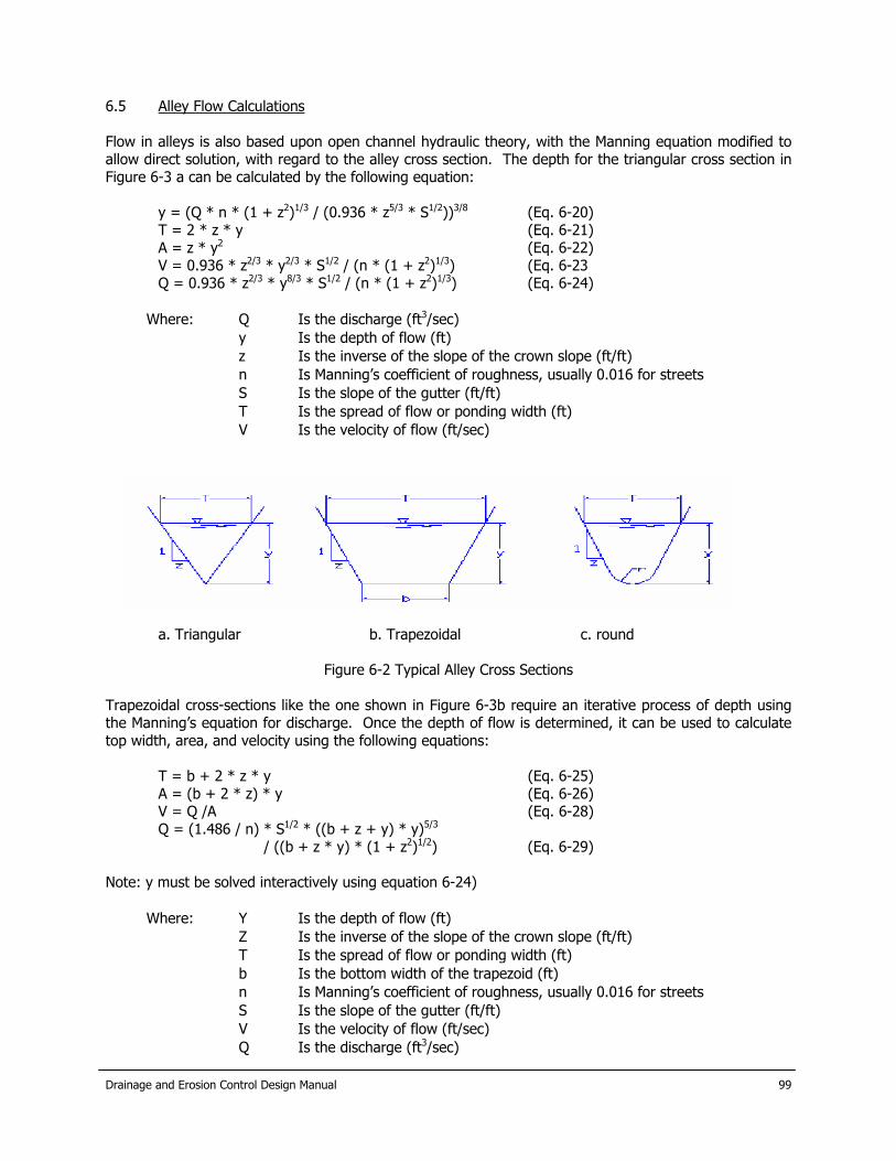
6.5 Alley Flow Calculations Flow in alleys is also based upon open channel hydraulic theory, with the Manning equation modified to allow direct solution, with regard to the alley cross section. The depth for the triangular cross section in Figure 6-3 a can be calculated by the following equation:
y = (Q * n * (1 + z2)1/3 / (0.936 * z5/3 * S1/2))3/8 (Eq. 6-20) T = 2 * z * y (Eq. 6-21) A = z * y2 (Eq. 6-22) V = 0.936 * z2/3 * y2/3 * S1/2 / (n * (1 + z2)1/3) (Eq. 6-23 Q = 0.936 * z2/3 * y8/3 * S1/2 / (n * (1 + z2)1/3) (Eq. 6-24)
Is the discharge (ft3/sec) Where: Q
y Is the depth of flow (ft) z Is the inverse of the slope of the crown slope (ft/ft) n Is Manning’s coefficient of roughness, usually 0.016 for streets S Is the slope of the gutter (ft/ft) T Is the spread of flow or ponding width (ft) V Is the velocity of flow (ft/sec)
a. Triangular b. Trapezoidal c. round
Figure 6-2 Typical Alley Cross Sections Trapezoidal cross-sections like the one shown in Figure 6-3b require an iterative process of depth using the Manning’s equation for discharge. Once the depth of flow is determined, it can be used to calculate top width, area, and velocity using the following equations:
T = b + 2 * z * y (Eq. 6-25) A = (b + 2 * z) * y (Eq. 6-26) V = Q /A (Eq. 6-28) Q = (1.486 / n) * S1/2 * ((b + z + y) * y)5/3
/ ((b + z * y) * (1 + z2)1/2) (Eq. 6-29) Note: y must be solved interactively using equation 6-24)
Where: Y Is the depth of flow (ft) Z Is the inverse of the slope of the crown slope (ft/ft) T Is the spread of flow or ponding width (ft) b Is the bottom width of the trapezoid (ft) n Is Manning’s coefficient of roughness, usually 0.016 for streets S Is the slope of the gutter (ft/ft) V Is the velocity of flow (ft/sec)
Is the discharge (ft3/sec) Q Drainage and Erosion Control Design Manual
99

Drainage and Erosion Control Design Manual
100
The normal depth for a round-bottomed, triangular cross-section shown in Figure 6-3c can be calculated if the top width is known. To determine the top width, a trial-and-error approach must be taken using the Manning’s equation: Q = (1.486 / n) * S1/2 * ((T / (4 * z)) – (1 – z * cot-1z))5/3 (Eq. 6-30) ((T/2 * (1+z2)½) – (2 * r / z) * (1 – z * cot-1z))2/3 y = (T/2) – r * (1 + z2) + r (Eq. 6-31) z A = (T / (4 * z)) – (r2 / z) * (1 – z * cot-1z) (Eq. 6-32) V = Q / A (Eq. 6-33)
Where: T Is the spread of flow or ponding width (ft) b Is the bottom width of the trapezoid (ft) n Is Manning’s coefficient of roughness, usually 0.016 for streets S Is the slope of the gutter (ft/ft) V Is the velocity of flow (ft/sec Q Is the discharge (ft3/sec) r Is the radius of curvature in the bottom of the alley (ft)
6.6 Computer Models Computer models such as Haestad FlowMaster may be used when appropriate to the situation.

Drainage and Erosion Control Design Manual
101
7.0 Inlet Design 7.1 Inlet Design Considerations
A. Inlets shall be located as necessary to remove the flow based on the 10-year storm. The hydraulic efficiency of storm drain inlets varies with the amount of gutter flow, street grade, street crown and the geometry of the inlet opening. The following are some considerations which must be given attention during inlet design:
1. Inlets must be located where the allowable street flow capacities are exceeded,
at low points (sumps or sags) and upstream of transition between normal and super-elevated street sections.
2. In super-elevated sections of divided arterial streets, inlets placed against the
center medians shall have no gutter depression. Interior gutter flow (flow along the median) shall be intercepted at the point of super-elevation transition, to prevent pavement cross flow.
3. At bridges with curbed approaches, gutter flow shall be intercepted prior to
flowing onto the bridge, to prevent ice from developing during cold weather. 4. The maximum approved vertical inlet opening is six inches. Openings larger than
six inches require approval of the City Engineer and, if approved must contain a bar or other form of restraint to prevent entry by a child.
5. The design and location of all inlets must take into consideration pedestrian and
bicycle traffic. 6. Combination curb inlets (with opening in curb and grate opening in gutter) may
be used only where space behind the curb prohibits the use of other inlet types. 7. Where recessed inlets are required, they shall not decrease the width of the
sidewalk or interfere with utilities. 8. Recessed inlets must also be depressed, unless otherwise approved by the City
Engineer. The maximum allowable inlet depression for recessed inlets shall be seven inches.
9. Non-recessed, depressed inlets shall have a maximum allowable inlet depression
of five inches. 10. The use of slotted drains is not allowed except in instances where there is no
alternative, in which case approval must be obtained from the City Engineer. If slotted drains are used, the inlet capacity shall be the lesser of the calculated capacity from this manual or the manufacturer’s design guidelines.
7.2
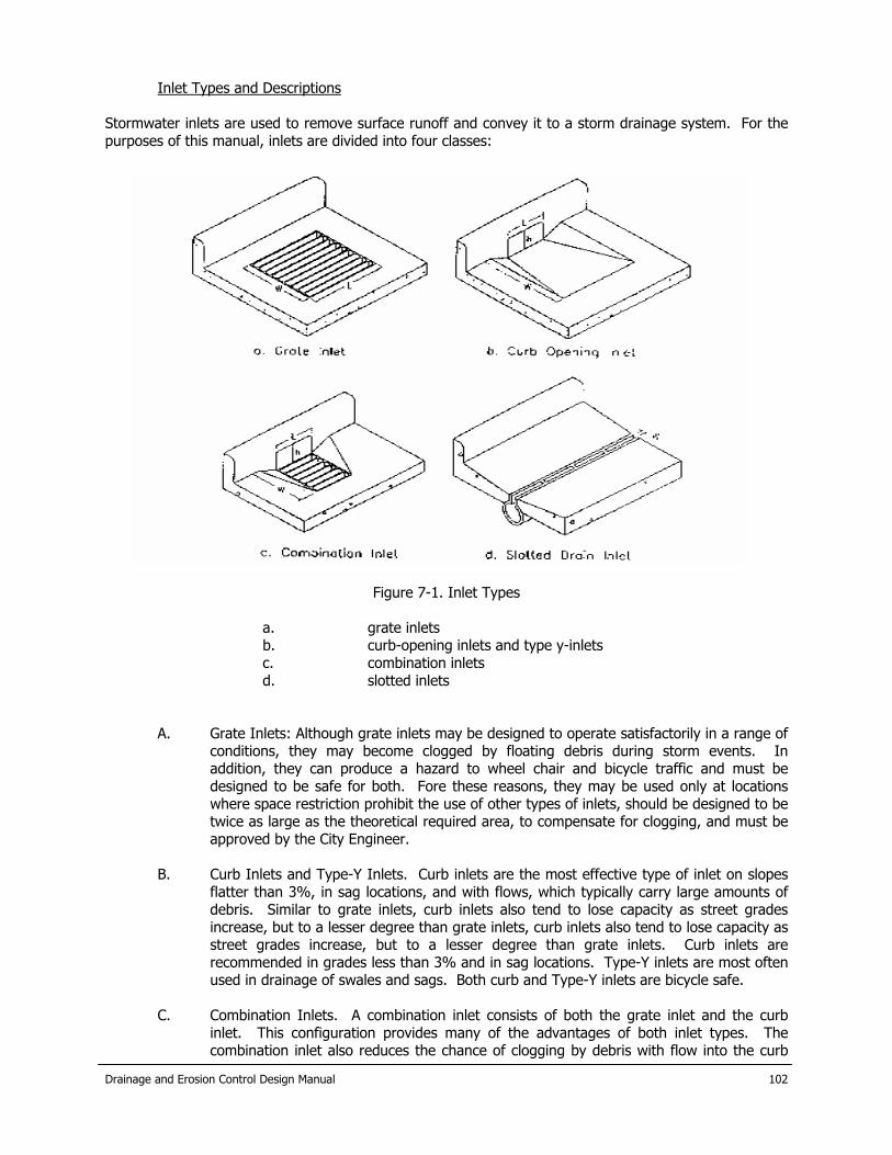
Inlet Types and Descriptions Stormwater inlets are used to remove surface runoff and convey it to a storm drainage system. For the purposes of this manual, inlets are divided into four classes:
Figure 7-1. Inlet Types
a. grate inlets b. curb-opening inlets and type y-inlets c. combination inlets d. slotted inlets
A. Grate Inlets: Although grate inlets may be designed to operate satisfactorily in a range of conditions, they may become clogged by floating debris during storm events. In addition, they can produce a hazard to wheel chair and bicycle traffic and must be designed to be safe for both. Fore these reasons, they may be used only at locations where space restriction prohibit the use of other types of inlets, should be designed to be twice as large as the theoretical required area, to compensate for clogging, and must be approved by the City Engineer.
B. Curb Inlets and Type-Y Inlets. Curb inlets are the most effective type of inlet on slopes
flatter than 3%, in sag locations, and with flows, which typically carry large amounts of debris. Similar to grate inlets, curb inlets also tend to lose capacity as street grades increase, but to a lesser degree than grate inlets, curb inlets also tend to lose capacity as street grades increase, but to a lesser degree than grate inlets. Curb inlets are recommended in grades less than 3% and in sag locations. Type-Y inlets are most often used in drainage of swales and sags. Both curb and Type-Y inlets are bicycle safe.
C. Combination Inlets. A combination inlet consists of both the grate inlet and the curb
inlet. This configuration provides many of the advantages of both inlet types. The combination inlet also reduces the chance of clogging by debris with flow into the curb
Drainage and Erosion Control Design Manual
102
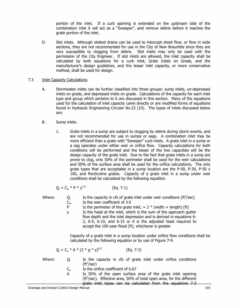
Drainage and Erosion Control Design Manual
103
portion of the inlet. If a curb opening is extended on the upstream side of the combination inlet it will act as a “Sweeper”, and remove debris before it reaches the grate portion of the inlet.
D. Slot inlets. Although slotted drains can be used to intercept sheet flow, or flow in wide
sections, they are not recommended for use in the City of New Braunfels since they are very susceptible to clogging from debris. Slot inlets may only be used with the permission of the City Engineer. If slot inlets are allowed, the inlet capacity shall be calculated by both equations for a curb inlet, Grate Inlets on Grade, and the manufacturer’s design guidelines, and the lesser inlet capacity, or more conservative method, shall be used for design.
7.3 Inlet Capacity Calculations
A. Stormwater inlets can be further classified into three groups: sump inlets, un-depressed inlets on grade, and depressed inlets on grade. Calculations of the capacity for each inlet type and group which pertains to it are discussed in this section. Many of the equations used for the calculation of inlet capacity came directly or are modified forms of equations found in Hydraulic Engineering Circular No.22 (10). The types of inlets discussed below are:
B. Sump inlets.
1. Grate inlets in a sump are subject to clogging by debris during storm events, and
are not recommended for use in sumps or sags. A combination inlet may be more efficient than a grate with “Sweeper” curb inlets. A grate inlet in a sump or a sag operates under either weir or orifice flow. Capacity calculations for both conditions will be performed and the lesser of the two capacities will be the design capacity of the grate inlet. Due to the fact that grate inlets in a sump are prone to clog, only 50% of the perimeter shall be used for the weir calculations and 50% of the surface area shall be used for the orifice calculations. The only grate types that are acceptable in a sump location are the P-50, P-30, P-50 x 100, and Recticuline grates. Capacity of a grate inlet in a sump under weir conditions shall be calculated by the following equation.
Qi = Cw * P * y1.5 (Eq. 7-1)
Where: Qi Is the capacity in cfs of grate inlet under weir conditions (ft3/sec) Cw Is the weir coefficient of 3.0 P Is the perimeter of the grate inlet, = 2 * (width + length) (ft) y Is the head at the inlet, which is the sum of the approach gutter
flow depth and the inlet depression and is derived in equations 6-2, 6-5, 6-10, and 6-15 or it is the adjusted head required to accept the 100-year flood (ft), whichever is greater
Capacity of a grate inlet in a sump location under orifice flow conditions shall be calculated by the following equation or by use of Figure 7-9.
Qi = Co * A * (2 * g * y)0.5 (Eq. 7-2)
Where: Qi Is the capacity in cfs of grate inlet under orifice conditions
(ft3/sec) Co Is the orifice coefficient of 0.67 A Is 50% of the open surface area of the grate inlet opening
(ft2/sec). Effective area, 50% of total open area, for the different grate inlet types can be calculated from the equations 7-3

Drainage and Erosion Control Design Manual
104
through 7-6 in Table 7-2. g Is the acceleration due to gravity, = 32.2 (ft/sec2) y Is the head at the inlet, which is the sum of the approach gutter
flow depth and the inlet depression and is derived in equations 6-2, 6-5, 6-10 and 6-15 or it is the adjusted head required to accept the 100-year flood (ft), whichever is greater
Table 7-2 Grate Effective Area
Inlet Area
Sag Grate P-50 L * W * 0.729 * 50% (Eq. 7-3)
Sag Grate P-30 (L * 0.948) * (W * 0.655) * 50% (Eq. 7-4)
Sag Grate 50x100 (L * 0.910) * (W * 0.729) 50% (Eq. 7-5)
Sag Recticuline L * W * 0.800 * 50% (Eq. 7-6)
2. Curb inlets in a Sump are to be used along paved streets and Type-Y inlets (drop inlets) in a Sump are to be used in unpaved areas and drainage ditches. Curb inlets, recessed curb inlets, and Type-Y inlets located in a sump or a low point can generally be considered to function as rectangular broad-crested weirs. The capacity of an inlet in a sump should be based on the following weir equation:
Qi = Cw (L + 1.8 W) y3/2 (Eq. 7-7)
Where: QI Is the intercept capacity in cfs of curb opening inlet or drop inlet,
(ft3/sec) Cw Is the weir coefficient, 2.3, for on grade curb gutters, and 3.0 for
depressed curb gutters and Type-Y inlets. L Is the length of curb opening, or the portion of perimeter of inlet
opening through which water enters the drop inlet (ft) W Is the width of the depression or the gutter. This is zero if there is
no depression, or if the inlet length is greater than 12.0 feet (ft) y Is the head at the inlet, which is the sum of the approach gutter
flow depth and the inlet depression and is derived in equations 6-2, 6-5, 6-10, and 6-15, or it is the adjusted head required to accept the 100-year flood (ft), whichever is greater
Inlets should be located frequently enough along the street that the inlet openings do not become submerged. When the depth of flow is more than 1.4 times the height of the opening of the inlet, the inlet operates under completely submerged conditions and the orifice equation should be used to compute the inlet capacity. The capacity of a completely submerged inlet is derived from following orifice equation:
Qi = Co * A * [2 * g * (y – (h / 2))]0.5 (Eq. 7-8)
Where: QI Is the capacity in cfs of curb opening inlet or drop inlet under submerged conditions (ft3/sec)
Co Is the orifice coefficient of 0.67

Drainage and Erosion Control Design Manual
105
h Is the height of the curb opening (ft) A Is the area of inlet opening, L 8 h (ft2) g Is the acceleration due to gravity, = 32.2 (ft/sec2) y Is the head at the inlet, which is the sum of the approach gutter
flow depth and the inlet depression and is derived in equations 6-2, 6-5, 6-10 and 6-15, or it is the adjusted head required to accept the 100-year flood (ft), whichever is greater
3. Combination Inlets in a Sump shall have a minimum of a five-foot “Sweeper” curb inlet on both sides. The “Sweeper” curb inlet capacity, that portion of inlet, which does not have a grate, shall be calculated as if it was operating alone. The flow which bypasses the “Sweeper” inlets will then be used for the sizing of the grate inlet in the sump. The capacity of the combination inlet is equivalent to the sum of 50% of the capacity of the grate inlet in a sump as determined in Section 7.4, Grate Inlets in a Sump, and 50% of the capacity of the curb inlet in a sump as determined in Section 7.4, Curb Inlets and Type-Y Inlets in a Sump.
4. Slot Inlets are not allowed in a sump due to their susceptibility to clogging.
C. Un-depressed inlets on grade are to be placed to provide sufficient capacity to capture
the flow from a 10-year event as outlined in Table 2-2. Inlets on grade generally do not suffer diminished capacity due to floating debris. They do, however, suffer from diminished capacity from excessive street grades. In general, more inlet length will be required to remove the same flow from a steeper roadway than from a flatter roadway.
1. Grate Inlets on Grade are an effective means of conveying flow from the
roadway to the drainage system. Grate inlets are to only be used in areas where floating debris will not be a problem and with the approval of the City Engineer. Each grate inlet type has a splash over velocity, V0, which is used to determine the amount of the flow which will be intercepted by the front of the inlet, based on the spacing of the bars, length of the inlet, and longitudinal slope of the road. The equations for V0 can be found in Table 7-3. If the velocity of the flow in the gutter is less than V0 then essentially all of the frontal flow will be intercepted by the grate. If the velocity of flow is greater than V0 then only a portion of the flow will be intercepted.
The frontal flow or the gutter flow is the portion of the total gutter flow that is found between the curb and the outer edge of the grate, or between the curb and the point where the depression/gutter begins. The ratio of frontal flow or gutter flow to the total flow, E0, is found by the following equation:
E0 = 1 / {(1 + ((Sw / Sx) / ([1 + (Sw / Sx) / ((T / W) – 1)]2.67 – 1)} (Eq. 7-16) For non-depressed inlets, the equation can be simplified to:
E0 =1 – (1 – W / T)2.67 (Eq. 7-17) Q8 / Q = 1 – (Qw / Q) = 1 – E0 (Eq. 7-18)
Where: E0 Is the ratio of frontal flow or gutter flow to total flow Sx Is the cross slope of the roadway (ft/ft) W Is the width of the grate or the depression (ft) Sw Is Sx + [a * 12 (ft/in)] / W. (ft/ft) a Is the amount of depression (in)

Drainage and Erosion Control Design Manual
106
T Is the spread width of the flow in the roadway, y/Sx, (ft) for straight streets
Qw Is the flow in the gutter or depressed section (ft3/sec) Q8 Is the side flow that does not flow in the gutter or depressed
section and will flow into or along the side of the grate (ft3/sec) Q Is the total flow (ft3/sec)
Table 7-3 Splash over Velocity, V0, for Various Grate Inlets
Grate Type Splash over Velocity, V0
P-50 2.218 + 4.031 * L – 0.65 * L2 + 0.06 * L3 Eq. 7-9
P-30 1.762 + 3.117 * L – 0.45 * L2 + 0.03 * L3 Eq. 7-10
Curved Vane 1.381 + 2.780 * L – 0.30 * L2 + 0.02 * L3 Eq. 7-11
45° Tilt Bar 0.988 + 2.625 * L – 0.26 * L2 + 0.03 * L3 Eq. 7-12
30° Tilt Bar 0.505 + 2.344 * L – 0.20 * L2 + 0.01 * L3 Eq. 7-13
P-50x100 0.735 + 2.437 * L – 0.26 * L2 + 0.02 * L3 Eq. 7-14
Recticuline 0.030 + 2.278 * L – 0.18 * L2 + 0.01 * L3 Eq. 7-15
Note: L is the length of the grate The ratio of flow intercepted by the grate to frontal flow, Rf, is given by the following equation:
Rf = 1 – Kc (V – V0) (Eq. 7-20)
Where: Kc Is the coefficient of 0.09 V Is the velocity of flow in the gutter, 2Q / (T2 * Sx), (ft/sec) (Eq. 7-
21) V0 Is the splash over velocity which can be determined from the
equations 7-9 through 7-15 found in Table 7-3, (ft/sec) Note: Rf can not exceed 1.0.
The ratio of side flow intercepted to total flow, Rs, is given by the equation:
Rs = 1 / [1 + ((Ks * V1.8) / (Sx * L2.3))] (Eq. 7-22)
Where: K8 Is the coefficient of 0.15 The efficiency, E, of a grate inlet is given by the equation:
E = Rf * E0 + RS * (1 – E0) (Eq. 7-23) Therefore the total interception (capacity) of grate inlet on grade is given by the equation:
Qi = E * Q = Q * [Rf * E0 + Rs * (1 – E0)] (Eq. 7-24)
2. Curb inlets and Type-Y inlets On Grade. The recessed curb inlet is recommended due to its superior interception efficiency. In areas where there is insufficient room to construct the recessed inlet, or it poses the possibility of a traffic hazard, other inlet types may be used with the permission of the City Engineer.

a. Recessed Inlet b. Type-Y Inlet
Figure 7-2. Curb Inlet Types The calculation of the amount of flow intercepted by a curb inlet on grade requires the
calculation of the length of inlet required to intercept the entire flow, LT, which is given by the following equation:
LT = Kc * Q0.42 * SL
0.3 * (1 / (n * Se))0.9 (Eq. 7-25)
Drainage and Erosion Control Design Manual
107
Where: Kc Is the coefficient 0.6 Is the total flow (ft3/sec) Q
SL Is the longitudinal slope of the roadway (ft/ft) n Is Manning’s roughness coefficient, usually = 0.016 for streets Se Is the equivalent cross slope in cross sections with a depression,
this is Sx if there is no depression (ft/ft) Se Is Sx + S’w * E0 Sx Is the cross slope of the roadway (ft/ft) S’w Is the cross slope of the gutter measured from the cross slope of
the pavement, Sx, (ft/ft) S’w Is a / 12 (in/ft), (ft) a Is the gutter depression (in) E0 Is the ratio of frontal or gutter flow to total flow from equation 7-
16 or 7-17 The amount of flow that a curb inlet on grade will intercept is equivalent to the product of the
total flow and the efficiency of the inlet, E. The inlet efficiency, E, is dependent on the actual inlet length, L, and the required inlet length to intercept the entire flow, LT, and is determined by the equation:
E = 1 – (1 – (L / LT))1.8 (Eq. 7-28)
Therefore the total amount of flow intercepted by a curb inlet on grade is:
Qi = Q * E = Q * [1 – (1 – (L / LT))1.8] (Eq. 7-29)
3. Combination Inlets On Grade inlets may be used, with the permission of the City
Engineer, in areas where a depressed inlet cannot be constructed. The “Sweeper” curb inlet capacity, that portion of inlet, which does not have a grate, will be calculated as if it was operating along. The flow which bypasses the “Sweeper” inlets will then be used for the sizing of the combination inlet on grade. The capacity of the combination inlet on grade is equivalent to the sum of 50% of the capacity of the grate of the combination inlet on grade is equivalent to the sum of 50% of the capacity of the grate inlet on grade as

Drainage and Erosion Control Design Manual
108
determined above and 50% of the capacity of the curb inlet on graded as determined above.
4. Slot Inlets On Grade may only be used with the permission of the City Engineer.
If slot inlets are allowed, the inlet capacity shall be calculated by equations for a curb inlet found as discussed above and the manufacturer’s design guidelines. The more conservative method of the two shall be used.

Drainage and Erosion Control Design Manual
109
8.0 Storm Drain Design 8.1 Storm Drain Design Standards
A. Storm sewer conduit shall be sized to flow full, and Manning’s Equation shall be used to determine the conduit size. The coefficients of roughness listed in Table 8-1 are for use in Manning’s Equation.
B. The minimum velocity in a conduit shall be 2.5 feet per second (10-year design storm).
This minimum velocity is required to minimize or prevent the accumulation of sediment in the system. Such sediment accumulation can severely reduce to ability of the system to convey the design flow. The minimum slopes for various pipe sizes required to maintain this minimum velocity and the recommended maximum velocities of flow in a conduit.
C. Maximum velocities in conduits are important because of the possibility of excessive
erosion of the storm drainpipe material. Table 8-3 lists the maximum velocities allowed. Maximum flow velocities at the downstream end of pipe systems shall be consistent with the maximum allowable velocities for the receiving channel (refer to Section 9, Open Channels). Erosion protection is required for disturbed banks of natural channels.
D. The maximum discharge velocities in the pipe shall not exceed the design velocity of the
receiving channel or conduit at the outfall. The maximum outfall velocity of a conduit in partial flow shall be computed for partial depth and shall not exceed the maximum permissible velocity of the receiving channel unless controlled by an appropriate energy dissipator.
E. When establishing the hydraulic gradient of a storm sewer, entrance and exit losses,
expansion losses, manhole and bend losses, junction losses, and minor head losses at points of turbulence shall be calculated and included in the computation of the hydraulic gradient.
F. Outfalls to Open Channels and Lakes. The flow lines of storm sewer conduits that
discharge into open channels shall match the flow line of the channel. G. Pipe diameters shall increase downstream, unless otherwise approved by the City
Engineer. Select pipe size and slope so that the velocity of flow will increase progressively down the system or at least will not appreciably decrease at inlets, bends or other changes in geometry or configuration.
H. At points of change in storm drain size, pipe crowns (soffits) shall be set at the same
elevation. 8.2 Calculation of the Hydraulic Grade Line The 10-year and 100-year frequency hydraulic grade lines (HGL) shall be computed and plotted for all storm drain systems. The 10-year frequency hydraulic grade line shall be calculated throughout the system and shall be at least two feet below the street subgrade at the entrance to the inlet. For designs that contain sumps, the 100-year hydraulic grade line is required from the system outfall to the most upstream sump. The determination of friction losses and minor losses are required for these calculations. 8.2.1 Starting Tailwater Conditions

Drainage and Erosion Control Design Manual
110
A. The designer must determine the tailwater conditions at the downstream end of the proposed storm drain system when calculating the hydraulic performance of the system. When proposed storm drains are to discharge into existing watercourses, the tailwater elevation used in hydraulic calculations of the proposed storm drain system will be determined by the design engineer and approved by the City Engineer. The tailwater elevation shall be the greater of the water surface of the receiving stream and the minimum outlet water surface, ym, both in feet above mean sea level (ft msl),
Table 8-1 Roughness Coefficient “N” for Storm Drains
Materials of Construction Minimum Roughness Coefficient “n”
Concrete Pipe 0.013
Corrugated-metal pipe*
Plain or coated 0.024
Concrete Lined 0.013
Plastic pipe
Smooth 0.011
Corrugated 0.024
*Requires approval
Table 8-2 Maximum Spacing of Manholes and Junction Boxes
Pipe Diameter (in) Max. Spacing (ft)
18-24 400
27-39 800
42-60 1,000
Larger than 60 1,200
Table 8-3
Maximum Velocity in Storm Drains Storm Drain Type Maximum Velocity
Inlet Laterals (shorter than 30 feet) No Limit
Inlet Laterals (longer than 30 feet) 20 fps
Trunk Lines 20 fps
B. The water surface of the receiving stream, shall be based on the “Coincidence
Occurrence Frequency Table”, Table 8-4, obtained from the Federal Highway Administration HEC-22, (8). If there is a difference in the drainage area of the receiving stream and the contributing stream there will most likely be a difference in the time the peak flow from both systems will reach the point where the contributing tributary discharges into the receiving stream. In an effort to determine what the water surface will be in the receiving stream a statistical analysis has been compiled to show, given the

Drainage and Erosion Control Design Manual
111
ratio of drainage areas, what storm frequency should be used in receiving stream to determine its water surface elevation.
C. As an example, given a contributing tributary of with a drainage area of 10 acres and a
receiving stream with a drainage area of 1,000 acres, the ratio would be 10 to 1,000, or 1 to 100. For a 10-year storm design the design engineer would use the 5-year water surface of the receiving stream.
D. It is also important to ensure that when the receiving stream is at its high flow condition,
the back water will not cause the low flow in the contributing tributary to either 1) flow at velocities less than 2.5 ft/sec causing sedimentation, or 2) raise the HGL above the natural ground or inlets. Therefore the design engineer must also calculate the velocities in the conduit and HGL of the contributing tributary at the higher water surface. Using the same example, the design engineer would use the 10-year water surface of the receiving stream, and the 5-year flows in the contributing tributary to check sufficient velocities and HGL.
The minimum water surface, ym, is derived from the following equations:
ym = (D0 + yc) / 2 + FL (Eq. 8-1)
Where: ym Is the minimum water surface elevation of the pipe in question (ft msl)
D0 Is the pipe outlet diameter (ft) yc Is the critical depth of the channel for a given flow and geometric
conditions (ft) FL Is the flow line of the pipe, lateral, trunk, or channel in question (ft
msl) The critical depth, yc, is determined by the following equation for Froude Number, which is set equal to 1.0 and solved for depth:
1.0 = (Q / A) / (g * D)0.5 (Eq. 8-2)
Where: Q Is the flow in the inlet pipe (ft3/sec) A Is the cross-sectional area of the flow as determined from the
equations in Table 8-5, in section 8.3B, (ft2) D Is the diameter of the inlet pipe (ft) g Is the acceleration due to gravity (32.2 ft/sec2)
8.2.2 Friction Losses Friction losses shall be computed using Manning’s equation, below, with the Manning’s “n” values consistent with Table 8-1.
Q = (1.486 / n) * A(5/3) / P(2/3) * S0.5 (Eq. 8-3) V = (1.486 / n) * A(5/3) / P(2/3) * S0.5 (Eq. 8-4) S = ((Q * n * P(2/3)) / (1.486 * A(5/3)))2 (Eq. 8-5)
Where: Q Is the flow in the conduit (cfs) V Is the velocity of the flow in the conduit (ft/sec) S Is the slope of the conduit in the direction of flow (percent) n Is the Manning’s roughness coefficient from Table 8-1 A Is the cross sectional area of the flow from the equations from the
equations found in Table 8-5 (ft2)
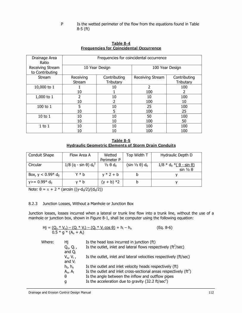
Drainage and Erosion Control Design Manual
112
P Is the wetted perimeter of the flow from the equations found in Table 8-5 (ft)
Table 8-4 Frequencies for Coincidental Occurrence
Drainage Area
Ratio Frequencies for coincidental occurrence
Receiving Stream to Contributing
10 Year Design 100 Year Design
Stream Receiving Stream
Contributing Tributary
Receiving Stream Contributing Tributary
10,000 to 1 1 10
10 1
2 100
100 2
1,000 to 1 2 10
10 2
10 100
100 10
100 to 1 5 10
10 5
25 100
100 25
10 to 1 10 10
10 10
50 100
100 50
1 to 1 10 10
10 10
100 100
100 100
Table 8-5
Hydraulic Geometric Elements of Storm Drain Conduits Conduit Shape Flow Area A Wetted
Perimeter P Top Width T Hydraulic Depth D
Circular 1/8 (q - sin θ) d02 ½ θ d0 (sin ½ θ) d0 1/8 * d0 *( θ - sin θ)
sin ½ θ Box, y < 0.99* d0 Y * b y * 2 + b b y
y>= 0.99* d0 y * b (y + b) *2 b y
Note: θ = π + 2 * (arcsin ((y-d0/2)/(d0/2)) 8.2.3 Junction Losses, Without a Manhole or Junction Box Junction losses, losses incurred when a lateral or trunk line flow into a trunk line, without the use of a manhole or junction box, shown in Figure 8-1, shall be computer using the following equation:
Hj = (Qo * Vo) – (Qi * Vi) – (Ql * Vl cos θ) + hi – ho (Eq. 8-6) 0.5 * g * (Ao + Ai)
Where: Hj Is the head loss incurred in junction (ft) Qo, Qi ,
and Ql Is the outlet, inlet and lateral flows respectively (ft3/sec)
Vo, Vi , and Vl
Is the outlet, inlet and lateral velocities respectively (ft/sec)
hI, ho Is the outlet and inlet velocity heads respectively (ft) Ao, AI Is the outlet and inlet cross-sectional areas respectively (ft2) θ Is the angle between the inflow and outflow pipes g Is the acceleration due to gravity (32.2 ft/sec2)

Drainage and Erosion Control Design Manual
113
8.2.4 Junction Losses, With a Manhole or Junction Box Junction losses incurred when a lateral or trunk line flows into a trunk line, concurrent with the use of a manhole or junction box, shown in Figure 8-2, shall be computed using the following equations:
Hah = Kj (Vo2 / 2g) (Eq. 8-7)
Kj = Ko * CD * CQ (Eq. 8-8)
Where: Hah Is the head loss incurred in the junction (ft) Vo Is the velocity of the flow in the outlet pipe (ft/sec) g Is the acceleration due to gravity (32.2 ft/sec2) Kj Is the adjusted loss coefficient Ko Is the initial head loss coefficient based on relative access hole
size CD Is the correction factor for pipe diameter and pipe depth CQ Is the correction factor for relative flow
The coefficient of head loss due to relative access hole size, Ko, is determined by the following equation:
Ko = 0.1 (b / Do) * (1 – sin θ) + 1.4 (b / Do) 0.15 sin θ (Eq. 8-9)
Where: Ko Is the coefficient of head loss due to relative access hole size b Is the manhole of junction box diameter Do Is the outlet pipe diameter (ft) θ Is the angle between the inflow and outflow pipes
A head loss due to pipe diameter is only significant in pressure flow, likewise head loss due to flow depth is only significant in non-pressure flow. Therefore, the coefficient of head loss for pipe diameter and pipe depth, CD, is determined by the following equations:
If daho / Do => 3.2; then CD = (Do / Di)3 (Eq. 8-10) If daho / Do < 3.2; then CD = 0.5 * (daho / Do)0.6 (Eq. 8-11)
Where: CD Is the coefficient of head loss due to for pipe diameter and pipe
depth daho Is the water depth in the access hole above the outlet pipe
invert (ft) Do Is the outlet pipe diameter (ft) Di Is the inflowing pipe diameter (ft)
A coefficient of head loss due to the flow relative to an incoming pipe, CQ, is a function of the angle of the incoming flow as well as the ratio of the flow from the inflow pipe to the total outflow. The coefficient is given by the following equation:
CQ = (1 – 2 sin θ) * (1 – (Qi / Qo))0.75 + 1 (Eq. 8-12)
Where: CQ Is the coefficient of head loss due to the flow relative to an incoming pipe
QI and Qo Is the inlet and outlet flows respectively (ft3/sec) θ Is the angle between the inflow and outflow pipes
If the flow line of the inflow lateral or trunk line is above the hydraulic grade line of the outflow pipe, then the initial depth is equivalent to the minimum depth, ym, of the inflow pipe and is determined by the Equation 8-2.

Drainage and Erosion Control Design Manual
114
8.2.5 Losses in a Bend The head loss at pipe bends is related to the velocity head and can be computed using the following equation:
hb = Ka * Kr * V2 / 2g (Eq. 8-13)
Where: hb Is the head loss at the bend (ft) Ka Is the bend loss coefficient due to the angle of the bend, Table
8-6 Kr Is the bend loss coefficient due to the diameter of the radius the
bend is pulled, Table 8-6 V2 / 2g Is the velocity head using the velocity at the downstream end of
the bend The coefficients Ka and Kr vary with the angle of the bend. Table 8-6 and Figure 8-3 contain different Kr coefficients used in bend losses calculations. 8.2.6 Losses Due to Transitions (Sudden Expansion or Contraction) The head losses due to sudden enlargements and contractions are calculated using the same equation as for junction losses, Equation 8-7. The values for Kj for sudden enlargements and contractions are in Table 8-7. 8.3 Hydraulic Grade Line Computation Sheet In order to facilitate computations required in determining the hydraulics of a drainage system, Computation Sheet No. 8-1 has been prepared and may be used. Each line in the computation sheet represents a junction or structure and its associated pipe. The calculations begin at the outfall and work upstream with each junction. Computation Sheet 8-2 is used to calculate HGL and EGL elevations and pipe and structure losses. In subcritical flow, the losses are summed to determine upstream HGL levels. In the case of supercritical flow, pipe and manhole losses are not carried upstream. Should supercritical flow occur, the designer should advance to the next section upstream to determine to flow regime at that point. This process continues until the system returns to a subcritical flow regime. Before filling out the columns in Sheet 8-2, the designer should determine a Hydraulic grade line (HGL_ at the outlet of the structure. Section 8.4, Starting Tailwater Conditions, describes the method for determining the starting tailwater elevation is described above.
Table 8-6 Coefficients of Loss Due to a Bend Ka and Kb
Bend Angel Degrees Angle Bend Loss
Coefficient, Ka Radius / Diameter Radius Bend Loss
Coefficient, Kr θ ≤ 15˚ R/D<2 1.000
15˚ < θ ≤ 22.5˚ 0.20 2≤R/D<4 0.500
22.5˚ < θ ≤ 45˚ 0.35 4≤R/D<6 0.433
45˚ < θ ≤ 60˚ 0.43 6≤R/D<8 0.367
60˚ < θ 0.50 8≤R/D<20
20≤R/D
0.300
-
Note: Minimum radius of bend shall be specified by the manufacture.

Drainage and Erosion Control Design Manual
115
Table 8-7 Head Loss Coefficients Due to Sudden
Expansion and Contraction D2/D1* Sudden Expansion Kj Sudden Contractions Kj
1.2 0.10 0.08
1.4 0.23 0.18
1.6 0.35 0.25
1.8 0.44 0.33
2.0 0.52 0.36
2.5 0.65 0.40
3.0 0.72 0.42
4.0 0.80 0.44
5.0 0.84 0.45
10.0 0.89 0.46
0.91 0.47
*D2/D1 = Ratio of larger to smaller diameter

Drainage and Erosion Control Design Manual
116
9.0 Open Channels 9.1 Hydraulics 9.1.1 Gradually Varied Flow Calculations of water surface profiles can be accomplished by using standard backwater methods, Standard Step Method, or acceptable computer routines. Water surface profiles for the design frequency floods shall be computed for all channels and shown on all final drawings. The Corps of Engineers HEC-2 or HEC-RAS Water Surface Profile Programs may also be used to perform standard step backwater calculations, and if used, a summary table shall be submitted to the City. Losses due to changes in velocity, drops, bridge openings, and other obstructions shall be considered in the backwater computations, as described in the HEC-2 and HEC-RAS User’s Manuals. The Standard Step Method for determining water surface profiles can be performed using Computation Sheet 9-1.
Sf = n2V2 = Se (Eq. 9-1) 2.22 R4/3
9.1.2 Normal Flow Any of several computer programs or nomograms are acceptable. Manning’s “n” for Various conditions are in Table 9-1 and 9-2. 9.2 Design Parameters
A. Where possible, channels should have sufficient gradient, depending upon the type of soil or channel lining material, to provide velocities that will be self-cleaning (greater than 2 feet per second) but will not be so great as to create erosion. Maximum permissible velocities are shown in Table 9-3.
B. Appropriate energy dissipating structures may be used to control erosion due to high
velocities at pipe system outfalls and steep grades and shall be designed in accordance with accepted design practices such as outlined by the Soil Conservation Service, the Corps of Engineers, the Bureau of Land Reclamation, or TxDOT.
9.3 Supercritical Flow
A. The Froude Number provides a relationship between flow velocity and the hydraulic depth of flow, and gravitational action and shall be calculated for all channel improvements designs. Subcritical flow conditions occur when the Froude Number is less than 1.0 and supercritical flow conditions exist in lined channels when the Froude Number exceeds 1.0. The Froude Number may be calculated by the following equations:
Fr = V / (g * D)0.5 (Eq. 9-2)
Where: V Is velocity of flow (ft/sec) g Is the acceleration due to gravity (ft/sec2) D Is the hydraulic depth (ft)
And
D = A / T (Eq. 9-3)
Where: A Is the cross-sectional area of the flow (ft2)

Drainage and Erosion Control Design Manual
117
T Is the top of the flow (ft)
B. Each channel cross section has two flow depths, the normal depth and the alternate depth. Although the depths, velocities, and Froude Number differ, the specific energy of the two depths are equivalent. Figure 9-1 shows the relationship of specific energy to depth. If a channel’s normal depth is supercritical, its alternate depth is a deeper subcritical depth. Obstructions that may enter a stream during a storm event may cause supercritical flows to experience a hydraulic jump and become subcritical flows. Due to this fact, channels that are designed for supercritical conditions must have freeboard equal to the alternate depth. Supercritical flow must be contained in straight reinforced concrete lined sections of the channel with no bends.
Table 9-1 Roughness Coefficients of New or Altered Channels
Type of Channel Manning’s “n” Grass lined
Bermuda 0.04 St. Augustine 0.045
Soils Velocity (fps) Cobbles 0.035 5.5
Coarse gravel 0.025 6 Graded silts to gravel 0.030 5.5
Graded loam to cobbles 0.030 5 Fine gravel 0.020 5
Shale & hardpan 0.025 6 Alluvial silts, colloidal 0.025 3.75
Stiff clay, very colloidal 0.025 3.75 Firm loam 0.020 2.5
Alluvial silts, non-colloidal 0.020 2 Silt loam, non-colloidal 0.020 2
Sandy loam, non-colloidal 0.020 1.75 Fine sand, colloidal 0.020 1.5
Concrete Rough finish 0.02
Smooth finish 0.015 Exposed rubble 0.025
Gabion 0.035 Rock-cut 0.025
Table 9-2 Computation of Composite Roughness Coefficient for Excavated and Natural Channels
For use with n = (n0 + n1 + n2 + n3 + n4) * m

Drainage and Erosion Control Design Manual
118
Channel Conditions Qualifiers Values
n0 Material Earth 0.02
Fine Gravel 0.024
Course Gravel 0.028
n1 Degree of Irregularity Smooth 0.0
Minor 0.005
Moderate 0.010
Severe 0.02
n2 Relative Effect of Channel Cross Section
Gradual 0.0
Alternating Occasionally
0.005
Alternating Frequently 0.013
N3 Relative Effect of Obstructions
Negligible 0.0
Minor 0.013
Appreciable 0.025
Severe 0.05
n4 Vegetation Low 0.008
Medium 0.018
High 0.038
Very High 0.075
m Degree of Member Minor 1.0-1.02
Appreciable 1.2-1.5
Severe 1.5 or greater
In selecting the value of n1, the degree of irregularity is considered smooth for surfaces comparable to the best attainable for the materials involved; minor for good dredged channels, slightly eroded or scoured side slopes of canals or drainage channels; moderate for fair to poor dredged channels, moderately sloughed or eroded side slopes of canals or drainage channels, and unshaped, jagged and irregular surfaces of channels excavated in rock.
In selecting the value of n2, the character of variations in size and shape of cross section is considered gradual when the change in size or shape occurs gradually; alternating occasionally when large and small sections alternate occasionally or when shape changes cause occasional shifting of main flow from side to side; and alternating frequently when large and small sections alternate frequently or when shape changes cause frequent shifting of main flow from side to side.
In selection of the value of n3 is based on the presence and characteristics of obstructions such as debris deposits, stumps, exposed rots, boulders and fallen and lodged logs. One should recall that conditions considered in other steps must not be re-evaluated or double-counted in this selection. In judging the relative effect of obstructions, consider the following: the extent to which the obstruction occupy or

Drainage and Erosion Control Design Manual
119
reduce the average water area, the obstruction characteristics (sharp-edged or angular objects induce greater turbulence than curved, smooth-surfaced objects) and the position and spacing of obstructions transversely and longitudinally in the reach under consideration.
In selecting the value of n4, the degree of effect of vegetation is considered in the following way:
1. Low for conditions comparable to: 1) dense growths of flexible turf grasses or
weeds, of which Bermuda and blue grasses are examples; where the average depth of flow is two to three time the height of vegetation and 2) supple seeding tree switches, such as willow, cottonwood or salt cedar where the average depth of flow is three to four times the height of the vegetation.
2. Medium for conditions comparable to: 10 turf grasses where the averaged depth
of flow is one to two times the height of vegetation, 2) stemmy grasses, weed or tree seedlings with moderate cover where the average depth of flow is two to three times the height of vegetation and 3) brush growth, moderately dense, similar to willows one to two years old, dormant season, along side of a channel with no significant vegetation along the channel bottom, where the hydraulic radius is greater that two feet.
3. High for conditions comparable to: 1) turf grasses where the average depth of
flow is about equal to the height of vegetation, 2) dormant season – willow or cottonwood trees eight to ten years old, inter-grown with some weeds and brush, where none of the vegetation is in foliage along side slopes, no significant vegetation along channel bottom, where hydraulic radius is greater that two feet.
4. Very high for conditions comparable to: 1) turf grasses where the average depth
of flow is less than one-half the height of vegetation, 2) growing season – bushy willows about one year old, inter-grown with weeds in full foliage along side slope, or dense growth of cattails along channel bottom, with any value of hydraulic radius up to ten or 15 feet and 3) growing season trees inter-grown with weed and brush, all in full foliage, with any value of hydraulic radius up to ten or 15 feet.
In selecting the value of m, the degree of meandering depends on the ratio of the meander length to the straight length of the channel reach. The meandering is considered minor for ratios of 1.0 to 1.2, appreciable for rations of 1.2 to 1.5, and severe for rations of 1.5 and greater.
B. Subcritical flow conditions are recommended for all channel designs, as supercritical flow
tends to have high velocities and high potential for channel erosion. Supercritical flow conditions will not be allowed in unlined channels. Subcritical flow conditions may be achieved by using energy dissipators in unlined channels in areas where the existing topography will not allow subcritical flow conditions to occur naturally. In all cases, the channel improvements shall be designed to avoid the unstable transitional flow conditions that occur when the Froude Number is between 0.9 and 1.1.
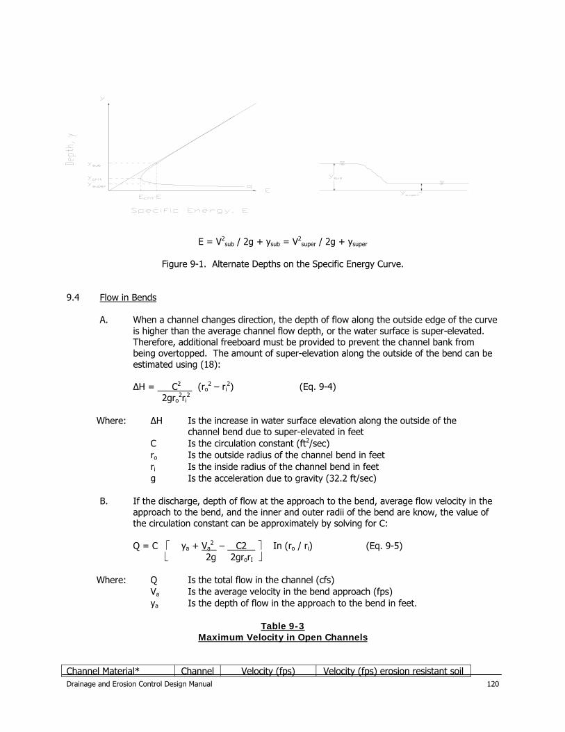
E = V2
sub / 2g + ysub = V2super / 2g + ysuper
Figure 9-1. Alternate Depths on the Specific Energy Curve.
9.4 Flow in Bends
A. When a channel changes direction, the depth of flow along the outside edge of the curve is higher than the average channel flow depth, or the water surface is super-elevated. Therefore, additional freeboard must be provided to prevent the channel bank from being overtopped. The amount of super-elevation along the outside of the bend can be estimated using (18):
∆H = C2 (ro
2 – ri2) (Eq. 9-4)
2gro2ri
2
Where: ∆H Is the increase in water surface elevation along the outside of the channel bend due to super-elevated in feet Is the circulation constant (ft2/sec) C
ro Is the outside radius of the channel bend in feet ri Is the inside radius of the channel bend in feet g Is the acceleration due to gravity (32.2 ft/sec)
B. If the discharge, depth of flow at the approach to the bend, average flow velocity in the
approach to the bend, and the inner and outer radii of the bend are know, the value of the circulation constant can be approximately by solving for C:
Q = C ⎡ ya + Va
2 – C2 ⎤ In (ro / ri) (Eq. 9-5) ⎣ 2g 2grorI ⎦
Where: Q Is the total flow in the channel (cfs) Va Is the average velocity in the bend approach (fps) ya Is the depth of flow in the approach to the bend in feet.
Table 9-3
Maximum Velocity in Open Channels Channel Material* Channel Velocity (fps) Velocity (fps) erosion resistant soil Drainage and Erosion Control Design Manual
120
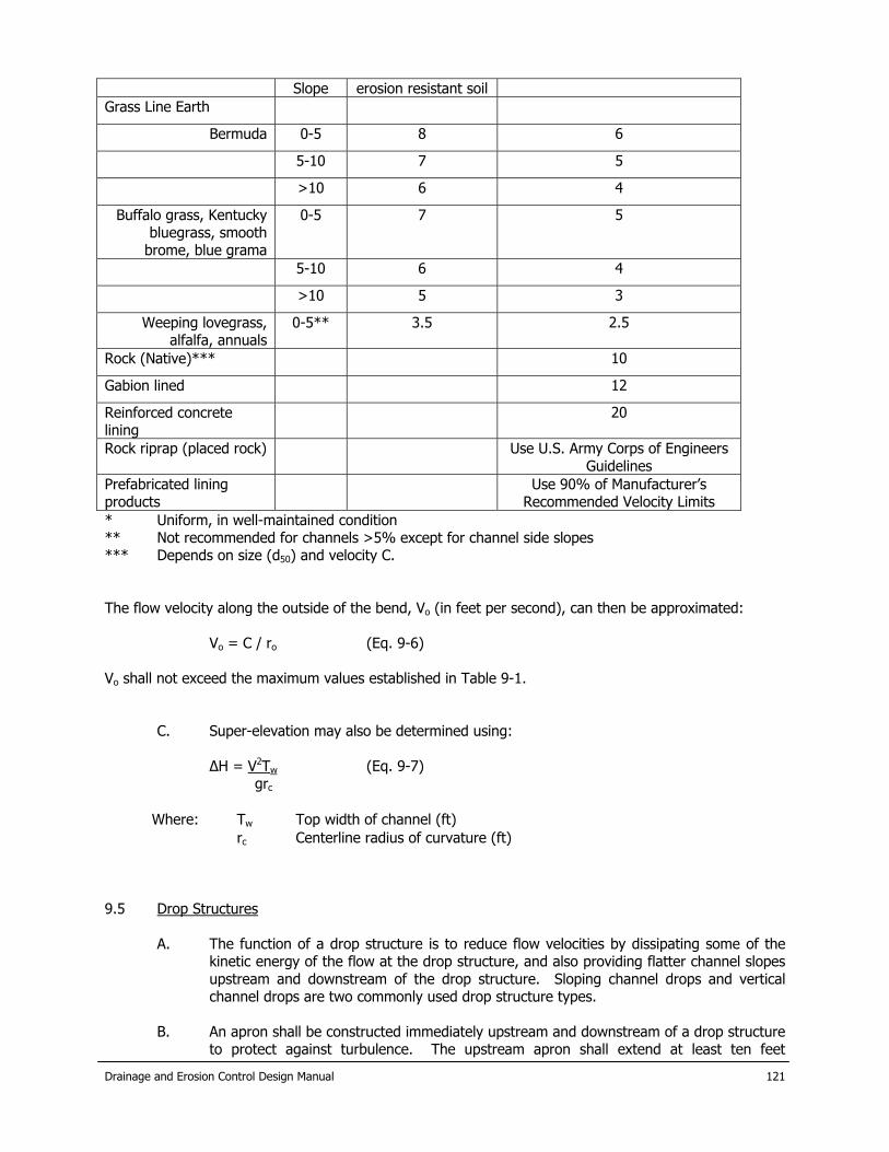
Drainage and Erosion Control Design Manual
121
Slope erosion resistant soil Grass Line Earth
Bermuda 0-5 8 6
5-10 7 5
>10 6 4
Buffalo grass, Kentucky bluegrass, smooth
brome, blue grama
0-5 7 5
5-10 6 4
>10 5 3
Weeping lovegrass, alfalfa, annuals
0-5** 3.5 2.5
Rock (Native)*** 10
Gabion lined 12
Reinforced concrete lining
20
Rock riprap (placed rock) Use U.S. Army Corps of Engineers Guidelines
Prefabricated lining products
Use 90% of Manufacturer’s Recommended Velocity Limits
* Uniform, in well-maintained condition ** Not recommended for channels >5% except for channel side slopes *** Depends on size (d50) and velocity C. The flow velocity along the outside of the bend, Vo (in feet per second), can then be approximated:
Vo = C / ro (Eq. 9-6) Vo shall not exceed the maximum values established in Table 9-1.
C. Super-elevation may also be determined using:
∆H = V2Tw (Eq. 9-7) grc
Where: Tw Top width of channel (ft) rc Centerline radius of curvature (ft)
9.5 Drop Structures
A. The function of a drop structure is to reduce flow velocities by dissipating some of the kinetic energy of the flow at the drop structure, and also providing flatter channel slopes upstream and downstream of the drop structure. Sloping channel drops and vertical channel drops are two commonly used drop structure types.
B. An apron shall be constructed immediately upstream and downstream of a drop structure
to protect against turbulence. The upstream apron shall extend at least ten feet
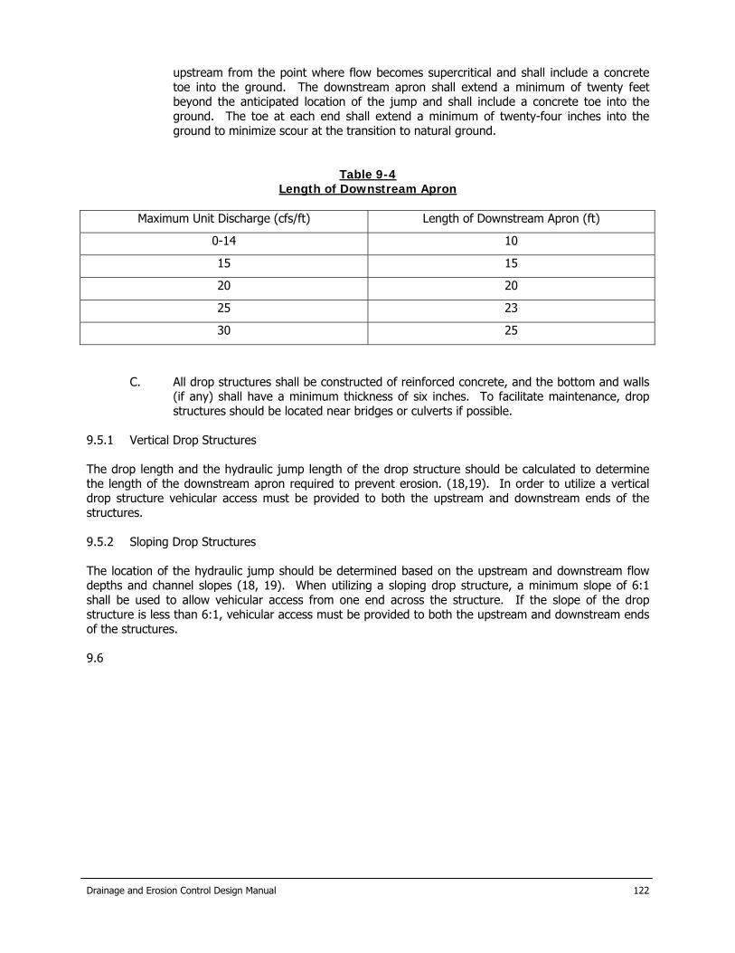
Drainage and Erosion Control Design Manual
122
upstream from the point where flow becomes supercritical and shall include a concrete toe into the ground. The downstream apron shall extend a minimum of twenty feet beyond the anticipated location of the jump and shall include a concrete toe into the ground. The toe at each end shall extend a minimum of twenty-four inches into the ground to minimize scour at the transition to natural ground.
Table 9-4 Length of Downstream Apron
Maximum Unit Discharge (cfs/ft) Length of Downstream Apron (ft)
0-14 10
15 15
20 20
25 23
30 25
C. All drop structures shall be constructed of reinforced concrete, and the bottom and walls (if any) shall have a minimum thickness of six inches. To facilitate maintenance, drop structures should be located near bridges or culverts if possible.
9.5.1 Vertical Drop Structures The drop length and the hydraulic jump length of the drop structure should be calculated to determine the length of the downstream apron required to prevent erosion. (18,19). In order to utilize a vertical drop structure vehicular access must be provided to both the upstream and downstream ends of the structures. 9.5.2 Sloping Drop Structures The location of the hydraulic jump should be determined based on the upstream and downstream flow depths and channel slopes (18, 19). When utilizing a sloping drop structure, a minimum slope of 6:1 shall be used to allow vehicular access from one end across the structure. If the slope of the drop structure is less than 6:1, vehicular access must be provided to both the upstream and downstream ends of the structures. 9.6

Drainage and Erosion Control Design Manual
123
Energy Dissipaters Although hydraulic jumps can be used as energy dissipators, impact dissipators are recommended for their predictability, efficiency, and economy. The Baffled Apron is used to dissipate the energy in the flow at a drop. It requires no initial tailwater to be effective, although scour is reduced with tailwater. The chute of the Baffle Apron is constructed on a 2:1 or flatter slope extending below the channel bottom. See Examples.

Drainage and Erosion Control Design Manual
124
10.0 Bridge and Culvert design 10.1 Applicable Design Criteria Bridge design shall be on a case-by-case basis to establish design requirements. Headwalls and necessary erosion protection shall be provided at all culverts and shall comply with TxDOT standard. 10.2 Design Parameters
A. Alignment, location and grade of proposed culverts must be consistent with planned development of the drainage system for that watershed. In the event the particular watershed or waterway is not covered by a planned storm drainage system, the designer should proceed with the design from the nearest downstream control (i.e. bridge, culvert dam, etc.) and design the proposed drainage system improvements anticipating future system expansion due to fully developed watershed conditions.
B. Wingwalls, if used, may be either straight parallel, flared, or tapered. Approach and
discharge aprons shall be provided for all culvert headwall designs. The guidelines listed in Table 10-1 are intended to aid in determining when to use various types of wingwalls. Precast headwalls and endwalls may be used if all other criteria are satisfied; generally precast headwalls/endwalls are available for smaller culverts (18 inches to 24 inches diameter).
Table 10-1 Guidelines for Wingwall Use
Conditions Wingwall Type
Small culverts with flat slopes Straight (parallel), flared of tapered.
Abrupt change in flow direction is necessary Straight with one perpendicular wingwall (not recommended for large culverts) or flared.
Approach velocities below 6 fps, approach channel undefined, formation of backwater pools acceptable
Straight, flared or tapered
Approach velocities 6-10 fps, approach channel well defined
Flared (wingwalls located with respect to axis of the approach channel)
10.3 Culvert Outlet Protection High discharge velocities from culverts can cause eddies or other turbulence which could damage unprotected downstream channel banks and roadway embankments. To prevent damage from scour and erosion in these conditions, culvert outlet protection is needed. The outlet protection should extend downstream to a point where non-erosive channel velocities are established in accordance with Table 9-1. The outlet protection should be placed sufficiently high on the adjacent banks to provide protection from wave wash under design flow conditions.
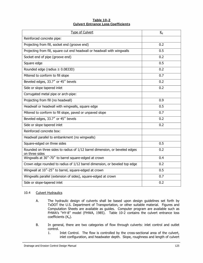
Drainage and Erosion Control Design Manual
125
Table 10-2 Culvert Entrance Loss Coefficients
Type of Culvert Ke
Reinforced concrete pipe:
Projecting from fill, socket end (groove end) 0.2
Projecting from fill, square cut end headwall or headwall with wingwalls 0.5
Socket end of pipe (groove end) 0.2
Square edge 0.5
Rounded edge (radius ≥ 0.0833D) 0.2
Mitered to conform to fill slope 0.7
Beveled edges, 33.7˚ or 45˚ bevels 0.2
Side or slope tapered inlet 0.2
Corrugated metal pipe or arch-pipe:
Projecting from fill (no headwall) 0.9
Headwall or headwall with wingwalls, square edge 0.5
Mitered to conform to fill slope, paved or unpaved slope 0.7
Beveled edges, 33.7˚ or 45˚ bevels 0.2
Side or slope tapered inlet 0.2
Reinforced concrete box:
Headwall parallel to embankment (no wingwalls)
Square-edged on three sides 0.5
Rounded on three sides to radius of 1/12 barrel dimension, or beveled edges on three sides
0.2
Wingwalls at 30˚-70˚ to barrel square-edged at crown 0.4
Crown edge rounded to radius of 1/12 barrel dimension, or beveled top edge 0.2
Wingwall at 10˚-25˚ to barrel, square-edged at crown 0.5
Wingwalls parallel (extension of sides), square-edged at crown 0.7
Side or slope-tapered inlet 0.2
10.4 Culvert Hydraulics
A. The hydraulic design of culverts shall be based upon design guidelines set forth by TxDOT the U.S. Department of Transportation, or other suitable material. Figures and Computation Sheets are available as guides. Computer program are available such as FHWA’s “HY-8” model (FHWA, 1985). Table 10-2 contains the culvert entrance loss coefficients (Ke).
B. In general, there are two categories of flow through culverts: inlet control and outlet
control. 1. Inlet Control. The flow is controlled by the cross-sectional area of the culvert,
inlet configuration, and headwater depth. Slope, roughness and length of culvert

Drainage and Erosion Control Design Manual
126
are of no importance. Inlet control can generally be assumed when the slope is greater than the critical slope as defined below with culvert diameter (D) in feet:
So% = 2.04 / D0.333 (Eq. 10-1)
Nomographs are available for inlet control estimations. Note that there is a choice of three axes on the right hand side, depending on the entrance type. Also note that the box culvert nomograph give discharge in cfs per foot of box width.
2. Outlet control. The flow is controlled by the cross-section area of the culvert,
inlet configuration, and headwater depth and, slope, roughness and length of culvert. Culverts will be outlet controlled if the culvert slope is relatively flat, the tailwater sufficiently deep or the culvert is quite long. It is also possible, where the water enters the culvert under inlet control, but the culvert slope or tailwater conditions cause a hydraulic jump near the outlet. This situation should be avoided because damage can occur tot he culvert pipe. Unstable conditions are most likely when the culvert is placed at a near-critical slope.
3. The typical procedure is to calculate for both outlet and inlet control and use the
small flow rates to design the system.
C. Terms shown on the nomographs are defined as:
1. HW = Headwater depth, the vertical distance from culvert at inlet to surface of ponded water at inlet.
2. ho = tailwater depth, the vertical distance from culvert invert at outlet to water surface at outlet. Actually, ho is a reference depth for calculations and can differ from the actual tailwater depth, TW.
3. So = barrel slope 4. ke = entrance loss coefficient (e.g. wingwalls, see table) 5. H = head, the energy needed to pass a given quantity of water through a
culvert under outlet control. Equal to sum of velocity head, entrance loss and friction loss in the pipe. Note that the nomographs provide an estimate of “H” only, and headwater “HW” must be calculated from:
HW = H + ho +LSo (Eq. 10-2)
D. For the case of outlet control where both end are submerged and velocity (V) is
discharge (cfs)/cross sectional area (SF) (Q/A) “H” can be calculated directly:
h = (1 + ke + (29n2L) / (R1.33)) (V2 / 2g) (Eq. 10-3)
E. For the case of outlet control where the tailwater is at or below the top of the culvert critical depth (dc) must be determined.
1. If critical depth is greater than culvert height, pipe will flow full at outlet, and H
is measured from the top of the pipe at the outlet. 2. If the culvert flows full over part of its length, H is calculated from a point slightly
higher than critical depth:
ho = max ( ((de + D)/2), TW) (Eq. 10-4)
3. A free water surface will extend through the culvert barrel if:
HW < D + (1 + ke) (V2 / 2g) (Eq. 10-5)
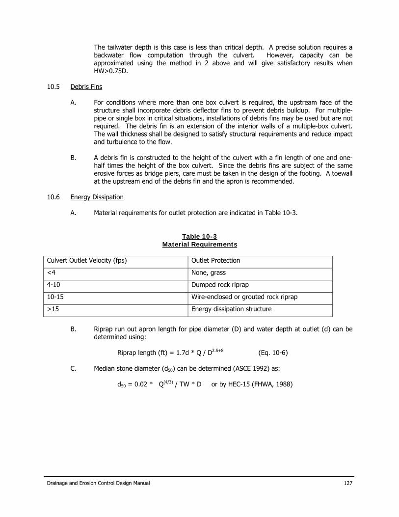
Drainage and Erosion Control Design Manual
127
The tailwater depth is this case is less than critical depth. A precise solution requires a backwater flow computation through the culvert. However, capacity can be approximated using the method in 2 above and will give satisfactory results when HW>0.75D.
10.5 Debris Fins
A. For conditions where more than one box culvert is required, the upstream face of the structure shall incorporate debris deflector fins to prevent debris buildup. For multiple-pipe or single box in critical situations, installations of debris fins may be used but are not required. The debris fin is an extension of the interior walls of a multiple-box culvert. The wall thickness shall be designed to satisfy structural requirements and reduce impact and turbulence to the flow.
B. A debris fin is constructed to the height of the culvert with a fin length of one and one-
half times the height of the box culvert. Since the debris fins are subject of the same erosive forces as bridge piers, care must be taken in the design of the footing. A toewall at the upstream end of the debris fin and the apron is recommended.
10.6 Energy Dissipation
A. Material requirements for outlet protection are indicated in Table 10-3.
Table 10-3 Material Requirements
Culvert Outlet Velocity (fps) Outlet Protection
<4 None, grass
4-10 Dumped rock riprap
10-15 Wire-enclosed or grouted rock riprap
>15 Energy dissipation structure
B. Riprap run out apron length for pipe diameter (D) and water depth at outlet (d) can be
determined using:
Riprap length (ft) = 1.7d * Q / D2.5+8 (Eq. 10-6)
C. Median stone diameter (d50) can be determined (ASCE 1992) as:
d50 = 0.02 * Q(4/3) / TW * D or by HEC-15 (FHWA, 1988)

Drainage and Erosion Control Design Manual
128
11.0 Detention Basin Design 11.1 Design Criteria
A. Stormwater detention basins are used to temporarily impound (detain) excess stormwater, thereby reducing peak discharge rates.
B. Detention basins without upstream detention areas where the design rainfall was
determined using the Rational Method can be designed using the Modified Rational Method to determine the critical duration. The detention volume for a given duration in this method is calculated as the difference between the trapezoidal inflow hydrograph and the triangular outflow hydrograph. A range of storm durations is required to determine the critical duration for the detention basin. See Appendix F for example of this calculation method. The “C” for the Rational Method shall be a minimum of 0.60. Time of concentration shall provide a conservative choice.
C. Computations performed for detention pond sizing using a unit hydrograph shall use a
minimum curve number of 67, 79, 86 and 89 for soil types A, B, C and D, respectively. Time of concentration shall provide a conservative choice.
11.2 Minimum Requirements for Detention Pond Design
A. The following criteria shall serve as minimum requirements for detention pond design:
1. Detention basins to be excavated shall provide positive drainage through the pond with a minimum slope of 0.25%.
2. When the outflow structure discharges flow into a natural stream or unlined
channels, it shall do so at a non-erosive rate in accordance with Section 9 of this Manual.
3. Earthen embankments used to impound a required detention volume must have
a minimum top-width of 4 feet, shall contain a non-permeable core, and shall be based on a geotechnical investigation for the site. Compaction of al earthen drainage structures shall be to 90% standard proctor. Earthen embankments higher than 6 feet shall conform to Permanent Rule 31, Texas Administrative Code (TAC) Chapter 299 and other applicable dam safety requirements.
4. Security fencing with a minimum height of six feet may be required to
encompass the detention storage area if the location, velocity, depth, or slopes justify restricted access to the general public as determined by the City Engineer. Ten fence shall be designed to allow access for maintenance as well as not to restrict stormwater flow into or out of the detention basin.
5. A maintenance ramp shall be provided for vehicular access in detention basin
design for periodic desiliting and debris removal. The slope of the ramp shall not exceed 6:1 and the minimum width shall be 12 feet.
6. Basins with permanent storage must include dewatering facilities to provide for
maintenance. 7. The design of detention facilities shall include provisions for collecting and
removing sediment deposited after collecting and releasing stormwater. 8. A non-erodible pilot channel shall be provided to convey runoff from entry points
of concentrated flow into the pond to the outlet structure of the pond during low

Drainage and Erosion Control Design Manual
129
flow conditions. Erosion protection must be provided adjacent to the pilot channel to prevent undermining of the pilot channel due to scour.
11.3 Outlet Structure Design
A. Design and construction information for outlet works is contained in the publication “Stormwater Detention Outlet Control Structures (ASCE, 1985). Multi-level outlet structures may be necessary to reduce both the 10-year and 100-year design storm runoff to pre-development levels, and provided for an emergency spillway.
B. For small slick pipes flush with the upstream embankment and a free outfall, the orifice
equation can be used (H = height of water above center of pipe, ft):
Outflow (cfs) = 4.8 * (area of opening, sq ft) * H0.5
C. Standard culvert design techniques are appropriate for larger pipes. D. Spillway size should generally be estimated using a broad-crested weir equation such as:
Outflow (cfs) = 2.7 * L * H1.5
E. The spillway should be heavily protected from erosion with concrete, rock, grouted
riprap, gabions, geotextile, geogrids, concrete block or other material, as selected by the designer.
F. Documentation on retention or detention structures should include design hydrographs,
calculation of stage-storage-discharge tables, drawings of the basin, spillway and outlet size and location, and erosion control measures.
11.4 Playa Lakes Playa Lakes are natural formations which retain runoff but lack the ability to sufficiently drain after a storm event. A designer may use a playa as part of a runoff control plan if there is suitable area-capacity information describing storage availability. Excavation and fill are allowed, if necessary, but under no circumstances may the storage capacity be reduced without the appropriate compensation of storage loss within the immediate are of the development. In creating a hydraulic model of the playa, the lake shall be assumed to be full to the lowest natural outlet point prior to rainfall.

Drainage and Erosion Control Design Manual
130
12.0 Lakes, Dam and Levees 12.1 Lakes and Dams 12.1.1 General In the event that a property owner or developer desires to modify an existing pond or lake or desires to impound stormwater by filling or constructing an aboveground dam, thereby creating a lake, pond, lagoon or basin as part of the planned development of that property, the criteria listed below shall met before city approval of the impoundment can be given. Ponds or lakes created by excavation of a channel area without erecting a dam above natural ground elevation or instream low water check dams are also subject to the criteria listed below, with the exception of spillway capacity requirements. The City Engineer has the final authority to determine the design criteria for a proposed dam, check dam or excavated lake. The dam safety requirements of the State of Texas must also be met for the construction of dams, lakes, and other improvements. 12.1.2 Applicable Design Criteria
A. The design criteria for a dam is dependent on the size and hazard classification of the dam. The size and hazard classification will be based on the recommended guidelines adopted by the Texas Natural Resource Conservation Commission under V.T.C.A, Water Code 12.052, which provides for the safe construction, maintenance, repair and removal of dams located in the State of Texas, and will be determined by the City Engineer based on information furnished by the owner. The following criteria will be used to classify a dam:
1. Size. The classification for size is based on the height of the dam and storage
capacity, whichever gives the larger size category. “Height” is defined as the distance between the top of the dam (minus the freeboard) and the existing streambed at the downstream toe. Storage is defined as the maximum water volume impounded at the top of the dam (minus the freeboard).
2. Hazard potential. The hazard potential for a dam is based on the potential for
loss of human life and property damage downstream from a dam in the event of failure. Hazard Potential Classifications are based on the potential for loss of life and for the extent of economic loss based on existing and potential development downstream of the dam.
3. Spillway Design Flood. The classification of a dam based on the above criteria
will be used to determine the Spillway Design Flood (SDF). The total capacity of a dam structure, including principal and emergency spillways, shall be adequate to pass the SDF without exceeding the top dam elevation. The SDF’s for various dam classifications are shown in this Drainage Design Manual.
B. All design will be for the fully developed watershed contributing to the structure. C. In all cases, the minimum principal spillway design capacity is a minimum of the 100-year
design flood. In certain cases, a dam breach analysis may be required to determine the proper classification of the structure. For all structures requiring a spillway design flood equal to the Probable Maximum Flood (PMF), a dam breach analysis is required to determine the downstream consequences of a failure. All dams shall be constructed with a minimum freeboard of two feet above SDF elevation and upstream development within the contour line determined by the emergency spillway crest elevation plus 2-feet, or the

Drainage and Erosion Control Design Manual
131
100-year flood elevation (based on fully developed watershed conditions) plus 2-feet, whichever is greater is prohibited.
12.1.3 Maintenance and Liability Criteria The owner or developer shall retain their private ownership of the constructed lake, pond or lagoon or basin and shall assume full responsibility for the protection of the general public from any health or safety hazards related to the lake, pond or lagoon constructed. The owner or developer shall assume full responsibility for the maintenance of the lake, pond or lagoon or basin constructed. The owner or developer shall keep the City Engineer advised of the currently responsible agent for this maintenance. 12.1.4 Natural Resource Conservation Service Lakes
A. There are a number of NRCS (previously Soil Conservation Service) lakes within the city limits and extraterritorial jurisdiction of the City of New Braunfels. These lakes present complex issues of flood control, erosion control, maintenance and floodplain management. These lakes were constructed to NRCS standards. The lakes are in private ownership, with maintenance provided by Comal County. Operation of the lakes is the responsibility of Comal County. The City of New Braunfels is responsible for floodplain management of those areas upstream, downstream and adjacent to the lakes. Operation and maintenance of the NRCS lakes shall remain the responsibility of others.
B. The City of New Braunfels shall control future development upstream, downstream and
adjacent to all NRCS lakes. Planning for future development which impacts on, or is impacted by, NRCS lakes shall require that a detailed engineering study be performed to provide a technical basis for development and that the dam be upgraded as follows:
1. Provide principal spillway capacity adequate to discharge the 100-year flood
event based on fully developed watershed conditions. 2. Provide total capacity of the dam structure, including principal and emergency
spillways to accommodate the Probable Maximum Flood (PMF).
3. Maintain existing flood storage capacity.
4. Prohibit upstream development within the contour line determine by the emergency spillway crest elevation plus 2-feet, or the 100-year flood elevation (based on fully developed watershed conditions) plus 2-feet, whichever is greater.
5. Restrict development and improvements within the floodplain established by a
breach flow analysis from the dam to the downstream limits of the dam breach impact.

Drainage and Erosion Control Design Manual
132
Table 12-1 Size Classifications Impoundment
Category Storage (acre-foot) Height (feet)
Small <1,000 <40
Intermediate ≥1,000 and <50,000 ≥40 and <100
Large ≥50,000 ≥100
12.1.5 Design Frequencies for Dam or Impoundments
A. the design criteria for a dam is dependent on the size and hazard classification of the dam, as described by the Texas Natural Resource Conservation Commission (TNRCC) under 30 TAC §299.11-§299.14 (5), which provides for the safe construction, maintenance, repair and removal of dams located in the State of Texas. The following criteria from current TNRCC regulations will be used to classify a dam. If the TNRCC criteria are updated, then the revised TNRCC regulations will apply.
1. Size. The classification for size is based on the height of the dam and storage
capacity, whichever gives the larger size category. “Height” is defined as the distance between the top of the dam and the existing streambed at the downstream toe. Storage is defined as the maximum water volume impounded at the top of the dam.
2. Hazard Potential. The hazard potential for a dam is based on the potential for
loss of human life and property damage downstream from a dam in the event of failure. The categories from Table 12-2 will be used.
3. Spillway Design Flood. The classification of a dam based on the above criteria
will be used to determine the Spillway Design Flood (SDF). The total capacity of a dam structure, including principal and emergency spillways, shall be adequate to pass the SDF without a failure of the dam. The SDF is computed as a percentage of the PMF hydrograph for various dam classifications according to the following table:
Table 12-2
Hazard Potential Classification Category Loss of Life Economic Loss
Low None expected (no permanent structures for human habitation)
Minimal (undeveloped to occasional structures of agriculture)
Significant Few (no urban Appreciable developments and no more than a small number of inhabitable structures)
(notable agricultural, industry structures)
High More than few Excessive (extensive industry or agriculture)
12.1.6 Additional Design Requirements

Drainage and Erosion Control Design Manual
133
A. An engineering plan for such construction accomplished by complete drainage design information and sealed by a licensed professional engineer, shall be approved by the City of New Braunfels.
B. The spillway and any emergency overflow areas shall be located so that floodwaters will
not inundate any permanent habitable structures.
C. The minimum SPF should be the 100-year, 24-hour storm regardless of critical inflow design storm peaks.
D. The design shall comply with all federal, state and county laws pertaining to the
impoundment of surface water, including the design, construction, and safety of the impounding structure. Copies of any federal, state or county permits issued for proposed impoundments shall be submitted to the City Engineer.
E. Any existing NRCS structure or other dams which are included in the project drainage
area shall comply with the applicable federal, state, county and city safety requirements for structures. Improvements may be required to upgrade the structure to the currently adopted guidelines. Before removing, enlarging or altering any existing lake, the applicant will furnish a study of the effects of the alteration upon flooding conditions both upstream and downstream. The study shall be prepared by a professional engineer and submitted to the City Engineer for approval prior to making the proposed alteration.
F. Any improvements to existing dams or lakes or construction of new impoundments shall
be make at the expense of the developer, prior to completion of the adjacent street, utilities and drainage improvements, as provided for under the subdivision regulations.
12.2 Levees In the event that developers or owners wish to build levees to protect an area from flooding, applicable FEMA guidelines, State of Texas dam safety guidelines and the following criteria apply:
A. Levees shall be designed to have four feet of freeboard above the Standard Project Flood for the fully developed watershed flows.
B. Levees shall be designed according to the Corps of Engineers’ design criteria used for
federally authorized levees, whether or not they are federally authorized.
C. Ring levees protecting individual structures proposed for construction after the enactment date of this Ordinance shall not be permitted.
D. If possible, provision shall be made to provide the permanent maintenance of levees
either by a flood control district or similar governmental organization of by the existing property owner and all future owners, heirs or assigns, through the use of a maintenance agreement.
E. Levee systems shall be designed with interior drainage system to prevent flooding from
local runoff contained within the system for the 100-year design flood.
F. Levee system shall have written operation procedures that address gate-closure conditions and an emergency warning plan. A copy of these procedures shall be furnished to the City Engineer.
G. Automated gate-closure systems shall have power from two independent sources and
shall be capable of being operated manually.

Drainage and Erosion Control Design Manual
134
H. All new levee systems shall have permanent positive closures to the required design elevation. Temporary closures involving sandbagging or other procedures requiring manual operations shall not be permitted.
I. Additional plan requirements including water surface profiles for the design flood and
standard project flood; the top of the levee profile, definition of interior drainage facilities, including pump station and ponding areas; location of gravity outlets, gatewells and closure structures; and elevation-duration data on the receiving system.
Table 12-3
Spillway Design Hazard Potential* Size SDF (Flood Hydrograph)
Low Small ¼ PMF
Intermediate ¼ PMF to ½ PMF**
Large PMF
Significant Small ¼ PMF to ½ PMF**
Intermediate ½ PMF to PMF**
Large PMF
High Small PMF
Intermediate PMF
Large PMF
* In certain cases, a dam breach analysis may be required to determine the proper classification of the structure. For all structures requiring a spillway design flood equal to the PMF, and emergency action plan, prepared according to TNRCC guidelines, is required prior to completion of construction. ** Where a range is given, the minimum flood hydrograph will be determined b straight-line interpolation with the given range. Interpolation shall be based on either hydraulic height or impoundment size, whichever is greater. In all cases, the minimum spillway design capacity is the 100-year design flood.

Drainage and Erosion Control Design Manual
135
13.0 Site Erosion Control During Construction 13.1 Applicable Properties or Construction Sites Private property owners, developers or builders shall be accountable for any erosion of their property or construction site which results in measurable accumulation of sedimentation in dedicated streets, alleys, any waterway or other private properties. Any accumulation or deposit of soil material beyond the limits of the property or in City streets, alleys or drainage facilities in an amount sufficient to constitute a threat to public safety and comfort as determined by the City Engineer shall constitute a violation. Sediment carried by stormwater runoff through these acres shall be prevented from entering storm drain systems and natural watercourses. 13.2 General Guidelines for Erosion Control Plan
A. Maximum use shall be made of vegetation to minimize soil loss. B. Natural vegetation should be retained wherever possible.
C. Where inadequate natural vegetation exists, or where it becomes necessary to remove
existing natural vegetation, temporary controls should be installed promptly to minimize soil loss and ensure that erosion and sedimentation does not occur. The developer is responsible for maintenance of site erosion control devices until a sufficient vegetation cover has been provided or replaced as determined by the City Engineer. Periodic maintenance shall be performed by the developer to remove accumulated sediment that would otherwise inhibit the proper functioning of the erosion control devices.
D. Wherever possible during construction, erosion controls shall be used on hillsides to slow
drainage flow rate.
E. Erosion control elements should be implemented as soon as practical in the development process.
F. Waste or disposal areas and construction roads should be located and constructed in a
manner that will minimize the amount of sediment entering streams.
G. Frequent fording of live streams will not be permitted; therefore, temporary bridges or other structures shall be used wherever an appreciable number of crossings of a stream are necessary.
H. When work areas or material sources are located in or adjacent to live streams, such
areas shall be separated from the stream by a dike or other barrier to keep sediment from entering a flowing stream. Care shall be taken during the construction and removal of such barriers to minimize the sediment transport into a stream.
I. Should preventative measures fail to function effectively, the applicant shall act
immediately to bring the erosion and/or siltation under control by whatever additional means are necessary.
J. Erosion control devices shall be placed to trap any losses from stockpiled topsoil. Some
acceptable forms of site erosion control devices include, but are not limited to, silt fences, silt traps, hay bale barriers, geonetting and geotextiles. Hay bale barriers, if used, shall be replaced with new hay bales as a part of the regular maintenance program.
K. The selection and timing of the installation of erosion controls shall be based upon
weather and seasonal conditions that could make certain controls not practicable.

Drainage and Erosion Control Design Manual
136
L. Vegetation used for vegetative cover shall be suitable for local soil and weather
conditions. Ground cover plants shall comply with listings from the Texas Agricultural Extension Service.
M. Runoff shall be diverted away from construction areas as much as possible.
N. Stripping of vegetation from project sites shall be phased so as to expose the minimum
amount of area to soil erosion for the shortest possible period of time. Phasing shall also consider the varying requirements of an erosion control plan at different stages of construction.
O. Developers, builders, or owners of property shall install all utilities, including franchise
utilities, before final acceptance of a subdivision, property and/or structure. Final acceptance will also be contingent upon having all necessary erosion control measures installed to minimize off-site sediment. At the discretion of the City Engineer; a site may be accepted without erosion control measures if perennial vegetative cover is actively growing.
13.3 Applicable Best Management Practices Published Best Management Practices for erosion control for many different activities are available through libraries, Internet, and through the City Engineer. 13.4 Stream Bank Erosion Erosion control will be provided along streams and drainage channels. Where bank stabilization or other erosion protection measures are required to protect streams and channels, the stream bank protection and erosion damage mitigation measures provided in this Manual shall be utilized as approved by the City Engineer.

Drainage and Erosion Control Design Manual
137
APPENDIX A LIST OF REFERENCES
(1) City of San Angelo, San Angelo Master Drainage Plan, 1994. (2) USGS, "Depth-Direction Frequency of Precipitation for Texas", Water Resources Investigations Report
98-4044, 1998. (3) National Oceanic and Atmospheric Administration, "Probable Maximum Precipitation Estimates, United
States East of the 105th Meridian", Hydro-meteorological Report No. 51, 1978. (4) National Oceanic and Atmospheric Administration, "Application of Probable Maximum Precipitation
Estimates, United States East of the 105th Meridian", Hydro-meteorological Report No. 52, 1982. (5) Texas, Secretary of State. "Official Texas Administrative Code. Title 30-Environmental Quality."
§299.12- §299.14, West Group, St. Paul, Minn. 1997. (6) ASCE and Water Pollution Control Federation, "Quantity of Stormwater, Manuals and Reports of
Engineering Practice - No. 37," New York, N.Y., 1969. (7) City of Fort Worth, "Storm Drainage Criteria and Design Manual," Fort Worth, Texas, 1967. (8) Highway Administration, "Urban Drainage Design Manual, Hydraulic Engineering Circular No. 22",
Washington, D.C., 1996. (9) U.S. Soil Conservation Service, "Urban Hydrology for Small Water Sheds", Technical Release No. 55,
January 1975. (10) U.S. Army Crops of Engineers, "Flood Hydrograph Analysis and Computations", EM 1110-2- 1405,
1959. (11) Viessman, Warren, "Introduction to Hydrology", Harper and Row, Publishers, New York, 1996. (12) U.S. Army Corps of Engineers, "NUDALLAS, Documentation and Supporting Appendices", 1986. (13) U.S. Soil Conservation Service, "National Engineering Handbook", 1972. (14) U.S. Soil Conservation Service, Engineering Technical Note NO. 210-1 8-TX-l,"Emergency Spillway and
Freeboard Hydrograph Development", August, 1982. (15) U.S. Soil Conservation Service, "Soil Survey of Tom Green County, Texas”, October1976. (16) U.S. Army Corps of Engineers, "HEC-I Flood Hydrograph Package User's Manual", 1987. (17) U.S. Soil Conservation Service, Technical Release No. 20, "TR-20", Project Formulation - Hydrology,"
August 1972. (18) Chow, V.T., "Open Channel Hydraulics." McGraw-Hill Book Co., Inc., New York, 1959. (19) Merritt, Frederick S., "Standard Handbook for Engineers', McGraw-Hill Book Co., Inc., New York, 1986. (20) U.S. Army Corps of Engineers, "HEC-2 Water Surface Profile User's Manual", 1982. (21) U.S. Army
Corps of Engineers, "HEC-RAS River Analysis System User's Manual", 1997. (22) Rodman, Paul K., "Effects of Urbanization on Various Frequency Peak Discharges," 1977.

Drainage and Erosion Control Design Manual
138
This page was left blank intentionally.

Drainage and Erosion Control Design Manual
71
APPENDIX B LIST OF ABBREVIATIONS
Θ Slope of inlet gutter depression a Gutter depression ac Acres A Area AMC Antecedent moisture condition ASCE American Society of Civil Engineers b Width of partial flow in circular conduit C Dimension less weighted runoff coefficient used in the Rational Method to account for
ground cover and/or land use within the watershed CA Product of runoff coefficient and drainage area used in Rational Method cfs Cubic feet per second CLOMR Conditional letter of map revision Cp Coefficient of peak discharge used in Snyder's unit hydrograph method to account for
flood wave and storage conditions Ct Dimension less coefficient used in Snyder's unit hydrograph method related to the
watershed slopes and storage D Diameter dc Critical depth FEMA Federal Emergency Management Agency fps Feet per second Ft Feet g Acceleration due to gravity (32.2 fps) SASMMP San Angelo Stormwater Management Master Plan h,H Head hb Headloss at a bend Hj Headloss at a junction HL Total headloss HW Headwater depth I Rainfall intensity K Dimension less coefficient used in the Ration Method to account for antecedent
precipitation Kb Headloss coefficient at a bend Ke Entrance loss coefficient Kj Headloss coefficient at a junction L Length La Length of curb inlet require for 100% interception Lca River mileage from design point to center of gravity of drainage area Lg Gutter flow length Lo Overland flow length Min. Minimum or minutes MSL Mean sea level n,N Roughness coefficient used in Manning's formula P Wetted perimeter of flow PMF Probable maximum flood q Peak design discharge per unit area Q,Qp Peak design discharge Qa Approach flow in gutter upstream of curb inlet qp Peak rate of discharge of unit hydrograph for unit rainfall duration, tr qpR Peak rate of discharge of unit hydrograph for unit rainfall duration, tR

Drainage and Erosion Control Design Manual
72
ROW Right-of-way S, So, Sg Ground slope, overland ground slope, or gutter flow ground slope. SCS Soil Conservation Service Se Slope of energy gradient Sf Slope of frictional gradient Sp Spread of water from curb toward the street centerline for peak flow SW Slope of hydraulic gradient tc Time of concentration tp Hydrograph lag time from midpoint of rainfall duration, tr, to peak of unit hydrograph tpR Lag time from midpoint of unit rainfall duration, tR, to peak of unit hydrograph tr Standard unit rainfall duration tR Unit rainfall duration in hours other than the standard unit tr T Top width of flow v,V Velocity w, W Width y, Y Flow depth z Reciprocal of street cross slope

Drainage and Erosion Control Design Manual
73
APPENDIX C DEFINITIONS OF TERMS
Abstractions. The fractions of precipitation lost to evaporation, transpiration, interception,
depression storage and infiltration. Abutment. A wall supporting the end of a bridge or span, and sustaining the pressure of the
abutting earth. Apron. A floor or lining of concrete, timber, or other suitable material at the toe of a
dam, entrance or discharge side of spillway, a chute, or other discharge structure, to protect the waterway from erosion from falling water or turbulent flow.
Arterial street. Any major street defined as an arterial street in the City of New Braunfels
Comprehensive Traffic Plan, or as designated on official maps of the City of New Braunfels.
Backwater. The rise of the water level upstream due to an obstruction or constriction in the
channel. Backwater Curve. The term applied to the longitudinal profile of the water surface in an open
channel when flow is steady but non-uniform. Baffle Chute. A drop structure in a channel with baffles for energy dissipation to permit the
lowering of the hydraulic energy gradient in a short distance to accommodate topography.
Baffles. Deflector vanes, guides, grids, gratings, or similar devices constructed or placed
in flowing water, to: (a) check or effect a more uniform distribution of velocities; (b) absorb energy; (c) divert, guide, or agitate the liquids; and (d) check eddy currents.
Base Flood. The base flood for the City of San Angelo is defined as the 100-year frequency
flood based on fully developed watershed conditions. The base flood elevation is the water surface elevation developed using the base flood as defined in part II of this manual. The City of San Angelo base flood elevation will not necessarily correspond FEMA base flood elevation.
Calibration. Process of checking, adjusting, or standardizing operating characteristics of
instruments and model appurtenances on a physical model or coefficients in a mathematical model. The process of evaluating the scale readings of an instrument in terms of the physical quantity to be measured.
Channel. Any arroyo, stream, wash, swale, gully, ditch, diversion, or watercourse that
conveys storm runoff, including manmade facilities. Channel Roughness. Irregularities in channel configuration which retard the flow of water and
dissipate its energy. Channel stability. A condition in which a channel neither degrades to the degree that structures,
utilities or private property are endangered, nor aggrades to the degree that flow

Drainage and Erosion Control Design Manual
74
capacity is significantly diminished as a result of one or more storm runoff events or moves laterally to the degree that adjacent property is endangered.
Channel treatment measure. A physical alteration of a channel for any purpose. Chute. An inclined conduit or structure used for conveying water to a lower level. City Engineer. City of New Braunfels staff individual responsible for administration, processing
and compliance with provisions of this ordinance or his/her designated representative.
Comprehensive plan. The City of New Braunfels Comprehensive Plan and amendments thereto. Conduit. Any open or closed device for conveying flowing water. Contaminants. Contaminating agents such as oil wastes, sewage, chemicals, etc. Continuity. Continuity of flow exists between two sections of a pipe or channel when the
same quantity of water passes the two cross sections and all intermediate cross sections at any one instant.
Critical Flow. The state of flow which exhibits the following characteristics: (a) the specific
energy is a minimum for a given discharge; (b) the discharge is a maximum for a given specific energy; (c) the specific force is a minimum for a given discharge; (d) the velocity head is equal to half the hydraulic depth in a channel of small slope; (e) the Froude Number is equal to unity.
Crown. (a) The highest point on a transverse section of conduit; (b) the highest point of
a roadway cross section. Culvert. Large pipe or other conduit through which a stormwater flows under a road or
street. Curb. A vertical or sloping rim along the edge of a roadway, normally constructed
integrally with the gutter, which strengthens and protects the pavement edge and clearly defines the pavement edge to vehicle operators.
Curb Inlet. A vertical opening in a curb through which the gutter flow passes. The gutter
may be undepressed or depressed in the area of the curb opening. Curb Split Dam. The elevation difference between curbs on opposite sides of a street. Dam. A barrier constructed across a watercourse for the purposes of (a) creating a
reservoir; (b) diverting water from a conduit or channel. Degradation. The progressive general lowering of a stream channel by erosion. Depression Storage. Collection and storage of rainfall in natural depressions (small puddles) after
exceeding infiltration capacity of the soil. Design Storm or Flood. The storm or flood which is used as the basis for design, i.e., against which the
structure is designed to provide a stated degree of protection or other specified result.

Drainage and Erosion Control Design Manual
75
Detention. The storage of storm runoff for a controlled release during or immediately following the design storm.
a. Off-site detention - A detention pond located outside the boundary of the
area it serves. b. On-site detention - A detention pond which is located within and serves
only a specific site or subdivision. c. On-stream detention - Detention facilities provided to control excess
runoff based on a watershed-wide hydrologic analysis. Developed land. Any lot or parcel of land occupied by any structure intended for human
occupation, including structures intended for commercial or industrial enterprise. Developer. Any individual, estate, trust, receiver, cooperative association, club, corporation,
company, firm, partnership, joint venture, syndicate or other entity engaging in platting, subdivision, filling, grading, excavating, or construction of structures.
Downstream capacity. The ability of downstream drainage facilities to accept and safely convey runoff
generated upstream. Drainage way. Any path of concentrated flow which drains more than 1/4 acre. Watercourse is
typically used for larger drainage ways. Channel is a more general term. Drainage basin. The storm water catchment area above a point on a channel to which waters
drain and collect. Watershed has the same meaning. Drainage control. The treatment and/or management of surface runoff. Drainage easement. A platted area reserved for the primary purpose of stormwater drainage and
maintenance. Drainage System. Drainage systems shall include streets, alleys, storm drains, drainage channels,
culverts, bridges, overflow swales and any other facility through which or over which storm water flows.
Drop Inlet. A storm drain intake structure typically located in unpaved areas. The inlet may
extend above the ground level with openings on one or more sides or it may be flush with the ground with a grated cover.
Drop Structures. A sloping or vertical section of a channel designed to reduce the elevation of
flowing water without increasing its velocity. Entrance Head. The head required to cause flow into a conduit or other structure; it includes
both entrance loss and velocity head. Entrance Loss. Head lost in eddies or friction at the inlet to a conduit, headwall or structure. Erosion control. Treatment measures for the prevention of damages due to soil movement and to
deposition. Evaporation. Process by which water is transferred from land and water masses to the
atmosphere.

Drainage and Erosion Control Design Manual
76
Excavation. Digging and removal of earth by mechanical means. Exceedance Probability. The statistical probability that an event will equal or exceed a specific
magnitude. Fill. The placement of material such as soil or rock to replace existing material, or to
create an elevated embankment. Fill also refers to the material which is placed. Flash Flood. A flood of short duration with a relatively high peak rate of flow, usually resulting
from high intensity rainfall over a small area. Flexible Pipe. Any corrugated metal pipe, pipe-arch, sectional plate pipe, sectional plate
pipe-arch or plastic (polyethylene) pipe. Flood or Flooding. A general and temporary condition of inundation of normally dry land areas by
surface runoff. The 100-year flood is the flow rate with a 1% probability of being equaled or exceeded in any one year.
Flood Control. The elimination or reduction of flood damage by the construction of flood storage
reservoirs, channel improvements, dikes and levees, bypass channels, or other engineering works.
Flood Hazard Area. Area subject to flooding by 100-year frequency floods. Flood Hazard Mitigation. See Stormwater Management. Flood Management. See Stormwater Management. Floodplain. Geographically the entire area subject to flooding. In usual practice, it is the area
subject to flooding by the 100-year frequency flood. In this manual, the "100-year floodplain" refers to the floodplain resulting from a 100-year flood based on ultimate watershed development conditions. The "FEMA floodplain" shall refer to the area subject to flooding resulting from the 100-year flood for current watershed development conditions.
Floodway. The channel of a river or other watercourse and the adjacent land areas that
must be reserved in order to discharge the base flood without cumulatively increasing the water surface elevation by more than a designated height. In this manual, the floodway refers to the floodway resulting from a 100-year flood event based on ultimate development conditions with a cumulative increase of no more than one foot.
Floodway Fringe. Part of the flood hazard area within the floodplain but outside of the floodway. Freeboard. The distance between the normal operating level and the top of the side of an
open conduit left to allow for wave action, floating debris, or any other condition or emergency without overtopping the structure.
Frequency. Average recurrence interval of a given flood event over long periods of time.
Mathematically, frequency is the reciprocal of the exceedance probability. Froude Number. A flow parameter which is a measure of the extent to which gravitational action
affects the flow. A Froude number greater than one indicates supercritical flow and a value less than one indicates subcritical flow. The simplest form of the Froude number is given by the equation: F = V/(gD)0.5

Drainage and Erosion Control Design Manual
77
where: V=Velocity in ft/sec g = the acceleration due to gravity (32.2f t/see2) D= depth in ft Fully developed watershed. A hydrologic condition in which all areas upstream and downstream of a
point in question are assumed completely developed, including any undeveloped areas which are assumed to be developed in accordance with development densities established in the Comprehensive Zoning Map of the City of New Braunfels.
Gabion. A wire basket containing earth or stones, deposited with others to provide
protection against erosion. Grade. (a) The inclination or slope of a channel, canal, conduit, etc., or natural ground
surface, usually expressed in terms of the percentage of number of units of vertical rise (or fall) per unit of horizontal distance. (b) The elevation of the bottom of a conduit, canal, culvert, sewer, etc. (c) The finished surface of a canal bed, road bed, top of an embankment, or bottom of excavation.
Grading. Any movement of soil, rock or vegetation by artificial means, to include any or all
of the following acts: clearing, grubbing, excavating, placement of fill material, or grading of land.
Grate Inlet. An opening in the gutter covered by one or more grates through which the water
falls. As with all inlets, grated inlets may be either depressed or undepressed and may be located either on a continuous grade of in a sump.
Gutter. A generally shallow waterway adjacent to a curb, used or suitable for drainage of
water. Head. The amount of energy per pound of fluid. Headwater. (a) The upper reaches of a stream near its sources; (b) the region where ground
waters emerge to form a surface stream; (c) the water upstream from a structure.
High Intensity Node. Areas of existing or proposed development that contain a large concentration of
buildings and large amounts of pavement. High Intensity nodes typically generate large volumes of storm water runoff.
Histogram. Representation of statistical data by means of rectangles whose widths represent
rainfall, runoff, etc. and whose height represents frequency. Hydraulic Control. The hydraulic characteristic which determines the stage- discharge relationship in
a flowing stream or conduit. The control is usually critical depth, tailwater depth or uniform depth.
Hydraulic Grade Line. A line representing the pressure head available at any given point within the
system. Hydraulic Gradient. A hydraulic profile of the piezometric level of the water, representing the sum of
the depth of flow and the pressure head. In open channel flow it is the water surface.

Drainage and Erosion Control Design Manual
78
Hydraulic Jump. The hydraulic jump is an abrupt rise in the water surface which occurs in an open channel when water flowing at supercritical velocity is retarded by water flowing at subcritical velocity. The transition through the jump results in a marked loss of energy, evidenced by turbulence of the flow within the area of the jump. The hydraulic jump is sometimes used as a means of energy dissipation.
Hydraulics. A branch of science that deals with practical applications of the mechanics of
water movement. Hydrograph. A graph showing flow (or sometimes stage, velocity or other properties of water)
versus time at a given point on a stream or conduit. Hydrology. The science that deals with the processes governing the depletion and
replenishment of the water resources of the land areas of the earth. Hyetograph. A histogram or graph of rainfall intensity versus time usually during a storm. Impervious. A term applied to a material through which water cannot pass, or through which
water passes with great difficulty. Infiltration. (a) The entering of water through the interstices or pores of a soil or other
porous medium; (b) the quantity of groundwater which leaks into a sanitary or combined sewer or drain through defective joints, breaks or porous walls; (c) The absorption of water by soil, either as it falls as precipitation or from a stream flowing over the surface.
Inlet. (a) An opening into a storm sewer system for the entrance of surface storm
runoff, more completely described as a storm sewer inlet; (b) a structure at the diversion end of a conduit; (c) the upstream connection between the surface of the ground and a drain or sewer, for the admission of surface or storm water.
Intensity. As applied to rainfall, a rate usually expressed in inches per hour. Interception. As applied to hydrology, refers to the process by which precipitation is caught
and held by foliage, twigs, and branches of trees, shrubs and buildings, never reaching the surface of the ground, and then lost by evaporation.
Invert. The floor, bottom, or lowest portion of the internal cross-section of a conduit.
Used particularly with reference to storm drains, sewers, tunnels, channels and swales.
Lag Time. The time difference between two occurrences, such as between rainfall and
runoff or pumping of a well and effect on the stream. See Time of Concentration. Lining. Impervious material such as concrete, clay, grass, plastic, etc., placed on the
sides and bottom of a ditch, channel, and reservoir to prevent or reduce seepage of water through the sides and bottom and/or to prevent erosion.
Lip. A small wall on the downstream end of an apron, to break the flow from the
apron. Maintenance. The cleaning, shaping, grading, repair and minor replacement of drainage, flood
control and erosion facilities, but not including the cost of power consumed in the normal operation of pump stations.
Drainage and Erosion Control Design Manual
79
Major facility. Any facility, including a street or alley, which would collect, divert, or convey a peak discharge of more than 50 cubic feet per second (50 cfs) or store more than 2.0 acre-feet of runoff in the event of a 50-year design storm.
Manning Coefficient. The coefficient of roughness used in the Manning Equation for flow in open
channels. Manning Equation. A uniform flow equation used to relate velocity, hydraulic radius and the energy
gradient. Minor facility. Any facility which would collect, divert or convey a peak discharge of 50 cubic
feet per second (50 cfs) or less, or store 2-acre feet of water or less in the event of the 50-year design storm.
Model. Mathematical systems analysis by computer, applied to evaluate rainfall-runoff
relationships; simulate watershed characteristics; predict flood and reservoir routings; or for other aspects of planning.
Multiple use facility. A drainage control, flood control or erosion control facility in which other
secondary uses are planned or allowed, including but not limited to recreation, open space, transportation, and utility location.
Nappe. The sheet or curtain of water overflowing a weir or dam. When freely
overflowing any given structure, it has a well- defined upper and lower surface. 100-year Event. Event (rainfall or flood) that statistically has a one percent chance of being
equaled or exceeded in any given year. Open Channel. A conduit in which water flows with a free surface. Orifice. (a) An opening with closed perimeter and regular form in a plate, wall, or
partition, through which water may flow; (b) the end of a small tube, such as a Pitot tube, piezometer, etc.
Peak Flow. The maximum rate of runoff during a given runoff event. Percolation. To pass through a permeable substance such as ground water flowing through
an aquifer. Permeability. The property of a material which permits movement of water through it when
saturated and actuated by hydrostatic pressure. Pervious. Applied to a material through which water passes relatively freely. Porosity. (a) An index of the void characteristics of a soil or stratum as pertaining to
percolation; degree of perviousness; (b) the ratio, usually expressed as a percentage, of the volume of the interstices in a quantity of material to the total volume of the material.
Post-development. The condition of the given site and drainage area after the anticipated
development has take place. Precipitation. Any moisture that falls from the atmosphere, including snow, sleet, rain and hail.

Drainage and Erosion Control Design Manual
80
Pre-development. The condition of the given site and drainage area prior to development. Prismatic Channel. A channel with unvarying cross-section and constant bottom slope. Probable Maximum Flood (PMF). The flood that may be expected from the most severe meteorological
and hydrologic conditions that are reasonably possible in the region. Probable Maximum Precipitation (PMP). The critical depth-duration-area rainfall relationship for a given
area during a storm containing the most critical meteorological conditions considered probable of occurring.
Rainfall Duration. The length of time over which a single rainfall event occurs. Rainfall Frequency. The average recurrence interval of rainfall events, averaged over long periods of
time. Rainfall Intensity. The rate of accumulation of rainfall, usually in inches or millimeters per hour. Rational Formula. A traditional means of relating runoff from a drainage basin to the intensity of
the storm rainfall, the size of the basin, and the characteristics of the basin (such as land use, impervious cover).
Reach. Any length of river or channel. Normally refers to sections which are uniform
with respect to discharge, depth, area or slope, or sections between gagging stations.
Recurrence Interval. The average interval of time within which a given event is statistically predicted
to be equaled or exceeded once. For an annual series (as opposed to a partial duration series), it is the probability of occurrence interval. Thus a flood having a recurrence interval of 100 years has a one percent probability of being equaled or exceeded.
Return Period. See Recurrence Interval Reynold's Number. A flow parameter which is a measure of the viscous effects on the flow. Typically defined as: Re = VD/� where, V = Velocity D = Depth ν = Kinematic viscosity of the fluid Rigid Pipe. Any concrete, clay or cast iron pipe. Riprap (Revetment). Forms of bank channel protection, usually using rock or concrete. Riprap is a
term sometimes applied to stone which is dumped rather than placed more carefully.
Routing. Routing is a technique used to predict the temporal and spatial variations of a
flood wave as it traverses a river reach or reservoir. Generally, routing technique may be classified into two categories - hydrologic routing and hydraulic routing.
ROW (Right-of-Way). A strip of land dedicated for public streets and/or related facilities, including
utilities, drainage systems and other transportation uses.
Drainage and Erosion Control Design Manual
81
ROW Width. The shortest horizontal distance between the lines which delineate the limits of right-of-way of a street.
Runoff. That part of the precipitation that exceeds abstractions and reaches a stream or
storm drain. Runoff Coefficient. A decimal number used in the Rational Formula, which defines the runoff
characteristics (i.e., land use impervious cover) of the drainage area under consideration. It may be applied to an entire drainage basin as a composite representation or it may be applied to a small individual area such as one residential lot.
Runoff Total. The total volume of flow from a drainage area for a definite period of time such
as a day, month, year, or for the duration of a particular storm. Scour. The erosive action of running water in streams or channels in excavating and
carrying away material from the bed and banks. SCS Runoff Curve Number. Index number used by the Soil Conservation Service as a measure of the
tendency of rainfall to run off into streams rather than evaporate or infiltrate.
Sediment. Material of soil and rock origin transported, carried, or deposited by flowing
water. Sidewalk. A paved area within the street right-of-way specifically designed for pedestrians
and/or bicyclists. Slope, Critical. (a) The slope or grade of a channel that is exactly equal to the loss of head per
foot resulting from flow at a depth that will give uniform flow at critical depth; (b) the slope of a conduit which will produce critical flow.
Slope, Friction. The friction head or loss per unit length of channel or conduit. For uniform flow
the friction slope coincides with the energy gradient. Where a distinction is made between energy losses due to bends, expansions, impacts, etc., a distinction must also be made between the friction scope and the energy gradient. The friction slope is equal to the bed or surface slope only for uniform flow in uniform open channels.
Soffit. The top of the inside of a pipe. In a pipe, the uppermost point on the inside of
the structure. Spillway. A waterway in or about a darn or other hydraulic structure for the escape of
excess water. Steady Flow. Open channel flow is said to be steady if the depth of flow does not change and
can be assumed to be constant during the time interval under consideration. Stilling Basin. Pool of water conventionally used, as part of a drop structure or other structure,
to dissipate energy. Storm Hydrology. The branch of hydrology that concentrates on the calculation of runoff from
storm rainfall.

Drainage and Erosion Control Design Manual
82
Stormwater Management. The control of storm runoff by means of land use restrictions, detention storage, erosion control, and/or drainage systems
Stormwater Model. Mathematical method of solving stormwater problems by computer technology. Street Classifications: Alley- An alley is a passageway designed primarily to provide access to or from the rear
or side of property otherwise abutting on a public street. Arterial Street- Arterial streets are designed to carry high volumes of through traffic. Arterial
streets serve as a link between major activity centers within the urban area. Collector Street- The primary function of a collector street is to serve abutting traffic from
intersecting local streets and expedite the movement of this traffic in the most direct route to an arterial street or other collector street.
Freeway- Freeways are divided arterial highways designed with full control of access and
grade separations at all intersections. Freeways provide movement of high volumes of traffic at relatively high speeds. This system carries most of the trips entering and leaving the urban area, as well as most of the through movements bypassing the central city.
Local- The primary function of a local street is to serve abutting land use and traffic
within a neighborhood or limited residential district. A local street is not generally continuous through several districts.
Parkway- (a) a freeway which does not have continuous frontage roads; (b) greenspace
buffer between the roadway and adjacent development. Subcritical Flow. Relatively deep, tranquil flow with low flow velocities. The Froude Number is less
than 1.0 for subcritical flow conditions. Supercritical Flow. Relatively shallow, turbulent flow with high velocities. The Froude Number is
greater than 1.0 for supercritical flow conditions. Tailwater. The depth of flow in the stream directly downstream of a drainage facility or
other man-made control structure. Temporary drainage facility. A non-permanent drainage control, flood control or erosion control
facility constructed as part of a phased project or to serve until such time that a permanent facility is in place, including but not limited to desilting ponds, berms, diversions, channels, detention ponds, erosion control measures, bank protection and channel stabilization measures.
Time of Concentration. The estimated time in minutes required for runoff to flow from the most
hydraulically remote section of the drainage area to the point at which the flow is to be determined. Hydraulically remote refer to the travel path with the longest flow travel time, not necessarily the longest linear distance.
Total Head Line. A line representing the energy in flowing water. The elevation of the energy line
is equal to the elevation of the flow line plus the depth plus the velocity head plus the pressure head.

Drainage and Erosion Control Design Manual
83
Trash Rack. Racks, gratings, or mesh designed so as to prevent tree limbs, water-borne debris and rubbish from plugging the outlets from a dam or detention basin.
Trunk Line. The main line of a storm drain system, extending from manhole to manhole or
from manhole to outlet structure. Ultimate Development. The condition of the watershed after the entire watershed has undergone
development. Uniform Channel. A channel with a constant cross section, slope and roughness. Uniform Flow. Open channel flow is said to be uniform if the depth of flow is the same at every
section of the channel. Unit Hydrograph. The direct runoff hydrograph resulting from one inch of precipitation excess,
distributed uniformly over a watershed for a specified duration. Velocity Head. The energy per unit weight of water due to its velocity. The velocity head also
represents the vertical distance water must all freely under gravity to reach its velocity. The velocity head can be computed from:
Hv = V2/2g where, Hv = Velocity head in ft V = Velocity in ft/sec g = acceleration due to gravity 32,2 ftJsec2) Warped Headwall. The wingwalls are tapered from vertical at the abutment to a stable bank slope
at the end of the wall. Water Year. The water year commonly used in the United States is the period from October 1
of the previous calendar year to September 30 of the numbered calendar year. Watershed. The area contributing storm runoff to a stream or drainage system. Other terms
are drainage area, drainage basin and catchment area.

Drainage and Erosion Control Design Manual
84
This page was left blank intentionally.

Drainage and Erosion Control Design Manual
85
APPENDIX D EXAMPLES
1. Sizing drainage basin using Rational Method 2. Input file for TR-20 with basin 3. Input file for HEC-1 run

Drainage and Erosion Control Design Manual
86
This page was left blank intentionally.

Drainage and Erosion Control Design Manual
87
SIZING DRAINAGE BASIN USING RATIONAL METHOD
GIVEN: A 10-acre site, currently agricultural use, is to be developed for townhouses. The entire area is the drainage area of the proposed detention basin.
DETERMINE: Maximum release rate and required detention storage. SOLUTION:
1. Determine 100-year peak run-off rate prior to site development. This is the maximum release rate from site after development.
2. Determine inflow hydrograph for storms of various durations in order to determine
maximum volume required with release rate determined in Step 1. NOTE: Incrementally increase durations by 10- minutes to determine maximum required volume. The duration with a peak inflow less than maximum release rate or where required storage is less than storage for the prior duration is the last increment.
STEP 1. Calculate Peak Discharge for Present Conditions Q = KCIA K = 1.25 C = 0.30 Tc = 20 minutes il00 = 7.0 in./hr Q100 = 1.25 * 0.30 * (7.0) * 10 = 26.25 cfs (Maximum release rate) STEP 2. Future Conditions (Townhouses) K = 1.25 C = 0.80 Tc = 15 minutes il00 = 7.7 in./hr. Q100 = 1.25 * 0.80 * ( ) * 10 = cfs Check various duration storms: 15 minutes i = Q = 1.25 * 0.80 * ( ) * 10 = cfs 20 minutes i = Q = 1.25 * 0.80 * ( ) * 10 = cfs 30 minutes i = Q = 1.25 * 0.80 * ( ) * 10 = cfs 40 minutes i = Q = 1.25 * 0.80 * ( ) * 10 = cfs 50 minutes i = Q = 1.25 * 0.80 * ( ) * 10 = cfs 60 minutes i = Q = 1.25 * 0.80 * ( ) * 10 = cfs 70 minutes i = Q = 1.25 * 0.80 * ( ) * 10 = cfs 80 minutes i = Q = 1.25 * 0.80 * ( ) * 10 = cfs 90 minutes i = Q = 1.25 * 0.80 * ( ) * 10 = cfs
Maximum Storage Volume is determined by deducting the volume of runoff released during the time of inflow from the total inflow for each storm duration.
Inflow = Tc * Q * 60 sec/min Outflow = 0.5 * (Ti + To) * Q0 * 60 sec/min Storage = Inflow - Outflow where: Tc = Time of concentration, (min) for that duration Q = Flow for that To, (cfs) Ti = Time of concentration of the basin Q0 = Original flow, pre-development conditions

Drainage and Erosion Control Design Manual
88
15 min. Storm Inflow 15 * (61.6) * 60 sec/min = 55,440 cf Outflow (0.5) * (15+15) * (21.0) * 60 sec/min = 18,900 cf Storage = 36,540 cf 20 min. Storm Inflow 20 * (56.0) * 60 sec/min = 67,200 cf Outflow (0.5) * (15+20) * (21.0) * 60 sec/min = 22,050 cf Storage = 45,150 cf 30 min. Storm Inflow 30 * (46.4) * 60 sec/min = 83,520 cf Outflow (0.5) * (15+30) * (21.0) * 60 see/rain = 28,350 cf Storage = 55,170 cf 40 min. Storm Inflow 40 * (40.0) * 60 sec/min = 96,000 cf Outflow (0.5) * (15+40) * (21.0) * 60 sec/min = 34,650 cf Storage = 61,350 cf 50 min. Storm Inflow 50 * (35.2) * 60 sec/min = 105,600 cf Outflow (0.5) * (15+50) * (21.0) * 60 sec/min = 40,950 cf Storage = 64,650 cf 60 min. Storm Inflow 60 * (32.0) * 60 sec/min = 115,200 cf Outflow (0.5) * (15+60) * (21.0) * 60 sec/min = 47,250 cf Storage = 67,950 cf 70 min. Storm Inflow 70 * (29.6) * 60 sec/min = 124,320 cf Outflow (0.5) * (15+60) * (21.0) * 60 see/rain = 53,550 cf Storage = 70,770 cf 80 min. Storm Inflow 80 * (27.2) * 60 sec/min = 130,560 cf Outflow (0.5) * (15+80) * (21.0) * 60 see/rain = 59,850 cf Storage = 70,710 cf 90 min. Storm Inflow 90 * (24.8) * 60 sec/min = 133,920 cf Outflow (0.5) * (15+90) * (21.0) * 60 sec/min = 66,150 cf Storage = 67,770 cf
Maximum volume required is 70,770 cfs at the 70 min. storm duration.
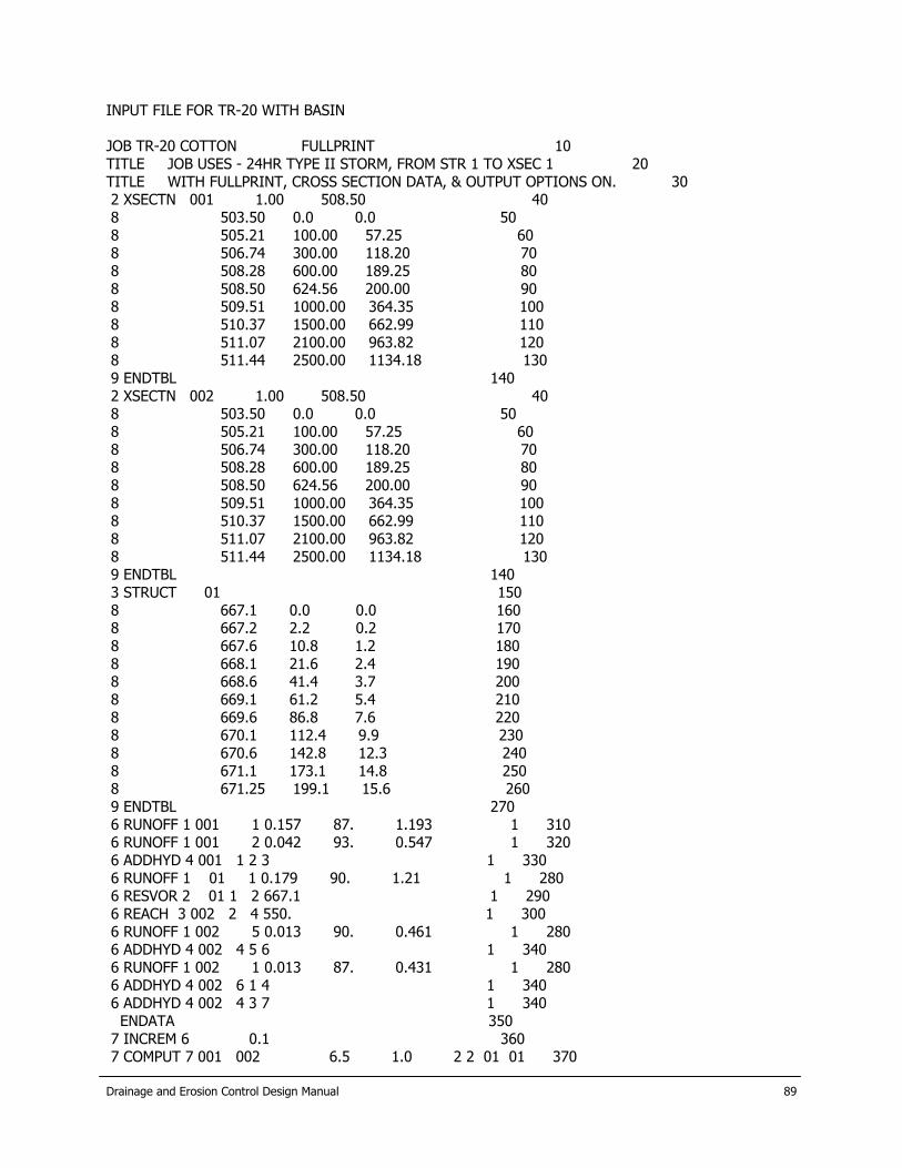
Drainage and Erosion Control Design Manual
89
INPUT FILE FOR TR-20 WITH BASIN JOB TR-20 COTTON FULLPRINT 10 TITLE JOB USES - 24HR TYPE II STORM, FROM STR 1 TO XSEC 1 20 TITLE WITH FULLPRINT, CROSS SECTION DATA, & OUTPUT OPTIONS ON. 30 2 XSECTN 001 1.00 508.50 40 8 503.50 0.0 0.0 50 8 505.21 100.00 57.25 60 8 506.74 300.00 118.20 70 8 508.28 600.00 189.25 80 8 508.50 624.56 200.00 90 8 509.51 1000.00 364.35 100 8 510.37 1500.00 662.99 110 8 511.07 2100.00 963.82 120 8 511.44 2500.00 1134.18 130 9 ENDTBL 140 2 XSECTN 002 1.00 508.50 40 8 503.50 0.0 0.0 50 8 505.21 100.00 57.25 60 8 506.74 300.00 118.20 70 8 508.28 600.00 189.25 80 8 508.50 624.56 200.00 90 8 509.51 1000.00 364.35 100 8 510.37 1500.00 662.99 110 8 511.07 2100.00 963.82 120 8 511.44 2500.00 1134.18 130 9 ENDTBL 140 3 STRUCT 01 150 8 667.1 0.0 0.0 160 8 667.2 2.2 0.2 170 8 667.6 10.8 1.2 180 8 668.1 21.6 2.4 190 8 668.6 41.4 3.7 200 8 669.1 61.2 5.4 210 8 669.6 86.8 7.6 220 8 670.1 112.4 9.9 230 8 670.6 142.8 12.3 240 8 671.1 173.1 14.8 250 8 671.25 199.1 15.6 260 9 ENDTBL 270 6 RUNOFF 1 001 1 0.157 87. 1.193 1 310 6 RUNOFF 1 001 2 0.042 93. 0.547 1 320 6 ADDHYD 4 001 1 2 3 1 330 6 RUNOFF 1 01 1 0.179 90. 1.21 1 280 6 RESVOR 2 01 1 2 667.1 1 290 6 REACH 3 002 2 4 550. 1 300 6 RUNOFF 1 002 5 0.013 90. 0.461 1 280 6 ADDHYD 4 002 4 5 6 1 340 6 RUNOFF 1 002 1 0.013 87. 0.431 1 280 6 ADDHYD 4 002 6 1 4 1 340 6 ADDHYD 4 002 4 3 7 1 340 ENDATA 350 7 INCREM 6 0.1 360 7 COMPUT 7 001 002 6.5 1.0 2 2 01 01 370

Drainage and Erosion Control Design Manual
90
ENDCMP 1 380 7 COMPUT 7 001 002 7.8 1.0 2 2 01 02 370 ENDCMP 1 380 ENDJOB 2 390

Drainage and Erosion Control Design Manual
91
INPUT FILE FOR HEC-1 RUN (EXTRACT ONLY) ID New Braunfels Hydrology Study ID DA A for existing conditions and the 100-year frequency storm ID The USGS New Braunfels precipitation data is being used for Alligator Ck ID Note that TR20 side slope data not available from DS of Reach 3, so assumed z=0.053 ID Alligator Creek, 1999 * ID FNI JOB:NEB99163 DATE: 12/1/99 ID BY: MHP FILE: 100H1E.PRN IT 20 01JUL99 0 216 IO 4 0 * KK E-A1 KM Calculation under existing conditions,100 year frequency storm, and Comal Ct. rainfall data BA 7.427 PH 1 1.04 2.19 4.11 5.12 5.73 6.82 8.01 9.35 PH 10.87 12.56 UD 0.91 LS 70 * KK Route 1 KM Route A1 Hydrograph RD 9200 0.00126 0.03 TRAP 10 8.33 * KKE-A10 KM Local Runoff from A10 BA 1.29 UD 0.97 LS 74 * KK CP10 KM Combine Local A10 and Routed A1 Hydrographs HC 2 * ZZ

Drainage and Erosion Control Design Manual
92
This page was left blank intentionally.

Drainage and Erosion Control Design Manual
93
APPENDIX E
COMPUTATIONS SHEETS 1. Standard Step Backwater Calculations

Drainage and Erosion Control Design Manual
94
This page was left blank intentionally.
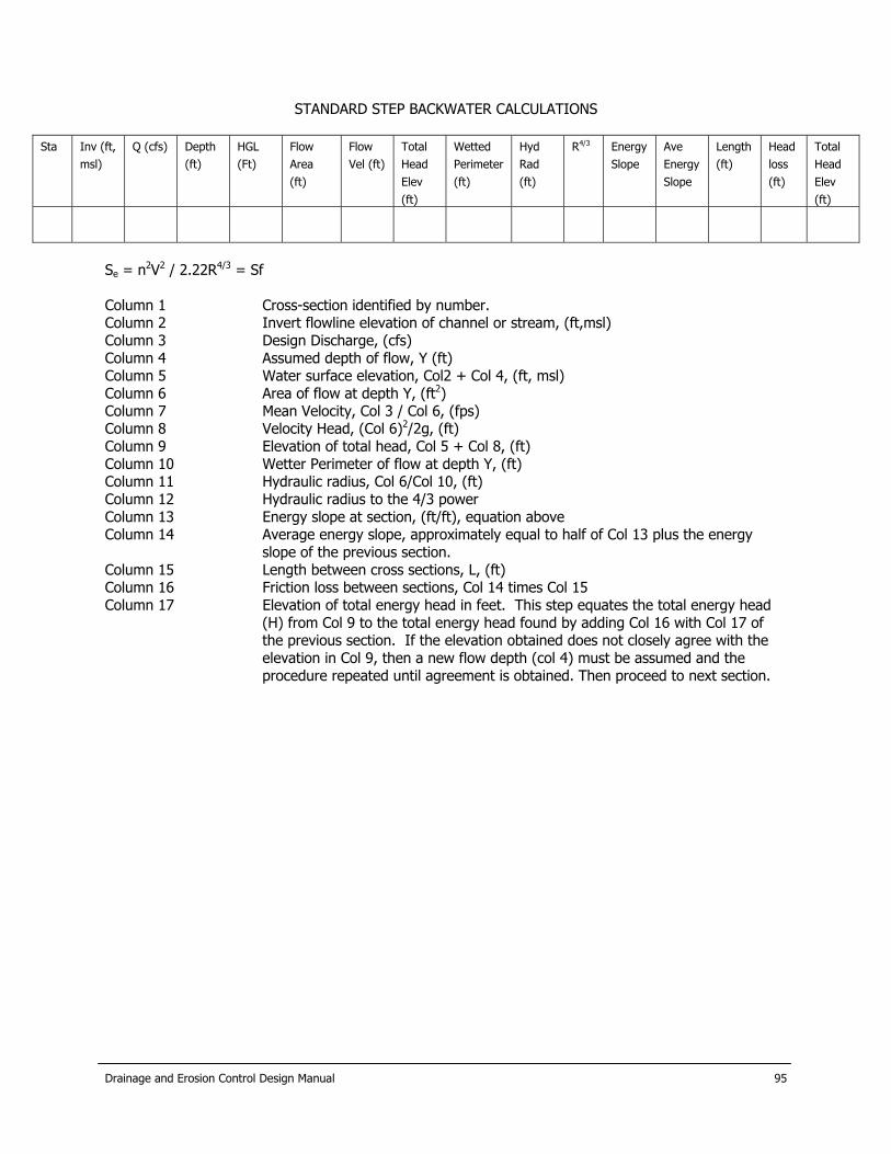
STANDARD STEP BACKWATER CALCULATIONS
R4/3 Sta Inv (ft,
msl) Q (cfs) Depth
(ft) HGL (Ft)
Flow Area (ft)
Flow Vel (ft)
Total Head Elev (ft)
Wetted Perimeter (ft)
Hyd Rad (ft)
Energy Slope
Ave Energy Slope
Length (ft)
Head loss (ft)
Total Head Elev (ft)
Se = n2V2 / 2.22R4/3 = Sf Column 1 Cross-section identified by number. Column 2 Invert flowline elevation of channel or stream, (ft,msl) Column 3 Design Discharge, (cfs) Column 4 Assumed depth of flow, Y (ft) Column 5 Water surface elevation, Col2 + Col 4, (ft, msl) Column 6 Area of flow at depth Y, (ft2) Column 7 Mean Velocity, Col 3 / Col 6, (fps) Column 8 Velocity Head, (Col 6)2/2g, (ft) Column 9 Elevation of total head, Col 5 + Col 8, (ft) Column 10 Wetter Perimeter of flow at depth Y, (ft) Column 11 Hydraulic radius, Col 6/Col 10, (ft) Column 12 Hydraulic radius to the 4/3 power Column 13 Energy slope at section, (ft/ft), equation above Column 14 Average energy slope, approximately equal to half of Col 13 plus the energy
slope of the previous section. Column 15 Length between cross sections, L, (ft) Column 16 Friction loss between sections, Col 14 times Col 15 Column 17 Elevation of total energy head in feet. This step equates the total energy head
(H) from Col 9 to the total energy head found by adding Col 16 with Col 17 of the previous section. If the elevation obtained does not closely agree with the elevation in Col 9, then a new flow depth (col 4) must be assumed and the procedure repeated until agreement is obtained. Then proceed to next section.
Drainage and Erosion Control Design Manual
95

This page was left blank intentionally.
Drainage and Erosion Control Design Manual
96
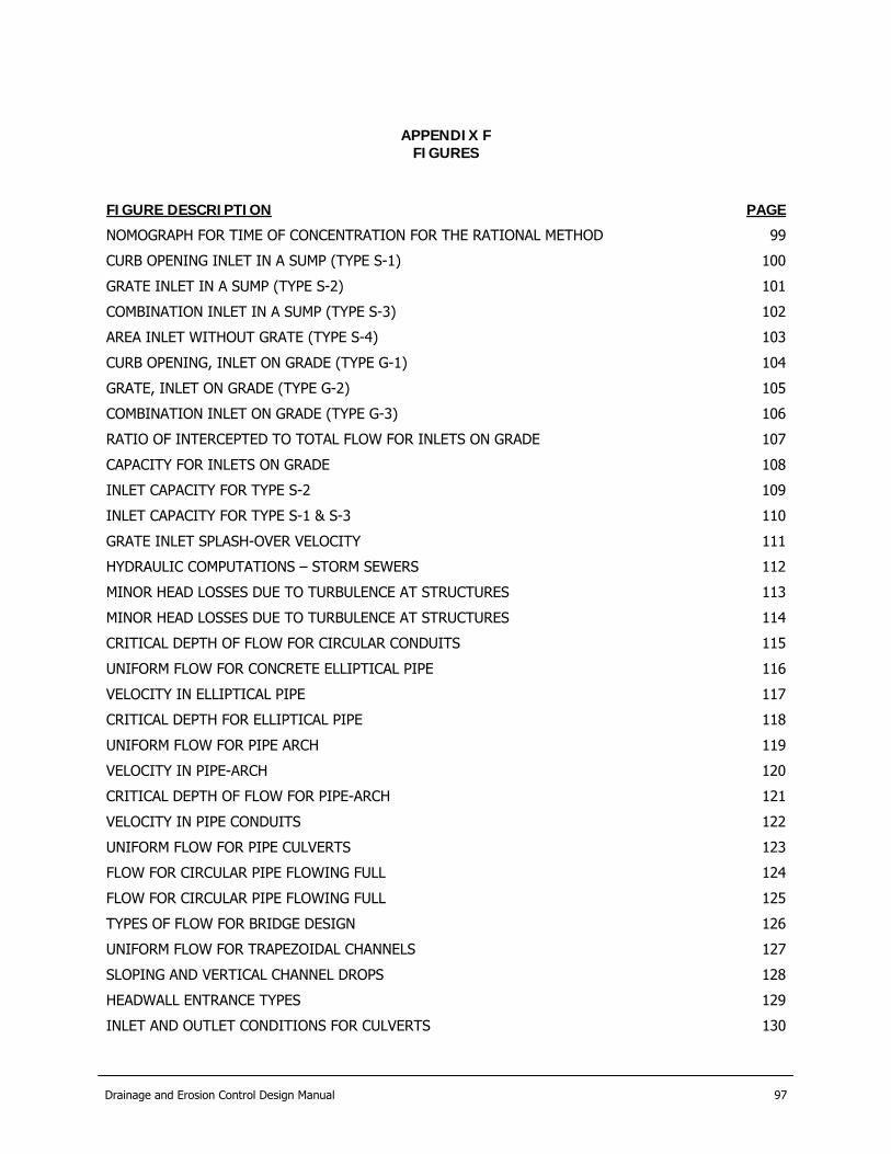
Drainage and Erosion Control Design Manual 97
APPENDIX F
FIGURES
FIGURE DESCRIPTION PAGE
NOMOGRAPH FOR TIME OF CONCENTRATION FOR THE RATIONAL METHOD 99
CURB OPENING INLET IN A SUMP (TYPE S-1) 100
GRATE INLET IN A SUMP (TYPE S-2) 101
COMBINATION INLET IN A SUMP (TYPE S-3) 102
AREA INLET WITHOUT GRATE (TYPE S-4) 103
CURB OPENING, INLET ON GRADE (TYPE G-1) 104
GRATE, INLET ON GRADE (TYPE G-2) 105
COMBINATION INLET ON GRADE (TYPE G-3) 106
RATIO OF INTERCEPTED TO TOTAL FLOW FOR INLETS ON GRADE 107
CAPACITY FOR INLETS ON GRADE 108
INLET CAPACITY FOR TYPE S-2 109
INLET CAPACITY FOR TYPE S-1 & S-3 110
GRATE INLET SPLASH-OVER VELOCITY 111
HYDRAULIC COMPUTATIONS – STORM SEWERS 112
MINOR HEAD LOSSES DUE TO TURBULENCE AT STRUCTURES 113
MINOR HEAD LOSSES DUE TO TURBULENCE AT STRUCTURES 114
CRITICAL DEPTH OF FLOW FOR CIRCULAR CONDUITS 115
UNIFORM FLOW FOR CONCRETE ELLIPTICAL PIPE 116
VELOCITY IN ELLIPTICAL PIPE 117
CRITICAL DEPTH FOR ELLIPTICAL PIPE 118
UNIFORM FLOW FOR PIPE ARCH 119
VELOCITY IN PIPE-ARCH 120
CRITICAL DEPTH OF FLOW FOR PIPE-ARCH 121
VELOCITY IN PIPE CONDUITS 122
UNIFORM FLOW FOR PIPE CULVERTS 123
FLOW FOR CIRCULAR PIPE FLOWING FULL 124
FLOW FOR CIRCULAR PIPE FLOWING FULL 125
TYPES OF FLOW FOR BRIDGE DESIGN 126
UNIFORM FLOW FOR TRAPEZOIDAL CHANNELS 127
SLOPING AND VERTICAL CHANNEL DROPS 128
HEADWALL ENTRANCE TYPES 129
INLET AND OUTLET CONDITIONS FOR CULVERTS 130

HEADWATER DEPTH FOR CONCRETE PIPE CULVERTS WITH INLET CONTROL 131
HEADWATER DEPTH FOR BOX CULVERTS WITH INLET CONTROL 132
HEADWATER DEPTH FOR C.M. PIPE-ARCH CULVERTS WITH INLET CONTROL 133
HEADWATER DEPTH FOR C.M. PIPE CULVERTS WITH INLET CONTROL 134
HEAD FOR STANDARD C.M. PIPE-ARCH CULVERTS FLOWING FULL 135
HEAD FOR STANDARD C.M. PIPE CULVERTS FLOWING FULL 136
HEAD FOR CONCRETE PIPE CULVERTS FLOWING FULL 137
CULVERT DESIGN FORM 138
CRITICAL DEPTH-STANDARD C.M. PIPE-ARCH 139
CRITICAL DEPTH-RECTANGULAR SECTION 140
CONCEPTUAL DESIGN OF DEBRIS FINS 141
BAFFLED OUTLET 142
BAFFLED APRON AND ITS DESIGN CURVE 143
Drainage and Erosion Control Design Manual 98