city of oakland planning co mission
TRANSCRIPT
Oakland City Planning Commission STAFF REPORT
Case File Number: PLNlS-389 May 4, 2016
Location: The Public Right-of-Way adjacent to 41st Street and Piedmont Avenue. (See map on reverse)
Assessors Parcel Numbers: Nearest adjacent lot (012-0993-006-01)
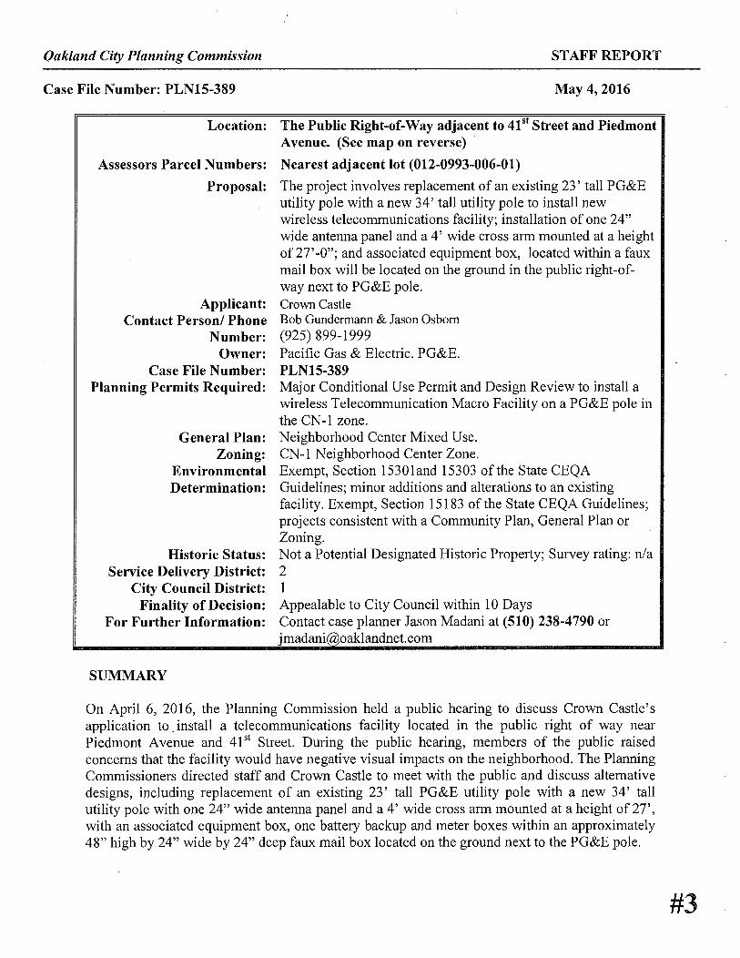
Proposal: The project involves replacement of an existing 23' tall PG&E utility pole with a new 34' tall utility pole to install new wireless telecommunications facility; installation of one 24" wide antenna panel and a 4' wide cross arm mounted at a height of 27' -0"; and associated equipment box, located within a faux mail box will be located on the ground in the public right-ofway next to PG&E pole.
Applicant: Crown Castle Contact Person/ Phone Bob Gundermann & Jason Osborn
Number: (925) 899-1999 Owner: Pacific Gas & Electric. PG&E.
Case File Number: PLNlS-389 Planning Permits Required: Major Conditional Use Permit and Design Review to install a
wireless Telecommunication Macro Facility on a PG&E pole in the CN-1 zone.
General Plan: Neighborhood Center Mixed Use. Zoning: CN-1 Neighborhood Center Zone.
Environmental Exempt, Section 15301and 15303 of the State CEQA Determination: Guidelines; minor additions and alterations to an existing
facility. Exempt, Section 15183 of the State CEQA Guidelines; projects consistent with a Community Plan, General Plan or Zoning.
Historic Status: Not a Potential Designated Historic Property; Survey rating: n/a Service Delivery District: 2
City Council District: 1 Finality of Decision: Appealable to City Council within 10 Days
For Further Information: Contact case planner Jason Madani at (510) 238-4790 or j madani@,oaklandnet.com
SUMMARY
On April 6, 2016, the Planning Commission held a public hearing to discuss Crown Castle's application to . install a telecommunications facility located in the public right of way near Piedmont A venue and 41 st Street. During the public hearing, members of the public raised concerns that the facility would have negative visual impacts on the neighborhood. The Planning Commissioners directed staff and Crown Castle to meet with the public and discuss alternative designs, including replacement of an existing 23' tall PG&E utility pole with a new 34' tall utility pole with one 24" wide antenna panel and a 4' wide cross arm mounted at a height of 27', with an associated equipment box, one battery backup and meter boxes within an approximately 48" high by 24" wide by 24" deep faux mail box located on the ground next to the PG&E pole.
#3

CITY OF OAKLAND PLANNING CO MISSION
111i111111111111C:::::J11111-==lllllllllll11111111111111111111111111111111111111111111111111111111:=:=========-111111111111111111111111111111111111111111111111111111Feet 0 125 250 500
Case File: PLN 15389 Applicant: Crown Castle
750 1,000
Address: Public Right of Way 41 st Street and Piedmont Avenue Zone: CN-1
®

Oakland City Planning Commission May 4,2016 Case File Number: PLN15-389 Page 3
Subsequently, Crown Castle developed three different alternative design options which was presented to the Piedmont Avenue Neighborhood Improvement League (PANIL) community meeting on April 27, 2016. The majority of the community members voted to support alternative design option (1) to install one 24" wide antenna panel and a 4' wide cross arm mounted at a height of 27'-0"; and associated equipment box, located within a faux mail box will be located on the ground in the public right-of-way next to a PG&E pole vs to attach the equipment cabinet on the PG&E pole) see (attachment A)
PROJECT DESCRIPTION
In response to the Planning Commission's direction Crown Castle was advised to meet with PANIL and staff to discuss alternative design options, Among the options presented, Crown Castle is proposing "Design Option 1, which consists of replacing an existing 23' tall PG&E utility pole with a new 34' tall utility pole located in the public right-of-way. The new pole would include one 24" wide antenna panel and a 4' wide cross arm mounted at a height of27'-0", with an associated equipment box located within an approximately 48" high by 24" wide by 24" deep faux mail box or an standard cabinet metal box located on the ground next to the PG&E pole. (See Attachment A).
REQUIRED FINDINGS AND CONDITIONS OF APPROVAL
As demonstrated in the attached findings, staff believes the new design proposal (Design Option 1) meets all the required findings under Planning Code sections 17.134.050 (General Use Permit criteria), 17.136.0SO(B) (Non-Residential Design Review criteria), 17.128.070(B) (Macro) Design Review criteria; AND 17.128.070(C) (Macro) Conditional Use Permit criteria. For convenience purposes, staff has attached all required findings to this staff report. The attached findings have been updated to reflect the newly proposed Design Option 1.
In addition, staff inadvertently attached outdated Conditions of Approval to the April 6, 2016 Staff Report. Attached to this staff report is a complete set of updated Conditions of Approval that will apply to the project.
CONCLUSION
Staff recommends approval of the new design alternative for the subject site and is available for questions.

Oakland City Planning Commission Case File Number: PLN15-389
RECOMMEND A TIO NS:
Reviewed by:
~~ Scott Miller Zoning Manager
Reviewed By:
~/L-. Darin Ranelletti, Deputy Director Bureau of Planning and Building
Approved for forwarding to the City lanning Commission
ATTACHMENTS:
Mav 4,2016 Page 4
1. Affirm staffs environmental determination; and 2. Approve Major Conditional Use Permit and Design
Review application PLN15-389 subject to the attached findings and conditions of approval.
Prepared by:
Jason Madani Planner II
I
A. Project revised Plans & Revised Photo simulations & Alternative Site Analysis B. Jerrold T. Bushberg Health and Medical Physics Consulting, Inc. Engineering RF
Emissions Report C. Correspondence D. April 6, 2016 Staff Report

Oakland City Planning Commission May 4,2016 Case File Number: PLN15-389 Page 5
FINDINGS FOR APPROVAL
FINDINGS FOR APPROVAL: As demonstrated in the attached findings, staff believes the new design proposal (Design Option 1) meets all the required findings under Planning Code sections 17.134.050 (General Use Permit criteria), 17.136.0SO(B) (Non-Residential Design Review criteria), 17.128.070(B) (Macro) Design Review criteria; AND 17.128.070(C) (Macro) Conditional Use Permit criteria. For convenience purposes, staff has attached all required findings to this staff report. The attached findings have been updated to reflect the newly proposed Design Option 1.
SECTION 17.134.050 - USE PERMIT FINDINGS:
A. That the location, size, design, and operating characteristics of the proposed development will be compatible with, and will not adversely affect, the livability or appropriate development of abutting properties and the surrounding neighborhood, with consideration to be given to harmony in scale, bulk, coverage, and density; to the availability of civic facilities and utilities; to harmful effect, if any upon desirable neighborhood character; to the generation of traffic and the capacity of surrounding streets; and to any other relevant impact of the development.
The purpose of the project is to enhance wireless telecommunications in the Piedmont A venue commercial corridor. The project involves replacement of an existing 23' tall PG&E utility pole with a new 34' tall utility pole to install new wireless telecommunication facility; installation of one 24" wide antenna panel and a 4' wide cross arm mounted at a height of 27'-0"; and associated equipment box, one battery backup and meter box located within a faux mail box will be located on the ground in the public right-of-way next to PG&E pole. The facility will be unmanned and will not create additional vehicular traffic in the area and will not adversely affect the operating characteristics or livability of this neighborhood.
B. That the location, design, and site planning of the proposed development will provide a convenient and functional living, working, shopping, or civic environment, and will be as attractive as the nature of the use and its location and setting warrant.
The proposed unmanned wireless telecommunication facility will not adversely affect or detract from the civic, commercial or residential characteristics of the neighborhood, because the antennas will be mounted on a PG&E pole located in public right-of-way.
C. That the proposed development will enhance the successful operation of the surrounding area in its basic community functions, or will provide an essential service to the community or region.
The proposed development will enhance the successful operation of the surrounding area in its basic community function and will provide an essential service to the community or region. This will be achieved by improving the functional use of the site by providing a regional telecommunication facility for the community which will be available to police, fire, public safety organizations and the general public.

Oakland City Planning Commission May 4,2016 Case File Number: PLNlS-389 Page 6
D. That the proposal conforms to all applicable design review criteria set forth in the regular design review procedure at Section 17.136.050.
The proposal conforms with all significant aspects of the design review criteria set forth in Chapter 17.136.050 of the Oakland Planning Code, as outlined below.
E. That the proposal conforms in all significant respects with the Oakland General Plan and with any other applicable guidelines or criteria, district plan or development control map which has been adopted by the Planning Commission or City Council.
The proposal conforms in all significant respects with the Oakland General Plan. The subject property is located within the Neighborhood Center Mixed Use General Plan designation and conforms in all significant respects with this designation. The Neighborhood Center Mixed Use land use classification is intended to identify, create, maintain and enhance mixed use neighborhood commercial centers. These centers are typically characterized by smaller scale pedestrian-oriented, continuous street frontage with a mix of retail, housing, office, active open space, eating and drinking places, personal and business services, and smaller scale educational, cultural, or entertainment uses. The proposed unmanned wireless telecommunication facility will not adversely affect or detract from the desirable characteristics of the neighborhood. The proposal will be located on a new PG&E utility pole and will not negatively affect the general quality and character of the neighborhood: The proposed project with appropriate conditions of approval is not expected to have a significant visual impact on the existing structure and surrounding area.
SECTION 17.136.0SO(B) - NONRESIDENTIAL DESIGN REVIEW CRITERIA:
1. That the proposal will help achieve or maintain a group of facilities which are well related to one another and which, when taken together, will result in a well-composed design, with consideration given to site, landscape, bulk, height, arrangement, texture, materials, colors, and appurtenances; the relation of these factors to other facilities in the vicinity; and the relation of the proposal to the total setting as seen from key points in the surrounding area. Only elements of design which have some significant relationship to outside appearance shall be considered, except as otherwise provided in Section 17.136.060;
The project involves replacement of an existing 23' tall PG&E utility pole with a new 34' tall utility pole to install a new wireless telecommunication facility for Crown Castle located in the public right-of-way; installation of one 24" wide antenna panel and a 4' wide cross arm mounted at a height of27'-0", with an associated equipment box, one battery backup and meter boxes within a 48" tall by 24" wide faux mail box located on the ground next to the PG&E pole. The proposed antennas and equipment cabinet will be screened and painted to match wooden PG&E utility pole.
2. That the proposed design will be of a quality and character which harmonizes with, and serves to protect the value of, private and public investments in the area;
The associated equipment box, one battery backup and meter boxes will be within a 48" tall by 24" wide faux mail box and painted to match the wooden utility pole. Therefore, the proposed unmanned wireless telecommunication facility will blend in with an existing PG&E utility pole,

Oakland City Planning Commission May 4,2016 Case File Number: PLN15-389 Page 7
and will not adversely affect or detract from commercial and residential characteristics of the neighborhood.
3. That the proposed design conforms in all significant respects with the Oakland General Plan and with any applicable design review guidelines or criteria, district plan, or development control map which have been adopted by the Planning Commission or City Council.
The proposal conforms in all significant respects with the Oakland General Plan. See Finding 17 .134.0SO(E).
SECTION 17.128.070(B) DESIGN REVIEW CRITERIA FOR MACRO FACILITIES
1. Antennas should be painted and/or textured to match the existing structure:
The antennas and equipment will be painted brown to match the wooden utility pole to minimize the potential visual impact.
2. Antennas mounted on architecturally significant structures or significant architectural details of the building should be covered by appropriate casings which are manufactured to match existing architectural features found on the building:
The proposed antenna and equipment will not be mounted onto an architecturally significant structure. The proposed antennas and equipment are consistent with the utility pole.
3. Where feasible, antennas can be placed directly above, below or incorporated with vertical design elements of a building to help in camouflaging:
The proposal antennas will be placed above, and vertically in line with the utility pole.
4. Equipment shelters or cabinets shall be screened from the public view by using landscaping, or materials and colors consistent with surrounding backdrop:
The associated equipment cabinets will be located on the ground within a faux mail box located next to PG&E pole and painted to match the wooden pole to minimize visual impacts on the neighboring properties.
5. Equipment shelters or cabinets shall be consistent with the general character of the area.
The proposed equipment cabinet design is consistent with other utility equipment located within the public right -of- way along Piedmont A venue corridor
6. For antennas attached to the roof, maintain a 1:1 ratio for equipment setback; screen the antennas to match existing air conditioning units, stairs, or elevator towers; avoid placing roof mounted antennas in direct line with significant view corridors.
NIA

Oakland City Planning Commission May 4,2016 Case File Number: PLN15-389 Page 8
7. That all reasonable means of reducing public access to the antennas and equipment has been made, including, but not limited to, placement in or on buildings or structures, fencing, anti-climbing measures and anti-tampering devices.
The antennas will be mounted at a height of27'-0" of the PG&E utility pole and will not be accessible to the public due to its location. The equipment cabinet will be concealed within a faux mail box located next to the PG&E pole and will not be accessible to the public.
SECTION 17.128.070(C) CONDITIONAL USE PERMIT (CUP) FINDINGS FOR MACRO FACILITIES
1. The project must meet the special design review criteria listed in subsection B of this section (17.128.070B):
The project meets the criteria in 17 .128.070(B). Please see findings above.
2. The proposed project must not disrupt the overall community character:
The proposed Telecommunications facility is fully screened from public view and, therefore the proposal will not disrupt the overall community character surrounding the subject site.

Oakland City Planning Commission Case File Number: PLN15-389
STANDARD CONDITIONS:
1. Approved Use
CONDITIONS OF APPROVAL PLNlS-389
May4,2016 Page 9
The project shall be constructed and operated in accordance with the authorized use as described in the approved application materials, PLNlS-386 and the approved plans dated December 7, 2015 and April 27, 2016 (design option 1), as amended by the following conditions of approval and mitigation measures, if applicable ("Conditions of Approval" or "Conditions").
2. Effective Date, Expiration, Extensions and Extinguishment
This Approval shall become effective immediately, unless the Approval is appealable, in which case the Approval shall become effective in ten calendar days unless an appeal is filed. Unless a different termination date is prescribed, this Approval shall expire two years from the Approval date, or from the date of the final decision in the event of an appeal, unless within such period all necessary permits for construction or alteration have been issued, or the authorized activities have commenced in the case of a permit not involving construction or alteration. Upon written request and payment of appropriate fees submitted no later than the expiration date of this Approval, the Director of City Planning or designee may grant a oneyear extension of this date, with additional extensions subject to approval by the approving body. Expiration of any necessary building permit or other construction-related permit for this project may invalidate this Approval if said Approval has also expired. If litigation is filed challenging this Approval, or its implementation, then the time period stated above for obtaining necessary permits for construction or alteration and/or commencement of authorized activities is automatically extended for the duration of the litigation.
3. Compliance with Other Requirements The project applicant shall comply with all other applicable federal, state, regional, and local laws/codes, requirements, regulations, and guidelines, including but not limited to those imposed by the City's Bureau of Building, Fire Marshal, and Public Works Department. Compliance with other applicable requirements may require changes to the approved use and/or plans. These changes shall be processed in accordance with the procedures contained in Condition #4.
4. Minor and Major Changes a. Minor changes to the approved project, plans, Conditions, facilities, or use may be approved
administratively by the Director of City Planning b. Major changes to the approved project, plans, Conditions, facilities, or use shall be reviewed
by the Director of City Planning to determine whether such changes require submittal and approval of a revision to the Approval by the original approving body or a new independent permit/approval. Major revisions shall be reviewed in accordance with the procedures required for the original permit/approval. A new independent permit/approval shall be reviewed in accordance with the procedures required for the new permit/approval.
Oakland City Planning Commission May 4,2016 Case File Number: PLN15-389 Page 10
5. Compliance with Conditions of Approval
a. The project applicant and property owner, including successors, (collectively referred to hereafter as the "project applicant" or "applicant") shall be responsible for compliance with all the Conditions of Approval and any recommendations contained in any submitted and approved technical report at his/her sole cost and expense, subject to review and approval by the City of Oakland.
b. The City of Oakland reserves the right at any time during construction to require certification by a licensed professional at the project applicant's expense that the as-built project conforms to all applicable requirements, including but not limited to, approved maximum heights and minimum setbacks. Failure to construct the project in accordance with the Approval may result in remedial reconstruction, permit revocation, permit modification, stop work, permit suspension, or other corrective action.
c. Violation of any term, Condition, or project description relating to the Approval is unlawful, prohibited, and a violation of the Oakland Municipal Code. The City of Oakland reserves the right to initiate civil and/or criminal enforcement and/or abatement proceedings, or after notice and public hearing, to revoke the Approval or alter these Conditions if it is found that there is violation of any of the Conditions or the provisions of the Planning Code or Municipal Code, or the project operates as or causes a public nuisance. This provision is not intended to, nor does it, limit in any manner whatsoever the ability of the City· to take appropriate enforcement actions. The project applicant shall be responsible for paying fees in accordance with the City's Master Fee Schedule for inspections conducted by the City or a Citydesignated third-party to investigate alleged violations of the Approval or Conditions.
6. Signed Copy of the Approval/Conditions
A copy of the Approval letter and Conditions shall be signed by the project applicant, attached to each set of permit plans submitted to the appropriate City agency for the project, and made available for review at the project job site at all times.
7. Blight/Nuisances
The project site shall be kept in a blight/nuisance-free condition. Any existing blight or nuisance shall be abated within 60 days of approval, unless an earlier date is specified elsewhere.
8. Indemnification
a.To the maximum extent permitted by law, the project applicant shall defend (with counsel acceptable to the City), indemnify, and hold harmless the City of Oakland, the Oakland City Council, the Oakland Redevelopment Successor Agency, the Oakland City Planning Commission, and their respective agents, officers, employees, and volunteers (hereafter collectively called "City") from any liability, damages, claim, judgment, loss (direct or indirect), action, causes of action, or proceeding (including legal costs, attorneys' fees, expert witness or consultant fees, City Attorney or staff time, expenses or costs) (collectively called "Action") against the City to attack, set aside, void or annul this Approval or implementation of this Approval. The City may elect, in its sole discretion, to participate in the defense of said Action and the project applicant shall reimburse the City for its reasonable legal costs and attorneys' fees.

Oakland City Planning Commission May 4,2016 Case File Number: PLN15-389 Page 11
b. Within ten (10) calendar days of the filing of any Action as specified in subsection (a) above, the project applicant shall execute a Joint Defense Letter of Agreement with the City, acceptable to the Office of the City Attorney, which memorializes the above obligations. These obligations and the Joint Defense Letter of Agreement shall survive termination, extinguishrnent, or invalidation of the Approval. Failure to timely execute the Letter of Agreement does not relieve the project applicant of any of the obligations contained in this Condition or other requirements or Conditions of Approval that may be imposed by the City.
9. Severability
The Approval would not have been granted but for the applicability and validity of each and every one of the specified Conditions, and if one or more of such Conditions is found to be invalid by a court of competent jurisdiction this Approval would not have been granted without requiring other valid Conditions consistent with achieving the same purpose and intent of such Approval.
PROJECT SPECIFIC CONDTIONS:
10. Radio Frequency Emissions Prior to the final building permit sign off. The applicant shall submit a certified RF emissions report stating the facility is operating within the acceptable standards established by the regulatory Federal Communications Commission.
11. Operational Ongoing. Noise levels from the activity, property, or any mechanical equipment on site shall comply with the performance standards of Section 17 .120 of the Oakland Planning Code and Section 8.18 of the Oakland Municipal Code. If noise levels exceed these standards, the activity causing the noise shall be abated until appropriate noise reduction measures have been installed and compliance verified by the Planning and Zoning Division and Building Services.
12. Radio Frequency Emissions Prior to the final building permit sign off The applicant shall submit a certified RF emissions report stating the facility is operating within the acceptable standards established by the regulatory Federal Communications Commission.
13. Operational Ongoing Noise levels from the activity, property, or any mechanical equipment on site shall comply with the performance standards of Section 17.120 of the Oakland Planning Code and Section 8.18 of the Oakland Municipal Code. If noise levels exceed these standards, the activity causing the noise shall be abated until appropriate noise reduction measures have been installed and compliance verified by the Planning and Zoning Division and Building Services.
14. Revised Plan Prior to issuance of building permit. Revised detail plans, to scale, for either of the alternative design options, that will not include meters box and equipment will be passively cooled reviewed and approved, by the Planning

Oakland City Planning Commission Case File Number: PLNlS-389
Commission shall be submitted to and approved by Planning Bureau.
15. Possible District Undergrounding PG&E Pole Ongoing
May 4,2016 Page 12
Should the PG &E utility pole be voluntarily removed for purposes of district undergrounding or otherwise, the telecommunications facility can only be re-established by applying for and receiving approval of a new application to the Oakland Planning Department as required by the regulations.

ATTACHMENT A
Proposed Site PA03m2 Option 1

ATTACHMENT A
POLE #110107270
TOP OF EXISTING POLE: 30'
TOP OF NEW POLE: 34' 0
TOP OF ANTENNA: 27' O"
RAD CENTER: 26' O"
AZIMUTH: 70°
PROFILE VIEW: 9 O'CLOCK
A NOTES
REPLACE EXISTING OVERHEAD GUY POLE WITH NEW 40' POLE.
INSTALL SECONDARY SERVICE AT 33' O".
• PLACE POWER OVERHEAD GUY WITH DOWNGUY AT 32' O"; EXISTING HEIGHT 23' 6".
PLACE CATV OVERHEAD GUY WITH DOWNGUY AT 23' O" ; EXISTING HEIGHT AT 23' O".
PLACE TELCO OVERHEAD GUY WITH DOWNGUY AT 22' O" ; EXISTING HEIGHT AT 22' 6".
INSTALL 2" X 2" X 24" STAND-OFF BRACKETS (TYPICAL) ACCORDING TO UTILITY
STANDARDS AND PRACTICES.
INSTALL DISCONNECT BOX WITH PG&E SHUTDOWN PROCEDURE.
INSTALL RECTIFIER UNIT BOX.
INSTALL (1) 2" SCHEDULE 80 COMM RISER.
INSTALL (1) 1" SCHEDULE 80 POWER RISER.
INSTALL 4' CROSS ARM CEA WITH (1) 24" AMPHENOL (HTXCWW63111414FOOO) ANTENNA
AT 27' O"
ANTENNAS & EQUIPMENT TO BE PAINTED TO MATCH POLE.
INSTALL VGR.
INSTALL MPE PLACARD.
B NEW CONSTRUCTION NOTES
EXISTING UTILITY POLE \
AMPHENOL (HTXCWW63111414FOOO)
ANTENNA AT 70°
I lo::: 0 z oo
D__goo C TOP VIEW
POWER COMM
N.T.S.
INSTALL SECONDARY SERVICE AT 33' O"
PLACE POWER OVERHEAD GUY WITH DOWNGUY AT 32' O"; EXISTING HEIGHT AT 23' 6"
TOP OF POLE AT 34' - O"
INSTALL 1" SCHEDULE 80 POWER RISER ------1-.J.J
PLACE CATV OVERHEAD GUY WITH DOWNGUY AT 23' O";
EXISTING HEIGHT AT 23' O"
PLACE TELCO OVERHEAD GUY WITH DOWNGUY AT 22' O";------~
EXISTING HEIGHT AT 22' 6"
INSTALL 2" X 2" X 24" STAND-OFF BRACKETS (TYPICAL) ACCORDING TO UTILITY STANDARDS AND PRACTICES
(SEE DETAIL 8 ON SHEET D-3)
D PROFILE
NEW 40' ULITLITY POLE
INSTALL RECTIFIER UNIT BOX (SEE DETAIL 3 ON SHEET D-2)
INSTALL DISCONNECT BOX WITH PG&E SHUTDOWN PROCEDURE
(SEE DETAILS 9 & 10 ON SHEET D-3)
INSTALL MAIL BOX CONCEALMENT WITH (2) ERICSSON MRRUs INSIDE (SEE DETAILS 4 & 5 ON SHEET D-2)
t 5' 6'
2'
INSTALL 4' CROSS ARM CEA WITH (1) 24" AMPHENOL (HTXCWW63111414FOOO) ANTENNA AT 27' O" (SEE DETAIL 2 ON SHEET D-2 AND DETAIL 11 ON SHEET D-3)
! 1 INSTALL MPE PLACARD (SEE DETAIL 1 ON SHEET D-2)
BOTTOM OF ANTENNA
25' O"
RAD CENTER 26' O"
N.T.S.
/
CLIENT:
PA03m2 (OPTION 1)
CROWN CASTLE PROJECT l\"O.
V243288
CROWN ~CASTLE
300 SPECTRUM CENTER DRIVE, STE 1200 IRVINE, CA 92618
WWW.CfO\\TICastle.com
PREPARED BY:
• Communications _ Telecommunications Engineering
~
584 l EDISON PLACE, SUITE 110 CARLSBAD, CA 92008 PHONE' (760) 929-0910
FAX (760) 929-0936 www.coastalcomminc.com
PROPRlETARY INFORMATION
THE INFORMATION CONTAINED lN THIS SET OF DRAWINGS IS PROPRIETARY AND
CONFIDENTIAL TO VERIZON. ANY USE OR DISCLOSURE OTHER THAN AS IT RELATES
TO VERIZON IS STRICTLY PROl-llBITEO.
1-800-227-2600 CALL AT
LEAST TWO DAYS BEFORE
YOU DIG
UNDERGROUND SERVICE ALERT TICKET#
REVISIO~ I ISSUE DA TE
SITE Nfu\!E& ADDRESS:
PROW ADJACENT TO 157 41st ST
OAKLAND, CA
( ___ PR_O_FIL_E_~)
SHEETl\O.
P-1.3

COORDINATES LATITUDE:
LONGITUDE: 37.826449
-122.252675
CONDUIT SIZE OF COUNT~CONDUIT
~APPROX. LENGTH OF FOOTAGES
FOOTAGE TOTALS ASPHALT TRENCH O'
DIRT TRENCH 8'
BORE O'
PUNCHTHRU O'
TOTAL 8'
PCC SIDEWALK TOTAL 60 SQ. FT.
BILL OF MATERIALS DESCRIPTION QTY
17" X30" 0 VAULTS 2' x 3' 1 (PVT)
3' XS' 0 1"PVC O'
CONDUIT 3"PVC O' (PVT) 4" PVC 8'
NOTES:
1. CONTRACTOR TO POTHOLE ALL UTILITY CROSSINGS.
2. CONTRACTOR TO PLACE SANDBAGS AROUND ANY/ALL STORM DRAIN INLETS TO PREVENT CONTAMINATED WATER.
3. SPOILS PILE WILL BE COVERED AND CONTAINED AND STREET WILL BE SWEPT AND CLEANED AS NEEDED.
4. CONTRACTOR TO REPAIR DAMAGED PUBLIC IMPROVEMENTS TO THE SATISFACTION OF THE CITY ENGINEER.
5. CURB & GUTTER TO BE PROTECTED IN PLACE. SIDEWALK TO BE REPLACED TO THE SATISFACTION OF THE CITY ENGINEER.
6. THE CONTRACTOR SHALL RESTORE THE ROADWAY BACK TO ITS ORIGINAL CONDITION SATISFACTORY TO THE CITY ENGINEER INCLUDING, BUT NOT LIMITED TO PAVING, STRIPING, BIKE LANES, PAVEMENT LEGENDS, SIGNS, AND TRAFFIC LOOP DETECTORS.
f>,
" 80'
" 54'
~ "
" 7J>, ~
~ " 66'
~ " /
52' 1- " / " "
EXISTING UTILITY POLE ~ """
(2' B.O.C.} STA. 100 • 87 " ,' - , ~: '. /
/ PIEMONT AVE STA 100 + 00
/ 52'
/ 66' ~
Liln ~
/ /
\/ / \
\ \ / /
/ \ / \1 \ ~
\ ~tz,
' '
41st ST STA 100 + 00
8' DIRT TRENCH \ " / 1
1
(SEE DETAIL 9 ON SHEET D-3) ', ~ SCALE: 1" = 10' ,,. ,,
--~ - - ---
PROPOSED MAIL BOX CONCEALMENT (1' 8.0.C.) STA. 100 + 66
PROPOSED 2' X 3' CROWN CASTLE FIBER VAULT (1 ' 8.0.C.) (SEE DETAIL 6 ON SHEET D-3) STA. 100 + 63
PROPOSED NODE LOCATION EXISTING UTIL TIY POLE #N/A (2' B.O.C.) STA. 100 + 58
REMOVE & REPLACE 12' X 5' SIDEWALK PANEL
NORTH
@ SCALE: 1" = 40'
PA03m2 (OPTION 1)
CROWN CASTLE PROJECT NO.
V243288
CLIENT:
CROWN ._..._ CASTLE
300 SPECTRUM CENTER DRIVE, STE 1200 IR VINE, CA 92618
WWW.CfO\\lJCastle.com
PREPARED BY:
~ Communications - Telecommunications Engineering -~
584 1 EDISON PLACE, SUJTE 110 CARLSBAD, CA 92008 PHONE: (760) 929-0910
F AJ C (760) 929-0936 www.coastalcomminc.com
PROPRlETARY INFORMATION
TI·rE INFORMATION CONTAINED IN THIS SET OF ORA WINGS IS PROPRIETARY AND
CONFIDENTIAL TO VER JZON. AN Y USE OR DISCLOSURE OTHER THAN AS IT RELATES
TO VERIZON IS STRICTLY PROHIBITED.
1-800-227 -2600 CALL AT
LEAST TWO DAYS BEFORE
YOU DlG
UNDERGROUND SERVICE ALERT TICKET #
REVISION / ISSUE
SITE NAME& ADDRESS:
PROW ADJACENT TO 157 41st ST
OAKLAND, CA
DATE .)
( _ __ s_I_TE_PL_A_N _ _ )
DRAWN BY: DRAFT DATE: APPROVED BY:
AGR 04/22/1 6 TT SHEET KO.
SP-1

UTILITY POLE
A ENLARGED VIEW
B I N/A
C&G
t>
!:>..
SIDEWALK
INSTALL MAIL BOX CONCEALMENT WITH (2) ERICSSON MRRUs INSIDE
REMOVE & REPLACE SIDEWALK PANEL
-----RJW. -
12'
RO POSED 2' x 3'
VAU LT
!:>.
t>
PROPOSED NODE LOCATION EXISTING UTILITY POLE #N/A
13'
SCALE:
I SCALE:
l" = 5'
N.T.S.
PA03m2 (OPTION 1)
CROWN CASTLE PROJECT 1\0.
V243288
CLIENT:
CROWN ~CASTLE
300 SPECTRUM CENTER DRIVE, STE 1200 IR VINE, CA 92618
W\\W,CJ'O\\TICastle.com
PREPARED BY:
• Communications _ Telecommunications Engineering
~
584 ! EDISON PLACE, SUITE 110 CARLSBAD, CA 92008 PHONE: (760) 929-0910
FAX (760) 929-0936 www.coastalcomminc.com
PROPRIETARY INFORl\1A TION
THE INFORMATION CONTAINED IN THIS SET OF DRAWINGS JS PROPRIETARY AND
CONFIDENTIAL TO VERIZON. ANY USE OR DISCLOSURE OTHER 11-IAN AS IT RELATES
TO VERIZON IS STRICTLY PROHIBITED.
1-800-227-2600 CALL AT
LEAST TWO DAYS BEFORE
YOU DIG
UNDERGROUND SER VICE ALERT TICKET#
REVISION I ISSUE
SITE NA\1E& t\DDRESS:
PROW ADJACENT TO 157 41st ST
OAKLAND, CA
DATE
(_~_S_I_TE~P_LA_N~~) / DR.o\WNBY:
A GR
SHEET NO.
SP-2

CROWN CASTLE
CROWN CASTLE TO INSTALL THE FOLLOWING:
REPLACE EXISTING OVERHEAD GUY POLE WITH
NEW 40' POLE.
INSTALL SECONDARY SERVICE AT 33' O".
PLACE POWER OVERHEAD GUY WITH DOWNGUY
AT 32' O" ; EXISTING HEIGHT 23' 6 ...
PLACE CATV OVERHEAD GUY WITH DOWNGUY
AT 23' O" ; EXISTING HEIGHT AT 23' O" .
PLACE TELCO OVERHEAD GUY WITH DOWNGUY
AT 22' O"; EXISTING HEIGHT AT 22' 6".
INSTALL 2" X 2" X 24" STAND-OFF BRACKETS
(TYPICAL) ACCORDING TO UTILITY STANDARDS
AND PRACTICES.
INSTALL DISCONNECT BOX WITH PG&E
SHUTDOWN PROCEDURE.
INST ALL RECTIFIER UNIT BOX.
INSTALL ( I ) 2" SCHEDULE 80 COMM RISER.
INSTALL ( I ) I " SCHEDULE 80 POWER RISER.
INSTALL 4' CROSS ARM CEA WITH ( I ) 24"
AMPHENOL (HTXCWW63111414FOOO) ANTENNA AT
27' O"
ANTENNAS & EQUIPMENT TO BE PAINTED TO
MATCH POLE.
INSTALL VGR.
INST ALL MPE PLACARD.
INST ALL MAJL BOX CONCEALMENT WITH
ERICSSON MRRUs INSIDE.
PROJECT SUMMARY
PROJECT MANAGER: CROWN CASTLE 300 SPECTRUM CENTER DRIVE, STE 1200 IRVINE, CA 926 18 JOHN GRIFFITHS (408) 468-5524 [email protected]
NODE ENGINEER: COASTAL COMMUNICATIONS 5841 EDISON PL, STE. 110 CARLSBAD, CA 92008 TODD THREW (760) 929-0910 ext 101 TODD@COAST ALCOMMINC.COM
PROJECT TEAM
ATTACHMENT A
PIEDMONT AVE PROW ADJACENT TO
157 41st ST OAKLAND, CA
OPTION 1 - MAIL BOX CONCEAMENT
VICINITY MAP
r SHEET NUMBER: DESCRIPTION
\.
T-1 TITLE SHEET
D-1 DETAILS & NOTES
D-2 DETAILS & NOTES
D-3 DETAILS & NOTES
D-4 DETAILS & NOTES
P-1.1 PA03m2 PHOTOS
P-1.2 PA03m2 PHOTO SIM
P-1.3 PA03 m2 PROFILE
SP-I PA03m2 SITE PLAN
SP-2 PA03m2 ENLARGED VIEW
SHEET INDEX
1. STREET USE PERMIT SHALL BE OBTAINED BY CONTRACTOR PRIOR TO COMMENCING WORK.
2. ALL WORK TO BE CONDUCTED IN THE RIGHT OF WAY.
3. ALL DISTURBED LANDSCAPING SHALL BE REPLACED TO SIMILAR EXISTING CONDlTION.
4. ANY SIDEWALK CLOSURE SHALL BE COO RD INA TED WJTH THE CITY AND PROPER SIGNING WJLL BE PLACED.
5. NO MATERIALS OR EQUIPMENT SHALL BE STORED ON PRIVATE PROPERTY OR BLOCK ACCESS TO PRIVATE PROPERTY.
6. CLEANUP OF SITE WJLL BE COMPLETED EACH EVENING AND THE SITE WILL BE RETURNED TO EXISTING CONDlTIONS AT THE COMPLETION OF CONSTRUCTION AT EACH SITE.
CONTRACTOR SHALL VERIFY ALL PLANS AND EXISTING DIMENSIONS AND CONDlTIONS ON THE JOB SITE AND SHALL IMMEDIATELY NOTIFY THE ENGINEER IN WRITING OF ANY DISCREPANCIES
BEFORE PROCEEDING WJTH THE WORK OR RESPONSIBLE FOR SAME.
GENERAL CONTRACTOR NOTES
"
~
CLIENT
PA03m2 (OPTION 1)
CROWN C..l.STI.E PROJECT NO.
V243288
CROWN ~CASTLE
300 SPECTRUM CENTER DRIVE, STE 1200 IRVINE, CA 9:?618
www .crowncastle.com
PREPARED BY:
• Communications _ Telecommunications Engineering
~
584 1 EDISON PLACE, SUITE 11 0 CARLSBAD, CA 92008 PHONE (760) 929-09 10
FAX: (760) 929-0936 \\ww.coastalcomminc com
PROPRIETARY INFORMATION
THE ll\1FORMAT10N CONTAINED TN THIS SET OF DRAWINGS IS PROPRI ETARY AND
CONFIDENTIAL TO VERIZON ANY USE OR DISCLOSURE OTHER THAN AS lT RELATES
TO VERIZON IS STRJCTL Y PROHIBITED
1-800.'.~27-2600
CALL AT LEAST TWO
DAYS BEFORE YOU DIG
UNDERGROUND SERVICE ALERT TICKET#
REVISION I ISSUE
Sile NAME&. ADDRESS:
PROW ADJACENT TO 157 41st ST
OAKLAND, CA
DATE
/
( TITLE SHEET ) /' DRAWNBY
AGR SHEETJ\O.
T-1 J

LEGEND SYMBOL DESCRIPTION
D
•
®
~
D
• ® - I
2' XJ'VAULT
CABINET
NEW WOOD POLE
NEW STREET LIGHT
rec SIDEWALK
TRE!\Cll AXD FIBER CO:-:'DUIT (PVl)
EXISllKG liT!Lln· POLE
EXIS11'.\"G STREET LIGHT
EXISTIXG VAULT . H.'\NDHOLE
EX!srn-:G PEDESTt\L
STEEL POLE
STA TIO:-< POINTS ( 100' INCREMENTS)
E.'\'.ISlTh'G CllRB RA.MP
=====C&G E.'\]STT1\G CURB & GUTTER
------RIW E...""i'.ISTI?\GRIGHTOFW.\Y
- - ct_ EX!STTI\G CENTER LINE
----- It EX!sm.:o CENTER LINE
ABBREVIATIONS AJC ASPHALT CURB
B.O.C. BACK OF CURB
B/EOP BACK OF EDGE OF PAVEMENT
C&G CURB & GUTTER
CL CENTERLINE
EX EXISTING
EOP EDGE OF PAVEMENT
F.O.C. FACE OF CURB
F/EOP FACE OF EDGE OF PAVEMENT
PL PROPERTY LINE
RJIV RJGHTOFWAY
SIB SUBDIVISION BOUNDARY
EROSION AND SEDIMENT CONTROL NOTES: TEMPORARY EROSION/SEDIMENT CONTROL, PRJOR TO COMPLETION OF FINAL IMPROVEMENTS, SHALL BE
PERFORMED BY THE CONTRACTOR OR QUALIFlED PERSON AS INDICATED BELOW•
2.
3.
4.
5.
6.
7.
8.
9.
ALL REQUIREMENTS OF THE CITY ' ' LAND DEVELOPMENT MANUAL, STORM IV ATER STANDARDS" MUST
BE INCORPORATED INTO THE DESIGN AND CONSTRUCTION OF THE PROPOSED PUBLIC IMPROVEMENTS
CONSISTENT WITH THE EROSION CONTROL PLAN AND/OR WATER POLLUTION CONTROL PLAN (WPCP),
IF APPLICABLE.
FOR STORM DRAIN INLETS. PROVIDE A GRAVEL BAG SILT BASIN IMMEDIATELY UPSTREAM OF INLET
AS INDICATED ON DETAJLS.
THE CONTRACTOR OR QUALIFIED PERSON SHALL BE RESPONSIBLE FOR CLEANUP OF SILT AND MUD ON
ADJACENT STREET(S) AND STORM DR'.IN SYSTEM DUE TO CONSTRUCTION ACTIVITY
THE CONTRACTOR SHALL REMOVE SILT AND DEBRIS AFTER EACH MAJOR RAINFALL.
EQUIPMENT AND WORHRS FOR EMERGENCY WORK SHALL BE MADE AVAILABLE AT ALL TIMES
DURING THE RAINY SEASON .
THE CONT RACTOR SHALL RESTORE ALL EROSION/SEDIMENT CONTROL DEVICES TO WORKING ORDER
TO THE SATISFACTION OF THE CITY ENGINEER OR RESIDENT ENGINEER AFTER EACH RUN-OFF
PRODUCING RAINFALL.
THE CONTRACTOR SHALL INST ALL ADDITIONAL EROSION/SEDIMENT CONTROL MEASURES AS MAY BE
REQUIRED BY THE RESIDENT ENGINEER DUE TO UNFORESEEN CIRCUMSTANCES, WHICH MAY ARISE.
ALL EROSION/SEDIMENT CONTROL MEASURES PROVIDED PER THE APPROVED IMPROVEMENT PLAN
SHALL BE IN CORPORA TED HEREON. ALL EROSION/SEDIMENT CONTROL FOR INTERJM CONDITIONS
SHALL BE DONE TO THE SATISFACTION OF THE RESIDENT ENGINEER.
ALL REMOVABLE PROT ECTIVE DEVICES SHOWN SHALL BE IN PLACE AT THE END OF EACH WORKING
DAY WHEN RAIN IS IMMINENT.
IO. THE CONTRACTOR SHALL ARRA.NOE FOR IVEEKL Y MEETINGS DURJNG OCTOBER I ST TO APRJ L 30TH
FOR PROJECT TEAM (GENERAL CONTRACTOR, QUALIFlED PERSON, EROSION CONTROL
SUBCONTRACTOR IF ANY, ENGINEE R OF WORK, OWNER/DEVELOPER AND THE RESIDENT ENGINEER) TO
EV ALU ATE THE ADEQUACY OF THE EROSION/SEDIMENT CONTROL MEASURES AND OTHER RELAT ED
CONSTRUCTION ACTIVITIES.
STORMDRAIN INLET PROTECTION
EDGE OF PAVEMENT
FLOW FLOW
TYPICAL PROTECTION FOR INLET WITH OPPOSING FLOW DIRECTIONS
TYPICAL PROTECTION FOR INLET WITH SINGLE FLOW DIRECTION
NOTES: I . INTENDED FOR SHORT - TERM USE. 2. USE T O INHIBIT NON - STORM WATER FLOW
3. ALLOW FOR PROPER MAINTENANCE AND CLEANUP. 4. BAGS MUST BE REMOVED AFTER ADJACENT OPERATION IS COMPLETED. S. NOT APPLICABLE IN AREAS WIT H IDGH SILTS AND CLAYS WITHOUT FILTER FABRJC.
NOTES: L
2.
3.
4.
5.
6.
7.
8.
CONTRACTOR TO POTHOLE ALL UTILITY CROSSINGS.
CONTRACTOR TO PLACE SANDBAGS AROUND ANY/ALL STORM DRAIN INLETS TO PREVENT
CONTAMINATED WATER.
SPOILS PILE WILL BE COVERED AND CONTAINED AND STREET WI LL BE SWEPT AND CLEANED
AS NEEDED.
CONTRACTOR TO REPAIR DAMAGED PUBLIC IMPROVEMENTS TO THE SATISFACTION OF THE
CITY ENGINEER.
CURB& GUTTER TO BE PROTECTED IN PLACE. SIDEWALK TO BE REPLACED TO THE
SATISFACTION OF THE CITY ENGINEER
THE CONTRACTOR SHALL RESTORE THE ROADWAY BACK TO ITS ORIGINAL CONDITION
SATISFACTORY TO THE CITY ENGINEER INCLUDING, BUT NOT LIMITED TO PAVING, STRIPING,
BIKE LANES. PAVEMENT LEGENDS, SIGNS, AND TRAFFIC LOOP DETECTORS.
SIDEWALK SHALL BE RESTORED/REPLACED PER CITY STANDARD DRAWINGS.
PEDESTRJAN RAMP WILL NOT BE DISTLRBED.
ROW GROUND CONSTRUCTION NOTES:
2.
3.
4.
5.
6.
7.
2.
4.
GROUND CONSTRUCTION TO REMOVE/CLEAN ALL DEBRIS, NAI LS. ST AP LES, OR NON-USED
VERTICALS OFF THE POLE.
ALL CONSTRUCTION SHALL BE IN ACCORDANCE WITH MUNICIPAL. COUNTY, STATE. FEDERAL,
G095 AND GO I28 STANDARDS AND REGULATIONS.
CALL USA 48 HOURS PRIOR TO EXCAVATING AT (800) 227-2600 OR 8 1 L
ALL LANDSCAPING TO BE RESTORED TO ORIGINAL CONDITION OR BETTER.
ALL EQUIPMENT TO BE BONDED.
METERJNG CABINET REQUIRES 36" CLEARANCE AT DOOR OPENING.
CAULK CABINET BASE AT PAD.
NORMAL LOCATION OF UNDERGROUND UTILITIES NOTES:
LOCATION AND DEPTH OF EXISTING AND PROPOSED UTI LITIES MUST BE PROVIDED BY THE
SUBDIVIDER AND SHOWN ON ANY PLANS SUBMITTED TO THE DEPT. OF PUBLIC WORKS FOR
APPROVAL.
CHANGES MAY BE PERM ITTED BY THE DEPT. OF PUBLIC WORKS IN CASES OF CONFLICTING
FACILITIES.
CONFLICTS BETWEEN UTILITY COMPANIES FAClLITfES. EXISTING AND PROPOSED, MUST BE
MUTLALL Y RESOLVED BY THE UTI LITY COMPANlES.
FOR COMMERCIAL SIDEWALKS, THE FIRE HYDRANT SHALL BE PLACED WITHIN THE
SIDEWALK I'-6" BEHIND FACE OF CURB.
5. MAXIMUM 2" DIAMETER GAS MAINS MAY BE PLACED IN JOINT UTILITIES TRENCH SUBJECT
TO APPROVAL OF CITY ENGINEER ON TRA.CTS).
CALIFORNIA STATE CODE COMPLIANCE: ALL WORK AND MATERLALS SHALL BE PREFORMED AND INSTALLED IN ACCORDANCE WITH THE
CURRENT EDITIONS OF THE FOLLOWING CODES AS ADOPTED BY THE LOCAL GOVERNING AUTHORITIES.
NOTHING IN THESE PLANS IS TO BE CONSTRUCTED TO PERMIT WORK NOT CONFORMING TO THESE
CODES•
• CALIFORNIA ADMJNISTRA TIVE CODE (INCLUDING TITLES 24 & 25) 2010
• 2010 CALIFORNIA BUILDING CODES WHICH ADOPTS THE 20IO UBC. 2010 UMC. 2010 UPC AND THE
2010 NEC.
• BUILDING OFFICIALS & CODE ADMINISTRATORS (BOCA)
• 2010 CALIFORNIA MECHANICAL CODE
• ANSI/EIA-222-F LIFE SAFETY CODE NFPA- 101
• 2010 CALIFORNIA PLUMBfNG CODE
• 2010 CALIFORNIA ELECTRICAL CODE
• 2010 LOCAL BUILDING CODE
• CITY/COUNTY ORDINANCES
ACCESSIBILITY REQUIREMENTS•
FACILITY IS UNMANNED AND NOT FOR HUMAN HABITATION. HANDICAPPED ACCESS REQUIREMENTS
DO NOT APPLY IN ACCORDANCE WITH THE 2010 CALIFORNIA BUILDING CODE.
FCC NOTE•
THIS WIRELESS COMMUNICATION FACILITY COMPLI ES WITH FEDERAL STANDARDS FOR RADIO
FREQUENCY IN ACCORDANCE WITH THE T ELECOMMUNICATION ACT OF 1996 AND SUBSEQUENT
AMENDMENT S AND ANY OTHER REQUIREMENTS IMPOSED BY ST ATE OR FEDERAL REGULATORY
AGENCIES.
PA03m2 (OPTION 1)
CROWN CASTLE PROJECT l\O.
V243288
CLIENT:
CROWN ~CASTLE
300 SPECTRUM CENTER DRIVE, STE 1200 IRVINE, CA 9:!618
\\"\\"\\"crowncastlc.com
/PREPARED BY
~ Communications .. Telecommunications Engineering
~
5841 EDJSON PLACE, SUITE 110 CARLSBAD, CA 92008 PHONE• (760) 929-09 10
FAX. (760) 929-0936 \\l\'W.coastalcomminccom
PROPRIETARY INFORMATION
THE INFORMATION CONTAINED TN THIS SET OF DRAWINGS IS PROPR.IETARY AND
CONFJDENTL.o\L TO VERIZON ANY USE OR DISCLOSURE OTHER THAN AS IT RELATES
TO VERJZON IS STRJCTL Y PROHIBITED
l -800-:!27-2600 CALL AT
LEAST TWO DAYS BEFORE
YOUDIG
UNDERGROUND SERVICE ALERT TICKET#
REVISION I ISSUE
S!TE NAME & ADDRESS:
PROW ADJACENT TO 157 41st ST
OAKLAND, CA
DATE .,;
(DETAILS & NOTES)
/ DRA\\"NBY·
AGR
SHEET KO.
D-1

MAXIMUM PERMISSIBLE EXPOSURE (MPE) PLACARD
NOTICE
Radio Frequency fields beyond this point may exceed the FCC general public exposure limit. Obey all posted signs and site guidelines for working in rad io frequency environments.
In accordance 'With Federal Communications Commission rules on radio frequency emissions 47 CFR 1.1307{b)
ERICSSON MRRU (MICRO RADIO REMOTE UNIT)
1 SCALE N.T.S.
Specifications 6.5 in (depth)
• Band 4 • Outdoor or indoor installation • Output power 2x125mW -> 2 x 5 W • 2 CPRI ports • 2 external alarm inputs • Dimensions: 16.5" x 9.8" x 6.5" (HWD) • Weight: 1 O Kgs/22 lbs, Volume: 11 L • Temperature range: -40° to +131 ° F • Environmental protection at IP55 • DC -48V or integrated AC Power Supply
Recommended Clearance Distance
• Side-by-side (2 units): preliminary 50 mm • Above-below (2 units on top of each other):
preliminary 400 mm • Top-ceiling: preliminary 400 mm • Bottom-floor: preliminary 300 mm
n
4
16.5 in (height)
SCALE N.T.S.
AMPHENOL 65° TRI BAND FET PANEL ANTENNA (Model# HTXCWW63111414Fxy0)
- 1 806-"60 1110-1800 I 1850-1GGO I 1900-2170 .... 10·
·· ·· ·.·_ ;,;~~ J 10· 1 75"
4(]' 16' ,.. 1t.Od81 1-4.0 dBi 1'4.0dBI
(y)O
lm;>odance 500 ····------·-------·- -·-· -· .. ...
VSWR .S1.5:1 S.1.5:1
Front·t:>-back nilio > 20 dB I > 20 d3 > 2-~-~~L~-~ dB __ _L __ ~-~-~-------ji---,-,L •• -.---r--- > 25dB
lsoh11ion between ports
lM3 (2:x2t:Nitarricr$)·-----+
Lightning protedion
Conne:7.0r(s)
Mochan lc:il Charactcnst1cs
~W JCOW
<-150 dBc < -150d3c
Direct Ground
6 Ports/ 7116 DIN I FOIN69/ Bo!lom
=D="'°:::..::""""'=·=-=1.en=g~~='=w.=~=••=°"""':..::..:=--+---~-·_-x_J_cs_x_1~~,_mm=------~-2_x_12_.o_x_1._1 _i~ _ ___, WelghtwtthOOI moonUng blad<ets 5.9 kQ.::_ _________ ,_,_'"'---1 SUrvfv31 wind~---··---·····-·- -·--·-----241 kmltw -------------------- 150 mph WIOderH Fronl: 0.1am':stde:0.11mZ Froot: 1.9 ft:;Side:1.1ft'
Wind loads (160 kmlhr or 100 mph) Front: 219 N; Side: 129 N Front .t9 It.; Side: ~ lot
4B63
2
1
SCALE N.T.S.
t:= 0, 79 (20.0MM)
0.79 (20.0MM)
SPS TE RECTIFIER
8,11 (206Ml'I) -----1-
AIR FLOW DIRECTION <FRONT TD BACK)
SIDE VIEW
"t~!l•-11 I--- 4.98 <126.5MM) ---I
FRONT VIEW
o.45 <11.5MM)
4.59 (1!6.5ml
3.10 (78,6MM)
0.63 (!5,9MM)
0.24 (6,!0MM) _L
3
5
1.58 (40.2Ml'l)
I
SCALE N.T.S.
SCALE N.T.S.
CLIENT:
PA03m2 (OPTION 1)
CROWN C.-\STI,E PROJECT l\"O
V243288
CROWN ...,CASTLE
300 SPECTRUM CENTER DRIVE, STE 1200 IRVINE, CA 926 18
www.cr0\\11cast lc.com
PREPARED BY:
5841 EDISON PLACE, SUITE 1 JO CARLSBAD, CA 92008 PHONE' (760) 929-0910
FAX: (760) 929-0936 www.coastalcomminc com
PROPRIETARY INFORMATION
THE INFORMATION CONTAINED IN Tl-l!S SET OF DRAWINGS JS PROPRIETARY AND
CONFIDENTIAL TO VERIZON. ANY USE OR DISCLOSURE OTHER Tl-lAN AS IT RELATES
TO VERIZON JS STRJCTL Y PROHIBITED
1-800-227-2600 CALL AT
LEAST TWO DAYS BEFORE
YOU DIG
UNDERGROUND SERVICE ALERT TICKET#
/ '
\ REVISIO'.'J I ISSUE DAT£ ;
/ SITE NAME & ADDRESS: '
PROW ADJACENT TO 157 41st ST
OAKLAND, CA
(DETAILS & NOTES)
DRA\\"N BY: DRAFT DATE APPRO\"EDBY:
AGR 04/22/16 TT
SHEETl\O.
D-2

HANDHOLE FEA TU RES: •POLYM ER CONCRETE RING AND
FI BERGLASS REINFORCED POLYMER BODY •COLOR OF RING:CONCRETE GREY
•APPROX. Wf. = 123 LBS. LIFTING
(""'Q:RoUND RO'DiNsWLAT~ TOP VIEW
I 6' MIN.
L::=:
#5 COPPER CLAD I GROUND ROD (5/8'' x 8')
SIDE VIEW
Cu GROUND CLAMP FCI I ~ No. GBL3-T8, TYCO No.
83749-1 , OR EQUAL
#5 COPPER CLAD ~ GROUND ROD (5/8" X 8')
~~ ~~ ~~
VAULT DETAIL (FLUSH MOUNT)
(PRIVATE)
DISCONNECT BOX TYPICAL SECTION: N.T.S.
NOTES: 1. MAIN DISCONNECT BREAKER. 2. MANUFACTURER SQUARE D - (OR
EQUIVALEN1). 3. BREAKER SIZE AND INCIDENTAL WIRING
SPECIFIED BY CLIENT. 4. KAIC SPECIFIED BY POWER COMPANY. 5. 1" CLOSE NIPPLE FOR FEED FROM POWER
SOURCE. 6. 3/4" LIQUID FLEX TO TRANSCEIVER. 7. CABINET LOCKABLE FOR CLIENT ONLY
4"
D ~
~"ON"
~'OFF"
S CA LE
N.T.S .
UL APPROVED ONLY
KNOCKOUT
PARTS LIST
CALLOUT QTY DESCRIPTION
A 1 CABINET WATER PART #
B BREAKER AMP KAIC 2 POLE 120/140 VAC SINGLE PHASE
c 1" CLOSE NIPPLE STRAIGHT
D 3/4" X 4' LIQUID TIGHT METALLIC FLEX CONDUIT WITH CONNECTOR
E 3/4" 0 LIQU ID TIGHT FLEX CONNECTOR 45"
3/4" 0 LIQU ID TIGHT FLEX CONNECTOR - STRAIGHT
G 5/6" X 1" BOLT - STAINLESS STEEL
H 5/6" LOCK WASHER - STAINLESS STEEL
5116" NUT - STAINLESS STEEL
1" LOCKNUT
SCALE 9 N.T.S .
GROUND ROD INSTALLATION FOR WOOD POLES TYPICAL SECTION: N.T.S.
FINI SH GRADE
#6 WIRE BONDING JUMPER
NEW WOOD POLE
Cu GROUND CLAMP FCI No. GBL3-T8, TYCO No. 83749-1 , OR EQUAL
#6 (5/8" X 8') COPPER CLAD GROUND ELECTRODE
GROUND ROD INSTALLATION FOR UTILITY POLES IGND-11
NOTE: UTILITY POLE GROUND SHALL COMPLY WITH PUBLIC UTILITIES COMMI SSION OF THE STATE OF CALIFORNIA GENERAL ORDER No. 95 (SECTION 59.4, 92.4)
7 SCALE
N .T .S.
PG&E SHUTDOWN PROCEDURES (INSTRUCTIONS FOR DE -ENERGIZING THE SITE) RF DISCONNECT BOX
FLIP BREAKER TO OFF POSITION TO TURN RFOFF. ·REMOVE SCREW
1. CALL CROWN CASTLE NETWORK OPERATIONS
CENTER AT 1-888-632-0931.
2. IDENTIFY RF DISCONNECT BOX.
3. OPEN RF DISCONNECT BOX.
4. OPEN COVER FOR RF DISCONNECT BREAKER.
5. TURN RF DI SCONNECT BREAKER TO THE OFF
POSITION TO DE-ENERGIZE NODE.
6. TO CONFIRM THAT THE SITE HAS BEEN
DE-ENERGIZED, PG&E CREW I TECHNICIAN
CAN REMOVE THE SINGLE SCREW ON THE
BOTTOM RIGHT COVER OF THE RF
DISCONN ECT BREAKER AND REMOVE THE
COVER TO EXPOSE THE SOURCE AND LOAD
TERM INALS ON THE SWITCH AND TH EN CHECK
FOR NO POTENTIAL BETWEEN THE LOAD
TERMINAL AND GROUN D TO VERIFY THAT NO
RF SIGNAL CAN BE GENERATED.
·REMOVE COVER 7. NOTI FY CROWN CASTLE NETWORK
LOAD TEST LUG
OPERATIONS C ENTE R THAT WORK IS
COMPLETE.
10 SCALE
N .T .S.
CALL QTY OUT
A 1 B 1 c 1 D 1 E 1 F 1 G 2 H 1 I 2 J 3
STAND-OFF BRACKET
FRONT VIEW OF STAND-OFF BRACKET
0 0
TOP VIEW OF STAND-OFF BRACKET
-----------24"----------__,
3"
3D VIEW OF STAND-OFF BRACKET
N .T.S .
SCA LE 8
4' CROSS EXTENSION ARM TYPICAL SECTION: N.T.S.
PART LIST
DESCRIPTION
WOOD CROSS ARM 4' X 3 3/4" X 4 1/2" GAIN PLATE 4 1/2" X 4 1/2" EXTENSION ARM BRACE 47" X 13/4" X 3/16"
~T16"X5/8" T 14" X 5/8" LT 6" X 1/2"
SQUARE NUT 5/8" SQUARE NUT 1/2" DOUBLE COIL SPRING WASHER FLAT SQUARE WASHER 2 1/4" X 2 1/4" X 3/16"
NOTES: 1. CROSS ARM AND BRACE MAY VARY IN
LENGTH AND DIMENSION. 2. 5/8" MACHINE BOLTS WI LL VARY DUE TO
POLE DIAMETER. 3. ALL LIN E HARDWARE TO BE HOT DI PPED
GALVANIZED IRON. 4. BRACE MAY BE REVERSED DU E TO POLE
CONDITIONS.
N.T. S .
SCALE 11
/
CLlENT:
PA03m2 (OPTION 1)
CROWN C.-\SlLE PROJECT 1\:0.
V243288
CROWN ~CASTLE
300 SPECTRUM CENTER DRIVE, STE 1200 IRVINE, CA 92618
\V\vw.cro,,11castlc.com
PREPARED BY:
Communications Telecommunications Engineering -~
5841 EDISON PLACE, SUITE 11 0 CARLSBAD, CA 92008 PHONE: (760) 929-0910
FAX: (760) 929-0936 www coastalcomminc com
/ '
/
P ROPRIETARY INF ORI\.HTION
Tl-IE INFORM:ATION CONTAINED IN THIS SET OF DRAWINGS JS PROPRIETARY AND
CONFIDENTIAL TO VERIZON ANY USE OR DISCLOSURE OTHER THAN AS IT RELATES
TO VERIZON JS STRICTLY PROHJBJTED
l -800-:!27-2600 CALL AT
LEAST TWO DAYS BEFORE
YOU DIG
UNDERGROUND SERVICE ALERT TICKET#
RE\'JSION / ISSUE DATE
/ SITE NA.l,,1 E &. ADDRESS:
PROW A DJA CENT TO
157 41st ST O A KLAND , CA
( DETAILS&NOTES)
DRA\\'N BY·
I DR..\FTDATE· I APPR~·~ BY·
AGR 04/2211 6 SHEET KO.
D-3 '-

IN DIRT - PRIVATE TYPICAL SECTION
(N.T.S.)
6"MAX.
INSTALLATION NOTES:
-CUT 6" MAX. WIDTH X 18" +DEPTH TRENCH -BACKFILL WITH THE ORIGINAL MATERIAL FROM THE TRENCH -RESTORE THE SURFACE
12 ,___S_C_A_L_E_ N.T.S.
/
\
CLIENT
PA03m2 (OPTION 1)
CROWN CASlLE PROJECT l\O.
V243288
CROWN ._., CASTLE
300 SPECTRUM: CENTER DRIVE, STE 1200 IRVINE, CA 92618
\\'\V\\'CrO\\ TIC:lStlecom
Communications I"-"'-'.;;...,;.;.;.:; Telecommunications Engineering
5841 EDISON PLACE, SUITE 110 CARLSBAD, CA 92008 PHONE: (760) 929-0910
FAX: (760) 929-0936 www.co:ist:ilcomminc com
PROPRIETARY INFORMATION
THE INFORMATION CONTAINED rN THIS SET OF DRAWINGS IS PROPRIETARY AND
CONFIDENTIAL TO VERIZON. ANY USE OR DISCLOSURE OTHER THAN AS !T RELATES
TO VER IZON IS STRICTLY PROHIBITED
1-800-227-2600 CALL AT
LEAST TWO DAYS BEFORE
YOU DIG
UNDERGROUND SERVICE ALERT TICKET#
RE\"ISIO:-J f !SSUE
SITE NAME & ADDRESS
PROW ADJACENT TO 15741stST
OAKLAND, CA
DATE
(DETAILS & NOTES)
/ DRA\\"NBY: l DR . .\FfDATE· I APPR~;BY~ AGR 04/22/16
SHEETl\O.
D-4 '-

A KEY MAP B 9 O'CLOCK VIEW
c 12 O'CLOCK VIEW D 3 O'CLOCK VIEW
PA03m2 (OPTION 1)
CRO\\N CASTI.E PROJECT l\O.
V243288
CLIENT
CROWN ~CASTLE
300 SPECTRill.1 CENTER DRIVE, STE 1200 IRVINE, CA 92618
WW\\' .CrQ\\1lC3Stlc.com
Communications Telecommunications Engineering -~
5841 EDJSON PLACE, SUJTE 11 0 CARLSBAD, CA 92008 PHONE: (760) 929-0910
FAX: (760) 929-0936 W\Vw.co:istalcomminc.com
PROPRlETARY INFOR!\tATION
THE INFORMATION CONTAINED IN THIS SET OF DRAWINGS IS PROPRlET ARY AND
CONFIDENTIAL TO VERIZON. ANY USE OR DISCLOSURE OTHER THAN AS IT RELATES
TO VERJZON IS STRICTLY PROHIBITED
1-800-227-2600 CALL AT
LEAST TWO DAYS BEFORE
YOU DIG
UNDERGROUND SERVJCE ALERT TICKET#
REVISION I ISSUE
SITE NAME & ADDRESS:
PROW ADJACENT TO 157 41st ST
OAKLAND, CA
DATE
( ___ PH_O_To_s __ )
SHEETl\O
P-1.1

POLE #110107270
TOP OF EXISTING POLE 30'
TOP OF NEW POLE: 34' 0
TOP OF ANTENNA: 27' O"
RAD CENTER: 26' O"
AZIMUTH: 70°
PROFILE VIEW: 9 O' CLOCK
A NOTES
REPLACE EXISTING OVERHEAD GUY POLE WITH NEW 40' POLE.
INSTALL SECONDARY SERVICE AT 33' O''.
PLACE POWER OVERHEAD GUY WITH DOWNGUY AT 32' O"; EXISTING HEIGHT 23' 6".
PLACE CATV OVERHEAD GUY WITH DOWNGUY AT 23' O"; EXISTING HEIGHT AT 23' O" .
PLACE TELCO OVERHEAD GUY WITH DOWNGUY AT 22' O" ; EXISTING HEIGHT AT 22' 6".
INSTALL 2" X 2" X 24" STAND-OFF BRACKETS (TYPICAL) ACCORDING TO UTILITY
STANDARDS AND PRACTICES.
INSTALL DISCONNECT BOX WITH PG&E SHUTDOWN PROCEDURE.
INSTALL RECTIFIER UNIT BOX.
INSTALL (1) 2" SCHEDULE 80 COMM RISER.
INSTALL (1) 1" SCHEDULE 80 POWER RISER.
INSTALL 4' CROSS ARM CEA WITH (1) 24" AMPHENOL (HTXCVWV63111414FOOO) ANTENNA
AT 27' O"
ANTENNAS & EQUIPMENT TO BE PAINTED TO MATCH POLE.
INSTALL VGR.
INSTALL MPE PLACARD.
B NEW CONSTRUCTION NOTES
I f-0::: 0 z oo
AMPHENOL (HTXCWVV63111414FOOO)
ANTENNA AT 70°
POWER
D__goo C TOPVIEW
COMM
N.T.S.
INSTALL SECONDARY SERVICE AT 33' O"
PLACE POWER OVERHEAD GUY WITH DOWNGUY AT 32' O"; EXISTING HEIGHT AT 23' 6"
TOP OF POLE AT 34' - O"
INSTALL 1" SCHEDULE 80 POWER RISER------LJ.J
PLACE CATV OVERHEAD GUY WITH DOWNGUY AT 23' O";
EXISTING HEIGHT AT 23' O"
PLACE TELCO OVERHEAD GUY WITH DOWNGUY AT 22' O";------..ll.;:;
EXISTING HEIGHT AT 22' 6"
INSTALL 2" X 2" X 24" STAND-OFF BRACKETS (TYPICAL) ACCORDING TO UTILITY STANDARDS AND PRACTICES
(SEE DETAIL 8 ON SHEET D-3)
D PROFILE
NEW 40' ULITLITY POLE
INSTALL RECTIFIER UNIT BOX (SEE DETAIL 3 ON SHEET D-2)
INSTALL DISCONNECT BOX WITH PG&E SHUTDOWN PROCEDURE
(SEE DETAILS 9 & 10 ON SHEET D-3)
INSTALL MAIL BOX CONCEALMENT WITH (2) ERICSSON MRRUs INSIDE (SEE DETAILS 4 & 5 ON SHEET D-2)
5'
2'
Tl 10'
8'
INSTALL 4' CROSS ARM CEA WITH (1) 24" AMPHENOL (HTXCVWV63111414FOOO) ANTENNA AT 27' O" (SEE DETAIL 2 ON SHEET D-2 AND DETAIL 11 ON SHEET D-3)
1 INSTALL MPE PLACARD (SEE DETAIL 1 ON SHEET D-2)
BOTTOM OF ANTENNA
25' O"
RAD CENTER 26' O"
N.T.S.
PA03m2 (OPTION 1)
CROWN CASTLE PROJECT l\O.
V243288
CLIENT:
CROWN ~CASTLE
300 SPECTRUM: CENTER DRIVE, STE 1200 IR VINE, CA 92618
WWW.CfO\\llC:lStlccom
/ PREPARED BY
• Communications _ Telecommunications Engineering
/
~
5841 EDISON PLACE, SUITE 110 CARLSBAD, CA 92008 PHONEo (760) 929-0910
FAX (760) 929-0936 www co:ist:ilcomminc.com
PROPRIETARY INFORMATfON
Tl-IE INFORMA Tl ON CONTAINED JN THIS SET OF ORA WINGS IS PROPRIETARY AND
CONFIDENTIAL TO VERIZON ANY USE OR DJSCLOSURE OTHER THAN AS IT RELATES
TO VERJZON JS STRJCTL Y PROHJBJTED
1-800-227-2600 CALL AT
LEAST TWO DAYS BEFORE
YOU DIG
UNDERGROUND SERVICE ALERT TJCKET #
/ '
REVISION I ISSUE
srrr NAME & ADDRESS
PROW ADJACENT TO 15741stST
OAKLAND, CA
DATE
(~~~P_R_O_F_IL_E~~) DRA\\'N BY· DRA FT DATE APPRO\"ED BY·
AGR 04/22/ 16 TT
SHEET NO
P-1.3

COORDINATES
LATITUDE: LONGITUDE:
37.826449 -122.252675
CONDUIT SIZE OF COUNT~CONDUIT
V-.._APPROX. LENGTH OF FOOTAGES
FOOT AGE TOTALS
ASPHALT TRENCH O'
DIRT TRENCH 8'
BORE O'
PUNCH THRU O'
TOTAL 8'
PCC SIDEWALK TOTAL 60 SQ. FT.
BILL OF MATERIALS
DESCRIPTION QTY
17'' x 30" 0 VAULTS
2' x 3' 1 (PVT) 3' x 5' 0
1" PVC O' CONDUIT
3" PVC O' (PVT) 4"PVC 8'
NOTES:
1. CONTRACTOR TO POTHOLE ALL UTILITY CROSSINGS.
2. CONTRACTOR TO PLACE SANDBAGS AROUND ANY/ALL STORM DRAIN INLETS TO PREVENT CONTAMINATED WATER.
3. SPOILS PILE WILL BE COVERED AND CONTAINED AND STREET WILL BE SWEPT AND CLEANED AS NEEDED.
4. CONTRACTOR TO REPAIR DAMAGED PUBLIC IMPROVEMENTS TO THE SATISFACTION OF THE CITY ENGINEER.
5. CURB & GUTTER TO BE PROTECTED IN PLACE. SIDEWALK TO BE REPLACED TO THE SATISFACTION OF THE CITY ENGINEER.
6. THE CONTRACTOR SHALL RESTORE THE ROADWAY BACK TO ITS ORIGINAL CONDITION SATISFACTORY TO THE CITY ENGINEER INCLUDING, BUT NOT LIMITED TO PAVING, STRIPING, BIKE LANES, PAVEMENT LEGENDS, SIGNS, AND TRAFFIC LOOP DETECTORS.
/
/
/ 52'
/ 66' ~
~ \}7
/
66' /
52'
)Y
PIEMONT AVE STA. 100 + 00
\/ / \
\
' '
41st ST STA. 100 + 00
""' ' ' \ / /
/ \ / \, \ ~ \ %
8' DIRT TRENCH \ '\. / (SEE DETAIL 9 ON SHEET D-3) ',
~ SCALE: 1" = 10' ,., /
--~ ------
PROPOSED MAIL BOX CONCEALM ENT (1' B.O.C.) STA. 100 + 66
PROPOSED 2' X 3' CROWN CASTLE FIBER VAULT (1' B.O.C.) (SEE DETAIL 6 ON SHEET D-3) STA. 100 + 63
PROPOSED NODE LOCATION EXISTING UTIL TIY POLE #N/A (2' B.O.C.) STA. 100 + 58
REMOVE & REPLACE 12' X 5' SIDEWALK PANEL
NORTH
@ SCALE: l" = 40'
PA03m2
CLIENT·
(OPTION 1)
CROWN C . .\STI.E PROJECT l\O.
V243288
CROWN ~CASTLE
300 SPECTRUM CENTER DRJVE, STE 1200 IRVINE, CA 92618
ww1\•.cr0\n1castle com
PREPARED BY:
• Communications _ Telecommunications Engineering
~
5841 EDISON PLACE, SUITE 110 CARLSBAD, CA 92008 PHONE: (760) 929--0910
FAX: (760) 929-0936 \\'WW co:ist::alcomminc com
PROPRlETARY INFORMATlON
THE INFORMATION CONTAINED IN THIS SET OF DRA WtNGS IS PROPRIETARY AND
CONFIDENTIAL TO VERIZON ANY USE OR DISCLOSURE OTHER THAN AS IT RELATES
TO VERIZON JS STRJCTL Y PROHIBITED
1-800-:!27-2600 CALL AT
LEAST TWO DAYS BEFORE
YOU DIG
UNDERGROUND SERVICE ALERT TICKET N
/ '
RE\'IS I0:-1 I ISSUE DATE
/ SITENAME&ADDRESS: """'
PROW ADJACENT TO 157 41st ST
OAKLAND, CA
(~~-S_I_TE~PL_A_N~~) DRAWN BY: DRAFT DATE: APPROYEO BY
AGR 04/22116 TT SHEF.TKO.
SP-1

UTILITY POLE
A ENLARGED VIEW
B I NIA
C&G
t:..
SIDEWALK
INSTALL MAIL BOX CONCEALMENT WITH (2) ERICSSON MRRUs INSIDE
REMOVE & REPLACE SIDEWALK PANEL
-----R~ -
12'
ROPOSED 2' x 3'
VAULT
t:.
t>
PROPOSED NODE LOCATION EXISTING UTILITY POLE #N/A
13'
SCALE: I"= 5'
!SCALE: N.T.S.
CLIENT·
PA03m2 (OPTION 1)
CROWN C.-\SlLE PROJECT 1\0
V243288
CROWN ~CASTLE
300 SPECTRUM CENTER DRIVE, STE 1200 IR VINE, CA 92618
WWW CTO\\TICastle.com
Communications Telecommunications Engineering -~
5841 EDISON PLACE, SUITE 110 CARLSBAD, CA 92008 PHONE: (760) 929-0910
FAX: (i60) 929-0936 www coaslalcomminc com
PROPRIETARY INFORMATION
THE JNFORMA TION CONTAINED IN THIS SET OF DRAWINGS JS PROPRIETARY AND
CONFIDENT1'\.L TO VERIZON ANY USE OR DISCLOSURE OTHER THAN AS IT RELATES
TO VERIZON IS STRJCTLY PROHIBITED
1-800-227-2600 CALL AT
LEAST TWO DAYS BEFORE
YOU DIG
UNDERGROUND SERVICE ALERT TICKET#
RE\'JSJON f ISSUE
SITE NAME & ADDRESS:
PROW ADJACENT TO 157 41st ST
OAKLAND, CA
DATE .)
c~~~SI_T_E_P_L_A_N~~)
SHEET!'O
SP-2

Project Description
Project Description Crown Castle Small-Cell Telecom Facility
PROW Adjacent to: 157 41st St., Oakland, CA (PA03m)
ATTACHMENT A
The proposal is for a new, unmanned, pole-mounted "small cell" facility. This project involves the replacement of an existing guy pole with new utility pole in the public right-of-way, as part of a distributed antennas system that will improve wireless coverage in the community. The equipment on the pole will be painted to match and will be compatible with other poles in the area. The new utility pole will not adversely affect abutting and surrounding neighborhoods and will have no effect on traffic. Furthermore, this project fulfills the criteria set forth in Section 17.136.050 of the Oakland Planning Code in that the pole will match other poles in the area.
The proposed work specifically includes:
0 REPLACE EXISTING OVERHEAD GUY POLE WITH NEW 40' POLE. 0 INSTALL SECONDARY SERVICE AT 33' O". 0 PLACE POWER OVERHEAD GUY WITH DOWN GUY AT 32' O"; EXISTING HEIGHT 23' 6". 0 PLACE CATV OVERHEAD GUY WITH DOWNGUY AT 23' O"; EXISTING HEIGHT AT 23' O". 0 PLACE TELCO OVERHEAD GUY WITH DOWNGUY AT 22' O"; EXISTING HEIGHT AT 22' 6". 0 INSTALL 2" X 2" X 24" STAND-OFF BRACKETS (TYPICAL) ACCORDING TO UTILITY STANDARDS AND
PRACTICES. 0 INSTALL MUSH-41 SHROUD WITH ERICSSON MRRUs INSIDE. 0 INSTALL DISCONNECT BOX WITH PG&E SHUTDOWN PROCEDURE.
INSTALL RECTIFIER UNIT BOX. 0 INSTALL (1) 2" SCHEDULE 80 COMM RISER. 0 INSTALL (1) 1" SCHEDULE 80 POWER RISER.
INSTALL 4' CROSS ARM CEA WITH (1) 24" AMPHENOL (HTXCWW63111414FOOO) ANTENNA AT 27' O".
ANTENNAS & EQUIPMENT TO BE PAINTED TO MATCH POLE. 0 INSTALL VGR. 0 INSTALL MPE PLACARD.
Statement of Operations
The proposed facility will use existing electrical and telephone services, which are readily available to the site. No nuisances will be generated by the proposed facility, nor will the facility injure the public health, safety, morals or general welfare of the community. The technology does not interfere with any other forms of communication
devices whether public or private.
Upon completion of construction, fine-tuning of the facility may be necessary, meaning the site will be adjusted
once or twice a month by a service technician for routine maintenance. No additional parking spaces are needed at the project site for maintenance activities. The site is entirely self-monitored and connects directly to a central office where sophisticated computers alert personnel to any equipment m,alfunction or breach of security.
Because the facility will be un-staffed, there will be no regular hours of operation and no impact to existing traffic patterns. Existing public roads will provide access to the technician who arrives infrequently to service the site. No
on-site water or sanitation services will be required as a part of this proposal.
1. Street use permit shall be obtained by contractor prior to commencing work. 2. All work to be conduced in the right of way. 3. All disturbed landscaping shall be replaced to similar existing conditions.

4. Any sidewalk closure shall be coordinated with the city and proper signing will be placed.
5. No materials or equipment shall be stored on private property or block access to private property.
6. Cleanup of site will be completed each evening and the site will be returned to existing conditions at the
completion of construction.
Zoning Analysis
Crown Castle is full facilities based local exchange carrier, they have been granted a certificate of public
convenience and necessity (CPNC). Crown Castle has the same rights as any other public utility. The same rights
that are granted to PG&E, Comcast and AT&T need to be shared by Crown Castle. As a public utility these projects
are technically exempt from any discretionary planning review. Crown cannot be discriminated in any way and needs to be afforded the same rights as any other public utility. Crown Castle is submitting this application to the
city to allow for comment and review. Crown wants to maintain a good relationship with the city and continue to
work with them on the design and location.
Alternative Site Analysis No rooftop locations or other alternative locations were sought. Mr. Scott Miller, Planning Manager, expressed the
desire of the City of Oakland that Crown Castle locate these small cell installations off of Piedmont Avenue.
Therefore, this project and the remaining 4 small-cell projects will be installed on poles not directly on Piedmont Avenue, along with (1) project which is only an equipment cabinet install to power the NODE system. The proposal
of these particular projects are to cover a very small concentrated area, and are designed to be innocuous to blend
into the surrounding public infrastructure.
Compliance with Federal Regulations
Please be advised that Crown Castle reserves all of its rights under California Public Utilities Code § 7901, the federal Telecommunications Act, Section 6409 of the Middle Class Tax Relief and Job Creation Act of 2012 (codified
at 47 U.S.C. § 1455(a)), the Federal Communications Commission ("FCC") declaratory ruling In Re: Petition for
Declaratory Ruling to Clarify Provisions of Section 332(c)(7)(B) to Ensure Timely Siting Review, Etc., FCC 09-99 (FCC
November 18, 2009), and the FCC rules adopted in In Re: Acceleration of Broadband Deployment by Improving
Wireless Facilities Siting Policies, Etc., FCC 14-153 (FCC October 17, 2014), the licenses granted to it by the FCC, and
all of its other rights that arise under any federal or state statute, regulation, or other legal authority (collectively,
"Federal and State Rights"). Among other Federal and State Rights, we note that California Public Utilities Code §
7901 grants a statewide franchise to telephone corporations to place telephone equipment in the public rights- of
way and that use of the rights-of-way by telephone corporations is a matter of statewide concern that is not
subject to local regulation except for limited regulation of the time, place, and manner of such use. In addition, the
Telecommunications Act limits the authority of local jurisdictions by, among other restrictions, requiring approval
within a reasonable period of time. In submitting this application, Crown Castle expressly reserves all of its Federal
and State Rights, including, without limitation, its rights under federal and state law to challenge the requirement
for a discretionary permit for its proposed installation in the public right-of-way. Neither the act of submitting the
application nor anything contained therein shall be construed as a waiver of any such rights.
Please send all written requests for additional information regarding this application to:
Bob Gundermann /Jason Osborne
Beacon Development, LLC
925-899-1999 I 415-559-2121
!2!2.!L~f'..£'~_1Jg'~!~&~~,~~~~~='-'-=~
Page 2

)>
(/) r=t= 0 )
ro -h )
0 > ~ ::; ~
r=t= > Cl
n ~ 0 ~
~ ::; ~
-h -· > OQ c )
OJ r=t= ......... 0 ::; l/)
n

ATTACHMENT B
JERROLD T. BUSHBERG Ph.D., DABMP, DABSNM, FAAPM, FHPS •HEALTH AND MEDICAL PHYSICS CONSULTING•
Ernesto Figueroa Sr. RF Engineer Crown Castle 695 River Oaks Parkway San Jose, CA 95134
7784 Oak Bay Circle Sacramento, CA 95831 (800) [email protected]
Introduction
December 4, 2015
At your request, I have reviewed the technical specifications and calculated the maximum radiofrequency, (RF), power density from the proposed Crown Castle nodes to be located in the public right-of-way. These nodes will be used for wireless telecommunications transmission and reception utilizing one directional Amphenol antennae model #HTXCWW 63111414 mounted to a street light, traffic light or similar structure. Each of the panel antennae used in this network is designed to transmit with a maximum input power of up to 6.32 watts, with a gain of up to 8.35 dBd at approximately 700 MHz and 6.32 watts with a gain of up to 11. 85 dBd at approximately 2, 100 MHz. The distance from the antenna center to the ground forall nodes will be at least 22.0 feet. An example of the site configurations is shown in attachment one. The antenna specification details are depicted in attachment two. This analysis represent the worst case of any of the proposed nodes that are utilizing these transmission and antennae specifications. There will be 5 nodes of this configuration proposed for Oakland, CA (see Appendix A-0).
Calculation Methodology
Calculations at the level of the antenna were made in accordance with the cylindrical model recommendations for near-field analysis contained in the Federal Communications Commission, Office of Engineering and Technology Bulletin 65 (OET 65) entitled "Evaluating Compliance with FCC-Guidelines for Human Exposure to Radiofrequency Electromagnetic Fields." RF exposure calculations at ground level were made using equation 10 from the same OET document. Several assumptions were made in order to provide the most conservative or "worse case" projections of power densities. Calculations were made assuming that all channels were operating simultaneously at their maximum design effective radiated power. Attenuation (weakening) of the signal that would result from surrounding foliage or buildings was ignored. Buildings or other structures can reduce the signal strength by a factor of 10 (i.e., 10 dB) or more depending upon the construction material. In addition, for ground level calculations, the ground or other surfaces were considered to be perfect reflectors (which they are not) and the RF energy was assumed to overlap and interact constructively at all locations (which they would not) thereby resulting in the calculation of the maximum potential exposure. In fact, the accumulations of all these very conservative assumptions, will significantly overestimate the actual exposures that would typically be expected from such a facility. However, this method is a prudent approach that errs on the side of safety.

RF Safety Standards
The two most widely recognized standards for protection against RF field exposure are those published by the American National Standards Institute (ANSI) C95. l and the National Council on Radiation Protection and measurement (N CRP) report #86.
The NCRP is a private, congressionally chartered institution with the charge to provide expert analysis of a variety of issues (especially health and safety recommendations) on radiations of all forms. The scientific analyses of the NCRP are held in high esteem in the scientific and regulatory community both nationally and internationally. In fact, the vast majority of the radiological health regulations currently in existence can trace their origin, in some way, to the recommendations of the NCRP.
All RF exposure standards are frequency-specific, in recognition of the differential absorption of RF energy as a function of frequency. The most restrictive exposure levels in the standards are associated with those frequencies that are most readily absorbed in humans. Maximum absorption occurs at approximately 80 MHz in adults. The NCRP maximum allowable continuous occupational exposure at this frequency is 1,000 µWI cm2
• This compares to 5 ,000 µ W /cm2 atthe most restrictive of the PCS frequencies ( ~ 1,800 MHz) that are absorbed much less efficiently than exposures in the VHF TV band.
The traditional NCRP philosophy of providing a higher standard of protection for members of the general population compared to occupationally exposed individuals, prompted a two-tiered safety standard by which levels of allowable exposure were substantially reduced for "uncontrolled "(e.g., public) and continuous exposures. This measure was taken to account for the fact that workers in an industrial environment are typically exposed no more than eight hours a day while members of the general population in proximity to a source of RF radiation may be exposed continuously. This additional protection factor also provides a greater margin of safety for children, the infirmed, aged, or others who might be more sensitive to RF exposure. After several years of evaluating the national and international scientific and biomedical literature, the members of the NCRP scientific committee selected 931 publications in the peer-reviewed scientific literature on which to base their recommendations. The current NCRP recommendations limit continuous public exposure at PCS frequencies to 1,000 µW/cm2
•
The 1992 ANSI standard was developed by Scientific Coordinating Committee 28 (SCC 28) under the auspices of the Institute of Electrical and Electronic Engineers (IEEE). This standard, entitled "IEEE Standards for Safety Levels with Respect to Human Exposure to Radio Frequency Electromagnetic Fields, 3 kHz to 300 GHz" (IEEE C95.l-1991), was issued in April 1992 and subsequently adopted by ANSI. A complete revision of this standard (C95.1-2005) was completed in October 2005 by SCC 39 the IEEE International Committee on Electromagnetic Safety. The current version, including minor revisions, was published in March 2010. Their recommendations are similar to the NCRP recommendation for the maximum permissible exposure (MPE) to the public PCS frequencies (950 µ W /cm2 for continuous exposure at 1,900 MHz) and incorporates the convention of providing for a greater margin of safety for public as compared with occupational exposure. Higher whole body exposures are allowed for brief periods provided that no 30 minute time-weighted average exposure exceeds these aforementioned limits.
On August 9, 1996, the Federal Communications Commission (FCC) established a RF exposure standard that is a hybrid of the current ANSI and NCRP standards. The maximum permissible exposure values used to assess environmental exposures are those of the NCRP (i.e., maximum public continuous exposure at PCS frequencies ofl,000 ~tW/cm2
). The FCC issued these standards in order to address its responsibilities under the National Environmental Policy Act (NEPA) to consider whether its actions will "significantly affect the

quality of the human environment." In as far as there was no other standard issued by a federal agency such as the Environmental Protection Agency (EPA), the FCC utilized their rulemaking procedure to consider which standards should be adopted. The FCC received thousands of pages of comments over a three-year review period from a variety of sources including the public, academia, federal health and safety agencies (e.g., EPA & FDA) and the telecommunications industry. The FCC gave special consideration to the recommendations by the federal health agencies because of their special responsibility for protecting the public health and safety. In fact, the maximum permissible exposure (MPE) values in the FCC standard are those recommended by EPA and FDA. The FCC standard incorporates various elements of the 1992 ANSI and NCRP standards which were chosen because they are widely accepted and technically supportable. There are a variety of other exposure guidelines and standards set by other national and international organizations and governments, most of which are similar to the current ANSI/IEEE or NCRP standard, figure one.
The FCC standards "Guidelines for Evaluating the Environmental Effects of Radiofrequency Radiation" (Report and Order FCC 96-326) adopted the ANSI/IEEE definitions for controlled and uncontrolled environments. In order to use the higher exposure levels associated with a controlled environment, RF exposures must be occupationally related (e.g., PCS company RF technicians) and they must be aware of and have sufficient knowledge to control their exposure. All other environmental areas are considered uncontrolled (e.g., public) for which the stricter (i.e., lower) environmental exposure limits apply. All carriers were required to be in compliance with the new FCC RF exposure standards for new telecommunications facilities by October 15, 1997. These standards applied retroactively for existing telecommunications facilities on September 1, 2000.
The task for the physical, biological, and medical scientists that evaluate health implications of the RF data base has been to identify those RF field conditions that can produce harmful biological effects. No panel of experts can guarantee safe levels of exposure because safety is a null concept, and negatives are not susceptible to proof. What a dispassionate scientific assessment can off er is the presumption of safety when RF-field conditions do not give rise to a demonstrable harmful effect.
Summary & Conclusions
All Crown Castle antenna systems operating with the maximal exposure conditions characteristics as specified above and observing a 5 foot public exclusion zone directly in front of and at the same elevation as the antenna, will be in full compliance with FCC RF public and occupational safety exposure standards. These transmitters, by design and operation, are low-power devices (see appendix A-1 ). An RF safety notice sign, as depicted in appendix A-2 should be placed near the antenna. This sign should contain appropriate contact information and indicate that RF exposures at 5 feet or closer to the face of the antenna may exceed the FCC public exposure standard. Thus only qualified RF workers may work within the 5 foot pub lie exclusion zone. The maximum RF exposure at ground level will not be in excess of 1.24 % of the FCC public safety standard, (see appendix A-3). A chart of the electromagnetic spectnun and a comparison of RF power densities from various common sources is presented in figures two and three respectively in order to place exposures from wireless telecommunications systems in perspective.
Given the low levels of radiofrequency fields that would be generated from all Crown Castle directional antenna installations of this configuration, (e.g., antenna specification and input power); where the center of the antenna is at least 22.0 above grade, and the 5 foot (public) exclusion zone directly in front and at the same elevation as the antenna are observed, there is no scientific basis to conclude that harmful effects will attend the utilization of these proposed wireless telecommunications facilities. This conclusion is supported by a large numbers of scientists that have participated in standard-setting activities in the United States who
are overwhelmingly agreed that RF radiation exposure below the FCC exposure limits has no demonstrably harmful effects on humans. These findings are based on my professional evaluation of the scientific issues related to the health and safety of non-ionizing electromagnetic radiation and my analysis of the technical specification as provided by Crown Castle Networks. The opinions expressed herein are based on my professional judgement and are not intended to necessarily represent the views of any other organization or institution. Please contact me if you require any additional information.
Sincerely,
~t=~DABSNM,FAAPM Diplomate, American Board of Medical Physics (DABMP) Diplomate, American Board of Science in Nuclear Medicine (DABSNM) Fell ow, American Association of Physicists in Medicine (F AAPM) Fellow, Health Physics Society (FHPS)
Enclosures: Figures 1-3; Attachment 1,2; Appendix A-0, A-1, A-2, A-3 and Statement ofExperience.

..••...........•.............•...........•.••..........••.•.........••.••........•••••.........••...........••..•.........••••..........•.••.........•••..
09 ·~ u ~ ............. ~ ~ Q~ ;.... ~ ~ ·-~s ~ ::;;
National and International Public RF Exposure Standards (DAS @ 1,950 MHz)
1.4 1.2
1 ... - "" ,.. - .. - - ... • - ""
0.8 - - - - - - - - - - - - - - - -
0.6 - - - - - - - - - - - - - - - -
0.4 - - - - - - - - - - - - - - - -
0.2 - - - - - - - - - - - - - - - -
0 I I I I I I I I I I I I I I I
cfJ ~ ~ b'lt 0<:- lfJ ·~'lt ~b ~ ~ ~(J ~(J t§-1i ~0~ ~'lt~ ~(b' ·~'Ii l/J>q
~t::) Ci t::) ~'1- "'.:§' ~~1' ~ ~ ~I}
~~ CJ0 ·~ R'4. ~ ~O ~~'lt~ t;;,<f ~~ <l)< fol.~
~(J? *'(J
*International Commission on Non-Ionizing Radiation Protection (ICNIRP) Public Safety Exposure Standard. ICNIRP standard recommended by the World Health Organization (WHO). Members of the ICNIRP Scientific Committee were from:
•Australia •Finland • France • Germany •Hungary • Italy • Sweden •Japan • United Kingdom • United States
.................................................................................... ~~~~~~ ... ~ .................................................................... . © HAMPC 2008 All Rights Reserved

...... ..... Non Ionizing Electromagnetic Radiation {Nl/EMR)
.... r : +- Ionizing Electromagnetic_..,
a Radiation Power line Wireless } PCS - 1,900 MHz
60 Hertz Communication Cellular - 900 MHZ
I I I Visible 1
Services
Television light Ultra-
f((((i~ll)))Mlcrowaves 4\ ~!~:t ~ 1 ~ Toaster :ID it7A " ...• 1 I /'7.1 ~ © I J/~
I - - ' I
Medical diagnosis
and therapy
cQ;C) CJ?> £;;?
Electric and Magnetic I Radio & TV ~aves I Infra-red
Fields
+-- X-rays --+J Cosmic Ultra- Ln °=~ Rays
Energy ( ev) I I I II I I I I I I I I I I I I I I I I I ' ( < 1 - r ' ('<'('I I I
10·" 10-12 10-11 10-10 lo·9 rn·s l0-1 10·6 10-s 10-4 10·3 10·2 -1 1 10 lOz 103 104 ms 106 101 10s 109 1010 1011
The Electromagnetic Spectrum
© HAMPC 2008 All Rights Reserved Figure 2
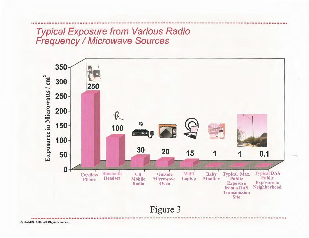
....................................................................................................................................................................
Typical Exposure from Various Radio Frequency I Microwave Sources
350 N e 300
......... !:'-)
~ 250 ~
~
b 200 ••
~ 150 ·~ ~ ~
; 100 !:'-)
0 ~ 50 ~ ~
0
250 -
Cl. i 100 ~ ~
Cordless Bluetooth Phone Headset
CB Mobile Radio
Outside WiFi Microwave Laptop
Oven
Figure 3
- ,
1 1 0.1
Bab} Typical Max. Typical DAS Monitor Public Public
Exposure Exposure in from a DAS Neighborhood
Transmission Site
.........................•.......................................................................................................................................... © HAMPC 2008 All Rights Reserved

Attachment 1 Site Configuration Examples

CROWN ~CASTLE
~llOWN CASTLJ: TO PEllJORM Tin: 10LLOWING' -...., /
ii; II>
PIEDMONT AVE
..
PROW ADJACENT TO:
5 MONTELL ST (PA02m)
OAKLAND, CA
J •o,,, s,
~, ., .......
¢.. .<> . SHALL CELL ANTl.NNA A.ND rt'8 ANCILLARY
&Ql1lP!IBKl ON ITllUT UGBT I TRAl'nC RGNAL
POU. n: i.c; ... ~ • ••
!NSTALL:U' ROUND STBBL S11U!BTUGHT.
(1) 2' X 3' CROWN CA.nu: VAULT wrrR CONDVlTI..
'\. PROJECT SUMMARY
/ Pll.OJECT MANAGER:
'
CROWNCASIUl 695 RIVER OAKS PARKWAY SAN JOSI!, CA 95134 JOHN OIUFFITHS (-408) 468-55'.U JOHN.ORlFl'[email protected]
NODE l!NOINF.l!R: COASTAL COMMUNICATIONS 51141 EDISON PL, STE.110 CAIILSBAD, CA 9l008 TODD THREW (160) 92~10 .... 101 [email protected]
PROJECT TEAM
~
....,
.J
.,, l
:~i
'ti . ~ --;,:,1
P2·~ ~
--·
~.::: llDUr_,._ ~.:~
~,,,.;;,.
: ·d~._1'1r-~·, ,~ Alie
1----- E:!- - -s ~ .. ~~
\.
7J . r, .,, ·•
l
.• f" . ...
j--- .,..- SITE: PA02m --~ 5 MONTELL ST _.J;;_
">
O•kl•nd .'/'"-,,,., 'lo,,
4~
.i;..:... !)~~:.; ..
'<"-1.ii,
$;: 4t.. '>;r "":fl
"'i~o O)..
,~--.,..
~.
"''· l '·~:.. .... ~ ""·
-0 ~-_, .. /.-~ """-~~-- ~: ... "'-"' ·~»· F=J \.)l >' "" ~
~..:..... f .;.Ck. _,,;wo"-~"' t, -.,..o '1- .
c"/ ~~ ;~ . ~ ~~ ... ~""""':" :.. .,;.,,· .
.,;• .... ,..{j: I
" ,., ~· 'v~
-A
~ - '<;. ~'I:.,!
--:;;'~ ""'~";"'-~~ ;!' O" ""-:- - l"'N.T.8.
VICINITY MAP ~
r S!ll!BT NUMBER: DESCRIPTION "
T·l 1ITL1111!EBT
1).1 DllT AILI a. NOTES
1>2 DBrAILI A.NOtllS
1).3 DP' AILI A NOll!I
P.1.1 ,,_l'HO'ltll ,_,. PA112attHOTOIIM
P.lJ PAGlaROm.D
Ill'·! PAmmllnl'LAH
.... SHEET INDEX
r ...... 1. STllP.BT USBP8llMIT SHA1L BEOBTAINBDBY
CONTRACTOR PltlOk TO COMMENCING WORX.
2. AU. won: TO BE CONDUCl'BD JN nm RIO HT OP WAY.
J, AU. DJSTIJRBED LANDSCAPING SHALL BB JlEPLACBD TO SIMILAJt. BXISTINO CONDmoN.
4. ANYSIDBWALl<CLOSURBSHAU.BE COORDl:NATBDWTIBTHBCITY AND PROPER SlGNING WlLL BBPLACllO .
S. NO MATlilUALS OR EQUIPMENT SHALL BB STORED ON PJUV ATB PROPER.TY OR BLOCK ACCl!SS TO PlUVATE PR OPEii.TY.
6, CLEANUP OF SITB WIIJ. DB COMPLETED BACH IM!NlNO AND 11lll SITE WlLL BBllll11JlOO!D TO BXISTINO CONDITIONll AT 11lll COMl'l.llTIONOJI CONBTkUcrtON ATl!ACH Sfm.
CONTJlACl'OR SHAU. VUJFY ALL PLAN!I AND EXlSTING Dll\ll!NSIONS AND CONDIDON!l ON 11IB JOB SITEAND SHALL JMMED!All!LYNOTIFY lHl! BNQINEBR. IN WRITING OF ANY DISCREPANCIES
BBFOIU! PROCBEDING wrrH 11IB WORK OR RBSPONSIDLE FOR SAM!!.
' GENERAL CONTRACTOR NOTES ,,,,
PA02m
V243288
• J llJVJll.Of.XIM&ICWAl' IA)(JOll,C.OSU4 --
Communications --»11 .... ILACl,turnlll
CAIUMO.CA"°" 1HONl:(7m)l'»lfll
PAXt('Hll)ftt..atM ---NOl'IUSTAIU'L'UDDUnotf
TllllDCJIOllMATIOHCCMl'Ar."C>Dfn!ll lft<:IDIA'WllfOlllaonzrrA.n A)CI) ~TDVIEION. A:JN l• m D11a.01tJU OT11D T1Wl AM rrULAm to vamJtf II nmcTt.Y NOllDl'l'Sb.
~ID.VIC&J.lDT ,_,.,_ IE" l#' .....,DUN. l'NXIT
"°""""""""TO ·~n """1MD,CA
c TITLE SHEET )
or;.~sn r=~· f7v-ni
T-1

LEGEND fil'.M!!Q1 DESCR1PTION
D
• • --u •
• ~
D
• • --4
-
-ttA.:Df-n ,._
- --t ---·
ABBREVIATIONS -TOJU
IAC<Cllctm
aACXOflDm<l'!'AVIMIKT
"" -EDOl<J1PAVD«!oo,.
fJ!a' IACICl'IDQICl'1AVDmCT
l'l.Ofll.TYUh"I
"NW IJaDTOIWAY
,,_llOIJM!JAl.T
EROSION AND SEDIMENT CONTROL NOTES: NOTES: CALIFORNIA STATE CODE COMPLIANCE: TDOORAl.Y lliOll1'.ltWIDG COHT10t., l'tJOl TO~ Of JITMAL DalO'YDIZHTI, lllAU. na 1. ooettlACrol.101'0TMOU AU. unurr CIOllHJL ALL wmr. Alio'I) MATDW.l IDALL IG l"lRUIUGD A?4l) mTALLID IK AOCOl,Dr,\..'-UI wnn Tiii
PIUOllOD IY TD COtfnACt'Ol.OI. QUAl.mlD l'D.ICJ!( AM INl:JICATllD Ill.OW: l. ~ 'lO a.ACI IAlCDMOS AJ.OU?m AMYIAU. maw mAl:N 1SU'l'I TO 1UVIMI' OJUl:.'ol Jll:nQ(I or nm 1'0UOWlMO COOll Al ADOPTm) !Y'tl!IBLOCAL OOYUJro«J AVT1IOll'T1U. can'MGYATIEWA'ID. NOTBINCIDfTmllPLAMl•TOllCXJNITllX:'l'Sl1'010Mrr~NOTlXr<oTODGHOTOtmll
AU. l..IQUIDWl!n'I Of '.Mm an" ''LA..'GJ mYllOPMDl'T MAlftiAl. l'l'<*W WATD rtAH!lA&lll":.&m l. ..cm.II M.-WILL • COVD!D AMII COlfTADOID A."ll mnTWILL U IWD'?' AM:! a.1AMID
MIHIDPCl.A.tmMOT111DlnmrAPIDCDllTJ.ucno!ii'OIT111'0f0Ul>:PUllJCIMJll,OYDCIS'rl
CUro'Wl'nM?wnHTHI DOl&OHCXINBOl.PLUf .tJonim. lf'ATD.~cornZOl.PU.~ (Wl'C'),.
l. 1'0l.ltoaMDL\JMIMtnl,PIOYD AOMVIL UO llLTaAJINDOGW.?11.YUPl?lMMOI IMLaT
ASDmtCATmONOSTAIU.
4. ~10ll1AAIWi&Nm>rwt.lC~to ?HllAJllPACtDl'OIDm • CALll'IOl..'1A.~TIVIOOOl(D4CUJOO«lnn.Zl'4&tt}»lO
• »IO CAlll'OlMlA.:l\mJ)QfQCXllU WWJCKADl»'TI 'nllXl lO U.C.XlOUMC,XllOU'PCA>m1lOI
JOIO>•'JIC .
• IUtUlD.'OonlCJAUACOOIAilliOXlllMTOUOJIOCA)
'- TH&COPn"MCn:aSIWLUStOaA'IHl!..oAD'WAYU.0.10rrt(alJl!rW..COKDmOIH • XllOCAl.D'OA."OA.)ao:UoJIOCALCOIJB
IAlWACT<laYTOTI!laTYINCIDCl<.'«U."DCHO,Mn'MOTLDGTIJ)TOPAV?NO,rt'lll'!MO, • ~UNIAn:l'Y<XIOltlrl-,,.A-101
'nll CCKTlACl'Ol.Ol.QUAUPl!DPDJClrfmAU.• UIPOSl!Bt.IJOl.ClJWl'tJl'Ot' ltLT AXDWtJDOH mDIA.."CS,1A'VD4'n'l.OClL'Cll. o:r.'1,A>CDn.AnlC LOOPt:m'9Ct'OU. t »tO ~JIWMllMOCXlOI ADrAcar mUTtl)AKD rrc.MMAIM rnTIIM DUITOOCJNITkUCTIOM ACTTYff'Y. 1. llmW'Ali. IHAU.D~fll.a'l'VITA.'lMllDOl.AWlMOL • lOlO CAUPOL~ILICtllCAl.eota
L ~"(MWPWJUllOT:llDll1llJJIZD, • lllOLOCALaulUJDo'OCX..
4. 'tllloc:tflMCrul.RtAI.LUWO'Vlta.TAmmoa.llArTRWlIMAJCaL\Di7AlL. • aTY~'"tY~
S. ~ AHDWOUIUlm. IMllOIMCTW'CaS.&KAU.D MA.m AVALULIAT All T1Mll A0:2lllllt1"' ~ Dt1JJHO 1111 UJHY llAD(. PACILlfY Ii V!Oi&Nt'lCIO A.HD HOT POI. Rt.MAM HAllTA'nl*. KANDX:AnlED A.OCU11.QJ2UM1m1
ROW GROUND CONSTRUCTION NOTES: "°""''""'""""""""~"'"' TTll""""""""""''"""""""" i. TKICON'IV.Cml.IKAI.1.lllTOUAU.:u.oum;~CXlNna-JXVJCUTOwau:DIOc:aDD.
TOnlllA.lllfACDOKOlnlla?TINOO.Dl Ollllllmn'~'ID"'11&.IADI~ 1, CM(llN)OCltOT11JCTIOOflO~AU.JllaD. HAILI, STAJ'U!l,QalQJ.USB) n.oouaMOMDCl'A.U. VD.:ncA.U 07P Tiil POU. llllJ WlUlZN caioonocA.TlOtf PAalJTT cmaull 'W1111 P11:DAL UA.HDA&DI f'l». IACIO
2. AU.ettm'XtX.'nl'.l IKAll lllDo' AODDANawrTUMm!DPAL, OJVMTY, ITAU.,l'IDDAL, '1IQVZNC'J' Df AODD.l.Mallt'm( nm ~TD( A.cr<J1 IM AMO~ 1. nlll~llW.J..O.'tfAU.AIDTICJMA.t.~COMDOtMEA.SUUa-"VAYltl OOtsAMDCIOl21UA.'CD.\mllAMDUIJU.AT10KI. AMIHtlML'fTJA."1>AlfY011111.1ll!QlltllMll!mDDCGO:tYUAT110lnmlAl.UCIUl.ATOl.Y
UQU!UDaY TJl&1lllllm.'(T~ DUI '!OuXf'OUlrZllfOIQlldTAJCU, WIDCH.MAY il&
AU.llOllOtWIZ>IMll OONTU. ~ PllOYDJlDPD THIA1ftOVIDNNOVDaNT l'l..Qf
lllllALLMIMCOU'OUTll>BDa::lrl AU. ~CXIN?10L10l.IHTDDilCXHXTIOHI
llW.l.MDOtfl TO n!Kll.1111AerDfOt'TD UIZDIHT ISOtMll1l.
A1L UYOY'Am.ll'A~DlVJCUIOOWKIHAlLa Dfru.c&ATTIDIMOCl'MOIWOUDKI
DAYWlllMaADIIllMM:I!GSf.
lG. 'DmCOtnMCTOl.llW.J..AUANOIJll». ll'llXLY MDTVKIJWWIM00Cf09lll. IST10Alllll.10TU
l'Ol.PI018Cr'?'Mlil(O!NllAL~ QO.um!DPIUC1.f,D.ODO!'l'COHnot
SUllCOtnVoCTOllD'AMY,~OllWOU.~A..''DmllE:SIDllMTm«JDaalTO
SVALUo\UTUl~Ol''llCll~CO!loTAOCXIAJt.IUIA."CIO'tUlll.Ul.ATID
""""""""'ACl!Vmll.
STORMDRAIN INLET PROTECTION
FLOW
SANDBAG 2-BAGS HBIGHT
TYl'ICAL PROJECT!ON !'OR !NL.IT W!I!! OPPO!!N!J !'LOW 111!!£CTIONa
TYPICAL PROTECJ!ON FOB !ILET WI!!! !1NCM FLOW D!tECJ!ON
NOTES: 1. L'(l'l.!r(OIDPOl.IHOl.T·T.ll.\tt111. 2. U!2TOIMHJ:artHOX-ll'Oti(WA'nSl.PLOW. l . AUD911CXl.l'lmUMADl"'l'ENAlrl'OAHDC1JWr<.1JP. 4. MOS wrruuwovxo APT!lt.ADJACSNT DPllATJarfJJ COliCPl.M1ID. ' · NOT Al'PUCAJILIIK AABAS wrmHJGHsU.11 AHD a.AY!I WITHOt1l'J'lLTU. PADIIC.
l. CAU. UIA .. MOUUl'lJOI. TOEXCAVAm«JAT(IOo:)2lf·JllCIOOl.lll.
AU. LUCDIC.U'INO TOE lllTOUDlOO&IOINAL aN>l'nOf( Da llTTD..
J. AU. llQIJ'Jft.mir 1'0 D kMlll>,
I. Kll'DIHOCA.llMITUQt'.l!IUWCllA.J.A.HCIATDOOl.(.ft)U)I).
CA.ULK~l.UIAT!'AD.
NORMAL LOCATION OF UNDERGROUND UTILITIES NOTES:
LOCA.TQfANODIPtBOfDlmNOA.ll."t>ftm'Ol!Dunz.rnut.tmr•NMllfDBY'nm
IUIDIVIDll A."ID IJIOWMQ.'( A.HYJILAMllllWm'mTOTlllDD'T.OP1UllU::~POI.
1. OLU«la MAYH nnalUDM'mBD112'1'. 0¥1\mJCWOU'.l ltlCAll!I rlaiisnrnNQ
PACIUTill.
J. cotm.ICrlllll'TTl'UMt.rm.nYCXMPAN:ll1A.CD.n'IU, UJntHOA.HDnorow:>,WUIT•
vvroAlLY UIOL vm ar nm \mL1t"r OOMP.un:rs.
4. J'Ol.OCMWDCAL GCSWA.lal, TMIJl!ll!ITDlA.."'71BAU.U~wrttmrTD
lllllWALX 1'.f"DKDil>PACSOFC\JU. J. w.xn.fVW 2" owani:t. OAS MADil MA.Y D l'UiCm DI ,IODfT tmLmEI TUMOl JlmJBCl'
TOAnW:rt/Al.OJO?TD«Jl'IUl.~'11AC11').
PA02m
V243288
lts.ivD.O/.Xll'Alk'W"Al' MHQa.CA.nlM --
Communications T---.tMl~PLACl,IUTTSlll
CW.....,CA,_ J'IU4Z<(M)nMflO
PAX1 ('HO) nt4DI ---_,.,..,.....,.....,... l mzlHJICbfAT04CONTA.D."XDJ!f'l1111 llTOf'laAWDDll~Arr.utD
CONPJtmmAL'TOYlalZDN. All'tta'*. DIJCt.OIUUOlBD. 'mAH M. rr UL\TU
1'Qvaux>ttlSIDIC?l.Yl'llOHlllTIXI,
tnltm.OUIUKDla.VOAUXT
"""'' llT~tilDNIDLW.HiCICET
PPON ADJM:f:HTlO 6MON'fllJ.ST -CA
( DETAILS &NarES)
~~"' I =~ I 7v"'"
D-1

Attachment 2 Antenna Specifications
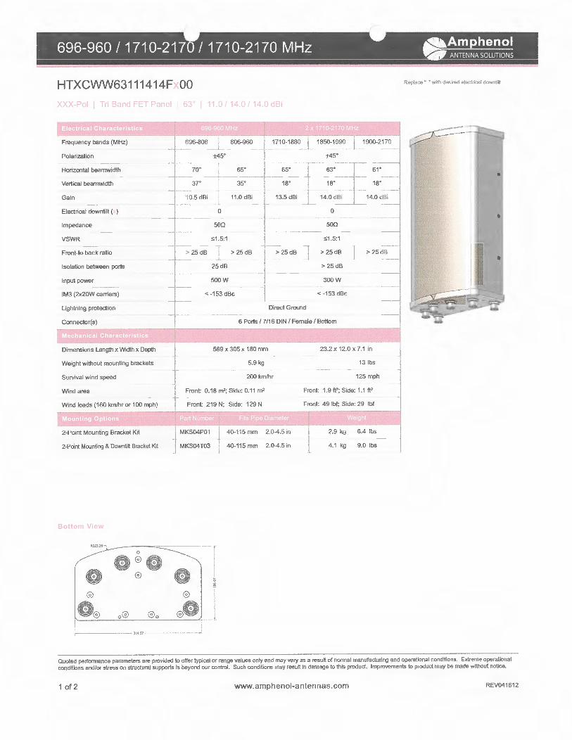
696-960 I 1710-2170 I 1710-2170 MHz a.Amphenol ., ANTEN NA SOLUTIONS
HTXCWW63111414F 00
1 n tlel 'fl t E~ f-'ane1
Frequency bands (MHz)
Polarization
Horizontal beamwidth
Vertical beamwidth
Gain
Electrical downtilt ( )
Impedance
VSWR
Front-to-back ratio
Isolation between ports
Input power
IM3 (2x20W carriers)
lightning protection
Connector(s)
Dimensions Length x Width x Depth
Weight without mounting brackets
Survival wind speed
Wind area
Wind loads (160 km/hr or 100 mph)
2-Point Mounting Bracket Kit
2-Point Mounling & Downlilt Bracket Kit
BottoTI View
0
®
®
®
a ® o® ®o
l l"IS7
OJ i 11.0/140 14Qd8•
696-806 L 806-960
±45°
--~:~~ -~j 10.5 dBi J
0
500
~1.5:1
>25dB _I
25dB
500W
> 25dB
< -153 dBc
1710-1880
> 25dB
1850-1990 1900-2170
±45°
500
~1.5:1
> 25dB > 25 dB
>25dB
300W
< -153 dBc
Direct Ground
6 Ports/ 7/16 DIN I Female I Bottom
589 x 305 x 180 mm
5.9 kg
200 km/hr
Front: 0.18 m'; Side: 0.11 m'
Front 219 N; Side: 129 N
MKS04P01 40-115 mm 2.0-4.5in
MKS04T03 40-115 mm 2.0-4.5 in
I ~
®
I ®e -·'·
23.2x12.0x7.1 in
13 lbs
125 mph
Front: 1.9 fl'; Side: 1.1 fl'
Front: 49 lbf; Side: 29 lbf
2.9 kg
4.1 kg
6.4 lbs
9.0 lbs
Replace" "with desired electrical downtitt.
Quoted performance parameters are provided to offer typical or range values only and may vary as a result of normal manufaduring and operational conditions. Extreme operafional conditions and/or stress on structural supports is beyond our control. Such conditions may result in damage to this product. Improvements to product may be made without notice.
1of2 www.amphenol-antennas.com REV041612

696-960 I 1710-2170 I 1710-2170 MHz a.Amphenol ., AN 1 ENNA SOLUTIONS
HTXCWW63111414F 00
MJ\-'-01 I n Bnno t -1 ...,~ •1 , ti...> 1• IJ 140 14 dBi
696-896 MHz 1710-2170 MHz
Horizontal I 696-806 MHz Horizontal I 806-896 MHz Horizontal I 1710-1880 MHz Horizontal I 1850-1990 MHz Horizontal I 1900-2170 MHz
o· I Vertical I 696-806 MHz o· I Vertical I 806-896 MHz o· I Vertical I 1710-1880 MHz o· I Vertical I 1850-1990 MHz o· I Vertical I 1900-2170 MHz
Quoted performance parameters are provided to offer typical or range values only and may vary as a result of normal manufacturing and operational conditions. Extreme operational conditions and/or stress on structural supports is beyond our control. Such conditions may result in damage to this product. Improvements to product may be made without notice.
2 of2 www.amphenol-antennas.com REV041612

Appendix A-0
Node IDs, Configuration & Locations

Appendix A-0 Node IDs, Configuration & Locations
PA02m 1-Panel 22'-0" 30 37 824731 -122 254356 5 Montell St Oakland CA HTXCVVV\163 111414FOOO Two 2x5W mRRU (700, AWS) 89 PA03m2 1-Panel 26'-0" 70 37.826449 -122 252675 157 41st St Oakland. CA HTXCVVV\163 111414FOOO Two 2x5W mRRU (700, AWS) 107 PA04m 1-Panel 22'-0" 30 37.827186 -122 251125 3 Linda Ave Oakland, CA HTXCVVV\163111414FOOO Two 2x5W mRRU (700, AWS) 116 PAO Sm 1-Panel 22'-0" 30 37.828144 -122.249969 3 Glenwood Ave Oakland CA HTXCVVV\163111414FOOO Two 2x5W mRRU (700, AWS) 124 PA06m 1-Panel 37'-4" 30 37 829489 -122.248086 2 Glen Eden Ave Oakland, CA HTXCVVV\163111414FOOO Two 2x5W mRRU (700. AWS) 144

Appendix A-1 RF EXPOSURE AT THE LEVEL OF THE ANTENNA

RF EXPOSURE AT THE LEVEL OF THE ANTENNA BASED ON PERCENTAGE OF FCC MAXIMUM PUBLIC EXPOSURE (MPE) LIMIT
j ! j ! i Maximum RF Exposure ! i ! i ' i i ' 304% Public MPE ~J i i
j j ! j i D Blue: Less than 20% Public MPE j ll I I i i D G•Mn L~s than 5% P"bllc MPE IJ

Appendix A-2 RF NOTICE SIGN

The radio frequency (RF) emissions at this site have been evaluated for potential RF exposure to personnel who may need to work near these antennae.
RF EXPOSURE AT 5 FEET OR CLOSER TO THE FACE OF THE ANTENNA MAY EXCEED THE FCC PUBLIC EXPOSURE STANDARD AND THUS ONLY QUALIFIED RF WORKERS MAY WORK IN THIS 5 FOOT EXCLUSION ZONE. OTHERS WHO NEED TO WORK IN THE EXCLUSION ZONE SHOULD CALL -FOR INSTRUCTIONS. REFER TO SITE # ------
Reference: Federal Communications Commission (FCC) Public Exposure Standard. OET Bulletin-65, Edition 97-01, August 1997.

Appendix A-3 Antennae Amphenol Model HTXCWW63111414Fx00
Exposure Calculation Ground Level
Antenna Center 22.0 ft AGL

1.40
..... 1.20 .... e .... ~ C.l 1.00 ~ "' 0 Cl.. ;-i
r.:.i ~
0.80
'§ ~
u 0.60 u i;..
~ " 0.40
0.20
0.00 0 200 400 600
Ground Level RF Exposure Antenna Center 22.0
800 1000
Distance to base of antenna in feet
Appendix A-3
1200 1400 1600

STATEMENT OF EXPERIENCE Jerrold Talmadge Bushberg, Ph.D., DABMP, DABSNM, FAAPM, FHPS
Dr. Jerrold Bushberg has performed health and safety analysis for RF & ELF transmissions systems since 1978 and is an expert in both health physics and medical physics. The scientific discipline of Health Physics is devoted to radiation protection, which, among other things, involves providing analysis of radiation exposure conditions, biological effects research, regulations and standards as well as recommendations regarding the use and safety of ionizing and non-ionizing radiation. In addition, Dr. Bushberg has extensive experience and lectures on several related topics including medical physics, radiation protection, (ionizing and non-ionizing), radiation biology, the science of risk assessment and effective risk communication in the public sector.
Dr. Bush berg's doctoral dissertation at Purdue University was on various aspects of the biological effects of microwave radiation. He has maintained a strong professional involvement in this subject and has served as consultant or appeared as an expert witness on this subject to a wide variety of organizations/institutions including, local governments, school districts, city planning departments, telecommunications companies, the California Public Utilities Commission, the California Council on Science and Technology, national and international news organizations, and the U.S. Congress. In addition, his consultation services have included detailed computer based modeling of RF exposures as well as on-site safety inspections. Dr. Bushberg has performed RF & ELF environmental field measurements and recommend appropriate mitigation measures for numerous transmission facilities in order to assure compliance with FCC and other safety regulations and standards. The consultation services provided by Dr. Bushberg are based on his professional judgement as an independent scientist, however they are not intended to necessarily represent the views of any other organization.
Dr. Bushberg is a member of the main scientific body of International Committee on Electromagnetic Safety (ICES) which reviews and evaluates the scientific literature on the biological effects of nonionizing electromagnetic radiation and establishes exposure standards. He also serves on the ICES Risk Assessment Working Group that is responsible for evaluating and characterizing the risks of nonionizing electromagnetic radiation. Dr. Bushbergwas appointed and is serving as a member of the main scientific council of the National Council on Radiation Protection and Measurements (NCRP). He is also the Senior Scientific Vice-President of the NCRP and chairman of the NCRP Board of Directors. Dr. Bushberg has served as chair of the NCRP scientific committee on Radiation Protection in Medicine and he continues to serve as a member of this committee as well as the NCRP scientific advisory committee on Non-ionizing Radiation Safety. The NCRP is the nation's preeminent scientific radiation protection organization, chartered by Congress to evaluate and provide expert consultation on a wide variety of radiological health issues. The current FCC RF exposure safety standards are based, in large part, on the recommendations of the NCRP. Dr. Bushberg holds several radiation detection technology patents and was awarded the NCRP Sinclair Medal for "Excellence in Radiation Science" in 2014. Dr. Bushberg was elected to the International Engineering in Medicine and Biology Society Committee on Man and Radiation (COMAR) which has as its primary area of responsibility the examination and interpreting the biological effects of non-ionizing electromagnetic energy and presenting its findings in an authoritative and professional manner. Dr. Bushberg also served for several years as a member of a six person U.S. expert delegation to the international scientific community on Scientific and Technical Issues for Mobile Communication Systems established by the FCC and the FD A Center for Devices and Radiological Health.
Dr. Bushberg is a full member of the Bioelectromagnetics Society, the Health Physics Society and the Radiation Research Society. Dr. Bushberg received both a Masters of Science and Ph.D. from the Department of Bionucleonics at Purdue University. Dr. Bushberg is a fellow of the American Association of Physicists in Medicine, a fellow of the National Health Physics Society and is certified by several national professional boards with specific sub-specialty certification in radiation protection and medical physics. Prior to coming to California, Dr. Bushberg was on the faculty of Yale University School of Medicine.

Madani, Jason
From: Sent: To: Cc: Subject:
David Mitroff, Ph.D. <[email protected]> Saturday, March 19, 2016 4:41 PM Madani, Jason
ATTACHMENT C
[email protected]; [email protected]; Schaaf, Libby; [email protected] Do not approve Case# PLNlS-386 3770 Piedmont Ave and Yosemite Ave Light Pole and Wireless Tower
Hello Jason, This email i.s to inform you that I strongly object for numerous reasons, outlined below, to proposed project #PLNlS-386 (telecommunications installation at Yosemite Avenue and Piedmont Avenue) ... as well as the numerous other projects this same group is trying to install up and down Piedmont A venue and will file whatever paperwork, attend meetings and/or engage in activities to see this proposal is not approved.
I live directly across the street (8 Yosemite A venue) from this proposed site and the "light pole, cell tower, etc." will create unnecessary light onto my living space, be a source of dangerous radio frequency fields, will be unsightly and much more.
Below are my top concerns:
1.) I was just informed of this. Unlike ABC or other offices that require notices to be sent to all those within close proximity to the activity occurring, this has come to my attention via local outrage and the face that an outside company is proposing to make money of government right of way property by installing extremely powerful cellular towers disguised at unnecessary light poles on at least 5 streets right of Piedmont A venue. I think your office may want to look into informing the public and/or requiring the contractors to inform the public better. The Planning Commission ideally can not only plan, but inform.
2.) The idea of adding a light pole when one exist right next to this proposed "light pole" and every direction you look makes no sense. We do not need a light pole or more light pollution in this area. Furthermore we do not need more cellular towers.
3.) Chow Restaurant Group is currently building a multi-million dollar new restaurant project and I'm highly confident they do not want a light pole and cell towers right in front of their new business. This will be unsightly and completely offset all of the landscaping and lighting work they are doing. This pole will also block my view and will be unsightly.
4.) Health and safety wise, Living across the street means the radio waves will be traveling directly through my living areas and creating unnecessary exposure to me and the other residents in my building. It is not ok to introduce even more radio waves into the air and especially that close to residence that have been labeled "exceed the FCC general public exposure limit"!!!
5.) The idea that public property is being used by private companies for profits is also very disturbing.
There are likely many other unforeseen issues I have not thought of. Please take this email as an official NO that I do not agree to or accept or approve of project #PLNlS-386 and I will to the best of my ability work with others to make sure this project does not happen. I will also work with others to make sure the Planning Commission going forward focuses more attention on not only planning, but informing.
I have lived on Piedmont A venue for 13 years, along with being an Oakland business owner and public servant and have supported many many good things in Oakland and continue too and at the same time also been
1

instrumental in making bad things go away, such as Egbert Souses, Kaiser trying to fence in their open space and more. I'm up to the challenge to make sure Oakland grows in the right way and that includes making sure this project does not happen. Let me know if you need anything else from me.
David Mitroff 8 Yosemite A venue #6 Oakland, CA 94611 510-761-5895
2

Madani, Jason
From: Sent: To: Cc:
George Horton <[email protected]> Wednesday, February 24, 2016 11:48 AM Madani, Jason Merkamp, Robert; Valerie Winemiller
Subject: Fwd: Piedmont Avenue Neighborhood Telecom Plan
Jason -I sent this to Robert Merkamp yesterday but accidentally did not copy you on it. Please include this with your staff report to be sent to the Planning Commissioners regarding the proposed Yosemite telecom installation (Crown Castle, PLNl 5388).
I canvassed the neighborhood widely yesterday - no one received the first notice supposedly sent by the City on 2111116. Everyone to whom I spoke (on Montell, Rio Vista, and Yosemite) received two identical notices dated both 2/16 (Pitney Bowes) and 2/17 SF (USPS?). Properties on Montell and Rio Vista received these duplicate notices on Saturday 2/20, residences on Yosemite received these notices on Monday 2/22 (two days ago). I will forward scans of the envelopes (a pair from each of the three streets) to you later today.
Why would duplicate notices be sent? Perhaps the first supposed mailing (2/11) was not stamped and did not the City until the second mailing was sent, resulting in identical notices arriving at residences on the same day.
As you may know, P ANIL is one of the most active neighborhood organizations in Oakland. City mailings are carefully reviewed by many residents. If residents unanimously state that they never received the telecom mailing which was supposedly sent prior to the recent mailing, then it is virtually certain that the supposed 2/11 mailing never occurred.
Therefore, due to lack of sufficient notice, the neighborhood requests that the Yosemite item be removed from the March 2 agenda.
Thank you, George Horton, Architect
Sent from my iPad
Begin forwarded message:
From: George Horton <[email protected]> Date: February 23, 2016 at 17:06:29 PST To: [email protected] Cc: Valerie Winemiller <[email protected]> Subject: Piedmont Avenue Neighborhood Telecom Plan
Robert -It seems to residents in the Piedmont A venue neighborhood that the issue of the proposed telecom installations should be treated as a whole, not as individual installations. Because this issue affects the whole neighborhood and because residents have many concerns and questions, a neighborhood meeting where staff could explain the rationale for such a plan (as well as explore other options) plus answer questions would be very helpful. This most reasonably would occur
1
prior to any further consideration of these installations by the Planning Commission.
Some of the questions which have been raised in just the past few days: 1. Why is a 100-foot separation typically required to residential areas? Why would the City consider waiving this requirement? Many families, especially those with young children (and/or pregnant women) are concerned about radiation and the lessening of the typically required distance. 2. Why is a 1500-foot separation between installations typically required? Why would the City consider waiving this requirement? What is the effect of decreasing required distances on radiation levels? 3. Why are the installations not being placed on top of buildings as in other parts of Oakland, where they are out of sight and transmission not easily blocked by buildings (allowing antennae to be more widely separated)? 4. Why is the City not concerned about increasing clutter, including visual clutter, while other cities are undergrounding utilities, partly to reduce clutter? The City has strict rules about screening rooftop installations of antennae but seems to be turning a blind eye to these proposed installations at street level. 5. Providers who install antennae on building roofs pay the building owners rent. How much rent would this telecom company be paying to the City of Oakland? 6. Why does the City feel that it is acceptable to have a private company install its equipment on public land? The sidewalk areas are already increasingly congested with various signs, obstructing passage and the opening of car doors on the right side of the vehicle. This makes exiting/entering vehicles particularly difficult for elderly people as well as those with various physical challenges. 7. It seems that the proposed installations are for one telecom carrier. What happens when another carrier wants to install another set of poles next year? It seems that allowing the current applicant to install these poles sets a dangerous precedent for future installations. 8. A street light is proposed for the Montell location. This is directly opposite an existing streetlight. The Pet Food Express has bright lights mounted on the side of the building which illuminate the parking lot and sidewalk. Additional light is not needed at this location. In fact, it would be a waste of energy and contribute to light pollution. Has the City reviewed the appropriateness of each installation to its particular location? 9. And so on ....
It seems that an open forum where these issues could be discussed would be very helpful. Perhaps a more rational long term plan could be developed, based upon information provided by staff and neighborhood input.
Thanks, George Horton, Architect
Sent from my iPad
2

March 22, 2015
Dear Members of Oakland City Planning Commission,
We attended the neighborhood meeting where Crown Castle Representatives presented their project. We own a house on Montell St.
We are opposed to the installation of new wireless Telecommunications facilities on new poles at the public Right-of-Way adjacent to 3868 Piedmont Avenue and Montell St, at the public Right-of-Way adjacent to 3770 Piedmont Avenue and Yosemite Ave and at the public Right-of-Way 41 st Street and Piedmont Avenue for the following reasons:
This project is not intended for the benefit of the street residents but rather for Piedmont Ave passers-by, shoppers and drivers using data on their Verizon wireless device.
The number and proximity of these new wireless facilities is a concern for aesthetic and safety reasons. Placing antennas at higher strategic levels (top of buildings) would be less if not visible and much more effective.
Adding a light pole on Montell St where there is sufficient light provided by an existing street light across the street and lights from an adjacent business is unnecessary and will contribute to light pollution.
Our neighborhood does not need more visual clutter. We already have our share of poles, wires, unsightly utility boxes from AT&T ...
Above all, if this project is accepted, Crown Castle will be able to add other antennas, equipment boxes, meter boxes for other wireless companies to their newly installed poles. Our streets seen from Piedmont Ave will definitely look unattractive with a clutter of metal boxes at 8' or 9' high.
We need aesthetic enhancements of our urban environment and not degradation.
We sincerely hope that after reviewing the major conditional use permits, design reviews and variances and after hearing the concerns and issues brought up by our neighborhood, you will deny the application from Crown Castle. We thank you for your consideration.
Sincerely,
Elisabeth Soeurs and Andre Jones 56, Montell St

Madani, Jason
From: Sent: To: Subject:
Hello Mr Mandani
Philip Cohen <[email protected]> Wednesday, February 24, 2016 8:58 AM Madani, Jason Crown Castle, PLN15388
Please let it be known that I am opposed to allowing another telecommunications company to benefit from adding street-level obstacles to our already clogged public rights-of-way. Like the cable boxes that already grace the landscape, microwave antennas and associated equipment can be (and usually are} placed elsewhere. Let them put their crowns on their own castles.
Thank You,
Philip Cohen 41 Yosemite Avenue Oakland, CA 94611
[email protected] (510) 652-4944
1

Oakland City Planning Commissioners Bureau of Planning, Zoning Division 250 Frank Ogawa Plaza Oakland CA 94612-2032
March 27, 2016
Re: Telecommunications installations in the Public Right of Way:
Piedmont Avenue Neighborhood Improvement League (PANIL) P.O. Box 20375 Oakland CA 94620-0375
3770 Piedmont Avenue and Yosemite, Case File No. PLN15-386 3868 Piedmont Avenue and Montell Street, Case File No. PLN15-388 41 st Street and Piedmont Avenue, Case File No. PLN15-389
To Members of the Oakland Planning Commission:
The Piedmont Avenue Neighborhood Improvement League (PANIL) submits these comments after consultation with an expert in the telecommunications field and with neighboring cities. Cognizant of the "shot clock" deadline for governmental telecommunication decisions, PANIL urges the Oakland Planning Commission to reject these three applications and decline to grant the requested Major Conditional Use Permit, Design Review, and Minor Variance. The Commission should request new submittals for the reasons discussed below, or request that Crown Castle voluntarily extend the shot clock to allow the City to adequately address this issue. Crown Castle stated at a recent PANIL meeting that they would "work with the City" to achieve this.
The proposals by Crown Castle are not compatible with the Piedmont Avenue context from either a current or a future perspective, as the City works to improve streetscapes, attract quality redevelopment, and encourage upkeep by neighbors. This concern is exacerbated by the multiple installation applications expected from various carriers, as described further below (see Section B). This concern is additionally exacerbated by the pursuit of cell antennae in the public right-of-way, as such locations are rent-free in Oakland versus rooftop-mounted sites on private property (which range from $1,500 to $6,000 per month in San Francisco). Mobilitie (competitor to Crown) has begun proposing tens of thousands of new sites for Sprint in the U.S., on new wood poles in front of homes. In some cases they knowingly installed poles without any permits and use deceptive names such as Interstate Transport and Broadband or the California Utility Pole Authority. Simply put, this rapidly evolving landscape creates a major city-wide challenge that needs to be addressed in a robust manner.
In Sprint v Palos Verdes Estates, the court noted that California Public Utilities Code Section 7901.1 permits municipalities to control the "time, place and manner" in which public rights-of-way are accessed. Aesthetic regulations are time, place and manner regulations, and therefore fall within the purview of the City. [California Planning and Development Report http://www.cp-dr.com/node/247]
Regarding the specifics of the applicant's proposal, we recommend that Crown Castle provide a more context-compatible proposal (see Section A below), and that the City Attorney, Planning Department, and Public Works create more focused siting and design standards, as well as guidelines similar to those seen in commt.mities such as Palos Verdes (Estates and Rancho) and San Francisco. Some core policy recommendations are noted below (Section B). We urge the City to form a working group to address this matter.

These installations as proposed by Crown Castle will be extremely incompatible with the existing streetscape of Piedmont Avenue when initially installed and look worse over time with the accumulation of additional components on these poles as well as the proliferation of installations by other carriers. This visual blight will be here for decades. Under state law, no further review will be allowed for additions to these installations if the poles are not owned by the City. Without the protection of City ownership of the poles, Oakland's urban landscape will be degraded by companies whose focus is their bottom line.
We recognize that the City of Oakland :S staff has a "one hundred and one" pressing challenges and opportunities, ranging from improving public safety, to fixing potholes and addressing displacement. Through this document, we hope to empower City staff to find a path that is not determined by wireless carriers pressuring the City into establishing a poor policy precedent. Although we recognize that various State and Federal laws do limit the authority of the City, they also allow the City to exercise control over some aspects of wireless installations.
Section A: Specific Concerns Regarding Crown Castle Proposals Scheduled for this Hearing
1. The drawings and photo simulations lack clarity regarding the actual installations, such as unsightly bundles of cabling hanging below the panel antennas; electric meters; battery cabinets; ground-mounted equipment; and other components. We are told that there is an overwhelming pattern of these carriers providing incomplete and inaccurate depictions. In response to these continued frustrations, cities such as Palos Verdes (Estates and Rancho) request a full scale-mockup to be provided before a decision is made. We request that Oakland require the same.
2. If a component is too large to mount on the pole, it must be placed in an underground vault, as will be required in the City of Piedmont. No sidewalk placements of cabinets should be permitted.
3. City staff has informed us that meters and ground-mounted components are considered only during the Building Permit process, which follows Zoning approval. This is unacceptable. These additional components, some of which can be quite large, are important in the overall visual impact, access from parked cars, and encumbrance of the sidewalk, including its use by all residents, but especially by parents with strollers, senior citizens, and those with mobility restrictions.
4. All new poles should be steel. No new wood poles should be allowed, as they do not permit hiding the wiring internally.
5. All new poles should be paid for by the pole provider and gifted to the city, as in San Francisco. In Piedmont, the poles will be owned by the city.
6. Provision of street lighting on the poles should be site-specific. Over-lighting can make it more difficult for a pedestrian's eyes to adjust to the lower level of lighting beyond, and can also intrude into nearby bedrooms. For example, some Montell Street residents have indicated that they object to the proposed street light at that location.
7. The City should coordinate with Pacific Gas & Electric to obtain approval for wireless metering and require that wireless metering be utilized in all instances. This would eliminate the need to place a box with a glass meter bubble and additional wiring on either the sidewalk or the pole itself. PG&E has begun to allow this in their service territory.

8. Replace the proposed panel antennae with radome design antennae (a baseball bat shape mounted vertically on top of the pole). This allows for a more streamlined and less intrusive profile. Carriers will often cite "PIM" (interference) issues, but there are PIM-compliant radome antennae.
9. Any poles proposed to hold large cabinets should instead utilize an integrated steel pole such as those made by Phillips Ericsson (SmartPole), Sabre, or Citisites. This allows for a more streamlined design. They could mimic the decorative light poles that were already installed at Piedmont and Glen, for example.
10. The proposed shroud (2 ft. by 5 ft.) covering various components may appear more bulky than the components simply mounted on the pole without the shroud. We request that Crown Castle provide drawings eliminating the shroud.
11. Battery backup components should be no wider than the pole.
12. No components of any kind, including meters, should be mounted in a manner that leaves less than 8 feet of vertical clearance to the sidewalk.
13. No placards should be placed on the pole with the exception of a site ID sticker on the underside of cabinets and the RF warning sticker near the transmitting antenna. There is no need (though pole providers may insist otherwise) to place additional placards and stickers on poles. Too often these sites feature unnecessary stickers and decals that function more like advertising and do not address a regulatory requirement by the FCC.
14. No exposed cabling. Cable shrouds, such as those produced by dbSpectra should be used to hide cable loops below panel antennae and other components.
15. No flashing lights.
16. Passive cooling should be required. Fans not regularly maintained become noisy, even if when installed the initial noise levels are below 40 decibels at the nearest residential window/door.
Section B: Cumulative Concerns Regarding Installations by Multiple Carriers
While pole providers such as Crown will often state that they can act as a "neutral host" system for multiple cell service carriers, the reality is that they rarely do so, with the exception of more confined spaces such as stadiums and subway platforms (due to space constraints and limited area coverage).
Although multiple carriers may be able to share a single set of antennae, each Tier 1 carrier (i.e., AT&T Mobility, Sprint, T-Mobile, Verizon) typically wants their own radio head units (more boxes with potentially noisy cooling fans) at the pole. So, while Government Relations personnel from Crown, Extenet, and Mobilitie will suggest such a possibility to policy makers, this is typically not achieved.
Because there are currently four Tier 1 carriers (serving mobile users), there is a concern that Oakland could end up with cluttered street intersections with multiple poles serving these four carriers, each with their own design. Additional sites for Internet of Things (IoT) sensor networks and other technologies will also be requested.
This makes it more important to establish a comprehensive review precedent at the outset, with realistic and accurate location, design, and noise standards.
The City should maintain a no-new-pole policy with the exception and requirements listed below:
1. If a new pole is proposed, the carrier (actual Tier 1 PCS carrier the proposed network is serving) must demonstrate that there are no available rooftop-mounted site opportunities available. Even

if only a combination of rooftop and street level poles is possible, this is preferable as it reduces street level clutter and encumbrances.
2. A street tree should be planted for screening at the expense of the applicant, adjacent to or in the vicinity of each new pole. If this is not possible, funds should be provided by the applicant for maintenance of existing street trees within the area.
3. If a new pole is proposed it may not be made of wood. Wood poles will always appear more cluttered since bundles of cabling cannot be placed inside the pole. New poles need to either be integrated steel (with equipment inside), or steel poles with minimum profile equipment mounted on the outside.
4. The pole provider should gift any new pole to the City. The City should lease the site to the pole provider, as is done in San Francisco and will be done in Piedmont. While this may seem to be an additional burden for Public Works Department to take on, this arrangement is vital because City ownership of the pole provides important control over the installation, including maintenance and future changes to the installation. A recent and worrisome interpretation by the Federal Communications Commission (2014 Report and Order), says that under 6409, for a cell site on a pole that is NOT owned by the City, the carrier can demand the right to increase the height by 10 feet, add horizontal arms up to 6 feet and add a large number of unsightly and potentially noisy cooling fans, antennas, equipment boxes, and wide swoops of cabling. In other words, the carrier could demand the right to modify the site in a manner that does not even remotely resemble what was originally "promised" to the City by the pole provider.
5. Abandoned obsolete equipment, including the poles themselves, must be removed at the expense of the pole provider or its successor.
6. If the City undergrounds electric and telecommunications utilities, the poles and associated equipment must be removed at the expense of the pole provider or its successor.
Mr. Osborn of Crown Castle wrote a letter to City staff citing numerous state and federal laws regarding telecommunication installations in the public right-of-way. However, it is important to note that nothing in Federal or State law sanctions unsightly and noisy designs. Much of what drives data demand, that in turn drives the demand for new cell sites, is the walkable, visually appealing, and intimate nature of our streets. New cell sites should offer the least intrusive means of providing wireless service, and should not compromise the very factors that attract many residents and visitors to our neighborhoods.
These three applications before the Commission are a poor fit for the Piedmont Avenue neighborhood and for Oakland in general, and should therefore be denied. In future applications, Crown Castle must propose the same level of design quality for their installations in Oakland that it provides to communities such as San Francisco, Palos Verdes, and Piedmont.
Thank you for your consideration of these concerns.
Very Truly Yours,
The Piedmont Avenue Neighborhood Improvement League Steering Committee
By Valerie Winemiller Steering Committee Member

Madani, Jason
From: Sent: To: Cc: Subject:
Dear Jason,
[email protected] Monday, March 28, 2016 11:46 AM [email protected]; Madani, Jason [email protected]; Schaaf, Libby; [email protected] Re: Do not approve Case# PLNlS-386 3770 Piedmont Ave and Yosemite Ave Light ...
May I please have a copy of your response to Mr. Mitroff.
Sincerely, Harry (Eisenberg) Chow Restaurant Group
In a message dated 3/19/2016 4:41 :09 P.M. Pacific Daylight Time, [email protected] writes:
Hello Jason, This email is to inform you that I strongly object for numerous reasons, outlined below, to proposed project #PLN15-386 (telecommunications installation at Yosemite Avenue and Piedmont Avenue) ... as well as the numerous other projects this same group is trying to install up and down Piedmont Avenue and will file whatever paperwork, attend meetings and/or engage in activities to see this proposal is not approved.
I live directly across the street (8 Yosemite Avenue) from this proposed site and the "light pole, cell tower, etc." will create unnecessary light onto my living space, be a source of dangerous radio frequency fields, will be unsightly and much more.
Below are my top concerns:
1.) I was just informed of this. Unlike ABC or other offices that require notices to be sent to all those within close proximity to the activity occurring, this has come to my attention via local outrage and the face that an outside company is proposing to make money of government right of way property by installing extremely powerful cellular towers disguised at unnecessary light poles on at least 5 streets right of Piedmont Avenue. I think your office may want to look into informing the public and/or requiring the contractors to inform the public better. The Planning Commission ideally can not only plan, but inform.
2.) The idea of adding a light pole when one exist right next to this proposed "light pole" and every direction you look makes no sense. We do not need a light pole or more light pollution in this area. Furthermore we do not need more cellular towers.
3.) Chow Restaurant Group is currently building a multi-million dollar new restaurant project and I'm highly confident they do not want a light pole and cell towers right in front of their new business. This will be unsightly and completely offset all of the landscaping and lighting work they are doing. This pole will also block my view and will be unsightly.
4.) Health and safety wise, Living across the street means the radio waves will be traveling directly through my living areas and creating unnecessary exposure to me and the other residents in my building. It is not ok to introduce even more radio waves into the air and especially that close to residence that have been labeled "exceed the FCC general public exposure limit"!!!
5.) The idea that public property is being used by private companies for profits is also very disturbing.
There are likely many other unforeseen issues I have not thought of. Please take this email as an official NO that I do not agree to or accept or approve of project #PLN 15-386 and I will to the best of my ability work with others to make sure this project does not happen. I will also work with others to make sure the Planning Commission going forward focuses more attention on not only planning, but informing.
1

I have lived on Piedmont Avenue for 13 years, along with being an Oakland business owner and public servant and have supported many many good things in Oakland and continue too and at the same time also been instrumental in making bad things go away, such as Egbert Souses, Kaiser trying to fence in their open space and more. I'm up to the challenge to make sure Oakland grows in the right way and that includes making sure this project does not happen. Let me know if you need anything else from me.
David Mitroff 8 Yosemite Avenue #6 Oakland, CA 94611 510-761-5895
2

Oakland City Planning Commission
Case File Number: PLNlS-389
Location:
Assessors Parcel Numbers:
Proposal:
Applicant: Contact Person/ Phone
Number: Owner:
Case File Number: Planning Permits Required:
General Plan: Zoning:
Environmental Determination:
Historic Status: Service Delivery District:
City Council District: Finality of Decision:
For Further Information:
SUMMARY
ATTACHMENT D STAFF REPORT
April 6, 2016
The Public Right-of-Way adjacent to 41 81 Street and Piedmont Avenue. (See map on reverse) ·
Nearest adjacent lof (012-0993-006-01)
The project involves replacement of an existing 23' tall PG&E utility pole with a new 34' tall utility pole to install new wireless telecommunication facility; installation of one 24" wide antenna panel and a 4' wide cross· arm mounted at a height of 27'-0"; an associated equipment box, one battery backup and meter boxes within a 5 foot long by 22 inch wide equipment shroud mounted on the pole at 8 feet above the ground. Crown Castle Bob Gundermann & Jason Osborn (925)899-1999 Pacific Gas & Electric. PG&E. PLNlS-389 Major Design Review to install a wireless Telecommunication Macro Facility on a PG&E pole in the CN-1 zone. Neighborhood Center Mixed Use. CN-1 Neighborhood Center Zone. Exempt, Section 15301and 15303 of the State CEQA Guidelines; minor additions and alterations to an existing facility. Exempt, Section 15183 of the State CEQA Guidelines; projects consistent with a Community Plan, General Plan or Zoning. Not a Potential Designated Historic Property; Survey rating: n/a 2 .
1 Appealable to City Council within 10 Days Contact case planner Jason Madani at (510) 238-4790 or [email protected]
The proposal is to replace an existing 23' tall PG&E utility pole with a new 34' tall utility pole to install a new wireless telecommunication facility for Crown Castle located in the public right-ofway near the intersection of Piedmont A venue and 41 st Street. Crown Castle is proposing to install one 24" wide antenna panel and a 4' wide cross arm mounted at a height of 27'; an associated equipment box, one battery backup and meter boxes within a 5 foot long by 22 inch wide equipment shroud mounted on the pole at 8 feet above the ground. Major Design Review is required for the installation of a new Macro Telecommunications Facility in the CN-1 zone. Staff believes that because the new PG&E utility pole is located adjacent to the parking lot of a commercial building, it is in an appropriate location for the proposed telecommunication facility and would not significantly increase negative visual impacts to adjacent neighboring properties, and the project meets all the required findings for approval of the project.
#8

CITY OF OAKLAND PLANNING COMMISSI N
-c::=-mc:=:i11111111111111111111111111111111i1111111[========:=:1111111111111111111111111111111aFeet 0 125 250 500
Case File: PLN 15389 Applicant: Crown Castle
750 1,000
Address: Public Right of Way 41 st Street and Piedmont Avenue Zone: CN-1

Oakland City Planning Commission April 6, 2016 Case File Number: PLN15-389 Page3
BACKGROUND
Limitations on Local Government Zoning Authority under the Telecommunications Act of 1996 Section 704 of the Telecommunications Act of 1996 (TCA) provides federal standards for the sitting of "Personal Wireless Services Facilities." "Personal Wireless Services" include all commercial mobile services (including personal communications services (PCS), cellular radio mobile services, and paging); unlicensed wireless services; and common carrier wireless exchange access services. Under Section 704, local zoning authority over personal wireless services is preserved such that the FCC is prevented from preempting local land use decisions; however, local government zoning decisions are still restricted by several provisions of federal law. Under Section 253 of the TCA, no state or local regulation or other legal requirement can prohibit or have the effect of prohibiting the ability of any entity to provide any interstate or intrastate telecommunications service. Further, Section 704 of the TCA imposes limitations on what local and state governments can do. Section 704 prohibits any state and local government action which unreasonably discriminates among personal wireless providers. Local governments must ensure that its wireless ordinance does not contain requirements in the form of regulatory terms or fees which may have the "effect" of prohibiting the placement, construction, or modification of personal wireless services. Section 704 also preempts any local zoning regulation purporting to regulate the placement, construction and modification of personal wireless service facilities on the basis, either directly or indirectly, on the environmental effects of radio frequency emissions (RF) of such facilities, which otherwise comply with FCC standards in this regard. See, 47 U.S.C. 332(c) (7) (B) (iv) (1996). This means that local authorities may not regulate the sitting or construction of personal wireless facilities based on RF standards that are more stringent than those promulgated by the FCC. Section 704 mandates that local governments act upon personal wireless service facility sitting applications to place, construct, or modify a facility within a reasonable time. 47 U.S.C.332(c) (7) (B) (ii). See FCC Shot Clock ruling setting forth "reasonable time" standards for applications deemed complete. Section 704 also mandates that the FCC provide technical support to local governments in order to encourage them to make property, rights-of-way, and easements under their jurisdiction available for the placement of new spectrum-based telecommunications services. This proceeding is currently at the comment stage. For more information on the FCC's jurisdiction in this area, contact Steve Markendorff, Chief of the Broadband Branch, Commercial Wireless Division, Wireless Telecommunications Bureau, at (202) 418-0640 or e-mail "[email protected]".
PROJECT DESCRIPTION
The project is to replace an existing 23' tall PG&E utility pole with a new 34' tall utility pole to install new wireless telecommunication facility located in the public right-of-way near the intersection of Piedmont A venue and 41 st Street. The new pole would include one 24" wide antenna panel and a 4' wide cross arm mounted at a height of 27'-0"; an associated equipment box, one battery backup and meter boxes within a 5 feet long by 22 inch wide equipment shroud mounted on the pole at 8 feet above the ground. (See Attachment A).

Oakland Citv Planning Commission April 6, 2016 Case File Number: PLN15-389 Page 4
PROPERTY DESCRIPTION
The subject site is located in the City of Oakland public right-of-way near the intersection of 41 st Street and Piedmont Avenue adjacent to a City of Oakland parking lot and Citi Bank building across the street. The proposal is more than 100' away from residential buildings located on 4151
Street.
GENERAL PLAN ANALYSIS
The subject property is located within the Neighborhood Center Mixed Use General Plan designation. The Neighborhood Center Mixed Use land use classification is intended.to identify, create, maintain and enhance mixed use neighborhood commercial centers. These centers are typically characterized by smaller scale pedestrian-oriented, continuous street frontage with a mix of retail, housing, office, active open space, eating and drinking places, personal and business services, and smaller scale educational, cultural, or entertainment uses. The proposed unmanned wireless telecommunication facility will not adversely affect or detract from the desirable characteristics of the neighborhood. The proposal will be located on an new PG&E utility pole and will not likely affect the general quality and character of the neighborhood. The proposed project is not expected to have a significant visual impact on the existing structure and surrounding· area.
ZONING ANALYSIS
The subject property is located in the CN-1 Neighborhood Center Mixed Use. The intent of the CN-1 zone is to maintain and enhance vibrant commercial districts with a wide range of retail establishments serving both short and long term needs in attractive settings oriented to pedestrian comparison shopping. The project requires Major Design Review. Staff finds that the proposed project meets the applicable CN-1 Zoning and City of Oakland Telecommunications Regulations as discussed under "Findings" of this report.
ENVIRONMENTAL DETERMINATION
The California Environmental Quality Act (CEQA) Guidelines lists the projects that qualify as categorical exemptions from environmental review. The proposed project is categorically exempt from the environmental review requirements pursuant to Section 15301, 15303 for installation of teleconununication facility on the existing public utility pole, and small structures. In addition, the project is also exempt per Section15183, for projects consistent with a community plan, general plan or zoning.
KEY ISSUES AND IMP ACTS
A community meeting was held on March 9, 2016. Many community members believe that a telecommunications facility within close proximity to homes or along Piedmont A venue would have negative visual impacts on their neighborhood.
Staff believes that a new telecommunication facility located on a new PG&E utility pole located in public right-of-way adjacent to a City of Oakland parking lot and other commercial buildings, which provides more than 100' separation from adjacent residential zone, and with appropriate

Oakland City Planning Commission Case File Number: PLN15-389 '
April 6, 2016 Page 5
conditions of approval will not have significant visual impacts on the neighborhood. It will provide an essential telecommunications service to the community and the City of Oakland at large. It will also .be available to emergency services such as Police, Fire and health response teams. The submitted RF analysis indicates compliance with FCC Limitations regarding RF emissions.
1. Regular Design Review
Section 17.136.040 and 17.128.070 of the City of Oakland Planning Code requires Major Design Review to install or to expand a Macro Telecommunication facility fully. attached to the new PG&E pole in the CN-1 zone, or within one hundred (100) feet of the boundary of any residential zone. The required findings for Regular Design Review findings are listed and included in staffs evaluation in this report.
2. Project Site
Section 17.128.110 of Oakland's Telecommunication Regulations indicate that new wireless facilities shall generally be located on designated properties or facilities in the following order of preference: A. Co-located on an existing structure or facility with existing wireless antennas. B. City owned properties or other public or quasi-public facilities. C. Existing commercial or industrial structures in non-residential zones (excluding all HBX
Zones and the D-CE3 and D-C-4 Zones). D. Existing commercial or industrial structures in residential zones, HBX Zones, or the D-CE-
3 or D-CE-4 Zones. E. Other non-residential uses in residential zones, HBX Zones, or the D-CE-3 or D-CE-4 Zones. F. Residential uses in non-residential zones. (excluding all HBX Zones and the D-CE-3 and D-
CE-4 Zones). . G. Residential uses in residential zones, HBX Zones, or the D-CE-3 or D-CE-4 Zones.
*Facilities locating on an A, B or C ranked preference do not require a site alternatives analysis. Facilities proposing to locate on a D through G ranked preference, inclusive, must submit a site alternatives analysis as part of the required application materials.
Since the proposed project involves the installation of a new antenna on a new PG&E utility pole within CN-1 zone and provides 100' separation from residential zone, the proposed project meets ( B ), hence a site alternatives analysis is not required.
Alternative Site Analysis:
Crown Castle considered alternative sites on other utility poles in this area but none of these sites are as desirable from a coverage perspective or from an aesthetics perspective to minimize visual impact. The proposed location is approximately equidistant from other DAS nodes proposed in the surrounding area so that service coverage can be evenly distributed.
Staff agrees that no other sites are more suitable. The project has met alternative site analysis ( B) since, the proposed one (1) new antenna is mounted on the PG&E utility pole 27'-0" above ground and associated equipment box will be attached to the pole at 8' height above ground.

Oakland City Planning Commission April 6, 2016 Case File Number: PLNlS-389 Page 6
3. Project Design
Section 17.128.120 of the City of Oakland Telecommunications Regulations indicates that new wireless facilities shall generally be designed in the following order of preference: A. Building or structure mounted antennas completely concealed from view. B. Building or structure mounted antennas set back from roof edge, not visible from public rightof way. C. Building or structure mounted antennas below roof line (facade mount, pole mount) visible from public right-of-way, painted to match existing structure. D. Building or structure mounted antennas above roofline visible from public right of-way. E. Monopoles. F. Towers.
The project meets design criteria (C} since the one (1) new antenna is mounted at 27'-0" high on the PG&E utility pole, and the associated equipment box is attached to the pole at 8' height above ground within CN-1 zone. Facilities designed to meet C through F ranked preference, inclusive, must submit a site design alternatives analysis as part of the required application materials. A site design alternatives analysis shall, at a minimum, consist of:
Written evidence must indicate why each higher preference design alternative cannot be used. Such evidence shall be in sufficient detail that independent verification could be obtained if required by the City of Oakland Zoning Manager. Evidence should indicate if the reason an alternative was rejected was technical (e.g. incorrect height, interference from existing RF sources, inability to cover required area) or for other concerns (e.g. inability to provide utilities, construction or structural impediments).
Alternative Design Analysis:
Crown Castle evaluated whether the equipment could be under grounded but unfortunately this is not possible because there is insufficient right-of-~ay space for the necessary equipment access and the equipment would be compromised from saturation by rainwater. The proposed antenna design is approximately equidistant from other DAS nodes proposed in the surrounding area so that service coverage can be evenly distributed. The proposed design is a good option because it sits at a spot that a signal can be adequately propagated without obstruction, which could not have been the case if the antenna was designed on a building.
Planning staff has reviewed the applicant's written evidence of alternative design analysis (see attachment A) and determined that the site selected conforms to the telecommunication regulation requirements.
4. Project Radio Frequency Emissions Standards
Section 17.128.130 of the City of Oakland Telecommunication Regulations requires that the applicant submit the following verifications including requests for modifications to existing facilities: a. The Telecommunications regulations require that the applicant submit written documentation demonstrating that the emission from the proposed project are within the limits set by the Federal Communications Commission. In the document (attachment B) prepared by Jerrold T. Bushberg

Oakland City Planning Commission April 6, 2016 Case File Number: PLN15-389 Page 7
Health and Medical Physics Consulting, Inc. the pr(lposed project was evaluated for compliance with appropriate guidelines limiting human exposure to radio frequency electromagnetic fields. According to the report on the proposal, the project will comply with the prevailing standards for limiting public exposure to radio frequency energy and, therefore, the proposed site will operate within the current acceptable thresholds as established by the Federal Government or any such agency that may be subsequently authorized to establish such standards.
b. Prior to final building permit sign off, an RF emissions report indicating that the site is actually operating within the acceptable thresholds as established by the Federal governnient or any such agency who may be subsequently authorized to establish such standards. The information submitted with the initial application was an RF emissions report, prepared by Jerrold T. Bushberg Health and Medical Physics Consulting, Inc. (Attachment B). The report states that the proposed project will comply with the prevailing standards for limiting public exposure to radio frequency energy and, therefore, will not cause a significant impact on the environment. Additionally, staff recommends that prior to the final building permit sign off; the applicant submits certified RF emissions report stating that the facility is operating within acceptable thresholds established by the regulatory federal agency.
CONCLUSION
Staff recommends that the new telecommunication facility with appropriate conditions of approval will not have significant visual impacts on the operating characteristic of the Piedmont Avenue commercial corridor. It will also be available for services to the community and the City of Oakland, including emergency services such as police, fire and health response teams. It will be painted to match the color of the pole. Staff has provided the findings for approval to support this application.

Oakland City Planning Commission Case File Number: PLN15-389
RECOMMENDATIONS:
Reviewed by:
~J1tc~ Scott Miller Zoning Manager
Reviewed By:
~vL. Darin Ranelletti, Deputy Director Bureau of Planning and Building
Approved for forwarding to the City Planning Commission
~IL-.~ Rachel Flynn, Director Bureau of Planning and Building
ATTACHMENTS:
April 6, 2016 Page 8
1. Affirm staffs environmental determination 2. Approve Major Design Review application PLNIS-389
subject to the attached findings and conditions of approval.
Prepared by:
~~ l!U~/ffi Jason Madani Planner II
\
A. Project Plans & Photo simulations & Alternative Site Analysis B. Jerrold T. Bushberg Health and Medical Physics Consulting, Inc. Engineering RF
Emissions Report C. Correspondence

Oakland City Planning Commission April 6, 2016 Case File Number: PLN15-389 Page 9
FINDINGS FOR APPROVAL
This proposal meets the required findings under Section 17.136.050 (B) (Non-Residential Design Review criteria); and, 17.128.060(8) (Telecommunications Macro Facilities 17.128.070 (B), as set forth below. Required findings are shown in bold type; reasons proposal satisfies them are shown in normal type.
17.136.0SO(B) - NONRESIDENTIAL DESIGN REVIEW CRITERIA:
1. That the proposal will help achieve or maintain a group of facilities which are well related to one another and which, when taken together, will result in a well-composed design, with consideration given to site, landscape, bulk, height, arrangement, texture, materials, colors, and appurtenances; the relation of these factors to other facilities in the vicinity; and the relation of the proposal to the total setting as seen from key points in the surrounding area. Only elements of design which have some significant relationship to outside appearance shall be considered, except as otherwise provided in Section 17.136.060;
The project involves replacement of an existing 23' tall PG&E utility pole with a new 34' tall utility pole to install a new wireless telecommunication facility for Crown Castle located in the public right-of-way; installation of one 24" wide antenna panel and a 4' wide cross arm mounted at a height of 27'-0"; an associated equipment box, one battery backup and meter boxes within a 5 foot long by 22 inch wide equipment shroud mounted on the pole at 8 feet above the ground. The proposed antennas and equipment cabinet attached to the utility pole will be painted to match wooden PG&E utility pole:
2. That the proposed design will be of a quality and character which harmonizes with, and serves to protect the value of, private and public investments in the area;
·The associated equipment box, one battery backup and meter boxes will be within a 5 foot long by 22 inch wide equipment shroud antennas and painted to match the wooden utility pole. Therefore, the proposed unmanned wireless telecommunication facility will blend in with an existing PG&E utility pole, and will not adversely affect or detract from commercial and residential characteristics of the neighborhood.
3. That the proposed design conforms in all significant respects with the Oakland Ge~eral Plan and with any applicable design review guidelines or criteria, district plan, or development control map which have been adopted by the Planning Commission or City Council.
The subject property is located within the Neighborhood Center Mixed Use General Plan designation. The Neighborhood Center Mixed Use land use classification is intended to identify, create, maintain and enhance mixed use neighborhood commercial centers. These centers are typically characterized by smaller scale pedestrian-oriented, continuous street frontage with a mix of retail, housing, office, active open space, eating and drinking places, personal and business services, and smaller scale educational, cultural, or entertainment uses. The proposed unmanned wireless telecommunication facility will not adversely affect and detract from the characteristics of the neighborhood. The proposal will be located on a new PG&E utility pole and will not likely affect the general quality and character of the neighborhood. The proposed

Oakland City Planning Commission April 6, 2016 Case File Number: PLN15-389 Page 10
project is not expected to have a significant visual impact on the existing structure and surrounding area.
17.128.070(B) DESIGN REVIEW CRITERIA FOR MACRO FACILITIES
1. Antennas should be painted and/or textured to match the existing structure:
The antennas and equipment will be painted brown to match the wooden utility pole to minimize the potential visual impact.
2. Antennas mounted on architecturally significant structures or significant architectural details of the building should be covered by appropriate casings whh;h are manufactured to match existing architectural features found on the building:
The proposed antenna and equipment will not be mounted onto an architecturally significant structure. The proposed antennas and equipment are consistent with the utility pole.
3. Where feasible, antennas can be placed directly above, below or incorporated with vertical design elements of a building to help in camouflaging:
The proposal antennas will be placed above, and vertically in line with the utility pole.
4. Equipment shelters or cabinets shall be screened from the public view by using landscaping, or materials and colors consistent with surrounding backdrop:
The associated equipment cabinets will be located within a shroud attached to the utility pole and painted to match the wooden pole to minimize visual impacts on the neighboring properties.
5. Equipment shelters or cabinets shall be consistent with the general character of the area.
See above finding # 4
6. For antennas attached to the roof, maintain a 1: 1 ratio for equipment setback; screen the antennas to match existing air conditioning units, stairs, or elevator towers; avoid placing roof mounted antennas in direct line with significant view corridors.
NIA
7. That all reasonable means of reducing public access to the antennas and equipment has been made, including, but not limited to, placement in or on buildings or structures, fencing, anti-climbing measures and anti-tampering devices.
The antennas will be mounted at a height of27'-0" of the PG&E utility pole and will not be accessible to the public due to its location. The equipment cabinet shroud will be attached to the pole 8' above the ground.
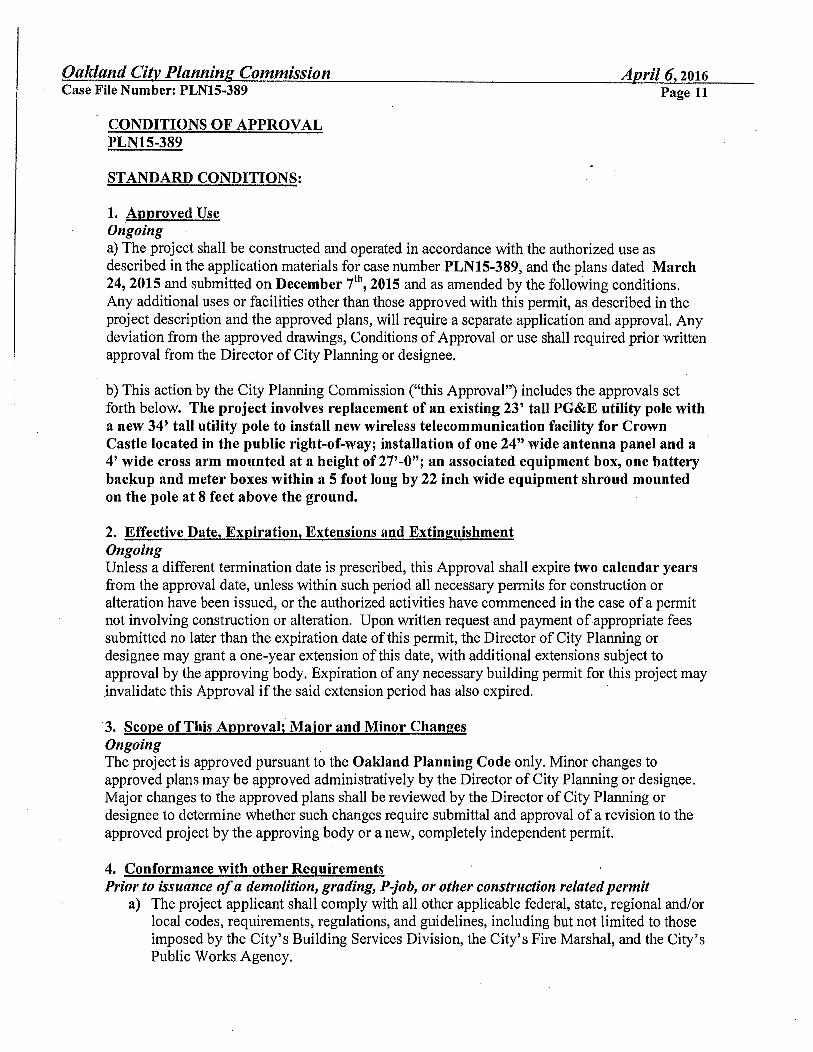
Oakland City Planning Commission Case File Number: PLN15-389
CONDITIONS OF APPROVAL PLN15-389
STANDARD CONDITIONS:
1. Approved Use Ongoing
April 6, 2016 Page 11
a) The project shall be constructed and operated in accordance with the authorized use as described in the application materials for case number PLN15-389, and the plans dated March 24, 2015 and submitted on December 7t\ 2015 and as amended by the following conditions. Any additional uses or facilities other than those approved with this permit, as described in the project description and the approved plans, will require a separate application and approval. Any deviation from the approved drawings, Conditions of Approval or use shall required prior written approval from the Director of City Planning or designee.
b) This action by the City Planning Commission ("this Approval") includes the approvals set forth below. The project involves replacement of an existing 23' tall PG&E utility pole with a new 34' tall utility pole to install new wireless telecommunication facility for Crown Castle located in the public right-of-way; installation of one 24" wide antenna panel and a 4' wide cross arm mounted at a height of 27'-0"; an associated equipment box, one battery backup and meter boxes within a 5 foot long by 22 inch wide equipment shroud mounted on the pole at 8 feet above the ground.
2. Effective Date, Expiration, Extensions and Extinguishment Ongoing Unless a different termination date is prescribed, this Approval shall expire two calendar years from the approval date, unless within such period all necessary permits for construction or alteration have been issued, or the authorized activities have commenced in the case of a permit not involving construction or alteration. Upon written request and payment of appropriate fees submitted no later than the expiration date of this permit, the Director of City Planning or designee may grant a one-year extension of this date, with additional extensions subject to approval by the approving body. Expiration of any necessary building permit for this project may invalidate this Approval if the said extension period has also expired. ·
·3, Scope of This Approval;° Major and Minor Changes Ongoing The project is approved pursuant to the Oakland Planning Code only. Minor changes to approved plans may be approved administratively by the Director of City Planning or designee. Major changes to the approved plans shall be reviewed by the Director of City Planning or designee to determine whether such changes require submittal and approval of a revision to the approved project by the approving body or a new, completely independent permit.
4. Conformance with other Requirements Prior to issuance of a demolition, grading, P-job, or other construction related permit
a) The project applicant shall comply with all other applicable federal, state, regional and/or local codes, requirements, regulations, and guidelines, including but not limited to those imposed by the City's Building Services Division, the City's Fire Marshal, and the City's Public Works Agency.

Oakland City Planning Commission April 6, 2016 Case File Number: PLN15-389 Page 12
b) The applicant shall submit approved building plans for project-specific needs related to fire protection to the Fire Services Division for review and approval, including, but not limited to automatic extinguishing systems, water supply improvements and hydrants, fire department access, and vegetation management for preventing fires and soil erosion.
· 5. Conformance to Approved Plans; Modification of Conditions or Revocation Ongoing
a) Site shall be kept in a blight/nuisance-free condition. Any existing blight or nuisance shall be abated within 60-90 days of approval, unless an earlier date is specified elsewhere.
b). The City of Oakland reserves the right at any time during construction to require certification by a licensed professional that the as-built project conforms to all applicable zoning requirements, including but not limited to approved maximum heights and minimum setbacks. Failure to construct the project in accordance with approved plans may result in remedial reconstruction, permit revocation, permit modification, stop work, permit suspension or other corrective action.
c) Violation of any term, conditions or project description relating to the Approvals is unlawful, prohibited, and a violation of the Oakland Municipal Code. The City of Oakland reserves the right to initiate civil and/or criminal enforcement and/or abatement proceedings, or after notice and public hearing, to revoke the Approvals or alter these. conditions if it is found that there is violation of any of the conditions or the provisions of the Planning Code or Municipal Code, or the project operates as or causes a public nuisance. This provision is not intended to, nor does it; limit in any manner whatsoever the ability of the City to take appropriate enforcement actions.
6. Signed Copy of the Conditions Witli submittal of a demolition, grading, and building permit A copy of the approval letter and conditions shall be signed by the property owner, notarized, and submitted with each set of permit plans to the appropriate City agency for this project.
7. Indemnification a) Ongoing The project applicant shall defend (with counsel reasonably acceptable to the
City), indemnify, and hold harmless the City of Oakland, the Oakland City Council, the City of Oakland Redevelopment Agency, the Oakland City Plam1ing Commission and their respective agents, officers, and employees (hereafter collectively called the City) from any claim, action, or proceeding (including legal costs and attorney's fees) against the City to attack, set aside, void or annul this Approval, or any related approval by the City. The City shall promptly notify the project applicant of any claim, action or proceeding and the City shall cooperate fully in such defense. The City may elect, in its sole discretion, to participate in the defense of said claim, action, or proceeding. The project applicant shall reimburse the City for its reasonable legal costs and attorney's fees.
b) · Within ten ( 10) calendar days of the filing of a claim, action or proceeding to attack, set aside, void, or annul this Approval, or any related approval by the City, the project applicant shall execute a Letter Agreement with the City, acceptable to the Office of the City Attorney, which memorializes the above obligations and this condition of approval.

Oakland City Planning Commission April 6, 2016 Case File Number: PLN15-389 Page 13
This condition/obligation shall survive termination, extinguishment, or invalidation of this, or any related approval. Failure to timely execute the Letter Agreement does not relieve the project applicant of any of the obligations contained in 7(a) above, or other conditions of approval.
8. Compliance with Conditions of Approval Ongoing The project applicant shall be r~sponsible for compliance with the recommendations in any submitted and approved technical report and all the Conditions of Approval set forth below at its sole cost and expense, and subject to review and approval of the City of Oakland.
9. Severability Ongoing . Approval of the project would not have been granted but for the applicabifity and validity of each and every one of the specified conditions, and if any one or more of such conditions is found to be invalid by a court of competent jurisdiction this Approval would not have been granted without requiring other valid conditions consistent with achieving the same purpose and intent of such Approval.
10. Job Site Plans Ongoing throughout demolition, grading, and/or construction At least one (1) copy of the stamped approved plans, along with the Approval Letter and Conditions of Approval, shall be available for review at the job site at all times.
11. Special Inspector/Inspections, Independent Technical Review, Project Coordination and Management · Prior to issuance of a demolition, grading, and/or construction permit The project applicant may be required to pay for on-call special inspector(s)/inspections as needed during the times of extensive or specialized plan check review, or construction. The project applicant may also be required to cover the full costs of independent technical and other types of peer review, monitoring and inspection, including without limitation, third party plan check fees, including inspections of violations of Conditions of Approval. The project applicant shall establish a deposit with the Building Services Division, as directed by the Building Official, Director of City Planning or designee.
12. Days/Hours of Construction Operation Ongoing throughout demolition, grading, and/or construction The project applicant shall require construction contractors to limit standard construction activities as follows:
a) Construction activities are limited to between 7:00 AM and 7:00 PM Monday through Friday, except that pile driving and/or other extreme noise generating activities greater than 90 dBA shall be limited to between 8:00 a.m. and 4:00 p.m. Monday through Friday.
b) Any construction activity proposed to occur outside of the standard hours of 7 :00 am to 7:00 pm Monday through Friday for special activities (such as concrete pouring which may require more continuous amounts of time) shall be evaluated on a case by case basis, with criteria including the proximity of residential uses and a consideration of resident's preferences for whether the activity is acceptable if the overall duration of construction is shortened and such construction activities shall

Oakland Citv Planning Commission April 6, 2016 Case File Number: PLNlS-389 Page 14
only be allowed with the prior written authorization of the Building Services Division.
c) Construction activity shall not occur on Saturdays, with the following possible exceptions:
i. Prior to the building being enclosed, requests for Saturday construction for special activities (such as concrete pouring which may require more continuous amounts of time), shall be evaluated on a case by case basis, with criteria including the proximity of residential uses and a consideration of resident's preferences for whether the activity is acceptable if the overall duration of construction is ·shortened. Such construction activities shall only be allowed on Saturdays with the prior written authorization of the Building Services Division.
ii. After the building is enclosed, requests for Saturday construction activities shall only be allowed on Saturdays with the prior written authorization of the Building Services ·Division, and only then within the interior of the building with the doors and windows closed.
d) No extreme noise generating activities (greater than 90 dBA) shall be allowed on Saturdays, with no exceptions.
e) No construction a:ctivity shall take place on Sundays or Federal holidays.
f) Construction activities include but are not limited to: truck idling, moving equipment (including trucks, elevators, etc) or materials, deliveries, and construction meetings held on-site in a non-enclosed area.
PROJECT SPECIFIC CONDTIONS:
13. Radio Frequency Emissions Prior to the final building permit sign off. The applicant shall submit a certified RF emissions report stating the facility is operating within the acceptable standards established by the regulatory Federal Communications Commission.
14. Operational Ongoing Noise levels from the activity, property, or any mechanical equipment on site shall comply with the performance standards of Section 17.120 of the Oakland Planning Code and Section 8.18 of the Oakland Municipal Code. If noise levels exceed these standards, the activity causing the noise shall be abated until appropriate noise reduction measures have been installed and compliance verified by the Planning and Zoning and Building Services Division.
15. Equipment cabinets Prior to building permit Issuances. The applicant shall submit revised elevations showing the associated equipment cabinet are concealed within a single equipment box that is painted to match the utility pole, to the Oakland Planning Department for review and approval.

Oakland Citv Planning Commission Case File Number: PLNlS-389
16. Possible District Undergrounding PG&E Pole Ongoing
April 6, 2016 Page 15
Should the PG &E utility pole be voluntarily removed for purposes of district undergrounding or otherwise, the telecommunications facility can only be re-established by applying for and receiving approval of a new application to the Oakland Planning Department as required by the regulations.