city of roseville design standards january 20210
TRANSCRIPT

City of Roseville Design Standards ___________________________________ Table of Contents January 20210
DS 1 of 12
CITY OF ROSEVILLE DESIGN STANDARDS
January 20210
Section 1 Purpose and Definitions
1-1 Purpose PD 1 1-2 Design Practice PD 1 1-3 Definitions PD 2 A. Applicant PD 2 B. Building Division PD 2 C. Cadastral Surveys PD 2 D. City PD 2 E. City Engineer PD 2 F. Community Design Guidelines PD 2 G. Construction Standards PD 2 H. Consulting Engineer PD 2 I. Contractor PD 2 J. Department of Environmental Utilities PD 3 K. Department of Public Works PD 3 L. Developer PD 3 M. Development PD 3 N. Development Services Department PD 3 O. Engineering Division PD 3 P. Environmental Utilities Director PD 3 Q. Fire Apparatus Access Roads PD 3 R. Fire Department PD 3 S. Fire Flow PD 3 T. Fire Prevention Standards PD 3 U. Grading Ordinance PD 4 V. Improvements PD 4 W. Laboratory PD 4 X. California MUTCD PD 4 Y. Soils Reports PD 4 Z. Standard Drawings PD 4 AA. State PD 4 BB. State Highway Design Manual PD 4 CC. State Standard Plans PD 4 DD. State Standard Specifications PD 4 EE. State Traffic Manual PD 4 FF. Subdivision Ordinance PD 5 GG. Traffic Plans (Signal Plans) PD 5 HH. Water Efficient Landscape Requirements PD 5 II. Zoning Ordinance PD 5 JJ. Trench Cut Ordinance PD 5

City of Roseville Design Standards ___________________________________ Table of Contents January 20210
DS 2 of 12
Section 2 General Requirements
2-1 Plans by an Appropriate Engineer GR 1 2-2 Accepted Plans GR 1 2-3 Reference to City Specifications and Standards GR 1 2-4 Work in City Right of Way and Easements GR 1 2-5 Submission of Improvement Plans GR 2 A. Development Projects GR 2 B. Subdivision GR 2 2-6 Submission of Development Plans GR 3 2-7 Submission of Rough Grading Plans GR 4 Submission of Electrical Design, Landscaping and GR 4 Irrigation Plans 2-8 Submission of Final and parcel Maps GR 5 2-9 Soils Reports GR 6 2-10 Resubmittal Requirements GR 6 2-11 Plan Check and Inspection Fees GR 7 2-12 Plan Acceptance GR 7 2-13 Expiration of Plans GR 8 2-14 Improvement Plan Revision During Construction GR 8 2-15 Record (As-Built) Plans GR 9 2-16 Conflict, Errors, and Omissions GR 9 2-17 Change In Consulting Engineer GR 9 2-18 Other Agency Notification GR 10 2-19 Inspection Requirements GR 10 2-20 Final Inspection GR 10 2-21 Acceptance of Improvements GR 10 2-22 Special Notices and Permits GR 11 2-23 Grading Permits, Encroachment Permits, Improvement GR 11 Permits, and Subdivision Agreements A. Grading Permits GR 12 B. Encroachment Permits GR 12 C. Improvement Permits GR 14 D. Subdivision Agreement GR 14 2-24 Submission of Lot Line Adjustments GR 15 2-25 Submission of Dedication By Separate Instrument GR 16 2-26 Bridges and Other Structural Items GR 17 A. Private Improvements GR 17 B. Public Improvements GR 17 2-27 Deviation from Standards GR 18
Section 3 Plan Sheet Requirements
3-1 General PS 1 3-2 Plan and Profile Sheets PS 1 A. Drafting Standards PS 1

City of Roseville Design Standards ___________________________________ Table of Contents January 20210
DS 3 of 12
B. Scale PS 1 C. Title Block PS 1 D. Orientation PS 1 3-3 Title or General Information Sheet PS 1 3-4 Street Plan and Profile Sheets PS 4 3-5 Detail Sheets PS 5 3-6 Parcel and Final Maps PS 6 A. Preparation and Form PS 6 B. Certificate Sheet PS 7 C. Information PS 8 D. Additional Data Required PS 10 E. Subdivision Agreement PS 11 3-7 Property of City of Roseville PS 11
Section 4 Traffic VMT Impact StudiesStandards
4-1 General TI 1 4-2 Purpose of Traffic Impact Studies TI 1 4-3 Responsibility for Traffic Impact Studies TI 1 4-4 Types of Traffic Impact Studies TI 1 4-5 Traffic Study Format TI 4 A. Introduction TI 4 B. Project Trip Generation TI 5 C. Trip Distribution TI 6 D. Traffic Assignment TI 6 E. Level of Service TI 6 F. Site Access TI 6 G. Traffic Signals TI 10 H. Traffic Accidents TI 12 I. On-Site Circulation TI 12 J. Report Documentation TI 12 4-6 Traffic Impact Study Preparation and Submittal TI 12 Requirements 4-7 Purpose of VMT Impact Studies TI 16 4-8 Responsibility for VMT Impact Studies TI 16 4-9 VMT Impact Studies TI 16 A. Qualitative Studies Screening TI 16 B. VMT Analysis TI 18 4-10 VMT Analysis TI 19 4-11 VMT Study Format TI 20 A. Table of Contents TI 20 B. Executive Summary TI 20 C. Introduction TI 21 D. Methodology TI 21 E. Results TI 21 F. Mitigation Measures TI 21 G. Conclusion TI 22
City of Roseville Design Standards ___________________________________ Table of Contents January 20210
DS 4 of 12
4-12 VMT Impact Study Preparation and Submittal TI 22
Section 5 Site Access
5-1 General SA 1 5-2 Driveway Locations on Minor and Primary Residential SA 1 Streets 5-3 Driveway Location on Collector or Arterial Streets SA 2 5-4 Number of Driveways Serving a Parcel or Site SA 2 5-5 Right Turn Deceleration/Acceleration Lanes for SA 3 Driveways 5-6 Left Turn Deceleration/Acceleration Lanes for SA 3 Driveways 5-7 Minimum Offset for Opposing Driveways SA 4 5-8 Restricted Turning Movements for Driveways SA 4 5-9 Signalized Driveways SA 5 5-10 Minimum Required Throat Depth SA 6
Section 6 Traffic Signals, Signs, and Striping
6-1 Traffic Signal Needs Assessment TS 1 6-2 Design Standards TS 1 A. Signal Standard Types TS 1 B. Vehicle and Pedestrian Signal Types TS 3 C. Vehicle Signal Alignment TS 4 D. Number of Vehicle Signal Indications TS 4 E. Signal Phasing TS 5 F. Permissive Left Turn Phasing TS 5 G. Vehicle Detector Layout and Inputs TS 5 H. Traffic Signal Conductors TS 8 I. Traffic Signal Interconnect (SIC) TS 110 J. Traffic Signal Conduit TS 15 K. Traffic Signal Pull Boxes TS 16 L. Pedestrian Push Button (PPB) TS 17 M. Intersection & Arterial Roundabout Safety TS 17 Lighting N. Controller/Service Pad TS 18 O. Traffic Signs TS 19 P. Striping TS 21 Q. Right Turn Lanes TS 24 R. City Supplied Equipment TS 24 S. Contractor Supplied Equipment TS 25 T. Salvaged Equipment TS 265

City of Roseville Design Standards ___________________________________ Table of Contents January 20210
DS 5 of 12
U. Traffic Control TS 26 V. Signal Activation TS 29 W. Roadway Improvements TS 29 6-3 Preparation of Plans TS 30 A. Title Sheet TS 310 B. Signal and Lighting Sheet TS 31 C. Interconnect Sheet TS 32 D. Signing and Striping Sheet TS 32 E. Intersection Lighting Sheet TS 32
Section 7 Streets
7-1 Street Classes and Design Widths ST 1 A. 20-Foot Street (Alley) ST 1 B. Residential Streets ST 1 C. Collector/Industrial ST 2 D. Minor Arterial ST 2 E. Major Arterial ST 2 F. Cul-de-Sac ST 2 G. Partial Width Streets ST 3 H. Private Streets ST 3 I. Gated Entryways ST 3 7-2 Right-of-Way Width ST 5 7-3 Roadway Signage and Striping ST 5 7-4 Structural Section ST 5 A. Structural Street Sections at Signalized ST 6 Intersections 7-5 Curb and Gutter Requirements ST 76 A. Type 1 Roll Curb and Gutter ST 76 B. Type 2 Vertical Curb and Gutter ST 7 C. Type 6 Modified V-Gutter ST 87 D. Cross Gutters ST 87 7-6 Sidewalk Requirements ST 87 A. Width ST 87 B. Slopes ST 87 C. Radius ST 8 D. Pedestrian Curb Ramps ST 8 E. Sidewalk Barricades ST 98 7-7 Pedestrian Walks and Bike Paths ST 98 7-8 Roadway Profile Standards ST 98 A. Grades ST 9 B. Cross Slopes ST 109 C. Vertical Curves ST 109 7-9 Intersections ST 109 7-10 Offset Intersections ST 109 7-11 Elbow Intersections ST 110 7-12 Design Speed Sight Distances ST 110 A. Stopping Sight Distance ST 110

City of Roseville Design Standards ___________________________________ Table of Contents January 20210
DS 6 of 12
B. Sight Distances for Cars Entering Side Streets ST 110 or Driveways via Left Turn in
C. Corner Sight Distances for Cars Exiting at ST 121 Intersections and Driveways 7-13 Centerline Radii ST 132 7-14 Driveways ST 143 A. Types, Widths and Grades ST 142 B. Location ST 143 C. Sight Distance ST 14 7-15 Bus Stops and Turnouts ST 154 7-16 Developer Responsibility for Improvements to Streets ST 154 7-17 Trenching in Existing Paved Roadways ST 175 7-18 Street Names and Street Name Signs ST 176 A. Location and Number Required ST 176 7-19 Survey Monuments ST 187 7-20 Benchmarks ST 198
Section 8 Domestic Water Supply System Design
8-1 Introduction W 1 8-2 Design Criteria W 1 8-3 Current Standards W 1 8-4 Water Supply Quality W 1 8-5 Water Supply Pressure W 1 8-6 Flow Determination W 2 8-7 Peaking Factors W 2 8-8 Required Fire Flows W 2 A. Residential Areas W 2 B. Multi-Family Areas W 3 C. Commercial, Business, Industrial or School W 3 District Areas 8-9 Location in Existing Streets W 3 8-10 Location in Unpaved Areas W 3 8-11 Transmission System Design W 3 A. Transmission Main Location W 4 B. Transmission Main Appurtenances W 4 C. Corrosion Protection W 4 D. Insulating Flange Test Station W 4 8-12 Distribution System Design W 4 A. Hydraulic Analysis W 4 B. Pipe Sizes W 5 C. Stubs W 5 8-13 Water Main Location W 5 A. Location W 6 B. Vertical Elevation Change W 7 C. Cover W 7 D. Dead-End Mains W 7

City of Roseville Design Standards ___________________________________ Table of Contents January 20210
DS 7 of 12
E. Warranty Inspection of Water Main Stubs W 7 F. Public Lines in Commercial Development W 7 8-14 Valves W 7 A. Locations W 7 B. Removal and Abandonment W 8 C. Valve Extension Stems W 8 D. Air Relief Valves W 8 8-15 Hydrants and Blow-offs W 8 A. Location W 8 B. Spacing W 9 C. Cul-de-sacs and Dead-end Streets W 9 D. Valves W 9 8-16 Water Service W 9 A. Location W 9 B. Curb Stamp W 10 C. Sizing W 10 D. Spacing W 10 E. Service Taps W 10 F. Water Meters W 10 8-17 Restraint W 10 8-18 Work Near Existing Water Mains W 10 A. Water Mains 16 Inches and Larger W 11 8-19 Water Improvement Plan Requirements W 11 A. Water Study W 11 B. General Requirements W 11 C. Layout Sheet W 11 D. Plan and Profile Sheet W 12 E. Detail Drawings W 13 8-20 Record (As-Built) Plans W 13
Section 9 Sanitary Sewer Design
9-1 Design Criteria SS 1 9-2 Average Flow Determination SS 1 9-3 Design Flow SS 1 9-4 Pipe Capacity, Slope, Velocity, Size, Depth and Material SS 3 A. Main Sizes SS 3 B. Slope and Velocity SS 3 C. Capacity SS 4 D. Hydraulic Grade Line SS 4 E. Depth SS 4 9-5 Sewer Location and Alignment Requirements SS 4 A. General SS 4 B. Location in New Subdivisions SS 4 C. Location in Existing Streets SS 4 D. Location in Unpaved Areas SS 5 E. Easements Sewer Lines SS 5

City of Roseville Design Standards ___________________________________ Table of Contents January 20210
DS 8 of 12
F. Public Lines in Commercial Developments SS 5 G. Water Well Clearance SS 5 H. Lines in Drainage Swales SS 5 I. Alignment SS 5 J. Sewer Main Stub SS 6 9-6 Trench Loading Conditions and Pipe Design SS 6 A. Rigid Conduit Loading SS 6 B. Safety Factor SS 6 C. Bedding and Initial Backfill SS 6 D. Special Pipe Strength Requirements SS 6 9-7 Manhole Criteria SS 6 A. General SS 7 B. Spacing SS 7 C. Invert Elevations SS 7 D. Manhole Sizing SS 7 E. Manhole Coating SS 7 F. Manhole Access SS 7 G. Connection City Mains SS 8 9-8 Drop Connection Criteria SS 8 9-9 Mainline and Dip Transitions SS 8 9-10 Sewer Service Design SS 8 A. General SS 8 B. Sizing SS 8 C. Depth SS 10 D. Special Requirements in Developed Areas SS 10 E. Warranty Inspection of Sewer Main Stubs SS 10 F. Abandoning Existing Sewer Stubs SS 11 G. Grease Interceptor SS 11 H. Oil/Sand Interceptor SS 11 I. Automatic Car Wash SS 11 9-11 Siphon and Creek Crossing Design SS 11 A. General SS 11 B. Gravity Mains SS 11 C. Design SS 12 D. Siphon SS 12 9-12 Boring and Jacking Requirements SS 12 9-13 Pump Station and Force Main Requirements SS 12 A. Location SS 12 B. Capacity SS 12 C. Wet Well SS 13 D. Pumps SS 13 E. Station Piping SS 13 F. Odor Control SS 13 G. Force Mains SS 13 H. S.C.A.D.A. SS 14 I. Valves SS 14 9-14 Sewer Improvement Plan Requirements SS 14

City of Roseville Design Standards ___________________________________ Table of Contents January 20210
DS 9 of 12
A. Sewer Study SS 14 B. General Requirements SS 14 C. Layout Sheet SS 14 D. Plan and Profile Sheets SS 15 E. Detail Drawings SS 16 F. Connection to Existing Facilities Where Bypassing SS 16 or Stoppage of Existing Flow Will be Required 9-15 Multi-Parcel Commercial and Industrial Developments SS 16 9-16 Record (As-Built) Plans SS 16
Section 10 Drainage
10-1 General DR 1 10-2 City Policies and Requirements DR 1 10-3 Development In or Adjacent to a Regulatory Floodplain DR 1 10-4 Federal Flood Program DR 3 10-5 Drainage Diversions DR 3 10-6 Drainage Easements DR 3 10-7 Drainage Capacity/Design DR 4 10-8 Design Peak Discharge Methods DR 4 10-9 Unit Peak Discharge Method DR 5 A. Criteria DR 5 B. Response Time DR 5 C. Unit Peak Discharge DR 6 D. Infiltration Factor DR 7 E. Connecting Separately Connected Areas DR 8 F. Procedure DR 8 10-10 Hydraulic Standards for Drainage Systems DR 12
A. Hydraulic Grade Line DR 12 B. Manning’s Formula DR 12
10-11 Street Inundation Requirements DR 12 10-12 Closed Conduits DR 14 A. Size and Material DR 14 B. Cover Requirements DR 14 C. Alignment DR 14 10-13 Manholes DR 14 A. Saddle Manholes DR 15 B. Covers DR 15 10-14 Inlets DR 15 10-15 Junction Boxes DR 16 10-16 Inlet and Outlet Structures DR 16 A. Headwalls, Wingwalls, and Endwalls DR 16 B. Trash Racks and Access Control Racks DR 16 10-17 Drainage Pumps DR 16 A. Design Requirements DR 16 B. Maintenance Requirements DR 17 10-18 Channels and Outfall Design DR 17

City of Roseville Design Standards ___________________________________ Table of Contents January 20210
DS 10 of 12
A. Open Channel Design Requirements DR 17 B. Interceptor Ditches DR 18 C. Outfall Profiles DR 18 D. Fencing DR 18 E. Access Roads DR 18 10-19 Cross Culverts and Bridges DR 19 A. Design Storm DR 19 B. Computation of Flow DR 19 10-20 Detention and Retention Basins DR 20 10-21 Access for Maintenance DR 20 Standard Hydraulic Calculation Sheet DR 21 Submittal Requirements – HEC-1 Studies DR 22 Submittal Requirements – HEC-2 Studies or HEC RAS DR 26 Floodplain Encroachment Compliance Statements DR 30
Section 11 Grading
11-1 Introduction GR 1 11-2 Fees and Bonds GR 2 11-3 Preparation GR 2 11-4 Finished Grading Plan Requirements GR 2 11-5 Rough Grading Plan Requirements GR 4 A. Improvements GR 4 B. Drainage GR 4 11-6 Design Requirements GR 4 A. Rolling Terrain Grading GR 4 B. Boundary Grading GR 4 C. Interior Grading GR 5 D. Retaining Walls GR 7 E. Grading Near Trees GR 7 F. Stormwater Pollution Prevention plan (SWPPP) GR 10 G. Mitigation Monitoring Requirement GR 15 H. Certifying Pad Elevations GR 15 I. Maintenance of Access to Utility Facilities GR 16
Section 12 Sound Barrier Design
12-1 General SB 1 12-2 Sound Studies SB 1 12-3 Location Requirements SB 1 12-4 Design Requirements SB 1
Section 13 Bikeways
13-1 General BK 1 13-2 Design Criteria BK 1

City of Roseville Design Standards ___________________________________ Table of Contents January 20210
DS 11 of 12
13-3 Plan Acceptance BK 1 13-4 Class I Bikeways (Bike Paths) BK 1 A. Width BK 2 B. Clearance to Obstructions BK 2 C. Signing and Delineation BK 2 D. Intersections with Roadways BK 3 E. Entry Control BK 3 F. Separation Between Bike Paths and Roadways BK 4 G. Design Speed BK 4 H. Grades BK 4 I. Horizontal Alignment and Super elevation BK 54 J. Stopping Sight Distance BK 54 K. Lateral Clearance on Horizontal Curves BK 5 L. Vertical Curves BK 5 M. Structural Section BK 5 N. Drainage BK 6 O. Access Points BK 6 P. Temporary Bike Path Closures BK 6 Q. Bike Bridges BK 6 R. Lighting BK 7 13-5 Bike Paths in Floodplains BK 7 13-6 Bike Bridges in Floodplains BK 7 13-7 Class IA Sidewalk Bikeways BK 8 13-8 Class II Bikeways BK 8 A. Signing and Pavement Markings BK 8 B. At-grade Intersection Design BK 8 13-9 Class III Bikeways BK 8
Section 14 Recycled Water Infrastructure Design
14-1 Determination of Use RW 1 14-2 Design Information RW 1 14-3 Current Standards RW 1 14-4 Recycled Water Supply Quality RW 2 14-5 Off-Site Recycled Water Facilities RW 2 14-6 Private On-Site Recycled Water Facilities RW 2 14-7 Water Supply Pressure RW 2 14-8 Transmission System Design RW 2 A. Hydraulic Analysis RW 2 B. Specifications RW 3 C. Transmission Main Size RW 3 D. Transmission Main Location RW 3 E. Main Line Fittings and Connections RW 5 F. Recycled Water Transmission Main RW 5 and Appurtenances G. Booster Pump Stations RW 5 H. Air and Vacuum Valves and Blow-Offs RW 6

City of Roseville Design Standards ___________________________________ Table of Contents January 20210
DS 12 of 12
I. Corrosion Protection RW 6 J. Insulating Flange Test Station RW 6 K. Warranty Inspection of Recycled Water Stubs RW 6 14-9 Service Lines RW 6 14-10 On-Site Recycled Water Facilities Design RW 7 14-11 Determination to Use Recycled Water or Potable Water RW 12 14-12 Design of Recycled Water Facilities With Temporary RW 12 Potable Water Service 14-13 Backflow Prevention Devices RW 12 14-14 Prohibition and Limitations RW 13 14-15 Control of Runoff and Application Areas RW 13 14-16 Minimum Depth to Top of On-Site Recycled Water RW 14 Piping 14-17 Data Required on Plans RW 14 A. Meter Data RW 14 B. Drinking Fountains RW 15 C. Irrigation Equipment Legend RW 15 D. Recycled Water Warning/Information Sign RW 15 14-18 Location RW 15 14-19 Plan Submittal and Approval RW 16 14-20 Inspection RW 16 14-21 Record Drawings RW 16 14-22 Controller Access RW 17 14-23 Blow-off Hydrants and Other Points of Public Access RW 17 14-24 Detail Drawings RW 17
Section 15
Solid Waste Design 15-1 Introduction SW 1 15-2 Current Standards SW 1 15-3 Design Criteria SW 1 A. General SW 1 B. Walls SW 1 C. Gates SW 1 D. Vehicle Approach and Floor SW 1 E. Signs and Striping SW 2 F. Location SW 2 G. Path of Travel SW 2 H. Back-up Lengths SW 2 I. Frontloading Compactors Enclosure SW 2 J. Detail Drawings SW 2 K. Organics SW 2

City of Roseville Section 4 Design Standards_______________________________________________________________________ Traffic Impact Studies January 20210
DS TI 1 of 22
SECTION 4
TRAFFIC VMT IMPACT STUDIES STANDARDS
4-1 GENERAL – The City of Roseville has established the following guidelines for the preparation of Ttraffic Impact Sstudies and VMT Impact Studies to ensure consistency of analysis and adequacy of information to aid City staff and decision makers in the consideration of project approval with regard to impacts to the City’s transportation system.
4-2 PURPOSE OF TRAFFIC IMPACT STUDIES – Traffic impact studies
are an important tool in the overall development planning process (residential, commercial, industrial, institutional, etc.) for the City. They provide the necessary information to allow an assessment of the potential traffic impacts associated with proposed projects as they relate to transportation policies established by the City. Traffic impact studies are also used to identify appropriate mitigation and/or recommendations where practicable to offset project impacts.
4-3 RESPONSIBILITY FOR TRAFFIC IMPACT STUDIES – The City
utilizes on-call transportation services with approved transportation Consultants for the preparation of all city-required transportation studies. Traffic impact studies, when required by the City, shall adequately assess the impacts of a development proposal on the existing and/or planned street system.
Applicants should contact the Planning Division as early as possible and provide a site plan with proposed land use and associated square footages prior to submitting an application so that the City can evaluate the traffic study requirements. Should it be determined that a traffic study will be required, the City will provide an estimated cost, scope and scheduled for the study, and the project applicant will be required to authorize the City to proceed with the traffic study and deposit the necessary funds prior to the City commencing with the study. Note: The City will not accept traffic studies prepared directly by an applicant’s traffic/transportation Consultant.
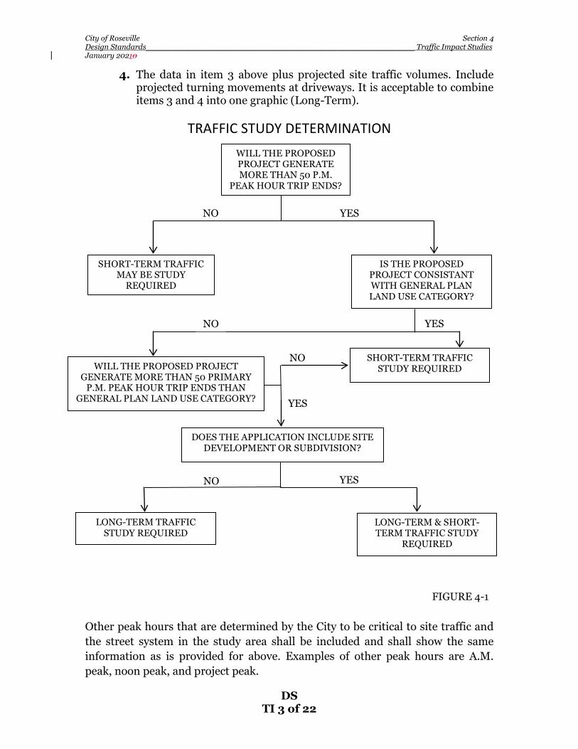
4-4 TYPES OF TRAFFIC IMPACT STUDIES – The flow chart shown in Figure 4-1 shall be used to determine when and what type of traffic study may be required for proposed development projects. The City utilizes both short-term and long-term traffic studies for assessing the potential impacts of a proposed project. Short-Term Traffic Studies – The primary purpose of a short-term traffic study is to identify the project’s impact to the roadway network under existing and/or near-term conditions and to evaluate proposed site access.

City of Roseville Section 4 Design Standards_______________________________________________________________________ Traffic Impact Studies January 20210
DS TI 2 of 22
Where access points are not defined at the time the traffic study is prepared, additional analysis may be required when the access points are defined. When only short-term traffic studies are prepared, they shall include an explanation as to why the future scenario need not be analyzed (e.g., the proposed land use is consistent with the General Plan, therefore the project’s long term traffic impact is already accounted for via the City’s Capital Improvement Program which was derived from the City-wide traffic model). Long-Term Traffic Studies – Long-term traffic studies are generally required when a proposed project will generate greater than 50 p.m. peak hour trip ends and the land use is not consistent with the assumptions of the City’s travel demand forecasting model, with regard to intensity of development and/or type of use. Cumulative traffic impacts are evaluated using the latest version of the City’s CIP travel demand model. A LOS comparison of with and without project conditions for all signalized intersections (existing & future) is reported and intersections that degrade from acceptable to unacceptable (per the City’s current LOS policy) shall be identified and appropriate mitigation identified where feasible. The term “impact” in this case refers to violation of the City’s intersection LOS policy as described below: Maintain a level of service (LOS) “C” standard at a minimum of 70 percent of all signalized intersections and roadway segments in the City during the p.m. peak hours or causing an intersection operating at LOS “C” to operate at worse than LOS “C”. Exceptions to the LOS “C” standard may be considered for intersections where the city finds that the required improvements are unacceptable based on established criteria identified in the implementation measures. In addition, Pedestrian Districts may be exempted from the LOS standard. Both short-term and long-term traffic analysis shall include graphics that show traffic volumes for private access points, study intersections and roadway segments, as required: 1. Existing P.M. peak hour directional roadway traffic volumes including
turning movements at intersections. (Short-Term). 2. The data in item 1 above plus projected site traffic volumes for the
development scenario being analyzed. Include projected turning movements at driveways. It is acceptable to combine items 1 and 2 into one graphic. (Short-Term).
3. Future P.M. peak hour directional roadway traffic volumes including
turning movements at intersections without the project. (Long-Term).
City of Roseville Section 4 Design Standards_______________________________________________________________________ Traffic Impact Studies January 20210
DS TI 3 of 22
4. The data in item 3 above plus projected site traffic volumes. Include projected turning movements at driveways. It is acceptable to combine items 3 and 4 into one graphic (Long-Term).
TRAFFIC STUDY DETERMINATION
Other peak hours that are determined by the City to be critical to site traffic and the street system in the study area shall be included and shall show the same information as is provided for above. Examples of other peak hours are A.M. peak, noon peak, and project peak.
WILL THE PROPOSED PROJECT GENERATE MORE THAN 50 P.M.
PEAK HOUR TRIP ENDS?
SHORT-TERM TRAFFIC MAY BE STUDY
REQUIRED
IS THE PROPOSED PROJECT CONSISTANT WITH GENERAL PLAN LAND USE CATEGORY?
SHORT-TERM TRAFFIC STUDY REQUIRED
DOES THE APPLICATION INCLUDE SITE DEVELOPMENT OR SUBDIVISION?
LONG-TERM TRAFFIC STUDY REQUIRED
LONG-TERM & SHORT-TERM TRAFFIC STUDY
REQUIRED
NO YES
NO YES
NO
YES
NO YES
FIGURE 4-1
WILL THE PROPOSED PROJECT GENERATE MORE THAN 50 PRIMARY
P.M. PEAK HOUR TRIP ENDS THAN GENERAL PLAN LAND USE CATEGORY?
City of Roseville Section 4 Design Standards_______________________________________________________________________ Traffic Impact Studies January 20210
DS TI 4 of 22
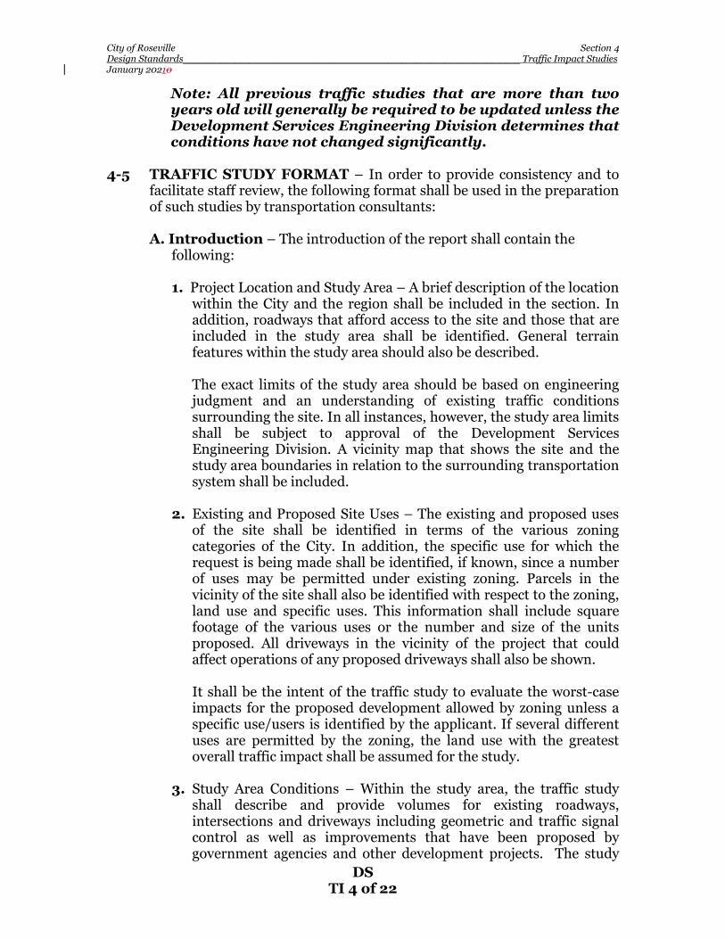
Note: All previous traffic studies that are more than two years old will generally be required to be updated unless the Development Services Engineering Division determines that conditions have not changed significantly.
4-5 TRAFFIC STUDY FORMAT – In order to provide consistency and to
facilitate staff review, the following format shall be used in the preparation of such studies by transportation consultants:
A. Introduction – The introduction of the report shall contain the
following:
1. Project Location and Study Area – A brief description of the location within the City and the region shall be included in the section. In addition, roadways that afford access to the site and those that are included in the study area shall be identified. General terrain features within the study area should also be described.
The exact limits of the study area should be based on engineering
judgment and an understanding of existing traffic conditions surrounding the site. In all instances, however, the study area limits shall be subject to approval of the Development Services Engineering Division. A vicinity map that shows the site and the study area boundaries in relation to the surrounding transportation system shall be included.
2. Existing and Proposed Site Uses – The existing and proposed uses
of the site shall be identified in terms of the various zoning categories of the City. In addition, the specific use for which the request is being made shall be identified, if known, since a number of uses may be permitted under existing zoning. Parcels in the vicinity of the site shall also be identified with respect to the zoning, land use and specific uses. This information shall include square footage of the various uses or the number and size of the units proposed. All driveways in the vicinity of the project that could affect operations of any proposed driveways shall also be shown.
It shall be the intent of the traffic study to evaluate the worst-case
impacts for the proposed development allowed by zoning unless a specific use/users is identified by the applicant. If several different uses are permitted by the zoning, the land use with the greatest overall traffic impact shall be assumed for the study.
3. Study Area Conditions – Within the study area, the traffic study
shall describe and provide volumes for existing roadways, intersections and driveways including geometric and traffic signal control as well as improvements that have been proposed by government agencies and other development projects. The study

City of Roseville Section 4 Design Standards_______________________________________________________________________ Traffic Impact Studies January 20210
DS TI 5 of 22
shall identify roadway improvements within the study area that are planned to be constructed by the City as part of the City’s Capital Improvement Program.
Note: The City will provide copies of current traffic
count information, where available; however, the Consultant is ultimately responsible to provide up-to-date traffic volume count information for all study locations. Traffic count information for many locations are available on the City’s website. Please visit the following link for more information: http://www.roseville.ca.us/pw/engineering/traffic_engineering/default.asp
B. Project Trip Generation - A summary table listing each specific use,
the size involved, the trip generation rates used (total daily traffic and A.M. /P.M. peak hours) and the resultant total trips generated shall be that of a typical weekday and shall coincide with the peak hour of the roadway system (not the peak hour of the project). However, there may be instances where a unique project use requires an analysis during different time frames; such as a weekend.
This section shall also include a discussion on how the project’s trip
generation rate compares with typical trip generation rates for the site’s existing General Plan land use category. If the proposed project represents only a portion of a larger overall site, such as a phased project, then the traffic study shall discuss the degree to which both the initial phase and the ultimate development impact the roadway network.
Trip generation shall be calculated based on data contained within the
latest edition of the Institute of Transportation Engineer’s (ITE) Trip Generation Manual approved for use by the City or more appropriate local data as approved by the Development Services Engineering Division. Any internal trip reductions or modal split assumptions will require analytical support to demonstrate how the figures were derived.
Pass-by trip factors may be used to reduce the estimated additional
traffic to streets serving a proposed development. However, the percentage of pass-by traffic shall be documented and referenced as to the source of the assumptions (e.g., ITE Trip Generation Manual, ITE Journal article, local study, etc.). Pass-by rates are not to be applied to reduce turning movement volumes at driveways serving the proposed development.

City of Roseville Section 4 Design Standards_______________________________________________________________________ Traffic Impact Studies January 20210
DS TI 6 of 22
C. Trip Distribution – The directional distribution of trips entering and departing the proposed project site shall be clearly identified on a figure. The methodology of distribution shall be discussed in the study.
D. Traffic Assignment – The assignment of site-generated traffic onto
the area’s street system shall be clearly depicted on a map/figure. The traffic assignment shall consider the general trip distribution, logical routing, turn movement restrictions, available and projected roadway capacities and travel times. The technical analysis steps, basic methods, and assumptions used in this work shall be clearly stated.
E. Level of Service – The traffic study report shall include appropriate
tables indicating the LOS and volume/capacity (V/C) of all study intersections and roadway segments, comparing with and without project scenarios. Signalized intersections shall be evaluated using the Transportation Research Board (TRB) Circular 212 planning methodology, or Highway Capacity Manual methodology, as determined by the Development Services Engineering Division, with the City-approved critical capacity adjustments. There may be instance where the City desires to evaluate signalized intersections utilizing the “operations methodology” as described in the latest edition of the Highway Capacity Manual. In such instances, the City will provide direction to the Consultant in the development of the scope of the traffic study. Unsignalized intersections shall be analyzed using the latest version of the Highway Capacity Manual, or other appropriate methodology as approved by the Development Services Engineering Division.
A minimum intersection Level of Service “C” shall be the peak hour
design objective. If the proposed project is shown to cause degradation of intersection LOS to worse than “C” (or whichever LOS has been approved by the City Council for a particular intersection) after considering any improvements already planned by the City, then the traffic study shall recommend feasible mitigation measures to bring the intersection Level of Service within acceptable standards in accordance with the City’s LOS policy. The Consultant shall inquire with the Development Services Engineering Division as to planned roadway and intersection improvements.
The report shall include a discussion of assumptions made in the above
calculations, such as saturation flow rates, peak hour factors and lane configurations. Full documentation of the LOS calculations shall be provided in an appendix.
F. Site Access – A short-term traffic study shall discuss how the
proposed site access compares with the City’s access standards as described in this section and in Section 5 of these Design Standards entitled “Site Access.” Some of the topics that must be included in the

City of Roseville Section 4 Design Standards_______________________________________________________________________ Traffic Impact Studies January 20210
DS TI 7 of 22
traffic study are: number of driveways serving a parcel or site, right turn deceleration lane or right turn curb flares for driveways, left turn deceleration lane for driveways, storage requirements for turn lanes, minimum offset for opposing driveways, restricted turning movements for driveways and sight distance. Each site access point shall be discussed separately. If the proposed site access does not meet the City’s standards, then the traffic study shall identify what modifications to the proposed site access would be necessary to meet City standards and explain why these modifications are not proposed.
1. Driveways – Minimum Required Throat Depth (MRTD): The traffic study shall evaluate the Minimum Required Throat
Depth (MRTD) needed on-site for each access point for the proposed development. The MRTD, as illustrated in Figure 4-2 entitled “MINIMUM REQUIRED THROAT DEPTH”, is measured from the back of sidewalk to the first drive aisle or parking stall. The purpose of the MRTD is to allow enough stacking distance for egressing vehicles so that the first drive aisle or parking stall is not blocked. This minimizes the possibility of incoming vehicles queuing out into the traveled way of the main street thereby creating a safety concern as shown in Figure 4-2.
The MRTD shall be measured in car length increments of 25 feet
and rounded up to the nearest division of 25 feet. In no case will the City allow a MRTD of less than 25 feet for any project. Throat depths greater than the calculated MRTD are encouraged. On-site parking shall not be permitted within the MRTD area.
Note: The MRTD requirement does not apply to single
family residential or duplex uses. Figure 4-2 illustrates that the MRTD is a function of the length of
the queue of vehicles waiting to exit the driveway. The length of this queue is a function of two variables: the number of vehicles desiring to egress during a given time period versus the number of vehicles that can enter the traffic stream of the main road during that same time period.
If the proposed project represents only a portion of a larger overall
site, or if it is expected that vehicles generated by other than the project will use the access under study, then the total expected turning movement volumes at the subject access location shall be used in determining the MRTD.
As shown in Figure 4-2, there are cases when a MRTD of 25 feet is
acceptable. This is when the first drive isle is “one way only” to the right in the figure. Another scenario where a MRTD of 25 feet is acceptable is when a raised center median is constructed in the

City of Roseville Section 4 Design Standards_______________________________________________________________________ Traffic Impact Studies January 20210
DS TI 8 of 22
driveway throat from the back of sidewalk to the calculated MRTD distance. In this case, the nearest drive aisle can be two-way, but turning movements into and out of the drive aisle are restricted by the raised median, thereby mitigating the concern as shown in Figure 4-2.
If the calculated MRTD is physically or unreasonable too long for
the proposed development, then the traffic study shall suggest ways to reduce the MRTD by either reducing the egressing demand volume, or by increasing the movement capacity. Examples of reducing the egressing demand volume at an access location would be to suggest additional egress locations, cause a different distribution of vehicles by modifying the on-site design, or somehow reduce the site’s trip generation. Examples of increasing the movement capacity at an access location would be to suggest additional egress lanes or, in the case of an unsignalized access location, suggest fewer allowed turning movements onto the roadway. In any case, the traffic study shall fully evaluate the impacts of any such modifications.
MRTD lengths at unsignalized project driveways shall be based
on a series of regression equations that the City uses to predict maximum queue lengths at minor stop-controlled intersections. These equations are based on the methodology presented in Estimation of Maximum Queue Lengths at Unsignalized Intersections (ITE Journal, November 2001). Exhibit 4-1 presents the methodologies used for calculating the MRTD for various unsignalized driveway conditions. Major street volumes shall be based on projected future traffic volumes from the latest version of the Citywide traffic model. Alternative methodologies for calculating unsignalized MRTD lengths may be considered, but shall first be approved by the Development Services Engineering Division prior to incorporation into traffic studies.

City of Roseville Section 4 Design Standards_______________________________________________________________________ Traffic Impact Studies January 20210
DS TI 9 of 22

City of Roseville Section 4 Design Standards_______________________________________________________________________ Traffic Impact Studies January 20210
DS TI 10 of 22
MRTD lengths at signalized project driveways are a function of egressing traffic volumes, lane geometrics and traffic signal timing. Typically, signalized access locations will have more than one approach lane for egressing vehicles; therefore, the MRTD shall be determined from the lane with the longest queue. The MRTD should be based on the Operational Analysis methodology contained in the latest version of the Highway Capacity Manual, or other methodology as approved by the Development Services Engineering Division. Major street volumes shall be based on projected future traffic volumes from the latest version of the Citywide traffic model. For existing traffic signals, the Consultant is recommended to discuss likely signal timing parameters with City staff. There may be some restrictions to signal timing parameters for existing signals due to progression, etc.
2. “Drive-Thru Service” Uses – On-Site Storage Requirements for traffic studies evaluating “drive-thru service” type land uses, the study shall evaluate vehicle storage requirements to ensure that vehicles will not queue out into the public right-of-way. Such types of uses/conditions include, drive-thru restaurants, drive-thru pharmacies, carwash facilities, gated communities, gated self-storage facilities, parking garages etc. The required storage length shall be determined based on expected arrival rates and service rates using accepted statistical practices. The distance is measured from the back of sidewalk at the street driveway to the service point in increments of 25 feet. All supporting assumptions and calculations shall be provided in the appendix.
3. Left-Turn Ingress Storage Requirements: Left-turn ingress lanes serving the proposed project shall be
evaluated with respect for turn lane storage/deceleration lengths. The left-turn storage shall be based on the regression equations that the City uses to predict maximum queue lengths at left-turn lanes based on the methodology presented in Estimation of Maximum Queue Lengths at Unsignalized Intersections (ITE Journal, November 2001). Table 4-1 presents the regression equation for approximating left-turn storage requirements for major-street left-turn movements. Major street through volumes shall be based on projected future traffic volumes from the latest version of the Citywide traffic model. Alternative methodologies for calculating storage lengths may be considered, but shall first be approved by the Development Services Engineering Division prior to incorporation into traffic studies.
G. Traffic Signals – The need for new traffic signals shall be based on
warrants contained in the latest edition of the California Manual of Uniform Traffic Control Devices (California MUTCD), or other
City of Roseville Section 4 Design Standards_______________________________________________________________________ Traffic Impact Studies January 20210
DS TI 11 of 22
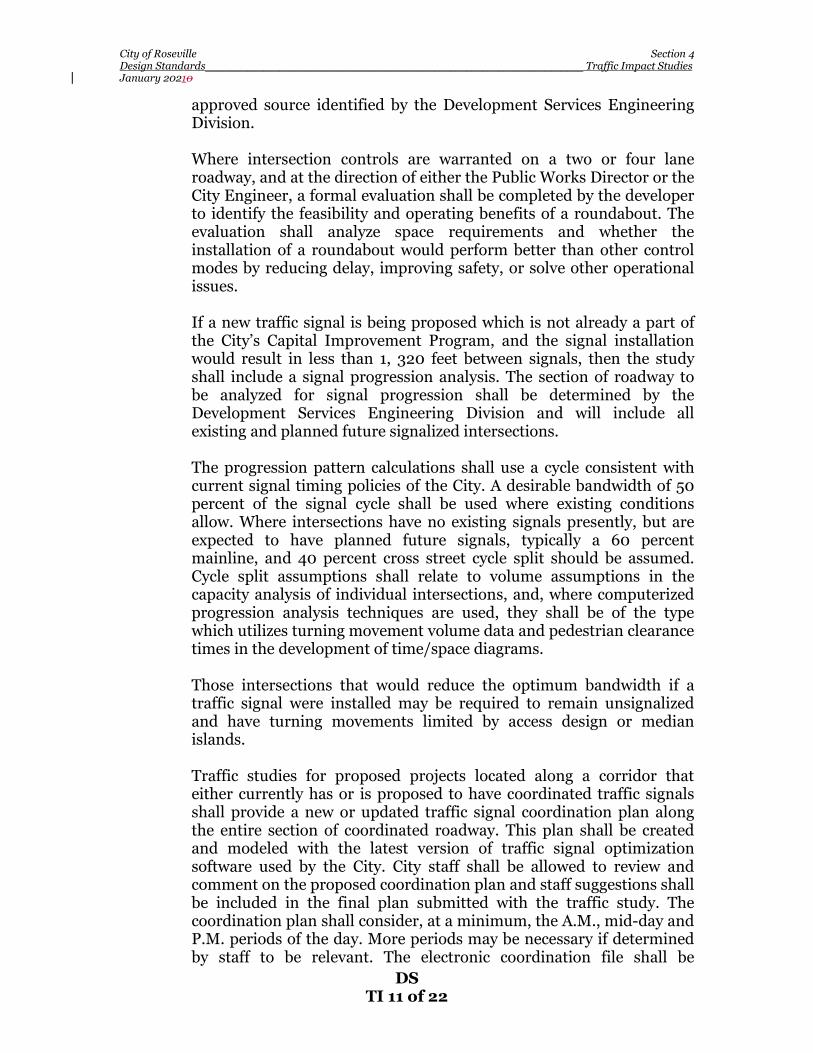
approved source identified by the Development Services Engineering Division.
Where intersection controls are warranted on a two or four lane
roadway, and at the direction of either the Public Works Director or the City Engineer, a formal evaluation shall be completed by the developer to identify the feasibility and operating benefits of a roundabout. The evaluation shall analyze space requirements and whether the installation of a roundabout would perform better than other control modes by reducing delay, improving safety, or solve other operational issues.
If a new traffic signal is being proposed which is not already a part of
the City’s Capital Improvement Program, and the signal installation would result in less than 1, 320 feet between signals, then the study shall include a signal progression analysis. The section of roadway to be analyzed for signal progression shall be determined by the Development Services Engineering Division and will include all existing and planned future signalized intersections.
The progression pattern calculations shall use a cycle consistent with
current signal timing policies of the City. A desirable bandwidth of 50 percent of the signal cycle shall be used where existing conditions allow. Where intersections have no existing signals presently, but are expected to have planned future signals, typically a 60 percent mainline, and 40 percent cross street cycle split should be assumed. Cycle split assumptions shall relate to volume assumptions in the capacity analysis of individual intersections, and, where computerized progression analysis techniques are used, they shall be of the type which utilizes turning movement volume data and pedestrian clearance times in the development of time/space diagrams.
Those intersections that would reduce the optimum bandwidth if a
traffic signal were installed may be required to remain unsignalized and have turning movements limited by access design or median islands.
Traffic studies for proposed projects located along a corridor that
either currently has or is proposed to have coordinated traffic signals shall provide a new or updated traffic signal coordination plan along the entire section of coordinated roadway. This plan shall be created and modeled with the latest version of traffic signal optimization software used by the City. City staff shall be allowed to review and comment on the proposed coordination plan and staff suggestions shall be included in the final plan submitted with the traffic study. The coordination plan shall consider, at a minimum, the A.M., mid-day and P.M. periods of the day. More periods may be necessary if determined by staff to be relevant. The electronic coordination file shall be

City of Roseville Section 4 Design Standards_______________________________________________________________________ Traffic Impact Studies January 20210
DS TI 12 of 22
delivered along with the paper coordination plans contained in the traffic study and they shall become the property of the City.
H. Traffic Accidents – Traffic accident data for affected street corridors
may be required in the study as required by the City. The study period will normally be three years. The locations shall be specified by the Development Services Engineering Division and the Public Works Department. Accident data is on file in the Public Works Department. It shall be the Consultant’s responsibility to make copies of the data.
Estimates of increased or decreased accident potential shall be
evaluated for the development, particularly if the proposed development might impact existing traffic safety problems in the study area. Safety improvements shall be recommended where necessary.
I. On-Site Circulation – Where applicable, the Consultant shall review
and evaluate the site plan with respect to vehicular and non-vehicular circulation and safety. All recommendations shall be clearly documented in the report.
J. Report Documentation – The analysis conducted for traffic studies
shall be documented in a report for review by the City, with supporting tables and figures.
An executive summary shall be provided that clearly and concisely
describes the project scope and purpose, findings, conclusion and mitigation measures and recommendations. Technical publications, calculations, data reporting and detail design shall not be included in the executive summary. The executive summary should be short, complete in itself and not dependent on supplementary data included by reference.
A table of contents, list of tables & figures and an appendix with
supporting data, calculations, etc., should also be included, when appropriate to produce a professional and readable document.
4-6 TRAFFIC IMPACT STUDY PREPARATION AND SUBMITTAL
REQUIREMENTS - The following requirements shall pertain to all traffic studies, unless otherwise directed by the City staff.
1. Traffic studies shall be prepared and stamped by a Registered
Traffic Engineer or a Registered Civil Engineer with demonstrated competence and adequate experience in Transportation Engineering.
2. Initially, five (5) hard copies and one (1) electronic version of the
Draft traffic study shall be submitted to the Development Services

City of Roseville Section 4 Design Standards_______________________________________________________________________ Traffic Impact Studies January 20210
DS TI 13 of 22
Engineering Division for review and comment. The City will forward one hard copy to the applicant for the review.
3. Upon completing their review, the City will provide the Consultant
with comments and discuss revisions to be incorporated into the final report.
4. The Consultant shall submit three (3) hard copies and one (1)
electronic version of the Final traffic study. 5. All copies of the traffic study submitted to the City shall become the
property of the City.
6. Traffic studies that are not in compliance with the requirements set forth in these Design Standards may be rejected until corrected to the satisfaction of the City.
Exhibit 4-1
Minimum Required Throat Depth Regression Equations (Unsignalized Project Driveways)
Regression Equations
Movement Condition Equation
Major-street left turn
Approach volume ≤ 100 VPH/PHF
Max. Queue = -2.042 + 1.167 In(AppVol) + .0975*TS
Approach volume > 100 VPH/PHF
Max. Queue = +4.252 – 1.23*Lanes + 0.07996*Speed + 1.412*TS – 374.028/AppVol + 0.00001144*AppVol *ConflVol
Minor-street left turn
Approach volume ≤ 100 VPH/PHF
Max. Queue = +0.958 + 0.00111*(AppVol)^2 + 0.000333* (ConflVol)
Approach volume > 60 VPH/PHF
Max. Queue = +6.174 – 2.313*TS + 0.03307*Speed – 1201.644/ConflVol + 0.00006549 (AppVol)^2
Minor-street right turn See Graph on Exhibit 4-2
Minor-street shared Left/through/right
All conditions
Max. Queue = -12.916 + 3.225ln(AppVol) + 0.00569*(ConflVol for LTs & THs) – 0.000177*(ConflVol for Rts) – 2.109*(RT%) – 3.157*TS

City of Roseville Section 4 Design Standards_______________________________________________________________________ Traffic Impact Studies January 20210
DS TI 14 of 22
Source: Fehr & Peers, Transportation Consultants Based on the methodology presented in Estimation of Maximum Queue Lengths at Unsignalized Intersections (ITE Journal, November 2001). AppVol = hourly traffic volume divided by peak-hour factor (PHF) for subject movement; ConflVol = hourly traffic volume divided by PHF that conflicts with subject movement (refer to the Highway Capacity Manual 3 to identify movements that conflict with subject approach); TS = a dummy variable with a value of 1 if a traffic signal is located on the major street within one-quarter mile of the subject intersection and o otherwise; Lanes = number of through lanes occupied by conflicting traffic; Speed = posted speed limit on major street (in miles per hour); and RT % = Percentage of vehicles on shared left/through/right minor street approach that turn right.

City of Roseville Section 4 Design Standards_______________________________________________________________________ Traffic Impact Studies January 20210
DS TI 15 of 22
Exhibit 4-2 Minimum Required Throat Depth
For Right-Turn Only Movements (Unsignalized Project Driveways)

City of Roseville Section 4 Design Standards_______________________________________________________________________ Traffic Impact Studies January 20210
DS TI 16 of 22
4-7 PURPOSE OF VMT IMPACT STUDIES – VMT impact studies are an important tool in the overall development planning process (residential, commercial, industrial, institutional, etc.) for the City. They provide the necessary information to allow an assessment of the potential VMT generation effects associated with proposed projects as they relate to circulation policies established by the City. VMT impact studies are also used to identify appropriate mitigation and/or recommendations where practicable to offset project impacts.
4-8 RESPONSIBILITY FOR VMT IMPACT STUDIES – The City uses on-
call transportation services with approved transportation Consultants for the preparation of all City-required VMT studies. VMT impact studies, when required by the City, shall adequately assess the VMT impacts of a development proposal on the existing and/or planned circulation system.
Applicants should contact the Planning Division and Engineering Division as early as possible and provide a site plan with proposed land use, and associated square footages, and any relevant proposed transportation programs (e.g., transit passes) prior to submitting an application so that the City can evaluate the VMT study requirements. Should it be determined that a VMT study will be required, the City will provide an estimated cost, scope, and schedule for the study, and the project applicant will be required to authorize the City to proceed with the VMT study and deposit the necessary funds prior to the City commencing with the study. The VMT study may be combined with a circulation and/or traffic impact study. Note: The City will not accept VMT studies prepared directly by an applicant’s traffic/transportation Consultant.
4-9 TYPES OF VMT IMPACT STUDIES – The flow chart shown in Figure 4-1B [HL1][RB2]shall generally be used to determine when and what type of VMT study may be required for proposed development projects. The City uses both qualitative and quantitative studies for assessing the potential impacts of a proposed project.VMT impacts may be determined by screening, if a project meets any of the screening criteria discussed below, or by a full VMT analysis with comparison to the appropriate threshold if no screening criteria are met.
A. Screening – The primary purpose of a qualitative study is to demonstrateA project may be screened from additional VMT analysis if it meets one or more of the following criteria. These criteria are based on the Governor’s Office of Planning and Research (OPR) Technical Advisory on Evaluating Transportation Impacts in CEQA (December 2018)1:
1. Within Scope of Prior CEQA Analysis – The VMT generated by the project is within the scope of a prior California Environmental
1 https://opr.ca.gov/docs/20190122-743_Technical_Advisory.pdf

City of Roseville Section 4 Design Standards_______________________________________________________________________ Traffic Impact Studies January 20210
DS TI 17 of 22
Quality Act (CEQA) analysis, and is therefore covered by a prior analysis,. Prior analysis includes analysis performed for the General Plan.
2. Small Projects – Absent any information to the contrary, projects that generate 110 trips per day or less may be assumed to cause a less-than-significant transportation impact.
3. Projects Near Transit Stations [HL3][JM4]– Projects located within ½ mile of an “existing major transit stop” or an “existing stop along a high-quality transit corridor” pursuant to Public Resources Code 21155 (as it may hereafter be amended) may be assumed to have a less-than-significant impact on VMT. According to Public Resources Code 21155, a high-quality transit corridor means fixed route bus service with service intervals of 15 minutes or less during peak commute hours (regardless of whether service is provided by a single route or multiple routes).
4. Affordable Residential Development –Affordable housing may be assumed to cause a less-than-significant transportation impact on VMT because it may improve jobs-housing balance and/or otherwise generate less VMT than market-based units.
5. Redevelopment Projects – If a proposed redevelopment project leads to a net overall decrease in VMT (when compared against the VMT of the existing land uses), the project would lead to a less-than-significant transportation impact.
6. Local-Serving Retail Projects – Trip lengths may be shortened and VMT reduced by adding “local-serving” retail opportunities that improve retail destination proximity. A retail building that is 50,000 square feet or less may be considered local-serving; larger retail buildings may still be considered local-serving pursuant to Item 6, below.
7. Other Local-Serving Development – Other development that will improve destination proximity may also be considered to have a less-than-significant transportation impact, at the discretion of the City.
8. Development in Low VMT Areas – The project is within a low VMT area of the City and comprised of land use consistent with existing land use in the area[HL5]. This condition may be demonstrated by providing evidence thatwhich is defined as a project will be located in a travel analysis zone (TAZ) in the Roseville travel forecasting model which has VMT performance that meets the qualitative thresholds described in Section 4-10 below.
9. Transportation Projects Not Generating New VMT – The project is a transportation project not expected to induce additional
City of Roseville Section 4 Design Standards_______________________________________________________________________ Traffic Impact Studies January 20210
DS TI 18 of 22
vehicle travel. The OPR Technical Advisory provides a list of such projects on pages 20–21.
A qualitative study using screening shall include a justification statement supporting the use of the screening criteria and a qualitative approach, and shall provide substantial evidence supporting its conclusions.
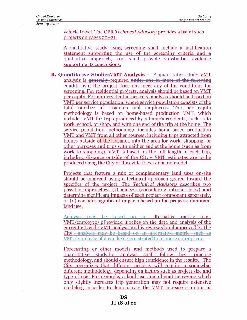
B. Quantitative StudiesVMT Analysis – A quantitative study VMT analysis is generally required under one or more of the following conditions:if the project does not meet any of the conditions for screening. For residential projects, analysis should be based on VMT per capita. For non-residential projects, analysis should be based on VMT per service population, where service population consists of the total number of residents and employees. The per capita methodology is based on home-based production VMT, which includes VMT for trips produced by a home’s residents, such as to work, school, or shop, and with one end of the trip at the home. The service population methodology includes home-based production VMT and VMT from all other sources, including trips attracted from homes outside of the [JM6]area into the area for work, shopping, or other purposes and trips with neither end at the home (such as from work to shopping). VMT is based on the full length of each trip, including distance outside of the City. VMT estimates are to be produced using the City of Roseville travel demand model.
Projects that feature a mix of complementary land uses on-site should be analyzed using a technical approach geared toward the specifics of the project. The Technical Advisory describes two possible approaches: (1) analyze (considering internal trips) and determine significant impacts of each project component separately, or (2) consider significant impacts based on the project’s dominant land use.
Analysis may be based on an alternative metric (e.g., VMT/employee) pProvided it relies on the data and analysis of the current citywide VMT analysis and is reviewed and approved by the City., analysis may be based on an alternative metric, such as VMT/employee, if it can be demonstrated to be more appropriate.
Forecasting or other models and methods used to prepare a quantitative studythe analysis shall follow best practice methodology, and should ensure high confidence in the results. The City recognizes that different projects will require a somewhat different methodology, depending on factors such as project size and type of use. For example, a land use amendment or rezone which only slightly increases trip generation may not require extensive modeling in order to demonstrate the VMT increase is minor or
City of Roseville Section 4 Design Standards_______________________________________________________________________ Traffic Impact Studies January 20210
DS TI 19 of 22
absent.
The proposed scope and justification of the proposed methodology shall be reviewed and approved by the City prior to initiation of the quantitative VMT study. The completed study shall include a detailed explanation and justification of the methodology employed.
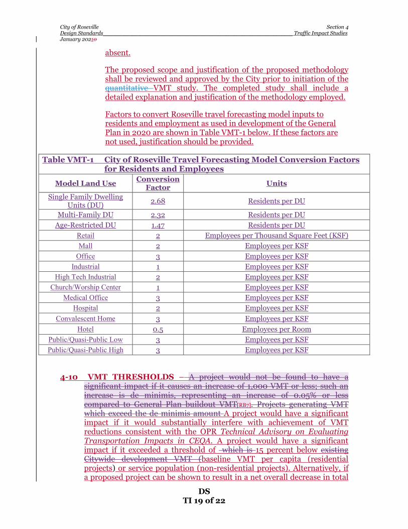
Factors to convert Roseville travel forecasting model inputs to residents and employment as used in development of the General Plan in 2020 are shown in Table VMT-1 below. If these factors are not used, justification should be provided.
Table VMT-1 City of Roseville Travel Forecasting Model Conversion Factors for Residents and Employees
Model Land Use Conversion Factor Units
Single Family Dwelling Units (DU) 2.68 Residents per DU
Multi-Family DU 2.32 Residents per DU Age-Restricted DU 1.47 Residents per DU
Retail 2 Employees per Thousand Square Feet (KSF) Mall 2 Employees per KSF
Office 3 Employees per KSF Industrial 1 Employees per KSF
High Tech Industrial 2 Employees per KSF Church/Worship Center 1 Employees per KSF
Medical Office 3 Employees per KSF Hospital 2 Employees per KSF
Convalescent Home 3 Employees per KSF Hotel 0.5 Employees per Room
Public/Quasi-Public Low 3 Employees per KSF Public/Quasi-Public High 3 Employees per KSF
4-10 VMT THRESHOLDS – A project would not be found to have a significant impact if it causes an increase of 1,000 VMT or less; such an increase is de minimis, representing an increase of 0.05% or less compared to General Plan buildout VMT[RB7]. Projects generating VMT which exceed the de minimis amount A project would have a significant impact if it would substantially interfere with achievement of VMT reductions consistent with the OPR Technical Advisory on Evaluating Transportation Impacts in CEQA. A project would have a significant impact if it exceeded a threshold of which is 15 percent below existing Citywide development VMT (baseline VMT per capita (residential projects) or service population (non-residential projects). Alternatively, if a proposed project can be shown to result in a net overall decrease in total

City of Roseville Section 4 Design Standards_______________________________________________________________________ Traffic Impact Studies January 20210
DS TI 20 of 22
City VMT when compared to baseline VMT, the project would lead to a less-than-significant transportation impact
Table VMT-1 2 (which isderived from Table 4.3-5 of the General Plan Update EIR, certified on August 5, 2020), below, reports the City’s current VMT thresholds; the referenced EIR is the most current Citywide VMT analysis. These thresholds are based on analysis with the Roseville travel forecasting model
Table VMT-1 2 hese thresholds will bemay be updated on an as-needed basis as the City develops and travel patterns change.
Table VMT-12 City of Roseville VMT Thresholds Analysis
Non-Residential Projects:
Service Population Methodology
Residential Projects: Per Capita
Methodology VMT Produced 5,459,700 1,822,100 # of Residents 120,812 120,812 # of Employees 67,530 -- Service Population 188,342 -- Baseline VMT Metric 29 VMT/service population 15.1 VMT/capita Target VMT MetricThreshold 24.5 VMT/service population 12.8 VMT/capita
4-11 VMT STUDY FORMAT– The analysis conducted for VMT studies shall be
documented in a report for review by the City, with supporting tables and figures. It shall be the intent of the VMT study to evaluate the reasonable worst-case impacts for the proposed development allowed by zoning unless a specific use/user/s is identified by the applicant.
In order to provide consistency and to facilitate staff review, the following format shall be used in the preparation of such studies by transportation consultants:
A. Table of Contents – A list of tables & figures, and when appropriate an appendix with supporting data, calculations, etc., to produce a professional and readable document.
B. Executive Summary – This section shall clearly and concisely describe the project scope and purpose, findings, conclusion, and mitigation measures and recommendations. Technical publications, calculations, data reporting and detailed design shall not be included in the executive summary. The executive summary should be short, complete in itself and not dependent on supplementary data included by reference.
City of Roseville Section 4 Design Standards_______________________________________________________________________ Traffic Impact Studies January 20210
DS TI 21 of 22
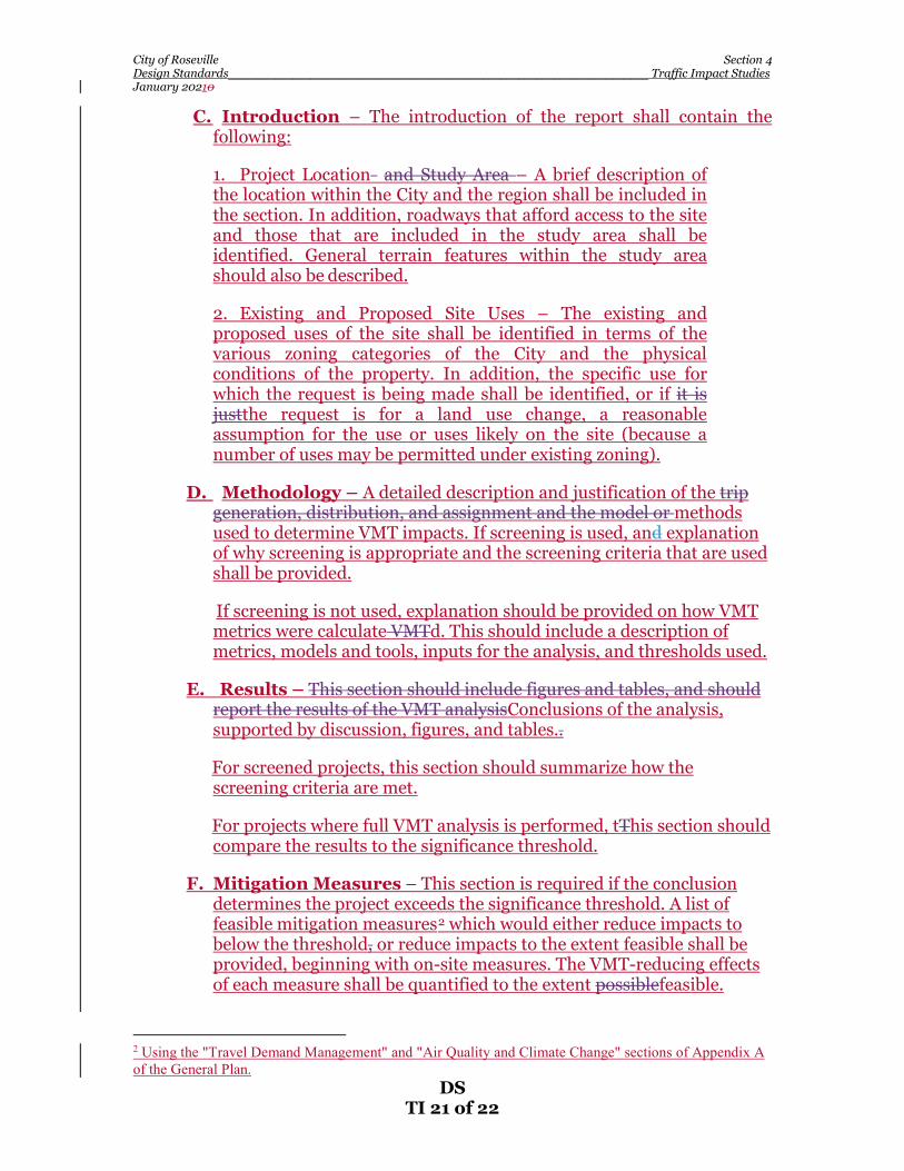
C. Introduction – The introduction of the report shall contain the following:
1. Project Location and Study Area – A brief description of the location within the City and the region shall be included in the section. In addition, roadways that afford access to the site and those that are included in the study area shall be identified. General terrain features within the study area should also be described.
2. Existing and Proposed Site Uses – The existing and proposed uses of the site shall be identified in terms of the various zoning categories of the City and the physical conditions of the property. In addition, the specific use for which the request is being made shall be identified, or if it is justthe request is for a land use change, a reasonable assumption for the use or uses likely on the site (because a number of uses may be permitted under existing zoning).
D. Methodology – A detailed description and justification of the trip generation, distribution, and assignment and the model or methods used to determine VMT impacts. If screening is used, and explanation of why screening is appropriate and the screening criteria that are used shall be provided.
If screening is not used, explanation should be provided on how VMT metrics were calculate VMTd. This should include a description of metrics, models and tools, inputs for the analysis, and thresholds used.
E. Results – This section should include figures and tables, and should report the results of the VMT analysisConclusions of the analysis, supported by discussion, figures, and tables..
For screened projects, this section should summarize how the screening criteria are met.
For projects where full VMT analysis is performed, tThis section should compare the results to the significance threshold.
F. Mitigation Measures – This section is required if the conclusion determines the project exceeds the significance threshold. A list of feasible mitigation measures2 which would either reduce impacts to below the threshold, or reduce impacts to the extent feasible shall be provided, beginning with on-site measures. The VMT-reducing effects of each measure shall be quantified to the extent possiblefeasible.
2 Using the "Travel Demand Management" and "Air Quality and Climate Change" sections of Appendix A of the General Plan.

City of Roseville Section 4 Design Standards_______________________________________________________________________ Traffic Impact Studies January 20210
DS TI 22 of 22
C.G. Conclusion – This section should summarize the analysis and indicate whether VMT exceeds the threshold, taking into accountincluding the effects of any applied mitigation measures.
4-12 VMT IMPACT STUDY PREPARATION AND SUBMITTAL REQUIREMENTS – The following requirements shall pertain to all VMT studies, unless otherwise directed by City staff.
1. VMT studies shall be prepared and stamped by a Registered Traffic Engineer or a Registered Civil Engineer with demonstrated competence and adequate experience in Transportation Engineering.
2. An electronic version of the Draft VMT study shall be submitted to the Development Services Engineering Division for review and comment. The City will forward a copy to the applicant for the review.
3. Upon completing their review, the City will provide the Consultant with comments and discuss revisions to be incorporated into the final report.
4. The Consultant shall submit an electronic version of the Final VMT study and the model results.
5. All copies of the VMT study submitted to the City shall become the property of the City.
VMT studies that are not in compliance with the requirements set forth in these VMT Impact Study Standards may be rejected until corrected to the satisfaction of the City.

City of Roseville Section 5 Design Standards_______________________________________________________________________ Site Access January 20210
DS SA 1 of 8
SECTION 5
SITE ACCESS
This section establishes requirements for site access and driveway locations.
5-1 GENERAL – Driveways shall meet sight distance requirements as
discussed in Section 7-12 of these Design Standards for both ingressing and engressing movements. Driveway width, type and design shall conform to Section 7-14 of these Design Standards.
Backing of vehicles out of driveways onto the roadway shall only be
permitted for single family residential or duplex land use. Other land uses shall be designed so both ingressing and engressing vehicles are traveling forward.
Driveways shall be located to provide at least five (5) feet between the
driveways’s traveled way and appurtenances such as fire hydrants, poles, and drop inlets.
The City recognizes that infill projects (projects within older, previously
developed areas) may have certain constraints such as lot size, existing driveways near the property line on adjacent parcels, etc. which may deem it impractical to achieve the requirements contained in these Design Standards for site access. Infill projects such as these will be evaluated on a case-by-case basis by the City. However, the goal will be to achieve the requirements contained herein to the extent practicable.
NOTE: Distances discussed below are measured to driveway
centerlines. Where distances refer to an intersection, the intersection point of reference is the near curb return.
5-2 DRIVEWAY LOCATIONS ON MINOR AND PRIMARY
RESIDENTIAL STREETS – For single family residential or duplex, the following shall apply:
A. Driveways shall be at least ten (10) feet apart as measured edge to edge,
except in cul-de-sac bulbs and the outside portion of elbows, where the minimum shall be five (5) feet. For corner parcels, the driveway shall front whichever street is projected to have a lower traffic volume, and the driveway shall be located as far from the curb return as possible, i.e., at the far end of the lot.
For Land uses other than single family residential or duplex, the following shall apply:

City of Roseville Section 5 Design Standards_______________________________________________________________________ Site Access January 20210
DS SA 2 of 8
B. Driveways shall be at least 100 feet apart. There shall be no driveways within 100 feet of an intersection. Where residential streets intersect collector or arterial streets there shall be no driveways on the residential streets within 150 feet of said intersection.
5-3 DRIVEWAY LOCATIONS ON COLLECTOR OR ARTERIAL
STREETS – There shall be no driveways along collector or arterial streets serving single family residential or duplex land uses. Driveways fronting roadways which have been classified in the General Plan as expressways shall be at least 500 feet apart, shall be right-turn-in, right-turn-out only, and shall have a standard right turn deceleration lane. No portion of a driveway shall be allowed within the straight portion of an acceleration or deceleration lane, however, driveways are permitted within acceleration and deceleration lane tapers. No portion of a driveway shall be allowed within a separate bus turnout, including tapers.
Driveways shall be at least 200 feet apart on collector streets and at least 250 feet apart on arterial streets. Driveways on collector streets shall be at least 150 feet from a collector/collector or a collector/arterial intersection or per standard drawing ST-46 if the collector has a right turn lane. Driveways on arterial streets near an arterial/collector or arterial/arterial intersection shall be located and restricted per standard drawing ST-46.
5-4 NUMBER OF DRIVEWAYS SERVING A PARCEL OR SITE – For
single family residential or duplex land uses, only one (1) driveway per parcel will be permitted, except where circular drives are proposed and approved by the City Engineer. For other land uses, the number of driveways shall be minimized, but not to a point that could cause local congestion within the public right-of-way. Consolidation of driveways with adjacent parcels shall occur whenever possible. Where driveway location standards cannot be met for a parcel, the City may require the only access to that parcel be achieved via cross access over an adjacent parcel. This shall satisfy legal requirements for access to a parcel, and the City therefore shall not be required to permit direct access to any parcel via a driveway along the parcel’s frontage. Where land uses other than single family residential or duplex are adjacent, the City typically requires cross access to minimize motorists having to use the street to get from one development to another.
For projects requiring a Traffic Study, the study shall evaluate the proposed site access for the project (see Section 4-5 (F), “Site Access”). The study shall discuss balancing the number of driveways for the project so the number of driveways is minimized, while still providing a sufficient number of access points to minimize congestion and delay.

City of Roseville Section 5 Design Standards_______________________________________________________________________ Site Access January 20210
DS SA 3 of 8
5-5 RIGHT TURN DECELERATION/ACCELERATION LANES FOR DRIVEWAYS – A right turn deceleration lane shall be provided for a driveway if all of the following conditions are met:
A. The driveway is located on an arterial or expressway.
B. Right turn ingress volume is expected to exceed fifty (50) during peak
hour flows on the roadway. For right turn ingress volumes between ten (10) and fifty (50) a right turn curb taper shall be constructed in conformance with the Standard Drawings.
C. There is ample room and frontage to fit a deceleration lane as
determined by the City Engineer. D. The travel speed of the roadway, as determined by the City Engineer,
equals or exceeds 45 mph. There may be cases where some of the above criteria are not met, but City
staff may still require a deceleration lane in the interest of safety. There may be cases where it will be necessary to merge a deceleration lane
with an existing acceleration lane. Where the beginning of a deceleration taper will be within 100 feet of the end of acceleration taper, then the deceleration and acceleration shall be merged to form a continuous auxiliary lane.
There may be cases where it is desirable to provide room for right turn
deceleration, but an entirely separate deceleration lane is either too difficult to install, due to design constraints, or is not reasonable. In these cases, a right turn curb taper shall be provided in accordance with the Standard Drawing.
Right turn acceleration lanes for driveways shall not be provided.
5-6 LEFT TURN DECELERATION/ACCELERATION LANES FOR
DRIVEWAYS – Left turn deceleration lanes (left turn pockets) are not required on collector or residential streets.
On arterials and expressways and where left turns in will be permitted, a
left turn deceleration lane shall be provided. This may be in the form of a separate left turn pocket on a six (6)-lane road, or a continuous two (2)-way-left-turn-lane on a four (4)-lane road. The minimum left turn pocket length shall be 200 feet plus a 120 foot entry taper. Longer left turn pockets may be required if a Traffic Study demonstrates the need.
Separate left turn acceleration lanes are not typically required.

City of Roseville Section 5 Design Standards_______________________________________________________________________ Site Access January 20210
DS SA 4 of 8
5-7 MINIMUM OFFSET FOR OPPOSING DRIVEWAYS- For land uses other than single family residential or residential duplex, the centerline of driveways on opposite sides of the street shall either be in direct line, or have a minimum offset distance as listed below (measured from the centerline of the driveways):
A. For driveways on minor and primary residential streets the minimum
offset shall be 150 feet.
B. For driveways on collectors the minimum offset shall be 200 feet. C. For driveways on arterials and expressways the minimum offset shall
be as specified in detail ST-47. Where a raised median is provided along the center of the street
separating conflicting turning movements, the offset requirements as stated above will not apply.
5-8 RESTRICTED TURNING MOVEMENTS FOR DRIVEWAYS –
Turning movement restrictions shall apply to unsignalized driveways on arterial and expressway streets as listed below:
A. Left turns out of driveways onto six (6)-lane roads shall be prohibited. B. On six (6)-lane roads, driveways within 400 feet of an intersection
containing left turn pockets shall be right turn-in, right turn out only. No driveways will be permitted in Zones One (1) and Six (6) as shown in detail ST-46.
C. On 6-lane roads, left turns into driveways may be allowed if all of the
following conditions are met: 1. The standard left turn lane length and bay taper can be achieved. 2. Opposing traffic will not queue-up to the point of blocking the left
turn in movement. Such a queuing calculation shall be provided by the Consultant preparing the Traffic Study for the project, and the analysis shall use the City’s projected modeled traffic volumes for the model’s horizon year.
3. The driveway is at least 400 feet downstream and 600 feet
upstream of an intersection containing left turn pockets. D. On four (4)-lane roads, see detail ST-46 for permitted turning
movements. E. Turning movements may be restricted for any driveway where deemed
necessary by the City Engineer because of safety concerns.

City of Roseville Section 5 Design Standards_______________________________________________________________________ Site Access January 20210
DS SA 5 of 8
5-9 SIGNALIZED DRIVEWAYS – The need for signalized driveways shall be based on warrants contained in the latest edition of the Caltrans Traffic Manual. Any such evaluation shall be performed by the Consultant as part of the Traffic Study for the project. For a more detailed description of a traffic signal that needs assessment, refer to Section 4-5 (G) (Traffic Impact Studies) of these Design Standards. Attention is directed to signal spacing requirements as discussed in that section. The City will typically deny a request for a new signal if spacing requirements cannot be met.
Attention is also directed to Section 4-5 (F) for Minimum Required Throat Depth (MRTD) for signalized access locations. The City does not share in the cost of design and construction of traffic signals which solely serve private property (i.e. a “tee” intersection where the driveway is situated as the “stem” of the “tee”). The Developer shall bear all costs of providing signalization at the private access point, including design and construction. In the case where a private access point comprises the fourth (4th) leg of an intersection where the other three (3) legs are public streets, the Developer shall ultimately be 100% financially responsible for the private leg (or approximately one-fourth the cost of signalizing the intersection). The obligation is in addition to sharing in the cost of the remaining signal via payment of the City’s Traffic Mitigation Fee. See Section Six (6) of these Design Standards for more information on traffic signals.
The interconnect shall connect the subject signal with at least one existing
traffic signal. If the subject signal is between two existing signals, the interconnect shall connect all three signals.
If a City Parcel is adjacent to a new fiber run, a fiber stub shall be
provided. Unless specified otherwise on the plans, six (6) feet of copper and/or
fifteen (15) feet of fiber optic cable slack shall be provided in each pull box. Fifty (50) feet of copper and/or one hundred (100) feet of fiber optic cable slack for each signal interconnect cable run shall be provided in the dedicated communications Home Run pull box in front of each signal controller or the last pull box before the controller if a dedicated communications Home Run pull box is not available.
Signal interconnect cable (SIC) shall be 9/125 μm wavelength, 72 to 216
strand, single mode, indoor/outdoor, loose tube, all-dielectric fiber optic cable as specified on the plans. 24 strand fiber shall be allowed where the majority of a pre-existing SIC conduit run’s pull boxes are smaller than No. 6.

City of Roseville Section 5 Design Standards_______________________________________________________________________ Site Access January 20210
DS SA 6 of 8
5-10 MINIMUM REQUIRED THROAT DEPTH - Driveways shall meet the Minimum Required Throat Depth (MRTD) requirements as discussed in Section 4-5 (F) of these Design Standards. In the case of “drive-thru” facilities, attention is directed to the latter part of Section 4-5 (G) for minimum on-site storage distances for ingressing vehicles.
On-site parking shall not be permitted within the MRTD area. The MRTD
requirement does not apply to single family residential or duplex land uses.
In cases where a Traffic Study is not required or in cases where there is
insufficient data available to calculate the MRTD in accordance with Section 4-5 (F), Exhibit 4-2 shall be used to determine Minimum Required Throat Depth for access points for the site. In cases where a traffic study will be provided, but the access points have not yet been determined for a site, Exhibit 4-2 shall be used to estimate the MRTD during the site design process. In these cases, the final MRTD requirements shall be determined by the Traffic Study via the methodology in Section 4-2 (F). The distances shown in Table 5-1 represent vehicle storage equivalents, which means the total required distance may be achieved by summing the throat depths for several access points if more that one access point is to serve the site. In these cases, the distance shown in Exhibit 4-2 shall be prorated to each access point to the nearest 25 feet based on the estimated relative percent usage of each access point.

City of Roseville Section 5 Design Standards_______________________________________________________________________ Site Access January 20210
DS SA 7 of 8
TABLE 5-1 MINIMUM THROAT DEPTH
LAND USE SIZE STREET RIGHT-OF-WAY <60' 60' >60'
Apartment, Condos, Mobile Homes, Planned Unit Development Quality Restaurant High Turnover/Sit Down Restaurant Drive-Thru Restaurant Motel Convention Hotel Office Park General Office
0 - 80 units 81 - 160 > 160
0 - 15,000 SF > 15,000
0 - 8,000 0 - 2,000 SF 2,001 - 3,000 3,001 - 5,000 > 5,000 0 - 150 rooms 151 - 400 > 400 0 - 150 rooms 151 - 400 > 400 0 - 20,000 SF 20,001 - 50,000 50,001 - 100,000 100,001 - 150,000 150,001 - 300,000 > 300,000 0 - 50,000 SF 50,001 - 100,000 100,001 - 150,000 150,001 - 200,000 200,001 - 300,000 300,001 - 400,000 > 400,000
25' 50' 50' 50' 50' 50' 50' 50' 100' 25' 25' 25' 25' 25' 50' 25' 25' 25' 25' 25' 25' 25' 50' 100' 50' 75' 150' 75' 100' 225' 25' 25' 25' 25' 75' 125' 25' 100' 175' 50' 50' 100' 50' 150' 250' 50' 250' 350' 25' 25' 25' 25' 50' 75' 25' 75' 175' 75' 125' 250' 125' 250' 500' 200' 400' 825' 25' 25' 50' 25' 50' 100' 50' 75' 175' 50' 100' 225' 75' 175' 350' 125' 225' 450' 150' 275' 575'

City of Roseville Section 5 Design Standards_______________________________________________________________________ Site Access January 20210
DS SA 8 of 8
TABLE 5-1 (cont.) MINIMUM THROAT DEPTH
LAND USE SIZE STREET RIGHT-OF-WAY <60' 60' >60'
Light Industrial Industrial Park Discount Store Shopping Center Drive-In Bank Supermarket Medical Clinic
0 - 100,000 SF 100,001 - 200,000 200,001 - 300,000 300,001 - 400,000 > 400,000 0 - 500,000 SF 0 - 30,000 SF 30,001 - 50,000 50,001 - 75,000 > 75,000 0 - 10,000 SF 10,001 - 20,000 20,001 - 30,000 30,001 - 40,000 40,001 - 100,000 100,001 - 150,00 150,001 - 200,000 200,001 - 250,000 250,001 - 600,000 600,001 - 700,000 700,001 - 800,000 800,001 - 900,000 900,001 - 1 million > 1 million 0 - 10,000 SF 10,001 - 20,000 20,001 - 30,000 30,001 - 40,000 > 40,000 0 - 20,000 SF 20,001 - 30,000 30,001 - 40,000 > 40,000
0 - 100 employees
25' 25' 50' 25' 50' 100' 50' 75' 150' 50' 100' 200' 75' 125' 250' 25' 25' 50' 25' 25' 25' 25' 50' 75' 125' 50' 125' 50' 75' 175' 25' 25' 50' 25' 50' 125' 50' 100' 175' 75' 125' 225' 75' 150' 250' 100' 175' 375' 125' 250' 500' 150' 300' 625' 175' 375' 750' 200' 375' 750' 225' 425' 875' 250' 500' 975' 275' 550' 1075' 425' 825' 1625' 25' 25' 50' 50' 50' 200' 75' 150' 300' 100' 200' 400' 150' 250' 500' 25' 25' 50' 25' 50' 75' 25' 50' 100' 25' 75' 150' 25' 25' 50'

City of Roseville Section 6 Design Standards__________________________________________________________ _ Traffic Signals, Signs, and Striping January 20210
DS TS 1 of 32
SECTION 6
TRAFFIC SIGNALS, SIGNS, AND STRIPING
6-1 TRAFFIC SIGNAL NEEDS ASSESSMENT – The need for new traffic signals shall be based on warrants contained in the latest edition of the California Manual on Uniform Traffic Control Devices (CAMUTCD). For a more detailed description of a traffic signal needs assessment, refer to Section 4-2H of these Design Standards.
6-2 DESIGN STANDARDS - Traffic signals, striping, and signage shall be designed and constructed in accordance with these Design Standards and the latest editions (English units) of the following listed in order of precedence:
* City of Roseville Standard Notes as published on the City’s Web site at: http://www.roseville.ca.us/gov/development_services/engineering_ land_development/plan_review/standard_notes.asp.
* City of Roseville Design & Construction Standards.
* Caltrans Standard Specifications and Caltrans State Standard Plans, including all standard symbols contained therein.
* California Manual on Uniform Traffic Control Devices (CAMUTCD).
* Attention is directed to the following from the CAMUTCD:
1. Table 4D-101. Suggested Detector Setbacks from Limit line.
2. Tables 4D-108 and 4D-109 for conduit sizing. The 26% fill limit shall apply to new installations. * A copy of the Traffic Signal Inspection Check list is included on Detail TS-22 as
a reference of required inspections during construction.
A. Signal Standard Types – Traffic signal standards, posts, and mast arms shall be of the types listed in Table 6-1:
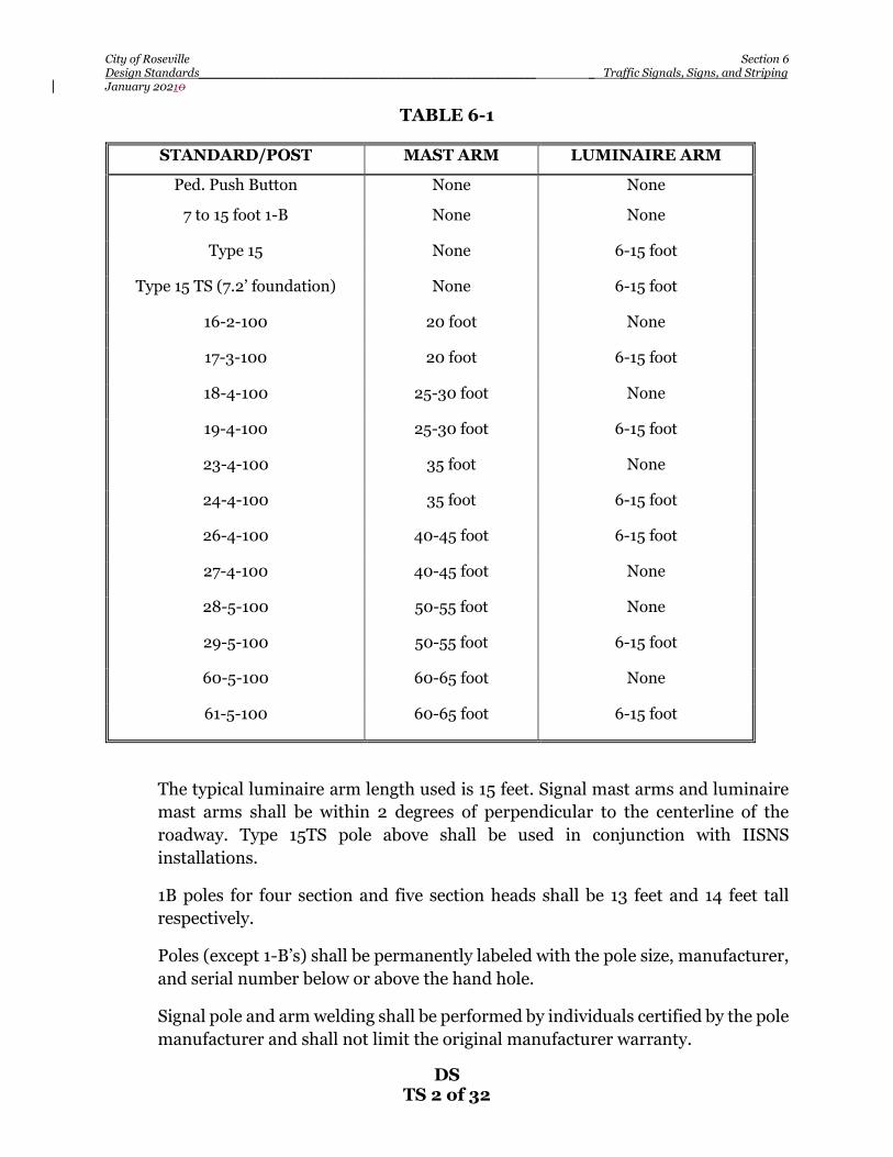
City of Roseville Section 6 Design Standards__________________________________________________________ _ Traffic Signals, Signs, and Striping January 20210
DS TS 2 of 32
TABLE 6-1
STANDARD/POST MAST ARM LUMINAIRE ARM
Ped. Push Button None None
7 to 15 foot 1-B None None
Type 15 None 6-15 foot
Type 15 TS (7.2’ foundation) None 6-15 foot
16-2-100 20 foot None
17-3-100 20 foot 6-15 foot
18-4-100 25-30 foot None
19-4-100 25-30 foot 6-15 foot
23-4-100 35 foot None
24-4-100 35 foot 6-15 foot
26-4-100 40-45 foot 6-15 foot
27-4-100 40-45 foot None
28-5-100 50-55 foot None
29-5-100 50-55 foot 6-15 foot
60-5-100 60-65 foot None
61-5-100 60-65 foot 6-15 foot
The typical luminaire arm length used is 15 feet. Signal mast arms and luminaire mast arms shall be within 2 degrees of perpendicular to the centerline of the roadway. Type 15TS pole above shall be used in conjunction with IISNS installations.
1B poles for four section and five section heads shall be 13 feet and 14 feet tall respectively.
Poles (except 1-B’s) shall be permanently labeled with the pole size, manufacturer, and serial number below or above the hand hole.
Signal pole and arm welding shall be performed by individuals certified by the pole manufacturer and shall not limit the original manufacturer warranty.

City of Roseville Section 6 Design Standards__________________________________________________________ _ Traffic Signals, Signs, and Striping January 20210
DS TS 3 of 32
Foundation locations must be verified by Engineering prior to installation.
B. Vehicle and Pedestrian Signal Types – Vehicle signals and pedestrian signals shall be of the following types:
MAT (3 section only) MAS MAS 4B SV-1-T SV-2-TB SV-3-TB TV-1-T TV-2-T TV-3-T SP-1-CS SP-2-CS
The MAT mounting shall only be used for 3 section vehicle signals for protected left turn movements. All other mast arm mounted vehicle signals shall be MAS mounted.
All signal faces shall be aluminum. Mountings for MAT and MAS signal sections shall be bronze metal.
Signal faces shall have 12-inch LED displays, unless otherwise specified.
All signal sections shall be 12-inch mold-cast aluminum with aluminum, perforated louver backplates.
Pedestrian heads shall be mounted on the intersection side of the signal pole unless otherwise directed by the Engineer and shall be clam shell type with bronze mounting hardware.
Protected left turn signals shall be all arrow.
Programmed visibility vehicle signals shall not be used without prior approval of City engineering staff and shall not be constructed of plastic.
Any 1B standard having a signal head display, 4 sections or larger, shall be installed under the following criteria:
1. Four (4) section displays will be side (SV-1-T or SV-2-T) mounted. The 1B standard shall be 13 feet in height. A PVC cap shall be provided as a pole cap.

City of Roseville Section 6 Design Standards__________________________________________________________ _ Traffic Signals, Signs, and Striping January 20210
DS TS 4 of 32
2. Five (5) section display shall be side (SV-1-T or SV-2-T) mounted. The 1B standard shall be 14 feet in height. A PVC cap shall be provided as a pole cap.
3. The extra support method shall consist of a 1” stand off w/ ¼” X 20 threaded hole. The stand-off shall be banded to the signal standard, 3” below the bottom of the top slip fitting of the displays’ 1 ½ inch riser. A ¼ inch hole shall be drilled in the center of the 1 ½ inch riser to match the position of the thread hole on the stand-off. The riser shall be attached to the standoff with a ¼” X 20 bolt, which shall include a lock washer and flat washer.
C. Vehicle Signal Alignment – The following vehicle signal alignments are typical. Variations may be required on a case by case basis.
1. For single left turn lanes with protected left turn movement, the left turn signal shall line up with the center of the left turn lane as close as possible.
2. For dual left turn lanes (which shall have a protected movement), the left turn signal shall line up with the line between the two left turn lanes as close as possible.
3. Through movement signal indications shall align as follows:
• 1 travel lane – the center of the lane. • 2 travel lanes, the lane line in-between the two lanes • 3 or more travel lanes – one signal indication shall be provided on each
lane line between through lanes.
4. For one through lane with permissive left turn, the MAS signal shall line up as close as possible with the center of the through lane. Far left permissive signal indication shall not be used.
5. When a 4 section MAS (MAS-4B) signal is used, it shall line up with:
• The lane line between the through and the left turn, or • The lane line between dual left turn lanes at a “T” intersection, or • The center of a single left turn lane at a “T” intersection, or • The center of a split phase shared through/left turn lane at a “T”
intersection.
D. Number of Vehicle Signal Indications – Typical indications are as follows:
1. For protected left turn movements: one 3-section all arrow MAT and one 3-section all arrow far left side pole-mounted signal.
City of Roseville Section 6 Design Standards__________________________________________________________ _ Traffic Signals, Signs, and Striping January 20210
DS TS 5 of 32
2. For through movements (with protected left turns): one 3-section MAS, one 3-section far right side pole-mounted signal, and one 3-section near right side or top pole-mounted signal.
3. For through movements (with permissive left turns): one 3-section MAS, one 3-section far right side pole-mounted signal, and one 3-section near right side pole-mounted signal. Far left permissive signal indications shall not be used.
4. For split phased situations: one 4-section MAS (MAS-4B w/GA), one 3-section far left side pole-mounted signal, (all Arrow), one 3-section far right side pole-mounted signal, and one 3-section near right side pole-mounted signal.
5. For right turn arrow overlap situations: same as above except the far right side and near right side pole-mounted signals shall be 5-section with green and yellow arrows. Right turn arrow overlaps shall not be provided without prior approval of the City Engineer. Where right turn arrow overlaps are provided, the conflicting U-turn shall be prohibited via signage.
6. For Bike exclusive signal phasing, turns are restricted during bike phase. Blank out sign required to prohibit right turns on red during bike phase activation.
E. Signal Phasing - Signal phasing shall start with phase 2 northbound and proceed in a clock wise direction unless directed otherwise due to coordinated corridor restrictions.
F. Permissive Left Turn Phasing – Permissive left turn phasing shall only be considered under the following conditions:
1. Minor side street approach.
2. Single approach lane (excluding right turn lane).
3. Low vehicular (less than 45 cars over the peak hour) and pedestrian volumes.
4. The approach does not service a park or school.
5. The approach is not a main school pedestrian route.
G. Vehicle Detector Layout and Inputs – Typical vehicle detector layout and inputs shall be as follows (see Details TS-9 and TS-10):

City of Roseville Section 6 Design Standards__________________________________________________________ _ Traffic Signals, Signs, and Striping January 20210
DS TS 6 of 32
1. For permissive or protected left turn situations, the left turn lane shall have four loops with the first and second loops spaced 8 feet apart, the second and third loops spaced 9 feet apart, and the third and fourth loops spaced
10 feet apart. The fourth loop shall have counting ability. The other three loops can share one input.
2. Each through lane shall have two call loops spaced 8 feet apart with one count loop spaced 9 feet behind the second call loop and one advanced loop placed per the CMUTCD.
3. Each right turn only lane shall have one loop placed 30 feet behind the stop bar in line with the through lane count loops. The loop shall be used for counting and may be used for detection following a 10 second minimum delay.
4. For the stem of a “tee” intersection, each left turn lane shall have four loops with the first and second loops spaced 8 feet apart, the second and third loops spaced 9 feet apart, and the third and fourth loops spaced 10 feet apart. The fourth loop shall have counting ability. The other three loops can share one input. No intermediate or advanced loops will be required on “tee” stems.
5. For split phase signals with a shared through/left turn lane, the shared lane shall have four loops with the first and second loops spaced 8 feet apart, the second and third loops spaced 9 feet apart, and the third and fourth loops spaced 10 feet apart. The fourth loop shall have counting ability. There shall also be one advanced loop placed per the CMUTCD.
Front vehicle loops shall be Type D or a “Quadra Circle”. Vehicle count and extension loops shall be Type A. The loops nearest the stop bar shall be placed 1 foot from the stop bar. Where a loop is designated to have counting ability as discussed above, the loop shall not share an input with any other loop. Loop wire shall terminate in the nearest pull box and not the hand hole.
Bicycle detection loops shall be Type D or a “Quadra Circle” except that their size shall be modified as follows:
• The loop size shall be decreased such that it is 1 foot narrower than the bike lane. A 6 foot bike lane shall have a 5 x5 foot loop, a 5 foot bike lane shall have a 4 x 4 foot loop, etc.
• The front of the loop shall be 6” back of the stop bar. • The center of the loop shall be 3 feet back of the crosswalk/stop bar.

City of Roseville Section 6 Design Standards__________________________________________________________ _ Traffic Signals, Signs, and Striping January 20210
DS TS 7 of 32
• Each bicycle loop shall have its own detector lead-in cable and shall be spliced in the pull box not the handhole.
• Each loop shall consist of five turns of 14 AWG with XLLP insulation. Detector lead-in cables shall be Type B and shall not be spliced between the termination point (pull box adjacent to detector loop) and the controller cabinet terminals. Tinned copper shall be permitted. There shall be a spare DLC in each advance loop pull box with 20’ of spare cable.
Type GO5 detector hand holes shall be placed so they line up with roadway stripes to minimize the frequency of vehicle tires driving over the handhole covers. A sufficient number of handholes shall be placed so that detector loop saw cuts shall not cross adjacent lanes of travel.
Signal loops installed in new asphalt concrete (AC) pavement shall be placed in the lift of asphalt concrete (AC) immediately below the final lift. The new bottom lift of AC shall be a minimum of 3 inches thick (5’ back of advance loop) where the traffic signal loops will be installed. New loops that will be buried under AC shall be installed with a saw cut depth as required to maintain a minimum of 1/2" coverage of loop sealant. Loops installed in the top lift of AC will be saw cut to a depth required to maintain 1” of sealant coverage.
Signal loops installed in new concrete pavement shall be placed immediately below the concrete and shall be preformed loops conforming to the Traffic Signal Approved Equipment List.
Signal loops shall be protected from damage before and during pavement placement.
Loops installed in existing pavement where existing loops are surface cut on that same approach may also be surface cut per the State of California Standard Plans unless otherwise directed by the Engineer. Vehicle loops shall have four (4) turns of wire in the slot.
Existing buried loops damaged by construction shall be reinstalled as if in new pavement per the above paragraph. The contractor shall grind 1½ inches of asphalt concrete pavement from lane line to lane line and at least 1 foot outside the limits of work required to install the entire loop wire. The loops shall then be covered by an asphalt concrete overlay per City Standards. Should the AC thickness be insufficient to install the loops as specified above, the contractor shall complete any additional grinding, excavating, or paving necessary to install the loops.

City of Roseville Section 6 Design Standards__________________________________________________________ _ Traffic Signals, Signs, and Striping January 20210
DS TS 8 of 32
Loop Home Run slots shall be double cut to accommodate the twisted pair (3-turns/foot), or as directed by the Engineer. Sealant for filling slots shall be Hot Melt Rubberized Asphaltic Sealant or equivalent as approved by the Engineer. All excess sealant shall be squeegeed off after application. All loops shall be wound in a clockwise rotation.
All loops shall be wound in a clockwise rotation
Where the approved plans call for preformed detector loops, the following shall apply:
1. The conduit shall be sealed to prevent the entrance of water and the movement of wires within the conduit.
2. The loop wires from the performed loop to the adjacent pull box or hand hole shall be twisted together into a pair (at least two turns per foot) and encased in Schedule 40 or Schedule 80 PVC or polypropylene conduit (⅜ inches minimum diameter). The lead-in conduit shall be sealed to prevent the entrance of water at the pull box or hand hole end.
3. The pereformed loop and lead-in conduits shall be placed prior to placing pouring final concrete. In new roadways the top of the conduit shall be placed flush with the top of the base course. For other roadways Tthe top of the conduit shall be between 2 and 3 inches below top of finished surface. Where the concrete is steel reinforced, the preformed loops may rest on the steel.
4. All detector loop shields shall not be grounded to the ground bus in the controller cabinet. 6” of the shield wire will be wound around the DLC’S then insulated with heat shrink tubing.
Loop locations must be verified by Engineering prior to installation. The contractor shall give 48 hours notice prior to loop verification request date.
H. Traffic Signal Conductors – New traffic signal and SIC conductors shall be installed per the following guidelines:
1. New wire may be pulled through existing conduits without removing conductors if based on common conditions:
a. There are a maximum number of four, ninety degree by twenty-four inch radius bends in one conduit run between pull boxes or termination points, and

City of Roseville Section 6 Design Standards__________________________________________________________ _ Traffic Signals, Signs, and Striping January 20210
DS TS 9 of 32
b. Conductors, conduit, number of bends and length of the pull are within reasonable limits (under 175 feet for signal wiring and under 400 feet for signal interconnect wiring), and
c. Ratio of the conduit (inside diameter) to the combined diameter of both the new and existing conductors or cables (outside diameter), otherwise known as conduit fill, does not exceed 40 percent.
2. All existing conductors shall be removed from conduits, the conduit proven, existing wires inspected, and the new wires added and re-pulled along with the wires previously removed if:
a. Items a and b under number 1 above are met but the ratio of the conduit (inside diameter) to the combined diameter of both the new and existing conductors or cables (outside diameter), otherwise known as conduit fill, is greater than 40 percent but less than or equal to 60 percent, or
b. Items a through c under number 1 above are met but jamming occurs.
3. New conduit shall be installed per City of Roseville Construction Standards if more than four ninety degree radii exist, the length of the pull exceeds Item #1b above, or the ration of the conduit (inside diameter) to the combined diameter of both the new and existing conductors or cables (outside diameter), otherwise known as conduit fill, exceeds 60 percent.
4. The new wire shall be pulled as follows:
a. Conductors shall be pulled into conduits by hand
b. Only Polymer Based pulling compounds such as Aqua-Gel by Ideal or equivalent shall be used
c. Lubricants shall be forcefully injected into the conduit system
d. Only fiberglass fish tape or polyester measure tape may be used
e. When pulling in multi conductor cable there shall be three spare conductors to each pole. When pulling individual conductors there shall be three spares at each pull box tied to a signal crossing.
It is assumed that all existing conductors and cables are undamaged unless inspected, documented, and reported to the inspector prior to the contractor starting that section of the work. Otherwise, any damage to City facilities shall

City of Roseville Section 6 Design Standards__________________________________________________________ _ Traffic Signals, Signs, and Striping January 20210
DS TS 10 of 32
be repaired by the contractor at the contractor’s cost in conformance with City standards.
Conductor installation in new conduits shall be limited to 26 percent fill of the conduit maximum.
Three (3) category 6E cables (from the City approved equipment list), or City approved equivalent, and one (1) power cable (IMSA 14-3/20-1-STR 600V, Belden part number 601195) or City approved equivalent to top of designated poles with 10 feet of slack for each cable at the top of the pole and 40’ of slack in the pull box adjacent to the pole.
In order to reduce strain on the CAT5 cabling, all cables shall be adequately supported by feeding them through a Kellems grip which is attached to and suspended from the pole cap.
The hole drilled for the CAT5 cabling shall be drilled on the back side of the pole three feet from the top in order to minimize the camera view obstructed by the cable and shall be threaded for a straight ¾” strain relief cord connector. At least four feet of cable shall be pulled through and secured by the strain relief cord connector. The cables shall be looped together, adequately secured to the pole to prevent movement, and sealed on the ends to prevent moisture exposure.
All new and replacement traffic signal phase wiring shall be multiple circuit conductors. Unique color coding shall be provided for each wire within the cable. The number of wires per cable shall be the next common size up from that required to provide the necessary wires as specified on the plans.
At new and remodeled traffic signals, a three inch, two cell “MAX CELL” or equivalent product shall be provided in all street crossing traffic signal conduits.
Equipment grounding conductors shall be # 6 stranded copper with THW green insulation, see Details TS-25.
The grounding electrode rod in the Service shall be paralleled with the grounding electrode rod in an adjacent pull box that is no less than 20 feet from service electrode. This connection shall consist of a continuous stranded #6 insulated conductor. The ground connection shall be on the line side of the electrical entrance terminal block. The continuous #6 stranded and insulated green copper conductor shall connect the ground bus in the electrical service, grounding electrode in the service.

City of Roseville Section 6 Design Standards__________________________________________________________ _ Traffic Signals, Signs, and Striping January 20210
DS TS 11 of 32
I. Traffic Signal Interconnect (SIC) – Traffic signal interconnect shall be provided for new signal installations, and for modifications of existing signals which currently do not have interconnect. The interconnect cable shall have its own conduit and shall not share conduit with service conductors, signal conductors, or lead-in cables.
The interconnect shall connect the subject signal with at least one existing traffic signal. If the subject signal is between two existing signals, the interconnect shall connect all three signals.
If a City Parcel is adjacent to a new fiber run, a fiber stub shall be provided.
Unless specified otherwise on the plans, six (6) feet of copper and/or fifteen (15) feet of fiber optic cable slack shall be provided in each pull box. Fifty (50) feet of copper and/or one hundred (100) feet of fiber optic cable slack for each signal interconnect cable run shall be provided in the dedicated communications Home Run pull box in front of each signal controller or the last pull box before the controller if a dedicated communications Home Run pull box is not available.
Signal interconnect cable (SIC) shall be 9/125 μm wavelength, 72 to 216 strand, single mode, indoor/outdoor, loose tube, all-dielectric fiber optic cable as specified on the plans. SIC shall have a footage marking every 4 feet. This marking may be on the outside of the cover or on the inside insulation jacket.
At the discretion of the City, existing SIC may be disconnected by the City and moved out of the work area by the contractor during construction. However, the SIC must be reinstalled by the contractor within seven days of its disconnection. Otherwise, all SIC must remain operational.
Existing copper SIC damaged during construction shall be replaced at the contractor’s cost from controller cabinet to controller cabinet on either end of the damage. Splicing of copper SIC is not allowed. Damaged copper SIC shall be replaced with fiber optic SIC, including cable, conduit, splices, terminations, patch panels, and pull boxes conforming to current City standards. The contractor shall also be responsible, at the contractor’s cost, to make any additional repairs needed to install the new cable from controller to controller.
Existing fiber optic SIC damaged during construction shall be repaired.
Damage

City of Roseville Section 6 Design Standards__________________________________________________________ _ Traffic Signals, Signs, and Striping January 20210
DS TS 12 of 32
1. Fiber Optic Cable and related facilities damaged during construction shall be replaced/repaired to current City standards and as specified below at the contractor’s cost. This work shall include fiber optic cable, conduit, pull boxes/vaults, trenches, concrete, asphalt, traffic control, pull tape, splices, splice enclosures, terminations, labor, etc, as required.
2. Damage is described as a breach in the fiber optic cable jacket, a kink, a break of the cable, or any other condition that causes a reduction in the capacity of the cable.
3. Should fiber optic cable facilities be damaged during construction without
visible damage to the cable, the cable shall be tested by a certified fiber optic technician provided by the contractor at the contractor’s cost to ensure that there is no internal damage. Should the test show internal damage, the cable shall be replaced as specified below. Otherwise, the cable shall be protected and the facilities repaired to current City standards.
Repair
1. Fiber optic cable running between and terminating at adjacent traffic signals or devices shall be replaced from termination to termination:
i. All new cable and terminations shall be acceptance tested as required elsewhere in the City standards.
ii. If the new cable must be pulled through conduits that contain traffic signal phase wiring, then a “MAX CELL” or equivalent sleeve, per City standards, shall be installed in the conduit prior to the installation of the new fiber optic cable
a. Pull box adjacent to the damage to controller cabinet.
iii. No more than 5 feet of slack may be used out of any one pull box.
iv. Pull boxes where new splices shall occur will be replaced with
Fiberlyte FL36 24” deep vaults as specified in the City standards
v. At least 50 feet of slack must be provided in the new splice vault.
vi. The slack shall be provided in even amounts on either side of the splice enclosure.
vii. Only fusion splicing meeting City standards by a certified fiber
optic technician will be allowed.
viii. All new cable, splices, and terminations shall be acceptance tested as required elsewhere in the City standards.

City of Roseville Section 6 Design Standards__________________________________________________________ _ Traffic Signals, Signs, and Striping January 20210
DS TS 13 of 32
ix. The average optical loss of each splice shall not exceed 0.10 dB.
The average is determined by measuring the splice loss in both directions with an OTDR, adding the two readings, and dividing by two. Testing should be performed for both the 1310 and 1550 nm wavelengths.
x. Splicing will not be allowed in pull boxes or vaults shared with non signal interconnect cables.
xi. If the new cable must be pulled through conduits that contain
traffic signal phase wiring, then a “MAX CELL” or equivalent sleeve, per City standards, shall be installed in the conduit prior to the installation of the new fiber optic cable.
2. Fiber optic cable running continuously past multiple traffic signals or devices may be repaired by splicing at adjacent pull box locations.
a. A single splice location may be appropriate if the damage is close enough to the adjacent pull box that the repair may be accomplished by using some of the slack in the existing cable.
i. No more than 5 feet of slack may be used out of any one pull box.
ii. Pull boxes where new splices shall occur will be replaced with Fiberlyte FL36 24” deep vaults as specified in the City standards
iii. At least 50 feet of slack must be provided in the new splice vault.
iv. The slack shall be provided in even amounts on either side of the
splice enclosure.
v. Only fusion splicing meeting City standards by a certified fiber optic technician will be allowed.
vi. All new cable, splices, and terminations shall be acceptance tested as required elsewhere in the City standards.
vii. The average optical loss of each splice shall not exceed 0.10 dB. The average is determined by measuring the splice loss in both directions with an OTDR, adding the two readings, and dividing by two. Testing should be performed for both the 1310 and 1550 nm wavelengths.
viii. Splicing will not be allowed in pull boxes or vaults shared with non signal interconnect cables.

City of Roseville Section 6 Design Standards__________________________________________________________ _ Traffic Signals, Signs, and Striping January 20210
DS TS 14 of 32
b. Two splices may be necessary if the damage is not near an existing pull box. In this case, a splice shall be provided on either side of the damage and a new length of cable meeting City standards shall be installed between the splices.
i. Pull boxes where new splices shall occur will be replaced with Fiberlyte FL36 24” deep vaults as specified in the City standards.
ii. At least 100 feet of slack must be provided in each vault.
iii. The slack shall be provided in even amounts on either side of the splice enclosure.
iv. Only fusion splicing meeting City standards by a certified fiber optic technician will be allowed.
v. All new cable, splices, and terminations shall be acceptance tested as required elsewhere in the City standards.
vi. The average optical loss of each splice shall not exceed 0.10 dB.
The average is determined by measuring the splice loss in both directions with an OTDR, adding the two readings, and dividing by two. Testing should be performed for both the 1310 and 1550 nm wavelengths.
vii. Splicing will not be allowed in pull boxes or vaults shared with
non signal interconnect cables.
viii. If the new cable must be pulled through conduits that contain traffic signal phase wiring, then a “MAX CELL” or equivalent sleeve, per City standards, shall be installed in the conduit prior to the installation of the new fiber optic cable.
3. Repair work must begin within 24 hours and be completed within 48
hours of the damage occurring irrespective of weekends and holidays.
4. Should the contractor be unable to make the repairs within this time frame, the City will complete temporary repairs and bill the contractor for their time and materials at the City’s billable rate. The temporary repair shall be treated with the same restrictions, requirements, and care as the original cable. The contractor will still be required to make the permanent repairs prior to completion of the project.
Temporary copper SIC repairs must be made within 48 hours of the damage
and provide sufficient bandwidth and reliability for the intended purpose of the copper SIC. Permanent Repairs shall be completed within 30 days of the

City of Roseville Section 6 Design Standards__________________________________________________________ _ Traffic Signals, Signs, and Striping January 20210
DS TS 15 of 32
damage. The City may make the repairs and bill the contractor for the work should the contractor be unwilling or unable to meet these requirements.
Should copper SIC installation be required by the city, the contractor shall test all copper SIC prior to installation:
1. For continuity of each wire pair. Resistance shall be consistent.
2. For high resistance (meggar) testing (250v setting):
a. Each wire pair to ground
b. Each wire pair to the cable shielding
c. Each wire pair to wire pair
3. The test may be in the field or shop
4. A city technician does not need to be present
5. The contractor shall be liable for all inspection costs related to the removal and re-installation of new cable if the untested cable is found to be faulty after installation.
Fiber optic cable shall be acceptance tested, every strand, both before and after installation at both 1310 and 1550 nm wavelengths. All testing shall be documented on OTDR Acceptance Test and Splice Loss Record forms. Losses shall not exceed 1.85 dB per mile of cable including patch panels and splices.
J. Traffic Signal Conduit – All new conduit placed in existing roadways shall be buried at a minimum depth of 15” for double conduits and 18” for single conduits below finished grade. All new conduit placed in new roadways shall be installed prior to any paving operations and be buried at a minimum of 18” below finished subgrade with the exception of conduit between detector hand holes and the first pull box which shall be buried a minimum of 18” below finished grade. New conduit installed outside of the roadway and sidewalk shall be installed at a minimum depth of 36” below finished grade.
Unless otherwise specified, all signal interconnect (SIC) conduit shall be 2-3” schedule 40 gray PVC conduit with 3 foot radius 90 degree sweeps into each number 6 pull box.
All traffic signal and SIC conduit shall have a DLC taped with a 5” green band and labeled with “locate”.

City of Roseville Section 6 Design Standards__________________________________________________________ _ Traffic Signals, Signs, and Striping January 20210
DS TS 16 of 32
Signal conduit diameter sizes shall be 2 inches minimum and 3 inches maximum except conduit runs to pedestrian push button posts shall be one (1) inch.
Existing conduits not to be reused shall be removed from existing pull boxes and the ends shall be plugged solid with grout. Existing conductors shall be removed form said conduits prior to plugging.
Abandoned conduits deemed reusable shall have the line blown out, existing conductors removed, No. 10 green pull wire installed, and the ends of the conduits sealed.
All pull tape shall be a minimum of 250 feet in length without splicing where possible. All pull tape splices shall have the ends knotted together in the pull box and all splices shall be made using 3M scotchlok connectors (models UR or UY) or approved equal to insure a continuous connection from signal controller to signal controller. Once pull tape is installed and all splices are completed, the City signal technician shall ground the tracer wires in the signal cabinet and test the wires for continuity before accepting the work. Should the pull tape tracer wire fail the continuity test, the Contractor shall repair or replace as necessary to achieve continuity.
K. Traffic Signal Pull Boxes – All pull boxes shall be No. 6 Fiberlyte FL36 per the City’s Construction Standards except as modified by the plans or the provisions below:
1. Advance loop pull boxes shall be No. 6 and shall have a minimum of 20 feet of detector lead-in cable (DLC) and 20 feet of extra loop cable spooled in the pull box.
2. The “Home Run” and “Communication Home Run” pull boxes (typically adjacent to the controller) shall be Fiberlyte FL36 24” deepboxes with 12 inch extensions (double stack). Detector loop splicing is not allowed in the “Home Run” pull boxes. The “Home Run” pull box shall be located a minimum of eight (8’) from the service and controller pad ground rods (See Detail TS-25).
3. Fiberlyte (FL36) + 24 in extension vaults shall be installed at all new
locations and at every fiber optic cable splice point unless otherwise specified on the plans.
4. Pull boxes shall not be placed within the area of an access ramp unless directed by the Engineer. Pull boxes should be installed a minimum offset of 1’ from, back of walk when within the sidewalk, and from any score or expansion joint. The bottoms of pull boxes shall be bedded in 6 inches of
City of Roseville Section 6 Design Standards__________________________________________________________ _ Traffic Signals, Signs, and Striping January 20210
DS TS 17 of 32
clean crushed rock. Grout in the bottom of pull boxes is not required. The pull box rim and lid shall be flush with surrounding surface. In unpaved areas, the pull box rim and lid shall be 1 inch above the finish grade. Pull boxes located outside of the sidewalk or planter area behind a sidewalk shall be of the Caltrans traffic rated pull box design.
All pull boxes and lids shall be #6 Fiberlyte (FL36) boxes unless otherwise directed by the Engineer. If an “in planter” type box is used, it must have a concrete collar.
All pull boxes to be abandoned shall have conductors removed from the pull boxes and conduits and the pull box shall be removed. The remaining hole shall be backfilled and compacted with similar material as the surrounding material. If within a sidewalk, the entire square of sidewalk shall be removed and replace.
Pull box covers shall read “TRAFFIC SIGNAL”, except for pull boxes and vaults used solely for traffic signal interconnect. Pull boxes and vaults used solely for copper traffic signal interconnect shall read “SIGNAL INTERCONNECT”. Should the signal interconnect pull box or vault contain any fiber optic cable, the cover shall read “TRAFFIC SIGNAL FIBER OPTICS” instead.
L. Pedestrian Push Button (PPB) - Pedestrian push buttons shall be aluminum Type “B” with metal international symbol signs. Push buttons shall meet all Americans with Disabilities Act guidelines and be placed 36 inches above the grade of the closest edge of sidewalk and shall require a reach of no more than 18 inches outside the closest edge of sidewalk. Pedestrian push buttons shall be within five (5) feet of the edge of the crosswalk line (extended) farthest from the center of the intersection (CMUTCD Figure 4E-3). Audible pedestrian signals shall be installed at all new and modified traffic signals in commercial and high pedestrian areas or as directed by the City. The contractor shall provide a city approved wave file. All other buttons shall be solid state, two tone audible, momentary LED type. . See the City’s website for a list of approved models.
M. Intersection & Arterial Roundabout Safety Lighting – Illumination provided by intersection safety lighting at signalized intersections & arterial roundabouts shall meet the following criteria: At Signalized Intersections:
1. A minimum of .15 footcandles throughout the crosswalks.
2. A minimum of .6 footcandles at the center of intersection.

City of Roseville Section 6 Design Standards__________________________________________________________ _ Traffic Signals, Signs, and Striping January 20210
DS TS 18 of 32
At Arterial Roundabouts, the following table (taken from Design Guide for Roundabout Lighting by IES) shall be used:
Luminaries shall be 250 and/or 400-watt equivalent LED and labeled as such. See the City’s website for a current list of approved materials. The luminaire equivalent wattage shall be called out on the plan sheet.
Luminaries shall be medium cutoff, Type II or III lighting distribution (MSII or MSIII)
For 400-watt luminaries, two separate 120-volt circuits shall be provided to equally split the power load.
Photoelectric controls shall be Type II and pole top mounted. Wiring from the photoelectric cell assembly to the electrical service shall be #14.
N. Controller/Service Pad – There shall be a minimum 6-inch high curb around the signal controller/service pad, excluding the sidewalk/roadway side of the pad. The minimum curb height shall increase as necessary to ensure no steeper than a 2:1 slope of the native material around the pad. Masonry blocks (not gravity type blocks) may be utilized to achieve the required 2:1 slope. The Contractor shall be responsible for acquiring engineering for retaining walls if the wall is greater than four feet from base of footing to top of wall. Refer to Detail TS-4 through TS-8 for further details.
Functional Classification E avg/Emin
High Medium Low
Major/Major 34.0/3.4 26.0/2.6 18.0/1.8 3:1
Major/Collector 29.1/2.9 22.0/2.2 15.0/1.5 3:1
Major/Local 26.0/2.6 20.0/2.0 13.0/1.3 3:1*Recommended Il luminance for Roundabouts based on IES Roadway l ighting for Roundabouts
Maintained Average Horizontal Illuminance in Lux/FC on the Pavement based on Pedestrian
Area Classification
Illumination for Roundabouts
**The average vertical i l luminance for a series of points 5 ft. in height along the centerline of the crosswalk extending to the edge of the roadway, spaced at 1.65 ft, for each driving direction, be equal to the required horizontal i l luminance and uniformity for the roundabout as described in the above Table.

City of Roseville Section 6 Design Standards__________________________________________________________ _ Traffic Signals, Signs, and Striping January 20210
DS TS 19 of 32
The service pedestal shall be installed a minimum of six (6) feet from the controller cabinet.
A City of Roseville Encroachment Permit is required for every traffic signal installation and/or modification. The project address for the permit shall be the service pedestal address. This address should be noted on the plans but is obtainable from the City in its absence. Minor modifications by City forces not involving the service pedestal are exempt from the encroachment permit requirement. Should a traffic signal be a part of a larger project, there may be an encroachment permit for the entire larger project and one or more permits for each and every signal installation/modification.
On 332 cabinets, the field wire entrance section of the controller shall face the intersection or as directed by the Engineer.
O. Traffic Signs – Sign codes shall be per the CMUTCD unless denoted otherwise. Typical signs include the R-73 (CA) series mast arm mounted signs, R3-18 mast arm mounted signs, R9-3 and R9-3b signs (where crossing the street is restricted), W3-3 Signal Ahead roadside signs (pavement markings are only necessary where visibility of the signal is limited or where the signal may be unexpected by motorists), and R3 series roadside signs on the stem of a “tee” intersection.
As a minimum, all signs shall be the common size as shown in the Standard Highway Signs manual. On collector and arterial streets, the minimum size of type R1 stop signs shall be 36 inches. If the intersection has more than three lanes (including turn lanes) in each direction, a supplemental 24” STOP sign is required in the median. Retro reflective red tape is also required for both unistruts. If the median is too narrow for supplemental signage, a 36” LED flashing STOP sign is required from the approved City equipment list. Type R1 stop signs on other streets shall be 30 inches. Type R1 stop signs installed on bike trails may be either 24 inches or 18 inches as approved by the Engineer.
Fluorescent Yellow Green (FYG) background colored signs shall be installed for the following sign types: S1-1, S3-1, S4-3, W11-1, W11-2, and W16-7p and W16-9p when used with one of the previously listed signs.
Where crossing the street is restricted at signalized intersections, R9-3 and R9-3b signs shall be installed on the signal pole in the place of the pedestrian signal indication.
In the case of R73 (CA) series of mast arm mounted signs, a common question is whether or not to allow U-turns. This determination is a function of whether

City of Roseville Section 6 Design Standards__________________________________________________________ _ Traffic Signals, Signs, and Striping January 20210
DS TS 20 of 32
or not there is sufficient room for turning radius. The guideline used by the City is that U-turns shall be restricted where less than 44 feet exists between the right lane line of the left turn lane and the face of curb for the opposing direction of travel for single left turn lanes, where less than 36 feet exists between the left edge of the inside left turn lane to the face of curb for the opposing direction of travel for dual left turn lanes, or as required by the Engineer (Detail TS-15). If U-turns are to be restricted at permissive or no left turn intersections, R3-4 or R3-18 signs shall be installed on the mast arm.
A bicycle signal actuation sign, R10-22, shall be installed in conjunction with bicycle detection. The sign shall be placed adjacent to the bicycle loop on the nearest signal pole or on a sign post per City standards as directed by the Engineer.
W3-3 Signal Ahead signs shall be installed on all approaches to a signalized intersection on the day of signal activation and before the signal is activated. The signs shall be installed prior to the left or right turn pocket bay tapers at a minimum and shall be mounted on street light poles when possible. Please see Detail TS-16 for additional placement information. Immediately prior to the activation of a new traffic signal. The contractor shall install two (2) orange flags on the “Signal Ahead” signs. The flags shall remain in place for two weeks prior to removal by the contractor.
All existing traffic signs, which are in conflict with the proposed work as shown on the plans, shall be removed by the Contractor and returned to the City. The Engineer shall make the final decision if a question arises as to what represents said conflict.
Efforts shall be made to ensure that all signs in the center median or shoulder areas are not installed next to landscaping or other objects which may impair visibility of the sign nor shall they impair the visibility of the traffic signal.
Internally Illuminated Street Name Signs (IISNS) shall require a City Traffic Engineering accepted stamp for all approved proofs matching existing City LED IISNS’s prior to ordering. Only products with prior approval from the City shall be allowed.
1. Refer to City of Roseville Construction Standards Section 56 “Signs”.
2. Internally Illuminated Street Name Signs (IISNS)
a. All proofs require a City approved layout matching existing City LED IISNI’s prior to ordering.
City of Roseville Section 6 Design Standards__________________________________________________________ _ Traffic Signals, Signs, and Striping January 20210
DS TS 21 of 32
b. IISNS name panels shall be manufactured as follows:
i. Sign panel material shall be clear (not opaque) poly.
Thickness of the panel shall be 3.5 mm /6.0 mm maximum.
ii. Sign panels background sheeting shall be: 3M DG3 (Diamond Grade) series 4090. Color (White).
iii. Etched sheeting (Street name and City of Roseville logo) shall
be 3M EC 1177c material. Color (Green).
iv. Manufacturer shall warranty, no chemical reaction, shall be exhibited between the background sheeting and etched sheeting components.
v. The IISNS shall be double sided with street names on both
sides. 3. Courts
• Install a type W53 “Not a Through Street” sign at the entrance to all Courts or Cul-de-Sac’s when you cannot see the end of the roadway from the last intersection. Place the sign on the nearest street light pole when possible.
4. Intersections within Subdivisions
• All four-way intersections shall have right-of-way controls established on the minor street. Install type R1-1 “Stop” signs, bars and legends on the minor street.
• Install R26 (CA) “No Parking Anytime” signs at the entrance to
subdivisions that have a median island just off an arterial or collector.
P. Striping – All painted traffic stripes, arrows, and pavement markings shall be constructed with thermoplastic material to the specifications set forth in Section 84 of the Caltrans Standard Specifications (latest edition). Non reflective pavement markers shall consist of ceramic markers only conforming to Section 85-1.04A of the same standards.
The following permanent traffic lane striping shall be raised pavement markings, and placed as one of the following types: Detail 4, 7, 10, 13, 17, 20,
City of Roseville Section 6 Design Standards__________________________________________________________ _ Traffic Signals, Signs, and Striping January 20210
DS TS 22 of 32
23, 25, 26, 30, 33, 37C, or Detail 38. Thermoplastic striping is also required for placement of Detail 25 and 38.
The following permanent traffic lane striping shall be thermoplastic, and placed as one of the following types: Detail 25, 27B, 38, 39, 39A and Detail 40. Pavement Markers are also required for placement of Detail 25 and 38.
Detail 26 markers shall be placed 2 inches from the face of the median curb.
At all fire hydrant locations, a blue reflective pavement marker shall be installed one foot off paved centerline or median on the hydrant side of the roadway.
Sandblasting of traffic stripes shall not be permitted. Removal of traffic stripes shall be by grinding, or by other methods approved in writing by the Engineer. For removal of pavement markings, a rectangular area shall be ground to prevent ghosting of the original marking and be covered with rectangular area of Type II slurry. Conflicting striping shall be removed completely. Type II slurry of conflicting striping is required when it crosses the new traveled lane. When this occurs, the entire lane shall be slurried from lane line to lane line over the entire length of the conflicting striping. This requirement will not apply to ceramic markers unless specified on the plans.
All striping or pavement markings damaged during construction shall be repaired at the contractor’s expense. Repairs shall consist of complete replacement of marking or legends, replacement of sections of thermoplastic striping, and replacement of damaged or missing markers as directed by the Engineer.
The following shall apply when installing traffic stripes and pavement markings:
1. In addition to locations as shown on the plans, bike lane signs and pavement markings shall be installed at no more than one half-mile intervals and following every break in the bike lane striping. The BIKE LANE legend shall be centered in the lane to ensure the legend does not run into the lane striping.
2. A bicycle detector pavement marking shall be installed in conjunction with each bicycle detector per CMUTCD Figure 9C-7 and shall be placed starting 6 inches back of the crosswalk/stop bar.
3. Unless otherwise specified on the plans, crosswalks shall be eleven (11) feet wide, measured from the centerline of the stripe.

City of Roseville Section 6 Design Standards__________________________________________________________ _ Traffic Signals, Signs, and Striping January 20210
DS TS 23 of 32
4. Traffic stripes and pavement marking shall not be placed over utility covers including, but not limited to, manhole covers, utility boxes, hand holes, or water valve covers.
5. STOP legend pavement marking and limit lines are required with stop signs. YIELD legend pavement marking are required with yield signs. The yield limit line shall be per the CMUTCD (24” by 36” triangles).
6. Pavement arrows shall be one of the following types unless otherwise directed by the Engineer: Type II (L, R or B), Type III (L, R, or B), Type VI, or Bike Lane Arrow.
7. At signalized intersections with left turn lanes longer than 150 feet the Type II, or Type III arrows shall be placed 20 feet behind the limit line. Where there are dual left turn lanes with staggered limit lines, the arrows in the number 1 left turn lane (closest to the median) shall be placed 15 feet behind the limit line, and the arrow in the number 2 left turn lane shall be placed 20 feet behind the limit line. The intent is to have the two arrows line up side by side, even though the limit lines are staggered.
8. All turn lanes shall have a Type II or Type III arrow at the beginning of the turn lane such that the tail of the arrow lines up with the beginning of the Detail 38 striping. All turn lanes 150 feet or longer shall have a minimum of two Type II or Type III arrows (one arrow for every 150 feet of turn lane).
9. All traffic lane striping shall be discontinued through any four way public intersection from crosswalk, marked or unmarked. Striping shall be continuous through private intersections unless there is a striped left turn lane and/or traffic signal. For non-signalized public “T” intersections, the through and bike lane striping shall be continuous for the non-intersection direction, i.e. “across the top of the T”. However, there shall be no striping within the limits of the crosswalks.
10. At locations where bike lane striping is parallel striping used to channelize traffic, right turn acceleration/deceleration lanes and bus turnouts, both stripes shall be detail 38. Reflective pavement markers shall be placed to the outside of the bike lane.
11. Bike lane striping shall be continuous except at right turn bay tapers, intersections with City streets, and driveways where the centerline/median is broken. See Detail TS-18 for examples.
12. Lanes designated by the Engineer as auxiliary shall be striped as directed by the Engineer. Examples of typical auxiliary lane striping can be seen on

City of Roseville Section 6 Design Standards__________________________________________________________ _ Traffic Signals, Signs, and Striping January 20210
DS TS 24 of 32
Detail TS-19. Bike lane striping along auxiliary lanes shall be modified Detail 38 with 4 foot stripes at 10 feet on center.
13. Left turn arrows shall not be placed in Two Way Left Turn Lanes unless otherwise directed by the Engineer.
14. Stop and yield bars shall be 7 feet back from the center of the pedestrian access ramp unless directed otherwise by the Engineer. Where a stop sign is installed with a yellow school crosswalk, a supplemental white stop bar shall be installed 4 feet back from the crosswalk line.
15. Lane line extensions for dual turning lanes shall be placed on a continuous arc as appropriate for a turning 40 foot bus. Triple turning lanes shall be placed to accommodate the turning of a 65 foot total length (California legal) tractor truck-semitrailer (Detail TS-20).
Type K-4 (Type Q in the CalTrans Traffic Manual) markers (aka: Superducks) shall be 36 inches tall and have 3 bands of reflective sheeting per Section A73C of the CalTrans Standard Plans.
Type K-4 markers mounted between two lanes of opposing traffic shall be yellow with yellow reflectorized sheeting. Type K-4 markers mounted between two lanes of traffic traveling in the same direction shall be white with white reflectorized sheeting.
At median curb noses, a yellow Type K-4 marker shall be mounted on top of the curb. A white Type K-4 marker shall be mounted at the nose for a Right turn ‘pork chop’ island. At entrances to subdivisions, the median shall have 3 yellow reflective markers. One on the median nose and one on either side (end of radius).
Additional City striping guidelines can be found in Section 7, Streets, of these standards and Sections 82, 84, and 85 of the City’s Construction Standards.
Q. Right Turn Lanes – Right turn lanes shall be provided at signalized intersections:
1. On all main street approaches.
2. On all minor street or driveway approaches with peak hour approach volumes of 60 vehicles or more.
R. City Supplied Equipment – City supplied equipment shall be picked up by the
contractor at the City’s corporation yard (2005 Hilltop Circle, Roseville) upon 10 calendar days notice to the City’s inspector. The contractor is responsible to

City of Roseville Section 6 Design Standards__________________________________________________________ _ Traffic Signals, Signs, and Striping January 20210
DS TS 25 of 32
provide all labor and equipment necessary to load, transport, and install the equipment. Equipment provided by the City typically includes:
1. NEMA Type P or Caltrans 332 cabinet (fully equipped)
2. Type 27-22 electrical service with battery backup system
3. 2070L controller
4. Communications equipment
5. EVP equipment with the exception of the cable from the detector to the discriminator
6. CCTV camera
7. WiFi communications equipment
S. Contractor Supplied Equipment – Attention is drawn to the following contractor supplied and installed materials:
1. Equipment grounding conductors shall be AWG #8 bare solid copper wire minimum.
2. Three (3) category 5E cables (Mohawk Lan-Trak OSP, part number M58790), or City approved equivalent, and one (1) power cable (IMSA 14-3/20-1-STR 600V, Belden part number 601195) or City approved equivalent to top of designated pole with ten (10) feet of slack for each cable at the top of the pole.
3. 16” countdown pedestrian heads. Contact the City for approved vendors and models.
4. Audible pedestrian or solid state, two tone audible, momentary LED pedestrian push buttons. See the City’s website for a list of approved models.
5. Internally Illuminated Street Name Sign (IISNS) Mast Arms shall be per TS-11 and TS-12 and have a permanent name plate identifying compatible pole model number. The loading of the mast arms and the signal pole to which the sign mast arm is attached shall be approved in writing by the manufacturer or a licensed Structural Engineer.
6. Slim profile, LED IISNS’s with City Logo. Contact the City for approved vendors and models. Sign proofs must be approved by the City prior to ordering equipment.

City of Roseville Section 6 Design Standards__________________________________________________________ _ Traffic Signals, Signs, and Striping January 20210
DS TS 26 of 32
T. Salvaged Equipment – Salvaged equipment shall become property of the City and shall be delivered by the Contractor upon 24 hours notice. The Contractor shall deliver salvaged equipment to the City’s Corporation Yard located at 2005 Hilltop Circle, Roseville, following at least 48 hours advance notice of delivery.
Where signals are being modified or relocated, existing emergency preemption equipment shall be relocated to the new signal poles.
Damaged conduits deemed to not be reusable shall be removed from existing pull boxes and ends plugged solid with grout. Existing conductors shall be removed from said conduits prior to plugging. Contractor shall dispose of said conductors.
Abandoned conduits deemed reusable shall have the line blown out, existing conductors shall be removed, a number 10 green locate wire shall be installed, and the ends of the conduits shall be sealed.
U. Traffic Control – Construction area traffic control shall be installed in accordance with the City accepted projects specific traffic control plan, the approved improvement plans and specifications, the Construction Standards, the City Design Standards, The current California Manual on Uniform Traffic Control Devices (CAMUTCD), The State of California Standard Plans, and the latest edition of The State of California Department of Transportation Standard Specifications hereinafter referred to as the Cal Trans Standard Specs and as follows:
1. Construction that inhibits free flow traffic shall not occur between the hours of 4 p.m. to 6 p.m. on Monday through Friday without prior written approval of the Engineer. Traffic control lasting more that one hour will be subject to additional time restrictions set by the City’s Traffic Section in order to minimize the impact to the public.
2. At least one lane in each direction shall remain open to traffic unless otherwise approved by the Engineer.
3. Turning movement restrictions require prior approval of the City. A changeable message sign (CMS) shall be posted in the direction of travel affected by the restriction a minimum of three days prior to the implementation of the traffic control at the contractor’s expense. Wording and placement of the CMS shall be “ACCEPTED” by the City’s Traffic Section prior to installation.
4. Traffic control hours are subject to limitation by the City.

City of Roseville Section 6 Design Standards__________________________________________________________ _ Traffic Signals, Signs, and Striping January 20210
DS TS 27 of 32
5. Lane closures that affect traffic flow may require night work, changeable message signs, and/or certified flaggers at the contractor’s expense. The contractor should consider traffic control included in their cost of work and may contact the City’s Traffic Section for requirements prior to bidding a job.
6. Approved road closures require 72 hour advance notification to the City, the public and emergency services. Changeable message signs (CMS’s) shall be posted in the directions of travel affected by the closure a minimum of 1 week prior to the implementation of the traffic control at the contractor’s expense. Wording and placement of the CMS’s shall be “ACCEPTED” by the City’s Traffic Section prior to installation.
7. A Red Flash Request form must be submitted 48 hours prior to the time the red flash is needed. Allowable hours of flashing operation will be set by the City’s Traffic Section and will require early morning, evening, or night work unless otherwise approved in writing by the City’s Traffic Section. The Red Flash Request form is on Detail TS-21.
8. Special events shall go through the City’s special event process (Contact the City of Roseville’s Parks & Recreation Dept. for a Special Events packet). Changeable message signs placed in advance of the event may be required depending upon the size of the event and its impact on traffic movement. Contact the City’s Traffic Section for requirements.
9. Special holiday traffic control restrictions are in place from one week prior to the Thanksgiving holiday through January 3rd each year for various roads throughout the City (Detail TS-23).
TRAFFIC CONTROL PLANS:
All traffic control plans (including signage) shall be per the current CAMUTCD (California Manual on Uniform Traffic Control Devices).
The City’s Construction Inspector or Engineer shall determine the necessity of a formal traffic control plan (TCP) submittal based upon the following guidelines:
A TCP submittal will be required if the TCP is anyone of the following:
1. Complicated (to be determined by the City’s Construction Inspector)
2. Involves a signalized intersection
3. Longer than 12 hours

City of Roseville Section 6 Design Standards__________________________________________________________ _ Traffic Signals, Signs, and Striping January 20210
DS TS 28 of 32
4. Not detailed in the CAMUTCD
5. Involves road closure or detours
If significant detours, lanes closures, and/or signal modifications (including but not limited to loop disruption, the need for a temporary signal, etc.) are needed, a separate Traffic Handling Plan from that of the Traffic Control Plan may be required. The Traffic Handling Plan will require review and approval by Traffic Engineering and will require additional review time for submittals.
Traffic Control Plans require responsible party contact information, hours of operation (which may be restricted by the City), and duration of work.
TCP submittals require the following minimum review times per submittal:
Type of TCP Min. Review Time
Lane Closure 2 days
Intersection Signal Flash 2 days
One-way traffic control 2-4 days
Detour/Road Closure 3-4 weeks
Note that complicated TCP’s may require more review time. Traffic control review time should be included in the contractor’s work schedule.
The traffic control plan submittal process is as follows:
1. Three copies of the TCP must be submitted to the inspector.
2. The TCP is reviewed by the City Traffic Section and corrections/modifications are made by the contractor as necessary.
3. The City Traffic Section will stamp the TCP as “ACCEPTED” once the plans are to the City’s satisfaction.
4. Two copies of the “ACCEPTED” TCP are returned to the inspector – one copy each for the inspector and contractor.
5. The contractor must have a copy of the “ACCEPTED” TCP on site during the entire time the TCP is in place.
Any deviation from the “ACCEPTED” TCP shall be approved by the inspector and may require re-submittal of the TCP for City review. Failure to maintain the TCP may result in shutdown of the project, suspension of inspection
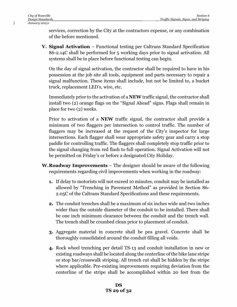
City of Roseville Section 6 Design Standards__________________________________________________________ _ Traffic Signals, Signs, and Striping January 20210
DS TS 29 of 32
services, correction by the City at the contractors expense, or any combination of the before mentioned.
V. Signal Activation – Functional testing per Caltrans Standard Specification 86-2.14C shall be performed for 5 working days prior to signal activation. All systems shall be in place before functional testing can begin.
On the day of signal activation, the contractor shall be required to have in his possession at the job site all tools, equipment and parts necessary to repair a signal malfunction. These items shall include, but not be limited to, a bucket truck, replacement LED’s, wire, etc.
Immediately prior to the activation of a NEW traffic signal, the contractor shall install two (2) orange flags on the “Signal Ahead” signs. Flags shall remain in place for two (2) weeks.
Prior to activation of a NEW traffic signal, the contractor shall provide a minimum of two flaggers per intersection to control traffic. The number of flaggers may be increased at the request of the City’s inspector for large intersections. Each flagger shall wear appropriate safety gear and carry a stop paddle for controlling traffic. The flaggers shall completely stop traffic prior to the signal changing from red flash to full operation. Signal Activation will not be permitted on Friday’s or before a designated City Holiday.
W. Roadway Improvements – The designer should be aware of the following requirements regarding civil improvements when working in the roadway:
1. If delay to motorists will not exceed 10 minutes, conduit may be installed as allowed by “Trenching in Pavement Method” as provided in Section 86-2.05C of the Caltrans Standard Specifications and these requirements.
2. The conduit trenches shall be a maximum of six inches wide and two inches wider than the outside diameter of the conduit to be installed. There shall be one inch minimum clearance between the conduit and the trench wall. The trench shall be crumbed clean prior to placement of conduit.
3. Aggregate material in concrete shall be pea gravel. Concrete shall be thoroughly consolidated around the conduit filling all voids.
4. Rock wheel trenching per detail TS-13 and conduit installation in new or existing roadways shall be located along the centerline of the bike lane stripe or stop bar/crosswalk striping. All trench cut shall be hidden by the stripe where applicable. Pre-existing improvements requiring deviation from the centerline of the stripe shall be accomplished within 20 feet from the

City of Roseville Section 6 Design Standards__________________________________________________________ _ Traffic Signals, Signs, and Striping January 20210
DS TS 30 of 32
beginning to the end of deviation. Deviations along bike lane lines shall be to the curb side of the stripe unless directed otherwise by the City. Deviations greater than 20 feet shall require asphalt concrete repair per Item #6 below.
5. Rock wheel trenching parallel to the roadway centerline across acceleration, deceleration, or bus turn out openings that cannot be completed per TS-13 upon the same day shall be filled with concrete to the top of the trench and the contractor shall return to complete an 18 inch “T” grind and overlay per CST-TB-1
6. Saw cutting in the street other than rock wheel trenching will require pavement repair per CST-TB-1 or TB-3 and/or grinding between lane lines per City Standards found elsewhere in this document and the Construction Standards.
7. Should the contractor fail to install the conduits in NEW asphalt roadways roadways prior to the bottom lift of asphalt concrete, the City will require the installation of a Tensar Glass Grid 8502 or equivalent matt prior to the final lift of pavement.
8. Should the contractor fail to install the conduits in NEW Portland cement concrete roadways prior to the placement of concrete, the City will require the conduits be installed by horizontal direction drilling or the contractor shall place the conduit per TB-1 or TB-3a.
98. The contractor is solely responsible to provide all labor and equipment necessary to locate existing underground facilities beyond the information provided by the U.S.A. markings including, but not limited to, metal detectors, wire locating equipment, and potholing.
109. Where combinations of sidewalk or curb and gutter are poured contiguous to existing, all adjoining existing concrete vertical faces shall be doweled per City Standards found elsewhere in this document and the Construction Standards.
110. Curb ramps conforming to the latest ADA, Title 24 requirements, and the City Construction Standards shall be installed at all pedestrian crossing locations within the project area. Existing ramps that do not meet these requirements shall be removed and replaced.
6-3 PREPARATION OF PLANS – Traffic signal plan sheets shall conform to the provisions of Sections 2 and 3 of these improvements standards, including submittal requirements, AutoCAD files, etc. Traffic signal plans shall have one title

City of Roseville Section 6 Design Standards__________________________________________________________ _ Traffic Signals, Signs, and Striping January 20210
DS TS 31 of 32
sheet followed by separate signal and lighting, interconnect, and signing and striping sheets for each intersection. Signing and striping sheets shall be submitted concurrent with signal and lighting sheets for review. Signal and striping plan sheets must be stamped and signed by a licensed Civil Engineer.
A. Title Sheet – The title sheet shall include the following:
1. Title of project, which shall include the location.
2. A vicinity may with north arrow showing the limits of work. The location map is not required to be to scale.
3. Pertinent signature blocks, and revision block.
4. A legend for symbols not found in the Standard Plans (e.g., utility lines, etc.). Below the legend, place the following note: NOTE: SEE STATE STANDARD PLANS ES-1A, ES-1B and ES-1B FOR EXPLANATION OF OTHER SYMBOLS.
5. Controller/Service foundation detail (TS-4 through TS-8), loop layout detail (TS9 and TS-10), and other special details. The service pedestal address shall be place adjacent to these details in large, bold letters.
6. Applicable City of Roseville Standard Notes as published on the City’s Web site at www. roseville.ca.us/engineering.
B. Signal and Lighting Sheet – The signal and lighting sheet shall be drawn at a scale of 1 inch equals 20 feet, and shall include the following:
1. A north arrow.
2. Existing and proposed field conditions which include, but are not limited to, the following: underground and overhead utilities (including height of lines near signal poles), driveways, fire hydrants, poles, signs, fences, street lights, edge of pavement, curb and gutter, sidewalk, right-of-way line, P.U.E.’s, roadway striping, medians, centerline, pull boxes, curb ramps, trees (particularly those needing trimming), adjacent topography, etc., Existing field conditions, appurtenances, etc, shall be dashed and screened. Proposed shall be solid and bold.
3. Pole and equipment schedule (TS-2).
4. Conductor and conduit schedule. The schedule shall include rows showing “percent fill” values, and conduit quantity/size (TS-3).

City of Roseville Section 6 Design Standards__________________________________________________________ _ Traffic Signals, Signs, and Striping January 20210
DS TS 32 of 32
5. Complete traffic signal design, including but not limited to, the following: conduit runs, detector loops (with input designations), detector handholes, vehicle and pedestrian signals (with phase designation), luminaries, pedestrian pushbuttons (with phase designation), controller, service pedestal, service point, emergency vehicle detectors, signing, striping, interconnect, CCTV Camera, and WiFi equipment.
6. Phasing diagram. Designate type of flashing operation below the phasing diagram.
7. Phasing for emergency vehicle preemption. Typically, protected left turn phases are combined with the concurrent through movement during EV preemption.
C. Interconnect Sheet - The interconnect sheet may be drawn at a scale of 1 inch equals 20 feet or 1 inch equals 40 feet and shall include a north arrow.
D. Signing and Striping Sheet – The signing and striping sheet shall be drawn at 1 inch equals 40 feet, and shall include the following:
1. A north arrow.
2. Existing signing and striping – dashed or screened.
3. Proposed signing and striping where line types shall closely approximate striping proposed.
4. Centerline stationing with either begin and end modification stationing or lineal feet of modification specified along with the detail.
E. Intersection Lighting Sheet – The Intersection Lighting sheet shall be drawn at 1 inch equals 40 feet, and shall include the luminaire diagrams, luminaire wattage equivalent, and min, max, and average illuminance.

City of Roseville Section 7 Design Standards__________________________________________________ ____ Streets January 20210
DS ST 1 of 20
SECTION 7
STREETS 7-1 STREET CLASSES AND DESIGN WIDTHS – For purposes of geometric and
structural design of all new public streets, streets shall be classified according to the following requirements, the appropriate Standard Drawings, and Table 7-1. Under certain circumstances, particularly within the infill areas of the City, changes to the standards can be made at the discretion of the City Engineer.
A. 20-Foot Street (Alley) – A Street depressed in the center with a right-of-way
and surface width of 20 feet. Alleys are not permitted unless specifically approved by the City Council. STD DWG #ST-1A
B. Residential Streets – Where residential streets serve Low Density
Residential (LDR) and Medium Density Residential (MDR) subdivisions, the following standards apply. In the case of High Density Residential (HDR) and (MDR) condominium development, please refer to City of Roseville Fire Department for minimum street sections.
LDR MDR HDR
Fee Lot Condo Style Design &
Construction Standards
Design & Construction
Standards
Fire Department Standards
Fire Department Standards
1. Minor Residential with Attached Sidewalks – A residential street
servicing 100 or fewer lots shall be classified as a minor residential street. Minor residential streets shall have a right-of-way width of 42 feet, and back of curb to back of curb width of 34 feet. STD DWG #ST-2
2. Minor Residential with Detached Sidewalks – A residential street
servicing 100 or fewer lots shall be classified as a minor residential street. Minor residential streets shall have a right-of-way width of 54 feet and a back-of-curb to back-of-curb width of 34 feet. STD DWG #ST-3
3. Primary Residential with Attached Sidewalks – A residential street
servicing more than 100 lots or along which schools or parks are proposed to front, shall be classified as a primary residential street. Primary residential streets shall have a right-of-way width of 46 feet, and back of curb to back of curb width of 38 feet. STD DWG #ST-4
4. Primary Residential with Detached Sidewalks – A residential street
servicing more than 100 lots or along which schools or parks are proposed to front, shall be classified as primary residential. Primary residential

City of Roseville Section 7 Design Standards__________________________________________________ ____ Streets January 20210
DS ST 2 of 20
streets shall have a right-of-way width of 58 feet and back-of-curb to back-of-curb width of 38 feet. STD DWG #ST-5
C. Collector/Industrial – A Street serving an industrial/commercial
subdivision or a residential subdivision along which no home frontage is allowed shall be classified as a collector/industrial street. Collector/industrial streets shall have a right-of-way width of 58 feet, and back-of-curb to back-of-curb width of 48 feet. Additional right-of-way and pavement shall be provided at intersections for deceleration lanes, bus turnouts, and turn lanes, as specified by the City Engineer. STD DWG #ST-7 (58’ R/W – Attached sidewalk); STD DWG #ST-6 (48’ R/W – Detached sidewalk)
D. Minor Arterial – Those roads specified in the City’s Capital Improvement
Program as requiring a four-lane roadway shall be classified as minor arterials. Minor arterial shall have a right-of-way and back-of-curb to back-of-curb width of 76 feet, and shall provide a center 2-way left lane or raised landscape median as specified by the City Engineer. Additional right-of-way and/or pavement may be required for bus turnouts and at intersections and driveways for acceleration lanes, deceleration lanes, and multiple left turn lanes, as specified by the City Engineer. Additional right-of-way shall also be provided if sidewalks are not part of a landscape/pedestrian corridor adjacent to the back of curb. STD DWG #ST-8
E. Major Arterial – Those roads specified in the City’s Capital Improvement
Program as requiring a six-lane roadway shall be classified as major arterials. Major arterials shall have a right-of-way width of 100 feet and back-of-curb to back-of-curb width of 100 feet. Additional right-of-way and/or pavement may be required for bus turnouts and at intersections and driveways for acceleration lanes, deceleration lanes, and multiple left turn lanes, as specified by the City Engineer. Additional right-of-way shall also be provided if sidewalks are not part of a landscape/pedestrian corridor adjacent to the back of curb. STD DWG #ST-9
F. Cul-de-Sac – The length of cul-de-sac streets as measured from the centerline
of the intersecting street to the center of the bulb, shall not exceed 500 feet, unless a secondary emergency vehicle access is provided to the rear of the cul-de-sac bulb area, in which case the length of the cul-de-sac may be increased to maximum length of 1000 feet with the approval of the Fire Chief and City Engineer.
In the case of stub streets associated with phased development, the combined
street lengths as measured from the dead-end to the nearest through street shall be in accordance with the requirements for cul-de-sacs. Stub streets shall be terminated with a temporary bulb or a hammerhead conforming to the Standard Drawing. A barricade conforming to the Standard Drawings shall be installed at the end of all streets that are proposed for future extension. For cul-de-sacs greater than 200 feet or where the end of the cul-de-sac is not visible

City of Roseville Section 7 Design Standards__________________________________________________ ____ Streets January 20210
DS ST 3 of 20
from the centerline intersection of cross street, a “NOT A THROUGH STREET” sign shall be installed at the beginning of cul-de-sacs. STD DWG #ST-14 & #ST-15
G. Partial Width Streets – At the discretion of the City Engineer, partial width
streets may be permitted along the boundary of a subdivision of other private development where the full right-of-way width cannot be dedicated. For collector and arterial streets, the developer shall, as a minimum, dedicate sufficient right-of-way and construct 32 feet width of pavement with full frontage improvements along the developing property and a two-foot wide gravel shoulder on the opposite side. Street centerline and pavement crown shall be placed at the ultimate location. Partial streets will not be permitted for residential streets.
H. Private Streets – Private streets shall be designed to the same structural and
geometric requirements as those for public streets. Minimum pavement widths shall be 28-feet, and curb and gutter sections shall have a 3-foot minimum width. Sidewalks on one side of the street can be eliminated at the discretion of the City Engineer.
I. Gated Entryways – Gated entryways are allowed in private subdivisions.
Gate access must be provided in accordance with Fire Department requirements. They shall be designed per the standard drawing and shall be privately maintained. See STD DWG #ST-25
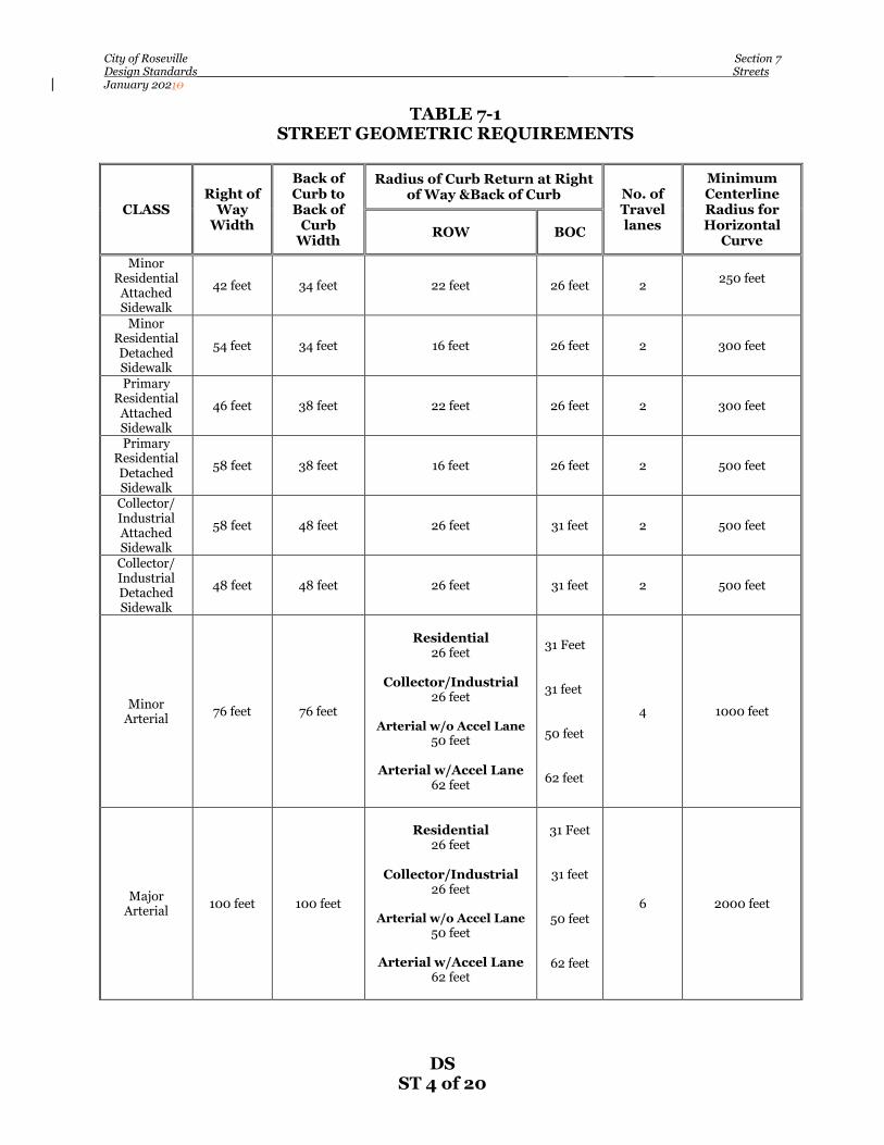
City of Roseville Section 7 Design Standards__________________________________________________ ____ Streets January 20210
DS ST 4 of 20
TABLE 7-1 STREET GEOMETRIC REQUIREMENTS
CLASS Right of
Way Width
Back of Curb to Back of
Curb Width
Radius of Curb Return at Right of Way &Back of Curb No. of
Travel lanes
Minimum Centerline Radius for Horizontal
Curve ROW BOC
Minor Residential
Attached Sidewalk
42 feet 34 feet 22 feet 26 feet 2 250 feet
Minor Residential Detached Sidewalk
54 feet 34 feet 16 feet 26 feet 2 300 feet
Primary Residential
Attached Sidewalk
46 feet 38 feet 22 feet 26 feet 2 300 feet
Primary Residential Detached Sidewalk
58 feet 38 feet 16 feet 26 feet 2 500 feet
Collector/ Industrial Attached Sidewalk
58 feet 48 feet 26 feet 31 feet 2 500 feet
Collector/ Industrial Detached Sidewalk
48 feet 48 feet 26 feet 31 feet 2 500 feet
Minor Arterial 76 feet 76 feet
Residential
26 feet
Collector/Industrial 26 feet
Arterial w/o Accel Lane
50 feet
Arterial w/Accel Lane 62 feet
31 Feet 31 feet 50 feet 62 feet
4 1000 feet
Major Arterial 100 feet 100 feet
Residential
26 feet
Collector/Industrial 26 feet
Arterial w/o Accel Lane
50 feet
Arterial w/Accel Lane 62 feet
31 Feet
31 feet
50 feet
62 feet
6 2000 feet

City of Roseville Section 7 Design Standards__________________________________________________ ____ Streets January 20210
DS ST 5 of 20
7-2 RIGHT-OF-WAY WIDTH - Right-of-way widths shall be in accordance with these standards for the street classification under consideration or as determined by the City Engineer. In no instance, without approval of the City Engineer, shall a street have a right-of-way width that is less than the street of which it is a continuation. Right-of-way requirements for widening at intersections shall be as specified by the City Engineer.
Building setbacks, landscaping requirements, and parking requirements shall be
based on the ultimate right-of-way, regardless of the location of public street improvements.
A minimum 12.5-foot public utility easement (P.U.E.) shall be dedicated adjacent
to all public and private streets and shall include traffic control appurtenances. Additional easement for sewer, water, storm drainage, landscaping, fencing, and all other public utilities shall be provided as required by the utility companies, these Design Standards, and as specified by the City Engineer.
Along the frontage of collector and arterial roadways, the right-of-way dedication
shall include the landscape corridor adjacent to parcels zoned single-family residential (SFR).
7-3 ROADWAY SIGNAGE AND STRIPING - Signing and striping shall conform
to the latest edition of the California Manual of Uniform Traffic Control Devices, (CMUTCD), unless modified by these standards, the Construction Standards, or in writing by City Engineer.
7-4 STRUCTURAL SECTION – All roads, both public and private, to be constructed
within the City of Roseville shall be one of the following:
• Aasphalt concrete over aggregate base and, if necessary, aggregate sub-base.
• Portland Cement Concrete over cement treated base, aggregate base or native subgrade
For asphalt concrete arterial roadways iIt’s desirable to the City to have them all arterial roadways designed and constructed with the two-inch top lift of asphalt concrete, rubberized asphalt concrete material. Asphalt concrete cCollector, residential and alley ways shall be designed and constructed with Type A, 1/2 –inch maximum medium asphalt concrete mix as described in the City’s Construction Standards. Portland Cement Concrete roadways shall be designed and constructed with the Portland cement concrete mix described in the City’s Construction Standards

City of Roseville Section 7 Design Standards__________________________________________________ ____ Streets January 20210
DS ST 6 of 20
All pavement sections shall be designed on the basis of the resistance R-value as
determined in accordance with the State of California, Department of Transportation design method and appropriate traffic indices (TI). If the subgrade has an “R” value of 10 or less, a geotextile fabric or other approved product shall be installed on subgrade prior to placement of AB or ASB material. In addition, the City Engineer may require the installation of edge drains in soils where the “R” value of the subgrade is 10 or less. The Geotechnical Engineer may submit for treatment of the subgrade material, with lime or cement or other approved product if suitable soils exist. This may be considered in lieu of geotextile fabric and base material with approval of the City Engineer. The resulting structural section shall be no less than City standards from Table 7-2.
Minimum TI values shall be as specified in Table 7-2 or as determined by City
Engineer. At the discretion of the City Engineer, design traffic indexes (TI’s) may be revised to reflect designated truck routes and/or where projected future traffic volumes, based upon the City’s Travel Demand Forecast Model, indicate increased or reduced trip. Pavement sections shall be designed by a Registered Geotechnical Engineer. In the case where actual subgrade R-Values are less than the designed value of 50, and where alternative structural sections are submitted for City consideration, supportive pavement design Gravel Equivalence (GE) calculations shall be submitted as well.
TABLE 7-2
Street Classification
Minimum Traffic Index
Minimum Structural
Section (Assumes R=50)
AC AB AS PCC (Max Joint Spacing)
Signalized Inter.
at Approaching
Lane Loop Locations
PCC Pavement
Surface Treatment
Alley-Way - 2” 6” 5”PCC(8.5’)
Trowel and Broom finish
Minor Residential 6 3” 8” 5.25” PCC (11’) 5” AC 6”AB Trowel and
Broom finish Primary Residential 7 3” 9”
6”PCC(12’) 5” AC 7”AB Trowel and
Broom finish Collector Non-Residential Collector 8 4” 9”
7.75”PCC(12’)
5” AC 8”AB Traveled Lanes:
Diamond Grind Bike
Lanes: Trowel and
Broom Finish

City of Roseville Section 7 Design Standards__________________________________________________ ____ Streets January 20210
DS ST 7 of 20
Industrial
9 4” 7” 6” 7.75”PCC(13’)
5” AC 6”AB 6”AS
Traveled Lanes:
Diamond Grind Bike
Lanes: Trowel and
Broom Finish Minor Arterial
10 5” 7” 6” 8”PCC(13’)
5” AC 7”AB 6”AS
Traveled Lanes:
Diamond Grind Bike
Lanes: Trowel and
Broom Finish Major Arterial
11 5” 7” 8” 8.25”PCC(13’)
5” AC 7”AB 86” AS
Traveled Lanes:
Diamond Grind Bike
Lanes: Trowel and
Broom Finish A. Structural Street Sections at Signalized Intersections –Where traffic
signals loops are anticipated as identified in individual Specific Plan and General Plan Circulation Element Exhibits, the minimum structural section shall include 5” of AC (3” bottom lift, 2” top lift) on the minimum required AB for a length 5’ beyond the furthest loop on all intersection approaching lanes. There is no change required for Portland Cement Concrete roadways. At the option of the Developer, (For constructability purposes), both approaching and downstream lanes may have thickened HMA sections as identified in Table 7-2 above. When “cutting” in signal loops, the slot depth shall be cut to achieve a minimum of 2 inch cover over the loops.
7-5. CURB AND GUTTER REQUIREMENTS – Curb and/or gutter are required
adjacent to all public and private streets. All sidewalk, curb and gutter shall be constructed of minor concrete conforming to the provisions in Section 71-5 (B) “Minor Concrete.
A. Type 1 Roll Curb and Gutter – Type 1 roll curb and gutter shall be installed
adjacent to all single-family residential and duplex developments, poured monolithically with sidewalk. STD DWG #ST-17
B. Type 2 Vertical Curb and Gutter – Type 2 vertical curb and gutter shall be installed adjacent to all multiple residential, industrial/commercial developments, school and park sites, poured monolithically with sidewalk or as specified by City Engineer. STD DWG #ST-17

City of Roseville Section 7 Design Standards__________________________________________________ ____ Streets January 20210
DS ST 8 of 20
C. Type 6 Modified V-Gutter – Type 6 modified V-gutter may be used for alleys and parking lots. Type 6 modified V-gutter shall not be used in either public or private streets.
D. Cross Gutters – Cross gutters shall not be installed unless the intersection
cannot be drained by an underground system. Installation of cross gutters shall be subject to the approval of the City Engineer.
7-6 SIDEWALK REQUIREMENTS – Sidewalks shall be constructed adjacent to all
public streets. All sidewalks shall be Minor Concrete as specified in section 71-5B of the Construction Standards and shall conform to the provisions of Section 90 of the Caltrans Specifications. All sidewalks shall have a minimum thickness of six (6) inches on native soil, at 95% relative compaction, or four (4) inches thick with four (4) inches of AB at 95% relative compaction, and shall meet the following requirements:
A. Width – The required minimum width of sidewalks shall be as listed in Table
7-3 unless the project is located within a Specific Plan area. In such case, the sidewalk width shall conform to the appropriate Specific Plan Landscaping Guideline, which may be obtained from the City of Roseville Planning Department. The width of the curb shall not be considered as included in the width of the sidewalk.
TABLE 7-3
Street Classification Sidewalk Width
Minor Residential – Attached Sidewalk 4 feet Primary Residential – Attached Sidewalk 4 feet Minor Residential – Detached Sidewalk 5 feet Primary Residential – Detached Sidewalk 5 feet Collector/Industrial – Attached/Detached Sidewalk 5 feet Minor Arterial 8 feet Major Arterial 8 feet Roadway w/ Paseo/Multi-model Path 10 Feet
B. Slopes – Detached sidewalks shall have a maximum slope in the direction of
travel of 5.0 percent unless otherwise approved by the City Engineer. If the longitudinal street grade is greater than 5.0 percent, the slope of the sidewalk shall not exceed the longitudinal slope of the street. Cross slope shall be a minimum of 1.0 percent and maximum of 2.0 percent sloped downwards towards the gutter.
C. Radius – Detached meandering sidewalks shall have a minimum radius of 50 feet.
D. Pedestrian Curb Ramps – Pedestrian curb ramps shall be provided at all
intersections and Type A-7 driveways. All curb ramps shall conform to the

City of Roseville Section 7 Design Standards__________________________________________________ ____ Streets January 20210
DS ST 9 of 20
requirements of these standards and the City’s Construction Standards for slope criteria and standard design. It is the design engineer’s responsibility to ensure that the intersection slopes designated on the improvement plans allow for the construction of pedestrian curb ramps that meet the above criteria.
At “T” intersection located at signalized intersections, ramps shall be
constructed in the appropriate position on the side of the through street, directly opposite the ramps at the curb return of the “T” intersecting street. Such ramps are not required on the side of the through street on residential streets unless the distance to the next available street crossing is greater than 500 feet.
E. Sidewalk Barricades – Sidewalk barricades shall be required where
satisfactory provisions cannot be made for pedestrians to safely continue beyond the terminus of the sidewalk. Where sidewalks end in fill area, the fill shall be extended beyond the end of the sidewalk for a minimum distance of six feet.
7-7 PEDESTRIAN WALKS AND BIKE PATHS – Pedestrian walks within a
development shall have a minimum easement width of 8 feet and sidewalk width of 5 feet. All walks shall conform to the requirements of Title 24. Walks shall be constructed with a minimum thickness of six inches of Portland cement concrete, Minor Concrete as specified in Section 71-5B of the Construction Standards.
Bike paths design shall conform to Section 13 of these Standards. Combined
pedestrian/bike paths (See Class 1A Bikeways within Section 13) shall be a minimum of 12 feet wide. The structural section for the bike path shall conform to Section 13 of these Standards. and be constructed of either Portland cement concrete, per section 71-5B, having a minimum thickness of 4 inches or 2 inches of asphalt concrete over 4 inches of aggregate base.
Pedestrian walks and Class 1A bike paths, if situated between lots, including
paseos, shall be fenced with chain link fencing or other material as approved by the City of Roseville Development Services Department and shall extend from the street right-of-way to the back lot line. These fences shall be 6 feet high from the building setback line to the back lot line and 3 feet high from the building setback line to the street right-of-way line. Collapsible bollards shall be placed at both ends of all these pedestrian walks/Class 1A bike paths.
See Section 13 for other requirements for bike paths.
7-8 ROADWAY PROFILE STANDARDS – The following standards shall apply to
the design of roadway profiles. Also refer to Section 3 of these Design Standards. A. Grades – The minimum centerline (longitudinal) grades on new streets and
gutter flow lines shall be 0.35 percent. The maximum street slope shall limit 5 percent except where a steeper street is determined necessary by the City

City of Roseville Section 7 Design Standards__________________________________________________ ____ Streets January 20210
DS ST 10 of 20
Engineer due to existing topographical features. The minimum grade of gutter sections constructed along existing streets shall be 0.20 percent.
B. Cross Slopes – Standard cross slopes shall be 2.0 percent on all roadways.
Certain roadways may require super elevations as directed by the City Engineer. Cross slopes on widened existing streets shall be a minimum of 1.5 percent and maximum of 3.0 percent. Where a street constructed with a super elevation is to be widened, the cross slope shall be as specified by the City Engineer.
C. Vertical Curves – The minimum allowable vertical curve length at the
intersection of two grades shall be 50 feet; however, vertical curves may be omitted where the algebraic difference in grades does not exceed 2.0 percent. When vertical curves are required, they shall provide for adequate sight distance based on the minimum design speeds specified in Table 7-4. The vertical curve data shall be computed and shown on the plans and shall call out the tangent gradient length of curve, the elevations and stationing points of the beginning of vertical curve (BVC), end of vertical curve (EVC), PI, high and low points and along 25 foot intervals.
7-9 INTERSECTIONS – Street centerlines shall intersect one another at an angle as
near to a right angle as is possible by tangents not less than 100 feet in length. In unusual circumstances the City Engineer may waive this requirement. Refer to Standard Drawings for required rights-of-way, pavement, taper lengths, etc. for intersections involving minor and major arterials.
At intersections, where two streets intersect, the centerline grade of the major
street shall have a maximum centerline (longitudinal) grade of 2.0 percent for a minimum distance of 40 feet measured from the curb line of the intersecting street, except in unusually rough terrain, as determined by the City Engineer. The centerline of the minor street shall meet the crown slope at the projected lip of gutter. Crown slope may be reduced to 1.0 percent within the intersection if necessary.
7-10 OFFSET INTERSECTIONS – The following requirements apply to all offset
intersections. Any variation to these requirements shall be subject to the approval of the City Engineer. Distances are measured from centerline to centerline.
A. Residential streets intersecting another residential street from opposite sides
shall have their centerlines meet, or the offset between intersections shall be a minimum of 150 feet.
B. Minor and primary residential streets intersecting collector streets from
opposite sides shall have their centerlines meet or the offset between the intersections shall be a minimum of 200 feet.
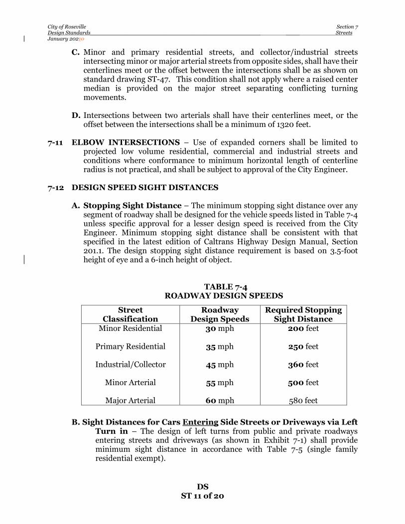
City of Roseville Section 7 Design Standards__________________________________________________ ____ Streets January 20210
DS ST 11 of 20
C. Minor and primary residential streets, and collector/industrial streets intersecting minor or major arterial streets from opposite sides, shall have their centerlines meet or the offset between the intersections shall be as shown on standard drawing ST-47. This condition shall not apply where a raised center median is provided on the major street separating conflicting turning movements.
D. Intersections between two arterials shall have their centerlines meet, or the
offset between the intersections shall be a minimum of 1320 feet. 7-11 ELBOW INTERSECTIONS – Use of expanded corners shall be limited to
projected low volume residential, commercial and industrial streets and conditions where conformance to minimum horizontal length of centerline radius is not practical, and shall be subject to approval of the City Engineer.
7-12 DESIGN SPEED SIGHT DISTANCES A. Stopping Sight Distance – The minimum stopping sight distance over any
segment of roadway shall be designed for the vehicle speeds listed in Table 7-4 unless specific approval for a lesser design speed is received from the City Engineer. Minimum stopping sight distance shall be consistent with that specified in the latest edition of Caltrans Highway Design Manual, Section 201.1. The design stopping sight distance requirement is based on 3.5-foot height of eye and a 6-inch height of object.
TABLE 7-4 ROADWAY DESIGN SPEEDS
B. Sight Distances for Cars Entering Side Streets or Driveways via Left
Turn in – The design of left turns from public and private roadways entering streets and driveways (as shown in Exhibit 7-1) shall provide minimum sight distance in accordance with Table 7-5 (single family residential exempt).
Street Classification
Roadway Design Speeds
Required Stopping Sight Distance
Minor Residential
Primary Residential
Industrial/Collector
Minor Arterial
Major Arterial
30 mph
35 mph
45 mph
55 mph
60 mph
200 feet
250 feet
360 feet
500 feet
580 feet

City of Roseville Section 7 Design Standards__________________________________________________ ____ Streets January 20210
DS ST 12 of 20
TABLE 7-5 SIGHT DISTANCE FOR CARS ENTERING STREETS/ DRIVEWAYS BY LEFT TURN
Street
Classification Required
Sight Distance
Industrial/Collector
Minor Arterial
Major Arterial
410 feet
530 feet
695feet
Taken from the 2004 AASHTO Geometric
Design of Highways and Streets
EXHIBIT 7-1
Sight Distance is based on a 3.5 foot height at the location of the driver and a 3.5 foot object height in the center of the approaching lane of the major road. The left turn driver measurement is taken 4 feet from the left edge of the turn lane at the projected edge of the curb return (as shown above). If the major road is a multi-lane road, the controlling measurement for sight distance shall be based on the approach lane that is the worst case scenario.
C. Corner Sight Distances for Cars Exiting at Intersections and
Driveways – The design of all public streets, private streets, and major non-residential driveways (as shown in Exhibit 7-2) shall provide minimum sight distance in accordance with the following requirements. Design speeds and the corresponding minimum required corner sight distance shall be as specified in Table 7-6. Minimum corner sight distance shall be consistent with that

City of Roseville Section 7 Design Standards__________________________________________________ ____ Streets January 20210
DS ST 13 of 20
specified in the latest edition of Caltrans Highway Design Manual, Section 405.1A.
TABLE 7-6
DESIGN SPEEDS FOR CORNER SIGHT DISTANCE
EXHIBIT 7-2
Setback for the driver of the vehicle on the crossroad shall be a minimum of 10’ from the edge of travel way plus the shoulder width of the major road, but not less than 15 feet as shown above. Line of sight for corner sight distance is to be determined from a 3.5 foot height at the location of the driver of the vehicle on the minor road to a 4.25 3.5 foot object height in the center of the approaching lane of the major road. (Highway Design Manual section 405.1(2)(a)). If the roadway being entered is a multi-lane road, the controlling measurement for sight distance shall be based on the approach lane that is the worst case scenario.
7-13 CENTERLINE RADII – The curve data (delta angle, length, tangent and radius)
for all centerline curves shall be computed and shown on the plans. The minimum centerline curve radii shall be as specified in Table 7-1. Special consideration may be given by the City Engineer for unusually difficult alignment problems.
Street Classification
Corner Sight Distance
Design Speed
Required Corner Sight
Distance Minor Residential
Primary Residential
Industrial/Collector
Minor Arterial
Major Arterial
30 mph
35 mph
45 mph
55 mph
60 mph
330 feet
385 feet
495 feet
605 feet
660 feet

City of Roseville Section 7 Design Standards__________________________________________________ ____ Streets January 20210
DS ST 14 of 20
7-14 DRIVEWAYS – When driveways are abandoned or relocated, the driveway
section shall be removed and replaced with curb, gutter, and sidewalk conforming to these standards. Parking is restricted within the throat depth of all driveways. All new driveways shall conform to the following requirements:
A. Types, Widths and Grades 1. Single Family Residential and Duplex Driveways shall have a minimum
throat width of 16 feet and maximum throat width of 32 feet. Lot pads shall be graded to accommodate maximum driveway slopes of 14
percent from back of right-of-way. Unusual terrain conditions may warrant waiver of this design subject to the approval of the City Engineer. Number of driveways accessing a single parcel is defined in Section 5-4 “Site Access” of these Design Standards.
2. Multi-Family/Office Commercial/Industrial Driveway main entrances shall
have a minimum throat width of 35 feet. The minimum throat width may be reduced to 25 feet if the driveway is a secondary access or restricted to right turn movements. If a raised median is provided in the driveway throat, the driveway width shall be widened as necessary to accommodate the number of ingress and egress lanes required, with a minimum ingress lane width of 18 feet. The minimum driveway median width shall be 4 feet and the maximum width shall be 10 feet. The nose of the median shall be no less than 7 feet and no more than 15 feet from the gutter flow line.
Driveways located on collector streets shall be standard commercial
driveways per the Standard Drawings unless the City Engineer deems a Type A-7 driveway appropriate for a particular project. Driveways on arterial streets shall be either at grade with appropriate drainage collection facilities or “Type A-7” per these Standards.
Driveway slopes shall have a maximum grade of 10 percent except from the
edge of pavement to a distance 15 feet within the project. This area shall have a maximum slope of 2 percent. Unusual terrain condition may warrant waiver of this requirement subject to the approval of the City Engineer. If the driveway is other than a “Type A-7” driveway that provides cross gutter, a traffic control sign shall be provided.
B. Location – All aspects of site access (location of driveways, number of
driveways allowed, spacing of driveways, etc.) are addressed in Section 5 of these Design Standards.
C. Sight Distance – Sight distance at driveways shall be as specified in Section 7-12.

City of Roseville Section 7 Design Standards__________________________________________________ ____ Streets January 20210
DS ST 15 of 20
7-15 BUS STOPS AND TURNOUTS – Bus turnouts and shelter pads shall be required at locations specified by the City Engineer. All bus turnouts shall conform to the STD DWG #ST-29. The size and location of bus shelter pads, whether existing or proposed, shall conform to STD Drawing ST-28 and shall be shown at all bus turnouts. “Bus stops with or without shelters, shall have a concrete bus stop pad, with minimum dimensions of 8-ft long as measured perpendicular from the face of curb and 5-ft wide as measured parallel to the curb. Bus stop pads are to be kept clear of bus shelters and other street furnishings including bike racks, trash cans, street lights, and other vertical objects.”
7-16 DEVELOPER RESPONSIBILITY FOR IMPROVEMENTS TO STREETS -
The following requirements apply to private development project adjacent to existing and proposed streets.
A. The Developer shall be responsible for upgrading streets within and adjacent
to the developer’s project where the pavement section of an existing street does not meet the structural section and/or the centerline grade and alignment requirements specified in these Design Standards for those streets.
Where the design centerline grade is to be higher than the existing, the
Developer shall extend the overlay beyond the centerline of the street and shall neatly conform to the existing surface grade on the other side. The Developer shall also be responsible for overlaying any low areas where the new pavement is proposed to meet the existing pavement to maintain a uniform cross slope.
B. When making a connection to an existing stub street, the Developer shall be
responsible for removing and reconstructing up to a maximum of twenty feet of the existing roadway to make a satisfactory connection as required by the City Engineer.
C. When widening to complete an existing partial street along a development
project, or when removing existing curb and gutter, the Developer shall be responsible for saw cutting and removing a narrow strip along the outside portion of the pavement to provide a clean and stable pavement section for constructing against.
For asphalt concrete roadways Ggrinding of existing pavement (1½-inch minimum) shall be made to the next nearest edge of lane line. The width to be removed shall be determined by the City Engineer. In the case of curb and gutter removal adjacent to asphalt concrete roadways, minimum width of pavement cut shall be 2 feet. For Portland cement concrete roadways PCC pavement may be placed against the existing pavement if the City’s Construction Inspector determines the pavement edge is flawless, otherwise the existing pavement width to be

City of Roseville Section 7 Design Standards__________________________________________________ ____ Streets January 20210
DS ST 16 of 20
removed shall be determined by the City Engineer. In the case of curb and gutter removal adjacent to Portland cement concrete roadways, minimum width of pavement cut shall be to the bike lane stripe.
D. All temporary approaches to existing roadways required as a result of the
development shall be at the Developer’s expense. The temporary approaches shall be paved with the structural section to be determined individually for each situation.
E. The Developer shall be responsible for relocating existing traffic signals and
streetlights, and installing new traffic signals and street lights as necessary for new street and driveway locations. The Developer shall also be responsible for relocating existing traffic signals and street lights as necessary for the installation of new curbs or new curbs and sidewalks at locations where there are no existing curbs or curbs and sidewalks, or, where existing improvements do not meet current standards. Traffic signals must remain operational during all construction within signalized intersections.
F. The Developer shall be responsible for constructing or modifying median island
curbs where required by these standards, or when required for traffic control as a result of the development, as determined by the City Engineer.
G. The Developer is required to provide frontage improvements along existing and
proposed roadways at the Developer’s expense. Frontage improvements include, but are not limited to, sidewalk, curb and gutter, center median, 18 feet pavement width, additional pavement width beyond the 18–feet for intersection widening (including acceleration and deceleration lanes, bus turnouts, widening for dual left turns, etc. ), drainage system, landscaping, soundwalls, street lighting, roadway signing and striping, and all utilities (including traffic signal interconnect if applicable). For minor residential, primary residential, collector and industrial streets, the Developer shall provide the full right-of-way improvement.
H. For development within the “infill” areas of the City, the level of improvements
to public streets adjacent to the development site shall be determined on a project specific basis at the discretion of the City Engineer.
I. The Developer shall be responsible for all drainage facilities (bridges, pipes,
culverts, and appurtenances) crossing new streets within or adjacent to the project.
J. The Developer shall be responsible for all necessary modifications within the
public right-of-way and the project site to comply with state and federal standards for access for disabled, including but not limited to sidewalk ramps.

City of Roseville Section 7 Design Standards__________________________________________________ ____ Streets January 20210
DS ST 17 of 20
7-17 TRENCHING IN EXISTING PAVED ROADWAYS – All trenching in existing roadways shall conform to the Standard Drawings and the Construction Standards. The Developer may be required to coordinate trenching work schedules to avoid cutting pavement where repaving is planned by the City. All cuts within a paved street shall be subject to the City’s Trench Cut Ordinance. The Trench Cut Ordinance fee shall be paid prior to the approval of any plans. In no case will trenching be permitted on any street that has been constructed or overlayed within the last five years (Moratorium Streets). The City Engineer under unusual circumstances may give special consideration.
7-18 STREET NAMES AND STREET NAME SIGNS – Street names shall be
proposed by the Developer and shall be shown on the tentative map when submitted. These names shall be subject to approval by the City Council. No duplication of names already in use or previous proposed or sound alike names will be permitted. Street name signs shall be furnished and installed by the Developer. The requirements for location of signs do not apply to signalized intersections since signals will have their own street name signs. Street name signs shall conform to City of Roseville Construction. Refer to Roseville Construction Standards Section 56 “Signs”.
A. Location and Number Required – The required number of street name signs installed and location, depends upon the width of street right-of-way and shall conform to the following:
Case 1 – Two street name sign installations (with four sign plates on each
post) are required at each intersection where one or both of the intersecting streets are a collector or arterial street. At a four-way intersection, the installations shall be located on both far right hand corners of the intersection relative to the direction of travel on the street having the greater right-of-way width or on the major street if right-of-way widths are equal.
At a “T” intersection, one sign shall be installed on the far right hand corner
of the intersection relative to the direction of travel on the through street and the other shall be installed along the left side of through street relative to the direction of travel at a point directly opposite the centerline of the “T” intersecting street. One sign plate should be omitted from the standard four-plate installation at the “T” intersection sign locations where an approach street does not exist.
Street name signs shall be located adjacent to the major street at the end of
the curb return. Case 2 – One street name sign installation (with four sign plates on each
post) is required at each intersection where both intersecting streets are residential streets. At a four-way intersection, the installation shall be located at one of the far right had corners of the intersection relative to the

City of Roseville Section 7 Design Standards__________________________________________________ ____ Streets January 20210
DS ST 18 of 20
direction of travel on the street having the greater right-of-way width or on the major street if the right-of-way widths are equal.
At a “T” intersection, the installation shall be located on the far right hand
corner relative to the direction of travel on the through street. Street name sign shall be located at the midpoint of the curb return. Case 3 – For arterials with frontage roads, the street name sign
installations shall be located in the divider strip between the frontage road and the main traveled way of the highway at the near side of the intersection. All other requirements shall be as outlined above, except that only one sign will be required (in the divider strip in line with the centerline of the minor street) when there is no opening in the divider strip for access to main highway.
7-19 SURVEY MONUMENTS – The consulting engineer shall place survey
monuments at the following locations: A. At the intersection of street centerlines. B. At the beginning and end of curves on the street centerline. C. At the center of all cul-de-sacs and elbow points. D. At the subdivision boundary corners and at such other locations so as to
enable any lot or portion of the improvements to be retraced or located, as directed by the City Engineer.
The above-described monuments shall be as follows:
1. Subdivisions boundary monuments except those in street pavement shall be not less than 1-inch solid steel or 1-¾ inch galvanized iron pipe 30 inches in length, capped and tagged.
2. Subdivision monuments in street pavements shall be no less than a ¾
inch galvanized iron pipe, 18 inches in length. Top of pipe shall be driven flush with surface pavement.
3. All monuments in street pavement shall be monument wells,
conforming to the standard drawing and shall be Detail ST-36 and shall be placed at all street intersections, centers of street cul-de-sacs and elbow points. In addition, monument wells shall be required on street centerlines and located such that there will be a clear line of sight distance between the two monuments within the street right-of-way. These will normally be located at points of curvature not exceed 1000 feet.

City of Roseville Section 7 Design Standards__________________________________________________ ____ Streets January 20210
DS ST 19 of 20
4. Lot corners shall have a ½ inch rebar at rear corners. Front corner and
side lot lines shall be projected and marked twelve six inches to center from the back of sidewalk (or 3” from back of curb to center of marker when no sidewalk is present), with a permanent disc survey marker between ¾”–1 1/4” diameter with a minimum of one-inch deep knurl shank anchor drilled and epoxied into sidewalk or curb with expansion plug, flush with concrete surface. Survey markers shall be stamped as specified in the Professional Land Surveyors Act. Article 5, Section 8772. Use Berntsen BP2-BP copper disc with expansion anchor with countersink drill bit, or approved equal. Epoxy as specified in Section 71-5.G.2. Where survey markers cannot be installed as described above, surveyor to recommend alternate method of placement to City Engineer prior to placement.
5. Permanent survey monuments shall be placed by the Consulting
Engineer at all section and quarter corners within the development. The section corner monuments shall be Minor Concrete, Per Caltrans Section 90-2, poured in place, with minimum dimensions of 6” diameter x 24” deep, with a brass cap in accordance with Bureau of Land Management Standards.
All such monuments shall be referenced to permanent objects located nearby and all ties shall be furnished to the City Engineer for general public use. Final acceptance of the public improvements will not be made until such ties have furnished to the City Engineer.
The Consulting Engineer shall also place a note on all construction plans stating that the Contractor is responsible for the protection of all existing monuments and other survey markers.
7-20 BENCHMARKS – In locations where a new benchmark will be required, as
determined by the City Engineer, the Consulting Engineer’s Land Surveyor (L.S.) will set in concrete a 3¼ inch brass cap, provided by the City Engineer. Survey for establishing the new benchmark must meet or exceed Federal Geodetic Control Committee (FGCC) Second-order class II survey requirements. The level notes shall include the new benchmark elevation in North American Vertical Datum of 1988 (NAVD 88) and National Geodetic Vertical Datum of 1929 (NGVD) vertical datum. The survey shall also include the California II State Plane Coordinate values if the new benchmark in North American Datum (NAD 83). All new benchmarks shall have a NGS stability rating of A or B. The survey notes shall be submitted to the City Engineer for review and approval.
Licensed Surveyors recovering existing benchmarks for use in their work and
for work with Consulting Engineers shall provide the City Engineer with the elevation of the recovered benchmarks in NAVD 88 and NGVD 29 vertical

City of Roseville Section 7 Design Standards__________________________________________________ ____ Streets January 20210
DS ST 20 of 20
datum. The L.S. shall also provide the City Engineer with the California II State Plan Coordinate values for recovered benchmarks.
After approval of the notes, the new benchmark will be assigned a number that
the developer’s engineer will mark on the brass cap, along with the date, and R.C.E. or L.S. number of the person certifying the level notes.
Benchmarks shall be provided where specified by the City Engineer and at all
culverts 60-inches or greater, bridge crossings passing a 100 year flow of 250 cfs or greater, and within subdivisions that are greater than 60 lots.
City of Roseville Section 8 Design Standards_______________________________ ____ Domestic Water Supply System January 20210
DS W 1 of 13
SECTION 8
DOMESTIC WATER SUPPLY SYSTEM DESIGN 8-1 INTRODUCTION – These improvement standards shall govern the engineering
design of all domestic water systems intended for operation and maintenance by the City of Roseville.
8-2 DESIGN CRITERIA – These criteria shall apply to the engineering design of all
water systems intended for operation and maintenance by the City of Roseville. The intent of these criteria is to provide a water system that will dependably and safely convey high quality water throughout the distribution system.
8-3 CURRENT STANDARDS – Pertinent and current requirements of the following
agencies or standards shall be complied with. In case of conflicting design criteria, standards set forth by the City of Roseville, as established herein, shall govern.
A. United States Environmental Protection Agency (EPA) Drinking Water
Regulations. B. Laws and Standards of the State of California, Department of Public Health
Services relating to Domestic Water Supply. C. City of Roseville Design Standards. D. City of Roseville Industrial Waste Regulations (Cited in Section 9.2E) E. Rules for installation of individual water services (Cited in Section 9.10C) F. City Code for taps to water system G. Title 17, Chapter V, Sections 7583-7622, California Administrative Code
regarding cross-connections and backflow prevention H. Roseville Fire Code I. Latest Edition of the American Water Works Association (AWWA) Standards. 8-4 WATER SUPPLY QUALITY – The quality of water supplied to the
City’s distribution system shall conform to the Environmental Protection Agency Drinking Water Act, and the State Department of Health Services Drinking Water Standards.
8-5 WATER SUPPLY PRESSURE – Normal-operating pressures of not less than
50 PSI nor more than 100 PSI shall be maintained at service connections to the

City of Roseville Section 8 Design Standards_______________________________ ____ Domestic Water Supply System January 20210
DS W 2 of 13
distribution system, except that during periods of peak domestic and fire demand, the pressure shall not be less than 20 PSI.
8-6 FLOW DETERMINATION – Determination of flow volumes required for a
specific land use category shall consider maximum day domestic demands occurring in conjunction with an emergency fire flow demand. For design of the distribution system, the following unit demand factors shall be assumed.
Land Use Category
Average Day Unit Water
Demand Factors
Res
iden
tial
LDR (<3.5 DU’s/Ac) 728 gpd/DU LDR (3.5 to 5.0 DU’s/Ac) 600 gpd/DU LMDR (>5.0 to 6.0 DU’s/Ac) 521 gpd/DU LMDR (>6.0 to 8.0 DU’s/Ac) 430 gpd/DU MDR (>8.0 to 12.0 DU’s/Ac) 323 gpd/DU HDR (>12.0 to 16.0 DU’s/Ac 288 gpd/DU HDR (>16.0 DU’s/Ac) 177 gpd/DU
Com
mer
cial
/Oth
er
Commercial/Retail 2,598 gpd/ac Business Professional 2,598 gpd/ac Light Industrial 2,598 gpd/ac Industrial 2,562 gpd/ac Railroad Yard 109 gpd/ac Elementary Schools 3,454 gpd/ac High Schools 4,068 gpd/ac Public (Fire Station, etc) 1,780 gpd/ac Park/Recreation 2,988 gpd/ac Open Space/Major ROW - Vacant/Unassigned -
*Factors assume a 30% F.A.R. 50% F.A.R. for senior living. 8-7 PEAKING FACTORS – The average day demand to maximum day demand
peaking factor shall be 2.0. The maximum day demand to peak hour demand peaking factor shall be 1.7 (3.4 average day to peak hour).
8-8 REQUIRED FIRE FLOWS – For areas of the general type noted below, the
indicated water supply for fire flows shall be provided with the initial development. Expansion or change in zoning of the development shall be subject to the requirements of the California Fire Code (CFC hereafter) as adopted by the Roseville Fire Department (RFD hereafter). The RFD shall determine all fire flows.
A. Residential Areas – The fire flow demand for detached single family
dwelling units shall be a minimum of 1,500 gallons per minute (gpm) in accordance with the CFC as adopted by the RFD. For fire flow greater than

City of Roseville Section 8 Design Standards_______________________________ ____ Domestic Water Supply System January 20210
DS W 3 of 13
1,500 gpm, each fire hydrant shall maintain 1,000 gpm or fraction thereof based on the provisions of the CFC.
Note: Automatic Fire Sprinklers – Single-family homes equipped with
automatic fire sprinklers systems shall require a minimum 1-inch water service and meter as determined by the RFD. The minimum 1-inch water line shall start from the public main to the required water meter. Service and meter size shall be approved by the RFD.
B. Multi-Family Areas – For attached multi-family units, the fire flow shall be
determined by the Roseville Fire Department. The maximum fire flow however shall not exceed 4,000 gpm provided the building is fully sprinklered in accordance with the CFC as adopted by the RFD. For buildings that are not sprinklered, contact the RFD. For fire flow demand greater than 1,500 gpm, each fire hydrant shall be 1,000 gpm or fraction thereof based on the provisions of the CFC.
C. Commercial, Business, Industrial or School District Areas –
The maximum fire flow shall be determined by the Roseville Fire Department. The required fire flow however shall not exceed 4,000 gpm, provided all the buildings are fully sprinklered in accordance with the CFC as adopted by the RFD. For buildings that are not sprinklered, contact the RFD. For fire flow greater than 1,500 gpm, each fire hydrant shall be 1,000 gpm or fraction thereof based on the provisions of the CFC.
8-9 LOCATION IN EXISTING STREETS – Where water mains or services are to
be located in an existing street, factors such as curbs, gutters, sidewalks, traffic conditions, traffic lane conditions, pavement conditions, future street improvement plans, and existing utilities shall be considered. The approval of the Environmental Utilities Director and City Engineer shall be obtained in every instance.
8-10 LOCATION IN UNPAVED AREAS – All mains in unpaved areas shall be
ductile iron pipe and marked every 150 feet with a blue 5-foot 6-inch composite utility marker. A decal shall be placed on the marker stating “CAUTION WATER MAIN.” Utility markers shall be Carsonite or approved equal with anchor barb kit. The first utility marker shall be placed within 20 feet of the public roadway.
8-11 TRANSMISSION SYSTEM DESIGN – Transmission mains are 16 inches in
diameter or larger. Standard transmission main sizes are 16-, 24-, 30-, 36-, 42-, 48- and 54- inches in diameter. Sizing and layout of transmission mains shall conform to the Master Water Supply Plans of the City of Roseville Environmental Utilities Department. Technical specifications for water transmission mains shall be a requirement of the proposed improvements plans. Under no circumstances shall fire hydrants or water services be directly connected to a transmission main, with the exception of hydrants that are acting as blow-offs.
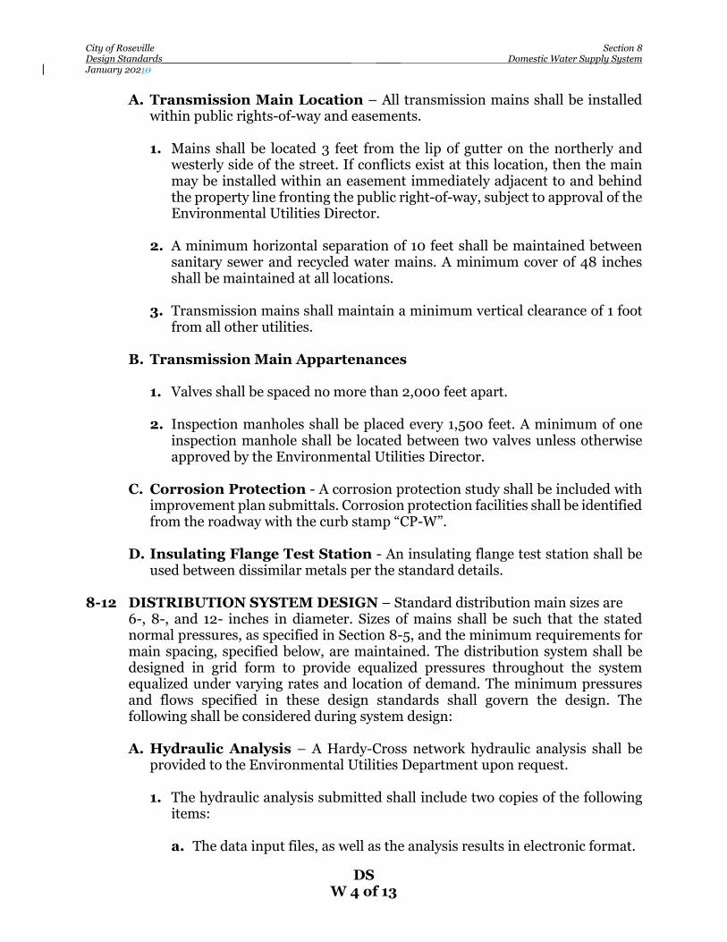
City of Roseville Section 8 Design Standards_______________________________ ____ Domestic Water Supply System January 20210
DS W 4 of 13
A. Transmission Main Location – All transmission mains shall be installed within public rights-of-way and easements.
1. Mains shall be located 3 feet from the lip of gutter on the northerly and
westerly side of the street. If conflicts exist at this location, then the main may be installed within an easement immediately adjacent to and behind the property line fronting the public right-of-way, subject to approval of the Environmental Utilities Director.
2. A minimum horizontal separation of 10 feet shall be maintained between
sanitary sewer and recycled water mains. A minimum cover of 48 inches shall be maintained at all locations.
3. Transmission mains shall maintain a minimum vertical clearance of 1 foot
from all other utilities. B. Transmission Main Appartenances 1. Valves shall be spaced no more than 2,000 feet apart. 2. Inspection manholes shall be placed every 1,500 feet. A minimum of one
inspection manhole shall be located between two valves unless otherwise approved by the Environmental Utilities Director.
C. Corrosion Protection - A corrosion protection study shall be included with
improvement plan submittals. Corrosion protection facilities shall be identified from the roadway with the curb stamp “CP-W”.
D. Insulating Flange Test Station - An insulating flange test station shall be
used between dissimilar metals per the standard details. 8-12 DISTRIBUTION SYSTEM DESIGN – Standard distribution main sizes are 6-, 8-, and 12- inches in diameter. Sizes of mains shall be such that the stated
normal pressures, as specified in Section 8-5, and the minimum requirements for main spacing, specified below, are maintained. The distribution system shall be designed in grid form to provide equalized pressures throughout the system equalized under varying rates and location of demand. The minimum pressures and flows specified in these design standards shall govern the design. The following shall be considered during system design:
A. Hydraulic Analysis – A Hardy-Cross network hydraulic analysis shall be
provided to the Environmental Utilities Department upon request.
1. The hydraulic analysis submitted shall include two copies of the following items:
a. The data input files, as well as the analysis results in electronic format.

City of Roseville Section 8 Design Standards_______________________________ ____ Domestic Water Supply System January 20210
DS W 5 of 13
b. Information on the proposed development (e.g. type of development, number of acres, number of units, fire flow requirements, etc.).
c. Data sheets outlining all assumptions (e.g. method used to assign
demands to corresponding junction nodes and source HGL’s used). d. Map identifying pipe and node numbers and their locations. e. Fire hydrant locations. f. The name and version of software used for the analysis. g. Elevations of junction and source nodes. The elevations used in the
network hydraulic analysis shall be based on a project grading plan or the anticipated final elevations. If the final grading plan deviates significantly from the elevations used in the analysis, a revised analysis will be required.
h. Staging or phasing of the development. i. Appropriate off-site demands. 2. The Hazen-Williams formula shall be used in the analysis of the system. The
roughness factor shall be as follows: a. C=130 for all new cement-line, PVC C-900, and ductile iron pipes b. C=130 for all existing pipes greater or equal to 16 inches in diameter c. C=120 for all existing pipes less than or equal to 12 inches in diameter 3. When identifying the fire flow available in a network analysis, use the
hydrant located at the development’s weakest point (highest point in the development and/or last hydrant on a dead-end main). Also verify the hydrant is located at a junction node. The maximum delivery from any hydrant of the type conforming to current City Standards shall be limited to 1,000 gallons per minute.
B. Pipe Sizes – The minimum pipe size for residential development shall be 6
inches in diameter. For commercial developments, the minimum pipe size shall be 8 inches in diameter.
C. Stubs – Stubs for future developments shall be a minimum 18feet fully
restrained ductile iron pipe originating from the water main. 8-13 WATER MAIN LOCATION – Water mains shall be installed in public rights-of-
way or easements granted to the City.
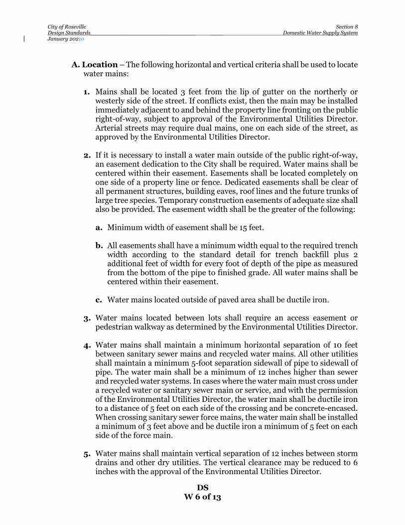
City of Roseville Section 8 Design Standards_______________________________ ____ Domestic Water Supply System January 20210
DS W 6 of 13
A. Location – The following horizontal and vertical criteria shall be used to locate
water mains: 1. Mains shall be located 3 feet from the lip of gutter on the northerly or
westerly side of the street. If conflicts exist, then the main may be installed immediately adjacent to and behind the property line fronting on the public right-of-way, subject to approval of the Environmental Utilities Director. Arterial streets may require dual mains, one on each side of the street, as approved by the Environmental Utilities Director.
2. If it is necessary to install a water main outside of the public right-of-way,
an easement dedication to the City shall be required. Water mains shall be centered within their easement. Easements shall be located completely on one side of a property line or fence. Dedicated easements shall be clear of all permanent structures, building eaves, roof lines and the future trunks of large tree species. Temporary construction easements of adequate size shall also be provided. The easement width shall be the greater of the following:
a. Minimum width of easement shall be 15 feet. b. All easements shall have a minimum width equal to the required trench
width according to the standard detail for trench backfill plus 2 additional feet of width for every foot of depth of the pipe as measured from the bottom of the pipe to finished grade. All water mains shall be centered within their easement.
c. Water mains located outside of paved area shall be ductile iron.
3. Water mains located between lots shall require an access easement or
pedestrian walkway as determined by the Environmental Utilities Director. 4. Water mains shall maintain a minimum horizontal separation of 10 feet
between sanitary sewer mains and recycled water mains. All other utilities shall maintain a minimum 5-foot separation sidewall of pipe to sidewall of pipe. The water main shall be a minimum of 12 inches higher than sewer and recycled water systems. In cases where the water main must cross under a recycled water or sanitary sewer main or service, and with the permission of the Environmental Utilities Director, the water main shall be ductile iron to a distance of 5 feet on each side of the crossing and be concrete-encased. When crossing sanitary sewer force mains, the water main shall be installed a minimum of 3 feet above and be ductile iron a minimum of 5 feet on each side of the force main.
5. Water mains shall maintain vertical separation of 12 inches between storm
drains and other dry utilities. The vertical clearance may be reduced to 6 inches with the approval of the Environmental Utilities Director.

City of Roseville Section 8 Design Standards_______________________________ ____ Domestic Water Supply System January 20210
DS W 7 of 13
6. Water mains under large structures such as culverts and large diameter storm drains shall be ductile iron and installed within a casing per these standards. The casing shall extend beyond the structure a minimum of 5 feet or the depth of the water main on each side.
B. Vertical Elevation Change – Mains designed with a vertical elevation
change using angle fittings shall use a segment of ductile iron pipe with an approved restraint system between the two angle fittings.
C. Cover - A minimum cover of 36 inches and a maximum cover of 60 inches shall
be maintained as measured from the outside bell of the pipe to gutter flow-line for distribution mains. A minimum cover of 48 inches as measured above shall be maintained for transmission mains.
D. Dead-End Mains – Dead-end mains shall be eliminated wherever possible
by looping the system. Blow-offs conforming to the Construction Standard details shall be installed on all permanent or temporary dead-end mains. Removal of the blow-off at the end of cul-de-sacs and service connection to the end of the main is not permitted without prior approval by the Environmental Utilities Director.
E. Warranty Inspection of Water Main Stubs - As a requirement, water
stubs are provided to subdivisions as a courtesy by developers during the construction of backbone infrastructures in streets to prevent cutting up the newly paved streets when the subdivisions are ready to develop. These stubs become an integral part of the water system and subsequently the responsibility of the developers of the subdivision and are therefore imperiled to both construction and warranty inspections. This practice saves future developers construction time and cost that would have otherwise been spent on tie-ins and street repairs and in some instances prevents delays in the event a street has a moratorium. Since these stubs are provided at no cost to future developers, it is our position, hence our policy, that it is the responsibility of the contractors to test and repair these stubs, if found damage, prior to tie-ins. A note to this effect shall be placed on the improvement plans.
F. Public Lines in Commercial Developments – Water mains shall be
located within drive aisles unless otherwise approved by the Environmental Utilities Director. The Design Engineer shall minimize the length of publicly-owned mains where on on-site water loop is required.
8-14 VALVES – Sufficient valves shall be provided on water mains to minimize
customer service interruptions and sanitary hazards during repairs and future development.
A. Locations – Valves shall be generally located as follows: 1. No single shutdown will result in shutting down a transmission main.

City of Roseville Section 8 Design Standards_______________________________ ____ Domestic Water Supply System January 20210
DS W 8 of 13
2. At minimum intervals of 500 feet in school, commercial, industrial, or multi-family residential developments.
3. In residential areas, valves shall be spaced such that no single shutdown will
result in shutting off water to more than 20 services or 800 feet of water main, whichever occurs first.
4. Valves shall be located such that any section of main can be shut down
without going to more than three valves to shut down the section main. 5. All tees shall have a minimum of two valves. Commercial services 6 inches
and greater shall have a valve on each leg of the tee for a total of three valves. 6. All crosses shall have a minimum of three valves. 7. Valves shall not be located in street gutters, valley gutters, or driveways. 8. A valve shall be installed on each side of a creek bridge, major highway, or
as required by the Environmental Utilities Director. B. Removal and Abandonment – Any valve outlet installed prior to lot
development and subsequently not required shall be removed in its entirety. If removal is not practical, the valve shall be abandoned in the closed position and the lateral shall be cut, capped, and finished with an adequate thrust block. The lid shall be welded shut and painted red. The following note shall appear on the construction drawing:
The Contractor shall cut the existing pipe where shown on the drawing and
install a restrained cap complete with thrust block. Where a joint or coupling in the existing pipe is uncovered at the cut and cap locations, the installation of a plug may be permitted with approval from the Environmental Utilities Director.
C. Valve Extension Stems – Valve extension stems are required where the
distance from the top of the valve box to the top of the operation nut exceeds 40 inches. The valve extension stem shall be a minimum of 24 inches long and shall be within 24 inches of the surface.
D. Air Relief Valves – In the absence of services to relieve air trapped in high
points of the water main, air relief or air vacuum relief valves are required on pipeline high points and changes in grade.
8-15 HYDRANTS AND BLOW-OFFS
A. Location – Hydrants and blow-offs shall adhere to the following criteria:

City of Roseville Section 8 Design Standards_______________________________ ____ Domestic Water Supply System January 20210
DS W 9 of 13
1. Fire hydrants shall be placed at street intersections wherever possible. Hydrants located at intersections shall be installed at the curb return on the same opposite side of the water main connection.
2. Fire hydrants and blow-offs not located at intersections shall be installed on
property lines between lots. 3. Not more than three hydrants shall be installed on an 8-inch main between
intersecting 12-inch mains. The pipeline connecting the hydrant and the main shall be a minimum of 6 inches, with a gate valve flange connected to the main.
4. A blow-off assembly shall be installed on all permanent and temporary
dead-end runs. A 2-inch blow-off shall be used on mains 12 inches and smaller. A 6-inch blow-off shall be used on mains 16 inches and larger. In no case shall the location be such that there is a possibility of back-siphonage into the distribution system.
5. Blow-off assemblies shall be located at low points along transmission
mains. B. Spacing – Fire hydrants and blow-offs shall have a maximum spacing of 500
feet measured along the street frontage in residential areas and a maximum spacing of 350 feet in all other areas. Where new water mains are extended along streets where hydrants are not needed for protection of buildings or similar fire problems, fire hydrants shall be provided at spacing not to exceed 1,000 feet to provide for transportation hazards. Refer to Roseville Fire Code for the number and distribution of fire hydrants served by private fire service water systems.
C. Cul-de-sacs and Dead-end Streets – Hydrants shall be required within a
cul-de-sac or dead-end street measuring more than 250 feet as measured from the curb return of the intersecting street and the end of the bulb or street. A minimum 8-inch water main shall extend up to the hydrant tee.
D. Valves – Hydrant valves shall be placed with a minimum separation of 15 feet
from the hydrant. 8-16 WATER SERVICE – Water services shall be installed at the time the water main
is constructed. Service stubs 2 inches and smaller shall be copper. Service stubs 3 inches and larger shall be fully restrained ductile iron pipes. Services from mains installed in private roads shall be extended 1-foot beyond the edge of pavement. Water services shall also conform to the following requirements:
A. Location – Water services for residential subdivisions shall be located 54
inches from the property line per these Construction Standards (Detail W-9). The building service shall be located to provide the most direct connection to

City of Roseville Section 8 Design Standards_______________________________ ____ Domestic Water Supply System January 20210
DS W 10 of 13
the main. Every effort shall be made to pair services. Water service laterals shall not cross lots they do not serve.
B. Curb Stamp – The curb shall be stamped with a “W” at all service locations. C. Sizing – The standard size of a single-family residential service line shall be a
minimum 1- inch service or as determined by Roseville Fire Department. Schools, commercial, industrial, or a multi-family residential developments shall be provided with a larger service subject to approval by the Environmental Utilities Director.
D. Spacing – For service laterals 2 inches in diameter or smaller, service saddles
shall be a minimum of 12 inches from the end of the main and 24 inches to any other service saddle or pipe joint.
E. Service Taps – The Environmental Utilities Department reserves the right to
make all water service taps onto existing mains upon application for a service tap and authorization for payment. Work by the City shall be performed on a time and materials basis. A note to this effect shall be placed on the plan sheet which shows a detail of the area that requires such tapping. The service tap application shall be made to the Environmental Utilities Department a minimum of two weeks in advance of the time the tap is desired. All connection fees must be paid prior to the time of application. All excavation, backfill and the installation of the remainder of the water service shall be performed by the Contractor.
F. Water Meters – Water meters shall be installed on all water services. Meters
shall be purchased through the City and installed by City forces upon plan approval and payment of the connection fees.
8-17 RESTRAINT – Joint restraint shall be achieved by means of a mechanical joint
restraint device. Full pipe restraint shall be required within bridges, casings, dead end runs, temporary dead end runs, and as determined by the Environmental Utilities Director. Restrained pipe within casings or bridges shall be fully extended or “stretched out” to remove the slack between the joints the entire length of the structure. A note shall be placed on the plans. Thrust blocks shall not be used unless specifically called out on the plan set and approved by the Environmental Utilities Director. In the case of hydrant runs and dead-ends, thrust blocks shall be used in addition to mechanical restraints as a redundant feature. Restraint calculations shall be submitted with the plan review. Restraint calculation parameters are as follows: soil type ml, granular fill, 1.5 to 1 safety factor, trench type 4, and minimum test pressure of 150 psi.
8-18 WORK NEAR EXISTING WATER MAINS – Existing transmission water
mains shall be clearly shown on the plans. The plans shall have a caution note on the cover sheet, plan/profile sheets, and grading sheets where the transmission main is shown as existing. The notes shall read as follows:

City of Roseville Section 8 Design Standards_______________________________ ____ Domestic Water Supply System January 20210
DS W 11 of 13
CAUTION EXISTING (name size) WATER MAIN. No construction shall be permitted within the water main easement without the
presence of the Environmental Utilities inspector. Prior to start of construction, 48-hour notice shall be given. Heavy equipment and vibratory equipment may cross designated segments of the water main with a minimum of 10 feet of cover or approved equivalent. The City shall inspect the condition of the existing main prior to paving. Request for inspection shall be made one week in advance.
A. Water Mains 16 Inches and Larger: 1. The Environmental Utilities Department shall inspect the interior of the
existing water transmission main prior to paving. If damage to the pipe resulting from construction activities is discovered, the Contractor shall be billed for repairs. A minimum of 1 week advance notice is required prior to inspection.
2. The Contractor shall provide the City with a construction schedule, and a
list of equipment proposed to be used within the water main easement. 3. A plastic mesh fence shall be installed on both sides of the water main a
minimum of 10 feet from the centerline prior to the start of construction and/or grading operations.
8-19 WATER IMPROVEMENT PLAN REQUIREMENTS – Plans for the
construction of water infrastructure, whether in conjunction with other improvements or for a water project only, shall conform to these standards, the Construction Standards, and meet the following requirements.
A. Water Study – A water study or water master plan as determined by the
Environmental Utilities Director may be required prior to review of the water design if there is a possibility that adjacent areas might require service through the subject property.
B. General Requirements – Plans for the water improvement project shall
include a layout sheet, plan and profile of each public water line, and necessary detail drawings. Reference to the Construction Standards shall be made for all standard details.
C. Layout Sheet – Improvement plans shall include an overall map which shows
the project boundaries, water mains, valves, services, and other important items of the work.
1. A parcel which benefits from and financially participates in a water
construction project, but is not included within the project boundaries, shall have a note to this effect placed on the layout map and on the plan and profile sheet if the parcel appears thereon. Parcels which make use of those
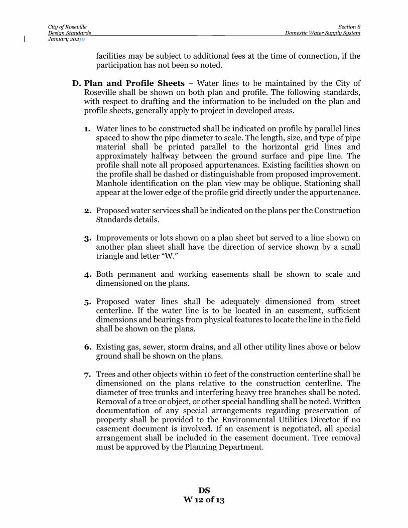
City of Roseville Section 8 Design Standards_______________________________ ____ Domestic Water Supply System January 20210
DS W 12 of 13
facilities may be subject to additional fees at the time of connection, if the participation has not been so noted.
D. Plan and Profile Sheets – Water lines to be maintained by the City of
Roseville shall be shown on both plan and profile. The following standards, with respect to drafting and the information to be included on the plan and profile sheets, generally apply to project in developed areas.
1. Water lines to be constructed shall be indicated on profile by parallel lines
spaced to show the pipe diameter to scale. The length, size, and type of pipe material shall be printed parallel to the horizontal grid lines and approximately halfway between the ground surface and pipe line. The profile shall note all proposed appurtenances. Existing facilities shown on the profile shall be dashed or distinguishable from proposed improvement. Manhole identification on the plan view may be oblique. Stationing shall appear at the lower edge of the profile grid directly under the appurtenance.
2. Proposed water services shall be indicated on the plans per the Construction
Standards details. 3. Improvements or lots shown on a plan sheet but served to a line shown on
another plan sheet shall have the direction of service shown by a small triangle and letter “W.”
4. Both permanent and working easements shall be shown to scale and
dimensioned on the plans. 5. Proposed water lines shall be adequately dimensioned from street
centerline. If the water line is to be located in an easement, sufficient dimensions and bearings from physical features to locate the line in the field shall be shown on the plans.
6. Existing gas, sewer, storm drains, and all other utility lines above or below
ground shall be shown on the plans. 7. Trees and other objects within 10 feet of the construction centerline shall be
dimensioned on the plans relative to the construction centerline. The diameter of tree trunks and interfering heavy tree branches shall be noted. Removal of a tree or object, or other special handling shall be noted. Written documentation of any special arrangements regarding preservation of property shall be provided to the Environmental Utilities Director if no easement document is involved. If an easement is negotiated, all special arrangement shall be included in the easement document. Tree removal must be approved by the Planning Department.

City of Roseville Section 8 Design Standards_______________________________ ____ Domestic Water Supply System January 20210
DS W 13 of 13
8. Culverts shall be shown on both plan and profile when crossed by the construction or when parallel and within 20 feet of the construction line. Type, size, and invert elevation shall be called out.
9. No trees or permanent structures shall be placed within water easements
without the approval of the Environmental Utilities Director. E. Detail Drawings – Details not covered by the Construction Standard Detail
sheets shall be shown on the plans.
8-20 RECORD (AS-BUILT) PLANS –The Contractor/Developer shall keep an accurate record of all approved deviations from plans and shall provide a PDF electronic, full size bond and 11 x 17 copy of the as-built plans prior to final acceptance of the completes improvements. Each sheet of the plans shall be marked “AS-BUILT” or “RECORD DRAWING”. “AS-BUILT” or “RECORD DRAWING” of signal plans, water, sewer and storm drain composite in plan view only, and parcel and final maps shall also be submitted on computer disk in DXF or DWG format.

City of Roseville Section 9 Design Standards________________________________________________________ ____ Sanitary Sewer Design January 202119
DS SS 1 of 17
SECTION 9
SANITARY SEWER DESIGN 9-1 DESIGN CRITERIA – These criteria shall apply to the engineering design of any
sanitary sewer system to be maintained by the City of Roseville, or with those exceptions as noted, within private multiple ownership residential or multi-parcel commercial and industrial developments.
9-2 AVERAGE FLOW DETERMINATION – The determination of average dry
weather flows for design purposes shall be based upon the best available information concerning land use and density as determined by the Environmental Utilities Director. This information may include approved land use and density in accordance with current zoning in the absence of more specific information pertaining to expected development. Average dry weather flow factors are listed in Table 1.
Table 1 – Average Dry Weather Unit Flow Factors
Land Use Designation Units Flow Factor (gpd/unit)1,3
Commercial gpd per acre 850 Heavy Industrial gpd per acre 850 Light Industrial gpd per acre 850 Mixed Use gpd per acre 2,300 Public/Quasi-Public gpd per acre 660 Schools gpd per acre 170 Residential 1 DU gpd per DU 190 Residential 2 DU gpd per DU 190 Residential 3 DU gpd per DU 190 Residential Multiple DU2 gpd per acre
Or gpd per DU
2,040 Or 130
Open Space gpd per acre 0 Parks> 10 Acres gpd per acre 10 Vacant gpd per acre 0
1Includes allowances for dry season groundwater infiltration (GWI) 2Future development projects should use the factor that results in the highest flow. 3factor flow assumes a 30% F.A.R. 50% for senior living 9-3 DESIGN FLOW– Design flow sizing of infrastructure 15 inches in diameter and
smaller shall be calculated by using the average dry weather unit flow factor(s) listed in Table 1 for the upstream service area along with a safety factor of 2.0 and the appropriate peaking factor listed on Figure SS-1. Attachment A located at the end of this section provides a sample calculation. For sizing trunk sewers 18 inches in diameter and larger, utilize the hydraulic model of the collection and conveyance system and consult with Environmental Utilities Department staff.
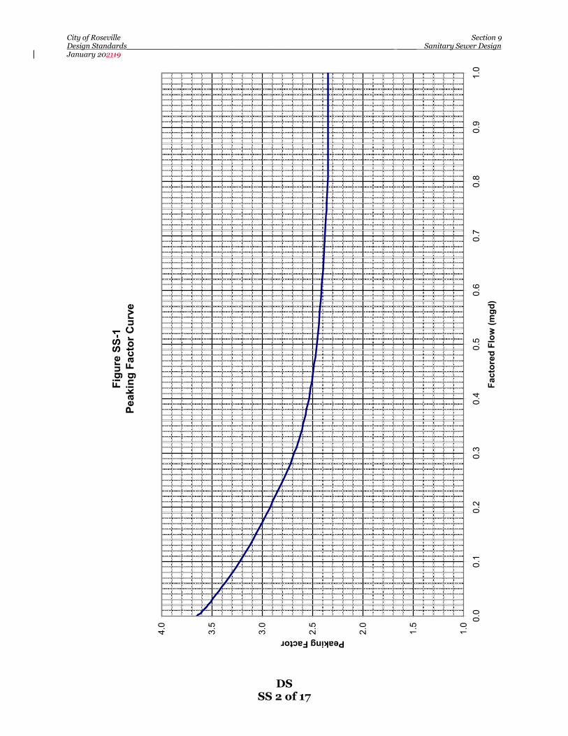
City of Roseville Section 9 Design Standards________________________________________________________ ____ Sanitary Sewer Design January 202119
DS SS 2 of 17
Figu
re S
S-1
Peak
ing
Fact
or C
urve
1.0
1.5
2.0
2.5
3.0
3.5
4.0 0.
00.
10.
20.
30.
40.
50.
60.
70.
80.
91.
0
Fact
ored
Flo
w (m
gd)
Peaking Factor
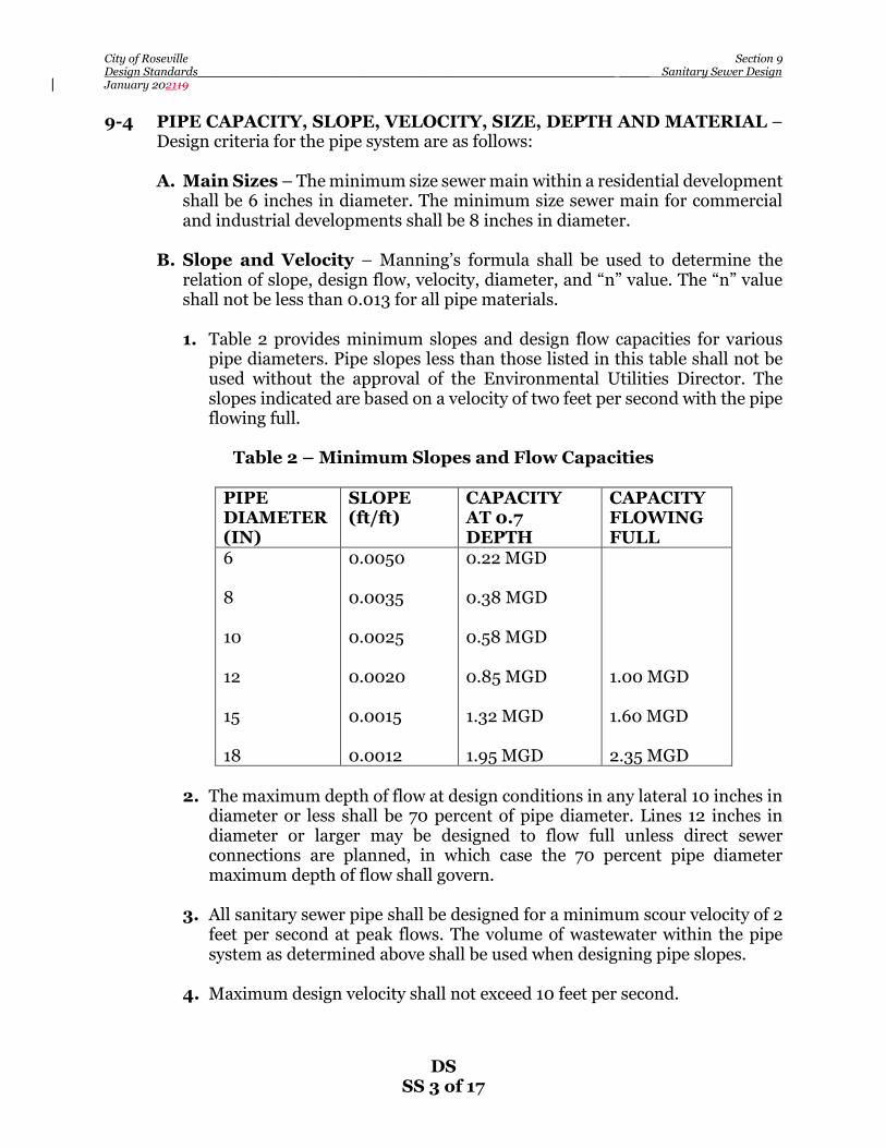
City of Roseville Section 9 Design Standards________________________________________________________ ____ Sanitary Sewer Design January 202119
DS SS 3 of 17
9-4 PIPE CAPACITY, SLOPE, VELOCITY, SIZE, DEPTH AND MATERIAL – Design criteria for the pipe system are as follows:
A. Main Sizes – The minimum size sewer main within a residential development
shall be 6 inches in diameter. The minimum size sewer main for commercial and industrial developments shall be 8 inches in diameter.
B. Slope and Velocity – Manning’s formula shall be used to determine the
relation of slope, design flow, velocity, diameter, and “n” value. The “n” value shall not be less than 0.013 for all pipe materials.
1. Table 2 provides minimum slopes and design flow capacities for various
pipe diameters. Pipe slopes less than those listed in this table shall not be used without the approval of the Environmental Utilities Director. The slopes indicated are based on a velocity of two feet per second with the pipe flowing full.
Table 2 – Minimum Slopes and Flow Capacities
PIPE DIAMETER (IN)
SLOPE (ft/ft)
CAPACITY AT 0.7 DEPTH
CAPACITY FLOWING FULL
6 8 10 12 15 18
0.0050 0.0035 0.0025 0.0020 0.0015 0.0012
0.22 MGD 0.38 MGD 0.58 MGD 0.85 MGD 1.32 MGD 1.95 MGD
1.00 MGD 1.60 MGD 2.35 MGD
2. The maximum depth of flow at design conditions in any lateral 10 inches in
diameter or less shall be 70 percent of pipe diameter. Lines 12 inches in diameter or larger may be designed to flow full unless direct sewer connections are planned, in which case the 70 percent pipe diameter maximum depth of flow shall govern.
3. All sanitary sewer pipe shall be designed for a minimum scour velocity of 2
feet per second at peak flows. The volume of wastewater within the pipe system as determined above shall be used when designing pipe slopes.
4. Maximum design velocity shall not exceed 10 feet per second.

City of Roseville Section 9 Design Standards________________________________________________________ ____ Sanitary Sewer Design January 202119
DS SS 4 of 17
C. Capacity – Pipe capacity, in all cases, shall be adequate to carry the Peak Wet Weather Flow (PWWF) from the entire tributary shed area even though said area may not be within the project boundaries.
D. Hydraulic Grade Line – The hydraulic grade line shall be determined from
the design flows, based upon 100 percent development of the tributary area. Hydraulic grade line calculations must be submitted for the design of all lines 12 inches in diameter or larger.
E. Depth – Sewer mains with service lateral shall not exceed a depth of 15 feet.
The system shall be designed to provide a minimum slope for sewer services of ¼ inch per foot with a minimum cover of 12 inches at any buildable location within the properties to be served. Proposed building pad elevations shall be a minimum six inches above the lowest upstream manhole rim. Where the building pad does not meet the elevation requirement, a backwater valve for the building shall be required. The backwater valve shall be noted on the improvement plans and building plans. Installation shall be made during construction of the underground improvements. Deed restrictions shall be put in place which hold the City harmless for failure of the backwater valves on such lots.
9-5 SEWER LOCATION AND ALIGNMENT REQUIREMENTS – Location and
alignment criteria are as follows: A. General – All sanitary sewers shall be placed in rights-of-way dedicated for
public streets or within easements approved by the Environmental Utilities Director. Developments with deep sewer mains or with trunk mains may require dual sewer mains. There shall be a minimum horizontal clearance of 10 feet between parallel water, recycled water, and sanitary sewer mains. A minimum horizontal clearance of 5 feet shall be maintained between sewer mains, parallel storm drains, and other utilities. On crossings, water and recycled water lines shall be a minimum of 12 inches above the sewer line. If a sanitary sewer force main must cross a water or recycled water line, refer to sections 8 (Domestic Water Supply System) and 14 (Recycled Water Supply System) of these standards.
B. Location in New Subdivisions – In new subdivisions, sewers shall be
located 5 feet south or east of street centerlines within minor and primary residential streets, or as approved by the Environmental Utilities Director.
C. Location in Existing Streets – When sanitary sewers are to be installed in
an existing street, factors such as curbs, gutters, sidewalks, traffic conditions, traffic lane conditions, pavement conditions, future street improvement plans, and existing utilities shall be considered. The approval of the Environmental Utilities Director and City Engineer shall be obtained in every instance.

City of Roseville Section 9 Design Standards________________________________________________________ ____ Sanitary Sewer Design January 202119
DS SS 5 of 17
D. Location in Unpaved Area – All mains in unpaved areas shall be marked every 125 lineal feet maximum between manholes with a green 5-feet 6-inch composite utility marker. A decal shall be placed on marker stating “CAUTION SEWER PIPE.” Utility marker shall be Carsonite or approved equal with anchor barb kit.
E. Easement Sewer Lines – Easement sewer lines outside of the public right-
of-way, or within a narrow right- of-way shall require an easement dedication to the City. Sewer lines shall be centered within their easement. Easements shall be completely on one side of the property line of fence. The easement shall be clear of permanent structures, building eves, roof lines, and the future trunk of large tree species. Temporary construction easements of adequate size shall also be provided. The proposed easement shall be the greater of the following:
1. Minimum width of easement shall be 15 feet. 2. All easements shall have a minimum width equal to the required trench
width according to the standard detail for trench backfill, plus 2 additional feet for every 1 foot of depth of the pipe as measured from the bottom of the pipe to finished grade. All sewer lines shall be centered within their easement.
3. No trees or permanent structures are allowed within the sewer easement
except with the approval of the Environmental Utilities Director. F. Public Lines in Commercial Developments – Sewer mains shall be located within drive aisles unless otherwise approved by the Environmental Utilities Director. G. Water Well Clearance – Sewer lines shall maintain a minimum 100-foot
separation from all public or private wells. (Properly abandoned wells are not included.) If a clearance of less than 100 feet is approved, the pipe material shall be approved by the Environmental Utilities Director. In no case shall the clearance be less than 50 feet.
H. Lines in Drainage Swales – Sewer lines, public or private, shall not be
located within a drainage swale. The horizontal distance between the sewer line and the top of the bank shall be sufficient to maintain the integrity of the drainage swale and provide access for maintenance to the sewer line.
I. Alignment – Sewer lines and structures shall be designed to provide a
minimum 12-inch vertical clearance from all utilities and/or improvements, unless otherwise approved by the Environmental Utilities Director.
1. Horizontal alignment shall be parallel to the street centerline. Minimum
radius for sanitary sewers 6 inches through 12 inches in diameter shall be 200 feet. For pipe 27 inches in diameter or larger, mitered joints, fittings,

City of Roseville Section 9 Design Standards________________________________________________________ ____ Sanitary Sewer Design January 202119
DS SS 6 of 17
or other methods as specified in the Standard Construction Specifications may be utilized to accomplish alignment changes.
2. Vertical alignment shall provide a constant slope between manholes. If a
change in grade is necessary, construction of a manhole shall be required unless the use of a vertical curve is approved by the Environmental Utilities Director. In such case, elevations shall be shown at 10-foot intervals throughout the length of the vertical curve. The maximum deflection permitted shall be two percent for each 10-foot interval.
J. Sewer Main Stub – Sewer main stubs for future development which are
perpendicular to the sewer main shall be ductile iron pipe vitrified clay pipe (VCP) originating from the manhole. The stub shall be within 150 feet of the manhole and terminate 5 feet into the future development. Green Carsonite marker shall be installed at the end of the stub.
9-6 TRENCH LOADING CONDITIONS AND PIPE DESIGN – The loading
condition and pipe design criteria for conduits are as follows: A. Rigid Conduit Loading – On rigid conduits, Marston’s formula shall be used
to determine the load placed on the pipe by backfill. The procedure for rigid pipe is described in the ASCE Manual and Report of Engineering Practice No. 60, the Clay Pipe Engineering Manual, and in similar handbooks. In the absence of specific soils data, as determined by the soils engineer, a soil weight of 120 p.c.f. and a Ku factor of 0.110 shall be used. Minimum strength requirements for verified vitrified clay pipe shall be shall be as specified per ASTM C-700 “extra strength” VCP.
B. Safety Factor – On rigid conduits, a safety factor of 1.5 shall be used for all
pipe. The three edge bearing strength of the pipe shall be used in the computation for rigid pipe.
C. Bedding and Initial Backfill – Unless otherwise noted on the plans,
bedding and initial backfill shall be per the Construction Standards. Special backfill requirements shall be noted on the plans.
D. Special Pipe Strength Requirements – For sewer mains greater than 20
feet deep or mains requiring extra support strength, pipe material shall be approved by the Environmental Utilities Director. Ductile iron pipe shall be used if cover is less than three feet or insufficient clearance exists between the sewer pipe and the rigid load transmitting structures. Such structures include large diameter storm drains and other structures subject to settlement. The ductile iron pipe shall extend 5 feet each side of the structure crossing.
9-7 MANHOLE CRITERIA - The design criteria for manholes are as follows:

City of Roseville Section 9 Design Standards________________________________________________________ ____ Sanitary Sewer Design January 202119
DS SS 7 of 17
A. General – Manholes shall be placed at the intersection of all sanitary sewer lines, at the upstream end of a pipe run, and at the end of any temporary line more than 200 feet in length. No more than three lines may enter a manhole with one line exiting. Medium-density single-family subdivisions may enter a manhole with up to 4 services with one exiting main line upon approval of the Environmental Utilities Director. Summit manholes are not permitted.
B. Spacing – Maximum spacing of manholes shall be 500 feet for all straight
lines of 10 inches in diameter or less. Manhole spacing for mains 12 inches and larger shall be considered on a case by case basis. A line with a radius greater than 400 feet shall be considered as straight for purposes of this section. Manhole spacing on curved lines of 200-feet radius (minimum allowable) shall be 200 feet. Manhole spacing on curved lines of radii between 200 and 400 feet, or where only a portion of the line is curved, shall be adjusted proportionately. Reverse curves require a manhole at the point of tangency of the curves or as determined by the Environmental Utilities Director. A manhole shall be required at any change in vertical alignment unless use of a vertical curve is approved by the Environmental Utilities Director.
C. Invert Elevations – The invert elevation for pipe of the same diameter
entering a manhole shall have a 0.10-foot drop between the entering and exiting pipe. Under special circumstances, the 0.10-foot drop may be waived with the approval of the Environmental Utilities Director. Invert elevations for pipe of different diameters shall match crown of exiting pipe. The crown of the entering pipe shall be at the same elevation or higher than the exit pipe. Mains with 10 or fewer services shall enter manholes at an invert to crown match with the exit pipe. Lateral mains entering trunk mains, as defined by the Environmental Utilities Director, shall enter manholes at an invert to crown match with the exit pipe.
D. Manhole Sizing – A standard 48 inch manhole with a 24 inch access opening
shall be used for sewer mains 12 inches and smaller, and not exceeding 20 feet depth. A 60 inch manhole with a 36 inch opening shall be used for sewer trunk mains 15 inches to 36 inches in diameter. The design of larger trunk mains shall be approved on a case-by-case basis.
E. Manhole Coatings –Manholes coatings shall be required in areas
determined to have a potential of generating excessive sulfide gases. Such manholes shall include, but are not limited to, all manholes on trunk mains 15” in diameter or larger, the first manhole originating from a sewer trunk main 15 inches in diameter or larger, force main transition manholes, manholes designed with inside drops, or as determined by the Environmental Utilities Director.
F. Manhole Access – Provisions must be made to prevent vegetation from
overgrowing the manholes. An all-weather 10-ton vehicular access shall be provided to each manhole as required by the Environmental Utilities

City of Roseville Section 9 Design Standards________________________________________________________ ____ Sanitary Sewer Design January 202119
DS SS 8 of 17
Department. Turning radii of 30 feet inside and 45 feet outside, and a vertical clearance of 14 feet are required.
G. Connection to City Mains – Improvement plans which require a connection
to an existing City of Roseville sewer main or structure shall specify that such connection be performed by City forces on a time and materials basis.
9-8 DROP CONNECTION CRITERIA – Drop connections shall be permitted under
special conditions and with the approval of the Environmental Utilities Director. There shall be no more than two inside drop connections into a 4-foot diameter manhole. If an elevation difference of at least 3 feet is not available, the slope of the incoming line shall be increased to eliminate the need for the drop.
9-9 MAINLINE AND DIP TRANSITIONS – Mainline transitions shall be made at
a sewer manhole. Transitions for services may be made at a manhole or with the use of a specially fitted DIP piece with a VCP “speed seal” spigot. Arrangements for the special spigot shall be coordinated with the Environmental Utilities Department.
9-10 SEWER SERVICE DESIGN – The design criteria for sewer services are as
follows: A. General – Services shall be designed and constructed perpendicular to the
main or as approved by the Environmental Utilities Director. The service shall extend from the main to the edge of the public right-of-way or easement. The cleanout shall be constructed per the Construction Standards 2’ outside of the sewer easement. The cleanout indicates the separation between private and public for the purpose of maintenance. In cases where there is no cleanout, the sewer service is considered private all the way to the main. Services shall extend two feet beyond edge of pavement of private roads. Easements of adequate width to accommodate the service shall be obtained. A plan and profile of services shall be supplied to the Environmental Utilities Director on request.
1. Cleanouts shall be designed and constructed to grade with subdivision
improvements or at the time connection is made to the building sewer. Unless otherwise noted on the plans, construction of the cleanout to grade is the responsibility of the contractor for the subdivision improvements. If installation of the cleanout is deferred, the plans shall call for the placement of a 4-inch by 4-inch post at the end of the service sewer extending from the flow line to not less than 12 inches above ground surface.
B. Sizing – The minimum size service for single-family developments shall be 4
inches in diameter. Services greater than 100 feet in length shall be 6 inches in diameter. Schools, commercial, industrial and multiple residential properties shall be served by a minimum 6-inch diameter service.

City of Roseville Section 9 Design Standards________________________________________________________ ____ Sanitary Sewer Design January 202119
DS SS 9 of 17
1. Connection to Sewer Mains – Residential services shall connect to the sewer main by means of a factory fitting. Properties with services located at the end of cul-de-sacs shall enter a manhole. A 6-inch service shall enter a 6-inch main by means of a manhole. A 6-inch service entering an 8-inch or larger main must either be connected with a manhole or by means of a factory fitting with a manhole placed at the property line. Services 8 inches in diameter and larger shall be connected to the main by use of a manhole. Connection to trunk mains shall be approved by the Environmental Utilities Director. In no case shall a service connection be made with the use of a tee.
2. Connection to Existing Sewer Mains - The Environmental Utilities
Department reserves the right to make all sewer service taps onto existing mains upon completing an application for a permit and payment of the required connection fees. Proposed work by the City shall be performed by City forces and payment made to the City for such work will be on a time and materials basis. A note to this effect shall be placed on the plan sheet which shows a detail for the area that requires such tapping. The application shall be made to the Environmental Utilities Department. Connection fees shall be paid prior to submittal of the application. All excavation, backfill, and the installation of the remainder of the sewer service or stub shall be performed by the Contractor.
3. Connection Limitations – Sewer services shall connect to 12-inch
diameter and larger pipe or to lines more than 15-feet in depth at a manhole. Direct connection to trunk mains shall only be with the approval of the Environmental Utilities Director.
4. Material – The service shall be of the same material as the lateral to which
it connects or as specified by these standards. 5. Location - A sewer service shall be constructed to each lot. In new
subdivisions or developed areas, unless specifically requested otherwise in writing, sewer services shall be placed on the low side of a typical subdivision lot or similar parcel with 2 percent or greater slope across the front, or shall be placed in the center of lots of lesser slope. Under no circumstances shall a sewer service be placed less than 14’ from the property line. Trees, improvements, etc., are to maintain a minimum of 5’ from the sewer service, including the cleanout and where the sewer service is extended to service the house.
If the property is located such that service is available both to a line located
in an easement and also in a right-of-way, service shall be at the latter location unless otherwise approved by the Environmental Utilities Director. No sewer service shall be located such that future on-site construction will result in the line being is such proximity to a water well or water main or service that applicable health standards will be violated.

City of Roseville Section 9 Design Standards________________________________________________________ ____ Sanitary Sewer Design January 202119
DS SS 10 of 17
C. Depth – Adequate depth of sewer service at the edge of easement or right-of-way to service the intended parcel shall be verified. A depth of 3 to 4 feet to crown of pipe, measured from existing ground surface or edge of adjacent roadway, whichever is lower, shall be considered the standard for service sewer depth, except where the water main is to be installed at back of sidewalk as part of the subdivision improvements. In such cases, service shall have a minimum depth of cover of 4-feet 6-inches at the property line and the service shall be extended to a minimum of 7 feet back of sidewalk with the cleanout to grade remaining within 2 feet of back of sidewalk. When greater depth is required, the invert elevation of the service sewer at the edge of the right-of-way or easement shall be noted on the improvement plans. If a joint trench is being utilized for other utilities, the plans shall indicate that a joint trench will exist and service elevations shall be adjusted accordingly.
Sewer service connection to the main 14 feet or deeper, shall place concrete around the haunch of the “wye”. Sewer service connection to the main shall not exceed 15 feet.
D. Special Requirements in Developed Areas – In developed areas, a sewer
service shall be provided to each parcel participating in the project which contains a source of sewage less than 200 feet from a lateral. A property owner’s request for service location shall be honored whenever practical. Parcels which have two or more sources of sewage must have an independent sewer service provided for each sewage source which can be separated from the rest of the parcel and sold. A service shall be provided to each lot. During the design period, each property owner affected by the proposed work shall be contacted in writing to determine the preferred sewer service location. In absence of a response, a sewer service shall be provided in accordance with these standards. In addition, upon staking the location of the proposed sewer services prior to construction, each property owner shall be given a final opportunity to approve the proposed sewer service location. Compilation of this information shall be furnished to the Environmental Utilities Director.
E. Warranty Inspection of Sewer Main Stubs – As a requirement, sewer
stubs are provided to subdivisions as a courtesy by developers during the construction of backbone infrastructures in streets to prevent cutting up the newly paved streets when the subdivisions are ready to develop. These stubs become an integral part of the sewer system of the subdivisions and subsequently the responsibility of the developers of the subdivisions and are therefore imperiled to both construction and warranty inspections. This practice saves future developers construction time and cost that would have otherwise been spent on tie-ins and street repairs and in some instances prevents delays in the event a street has a moratorium. Since these stubs are provided at no cost to future developers, it is our position, hence our policy, that it is the responsibility of contractors to test and repair these stubs, if found damage, prior to tie-ins. A note to this effect shall be placed on the improvement plans.

City of Roseville Section 9 Design Standards________________________________________________________ ____ Sanitary Sewer Design January 202119
DS SS 11 of 17
F. Abandoning Existing Sewer Stubs – Existing sewer stubs to be abandoned shall be abandoned per Section 91 of the Construction Standards.
G. Grease Interceptor – A grease interceptor shall be required for any business
having the potential of producing grease as specified in the Roseville Municipal Code. Minimum size of the interceptor shall be 1000 gallons. Sizing of the interceptor shall be based on the current edition of the California Plumbing Code adopted by the City.
1. General Commercial/Retail buildings shall require dedicated grease lines
for future use. A location for the future grease interceptor shall be identified on the improvement plans.
H. Oil/Sand Interceptor – An oil/sand interceptor shall be installed for any
business having the potential of producing oil and sand waste resulting from routine maintenance as specified in the Roseville Municipal code. Minimum size shall be 450 gallons. Sizing of the interceptor shall be based on the current edition of the California Plumbing Code adopted by the City.
I. Automatic Car Wash – An oil/sand interceptor or an approved clarifier shall
be installed for an automatic car wash as specified in the Roseville Municipal Code. The car wash shall recycle a minimum of 75% of the water used prior to discharging into the City’s sewer system. Minimum size of oil/sand interceptor shall be 450 gallons. Sizing of the oil/sand interceptor shall be based on the current edition of the California Plumbing Code adopted by the City.
9-11 SIPHON AND CREEK CROSSING DESIGN – Advance approval of the
Environmental Utilities Director, City Engineer, and other appropriate agencies is necessary to initiate design. The criteria for creek crossings are as follows:
A. General – In all cases, the proposed future creek bed elevation shall be used
for design purposes. Crossing details of pipe, piers, anchorage, transition couplings, etc., shall be shown on a detail sheet of the plans. The top of pipe shall have a minimum 3 feet of cover at the shallowest point of the crossing.
B. Gravity mains– For line sizes 10 inches and smaller, ductile iron pipe shall
be used under the full creek width plus 10 feet each side. For line sizes 12 inches and larger, pipe used shall be as determined by the Environmental Utilities Director. The ductile iron pipe shall be supported by steel I-beam piles. The steel I-bean pile shall be installed to a yielding depth as recommended by the soils engineer. Each stick of pipe shall be supported by a least one pile or as approved by the Environmental Utilities Director. A steel plate shall be welded on top of the I-beam. A ½-inch thick polyethylene plane shall be installed on top of the steel plate for the pipe to rest on. The pipe shall be held by two 2-inch wide galvanized steel straps, with galvanized bolts attached through the steel plate and polyethylene plate. An insulating material shall be used between the pipe and the section of strap coming into contact with the pipe. All exposed

City of Roseville Section 9 Design Standards________________________________________________________ ____ Sanitary Sewer Design January 202119
DS SS 12 of 17
surfaces shall be coated with coal tar epoxy. A layer of 4-inch to 8-inch cobbles shall be placed and compacted on the top surface of the trench area for the full width of the creek. A trench plug shall be required at the top of the pipe at the downstream side of the crossing. The plug shall be a minimum of 4 feet in length, and shall extend 24 inches beyond the width and depth of the trench.
C. Design – Calculations shall be submitted which clearly indicate the design of
the pipe and supports regarding impact, horizontal and vertical forces, overturning, pier and anchorage reactions, etc.
D. Siphon - ductile iron pipe shall be used under the full creek width plus 10 feet
each side. Pipe shall be concrete encased per detail W-24. A layer of 4-inch to 8-inch cobbles shall be placed and compacted on the top surface of the trench area for the full width of the creek. A trench plug shall be required at the top of the pipe at the downstream side of the crossing. The plug shall be a minimum of 4 feet in length, and shall extend 24 inches beyond the width and depth of the trench.
1. Condensate Stations for air jumpers shall be designed per the City
Process Control Standards. 9-12 BORING AND JACKING REQUIREMENTS – The requirements outlined in
the Construction Standards shall be followed. 9-13 PUMP STATION AND FORCE MAIN REQUIREMENTS – Every phase of
pump station design, including force main design, shall be closely coordinated under the direction of the Environmental Utilities Director. The pump station and force main shall be designed and submitted concurrently. The plan sheets will show the general layout and control system required for a typical acceptable sewage pump station. The plans shall call out the testing required for acceptance of the pump station. The lift station shall be designed per the City Process Control Standards.
A. Location – The pump station and facilities shall maintain a minimum 100-
foot separation from existing and proposed residential and commercial structures. Adequate maintenance access shall be provided to the pump station. The access design shall consider requirements for the removal of pump station equipment.
B. Capacity – The pump station shall be designed to accommodate ultimate
buildout flows as well as initial flows. Allowances for larger or additional pumping equipment must be made for future requirements. If the design capacity is in excess of anticipated initial flow, the effects of the minimum flow condition must be estimated to prevent excessive retention of sewage in the wet well, to prevent septic conditions, and to determine whether the pumping equipment will operate within the manufacturer’s guidelines. Table 3 provides

City of Roseville Section 9 Design Standards________________________________________________________ ____ Sanitary Sewer Design January 202119
DS SS 13 of 17
planning level criteria for sizing and configuration of pump station and force main facilities.
Table 3 – Planning Level Criteria for Pump Stations and Force Mains
Pump Stations Capacity PWWF (hydraulic modeling required for pipes 18
inches and larger) Storage 4 hours Operation Lead/lag for duty pump(s), plus 1 standby pump Maximum Pump Cycles 6 cycles/hour (3 cycles per pump) Force Mains Headloss Hazen-Williams roughness coefficient (C-factor)
of 120 Maximum Velocity 7-10 feet per second Minimum Velocity 3.0 feet per second
C. Wet Well – The wet well design and detention time shall be such that the
deposition of solids is minimized and the sewage does not become septic. Provisions for 4 hour storage capacity shall be provided. Wet well material shall be Armorock Polymer Concrete or approved equal. Maximum depth of wet well shall not exceed 35’.
D. Pumps – Pumping equipment shall consist of centrifugal pumps. Pump
suction and discharge size shall be a minimum of 4 inches in diameter. Pump drive units shall be electric. A sufficient number of pumping units shall be installed such that station capacity can be maintained with any one unit out of service. Pump manufacture is to be Flygt or approved equal. Provisions for telemetry shall be included in the station control system as directed by the Environmental Utilities Director.
E. Station Piping - Suction, discharge, and header piping within the station shall
be sized to adequately handle flows. Piping less than 4 inches in diameter shall not be used for conveying sewage. Valves shall be located to allow proper equipment maintenance and operation. The design shall provide a bypass configuration back to the wet well.
F. Odor Control – If required, the station shall have equipment and/or space
provided for the purpose of introducing odor control chemicals into the wet well, upstream gravity line, and/or force main. Adequate provisions shall be made for the safe handling and storage of chemical containers. The force main shall be designed to maintain a continuous uphill grade, or, as a minimum be level. All force mains shall have provisions for introduction of either air or odor control chemicals.

City of Roseville Section 9 Design Standards________________________________________________________ ____ Sanitary Sewer Design January 202119
DS SS 14 of 17
G. Force Mains – Force mains shall be designed such that velocities normally fall within a range from 3 to 5 feet per second. If initial capacity of the station is considerably less than ultimate, consideration should be given to the prevention of septic conditions due to extensive detention time within the force main. The feasibility of installing dual force mains to accommodate initial and ultimate flows shall be investigated in such situations. Provisions shall be made introducing a “cleaning pig” into all force mains. The design shall also include facilities to eliminate or sufficiently dampen transient forces and/or surging in the event of an immediate station shutdown. Details shall be included in the improvement plans. The maximum angle allowed on force mains is 22.5 degrees. A corrosion protection study shall be included with the improvement plan submittals. Corrosion protection facilities for the force main shall be identified from the roadway with a curb stamp labeled “CP – FM”.
H. S.C.A.D.A. – SCADA requirements for pump stations shall be provided by the
Environmental Utilities Department. The submittal shall be included along with the improvement plans for such facilities.
I. Valves - Valves on pressurized sewer systems shall be Crispin plug valves.
9-14 SEWER IMPROVEMENT PLAN REQUIREMENTS – Plans for the
construction of sanitary sewers, whether in conjunction with other improvements or for a sewer project only, shall conform to these standards, the Construction Standards, and meet the following requirements.
A. Sewer Study – A sewer study or sewer master plan as determined by the
Environmental Utilities Director may be required prior to review of the sewer design if there is a possibility that upstream or adjacent areas might require service through the subject property. The map shall show the entire area including upstream tributary and adjacent areas, and all other data necessary to determine anticipated sewage flows. The method of providing service to the entire service area, including pipe sizes and slopes, shall be shown to the extent necessary to determine the requirements within the subject property.
B. General Requirements – Plans for sewer improvement projects shall
include a layout sheet, plan and profile of each public sewer line, and necessary detail drawings. Reference to the Construction Standards shall be made for all standard details.
C. Layout Sheet – Improvement plans shall include an overall map which shows
the project boundaries, sewer lines, manholes, backwater valves, and other important items of the work.
1. A parcel which benefits from and financially participates in a sewer
construction project, but is not included within the project boundaries, shall

City of Roseville Section 9 Design Standards________________________________________________________ ____ Sanitary Sewer Design January 202119
DS SS 15 of 17
have a note to this effect placed on the layout map and on the plan and profile sheet if the parcel appears thereon. Parcels which make use of those facilities may be subject to additional fees at the time of connection, if the participation has not been so noted.
D. Plan and Profile Sheets – Sewer lines to be owned and maintained by the
City of Roseville shall be shown on both plan and profile. The following standards, with respect to drafting and the information to be included on the plan and profile sheets, generally apply to projects in developed areas.
1. Sewer lines to be constructed shall be indicated on profile by parallel lines
spaced to show the pipe diameter to scale. Manholes shall also be indicated by parallel lines spaced according to scale. Slope shall be printed 1/8-inch above, and preferably parallel to, the pipe line, or between the parallel lines. The length, size and type of pipe material between each manhole shall be printed parallel to the horizontal grid lines and approximately halfway between the ground surface and pipe line. Pipe inverts, “IN and OUT,” at manholes and other structures shall be indicated on the profile. The invert elevations shall be printed parallel to the horizontal grid lines and shall be underscored by a line which then runs at a 45-degree angle to the corresponding pipe invert. Rim elevation for all manholes shall be labeled. The profile shall note all proposed manholes, special connections, and other appurtenances. Existing facilities shown on the profile shall be dashed or distinguishable from proposed improvements. Manhole identification on the plan view may be oblique. Stationing shall appear at the lower edge of the profile grid directly under the manhole. Each manhole shall be assigned a number that will appear in both plan/profile and the cover sheet.
2. Proposed sewer services shall be indicated on the plans by stationing, or an
approved reference point such as a property line. The invert elevation of the service at its upstream end shall be shown on the plans whenever the standard depth is inadequate to serve the property. Standard depth shall conform to the conditions set forth in the Construction Standards.
3. Improvements or lots shown on a plan sheet but served to a line shown on
another plan sheet shall have the direction of service shown by a small triangle and letter “S.” “As Built” plans shall also show the service sewer location measured from the nearest downstream manhole.
4. Both permanent and working easements shall be shown to scale and
dimensioned on the plans. 5. Proposed sewer lines shall be adequately dimensioned from street
centerline. If the sewer is to be located in an easement, sufficient dimensions and bearings from physical features to locate the line in the field shall be shown on the plans.

City of Roseville Section 9 Design Standards________________________________________________________ ____ Sanitary Sewer Design January 202119
DS SS 16 of 17
6. Existing gas, water, storm drains, and all other utility lines above or below ground shall be shown on the plans.
7. Trees and other objects within 10 feet of the construction centerline shall be dimensioned on the plans relative to the construction centerline. The diameter of tree trunks and interfering heavy tree branches shall be noted. Removal of a tree or object, or other special handling shall be noted. Written documentation of any special arrangements regarding preservation of property shall be provided to the Environmental Utilities Director if no easement document is involved. If an easement is negotiated, all special arrangements shall be included in the easement document. Tree removal must be approved by the Planning Department.
8. Culverts shall be shown on both plan and profile when crossed by the
construction or when parallel and within 20 feet of the construction line. Type, size, and invert elevations shall be called out.
9. No trees or permanent structures shall be placed within sewer easements
without the approval of the Environmental Utilities Director. E. Detail Drawings – Details not covered by the Construction Standard Detail
sheets shall be shown on the plans.
F. Connection to Existing Facilities Where Bypassing or Stoppage of Existing Flow Will be Required – Upon approval of the application to connect to an existing sewer main by the Environmental Utilities Department, a coordination meeting to discuss the work plan shall be organized by the contractor a minimum of seven days prior to the proposed connection or as permitted by the City’s work schedule. Should the Environmental Utilities Director determine that such work be performed by City forces, the work shall be performed on a time and material basis.
9-15 MULTI-PARCEL COMMERCIAL AND INDUSTRIAL DEVELOPMENTS – “On-site” sewer mains for new commercial and industrial developments containing more than one parcel, shall be designed in accordance with the requirements contained in these standards or as approved by the Environmental Utilities Director. The sewer main shall be installed within a dedicated public sewer easement in accordance with these standards. Each separate parcel within a multi-parcel commercial or industrial development shall have a separate connection to the public sewer line(s).
9-16 RECORD (AS-BUILT) PLANS –The Contractor/Developer shall keep an accurate record of all approved deviations from plans and shall provide a PDF electronic, full size bond and 11 x 17 copy of the as-built plans prior to final acceptance of the completes improvements. Each sheet of the plans shall be marked “AS-BUILT” or “RECORD DRAWING”. “AS-BUILT” or “RECORD DRAWING” of signal plans, water, sewer and storm drain

City of Roseville Section 9 Design Standards________________________________________________________ ____ Sanitary Sewer Design January 202119
DS SS 17 of 17
composite in plan view only, and parcel and final maps shall also be submitted on computer disk in DXF or DWG format. ATTACHMENT A: Example Design Flow Analysis for Sewers 15 Inches and Smaller
Example calculation for application of safety factor and peaking factor curve for 400-unit single family subdivisions:
ADWFi: (400 DUs)*(190 gpd/DU) = 76,000 gpd = ADWF Factored Flow: (ADWF)*(2.0) = (76,000gpd)*(2.0) = 152,000 gpd = Factored Flow PWWF: (Factored flow)*(3.05ii) = (152,000)*(3.05) = 464,000 gpd = PWWF Size sewer for this flow based on Section 9-4.
For example, per City of Roseville Improvement Standards, Section 9-4, a 10-inch sewer line at minimum slope is adequate for this PWWF.
a Based on ADWF unit flow factors shown in Table 1 b From Figure SS-1
City of Roseville Section 10 Design Standards_____________________________ ___________________________________ Drainage January 20210
DS DR 1 of 30
SECTION 10
DRAINAGE
10-1 GENERAL – This Section is formulated to clearly define acceptable drainage analysis and design criteria for development in the City of Roseville. Drainage facets not covered in this Section shall conform to the Placer County Flood Control and Water Conservation District “Stormwater Management Manual” (SWMM), latest edition, and good engineering practice.
The City of Roseville has adopted storm water quality design standards to reduce water pollution generated by urban runoff. These design standards are detailed in the West Placer Storm Water Quality Design Manual. This Manual is available on-line at the City of Roseville’s website, https://roseville.ca.us/UserFiles/Servers/Server_7964838/File/Government/Departments/Development%20Services/Engineering/Stormwater%20Design%20Inspection/Post%20Development%20Run-off%20Control/W%20Placer%20SWMP%20Manual%20FINAL%202016-04-01.pdf. Storm water design calculations and an operations and maintenance plan shall be made a part of the drainage report.
10-2 CITY POLICIES AND REQUIREMENTS – All residential lots shall have
minimum pad elevations of one foot above the 100 year water surface elevation and all commercial sites shall have minimum finished floor elevations of one foot above the 100 year surface elevation assuming failure of the drainage system. This requires the Consulting Engineer to provide an overland release for all projects or provide storage for the 100-year storm frequency.
The overland release path shall be constructed in a manner to transport the peak
rate runoff from the 100-year storm frequency through the site assuming all storm drains are inoperative, all upstream areas are fully developed, and that antecedent rainfall has saturated the tributary watershed. Streets, parking lots, playgrounds, pedestrian areas, pedestrian walkways, utility easements, and other open space areas may be considered compatible uses within the overland release path.
Except for single family or duplex residential lots, site drainage shall be collected
on-site and conveyed via an underground storm drain system to approved existing storm drainage system without flowing into existing street gutters or existing roadside ditches.
Unless regional storm water mitigation devices are available specific mitigation
shall be required for the project, shall be located on-site, and shall be maintained by the landowner.
10-3 DEVELOPMENT IN OR ADJACENT TO A REGULATORY FLOODPLAIN
– The City’s Regulatory Floodplain boundaries are defined in the City’s General Plan – Safety Element. They are not the same as the flood hazard area shown on

City of Roseville Section 10 Design Standards_____________________________ ___________________________________ Drainage January 20210
DS DR 2 of 30
FEMA’s Flood Insurance Rate Map (FIRM). For the most part the Regulatory Floodplain is the land inundated by the 100-year flood event, assuming build-out of the drainage basin, with a total drainage area of greater than 300 acres. Precise boundaries shall be as approved by the Public Works Director.
Residential lots developed in or adjacent to the City’s Regulatory Floodplain shall have pad elevations a minimum of two feet above the City’s 100-year flood elevation. A Letter Of Map Amendment (LOMA), or a Letter Of Map Revision (LOMR) or LOMR-F (LOMR based on fill) is required for any residential lot in or adjacent to the flood hazard area as shown on a Flood Insurance Rate Map. Non-residential projects shall have finished floor elevations a minimum of two feet above the City’s 100-year flood elevation. A Letter Of Map Amendment (LOMA), a Letter Of Map Revision (LOMR) or LOMR based on fill (LOMR-F) is required for any development in or adjacent to the flood hazard area as shown on a Flood Insurance Rate Map. Elevations Certificates are required for such non-residential structures. In areas where the 100-year flood depths (measured at centerline of creek) are less than eight feet within the infill area on Cirby Creek, Strap Ravine, and Pleasant Grove Creek South Branch Sierra View Tributary, the above freeboard requirements will be is increased to a minimum of three feet. In the case of no-grade or contour grade lots, located adjacent to the City’s Regulatory Floodplain, and where a portion of the lot may become inundated with the 100-year storm event, a standard Guarantee letter shall be submitting to the Engineering Division prior to plan approval, or issuance of a building permit. The Guarantee letter shall be submitted by a Registered Civil Engineer or Land Surveyor licensed in the State of California and confirm that the lowest ground elevation adjacent to the building foundation meets the minimum requirements for pad elevations as described above. If a tentative project is submitted which shows fill or other significant improvements within the Regulatory Floodplain, a hydraulic study shall be required to determine the effect of the encroachment. Encroachment shall not result in any off-site increase in water surface elevation. The Consulting Engineer should contact the City of Roseville’s Floodplain Management Division to ascertain what existing studies, if available, should be used as a base model for the proposed development. The Consulting Engineer is responsible for assembling the necessary data and presenting the study to the City for review. The study should reflect ultimate build-out conditions of the watershed. When submitting plans that show improvements in the floodplain, the Consulting Engineer must submit a “Compliance Statement”, stating that the proposed improvements shown on the plans are accurately reflected in the approved hydraulic study. A sample of the “Compliance Statement”, the hydraulic study submittal requirements, and sample Hydraulic Study Worksheets are provided in the attachments at the end of this section. Parking lots and storage areas shall be no more than 1.5 feet below the 100-year water surface elevation.

City of Roseville Section 10 Design Standards_____________________________ ___________________________________ Drainage January 20210
DS DR 3 of 30
When developing property inundated by the City’s Regulatory Floodplain, the portion of property that extends into the floodplain shall be dedicated to the City in fee or as a Flood Water Conservation Easement as determined by the Engineering Division. In areas where the floodplain has been dedicated as part of a Specific Plan but the 100-year flood levels are shown to extend slightly outside this dedicated floodplain area, the development shall fill the property located outside the dedicated floodplain to an elevation that is a minimum of two feet higher than the 100-year flood elevation, or incorporate that area into the floodplain. All development in the City’s Regulatory Floodplain shall comply with the regulations of the City’s Flood Damage Prevention Ordinance and the City’s General Plan. NOTE: Design requirements for bike paths within the floodplains are provided in the section entitled “Bikeways” of these Design Standards.
10-4 FEDERAL FLOOD PROGRAM – The City of Roseville is a participant in the
National Flood Insurance Program (NFIP) and all development in the City shall comply with the regulations of the Federal Emergency Management Agency (FEMA) and the City’s Flood Damage Prevention Ordinance.
Amendments of the FEMA flood maps will be required of all new developments located in a FEMA flood zone. Petitions for Letter of Map Amendment, including any fee required by FEMA, shall be submitted to the Public Works Department prior to approval of the improvement or site plans. For further information regarding these requirements, contact the City of Roseville’s Floodplain Management Section.
10-5 DRAINAGE DIVERSIONS – The diversion of natural drainage is allowable only within the limits of the proposed improvement. All drainage must enter and leave the improved area at its original horizontal and vertical alignment unless an agreement, approved by the City Attorney, has been executed with the affected property owners. Temporary drainage diversions during construction shall be approved by the City Engineer and shall be located and constructed in such a fashion as to permit their removal when necessary for the prevention of damage to adjoining properties.
10-6 DRAINAGE EASEMENTS – Publicly owned drainage conduits and channels will not be allowed on private property unless they lie within a dedicated public drainage easement. Where minor improvement of an existing channel falls on adjacent property (such as day lighting a ditch profile) a notarized right-of-entry from the property owner(s) for such construction shall be required. A copy of the document, which grants such approval, shall be submitted to the City Engineer prior to the approval of the improvement plans.

City of Roseville Section 10 Design Standards_____________________________ ___________________________________ Drainage January 20210
DS DR 4 of 30
A. Easements for closed conduits shall meet the following width criteria:
1. All easements for closed conduits shall have a minimum width in feet equal to the required trench width according to the standard detail for unshored trenches and excavation backfill plus two (2’) additional feet of width for every foot of depth as measured from the bottom of the pipe to finish grade. All conduits shall be centered within their easements.
2. Minimum width of any easement for closed conduit shall be 15 feet.
3. Easements adjacent to property lines shall be located entirely on one parcel.
B. Drainage easements for open channels shall have significant width to accommodate the following criteria:
1. Contain the channel and channel slopes. 2. Provide for fencing, where required. 3. A 15-foot wide service road and maintenance access ramps. A service road
may not be required where the channel bottom is lined and a suitable access ramp is provided. Dedication of easements shall be completed and submitted to the City Engineer with copies of deeds or title reports for the affected properties before improvement plans will be approved.
C. Open channels (natural or man-made) with a drainage area that exceeds 300
acres shall have the 100-year water surface elevation limits dedicated to the City in-fee or as Flood Water Conservation Easement.
10-7 DRAINAGE CAPACITY/DESIGN - All drainage systems shall be designed to
accommodate the ultimate development of the entire upstream watershed. The 10-year peak storm discharge shall be used in the design of local drainage systems. In addition, other facilities such as streets, bridges, open channels, and buildings have requirements that relate to the 25 and 100-year peak storm discharge. The Consulting Engineer shall calculate the 10, 25, & 100-year peak discharge and submit these calculations along with the plans for all proposed drainage systems.
10-8 DESIGN PEAK DISCHARGE METHODS – The acceptable methods for the
determination of runoff quantities for the 10, 25, & 100-year peak discharge are specified in the most recent edition of the Placer County Flood Control and Water Conservation District’s (PCFCD) “Stormwater Management Manual” (SWMM). The SWMM allows for the “Unit Peak Discharge” method which is based on the relationship between the characteristic watershed response time and peak flow per unit area from precipitation patterns typical for the region, and provides a rapid evaluation of the peak flow rate from small watersheds (less than 200 acres). This method is presented in this section.

City of Roseville Section 10 Design Standards_____________________________ ___________________________________ Drainage January 20210
DS DR 5 of 30
The SWMM also allows a HEC (Hydraulic Engineering Center) hydraulic analysis for watersheds larger than 200 acres. The HEC analysis must conform to the requirements of the most recent edition of the SWMM. All HEC analysis shall have the City’s “HEC Hydraulic Study” Worksheet completed and included with the study. Sample worksheets and submittal requirements are provided at the end of this section.
10-9 UNIT PEAK DISCHARGE METHOD
A. Criteria – Peak flow is a product of watershed area and peak discharge per unit area, which, in turn, is a function of a completed response time.
Qp = qA [Equation 10-1]
Where: Qp = peak discharge (cfs) q = unit peak discharge (cfs/acre)
A = area (acres)
B. Response Time – Response time (tr) an indication of the response time of the watershed to intense precipitation. It is determined as the sum of separate response times for a path consisting of the initial, overland sheet flow and succeeding collector flows from the most hydraulic remote location in the watershed to the watershed outlet.
1. Overland Flow – Overland flow includes flow over planar surfaces such
as roofs, streets, lawns, parking lots and fields. The overland flow length is not always well defined in natural areas, but usually becomes concentrated in shallow rivulets or swales within no more than 300 feet. In areas with development, the point at which the overland flow is concentrated in a collector, such as a gutter or pipe, is usually identifiable. Acceptable overland flow response times for various land uses are as follows. These times should be reduced to 0.90 * tro in 25 year events and 0.70 in a 100 year events.
OVERLAND RESPONSE TIME: Table 10-1
LAND USE OVERLAND RESPONSE TIME
Low Density Residential
Medium or High Density Residential
Commercial / Industrial
15 minutes maximum
10 minutes maximum
10 minutes maximum
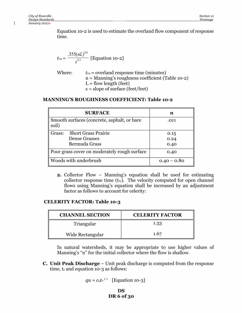
City of Roseville Section 10 Design Standards_____________________________ ___________________________________ Drainage January 20210
DS DR 6 of 30
Equation 10-2 is used to estimate the overland flow component of response time.
tro = 3.0
6.0)(355.snL
[Equation 10-2]
Where: tro = overland response time (minutes) n = Manning’s roughness coefficient (Table 10-2) L = flow length (feet) s = slope of surface (feet/feet) MANNING’S ROUGHNESS COEFFICIENT: Table 10-2
SURFACE n Smooth surfaces (concrete, asphalt, or bare soil)
.011
Grass: Short Grass Prairie Dense Grasses Bermuda Grass
0.15 0.24 0.40
Poor grass cover on moderately rough surface 0.40
Woods with underbrush 0.40 – 0.80
2. Collector Flow – Manning’s equation shall be used for estimating
collector response time (trc). The velocity computed for open channel flows using Manning’s equation shall be increased by an adjustment factor as follows to account for celerity:
CELERITY FACTOR: Table 10-3
CHANNEL SECTION CELERITY FACTOR
Triangular
Wide Rectangular
1.33
1.67
In natural watersheds, it may be appropriate to use higher values of
Manning’s “n” for the initial collector where the flow is shallow.
C. Unit Peak Discharge – Unit peak discharge is computed from the response time, tr and equation 10-3 as follows:
qu = cotr 1C [Equation 10-3]

City of Roseville Section 10 Design Standards_____________________________ ___________________________________ Drainage January 20210
DS DR 7 of 30
Where: qu = peak unadjusted unit discharge (cfs/acre)
tr = tro + trc = response time (minutes) Co, C1 = coefficient from Table 10-4
COEFFICIENT FOR UNIT PEAK DISCHARGE: Table 10-4
Return Period (Yrs)
tr<20 minutes C0 C1
tr>20 minutes C0 C1
10 5.80 -0.50 17.80 -0.87
25 7.54 -0.50 23.14 -0.87
100 9.28 -0.50 28.48 -0.87
D. Infiltration Factor – The effect of infiltration is reflected in the infiltration
factor Fi. Fi is found from the infiltration rate and Equation 10-4 as follows: Fi = 1.7I [Equation 10-4] Where: Fi = infiltration factor (cfs/acre) I = infiltration rate (inches/hour, Table 10-5) INFILTRATION RATES FOR URBAN COVERS: Table 10-5
COVER TYPE QUALITY OF COVER
SOIL GROUP A B C D
Residential or Commercial Landscaping
Good .48 .25 .16 .12
Open Space Poor Fair
Good
.26 .09 .06 .04 .31 .16 .09 .07 .41 .22 .12 .09
Streets and Roads: Paved with open
ditches Gravel, Dirt
Poor Fair
Good
.07 .06 .03 .02 .11 .06 .04 .03 .14 .08 .05 .04
Most soils within the City of Roseville are of Soil Group D. If the Consulting Engineer feels that the soil group in the area of development is of a different group, he must supply additional information to substantiate his assumption.
Soil Groups – The Soil Conservation Service (SCS) classifies soil into four hydrologic soils groups. Soils maps and soil surveys of the City are available for

City of Roseville Section 10 Design Standards_____________________________ ___________________________________ Drainage January 20210
DS DR 8 of 30
inspection at the Placer County Resource Conservation District and the Flood Control District. Group A – Low runoff potential. Soils having high infiltration rates even when thoroughly wetted and consisting chiefly of deep, well to excessively drained sands or gravels. These soils have a high rate of water transmission. Group B – Soils having moderate infiltration rates when thoroughly wetted and consisting chiefly of moderately deep to deep, moderately well to well drained soils with moderately fine to moderately course textures. These soils have a moderate rate of water transmission. Group C – Soils having slow infiltration rates when thoroughly wetted and consisting chiefly of soils with a layer that impedes downward movement of water, or soils with moderately fine to fine texture. These soils have a slow rate of water transmission. Group D – High runoff potential. Soils having very slow infiltration rates when thoroughly wetted and consisting chiefly of clay soils with high swelling potential, soils with a permanent high water table, soils with a clay pan or clay layer at or near the surface, and shallow soils over nearly impervious material. These soils have a very slow rate of water transmission.
E. Connecting Separately Connected Areas - When both pervious and connected, impervious overland flow areas are present, the estimate of combined flow is computed as a weighted adjustment to the peak unit runoff as follows in Equation 10-5:
Qp = A(qu – pF i) [Equation 10-5] Where: Qp = peak flow(cfs) A = total watershed area (acres) qu = unit peak unadjusted runoff (cfs/acre) Fi = infiltration factor (cfs/acre) P = percent of pervious area (%)
F. Procedure – The following procedures shall be used in determination of design runoff:
1. Determine the typical pervious and connected impervious flow paths with the
longest response time.
2. Determine the total response time for the shed being analyzed combining the overland flow elements and their common collector.
3. Determine unit peak unadjusted runoff (qu) for the shed area using Equation
10-3.

City of Roseville Section 10 Design Standards_____________________________ ___________________________________ Drainage January 20210
DS DR 9 of 30
4. Determine the pervious infiltration factor using Equation 10-4.
5. Complete the total peak flow using Equation 10-5. EXAMPLE OF UNIT PEAK DISCHARGE METHOD
For this example, the following assumptions were made:
A. Lots have constant slope of one percent.
B. Lots have a Bermuda grass ground cover.
C. Average elevation of subdivision is 200 feet.
D. Class D soils.
E. Area = 65% impervious, 35% pervious. See Figure 10-1 for a typical lot detail. A sample computation sheet is provided the end of this Section.
Step 1 Determine overland response time tro as follows: tro = 3.0
6.0)(355.snL
Overland flow length = 160’ Bermuda grass cover, n= 0.24 Slope = 1% Equation 10-2 gives: tro = 12.6 minutes Step 2 Determine collector flow, trc, as follows:
Collector flow to inlet is assumed to be gutter flow. Gutter flow velocity = 2.0 fps. trc = 420 ft / 2 fps = 3.5 minutes Response time tr = tro + trc = 16.1 minutes
Step 3 Determine the unit peak discharge for 10-year storm from Equation 10-3 qu = cotr 1C [Equation 10-3] tr = 16.1 minutes Co = 5.8 C1 = -0.50 qu = 1.45 cfs/acre Step 4 Determine infiltration factor:

City of Roseville Section 10 Design Standards_____________________________ ___________________________________ Drainage January 20210
DS DR 10 of 30
Elevation = 200 feet Class D soils, residential landscaping with good cover. Infiltration factor = .12 (Table 10-5) From Equation 10-4, Fi = 1.7*1 Fi = 0.2121 Step 5 Compute total peak flow: Pervious area = (.035)(1.4) = .49 acres Qp = 1.4(1.45) - .49(.21) = 1.93 cfs
This establishes flow into the drainage system. From this point, the time within the conduit is added to both the impervious response times and conduits are sized appropriately.

City of Roseville Section 10 Design Standards_____________________________ ___________________________________ Drainage January 20210
DS DR 11 of 30
City of Roseville Section 10 Design Standards_____________________________ ___________________________________ Drainage January 20210
DS DR 12 of 30
10-10 HYDRAULIC STANDARDS FOR DRAINAGE SYSTEMS – All storm drain pipelines and open channels shall be designed to convey the design peak runoff calculated per Section 10-8 and shall conform to the following requirements:
A. Hydraulic Grade Line – The grade line for the 10-year discharge shall be a
minimum of one foot below all inlet grates, manhole covers, and all other drainage structures in the system. The hydraulic grade line shall be shown on the plans when it is above the top of the pipe.
B. Manning’s Formula – The “n” value used in Manning’s formula shall
conform to the following:
1. Manning’s formula shall be used to compute capacities of all open and closed conduits other than culverts.
2. A minimum “n” value of 0.015 shall be used for sizing conduits.
3. Minimum velocity in closed conduits shall be 2 feet per second. Maximum velocity shall be 12 feet per second. Velocities shall be based on full flow conditions.
10-11 STREET INUNDATION REQUIREMENTS – City streets are allowed to
convey runoff for storm events larger than the 10-year. The standards for street inundation are specified in Table 10-6. The Consulting Engineer shall provide calculations and an exhibit showing that these standards are met. Street inundation calculations will assume the pipe system is fully functional.
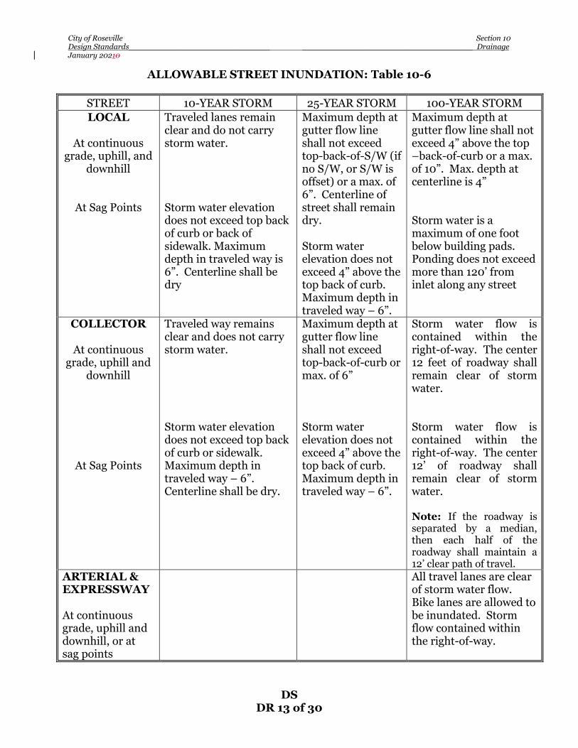
City of Roseville Section 10 Design Standards_____________________________ ___________________________________ Drainage January 20210
DS DR 13 of 30
ALLOWABLE STREET INUNDATION: Table 10-6
STREET 10-YEAR STORM 25-YEAR STORM 100-YEAR STORM LOCAL
At continuous
grade, uphill, and downhill
At Sag Points
Traveled lanes remain clear and do not carry storm water. Storm water elevation does not exceed top back of curb or back of sidewalk. Maximum depth in traveled way is 6”. Centerline shall be dry
Maximum depth at gutter flow line shall not exceed top-back-of-S/W (if no S/W, or S/W is offset) or a max. of 6”. Centerline of street shall remain dry. Storm water elevation does not exceed 4” above the top back of curb. Maximum depth in traveled way – 6”.
Maximum depth at gutter flow line shall not exceed 4” above the top –back-of-curb or a max. of 10”. Max. depth at centerline is 4” Storm water is a maximum of one foot below building pads. Ponding does not exceed more than 120’ from inlet along any street
COLLECTOR
At continuous grade, uphill and
downhill
At Sag Points
Traveled way remains clear and does not carry storm water. Storm water elevation does not exceed top back of curb or sidewalk. Maximum depth in traveled way – 6”. Centerline shall be dry.
Maximum depth at gutter flow line shall not exceed top-back-of-curb or max. of 6” Storm water elevation does not exceed 4” above the top back of curb. Maximum depth in traveled way – 6”.
Storm water flow is contained within the right-of-way. The center 12 feet of roadway shall remain clear of storm water. Storm water flow is contained within the right-of-way. The center 12’ of roadway shall remain clear of storm water. Note: If the roadway is separated by a median, then each half of the roadway shall maintain a 12’ clear path of travel.
ARTERIAL & EXPRESSWAY At continuous grade, uphill and downhill, or at sag points
All travel lanes are clear of storm water flow. Bike lanes are allowed to be inundated. Storm flow contained within the right-of-way.

City of Roseville Section 10 Design Standards_____________________________ ___________________________________ Drainage January 20210
DS DR 14 of 30
10-12 CLOSED CONDUITS – The specific type of pipe or alternate pipe to be used in any development shall be shown on the approved plans. If the Consulting Engineer proposes to use any type of pipe not shown on the approved plans, the plans shall be resubmitted to the City Engineer for approval.
A. Size and Material – Drainage systems to be maintained by the City shall have
a minimum pipe diameter of 12 inches. Private, onsite drainage systems that are reviewed by the City shall have a minimum pipe diameter of 8 inches. The types of pipe materials that are allowed are stated in the City of Roseville’s Construction Standards, Section 101-8 D.
B. Cover Requirements – See details DR-19 and TB-2 for minimum pipe cover
requirements.
In fill areas, or in areas with poor soil conditions where it is anticipated that a good, firm, vertical-walled trench cannot be constructed, the Consulting Engineer shall design the pipe structural requirements in accordance with good engineering practice. If trench conditions are uncertain, a note shall be placed on the plans making it the Contractor’s responsibility to work with the Consulting Engineer to determine and place the proper strength pipe if poor trench conditions are encountered.
C. Alignment – Pipelines for storm drainage shall have a constant slope between
manholes, junction boxes, and/or catch basins. Minimum radius of horizontal curvature shall be 200 feet. In no case shall the radius of curvature be less than the manufacturer’s recommendations for the particular pipe size under consideration.
Drainage pipelines shall be located in the street whenever possible. The location of storm drainage pipelines in the streets shall be 5 feet north or west of and parallel with the street centerline. A minimum angle of 90 degrees shall be accommodated for downstream flow around bends, tees, and connection points.
When storm drainage lines are to be placed in existing streets, factors such as curbs, gutters, sidewalks, traffic conditions, pavement conditions, future street improvement plans, and existing utilities shall be considered.
Open ditches, lined channels, swales, and floodplain areas shall be maintained as nearly as possible in their existing alignment. When an open ditch is to be constructed parallel to an existing roadway, the ditch shall be constructed outside the proposed right-of-way of the ultimate street development.
10-13 MANHOLES – Standard precast concrete manholes shall be constructed as required. Where special manholes or junction boxes are required, the City Engineer must accept the design. In no case will junction boxes or manholes be allowed which are smaller than 48 inches inside diameter. Manholes shall be

City of Roseville Section 10 Design Standards_____________________________ ___________________________________ Drainage January 20210
DS DR 15 of 30
located at junction points, angle points, changes in gradient, changes in conduit size, end of curves and beginning of curves. Manholes or junction boxes will not be required for reach of pipe less than 80 feet in length that is to be connected to a 36 inch or larger diameter pipe, subject to approval of the City Engineer. For straight alignment, the spacing of manholes shall not exceed 500 feet. The spacing of manholes shall be nearly equal whenever possible. On curved pipe, spacing of manholes shall be as specified in Table 10-7:
MANHOLE SPACING: Table 10-7
RADIUS PIPE DIAMETER SPACING
400’ OR LESS
GREATER THAN 400’
GREATER THAN 400’
ALL
24” OR LESS
GREATER THAN 24”
300’
400’
500’
A. Saddle Manholes – Saddle manholes may be constructed on storm drain conduit 36 inches or greater in diameter provided that no junction exists with any other storm drain conduit as determined by the Director.
B. Covers – All manholes and junction boxes, other than inlets, shall have standard manhole covers per the Standard Drawings. No pipe will be allowed to enter a manhole into the transition portion of the manhole cone. Manholes will not be allowed in gutter flow line except where approved by the City Engineer. Slotted manhole covers may be used to pick up minor drainage in non-traffic areas.
10-14 INLETS – Drop inlets in streets shall be located on property lines in residential
subdivisions except at intersections, where they shall be placed at curb returns. Inlets shall be such that the length of the flow in the gutter does not exceed 500 feet. The depth of flow in the gutter at the inlet shall not exceed 4.0 inches in a 10-year storm and shall not encroach into the traveled ways as specified in Table 10-6 for other design storms. The runoff volume shall include any flow that bypasses upstream inlets.
All inlets located with the right-of-way or easements shall conform to the City of Roseville’s Construction Standards. Inlets may be modified for use without curb sections for on-site drainage. Where an inlet is proposed in public streets and sidewalk is not constructed adjacent to the back of curb, a concrete collar shall be placed behind the inlet. Type C inlets may be used as junction inlets if the flow line is 4 feet or less below the grate elevation. Drop inlets draining public streets may be connected directly to a trunk line 36 inches in diameter or larger by means of a lateral not exceeding 15 inches in diameter and 80 feet in length.

City of Roseville Section 10 Design Standards_____________________________ ___________________________________ Drainage January 20210
DS DR 16 of 30
10-15 JUNCTION BOXES – The requirement for junction boxes are as follows:
A. Junction boxes shall be constructed of reinforced concrete or fabricated from reinforced concrete pipe section where size limitations permit. Structural calculations shall be provided for all junction boxes.
B. Minimum wall thickness for reinforced concrete junction boxes shall be 6
inches.
C. The inside dimension of junction boxes shall be such as to provide a minimum of three inches of clearance on the outside diameter of the largest pipe in each face. All junction boxes shall be rectangular in shape unless otherwise approved by the City Engineer. Junction boxes deeper than 4 feet shall have a minimum inside dimension of 48 inches.
10-16 INLET AND OUTLET STRUCTURES – The requirements for these facilities are as follows:
A. Headwalls, Wingwalls, and Endwalls – All headwalls, wingwalls,
endwalls, preformed end sections, guard rails and bank protection shall be considered individually and shall be, in general, designed in accordance with the Standard Specifications and Standard Plans of the California Department of Transportation and City of Roseville, Construction Standards.
Metal beam guardrails or chain link fencing may be required by the City Engineer at culverts, headwalls, box culverts, and steep side slopes.
B. Trash Racks and Access Control Racks – Trash racks will be provided where they are necessary to prevent clogging of culverts, storm drains, and to eliminate hazards. Access Control Racks shall be required on all pipes, 24 inches or larger in diameter.
10-17 DRAINAGE PUMPS – Drainage pumps shall be avoided whenever possible, and
used only with specific approval of the City Engineer. If the use of drainage pumps is permitted, the drainage system shall be designed so as to provide for gravity outfall during the summer months and other periods of low water stages. If a low stage gravity outfall is impossible or impractical, an alternative pump of a smaller capacity for low stage flow may be used provided the City Engineer grants specific approval.
A. Design Requirements – Pumping installations shall be designed to
accommodate a design storm as specified by the City Engineer. When a station contains a gravity discharge, pumping capacity must be equal to the design inflow. When the station does not have a gravity discharge, pumping units must be designed to furnish 100 percent capacity with any one pump out. Any deviation from this criteria must receive the specific approval of the City Engineer.

City of Roseville Section 10 Design Standards_____________________________ ___________________________________ Drainage January 20210
DS DR 17 of 30
Pumping stations shall be designed so that gravity flow does not pass through the pump pit. No motor overload condition shall exist at any sump or flow condition. This does not preclude high sump design if low sump condition does not create an overload. Each pumping station shall receive separate approval for the electrical system, piping system, housing installation and other miscellaneous design features. The electrical system for drainage pumps shall conform to the electrical code and the State Department of Transportation Standards. A detailed Operation and Maintenance Plan (O&M Plan) shall be submitted to the Engineering Division for approval prior to the approval of the pumping station.
B. Maintenance Requirements – Adequate access shall be provided for cleaning the pump sump. Trash racks shall be provided upstream from the pumping plant. Provisions shall be made for easy cleaning of the trash racks. Hatch covers, where used, shall be of raised pattern aluminum floor plate, or other approved lightweight cover. Dissimilar metals shall be insulated from each other when necessary. Ladder rungs, where used, shall be of non-slip variety. All drainage pumping plant sites shall be fenced with 6-foot chain link fence with barbed wire extensions arms.
10-18 CHANNELS AND OUTFALL DESIGN – Drainage shall be conveyed in an
open channel if the drainage area exceeds 300 acres. Residential lots adjacent to open channels shall have minimum pad elevations of two feet above the 100-year water surface elevation. Non-residential lots shall have the lowest ground elevation adjacent to the building foundation at least two feet above the 100-year water surface elevation.
A. Open Channel Design Requirements – Channels shall be constructed to
a typical cross section. Fully lined channels shall be designed with side slopes of 1:1 or flatter. Channels with unlined sides shall be designed with side slopes of 3:1 or flatter, or as specified by the Geotechnical Engineer based on existing soil conditions. Lined channels shall have a minimum bottom width of 6 feet. Lined channels shall be finished concrete, sacked concrete, or doweled and sacked concrete. The minimum weight of sacked concrete shall be 60 pounds per bag. Unlined channels shall be designed with a minimum “n” value of 0.085.
All open channels shall be designed to carry the 100-year frequency design storm. The hydraulic grade line of the 10 and 100-year storms shall be calculated and plotted on all channel profiles. Freeboard shall be a minimum of one foot for the 100-year event and two feet when the drainage area exceeds 300 acres. The velocity range shall be 2.5 to 6.0 feet per second in unlined open channels and 3.0 to 12.0 feet per second in lined open channels. All

City of Roseville Section 10 Design Standards_____________________________ ___________________________________ Drainage January 20210
DS DR 18 of 30
computations shall be clearly documented and submitted to the City Engineer for approval. For all channels, either realigned or natural, the following shall be shown on the improvement plans in addition to the information heretofore required:
1. The profile of existing channels shall be shown for a minimum of 1000 feet
at each end of the development on the construction plan to establish a minimum profile grade.
2. Typical sections and cross sections.
B. Interceptor Ditches – Interceptor ditches or approved alternates shall be placed at the top of the cut or bank where deemed necessary by the City Engineer to prevent erosion of the channel bank. Runoff shall not be allowed to sheet flow over the top of banks.
C. Outfall Profiles – All drainage outfalls shall be shown both in the plan and profile view, on the improvement plans for a distance of 1000 feet or until a definite “daylight” condition is established. All drainage ditches upstream of the improvement shall be shown on the plan and profile sheets for a distance of at least 500 feet or until an average profile grade through the improvement is established. The profiles shall include ditch flow line and top of bank elevations.
When improvements have more than one unit, the drainage outfall shall be
shown as extending to the property boundary and beyond if required, although it may not be constructed with the current unit development. All temporary outfalls shall be shown both in plan and profile view, on the improvement plans.
D. Fencing – Channels exceeding three (3) feet in depth and with side slopes
steeper than 3:1 shall be fenced with six(6) foot high chain link fence per Section 80-4 of the Caltrans Standard Specifications. In all other areas, fencing shall be placed as specified the City Engineer. Fences shall be located 6 inches inside the drainage easement lines and a minimum of 12 inches from the top bank. No fencing shall be allowed within the floodway of an open watercourse without the approval of the City Engineer. Special requirements shall be specified by the City Engineer for fencing within the 100-year floodplain of any open watercourse.
Drive gates shall be provided with a minimum width of 12 feet. A minimum 4-foot wide walk gate shall also be provided.
E. Access Roads – An all-weather access road consisting of six (6) inches of
compacted AB shall be provided adjacent to all channels and outfall ditches to
City of Roseville Section 10 Design Standards_____________________________ ___________________________________ Drainage January 20210
DS DR 19 of 30
the satisfaction of the City Engineer. Access roads shall have a minimum width of 12 feet and shall provide a bulb at end for turning movements.
10-19 CROSS CULVERTS AND BRIDGES – This section specifies criteria for
relatively short circular or box culverts and bridges for transverse crossings (typically road or railroad embankments). Cross culverts shall be of the same material as allowed for closed conduits. (See Section 10-11).
Cross culvert profiles will be determined on an examination of the channel for a minimum distance of 1000 feet on each side of the installation. Driveway culverts shall be approved by the City for size, grade, alignment and type. Driveway culverts will not be allowed unless the City has agreed to deter the construction of the curb and gutter unless it is for the temporary construction access. New culverts or bridges for roadways that cross the City’s Regulatory Floodplain shall incorporate provisions for the installation of permanent stream measuring equipment. This shall of a 10’ x 10’ flat pad near the 100-year water surface elevation with vehicle access. A two(2) inch diameter electrical conduit from the pad to the flow line of the channel will be installed, (see detail DR-21 of the City of Roseville Construction Standards). A. Design Storm – Cross culvert size shall be determined on the basis of runoff
as specified in the hydrology portion of this section. Cross culverts, in general, shall be designed for a 25-year storm event with no head on the inlets. They shall also be sized such that no serious damage will be incurred due to ponding as a result of a 100-year event. A flood easement shall be provided for all areas impacted due to upstream ponding in the 100-year event. Culverts across arterials shall be sized for the 100 year storm with a minimum of one foot of freeboard below the lowest travel lane. Minimum diameter of cross culverts shall be 18 inches.
To account for debris collection, a clogging factor of 150% shall be applied to all storm frequencies in the design of bridges or culverts that cross a channel or stream with a drainage area that exceeds 300 acres. Note: New bridges along planned bike trail corridors need to be designed so that the head clearance on the trail will meet the standards of Section 13-5.
B. Computation of Flow – Inlet or outlet conditions control flow in transverse
culverts. In culverts operating under inlet control, the cross-section area of the culvert barrel, the inlet geometry and the amount of headwater at the entrance are primary importance. Outlet control involves the additional consideration of the elevation of the tail water in the outlet channel and the slope, roughness and length of the culvert barrel.

City of Roseville Section 10 Design Standards_____________________________ ___________________________________ Drainage January 20210
DS DR 20 of 30
Anticipated downstream flow depth and allowable headwater depth govern the available head on culverts. The type of flow under which a culvert will operate may be determined from a given set of conditions. This may be avoided by computing headwater depths from the charts in this section for both inlet and outlet control and then using the higher value to indicate the type of control and to determine the headwater depth. This method of determining the type of control is accurate except for a few cases where the headwater depth is approximately the same for the both types of control. The monographs provided in this section shall be used for culvert design with uniform barrels. Where barrel sizes or entrance configurations differ between barrels, written calculations shall be provided to the satisfaction of the City Engineer. The roughness coefficient, “n”, can be adjusted for the monographs by use of the following equation:
L1 = L* 2
1
nn
10-20 DETENTION AND RETENTION BASINS – If detention or retention basins
are required for peak flow reduction, the design of the basin must conform to the latest addition of the Placer County Flood Control District’s “Stormwater Management Manual”. The basin layout and design shall minimize its maintenance time and cost. The basin should be designed to allow for the 2-year storm event flows to bypass the basin. This will be key factor in the approval of the basin’s O&M Plan by the Engineering Division.
10-21 ACCESS FOR MAINTENANCE –These facilities may include, but are not
limited to bridges, culverts, headwalls, lined and unlined channels/ditches, sand/oil separators, manholes, retention basins and drain inlets. The access way shall be a minimum 12 feet wide and include six(6) inches of ¾ inch aggregate base (95% relative compaction) over six(6) inches of processed, native soil (95% RC). Upon the City Engineer’s request, four (4) inches of asphalt concrete shall be added to the section and/or a cul-de-sac with a minimum diameter of 75 feet.

City of Roseville Section 10 Design Standards_____________________________ ___________________________________ Drainage January 20210
DS DR 21 of 30
STANDARD HYDRAULIC CALCULATIONS SHEET
TO
FRO
M
AR
EA
CU
MU
. A
RE
A
Tr
q
Fi
Qp
DIA
STOR
M D
RA
IN PIPE
SL
L
Qm
ax
VE
L
Tc
SL
HYD
GR
AD
E
LINE
UM
H
LMH

City of Roseville Section 10 Design Standards_____________________________ ___________________________________ Drainage January 20210
DS DR 22 of 30
CITY OF ROSEVILLE – ENGINEERING DIVISION
SUBMITTAL REQUIREMENTS FOR ALL HEC – 1 STUDIES
Submit the items listed under each category that applies to each HEC – 1 model run that is submitted. 1. Hec-1 print out with summary tables.
The following information shall be on the cover of the print out:
• Name of engineering firm who performed the study • Name of the project • Version of HEC-1 program • Date & time that the model was run • A statement if the model is pre-project or post-project
2. The computer model disk.
• Disk must be clearly labeled • If more than one model file is on the disk, a listing and description of
all files shall be included with the disk in an envelope • HEC-1, HEC-2 or HEC-RAS files shall be submitted on separate disks
3. City of Roseville’s “Model Summary Worksheet” Pages 1-3 completed out
for each HEC-1 run submitted and attached to the printout.
4. Drainage Shed map showing the following:
• Outline of all subsheds used in the HEC-1 study • The label of each subshed as modeled in the HEC-1 study • The area of each subshed as used in the HEC-1 study • The location where each subshed merges with the next clearly
marked
5. If the study compares pre-project to post-project HEC-1 models, the City’s summary sheets shall include a listing of all the types and the locations of changes made in the model

City of Roseville Section 10 Design Standards_____________________________ ___________________________________ Drainage January 20210
DS DR 23 of 30
CITY OF ROSEVILLE HEC -1 MODEL SUMMARY WORKSHEET Page 1 OF 3 GENERAL INFORMATION
Name of project:___________________________________________________________
Name of engineering firm who performed the study:___________________________________
Contact person ___________________________________Ph#_____________________
If this replaces a previously submitted study, what is the name of that study?
_______________________________________________________________________
This study reflects: ___Existing conditions ___Post-development conditions If this HEC-1 study is used to compare pre-project to post-project runoff, what is the name of the study that you are comparing it with? _________________________ Run date_________________ Has the pre-project study been approved by the city? ___ YES and when ____________________
___ NO
BASIN INFORMATION
Total area of the basin studied (sq. mile)___________ Number of sub-sheds _________________
Elevation of shed: High point _________ Low point ________ Ave. _______Used___________
The method used to determine the design storm used in the model: ____ P.C. Flood Dist. manual ____ HEC-1 synthetic storm ____ P.C. Flood Dist. PDP program ____ Rain gauge data
Duration of design storm: 1 hr 2 hrs 3 hrs 6 hrs 12 hrs 1 day other ________________
Design storm frequency: 2 yr 5 yr 10 yr 25 yr 50 yr 100 yr other ________________
Base flow ( cfs / sq mile): ________________ Infiltration ( in/hour ) _____________________
Response time of entire basin _____________________
Detention Basins Give location and size of all detention basins that were modeled: Provide topo or grading plans used to calculate storage volume for each detention basin.
Location Amount of storage Storm Max. Stage Freeboard to in model resulting from each frequency Height (ft.) Spill Point (ft.) design storm _____________ ________________ _________ __________ _____________
_____________ ________________ _________ __________ _____________
_____________ ________________ _________ __________ _____________
_____________ ________________ _________ __________ _____________
_____________ ________________ _________ __________ _____________

City of Roseville Section 10 Design Standards_____________________________ ___________________________________ Drainage January 20210
DS DR 24 of 30
CITY OF ROSEVILLE HEC-1 MODEL SUMMARY WORKSHEET Page 2 OF 3 SUBSHED INFORMATION
The total number of subsheds in the model: ___________________
Provide an assumed "N" factor used most often for the following surfaces:
Overland swales _________ Concrete gutters __________ Drainage Pipes __________
Earth-lined channels ____________ Streams ____________ Other ____________
TITLE OF SUBSHED OR ROUTING LEG IN MODEL
PRIMARY LAND USES OF SUBSHED residential, open space, commercial, etc.
AREA OF SUBSHED (SQ ML)
METHOD USED IN ROUTING EXAMPLE: Kinematic wave, Muskingum
WAS DETENTION MODELED ( YES OR NO )

City of Roseville Section 10 Design Standards_____________________________ ___________________________________ Drainage January 20210
DS DR 25 of 30
CITY OF ROSEVILLE HEC-1 MODEL SUMMARY WORKSHEET Page 3 OF 3
PRE-PROJECT TO POST-PROJECT CHANGES This sheet shall be completed if this HEC-1 study is used to compare pre-project to post-project runoff.
Name of pre-project HEC-1 study : ______________________________________ Run date______________
Basin’s peak flow rate: Existing conditions ____________
Post-development conditions ____________
Has the pre-project study been approved by the City? ____ YES If yes, when?__________ ____ NO
Locations in
Types of change made
Example Shed-2S Change earth-lined channels to drainage pipes and increased sub-shed area

City of Roseville Section 10 Design Standards_____________________________ ___________________________________ Drainage January 20210
DS DR 26 of 30
CITY OF ROSEVILLE - ENGINEERING DIVISION SUBMITTAL REQUIREMENTS FOR ALL
HEC-2 or HEC-RAS STUDIES
SUBMIT THE ITEMS LISTED UNDER EACH CATEGORY THAT APPLY TO EACH HEC-2 or HEC-RAS MODEL RUN THAT IS SUBMITTED.
1. HEC-2 or HEC-RAS print out with summary tables, The following information shall be on cover of the print out:
• Name of engineering firm who performed the study • Name of project • Version of HEC-2 or RAS program • Date & time that the study was run • Statement if the study is pre-project or post-project and, if applicable,
if the study is a Duplicate Effective Model, Corrected Effective Model, Existing or Pre-Project Conditions Model, and/or Revised or Post-Project Conditions Model
2. Provide the computer model on a new USB flash drive (Sandisk, PNY, or
Kingston) or CD/DVD disk. • Flash Drive/Disk must be clearly labeled. • If more than one model file is on the flash Drive/disk, a listing and
description of all files shall be included with the flash Drive/disk in an envelope.
• HEC-1, HEC-2 or HEC-RAS files needs to be submitted in separate folders within flash drive/disk(s).
3. City of Roseville's "Model Summary Worksheet" pages 1-3 filled out for
each HEC-2 or HEC-RAS run that is submitted. 4. Water course map showing the following:
• Lay out of the route of all water courses used in the HEC-2/RAS study. • All man-made structures with their type and size will be clearly marked
and labeled (bridges, culverts, storm drain pipes, man-made channels, etc.).
• Map of the locations and number of all cross-section used in study. • The starting HGL and peak flow rate for all storm frequencies modeled. • The location of where the flow rate changes and what the new flow rate
is.
5. If the study compares pre-project to post-project HEC-2/RAS models, you shall include a summary sheet listing the locations and types of changes made between the models.

City of Roseville Section 10 Design Standards_____________________________ ___________________________________ Drainage January 20210
DS DR 27 of 30
CITY OF ROSEVILLE Page 1 of 3 HEC-2 / HEC-RAS MODEL SUMMARY WORKSHEET Name of project:_______________________________________________________________ Name of engineering firm who performed the study: ______________________________________ Contact person __________________________________ Phone # _______________________ If this replaces a previous study, what is the name of that study_______________________________ This study reflects: Existing conditions Post-development conditions If this HEC-2/RAS study is used to compare pre-project to post-project runoff what is the name of the study that you are comparing it with __________________________________________ Run date______________ Has the pre-project study been approved by the city yes no If yes, name and when ________________________________________________________________ Total length of water course ( miles )_____________ Total number of cross-sections _____________ Name of Hydrology study used to get peak Discharge? ______________________________________ Design storm frequency: 2 yr 5 yr 10 yr 25 yr 50 yr 100 yr Other_______ The starting HGL _____ _____ _____ ______ _____ ______ _______ Starting flow rate _____ _____ _____ ______ _____ ______ _______ How was the starting HGL determined: _______________________________________________________________________ _____________________________________________________________________________________________________________________________________________________________________________________________________________________ Give location of cross-sections where the flow rate changes and what the new flow rate(s) are.
START 10 YEAR 50 YEAR 100 YEAR
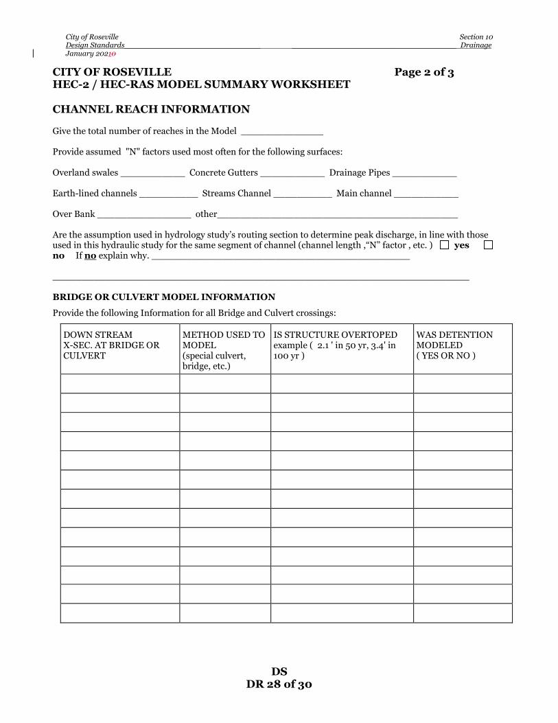
City of Roseville Section 10 Design Standards_____________________________ ___________________________________ Drainage January 20210
DS DR 28 of 30
CITY OF ROSEVILLE Page 2 of 3 HEC-2 / HEC-RAS MODEL SUMMARY WORKSHEET CHANNEL REACH INFORMATION Give the total number of reaches in the Model ______________ Provide assumed "N" factors used most often for the following surfaces: Overland swales ___________ Concrete Gutters ___________ Drainage Pipes ___________ Earth-lined channels __________ Streams Channel __________ Main channel ___________ Over Bank ________________ other_________________________________________ Are the assumption used in hydrology study’s routing section to determine peak discharge, in line with those used in this hydraulic study for the same segment of channel (channel length ,“N” factor , etc. ) yes no If no explain why. ____________________________________________ _______________________________________________________________________ BRIDGE OR CULVERT MODEL INFORMATION
Provide the following Information for all Bridge and Culvert crossings: DOWN STREAM X-SEC. AT BRIDGE OR CULVERT
METHOD USED TO MODEL (special culvert, bridge, etc.)
IS STRUCTURE OVERTOPED example ( 2.1 ' in 50 yr, 3.4' in 100 yr )
WAS DETENTION MODELED ( YES OR NO )

City of Roseville Section 10 Design Standards_____________________________ ___________________________________ Drainage January 20210
DS DR 29 of 30
CITY OF ROSEVILLE Page 3 of 3 HEC-2 / HEC-RAS MODEL SUMMARY WORKSHEET PRE-PROJECT TO POST-PROJECT CHANGES Name of pre-project study: ____________________________________________________ Run date______________ Name of post-project study: ____________________________________________________ Run date______________ Do you plan to place any improvements in, or change the Floodway yes no If yes explain. Provide the following Information for all changes between studies:
Locations
Types of changes ( added, deleted, changed )
Xsec-252
Added xsec. to reflect encroachment, Changed right overbank “N” to 0.04
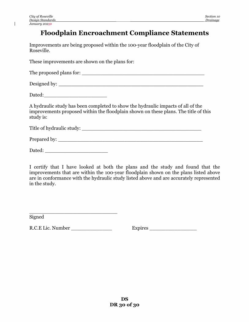
City of Roseville Section 10 Design Standards_____________________________ ___________________________________ Drainage January 20210
DS DR 30 of 30
Floodplain Encroachment Compliance Statements Improvements are being proposed within the 100-year floodplain of the City of Roseville. These improvements are shown on the plans for: The proposed plans for: _______________________________________ Designed by: ______________________________________________ Dated: ____________________ A hydraulic study has been completed to show the hydraulic impacts of all of the improvements proposed within the floodplain shown on these plans. The title of this study is: Title of hydraulic study: ______________________________________ Prepared by: ______________________________________________ Dated: ____________________ I certify that I have looked at both the plans and the study and found that the improvements that are within the 100-year floodplain shown on the plans listed above are in conformance with the hydraulic study listed above and are accurately represented in the study. ____________________________ Signed R.C.E Lic. Number _____________ Expires _______________

City of Roseville Section 13 Design Standards___________________________________________________________ _Bikeways January 20210
DS BK 1 of 9
SECTION 13
BIKEWAYS 13-1 GENERAL – The City of Roseville bikeway standards are designed to
insure that transportation and recreational bikeways are constructed in a manner that would provide a safe and comfortable use by both bicycles and pedestrians. Bikeways shall be designed to enhance safety and reduce maintenance.
13-2 DESIGN CRITERIA – All bikeway design shall conform to the latest
editions of the following documents:
• The American Association of State Highway and Transportation Officials “Guide for the Development of Bicycle Facilities
• The State of California Department of Transportation (Caltrans)
Highway Design Manual Chapter 1000, “Bikeway Planning and Design”
• The latest editions of the California Manual on Uniform Traffic
Control Devices (California MUTCD) for Streets and Highways (FHWA’s MUTCD 2003 Edition, as amended for use in California)
• These standards and any applicable Specific Plan guidelines which pertain to various areas of the City. Specific Plan Guidelines are available from the Planning Department.
All Bikeway improvement plans shall be prepared per the requirements of Section 3, “Plan Sheet Requirements”, of these standards and shall be drawn at a scale no smaller than 1 inch = 40 feet. The plans shall show all existing and proposed grades, sidewalks, landscaping, fences, guardrails, utilities, street lights, traffic signs, and any other structure which may be impacted by revisions to grading.
13-3 PLAN ACCEPTANCE – Prior to construction of any bikeway related
improvements, a complete set of bikeway improvement plans must be accepted by the Development Services Engineering Division. See Section 2, “General Requirements”, of these standards for submittal requirements of bikeway improvement plans.
13-4 CLASS I BIKEWAYS (Bike Paths) – Class I bike paths are facilities
located in separate right-of-way, for the exclusive use of bicycles and pedestrians with minimal cross flow by motor vehicles. Sidewalks are not considered Class I facilities. Sidewalks, including Class IA Sidewalks, Bikeways, are not subject to this Standard. See Section 7, “Streets”, of

City of Roseville Section 13 Design Standards___________________________________________________________ _Bikeways January 20210
DS BK 2 of 9
these Standards for design requirements of sidewalks and pedestrian walks.
A. Width – The minimum paved width for a two-way bike path shall be
10 feet. The minimum width of a one-way bike path shall be 5 feet. In each case, per BK-1, a minimum of 2 feet wide graded shoulders shall be provided adjacent to the pavement. One shoulder shall consist of Class 2 Aggregate Base material and one shoulder shall consist of decomposed granite. Where profile grades are 4% or more, the decomposed granite may be stabilized with lime/fly ash or cement treatment. Otherwise, Class 2 Aggregate Base material may be considered for both shoulders.
B. Clearance to Obstructions – A minimum of 3 feet of horizontal
clearance to obstructions, including post and cable fencing, retaining walls, buildings, and other permanent improvements, shall be provided adjacent to the pavement where the downgrades are less than 4% and a minimum of 5 feet from the edge of pavement where downgrades exceed 4%. If a bike path is paved contiguous with a continuous fixed object, such as a block wall, a 4-inch white edge line, 2 feet from the fixed object, is required.
Manhole covers shall be located within the bike path’s shoulder area, with preference given to the Class 2 Aggregate Base shoulder. The Class 2 Aggregate Base or decomposed granite material shall be extended 1 foot beyond the rim of the manhole cover. In conditions where the bike path is located adjacent to creeks, ditches, or down-slopes greater than 3 feet horizontal to 1 foot vertical, a minimum shoulder width of 5 feet from the edge of pavement to the top of the slope is required. The clear width on structures between railings shall be not less than 12 feet, with a preferred width of 14 feet. The vertical clearance to obstructions across the clear width of the bike path shall be a minimum of 12 feet when Fire Department access is required, otherwise 9 feet, including bike paths placed beneath bridge structures. The minimum elevation of the path shall coincide with the 2-year water surface elevation.
C. Signing and Delineation – For applications and placements of
signs, see the California Manual on Uniform Traffic Control Devices (California MUTCD) for Streets and Highways, Section 9B.01 and figure 9B-101. For pavement markings guidance, see section 9C.03.
The sign sizes for shared-use paths shown in Table 9B-1 of the California MUTCD are preferred for all Class I bike paths. The

City of Roseville Section 13 Design Standards___________________________________________________________ _Bikeways January 20210
DS BK 3 of 9
minimum sign sizes for shared-use paths shall be used only for signs installed specifically for bicycle traffic applications. The minimum sign sizes for bicycle facilities shall not be used for signs that are placed in a location that would have any application to other vehicles.
All Class I bike paths shall be striped per BK-2 or at intervals determined by the City Engineer.
Guide signs to roadways, parks, and other points of interest shall be provided at trail junctions and as determined by the City Engineer.
All stripes and pavement markings for Class I bike paths shall be constructed with paint per Section 84-3 of the CalTrans Standard Specifications.
D. Intersections with Roadways – Bicycle path intersections and
approaches should be on relatively flat grades. Stopping sight distances at intersections shall be met for vehicle traffic per section 7-12, Design Site Distances, of these design standards and adequate warning should be given to permit bicyclists to stop before reaching the intersection, especially on downgrades. Curb ramps shall be installed with the same widths as the bicycle path. When crossing an arterial roadway, the crossing should either occur at the pedestrian crossing or at a location completely out of the influence of any intersection to permit adequate opportunity for bicyclists to see turning vehicles. Mid-block crossing shall be considered on a case by case basis by the City Engineer. In these instances, right-of-way should be assigned by devices such as stop signs or traffic signals which can be activated by bicyclists. Grade separations shall also be considered at the discretion of the City Engineer.
E. Entry Control – Entry points to bike paths shall be designed to prevent unauthorized vehicle entry. The approach to prevent unauthorized vehicle entry is:
a. At a minimum, post signs identifying the entry as a bicycle path
with regulatory signs prohibiting motor vehicle entry per Section 9B of the California MUTCD, or as approved by the City Engineer.
b. Design the path entry so it does not look like a vehicle access and
makes Intentional access by unauthorized users more difficult. Dividing a path into two one-way paths prior to the intersection, separated by low plantings or other features not conducive to motor vehicle use, can discourage motorists from entering and reduce driver error.

City of Roseville Section 13 Design Standards___________________________________________________________ _Bikeways January 20210
DS BK 4 of 9
c. If installation of a bollard is deemed warranted by the City Engineer then a flexible, spring loaded bollard shall be used. The flexible bollard shall be a Tuff Post 3” Flexible Post manufactured by Impact Recovery Systems or approved equal. The flexible bollard shall meet the following specifications:
• Height: 28” • Post Type: 3” post • Post color: Yellow • Post Top: Short Squeeze (when installed, the flat side of the squeeze is
to face traffic) • Sheeting: White, 3M Diamond Grade • Sheeting Quantity: Two (std. tubular) • Base: Surface Mount Fixed • Base Color: Black
F. Separation Between Bike Paths and Roadways – Bike paths immediately adjacent to roadways and within medians are not recommended. Bike paths closer than 5 feet from back of curb shall include a physical barrier to prevent bicyclist from encroaching onto the roadway. Suitable barriers could include dense shrubs or other materials approved by the Development Services, Planning and Parks and Recreation Departments.
G. Design Speed – The minimum design speed for bike paths is 20 mph.
When a downgrade exceeds 4%, the minimum design speed for the section of bike path is 30 mph.
H. Grades – The maximum grade rate recommended for bike paths is
5%. However, steeper grades can be allowed for short segments.
When using grades steeper than 5%, the following grade restrictions and grade lengths are required: 5-6% for up to 800 feet 7% for up to 400 feet 8% for up to 200 feet The bike path segment immediately following a positive grade of 8% is required to have a maximum grade of 5%. All bike paths segments with grades steeper than 5% shall be posted with the appropriate warning signs. Any bike path segments designed with a grade greater than 8% will require approval by the City Engineer and Parks and Recreation Director.

City of Roseville Section 13 Design Standards___________________________________________________________ _Bikeways January 20210
DS BK 5 of 9
I. Horizontal Alignment and Super elevation – A 2% cross slope is
required on tangent sections. Bike paths super elevations rates may vary from a minimum of 2% to ensure drainage to a maximum of 5%.
The minimum distance for a transition from a 2% cross slope is 75 feet
per one percent change in superelevation. The minimum radius of curvature can be derived from figure 1003.1C
of the CalTrans Highway Design Manual. The minimum radius with any given combination of design speed, rate of superelevation, and friction factor shall not be less than 30 feet. The minimum radius of curvature may be increased to 45 feet if the bikeway will also serve to function as a utility maintenance access.
J. Stopping Sight Distance – The minimum stopping sight distances
for various design speeds and grades can be determined from figure 1003.1D of the CalTrans Highway Design Manual. For two-way bike paths, the descending direction grade and design speed will control the design.
K. Lateral Clearance on Horizontal Curves – The minimum
clearances to line of site obstructions for horizontal curves can be determined from the figure 1003.1F of the CalTrans Highway Design Manual.
Bicyclist frequently ride abreast of each other on bicycle paths, and on
narrow bicycle paths, bicyclists have a tendency to ride near the middle of the path. For these reasons, and because of the serious consequences of head-on bicycle accident, lateral clearances on horizontal curves should be calculated based on the sum of the stopping sight distances for bicyclist traveling in opposite directions around the curve. Where this is not possible or feasible, consideration should be given to widening the path through the curve, installing a solid yellow centerline, installing a curve warning sign, or combination of these alternatives.
L. Vertical Curves – The minimum allowable vertical (sag or crest)
curve length at the intersection of two grades shall be 50 feet; however, vertical curves may not be omitted where the algebraic difference in grades does not exceed 2.0 percent. The minimum lengths of crest vertical curves can be determined from figure 1003.1E of the CalTrans Highway Design Manual. When vertical curves are required, they shall provide for adequate sight distance based in the minimum design speeds specified in paragraph 13-4F of these standards.
M. Structural Section – Bike path structural section shall be a
minimum of 2 inches of Type A asphalt concrete on 4 inches of class 2
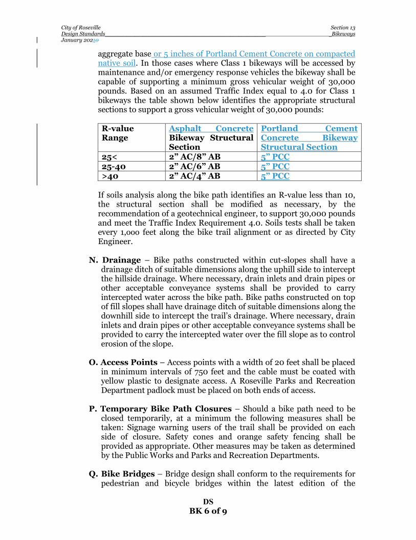
City of Roseville Section 13 Design Standards___________________________________________________________ _Bikeways January 20210
DS BK 6 of 9
aggregate base or 5 inches of Portland Cement Concrete on compacted native soil. In those cases where Class 1 bikeways will be accessed by maintenance and/or emergency response vehicles the bikeway shall be capable of supporting a minimum gross vehicular weight of 30,000 pounds. Based on an assumed Traffic Index equal to 4.0 for Class 1 bikeways the table shown below identifies the appropriate structural sections to support a gross vehicular weight of 30,000 pounds:
R-value Range
Asphalt Concrete Bikeway Structural Section
Portland Cement Concrete Bikeway Structural Section
25< 2” AC/8” AB 5” PCC 25-40 2” AC/6” AB 5” PCC >40 2” AC/4” AB 5” PCC
If soils analysis along the bike path identifies an R-value less than 10,
the structural section shall be modified as necessary, by the recommendation of a geotechnical engineer, to support 30,000 pounds and meet the Traffic Index Requirement 4.0. Soils tests shall be taken every 1,ooo feet along the bike trail alignment or as directed by City Engineer.
N. Drainage – Bike paths constructed within cut-slopes shall have a
drainage ditch of suitable dimensions along the uphill side to intercept the hillside drainage. Where necessary, drain inlets and drain pipes or other acceptable conveyance systems shall be provided to carry intercepted water across the bike path. Bike paths constructed on top of fill slopes shall have drainage ditch of suitable dimensions along the downhill side to intercept the trail’s drainage. Where necessary, drain inlets and drain pipes or other acceptable conveyance systems shall be provided to carry the intercepted water over the fill slope as to control erosion of the slope.
O. Access Points – Access points with a width of 20 feet shall be placed
in minimum intervals of 750 feet and the cable must be coated with yellow plastic to designate access. A Roseville Parks and Recreation Department padlock must be placed on both ends of access.
P. Temporary Bike Path Closures – Should a bike path need to be
closed temporarily, at a minimum the following measures shall be taken: Signage warning users of the trail shall be provided on each side of closure. Safety cones and orange safety fencing shall be provided as appropriate. Other measures may be taken as determined by the Public Works and Parks and Recreation Departments.
Q. Bike Bridges – Bridge design shall conform to the requirements for
pedestrian and bicycle bridges within the latest edition of the
City of Roseville Section 13 Design Standards___________________________________________________________ _Bikeways January 20210
DS BK 7 of 9
California Department of Transportation (CalTrans) Bridge Design Specifications.
The minimum width of a bike path bridge is 12 feet with a minimum vertical clearance of 12 feet when Fire Department access is required, otherwise 10 feet. A straight-line approach of 35 feet is required on each side of the bridge.
All bicycle bridges shall be designed for a fire access use and maintenance vehicles, capable of supporting a minimum gross vehicular weight of 30,000 pounds. All bicycle bridges shall have the maximum gross vehicular weight rating posted on each approach. Bicycle bridges may be designed to support a gross vehicular weight of less than 30,000 pounds but shall include maintenance vehicle traffic loading with the approval of the Fire Department and City Engineer. In cases where the bike trail is not required for fire access use and bridge loading is less than 30,000 pounds, the bike trail shall be designed to accommodate a fire vehicle turn-around area on each side of the bridge and/or provisions for alternative access.
R. Lighting – Lighting is not required along bike trails. However, lighting may be required through underpasses, tunnels, roadway intersections, mid-block crossings, and whenever security could be a problem and at the City’s discretion.
Depending on the location, average maintained horizontal illumination levels within underpasses and tunnels of 50 foot-candles should be considered. Where special security problems exist, higher illumination levels may be considered. All lighting shall be designed with appropriate shielding to prevent unnecessary glare and resistant to vandalism. Light standards should meet the recommended horizontal and vertical clearances as specified within Section 13-4B of these standards. Luminaries and standards should be at a scale appropriate for a pedestrian on bicycle path.
13-5 BIKE PATHS IN FLOODPLAINS – When a bike path is to be located
in the City’s Floodplain, the path shall be designed to be no more than one (1) foot below the 10-year storm event water surface elevation (10-WSE). Exceptions to this requirement may be allowed where the path goes under existing bridges to accommodate minimum vertical clearance. At these crossings, the path shall have an elevation at least as high as the 2-year storm event water surface elevation (2-WSE). All segments of the path that are below the 10-WSE shall be Portland Cement Concrete, or other approved material, with toe protection to prevent the path from being undermined during flood events. All segments of the path that are more than 45 degrees to the directional flow of the water shall be Portland

City of Roseville Section 13 Design Standards___________________________________________________________ _Bikeways January 20210
DS BK 8 of 9
Cement concrete, or other approved material, and shall have armored embankments with toe protection to prevent the path from being undermined during flood events.
13-6 BIKE BRIDGES IN FLOODPLAINS – When a bike or pedestrian
bridge is to be placed in the City’s Floodplain, the minimum elevation of the bridge deck shall be at or above the 10-WSE. Bridge railings shall be designed to sustain the 100-year flood event without damage and without human intervention. Hydraulic and structural calculations shall be based on the assumption that the bridge (with railings) is solid, not assuming that water will pass through the rails.
Bridge railings shall be a minimum of 54” high, and shall have a toe board at the base of the guardrail. All material used on the bridge shall be water resistant. A letter of map revision (LOMR) may need to be submitted to FEMA for approval, as determined by the Department of Public Works. Approach ramps to the bridge shall be armored to allow for cross flow around the bridge with out damage to path. Where feasible, the approaches to the bridge shall contain a dip in the profile (lower than the bridge) to facilitate the water to flow around the bridge instead of directly over it. All portions of the path that are more than 45 degrees to the flow path, shall be Portland Cement Concrete, or other approved material, and shall have armored embankments with toe protections to prevent the path from being undermined during flood events.
13-7 CLASS IA SIDEWALK BIKEWAYS – Class IA sidewalk bikeways are
typically located along major streets and separated from the normal vehicle lanes. They are primarily sidewalks, paseos, etc, that are wider than normal to accommodate both pedestrians and bicycles. The design of Class IA sidewalk bikeways shall follow the design standards for pedestrian walk construction located within Section 7-7 of these standards. The location and width of Class IA sidewalk bikeways shall follow the applicable Specific Plan guidelines which pertain to various areas of the City. Specific Plan Guidelines are available from the Planning Department.
13-8 CLASS II BIKEWAYS – Class II bikeways (bike lanes) shall be provided
within all collectors and arterial roadways as shown per the cross sections for various roadways within these Design Standards.
A. Signing and Pavement Markings – Details for signage and
pavement markings for Class II bikeways are found in the California

City of Roseville Section 13 Design Standards___________________________________________________________ _Bikeways January 20210
DS BK 9 of 9
MUTCD, and within the standard drawings for streets within these Design Standards.
B. At-grade Intersection Design – Details for design of Class II
bikeways at intersections are found within the standard drawings of these Design Standards.
Bicycle-sensitive detectors, signs, and pavement markings for traffic signal actuation shall be included within the traffic signal design for all intersections requiring traffic signals and at the discretion of the City Engineer per Sections 4D.104 &105 of the California MUTCD.
13-9 CLASS III BIKEWAYS – Class III Bikeways are on-street routes
designated by signs or permanent markings per the California MUTCD, and are shared by motorists. The locations of Class III bikeway route shall follow the Bicycle Master Plan and applicable Specific Plan guidelines which pertain to various areas of the City. Specific Plan Design Guidelines are available from the Planning Department.