city of san buenaventura -...
TRANSCRIPT

CITY OF SAN BUENAVENTURA
May 14, 1997
California Division of Mines & Geology Earl W. Hart, Project Manager 185 Berry Street Suite 3600 San Francisco, CA 94107
CITY COUNCIL
Jack Tingstro1.n, Mayor l:Zosa Lee Measur(~S, L\~puty Mayor Stephen i\. nenant H.ay [h (Juilin J1.Hnc::; J, FrieJm;:in Jarn.(~S L. Monah<ln Gory R. "Ilttdc
Subject: Ventura Fault Special Study Zone - 71 N. Palm Street, Ventura, CA - Land Division
Dear Mr. Hart:
I have attached a copy of the May 1990 Buena Engineers Geotechnical Investigation for the subject property. This report was done for a moved residence to the site, which is now parcel 3 of the recent land division.
This should help complete your file for this piece of property.
Sincerely,
-~-P~ Bob Prodoehl Building Official/Fire Marshal
501 Poli Street• P. 0. Rox 99 •Ventura, California• 93002-0099 • (805) 614-7800 •FAX (801) 652-0865
Prinn~d un rt'cyded p::i.pcr - T<1 hdp pr!'>lect uur environnKnr

I .. r ~
I I I I I I I I I I I I I I I I I I
-·
lo)~~~~W~'fi' uu SEP 27 1990 ~ Oopt, of Community Development
Suilding & Safety Son Buana-.tura
GEOTECHNICAL ENGINEERING AND
ENGINEERING GEOLOGY REPORT
FOR
RELOCATION OF DE SIL VA RESIDENCE
NORTH PALM STREET
VENTIJRA, CALIFORNIA
B-18811-Vl
MAY 1990
PREPARED FOR
GAYLE KIERAN LIVING TRUST
BY
BUENA ENGINEERS, INC.
1731-A WALTER STREET
VENTURA, CALIFORNIA
BUENA ENGINEERS, INC.

II
• • • • • • • • • • • • • • • • • •
'
Buena Engineers, Inc •
1731-A WALTER STREET VENTURA. CALIFORNIA 93003 (805) 642-6727
May 24, 1990
Gayle Kieran Living Trust 158 South Fir Street Ventura,CA 93001
Project:
Subject:
De Silva Residence North Palm Street Ventura, California Geotechnical Report
B-18811-Vl 90-5-193
As authorized, we have performed a geotechnical study for the subject project. The accompanying Geotechnical Engineering and Engineering Geology Report presents findings from our literature reviews and subsurface exploration, results from our laboratory testing program, and our conclusions and recommendations for geotechnical engineering aspects of project design. Our services were performed using the standard of care ordinarily exercised in this locality when this report was prepared .
Based on our study, it is our opinion that the site is suitable for the proposed development from a Geotechnical Engineering standpoint provided that the recommendations of this repon are successfully implemented.
We have appreciated this opponunity to be of service to you on this project. Please call if you have any questions, or if we can be of funher service.
Respectfully submitted,
BUENA ENGINEERS, INC •
Paul E. Mooney CEO 1227
PEMJRMB/ggv GEO
Copies:
VENTURA (805) 642-6727
BAKERSFIELD (605) 327-5150
SANTA BARBARA (605) 966-9912
Reviewed and Approved
LANCASTER (805) 948-7538
PALM SPRINGS (619) 345-1588
SAN LUIS OBISPO (805) 544-6187

I .
I I I I I I I I
' ' • • • • • • II
•
TABLE OF CONTENTS
INIRODUCTION ............................................................................................. 1
Project Description .................................................................................... 1
Purpose and Scope of Work ......................................................................... 1
Site Setting ............................................................................................. 2
GEOLOGY ................................................................................................. 2
Stratigraphy ............................................................................................ 2
Strucrure ..................... , ......................................................................... 3
GEOLOGIC HAZARDS ...................................................................................... 3
Seismic Hazards ...................................................................................... 3
Flooding ............................................................................................... 6
Liquefaction ........................................................................................... 6 Erosion ................................................................................................. 6
GEOLOGIC CONCLUSIONS AND DISCUSSION ..................................................... 6
General ................................................................................................. 6
Specific ................................................................................................. 6
SOIL CONDIDONS .......................................................................................... 7
CONCLUSIONS AND RECOMMENDATIONS ......................................................... 8
Grading ................................................................................................ 8
General Grading ............................................................................. 8
Site Grading/Development. ................................................................. 9
Utility Trenches ............................................................................ l 0
Structural Design .................................................................................... 10
Foundations ................................................................................ 10
Slabs-on-Grade ............................................................................ 11
Frictional and Lateral Coefficients ....................................................... 12
Settlement Considerations ................................................................ 12
Retaining Walls ............................................................................ 13
REFERENCES .............................................................................................. 14
ADDITIONAL SERVICES ................................................................................. IS
LIMITATIONS AND UNIFORMITY OF CONDIDONS ............................................. 16
BUENA ENGINEERS, INC.

I ,
I l I I j
J I I I I I I
' • • • • II
APPENDIX A
Site Plan/Geology Map
Field Investigation
TABLE OF CONTENTS
Boring and Backhoe Pit Logs
Symbols Commonly Used on Boring Logs
Unified Soil Oassification
Terms Describing Consistency or Condition
APPENDIXB
Laboratory Testing
Summary of Test Results
In-Place Densities
Individual Test Results
Table29-AR
Footnotes to Table 29-AR
APPENDIXC
Standard Grading Specifications
BUENA ENCINEERS, INC.
1.
I I I I I I I I I I I I I I I I I
•
May 24, 1990 -1- B-18811-Vl 90-5-193
A.
B.
INTRODUCTION
Project Description
Tiris report presents results of a Geotechnical Study related to the proposed relocation of
the De Silva residence to North Palm Street in Ventura, California. The proposed
location is within the Alquist Priolo Special Studies Zone for fault hazard and
accordingly, our subsurface study included a backhoe trenching.
1. The two story historic structure is to be positioned over a new basement structure.
2. Structural considerations for building column loads of up to 30 kips with maximum
wall loads of 2 kips per lineal foot were used as a basis for the recommendations of
this report. If actual loads vary significantly from these assumed loads, Buena
Engineers, Inc. should be notified since reevaluation of the recommendations
contained in this report may be required.
Purpose and Scope of Work
One purpose of the geotechnical investigation that led to this report was to evaluate the
soil conditions of the site with respect to the proposed foundation and basement
construction. These conditions include surface and subsurface soil types, expansion
potential, senlement potential, bearing capacity, the presence or absence of subsurface
water and_liqm:faction poten~il:l:. A second purpose of our study was to satisfy
requirements of the State of California Alquist Priolo Special Studies Zones Act for
proposed construction within an identified fault hazard zone (Reference 1). The scope of
our work included:
1. Reviews of available geologic repons and maps relevant to the project site.
2. Excavating an approximately sixty (60) foot long backhoe trench to observe the
geologic relationships and provide access to soils sampling.
3. Excavating by hand a boring adjacent to the building area to allow sampling of the
soils.
4. Laboratory testing of soil samples obtained from the subsurface exploration to
determine their physical and engineering properties.
5. Geotechnical analysis of the data obtained.
6. Preparation of this report.
BUENA ENGINEERS. INC.

I J J J J J I I I I I I I I I
• • • •
May 24, 1990 -2- B-18811-Vl 90-5-193
C.
C.Ontained in the report are:
1. Discussions on local geologic, soil and groundwater conditions.
2. Results of laboratory and field tests.
3. Conclusions and recommendations pertaining to site grading and structural design.
Site Setting
1. The site of the proposed improvements is located at 73 North Palm Street in
Ventura. California. See the Vicinity Map in Appendix A.
2. The site is currently utilized for auto parking.
3. The property is situated at the base of the Ventura Hills in an area where slopes are
slight to the south. The nonhern portion of this property, beyond the area of
proposed development, slopes steeply to the south.
GEOLOGY
Stratigraphy
The bedrock underlying the site is the San Pedro Formation of lower Pleistocene age. Near surface
deposits on the site consist of an older alluvium deposit (Qoa) estimated to be Pleistocene, overlain
by colluvium (Qco ), recent and artificial fill (Qaf).
Qoa
Qco
Qaf
Older Alluvium - Non Marine - Upper Pleistocene?
The oldest units exposed by the trenching are interpreted to be of non marine fluvial
origin. These are orange brown sandy clays with rounded gravel to cobble
conglomerates.
Colluvium - Non Marine - Recent
These topmost native units are dusky yellowish brown clayey silts with lenticular
interbedding of fine grained sands
Artificial Fill
These units are typically silty fine grained sands and sandy silts with miscellane.ous small
fragments of debris and cobbles .
BUENA ENGINEERS. INC.
"

I I I I I I I I I I
May 24, 1990
Structure
-3- B-18811-Vl 90-5-193
The site lies within the western Transverse Ranges, a region characterized by ongoing tectonic
activity which has resulted in both folding and faulting. The site lies on the south flank of the
Ventura anticline. Here, overlying the folded bedrock units in this area, are Pleistocene and Recent
aged alluvial fan deposits of variable thicknesses. San Pedro formation units dip to the south in the
45° - 75° range in this area while the younger alluvial units typically dip to the south in the 5° - 30° range. The alluvial units exposed in this study were massive and showed a slight dip to the south.
Several faults trend through the Ventura Basin and the Ventura Fault has been mapped through the
north portion of this site (Figure 1). To help determine if this fault trends through the now
proposed building area, a backhoe trench was excavated at approximately 90° to the mapped fault
trace. Trench No. 1 eJ1tends from near the center of the property along the western limit to a point
approximately sixty ( 60) feet to the south. Further trenching to the south was prohibited due to
underground utility easements and required safety setbacks.
Observation within the trenches revealed that the fault trace does not cross through the length and
depth ellp\ored. Therefore, since the mapped trace of the fault is where a sharp break in the
topography is found to the north of the trench excavated for this study, we conclude the fault
probably does not cross through the proposed building areas.
GEOLOGIC HAZARDS
Geologic hazards which may impact a site include seismic hazards, flooding, liquefaction and
erosion.
A. Seismic Hazan:!s
1. The site is located in Southern California, a seismically active area where large
numbers of earthquakes are recorded each year (Figure 2). Historically, major
earthquakes felt in the vicinity of Ventura have originated from faults outside the area. These include the 1812 Santa Barbara Region earthquake, that was presumably
centered in the Santa Barbara Channel (CDMG, 1978), the 1857 Fort Tejon
earthquake, the 1872 Owens Valley earthquake, and the 1952 White Wolf earthquake.
2. This site, like all other sites in the area, can be affected by a seismic event. Regional
faults have the potential to generate earthquakes of up to an 8.25 (maximum credible)
Richter magnitude (Table 1), although any event could result in ground shaking at the
BUENA ENGINEERS, INC.

l 1 J ]
1 I I I I I I I I I
I I
-• I
HARBOR
'· •
I
of
CITY HALL CJ\
CITY, PARK
VICINTY I REGIONAL GEOLOGY
FlGlff 1
BUENA ENGINEERS, INC.
FILE NO. 8-18811·¥1

I I I I I I I I I I I I I I I l I I I
r
EXPlAllAI ION
•;11RfTCl~L ~l:l'!l~IT~
·lnlH(l~L '11.L. l<>c>ll' '"~Ju,lt~ ;u!! ~ru• nf (ul. 'i<J<fL<~ •hen un<.rr>ln U•!< ~··n vo:n nf .>,·li•L 1inutu~r•phy !Tam •nl(h ,..,filloJ "'''"·'11t •->~ ~oppod. l'Lllod J"I0.111.0 n~ ~''""~ fon li)t1·, 1~'1<) ft I:.. U! '/•n!11T> l"ll\" ll;ol I 1 rio\m I''""'"""" ... 1,I •!·••I io '1'>'"1
r;;~~ ; .. ;: ,.. I !.~-----·----
·,1.~m·111~ l'J;ilr, 1r.i-..i, n11d, ;on11 <111 ,,f •~\"' "'"°"" ~h~nn•I<: ~p,I~• l,1~<rull1· '"'" r,J"(', ·'l.l.U\'l.1.1. ~A~ l•I' 1'1"'.';ir~ 11.)f•I. ·•l\r d:in, <lltL ·lit~ un<l•, .in~ ~r~utl~ Jt Wu~h• <-I "'~·''"'· w•nwn!y n.il~•c,~ M 1· .. ,~ •·•lrn>"< •11run• >le>n~ rhc One cit rll~ hol I<: Huro~
•'"""' m~rl lo< "'·•li•ic tocr>co .J,•r-:><•l< '" l'i•tiur~•; loh'.111; ;,,, l"1lc~ '~1>!1 ;,ro>< .u" ,,l<i<"I ·11rt"L<"'".I m;ororo,,I· 1,., .• 1 1, '''""" •1... '·•· r .• 11 .. , .. ,. 1'1•11 .<•hi '"""'" . .J 1 ... , .1 '·"" ILi1,1 ):CL'~<· 110lu ~ll.l•1l 1'1.1·•.r,l1S •'/01, ,,,;1.,, .. 1<'<1 ~,-J;um- !" c~••>•·~r;i1n,·J """~n•ul1<lor"'I •.in.) "'l'llllR· IHIHl'll l•ll~l~lr; 'llL1i, ,n.·JL.,I~< HlLfici>I :'ii~ 011 .... ,. ... 110.0,lo ooJ :O•rnc Jr1•0•1f<, m,) \.•ro <IOI"-'" LC'·
., . r ::;-.,1a~-~~<fL.)~.:'._;
1 ~li>~R ~l.LllVllllLI 11)~1~1. ,, . .,rl. :-;inJ, >C1'1 'llT ''",Jr1·i''I"' (l<•<-<lrl;,111•: ~r>J~< l:1tcr:1l!v '""' :)r• ·'1•Y :)!, •··>nu .. l,,\~l"l.11•1' l;'l~l~l'r~ l'I'''• ,·n1~rt~ ··''il"YIUm "". ln<;ill, '''' .ml, .. k Oe~ro•ek. ~·1, •"•<l•i<lc ·'~•· :1ro;<< .. c .. ,.,.
I,
. ·-':
I. ''" --:p----1 L __ ,,.:.'•~ ._"pl" !
~ ------'"';'l·\~l~I rn~1rr: 1~:1"<.!~lr~ '.LJrl .. 111,,. 1 ,1 ~··•~I, '""'1. ·JIT, .11 .. 1 ,·1 ... l.·,,11!v io.·lrnLt' ,,,,.,.,~ '"'""" .1001,"''· ""hr•< ,, ..... '''J c••llUL''"" ,.,,~-·oly '""HIH·< '""''' lll!K.1(> 1>1·.l'll~ll'"- r•)!IOI. ·•nd. •111\ '" 1\01'~1 .... ,~. ~,.,,,·I; lo~:.11,· ,·nor,i1n• •>r1n• ....,11 .. ~'''" 1'mnJ. Ponn•· ,,. ro·.~ ''" ''"t '" ""'" llf•l,t~t-.1. (•<>ll~J .. incl :Llrr~
I ·~ ~ ,·:·:~ ~:'":::~~,: ,; ~~' ~~~.'.:o ·~~~~'. ;. , ~.~,~~.,~:.',I:~ l ;~~~~
l '''"'•'I.II \1.1.111'1\I 1·1~ .·ri·o~IT~ ~1Jfn1. ·•llu•1>l , .• ~•Pl, ""nJ, <111< .. in.I ;1 0,., lao•ll~· .. pllftecl ,IT<I Li"'"'"'I .1\n~~ t•1r IV•cr •lor~• nf tho n11l1 our.II .1n.1 "':'l •it" '·rntu1·0. Lor.ill\. nlJ ·lllUVl•I ~-'" ,1000;1~~ l~fo· UV conr.11n •Ull .>r~.>< 0 t' '"""' .111.,,;.Jl i>n Joriu"'" IQf\I
:r.•ofr...,, .,.,,,:. "--.
i CJ
1 ;1~ rw111) l\!~M1r1:1~ nf •<·Oor ·'"'' ·ll•rr• 1~·;1 ''"""'" >•ncl•l~n•, po~ol1 · .. ,.,LJ"ono. <•l~'l··ne, .L'"' , . .,,, .• ,,,nr 10,··11 I.•' '·'""'·lrw· •~<in.J.inr "'<'I lu•'"" 11111>.1. ''"'"" CL' 1., , ..... ! 1"111 10~11~ ; ~ • 'I J I ·~P 1"1.,:. •
1111• ·;rn11111,,
.---··--- ··" ,·"nr><t ''" 11.ir'.'"I ~c,rl•~n. 1"11i. -••h, >?rrn•i~'t<I• \,,,·.iuJ
.1.1:.1,. irc{•:c:'<·O. J"l~<O. ,.,,,.,·o;oJ, . .i rLJ<"r1r<I ~'"'" '"''"'n~I
• "'ii n1,,
',!r1 ·~ '".j ,111' "' "\•••'T•or·i<·<J O<n• r,., .. L ~"~n I'''~ •.,J, .• , . .,\.ll"' "<"1h ,,,,,.,
•,·1•:•r<'l•r "' ,,
,lc·· 'n·. I•. I""'""'"~' _, .. '
~~ ~ ~--~- • l'l'llM II~, ••l·'I'
~-.i:...::...:....:..::..t._·?--1,,,,,,.
I "'' r •,·,1:-n, 11.icl\.,ro< '·'"1 C0
>Cf .lr l'>CC10.! .1,,,, ,.,,,l,t (,,I. JV!!<"<! >n<rl' ,(C• I< LI .:i'••I"'~ fr .. ~ •ol .I •c,,i .. ·P\I ,.,,.. l'l•I •O.~~ •. ,., .. ,,drJ.
'"'l'I""~ •·• • 1,•ld •I"'
;,,,,,11 rot•.·l11h','I"""" I'·'""'
.1l ~c:i.! ~; I ,,0,1<1 i<lc· ·'n••I\ •l•\"I<" l•l''~U
""~,..,JiJ'h0 l~r>!lnn '"~ ol•"''''"· \ ~olc" . '""'c~ ~•1•rr••:oo
., ... ,.1,, ... ·'"~IC ~T ,nf~fio•J ~'""'" '"'"''" l'l.<ttN'•
....!....!....!....!
Lou11~n orul •l••><>an, \,1 •otn•, ~-~~·~~1·1 lorTO<~ ol.nfn.~
107 '"'l"J>r'tl 1nanl
~----.1_9,"!:I_
'"''"'' '111 ', .• ,.
.,,., •• ,110.1
"'""I·
A c--·
192.Jt
"''' · .. \' ,1.,,
•• _ ______,
., •111 '' • l' I-'"""'"""''""''' •:11•
.,.,. IC"lll'f 'JI' f''\'T"•
'"<"h<r "'~''' I\,, I•· "'~ ,,,,.,,.,, 1,,, .,.~. ·~"""
cv '>">l>rr ,,1 '''I' I
.,.,.Ir
,,,,.,
'"I·,
11 ••
KEY TO AGIJlE 1
BUENA ENGINEERS, INC.
I FILE NO. B-18811·Y1

.••••••••••••••••• :--_ • . ,--
' ' ' \
0
Pacific Ocean SITE
-------- ----------- -- - -
Events Equal To And Greater Than Richter Ma gnltude 5 .5 Belw een 193 2 And 198 4 '
From US GS Open-File Reporl 86-401
' '
Epicenter Symbol And Earthquake Magnitude
0 S.5+
0 G.11+
"k 7. O•
MAP OF EPICENTERS OF LARGE EARTHQUAKES IN SOUTHERN CALIFORNIA
FIGURE 2
BUENA ENGINEERS, INC.
D•H 5·22-90 Fi L f ND 8-18811-Vl

~-~··········~-----
TABLE 1
Maximum Maximum Estimated Nearest Maximum Credible Credible Repeatable Distance Credible Bedrock Swface Surface
Fault To Site Cmi.l Eanhgu ake* Ac.celeyations (gl Accelerations fgl Accelerations ( ~l
Ventura Less that I **
Oak Ridge 2.5 7.5 .67 .58 .38
Red Mountain 4.5 6.75 .52 .46 .30
Arroyo Parida 10 7.5 .42 .38 .25
San Cayetano 14 6.75 .28 .26 .17
Santa Ynez 16 7.5 .33 .31 .20
Santa Rosa 17 6.5 .19 .19 .12
Malibu Coast 18 7.5 .30 .28 .18
Big Pine 28 7.5 .20 .19 .19
San Andreas 41 8.25 .18 .18 .18
* Richter Magnitude
** The Ventura Fault is considered to be a "low" shake fault with insufficient depth to generate a significant earthquake (Yeats, 1982).

• • • II
• • • • • • • I I
May 24, 1990 -4- B-18811-Vl 9Q..5-193
site. Theoretically, if crystalline bedrock lay at shallow depths beneath the site, peak
accelerations could range up to 0.67g in the bedrock during a maximum event
(Greensfelder, 1974). However, in estimating surface shake from peak accelerations,
some attenuation can be expected to occur as the seismic waves travel through the
overlying poorly to mcxlerately consolidated alluvium and San Pedro Formations
(Seed and Idriss, 1982). The accelerations are further reduced when evaluated with
regard to repeatable accelerations (Ploessel and Slosson, 1974). Therefore, in theory,
repeatably surface accelerations ranging up to 0.38g could occur at the site during a
maximum credible seismic event (Table 1 ).
3. The sire has a probable maximum intensity of seismic response in the range of VIIl on
the Modified Mercalli Scale (CDMG, 1975). Historically, the highest observed
intensity of ground response has also been VIII in the Ventun area. Table 2,
attached, sununarizes the Mcxlified Mercalli Scale.
4 . The San Andreas Fault Zone is the dominant active fault in California. The fault
extends from the Gulf of California to Cape Mendocino in Nonhem California
(Figure 3). That portion of the zone extending south from Parkfield, California is
estimated to have been active for the last 12 million years. As much as one hundred
ninety (190) miles of right lateral displacement has occurred across the zone (Crowell,
1975). This displacement includes offsets on the San Andreas Fault and related faults
that include the Imperial, Banning, Mission Creek, and San Jacinto Faults.
5. Historically, the San Andreas Fault is responsible for two of the three largest
eanhquakes experienced in California, the 1857 Fon Tejon and the 1906 San
Francisco earthquakes. Both events are credited with approximately two hundred
(200) miles of surface rupture and horizontal displacements possibly as large as thiny
(30) feet. Ground shaking was very intense and damage to man-made structures
widespread. The 1857 rupture extended along the San Andreas Fault from near
Bakersfield to Cajon Pass, and was felt throughout most of California. Horizontal
displacements of ten to thineen (10-13) feet were observed along the fault in the
Palmdale area. No significant earthquakes or fault movements have been attributed to
that segment of the San Andreas Fault since 1857 .
6. On December 21, 1812, an estimated 7 .0 Richter magnitude event occurred in an area
believed to be in the western part of the Santa Barbara Channel (CDMG, 1975). This
earthquake caused considerable shaking in the Ventura area and reportedly generated a
tsunami with disputed nm-up heights of fifty (50) feet in Goleta and fifteen ( 15) feet
in Ventura.
BUENA ENGINEERS, INC.

• • • • I
• • • • • • I I
• • I
•
TABLE 2
Modified Merc•lll Intensity Sc:•I• of 1931•, (1958 version)•
Masonry A, B, C, D. To avoid ambiguity of language, the quality of masonry, brick or otherwise, is specified by the following lettering .
Masonry A. Good workmanship, mortar, and design; reinforced, especially laterally, and bound together by using sleel. concrete, etc.; designed to resist lateral forces,
Masonry B. Good workmanship and mortar; reinforced, bul nol designed in detail lo resist lateral forces.
Masonry C. Ordinary workmanship and mortar; no extreme weaknes~es like failing to tie in at ·corners, but neither reinforced nor designed against horizontal for. ces.
Masonry D. Weak materials, such as adobe; poor mortar; low standards of workmanship; weak horizontally.
L Not felt. Marginal •nd long~rlod eHect• of l•r;• eannquak:M.
IL Felt by per.on• at rest, on upper floors, or fa"VOrabty placed .
m. F•lt Indoors. Hanging objects swing. Vlbtahon Ilk• paq,ing of light trucks. Duratton estimated. May nat be rK:~nized •• an eartf'lquake.
IV. Hanging Obfecta swing. Vibration Ilk• passing of tteavy truck•; or &ensation of a ;cit lite• a heavy ball •rlklng the w•!la. Standing motor cars ro<:-k. Window•, dishe•. OOOtt r•ttle. Gleesea elink. Crocluuy clashes. In tl'l• upper range of IV wooden walls and fram• creek.
v. Fett outdoort; direction estimated. Sleepers waic.&ned. Liciuids disturbed, lk)m• spilled. Small un. stable ob)e.cta displaced or upset. Doors swing, cloee, open. Sl'lunen., plctunrs move. Pendulum ciOCks •op1 .-art, ehang• rate_
VI. f!ett t::iy all. ~any trigl'ltened and run outdoora. Perxtns walk unsteadily. Windows, dish••. gla&SYt'•l'9 broken. Knickknac~s. bOOks., etc.1 oH shelves. F'ictures ott walls. Furniture moved or oYenumed. Weak. ?laster and rriaaonry O cracked. Small belts rin; (churcn, .school), Trees., bustles atiaken visibty, or l'leard to rusti. .
VIL Olfficutt to stand. Noticed by dtiY•rs of motor cars. Hanging objects quiv•r. Fumiture broken_ Oemaoe to t't'laJOnry 0, including cracks. Weak cnimneys broken &t roof line. Fall of pll.ster. kx>• brlck..s, stone•, tiles, comlc:•s 11llO unbraced parapets and a~tiitectur•I or-nament.s. Some cracks in masonry C. Waves on pondt; water turbid with mud. Small slidn and caving in ak:iing :s.and of grawl banks. Large bella ring. Concret• Irrigation dltct\e• damaged.
VIII. StHring of motor cars affected. Oamaoe to masonry C: panlal couapM. Some damage to masonry B; non• to ma:110nry A. Fall of stucco and aome masonry walls. Twisting, fall of criimneys, factory stacks, monuments, towers. eleYated tanka. Frame hOuMs moved on foundations If not boned down: toos.e panel well• thrown out. O.cayed plllng broken off_ Branches broili•n from tr&es. Chang.es in flow or tamperatutt of springs and wella. Crack• In wet ground and on steep slopes.
Jl(. Gener'•I panic. Ma10nry 0 destr0Y9CI; maaonry C neavity damaged, KJtnetimes with complete colllPM; m•aonry B Mrloutly damaged. General damag• to f0Undation11.. Frame structure•, If not bolted, litlltt.c! off louncletlona. Framn racked. Serlou• damag• to re:sen;olra. Underground pipes bro!(•"· Con.-picuoua cracl(• ln ground. In allu~ated .,.... .. sand and mud ejected, aanhqua11:e foun-talne, e.and cratara.
l(. Most mNOnry and frame structurn d"troyed \With their foundations_ Some well.Cunt wOOden •tr'uc:-tures and btid0ft dast~yed. Serlou• damage to dams, dike•. ambanktnoflt•. L&r;• JandtlidO•. Water thrown on banks of eanals, rtvera, lake•, etc::. Sand and mud shifted nontontally on ~•ct"tet ond 11.ot l•nd. Roli. bent •lightly .
XI. Rail• bent grei•tty. Underground pipeline• COm?lietety out of service.
XIL Oamaoe ne•tty totel. Large rock manes dlaplaeed. Lifl•• of sight and level distonod. °""'"" thl'O'#n Into ti... air .
10rlgin.1.I U131 ....,-iaon in Wood, 11. O .. and N•umtnn, F .• 1131, MGdili.O Merealll in1...,•i1y .e;al• of 1131: S~•mtllog~•' Socliflty of Anrtirie .. aun•in, 11. 5.3, j\O_ 5. p. 179-M7.
4'1i$6 v_..iOQ Pf°9P9red by" Cnat._I r:. Ri~htw, in f.MmMf.,.,. ~•molOQy, 1158. I). 137°13$, W. Ii. FrMman & Co,
Table 1. Modilied Mercalli intensity scale of 1931' (1956 versionp

" • • • • • II
• • • • • I I I I I
•
...
"'\ ..
~NATION
----------et.~ol N~ IM~ Mlllll• ta.-~ re4llM ~~ Wilia
~-- MQ!Mftlt. Wltll ~CM' lKI~ ·~ Nip cM"'O rildl;lnCali...,~orWI ... ~Of' in1•1M111t.,., ~ -.. ~
<@ ~ qr""' dWQftQ~ ~ Oi ~
••rw•"
ti/II.!' tJ,. Cl.Ll,'1ltlll
ACTIVE FAUJ'S OF CALFORMA
AGURE 3
BUENA ENGINEERS, INC •
DATE, 5-22·90 '1U NO. B·188t1-V1

• .. • • • • • • • • • • I I
' '
',"··.__,,,-·fl.~~-----------·::;-·.
"--- ------- E:!
"' , ~
SITE --··
··--- ---·-----...,._~
··--.
PORTION OF Al.QUIST-PRIOLO SPECIAL STUlES ZONES M
FIGURE 4
BUENA ENGINEERS, INC.
OAT E 5-22·90 F1Le N0.8-18811·V1

I I
• I I I
• • • • • • • I
• • • I
•
May24, 1990 -5- B-18811-Vl 90-5-193
7. On March 26, 1872, the largest recorded earthquake in the western United States,
excluding Alaska, occurred along the Owens Valley Fault near Lone Pine. The
earthquake is estimated to have had a Richter magnitude of 8.25 and significantly
shook most of California.
8. On November 25, 1927, an estimated 7.5 Richter magnitude event occurred near
Point Arguello, probably causing notable ground shaking in the Ventura area.
Referred to as either the Lompoc or Point Arguello earthquake, it is thought to have
occurred on the Hosgri Fault or an associated fault.
9. In 1952, the White Wolf Fault, located east of Bakersfield, was the source of the
Arvin-Tehachapi earthquake, registering 7.7 on the Richter Scale .
10. On February 21, 1973, a 5.9 magnitude event occurred approximately twenty (20)
miles southeast of this site. This earthquake caused considerable ground shaking and
notable structural damage in the Oxnard area. The Mayfair Market at Fifth Street and
Ventura Road reportedly suffered "buckled walls" and fallen ceiling tiles (CDMG,
1975). One hundred ninety (190) chimneys in the area were reported damaged and a
five hundred (500) gallon water tank was shaken loose from its foundation at St.
Johns Regional Medical Center. Horizontal ground accelerations of 0.13g were
recorded in Port Hueneme.
11. Recurrence intervals for major earthquakes in Southern California are best
documented for the San Andreas Fault. Using data relating to the recurrence intervals
of major seismic events on the San Andreas Fault, it is estimated that a major
earthquake has occurred along the southern portion of the San Andreas Fault every
one hundred to two hundred (100-200) years (Sieh, 1978). The average recurrence
interval is estimated to be one hundred forty (140) years. The last major earthquake
on the San Andreas Fault in the Southern California area occurred in 1857; therefore,
the occurrence of an earthquake in this area within the estimated lifetime of any new
construction is considered likely.
12. Fault rupture is a seismically related hazard. Fault rupture usually occurs along
existing fault traces, although that is not always the case. This site is located within
the Alquist - Priolo Special Studies Zone for the Ventura Fault. It is the current state
of-the-industry to determine whether existing fault traces cross through proposed
building areas to evaluate the potential for fault rupture. Observations of the backhoe
trenches for this study indicate that faulting does not impact the units exposed. Due to
safety setbacks from underground utilities, we could not trench to the southern limit
of the lot and thus clear the entire proposed building site. Based on geomorphic
BUENA ENGINEERS, INC.

--
--
Ill ----.. -
---------
May 24, 1990 -6- B-18811-Vl 90-5-193
B.
C.
D.
A.
B.
interpretation, the location of the Ventura Fault has been positioned to the north of the
north limit of our trench for this study. If the Ventura Fault reaches the surface in this
area, its most likely location would be at the shaip break in slope gradient to the north
of our trench. From the above and since the oldest of these units are interpreted to be
of upper Pleistocene age, the potential for future fault rupture on the site is considered
low.
Flooding
Earthquake induced flooding includes tsunamis, seiches, and reservoir failure. Due to the
elevated location of the site, hazards from tsunamis and seiches are considered unlikely.
There are no large reservoirs up canyon from this site which could pose hazard to this
development
Liquefaction
The property is not located in any identified zones of liquefaction potential (CDMG, 75)
and based on our recent exploration at a site within one block from this location,
groundwater should be below forty ( 40) feet from the surface at this site. From the above,
liquefaction should not be considered a potential hazard to the proposed development
Erosion
Grading should be such that runoff waters are directed away from the structure and out of
the site over non-erosive surfaces or drainage devices.
GEOLOGIC CONCLUSIONS ANO DISCUSSION
General
Based on field mapping program, review of geotechnical literature, and past professional
experience, it is our opinion that the site is suitable for the proposed development from a
geological standpoint. The following is a summary of our conclusions and professional
opinions based on the data obtained.
Soecific
I. Trench observations indicate no evidence of faulting in the units explored. The
trenches penetrated into units interpreted to be Upper Pleistocene in age. Based on
this and the fact that the Ventura Fault has been mapped to the north of the area we
BUENA ENGINEERS, INC.
-• • • • • • • • • • • • •
May24, 1990 -7- B-18811-Vl 90-5-193
A.
B. c.
D . E.
F .
G.
trenched, the potential hazard for fault rupture must be considered low in the
proposed building area.
2. In our opinion, the primary geologic hazard relative to site development is ground
shaking from earthquakes originating outside of the site area. The site is located
within an active seismic area where past earthquakes have caused considerable ground
shaking. A significant seismic event originating on the San Andreas, Big Pine, Santa
Ynez. San Cayetano, Oak Ridge, Simi - Santa Rosa, Springville, or other faults in
Southern California can affect the site. The estimated maximum credible repeatable
surface acceleration for the site is 0.38g. Based on this value, the low probability of
this magnitude of shake occurring during the expected economic life of the structures
and the expected type of construction, it is recommended that the UBC guidelines for
structural design in Seismic Zone IV be followed or considered as minimum
requirements.
3. Due to the inland location of the site, potential hazards due to tsunamis or seiches are
considered negligible.
4. Based on the findings summarized in this repon, it is our opinion that proposed on
site developments are not subject to a geologic hazard from earthquake induced
settlement. slippage or landslides .
SOIL CONDITIONS
Evaluation of the subsurface indicates that_soils are generally sandy silts and silty sands.
The upper few feet are uncertified fills which contain miscellaneous debris and cobbles .
Soils encountered at approximate bearing depths are expected to be relatively ftnn.
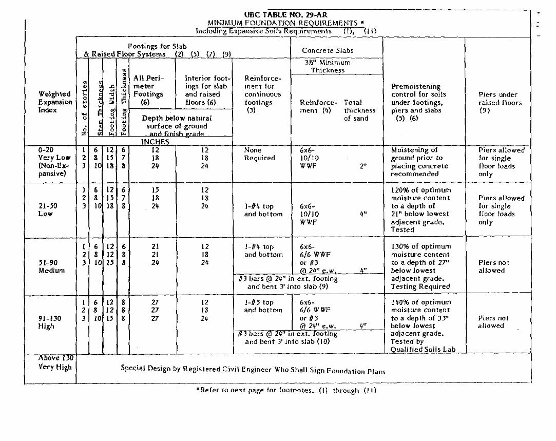
Expansion determination indicates that bearing soils lie in the "low to medium" ranges in
accordance with Table 29-AR. A copy of this table is included in Appendix B of this
repon.
Silt and clay contents are of moderate plasticity.
Groundwater was not encountered to a depth of founeen (14) feet.
Soils can be cut by normal heavy grading equipment
The existing fill at the proposed construction site contains miscellaneous debris, some of
which will require removal before placement as compacted fill.
BUENA ENGINEERS, INC.

• • II
• •
II
• II
•
May24, 1990 -8-
CONCLUSIONS AND RECOMMENDATIONS
B-18811-Vl 9().5-193
The site is suitable for the proposed development from a Geotechnical Engineering standpoint
provided that the recommendations contained in this report are successfully implemented into the
project .
A. Qmdin~
1. General Gradin~
a. Grading at a minimum should conform to Chapter 70 of the Uniform Building
Code and Appendix C, "Standard Grading Specifications" of this report.
b. The existing ground surface should be initially prepared for grading by
removing all vegetation, trees, large roots, debris, non complying fill, and other
organic material. Voids created by removal of such material should be properly
backfilled and compacted. No compacted fill should be placed unless the
underlying soil has been observed by the Geotechnical Engineer. Specific
suggestions for removal and disposal of unsuitable materials are given in
Appendix C of this report, "Standard Grading Specifications".
c. The bottom-of all __ excal(ations sho_uld be qbserved by_a_ repre_s!;ntative of this
Xrrm prior to processing or placing fill.
d. Fill and backfill placed at near optimum moisture in layers with loose thickness
not greater than eight (8) inches should be compacted to a minimum of ninety
(90) percent of the maximum dry density obtainable by the ASTM D 1557 test
method.
e. Loss due to clearing could be approximately 0.2 to 0.3 feet. Shrinkage of soils
affected by compaction is estimated to be between fifteen (15) and twenty (20)
percent. Shrinkage from rock and debris removal is not included in these
figures.
f. Import soils used to raise site grade, if necessary, should be equal to, or better
than, on-site soils in strength, expansion, and compressibility characteristics.
Import soil can be evaluated, but will not be prequalified by the Geotechnical
Engineer. Final comments on the characteristics of the import will be given
after the material is at the project site.
g. Roof draining systems should be designed so that water is not discharged into
bearing soils or near structures.
h. Final site grade could be such that all water is diverted away from the structures,
and is not allowed to pond.
BUENA ENGINEERS, INC.

I
• • • • • • • • • • •
May 24, 1990 -9- B-18811-Vl 90-5-193
1. It is recommended that Buena Engineers, Inc. be retained to provide continuous
Geotechnical Engineering services during site development and grading, and
foundation construction phases of the work to observe compliance with the
design concepts, specifications and recommendations, and to allow design
changes in the event that subsurface conditions differ from those anticipated
prior to the stan of construction.
J. P!~~ and specifications should be provided to Buena Engineers, Inc. prior to
grading. Plans should include the grading plans, foundation plans, and
foundation details. Preferably, structural loads should be shown on the
foundation plans. For concrete tilt-up construction, panel elevations should also
be provided .
2. Site Gmdin&(Development
a. It is our understanding that the construction of the basement will involve
excavating down approximately six (6) feet from existing grade. Our hand
excavated boring at the proposed building area was refused at four ( 4) feet in
uncertified fill. Based on exposures provided by the backhoe trench, we would
expect the uncertified fill to not extend much below four (4) feet. Once the
. removals have been made down to basement grade, we r~u~st the opportunity
-· · f ~~~-to observe the exposed soils and measure their rela~".'; co~paction. From this,
recommendations for additional grading, if necessary, could be presented .
b. Areas outside of the building area to receive fill, exterior slabs-on-grade,
sidewalks or paving should be scarified to a depth of one (1) foot moisture
conditioned and recompacted.
c. On-site soils may be used for fill once they are cleaned of all organic material,
rock, debris and irreducible material larger than eight (8) inches. It should be
noted that a large amount of rock and debris may be encountered during grading
based on observations made during the field work. Appropriate measure should
be taken prior to grading to prepare for mitigation of this problem.
d. Voids created by dislodging cobbles and boulders during scarification should be
backfilled and recompacted and the dislodged cobbles larger than eight (8)
inches in diameter should be removed from the subgrade.
BUENA ENGINEERS, INC.

• • • •
May 24, 1990 -10- B-18811-Vl 90-5-193
3. Utility Trenclles
a. Utility trench backfill should be governed by the provisions of this repon
relating to minimum compaction standards. In general, service lines inside of
the propeny lines may be backfilled with native soils compacted to ninety (90)
percent of maximum density. Backfill of off-site service lines will be subject to
the specifications of the jurisdictional agency or this report, whichever ate
greater.
b. Backfill operations should be observed and tested by the Geotechnical Engineer
to monitor compliance with these recommendations.
c. Jetting of native soils is not recommended.
B. Strucnu:al Design
1. Foundations
a. Conventional continuous footings and/or isolated pad footings may be used for
suppon of structures.
b. Footings with a minimum embcdment depth of twenty-one (21) inches should
bear into finn recompacted soils or finn natural soils as recommended elsewhere
in this report
c. Conventional continuous footings may be designed based on an allowable
bearing value of 1700 psf for an assumed footing size of twelve (12) inches ·-. wi!ie-llild riventy-one (21) inches deep.
d. Isolated ~ad footings may be designed based on an allowable beating value of
2000 psf for an assumed squate footing size of two (2) feet by two (2) feet by
-·eighteen (18) inches deep.
e. The above bearing values may be increased by 50 psf for each additional six ( 6)
inches of footing width and by 100 psf for each additional six (6) inches of
footing depth to a maximum value of 3000 psf.
f. Allowable beating values are net (weight of footing and soil surchaige may be
neglected) and are applicable for dead plus reasonable live loads.
g. Beating values may be increased by one-third when transient loads such as
wind and/or seisrnicity are included.
h. Lateral loads may be resisted by soil friction on floor slabs and foundations and
by passive resistance of the soils acting on foundation stem walls. Lateral
capacity is based on the assumption that any required backfill adjacent to
foundations and grade beams is properly compacted.
BUENA ENGINEERS. INC.

• II II
• • II I
• II
• II
• II II
• -
May24, 1990 -11- B-18811-Vl 90-5-193
1. The data that follow regarding depths, widths, reinforcement and premoistening
for footings are (generally) the same as those given in Table 29-AR of the
Uniform Building Code as locally adopted for the "m~diuqi" ex_Ransion range . "---~ ........... ---.......... __ ,., __
It should be noted, however, that these values are minima and that other more
stringent structural considerations may govern. Actual footing designs, depths,
widths and reinforcement should be provided by the Structural Engineer but
should not be less than values given herein.
j. Reinforcement of footings bottomed in soils in the "medium" expansion range
should be with two No. 4 bars, one top and one bottom.
k. Bearing soils in the "medium" expansion range should be premoistened to one
hundred thirty (130) percent of optimum moisture content to a depth of twenty
seven (27) inches below lowest adjacent grade. Premoistening should be
confirmed by testing.
I. 1.'._(l~!ldation excavatio11s }hould be_ visually observed by a representative of
Buena Engineers, Inc. after excavation, but prior to placing of reinforcing steel_ ., -
or concrete .
2. Slabs-on-Grade
a. Concrete slabs should be supponed by compacted structural fill or fum native
soils as recommended elsewhere in this repon.
b. It is recommended that perimeter slabs (walks, patios, etc.) be designed
relatively independent of footing stems (i.e., free floating) so foundation
adjustment will be less likely to cause cracking .
c. To help prevent moisture build-up below the basement floor, slabs should be
underlaid with a minimum of two (2) inches of sand and six (6) inches of
crushed rock. Areas where floor wetness would be undesirable should be
underlaid with a moisture barrier to reduce moisture transmission from the
subgrade soils to the slab. See diagram in Appendix A. The membrane should
be covered with two (2) inches of sand. The sand should be lightly moistened
just prior to placing concrete.
d. Reinforcement and premoistening data given herein for slabs are the same as
those given in Table 29-AR for the "medium" e1>pansion range. It should be
noted, however, that these values are minima and that other more stringent
structural consideration, such as large construction loads may govern. Actual
BUENA ENGINEERS, INC_
-I ••
--""
--.,
--
.,
~ -
-
May24, 1990 -12- B-18811-Vl 90-5-193
reinforcement and slab thickness should be determined by the Strucmral
Engineer, but should be less than values given herein.
e. Slabs bottomed on soils in the "me.dium" expansion range should be reinforced
with 6x6 - 6/6 WWF or No. 3 bars on twenty-four (24) inch centers, both
ways, placed at mid-slab.
f. Soils underlying slabs that are in the "medium" expansion range should be
premoistened to one hundred thirty ( 130) percent of optimum moisture content
to a depth of twenty-seven (27) inches below lowest adjacent grade.
g. Premoistening of slab areas should be observed and tested by Buena Engineers,
Inc. for compliance with these recommendations prior to placing of sand,
reinforcing steel, or concrete.
3 . Frictional and Lateral Coefficients
a.
b.
c .
d.
Resistance to lateral loading may ~e I'r()v1ded by friction acting on the base of
foundations. A coefficient of friction of O.S ~y be applied to dead load forces.
This value does noi include a factor of safety.
Passive resistance acting on the sides of foundation stems equl)l to 277 pcf of
equivalent fluid weight may be included for resistance to lateral load; This value
does not include a factor of safety. However, when passive resistance is used
in conjunction with friction, the coefficient of friction shoul_4.bereduced by one
thild (1/3) in.determining the·total lateral resistance.
A one-third (1/3) increase in the quoted passive value may be used when
considering transient loads such as wind and seismicity.
Passive resistance of soils again.st grade beams combined with frictional
resistance between the floor slabs and supporting soils may be used provided
that a one-third (1/3) reduction in the coefficient of friction to .33 is used.
4. Settlement Considerations
a. Maximum expected settlements of less than one (1) inch are anticipated for
foundations and floor slabs designed as recommended.
b. Differential settlement between adjacent load bearing members should be less
than one-half the total settlement.
c. The majority of settlement should occur during construction. Post-construction
settlement should be minimal.
BUENA ENGINEERS, INC.

---
I
•
• ' I I II
' ' '
May24, 1990 -13- B-18811-Vl 90-5-193
5. Retaining Walls
a. Conventional cantilever retaining walls backfill\;d_with.compacted on-site soils
may be designed for active pressuresoi36-·;f of equivalent fluid ;~ight for
well-drained, level backfill. Basement walls; whkh" Will IJe··designell:airlgjd . . ... ,,
retaining walls, may be designed for active J?ressures of 50 pcf of equivalent \,
fluid weight. . .... ,,, .....•... ~····
b. The pressures listed above were based on the assumption that backfill soils will
be compacted to ninety (90) percent of maximum dry density as detennioed by
the AS1M D 1557 Test Method.
c. The lateral earth pressure to be resisted by the retaining walls or similar
structures should be increased to allow for surcharge loads. The surcharge
considered should include the loads from any structures or temporary loads that
would influence the wall design.
d. A backdrain or an equivalent system of backfill drainage should be incorporated
into the retaining wail design. Backfill immediately behind the retaining ··- .. •'• •' "· ··--- ..... -··--~~~.~~--,··' . ___ ,....._·-··~.·-
structure should be a free-draining granular material. Alternately, the back of "'-----~---·-. ·····-·-·- ···- .. ~- ·---.. ~-.... ~~ -·•''•"•""" .... _ .. ·.- ..... , ... ······- '"'"~·-·-----··
the wall could be lined with a geodrain system . ..... ---- .
e. Compaction on the uphill side oftfiewall within a horiwntal distance equal to
one (1) wall height should be performed by hand-operated or other light weight
compaction equipment. This is intended to reduce potential "locked-in" lateral
pressures caused by compaction with heavy grading equipment.
f. Water should not be allowed to pond near the top of the wall. To accomplish
this the final backfill site grade should be such that all water is diverted away
from the retaining wall.
BUENA ENGINEERS, INC.
"
------
-..
..
May24, 1990 -14-
REFERENCES
l. C.D.M.G., 1982 (Revised 1988) Fault Rupture Hazard Z.Ones in California.
B-18811-Vl 90-5-193
2. C.D.M.G., 1975, Seismic Hazards Study of Ventura County, California, Special Repon.
3. C.D.M.G., 1978, Eanhquake Epicenter Map of California, 1900-1974, Map Sheet 118.
4. Crowell, John C., 1975, San Andreas Fault in Southern California, C.D.M.G. Special Repon 118.
5. Dibblee, T.W., 1988, Geologic Map of the Ventura and Pitas Point Quadrangles.
6. Greensfelder, Roger W., 1974, Maximum Credible Rock Accelerations From Earthquakes in California, C.D.M.G. Map Sheet 23.
7. Hileman, J.A., Allen, C.R., and Norquist, J.M., 1973, Seismicity of the Southern California Region, January l, 1932 to December 1972, Seismological Laboratory, California Institute of Technology.
8. Ploessel and Slosson, 1974, Repeatable High Ground Acceleration From Earthquakes, California Geology Vol. 27, No. 9, pp 195-199.
9. Sarna - Wojcicki and Others, 1976, Geology of the Ventura Fault, U.S.G.S., Map MF-781.
10. Seed, Bolton Hand Idriss, I.M., 1982, Ground Motions and Soil Liquefaction During Earthquakes, Earthquake Engineering Research Institute, pp 34-40.
11.
12.
Sieh, Kerry E., 1978, Earthquake Intervals, San Andreas Fault, Palmdale, California, C.D.M.G., California Geology, June 1978.
State of California, July 25, 1978, Maps, Special Studies Zones, Ventura Quadrangle.
13. U.S.G.S., 1986, Open File Repon, No. 86-401.
14. Weber, F. Harold, Jr. and others, 1973, Geology and Mineral Resources of Southern Ventura County, California, C.D.M.G., Preliminary Report 14.
15. Yeats, Roberts S., 1982, Low Shake Faults of the Ventura Basin, California From Neotectonics in Southern California, G.S.A. Guidebook.
BUENA ENGINEERS. INC.

~ I I II I
• • • • • •
May 24, 1990 -15-
ADDITIONAL SERVICES
B-18811-Vl 90-5-193
This report is based on the assumption that an adequate program of monitoring and testing will be
performed by Buena Engineers, Inc. during construction to check compliance with the
recommendations given in this report. The recommended tests and observations include, but are
not necessarily limited to the following:
1. Review of the building and grading plans during the design phase of the project
2. Observation and testing during site preparation, grading, placing of engineered fill,
and foundation construction.
3. Consultation as required during construction.
BUENA ENGINEERS, INC.

,• • ll
• • • II II II
' -' '
May 24, 1990 -16-
LIMITATIONS AND UNIFORMITY OF CONDITIONS
B-18811-Yl 90-5-193
The analysis and recommendations submitted in this report are based in part upon the data obtained
from the backhoe pit excavated and boring drilled on the site. The nature and extent of variations
between and beyond the pit and boring may not become evident until constmction. If variations
then appear evident, it will be necessary to reevaluate the recommendations of this report.
The scope of our services did not include any environmental assessment or investigation for the
presence or absence of wetlands, hazardous or toxic materials in the soil, surface water,
groundwater or air, on, below, or around this site. Any statements in this report or on the soil
boring logs regarding odors noted, unusual or suspicious items or conditions observed, are strictly
for the information of our client
Findings of this repon are valid as of this date; however, changes in conditions of a propeny can
occur with passage of time whether they be due to natural processes or works of man on this or
adjacent propenies. In addition, changes in applicable or appropriate standards may occur whether
they result from legislation or broadening of knowledge. Accordingly, findings of this repon may
be invalidated wholly or partially by changes outside our control. Therefore, this repon is subject
to review and should not be relied upon after a period of one ( l) year .
In the event that any changes in the nature, design, or location of the stmcture(s) and other
improvements are planned, the conclusions and recommendations contained in this repon shall not
be considered valid unless the changes are reviewed and cone! usions of this report modified or
verified in writing.
This repon is issued with the understanding that it is the responsibility of the Owner, or of his
representative to insure that the information and recommendations contained herein are called to the
attention of the Architect and Engineers for the project and incorporated into the plan and that the
necessary steps are taken to see that the Contractor and Subcontractors carry out such
recommendations in the field
Buena Engineers, Inc. has prepared this report for the exclusive use of the Client and authorized
agents. This report has been prepared in accordance with generally accepted Geotechnical
Engineering practices. No other warranties either expressed or implied are made as to the
professional advice provided under the terms of this agreement.
BUENA ENCll'EERS. INC.

I • M II I I
' I ; I I I
'
May24, 1990 -17- B-18811-Vl 90-5-193
It is recommended that Buena Engineers, Inc. be provided the opportunity for a general review of
final design and specifications in order that earthwork and foundation recommendations may be
properly interpreted and implemented in the design and specifications. If Buena Engineers, Inc. is
not accorded the privilege of making rhis recommended review, we can assume no responsibility
fcir misinterpretation of our recommendations.
END OF TEXT
Appendixes
BUENA ENGINEERS, INC.

' ,. ·.
. . ...
·- . '• :ii, - -
' '
. OVERSIZED ::. · -. -DOCUMENT HAS ·-· -··
BEEN PULLED AND SCANNED · WITH THE MAP.
FILE. ··...
..;~
·· -
' . .
. ' '• . ' . . .
. . . ' . . . . .
., . . . . . . . . . . ·-. . . .
. . ' '
·-i
• • I
• • I
• I
• I
• I
• • • I I I
APPENDIX A
Site Plan/Geology Map
Field Investigation
Boring and Backhoe Pit Logs
Symbols Commonly Used on Boring Logs
Unified Soil Oassification
Temis Describing Consistency or Condition
BUENA ENGINEERS, INC.
I I I I I I I
• I I
• I I I ' I
I ' '
I I
"' I
I I
I
A.
B.
C.
D .
A-1
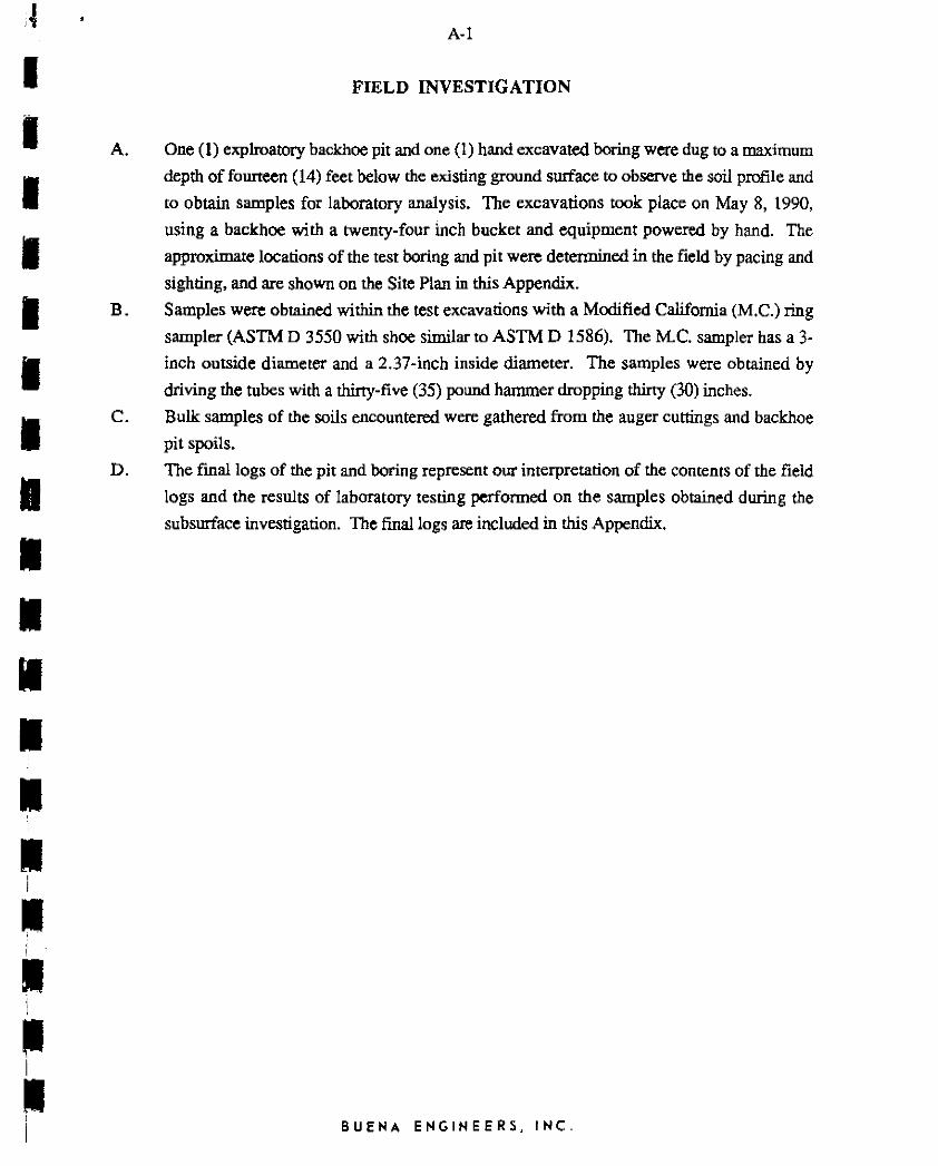
FIELD INVESTIGATION
One (1) explroatory backhoe pit and one (I) hand excavated boring were dug to a maximum
depth of founeen (14) feet below the existing ground surface to observe the soil profile and
ro obtain samples for laboratory analysis. The excavations took place on May 8, 1990,
using a backhoe with a twenty-four inch bucket and equipment powered by hand. The
approximate locations of the test boring and pit were detennined in the field by pacing and
sighting, and are shown on the Site Plan in this Appendix.
Samples were obtained within the test excavations with a Modified California (M.C.) ring
sampler (ASTM D 3550 with shoe similar to ASTM D 1586). The M.C. sampler has a 3-
inch outside diameter and a 2.37-inch inside diameter. The samples were obtained by
driving the tubes with a thirty-five (35) pound hammer dropping thirty (30) inches.
Bulk samples of the soils encountered were gathered from the auger cuttings and backhoe
pit spoils.
The final logs of the pit and boring represent our interpretation of the contents of the field
logs and the results of laboratory testing performed on the samples obtained during the
subsurface investigation. The final logs are included in this Appendix.
BUENA ENGINEERS. INC.

LOG OF TEST PIT
DATE May 8, 1990 EXCAVATION No. J_
--.c -Q. ... Cl
.. o
'- .
'I ·1 <----<Iii ! l---ll11 l .. s . :1,I ,____j1'I ,____ '
1: ,____ Ii " ,.
h. . '
1---111: ,, l---llli ·' >----' 111:1
_ .. 10· jl
"---111!
DESCRIPTION
~1: Dark yellowish brown silty fine grained sand with scattered masonry metal,asphalt and cobbles
Bl: Dusky brown elastic silt
82: Orangish brown sandy silt
... ... 5 c ....... "' u ·- ... 0 ... :::": n.
... Q. >. I--0 ..,,
92.7 22.9 SM
98.0 23.8 MH
105. 5 21. 7
111. 5 18. 5
78
82
88
93
B-18811-Vl 90-5-193
LOCATION Per Plan
Fill
l
REMARKS AND ANALYSIS
Colluvium
f--.fL!.-4-+--+-------------4--~-+---t--+-·---I Total Depth ~ 14 feet
.. 15 ,_____ ,____ --'- . I--
..__ 1---
'--.. .
,____ ,____ ,.__ ,.__ .. '
,_____ ,____
No Groundwater Encountered
L._L-..J--1-__1------------..-L.---.L..--L--.._ __ __.c.... ______ ~,ate B

I
I
• ~ ... .... ~
.<: .. • 0.. II.>
Cl
0
• --
• ---
I -5
• -----• -" ----• ----" .
I ,.....__ ---,.....__
I ---" ----I --" .
I ----I " -,____...
I ----. I ----• --• --
DATE May 8, 1990 Excavation No. 2
.. II.><::
0 .... .; .. c -;;, ~ ::l II.>
..0 " ~ DESCRIPTION .. u E .. .. ~ .!!? I...
>. ~ 0 ·2 t1J 0 "
Ctl :J Cl ..s- ::;;& "' " I 83: Dark yello~ish bro~
sandy silty with scattered gravel sized 94.3 7.2 fragments of masonry
98 .1 8.5
II.> 0.. >. I-
0
"'
ML
Job No. B-18811-Vl Report No. 90-5-193
LOCATION Per Plan
c 0 ·-ti> ... ~
> u c REMARKS ANO ANALYSIS ·-"'II.> .. 0.. u "'E .. "ii 0 v ci::u&
Fill
81
84
Total Depth ~ 4 feet
Plate B
I
I
•• I
• I
I I
• I I
• I
• • • I I
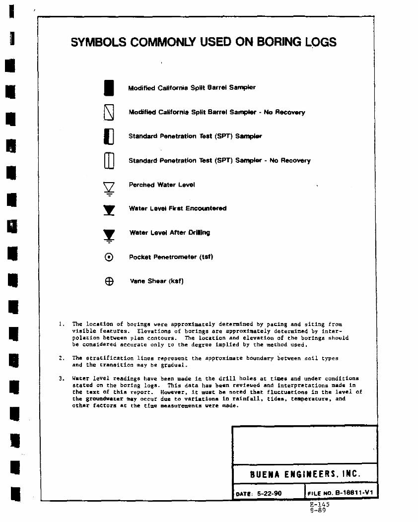
SYMBOLS COMMONLY USED ON BORING LOGS
I LSJ
(] [O
0
Modified Cafffornia SpHt Barrel Sampler
Modified California Split Barrel Sampler - No Recovfiy
Standard Penetration Test (SPT) Sampler
Standard Penetration Test (SPT) Sampler - No Recovery
Perched Water Level
Water Level First Encountfied
Water Level After DrUllng
Pocket Penetrometer (tsf)
vane Shear (ksf)
l. The location of borings were approximately determined by pacing and siting froq visible features. Elevations of borings are approxi~ately determined by interpolation bet~een plan contours. The location and elevation of the borings should be considered a~~urate only to th@ degree implied by the ~ethod used.
2. The stratifi~ation lines r@pre5ent the approximate boundary between soil types and the transition may be gradual.
J. Water level readings have been made in the drill holes at ti..mea and under condi~icna stated en the boring logs. This data ha& been revi~~ed and interpretations made in the t•xt of this report. However, it mu&t be noted that fluctuations in the level of the groundwater tn.ay o~eur due to variations in rainfally tides~ temperature, and othe~ factcrs at the time DH!la$u~ements w@re tll4de •
BUENA ENGINEERS, INC.
DAT~, 5-22-90 I l'ILE NO. B-18811-V1
E-145 B-89

I
I
• I I I I I I I
• I
• I I
• I I I
E-103
.... QU1G
SOILS
MA.IOlf DIYISIONS
_., fll,llilll q, °' i;:c.u.a c 'a,a.et 1 • W1al •• 4 Ut'l't
a..tM """Y<l.S (t,.1ttl,.& OI i10
r1111ct.)
SMa W11M FtNCS (...,,11u:ei.a1.c ~f °" , tJlllU:)
GW
GM
GC
SI"
5M
SC
ML
CL
OL
MH
CH
OH
l"T
#tu.-..~a ....... ._u,.1 • ..._..ljllb.• ~.Mif .,.,.,.11;:., L,.ltt'I,,, 11111 11a r 1111ci
~T ... &Dr..ti Ul.~t,M•wti.• 1-e- 111afw•ca, .. nt-.c M llO f'i11U
liL.t'f ...... va..t,, ll.llA~•s,.t.ill0-11iL.J l1U.aT1i11lltl
C;L.A't'r;T lla.t.Wltl,.t ............... ..,,.._.
c;a,.,.-. •••''"'''
~'t'~C. t.Nlllta ......... 1'il.1.:t 'MDt. 0 lolfl'l,.I: Olli lllD f'llllls
llll01.~1c=: Sh.ti M1P W(.l.t' ll'lllil &.AD ... aQCt; f!.CU .. , S 11,.'fT Diii C:Lil't'l¥ , ll•t .t.-oa Ol C.U.Ta 111..f1 •lfll "IM'I" ~ .. ITIC,ITT
UiC4..:..a.1e °'-A,.I OI L.1:19 T"Q llOi'-1"1...&f.TIG:i'J'l'o ....... vtu.T CW\n 0
Ulan' Ci,..t.'t'I. i1i.n ~Y'I, ~ Q.A't'I
~·~.i..1e SIL.fl .a.11111 Ol.&..WllC iu .. nr c1,..ava ot 1.ll)IJ •u1t1e1n
la,(li:&.UilU: 11'-Tlt liiC..&CCout M Pl.&TC.U.Ctovt. r1111. IMil Clll t.tL.'tT 1C111..t.
l.ol...._,IC: Q.ATI Oil" llllM l'\..&.f.TICIT'\', rt.1' a..a.n
Oilll&NllC Ci,,.ATI f:ll' •Ull\mll to 111191 11'\..UTIClti', ~11.i.mlC t.11,.TS
l't.fr,1' t fllll.IWUlo, MllliH' icill,.lj,
UNIFIED SOIL CLASSIFICATION SYSTEM
BUENA ENGINEERS, INC.
OAT E' 5-22-90 FILE NO. B-18811-V1
I
I
• • • ~
• • • ~ I
'
~
"' • .. .. ..
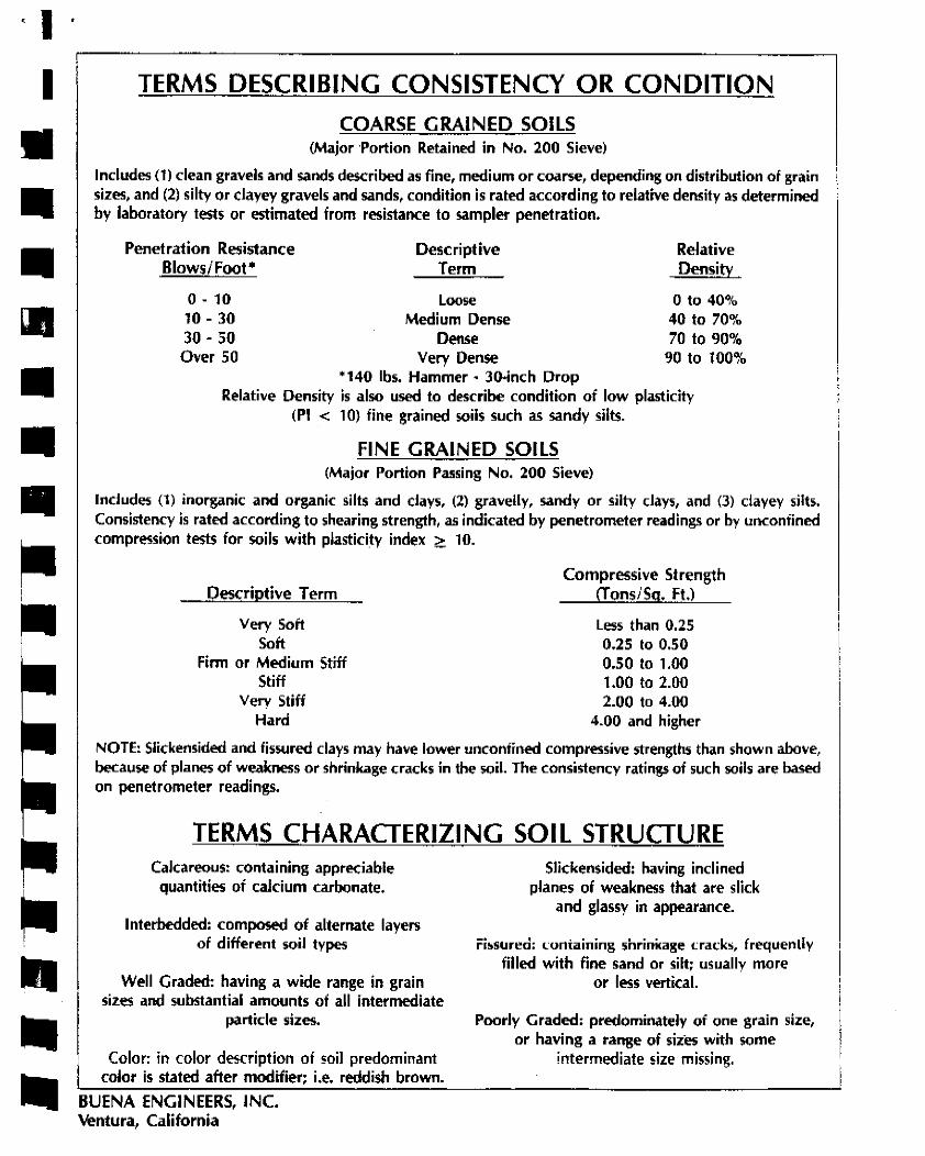
TERMS DESCRIBING CONSISTENCY OR CONDITION COARSE GRAINED SOILS
(Major ·Portion Retained in No. 200 Sieve)
Includes (1) clean gravels and sands described as fine, medium or coarse, depending on distribution of grain sizes, and (2) silty or clayey gravels and sands, condition is rated according to relative density as determined by laboratory tests or estimated from resistance to sampler penetration.
Penetration Resistance Blows/Foot*
0. 10 10. 30 30. 50
Over 50
Descriptive Term
Loose Medium Dense
Dense Very Dense
Relative Density
0 to 40% 40 to 70% 70 to 90%
90 to 100% * 140 lbs. Hammer • Jo.inch Drop
Relative Density is also used to describe condition of low plasticity (Pl < 10) fine grained soils such as sandy silts .
FINE GRAINED SOILS (Major Portion Passing No. 200 Sieve)
Includes (1) inorganic and organic silts and days, (2) gravelly, sandy or silty days, and (3) clayey silts. Consistency is rated according to shearing strength, as indicated by penetrometer readings or by unconfined compression tests for soils with plasticity index <!:. 10.
Descriptive Term
Very Soft Soft
Firm or Medium Stiff Stiff
Very Stiff Hard
Compressive Strength (!ons/Sg. Ft.)
Less than 0.25 0.25 to 0.50 0.50 to 1.00 1.00 to 2.00 2.00 to 4.00
4.00 and higher
NOTE: Slickensided and fissured clays may have lower unconfined compressive strengths than shown above, because of planes of weakness or shrinkage c;racks in the soil. The consistency ratings of such soils are based on penetrometer readings.
TERMS CHARACTERIZING SOIL STRUCTURE Calcareous: containing appreciable
quantities of calcium carbonate.
lnterbedded: composed of alternate layers of different soil types
Well Graded: having a wide range in grain sizes and substantial amounts of all intermediate
particle sizes •
Color: in color description of soil predominant color is stated after modifier; i.e. reddish brown .
BUENA ENGINEERS, INC. Ventura, California
Slickensided: having inclined planes of weakness that are slick
and glassy in appearance.
Fissured: i.:ontaining shrini<age cracks, frequently filled with fine sand or silt; usually more
or less vertical.
Poorly Graded: predominately of one grain size, or having a range of size-> with some
intermediate size missing.

l
~ 180° 0-•<>-
c:Jcf'd" <> i? o.o. • laminated sHts
J, ~ -=
•
' old retention basin wan Qco
____ ..oil._,~,..;.~>l.lh~ ·-·=·-
•:.; ;
=o t:rO •
a f wood post -+ gravel and pebble layer =
Qoa
- . -~
' ' -.
'= "" ·=
rOafl• ARTFICIAL FU: · pale yellowish brown to dark yellowish brown s6ghtly clayey, sNghtty sandy silt to silty sand ,
~ showing masoory fragments and cobbles
12~0J COU.UVJJM: dusky yelowish brown slighty clayey to clayey silt, showing sand lenses
OLDER ALWVIUM: orange brown sandy clay, showing rare cobbles
~ contact between units
000° -+ Oaf
IJ'avel and pebble layer
SCALE 1" = 5'
GEOLOGIC LOG OF BACKHOE TRENCH
73 North Palm Street
Ventura, California
BUENA ENGlkEERS, INC.
OA TE, May 1990 JOB NO 8-18811-V1
•• I
_ .. II
• • • • • APPENDIX B
Laboratory Testing
• Test Results
In-Place Densities
• Individual Test Results
Table 29-AR
• • • • • II
• • BUENA ENGINEERS, INC.

·I I
... II
• • • • • • II
• •
A.
B.
c.
D .
E.
F.
B-1
LABORATORY TESTING
Samples were reviewed along with field logs to determine which would be analyzed
further. Those chosen for laboratory analysis were considered representative of soils that
would be exposed and/or used during grading, and those deemed to be within the influence
of the proposed structure. Test results are presented in graphic and tabular form in this
Appendix .
In-situ Moisture Content and Unit Dry Weight for the ring samples were determined in
general accordance with AS1M D 2937 .
The relative strength characteristics of the soils were determined from the results of Direct
Shear tests on remolded samples. Specimens were placed in contact with water at least
twenty-four (24) hours before testing, and were then sheared under normal loads ranging
from 0.5 to 2.0 kips per square foot in general accordance with AS1M D 3080.
Settlement characteristics were developed from the results of one dimensional
Consolidation tests performed in general accordance with AS1M D 2435. The samples
were typically loaded to 0.5 or 1.0 ksf, flooded with water, and then incrementally loaded
to 2.0 and 4.0 ksf. The samples were allowed to consolidate under each load increment.
Rebound was measured under reverse alternate loading. Compression was measured by
dial gauges accurate to O.CXXll inch. Results of the consolidation tests in the fonn of
percent consolidation versus log of pressure curves are presented in this Appendix.
Expansion index tests were performed on bulk soil samples in accordance with Ventura
County and U.B.C. Test Method 29-2. The samples were surcharged under one hundred
fony-four (144) pounds per square foot at moisture content of near fifty percent (50%)
saturation. Samples were then submerged in water for twenty-four (24) hours and the
amount of el<pansion was recorded with a dial indicator .
Maximum density tests were performed to estimate the moisture-density relationship of
typical soil materials. The tests were performed in accordance with AS1M designation D
1557-88.
G. The gradation characteristics of selected samples were made by hydrometer and sieve
analysis procedures. Selected samples were soaked in water until individual soil particles
were separated and then washed on the No. 200 mesh sieve, oven dried, weighed to
calculate the percent passing the No. 200 sieve and then mechanically sieved. Additionally,
hydrometer analyses were performed to assess the distribution of the minus No. 200 mesh
material of selected samples. The hydrometer test was run using sodium
hexametaphosphate as a dispersing agent.
BUENA ENGINEERS, INC.

I I ~
• • I
• ' '
II
• • • • • •
B-2
TEST RESULTS
TRENCH/DEP'IH 1@3-5' 2@0-4'
SOIL TYPE Bl 83 Al
uses MH ML
MAXIMUMDENSITY(pc0 119.8 117.0 119.5•
OPTIMUM MOISTIJRE (%) 12.6 13.3 12.9
COHESION (psO 254 156
ANGLE OF INT. FR.IC. (0) 26 28
EXPANSION INDEX 54 44
* One Point Test
GRAIN SIZE DISTRIBUTION(%)
GRAVEL 0 1.6
SAND 10.2 26.2
SILT 48.1 43.4
a.AY 41.7 28.8
SOIL DESCRIPTIONS:
l@ 3-8' Bl: Dusky brown elastic silt. Colluvium
2 @ 0-4' BJ: Dark yellowish brown silt with sand and scattered masonry fragments. Fill
l @ 0-3' Al: Dark yellowish brown silty sand with scattered masonry, metal debris, asphalt
gravel and cobbles .
BUENA ENGINEERS, INC. --~ .. -~--~--·- .. -- .. ··--· ..

I I I I I I I
• • I I I I I I I
'
-I II
TRENCH & DEPTH
l@ l' 3' 5'
10'
2@ 1' 3'
B-3
IN-PLACE DENSITIES
RELATIVE DRY DENSITY %MOISTURE OOMPACTlON
92.7 22.9 78 89.0 23.8 82
105.5 21.7 88 111.5 18.5 93
94.3 7.2 81 98.1 8.5 84
BUENA ENGINEERS. INC.

•• ;
~
• • (IJ
• • • • • • • • • II II
• II
B-18811-Vl 90-5-193
MOISTURE CONTENT IN PERCENT OF DRY WEIGHT
lo 0 u.. (.)
al :::;) (.)
a: UJ a..
"' Cl z :::;)
0 a.. z > ....
"' z UJ Cl
> cc Cl
I I
I
METHOD OF COMPACTION
/
/ (
12
ASTM D-1557-78, METHOD A or C
·, \
14
119
I I
I '\ I '
\ I ' I I
117
I
I '
\ 115
0
16
SOIL TYPE MAXIMUM DENSITY OPTIMUM MOISTURE
Bl 119.8 pcf 12.6 %
MAXIMUM DENSITY - OPTIMUM MOISTURE CURVES
E-111

• I I I '
I
• • • I I I t I J
B-18811-Vl 90-5-193
MOISTURE CONTENT IN PERCENT OF DRY WEIGHT
lo 0
""' ()
cc ::i ()
cc w a. rn 0 z ::J 0 a. z >-1-rn z w 0
>cc 0
I
I
METHOD OF COMPACTION
I I
0 I
/0
I
I ' I I
12
ASTM D-1557-78, METHOD A or C
-· .
I
' 116
!
I 114 ',
I ' I
' I 0
'
' 112
14 16
SOIL TYPE MAXIMUM DENSITY OPTIMUM MOISTURE
BJ 117.0 pcf 13.3 %
MAXIMUM DENSITY - OPTIMUM MOISTURE CURVES
E-111

·I·, ~
~
Ill Ill I
• • • • • 1• ll
I I
I I ' '
I
.-. <\I lo 0 u. -(/) (/) UJ 0: ..... (/)
<!l z 0: < UJ J: (/)
4.0
3.5
3,0
2,5
2.0
1 .5
1.0
0.5
I
'-
-
-I
- -~ /
'
I I
A I /'J
i
I I
B-18811-Vl 90-5-193
I
-
I I
1 ' ' ! I I I
' i I '
i -
I
0 0 0,5 1.0 1.5 2.0 2.5 3.0 3.5 4.0
NORMAL LOAD (KIPS I FOOT 2 )
DIRECT SHEAR DAT A
Soil type: Bl
Boring and depth: l @ 3 - 8 feet
26 0 Angle of internal friction:
!XJ Samples remolded to 90% of maximum density
0 Samples relatively undisturbed
E-112

r . '
...... N
lo 0 u.. .....
4.0
3.5
3.0
Cl) a. 2.5 :.::: _.
Cl) Cl) w 0: IC/)
(!) z 0: <( w :r: (/)
2.0
1.5
1.0
0.5
0
I
,_
.._
-
- o· /
'
I
.-v ,. //
,/~ )
'
I
1)
I
I
I
B-18811-Vl 90-5-193
-
-
-
-
0 0.5 1.0 1.5 2.0 2.5 3.0 3.5 4.0
NORMAL LOAD (KIPS I FOOT2
)
DIRECT SHEAR DAT A
Boring and depth: 2 @ 0 - 4 feet
Angle of internal friction:
Cohesion: 156 psf
llil Samples remolded to 90% of maximum density
0 Samples relatively undisturbed

I "
~1
1 .l 0
:c u % .02 m: Ill ll.
"' Ill :x t)
. 04 z
%
z 0 I-4'. . o< a .J 0 If)
%
8 . 08
B-18811-Vl 90-5-193
0 . ..,
1..0•D IN KIPS P6R SQUA.RE- FOOT
0 0 0 Q m ~mio-
_o ' " "' • • " m ' '' 1,,, " '
1'li
I I i .. I · ' c " , I
' '. 111 I) !( ii :;:· ' ' r~.1 .... ''
' mi+:- -f.; , i 1: I , i -r '' ·1 ., " '
,, '
I, ,,;r
' ' ' '
' ' ' ,, I I
' ' ' '' ' Ii I , I, . ' a " 1 ~ I I I I ;
I 111 Ii ' ' I,. \ ,II ·I I
, IC
' ' '" ' ·i.I I mi' ' . ' 'I
~· " ' I '
.. ~ I
' '•' ' "' '1 · , I
,, ' '.' I ' '
Ii I Ii I.<'. ,.1. l!~i',lj1 1 _j,_ 1 1. '- I I 'j~~''I I
I, '' "
I> ''I' ,I, ;-!, .. tlD-''~.
""' ,,,,, !"'"' ' · ... -~'---'..:-.-"·'' .. ·~~· · .. " ~·.· '···.·.·!···: ,;r ~!'i"'" r I ij___...,:'i I: ~- l\rf, I.·~~' ; ., 1· ,,11 tn 11r:r:r't"T"'"""""-t-rrr-r:t-:-i ! , , , -1~r:"'.I.&,' ,,, : .~:rr f~ ;m;+-,-:-·c7"~LCJ!:; , , , ' ', ~. ---t-r-, ' , . , . , -'!.!' I '''·''.j ', '1--'--f't" I' I j \J ! · '' 11 ,, .~ri-p-rt, t
ttH-Hcm'+;;ll i ~ Iii I ' :~'.,I,, 'I I Ii i I: . r He' ''l+'c!Hl-\itl
~~~:!' ":! •:;:t:::::'"".· ~+ '• ·,_._,.:;! "':•::tt.:tt"i-rt----:"---,--,--'hr.....+. , . , : , , , ! ,~·, ·, f"T~if1 ttl .. '" ,, I'''"' ".I'" ' [Tl~·~
'1\1\;1•11 111 10' 11'''1'.'ll! II I , ·. ,.l-~ '~:\ ·.·11:1i11ill'tt
i 1: • 11111 nr 1 i: , ...-: .<: 1 , l
e Tested at in-place moisture: conditions
O Tested at 100% moisture conditions
COM'SOl..I DAT ION DA.TA
No. 2 at 3 feet
BUENA ENGINEERING SERVICES. INC .
. ..

I "
:x u , z .02 m: tll 11.
"' IU ::z: <J . 04 z
-z.
z 0 ... <( .06 a J 0 11) z 0 ()
B---18811-Vl 90-5-193
a 0 0 0 ·w -~ ,, "
T n r r ' ' ' ;,:
" II I
~ •T• ,,, , r-rn,
'
''' 11 \ .,,,..~,~p+J1 [·~ I I I 1 I i' 'I
' ], -a,4-1-1-.-)~,Ci+-+-_,_-.1-·:-+";T ,I _-,
,, " '
I ~ I I 11,n·
T, , f 1 ,- .''.I
0
" ' :
! , -r , , · 1 rTI
_o Ill
IT;,
i"
1-' TT 17" rrJ Cl-'-W.;---41--- - " ::;r+-; ;
0 <>
:+·
I I
' I
' . T
: ' I I
-, ' ' '
-, I -, T
'
,:
I
I
T
! 1) I
. '
' '
~-
' I
~-
~
'I ' '
. ! I.
''' '
'l 'I 1
I TT I! 'I
:
I ,, ,, "
r. 11~,
''' I I : I '
•I
'°. ,, '
>lit
CT ~ , , •----Tj--;-i---'---fi' , . IT , L' I ~ ·.It=+ 1:-·,,'·-fl\l•-iJ; ~;
TT'l ,, -. ! . ,\r,,·m · r i !'TIT
1--1-ll-~,_h---.'~.;+-,,_,_,j 1 ' 11 I · I , · . I '
1--1-i;.~:.;;."'>-'-----l+-'-'~·~"i.;+~ftrtj1rri-c'ltt:!t::::::::::;::•::::::::1t::::I·-::t1 i:·t·1t::;:;::tt!l:!1 :•:::'.•1:r:!•:t±tti1·~'::;:~!t"·tttittl l~llitiTI:tl:nilt:t' :· tlli±tt'±' 't' tdri 'mi!t:::::::::::::::::'t::::t:'j '"tt;' ,. :...,;___;__, ': I ....... ~'-'~--'~·,__,_._,_ ... , '-<' I i
111 ' I \l,l•.l '1) '·{11 -. ,; ! , ll'''~\\\1,1 1:1·r1:;J,
·1 Tt-"~1 '\! I '11/ii~~;Tl,1 I ! "r~ ·1
• · Tested at in-place moisture conditions
O T"sted at 100% moisture condii;ions
CONSOL.I CATION DATA No. 1 at 3 feet
BUENA ENGINEERING SERVICES. INC.
0:.\ • ""i 1"""
use TARLE NO. 29-AR MINIMUM FOUNDATION REQUIREMENTS *
Including Expansive Soils Requirements (! ), (I I}
Footings for Slab Concrete Slabs & Raised Floor Svstems {2) {5) (7) (9)
3Yiu Minimum
"' Thickness "' All Peri- Interior foot- Reinforce-"' "' " ings for slab ment for Premoistening "' .£: ... meter .... u u
Weighted ... "" .... Footings and raised continuous control for sells Piers under 0 . .... !,'; Expansion .., ~ (6) floors (6) footings Reinforce- Total under footings, raised floors "' t Index "" "" (J) ment (~) thickness piers and slabs (9) ... " " 0
1 .... .... Depth below natural of sand (5) (6} ., u 0 0 surface of ground
0 0 0 z ~ ~ _ ........ .f--:. .... ~ ---~ -·"" ...i~
INCHES 0-20 I 6 12 6 12 12 None 6x6- Moistening of Piers allowed Very Low 2 8 15 7 18 18 Required I 0/10 ground prior to for single (Non-Ex- J 10 18 8 24 24 WWF 2" pl acing concrete floor loads pansive) recommended only
l 6 12 6 15 12 120% of optimum 2 8 15 7 18 18 moisture content Piers allowed
21-50 J 10 18 8 24 24 1-04 top 6x6- to a depth of for single Low and bottom IO/ JO 4" 21" below lowest floor loads
WWF adjacent grade. only Tested
I 6 12 6 21 12 1-04 top 6x6- !JO% of optimum 2 8 12 8 21 18 and bottom 6/6 WWF moisture content
'1-90 J 10 15 8 24 24 or 03 to a depth of 27" Piers oot Medium r.:l 2lfn e~ w L 4" below lowest allowed
fl 3 bars@ 24" in ext. footing adjacent grade. and bent J' into slab (9) Testing Required
I 6 12 8 27 12 1-f/5 top 6x6- l 40% of optimum 2 8 12 8 27 !S and bottom 6/6 WWF moisture content
91-IJO J JO 15 8 27 24 or f/J to a depth of JJ" Piers not High (cl 24" e.w. 4" below lowest a/Jowed
fl J bars @ 24" in ext. footing adjacent grade. and bent 3' into slab (I 0) Tested by
Ouali lied Soi Is Lab ----- ~. -f'.DOVe L>v Very High Special Design by Registered Civil Engineer Who Shall Sign Foundation Plans
- -*Refer to next page for lootno tes. (I) through (I I)

tri Ml M
' ~ I I I I
=
I
1.
2.
3.
4.
5.
6.
7.
UBC TABLE 29-AR FOOTNOTES
F ounda ti on requirements are based on reducing the potential differential vertical movements due to expansive soil by premoistening the soil prior to construction. If premoistening is not desired, a much stronger foundation will be needed or other precautions must be taken as approved by the Building Official.
Crawl holes through footings for raised floors shall be installed with curbs extending a minimum of six inches above adjacent grade to prevent surface water from entering under the building.
Bottom bar three inches from bottom of footing, top bar within three inches from top of stem.
Slab reinforc,.ment shall be placed at slab mid-depth and continue to within two inches of "xt,.rior face of exterior footing walls.
Moisture content shall be maintained until foundations and piers are poured and a vapor barrier is installed, Tests shall b" tak"n within 24 hours of each s!ab pour.
Except under footings, the area under the raised floor need not be premoistened. Footings not located within a continuous footing or equivalent concrete or masonry moisture barrier per UBC Sec. 2907(a) shall be designed as perimeter footings.
A 12-inch m1mmum width grade beam shall be provided for garage openings, Depth and reinforcement shall be as specified in UBC Table No. 29-AR.
8. Footing widths may be reduced upon submittal of calculations by a registered civil or structural engineer or licensed archit,.ct, but shall be a minimum of twelve (12) inches for one and two-story structures and fifteen (15) inches for three-story structures.
9. The ground under the floor may be excavated to th" elevation of the top of the footing.
J 0. Bent steel reinforcement bars are not allowed between floating slabs and footings.
l J. Vertical steel reinforcing bars in chimneys shall hook under horizontal steel reinforcing bar mat of //4 bars at I 2 inches on center each way located three inches from the bottom of supporting foundation.

I ..
r1
-1 .. I
---•
I -
=
APPENDIX C
Standard Grading Specifications
BUENA ENGINEERS, INC.

C-1
STANDARD GRADING SPECIFICATIONS
PROJECT: 73 North Palm Street, Ventura California
Gayle Kieran Living Trust CLIENT:
1. These Standard Grading Specifications have been prepBred for the exclusive use of our
client for specific application to referenced project in accordance with generally accepted
soil and foundation engineering practices. No other warranty, expressed or implied, is
made.
2. Buena Enijneers. Inc., referred to as the Geotechnical Engineer, should be retained to
provide continuous Geotechnical Engineering services during construction of the grading,
e>;cavation and foundation phases of the work. This is to observe compliance with the
design concepts, specifications or recommendations and to allow design changes in the
event that subsurface conditions differ from that anticipated prior to strut of construction.
3. The presence of our field representative will be for the purpose of providing observation
and field testing. Our work does not include supervision or direction of the actual work of
the contractor, his employees or agents. The contractor for this project should be so
advised. The contractor should also be informed that neither the presence of our field
representative nor the observation and testing by our firm shall excuse him in any way from
defects discovered in his work. It is understood that our firm will not be responsible for
job or site safety on this project. Job and site safety will be the sole responsibility of the
contractor.
4. If the contractor encounters subsurface conditions at the site that (a) are materially different
from those indicated in the contract plans or in specifications, or (b) could not have been
reasonably anticipated as inherent in the work of the character provided in the contract, the
contractor shall immediate! y notify the owner verbally and in writing within 24 hours. This
notification shall be a condition precedent before any negotiations for "changed or differing
site conditions" can proceed. If the owner determines that conditions do materially so differ
and cause an increase or decrease in the contractor's cost of, or the time required for,
performance of any part of the work under this contract, then negotiations shall commence
between owner and contractor to provide equitable adjustment to owner or contractor
resulting therefrom
BUENA ENGINEERS, IHC

1 J
i 1
•
I
5.
6.
7.
8.
C-2
Whenever the words "supervision", "inspection'', or "control" appear they shall mean
periodic observation of the work and the tal<lng of soil tests as deemed necessary by the
Geoteehnical Engineer for substantial compliance with plans, specifications and design
concepts.
These specifications shall be integrated with the Geotechnical Engineering Report of which
they are a pan. Should conflicting statements be found between these standard
specifications and the itemized recommendations contained in the main body of the report,
the latter shall govern.
These specifications shall consist of clearing and grubbing, preparation of land to be filled,
filling of the land, spreading, compaction and control of the fill, and subsidiary work
necessary to complete the grading of the filled areas to confonn with the lines, grades and
slopes as shown on the accepted plans.
The standard test used to define minimum density of compaction work shall be the AS1M
Test Procedure D 1557. Densities shall be expressed as a relative compaction in terms of
the maximum density obtained in the laboratory by the foregoing standard procedure.
9. Field density tests will be performed by the Geotechnical Engineer during grading
operations. At least one (1) test shall be made for each five hundred (500) cubic yards or
fraction thereof placed with a minimum of two (2) tests per layer in isolated areas. Where
sheepsfoot rollers are used, the soil may be disturbed to a depth of several inches. Density
tests shall be taken in compacted material below the disturbed surlace. When these tests
indicate that the density of any layer of fill or portion thereof is below the required density,
the particular layer or portion shall be reworked until the required density has been
obtained .
10. Earth-moving and working operations shall be controlled to prevent water from running
into excavated areas. Excess water shall be promptly removed and the site kept dry. Fill
material shall not be placed, spread or rolled during unfavorable weather conditions. When
the work is interrupted by heavy rain, fill operations shall not be resumed until field tests by
the Gootechnical Engineer indicate that the moisture content and density of the fill are as
previously specified.
BUENA ENGINEERS, INC

Ill I b I I
-
=
J
11.
12.
13.
C-3
Compaction shall be by sheepsfoot rollers, vibrating sheepsfoot rollers, multiple-wheel
pneumatic-tired rollers or other types of acceptable compacting rollers. Rollers shall be of
such design that they will be able to compact the fill to the specified density. Rolling shall
be accomplished while the fill material is within the specified moisture content range.
Rolling of each layer shall be continuous over its entire area and the roller shall make
sufficient trips to insure that the required density has been obtained.
Existing structures, foundations, trash, debris, loose fill, trees (not included in
landscaping), roots, tree remains and other rubbish shall be removed, piled or burned or
otherwise disposed of so as to leave the areas that have been disturbed with a neat and
finished appearance free from debris. No burning shall be permitted in the area to be filled.
When fill material includes rock, large rocks will not be allowed to nest and voids must be
carefully filled with small stones or earth and properly compacted. Rock larger than six (6)
inches in diameter will not be permitted in the compacted fill without review as to location
by the Geotechnical Engineer.
14. Organic matter shall be removed from the surface upon which the fill, foundations or
pavement sections are to be placed. The surface shall then be plowed or scarified to a depth
of at least eight (8) inches and until the surface is free from ruts, hummocks or other
uneven features which would tend to prevent uniform compaction by the equipment to be
used. Specific recommendations penaining to stripping and minimum depth of
recompaction of native soils are presented in the main body of the repon.
15.
16.
Native soil free from organic material and other deleterious material may be used as
compaeted fill; however, during grading operations the Geotechnical Engineer will re
examine the native soils for organic content.
The Geotechnical Engineer may give a preliminary indication of the quality of proposed
impon soils by testing samples taken at the source. In general, proposed borrow soils
should be free from organic matter and any deletereous substances. Additionally, they
should be equal to or better than site soils with regard to gradation, compressibility and
strength characteristics. However, final acceptance of import soils will be given only after
the materials have be.en brought to the site in enough quantity to complete the project.
BUENA ENGINEERS, INC.

, ...
'
' I ' '
r
17.
C-4
Where fills are made on hillsides or exposed slope areas, greater than ten (10) percent
horizontal benches shall be cut into finn undisturbed natural ground to provide a horizontal
base so that each layer is placed and compacted on a horizontal plane. The initial bench at
the toe of the fill shall be at least ten ( l 0) feet in width on firm, undisturbed natural ground
at the elevation of the toe stake placed at the natural angle of repose or design slope. The
width and frequency of succeeding benches will vary with the soil conditions and the
steepness of slope.
18. The selected fill material shall be placed in layers which, when compacted, shall not exceed
six (6) inches in thickness. Layers shall be spread evenly and shall be thoroughly blade
mixed during spreading. After each layer has been placed, mixed and spread evenly, it
shall be thoroughly compacted to a relative compaction of not less than ninety (90) percent
The fill operation shall be continued in six (6) inch compacted layers, as specified above,
until the fill has been brought to the finished slopes and graded as shown on the accepted
plans.
19. When the moisture content of the fill material is not sufficient to achieve required
compaction, water shall be added until the soils attain a moisture content so that thorough
bonding is achieved during the compacting process. When the moisture content of the fill
material is excessive, the fill material shall be aerated by blading or other satisfactory
methods until the moisture content is reduced to an acceptable content to achieve proper
compaction.
20. Existing septic tanks and other underground storage tanks must be removed from the site
prior to commencement of building, grading or fill operations. Underground tanks,
including connecting drain fields and other lines, must be totally removed and the resulting
depressions properly reconstructed and filled. Depressions left from tree removal shall also
be properly filled and compacted.
21. The methods for removal of subsurface irrigation and utility lines will depend on the depth
and location of the line. One of the following methods may be used: I) Remove the pipe
and compact the soil in the trench according to the applicable portions of these grading
recommendations, 2) The pipe shall be crushed in the trench. The trench shall then be
filled, compacted according to the applicable portions of these grading specifications,
3) Cap the ends of the line with concrete to mitigate entrance of water. The length of the
cap shall not be less than five (5) feet. The concrete mix shall have a minimum shrinkage.
BUEHA EMCIHEERS, INC

I·
M
~ -J -i •
I
-
f
-
I
••
22.
C-5
Abandoned water wells on the site shall be capped according to the requirements of the
appropriate regulatory agency. The srrength of the cap shall be at least equal to the adjacent
soils. The final elevation of the top of the well casing must be a minimum of thirty-six (36)
inches below adjacent grade prior to grading or fill operations.
BUENA ENGINEERS, INC

STAlC:: OF CALIFORNIA-Tl-IE RESOUl=ICES AGENCY l='ETE WILSON, GDVt5!rnor ~.-····· .. ~"· ==~===··'==~ ·~====== ·=== ·-----: .. ,~-.· .. = DEPARTMENT OF CONSERVAilON
DIVISION OF MINES AND GEOLOGY BAY AREA REGIONAL OFFICE 185 Berry Street. Suite 210 San Francisco, CA 941 07 Phone (415) 904-7707 CAlN ET 539-7707 FAX (415) 904-7715
Bob Prodoehl
May 7, 1997
Building Official/Fire Marshall City of San Buenaventura 501 Poli Street Ventura, CA 93002-0099
Dear Mr. Prodoehl:
We are placing on open file the following report, reviewed and approved by the City of San Buenaventura in compliance with the Alquist-Priolo Earthquake Fault Zoning Act:
Preliminary geotechnical & seismic study, 71 N. Palm Ave., Ventura, CA; by CalGeo; 11/25/96, with supplements of 3/5/97 and 4/5/97.
Please note that this report refers to a trench excavated on the subject site by Buena Engineers {May 1990, Geotechnical engineering and engineering geology report for relocation of DeSilva residence, North Palm Street, Ventura). Since this report applies to proposed Parcel 3 of the subject site and contains trenching and perhaps other useful data, a copy of the Buena Engineers report probably should have been appended to the CalGeo report. In any event, a copy of the Buena Engineers report would be a useful addition to our files.
EWH:ra cc: W.A. Bryant
A-P file'
Sincerely,
,.~o;(,-t' ff· --· ,.. ...... , ' ... .....,. _,. •' '
EARL W. HART, CEG 935 Senior Geologist
. , '. · ... -. _,.·: ~ . :; . . . . . '· .. ;.. . - .:.,. ...

CITY OF SAN BUENAVENTURA
April 23, 1997
California Division of Mines & Geology Earl W. Hart, Project Manager 185 Berry Street Suite 3600 San Francisco, CA 94107
ClTY COUNClL
J;;ick Tingstrorn, M:.:1yor Ro~a Lee Measure.-., [)eputy M;:iyot Ste:phcn A. net1nctt R<iy [1i (Juilio Jan1~s J- Fried1na11 J a1n~s L. Mon::i.han Gary R. Tut.tie
Subject: Ventura Fault Special Study Zone - 71 N. Palm Street, Ventura, CA - Land Division
Dear Mr. Hart:
I have attached a copy of a geotechnical report for a small land division in downtown Ventura which is located in the special study zone. The report has been reviewed by our consulting geologist and found acceptable regarding Special Study Zone requirements. The remaining soils conditions will be addressed prior to any construction on the northerly panel.
Please consider this as our filing of the geologic report as required by Section 3603 of the AlquistPriolo Special Studies Zone Act.
Sincerely,
~.-(J~ Bob Prodoehl Building Official/Fire Marshal
cc: Ray Gutierrez Jim Mesa
501 Poli Street • E 0. Bnx 99 • Vo;ntura, California • 93002-0099 • (805) 654- 7800 • FAX (805) 652-086)
Prlnn::d -~n rt'cyckd p•1per - to hc:lp [.1r1.\lccc our !"'.11vironn1cn1

Bob Prodoehl City Building Onlcial P 0. Box 99 Ventura, California
CFG CONSULTANTS
Richard Paul Cousineau James E. Fisher
Engineering Geology
Re: Review of Supplemental Geotcchnical Response 71 Nort.h Palm Avenue, Ventura, California- Prepared by Cal Geo
Dear llob:
April I 6, 1997
I am in receipt of the April 5, 1997 response report by Cal Geo,( William La Chapelle) (received 4/15/97). It is my opinion that the responses arc adequate for the discussion of the presence or absence of the Ventura Fault as required by the AlquistPriolo Special Studies Zone and this portion of the review is considered completed.
I , however, continue to have strong reservations concerning the analysis of the stability of the surface and near surface soils on the subject parcel...The use of direct shear tests from a 6 foot deep sample classified as a silly clay, is not appropriate to the upper 4 to 5 feet of surface soils repres~nt"d on Plate JA , as" Dry, loose, slightly clayey Sand". II is common practice in sout>-Jrn C,_~Jornia to assign a cohesion value ;:ero for loose granular soils .The Consultani has assigned a cohesion of350 pounds per square ti.Jot and an internal angle of friction of3J degrees to this material. The consultant should provide a basis along with laboratory data justifying the use of these values for the granular surlacc soils. I also still question the deep seated stability analysis due to the assigned shear value used in the calculations presented.
By way of interest it is noted that in one of the references provided by the Consultant ( Earth Systems -Mission School Reconstruction, for the slope area immediately West of the subject property) that one of the foremost considerations was to improve the low stability of the slope surface with a stabilization fill. It was also noted that the fill soils immediately West of the subject slope are classified as loose dry silty sands, similar to that shown on Plate 3 A of the Cal Geo report.
This review will be continued upon receipt of additional suppo11ing data regarding specifically the upper five feet of soils and an appropriate surficial slope stability analysis, such as that contained in the US. G. S. Prof Paper 851.
Respectfully submitted CFG CONSULTANTS
~I?~ Richard P. Cousineau CEG 321
1727 State Street• Santa :Barbara• California• 93101
SOS Alegria Road• Sant"- :Barbara· California· 93lOS •Tele/Fax 809·682·6606

• CFG CONSULTANTS
Richard Paul Cousineau James E. Fisher
Engineering Geology RECEIVED
MAR 2 6 7997 INSPECTIQN SAN BUENAv~:~VICEs
"••TURA
Bob Prodoehl Mardi 25, I 997 City Building Official r, .O .Box 99 Venlurn, CA 93002
J~e; 71 North Palm Avenue Ventura, California
Deilr Hob;
I have reviewed th' c:urrent incomplete responses to my initial review by William La Chapelle, dated l'ebruary 15, 1997, receiv<~d in our office by l'ax on M~rch 6, ·1997, and a complete> report received this date bty hand delivery to our oftices. The Geot.edmic<'l Review Response is stated lo "super~ede all pnc'vious reporlc. '' and rt'commends that th~· proposed "grading plan be revised to accomrnodnte th<e local c·ondition8".
The discussions both in the origi1wl and in the r~'ceril response$ by the consultant concerning the location of the Ventura Fault have bc~en complex yet well document10d. We h11ve no significant reservations with the findings <11ld opinions that l:he most probable location coul.d b"' south of the subj"'d site, (even though the Geologic: Map, f'!ate 1, of the Cal-Geo stil.l depicts the V10nlurn Fault to be within Poli Street north of the property). Other consultants have• also been led to this conclusion because of the lack of definitive evidence for the fault's prc'"enct' west of San Jon Barranca.
Our lllajor difficulty with llw original report and with the recent response is not Lo the bask geologic information (albeit I had some concerm; that h<ive si1Ke been addressed) but lo the geotcc:hnical I geological evaluali<>n of the near ~;urfoC'e ea1'th conditions, the Mability of the surface materials on lhe slop•~, th., lack ol practical recomrnendations for .-:.'v<?lopment, and llw qu<•stionable relevance of certain soi.I test parameters .
Lest our review run onto page after p<1ge of technical questionings, ;rnd being made aware ()f the high cost of tk•lay, we recommend a. meeting w'1ll1 the consultant and the city and the owners to disn1ss the ii-ems we consider relevant, such as: Surfidal slope stability bolh static and under earthquake Jo,1ding, feasible foundation methodology, recommended A)ope nngles for grading, I.he snfety of
1727 Stat" Str""' • Santa Barbara• California• 93101
SOS Alegria Road. Santa f:larbara • California· 9:3109 •Tele/Fa>< 809·682·6606

'
unshored excavations, field classifications versus laboratory determinations, creep forces, and other geotechnical recommendations.
If such a meeting could be arragned and assurances given that the issues could be professionally decided, than the progress of the application could go forward. Please let me know if this is a reasonable approach to the impasse.
Very truly yours CFG CONSULTANTS
Richard P. Cousineau Engineering Geologist Certification No. 321
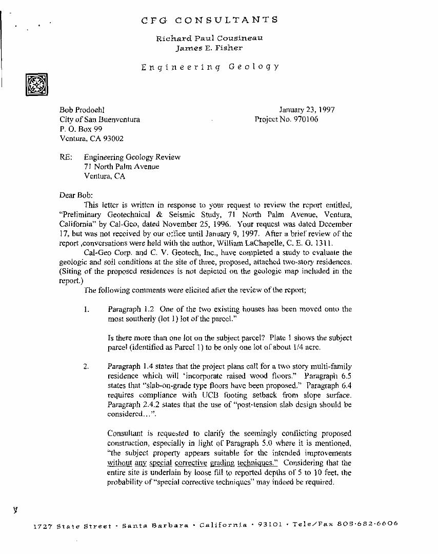
Bob Prodoehl
CFO CONSULTANTS
Richard Paul Cousineau Jam.es E. Fisher
Engineering Geology
City of San Buenvcntura P. 0. Box 99
January 23, 1997 Project No. 970106
Ventura, CA 93002
RE: Engineering Geology Review 71 North Palm Avenue Ventura, CA
Dear Bob: This letter is written in response t(l your request ((i review the report entitled,
"Preliminary Geotechnical & Seismic Study, 71 North Palm Avenue, Ventura, California" by Cal-Geo, dated November 25, 1996. Your request was dated December l 7, but was not received by our orlice until January 9, 1997. After a brier review of the report ,conversations were held with the author, William LaChapelle, C. E. G. 1311.
Cal-Geo Corp. and C. V. Geotech, Inc., have completed a study to evaluate the geologic and soil conditions at the site of three, proposed, attached two-story residences. (Siting of the proposed residences is not depicted on the geologic map included in the report.)
The following comments were elicited atler the review of lhe report;
l. Paragraph 1.2 One of the two existing houses has been moved onto the most southerly (lot I) lot ofthc parcel."
Is there more than one Jot on tlte subject parcel? Plate 1 shows the subject parcel (identified as Parcel 1) to be only one lot or about 1/4 acre.
2. Paragraph 1.4 states that the project plans call for a two story multi-family residence which will 'incorporate raised wood floors." Paragraph 6.5 states that "slab-on-grade type floors have been proposed." Paragraph 6.4 requires compliance with lJCll footing setback from slope su1face_ Paragraph 2.4.2 states that the use of "post-tension slab design should be considered ... ".
Consultant is rcq uc>ted to clarify the seemingly C\)!ltlicting proposed construction, especially in light of Paragraph 5.0 whcr" it is mentioned, "the subject property appears suitable for the intended improvements without any special corrective grading techniques." Considering that the entire site is underlain by loose fill to reported depths or 5 to l 0 feet, the probability of"special corrective techniques" may indeed be required.
1727 St<'te Street. S<'nta Barbara· c,,Jiforn!a • 93101 •Tele/Fax 809·682·6606

Buenaventura N. Palm Page 2
3. Paragraph 2.2 . The reference to Harden, et.al., 1986, is unknown to the reviewer and it is not listed on the Bibliography of the report, nor is it listed on the California Collegiate thesis list for 1986.
Consultant is requested to provide the referenced citation in that this referenced document could be important to later interpretations.
4. Paragraph 2.2. A clarification is requested of the consultant regarding the apparent contradiction in the statement, "A fault may form the proximal limit of this marine terrace (above which the property is situated), (i.e., on the escarpment formed by the Ventura Fault), and Paragraph 3.3, "old marine terrace beach sands and gravel deposits are found underlying the continental colluvium and fill across the site." "A thin veneer of marine material consisting of sand and gravel overlies the wave cut bedrock." None of these features are revealed or reported on the logs of the exploratory trenches.
5. Paragraph 2.3 states" ... the notch point (the intersection of the wave cut platform with the sea cliff) of this terrace has been elevated over 400 fret. The site is located above a marine terrace that is no more than 35,000-60,000 yr. B.P." Which terrace is the consultant reforring to?
Also, the consultant stales "The Ventura Fault ... (is) depicted as a north dipping reverse fault at the base of the Ventura Foothills" and "this fault is thus, considered to be active for the purposes of this investigation (Sec Figure 2). Figure 2 depicts the Ventura Fault to pass directly beneath the central portion of the subject site. Further, in Paragraph 2.4.1 the consultant states that the fault is concealed by alluvial fan deposits. No alluvial fans are known or have been reported by the consultant to be present on the site.
Further, the consultant states that his studies indicate that a major geologic contact is concealed below the colluvium south of the site. "Exploratory seismic trenches were excavated across the site" the consultant reports. " ... exposing terrace deposits and well developed colluvial soil in depositional contact with underlying Saugus Formation rocks (terrace on the south)," yet neither of the exploratory trenches log terrace deposits and well developed colluvial soil over Saugus Formation. Consultant is requested to address this anomalous statement.
6. On Page 6 the consultant mentions that the Ventura fault juxtaposes Pico Formation against Saugus. It is actually believed that the Ventura Fault is the contact between the Saugus Formation and Terrace Deposits of

Buenaventura N. Palm Page 3
Pleistocene age and is most commonly exposed as Oexures within the Terrace Deposits. Consultant is requested to address this issue.
7. Paragraph 2.4.2. states " ... there are no known active or potentially active faults on or adjacent to the site." Paragraph 2.2 states, "A fault may fonn the proximal limit of the terrace south of the property," and PrenticePowell (1991) show a fault in Poli Street north of the site, which the consultant refers to as the Ventura Fault, and it would seem that there are indeed active and/or potentially active faults" "on or adjacent to the site." As stated in Paragraph 2.5.1 "the area within 50 feet of the mapped trace of an active fault must be considered to be underlain by active strands of the fault." If the Ventura Fault is located in Poli Street, then the entire north half of the property is within 50 feet. If it is near the toe of the slope, then the entire south half of the site is within 50 feet. If the Ventura Fault is located as shown on the Alquist-Priolo Fault Hazard Zone Map, then the fault bifurcates the subject property. Consultant is requested to clarify these points.
8. Paragraph 2.5. l states that "this investigation demonstrates that the site is not underlain by strands of the fault identified by Prentice and Powell (199 I) in their Boring B-1." Is the consultant saying that the shear zones reported by Prentice and Powell (1991) are the Ventura Fault and that the materials on the footwall are Terrace Deposits and not Saugus Formation? Please clarify.
9. Paragraph 2.5.2 states that "the possibility of earthquake-induced landsliding has a low potential for occurrence" but "due lo the weak and fractured nature of the slope face material of marginal stability, primary failure and heavy rock fall may be possible." These two sentences appear to contradict each other. A layman, or for that matter, a professional, can often not distinguish between a landslide and primary failures and heavy rock falls. Consultant comment requested. "Regrading of the slopes should be incorporated into the grading plans to mitigate this hazard",the consultant recommends. To what depth with which grading techniques, and to what angles should the regrading be accomplished?
10. Paragraph 2.5.3 The consultant is requested to define which bedrock materials have been affected by faulting and where the "consolidated ancient alluvial fan deposits" are located. To what depth is removal and recompaction of the unconsolidated materials recommended ?
l l. Paragraph 3.0 The consultant states that "Investigations by the C.D.M.G and U.S.G.S. were considered as part of this investigation," yet both the

Buenaventura N_ Palm Page 4
referenced documents show the Ventura Fault to cross beneath the subject site. How were these investigations considered by the wnsultant?
12. Paragraph 3.l states that "Artificial Fill has been placed across the entire northern portion of the site," yet this fill does not appear on the Geologic Map, Plate I. Ten feet, more or less, ofloose unconsolidated artificial fill on a 1 ! /2: I +/- slope is not considered by this reviewer to be "minor grading" or "shallow". Paragraph 3.2. states that the site is mantled by colluvium. This contradicts Paragraph 3.1. The "disoontinuous stoneline" also referred to in this paragraph as colluvial material is shown on Plate 3 to be artificial fill. Consultant is requested to comment and clarify.
13. Paragraph 3.3 appears to refer to another site, not the one identified as the "subject site" by the consultant. None of the descriptions match tbe Seismic Trench Logs. Comment requested.
14. Paragraph 3.4 If the Ventura Fault juxtaposes Saugus Formation and Pico Formation rock, and the fault is buried beneath Poli Street, how can Saugus Formational rocks be exposed northwest of the property? What relation do The Las Posas Formation rocks bear on the site? The consultant is requested to reply.
\ 5. Paragraph 4.1 refers to a storm water control terrace drain along the southern boundary of the site, and refers to a storm water control system at Catalina Street and Hillcrest Drive_ Consultant is requested to clarify these statements which appear to be incorrect and/or have no bearing on the subject site.
16. Paragraph 4.2 states that Ventura County monitors a water well 1 mile southwest 01.· the site. Such a position would be in the Pacific Ocean, an obviously incorrect statement.
17. Paragraph 5.0 See Item 3 above regarding the suitability of the site "without any special corrective grading techniques.n The consultant is requested to stat" his assessment of the future stability of Poli Street if corrective grading is required that will, even temporarily, remove lateral support from the street.,
"Overexcavation of unsuitable materials will expose ancient terrace deposits" is a statement not considered relative to the subject site, as there are no "alluvial materials at tbe planned (?) foundation elevations" on the subject site according to the trench logs of tbe report.

Buenaventura N. Palm Page 5
18. Paragraph 6.0 states that "The on-site soils tested have a low expansion potential." The report includes no such testing but does, however, identify the on-site soils as silty clays, and clayey silts; soils typically with expansion potentials greater than "low." Paragraph 6.5 requires special design features to minimize the effects of expansive ooil. This apparent contradiction should be resolved by the Consultant.
As in Paragraph 5.0 there are no ancient marine terrace deposits or loose surficial weathered bedrock depicted on the site. ln addition, how can footings be of minimum depth of 12 inches if all the structures are two story, as stated? If the soils are clayey, what are the expansion indicies and the appropriate required footing depths and reinforcement?
What is the basis for the consultant's estimate that t footing settlement will be between 1/4 and 1/2 inch when consolidation tests were not perfom1ed either on the "loose surficial weathered bedrock" or upon remolded fill materials, or upon the colluvial materials encountered below the artificial fill?
19. Paragraph 6.2 Has the consultant considered creep forces on footings placed on a I 1/2: 1 fill slope? It is requested that the potential for soil creep be addressed by the consultant, not only for foundations, but also for surcharge against retaining walls referred to in Section 6.3.
20. Paragraph 6.7 does not address the very probable condition of encountering loose fill soils in excess of 5 feet The consultant is requested to state the recommended temporary slope construction, where loose soils exist deeper than 5 feet.
21. Paragraph 6.8 appears out of context frnm another site, not the subject site.
22. Paragraph 7 .0. The reviewer takes issue with the statement that the investigation by Cal-Geo "was performed using the degree of care and skill ordinarily exercised by reputable geotechnical firms practicing in this or similar localities.". Our review demonstrates that the investigation displays a lower than ordinary degree of care and skill compared to other geotechnical consultants working in this area. The report "entitled Preliminary Geotechnical and Seismic Study" is not signed by a Registered Geotechnical Engineer.
23. Page 1 of Laboratory Testing Services has the wrong address of the project.
Page 2 and Plates CM-2, CM-3 and CM-I report clay and silt soils with very unusual "curve" results. Please clarify classification and test results.

Buenaventura N. Palm Page 6
Plates DS-lk DS-2 and DS-3 report direct shear test results both for remolded and undisturbed samples. Please clarify.
24. Plate 3.A displays bedrock to be massive fine to medium sandstone with thickly interbedded fine siltstone bed, yet the samples reported as bedrock are classified as clayey silt or alluvium.
25. The stability analyses presented on Figures D-1 through D-2 use no bedrock shear data, only fill and alluvium; DS-1, DS-2, and DS-3. The lowermost sample ST-1 at 20 feet displays lower density and cohesion than does the loose fill from 6 feet and alluvium from 18 feet. Consultant is requested to review the test results in light of the classifications assigned to them
The review will be continued upon receipt of responses by the geologic and geotechnical consultants.
Respectfu11y submitted,
CFG Consultants
~f.?2 C.E.G. 321