civ100__
DESCRIPTION
Wind and Earthquake design standardsTRANSCRIPT
100 Wind and Earthquake Design Standards
AbstractThis section contains guidance for determining wind and earthquake loads on indus-trial structures and equipment. It also includes design methods for avoiding wind-induced vibration of steel stacks. Wind load is based on ASCE 7-02 (2002) and the Uniform Building Code (1997) and earthquake load is based on UBC 1997. Wind and earthquake loads on tanks, buildings, and offshore platforms are beyond the scope of this document. The Tank Manual covers wind and earthquake loads on tanks. Local building codes define lateral loads on buildings. Finally, API RP-2A should be used for the design of offshore platforms.
Maps showing basic wind speeds and seismic zones for the United States are included in this section.
Allowable stresses, foundation stability ratios, soil bearing pressures, and sample calculations are also included.
This section can be used as a design guide for contractors responsible for seismic and wind design of new or existing Company facilities. Copies of this section can be obtained from ETC Technical Standards Team. For additional guidance and require-ments, refer to ChevronTexaco Specification CIV-EG-5009, Structural Design Criteria. This document can also be obtained from the ETC Technical Standards Team.
Contents Page
110 Design Standards 100-3
111 Introduction
112 General
113 Wind Design
114 Earthquake Design
115 Allowable Stresses, Soil Bearing, and Stability Ratios
ChevronTexaco Energy Technology Co. 100-1 March 2004
100 Wind and Earthquake Design Standards Civil and Structural Manual
120 Methods and Calculations 100-35
121 Natural Period of Vibration
122 Wind-Induced Vibration of Steel Stacks and Columns
123 Examples of Wind and Earthquake Load Calculations
Example 1—Two-Story Concrete Vessel Support Structure per 1997 UBC (Assume El Segundo, CA Location)
Example 2—Uniform Cylindrical Column per 1997 UBC (Assume El Segun-do, CA Location)
Example 2A—Uniform Cylindrical Column at El Segundo, CA using ASCE 7-02 Wind Loads
Example 3—Column of Variable Cross Section per 1997 UBC (Assume Salt Lake City, UT Location)
Example 3A—Variable Cross Section Column at Salt Lake City, UT using ASCE 7-02 Wind Loads
Example 4—Braced-Column Spheres per 1997 UBC (Assume Richmond, California Location)
Example 5—Vertical Vessels with Unbraced Legs per 1997 UBC (Assume Richmond, CA Location)
Example 6—Stack Vibration and Ovalling
Example 7—Stack Vibration
Example 8—Effect of Various Wind Load Design Variables on Gust Effect Factor
Example 9—Comparison of Wind Loads with UBC 97 and ASCE 7 Various Editions
130 References 100-74
March 2004 100-2 ChevronTexaco Energy Technology Co.

Civil and Structural Manual 100 Wind and Earthquake Design Standards
110 Design Standards
111 IntroductionIt is important that a civil engineer be consulted whenever new facilities or existing structures are being evaluated for seismic and wind loads. This section is for civil engineers of all experience levels. Engineers from other disciplines might use this as a reference to follow a civil engineer’s calculations.
This section gives the reader specific instructions for calculating wind and earth-quake loads on structures. It does not describe how to use the loads to calculate stresses and design/analyze a structure or piece of equipment. It does, however, give allowable stresses and foundation stability information that must be used in wind and earthquake design.
This section includes formulas for natural period of vibration, example load calcula-tions, and a method of preventing wind-induced vibration of tall steel stacks.
Section 110 may be used as a design specification.
112 GeneralThese requirements provide the basic criteria for calculating wind and seismic loads for Company facilities. For further information and background material used in formulating these provisions, a list of references is provided in Section 130.
For critical structures containing significant quantities of acutely hazardous mate-rial whose failure could result in off-site consequences, more stringent require-ments may be appropriate. Examples of critical structures are LNG tanks and ammonia spheres. The ETC Civil/Structural Technical Service Team may be consulted in these cases.
Use of Building CodesWhere legal or local building code provisions are more stringent and more appli-cable to a particular structure than the guidelines and requirements presented here, then the more stringent provisions must necessarily govern the design.
These provisions apply primarily to framed industrial structures other than build-ings and to industrial equipment.
Load CombinationsThe basic principle of design for lateral forces involves determining the lateral forces due to wind and earthquake (although not both simultaneously) and designing for the most adverse conditions. Wind or earthquake loads should be combined with all other loads which may reasonably be expected to occur simultaneously with the design lateral loads. Vessels and other equipment and their supports should be analyzed for wind loads combined with gravity loads, both including and excluding the weight of the normal contents of the equipment. Earthquake loads need be
ChevronTexaco Energy Technology Co. 100-3 March 2004

100 Wind and Earthquake Design Standards Civil and Structural Manual
combined only with normal operating and gravity loads. Wind and earthquake loads need not be combined with hydrostatic test loads.
Structures designed for wind and earthquake loads must also be capable of with-standing all other conditions of loading. Stresses from other loads must not exceed normal allowable stresses.
Load DirectionThe wind or earthquake forces should be considered as acting in any direction, but for analysis they can be resolved into components in the directions of the principal axes of the structure.
Dynamic EffectsBoth wind and earthquake effects are dynamic phenomena. However, for the design of structures covered by this document, the use of equivalent static forces is adequate. Wind design for some structures, e.g., for stacks or slender processing columns, must consider dynamic behavior. ASCE 7 contains gust effect factor which will increase the wind load significantly if the structure is flexible. For earth-quake design, dynamic behavior is considered to a limited extent in that the lateral force is based on the structure’s natural period. For major structures or critical facili-ties, it may be desirable to use dynamic procedures to supplement the basic static approach.
Design Standard BasisThe wind design provisions are based on 1997 UBC (equivalent to ASCE 7-93) and ASCE 7-02.
The earthquake provisions are similar in form to those in “Recommended Lateral Force Requirements and Commentary” (1997 7th Edition), Structural Engineers Association of California, and to the 1997 Uniform Building Code.
Locations outside the US must determine whether these standards or their own (e.g., Canada’s NBC) apply.
113 Wind Design
Wind Design per 1997 UBC (or ASCE 7-93)Design wind pressures are dependent on the Wind Speed Zone, which is defined for Company locations in Figure 100-1. Use Figure 100-2 to determine the Wind Speed Zone for other locations in the United States including Alaska and Hawaii. Increase the Wind Speed Zone if warranted by local conditions or anomalies.
After determining the appropriate Wind Speed Zone, wind forces (Fw) on an exposed structure can be calculated:
FW = (Shape Factor) × (Basic Wind Pressure) ×(Projected Area) × (Importance Factor)
(Eq. 100-1)
March 2004 100-4 ChevronTexaco Energy Technology Co.

Civil and Structural Manual 100 Wind and Earthquake Design Standards
Shape factors for various elements are defined in Figure 100-3. The wind impor-tance factor IW shall be taken as 1.0 for normal non-critical oil industry structures. For critical structures or structures housing or supporting acutely hazardous mate-rials (AHMs) Iw shall be taken as 1.15.
Fig. 100-1 Wind Speed Zone for Company Locations per UBC 1997
LocationUBC 97 Wind Speed Zone
(mph)California
Bakersfield/Cymric/McKittrick/Kern River/Taft 70
Carpinteria/Gaviota 70
El Segundo 70
Richmond 70
Colorado
Rangely 70
Hawaii
Barbers Point/Honolulu 80
Louisiana
Venice/Leeville/Oak Point/Morgan City/Cameron/St. James100
Mississippi
Pascagoula 100
Ohio
Marietta 70
Oregon
Willbridge 75
Texas
El Paso 75
Cedar Bayou/Houston/Mount Belvieu 90
Orange 95
Port Arthur 100
Utah
Salt Lake City 70
Washington
Kennewick 75
Wyoming
Evanston 75
Rock Springs 80
ChevronTexaco Energy Technology Co. 100-5 March 2004

Civil and Structural Manual100 W
ind and Earthquake Design Standards
ChevronTexaco Energy Technology Co.100-6
March 2004
F uilding Code © 1997, with the
ig. 100-2 Basic Wind Speeds for the United States (from 1997 Ed. UBC) Reproduced from the 1997 edition of the Uniform Bpermission of the International Conference of Building Officials
Civil and Structural Manual 100 Wind and Earthquake Design Standards
Fig. 100-3 Shape Factors For Wind Load CalculationThe shape factor shall be 1.3 for structures 40 feet or less in height and 1.4 for structures over 40 feet in height, except as specified below:
• Spheres 0.65
• Tanks, stacks (except for cooling towers or stacks with helical spoilers) and other cylindrical structures, excluding appendages
0.8
• Induced draft cooling towers: 1.3 +(0.2N)
N = number of cells in direction of wind loading
Total design pressure shall not be less than 23 psf at any height.
• Cooling tower stacks 0.9
• Stacks with helical spoilers (projected area to include the spoilers, i.e., to outside diam-eter of spoilers)
1.2
• Columns and vessels, including normal piping and platforms:
Under 4-ft diameter 1.4
4-ft to 8-ft diameter 1.7 –(0.075D)
Over 8-ft diameter 1.1
D = Outside diameter, including insulation, ft
Note The above factors provide for normal piping and platforms. Other simplified methods which take these into account may be used in place of these factors. Where there is more than normal piping and platforms, determine the wind force by applying the factor for cylindrical structures, excluding append-ages, to the column or vessel and adding the forces on the attached elements.• Elements of structures:
Applies to the projected framing area of the wind members on any element exposed to the wind (i.e., consider both columns for a frame parallel to the wind).
2.0
(Forces on equipment and piping supported on the structure shall be added.)
Flat or angular sections 1.3
Cylindrical members (including piping):
Two inches or less in diameterOver two inches in diameter
1.00.8
Note For structures and elements of structures not listed, refer to ASCE 7-93 Force Coefficients, Cf.
ChevronTexaco Energy Technology Co. 100-7 March 2004

100 Wind and Earthquake Design Standards Civil and Structural Manual
Basic Wind Pressures are defined in Figure 100-4 and are a function of exposures. Exposure B has terrain which has buildings, forest or surface irregularities 20 feet or more in height covering at least 20 percent of the area, extending one mile or more from the site. Exposure C has terrain which is flat and generally open, extending one-half mile or more from the site in any full quadrant. Exposure D represents the most severe exposure in areas with basic wind speeds of 80 mph or greater and has terrain which is flat and unobstructed facing large bodies of water over one mile or more in width. Exposure D extends inland from the shoreline 1/4 miles or 10 times building height, whichever is greater.
Fig. 100-4 Basic Wind Pressures (psf) for Heights above Ground per UBC 1997
Height Fastest Mile Design Wind Speed (MPH) Exposure70 75 80 85 90 95 100 110
0-15 ft.202530406080
100120160200300400
889
10111213141516182022
9101011121415161719202326
10111212141617192021232629
11121314151819212224263033
13141516172021232527293337
14151617192224262830323741
16171819212426293133364146
19212223262932353740445055
B
0-15 ft.202530406080
100120160200300400
13141516161819202122232628
15161718192122232426273032
17181920212325262729313436
20212223242628303133353841
22232526273032333537394346
24262729303335373941434751
27293032333739414346485356
33353738404447505255586468
C
March 2004 100-8 ChevronTexaco Energy Technology Co.

Civil and Structural Manual 100 Wind and Earthquake Design Standards
The values of basic wind pressures in Figure 100-4 include: Structure Importance Factor for wind, Velocity Pressure Exposure Coefficient, and a Gust Response Factor per ASCE 7-93.
Use the projected area of each element within each height zone for calculating the force. The total force on the structure is the sum of the forces on all the elements, including wind up-lift forces on the surfaces of horizontal projections. Apply all forces at the centroids of the projected areas. For calculations demonstrating wind design methodology, see Section 123, Examples of Wind and Earthquake Load Calculations. Other wind design concerns include wind-induced vibration of stacks, above-grade pipelines, or any slender element which can be excited aerodynami-cally. See Section 122 for an analysis of this problem.
Wind Design per ASCE 7-2002 EditionThe wind design method described in this section is based on ASCE 7-02. The analytical wind procedure provides wind pressures and forces for the design of main wind force resisting systems and other structures. The procedure involves determi-nation of velocity pressure and wind directionality factor, the selection or determi-nation of an appropriate gust effect factor (function of rigidity of the structure), the effects of differing wind exposures, and the speed-up effects of certain topographic features such as hills and escarpments. The ASCE 7-02 procedure allows the selec-tion of the importance factor based on the level of structural reliability required and whether the risk of structural failure has been properly assessed.
For ASCE 7, basic design wind speed was changed from “fastest-mile” speed to “3-second gust” in the 1995 and later editions, while UBC is still based on fastest mile wind speed. Therefore it is very important not to mix basic design wind speed in these two codes. Design 3-second gust wind speed in the U.S. can be found in
0-15 ft.202530406080
100120160200300400
17181919202223242425262829
20212222232526272829303234
23242425272830313133343638
26272828303233353637394143
29303132343637394042434648
32333536374042434447485154
35373839424446484952545760
43454648505356585962656972
D
Note For regions between the hurricane oceanline and 100 miles inland, the basic wind pressures shall be determined by linear interpolation. At the hurricane oceanline, the basic wind pressures shall be multiplied by 1.05. At 100 miles from the hurri-cane oceanline, the basic wind pressures shall be multiplied by 1.00. Hurricane oceanlines are the Atlantic and Gulf of Mexico coastal areas.
Fig. 100-4 Basic Wind Pressures (psf) for Heights above Ground per UBC 1997 (Cont’d.)
Height Fastest Mile Design Wind Speed (MPH) Exposure70 75 80 85 90 95 100 110
ChevronTexaco Energy Technology Co. 100-9 March 2004

100 Wind and Earthquake Design Standards Civil and Structural Manual
ASCE 7. In the case where direct wind speed data is not available, the table in Figure 100-5 can be used to convert wind speeds from the classic fastest mile to 3-second gust.
Note: V3S = 3 second gust wind speed; Vfm = fastest mile wind speed.
Design MethodologyDesign Procedures for Open Buildings, Pressure Vessels, Columns, and other similar non-building structures per ASCE 7:
1. Determine basic wind speed V
2. Determine wind directionality factor Kd
3. Determine importance factor I
4. Determine exposure category (B, C, or D) and velocity pressure exposure coef-ficient Kz
5. Determine topographic factor Kzt
6. Determine gust effect factor G for rigid structures or Gf for flexible structure
7. Determine velocity pressure qz
8. Determine force coefficient Cf
9. Determine design wind force Fw
More details can be found below. Example calculations using ASCE 7-02 method-ology are included in Section 123 following the classic UBC 97 examples.
Design Wind Velocity Pressure, qz.
Design wind velocity pressures qz is defined by
(ASCE Equation 6-15)
where:V = basic 3-second gust design wind speed
(Figure 100-6 or Figure 100-7,or ASCE Figures 6-1, 6-1a, 6-1b, or 6-1c)
Kz = velocity pressure exposure coefficient at height z for the corre-sponding exposure category.
(ASCE Table 6-3, or Figure 100-8)
Fig. 100-5 Equivalent Basic Wind Speed in MPH (from IBC 2000 Table 1609.3.1)V3S 85 90 100 105 110 120 125 130 140 145 150 160 170
Vfm 70 75 80 85 90 100 105 110 120 125 130 140 150
IVKKKq dztzz200256.0=
March 2004 100-10 ChevronTexaco Energy Technology Co.

Civil and Structural Manual 100 Wind and Earthquake Design Standards
Kzt = topographic factor
(ASCE Figure 6-4)
Kd = wind directional factor
(ASCE Table 6.4)
I = importance factor per ASCE Table 6-1 based on structure category per Table 1-1. Structures can be assigned an importance factor of 1.0 (Category II) if hazard risk assessment has been performed to miti-gate the risks to the general public. Otherwise, vessels that manufac-ture, handle or store hazardous (Category III) or extremely hazardous (Category IV) fuels or chemicals should be assigned an importance factor of 1.15.
Values of velocity pressure qz at different heights for various wind speeds and expo-sures are listed in Figure 100-3. These tabular values are based on topographic factor Kzt =1.0, wind direction factor Kd =1.0 and importance factor I =1.0. User will need to adjust the table values by multiplying the appropriate factors specific to their design.
Design Wind Force, Fw.
(ASCE Equation 6-25)
where:Fw = wind force in pound force
G = gust effect factor, function of rigidity or fundamental frequency of structure,
(ASCE Section 6.5.8)
Cf = force coefficient (shape factor), function of shape, surface, and h/D ratio
(ASCE Figures 6-18 - 6.22)
Af = area normal to the wind direction in square feet
Additional guidance on wind loads can be found in the ASCE Publication “Wind Loads and Anchor Bolt Design for Petrochemical Facilities” (Reference 16). Although the guidelines were developed with the ASCE 7-1995 edition in mind, most of the guidance on pipe racks, open frame structures and pressure vessels are applicable to the 2002 edition. For example, for pressure vessels that may not have detailed information at the time of design of foundation or piles, a “simplified” approach would be to add 5 ft to the diameter of the vessel, or add 3 ft plus the diameter of the largest pipe to the diameter of the vessel, whichever is greater. If there is large diameter pipe and platform attached on top of the vessel, then the vessel height should be increased one vessel diameter.
ffzw ACGqF =
ChevronTexaco Energy Technology Co. 100-11 March 2004

100 Wind and Earthquake Design Standards Civil and Structural Manual
Fig. 100-6 Design Wind Speed for Company Locations per ASCE 7-02
Location
3-Second Gust WindSpeed
ASCE 7-02 (mph)California
Bakersfield/Cymric/McKittrick/Kern River/Taft 85
Carpinteria/Gaviota 85
El Segundo 85
Richmond 85
Colorado
Rangely 90
Hawaii
Barbers Point/Honolulu 105
Louisiana
Venice/Leeville/Oak Point/Morgan City/Cameron/St.James
130
Mississippi
Pascagoula 150
Ohio
Marietta 90
Oregon
Willbridge 85
Texas
El Paso 90
Cedar Bayou / Houston / Mount Belvieu 120
Orange 120
Port Arthur 130
Utah
Salt Lake City 90
Washington
Kennewick 85
Wyoming
Evanston 90
Rock Springs 90
March 2004 100-12 ChevronTexaco Energy Technology Co.

Civil and Structural Manual 100 Wind and Earthquake Design Standards
Fig. 100-7 Basic Wind Speeds for the United States (Reproduced from ASCE 7-02 Minimum Design Loads for Build-ings and Other Structures, ©2003, Figure 6-1, 6-1a, 6-1b, and 6-1c. Used with permission of ASCE) (1 of 2)
ChevronTexaco Energy Technology Co. 100-13 March 2004

100 Wind and Earthquake Design Standards Civil and Structural Manual
Fig. 100-7 Basic Wind Speeds for the United States (Reproduced from ASCE 7-02 Minimum Design Loads for Build-ings and Other Structures, ©2003, Figure 6-1, 6-1a, 6-1b, and 6-1c. Used with permission of ASCE) (2 of 2)
March 2004 100-14 ChevronTexaco Energy Technology Co.
Civil and Structural Manual 100 Wind and Earthquake Design Standards
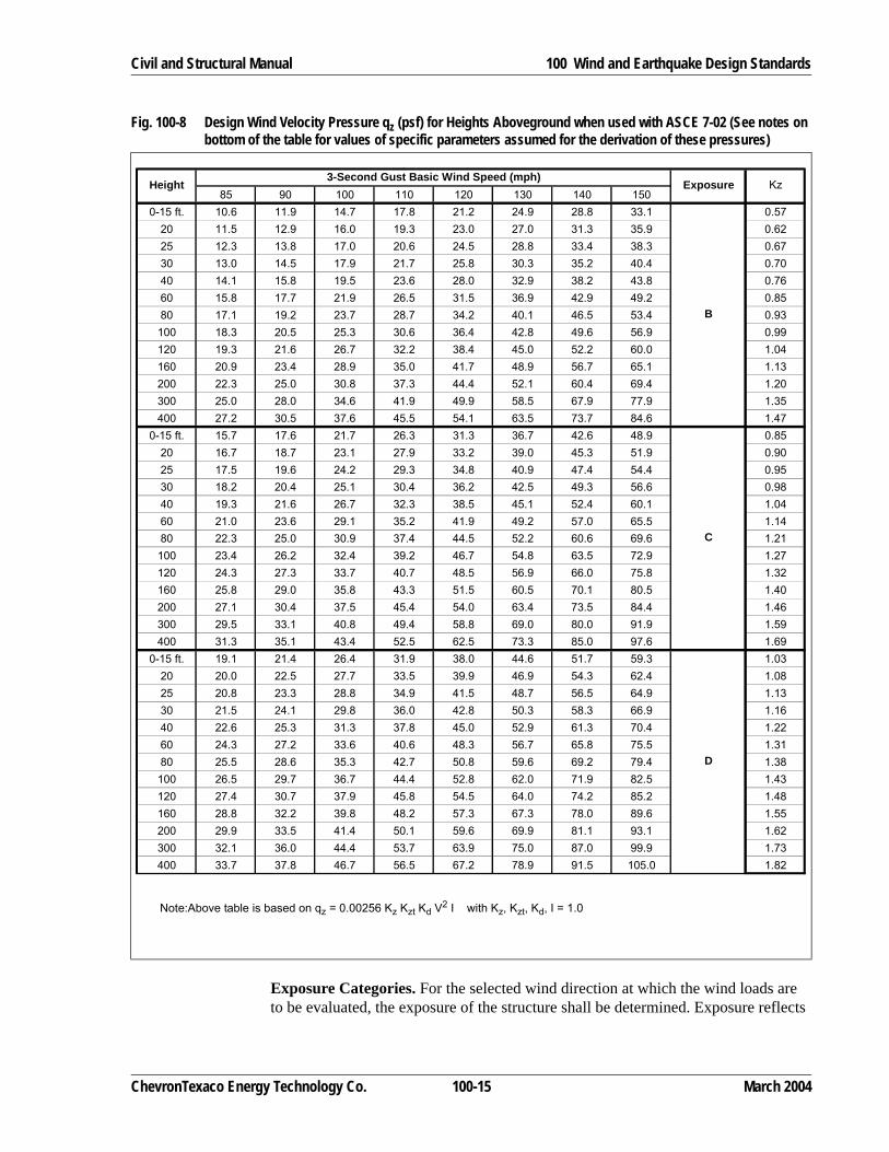
Exposure Categories. For the selected wind direction at which the wind loads are to be evaluated, the exposure of the structure shall be determined. Exposure reflects
Fig. 100-8 Design Wind Velocity Pressure qz (psf) for Heights Aboveground when used with ASCE 7-02 (See notes on bottom of the table for values of specific parameters assumed for the derivation of these pressures)
Note:Above table is based on qz = 0.00256 Kz Kzt Kd V2 I with Kz, Kzt, Kd, I = 1.0
85 90 100 110 120 130 140 1500-15 ft. 10.6 11.9 14.7 17.8 21.2 24.9 28.8 33.1 0.57
20 11.5 12.9 16.0 19.3 23.0 27.0 31.3 35.9 0.6225 12.3 13.8 17.0 20.6 24.5 28.8 33.4 38.3 0.6730 13.0 14.5 17.9 21.7 25.8 30.3 35.2 40.4 0.7040 14.1 15.8 19.5 23.6 28.0 32.9 38.2 43.8 0.7660 15.8 17.7 21.9 26.5 31.5 36.9 42.9 49.2 0.8580 17.1 19.2 23.7 28.7 34.2 40.1 46.5 53.4 0.93100 18.3 20.5 25.3 30.6 36.4 42.8 49.6 56.9 0.99120 19.3 21.6 26.7 32.2 38.4 45.0 52.2 60.0 1.04160 20.9 23.4 28.9 35.0 41.7 48.9 56.7 65.1 1.13200 22.3 25.0 30.8 37.3 44.4 52.1 60.4 69.4 1.20300 25.0 28.0 34.6 41.9 49.9 58.5 67.9 77.9 1.35400 27.2 30.5 37.6 45.5 54.1 63.5 73.7 84.6 1.47
0-15 ft. 15.7 17.6 21.7 26.3 31.3 36.7 42.6 48.9 0.8520 16.7 18.7 23.1 27.9 33.2 39.0 45.3 51.9 0.9025 17.5 19.6 24.2 29.3 34.8 40.9 47.4 54.4 0.9530 18.2 20.4 25.1 30.4 36.2 42.5 49.3 56.6 0.9840 19.3 21.6 26.7 32.3 38.5 45.1 52.4 60.1 1.0460 21.0 23.6 29.1 35.2 41.9 49.2 57.0 65.5 1.1480 22.3 25.0 30.9 37.4 44.5 52.2 60.6 69.6 1.21100 23.4 26.2 32.4 39.2 46.7 54.8 63.5 72.9 1.27120 24.3 27.3 33.7 40.7 48.5 56.9 66.0 75.8 1.32160 25.8 29.0 35.8 43.3 51.5 60.5 70.1 80.5 1.40200 27.1 30.4 37.5 45.4 54.0 63.4 73.5 84.4 1.46300 29.5 33.1 40.8 49.4 58.8 69.0 80.0 91.9 1.59400 31.3 35.1 43.4 52.5 62.5 73.3 85.0 97.6 1.69
0-15 ft. 19.1 21.4 26.4 31.9 38.0 44.6 51.7 59.3 1.0320 20.0 22.5 27.7 33.5 39.9 46.9 54.3 62.4 1.0825 20.8 23.3 28.8 34.9 41.5 48.7 56.5 64.9 1.1330 21.5 24.1 29.8 36.0 42.8 50.3 58.3 66.9 1.1640 22.6 25.3 31.3 37.8 45.0 52.9 61.3 70.4 1.2260 24.3 27.2 33.6 40.6 48.3 56.7 65.8 75.5 1.3180 25.5 28.6 35.3 42.7 50.8 59.6 69.2 79.4 1.38100 26.5 29.7 36.7 44.4 52.8 62.0 71.9 82.5 1.43120 27.4 30.7 37.9 45.8 54.5 64.0 74.2 85.2 1.48160 28.8 32.2 39.8 48.2 57.3 67.3 78.0 89.6 1.55200 29.9 33.5 41.4 50.1 59.6 69.9 81.1 93.1 1.62300 32.1 36.0 44.4 53.7 63.9 75.0 87.0 99.9 1.73400 33.7 37.8 46.7 56.5 67.2 78.9 91.5 105.0 1.82
D
Height Exposure Kz
B
3-Second Gust Basic Wind Speed (mph)
C
ChevronTexaco Energy Technology Co. 100-15 March 2004
100 Wind and Earthquake Design Standards Civil and Structural Manual
the characteristics of ground roughness and surface irregularities. To determine the exposure category, we need to determine the extent and surface roughness of the frontal area upwind of the structure.
Surface roughness category B is for urban and suburban areas with closely spaced obstructions, Surface roughness C is for open terrain with scattered obstructions and includes flat open country, grassland and all water surfaces in hurricane prone regions. Surface roughness category D is for flat, unobstructed areas and water surface outside hurricane-prone regions.
Exposure category B applies to situation where surface roughness category B prevails for a distance of 2630 ft or 10 times the height of the structure, whichever is greater. Exposure category D applies to situations where surface roughness cate-gory D prevails for a distance of 5000 ft or 10 times the height of the structure, whichever is greater. Exposure D shall extend inland from the shoreline for a distance of 660 ft or 10 times the height of the structure, whichever is greater. Anything else including shorelines in hurricane prone regions fall under Exposure Category C.
ASCE 7-02 further requires evaluation for two upwind sectors extending 45 degrees on either side of the selected wind direction. The higher resulting wind load governs. For all practical purpose, if we choose the most severe roughness in the general area upwind of the structure, we would have captured the most severe wind load to the structure.
Design Wind Velocity Pressure Exposure Coefficient, Kz. Wind velocity pres-sure Coefficient Kz is a function of exposure roughness category upwind of the structure and the height at which the evaluation is performed. It has been built into the tabular wind pressure values and also listed in Figure 100-8.
Topographic Factor, Kzt. The topographic factor Kzt accounts for the effect of wind speed-up over hills, ridges, and escarpment. Kzt is 1.0 unless the structure is built behind hills, ridges, or escarpment. In those cases, the value of Kzt, equals to (1 + K1 K2 K3)2, can be determined from ASCE Table 6-4, shown as Figure 100-9.
March 2004 100-16 ChevronTexaco Energy Technology Co.

Civil and Structural Manual 100 Wind and Earthquake Design Standards
Wind Directional Factor, Kd. This factor has been hidden in previous ASCE 7 editions in the form of load combination multiplication factor for wind load. ASCE 7 states that this factor has been taken out from the load factor for the ease of future adjustments. It is for this reason that this factor can only be used with the explicit ASCE load combinations. ASCE 7 load combination also does not permit allow-able stress increase when Allowable Stress Design (ASD) method is used. Since most designers still use ASD, we recommend not taking credit for this factor, i.e. use a Kd factor of 1.0. For completeness, the values of Kd are listed in Figure 100-10.
Fig. 100-9 Wind Topographic Factor Kzt (from ASCE Table 6.4. Used with permission of ASCE from ASCE 7-02)
ChevronTexaco Energy Technology Co. 100-17 March 2004

100 Wind and Earthquake Design Standards Civil and Structural Manual
Note that the proper reduction factor Kd should be used when evaluating founda-tion for overturning.
Gust Effect Factor, G or Gf
Gust effect on the structure depends on its response to the wind dynamics. It is a function of the structure’s fundamental natural frequency (n1) and the system crit-ical damping ratio. See Section 121 for the determination of the natural frequency of structure.
Most structures are “rigid” structures (n1 ≥ 1 hz). Gust effect factor G for rigid structure can be calculated using ASCE Equation 6-4. Note that ASCE permits a value of 0.85 for rigid structures without calculation.
For “flexible” structures (n1 < 1 hz), gust effect factor Gf is given by ASCE Equa-tion 6-8 in Section 6.5.8. Note that for flexible structures, the gust effect factor can be significantly higher than 0.85.
An example structure with height equals to 100 ft and diameter equals to 5 ft is used in Example 8 to illustrate how the gust effect factor varies with natural frequency, exposure category, wind speed and system damping ratio.
Force Coefficient, Cf
This net force coefficient can be viewed as a “shape factor”. For pressure vessels, chimneys, tanks and similar non-building structures, values can be obtained from Figure 100-11. For other type of structures, refer to ASCE 7. Note that additional guidance is also available from the ASCE wind load guidance document (Refer-ence 16) on choosing the appropriate force coefficients for different structures.
Fig. 100-10 Wind Directional Factor Kd (from ASCE Table 6.4. Used with permission of ASCE from ASCE 7-02)
Structure Type Directionality Factor Kd(1)
(1) Directionality Factor Kd has been calibrated with combinations of loads specified in Section 2. This factor shall only be applied when used in conjunction with load combinations specified in 2.3 and 2.4
BuildingsMain Wind Force Resisting SystemComponents and Cladding
0.850.85
Arched Roofs 0.85
Chimneys, Tanks, and Similar StructuresSquareHexagonalRound
0.900.950.95
Solid Signs 0.85
Open Signs and Lattice Framework 0.85
Trussed TowersTriangular, square, rectangularAll other cross sections
0.850.95
March 2004 100-18 ChevronTexaco Energy Technology Co.

Civil and Structural Manual 100 Wind and Earthquake Design Standards
Alternative ChevronTexaco Shape Factor. In lieu of the ASCE 7-02 gust effect factor G (or Gf) and force coefficient Cf as shown above, user can also use the “classic” ChevronTexaco shape factors per Figure 100-3 together with the actual diameter to estimate the wind load. This method has been used successfully at ChevronTexaco in the past for initial load estimates when detailed information is not available. For a comparison of results generated using these methods, user is referred to Example 2A (Figure 100-32, Figure 100-33) and Example 3A (Figure 100-37, Figure 100-38 and Figure 100-39).
ASCE 7 coefficients should be used for detailed calculations when all the piping, platform and other appurtenances are known.
114 Earthquake DesignThese requirements are intended only for use in designing ordinary industrial struc-tures. They are not intended to cover offshore platforms or buildings.
These criteria are adequate for most conditions. However, specific sites may present special seismic hazards, such as soil liquefaction, landslide, surface rupture, and
Fig. 100-11 Force Coefficient Cf for “Other Structures” (from ASCE 7 Figure 6-19. Used with permission of ASCE from ASCE 7-02)
ChevronTexaco Energy Technology Co. 100-19 March 2004

100 Wind and Earthquake Design Standards Civil and Structural Manual
tsunami that require additional design considerations beyond the scope of this docu-ment.
These provisions shall apply to the structure as a unit and also to the individual parts of a structure.
Structural Systems Similar to Buildings (SSSB)A concentric braced frame is a braced frame in which the members are subjected primarily to axial forces.
A shear wall is a wall designed to resist lateral forces parallel to the plane of the wall (sometimes referred to as a vertical diaphragm).
A light-framed wall with shear panels is similar to a shear wall system except the vertical diaphragm is usually light gage metal, i.e., similar to a refinery box furnace.
A moment-resisting space frame is a structural system in which the members and joints are capable of resisting lateral forces primarily by flexure. An ordinary moment-resisting space frame (OMRSF) is a moment-resisting space frame not meeting special detailing requirements for ductile behavior. An intermediate moment-resisting space frame (IMRSF) is a concrete space frame designed in conformance with UBC Section 1921.8. A special moment-resisting space frame (SMRSF) is a moment-resisting space frame specially detailed to provide ductile behavior and comply with the requirements given in UBC Section 1921 for concrete and UBC Chapter 22, Division IV or V for steel.
An induced draft cooling tower is typically a timber structure with some type of internal brace system.
Nonbuilding-Type StructuresThese structures include all self-supporting structures (equipment with integral supports) other than buildings which carry gravity loads and resist the effects of earthquake. Nonbuilding structures also include structures supporting equipment with structural systems similar to buildings (SSSB).
Design Base Shear for StructuresThe determination of design base shear is directly related to the structure’s funda-mental period of vibration, T. The fundamental period of a structure can be deter-mined by rational methods as demonstrated in Section 121, Natural Period of Vibration. Structures with longer periods of vibration, such as stacks, frames, one-column pipe supports, and vertical vessels, will typically be governed by Equation 100-2 below. “Rigid” structures with a short period of vibration, such as short horizontal vessel supports or pump foundations, will typically be governed by Equation 100-6.
It is important to note that the earthquake design forces specified by the 1997 Uniform Building Code are based on strength design; whereas in past editions of the UBC the design forces were based on allowable stress design. Because this section is based on the 1997 UBC, the following equations will provide results which are
March 2004 100-20 ChevronTexaco Energy Technology Co.

Civil and Structural Manual 100 Wind and Earthquake Design Standards
strength design based. If one desires to use allowable stress design, the earthquake forces calculated using the following equations need to be divided by a factor of 1.4.
For structure systems similar to buildings (such as those listed in sections I and II of Figure 100-18) the total design base shear in a given direction shall be:
(Eq. 100-2)
With the conditions that:
(Eq. 100-3)
and
(Eq. 100-4)
In addition, for Seismic Zone 4,
(Eq. 100-5)
For nonbuilding structures (such as those listed in Sections III and IV of Figure 100-18) and having a period, T, less than 0.06 seconds, the total design base shear shall be:
(Eq. 100-6)
For flexible nonbuilding structures (such as those listed in sections III and IV of Figure 100-18), Equation 100-2 and Equation 100-3 shall apply, with the additional stipulations that:
(Eq. 100-7)
and additionally, for Seismic Zone 4,
(Eq. 100-8)
The coefficients used above are defined as follows:
V = Total base shear
Z = Seismic zone factor
I = Occupancy importance factor
VCvIRT--------W=
Vmax2.5CaI
R----------------W=
Vmin 0.11CaIW=
Vmin0.8ZNvI
R--------------------W=
V 0.7CaIW=
Vmin 0.56CaIW=
Vmin1.6ZNvI
R--------------------W=
ChevronTexaco Energy Technology Co. 100-21 March 2004

100 Wind and Earthquake Design Standards Civil and Structural Manual
Ca, Cv = Site-dependent seismic coefficients representing the ground motion
Na, Nv = Near-source factors related to the proximity of the structure to known faults in seismic zone 4
R = Structural system factor
T = Fundamental period of vibration, in seconds, of the structure in the direction under consideration. See Section 121.
W = Total seismic deadload plus operating weight
The Seismic Zone Factor, Z, shall be as specified below for the earthquake zone in which the structure is located. The earthquake zone shall be as listed in Figure 100-12 and shown on Figure 100-13.
Seismic Zone Corresponding Seismic Zone Factor, Z0 0
1 0.075
2A 0.15
2B 0.20
3 0.30
4 0.40
Fig. 100-12 Seismic Zone for Company Locations (1 of 2)(1)
Location Earthquake Zone Na NvCalifornia
Bakersfield/Cymric/McKittrick/Kern River/Taft 4 1.0 1.0
Carpinteria 4 1.3 1.6
El Segundo 4 1.1 1.33
Gaviota 4 1.1 1.33
Richmond 4 1.2 1.6
Colorado
Rangely 1
Hawaii
Barbers Point/Honolulu 2A
Louisiana
Venice/Leeville/Oak Point/Morgan City/Cameron/St. James 0
Mississippi
Pascagoula 0
March 2004 100-22 ChevronTexaco Energy Technology Co.

Civil and Structural Manual 100 Wind and Earthquake Design Standards
Ohio
Marietta 1
Oregon
Willbridge 3
Texas
Cedar Bayou/Houston/Mont Belvieu/
Orange/Port Arthur 0
El Paso 1
Utah
Salt Lake City 3
Washington
Kennewick 2B
Wyoming
Evanston 2B
Rock Springs 1
(1) Near-source factors (Na and Nv) are given for Company locations found in Zone 4 only.
Fig. 100-12 Seismic Zone for Company Locations (2 of 2)(1)
Location Earthquake Zone Na Nv
ChevronTexaco Energy Technology Co. 100-23 March 2004

100 Wind and Earthquake Design Standards
Civil and Structural Manual
March 2004100-24
ChevronTexaco Energy Technology Co.
Fig. 100-13 Seismic Zone Map of the United States (from 1997 ed. of UBC) Reproduced from the 1997 edition of the Uniform Building Code © 1997, with the
permission of the International Conference of Building Officials
Civil and Structural Manual 100 Wind and Earthquake Design Standards
The Occupancy Importance Factor, I, shall be taken as 1.0 for normal non-critical oil industry structures. For critical structures or structures housing or supporting acutely hazardous materials (AHMs), “I” shall be taken as 1.25. See Figure 100-19.
The seismic coefficients, Ca and Cv, shall be determined using Figures 100-14 and 100-15:
Ca and Cv represent the ground motion, and are a function of the seismic zone (Z) and the soil profile type (given in Figure 100-16). In seismic zone 4 only, Ca and Cv are also a function of the near source factors Na and Nv. Na and Nv factors are dependent on the distance of the structure to known active large magnitude faults. The Na and Nv factors for Company locations in seismic zone 4 are given in Figure 100-12.
A review of the Design Response Spectra (shown in Figure 100-17) helps to illus-trate how the seismic coefficients Ca and Cv define the seismic response throughout the spectral range. There are two basic regions to the response spectrum-short period (T < TS) and long period (T > TS). Equation 100-2 represents the curved
Fig. 100-14 Seismic Coefficient Ca (Reproduced from the 1997 edition of the Uniform Building Code © 1997, with the permission of the International Conference of Building Officials)
Seismic Zone Factor, Z
Soil Profile Type Z = 0.075 Z = 0.15 Z = 0.2 Z = 0.3 Z = 0.4SA 0.06 0.12 0.16 0.24 0.32Na
SB 0.08 0.15 0.20 0.30 0.40Na
SC 0.09 0.18 0.24 0.33 0.40Na
SD 0.12 0.22 0.28 0.36 0.44Na
SE 0.19 0.30 0.34 0.36 0.36Na
SF See Footnote(1)
(1) Site-specific geotechnical investigation and dynamic site response analysis shall be performed to determine seismic coeffi-cients for Soil Profile Type SF.
Fig. 100-15 Seismic Coefficient Cv (Reproduced from the 1997 edition of the Uniform Building Code © 1997, with the permission of the International Conference of Building Officials)
Seismic Zone Factor, Z
Soil Profile Type Z = 0.075 Z = 0.15 Z = 0.2 Z = 0.3 Z = 0.4SA 0.06 0.12 0.16 0.24 0.32Nv
SB 0.08 0.15 0.20 0.30 0.40Nv
SC 0.13 0.25 0.32 0.45 0.56Nv
SD 0.18 0.32 0.40 0.54 0.64Nv
SE 0.26 0.50 0.64 0.84 0.96Nv
SF See Footnote(1)
(1) Site-specific geotechnical investigation and dynamic site response analysis shall be performed to determine seismic coeffi-cients for Soil Profile Type SF.
ChevronTexaco Energy Technology Co. 100-25 March 2004

100 Wind and Earthquake Design Standards Civil and Structural Manual
(long period) portion of the response spectrum, while Equation 100-3 represents the flat (short period) portion of the spectrum.
The Structural System Factor, R, reflects the expected earthquake resistance for different types of structures. It is a numerical coefficient which represents the inherent global energy absorbing capability or ductility and overstrength in a partic-ular type of structural system. Values for R for a wide variety of structural systems are presented in Figure 100-18.
Two major types of structural systems exist, e.g., structures similar to buildings, and nonbuilding-type structures, each having a different minimum design requirement.
Fig. 100-16 Site Coefficients (Reproduced from the 1997 edition of the Uniform Building Code © 1997, with the permis-sion of the International Conference of Building Officials)
Soil Profile Type
Soil Profile Name/Generic Description
Average Soil Properties for Top 100 Feet (30 480 mm) of Soil Profile
Shear Wave Velocity Vs feet/second (m/s)
Standard Penetration Test, N [or NCH for cohesionless soil
layers] (blows/foot)Undrained Shear
Strength SU psf (kPa)SA Hard Rock > 5,000
(1,500)--- ---
SB Rock 2,500 to 5,000(760 to 1,500)
SC Very Dense Soil and Soft Rock 1,200 to 2,500(360 to 760)
> 50 > 2,000(100)
SD Stiff Soil Profile 600 to 1,200(130 to 360)
15 to 50 1,000 to 2,000(50 to 100)
SE(1) Soft Soil Profile < 600
(180)< 15 < 1,000
(50)
SF Soil Requiring Site-specific Evaluation. See Section 1629.3.1.
(1) Soil Profile Type SE also includes any soil profile with more than 10 feet (3048 mm) of soft clay defined as a soil with a plasticity index, PI > 20, wmc ≥ 40 percent and su < 500 psf (24 kPa). The Plasticity Index, PI, and the moisture content, wmc, shall be determined in accordance with approved national standards.
March 2004 100-26 ChevronTexaco Energy Technology Co.

Civil and Structural Manual 100 Wind and Earthquake Design Standards
Fig. 100-17 Design Response Spectra (Reproduced from the 1997 edition of the Uniform Building Code © 1997, with the permission of the International Conference of Building Officials)
Fig. 100-18 Structural System Factors (R Factors) (1 of 2)Structural System DescriptionI. STRUCTURAL SYSTEMS SIMILAR TO BUILDINGS (SSSB) Structural System Factor, RSteel Structures
Special moment resisting frame 5.6
Ordinary moment resisting frame 4.5
Braced frame
a. Eccentrically braced frame 5.6
b. Concentrically braced frame 4.5
Inverted pendulum type structure (cantilever column) 2.2
Concrete Structures
Special moment resisting frame 5.6
Intermediate moment resisting frame(1) 4.5
Ordinary moment resisting frame(2) 3.5
Shear wall 4.5
Inverted pendulum type structure (cantilever pier/column) 2.2
ChevronTexaco Energy Technology Co. 100-27 March 2004

100 Wind and Earthquake Design Standards Civil and Structural Manual
II. PIPEWAYS
Steel
Special moment resisting frame 5.6
Ordinary moment resisting frame 4.5
Braced frame (CBF) 4.5
Cantilever column 2.9
Concrete
Special moment resisting frame 5.6
Intermediate moment resisting frame(1) 4.5
Ordinary moment resisting frame(2) 3.5
Cantilever column 2.9
III. EQUIPMENT BEHAVING AS STRUCTURES WITH INTEGRAL SUPPORTS
Vertical vessels/heaters, tanks, or spheres supported by:
Steel skirts 2.9
Steel skirt when tshell/tskirt > 1.5 2.2
Steel braced legs 2.9
Steel or concrete unbraced legs 2.2
Horizontal vessels
Flexible concrete support 2.2
Boilers
Light steel framed wall with shear panels 4.5
Steel braced frame where bracing carries gravity load 4.5
Steel ordinary moment frame 4.5
Chimneys, stacks, or truss covers
Steel guyed 2.9
Steel cantilever 2.9
Concrete 2.9
IV. COOLING TOWERS
Wood frame 5.6
Concrete 3.6(1) Some R values are slightly different than those prescribed by the 1997 UBC. This is in accordance with the ASCE
Publication “Guidelines for Seismic Evaluation and Design of Petrochemical Facilities.”(2) For analysis of existing Moment-Resisting Frames, use R for an Ordinary Moment-Resisting Frame unless a different
value can be justified.(3) If assigning a value of R to a system not itemized in this table, in the absence of a detailed study, use R = 2.1. ETC’s
Civil/Structural Team is available for counsel on this subject.
(1) Prohibited in Seismic Zones 3 and 4, except as permitted in UBC Section 1634.2.(2) Prohibited in Seismic Zones 2A, 2B, 3, and 4.
Fig. 100-18 Structural System Factors (R Factors) (2 of 2)
March 2004 100-28 ChevronTexaco Energy Technology Co.

Civil and Structural Manual 100 Wind and Earthquake Design Standards
Vertical Distribution of Base Shear Force for Free Standing StructuresFor structures having a natural period, T, greater than 0.7 sec., a portion of the total base shear force, V, shall be applied at the top of the structure, as determined by the following equation:
Ft = 0.07 TV (Eq. 100-9)where:
Ft = Portion of base shear applied at the top of the structure.
T = Structure natural period of vibration, sec.
V = Total base shear from appropriate equation (Equation 100-2 through Equation 100-8)
Ft need not exceed 0.25V (applies when T is equal to or greater than 3.57 sec.). If T is less than or equal to 0.7 sec., Ft shall be taken as zero.
The remainder of the total base shear force shall be distributed and applied to the various masses in the structure in accordance with the following equation:
(Eq. 100-10)
where:Fx = Lateral force applied to a mass at level x.
Wx = Weight of the mass at level x.
hx = Height of level x above the base (normally the bottom of the base plate of the structure or portion of the structure being analyzed)
V = Total base shear from appropriate equations (Eq. 100-2 through 100-8)
ΣWh = The sum of the products of Wx and hx for all the masses within the structure.
Vertical Distribution of Base Shear Force for Guyed StructuresWhere guys are used to provide lateral force resistance, the total lateral force shall be distributed to the various masses in direct proportion to their weights and shall be applied at their centers of gravity. See Section 300 for more information on the design of guyed structures.
Horizontal Distribution of Base Shear ForceThe total shear in any horizontal plane shall be distributed to the various resisting elements in proportion to their rigidities, considering the rigidity of the horizontal bracing system or diaphragm as well as the rigidities of the vertical resisting elements. Provision shall be made for the increase in shear resulting from the hori-zontal torsion due to an eccentricity between the center of mass and the center of rigidity. Negative torsional shears may be neglected. In addition, where the vertical resisting elements depend upon diaphragm action for shear distribution at any level,
Fx V Ft–( )WxhxΣWh-------------=
ChevronTexaco Energy Technology Co. 100-29 March 2004

100 Wind and Earthquake Design Standards Civil and Structural Manual
the shear resisting element shall be capable of resisting a torsional moment assumed to be equal to the shear at the level, acting with an eccentricity of not less than 5% of the maximum structure plan dimension at that level.
Details of Earthquake Resistant DesignMuch of the damage sustained in past earthquakes could have been avoided through proper detailing of structural elements and connections. It is important in earth-quake-resistant design to give the structure the ability to absorb energy if loaded to levels above the minimum design. This quality is best achieved by detailing the structural frame, the members, and the connections so that overall structural defor-mation will be ductile rather than brittle. This flexibility is particularly desirable for reinforced concrete construction. Structures should also have a consistent stress level, or margin of reserve strength throughout.
An increased force, Em, shall be used for the design of crucial structural components in the lateral force resisting system such as collector elements, steel connections, and elements supporting discontinuous systems. The symbol Em repre-sents the estimated maximum earthquake force that can be developed in a structure. It is a function of the base shear and the system overstrength, which takes into account factors such as material overstrengths, advantageous collapse mechanisms, and the type of lateral force resisting system. For more information on this topic, contact the ETC Civil/Structural Team.
The following general comments apply to structures and components of structures.
1. Masonry Structures—Always reinforce in accordance with Section 2106 of the Uniform Building Code.
2. Reinforced Concrete Structures—Concrete frames in Seismic Zones 3 and 4 shall be Special Moment Resisting Space Frames (SMRSF). Concrete frames in Seismic Zones 2A and 2B shall be, as a minimum, an Intermediate Moment Resisting Space Frame (IMRSF). Concrete shear walls, braced frames, or moment resisting frames used to resist earthquake forces shall be designed in accordance with Section 1921 of the Uniform Building Code.
3. Steel Structures—Pay special attention to connections. At connections and other points of high stress in rigid frame structures, follow the requirements of the AISC Specification for plastic design regarding width-thickness ratios, lateral bracing, web stiffening, and fabrication. Follow the provisions of Chapter 22, Divisions IV or V of the Uniform Building Code.
4. Vessels, Columns and Spheres—Minimize stress raisers and provide for conti-nuity of reinforcement around openings. Use bracing effective in tension and compression for braced legs of spheres and vertical vessels. Anchor bolts should be sized to resist the maximum predicted earthquake forces. Use the Standard Anchor Bolt Drawing (GD-Q68922) for bolt selection and spacing. This drawing was developed based on a ductile failure criteria. Do not oversize the anchor bolts as this will result in a non-ductile failure.
March 2004 100-30 ChevronTexaco Energy Technology Co.

Civil and Structural Manual 100 Wind and Earthquake Design Standards
5. Foundations—Provide tie beams, reinforced concrete slabs, or other equivalent restraint interconnecting individual footings on piles when the surface soil does not provide adequate lateral restraint.
See Sections 1626 through 1636 of the Uniform Building Code for general earth-quake regulations.
Electrical and Mechanical EquipmentAll equipment and equipment anchorage to foundations or supporting structures shall be designed to resist a minimum lateral earthquake force acting at the center of mass of the equipment. This provision includes such items as switch gear, trans-formers, vessels supported in structures, control panels, etc.
For equipment supported by a structure:
(Eq. 100-11)
With the condition that:
(Eq. 100-12)
(Eq. 100-13)where:
For rigid equipment supported at grade (such as a transformer, switchgear, etc.):
(Eq. 100-14)
Fp = Design lateral earthquake force
IP = Seismic importance factor (See Figure 100-19)
Wp = Total operating weight of equipment
ap = In-Structure Component Application Factor (from Figure 100-20)
Rp = Component Response Modification Factor (from Figure 100-20)
hx = element or component attachment elevation with respect to grade. hx shall not be less than 0.0
hr = structure roof elevation with respect to grade
Fig. 100-19 Seismic Importance Factor
Description I IP
Equipment required for life safety systems 1.25 1.5
Items containing sufficient quantities of acutely hazardous material whose failure could result in off-site consequences.
1.25 1.5
All other equipment or normal non-critical structures 1.0 1.0
Critical structures 1.25 1.5
FpapCaIp
Rp----------------- 1 3
hxhr-----+
⎝ ⎠⎜ ⎟⎛ ⎞
Wp=
Fpmin 0.7CaIpWp=
Fpmax 4.0CaIpWp=
Fp 0.7CaIpWp=
ChevronTexaco Energy Technology Co. 100-31 March 2004

100 Wind and Earthquake Design Standards Civil and Structural Manual
Direct anchorage through anchor bolts shall be provided where possible. For shallow expansion anchor bolts, use Rp = 1.5. For nonductile or adhesive anchor bolts, use Rp = 1.0. In situations where anchor bolt connections are impractical, a welded ductile connection between equipment and support may be provided. A ductile connection shall be defined as one that will undergo inelastic deformation through yielding before the connection fails. The direct welding of rigid equipment to a rigid foundation or support is not recommended.
Appendix H indicates the appropriate base shear equations that should be used for many typical refinery structures and types of equipment. Appropriate R values are also included.
DisplacementThere is no specific code requirement which limits the lateral displacement/drift in industrial structures. However, it is recommended that the lateral displacement be limited to a displacement that can be tolerated by the equipment being supported, including the associated piping and other appurtenances.
The Maximum Inelastic Response Displacement, ∆M, corresponds to the maximum deformations of a structure responding in the inelastic range. In order to calculate ∆M, the design level displacement (∆S) is simplified to the inelastic level using the following equation:
(Eq. 100-15)where:
∆M is as defined above
∆S is the displacement corresponding to the code-level design seismic forces
R is the structural system factor.
The analysis used to determine the Maximum Inelastic Response Displacement (∆M) shall consider P∆ effects. For guidance on this subject, contact the ETC Civil/Structural Team.
Fig. 100-20 Horizontal Force Factors (ap and Rp)
Equipment Description ap Rp
1. Vessels (including contents), and their support systems 1.0 3.0
2. Electrical, mechanical, and plumbing equipment and associated conduit and duct-work and piping such as switchgears, transformers, pumps, and air-handling units.
1.0 3.0
NOTE:Refer to UBC Table 16-0 for a more extensive listing of horizontal force factors.
∆M 0.7R∆S=
March 2004 100-32 ChevronTexaco Energy Technology Co.

Civil and Structural Manual 100 Wind and Earthquake Design Standards
Earthquake LoadsTo design a structure, calculate the forces to be applied to each element of the struc-ture. The earthquake load (E) on an element of a structure is a result of the combina-tion of the horizontal component (Eh) and the vertical component (Ev), and can be calculated using the following equation:
(Eq. 100-16)where:
ρ = redundancy/reliability factor
= 1.0 for nonbuilding structures and for structures in seismic zone 0, 1, or 2
≥ 1.0 for structural systems similar to buildings (SSSB) in seismic zone 3 or 4
Eh = earthquake load due to either the base shear (V) or the design lateral force (Fp)
Ev = the load effect resulting from the vertical component of the earth-quake ground motion
= 0.5CaID for Strength Design
= 0 for Allowable Stress Design
The intent of the ρ factor is to encourage the design of redundant lateral force resisting structures by penalizing non-redundant structures. There are a number of important benefits to redundancy, one of the most evident being that the failure of any single element in a non-redundant structure can produce global structural collapse. Therefore, in order to obtain good seismic performance, the lateral resis-tance should be distributed throughout the structure so that failure of any single element will not result in collapse of the entire structure. The ρ factor varies between 1.0 and 1.5, and takes into account the number of lateral force resisting elements, the plan area of the structure, and the distribution of the forces to the lateral force resisting elements. For a structure with an adequate level of redun-dancy, the ρ factor would be equal to 1.0; whereas a structure with poor overall redundancy could have a ρ factor of up to 1.5, resulting in design forces that are 50% higher than otherwise required. Contact the ETC Civil/Structural Team for guidance on this subject.
Analysis of Existing FacilitiesThese Design Standards are intended to apply to the design of new facilities. In general, structures and equipment properly designed in accordance with earlier codes need not be redesigned to meet the present Wind and Earthquake Design Standards. However, when any significant modification is made or weight is added to an existing structure, the design should be reviewed. If required, the structure should be modified to meet the requirements of the appropriate building code.
Although current building codes do not require the upgrading of existing facilities, in keeping with Corporate Policy 530 for Safety, Fire, Health, and the Environment,
E ρEh Ev+=
ChevronTexaco Energy Technology Co. 100-33 March 2004

100 Wind and Earthquake Design Standards Civil and Structural Manual
it may be appropriate to review the design of facilities in critical service. A portion of that policy instructs management to “conduct scientific hazard and risk assess-ments, as needed, to identify, characterize, and safely manage any present or future potential hazards of Company products and operations.”
A critical facility is defined as one for which a major failure would cause one of the following:
1. Develop a condition which would result in serious injury or death.
2. Result in damage to the environment significantly beyond that which the earth-quake would cause at the site.
3. Result in appreciable loss of revenue.
To evaluate the risk of a critical facility, the following steps are recommended:
1. Determine the existing strength of the structures.
2. Make a judgment as to whether the existing strength is acceptable in light of current conditions, including the types of risk factors previously noted.
The judgments required to determine acceptability should include evaluation of structural redundancy and reserve strength. The assessment of existing facilities for earthquake capacity is not commodity engineering and should be done by qualified personnel.
Since most assessments of existing facilities are voluntary efforts to mitigate poten-tial business risks, it is not always necessary or even beneficial to measure a struc-ture’s acceptability against the current building code requirements. ETC’s Civil/Structural Technical Service Team has performed many seismic assessments of Company owned facilities utilizing “Proposed Guidance for Risk Management and Prevention Program (RMPP) Seismic Assessments.” This document was devel-oped in 1992 by a team of technical experts and industry professionals to aid in the assessment of seismic risk at existing industrial facilities. In 1998, this document was revised and renamed “Proposed Guidance for California Accidental Release Prevention (CalARP) Program Seismic Assessments.”
“Proposed Guidance for CalARP Seismic Assessments” evaluates the ultimate strength capacity of existing structures. The ultimate strength capacity of a structure is defined here as the ability of a structure to perform inelastically while avoiding failure. The ultimate strength must be compared to the expected structural demand resulting from the expected levels of ground shaking at the site. The CalARP guide-lines utilize the same level of acceptable risk as that defined in the current UBC, i.e., the level of ground motion associated with a 10 percent chance of exceedance in 50 years.
For facilities with unacceptably low strength, one of the following should be considered:
1. Strengthen the facility2. De-rate the facility to lower the risk of failure. For example, reduce the safe
operating height for tanks.ETC’s Civil/Structural Technical Service Team is available for counsel regarding these procedures and judgments.
March 2004 100-34 ChevronTexaco Energy Technology Co.
Civil and Structural Manual 100 Wind and Earthquake Design Standards
115 Allowable Stresses, Soil Bearing, and Stability Ratios
Allowable Stresses for Structural MembersThe allowable stresses for structural members for loading conditions including wind or earthquake loads shall be one-third greater than the stresses allowed for normal conditions of loading by applicable structural design codes.
Stability RatioThe stability ratio of the resisting moments about the edge of a foundation to the overturning moment due to wind loads shall not be less than 1.5.
The stability ratio for earthquake loads shall not be less than 1.0 and the force Ft, if applicable, may be omitted when determining the earthquake overturning moment to be resisted at the foundation-soil interface.
Foundation Soil Bearing PressuresFoundation soil bearing pressures for loading conditions including wind or earth-quake loads should be based on sound engineering principles taking into account the nature of the subsoil and distribution of the load. In the absence of other criteria, the allowable soil bearing pressures may be increased by one-third when considering wind or earthquake forces acting alone or when combined with vertical loads.
Allowable Stresses in Pressure Vessel Shells and SkirtsSee the Pressure Vessel Manual for allowable stresses in pressure vessels subject to wind or earthquake loads. Allowable stresses for loading conditions including wind or earthquake loads are typically higher than stresses allowed for normal conditions.
120 Methods and Calculations
121 Natural Period of VibrationIn the design of flexible structures for earthquake loads and wind-induced vibra-tion, it is necessary to determine the first mode natural period of vibration of the structure. The following figures (Figures 100-21 through 100-27), and their accom-panying equations give the natural period of vibration for several types of industrial structures. Texts about dynamics of structures tell how to find the periods of more complex structures. Computer programs with dynamic structural analysis capabili-ties can also determine periods of structural vibration.
The units used throughout the following formulas must be consistent except where otherwise noted.
Equation 100-23 in Figure 100-27 is an approximate formula which is sufficiently accurate for most non-uniform distillation columns and vertical vessels. If a vessel has a lower section several times the diameter of the upper portions, and the lower portion is short compared with the overall height (such as a vertical seal drum on which is mounted a self-supporting flare or vent stack), the period can be more
ChevronTexaco Energy Technology Co. 100-35 March 2004

100 Wind and Earthquake Design Standards Civil and Structural Manual
accurately determined by finding the period of the upper portion, assuming that displacement and rotation are fixed at its junction with the lower section. For vessels where the shell diameter or thickness is large in comparison with the supporting skirt, such as for high pressure reactors, the period calculated from Equation 100-23 may be overly conservative for earthquake design, and more accu-rate methods may be justified.
The equations presented in this section ignore the effects of soil-structure inter-action. Soil-structure interaction can have a profound effect on the natural period of large vertical vessels on individual pile-supported foundations. All critical calculations for such vessels should consider this dynamic phenom-enon. The ETC Civil/Structural Technical Service Team may be consulted in these cases.
• Figure 100-21 gives the general formula for determining the natural period of vibration, T, for a one mass structure.
• Figure 100-22 gives the equation for determining the natural period of vibra-tion for a one mass, Bending Type Structure.
• Figure 100-23 gives the equations for a one mass, rigid frame-type structure.
• Figure 100-24 gives the equation and parameters for determining the natural period of vibration for a two mass structure.
• Figure 100-25 gives the equation for a bending type structure of uniform weight distribution and constant cross section.
• Figure 100-26 gives the equation for the natural period of vibration for a uniform vertical cylindrical steel vessel.
• Figure 100-27 gives the equation for the natural period of vibration for a non-uniform vertical cylindrical vessel.
• Figure 100-28 lists the coefficients for determining the natural period of vibra-tion of free-standing cylindrical shells with varying cross sections and mass distribution.
Fig. 100-21 Natural Period of Vibration - One Mass Structure
(Eq. 100-17)
where:y = static deflection of mass resulting from a lateral load applied at the
mass equal to its own weight.
g = acceleration due to gravity.
See Examples 4 and 5 for application.
T 2π yg---⎝ ⎠⎛ ⎞ 0.5
=
March 2004 100-36 ChevronTexaco Energy Technology Co.

Civil and Structural Manual 100 Wind and Earthquake Design Standards
Fig. 100-22 Natural Period of Vibration - One Mass, Bending Type Structure
Fig. 100-23 Natural Period of Vibration - One Mass, Rigid Frame Type Structure
(Eq. 100-18)
(Eq. 100-19)
ChevronTexaco Energy Technology Co. 100-37 March 2004

100 Wind and Earthquake Design Standards Civil and Structural Manual
Fig. 100-24 Natural Period of Vibration - Two Mass Structure
Fig. 100-25 Natural Period of Vibration - Bending Type Structure, Uniform Weight Distribution and Constant Cross Section
(Eq. 100-20)
(Eq. 100-21)
March 2004 100-38 ChevronTexaco Energy Technology Co.

Civil and Structural Manual 100 Wind and Earthquake Design Standards
Fig. 100-26 Natural Period of Vibration - Uniform Vertical Cylindrical Steel Vessel
Fig. 100-27 Natural Period of Vibration - Non-uniform Vertical Cylindrical Vessel Courtesy of the James F. Lincoln Arc Welding Foundation
(Eq. 100-22)
(Eq. 100-23)
ChevronTexaco Energy Technology Co. 100-39 March 2004

100 Wind and Earthquake Design Standards
Civil and Structural Manual
March 2004100-40
ChevronTexaco Energy Technology Co.
Fig. 100-28 Coefficients for Determining Period of Vibration of Free-Standing Cylindrical Shells Having Varying Cross Sections and Mass Distribution Courtesy
α β γ.30 0.010293 0.16200 0.7914
.29 0.008769 0.14308 0.7776
.28 0.007426 0.12576 0.7632
.27 0.006249 0.10997 0.7480
.26 0.005222 0.09564 0.7321
.25 0.004332 0.08267 0.7155
.24 0.003564 0.07101 0.6981
.23 0.002907 0.06056 0.6800
.22 0.002349 0.05126 0.6610
.21 0.001878 0.04303 0.6413
.20 0.001485 0.03579 0.6207
.19 0.001159 0.02948 0.5992
.18 0.000893 0.02400 0.5769
.17 0.000677 0.01931 0.5536
.16 0.000504 0.01531 0.5295
.15 0.000368 0.01196 0.5044
.14 0.000263 0.00917 0.4783
.13 0.000183 0.00689 0.4512
.12 0.000124 0.00506 0.4231
.11 0.000081 0.00361 0.3940
.10 0.000051 0.00249 0.3639
.09 0.000030 0.00165 0.3327
.08 0.000017 0.00104 0.3033
.07 0.000009 0.00062 0.2669
.06 0.000004 0.00034 0.2323
.05 0.000002 0.00016 0.1966
.04 0.000001 0.00007 0.1597
.03 0.000000 0.00002 0.1216
.02 0.000000 0.00000 0.0823
.01 0.000000 0.00000 0.0418
0. 0. 0. 0.
x---
of the James F. Lincoln Arc Welding Foundation
α β γ α β γ1.00 2.103 8.347 1.000000 0.65 0.3497 2.3365 0.99183 0
0.99 2.021 8.121 1.000000 0.64 0.3269 2.2400 0.99065 0
0.98 1.941 7.898 1.000000 0.63 0.3052 2.1148 0.98934 00.97 1.863 7.678 1.000000 0.62 0.2846 2.0089 0.98789 0
0.96 1.787 7.461 1.000000 0.61 0.2650 1.9062 0.98630 0
0.95 1.714 7.248 0.999999 0.60 0.2464 1.8068 0.98455 0
0.94 1.642 7.037 0.999998 0.59 0.2288 1.7107 0.98262 0
0.93 1.573 6.830 0.999997 0.58 0.2122 1.6177 0.98052 00.92 1.506 6.626 0.999994 0.57 0.1965 1.5279 0.97823 0
0.91 1.440 6.425 0.999989 0.56 0.1816 1.4413 0.97573 0
0.90 1.377 6.227 0.999982 0.55 0.1676 1.3579 0.97301 0
0.89 1.316 6.032 0.999971 0.54 0.1545 1.2775 0.97007 0
0.88 1.256 5.840 0.999956 0.53 0.1421 1.2002 0.96688 00.87 1.199 5.652 0.999934 0.52 0.1305 1.1259 0.96344 0
0.86 1.143 5.467 0.999905 0.51 0.1196 1.0547 0.95973 0
0.85 1.090 5.285 0.999867 0.50 0.1094 0.9863 0.95573 0
0.84 1.038 5.106 0.999817 0.49 0.0998 0.9210 0.95143 0
0.83 0.988 4.930 0.999754 0.48 0.0909 0.8584 0.94683 00.82 0.939 4.758 0.999674 0.47 0.0826 0.7987 0.94189 0
0.81 0.892 4.589 0.999576 0.46 0.0749 0.7418 0.93661 0
0.80 0.847 4.424 0.999455 0.45 0.0678 0.6876 0.93097 0
0.79 0.804 4.261 0.999309 0.44 0.0612 0.6361 0.92495 0
0.78 0.762 4.102 0.999133 0.43 0.0551 0.5872 0.91854 00.77 0.722 3.946 0.998923 0.42 0.0494 0.5409 0.91173 0
0.76 0.683 3.794 0.998676 0.41 0.0442 0.4971 0.90448 0
0.75 0.646 3.645 0.998385 0.40 0.0395 0.4557 0.89679 00.74 0.610 3.499 0.998047 0.39 0.0351 0.4167 0.88864 0
0.73 0.576 3.356 0.997656 0.38 0.0311 0.3801 0.88001 0
0.72 0.543 3.217 0.997205 0.37 0.0275 0.3456 0.87088 00.71 0.512 3.081 0.996689 0.36 0.0242 0.3134 0.86123 0
0.70 0.481 2.949 0.996101 0.35 0.0212 0.2833 0.851050.69 0.453 2.820 0.995434 0.34 0.0185 0.2552 0.84032
0.68 0.425 2.694 0.994681 0.33 0.0161 0.2291 0.82901
0.67 0.399 2.571 0.993834 0.32 0.0140 0.2050 0.817100.66 0.374 2.452 0.992885 0.31 0.0120 0.1826 0.80459
hxH-----
hxH-----
hH--

Civil and Structural Manual 100 Wind and Earthquake Design Standards
122 Wind-Induced Vibration of Steel Stacks and Columns
IntroductionWelded steel stacks and other tall, cylindrical structures such as fractionating columns are susceptible to large-amplitude oscillations during steady winds of moderate velocity. These oscillations occur transverse to the mean wind direction and are driven by the vortices which form the downstream wake. The amplitude of the oscillations is inversely related to the mass and damping of the structure. Unac-ceptable oscillations are most likely to be encountered with lightly damped struc-tures, such as welded steel stacks on rigid foundations, and less likely with lined stacks, riveted structures, concrete stacks, or columns containing process fluids.
The following is a method for design to avoid wind-induced oscillations for tall cylindrical structures, including guyed stacks. The method is based on a conserva-tive interpretation of available data, and will produce reliable results when used with realistic estimates of structural damping.
Ovalling vibration of thin walled stacks must also be checked.
Critical Wind VelocityThe design objective is to have the Critical Wind Velocity (Uc) be greater than the Design Wind Velocity (Ud), thereby eliminating wind-induced vibration.
The Critical Wind Velocity is the lowest velocity at which wind-induced oscilla-tions occur. It is computed as follows:
1. Determine the natural fundamental period (T) of the structure (See Section 121)
2. Using the outside diameter of the stack (D), find the Critical Wind Velocity (Uc):
(Eq. 100-24)
3. Determine the Mean Steady Wind Velocity (Um) at the site, sustained for approximately 10 minutes. This wind velocity should be referenced to a partic-ular height above grade (Z), which is 30 feet in most meteorological data. Note: This is not the “Wind Speed Zone” used in Section 113 or the Base Shear “Z” used in Section 114.
4. Determine the Mean Steady Wind Velocity (Ut) at the top of the stack (H):
(Eq. 100-25)
5. Calculate the Design Wind, (Ud):
Ud = 3Ut (Eq. 100-26)If Uc > Ud, then the stack is not susceptible to wind-induced oscillation. If Uc < Ud, the following design check is required.
Uc4.7D
T------------=
Ut UmHZ----⎝ ⎠⎛ ⎞ 0.28
=
ChevronTexaco Energy Technology Co. 100-41 March 2004

100 Wind and Earthquake Design Standards Civil and Structural Manual
Design CheckThe design objective is to have the Design Damping Coefficient (Cd) be less than the Structural Damping Coefficient (Cs) so wind-induced vibration amplitudes will not exceed acceptable limits.
The Design Damping Coefficient (Cd) and the Structural Damping Coefficient (Cs) are determined as follows.
1. Select an allowable vibration amplitude, Ya, which represents the amplitude of vibrations that could be sustained indefinitely without fatigue damage to the stack. Use this method to find a good approximation for Ya.
a. Define allowable stress range (Fr) for infinite life. For shells with butt welded circumferential joint, Fr is 16 ksi. For shells with fillet welded circumferential joint, Fr is 5 ksi. For other types of connections, refer to the tables in the AISC Manual of Steel Construction, Part 5, Appendix K4.
b. Determine stress per unit-deflection (Fm) for the fundamental mode shape of the stack. This may be approximated by:
Fm = 1.2 Fw / Yw (Eq. 100-27)where:
Fw = the maximum change in stress from a static condition due to design wind load only.
Yw = The maximum deflection from a static condition due to the design wind load only.
c. Let:
Ya = (Fr/2Fm) (Eq. 100-28)Note that allowable stress range is divided by two to get single amplitude allowable stress.
2. Compute Mr:
(Eq. 100-29)
w = Weight/unit length of the top one-third of the stack. If variable, average the weight over the top one-third of the stack.
λ = Weight density of air times π/4 = 0.076 lb/ft3 x π/4 = 0.06 lb/ft3
D = Diameter of the top one-third of the stack. If variable, take the square root of the length-weighted average of the squared values of the diameters over the top one-third. For example, for two sections:
(Eq. 100-30)
Mrw
λD2----------=
DD1
2l1 D22l2+
l1 l2+( )------------------------------
0.5
=
March 2004 100-42 ChevronTexaco Energy Technology Co.

Civil and Structural Manual 100 Wind and Earthquake Design Standards
3. Compute Design Minimum Required Damping Coefficient (Cd):
(Eq. 100-31)
α = A shape factor; use 1.3 for the fundamental mode of cantilever structures.
4. Select a Structural Damping Coefficient (Cs) by adding the appropriate frac-tions listed below (other values for structural damping may be used if they can be substantiated):
For example, a stack with refractory lining on a 2000 psf foundation would have:
Cs = 0.003 + 0.002 + 0.002 = 0.007.
5. If Cd < Cs, then wind-induced vibration amplitudes will not exceed acceptable limits. If Cd > Cs, then design alternatives must be considered.
Design Alternatives1. Lower H/D or increase t, stack wall thickness (to raise Uc above Ud.)
2. Increase t or refractory line stack (to increase Mr and Cs.)
3. Attach helical spoilers to the top third of the stack. Conservative guidelines for spoiler design are:
a. Spoilers shall consist of three helical strakes over the top third of the stack with a pitch of 5D and a height of 0.12D.
Cd0.45Mr
---------- αDYa-------- 1.0–⎝ ⎠⎛ ⎞ 0.5
=
Factor Incremental Damping FractionBasic Stack 0.003Refractory 0.002Basic Column
–Empty 0.008–With Liquid Content 0.013
Foundation soil strength:less than 1500 psf 0.0061500 psf to 3000 psf 0.002greater than 3000 psf 0.0
Pile-supported stacks 0.0Stacks supported atop structures 0.0
ChevronTexaco Energy Technology Co. 100-43 March 2004

100 Wind and Earthquake Design Standards Civil and Structural Manual
b. A conservative estimate for Design Minimum Damping Fraction for a stack with spoilers is:
(Eq. 100-32)
Spoilers will be effective if Cs > Cd. A lower value of Cd may be used if it can be justified.
Note that spoilers increase the effective area and shape factor for static wind load, which must be accounted for in the design.
4. Attach a damping device to the stack. Several such devices have been used. Two proven alternatives are hydraulically tensioned guys, and chain impact dampers.
If Design Minimum Damping is close to the required minimum, so that short dura-tions of wind-induced vibration will not result in damage, then a reasonable alterna-tive is to design an auxiliary damping system and provide attachments to the stack (i.e., padeyes), but defer fabrication and installation of the dampers until after the stack is erected and actual unacceptable vibration amplitudes have been observed.
Ovalling Vibration of Thin-walled StacksThin-walled stacks are also susceptible to ovalling vibrations, i.e., oscillations where the stack cross-section vibrates as a ring. The same aeroelastic phenomena described in the introduction to this section create this mode of vibration. Ovalling, however, can be directly prevented by the addition of circumferential stiffeners to the stack.
Criteria for avoiding ovalling is:
If (Eq. 100-33)
where:t = stack wall thickness, inch
R = stack radius, inch
Ud = Design Wind (see Equation 100-26), fps
If stiffeners are required:
1. Choose a spacing of stiffeners, L, such that:
(Eq. 100-34)
Cd0.30Mr
----------=
tR---
Ud10200--------------- stiffeners are required<
4 LR--- 6≤ ≤
March 2004 100-44 ChevronTexaco Energy Technology Co.

Civil and Structural Manual 100 Wind and Earthquake Design Standards
2. Calculate the required moment of inertia, Ir (in4), of the added stiffener section about its center of gravity axis by
(Eq. 100-35)
where:E = modulus of elasticity at operating temperature in psi
D = Diameter in feet
R = Radius in inches
3. Select the stiffener section to provide this Ir. Usually a flat projecting circum-ferential bar will do this efficiently.
4. Check that stack thickness, t, is large enough to avoid possible vibration of the shell between stiffeners.
t > 0.003 R (Eq. 100-36)
Example CalculationsSee Section 123, Examples 6 and 7, for a demonstration of the methodology for analyzing wind-induced vibration of steel stacks
123 Examples of Wind and Earthquake Load CalculationsFollowing are eleven examples of wind and earthquake load calculations for several different structures and supports. These examples are:
IrUd
2.5D------------
2 0.00334LtR4
E--------------------------------=
Example 1 Two-Story Concrete Vessel Support Structure per UBC 1997(Assume El Segundo, CA Location)
Example 2 Uniform Cylindrical Column per UBC 1997(Assume El Segundo, CA Location)
Example 2A Uniform Cylindrical Column per ASCE 7-02 (Assume El Segundo, CA Location)
Example 3 Column of Variable Cross Section per UBC 1997 (Assume Salt Lake City, UT Location)
Example 3A Column of Variable Cross Section per ASCE 7-02 (Assume Salt Lake City, UT Location)
Example 4 Braced-Column Spheres per UBC 1997(Assume Richmond, California, Location)
Example 5 Vertical Vessels with Unbraced Legs per UBC 1997(Assume Richmond, CA Location)
Example 6 Stack Vibration and OvallingExample 7 Stack VibrationExample 8 Effect of Various ASCE 7-02 Wind Load Design Variables on
Gust Effect Factor
ChevronTexaco Energy Technology Co. 100-45 March 2004

100 Wind and Earthquake Design Standards Civil and Structural Manual
Note The earthquake design forces specified by the 1997 UBC are based on strength design; whereas in past editions of UBC the design forces were based on allowable stress design. Therefore, in order to be consistent with the 1997 UBC, examples 1-5 are strength design based. If you want to use allowable stress design, the calculated earthquake forces should be divided by a factor of 1.4.
Example 1—Two-Story Concrete Vessel Support Structure per 1997 UBC (Assume El Segundo, CA Location)
Earthquake Forces on structure as shown in Figure 100-29 (Transverse direction—Loads on one bent)
W = 20 kips (includes structure weight)
Deflections from 1 kip at A and B (calculations not shown):
Caa = 0.0384 in., Cab = 0.0180 in., Cbb = 0.0157 in.
Example 9 Comparison of Wind Loads with UBC 1997 and ASCE Various Editions for Pascagoula, MS and Port Arthur, TX
Fig. 100-29 Two-Story Concrete Vessel Support Structure—SMRSF, EQ Zone 4, Wind Zone 70 MPH
March 2004 100-46 ChevronTexaco Energy Technology Co.

Civil and Structural Manual 100 Wind and Earthquake Design Standards
Use Equation 100-20
(Eq. 100-2)
Z = 0.40 (Seismic Zone 4)
I = 1.0
Assume Type Sc soil.
For El Segundo, Na = 1.1 and Nv = 1.33 (Figure 100-12)
Check vs. Vmax:
(Eq. 100-3)
Note If it is desired to use allowable stress design, the base shear value (V = 3.93K) should be divided by 1.4.
(Eq. 100-10)
Base Moment, Mo = (2.95) (20) + (0.98) (10) = 68.2 k-ft.
T 2 3.14( )12 0.0384( ) 8 0.0157( ) 12 0.0384( ) 8 0.0157( )–[ ]2 4 12( ) 8( ) 0.0180( )2+[ ]0.5
+ +2 386( )
---------------------------------------------------------------------------------------------------------------------------------------------------------------------------------------------------⎩ ⎭⎨ ⎬⎧ ⎫
0.5
=
0.234 sec 0.06 sec>=
Use V∴CvIRT--------W=
Ca 0.40Na 0.40 1.1( ) 0.44 (Figure 100-14)= = =∴
Cv 0.56Nv 0.56 1.33( ) 0.745= = = Figure 100-15( )
R 5.6 (Figure 100-11) Special Moment-Resisting Space Frame - Concrete=
VCvIRT--------W 0.745( ) 1.0( )
5.6( ) 0.234( )------------------------------- 20( ) 11.17 kip Total Base Shear= = =
Vmax2.5CaI
R----------------W=
2.5( ) 0.44( ) 1.0( )5.6
---------------------------------------- 20( )=
3.93k=Vmax∴ controls!
Use V 3.93k=
T 0.7 sec., therefore Ft≤ 0.0=
WAhA 12 20( ) 240 WBhB; 8 10( ) 80 ΣWh; 320= = = = =
FA VWAhAΣWh
---------------- 3.93( )240320--------- 2.95 kip FB;
WBhBΣWh
---------------- 3.93 80320--------- 0.98 kip= = = = = =
ChevronTexaco Energy Technology Co. 100-47 March 2004

100 Wind and Earthquake Design Standards Civil and Structural Manual
Wind Forces (Transverse direction—Loads on one bent). Assume wind speed zone = 70, Exposure B.
Shape Factors: Vessels = 1.4; Open Framework Structures = 1.3
Base Overturning Moment = (0.64) (20) + (0.41) (10) = 16.9 k-ft
Therefore, the Earthquake Moment controls the design.
Example 2—Uniform Cylindrical Column per 1997 UBC (Assume El Segundo, CA Location)In most columns of constant diameter, the entire mass can be assumed uniformly distributed over the height. Where there are large concentrations of mass or varia-tions in cross-section, the analysis should be made as shown in Example 3.
FA
1.4 9( ) 4 202
------⎝ ⎠⎛ ⎞ 1.3 8( ) 1.5 11
2------⎝ ⎠⎛ ⎞ 1.0 10
2------⎝ ⎠⎛ ⎞++
1 000,-------------------------------------------------------------------------------------------------------------- 0.64 kip= =
FB
1.4 8( ) 2 152
------⎝ ⎠⎛ ⎞ 1.3 8( ) 1.5 11
2------⎝ ⎠⎛ ⎞ 1.0 10
2------ 10+⎝ ⎠⎛ ⎞++
1 000,-------------------------------------------------------------------------------------------------------------------------- 0.41 kip Total Shear 1.05 kip= = =
Fig. 100-30 Uniform Cylindrical Column: Earthquake Forces
March 2004 100-48 ChevronTexaco Energy Technology Co.

Civil and Structural Manual 100 Wind and Earthquake Design Standards
Period of Vibration:
(Eq. 100-22)
Z = 0.4 (Zone 4); Importance Factor, I = 1.0
Na = 1.1; Nv = 1.33 (From Figure 100-12).
Assume Type Sc soil.
From Figures 100-14 and 100-15,
Ca = 0.40Na = 0.40(1.1) = 0.44
Cv = 0.56Nv = 0.56(1.33) = 0.745
(Eq. 100-2)
(Eq. 100-0)
Check Vmin:
(Eq. 100-7)
Also, for Zone 4:
(Eq. 100-8)
Note If it is desired to use allowable stress design, the base shear value (V = 23.21k) should be divided by 1.4.)
T 7.78106---------- 100
6---------⎝ ⎠⎛ ⎞ 2 12 600 6××
0.25------------------------------⎝ ⎠⎛ ⎞ 0.5
0.898 sec= =
tvesseltskirt
--------------- 0.6250.25
------------- 2.5 and 2.5 1.5 therefore, use R 2.2= (from Figure 100-18),>= =
W wH 600 lb ft⁄( ) 100 ft( ) 60 000 lb, 60 kip= = = =
Base Shear, VCVIRT---------W 0.745( ) 1.0( )
2.2( ) 0.898( )------------------------------- 60 kip( ) 22.63 kips= = =
Check Vmax2.5CaI
R----------------W 2.5( ) 0.44( ) 1.0( )
2.2---------------------------------------- 60( ) 30.0 kip= = =
Vmin 0.56CaIW=
0.56 0.44( ) 1.0( ) 60( )=14.78kips=
Vmin1.6ZNVI
R---------------------W=
1.6 0.4( ) 1.33( ) 1.0( )2.2
------------------------------------------------ 60( )=
23.21kips=Vmin∴ controls! Use V 23.21 kips=
ChevronTexaco Energy Technology Co. 100-49 March 2004

100 Wind and Earthquake Design Standards Civil and Structural Manual
T > 0.7 sec, therefore Ft = 0.07 TV = 0.07(0.898)(23.21) = 1.46 kip (Eq. 100-9)
V-Ft = 21.75 kip
When the weight is distributed uniformly along the height, the distribution of the lateral force V-Ft given by Equation 100-10 resolves to the triangular distribution shown in Figure 100-30.
The moment at the top of the skirt, or at any other elevation, can be found by drawing a free body diagram. For example, M15 = 1,243 k-ft.
Wind Forces (Wind Zone = 70, Exposure C)
Diam. = 6 ft.-0 in. + 2 (2 in) = 6.33 ft.
Shape Factor = 1.7 - (0.075 D) = 1.7 - (0.075)(6.33) = 1.23
Base Moment, Mo FtH ΣFxhx+ 1.46 100( ) 23--- 21.75( ) 100( )+ 1 596 k-ft,= = =
Fig. 100-31 Uniform Cylindrical Column: Wind Forces
March 2004 100-50 ChevronTexaco Energy Technology Co.
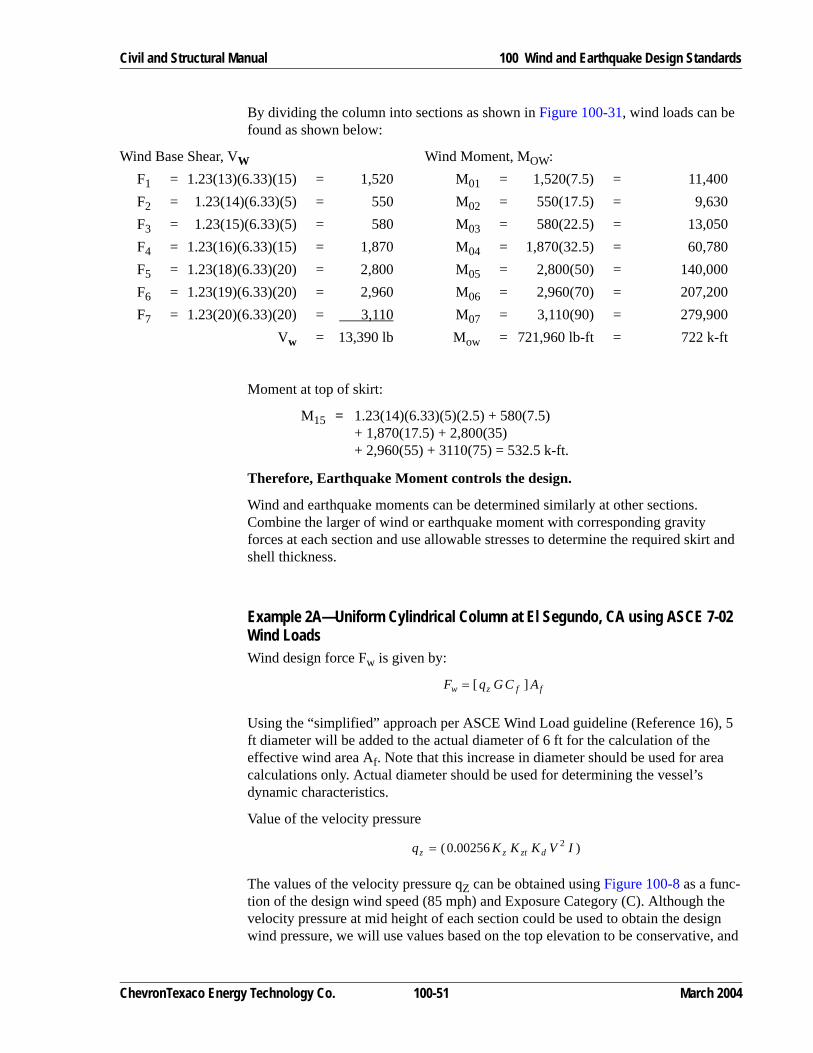
Civil and Structural Manual 100 Wind and Earthquake Design Standards
By dividing the column into sections as shown in Figure 100-31, wind loads can be found as shown below:
Moment at top of skirt:
M15 = 1.23(14)(6.33)(5)(2.5) + 580(7.5)+ 1,870(17.5) + 2,800(35)+ 2,960(55) + 3110(75) = 532.5 k-ft.
Therefore, Earthquake Moment controls the design.
Wind and earthquake moments can be determined similarly at other sections. Combine the larger of wind or earthquake moment with corresponding gravity forces at each section and use allowable stresses to determine the required skirt and shell thickness.
Example 2A—Uniform Cylindrical Column at El Segundo, CA using ASCE 7-02 Wind LoadsWind design force Fw is given by:
Using the “simplified” approach per ASCE Wind Load guideline (Reference 16), 5 ft diameter will be added to the actual diameter of 6 ft for the calculation of the effective wind area Af. Note that this increase in diameter should be used for area calculations only. Actual diameter should be used for determining the vessel’s dynamic characteristics.
Value of the velocity pressure
The values of the velocity pressure qZ can be obtained using Figure 100-8 as a func-tion of the design wind speed (85 mph) and Exposure Category (C). Although the velocity pressure at mid height of each section could be used to obtain the design wind pressure, we will use values based on the top elevation to be conservative, and
Wind Base Shear, VW Wind Moment, MOW:F1 = 1.23(13)(6.33)(15) = 1,520 M01 = 1,520(7.5) = 11,400F2 = 1.23(14)(6.33)(5) = 550 M02 = 550(17.5) = 9,630F3 = 1.23(15)(6.33)(5) = 580 M03 = 580(22.5) = 13,050F4 = 1.23(16)(6.33)(15) = 1,870 M04 = 1,870(32.5) = 60,780F5 = 1.23(18)(6.33)(20) = 2,800 M05 = 2,800(50) = 140,000F6 = 1.23(19)(6.33)(20) = 2,960 M06 = 2,960(70) = 207,200F7 = 1.23(20)(6.33)(20) = 3,110 M07 = 3,110(90) = 279,900
Vw = 13,390 lb Mow = 721,960 lb-ft = 722 k-ft
ffzw ACGqF ][=
)00256.0( 2 IVKKKq dztzz =
ChevronTexaco Energy Technology Co. 100-51 March 2004
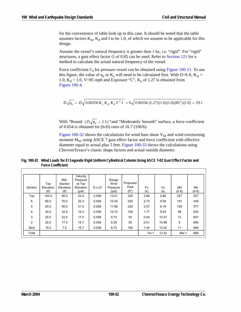
100 Wind and Earthquake Design Standards Civil and Structural Manual
for the convenience of table look up in this case. It should be noted that the table assumes factors Kzt, Kd and I to be 1.0, of which we assume to be applicable for this design.
Assume the vessel’s natural frequency is greater than 1 hz, i.e. “rigid”. For “rigid” structures, a gust effect factor G of 0.85 can be used. Refer to Section 121 for a method to calculate the actual natural frequency of the vessel.
Force coefficient Cf for pressure vessel can be obtained using Figure 100-11. To use this figure, the value of qz or Kz will need to be calculated first. With D=6 ft, Kzt = 1.0, Kd = 1.0, V=85 mph and Exposure “C”, Kz of 1.27 is obtained from Figure 100-4.
With “Round “and “Moderately Smooth” surface, a force coefficient of 0.654 is obtained for (h/D) ratio of 16.7 (100/6).
Figure 100-32 shows the calculations for wind base shear VW and wind overturning moment MW using ASCE 7 gust effect factor and force coefficient with effective diameter equal to actual plus 5 feet. Figure 100-33 shows the calculations using ChevronTexaco’s classic shape factors and actual outside diameter.
1.29)0.1()85()0.1()0.1()27.1(00256.0600256.0 22 === IVKKKDqD dztzz
)5.2( >zqD
Fig. 100-32 Wind Loads for El Segundo Rigid Uniform Cylindrical Column Using ASCE 7-02 Gust Effect Factor and Force Coefficient
SectionTop
Elevation(ft)
Mid-Section
Elevation(ft)
Velocity Pressure
at Top Elevation
(psf)G x Cf
Design Wind
Pressure(psf)
Projected Area (ft2)
Fx (k)
Vx (k)
∆M (k-ft)
Mx (k-ft)
Top 100.0 90.0 23.4 0.556 13.01 220 2.86 2.86 257 257
6 80.0 70.0 22.3 0.556 12.40 220 2.73 5.59 191 449
5 60.0 50.0 21.0 0.556 11.68 220 2.57 8.16 129 577
4 40.0 32.5 19.3 0.556 10.73 165 1.77 9.93 58 635
3 25.0 22.5 17.5 0.556 9.73 55 0.54 10.47 12 647
2 20.0 17.5 16.7 0.556 9.29 55 0.51 10.98 9 656
Skirt 15.0 7.5 15.7 0.556 8.73 165 1.44 12.42 11 666
Total Vw = 12.42 Mw = 666
March 2004 100-52 ChevronTexaco Energy Technology Co.

Civil and Structural Manual 100 Wind and Earthquake Design Standards
Example 3—Column of Variable Cross Section per 1997 UBC (Assume Salt Lake City, UT Location)
Period of Vibration—Use Equation 100-23 (see Figure 100-27.)
Z = 0.30 (Zone 3); Occupancy Factor = 1.0
Fig. 100-33 Wind Loads for El Segundo Rigid Uniform Cylindrical Column Using ASCE 7-02 Method and Chevron-Texaco Classic Shape Factor
SectionTop
Elevation(ft)
Mid-Section
Elevation(ft)
Velocity Pressure
at Top Elevation
(psf)
ChevronShape Factor
Design Wind
Pressure(psf)
Projected Area (ft2)
Fx (k)
Vx (k)
∆M (k-ft)
Mx (k-ft)
Top 100.0 90.0 23.4 1.23 28.67 127 3.63 3.63 327 327
6 80.0 70.0 22.3 1.23 27.32 127 3.46 7.09 242 569
5 60.0 50.0 21.0 1.23 25.73 127 3.26 10.35 163 732
4 40.0 32.5 19.3 1.23 23.64 95 2.25 12.60 73 805
3 25.0 22.5 17.5 1.23 21.44 32 0.68 13.28 15 820
2 20.0 17.5 16.7 1.23 20.46 32 0.65 13.93 11 832
Skirt 15.0 7.5 15.7 1.23 19.23 95 1.83 15.76 14 845
Total Vw = 15.76 Mw = 845
Fig. 100-34 Column of Variable Cross Section: Natural Period of Vibration
tvesseltskirt
--------------- 0.6250.25
------------- 2.5 and 2.5> 1.5, therefore, use R 2.2 (from Figure 100-18)= = =
ChevronTexaco Energy Technology Co. 100-53 March 2004

100 Wind and Earthquake Design Standards Civil and Structural Manual
Assume SD soil.
Therefore, from Figures 100-14 and 100-15, Ca = 0.36, and Cv = 0.54
W = 58.5(1.8) + 23.5(1.2) + 12(0.9) + 8.0 = 152.3 kips
(Eq. 100-2)
Check Vmin = 0.56CaIW = 0.56(0.36)(1.0)(152.3) = 30.7 kips (Eq. 100-7)
Therefore, use V = 33.83 kips.
Note If it is desired to use allowable stress design, the base shear value (V=33.83 kips) should be divided by 1.4.
T > 0.7 sec; therefore Ft = 0.07TV = 0.07 (1.105) (33.83) = 2.62 kip (Eq. 100-9)
V - Ft = 31.21 kips
(Eq. 100-10)
Shear and Moments: Divide column into segments not exceeding 20% of height.Base overturning moment, Mo = 2239.3 k-ft. See Figure 100-35.
Wind Forces (Wind Speed Zone = 70, Exposure B)
Base overturning moment, Mo = 499 k-ft. See Figure 100-36. The shape factor and projected area are based on the outside diameter including the insulation. ∆M (Figure 100-36) is calculated for each section by multiplying average shear in section by height of section. (Area under shear diagram.) Therefore, ∆M is the incremental moment at each section, while Mx is the total moment at each section.
Therefore, Earthquake Moment controls the design.
Example 3A—Variable Cross Section Column at Salt Lake City, UT using ASCE 7-02 Wind LoadsWind design force Fw is given by:
Per ASCE Wind Load Guideline (Reference 16), add 5 ft diameter to the actual diameter for the calculation of the effective wind area Af.
Base Shear, VCvIRT--------W 0.54( ) 1.0( )
2.2( ) 1.105( )------------------------------- 152.3( ) 33.83 kips= = =
Fx V Ft–( )WxhxΣWh------------- 31.21
7672.7----------------Wxhx= =
ffdztzffzw ACGIVKKKACGqF ])00256.0([][ 2==
March 2004 100-54 ChevronTexaco Energy Technology Co.

Civil and Structural Manual 100 Wind and Earthquake Design Standards
Fig. 100-35 Column of Variable Cross Section: Earthquake Forces
Fig. 100-36 Column of Variable Cross Section: Wind Forces Per 1997 UBC
∆
Σ
62 6211.7
11.7
11.7
11.7
11.7
21.06
21.06
21.06
21.06
21.06
88.15
76.45
64.75
53.05
41.35
1856.44
1610.04
1363.64
1117.23
870.83
7.55
6.55
5.55
4.54
3.54
10.17
16.72
22.27
26.81
30.35
6.40
13.45
19.49
24.54
28.58
74.83
157.32
228.08
287.11
334.42
74.83
232.15
460.22
747.34
1081.76
5.8755.8755.875
7.057.057.05
32.5626.6920.81
229.57188.15146.73
0.930.770.60
31.2932.0532.6533.14
33.57
33.83
30.8231.6732.3532.8933.35
33.70
181.07186.06190.07
0.0195.94
404.38
1262.831448.891638.961638.961834.90
2239.28
5.875 7.05 14.94 105.310.490.43
0.26
60
73
106
179
19234
226
22 24837
28539
32441
365
26391
108499
ChevronTexaco Energy Technology Co. 100-55 March 2004

100 Wind and Earthquake Design Standards Civil and Structural Manual
Obtain velocity pressure qz from Figure 100-8 with design wind speed of 90 mph and exposure category B. Top elevation is used for table lookup and to be conserva-tive.
Assume the vessel is “rigid”, hence gust effect factor G of 0.85 can be used.
Force coefficient Cf for pressure vessel can be obtained using Figure 100-11. To use this figure, the value of qz or Kz will need to be calculated first. For multi-diameter vessels, one can make the argument to use the weighted average diameter. To be conservative, we will use the smallest diameter of 5.5 ft as D. With Kzt = 1.0, Kd = 1.0, V=90 mph and Exposure “B”, Kz of 0.97 is obtained from Figure 100-8.
With for “Moderately Smooth” surface and (h/D) ratio
equals to , a net force coefficient Cf of 0.656 is obtained.
Figure 100-37 shows the calculations for wind base shear VW and wind overturning moment MW:
If the natural period of vibration is 1.105 seconds as calculated per Figure 100-34, the natural frequency would be 0.905 hz, i.e. “flexible” structure. The gust effect factor should be calculated per ASCE 7 Section 6.5.8.2 for flexible structures. Assuming a damping ratio of 1%, h=94 ft, B=L=5.5 ft, the flexible gust effect factor Gf can be shown to be 1.062. As a comparison, if the largest diameter (8.0 ft) is used, Gf equals to 1.036. If the weighted average diameter (7.056 ft) is used, Gf equals 1.045. For this example, we will use 1.062. The factor (Gf x Cf) = 1.062 x 0.656 = 0.697.
7.24)0.1()90()0.1()0.1()97.0(00256.05.500256.0 22 === IVKKKDqD dztzz
)"5.2(" >zqDRound
( ) 1.175.594 =
Fig. 100-37 Wind Loads for Salt Lake Rigid Column with Variable Cross Section Using ASCE 7-02 Gust Effect Factor and Force Coefficient
SectionTop
Elevation(ft)
Mid-Section
Elevation(ft)
Velocity Pressure
at Top Elevation
(psf)G x Cf
Design Wind
Pressure(psf)
Projected Area (ft2)
Fx (k)
Vx (k)
∆M (k-ft)
Mx (k-ft)
Top 94.0 87.0 20.1 0.558 11.21 182.0 2.04 2.04 177 177
9 80.0 70.0 19.2 0.558 10.71 260.0 2.78 4.82 195 372
8 60.0 50.0 17.7 0.558 9.87 260.0 2.57 7.39 129 501
7 40.0 39.0 15.8 0.558 8.81 26.0 0.23 7.62 9 510
Transition 38.0 35.5 15.6 0.558 8.70 58.8 0.51 8.13 18 528
5 33.0 31.5 14.9 0.558 8.31 31.5 0.26 8.39 8 536
4 30.0 27.5 14.5 0.558 8.09 52.5 0.42 8.81 12 547
3 25.0 22.5 13.8 0.558 7.70 52.5 0.40 9.21 9 556
2 20.0 17.5 12.9 0.558 7.19 52.5 0.38 9.59 7 563
1 15.0 13.5 11.9 0.558 6.64 31.5 0.21 9.80 3 566
Skirt 12.0 6.0 11.9 0.558 6.64 126.0 0.84 10.64 5 571
Reboiler 15.0 11.9 0.558 6.64 20.0 0.13 10.77 2 573
TOTAL Vw = 10.77 Mw = 573
March 2004 100-56 ChevronTexaco Energy Technology Co.

Civil and Structural Manual 100 Wind and Earthquake Design Standards
Figure 100-38 shows the calculations for wind base shear VW and wind overturning moment MW if the vessel is a flexible structure with natural frequency 0.905 hz and 1% system damping.
Figure 100-39 shows the calculations for wind base shear VW and wind overturning moment MW if the classic ChevronTexaco shape factors are used instead of ASCE 7 gust effect factor and force coefficient.
Fig. 100-38 Wind Loads for Salt Lake “Flexible” Column with Variable Cross Section Using ASCE 7-02 Gust Effect Factor and Force Coefficient
SectionTop
Elevation(ft)
Mid-Section
Elevation(ft)
Velocity Pressure
at Top Elevation
(psf)G x Cf
Design Wind
Pressure(psf)
Projected Area (ft2)
Fx (k)
Vx (k)
∆M (k-ft)
Mx (k-ft)
Top 94.0 87.0 20.1 0.697 14.00 182.0 2.55 2.55 222 222
9 80.0 70.0 19.2 0.697 13.38 260.0 3.48 6.03 244 465
8 60.0 50.0 17.7 0.697 12.33 260.0 3.21 9.24 161 626
7 40.0 39.0 15.8 0.697 11.01 26.0 0.29 9.53 11 637
Transition 38.0 35.5 15.6 0.697 10.87 58.8 0.64 10.17 23 660
5 33.0 31.5 14.9 0.697 10.38 31.5 0.33 10.50 10 670
4 30.0 27.5 14.5 0.697 10.10 52.5 0.53 11.03 15 685
3 25.0 22.5 13.8 0.697 9.61 52.5 0.50 11.53 11 696
2 20.0 17.5 12.9 0.697 8.99 52.5 0.47 12.00 8 704
1 15.0 13.5 11.9 0.697 8.29 31.5 0.26 12.26 4 708
Skirt 12.0 6.0 11.9 0.697 8.29 126.0 1.04 13.30 6 714
Reboiler 15.0 11.9 0.697 8.29 20.0 0.17 13.47 3 717
TOTAL Vw = 13.47 Mw = 717
ChevronTexaco Energy Technology Co. 100-57 March 2004

100 Wind and Earthquake Design Standards Civil and Structural Manual
Fig. 100-39 Wind Loads for Salt Lake Column with Variable Cross Section Using ASCE 7-02 Method and Chevron-Texaco Classic Shape Factor
SectionTop
Elevation(ft)
Mid-Section
Elevation(ft)
Velocity Pressure
at Top Elevation
(psf)
Chevron Shape Factor
Design Wind
Pressure(psf)
Projected Area (ft2)
Fx (k)
Vx (k)
∆M (k-ft)
Mx (k-ft)
Top 94.0 87.0 20.1 1.100 22.11 116.7 2.58 2.58 224 224
9 80.0 70.0 19.2 1.100 21.12 166.7 3.52 6.10 246 471
8 60.0 50.0 17.7 1.100 19.47 166.7 3.25 9.35 163 633
7 40.0 39.0 15.8 1.100 17.38 16.7 0.29 9.64 11 645
Transition 38.0 35.5 15.6 1.169 18.23 35.4 0.65 10.29 23 668
5 33.0 31.5 14.9 1.263 18.81 17.5 0.33 10.62 10 678
4 30.0 27.5 14.5 1.263 18.31 29.2 0.53 11.15 15 693
3 25.0 22.5 13.8 1.263 17.42 29.2 0.51 11.66 11 704
2 20.0 17.5 12.9 1.263 16.29 29.2 0.48 12.14 8 713
1 15.0 13.5 11.9 1.263 15.02 17.5 0.26 12.40 4 716
Skirt 12.0 6.0 11.9 1.263 15.02 70.0 1.05 13.45 6 722
Reboiler 15.0 11.9 1.400 16.66 20.0 0.33 13.78 5 727
TOTAL Vw = 13.78 Mw = 727
March 2004 100-58 ChevronTexaco Energy Technology Co.

Civil and Structural Manual 100 Wind and Earthquake Design Standards
Example 4—Braced-Column Spheres per 1997 UBC (Assume Richmond, California Location)The recommended bracing system for spheres consists of x-bracing connecting adjacent pairs of columns as illustrated in Figure 100-40. In accordance with Details of Earthquake Resistant Design in Section 114, the bracing for large spheres subject to earthquake loads should be effective both in tension and compression to better resist the lateral forces. The lateral forces are transmitted into the shell by a “balcony” girder.
Fig. 100-40 Recommended Bracing System for Spheres
ChevronTexaco Energy Technology Co. 100-59 March 2004

100 Wind and Earthquake Design Standards Civil and Structural Manual
The shear in each panel and the maximum panel shear may be found by the formulas:
(Eq. 100-37)
(Eq. 100-38)
where:
Vp = panel shear
Vpmax = maximum panel shear
V = total lateral force
n = number of panels (equal to number of columns)
α = angle between the plane of the panel and the direction of the lateral force.
Wind ForcesWind force calculations for the sphere can be found in Figure 100-41.
Vp2Vn
------- αcos=
Vpmax2Vn
-------=
Fig. 100-41 Wind Forces for Braced-Column Spheres Per 1997 UBC
Wind Forces (Wind Speed Zone = 70, Exposure C)Description Projected Area ft2 Shape
factorWind
Pressurepsf
Forcek
Sphere Above 40’ Elev. 246 0.65 18 2.9
Sphere Between 30’ and 40’ Elev. 382 0.65 16 4.0
Sphere Between 25’ and 30’ Elev. 198 0.65 16 2.1
Sphere Between 20’ and 25’ Elev. 184 0.65 15 1.8
Sphere Between 15’ and 20’ Elev. 154 0.65 14 1.4
Sphere Below 15’ Elev. 92 0.65 13 0.8
Columns & Bracing Above 25’ Elev. (1/6)[4(1)(30)+6(.5)(36)]=38
2.0 16 1.2
Columns & Bracing Between 20’ and 25’ Elev. (1/6)[228]=38 2.0 15 1.1
Columns & Bracing Between 15’ and 20’ Elev. (1/6)[228]=38 2.0 14 1.1
Columns & Bracing Below 15’ Elev. (1/2)[228]=114 2.0 13 3.0
Total Wind Force, VW = 19.4
Note In computing the slenderness ratio of bracing in an x-braced frame, effective length may be taken as one-half the total length about both axes of the member. Braces should be attached at their point of intersection.
March 2004 100-60 ChevronTexaco Energy Technology Co.

Civil and Structural Manual 100 Wind and Earthquake Design Standards
Earthquake ForcesPeriod of Vibration:
The period of vibration is found using the general formula for one-mass structure in Section 121, Equation 100-17. The static deflection, y, is found by determining the change in length of the bracing resulting from a total lateral load equal to the weight of the sphere. Deformation of the columns and balcony girder are usually neglected for one-story structures.
(Eq. 100-17)
Z = 0.4, Zone 4; Occupancy Factor I = 1.0, R = 2.9 (Figure 100-18)
From Figure 100-12, Na = 1.2 and Nv = 1.6.
Assume SE Soil (site over Bay mud)
Therefore, from Figures 100-14 and 100-15,
Ca = 0.36Na = 0.36(1.2) = 0.43
Cv = 0.96Nv = 0.96(1.6) = 1.54
Check Vmax:
P Maximum force in brace 12--- 2 1500×
6---------------------⎝ ⎠⎛ ⎞ 36.0
20.0----------⎝ ⎠⎛ ⎞ 450 kip= = =
∆ Change in length of brace PLEA------- 450( ) 36.0( ) 12( )
29 000,( ) 8.0( )---------------------------------------- 0.838 in.= = = =
y ∆θsin
----------- 0.838( ) 36.020
----------⎝ ⎠⎛ ⎞ 1.51 in. = = =
Period of Vibration, T 2π yg---⎝ ⎠⎛ ⎞ 0.5
=
T 2π 1.5132.2 12( )---------------------⎝ ⎠⎛ ⎞ 0.5
0.393 sec= =
Base Shear, VCvI
RT---------W 1.54( ) 1.0( )
2.9( ) 0.393( )------------------------------- 1500( ) 2026.8 kips= = =
Vmax2.5CaI
R----------------W=
2.5 0.43( ) 1.0( )2.9
----------------------------------- 1500( )= 556.0 kips=
ChevronTexaco Energy Technology Co. 100-61 March 2004

100 Wind and Earthquake Design Standards Civil and Structural Manual
Comparing Vmax with the wind force of 19.4 kips as shown in Figure 100-41,
Note If it is desired to use allowable stress design, the base shear value (V = 556 kips) should be divided by 1.4.
Therefore, earthquake forces control the design.
Example 5—Vertical Vessels with Unbraced Legs per 1997 UBC (Assume Richmond, CA Location)Vertical vessels are often supported with legs rather than skirts as represented in Figure 100-42. Where the legs are braced, earthquake and wind loads may be deter-mined as in Example 4. Small vessels are frequently supported on legs without bracing. Usually the legs are considered fixed at the vessel shell and pinned at their bases. For these cases, the shell must be adequate to resist the bending moments applied by the legs, or must be adequately stiffened.
Vmax controls.∴
Use V 556.0 kips=
March 2004 100-62 ChevronTexaco Energy Technology Co.

Civil and Structural Manual 100 Wind and Earthquake Design Standards
Fig. 100-42 Vertical Vessel with Unbraced Legs
ChevronTexaco Energy Technology Co. 100-63 March 2004

100 Wind and Earthquake Design Standards Civil and Structural Manual
Earthquake Forces
Period of Vibration:
Since the stiffness of the shell is usually large compared with that of the legs, the period of vibration can be found using the general formula for a one-mass structure in Section 121 (Equation 100-17) assuming the deflection, y, equals the deflection of the legs resulting from a total lateral force equal to the weight of the vessel. For a vessel supported on three or more legs symmetrically spaced about the center, y may be determined from the formula:
(Eq. 100-39)
where:N = number of legs
Ix + Iy = sum of moments of inertia of one leg about the perpendicular axis
L = length of legs from base to shell attachment
For example shown:
Period of Vibration:
(Eq. 100-17)
Zone 4; Z = 0.40, Occupancy Factor, I = 1.0; Assume SE soil
From Figure 100-12, Na = 1.2; Nv = 1.6
(Eq. 100-2)
y 2WL3
3NE Ix Iy+( )-------------------------------=
y 2( ) 15.0( ) 5 12×( )3
3( ) 4( ) 29000( ) 2.45 2.45+( )-------------------------------------------------------------------- 3.80 in= =
T 2π yg---⎝ ⎠⎛ ⎞ 0.5
2π 3.8032.2 12( )---------------------⎝ ⎠⎛ ⎞ 0.5
0.623 sec= = =
R 2.2 (Figure 100-18)=From Figure 100-14, Ca 0.36Na 0.36 1.2( ) 0.43= = =
From Figure 100-15, Cv 0.96Nv 0.96 1.6( ) 1.54= = =
Base Shear, VCvIW
RT-------------- 1.54( ) 1.0( ) 1.5( )
2.2( ) 0.623( )---------------------------------------- 16.85 kips= = =
March 2004 100-64 ChevronTexaco Energy Technology Co.

Civil and Structural Manual 100 Wind and Earthquake Design Standards
Check Vmax:
(Eq. 100-3)
Vmax controls.
Note If it is desired to use allowable stress design, the base shear value (V = 7.33 kips) should be divided by 1.4.
T < 0.7, therefore Ft = 0.0
Considering the weight, W, uniformly distributed along the shell length, the force V-Ft given by Equation 100-10 resolves to a trapezoid, the extended non-parallel sides of which intersect at the base as shown in the sketch in Figure 100-42.
Earthquake Base Overturning Moment:
For the distribution noted above, the base overturning moment, Mo, can be deter-mined by the formula:
(Eq. 100-40)
for design example,
Wind Forces (Wind Speed Zone = 70, Exposure B)
Using base shear calculations as shown in Figure 100-43, Wind Base Moment Mo = 0.53(10) + 0.067(2.5) = 5.47 k-ft.
Therefore, Earthquake Moment controls the design.
The axial loads may be determined using the vessel weight and governing base overturning moment. The bending moment in the legs at the shell about each prin-
Vmax2.5CaI
R----------------W=
2.5 0.43( ) 1.0( )2.2
----------------------------------- 15( )=
7.33 kips=
use V 7.33 k=∴
M0 FtH23--- V Ft–( )H
3 L3–H2 L2–-------------------+=
M023--- 7.33( ) 153 53–( )
152 52–( )------------------------- 79.4 k-ft.= =
Fig. 100-43 Base Shear for Vertical Vessels with Unbraced Legs
Item Projected Area (ft2) Shape Factor Wind Pressure Force (lb)Shell 5' × 10' = 50 1.7-(0.075×5) = 1.33 8 532
Legs 5' × 0.84' = 4.2 2.0 8 67
Base Shear = 599 lb
ChevronTexaco Energy Technology Co. 100-65 March 2004

100 Wind and Earthquake Design Standards Civil and Structural Manual
cipal axis (axes of maximum and minimum moment of inertia) may be determined using the governing base shear.
Example 6—Stack Vibration and OvallingCheck the susceptibility to large-amplitude oscillation and also determine the required circumferential stiffener size and spacing for the following stack:
H = 180 ft
D = 15.0 ft
t = 0.50 in.
Um = 15 fps at elev. + 30 ft
Use Figure 100-26, Uniform Vertical Cylindrical Steel Vessel, for determining period of vibration.
(Eq. 100-22)
(Eq. 100-24)
(Eq. 100-25)
(Eq. 100-26)
Since Uc > Ud for this location, the stack is not susceptible to wind-induced vibration.
Check Ovalling:
w π4--- 180( )2 179( )2–( ) 1
144--------- 490×× 959 lb/ft.= =
T 7.78106---------- 180
15---------⎝ ⎠⎛ ⎞ 2 12 959 15××
0.50---------------------------------⎝ ⎠⎛ ⎞ 0.5
0.66 sec.= =
Uc4.7D
T------------ 4.7( ) 15( )
0.66----------------------- 106.8 fps= = =
Ut UmHZ----⎝ ⎠⎛ ⎞ 0.28
15( ) 18030
---------⎝ ⎠⎛ ⎞ 0.28
24.8 fps= = =
Ud 3Ut 3( ) 24.8( ) 74.4 fps= = =
tR--- 0.5
90------- 0.00555= =
Ud10200--------------- 74.4
10200--------------- 0.0074= =
March 2004 100-66 ChevronTexaco Energy Technology Co.

Civil and Structural Manual 100 Wind and Earthquake Design Standards
(Eq. 100-33)
Ring stiffeners are required. Try spacing equal to 2D.L = 360 in.
(Eq. 100-35)
Use flat bar 5 in. x 9/16 in., I = 5.8 in.4
Check thickness necessary to prevent shell vibration between stiffeners:
tmin > 0.003R
tmin = 0.50 in.
0.003 R = 0.27
0.50 > 0.27 OK, thickness is adequate
Example 7—Stack VibrationCheck the susceptibility of the stack to large amplitude oscillation:
H = 188 ft.
D = 7 ft.
R = 42 in.
t = 0.50 in.
w = 900 lb/ft
Um = 15 ft/sec at elev. + 30 ft.
Exposure BWind speed zone: 80 mphFoundation soil strength: 3000 psfRefractory lining
(Eq. 100-22)
(Eq. 100-24)
tR---
Ud10200---------------<
IUd
2.5D------------
2 0.00334( ) L( ) t( ) R( )4E
---------------------------------------------------- 74.437.5----------
2 0.00334( ) 360( ) 0.50( ) 90( )4
29 106×--------------------------------------------------------------------- 5.35 in.4= = =
T 7.78106---------- H
D----⎝ ⎠⎛ ⎞ 2 12wD
t---------------⎝ ⎠⎛ ⎞ 0.5 7.78
106---------- 188
7---------⎝ ⎠⎛ ⎞ 2 12 900 7××
0.5------------------------------⎝ ⎠⎛ ⎞ 0.5
2.18 sec= = =
Uc4.7D
T------------ 4.7( ) 7( )
2.18-------------------- 15.1 ft/sec= = =
ChevronTexaco Energy Technology Co. 100-67 March 2004
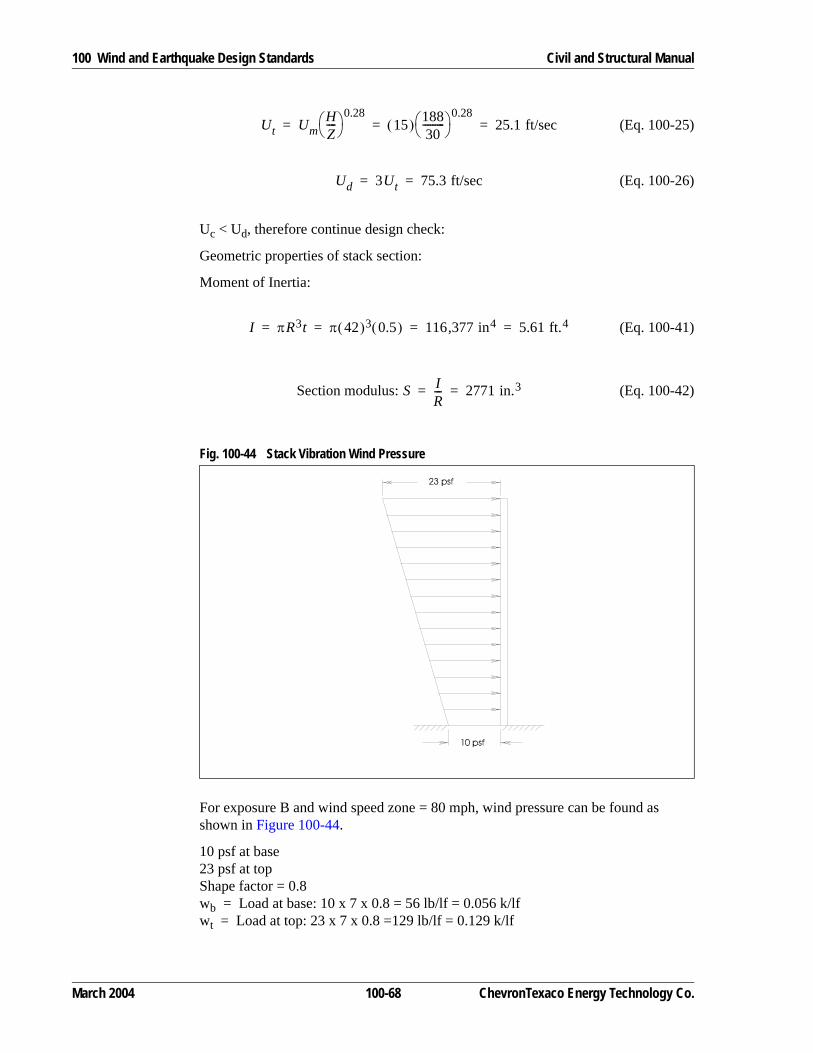
100 Wind and Earthquake Design Standards Civil and Structural Manual
(Eq. 100-25)
(Eq. 100-26)
Uc < Ud, therefore continue design check:
Geometric properties of stack section:
Moment of Inertia:
(Eq. 100-41)
(Eq. 100-42)
For exposure B and wind speed zone = 80 mph, wind pressure can be found as shown in Figure 100-44.
10 psf at base23 psf at topShape factor = 0.8wb = Load at base: 10 x 7 x 0.8 = 56 lb/lf = 0.056 k/lfwt = Load at top: 23 x 7 x 0.8 =129 lb/lf = 0.129 k/lf
Fig. 100-44 Stack Vibration Wind Pressure
Ut UmHZ----⎝ ⎠⎛ ⎞ 0.28
15( ) 18830
---------⎝ ⎠⎛ ⎞ 0.28
25.1 ft/sec= = =
Ud 3Ut 75.3 ft/sec= =
I πR3t π 42( )3 0.5( ) 116 377 in4, 5.61 ft.4= = = =
Section modulus: S IR--- 2771 in.3= =
March 2004 100-68 ChevronTexaco Energy Technology Co.

Civil and Structural Manual 100 Wind and Earthquake Design Standards
(Eq. 100-43)
Moment about base,
(Eq. 100-44)
(Eq. 100-45)
(Eq. 100-27)
Assume a full penetration weld, ground flush and checked in accordance with the requirement of Table 9.25.3 of AWS D1.1. Hence, allowable fatigue stress range: Fr = 16 ksi
(Eq. 100-28)
(Eq. 100-29)
(Eq. 100-31)
Structural damping coefficient, Cs = 0.003 + 0.002 + 0.002 = 0.007
Cd < Cs, therefore wind-induced vibration amplitudes will not exceed allowable limits.
Example 8—Effect of Various Wind Load Design Variables on Gust Effect FactorGust effect factor varies as a function of the rigidity of the structure, wind speed, exposure category and system damping ratio. Figure 100-45 shows the results of a pressure vessel with height equals to 100 ft and diameter equals 5 ft. Three wind speeds (80, 100, 130 mph) were chosen. Note that these are 3-second gust wind
YWH4EI-------
wt8-----
wt wb–( )
30-----------------------– 188 ft( )4
4 176 000 k/ft2,,( ) 5.61 ft4( )-------------------------------------------------------------------- 0.129 k/lf
8----------------------- 0.129 k/lf( ) 0.056 k/lf( )–
30---------------------------------------------------------------–= =
0.763 ft. = 9.2 in.=
M H2 wt wb–
3-------------------
wb2
-------+ 188 ft( )2 0.129 k/lf( ) 0.056 k/lf( )–3
--------------------------------------------------------------- 0.056 k/lf2
-----------------------+= =
1 850 k-ft.,= 22 200 k-in.,=
FwMS----- 22 200,
2 771,---------------- 8.01 ksi= = =
Stress/unit deflection, Fm 1.2FwYw------- 1.2( ) 8.01
9.2----------⎝ ⎠⎛ ⎞ 1.04 ksi/inch deflection= = =
Allowable vibration amplitude,YaFr
2Fm----------- 1
2---⎝ ⎠⎛ ⎞ 16
1.04----------⎝ ⎠⎛ ⎞ 7.69 in. 0.64 ft.= = = =
Mrw
λD2---------- 900
0.060( ) 7( )2----------------------------- 306= = =
Cd0.45Mr
---------- αDYa-------- 1.0–⎝ ⎠⎛ ⎞ 0.5 0.45
306---------- 1.3 7×
0.64---------------- 1.0–⎝ ⎠⎛ ⎞ 0.5
0.005= = =
ChevronTexaco Energy Technology Co. 100-69 March 2004

100 Wind and Earthquake Design Standards Civil and Structural Manual
speeds. All three exposure categories (B, C and D) were illustrated. Three damping ratios (5%, 1% and 0.5%) were assumed. Baseline case is represented by V=100 mph, Exposure “C” with damping ratio of 1%. As expected, the gust effect factor increases with wind speed and decreasing damping ratio. The effect from exposure is not as great.
Note that this is for one specific geometry only. However, the example illustrates the importance of identifying the structure’s rigidity (natural frequency). All possible conditions (e.g. empty vs full, corroded vs new) should be considered when determining the structure’s dynamic response.
Example 9—Comparison of Wind Loads with UBC 97 and ASCE 7 Various EditionsExample 9 is an attempt to compare wind loads derived using UBC 97, ASCE 7-93, 7-95, 7-98 and 7-02. Since wind load has a bigger effect on U.S. Gulf Coast regions where winds are controlling, Pascagoula MS and Port Arthur TX are used in this example. It should be noted that the loads are dependent on the geometry and
Fig. 100-45 Gust Effect Factor Variation
ASCE 7-02 Gust Effect Factor ComparisonExample Structure H=100', D=5'
0.8
0.9
1.0
1.1
1.2
1.3
1.4
1.5
0.4 0.6 0.8 1.0 1.2 1.4 1.6 1.8 2.0
Fundamental Natural Frequency, Hz
Gus
t Effe
ct F
acto
r, G
or
Gf
Gf increases w ith increasing w ind speed (80mph, 100 mph, 130 mph)
Gf decreases w ith increasing damping (5%, 1%, 0.5%)
Gf varies w ith frequency and exposure category B, C, D
Rigid G increases w ith increasing exposure category
Exp "C"
Exp "B"
Baseline : V=100 mph, Exp "C", Damp=1%
V=80 mph
Damp=5%
Damp=0.5%
V=130 mph
Exp "B"Exp "D"
More RigidMore Flexible
March 2004 100-70 ChevronTexaco Energy Technology Co.

Civil and Structural Manual 100 Wind and Earthquake Design Standards
dynamic property of the structure. Actual design wind load may be different than what is shown here, especially for “flexible” structures. Some factors may be subjective. For example, the verbiage on building/structure classification had become more restrictive so that the same importance factor may not be appropriate for different editions. However, for this exercise, we assume a constant importance factor of 1.0 for all codes and editions.
UBC 97
1. Design wind speed of 100 mph is used for both locations.
2. Exposure category D is assumed.
3. Wind pressure Pw = Ce Cq qs I
4. Pressure coefficient Cq equals to 0.8 for round chimneys or tanks.
ASCE 7-93
1. Design wind speed of 100 mph (fastest mile) is used for both locations.
2. Exposure category D is assumed.
3. Velocity Pressure qz = 0.00256 Kz (I V)2
4. Wind pressure Pw = qz Gh Cf
5. Cf of 0.7 is assumed based on “moderately smooth” round structure with h/D = 25.
6. Wind load is multiplied by 1.05 for hurricane oceanline locations per Table 5.
ASCE 7-95
1. Design wind speed of 135 mph is used for Pascagoula and 125 mph for Port Arthur. Note that these are 3-second gust wind speeds.
2. Exposure category D is assumed.
3. Velocity Pressure qz= 0.00256 Kz Kzt V2 I. Note that importance factor I is not squared.
4. Topographic factor Kzt of 1.0 is assumed.
5. Wind pressure Pw = qz G Cf
6. Cf of 0.7 is assumed based on “moderately smooth” round structure with h/D = 25.
7. Gust effect factor G set to 0.85 assuming “rigid” structure (n1 ≥ 1 hz). ASCE 7-95 calls for a “rational” analysis for flexible structures.
ChevronTexaco Energy Technology Co. 100-71 March 2004

100 Wind and Earthquake Design Standards Civil and Structural Manual
ASCE 7-98 and 7-02
1. These two editions are almost identical on wind load, and are taken as being the same here.
2. 3-second gust design wind speed of 150 mph is used for Pascagoula and 130 mph for Port Arthur.
3. Exposure category C is assumed. Exposure C is used here because of the explicit reference to hurricane-prone regions.
4. Velocity Pressure qz= 0.00256 Kz Kzt Kd V2 I. Note that importance factor I is not squared.
5. Topographic factor Kzt of 1.0 is assumed.
6. Wind directionality factor Kd of 1.0 is assumed.
7. Wind pressure Pw = qz G Cf
8. Cf of 0.7 is assumed based on “moderately smooth” round structure with h/D = 25.
March 2004 100-72 ChevronTexaco Energy Technology Co.

Civil and Structural Manual 100 Wind and Earthquake Design Standards
9. Gust effect factor G set to 0.85 assuming “rigid” structure (n1 ≥ 1 hz). ASCE 7-98 and 02 included a method for calculating Gf for flexible structures.
Fig. 100-46 Wind Pressure Comparison for Pascagoula, MS
Height V Ce Cq qs Pw Kz V qz Gh Cf Pw
(ft) (mph) (psf) (psf) (mph) (psf) (psf)0-15 100 1.39 0.8 25.6 28.47 1.20 100 30.72 1.15 0.70 25.9720 100 1.45 0.8 25.6 29.70 1.27 100 32.51 1.14 0.70 27.2425 100 1.50 0.8 25.6 30.72 1.32 100 33.79 1.13 0.70 28.0730 100 1.54 0.8 25.6 31.54 1.37 100 35.07 1.12 0.70 28.8740 100 1.62 0.8 25.6 33.18 1.46 100 37.38 1.11 0.70 30.4960 100 1.73 0.8 25.6 35.43 1.58 100 40.45 1.09 0.70 32.4080 100 1.81 0.8 25.6 37.07 1.67 100 42.75 1.08 0.70 33.94100 100 1.88 0.8 25.6 38.50 1.75 100 44.80 1.07 0.70 35.23120 100 1.93 0.8 25.6 39.53 1.81 100 46.34 1.06 0.70 36.10160 100 2.02 0.8 25.6 41.37 1.92 100 49.15 1.05 0.70 37.93200 100 2.10 0.8 25.6 43.01 2.01 100 51.46 1.04 0.70 39.33300 100 2.23 0.8 25.6 45.67 2.18 100 55.81 1.02 0.70 41.84400 100 2.34 0.8 25.6 47.92 2.31 100 59.14 1.01 0.70 43.90
ASCE 7-93UBC 97
Height Kz V qz G Cf Pw Kz V qz G Cf Pw
(ft) (mph) (psf) (psf) (mph) (psf) (psf)0-15 1.03 135 48.06 0.85 0.70 28.59 0.85 150 48.96 0.85 0.70 29.1320 1.08 135 50.39 0.85 0.70 29.98 0.90 150 51.84 0.85 0.70 30.8425 1.12 135 52.25 0.85 0.70 31.09 0.94 150 54.14 0.85 0.70 32.2230 1.16 135 54.12 0.85 0.70 32.20 0.98 150 56.45 0.85 0.70 33.5940 1.22 135 56.92 0.85 0.70 33.87 1.04 150 59.90 0.85 0.70 35.6460 1.31 135 61.12 0.85 0.70 36.37 1.13 150 65.09 0.85 0.70 38.7380 1.38 135 64.39 0.85 0.70 38.31 1.21 150 69.70 0.85 0.70 41.47100 1.43 135 66.72 0.85 0.70 39.70 1.26 150 72.58 0.85 0.70 43.18120 1.48 135 69.05 0.85 0.70 41.09 1.31 150 75.46 0.85 0.70 44.90160 1.55 135 72.32 0.85 0.70 43.03 1.39 150 80.06 0.85 0.70 47.64200 1.61 135 75.12 0.85 0.70 44.69 1.46 150 84.10 0.85 0.70 50.04300 1.73 135 80.71 0.85 0.70 48.03 1.59 150 91.58 0.85 0.70 54.49400 1.82 135 84.91 0.85 0.70 50.52 1.69 150 97.34 0.85 0.70 57.92
ASCE 7-95 ASCE 7-98/02
ChevronTexaco Energy Technology Co. 100-73 March 2004

100 Wind and Earthquake Design Standards Civil and Structural Manual
130 References1. American Society of Civil Engineers 7-93 Minimum Design Loads for Build-
ings and Other Structures, 1994.
2. International Conference of Building Officials, Uniform Building Code. Copy-right 1997, Whittier, California.
3. American Petroleum Institute, API Recommended Practice for Planning, Designing, and Constructing Fixed Offshore Platforms, API RP 2A. Produc-tion Department, Dallas, Texas.
4. Seismology Committee, Structural Engineers Association of California, Recommended Lateral Force Requirements and Commentary. 1999 Edition, San Francisco, California.
Fig. 100-47 Wind Pressure Comparison for Port Arthur, TX
Height V Ce Cq qs Pw Kz V qz Gh Cf Pw
(ft) (mph) (psf) (psf) (mph) (psf) (psf)0-15 100 1.39 0.8 25.6 28.47 1.20 100 30.72 1.15 0.70 25.9720 100 1.45 0.8 25.6 29.70 1.27 100 32.51 1.14 0.70 27.2425 100 1.50 0.8 25.6 30.72 1.32 100 33.79 1.13 0.70 28.0730 100 1.54 0.8 25.6 31.54 1.37 100 35.07 1.12 0.70 28.8740 100 1.62 0.8 25.6 33.18 1.46 100 37.38 1.11 0.70 30.4960 100 1.73 0.8 25.6 35.43 1.58 100 40.45 1.09 0.70 32.4080 100 1.81 0.8 25.6 37.07 1.67 100 42.75 1.08 0.70 33.94100 100 1.88 0.8 25.6 38.50 1.75 100 44.80 1.07 0.70 35.23120 100 1.93 0.8 25.6 39.53 1.81 100 46.34 1.06 0.70 36.10160 100 2.02 0.8 25.6 41.37 1.92 100 49.15 1.05 0.70 37.93200 100 2.10 0.8 25.6 43.01 2.01 100 51.46 1.04 0.70 39.33300 100 2.23 0.8 25.6 45.67 2.18 100 55.81 1.02 0.70 41.84400 100 2.34 0.8 25.6 47.92 2.31 100 59.14 1.01 0.70 43.90
UBC 97 ASCE 7-93
Height Kz V qz G Cf Pw Kz V qz G Cf Pw
(ft) (mph) (psf) (psf) (mph) (psf) (psf)0-15 1.03 125 41.20 0.85 0.70 24.51 0.85 130 36.77 0.85 0.70 21.8820 1.08 125 43.20 0.85 0.70 25.70 0.90 130 38.94 0.85 0.70 23.1725 1.12 125 44.80 0.85 0.70 26.66 0.94 130 40.67 0.85 0.70 24.2030 1.16 125 46.40 0.85 0.70 27.61 0.98 130 42.40 0.85 0.70 25.2340 1.22 125 48.80 0.85 0.70 29.04 1.04 130 44.99 0.85 0.70 26.7760 1.31 125 52.40 0.85 0.70 31.18 1.13 130 48.89 0.85 0.70 29.0980 1.38 125 55.20 0.85 0.70 32.84 1.21 130 52.35 0.85 0.70 31.15100 1.43 125 57.20 0.85 0.70 34.03 1.26 130 54.51 0.85 0.70 32.44120 1.48 125 59.20 0.85 0.70 35.22 1.31 130 56.68 0.85 0.70 33.72160 1.55 125 62.00 0.85 0.70 36.89 1.39 130 60.14 0.85 0.70 35.78200 1.61 125 64.40 0.85 0.70 38.32 1.46 130 63.17 0.85 0.70 37.58300 1.73 125 69.20 0.85 0.70 41.17 1.59 130 68.79 0.85 0.70 40.93400 1.82 125 72.80 0.85 0.70 43.32 1.69 130 73.12 0.85 0.70 43.50
ASCE 7-95 ASCE 7-98/02
March 2004 100-74 ChevronTexaco Energy Technology Co.

Civil and Structural Manual 100 Wind and Earthquake Design Standards
5. American Institute of Steel Construction, Manual of Steel Construction, Chicago, Illinois.
6. Administering Agency (AA) Subcommittee; Region I Local Emergency Plan-ning Committee (LEPC), Proposed Guidance for California Accidental Release Prevention (CalARP) Program Seismic Assessments, August 1998.
7. American Welding Society, Structural Welding Code, ANSI/AWS D1.1-8.3., Miami, FL.
8. Wiegel, R.L., Ed. Earthquake Engineering. Copyright 1970, Prentice-Hall, Inc., Engleweel Cliffs, NJ, 518 pp.
9. Newmark, N.M., and E. Rosenbluth. Fundamentals of Earthquake Engi-neering. Copyright 1971, Prentice-Hall, Inc., Englewood Cliffs, NJ, 640 pp.
10. Blume, J.A., N.M. Newmark, and L.H. Corning, Design of Multistory Rein-forced Concrete Buildings for Earthquake Motions. Copyright 1961, Portland Cement Association (Chapter 5).
11. Tighe, J.T. Dynamic Analysis Methods for Structures in Earthquakes and Waves. Engineering Department Report, February 1972.
12. Lockheed Aircraft Corp. and Holmes and Narver, Inc. Nuclear Reactors and Earthquakes. TID-7024, U.S. Atomic Energy Commission, August 1963, 415 pp.; see esp. Chapters 1 and 6 and Appendix F.
13. Titlow, Joseph D. Steel Stacks: Structural Behavior in Steady Winds and Fire Protection. Engineering Department Report, December 1968.
14. Kircher, C.A., R. M. Czarnecki, R.E. School, H.C. Shah, and J. M. Gere. Seismic Analysis of Oil Refinery Structures, Parts I and II. The John A. Blume Earthquake Engineering Center, Stanford University, Technical Report No. 31, September 1978.
15. American Society of Civil Engineers. Guidelines for Seismic Evaluation and Design of Petrochemical Facilities, 1997.
16. American Society of Civil Engineers. Wind Loads and Anchor Bolt Design for Petrochemical Facilities, 1997.
ChevronTexaco Energy Technology Co. 100-75 March 2004
100 Wind and Earthquake Design Standards Civil and Structural Manual
March 2004 100-76 ChevronTexaco Energy Technology Co.