civil design check list version: 8/11/2016 project … · civil design check list version:...
TRANSCRIPT

Civil Design Check List Version:
8/11/2016
EVERY ITEM WILL BE REVIEWED AND NOTED FOR COMPLIANCE (C),
NONCOMPLIANCE (NC), OR NONAPPLICABILITY (NA)
ITEM # ITEM DESIGNER
SECTION 1 - SITING
A - GENERAL CHECK:
1. Siting furnished by using agency for compliance with Master
Plan.
2. Layout for compliance with:
a. Unified Facility Criteria, and Air Force and Army Manuals
and Regulations.
b. Separation distances between buildings; for Fire
Protection & Force Protection.
c. Quantity-distances in case of storage of mass-detonating
military explosives.
- Note: That even if your project has no explosives the Base's
Explosive Safety Site Plan needs to be verified to ensure the
project is not encroaching an explosive safety arc.
d. Airfield clearances.
e. Fuel storage criteria.
3. Location of facility for interferences with existing
facilities.
4. Square footage authorized by directive against definitive,
standard, or repetitive drawing quoted in directive or sketch
floor plan furnished by Using Service.
5. Whether real estate is required.
6. Whether access easement rights are required.
7. That adequate cross referencing has been shown on the Plans.
8. To see that Plans have been checked against criteria, criteria
revisions, and design review comments to ensure the latest
approved data have been used in design.
DISCIPLINE: CIVIL DATE: TYPE REVIEW:
REVIEWER: DRAWINGS REVIEWED:
PROJECT NAME:
1 of 34

Civil Design Check List Version:
8/11/2016
ITEM # ITEM DESIGNER
B - DETAIL SITE PLAN - CHECK:
1. Detail site plan for conformity with siting furnished by Using
Agency.
2. That a sufficient number of dimensions and grades have been
shown for complete layout and grading for control points,
layout dimensions, finish floor elevations, finish grade,
bench marks, and grid lines for horizontal control.
3. That all existing utilities (water, sewer, electric,
communications) are shown.
4. For north arrows (and indications of the directions to Mecca,
where applicable) on site plans, for proper orientation.
5. Limits of clearing, grading, grassing, and landscaping.
6. That necessary sidewalks and service drives are shown.
7. That details are shown and figures added (when applicable to
the project) for curbs and gutters, inlets, manholes,
headwalls, painting lines, and other miscellaneous paving and
drainage structures.
8. The site plan with exterior electrical and mechanical drawings
for location of transformer enclosures, cooling towers,
underground storage tanks, etc. These facilities should be
shown on the site plan.
9. The legend to assure that symbols for all new and existing
facilities are included.
10. That location of subsurface explorations(boring logs, test
pits, field tests, etc.) are shown and logs of borings and
test pits are provided.
11. That the type of ground cover is indicated.
12. That a clear distinction is made between original ground and
new contours, which will result from the construction.
13. That outlines of new structures and utilities are heavier than
for those of existing, so that the new work is highlighted and
easily distinguished.
2 of 34

Civil Design Check List Version:
8/11/2016
ITEM # ITEM DESIGNER
14. That all existing structures requiring removal are clearly
identified. Their dimensions and type of construction should
be stated. Existing structures include poles and other
obstructions, which may interfere with new driveways and
parking areas.
15. That oil tank fill lines are not beyond reach of the truck for
delivery of the fuel.
16. The direction of prevailing winds and any unusual climatic
conditions to be expected, such as floods or sandstorms.
Orient and elevate structures as required, to minimize
blocking of doors or infiltration into entrances and openings
of structures.
17. That dikes are provided around above-ground fuel tanks and
that enclosure can be drained at low point.
18. That overall grading is done in the most economical manner
unless design is controlled by other factors such as
landscaping or drainage.
19. That appropriate turn-around is provided in service access
pavement.
20. That significant existing vegetation is shown. Ensure that
trees to be removed are identified.
21. That adequate topographic mapping has been obtained for the
complete design, including existing utility line invert
elevations, dimensions, etc.
22. That in areas where swelling clay exists, measures have been
taken to drain water away from foundations and slabs-on-grade.
23. That provisions for new fencing and/or modification to
existing fences have been covered in the design. Ensure that
the height and type of existing and new fences have been
indicated and that appropriate fencing details have been
included.
24. That slopes of paved surfaces and earth areas are within the
criteria of minimum and maximum grades. Ensure that finish
contours are properly drawn to indicate slopes of finish
grades.
25. That typical sections through the site have been adequately
detailed.
3 of 34

Civil Design Check List Version:
8/11/2016
ITEM # ITEM DESIGNER
26. That provisions have been made for some type of barrier around
the communities and structures to deflect sand driven by
winds. Stabilized berms, walls, trees, and bushes, or a
combination of these may be used. Check the possibility of
taking advantage of natural barriers such as jebels.
27. That screen walls have been provided for all facilities
housing females, when privacy is required by local customs.
28. Potential for problems on galvanized chain-link fences in the
areas of corrosive atmosphere in which the projects are
located. Consider the use of PVC-covered or aluminum chain-
link fence in those areas.
4 of 34

Civil Design Check List Version:
8/11/2016
ITEM # ITEM DESIGNER
SECTION 2 - PAVING AND STORM DRAINAGE
A-GENERAL - Check:
1. Drawings to see that the legend covers every symbol used.
2. The legend to see that existing and new construction are
clearly indicated.
3. That there is no conflict between plans and specifications.
4. That pavement and storm drainage design analyses are complete
and correct.
5. That proper layout measurements, horizontal control points,
and benchmarks are shown.
6. That location of borrow pit is shown when possible; otherwise,
state in the specification that the borrow pit will be located
by the Contractor at his own expense.
7. That specifications cover local conditions and are compatible
with plans.
B-PAVEMENTS - CHECK:
1. Selection of road class for compliance with UFC 3-250-18FA.
Basis for selection must include consideration of type and
frequency of vehicles using the facility.
2. Widths of single-lane short access roads; within built-up
areas width shall be 3.66m (12 ft.) in all cases. In error,
this type road is often designed 3.05m (10 ft.) wide.
3. The transverse slope of single lane roads, which should be in
one direction only. This simplifies construction. This type
road is often designed with a crown resulting in more
difficulty during construction. Short drives may have
suitable longitudinal slope and slope and zero transverse
slope.
4. Earth slopes front and back. These must be determined
considering drainage, maintenance, and stability. Side slopes
should not be steeper than those indicated in TM 5-820-4. The
stability of earth slopes must be determined based upon soils
investigation data, including degree of compaction, cohesive
strength, angle of friction, and height of embankment.
5 of 34
Civil Design Check List Version:
8/11/2016
ITEM # ITEM DESIGNER
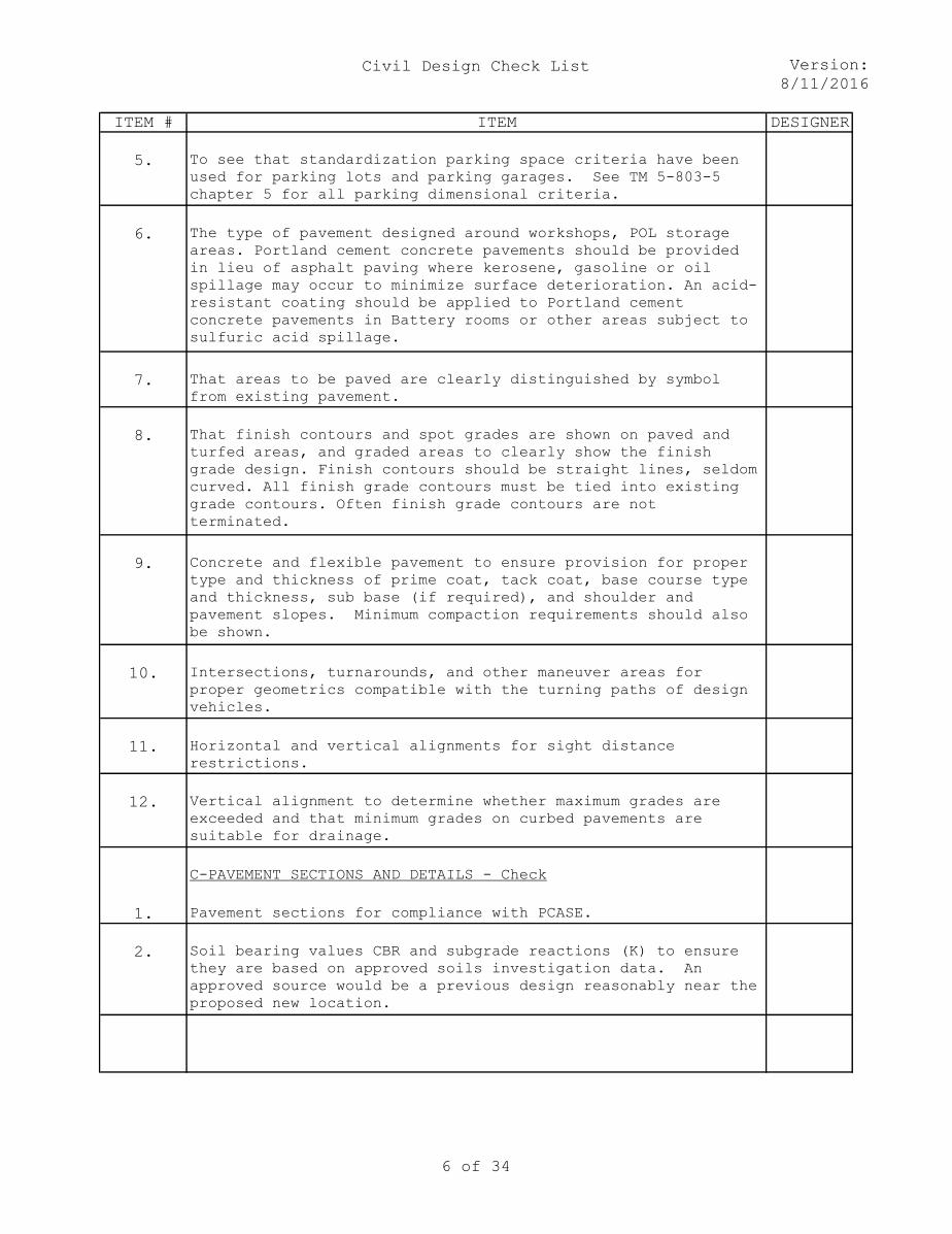
5. To see that standardization parking space criteria have been
used for parking lots and parking garages. See TM 5-803-5
chapter 5 for all parking dimensional criteria.
6. The type of pavement designed around workshops, POL storage
areas. Portland cement concrete pavements should be provided
in lieu of asphalt paving where kerosene, gasoline or oil
spillage may occur to minimize surface deterioration. An acid-
resistant coating should be applied to Portland cement
concrete pavements in Battery rooms or other areas subject to
sulfuric acid spillage.
7. That areas to be paved are clearly distinguished by symbol
from existing pavement.
8. That finish contours and spot grades are shown on paved and
turfed areas, and graded areas to clearly show the finish
grade design. Finish contours should be straight lines, seldom
curved. All finish grade contours must be tied into existing
grade contours. Often finish grade contours are not
terminated.
9. Concrete and flexible pavement to ensure provision for proper
type and thickness of prime coat, tack coat, base course type
and thickness, sub base (if required), and shoulder and
pavement slopes. Minimum compaction requirements should also
be shown.
10. Intersections, turnarounds, and other maneuver areas for
proper geometrics compatible with the turning paths of design
vehicles.
11. Horizontal and vertical alignments for sight distance
restrictions.
12. Vertical alignment to determine whether maximum grades are
exceeded and that minimum grades on curbed pavements are
suitable for drainage.
C-PAVEMENT SECTIONS AND DETAILS - Check
1. Pavement sections for compliance with PCASE.
2. Soil bearing values CBR and subgrade reactions (K) to ensure
they are based on approved soils investigation data. An
approved source would be a previous design reasonably near the
proposed new location.
6 of 34

Civil Design Check List Version:
8/11/2016
ITEM # ITEM DESIGNER
3. The depth of compaction for compliance with PCASE.
4. Types of bituminous surfacing, base course, and subbase course
for compliance with appropriate specifications.
5. That CBR of the materials to be used in the pavement section
are not given on the drawings or in the specifications.
6. PCC pavement jointing, reinforcement of odd-shaped slabs, and
abutment to existing concrete pavement for strict compliance
with UFC 3-250-01FA. Pavement design is to be in harmony with
specifications.
7. That direction of overland drainage flow is indicated by
arrows where not clearly defined by contours, profiles, and
sections. Where gutter flow is continuous across intersecting
pavements, such continuation of flow line is to be indicated
by flow arrows.
8. That curbs, wheel stops or retaining walls are provided at all
areas where vehicles are subject to damaging facilities or
areas where overruns may result in vehicle damage.
9. That vehicle service areas are fully detailed on drawings and
areas restricted to vehicles are provided with positive
barriers.
10. Public transit needs in a community before designing the road
network. If public transit is to be utilized, provide
locations for bus stops and/or bus drop-offs.
11. For vehicle volume requirements and intersectional problems,
to determine the need for stoplights or caution lights at
priniciple intersections.
12. That all main roads have been designed for heavy, high volume
traffic since military installations normally use the largest
trucks possible and since the entire population is becoming
increasingly mobile.
13. That an asphalt paving test strip has been required in the
specifiacations for the demonstration of proper mixes and
application techniques at the beginning of a paving job on all
large paving projects.
7 of 34

Civil Design Check List Version:
8/11/2016
ITEM # ITEM DESIGNER
D-STORM DRAINAGE - Check:
1. That the storm drainage system is clearly shown on plans and
that ultimate disposal of the runoff is shown to an existing
ditch, canal, etc.
2. The rainfall data for the vicinity of the project to determine
frequency, intensity, duration curve, infiltration, and
runoff. Quite often the time of concentration at culverts or
inlets of the system is ignored. The rational method will be
used to determine the runoff for areas less than 200 acres.
The rational formula must reflect the appropriate metric
conversion "K" factor (Q=KCIA) for metric values.
3. That velocities in open ditches are controlled in order to
avoid erosion, of embankments and damage in general.
4. That drainage details such as ditch and swale shapes, invert
elevations, and location dimensions are given.
5. That proper pipe strengths, types, and encasement requirements
are given. The cover over culvert pipe is often ignored,
resulting in exposed pipe at road edges or insufficient pipe
strength.
6. That reinforced concrete pipe is specified for storm drainage
unless some unusual circumstances dictate the use of other
types of pipe.
7. That the size of pipe was calculated for both concrete and
corrugated metal pipe. Normally corrugated metal pipe will be
the next larger size due to greater "n" factor.
8. That pipe size, type, class, gage, length, and inverts are
shown on plans. If extensive storm drainage is required,
check to see that drainage structures and pipe schedules are
shown on plans.
9. That adequate erosion control methods are employed, in the
form of curb and gutter, inlets, flumes, sodding, and rip rap
schedules are shown on plans.
10. The system for continuity of inverts, flow lines, and
contours.
11. The class and gage of storm drain pipes for adequate cover for
the specified load.
12. Drainage design analysis computations, factors used, and the
contributing drainage areas.
8 of 34

Civil Design Check List Version:
8/11/2016
ITEM # ITEM DESIGNER
13. Drainage structures for dimensions and adequate details
necessary for construction.
14. Drainage pipe for possible conflict with pipelines and other
underground construction.
15. That profiles of lines have been established to avoid or
minimize rock excavation. Where possible, show the surfaces
of existing rock on profiles.
16. That flared edges are used on the inlet edge of culvert pipe
as part of inlet control in accordance with FAA AC 150/5320-5
In conjunction with inlet control, check that outlet control
is applied. Have applicable computations been submitted with
inlet and outlet control design?
17. That detention ponding is considered in drainage design where
site conditions permit ot reduce design peak discharges.
18. That overall drainage design considers future site
development.
19. That scour apron or other suitable protection is provided at
downstream end of culverts and storm drain outlets.
20. The storm runoff is not discharged at the top of slopes unless
suitable chutes fumes, energy dissipaters, etc., are used to
control erosion and excessive energy.
21. That headwalls are selected considering lateral scour, band
erosion, and undercutting of headwall.
22. That appropriate drainage inlets are used.
23. That inlet spacing is predicated upon allowable width of
spread of gutter flow from the standpoint of the following
items:
a. Interference to traffic.
b. Prevention of cross flow.
c. Inconvenience to pedestrians.
24. That hydraulic gradient is computed where critical to the
design and function of the storm drainage system.
25. That frequency of design discharge is selected with due
consideration for the value of the improvements, desired
degree of protection, and requirements of the Technical
Manuals.
9 of 34
Civil Design Check List Version:
8/11/2016
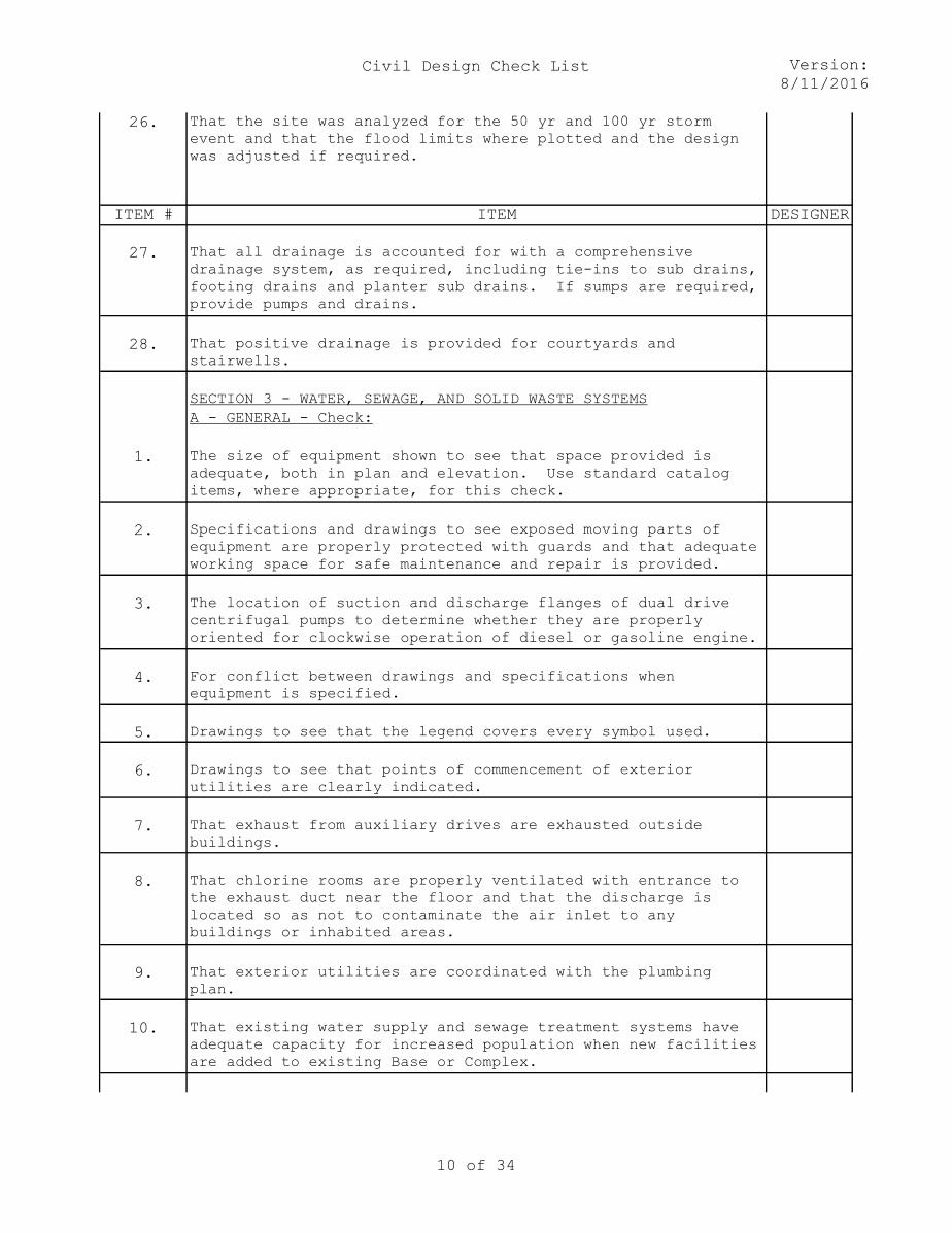
26. That the site was analyzed for the 50 yr and 100 yr storm
event and that the flood limits where plotted and the design
was adjusted if required.
ITEM # ITEM DESIGNER
27. That all drainage is accounted for with a comprehensive
drainage system, as required, including tie-ins to sub drains,
footing drains and planter sub drains. If sumps are required,
provide pumps and drains.
28. That positive drainage is provided for courtyards and
stairwells.
SECTION 3 - WATER, SEWAGE, AND SOLID WASTE SYSTEMS
A - GENERAL - Check:
1. The size of equipment shown to see that space provided is
adequate, both in plan and elevation. Use standard catalog
items, where appropriate, for this check.
2. Specifications and drawings to see exposed moving parts of
equipment are properly protected with guards and that adequate
working space for safe maintenance and repair is provided.
3. The location of suction and discharge flanges of dual drive
centrifugal pumps to determine whether they are properly
oriented for clockwise operation of diesel or gasoline engine.
4. For conflict between drawings and specifications when
equipment is specified.
5. Drawings to see that the legend covers every symbol used.
6. Drawings to see that points of commencement of exterior
utilities are clearly indicated.
7. That exhaust from auxiliary drives are exhausted outside
buildings.
8. That chlorine rooms are properly ventilated with entrance to
the exhaust duct near the floor and that the discharge is
located so as not to contaminate the air inlet to any
buildings or inhabited areas.
9. That exterior utilities are coordinated with the plumbing
plan.
10. That existing water supply and sewage treatment systems have
adequate capacity for increased population when new facilities
are added to existing Base or Complex.
10 of 34
Civil Design Check List Version:
8/11/2016
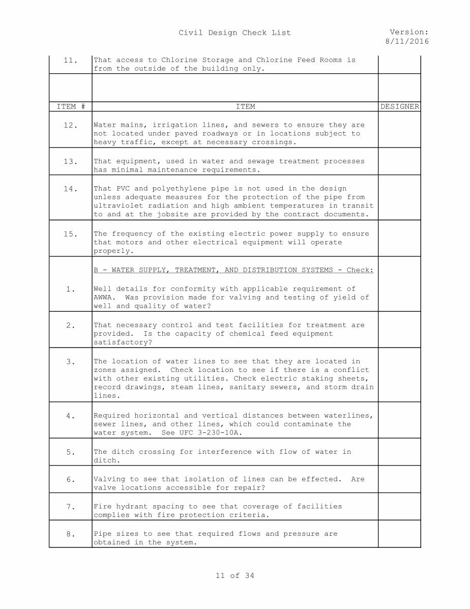
11. That access to Chlorine Storage and Chlorine Feed Rooms is
from the outside of the building only.
ITEM # ITEM DESIGNER
12. Water mains, irrigation lines, and sewers to ensure they are
not located under paved roadways or in locations subject to
heavy traffic, except at necessary crossings.
13. That equipment, used in water and sewage treatment processes
has minimal maintenance requirements.
14. That PVC and polyethylene pipe is not used in the design
unless adequate measures for the protection of the pipe from
ultraviolet radiation and high ambient temperatures in transit
to and at the jobsite are provided by the contract documents.
15. The frequency of the existing electric power supply to ensure
that motors and other electrical equipment will operate
properly.
B - WATER SUPPLY, TREATMENT, AND DISTRIBUTION SYSTEMS - Check:
1. Well details for conformity with applicable requirement of
AWWA. Was provision made for valving and testing of yield of
well and quality of water?
2. That necessary control and test facilities for treatment are
provided. Is the capacity of chemical feed equipment
satisfactory?
3. The location of water lines to see that they are located in
zones assigned. Check location to see if there is a conflict
with other existing utilities. Check electric staking sheets,
record drawings, steam lines, sanitary sewers, and storm drain
lines.
4. Required horizontal and vertical distances between waterlines,
sewer lines, and other lines, which could contaminate the
water system. See UFC 3-230-10A.
5. The ditch crossing for interference with flow of water in
ditch.
6. Valving to see that isolation of lines can be effected. Are
valve locations accessible for repair?
7. Fire hydrant spacing to see that coverage of facilities
complies with fire protection criteria.
8. Pipe sizes to see that required flows and pressure are
obtained in the system.
11 of 34

Civil Design Check List Version:
8/11/2016
9. That valves and fittings are provided to simplify future
expansion.
12 of 34

Civil Design Check List Version:
8/11/2016
ITEM # ITEM DESIGNER
10. That a water quality analysis of the water supply is provided
and has been used as the basis of design for any water
treatment process used.
11. That pipe penetrations in concrete tanks are provided with
embedded sleeves and flexible connections and are properly
caulked.
12. When necessary, for protection against freezing in tank
design. Inlet and overflow line are to run along inside wall,
and pipes to and from the tank are to run underground. Rodent
screen is to be placed on the discharge end of overflow and
drain line. Earth mounds are to be placed around tank and a
means of water circulation in the tank shall be provided to
avoid formation of ice.
13. That protective coating is provided on buried steel water
pipe.
14. That water supply source is adequate for design criteria and
is in accordance with UFC 3-230-07A. Has proper allowance
been made for supply under the most adverse conditions? Will
future development in the area seriously affect the supply?
15. That scales are shown for all plans. Visually check dimensions
shown against drawings to eliminate gross errors.
16. That instructions have been complied with in respect to
listing Government-furnished equipment.
17. That water rights are obtained.
18. The supply line to building sprinkler system for post
indicator valve. Coordinate with Fire Protection Engineer to
see if required.
19. That waterlines crossing roads, sewer lines, culverts,
ditches, etc., are shown in the respective profiles.
20. That pneumatic tank maximum cutoff and low start pressures are
given on the drawings. The volume percentage at these
pressures should be given to facilitate putting the system
into operation.
21. That adequate storage is provided for fire flow and domestic
demands.
22. That the specification call for sterilization of water storage
tanks as well as water lines.
13 of 34

Civil Design Check List Version:
8/11/2016
ITEM # ITEM DESIGNER
23. That portable water storage facilities have been designed to
preclude stagnation of the water.
24. That portable water, if readily available, or raw well water,
if it is of sufficient quality, has been used in lieu of oil
to lubricate well pump bearings.
25. That design of water lines installed above ground or in
utility tunnels is based on sound engineering principles
commensurate with maintenance, repair, inspection, testing,
and replacement.
26. That water lines have sufficient ground cover for load
protection.
27. That provisions have been made for the proper disposal of
reject brine from water treatment processes.
28. That ductile iron fittings and specials are specified for PVC
pipe systems for pipes 4" and larger.
29. That the working pressure for PVC pipe has been derated for
the maximum ambient temperature anticipated.
30. Insure proper placement of air relief valves.
31. Coordinate with the fire protection engineer on design working
pressures.
C - SEWERAGE SYSTEMS - Check:
1. That type of joints specified is compatible with ground water
level and dewatering conditions.
2. Grades and slopes for correctness.
3. That grades of manhole tops are set for finished grades. Also,
check that all invert and top elevations of manholes are
given.
4. That sewer location will not result in interference with other
utilities.
5. That centerline spacing between drain field lines is adequate.
6. That sufficient ground cover has been provided for load
protection in accordance with UFC 3-240-07 FA.
14 of 34

Civil Design Check List Version:
8/11/2016
ITEM # ITEM DESIGNER
7. That where crossing of waterlines and sewer lines is
unavoidable, the sewer pipe at the crossing is in accordance
with the applicable paragraph of UFC 3-230-10 A.
8. That all sanitary sewers are designed to discharge the
expected peak rate of flow when the pipe is running full.
However, regardless of sewage quantity, the minimum sizes to
be used are 6-inch for house connections and 8-inch for all
other sewers. Ensure that sewer lines are laid on sufficient
slope to provide a minimum velocity of 2 ft/s at average daily
flow.
9. That sewer connections are not made to force mains.
10. That invert of outside sewer will match the invert of the
building connection.
11. That black iron for handrails, etc., is not used in sewage
plants. Ferrous metals exposed to sewage gases should be
galvanized.
12. That complete hydraulic design computations are included in
the Design Analysis.
13. That traps are provided to prevent grease or oil from entering
the sewage system.
14. That the most economical disposal system is employed.
15. That sewage effluent from the treatment system will not
contaminate watercourses, water supply systems, etc.
16. That provisions have been made to use sewage treatment plant
effluent for irrigation water and/or other non-portable water
requirements, if permitted by the local government.
17. That any wastes which are detrimental to a biological
treatment system have been excluded from the sanitary sewer
system.
18. That the Paint Specification for Sewage Treatment Plants
requires all intermediate and finish paint coats be lead-free,
mercury-free fume proof, and suitable for sewage plant
atmosphere containing hydrogen sulfide.
D - SOLID WASTE SYSTEMS - Check
1. Check that provisions have been made for the collection,
storage, and disposal of solid wastes.
15 of 34
Civil Design Check List Version:
8/11/2016
ITEM # ITEM DESIGNER
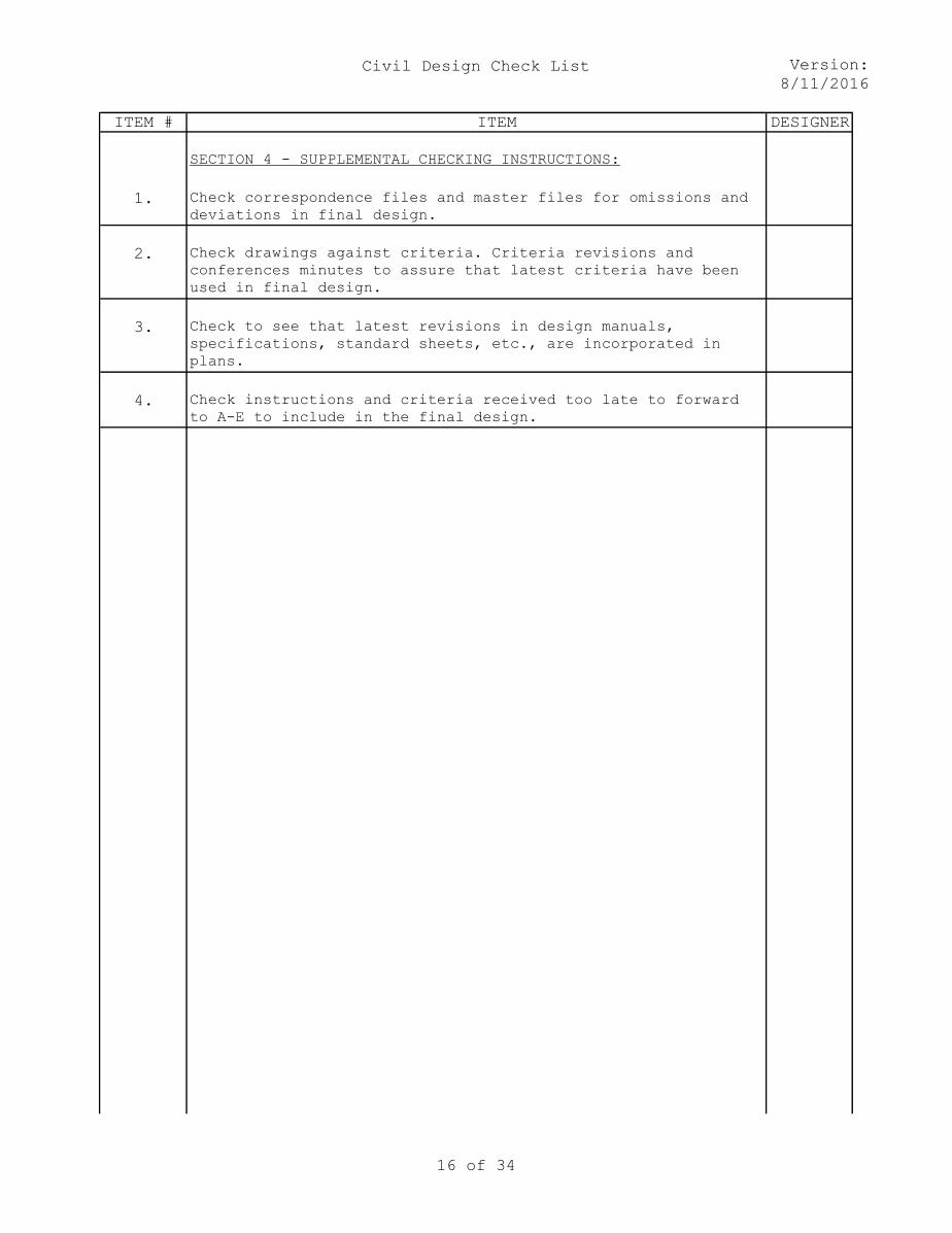
SECTION 4 - SUPPLEMENTAL CHECKING INSTRUCTIONS:
1. Check correspondence files and master files for omissions and
deviations in final design.
2. Check drawings against criteria. Criteria revisions and
conferences minutes to assure that latest criteria have been
used in final design.
3. Check to see that latest revisions in design manuals,
specifications, standard sheets, etc., are incorporated in
plans.
4. Check instructions and criteria received too late to forward
to A-E to include in the final design.
16 of 34

Civil Design Check List Version:
8/11/2016
17 of 34

Civil Design Check List Version:
8/11/2016
REVIEWER
18 of 34
Civil Design Check List Version:
8/11/2016
REVIEWER
19 of 34

Civil Design Check List Version:
8/11/2016
REVIEWER
20 of 34

Civil Design Check List Version:
8/11/2016
REVIEWER
21 of 34

Civil Design Check List Version:
8/11/2016
REVIEWER
22 of 34

Civil Design Check List Version:
8/11/2016
REVIEWER
23 of 34
Civil Design Check List Version:
8/11/2016
REVIEWER
24 of 34

Civil Design Check List Version:
8/11/2016
REVIEWER
25 of 34

Civil Design Check List Version:
8/11/2016
REVIEWER
26 of 34

Civil Design Check List Version:
8/11/2016
REVIEWER
27 of 34

Civil Design Check List Version:
8/11/2016
REVIEWER
28 of 34
Civil Design Check List Version:
8/11/2016
29 of 34

Civil Design Check List Version:
8/11/2016
REVIEWER
30 of 34

Civil Design Check List Version:
8/11/2016
REVIEWER
31 of 34

Civil Design Check List Version:
8/11/2016
REVIEWER
32 of 34

Civil Design Check List Version:
8/11/2016
REVIEWER
33 of 34

Civil Design Check List Version:
8/11/2016
34 of 34