civil engineering previous papers2
TRANSCRIPT
8/7/2019 Civil Engineering Previous Papers2
http://slidepdf.com/reader/full/civil-engineering-previous-papers2 1/13
Civil Engineering Previous Papers - Paper 2
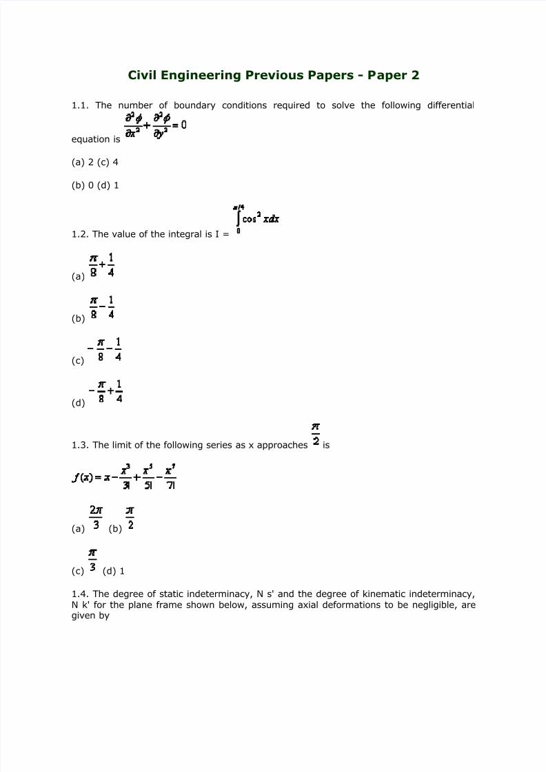
1.1. The number of boundary conditions required to solve the following differential
equation is
(a) 2 (c) 4
(b) 0 (d) 1
1.2. The value of the integral is I =
(a)
(b)
(c)
(d)
1.3. The limit of the following series as x approaches is
(a) (b)
(c) (d) 1
1.4. The degree of static indeterminacy, N s' and the degree of kinematic indeterminacy,N k' for the plane frame shown below, assuming axial deformations to be negligible, aregiven by

8/7/2019 Civil Engineering Previous Papers2
http://slidepdf.com/reader/full/civil-engineering-previous-papers2 2/13
(a) N s = 6 and N k = 11
(b) N s = 6 and N k = 6
(c) N s = 4 and N k = 6
(d) N s = 4 and N k = 4
1.5. The bending moment (in kNm units) at the mid-span location X in the beam with
overhangs shown below-is equal to:
(a) 0
(b) - 1 0
(c) - 15
(d) -20
1.6. Identify the FALSE statement from the following, pertaining to the effects due to atemperature rise D T in the bar BD alone in the plane truss shown below:
(a) No reactions develop at supports A and D.
(b) The bar BD will be subject to a tensile force.
(c) The bar AC will be subject to a compressive force.
(d) The bar BC will be subject to a tensile force.

8/7/2019 Civil Engineering Previous Papers2
http://slidepdf.com/reader/full/civil-engineering-previous-papers2 3/13
1.7. Identify the correct deflection diagramcorresponding to the loading in the plane
frame shown below:
1.8. Identify the False statement from the following, pertaining to the methods of
structural analysis:
y Influence lines for stress resultants in beams can be drawn using Miller Breslau'sPrinciple.
y The Moment Distribution Method is a force method of analysis, not a displacementmethod.
y The Principle of Virtual Displacements can be used to establish a condition of equilibrium. .
y The Substitute Frame Method is not applicable to frames subject to significantsideway.
1.9. Identify the FALSE statement from the following, pertaining to the design of concrete
structures:
y The assumption of a linear strain profile in flexure is made use of in working stressdesign, but not in ultimate limit state design.
y Torsional reinforcement is not required to be provided at the coners of simplysupported rectangular slabs, if the coners are free to lift up.
y A rectangular slab, whose length exceeds twice its width, always behaves as atwo-way slab, regardless of the support conditions.
y The 'load balancing' concept can be applied to select the appropriatetendon profile in a prestressed concrete beam subject to a given pattern of loads.
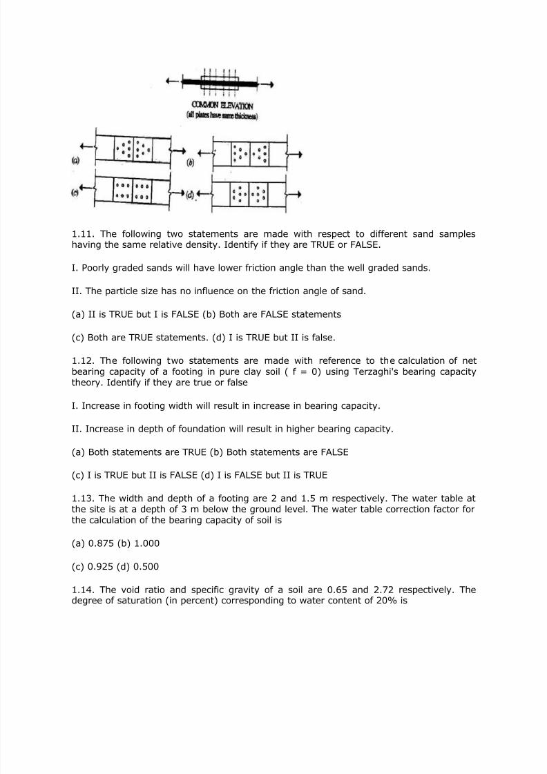
1.10. Identify the most efficient butt joint (with double cover plates) for a plate in tensionfrom the patterns (plan views) shown below, each comprising 6 identical bolts with thesame pitch and gauge:
8/7/2019 Civil Engineering Previous Papers2
http://slidepdf.com/reader/full/civil-engineering-previous-papers2 4/13
1.11. The following two statements are made with respect to different sand sampleshaving the same relative density. Identify if they are TRUE or FALSE.
I. Poorly graded sands will have lower friction angle than the well graded sands.
II. The particle size has no influence on the friction angle of sand.
(a) II is TRUE but I is FALSE (b) Both are FALSE statements
(c) Both are TRUE statements. (d) I is TRUE but II is false.
1.12. The following two statements are made with reference to the calculation of netbearing capacity of a footing in pure clay soil ( f = 0) using Terzaghi's bearing capacitytheory. Identify if they are true or false
I. Increase in footing width will result in increase in bearing capacity.
II. Increase in depth of foundation will result in higher bearing capacity.
(a) Both statements are TRUE (b) Both statements are FALSE
(c) I is TRUE but II is FALSE (d) I is FALSE but II is TRUE
1.13. The width and depth of a footing are 2 and 1.5 m respectively. The water table atthe site is at a depth of 3 m below the ground level. The water table correction factor forthe calculation of the bearing capacity of soil is
(a) 0.875 (b) 1.000
(c) 0.925 (d) 0.500
1.14. The void ratio and specific gravity of a soil are 0.65 and 2.72 respectively. Thedegree of saturation (in percent) corresponding to water content of 20% is

8/7/2019 Civil Engineering Previous Papers2
http://slidepdf.com/reader/full/civil-engineering-previous-papers2 5/13
(a) 65.3 (b) 20.9
(c) 83.7 (d) 54.4
1.15. With respect to a c- f soil in an infinite slope, identify if the following two
statements are TRUE or FALSE.
I. The stable slope angle can be greater than f
II: The factor of safety of the slope does not depend on the height soil in the slope.
(a) Both statements are FALSE (b) I is TRUE but II is FALSE
(c) I is FALSE but II is TRUE (d) Both statements are TRUE
1.16. In the Bernoulli equation. used in pipe flow. each term represents
(a) Energy per unit weight (b) Energy per unit mass
(c) Energy per unit volume (d) Energy per unit flow length
1.17. The stage-discharge relation in a river during the passage of flood is measured. If qf is the discharge at the stage when water surface is falling and q r is the discharge at thesame stage when water surface is rising, then
(a) q f= q r (b) q f <>
(c) q f > q r (d) = constant for all stages
1.18. lsopleths are lines on a map through points having equal depth of
(a) Rainfall (b) Infiltration
(c) Evapotranspiration (d) Total runoff
1.19. A linear reservoir is one in which
(a) Storage varies linearly with time
(b) Storage varies linearly with outflow rate
(c) Storage varies linearly with inflow rate
(d) Storage varies linearly with elevation

8/7/2019 Civil Engineering Previous Papers2
http://slidepdf.com/reader/full/civil-engineering-previous-papers2 6/13
8/7/2019 Civil Engineering Previous Papers2
http://slidepdf.com/reader/full/civil-engineering-previous-papers2 7/13
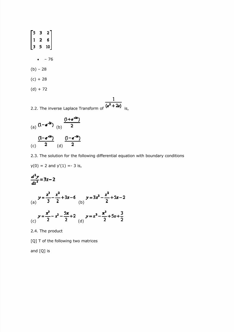
y ±76
(b) ± 28
(c) + 28
(d) + 72
2.2. The inverse Laplace Transform of is,
(a) (b)
(c) (d)
2.3. The solution for the following differential equation with boundary conditions
y(0) = 2 and y'(1) =- 3 is,
(a) (b)
(c) (d)
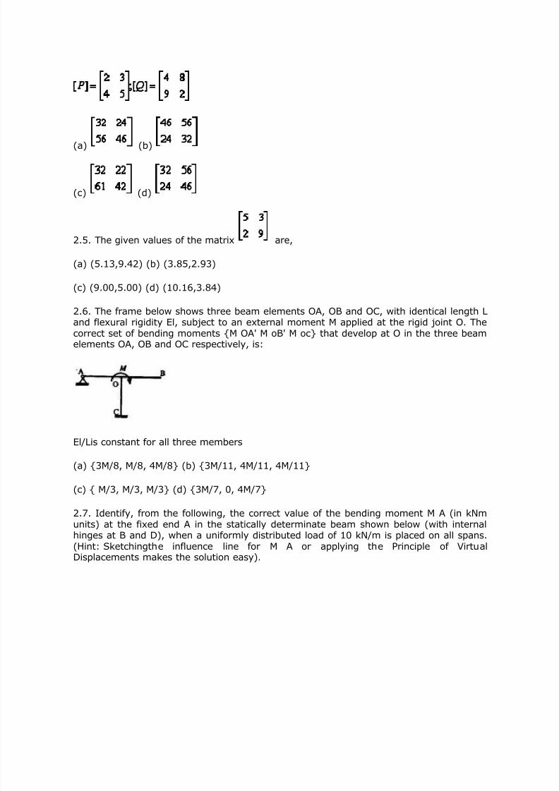
2.4. The product
[Q] T of the following two matrices
and [Q] is
8/7/2019 Civil Engineering Previous Papers2
http://slidepdf.com/reader/full/civil-engineering-previous-papers2 8/13
(a) (b)
(c) (d)
2.5. The given values of the matrix are,
(a) (5.13,9.42) (b) (3.85,2.93)
(c) (9.00,5.00) (d) (10.16,3.84)
2.6. The frame below shows three beam elements OA, OB and OC, with identical length Land flexural rigidity El, subject to an external moment M applied at the rigid joint O. Thecorrect set of bending moments {M OA' M oB' M oc} that develop at O in the three beamelements OA, OB and OC respectively, is:
El/Lis constant for all three members
(a) {3M/8, M/8, 4M/8} (b) {3M/11, 4M/11, 4M/11}
(c) { M/3, M/3, M/3} (d) {3M/7, 0, 4M/7}
2.7. Identify, from the following, the correct value of the bending moment M A (in kNmunits) at the fixed end A in the statically determinate beam shown below (with internalhinges at B and D), when a uniformly distributed load of 10 kN/m is placed on all spans.(Hint: Sketchingthe influence line for M A or applying the Principle of Virtual
Displacements makes the solution easy).

8/7/2019 Civil Engineering Previous Papers2
http://slidepdf.com/reader/full/civil-engineering-previous-papers2 9/13
(a) -80 (b) -40
(c) 0 (d) + 40
2.8. The end moment (in kNm units) developed in the roof level beams in the laterallyloaded frame shown below (with all columns having identical cross-sections), according tothe Cantilever Method of simplified analysis, is :
(a) 7.5 (b) 15
(c) 20 (d) 30
2.9. Consider the following two statements related toreinforced concrete design, and
identify whether they are TRUE or FALSE:
I. Curtailment of bars in the flexural tension zone in beams reduces the shear strength atthe cut-off locations.
II. When a rectangular column section is subject to biaxially eccentric compression, theneutral axis will be parallel to the resultant axis of bending.
(a) Both statements I and II are TRUE.
(b) Statement I is TRUE, and statement II is FALSE.
(c) Statement I is FALSE, and statement II is TRUE.
(d) Both statements I and II are FALSE.
2.10. Consider the following two statements related to structural steel design, and

8/7/2019 Civil Engineering Previous Papers2
http://slidepdf.com/reader/full/civil-engineering-previous-papers2 10/13
identify whether they are TRUE or FALSE:
I. The Euler buckling load of a slender steel column depends on the yield strength of steel.
II. In the design of laced column, the maximum spacing of the lacing does not depend onthe slenderness of column as a whole.
(a) Both statements I and II are TRUE.
(b) Statement I is TRUE, and statement II is FALSE.
(c) Statement I is FALSE, and statement II is TRUE.
(d) Both statements I and II are FALSE.
2.11. Identify the two FALSE statements from the following four statements.
I. The consolidation of soil happens due to the change in total stress.
II. When Standard Penetration Tests are performed in fine sands below the water table,the dilation correction is applied after the overburden correction is applied.
III. Over consolidated clays will have predominantly cohesive strength as compared tothe frictional strength.
IV. Compaction of soils is due to expulsion of water.
(a) II & III (b) I & IV
(c) I & III (d) II & IV
2.12. The critical slip circle for a slope is shown below along with the soil properties.
The length of the arc of the slip circle is 15.6m and the area of soil within the slip circle is
82 m 2. The radius of the slip circles is 10.3 m. The factor of safety against the slip circlefailure is nearly equal to,
(a) 1.05 (b) 1.22
(c) 0.78 (d) 1.28
2.13. The coefficients of permeability of a soil in horizontal and vertical directions are
8/7/2019 Civil Engineering Previous Papers2
http://slidepdf.com/reader/full/civil-engineering-previous-papers2 11/13
3.46 and 1.5 m/day respectively. The base length of a concrete dam resting in this soil is100 m. When the flow net is developed for this soil with 1 : 25 scale factor in the verticaldirection, the reduced base length of the dam will be
(a) 2.63 m (b) 4.00 m
(c) 6.08 m (d) 5.43 m
2.14. A plate load test was conducted in sand on a 300 mm diameter plate. If the platesettlement was 5 mm at a pressure of 100 kPa, the settlement (in mm) of a 5 m x 8 mrectangular footing at the same pressure will be
(a) 9.4 (b) 18.6
(c) 12.7 (d) 17.8
2.15. Identify the two TRUE statements from the following four statements.
I. Negative skin friction is higher on floating piles than on end bearing piles.
II. All other things being the same in footings on sand, the footing with smaller
width will have lower settlement at the same net pressure.
III. The void ratio of soils is always less than 1.0.
IV. For determining the depth of embedment of anchored sheet piles, net moment
at the anchor elevation is set to zero.
(a) I & IV (b) I & III
(c) II & IV (d) II & III
2.16. A 15 cm length of steel rod with relative density of 7.4 is submerged in a two layerfluid. The bottom layer is mercury and the top layer is water. The height of top surface of the rod above the liquid interface in 'cm' is
(a) 8.24 (b) 7.82
(c) 7.64 (d) 7.38
2.17. The direct runoff hydrograph of a storm obtained from a catchment is triangular inshape and has a base period of 80 hours. The peak flow rate is 30 m 3/sec andcatchment area is 86.4 km 2. The rainfall excess that has resulted the above hydrographis
(a) 5 cm (b) 8 cm
8/7/2019 Civil Engineering Previous Papers2
http://slidepdf.com/reader/full/civil-engineering-previous-papers2 12/13
(c) 10 cm (d) 16 cm
2.18. A field was supplied water from an irrigation tank at a rate of 120 lit/see to irrigatean area of 2.5 hectares. The duration of irrigation is 8 hours. It was found that the actualdelivery at the field, which is about 4 km from the tank, was 100 lit/sec. The runoff lossin the field was estimated as 800 m 3. The application efficiency in this situation is
(a) 62% (b) 72%
(c) 76% (d) 80%
2.19. A trapezoidal channel with bottom width of 3m and side slope of IV:1.5H carries adischarge of 8.0 m 3/sec with the flow depth of 1.5m. The Froude number of the flow is
(a) 0.066 (b) 0.132
(c) 0.265 (d) 0.528
2.20. In a 1/50 model of a spillway, the discharge was measured to be 0.3 m 3/sec. The
corresponding prototype discharge in m 3/sec is
(a) 2.0 (b). 15.0
(c) 106.0 (d) 5303.0
2.21. If the BOD 5,20 of waste is 150mg/L and the reaction rate constant (to the base 'e')
at 20°C is 0.35/day, then the ultimate BOD in mg/L is
(a) 97.5 (b) 181.5
(c) 212.9 (d) 230.5
2.22. The Ca 2+ concentration and Mg 2+ concentration of a water sample are 160 mg/litand 40 mg/lit as their ions respectively. The total hardness of this water sample in termsof CaCO 3 in mg / lit is approximately equal to
(a) 120 (b) 200
(c) 267 (d) 567
2.23. A town has an existing horizontal flow sedimentation tank with an overflow rate of 17m 3/day/m 2, and it is desirable to remove particles that have settling velocity of 0.1mm/sec. Assuming the tank is an ideal sedimentation tank, the percentage of particlesremoval is approximately equal to
(a) 30% (b) 50%

8/7/2019 Civil Engineering Previous Papers2
http://slidepdf.com/reader/full/civil-engineering-previous-papers2 13/13
(c) 70% (d) 90%
2.24. A valley curve has a descending gradient of 1 in 40 followed by an ascendinggradient of 1 in 50. The length of the valley curve required for a design speed of 80km/hour for comfort condition is
(a) 199 m (b) 116 m
(c) 58 m (d) 37 m
2.25. The radius of relative stiffness for a 20 cm thick slab with E = 3 x 10 5kg/cm 2 andPoisson's ratio = 0.15, resting on a subgrade having modulus of 5kg/cm 3 is
(a) 10 cm (b) 80 cm
(c) 120 cm (d) 320 cm