civil site design - procad · civil site design for civil 3d civil design and drafting here’s how...
TRANSCRIPT
Delivering Comprehensive
Civil Design Solutions
Contact:
mob: 004 072 90 11 85
email: [email protected]
www.australiandc.ro
Civil Site Design for Civil 3D
Civil Design and Drafting Here’s how Civil Site Design can benefit you:
Integrates design and drafting
o Improve quality and design revision controls – as you make the changes the drafting
updates
Modern software with dynamic relationships between objects
o One change – multiple updates. Save time keeping your objects co-ordinated
Built for Civil 3D
o Leverage Civil 3D surfaces and alignments
o Outputs to Civil 3D objects
Surfaces
Alignments
COGO Points
Profiles
Corridors
All-in-One Program – not modular!
o Get Surface, Alignment, Road and Pipe tools in the one program
Easy to learn
Low cost
Retrofit your civil design office at a fraction of the cost of using alternate software.
About Civil Site Design Civil Site Design was first developed in 2002 (originally named Advanced Road Design) to provide
civil engineering design functionality in CAD software. With over 1,500 licenses sold in Australia and
Internationally, Civil Site Design enables you to perform road, drainage and site design to Australian
standards in AutoCAD Civil 3D.
Australian road designers are familiar with String and template based road design methodologies.
Civil Site Design provides designers with these tools inside AutoCAD – so design and drafting occurs
in the one software program.
Written in modern .NET, Civil Site Design is fast and dynamic – providing interactive tools so
designers can try many “what if” design scenarios.
Civil Site Design is developed by the team at Civil Survey Solutions with offices in Melbourne, Sydney
and Brisbane. Civil Survey Solutions is an Authorised Autodesk Developer.
Civil Survey Solutions provides expert technical support, customisation and training services, focused
on the civil, survey and associated industries.

Civil Site Design for Civil 3D
Surfaces Civil Site Design reads Civil 3D surfaces, and
also includes a full terrain engine to create
surfaces for representation in the drawing.
These ‘CSD’ Surfaces can be exported to Civil
3D surfaces at the click of a button and then
used in the final surface model and drafting
output.
Surfaces and other models can be viewed in an interactive 3D viewing environment – the Model
Viewer. The Model Viewer is a resizable window which will give you a fully rendered, navigable
model of your design surfaces and Civil Site Design objects. Unlike Object Viewer in Civil 3D, the
Model Viewer can be open whilst you undertake your design in the drawing, can be docked on any
monitor, and updates whenever your design changes – for changes to Civil 3D surfaces, updates
occur at the click of a button. As well, sight distance analysis can be applied, drive throughs can be
viewed and fly over animations created.
Alignments Civil Site Design reads Civil 3D alignment geometry and creates Civil 3D alignments directly in the
drawing.
Civil Site Design for Civil 3D
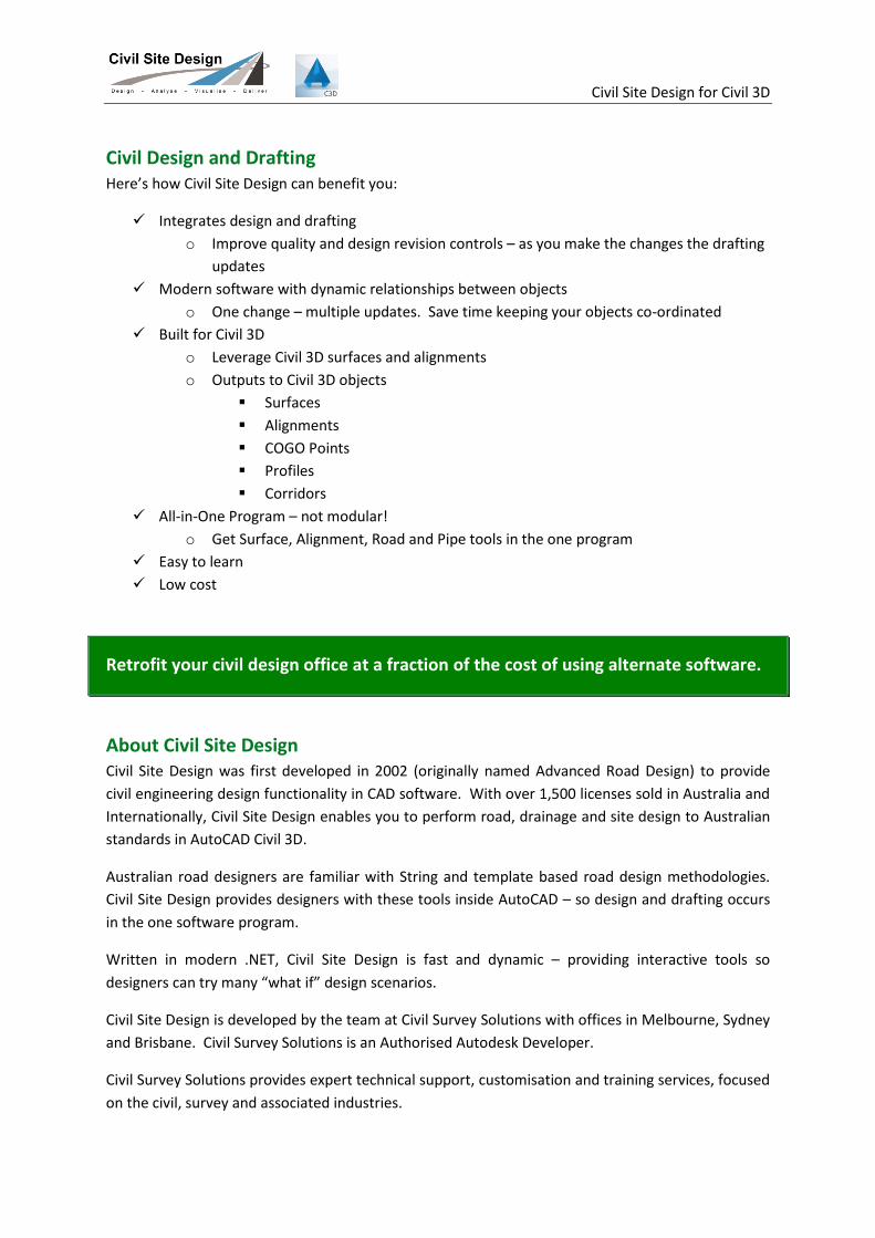
Site Grading Built for rapid design of features such as
building pads, retaining walls and
detention basins, the dynamic grading
tools automatically clean up internal
overlapping corners and include radial and
mitre options on external corners.
The surface and grading linework
automatically updates as you edit your
grading, so you get immediate feedback on
the impact of your design changes, as you make them.
You can immediately review volume outputs after making design changes, enabling easy volume
checking and optimisation. Overlay surfaces or use the CSD Surface Modelling tools to create one
total dynamic surface model incorporating all your land development components – perfect for lot
grading.
The grading tools support cross section templates and intelligent batter designs to address any site
design requirements. As well, you can combine template and string based designs into the grading
models to get the fine level of control you require.
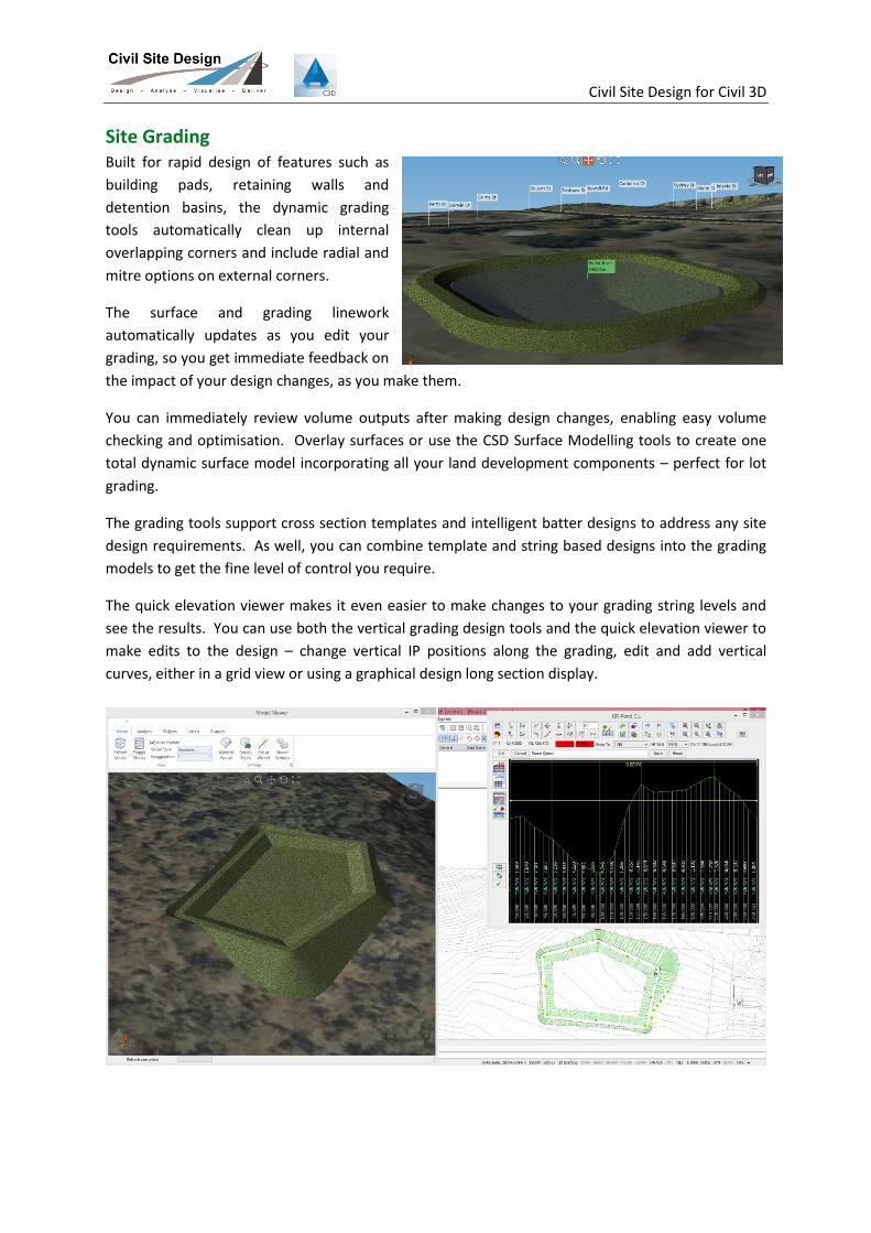
The quick elevation viewer makes it even easier to make changes to your grading string levels and
see the results. You can use both the vertical grading design tools and the quick elevation viewer to
make edits to the design – change vertical IP positions along the grading, edit and add vertical
curves, either in a grid view or using a graphical design long section display.
Civil Site Design for Civil 3D
Road Design Our philosophy of combining template and
String based design, as well as automating
common design elements such as
intersections and cul-de-sacs, provides a
familiar and complete set of tools for rapid
creation and output of your road subdivision,
reconstruction, rural, highway and other
design projects.
Create four dynamic and interactive views of your road design – plan, long section, cross section and
model.
As you edit your road profile in the Vertical Grading Editor, watch your cross sections, plan drafting
and interactive 3D model update in real time. You can show as many design objects as you like on
screen, giving you the power to design multiple objects simultaneously and to immediately assess
the interactions between design elements.
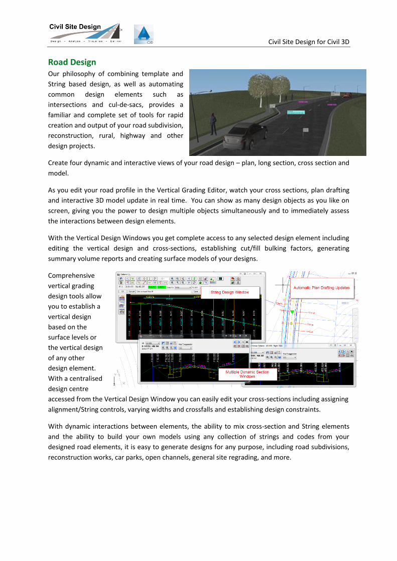
With the Vertical Design Windows you get complete access to any selected design element including
editing the vertical design and cross-sections, establishing cut/fill bulking factors, generating
summary volume reports and creating surface models of your designs.
Comprehensive
vertical grading
design tools allow
you to establish a
vertical design
based on the
surface levels or
the vertical design
of any other
design element.
With a centralised
design centre
accessed from the Vertical Design Window you can easily edit your cross-sections including assigning
alignment/String controls, varying widths and crossfalls and establishing design constraints.
With dynamic interactions between elements, the ability to mix cross-section and String elements
and the ability to build your own models using any collection of strings and codes from your
designed road elements, it is easy to generate designs for any purpose, including road subdivisions,
reconstruction works, car parks, open channels, general site regrading, and more.

Civil Site Design for Civil 3D
Plotting and Publishing to Your Drafting Standards As you complete section of your design you can publish it in the drawing, ready for plotting your
tender and construction plans. Civil Site Design has all the tools you need to rapidly generate
industry standard outputs of your designs directly inside your drawing, ready for immediate
plotting.
With Civil Site Design you can interactively control the sheet layout, scales, layers and linetypes of
your long and cross sections as well as what to present in your outputs. Plotting output styles can be
saved for reuse, and you can output them to separate drawings or as layouts in the current drawing.
Point setout, plan drafting of the
models and slope patterns are all
created directly inside your drawing.
Civil Site Design for Civil 3D
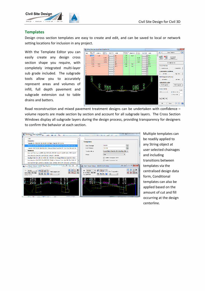
Templates Design cross section templates are easy to create and edit, and can be saved to local or network
setting locations for inclusion in any project.
With the Template Editor you can
easily create any design cross
section shape you require, with
completely integrated multi-layer
sub grade included. The subgrade
tools allow you to accurately
represent areas and volumes of
infill, full depth pavement and
subgrade extension out to table
drains and batters.
Road reconstruction and mixed pavement treatment designs can be undertaken with confidence –
volume reports are made section by section and account for all subgrade layers. The Cross Section
Windows display all subgrade layers during the design process, providing transparency for designers
to confirm the behavior at each section.
Multiple templates can
be readily applied to
any String object at
user selected chainages
and including
transitions between
templates via the
centralised design data
form, Conditional
templates can also be
applied based on the
amount of cut and fill
occurring at the design
centerline.
Civil Site Design for Civil 3D
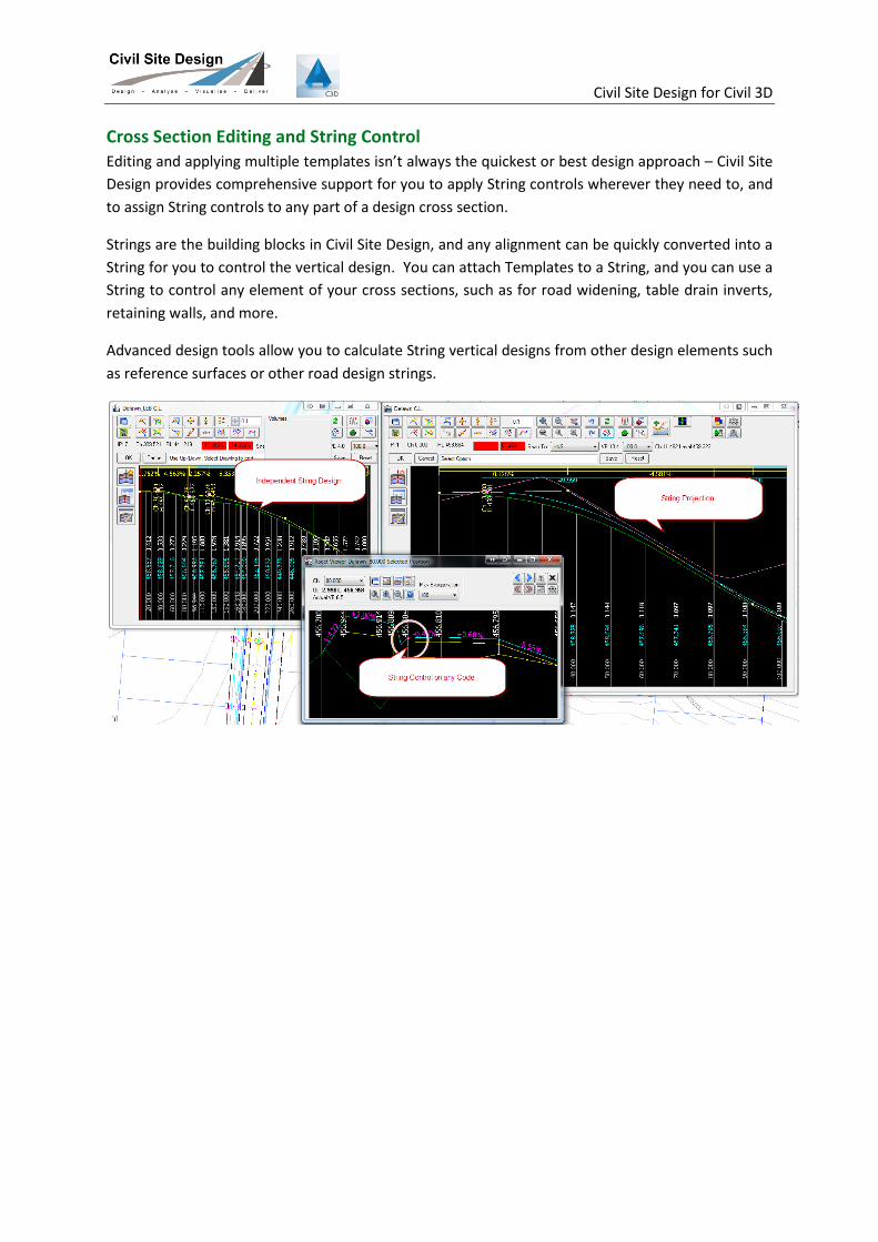
Cross Section Editing and String Control Editing and applying multiple templates isn’t always the quickest or best design approach – Civil Site
Design provides comprehensive support for you to apply String controls wherever they need to, and
to assign String controls to any part of a design cross section.
Strings are the building blocks in Civil Site Design, and any alignment can be quickly converted into a
String for you to control the vertical design. You can attach Templates to a String, and you can use a
String to control any element of your cross sections, such as for road widening, table drain inverts,
retaining walls, and more.
Advanced design tools allow you to calculate String vertical designs from other design elements such
as reference surfaces or other road design strings.

Civil Site Design for Civil 3D
You Design It - Civil Site Design Will Model It You can create your own design models in the software,
applying any combination of roads, kerb returns, cul-de-
sacs or other strings at user defined chainage ranges. Civil
Site Design’s modeling tools provide designer freedom
– build models of car parks,
retaining walls, building
foundations, wetlands or
any other feature using the
Civil Site Design Model
Manager.
Inside the Civil Site Design
Model Manager, users tick on/off design elements to include in a model and have access to trim
functions to remove any collection of codes or code groups (perfect for manual intersection
trimming and code overlaps). As edits are being applied, the plan drafting in the drawing updates,
so you have confidence on your modeling outcomes as you make changes.
There is a click button output to build a surface from any Model. Model results can be represented
on your output cross sections for accurate section results. Long sections can be extracted through
the model as required.
Civil Site Design’s modeling tools allow you to put together any
collection of roads, strings and cross-section codes,
over user-selected chainage ranges, to
allow for all your design
requirements.
Civil Site Design for Civil 3D
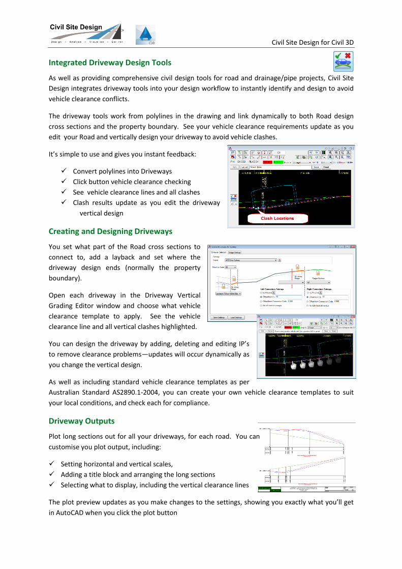
Integrated Driveway Design Tools
As well as providing comprehensive civil design tools for road and drainage/pipe projects, Civil Site
Design integrates driveway tools into your design workflow to instantly identify and design to avoid
vehicle clearance conflicts.
The driveway tools work from polylines in the drawing and link dynamically to both Road design
cross sections and the property boundary. See your vehicle clearance requirements update as you
edit your Road and vertically design your driveway to avoid vehicle clashes.
It’s simple to use and gives you instant feedback:
Convert polylines into Driveways
Click button vehicle clearance checking
See vehicle clearance lines and all clashes
Clash results update as you edit the driveway
vertical design
Creating and Designing Driveways
You set what part of the Road cross sections to
connect to, add a layback and set where the
driveway design ends (normally the property
boundary).
Open each driveway in the Driveway Vertical
Grading Editor window and choose what vehicle
clearance template to apply. See the vehicle
clearance line and all vertical clashes highlighted.
You can design the driveway by adding, deleting and editing IP’s
to remove clearance problems—updates will occur dynamically as
you change the vertical design.
As well as including standard vehicle clearance templates as per
Australian Standard AS2890.1-2004, you can create your own vehicle clearance templates to suit
your local conditions, and check each for compliance.
Driveway Outputs
Plot long sections out for all your driveways, for each road. You can
customise you plot output, including:
Setting horizontal and vertical scales,
Adding a title block and arranging the long sections
Selecting what to display, including the vertical clearance lines
The plot preview updates as you make changes to the settings, showing you exactly what you’ll get
in AutoCAD when you click the plot button

Civil Site Design for Civil 3D
Road Subdivision Design Tools With Civil Site Design you can automate your common road subdivision design processes using
intelligent objects that can handle design elements such as intersections, kerb returns, cul-de-sacs
and knuckles.
As you edit any of the subdivision objects the drafting linework updates in the drawing - at the click
of a button a surface model is created incorporating all the road, kerb returns, cul-de-sacs and
knuckles including all trimming of strings at intersections. As you make changes to Roads, all other
intersection and road type objects automatically update to ensure design integrity in the model.
Intersections
Intersections are automatically
created and incorporated into the
road model, including dynamic
connectivity for side and crossing
roads and inclusion of kerb returns.
Kerb returns automatically and
dynamically position themselves both
horizontally and vertically to the
intersecting roads. Design wizards allow for user creation of single or multi radius kerb returns, or
your own alignments. The auto kerb return function creates multiple kerb returns at once, all
matched to the intersecting roads and with cross-sections automatically matching between the main
and side roads.
You have complete control over the kerb return geometry, with the software managing the
connections to the roads start and end – redesign your roads knowing that the intersection
geometry will automatically update.
Civil Site Design for Civil 3D
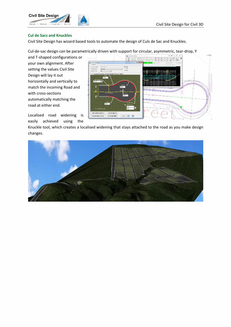
Cul de Sacs and Knuckles
Civil Site Design has wizard based tools to automate the design of Culs de Sac and Knuckles.
Cul-de-sac design can be parametrically driven with support for circular, asymmetric, tear-drop, Y
and T-shaped configurations or
your own alignment. After
setting the values Civil Site
Design will lay it out
horizontally and vertically to
match the incoming Road and
with cross-sections
automatically matching the
road at either end.
Localised road widening is
easily achieved using the
Knuckle tool, which creates a localised widening that stays attached to the road as you make design
changes.
Civil Site Design for Civil 3D
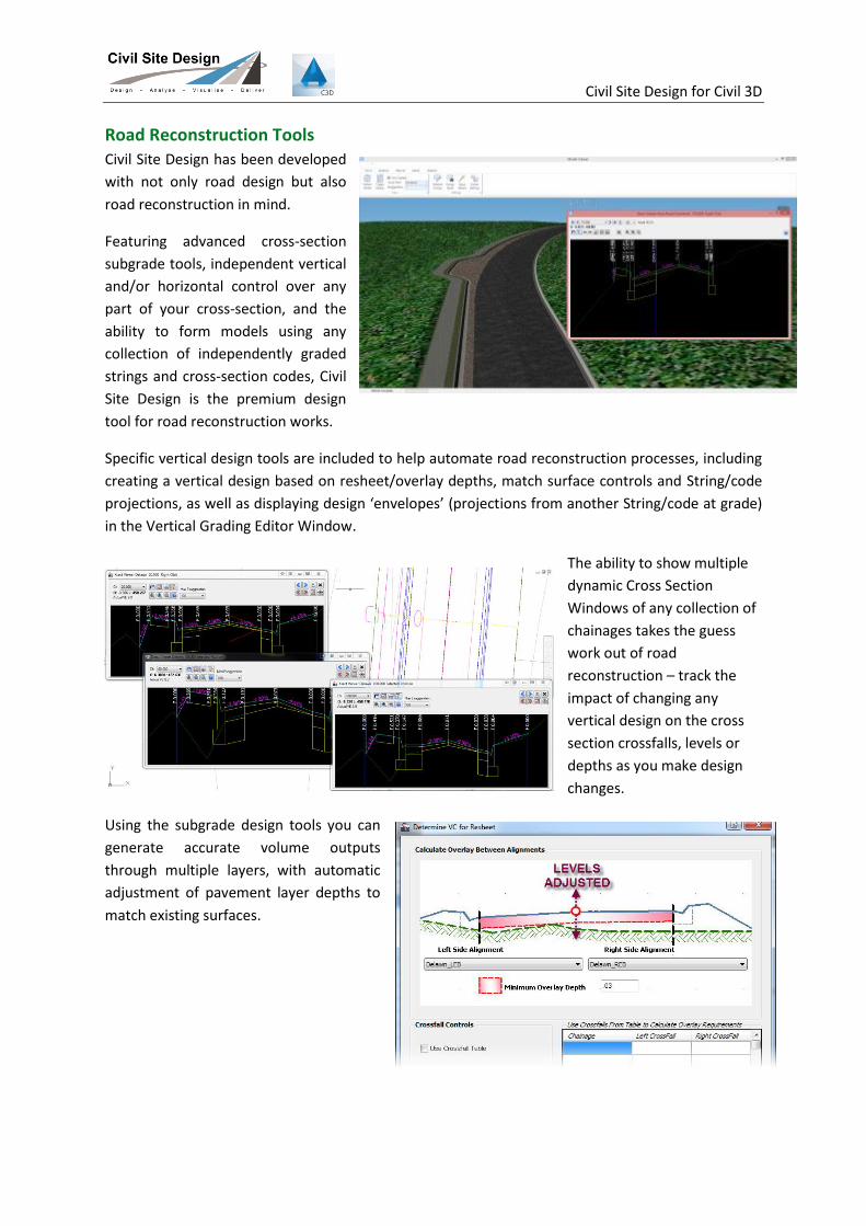
Road Reconstruction Tools Civil Site Design has been developed
with not only road design but also
road reconstruction in mind.
Featuring advanced cross-section
subgrade tools, independent vertical
and/or horizontal control over any
part of your cross-section, and the
ability to form models using any
collection of independently graded
strings and cross-section codes, Civil
Site Design is the premium design
tool for road reconstruction works.
Specific vertical design tools are included to help automate road reconstruction processes, including
creating a vertical design based on resheet/overlay depths, match surface controls and String/code
projections, as well as displaying design ‘envelopes’ (projections from another String/code at grade)
in the Vertical Grading Editor Window.
The ability to show multiple
dynamic Cross Section
Windows of any collection of
chainages takes the guess
work out of road
reconstruction – track the
impact of changing any
vertical design on the cross
section crossfalls, levels or
depths as you make design
changes.
Using the subgrade design tools you can
generate accurate volume outputs
through multiple layers, with automatic
adjustment of pavement layer depths to
match existing surfaces.
Civil Site Design for Civil 3D
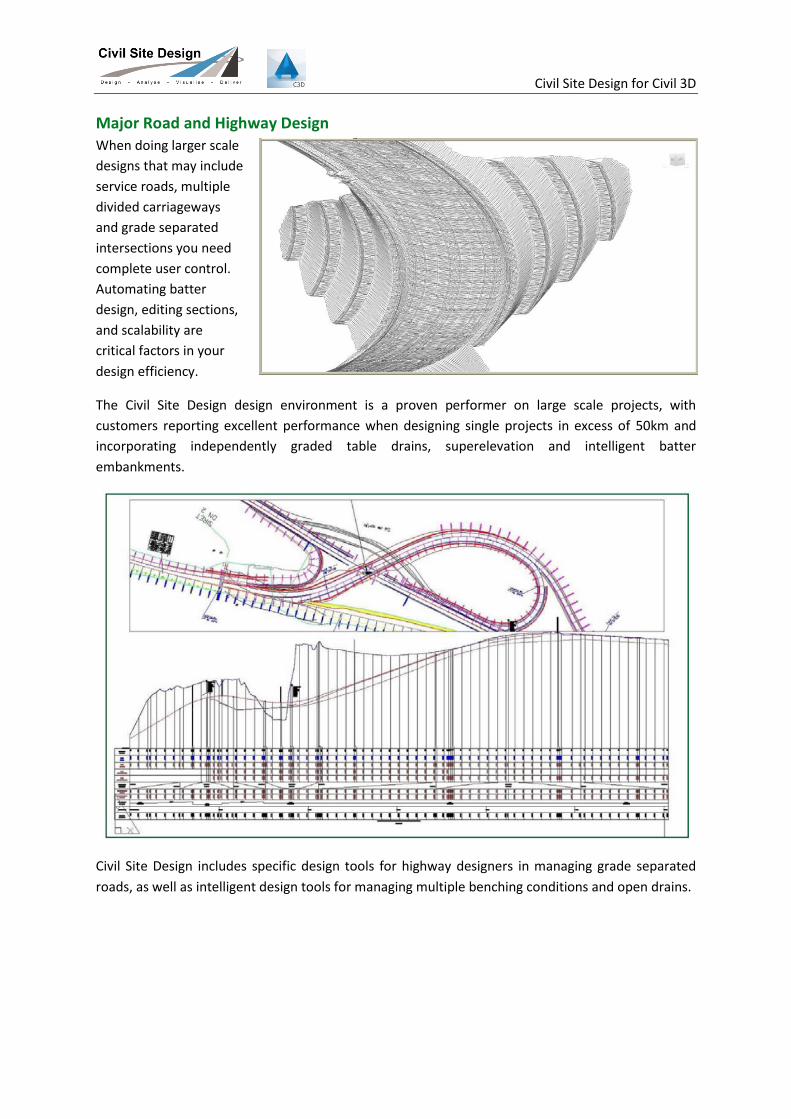
Major Road and Highway Design When doing larger scale
designs that may include
service roads, multiple
divided carriageways
and grade separated
intersections you need
complete user control.
Automating batter
design, editing sections,
and scalability are
critical factors in your
design efficiency.
The Civil Site Design design environment is a proven performer on large scale projects, with
customers reporting excellent performance when designing single projects in excess of 50km and
incorporating independently graded table drains, superelevation and intelligent batter
embankments.
Civil Site Design includes specific design tools for highway designers in managing grade separated
roads, as well as intelligent design tools for managing multiple benching conditions and open drains.
Civil Site Design for Civil 3D
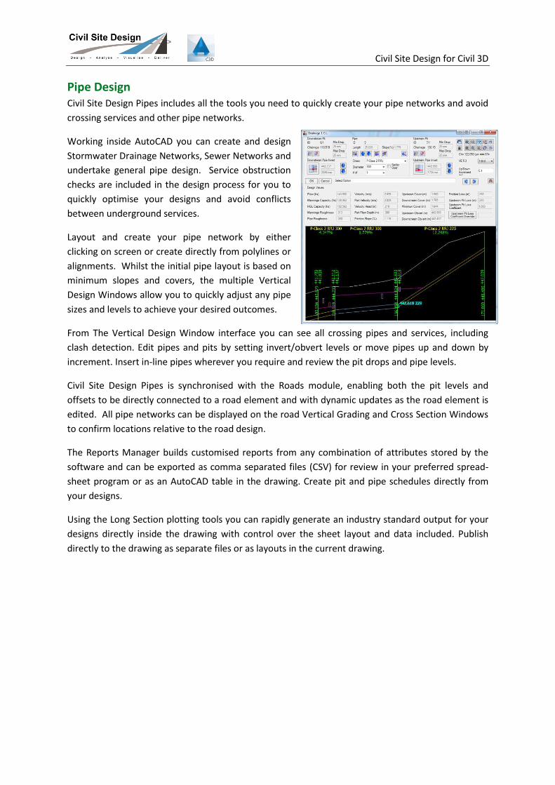
Pipe Design Civil Site Design Pipes includes all the tools you need to quickly create your pipe networks and avoid
crossing services and other pipe networks.
Working inside AutoCAD you can create and design
Stormwater Drainage Networks, Sewer Networks and
undertake general pipe design. Service obstruction
checks are included in the design process for you to
quickly optimise your designs and avoid conflicts
between underground services.
Layout and create your pipe network by either
clicking on screen or create directly from polylines or
alignments. Whilst the initial pipe layout is based on
minimum slopes and covers, the multiple Vertical
Design Windows allow you to quickly adjust any pipe
sizes and levels to achieve your desired outcomes.
From The Vertical Design Window interface you can see all crossing pipes and services, including
clash detection. Edit pipes and pits by setting invert/obvert levels or move pipes up and down by
increment. Insert in-line pipes wherever you require and review the pit drops and pipe levels.
Civil Site Design Pipes is synchronised with the Roads module, enabling both the pit levels and
offsets to be directly connected to a road element and with dynamic updates as the road element is
edited. All pipe networks can be displayed on the road Vertical Grading and Cross Section Windows
to confirm locations relative to the road design.
The Reports Manager builds customised reports from any combination of attributes stored by the
software and can be exported as comma separated files (CSV) for review in your preferred spread-
sheet program or as an AutoCAD table in the drawing. Create pit and pipe schedules directly from
your designs.
Using the Long Section plotting tools you can rapidly generate an industry standard output for your
designs directly inside the drawing with control over the sheet layout and data included. Publish
directly to the drawing as separate files or as layouts in the current drawing.
Civil Site Design for Civil 3D
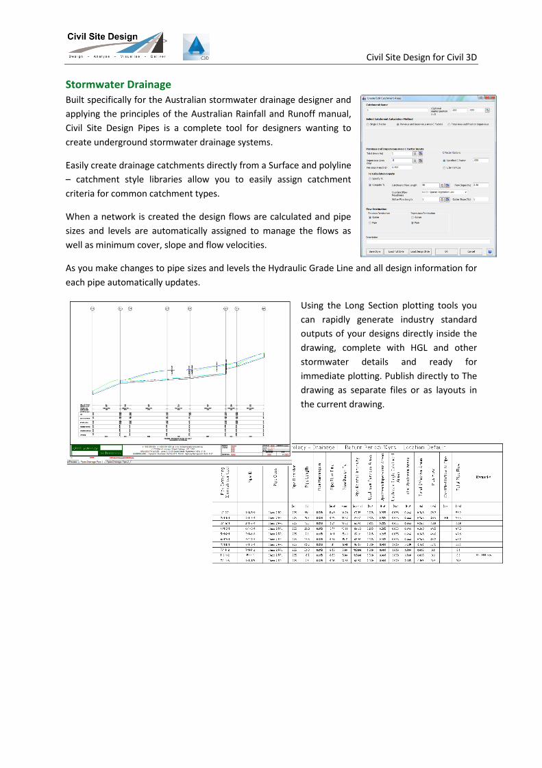
Stormwater Drainage Built specifically for the Australian stormwater drainage designer and
applying the principles of the Australian Rainfall and Runoff manual,
Civil Site Design Pipes is a complete tool for designers wanting to
create underground stormwater drainage systems.
Easily create drainage catchments directly from a Surface and polyline
– catchment style libraries allow you to easily assign catchment
criteria for common catchment types.
When a network is created the design flows are calculated and pipe
sizes and levels are automatically assigned to manage the flows as
well as minimum cover, slope and flow velocities.
As you make changes to pipe sizes and levels the Hydraulic Grade Line and all design information for
each pipe automatically updates.
Using the Long Section plotting tools you
can rapidly generate industry standard
outputs of your designs directly inside the
drawing, complete with HGL and other
stormwater details and ready for
immediate plotting. Publish directly to The
drawing as separate files or as layouts in
the current drawing.

Civil Site Design for Civil 3D
Sewer Design
Civil Site Design Pipes incorporates a comprehensive set of sewer pipe design tools.
Sewer house/property connections are
included in the design tools and can check
depth controls and minimum levels along the
sewer network. Each house connection can be
viewed in a Vertical Design window for editing
and adjustment.
The sewer network will automatically adjust to
ensure compliance with the minimum house
connection levels, and you will be alerted if
sewer pipe edits result in any compliance
issues with house/property connections.
Interactive vertical design windows are able to display any branch of pipes in a network and
complete with editing tools you can quickly and easily design a system to avoid all conflicts and
service the house/property connection. All house connections, service obstructions and other
networks display as crossing pipes, including clearance controls - as you make changes to pipe sizes
and levels you can immediately identify and address any conflicts.
Detailed and specific reporting tools for sewer designers enable quick identification of any
house/property connection issues.
Using the Long Section plotting tools you can rapidly generate industry standard outputs of your
designs directly inside the drawing, including house connection controls and ready for immediate
plotting. Publish directly to the drawing as separate files or as layouts in the current drawing.
Plan drafting occurs directly in the drawing including selected attributes from your design specific to
sewer design.
Civil Site Design for Civil 3D
Drafting You never leave the Civil 3D and AutoCAD drawing environment using Civil Site Design. Since the
drafting outputs in the model update as design changes are made, revision control is far easier to
manage and with much less risk of forgetting to update outputs when a design change is applied.
You can select the layers to output information.
Long sections and cross sections created from your design can be output to layouts on your
preferred title blocks, saving you time between design and final drafting.
Your pipe designs output to long sections in layouts or to external files, and the design tables for
setout and documentation can output directly to The drawing as AutoCAD tables.
Reports Civil Site Design includes a comprehensive set of reports, outputting both as external text files and
into the drawing as AutoCAD tables.
Alignment information can be readily outputted to user definable AutoCAD tables – you pick what
information you want and how it is arranged and click the button for it to be displayed in The
drawing ready for plotting. Alignment tables detail the alignment geometry, and curve tables enable
quick setout of curves along the alignment.
As part of the road design process users can quickly generate setout reports, section volume reports,
cross section listing reports, vertical design reports and more.
For road set out, set out all points for all road design objects at once – label in the drawing, generate
AutoCAD tables and display the setout locations on your long sections. Reports are customisable –
pick what information to place in each column and output both to the drawing and to file.
The Pipes design processes include a myriad of text and drawing output tables – quickly set up your
own output table in The drawing showing pipe and pit geometry and hydraulic information suitable
for stormwater design.
Civil Site Design for Civil 3D
Links Civil Site Design interfaces with other design programs that support Land XML transfer. Via LandXML
users can share surface and alignment data, as well as export Road data for upload to survey
equipment.
For pipe design, Civil Site Design shares data with:
WaterCom Drains: export pit, pipe, catchment and bypass geometry from Civil Site Design
directly to WaterCom Drains to save hours setting up your data. Data can also be exported
from Drains and imported into Civil Site Design for plotting of long sections to AutoCAD
PC Drain: use the PC Drain link to export pipe, pit and catchment data to PC Drain for further
analysis, design and output from PC Drain
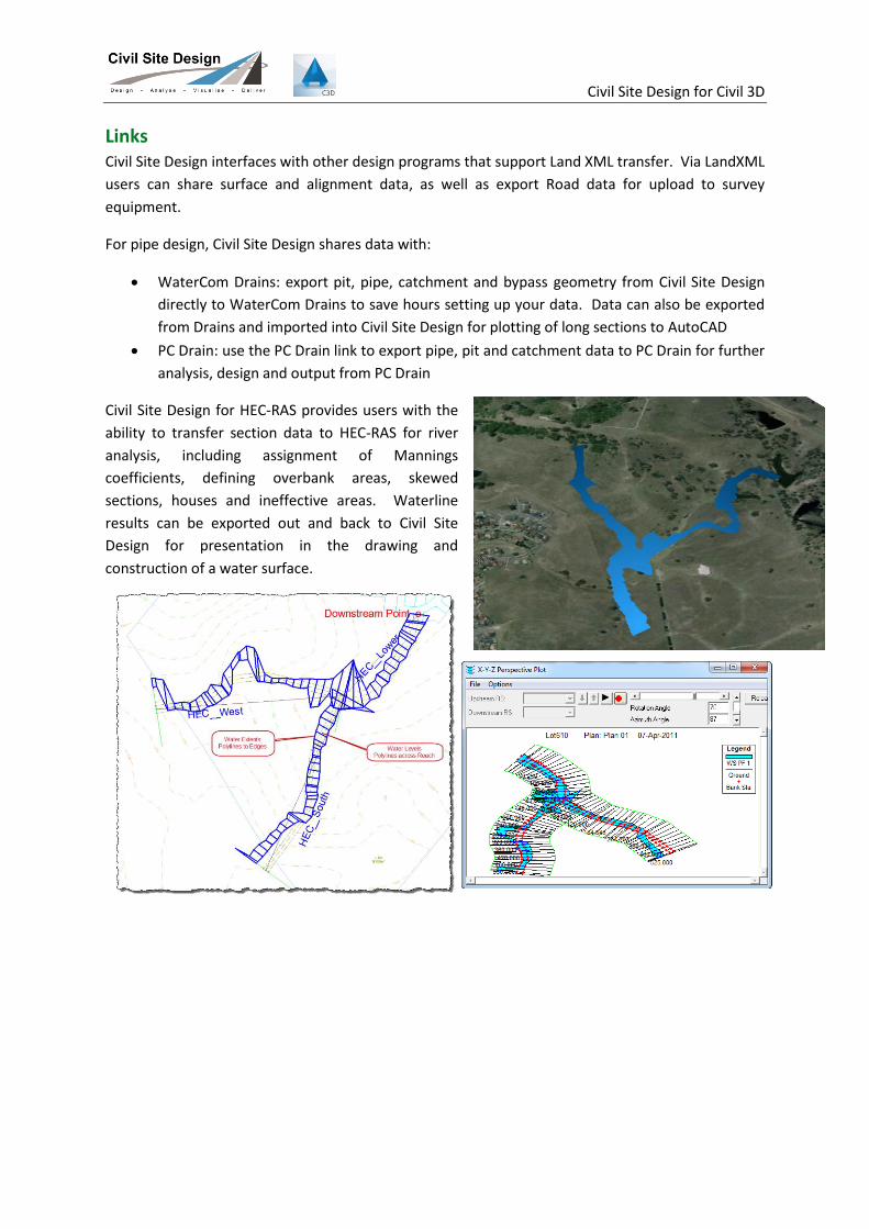
Civil Site Design for HEC-RAS provides users with the
ability to transfer section data to HEC-RAS for river
analysis, including assignment of Mannings
coefficients, defining overbank areas, skewed
sections, houses and ineffective areas. Waterline
results can be exported out and back to Civil Site
Design for presentation in the drawing and
construction of a water surface.
Civil Site Design for Civil 3D
Services
Training
Civil Site Design is easy to learn – with most operators able to complete road, drainage, sewer design
after only a few days training.
Civil Survey Solutions can provide onsite project based training; class room training or web based
training sessions.
Civil Survey Solutions creates its own training course ware with Australian data sets.
Quick Start Customisation Packages
The software comes complete with a wide variety of presentation styles, which can be easily edited
by the user to meet your company standards.
Whilst the drafting outputs are fully customisable, we recognise that you may want a kick-start to
getting your company standard drafting results in the settings. In order to address this demand we
can offer a Quick Start Customisation Package, which includes:
- Consultation with you regarding your work processes and how your outputs are managed
- Analysis of your project outputs and drawings/drawing templates to understand your
drafting standards (layers, linetypes, blocks, etc)
- Development and delivery of the following Civil Site Design settings/standards for
immediate use at your organisation:
Setting layers used by Civil Site Design
4 x Surface Styles (includes contour labeling styles)
2 x Alignment Styles and 2 x Annotation/Label Sets
1 x Alignment Table Style 2 x Cross Section Templates Default Road Settings
1 x Road Long Section Plot Style 1 x Road Cross Section Plot Style 1 x Setout Output Style 1 x Rainfall table (ARR Maps or Bureau of
Meteorology) added 5 x Pit Types (including pit performance
curves, if supplied) 1 x Pipe Long Section Style Default Pipe Settings
Please contact us for pricing to deliver customisation services.
About Civil Survey Solutions
Civil Survey Solutions is an Autodesk Partner, Authorised Developer and Authorised Training Centre
with offices in New South Wales and Victoria, focusing on the sale and support of Autodesk based
civil engineering and survey software.