civl%2131%)%stacs% - the university of memphis three.pdf · 2010-01-22 · the force f = 450 lb...
TRANSCRIPT

1
CIVL 2131 -‐ Sta-cs Resolu-on of a vector along an axes system
Cartesian Coordinates
Madness takes its toll. Please have exact change.
Objec-ves
Resolve a resultant vector into its components given any pair of axes
View and Review the Cartesian Coordinate/axis system as a basis for vector opera-ons
January 22, 2010 Basic Vector Operations II 2
2
Tools
Law of Sines
Law of Cosines
Basic Trigonometry
Pythagorean Theorem
January 22, 2010 Basic Vector Operations II 3
Review
Both Forces and Moments can be mathema-cally represented as vectors which allows us to have both a consistent representa-on and a convenient set of tools for manipula-ng the elements for analysis
January 22, 2010 Basic Vector Operations II 4

3
Review
Vectors are mathema-cal representa-ons which have two components
Magnitude and
Direc-on
January 22, 2010 Basic Vector Operations II 5
Resolving a Vector along Axes
This -me we will start with the resultant and try to find the components that were combined to get the resultant
We will need to be given the direc-ons of the axes
Remember, they do not need to look like our typical x and y axes
January 22, 2010 Basic Vector Operations II 6

4
Resolving a Vector along Axes
If we are given two axes, a’ and b’
January 22, 2010 Basic Vector Operations II 7
Resolving a Vector along Axes
We would like to find the components of the vector F that lie along the a’ and b’ axes
January 22, 2010 Basic Vector Operations II 8

5
Resolving a Vector along Axes
The a’ and b’ axes in this case are not perpendicular (though them may appear so in my drawing)
January 22, 2010 Basic Vector Operations II 9
Resolving a Vector along Axes
When we added vectors, we chose one to remain sta-onary and one to move
January 22, 2010 Basic Vector Operations II 10
6
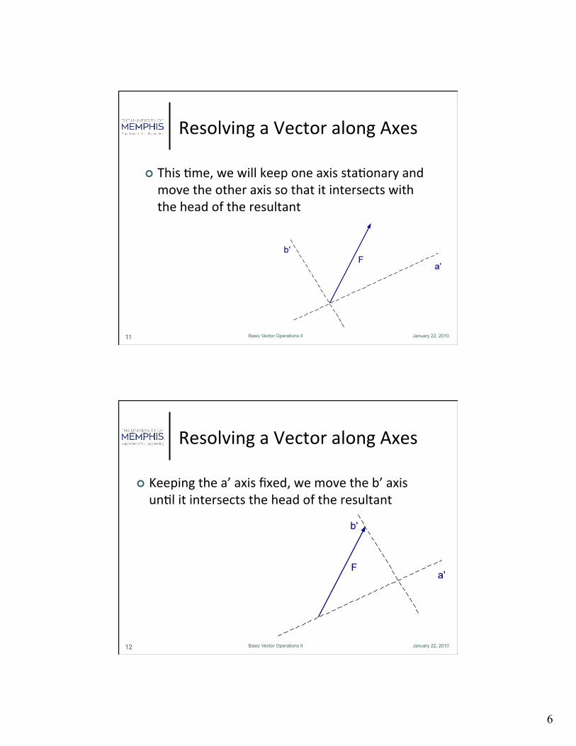
Resolving a Vector along Axes
This -me, we will keep one axis sta-onary and move the other axis so that it intersects with the head of the resultant
January 22, 2010 Basic Vector Operations II 11
Resolving a Vector along Axes
Keeping the a’ axis fixed, we move the b’ axis un-l it intersects the head of the resultant
January 22, 2010 Basic Vector Operations II 12

7
Resolving a Vector along Axes
Now, one of the components will go from the tail of the resultant to the intersec-on of the a’ axis and the shiWed b’ axis
January 22, 2010 Basic Vector Operations II 13
Resolving a Vector along Axes
The other component will go from the head of the vector just constructed to the head of the resultant
January 22, 2010 Basic Vector Operations II 14

8
Resolving a Vector along Axes
Knowing some magnitudes and angles, you can then find the components using trig and geometry
January 22, 2010 Basic Vector Operations II 15
An Example Problem
January 22, 2010 Basic Vector Operations II 16
F2-5. The force F = 450 lb acts on the frame. Resolve the force into components acting along members AB and AC, and determine the magnitude of each component.
9
17 January 22, 2010 Basic Vector Operations II 17
Cartesian Coordinates
There is a special case when the axes are perpendicular
The coordinate system or axis system in this case is known as a Cartesian system
This is the case that we typically see
In the most common 2D case, we have the tradi-onal x and y axis as we developed in the previous class
18 January 22, 2010 Basic Vector Operations II 18
Cartesian Coordinates
Combining component forces in this type of system allows for the use of the Pythagorean formula

10
19 January 22, 2010 Basic Vector Operations II 19
Cartesian Coordinates
For example, consider two forces F1 and F2 whose direc-ons are perpendicular to each other
20 January 22, 2010 Basic Vector Operations II 20
Cartesian Coordinates
We can extend their lines of ac-on to the point where they intersect
Remember that force vectors are sliding vectors and so they can be moved anywhere along their line of ac-on.
The line of ac-on of a vector is the line that would be generated if we extended the vector infinitely in both direc-ons.

11
21 January 22, 2010 Basic Vector Operations II 21
Cartesian Coordinates
So we can move (slide) the vectors un-l we reach a point where the tails of the vectors intersect
22 January 22, 2010 Basic Vector Operations II 22
Cartesian Coordinates
We can set the origin of our coordinate system at this intersec-on

12
23 January 22, 2010 Basic Vector Operations II 23
Cartesian Coordinates
If we place a Cartesian (right angle) set of axis on the forces, we can see that they are also perpendicular
24 January 22, 2010 Basic Vector Operations II 24
Cartesian Coordinates
Again for convenience, we will label the horizontal axis as the x-‐axis, and the ver-cal axis as the y-‐axis

13
25 January 22, 2010 Basic Vector Operations II 25
Cartesian Coordinates
We can move our new reference axis to coincide with the intersec-on of the two lines of ac-on or the origin we specified
26 January 22, 2010 Basic Vector Operations II 26
Cartesian Coordinates
We are going to use the same method to add there two forces (vectors) together that we used before
14
27 January 22, 2010 Basic Vector Operations II 27
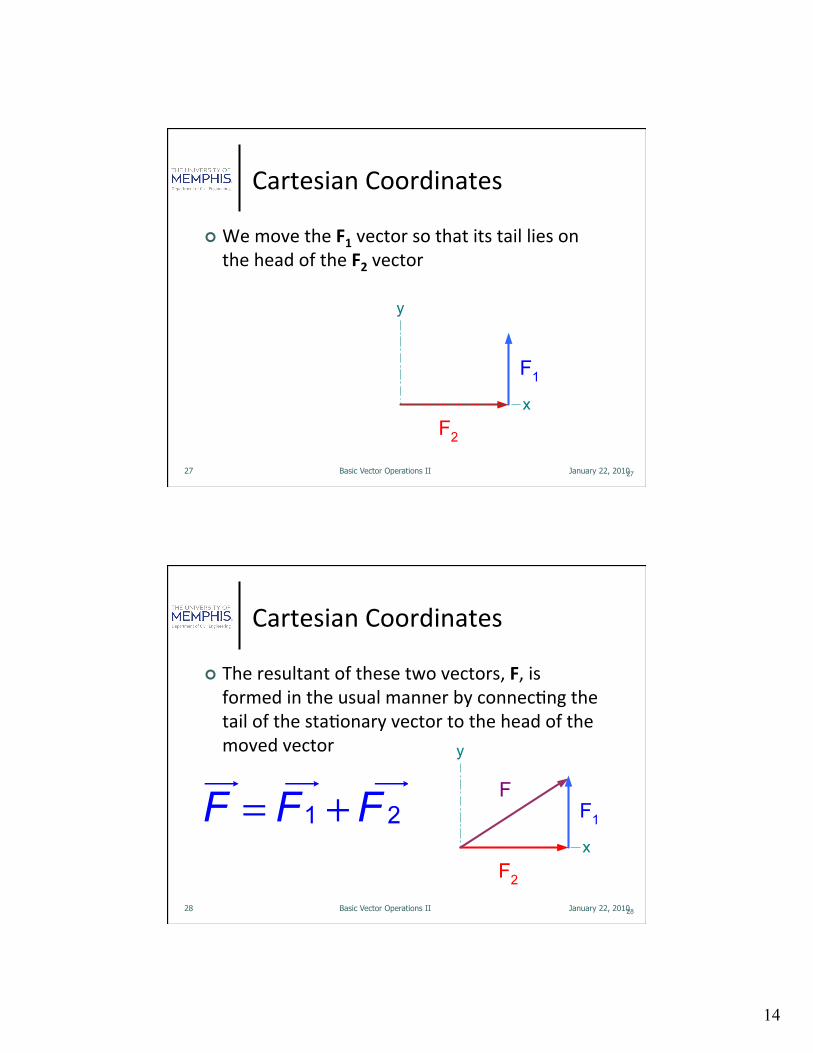
Cartesian Coordinates
We move the F1 vector so that its tail lies on the head of the F2 vector
28 January 22, 2010 Basic Vector Operations II 28
Cartesian Coordinates
The resultant of these two vectors, F, is formed in the usual manner by connec-ng the tail of the sta-onary vector to the head of the moved vector

15
29 January 22, 2010 Basic Vector Operations II 29
Cartesian Coordinates
In this case, since F2 lies along the x-‐axis, it is known as the x-‐component of F
30 January 22, 2010 Basic Vector Operations II 30
Cartesian Coordinates
In this case, since F1 lies along the y-‐axis, it is known as the y-‐component of F

16
31 January 22, 2010 Basic Vector Operations II 31
Cartesian Coordinates
We oWen rewrite this as
32 January 22, 2010 Basic Vector Operations II 32
Cartesian Coordinates
No-ce that the resultant makes an angle α that is CCW with the posi-ve x-‐axis.

17
33 January 22, 2010 Basic Vector Operations II 33
Cartesian Coordinates
From the drawing, we have the following rela-onships
34 January 22, 2010 Basic Vector Operations II 34
Cartesian Coordinates
All of these are drawn from the basic trig rela-onships
18
35 January 22, 2010 Basic Vector Operations II 35
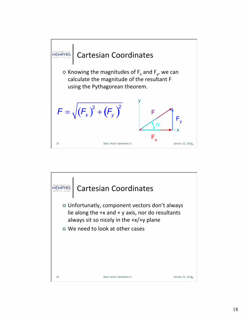
Cartesian Coordinates
Knowing the magnitudes of Fx and Fy, we can calculate the magnitude of the resultant F using the Pythagorean theorem.
36 January 22, 2010 Basic Vector Operations II 36
Cartesian Coordinates
Unfortunatly, component vectors don’t always lie along the +x and + y axis, nor do resultants always sit so nicely in the +x/+y plane
We need to look at other cases

19
37 January 22, 2010 Basic Vector Operations II 37
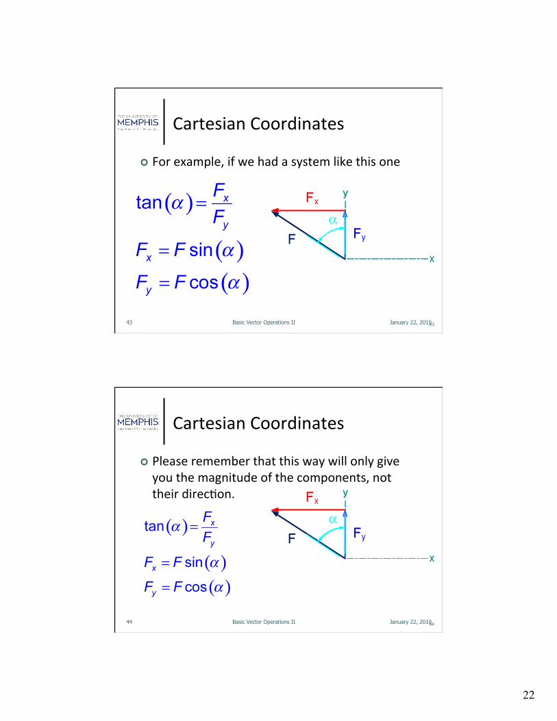
Cartesian Coordinates
For example, if we had a system like this one
38 January 22, 2010 Basic Vector Operations II 38
Cartesian Coordinates
Here the x component is in the nega-ve x-‐direc-on and the y component is in the posi-ve y-‐direc-on

20
39 January 22, 2010 Basic Vector Operations II 39
Cartesian Coordinates
If we use our same method we can move either vector so that the tail of the moved vector is on the head of the sta-onary vector.
40 January 22, 2010 Basic Vector Operations II 40
Cartesian Coordinates
Here the Fy vector is sta-onary and Fx vector is moved

21
41 January 22, 2010 Basic Vector Operations II 41
Cartesian Coordinates
We can s-ll use our trig rela-onships to calculate the components but we have to be careful of just what angle we are looking at
42 January 22, 2010 Basic Vector Operations II 42
Cartesian Coordinates
In this case, our angle is the CCW angle from the +y axis
This is no special angle, just what were given
22
43 January 22, 2010 Basic Vector Operations II 43
Cartesian Coordinates
For example, if we had a system like this one
44 January 22, 2010 Basic Vector Operations II 44
Cartesian Coordinates
Please remember that this way will only give you the magnitude of the components, not their direc-on.

23
45 January 22, 2010 Basic Vector Operations II 45
Cartesian Coordinates
The direc-on (sign) of the components will be based on the direc-ons of the +x and +y axex
46 January 22, 2010 Basic Vector Operations II 46
Cartesian Coordinates
REMEMBER, draw the picture before you try to use trig, even though the trig is always consistent, it does depend on where you draw the angle.

24
Example
January 22, 2010 Basic Vector Operations II 47
2-‐42 (not complete). Determine the components of the forces FA and FB along the x and y axes if FB = 600 N and θ = 20°.