c/k truck current age 1 - gm upfitter - home · make sure connections and fittings cannot leak on...
TRANSCRIPT

C/K Current 2001
C/K TRUCK (CURRENT) 1PA
GE
BODY BUILDERS INSTRUCTIONS
The Incomplete Vehicle Document (IVD) is supplied with each incomplete vehicle, and provides information that should be used byintermediate and final stage manufacturers in determining conformity to applicable Federal Motor Vehicle Safety Standards (FMVSS).The IVD also includes information which must be followed in order to ensure that Environmental Protection Agency (EPA) and Californiaemissions certification requirements and NHTSA Fuel Regulations are met.
This Body Builders Book contains information that may be used in addition to the IVD for any manufacturer making alterations to acomplete/incomplete vehicle. No alteration should be made to the incomplete vehicle which either directly or indirectly results in anycomponent, assembly or system being in nonconformance with any applicable Federal Motor Vehicle Safety Standard or EmissionRegulation. Intermediate and final stage manufacturers should be familiar with all Federal Motor Vehicle Safety Standards and EmissionRegulations and aware of their specific responsibilities as manufacturers.
For further assistance contact Upfitter Integration at: 1 (800) 875-4742, or go to our Web site at “http://www.gmupfitter.com.”
Section 0 — General Instructions
Check for proper clearance between body members and chassis components which may in any way affect the reliability andperformance of the vehicle by developing abrasion and wear points from moving parts or degradation from extreme environment orthermal exposure or may increase interior noise.
Check headlamp aim and all vehicle illumination systems for proper operation when the vehicle has been completed. Re-aim headlampswhen necessary. Check for proper operation of windshield washer, wipers and defroster system.
Extreme care must be taken when working on vehicles equipped with Engine Control Module (ECM), Powertrain Control Module (PCM),Transmission Control Module (TCM), Vehicle Control Module (VCM) or any electronic unit associated with an inflatable restraint system.(See Owner’s Manual).
If arc-welding is employed on the chassis, precautions must be taken to protect all vehicle components, especially brake and fuel lines,fuel tank assembly, electrical wiring and ECM/PCM/TCM or VCM. To avoid electronic component damage, disconnect battery (batteries);disconnect the negative cable first, followed by the positive. To reconnect cables; connect the positive first, then the negative.
When welding components to the frame assembly, remove the wax coating in the area of the weld in order to obtain secure welds. Aftercompletion of the weld, a compatible corrosion protection should be applied to the affected weld areas.
(Section 0 — continued on next page)
C/K Current 2001
C/K TRUCK (CURRENT) 2PA
GE
(Section 0 — continued from previous page)
All labels on the vehicle (any message applied to the vehicle or vehicle component that informs, instructs, or warns) must appear on thecompleted vehicle so the user can read them easily and without obstruction.
Those installing aftermarket systems should provide information as to where and how to obtain service and replacement parts.
When installing a Power Take-Off (PTO) with hydraulic lines, the following care should be exercised:
• Route and secure all hydraulic lines so that they are not in close proximity to any parts of the exhaust system. Keep all fittingsand connections away from the exhaust system. Make sure connections and fittings cannot leak on the exhaust system.
• Exhaust system heat can damage and degrade hydraulic lines and components. Oils and hydraulic fluid coming in contact witha hot exhaust system could result in a fire.
Section 1 — Body
Accessory items; such as refrigerator, hot water heater, furnace, etc., which operate on liquid propane gas should be located andprotected to prevent exposure to any flame.
Body structures, interior and accessory arrangements must be designed into the vehicle to provide for proper load distribution on bothaxles and not to exceed any gross axle weight ratings. Lateral load equalization must also be maintained. The resultant Center of Gravityof the unladen vehicle must be within the limits tabulated in the FMVSS 105 section of the Incomplete Vehicle Document.
Body insulation provided by General Motors should not be removed. This includes any thermal or underbody heat shields. This insulationis provided to protect the vehicle body and occupants from excessive heat and/or provide noise attenuation. Any replacement materialinternal to the occupant compartment must be certified for FMVSS 302 Flammability of Interior Materials. Areas of specific concern, butnot limited to are:
• Underbody exhaust, muffler and tail pipe shields and insulators.
• Rear load floor interior insulation.
• Front floor interior insulation.
• Dash mat insulation.
• Engine cowl insulation – interior and exterior.
• Engine cover insulation.(Section 1 — continued on next page)

C/K Current 2001
C/K TRUCK (CURRENT) 3PA
GE
(Section 1 — continued from previous page)
Conversions
A minimum of 10º departure angle should be maintained if frame and/or body is extended.
If body builder installs seating other than that supplied with vehicle, it is the body builder’s responsibility to ensure that the seating andrestraint systems comply with FMVSS requirements. The restraint systems supplied with the vehicle were designed to accommodate theseating reference points and seat travel of the original equipment seats only.
Air Conditioning
For additional information refer to Engine - Section 6.
NOTE: Air conditioning systems using R-134A refrigerant are equipped with metric fittings to prevent interchange with R-12 refrigerantcomponents. Do not interchange R-134A components, refrigerant oil or service equipment with R-12 components, refrigerant oilor service equipment.
Rear Air Conditioning
This unit may be equipped with A/C quick-connect fittings (Option YF7) on the liquid tube (high pressure) and the suction (low pressure)return tube. These fittings are designed to accept matching Aeroquip connecting fittings attached to pre-charged lines. This allows a onetime only connection to the O.E.M. charged A/C system without having to discharge, evacuate and recharge for the connection of a rearA/C system.
A modification to the A/C system which causes the A/C plumbing lines to increase in length (such as the addition of a rear after-marketevaporator and blower assembly) will necessitate the following changes:
• Lubrication – PAG refrigerant oil must be added to rear system to provide lubrication for compressor. Refer to Service Manualfor specifications.
• Refrigerant – Add R-134A refrigerant to system based on sizing of new tubes, hoses and evaporator. Contact your A/C supplierfor recommended charge.
• Label – Revise/modify GM charge label (located on top of front evaporator or A/C bottle) from factory recommended charge fora front system only to body builder’s new recommended dual system per SAE J639. This is important for servicing the A/Csystem so that the technician knows the correct amount to add to the modified system.

C/K Current 2001
C/K TRUCK (CURRENT) 4PA
GE
Section 2 — Frame
Hole drilling, welding, modifications, or alterations to the frame assembly are the responsibility of persons performing these operations.These same individuals assume complete responsibility for frame assembly reliability, performance after alterations and compliance toapplicable FMVSS requirements.
The following procedures and specific precautionary instructions are recommended for proper installation of special bodies and/orequipment on GM frames. Failure to follow these recommendations could result in serious damage to the basic vehicle.
Flanges
Do not drill holes in frame flanges.
Holes
Holes to mount brackets, supports, and out-riggers must be drilled in the vertical side rail web with the following restrictions:
• Material between edge of hole and inside of upper or lower flange must not be less than 37 mm (1.50 in.) for low carbon steel(36,000 PSI yield).
• The minimum edge distance between any two (2) holes must be larger than twice the diameter of the larger hole.
• No holes should exceed 20 mm (0.75 in.) in diameter.
• All holes should be drilled in the frame using appropriate drilling practice and safety precautions.
Welding
CAUTION: Fuel tank and fuel lines must be drained and all vapors purged to ensure non-combustible mixture before any welding,brazing or soldering.
When welding low carbon steel side rails, crossmembers and brackets (32,000 or 36,000 PSI yield strength), emphasis is placed uponweld application techniques to avoid stress risers that may adversely affect frame operating stresses.
When welding is performed anywhere on the vehicle, precautionary measures should be taken to prevent damage to electrical system wiringor components. Prior to any welding, parts or components which could be damaged by excessive temperatures must be removed oradequately shielded; the battery cables should be disconnected at the battery. Also prior to welding, the area to be welded and surroundingarea must be cleaned of all frame protective coating. After welding, when parts are cool, carefully inspect wiring and electrical
(Section 2 — continued on next page)

C/K Current 2001
C/K TRUCK (CURRENT) 5PA
GE
(Section 2 — continued from previous page)
components for shorts or other damage which could draw excessive currents and possibly cause an electrical system short when thebattery is reconnected. Apply protective coating to areas where coating was removed.
Alterations
If the wheelbase is modified the alterer must take responsibility for compliance with affected MVSS and for warranty on items such asdriveshafts, universal joints, center bearings and rear transmission tailshaft, transfer case and transmission case fractures, output shaftbushings, bearings, brakes, fuel systems and any other related component failures. Additionally, the customer must be alerted in themodifier’s owner’s manual that parts for the reworked area are not available through the General Motors service parts system.
Shear Plate Attachments
Attachments of shear plates should be accomplished by using existing manufacturing holes already available in the frame side rails.Manufacturing holes, normally 16 mm in diameter, are consistently placed along the frame side member in the center of the web on eachframe.
When additional holes are required for shear plate attachment, they should be no larger than 19 mm (0.75 in.) in diameter. Holes are to bedrilled no closer than 63.5 mm (2.5 in.) apart. For holes drilled forward of the rear axle, centers are to be no closer than 63.5 mm (2.5 in.)from the top or bottom flanges and no closer than 89 mm (3.5 in.) from any suspension attachments. For frame holes drilled rearward ofthe rear axle, hole centers are to be no closer than 51 mm (2.0 in.) from the top or bottom flange and no closer than 89 mm (3.5 in.) fromsuspension attachments.
No additional holes or notching of either top or bottom frame flanges are allowed.
Section 3 — Front Suspension
Since there is a large variation in completed vehicle front weight due to differences in body weight and equipment, the front suspensionalignment must be checked and reset if necessary after the vehicle is completed. Caster and camber should be set with reference to the“A” dimensions. On C3500HD trucks with I-beams, camber and caster is designed into the axle/suspension and cannot be adjusted.
See Truck Service Manual for complete alignment procedure, specifications and measurement of the “A” dimension under “Diagnosisand Front Alignment” section.
C/K Models are designed such that camber and caster do not need adjustment unless severe road impact or accident deformationoccurs. Toe should be reset after the vehicle is completed and while at normal operating load with trim height as specified (K-Model).
(Section 3 — continued on next page)

C/K Current 2001
C/K TRUCK (CURRENT) 6PA
GE
(Section 3 — continued from previous page)
The following statement applies to C3500HD Models with I-Beam Front Axle.
The front crossmember steering gear attachment is a weldment. Under no conditions may the flanges be cut or notched out in anymanner. Any alteration would severely affect steering attachment capabilities.
Section 4 — Rear Suspension
Clearance to body should be provided for the suspension, axle, driveshaft and tires under the following conditions: (1) Axle in full jounceagainst the metal-to-metal stop, (2) Axle at 4.5º roll with one side of axle in full jounce at the metal-to-metal stop and (3) Axle at designposition. Allowance for the tire chain clearance shown on a maximum grown tire must allow for 42.2 mm (1.66 in.) clearance to the sidesof the tire and 63.5 mm (2.5 in.) to the top of the tire. Be sure sufficient clearance is provided for suspension, axle and tire and wheel in fullvertical travel (up and down).
NOTE: Notification to the consumer may be required in certain states if tire chains cannot be used.
Pipes, wiring, conduits and any other related components must not be placed where they cross the path of motion of the rear axle,driveshaft, axle brake pipes, hoses, spring or tires. Such crossing could result in rupture, wear-through, or separation due to normal axlemotion.
See chassis data information for additional clearances and for assistance in calculating trim heights.
NOTE: Concerns regarding the addition of leafs or modifying the rear suspension on the C3500HD Models, refer to Brakes – Section 5for additional information.
Section 5 — Brakes
See Truck Service Manual for brake specifications.
Due to the critical nature of brake systems, anyone making modifications or alterations must assume complete responsibility for systemreliability, performance and certification to FMVSS 105 or FMVSS 121.
It is mandatory that no change be made to the brake main cylinder location, brake pedal push rod length or pedal position.
Ensure that hydraulic brake system is free of air and hydraulic leaks. Bleed brakes if required, following procedures as outlined in theTruck Chassis Service Manual. Ensure that vacuum booster system or hydroboost system is functional and free of leaks.
(Section 5 — continued on next page)
C/K Current 2001
C/K TRUCK (CURRENT) 7PA
GE
(Section 5 — continued from previous page)
Check master cylinder fluid level and fill as necessary. (Refer to Owner’s Manual).
Check power steering fluid level for models equipped with hydroboost brake. (Refer to Owner’s Manual).
Added floor covering or carpeting must not restrict service or parking brake pedal travel from released position to full pedal travel.
No body part or chassis-mounted component may be located within 2.0 in. of brake hose routing in all wheel and axle positions. Allexhaust system components must also have a minimum of 2.0 in. clearance to brake hoses in closest positions. (Be sure to account forbrake hose travel with suspension.)
Body builder is to verify that the brake warning switch is operative. The brake warning switch on models equipped with vacuum-hydraulicbrakes is located adjacent to the master cylinder vacuum unit. This includes both the brake system differential pressure and parkingbrake actuator switch.
Section 6 — Engine
For additional information refer to Body - Section 1.
Air conditioning and auxiliary belt-driven equipment installation recommendations:
No alterations or additions to the accessory drive belt system will be warranted on serpentine belt systems.
The serpentine belt type of drive is designed as a total system, incorporating a single poly-V belt and an automatic tensioner. In this typeof system, degrees of pulley wrap, belt tension, and pulley alignment are very critical factors. Modification is not recommended.
In some single belt serpentine systems, belt tension is determined by the automatic tensioner and its position relative to the belt. Noadjustment required.
Due to the critical nature of the accelerator system, anyone making modifications or alterations assumes complete responsibility forsystem reliability, performance and compliance to FMVSS 124. Caution must be exercised so that the accelerator cable is properlyrouted. Specifications are as follows:
• Route cable to maximize all bend radii. In no case should bend radii be less than 3 in. (76 mm).
• Minimum distance from exhaust manifold to be 6.0 in. (150 mm), unless a heat shield is provided.
(Section 6 — continued on next page)

C/K Current 2001
C/K TRUCK (CURRENT) 8PA
GE
(Section 6 — continued from previous page)
• Do not use accelerator cable or clips to route wires, harnesses or other cables. Cable sheath must be clipped so as not to pinchinner cable. Cable must not be loose in clip allowing sheath to move when accelerator pedal is applied and released.
• Cable must not be subjected to kinking or routing across any sharp edges.
• Cable routing must be perpendicular to the surface of the front-of-dash at the dashfitting. No objects or routings should forcecable to have a bend at the dash fitting. Flexible components (hoses, wires, conduits, etc.) must not be routed within 2.0 in.(50 mm) of moving parts or accelerator linkage unless routing is positively controlled.
• Caution must be taken so that the accelerator pedal remains properly located. Guidelines for accelerator pedal locations are asfollows:
1) Ensure that the accelerator can freely operate from idle to wide-open throttle position and return. Make sure that the pedalwill not hang up on any nearby items such as carpets, floor, screws, wiring harnesses, etc. Engine cover should have atleast one inch (25 mm) clearance to side of accelerator pedal with the carpet mat installed.
2) Accelerator to brake pedal relationship has been designed to provide minimum driver movement and should not be alteredin any way.
Gasoline engine induction and/or ignition system is certified in compliance with the Federal Vehicle Emission Standards. Any alterationsto the systems or components could void compliance and render the vehicle illegal. System includes:
• Fuel system - throttle body injector (TBI) or central port injector (CPI) and associated tubes, hoses and pipes, air cleaneroutside air hose and spacer heat stove and heat stove pipe, fuel pump and inlet manifold, fuel vapor canister.
• Exhaust system.
• Ignition system distributor and initial spark timing setting, spark plugs, spark plug wires.
• Crankcase ventilation system.
Diesel engine induction and injector pump system is certified to be in compliance with the Federal Vehicle Emission Standards and/orNoise Standards. Any alterations to the system or components could void compliance and render the vehicle illegal. System includes:
• Fuel system - Injection pump, injector lines and injectors, fuel return hoses and pipes, air cleaner, outside airhose, fuel pump,fuel filter, fuel heater assembly and intake manifold.
• Exhaust system.
• Crankcase pressure regulation system.(Section 6 — continued on next page)
C/K Current 2001
C/K TRUCK (CURRENT) 9PA
GE
(Section 6 — continued from previous page)
• Charge air cooler system.
• External engine components such as air cleaner, crankcase pressure regulator valve, alternator, injection pipes, fuel returnhoses from injectors, exhaust manifolds, oil fill pipe, etc., must be provided with sufficient clearance for engine roll and torque.
• When a vehicle is equipped with an electronic fuel injection (EFI) engine, it has an engine control module ECM/PCM/TCM orVCM. This ECM/PCM/TCM or VCM must be maintained at a temperature below 185ºF at all times. This is most essential if thevehicle is put through a paint baking process. The ECM/PCM/TCM or VCM will become inoperative if its temperature exceeds185ºF. Therefore, it is recommended that temporary insulation be placed around the ECM/PCM/TCM or VCM during the timethe vehicle is in a paint oven or undergoing another high temperature process.
Section 7 — Transmission
Light duty models equipped with manual transmission have a clutch-operated start safety switch. Starter should operate whenever theignition is turned to start and the clutch is fully depressed. Readjust if necessary as outlined in the Truck Service Manual.
Models equipped with automatic transmissions have a steering column mounted neutral/park start safety mechanical lockout feature,which interfaces with the steering column ignition switch. Starter should operate only when gear shift lever is in neutral or park position.Readjust the shift linkage if necessary as outlined in the Truck Service Manual.
Power Take-Off (PTO) systems refer to General - Section 0.
• The NV4500 manual 5-speed, heavy-duty overdrive transmission (RPO MW3) requires the use of special synthetic lubricant toreduce transmission internal operating temperatures. The lubricant is installed in all NV4500 transmissions at the factory.
• In instances where it is necessary to drain and refill or add fluid to the transmission, such as when installing PTO, DO NOTsubstitute any other lubricant. Installation of other lubricants may result in internal transmission damage.
• Castrol Syntroq GL4 is the only synthetic lubricant currently approved for use in the NV4500. This product can be securedthrough your local GM dealer under GM part number 12346190 per quart.
• Transmission lubricant capacity is 8.5 pints.
Models equipped with manual transmission use a hydraulic clutch actuator. Check fluid level as outlined in the vehicle owner’s manual.
It is mandatory that no change be made to the clutch master cylinder location, clutch master or slave cylinder push rod length, or pedalposition.

C/K Current 2001
C/K TRUCK (CURRENT) 10PA
GE
Section 8 — Fuel and Exhaust
Fuel Systems
The fuel evaporative emission control equipment is certified to be in compliance with the Federal and California Vehicle EmissionStandards. Metal fuel lines and fuel tanks have a surface coating to reduce corrosion on inside and outside surfaces to comply with usefullife requirements. All fuel hoses are made of a low permeation multi-layer material to comply with enhanced evaporative emissionrequirements. Any alterations to systems or components including materials, hose lengths and their location, except as described in thefuel fill system modifications section, could void compliance. The system includes:
• Fuel tank, fuel level sender, fuel fill and vent hoses and pipes, emission canisters, fuel feed, fuel return and vapor lines, purgecontrol solenoids, fuel fill cap, canister vent solenoid.
For these reasons, NO ALTERATION OF THE FUEL SYSTEM IS RECOMMENDED.
Fuel Fill
It is recommended that when mounting the fuel filler pipe assembly and vent hose that a minimum of 3.0 in. clearance be provided to anybody component to prevent contact between hoses and/or mating parts and that retention be provided to ensure routing and preventfailure due to wear and fatigue. Both the fill and vent hoses must be routed (and supported, if needed) such that there are no sags orkinks. As viewed from the filler neck, pipes and hoses must have a downward slope toward the tank. There should be a minimum of 4º ofdownward slope in the fill and vent pipe at any location. No fuel traps are allowed. Alterations of fuel line routings could affect the abilityof the completed vehicle and are, therefore, not desirable. The complete fuel system must comply with FMVSS 301.
If additional new hose is required when installing fuel tank filler neck, this hose must be suitable for use with unleaded fuels or diesel fuelrespectively and must allow the vehicle to meet enhanced evaporative emissions requirements.
Fuel Lines
Fuel line routing precautions:
• 12 in. minimum clearance to exhaust system is required or a metal shield must be provided.
• Fuel lines should be clipped to chassis to prevent chafing. Metal clips must have rubber or plastic liners.
• Use corrosion resistant steel tubing with short sections of approved hose to connect components. Hose-to-tube connectionsshould be clamped for diesel systems. Steel tube ends should be beaded for hose retention. Fuel supply is pressurized by anin tank pump for TBI and CPI systems. Coupled hose or nylon quick-connects must be used. Clamped hose is not acceptablefor TBI and CPI systems.
(Section 8 — continued on next page)

C/K Current 2001
C/K TRUCK (CURRENT) 11PA
GE
(Section 8 — continued from previous page)
All engines require a fuel return system which returns excess fuel from the injection pump and injector nozzles back to fuel tanks. Careshould be taken that these lines are not blocked nor their hoses pinched. The engine may run poorly or stall if these lines are restricted orblocked.
All gasoline engine vehicles are equipped with fuel evaporative emission control equipment which is certified to be in compliance with theFederal or applicable California vehicle emission standards. Alterations to fuel tank and metering unit, lines, canister or canisters, canisterfilters, canister purge control valves, relay switches, tank auxiliary vent valve, engine speed controller, or other devices/systems aretherefore not allowable since vehicle adherence to C.A.R.B. and Federal regulations may be affected.
Diesel powered vehicles incorporate water drain provisions in the fuel system. These valves are only to be opened when siphoning waterand contaminants from the fuel system.
Body attachment brackets and U-bolts must be located such that there is adequate clearance to all fuel system components, such as thefuel lines and the fuel level sending unit, under all operating conditions.
Fuel Tank
For vehicles with full frames, the tank must have a minimum clearance of 2 inches from top, front, rear and sides to body and othersupports.
Tank may be pressurized to 1.25 PSI maximum to check for final line leakage or for forcing fuel through the system. Pressures greaterthan this amount may be detrimental and affect tank durability.
The use of auxiliary fuel tanks is not recommended. If an auxiliary fuel tank is added, the alterer must take responsibility forcompliance with affected motor vehicle safety standards. Also, if an auxiliary fuel tank is added to a gasoline-powered vehicle, thefuel must be drawn through a pipe at the top of the tank (balance line between tanks is not permitted).
Gasoline fueled vehicles are now equipped with a fuel pump return line. If an auxiliary tank is added, the tank selector valve must includea return port which returns fuel to the tank from which the fuel is being drawn.
In gasoline engines, the fuel pump is located in the fuel tank. The battery must be disconnected before starting any work on the fuelsystem.
Gaseous Fuel Conversions
All truck gasoline engines may be converted to use liquified petroleum gas (LPG) or natural gas (NG); GM only approves the conversionof vehicles with option KL5. However, some conversions may cause harmful effects to the engine. Such fuel systems may require
(Section 8 — continued on next page)

C/K Current 2001
C/K TRUCK (CURRENT) 12PA
GE
(Section 8 — continued from previous page)
assurances from alternate fuel system manufacturers and/or installers that the equipment will not cause damage to the engine or theexhaust system.
In the use of dual fuel systems, the vehicle operator should strictly adhere to the manufacturer’s procedures for switching from gasolineto gaseous fuel operation. Improper switching procedures may result in overheating and damage to the exhaust system and the vehicle.The gaseous fuel tank should not be mounted in an enclosed area of the vehicle, such as the passenger compartment, trunk, etc., and thesystem should be vented to the outside of the vehicle. In addition, vehicles converted to gaseous fuels should not be stored in enclosedplaces such as garages. Further, General Motors cautions purchasers that the design, location and installation of any type of fuel storagesystem involves significant technical and engineering considerations and that these statements on gaseous fuel conversions should notbe interpreted to be an approval by General Motors of any modification to the original equipment fuel system.
Conversions to gaseous fuel should be made in conformance with applicable Federal and State regulations. Removal of emission-controlcomponents, or the addition of gaseous fuel systems which could damage or reduce the longevity of those components could also causethe mechanical and emission performance warranty to be voided.
Exhaust System
Particular care should be taken to prevent the possibility of exhaust fumes and carbon monoxide exposure to vehicle occupants in unitscompleted by body builders. Holes and openings through the floor and all other parts of the body must be permanently and adequatelysealed by the body builder to avoid exhaust intrusion into any occupant area. If it is necessary to change the exhaust outlet location, theexhaust discharge must be unobstructed and directed away from occupant areas. Alteration of the exhaust outlet or its position mayincrease exhaust noise and render the vehicle illegal in those areas with pass-by noise regulations. All vehicles >10,000 lbs. GVWR comeunder Federal noise regulations, vehicles: ≤10,000 lbs. GVWR are regulated by various state and local regulations of the EnvironmentalProtection Agency; see those regulations for rules, test procedure and noise levels permitted.
Tail pipe outlet location must be tested statically and with the vehicle in motion to ensure that exhaust gases do not penetrate side or rearwindows or underbody seams and holes. Auxiliary power plants should also be tested under the same conditions. Tail pipe exit ahead ofrear wheels is not recommended.
Check for leaks in exhaust systems and repair as required.
Exhaust temperatures can exceed 1600ºF under extreme operating conditions, with pipe surface temperatures slightly less than this.Extreme care must be used when placing body components in the proximity of the exhaust system so as not to exceed the ratedtemperature limits of the components. Due to variants in underbody configurations of the vehicles, we are not in a position to makerecommendations on how to insulate or design components in the proximity of the exhaust system.
(Section 8 — continued on next page)

C/K Current 2001
C/K TRUCK (CURRENT) 13PA
GE
(Section 8 — continued from previous page)
Each manufacturer must make temperature checks of critical areas of his vehicle and adjust his design accordingly, or provide shieldingto ensure safe operation of his body components.
The same can be said for the engine compartment. Obviously there will be additional heat radiated from the engine. How much is retainedin the area will depend on how well this area is ventilated in your individual designs. Here again, temperature checks of interior areassurrounding the engine should be made to determine if your insulation is adequate. This is the same engineering practice we havefollowed on our complete vehicles incorporating these exhaust systems.
Exhaust system materials are selected and tested to withstand the operating environment of the vehicle. Do not modify the exhaustsystem in any way. The tail pipes are made of 409 stainless steel.
Heat shields are mounted to the underbody and/or exhaust system components (catalytic converter and muffler). Shields for the propshafthanger bearings are also provided in some vehicles.
Section 9 — Steering
Check power steering fluid level and system operations. (Refer to Owner’s Manual).
Steering wheel and horn pad must not be altered or replaced.
The steering column mast jacket must not be altered.
Section 10 — Tires
Check wheel lug nuts for proper torque; specifications are provided in the Owner’s Manual.
Substitution of tires of greater capacity than those offered as original equipment by vehicle manufacturer is not approved for use onoriginal equipment wheels. Any usage of higher capacity tires must be accompanied by higher capacity wheels. However, the wheeloffset and distance from centerline of rim to wheel mounting face must be the same as the replaced original equipment wheel to ensureproper wheel bearing loading and clearance of tires to body and chassis components. Increasing tire and wheel capacity does notnecessarily increase vehicle GVW ratings.
Any substitution of tires may affect Speedometer/Odometer accuracy.
(Section 10 — continued on next page)

C/K Current 2001
C/K TRUCK (CURRENT) 14PA
GE
(Section 10 — continued from previous page)
It is recommended that tire chain clearance guideline, J683 from the Society of Automotive Engineers be adhered to in designing rearwheelhouse clearance.
Check tires and inflate to recommended tire pressure according to the tire pressure information provided in Owner’s Manual and tireinflation label provided with vehicle.
Section 12 — Electrical Battery and Battery Cables
The vehicle battery should be located and positioned to make use of the existing battery cables. If the battery requires relocation andlonger cables are required, a proportionately larger gauge wire must be used. If, in relocating the battery, the negative ground cable isattached to the frame rail, a cable of similar gauge must be provided between the frame rail and the engine. This is required due to theheavy electrical loads imposed by the starting circuit. To ensure proper operation of the battery cables, the following chart on length,gauge and materials must be strictly adhered to:
Combined length of positive and negativeCable Gauge Cable in Inches (Copper)
4 66
2 107
0 170
If the battery is remotely mounted (other than in the engine compartment) the ‘sense’ circuit in the generator regulator shall be used. Thesense circuit consists of a 7.76 OHM 1/4 watt resistor connected in series between the ‘S’ terminal of the generator and the B+ terminalof the battery.
Auxiliary Battery (Gasoline Engines Only)
If an auxiliary battery is to be retro-fitted, the electrical schematic for option TP2 is recommended as a guide. This will result in theauxiliary battery being connected to the vehicle load and charging circuit when the ignition switch is ‘on’ (fuse block terminal “Acc. Ign.Fused”). When the ignition switch is turned off, the interlocking relay is disengaged and the auxiliary battery is disconnected from thevehicle circuit.
(Section 12 — continued on next page)

C/K Current 2001
C/K TRUCK (CURRENT) 15PA
GE
(Section 12 — continued from previous page)
Modifications/add-on wiring must be carefully reviewed to ensure compatibility with the base vehicle wiring by reviewing systemschematics, wire routing paths, harness connections, etc. Due to the wide range of modifications that may be required for vocationalneeds, it is not feasible for the O.E.M. to take into account all potential revisions. For this reason, any person modifying existing vehiclewiring must assume responsibility that the revisions have not degraded the electrical system performance. Any add-on wiring mustbe properly fused and routed to prevent cut, pinch, and chafe problems, as well as avoid exposure to excessive heat. Care must beexercised that existing vehicle interfaces do not have their current load capabilities exceeded, and that the respective control devicesare not overloaded. Added wire size should be at least as large as the wire to which it is attaching in order for fuse protection to bemaintained.
A Packard Electric wiring repair kit is available through Kent-Moore (GM P/N 12085264, Kent-Moore P/N J38125-4). This kit containsinstructions, tools and components for making repairs to wiring harness components. This kit would also greatly assist in accomplishingnecessary add-on wiring, such as body marker lamps, so that system reliability/durability is maintained.
Electrical wiring components can be obtained through your authorized GM dealer. Many Packard Electric components are also availablethrough Pioneer Standard Company (1-800-PACKARD). Pioneer may also be able to assist in making necessary wiring additions byproviding custom wiring stubs or jumpers to your specifications.
Fusible Link Repair Procedure:
1. Cut damaged fusible link from wiring harness assembly splice.
2. Strip insulation from harness wire as required to splice on new fusible link.
3. Fabricate a new fusible link wire approximately 6 to 8 in. long from the same wire size as the original link. (Acceptable fusiblelink material will be imprinted with the wire size and the wording to identify it as fusible link. Fusible link cable is not the sameas normal vehicle wiring.)
4. Terminate fusible link harness wire with a suitable compression splice clip, and solder with an electrical grade rosin core solder.Splice area with heat-shrink tubing to provide electrical insulation, as well as mechanical strain relief at the splice.
5. Strip, terminate, solder, and insulate remaining end of fusible link with appropriate termination to be compatible with the rest ofthe electrical system.
6. For further information, refer to the instruction manual in the wiring repair kit referenced elsewhere in this section.
(Section 12 — continued on next page)

C/K Current 2001
C/K TRUCK (CURRENT) 16PA
GE
(Section 12 — continued from previous page)
Accessory Power Supply Feed
For power requirements to service additional devices to be added by Body Builders/Upfitter, the power supply source may be at either ofthe two fuse center output studs at the underhood fuse center. Each stud is protected by a 30-amp Maxi fuse inside the fuse center. Ifmore than 30-amp is required, the battery should be used as a power supply source.
Section 13 — Cooling
To provide satisfactory engine cooling, the following conditions must be met:
1. Do not locate any large objects in front of the radiator core or grille, such as batteries, spare tires, lights/sirens, etc. They restrictair flow into the radiator core and influence fan blade stress.
(Section 13 — continued on next page)
C/K Current 2001
C/K TRUCK (CURRENT) 17PA
GE
(Section 13 — continued from previous page)
2. Grille opening, size configuration and the external baffles provided should not be altered in any manner. Any reduction incooling ability may adversely affect engine/transmission performance.
3. Fan clutches not conforming to the original equipment specifications may not operate correctly and may stay “on”continuously, never come on, or cycle on and off excessively. This will result in a reduction of fuel economy, engine overheatat times, and annoying cycling respectively.
4. Heavy duty cooling equipment is required when air conditioning, auxiliary belt driven equipment, snow plows, winches, etc. areinstalled.
5. Continuous coolant flow is necessary from heater connection on engine to heater connection on radiator to controltransmission oil temperatures during closed thermostat (warm-up) operation. Do not alter this flow as it may result in prematureengine or transmission failure.
6. If a heater unit is not installed in the vehicle or a heater shut-off valve is required, a line connecting the heater connection on theengine to the heater connection on the radiator must be installed. When a shut-off valve is required in the heating system, itmust be teed into the system in such a manner as to maintain continuous flow between engine heater connection – radiatorheater connection at all times.
Do not install any internal flow restrictors.
• Heater hose: 3-way or 4-way valves must be used to provide constant water flow through the intake manifold pad area used tomount the TBI unit.
NOTE: TBI unit does not have internal coolant passages.
• If in-line shut-off valve is used in combination with 3-way valves, shut-off valve must not be closed until 3-way valve at engineis in the proper position.
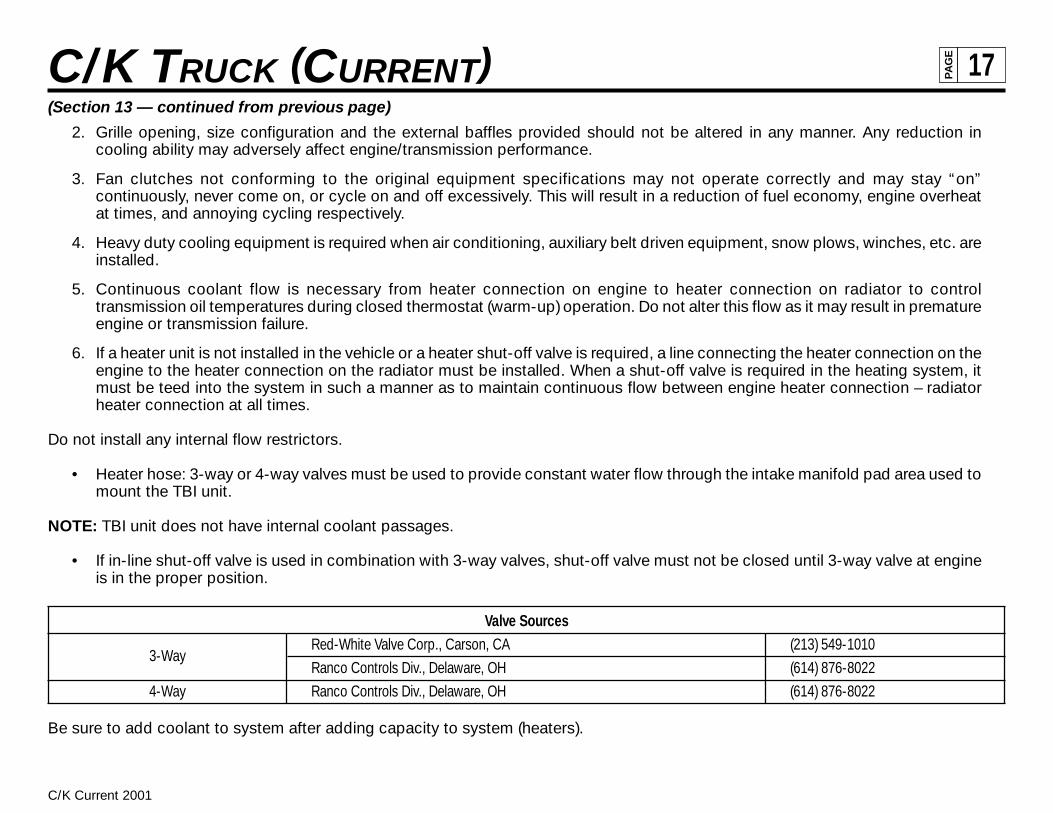
Valve Sources
3-WayRed-White Valve Corp., Carson, CA (213) 549-1010
Ranco Controls Div., Delaware, OH (614) 876-8022
4-Way Ranco Controls Div., Delaware, OH (614) 876-8022
Be sure to add coolant to system after adding capacity to system (heaters).

C/K Current 2001
C/K TRUCK (CURRENT) 18PA
GE
K (310/314/318)03 Chassis Cab, Regular Cab, 2 Wheel Drive, 15,000 GVWR w/6.5T Diesel Engine
TD005184
C (310/314/318)03 Chassis Cab, Regular Cab, 2 Wheel Drive

C/K Current 2001
C/K TRUCK (CURRENT) 19PA
GE
Chassis Cab, Body Cargo Weight Distribution
TX005090
Chassis Cab, Body Cargo Weight Distribution

C/K Current 2001
C/K TRUCK (CURRENT) 20PA
GE
Front Mounted Accessories
% Front/Rear Weight Distribution for Equipment Mounted Ahead of Front Axle
WheelbaseOverhang (Center of Front Axle to the Equipment Center of Gravity)
30” 36” 42” 48” 54” 60”135.5 122/–22 127/–27 131/–31 135/–35 140/–40 144/–44159.5 119/–19 123/–23 126/–26 130/–30 134/–34 138/–38183.5 116/–16 120/–20 123/–23 126/–26 129/–29 133/–33
Example:When mounting equipment with the center of gravity 30 inches ahead of the front axle centerline on a truck with 135.5 wheelbase, thechart indicates the front/rear percentages to be 122/–22. If the front mounted accessory weighs 150 lbs., the front axle is equal to150x1.22, or the weight is decreased by 22% (or 150x0.22), which equals –33 lbs. In effect, the weight on the front axle is increased bythe weight of the equipment and payload plus the weight transferred from the rear.
Rear Mounted Accessories
% Front/Rear Weight Distribution for Equipment Mounted Behind Rear Axle
WheelbaseOverhang (Center of Rear Axle to the Equipment Center of Gravity)
30” 36” 42” 48” 54” 60”135.5 –22/122 –27/127 –31/131 –35/135 –40/140 –44/144159.5 –19/119 –23/123 –26/126 –30/130 –34/134 –38/138183.5 –16/116 –20/120 –23/123 –26/126 –29/129 –33/133
Example:When mounting an item of equipment with the center of gravity 48 inches behind the center of rear axle on a truck with a wheelbase of159.5 inches, the chart shows the front/rear percentage to be 30/130. If the tailgate weighs 600 lbs., 3.32 (30%) times 600 lbs. equals–180 lbs. Mounting the liftgate makes the front axle 180 lbs. lighter. The rear axle weight is increased by 1.30 (130%) times 600 lbs. equals780 lbs. In effect, 180 lbs. are transferred from the front to the rear axle and the weight is increased by the transferred weight plus theweight of the tailgate, or 780 lbs.
C/K Current 2001
C/K TRUCK (CURRENT) 21PA
GE
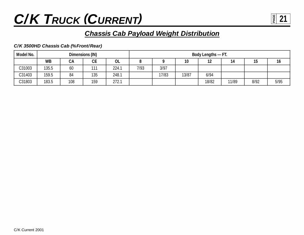
Chassis Cab Payload Weight Distribution
C/K 3500HD Chassis Cab (%Front/Rear)
Model No. Dimensions (IN) Body Lengths — FT.WB CA CE OL 8 9 10 12 14 15 16
C31003 135.5 60 111 224.1 7/93 3/97
C31403 159.5 84 135 248.1 17/83 13/87 6/94
C31803 183.5 108 159 272.1 18/82 11/89 8/92 5/95

C/K Current 2001
C/K TRUCK (CURRENT) 22PA
GE
TD005091
C (310/314/318)03 Power Take Off (PTO) Transmission

C/K Current 2001
C/K TRUCK (CURRENT) 23PA
GE
TD005187
C/K Truck, Regular Cab, Interior

C/K Current 2001
C/K TRUCK (CURRENT) 24PA
GE
TD005187
C/K Truck, Regular Cab, Exterior

C/K Current 2001
C/K TRUCK (CURRENT) 25PA
GE
TD000000
C/K (1/2/3)0000 Mirror Options, General Arrangement

C/K Current 2001
C/K TRUCK (CURRENT) 26PA
GE
TX005076
C/K Truck, Front Floor Seat Mounting

C/K Current 2001
C/K TRUCK (CURRENT) 27PA
GE
TX005072
C (310/314/318)03 Chassis Cab, 15,000 lb. GVWR, Crossmember Arrangement

C/K Current 2001
C/K TRUCK (CURRENT) 28PA
GE
TD005186
C 3500HD Outside Channel Reinforcement

C/K Current 2001
C/K TRUCK (CURRENT) 29PA
GE
TX005093
C 3500HD Front Axle/Tire Data Chart, Chassis Cab, 15,000 GVWR

C/K Current 2001
C/K TRUCK (CURRENT) 30PA
GE
TX005090
C 3500HD Rear Suspension Hanger Bracket Locations, Chassis Cab, 15,000 GVWR

C/K Current 2001
C/K TRUCK (CURRENT) 31PA
GE
TX005065
C/K 300 Rear Axle/Tire Data Chart, Chassis Cab

C/K Current 2001
C/K TRUCK (CURRENT) 32PA
GE
TX005090
C/K (310/314/318)03 Chassis Cab, 15,000 lb. GVWR

C/K Current 2001
C/K TRUCK (CURRENT) 33PA
GE
TD005757
C 3500HD/314/03 Exhaust System Gas L18

C/K Current 2001
C/K TRUCK (CURRENT) 34PA
GE
Ordering Information
Electrical diagrams are available from Chevrolet and GMC through service publications. They have contracted the following companiesto handle the ordering and shipping of the manuals.
Helm Inc.P.O. Box 07130Detroit, Michigan 48207
1 (313) 865-5000 for information and inquiries1 (800) 782-4356 for credit card orders
Routine orders will be shipped within 10 days of receipt. Rush orders will be accommodated for an additional charge.
Order forms are available upon request and orders can be paid by check or money order, made payable to the mentioned companies.Credit Card orders can be made by phone on the listed toll free phone numbers.
Electrical System Interfacing Guidelines
General Discussion
General Motors recognizes that the completion of manufacture of some cab/chassis vehicles, by Body Builders for specific vocationalneeds, will require interfacing with portions of the OEM chassis electrical system. The manner in which these interfacing modifications aremade can have an adverse affect on chassis electrical operations, in addition to causing problems with the Body Builder electricalsystem. In some cases, a “no-start” condition can occur. Additionally, an improper interface can cause the engine control computer to setand store fault codes and illuminate service telltale lights. For these reasons, extra care must be taken to ensure that these types ofmodifications are performed using reliable processes and components.
The following pages describe some of the known electrical system modifications which are being done by ambulance manufacturers,and provides a general definition of the recommended interfacing between the OEM chassis and Body Builder hardware to minimize theimpact to the OEM chassis electrical system.
This is not a “How To” manual. It assumes the reader has technical expertise in the area. It is ultimately the responsibility of the BodyBuilder to design the interface to the OEM electrical system such that the operation of the completed vehicle is not compromised. If thereare questions regarding these or other vehicle interface recommendations, please contact General Motors.

C/K Current 2001
C/K TRUCK (CURRENT) 35PA
GE
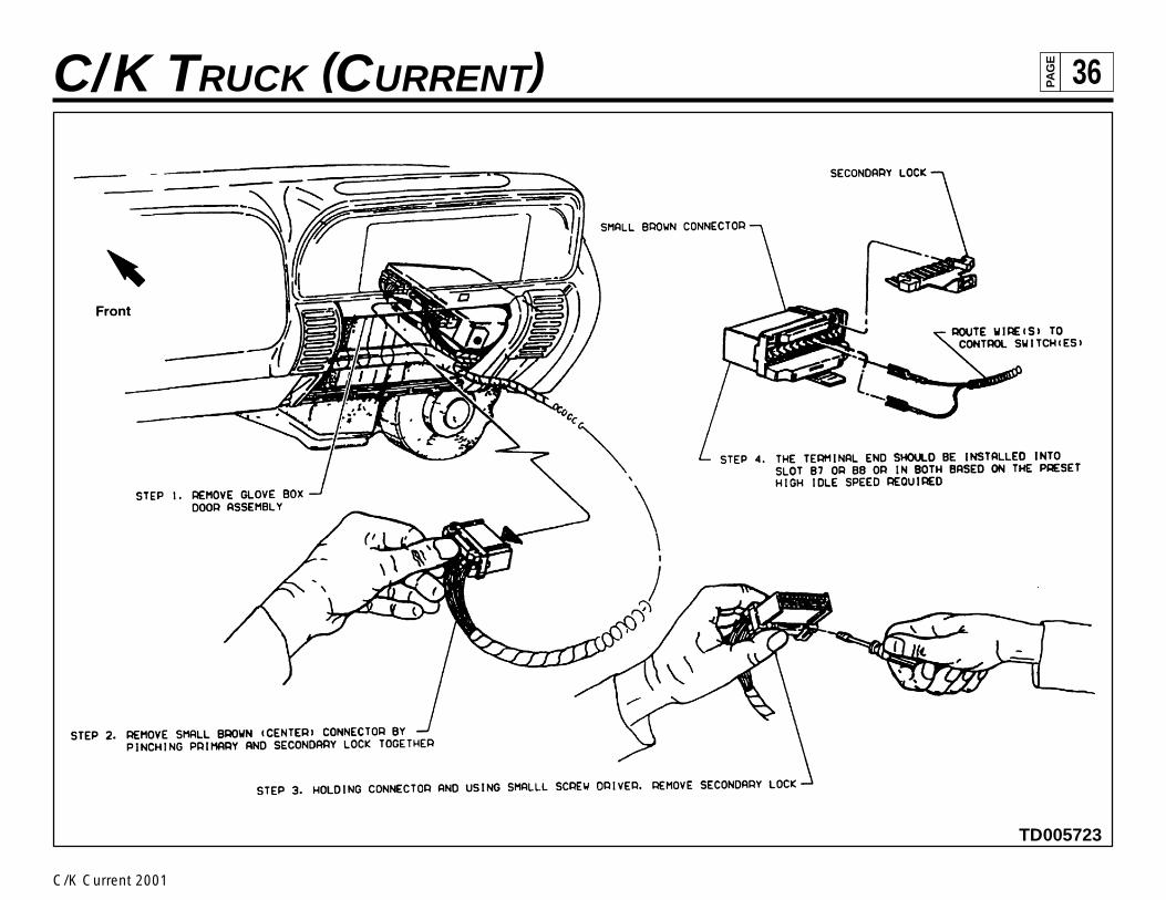
High Idle Control — (Diesel Vehicles Only)
When it is desirable to increase the engine idle RPM, when the vehicle is in Park or Neutral, to facilitate the operation of a PTO or otherelectrical accessories, there are pins on the diesel powertrain control module (PCM) which can be accessed to do so.
Connecting to and subsequently grounding either or both of the pins at the PCM described in the following connecting guidelines andshown in the following illustration will cause the engine idle RPM to be raised to the values indicated below, whenever the shift selectoris placed in “Park” or “Neutral”. Wire(s) from the PCM must be connected to ground through a driver controlled switch(s) to be able to“enable” or” disable” this high idle feature. Note: These are extremely low current circuits. It is therefore very important that low energyswitches be utilized for grounding these circuits. The use of low energy switches will help to prevent future system failures that are causedby a film build up on the switch contacts.
• Plugging a terminated wire into cavity B-7 of the 24-pin brown Micro-Pack connector at the PCM and grounding the other endof this wire lead through a Body Builder installed control switch will enable a high idle mode of 1360 RPM. It is recommendedthat an 18-gauge (0.8 metric) dark green wire be utilized for this application.
• Plugging a terminated wire into cavity B-8 of the 24-pin brown Micro-Pack connector at the PCM and grounding the other endof this wire lead through a Body Builder installed control switch will enable a high idle mode of 1070 RPM. It is recommendedthat an 18-gauge (0.8 metric) light green wire be utilized for this application.
• If both sets of wires and Body Builder switches are added to the vehicle, the grounding of both of these circuits at the sametime, through their respective switches, will result in a high idle mode of 1600 RPM.
C/K Current 2001
C/K TRUCK (CURRENT) 36PA
GE
TD005723
C/K Current 2001
C/K TRUCK (CURRENT) 37PA
GE
TD005721
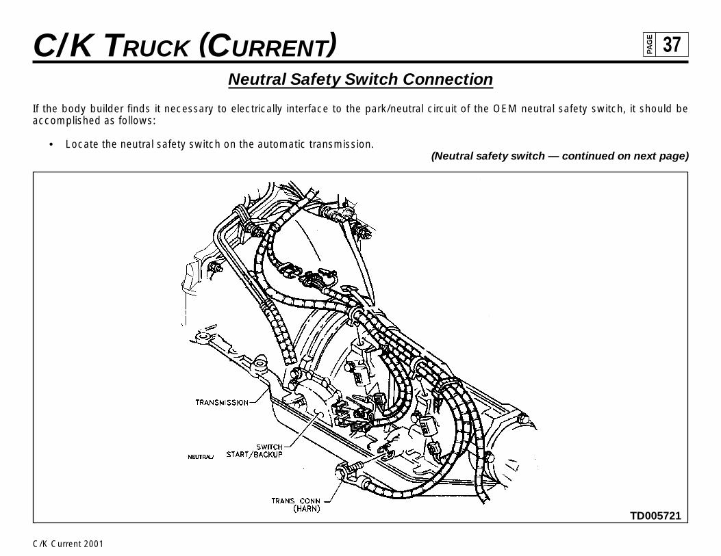
Neutral Safety Switch Connection
If the body builder finds it necessary to electrically interface to the park/neutral circuit of the OEM neutral safety switch, it should beaccomplished as follows:
• Locate the neutral safety switch on the automatic transmission.(Neutral safety switch — continued on next page)

C/K Current 2001
C/K TRUCK (CURRENT) 38PA
GE
(Neutral safety switch — continued from previous page)
• Splice a wire onto the 18-gauge (0.8 metric) yellow wire that exits from cavity “A” of the 7-way connector at the switch. Cautionmust be exercised to assure that only the yellow wire from cavity “A” is spliced into, as there are two other yellow wiresexiting from this same switch. The splice should be made in an area that is protected from the environment and should alsobe sealed to be weather resistant. Note: This circuit is pulled to ground whenever the automatic transmission lever is in “Park”or “Neutral”.
• The maximum body builder electrical load that can be added to this circuit is one (1) ampere. The body builder shouldincorporate a relay into the system, if the added load will exceed the one ampere maximum limitation. The OEM circuit can thenact as a ground signal for the Body Builder relay coil whenever the transmission selector is in “Park” or “Neutral”. The “High”side of the relay coil should be powered by an ignition switch controlled power source so that the relay will not be energizedwhen the ignition key is in the “Off” position.

C/K Current 2001
C/K TRUCK (CURRENT) 39PA
GE
TD005721
C/K Current 2001
C/K TRUCK (CURRENT) 40PA
GE
TD005723
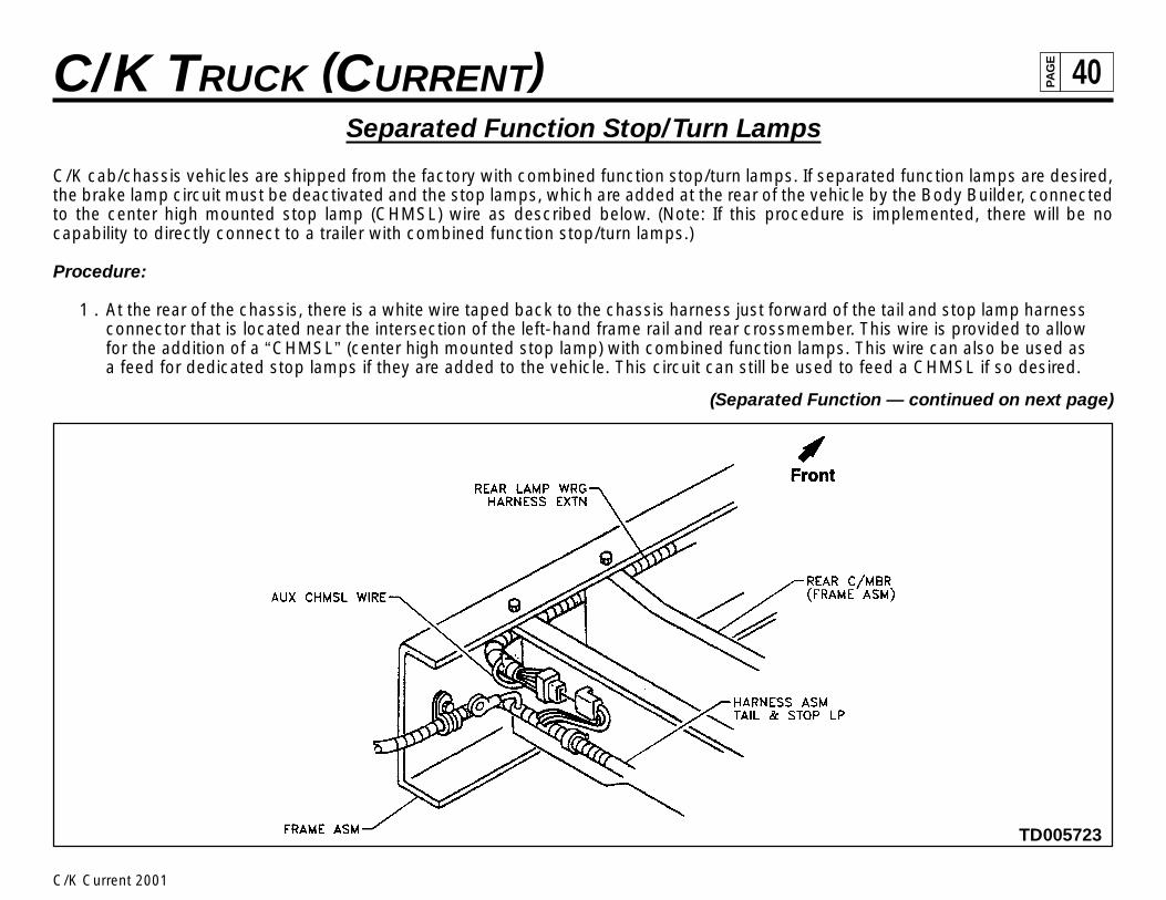
Separated Function Stop/Turn Lamps
C/K cab/chassis vehicles are shipped from the factory with combined function stop/turn lamps. If separated function lamps are desired,the brake lamp circuit must be deactivated and the stop lamps, which are added at the rear of the vehicle by the Body Builder, connectedto the center high mounted stop lamp (CHMSL) wire as described below. (Note: If this procedure is implemented, there will be nocapability to directly connect to a trailer with combined function stop/turn lamps.)
Procedure:
1 . At the rear of the chassis, there is a white wire taped back to the chassis harness just forward of the tail and stop lamp harnessconnector that is located near the intersection of the left-hand frame rail and rear crossmember. This wire is provided to allowfor the addition of a “CHMSL” (center high mounted stop lamp) with combined function lamps. This wire can also be used asa feed for dedicated stop lamps if they are added to the vehicle. This circuit can still be used to feed a CHMSL if so desired.
(Separated Function — continued on next page)

C/K Current 2001
C/K TRUCK (CURRENT) 41PA
GE
(Separated Function — continued from previous page)
2. In the underhood electrical center, remove the “Brake Lamp Relay” from its socket, and remove the 30-amp maxifuse marked“Stop” from the long row of maxifuses. This will effectively remove the stop lamp input from the steering column, so that therear turn signal lamps will be “turn only” instead of “stop/turn”.
3. Verify proper operation of turn and stop lamps, and CHMSL if so equipped.
Continuous Powered Memory Circuits (Diesel)
If a “Master Battery Disconnect Switch” is required for a specific vehicle application, it will be necessary to add a wiring circuit to thevehicle to connect direct (fused) battery power to the powertrain control module (PCM) to maintain the continuous powered memorycircuits.
To maintain PCM memory, the 18-gauge (0.8 metric) orange wires that are terminated in cavities C-13 and D-13, of the blue 32-pinMicro-Pack connector at the PCM, must be removed from the connector and their ends insulated and taped back on the harness.Body Builder added direct battery feed circuit wires, that are protected by a 20-amp fuse and have been properly terminated, shouldthen be inserted into both of these cavities.
(Continuous Powered Memory Circuits — continued on page 43)

C/K Current 2001
C/K TRUCK (CURRENT) 42PA
GE
TD005723

C/K Current 2001
C/K TRUCK (CURRENT) 43PA
GE
(Continuous Powered Memory Circuits — continued from page 41)
Additionally, the vehicle radio/clock must be powered continuously to maintain the correct time and radio pre-set stations. To maintainradio/clock memory, the 20-gauge (0.5 metric) orange wire that is terminated in cavity C-10 of the 20-pin (2 10-pin assembly) connectorat the back of the radio, must be removed from the connector and its end insulated and taped back on the harness. A body builder addeddirect battery feed wire, that is protected by a 10-amp fuse, and properly terminated should be inserted into this cavity.
The radio may have to be removed from the instrument panel to gain access to the 20-pin connector.
(Continuous Powered Memory Circuits — continued on next page)

C/K Current 2001
C/K TRUCK (CURRENT) 44PA
GE
(Continuous Powered Memory Circuits — continued from previous page)
It should be noted that it is the responsibility of the Body Builder to ensure that power feed wires to these devices are properly fused androuted to prevent damage to the OEM electrical system during subsequent vehicle use.
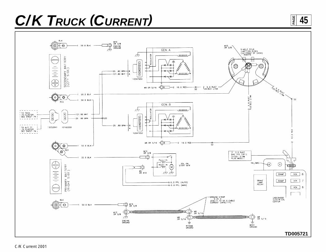
Auxiliary Electrical Loads
When option “YF2” is specified for ambulance conversion, the cab/chassis vehicle will be equipped with a dual generator system.Additionally, an electrical junction block is provided in the engine compartment, mounted to the dash panel on the driver’s side. Thisjunction block functions as an interconnect between the vehicle batteries, generators, and for the purpose of attaching body builderelectrical loads. The intent of this block is to provide a convenient location for the body builder to incorporate the electrical shunt for avehicle ammeter (if required), and also to provide a point where a high current lead can be attached for the ambulance accessories.Please note that the wiring to this block comes directly from the batteries, and that any loads attached at that point would have to havetheir own circuit protection devices. Refer to the electrical diagram for this system.
Also, for cab/chassis with the “YF2” option, heavy gauge ground straps have been provided between the engine, chassis and body sheetmetal near the right rear of the engine for the purpose of providing a robust ground return path from the body or chassis to the battery. Thebody builder must ensure that the ground returns from their loads provide an adequate ground path into these straps such that voltagedrops are minimized.
C/K Current 2001
C/K TRUCK (CURRENT) 45PA
GE
TD005721

C/K Current 2001
C/K TRUCK (CURRENT) 46PA
GE
HVAC Controls
If it is desirable to activate the OEM A/C system (compressor) from a secondary remote switch, care must be taken to insure that the OEMpressure switches are still active in the system, to maintain proper compressor cycling action and over-pressure protection.
In order to connect a remote HVAC switch (controller) into the base OEM system, it will be necessary to tie into the circuit that runsbetween the OEM control head and the compressor cycling switch. (This is the light green wire that exits cavity 10 of the OEM controllerconnector.) A 12 volt DC ignition signal must be applied to this circuit when requesting the HVAC compressor to turn on. The Body Buildermay obtain this signal by splicing into the brown wire that exits cavity 5 of the OEM controller connector. It will be necessary toincorporate either diodes or an isolation relay into this circuit to prevent damage to the OEM controller due to unwanted electricalfeedback. Note: The compressor cycling switch circuit, that must be spliced into by the Body Builder, is an extremely low current circuitand will require the use of a low energy switch to prevent future system malfunctions that can be caused by a film build up on the switchcontacts.

C/K Current 2001
C/K TRUCK (CURRENT) 47PA
GE
Ignition Power Feed Interfacing
A vehicle ignition power feed circuit may be obtained by the Body Builder by connecting to an ignition circuit terminal at the OEMconvenience center. The convenience center is located in the passenger compartment, on the left side of the dash panel, outboard of thesteering column. A wire of an appropriate gauge size should be properly terminated and inserted into cavity “C” of a Delphi PackardElectric 280 Metri-Pack connector (Part Number 12110777-dark green in color). The connector should then be inserted into the 3-wayconnector cavity in the convenience center marked “spare”. This circuit may be used for circuit loads of one (1) ampere or less. If powergreater than the one ampere maximum limitation is required, this circuit can still be used but only as a signal source to energize a BodyBuilders supplied relay.