ckr compact module - ahr international compact module with ball rail guide and toothed belt drive 2...
TRANSCRIPT

The Drive & Control Company
CKR Compact Modulewith Ball Rail Guideand Toothed Belt Drive

2
Rexroth Linear Motion Technology
Ball Rail® Systems Standard Ball Rail SystemsSuper Ball Rail SystemsBall Rail Systems with Aluminum Runner BlocksHigh-Speed Ball Rail SystemsCorrosion-Resistant Ball Rail SystemsWide Ball Rail Systems
Ball Rail Systems with Integrated Measuring SystemsClamping and Braking Elements for Ball Rail SystemsRacks for Ball Rail SystemsMiniature Ball Rail SystemsRoller Guides
Roller Rail™ Systems Standard Roller Rail SystemsWide Roller Rail SystemsHeavy-Duty Roller Rail SystemsRoller Rail System with Integrated Measuring SystemsClamping and Braking Elements for Roller Rail SystemsRacks for Roller Rail Systems
Linear Bushing Guides Linear Bushings, Linear Sets,Shafts, Shaft Supports, Tail-Shaft Brackets
Ball Transfer UnitsOther Engineering Components
Ball-Screw Systems
Linear Motion Systems Linear Motion Slides – Ball-Screw Drive– Toothed Belt Drive
Linear Modules – Ball-Screw Drive– Toothed Belt Drive– Rack and Pinion Drive– Pneumatic Drive– Linear Motor
Compact Modules – Ball-Screw Drive
– Toothed Belt Drive– Linear Motor
Precision Modules – Ball-Screw Drive
Ball Rail Tables – Ball-Screw Drive– Linear Motor
Controls, Motors, Electrical Accessories
Electrical Cylinders

3
CKR Compact Modules
A Single Solution for Many Applications 4
Product Overview (General) 6
Product Overview with Load Capacities 10
Construction 12
Technical Data 14
Calculations 17
CKR 12-90 18– Components and Performance Data 18– Dimensional Drawings 20
CKR 15-110 22– Components and Performance Data 22– Dimensional Drawings 24
CKR 20-145 26– Components and Performance Data 26
– Dimensional Drawings 28
Switch Mounting 30
Servomotors 32
Mounting Accessories and Instructions 34
Lubrication Connection 35
Documentation 36
Ordering Examples 38
Inquiry/Order Form 39

CKR Compact Modules
4
A Single Solution forMany Applications
• Driving
• Transporting
• Positioning
The Applications
Length
Load Capacities and Moments
Static Loading
Speed
Accessories
Documentation
Complete SystemsIncluding Drive Unit
Switch Mounting
Height

5
The Solution
RexrothCompact Modules
Servomotor Type MKD or MSMwith LP Gear Reducer (plus Control)
Switching without Switch Cam overthe Entire Travel Range
Clamping Fixtures, Motor Mounts,Connection Plates, Connection Elements
Frictional TorqueFrictional Load Measurements, Lead DeviationPositioning Accuracy
40 mm to 65 mm
up to 5,500 mm
Load Capacity C up to 56,530 NLongitudinal Moments ML up to 2,820 NmTorsional Moments Mt up to 1,910 Nm
up to 200 kg
up to 5 m/s

CKR Compact Modules
6
Construction
– Extremely compact precision aluminum profile (main base structure)with two integrated ball rail guides for optimal movement of heavyloads at high speeds
– Ready-to-install Compact Modules in selectable lengths up to Lmax
– Short or long aluminum carriage lengths available, depending onapplication load
– Driven by a pre-tensioned, steel-cord reinforced polyurethanetoothed belt
Optional Components
– Maintenance-free digital servo drives with integrated brake andpre-installed feedback
– Gear Reducer type LP
– REED or HALL sensor switches available
– Socket with terminals for connecting switches
– Aluminum profile cable duct for easy mounting of switches
Compact Modules are precision, ready-to-install linear systemsoffering high performance within a compact envelope–dimensions andselectable length, combined with an economical price-to-performanceratio and fast delivery
Product Overview
Optimal movement, high loadcapacity, high rigidity throughtwo integrated, pre-loaded ballrail guides
High travel speed, with highprecision and low noise,lengths up to 5,500 mm
Identical outer dimensions, matchingaccessories and add-on componentsto (ball screw driven) Type CKKCompact Modules

7
Pilot bore and tapped mounting holes for simplemotor installation
Adjustable switches over the entire travel range;switch activation by magnet built into carriage
Belt guided by aluminum channel whichseals out debris and contaminants
Economical maintenance ofthe ball rail guides throughcentralized lubrication (grease)system. Acccess ports on topof carriage and either sideof extrusion
Precision alignment and securemounting of attachments thanks tothreaded bores and dowel pin holesin the carriage
Idler (non-drive) end with integral belttensioning system. Pulley ball bearingsare lubricated for life
Gear Reducer: A variety of gear ratios allow anoptimal match between the load and the drivemotor inertia
Ratio i = 3i = 5i = 10

CKR Compact Modules
8
Product Overview
MKD 25B-144-KG1MKD 41B-144 KG1MKD 71B-061 KG1
MSM 030 CMSM 040 B
Digital ServomotorType MSM
Digital ServomotorType MKD
Motor SelectionBased on the drive and control system
To provide a cost-effective solution for everycustomer application, several motor/drivecombinations are offered.
When sizing the module, always take themotor-drive combination into consideration.

9
DKC
Digital Drive UnitECODRIVE
The cost-effective solution forsingle- and multi-axis systems
Compact Modules are available completewith motor, drive unit, and control.
DKC
Digital Drive UnitECODRIVE Cs
Compact, dynamic solutionfor the lower end of theperformance range.

CKR Compact Modules
10
Type Overview with Load CapacitiesType Designation (size)Compact Modules are identified bydesignating the Type and the Size.
Respective structures without drive alsocomply with type and size designation
Type Guide Drive Compact Module
CKR
RexrothCompactModule
Ball Rail Guide Toothed Belt Drive
Type Size
C K RSystem = C = Compact Module
Guide = K = Ball Rail Guide
Drive = R = Toothed Belt Drive
Dimensionsof guideway =
Aluminum profiledimension =
Compact Module (Example) = 20-145
(mm)
A

11
Overview of Compact Moduleswith permissible loads
CKR 20-145 145 x 65 34,800 56,530
CKR 12-90 90 x 40 4,620 7,500
In consideration of the desired operatinglife, general loads up to 20% of thedynamic values (C, Mt, ML ) have beenshown as acceptable.
Acceptable Loads(values based on experienceand testing)
Compact Module Dimensions A x H (mm) Dynamic Load Capacity C (N)
CKR 15-110 110 x 50 14,000 22,740
In this respect, the following must not beexceeded:
– The maximum permissible load
– The permissible drive torque
– The permissible speed
short carriage long carriage
H
A
C
CCL
C
Note: All Compact Modules are also available without a drive.

CKR Compact Modules
12
ConstructionConstruction of the CKR1 Toothed Belt
2 Drive End Assembly
3 Carriage Versions
• Short carriage versionwith two runner blocks
• Long carriage versionwith four runner blocks
4 Main Body
5 Tensioning End Unit Assembly(Idler End)
Additional Components:
6 Switch
7 Cable Duct
8 Sockets/Plugs
11 Motor
12 Gear Reducer type LP
8
6
7
34
2
11
12
1
5

13
Construction ofGear Reducer LPFor all Compact Modules, a planetarygearbox can be installed via a flange. Theflange serves as a mounting point for thegearbox to the Compact Module. Thisdirect connection eliminates the need fora coupling, thereby minimizing torsionaldeflection.
Different gear ratios are available:i = 3 (only for CKR 20-145)i = 5i = 10
1 Servomotor2 Gear Reducer3 Flange4 Drive End Assembly5 Compact Module Base Structure
2
1
5
4
3

CKR Compact Modules
14
Technical Data
E = 70,000 N/mm2Modulus of Elasticity E
General Technical DataLoad capacities and moments
Compact Carriage Maximum Permissible Forces Maximum Permissible Moments
Module Length Fy1 Fy2 FX Mt ML
(N) (N) (N) (Nm) (Nm)
102 4,620 4,120 1,195 110 16
156 7,500 6,700 2,170 180 210
170 10,760 5,380 3,120 170 40
215 17,480 8,740 5,060 280 370
180 26,760 13,380 7,760 580 130
240 43,470 21,730 12,600 950 1,080
Maximum permissible loads
Compact Carriage Belt Dynamic Dynamic Planar Moment Moved Maximum Specific
Module Length Type Load Capacity C Moments of Inertia Mass Length Spring Rate
of Guideway Mt ML Ix Iy mb Lmax Cspec
(N) (Nm) (Nm) (cm4) (cm4) (kg) (mm) (N/mm · m)
CKR 20-145
CKR 15-110
CKR 12-90
CKR 12-90
CKR 15-110
CKR 20-145
102 4,620 110 16
156 7,500 360 240
170 14,000 350 80
215 22,740 570 960
180 34,800 1,170 260
240 56,530 1,910 2,820
12.81 115.3 0.50 3,000 350
32.68 282.9 0.87 4,500 1,050
87.50 903.9 1.67 5,500 1,225
AT 3
ATL 5
AT 5
Lengths over Lmax (for CKR 12-90 and CKR 15-110) available on request. See ordering example for length calculation.
Mass
Compact Module Carriage Drive Type Mass Additional MassLength (kg) Gear Reducer LP(mm) (kg)
102
156
170
215
180
240
CKR 12-90
CKR 15-110
CKR 20-145
without driveDrive i = 1without driveDrive i = 1without driveDrive i = 1without driveDrive i = 1without driveDrive i = 1without driveDrive i = 1
0.0045 · L + 0.790.0045 · L + 0.990.0045 · L + 0.980.0045 · L + 1.180.0075 · L + 1.650.0075 · L + 1.910.0075 · L + 1.900.0075 · L + 2.160.0124 · L + 2.680.0124 · L + 3.490.0124 · L + 3.280.0124 · L + 4.09
–2.48
–2.48
–2.48
–2.48
–4.14
–4.14
Mass calculation without motor and switch.
Mass formula: Mass (kg/mm) · Length L (mm) + Mass of all parts of fixed lengths(carriage, drive end, idler end, etc.) (kg) (+ additional mass (kg))

15
ML
ML
C
Mt
Fy2
FxFx
Fy1
ML
CC
Note for dynamic load capacitiesand moments
The determination of the dynamic loadcapacities and moments is based on100,000 m of travel.
However, in many cases, only 50,000 m isassumed.
For this, the following comparison applies:
Values C, Mt and ML from the tableshould be multiplied by 1.26.
Compact Module with Short Carriage
Compact Module with Long Carriage
Roll Moment
Pitch Moment
Yaw Moment
Yaw Moment

CKR Compact Modules
16
CKR 12-90i = 1
Gear Reducer
1 8.0 90.05 1.6 18.0
10 0.8 9.0
CKR 15-110
CKR 20-145
i = 1
Gear Reducer
1 13.5 120.05 2.7 24.0
10 1.4 12.0i = 1
Gear Reducer
1 32.5 165.03 10.8 55.05 6.4 33.0
10 3.2 16.5
Technical Data
Drive Data
Compact Drive Type Gear Reducer Max. Drive Lead Belt Width Tooth Max. Belt BeltModule Ratio Torque Constant Type b Pitch Drive Elasticity
i Ma u (mm) T Transmission Limit(Nm) (mm/U) (mm) Force Fzul
F(N) (N)
AT 3 35 3 560 1,600
ATL 5 50 5 980 4,200
AT 5 70 5 1,238 4,800
Belt Data

17
Calculations
Frictional Torque Data Compact Module Motor Gearbox Type i MRS MRLP
(Nm) (Nm)
CKR 12-90
CKR 15-110
CKR 20-145
MKD25B-144
MSM030CGear Reducer 5, 10 0.060.58
MKD25B-144
MSM030CGear Reducer 5, 10 0.061.42
MKD41B-144
MSM040CGear Reducer 3, 5, 10 0.152.04
Mass Moment of InertiaFor Handling:
6 · JM ≥ Jfr
For Machining:
1.5 · JM ≥ Jfr
Jfr = Mass Moment of Inertia ofAdditional Load (kgm2)
JM = Mass Moment of Inertia ofMotor (kgm2)
Frictional Torque
With motor mounting via flangeand coupling: MR = MRS
MR = Frictional Torque atMotor Shaft (Nm)
MRS = Frictional Torque of System (Nm)
MRLP = Frictional Torque ofthe Gear Reducer (Nm)
i = Gear Ratio
iMR =
MRS + MRLP
With motor mounting via gear reducer:
Nominal Life Expectancy in Meters:
Nominal Life Expectancy in Hours:
Formulas
Nominal Life Expectancy
L10 = Nominal Life Expectancyin Meters (m)
L10h = Nominal Life Expectancyin Hours (h)
C = Dynamic Load Capacity (N)Fm = Mean Equivalent
Dynamic Load (N)v = Speed (m/s)L10h =
3600 · vL10
Fm
L10 = ( )C 3· 10 5

CKR Compact Modules
18
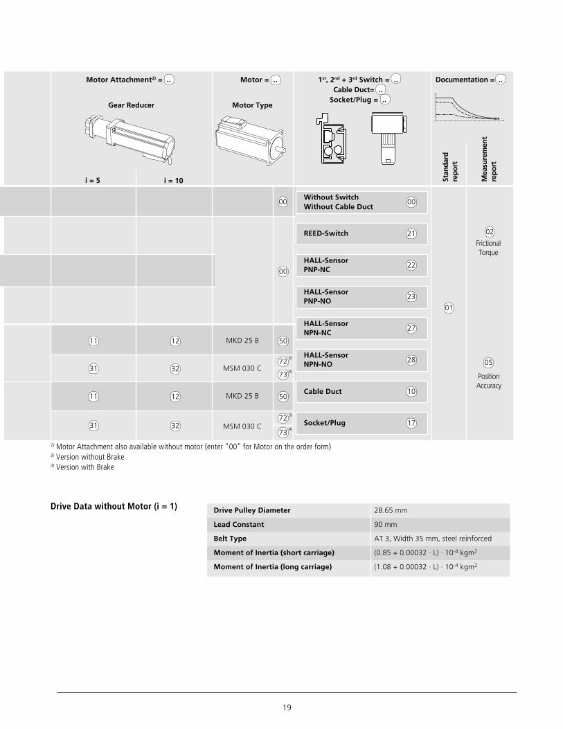
Components and Order Configuration Data CKR 12-90
(03.34.00)
Without Drive
Shaftfor
Motor
withoutkeyway
i = 1
withkeyway
i = 1
GearReducer
Len
gth
102
mm
Len
gth
156
mm
OA01
(03.34.10)
MA01
(03.34.10)
MA02
(03.34.12)
MA03
(03.34.20)
MG01
MG02
(03.34.20)
MG03
MG04
without
right
left
both sides
50
01
02
03
04
10
11for
Gea
r Re
duce
r
01
01
02
02
Part Number, Length Type = .... Guideway = .. Drive = .. Carriage = ..(and Dim. Drawing)
0364-300-00 , .... mm
For Gear Reducer
With Drive (i = 1)
01
01
MG01
MG03
MG04
MG02
1 Sh
aft
2 Sh
afts
Performance values for horizontal operation with Servomotor MSM 030C and Drive DKC **.*-012Connection Voltage: 1 x 230 V
Performance Data for Gear ReducersPerformance values for horizontal operationwith Servomotor MKD 25B-144 and Drive DKC **.*-040Connection Voltage: 3 x 400 V
Gear Reducer Ratio i = 5 i = 10
Mass (kg) 2 4 6 8 10 2 4 6 8 10Acceleration Time t (ms) 54 69 84 99 114 88 97 106 114 123Acceleration Distance s (mm) 65 83 101 119 137 53 58 63 69 74Acceleration a (m/s2) 44.1 34.6 28.4 24.2 21.0 13.6 12.4 11.3 10.5 9.7Speed v (m/s) 2.4 1.2Repeatability (mm) 0.1 0.1
Gear Reducer Ratio i = 5 i = 10
Mass (kg) 2 4 6 8 10 2 4 6 8 10Acceleration Time t (ms) 16 22 27 33 38 23 26 29 33 36Acceleration Distance s (mm) 7 10 12 15 17 5 6 7 7 8Acceleration a (m/s2) 56.4 41.7 33.1 27.4 23.4 19.7 17.2 15.3 13.8 12.5Speed v (m/s) 0.9 0.45Repeatability (mm) 0.1 0.1
The tables contain performancevalue examples for gearbox-motorcombinations. They are intended to serveas a guide for selecton; exact values mustbe calculated based on individual cases.
19
FrictionalTorque
PositionAccuracy
02
05
01
Stan
dard
repo
rt
Mea
sure
men
tre
port
Motor Type
00
00
Motor Attachment2) = .. Motor = .. 1st, 2nd + 3rd Switch = .. Documentation = ..Cable Duct= ..
Socket/Plug = ..
i = 5 i = 10
11 12 MKD 25 B
MSM 030 C
MKD 25 B
MSM 030 C
31 32
11 12
31 32
Gear Reducer
50
72
72
50
2) Motor Attachment also available without motor (enter "00" for Motor on the order form)3) Version without Brake4) Version with Brake
00Without SwitchWithout Cable Duct
21REED-Switch
22HALL-SensorPNP-NC
23HALL-SensorPNP-NO
27HALL-SensorNPN-NC
28HALL-SensorNPN-NO
10Cable Duct
17Socket/Plug
Drive Data without Motor (i = 1) Drive Pulley Diameter 28.65 mm
Lead Constant 90 mm
Belt Type AT 3, Width 35 mm, steel reinforced
Moment of Inertia (short carriage) (0.85 + 0.00032 · L) · 10-4 kgm2
Moment of Inertia (long carriage) (1.08 + 0.00032 · L) · 10-4 kgm2
73
73
3)
4)
3)
4)
CKR Compact Modules
20
Ø34H7
1.8 deep 49.5
19.5 28
L
L / 2
59
28
40
31.5
Ø10h6
13.5 13.5 38 13.5 13.5
156
20
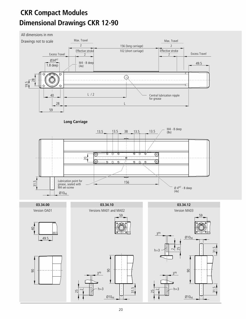
Dimensional Drawings CKR 12-90
All dimensions in mm
Drawings not to scale
03.34.12
Version MA03
03.34.00
Version OA01
03.34.10
Versions MA01 and MA02
Excess Travel
156 (long carriage)
102 (short carriage)
M4 - 8 deep(4x)
M4 - 8 deep(8x)
Ø 4H7 - 8 deep(4x)
Lubrication point forgrease, sealed withM4 set-screw
Long Carriage
Central lubrication nipplefor grease
Max. Travel
2
Effective stroke2
Effective stroke2
Max. Travel
2
90
49.5
40
3P9
25 2 h=3
31.5
59
90
3P9
25 2 h=3
3P9
25
2 h=3
Ø10h6
Ø10h6Ø10h6
31.5
31.5
59
90
Excess Travel

21
03.34.20
Version MG01, MG02, MG03 and MG04Motors MKD 25B and MSM 030C
Ø 4H7 - 8 deep(2x)
M4 - 8 deep(4x)
Short Carriage
Lubrication point forgrease, sealed withM4 set-screw
L = (stroke + 2 · excess travel) + LT + 25 mm
For an example of length calculation, seeordering example
To calculate the length of theCompact Module:
102
90
27
7.6
39
40
13.5 13.5
B
A
20
A
4.8
3.2 1.
8
3.2
1.3
B
2
5.2
4.2
4
337
(MKD
25B
)27
2.5
(MSM
030
C w
/ bra
ke)
239.
5 (M
SM 0
30C
w/o
bra
ke)
101
14
Ø10h6
31.5

CKR Compact Modules
22
Components and Order Configuration Data CKR 15-110
(03.44.00)
Without Drive
Shaftfor
Motor
Withoutkeyway
i = 1
Withkeyway
i = 1
GearReducer
Len
gth
170
mm
Len
gth
215
mm
OA01
(03.44.10)
MA01
(03.44.10)
MA02
(03.44.12)
MA03
without
right
left
both sides
50
01
02
03
04
01 02
Part Number, Length Type = .... Guideway = .. Drive = .. Carriage = ..(and Dim. Drawing)
0364-400-00 , .... mm
With Drive (i = 1)
01
(03.44.20)
MG01
MG02
(03.44.20)
MG03
MG04
10
11
01 02
For Gear Reducer
01
For
Gea
r Re
duce
r
MG01
MG03
MG04
MG021
Shaf
t2
Shaf
ts
Performance values for horizontal operation with Servomotor MSM 030C and Drive DKC **.*-012Connection Voltage: 1 x 230 V
Gear Reducer Ratio i = 5 i = 10
Mass (kg) 2 4 6 8 10 3 6 9 12 15 18 21Acceleration Time t (ms) 60 79 98 117 136 89 107 125 143 162 180 198Acceleration Distance s (mm) 96 126 156 187 217 71 86 100 115 129 144 158Acceleration a (m/s2) 53.6 40.7 32.8 27.4 23.6 18.0 14.9 12.8 11.2 9.9 8.9 8.1Speed v (m/s) 3.2 1.6Repeatability (mm) 0.1 0.1
Performance Data for Gear ReducerPerformance values for horizontal operationwith Servomotor MKD 25B-144 and Drive DKC **.*-040Connection Voltage: 3 x 400 V
Gear Reducer Ratio i = 5 i = 10
Mass (kg) 1 2 3 4 3 6 9 12 15 18 21Acceleration Time t (ms) 16 19 23 26 25 32 39 46 53 59 66Acceleration Distance s (mm) 9 12 14 16 8 10 12 14 16 18 20Acceleration a (m/s2) 76.7 62.5 52.7 45.6 23.8 18.7 15.4 13.1 11.4 10.1 9.1Speed v (m/s) 1.2 0.6Repeatability (mm) 0.1 0.1
The tables contain performancevalue examples for gearbox-motorcombinations. They are intended to serveas a guide for selecton; exact values mustbe calculated based on individual cases.

23
FrictionalTorque
PositionAccuracy
02
05
01
i = 5 i = 10
11 12
31 32
11 12
31 32
Gear Reducer
00Without SwitchWithout Cable Duct
21REED-Switch
22HALL-SensorPNP-NC
23HALL-SensorPNP-NO
27HALL-SensorNPN-NC
28HALL-SensorNPN-NO
10Cable Duct
17Socket/Plug
Stan
dard
repo
rt
Mea
sure
men
tre
port
Motor Attachment2) = .. Motor = .. 1st, 2nd + 3rd Switch = .. Documentation = ..Cable Duct = ..Socket/Plug= ..
00
00
50MKD 25 B
MSM 030 C
MKD 25 B
MSM 030 C
50
Motor Type
Drive Data without Motor (i = 1) Drive Pulley Diameter 38.20 mm
Lead Constant 120 mm
Belt Type ATL 5, Width 50 mm, steel reinforced
Moment of Inertia (short carriage) (2.50 + 0.00136 · L) · 10-4 kgm2
Moment of Inertia (long carriage) (3.81 + 0.00136 · L) · 10-4 kgm2
72
72
2) Motor Attachment also available without motor (enter "00" for Motor on the order form)3) Version without Brake4) Version with Brake
73
73
3)
4)
3)
4)

CKR Compact Modules
24
Ø42H7
2 deep60.5
24.5
35
L
L / 245
66
33
31.5
Ø14h6
215
25 3525 25 25
Dimensional Drawings CKR 15-110
All dimensions in mm
Drawings not to scale
03.44.12
Version MA03
03.44.00
Version OA01
03.44.10
Version MA01 and MA02
Excess Travel Excess Travel
215 (long carriage)
170 (short carriage)
M5 - 10 deep(4x)
M5 - 10 deep(8x)
Ø 6H7 - 6.5 deep (4x)
Lubrication point forgrease, sealed withM6 set-screw
Long Carriage
Central lubrication nipplefor grease
Effective Stroke2
Effective Stroke2
Max. Travel
2Max. Travel
2
60.5
4911
0
5P9
252 h=3
Ø14h6
31.5
66
110
5P9
5P9
252 h=3
252h=3
Ø14h6
Ø14h6
31.5
31.5
66
110

25
03.44.20
Versions MG01, MG02, MG03 and MG04Motors MKD 25B and MSM 030C
Ø 6H7 - 6.5 deep(2x)
M5 - 10 deep(4x)
Short CarriageLubrication point forgrease, sealed withM6 set-screw
L = (stroke + 2 · excess travel) + LT + 25 mm
For an example of length calculation, seeordering example
To calculate the length of theCompact Module:
328.
5 (M
KD 2
5B)
264
(MSM
030
C w
/ bra
ke)
231
(MSM
030
C w
/o b
rake
)
92.5
14
Ø14h6
31.5
34
25 25
41.5
50499.5
46
110
A
A
B
B4.
8
3.2
1.8
3.2
1.3
8.2
4.8
5.2
2.5
170
CKR Compact Modules
26
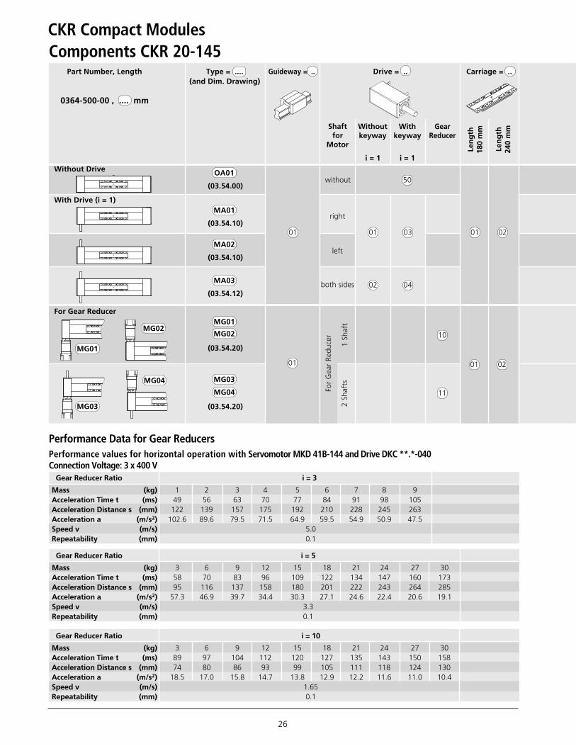
Components CKR 20-145
(03.54.00)
Without Drive
Shaftfor
Motor
Withoutkeyway
i = 1
Withkeyway
i = 1
GearReducer
Len
gth
180
mm
Len
gth
240
mm
OA01
(03.54.10)
MA01
(03.54.10)
MA02
(03.54.12)
MA03
without
right
left
both sides
50
01
02
03
04
01 02
Part Number, Length Type = .... Guideway = .. Drive = .. Carriage = ..(and Dim. Drawing)
0364-500-00 , .... mm
With Drive (i = 1)
01
(03.54.20)
MG01
MG02
(03.54.20)
MG03
MG04
10
11
01 02
For Gear Reducer
01
For
Gea
r Re
duce
r
MG01
MG03
MG04
MG02
1 Sh
aft
2 Sh
afts
Gear Reducer Ratio i = 3
Mass (kg) 1 2 3 4 5 6 7 8 9Acceleration Time t (ms) 49 56 63 70 77 84 91 98 105Acceleration Distance s (mm) 122 139 157 175 192 210 228 245 263Acceleration a (m/s2) 102.6 89.6 79.5 71.5 64.9 59.5 54.9 50.9 47.5Speed v (m/s) 5.0Repeatability (mm) 0.1
Gear Reducer Ratio i = 5
Mass (kg) 3 6 9 12 15 18 21 24 27 30Acceleration Time t (ms) 58 70 83 96 109 122 134 147 160 173Acceleration Distance s (mm) 95 116 137 158 180 201 222 243 264 285Acceleration a (m/s2) 57.3 46.9 39.7 34.4 30.3 27.1 24.6 22.4 20.6 19.1Speed v (m/s) 3.3Repeatability (mm) 0.1
Gear Reducer Ratio i = 10
Mass (kg) 3 6 9 12 15 18 21 24 27 30Acceleration Time t (ms) 89 97 104 112 120 127 135 143 150 158Acceleration Distance s (mm) 74 80 86 93 99 105 111 118 124 130Acceleration a (m/s2) 18.5 17.0 15.8 14.7 13.8 12.9 12.2 11.6 11.0 10.4Speed v (m/s) 1.65Repeatability (mm) 0.1
Performance Data for Gear ReducersPerformance values for horizontal operation with Servomotor MKD 41B-144 and Drive DKC **.*-040Connection Voltage: 3 x 400 V

27
Gear Reducer Ratio i = 10
Mass (kg) 3 6 9 12 15 18 21 24 27 30Acceleration Time t (ms) 26 29 33 37 41 45 49 52 56 60Acceleration Distance s (mm) 11 12 14 15 17 18 20 22 23 25Acceleration a (m/s2) 32.2 28.1 24.8 22.3 20.2 18.5 17.0 15.8 14.7 13.8Speed v (m/s) 0.8Repeatability (mm) 0.1
Gear Reducer Ratio i = 5
Mass (kg) 1 2 3 4 5 6 7 8 9 10Acceleration Time t (ms) 17 19 21 23 25 27 29 31 34 36Acceleration Distance s (mm) 14 15 17 19 21 22 24 26 28 29Acceleration a (m/s2) 99.8 88.4 79.3 71.9 65.8 60.7 56.2 52.4 49.1 46.2Speed v (m/s) 1.65Repeatability (mm) 0.1
Drive Data without Motor (i = 1)Drive Pulley Diameter 52,52 mm
Lead Constant 165 mm
Belt Type AT 5, width 70 mm, steel reinforced
Moment of Inertia (short carriage) (8.91 + 0.00317 · L) · 10-4 kgm2
Moment of Inertia (long carriage) (14.49 + 0.00317 · L) · 10-4 kgm2
FrictionalTorque
PositionAccuracy
02
05
01
i = 5
Gear Reducer
00Without SwitchWithout Cable Duct
21REED-Switch
22HALL-SensorPNP-NC
23HALL-SensorPNP-NO
27HALL-SensorNPN-NC
28HALL-SensorNPN-NO
10Cable Duct
17Socket/Plug
Stan
dard
repo
rt
Mea
sure
men
tre
port
i = 3 i = 10
Motor Attachment2) = .. Motor = .. 1st, 2nd + 3rd Switch = .. Documentation = ..Cable Duct = ..
Socket/Plug = ..
00
00
10 12 10MKD 41 B
MSM 040 C
MKD 41 B
MSM 040 C
10
30 32
10 12
30 32
11
31
11
31
Motor Type
74
74
2) Motor Attachment also available without motor (enter "00" for Motor on the order form)3) Version without Brake4) Version with Brake
75
75
3)
4)
3)
4)
Performance values for horizontal operation with Servomotor MSM 040B and Drive DKC **.*-018, Connection Voltage: 1 x 230 V
The tables contain performancevalue examples for gearbox-motorcombinations. They are intended to serveas a guide for selecton; exact values mustbe calculated based on individual cases.

CKR Compact Modules
28
Ø49H7
2.5 deep
32
30
61
240
Ø19h6
71.5
L
L / 2
45
45
64
30
48
30 40 30 30
Dimensional Drawings CKR 20-145
Excess TravelEffective Stroke
2Effective Stroke
2
240 (long carriage)
180 (short carriage)
M6 - 12 deep(4x)
M6 - 15 deep(8x)
Ø 6H7 - 7.5 deep(4x)
Lubrication point forgrease, sealed withM6 set-screw
Long Carriage
All dimensions in mm
Drawings not to scale
03.54.12
Version MA03
03.54.00
Version OA01
03.54.10
Versions MA01 and MA02
Central lubrication nipplefor grease
Max. Travel
2
Max. Travel
2
71.5
6414
5
61
6P9
402 h=3.5
Ø19h6 Ø19h6
Ø19h6
64
145
402 h=3.5
6P9
6P9
402h=3.5
6461
61
145
Excess Travel

29
03.54.20
Versions MG01, MG02, MG03 and MG04Motors MKD 41B and MSM 040 B
M6 - 15 deep(4x)
Ø 6H7 - 7.5 deep(2x)
Short Carriage
Lubrication point forgrease, sealed withM6 set-screw
L = (stroke + 2 · excess travel) + LT + 25 mm
For an example of length calculation, seeordering example
To calculate the length of theCompact Module:
62
65649.5
B
A
145
A B
50
3030
180 4.8
3.2
1.8
3.2
1.3
8.2
4.8
5.2
2.5
Ø19h6
61
370
(MKD
41B
)31
8.5
(MSM
040
B w
/ bra
ke)
284.
5 (M
SM 0
40B
w/o
bra
ke)
127
22
71

CKR Compact Modules
30
Switch Mounting
SwitchMiniature switch with potted cable.
Versions:
– Hall Sensor (NC/NO) or– Reed Contact (Relay)
Assembly Note:
Switch mounting is permitted on onlyone side of the Compact Module (left orright) and should be done only after theCompact Module has been installed onits base structure.
A cable duct is needed to attach switches.
Switches are inserted in the upper T-slot(CKR 12-90 und 15-110) or in the lowerT-slot (CKR 20-145) of the cable duct, andsecured with set-screws.
Overview of the Switching System1 Socket and Plug2 Switch3 Cable Duct
(aluminum extrusion, black anodized)
Short stroke: Note the length ofthe switch and socket!
Set-screw formounting
Active Surface
Hall SensorContact Type PNP NC/ NO
NPN NC/ NO
Operating Voltage 3.8–30 V DC
Current Draw max. 10 mA
Output Current max. 20 mA
Cable Length 2 m
Housing Protection Class IP 66
Short-Circuit Protection No
Wiring Schematic
Reed ContactContact Type Relay
Switching Voltage max. 100 V DC
Switching Current max. 0.5 A
Cable Length 2 m
Housing Protection Class IP 66
White: +3.8 ... 30 VDC
Green: Output
Brown:OV Ground
Brown
White
Green
Reed ContactHall-Sensor
IMPORTANT: 2 Switching points!
Hall Sensor and Reed Contact
12
3
66.
535
5
3

31
503 4.5
Ø26
27.5
28.5
49
60
Part Number
Pos. For installation on: CKR 12-90, CKR 15-110, CKR 20-145
16-pin plug
Ordering of Switches andAccessories
Refer to the following table for partnumbers.
Accessories can also be orderedseparately.
Socket and PlugThe socket is installed on the side with theswitches.
The socket and plug have 16 pins.
The socket and switch are not wired.This allows optimal assignment of switchpositions during installation.
One plug is included.
The plug can be attached in threedirections (see illustration).
Cable DuctFunction:
– To attach and secure switches– Cable routing
Assembly Note:The cable duct is hooked into the T-slotsof the main body and secured withset-screws.
Set-screws are included.
CKR 12-90 and CKR 15-110 CKR 20-145
1 Socket/Plug
2 Switches
– Reed Contact
– Hall Sensor
3 Mounting Channel
0375-400-00
8616-009-03
PNP-NC 8616-010-03 / PNP-NO 8616-012-03
NPN-NC 8616-013-03 / NPN-NO 8616-014-03
0399-800-63
27.5
21.5
13
3
27.5
21.5
13
3

CKR Compact Modules
32
ServomotorsType MKD
MKD 25B-144 KG1 Part Number 8611-050-03
MKD 41B-144 KG1 Part Number 8611-010-03
MKD 71B-061 KG1 Part Number 8611-011-03
Motor Data for Servomotors Type MKD
MKD 41B-144 KG1Motor
170 + 16
2.2
4.65
2.7
Maximum Effective Speed RPM nmax (min-1)
Rated Torque1) MN (Nm)
Maximum Torque Mmax (Nm)
Mass Moment of Inertia JM + JBr (10-6 kgm2)
Braking Torque MBr (Nm)
Mass with Brake mBr (kg)
MKD 71B-061 KG1
870 + 38
5.0
9.42
8.0
MKD 25B-144 KG1
30 + 8
1.0
2.25
0.9
Drawings not to scale
547
45o 45 o
20
Ø63
233
Ø40
j6
Ø9 k
6
2.5
Ø4.
5 8
45o 45 o
30
2.5
82Ø6.
6
Ø95
243
Ø50
j6
Ø14
k6
9.5
40
3
Ø95
j6
Ø19
k6
264
45o 45 o
115Ø9
Ø130
1) Continuous torque at standstill, natural convention cooling at (at 60° K over temperature at motor housing)

33
NOTE:
Type MSM
MSM 030C-0300-NN-M0-CG1 with BrakePart Number 8611-073-03
MSM 030C-0300-NN-M0-CG0 without BrakePart Number 8611-072-03
Drawings not to scale
MSM 040B-0300-NN-M0-CG1 with Brake Part Number 8611-075-03
MSM 040B-0300-NN-M0-CG0 without BrakePart Number 8611-074-03
Motor Data Servomotors Type MSM
MSM 040 Bwith Absolute Encoder
Motor
Maximum Effective Speed RPM nmax (min-1)
Rated Torque1) MN (Nm)
Maximum Torque Mmax (Nm)
Mass Moment of Inertia JM + JBr (10-6 kgm2)
Braking Torque MBr (Nm)
Mass with Brake mBr (kg)
MSM 030 Cwith Absolute Encoder
5000 5000 4500 4500
1.3 1.3 2.4 2.4
3.8 3.8 7.1 7,1
17 17+3 67 67+8
– 1.27 – 2.45
1.5 1.9 3.1 3.8
Without Brake With Brake Without Brake With Brake
Motors are available completewith controls.
Ø4.
5
Ø50
h7
Ø14
h6
45 o
60171.5 w/ brake138.5 w/o brake
6
30
Ø70
45o
3
Ø6
45 o
Ø19
h6
Ø70
h7
80 157.5 w/o brake191.5 w/ brake
6
35
Ø90
45o
1) Continuous torque at standstill, natural convention cooling at (at 60° K over temperature at motor housing)

CKR Compact Modules
34
5.5
11.5
8.5
3030
30
107
1140
4040
142
25
7
19.3
25
625
2525
87
8.5
3030
30
107
4.6
9
5
14.5
Mounting
Clamping Fixtures Recommended quantity of clamping fixtures: with 1 hole, 6 pieces per meter on each sidewith 4 holes, 3 pieces per meter on each side
Tightening Torque forMounting Screws
For Friction Factor 0.125Tensile Class 8.8
0375-310-00
NoteThe Compact Module is mounted usingclamping fixtures.
Do not secure or support CompactModules on the drive or idler end blocks.The aluminum profile base is the weight-bearing section.
When mounting Compact Modules, pleasenote the maximum tightening torqueslisted in the table.
8.8 M4 M5 M6
Nm 2.7 5.5 9.5
Size 15-110Size 20-145
Size 12-90
Mounting with Clamping Fixtures
Size A B
(mm) (mm)
12-90 102 112
15-110 126 140
20-145 161 175
0375-310-02
Part Numbers0375-310-03 0375-510-000375-410-02
Part Numbers0375-510-02
Countersink for M6ISO 4762
Countersink for M4ISO 4762 Countersink for M5
ISO 4762
BA +– 0.1

35
ØA
ØB
C
ØY
ØY
X
ØY
ØY
Lubrication access points for short carriage
Lubrication access points for long carriage
O-Ring
Carriage
Customer-installed plate
Size X Y
(mm) (mm)
CKR 12-90 0 8
CKR 15-110 41.5 10
CKR 20-145 50 10
Size A ± 0.1 BH13 C-0.2
(mm) (mm) (mm)
CKR 12-90 10 4 1.7
CKR 15-110 10 5 1.2
CKR 20-145 10 5 1.2
Center of carriage
Center of main body
Drive
Centrallubricationpointsfor grease
DriveFor short-stroke units, please contact usfor lubrication information:
CKR 12-90: Stroke< 70 mmCKR 15-110: Stroke< 120 mmCKR 20-145: Stroke< 150 mm
Central lubrication pointsfor grease
Main Body
Lubrication Access PortsThe Compact Module with toothed-beltdrive is designed for single point greaselubrication via one of three access ports.
The schematic at right indicates all availableaccess ports for lubrication. Grease appliedat any of these ports will travel through themanifold and lubricate all runner blocks.This central lubrication system allows foreasy maintenance of the module.
When using the lube port in the carriage,the set-screw must be removed. To preventany grease leakage, an O-ring must be usedas a seal between the carriage and thecustomer installed plate as shown in theschematic at the bottom right.
The table below locates the position of thelubrication ports:
Central LubricationVia carriage:• Each unit is shipped with an M6 set-screw
sealing the access the port (size 12-90uses an M4 set-screw).
Via side of extrusion ØY:• Each unit uses a funnel-shaped grease
nipple according to DIN 3405-AM6 (size12-90 per DIN 3405-D4).
O-Ring DesignFor customer installed connection plates,we recommend the seat of the O-ring to beaccording to the following table (referenceschematic bottom right):
Module size Part Number O-Ring Desc.
CKR 12-90 8411-119-01 Ø4 x 2.5
CKR 15-110 8411-109-01 Ø5 x 2.0
CKR 20-145 8411-109-01 Ø5 x 2.0
O-Ring according to DIN 3771:

CKR Compact Modules
36
DocumentationThe standard report serves as confirmationthat the listed inspection items have beenchecked, and the the measured values fallwithin the permitted tolerance range.
Inspection items included in thestandard report :
– Functional test of mechanicalcomponents
– Functional test of electricalcomponents
– Unit matches order confirmation
Forward Reverse
Standard reportOption 01
Frictional Torque Measurementsfor the Complete SystemOption 02
The frictional torque is measured along theentire travel path. Due to friction, thetorque moment is measured along theentire travel range.
3.2
2.41.60.800.81.62.43.2
M (Nm)
M (Nm)
t (ms)

37
Positioning Accuracy
per VDI/DGQ 3441Option 05
Measurement points are selected atirregular intervals along the travel path.These points allow the capture of periodicpositioning deviations.
Each measurement point is approachedseveral times, from both directions.
From this, the following values can becalculated.
Position Accuracy P The position accuracy is determinedby the total deviation. It includes allsystematic and random deviationsin positioning.
Position Deviation Pa The position deviation is determined by themaximum occurring difference betweenthe mean values of all measurementpoints. It describes systematic deviations.
Reversal Range U The reversal range is determined by thedifference in the mean values from bothdirections of approach. The reversal rangeis calculated at each measurement point.It describes systematic deviations.
Variation Range PS The variation range shows the effects ofrandom deviations. It is calculated at eachmeasurement point.
Dev
iatio
n (µ
m)
The position accuracy takes the followingvalues under consideration:
– Position deviation– Reversal range– Variation range
Example
Measurement path (mm)
P
U
P a
P S/2
P S/2
0 400 800 1200 1600 2000 2400
300
150
0
-150

CKR Compact Modules
38
Ordering Example
L = (Stroke + 2 · excess travel) + LT + 25 mm
Stroke = Maximum distance of the carriagecenter to the outermost switchactivation points.
Stroke = 1500 mmLT = 156
Description
Compact ModuleCKR 12-90, length = 2250 mm
With gear reducer per illustration MG01 (gear reducer on right)
Ball rail guideDrive end for use with gear reducerCarriage with length LT = 156 mmFor motor MKD 25 B, i = 5Motor MKD 25 BHALL Sensor, PNP NCREED SwitchHALL Sensor, PNP NCCable duct shipped uninstalledSocket/plug shipped uninstalledMeasurement report: Moment of friction
The excess travel must be greater than thebraking distance. As a guideline for thebraking distance, refer to the accelerationdistance "s" in the performance valuestables.Example CKR 12-90:Horizontal operation with Motor MKD 25 B,i = 5, m = 4 kg: s = 82 mmExcess travel > 82 (90 mm assumed)
Ordering Code
Compact Module(Part Number): 0364-300-00, 2250 mm
Version = MG01
Guideway = 01Drive = 10Carriage = 02Motor Mount = 11Motor = 501st Switch = 222nd Switch = 213rd Switch = 22Cable Duct = 10Socket/Plug = 17Documentation = 02
Please check to ensure that the selected combination is permitted (load capacity, torque, maximum RPMs, motor data, etc.)!
Calculate the length of theCompact Module (all sizes):
A cable duct is required for switchinstallation.
Switch installation is permitted on only oneside of the Compact Module (left or right).
For further information on switch installationand switch types, see "Switch Installation".
Switch Installation
Example L = [(1500 + 2 · 90) + 156 + 25] mm
L = 1861 mm

39
Inquiry/Order Form
Rexroth Compact Module CKR
To be completed by customer: Inquiry / OrderCompact Module CKR _________________________________
(Part Number): ______-______-______, Length__________mm
Type =
Guideway =Drive =Carriage =Motor Mount =Motor =1st Switch =2nd Switch =3rd Switch =Cable Duct = , mmSocket/Plug =Documentation =
Quantity Order of:____ pcs., _____ per month, ______ per year, per order, or ____________________
Comments:
From:Company: _________________________________________ Name: _________________________________________
Address: _________________________________________ Department: _________________________________________
_________________________________________ Telephone: _________________________________________
_________________________________________ Fax: _________________________________________
Telephone 704/583-4338
Fax 704/583-0523
Individual Parts:
(Part Number): _______-_______-_______
_______-_______-_______
_______-_______-_______
_______-_______-_______
Bosch Rexroth Corporation14001 South Lakes DriveCharlotte, NC 28273

Bosch Rexroth CorporationCorporate Headquarters5150 Prairie Stone ParkwayHoffman Estates, IL 60192-3707Telephone (847) 645-3600Facsimile (847) 645-6201
Bosch Rexroth CorporationIndustrial Hydraulics2315 City Line RoadBethlehem, PA 18017-2131Telephone (610) 694-8300Facsimile (610) 694-8467
Bosch Rexroth CorporationElectric Drives and Controls5150 Prairie Stone ParkwayHoffman Estates, IL 60192-3707Telephone (847) 645-3600Facsimile (847) 645-6201
Bosch Rexroth CorporationPneumatics1953 Mercer RoadLexington, KY 40511-1021Telephone (859) 254-8031Facsimile (859) 281-3491
Bosch Rexroth CorporationMobile Hydraulics1700 Old Mansfield RoadWooster, OH 44691-0394Telephone (330) 263-3300Facsimile (330) 263-3333
Printed in the United States RE 82 615
Bosch Rexroth CorporationLinear Motion andAssembly Technologies14001 South Lakes DriveCharlotte, NC 28273Telephone (800) 438-5983Facsimile (704) 583-0523www.boschrexroth-us.com