clamp es1000 ac/es400 ac 3 ¾ digits digital clamp...
TRANSCRIPT
RISH Clamp ES400 AC
HOLD RELAUTO/MAN
RISH Clamp ES1000 AC
OFF
NC
V
/%
HOLD RELAUTO/MAN
OFF
NC
V
/%
Data Sheet
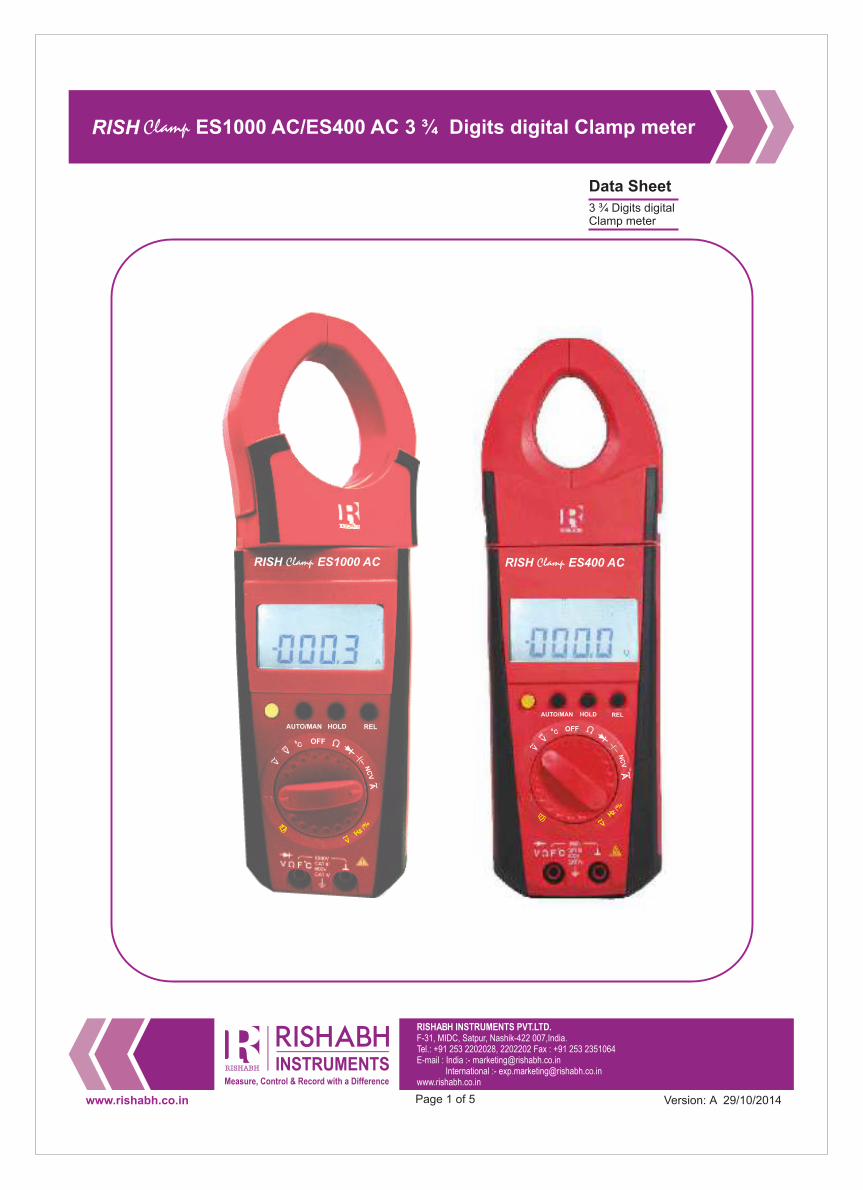
RISH Clamp ES1000 AC/ES400 AC 3 ¾ Digits digital Clamp meter
3 ¾ Digits digital Clamp meter
www.rishabh.co.in Page 1 of 5 Version: A 29/10/2014
RISHABH INSTRUMENTS PVT.LTD.F-31, MIDC, Satpur, Nashik-422 007,India.Tel.: +91 253 2202028, 2202202 Fax : +91 253 2351064E-mail : India :- [email protected] International :- [email protected]

Application
RISH Clamp Es1000 AC/ES400 AC measures important electrical parameters like AC Current, AC Voltage, and DC Voltage. It also features Capacitance, Ohm & Continuity, frequency, and Duty cycle and temperature measurement.
Product Features
Unique Design RISH Clamp ES1000 AC/ES400 AC is a highly innovative design for features those increases safety and comfort of user. Rotating clamp jaws facilitate the measurement at physically awkward positions, vertical bus bars, conductors placed at positions difficult to access. Clamp jaws can be opened or closed with the trigger placed at bottom side away from the jaws. This allows the user to place his/her hand at safer distance from live conductor. This greatly reduces exposure of human beings to electrical shocks Location and design of trigger eliminates fatigues caused by single finger operation. It allows spreading the force required to open the jaws over more than one finger to ensure comfortable operation. Comfortable operation of push buttons and function selector switch, in adverse field conditions.
Large Jaw OpeningFor RISH Clamp ES1000 AC Jaw opening of 51mm for standard
Narrow BodyNarrow housing for firm grip and easy to carry.
High Accuracy for low current measurementThe clamp meter can measure accurately at not only the High currents but also Low current ranges.
User selectable Backlit
It is possible to conduct measurement using the clamp meter during night time in darkness with the help of Backlit.
Temperature measurement
Temperature from 0 to 1300 °C using K type thermocouple sensors.
AUTO POWER OFF
In order to save the power of the Batteries, the clamp meter will automatically shut OFF if it detects no activity for 15 minutes.
Relative Measurement
By pressing REL key, the zero correction is made and relative
wire diameter of 50mm and for RISH Clamp ES400 AC Jaw opening of 41mm for standard wire diameter of 40mm for 400A
Hold Function
By pressing HOLD key reading on the display can be latched. Simultaneously HOLD is displayed on display.
Hz / Duty
The instrument can measure frequency (Hz) and Duty cycle (%) of ACvoltage by pressing yellow key in VAC function.
NULL ZERO Correction for Resistance
For Low ohm measurement, the lead resistance can be compensated by pressing REL key.
AUTO and MANUAL ranging modes
In AUTO ranging mode the instrument automatically selects the range with best resolution depending on the applied input.In MANUAL ranging mode range is user selectable using MAN key.
Protection from dust and water
IP20 for terminals as per IEC60529
Applicable International Safety standards
600 V CAT III/1000V CAT II as per International Safety standard IEC 61010-1- 2010
Double molded Cover for soft touch and firm grip of the Instrument
Diode and continuity testingFor testing diode and transistors, diode measurement function is available. Continuity test generates beep sound if resistance is less
than 75 ohm
Non contact voltage (NCV) detection
Presence of AC voltage >75 V AC 50/60 Hz can be detected
by keeping jaws near voltage carrying conductor.
RISH Clamp ES1000 AC/ES400 AC 3 ¾ Digits digital Clamp meter
www.rishabh.co.in Page 2 of 5
RISHABH INSTRUMENTS PVT.LTD.F-31, MIDC, Satpur, Nashik-422 007,India.Tel.: +91 253 2202028, 2202202 Fax : +91 253 2351064E-mail : India :- [email protected] International :- [email protected]
Version: A 29/10/2014
It is indicated by beep sound.
value is measured. All functions can measure Relative valueexcept Hz/Duty.
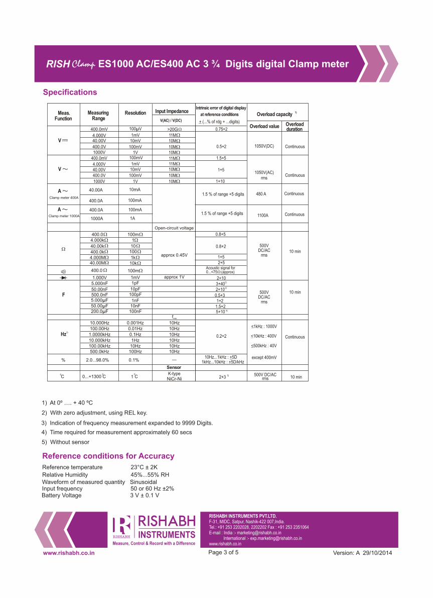
Reference conditions for Accuracy
Reference temperature 23°C ± 2K
Relative Humidity 45%...55% RHWaveform of measured quantity Sinusoidal Input frequency 50 or 60 Hz ±2%Battery Voltage 3 V ± 0.1 V
1) At 0º …. + 40 ºC
2) With zero adjustment, using REL key.
3) Indication of frequency measurement expanded to 9999 Digits.
4) Time required for measurement approximately 60 secs
5) Without sensor
Specifications
RISH Clamp ES1000 AC/ES400 AC 3 ¾ Digits digital Clamp meter
Meas.Function
MeasuringRange
Resolution Input Impedance
400.0mV
4.000V40.00V
400.0V1000V
400.0mV
4.000V40.00V400.0V
1000V
100 Vµ
1mV10mV
100mV1V
100mV
1mV10mV
100mV
1V
40.00A
400.0A
400.0A
1000A
10mA
100mA
100mA
1A
400.04.000k
40.00k400.0k4.000M40.00M
400.0
1.000V5.000nF
50.00nF500.0nF5.000 Fµ50.00 Fµ200.0 Fµ
100m1
10100
1k10k
100m
1mV1pF
10pF100pF
1nF10nF
100nF
10.000Hz100.00Hz1.0000kHz10.000kHz100.00kHz500.0kHz
0.001Hz0.01Hz0.1Hz1Hz10Hz
100Hz
2.0...98.0% 0.1%
V(AC) / V(DC)
>20G
11M10M
10M10M
11M11M10M
10M
10M
Open-circuit voltage
approx 0.45V
approx 1V
10Hz
10Hz
10Hz
10Hz10Hz10Hz
fmin
F
Hz
%
V
V
A
3)
Sensor
0
0...+1300 C0 C
0
1 C NiCr-NiK-type
AClamp meter 400A
Clamp meter 1000A
1.5 % of range +5 digits
0.8+5
0.8+2
1+52+5
2+102)3+402)2+10
0.5+31+2
1.5+24)5+10
0.2+2
10Hz...1kHz : +5D1kHz...10kHz : +5D/kHz
2+3
Continuous
Continuous
480 A
1100A
500VDC/AC
rms10 min
500VDC/AC
rms
Continuous
10 min
10 min
<1kHz : 1000V
<10kHz : 400V
except 400mV
<500kHz : 40V
500V DC/ACrms
Intrinsic error of digital display
at reference
+ (...% of rdg + ...digits)
0.75+2
0.5+2
1.5+5
1+5
1+10
1)Overload capacity
Overload value Overload duration
1050V(DC)
1050V(AC)rms
Continuous
Continuous
conditions
Acoustic signal for 0...<75 (approx)
5)
www.rishabh.co.in Page 3 of 5
RISHABH INSTRUMENTS PVT.LTD.F-31, MIDC, Satpur, Nashik-422 007,India.Tel.: +91 253 2202028, 2202202 Fax : +91 253 2351064E-mail : India :- [email protected] International :- [email protected]
Version: A 29/10/2014
1.5 % of range +5 digits
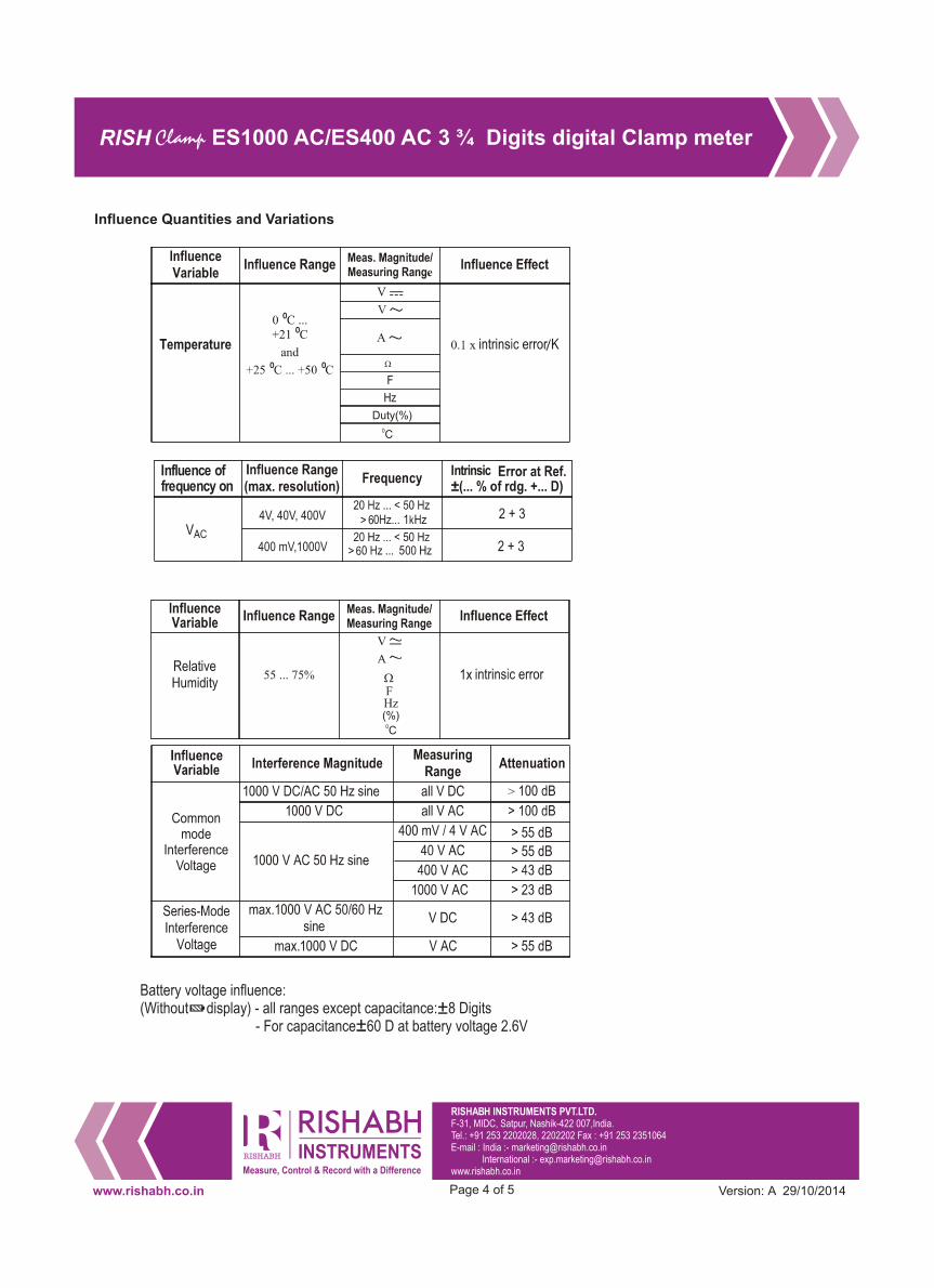
Influence Quantities and Variations
Intrinsic
RISH Clamp ES1000 AC/ES400 AC 3 ¾ Digits digital Clamp meter
Influence of frequency on
400 mV,1000V
4V, 40V, 400V
6
6
www.rishabh.co.in Page 4 of 5
RISHABH INSTRUMENTS PVT.LTD.F-31, MIDC, Satpur, Nashik-422 007,India.Tel.: +91 253 2202028, 2202202 Fax : +91 253 2351064E-mail : India :- [email protected] International :- [email protected]
Version: A 29/10/2014
Battery voltage influence:(Without display) - all ranges except capacitance: 8 Digits - For capacitance 60 D at battery voltage 2.6V

400 hrs
200 hrs
Applicable Standards
EMC IEC 61326: Class B
Immunity IEC 61000-4-2
8 KV atmosphere discharge, 4 KV contact discharge IEC 61000-4-3 : 3 V/m
Safety IEC 61010-1-2010 IP for water & dust IEC60529Pollution degree 2Installation category 600V CATIII / 1000V CATII
High Voltage Test 4.4 kV AC, 50Hz for 1 minute between housing and input.
Mechanical configuration
Environmental
Operating temperature -10 to +50°C
Storage temperature -25 to +70°CRelative humidity 45...75% non condensing
Terminal Protection IP 52 for Housing and IP20 for terminals
Battery
Battery Voltage 1.5 x 2 V AAA size batteries
Battery type
Battery Life
Display
IEC 6LR 03
OR
3
RISH Clamp ES1000 AC/ES400 AC 3 ¾ Digits digital Clamp meter
RISHABH INSTRUMENTS PVT.LTD.F-31, MIDC, Satpur, Nashik-422 007,India.Tel.: +91 253 2202028, 2202202 Fax : +91 253 2351064E-mail : India :- [email protected] International :- [email protected]
www.rishabh.co.in Page 5 of 5 Version: A 29/10/2014
0.6 KgWeight
90mm (W) x 270mm (L) x 70mm (H)Dimensions

Data Sheet
RISH Clamp-on CT 1000/1A/, CT 1000/5A, CT 300/0.3AClamp-on CT for AC current measurement
www.rishabh.co.in Page 1 of 2
Clamp- on CT for AC current measurement
Rish clamp on CT 300 A / 0.3A
RISH Clamp -on CT 300 A should be used asaccessories for RiSH Multi 12s which directlydisplays the Current in 300 A range.
Rish clamp on CT 1000 A / 1A
RISH Clamp -on CT 1000 A should be used as accessories for RiSH Multi series.
Rish clamp on CT 1000/ 5A
RISH Clamp -on CT 1000 A should be used as accessories for RiSH Multi series.
Version: A 03/01/2012

Application
Features of Rish Clamp on CT 300 A / CT 1000 A
Measurement
Rish Clamp-on CT 300 A / 1000A measures current without interrupting the conducting line. They are used for electrically isolated measurement of alternating current within a broad range ,without interrupting the current conducting cable and bus bars.
nSafety in accordance with IEC 61010-1.nMinimumtransformation ratio error.nCompact, handy design.nPermanently connected safety cables.
Rish Clamp on CT measures AC current without interrupting the conducting line. The opening contact of both the core which become visible when trigger is pressed, must be always kept clean. Even small outside particles can deviate measuring accuracy. The measuring secondary long cables with contact- protected connection plugs, which electrically isolates the measurement of AC current without interruption.
Clamp on current transformer
Type CT 1000A / 1A CT 300A / 0.3A
Descrition/
Appllication
Nominal Primary
Current
Output signal
Transmission ratio
Input:Output
Accuracy /
max.error
Jaw opening /
ConductorDiameter
1 1- -1 10 00 00 0A AAC AC4-300 A AC
1 1m mA AA AC C/ /A AAC AC0.3 mA AC / A AC
1 200:1000:1 1000:1
C Cl la as ss s1 1(2. (2.5 5V VA) A)
( (f fo or rcurre curren nt tr ra an ng ge ef fr rom om
1 1A At to o1 10 00 00 0A A, ,5 50Hz) 0Hz)
Class 1 ( 1.25 VA)
(for current range from
4A to 300A, 50Hz)
43 43m mm / m /
Dia Diam me et te er r4 43 3mm mm
Used with Ris Rish hmu mul lt ti is ser eri ies esRish multi 12s
Frequency range
Dimensions(W X H X D)
Weight
Cable length
40 40H Hz z. .. .. .. .1k 1kHz Hz40Hz....1kHz
A Appr ppro ox x65 650 0g gms msApprox 500 gms
1 1. .5 5m me et ter er1.5 meter
35mm /
Diameter 35mm
( (9 92 2X X3 39 9X X220 220) )mm mm(84 X 39 X 202)mm
Max. operating
Voltage
C CA AT TI II II I60 600 V 0 V
a as sp pe er rI IE EC C- -610 61010 10
CAT III 600 V
as per IEC-61010
The current transformers are used for electrically isolated measurement of alternating current within broad range.It is possible to measure AC current without interrupting the current conducting cable and bus bars via hard wired leads with contact protected plugs.
Periodic Check-up
Safety Features & Precautions
The clamp on CT does not require any specific maintenance. While cleaning, the probes must not be immersed into any liquid. No special maintenance is required for housing. The surface between the opening jaws should be cleaned with dry cloth before operating. Avoid use of cleansers, abrasives or solvents.
- Application around & removal fromHAZARDOUS LIVE conductor is permitted
The Rish Clamp on current transformers are constructed with safety rules of IEC 61010-1. When in operation the safety of user and unit is assured. Also when the secondary circuit is interrupted, the Clamp has a Protection circuit which prevents high voltage to be generated. Before operating read completely the instruction manual. These instruction must be followed by users in all respects. In case of incorrect use or careless handling, the safety of both user and clamp is not assured.
RISHABH INSTRUMENTS PVT.LTD.F-31, MIDC, Satpur, Nashik-422 007,India.Tel.: +91 253 2202160, 2202202 Fax : +91 253 2351064E-mail : India :- [email protected] International :- [email protected]
www.rishabh.co.in Page 2 of 2 Version: A 03/01/2012
Specifications
1000A /5A
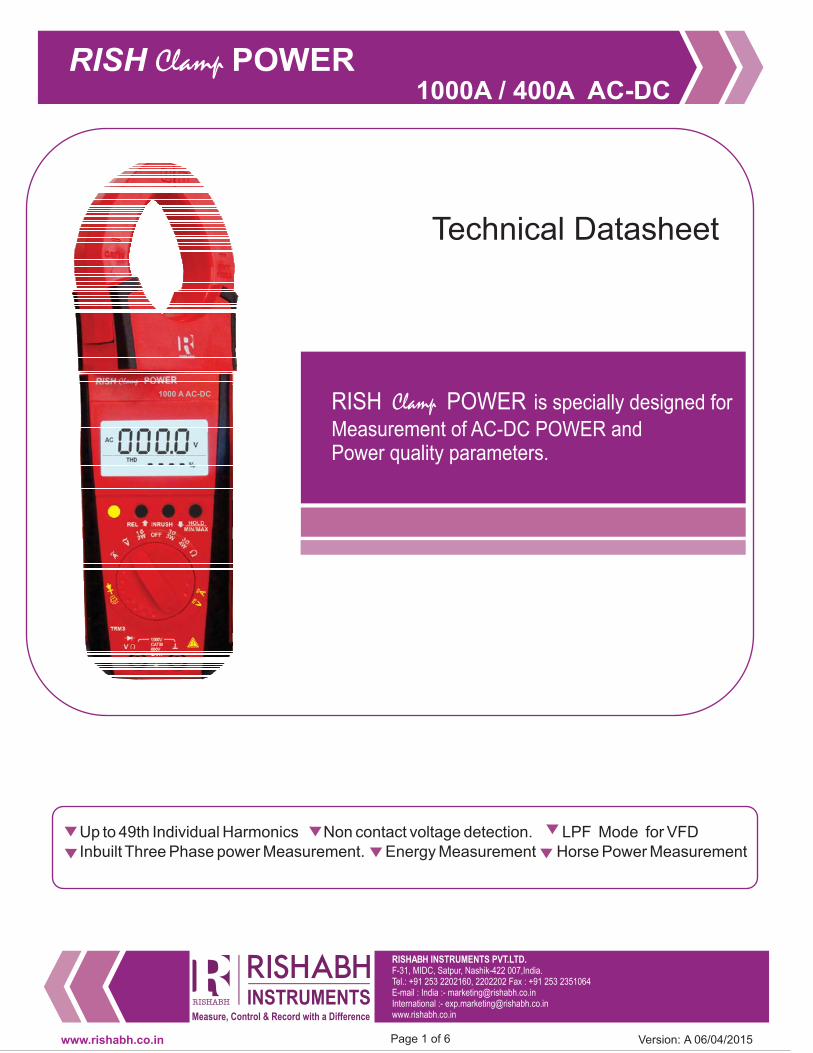
Technical Datasheet
RISH POWERClamp is specially designed for
Measurement of AC-DC POWER andPower quality parameters.
F-31, MIDC, Satpur, Nashik-422 007,India.Tel.: +91 253 2202160, 2202202 Fax : +91 253 2351064E-mail : India :- [email protected] :- [email protected]
Up to 49th Individual Harmonics Non contact voltage detection. LPF Mode for VFD
Inbuilt Three Phase power Measurement. Energy Measurement Horse Power Measurement
RISH Clamp POWER
www.rishabh.co.in Page 1 of 6
1000A / 400A AC-DC
1000 A AC-DC
Version: A 06/04/2015

www.rishabh.co.in Page 2 of 6
Application
RISH Clamp POWER 1000A/400A measures, calculate and displays
important electrical parameters of single phase or three phasepower system. It also features Resistance, continuity, diode andnon contact voltage detection.
Product Features
Measures following parameters
� AC & DC Voltage up to 1000V
� AC & DC Current up to 1000A/400A
� Inrush/Peak Value Measurement
� Active, Reactive andApparent Power
� Horse Power Measurement
� kWh
� Measure up to 49th Harmonics
� PhaseAngle
� THD
� DF
� Power Factor
� Crest Factor
� LPF Mode for VFDApplication
Unique DesignRISH POWER1000A/400A is a highly innovative design forClampfeatures those increases and of user.safety comfort�� Rotating clamp jaws facilitate the measurement at physicallyawkward positions, vertical bus bars, conductors placed atpositions difficult to access.�� Clamp jaws can be opened or closed with the trigger placed atbottom side away from the jaws. This allows the user to placehis/her hand at safer distance from live conductor. This greatlyreduces exposure of human beings to electrical shocks.�� Location and design of trigger eliminates fatigues caused bysingle finger operation. It allows spreading the force requiredto open the jaws over more than one finger to ensurecomfortable operation.�� Comfortable operation of push buttons and function selectorswitch, in adverse field conditions.
Large Jaw Opening
Jaw opening of 51mm and 41 mm for standard wire diameter of50mm and 40mm for 1000A and 400Arespectively.
Narrow Body
Narrow housing for firm grip and easy to carry.
DATAHold Function
By pressing DATA HOLD button, reading on the display can belatched for Hands free operation.
MIN,MAX Function
By pressing MIN/MAX button, the clamp meter will start recordinglatest Minimum and Maximum readings
User Selectable Backlit
It is possible to conduct measurement using the clamp meter during
Non Contact Voltage Detection
The clamp meter can detect the presence of AC Voltage between100 to 1000 V 50hz/60Hz without any electrical connection andgive acoustic signal as an indication.
Three Phase Power Measurement
Clamp meter can measure power in 3 phase 3 wire or 3 phase 4wire (Symmetric as well as Asymmetric) network without anymanual calculation like other clamp meters.
Dual Display
User friendly dual display shows the simultaneous parameters ofmeasuring input quantity.
LPF Mode
LPF mode is available for voltage and current for true measurementof VFDApplication
TRMS Measurement
In order to calculate true value of distorted waveform due topresence of high crest factor or harmonics, TRMS measurements isdone forAC voltage and current
Auto Power OFF
In order to save the power of the Batteries, the clamp meter willautomatically shut OFF if it detects no activity for 10 minutes.
Continuous ON Mode
In this mode,AUTO POWER OFF is disabled.
Low Battery Indication
Double molded Cover for soft touch and firm gripof the Instrument
RISH Clamp POWER
RISH POWERClamp400 A AC-DC
REL INRUSH HOLD
MIN/MAX
1000A / 400A AC-DC
Version: A 06/04/2015

Reference conditions for Accuracy
Reference temperature 23°C ± 2°CRelative Humidity 45%...55% RHInput frequency 50 or 60 HzPower Factor 0.5L....1....0.5CBattery Voltage 8 V ± 0.1 V
Technical Specification
Protection from dust and water
IP20 for terminals as per IEC60529
Applicable International Safety standards
600 V CAT IV/1000V CAT III as per International Safety standardIEC 61010-1- 2010
www.rishabh.co.in Page 3 of 6 Version: A 06/04/2015
V DC 999.9 V 0.1 V ±(0.5% of rdg + 5 dgt)
1000 V DC/AC
eff/rms Sine waveContinuously
999.9 V 0.1 V ±(0.75% of rdg+5 dgt)
V ACDC 999.9 V 0.1 V ±(1.25% of rdg+10dgt)
LPF V~ 999.9 V 0.1 V50.....60 Hz ±(0.75% of rdg + 5dgt)
61...400Hz ±(5.0% of rdg + 5dgt)
POWER CLAMP
1000A ADC-AAC999.9A 0.1 A ±(1.5% of rdg+5 dgt)
1100 A AC/DC
for power clamp
1000A
440 A AC/DC
for power clamp
400A
Continuously
POWER CLAMP
400A ADC - AAC
99.99 A 0.01 A display value
<1000 add 10
dgt
±(1.5% of rdg+0.2A)
400 A 0.1 A ±(1.5% of rdg+5 dgt)
POWER CLAMP
1000A A ACDC999.9A 0.1 A ±(3% of rdg+10 dgt)
POWER CLAMP
400A A ACDC
99.99 A 0.01 A display value
<1000 add 10
dgt
±(3% of rdg+0.4A)
400 A 0.1 A ±(3% of rdg+10 dgt)
POWER CLAMP
LPF 1000A A AC999.9A 0.1 A
50....60 Hz
61...400Hz
±(1.5% of rdg + 5dgt)
±(5.0% of rdg + 5dgt)
POWER CLAMP
LPF 400A A AC
99.99 A 0.01 A50....60 Hz
61...400Hz
±(1.5% of rdg + 0.3A)
±(5.0% of rdg + 5dgt)
400 A 0.1 A50....60 Hz
61...400Hz
±(1.5% of rdg + 5dgt)
±(5.0% of rdg + 5dgt)
Active
Power
9.999 kW 1 W
±(2% of rdg+5 dgt)1000 V DC/AC
1100 A AC/DC for
Power Clamp
1000A
440 A AC/DC for
Power Clamp
400A
Continuously
99.99 kW 10 W
999.9 kW 100 W
9999 kW 1 kW
Reactive
Power
9.999 kVAr 1 VAr
99.99 kVAr 10 VAr
999.9 kVAr 100 VAr
9999 kVAr 1 kVAr
Apparent
Power
9.999 kVA 1 VA
99.99 kVA 10 VA
999.9 kVA 100 VA
9999 kVA 1 kVA
Horse
Power
9.999 hp 0.001 hp
99.99 hp 0.01 hp
999.9
Measuring
function
Measuring
rangeResolution
Intrinsic error of digital display
at reference condition
Over load capacity
Over load valueOverload
duration
hp 0.1 hp
9999 hp 1 hp
kWh
9.999 kWh 0.001 kWh
±(3% of rdg+5 dgt)99.99 kWh 0.01kWh
999.9 kWh 0.1 kWh
9999 kWh 1 kWh
V ~
1)
1)
1)
1)
1)
1)
2)
1)
2)
2)
2)
2)

Technical Specification
www.rishabh.co.in Page 4 of 6
For Power Clamp 1000A2)Accuracy Defined for V 10V and I 5A≧ ≧
Add 10 digit to accuracy when power is< 5.000 kW/kVAr/kVAor <6.700 hp
3)Accuracy Defined for V 10V and I 10A≧ ≧4)Accuracy Defined for I 10A≧
For Power Clamp 400A2)Accuracy Defined for V 10V and I 4A≧ ≧
Add 10 digit to accuracy when power is< 5.000 kW/kVAr/kVAor <6.700 hp
3)Accuracy Defined for V 10V and I 10A≧ ≧4)Accuracy Defined for I 5A≧
For Power Clamp 1000AIn 1P2W mode maximum power meter can measure is, 1000 kVA/ 1000 kVAr / 1000 kW / 1341 hpIn 3P4W mode maximum power meter can measure is,3000 kVA/ 3000 kVAr / 3000 kW / 4023 hpIn 3P3W mode maximum power meter can measure is,1732 kVA/ 1732 kVAr / 1732 kW / 2322 hp
For Power Clamp 400AIn 1P2W mode maximum power meter can measure is, 400 kVA/ 400 kVAr / 400 kW / 536 hpIn 3P4W mode maximum power meter can measure is,1200 kVA/ 1200 kVAr / 1200 kW / 1608 hpIn 3P3W mode maximum power meter can measure is,693 kVA/ 693 kVAr / 693 kW / 928 hp
Measuring
function
Measuring
rangeResolution
Intrinsic error of digital display
at reference condition
Over load capacity
Over load valueOverload
duration
Ahr 999.9 Ahr 0.1 Ahr
Phase angle 0.0°…360.0° 0.1°
Pow er Factor -1…0…1 0.001
Harmonics
(RMS & %)
1…13 0.1V
0.1A
0.1%14…49
THD 0…99.9% 0.1%
DF 0…99.9% 0.1%
Crest Factor1.0…2.9 0.1
3.0…5.0 0.1
560 A/ 1000 V 1 A / 1 V
Resistance 4000 Ohm 1 Ohm
10 SecsContinuity Below 40 Ohm 1 Ohm
Diode 0…2.2V 0.001 V
±(3% of rdg+5 dgt)
1000 VDC/AC
1100 AAC/DC for
Power Clamp
1000A
440 AAC/DC for
Power Clamp
400A
Continuously
±3°
±(3% of rdg+10 dgt)
±(5% of rdg+20 dgt)
±(3% of rdg+20 dgt)
±(3% of rdg+20 dgt)
±(2% of rdg+3 dgt)
±(3% of rdg+5 dgt)
POWER CLAMP
1000A Peak
1400 A/
1400V1 A ±(3% of rdg+3 dgt)
POWER CLAMP
400A Peak
100 A 0.1 A ±(3% of rdg+10 dgt)
±(3% of rdg+3 dgt)
POWER CLAMP
1000A INRUSH999.9A 0.1 A ±(3% of rdg+5 dgt)
POWER CLAMP
400A INRUSH
99.99 A 0.01 A ±(3% of rdg+0.3A)
400 A 0.1 A ±(3% of rdg+5 dgt)
±(0.5% of rdg+5 dgt)
±(0.5% of rdg+5 dgt)
±(0.5% of rdg+5 dgt)
2)
2)
3)
3)
3)
3)
4)
4)
1000 V DC/AC
eff/rms Sine wave
Note:- Accuracy claimed for Power and Current when conductor is positioned at the center of the jaw.
1)For DCAmake auto zero correction by long pressing the keyHOLD
Version: A 06/04/2015

Influence Quantity
www.rishabh.co.in Page 5 of 6
1) Except SineWave
CF 2 @ 690V, 690Afor Power Clamp Meter 1000 A ACDCCF 3 @ 690V, 186Afor Power Clamp Meter 400AACDCCF 4 @ 345V, 345Afor Power Clamp Meter 1000 A ACDCCF 4 @ 345V, 140Afor Power Clamp Meter 400 A ACDCCF 2 @ 690V, 280Afor Power Clamp Meter 400AACDCCF 5 @ 280V, 280Afor Power Clamp Meter 1000 A ACDCCF 3 @ 460V, 460Afor Power ClampMeter 1000 A ACDCCF 5 @ 280V, 112Afor Power Clamp Meter 400 A ACDC
2) Except for 50 or 60 Hz
Infulence
quantityRange of Infuence
Measured
quantity /
Measuring Range
Variation
Temperature
0 ºC… 21 ºC
and
25 ºC….50 ºC
V AC
0.15 X Intrinsic Error / ºC
V DC
V ACDC
A AC
A DC
A ACDC
AC Power
DC Power
Resistance/ Diode/
Continuity
Frequecy of
the measured
quantity
40 Hz… 50 Hz
and
60 Hz….400 Hz
V AC
1 X Intrinsic Error
V ACDC
A AC
A ACDC
45 Hz….65 Hz AC Power
Crest Factor
1.4…2V AC
A AC
1% + Intrinsic Error
2…2.5 2.5% + Intrinsic Error
2.5...5 4% + Intrinsic Error
Supply
Voltage
When Low Battery
symbol is ONAll Ranges 1 X Intrinsic Error
Relative
humidity75% All Ranges 1 X Intrinsic Error
2)
1)
Version: A 06/04/2015
Environmental
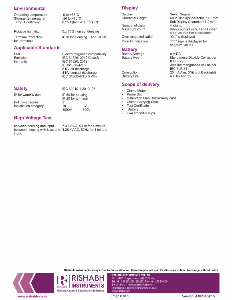
Operating temperature 0 to +55°CStorage temperature -20 to +70°CTemp. Coefficient 0.15 X(Intinsic Error) / °C
Relative humidity 0... 75% non condensing
Terminal Protection IP50 for Housing and IP20for terminals
Applicable Standards
EMC Electro magnetic compatibilityEmission IEC 61326: 2012 ClassBImmunity IEC 61326: 2012
IEC61000-4-2 :-8 KV air discharge,4 KV contact dischargeIEC 61000-4-3 :- 3 V/m
Safety IEC 61010-1-2010 -06
IP for water & dust IP 50 for housingIP 20 for terminal
Pollution degree 2Installation category III IV
1000V 600V
High Voltage Test
between housing and input. 7.4 kV AC, 50Hz for 1 minutebetween housing with jaws and 4.26 kV AC, 50Hz for 1 minuteinput.
RISHABH INSTRUMENTS PVT.LTD.
F-31, MIDC, Satpur, Nashik-422 007,India.Tel.: +91 253 2202028, 2202202 Fax : +91 253 2351064E-mail : India :- [email protected] :- [email protected]
Rishabh Instruments always tries for innovation and therefore product specifications are subject to change without notice
www.rishabh.co.in Page 6 of 6
Display
Display Seven SegmentCharacter Height Main Display Character : 11.5 mm
Sub Display Character : 7.2 mmNumber of digits 4 digits.Maximum count 9999 counts For V, I and Power
4000 counts For ResistanceOver range indication “OL” is displayed
Polarity indication “ ” sign is displayed for─negative values.
BatteryBattery Voltage 9 V DCBattery type Manganese Dioxide Cell as per
IEC6F22Alkaline manganese cell as perIEC 6LR 61
Consuption 20 mA Avg. (Without Backlight)Battery Life 48 Hrs Approx.
Scope of delivery
� Clamp Meter� Probe Set� Instruction Manual/Warranty card� Clamp Carrying Case� Test Certificate� Battery� Two crocodile clips
Version: A 06/04/2015
Data Sheet
RISH
Clamp1000A/300A AC-DC
www.rishabh.co.in Page 1 of 5
3 ¾ Digits digital
Version: E 08/04/2014
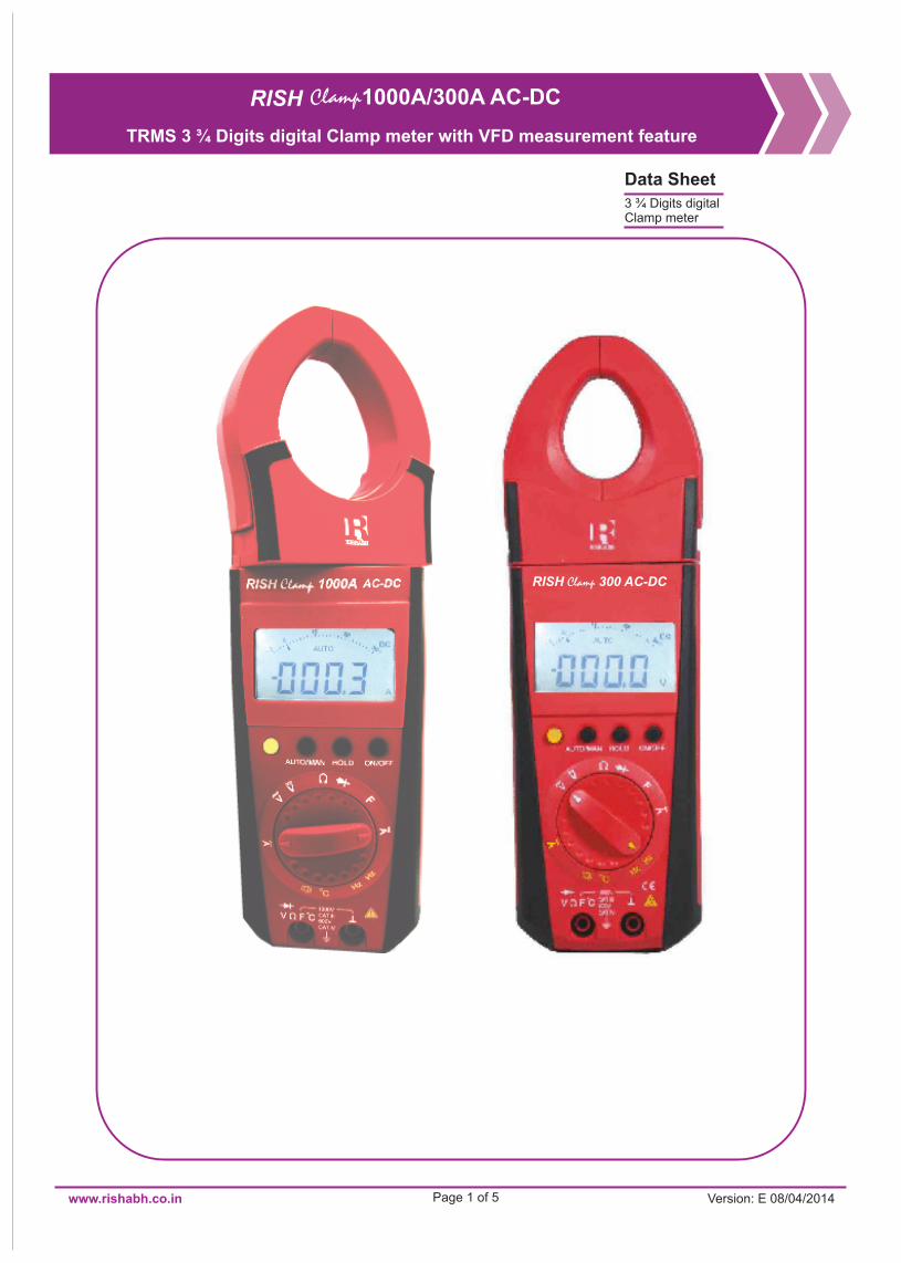
TRMS 3 ¾ Digits digital Clamp meter with VFD measurement feature
Clamp meter
RISH Clamp 300 AC-DC

www.rishabh.co.in Page 2 of 5
Application
RISH Clamp 1000A/300A measures important electrical parameters like AC Current (TRMS), DC Current, AC Voltage(TRMS), and DC Voltage. It also features Capacitance, Ohm & Continuity, frequency, and Duty cycle and temperature measurement.
Product Features
Unique DesignRish Clamp 1000A/300A is a highly innovative design for features those increases safety and comfort of user. Rotating clamp jaws facilitate the measurement at physically awkward positions, vertical bus bars, conductors placed at positions difficult to access. Clamp jaws can be opened or closed with the trigger placed at bottom side away from the jaws. This allows the user to place his/her hand at safer distance from live conductor. This greatly reduces exposure of human beings to electrical shocks Location and design of trigger eliminates fatigues caused by single finger operation. It allows spreading the force required to open the jaws over more than one finger to ensure comfortable operation. Comfortable operation of push buttons and function selector switch, in adverse field conditions.
Large Jaw OpeningFor RISH CLAMP 1000A AC-DC Jaw opening of 51mm for standard
Narrow BodyNarrow housing for firm grip and easy to carry.
High Accuracy for low current measurementThe clamp meter can measure accurately at not only the High
currents but also Low current ranges.
User selectable Backlit : (Optional)
It is possible to conduct measurement using the clamp meter during night time in darkness with the help of Backlit. The back lit can be switched ON or OFF by pressing a single key.
Temperature measurement
Temperatures from -200 to 800 °C using Pt 100 and Pt 1000 sensors.
AUTO POWER OFF
In order to save the power of the Batteries, the clamp meter will automatically shut OFF if it detects no activity for 10 minutes.
Analog Scale
Analog scale that updates at the rate 20 times/sec to observe fluctuations in input.
CONTINOUS ON MODE
In this mode, AUTO POWER OFF is disabled.
DATA Hold Function
By pressing DATA HOLD button, reading on the display can be latched for Hands free operation.
MIN,MAX Function
By pressing MIN/MAX button, the clamp meter will start recording latest Minimum and Maximum readings
NULL ZERO Correction for Resistance
For Low ohm measurement, the lead resistance can be compensated by pressing the shift key (Yellow Key)
NULL ZERO Correction for Capacitance
Null zero connection for capacitance. For nF range, stray capacitance can be compensated by shift key (Yellow Key)
AUTO and MANUAL ranging modes
In AUTO ranging mode the instrument automatically selects the range with best resolution depending on the applied input.In MANUAL ranging mode range is user selectable using MAN key.
Diode MeasurementFor testing diode and transistors, diode measurement function is available.
Protection from dust and water
IP20 for terminals as per IEC60529
Applicable International Safety standards
600 V CAT IV/1000V CAT III as per International Safety standard IEC 61010-1- 2010
Double molded Cover for soft touch and firm grip of the Instrument
wire diameter of 50mm and for RISH CLAMP 300A AC-DC Jaw opening of 41mm for standard wire diameter of 40mm for 300A
Measurement on Variable Frequency DrivesThe clamp meter can measure accurately on variable frequency
drives (VFD) and UPS.
Version: E 08/04/2014
True Root Mean Square (TRMS) measurement Clamp meter measures AC signal’s root-mean-square value
accurately irrespective of the shape of input waveform.
300.0 A
2 to 300.0 A 1000 A
Rish clamp 300A~/Adc
www.rishabh.co.in Page 3 of 5
1) At 0º …. + 40 ºC
2) With zero adjustment, without zero adjustment + 35 digits
3) Range : 3 V ac/dc: Ue = 1.5 V eff/rms … 100 V eff/rms 30 V ac/dc: Ue = 15 V eff/rms … 300 V eff/rms
300 V ac/dc: Ue = 150 V eff/rms … 1000 V eff/rms
4) On the range 3 V dc, square – wave signal positive on one side 5 … 15 V, f = const., not 163.84 Hz or integral multiple.
5) Without sensor
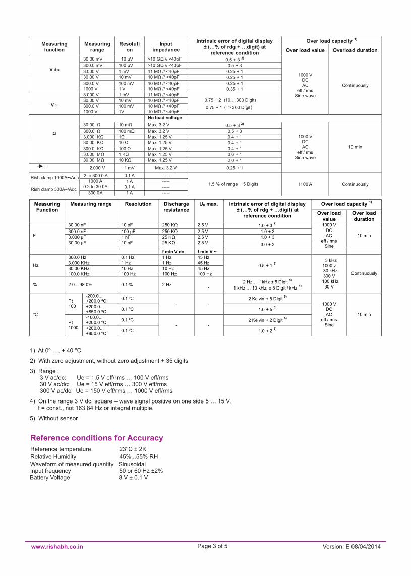
Reference conditions for Accuracy
Reference temperature 23°C ± 2K
Relative Humidity 45%...55% RHWaveform of measured quantity Sinusoidal Input frequency 50 or 60 Hz ±2%Battery Voltage 8 V ± 0.1 V
Over load capacity 1)
Measuring function
Measuring range
Resolution
Input impedance
Intrinsic error of digital display ± (…% of rdg + …digit) at
reference condition Over load value Overload duration
30.00 mV 10 µV >10 GΩ // <40pF 0.5 + 3 2) 300.0 mV 100 µV >10 GΩ // <40pF 0.5 + 3
3.000 V 1 mV 11 MΩ // <40pF 0.25 + 1
30.00 V 10 mV 10 MΩ // <40pF 0.25 + 1
300.0 V 100 mV 10 MΩ // <40pF 0.25 + 1
V dc
1000 V 1 V 10 MΩ // <40pF 0.35 + 1
3.000 V 1 mV 11 MΩ // <40pF 30.00 V 10 mV 10 MΩ // <40pF
300.0 V 100 mV 10 MΩ // <40pF
V ~ 1000 V 1V 10 MΩ // <40pF
0.75 + 2 (10….300 Digit)
0.75 + 1 > 300 Digit
1000 V DC AC
eff / rms Sine wave
Continuously
No load voltage
30.00 Ω 10 mΩ Max. 3.2 V 0.5 + 3 2)
300.0 Ω 100 mΩ Max. 3.2 V 0.5 + 3
3.000 KΩ 1Ω Max. 1.25 V 0.4 + 1 30.00 KΩ 10 Ω Max. 1.25 V 0.4 + 1
300.0 KΩ 100 Ω Max. 1.25 V 0.4 + 1 3.000 MΩ 1 KΩ Max. 1.25 V 0.6 + 1
Ω
30.00 MΩ 10 KΩ Max. 1.25 V 2.0 + 1
2.000 V 1 mV Max. 3.2 V 0.25 + 1
1000 V DC AC
eff / rms Sine wave
10 min
0.1 A ----- Rish clamp 1000A~/ 1 A -----
0.2 to 30.0A 0.1 A -----
1.5 % of range + 5 Digits
Adc
1 A -----
1100 A Continuously
Over load capacity 1)
Measuring Function
Measuring range Resolution Discharge resistance
U0 max. Intrinsic error of digital display ± (…% of rdg + …digit) at
reference condition Over load
value Over load duration
30.00 nF 10 pF 250 KΩ 2.5 V 1.0 + 3 2)
300.0 nF 100 pF 250 KΩ 2.5 V 1.0 + 3
3.000 µF 1 nF 25 KΩ 2.5 V 1.0 + 3 F
30.00 µF 10 nF 25 KΩ 2.5 V 3.0 + 3
1000 V DC AC
eff / rms Sine
10 min
f min V dc f min V ~ 300.0 Hz 0.1 Hz 1 Hz 45 Hz 3.000 KHz 1 Hz 1 Hz 45 Hz 30.00 KHz 10 Hz 10 Hz 45 Hz
Hz
100.0 KHz 100 Hz 100 Hz 100 Hz
0.5 + 1 3)
%
2.0....98.0%
0.1 %
2 Hz
-
2 Hz… 1kHz ± 5 Digit 4)
1 kHz … 10 kHz; ± 5 Digit / kHz 4)
3 kHz 1000 v 30 kHz; 300 V
100 kHz 30 V
Continuously
-200.0... +200.0 ºC
0.1 ºC 2 Kelvin + 5 Digit 5)
Pt 100 +200.0...
+850.0 ºC 0.1 ºC
- -
1.0 + 5 5)
-100.0... +200.0 ºC
0.1 ºC 2 Kelvin + 2 Digit 5)
ºC
Pt 1000 +200.0...
+850.0 ºC 0.1 ºC
- -
1.0 + 2 5)
1000 V DC AC
eff / rms Sine
10 min
Version: E 08/04/2014
( )
www.rishabh.co.in Page 4 of 5
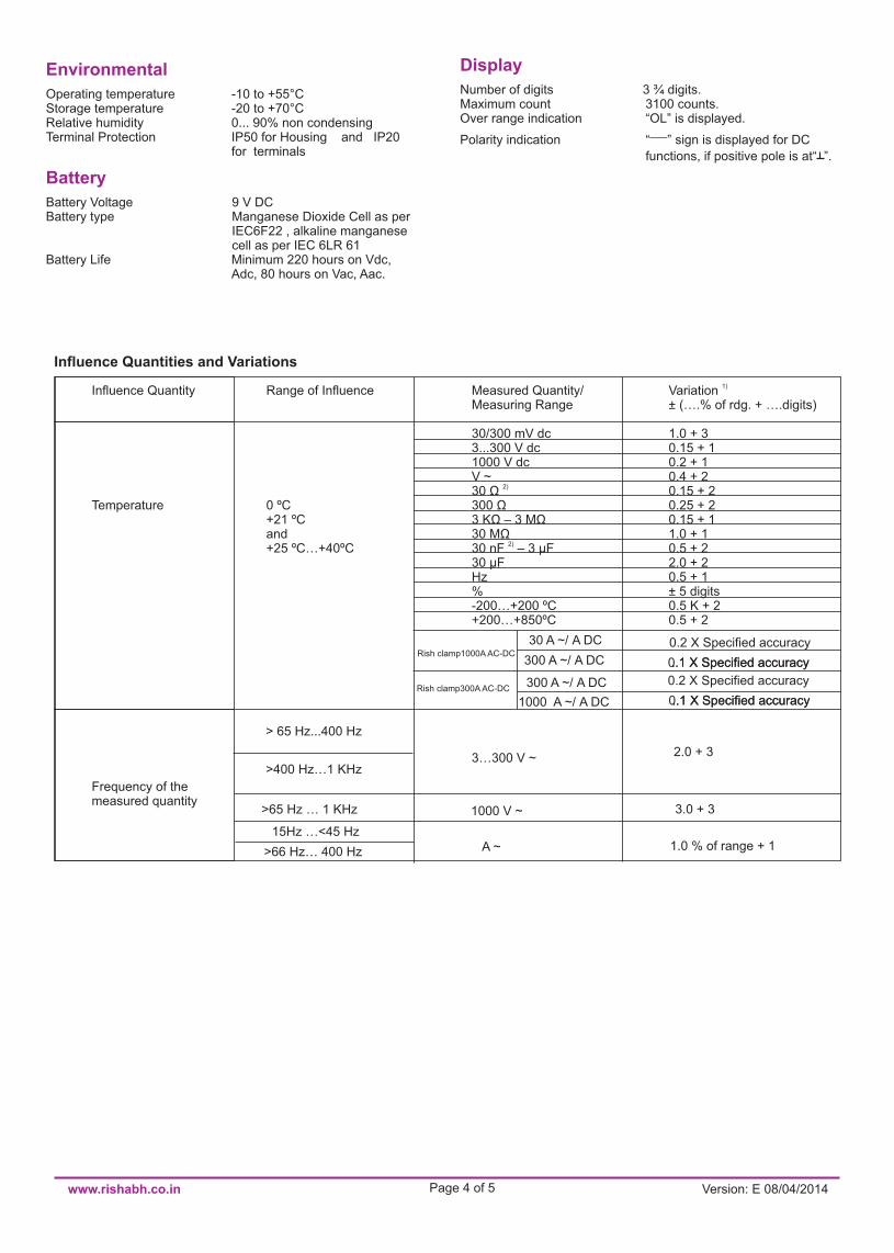
Environmental
Operating temperature -10 to +55°CStorage temperature -20 to +70°CRelative humidity 0... 90% non condensingTerminal Protection IP50 for Housing and IP20 for terminals
Battery
Battery Voltage 9 V DCBattery type Manganese Dioxide Cell as per IEC6F22 , alkaline manganese cell as per IEC 6LR 61Battery Life Minimum 220 hours on Vdc, Adc, 80 hours on Vac, Aac.
Display
Number of digits 3 ¾ digits.Maximum count 3100 counts.Over range indication “OL” is displayed.
Polarity indication “─” sign is displayed for DC
functions, if positive pole is at“ ”.
30 A ~/ A DC 0.2 X Specified accuracy
1)
Influence Quantity Range of Influence Measured Quantity/ Variation Measuring Range ± (….% of rdg. + ….digits) 30/300 mV dc 1.0 + 3 3...300 V dc 0.15 + 1 1000 V dc 0.2 + 1 V ~ 0.4 + 2
2) 30 Ω 0.15 + 2 Temperature 0 ºC 300 Ω 0.25 + 2 +21 ºC 3 KΩ – 3 MΩ 0.15 + 1 and 30 MΩ 1.0 + 1
2) +25 ºC…+40ºC 30 nF – 3 μF 0.5 + 2 30 μF 2.0 + 2 Hz 0.5 + 1 % ± 5 digits -200…+200 ºC 0.5 K + 2 +200…+850ºC 0.5 + 2
1000 A ~/ A DC 0 ..1 X Specified accuracy
> 65 Hz...400 Hz
3…300 V ~ >400 Hz…1 KHz
2.0 + 3
Frequency of the measured quantity 1000 V ~
>65 Hz … 1 KHz
3.0 + 3
15Hz …<45 Hz A ~ 1.0 % of range + 1
>66 Hz… 400 Hz
Influence Quantities and Variations
300 A ~/ A DC
300 A ~/ A DC
..1 X Specified accuracy
0.2 X Specified accuracy
0 ..1 X Specified accuracy ..1 X Specified accuracy Rish clamp1000A AC-DC
Rish clamp300A AC-DC
Version: E 08/04/2014
For Aac/Adc error data apply per K change in temperature.
± 1 % of rdg
± 3 % of rdg
RISHABH INSTRUMENTS PVT.LTD.F-31, MIDC, Satpur, Nashik-422 007,India.Tel.: +91 253 2202028, 2202202 Fax : +91 253 2351064E-mail : India :- [email protected] International :- [email protected]
www.rishabh.co.in Page 5 of 5
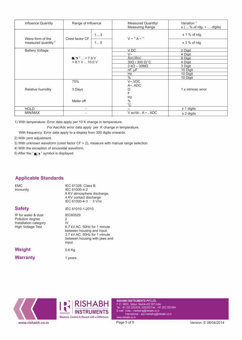
1) With temperature: Error data apply per 10 K change in temperature.
With frequency: Error data apply to a display from 300 digits onwards.
2) With zero adjustment.
3) With unknown waveform (crest factor CF > 2), measure with manual range selection
4) With the exception of sinusoidal waveform.
5) After the “ ” symbol is displayed
1)
Influence Quantity Range of Influence Measured Quantity/ Variation Measuring Range ± (….% of rdg. + ….digits)
1....3 4) 4) Wave form of the Crest factor CF V ~ A ~
3) measured quantity 1....5 Battery Voltage V DC 2 Digit V~ 4 Digit
5) …< 7.9 V AAC/ADC 8 Digit > 8.1 V …10.0 V 30Ω / 300 Ω/˚C 4 Digit 3 kΩ – 30MΩ 3 Digit nF, μF 10 Digit Hz 10 Digit % 10 Digit 75% V~,VDC A~, ADC Relative humidity 3 Days Ω 1 х intrinsic error F Hz Meter off %
0 C HOLD - -- ± 1 digits MIN/MAX - V ac/dc , A ~ , ADC ± 2 digits
Applicable Standards
EMC IEC 61326: Class BImmunity IEC 61000-4-2 8 KV atmosphere discharge, 4 KV contact discharge IEC 61000-4-3 : 3 V/m
Safety IEC 61010-1-2010
IP for water & dust IEC60529Pollution degree 2Installation category IVHigh Voltage Test 6.7 kV AC, 50Hz for 1 minute between housing and input. 3.7 kV AC, 50Hz for 1 minute between housing with jaws and input.
Weight 0.6 Kg
Warranty 1 years
Version: E 08/04/2014

1000A/ 400A AC-DC
PDF created with FinePrint pdfFactory trial version www.softwarelabs.com

PDF created with FinePrint pdfFactory trial version www.softwarelabs.com

1
PDF created with FinePrint pdfFactory trial version www.softwarelabs.com

Contents Page
1. Introduction , Application and Features ..........................................................................32. Safety features and safety precautions............... ............................3
3. Switching the Power Clamp meter "ON".....................................................5
4 Liquid crystal display and backlit.......................................................................65. Advanced Data “HOLD” Facility......................................................7
6. Minimum value and maximum value"MIN/MAX storage facility. ...........8
7. Relative Function ............................... .............................................9
8. Voltage measurement ....................................................................10
9. Current measurement.....................................................................13
10. 1Ph Power measurement .......................... ...................................19
11. 3-Phase 4 were Power measurement ........... ................................23
13. NCV Detection..................... ............................
..................................3114. Resistance, continuity & Diode measurement...................................31
............................
(1) Liquid crystal display
(2) Push button for data hold
(3) Push button for Down and Inrush
and MIN/MAX storage functions
(4) Push button for Up and RelativeFunction
(5) Multifunction push button
(6) Function selector switch.
(7) Terminal sockets
................................3316. Specifications...................................................15. Empty Positions............. .......................................32
17.1 Battery ........................................ .....................................3717.2 Periodic Check-up ...................................................................37
(8) Rotary mechanism for clamp jaws.
(9) Safe trigger mechanism.
17. Maintainance .................................. .............................................. 37
18. Servicing ....................................... ...............................................37
(10) Limit of safe access for hand held.
8.1 THD .................... ....................................................................108.2 DF ...................... ....................................................................108.3 CF ...................... ....................................................................118.4 Peak Min/ Peak Max ...............................................................118.5 Frequency........... ....................................................................118.6 Individual Harmonic measurement .........................................118.7 LPF.......................... ...............................................................11
9.1 THD .................... 9.2 DF ...................... 9.3 CF ...................... 9.4 Peak Min/ Peak Max 9.5 Frequency........... 9.6 Individual Harmonic measurement9.7 LPF.......................... 9.8 Inrush Current measurement 9.9 Ampere hour measurement..... .....
....................................................................14....................................................................15....................................................................15 ...............................................................15....................................................................15 .........................................15 ...............................................................15 .................................................17
..........................................18
10.1 kVA,kW ,kVAr ... 10.2 PF & Ф.............. 10.3 HP ...................... 10.4 DC Power10.5 kWh measurement
....................................................................19
....................................................................19
....................................................................19 ............................................................................19
...............................................................22
11.1 3 Ph 4W unbalance Load Power 11.2 3 Ph 4W balance Load Powe
..........................................23. r...............................................25
12. 3 Phase 3 Wire Power measurement ........... ................................2712.1 3 Ph 3W unbalance Load Power 12.2 3 Ph 3W balance Load Power
..........................................27. ..............................................29
2
PDF created with FinePrint pdfFactory trial version www.softwarelabs.com

1. Introduction , Application and Features:Power Clamp meter is a Portable Digital multi functional measuring instrument .designed for Measuring selected power network parameters, AC/DC Voltage, AC/DC current, Resistance, Continuity, Diode and Frequency. Apart From basic quantities meter enables the measurement of additional quantities calculated from values of voltage and current.
Power clamp meter is innovatively designed for increasing safety and comfort of user. Rotating clamp jaws facilitate the measurement at physically awkward position, vertical bus bars , conductors placed at position difficult to access. Clamp jaws can be opened or closed with the triggered placed at bottom side placed away from the jaws . This allows the user to place his/her hand at safer distance from live conductor.
.Location and design of trigger eliminates fatigues caused by single finger operation. It allows spreading the force required to open the jaws over more than one finger to ensure comfortable operation.
Power Clamp meter have following features
2. Safety features and safety precautions
Please note the following safety precautions:
Power Clamp meter provides a very high degree of safety.The digital power clamp meterin compliance with the safety standard IEC 61010-1:2010.In case of incorrect use or careless handing,the safety of both user and power clamp meter is not assured.
For proper use and safe handling,it is absolutely necessary to read andunderstand the operating instructions before using the clamp meter.
400A/1000A manufactured and tested
The clamp meter must be operated only by persons who understandthe danger of shock hazards and are aware of the necessary safetyprecautions.Shock hazards exist wherever voltages of more than30V(TRMS) are present.Do not work alone in shock hazardous environment while carryingout measurement.
Operators must use individual protective equipment if hazardous live parts of installation could be accessible .Keep hands/fingers behind the edge that separates rotating jaws with hand held part(10). This is the limits of the hand held part during measurement.
The maximum permissible voltage between any of the terminalsockets (7) and ground is 1000V.
3
PDF created with FinePrint pdfFactory trial version www.softwarelabs.com

voltages can occur on devic e
voltage.
s with
environmental conditions are not
Take into account that unexpectedunder test(e.g.defective instrument).For example, capacitors maybe charged to a dangerously high
in good condition, e.g.no crac kedVerify that the test leads areinsulation, no open circuits in the leads or connectors.This clamp meter must not be used for measurements on circuitcorona discharge (high voltage).
on HF circuits.Dangerouscomposite voltages may exist there.Be particularly careful when measuring
Measurements under moistpermitted.Do not overload the measuring ranges beyond their allowablecapacities. Limit values are given in specifications. Ref. Chapter 16.Please verify the performance of clamp meter after repairing of the meter, before using it for actual measurement.Do not use the clamp meter if obvious wear in jaw opening is visible.Protection provided by the digital clamp meter may be impaired if the clamp meter is not used in a manner specified in this user manual.
Measurements at power sources for low-voltage installations,
consumers, distributor terminals, devices connected permanently
Measurements in electrical circuits which are not directlyconnected to the mains: for example electrical systems in motor
Measurements in building installations, stationary power
eters, mains terminals, primary over voltage protection devices.
Meaning of categories and their significance as per IEC61010-1
vehicles and aircraft, batteries etc.
to the distributor.
CAT III:
CAT IV:
CAT I:
which are electrically connected to the low-voltage mains:with plugs, e.g. at home, in the
Measurements in electrical circuits
office or laboratory etc.
II:CAT
m
4
PDF created with FinePrint pdfFactory trial version www.softwarelabs.com
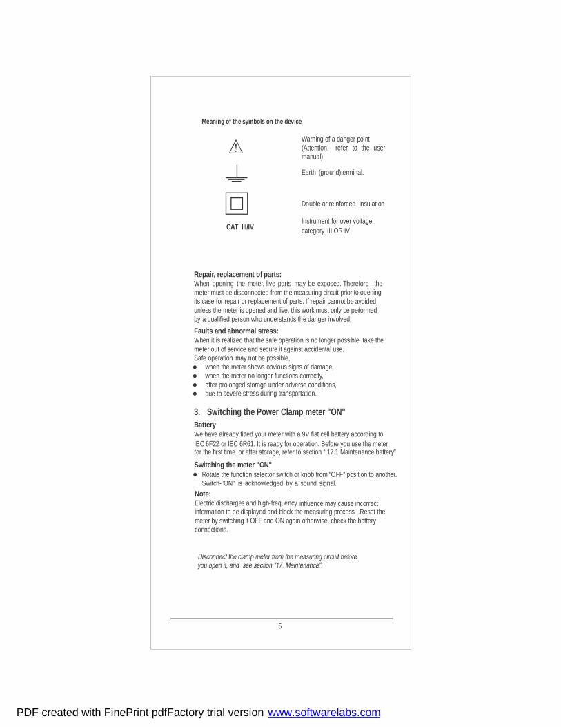
Repair, replacement of parts:When opening the meter, live parts may be exposed. Therefore , themeter must be disconnected from the measuring circuit prior to openingits case for repair or replacement of parts. If repair cannot be avoidedunless the meter is opened and live, this work must only be performedby a qualified person who understands the danger involved.
Faults and abnormal stress:When it is realized that the safe operation is no longer possible, take themeter out of service and secure it against accidental use.Safe operation may not be possible,
when the meter shows obvious signs of damage,when the meter no longer functions correctly,after prolonged storage under adverse conditions,due to severe stress during transportation.
3. Switching the Power Clamp meter "ON"BatteryWe have already fitted your meter with a 9V flat cell battery according toIEC 6F22 or IEC 6R61. It is ready for operation. Before you use the meter
Meaning of the symbols on the device
Warning of a danger point(Attention, refer to the usermanual)
Earth (ground)terminal.
Double or reinforced insulation
Instrument for over voltagecategory III OR IVCAT III/IV
for the first time or after storage, refer to section “ 17.1 Maintenance battery”
Switching the meter "ON"
Note:Electric discharges and high-frequency influence may cause incorrectinformation to be displayed and block the measuring processmeter by switching it OFF and ON again otherwise, check the batteryconnections.
Rotate the function selector switch or knob from “OFF" position to another.Switch-"ON" is acknowledged by a sound signal.
.Reset the
5
PDF created with FinePrint pdfFactory trial version www.softwarelabs.com
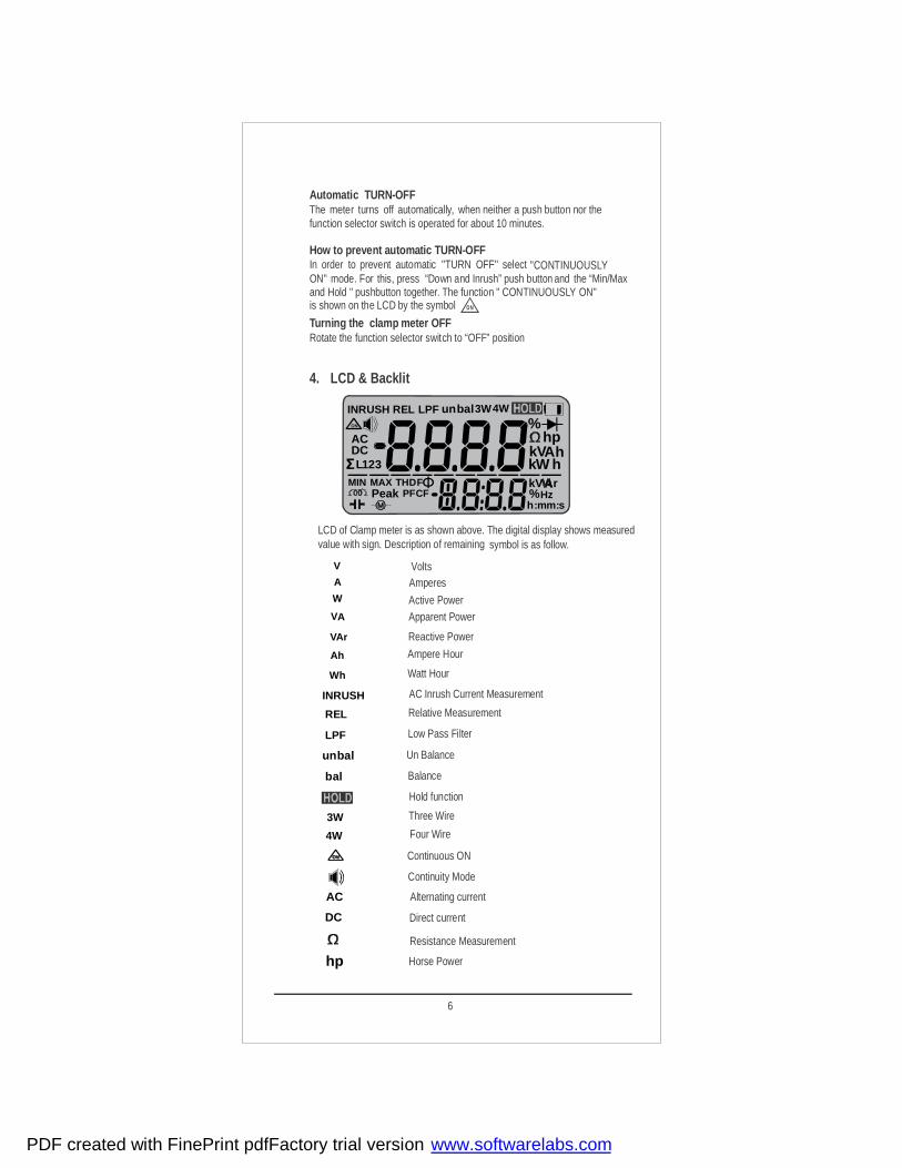
Automatic TURN-OFFThe meter turns off automatically, when neither a push button nor the function selector switch is operated for about 10 minutes.
How to prevent automatic TURN-OFFIn order to prevent automatic "TURN OFF" select "CONTINUOUSLYON" mode. For this, press “Down and Inrush” push button and the “Min/Max and Hold " pushbutton together. The function " CONTINUOUSLY ON"is shown on the LCD by the symbol
Turning the clamp meter OFFRotate the function selector switch to “OFF” position
ON
4. LCD & Backlit
s:
ON
Ф
RELINRUSH
k
Peak
hA
Hz:m
kDTH F
CFPF
ACDC
hpVW
h
rVk%
%4W3Wunbal
321ΣL
m
MAXMIN
LPF
h
LCD of Clamp meter is as shown above. The digital display shows measured value with sign. Description of remaining symbol is as follow.
INRUSH AC Inrush Current Measurement
REL Relative Measurement
LPF Low Pass Filter
unbal Un Balance
bal Balance
3W Three Wire
4W
Four Wire
Continuous ON
Continuity Mode
AC Alternating current
DC Direct current
Resistance Measurement
hp Horse Power
4W
Hold function
AV
W
V
A
ArV
Ah
Wh
Volts Amperes
Active Power
Reactive Power
Apparent Power
Ampere Hour
Watt Hour
6
PDF created with FinePrint pdfFactory trial version www.softwarelabs.com
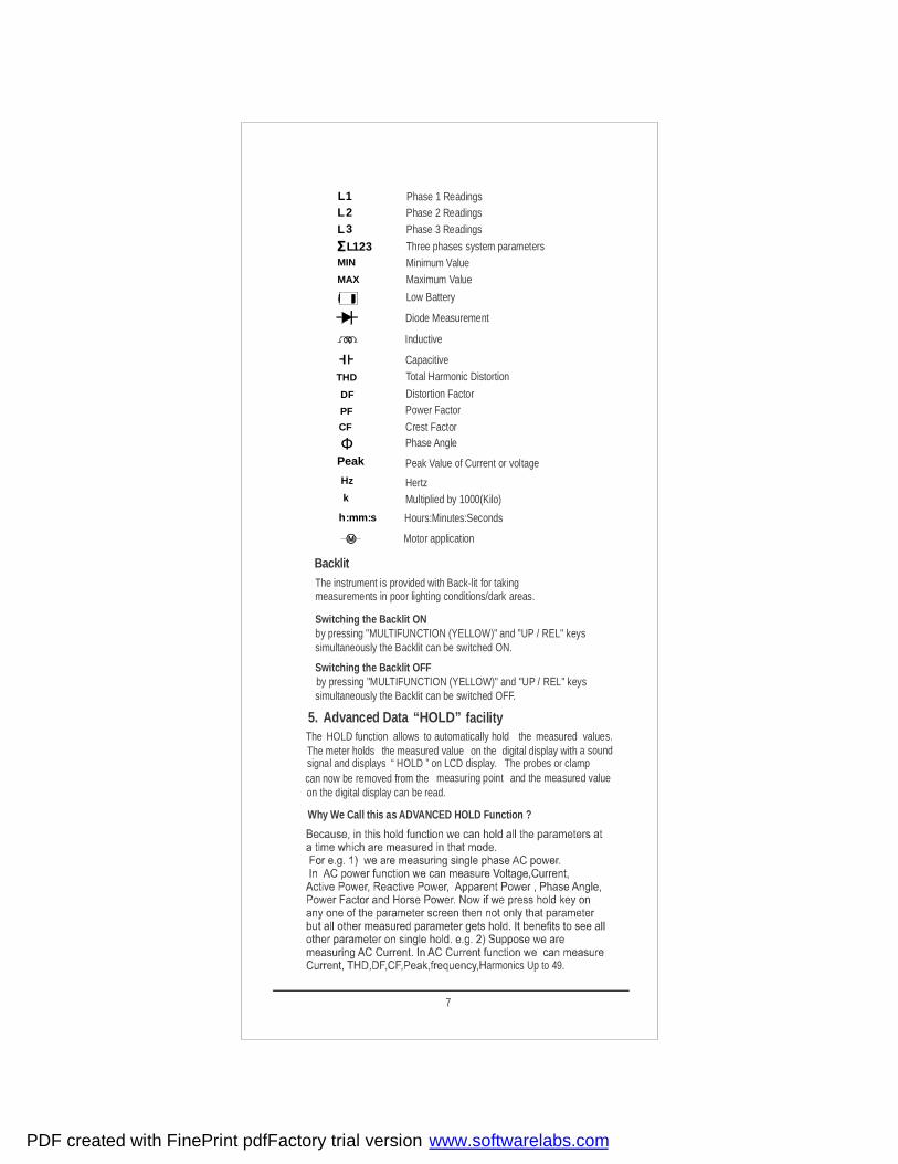
Backlit The instrument is provided with Back-lit for takingmeasurements in poor lighting conditions/dark areas.
Switching the Backlit ONby pressing "MULTIFUNCTION (YELLOW)" and "UP / REL" keys simultaneously the Backlit can be switched ON.
Switching the Backlit OFF
simultaneously the Backlit can be switched OFF.by pressing "MULTIFUNCTION (YELLOW)" and "UP / REL" keys
5. Advanced Data “HOLD” facilityThe HOLD function allows to automatically hold the measured values.The meter holds the measured value on the digital display with a soundsignal and displays “ HOLD ” on LCD display. The probes or clamp
measuring point and the measured valueon the digital display can be read. can now be removed from the
1L Phase 1 Readings2L Phase 2 Readings3L Phase 3 Readings
ΣL1 32 Three phases system parametersMIN Minimum ValueMAX Maximum Value
Low Battery
Diode Measurement
Inductive
Capacitive
DTH Total Harmonic Distortion
DF Distortion Factor
CF
PF Power Factor
Crest FactorPhase AngleФ
Peak
Hz Hertzk Multiplied by 1000(Kilo)
Peak Value of Current or voltage
Why We Call this as ADVANCED HOLD Function ?
s::mh m Hours:Minutes:Seconds
Motor application
armonics Up to 49.
7
PDF created with FinePrint pdfFactory trial version www.softwarelabs.com

Minimum value and Maximum value "MIN / MAX"storage facility.
With the MIN/MAX function, we can hold the minimum and the maximummeasured value which was applied to the input of the clamp meter afteractivating MIN/MAX function.The most important application is thedetermination of the minimum and the maximum value for long-termmonitoring of measured quantities.
The data “MIN MAX ” function is switched OFF, when
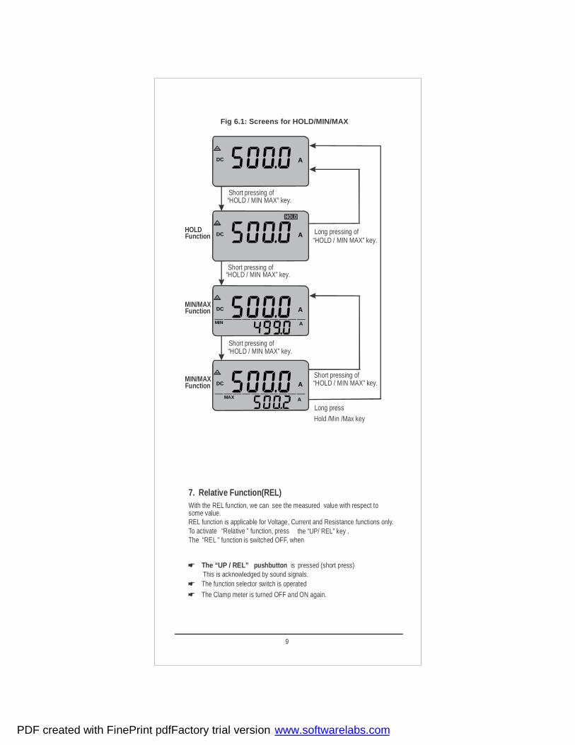
The “HOLD / MIN MAX” pushbutton is pressed for approx.2s.(long press) This is acknowledged by sound signals.The function selector switch is operated
The Clamp meter is turned OFF and ON again.
To activate “MIN MAX ” function, press the “HOLD / MIN MAX” key twice.
Now if we press hold key on any one of the parameter screen then not only that parameter but all other measured parameter gets hold. including
all 49 harmonics.
To activate “HOLD ” function, momentarily press (short press) the “HOLD / MIN MAX” key.
The data HOLD function is switched OFF, when
isThis is acknowledged by sound signals.The “HOLD” pushbutton pressed for approx. 2sec (long press).
The function selector switch is operated. The Clamp meter is turned OFF and ON again.
So Advanced Hold feature benefits user to make data analysis of different parameters even after removal of input .
The “HOLD / MIN MAX” key will not be enabled in 3 phase powermeasurement unless and until measurement of power is done.The “HOLD / MIN MAX” key will be disabled in NCV, kWh, Ahr functions.
Note : HOLD function not applicable for 3P4W, 3P3W unbalanced system, Diodeand Continuity .
Figure 6.1 will show procedure for entering in hold and min max functions
“MIN MAX” is not applicable for Harmonics and the parameters on sub display “MIN MAX” is also not applicable for 3P3W and 3P4W unbalanced load.
8
PDF created with FinePrint pdfFactory trial version www.softwarelabs.com
ON
DC A
ON
DC A
ON
DC
MIN
A
ON
DC
MAX
A
A
A
Short pressing of
Short pressing of
Short pressing of
Long pressing of“HOLD / MIN MAX” key.
“HOLD / MIN MAX” key.
“HOLD / MIN MAX” key.
“HOLD / MIN MAX” key.
Short pressing of “HOLD / MIN MAX” key.
Long press
Hold /Min /Max key
HOLDFunction
MIN/MAXFunction
MIN/MAXFunction
Fig 6.1: Screens for HOLD/MIN/MAX
9
7. Relative Function(REL)With the REL function, we can see the measured value with respect to some value.REL function is applicable for Voltage, Current and Resistance functions only.
The “REL ” function is switched OFF, when
The “UP / REL” pushbutton is pressed (short press) This is acknowledged by sound signals.The function selector switch is operated
The Clamp meter is turned OFF and ON again.
To activate “Relative ” function, press the “UP/ REL” key .
PDF created with FinePrint pdfFactory trial version www.softwarelabs.com

8. Voltage measurementAccording to the voltage to be measured, set the function selector
switch to V Connect the test leads as shown in fig 8.1. The socket should be connected to the lowest potential ground available.Select the appropriate working mode i.e. AC or DC or ACDC by long pressing Yellow key (Function key).
For AC voltage mode following parameters measured.
8.1 THD (Total Harmonic Distortion)Power Clamp meter can measure THD up to 49 Harmonic.th
By default meter is present on THD measurement screen.
THD = n=2
49( n order harmonic voltage RMS value)th 2
( Fundamental wave voltage RMS value)2
X 100 %
8.2 DF ( Distortion Factor)Power Clamp Power can measure DF up to 49 Harmonic.th
DF = n=2
49( n order harmonic voltage RMS value)
th 2
( Voltage RMS value)2
X 100 %
“
Fig 8.1 Voltage measurement on electrical systems up to 1000V
1000VCAT III600VCAT IV
INRUSH HOLD
MIN/MAX
REL
10
PDF created with FinePrint pdfFactory trial version www.softwarelabs.com

8.3 CF ( Crest Factor)Power Clamp meter can measure CF. CF is the ratio between the value the peak voltage and corresponding RMS voltage.
CF = V (Peak Voltage Value) m
V (RMS Voltage Value) RMS
8.4 Peak Max / Peak MinPeak Max /Min is the Positive / Negative peak value of measuring waveform. It updates continuously as per measuring waveforms peak.
8.5 Frequency Power Clamp meter measures frequency from 45 to 65 Hz.
8.6 Individual Harmonic measurementPower Clamp meter can measure individual harmonic voltage up to 49 th
Harmonic. Measured harmonic can also be seen in percent (%) w.r.t. fundamental voltage.
8.7 LPF measurement modePower Clamp meter have LPF mode for voltage measurement. In LPF mode meter measures voltage bellow cut off frequency. The cutoff frequency of clamp meter for LPF mode is 400 Hz. This means that meter will measure voltage having frequency bellow 400 Hz.
Note :
Note :
1) If display shows OL then it indicates Voltage Overload
1) “----” is displayed for THD, DF, CF, Freq and Harmonics if voltage level
2) “----” is displayed for THD, DF and Harmonics if signal frequency is
3) Meter will display 0 V if V <0.5V and in LPF mode meter will display out of measuring band i.e. Freq Except 45Hz....65Hz
0 V if V < 1V
is below measurement band or applied voltage is OL value i.e. 1020 V
i.e > 1020 V .
To enter in LPF mode Simultaneously press “ ” yellow function key
and “ ” keys.Hold/Min/Max
Fig 8.2 Low Pass Filter mode
11
PDF created with FinePrint pdfFactory trial version www.softwarelabs.com

DTH
ACV
%
DF
ACV
%
CF
ACV
Peak
ACV
VMAXMINPeak
ACV
VMAX
Peak
ACV
VMAXMINPeak
ACV
VMIN
Hz
ACV
ACV
AC
%
ACV
AC
%
VDC
Yellow keyLong Press
REL key
Short Press
REL
REL key
Short Press
REL
Yellow key Short Press
Yellow key Short Press
Yellow key Short Press
Yellow key Short Press
Yellow key Short Press
Yellow key Short Press
Yellow key Short Press
Yellow key Short Press
DC VoltageAC Voltage / THD
Distortion
Crest Factor
Max Peak
Min Peak
Frequency
Individual Harmonics Amplitude
Individual Harmonics in %
Knob Position
Voltage measurement
Fig 8.3 Voltage measurement screens
VDC
AC DC Voltage
Factor
AC
Yellow key Long Press
Yellow keyLong Press
12
PDF created with FinePrint pdfFactory trial version www.softwarelabs.com

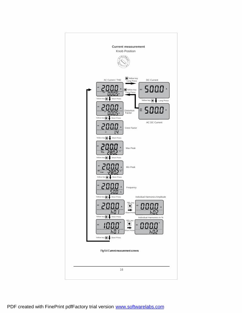
9. Current measurementSet the function selector switch to A . Connect the Clamp as shown in figure 9.1 for current measurement.
Select the appropriate working mode i.e. AC or DC or ACDC by long
Note :- For better accuracy of current, position conductor at the marking onthe jaw (center of the jaw)
pressing yellow key (Function key).
Unique design for safety and comfortRotary mechanism for clamp jaws:
In conventional clamp meters display, keys and clamp jaws are in the same plane.When current measurement is to be done on vertical bus bars, over head cables,cables in congested places user connect the clamp meter but the keys and displaymay not be visible, hence not able to take the readings or operate the keys.
To over come the above mentioned problem has aunique feature called“Rotary mechanism for clamp jaws”. In this, the clamp jawsare rotating. Hence it is possible to align the clamp jaws as the orientation ofbus bar/conductor while keeping Display and keys facing the user, so that user cantake the readings and operate the keys.
Rotary clamp jaws can be rotated at different angles with the maximumup to 90 in both clock-wise as well as anti-clock wise direction as shown in
step of 30figure 9.2
400A/1000AClamp meter
º,º
To measure current through cable push the trigger (present at back ) to open the jaws and clamp the jaws around the cable as shown in fig 9.1
Figure 9.1
13
PDF created with FinePrint pdfFactory trial version www.softwarelabs.com

For DC and ACDC current measurement mode , Auto Zero adjustmentfunctionality is available for DC current up to + / - 5 A.
9.1 THD (Total Harmonic Distortion)Power Clamp meter can measure THD up to 49 Harmonic.th
By default meter is present on THD measurement screen.
THD = n=2
49( n order harmonic Current RMS value)th 2
( Fundamental wave Current RMS value)2
X 100 %
To make zero adjustment , long Press key on meter. HOLDThe meter acknowledge zero setting by a sound signal,
For AC Current mode following parameters are measured.
Figure 9.2
14
PDF created with FinePrint pdfFactory trial version www.softwarelabs.com

9.2 DF ( Distortion Factor)Power Clamp Meter can measure DF up to 49 Harmonic.th
DF = n=2
49( n order harmonic Current RMS value)
th 2
( Current RMS value)2 X 100 %
9.3 CF ( Crest Factor)Power Clamp meter can measure CF. CF is the ratio between the value the peak current and corresponding RMS current.
CF = I (Peak Current Value) m
I (RMS Current Value) RMS
9.4 Peak Max / Peak MinPeak Max /Min is the Positive / Negative peak value of measuring waveform. It updates continuously as per measuring waveforms peak.
9.5 Frequency Power Clamp meter measures frequency from 45 to 65 Hz.
9.6 Individual Harmonic measurementPower Clamp meter can measure individual harmonic current up to 49 th
Harmonic. Measured harmonic can also be seen in percent (%) w.r.t. fundamental current.
9.7 LPF measurement modePower Clamp meter have LPF mode for current measurement. In LPF mode meter measures current bellow cutoff frequency. The cutoff frequency of clamp meter for LPF mode is 400 Hz. This means that meter will measure current having frequency bellow 400 Hz.
Note : 1) If display shows OL then it indicates Current Overload. Overload. i.e. > 1020A
To enter in LPF mode Simultaneously press “ ” yellow function keyand “ ” keys.Hold/Min/Max
Figure 9.3
Note : 1) “----” is displayed for THD, DF, CF, Freq and Harmonics if current level
2) “----” is displayed for THD, DF and Harmonics if signal frequency is
3) Meter will display 0 A if I <0.5 A and in LPF mode meter will display
4) For better accuracy of harmonic do not apply voltage at input terminal
out of measuring band i.e. Freq Except 45Hz....65Hz
0 A if I < 1A
is below measurement band or applied current is OL Value, 1020 A for Power clamp 1000A and 415 A for Power Clamp 400A
15
PDF created with FinePrint pdfFactory trial version www.softwarelabs.com
DTH
AC
%
DF
AC
%
CF
AC
Peak
ACV
VMAXMINPeak
AC
MIN
Hz
AC
AC
AC
%
AC
AC%
REL key
Short Press
REL
REL key
Short Press
RELREL
Yellow key Short Press
Yellow key Short Press
Yellow key Short Press
Yellow key Short Press
Yellow key Short Press
Yellow key Short Press
Yellow key Short Press
Yellow key Short Press
AC Current / THD
Crest Factor
Max Peak
Min Peak
Frequency
Individual Harmonics Amplitude
Individual Harmonics in %
A
A
A
Peak
AC
MAXMINPeak
AC
MAX
A
A
A
A
A
A A
Knob PositionCurrent measurement
Fig 9.4 Current measurement screens
DC
Yellow keyLong Press DC Current
Distortion DC
AC DC Current
Factor
AC
Yellow key Long Press
Yellow keyLong Press
A
A
16
PDF created with FinePrint pdfFactory trial version www.softwarelabs.com

9.8 Inrush current measurement
Power Clamp meter can measure AC Inrush current . This function allows us to easily measure inrush current that occurs when starting a motors Just clamp the clamp meter to line of motor and set meter in inrush mode before starting of motor so that after starting of motor meter will automatically measure and hold inrush Current value that occurred in
Step2: Clamp the meter around live conductor of motor
would look like
Step3: Press key to set the meter in inrush modeINRUSH
Step4: Start the motor. Clamp meter will be triggered by inrush
Note: In harmonics screen INRUSH key is used to scroll harmonicsInrush mode can not be activated in harmonics screen
current >5 A. Inrush current for 100 ms is measured.
Now meter will wait for trigger to occur and display
100 ms (measurement period ). Refer fig 9.5
Keep Knob Position on A ACStep1:
INRUSH
AAC
INRUSH
AAC
INRUSH
AAC
M
Motor
100 0VCAT III600 VCAT IV
INRUSH HOLD
MIN/MAX
REL
Inrush Current
Fig 9.5
100 ms
Motor ON Time
100A
0.0A
A 10A
Trigger Point
17
PDF created with FinePrint pdfFactory trial version www.softwarelabs.com
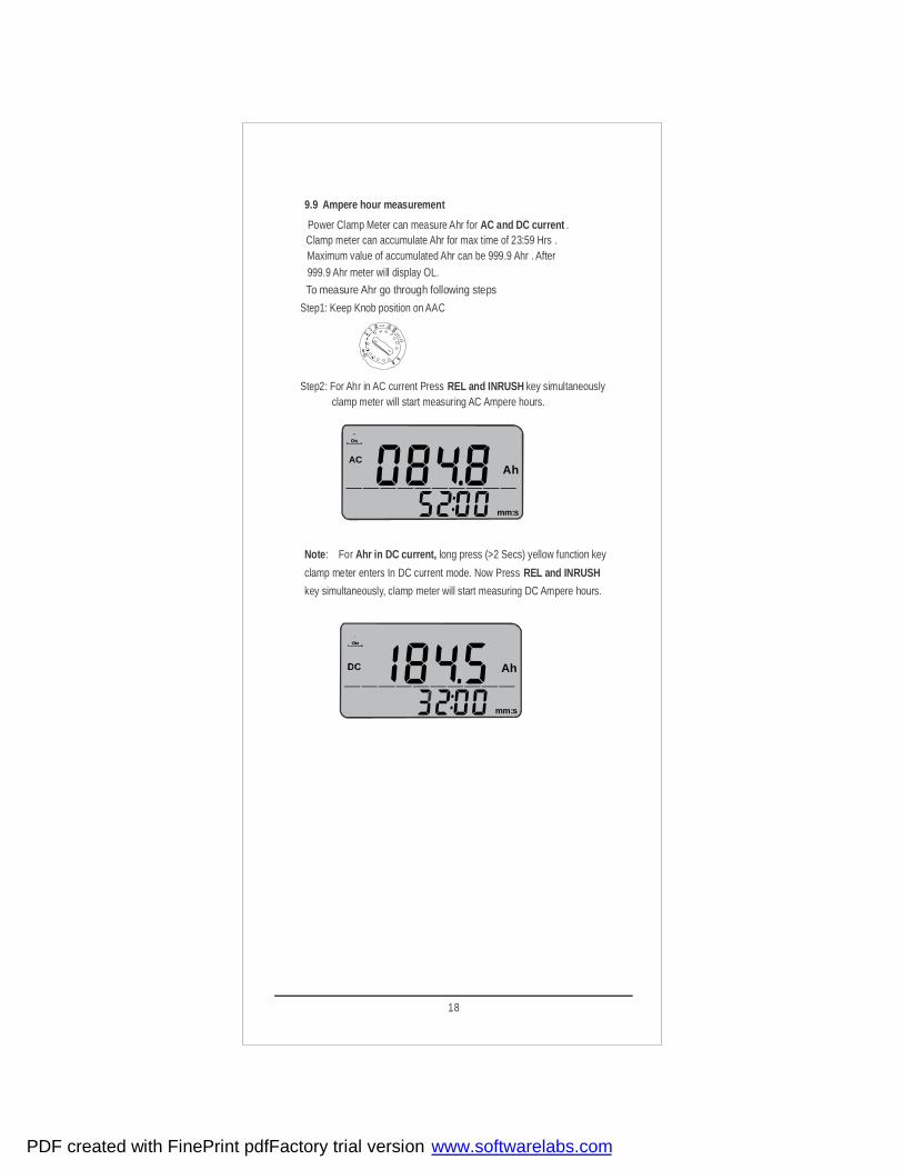
9.9 Ampere hour measurement
Power Clamp Meter can measure Ahr for . AC and DC currentClamp meter can accumulate Ahr for max time of 23:59 Hrs . Maximum value of accumulated Ahr can be 999.9 Ahr . After 999.9 Ahr meter will display OL.
Step2: For Ahr in AC current Press key simultaneouslyREL and INRUSH
Step1: Keep Knob position on AAC
clamp meter will start measuring AC Ampere hours.
Note Ahr in DC current,: For long press (>2 Secs) yellow function key
clamp meter enters In DC current mode. Now Press REL and INRUSH
key simultaneously, clamp meter will start measuring DC Ampere hours.
To measure Ahr go through following steps
s:
A
mm
h
s:
A
m
AC
m
h
18
PDF created with FinePrint pdfFactory trial version www.softwarelabs.com
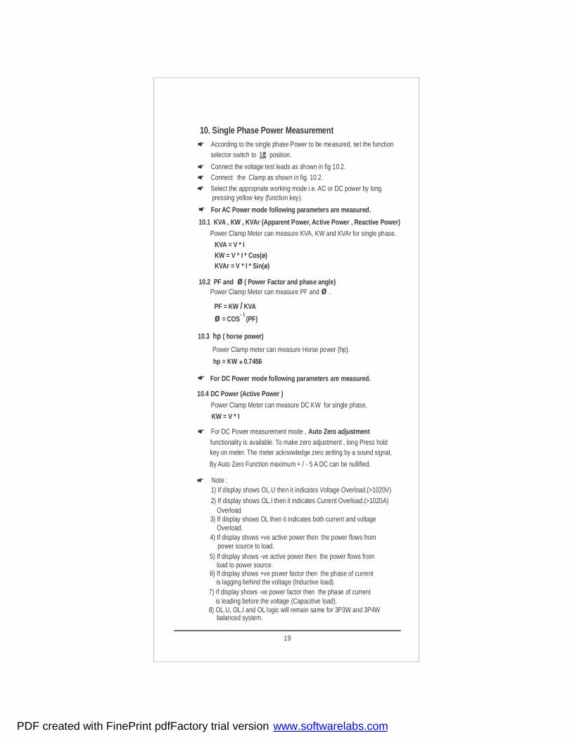
10. Single Phase Power Measurement
selector switch to position.
Connect the Clamp as shown in fig. 10.2.
According to the single phase Power to be measured, set the function
Select the appropriate working mode i.e. AC or DC power by long pressing yellow key (function key).
10.1 KVA , KW , KVAr (Apparent Power, Active Power , Reactive Power)
Power Clamp Meter can measure KVA, KW and KVAr for single phase.
10.2 PF and ( Power Factor and phase angle) øPower Clamp Meter can measure PF and .ø
10.3 ( horse power)hp
Power Clamp meter can measure Horse power (hp).
Connect the voltage test leads as shown in fig 10.2.
KVA = V * I KW = V * I * Cos(ø) KVAr = V * I * Sin(ø)
PF = KW KVA /ø = COS (PF)
- 1
hp = KW 0.7456
10.4 DC Power (Active Power )
Power Clamp Meter can measure DC KW for single phase.
For DC Power mode following parameters are measured.
KW = V * I
For AC Power mode following parameters are measured.
For DC Power measurement mode , Auto Zero adjustmentfunctionality is available. To make zero adjustment , long Press hold key on meter. The meter acknowledge zero setting by a sound signal,
By Auto Zero Function maximum + / - 5 A DC can be nullified.
Note : 1) If display shows OL.U then it indicates Voltage Overload.(>1020V)
2) If display shows OL.I then it indicates Current Overload.(>1020A) Overload.
4) If display shows +ve active power then the power flows from power source to load. 5) If display shows -ve active power then the power flows from load to power source. 6) If display shows +ve power factor then the phase of current is lagging behind the voltage (Inductive load). 7) If display shows -ve power factor then the phase of current
8) OL.U, OL.I and OL logic will remain same for 3P3W and 3P4Wbalanced system.
is leading before the voltage (Capacitive load).
3) If display shows OL then it indicates both current and voltage Overload.
*
19
PDF created with FinePrint pdfFactory trial version www.softwarelabs.com
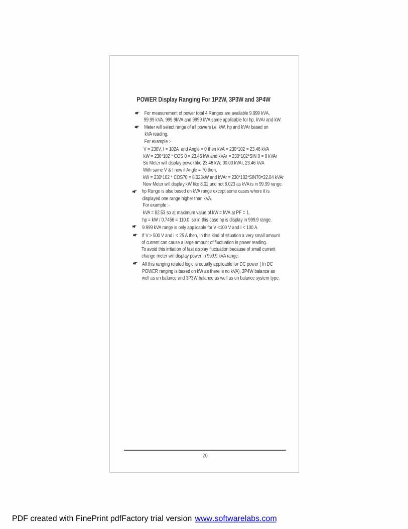
POWER Display Ranging For 1P2W, 3P3W and 3P4W
99.99 kVA, 999.9kVA and 9999 kVA same applicable for hp, kVAr and kW.For measurement of power total 4 Ranges are available 9.999 kVA,
hp Range is also based on kVA range except some cases where it is
If V > 500 V and I < 25 A then, In this kind of situation a very small amount
POWER ranging is based on kW as there is no kVA), 3P4W balance as well as un balance and 3P3W balance as well as un balance system type.
of current can cause a large amount of fluctuation in power reading. To avoid this irritation of fast display fluctuation because of small currentchange meter will display power in 999.9 kVA range.
9.999 kVA range is only applicable for V <100 V and I < 100 A.
displayed one range higher than kVA.For example :-kVA = 82.53 so at maximum value of kW = kVA at PF = 1,hp = kW / 0.7456 = 110.0 so in this case hp is display in 999.9 range.
For example :-kVA reading.
V = 230V, I = 102A and Angle = 0 then kVA = 230*102 = 23.46 kVAkW = 230*102 * COS 0 = 23.46 kW and kVAr = 230*102*SIN 0 = 0 kVAr So Meter will display power like 23.46 kW, 00.00 kVAr, 23.46 kVA
Now Meter will display kW like 8.02 and not 8.023 as kVA is in 99.99 range.
With same V & I now if Angle = 70 then,kW = 230*102 * COS70 = 8.023kW and kVAr = 230*102*SIN70=22.04 kVAr
Meter will select range of all powers i.e. kW, hp and kVAr based on
All this ranging related logic is equally applicable for DC power ( In DC
20
PDF created with FinePrint pdfFactory trial version www.softwarelabs.com

Peak
AC
MAXMIN AkW
DC
Peak
AC
MAXMIN A
VDC
k A
PF
ACV
Peak
AC
MAXMIN
AC
A
V
Yellow key Short Press
Yellow key Short Press
Yellow key Short Press
Yellow key
Long Press
Yellow key Short Press
Yellow key Short Press
Knob Position
Fig 10.1 Power measurement screens
AC hp
Vk
k AAC
V
Vk
Yellow key Short Press
Yellow key Short Press
k
AC
WФ
L
N
100 0VCAT III600 VCAT IV
INRUSH HOLD
MIN/MAX
REL
Fig 10.2 Connection diagram for 1P2W Power measurement
21
A
A
PDF created with FinePrint pdfFactory trial version www.softwarelabs.com

h
:m
k
AC
W
h m
h
:m
kW
h m
DC
10.5 KWH Measurement in 1-phase 2-wire system
Power clamp meter accumulates r to measure the energyAC or DC poweup to 9999kWh. Beyond this limit it shows OL. Clamp meter can accumulates
energy max up to 23.59 hrs. To measure Energy in AC powersystem follow the below steps
Step1: keep knob position as shown below
Step2: For kWh in AC Power Press and key simultaneouslyREL INRUSH
clamp meter will start measuring kWh
Note kWh in DC power system,: For long press (>2 Secs)
1) kWh Measurement is also possible in 3P3W and 3P4W balanced load
2)To reset energy measurement exit from energy mode and re enter into
by using simultaneous pressing key.REL and INRUSH
energy mode or restart the meter and enter into energy mode again.
yellow function key,clamp meter enters In DC power mode.
Now Press and key simultaneously clamp meter will REL INRUSHstart measuring DC energy.
3) If display shows -ve Energy then the power flows from load to power source.
22
PDF created with FinePrint pdfFactory trial version www.softwarelabs.com
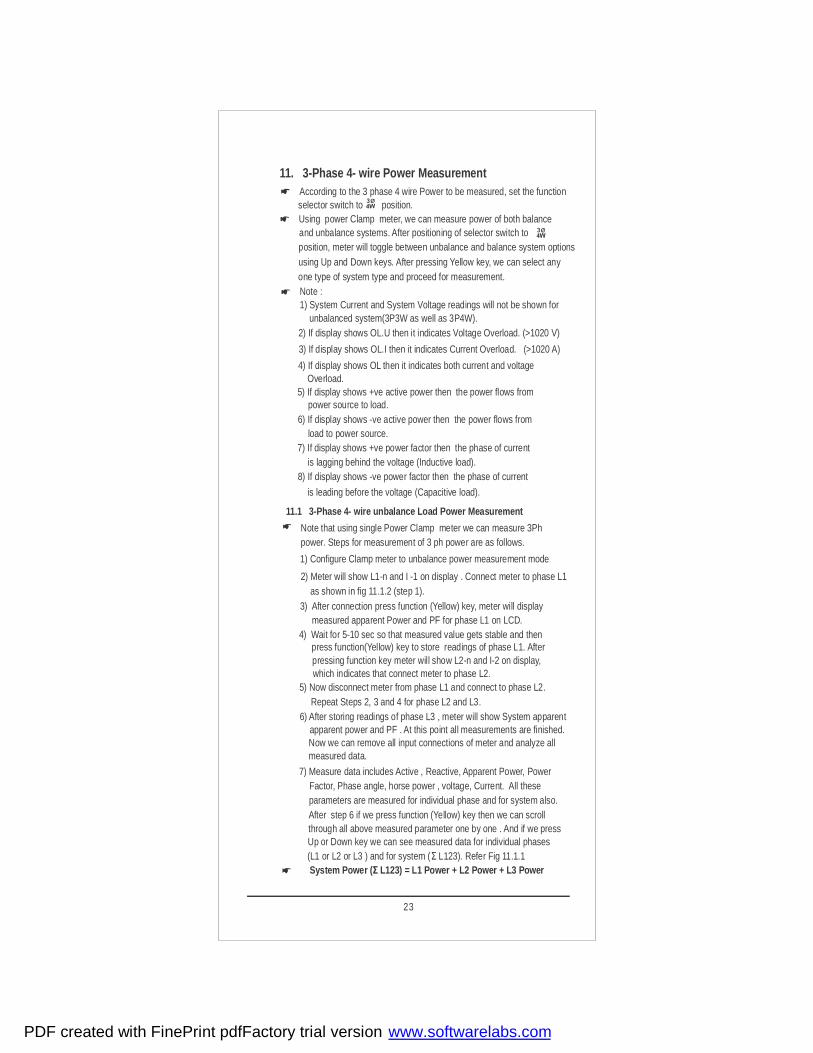
11. 3-Phase 4- wire Power Measurement
2) Meter will show L1-n and I -1 on display . Connect meter to phase L1
According to the 3 phase 4 wire Power to be measured, set the function
Note that using single Power Clamp meter we can measure 3Ph
selector switch to position.
power. Steps for measurement of 3 ph power are as follows.
3) After connection press function (Yellow) key, meter will display
Using power Clamp meter, we can measure power of both balance and unbalance systems. After positioning of selector switch to position, meter will toggle between unbalance and balance system options using Up and Down keys. After pressing Yellow key, we can select any one type of system type and proceed for measurement.
11.1 3-Phase 4- wire unbalance Load Power Measurement
1) Configure Clamp meter to unbalance power measurement mode
as shown in fig 11.1.2 (step 1).
measured apparent Power and PF for phase L1 on LCD. 4) Wait for 5-10 sec so that measured value gets stable and then press function(Yellow) key to store readings of phase L1. After pressing function key meter will show L2-n and I-2 on display, which indicates that connect meter to phase L2.
5) Now disconnect meter from phase L1 and connect to phase L2.
6) After storing readings of phase L3 , meter will show System apparent apparent power and PF . At this point all measurements are finished. Now we can remove all input connections of meter and analyze all measured data.
7) Measure data includes Active , Reactive, Apparent Power, Power Factor, Phase angle, horse power , voltage, Current. All these parameters are measured for individual phase and for system also. After step 6 if we press function (Yellow) key then we can scroll through all above measured parameter one by one . And if we press Up or Down key we can see measured data for individual phases (L1 or L2 or L3 ) and for system (Σ L123). Refer Fig 11.1.1
1) System Current and System Voltage readings will not be shown for Note :
2) If display shows OL.U then it indicates Voltage Overload. (>1020 V)
3) If display shows OL.I then it indicates Current Overload. (>1020 A)
4) If display shows OL then it indicates both current and voltage Overload. 5) If display shows +ve active power then the power flows from power source to load. 6) If display shows -ve active power then the power flows from load to power source. 7) If display shows +ve power factor then the phase of current is lagging behind the voltage (Inductive load). 8) If display shows -ve power factor then the phase of current
is leading before the voltage (Capacitive load).
Repeat Steps 2, 3 and 4 for phase L2 and L3.
unbalanced system(3P3W as well as 3P4W).
System Power (Σ L123) = L1 Power + L2 Power + L3 Power
23
PDF created with FinePrint pdfFactory trial version www.softwarelabs.com
24
12
AC
4Wunbal
ACV
4Wunbal
k A
PF
ACV
4Wunbal
1L
ACV
4Wunbal
k A
PF
ACV
4Wunbal
L 2
ACV
4Wunbal
k A
PF
ACV
4Wunbal
L 3
k A
PF
ACV
4Wunbal
L 321ΣL
AC hp
Vk
k AAC
V
Vk
k
AC
WФ
Yellow key Short Press
Yellow key Short Press
Yellow key Short Press
Yellow key Short Press
Yellow key Short Press
Yellow key Short Press
Yellow key Short Press
Yellow key Short Press
Yellow key Short Press
UP keyShort Press
Yellow key Short Press
Yellow keyShort Press
4Wunbal
4Wunbal
4Wunbal
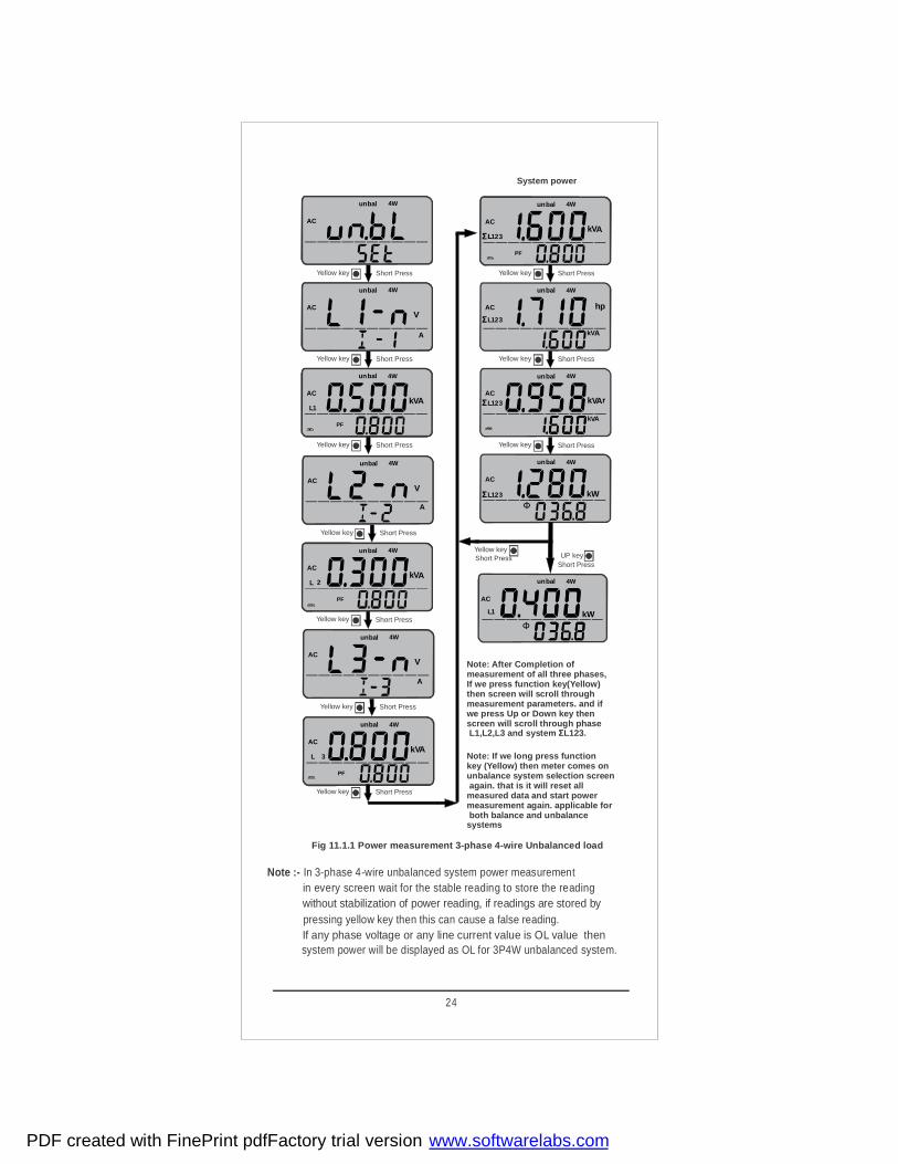
Fig 11.1.1 Power measurement 3-phase 4-wire Unbalanced load
Note :- In 3-phase 4-wire unbalanced system power measurement in every screen wait for the stable reading to store the readingwithout stabilization of power reading, if readings are stored by pressing yellow key then this can cause a false reading.If any phase voltage or any line current value is OL value then system power will be displayed as OL for 3P4W unbalanced system.
System power
321ΣL
321ΣL
321ΣL
Peak
AC
MAXMIN
AC
4Wunbal
1L
Note: After Completion of measurement of all three phases,If we press function key(Yellow) then screen will scroll through measurement parameters. and ifwe press Up or Down key then screen will scroll through phase L1,L2,L3 and system ΣL123.
Note: If we long press function key (Yellow) then meter comes on unbalance system selection screen again. that is it will reset all measured data and start power measurement again. applicable for both balance and unbalance systems
kWФ
A
A
A
A
A
PDF created with FinePrint pdfFactory trial version www.softwarelabs.com

25
2) Meter will show L1-n and I -1 on display.Connect meter to phase 1
In 3Ph balance load power measurement , we need to measure power
1 phase only. Steps for 1 ph power measurement are as follows.
3) After connection press function (Yellow) key, meter will display
11.2 3-Phase 4- wire balance Load Power Measurement
1) Configure Clamp meter to balance power measurement mode
as shown in fig 11.2.1.
measured apparent Power and PF on LCD. 4) In balance load, measured parameters updates continuously. Hold function can be used to hold all measured values. After hold we can
remove all input connections of meter and analyze all data 5) Measure data includes Active , Reactive, Apparent Power, Power Factor, Phase angle, horse power , voltage, Current. All these parameters are measured for system (Σ L123 ) only. If we press function (Yellow) key then we can scroll through all
above measured parameter one by one . Refer Fig 11.2.2.
Keep Knob Position
System Power (Σ L123) = L1 Power * 3
N
L1
L2L3
Fig 11.1.2 Connection diagram for 3ph4w unbalance load
PDF created with FinePrint pdfFactory trial version www.softwarelabs.com

Fig 11.2.1 Connection diagram for 3ph4w balance load
ACV
4Wbal
AC
4Wunbal
AC
4Wbal
Yellow key Short Press
Yellow key Short Press
Up key
Short Press
REL
Fig 11.2.2 Power measurement 3-phase 4-wire balanced load
4W
k A
PF
ACV
L 321ΣL
4W
AC hp
bal
4W
k AAC
V
V
V
k
k
bal4W
k
AC
WФ
bal
Yellow key Short Press
Yellow key Short Press
Yellow key Short Press
Yellow key Short Press
AC
4W
AC
A
V
bal
Yellow key Short Press
321ΣL
321ΣL321ΣL
321ΣL
bal
Yellow key Long Press
N
L3
L2L1
26
A
A
A
PDF created with FinePrint pdfFactory trial version www.softwarelabs.com

12. 3-Phase 3- wire Power MeasurementAccording to the 3 phase 3 wire Power to be measured, set the function
2) Meter will show L1-2 and I -1 on display. Now connect meter to
Note that using single Power Clamp Meter we can measure 3Ph power. Steps for measurement of 3 ph power are as follows.
3) After connection press function (Yellow) key, meter will display
and unbalance systems. After positioning of selector switch to Using Power Clamp Meter, we can measure power of both balance
position, meter will toggle between unbalance and balance system options using Up and Down keys. After pressing Yellow key, we can select any one type of system type and proceed for measurement.
12.1 3-Phase 3- wire unbalance Load Power Measurement
1) Configure Clamp meter to unbalance power measurement mode
phase 1 as shown in fig 12.1.2.
measured apparent Power and PF of phase 1-2 on LCD. 4) Wait for 5-10 sec so that measured value gets stable and then press function(Yellow) key to store readings of phase 1-2. After pressing function key meter will show L3-2 and I-3 on display, which indicates that connect meter to phase 3-2
5) Now disconnect meter from phase 1-2 and connect to phase 3-2.
6) After storing readings of phase 3-2 , meter will show System apparent power and PF . At this point all measurements are finished. Now we can remove all input connections of meter and analyze all measured data. 7) Measure data includes Active , Reactive, Apparent Power, Power Factor, Phase angle, horse power . All these parameters are measured for phase 1-2 , phase 3-2 and for system (Σ L123). After step 6 if we press function (Yellow) key then we can scroll through all above measured parameter one by one . And if we press Up or Down key we can see measured data for phase1-2 , phase 3-2 and for system (Σ L123). Refer Fig 12.1.1
1) System Current and System Voltage readings will not be shown for Note :
2) If display shows OL.U then it indicates Voltage Overload. (>1020 V) 3) If display shows OL.I then it indicates Current Overload. (>1020 A) 4) If display shows OL then it indicates both current and voltage Overload. 5) If display shows +ve active power then the power flows from power source to load. 6) If display shows -ve active power then the power flows from load to power source. 7) If display shows +ve power factor then the phase of current is lagging behind the voltage (Inductive load). 8) If display shows -ve power factor then the phase of current is leading before the voltage (Capacitive load).
Repeat Step 2,3 and 4 for phase 3-2.
unbalanced system(3P3W as well as 3P4W).
System Power (Σ L123) = L1-2 Power + L2-3 Power
selector switch to position.
27
PDF created with FinePrint pdfFactory trial version www.softwarelabs.com

28
Fig 12.1.1 Power measurement 3-phase 3-wire Unbalanced load
ACV
unbal3W
AC
unbal3W
ACV
unbal3W
k A
PF
ACV
unbal
1L
3W
2
k A
PF
ACV
unbal
L
3W
23
Yellow key Short Press
Yellow key Short Press
Yellow key Short Press
Yellow key Short Press
Yellow key Short Press
Up key
Short Press
Peak
AC
MAXMIN
AC
Yellow keyShort Press
bal3Wun
21L kW
k A
PF
ACV
L 321ΣL
AC hp
bal
k AAC
V
V
V
k
k
bal
k
AC
WФ
Ф
bal
Yellow key Short Press
Yellow key Short Press
Yellow key Short Press
321ΣL
321ΣL
321ΣL
bal3W
3W
3W
3W
Note :- After completion of measurement in individual phases, if we press YELLOW key then screen will scroll through measurement parameters and if we press UP and DOWN key then screen will scroll through phase and system . L1-2, L2-3 Σ L123 If we long press YELLOW key then meter will come to Un-bAl and bal system type selection screen and this will reset all measured data to again restart measurement. It is applicable for both system type.
In 3-phase 3-wire unbalanced system power measurement in every screen wait for the stable reading to store the readingwithout stabilization of power reading, if readings are stored by pressing yellow key then this can cause a false reading.If any phase voltages or any line current value is OL value then system power will be displayed as OL for 3P3W unbalanced system.
un
un
un
un
A
A
A
A
PDF created with FinePrint pdfFactory trial version www.softwarelabs.com

Keep Knob Position
Fig 12.1.2 Connection diagram for 3ph3w unbalance load
2) Meter will show L1-2 and I -1 on display. Connect meter to phase
In 3Ph balance load power measurement , we need to measure power 1-2 phase only. Steps for 1-2 ph power measurement are as follows.
3) After connection press function (Yellow) key, meter will display
12.2 3-Phase 3- wire balance Load Power Measurement
1) Configure Clamp meter to balance power measurement mode
1-2 as shown in fig 12.2.1.
measured apparent Power and PF on LCD.4) In balance load, measured parameters updates continuously. Hold function can be used to hold all measured values. After hold we can
remove all input connections of meter and analyze all data 5) Measure data includes Active , Reactive, Apparent Power, Power Factor, Phase angle, horse power , voltage, Current. All these parameters are measured for system (Σ L123 ) only. If we press function (Yellow) key then we can scroll through all above measured parameter one by one .Refer Fig 12.2.2
System Power (Σ L123) = VL1-2 * I1 * 1.732
L1
L2L3
29
PDF created with FinePrint pdfFactory trial version www.softwarelabs.com
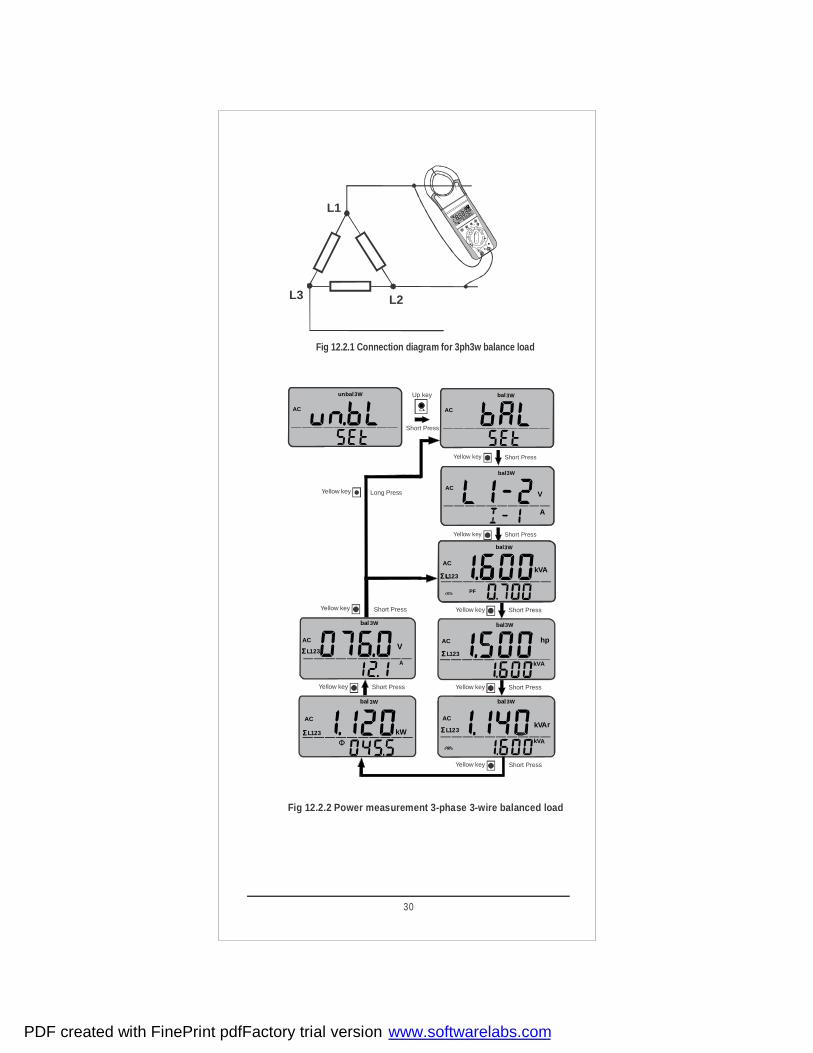
Fig 12.2.2 Power measurement 3-phase 3-wire balanced load
Fig 12.2.1 Connection diagram for 3ph3w balance load
AC
bal3W
ACV
bal3W
Yellow key Short Press
Yellow key Short Press
AC
unbal3W Up key
Short Press
REL
k A
PF
ACV
L 321ΣL
AC hp
bal
k AAC
V
V
V
k
k
bal
k
AC
W
Ф
bal
Yellow key Short Press
Yellow key Short Press
Yellow key Short Press
Yellow key
Yellow key
Short Press
Long Press
ACAC
A
V
bal
Yellow key Short Press
321ΣL
321ΣL321ΣL
321ΣL
bal3W
3W
3W
3W
3W
L1
L2L3
30
A
A
A
PDF created with FinePrint pdfFactory trial version www.softwarelabs.com

13. NCV Detection (Non Contact Voltage Detection)For NCV detection mode place selector switch to NCV position..
For NCV detection,touch the left jaw to voltage carrying conductor NCV allows detection of AC voltage from >100 V 50/60 Hz.
Presence of voltage will be indicated by buzzer sound along with
Note :- Even if voltage presence is not detected do not touch bare wire or cable.
backlit blinking
14. Resistance, Continuity and Diode measurement
For Resistance or continuity or diode measurement place function selector switch to position .
For Resistance and continuity measurement connect DUT as shown bellow
For Diode measurement connect DUT as shown bellow
The measuring instrument displays forward voltage in volts. As long as
OL will be displayed on display when diode is connected in reverse bias.
voltage drop does not exceeds the maximum display value of 2.2V ,we can test several instruments in series.
The clamp meter can measure resistance up to 4000 ohm . For continuity measurement , meter will generate continuous beep sound if measured resistance is from 0 to 40 ohm approx.
31
PDF created with FinePrint pdfFactory trial version www.softwarelabs.com
15.Empty Positions
Empty positions on dial indicates no function is available on these positions.Thedigital display will look like as in figure below.
32
PDF created with FinePrint pdfFactory trial version www.softwarelabs.com

16. Specifications
Ambient temperature : + 23 0C +2K
Relative humidity: 45%... 55 % RH
Frequency of measuredquantityPower factor 0.5L...1....0.5C
50Hz or 60 Hz
Waveform of the measuredquantity
Sinusoidal
Battery voltage 8V +0.1V
Technical Specification
Reference Conditions
V DC 999.9 V 0.1 V ±(0.5% of rdg + 5 dgt)
999.9 V 0.1 V ±(0.75% of rdg+5 dgt)
V ACDC 999.9 V 0.1 V ±(1.25% of rdg+10dgt)
LPF V~ 999.9 V 0.1 V50.....60 Hz ±(0.75% of rdg + 5dgt)
61...400Hz ±(5.0% of rdg + 5dgt)
POWER CLAMP1000A ADC-AAC
999.9A 0.1 A ±(1.5% of rdg+5 dgt)
POWER CLAMP400A ADC - AAC
99.99 A 0.01 A display value<1000 add
10 dgt
±(1.5% of rdg+0.2A)
400 A 0.1 A ±(1.5% of rdg+5 dgt)
POWER CLAMP1000A A ACDC
999.9A 0.1 A ±(3% of rdg+10 dgt)
POWER CLAMP400A A ACDC
99.99 A 0.01 A display value<1000 add
10 dgt
±(3% of rdg+0.4A)
400 A 0.1 A ±(3% of rdg+10 dgt)
POWER CLAMPLPF 1000A A AC
999.9A 0.1 A50....60 Hz61...400Hz
±(1.5% of rdg + 5dgt)±
Measuringfunction
Measuringrange
ResolutionIntr ins ic error of digital display
at reference condition
(5.0% of rdg + 5dgt)
POWER CLAMPLPF 400A A AC
99.99 A 0.01 A50....60 Hz61...400Hz
±(1.5% of rdg + 0.3A)±(5.0% of rdg + 5dgt)
400 A 0.1 A50....60 Hz61...400Hz
±(1.5% of rdg + 5dgt)±(5.0% of rdg + 5dgt)
Active
Power
9.999 kW 1 W
±(2% of rdg+5 dgt)
99.99 kW 10 W
999.9 kW 100 W
9999 kW 1 kW
Reactive
Power
9.999 kVAr 1 VAr
99.99 kVAr 10 VAr
999.9 kVAr 100 VAr
9999 kVAr 1 kVAr
Apparent
Power
9.999 kVA 1 VA
99.99 kVA 10 VA
999.9 kVA 100 VA
9999 kVA 1 kVA
Horse
Power
9.999 hp 0.001 hp
99.99 hp 0.01 hp
999.9 hp 0.1 hp
9999 hp 1 hp
V ~
1)
1)
1)
1)
1)
1)
2)
1)
2)
2)
2)
33
PDF created with FinePrint pdfFactory trial version www.softwarelabs.com

Technical Specification
For Power Clamp 1000A
Note:- Accuracy claimed for Power and Current when conductor is positioned at
For Power Clamp 1000A
For Power Clamp 400A
the center of the jaw.
1) For DC A make auto zero correction by long pressing the key HOLD
For Power Clamp 400A
2) Accuracy Defined for V 10V and I 5A≧ ≧
Add 10 digit to accuracy when power is < 5.000 kW/ kVA/ kVAr or < 6.700 hp
Add 10 digit to accuracy when power is < 5.000 kW/ kVA/ kVAr or < 6.700 hp 2) Accuracy Defined for V 10V and I 4A≧ ≧
3) Accuracy Defined for V 10V and I 10A≧ ≧
3) Accuracy Defined for V 10V and I 10A≧ ≧
4) Accuracy Defined for I 10A≧
4) Accuracy Defined for I 5A≧
In 1P2W mode maximum power meter can measure is,
In 1P2W mode maximum power meter can measure is,
1000 kVA / 1000 kVAr / 1000 kW / 1341 hp
400 kVA / 400 kVAr / 400 kW / 536 hp
In 3P4W mode maximum power meter can measure is,
In 3P4W mode maximum power meter can measure is,
3000 kVA / 3000 kVAr / 3000 kW / 4023 hp
1200 kVA / 1200 kVAr / 1200 kW / 1608 hp
In 3P3W mode maximum power meter can measure is,
In 3P3W mode maximum power meter can measure is,
1732 kVA / 1732 kVAr / 1732 kW / 2322 hp
693 kVA / 693 kVAr / 693 kW / 928 hp
34
Measuring functionMeasuring
rangeResolution
Intr insic error of digital displayat reference condition
kWh
9.999 kWh 0.001 kWh
±(3% of rdg+5 dgt)
99.99 kWh 0.01kWh
999.9 kWh 0.1 kWh9999 kWh 1 kWh
Ahr 999.9 Ahr 0.1 Ahr
Phase angle 0.0°…360.0° 0.1°±3°
Pow er Factor -1…0…1 0.001
Harmonics
(RMS & %)
1…13 0.1V0.1A0.1%
±(3% of rdg+10 dgt)
14…49 ±(5% of rdg+20 dgt)
THD 0…99.9% 0.1% ±(3% of rdg+20 dgt)
DF 0…99.9% 0.1% ±(3% of rdg+20 dgt)
Crest Factor1.0…2.9 0.1 ±(2% of rdg+3 dgt)
3.0…5.0 0.1 ±(3% of rdg+5 dgt)
±(3% of rdg+10 dgt)
560 A/ 1000 V 1 A / 1 V ±(3% of rdg+3 dgt)
Resistance 4000 Ohm 1 Ohm ±(0.5% of rdg+5 dgt)
Continuity Below 40 Ohm 1 Ohm ±(0.5% of rdg+5 dgt)
Diode 0…2.2V 0.001 V ±(0.5% of rdg+5 dgt)
2)
2)
2)
3)
3)
3)
3)
POWER CLAMP1000A Peak
1400 A/ 1400V 1 A ±(3% of rdg+3 dgt)
POWER CLAMP400A Peak
100 A 0.1 A
POWER CLAMP
1000A INRUSH999.9A 0.1 A ±(3% of rdg+5 dgt)
POWER CLAMP
400A INRUSH
99.99 A 0.01 A ±(3% of rdg+0.3A)
400 A 0.1 A ±(3% of rdg+5 dgt)
4)
4)
PDF created with FinePrint pdfFactory trial version www.softwarelabs.com
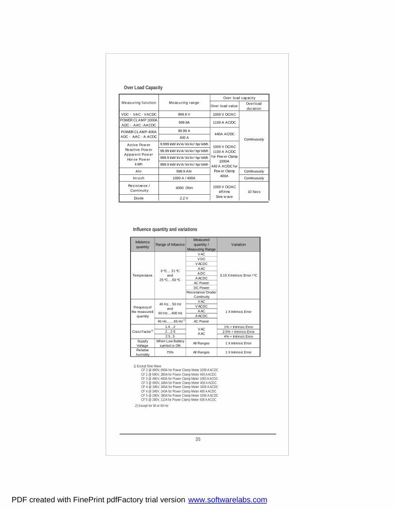
Influence quantity and variations
Over Load Capacity
1) Except Sine Wave
2) Except for 50 or 60 Hz
CF 2 @ 690V, 690A for Power Clamp Meter 1000 A ACDC
CF 3 @ 690V, 186A for Power Clamp Meter 400 A ACDCCF 4 @ 345V, 345A for Power Clamp Meter 1000 A ACDCCF 4 @ 345V, 140A for Power Clamp Meter 400 A ACDC
CF 2 @ 690V, 280A for Power Clamp Meter 400 A ACDC
CF 5 @ 280V, 280A for Power Clamp Meter 1000 A ACDC
CF 3 @ 460V, 460A for Power Clamp Meter 1000 A ACDC
CF 5 @ 280V, 112A for Power Clamp Meter 400 A ACDC
Infulencequantity
Range of InfuenceMeasuredquantity /
Measuring RangeVariation
Temperature0 ºC… 21 ºC
and25 ºC….50 ºC
V AC
0.15 X Intrinsic Error / ºC
V DCV ACDC
A ACA DC
A ACDCAC PowerDC Power
Resistance/ Diode/Continuity
Frequecyofthe measured
quantity
40 Hz… 50 Hzand
60 Hz….400 Hz
V AC
1 X Intrinsic Error
V ACDCA AC
A ACDC
45 Hz…….65 Hz AC Power
Crest Factor
1.4…2V ACA AC
1% + Intrinsic Error2…2.5 2.5% + Intrinsic Error2.5...5 4% + Intrinsic Error
SupplyVoltage
When Low Batterysymbol is ON
All Ranges 1 X Intrinsic Error
Relativehumidity
75% All Ranges 1 X Intrinsic Error
1)
2)
35
Measur ing function Meas ur ing rangeOver load capacity
Over load valueOver loadduration
VDC - VAC - VACDC
POWER CLAMP 1000AADC - AAC -AACDC
POWER CLAMP 400AADC - AAC - A ACDC
Act ive Pow erReactive Pow erApparent Pow er
Hor se Pow erk Wh
Ahr
Inrush
Resis tance /Continuity
Diode
999.9 V 1000 V DC/AC
Continuously
999.9A 1100 A AC/DC
99.99 A440A AC/DC
400 A
9.999 kW/ kVA/ kVAr/ hp/ kWh1000 V DC/AC1100 A AC/DC
for Pow er Clamp1000A
440 A AC/DC forPow er Clamp
400A
99.99 kW/ kVA/ kVAr/ hp/ kWh
999.9 kW/ kVA/ kVAr/ hp/ kWh
999.9 kW/ kVA/ kVAr/ hp/ kWh
999.9 Ahr Continuously
1000 A / 400A Continuously
4000 Ohm 1000 V DC/ACeff /rms
Sine w ave10 Secs
2.2 V
PDF created with FinePrint pdfFactory trial version www.softwarelabs.com

Digital Display :
Number
Character HeightDisplay
Main Display character : 11.5 mmSeven Segment Display
Sub Display character : 7.2 mmof digits 4 digits
Over range Indication "OL"is displayed.Polarity indication " - " sign is displayed for negative values.
Power supplyBattery 9V flat cell battery , manganese-di oxide cell according
to IEC6F22, alkaline-manganese cell according toIEC6LR61
Consumption 14 mA average (without backlit) Battery life Approx 48 Hrs
EMC Electromagnetic compatibilityEmission IEC61326: 2012 ClassBImmunity IEC61326:2012
IEC61000-4-2 8 kV Air discharge4kV contact discharge
IEC61000-4-3 3V/m
Electrical Safety:
Measuring Category III IV1000V 600V
7.4 kV between housing and input
As per IEC 61010-1 2010-06
Pollution Degree 2 High Voltage (HV)
4.26 kV between housing with jaws and input
Maximum Count 9999 counts for V, I & P and 4000 counts for Resistance
Environmental ConditionsOperating temperaturerange
0
0 to +55°
0
CStorage temperatureRange -20 C...+70 C Relative humidity 0 to 75 % non condensing
Mechanical configuration
Dimensions 90mm(W)x270mm(L)x70mm(H)Weight 600g approx.,including battery
Altitude up to 2000m
IP 50 for housing Ingress Protection IP 20 for terminal
36
PDF created with FinePrint pdfFactory trial version www.softwarelabs.com

17. Maintenance
17.1.BatteryPrior to initial start-up,or after storage of power clamp meter, verify that the batteryof power clamp meter does not leak. Repeat this check in regular short intervals.If the battery leaks, completely remove the battery electrolyte carefullywith a moist cloth and install a new battery before you operate power clampmeter again.When the symbol " " is ON (Battery Voltage < 6.5 V) on the LCD replace the battery as soon as possible. Measurement can be done, but a reduced measuringaccuracy must be taken into account. “ ” will be displayed on LCD when bAtt
The Power clamp meter operates with a 9V flat cell battery according to IEC6F22or IEC6LR61 or with a suitable NiCd storage battery .
after that measurement is not possible with meter.battery voltage drops below 5 V,
Replacing the batteryPlace the power clamp meter on its face. Loosen the screw of battery cover.Which is at rear bottom side of meter.Remove battery cover by
Remove the battery from the battery compartment and careful lydisconnect battery connectors.
Snap the battery connectors to a new 9 V battery and insert thebattery into the battery compartment.
Replace the battery cover by fitting it into slots on battery compartment
Tighten the battery cover with the screw.Please destroy the battery in an environment friendly way .
18.ServicingWhen you need service, refer the cover page for company addre ss.
Disconnect the instrument from the measuring circuitbefore opening battery cover to replace the batteries.Attention!
Sliding It to bottom side.
17.2.Periodic Check-up:
between opening jaws should be cleaned with dry cloth before operating.The power clamp meter does not require any specific maintenance. The surface
Avoid use of cleansers, abrasives or solvents.
37
PDF created with FinePrint pdfFactory trial version www.softwarelabs.com

WARRANTYDear Customer,You are now the privileged owner of Digital Power Clamp meter / Accessories, a product that ranks the first of its kind in the world.Company provides 12 months warranty from the original date of purchase against defective material and workmanship.In the unlikely event of failure of this meter / accessories within the warranty period, Company will repair the meter / accessories free of charges. Please hand over the meter / accessories to the dealer / Stockiest from whom you have purchased along with this card and relevant cash memo / Invoice. This warranty entitles you to bring the meter / accessories at your cost to the nearest stockiest / dealer and collect it after repairs.NO TRANSPORTATION CHARGES WILL BE REIMBURSEDThe warranty is not valid in following cases: 1) Warranty card duly signed / stamped and original cash memo / invoice are not sent
along with the meter / accessories.2) Complete warranty card is not presented to authorized person at the time of
repairs.3) Meter / accessories not used as per the instruction in the user manual.4) Defect caused by misuse, negligence, accidents, tampering and acts of god.5) Improper repairing by any person not authorized by the company.6) Any sort of modification, alteration is made in electrical circuitry.7) Seal provided inside is broken.
Warranty of Digital Clamp meter / Accessories does not cover fuses and battery. In case of dispute to the validity of warranty, the decision of Company’s service center will be final.If you bought this meter / accessories directly from the company, and if you notice transit Damage, then you must obtain the insurance surveyors report and forward it to Company.Thank you.
Serial Number :
Date of Purchase :
Cash Memo / Invoice No. :
Dealer’s Signature :
Dealer’s Stamp :
(To be lled by authorized dealer)
Model No. :
Scope ofSupply:
1) Meter 2) Cable set 3) Battery 4) User Manual 5) Warranty Card 6) Test Certicate
8) Crocodile Clips 7) Carrying Case
38
PDF created with FinePrint pdfFactory trial version www.softwarelabs.com

39
PDF created with FinePrint pdfFactory trial version www.softwarelabs.com

40
PDF created with FinePrint pdfFactory trial version www.softwarelabs.com

41
PDF created with FinePrint pdfFactory trial version www.softwarelabs.com

Printed in India , Subject to change without Notice
Website:www.rishabh.co.in
Factory: F-31, MIDC, Satpur, Nashik-422 007 IndiaPhone(0253) 2202202, 2202162Fax : 91 - 0253 - 2351064, 2202302E-mail : International: [email protected]
RISHABH INSTRUMENTS PVT. LTD.
India: [email protected]
Rev A: 18/03/2015
PDF created with FinePrint pdfFactory trial version www.softwarelabs.com

Data Sheet
RISH Clamp 1000A AC/DC 3 ¾ (TRMS) Digits digital Clamp meter
www.rishabh.co.in Page 1 of 5 Version: A 21/02/2013
3 ¾ Digits digital Clamp meter

www.rishabh.co.in Page 2 of 5
Application
RISH Clamp 1000A measures important electrical parameters like AC Current, DC Current, AC Voltage, and DC Voltage. It also features Capacitance, Ohm & Continuity, frequency, and Duty cycle and temperature measurement.
Product Features
Unique DesignRish Clamp 1000A is a highly innovative design for features those increases safety and comfort of user. Rotating clamp jaws facilitate the measurement at physically awkward positions, vertical bus bars, conductors placed at positions difficult to access. Clamp jaws can be opened or closed with the trigger placed at bottom side away from the jaws. This allows the user to place his/her hand at safer distance from live conductor. This greatly reduces exposure of human beings to electrical shocks Location and design of trigger eliminates fatigues caused by single finger operation. It allows spreading the force r e q u i r e d to open the jaws over more than one finger to ensure comfortable operation. Comfortable operation of push buttons and function selector switch, in adverse field conditions.
Large Jaw Opening
Jaw opening of 55mm for standard wire diameter of 50mm
Narrow Body
Narrow housing for firm grip and easy to carry.
High Accuracy for low current measurement
The clamp meter can measure accurately at not only the High currents but also Low current ranges.
User selectable Backlit : (Optional)
It is possible to conduct measurement using the clamp meter during night time in darkness with the help of Backlit. The back lit can be switched ON or OFF by pressing a single key.
Temperature measurement
Temperatures from -200 to 800 °C using Pt 100 and Pt 1000 sensors.
AUTO POWER OFF
In order to save the power of the Batteries, the clamp meter will automatically shut OFF if it detects no activity for 10 minutes.
Analog Scale
Analog scale that updates at the rate 20 times/sec to observe fluctuations in input.
CONTINOUS ON MODE
In this mode, AUTO POWER OFF is disabled.
DATA Hold Function
By pressing DATA HOLD button, reading on the display can be latched for Hands free operation.
MIN,MAX Function
By pressing MIN/MAX button, the clamp meter will start recording latest Minimum and Maximum readings
NULL ZERO Correction for Resistance
For Low ohm measurement, the lead resistance can be compensated by pressing the shift key (Yellow Key)
NULL ZERO Correction for Capacitance
Null zero connection for capacitance. For nF range, stray capacitance can be compensated by shift key (Yellow Key)
AUTO and MANUAL ranging modes
In AUTO ranging mode the instrument automatically selects the range with best resolution depending on the applied input.In MANUAL ranging mode range is user selectable using MAN key.
Diode MeasurementFor testing diode and transistors, diode measurement function is available.
Protection from dust and water
IP20 for terminals as per IEC60529
Applicable International Safety standards
600 V CAT IV/1000V CAT III as per International Safety standard IEC 61010-1- 2010
Double molded Cover for soft touch and firm grip of the Instrument
Version: A 21/02/2013

www.rishabh.co.in Page 3 of 5
1) At 0º …. + 40 ºC 2) With zero adjustment, without zero adjustment + 35 digits3) Range : 3 V ac/dc: Ue = 1.5 V eff/rms … 100 V eff/rms 30 V ac/dc: Ue = 15 V eff/rms … 300 V eff/rms 300 V ac/dc: Ue = 150 V eff/rms … 1000 V eff/rms4) On the range 3 V dc, square – wave signal positive on one side 5 … 15 V, f = const., not 163.84 Hz or integral multiple.5) Without sensor
Reference conditions for Accuracy
Reference temperature 23°C ± 2KRelative Humidity 45%...55% RHWaveform of measured quantity Sinusoidal Input frequency 50 or 60 Hz ±2%Battery Voltage 8 V ± 0.1 V
Version: A 21/02/2013
Over load capacity 1) Measuring function
Measuring range
Resolution
Input impedance
Intrinsic error of digital display ± (…% of rdg + …digit) at
reference condition Over load value Overload duration
30.00 mV 10 µV >10 GΩ // <40pF 0.5 + 3 2)
300.0 mV 100 µV >10 GΩ // <40pF 0.5 + 3
3.000 V 1 mV 11 MΩ // <40pF 0.25 + 1
30.00 V 10 mV 10 MΩ // <40pF 0.25 + 1
300.0 V 100 mV 10 MΩ // <40pF 0.25 + 1
V dc
1000 V 1 V 10 MΩ // <40pF 0.35 + 1
3.000 V 1 mV 11 MΩ // <40pF
30.00 V 10 mV 10 MΩ // <40pF
300.0 V 100 mV 10 MΩ // <40pF
V ~ 1000 V 1V 10 MΩ // <40pF
0.75 + 2 (10….300 Digit)
0.75 + 1 > 300 Digit
1000 V DC AC
eff / rms Sine wave
Continuously
No load voltage
30.00 Ω 10 mΩ Max. 3.2 V 0.5 + 3 2)
300.0 Ω 100 mΩ Max. 3.2 V 0.5 + 3
3.000 KΩ 1Ω Max. 1.25 V 0.4 + 1 30.00 KΩ 10 Ω Max. 1.25 V 0.4 + 1
300.0 KΩ 100 Ω Max. 1.25 V 0.4 + 1 3.000 MΩ 1 KΩ Max. 1.25 V 0.6 + 1
Ω
30.00 MΩ 10 KΩ Max. 1.25 V 2.0 + 1
2.000 V 1 mV Max. 3.2 V 0.25 + 1
1000 V DC AC
eff / rms Sine wave
10 min
300.0 A 0.1 A ----- 1.5 % of range + 5 Digits A ~
1000 A 1 A ----- 1.5 % of range + 5 Digits 300.0 A 0.1 A ----- 1.5 % of range + 5 Digits
A dc 1000 A 1 A ----- 1.5 % of range + 5 Digits
1100 A Continuously
Over load capacity 1)
Measuring Function
Measuring range Resolution Discharge resistance
U0 max. Intrinsic error of digital display ± (…% of rdg + …digit) at
reference condition Over load
value Over load duration
30.00 nF 10 pF 250 KΩ 2.5 V 1.0 + 3 2)
300.0 nF 100 pF 250 KΩ 2.5 V 1.0 + 3 3.000 µF 1 nF 25 KΩ 2.5 V 1.0 + 3 F
30.00 µF 10 nF 25 KΩ 2.5 V 3.0 + 3
1000 V DC AC
eff / rms Sine
10 min
f min V dc f min V ~ 300.0 Hz 0.1 Hz 1 Hz 45 Hz 3.000 KHz 1 Hz 1 Hz 45 Hz
30.00 KHz 10 Hz 10 Hz 45 Hz Hz
100.0 KHz 100 Hz 100 Hz 100 Hz
0.5 + 1 3)
%
2.0....98.0%
0.1 %
2 Hz
-
2 Hz… 1kHz ± 5 Digit 4)
1 kHz … 10 kHz; ± 5 Digit / kHz 4)
≤ 3 kHz 1000 v
≤ 30 kHz; 300 V
≤100 kHz 30 V
Continuously
-200.0... +200.0 ºC
0.1 ºC 2 Kelvin + 5 Digit 5)
Pt 100 +200.0...
+850.0 ºC 0.1 ºC
- -
1.0 + 5 5)
-100.0... +200.0 ºC
0.1 ºC 2 Kelvin + 2 Digit 5)
ºC
Pt 1000 +200.0...
+850.0 ºC 0.1 ºC
- -
1.0 + 2 5)
1000 V DC AC
eff / rms Sine
10 min

www.rishabh.co.in Page 4 of 5
Influence Quantity Range of Influence Measuring Ranges Attenuation Noise quantity max. 1000 V V dc > 120 dB Common 3V~ 30 V~ Mode Noise quantity max. 1000 V ~ 300 V~ > 70 dB interference 50 Hz, 60 Hz sinusoidal voltage 1000 V~ > 60 dB
Noise quantity V ~ Value of the measuring range Normal Mode at a time V dc > 50dB interference Max. 1000V~ ,50Hz, 60Hz voltage sinusoidal
Noise quantity max. 1000 V- V~ >110dB
Response time
Environmental
Operating temperature -10 to +55°CStorage temperature -20 to +70°CRelative humidity 0... 90% non condensingTerminal Protection IP50 for Housing and IP20 for terminals
Battery
Battery Voltage 9 V DCBattery type Manganese Dioxide Cell as per IEC6F22 , alkaline manganese cell as per IEC 6LR 61Battery Life Minimum 220 hours on Vdc, Adc, 80 hours on Vac, Aac.
Display
Number of digits 3 ¾ digits.Maximum count 3100 counts.Over range indication “OL” is displayed.
Polarity indication “─” sign is displayed for DC
functions, if positive pole is at“ ”.
1) Influence Quantity Range of Influence Measured Quantity/ Variation Measuring Range ± (….% of rdg. + ….digits) 30/300 mV dc 1.0 + 3 3...300 V dc 0.15 + 1 1000 V dc 0.2 + 1 V ~ 0.4 + 1
2) 30 Ω 0.15 + 2 Temperature 0 ºC 300 Ω 0.25 + 2 +21 ºC 3 KΩ – 3 MΩ 0.15 + 1 and 30 MΩ 1.0 + 1
2) +25 ºC…+40ºC 30 nF – 3 μF 0.5 + 2 30 μF 2.0 + 2 Hz 0.5 + 1 % ± 5 digits -200…+200 ºC 0.5 K + 2 +200…+850ºC 0.5 + 2 A ~, A DC 0 .75% of range + 1
15 Hz....<30 Hz -- 30 Hz....<45 Hz -- > 65 Hz...400 Hz 3…300 V ~ 2.0 + 3 >400 Hz…1 KHz 2.0 + 3 Frequency of the >1 KHz…20 Khz -- measured quantity 15 Hz…<30 Hz -- 30Hz …<45 Hz 1000 V ~ -- >65 Hz … 1 Khz 3.0 + 3 15 Hz…<30 Hz 30Hz …<45 Hz A ~ 0.5 % of range + 1 >66 Hz… 1 kHz
Influence Quantities and Variations
Version: A 21/02/2013

RISHABH INSTRUMENTS PVT.LTD.F-31, MIDC, Satpur, Nashik-422 007,India.Tel.: +91 253 2202028, 2202202 Fax : +91 253 2351064E-mail : India :- [email protected] International :- [email protected]
www.rishabh.co.in Page 5 of 5
1) With temperature: Error data apply per 10 K change in temperature.
With frequency: Error data apply to a display from 300 digits onwards.
2) With zero adjustment.
3) With unknown waveform (crest factor CF > 2), measure with manual range selection
4) With the exception of sinusoidal waveform.
5) After the “ ” symbol is displayed
1) Influence Quantity Range of Influence Measured Quantity/ Variation Measuring Range ± (….% of rdg. + ….digits)
1....3 4) 4) Wave form of the Crest factor CF V ~ A ~
3) measured quantity 1....5 Battery Voltage V DC 2 Digit V~ 4 Digit
5) …< 7.9 V A~ 6 Digit > 8.1 V …10.0 V 30Ω / 300 Ω/˚C 4 Digit 3 kΩ – 30MΩ 3 Digit nF, μF 1 Digit Hz 1 Digit % 1 Digit 75% V~,VDC A~, ADC Relative humidity 3 Days Ω 1 х intrinsic error F Hz Meter off %
0 C HOLD - -- ± 1 digits MIN/MAX - V ac/dc , A ~ , ADC ± 2 digits
Applicable StandardsEMC IEC 61326: Class BImmunity IEC 61000-4-2 8 KV atmosphere discharge, 4 KV contact discharge IEC 61000-4-3 : 3 V/m
Safety IEC 61010-1-2010
IP for water & dust IEC60529Pollution degree 2Installation category IVHigh Voltage Test 6.7 kV AC, 50Hz for 1 minute between housing and input. 3.7 kV AC, 50Hz for 1 minute between housing with jaws and input.
Weight 0.6 Kg
Warranty 1 years
Version: A 21/02/2013

Data Sheet
RISH Clamp 1000A / 300A 3 ¾ Digits digital Clamp meter
www.rishabh.co.in Page 1 of 5 Version: G 28/12/2011
3 ¾ Digits digital Clamp meter
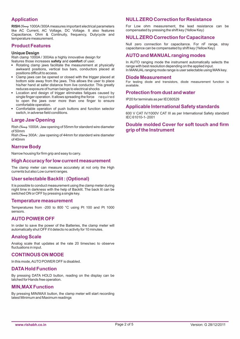
www.rishabh.co.in Page 2 of 5 Version: G 28/12/2011
Application
Product Features
Large Jaw Opening
Narrow Body
High Accuracy for low current measurement
User selectable Backlit : (Optional)
Temperature measurement
AUTO POWER OFF
Analog Scale
CONTINOUS ON MODE
DATA Hold Function
MIN,MAX Function
RISH Clamp 1000A /300A measures important electrical parameters like AC Current, AC Voltage, DC Voltage. It also features Capacitance, Ohm & Continuity, frequency, Dutycycle and temperature measurement.
Rish clamp 1000A / 300Ais a highly innovative design for features those increases safety and comfort of user.nRotating clamp jaws facilitate the measurement at physically
awkward positions, vertical bus bars, conductors placed at positions difficult to access.
nClamp jaws can be opened or closed with the trigger placed at bottom side away from the jaws. This allows the user to place his/her hand at safer distance from live conductor. This greatly reduces exposure of human beings to electrical shocks
nLocation and design of trigger eliminates fatigues caused by single finger operation. It allows spreading the force requi red to open the jaws over more than one finger to ensure comfortable operation.
nComfortable operation of push buttons and function selector switch, in adverse field conditions.
Rish Clamp 1000A: Jaw opening of 55mm for standerd wire diameter of 50mmRish 300A : Jaw opening of 44mm for standerd wire diameter of 40mm
Narrow housing for firm grip and easy to carry.
The clamp meter can measure accurately at not only the High currents but also Low current ranges.
It is possible to conduct measurement using the clamp meter during night time in darkness with the help of Backlit. The back lit can be switched ON or OFF by pressing a single key.
Temperatures from -200 to 800 °C using Pt 100 and Pt 1000 sensors.
In order to save the power of the Batteries, the clamp meter will automatically shut OFF if it detects no activity for 10 minutes.
Analog scale that updates at the rate 20 times/sec to observe fluctuations in input.
In this mode, AUTO POWER OFF is disabled.
By pressing DATA HOLD button, reading on the display can be latched for Hands free operation.
By pressing MIN/MAX button, the clamp meter will start recording latest Minimum and Maximum readings
Unique Design
Clamp
NULL ZERO Correction for Resistance
NULL ZERO Correction for Capacitance
AUTO and MANUAL ranging modes
For Low ohm measurement, the lead resistance can be compensated by pressing the shift key (Yellow Key)
Null zero connection for capacitance. For nF range, stray capacitance can be compensated by shift key (Yellow Key)
In AUTO ranging mode the instrument automatically selects the range with best resolution depending on the applied input.In MANUAL ranging mode range is user selectable using MAN key.
For testing diode and transistors, diode measurement function is available.
IP20 for terminals as per IEC60529
600 V CAT IV/1000V CAT III as per International Safety standard IEC 61010-1- 2001
Diode Measurement
Protection from dust and water
Applicable International Safety standards
Double molded Cover for soft touch and firm grip of the Instrument

www.rishabh.co.in Page 3 of 5 Version: G 28/12/2011
2)30.00 nF 10 pF 250 KΩ 2.5 V 1.0 + 3 300.0 nF 100 pF 250 KΩ 2.5 V 1.0 + 3
F 3.000 μF 1 nF 25 KΩ 2.5 V 1.0 + 330.00 μF 10 nF 25 KΩ 2.5 V 3.0 + 3
f min V dc f min V ~300.0 Hz 0.1 Hz 1 Hz 45 Hz
3)3.000 KHz 1 Hz 1 Hz 45 Hz 0.5 + 1 Hz 30.00 KHz 10 Hz 10 Hz 45 Hz
100.0 KHz 100 Hz 100 Hz 100 Hz4)2 Hz… 1kHz ± 5 Digit
% 2.0....98.0% 0.1 % 2 Hz -- 1 kHz … 10 kHz; ± 5 Digit / 4)kHz
-200.0...5)Pt +200.0 ºC 0.1 ºC – -- 2 Kelvin + 5 Digit
5)ºC 100 +200.0... 0.1 ºC 1.0 + 5 +850.0 ºC -100.0...
5)Pt +200.0 ºC 0.1 ºC 2 Kelvin + 2 Digit 1000 +200.0...
5) +850.0 ºC 0.1 ºC – -- 1.0 + 2
Measuring function
Measuringrange
Resolution Inputimpedance
Intrinsic error of digital display± (…% of rdg + …digit) at
reference condition
1)Over load capacity
Over load value
1000 VDCAC
eff / rmsSine wave
1000 VDCAC
eff / rmsSine wave
1100* A / 360A
Overload duration
Continuously
10 min
Continuously
300.0 mV 100 μV >10 GΩ // <40pF 0.5 + 3V dc 3.000 V 1 mV 11 MΩ // <40pF 0.25 + 1
30.00 V 10 mV 10 MΩ // <40pF 0.25 + 1300.0 V 100 mV 10 MΩ // <40pF 0.25 + 11000 V 1 V 10 MΩ // <40pF 0.35 + 13.000 V 1 mV 11 MΩ // <40pF 0.75 + 2
V ~ 30.00 V 10 mV 10 MΩ // <40pF (10….300 Digit)300.0 V 100 mV 10 MΩ // <40pF 0.75 + 11000 V 1V 10 MΩ // <40pF > 300 Digit
No load voltage2)30.00 Ω 10 mΩ Max. 3.2 V 0.5 + 3
Ω 300.0 Ω 100 mΩ Max. 3.2 V 0.5 + 33.000 KΩ 1Ω Max.1.25 V 0.4 + 130.00 KΩ 10 Ω Max. 1.25 V 0.4 + 1300.0 KΩ 100 Ω Max. 1.25 V 0.4 + 13.000 MΩ 1 KΩ Max. 1.25 V 0.6 + 130.00 MΩ 10 KΩ Max. 1.25 V 2.0 + 12.000 V 1 mV Max. 3.2 V 0.25 + 1
0.01 A ----- 1000A* 0.1 A -----
2)30.00 mV 10 μV >10 GΩ // <40pF 0.5 + 3
A ~ 300.0 A 1.5 % of range + 5 Digits1.5 % of range + 5 Digits
Measuring function
Measuringrange
Resolution Dischargeresistance
Intrinsic error of digital display± (…% of rdg + …digit) at
reference condition
1)Over load capacity
Over load value
1000 VDCAC
eff / rmsSine
≤ 3 kHz1000 v
≤ 30 kHz;300 V
≤100 kHz30 V
1000 VDCAC
eff / rmsSine
Overload duration
10 min
Continu-ously
10 min
U0 max.
1) At 0º …. + 40 ºC2) With zero adjustment, without zero adjustment + 35 digits3) Range :
3 V ac/dc: Ue = 1.5 V eff/rms … 100 V eff/rms30 V ac/dc: Ue = 15 V eff/rms … 300 V eff/rms300 V ac/dc: Ue = 150 V eff/rms … 1000 V eff/rms
4) On the range 3 V dc, square – wave signal positive on one side 5 … 15 V, f = const., not 163.84 Hz or integral multiple.5) Without sensor
*applicable for 1000A
Reference conditions for Accuracy
Reference temperature 23°C ± 2KRelative Humidity 45%...55% RHWaveform of measured quantity Sinusoidal Input frequency 50 or 60 Hz ±2%Battery Voltage 8 V ± 0.1 V

www.rishabh.co.in Page 4 of 5 Version: G 28/12/2011
Influence Quantity Range of Influence Measuring Ranges Attenuation
Noise quantity max. 1000 V V dc > 120 dBCommon 3V~ 30 V~ Mode Noise quantity max. 1000 V ~ 300 V~ > 70 dBinterference 50 Hz, 60 Hz sinusoidalvoltage 1000 V~ > 60 dB
Noise quantity V ~Value of the measuring range
Normal Mode at a time V dc > 50dBinterference Max. 1000V~ ,50Hz, 60Hzvoltage sinusoidal
Noise quantity max. 1000 V- V~ >110dB
Response time
Environmental
Battery
Operating temperature -10 to +55°CStorage temperature -20 to +70°CRelative humidity 0... 90% non condensingTerminal Protection IP50 for Housing and IP20
for terminals
Battery Voltage 9 V DCBattery type
Battery Life Minimum 220 hours on Vdc, Adc, 80 hours on Vac, Aac.
Manganese Dioxide Cell as per IEC6F22 , alkaline manganese cell as per IEC 6LR 61
Display
Number of digits 3 ¾ digits.Maximum count 3100 counts.Over range indication “OL” is displayed.
Polarity indication “─” sign is displayed for DC
functions, if positive pole is at“ ”.
1)Influence Quantity Range of Influence Measured Quantity/ Variation Measuring Range ± (….% of rdg. + ….digits)
30/300 mV dc 1.0 + 33...300 V dc 0.15 + 11000 V dc 0.2 + 1V ~ 0.4 + 1
2)30 Ω 0.15 + 2Temperature 0 ºC 300 Ω 0.25 + 2
+21 ºC 3 KΩ – 3 MΩ 0.15 + 1and 30 MΩ 1.0 + 1
2)+25 ºC…+40ºC 30 nF – 3 μF 0.5 + 230 μF 2.0 + 2Hz 0.5 + 1% ± 5 digits-200…+200 ºC 0.5 K + 2+200…+850ºC 0.5 + 2A ~ 0.75% of range + 1
15 Hz....<30 Hz --30 Hz....<45 Hz --> 65 Hz...400 Hz 3…300 V ~ 2.0 + 3>400 Hz…1 KHz 2.0 + 3
Frequency of the >1 KHz…20 Khz --measured quantity 15 Hz…<30 Hz --
30Hz …<45 Hz 1000 V ~ -->65 Hz … 1 Khz 3.0 + 315 Hz…<30 Hz --30Hz …<45 Hz A ~ -->66 Hz… 1 kHz 2.0% of range + 1
Influence Quantities and Variations

RISHABH INSTRUMENTS PVT.LTD.F-31, MIDC, Satpur, Nashik-422 007,India.Tel.: +91 253 2202160, 2202202 Fax : +91 253 2351064E-mail : India :- [email protected] International :- [email protected]
www.rishabh.co.in Page 5 of 5 Version: G 28/12/2011
1) With temperature: Error data apply per 10 K change in temperature.
With frequency: Error data apply to a display from 300 digits onwards.
2) With zero adjustment.
3) With unknown waveform (crest factor CF > 2), measure with manual range selection
4) With the exception of sinusoidal waveform.
5) After the “ ” symbol is displayed
1)Influence Quantity Range of Influence Measured Quantity/ Variation Measuring Range ± (….% of rdg. + ….digits)
1....34) 4)Wave form of the Crest factor CF V ~ A ~
3)measured quantity 1....5
Battery Voltage V DC 2 DigitV~ 4 Digit
5) …< 7.9 V A~ 6 Digit> 8.1 V …10.0 V 30Ω / 300 Ω/˚C 4 Digit
3 kΩ – 30MΩ 3 DigitnF, μF 1 DigitHz 1 Digit% 1 Digit
75% V~,VDCA~
Relative humidity 3 Days Ω 1 х intrinsic errorFHz
Meter off %0C
HOLD - -- ± 1 digitsMIN/MAX - V ac/dc , A ~ ± 2 digits
Applicable Standards
Safety
Weight
Warranty
EMC IEC 61326: Class BImmunity IEC 61000-4-2 8 KV
atmosphere discharge, 4 KV contact dischargeIEC 61000-4-3 : 3 V/m
IEC 61010-1-2001
IP for water & dust IEC60529Pollution degree 2Installation category IVHigh Voltage Test 6.7 kV AC, 50Hz for 1 minute
between housing and input.3.7 kV AC, 50Hz for 1 minute between housing with jaws and input.
0.6 Kg
1 years