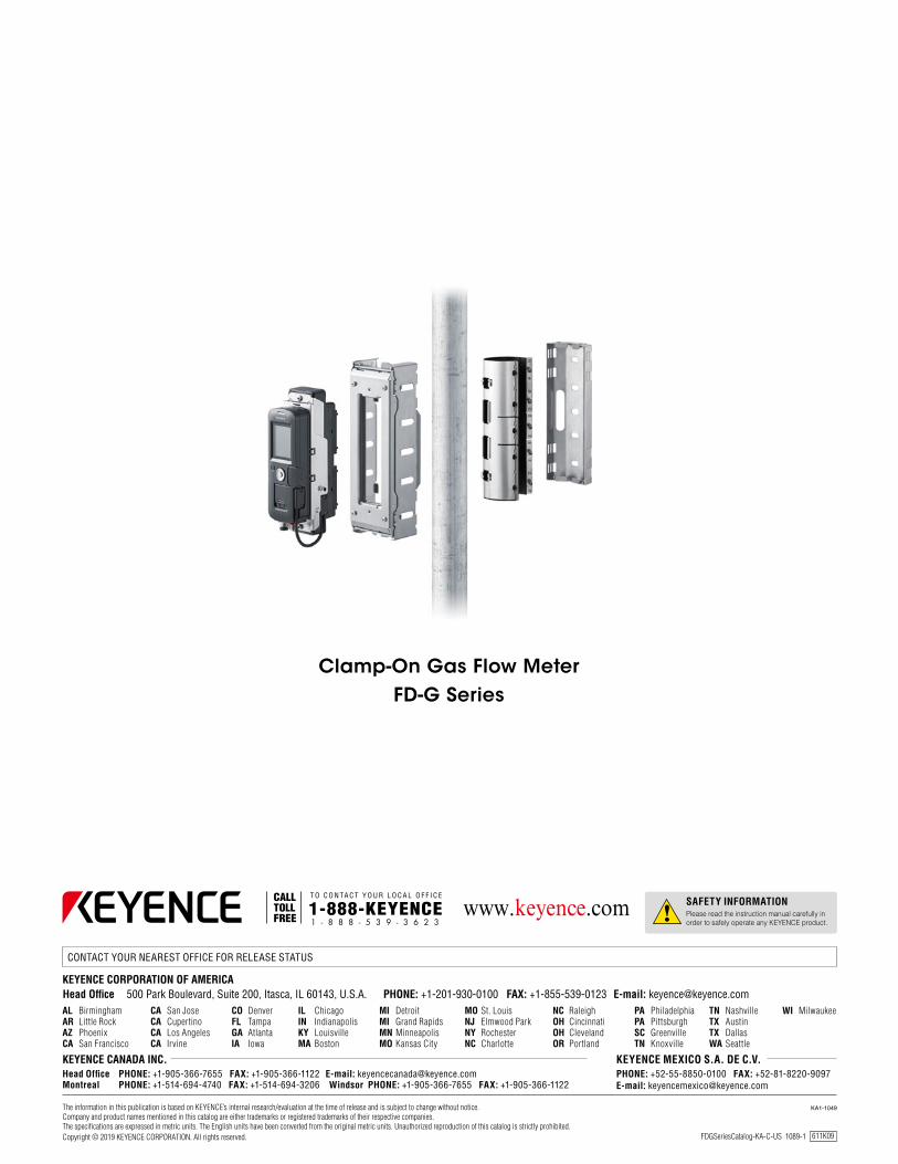
clamp-on gas flow meter
TRANSCRIPT

Clamp-On to Access
Limitless Data
Clamp-On Gas Flow Meter
NEW FD-G Series
FD-G Series

Monitor Compressed Air and Gases Throughout Your Facility
NEW
Clamp-On Gas Flow Meter
FD-G Series
2

P.10
P.8
P.6
3
ENDLESS OPPORTUNITIES
❚ Variety of Applications
❚ Wide Range of Pipe Sizes
❚ Monitor Consumption and Leaks
❚ No Pipe Modification
❚ Completely Non-Invasive
❚ No Special Tools Required
❚ Impressive Display
❚ Versatile Output Options
❚ Intuitive Optional Software
LIMITLESS INFORMATION
EFFORTLESS INSTALLATION

Compressors Receiver tank
ENDLESS OPPORTUNITIES
Main/Compressor Pipes
Branch Pipes
Drop / Machine Pipes
4
Compressor Monitoring Facility Air Consumption
Energy saving(cost reduction)
Energy saving(cost reduction)
Stable operation Stable operation
By monitoring the discharge amount from each compressor, performance issues can be recognized and preventative maintenance can be performed.
Finally determine how much compressed air your facility consumes and optimize your compressor usage.

Die-casting machines
Nitrogen tank
Welding machines
Molding machines
Machining centers Assembly machines
Inspection machines
5
Branch Pipe Comparisons Machine Gas Usage/Leakage
Energy saving(cost reduction)
Stable operation
Easily identify which lines are potentially leaking the most air, by comparing overall consumption and leakage amounts between branch pipes.
Maintain quality at the machine level, by monitoring gas or compressed air usage and also identifying potential leakage concerns.
Stable operation
Quality control

ENDLESS OPPORTUNITIES
¾" 1"
1 ¼" 1 ½"
2"2 ½"
3"4" 5"
6"8"
The FD-G Series is designed to work with a variety of pipe sizes throughout the facility. With five distinct models, the FD-G Series can fit on pipes from 3/4" up to 8" in size.
Range of Sizes NPS (Nominal Pipe Size) DN (Diameter Nominal) Compatible model
3/4", 1" 20A/25A FD-G25
1 1/4", 1 1/2", 2" 32A/40A/50A FD-G50
2 1/2", 3" 65A/80A FD-G80
4", 5" 100A/125A FD-G125
6", 8" 150A/200A FD-G200
6

Compatible Pipes
Compatible Gases
Consumption & Leakage Monitoring
Clamp directly onto a variety of metal pipes throughout your facility. This includes painted pipes, as well as pipes that may be rusted on the inside, which will not affect the detection stability of the unit.
Monitor air as it moves through the compressors, receiving tanks, main lines, and machines throughout the facility. Along with compressed air, the FD-G Series is designed to detect Nitrogen, as well as other pressurized* gases in the facility. * Gases must be pressurized to 58 PSI or greater to be detected
The FD-G Series is designed to not only monitor air/gas consumption for an entire facility, but also measure large and small amounts of leakage at all levels. With an impressive rangeability of 1:100, the FD-G Series can help identify costly leakage points for easy cost savings.
Stainless steelIron
Air Nitrogen
Identify Costly Leakage Points
7

No pipe modification required for installation
EFFORTLESS INSTALLATION
8

Zero intrusion into the pipe
Mount in Minutes
Completely Non-Invasive
No Added Leakage Points
With zero pipe modification necessary and no special tools or knowledge required for installation, the FD-G Series units can be mounted in mere minutes.
Unlike conventional air flow meters that require probes or pipe modifications, the FD-G Series has zero impact on the air or gas inside the pipe.
Avoid new sources of costly leakage by simply clamping the unit around the pipe. No modifications means no new spots for air or gas to escape.
9

Revolutionary display offers easy to understand graphical and numerical interface
Separate mounting
Ceiling pipe
LIMITLESS INFORMATION
The innovative detachable display can be mounted in an easily accessible location, while the sensing portion is mounted on pipes in the ceiling or other difficult to reach locations.
Flexible Mounting
Conventional unit
PC is needed for data analysis
External device required to log data
10
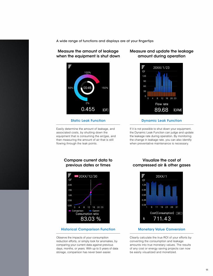
A wide range of functions and displays are at your fingertips
Measure the amount of leakage when the equipment is shut down
Compare current data to previous dates or times
Measure and update the leakage amount during operation
Visualize the cost of compressed air & other gases
Static Leak Function
Historical Comparison Function
Dynamic Leak Function
Monetary Value Conversion
Easily determine the amount of leakage, and associated costs, by shutting down the equipment that is consuming the air/gas, and then measuring the amount of air that is still flowing through the leak points.
Observe the impacts of your consumption reduction efforts, or simply look for anomalies, by comparing your current data against previous days, months, or years. With up to 5 years of data storage, comparison has never been easier.
If it is not possible to shut down your equipment, the Dynamic Leak Function can judge and update the leakage rate during operation. By monitoring the change in leakage rate, you can also identify when preventative maintenance is necessary.
Clearly calculate the true ROI of your efforts by converting the consumption and leakage amounts into true monetary values. The results of any cost or energy saving projects can now be easily visualized and monetized.
11

Control outputsMonitor the instantaneous flow rate or total consumption/leakage amount and trigger an output signal when they pass a certain level or enter a particular area.
IO-Link master
Server
PLC
Touch panelMonitor, etc.
Analog outputPulse outputControl output
Modbus TCP Modbus TCPAnalog outputPulse outputControl output
Analog outputPulse outputControl output
Data logger
Demand control system, etc.
Pulse output modeIdeal for data loggers and counters, the pulse output mode sends a signal each time a specified amount of flow has passed, with the ability to also distinguish direction of flow.
Time
Time
Hysteresis
Instantaneous flow
Instantaneous flow
0
P1 (P2)
ONOFF
ONOFF
Output (N.O.)
ch.1 output (forward
direction)
Output(N.C.)
ch.2 output (reverse
direction)
ONOFF
ONOFF
Analog outputTrack the instantaneous flow rate over time with a continuous analog signal that can range from 4 to 20 mA or 0 to 20 mA with customizable upper and lower limits.
If the flow exceeds the specified lower or upper limits, the signal outputs 3.8 mA or 20.5 mA.
Analog output
Instantaneous flow
3.8 mA
Lower limit Upper limit
4 mA
20 mA20.5 mA
Network communication capabilities
LIMITLESS INFORMATION
Versatile Outputs
EtherNet/IP™Modbus
TCP
IO-Link
Cyclic communication
Message communication
Process data
Service data
Output status readout ✓ ✓ ✓ ✓ ✓
Instantaneous flow readout ✓ ✓ ✓ ✓ ✓
Total consump. readout ✓ ✓ ✓ ✓ ✓
Accumulated flow/leak rate readout*
✓ ✓ ✓ — ✓
Settings readout — ✓ ✓ — ✓
Execution of external input operations
✓ — ✓ — ✓
* For these values, the graph displayed on the FD-G unit can be displayed on an external monitor or other device.
12

Batch monitoring Fully customizable monitor
Screen output function Copy settings function
Monitor FD-G units all throughout the facility via Ethernet on a single PC with the FD-G Monitor software. Quickly and easily compare consumption and leakage amounts across different locations to identify new energy saving opportunities.
In the past, monitoring screens needed to be programmed by specialist over months of times. Now with the FD-G Monitor, anyone can create an intuitive interface in minutes by simply selecting what information they want and laying it out how they best see fit.
The data that is being monitored can be output as a screen capture and used to improve clarity in reporting. *Data can be transmitted to the PC via USB or Ethernet.
Flow meter settings can be configured via the PC. Settings can then be saved and copied to several different units saving time.
Setting values, target values, alarm settings, etc.
Line A Line B Line C Line D Line E
OfficeCan be used to create reports, etc.Screen capture
Equipment A
Equipment B
Equipment CEthernet*
Intuitive Software
Improvement report
Energy analysis report
*USB connection to a single unit also available
13
NTP (Normal conversion)
STP (Standard conversion)
Display method
m3/h (N)
L/min (N)
CFM (S)
m3/h (S)
L/min (S)
Definition
Volume at 0ºC 32°F ,
101.3 kPa 14.7 psi (atmospheric pressure)
Volume at 20ºC* 68°F ,
101.3 kPa 14.7 psi (atmospheric pressure)
*Can be set to a value between 0 32°F and 100 ºC 212°F
English
Japanese
Chinese
German
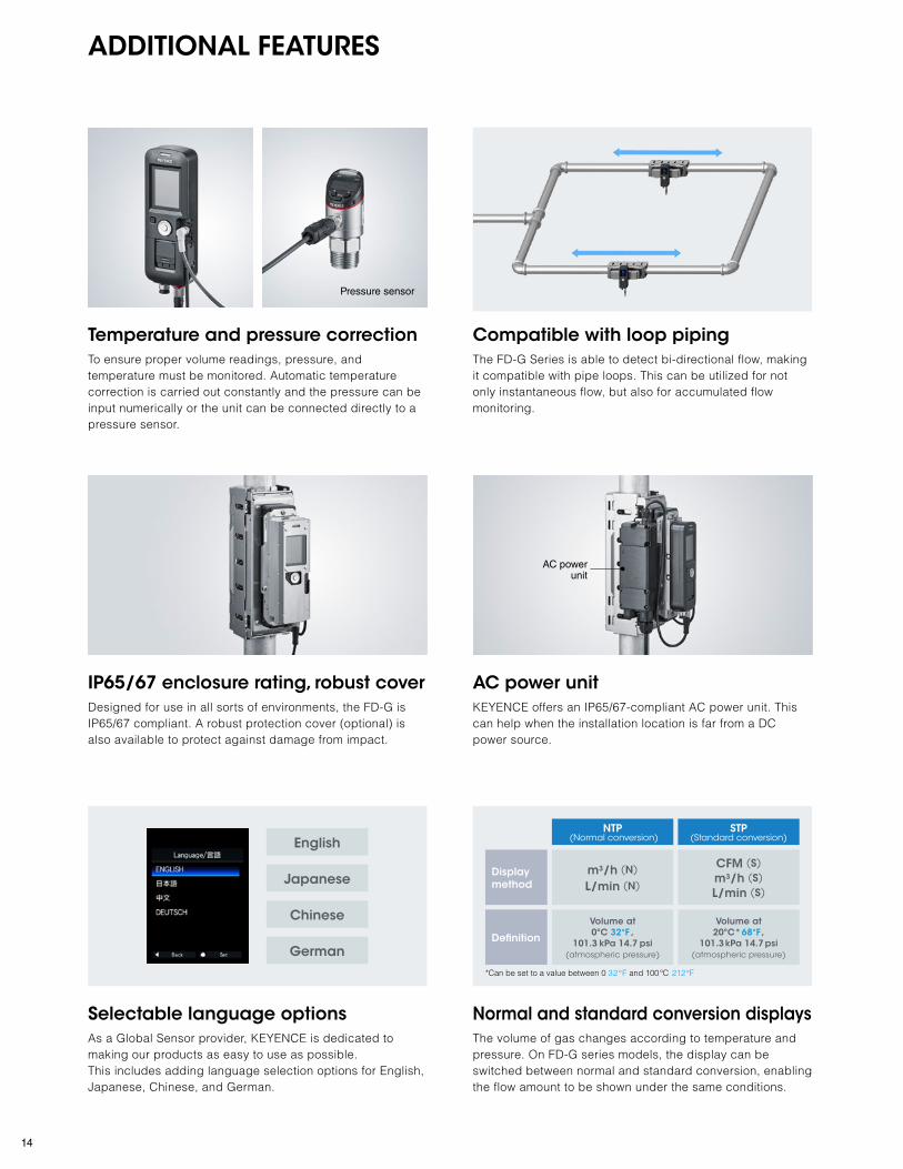
Pressure sensor
ADDITIONAL FEATURES
Temperature and pressure correction Compatible with loop piping
AC power unit
Normal and standard conversion displaysSelectable language options
IP65/67 enclosure rating, robust cover
To ensure proper volume readings, pressure, and temperature must be monitored. Automatic temperature correction is carried out constantly and the pressure can be input numerically or the unit can be connected directly to a pressure sensor.
The FD-G Series is able to detect bi-directional flow, making it compatible with pipe loops. This can be utilized for not only instantaneous flow, but also for accumulated flow monitoring.
KEYENCE offers an IP65/67-compliant AC power unit. This can help when the installation location is far from a DC power source.
The volume of gas changes according to temperature and pressure. On FD-G series models, the display can be switched between normal and standard conversion, enabling the flow amount to be shown under the same conditions.
As a Global Sensor provider, KEYENCE is dedicated to making our products as easy to use as possible. This includes adding language selection options for English, Japanese, Chinese, and German.
Designed for use in all sorts of environments, the FD-G is IP65/67 compliant. A robust protection cover (optional) is also available to protect against damage from impact.
AC power unit
14

CLEAR RETURNS
SituationCompressors are one of the largest energy consumers in most facilities, and in turn have some of the biggest impacts on electricity costs. Sadly most facilities do not understand how much air is consumed on a regular basis and only know the risk associated with not having compressed air available. Due to this, multiple compressors are run continuously to make sure there is always enough.
Advantage of The FD-GWith the FD-G Series, it is now possible to determine a baseline for how much air your facility truly needs by monitoring overall usage after the receiver tank. This means you can optimize your compressor usage and save money.
Run fewer compressors
Less leakage = Lower energy costs
Extend compressor lifetime with less wear
Prevent unnecessary maintenance
Only turn on additional compressors when absolutely necessary
Identify valuable preventative maintenance opportunities
Situation
Air and gas leakage is all too common throughout any facility, but it is near impossible to recognize how much air or gas is being lost and the associated energy costs. Due to this, most facilities rarely take actions to reduce leakage, as the impacts are hard to realize.
Advantage of The FD-G
With the FD-G Series, all main lines, branch pipes, and machine drop points can be monitored to determine how much they are leaking and show the true monetary value associated with the unchecked leakage. Now users can identify their biggest leakage points and measure the true impact of improvements.
Cost Savings
Cost Savings
Compressor Optimization
Leakage Identification
Example 1
Example 2
15

Measurement accuracy : ±2.0% of RD *1
Minimum detectable flow : 0.018 CFM *2
Rangeability*3 : 1:100
*1 Value obtained under conditions specified by KEYENCE. For details, see the specifications.*2 Detectable flow taking account of zero point error in a 3/4" pipe.*3 "Rangeability" is the ratio of the maximum to minimum flow for which accuracy is guaranteed.
Detection head
Detection head
Wraparound noise
The "guided wave" makes the pipe resonate, strengthening the signals
Transceiver Transceiver
Against flow ultrasonic
waves
With flow ultrasonic waves
Transceiver
Damping material
Ultrasonic wave (guided wave)
Gas flow direction ➝
DETECTION PRINCIPLES
The FD-G monitors gas flow by emitting and receiving two different sets of ultrasonic pulses. One pulse travels in the same direction as the gas flow and the other travels in the opposite direction of the gas flow. By doing this, the FD-G can monitor the gas flow rate by measuring the time differences between the two signals. This method offers stable detection and eliminates the effects of external factors.
Delta TOF (Time of Flight)
Guided Wave & Damping Material
Impressive Detection Capabilities
Signal strength is key to proper ultrasonic transmission. The FD-G Series utilizes a guided wave technique that resonates the pipe and strengthens the overall signal inside the pipe. Damping material is used to prevent this signal from wrapping around the pipe and affecting detection.
From detecting tiny leaks to measuring all the air coming from a receiving tank, the FD-G Series can monitor it all. This series boasts an impressive ±2% RD accuracy rating, which is even more impressive with its 1:100 rangeability.
16

Select a flow meter main unit and unit damping material
FD-G25 FD-G50 FD-G80 FD-G125 FD-G200 FD-GDxxU
FD-GDxxB
FD-GU1 OP-88394
FD-GP1
Flow meter main unit
Upstream/downstream damping material
Unit connection cable
Robust protection cover
AC power unitM12 power supply cable
Pressure sensor connection cable and connector
Separate system mounting bracket
Communication cables
Unit damping material
USB cable (A-mini B)
Ethernet cableM8 power supply cable Loose wires - M12 adapter connector (female)
How to Choose a Clamp-On Gas Flow MeterTo select the best FD-G series components for your installation location, follow the steps shown below.
STEP
1
STEP
2
STEP
3
STEP
4
Select upstream/downstream damping material(s), if deemed necessary
Determine mounting and power supply requirements
Select any additional components that may be necessary
P. 18
P. 19
P. 20
P. 22
17

Pipe size/ Outer diameter
[mm inch]
A Unit damping material B Flow meter main unit
Appearance Model Weight Appearance Model Weight
3/4" (20 A) ø25 to ø29
ø0.98" to ø1.14"FD-GD20U Approx. 0.19 kg
FD-G25 Approx. 2.2 kg1" (25 A)
ø32 to ø36 ø1.26" to ø1.42"
FD-GD25U Approx. 0.21 kg
1 1/4" (32 A) ø41 to ø45
ø1.61" to ø1.77"FD-GD32U Approx. 0.29 kg
FD-G50 Approx. 2.7 kg
1 1/2" (40 A) ø47 to ø51
ø1.85" to ø2.01"FD-GD40U Approx. 0.31 kg
2" (50 A) ø58 to ø62
ø2.28" to ø2.44"FD-GD50U Approx. 0.34 kg
2 1/2" (65 A) ø72 to ø78
ø2.83" to ø3.07"FD-GD65U Approx. 0.41 kg
FD-G80 Approx. 3.6 kg3" (80 A)
ø86 to ø92 ø3.39" to ø3.62"
FD-GD80U Approx. 0.46 kg
4" (100 A) ø111 to ø117
ø4.37" to ø4.61"FD-GD100U Approx. 0.56 kg
FD-G125 Approx. 2.7 kg5" (125 A)
ø138 to ø144 ø5.43" to ø5.67"
FD-GD125U Approx. 0.65 kg
6" (150 A) ø163 to ø171
ø6.42" to ø6.73"FD-GD150U Approx. 0.77 kg
FD-G200 Approx. 2.8 kg
8" (200 A) ø214 to ø222
ø8.43" to ø8.74"FD-GD200U Approx. 0.96 kg
A Unit damping material
B Flow meter
[Display unit + detection head + mounting bracket]
Check the diameter of the pipe on which the FD-G is to be mountedSTEP
1
This will also determine the flow meter main unit. Select the unit damping material based on the size/diameter of the pipe it is to be mounted on.1 2
How to select an FD-G series setup
18

A "junction" is defined as follows:
A weld, a threaded area, a flange or a branch in the pipe(U-bolts and other items not directly connected to the pipe itself are not included)
Check the distance "L" to the nearest upstream and downstream junctions
Determine if upstream/downstream damping material is required
Pipe size/Outer diameter [mm inch]
Lmin [mm inch]
Lmax [mm inch]
C Upstream/downstream damping material
Appearance Model Length x quantity in pack Weight
3/4" (20 A) ø25 to ø29 ø0.98" to ø1.14" 321 12.64" 1200 47.24" FD-GD20B 200 7.87" × 1 Approx. 0.2 kg
1" (25 A) ø32 to ø36 ø1.26" to ø1.42" 321 12.64" 1200 47.24" FD-GD25B 200 7.87" × 1 Approx. 0.22 kg
1 1/4" (32 A) ø41 to ø45 ø1.61" to ø1.77" 387 15.24" 1100 43.31" FD-GD32B 245 9.65" × 1 Approx. 0.3 kg
1 1/2" (40 A) ø47 to ø51 ø1.85" to ø2.01" 387 15.24" 1200 47.24" FD-GD40B 245 9.65" × 1 Approx. 0.32 kg
2" (50 A) ø58 to ø62 ø2.28" to ø2.44" 387 15.24" 1500 59.06" FD-GD50B 245 9.65" × 1 Approx. 0.35 kg
2 1/2" (65 A) ø72 to ø78 ø2.83" to ø3.07" 471 18.54" 1900 74.80" FD-GD65B 320 12.60" × 1 Approx. 0.52 kg
3" (80 A) ø86 to ø92 ø3.39" to ø3.62" 471 18.54" 2200 86.61" FD-GD80B 320 12.60" × 1 Approx. 0.58 kg
4" (100 A) ø111 to ø117 ø4.37" to ø4.61" 690 27.17" 2000 78.74" FD-GD100B 260 10.24" × 2 Approx. 1.13 kg
5" (125 A) ø138 to ø144 ø5.43" to ø5.67" 690 27.17" 2400 94.49" FD-GD125B 260 10.24" × 2 Approx. 1.32 kg
6" (150 A) ø163 to ø171 ø6.42" to ø6.73" 727 28.62" 2800 110.24" FD-GD150B 275 10.83" × 2 Approx. 1.57 kg
8" (200 A) ø214 to ø222 ø8.43" to ø8.74" 727 28.62" 3600 141.73" FD-GD200B 275 10.83" × 2 Approx. 1.95 kg
If L is smaller than Lmin: The flow meter cannot be installed in this location. Look for another installation location.If Lmin < L < Lmax: Upstream/downstream damping material is required on that side of the unit.If L is greater than Lmax: Upstream/downstream damping material is not required on that side of the unit.
"L" is the distance from the center of the sensor head to the nearest junctions on the pipe. ❙ Flange
L
500 mm 19.69"
L
1700 mm 66.93"
L L
L L L❙ Threaded section
❙ Branch in pipe
❙ U-bolt, etc.
U-bolt
❙ Weld
The length "L" from the sensor head to the junction on the upstream and downstream sides determines whether or not upstream/downstream damping material is required.
Lmin is 387 mm 15.24", and Lmax is 1500 mm 59.06", so the flow meter can be used if upstream/downstream damping material is installed on the upstream side. There is no need to install upstream/downstream damping material on the downstream side. Therefore, only one upstream/downstream damping material is needed.
* Install the upstream/downstream damping material in any position between the flow meter and the junction.
* If using the FD-GD100B/FD-GD125B/FD-GD150B/FD-GD200B, 2 upstream/downstream damping materials need to be installed on one side.
* Ensure that the upstream/downstream damping material does not interfere with U-bolts and other such piping supports. If it does interfere, mount the piping support around the upstream/downstream damping material.
In order to detect the ultrasonic signals correctly, upstream/downstream damping material may be required, depending on the FD-G unit's installation location.
1
2
[Example] When the meter is mounted in the following location on a 2" (50 A) pipe:
Check the location where the FD-G will be installedSTEP
2
U-boltUpstream/downstream damping material installation
U-bolt
19

DC power supply AC power supply
Integrated system on a vertical pipe
Integrated system on a horizontal pipe
Separate system regardless of the pipe orientation
The components required vary depending on the mounting style and power supply method for the display unit.
Determine the most appropriate mounting style and power supply method for the display unit from the table below.
Then select the appropriate components shown in the diagram from the tables on the right.
Detection head display unit
Detection head display unit
Detection head display unit
Detection head display unit
* 2 Mounting brackets are required.
Display unit
Display unit
Detection headDetection head
AC power supply
DC power supply
DC power supply
DC power supply
AC power supply
AC power supply
AC power unit
AC power unit
AC power unit
Separate system
mounting bracket
Separate system
mounting bracket*
M12 power supply cable
M12 power supply cable
M12 power supply cable
Round terminals
G Round terminals
H AC cable
H AC cable
H AC cable
Unit connection cable
Unit connection cable
Unit connection cable
Unit connection cable
F
F
E
E
E
F
I
I
DD
D
D
How to select an FD-G series setup
Determine the mounting style and power supply method for the display unitSTEP
3
G
Round terminalsG
20

D Unit connection cable
Appearance Specifications Model Length Material Weight
Horizontal integrated system OP-88390 0.3 m 0.98'
PVC
Approx. 20 g
Separate system
OP-88391 5 m 16.40' Approx. 200 g
OP-88392 15 m 49.21' Approx. 600 g
OP-88393 30 m 98.43' Approx. 1200 g
*The unit connection cable for a vertical integrated system is included with the flow meter.
E M12 power supply cable
Specifications Appearance Model Length Material Weight
Standard (PVC)OP-75721 2 m 6.56' PVC
nickel-plated brassApprox. 55 g
OP-85502 10 m 32.81' Approx. 220 g
Oil proof (PUR)OP-87636 2 m 6.56' PUR
zinc nickel platingApprox. 55 g
OP-87637 10 m 32.81' Approx. 260 g
F AC power unit
Appearance Model Material Weight
FD-GU1 PBT Approx. 400 g
G Round terminals ( to be provided separately by customer)
Type Round terminal size
Number required B (outer diameter) ød (inner diameter)
AC power supply M4 2 8.2 mm 0.32" or less 4.3 mm 0.17" or moreAnalog output*2 M3 2 5.5 mm 0.22" or less 3.2 mm 0.13" or more
H Cables ( to be provided separately by customer)
Type No. of core wires
Overall outer diameter
Nominal cross-sectional area
AC power supply cable 2 ø6.5 to ø12.5 ø0.26" to ø 0.49"
1.2 to 2.1 mm2
Analog output cable*2 2 0.3 to 1.75 mm2
I Separate system mounting bracket
Appearance Model Material Weight
OP-88394 SUS304 Approx. 210 g
*If the flow meter is to be installed as a separate system with an AC power supply, 2 separate system mounting brackets will be required.
B ød
*1 A 350 mm 13.78" M12 cable is supplied with the AC power unit. If the display unit is to be installed distant from the AC power unit, an extension cable such as OP-85503 (2 m 6.56') or OP-85504 (5 m 16.40') must be purchased separately. *2 The use of an analog output cable is optional.
Unit connection cable
Cable for DC power supply options Select a M12 power supply cable according to the required cable length and specification.
AC power supply options The AC power unit convert AC power to 24 VDC for the FD-G.
Separate system mounting bracket
F AC power unitDisplay unit
M12 cable*1 G Round terminals H Cables
AC power supply cable
Analog output cable
Determine the mounting style and power supply method for the display unit
21

Name Appearance Model Material Weight
Robust protection cover FD-GP1 SUS304
Polycarbonate Approx. 180 g
Name Appearance Model Length Material Weight
M8 power supply cable
OP-87632 2 m 6.56'
PUR Nickel-plated brass
Approx. 55 g
OP-87633 10 m32.81'
Approx. 260 g
Loose wires - M12 adapter
connector (female)*
OP-88395 —
Nylon Zinc
nickel plating
Approx. 12 g
*Use this when using a M12 connector type pressure sensor.
Name Appearance Model Length
Ethernet cable
OP-88086 2 m 6.56'
OP-88087 5 m 16.40'
OP-88088 10 m 32.81'
Name Appearance Model Length
USB cable A-mini BOP-51580 2 m 6.56'
OP-86941 5 m 16.40'
Name Model
Software FD-GH1
Name Model
Software FD-GH1
Select any additional components that may be necessary
How to select an FD-G series setup
Protection cover for display unit
Cable components to integrate the analog signal from a pressure sensor
Connection to PC (via USB)
Connections to PC, PLC, data logger, and other external devices on LAN
Pressure sensor
GP-M010 (M12 type)
Pressure sensor (loose wires type)
M8 power supply cable
USB cable
Ethernet cable
EtherNet/IP™Modbus TCP
Ethernet
Software
Software
PC
PC
PLC
Data logger
Loose wires - M12 adapter connector (female) *
Terminal block
STEP
4
22

Specifications
Clamp-On Gas Flow Meter
Model FD-G25 FD-G50 FD-G80 FD-G125 FD-G200
Pipe size
DN (Diameter Nominal) 20 A 25 A 32 A 40 A 50 A 65 A 80 A 100 A 125 A 150 A 200 ANPS (Nominal Pipe Size) 3/4" 1" 1 1/4" 1 1/2" 2" 2 1/2" 3" 4" 5" 6" 8"
Outer diameter of pipe (mm inch)
ø25 to 29 0.98" to 1.14"
ø32 to 36 1.26" to 1.42"
ø41 to 45 1.61" to 1.77"
ø47 to 51 1.85" to 2.01"
ø58 to 62 2.28" to 2.44"
ø72 to 78 2.83" to 3.07"
ø86 to 92 3.39" to 3.62"
ø111 to 117 4.37" to 4.61"
ø138 to 144 5.43" to 5.67"
ø163 to 171 6.42" to 6.73"
ø214 to 222 8.43" to 8.74"
Pipe thickness (mm inch)
2 to 4.2 0.08" to 0.17"
2.2 to 4.5 0.09" to 0.18"
2.4 to 5.3 0.09" to 0.21"
2.4 to 5.3 0.09" to 0.21"
2.6 to 5.7 0.10" to 0.22"
2.9 to 6.3 0.11" to 0.25"
2.9 to 6.3 0.11" to 0.25"
3.1 to 6.8 0.12" to 0.27"
3.1 to 6.8 0.12" to 0.27"
3.5 to 7.5 0.14" to 0.30"
4.0 to 8.7 0.16" to 0.34"
Supported pipe materials Iron, steel, stainless steelSupported fluids Air, Nitrogen, other gases*1
Fluid temperature 0 to 60ºC 32 to 140 °FRecommended pressure 0.4 MPa or greater (58 PSI or greater)Rated velocity of flow range Up to 15 m/s
Actual flow rate range (typical)
m3/h 20.00 32.00 54.00 72.00 120.00 200.0 280.0 470.0 720.0 1000.0 1800.0L/min 330.0 540.0 900.0 1200.0 2000.0 3300 4600 7800 12000 17000 30000CFM 12.00 19.00 32.00 42.00 70.00 120.00 160.00 280.00 420.00 600.00 1100.00
Standard flow rate range (typical) [CFM]
20°C 68°F 60 psi 0.41 MPa 56.84 90.00 151.58 198.95 331.58 568.43 757.91 1326.34 1989.51 2842.15 5210.6220°C 68°F 80 psi 0.55 MPa 72.06 114.10 192.17 252.22 420.37 720.64 960.85 1681.49 2522.23 3603.18 6605.8420°C 68°F 100 psi 0.69 MPa 87.28 138.20 232.76 305.49 509.16 872.84 1163.79 2036.63 3054.95 4364.21 8001.0620°C 68°F 120 psi 0.83 MPa 102.50 162.30 273.35 358.77 597.95 1025.05 1366.73 2391.78 3587.67 5125.24 9396.2820°C 68°F 140 psi 0.97 MPa 117.73 186.40 313.93 412.04 686.73 1177.25 1569.67 2746.93 4120.39 5886.27 10791.50
Display QVGA 2.2" LCD color monitorDisplay update cycle Approx. 3 Hz
Display resolution
Instantaneous flow rate0.01 m3/h, 0.1 L/min 0.1 m3/h, 1 L/min
0.001 CFM 0.01 CFM 0.1 CFM
Consumption/leakage amount
0.001 m3, 1 L 0.01 m3, 1 L 0.1 m3, 1 L0.1 CF 1 CF
Response time 1.0 s/2.5 s/5.0 s/10.0 s/30.0 s/60.0 s/120.0 s/200.0 s (variable)
Measurement accuracy
Between 10 and 100% of F.S. ±2.0% of RD*2, 3, 4, 5
Between 1 and 10% of F.S. ±1.0% of F.S.*2, 3, 4, 5
Zero point error ±0.15% of F.S.*2, 6
Static leakage repeatability ±1.0% of RD*4, 7
Hysteresis VariableFlow units CFM(S), CFM, m3/h (N), m3/h (S), m3/h, L/min (N), L/min (S), L/minI/O wiring connection port M12 4-pin connector (male)
Detection mode (switchable)*8
ch.1 Instantaneous flow mode/area mode/pulse (+) mode/integrated flow mode/warning mode (consump)
ch.2Instantaneous flow mode/area mode/pulse (−) mode/warning mode (leak)/error output mode/analog output/integrated flow reset/
flow rate zero input/origin adjustment input
Standard I/O (switchable)
Control output (ch.1/ch.2) NPN/PNP setting switchable, open collector output 30 VDC or less, max. 100 mA/ch, residual voltage: 2.5 V or lessAnalog output (ch.2) 4 to 20 mA/0 to 20 mA, load resistance: 500 Ω or lessExternal input (ch.2) Short-circuit current: 1.5 mA or less, input time: 20 ms or more
Power supply
Power supply voltage 20 to 30 VDC including 10% ripple (P-P), Class 2
Current consumption (analog output of the pressure sensor excluded)
350 mA or less at 20 V, 290 mA or less at 24 V, 230 mA or less at 30 V (load current excluded), 550 mA or less at 20 V, 490 mA or less at 24 V, 430 mA or less at 30 V (Maximum load current excluded)
Protection circuit Power supply reverse connection protection, power supply surge protection, short-circuit protection for each output, surge protection for each outputAnalog input (for volume conversion) M8 4-pin connector (female), analog current input (4 to 20 mA), input resistance: 100Ω or lessPower supplied to pressure sensor Supply voltage: Equivalent to voltage applied to the FD-G, Supply current:70 mA or less (analog output of the pressure sensor included)
Communication interface
USB USB 2.0
Ethernet
Standard IEEE 802.3u (100BASE-TX)Transmission rate 100 MbpsCable Category 5 or higher STP (shielded twisted pair) or UTP (unshielded twisted pair) cableConnector M12 connector (female, D-code)
Recording capacity
Consumption amount/ leakage amount Approx. 5 yearsEvents 100
Network function Modbus TCP, EtherNet/IPTM, IO-Link
Environmental resistance
Enclosure rating IP65/67 (IEC 60529)*10
Ambient temperature Detection head: −10 to +60°C 14 to 140°F (no freezing), display unit: −10 to +55°C 14 to 131°F (no freezing)Ambient humidity 5 to 85%RH (no condensation)Vibration resistance 10 to 500 Hz, power spectral density: 0.816 G2/Hz, XYZ axesShock resistance 100 m/s2, 16 ms pulse, XYZ axes, 1000 times for each axis
MaterialDisplay unit Body: PBT + coating, display: PMMA, Power supply port: SUS304-equivalent, Ethernet port: zinc nickel platingDetection head Body: PPS/SUS304, rear surface: rubberMounting/damping bracket SUS304
Weight Approx. 2.2 kg Approx. 2.7 kg Approx. 3.6 kg Approx. 2.7 kg Approx. 2.8 kg
*1 The gas must be uniform and capable of transmitting ultrasonic waves. Measurement may be unstable due to the pressure inside of the pipe and the type of gas.*2 This value is guaranteed by KEYENCE inspection facilities. Errors will be introduced by factors such as the type and status of the pipe and the type and temperature of the gas.*3 This is the value when considering linearity + span error in a stable environment with a temperature of 25°C 77°F.*4 Defined with stable velocity of flow distribution. Does not include pulsations and fluctuations in the velocity of flow distribution primarily attributable to the equipment.*5 The linearity error characteristic due to the pipe is not included in this value.*6 It is possible to reduce zero point errors by performing an origin adjustment.*7 This is the value within the range where measurement accuracy is guaranteed.*8 When Bi-directional is specified, the following functions cannot be used. The selection of the comparison view/leak ratio view/static leakage, the measurement/display of the leakage amount/integrated flow,
the setting of the target value/warning set value, and money conversions. Also, the I/O settings are limited as shown below. • ch.1: Pulse(+) mode • ch.2: Pulse(-) mode, Error output mode, Integrated flow reset, Flow zero input, Origin adjustment input
*9 IO-Link: Compatible with specification v1.1/COM1 (4.8 kbps). IO-Link is a trademark or registered trademark of PROFIBUS Nutzerorganisation e.V. (PNO).*10 The IP65/67 enclosure rating is lost when a USB connection is established.
23

Inside AC terminal block coverTerminal
block Terminal symbol Role
A ANLG Analog output
B COM Common (0 VDC)
C N AC power supplyD L
Inside DC terminal block coverTerminal
block Terminal symbol Role
A ANLG Analog output
B N.C. (Not used)
C 0 V 0 V DC
D 24 V 24 V DC
AB
C
D
ABCD
Load (input device)Analog current input device(4–20 mA or 0–20 mA)
2
43 1
Pin layout on display unit side
Specifications
AC power unit
Model FD-GU1
System Switching typeInput supply voltage 100 to 240 VAC; +10%/−15% (50/60 Hz)Output voltage 24 VDC ±5%Overvoltage category llRipple noise 260 mV (p-p) or lowerOutput capacity 9.1 W (0.38 A) (Class 2)Power consumption 100 VAC: 0.3 A or lower; 200 VAC: 0.2 A or lowerPollution degree 2Withstand voltage 3000 VAC, 1 minute (between input and output, between all external terminals and case)Momentary interruption 20 ms or lowerWiring specifications AC input: power supply M4 terminal block, 2 poles; Analog output: M3 terminal block, 2 poles; DC output: M12 4-pin connectorProtection circuit Protection against power supply surge, protection against output short-circuiting
Environmental resistance
Enclosure rating IP65/67 (IEC60529)Operating ambient temperature -20 to +50ºC -4 to 122°F (no freezing)Operating ambient humidity 5 to 90%RH (no condensation)Vibration resistance 10 to 500 Hz power spectral density: 0.816 G2/Hz in X, Y, Z axis directionsShock resistance Shock resistance 50 m/s2; 16 ms pulses, 1000 times each for X, Y, and Z axes
Material PBTWeight Approx. 400 gMain unit size 63 2.48" × 240 9.45" × 40 1.57" mm
Wiring examples
When FD-G unit is used alone
When the AC power unit FD-GU1 is used
Wiring varies according to the functions selected. I/O wires that will not be used should be insulated independently.
1
34 2
When control output is used
NPN
NPNNPN
PNP
PNPPNP
When control output + analog output is used
M12 connector cable (female) pin layout
When control output + external input is used
(1) Brown20-30 VDC
0 V
(4) Black (ch.1)
(2) White (ch.2)
(3) Blue
(1) Brown20-30 VDC
0 V
(4) Black (ch.1)
(2) White (ch.2)
(3) Blue
(1) Brown20-30 VDC
0 V
(4) Black (ch.1)
(2) White (ch.2)
(3) Blue
(1) Brown20-30 VDC
0 V
(4) Black (ch.1)
(2) White (ch.2)
(3) Blue
(1) Brown20-30 VDC
0 V
(4) Black (ch.1)
(2) White (ch.2)
(3) Blue
(1) Brown20-30 VDC
0 V
(4) Black (ch.1)
(2) White (ch.2)
(3) Blue
(1) Brown (20–30 VDC)
(4) Black (ch.1)
(2) White (ch.2)
(3) Blue (0 V)
24

Dimensions Unit: mm inch
Flow meter
FD-G25
FD-G50/FD-G80
FD-G125/FD-G200
FD-G125 FD-G200
A 96.8 3.81" 97.5 3.84"
B 332.4 13.09" 347.4 13.68"
C 105.3 4.15" 112.8 4.44"
FD-G50 FD-G80
A 98.8 3.89" 139.6 5.50"
B 89.6 3.53" 130.3 5.13"
C Max.80.5 3.17" Max.90.5 3.56"
D 278.9 10.98" 296.1 11.66"
E 58.2 2.29" 66.8 2.63"
F Max.60 2.36" Max.70 2.76"
G Max.97 3.82" Max.107 4.21"
36.31.43"
235.1 9.26"
Max
. 60 2.36
"M
ax. 9
7 3.
82"
Max
.28 1.
10"
162.56.40"
Max
. 80.
53.
17"
74.4 2.93"
90.35"
11.30.44"
D
Max
.22 0.
87"
F
G
E 162.56.40"
C
A
B90.35"
11.30.44"
Max
. 90.
53.
56"
12.40.49"
A
81.8 3.22" B
C 162.56.40"
Max
. 70
2.76
"M
ax. 7 0.28
"
Max
. 107
4.2
1"
90.35"
11.30.44"
25

84.5
3.33
"
27.9
1.1
0"
64.1
2.5
2"
100.
5 3.
96"
84.5
3.33
"12 0.
47"
60 2.36"
27.1
1.07"
38 1
.50"
A
B M4
Material: SUS304t = 1.3 0.05"
254 10.00"
90 3
.54"
34 1.3
4"52 2.05
"
72 2
.83"
227.5 8.96"5 0.20"
160.63"
107 4.21"
ø 6.4
0.25"
11.5
0.4
5"
Material: SUS304
254 10.00"
90 3
.54"
45 1
.77"
176.8 6.96"
65.8
2.5
9"38
.1 1.
50"
6.4
0.25
"
Grounding surface
Material: SUS304Polycarbonate
17°
FD-G25/G50: 37 1.46"FD-G80/G125/G200: 52.1 2.05"
FD-G25/G50: 77.2 3.04"
FD-G80/G125/G200: 81.6 3.21"
15.7
0.6
2"
OP-88394
FD-GP1
When used with display unit
Model A B
FD-GD20B/FD-GD25B 200 7.87"
Max. 18
FD-GD32B/FD-GD40B/ FD-GD50B 245 9.65"
FD-GD65B/FD-GD80B 320 12.60"
FD-GD100B/FD-GD125B* 260 10.24"
FD-GD150B/FD-GD200B* 275 10.83"
* 2 Upstream/downstream damping materials need to be installed on one side.
Dimensions Unit: mm inch
Upstream/downstream damping material
Separate system mounting bracket
Robust protection cover
When mounted on a horizontal pipe When tilted When USB cable is connected
26

OP-87636: 2000 78.74"/OP-87637: 10000 393.70"44 1.73"
ø14.
8 0.
58"
ø4.7 ø0.19" (4 × 0.34 mm2)
M12
Pin layout
4
3
2
Number
1
Colour
Brown
White
Blue
Black
34
12
M8 ø10ø0.39"
ø4.4 ø0.17" (4 × 0.25 mm2)
18.9
0.7
4"
27.91.10"
2000 78.74" (OP-87632) / 10000 393.70" (OP-87633)5°
Pin layout
4
3
2
Number
1
Colour
Brown
White
Blue
Black
24 3
1
R150.5
9"
67.4
2.6
5"
(350 13.78")
(41 1.61") 162.5 6.40"
40 1
.57"
14.8
0.5
8"
63 2
.48"
M4×2
44 1.73"
(31 1.22")
M3×4 M3×4
40 1.57"
ø16.
3 ø0
.64"
51.7 2.04" Across flats: 130.51"
Material: NylonZinc nickel plating
254 10.00"
16 0.63"
ø6.4 0.25"
72 2
.83"
90 3
.54"
49.5
1.9
5"
227.5 8.96"5 0.20"
ø4 ø0.16" 4 × 0.28 mm2
ø14ø0.55"
ø12 ø0.47"0.54" 13.7 30
1.18"
OP-75721: 2000 78.74" / OP-85502: 10000 393.70"
When separate system mounting bracket OP-88394 is used
When M12 power supply cable is connected
When mounted on flow meter
OP-87632/87633
FD-GU1
Standard PVCOP-75721/85502
Oil proof PUROP-87636/87637
OP-88395
M12 power supply cable
AC power unit
M8 power supply cable (for use with pressure sensor signal input) Loose wires - M12 adapter connector (female)
CAD DATA DOWNLOAD
www.keyence.com/CADG
27

AP-C30 Series AP-C40/V40 Series
AP-V80 Series
Key Features
> IP67 full stainless steel structure
> Up to 7,250 PSI range
> Up to 100°C (212°F) heat resistance
Key Features
> Small heads
> Fast response time
> Pre-programmed modes for various applications
Key Features
> Compact size
> Large display
> Various mounting options
Amplifiers
Type AppearanceModel
NPN PNP
DIN
Standard AP-V80W AP-V80WP
Differential pressure AP-V82W AP-V82WP
PanelStandard AP-V85W AP-V85WP
Differential pressure AP-V87W AP-V87WP
AccessoriesAppearance Designation Model
Panel mounting bracket kit for
AP-V85W(P) OP-51476
Panel spacer kit for AP-V85W(P) OP-51605
Head connectors (x2) OP-42367
Sensor Heads
Appearance Pressure port
Pressure type Model
Sensor head
Pressure port
NPT 1/8
Compound -29.9 to +29.9 inchHg AP-10SK
Negative -29.9 to 0 inchHg AP-11SK
Positive (Low) 0 to 14.5 PSI AP-12SK
Positive 0 to 145 PSI AP-13SK
NPT 1/4
(with a throttle)
Posi t ive (High)
0 to 1,450 PSI AP-14SK
0 to 2,900 PSI AP-15SK
0 to 7,250 PSI AP-16SK
-29.9 0 29.9 145.0 1,450 2,900 7,250
Includes brackets for installation without DIN rail.
Key Features
> Multiple adapter options ensure fit
> Clog resistant step flush diaphragm
> Rotatable display requiring no union joint
OP-51605AP-V85W
GP-M Series
Accessories
Sensors
Appearance Rated pressure rangeFluid type
Thread diameter
Model
-14.50 to +14.50 PSI (-100 to +100 kPa)Gas
Liquid
G3/4
GP-M001
-14.5 to +145.0 PSI (-0.1 to +1 MPa) GP-M010
-14.5 to +362.6 PSI (-0.1 to +2.5 MPa) GP-M025
0 to +1450 PSI (0 to +10 MPa)
Liquid
GP-M100
0 to +3626 PSI (0 to +25 MPa) GP-M250
0 to+5802 PSI (0 to +40 MPa) GP-M400
0
AdaptersAppearance Type Model
R male 1/8 OP-87281
R male 1/4 OP-87282
R male 3/8 OP-87280
G female 1/4 OP-87283
NPT male 1/8 OP-87284
NPT male 1/4 OP-87285
Rc female 1/2 OP-87286
Do not use unauthorized adapters.
Cables: Please refer to the GP-M Series Brochure
Display protection coverAppearance Material Model
Polysulfone OP-87289
Throttles (Attach to the adapter before use)Appearance Material Applicable adapter Model
SUS303OP-87280/OP-87281OP-87282/OP-87284
OP-87285OP-87311
SUS303 OP-87283 OP-87312
It is recommended to attach a throttle to the GP-M100/M250/M400. For the other models, use it when excessive pulses or surge pressure is expected.
PRESSURE SENSORS
28

SensorsCONTROLLER (Required) PROBE (Required)
Standard type
FL-001
FL-P20 (200 mm 0.66')FL-P40 (400 mm 1.31')FL-P60 (600 mm 1.97')FL-P80 (800 mm 2.62')FL-P100 (1000 mm 3.28')FL-P120 (1200 mm 3.94')FL-P140 (1400 mm 4.59')FL-P160 (1600 mm 5.25')FL-P180 (1800 mm 5.91')FL-P200 (2000 mm 6.56')
Sanitary type
FL-S001
FL-SP20 (200 mm 0.66')FL-SP40 (400 mm 1.31')FL-SP60 (600 mm 1.97')FL-SP80 (800 mm 2.62')FL-SP100 (1000 mm 3.28')FL-SP120 (1200 mm 3.94')FL-SP140 (1400 mm 4.59')FL-SP160 (1600 mm 5.25')FL-SP180 (1800 mm 5.91')FL-SP200 (2000 mm 6.56')
Plastic/Chemical type
FL-C001
FL-CP20 (200 mm 0.66')FL-CP40 (400 mm 1.31')FL-CP60 (600 mm 1.97')FL-CP80 (800 mm 2.62')FL-CP100 (1000 mm 3.28')FL-CP120 (1200 mm 3.94')FL-CP140 (1400 mm 4.59')FL-CP160 (1600 mm 5.25')FL-CP180 (1800 mm 5.91')FL-CP200 (2000 mm 6.56')
FL SeriesLiquid Level Sensors
Zinc die-casting (Nickel plated)
PVC
Zinc die-casting (Nickel plated)
PVC
SUS316L
PVC
SUS316L
PVC
SUS316L
PVC
SUS316L
PVC
Key Features
> Completely trouble-free operation
> Sensing Guide-Pulse Technology
> Multiple output options
3 Different Models Designed for Varying Applications
Standard typeFL‐001
Sanitary typeFL‐S001
Plastic/Chemical typeFL‐C001
• Water/oil model• Applicable for liquids containing solid particulates• Applicable for viscous liquids
• Food/chemical industry model• Ready for CIP/SIP cleaning• Applicable for viscous liquids
• Chemical resistant model• Applicable for corrosive liquids• Applicable for viscous liquids
CablesAppearance Standard power supply cable Model
Straight cableOP-87564 (2 m 6.56')OP-87565 (5 m 16.40')OP-87566 (10 m 32.81')
The following are standard PVC cables.
OP-87564OP-87565OP-87566
L-shaped cableOP-87568 (2 m 6.56')OP-87569 (5 m 16.40')OP-87570 (10 m 32.81')
OP-87568OP-87569OP-87570
Straight cablesOP-87647 (2 m 6.56')OP-87648 (5 m 16.40')OP-87649 (10 m 32.81')
The following are PVC cables with stainless steel (SUS316L) connectors. Use in situations where rust is a concern for the connectors.
OP-87647OP-87648OP-87649
L-shaped cablesOP-87650 (2 m 6.56')OP-87651 (5 m 16.40')OP-87652 (10 m 32.81')
OP-87650OP-87651OP-87652
Straight cablesOP-87582 (2 m 6.56')OP-87583 (5 m 16.40')OP-87584 (10 m 32.81')
The following are PUR cables with high resistance to oily environments.
OP-87582OP-87583OP-87584
L-shaped cablesOP-87586 (2 m 6.56')OP-87587 (5 m 16.40')OP-87588 (10 m 32.81')
OP-87586OP-87587OP-87588
Accessories: Please refer to the FL Series Brochure
LIQUID LEVEL SENSOR
29
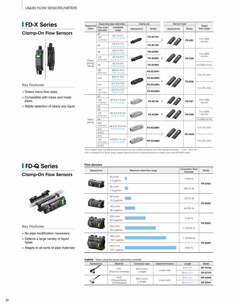
Flow Sensors
Appearance Maximum rated flow rangeConnection Bore
DiameterModel
20 L/min
5.2 gal/min1/4"(8 A)
FD-Q10C30 L/min
7.9 gal/min3/8"(10 A)
60 L/min
15.9 gal/min1/2"(15 A)
FD-Q20C100 L/min
26.4 gal/min3/4"(20 A)
200 L/min
52.8 gal/min1"(25 A)
FD-Q32C300 L/min
79.3 gal/min1 1/4"(32 A)
400 L/min
105.7 gal/min1 1/2"(40 A)
FD-Q50C500 L/min
132.1 gal/min2"(50 A)
Cables *When using the sensor without the controller
Appearance Material Connector type Cable termination Length Model
PVC (Polyvinyl chloride)
M12 4 pins L-shape Loose wire
2 m 6.56' OP-75722
10 m 32.81' OP-87274
PUR (Polyurethane) (Oil Resistant)
M12 4 pins L-shape Loose wire
2 m 6.56' OP-87640
10 m 32.81' OP-87641
Supported pipes
Supported pipe diameters Clamp set Sensor headRated
flow rangePipe outer diameter*
Installable range
Appearance Model Appearance Model
Plastic piping/tubing
ø3ø2.7 to 3.7
0.11" to 0.15" FD-XC1R1
FD-XS10 to 1000 mL/min
1/8" (3.18 mm)
ø4 ø3.5 to 4.50.14" to 0.18" FD-XC1R2
ø6 ø5.5 to 6.50.22" to 0.26" FD-XC8R1
FD-XS8
0 to 3000 mL/min1/4"
(6.35 mm)ø5.9 to 6.9
0.23" to 0.27" FD-XC8R2
ø8 ø7.5 to 8.50.30" to 0.33" FD-XC8R3 0 to 8000 mL/min
3/8" (9.53 mm)
ø9.0 to 10.00.35" to 0.39" FD-XC20R1
FD-XS20
0 to 15 L/minø10 ø9.5 to 10.5
0.37" to 0.41" FD-XC20R2
ø12 ø11.5 to 12.50.45" to 0.49" FD-XC20R3
0 to 20 L/min1/2" (12.7 mm)
ø12.2 to 13.20.48" to 0.52" FD-XC20R4
Metal piping
ø3
ø2.8 to 5.5 mm0.11" to 0.22" FD-XC1M FD-XS1
0 to 1000 mL/min
1/8" (3.18 mm)
ø4ø6
ø5.5 to 8.3 mm0.22" to 0.33" FD-XC8M FD-XS8
0 to 3000 mL/min1/4"
(6.35 mm)
ø8 0 to 8000 mL/min
3/8" (9.53 mm) ø8.3 to 10.8 mm
0.33" to 0.43" FD-XC20M1
FD-XS20
0 to 15 L/minø10ø10.5ø12
ø10.8 to 14 mm0.43" to 0.55" FD-XC20M2 0 to 20 L/min1/2"
(12.7 mm)
ø13.8
*Inch notation does not refer to the B-nominal in the JIS or ANSI standards, but to the standard whereby 1 inch = 25.4 mm. *For a complete FD-X Series setup, please reference the FD-X Series brochure or contact your local KEYENCE office.
FD-Q SeriesClamp-On Flow Sensors
FD-X SeriesClamp-On Flow Sensors
Key Features
> No pipe modification necessary
> Detects a large variety of liquid types
> Adapts to all sorts of pipe materials
Key Features
> Detect micro flow rates
> Compatible with tubes and metal pipes
> Stable detection of nearly any liquid
LIQUID FLOW SENSORS/METERS
30

Cable gland *When supplying AC power to the unit
Appearance MaterialCompatible cable
outer diameterNumber of
piecesWeight Model
PA/FKM/EPDM ø7 to ø12 2 Pieces Approx. 20 g 2 pieces OP-88199
AccessoriesDescription Appearance Usage Weight Model
Protection coverPrevent damage to the main unit or
unintended settings changes Material : SUS304, Polycarbonate
Approx. 285 g FD-RP1
Modular cable
Send recorded data stored in FD-R to a computer
Approx. 72 g OP-26487
RS-232C conversion
adapter [9-pin]
Approx. 25 g OP-26401
FD-R SeriesClamp-On Flow Meters
Flow Meters
Supported pipe size (Outer diameter)
AppearanceRated flow
velocity rangeFlow rate range (Typical) Weight Model
1 1/2" (40A)(ø44 to ø55)
0.3 m/s to
5 m/s
36 to 400 L/min 9 to 100 gal/min 2.4 to 24 m3/h
Approx. 2.5 kg FD-R50
2" (50A)(ø55 to ø64)
36 to 600 L/min 9 to 150 gal/min 2.4 to 36 m3/h
2 1/2" (65A)(ø64 to ø83)
90 to 1000 L/min 24 to 260 gal/min 5.4 to 60 m3/h
Approx. 3.0 kg FD-R80
3" (80A)(ø83 to ø100)
90 to 1500 L/min 24 to 390 gal/min 5.4 to 90 m3/h
4" (100A)(ø100 to ø127)
220 to 2500 L/min 60 to 660 gal/min 12 to 150 m3/h
Approx. 3.3 kg FD-R125
5" (125A)(ø127 to ø152)
220 to 3700 L/min 60 to 990 gal/min 12 to 220 m3/h
6" (150A)(ø152 to ø191)
570 to 5500 L/min 150 to 1400 gal/min 36 to 330 m3/h
Approx. 3.5 kg FD-R200
8" (200A)(ø191 to ø220)
570 to 9500 L/min 150 to 2500 gal/min 36 to 570 m3/h
*The minimum flow rates (zero cut flow rates) can be changed in the settings.
CablesSpecifications Appearance Length Material Weight Model
Indoor use (standard)
2 m 6.56' PVC Brass nickel plating
Approx. 55 g OP-75721
10 m 32.81' Approx. 220 g OP-85502
Indoor use (oil resistant)
2 m 6.56' PUR Zinc nickel plating
Approx. 75 g OP-87636
10 m 32.81' Approx. 260 g OP-87637
Outdoor use 10 m 32.81' PUR SUS316L Approx. 310 g OP-88196
Key Features
> No pipe modification necessary
> Compatible with countless liquids and pipe materials
> Integrated temperature monitoring
31
KA1-1049The information in this publication is based on KEYENCE’s internal research/evaluation at the time of release and is subject to change without notice.Company and product names mentioned in this catalog are either trademarks or registered trademarks of their respective companies.The specifications are expressed in metric units. The English units have been converted from the original metric units. Unauthorized reproduction of this catalog is strictly prohibited.
ALARAZCA
BirminghamLittle RockPhoenixSan Francisco
CACACACA
San JoseCupertinoLos AngelesIrvine
COFLGAIA
DenverTampaAtlantaIowa
ILINKYMA
ChicagoIndianapolisLouisvilleBoston
MIMIMNMO
DetroitGrand RapidsMinneapolisKansas City
MONJNYNC
St. LouisElmwood ParkRochesterCharlotte
NCOHOHOR
RaleighCincinnatiClevelandPortland
PAPASCTN
PhiladelphiaPittsburghGreenvilleKnoxville
TNTXTXWA
NashvilleAustinDallasSeattle
WI Milwaukee
www.keyence.com
KEYENCE MEXICO S.A. DE C.V.PHONE: +52-55-8850-0100 FAX: +52-81-8220-9097
KEYENCE CANADA INC.Head Of�ce PHONE: +1-905-366-7655 FAX: +1-905-366-1122 Montreal PHONE: +1-514-694-4740 FAX: +1-514-694-3206 Windsor PHONE: +1-905-366-7655 FAX: +1-905-366-1122
KEYENCE CORPORATION OF AMERICAHead Of�ce 500 Park Boulevard, Suite 200, Itasca, IL 60143, U.S.A. PHONE: +1-201-930-0100 FAX: +1-855-539-0123
SAFETY INFORMATIONPlease read the instruction manual carefully in order to safely operate any KEYENCE product.1 - 8 8 8 - 5 3 9 - 3 6 2 3
1-888-KEYENCECALL TOLL FREE
T O C O N TA C T Y O U R L O C A L O F F I C E
CONTACT YOUR NEAREST OFFICE FOR RELEASE STATUS
E-mail: [email protected]
E-mail: [email protected] E-mail: [email protected]
Clamp-On Gas Flow Meter FD-G Series
Copyright © 2019 KEYENCE CORPORATION. All rights reserved. FDGSeriesCatalog-KA-C-US 1089-1 611K09