clamping devices - avalon...clamping devices. 716 notes. 717 mounting instructions for eccentric...
TRANSCRIPT
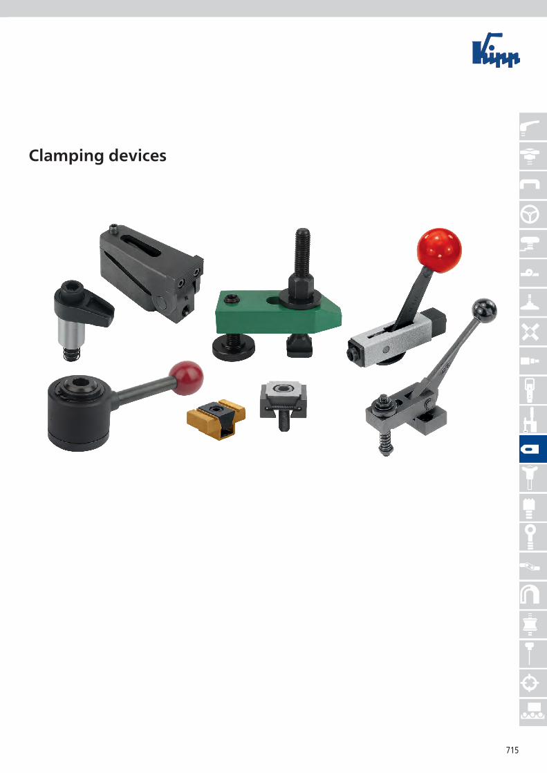
715
Clamping devices

716
Notes
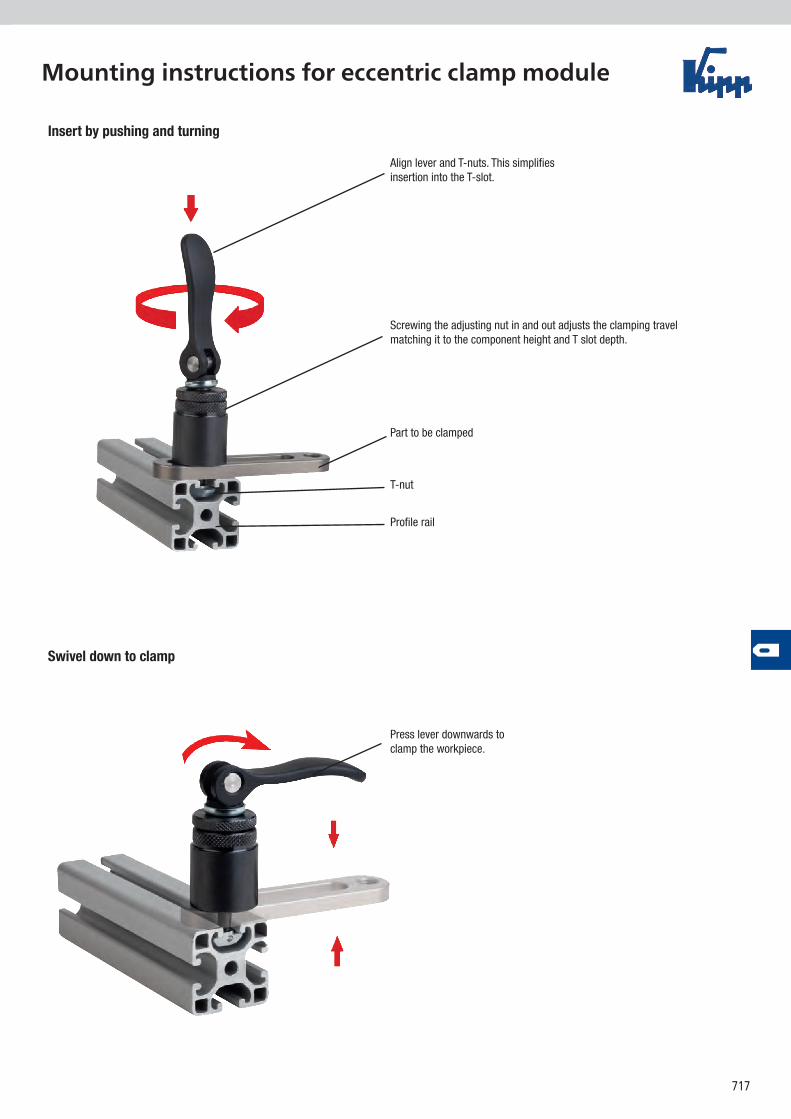
717
Mounting instructions for eccentric clamp module
Press lever downwards to clamp the workpiece.
Align lever and T-nuts. This simplifies insertion into the T-slot.
Screwing the adjusting nut in and out adjusts the clamping travel matching it to the component height and T slot depth.
Part to be clamped
T-nut
Profile rail
Insert by pushing and turning
Swivel down to clamp
718
D1
SW 30
L10H1
H2H
D
A
L
H1H2H
A
workpiece / component
adjustment
hammer nutfor 8 mm T-slot
alu profile / machine tableForm B
Form A
hand
force
clamping force
min.
4 /
max
. 12
adjustment
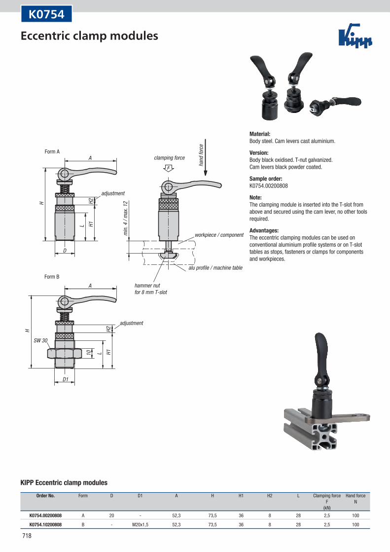
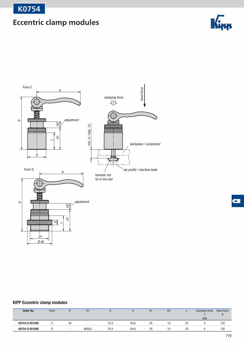
K0754
KIPP Eccentric clamp modules
Order No. Form D D1 A H H1 H2 L Clamping force Hand force F N (kN)
K0754.00200808 A 20 - 52,3 73,5 36 8 28 2,5 100
K0754.10200808 B - M20x1,5 52,3 73,5 36 8 28 2,5 100
Material:Body steel. Cam levers cast aluminium.
Version:Body black oxidised. T-nut galvanized. Cam levers black powder coated.
Sample order:K0754.00200808
Note:The clamping module is inserted into the T-slot from above and secured using the cam lever, no other tools required.
Advantages:The eccentric clamping modules can be used on conventional aluminium profile systems or on T-slot tables as stops, fasteners or clamps for components and workpieces.
Eccentric clamp modules
719
H
D1
L8
Ø 40
A
D
H1H2
L
H
A
H1H2
workpiece / component
adjustment
hammer nutfor 8 mm slot
alu profile / machine table
Form C
Form D
hand
force
clamping force
min.
4 /
max
. 14
adjustment
K0754
KIPP Eccentric clamp modules
Order No. Form D D1 A H H1 H2 L Clamping force Hand force F N (kN)
K0754.21301008 C 30 - 70,4 84,6 35 10 25 4 120
K0754.31301008 D - M30x2 70,4 84,6 35 10 25 4 120
Eccentric clamp modules
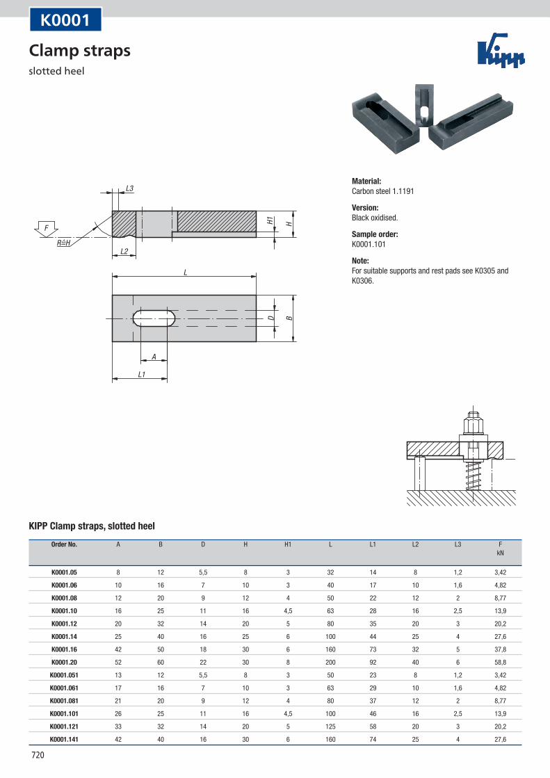
720
L1
L2
F
R=H^
L3
L
A
H1 HBD
K0001
KIPP Clamp straps, slotted heel
Order No. A B D H H1 L L1 L2 L3 F kN
K0001.05 8 12 5,5 8 3 32 14 8 1,2 3,42
K0001.06 10 16 7 10 3 40 17 10 1,6 4,82
K0001.08 12 20 9 12 4 50 22 12 2 8,77
K0001.10 16 25 11 16 4,5 63 28 16 2,5 13,9
K0001.12 20 32 14 20 5 80 35 20 3 20,2
K0001.14 25 40 16 25 6 100 44 25 4 27,6
K0001.16 42 50 18 30 6 160 73 32 5 37,8
K0001.20 52 60 22 30 8 200 92 40 6 58,8
K0001.051 13 12 5,5 8 3 50 23 8 1,2 3,42
K0001.061 17 16 7 10 3 63 29 10 1,6 4,82
K0001.081 21 20 9 12 4 80 37 12 2 8,77
K0001.101 26 25 11 16 4,5 100 46 16 2,5 13,9
K0001.121 33 32 14 20 5 125 58 20 3 20,2
K0001.141 42 40 16 30 6 160 74 25 4 27,6
Material:Carbon steel 1.1191
Version:Black oxidised.
Sample order:K0001.101
Note:For suitable supports and rest pads see K0305 and K0306.
Clamp straps slotted heel
721
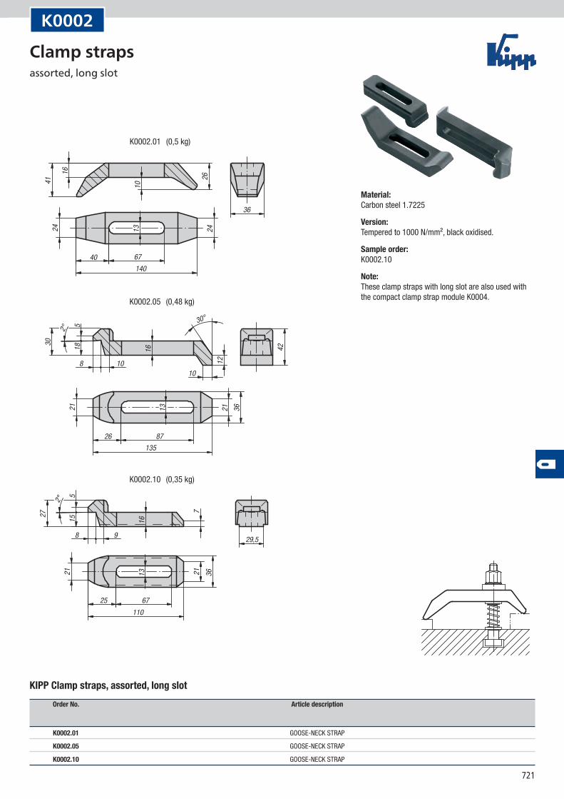
K0002.05
K0002.10
K0002.01
36
140
8 1010
8726135
30°
6740
2416
1013
2624
30
518 16
12
42
362113212°
41
8 9
25 67110
29,5
27
515 16
7
21 21 3613
2°
(0,48 kg)
(0,35 kg)
(0,5 kg)
K0002
KIPP Clamp straps, assorted, long slot
Order No. Article description
K0002.01 GOOSE-NECK STRAP
K0002.05 GOOSE-NECK STRAP
K0002.10 GOOSE-NECK STRAP
Material:Carbon steel 1.7225
Version:Tempered to 1000 N/mm², black oxidised.
Sample order:K0002.10
Note:These clamp straps with long slot are also used with the compact clamp strap module K0004.
Clamp straps assorted, long slot
722
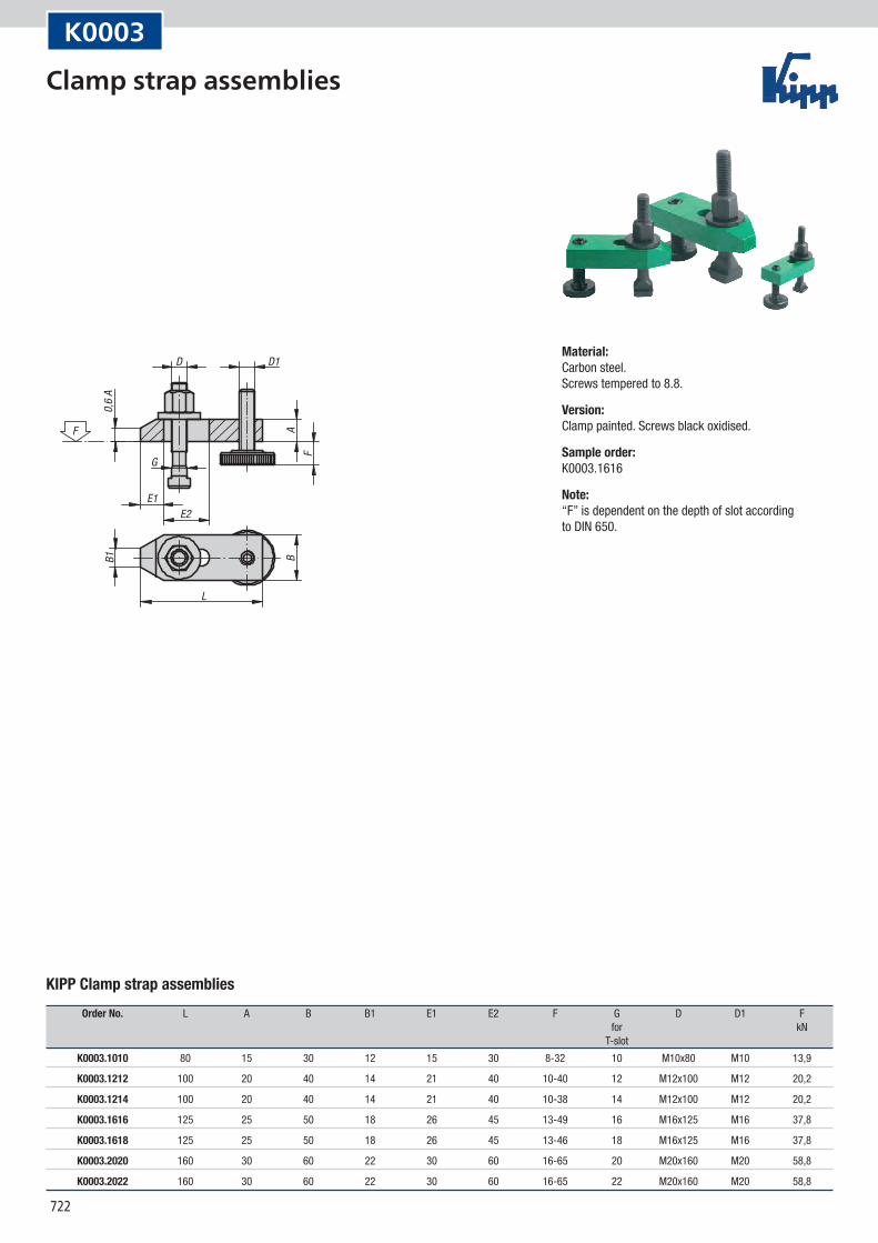
A
B1 B
0,6
A
F
D
G
E1
F
E2
L
D1
K0003
KIPP Clamp strap assemblies
Order No. L A B B1 E1 E2 F G D D1 F for kN T-slot
K0003.1010 80 15 30 12 15 30 8-32 10 M10x80 M10 13,9
K0003.1212 100 20 40 14 21 40 10-40 12 M12x100 M12 20,2
K0003.1214 100 20 40 14 21 40 10-38 14 M12x100 M12 20,2
K0003.1616 125 25 50 18 26 45 13-49 16 M16x125 M16 37,8
K0003.1618 125 25 50 18 26 45 13-46 18 M16x125 M16 37,8
K0003.2020 160 30 60 22 30 60 16-65 20 M20x160 M20 58,8
K0003.2022 160 30 60 22 30 60 16-65 22 M20x160 M20 58,8
Material:Carbon steel. Screws tempered to 8.8.
Version:Clamp painted. Screws black oxidised.
Sample order:K0003.1616
Note:“F” is dependent on the depth of slot according to DIN 650.
Clamp strap assemblies
723
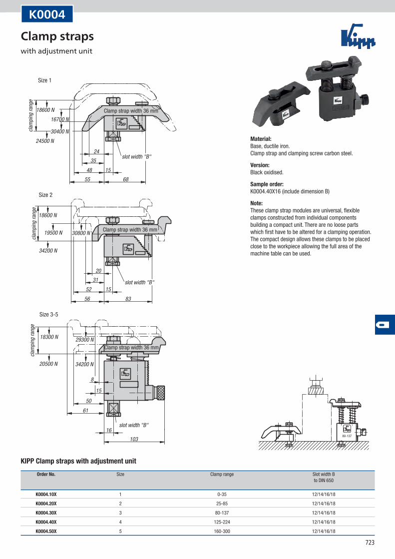
18600 N16700 N
30400 N24500 N
2435
48 1555 68
18600 N
19500 N
34200 N
30800 N
2031
52 1556 83
18300 N
20500 N
29300 N
34200 N
8
15
5061
16103
clam
ping r
ange
Clamp strap width 36 mm
slot width "B"
clam
ping r
ange
Clamp strap width 36 mm
slot width "B"
clam
ping r
ange
Clamp strap width 36 mm
slot width "B"
Size 3-5
Size 2
Size 1
80-137
K0004
KIPP Clamp straps with adjustment unit
Order No. Size Clamp range Slot width B to DIN 650
K0004.10X 1 0-35 12/14/16/18
K0004.20X 2 25-85 12/14/16/18
K0004.30X 3 80-137 12/14/16/18
K0004.40X 4 125-224 12/14/16/18
K0004.50X 5 160-300 12/14/16/18
Material:Base, ductile iron. Clamp strap and clamping screw carbon steel.
Version:Black oxidised.
Sample order:K0004.40X16 (include dimension B)
Note:These clamp strap modules are universal, flexible clamps constructed from individual components building a compact unit. There are no loose parts which first have to be altered for a clamping operation. The compact design allows these clamps to be placed close to the workpiece allowing the full area of the machine table can be used.
Clamp straps with adjustment unit
724
M1H13
L1+0,5
LD3
D2h1
1
D1f8
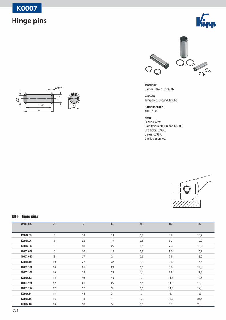
K0007
KIPP Hinge pins
Order No. D1 L L1 M1 D2 D3
K0007.05 5 18 13 0,7 4,8 10,7
K0007.06 6 22 17 0,8 5,7 12,2
K0007.08 8 30 25 0,9 7,6 15,2
K0007.081 8 20 16 0,9 7,6 15,2
K0007.082 8 27 21 0,9 7,6 15,2
K0007.10 10 37 32 1,1 9,6 17,6
K0007.101 10 25 20 1,1 9,6 17,6
K0007.102 10 35 29 1,1 9,6 17,6
K0007.12 12 46 40 1,1 11,5 19,6
K0007.121 12 31 25 1,1 11,5 19,6
K0007.122 12 37 31 1,1 11,5 19,6
K0007.14 14 44 37 1,1 13,4 22
K0007.16 16 48 41 1,1 15,2 24,4
K0007.18 18 58 51 1,3 17 26,8
Material:Carbon steel 1.0503.07
Version:Tempered. Ground, bright.
Sample order:K0007.08
Note:For use with: Cam levers K0008 and K0009. Eye bolts K0396. Clevis K0397. Circlips supplied.
Hinge pins
725
FH
LL1±0,3
H ±0
,6
H1 ±
0,3
R
B
D1
D H11
15°
30°
F
105°R1
base radiusbase radius
F (N)
F (N)H0
500
1000
1500
2000
2500
3000
3500
4000
4500
050 100 150 200 250
Force diagram
clamping force range
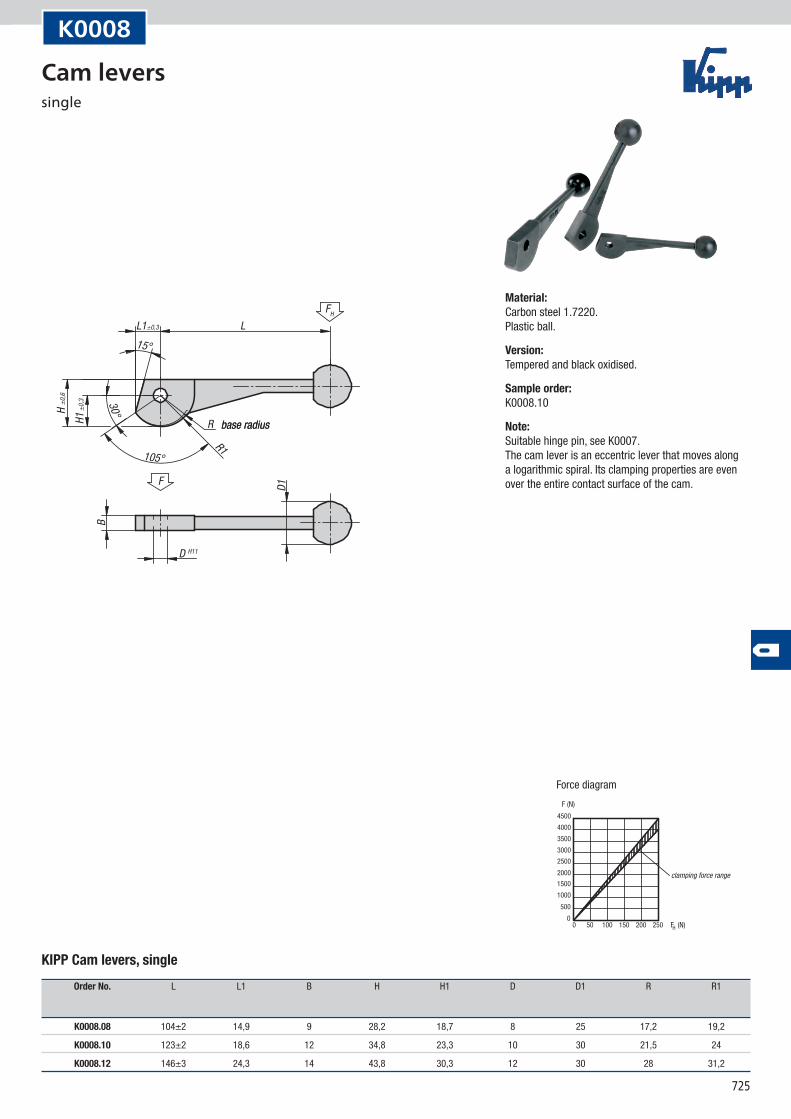
K0008
KIPP Cam levers, single
Order No. L L1 B H H1 D D1 R R1
K0008.08 104±2 14,9 9 28,2 18,7 8 25 17,2 19,2
K0008.10 123±2 18,6 12 34,8 23,3 10 30 21,5 24
K0008.12 146±3 24,3 14 43,8 30,3 12 30 28 31,2
Material:Carbon steel 1.7220. Plastic ball.
Version:Tempered and black oxidised.
Sample order:K0008.10
Note:Suitable hinge pin, see K0007. The cam lever is an eccentric lever that moves along a logarithmic spiral. Its clamping properties are even over the entire contact surface of the cam.
Cam levers single
726
FH
H1±0
,3
H±0
,6
L1 ±0,3 L
B1
B D1
D H11
F
R1
R
15°
30°
105°
base radius
F (N)
F (N)H0
500
1000
1500
2000
2500
3000
3500
4000
4500
050 100 150 200 250
Force diagram
clamping force range
K0009
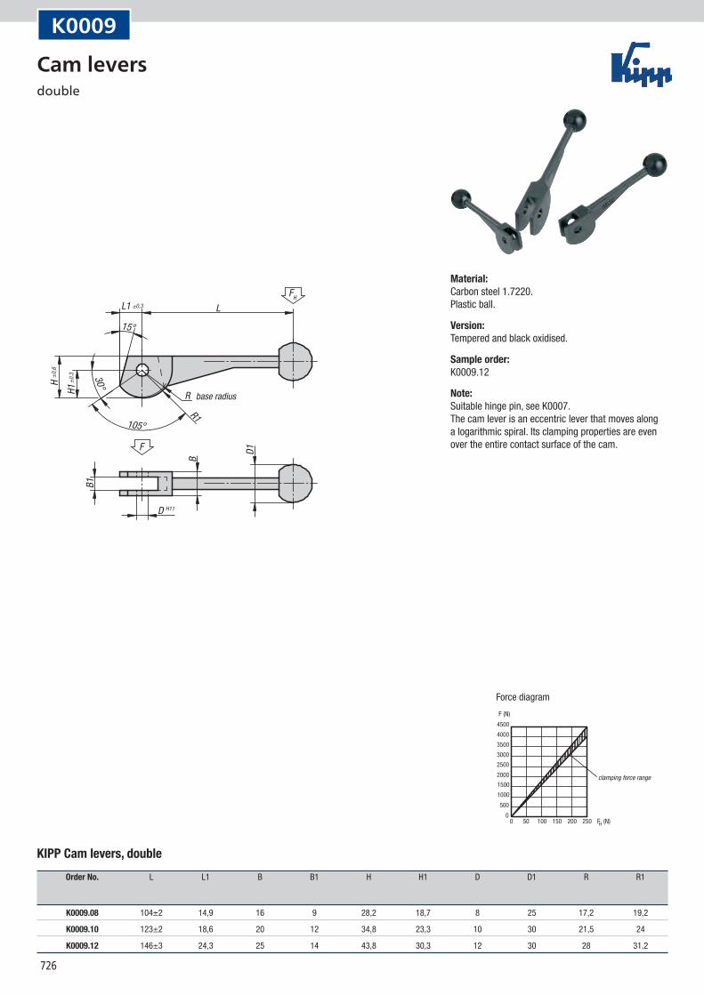
KIPP Cam levers, double
Order No. L L1 B B1 H H1 D D1 R R1
K0009.08 104±2 14,9 16 9 28,2 18,7 8 25 17,2 19,2
K0009.10 123±2 18,6 20 12 34,8 23,3 10 30 21,5 24
K0009.12 146±3 24,3 25 14 43,8 30,3 12 30 28 31,2
Material:Carbon steel 1.7220. Plastic ball.
Version:Tempered and black oxidised.
Sample order:K0009.12
Note:Suitable hinge pin, see K0007. The cam lever is an eccentric lever that moves along a logarithmic spiral. Its clamping properties are even over the entire contact surface of the cam.
Cam levers double
727
FH
L2 L1 LDSW
L4 A
F
H1,
5xD S 5
10
D1
H2
B1 BB2
L3
D2 for hexagon socket screw M6
H1 m
ax.
F (N)
F (N)H0
500100015002000250030003500400045005000
050 100 150 200 250
Force diagram
K0010
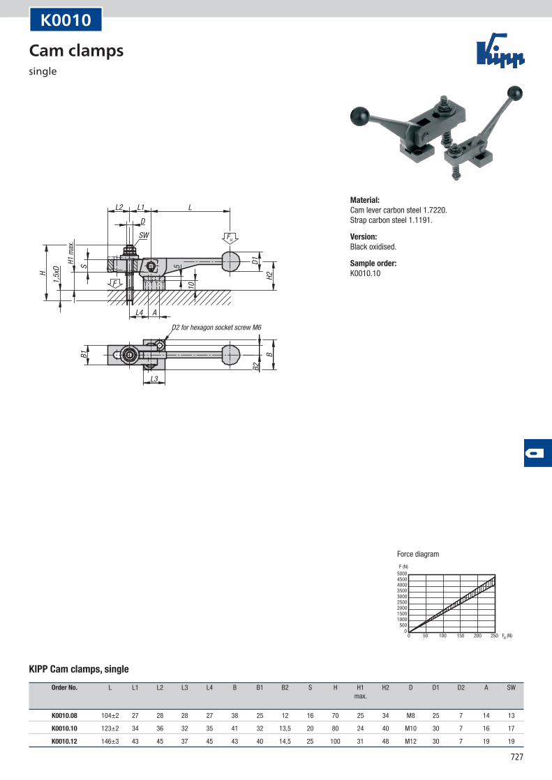
KIPP Cam clamps, single
Order No. L L1 L2 L3 L4 B B1 B2 S H H1 H2 D D1 D2 A SW max.
K0010.08 104±2 27 28 28 27 38 25 12 16 70 25 34 M8 25 7 14 13
K0010.10 123±2 34 36 32 35 41 32 13,5 20 80 24 40 M10 30 7 16 17
K0010.12 146±3 43 45 37 45 43 40 14,5 25 100 31 48 M12 30 7 19 19
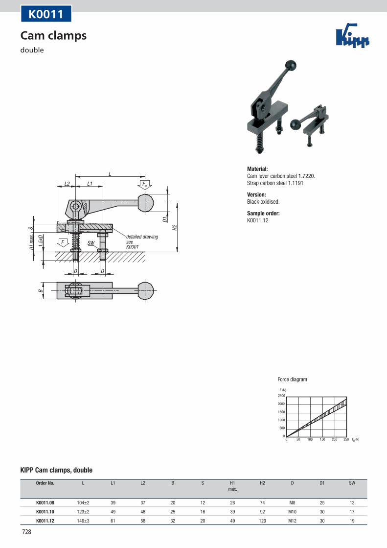
Material:Cam lever carbon steel 1.7220. Strap carbon steel 1.1191.
Version:Black oxidised.
Sample order:K0010.10
Cam clamps single
728
K0001
FH
LL2 L1
S1,
5xD
F SW
D D
D1H2
B
detailed drawingsee
H1 m
ax.
F (N)
F (N)H0
500
1000
1500
2000
2500
050 100 150 200 250
Force diagram
K0011
KIPP Cam clamps, double
Order No. L L1 L2 B S H1 H2 D D1 SW max.
K0011.08 104±2 39 37 20 12 28 74 M8 25 13
K0011.10 123±2 49 46 25 16 39 92 M10 30 17
K0011.12 146±3 61 58 32 20 49 120 M12 30 19
Material:Cam lever carbon steel 1.7220. Strap carbon steel 1.1191
Version:Black oxidised.
Sample order:K0011.12
Cam clamps double
729
Notes
730
D -0,10-0,02 D -0,10
-0,02
D2
D1 D1
H H
H1 H1
H2
D3 D3
3,2
3,2
F F
H3
R2 R2
H325°
25°
R R
R1 R1
B B
Form A Form B
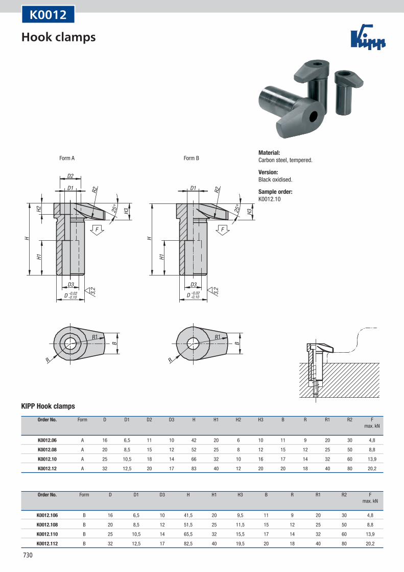
K0012
KIPP Hook clamps
Order No. Form D D1 D2 D3 H H1 H2 H3 B R R1 R2 F max. kN
K0012.06 A 16 6,5 11 10 42 20 6 10 11 9 20 30 4,8
K0012.08 A 20 8,5 15 12 52 25 8 12 15 12 25 50 8,8
K0012.10 A 25 10,5 18 14 66 32 10 16 17 14 32 60 13,9
K0012.12 A 32 12,5 20 17 83 40 12 20 20 18 40 80 20,2
Order No. Form D D1 D3 H H1 H3 B R R1 R2 F max. kN
K0012.106 B 16 6,5 10 41,5 20 9,5 11 9 20 30 4,8
K0012.108 B 20 8,5 12 51,5 25 11,5 15 12 25 50 8,8
K0012.110 B 25 10,5 14 65,5 32 15,5 17 14 32 60 13,9
K0012.112 B 32 12,5 17 82,5 40 19,5 20 18 40 80 20,2
Material:Carbon steel, tempered.
Version:Black oxidised.
Sample order:K0012.10
Hook clamps
731
D2
D1
D3
D -0,02-0,10
H
H1H2 H325
°
R2
R1
R
B
3,2
F
K0012
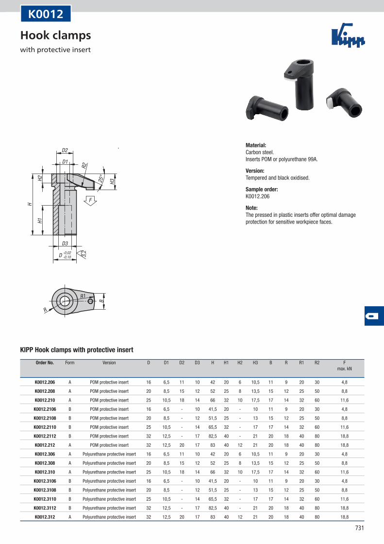
KIPP Hook clamps with protective insert
Order No. Form Version D D1 D2 D3 H H1 H2 H3 B R R1 R2 F max. kN
K0012.206 A POM protective insert 16 6,5 11 10 42 20 6 10,5 11 9 20 30 4,8
K0012.208 A POM protective insert 20 8,5 15 12 52 25 8 13,5 15 12 25 50 8,8
K0012.210 A POM protective insert 25 10,5 18 14 66 32 10 17,5 17 14 32 60 11,6
K0012.2106 B POM protective insert 16 6,5 - 10 41,5 20 - 10 11 9 20 30 4,8
K0012.2108 B POM protective insert 20 8,5 - 12 51,5 25 - 13 15 12 25 50 8,8
K0012.2110 B POM protective insert 25 10,5 - 14 65,5 32 - 17 17 14 32 60 11,6
K0012.2112 B POM protective insert 32 12,5 - 17 82,5 40 - 21 20 18 40 80 18,8
K0012.212 A POM protective insert 32 12,5 20 17 83 40 12 21 20 18 40 80 18,8
K0012.306 A Polyurethane protective insert 16 6,5 11 10 42 20 6 10,5 11 9 20 30 4,8
K0012.308 A Polyurethane protective insert 20 8,5 15 12 52 25 8 13,5 15 12 25 50 8,8
K0012.310 A Polyurethane protective insert 25 10,5 18 14 66 32 10 17,5 17 14 32 60 11,6
K0012.3106 B Polyurethane protective insert 16 6,5 - 10 41,5 20 - 10 11 9 20 30 4,8
K0012.3108 B Polyurethane protective insert 20 8,5 - 12 51,5 25 - 13 15 12 25 50 8,8
K0012.3110 B Polyurethane protective insert 25 10,5 - 14 65,5 32 - 17 17 14 32 60 11,6
K0012.3112 B Polyurethane protective insert 32 12,5 - 17 82,5 40 - 21 20 18 40 80 18,8
K0012.312 A Polyurethane protective insert 32 12,5 20 17 83 40 12 21 20 18 40 80 18,8
Material:Carbon steel. Inserts POM or polyurethane 99A.
Version:Tempered and black oxidised.
Sample order:K0012.206
Note:The pressed in plastic inserts offer optimal damage protection for sensitive workpiece faces.
Hook clamps with protective insert
732
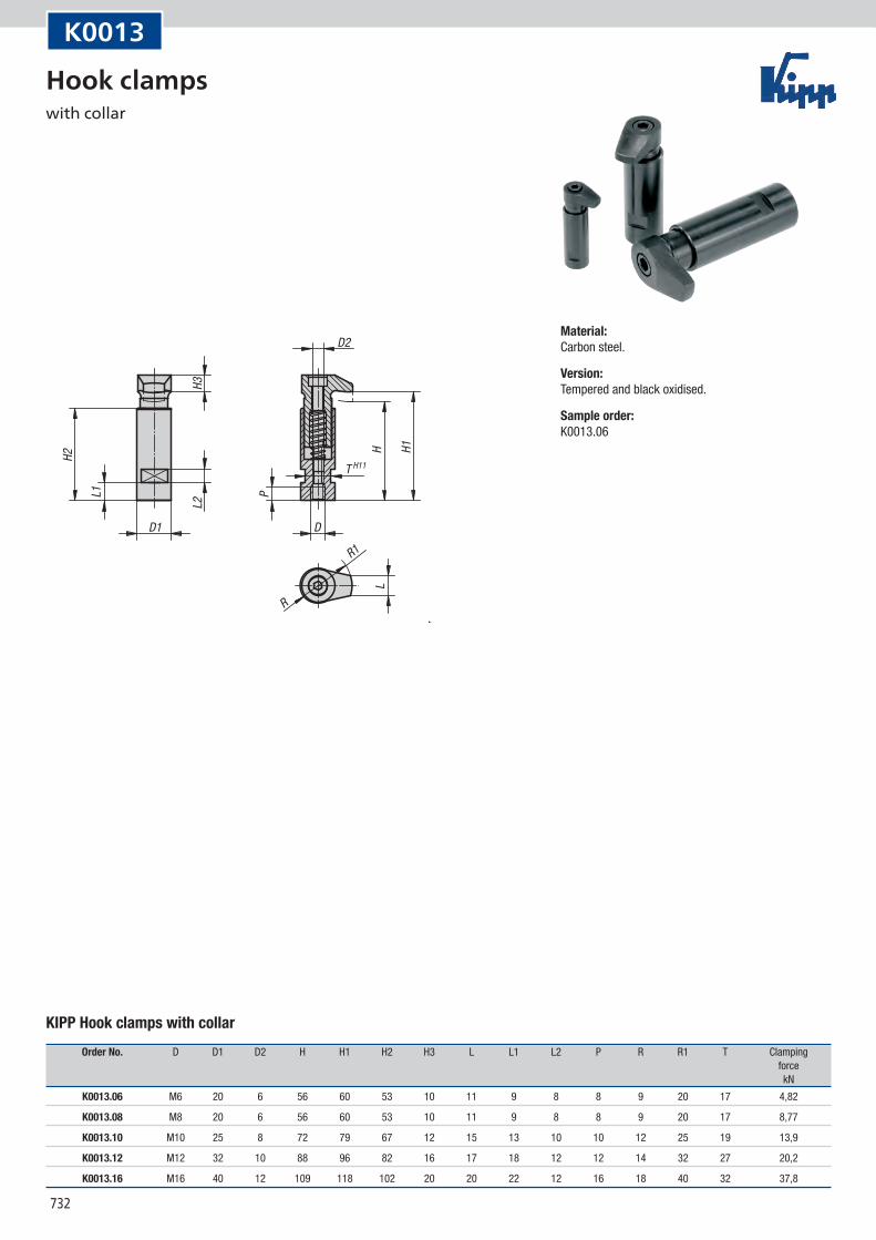
T H11
D
D2
D1
L1 P
R
R1
L2
L
H1H2
H3
H
K0013
KIPP Hook clamps with collar
Order No. D D1 D2 H H1 H2 H3 L L1 L2 P R R1 T Clamping force kN
K0013.06 M6 20 6 56 60 53 10 11 9 8 8 9 20 17 4,82
K0013.08 M8 20 6 56 60 53 10 11 9 8 8 9 20 17 8,77
K0013.10 M10 25 8 72 79 67 12 15 13 10 10 12 25 19 13,9
K0013.12 M12 32 10 88 96 82 16 17 18 12 12 14 32 27 20,2
K0013.16 M16 40 12 109 118 102 20 20 22 12 16 18 40 32 37,8
Material:Carbon steel.
Version:Tempered and black oxidised.
Sample order:K0013.06
Hook clamps with collar
733
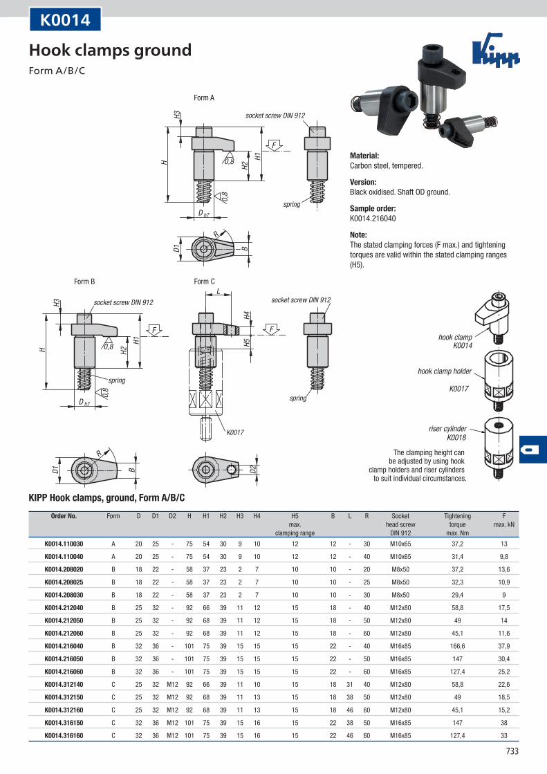
K0017
D h7
H
H
H3
H3
0,8
0,8
0,8
0,8
D h7
H2
H2
H1
H1F
F F
D1
D1
R
R
B
B
L
H4H5
D2
spring
socket screw DIN 912socket screw DIN 912
spring
spring
socket screw DIN 912
Form A
Form B Form C
K0014
K0017
K0018
hook clamp
hook clamp holder
riser cylinder
The clamping height can be adjusted by using hook
clamp holders and riser cylinders to suit individual circumstances.
K0014
KIPP Hook clamps, ground, Form A/B/C
Order No. Form D D1 D2 H H1 H2 H3 H4 H5 B L R Socket Tightening F max. head screw torque max. kN clamping range DIN 912 max. Nm
K0014.110030 A 20 25 - 75 54 30 9 10 12 12 - 30 M10x65 37,2 13
K0014.110040 A 20 25 - 75 54 30 9 10 12 12 - 40 M10x65 31,4 9,8
K0014.208020 B 18 22 - 58 37 23 2 7 10 10 - 20 M8x50 37,2 13,6
K0014.208025 B 18 22 - 58 37 23 2 7 10 10 - 25 M8x50 32,3 10,9
K0014.208030 B 18 22 - 58 37 23 2 7 10 10 - 30 M8x50 29,4 9
K0014.212040 B 25 32 - 92 66 39 11 12 15 18 - 40 M12x80 58,8 17,5
K0014.212050 B 25 32 - 92 68 39 11 12 15 18 - 50 M12x80 49 14
K0014.212060 B 25 32 - 92 68 39 11 12 15 18 - 60 M12x80 45,1 11,6
K0014.216040 B 32 36 - 101 75 39 15 15 15 22 - 40 M16x85 166,6 37,9
K0014.216050 B 32 36 - 101 75 39 15 15 15 22 - 50 M16x85 147 30,4
K0014.216060 B 32 36 - 101 75 39 15 15 15 22 - 60 M16x85 127,4 25,2
K0014.312140 C 25 32 M12 92 66 39 11 10 15 18 31 40 M12x80 58,8 22,6
K0014.312150 C 25 32 M12 92 68 39 11 13 15 18 38 50 M12x80 49 18,5
K0014.312160 C 25 32 M12 92 68 39 11 13 15 18 46 60 M12x80 45,1 15,2
K0014.316150 C 32 36 M12 101 75 39 15 16 15 22 38 50 M16x85 147 38
K0014.316160 C 32 36 M12 101 75 39 15 16 15 22 46 60 M16x85 127,4 33
Material:Carbon steel, tempered.
Version:Black oxidised. Shaft OD ground.
Sample order:K0014.216040
Note:The stated clamping forces (F max.) and tightening torques are valid within the stated clamping ranges (H5).
Hook clamps ground Form A/B/C
734
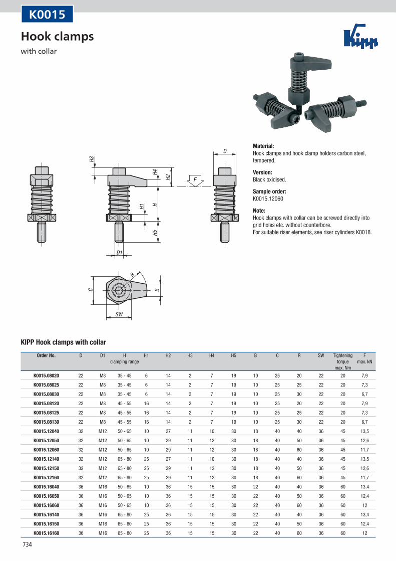
C
D
D1
SW
R
F
B
H1
H2
H3
H4H5
H
K0015
KIPP Hook clamps with collar
Order No. D D1 H H1 H2 H3 H4 H5 B C R SW Tightening F clamping range torque max. kN max. Nm
K0015.08020 22 M8 35 - 45 6 14 2 7 19 10 25 20 22 20 7,9
K0015.08025 22 M8 35 - 45 6 14 2 7 19 10 25 25 22 20 7,3
K0015.08030 22 M8 35 - 45 6 14 2 7 19 10 25 30 22 20 6,7
K0015.08120 22 M8 45 - 55 16 14 2 7 19 10 25 20 22 20 7,9
K0015.08125 22 M8 45 - 55 16 14 2 7 19 10 25 25 22 20 7,3
K0015.08130 22 M8 45 - 55 16 14 2 7 19 10 25 30 22 20 6,7
K0015.12040 32 M12 50 - 65 10 27 11 10 30 18 40 40 36 45 13,5
K0015.12050 32 M12 50 - 65 10 29 11 12 30 18 40 50 36 45 12,6
K0015.12060 32 M12 50 - 65 10 29 11 12 30 18 40 60 36 45 11,7
K0015.12140 32 M12 65 - 80 25 27 11 10 30 18 40 40 36 45 13,5
K0015.12150 32 M12 65 - 80 25 29 11 12 30 18 40 50 36 45 12,6
K0015.12160 32 M12 65 - 80 25 29 11 12 30 18 40 60 36 45 11,7
K0015.16040 36 M16 50 - 65 10 36 15 15 30 22 40 40 36 60 13,4
K0015.16050 36 M16 50 - 65 10 36 15 15 30 22 40 50 36 60 12,4
K0015.16060 36 M16 50 - 65 10 36 15 15 30 22 40 60 36 60 12
K0015.16140 36 M16 65 - 80 25 36 15 15 30 22 40 40 36 60 13,4
K0015.16150 36 M16 65 - 80 25 36 15 15 30 22 40 50 36 60 12,4
K0015.16160 36 M16 65 - 80 25 36 15 15 30 22 40 60 36 60 12
Material:Hook clamps and hook clamp holders carbon steel, tempered.
Version:Black oxidised.
Sample order:K0015.12060
Note:Hook clamps with collar can be screwed directly into grid holes etc. without counterbore. For suitable riser elements, see riser cylinders K0018.
Hook clamps with collar
735
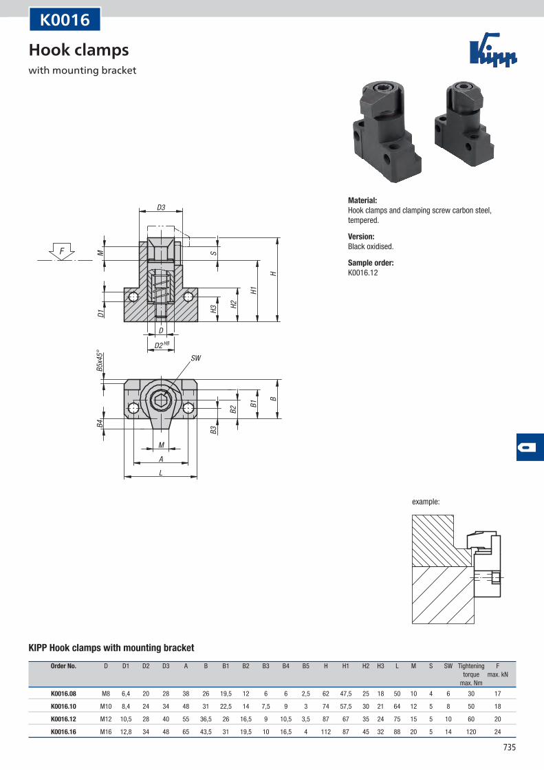
D1
B1
B2
B3
B
SH3 H2
H1
H
B4B5
x45°
M
D
SW
M
F
AL
D2 H8
D3
example:
K0016
KIPP Hook clamps with mounting bracket
Order No. D D1 D2 D3 A B B1 B2 B3 B4 B5 H H1 H2 H3 L M S SW Tightening F torque max. kN max. Nm
K0016.08 M8 6,4 20 28 38 26 19,5 12 6 6 2,5 62 47,5 25 18 50 10 4 6 30 17
K0016.10 M10 8,4 24 34 48 31 22,5 14 7,5 9 3 74 57,5 30 21 64 12 5 8 50 18
K0016.12 M12 10,5 28 40 55 36,5 26 16,5 9 10,5 3,5 87 67 35 24 75 15 5 10 60 20
K0016.16 M16 12,8 34 48 65 43,5 31 19,5 10 16,5 4 112 87 45 32 88 20 5 14 120 24
Material:Hook clamps and clamping screw carbon steel, tempered.
Version:Black oxidised.
Sample order:K0016.12
Hook clamps with mounting bracket
736
D F7
D1
D2
D3
SW
L1
L2L3
L
K0017
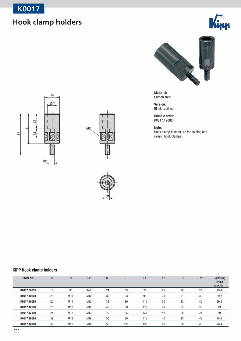
KIPP Hook clamp holders
Order No. D D1 D2 D3 L L1 L2 L3 SW Tightening torque max. Nm
K0017.08055 18 M8 M8 24 55 74 25 20 22 29,4
K0017.10063 20 M10 M12 32 63 93 30 21 30 39,2
K0017.10080 20 M10 M12 32 80 110 30 23 30 39,2
K0017.12080 25 M12 M12 40 80 110 40 25 36 49
K0017.12100 25 M12 M12 40 100 130 40 28 36 49
K0017.16080 32 M16 M16 50 80 110 40 25 46 78,4
K0017.16100 32 M16 M16 50 100 130 40 28 46 78,4
Material:Carbon steel.
Version:Black oxidised.
Sample order:K0017.12080
Note:Hook clamp holders are for holding and raising hook clamps.
Hook clamp holders
737
SW
D1
D2
D3
L1
L2
L
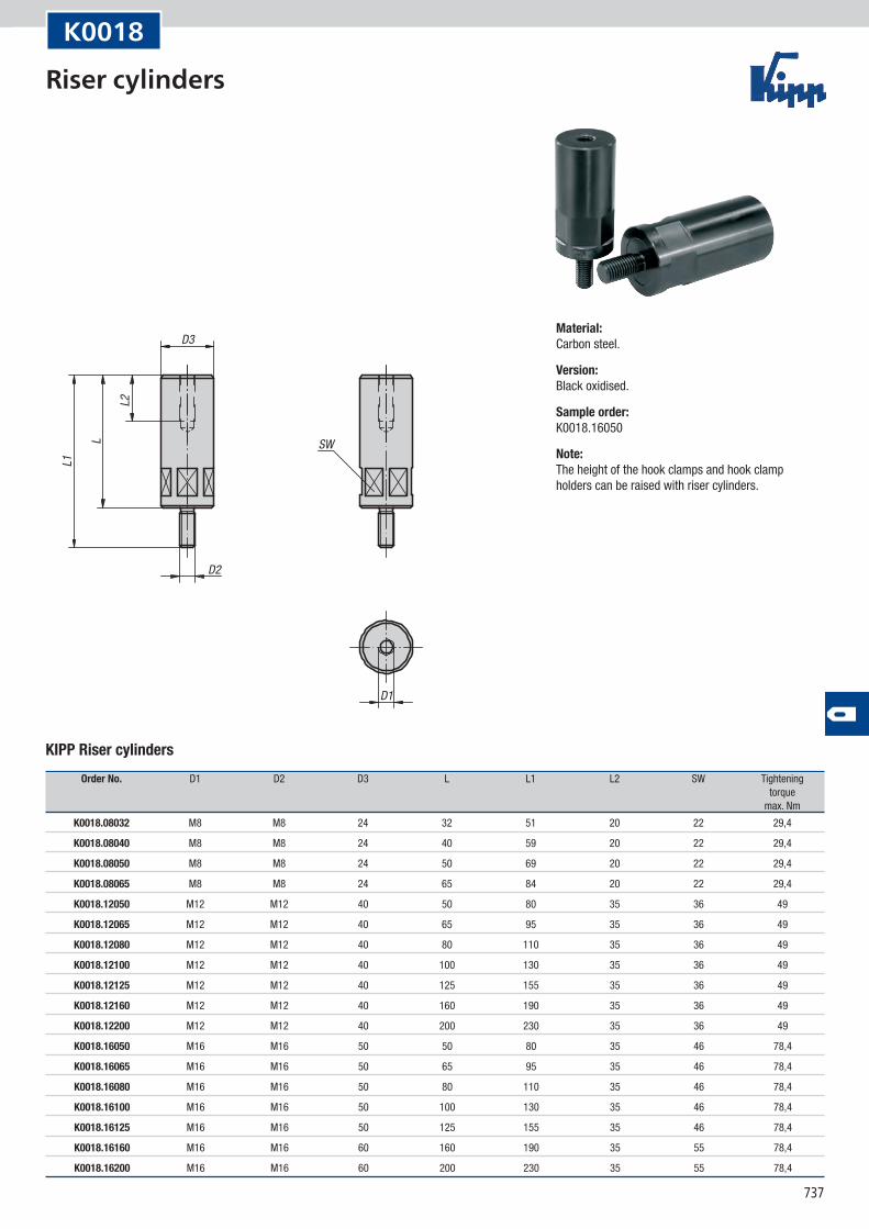
K0018
KIPP Riser cylinders
Order No. D1 D2 D3 L L1 L2 SW Tightening torque max. Nm
K0018.08032 M8 M8 24 32 51 20 22 29,4
K0018.08040 M8 M8 24 40 59 20 22 29,4
K0018.08050 M8 M8 24 50 69 20 22 29,4
K0018.08065 M8 M8 24 65 84 20 22 29,4
K0018.12050 M12 M12 40 50 80 35 36 49
K0018.12065 M12 M12 40 65 95 35 36 49
K0018.12080 M12 M12 40 80 110 35 36 49
K0018.12100 M12 M12 40 100 130 35 36 49
K0018.12125 M12 M12 40 125 155 35 36 49
K0018.12160 M12 M12 40 160 190 35 36 49
K0018.12200 M12 M12 40 200 230 35 36 49
K0018.16050 M16 M16 50 50 80 35 46 78,4
K0018.16065 M16 M16 50 65 95 35 46 78,4
K0018.16080 M16 M16 50 80 110 35 46 78,4
K0018.16100 M16 M16 50 100 130 35 46 78,4
K0018.16125 M16 M16 50 125 155 35 46 78,4
K0018.16160 M16 M16 60 160 190 35 55 78,4
K0018.16200 M16 M16 60 200 230 35 55 78,4
Material:Carbon steel.
Version:Black oxidised.
Sample order:K0018.16050
Note:The height of the hook clamps and hook clamp holders can be raised with riser cylinders.
Riser cylinders
738
L
Ø63
Ø50
Ø45
650
,5 50
M16
F
Ø25
20
M12
appr
ox. 2
512
5 m
ax.
16 max
.
example:example:
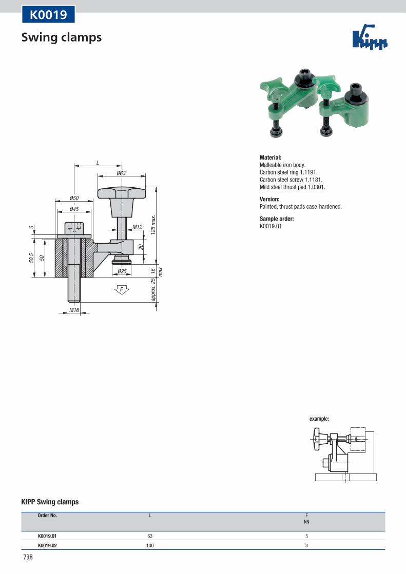
K0019
KIPP Swing clamps
Order No. L F kN
K0019.01 63 5
K0019.02 100 3
Material:Malleable iron body. Carbon steel ring 1.1191. Carbon steel screw 1.1181. Mild steel thrust pad 1.0301.
Version:Painted, thrust pads case-hardened.
Sample order:K0019.01
Swing clamps

739
Notes
740
Ø46
M6
60°
90°
60°
45°
25° 25°
120
Ø28
Ø55Ø1
4 H8
Ø14 H
8
Ø37
Ø14
26
34,59
46,5
54,510
2
45°
65°25°
4°30
'
10
2
F
10
2
F
clamp traveltravel path
travel path
travel path
start pointright hand type
end point right hand type
start point left hand typeend point
left hand type
self-locking clamp travel
pres
sure
bush
, axia
l mov
emen
t only
drilled throughwith transverse
axis in bore
clamping curve
push pull
View from below
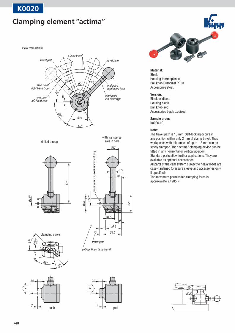
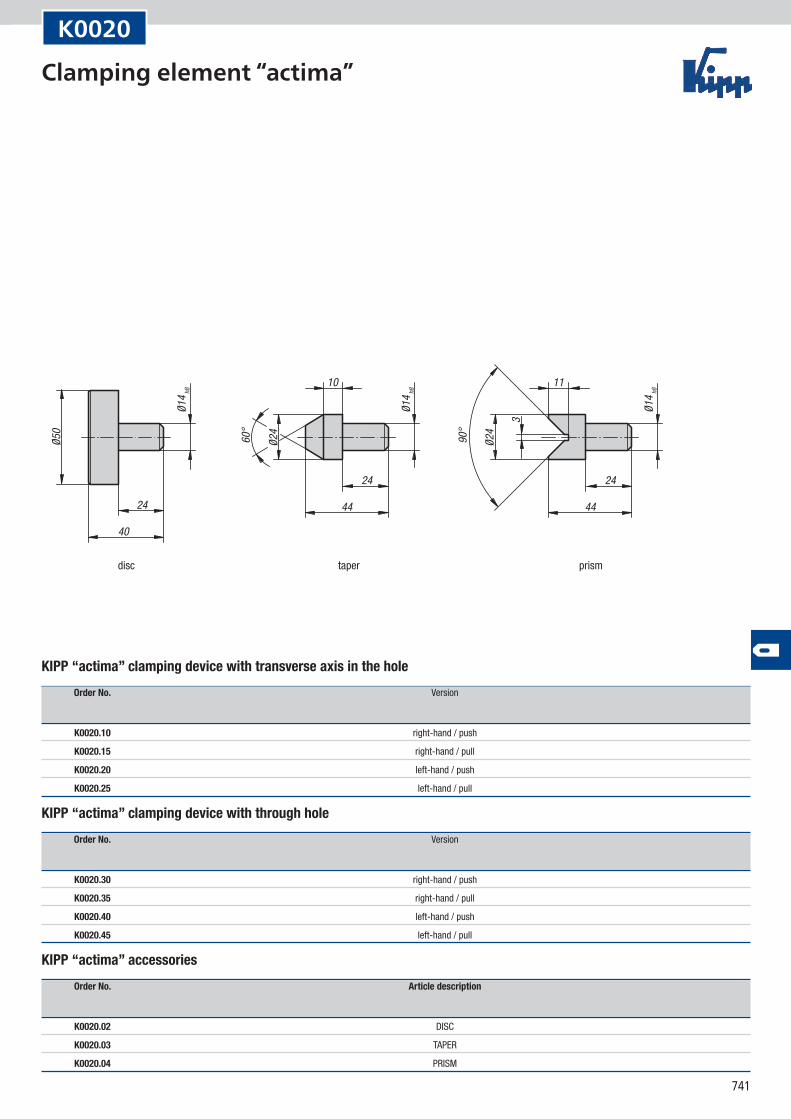
K0020
Material:Steel. Housing thermoplastic. Ball knob Duroplast PF 31. Accessories steel.
Version:Black oxidised. Housing black. Ball knob, red. Accessories black oxidised.
Sample order:K0020.10
Note:The travel path is 10 mm. Self-locking occurs in any position within only 2 mm of clamp travel. Thus workpieces with tolerances of up to 1.5 mm can be safely clamped. The “actima” clamping device can be fitted in any horizontal or vertical position. Standard parts allow further applications. They are available as optional accessories. All parts of the cam system subject to heavy loads are case-hardened (pressure sleeve and accessories only if specified). The maximum permissible clamping force is approximately 4905 N.
Clamping element “actima”
741
Ø50
40
24
Ø14 h8
Ø14 h8
Ø14 h8
60°
90°
Ø24
Ø24
10 11
24
44
24
443
disc taper prism
K0020
KIPP “actima” clamping device with transverse axis in the hole
Order No. Version
K0020.10 right-hand / push
K0020.15 right-hand / pull
K0020.20 left-hand / push
K0020.25 left-hand / pull
KIPP “actima” clamping device with through hole
Order No. Version
K0020.30 right-hand / push
K0020.35 right-hand / pull
K0020.40 left-hand / push
K0020.45 left-hand / pull
KIPP “actima” accessories
Order No. Article description
K0020.02 DISC
K0020.03 TAPER
K0020.04 PRISM
Clamping element “actima”
742
10
4
1,5
11,5
74
28 2
F
12
6 10
3
4
M8Ø1
1-0,1
-0,2
18 20
20 18
46° 64°
R85
46°
64°
clamp travel travel path
travel pathself-locking clamp travel
tension cam
K0021
Material:Steel. Ball knob Duroplast PF 31
Version:Housing painted silver-grey hammertone. All other parts and accessories black oxidised. Ball knob red.
Sample order:K0021.01
Note:The travel path is 12 mm. Self-locking occurs in any position within only 1.5 mm of clamp travel, allowing workpieces with tolerances of up to 1 mm to be securely clamped. The “arness” clamping element can be fitted in any horizontal or vertical position. Several standard parts have been developed to achieve individual adaptation for various circumstances and are available as optional accessories. The thrust pad and all parts of the cam system subject to heavy loads are case-hardened. The maximum permissible clamping force is approximately 4905 N.
Clamping element “arness”
KIPP Clamping element “arness”
Order No. Dimensions
K0021.01 see drawing
743
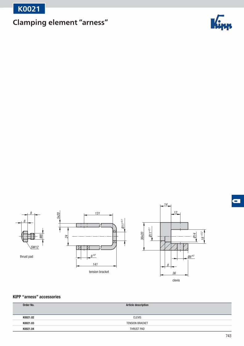
9
8
SW12
M8
5x20 131
24
8 H7
141
Ø11+0
,1
12
14
36x2
0
Ø11+0
,1
36
8
Ø8 H7
Ø14
18 +0
,2
thrust pad
tension bracket
clevis
K0021
KIPP “arness” accessories
Order No. Article description
K0021.02 CLEVIS
K0021.03 TENSION BRACKET
K0021.04 THRUST PAD
Clamping element “arness”
744
D D1
SW
H AL
S1
D1 m
in.
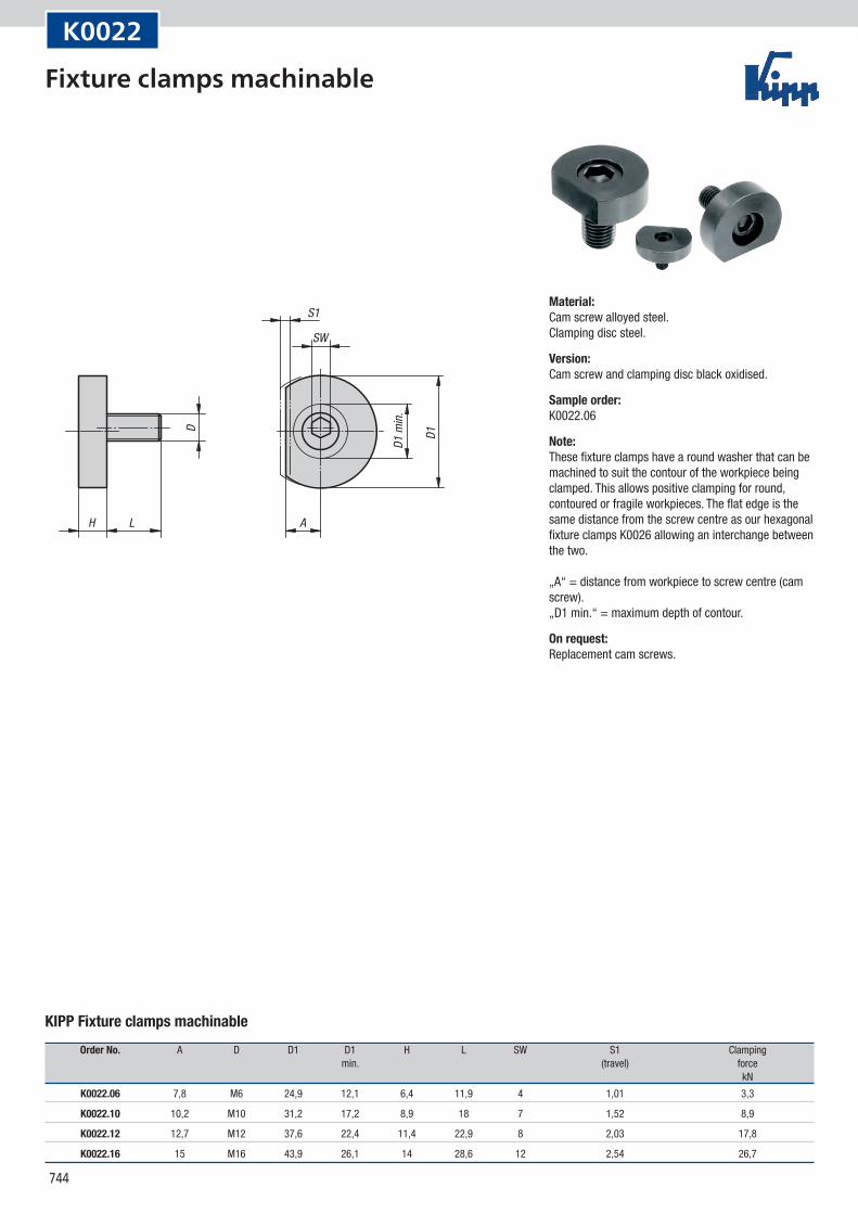
K0022
KIPP Fixture clamps machinable
Order No. A D D1 D1 H L SW S1 Clamping min. (travel) force kN
K0022.06 7,8 M6 24,9 12,1 6,4 11,9 4 1,01 3,3
K0022.10 10,2 M10 31,2 17,2 8,9 18 7 1,52 8,9
K0022.12 12,7 M12 37,6 22,4 11,4 22,9 8 2,03 17,8
K0022.16 15 M16 43,9 26,1 14 28,6 12 2,54 26,7
Material:Cam screw alloyed steel. Clamping disc steel.
Version:Cam screw and clamping disc black oxidised.
Sample order:K0022.06
Note:These fixture clamps have a round washer that can be machined to suit the contour of the workpiece being clamped. This allows positive clamping for round, contoured or fragile workpieces. The flat edge is the same distance from the screw centre as our hexagonal fixture clamps K0026 allowing an interchange between the two. „A“ = distance from workpiece to screw centre (cam screw). „D1 min.“ = maximum depth of contour.
On request:Replacement cam screws.
Fixture clamps machinable
745
D
AS
H1H
Form Asmooth
Form Bserrated
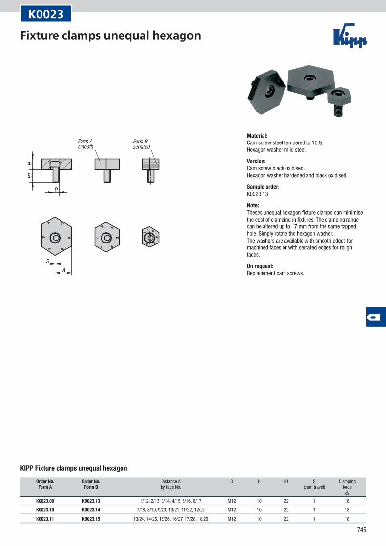
K0023
KIPP Fixture clamps unequal hexagon
Order No. Order No. Distance A D H H1 S Clamping Form A Form B by face No. (cam travel) force kN
K0023.09 K0023.13 1/12, 2/13, 3/14, 4/15, 5/16, 6/17 M12 10 22 1 18
K0023.10 K0023.14 7/18, 8/19, 9/20, 10/21, 11/22, 12/23 M12 10 22 1 18
K0023.11 K0023.15 13/24, 14/25, 15/26, 16/27, 17/28, 18/29 M12 10 22 1 18
Material:Cam screw steel tempered to 10.9. Hexagon washer mild steel.
Version:Cam screw black oxidised. Hexagon washer hardened and black oxidised.
Sample order:K0023.13
Note:Theses unequal hexagon fixture clamps can minimise the cost of clamping in fixtures. The clamping range can be altered up to 17 mm from the same tapped hole. Simply rotate the hexagon washer. The washers are available with smooth edges for machined faces or with serrated edges for rough faces.
On request:Replacement cam screws.
Fixture clamps unequal hexagon
746
LH
D
30°
SW
A
A2
A1
S1
X
Z ±0,2
W
mounting dimensions
clamping sheet metal clamping round parts
D1 max.
max
. ½ W
K0024
KIPP Spiral cam screws
Order No. A A1 A2 D D1 H L SW S1 X Z Clamping Tightening max. (travel) force torque kN max. Nm
K0024.0408 3 4,6 4 M4 9,2 3 8 2,5 0,6 3,5 4,2 0,09 1,5
K0024.0510 3,5 5,7 5 M5 11,4 4 10 3 0,7 4,2 5,2 0,1 2
K0024.0612 4,5 7,1 6,1 M6 14,2 5 12 4 1 5,4 6,4 0,3 4,5
K0024.0816 5,5 8,9 7,7 M8 18 6 16 5 1,2 6,6 8 2,7 20
K0024.1020 6,5 11,1 9,4 M10 22,2 7 20 6 1,7 8,3 9,8 4 30
K0024.1224 8 13,5 11,6 M12 27 9 24 8 1,9 10,1 12 5,4 44
Material:Steel.
Version:Case-hardened (56 ±1 HRC) and blue galvanized. Grade 8.8
Sample order:K0024.0408
Note:Robust, compact spiral cam clamping screws that exert a positive down force on diverse workpiece forms.
Assembly:Drill and tap several holes at a distance X or Z (see diagram). Screw the cam screw into the required height and position with the flat side to the workpiece. Position the workpiece and tighten the cam screw with a hexagon key. Full clamping is achieved with approximately a 1/3 rotation. Lubricate the tapped hole regularly. Place stops on the face towards which the screw turns to prevent the workpiece rotating away.
On request:Spiral cam screws with LH thread.
Spiral cam screws
747
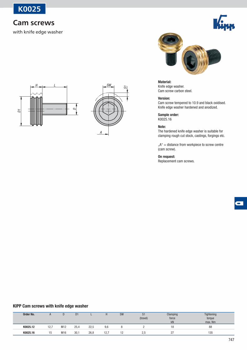
A
LH SW
D
D1
S1
K0025
KIPP Cam screws with knife edge washer
Order No. A D D1 L H SW S1 Clamping Tightening (travel) force torque kN max. Nm
K0025.12 12,7 M12 25,4 22,5 9,6 8 2 18 88
K0025.16 15 M16 30,1 26,8 12,7 12 2,5 27 135
Material:Knife edge washer. Cam screw carbon steel.
Version:Cam screw tempered to 10.9 and black oxidised. Knife edge washer hardened and anodized.
Sample order:K0025.16
Note:The hardened knife edge washer is suitable for clamping rough cut stock, castings, forgings etc. „A“ = distance from workpiece to screw centre (cam screw).
On request:Replacement cam screws.
Cam screws with knife edge washer
748
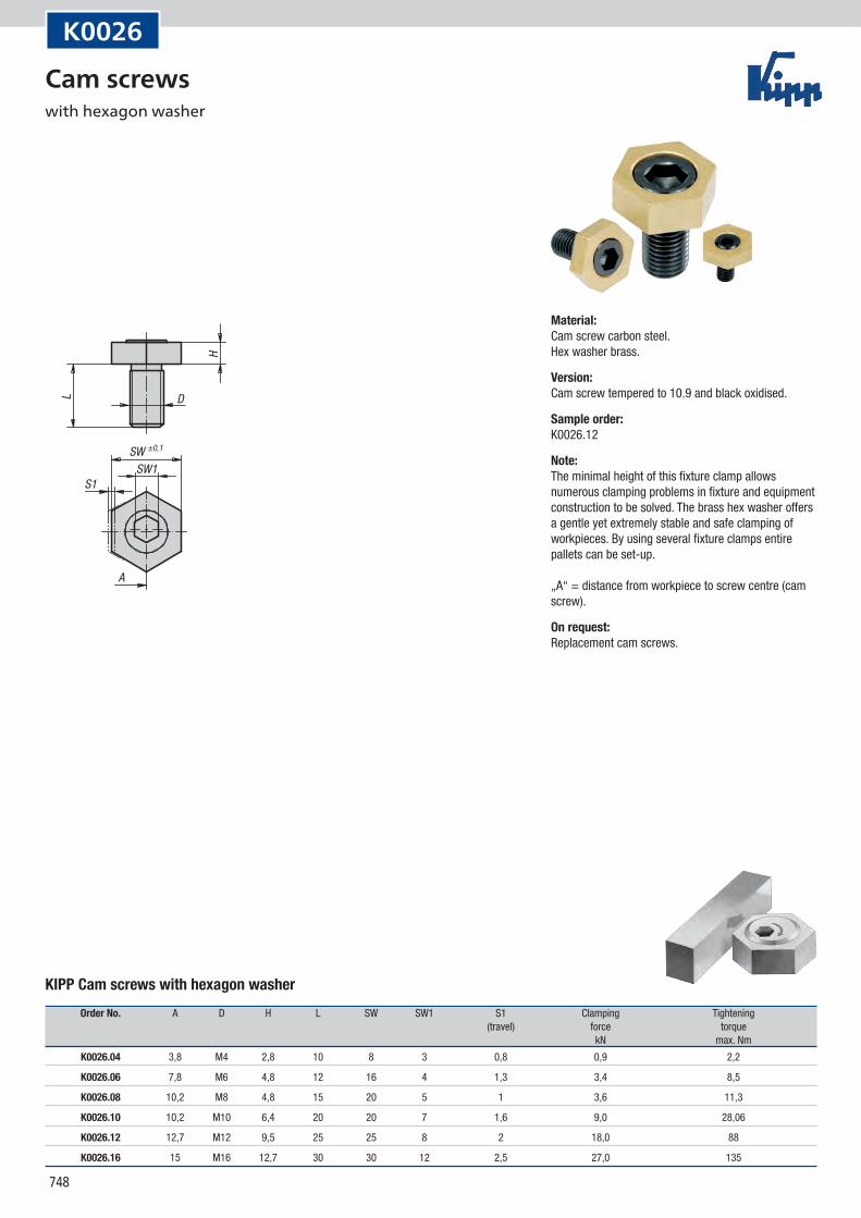
SW ±0,1
SW1S1
DL
H
A
K0026
KIPP Cam screws with hexagon washer
Order No. A D H L SW SW1 S1 Clamping Tightening (travel) force torque kN max. Nm
K0026.04 3,8 M4 2,8 10 8 3 0,8 0,9 2,2
K0026.06 7,8 M6 4,8 12 16 4 1,3 3,4 8,5
K0026.08 10,2 M8 4,8 15 20 5 1 3,6 11,3
K0026.10 10,2 M10 6,4 20 20 7 1,6 9,0 28,06
K0026.12 12,7 M12 9,5 25 25 8 2 18,0 88
K0026.16 15 M16 12,7 30 30 12 2,5 27,0 135
Material:Cam screw carbon steel. Hex washer brass.
Version:Cam screw tempered to 10.9 and black oxidised.
Sample order:K0026.12
Note:The minimal height of this fixture clamp allows numerous clamping problems in fixture and equipment construction to be solved. The brass hex washer offers a gentle yet extremely stable and safe clamping of workpieces. By using several fixture clamps entire pallets can be set-up. „A“ = distance from workpiece to screw centre (cam screw).
On request:Replacement cam screws.
Cam screws with hexagon washer
749
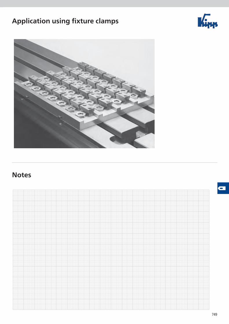
Application using fixture clamps
Notes
750
H1
H
H2
D
SW
N
L
S1
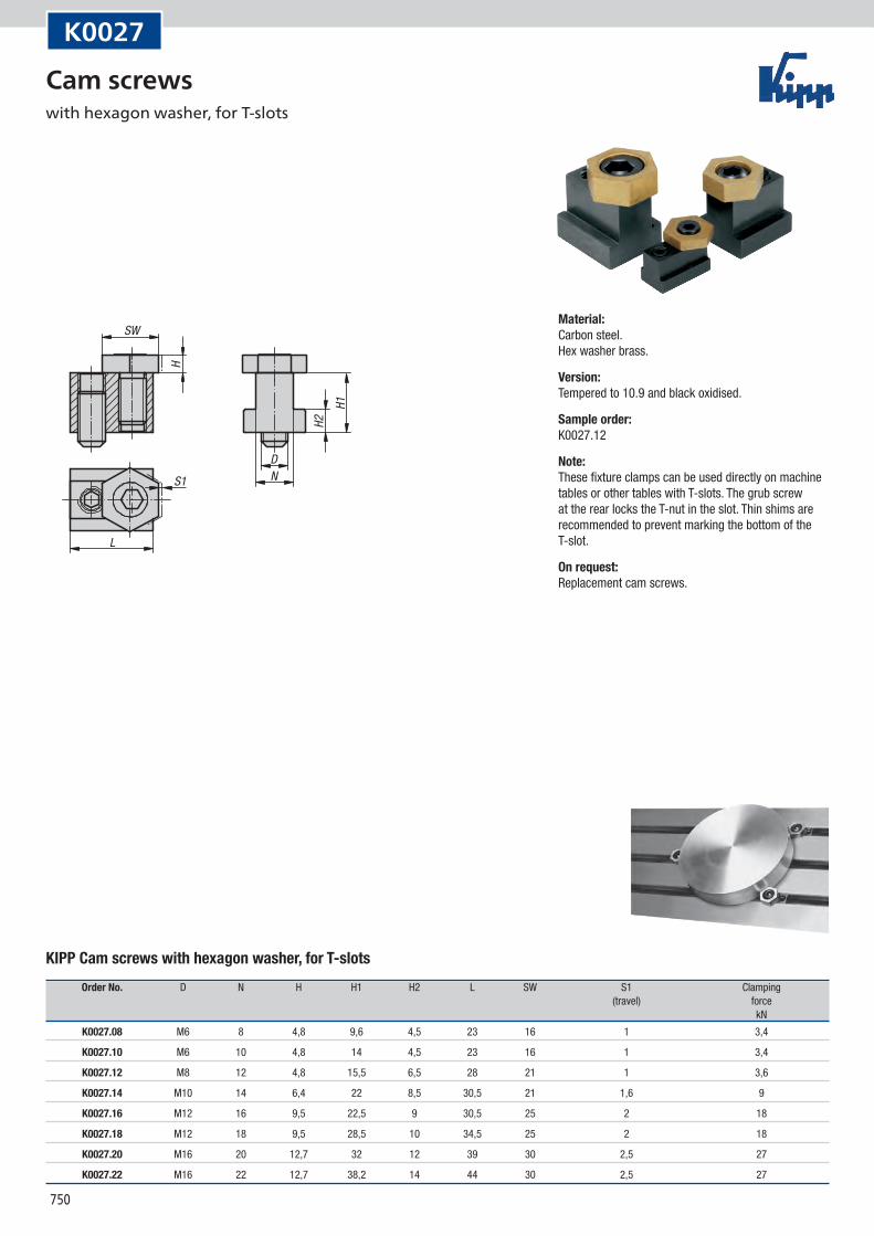
K0027
KIPP Cam screws with hexagon washer, for T-slots
Order No. D N H H1 H2 L SW S1 Clamping (travel) force kN
K0027.08 M6 8 4,8 9,6 4,5 23 16 1 3,4
K0027.10 M6 10 4,8 14 4,5 23 16 1 3,4
K0027.12 M8 12 4,8 15,5 6,5 28 21 1 3,6
K0027.14 M10 14 6,4 22 8,5 30,5 21 1,6 9
K0027.16 M12 16 9,5 22,5 9 30,5 25 2 18
K0027.18 M12 18 9,5 28,5 10 34,5 25 2 18
K0027.20 M16 20 12,7 32 12 39 30 2,5 27
K0027.22 M16 22 12,7 38,2 14 44 30 2,5 27
Material:Carbon steel. Hex washer brass.
Version:Tempered to 10.9 and black oxidised.
Sample order:K0027.12
Note:These fixture clamps can be used directly on machine tables or other tables with T-slots. The grub screw at the rear locks the T-nut in the slot. Thin shims are recommended to prevent marking the bottom of the T-slot.
On request:Replacement cam screws.
Cam screws with hexagon washer, for T-slots
751
12,1
92 -0
,013
15,7
528
,5
6,355
M12
25,5
B
63,5
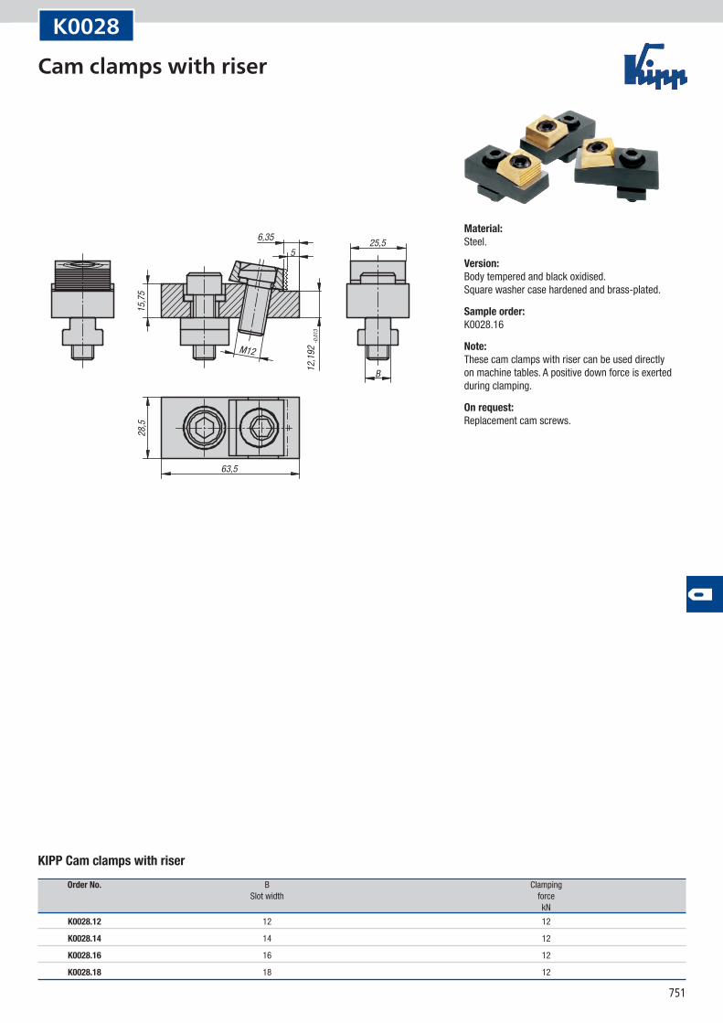
K0028
KIPP Cam clamps with riser
Order No. B Clamping Slot width force kN
K0028.12 12 12
K0028.14 14 12
K0028.16 16 12
K0028.18 18 12
Material:Steel.
Version:Body tempered and black oxidised. Square washer case hardened and brass-plated.
Sample order:K0028.16
Note:These cam clamps with riser can be used directly on machine tables. A positive down force is exerted during clamping.
On request:Replacement cam screws.
Cam clamps with riser
752
M12SW 10
53
SW 8
M12
2
50 -1
25,5
B
28,4
16max
. 26
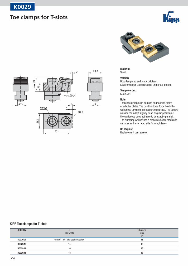
K0029
KIPP Toe clamps for T-slots
Order No. B Clamping Slot width force kN
K0029.00 without T-nut and fastening screw 18
K0029.14 14 18
K0029.16 16 18
K0029.18 18 18
Material:Steel.
Version:Body tempered and black oxidised. Square washer case hardened and brass-plated.
Sample order:K0029.14
Note:These toe clamps can be used on machine tables or adapter plates. The positive down force holds the workpiece down on the supporting surface. The square washer can adapt slightly to an angular position i.e. the workpiece does not have to be exactly parallel. The clamping washer has a smooth side for machined surfaces and a serrated side for rough faces.
On request:Replacement cam screws.
Toe clamps for T-slots
753
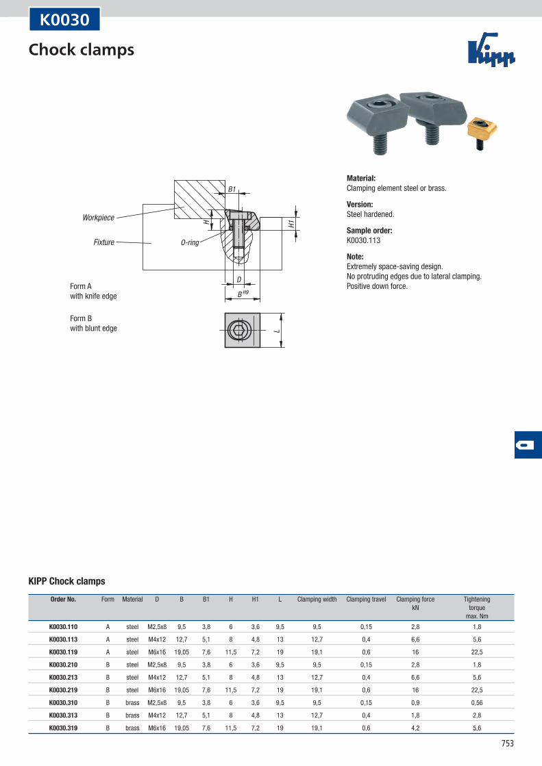
B H9
B1
DH1H
L
O-ring
Workpiece
Fixture
Form Awith knife edge
Form Bwith blunt edge
K0030
KIPP Chock clamps
Order No. Form Material D B B1 H H1 L Clamping width Clamping travel Clamping force Tightening kN torque max. Nm
K0030.110 A steel M2,5x8 9,5 3,8 6 3,6 9,5 9,5 0,15 2,8 1,8
K0030.113 A steel M4x12 12,7 5,1 8 4,8 13 12,7 0,4 6,6 5,6
K0030.119 A steel M6x16 19,05 7,6 11,5 7,2 19 19,1 0,6 16 22,5
K0030.210 B steel M2,5x8 9,5 3,8 6 3,6 9,5 9,5 0,15 2,8 1,8
K0030.213 B steel M4x12 12,7 5,1 8 4,8 13 12,7 0,4 6,6 5,6
K0030.219 B steel M6x16 19,05 7,6 11,5 7,2 19 19,1 0,6 16 22,5
K0030.310 B brass M2,5x8 9,5 3,8 6 3,6 9,5 9,5 0,15 0,9 0,56
K0030.313 B brass M4x12 12,7 5,1 8 4,8 13 12,7 0,4 1,8 2,8
K0030.319 B brass M6x16 19,05 7,6 11,5 7,2 19 19,1 0,6 4,2 5,6
Material:Clamping element steel or brass.
Version:Steel hardened.
Sample order:K0030.113
Note:Extremely space-saving design. No protruding edges due to lateral clamping. Positive down force.
Chock clamps
754
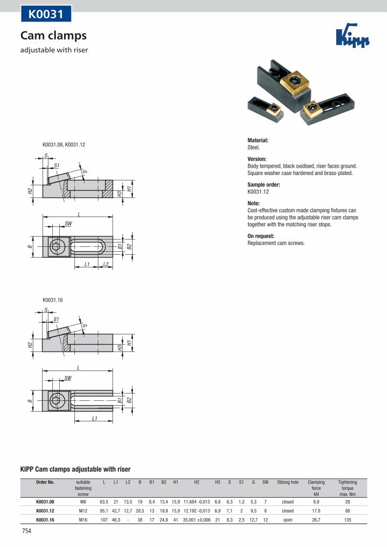
K0031.08, K0031.12
K0031.16
H2H2
SS1 G
SW
L1 L2
L
B1 B2B
H1H3
SS1 G
SW
L1
L
B1 B2B
H1H3
K0031
KIPP Cam clamps adjustable with riser
Order No. suitable L L1 L2 B B1 B2 H1 H2 H3 S S1 G SW Oblong hole Clamping Tightening fastening force torque screw kN max. Nm
K0031.08 M8 63,5 21 13,5 19 8,4 13,4 15,9 11,684 -0,013 6,6 6,3 1,2 5,3 7 closed 8,9 28
K0031.12 M12 95,1 42,7 12,7 28,5 13 19,8 15,9 12,192 -0,013 6,9 7,1 2 9,5 8 closed 17,8 88
K0031.16 M16 107 46,3 - 38 17 24,8 41 35,001 ±0,006 21 8,3 2,5 12,7 12 open 26,7 135
Material:Steel.
Version:Body tempered, black oxidised, riser faces ground. Square washer case hardened and brass-plated.
Sample order:K0031.12
Note:Cost-effective custom made clamping fixtures can be produced using the adjustable riser cam clamps together with the matching riser stops.
On request:Replacement cam screws.
Cam clamps adjustable with riser
755
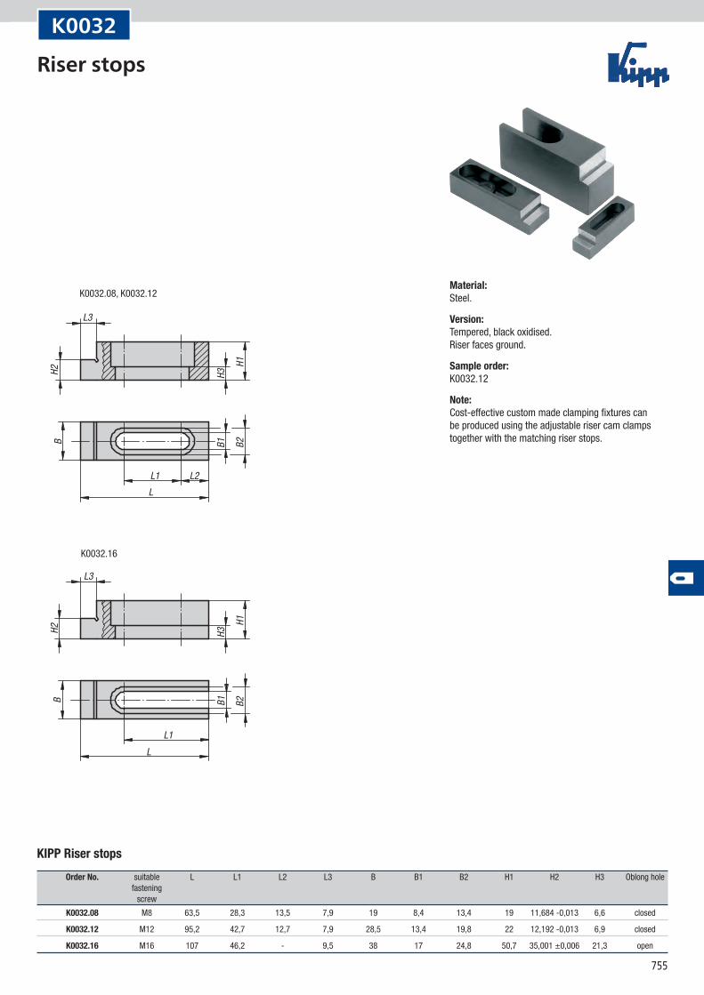
K0032.16
K0032.08, K0032.12
H2H2
L1 L2
L3
L
L1
L3
L
H1
H3
H1
H3B1 B2B
B1 B2B
K0032
KIPP Riser stops
Order No. suitable L L1 L2 L3 B B1 B2 H1 H2 H3 Oblong hole fastening screw
K0032.08 M8 63,5 28,3 13,5 7,9 19 8,4 13,4 19 11,684 -0,013 6,6 closed
K0032.12 M12 95,2 42,7 12,7 7,9 28,5 13,4 19,8 22 12,192 -0,013 6,9 closed
K0032.16 M16 107 46,2 - 9,5 38 17 24,8 50,7 35,001 ±0,006 21,3 open
Material:Steel.
Version:Tempered, black oxidised. Riser faces ground.
Sample order:K0032.12
Note:Cost-effective custom made clamping fixtures can be produced using the adjustable riser cam clamps together with the matching riser stops.
Riser stops
756
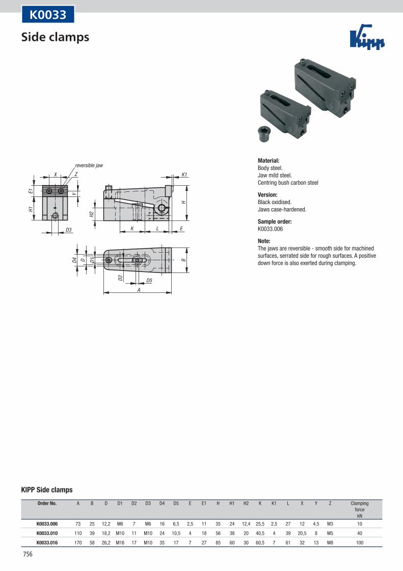
D4
D5A
LKD3
X Z K1
E
H1E1 Y
H2
HBD D1
D2
reversible jaw
K0033
KIPP Side clamps
Order No. A B D D1 D2 D3 D4 D5 E E1 H H1 H2 K K1 L X Y Z Clamping force kN
K0033.006 73 25 12,2 M6 7 M6 16 6,5 2,5 11 35 24 12,4 25,5 2,5 27 12 4,5 M3 10
K0033.010 110 39 18,2 M10 11 M10 24 10,5 4 18 56 38 20 40,5 4 39 20,5 8 M5 40
K0033.016 170 58 26,2 M16 17 M10 35 17 7 27 85 60 30 60,5 7 61 32 13 M8 100
Material:Body steel. Jaw mild steel. Centring bush carbon steel
Version:Black oxidised. Jaws case-hardened.
Sample order:K0033.006
Note:The jaws are reversible - smooth side for machined surfaces, serrated side for rough surfaces. A positive down force is also exerted during clamping.
Side clamps
757
15E
5
15
D3 D2
E
5
R
B
H
H1
E1E2
E3
E
KL
D1DL1
L2 K1A
right hand type
Form Asteel jawserrated
Form B jaw with 2 round carbide inserts
Form Cjaw with 2 roundcarbide inserts and central prism
Form DPOM jawserrated
3 rectangular carbide inserts
2 rectangular carbide inserts and central prism
stop screw
workpiece
centringbush
socket head screw
support
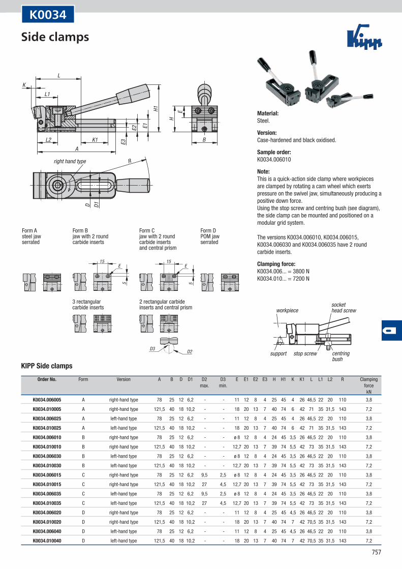
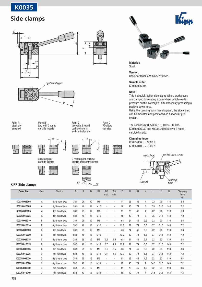
K0034
KIPP Side clamps
Order No. Form Version A B D D1 D2 D3 E E1 E2 E3 H H1 K K1 L L1 L2 R Clamping max. min. force kN
K0034.006005 A right-hand type 78 25 12 6,2 - - 11 12 8 4 25 45 4 26 46,5 22 20 110 3,8
K0034.010005 A right-hand type 121,5 40 18 10,2 - - 18 20 13 7 40 74 6 42 71 35 31,5 143 7,2
K0034.006025 A left-hand type 78 25 12 6,2 - - 11 12 8 4 25 45 4 26 46,5 22 20 110 3,8
K0034.010025 A left-hand type 121,5 40 18 10,2 - - 18 20 13 7 40 74 6 42 71 35 31,5 143 7,2
K0034.006010 B right-hand type 78 25 12 6,2 - - ø 8 12 8 4 24 45 3,5 26 46,5 22 20 110 3,8
K0034.010010 B right-hand type 121,5 40 18 10,2 - - 12,7 20 13 7 39 74 5,5 42 73 35 31,5 143 7,2
K0034.006030 B left-hand type 78 25 12 6,2 - - ø 8 12 8 4 24 45 3,5 26 46,5 22 20 110 3,8
K0034.010030 B left-hand type 121,5 40 18 10,2 - - 12,7 20 13 7 39 74 5,5 42 73 35 31,5 143 7,2
K0034.006015 C right-hand type 78 25 12 6,2 9,5 2,5 ø 8 12 8 4 24 45 3,5 26 46,5 22 20 110 3,8
K0034.010015 C right-hand type 121,5 40 18 10,2 27 4,5 12,7 20 13 7 39 74 5,5 42 73 35 31,5 143 7,2
K0034.006035 C left-hand type 78 25 12 6,2 9,5 2,5 ø 8 12 8 4 24 45 3,5 26 46,5 22 20 110 3,8
K0034.010035 C left-hand type 121,5 40 18 10,2 27 4,5 12,7 20 13 7 39 74 5,5 42 73 35 31,5 143 7,2
K0034.006020 D right-hand type 78 25 12 6,2 - - 11 12 8 4 25 45 4,5 26 46,5 22 20 110 3,8
K0034.010020 D right-hand type 121,5 40 18 10,2 - - 18 20 13 7 40 74 7 42 70,5 35 31,5 143 7,2
K0034.006040 D left-hand type 78 25 12 6,2 - - 11 12 8 4 25 45 4,5 26 46,5 22 20 110 3,8
K0034.010040 D left-hand type 121,5 40 18 10,2 - - 18 20 13 7 40 74 7 42 70,5 35 31,5 143 7,2
Material:Steel.
Version:Case-hardened and black oxidised.
Sample order:K0034.006010
Note:This is a quick-action side clamp where workpieces are clamped by rotating a cam wheel which exerts pressure on the swivel jaw, simultaneously producing a positive down force. Using the stop screw and centring bush (see diagram), the side clamp can be mounted and positioned on a modular grid system. The versions K0034.006010, K0034.006015, K0034.006030 and K0034.006035 have 2 round carbide inserts.
Clamping force:K0034.006... = 3800 N K0034.010... = 7200 N
Side clamps
758
15E
5
15
D3 D2
E
5R
B
H
H1 E
KL
D1D
L1A
right hand type
Form Asteel jawserrated
Form Bjaw with 2 roundcarbide inserts
Form Cjaw with 2 roundcarbide inserts and central prism
Form DPOM jaw serrated
3 rectangular carbide inserts
2 rectangular carbide inserts and central prism
workpiece socket head screw
centringbushsupport
K0035
KIPP Side clamps
Order No. Form Version A B D D1 D2 D3 E H H1 K L L1 R Clamping max. min. force kN
K0035.006005 A right-hand type 38,5 25 12 M6 - - 11 25 45 4 22 20 110 3,8
K0035.010005 A right-hand type 58,5 40 18 M10 - - 18 40 74 6 35 31,5 143 7,2
K0035.006025 A left-hand type 38,5 25 12 M6 - - 11 25 45 4 22 20 110 3,8
K0035.010025 A left-hand type 58,5 40 18 M10 - - 18 40 74 6 35 31,5 143 7,2
K0035.006010 B right-hand type 38,5 25 12 M6 - - ø 8 24 45 3,5 22 20 110 3,8
K0035.010010 B right-hand type 58,5 40 18 M10 - - 12,7 39 74 5,5 37 31,5 143 7,2
K0035.006030 B left-hand type 38,5 25 12 M6 - - ø 8 24 45 3,5 22 20 110 3,8
K0035.010030 B left-hand type 58,5 40 18 M10 - - 12,7 39 74 5,5 37 31,5 143 7,2
K0035.006015 C right-hand type 38,5 25 12 M6 9,5 2,5 ø 8 24 45 3,5 22 20 110 3,8
K0035.010015 C right-hand type 58,5 40 18 M10 27 4,5 12,7 39 74 5,5 37 31,5 143 7,2
K0035.006035 C left-hand type 38,5 25 12 M6 9,5 2,5 ø 8 24 45 3,5 22 20 110 3,8
K0035.010035 C left-hand type 58,5 40 18 M10 27 4,5 12,7 39 74 5,5 37 31,5 143 7,2
K0035.006020 D right-hand type 38,5 25 12 M6 - - 11 25 45 4,5 22 20 110 3,8
K0035.010020 D right-hand type 58,5 40 18 M10 - - 18 40 74 7 34,5 31,5 143 7,2
K0035.006040 D left-hand type 38,5 25 12 M6 - - 11 25 45 4,5 22 20 110 3,8
K0035.010040 D left-hand type 58,5 40 18 M10 - - 18 40 74 7 34,5 31,5 143 7,2
Material:Steel.
Version:Case-hardened and black oxidised.
Sample order:K0035.006005
Note:This is a quick-action side clamp where workpieces are clamped by rotating a cam wheel which exerts pressure on the swivel jaw, simultaneously producing a positive down force. Using the centring bush (see diagram), the side clamp can be mounted and positioned on a modular grid system. The versions K0035.006010, K0035.006015, K0035.006030 and K0035.006035 have 2 round carbide inserts.
Clamping force:K0035.006... = 3800 N K0035.010... = 7200 N
Side clamps
759
B -0,1
DL1
L2
L
SW
SW1
S
H1H2
H
S1
H3 m
ax.
Example of series clamping using compact toe clamps
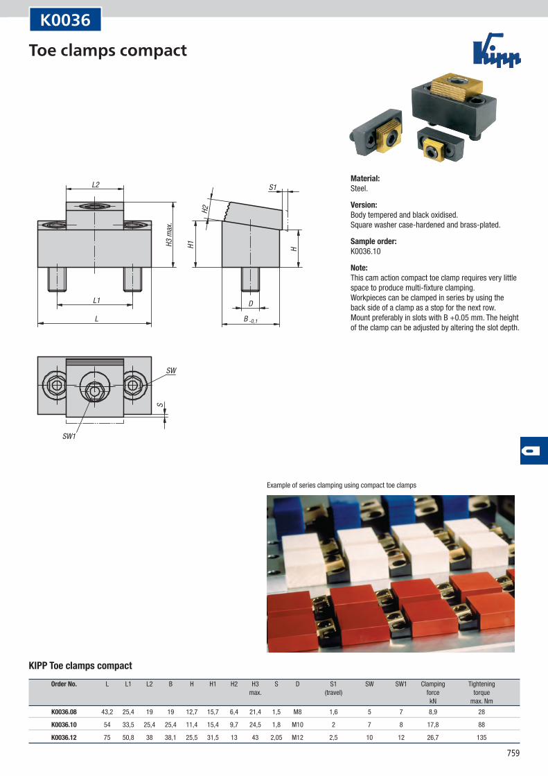
K0036
KIPP Toe clamps compact
Order No. L L1 L2 B H H1 H2 H3 S D S1 SW SW1 Clamping Tightening max. (travel) force torque kN max. Nm
K0036.08 43,2 25,4 19 19 12,7 15,7 6,4 21,4 1,5 M8 1,6 5 7 8,9 28
K0036.10 54 33,5 25,4 25,4 11,4 15,4 9,7 24,5 1,8 M10 2 7 8 17,8 88
K0036.12 75 50,8 38 38,1 25,5 31,5 13 43 2,05 M12 2,5 10 12 26,7 135
Material:Steel.
Version:Body tempered and black oxidised. Square washer case-hardened and brass-plated.
Sample order:K0036.10
Note:This cam action compact toe clamp requires very little space to produce multi-fixture clamping. Workpieces can be clamped in series by using the back side of a clamp as a stop for the next row. Mount preferably in slots with B +0.05 mm. The height of the clamp can be adjusted by altering the slot depth.
Toe clamps compact
760
H1F F
B2
L
D
H
B1 max.
B1 min.
In clamped position dimension B1 max. given in the table should be achieved.
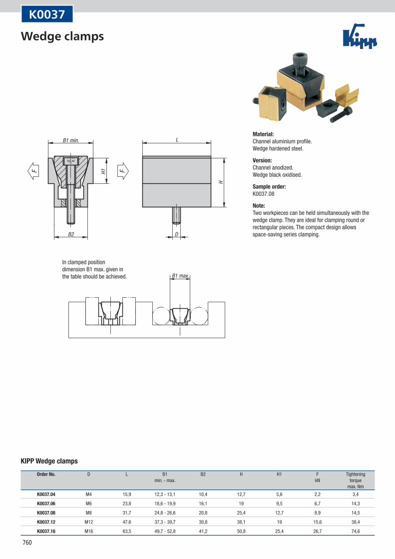
K0037
KIPP Wedge clamps
Order No. D L B1 B2 H H1 F Tightening min. - max. kN torque max. Nm
K0037.04 M4 15,9 12,3 - 13,1 10,4 12,7 5,6 2,2 3,4
K0037.06 M6 23,8 18,6 - 19,9 16,1 19 9,5 6,7 14,3
K0037.08 M8 31,7 24,8 - 26,6 20,8 25,4 12,7 8,9 14,5
K0037.12 M12 47,6 37,3 - 39,7 30,8 38,1 19 15,6 38,4
K0037.16 M16 63,5 49,7 - 52,8 41,2 50,8 25,4 26,7 74,6
Material:Channel aluminium profile. Wedge hardened steel.
Version:Channel anodized. Wedge black oxidised.
Sample order:K0037.08
Note:Two workpieces can be held simultaneously with the wedge clamp. They are ideal for clamping round or rectangular pieces. The compact design allows space-saving series clamping.
Wedge clamps
761
B1
B2
B3
H1
H
FF
L1
L
D
D1
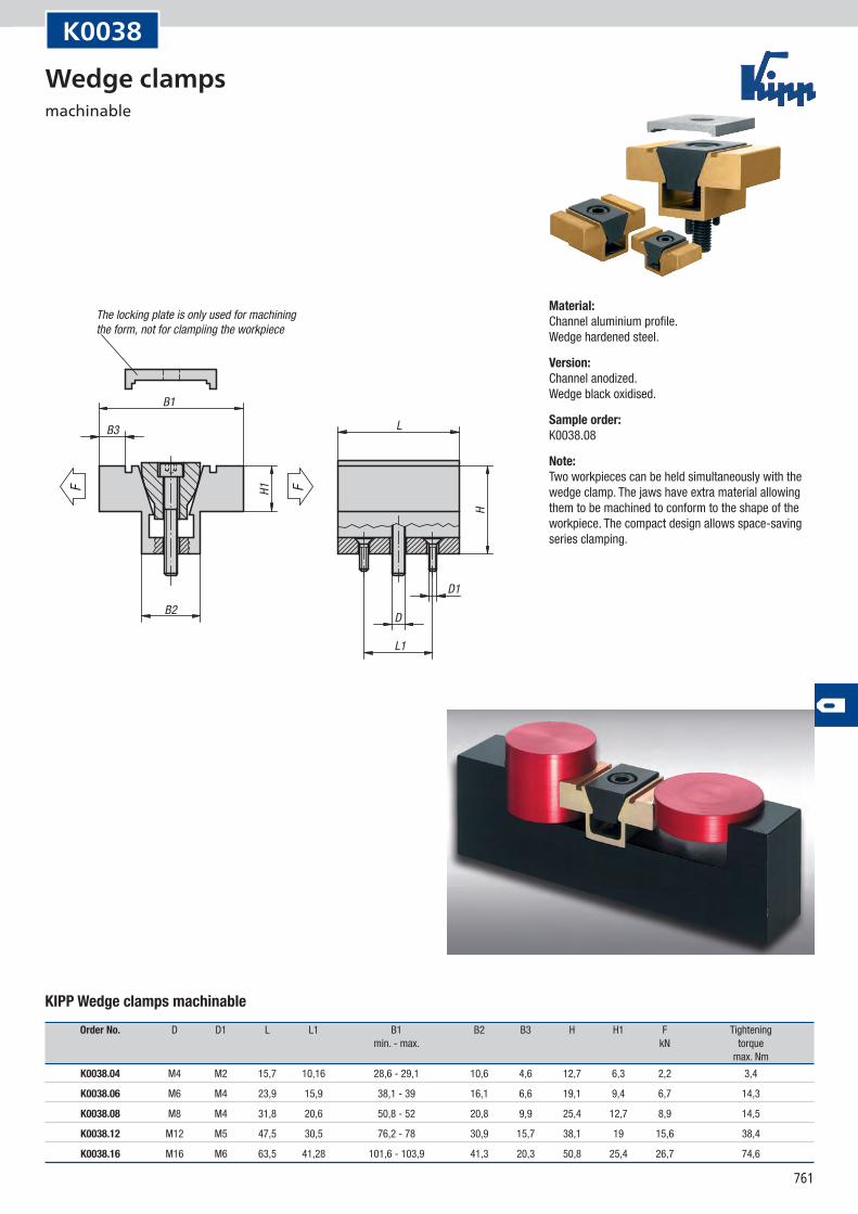
The locking plate is only used for machining the form, not for clampiing the workpiece
K0038
KIPP Wedge clamps machinable
Order No. D D1 L L1 B1 B2 B3 H H1 F Tightening min. - max. kN torque max. Nm
K0038.04 M4 M2 15,7 10,16 28,6 - 29,1 10,6 4,6 12,7 6,3 2,2 3,4
K0038.06 M6 M4 23,9 15,9 38,1 - 39 16,1 6,6 19,1 9,4 6,7 14,3
K0038.08 M8 M4 31,8 20,6 50,8 - 52 20,8 9,9 25,4 12,7 8,9 14,5
K0038.12 M12 M5 47,5 30,5 76,2 - 78 30,9 15,7 38,1 19 15,6 38,4
K0038.16 M16 M6 63,5 41,28 101,6 - 103,9 41,3 20,3 50,8 25,4 26,7 74,6
Material:Channel aluminium profile. Wedge hardened steel.
Version:Channel anodized. Wedge black oxidised.
Sample order:K0038.08
Note:Two workpieces can be held simultaneously with the wedge clamp. The jaws have extra material allowing them to be machined to conform to the shape of the workpiece. The compact design allows space-saving series clamping.
Wedge clamps machinable
762
F
CB
E
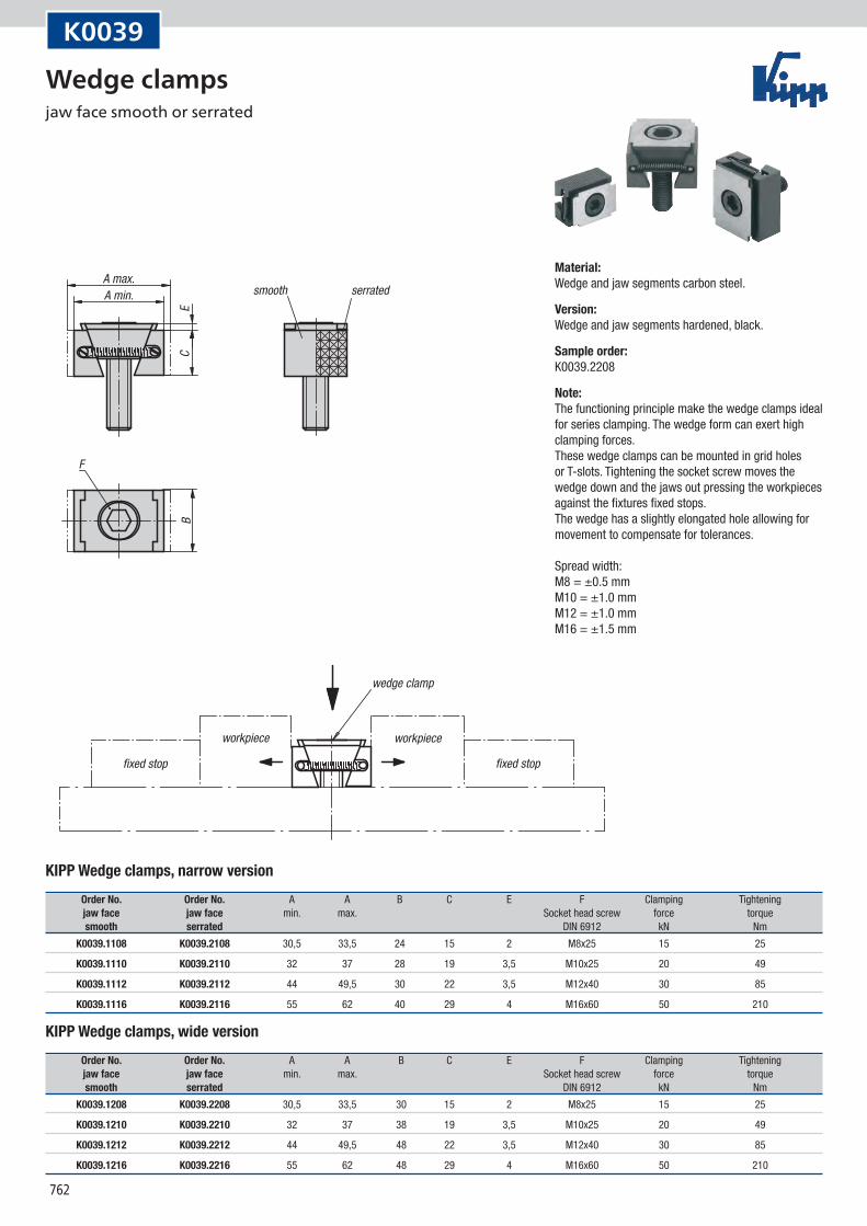
smooth serratedA max.A min.
fixed stop
workpiece
wedge clamp
workpiece
fixed stop
K0039
KIPP Wedge clamps, narrow version
Order No. Order No. A A B C E F Clamping Tightening jaw face jaw face min. max. Socket head screw force torque smooth serrated DIN 6912 kN Nm
K0039.1108 K0039.2108 30,5 33,5 24 15 2 M8x25 15 25
K0039.1110 K0039.2110 32 37 28 19 3,5 M10x25 20 49
K0039.1112 K0039.2112 44 49,5 30 22 3,5 M12x40 30 85
K0039.1116 K0039.2116 55 62 40 29 4 M16x60 50 210
KIPP Wedge clamps, wide version
Order No. Order No. A A B C E F Clamping Tightening jaw face jaw face min. max. Socket head screw force torque smooth serrated DIN 6912 kN Nm
K0039.1208 K0039.2208 30,5 33,5 30 15 2 M8x25 15 25
K0039.1210 K0039.2210 32 37 38 19 3,5 M10x25 20 49
K0039.1212 K0039.2212 44 49,5 48 22 3,5 M12x40 30 85
K0039.1216 K0039.2216 55 62 48 29 4 M16x60 50 210
Material:Wedge and jaw segments carbon steel.
Version:Wedge and jaw segments hardened, black.
Sample order:K0039.2208
Note:The functioning principle make the wedge clamps ideal for series clamping. The wedge form can exert high clamping forces. These wedge clamps can be mounted in grid holes or T-slots. Tightening the socket screw moves the wedge down and the jaws out pressing the workpieces against the fixtures fixed stops. The wedge has a slightly elongated hole allowing for movement to compensate for tolerances. Spread width: M8 = ±0.5 mm M10 = ±1.0 mm M12 = ±1.0 mm M16 = ±1.5 mm
Wedge clamps jaw face smooth or serrated
763
F
CB
E
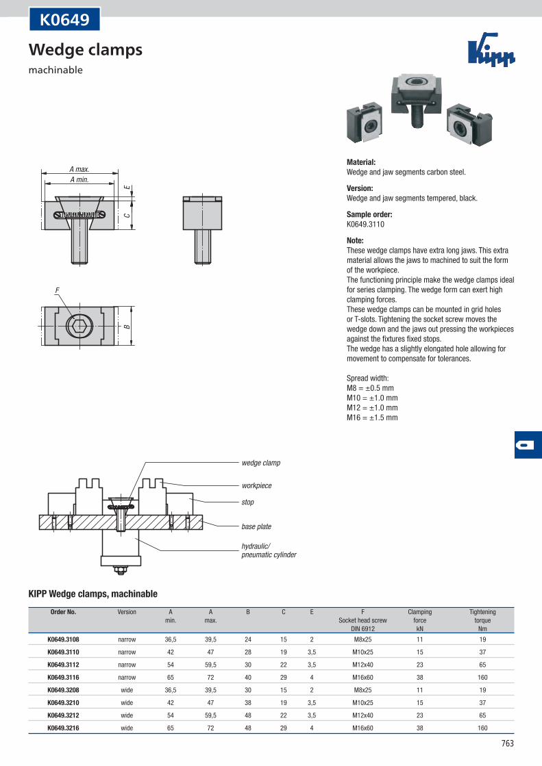
A max.A min.
workpiece
wedge clamp
stop
base plate
hydraulic/pneumatic cylinder
K0649
KIPP Wedge clamps, machinable
Order No. Version A A B C E F Clamping Tightening min. max. Socket head screw force torque DIN 6912 kN Nm
K0649.3108 narrow 36,5 39,5 24 15 2 M8x25 11 19
K0649.3110 narrow 42 47 28 19 3,5 M10x25 15 37
K0649.3112 narrow 54 59,5 30 22 3,5 M12x40 23 65
K0649.3116 narrow 65 72 40 29 4 M16x60 38 160
K0649.3208 wide 36,5 39,5 30 15 2 M8x25 11 19
K0649.3210 wide 42 47 38 19 3,5 M10x25 15 37
K0649.3212 wide 54 59,5 48 22 3,5 M12x40 23 65
K0649.3216 wide 65 72 48 29 4 M16x60 38 160
Material:Wedge and jaw segments carbon steel.
Version:Wedge and jaw segments tempered, black.
Sample order:K0649.3110
Note:These wedge clamps have extra long jaws. This extra material allows the jaws to machined to suit the form of the workpiece. The functioning principle make the wedge clamps ideal for series clamping. The wedge form can exert high clamping forces. These wedge clamps can be mounted in grid holes or T-slots. Tightening the socket screw moves the wedge down and the jaws out pressing the workpieces against the fixtures fixed stops. The wedge has a slightly elongated hole allowing for movement to compensate for tolerances. Spread width: M8 = ±0.5 mm M10 = ±1.0 mm M12 = ±1.0 mm M16 = ±1.5 mm
Wedge clamps machinable
764
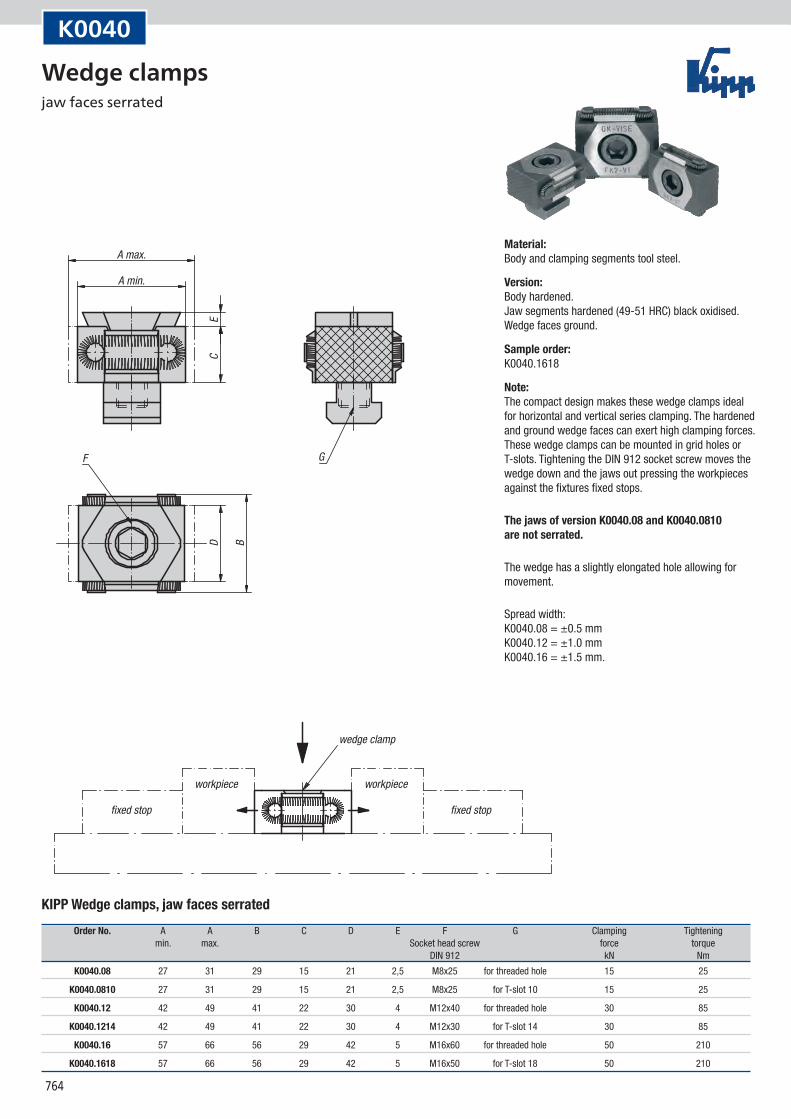
F G
C
B
ED
A max.
A min.
fixed stop fixed stop
workpiece workpiece
wedge clamp
K0040
KIPP Wedge clamps, jaw faces serrated
Order No. A A B C D E F G Clamping Tightening min. max. Socket head screw force torque DIN 912 kN Nm
K0040.08 27 31 29 15 21 2,5 M8x25 for threaded hole 15 25
K0040.0810 27 31 29 15 21 2,5 M8x25 for T-slot 10 15 25
K0040.12 42 49 41 22 30 4 M12x40 for threaded hole 30 85
K0040.1214 42 49 41 22 30 4 M12x30 for T-slot 14 30 85
K0040.16 57 66 56 29 42 5 M16x60 for threaded hole 50 210
K0040.1618 57 66 56 29 42 5 M16x50 for T-slot 18 50 210
Material:Body and clamping segments tool steel.
Version:Body hardened. Jaw segments hardened (49-51 HRC) black oxidised. Wedge faces ground.
Sample order:K0040.1618
Note:The compact design makes these wedge clamps ideal for horizontal and vertical series clamping. The hardened and ground wedge faces can exert high clamping forces. These wedge clamps can be mounted in grid holes or T-slots. Tightening the DIN 912 socket screw moves the wedge down and the jaws out pressing the workpieces against the fixtures fixed stops.
The jaws of version K0040.08 and K0040.0810 are not serrated.
The wedge has a slightly elongated hole allowing for movement.
Spread width: K0040.08 = ±0.5 mm K0040.12 = ±1.0 mm K0040.16 = ±1.5 mm.
Wedge clamps jaw faces serrated
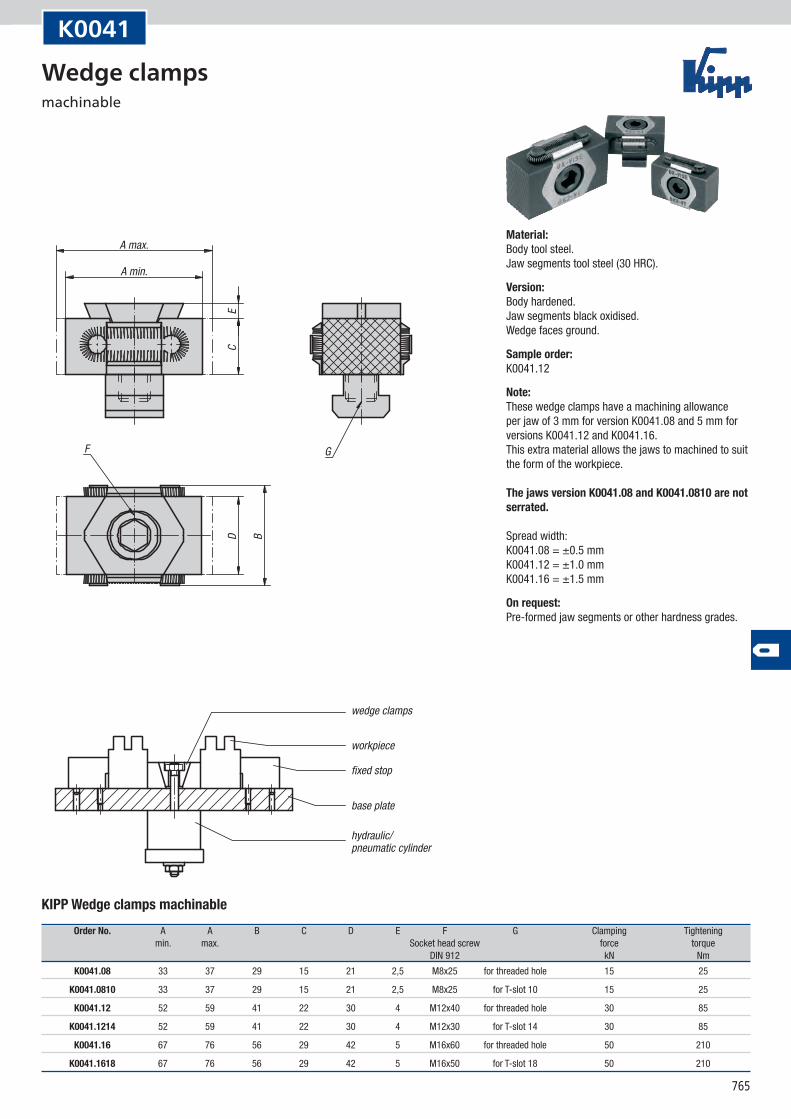
765
F G
C
B
ED
A max.
A min.
wedge clamps
workpiece
fixed stop
base plate
hydraulic/pneumatic cylinder
K0041
KIPP Wedge clamps machinable
Order No. A A B C D E F G Clamping Tightening min. max. Socket head screw force torque DIN 912 kN Nm
K0041.08 33 37 29 15 21 2,5 M8x25 for threaded hole 15 25
K0041.0810 33 37 29 15 21 2,5 M8x25 for T-slot 10 15 25
K0041.12 52 59 41 22 30 4 M12x40 for threaded hole 30 85
K0041.1214 52 59 41 22 30 4 M12x30 for T-slot 14 30 85
K0041.16 67 76 56 29 42 5 M16x60 for threaded hole 50 210
K0041.1618 67 76 56 29 42 5 M16x50 for T-slot 18 50 210
Material:Body tool steel. Jaw segments tool steel (30 HRC).
Version:Body hardened. Jaw segments black oxidised. Wedge faces ground.
Sample order:K0041.12
Note:These wedge clamps have a machining allowance per jaw of 3 mm for version K0041.08 and 5 mm for versions K0041.12 and K0041.16. This extra material allows the jaws to machined to suit the form of the workpiece. The jaws version K0041.08 and K0041.0810 are not serrated. Spread width: K0041.08 = ±0.5 mm K0041.12 = ±1.0 mm K0041.16 = ±1.5 mm
On request:Pre-formed jaw segments or other hardness grades.
Wedge clamps machinable
766
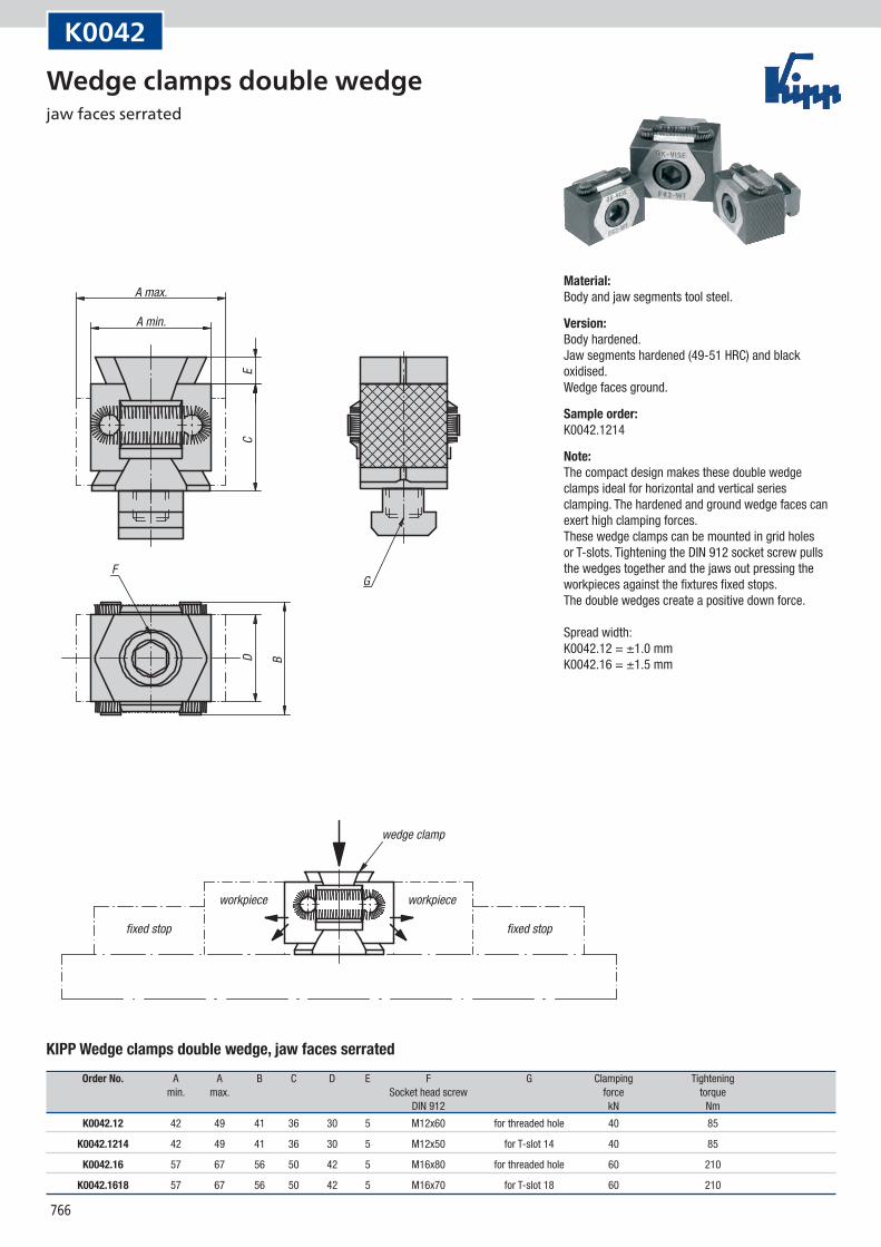
FG
C
B
ED
A max.
A min.
fixed stop fixed stop
workpiece workpiece
wedge clamp
K0042
KIPP Wedge clamps double wedge, jaw faces serrated
Order No. A A B C D E F G Clamping Tightening min. max. Socket head screw force torque DIN 912 kN Nm
K0042.12 42 49 41 36 30 5 M12x60 for threaded hole 40 85
K0042.1214 42 49 41 36 30 5 M12x50 for T-slot 14 40 85
K0042.16 57 67 56 50 42 5 M16x80 for threaded hole 60 210
K0042.1618 57 67 56 50 42 5 M16x70 for T-slot 18 60 210
Material:Body and jaw segments tool steel.
Version:Body hardened. Jaw segments hardened (49-51 HRC) and black oxidised. Wedge faces ground.
Sample order:K0042.1214
Note:The compact design makes these double wedge clamps ideal for horizontal and vertical series clamping. The hardened and ground wedge faces can exert high clamping forces. These wedge clamps can be mounted in grid holes or T-slots. Tightening the DIN 912 socket screw pulls the wedges together and the jaws out pressing the workpieces against the fixtures fixed stops. The double wedges create a positive down force. Spread width: K0042.12 = ±1.0 mm K0042.16 = ±1.5 mm
Wedge clamps double wedge jaw faces serrated
767
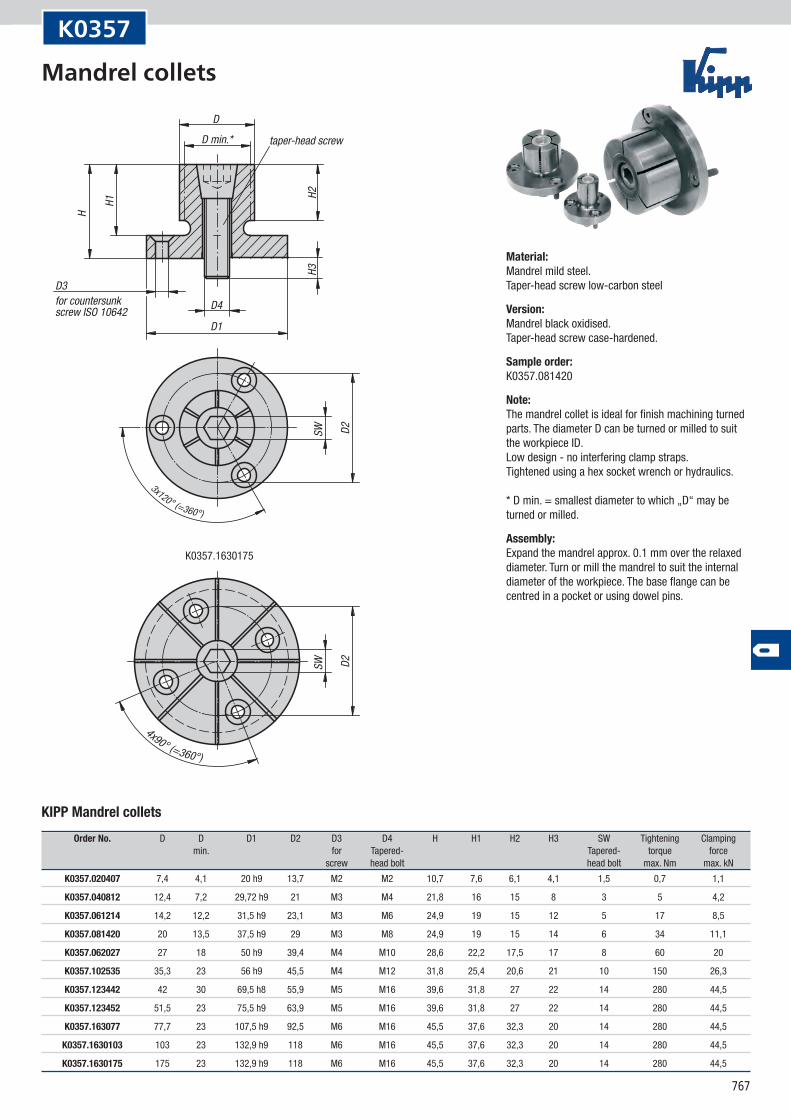
K0357.1630175
H3
D
D4
D1
3x120° (=360°)
H2H1
H
SW D2
4x90° (=360°)
SW D2
taper-head screw
D3for countersunk screw ISO 10642
D min.*
K0357
KIPP Mandrel collets
Order No. D D D1 D2 D3 D4 H H1 H2 H3 SW Tightening Clamping min. for Tapered- Tapered- torque force screw head bolt head bolt max. Nm max. kN
K0357.020407 7,4 4,1 20 h9 13,7 M2 M2 10,7 7,6 6,1 4,1 1,5 0,7 1,1
K0357.040812 12,4 7,2 29,72 h9 21 M3 M4 21,8 16 15 8 3 5 4,2
K0357.061214 14,2 12,2 31,5 h9 23,1 M3 M6 24,9 19 15 12 5 17 8,5
K0357.081420 20 13,5 37,5 h9 29 M3 M8 24,9 19 15 14 6 34 11,1
K0357.062027 27 18 50 h9 39,4 M4 M10 28,6 22,2 17,5 17 8 60 20
K0357.102535 35,3 23 56 h9 45,5 M4 M12 31,8 25,4 20,6 21 10 150 26,3
K0357.123442 42 30 69,5 h8 55,9 M5 M16 39,6 31,8 27 22 14 280 44,5
K0357.123452 51,5 23 75,5 h9 63,9 M5 M16 39,6 31,8 27 22 14 280 44,5
K0357.163077 77,7 23 107,5 h9 92,5 M6 M16 45,5 37,6 32,3 20 14 280 44,5
K0357.1630103 103 23 132,9 h9 118 M6 M16 45,5 37,6 32,3 20 14 280 44,5
K0357.1630175 175 23 132,9 h9 118 M6 M16 45,5 37,6 32,3 20 14 280 44,5
Material:Mandrel mild steel. Taper-head screw low-carbon steel
Version:Mandrel black oxidised. Taper-head screw case-hardened.
Sample order:K0357.081420
Note:The mandrel collet is ideal for finish machining turned parts. The diameter D can be turned or milled to suit the workpiece ID. Low design - no interfering clamp straps. Tightened using a hex socket wrench or hydraulics. * D min. = smallest diameter to which „D“ may be turned or milled.
Assembly:Expand the mandrel approx. 0.1 mm over the relaxed diameter. Turn or mill the mandrel to suit the internal diameter of the workpiece. The base flange can be centred in a pocket or using dowel pins.
Mandrel collets
768
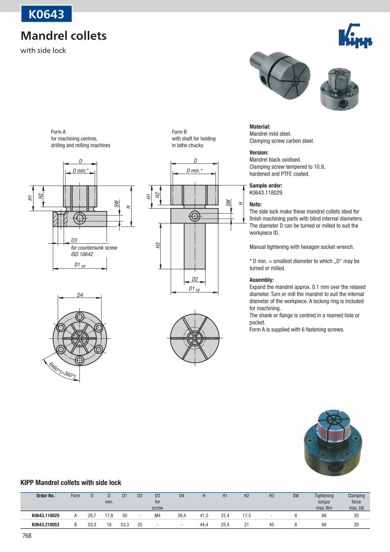
D
SW
H1
D
H2
H
D1 h8
D1 h8
6x60° (=360°)
D4
D2
SW H
H1 H2H3
D min.* D min.*
D3for countersunk screw ISO 10642
Form Afor machining centres,drilling and milling machines
Form Bwith shaft for holding in lathe chucks
K0643
KIPP Mandrel collets with side lock
Order No. Form D D D1 D2 D3 D4 H H1 H2 H3 SW Tightening Clamping min. for torque force screw max. Nm max. kN
K0643.118029 A 28,7 17,8 50 - M4 39,4 41,3 22,4 17,5 - 6 66 20
K0643.218053 B 53,3 18 53,3 25 - - 44,4 25,4 21 45 6 66 20
Material:Mandrel mild steel. Clamping screw carbon steel.
Version:Mandrel black oxidised. Clamping screw tempered to 10.9, hardened and PTFE coated.
Sample order:K0643.118029
Note:The side lock make these mandrel collets ideal for finish machining parts with blind internal diameters. The diameter D can be turned or milled to suit the workpiece ID. Manual tightening with hexagon socket wrench. * D min. = smallest diameter to which „D“ may be turned or milled.
Assembly:Expand the mandrel approx. 0.1 mm over the relaxed diameter. Turn or mill the mandrel to suit the internal diameter of the workpiece. A locking ring is included for machining. The shank or flange is centred in a reamed hole or pocket. Form A is supplied with 6 fastening screws.
Mandrel collets with side lock
769
D2 h1
1
D3 G
DG1 SWL1 L1
H
X +0,
2
D1 +0
,2
SW
G1
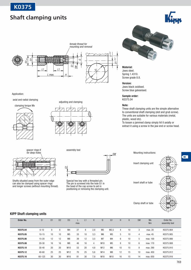
female thread formounting and removal
L max.
Application:
axial and radial clampingadjusting and clamping
Shafts situated away from the outer edgecan also be clamped using spacer ringsand longer screws (without mounting thread).
spacer rings Kfor deep holes
assembly tool
Special hex key with a threaded pin. The pin is screwed into the hole G1 in the head of the cap screw to aid in positioning or removing the clamping unit.
clamping torque Mx
Mounting instructions:
Insert clamping unit
Insert shaft or tube
Clamp shaft or tube
K0375
KIPP Shaft clamping units
Order No. D D1 D2 D3 L L1 X G G1 H K SW Mx Order No. max. Nm assembly tool
K0375.04 6-10 8 8 M4 27 8 2,8 M5 M2,5 4 10 3 max. 20 K0375.904
K0375.05 10-15 10 10 M5 33 10 3,3 M6 M3 5 10 4 max. 45 K0375.905
K0375.06 15-20 12 12 M6 39 12 3,5 M7 M4 6 10 5 max. 100 K0375.906
K0375.08 20-30 16 16 M8 46 16 4 M10 M5 8 10 6 max. 170 K0375.908
K0375.10 30-40 20 20 M10 53 20 4,8 M12 M6 10 15 8 max. 290 K0375.910
K0375.12 40-60 25 25 M12 70 25 5,6 M14 M8 12 15 10 max. 450 K0375.912
K0375.16 60-125 30 30 M16 81 30 7,9 M18 M10 16 15 14 max. 650 K0375.916
Material:Jaws steel. Spring 1.4310. Screw grade 8.8.
Version:Jaws black oxidised. Screw blue galvanised.
Sample order:K0375.04
Note:These shaft clamping units are the simple alternative to conventional shaft clamping (slot and grub screw). The units are suitable for various materials (metal, plastic, wood etc). To loosen a jammed clamp simply hit it axially or extract it using a screw in the jaw end or screw head.
Shaft clamping units
770
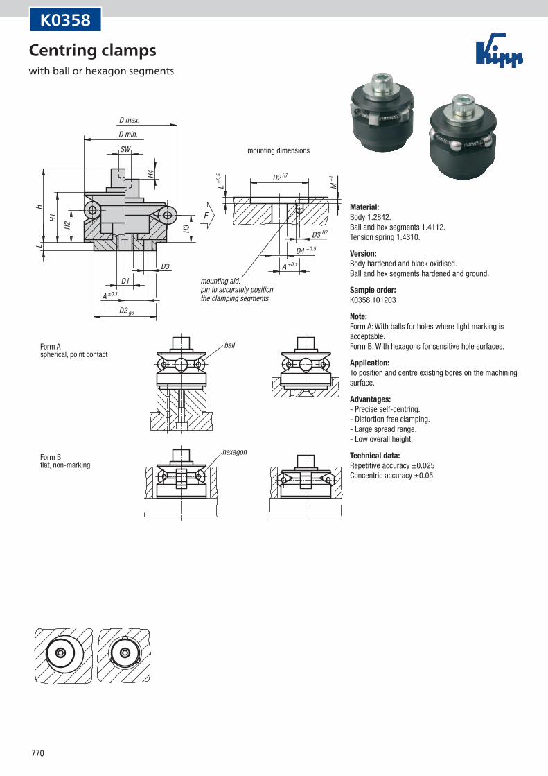
A ±0,1
A ±0,1
L +0,5
M +1
H3
H1
H2
H4
HL
D3 H7
D4 +0,5
SW
D2 H7
D3
D1
F
D2 g6
ball
hexagonForm Bflat, non-marking
Form Aspherical, point contact
mounting dimensions
D max.
D min.
mounting aid:pin to accurately positionthe clamping segments
K0358
Material:Body 1.2842. Ball and hex segments 1.4112. Tension spring 1.4310.
Version:Body hardened and black oxidised. Ball and hex segments hardened and ground.
Sample order:K0358.101203
Note:Form A: With balls for holes where light marking is acceptable. Form B: With hexagons for sensitive hole surfaces.
Application:To position and centre existing bores on the machining surface.
Advantages:- Precise self-centring. - Distortion free clamping. - Large spread range. - Low overall height.
Technical data:Repetitive accuracy ±0.025 Concentric accuracy ±0.05
Centring clamps with ball or hexagon segments
771
K0358
Centring clamps with ball or hexagon segments
KIPP Centring clamps with ball segments
Order No. Form A D D D1 D2 D3 D4 H H1 H2 H3 H4 L M SW Ball-Ø No. of F min. max. segments kN
K0358.101203 A 3,5 11,7 14,2 M4 10 1,5 4,3 15 10 4,2 3 1,5 3,5 2,5 3 2,5 3 0,5
K0358.101504 A 4,5 14,5 18,5 M4 12 2 4,3 19,5 14,5 9,8 8,6 2,3 5,5 3 3 4 3 3,5
K0358.101905 A 5,5 18,5 22,5 M5 15 2,5 5,3 23,5 16,5 11,6 10,4 2,3 7,5 3 4 4 3 4
K0358.102306 A 7 22,5 26,5 M6 20 3 6,4 28,6 19,8 14,2 13 2,3 6 4 5 4 3 4,5
K0358.102706 A 7 26,5 30,5 M6 20 3 6,4 28,6 19,8 14,2 13 2,3 6 4,5 5 4 3 4,5
K0358.103106 A 9 30,5 38,5 M6 25 4 6,4 32,7 23,1 14,2 11,9 4,6 7 4,5 5 8 3 4,5
K0358.103908 A 11 38,5 46,5 M8 30 4 8,4 39,2 27,2 17,8 15,5 4,6 7,5 4,5 6 8 6 6,5
K0358.104708 A 11 46,5 54,5 M8 30 4 8,4 39,2 27,2 18 15,7 4,6 7,5 4,5 6 8 6 6,5
K0358.105510 A 15 54,5 70,5 M10 45 5 10,5 54,6 40,6 23,7 19,1 9,3 9 5,5 8 16 6 8
K0358.107112 A 17 70,5 86,5 M12 60 5 13 63,1 46,1 28,3 23,7 9,3 10 5,5 10 16 6 10
K0358.108712 A 25 86,5 102,5 M16 60 5 17 73 51 30,2 23,7 9,3 10 5,5 14 16 6 12,5
KIPP Centring clamps with hexagon segments
Order No. Form A D D D1 D2 D3 D4 H H1 H2 H3 H4 L M SW Hex No. of F min. max. segments kN
K0358.201504 B 4,5 14,5 18,5 M4 12 2 4,3 19,5 14,5 9,8 8,6 2,3 5,5 3 3 4 3 3,5
K0358.201905 B 5,5 18,5 22,5 M5 15 2,5 5,3 23,5 16,5 11,6 10,4 2,3 7,5 3 4 4 3 4
K0358.202306 B 7 22,5 26,5 M6 20 3 6,4 28,6 19,8 14,2 13 2,3 6 4 5 4 3 4,5
K0358.202706 B 7 26,5 30,5 M6 20 3 6,4 28,6 19,8 14,2 13 2,3 6 4,5 5 4 3 4,5
K0358.203106 B 9 30,5 38,5 M6 25 4 6,4 32,7 23,1 14,2 11,9 4,6 7 4,5 5 8 3 4,5
K0358.203908 B 11 38,5 46,5 M8 30 4 8,4 39,2 27,2 17,8 15,5 4,6 7,5 4,5 6 8 6 6,5
K0358.204708 B 11 46,5 54,5 M8 30 4 8,4 39,2 27,2 18 15,7 4,6 7,5 4,5 6 8 6 6,5
K0358.205510 B 15 54,5 70,5 M10 45 5 10,5 54,6 40,6 23,7 19,1 9,3 9 5,5 8 16 6 8
K0358.207112 B 17 70,5 86,5 M12 60 5 13 63,1 46,1 28,3 23,7 9,3 10 5,5 10 16 6 10
K0358.208712 B 25 86,5 102,5 M16 60 5 17 73 51 30,2 23,7 9,3 10 5,5 14 16 6 12,5
772
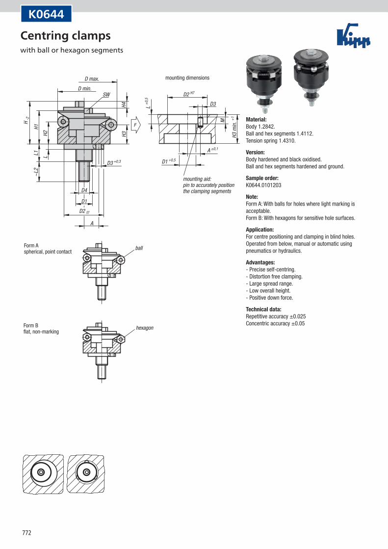
A ±0,1L +0
,5
M
D2 H7
D3
H2L
H1
H -2
~L2
L1
H4H3
F
D2 f7
D4
D3 +0,3
SW
A
D1
D1 +0,5
mounting dimensions
mounting aid:pin to accurately positionthe clamping segments
Form Aspherical, point contact
ball
hexagonForm Bflat, non-marking
D max.D min.
H3 m
in. +1
K0644
Material:Body 1.2842. Ball and hex segments 1.4112. Tension spring 1.4310.
Version:Body hardened and black oxidised. Ball and hex segments hardened and ground.
Sample order:K0644.0101203
Note:Form A: With balls for holes where light marking is acceptable. Form B: With hexagons for sensitive hole surfaces.
Application:For centre positioning and clamping in blind holes. Operated from below, manual or automatic using pneumatics or hydraulics.
Advantages:- Precise self-centring. - Distortion free clamping. - Large spread range. - Low overall height. - Positive down force.
Technical data:Repetitive accuracy ±0.025 Concentric accuracy ±0.05
Centring clamps with ball or hexagon segments

773
K0644
Centring clamps with ball or hexagon segments
KIPP Centring clamps with ball segments
Order No. Form A D D D1 D2 D3 D4 H H1 H2 H3 H4 L L1 L2 M SW Ball-Ø No. of F min. max. segments kN
K0644.0101203 A 3,5 11,7 14,2 M5 10 1,5 M3 12,8 10 4,2 3 1,5 3,5 11 8 2,5 5,5 2,5 3 0,5
K0644.0101503 A 4,5 14,5 18,5 M6 12 2 M3 17,3 14,5 9,8 8,6 2,3 5,5 14,1 8 3 5,5 4 3 3,5
K0644.0101904 A 5,5 18,5 22,5 M8 15 2,5 M4 20,9 16,5 11,6 10,4 2,3 7,5 18,2 8 3 7 4 3 4
K0644.0102305 A 7 22,5 26,5 M10 20 3 M5 25,4 19,8 14,2 13 2,3 6 17,4 11 4 8 4 3 4,5
K0644.0102705 A 7 26,5 30,5 M10 20 3 M5 25,4 19,8 14,2 13 2,3 6 17,4 10 4,5 8 4 3 4,5
K0644.0103106 A 9 30,5 38,5 M12 25 4 M6 30,3 23,1 14,2 11,9 4,6 7 21,9 13 4,5 10 8 3 4,5
K0644.0103906 A 11 38,5 46,5 M12 30 4 M6 34,2 27,2 17,8 15,5 4,6 7,5 22,5 12 4,5 10 8 6 6,5
K0644.0104706 A 11 46,5 54,5 M12 30 4 M6 34,2 27,2 18 15,7 4,6 7,5 22,5 12 4,5 10 8 6 6,5
K0644.0105508 A 15 54,5 70,5 M14 45 5 M8 49,9 40,6 23,7 19,1 9,7 9 24,5 16 5,5 13 16 6 8
K0644.0107108 A 17 70,5 86,5 M16 60 5 M8 55,4 46,1 28,3 23,7 9,9 10 29,4 17 5,5 13 16 6 10
K0644.0108708 A 25 86,5 102,5 M16 60 5 M10 61,6 51 30,2 25,7 9,2 10 29,4 17 5,5 16 16 6 12,5
KIPP Centring clamps with hexagon segments
Order No. Form A D D D1 D2 D3 D4 H H1 H2 H3 H4 L L1 L2 M SW Hex No. of F min. max. segments kN
K0644.0201503 B 4,5 14,5 18,5 M6 12 2 M3 17,3 14,5 9,8 8,6 2,3 5,5 14,1 8 3 5,5 4 3 3,5
K0644.0201904 B 5,5 18,5 22,5 M8 15 2,5 M4 20,9 16,5 11,6 10,4 2,3 7,5 18,2 8 3 7 4 3 4
K0644.0202305 B 7 22,5 26,5 M10 20 3 M5 25,4 19,8 14,2 13 2,3 6 17,4 11 4 8 4 3 4,5
K0644.0202705 B 7 26,5 30,5 M10 20 3 M5 25,4 19,8 14,2 13 2,3 6 17,4 10 4,5 8 4 3 4,5
K0644.0203106 B 9 30,5 38,5 M12 25 4 M6 30,3 23,1 14,2 11,9 4,6 7 21,9 13 4,5 10 8 3 4,5
K0644.0203906 B 11 38,5 46,5 M12 30 4 M6 34,2 27,2 17,8 15,5 4,6 7,5 22,5 12 4,5 10 8 6 6,5
K0644.0204706 B 11 46,5 54,5 M12 30 4 M6 34,2 27,2 18 15,7 4,6 7,5 22,5 12 4,5 10 8 6 6,5
K0644.0205508 B 15 54,5 70,5 M14 45 5 M8 49,9 40,6 23,7 19,1 9,7 9 24,5 16 5,5 13 16 6 8
K0644.0207108 B 17 70,5 86,5 M16 60 5 M8 55,4 46,1 28,3 23,7 9,9 10 29,4 17 5,5 13 16 6 10
K0644.0208708 B 25 86,5 102,5 M16 60 5 M10 61,6 51 30,2 25,7 9,2 10 29,4 17 5,5 16 16 6 12,5

774