class 39 final control elements - actuators
TRANSCRIPT

ICE401: PROCESS INSTRUMENTATION
AND CONTROL
Class 39
Final Control Elements - Actuators
Dr. S. Meenatchisundaram
Email: [email protected]
Process Instrumentation and Control (ICE 401)
Dr. S.Meenatchisundaram, MIT, Manipal, Aug – Nov 2015

Actuators:
Process Instrumentation and Control (ICE 401)
Dr. S.Meenatchisundaram, MIT, Manipal, Aug – Nov 2015
• Actuators are devices used to produce action or motion.
• Input (mainly electrical signal, air, fluids)
• Electrical signal can be low power or high power.
• Actuators output can be position or rate i. e. linear displacement or
velocity. Actuation can be from few microns to few meters.

Classification of Actuators:
Process Instrumentation and Control (ICE 401)
Dr. S.Meenatchisundaram, MIT, Manipal, Aug – Nov 2015
Type of motion
Linear Rotary
Type of medium
Hydraulic pneumaticelectrical
ACTUATORS

Actuators:
Process Instrumentation and Control (ICE 401)
Dr. S.Meenatchisundaram, MIT, Manipal, Aug – Nov 2015
• Linear actuator: solenoid, Hydraulic/Pneumatic.
• Rotary actuator: motor, Hydraulic/Pneumatic.
• A solenoid is a coil wound into a tightly packed helix.
• In physics, the term solenoid refers to a long, thin loop of wire, and
wrapped around a metallic core.
• Which produces a magnetic field when an electric current is passed
through it.

Solenoid Controlled Valves:
Process Instrumentation and Control (ICE 401)
Dr. S.Meenatchisundaram, MIT, Manipal, Aug – Nov 2015

Hydraulic Actuators:
Process Instrumentation and Control (ICE 401)
Dr. S.Meenatchisundaram, MIT, Manipal, Aug – Nov 2015
• Hydraulic Actuators are used in industrial process control, employ
hydraulic pressure to drive an output member.
• Principle: Pascal’s Law
“Pressure exerted anywhere in a confined incompressible fluid is
transmitted equally in all directions throughout the fluid, acts upon
every part of the confining vessel at right angles to its interior
surfaces”.
• F = PxA

Hydraulic Actuators:
Process Instrumentation and Control (ICE 401)
Dr. S.Meenatchisundaram, MIT, Manipal, Aug – Nov 2015

Working of Hydraulic Actuators:
Process Instrumentation and Control (ICE 401)
Dr. S.Meenatchisundaram, MIT, Manipal, Aug – Nov 2015
• Α directional control valve controls the direction of oil flow in the
system and, therefore, the direction of motion of the cylinder piston.
• The valve has four ports, labelled Ρ, Τ, Α, and Β. Ρ and Τ stand for
pressure and tank (or reservoir), and Α and Β are output ports. The
valve can be operated in three different positions.

Working of Hydraulic Actuators:
Process Instrumentation and Control (ICE 401)
Dr. S.Meenatchisundaram, MIT, Manipal, Aug – Nov 2015
• The oil from the pump flows through path Ρ-Α of the valve to the
upper end of the cylinder.
• The oil pushes the piston downward, which lowers the attached load.
At the same time, the oil at the lower end of the cylinder flows back to
the reservoir through path Β-Τ of the directional control valve.

Working of Hydraulic Actuators:
Process Instrumentation and Control (ICE 401)
Dr. S.Meenatchisundaram, MIT, Manipal, Aug – Nov 2015
• When the directional control valve lever is released, the valve
automatically returns to the center (neutral) position.
• In this position, all four ports are blocked and oil cannot escape from
either side of the cylinder. This stops the movement of the piston and
causes oil to flow from the pump back to the reservoir through the
pressure relief valve.
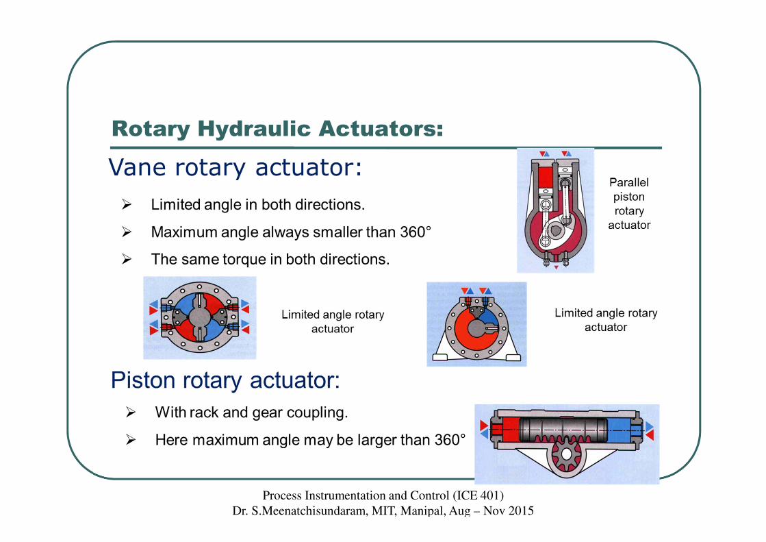
Rotary Hydraulic Actuators:
Process Instrumentation and Control (ICE 401)
Dr. S.Meenatchisundaram, MIT, Manipal, Aug – Nov 2015

Pneumatic Actuators:
Process Instrumentation and Control (ICE 401)
Dr. S.Meenatchisundaram, MIT, Manipal, Aug – Nov 2015
• A pneumatic actuator converts energy (typically in the form
of compressed Air) into motion. The motion can be rotary or linear,
depending on the type of actuator.
• A Pneumatic actuator mainly consists of a piston, a cylinder, and
valves or ports.
• Pneumatic systems are very common, and have much in common with
hydraulic systems with a few key differences.

Working of Pneumatic Actuators:
Process Instrumentation and Control (ICE 401)
Dr. S.Meenatchisundaram, MIT, Manipal, Aug – Nov 2015
• Pneumatic actuators are generally relatively simplistic and depend on
their own ability to convert potential energy into kinetic energy.

Constructional Features of Pneumatic
Cylinders:
Process Instrumentation and Control (ICE 401)
Dr. S.Meenatchisundaram, MIT, Manipal, Aug – Nov 2015

Hydraulic & pneumatic actuators: Cylinders
Process Instrumentation and Control (ICE 401)
Dr. S.Meenatchisundaram, MIT, Manipal, Aug – Nov 2015
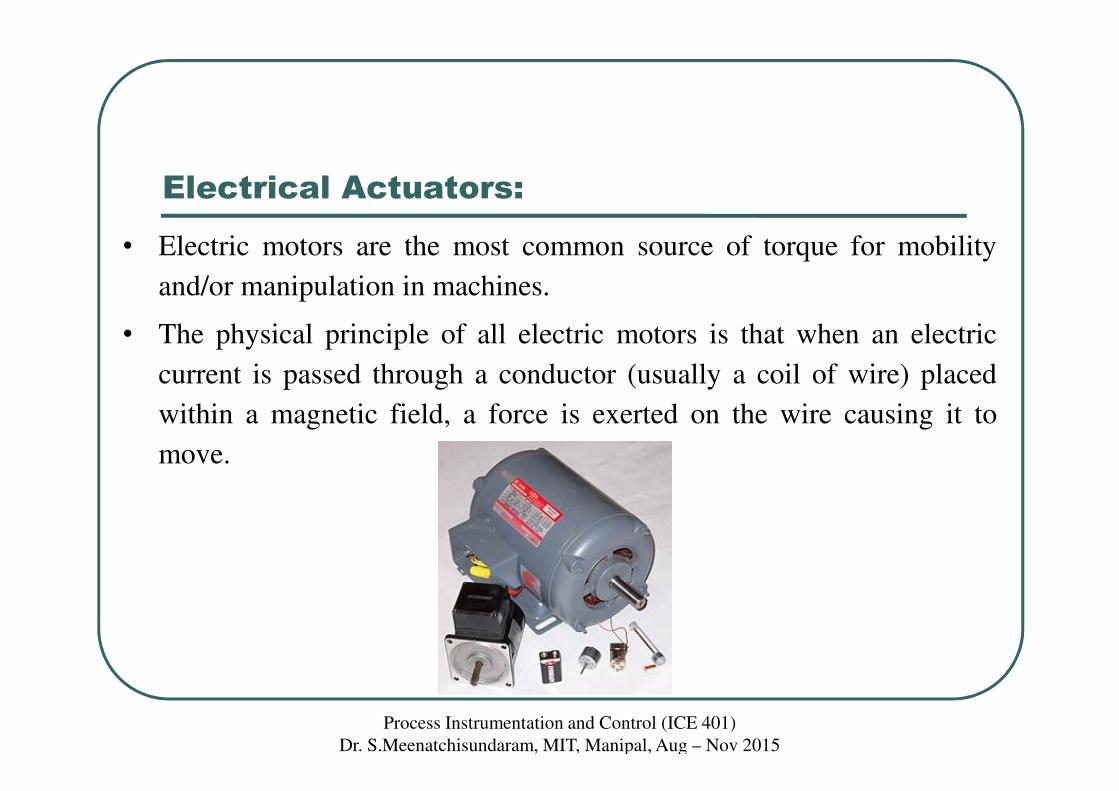
Electrical Actuators:
Process Instrumentation and Control (ICE 401)
Dr. S.Meenatchisundaram, MIT, Manipal, Aug – Nov 2015
• Electric motors are the most common source of torque for mobility
and/or manipulation in machines.
• The physical principle of all electric motors is that when an electric
current is passed through a conductor (usually a coil of wire) placed
within a magnetic field, a force is exerted on the wire causing it to
move.

Components of An Electric Motor:
Process Instrumentation and Control (ICE 401)
Dr. S.Meenatchisundaram, MIT, Manipal, Aug – Nov 2015
• The principle components of an electric motor are:
• North and south magnetic poles to provide a strong magnetic field.
Being made of bulky ferrous material they traditionally form the outer
casing of the motor and collectively form the stator
• An armature, which is a cylindrical ferrous core rotating within the
stator and carries a large number of windings made from one or more
conductors.
• A commutator, which rotates with the armature and consists of copper
contacts attached to the end of the windings
• Brushes in fixed positions and in contact with the rotating commutator
contacts. They carry direct current to the coils, resulting in the required
motion.