classic analog keyboards - synth...
TRANSCRIPT

VINTAGE KEYSC L A S S I C A N A L O G K E Y B O A R D S
OPERATION MANUAL
E-mu Systems, Inc.

This product is covered under one or more of the following U. S. patents: 3,969,682;3,986,423; 4,404,529; 4,506,579; 4,699,038; 4,987,600; 5,013,105; 5,072,645;5,111,727 and foreign patents and/or pending patents. Vintage keys is a registeredtrademark of E-mu Systems, Inc.
Important Notice:In order to obtain warranty service on your Vintage Keys unit, the serial number stickermust be intact and you must have a sales receipt or other proof of purchase. If there is noserial number sticker on Vintage Keys, please contact E-mu Systems at once.
Operation Manual© 1992 E-mu Systems, Inc.All Rights Reserved
• FI407 Rev. C
PRINTED AND MADE IN THE USA
VINTAGE KEYSC L A S S I C A N A L O G K E Y B O A R D S
Manual - Riley SmithDesign & Cover - Nancy Enge
E-mu World HeadquartersE-mu Systems, Inc. U.S.A.P.O. Box 660015Scotts Valley, CA USA95067–0015Telephone: 408-438-1921Fax: 408-438-8612
Europe, Africa, Middle EastE-mu Systems, Ltd.Suite 6, Adam FergusonHouseEskmills Industrial ParkMusselburgh, East LothianScotland, EH21 7PQTelephone: 44-31-653-6556Fax: 44-31-665-0473

WARNING: READ THIS FIRST!
This symbol is intended to alertthe user to the presence ofimportant operating andmaintenance (servicing)instructions in the literatureaccompanying the appliance.
This symbol is intended to alertthe user to the presence ofuninsulated dangerous voltagewithin the product's enclosurethat may be of sufficientmagnitude to constitute a risk ofelectric shock to persons.
IMPORTANT SAFETY INSTRUCTIONSUse in countries other than the U.S.A. may require the use of a different linecord or attachment plug, or both. To reduce the risk of fire or electric shock,refer servicing to qualified service personnel. To reduce risk of fire or electricshock do not expose this product to rain or moisture.
GROUNDING INSTRUCTIONSThis product must be grounded. If it should malfunction or break down,grounding provides a path of least resistance for electric current, reducing therisk of electric shock. This product is equipped with a cord having an equip-ment-grounding conductor and a grounding plug. The plug must be pluggedinto an appropriate outlet properly installed and grounded in accordancewith all local codes and ordinances.
DANGERImproper connection of equipment grounding conductor can result in therisk of electric shock. Check with a qualified electrician or service personnelif you are in doubt as to whether the product is properly grounded. Do notmodify the plug provided with this product — if it will not fit the outlet,have a proper outlet installed by a qualified technician.
CAUTIONIf the 9045, Vintage Keys is rack mounted, a standard 19-inch open framerack must be used.
USER-MAINTENANCE INSTRUCTIONS1. Vintage Keys should be kept clean and dust free. Periodically wipe the unit
with a clean, lint free cloth. Do not use solvents or cleaners.
2. There are no user lubrication or adjustment requirements.
3. Refer all other servicing to qualified service personnel.
INSTRUCTIONS PERTAINING TO A RISK OF FIRE,ELECTRIC SHOCK, OR INJURY TO PERSONS
WARNING; When using electric products, basic precautions shouldalways be followed, including the following:
1. Read all instructions before using Vintage Keys.
2. To reduce the risk of injury, close supervision is necessary when VintageKeys is used near children.
3. Do not use Vintage Keys near water — for example near a bathtub, wash-bowl, kitchen sink, in a wet basement, on a wet bar, or near or in a swim-ming pool.
SAVE THESE INSTRUCTIONS
4. Vintage Keys should be situated so that its location or position does notinterfere with its proper ventilation.
5. Vintage Keys should be located away from heat sources such as radiators,heat registers, fireplaces, stoves, or ovens.
6. Vintage Keys should only be connected to a power supply of the typedescribed in the operating instructions and as marked on the product.
7. This product, in combination with an amplifier and headphones andspeakers, may be capable of producing sound levels that could causepermanent hearing loss. Do not operate for a long period of time at a highvolume level or at a level that is uncomfortable. If you experience anyhearing loss or ringing in the ears, consult an audiologist.
8. Vintage Keys may be equipped with a polarized line plug (one blade widerthat the other). This is a safety feature. If you are unable to insert this pluginto the outlet, do not defeat the safety purpose of the plug. Contact anelectrician to replace your obsolete outlet.
9. The power supply cord of Vintage Keys should be unplugged from theoutlet when left unused for a long period of time.
10. Care should be taken so that objects do not fall and liquids are not spilledinto the enclosure of Vintage Keys through openings.
11. The product should be serviced by qualified service personnel when:
A. The power supply cord has been damaged; or
B. Objects have fallen, or liquid has been spilled into the product; or
C. The product has been exposed to rain; or
D. The product does not appear to operate normally or exhibits amarked change in performance; or
E. The product has been dropped or the enclosure damaged.
12. All servicing should be referred to qualified service personnel.
SAVE THESE INSTRUCTIONS

CONTENTS
INTRODUCTION & BASIC SETUP 1
Introduction ............................................................................................ 3Vintage Keys Organization .................................................................. 4Connection Instructions ....................................................................... 5
BASIC OPERATION 9
Main Controls ....................................................................................... 11Selecting MIDI Channels .................................................................... 12Selecting Presets ................................................................................... 12Adjusting Volume & Pan Position .................................................... 12Playing the Demo Sequences ............................................................. 13Multi-Timbral Operation .................................................................... 13About Vintage Keys ............................................................................. 14
MASTER MENU 15
Enabling the Master Menu ................................................................ 17Master Tune .......................................................................................... 17Transpose .............................................................................................. 18Global Bend .......................................................................................... 18Global Velocity Curve ......................................................................... 18Mix Output ............................................................................................ 20MIDI Mode ............................................................................................ 20MIDI Mode Change ............................................................................. 21MIDI Overflow ...................................................................................... 21MIDI Enable .......................................................................................... 21Preset Change ........................................................................21MIDI Controller Assign ....................................................................... 22MIDI Footswitch Assign ...................................................................... 22MIDI Program Preset ...................................................................... 22Send MIDI Data ................................................................................... 23User Key Tuning ................................................................................... 24Viewing Angle ....................................................................................... 24
PROGRAMMING BASICS 25
Modulation ........................................................................................... 28Modulation Sources ............................................................................. 29Envelope Generators ........................................................................... 30Low Frequency Oscillators ................................................................. 31MIDI Patch ............................................................................................ 32

PROGRAMMING BASICS (continued)
Filter Modulation ...................................................................... 33Vintage Keys Signal Flow .......................................................... 36Keyboard & Velocity Modulation ............................................. 37Key Number .............................................................................. 38Velocity Curves ......................................................................... 38Realtime Modulation ................................................................ 39MIDI Realtime Controls ............................................................ 40Stereo Mix Outputs ................................................................... 42
EDIT MENU 43
Enabling the Edit Menu ...................................................................... 45Preset Name .......................................................................................... 46Primary Instrument ............................................................................. 47Secondary Instrument ......................................................................... 47Key Range .............................................................................................. 47Primary Key Range .............................................................................. 48Secondary Key Range .......................................................................... 48Coarse Tuning ...................................................................................... 49Fine Tuning ........................................................................................... 49Volume ................................................................................................... 49Pan .......................................................................................................... 49Alternate Envelope On/Off ................................................................. 50Primary Alternate Envelope Parameters ......................................... 50Secondary Alternate Envelope Parameters ..................................... 50Delay ...................................................................................................... 51Sound Start ........................................................................................... 51Reverse Sound ....................................................................................... 51Solo Mode ............................................................................................. 52Portamento Rate .................................................................................. 52Chorus .................................................................................................... 52Crossfade Mode .................................................................................... 53Crossfade Direction ............................................................................. 54Crossfade Amount .................................................................... 55Cross-switch Point ............................................................................... 55Primary Filter Type .............................................................................. 55Primary Filter Cutoff & Q ................................................................... 56Secondary Filter Type .......................................................................... 56Secondary Filter Cutoff & Q .............................................................. 56Auxiliary Envelope ............................................................................... 57LFO 1 - Shape & Amount ................................................................... 58
CONTENTS

EDIT MENU (continued)
LFO 1 - Rate, Delay & Variation ...............................................58LFO 2 - Shape & Amount .......................................................... 59LFO 2 - Rate, Delay & Variation ...............................................59Keyboard & Velocity Modulation Control................................. 60Realtime Modulation Control ................................................... 61Footswitch Control .............................................................................. 62Pitch Bend Range ..................................................................... 62Pressure Amount .................................................................................. 62MIDI Controller Amount .................................................................... 62Velocity Curve ....................................................................................... 63Keyboard Center .................................................................................. 64Keyboard Tuning ...................................................................... 64Mix Output Assign ............................................................................... 65Preset Links ............................................................................................ 65Save Preset ............................................................................................ 66
PRACTICE PROGRAMMING 67
Linking Presets ..........................................................................69Editing Presets ...................................................................................... 70Changing the Tuning of an Instrument .......................................... 70Chorus ......................................................................................71Reversing an Instrument ...........................................................71Alternate Volume Envelope ................................................................ 72Working with the Filter ....................................................................... 73Vintage Synthesis ................................................................................. 77Reverb Spaces ....................................................................................... 78Using Vintage Keys with a Sequencer ............................................. 79More Advanced Sequencing .............................................................. 80
REFERENCE SECTION 83
Preset Listing ............................................................................ 84Instrument Listing ....................................................................88B3 Waves - Drawbar Settings ................................................... 95Percussion Instrument Locations .............................................. 98Technical Specifications .......................................................... 101MIDI Specifications ................................................................. 102Warranty ................................................................................ 118Index ...................................................................................... 119
CONTENTS


INTRODUCTION

1Chapter 1: Basic Setup
INTRODUCTION& BASIC SETUP
Vintage Keys Operation Manual2
3Chapter 1: Basic Setup
INTRODUCTION
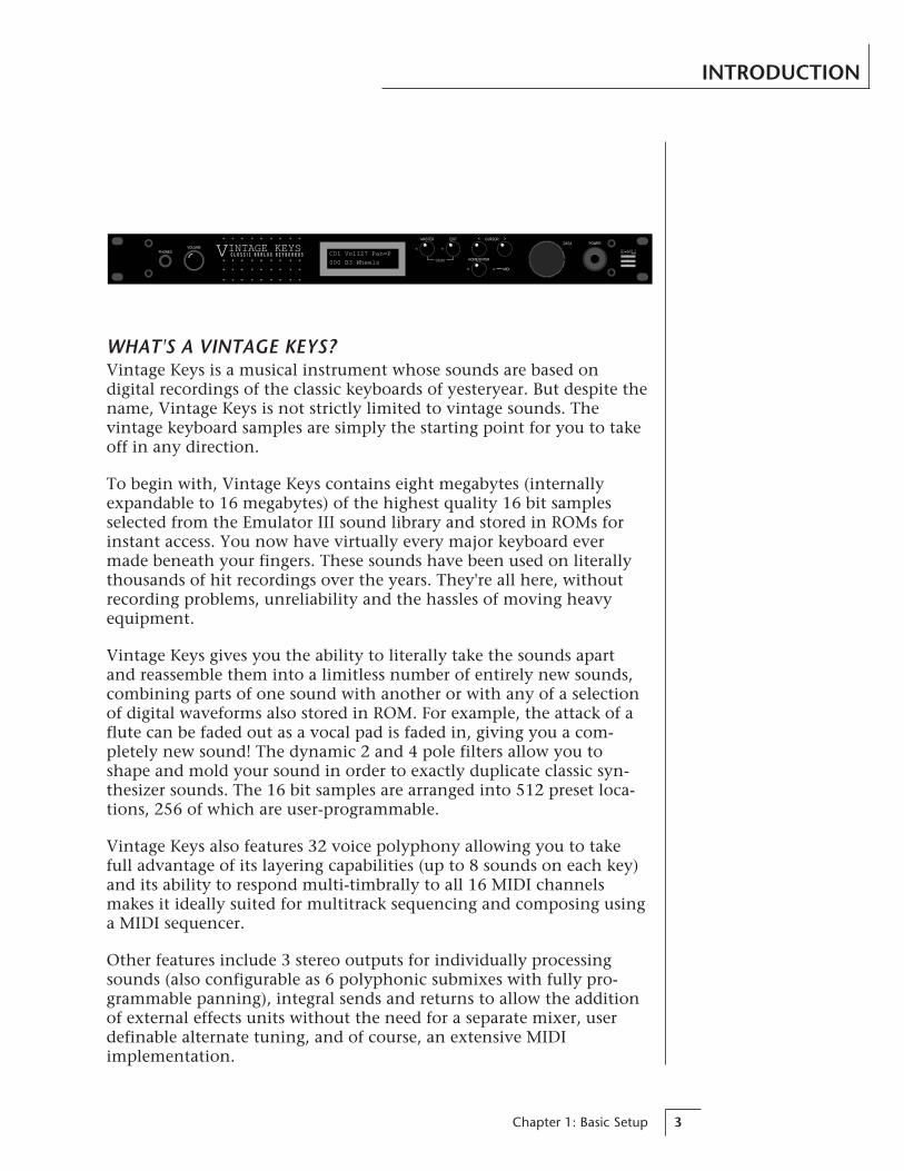
WHAT'S A VINTAGE KEYS?Vintage Keys is a musical instrument whose sounds are based ondigital recordings of the classic keyboards of yesteryear. But despite thename, Vintage Keys is not strictly limited to vintage sounds. Thevintage keyboard samples are simply the starting point for you to takeoff in any direction.
To begin with, Vintage Keys contains eight megabytes (internallyexpandable to 16 megabytes) of the highest quality 16 bit samplesselected from the Emulator III sound library and stored in ROMs forinstant access. You now have virtually every major keyboard evermade beneath your fingers. These sounds have been used on literallythousands of hit recordings over the years. They're all here, withoutrecording problems, unreliability and the hassles of moving heavyequipment.
Vintage Keys gives you the ability to literally take the sounds apartand reassemble them into a limitless number of entirely new sounds,combining parts of one sound with another or with any of a selectionof digital waveforms also stored in ROM. For example, the attack of aflute can be faded out as a vocal pad is faded in, giving you a com-pletely new sound! The dynamic 2 and 4 pole filters allow you toshape and mold your sound in order to exactly duplicate classic syn-thesizer sounds. The 16 bit samples are arranged into 512 preset loca-tions, 256 of which are user-programmable.
Vintage Keys also features 32 voice polyphony allowing you to takefull advantage of its layering capabilities (up to 8 sounds on each key)and its ability to respond multi-timbrally to all 16 MIDI channelsmakes it ideally suited for multitrack sequencing and composing usinga MIDI sequencer.
Other features include 3 stereo outputs for individually processingsounds (also configurable as 6 polyphonic submixes with fully pro-grammable panning), integral sends and returns to allow the additionof external effects units without the need for a separate mixer, userdefinable alternate tuning, and of course, an extensive MIDIimplementation.
PHONESVOLUME
EDITMASTER
DEMO
CURSOR< >
HOME/ENTER
DATA POWER
MIDI
VINTAGE KEYSC L A S S I C A N A L O G K E Y B O A R D S C01 Vol127 Pan=P
000 B3 Wheels

Vintage Keys Operation Manual4
VINTAGE KEYS ORGANIZA-TION
Vintage Keys is organized as shown in the diagram below.
The Preset is a complete set of all program parameters for a completeVintage Keys sound. The fully programmable user presets and theunalterable ROM presets are organized as shown below.
000 - 255 USER PRESETS
256 - 511 ROM PRESETS
Each preset consists of one or more instruments. An instrument is acomplete set of samples or a digital waveform which covers the entirekeyboard range. An instrument can be assigned to each of the Primaryand Secondary layers of the preset.
The primary and secondary layers are essentially two complete soundsstacked or placed adjacent to each other, and can be switched orcrossfaded together in various ways.
Up to four presets can be Linked in order to have more than one preseton the keyboard at a time. The linked presets may overlap each otherfor layered sounds or be adjacent to each other to create keyboard“splits”.
PRESETPRIMARY
SECONDARY
PRESETPRIMARY
SECONDARY
PRESETPRIMARY
SECONDARY
PRESETPRIMARY
SECONDARY
LINK 1
LINK 2
LINK 3
INSTRUMENT
INSTRUMENT
PRESETPRIMARY
SECONDARY
• User Presets can bemoved, erased or modified asdesired.• ROM Presets cannot bemoved or altered unless theyare first copied to a userlocation.

5Chapter 1: Basic Setup
CONNECTION INSTRUCTIONS
• • • If Vintage Keys does notseem to be respondingcorrectly, make sure the bothVintage Keys and your MIDIcontroller are set to the sameMIDI channel.
SETUP #1 BASIC SETUP
MIDI InVintage Keys is controlled by MIDI messages received at the MIDIIn connector. Connect the MIDI In of the Vintage Keys to theMIDI Out connector of a MIDI controller such as a MIDI key-board, MIDI wind controller or MIDI guitar controller.
OutputsVintage Keys is a high quality, stereo audio device. In order toreproduce its wide dynamic range and frequency response, use ahigh quality amplification and speaker system such as a keyboardamplifier or home stereo system. A stereo setup is highly desirablebecause of the added realism of stereophonic sound. Headphonescan be used if an amplifier and speaker system is not available.Plug stereo headphones into the headphone jack located on theleft side of the front panel. The Right Main output jack serves as amono output when the Left Main plug is not plugged in.
R - SUB2 - L R - SUB1 - L R - MAIN - LMONO STEREO
THRUOUTIN
OUTPUTSMIDI
Scotts Valley, California U.S.A.
100-250VAC 50/60 Hz ~
E-MU SYSTEMS, INC.
WARNING: TO REDUCE THE RISK OF FIREOR ELECTRIC SHOCK, DO NOT EXPOSETHIS PRODUCT TO RAIN OR MOISTURE.
Mai
n O
uts
to M
ixer
In
MIDI Controller(MIDI Keyboard, Sequencer, etc.)
MIDI Out
Aux. orTape In
Male RCA plugto
Male Phono Plug
ToMain Outs
Home StereoSystem
Home StudioSystem
Speakers
Amp
Mixer
The Headphone Output is located
on the Front Panel The headphone outputmonitors the main outputsonly.The submix outputs do NOTfeed into the headphoneoutput.

Vintage Keys Operation Manual6
CONNECTION INSTRUCTIONS
SETUP #2 STUDIO SETUP
MIDI InIn this setup, Vintage Keys is controlled by MIDI messages re-ceived at the MIDI In connector which have been routed by aMIDI switcher. The MIDI switcher allows any MIDI controllersuch as a MIDI keyboard, MIDI wind controller or a computer tobe easily connected.
MIDI OutThe MIDI Out jack is normally used to transmit program data to acomputer or other device.
OutputsVintage Keys has three sets of programmable stereo outputs;Main, Sub 1, and Sub 2. Specific Vintage Keys presets (or MIDIchannels) can be routed to one of these stereo pairs in order to befurther processed or mixed separately.
Sub
2 O
utp
uts
Sub
1 O
utp
uts
Mai
n O
utp
uts
MIDI Out
MIDI Controller(MIDI Keyboard, Sequencer, etc.)
Computer
MIDI In
AdditionalMIDI
Devices
MIDI Switcher
MIDIOut
Out In
Out
OutInIn
R - SUB2 - L R - SUB1 - L R - MAIN - LMONO STEREO
THRUOUTIN
OUTPUTSMIDI
Scotts Valley, California U.S.A.
100-250VAC 50/60 Hz ~
E-MU SYSTEMS, INC.
WARNING: TO REDUCE THE RISK OF FIREOR ELECTRIC SHOCK, DO NOT EXPOSETHIS PRODUCT TO RAIN OR MOISTURE.
MIDIIn

7Chapter 1: Basic Setup
CONNECTION INSTRUCTIONS
SETUP #3 PERFORMANCE SETUP
MIDI InVintage Keys is controlled by MIDI messages received at the MIDIIn connector. Connect the MIDI In of Vintage Keys to the MIDIOut connector of a MIDI controller such as a MIDI keyboard,MIDI wind controller or MIDI guitar controller.
MIDI ThruThe MIDI Thru jack is used to connect additional MIDI devicesonto the MIDI chain. MIDI Thru transmits an exact copy of themessages received at the MIDI In jack.
OutputsEach of the Sub 1 and Sub 2 output jacks on the Vintage Keys arestereo jacks. The tip of each jack (accessed when a standard phoneplug is inserted) connects to the left or right output of that group.
R - SUB2 - L R - SUB1 - L R - MAIN - LMONO STEREO
THRUOUTIN
OUTPUTSMIDI
Scotts Valley, California U.S.A.
100-250VAC 50/60 Hz ~
E-MU SYSTEMS, INC.
WARNING: TO REDUCE THE RISK OF FIREOR ELECTRIC SHOCK, DO NOT EXPOSETHIS PRODUCT TO RAIN OR MOISTURE.
Sub OutputReturn(To Main Output)
Tip Ring
To Effect From Effect
SEND/RETURN CABLES
Effect Device
Send
/Ret
urn
Effect Device Mai
n O
uts
to M
ixer
In
AdditionalMIDI
Devices
MIDI Controller(MIDI Keyboard, Sequencer, etc.)
MIDI OutMIDI In
Send
/Ret
urn

Vintage Keys Operation Manual8
If a stereo plug is inserted, the Ring of the stereo plug serves as a signalReturn which sums into the Main outputs.
Therefore, the Sub 1 and Sub 2 jacks can serve as effect sends andreturns in order to further process selected instruments and thenreturn them to the main mix.
The diagram shows the Sub 1 and Sub 2 jacks being used as send/returns in order to further process selected Vintage Keys presets with-out using the effects bus on the mixing board. In a pinch, the effectreturns could also be used to sum additional instruments into themain outputs.
The Sub 1 and Sub 2 jacks can be used as effect returns to the Main Outputs.
Tip
Ring
Tip
Ring
Tip
Ring
Tip
Ring
Tip Tip
Ring
SUB 2 SUB 1 MAIN
R L R L R L
R Bus
L Bus
Vintage Keys Output Section
POWER UP!The power switch is located on the right side of the front panel. Vin-tage Keys and its MIDI controller may be turned on in any order.When power is applied, the liquid crystal display will light, indicatingthat Vintage Keys is operating. You may have noticed that there is no110/220 Volt power selector switch on Vintage Keys.
Vintage Keys automatically switches itself for 110 or 220 Voltoperation.
CONNECTIONS
••• Inserting a standardmono phone plug halfwayinto the jack allows you tosum into the main outputswithout a special cable.

Chapter 2: Basic Operation 9
BASICOPERATION

Vintage Keys Operation Manual10

Chapter 2: Basic Operation 11
MAIN CONTROLS
BASIC OPERATION
PHONESVOLUME
EDITMASTER
DEMO
CURSOR< >
HOME/ENTER
DATA POWER
MIDI
VINTAGE KEYSC L A S S I C A N A L O G K E Y B O A R D S C01 Vol127 Pan+0
000 Preset Name
VOLUMECONTROL
HOME/ENTERBUTTON
EDIT MENUSELECT
DATA ENTRYCONTROL
CURSORCONTROLS
POWERSWITCH
MASTER MENUSELECT
DISPLAY
MIDIACTIVITY
HEADPHONEJACK
Power SwitchSwitches AC power to Vintage Keys On and Off.
MIDI Activity LEDIndicates that MIDI data is being received.
Master Menu Select ButtonThe Master menu contains parameters that affect the entiremachine, not just certain presets. An illuminated LED to the leftof the button indicates that you are in the Master menu.
Edit Menu Select ButtonThe Edit menu is used when you want to change parameters of apreset. An illuminated LED to the left of the button indicates thatyou are in the Edit menu.
Home/Enter ButtonThe Home/Enter button is used to initiate a particular operation.The red LED to the left of the enter button flashes to let you knowthat Vintage Keys is waiting for your response.
Cursor ControlThis button moves the cursor to the next parameter on the dis-play. (The cursor is a little flashing line underneath one of theparameters in the display.) Press the cursor control repeatedlyuntil the cursor is underneath the desired parameter. The cursorcan also be moved bidirectionally using the data entry controlwhile the cursor select button is being held down (i.e. Press andhold the cursor button and turn the data entry knob).
Data Entry ControlThe data entry control is a stepped, variable control which is usedto change parameter values. The control increments or decre-ments the current value one unit with each click. This controlincorporates acceleration (values advance faster if the control isturned quickly).
Volume ControlThis is the master volume control for all audio outputs. Note: Formaximum dynamic range, set this control at full level.

Vintage Keys Operation Manual12
÷ MIDI Channel Parameters÷ Preset Information
BASIC OPERATION
••• Channel Pan shouldnormally be set to “P” unlessrealtime control of panning isdesired. This will allow theprogrammed pan setting foreach preset to be used.
• • • If Vintage Keys is notresponding properly or playsthe wrong preset, make surethat both Vintage Keys andyour MIDI controller are setto the same MIDI channeland that the MIDI Volume isturned up.
For more information aboutMIDI, see MIDI RealtimeControls on page 40.
MIDI CHANNEL SELECTIONPress the cursor key repeatedly until the cursor is underneath thechannel number. (The cursor is a little flashing line underneath one ofthe parameters in the display.) Rotate the data entry control to selectMIDI channel 01-16. As the channel is changed, the display willchange to show the preset, volume and pan associated with the dis-played channel.
C01 Vol127 Pan=P000 Preset Name
PRESET SELECTIONPress the cursor key repeatedly until the cursor is underneath thepreset number. (The cursor is a little flashing line underneath one ofthe parameters in the display.) As the data entry control is rotated, thepreset number and name will change. The displayed preset will beassigned to the displayed MIDI channel. Preset numbers range from000 to 511.
C01 Vol127 Pan=P000 Preset Name
CHANNEL VOLUMEPress the cursor key repeatedly until the cursor is underneath thevolume value. Rotate the data entry control to select volume 00-127.(This is the same parameter as MIDI volume control #7, and changesmade over MIDI will be shown in the display.)
CHANNEL PANPress the cursor key repeatedly until the cursor is underneath the panvalue. Rotate the data entry control to select pan values -7 to +7 or“P”. When “P” is selected, the pan value specified in the preset isselected. Any other value will override the pan parameter in the pre-set. (This is the same parameter as MIDI pan control #10, and changesmade over MIDI will be shown in the display.)
MIDI Channel
Preset No.
Volume
Stereo Position
Preset Name

Chapter 2: Basic Operation 13
BASIC OPERATION
Each of the 16 MIDI channels can be assigned to play a specific Vintage Keys preset.
PLAYING THE DEMO SEQUENCESVintage Keys contains a play-only sequencer in order to give you anidea of what is possible using this amazing machine. Press and holdboth the Master button and the Edit button. The sequence will startina moment. Press the Enter button to stop the sequence. Press eithercursor button to change the sequence. Vintage Keys contains 4 se-quences (1-4).
DEMO 1 2 3 4ENTER=Stop >=Nxt
MULTI-TIMBRAL OPERATIONMulti-timbral operation means that the Vintage Keys can play morethan one sound at the same time. To access multiple presets on differ-ent MIDI channels simultaneously, follow these instructions:
1. Set the MIDI mode to MULTI-Mode, using the MIDI mode func-tion in the Master menu (page 20).
2. Decide which MIDI channels you wish the Vintage Keys to re-ceive, and turn all other channels OFF using the MIDI Enablefunction in the Master menu (page 21). Up to 16 channels can beselected simultaneously!
3. Select the desired preset for each of the MIDI channels you wishthe Vintage Keys to receive using the MIDI Channel/Preset selec-tion screen (see previous instructions).
4. Vintage Keys will now respond multi-timbrally on the MIDIchannels you have specified. The volume and pan position pa-rameters can be adjusted over MIDI (for each MIDI channel) orusing the Cursor and Data Entry control in the MIDI Channel/Preset selection screen.
••• Demo Sequences
1. Funky Blues & R+B OrganDemo - by HerbJimmerson
2. Synth Rock Orchestraby Gary Hull
3. Techno Raveby Sean Wilhelmsen
4. Pop/Rock Medleyby Will Puckett
Channel 01Volume
Pan
Channel 02Volume
Pan
Channel 03Volume
Pan
Channel 16Volume
Pan
PRESET
PRESET
PRESET
PRESET

Vintage Keys Operation Manual14
Memory
10100101001010100101001010101010010101001010
Digital/AnalogConverter
1011001
Amplifier
Basic Sampling System
Analog/DigitalConverter
10110011011001
-1V -2V3V-1V-2V3V1V
0V
3V
-3V
MASTER MENU
ABOUT VINTAGE KEYSVintage Keys utilizes digital recordings of real instruments for the basisof its sound. This is similar to a tape recorder except that inside theVintage Keys, the sounds are permanently recorded on digital memorychips.
To perform this modern miracle, sounds and instrument waveformsare first sampled into the Emulator III, our top of the line, 16 bit stereodigital sampler. After the sounds and waveforms have been truncated,looped and processed, they are “masked” into the Vintage Keys ROM(Read Only Memory) chips.
Conceptually, the sampling process is very simple, as shown in theBasic Sampling System diagram. As a sound wave strikes the dia-phragm of a microphone, a corresponding voltage is generated. Tosample the sound, the voltage level is repeatedly measured at a veryhigh rate and the voltage measurements are stored in memory. To playthe sound back, the numbers are read back out of memory, convertedback into voltages, then amplified and fed to a speaker which convertsthe voltage back into sound waves. Of course, playing back 32 chan-nels at different pitches tends to complicate matters, but this is basi-cally how it works. In Vintage Keys, we have left out the Analog/Digital converter stage since the sounds are already sampled for you.

Chapter 3: Master Menu 15
MASTERMENU

Vintage Keys Operation Manual16

Chapter 3: Master Menu 17
MASTER MENU
The Master menu contains functions that affect the overall operationof Vintage Keys. For example, changing the Master Tune will changethe tuning of all the presets, not just the one currently displayed.
To enable the Master menuPress the Master key, lighting the LED. The current screen will bethe one most recently selected since powering up Vintage Keys.The cursor will appear underneath the first character of the screenheading on line one.
To select a new screenPress the cursor key repeatedly (or hold the cursor key whileturning the data entry control) until the cursor is underneath thescreen title heading. Rotate the data entry control to select an-other screen.
To modify a parameterPress the cursor key repeatedly (or hold the cursor key whileturning the data entry control) until the cursor is underneath theparameter value. Rotate the data entry control to change thevalue.
To return to Preset Select modePress the Master key, turning off the LED.
MASTER MENU FUNCTIONS
• Master TuneMaster Tune adjusts the overall tuning of all presets so that VintageKeys can be tuned to other instruments. The master tuning range is ±1 semitone in 1/64th semitone increments. A master tune setting of“00” would indicate that the Vintage Keys is perfectly tuned to concertpitch (A=440 Hz).
MASTER TUNE+63

Vintage Keys Operation Manual18
MASTER MENU
• TransposeThis function transposes the key of Vintage Keys in half-step intervals.The transpose range is ± 12 semitones or one octave.
TRANSPOSE+12 semitones
• Global BendThis function sets the range of the pitch wheel only when it is routedto control pitch. The maximum pitch bend range is ± 12 semitones.This function only affects presets which have their individual pitchbend range set to global.
GLOBAL BEND+/- 12 semitones
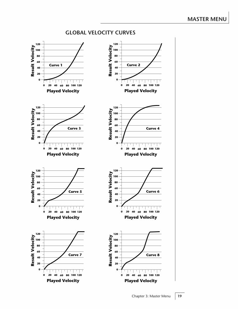
• Global Velocity CurveIncoming velocity data can be modified by a velocity curve in order toprovide different types of dynamics in response to your playing or tobetter adapt to a MIDI controller. This function allows you to selectone of eight global velocity curves or leave the velocity data unaltered(off). Global velocity curve only affects presets which have their indi-vidual velocity curve set to global.
GLOBAL VEL CURVE8
Chapter 3: Master Menu 19
MASTER MENU
Curve 1
0
20
40
60
80
100
120
0 20 40 60 80 100
Played Velocity120
Res
ult
Vel
oci
ty
Curve 3
0
20
40
60
80
100
120
0 20 40 60 80 100
Played Velocity120
Res
ult
Vel
oci
ty
Curve 5
0
20
40
60
80
100
120
0 20 40 60 80 100
Played Velocity120
Res
ult
Vel
oci
ty
Curve 7
0
20
40
60
80
100
120
0 20 40 60 80 100
Played Velocity120
Res
ult
Vel
oci
ty
Curve 2
0
20
40
60
80
100
120
0 20 40 60 80 100
Played Velocity120
Res
ult
Vel
oci
ty
Curve 4
0
20
40
60
80
100
120
0 20 40 60 80 100
Played Velocity120
Res
ult
Vel
oci
ty
Curve 6
0
20
40
60
80
100
120
0 20 40 60 80 100
Played Velocity120
Res
ult
Vel
oci
ty
Curve 8
0
20
40
60
80
100
120
0 20 40 60 80 100
Played Velocity120
Res
ult
Vel
oci
ty
GLOBAL VELOCITY CURVES

Vintage Keys Operation Manual20
MASTER MENU
• Mix OutputThis function allows you override the output assignments made ineach preset and instead assign the outputs according to MIDI channel.This also allows you to change the output assignment of the factorypresets. For each of the 16 MIDI channels, you can select the Main,Sub 1, or Sub 2 outputs, or “P”. When “P” is selected, the outputassignment selected in the preset is used. If no plugs are inserted intothe sub outputs, the audio will be automatically directed to the mainoutputs.
MIX OUTPUTchannel 01:P
• MIDI ModeThis function selects one of the four MIDI modes and the MIDI systemexclusive ID number.
Omni modeVintage Keys responds to note information on all MIDI channelsand plays the preset currently displayed in the main screen.
Poly modeVintage Keys only responds to note information received on thecurrently selected MIDI channel (on the preset selection screen)and plays that channel’s associated preset.
Multi modeVintage Keys responds to data on any combination of MIDIchannels and plays the specific preset associated with each of theMIDI channels.
Mono modeVintage Keys responds to data on any combination of MIDIchannels but plays each channel monophonically. If a new noteon a channel is played before the last note is released, the enve-lopes will not be retriggered (legato). Mono mode is particularlyuseful with alternate controllers such as MIDI guitars, etc.
ID numberThis function allows an external programming unit to distinguishbetween multiple Vintage Keys units. In the case of multipleVintage Keys units, each unit should have a different ID number.
MIDI MODE IDOmni 00
••• This function is usefulwhen sequencing because itallows you route specificMIDI channels to the Submixoutputs. From there they canbe externally processed withreverb or other effects.
Warning: Presets will notbe transferred between twoVintage Keys units unless theID numbers of both unitsmatch.
Chapter 3: Master Menu 21
• MIDI Mode ChangeThis function selects whether or not MIDI mode change commandsare accepted or ignored when received over MIDI (see MIDI Mode).
MIDI MODE CHANGEDisabled
• MIDI OverflowWhen on, if you play more notes than Vintage Keys has channels (32),the additional note data will be directed out the MIDI Out port to asecond Vintage Keys or other MIDI device, thus doubling the numberof available channels. MIDI Overflow can be turned On or Off.
MIDI OVERFLOWOff
• MIDI EnableWhen in MIDI Multi mode, this function lets you turn each MIDIchannel On or Off. This is useful when you have other MIDI devicesconnected and do not want the Vintage Keys to respond to the MIDIchannels reserved for the other devices. MIDI Enable only operates inMulti Mode.
MIDI ENABLEchannel:01 On
• Preset ChangeThis function lets the Vintage Keys utilize or ignore incoming MIDIpreset change commands for each channel. Note that MIDI can onlyselect presets 000-127. Presets 128-511 can either be selected manuallyor over MIDI using the mapping function “MIDI PROGRAM PRE-SET”.
PRESET CHANGEchannel:01 On
MASTER MENU
Vintage Keys Operation Manual22
MASTER MENU
• MIDI Controller AssignVintage Keys allows you to assign up to four realtime control sourcesfrom your MIDI controller. These control sources could be modulationwheels, data sliders or whatever. In this screen, you set up which con-trollers will be received by the Vintage Keys. What effect the controllerwill have is programmed separately for each preset. The Vintage KeysMIDI controllers are each assigned a letter, A-D. Each controller lettercan be assigned to a MIDI realtime controller from 01-31. Note: Ifcontroller numbers 7 or 10 are selected, they will override the standardMIDI volume and pan control routings. For more information, see MIDIRealtime Controls in the Programming Basics section.
CONTROLLER # CONTROLLER #A:01 B:02 C:03 D:04
• MIDI Footswitch AssignLike the MIDI Controllers, 3 MIDI footswitches can be assigned to MIDIfootswitch numbers. Footswitches can be assigned numbers from 64-79.Destinations for the footswitch controllers are programmed in the Editmenu.
FOOTSWITCH #1:64 2:65 3:66
• MIDI Program PresetIncoming MIDI program changes can be “mapped” to call a differentnumbered preset. This is a handy feature when you want a specificpreset number sent from the master synth to be linked with a specificpreset on Vintage Keys. For example, the Program Preset Map couldbe set to call up preset 12 whenever Vintage Keys receives programchange number 26. Any of the presets in Vintage Keys can be mappedto any incoming MIDI program change number. This feature also allowsyou to call up the presets 128-511, which are not normally accessibleover MIDI.
MIDI PROG>PRESET026 > 012
••• A few of the standard-ized MIDI Controllernumbers are listed below.
1 - Modulation Wheel orLever
2 - Breath Controller
3 - Aftertouch: Rev 1 DX7
4 - Foot Pedal
5 - Portamento Time
6 - Data Entry
7 - Volume
8 - Balance
9 - Undefined
10 - Pan
11 - Expression
••• A few of the standard-ized MIDI switch numbersare listed below.
64 - Sustain Switch (on/off)
65 - Portamento (on/off)
66 - Sostenuto (on/off)
67 - Soft Pedal (on/off)
69 - Hold Pedal 2 (on/off)

Chapter 3: Master Menu 23
This chart shows how MIDI preset changes can be re-mapped. In this example, programchanges 10-29 have been re-mapped. All other programs will be selected normally.
SelectedProgram
MappedProgram
0 1 2 3 4 5 6 7 8 9
10
20
30
40
50
60
70
80
90
100
110
120
00 01 02 03 04 05 06 07 08 09
30 31 32 33 34 35 36 37 38 39
40 41 42 43 44 45 46 47 48 49
50 51 52 53 54 55 56 57 58 59
60 61 62 63 64 65 66 67 68 69
70 71 72 73 74 75 76 77 78 79
80 81 82 83 84 85 86 87 88 89
90 91 92 93 94 95 96 97 98 99
100 101 102 103 104 105 106 107 108 109
110 111 112 113 114 115 116 117 118 119
120 121 122 123 124 125 126 127
44 191 50 01 15 88 151 78 99 88
34 73 106 55 43 75 12012118012
To Record MIDI Data intoa Sequencer:
1. Setup sequencer to receivesystem exclusive data.
2. Place sequencer intorecord mode, then SendPreset Data.
To Receive MIDI Datafrom a Sequencer:
1. Simply play back thesequence into Vintage Keys.
Warning: Send data asyou would a regular se-quence. Sending data in onehuge chunk may clog theVintage Keys input buffer.
••• The Preset, Volume, andPan information for all 16channels is included whenthe Master settings aretransmitted or received.
Warning: When transfer-ring SysEx data from oneVintage Keys to another, theID numbers of both unitsmust match.
• Send MIDI DataThis function will send MIDI System Exclusive data to the MIDI Outport of Vintage Keys. The MIDI data can either be sent to a computer/sequencer or to another Vintage Keys. Using the cursor key and thedata entry control, select the type of MIDI data you wish to transmit.The choices are:
Master SettingsTransmits all parameters in the Master menu except tuning table,program/preset map and viewing angle.
Program/ Preset MapTransmits only the program/preset map.
Tuning TableTransmits only the user tuning table.
Factory PresetsTransmits all the factory ROM presets.
User PresetsTransmits all the user presets.
Any Individual PresetTransmits only the selected preset.
The Enter LED will be flashing. Press the Enter button to confirm theoperation. To receive MIDI data, simply send the MIDI data into Vin-tage Keys from another Vintage Keys or your sequencer.
SEND MIDI DATA000 Stereo Piano
MASTER MENU
…etc. through 511

Vintage Keys Operation Manual24
• User Key TuningIn addition to standard twelve tone equal temperament, Vintage Keyscontains four additional preset tuning tables (Just C, Vallotti, 19 tone,and Gamelan) and one user definable tuning. User Key Tuning allowsyou to alter the parameters of the user definable tuning stored inmemory. The initial frequency of every key can be individually tuned,facilitating the creation of microtonal scales. Using the cursor key andthe data entry control, select the key name, the MIDI key number andthe fine tuning. The key name is variable from C-2 to G8. MIDI keynumber is variable from 0 to 127. The fine tuning is variable from 00to 63 in increments of 1/64 of a semitone (approx. 1.56 cents). Foreach preset, the specific tuning table is selected in the Edit menu.
USER KEY TUNINGKey:C1 036-00
• Viewing AngleThis function allows you to change the viewing angle of the display sothat it may be easily read from either above or below. The angle isadjustable from +7 to -8. Positive values will make the display easier toread when viewed from above. Negative values make the display easierto read from below.
VIEWING ANGLE+7
Key Name Fine Tuning
Coarse Tuning
••• Application: The userkey tuning can be used totune individual percussioninstruments.
MASTER MENU

Chapter 4: Programming Basics 25
PROGRAMMINGBASICS

Vintage Keys Operation Manual26
Chapter 4: Programming Basics 27
PROGRAMMING BASICS
This chapter explains how Vintage Keys sounds are constructed andcontains important background information on how to create yourown custom presets.
Your initial involvement with Vintage Keys will most likely consist ofusing the existing presets and selecting MIDI channels. While thefactory presets are very good, there are probably some things youwould like to change, perhaps the LFO speed, the filter cutoff or theattack time. You may also want to make your own custom presetsusing complex modulation routings. There are 256 user locations (000-255) available to store your own creations or edited factory presets.Best of all, it’s easy to edit or create new presets using the edit menu.
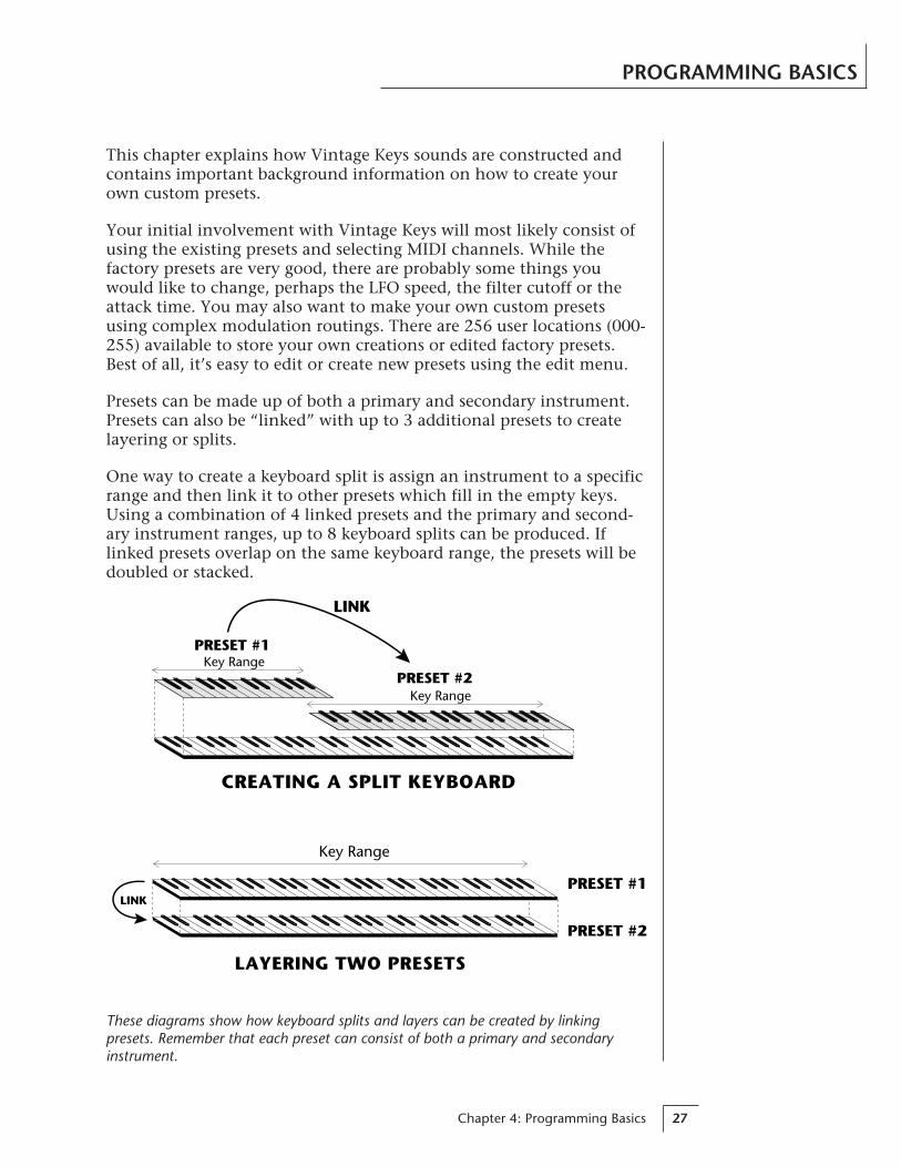
Presets can be made up of both a primary and secondary instrument.Presets can also be “linked” with up to 3 additional presets to createlayering or splits.
One way to create a keyboard split is assign an instrument to a specificrange and then link it to other presets which fill in the empty keys.Using a combination of 4 linked presets and the primary and second-ary instrument ranges, up to 8 keyboard splits can be produced. Iflinked presets overlap on the same keyboard range, the presets will bedoubled or stacked.
These diagrams show how keyboard splits and layers can be created by linkingpresets. Remember that each preset can consist of both a primary and secondaryinstrument.
PRESET #1
PRESET #2
LINK
LAYERING TWO PRESETS
Key Range
PRESET #1
PRESET #2Key Range
Key Range
LINK
CREATING A SPLIT KEYBOARD

Vintage Keys Operation Manual28
Vintage Keys has an extensive modulation implementation using twomulti-wave LFO’s (Low Frequency Oscillators), two envelope genera-tors and the ability to respond to multiple MIDI controllers. You cansimultaneously route any combination of these control sources tomultiple destinations.
MODULATIONModulation means to dynamically change a parameter, whether it bethe volume (amplitude modulation), the pitch (frequency modula-tion), or whatever. Turning the volume control on your home stereorapidly back and forth would be an example of amplitude modulation.To modulate something we need a modulation source and a modula-tion destination. The source is your hand turning the knob, and thedestination is the volume control. If we had a device that wouldautomatically turn the volume control, we would also call that devicea modulation source. The Vintage Keys is designed so that for each ofthe variable parameters, such as the volume, there is an initial settingwhich can be changed by a modulation source. Therefore in the caseof volume, we have an initial volume and we can change or modulatethat volume with a modulation source. Two main types of modulationsources on Vintage Keys are Envelope Generators and Low FrequencyOscillators. In the example above, an envelope generator could berouted to automatically turn the volume control as programmed bythe envelope. Or, a low frequency oscillator could be routed to auto-matically turn the volume control up and down in a repeatingfashion.
PROGRAMMING BASICS
Turning the volume control back and forth on your home stereo is an example ofAmplitude Modulation.

Chapter 4: Programming Basics 29
PROGRAMMING BASICS
MODULATION SOURCESVintage Keys uses three kinds of modulation sources.
• KEYBOARD AND VELOCITY MODULATIONValues which are generated at the start of a note and do not changeduring the note.
Keyboard KeyWhich key is pressed.
Key VelocityHow hard the key is pressed.
• REALTIME MODULATIONValues which can be continuously changed during the entire durationof the sound.
Pitch WheelA synthesizer pitch bend wheel.
Miscellaneous Controllers (4)Any type of MIDI controller data.
Keyboard Pressure (mono aftertouch)Key pressure applied after the key is initially pressed.
Polyphonic Key PressurePressure from a controller capable of generating polyphonicpressure data.
Low Frequency Oscillators (2)Generate repeating waves.
Envelope Generators (2)Generate a programmable “contour” which changes over timewhen a key is pressed.
• FOOTSWITCH MODULATIONChanges a parameter when one of the three footswitches are pressed.The footswitches can be programmed to switch: Sustain (pri/sec/both),Alternate Volume Envelope (pri/sec/both), Alternate Volume Release(pri/sec/both), or Cross-Switch between the primary and secondaryinstruments.
Vintage Keys Operation Manual30
PROGRAMMING BASICS
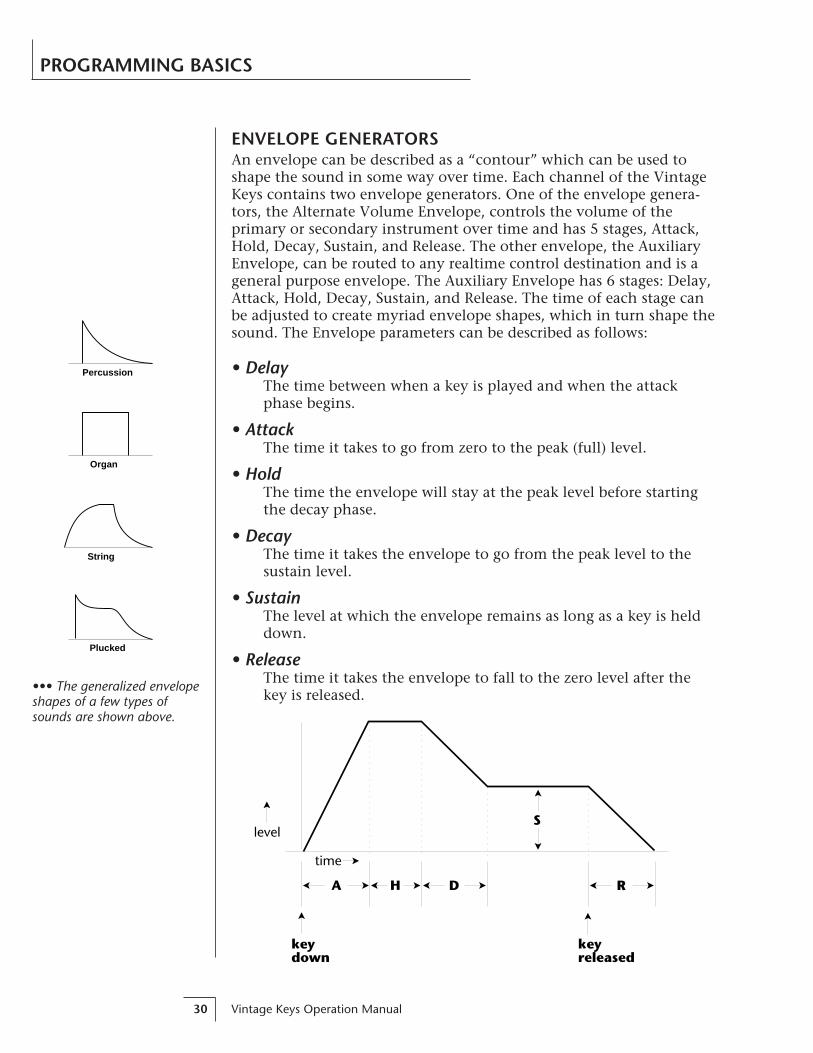
ENVELOPE GENERATORSAn envelope can be described as a “contour” which can be used toshape the sound in some way over time. Each channel of the VintageKeys contains two envelope generators. One of the envelope genera-tors, the Alternate Volume Envelope, controls the volume of theprimary or secondary instrument over time and has 5 stages, Attack,Hold, Decay, Sustain, and Release. The other envelope, the AuxiliaryEnvelope, can be routed to any realtime control destination and is ageneral purpose envelope. The Auxiliary Envelope has 6 stages: Delay,Attack, Hold, Decay, Sustain, and Release. The time of each stage canbe adjusted to create myriad envelope shapes, which in turn shape thesound. The Envelope parameters can be described as follows:
• DelayThe time between when a key is played and when the attackphase begins.
• AttackThe time it takes to go from zero to the peak (full) level.
• HoldThe time the envelope will stay at the peak level before startingthe decay phase.
• DecayThe time it takes the envelope to go from the peak level to thesustain level.
• SustainThe level at which the envelope remains as long as a key is helddown.
• ReleaseThe time it takes the envelope to fall to the zero level after thekey is released.
Percussion
Organ
String
Plucked
••• The generalized envelopeshapes of a few types ofsounds are shown above.
level
time
keydown
A H D
S
R
keyreleased
Chapter 4: Programming Basics 31
PROGRAMMING BASICS
Triangle
Square
Sine
Sawtooth
Random
level
keydown
keyreleased
A H R
time
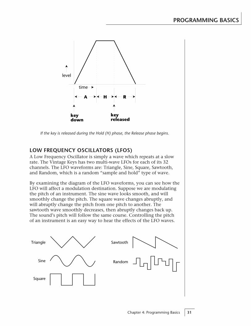
If the key is released during the Hold (H) phase, the Release phase begins.
LOW FREQUENCY OSCILLATORS (LFOS)A Low Frequency Oscillator is simply a wave which repeats at a slowrate. The Vintage Keys has two multi-wave LFOs for each of its 32channels. The LFO waveforms are: Triangle, Sine, Square, Sawtooth,and Random, which is a random “sample and hold” type of wave.
By examining the diagram of the LFO waveforms, you can see how theLFO will affect a modulation destination. Suppose we are modulatingthe pitch of an instrument. The sine wave looks smooth, and willsmoothly change the pitch. The square wave changes abruptly, andwill abruptly change the pitch from one pitch to another. Thesawtooth wave smoothly decreases, then abruptly changes back up.The sound’s pitch will follow the same course. Controlling the pitchof an instrument is an easy way to hear the effects of the LFO waves.

Vintage Keys Operation Manual32
When the amount of an LFO is a negative value, the LFO shape will beinverted. For example, inverting the sawtooth wave produces a wavethat smoothly increases, then instantly resets down.
PROGRAMMING BASICS
Sources
LFO 1LFO 2
Aux EnvWheel
PressureMIDIetc.
Destinations
PitchX-FadeVolume
LFO Amt.Filter FcAttack
etc.
ModulationSource Destination
Amount +/-
LFO 1 PrimaryVolume
+-
MIDIPATCHConnecting a modulation source to a destination is called a patch.Vintage Keys lets you connect the modulation sources in almost anypossible way to the modulation destinations. You can even modulateother modulators. Each patch also has an amount parameter whichdetermines “how much” modulation is applied to the destination. Themodulation amount can be positive or negative and will either add orsubtract from the initial value. Keyboard and velocity sources can besimultaneously patched to any 6 of the 42 destinations for each preset.Realtime modulation sources can be simultaneously patched to any 8of the 30 destinations for each preset.
Inverted Sawtooth
Negative Amount
+-
Sawtooth

Chapter 4: Programming Basics 33
PROGRAMMING BASICS
FILTER MODULATIONVintage Keys contains two low pass filters for each of its 32 channels.The block diagram of a single channel is shown below.
R
LVolume
Pan
VolumeAHDSR
Instrument
PitchSampleStart
ToneLow Pass
FilterQFc
DCA
Aux.AHDSR
The Tone filter is a simple tone control and can be used to brightenor darken the tone of an instrument. The Low Pass filter is a power-ful synthesizer filter which can dramatically alter the sound of aninstrument.
WHAT IS A FILTER?To understand how a filter works we need to understand what makesup a sound wave. A sine wave is the simplest form of sound wave. Anywaveform except a sine wave can be analyzed as a mix of sine waves atspecific frequencies and amplitudes.
One way to represent complex waveforms is to use a chart with fre-quency on one axis and amplitude on the other. Each vertical line ofthe chart represents one sine wave at a specific amplitude.
20
40
60
80
100
40 80 160 360 720 1440 2880
Frequency
...
Am
pli
tud
e

Vintage Keys Operation Manual34
PROGRAMMING BASICS
Most of the instruments in Vintage Keys are complex waves contain-ing many sine waves of various amplitudes and frequencies. A filter isa device which allows us to remove certain components of a sounddepending on its frequency. For example, a Low Pass Filter, like theone in Vintage Keys, lets the low frequencies pass and removes onlythe high frequencies.
The point at which the frequencies begin to be cut is called the CutoffFrequency (or Fc for short). A filter that let only the high frequenciespass would be called a High Pass filter. Using a filter, we now have away to control the harmonic content of a sampled sound. As it turnsout, a low pass filter can simulate the response of many naturalsounds.
For example, when a piano string is struck by its hammer, there areinitially a lot of high frequencies present. If the same note is playedsofter, there will be fewer of the high frequencies generated by thestring. We can simulate this effect by routing the velocity of thekeyboard to control the amount of high frequencies that the low passfilter lets through. The result is expressive, natural control over thesound.
The auxiliary envelope generator is commonly used to control thecutoff frequency of the low pass filter. This allows the frequencycontent to be varied dynamically over the course of the note. Dy-namic filtering coupled with all the different instruments available,makes for almost endless possibilities in the final sound. Any modula-tion source can be used to modulate the filter.
20
40
60
80
100
40 80 160 360 720 1440 2880
Frequency
...
Am
pli
tud
e
Cutoff Frequency
Output of Filter••• When the filter Fc is 000all sound will be cut off. Theinitial filter Fc and all Fcmodulators ADD algebra-ically to determine the actualFc. If you are not gettingsound, adjust the initial Fc orreduce the amount ofmodulation. Careful adjust-ment of all the filter param-eters is the secret to gettinggreat sounds.
Chapter 4: Programming Basics 35
PROGRAMMING BASICS
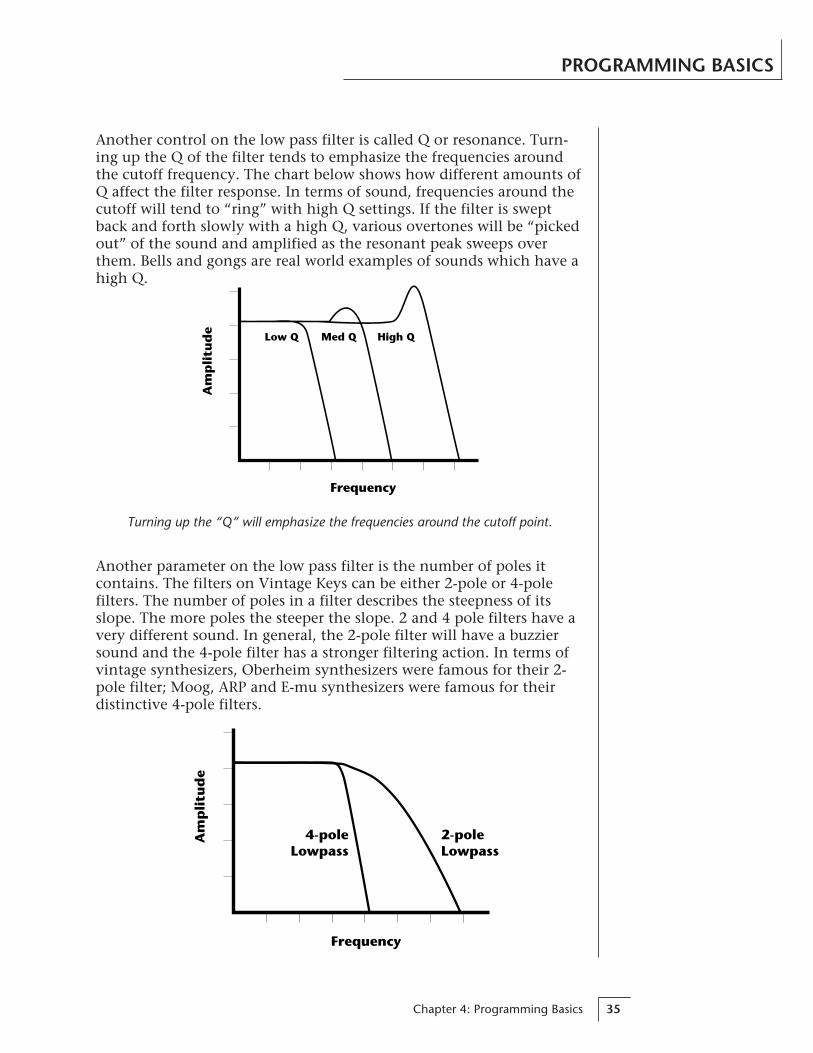
Another control on the low pass filter is called Q or resonance. Turn-ing up the Q of the filter tends to emphasize the frequencies aroundthe cutoff frequency. The chart below shows how different amounts ofQ affect the filter response. In terms of sound, frequencies around thecutoff will tend to “ring” with high Q settings. If the filter is sweptback and forth slowly with a high Q, various overtones will be “pickedout” of the sound and amplified as the resonant peak sweeps overthem. Bells and gongs are real world examples of sounds which have ahigh Q.
Frequency
Am
pli
tud
e Low Q Med Q High Q
Turning up the “Q” will emphasize the frequencies around the cutoff point.
Another parameter on the low pass filter is the number of poles itcontains. The filters on Vintage Keys can be either 2-pole or 4-polefilters. The number of poles in a filter describes the steepness of itsslope. The more poles the steeper the slope. 2 and 4 pole filters have avery different sound. In general, the 2-pole filter will have a buzziersound and the 4-pole filter has a stronger filtering action. In terms ofvintage synthesizers, Oberheim synthesizers were famous for their 2-pole filter; Moog, ARP and E-mu synthesizers were famous for theirdistinctive 4-pole filters.
Frequency
Am
pli
tud
e
4-poleLowpass
2-poleLowpass

Vintage Keys Operation Manual36
VINTAGE KEYS SIGNAL FLOWGoing back to the block diagram for a single channel we can re-exam-ine the complete signal path.
PROGRAMMING BASICS
R
LVolume
Pan
VolumeAHDSR
Instrument
PitchSampleStart
ToneLow Pass
FilterQFc
DCA
Aux.AHDSR
InstrumentThis is the sampled sound wave. The pitch of the instrument canbe modulated by any modulation source. The sample start pointcan only be modulated by a velocity or key source (see the nextpage).
ToneTone is a simple tone control which can be used to brighten ormute the sound. Tone can only be modulated by a velocity or keysource (see the next page). Key velocity is commonly used tomodulate the tone so that the harder you play, the brighter thesound becomes.
Low Pass FilterThe Low Pass Filter is used to shape the harmonic content of aninstrument. The Fc can be modulated by any source. The auxiliaryenvelope is commonly used to dynamically shape the harmoniccontent over time. Q or resonance can only be modulated by avelocity or key source. There are two types of low pass filteravailable: a 2-pole filter and a 4-pole filter. The 4-pole filter has asteeper slope and a stronger filtering action.
DCADigitally Controlled Amplifier. Together with the VolumeAHDSR, the DCA is used to shape the volume contour of a sound.The DCA can be controlled by any modulation source. Key Veloc-ity is often used as a modulation source for the DCA so that theharder you play, the louder the sound becomes.
PanAdjusts the balance of sound to the left and right channels. Pancan only be modulated by a velocity or key source.
Chapter 4: Programming Basics 37
PROGRAMMING BASICS
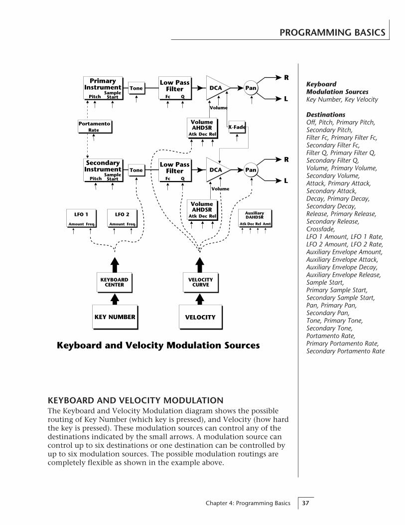
KEYBOARD AND VELOCITY MODULATIONThe Keyboard and Velocity Modulation diagram shows the possiblerouting of Key Number (which key is pressed), and Velocity (how hardthe key is pressed). These modulation sources can control any of thedestinations indicated by the small arrows. A modulation source cancontrol up to six destinations or one destination can be controlled byup to six modulation sources. The possible modulation routings arecompletely flexible as shown in the example above.
AuxiliaryDAHDSR
AmtAtk Dec Rel
LFO 1
Amount Freq.
LFO 2
Amount Freq.
R
LVolume
Pan
Atk Dec Rel
VolumeAHDSR
PrimaryInstrument
PitchSampleStart
Tone
VELOCITY
VELOCITYCURVE
KEY NUMBER
KEYBOARDCENTER
Keyboard and Velocity Modulation Sources
Low PassFilter
X-Fade
Q
R
LVolume
Pan
Atk Dec Rel
VolumeAHDSR
SecondaryInstrument
PitchSampleStart
ToneLow Pass
FilterQ
Fc
Fc
PortamentoRate
DCA
DCA
KeyboardModulation SourcesKey Number, Key Velocity
DestinationsOff, Pitch, Primary Pitch,Secondary Pitch,Filter Fc, Primary Filter Fc,Secondary Filter Fc,Filter Q, Primary Filter Q,Secondary Filter Q,Volume, Primary Volume,Secondary Volume,Attack, Primary Attack,Secondary Attack,Decay, Primary Decay,Secondary Decay,Release, Primary Release,Secondary Release,Crossfade,LFO 1 Amount, LFO 1 Rate,LFO 2 Amount, LFO 2 Rate,Auxiliary Envelope Amount,Auxiliary Envelope Attack,Auxiliary Envelope Decay,Auxiliary Envelope Release,Sample Start,Primary Sample Start,Secondary Sample Start,Pan, Primary Pan,Secondary Pan,Tone, Primary Tone,Secondary Tone,Portamento Rate,Primary Portamento Rate,Secondary Portamento Rate
Vintage Keys Operation Manual38
PROGRAMMING BASICS
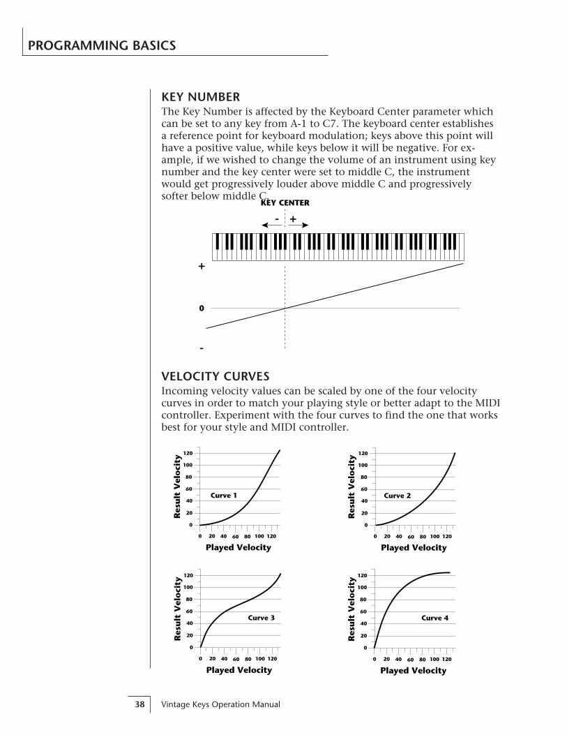
KEY NUMBERThe Key Number is affected by the Keyboard Center parameter whichcan be set to any key from A-1 to C7. The keyboard center establishesa reference point for keyboard modulation; keys above this point willhave a positive value, while keys below it will be negative. For ex-ample, if we wished to change the volume of an instrument using keynumber and the key center were set to middle C, the instrumentwould get progressively louder above middle C and progressivelysofter below middle C.
KEY CENTER
+
-
0
-
+
VELOCITY CURVESIncoming velocity values can be scaled by one of the four velocitycurves in order to match your playing style or better adapt to the MIDIcontroller. Experiment with the four curves to find the one that worksbest for your style and MIDI controller.
0
20
40
60
80
100
120
0 20 40 60 80 100
Played Velocity120
Res
ult
Vel
oci
ty
Curve 4
Curve 2
0
20
40
60
80
100
120
0 20 40 60 80 100
Played Velocity120
Res
ult
Vel
oci
ty
Curve 3
0
20
40
60
80
100
120
0 20 40 60 80 100
Played Velocity120
Res
ult
Vel
oci
ty
Curve 1
0
20
40
60
80
100
120
0 20 40 60 80 100
Played Velocity120
Res
ult
Vel
oci
ty

Chapter 4: Programming Basics 39
PROGRAMMING BASICS
AUXILIARYENVELOPE
POLYPRESSURE
Realtime Modulation Sources
MONOPRESSURE
MIDICONTROLLER
A/B/C/DLFO 2LFO 1PITCH WHEEL
AuxiliaryDAHDSR
AmtAtk Dec Rel
LFO 1
Amount Freq.
LFO 2
Amount Freq.
R
LVolume
Pan
Atk Dec Rel
VolumeAHDSR
PrimaryInstrument
Pitch
ToneLow Pass
Filter
X-Fade
R
LVolume
Pan
Atk Dec Rel
VolumeAHDSR
SecondaryInstrument
Pitch
ToneLow Pass
Filter
Fc
Fc
PortamentoRate
DCA
DCA
REALTIME MODULATIONIn addition to keyboard and velocity modulation, Vintage Keys hasmultiple realtime modulation sources. Realtime modulation sourcesare parameters which can be continuously varied over time. Thevelocity and keyboard modulations, in comparison, are set at the keydepression. The realtime modulation sources can control any of thedestinations except sample start, Q, tone and pan, as indicated by thesmall arrows. A modulation source can control up to eight destina-tions or one destination can be controlled by up to eight modulationsources. The possible modulation routings are completely flexible asshown in the example above.
RealtimeModulation SourcesPitch Wheel,MIDI Control A,MIDI Control B,MIDI Control C,MIDI Control D,Mono Pressure,Polyphonic Pressure,LFO 1, LFO 2,Auxiliary Envelope
DestinationsOff,Pitch, Primary Pitch,Secondary Pitch,Filter Fc, Primary Filter Fc,Secondary Filter Fc,Volume, Primary Volume,Secondary Volume,Attack, Primary Attack,Secondary Attack,Decay, Primary Decay,Secondary Decay,Release, Primary Release,Secondary Release,Crossfade,LFO 1 Amount, LFO 1 Rate,LFO 2 Amount, LFO 2 Rate,Auxiliary Envelope Amount,Auxiliary Envelope Attack,Auxiliary Envelope Decay,Auxiliary Envelope Release,Portamento Rate, PrimaryPortamento Rate,Secondary Portamento Rate
Vintage Keys Operation Manual40
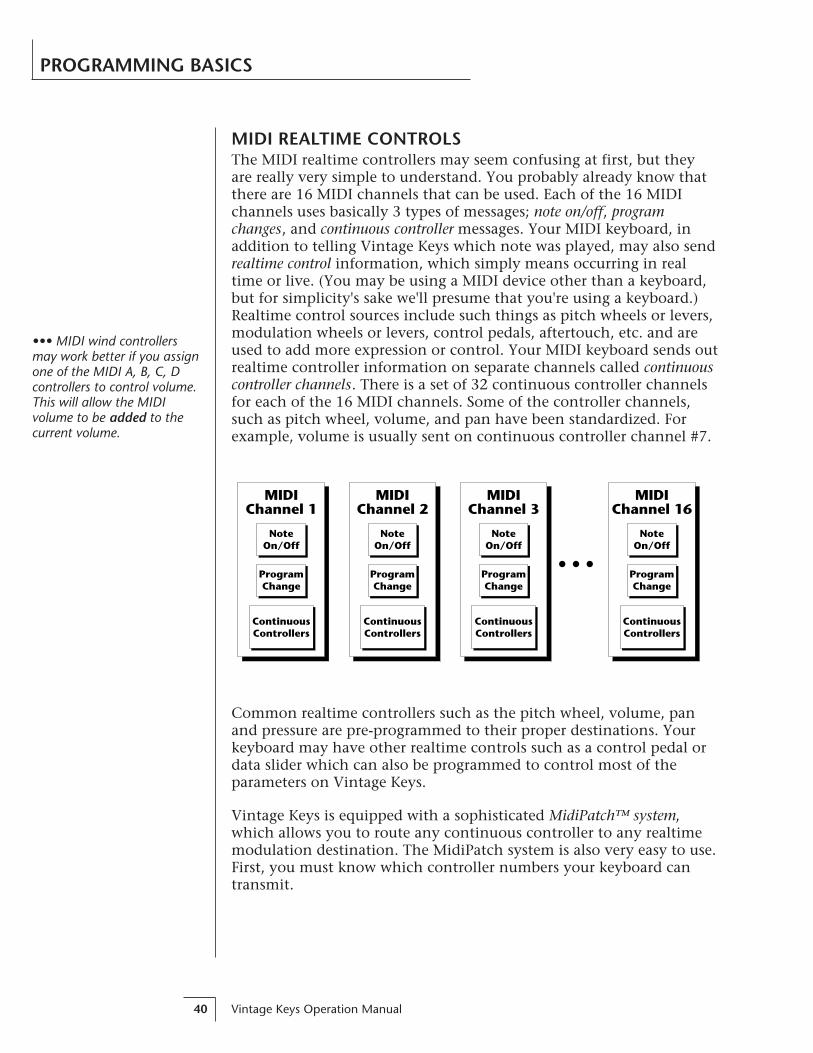
MIDI REALTIME CONTROLSThe MIDI realtime controllers may seem confusing at first, but theyare really very simple to understand. You probably already know thatthere are 16 MIDI channels that can be used. Each of the 16 MIDIchannels uses basically 3 types of messages; note on/off, programchanges, and continuous controller messages. Your MIDI keyboard, inaddition to telling Vintage Keys which note was played, may also sendrealtime control information, which simply means occurring in realtime or live. (You may be using a MIDI device other than a keyboard,but for simplicity's sake we'll presume that you're using a keyboard.)Realtime control sources include such things as pitch wheels or levers,modulation wheels or levers, control pedals, aftertouch, etc. and areused to add more expression or control. Your MIDI keyboard sends outrealtime controller information on separate channels called continuouscontroller channels. There is a set of 32 continuous controller channelsfor each of the 16 MIDI channels. Some of the controller channels,such as pitch wheel, volume, and pan have been standardized. Forexample, volume is usually sent on continuous controller channel #7.
PROGRAMMING BASICS
Common realtime controllers such as the pitch wheel, volume, panand pressure are pre-programmed to their proper destinations. Yourkeyboard may have other realtime controls such as a control pedal ordata slider which can also be programmed to control most of theparameters on Vintage Keys.
Vintage Keys is equipped with a sophisticated MidiPatch™ system,which allows you to route any continuous controller to any realtimemodulation destination. The MidiPatch system is also very easy to use.First, you must know which controller numbers your keyboard cantransmit.
NoteOn/Off
ContinuousControllers
MIDIChannel 16
ProgramChange
NoteOn/Off
ContinuousControllers
MIDIChannel 3
ProgramChange
NoteOn/Off
ContinuousControllers
MIDIChannel 2
ProgramChange
NoteOn/Off
ContinuousControllers
MIDIChannel 1
ProgramChange
••• MIDI wind controllersmay work better if you assignone of the MIDI A, B, C, Dcontrollers to control volume.This will allow the MIDIvolume to be added to thecurrent volume.

Chapter 4: Programming Basics 41
PROGRAMMING BASICS
Let's say for example, that you are using a Yamaha DX7 as your masterkeyboard. The DX has pitch and mod. wheels, a breath controller, adata slider and a foot pedal, all of which transmit their values overMIDI. The standard MIDI controller numbers for the controls are listedbelow (the pitch wheel has a dedicated controller, PWH). First, wewould go to the Master menu, MIDI Controller Assign and define the4 MIDI controllers that we wish to use. Assign each controller numberto one of the lettersA-B-C-D.
01 - Modulation Wheel A
02 - Breath Controller B
04 - Foot Pedal C
06 - Data Entry D
To complete the connections for a particular preset, go to the Editmenu, Realtime Control, and route the MIDI A, B, C, D to the desireddestinations. These could be patched to any 4 destinations or even tothe same destination. The MIDI Controller Amount menu, (in the Editmenu) allows you to scale the amounts of each of the controllers by apositive or negative value. The signal flow is shown in the diagrambelow.
The MIDI controllers A-B-C-D must have both a source (0-31), and a destinationassigned.
0123
31
MIDI
ControllerC
Control Destinations
+-
MasterMenu
EditMenu
A
B
C
D
0123
31
MIDI
ControllerA
0123
31
MIDI
ControllerB
0123
31
MIDI
ControllerD
MIDI
Amount
+-
+-
+-
PitchPrimary Pitch onlySecondary Pitch onlyVolumePrimary Volume onlySecondary Volume onlyAttackPrimary Attack onlySecondary Attack onlyDecayPrimary Decay onlySecondary Decay onlyReleasePrimary Release onlySecondary Release onlyCrossfadeLFO 1 RateLFO 1 AmountLFO 2 RateLFO 2 AmountAuxiliary Envelope AmountAuxiliary Envelope AttackAuxiliary Envelope DecayAuxiliary Envelope ReleasePortamento RatePrimary Portamento RateSecondary Portamento RateFilter FcPrimary Filter Fc onlySecondary Filter Fc only
Standard MIDI Control-ler Numbers
1 Modulation Wheel
2 Breath Controller
3 Pressure Rev 1 DX7
4 Foot Pedal
5 Portamento Time
6 Data Entry
7 Volume
8 Balance
9 Undefined
10 Pan

Vintage Keys Operation Manual42
STEREO MIX OUTPUTSVintage Keys has three sets of polyphonic stereo outputs (Main, Sub 1,Sub 2). The channels used by a particular preset may be directed toappear at any one of these three stereo outputs. This feature is usefulfor signal processing (EQ, reverb, etc.) of individual sounds prior tofinal mixdown. By panning a preset completely left or right, it can berouted to a single output jack.
Note: All presets will be automatically routed to the Main outputsunless plugs are inserted into the Sub 1 or Sub 2 outputs.
PROGRAMMING BASICS
Main
Sub 1
Sub 2
Preset01
Preset22
Preset12
Preset127
MIXOUTPUT
Preset18
Preset120
L
R
L
R
L
R
etc.
Each preset can be routed to one (and only one) set of stereo outputs.
Chapter 5: Edit Menu 43
EDITMENU

Vintage Keys Operation Manual44
Chapter 5: Edit Menu 45
EDIT MENU
The edit menu contains functions that can be modified by the userand then saved as preset information in one of the user presets. Forexample, the LFO speed or other parameter can be edited, then thepreset can be saved to a user location (0-255).
WARNINGChanges made in the Edit menu will be forever lost unlessthe preset is “saved” using the Save Preset function (page66) before changing the preset.
To enable the Edit menuPress the Edit key, lighting the LED. The current screen will be theone most recently selected since powering up the machine. Thecursor will appear underneath the first character of the screenheading on line one.
To select a new screenPress the cursor key repeatedly (or hold the cursor key whileturning the data entry control) until the cursor is underneath theparameter name. Rotate the data entry control to select thescreen.
To modify a parameterPress the cursor key repeatedly (or hold the cursor key whileturning the data entry control) until the cursor is underneath theparameter value. Rotate the data entry control to change thevalue.
To return to Preset Select modePress the Edit button, turning off the LED.
••• While the Edit menu isactivated, incoming MIDIpreset changes are ignored.This is a quick and easy wayto temporarily turn MIDIPreset Change OFF.

Vintage Keys Operation Manual46
EDIT MENU
EDIT MENU FUNCTIONS
• Preset NamePreset Name allows you to name each of the user presets with a nameof up to 12 characters. Position the cursor under the character locationand use the data entry control to change the character. The keyboardcan also be used to select characters. The charts below show the key-board character assignment.
PRESET NAME000 Untitled
C C# D D# E F F# G G# A A# B Pitch
OctaveNo.
-1
0
1
2
3
4
5
6
"! # $ % &blank
' ( ) * + , - . / 0 1 2
3 4 5 6 7 8 9 : ; < >=
? @ A B C D E F G H I J
K L M N O P Q R S T U V
W X Y Z [ ¥ ] ^ _ ` a b
c d e f g h i j k l m n
o p q r s t u v w x y z
|
-2
02
3
57
8
:<
>
?A
C
DF
H
JK
M
OP
R
TV
W
Y[
¥
^`
b
ce
g
hj
l
no
q
st
v
xz
<-
+,
.
&'
)
blank
"$
46
9;
=@
B
EG
IL
N
QS
UX
Z
]_
ad
f
ik
mp
r
uw
y|->
-/
1(
*
!#
%
Chapter 5: Edit Menu 47
EDIT MENU
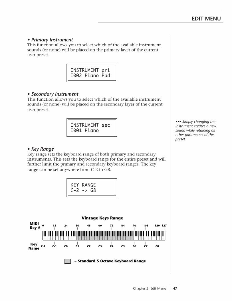
• Primary InstrumentThis function allows you to select which of the available instrumentsounds (or none) will be placed on the primary layer of the currentuser preset.
INSTRUMENT priI002 Piano Pad
• Secondary InstrumentThis function allows you to select which of the available instrumentsounds (or none) will be placed on the secondary layer of the currentuser preset.
INSTRUMENT secI001 Piano
• Key RangeKey range sets the keyboard range of both primary and secondaryinstruments. This sets the keyboard range for the entire preset and willfurther limit the primary and secondary keyboard ranges. The keyrange can be set anywhere from C-2 to G8.
KEY RANGEC-2 -> G8
C-2 C-1 C0 C1 C2 C3 C4 C5 C6 C7 C8
= Standard 5 Octave Keyboard Range
Vintage Keys RangeMIDIKey #
KeyName
0 12 24 36 48 60 72 84 96 108 120 127
••• Simply changing theinstrument creates a newsound while retaining allother parameters of thepreset.
Vintage Keys Operation Manual48
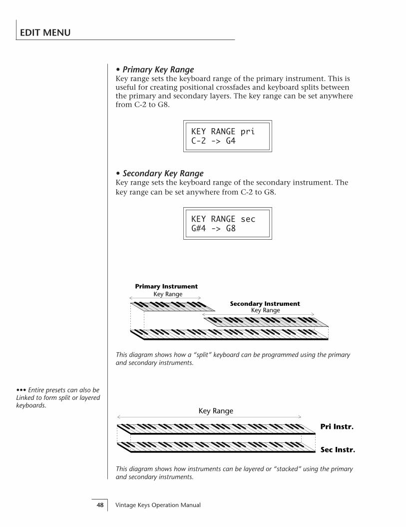
• Primary Key RangeKey range sets the keyboard range of the primary instrument. This isuseful for creating positional crossfades and keyboard splits betweenthe primary and secondary layers. The key range can be set anywherefrom C-2 to G8.
KEY RANGE priC-2 -> G4
• Secondary Key RangeKey range sets the keyboard range of the secondary instrument. Thekey range can be set anywhere from C-2 to G8.
KEY RANGE secG#4 -> G8
EDIT MENU
Pri Instr.
Sec Instr.
Key Range
This diagram shows how instruments can be layered or “stacked” using the primaryand secondary instruments.
Primary InstrumentKey Range
Key RangeSecondary Instrument
This diagram shows how a “split” keyboard can be programmed using the primaryand secondary instruments.
••• Entire presets can also beLinked to form split or layeredkeyboards.

Chapter 5: Edit Menu 49
EDIT MENU
• Coarse TuningThis function allows you to change the tuning of the primary andsecondary instruments in semitone intervals. The coarse tuning rangeis -36 to +36 semitones. A coarse tuning setting of “00” would indicatethat the instrument is tuned to concert pitch (A=440 Hz).
TUNING coarsepri:+00 sec:+00
• Fine TuningThis function allows you to change the tuning of the primary andsecondary instruments in 1/64 semitone intervals (approx. 1.56 cents).The fine tuning range is ± 1 semitone.
TUNING finepri:+00 sec:+00
• VolumeVolume sets the amplitude of the primary and secondary instruments.This function also allows you to compensate for the relative volumedifferences between instruments.
VOLUMEpri:127 sec:64
• PanPan allows you to independently set the initial pan position of theprimary and secondary instruments. A value of -7 pans the instrumenthard left and a value of +7 pans the instrument hard right. This pansetting is only valid if “P”, for preset pan, is selected in the maindisplay.
PANpri:-7 sec:+7

Vintage Keys Operation Manual50
EDIT MENU
• Alternate Envelope On/OffEach instrument has its own factory preset AHDSR volume envelopewhich is normally employed. If a programmable volume envelope isdesired, the alternate envelope is used.
ALT ENVELOPEpri:Off sec:On
DCA
Atk Dec Rel
NormalEnvelope
Atk Dec Rel
AlternateEnvelope
• Primary Alternate Envelope ParametersThis function allows you to adjust the alternate volume envelopeparameters for the primary instrument. The parameters are Attacktime, Hold time, Decay time, Sustain level, Release time and are ad-justable from 00 to 99.
P: A H D S R 00 00 00 99 16
• Secondary Alternate Envelope ParametersThis function allows you to adjust the alternate volume envelopeparameters for the secondary instrument. The parameters are Attacktime, Hold time, Decay time, Sustain level, Release time and are ad-justable from 00 to 99.
S: A H D S R 00 00 00 99 16
Chapter 5: Edit Menu 51
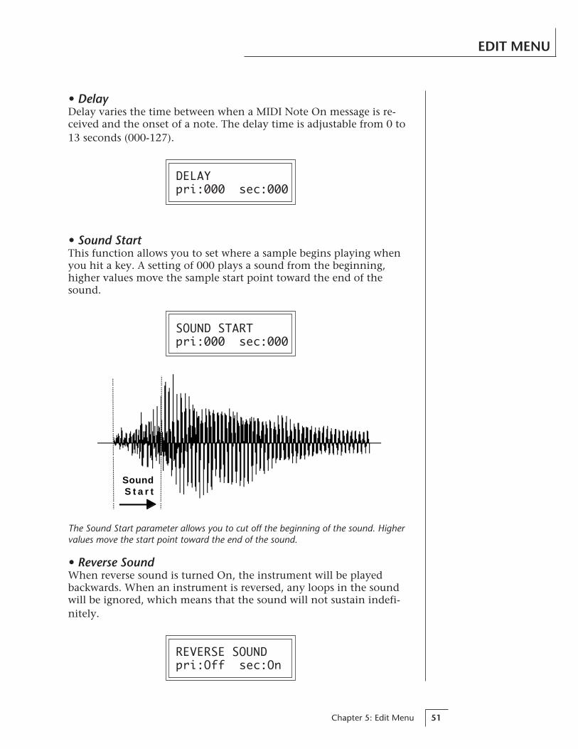
EDIT MENU
• DelayDelay varies the time between when a MIDI Note On message is re-ceived and the onset of a note. The delay time is adjustable from 0 to13 seconds (000-127).
DELAYpri:000 sec:000
• Sound StartThis function allows you to set where a sample begins playing whenyou hit a key. A setting of 000 plays a sound from the beginning,higher values move the sample start point toward the end of thesound.
SOUND STARTpri:000 sec:000
• Reverse SoundWhen reverse sound is turned On, the instrument will be playedbackwards. When an instrument is reversed, any loops in the soundwill be ignored, which means that the sound will not sustain indefi-nitely.
REVERSE SOUNDpri:Off sec:On
The Sound Start parameter allows you to cut off the beginning of the sound. Highervalues move the start point toward the end of the sound.
SoundS t a r t

Vintage Keys Operation Manual52
EDIT MENU
• Solo ModeSolo mode provides the playing action of a monophonic instrument.This mode does not allow you to play a chord. Two types of solo modeare provided: wind controller mode and synth mode. Both modeshave single triggering and last-note priority. In either solo mode, if anew note is played while another is being held, the envelope genera-tors will not retrigger. This allows a legato playing technique to beused. Wind controller mode, as its name suggests, provides morerealistic effects when working with wind controllers.
Wind modeThe envelope generator attack always begins at the start of theattack phase.
Synth modeThe envelope generator attack begins at whatever point in therelease phase the envelope is in when a new key is pressed.
SOLO MODEpri:Off sec:Wind
• Portamento RatePortamento is a smooth gliding between notes instead of the normalinstantaneous change in pitch when a new key is pressed. The porta-mento rate is the time it takes to glide to the new pitch. The larger thevalue, the slower the glide rate. The rate is adjustable from 1-127 or itcan be turned Off. Portamento glides at a linear rate between notesand can be set separately for the primary and secondary layers.Portamento works both in and out of Solo Mode.
PORTAMENTO RATEpri:127 sec:Off
• ChorusChorus “thickens” the sound by doubling the sound and thendetuning it. The chorus amount is variable over a range of 1 to 15.When Chorus is on, the number of channels used by an instrumentwill be doubled.
CHORUSpri:Off sec:07

Chapter 5: Edit Menu 53
EDIT MENU
• Crossfade ModeThis function determines which of the following crossfade modes willbe selected: Off, Crossfade, or Cross-Switch.
OffWhen “Off” is selected, none of the crossfade parameters willhave any effect.
CrossfadeWhen “Xfade” is selected, a control input is used to fade betweenthe primary and secondary. Any modulation source may be usedas an input (velocity, wheel, etc.).
Cross-switchWhen “Xswitch” is selected, the switched layer is selected if theinput crosses a certain threshold or if a footswitch controllingcross-switch is activated. The switch occurs only at the start of thenote; no further switching takes place while the key is held down.
If key position or velocity is routed to cross-switch, the thresholdis the switch point. Realtime controllers do not have any effectwhen routed to cross-switch. For more information, see Cross-Switch Point on page 55.
XFADE MODEOff
By overlapping the primary and secondary instruments, you can crossfade or cross-switch between the layers.
PrimaryInstrument
Key Range
Key Range
SecondaryInstrument
Crossfade Range
••• For more information,see Cross-switch Point onpage 55.
••• To use the keyboard forcrossfade, set the CrossfadeBalance to 64 and the KeyCenter to the split point.
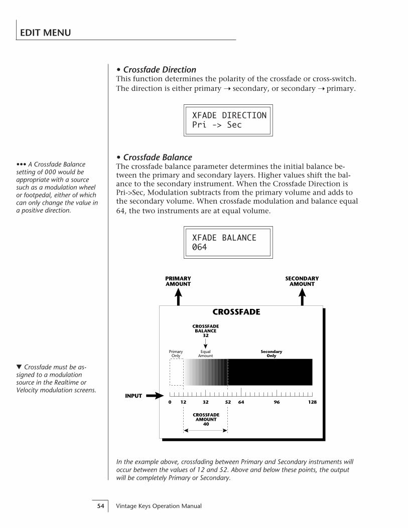
Vintage Keys Operation Manual54
EDIT MENU
• Crossfade DirectionThis function determines the polarity of the crossfade or cross-switch.The direction is either primary secondary, or secondary primary.
XFADE DIRECTIONPri -> Sec
• Crossfade BalanceThe crossfade balance parameter determines the initial balance be-tween the primary and secondary layers. Higher values shift the bal-ance to the secondary instrument. When the Crossfade Direction isPri->Sec, Modulation subtracts from the primary volume and adds tothe secondary volume. When crossfade modulation and balance equal64, the two instruments are at equal volume.
XFADE BALANCE064
In the example above, crossfading between Primary and Secondary instruments willoccur between the values of 12 and 52. Above and below these points, the outputwill be completely Primary or Secondary.
PrimaryOnly
CROSSFADEAMOUNT
40
SecondaryOnly
EqualAmount
128640 32 96
CROSSFADEBALANCE
32
INPUT
CROSSFADE
12 52
PRIMARYAMOUNT
SECONDARYAMOUNT
Crossfade must be as-signed to a modulationsource in the Realtime orVelocity modulation screens.
••• A Crossfade Balancesetting of 000 would beappropriate with a sourcesuch as a modulation wheelor footpedal, either of whichcan only change the value ina positive direction.

Chapter 5: Edit Menu 55
EDIT MENU
20
40
60
80
100
40 80 160 360 720 1440 2880
Frequency...
Am
pli
tud
e
Cutoff Frequency
Output of Filter
Frequency
Am
pli
tud
e
4-poleLowpass
2-poleLowpass
To enable the cross-switchfunction, you must assignCrossfade to a modulationsource in the Realtime orVelocity Modulation screen.
Velocity Key
• Crossfade AmountThe crossfade amount parameter determines the range over whichcrossfading will occur. Crossfade amount is variable from 000 to 255.The larger the value, the more modulation will be required to effect acomplete crossfade.
XFADE AMOUNT128
• Cross-switch PointThe cross-switch point determines the point at which cross-switchingwill occur when key position or velocity is controlling cross-switch.
SWITCH POINT064 c#2
• Primary Filter TypeA lowpass filter allows only the low frequencies to pass (lowpass). Alowpass filter can be used to simulate many natural sounds since it iscommon for the high frequencies to die away as a sound decays. Thefilter for the primary instrument can be either a 2-pole lowpass filter, a4-pole lowpass filter, or it can be turned Off. A 2-pole filter attenuatesfrequencies above the cutoff frequency at 12 dB per octave. A 4-polefilter attenuates frequencies above the cutoff at 24 dB per octave. (A 4-pole filter has a stronger filtering action.)
FILTER TYPE pri2 Pole Lowpass

Vintage Keys Operation Manual56
EDIT MENU
FrequencyA
mp
litu
de Low Q Med Q High Q
• Primary Filter Cutoff & QThis function allows you to set the cutoff frequency (the frequency atwhich filtering begins) and the Q or resonance of the sound. Turningup the Q causes the frequencies near the cutoff to be emphasized.
FILTER priFc:255 Q:5
• Secondary Filter TypeThe filter for the secondary instrument can be either a 2-pole lowpassfilter, a 4-pole lowpass filter, or it can be turned Off. See Primary FilterType.
FILTER TYPE sec4 Pole Lowpass
• Secondary Filter Cutoff & QThis is the same as the Primary Cutoff and Q for the secondary filter.
FILTER secFc:255 Q:5
Q boosts the amplitude at the cutoff frequency. Using high Q values, it is possible to“tune in” certain frequencies of an instrument.

Chapter 5: Edit Menu 57
EDIT MENU
• Auxiliary EnvelopeThis is a supplementary, utility envelope that can be routed to anyrealtime control destination including the lowpass filter. The auxiliaryenvelope parameters are: Envelope Amount, Delay, Attack Time, HoldTime, Decay Time, Sustain Level, and Release Time. The delay time isvariable from 0 to 13 seconds (000-127). The envelope amount isvariable from -128 to +127. Negative values will produce invertedenvelopes.
AUX ENV AMT DLY +127 000
A: A H D S R 00 00 00 99 20
This diagram shows the six stages of the Auxiliary Envelope Generator.
Delay
level
time
keydown
Attack
Hold
Decay
Sustain
Releasekey
released

Vintage Keys Operation Manual58
EDIT MENU
• LFO 1 - Shape & AmountThis screen controls the waveshape and amount of Low FrequencyOscillator 1. The LFO can be used to produce vibrato (when routed topitch), or tremolo (when routed to volume). The five LFO waveshapesare: Triangle, Sine, Square, Sawtooth, and Random. The amount canbe varied from -128 to +127. Negative values will produce inverted waveshapes.
LFO1 SHAPE AMT Rand +127
• LFO 1 - Rate, Delay & VariationThis screen controls the rate, delay and variation of LFO 1.
LFO RateVaries the LFO speed from 0.052 Hz to 25 Hz (000-127).
LFO DelaySets the amount of time between hitting a key and the onset ofmodulation. This can be used to simulate an effect often used byacoustic instrument players, where the vibrato is brought in onlyafter the initial note pitch has been established. The delay rangeis variable from 0 to 13 seconds (000-127).
LFO VariationSets the amount of random variation of an LFO each time a key ispressed. This function is useful for ensemble effects, where eachnote played has a slightly different modulation rate. The higherthe number, the greater the note to note variation in LFO rate.LFO variation is variable from 000-127.
Triangle
Square
Sine
Sawtooth
Random
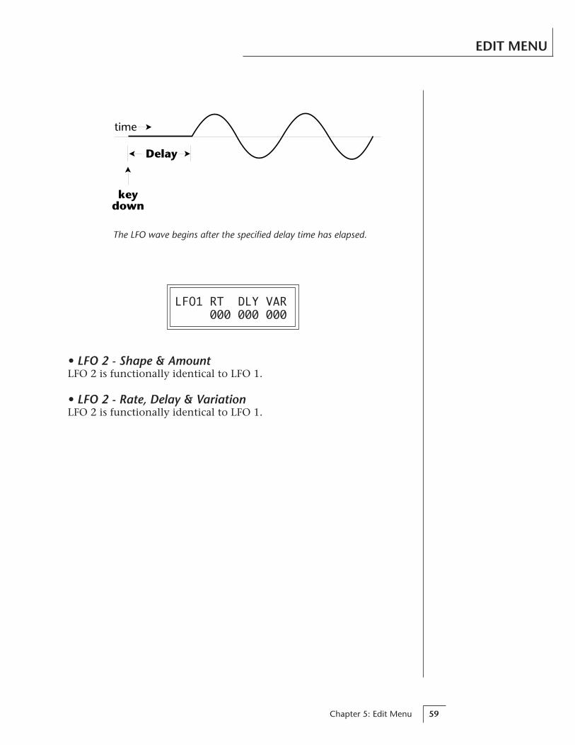
Chapter 5: Edit Menu 59
EDIT MENU
time
keydown
Delay
LFO1 RT DLY VAR 000 000 000
• LFO 2 - Shape & AmountLFO 2 is functionally identical to LFO 1.
• LFO 2 - Rate, Delay & VariationLFO 2 is functionally identical to LFO 1.
The LFO wave begins after the specified delay time has elapsed.

Vintage Keys Operation Manual60
EDIT MENU
• Keyboard & Velocity Modulation ControlThese functions allow you to route keyboard and velocity informationto any of the modulation destinations. Up to 6 simultaneous paths or“patches” may be programmed. For each modulation patch, there is asource (keyboard or velocity), and a corresponding amount parameterwhich is variable from -128 to +127. Place the cursor under theappropriate parameter and change the patch number, modulationsource, modulation destination, or the amount using the dataentry control. If a parameter is not labeled either primary or second-ary, it affects both.
KEY/VELOCITY CTL1 V>Pitch +064
ModulationSource
ModulationDestination
ModulationAmount
PatchNumber
AuxiliaryDAHDSR
AmtAtk Dec Rel
LFO 1
Amount Freq.
LFO 2
Amount Freq.
R
LVolume
PanPrimary
InstrumentPitch
SampleStart
Tone
VELOCITY
VELOCITYCURVE
KEY NUMBER
KEYBOARDCENTER
Keyboard and Velocity Modulation Sources
Low PassFilter
X-FadeAtk Dec Rel
VolumeAHDSR
Q
R
LVolume
PanSecondaryInstrument
PitchSampleStart
ToneLow Pass
Filter
Atk Dec Rel
VolumeAHDSR
Q
Fc
Fc
PortamentoRate
DCA
DCA
Modulation Destinations
When Modulating Enve-lope Attack, Decay orRelease Times:
Positive amounts of modula-tion increase the time.
Negative amounts of modu-lation decrease the time.
KeyboardModulation SourcesKey Number, Key Velocity
DestinationsOff,Pitch, Primary Pitch,Secondary Pitch,Filter Fc, Primary Filter Fc,Secondary Filter Fc,Filter Q, Primary Filter Q,Secondary Filter Q,Volume, Primary Volume,Secondary Volume,Attack, Primary Attack,Secondary Attack,Decay, Primary Decay,Secondary Decay,Release, Primary Release,Secondary Release,Crossfade,LFO 1 Amount, LFO 1 Rate,LFO 2 Amount, LFO 2 Rate,Auxiliary Envelope Amount,Auxiliary Envelope Attack,Auxiliary Envelope Decay,Auxiliary Envelope Release,Sample Start,Primary Sample Start,Secondary Sample Start,Pan, Primary Pan,Secondary Pan,Tone, Primary Tone,Secondary Tone,Portamento Rate,Primary Portamento Rate,Secondary Portamento Rate
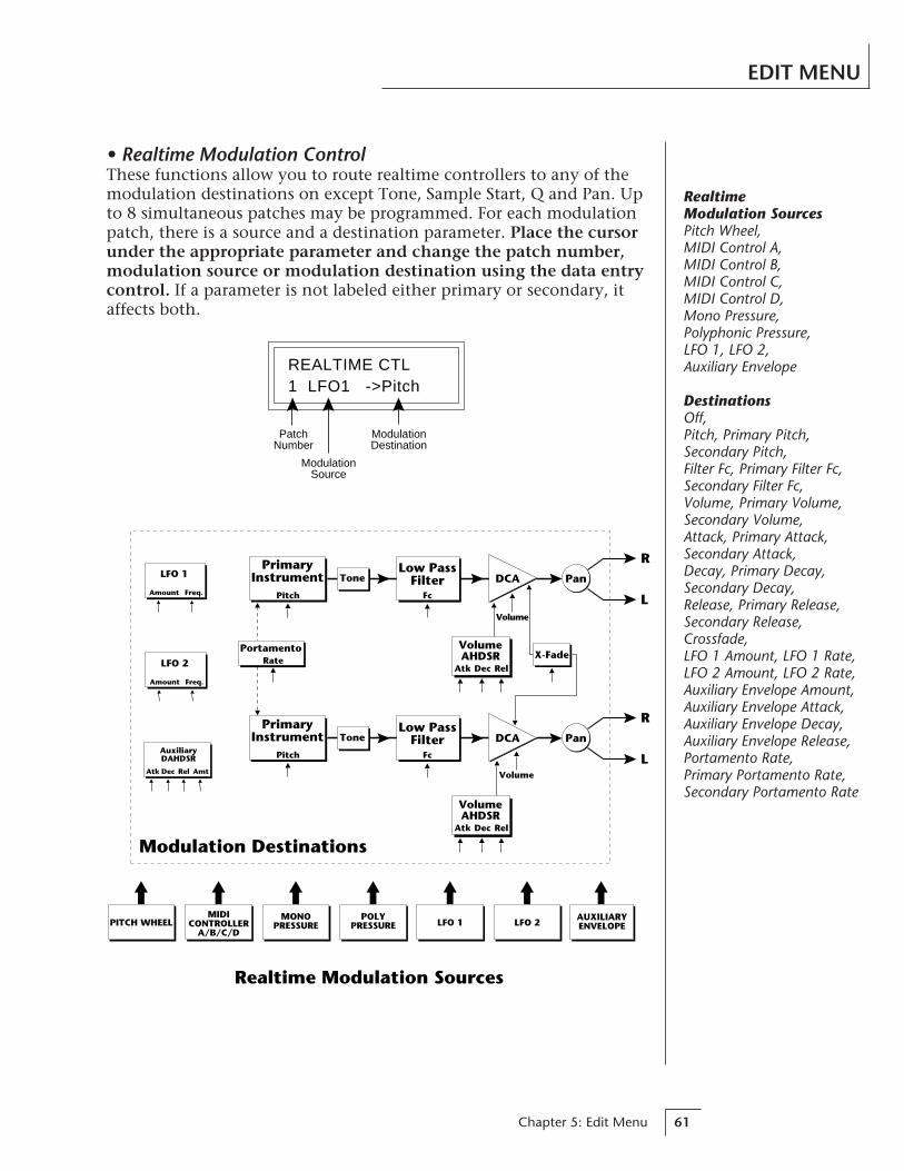
Chapter 5: Edit Menu 61
EDIT MENU
• Realtime Modulation ControlThese functions allow you to route realtime controllers to any of themodulation destinations on except Tone, Sample Start, Q and Pan. Upto 8 simultaneous patches may be programmed. For each modulationpatch, there is a source and a destination parameter. Place the cursorunder the appropriate parameter and change the patch number,modulation source or modulation destination using the data entrycontrol. If a parameter is not labeled either primary or secondary, itaffects both.
Realtime Modulation Sources
POLYPRESSURE
MONOPRESSURE
MIDICONTROLLER
A/B/C/DLFO 2
AUXILIARYENVELOPELFO 1PITCH WHEEL
AuxiliaryDAHDSR
AmtAtk Dec Rel
LFO 1
Amount Freq.
LFO 2
Amount Freq.
Modulation Destinations
R
LVolume
Pan
Atk Dec Rel
VolumeAHDSR
PrimaryInstrument
Pitch
ToneLow Pass
Filter
X-Fade
R
LVolume
Pan
Atk Dec Rel
VolumeAHDSR
PrimaryInstrument
Pitch
ToneLow Pass
Filter
Fc
Fc
PortamentoRate
DCA
DCA
REALTIME CTL1 LFO1 ->Pitch
ModulationSource
ModulationDestination
PatchNumber
RealtimeModulation SourcesPitch Wheel,MIDI Control A,MIDI Control B,MIDI Control C,MIDI Control D,Mono Pressure,Polyphonic Pressure,LFO 1, LFO 2,Auxiliary Envelope
DestinationsOff,Pitch, Primary Pitch,Secondary Pitch,Filter Fc, Primary Filter Fc,Secondary Filter Fc,Volume, Primary Volume,Secondary Volume,Attack, Primary Attack,Secondary Attack,Decay, Primary Decay,Secondary Decay,Release, Primary Release,Secondary Release,Crossfade,LFO 1 Amount, LFO 1 Rate,LFO 2 Amount, LFO 2 Rate,Auxiliary Envelope Amount,Auxiliary Envelope Attack,Auxiliary Envelope Decay,Auxiliary Envelope Release,Portamento Rate,Primary Portamento Rate,Secondary Portamento Rate
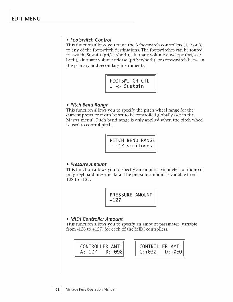
Vintage Keys Operation Manual62
EDIT MENU
• Footswitch ControlThis function allows you route the 3 footswitch controllers (1, 2 or 3)to any of the footswitch destinations. The footswitches can be routedto switch: Sustain (pri/sec/both), alternate volume envelope (pri/sec/both), alternate volume release (pri/sec/both), or cross-switch betweenthe primary and secondary instruments.
FOOTSWITCH CTL1 -> Sustain
• Pitch Bend RangeThis function allows you to specify the pitch wheel range for thecurrent preset or it can be set to be controlled globally (set in theMaster menu). Pitch bend range is only applied when the pitch wheelis used to control pitch.
PITCH BEND RANGE+- 12 semitones
• Pressure AmountThis function allows you to specify an amount parameter for mono orpoly keyboard pressure data. The pressure amount is variable from -128 to +127.
PRESSURE AMOUNT+127
• MIDI Controller AmountThis function allows you to specify an amount parameter (variablefrom -128 to +127) for each of the MIDI controllers.
CONTROLLER AMT CONTROLLER AMTA:+127 B:-090 C:+030 D:+060
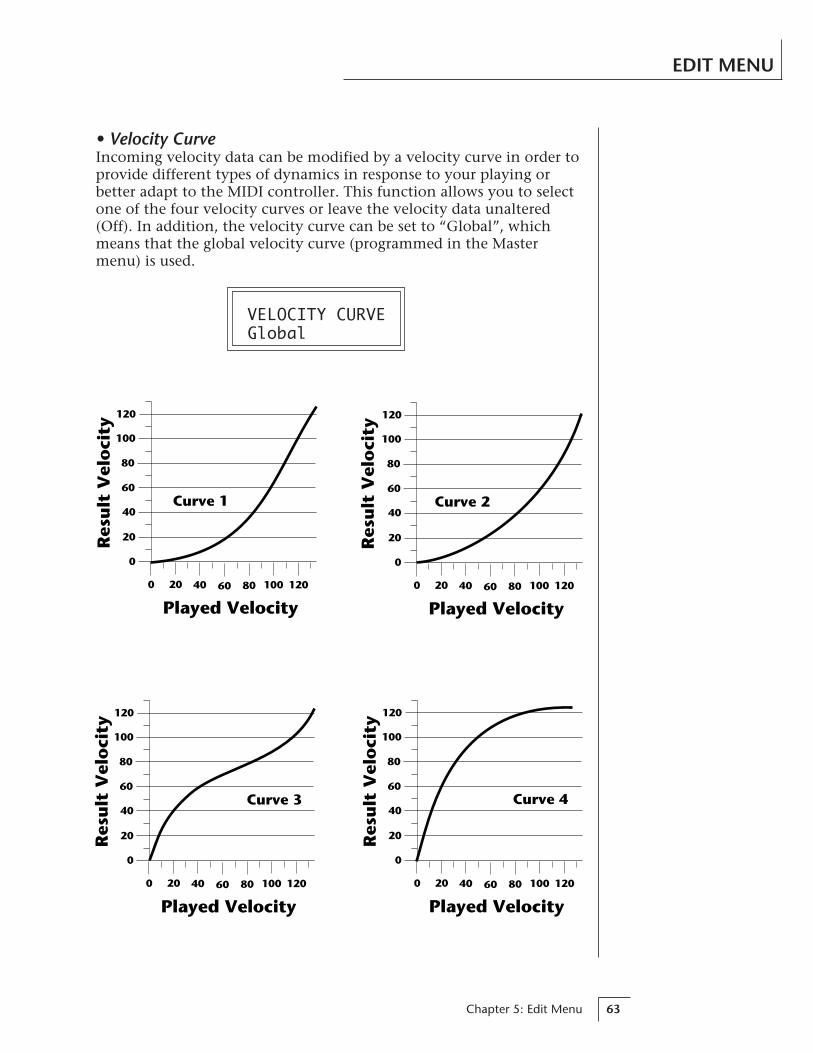
Chapter 5: Edit Menu 63
EDIT MENU
• Velocity CurveIncoming velocity data can be modified by a velocity curve in order toprovide different types of dynamics in response to your playing orbetter adapt to the MIDI controller. This function allows you to selectone of the four velocity curves or leave the velocity data unaltered(Off). In addition, the velocity curve can be set to “Global”, whichmeans that the global velocity curve (programmed in the Mastermenu) is used.
VELOCITY CURVEGlobal
Curve 2
0
20
40
60
80
100
120
0 20 40 60 80 100
Played Velocity120
Res
ult
Vel
oci
ty
0
20
40
60
80
100
120
0 20 40 60 80 100
Played Velocity120
Res
ult
Vel
oci
ty
Curve 4
Curve 1
0
20
40
60
80
100
120
0 20 40 60 80 100
Played Velocity120
Res
ult
Vel
oci
ty
Curve 3
0
20
40
60
80
100
120
0 20 40 60 80 100
Played Velocity120
Res
ult
Vel
oci
ty
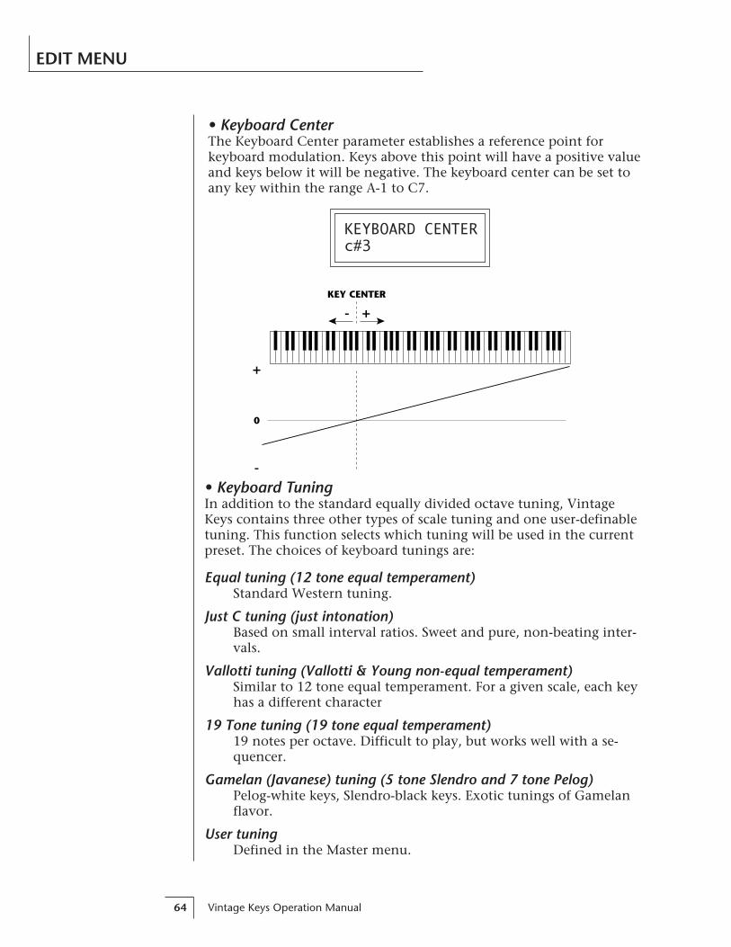
Vintage Keys Operation Manual64
EDIT MENU
• Keyboard CenterThe Keyboard Center parameter establishes a reference point forkeyboard modulation. Keys above this point will have a positive valueand keys below it will be negative. The keyboard center can be set toany key within the range A-1 to C7.
KEYBOARD CENTERc#3
KEY CENTER
+
-
0
-
+
• Keyboard TuningIn addition to the standard equally divided octave tuning, VintageKeys contains three other types of scale tuning and one user-definabletuning. This function selects which tuning will be used in the currentpreset. The choices of keyboard tunings are:
Equal tuning (12 tone equal temperament)Standard Western tuning.
Just C tuning (just intonation)Based on small interval ratios. Sweet and pure, non-beating inter-vals.
Vallotti tuning (Vallotti & Young non-equal temperament)Similar to 12 tone equal temperament. For a given scale, each keyhas a different character
19 Tone tuning (19 tone equal temperament)19 notes per octave. Difficult to play, but works well with a se-quencer.
Gamelan (Javanese) tuning (5 tone Slendro and 7 tone Pelog)Pelog-white keys, Slendro-black keys. Exotic tunings of Gamelanflavor.
User tuningDefined in the Master menu.
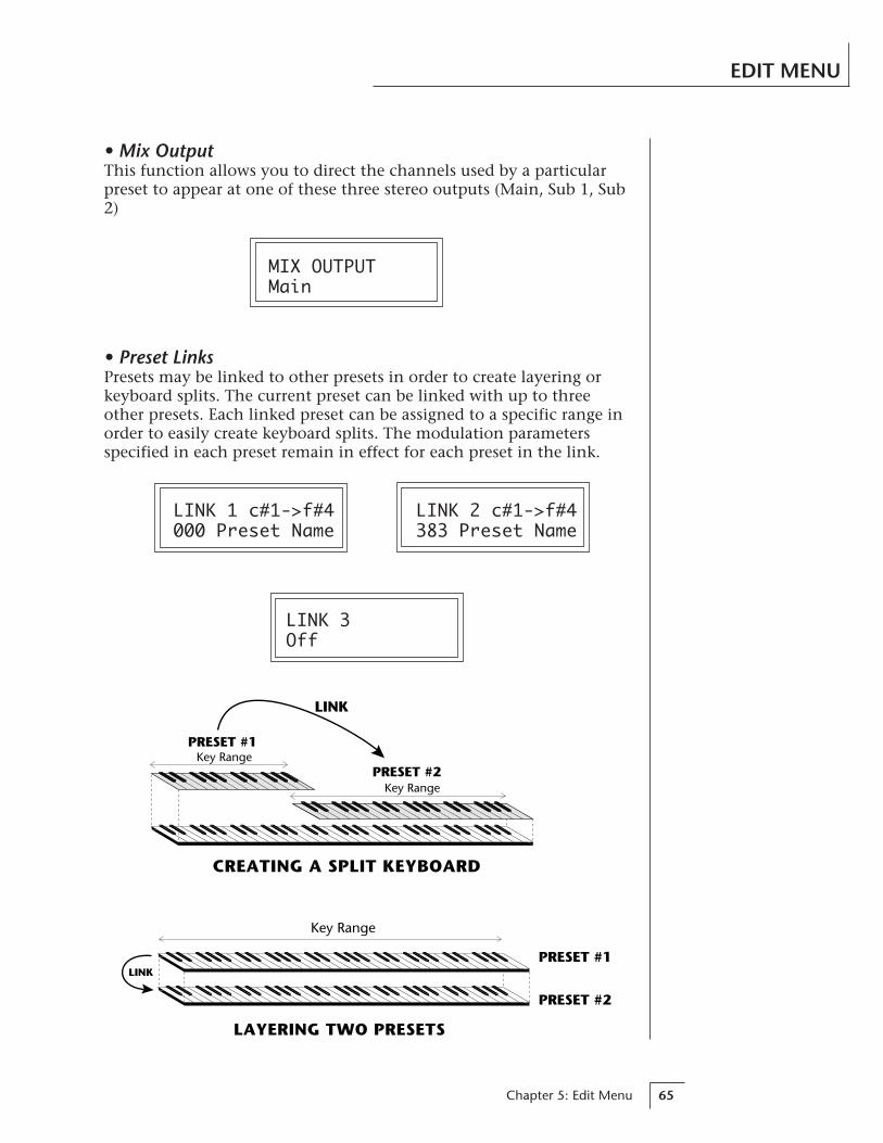
Chapter 5: Edit Menu 65
EDIT MENU
• Mix OutputThis function allows you to direct the channels used by a particularpreset to appear at one of these three stereo outputs (Main, Sub 1, Sub2)
MIX OUTPUTMain
• Preset LinksPresets may be linked to other presets in order to create layering orkeyboard splits. The current preset can be linked with up to threeother presets. Each linked preset can be assigned to a specific range inorder to easily create keyboard splits. The modulation parametersspecified in each preset remain in effect for each preset in the link.
LINK 1 c#1->f#4 LINK 2 c#1->f#4000 Preset Name 383 Preset Name
LINK 3Off
PRESET #1
PRESET #2
LINK
LAYERING TWO PRESETS
Key Range
PRESET #1
PRESET #2Key Range
Key Range
LINK
CREATING A SPLIT KEYBOARD
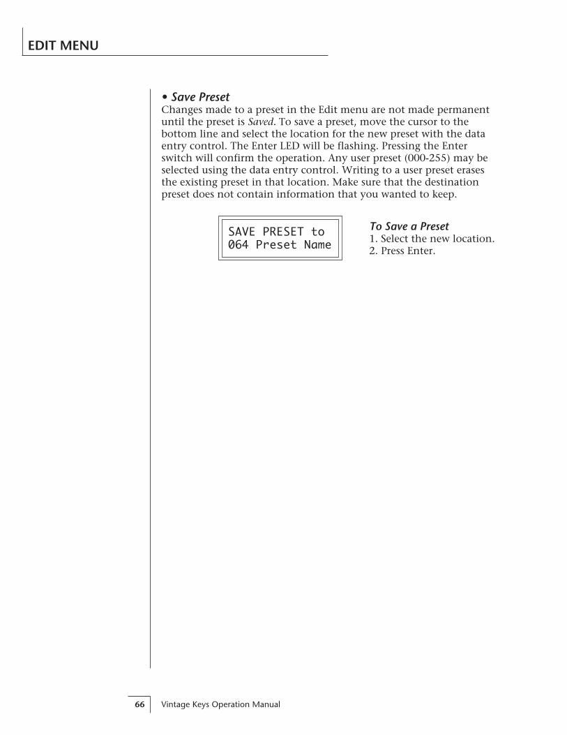
Vintage Keys Operation Manual66
• Save PresetChanges made to a preset in the Edit menu are not made permanentuntil the preset is Saved. To save a preset, move the cursor to thebottom line and select the location for the new preset with the dataentry control. The Enter LED will be flashing. Pressing the Enterswitch will confirm the operation. Any user preset (000-255) may beselected using the data entry control. Writing to a user preset erasesthe existing preset in that location. Make sure that the destinationpreset does not contain information that you wanted to keep.
SAVE PRESET to064 Preset Name
EDIT MENU
To Save a Preset1. Select the new location.2. Press Enter.
Chapter 6: Practice Programming 67
PRACTICEPROGRAMMING
Vintage Keys Operation Manual68

Chapter 6: Practice Programming 69
PRACTICE PROGRAMMING
This section contains step-by-step instructions on how to get started inprogramming your own custom sounds. It is recommended that youactually try each example on the Vintage Keys unit, rather than justreading through. The best way to learn something is by actually doing it.
LINKING PRESETSLinking presets is a quick and easy way to create new sounds by “layer-ing” presets and also to “split” a keyboard into sections containingdifferent sounds.
• Layering Two Presets1) Select the first preset you wish to layer.
2) Press the Edit button.
3) Use the data entry control to move through the screens until youfind one of the “LINK” screens.
4) Move the cursor to the second line of the display, then select thepreset that you want to be linked with this preset. You may want toplay the keyboard as you scroll through the various presets in orderto hear the results.
5) If you want the link to be a permanent part of the preset, be sure to“SAVE PRESET”. Otherwise, simply change the preset to erase yourwork.
• Create a Split Keyboard Using Links1) Follow steps 1 through 4 above.
2) Now set the range of the linked preset while still in the LINK menu.
3) Save the preset.
4) Now go back to the first preset, press the Edit button and use thedata entry control to move through the screens to KEY RANGE.
5) Set the range of this preset so that it fills the remaining range ofyour keyboard.
6) Save the preset.
PRESET #1
PRESET #2Key Range
Key Range
LINK
CREATING A SPLIT KEYBOARD
••• To get the most out ofthis section, please readChapter 3, ProgrammingBasics first.

Vintage Keys Operation Manual70
PRACTICE PROGRAMMING
EDITING PRESETSThe easiest way to make a new preset is to edit an existing preset. Thisis also an excellent way of becoming familiar with Vintage Keys. If youdon’t like what you hear, simply change the preset and Vintage Keysreverts back to the original sound. Changes are not made permanentuntil you Save them using the “SAVE PRESET” function, which is thelast screen in the Edit menu. Let’s experiment and modify a few pa-rameters of an existing preset. We’ll start with functions that have anobvious effect on the sound: Instrument Select, Coarse Tuning,Chorus and Reverse Sound.First, choose a preset that strikes your fancy and press the Edit button.
• Changing the InstrumentThis is probably the easiest and most dramatic way to modify anexisting preset. Scroll through the Edit menu functions until you cometo:
INSTRUMENT priIXXX Instr Name
Move the cursor down to the bottom line (using the cursor button)and change the primary instrument with the data entry control. Playthe keyboard as you scroll through the various instruments. Whenyou find an interesting instrument, move the cursor back up to thefirst line and select:
INSTRUMENT secIXXX Instr Name
Repeat the process for the secondary instrument. Find an instrumentthat sounds good when combined with the first one you selected. Youcan probably see that with all these great instruments to work with,you really can’t go wrong. Now let’s play with the tuning.
CHANGING THE TUNING OF AN INSTRUMENTScroll through the Edit menu functions until you come to:
TUNING coarsepri:+00 sec:+00

Chapter 6: Practice Programming 71
PRACTICE PROGRAMMING
If the numbers are “00” as in the previous screen, it means that theinstruments are tuned to concert pitch (A=440 Hz). Each whole num-ber in coarse tuning represents a semitone interval. To tune one orboth of the instruments up an octave, move the cursor to the number(using the cursor button) and set the number to +12 using the dataentry control. Try tuning one of the instruments to a perfect fifthabove the other. Simply set the coarse tuning to +7.
Tuning an instrument far out of its normal range will completelychange the character of the sound. For example, if you tune a bassguitar up 2 octaves, it's going to sound rather petite. On the otherhand, if you tune it down 2 octaves, you can probably rattle plaster offthe walls! Experiment with radical pitch shifting. You'll be surprised atthe results.
CHORUSThis is an easy one. With the cursor on the top line of the display,turn the data control until you find CHORUS. Various amounts ofchorusing can be selected for each of the primary and secondaryinstruments. Chorus works by doubling the instruments and detuningthem slightly. The larger the number, the more detuning will occur.Warning: Since it works by doubling the instruments, chorus halves thenumber of notes you can play on Vintage Keys. Chorus is useful when youwant to “fatten up” a part quickly and easily. Just turn chorus on! (Thesingle cycle waves love chorus.)
CHORUSpri:07 sec:Off
REVERSING THE INSTRUMENTA simple concept. The instrument sounds can be played in reverse.This will normally make an instrument sound quite a bit different. Italso virtually doubles the number of raw instruments you have towork with, and it’s fun.
REVERSE SOUNDpri:Off sec:Off
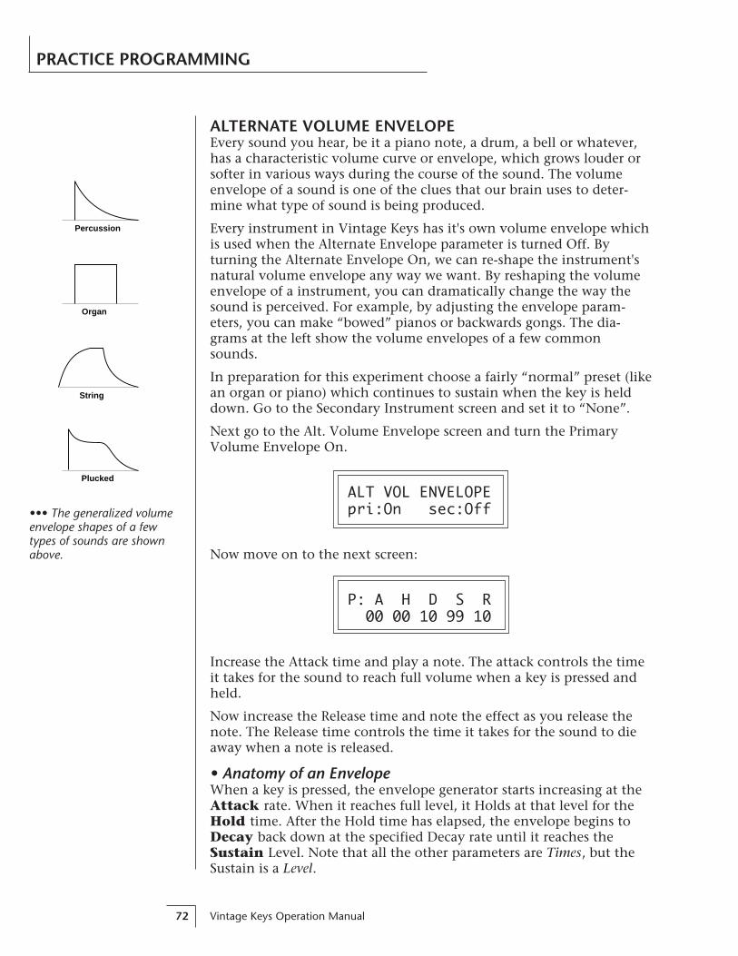
Vintage Keys Operation Manual72
PRACTICE PROGRAMMING
ALTERNATE VOLUME ENVELOPEEvery sound you hear, be it a piano note, a drum, a bell or whatever,has a characteristic volume curve or envelope, which grows louder orsofter in various ways during the course of the sound. The volumeenvelope of a sound is one of the clues that our brain uses to deter-mine what type of sound is being produced.
Every instrument in Vintage Keys has it's own volume envelope whichis used when the Alternate Envelope parameter is turned Off. Byturning the Alternate Envelope On, we can re-shape the instrument'snatural volume envelope any way we want. By reshaping the volumeenvelope of a instrument, you can dramatically change the way thesound is perceived. For example, by adjusting the envelope param-eters, you can make “bowed” pianos or backwards gongs. The dia-grams at the left show the volume envelopes of a few commonsounds.
In preparation for this experiment choose a fairly “normal” preset (likean organ or piano) which continues to sustain when the key is helddown. Go to the Secondary Instrument screen and set it to “None”.
Next go to the Alt. Volume Envelope screen and turn the PrimaryVolume Envelope On.
ALT VOL ENVELOPEpri:On sec:Off
Now move on to the next screen:
P: A H D S R 00 00 10 99 10
Increase the Attack time and play a note. The attack controls the timeit takes for the sound to reach full volume when a key is pressed andheld.
Now increase the Release time and note the effect as you release thenote. The Release time controls the time it takes for the sound to dieaway when a note is released.
• Anatomy of an EnvelopeWhen a key is pressed, the envelope generator starts increasing at theAttack rate. When it reaches full level, it Holds at that level for theHold time. After the Hold time has elapsed, the envelope begins toDecay back down at the specified Decay rate until it reaches theSustain Level. Note that all the other parameters are Times, but theSustain is a Level.
Percussion
Organ
String
Plucked
••• The generalized volumeenvelope shapes of a fewtypes of sounds are shownabove.

Chapter 6: Practice Programming 73
PRACTICE PROGRAMMING
The envelope will stay at the Sustain level for as long as the key isheld. When the key is released, the envelope falls back down to zero atthe Release rate.
level
time
keydown
A H D
S
R
keyreleased
WORKING WITH THE FILTERThe low pass filter makes it possible to remove certain components ofthe sound. A low pass filter removes the high frequency componentsor put another way, it “lets the lows pass”. In preparation for thisexperiment choose a fairly “normal” preset (like an organ or piano).Go to the Secondary Instrument screen and set it to “None”, then setthe Primary Instrument to one which is rich in harmonics, such as theViolin Trio. (Since the filter works by removing certain frequencies, wewant to make sure that we have a lot of frequencies to start with.). Setthe parameters as listed in the chartbelow in order to “clean the slate” foryour filter investigation.
Go to the primary filter cutoff and Qscreen shown below and position thecursor below the Fc value.
FILTER priFc:255 Q:00
Instrument: Violin Trio
Tuning course: +00
Volume: 100
Alt. Vol. Envelope: Off
Realtime CTL: 1-8 -> All Off
Filter Type Pri: 4 Pole Lowpass
Filter Fc: 255
Filter Q: 00
Aux Envelope Amt: +000
Primary
Aux Env.: A: A H D S R 40 00 00 99 50

Vintage Keys Operation Manual74
PRACTICE PROGRAMMING
Playing the keyboard now, you should hear the raw Violin Trio sound.Slowly decrease the filter Fc as you play the keyboard. The sound willget duller and duller as more and more high frequencies are filteredout until at some point the sound will completely disappear. (Youhave filtered out everything.) The chart below illustrates what you justdid. You moved the cutoff frequency down.
20
40
60
80
100
40 80 160 360 720 1440 2880
Frequency...
Am
pli
tud
e
Cutoff Frequency
Output of Filter
Open the filter back up to 255, then move the cursor underneath theQ. Set the Q to 15, then move the cursor back under the Fc. As youchange the Fc, notice that the sound now has a sharp, nasal quality.With a high Q, frequencies at the cutoff frequency (Fc) are beingboosted or amplified.
Now let's modulate the filter Fc with the Auxiliary envelope generator.The envelope generator is a device that can automatically change thefilter Fc during the course of the note. Set the Fc way down until youcan just hear the sound (about 60), then press Enter and go to theREALTIME CTL screen.
REALTIME CTL1 PWhl -> Off
Move the cursor down underneath the source and set it to Aux (forAuxiliary Envelope). Next move the cursor underneath the destinationand set it to Filter Fc. The screen should look like this:
REALTIME CTL1 Aux -> FiltFc

Chapter 6: Practice Programming 75
PRACTICE PROGRAMMING
You have just connected the Auxiliary Envelope Generator to theFilter Cutoff as shown in the diagram below.
R
L
PanInstrument ToneLow Pass
FilterQFc
DCA
Aux. AHDSR
Now go back to the Aux Envelope screen shown below.
AUX ENV AMT DLY +000 000
Move the cursor underneath the envelope amount and change thevalue to about +100. Now when you press a key the filter will slowlysweep up. Because the filter Q is set high, you can hear the differentharmonics of the sound being accentuated as the filter cutoff sweepspast.
Now, scroll back to the Auxiliary Envelope parameter screen.
A: A H D S R 15 00 00 99 50
Change the attack rate and note the change in the sound. The dia-gram below shows approximately how the envelope looks when theparameters are set as shown above.
time
Sustain Level
Att
ack
Tim
e Release Time
••• Note that all the enve-lope parameters are Ratesexcept for Sustain, which isa Level.

Vintage Keys Operation Manual76
PRACTICE PROGRAMMING
Because the Sustain level is set to maximum, the decay parameter hasno effect. Lower the Sustain to 00, then set the Decay to around 27.
A: A H D S R 15 00 27 00 50
Now the filter sweeps up, then decays back down to the Sustain Level(which is zero). Play with the envelope parameters for awhile to get afeel for their function. (If you're having trouble understanding theEnvelope Generators, please refer to the Programming Basics sectionin this manual.)
time
Att
ack
Tim
e Decay Time
Key Held
• TroubleshootingA common source of confusion when working with the filter envelopeis that the Attack or Release parameter might not seem to be workingcorrectly. Referring to the diagram below which shows the VintageKeys signal flow, you will notice that the DCA comes after the Filter.The DCA controls the final volume of the sound, so if the filter'srelease is longer than the release for the DCA, you won't hear it, be-cause the DCA has already shut off the sound.
R
L
PanInstrument ToneLow Pass
FilterQFc
DCA
This is just an example of why troubleshooting is important. If you arenot getting the expected result, try to analyze the situation. There willbe many times when you will have to stop for a minute and think,“What am I trying to do and why isn't it working?” When this hap-pens (and it will), don't panic. Troubleshooting is a normal part of thesynthesis process. Simply examine the various parameters and try tobe as analytical as possible as you solve the problem. Usually thesolution will be simple. (The filter is already wide open and can't openany more.) Learning to play an instrument takes… Practice.

Chapter 6: Practice Programming 77
PRACTICE PROGRAMMING
You’re probably getting the general idea by now. Remember not tochange presets or the preset will return to normal. If you want to saveyour creation, select the last screen in the Edit menu and select adestination preset location for your masterpiece, then press Enter.
Practice Modulating• Try modulating the pitch with the Aux. Envelope generator
• Use velocity to modulate the Aux Envelope Amount or the filterFc. (Key/Vel. screen). This will brighten the sound as you playharder.
• Program the LFO to modulate filter Fc and volume (Realtimemodulation screen).
• Modulate the LFO with the other LFO, with velocity, and withthe modulation wheel.
• Think of ten different modulation routings, then try them out.The key to learning about Vintage Keys is to experiment.
VINTAGE SYNTHESISVintage Synthesis is actually just a form of additive synthesis. Only,instead of building a sound from simple sine waves, Vintage Keyssupplies you with complete sampled sounds or complex waveformsallows you to combine all or part of these together to form a newsound. The process is illustrated below.
The envelope generators controlling the DCAs (digitally controlledamplifiers) can be used to fade between two instruments (primary andsecondary) during the course of a note. This powerful techniqueallows you to combine elements of different instruments together toform completely new sounds.
Instrument
Pri
Sec
FadeArea
FadeArea
Shaped with DCA Added Together toform Resultant Sound
Portions of two sounds are dynamically crossfaded in order to produce a new soundcontaining elements of both.
••• Presets can be stored inany of the non-volatile RAMlocations (0-255).

Vintage Keys Operation Manual78
PRACTICE PROGRAMMING
For example, the attack portion of one instrument can be crossfadedinto the body of another instrument, creating a hybrid of the two.Vintage Keys also contains many digitally generated waveforms thatmay be combined with other digital waves or with sampled instru-ments in order to change the character of the sound, perhaps to add adigital “edge” or add bass. In addition to the envelope generators,parameters such as Delay, Sound Start and Crossfade allow you tofurther control the blend of primary and secondary instruments. Andof course, the dynamic Low Pass Filters allow you to control the har-monic content of each instrument during the course of the note.
• Creating a New SoundAs an example, let's add a sampled flute attack to a Mini Moog synthe-sizer sound to create a sort of Flute Synth. Start with one of the defaultpresets and change only the parameters listed in the chart below. Theflute instrument is shaped by the Alternate Volume Envelope so thatonly the breathy attack “chiff” is heard (a short Decay with the Sustainset to zero). Also the attack time has been set to 2 to soften the breathsound a bit.
The Mini Moog 1 instrument serves as the body of the sound. Thedelay parameter is used to delay the onset of the Mini Moog until theflute sound has died away. The Attack parameter of the SecondaryAlternate Volume Envelope is set so that the Mini Moog will smoothlyfade in as the Flute is fading out. Lastly, the volume of each instru-ment is adjusted to balance the sound.
REVERB SPACESThe reverb spaces allow you to add reverb ambience to Vintage Keysdrums. By layering an instrument containing only reverb with a “dry”drum instrument, the effect of real reverb is created. In addition, thereverb spaces can be shaped and filtered just like any other instru-ment. There are eleven reverb spaces (instruments 76-84, 86, 88) inVintage Keys.
Using the reverb spaces is easy. Use one of the default presets as yourstarting point. Set up the Edit menu parameters as in the chart on thefollowing page and change only the parameters specified.
Instrument: Mini Moog 1
Volume: 91
Alt Envelope: On
A H D S R
12 00 43 59 40
Delay: 003
Instrument: Flute
Volume: 127
Alt Envelope: On
A H D S R
02 02 16 00 16
Delay: 000
Primary Secondary
••• The reverb spaces werecreated on our Emax II 16-bitsampling system using atechnique called TransformMultiplication.
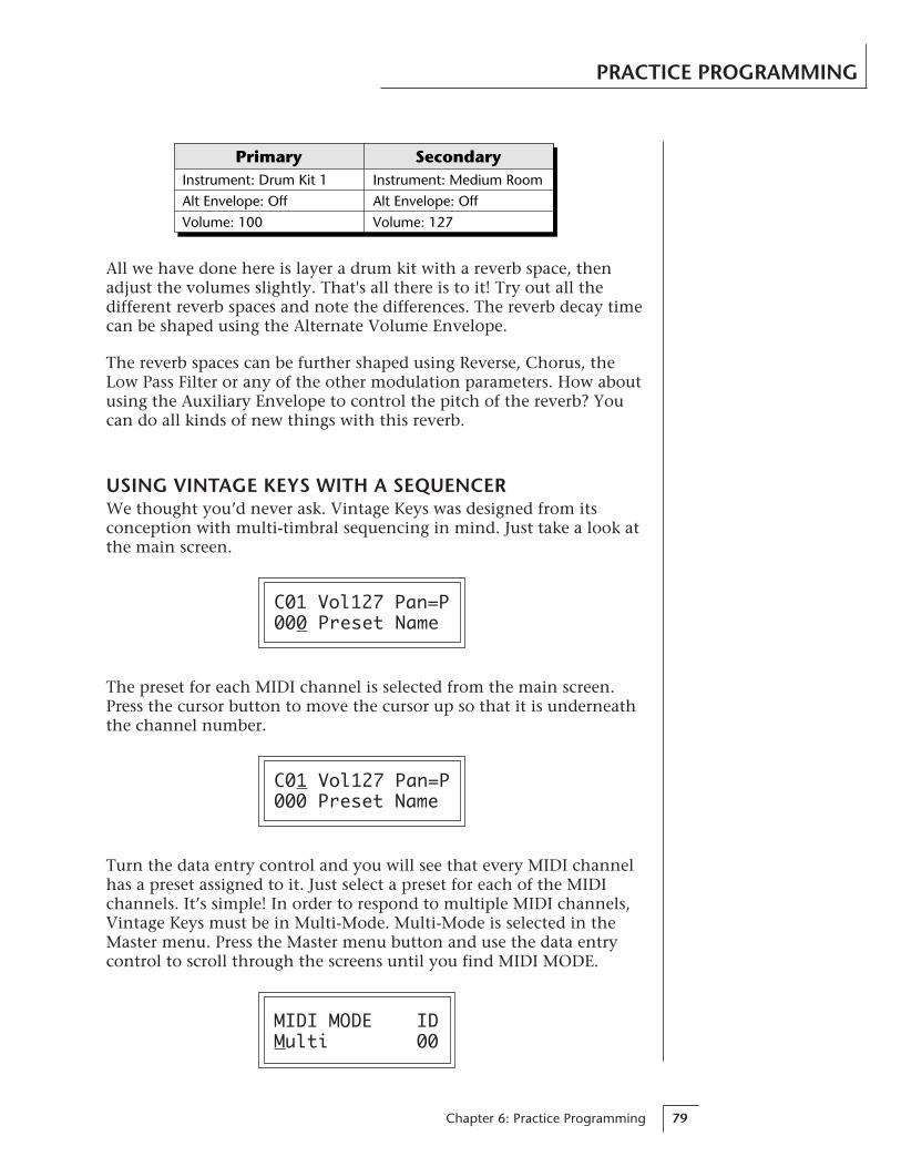
Chapter 6: Practice Programming 79
PRACTICE PROGRAMMING
Instrument: Medium Room
Alt Envelope: Off
Volume: 127
Instrument: Drum Kit 1
Alt Envelope: Off
Volume: 100
Primary Secondary
All we have done here is layer a drum kit with a reverb space, thenadjust the volumes slightly. That's all there is to it! Try out all thedifferent reverb spaces and note the differences. The reverb decay timecan be shaped using the Alternate Volume Envelope.
The reverb spaces can be further shaped using Reverse, Chorus, theLow Pass Filter or any of the other modulation parameters. How aboutusing the Auxiliary Envelope to control the pitch of the reverb? Youcan do all kinds of new things with this reverb.
USING VINTAGE KEYS WITH A SEQUENCERWe thought you’d never ask. Vintage Keys was designed from itsconception with multi-timbral sequencing in mind. Just take a look atthe main screen.
C01 Vol127 Pan=P000 Preset Name
The preset for each MIDI channel is selected from the main screen.Press the cursor button to move the cursor up so that it is underneaththe channel number.
C01 Vol127 Pan=P000 Preset Name
Turn the data entry control and you will see that every MIDI channelhas a preset assigned to it. Just select a preset for each of the MIDIchannels. It’s simple! In order to respond to multiple MIDI channels,Vintage Keys must be in Multi-Mode. Multi-Mode is selected in theMaster menu. Press the Master menu button and use the data entrycontrol to scroll through the screens until you find MIDI MODE.
MIDI MODE IDMulti 00

Vintage Keys Operation Manual80
Move the cursor down to the second line and change the mode toMulti as shown. Vintage Keys will now respond to multiple MIDIchannels.
MORE ADVANCED SEQUENCING• Pre-Sequence SetupSuppose that you want to have your sequencer set up everything foryou before the start of the song. Good idea. This will make the VintageKeys setup procedure automatic and prevent the wrong presets fromplaying.
The basic idea of a pre-sequence setup is to send out MIDI informationjust before the start of the song. This MIDI information will select allthe proper presets, adjust the mix, and pan positions of each preset.
Note: Vintage Keys setup information should be transmitted from thesequencer before the song actually starts, perhaps during a lead-in meas-ure or countdown. DO NOT send setup information just before the firstbeat of the song or MIDI timing errors could result.
• Initial SetupIn the Master menu:
1) Turn ON Multi-Mode
2) Turn ON Preset Change enable for each channel.
3) Turn OFF MIDI Enable on MIDI channels that are to be used forother synthesizers.
• Preset, Volume & Pan SetupProgram your MIDI sequencer to transmit the following informationbefore the song starts.
1) Select the proper presets for each MIDI channel used on VintageKeys.
2) Send MIDI volume information (controller #7) for each MIDIchannel used on Vintage Keys.
3) Send MIDI pan information (controller #10) for each MIDI channelused on Vintage Keys.
Now your song will play perfectly every time using the proper presets,volumes and pan positions. In addition, presets, volumes and panpositions (or anything else for that matter) can be adjusted in realtimeduring the song. Note: If the wrong presets are being selected, check theMIDI Program -> Preset map.
To carry the pre-sequence setup even further, you can even includepreset data for each preset used in the sequence. See page 22 for details.
••• The Preset, Volume andPan information for all 16channels is included whenthe Master Settings aretransmitted or received overMIDI.
••• The MIDI specificationonly allows for changingpresets0-127. If you need to accesspresets in locations above127, use the Program PresetMap (page 21). You can savethe Program Preset Mapalong with your sequence bysaving the Master Settings(page 22).
PRACTICE PROGRAMMING
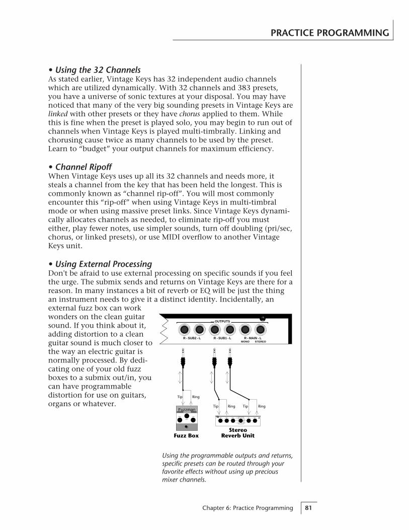
Chapter 6: Practice Programming 81
• Using the 32 ChannelsAs stated earlier, Vintage Keys has 32 independent audio channelswhich are utilized dynamically. With 32 channels and 383 presets,you have a universe of sonic textures at your disposal. You may havenoticed that many of the very big sounding presets in Vintage Keys arelinked with other presets or they have chorus applied to them. Whilethis is fine when the preset is played solo, you may begin to run out ofchannels when Vintage Keys is played multi-timbrally. Linking andchorusing cause twice as many channels to be used by the preset.Learn to “budget” your output channels for maximum efficiency.
• Channel RipoffWhen Vintage Keys uses up all its 32 channels and needs more, itsteals a channel from the key that has been held the longest. This iscommonly known as “channel rip-off”. You will most commonlyencounter this “rip-off” when using Vintage Keys in multi-timbralmode or when using massive preset links. Since Vintage Keys dynami-cally allocates channels as needed, to eliminate rip-off you musteither, play fewer notes, use simpler sounds, turn off doubling (pri/sec,chorus, or linked presets), or use MIDI overflow to another VintageKeys unit.
• Using External ProcessingDon't be afraid to use external processing on specific sounds if you feelthe urge. The submix sends and returns on Vintage Keys are there for areason. In many instances a bit of reverb or EQ will be just the thingan instrument needs to give it a distinct identity. Incidentally, anexternal fuzz box can workwonders on the clean guitarsound. If you think about it,adding distortion to a cleanguitar sound is much closer tothe way an electric guitar isnormally processed. By dedi-cating one of your old fuzzboxes to a submix out/in, youcan have programmabledistortion for use on guitars,organs or whatever.
RingTip
Fuzzman
Fuzz Box
RingTip RingTip
StereoReverb Unit
R - SUB2 - L R - SUB1 - L R - MAIN - LMONO STEREO
OUTPUTS
Using the programmable outputs and returns,specific presets can be routed through yourfavorite effects without using up preciousmixer channels.
PRACTICE PROGRAMMING

Vintage Keys Operation Manual82
Chapter 7: Reference Section 83
REFERENCESECTION

Vintage Keys Operation Manual84
FACTORY PRESETS - RAM
0. Hmnd B3 011. Fndr Rds 012. Wurli 013. Clav 014. TronStrng 015. CP Grand 016. Bass: Moog 017. Pad: Moog 558. Lead: P5 Sync9. Hmnd B3 0210. Hmnd B3 0311. Hmnd B3 0412. Hmnd B3 0513. Hmnd B3 0614. Hmnd B3 0715. Hmnd B3 0816. Hmnd B3 0917. Hmnd B3 1018. Hmnd B3 1119. Fndr Rds 0220. Fndr Rds 0321. Fndr Rds 0422. Fndr Rds 0523. Fndr Rds 0624. Fndr Rds 0725. Fndr Rds 0826. Fndr Rds 0927. Fndr Rds 1028. Fndr Rds 1129. Wurli 0230. Wurli 0331. Wurli 0432. Wurli 0533. Wurli 0634. Wurli 0735. Wurli 0836. Wurli 0937. Wurli 1038. Wurli 1139. Clav 0240. Clav 0341. Clav 0442. Clav 05
86. Pad: Fairlight87. Pad: OB Port88. Pad: P5 Piper89. Lead: Moog0190. Lead: Moog0291. Lead: Moog0392. Lead: Arp 0193. Lead: Arp 0294. Lead: Arp 0395. Lead: SEM 0196. Lead: SEM 0297. Lead: EMU Tri98. Lead: EMUSaws99. Lead: EMUSqrs100. Hmnd B3 12101. Syn Bass 01102. Soft Pad 01103. Hard Pad 01104. Syn Lead 01105. Intrvl Ld 01106. Misc Cool 01107. Swell FX 01108. Clock FX 01109. Hmnd B3 13110. Hmnd B3 14111. Hmnd B3 15112. Hmnd B3 16113. Hmnd B3 17114. Hmnd B3 18115. Hmnd B3 19116. Hmnd B3 20117. Hmnd B3 21118. Hmnd B3 22119. Syn Bass 02120. Syn Bass 03121. Syn Bass 04122. Syn Bass 05123. Syn Bass 06124. Syn Bass 07125. Syn Bass 08126. Syn Bass 09127. Syn Bass 10
43. Clav 0644. Clav 0745. Clav 0846. Clav 0947. Clav 1048. Clav 1149. TronStrng 0250. TronStrng 0351. TronFlute 0152. TronFlute 0253. TronFlute 0354. TronChoir 0155. TronChoir 0256. TronChoir 0357. Tron Str/Chr58. Tron Str/Brs59. CP Grand 0260. CP Grand 0361. CP Grand 0462. CP Grand 0563. CP Grand 0664. CP Grand 0765. CP Grand 0866. CP Grand 0967. CP Grand 1068. CP Grand 1169. Bass: Moog 0270. Bass: Moog 0371. Bass: Moog 0472. Bass: Moog 0573. Bass: Moog 0674. Bass: MicroMg75. Bass: Taurus76. Bass: M12 0177. Bass: M12 0278. Bass: Arp260079. Pad: MoogBras80. Pad: P5String81. Pad: M12Strng82. Pad: ArpStrng83. Pad: Obx Saws84. Pad: Arp 260085. Pad: PolyMoog
Vintage KeysPresets
0-255 RAM
256-511 ROM

Chapter 7: Reference Section 85
FACTORY PRESETS - RAM
128. Syn Bass 11129. Soft Pad 02130. Soft Pad 03131. Soft Pad 04132. Soft Pad 05133. Soft Pad 06134. Soft Pad 07135. Soft Pad 08136. Soft Pad 09137. Soft Pad 10138. Soft Pad 11139. Hard Pad 02140. Hard Pad 03141. Hard Pad 04142. Hard Pad 05143. Hard Pad 06144. Hard Pad 07145. Hard Pad 08146. Hard Pad 09147. Hard Pad 10148. Hard Pad 11149. Syn Lead 02150. Syn Lead 03151. Syn Lead 04152. Syn Lead 05153. Syn Lead 06154. Syn Lead 07155. Syn Lead 08156. Syn Lead 09157. Syn Lead 10158. Syn Lead 11159. Intrvl Ld 02160. Intrvl Ld 03161. Intrvl Ld 04162. Intrvl Ld 05163. Intrvl Ld 06164. Intrvl Ld 07165. Intrvl Ld 08166. Intrvl Ld 09167. Intrvl Ld 10168. Intrvl Ld 11169. Misc Cool 02170. Misc Cool 03
171. Misc Cool 04172. Misc Cool 05173. Misc Cool 06174. Misc Cool 07175. Misc Cool 08176. Misc Cool 09177. Misc Cool 10178. Misc Cool 11179. Swell FX 02180. Swell FX 03181. Swell FX 04182. Swell FX 05183. Swell FX 06184. Swell FX 07185. Swell FX 08186. Swell FX 09187. Swell FX 10188. Swell FX 11189. Clock FX 02190. Clock FX 03191. Clock FX 04192. Clock FX 05193. Clock FX 06194. Clock FX 07195. Clock FX 08196. Clock FX 09197. Clock FX 10198. Clock FX 11199. Clock FX 12200. Drum Kit 01201. Drum Kit 02202. Drum Kit 03203. Drum Kit 04204. Drum Kit 05205. Drum Kit 06206. Drum Kit 07207. Perc Loop208. Bass Gtr 01209. Bass Gtr 02210. Bass Gtr 03211. Bass Gtr 04212. Bass Gtr 05213. Elec Gtr 01
214. Elec Gtr 02215. Elec Gtr 03216. Elec Gtr 04217. Bass/Guitar218. CoolLink 11a219. CoolLink 11b220. Super Nova221. TronBrasLink222. HiBarLink L223. HiBarLink M224. HiBarLink S225. MidBarLink L226. MidBarLink M227. MidBarLink S228. LoBarLink L229. LoBarLink M230. LoBarLink S231. 2ndPercLink L232. 2ndPercLinkM233. 2ndPercLink S234. 3rdPercLink L235. 3rdPercLink M236. 3rdPercLink S237. B3 12 Link A238. B3 12 Link B239. Swell 3 Link240. - default -241. - default -242. - default -243. - default -244. - default -245. - default -246. - default -247. - default -248. - default -249. - default -250. - default -251. - default -252. - default -253. - default -254. - default -255. - default -
••• Store your own custompresets in the Default presetlocations.
••• Linked Presets are usedas part of another preset.

Vintage Keys Operation Manual86
256. Hmnd B3 23257. Fndr Rds 12258. Wurli 12259. Soft Pad 12260. TronStrng 04261. Hard Pad 12262. Syn Lead. 12263. Soft Pad. 13264. Syn Bass 12265. Drum Kit 08266. Farfisa267. Hard Pad 13268. Wurli 13269. Soft Pad 14270. Clock FX 13271. Swell FX 12272. Intrvl Ld 12273. Swell FX 13274. Syn Bass 13275. Drum Kit 09276. Hmnd B3 24277. Wurli 14278. Clav 12279. TronFlute 04280. TronChoir 04281. Soft Pad 15282. Soft Pad 16283. Soft Pad 17284. Syn Bass 14285. Drum Kit 10286. Hmnd B3 25287. CP Grand 12288. Toy Piano289. Soft Pad 18290. Soft Pad 19291. Misc Cool 12292. Soft Pad 20293. Soft Pad 21294. Clav 13295. Percussion 1296. Hmnd B3 26297. Clav 14298. Fndr Rds 13
299. Soft Pad 22300. Hard Pad 14301. Hard Pad 15302. Syn Lead 13303. Hard Pad 16304. Bass Gtr. 06305. Percussion 2306. Hmnd B3 27307. CP Grand 13308. Vox Cont 01309. Clock FX 14310. Syn Lead 14311. Swell FX 14312. Swell FX 15313. Elec Gtr 05314. Syn Bass 15315. Drum Kit 11316. Hmnd B3 28317. Clav 15318. Hmnd B3 29319. Syn Lead 15320. Hmnd B3 30321. Hmnd B3 31322. Hmnd B3 32323. Fndr Rds 14324. Clock FX 15325. Swell FX 16326. Hmnd B3 33327. Hard Pad 17328. CP Grand 14329. Hard Pad 18330. Misc Cool 13331. Soft Pad 23332. Drum Kit 12333. Drum Link A334. Drum Link B335. Drum Kit 13336. Hmnd B3 34337. Wurli 15338. Soft Pad 24339. Soft Pad 25340. Hard Pad 19341. Hard Pad 20
342. Soft Pad 26343. Soft Pad 27344. Syn Bass 16345. Percussion 3346. Hmnd Link A347. Soft Pad 28348. Soft Pad 29349. Soft Pad 30350. Soft Pad 31351. Percussion 4352. Syn Lead 16353. Hmnd Link B354. Syn Bass 17355. Hmnd Link C356. Hmnd B3 35357. TronStrng 05358. Drum Link C359. Drum Link D360. Drum Link E361. Percussion 5362. Hmnd B3 36363. Hard Pad 21364. Syn Bass 18365. Syn Bass 19366. Syn Bass 20367. Syn Bass 21368. Hmnd B3 37369. Hard Pad 22370. Percussion 6371. Hmnd B3 40372. Hmnd B3 41373. Hmnd Link D374. Hmnd B3 42375. Hmnd Link E376. Hmnd Link F377. Hmnd B3 43378. Hmnd B3 44379. Hmnd Link G380. Hmnd B3 45381. Hmnd Link H382. Hmnd B3 46383. —default—
FACTORY PRESETS - ROM
Vintage KeysPresets
0-255 RAM
256-511 ROM
••• Linked Presets are usedas a part of another preset.
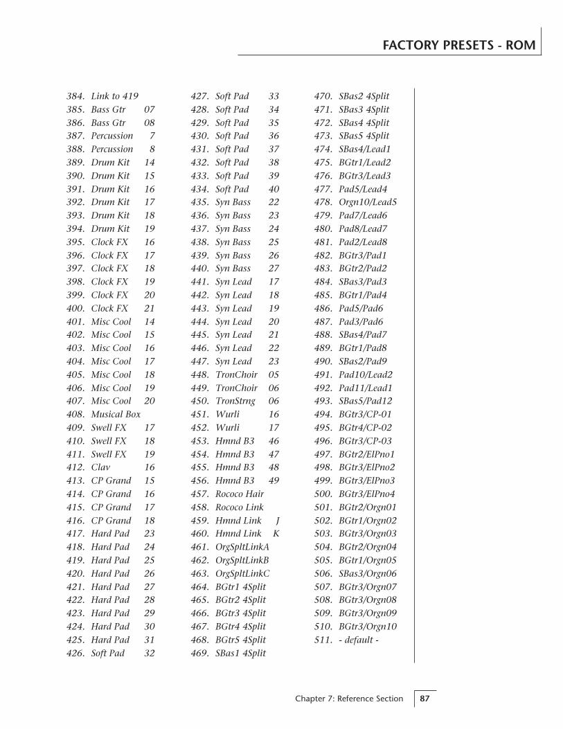
Chapter 7: Reference Section 87
384. Link to 419385. Bass Gtr 07386. Bass Gtr 08387. Percussion 7388. Percussion 8389. Drum Kit 14390. Drum Kit 15391. Drum Kit 16392. Drum Kit 17393. Drum Kit 18394. Drum Kit 19395. Clock FX 16396. Clock FX 17397. Clock FX 18398. Clock FX 19399. Clock FX 20400. Clock FX 21401. Misc Cool 14402. Misc Cool 15403. Misc Cool 16404. Misc Cool 17405. Misc Cool 18406. Misc Cool 19407. Misc Cool 20408. Musical Box409. Swell FX 17410. Swell FX 18411. Swell FX 19412. Clav 16413. CP Grand 15414. CP Grand 16415. CP Grand 17416. CP Grand 18417. Hard Pad 23418. Hard Pad 24419. Hard Pad 25420. Hard Pad 26421. Hard Pad 27422. Hard Pad 28423. Hard Pad 29424. Hard Pad 30425. Hard Pad 31426. Soft Pad 32
470. SBas2 4Split471. SBas3 4Split472. SBas4 4Split473. SBas5 4Split474. SBas4/Lead1475. BGtr1/Lead2476. BGtr3/Lead3477. Pad5/Lead4478. Orgn10/Lead5479. Pad7/Lead6480. Pad8/Lead7481. Pad2/Lead8482. BGtr3/Pad1483. BGtr2/Pad2484. SBas3/Pad3485. BGtr1/Pad4486. Pad5/Pad6487. Pad3/Pad6488. SBas4/Pad7489. BGtr1/Pad8490. SBas2/Pad9491. Pad10/Lead2492. Pad11/Lead1493. SBas5/Pad12494. BGtr3/CP-01495. BGtr4/CP-02496. BGtr3/CP-03497. BGtr2/ElPno1498. BGtr3/ElPno2499. BGtr3/ElPno3500. BGtr3/ElPno4501. BGtr2/Orgn01502. BGtr1/Orgn02503. BGtr3/Orgn03504. BGtr2/Orgn04505. BGtr1/Orgn05506. SBas3/Orgn06507. BGtr3/Orgn07508. BGtr3/Orgn08509. BGtr3/Orgn09510. BGtr3/Orgn10511. - default -
427. Soft Pad 33428. Soft Pad 34429. Soft Pad 35430. Soft Pad 36431. Soft Pad 37432. Soft Pad 38433. Soft Pad 39434. Soft Pad 40435. Syn Bass 22436. Syn Bass 23437. Syn Bass 24438. Syn Bass 25439. Syn Bass 26440. Syn Bass 27441. Syn Lead 17442. Syn Lead 18443. Syn Lead 19444. Syn Lead 20445. Syn Lead 21446. Syn Lead 22447. Syn Lead 23448. TronChoir 05449. TronChoir 06450. TronStrng 06451. Wurli 16452. Wurli 17453. Hmnd B3 46454. Hmnd B3 47455. Hmnd B3 48456. Hmnd B3 49457. Rococo Hair458. Rococo Link459. Hmnd Link J460. Hmnd Link K461. OrgSpltLinkA462. OrgSpltLinkB463. OrgSpltLinkC464. BGtr1 4Split465. BGtr2 4Split466. BGtr3 4Split467. BGtr4 4Split468. BGtr5 4Split469. SBas1 4Split
FACTORY PRESETS - ROM

Vintage Keys Operation Manual88
VINTAGE KEYS INSTRUMENTS
SAMPLED SOUNDS1. B3DistLwSlw ........... Distorted B3 Organ, Low Drawbars, Slow Rotor
2. B3 Dist Fast ....................................... Distorted B3 Organ, Fast Rotor
3. B3 Hi Slow.............................. B3 Organ, High Drawbars, Slow Rotor
4. B3 Hi Fast ................................ B3 Organ, High Drawbars, Fast Rotor
5. B3 Full Slow .............................B3 Organ, Full Drawbars, Slow Rotor
6. B3 Full Fast ................................ B3 Organ, Full Drawbars, Fast Rotor
7. B3 Perc 3rd .................................B3 Organ 3rd Harmonic Percussion
8. Male Choir .................................................... Mellotron - Male Choir
9. Femme Choir .............................................Mellotron - Female Choir
10. Males to Mix ............. Mellotron - Male Choir (to mix with Inst. 11)
11. Femmes to Mix ......Mellotron - Female Choir (to mix with Inst. 10)
12. Violin Trio............................................................ Mellotron - Violins
13. Flute .........................................................................Mellotron - Flute
14. Bari Sax............................................................... Baritone Saxophone
15. Tenor Sax ............................................................... Tenor Saxophone
16. Alto Sax ..................................................................... Alto Saxophone
17. Trumpet Sft ........................................................ Soft-blown Trumpet
18. Trumpet Sft .......................................................Hard-blown Trumpet
19. Trombone .......................................................................... Trombone
20. Trom/STpt ........................................... Trombone/Soft Trumpet Split
21. Trom/HTpt ........................................ Trombone/Hard Trumpet Split
22. Trom/Sax ............................................................. Trombone/Sax Split
23. Farfisa .............................................................................Farfisa Organ
24. CP-70 ............................................................................... CP-70 Piano
25. CP-70 Mellow................................... CP-70 Piano with Mellow Tone
26. CP-70 Brite ......................................... CP-70 Piano with Bright Tone
27. Piano Bass ..........................................CP-70 Piano Bass - Transposed
28. Wurlitzer1 ................................................. Wurlitzer Electric Piano 1
29. Wurlitzer2 ................................................. Wurlitzer Electric Piano 2
30. Dyno Rhodes1.............................. Dyno-My-Rhodes Electric Piano 1
31. Dyno Rhodes2.............................. Dyno-My-Rhodes Electric Piano 2
32. FendrRhodes ........................................ Fender Rhodes Electric Piano
33. Clavinet .................................................................... Hohner Clavinet
34. Brite Clavinet ................................................Bright Hohner Clavinet

Chapter 7: Reference Section 89
VINTAGE KEYS INSTRUMENTS
35. Mini Moog 1 .......................................Mini Moog w/Low Resonance
36. Mini Moog 2 ..................................... Mini Moog w/ Med Resonance
37. Mini Moog 3 ..................................... Mini Moog w/High Resonance
38. Mini Moog 4 .......................................... Mini Moog w/Lower Cutoff
39. Mini Moog 5 ................................................ Mini Moog Horn Sound
40. Mini Moog 6 .......................... Mini Moog w/Osc->Filter Modulation
41. Micro Moog ........................ Micro Moog w/ Osc->Filter Modulation
42. Taurus Pedal ................................................ Moog Taurus Bass Pedal
43. Jaco Bass ................................................................. DX-7 Bass Sound
44. M12 Lead 1 .................................. Oberheim Matrix-12 Sync Patch 1
45. M12 Lead 2 ................................................... Matrix-12 Sync Patch 2
46. ARP 2600 ....................... ARP 2600 Synth w/ Osc->Filter Modulation
47. Rock DXman ................................... DX-7 played through Rockman
48. P5 Sync Lead .................................................... Prophet-5 Sync Patch
49. Moog 55 Rez ............................ Moog Model 55 w/ Filter Resonance
50. Memory Moog ...................................... Memory Moog - Horn Patch
51. OBX Saws ...................................... Oberheim OBX - Sawtooth Patch
52. P5 Guitar Pad ....................................... Prophet-5 - Guitar-like Patch
53. Matrix Pad .................................................. Matrix-12 - Hollow Patch
54. P5 Piper ........................................Prophet-5 - Overblown Pipe Patch
55. P5 Strings ..................................................... Prophet-5 - String Patch
56. M12 Strings .................................................. Matrix-12 - String Patch
57. ARP Strings ........................................................ ARP String Ensemble
58. AHHs .......................................................................... Fairlight Vocals
59. Picked Bass ............................................................ Picked Bass Guitar
60. Finger Bass .................................................. Fingerpicked Bass Guitar
61. Finger Tre .................................................... Fingerpicked Bass Guitar
62 Pickd 8 Top ......................................................... 8-String Bass Guitar
63. Finger 8 Top ........................................................ 8-String Bass Guitar
64. Finger 8 Tre ......................................................... 8-String Bass Guitar
65. The Guitar ......................................................... Clean Electric Guitar
66. Twelve Top 1 ............................................................. 12-String Guitar
67. Twelve Top 2 ............................................................. 12-String Guitar
68. Twelve Top 3 ............................................................. 12-String Guitar

Vintage Keys Operation Manual90
VINTAGE KEYS INSTRUMENTS
69. Drum Kit 1 ...........................
70. Drum Kit 2 ...........................
71. Drum Kit 3 ...........................
72. Drum Kit 4 ...........................
73. Drum Kit 5 ...........................
74. Drum Kit 6 ...........................
75. Drum Kit 7 ...........................
76. Large Hall .........................................
77. Medium Room .................................
78. Tiled Room.......................................
79. Gated Short ......................................
80. Gated Long 1 ...................................
81. Gated Long 2 ...................................
82. Lush Reverb......................................
83. Blush Reverb ....................................
84. Full On Reverb .................................
85. Dry Kick ...................... Dry Kick Drum over the full keyboard range
86. Kick Verb ............... Kick Drum Reverb over the full keyboard range
87. Dry Snare....................Dry Snare Drum over the full keyboard range
88. Snare Verb ............. Snare Drum Reverb over the full keyboard range
89. Dry Tom ........................ Dry Tom Tom over the full keyboard range
90. Wet Tom ............... Ambient Tom Tom over the full keyboard range
91. High Hat 1..................... Closed Hi-Hat over the full keyboard range
92. High Hat 2............. Half Closed Hi-Hat over the full keyboard range
93. High Hat 3....................... Open Hi-Hat over the full keyboard range
94. Ride Ping ................. Ride Cymbal Ping over the full keyboard range
95. Ride Bell ................... Ride Cymbal Bell over the full keyboard range
96. Crash ............................. Crash Cymbal over the full keyboard range
97. Cowbell ...................................Cowbell over the full keyboard range
98. Tambourine...................... Tambourine over the full keyboard range
99. Side Stick .....................Snare Side Stick over the full keyboard range
100. Clave ....................... Rosewood Clave over the full keyboard range
See the Percussion Instru-ment Location Diagrams onpages98-100.
Reverb Spaces to com-bine with Drum Kits 1-7.
See the Reverb SpaceDiagram on page 100.
* The names of the above-mentioned instruments may be trademarks of third parties. In order to create
the instrument sounds, E-mu records such sound from the respective instrument and the recording is
converted into a digital signal which is then modified as necessary to be stored in a read only memory
(ROM) device.
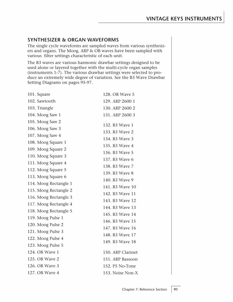
Chapter 7: Reference Section 91
VINTAGE KEYS INSTRUMENTS
SYNTHESIZER & ORGAN WAVEFORMSThe single cycle waveforms are sampled waves from various synthesiz-ers and organs. The Moog, ARP & OB waves have been sampled withvarious filter settings characteristic of each unit.
The B3 waves are various harmonic drawbar settings designed to beused alone or layered together with the multi-cycle organ samples(instruments 1-7). The various drawbar settings were selected to pro-duce an extremely wide degree of variation. See the B3 Wave DrawbarSetting Diagrams on pages 95-97.
101. Square
102. Sawtooth
103. Triangle
104. Moog Saw 1
105. Moog Saw 2
106. Moog Saw 3
107. Moog Saw 4
108. Moog Square 1
109. Moog Square 2
110. Moog Square 3
111. Moog Square 4
112. Moog Square 5
113. Moog Square 6
114. Moog Rectangle 1
115. Moog Rectangle 2
116. Moog Rectangle 3
117. Moog Rectangle 4
118. Moog Rectangle 5
119. Moog Pulse 1
120. Moog Pulse 2
121. Moog Pulse 3
122. Moog Pulse 4
123. Moog Pulse 5
124. OB Wave 1
125. OB Wave 2
126. OB Wave 3
127. OB Wave 4
128. OB Wave 5
129. ARP 2600 1
130. ARP 2600 2
131. ARP 2600 3
150. ARP Clarinet
151. ARP Bassoon
152. P5 No-Tone
153. Noise Non-X
132. B3 Wave 1
133. B3 Wave 2
134. B3 Wave 3
135. B3 Wave 4
136. B3 Wave 5
137. B3 Wave 6
138. B3 Wave 7
139. B3 Wave 8
140. B3 Wave 9
141. B3 Wave 10
142. B3 Wave 11
143. B3 Wave 12
144. B3 Wave 13
145. B3 Wave 14
146. B3 Wave 15
147. B3 Wave 16
148. B3 Wave 17
149. B3 Wave 18

Vintage Keys Operation Manual92
VINTAGE KEYS INSTRUMENTS
HARMONIC WAVEFORMS
154. Oct 1 (Sine)
155. Oct 2 All
156. Oct 3 All
157. Oct 4 All
158. Oct 5 All
159. Oct 6 All
160. Oct 7 All
161. Oct 2 Odd
162. Oct 3 Odd
163. Oct 4 Odd
164. Oct 5 Odd
165. Oct 6 Odd
166. Oct 7 Odd
167. Oct 2 Even
168. Oct 3 Even
169. Oct 4 Even
170. Oct 5 Even
171. Oct 6 Even
172. Oct 7 Even
173. Low Odds
174. Low Evens
175. Four Octaves
Starting from the first octave (fundamental),the harmonic waveforms contain the har-monics (odd, even, or all) present in eachoctave. In each successive octave, the numberofharmonics doubles. By combining (pri/sec orlink) the harmonic waveforms in variousamounts (volume), and transposing them(course/fine tuning), a wide range of timbresmay be produced.
As an example, this chart shows the harmonics present in the Octave 5 Odd wave-form.
1 2 3 4 5 6 7 8 9 10 151617 3118
1 2 3 4 5
Harmonic
Octave
Frequency (log)
Leve
l
1719
2123
2527
2931
OCTAVE-5 ODD
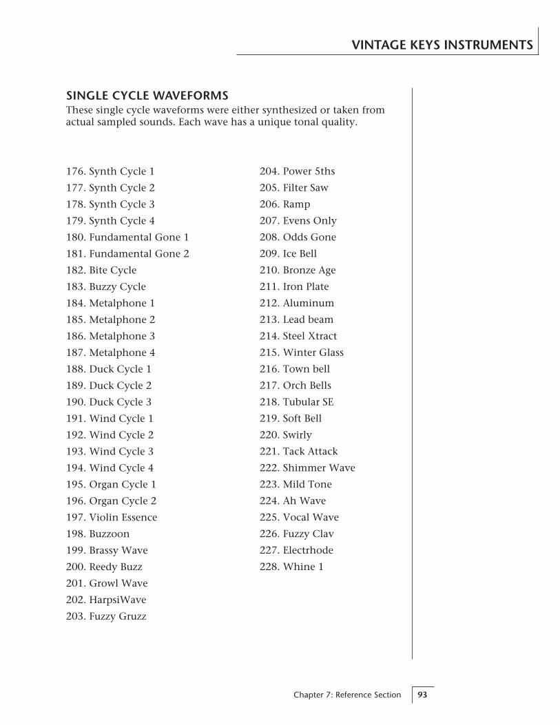
Chapter 7: Reference Section 93
VINTAGE KEYS INSTRUMENTS
SINGLE CYCLE WAVEFORMSThese single cycle waveforms were either synthesized or taken fromactual sampled sounds. Each wave has a unique tonal quality.
176. Synth Cycle 1
177. Synth Cycle 2
178. Synth Cycle 3
179. Synth Cycle 4
180. Fundamental Gone 1
181. Fundamental Gone 2
182. Bite Cycle
183. Buzzy Cycle
184. Metalphone 1
185. Metalphone 2
186. Metalphone 3
187. Metalphone 4
188. Duck Cycle 1
189. Duck Cycle 2
190. Duck Cycle 3
191. Wind Cycle 1
192. Wind Cycle 2
193. Wind Cycle 3
194. Wind Cycle 4
195. Organ Cycle 1
196. Organ Cycle 2
197. Violin Essence
198. Buzzoon
199. Brassy Wave
200. Reedy Buzz
201. Growl Wave
202. HarpsiWave
203. Fuzzy Gruzz
204. Power 5ths
205. Filter Saw
206. Ramp
207. Evens Only
208. Odds Gone
209. Ice Bell
210. Bronze Age
211. Iron Plate
212. Aluminum
213. Lead beam
214. Steel Xtract
215. Winter Glass
216. Town bell
217. Orch Bells
218. Tubular SE
219. Soft Bell
220. Swirly
221. Tack Attack
222. Shimmer Wave
223. Mild Tone
224. Ah Wave
225. Vocal Wave
226. Fuzzy Clav
227. Electrhode
228. Whine 1
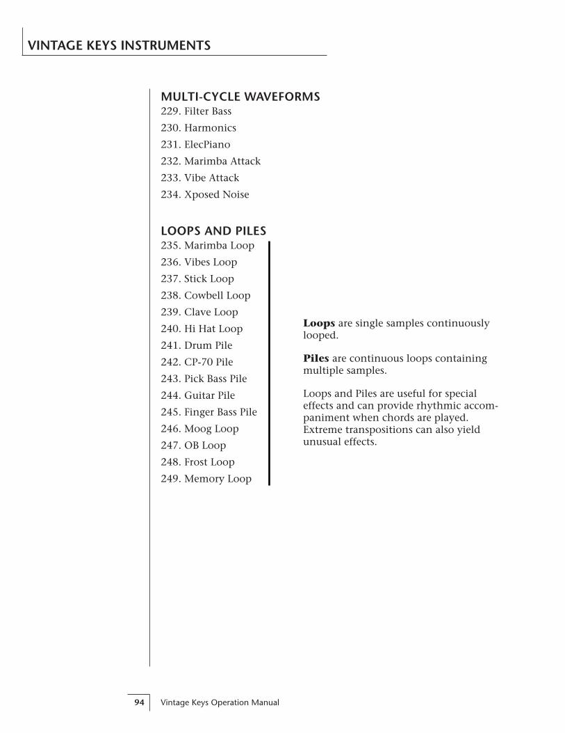
Vintage Keys Operation Manual94
VINTAGE KEYS INSTRUMENTS
MULTI-CYCLE WAVEFORMS229. Filter Bass
230. Harmonics
231. ElecPiano
232. Marimba Attack
233. Vibe Attack
234. Xposed Noise
LOOPS AND PILES235. Marimba Loop
236. Vibes Loop
237. Stick Loop
238. Cowbell Loop
239. Clave Loop
240. Hi Hat Loop
241. Drum Pile
242. CP-70 Pile
243. Pick Bass Pile
244. Guitar Pile
245. Finger Bass Pile
246. Moog Loop
247. OB Loop
248. Frost Loop
249. Memory Loop
Loops are single samples continuouslylooped.
Piles are continuous loops containingmultiple samples.
Loops and Piles are useful for specialeffects and can provide rhythmic accom-paniment when chords are played.Extreme transpositions can also yieldunusual effects.
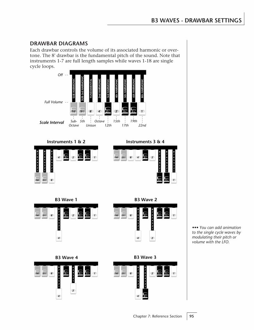
Chapter 7: Reference Section 95
B3 WAVES - DRAWBAR SETTINGS
DRAWBAR DIAGRAMSEach drawbar controls the volume of its associated harmonic or over-tone. The 8' drawbar is the fundamental pitch of the sound. Note thatinstruments 1-7 are full length samples while waves 1-18 are singlecycle loops.
16' 8'
4'
2'
1'
B3 Wave 4
87654321
654321
2 '23 1 '1
31 '355 '1
3
87654321
87654321
16' 8'
4'
2' 1'
B3 Wave 3
5 '13 1 '1
31 '35
2 '23
16' 8'
4'
2' 1'
87654321
B3 Wave 1
5 '13 1 '1
31 '352 '2
3 8'
4' 2'
1'
B3 Wave 2
87654321
87654321
16' 1 '132 '2
3 1 '355 '1
3
16' 8' 4' 2'
1'
Instruments 3 & 4
87654321
87654321
87654321
5 '13 2 '2
3
1 '131 '3
5
87654321
87654321
87654321
8'16'
4' 2' 1'
Instruments 1 & 2
5 '13
2 '23 1 '1
31 '35
Scale Interval
8' 4' 2' 1'1 '132 '2
3 1 '35
SUB
-HA
RM
ON
IC
SUB
-3rd
HA
RM
ON
IC
FUN
DA
MEN
TAL
2nd
HA
RM
ON
IC
3rd
HA
RM
ON
IC
4th
HA
RM
ON
IC
5th
HA
RM
ON
IC
6th
HA
RM
ON
IC
8th
HA
RM
ON
IC
Off
Full Volume
Sub-Octave
5thUnison
Octave12th
15th17th
19th22nd
5 '1316'
••• You can add animationto the single cycle waves bymodulating their pitch orvolume with the LFO.

Vintage Keys Operation Manual96
B3 WAVES - DRAWBAR SETTINGS
16' 8'
4'
2' 1'
B3 Wave 5
87654321
654321
5 '13 1 '1
31 '35
2 '23
2'
B3 Wave 6
87654321
87654321
1'16' 8' 4'5 '13 1 '3
5 1 '13
2 '23
87654321
87654321
87654321
1'2'16'
8' 4'
B3 Wave 8
16'
8' 4'
5 '13 1 '3
5 1 '13
2 '23
5 '13
7654321
87654321
87654321
87654321
16' 8'
4'2'
1'
B3 Wave 7
2 '23 1 '1
3
1 '355 '1
3
16'
8' 4'
1'2'
87654321
87654321
87654321
87654321
B3 Wave 9
1 '13
1 '35
2 '23
5 '13 16' 8' 4'
2'
1'
87654321
7654321
B3 Wave 10
5 '13
2 '23
1 '35 1 '1
3
16' 8'
4'
2' 1'
87654321
87654321
87654321
54321
B3 Wave 12
1 '13
1 '352 '2
35 '13
87654321
87654321
7654321
16' 8' 4'
2'
1'
B3 Wave 11
5 '13
2 '23
1 '35
1 '13
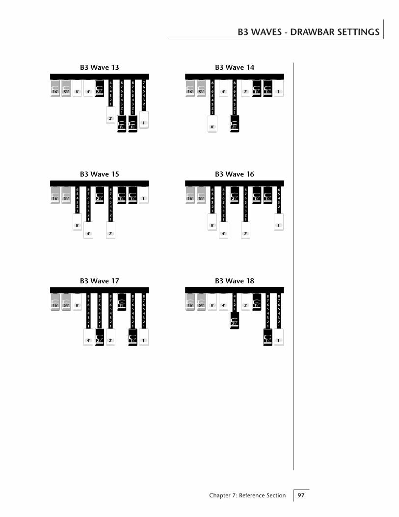
Chapter 7: Reference Section 97
B3 WAVES - DRAWBAR SETTINGS
654321
87654321
87654321
654321
16'
8'
4' 2'
1'
B3 Wave 16
1 '35 1 '1
32 '235 '1
3
87654321
87654321
16'
8'
4' 1'2'
B3 Wave 14
1 '131 '3
5
2 '23
5 '13
7654321
87654321
87654321
654321
16' 8' 4'
2'1'
B3 Wave 13
5 '13 2 '2
3
1 '35 1 '1
3
16'
8'
4' 2'
1'
654321
87654321
87654321
B3 Wave 15
1 '35 1 '1
32 '235 '1
3
87654321
87654321
87654321
87654321
87654321
16' 8'
4' 2' 1'
B3 Wave 17
1 '355 '1
3
2 '23 1 '1
3
4321
87654321
87654321
16' 8' 4' 2'
1'
B3 Wave 18
1 '355 '1
3
2 '23
1 '13

Vintage Keys Operation Manual98
Instrument 70Drum Kit 2
Side
Stic
k
MIDIKey #
36 48 60 72 84 96
Dry
Kic
k
Cow
bell
Hig
h H
at 1
Dry Tom
Hig
h H
at 2
Hig
h H
at 3
Cra
shRi
de P
ing
Tam
bour
ine
Cra
shD
ry K
ick
Ride
Bel
lC
lave
Dry
Kic
k Dry Kick Dry Snare
Dry TomDry Snare
Dry Tom
Dry Kick
Snare left Empty
Instrument 69Drum Kit 1
Side
Stic
k
MIDIKey #
36 48 60 72 84 96
Dry
Kic
kD
ry S
nare
Cow
bell
Hig
h H
at 1
Dry Tom
Hig
h H
at 2
Hig
h H
at 3
Cra
shRi
de P
ing
Tam
bour
ine
Cra
shD
ry K
ick
Ride
Bel
lC
lave
Dry
Kic
k Dry Kick Dry Snare
Dry TomDry Snare
Dry Tom
Dry Kick
Instrument 71Drum Kit 3
Side
Stic
k
MIDIKey #
36 48 60 72 84 96
Cow
bell
Hig
h H
at 1
Dry Tom
Hig
h H
at 2
Hig
h H
at 3
Cra
shRi
de P
ing
Tam
bour
ine
Cra
shD
ry K
ick
Ride
Bel
lC
lave
Dry
Kic
k Dry Kick Dry Snare
Dry TomDry Snare
Dry Tom
Dry Kick
Kick & Snareleft Empty
ALL DRUMS
SNARE EMPTYAllows you to place a
tuned snare (inst. #87)in this location usingthe secondary layer.
KICK & SNAREEMPTY
Allows you to placetuned kick & snares
(inst. 85 & 87) in theselocations using the
secondary layer or links.
PERCUSSION INSTRUMENT LOCATIONS

Chapter 7: Reference Section 99
PERCUSSION INSTRUMENT LOCATIONS
Instrument 72Drum Kit 4
Side
Stic
k
MIDIKey #
36 48 60 72 84 96
Cow
bell
Hig
h H
at 1
Dry Tom
Hig
h H
at 2
Hig
h H
at 3
Cra
shRi
de P
ing
Tam
bour
ine
Cra
shD
ry K
ick
Ride
Bel
lC
lave
Dry
Kic
k Dry Kick Dry Snare
Dry TomDry Snare
Dry Tom
Dry Kick
Kick & SnareTuned down 1/3
Instrument 73Drum Kit 5
Side
Stic
k
MIDIKey #
36 48 60 72 84 96
Cow
bell
Hig
h H
at 1
Dry Tom
Hig
h H
at 2
Hig
h H
at 3
Cra
shRi
de P
ing
Tam
bour
ine
Cra
shD
ry K
ick
Ride
Bel
lC
lave
Dry
Kic
k Dry Kick Dry Snare
Dry TomDry Snare
Dry Tom
Dry Kick
Kick & SnareTuned up 1/3
Drum Kit 6
Side
Stic
k
MIDIKey #
36 48 60 72 84 96
Cow
bell
Hig
h H
at 1
Dry Tom
Hig
h H
at 2
Hig
h H
at 3
Cra
shRi
de P
ing
Tam
bour
ine
Cra
shD
ry K
ick
Ride
Bel
lC
lave
Dry
Kic
k Dry Kick Dry Snare
Dry TomDry Snare
Dry Tom
Dry Kick
Snare Tuned Down& Panned Hard Left
Dry
Kic
k
Instrument 74
KICK & SNARETUNED DOWN
KICK & SNARETUNED UP
SNARE TUNEDDOWN,
PANNED LEFTAllows you to create a
stereo snare by panningthe secondary snare
hard right.(Hint: use delay, tuning,
sound start.)

Vintage Keys Operation Manual100
PERCUSSION INSTRUMENT LOCATIONS
Drum Kit 7
Side
Stic
k
MIDIKey #
36 48 60 72 84 96
Cow
bell
Hig
h H
at 1
Dry Tom
Hig
h H
at 2
Hig
h H
at 3
Cra
shRi
de P
ing
Tam
bour
ine
Cra
shD
ry K
ick
Ride
Bel
lC
lave
Dry
Kic
k Dry Kick Dry Snare
Dry TomDry Snare
Dry Tom
Dry Kick
Snare PannedHard Left
Dry
Kic
k
Instrument 75
Reverb Spaces
MIDIKey #
36 48 60 72 84 96
Tom
Kick
Instruments 76-84
Snar
e
SNARE PANNEDLEFT
Allows you to create astereo snare by panning
the secondary snarehard right.
(Hint: use delay, tuning,sound start.)
REVERB SPACESAllows you to add
reverb by layering withDrum Kits 1-7.
••• For more information onthe Reverb Spaces, see thePractice Programming sectionof this manual.
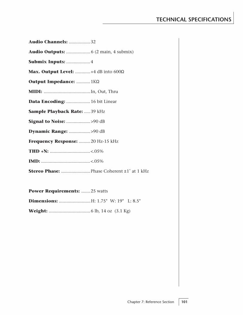
Chapter 7: Reference Section 101
TECHNICAL SPECIFICATIONS
Audio Channels: .................32
Audio Outputs: ................... 6 (2 main, 4 submix)
Submix Inputs: ................... 4
Max. Output Level: ............+4 dB into 600Ω
Output Impedance: ...........1KΩ
MIDI: ..................................... In, Out, Thru
Data Encoding: ................... 16 bit Linear
Sample Playback Rate: .....39 kHz
Signal to Noise: ................... >90 dB
Dynamic Range: .................>90 dB
Frequency Response: ......... 20 Hz-15 kHz
THD +N: ................................ <.05%
IMD: .......................................<.05%
Stereo Phase: .......................Phase Coherent ±1˚ at 1 kHz
Power Requirements: .......25 watts
Dimensions: .........................H: 1.75" W: 19" L: 8.5"
Weight: .................................6 lb, 14 oz (3.1 Kg)

Vintage Keys Operation Manual102
MIDI IMPLEMENTATION CHART
Transmitted Recognized Remarks
BasicChannel
DefaultChanged
Mode DefaultMessages
NoteNumber True Voice
Velocity Note ONNote OFF
AfterTouch
KeysChannels
Pitch Bender
Control Change
ProgramChange True Number
System Exclusive
SystemCommon
:Song Pos:Song Sel:Tune
SystemReal Time
:Clock:Commands
AuxMessages
:Local On/Off:Active Sense:Reset
NoNo
11-16
Memorized
Yes Mode 1, 3, 4MONO, POLYOMNI, ON/OFF
Memorized
NoNo
0-1270-127
NoNo
YesNo
v=1-127
NoNo
YesYes
No Yes
No Yes
NoNo
Yes 0-127Yes 0-127
Yes Yes
NoNoNo
NoNoNo
NoNo
NoNo
NoNoNo
NoNoNo
Notes: Pan 0=hard left 127=hard right
Function…
Mode 1: OMNI ON, POLYMode 3: OMNI OFF, POLY
Mode 2: OMNI ON, MONOMode 4: OMNI OFF, MONO
0-31 64-79
All Sound Off
Reset All Controllers
No Yes
No Yes
All Notes Off No Yes
GENERAL INFORMATION FOR VINTAGE KEYS SYSEX• Product ID for Vintage Keys is 0A.
• Device ID is [00-0F] (0-15 decimal).
• Parameter Number and Parameter Value are 2 bytes each.
• Since MIDI data bytes cannot be greater than [7F] (127 decimal), thedata values are “nibble-ized” to a 14-bit signed 2's complement format.
• There is only one edit buffer which is for the current preset (thepreset shown in the display). Only one preset at a time can be editedvia SysEx commands and changing the current preset erases the editbuffer.

Chapter 7: Reference Section 103
MIDI SPECIFICATIONS
RECEIVED CHANNEL COMMANDSChannels number (n) = 0-15. Message bytes are represented in hex. Allother numbers are decimal. Running Status is supported.
Command Message CommentsNote Off 8n kk vv release velocity is ignored
Note On 9n kk vv velocity 0 = note off
Key Aftertouch An kk vv kk = 0-127 vv = 0-127
Program Change Cn vv 0-127
Channel Aftertouch Dn vv 0-127
Pitch Bend En ll mm l = lsb, m = msb
Realtime Controller Bn cc vv cc = 00-31
Footswitch Bn cc vv cc = 64-79, vv ≥ 64 = on
Volume Bn 07 vv 0-127
Pan Bn 0A vv 0 = hard left, 127 = hard right
All Sound Off Bn 78 00 turns all sound off
Reset All Controllers Bn 79 00 ignored in omni mode
All Notes Off Bn 7B 00 ignored in omni mode
Omni Mode Off* Bn 7C 00 forces all notes & controls off
Omni Mode On* Bn 7D 00 forces all notes & controls off
Mono Mode On (Poly Off)* Bn 7E 00 forces all notes & controls off
Poly Mode On (Mono Off)* Bn 7F 00 forces all notes & controls off
* Special Notes:
From Omni Mode ... Omni Off turns Poly On.From Poly Mode ..... Omni On turns Omni On; Mono On turns Mono On.From Mono Mode ... Mono Off turns Poly On; Omni On turns Omni On.From Multi Mode ... Omni On turns Omni On; Omni Off or Mono Offturns Poly On; Mono On turns Mono On.
All other changes have no effect.
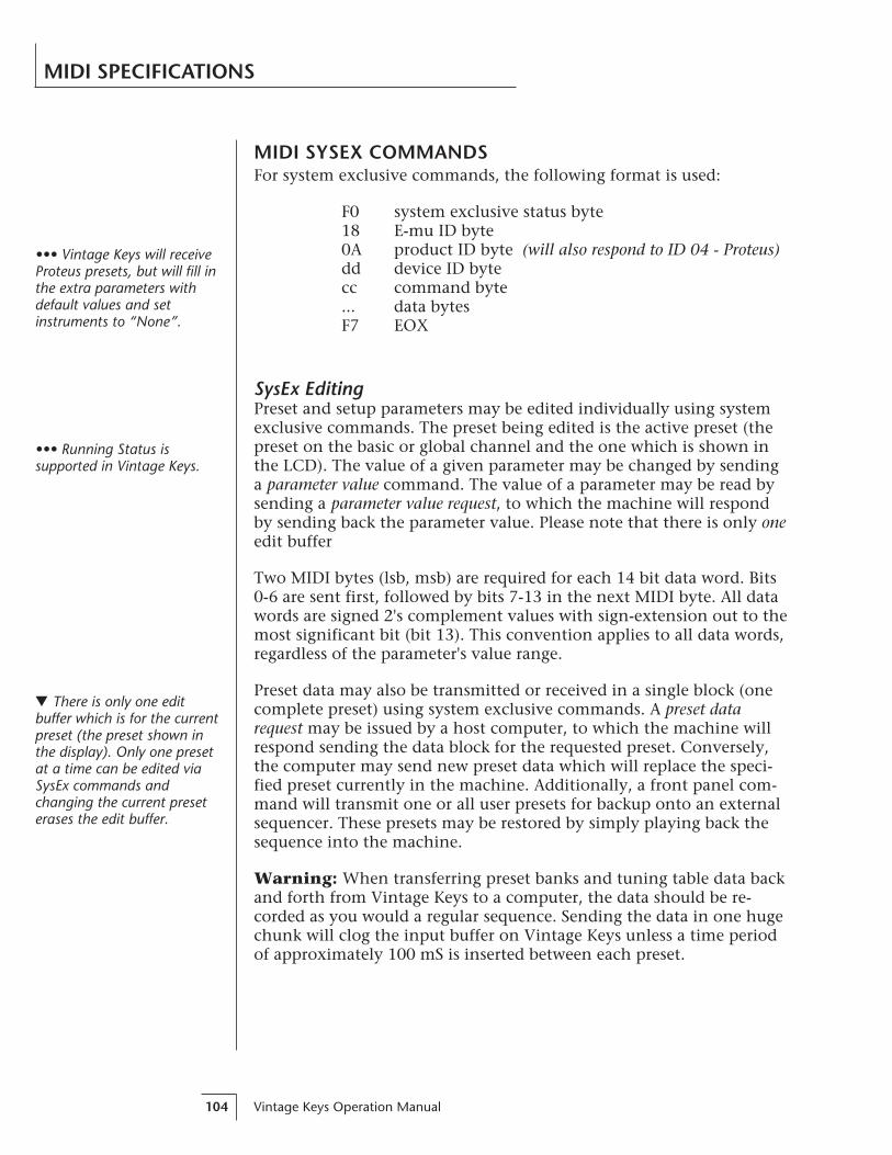
Vintage Keys Operation Manual104
MIDI SPECIFICATIONS
MIDI SYSEX COMMANDSFor system exclusive commands, the following format is used:
F0 system exclusive status byte18 E-mu ID byte0A product ID byte (will also respond to ID 04 - Proteus)dd device ID bytecc command byte... data bytesF7 EOX
SysEx EditingPreset and setup parameters may be edited individually using systemexclusive commands. The preset being edited is the active preset (thepreset on the basic or global channel and the one which is shown inthe LCD). The value of a given parameter may be changed by sendinga parameter value command. The value of a parameter may be read bysending a parameter value request, to which the machine will respondby sending back the parameter value. Please note that there is only oneedit buffer
Two MIDI bytes (lsb, msb) are required for each 14 bit data word. Bits0-6 are sent first, followed by bits 7-13 in the next MIDI byte. All datawords are signed 2's complement values with sign-extension out to themost significant bit (bit 13). This convention applies to all data words,regardless of the parameter's value range.
Preset data may also be transmitted or received in a single block (onecomplete preset) using system exclusive commands. A preset datarequest may be issued by a host computer, to which the machine willrespond sending the data block for the requested preset. Conversely,the computer may send new preset data which will replace the speci-fied preset currently in the machine. Additionally, a front panel com-mand will transmit one or all user presets for backup onto an externalsequencer. These presets may be restored by simply playing back thesequence into the machine.
Warning: When transferring preset banks and tuning table data backand forth from Vintage Keys to a computer, the data should be re-corded as you would a regular sequence. Sending the data in one hugechunk will clog the input buffer on Vintage Keys unless a time periodof approximately 100 mS is inserted between each preset.
••• Vintage Keys will receiveProteus presets, but will fill inthe extra parameters withdefault values and setinstruments to “None”.
••• Running Status issupported in Vintage Keys.
There is only one editbuffer which is for the currentpreset (the preset shown inthe display). Only one presetat a time can be edited viaSysEx commands andchanging the current preseterases the edit buffer.
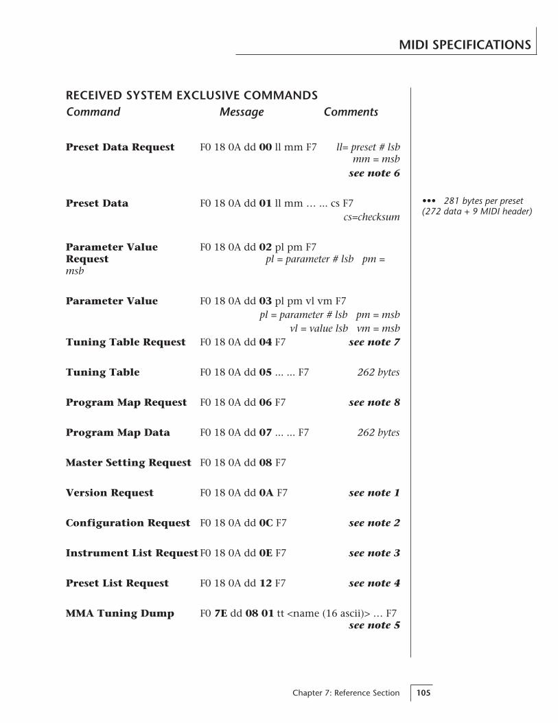
Chapter 7: Reference Section 105
MIDI SPECIFICATIONS
RECEIVED SYSTEM EXCLUSIVE COMMANDSCommand Message Comments
Preset Data Request F0 18 0A dd 00 ll mm F7 ll= preset # lsbmm = msb
see note 6
Preset Data F0 18 0A dd 01 ll mm … ... cs F7cs=checksum
Parameter Value F0 18 0A dd 02 pl pm F7Request pl = parameter # lsb pm =msb
Parameter Value F0 18 0A dd 03 pl pm vl vm F7pl = parameter # lsb pm = msb
vl = value lsb vm = msbTuning Table Request F0 18 0A dd 04 F7 see note 7
Tuning Table F0 18 0A dd 05 ... ... F7 262 bytes
Program Map Request F0 18 0A dd 06 F7 see note 8
Program Map Data F0 18 0A dd 07 ... ... F7 262 bytes
Master Setting Request F0 18 0A dd 08 F7
Version Request F0 18 0A dd 0A F7 see note 1
Configuration Request F0 18 0A dd 0C F7 see note 2
Instrument List RequestF0 18 0A dd 0E F7 see note 3
Preset List Request F0 18 0A dd 12 F7 see note 4
MMA Tuning Dump F0 7E dd 08 01 tt <name (16 ascii)> … F7see note 5
••• 281 bytes per preset(272 data + 9 MIDI header)

Vintage Keys Operation Manual106
MIDI SPECIFICATIONS
TRANSMITTED SYSTEM EXCLUSIVE COMMANDSCommand Message Comments
Preset Data F0 18 0A dd 01 ll mm ... ... CS F7ll= preset # lsb mm = msb cs = checksum
Parameter Value F0 18 0A dd 03 pl pm vl vm F7pl = parameter # lsb pm = msb
vl = value lsb vm = msb
Tuning Table F0 18 0A dd 05 ... ... F7 TT data = 256 bytes
Program Map Data F0 18 0A dd 07 ... ... F7 see note 8
Configuration F0 18 0A dd 0D pl pm s1 l1 m1 s2 l2 m2 F7Message see note 2
Instrument List F0 18 0A dd 0F (14 bytes per instrument) ... ...F7
see note 3
Preset List F0 18 0A dd 13 (13 bytes per preset) ... ... F7see note 4
• Note 1 - Version RequestThis command allows identification of machine type and softwarerevision. Vintage Keys will respond to the request with the versiondata:F0 18 0A dd 0B 01 r1 r2 r3 F7r1, r2, r3 = software revision # in ascii (decimal point between r1 & r2).
• Note 2 - Configuration MessageThis MIDI command is used to identify the sound sets in a givenVintage Keys. The configuration request command is: F0 18 0A dd 0CF7
Vintage Keys will respond to this command with the configurationmessage: F0 18 0A dd 0D pl pm s1 l1 m1 s2 l2 m2 F7
where pl and pm are the lsb and msb of the total number of presets, s1and s2 are the ID numbers of the sound sets contained in this unit,and n1=l1, m1 and n2=l2, m2 represent the lsb and msb of the num-ber of instruments in each sound set. If no expansion set is present, s2will be 7F and n2 will be zero. Standard Vintage Keys Sound Set= 6.

Chapter 7: Reference Section 107
MIDI SPECIFICATIONS
• Note 3 - Instrument ListThis MIDI command allows external software to upload the instru-ment list as an array of ASCII strings. The instrument list requestcommand is:
F0 18 0A dd 0E F7
Vintage Keys will respond to this command with the instrument listmessage:
F0 18 0A dd 0F (14 bytes per instrument) ... ... F7
The instruments are transmitted in the same order they appear to theuser on Vintage Keys. Note that a given instrument’s position in thislist may be different from its actual number within the sound set.
instrument entry: il im (11 ascii bytes) 00
Each instrument entry in the list consists of the actual instrumentnumber (as defined in “Sound Sets” - note 9) in lsb, msb format,followed by the instrument name (11 ascii characters plus a zeroterminator) for a total of 14 (decimal) bytes. The first instrument is #1as displayed on Vintage Keys. The total number of instrument namesis equal to (n1+n2) in the configuration message above.
• Note 4 - Preset ListThis MIDI command allows external software to upload all presetnames as an array of ASCII strings. The preset list request command is:
F0 18 0A dd 12 F7
Vintage Keys will respond to this command with the preset list mes-sage:
F0 18 0A dd 13 (13 bytes per preset) ... ... F7
Each preset name is 12 ascii characters, plus a zero terminator, for atotal of 13 (decimal) bytes. The first preset is #0. The total number ofpreset names is equal to pp in the configuration message above.
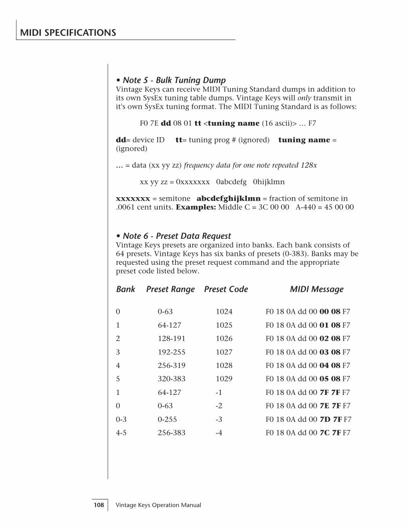
Vintage Keys Operation Manual108
MIDI SPECIFICATIONS
• Note 5 - Bulk Tuning DumpVintage Keys can receive MIDI Tuning Standard dumps in addition toits own SysEx tuning table dumps. Vintage Keys will only transmit init's own SysEx tuning format. The MIDI Tuning Standard is as follows:
F0 7E dd 08 01 tt <tuning name (16 ascii)> … F7
dd= device ID tt= tuning prog # (ignored) tuning name =(ignored)
… = data (xx yy zz) frequency data for one note repeated 128x
xx yy zz = 0xxxxxxx 0abcdefg 0hijklmn
xxxxxxx = semitone abcdefghijklmn = fraction of semitone in.0061 cent units. Examples: Middle C = 3C 00 00 A-440 = 45 00 00
• Note 6 - Preset Data RequestVintage Keys presets are organized into banks. Each bank consists of64 presets. Vintage Keys has six banks of presets (0-383). Banks may berequested using the preset request command and the appropriatepreset code listed below.
Bank Preset Range Preset Code MIDI Message
0 0-63 1024 F0 18 0A dd 00 00 08 F7
1 64-127 1025 F0 18 0A dd 00 01 08 F7
2 128-191 1026 F0 18 0A dd 00 02 08 F7
3 192-255 1027 F0 18 0A dd 00 03 08 F7
4 256-319 1028 F0 18 0A dd 00 04 08 F7
5 320-383 1029 F0 18 0A dd 00 05 08 F7
1 64-127 -1 F0 18 0A dd 00 7F 7F F7
0 0-63 -2 F0 18 0A dd 00 7E 7F F7
0-3 0-255 -3 F0 18 0A dd 00 7D 7F F7
4-5 256-383 -4 F0 18 0A dd 00 7C 7F F7
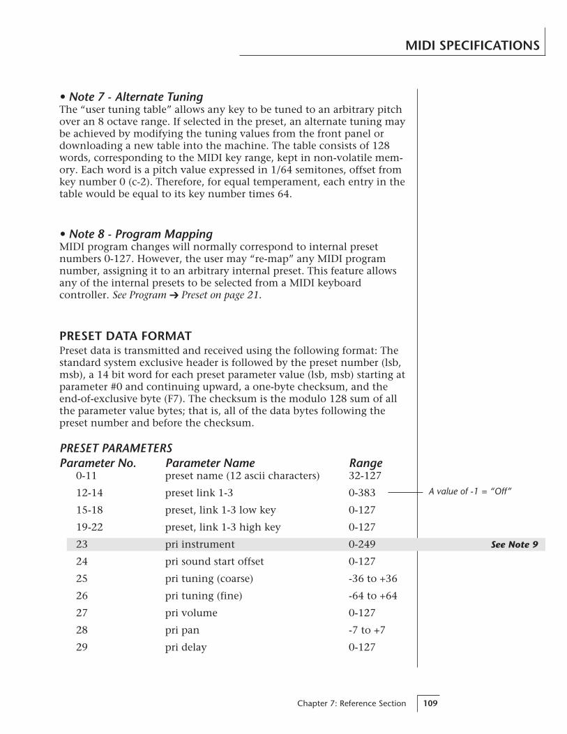
Chapter 7: Reference Section 109
See Note 9
MIDI SPECIFICATIONS
• Note 7 - Alternate TuningThe “user tuning table” allows any key to be tuned to an arbitrary pitchover an 8 octave range. If selected in the preset, an alternate tuning maybe achieved by modifying the tuning values from the front panel ordownloading a new table into the machine. The table consists of 128words, corresponding to the MIDI key range, kept in non-volatile mem-ory. Each word is a pitch value expressed in 1/64 semitones, offset fromkey number 0 (c-2). Therefore, for equal temperament, each entry in thetable would be equal to its key number times 64.
• Note 8 - Program MappingMIDI program changes will normally correspond to internal presetnumbers 0-127. However, the user may “re-map” any MIDI programnumber, assigning it to an arbitrary internal preset. This feature allowsany of the internal presets to be selected from a MIDI keyboardcontroller. See Program Preset on page 21.
PRESET DATA FORMATPreset data is transmitted and received using the following format: Thestandard system exclusive header is followed by the preset number (lsb,msb), a 14 bit word for each preset parameter value (lsb, msb) starting atparameter #0 and continuing upward, a one-byte checksum, and theend-of-exclusive byte (F7). The checksum is the modulo 128 sum of allthe parameter value bytes; that is, all of the data bytes following thepreset number and before the checksum.
PRESET PARAMETERSParameter No. Parameter Name Range
0-11 preset name (12 ascii characters) 32-127
12-14 preset link 1-3 0-383
15-18 preset, link 1-3 low key 0-127
19-22 preset, link 1-3 high key 0-127
23 pri instrument 0-249
24 pri sound start offset 0-127
25 pri tuning (coarse) -36 to +36
26 pri tuning (fine) -64 to +64
27 pri volume 0-127
28 pri pan -7 to +7
29 pri delay 0-127
A value of -1 = “Off”

Vintage Keys Operation Manual110
See Note 9
MIDI SPECIFICATIONS
Parameter No. Parameter Name Range30 pri low key 0-127
31 pri high key 0-127
32 pri alt. volume attack 0-99
33 pri alt. volume hold 0-99
34 pri alt. volume decay 0-99
35 pri alt. volume sustain 0-99
36 pri alt. volume release 0-99
37 pri alt. volume envelope on 0-1
38 pri solo mode 0-2
39 pri chorus 0-15
40 pri reverse sound 0-1
41 sec instrument 0-249
42 sec sound start offset 0-127
43 sec tuning (coarse) -36 to +36
44 sec tuning (fine) -64 to +64
45 sec volume 0-127
46 sec pan -7 to +7
47 sec delay 0-127
48 sec low key 0-127
49 sec high key 0-127
50 sec alt. volume attack 0-99
51 sec alt. volume hold 0-99
52 sec alt. volume decay 0-99
53 sec alt. volume sustain 0-99
54 sec alt. volume release 0-99
55 sec alt. volume envelope on 0-1
56 sec solo mode 0-2
57 sec chorus 0-15
58 sec reverse sound 0-1
59 crossfade mode 0-2
60 crossfade direction 0-1
61 crossfade balance 0-127
62 crossfade amount 0-255

Chapter 7: Reference Section 111
See Note 10
MIDI SPECIFICATIONS
See Note 10
A value of 13 = “Global”
A value of 5 = “Global”
Parameter No. Parameter Name Range63 switch point 0-127
64 LFO 1 shape 0-4
65 LFO 1 rate 0-127
66 LFO 1 delay 0-127
67 LFO 1 variation 0-127
68 LFO 1 amount 0-127
69 LFO 2 shape 0-127
70 LFO 2 rate 0-127
71 LFO 2 delay 0-127
72 LFO 2 variation 0-127
73 LFO 2 amount 0-127
74 aux. envelope delay 0-127
75 aux. envelope attack 0-99
76 aux. envelope hold 0-99
77 aux. envelope decay 0-99
78 aux. envelope sustain 0-99
79 aux. envelope release 0-99
80 aux. envelope amount -128 to +127
81-86 key/vel source 1-6 0-1
87-92 key/vel dest 1-6 0-42
93-98 key/vel amount 1-6 -128 to +127
99-106 realtime source 1-8 0-9
107-114 realtime dest 1-8 See list
115-117 footswitch dest 1-3 0-10
118-121 controller amount A-D -128 to +127
122 pressure amount 0-127
123 pitch bend range 0-13
124 velocity curve 0-5
125 keyboard center 0-127
126 submix 0-2
127 keyboard tuning 0-5
128 pri portamento rate 0-127
129 sec portamento rate 0-127
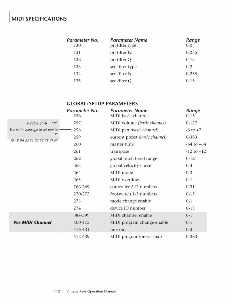
Vintage Keys Operation Manual112
Per MIDI Channel
MIDI SPECIFICATIONS
Parameter No. Parameter Name Range130 pri filter type 0-2
131 pri filter Fc 0-255
132 pri filter Q 0-15
133 sec filter type 0-2
134 sec filter Fc 0-255
135 sec filter Q 0-15
GLOBAL/SETUP PARAMETERSParameter No. Parameter Name Range
256 MIDI basic channel 0-15
257 MIDI volume (basic channel) 0-127
258 MIDI pan (basic channel) -8 to +7
259 current preset (basic channel) 0-383
260 master tune -64 to +64
261 transpose -12 to +12
262 global pitch bend range 0-12
263 global velocity curve 0-4
264 MIDI mode 0-3
265 MIDI overflow 0-1
266-269 controller A-D numbers 0-31
270-272 footswitch 1-3 numbers 0-15
273 mode change enable 0-1
274 device ID number 0-15
384-399 MIDI channel enable 0-1
400-415 MIDI program change enable 0-1
416-431 mix out 0-3
512-639 MIDI program/preset map 0-383
A value of -8 = “P”
The entire message to set pan toP:
F0 18 0A dd 03 02 02 78 7F F7

Chapter 7: Reference Section 113
MIDI SPECIFICATIONS
• Note 9 - Sound SetsA Vintage Keys sound set consists of sample data (sound ROMs), plusadditional instrument data in the program ROMs. Each sound set hasa unique ID number. The sound set for Vintage Keys is #6.
It is necessary to include the sound set number as part of the instru-ment number when exchanging data. The complete instrument num-ber contains two fields: bits 8-12 specify the sound set (0-31) and bits0-7 specify the instrument within the sound set (0-255).
Instrument Bit Fields:
12 8 7 0
<— sound set —> <——— instrument # ———>
(5 bits) (8 bits)
Within any given sound set, the first instrument is #1 and #0 selects“None”.
The “magic number” 1536 represents the start number for the stan-dard Vintage Keys instruments. To calculate the complete instrumentnumber follow the instructions below.
SysEx Instr. No. = 1536 + Vintage Keys Instr. No.
Next you must convert the SysEx instrument number to a 14-bit MIDInumber. See the information on the following pages.
Example:Suppose we want to change the instrument to I002 B3 Dist Fast.
1) 1536 + 2 = 1538 (1536 + Instr. No.)
2) 1538 ÷ 128 = 12 r-2 = 12 (ignore remainder)
3) 12 in Hex = 0C = msb
4) remainder 2 in Hex = 02 = lsb
5) SysEx Instrument Number = lsb msb02 0C
The complete message to change the primary instrument to #02:F0 18 0A dd 03 17 00 02 0C F7

Vintage Keys Operation Manual114
MIDI SPECIFICATIONS
• 14-bit Signed 2's Complement NumbersIf the data value is negative, you must first take the 2's complement ofthe number: In the case of a 14-bit number this is equivalent to add-ing 16384 to the original negative value.
To fit the 7-bit MIDI protocol, numbers must be “nibble-ized”.
To get the 14-bit nibble-ized value (of a positive value or a 2'scomplemented negative value):
msb = value DIV 128 (divide and ignore the remainder)
lsb = value MOD 128 (divide and use only the remainder)
To go the other way (convert 14 bit signed 2's complement to a signedreal number)
raw Value = (msb*128) + lsb (gives you the unsigned raw value)
if raw Value ≥ 8192 (8192 = 2^13)
then signed Value = raw value - 16384 (16384 = 2^14)
Example: To find the “nibble-ized” Hex value of -127:
1) -127 + 16384 = 162522) 16252 ÷ 128 = 126 r-1243) 126 in Hex = 7E = msb4) 124 in Hex = 7C = lsb5) Parameter value would be transmitted as 7C 7E
Example: To find the “nibble-ized” Hex value of parameter number257:
1) 257 ÷ 128 = 2 r-12) 2 in Hex = 02 = msb3) 1 in Hex = 01 = lsb4) Parameter number would be transmitted as 01 02
00000000 00000000
data bits data bits
StatusBit
StatusBit
Status Bit MUST be “0”in MIDI data bytes.

Chapter 7: Reference Section 115
MIDI SPECIFICATIONS
• Note 10 - Patchcord DestinationsThe order in which patchcord destinations appear on the screen doesnot necessarily match the SysEx ordering. This is necessary for variousreasons, one being to maintain Proteus compatibility.
Key/Velocity Controllers
MIDI value Destination0 Off1 Pitch2 Pri. Pitch3 Sec. Pitch4 Volume5 Pri. Volume6 Sec. Volume7 Attack8 Pri. Attack9 Sec. Attack10 Decay11 Pri. Decay12 Sec. Decay13 Release14 Pri. Release15 Sec. Release16 Crossfade17 LFO 1 Amount18 LFO 1 Rate19 LFO 2 Amount20 LFO 2 Rate21 Aux. Envelope Amount22 Aux. Envelope Attack23 Aux. Envelope Decay24 Aux. Envelope Release25 Sound Start26 Pri. Sound Start27 Sec. Sound Start28 Pan29 Pri. Pan30 Sec. Pan31 Tone32 Pri. Tone33 Sec. Tone

Vintage Keys Operation Manual116
MIDI SPECIFICATIONS
Key/Velocity Controllers (cont)
MIDI value Destination34 Filter Fc35 Pri. Filter Fc36 Sec. Filter Fc37 Filter Q38 Pri. Filter Q39 Sec. Filter Q40 Portamento Rate41 Pri. Portamento Rate42 Sec. Portamento Rate
Realtime Controllers
MIDI value Destination0 Off1 Pitch2 Pri. Pitch3 Sec. Pitch4 Volume5 Pri. Volume6 Sec. Volume7 Attack8 Pri. Attack9 Sec. Attack10 Decay11 Pri. Decay12 Sec. Decay13 Release14 Pri. Release15 Sec. Release16 Crossfade17 LFO 1 Amount18 LFO 1 Rate19 LFO 2 Amount20 LFO 2 Rate21 Aux. Envelope Amount22 Aux. Envelope Attack23 Aux. Envelope Decay24 Aux. Envelope Release

Chapter 7: Reference Section 117
MIDI SPECIFICATIONS
Realtime Controllers (cont)
MIDI value Destination34 Filter Fc35 Pri. Filter Fc36 Sec. Filter Fc40 Portamento Rate41 Pri. Portamento Rate42 Sec. Portamento Rate
Vintage Keys Operation Manual118
WARRANTY
Please read this warranty, as it gives you specific legal rights.
Length of WarrantyThis warranty covers all defects in materials and workmanship for a period of oneyear from the date of purchase by the original owner, provided that the WarrantyRegistration Card is filled out and returned to E-mu Systems within 14 days from thedate of purchase. Cases may arise where E-mu's Service Department or one of E-mu'sauthorized service centers will ask for a copy of your sales receipt to facilitate war-ranty service. Please keep your purchase receipt in a safe place.
E-mu Systems does not cover:
• Damages due to improper or inadequate maintenance, accident, abuse, misuse,alteration, unauthorized repairs, tampering, or failure to follow normal operatingprocedures as outlined in the owner's manual.
• Deterioration or damage of the cabinet.
• Damages occurring during any shipment of the product for any reason.
• An E-mu product that has in any way been modified by anyone other than E-muSystems, Inc.
Limitation of Implied WarrantiesNo warranty is expressed or implied. E-mu Systems specifically disclaims the impliedwarranties of merchantability and fitness for a particular purpose.
Exclusion of Certain DamagesE-mu Systems' liability for a product found defective is limited to repair or replace-ment of the unit, at E-mu's option. In no event shall E-mu Systems be liable fordamages based on inconvenience, whether incidental or consequential, loss of use ofthe unit, loss of time, interrupted operation or commercial loss, or any other conse-quential damages.
Some states do not allow limitation of the duration of implied warranties or the exclusion orlimitation of incidental or consequential damages, so the above limitations and exclusionsmay not apply to you.
How To Obtain Warranty ServiceAll E-mu products are manufactured with the highest standards of quality. If you findthat your instrument does require service, it may be done by an authorized E-muservice center. If you are unable to locate a service center in your area, please contactE-mu Systems Service Department at (408) 438-1921. They will either refer you to anauthorized service center or ask that you return your instrument to the factory.When returning an instrument to the factory, you will be issued a Return Authoriza-tion number (RA). Please label all cartons, shipping documents and correspondencewith this number. E-mu suggests you carefully and securely pack your instrument forreturn to the factory. Mark the outside of the shipping carton clearly with your RAnumber. Send to E-mu Systems, Inc. 1600 Green Hills Road, Scotts Valley, California,95066. You must pre-pay shipping charges to the service location. E-mu Systems willpay return shipping fees. You will be responsible for any damage or loss sustainedduring shipment in any direction.
11/92
Chapter 7: Reference Section 119
INDEX
AAftertouch 29
See also PressureAlternate tunings 24, 64Alternate volume envelope 30, 50, 72Attack 30, 50, 57, 72, 73, 75Auxiliary envelope 30, 57, 75
BB3 Wave
Charts 95-97Listing 91
Balance 36Basic operation 9Basic sampling system diagram 14Basic setup 5Block diagram, Vintage Keys 36, 37, 39
CChannel pan 12Channel volume 12Character chart 46Chorus 52, 71Coarse tuning 49, 70Continuous controller 40Contour
See Envelope generatorCrossfade
Amount 55Balance 54Direction 54Mode 53
Cross-switch 29, 53-55, 62Curves, velocity 38Cutoff frequency 34, 56
DData entry control 11DCA 33, 36, 50, 72Decay 30, 50, 57, 72Delay
Envelope 30, 57Instrument 51LFO 58
Demo sequences 13Dimensions: 100Display 23Drawbar settings 95-97Drum
Charts 98-100Listing 90
EEdit menu select 11, 45Editing presets 43-66, 70Effect returns 8Effect devices 7, 8, 81Enter 11Envelope Generators 29, 30, 57Equal tuning 64
FFactory presets 23, 84-87Fc 34Filter 33-36, 55, 56, 73, 74Filter Modulation 33, 60, 61, 73, 74Fine tuning 49Footswitch 22, 29, 62
GGamelan tuning 64Glide
See portamentoGlobal bend 18Global velocity curve 18-19
HHarmonic waveforms 92Headphone 5Hold 30, 57Home/Enter button 11
IID number 20Instrument 4
Listing 88-94Selection 36
Inverting 32
JJavanese tuning 64Just C tuning 64
KKey number 38, 60, 64
ChartKey range 47Key velocity 29, 37, 38, 60, 63
Vintage Keys Operation Manual120
INDEX
KeyboardCenter 38, 64Connection 5-7Layered 27, 48, 65, 69Modulation 29, 37, 60, 64Pressure 29Split 27, 48, 65, 69Tuning 64
LLayering 27, 65Legato 52LFO 28, 29, 31, 58, 59Link preset 4, 27, 65, 69Loops, instrument 94Low frequency oscillators 29, 31Low pass filter 33-36, 55, 56, 73, 74
MMain controls 11Main outputs 6Master menu select 11, 17Master settings 23Master tune 17MIDI 40
Basic info 40, 41Connections 5, 7Activity LED 11Channel selection 12Controller 29Controller amount 62Controller assign 22Controllers A-B-C-D 41, 62Enable 21Footswitch assign 22Implementation chart 102In 5, 6, 7Mode 20-21Mode change 21Out 6, 22Overflow 20Program Preset 22-23Realtime controllers 40Recording SysEx data 23, 104Specifications 102-116System exclusive 103-117Thru 7MIDI-patch 32, 40
Mix outputs 20, 42, 65
Modulation 28destination 28filter 33footswitch 22, 62source 28-41, 61
Mono mode 20Mono output 5Multi mode 20Multi-cycle waveforms 94Multi-mode 13Multi-timbral operation 13
OOmni mode 20Organ waveforms 91Organization basic 4Output impedance: 101Output level: 100Outputs 5, 6, 7, 20, 42, 65Overflow 20
PPan 36
Channel pan 12Modulation 37, 60Preset pan 49
Patch 32Percussion instrument
Diagrams 98-100Listing 90
Performance setup 7Piles 93Pitch modulation 60, 61Pitch bend range 62Pitch wheel 29Poly mode 20Poly key pressure 29Portamento 52
Rate 52Power 8, 101
110/220 8Power switch 11Preset 4
Change 2Factory preset listing 84-87Links 65Mapping 22-23Naming 46Recording to a sequencer 23Saving 66Selection 12

Chapter 7: Reference Section 121
INDEX
Pressure, key 29, 39, 61Amount 62
Primary 4Filter type 55Instrument 47Key range 48
Program/Preset map 22-23Programming basics 25
QQ 35, 56, 74
RRandom 31Rate, LFO 58Realtime modulation 29, 39, 61Release 30, 50, 57, 72Resonance 35Reverb spaces 78, 100Reverse sound 51Ripoff 81
SSample & hold 31Sample playback rate: 101Sample start point 51Sampled sounds 88-94Save preset 66Sawtooth 31Secondary 4
Instrument 47Key range 48
Send MIDI data 23Send/Return cables 7Setup 5-7Sequencing 79, 80
Multi-timbral 13Sequencer hookup 6
Signal flow 36-39Sine wave
Instrument 92LFO 31
Single cycle waveforms 93Solo mode 52Sound start 51
Modulation 60Sound wave 36Split keyboard 27, 48, 65, 69Square wave 31Stereo outputs, 5-8, 20, 42, 65Studio setup 6
Sub 1 & 2 outputs 7, 8, 42Submix returns 7,8, 81Sustain
Envelope generator 30, 50, 57,72Pedal/footswitch 62
Synth mode 52Synthesizer waveforms 91SysEx 104-117
TTechnical specifications 101Temperament 24Tone 33, 36, 37, 60Transpose 18Tremolo 58Triangle wave 31Tuning
Master 17Course & fine 49Tuning table 23, 24
UUser key tuning 24User presets 23
VVariation, LFO 58Vallotti tuning 64Velocity 63Velocity curve
Global velocity curve 18-19Velocity curves 38, 63
Velocity modulation 29, 37, 60Vibrato 58Vintage synthesis 77Viewing angle 24Volume
MIDI channel volume 12Preset volume 49Volume control 11
WWarranty 118Waveform, LFO 31Weight: 101Wind controller mode 52Wind controller tip 40
XXfade 53Xswitch 53
Vintage Keys Operation Manual122
NOTES