classification and complete solution of the kinetostatics of a
TRANSCRIPT

Classification and Complete Solution of the Kinetostatics of a
Compliant Stewart-Gough Platform
Hafez Taria,1, Hai-Jun Sub,2, Jonathan D. Hauensteinc,3
aDepartment of Mechanical Engineering,The Ohio State University,Columbus, OH 43210, USA
bDepartment of Mechanical Engineering,University of Maryland, Baltimore County,
Baltimore, MD 21250, USAcDepartment of Mathematics,
Texas A&M University,College Station, TX 77843, USA
Dedicated to Prof. Joseph Duffy.
Abstract
This paper studies a compliant Stewart-Gough platform whose six flexible links balanceexternal loads, including force and moment, applied to a general point at the platform.Soma coordinates are used to express the location of the moving plate with respect tothe base plate. The mathematical modeling involves both the kinematics and the statics.Seven kinematic and six static constraints are obtained. Vector dot- and cross-productsare also cast in quaternion form which reduce the degree of the resulting constraints. Byclassifying the parameters to the knowns and the unknowns, five major problem typesare recognized. Four of them are mathematically decoupled and the remaining one iscoupled for which the obtained 13 polynomials are of the total degree of 5,971,968 whichto the authors’ best of knowledge is the largest kinematic problem ever investigated.After solving the equations with the numerical polynomial solver Bertini, we concludethat the upper bound to the number of nonsingular solutions is 29,272. In addition,for practical problems a parameter continuation is devised to recompute for only 29,272generically nonsingular solutions. At last a numerical example is provided to demonstratethe solution process.
Key words: Compliant Stewart-Gough Platform, Kinematics, Kinetostatics, StiffnessMapping, Soma Coordinates, Numerical Continuation.
1Email: [email protected], Tel.: +1 614 292 2289, Address all correspondence to this author2Email: [email protected]: [email protected]
Preprint submitted to Mechanism and Machine Theory October 14, 2011

Nomenclature
i An integer index taking value 0 through 5
j An integer index taking value 1 through 5
1. Introduction
Stewart-Gough platforms [1, 2] are formed by connecting a moving platform link orstage to a fixed ground link via six limbs that are actuated with prismatic joints. They arefrequently used in applications such as the flight simulations. On the other hand, com-pliant platform mechanisms are parallel linked mechanisms [3] with one or more flexiblelimbs or joints which are designed to deform under an external loading. They can be foundin various applications including tensegrity systems [4, 5, 6], remote center compliancedevices [7] for industrial robots, statically balanced devices [8] and so on.
Numerous pieces of work have been done on the kinematics of traditional or rigidbody Stewart-Gough platforms. The two main kinematic problems are called inverse(indirect) kinematics and forward (direct) kinematics. It is well known that the former isrelatively easy while the latter is rather challenging. One of the earliest solution to theforward kinematics of the most general case was conducted by Raghavan [9] who found40 generic configurations using the numerical continuation method [10, 11, 12, 13]. Thesame result was found later with employing Grobner basis method [14, 15]. Wampler[16] also formulated the problem with soma coordinates [17] and verified the same resultby deriving the 2-homogeneous Bezout number. These results stimulated the derivationof other resultant elimination solutions by Husty [18], Innocenti [19] and others [20, 21].Very recently, Tari and Su [22] constructed a solution library for solving the forwardkinematics of the entire Stewart-Gough platform topologies with a recently developedhomotopy solver Bertini [23].
However, there are relatively less pieces of work on the analysis and design of compli-ant platforms. Unlike the classical platforms, the analysis of compliant platforms requiresboth kinematic analysis and static equilibrium analysis, which we call the “kinetostaticanalysis”. The former is essentially the same as that of the rigid body platform. While thelatter studies the relation between the external loading and the mechanism configurationdefined by its generalized coordinates. Moreover, the concept of the stiffness/compliancemapping comes into play once the static deformation due to an external loading is suffi-ciently small. This is what we call the “instantaneous or local static analysis”. In this area,Patterson and Lipkin [24] systematically studied compliance matrices of robots. Huangand Schimmels [25] studied the synthesis of a compliance matrix with simple springsconnected in serial or in parallel.
However, here we are interested in the “finite or global static analysis” problem inwhich both the position and the orientation of the platform link and the deformation ofcompliant limbs are unknown. In this area, Pigoski and Duffy [26] formulated the planartwo-spring problem consisting of point connect to ground by two compliant limbs andobtained a closed-form solution which led to as many as six equilibrium configurations fora given external load. Sun et al. [27] extended this problem and studied a planar three-spring system with a moving platform consisting of a line segment for which a maximum
2

of 54 equilibrium configurations is reported. The most general case of planar compliantplatforms was studied in Ref. [28] and using the numerical continuation it was concludedthat there can be as many as 70 equilibrium positions for a given loading applied to theplatform. With regard to spatial compliant platforms, Zhang et al. [29] studied a specialcase with three linear springs joined at the same point on the platform.
The problem to be solved in this paper is described as what follows. Given a compliantStewart-Gough platform with six compliant limbs modeled as six linear springs, and givena general external loading (force and moment) applied to the platform link, we would liketo find all possible equilibrium configurations of the mechanism.
The rest of the paper is organized as follows. Next we give vector dot- and cross-products using quaternion algebra. Section 3 introduces the compliant Stewart-Goughplatform and derives its kinetostatics. Section 4 gives the problem statements and theunderlying constraints and a solution procedure for each problem type. A numericalexample is given in section 5.
2. Vector Dot- and Cross-Products with Quaternion Algebra
Any four-tuple of real numbers Q0, Q1, Q2 and Q3, as in Ref. [17] or many otheravailable textbooks, is denoted as a quaternion Q = (Q0,Q) where Re(Q) = Q0 andVec(Q) = Q = (Q1, Q2, Q3) are called the real and the vector parts of Q, respectively.Moreover, the conjugate of Q is defined as Q′ = (Q0,−Q). Additionally, the quaternionQ is called a unit quaternion if QT Q = 1 where “T ” is the transpose operator. Finally,a pure vector quaternion is a quaternion whose real part is zero and we show it as Qv =(0,Q).
Addition of the two quaternions Q1 = (Q10,Q
1) and Q2 = (Q20,Q
2) is carried outelement-wise, i.e. Q1 + Q2 = (Q1
0 + Q20,Q
1 + Q2), and their product, which is again aquaternion, shown by the symbol “ ∗ ” is carried out in terms of vector dot- and cross-products as
Q1 ∗ Q2 =(Q1
0Q20 −Q1 ·Q2, Q1
0Q2 +Q2
0Q1 +Q1 ×Q2
). (1)
For any three-dimensional vector v and R, a 3× 3 orthogonal rotation matrix, thereis a unit quaternion q such that
Rv = q ∗ v ∗ q′, (2)
where R is as follows.
R =
q20 + q21 − q22 − q23 2(q1q2 − q0q3) 2(q0q2 + q1q3)2(q1q2 + q0q3) q20 − q21 + q22 − q23 2(q2q3 − q0q1)2(q1q3 − q0q2) 2(q0q1 + q2q3) q20 − q21 − q22 + q23
(3)
Moreover, once the rotation of R is combined with a pure displacement p, we use thequaternion g = (g0,g) where
3

0 = Re(g ∗ q′) = gT q (4)
p = Vec(g ∗ q′) = q0g− g0q+ q× g. (5)
The terms p · p, Rv · p and Rv × p require further attention as they play majorroles in the complexity, i.e. the degree of the nonlinearity, of the kinetostatic equationswhich govern the behavior of the compliant Stewart-Gough platform to be studied later.For example, both Rv · p and Rv × p seem to be fourth-degree in terms of the un-known quaternions g and q while in the following we show that both of them are actuallyquadratic.
It follows from Eq. (1) that the vector dot- and cross-products of two vectors Q1 andQ2 can also be obtained from the product of their pure vector quaternions as
Q1 ·Q2 = Re(Q1v ∗ Q2′
v ) (6)
Q1 ×Q2 = −Vec(Q1v ∗ Q2′
v ). (7)
Recall that q is a unit quaternion, it is clear from Eqs. (5) and (6) that
p · p = Re(g ∗ q′ ∗ q ∗ g′) = Re(g ∗ g′) = gT g. (8)
In addition, according to Eqs. (2), (5), (6) and (7) and considering the fact that
(Q1 ∗ Q2)′ = Q2′∗ Q1
′, it is not hard to see that
Rv · p = Re(q ∗ v ∗ q′ ∗ q ∗ g′) = Re(q ∗ v ∗ g′) = gTv (9)
Rv× p = −Vec(q ∗ v ∗ q′ ∗ q ∗ g′) = −Vec(q ∗ v ∗ g′) = Gv. (10)
where
gT =[g1q0 − g0q1 − g3q2 + g2q3 g2q0 + g3q1 − g0q2 − g1q3 g3q0 − g2q1 + g1q2 − g0q3
](11)
G =
2(g2q2 + g3q3) g3q0 − g2q1 − g1q2 + g0q3 −(g2q0 + g3q1 + g0q2 + g1q3)−(g3q0 + g2q1 + g1q2 + g0q3) 2(g1q1 + g3q3) g1q0 + g0q1 − g3q2 − g2q3g2q0 − g3q1 + g0q2 − g1q3 −(g1q0 + g0q1 + g3q2 + g2q3) 2(g1q1 + g2q2)
(12)
3. A Compliant Stewart-Gough Platform and its Kinetostatics
Figure 1 shows a schematic view of a compliant Stewart-Gough manipulator withgeneric force and moment applied to a general point of the moving platform. As is seen,the manipulator like its traditional rigid counterpart consists of six prismatic links, withinitial and final lengths of l0i and li. Via spherical or ball-in-socket joints, the links are
4

connected at one end to the stationary platform at points ai and at the other end tothe moving platform at points bi. The points ai and bi are local respectively to thebase and the end plates’ coordinate systems. However, unlike the rigid Stewart-Goughmanipulator, the compliant Stewart-Gough manipulator features flexible legs of stiffness,ki, which balance the globally defined external load, F and M, applied to the movingplatform at b6. Note, however, that a fully compliant Stewart-Gough platform whichfurther possesses compliant spherical joints may also be articulated but is beyond thescope of this article.
PlateBase
PlateEnd
S
S
p
b6
bi
ki
ai
lil
0i
F
M
δli
Figure 1: A schematic view of a general compliant Stewart-Gough platform
It is well known that any point bi on the moving platform may be measured in thebase plate as Bi using two parameters such as the vector p and the quaternion q. Theseparameters respectively define the position and the orientation of the moving plate withrespect to the base plate as follows.
Bi = p+Rbi, (13)
where R and p are as before and given by Eqs. (3) and (5), respectively.Since the compliant Stewart-Gough platform features compliant members, its mathe-
matical modeling involves both kinematic and static derivations as follows.
3.1. Kinematic Constraints
The kinematic constraints are common to both rigid and compliant Stewart-Goughplatforms. Quite well-known, the kinematic constraints are the squared distances betweenthe points ai and bi which equal to l2i . Without loss of generality, we set a0 = b0 = 0.Exploiting Eqs. (4), (8), (9) and (13) and the orthogonality of R, i.e. RTR = RRT = I
5

where I is the 3× 3 identity matrix, it is not hard to show that the following 7 quadricsconstitute the kinematic constraints in the projective space P7.
0 = gT q0 = qT ql20 − gT g
0 = [Bj − aj]T [Bj − aj]− l2j j=1,. . . ,5
= 2(gTbj − aTj [p+Rbj]) + (aT
j aj + bTj bj + l20 − l2j )q
T q
(14)
where the first equation follows from the orthogonality of the quaternions g and q. Notethat the equations are homogenized considering the fact that q is a unit quaternion whichimposes the side condition qT q = 0.
3.2. Static Constraints
Figure 2 illustrates the upper section of the free body diagram of the compliantStewart-Gough manipulator. As shown, the ith link at the cutting point reveals a generalinternal force fi with a magnitude of fi and along the direction of the link from the pointbi to ai. Summing the resultant of the forces and taking moment with respect to anarbitrary point, but for the sake of simplicity the point b0 = 0, and equating them to zeroand also taking Eq. (10) into account result in the following equations of equilibrium.
F =5∑
i=0
fili[Bi − ai] =
f0l0p+
5∑j=1
fjlj
[p− aj +Rbj] , (15)
M+Rb6 × F =5∑
j=1
fjljRbj × [Bj − aj] =
5∑j=1
fjljRbj × [p− aj]
=5∑
j=1
fjlj
[Gbj + aj ×Rbj] , (16)
where p and G are respectively given by Eqs. (5) and (12) and “× ” denotes the vectorcross-product operator. Recall that Eqs. (15) and (16) are each three-dimensional vectorequation, there are in total six static constraints which require the platform to be inequilibrium under the exertion of the external load F and M.
The obtained static equations are clearly valid for any general internal forces of thelinks for this particular compliant Stewart-Gough platform. This in return enables usto consider large and finite deformations for the platform’s entire workspace. Though,the internal forces and their nonlinearity structure are application based and dependon the material and the geometry of the links involved. However, for the sake of thesimplicity of the problem study given below we consider the links to be elastic meaningthat fi = kiδli = ki(li − l0i).
4. Category of Kinetostatic Problems
The kinetostatics of a compliant Stewart-Gough platform like the kinematics of thetraditional Stewart-Gough platform may be categorized depending on which parameters
6

PlateEnd
S
PlateEnd
F
Mb6
bi
fi
Figure 2: A schematic view of the upper section of the free body diagram of a general compliant Stewart-Gough platform
are known and which are not. Recall that for the traditional Stewart-Gough platform,the inverse kinematics is to find the legs length to achieve a desired configuration whilethe forward kinematics is completely opposite. In a verbatim manner, we define and addtwo more notions to the concepts of the forward and the inverse kinematics as follows.
Definition 1. Pure Inverse statics is to find the legs stiffness for prescribed externalload.
Definition 2. Pure Forward statics is to find the external load for prescribed legsstiffness.
Exploiting the word “pure” in the foregoing definitions is crucial in that it decouplesthe concepts of the kinematics and the statics which as a result would drastically ease thelater study. In addition, it would help avoid confusion with some common definitions inthe literature which emphasize that the forward and the inverse statics study the relationbetween the external load and the platform configuration which obviously intertwine thekinematics and the statics. However, for succinctness from this point on, we drop theword pure from the definitions and by the forward and the inverse statics we actuallymean the pure forward and the pure inverse statics, respectively.
With these concepts in mind, we categorize the kinetostatics of the compliant Stewart-Gough platforms to five major types. Surprisingly enough, the first four types lead tomathematically decoupled kinematic and static equations. We elaborate each type asfollows.
4.1. Inverse–Inverse Kinetostatics: Inverse Kinematics and Inverse Statics
The goal of the inverse–inverse kinetostatics which is the combination of the inversekinematics and the inverse statics is to find the legs length and stiffness which balancegiven external loads at the desired position and orientation of the moving platform w.r.t.the stationary plate. In this respect, we define ψIIK = {l0i, ai,bi,b6, q, g,F,M} which
7

includes 59 known parameters and the goal is to find the entire unknown sets φIIK ={li, ki} which define statically balanced configurations.
The solution procedure in this case is very easy as the kinematic and the static con-straint equations are decoupled. At first, one would independently solve the last sixpolynomials of Eq. (14) which leads to a single set of lengths li. Insertion of the obtainedlengths to Eqs. (15) and (16) results in a linear system and upon solution would give asingle set of stiffnesses ki.
4.2. Inverse–Forward Kinetostatics: Inverse Kinematics and Forward Statics
The goal of the inverse–forward kinetostatics which is the combination of the inversekinematics and the forward statics is to find the legs length and the external loads whichlead to the desired balanced platform configurations of known stiffness and location.Therefore, the new parameter set ψIFK = {l0i, ai,bi,b6, q, g, ki} still includes 59 knownparameters and the goal is to find the entire unknown sets φIFK = {li,F,M}.
The solution procedure in this case is mathematically even simpler than that of theinverse–inverse kinetostatics as the force and the moment constraints are further decou-pled. Once the legs length li are obtained from Eq. (14), one may proceed with obtainingthe unknown vector F directly from the linear system Eq. (15) and then solve Eq. (16)which is again a linear system for the external moment M.
4.3. Forward–Inverse Kinetostatics: Forward Kinematics and Inverse Statics
The forward–inverse kinetostatics combines the forward kinematics and the inversestatics and its goal is to find the legs stiffness and the statically balanced location of themoving platform for given external loads and legs length. In this respect, the parameterset ψFIK = {l0i, li, ai,bi,b6,F,M} includes 57 known parameters and the goal is to findthe entire unknown sets φFIK = {q, g, ki}.
While the solution procedure in this case is similar to that of the inverse–inversekinetostatics, the kinematic equations (Eq. 14) should be solved for the unknowns q, gwhich are well-known to have 40 nonsingular solutions. These solutions in return due tothe linearity of Eqs. (15) and (16) would give rise to 40 solutions for the legs stiffness ki.
4.4. Forward–Forward Kinetostatics: Forward Kinematics and Forward Statics
The forward–forward kinetostatics intertwines the forward kinematics and the forwardstatics and its goal is to find the required external loads and the resulting staticallybalanced location of the moving platform for the given legs length and stiffness. Theparameter set ψFFK = {l0i, li, ai,bi,b6, ki} includes 57 known parameters and the goal isto find the entire unknown sets φFFK = {q, g,F,M}.
Similar to the inverse–forward Kinetostatics, the loading equations are even decoupledhence resulting in a mathematically simpler and more efficient solution procedure. The40 unknown vectors F would be obtained upon the insertion of the already obtained 40solutions q, g of Eq. (14) into the linear system of Eq. (15). Then the 40 sets of theexternal moments M would be derived from the linear system of Eq. (16).
8
4.5. Coupled Kinetostatics
All of the cases considered so far led to mathematically decoupled formulations.However, it would no longer be a decoupled case if one assigned the parameter set asψ = {l0i, ai,bi,b6,F,M, ki} which contains 57 known parameters. The goal of this casewhich we simply call a coupled kinetostatics is to find φ = {q, g, li} which would result instatically balanced configurations.
To obtain the entire solution set to this case a simultaneous solution procedure isinevitable. Therefore, with letting li = l0i
liwe convert the constraints to the required
polynomial form and rewrite the kinematic and the static constraints given in Eqs. (14),(15) and (16) as follows.
F(φ) :
gT q = 0
qT ql200 − gT gl20 = 0
F− k0(1− l0)p−∑5
j=1 kj(1− lj) [p− aj +Rbj] = 0
M− F×Rb6 −∑5
j=1 kj(1− lj) [Gbj + aj ×Rbj] = 0
l20j − (gT g − aTj [2p− aj + 2Rbj] + bT
j [bj + 2g])l2j = 0, j = 1, . . . , 5
(17)With φ = {q, g, li} as the variable set, the polynomial system F(φ) is a system of 13
polynomials in C6P7 where C and P are the complex and projective spaces, respectively.Note that the total degree of F(φ) is 2 × 4 × 33 × 33 × 45 = 5, 971, 968 whose solutionappears to be challenging even with the current state-of-the-art computers.
To solve F(φ) we firstly defined a generic input parameter set ψ1, in our case with 400numerical digits, and employed Bertini [23, 30] with its built-in regeneration mode [31].However, to avoid round-off errors in computation of the intermediate Jacobian matrices,we implemented the polynomials in the straight-line form [32] and adopted very tighttolerances for the path tracker settings as follows. We employed the adaptive precision ofBertini and set the tracking tolerances before and during endgame to 10−8 and 10−9, theadmissible residual function evaluation tolerance to 10−13 and the maximum number offunction evaluations to 20000. Moreover, the solution endpoints were sharpened duringthe path-tracking to be correct up to 30 digits. Finally, as far as the computer platform,we used the parallel version of Bertini on “tara” the newly purchased cluster of the HighPerformance Computing facility of the University of Maryland, Baltimore County.
As a result, after tracing and moving respectively 253,602 and 190,162 solution paths,Bertini finally returned 29,272 nonsingular and finite solutions, i.e. only 6.6% of the totalpaths. On the other hand, the numerical continuation methods, which Bertini actuallyemploys, are probability-one methods [10, 11, 12, 13] meaning that they may fail only forcertain numerical values of the involved parameters. Hence, after repeating this step forseveral new input parameters and obtaining the same number of solutions, we concludethat the upper bound to the number of solutions to the coupled kinetostatics of a generalcompliant Stewart-Gough platform is 29,272.
It would be impractical if the solution of F(φ) for a newly defined parameter set ψ2
required repeating for the computation of the extra 93.4% junk paths. Since ψ1 is general,the theory of parameter homotopies (see [13]) states that the nonsingular solutions ofF(φ, ψ2) can be obtained by following the solution paths of F(φ, (1−s)ψ1+sψ2) starting
9

at the 29,272 nonsingular solutions of F(φ, ψ1) as the real parameter s increments from0 to 1.
4.5.1. Discussion
1. While the maximum number of assembly configurations of a general rigid Stewart-Gough platform is 40, there are special geometries which attain only eight assemblyconfigurations [22]. But regardless of the compliance, rigid and compliant Stewart-Gough platforms share a common topology and it makes sense compliant Stewart-Gough platforms of less general geometries possess less assembly configurations than29,272.
2. Once solving F(φ) numerically, the computations were carried out in the complexand the projective domains which would explain the fact that not the entire 29,272configurations be physically attainable in the real domain. Even if the entire 29,272solutions are real, not all of them may be valid since they should result in positivedisplaced leg length components li.
3. It is clear that if {q, g, li} is a solution set to F(φ) so will be {−q,−g, li} as itleaves F(φ) unchanged. This is in agreement with the forward kinematics of therigid Stewart-Gough platforms as well. Therefore, with twice endeavor one wouldhave obtained twice as many solutions as 29,272 if the formulation was done in thecomplex space C14.
4. Considering the complexity of deriving a 40th degree univariate polynomial for theforward kinematics of rigid Stewart-Gough platforms, obtaining closed form solu-tions or a univariate polynomial of 29, 272th degree for the coupled kinetostatics ofcompliant Stewart-Gough platforms seems infeasible. This may justify the use ofthe numerical continuation as the only means of the solution tool for the coupledkinetostatics of compliant Stewart-Gough platforms.
5. Further reduction of F(φ) is possible with some elimination steps. For example, onemay linearly solve the static equations to eliminate the variables li. This reduces Fto 7 equations but this is not numerically advantageous.
A summary of all five kinetostatic problems is tabulated in Table 1. Note that, forconciseness, we have grouped parameters as l0 = {l00, . . . , l05}, l = {l0, . . . , l5}, k ={k0, . . . , k5} and l = { l00
l0, . . . , l05
l5}.
Table 1: Five kinetostatic problems of the compliant Stewart-Gough platform
Kinetostatics Solution procedure:problem type
Known parameters UnknownsSolve Eqs.
# of sols.
Inv.–Inv. {l0, a,b, q, g,F,M} {l,k} (i) 14 (ii) 15,16 1Inv.–Fwd. {l0, a,b, q, g,k} {l,F,M} (i) 14 (ii) 15 (iii) 16 1Fwd.–Inv. {l0, l, a,b,F,M} {q, g,k} (i) 14 (ii) 15,16 40Fwd.–Fwd. {l0, l, a,b,k} {q, g,F,M} (i) 14 (ii) 15 (iii) 16 40
Coupled {l0, a,b,F,M,k} {l, q, g} 14,15,16 29,272
10

5. Numerical Example
Amongst the five problem types we give a numerical example for the coupled kine-tostatics due to its generality. In addition, to validate the completeness of our solutionprocedure it is customary to pick the parameter set ψ = {l0i, ai,bi,b6,F,M, ki} from aknown compliant platform solution and check whether this solution is contained in thefinal obtained solution set. To this end, we first generate a known solution as follows.
)(b
0a
1a 2a
3a
4a5a
1b 2b
3b
4b5b
0b 6b
1
1
5.0
5.0
x y
1b
1a
2b 3b
4b5b 6b
0b0a2a
5a
4a
3a,
NumberLink 0 1 2 4 3 5
4.0
2.0
6.0
0
)(mz
)(m
)(m
)(a
Figure 3: (a) x− y view of the stationary and moving platforms of a compliant Stewart-Gough platformand (b) the z coordinates of the hexagons’ vertices
Figure 3(a) depicts the x−y view of the base and the moving platforms of a manipula-tor where the z components of the vertices of base hexagon are twice those of the movinghexagon which are tabulated in Table 2. Let the quaternion that rotates the stationaryplate to the moving plate be q = 1√
30
(√30 cos(α), sin(α), 5 sin(α), 2 sin(α)
)which is the
rotation about the vector−→i + 5
−→j + 2
−→k with angle 2α = π
7. Moreover, let the quater-
nion that defines the displacement between a0 and b0 be g = (g0, 4 sin(β), sin(β), 3 sin(β))
where g0 = −14
√15
(5 +
√5)tan(α) and 2β = 4π
5.
Table 2: The z components of the vertices of the moving platform
b0z b1z b2z b3z b4z b5z b6z0.00000000 0.37746801 0.05059928 0.06599580 0.21691901 0.30877747 0.28789313
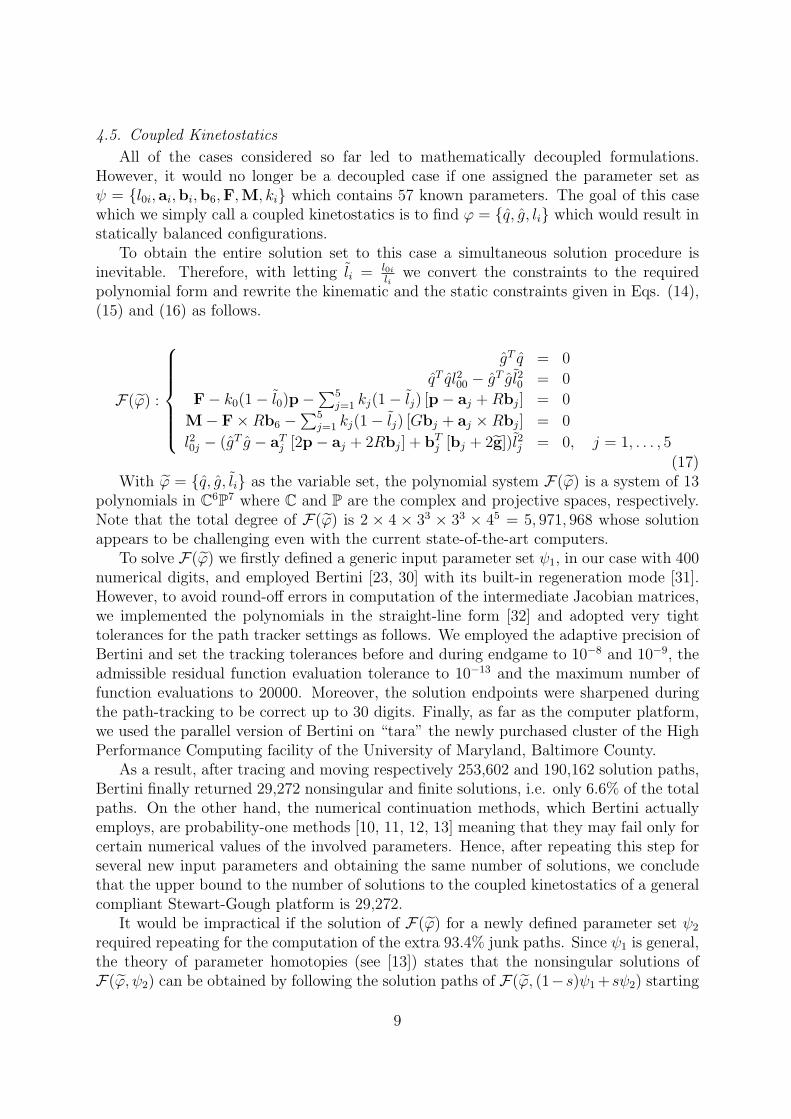
With these prescribed parameters, solution of the kinematic equations (14) gives riseto obtaining the displaced legs length as tabulated in Table 3. Figure 4 illustrates theview of the articulated platform.
Table 3: The displaced legs length of the platform
l0 l1 l2 l3 l4 l54.88575729 4.76619210 4.28773288 3.83318455 3.91072136 4.45133028
Moreover, we define ki(N/m) = {20, 35, 25, 45, 30, 40} and l0i(m) = {4, 4, 4, 3, 3, 4} asthe legs’ stiffness and initial length, respectively. These parameters if inserted to Eqs.
11
0a
1a
2a
3a
4a
5a
2b
0b
3b
5b
4b
1b
Figure 4: A compliant platform as a known solution
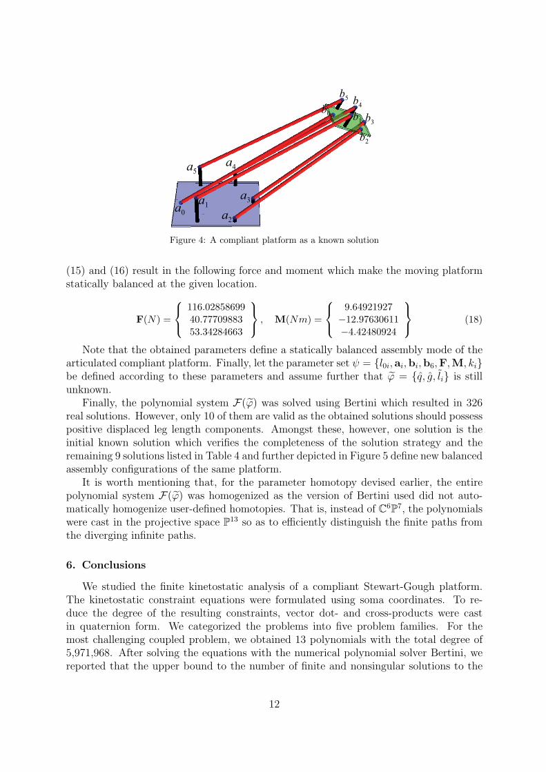
(15) and (16) result in the following force and moment which make the moving platformstatically balanced at the given location.
F(N) =
116.0285869940.7770988353.34284663
, M(Nm) =
9.64921927
−12.97630611−4.42480924
(18)
Note that the obtained parameters define a statically balanced assembly mode of thearticulated compliant platform. Finally, let the parameter set ψ = {l0i, ai,bi,b6,F,M, ki}be defined according to these parameters and assume further that φ = {q, g, li} is stillunknown.
Finally, the polynomial system F(φ) was solved using Bertini which resulted in 326real solutions. However, only 10 of them are valid as the obtained solutions should possesspositive displaced leg length components. Amongst these, however, one solution is theinitial known solution which verifies the completeness of the solution strategy and theremaining 9 solutions listed in Table 4 and further depicted in Figure 5 define new balancedassembly configurations of the same platform.
It is worth mentioning that, for the parameter homotopy devised earlier, the entirepolynomial system F(φ) was homogenized as the version of Bertini used did not auto-matically homogenize user-defined homotopies. That is, instead of C6P7, the polynomialswere cast in the projective space P13 so as to efficiently distinguish the finite paths fromthe diverging infinite paths.
6. Conclusions
We studied the finite kinetostatic analysis of a compliant Stewart-Gough platform.The kinetostatic constraint equations were formulated using soma coordinates. To re-duce the degree of the resulting constraints, vector dot- and cross-products were castin quaternion form. We categorized the problems into five problem families. For themost challenging coupled problem, we obtained 13 polynomials with the total degree of5,971,968. After solving the equations with the numerical polynomial solver Bertini, wereported that the upper bound to the number of finite and nonsingular solutions to the
12

Table 4: The newly obtained statically balanced assembly configurations
Par. Sol. 1 Sol. 2 Sol. 3 Sol. 4 Sol. 5 Sol. 6 Sol. 7 Sol. 8 Sol. 9
q0 -0.00656 -0.00811 -0.17307 -0.06932 -0.00830 0.99985 0.01236 -0.95790 0.89936q1 0.34330 0.36748 -0.11739 0.85841 -0.08242 -0.01088 0.93444 -0.02521 0.36491q2 -0.86974 -0.01398 0.10554 0.27761 0.98392 0.01308 0.15497 0.26931 -0.24064q3 0.35447 -0.92989 0.97218 0.42576 -0.15823 0.00328 -0.32040 0.09620 -0.00901g0 -0.04119 0.06327 - 0.21112 1.91278 0.27722 0.00355 -0.18485 0.25747 -1.22458g1 -0.22465 0.52426 -0.40137 -0.26075 -0.75479 0.30048 0.10310 1.94573 4.34795g2 0.38232 0.48224 0.84726 0.43340 0.03696 -0.06311 0.80483 0.98943 2.02488g3 1.15488 0.19938 -0.10286 0.55455 0.60843 0.16602 0.68281 0.30369 -0.21979l0 1.23777 0.74240 0.96649 2.05477 1.00902 0.34907 1.07647 2.21886 4.95507l1 1.67099 0.99774 1.99368 2.38804 0.27797 0.44234 0.83825 2.75142 4.52857l2 2.95952 1.84335 3.15096 3.01703 1.74222 0.59166 1.02680 2.95056 4.40092l3 4.04082 2.47805 3.81786 3.20988 2.45042 0.70132 0.84205 3.26208 4.02622l4 3.89204 2.63018 3.55675 3.14229 1.83657 0.66258 1.81806 3.19465 3.97829l5 2.73199 1.93971 2.40323 2.85478 0.76758 0.51481 1.91988 2.80623 4.30487
coupled kinetostatics is 29,272. A numerical example was studied for which the param-eters were picked from a known compliant mechanism solution. Other than the knownsolution, nine new statically balanced assembly configurations of the initial compliantmechanism were obtained.
Acknowledgments
The authors are grateful to the anonymous reviewers for the mindful comments. Theauthors acknowledge the University of Maryland, Baltimore County, for the computer-time on their high performance computing facility (HPCF-tara). The first author wouldlike to thank a few individuals; Dr. C.W. Wampler for the helpful comments, Mr. A.Knister for the assistance on compiling Bertini on tara and Prof. Matthias K. Gobbert, thechair of the UMBC HPCF, for his generosity on providing the extra computer-time usage.This work is supported by National Science Foundation under Grant (CMMI-0845793).
References
[1] V. E. Gough, Contribution to discussion of papers on research in Automobile Stabil-ity, Control and Tyre performance, Proc. Auto Div. Inst. Mech. Eng. (1956) 392–394.
[2] D. Stewart, A Platform with Six Degrees of Freedom, Proc. Institution of MechanicalEngineers (UK) 180, Part 1, No. 15 (1965) 371–376.
[3] J. P. Merlet, Parallel Robots, Springer, Netherlands, 2006.
[4] C. D. C. III, J. Duffy, J. C. Correa, Static Analysis of Tensegrity Structures, Journalof Mechanical Design 127 (2) (2005) 257–268.
[5] J. Bayat, C. D. C. III, Closed-Form Equilibrium Analysis of Planar Tensegrity Struc-tures, ASME Conference Proceedings 2007 (48094) (2007) 13–23.
13

(1) (2) (3)
(4) (5) (6)
(7) (8) (9)
Figure 5: The obtained nine new solutions
[6] M. Arsenault, C. M. Gosselin, Static Balancing of Tensegrity Mechanisms, ASMEJournal of Mechanical Design 129 (3) (2007) 295–300.
[7] D. E. Whitney, Romote Center Compliance, in: J. Diponio, Y. Hasegawa (Eds.),Encyclopedia of Robotics System and Control, vol. 2, Industrial Training Co., 1316–1324, 1986.
[8] M. Carricato, C. M. Gosselin, A Statically Balanced Gough/Stewart-Type Platform:Conception, Design, and Simulation, ASME Journal of Mechanisms and Robotics1 (3) (2007) 031005.
[9] M. Raghavan, The Stewart Platform of General Geometry Has 40 Configurations,Journal of Mechanical Design 115 (2) (1993) 277–282.
[10] A. P. Morgan, Solving Polynomial Systems Using Continuation for Scientific andEngineering Problems, Prentice-Hall, Englewood Cliffs, NJ, 1987.
[11] E. L. Allgower, K. Georg, Introduction to Continuation Methods, SIAM, Philadel-phia, 2003.
14

[12] T. Y. Li, Numerical Solution of Polynomial Systems by Homotopy ContinuationMethods, Handbook of Numerical Analysis 11 (1) (2003) 209–304.
[13] A. J. Sommese, C. W. Wampler, The Numerical Solution of Systems of Polynomialsarising in Engineering and Science, World Scientific Press, Singapore, 2005.
[14] J. C. Faugere, D. Lazard, Combinatorial classes of parallel manipulators, Mechanismand Machine Theory 30 (6) (1995) 765 – 776.
[15] B. Mourrain, The 40 “generic” positions of a parallel robot, in: Proceedings of the1993 international symposium on Symbolic and algebraic computation, ISSAC93,ACM, New York, NY, USA, 173–182, 1993.
[16] C. W. Wampler, Forward displacement analysis of general six-in-parallel sps (Stew-art) platform manipulators using soma coordinates, Mechanism and Machine Theory31 (3) (1996) 331 – 337.
[17] O. Bottema, B. Roth, Theoretical Kinematics, Dover Publications, INC, 1979.
[18] M. L. Husty, An algorithm for solving the direct kinematics of general Stewart-Goughplatforms, Mechanism and Machine Theory 31 (4) (1996) 365 –379.
[19] C. Innocenti, Forward Kinematics in Polynomial Form of the General Stewart Plat-form, ASME, Journal of Mechanical Design 123 (2) (2001) 254–260.
[20] T.-Y. Lee, J.-K. Shim, Improved dialytic elimination algorithm for the forward kine-matics of the general Stewart-Gough platform, Mechanism and Machine Theory38 (6) (2003) 563 – 577.
[21] D. Gan, Q. Liao, J. S. Dai, S. Wei, L. D. Seneviratne, Forward displacement analysisof the general 6-6 Stewart mechanism using Grobner bases, Mechanism and MachineTheory 44 (9) (2009) 1640 – 1647.
[22] H. Tari, H.-J. Su, A Secant Homotopy Solution Library for the Forward Kinematicsof Stewart-Gough Platforms, Journal of Mechanical Design, Submitted .
[23] D. J. Bates, J. D. Hauenstein, A. J. Sommese, C. W. Wampler, Bertini: Software forNumerical Algebraic Geometry, http://www.nd.edu/∼sommese/bertini, 2011.
[24] T. Patterson, H. Lipkin, Structure of robot compliance, ASME Journal of MechanicalDesign 115 (3) (1993) 576–580.
[25] S. Huang, J. M. Schimmels, The duality in spatial stiffness and compliance as realizedin parallel and serial elastic mechanisms, ASME Journal of Mechanical Design 124 (1)(2002) 76–84.
[26] T. M. Pigoski, J. Duffy, An Inverse Force Analysis of a Planar Two-Spring System,Journal of Mechanical Design 117 (4) (1995) 548–553.
15

[27] L. Sun, C. G. Liang, Q. Z. Liao, A reverse static force analysis of a special planarthree-spring system, Mechanism and Machine Theory 32 (5) (1997) 609 – 615.
[28] H.-J. Su, J. M. McCarthy, A Polynomial Homotopy Formulation of the Inverse StaticAnalysis of Planar Compliant Mechanisms, ASME Journal of Mechanical Design128 (4) (2006) 776–786.
[29] Y. Zhang, C. Liang, J. Duffy, E. J. F. Primrose, A reverse force analysis of a spatialthree-spring system, Mechanism and Machine Theory 32 (6) (1997) 667 – 678.
[30] D. J. Bates, J. D. Hauenstein, A. J. Sommese, C. W. Wampler, Software for numericalalgebraic geometry: a paradigm and progress towards its implementation, Softwarefor Algebraic Geometry, The IMA Volumes in Mathematics and its Applications 148(2008) 1–14.
[31] J. D. Hauenstein, A. J. Sommese, C. W. Wampler, Regeneration Homotopies forSolving Systems of Polynomials, Mathematics of Computation 80 (2011) 345–377.
[32] A. Griewank, A. Walther, Evaluating Derivatives: Principles and Techniques of Al-gorithmic Differentiation, SIAM, Philadelphia, PA, 2nd edn., 2008.
16