clean burn coil tube boiler models: cb-200-ctb and cb...
TRANSCRIPT

I88729−A
PUBLICATION DATE: 4/7/06, Rev. 4 CLEAN BURN PART #43186
OPERATOR'S MANUALCLEAN BURN COIL TUBE BOILER MODELS:
CB-200-CTB and CB-350-CTBwith CB-500 Series Burner & Metering Pump
WARNING: DO NOT assemble, install, operate, or maintain this equipment without firstreading and understanding the information provided in this manual. Installation and
service must be accomplished by qualified personnel. Failure to follow all safety precautionsand procedures as stated in this manual may result in property damage, serious personal injuryor death.
Copyright © 2006 Clean Burn, Inc. All rights reserved. No part of this publication may be reproduced, or distributedwithout the prior written permission of Clean Burn, Inc. 34 Zimmerman Road, Leola, PA 17540, U.S.A. Subject to changewithout notice. The Clean Burn logo is a trademark of Clean Burn, Inc. All other brand or product names mentioned are theregistered trademarks or trademarks of their respective owners.
230 V / 50 Hz


TABLE OF CONTENTSSECTION 1: INTRODUCTION.................................................................................... 1-1
Guide to this Manual ........................................................................................................ 1-1For Your Safety... ............................................................................................................. 1-2
Guidelines for CTB Usage ........................................................................................ 1-4Guidelines for Used Oil Tanks .................................................................................. 1-5Safety Labels ............................................................................................................. 1-6
SECTION 2: UNPACKING & PRE-INSTALLATION CONSIDERATIONS ................. 2-1Removing the Shipping Crate .......................................................................................... 2-1Unpacking and Inspection ................................................................................................ 2-1
CTB Component List ................................................................................................. 2-1Pre-Installation Considerations ........................................................................................... 2-2
Determining the CTB System Setup ............................................................................. 2-2Selecting a Location .................................................................................................... 2-2
SECTION 3: COIL TUBE BOILER ASSEMBLY ........................................................ 3-1Understanding Assembly .................................................................................................... 3-1CTB (Single Boiler) Assembly ............................................................................................ 3-2
Installing the CTB on the Support Stand ....................................................................... 3-3Dual-Stacked Boiler Assembly ........................................................................................... 3-4
Assembling the Dual-Stacked Boiler ............................................................................ 3-4Assembling the Adaptor Bracket for the CB-200-CTB ....................................................... 3-7Assembly for All Boilers ..................................................................................................... 3-8
Connecting the CTB .................................................................................................... 3-8Installing the Ceramic Sleeve ........................................................................................ 3-9Checking the Burner Nozzle and Electrodes ............................................................... 3-11Mounting the Burner on the Hinge Bracket ................................................................. 3-12Installing the Connector Block ................................................................................... 3-12Installing the Oil Line Tubing ...................................................................................... 3-13Installing the Air Line Tubing ...................................................................................... 3-14Locking the Burner into Firing Position ....................................................................... 3-14
SECTION 4: COIL TUBE BOILER INSTALLATION .................................................. 4-1Understanding Installation ................................................................................................... 4-1
Important Safety Guidelines ......................................................................................... 4-1Typical Installation Diagrams ........................................................................................ 4-3
Oil Tank Installation Specifications ...................................................................................... 4-5Installing the Tank Vent and Emergency Vent ............................................................... 4-6
Installing the Metering Pump ............................................................................................... 4-7Preparing for Installation .............................................................................................. 4-7Standard Mounting: Vertical Positioning ....................................................................... 4-7Alternate Mounting: Horizontal Positioning ................................................................... 4-9
Connecting Water to the Coil Tube Boiler ......................................................................... 4-10Filling the CTB with Water ........................................................................................ 4-10
Installing the Suction Oil Line Components ........................................................................ 4-11Installing the Pressure Relief and Low-Flow Check Valve ................................................. 4-14

SECTION 4: CTB INSTALLATION (continued) .............................................................Installing the Pressure Oil Line Components ...................................................................... 4-15Installing the Compressed Air Line .................................................................................... 4-15Wiring the Coil Tube Boiler .............................................................................................. 4-16
Wiring to the CTB ..................................................................................................... 4-16Wiring to the Metering Pump ..................................................................................... 4-17Wiring the Load Loop Circulator ............................................................................... 4-17
Installing the Stack ........................................................................................................... 4-18Installing the Interior Stack ......................................................................................... 4-20Installing the Barometric Damper ............................................................................... 4-21Installing the Stack Penetration ................................................................................... 4-22Installing the Exterior Stack ........................................................................................ 4-22Installing the Stack Cap ............................................................................................. 4-22
Installing the Wall Thermostat ........................................................................................... 4-23Inspecting the CTB Installation ......................................................................................... 4-23
SECTION 5: METERING PUMP PRIMING ................................................................ 5-1Understanding Metering Pump Priming .......................................................................... 5-1
Required Tools and Materials ................................................................................... 5-1Preparing the Burner for Use with the Metering Pump.................................................... 5-2Priming the Metering Pump ............................................................................................. 5-4Vacuum Testing the Oil Pump ......................................................................................... 5-6
SECTION 6: STARTING AND ADJUSTING THE BURNER ...................................... 6-1Understanding Burner Startup and Adjustment ............................................................... 6-1Preparing the Hydronics System for Burner Startup ........................................................ 6-1Preparing the Burner for Startup ...................................................................................... 6-1Starting the Burner ........................................................................................................... 6-3
SECTION 7: RESETTING THE OIL PRIMARY CONTROL ....................................... 7-1Understanding the Danfoss Oil Primary Control (CB-200-CTB) ......................................... 7-1Resetting the Danfoss Oil Primary Control (CB-200-CTB) ................................................. 7-1Understanding the Honeywell Oil Primary Control (CB-350-CTB) ..................................... 7-2Resetting the Honeywell Oil Primary Control (CB-350-CTB) ............................................. 7-2
SECTION 8: ADJUSTING THE DRAFT OVER FIRE ................................................ 8-1Understanding the Importance of Draft ............................................................................... 8-1Checking for Correct Draft Over Fire ................................................................................. 8-1
Understanding the Effect of Exhaust Fans on Draft ....................................................... 8-2Checking Draft Over Fire to Determine Severity of Backdraft ...................................... 8-2Correcting Backdraft ................................................................................................... 8-3
TABLE OF CONTENTS

TABLE OF CONTENTSSECTION 9: MAINTENANCE .................................................................................... 9-1
Understanding Maintenance ................................................................................................ 9-1Annual Preventative Maintenance & Burner Tune-up .......................................................... 9-1Cleaning the Canister Filter ................................................................................................. 9-2Servicing the Metering Pump .............................................................................................. 9-3Cleaning the Check Valve / Screen ..................................................................................... 9-4Cleaning Ash from the CTB ................................................................................................ 9-5Cleaning the Oil Tank ......................................................................................................... 9-6End of Season Maintenance ............................................................................................... 9-6
SECTION 10: THE CTB HYDRONIC SYSTEM ....................................................... 10-1Understanding the CTB Hydronic System ......................................................................... 10-1
Special Safety Guidelines ........................................................................................... 10-1CTB System Function and Configuration .................................................................... 10-2CTB Setup Options ................................................................................................... 10-4
Guidelines for CTB Setup and Operation .......................................................................... 10-7Guidelines for Preventing Oxygen Contamination ........................................................ 10-8Guidelines for Initial Cleaning and Maintaining Water Quality ...................................... 10-8Guidelines for CTB Operation ................................................................................... 10-8
APPENDIX ADetailed CTB Specifications ........................................................................................... A-1
CTB Technical Specifications .................................................................................. A-1Burner Technical Specifications............................................................................... A-2CTB Hydronic Specifications ................................................................................... A-2CTB Accessories and Parts Reference ..................................................................... A-3CB-200-CTB Dimensions .......................................................................................... A-4CB-350-CTB Dimensions .......................................................................................... A-6CB-500-CE 5W Burner Components (CB-200-CTB) ............................................... A-8
CB-500-CE 5W Preheater Block Assembly Detail (CB-200-CTB) .................... A-10CB-551-CE Burner Components (CB-350-CTB) .................................................... A-12
CB-551-CE Preheater Block Component Detail (CB-350-CTB) ........................ A-14Removing the Nozzle for Cleaning ............................................................................. A-17
APPENDIX BWiring Diagrams ............................................................................................................... B-1
CTB Sequence of Operation ...................................................................................... B-5CB-200-CTB Ladder Schematic ...................................................................................... B-6CB-350-CTB Ladder Schematic ...................................................................................... B-7
APPENDIX CAdditional Installation and Maintenance Requirements (United Kingdom ONLY) ............... C-1
APPENDIX DCTB Service Record ......................................................................................................... D-1


Coil Tube Boiler Operator's Manual: Models CB-200-CTB and CB-350-CTB (230 V / 50 Hz)
1-1
SECTION 1: INTRODUCTIONGuide to this Manual
This manual contains all the information necessary to safely install and operate the Clean Burn CoilTube Boilers (CTB), Models CB-200-CTB and CB-350-CTB. Consult the Table of Contents for a detailedlist of topics covered. You'll find this manual's step-by-step procedures easy to follow and understand. Shouldquestions arise, please contact your Clean Burn dealer before starting any of the procedures in this manual.
As you follow the directions in this manual, you'll discover that assembling and operating the CleanBurn CTB involves six basic activities as outlined here:
• UNPACKING & PRE-INSTALLATION CONSIDERATIONS ............................ (Section 2)• ASSEMBLY....................................................................................................... (Section 3)• INSTALLATION ................................................................................................ (Section 4)• OPERATION
• Oil Pump Priming ................................................................................ (Section 5)• Starting and Adjusting the Burner ..................................................... (Section 6)• Resetting the Oil Primary Control ...................................................... (Section 7)• Adjusting the Draft .............................................................................. (Section 8)
• MAINTENANCE ................................................................................................ (Section 9)• THE CTB HYDRONICS SYSTEM..................................................................... (Section 10)
The manual also contains important and detailed technical reference materials which are located at the back of
WARNING!
STOPYOUR SAFETY IS AT STAKE!
DO NOT INSTALL, OPERATE ORMAINTAIN THIS EQUIPMENTWITHOUT FIRST READING
AND UNDERSTANDING THEOPERATOR'S MANUAL!
the manual in the Appendixes.
Please read all sections carefully--including the followingsafety information--before beginning any installation/operation procedures; doing so ensures your safety and theoptimal performance of your Clean Burn Coil TubeBoiler.

Coil Tube Boiler Operator's Manual: Models CB-200-CTB and CB-350-CTB (230 V / 50 Hz)
1-2
For Your Safety...For your safety, Clean Burn documentation contains the following types of safety statements (listed herein order of increasing intensity):
• NOTE: A clarification of previous information or additional pertinent information.
• ATTENTION: A safety statement indicating that potential equipment damage may occur ifinstructions are not followed.
CAUTION: A safety statement that reminds of safety practices or directs attention to unsafepractices which could result in personal injury if proper precautions are not taken.
WARNING: A strong safetystatement indicating that a hazard exists which can result ininjury or death if proper precautions are not taken.
DANGER! The utmost levels of safety must be observed; an extreme hazard exists whichwould result in high probability of death or irreparable serious personal injury if properprecautions are not taken.
In addition to observing the specific precautions listed throughout the manual, the following generalprecautions apply and must be heeded to ensure proper, safe boiler operation.
DANGER! DO NOT create a fire or explosion hazard by storing or using gasoline or otherflammable or explosive liquids or vapors near your boiler.
DANGER! DO NOT operate your CTB if excess oil, oil vapor or fumes haveaccumulated in or near your boiler. As with any oil burning appliance, improper installation,operation or maintenance may result in a fire or explosion hazard.
WARNING: DO NOT add inappropriate or hazardous materials to your used oil, such as:• Anti-freeze• Carburetor cleaner• Paint thinner• Parts washer solvents• Gasoline• Oil additives• Any other inappropriate/hazardous material
WARNING: Burning chlorinated materials (chlorinated solvents and oils) is illegal, willseverely damage your heat exchanger, immediately void your warranty, and adversely affectthe proper, safe operation of your CTB. Instruct your personnel to never add hazardousmaterials to your used oil.

Coil Tube Boiler Operator's Manual: Models CB-200-CTB and CB-350-CTB (230 V / 50 Hz)
1-3
For Your Safety... (continued)
WARNING: Never alter or modify your CTB without prior written consent ofClean Burn, Inc. Unauthorized modifications or alteration can adversely affect the proper,safe operation of your boiler.
WARNING: The burner which is shipped with your Clean Burn CTB is to be used onlywith your boiler according to the instructions provided in this manual. DO NOT use theburner for any other purpose!
WARNING: For the safe installation and operation of the CTB, the boiler cannot be raisedabove the floor level, suspended from the ceiling, installed on a raised platform, or placed over topof any equipment, office space, parts room, etc. or installed in any other manner than directly on aconcrete floor.
WARNING: Electrical installation of the boiler is to be performed only by qualifiedpersonnel (i.e. licensed electrician/engineer). Improper electrical installation can adverselyaffect the proper, safe operation of the boiler and may cause serious personal injury/death.
WARNING: Install the boiler in an area away from the main shop traffic. It is essential forpersonal safety that only manufacturer-trained, qualified personnel have access to operateand maintain the boiler.
WARNING: DO NOT operate your boiler when the ambient temperature is above35o C (95o F).
WARNING: The Best Operator is a Careful Operator! By using common sense,observing general safety rules, and adhering to the precautions specific to the equipment, you,the operator, can promote safe equipment operation. Failure to use common sense, observegeneral safety rules, and adhere to the precautions specific to the equipment may result inequipment damage, fire, explosion, personal injury and/or death.
WARNING: The installation, operation, and maintenance of this equipment must beaccomplished by qualified personnel and in compliance with the specifications in theClean Burn Operator's Manual and with all national, state, and local codes or authoritieshaving jurisdiction over environmental control, building inspection and fuel, fire andelectrical safety.
Failure to comply with these standards and requirements may result in equipmentdamage, fire, explosion, personal injury and/or death.

Coil Tube Boiler Operator's Manual: Models CB-200-CTB and CB-350-CTB (230 V / 50 Hz)
1-4
Guidelines for Coil Tube Boiler Usage
• This boiler is listed for commercial and/or industrial use only; it is not listed for residentialuse.
• This boiler is designed to burn the following fuels:• Used crankcase oil up to 50 SAE• Used transmission fluid• Used hydraulic oils• #2, #4, and #5 fuel oils
NOTE: Used oils may contain other substances, including gasoline, that may hinderperformance.
• Make sure you comply with all environmental regulations concerning the use of your boiler.These regulations require that:
• Your used oil is generated on-site. You may also accept used oil from"do-it-yourself" oil changers.
• Hazardous wastes, such as chlorinated solvents, are NOT to be mixed with yourused oil.
• The flue gases are vented to the outdoors with an appropriate stack.• Your used oil is recycled as fuel for "heat recovery". DO NOT operate your boiler
in warm weather just to burn oil.Contact your Clean Burn dealer for current environmental regulations.
• If your CTB ever requires service, call your Clean Burn dealer. DO NOT allow untrained,unauthorized personnel to service your CTB. Make sure that your boiler receives annualpreventative maintenance to ensure optimal performance.
For Your Safety... (continued)

Coil Tube Boiler Operator's Manual: Models CB-200-CTB and CB-350-CTB (230 V / 50 Hz)
1-5
For Your Safety... (continued)
Guidelines for Used Oil Tanks
For the safe storage of used oil and the safety ofpersons in the vicinity of the used oil supply tank,ensure that your tank installation adheres to thefollowing safety guidelines:
• The tank installation must meet allnational and local codes. Consult yourlocal municipal authorities for moreinformation as necessary.
• Review and adhere to the safetyguidelines for used oil supply tanksas stated in the WARNING shown.
• Ensure that the tank for your boilerinstallation complies with all code andsafety requirements as stated here. If thetank does not comply, DO NOT use it.
• If you do not have a copy of the tanksafety label pictured at right, pleasecontact your Clean Burn dealer for thelabel, which is to be affixed directly onyour used oil supply tank.

Coil Tube Boiler Operator's Manual: Models CB-200-CTB and CB-350-CTB (230 V / 50 Hz)
1-6
For Your Safety... (continued)Safety Labels
Following are the locations and descriptions of all labels on your CTB. The following illustrations showthe location of ALL labels on your boiler. Please note that some labels denote model number, modeldescription, etc. while others contain important safety messages.
Each Safety Label contains an important safety message starting with a key word as discussed earlier inthis section (e.g. ATTENTION, CAUTION, WARNING, DANGER). For your safety and the safeoperation of your CTB, review all labels and heed all safety messages as printed on the labels.
If any labels on your Clean Burn CTB ever become worn, lost or painted over, please call your CleanBurn dealer for free replacements.CB-200-CTB and CB-350-CTB Cabinet LabelsLabel Part # Description
42306
42308
42367
AIR OIL
42197
42137
42481
42367 C.B. Safety Warning Label (multiple messages - fire/shock/burn hazards)42197 Patent Pending Label42137 Date Code Label42027 Burn Hazard / Hazardous Voltage Warning Label42308 Header Label42481 CB-200-CTB Data Label42306 CB-350-CTB Data Label42030 Electrical Shock Hazard Warning Label42421 CTB Hot Water Caution Label42216 C.B. Logo Label42465 CB-200-CTB Model # Label42286 CB-350-CTB Model # Label

Coil Tube Boiler Operator's Manual: Models CB-200-CTB and CB-350-CTB (230 V / 50 Hz)
1-7
CB-350-CTB Cabinet Safety Labels
CB-350-CTB Cabinet Labels (continued)
4228642465
42216
Burn Hazard.Fittings, piping, and boiler surface may be extremely hot.Pipes contain hot water.Do NOT touch without wearing protective gloves.
4242142286
CB *** CTB

Coil Tube Boiler Operator's Manual: Models CB-200-CTB and CB-350-CTB (230 V / 50 Hz)
1-8
For Your Safety... (continued)
CB-350-CTB Cabinet Safety Labels (continued)
30/766/1524/61
INPUT RATING W/NO 2 FUEL OIL (KW/HR)
6/15
CTB−200−CE
3.8 14
58.6
18/46
−.06 (1.5 mm)
6/15
MAXIMUM FUSE SIZE / WITH OPTIONS
230
230
230
POWER
1/10
1/20
400
HZ
.56
.40
1.65
50
50
50
2301/3
20
2
10
50
42481
1/6 230 1.05 50
3.8
3.8
3.8
3.8
3.8
14 2.7
14
18
18
18 4.0
4.0
3.4
2.5
2.5
230 1.5 50
1.24
1.24
1.24
.96
.96
.96
.23
.28
.28
.17
.19
.17
FOR COMMERCIAL OR INDUSTRIAL USE ONLY.
1/4 230 1.3 50

Coil Tube Boiler Operator's Manual: Models CB-200-CTB and CB-350-CTB (230 V / 50 Hz)
1-9
For Your Safety... (continued)
CB-200-CTB and CB-350-CTB BurnerSafety Labels
CB-350-CTB Burner Labels
LabelPart # Description42005 Sold/Serviced By Label42004 Burner Safety Warning Label
(High Voltage/Moving Parts Hazard)42235 Burner Safety Warning Label
(Fire/Explosion Hazard -Burner Installation and Service)
42470 CB-500-CE-5W Burner Model/Serial Number42340 CB-551-CE Burner Model/Serial Number42229 C.B. Logo/Burner Description Label42000 Burner Safety Warning Label
(Fire/Explosion Hazard - Reset Button)42309 CE Mark Label42023 Burner Power Label
I88854
42470/42197
42340

Coil Tube Boiler Operator's Manual: Models CB-200-CTB and CB-350-CTB (230 V / 50 Hz)
1-10

Coil Tube Boiler Operator's Manual: Models CB-200-CTB and CB-350-CTB (230 V / 50 Hz)
2-1
SECTION 2: UNPACKING & PRE-INSTALLATIONCONSIDERATIONS
Unpacking and InspectionFollowing is an itemized list of all components you should have received in your Clean Burn Coil TubeBoiler shipment. Open all shipping containers and inspect all components according to the list.Immediately notify the freight company and your Clean Burn dealer in case of shipping damage orshortage(s). Keep all components together so you will have them as needed for CTB assembly andinstallation.
Model CB-200-CTB and CB-350-CTB Component List
• Coil Tube Boiler with factory-installed controls(including operating aquastat, high temperature cut-off, flow switch, relief valve, and check valve)
Components packed inside boiler:• Ceramic combustion chamber sleeves (one (1) sleeve for 200-CTB)• Two (2) combustion chamber sleeve mounting stands (one (1) stand for 200-CTB)• Ceramic target (pre-mounted)• Canister filter• Vacuum gauge• Check valve with screen (for tank)• Boiler gauge• Tube sealant• Burner hook-up kit• 8" Barometric damper
• Burner• Oil pump (metering pump)• CTB base stand with hardware
Before assembling your coil tube boiler (CTB) , you must accomplish the following activities describedin this section:
• Removing the Shipping Crate• Unpacking and Inspecting All Components• Warranty Registration• Review the Pre-Installation Considerations
Removing the Shipping Crate1. Carefully remove the top boards of the shipping crate. Then remove the front, back, and side
panels.2. Remove the bolts holding the boiler on the shipping pallet.3. Carefully lift the CTB off the shipping pallet with a fork lift.
ATTENTION: DO NOT attempt to slide the CTB out of the shipping crate--you may damage thecabinet.

Coil Tube Boiler Operator's Manual: Models CB-200-CTB and CB-350-CTB (230 V / 50 Hz)
2-2
Pre-Installation Considerations
The following information is critical to the proper installation of your Clean Burn Coil Tube Boilersystem; read this section carefully before starting any other procedures.
Determining the CTB System Setup
Before installing the CTB, you must determine the following which relate to your installation:
(1) The type of oil storage tank you will be using (related information in Section 4)**(2) The positioning of your oil pump (related information in Section 4)(3) The appropriate size for your oil lines (related information in Section 4)(4) The electrical requirements for your CTB installation (related information in Section 4)(5) The type of hydronic installation you will be using (related information in Section 10)
**IMPORTANT NOTE: If you are installing an inside oil tank in the same room as the boiler, youmust allow a 1.5 m (5 ft) minimum clearance between the tank and the boiler. The oil tank should be set andinstalled in position BEFORE the boiler is installed.
Selecting a Location
The location you select for your CTB must allow the following:• Installation in a dedicated boiler/mechanical room with a minimum fire rating of two (2)
hours.• Installation on a substantial, level, non-combustible concrete floor (minimum 10 cm / 4" thick).• Proper clearances from combustibles. Verify according to your local safety codes.• Safe, easy access for servicing.• Adequate combustion air per national and local codes.• Proper stack installation and materials.
WARNING: For the safe installation and operation of the CTB, the boiler cannot be raisedabove the floor level, suspended from the ceiling, installed on a raised platform, or placed over
top of any equipment, office space, parts room, etc. or installed in any other manner than directly on aconcrete floor.

Coil Tube Boiler Operator's Manual: Models CB-200-CTB and CB-350-CTB (230 V / 50 Hz)
2-3
Selecting a Location (continued)
Adhere to the following minimum clearances from combustible surfaces. Specifications are alsoprovided for servicing clearance. Be sure to check local codes which may differ from these specifications.Refer to Figures 2A and 2C for a single CTB and Figures 2B and 2D for dual-stacked CTB boilers.
Fig. 2A and 2B Description Clearance from Combustibles Clearance for Service A Above 46 cm (18") 46 cm (18") B Front 122 cm (48") 122 cm (48") C Stack 46 cm (18") 46 cm (18") D Rear 137 cm (54") 137 cm (54") E L.H. Side 15 cm (6") * 15 cm (6") * F R.H. Side 91 cm (36") 91 cm (36") G Bottom 15 cm (6") 15 cm (6")* 91 cm (36") may be required
Figure 2A - Single Boiler Minimum Installation Clearances
MOR
E
LE SS
D RAFT
C
A
B D
C
F
G
E
I88734−A
R.H. SIDE
L.H. SIDE
OILA IR
I88733−B
L.H. SIDE
MO RE
LE SS
DR AFT
C
DOI L
AI R OI L
B
A
G
FE
CC
AI R
DRAFTSSE
L
EROM
Figure 2B - Dual-Stacked Boilers Minimum Installation Clearances

Coil Tube Boiler Operator's Manual: Models CB-200-CTB and CB-350-CTB (230 V / 50 Hz)
2-4
Pre-Installation Considerations (continued)
Figu
re 2
C -
Sing
le M
odel
CB
-350
-CT
B R
ecom
men
ded
Cle
aran
ces f
or S
ervi
cing
(Cle
aran
ces a
re th
e Sam
e for
the C
B-2
00-C
TB
)
31 c
m(1
2")
102
cm(4
0")
32 c
m(1
2 1/
2")
122
cm(4
8")
78 c
m(3
0 3/
4")
142
cm(5
6")
OIL
AIR
CO
NT
RO
L B
OX
BLO
CK
AIR
& O
ILC
ON
NE
CT
OR
VA
LVE
RE
LIE
F C
ON
NE
CT
ION
)
(ELE
CT
RIC
AL
TE
MP
/PR
ES
SU
RE
FLO
W S
WIT
CH
GA
UG
E
20 c
m D
IA. (
8")
FLU
EC
OLL
AR
I887
35−A
HIG
H L
IMIT
W/R
ES
ET
FR
ON
TS
ER
VIC
EC
LEA
RA
NC
E
RE
AR
SE
RV
ICE
CLE
AR
AN
CE
13 c
m(5
")
91 c
m (
36")
RE
TU
RN
1−1/
2 N
PT
62 c
m(2
4 1/
4")
117
cm(4
6")
104
cm(4
1")
7.6
cm (
3")
DR
AW
N 2
/20/
03 R
M R
EV
4/2
8/03
RM
18 c
m(7
")
87 c
m(3
4 1/
4")
13 c
m(5
")
14 c
m(5
1/2
")

Coil Tube Boiler Operator's Manual: Models CB-200-CTB and CB-350-CTB (230 V / 50 Hz)
2-5
Pre-Installation Considerations (continued)
Figu
re 2
D - D
ual-S
tack
ed C
B-3
50-C
TB
Rec
omm
ende
d C
lear
ance
s for
Ser
vici
ng(C
lear
ance
s are
the S
ame f
or th
e CB
-200
-CT
B)
(ELE
CT
RIC
AL
BLO
CK
CO
NN
EC
TO
RA
IR &
OIL
CO
NN
EC
TIO
N)
GA
UG
ET
EM
P/P
RE
SS
UR
E
CO
NT
RO
L B
OX
CO
LLA
R20
DIA
. (8"
)
FLU
EHIG
H L
IMIT
W/R
ES
ET
18 c
m(7
")
31 c
m(1
2 1/
2")
92 c
m (
36")
102
cm(4
0")
FLO
W S
WIT
CH
RE
LIE
FV
ALV
E
AIR
OIL
122
cm(4
8")
201
cm(7
9")
7.6
cm (
3")
210
cm(8
2 1/
2")
1−1/
2 N
PT
RE
TU
RN
RE
TU
RN
1−1/
2 N
PT
1−1/
2 N
PT
SU
PP
LY
SU
PP
LY1−
1/2
NP
T
123
cm(4
8 1/
2")
31 c
m(1
2 1/
4")
13 c
m(5
")13
cm
(5")
31 c
m(1
2")
14 c
m(5
1/2
")
122
cm(4
8")
62 c
m(2
4 1/
4")
78 c
m(3
0 3/
4")
142
cm(5
6")
87 c
m(3
4 1/
4")
OIL
AIR
I887
36−A
FR
ON
TS
ER
VIC
EC
LEA
RA
NC
E
RE
AR
SE
RV
ICE
CLE
AR
AN
CE

Coil Tube Boiler Operator's Manual: Models CB-200-CTB and CB-350-CTB (230 V / 50 Hz)
2-6

Coil Tube Boiler Operator's Manual: Models CB-200-CTB and CB-350-CTB (230 V / 50 Hz)
3-1
SECTION 3: COIL TUBE BOILER ASSEMBLY
Understanding AssemblyAssembling your Clean Burn Coil Tube Boiler (CTB) is a multi-step process. Note that some assemblyprocedures apply only to certain CTB installations or configurations (i.e. single model or dual-stacked boilers);the assembly procedures are outlined below as they appear in this section.
Be sure to refer to the appropriate instructions for your CTB configuration.
Single Boiler Assembly Only• Installing the CTB on the Support Stand
Dual-Stacked Boiler Assembly Only• Assembling the Dual-Stacked Boiler
Assembly For All Boilers• Connecting the CTB• Installing the Ceramic Sleeve• Checking the Burner Nozzle and Electrodes• Installing the Connector Block on the CTB Door• Installing the Oil Line Tubing• Installing the Air Line Tubing• Locking the Burner into Firing Position

Coil Tube Boiler Operator's Manual: Models CB-200-CTB and CB-350-CTB (230 V / 50 Hz)
3-2
DETAIL OF ITEM 21
PARTQTYNO
18
1 2
3
4
5
6
7
9
12
13
14
15
17
16
2019
21
22
29
23
24 25
26
27
28
I88747−A
HIGH TEMP CUT−OFF2814915
AQUASTAT2815013
10
30
11
BASE90188130
TERMINAL BLOCK33331129
TRANSFORMER 230V−24V 33340128
RELAY DPDT33328127
CONTROL BOX LID27058122
AMBER LIGHT33338123SWITCH DPDT ON−ON33286124TERMINAL BLOCK ASS’Y12222125RELAY DELAY33352126
FLOW SWITCH3333216RELIEF VALVE 3/4 M3504817
CHECK VALVE & PIPE ASS’Y1420419
UPPER PIPE ASS’Y INTERNAT.14292111
ACCUMULATOR BLOCK ASS’Y13141112HINGE BRACKET W. A.11033113BURNER MOUNT CTB W.A.11407114PORT LID21077115DOOR W.A.11405116INSULATION 350 DOOR31176117
CONNECTOR PLUG33336118ELECTR. BOX LID33067119ELECTRICAL BOX 2 x 433066120CONTROL BOX 120 AC12278121
DRAIN PIPE ASS’Y INTERNAT.14293110
GAUGE BOILER TEMP/PRESS3333018
PANEL REAR 350 WA1138011INSULATION PANEL3116612
FLANGE SET 1−1/2 NPT3506114
CIRCULATOR(USER SUPPLIED)
CB−350−CTBSHOWN
L − BRACKET
NOT USED
CONNECTOR PLUGINSULATION 200 DOOR
DOOR W.A.
UPPER PIPE ASS’Y
CHECK VALVE & PIPE ASS’Y
FLANGE SET 1−1/4 NPT
PARTS THAT DIFFER ON THE CB−200−CTB
NOT USED
INSULATION PANEL
PANEL LH 200 W.A.
DESCRIPTION
BASE90200130
18
17
19
20
16
9
1011
NO
1
4
211539
PARTQTY
1
3353431216
N/A
27158
11540
14298
35079
N/A
31215
143001
1
1
1
−
1
11
−1
DESCRIPTION
8
Single Boiler Assembly
Figure 3A - Single Boiler Assembly Component Detail

Coil Tube Boiler Operator's Manual: Models CB-200-CTB and CB-350-CTB (230 V / 50 Hz)
3-3
WARNING: Use extreme caution when moving and lifting the CTB (with a forklift) intoplace on the support stand. One CTB weighs approximately 560 kg (1240 pounds). Clean Burn
recommends placing safety blocking underneath the unit until it is properly installed and secured on the supportstand. Failure to follow these basic safety guidelines may result in serious personal injury and/ordamage to the unit.
1. Refer to Figure 3A to become familiar with the components required for CTB assembly.2. Assemble the CTB support stand as shown in Figure 3B, using the hardware provided.3. Move the support stand into the approximate position where the CTB is to be installed,
and place blocks (approximately 254 mm / 10 inches high) inside the stand to provide safety support forthe boiler.
4. Use a forklift to carefully lift the CTB into position over top of the support stand.WARNING: Secure the boiler to the forklift prior to lifting to prevent possible equipmentdamage or personal injury.
5. Lower the boiler down onto the safety blocks positioned inside the support stand.6. Insert bolts (provided) into the keyhole slots in the boiler, and then lift the stand in position
against the bottom of the boiler.7. Tighten the bolts to firmly attach the stand to the bottom of the boiler.8. Carefully lift the assembled boiler (with stand) off the safety blocks and move the unit into place.9. Proceed with the remainder of boiler assembly procedures marked for ALL CTB Models.
Installing the CTB on the Support Stand
Single Boiler Assembly
Figure 3B - Assembling the Support Stand
NOTE: When assembling the support stand, ensure thatthe channel brackets are aligned as shown; fasten theshorter brackets at the innermost set of holes.

Coil Tube Boiler Operator's Manual: Models CB-200-CTB and CB-350-CTB (230 V / 50 Hz)
3-4
I88743−A
Dual-Stacked Boiler Assembly
Assembling the Dual-Stacked Boiler
Figure 3C - Dual-Stacked Boilers(Completely Assembled)
WARNING: Use extreme caution when moving and lifting one of the CTB's (with a forklift)into place on the support stand. One CTB weighs approximately 560 kg (1240 pounds). Clean Burn
recommends placing safety blocking underneath the unit until it is properly installed and secured on the supportstand. Failure to follow these basic safety guidelines may result in serious personal injury and/ordamage to the unit.
ATTENTION: Dual-stacked units may be installed in several combinations: two (2) CB-200-CTB boilers,two (2) CB-350-CTB boilers, or one (1) CB-350-CTB and one (1) CB-200-CTB. For optimal systemfunctioning and to prevent system damage, each boiler must be installed/piped individually as shown in Figure3C.
1. Refer to Figures 3C and 3D. Move the support stand into the approximate position where the dual-stacked boiler is to be installed, and place blocks (approximately 25 cm (10") high) inside the stand toprovide safety support for the boiler.NOTE: If the support stand has not beenassembled, refer to Figure 3B.
2. Use a forklift to carefully lift one CTB intoposition over top of the support stand.WARNING: Secure the boiler to theforklift prior to lifting to prevent possibleequipment damage or personal injury.
3. Lower the boiler down onto the safetyblocks positioned inside the support stand.
4. Insert bolts (provided) into the keyholeslots in the boiler, and then lift the stand inposition against the bottom of the boiler.
5. Tighten the bolts to firmly attach thestand to the bottom of the boiler.
6. Carefully lift the assembled boiler(with stand) off the safety blocksand move the unit into place for therest of assembly.NOTE: This boiler will be referredto as the "bottom" boiler for theremainder of this procedure.
(Procedure continued on page 3-6.)

Coil Tube Boiler Operator's Manual: Models CB-200-CTB and CB-350-CTB (230 V / 50 Hz)
3-5
I88737-ABOILER TO INSTALL PLUMBING REMOVE EXTRA FLANGES FROM
"TOP" BOILER
"BOTTOM" BOILER
ADAPTOR BRACKET
SUPPORT STAND
INSTALLER SUPPLIED
INSTALLER SUPPLIED
Dual-Stacked Boiler Assembly
Figure 3D - Dual-Stacked Boiler Assembly Detail

Coil Tube Boiler Operator's Manual: Models CB-200-CTB and CB-350-CTB (230 V / 50 Hz)
3-6
Dual-Stacked Boiler Assembly
Assembling the Dual-Stacked Boiler (continued)
7. Refer to Figures 3D and 3E. Assemble the adaptor bracket using 1" x 3/8" carriage bolts.NOTE: The adaptor bracket is installed between the two boilers; it is fastened to the underside of the"top" boiler unit.
8. If you have not already done so, remove the pre-assembled hardware from the top of the "bottom"boiler. You will use this hardware to fasten the adaptor bracket.
9. Use a forklift to carefully lift the "top" boiler unit from underneath (see safety warning at the beginningof this procedure).
10. Attach the adaptor bracket to the bottom of the boiler using the 1" x 3/8" carriage bolts provided.DO NOT completely tighten the bolts until the two units are assembled together.NOTE: The notches on the adaptor bracket are designed to fit around standard forklift forks.
11. After the bracket has been attached to the underside of the "top" boiler unit, move the "top" unitinto position over the "bottom" unit.
12. Carefully lower the "top" boiler down onto the "bottom" boiler, watching for alignment of thebracket holes and the holes in the top of the boiler below.
13. Install the hardware through the lower set of holes in the adaptor bracket into the top of the"bottom" boiler while checking for proper alignment of the two units. Ensure that ALL hardwareis securely tightened.
Figure 3E - Dual-Stacked Boiler Adaptor Bracket

Coil Tube Boiler Operator's Manual: Models CB-200-CTB and CB-350-CTB (230 V / 50 Hz)
3-7
Assembly for ALL Boilers
Refer to Figures 3A, 3C, and 3D. Connecting the boiler involves three activities:• Supply Side Connections• Return Side Connections• Wiring
NOTE: If you are installing dual-stacked boilers, each boiler must be installed in the same manneraccording to the following guidelines for connections/wiring.
Supply Side Connections
• Install the temperature/pressure gauge into the first tee (the 1/2" tapping). Be sure to usepipe dope on the threads of the gauge. Tighten the gauge into the tee.
• All other components on the supply side are factory installed and pre-wired for operation.
Return Side ConnectionsOptional components (user-supplied) - Boiler circulatorNOTE: Installation instructions are provided for both required and optional components.
• Mount the boiler circulator (optional) onto the flanged check valve assembly mounted on the boiler.Place a gasket between the two flanges and tighten.
• Install the return piping assembly onto the other side of the circulator flange. Place a gasketbetween the two flanges and tighten.
Wiring• For each boiler, connect the wire from the CTB control box to the circulator. Refer to the
CTB wiring diagram in Appendix B as needed. If necessary, excess length may be trimmedfrom the circulator wires.
Connecting the CTB

Coil Tube Boiler Operator's Manual: Models CB-200-CTB and CB-350-CTB (230 V / 50 Hz)
3-8
Assembly for ALL Boilers
Installing the Ceramic Sleeve in the CB-350-CTB
NOTE: The ceramic target is factory-installed.1. Refer to Figures 3F and 3G.2. Swing open the clean-out door on the CTB front to gain access to the combustion chamber.3. Install the stand for the ceramic sleeve as detailed in Figure 3F. Position the rear stand (the
shorter one) on the coils approximately 35 cm (14") in from the door opening. Position the frontstand (the taller one) against the first turn of the coil as shown in Figure 3F.
4. Install the lower half of the ceramic sleeve in the combustion chamber, positioning the sleeveagainst the door. Hold a straight edge across the door opening to ensure proper positioning.NOTE: As shown in Figure 3F, the lower half of the ceramic sleeve (when installedproperly) will have a slight slope away from the door (see points "A" and "B" on the figure).At the bottom, the sleeve should just barely touch the door opening. At the top, the sleeveshould be approximately 3 mm (1/8") from the opening. The opposite end of the lower sleevehalf should extend beyond the rear stand approximately 2 1/2 to 5 cm (1 to 2 inches).
Figure 3F -Positioning of the Ceramic Stand and Ceramic Sleeve
I88463A
DOOR OPENINGSURFACE
"B"
"A"
REAR CERAMIC STAND
FRONT CERAMIC STAND
CB−350−CTB ONLY(CB−200−CTB IS SIMILAR)

Coil Tube Boiler Operator's Manual: Models CB-200-CTB and CB-350-CTB (230 V / 50 Hz)
3-9
Installing the Ceramic Sleeve (continued)
5. Invert the top ceramic sleeve and slide into the combustion chamber on top of the lower half (sothat the two form a cylinder). Use a straight edge across the door opening to ensure properpositioning.NOTE: The two halves of the sleeve will be offset in the front because of the similarbottom-to-top slopes of each piece (with a 3mm (1/8") gap at the top as shown in Figure 3F).
6. After the ceramic sleeve has been installed and positioned properly, close the clean-out door.7. Tighten the four (4) lock nuts in a criss-cross pattern until all are snug.
Figure 3G - Ceramic Stand and Sleeve Installed in the Combustion Chamber
Assembly for ALL Boilers
Installing the Ceramic Sleeve in the CB-200-CTB
NOTE: The Ceramic Sleeve and Stand on the CB-200-CTB are single piece entities and are installed in thesame way as the sleeve and stand for the CB-350-CTB. The CB-200-CTB ceramic sleeve needs to seatfirmly against the door insulation for proper combustion. Carefully position the ceramic sleeve on the stand sothat it extends out slightly beyond the door opening, so that the door will push the ceramic sleeve in place as it isclosed.
CB-350-CTB ONLY(CB-200-CTB IS SIMILAR)

Coil Tube Boiler Operator's Manual: Models CB-200-CTB and CB-350-CTB (230 V / 50 Hz)
3-10
Assembly for ALL Boilers
Figure 3H - Burner Nozzle and Electrode Specifications
Checking the Burner Nozzle and Electrodes
NOTE: The burner nozzle is factory installed. Both models (CB-200-CTB and CB-350-CTB) use aDelavan 9-5 nozzle. The nozzle size is indicated on the nozzles as shown in Figure 3H. Refer also toAppendix A at the back of the manual for additional specifications on the burner nozzle.
ATTENTION: Check the electrode settings as specified in Figure 3H. The electrode settings must becorrect for your burner to operate properly.
(3/16")
I88757
ELECTRODENOZZLE
3mm (1/8") SPARK GAP
NOZZLE IS STAMPED9−5 OR −5 ON FLATOF NOZZLE HEAD
5 mm
NOZZLE ADAPTER
OUTLINE OF RETENTION HEAD
NOZZLE TO BE AHEAD OFRETENTION HEAD BY 3 mm (1/8")
3 mm(1/8")

Coil Tube Boiler Operator's Manual: Models CB-200-CTB and CB-350-CTB (230 V / 50 Hz)
3-11
Mounting the Burner on the Hinge Bracket
NOTE: The burner may have been mounted on the CTB at the factory. If this is the case, simply checkthe clearance between the retention head and the boiler to make sure the burner swings freely into firingposition. If adjustments are necessary, follow the procedure below to adjust the hinge bracket bolts.
1. Remove the nut from the burner mounting flange on the boiler cabinet, and set it aside for lateruse.
2. Lift the burner into position and mount it on the hinge bracket of the boiler cabinet.3. Carefully swing the burner and check the clearance between the retention head and the boiler
throat. There must be at least 3 mm (1/8") clearance, so the retention head is not "bumped" as youswing the burner into firing position.
If the retention head "bumps" the boiler throat, adjust the hinge bracket bolts as follows:• While supporting the burner, slightly loosen the two (2) hinge bracket bolts.• Carefully re-position the burner so it swings freely into its firing position.• With the burner in its firing position, re-tighten the hinge bracket bolts.
Installing the Connector Block on the CTB Door
1. Refer to Figure 3I on the next page.2. Use the two (2) bolts to install the aluminum connector block onto the CTB cabinet.3. Remove and discard the red caps and plugs from the fittings and ports on the connector block.
DO NOT allow any dirt/debris to enter these components during CTB assembly.
ATTENTION: The connector block includes an accumulator. The accumulator functions like a shockabsorber on the oil line to prevent pressure buildup and protect vital burner components. It is importantthat the connector block is installed as shown so that the accumulator is in a vertical position to preventsediment from settling in the accumulator. Never operate your CTB without the connector block andaccumulator properly installed on the boiler, or damage may occur to vital burner components.
ATTENTION: DO NOT use teflon tape or teflon pipe dope products on any fittings; teflon residue willplug vital burner components. Non-hardening pipe dope compounds are recommended.
Assembly for ALL Boilers

Coil Tube Boiler Operator's Manual: Models CB-200-CTB and CB-350-CTB (230 V / 50 Hz)
3-12
Installing the Oil Line Tubing
NOTE: DO NOT disassemble the compressionfitting from the swivel fitting. To prevent leaks, theNPT threads of the compression fitting have beensealed with hydraulic sealant during assembly of thefittings at the factory.
1. Remove and discard the outer red protectivecaps from the oil line tubing.
2. Loosely install the oil line tubing into the oilline fitting on the burner.
3. Use a wrench to slightly rotate the oil linefitting on the burner counterclockwise so thetubing lines up with the swivel assembly.Slightly bend the tubing as shown in Figure3I, if required, to "line up" the oil line.
4. Make sure that the curl in the oil line ispositioned as shown in Figure 3I so that theburner can swing open correctly.
5. Install the oil line tubing and tighten the nutson the compression fittings. DO NOTovertighten these fittings to avoid damagingthe ferrules.
NOTE: You may also check the positioning of theoil line according to Figure 3J on the next page whichprovides a larger front view of the connector blockassembly.
Figure 3I - Installation ofConnector Block and Oil Line
Assembly for ALL Boilers
Coil Tube Boiler Operator's Manual: Models CB-200-CTB and CB-350-CTB (230 V / 50 Hz)
3-13
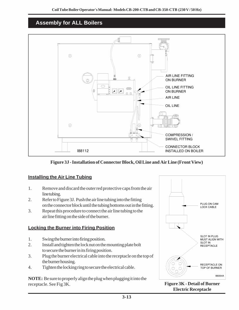
Figure 3J - Installation of Connector Block, Oil Line and Air Line (Front View)
Installing the Air Line Tubing
1. Remove and discard the outer red protective caps from the airline tubing.
2. Refer to Figure 3J. Push the air line tubing into the fittingon the connector block until the tubing bottoms out in the fitting.
3. Repeat this procedure to connect the air line tubing to theair line fitting on the side of the burner.
Locking the Burner into Firing Position
1. Swing the burner into firing position.2. Install and tighten the lock nut on the mounting plate bolt
to secure the burner in its firing position.3. Plug the burner electrical cable into the receptacle on the top of
the burner housing.4. Tighten the locking ring to secure the electrical cable.
NOTE: Be sure to properly align the plug when plugging it into thereceptacle. See Fig 3K. Figure 3K - Detail of Burner
Electric Receptacle
Assembly for ALL Boilers
PLUG ON CAMLOCK CABLE
SLOT IN PLUGMUST ALIGN WITHSLOT INRECEPTACLE
RECEPTACLE ONTOP OF BURNER
I88354A
OIL LINE FITTINGON BURNER
AIR LINE FITTINGON BURNER
AIR LINE
OIL LINE
COMPRESSION /SWIVEL FITTING
CONNECTOR BLOCKINSTALLED ON BOILERI88112
AIR OIL

Coil Tube Boiler Operator's Manual: Models CB-200-CTB and CB-350-CTB (230 V / 50 Hz)
3-14

Coil Tube Boiler Operator's Manual: Models CB-200-CTB and CB-350-CTB (230 V / 50 Hz)
4-1
Installing your Clean Burn Coil Tube Boiler (CTB) is a multi-step process which includes:(1) Oil Tank Installation Specifications(2) Installing the Metering Pump*(3) Connecting Water to the CTB(4) Installing the Oil Lines(5) Installing the Compressed Air Line(6) Wiring the CTB and Pump(7) Installing the Stack(8) Inspecting the Installation
*NOTE: This manual provides information for the installation of a metering pump with the CTB. If youordered a J-pump, please also refer to the separate J-Pump Installation Manual included with yourshipment.
Clean Burn recommends that you review all procedures before beginning installation, paying careful attention tosafety information statements. Figures 4A / 4B provide a general overview of a typicalcoil tube boiler installation and should be reviewed closely before proceeding.
SECTION 4: COIL TUBE BOILER INSTALLATIONUnderstanding Installation
WARNING: Improper installation can adversely affect the proper, safe operation of your CTB. It iscritical that your boiler installer reads and follows the instructions provided in this manual. Access to the
boiler must be restricted; only trained, qualified personnel should be permitted to perform installation andoperation procedures.Important Safety Guidelines for Safe Installation
General installation of the appliance shall be in accordance with the manufacturer's literature, in addition tocomplying with the following:
BS5410 Code of Practice for Oil Firing1997: Installation up to 45 KW output capacity for space heating and hot water supplypurposes.1998: Installation of 44 KW and above capacity for space heating, hot water and steamsupply purposes.1978: Installation for furnaces, kilns, ovens and other industrial purposes.
The Building Regulations:England and Wales: Approved Document J: Heat Producing Appliances (1991).Scotland: Technical standards for compliance with the Building Standard (Scotland) Regulations1990, Part F: Heat Producing Installations and Storage of Liquid and Gaseous Fuels.Northern Ireland: The Building Regulations (Northern Ireland) 1990. Technical Booklet L -Heat Producing Appliances, July 1991.Republic of Ireland: The Building Regulations of Ireland 1997, Part J: Heat ProducingAppliances.Isle of Man, Jersey and Guernsey: The Building Bylaws - BS 7671: 1992 IEE WiringRegulations 16th Edition.

Coil Tube Boiler Operator's Manual: Models CB-200-CTB and CB-350-CTB (230 V / 50 Hz)
4-2
Important Safety Guidelines for Safe Installation (continued)
The Environmental Protection Act 1990, Part 1: Processes prescribed for air pollution control by localenforcing authorities PG1/1 (95).
Secretary of State's Guidance: Waste Oil Burners, less than 0.4 MW net rated thermal input.November 1995 (Appendix A of OFTEC OFSA 103).
OFTEC Guidelines: Document OFG100 for externally serviced oil fired appliances.
Important Notes to the Electrician
WARNING: Electrical installation of the boiler is to be performed only by qualified personnel(i.e. licensed electrician/engineer). Improper electrical installation can adversely affect the proper, safe
operation of the boiler and may cause serious personal injury/death.
WARNING: Before completing any boiler wiring, refer to the wiring diagrams in Appendix Bat the back of the manual. Carefully review the wiring assignments and colors, noting that the Clean
Burn wire colors may not be "standard" or familiar.
WARNING: High earth leakage current / earth connection is essential and must be establishedbefore connecting the main power supply.
WARNING: Low voltage terminals are only protected by basic insulation--caution is required.
CAUTION: Use only approved wire conduit and connectors when wiring the Clean Burnboiler. An emergency stop device (i.e. "panic button") must be installed at ground level in the mains
cable to the boiler to ensure the safety of boiler operators and service personnel. The external disconnectdevice must employ a contact separation of 3mm in all poles; the external breaker must be an approved type.
CAUTION: The mains cable must be introduced into the control box using conduit connectorswhich provide adequate strain relief. The mains cable installation must be accomplished using suitably
rated and approved wiring (BASEC or HAR) or appropriate current-carrying capacity. The wires should havea minimum rating of 90 oC (194 oF).
NOTE: According to Clause 4A of 61000-3-11 (International Electrical Standard), the user must determine,in consultation with the supply authority, that the boiler is connected only to a supply with an impedance of3.773 x 10-3 + 2.358 x 10⁻³ or less.

Coil Tube Boiler Operator's Manual: Models CB-200-CTB and CB-350-CTB (230 V / 50 Hz)
4-3
Typical Installation Diagrams
Figure 4A - Typical Single Boiler Installation Diagram
"CLASS A" STACK CAP
"CLASS A" KIT FOR INSTALLING"CLASS A" STACK THROUGH CEILING
OIL PUMP ELECTRICAL CIRCUIT
PRESSURE OIL LINE INSTALLEDTO CONNECTOR BLOCK ON BOILER
20 cm (8") SINGLEWALL STACKMIN. 24 GAUGE
CLEAN−OUT TEEO
IL F
LOW
CLEAN−OUT
ELECTRICAL THERMO CUT−OFF (OPTIONAL)
220 VOLT 15 AMPDEDICATED ELECTRICAL CIRCUIT
(OPTIONAL)OIL THERMOCUT−OFF
COMPRESSED AIR LINE
VENTCAP
945 LITER TANK(250 GALLONS)
EMERGENCYVENT
CHECK VALVE
CHECK VALVE SCREEN
CONTROL BOX
AT CONNECTOR
AIR & OILCONNECTIONS
RELIEF VALVE CONNECTION)(ELECTRICAL
TEMP/PRESSURE
FLOW SWITCH
GAUGE HIGH LIMITW/RESET
RETURN1−1/2 NPT
BLOCK ON BOILER
DRAFTM
ORE
LESS
METERINGPUMP
SUCTIONOIL LINE
MA
XIM
UM
183
cm
(6
FT
)
6 mm (1/4") HOLE FOR CHECKING DRAFT AT BREACH
61 cm (2’)
3 m (10’)
"CLASS A" STACK1150 °C (2100 °F) ALL FUEL STACK
INSULATED STACK WITH ASTAINLESS STEEL LINER
WATERTIGHT ROOF FLASHING
"DEKTITE" FLASHING OREQUIVALENT
CA
UT
ION
: D
O N
OT
EX
CE
ED
183
cm
(6
FT
)V
ER
TIC
AL
SU
CT
ION
LIF
T O
R T
HE
PU
MP
WIL
LN
OT
PR
IME
AN
D/O
R T
HE
FLO
W R
AT
E F
RO
MT
HE
PU
MP
MA
Y B
E D
EC
RE
AS
E
FLUECOLLAR20 cm DIA. (8")
30 cm (1 FT)

Coil Tube Boiler Operator's Manual: Models CB-200-CTB and CB-350-CTB (230 V / 50 Hz)
4-4
Typical Installation Diagrams (continued)
Figure 4B - Typical Dual-Stacked Boiler Installation Diagram
61 cm (2’)
STAINLESS STEEL LINER
AT BREACH
OIL FLOW
30 cm (12")
3 m (10’)
30 cm (12")
R H ROTATION
INLET
GAU GE INLET
FILTER
"CLASS A" STACK CAP
"CLASS A" STACK 1150 °C (2100 °F) ALL FUEL STACK
INSULATED STACK WITH A
WATERTIGHT ROOF FLASHING"DEKTITE" FLASHING OREQUIVALENT
"CLASS A" KIT FOR INSTALLING
"CLASS A" STACK THROUGH CEILING
OIL PUMP ELECTRICAL CIRCUITS
PRESSURE OIL LINES INSTALLEDTO CONNECTOR BLOCKS ON BOILERS
BAROMETRIC DAMPER
6mm (1/4") HOLE FOR
CLEAN−OUT TEE
CLEAN−OUT TEE
20 cm (8") SINGLEWALL STACKMIN. 24 GAUGE
CLEAN−OUT
ELECTRICAL THERMO CUT−OFF (OPTIONAL)
230 VOLT 15 AMPDEDICATED ELECTRICAL CIRCUIT
(OPTIONAL)OIL THERMOCUT−OFF
COMPRESSED
AIR AND OIL CONNECTIONS AT
COMPRESSED AIR LINE
230 VOLT 15 AMP
CHECKING DRAFT
CONNECTOR BLOCK ON BOILERS
OIL
FLO
W
VENTCAP
945 LITER TANK(250 GALLONS)
EMERGENCYVENT
CHECK VALVE
CHECK VALVE SCREEN
SU
CT
ION
OIL
LIN
E
SUCTION OIL LINE
MO R
E
LE SS
D RAFT
(OPTIONAL)OIL THERMOCUT−OFF
1.5m (5 FT) MIN
1−1/2 NPTRETURN
1−1/2 NPTSUPPLY
1−1/2 NPTRETURN
AIR LINE
OIL LINECANISTER
INLETGAU GE
INLETR H ROTATION
SUPPLY1−1/2 NPT
DR AFTMOR E
LES
S

Coil Tube Boiler Operator's Manual: Models CB-200-CTB and CB-350-CTB (230 V / 50 Hz)
4-5
Oil Tank Installation Specifications
Ensure that your tank installation adheres to thefollowing safety guidelines as stated here and inSection 1 of this manual.
The tank safety label (shown at right) alsosummarizes these important specifications for tankinstallation and usage. If you do not have a copy ofthis label, please contact your Clean Burn dealer fora copy, which is to be affixed directly to your usedoil supply tank.
• The tank installation must meet allnational and local codes. Consult yourlocal municipal authorities for moreinformation as necessary.
• Use a minimum 945 liter (250 gallon) tank.DO NOT use a drum as a substitute for anappropriate tank. The tank must be largeenough to allow water, sludge, etc. to settleout of the used oil.
• The tank must have a manual shut-offtype valve on the side of the tank to allowthe water, sludge, etc. to be drained fromthe bottom of the tank.
• All unused openings in the tank must beplugged or capped off.
• For optimal system functioning, Clean Burnrecommends inside tank installations asshown in Figures 4A and 4B.
• The tank must be vented to the outside ofthe building using iron or steel pipe andfittings with an approved vent cap.
• Carefully review the oil tank and pumpinstallation details as shown in Figures 4A,4B, and 4C, including the metering pumpinstallation and specifications for the oilline installation. (Procedures for installingthese components can be found in thefollowing pages.)
IMPORTANT NOTE: If you are installing aninside oil tank in the same room as the boiler, youmust allow a 1.5 m (5 foot) minimum clearancebetween the tank and the boiler. The oil tank shouldbe set and installed in position BEFORE the boiler isinstalled.

Coil Tube Boiler Operator's Manual: Models CB-200-CTB and CB-350-CTB (230 V / 50 Hz)
4-6
Oil Tank Installation Specifications (continued)
Figure 4C - Typical Metering Pump Installation with Inside Tank
Installing the Tank Vent and Emergency Vent
Codes require that you install a tank vent (to the outside) and an emergency vent for your tank as shown inFigure 4C. Tank Vent Kits are available from Clean Burn; contact your local Clean Burn dealer to order. Besure to check your local codes for any additional tank installation requirements, and adhere to the followinginstallation guidelines:
• Install a length of minimum 50 mm (2") steel pipe (user-supplied) terminating outside with a propervent cap as shown in Figure 4C. Consult local codes for information and requirementsconcerning the proper venting of oil storage tanks.
• Install an emergency vent as shown in Figure 4C. Contact your tank manufacturer forinformation concerning the proper emergency vent for your tank.
PUMP
SUCTION LINE ASSEMBLY
EMERGENCYVENT
MUSHROOMCAP VENT
SCREENFILTER
VALVECHECK
(USER SUPPLIED)STEEL PIPE
FUNNEL WITH BALL VALVE
CLEAN−OUT(TANK DRAIN)
TANK VENT KITS AVAILABLE FROM CLEAN BURN: CB Part # 70380 − 4" Tank Vent Kit (2) elbows (2) 6" nipples (1) mushroom cap vent (1) emergency vent

Coil Tube Boiler Operator's Manual: Models CB-200-CTB and CB-350-CTB (230 V / 50 Hz)
4-7
Installing the Metering Pump
Preparing for Installation
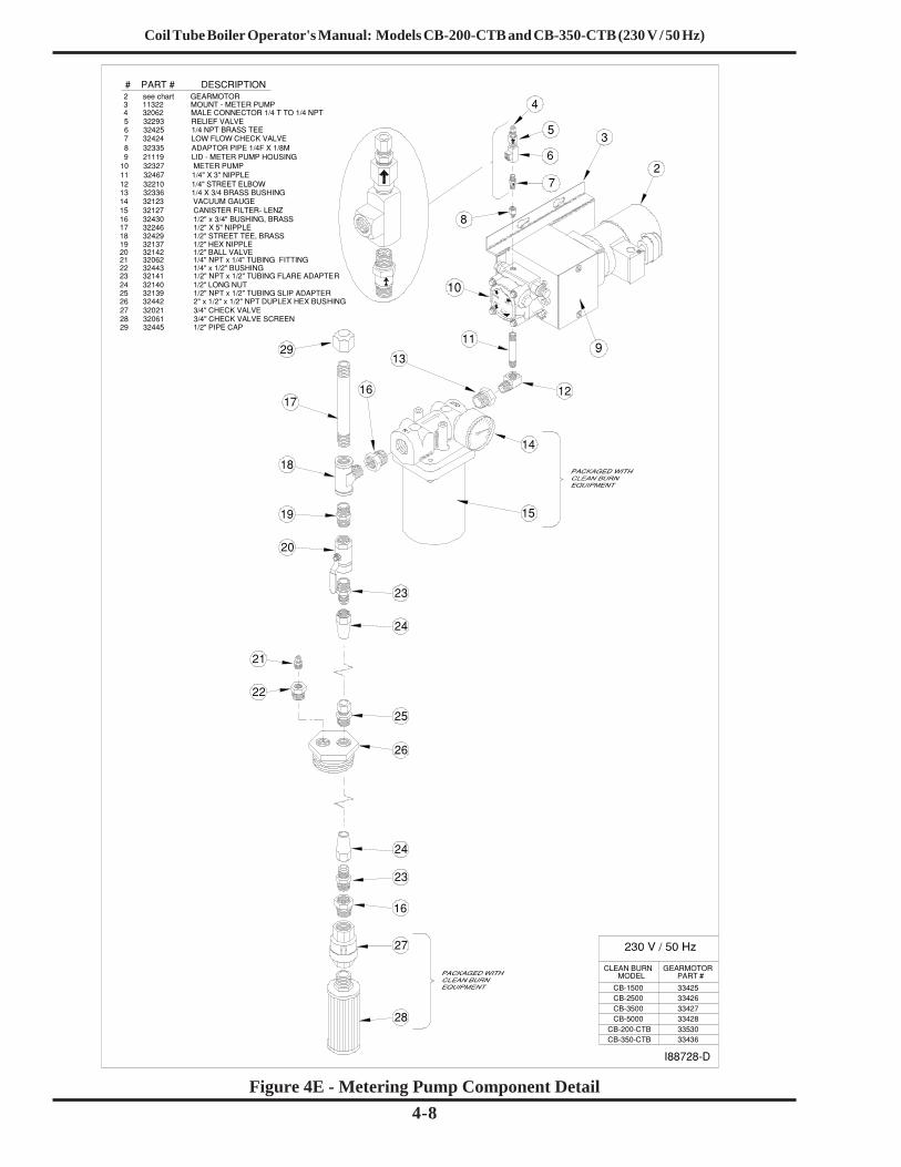
Before starting installation of the metering pump, review Figures 4D, 4E, and 4F to become familiarwith the metering pump components. You will also need to accomplish the following activities:
• Verify that you have the proper metering pump for your boiler (note the specific gear motorpart numbers shown in Figure 4E).
• Gather all required tools and materials as needed for installation; as indicated in thefollowing procedures, some materials (e.g. fittings, tubing) are to be user-supplied.
• Standard mounting is vertical mounting on a wall; this pump installation is recommended.Alternate mounting is horizontal mounting on a bracket. Be sure to carefully follow theappropriate procedures/diagrams for pump mounting.
• For optimal metering pump functioning, ensure that the pump is mounted at a distance notmore than 122 cm (4') from the oil tank.
Figure 4D - Standard (Recommended) Vertical Mounting of the Metering Pump
Standard Mounting: Vertical Positioning
1. Refer to Figures 4D, 4E, and 4F. Note that the metering pump is shipped with the pump head alreadypositioned for the standard vertical wall mounting.
2. Use the appropriate type of bolts and washers (user-supplied) to securely mount the metering pump tothe appropriate wall in your building at a distance not more than 122 cm (4') from the tank.
INLET
1/4" OUTLET
BLEEDER I88706
Coil Tube Boiler Operator's Manual: Models CB-200-CTB and CB-350-CTB (230 V / 50 Hz)
4-8Figure 4E - Metering Pump Component Detail
2
10
# PART # DESCRIPTION
9 21119 LID − METER PUMP HOUSING
3 11322 MOUNT − METER PUMP
10 32327 METER PUMP11 32467 1/4" X 3" NIPPLE
8 32335 ADAPTOR PIPE 1/4F X 1/8M7 32424 LOW FLOW CHECK VALVE6 32425 1/4 NPT BRASS TEE
5 32293 RELIEF VALVE
12 32210 1/4" STREET ELBOW13 32336 1/4 X 3/4 BRASS BUSHING
15 32127 CANISTER FILTER− LENZ16 32430 1/2" x 3/4" BUSHING, BRASS
9
4
3
12
5
11
14
8
6
13
14 32123 VACUUM GAUGE
2 see chart GEARMOTOR
27
15
7
27 32021 3/4" CHECK VALVE
4 32062 MALE CONNECTOR 1/4 T TO 1/4 NPT
CLEAN BURNMODEL
CB−15003342633427
CB−2500
3353033428CB−5000
CB−3500
33436CB−350−CTB
28
28 32061 3/4" CHECK VALVE SCREEN
16
23
24
26
25
24
23
16
22
21
20
19
18
17 32246 1/2" X 5" NIPPLE 18 32429 1/2" STREET TEE, BRASS19 32137 1/2" HEX NIPPLE20 32142 1/2" BALL VALVE21 32062 1/4" NPT x 1/4" TUBING FITTING22 32443 1/4" x 1/2" BUSHING23 32141 1/2" NPT x 1/2" TUBING FLARE ADAPTER24 32140 1/2" LONG NUT25 32139 1/2" NPT x 1/2" TUBING SLIP ADAPTER26 32442 2" x 1/2" x 1/2" NPT DUPLEX HEX BUSHING
I88728−D
17
29
29 32445 1/2" PIPE CAP
CB−200−CTB
GEARMOTORPART #
33425
Coil Tube Boiler Operator's Manual: Models CB-200-CTB and CB-350-CTB (230 V / 50 Hz)
4-9
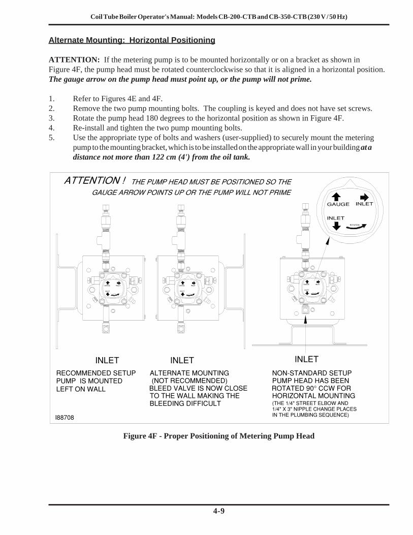
Figure 4F - Proper Positioning of Metering Pump Head
Alternate Mounting: Horizontal Positioning
ATTENTION: If the metering pump is to be mounted horizontally or on a bracket as shown inFigure 4F, the pump head must be rotated counterclockwise so that it is aligned in a horizontal position.The gauge arrow on the pump head must point up, or the pump will not prime.
1. Refer to Figures 4E and 4F.2. Remove the two pump mounting bolts. The coupling is keyed and does not have set screws.3. Rotate the pump head 180 degrees to the horizontal position as shown in Figure 4F.4. Re-install and tighten the two pump mounting bolts.5. Use the appropriate type of bolts and washers (user-supplied) to securely mount the metering
pump to the mounting bracket, which is to be installed on the appropriate wall in your building at adistance not more than 122 cm (4') from the oil tank.
INLET
(NOT RECOMMENDED)
BLEEDING DIFFICULT
ROTATION
ROTATION
NON−STANDARD SETUPPUMP HEAD HAS BEENROTATED 90° CCW FORHORIZONTAL MOUNTING(THE 1/4" STREET ELBOW AND1/4" X 3" NIPPLE CHANGE PLACESIN THE PLUMBING SEQUENCE)
INLETINLET
GAUGE
INLET
INLETINLETGAUGE
INLET
RECOMMENDED SETUPPUMP IS MOUNTEDLEFT ON WALL
ALTERNATE MOUNTING
TO THE WALL MAKING THEBLEED VALVE IS NOW CLOSE
I88708
ROTATION
ROTATION
INLET
GAUGE
INLET

Coil Tube Boiler Operator's Manual: Models CB-200-CTB and CB-350-CTB (230 V / 50 Hz)
4-10
Connecting Water to the Coil Tube Boiler
1. Connect the desired header supply and return lines to the CTB.2. Have the water trim installed by a certified hydronics technician. Heat exchangers must be used for
domestic water heater installations.3. For air separation and elimination, Clean Burn recommends the Enhanced Spiral-Type Air
Separator which can be supplied by your local Clean Burn dealer. Installing an air separatorhelps ensure that air is purged from the boiler, which is necessary for optimal startup andoperation of the burner.
4. The relief valve discharge must be piped to within four inches of the floor or to a floor drain.Be sure to allow for clearance to remove the back panel for servicing.
Filling the Coil Tube Boiler with Water
ATTENTION: It is necessary to fill the CTB with water prior to wiring and turning the CTB ON.The boiler circulator bearings are water lubricated and should not be allowed to operate dry. Filling theCTB with water provides immediate lubrication of the bearings. Purging air from the water is alsocritical; doing so enables proper startup of the burner.
1. Fill the CTB with clean tap water.ATTENTION: To prevent damage to the CTB, DO NOT fill the boiler with water when theboiler is hot.
2. The pressure gauge should read 0.8 bar (12 psig). If a different operating pressure is needed, contactthe Clean Burn Service Department for additional instructions.)
3. Refer to Section 10, The CTB Hydronic System, for additional information.
IMPORTANT NOTE! Detailed information on the installation and operation of thehydronics system is provided in Section 10 of this manual. The instructionsprovided here are abbreviated and serve only to indicate when these proceduresshould be performed; consult Section 10 for the detailed version.

Coil Tube Boiler Operator's Manual: Models CB-200-CTB and CB-350-CTB (230 V / 50 Hz)
4-11
Installing the Suction Oil Line Components
ATTENTION: It is critical that you adhere to the following specifications for suction oil lineinstallation (oil line from the tank to the pump). If these specifications are not met, the metering pumpwill not function correctly and the burner will shut down on reset. The majority of service problems with themetering pump are caused by leaks at fittings in the suction oil line; these problems are eliminated by ensuringa 100% airtight suction oil line which slants up to the pump.
• All suction oil line components must be installed as shown in Figures 4A, 4B, and 4E.Suction line size is 1/2" (12.7 mm) diameter. Proper installation allows the suction oil line to befilled with used oil during initial priming.
• The suction oil line may NOT exceed 183 cm (6') TOTAL vertical lift AND 122 cm (4')TOTAL horizontal lift (which equals 6.0” hg maximum operating vacuum). To determine ifyour suction oil line will meet this specification for maximum operating vacuum, base the calculationfor your installation on the following equivalents:
30 cm (1') vertical = 0.75” hg (vacuum)122 cm (4') horizontal = 0.75” hg (vacuum)
NOTE: ALSO ADD 0.75" hg to the final sum to account for every oil filter, shut-off valve, andcheck valve on the suction side of the pump assembly.Sample calculation: 183 cm / 30 vertical cm feet x 0.75" = 4.50" hg AND
122 horizontal cm = 0.75" hg4.50" hg + 0.75" hg + 0.75" hg = 6.00" hg vacuum
• The metering pump must be installed with a 3/4" check valve and screen at the end of thesuction oil line, or the pump will not maintain its prime.
• Use Permatex #2 non-hardening gasket sealer on every threaded fitting. DO NOT useteflon tape or teflon pipe dope compounds; the teflon can flake off and cause damage to thepump head.
• The suction oil line must be 100% airtight for proper system functioning. Use onlyhigh-quality flare fittings for the copper tubing. DO NOT use compression fittings.DO NOT use any steel pipe unions. DO NOT use sweat copper pipe. These types of fittingscause air leaks in the suction oil line and will require re-installation.
• The suction oil line must slant up to the pump; any high spots will trap air and will notallow the pump to prime.
1. Assemble the suction oil line fittings (from the metering pump to the canister filter):a. Refer to Figure 4E for a detailed look at the metering pump components and fittings.b. Remove the plug from the 1/4" inlet port of the pump.c. Install the 1/4" x 3" brass nipple into the 1/4" inlet port on the pump.d. Install the 1/4" brass street elbow onto the 3" brass nipple; turn the fitting onto the nipple
until it is tight and faces away from the pump mounting plate.e. Prepare the canister filter for installation:
• Install the 3/4" x 1/4" brass hex bushing into the outlet port of the canister filter.Check the direction of the arrow for the proper flow.
• Install the 3/4" x 1/2" brass bushing into the inlet port of the canister filter.

Coil Tube Boiler Operator's Manual: Models CB-200-CTB and CB-350-CTB (230 V / 50 Hz)
4-12
2. Install the suction oil line (from the the tank to the canister filter):a. Refer to Figures 4A, 4B, and/or 4E.b. Prepare a piece of 1/2" O.D. copper tubing (user-supplied) which will function as the pick-up
line from the tank to the canister filter. This copper tubing must have the followingspecifications:
• The tube must be one continuous piece of 1/2" O.D. copper tubing with no kinksor fittings.
• The tube is to slant up from the tank to the pump with no loops or high points totrap air.
c. Locate the 2" MPT x 1/2" FPT x 1/2" FPT duplex, slip-thru hex bushing (which willeventually be installed into one of the 2" openings on the tank). Note that the fitting ismarked "S" for suction and "R" for return.
d. Install the 1/2" MPT x 1/2" slip fitting into the "S" side of the 2" duplex slip-thru hexbushing.
e. Install the 1/4" MPT x 1/4" compression fitting into the 1/2" x 1/4" brass bushing.f. Install the 1/2" x 1/4" brass bushing into the "R" side of the 2" duplex slip-thru hex bushing.g. Measure the height of the oil tank (from the bottom of the tank, NOT the floor) to the 2"
opening that you are going to use for the supply oil line. Deduct 30 cm (12") from thismeasurement and transfer this new measurement onto the 1/2" O.D. coppper tubing.
h. Remove the locking nut and ferrel sleeve connector from the 1/2" slip fitting, and slide themover the copper tubing.
i. Slide the 1/2" O.D. copper tubing through the 1/2" slip fitting, which is installed in the "S"side of the 2" hex bushing.
j. Install the screen into one side of the 3/4" check valve (making sure the arrow is pointingaway from the screen assembly).
k. Install the 3/4" x 1/2" brass bushing into the 3/4" check valve.l. Install the 1/2" MPT x 1/2" flare adapter into the 3/4" x 1/2" brass bushing.
(e.) Prepare the canister filter for installation (continued):• Remove the plug from one of the 1/8" gauge ports in the canister filter and install the
vacuum gauge. Seal the threads of the gauge with Permatex #2 non-hardening gasketsealer.
• Install the 1/2" threaded pipe adapter into one side of the 1/2" ball valve.• Install the 1/2" MPT x 1/2" flare adapter into the other side of the ball valve.• Install this assembly into one side of the 1/2" brass tee.• Install the assembled 1/2" tee into the 3/4" x 1/2" brass bushing, which is installed in
the inlet port of the canister filter. Make sure that the 1/2" flare adapter is pointingdown.
• Install the canister filter assembly onto the 1/4" brass street elbow as shown in Figure4E. The canister filter must be installed with the arrow pointing towards the pump(direction of oil flow).
• Install the 1/2" x 5" brass nipple into the top side of the 1/2" brass tee assembly.• Loosely install the 1/2" brass cap onto this nipple. DO NOT tighten the cap at this
time.
Installing the Suction Oil Line Components (continued)

Coil Tube Boiler Operator's Manual: Models CB-200-CTB and CB-350-CTB (230 V / 50 Hz)
4-13
Installing the Suction Oil Line Components (continued)
(2.) Install the suction oil line (continued)):m. Slide the 1/2" flare nut over the end of the 1/2" copper tubing, and flare the end of the tubing.
NOTE: Use a high-quality flaring tool (such as a Ridgid Flaring Tool) to ensure that allflares are made properly (i.e. so they will be 100% airtight).
n. Install the flared oil line and nut onto the assembled check valve/screen and tighten.o. Pick up the assembled oil line, and carefully guide the end of the tubing with the check valve
through the 2" tank opening.p. Apply Permatex #2 non-hardening gasket sealer (or equivalent) to the threads of the 2"
duplex slip-thru tank bushing, and tighten this fitting into the tank.q. Pull the 1/2" copper tubing back up through the slip fitting until you see the mark that you put
on the tubing earlier. Holding the tubing with one hand, push the ferrel sleeve connector andlocking nut down the tubing, then tighten onto the 1/2" slip fitting. The oil line is nowinstalled in the correct position off of the bottom of the tank.
r. Carefully bend the oil line up to the canister filter; use a spring bender over the oil line whilebending the tubing to prevent kinks in the oil line. Allowing for the flare nut, cut off theexcess tubing.
s. Install the 1/2" flare nut onto the tubing, and flare the end of the tubing.t. Install the end of the tubing with the flare nut onto the 1/2" flare adapter (on the ball valve
assembly at the canister filter).u. Install a vent from the tank to the outside of the building according to code. The tank must
be properly vented to allow air to enter the tank as oil is pumped out and to safely vent fumesto the outside. See Figures 4A/4B.
v. Install plugs in all other tank openings as required by code.w. Inspect the installation. For proper suction oil line operation, make sure all components are
installed and positioned as specified in this manual.

Coil Tube Boiler Operator's Manual: Models CB-200-CTB and CB-350-CTB (230 V / 50 Hz)
4-14
ATTENTION: It is critical that you adhere to the following specifications for pressure relief andlow-flow check valve installation; if these specifications are not met, the metering pump will notfunction correctly and the burner will shut down on reset.
The metering pump requires the installation of a pressure relief and low-flow check valve as shown inFigures 4E and 4G.
• The pressure relief will open and relieve pressure on the line if there is a restriction in thepressure oil line, clogged nozzle, etc.
• The low-flow check valve is a vital component which maintains pressure in the oil pressureline.
Be sure to use Permatex #2 non-hardening gasket sealer to seal every threaded fitting. DO NOT useteflon tape or teflon pipe dope compounds.
1. Refer to Figure 4G.2. Remove the plug from the gauge port on top of the metering pump head.3. Install the pressure relief valve assembly in a vertical position in the gauge port. Note that the
directional arrows on the relief valve must be positioned so that the arrows point away from thepump head (i.e. in the direction of the oil flow).
4. Install 1/4" O.D. copper tubing (user-supplied) from the pressure relief back to the oil tank.See Figures 4A/4B as needed.
5. Refer to the following procedure for instructions on installing the pressure oil line (from the pump to theconnector block on the boiler).
Installing the Pressure Relief and Low-Flow Check Valve
Figure 4G - Installing the Pressure Relief Valve Assembly
I88692−A
32062
32293
32425
32424
TO TANK
TO BURNER
32335
FROM PUMP
ADAPTOR PIPE, 1/4 F X 1/8 M
LOW FLOW CHECK VALVE
1/4 NPT BRASS TEE
RELIEF VALVE
MALE CONNECTOR1/4 T TO 1/4 NPT
PRESSURE RELIEFVALVE COMPONENTS
Included with metering pump

Coil Tube Boiler Operator's Manual: Models CB-200-CTB and CB-350-CTB (230 V / 50 Hz)
4-15
Installing the Compressed Air Line
NOTE: Your air compressor system must supply air pressure to the boiler with the followingrequirements: 3.5 bar (50 psi) and water trap or dryer. If you do not have shop air, an optional aircompressor is available. Contact your local Clean Burn dealer for more information.
1. Run a compressed air line from your shop air to the connector block on the boiler. Use minimum 1/4"O.D. copper tubing or equivalent for the compressed air line.
2. Install an easily accessible shut-off valve in the air line so the burner can be serviced withoutshutting off the shop air in your service area.
3. If necessary, install a pressure regulator (additional to the burner air regulator) in the air line, and set it at3.5 bar (50 psi.)
ATTENTION: DO NOT feed full shop air pressure to the burner or damage to burnercomponents may occur.
4. Install a water trap or extractor/dryer in the air line with an automatic drain so compressed air(rather than water) is supplied to the burner.
ATTENTION: Water must not be fed to the burner, or the flame will be extinguished and theburner will shut down. Be sure to drain water from your compressor tank on a regular basis tokeep water out of the air line.
ATTENTION: It is critical that you adhere to the following specifications for pressure oil lineinstallation (oil line from the pump to the boiler); if these specifications are not met, the metering pump willnot function correctly and the burner will shut down on reset.
• The parameters for pressure oil line installation are:
Length of Pressure Line Line SizeUp to 30 meters (100') 9.5 mm (3/8") O.D. copper tubing
• The pressure oil line must slant up to the burner with no loops or high points to trap air.
• Local codes may require the installation of an in-line "Fire-O-Matic" safety valve.Be sure to check all appropriate codes to ensure compliance.
1. Refer to Figures 4A/4B, and 4G.2. Make sure you have purchased all the necessary fittings to complete the installation correctly.3. Install the fittings and components as shown in the related illustrations. Be sure to use Permatex #2
non-hardening gasket sealer to seal every threaded fitting. DO NOT use teflon tape or teflon pipe dopecompounds.
Installing the Pressure Oil Line Components

Coil Tube Boiler Operator's Manual: Models CB-200-CTB and CB-350-CTB (230 V / 50 Hz)
4-16
Wiring the Coil Tube Boiler
WARNING: To avoid electrical shock, make sure that power to the CTB is turned OFF beforeconnecting any wires. A licensed electrician should install all wiring to your furnace. All wiring must be
in accordance with national and local codes. Properly size all wires and use electrical conduit for all electricallines. Specific wiring schematics are provided in Appendix B at the back of this manual. For safe and properoperation of the boiler, DO NOT alter factory installed wiring.
Wiring your boiler requires the installation of the following lines/circuits:(1) A dedicated electrical line to the CTB (see IMPORTANT NOTE below)(2) A pump electrical circuit from the CTB to the oil pump (see IMPORTANT NOTE below)(3) A separate circuit for the load loop circulator
IMPORTANT NOTE: Separate, dedicated lines/circuits must be wired for each boiler in the dual-stackedunit.
Wiring to the Coil Tube Boiler
WARNING: A fuse-protected disconnect must be mounted in a readily accessible location forthe installation of the unit. This device can also be used for a disconnect in case of an emergency.
1. Install a dedicated electrical circuit to the electrical junction box on the CTB. Note that adual-stacked boiler will require two circuits.CAUTION: DO NOT tie into an existing circuit, or electrical overload may occur.
2. Wire the CTB according to the Wiring Schematic in Appendix B. Ensure that the ground wire isattached to the GREEN ground screw on the boiler junction box.
3. Check for correct voltage at the CTB and refer to the following chart.ATTENTION: Incorrect voltage may damage the CTB components.
Total Amp Draw Per Burner & Circulator: 9.4 amps Load Circulator Ampacity: 2.5 amps (when wired through the CTB control box)
Model Voltage Breaker Qty. & Size* Phase Hertz CB-200-CTB (single) 230 (1) @ 20 amps Single 50 CB-200-CTB (Dual-Stacked) 230 (2) @ 20 amps Single 50
CB-350-CTB (single) 230 (1) @ 20 amps Single 50 CB-350-CTB (Dual-Stacked) 230 (2) @ 20 amps Single 50
*NOTE: Breaker size with optional equipment is 30 amps. When installing any optional equipment (e.g. aircompressor or draft inducer), you must use a 30 amp breaker. Make sure a qualified electrician properly sizesand installs this electrical circuit. Note that minimum wire size with a 30 amp breaker is 10-gauge copper wire.
CAUTION: DO NOT turn on main power until instructed to do so.

Coil Tube Boiler Operator's Manual: Models CB-200-CTB and CB-350-CTB (230 V / 50 Hz)
4-17
Wiring to the Metering Pump
WARNING: DO NOT wire the oil pump directly into your building's electrical system. The oil pumpmust be activated (receive power from) the burner via the pump electrical circuit. DO NOT wire the
pump directly to a wall outlet so that it runs continuously; this will seriously damage your metering pump and/orboiler and may result in a fire or explosion hazard.
1. Install the oil pump electrical circuit from the CTB to the oil pump location using approved electricalconduit (refer to Figures 4A/4B).
2. Wire the oil pump circuit according to the wiring schematic provided (Appendix B).
Wiring the Load Loop Circulator
NOTE: To reduce the amount of cold water returned to the boiler (and to protect the boiler fromthermal shock), an optional circulator aquastat can be supplied by your Clean Burn Dealer.
1. Refer to the related information and illustrations in Section 10 and the CTB Wiring Diagram inAppendix B to locate and understand the wiring for the load loop circulator.
2. The cold water return in your CTB system installation should not be below 60 oC (140 oF).
NOTE: For installations where cold water return is a risk, Clean Burn recommends installationof a blending loop. If a blending loop is installed in your CTB system, the load loop circulatorshould be wired separately from the CTB control box. Refer to Section 10 for additionalinformation.
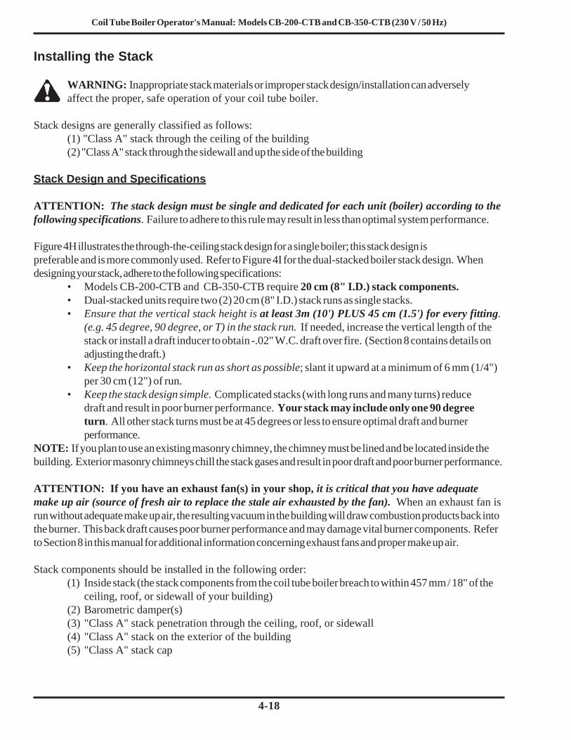
Coil Tube Boiler Operator's Manual: Models CB-200-CTB and CB-350-CTB (230 V / 50 Hz)
4-18
Installing the Stack
WARNING: Inappropriate stack materials or improper stack design/installation can adverselyaffect the proper, safe operation of your coil tube boiler.
Stack designs are generally classified as follows:(1) "Class A" stack through the ceiling of the building(2) "Class A" stack through the sidewall and up the side of the building
Stack Design and Specifications
ATTENTION: The stack design must be single and dedicated for each unit (boiler) according to thefollowing specifications. Failure to adhere to this rule may result in less than optimal system performance.
Figure 4H illustrates the through-the-ceiling stack design for a single boiler; this stack design ispreferable and is more commonly used. Refer to Figure 4I for the dual-stacked boiler stack design. Whendesigning your stack, adhere to the following specifications:
• Models CB-200-CTB and CB-350-CTB require 20 cm (8" I.D.) stack components.• Dual-stacked units require two (2) 20 cm (8" I.D.) stack runs as single stacks.• Ensure that the vertical stack height is at least 3m (10') PLUS 45 cm (1.5') for every fitting.
(e.g. 45 degree, 90 degree, or T) in the stack run. If needed, increase the vertical length of thestack or install a draft inducer to obtain -.02" W.C. draft over fire. (Section 8 contains details onadjusting the draft.)
• Keep the horizontal stack run as short as possible; slant it upward at a minimum of 6 mm (1/4")per 30 cm (12") of run.
• Keep the stack design simple. Complicated stacks (with long runs and many turns) reducedraft and result in poor burner performance. Your stack may include only one 90 degreeturn. All other stack turns must be at 45 degrees or less to ensure optimal draft and burnerperformance.
NOTE: If you plan to use an existing masonry chimney, the chimney must be lined and be located inside thebuilding. Exterior masonry chimneys chill the stack gases and result in poor draft and poor burner performance.
ATTENTION: If you have an exhaust fan(s) in your shop, it is critical that you have adequatemake up air (source of fresh air to replace the stale air exhausted by the fan). When an exhaust fan isrun without adequate make up air, the resulting vacuum in the building will draw combustion products back intothe burner. This back draft causes poor burner performance and may damage vital burner components. Referto Section 8 in this manual for additional information concerning exhaust fans and proper make up air.
Stack components should be installed in the following order:(1) Inside stack (the stack components from the coil tube boiler breach to within 457 mm / 18" of the
ceiling, roof, or sidewall of your building)(2) Barometric damper(s)(3) "Class A" stack penetration through the ceiling, roof, or sidewall(4) "Class A" stack on the exterior of the building(5) "Class A" stack cap
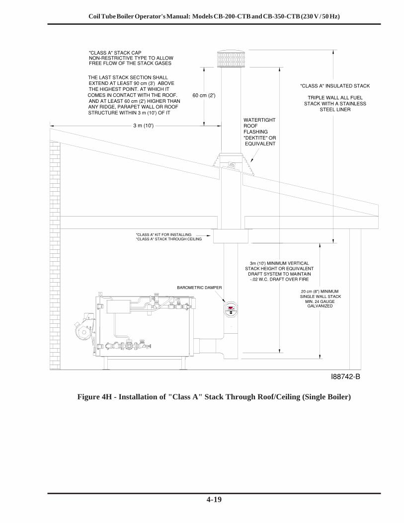
Coil Tube Boiler Operator's Manual: Models CB-200-CTB and CB-350-CTB (230 V / 50 Hz)
4-19
Figure 4H - Installation of "Class A" Stack Through Roof/Ceiling (Single Boiler)
MO RE
LE S S
DRAFT
NON−RESTRICTIVE TYPE TO ALLOWFREE FLOW OF THE STACK GASES
COMES IN CONTACT WITH THE ROOF.THE HIGHEST POINT. AT WHICH ITEXTEND AT LEAST 90 cm (3’) ABOVETHE LAST STACK SECTION SHALL
ANY RIDGE, PARAPET WALL OR ROOFAND AT LEAST 60 cm (2’) HIGHER THAN
STRUCTURE WITHIN 3 m (10’) OF IT
GALVANIZED
3 m (10’)
3m (10’) MINIMUM VERTICALSTACK HEIGHT OR EQUIVALENT
DRAFT SYSTEM TO MAINTAIN−.02 W.C. DRAFT OVER FIRE
60 cm (2’)
"DEKTITE" OR EQUIVALENT
20 cm (8") MINIMUM
"CLASS A" INSULATED STACK
TRIPLE WALL ALL FUELSTACK WITH A STAINLESS
STEEL LINER
"CLASS A" STACK CAP
WATERTIGHT ROOFFLASHING
"CLASS A" KIT FOR INSTALLING"CLASS A" STACK THROUGH CEILING
SINGLE WALL STACKMIN. 24 GAUGE
BAROMETRIC DAMPER
I88742−B

Coil Tube Boiler Operator's Manual: Models CB-200-CTB and CB-350-CTB (230 V / 50 Hz)
4-20
Installing the Stack (continued)
Figure 4I - Detail of Dual-Stacked Boiler Stack Installation
Installing the Interior Stack
CAUTION: Single wall stack components may be used only for those portions of the stackwhich are located inside your building and away from any fire/burn hazards.
1. The stack can be installed from either side of the smoke hood breach. Install the 20 cm (8") smokecap onto the unused smoke hood breach ring assembly.
2. Install a piece of the single-wall 24-gauge galvanized stack (minimum 45 cm (18") in length) onto thesmoke hood breach.
3. Install an elbow or clean-out tee (with a smoke cap installed in the bottom) onto the extensionpiece from the boiler smoke hood breach.
4. Install a smoke pipe tee onto this elbow or clean-out tee (for the installation of the barometricdamper).ATTENTION: Avoid additional 90-degree turns in the stack. Each additional 90-degree turnslows down stack gases, creates back-pressure, and results in repeated burner shutdown andunnecessary service calls. All other turns in the stack should be at a 45-degree (or smaller)angle.
82 cm (32 1/4") BETWEEN
CENTERS (CB−350−CTB)94 cm (37 1/8") BETWEEN
BETWEEN CENTERS25 cm (10")
CENTERS (CB−200−CTB)
DAMPER
STACK PIPE
I88744−B
20 cm (8")
20 cm (8")
STACK PIPE
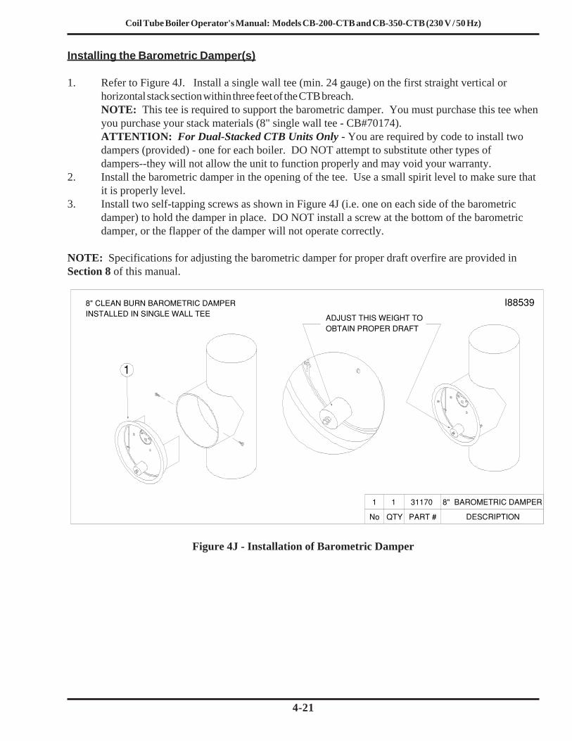
Coil Tube Boiler Operator's Manual: Models CB-200-CTB and CB-350-CTB (230 V / 50 Hz)
4-21
Installing the Barometric Damper(s)
1. Refer to Figure 4J. Install a single wall tee (min. 24 gauge) on the first straight vertical orhorizontal stack section within three feet of the CTB breach.NOTE: This tee is required to support the barometric damper. You must purchase this tee whenyou purchase your stack materials (8" single wall tee - CB#70174).ATTENTION: For Dual-Stacked CTB Units Only - You are required by code to install twodampers (provided) - one for each boiler. DO NOT attempt to substitute other types ofdampers--they will not allow the unit to function properly and may void your warranty.
2. Install the barometric damper in the opening of the tee. Use a small spirit level to make sure thatit is properly level.
3. Install two self-tapping screws as shown in Figure 4J (i.e. one on each side of the barometricdamper) to hold the damper in place. DO NOT install a screw at the bottom of the barometricdamper, or the flapper of the damper will not operate correctly.
NOTE: Specifications for adjusting the barometric damper for proper draft overfire are provided inSection 8 of this manual.
I885398" CLEAN BURN BAROMETRIC DAMPERINSTALLED IN SINGLE WALL TEE ADJUST THIS WEIGHT TO
OBTAIN PROPER DRAFT
1
No QTY PART # DESCRIPTION
8" BAROMETRIC DAMPER3117011
Figure 4J - Installation of Barometric Damper
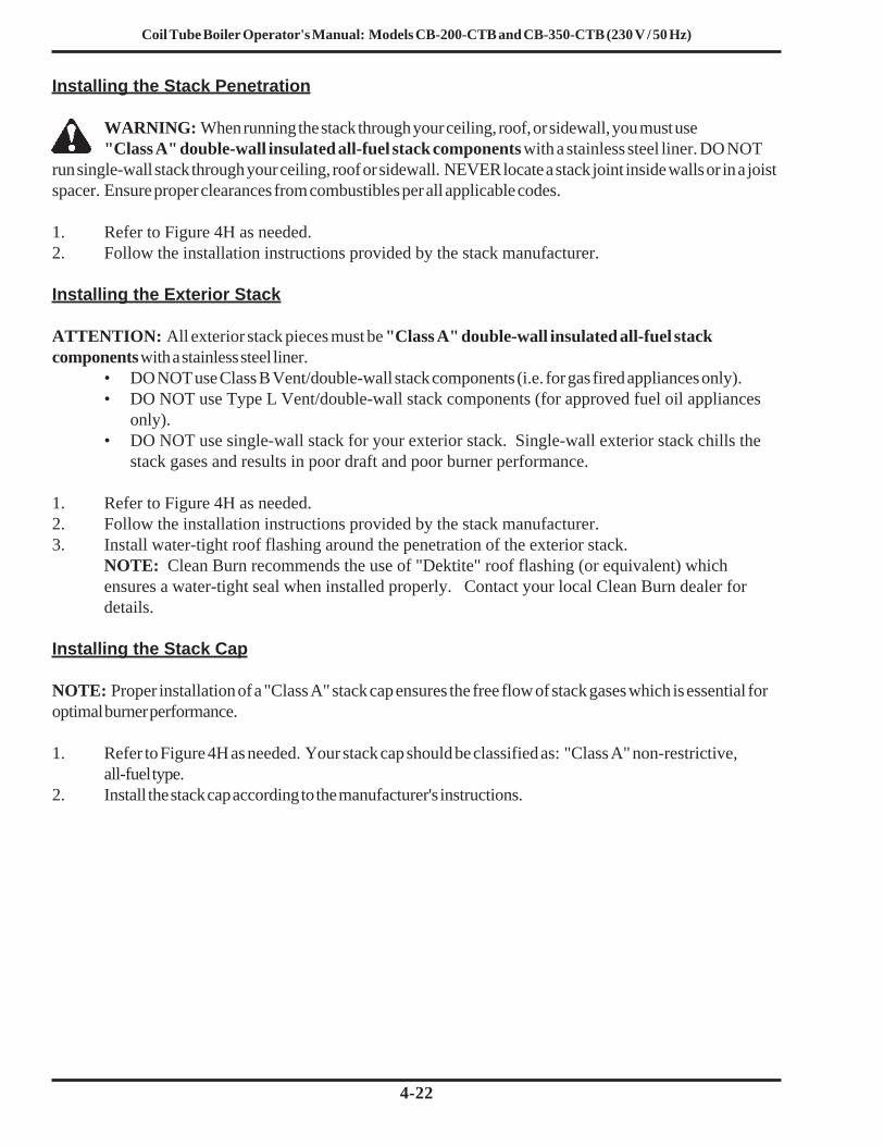
Coil Tube Boiler Operator's Manual: Models CB-200-CTB and CB-350-CTB (230 V / 50 Hz)
4-22
Installing the Stack Penetration
WARNING: When running the stack through your ceiling, roof, or sidewall, you must use"Class A" double-wall insulated all-fuel stack components with a stainless steel liner. DO NOT
run single-wall stack through your ceiling, roof or sidewall. NEVER locate a stack joint inside walls or in a joistspacer. Ensure proper clearances from combustibles per all applicable codes.
1. Refer to Figure 4H as needed.2. Follow the installation instructions provided by the stack manufacturer.
Installing the Exterior Stack
ATTENTION: All exterior stack pieces must be "Class A" double-wall insulated all-fuel stackcomponents with a stainless steel liner.
• DO NOT use Class B Vent/double-wall stack components (i.e. for gas fired appliances only).• DO NOT use Type L Vent/double-wall stack components (for approved fuel oil appliances
only).• DO NOT use single-wall stack for your exterior stack. Single-wall exterior stack chills the
stack gases and results in poor draft and poor burner performance.
1. Refer to Figure 4H as needed.2. Follow the installation instructions provided by the stack manufacturer.3. Install water-tight roof flashing around the penetration of the exterior stack.
NOTE: Clean Burn recommends the use of "Dektite" roof flashing (or equivalent) whichensures a water-tight seal when installed properly. Contact your local Clean Burn dealer fordetails.
Installing the Stack Cap
NOTE: Proper installation of a "Class A" stack cap ensures the free flow of stack gases which is essential foroptimal burner performance.
1. Refer to Figure 4H as needed. Your stack cap should be classified as: "Class A" non-restrictive,all-fuel type.
2. Install the stack cap according to the manufacturer's instructions.

Coil Tube Boiler Operator's Manual: Models CB-200-CTB and CB-350-CTB (230 V / 50 Hz)
4-23
Inspecting the Coil Tube Boiler Installation
Following the completion of all installation activities described in this chapter, the CTB should beinspected by qualified personnel before firing. This ensures that your installation meets all applicablenational and local codes and allows for any deficiencies in the installation to be corrected before CTBstartup. Improper installation will void your warranty.
NOTE: Important! During the inspection, be sure to check the aquastat settings. Initial settings arelisted here:
• Operating Aquastat 71 oC (160 oF) minimum• Hi-limit Aquastat (with manual reset) 115 oC (240 oF)
Refer to Section 6 for burner startup and final adjustments of the aquastat.
Any changes to these settings should be made only by a qualified hydronics technician. See Section10, The CTB Hydronics System, for more information.
Installing the Wall Thermostat
IMPORTANT NOTE: The wall thermostat is available separately from Clean Burn (i.e. it is notincluded with the CTB). Refer to Appendix A in this manual for additional information on remotetemperature sensing controls available from Clean Burn for your CTB system installation.
230 VAC Thermostat for the CB-200-CTB with the Danfoss Oil Primary Control #3353224 VAC Thermostat for the CB-350-CTB with the Honeywell Oil Primary Control #33506
1. Select a location for the thermostat on an interior wall away from any hot or cold drafts.2. Mount the thermostat according to the manufacturers instructions 1.5 m to 1.7 m (60" to 66") from
the floor.3. Wire the thermostat to the CTB following the wire schematics in Appendix B of this manual and
according to the manufacturers instructions included with the wall thermostat.

Coil Tube Boiler Operator's Manual: Models CB-200-CTB and CB-350-CTB (230 V / 50 Hz)
4-24

Coil Tube Boiler Operator's Manual: Models CB-200-CTB and CB-350-CTB (230 V / 50 Hz)
5-1
SECTION 5: METERING PUMP PRIMING
Understanding Metering Pump Priming
Preparing your Clean Burn boiler for operation begins with priming the metering pump. The procedures in thissection must be performed in sequence without interruption to properly prime the pump.
ATTENTION: Please note that in order to use the metering pump with the CB-500 Series burner (and toaccomplish pump priming), the oil regulator assembly must first be removed from the preheater blockassembly. The following procedure provides the necessary instructions.
IMPORTANT NOTE FOR DUAL-STACKED UNITS: The priming procedures will have to beperformed for one burner, and then repeated for the other burner (i.e. get one burner running first beforeattempting priming of the other burner.) Be sure to perform the Preparing the Burner for Use with theMetering Pump procedure for both units.
Required Tools and MaterialsThe following tools and materials are required for oil pump priming and should be gathered beforestarting any procedures:
• 3/8" open-end wrench• Rags• Two containers (minimum 4 liters / one-gallon each)• Medium straight-blade screwdriver

Coil Tube Boiler Operator's Manual: Models CB-200-CTB and CB-350-CTB (230 V / 50 Hz)
5-2
AIR REGULATOR
LOCKING NUT
AIR GAUGE
OIL GAUGE
COMBUSTIONAIR BAND
BURNER AFTER REMOVING OIL REGULATOR
SLOT COVER INSTALLED
WARNING: To avoid electrical shock hazards, turn off all power to the boiler, and unplug theburner before proceeding.
1. Figure 5A shows an exterior view of the burner components. In this procedure, you will beremoving the oil regulator from the preheater block assembly to prepare the burner for use withthe metering pump.
2. Remove the self-tapping screw with a 1/4" nut driver and swing open the double-hinged lid to exposethe heater block assembly.
3. Use a 1/8" Allen wrench to loosen the two locking bolts on the locking bar.4. Remove the locking bar.5. Refer to Figure 5B. Use a 5/32" Allen wrench to remove the four (4) bolts and washers holding
the surface-mounted oil regulator in place, then carefully remove the oil regulator.NOTE: Keep the oil regulator assembly in a safe place in case a standard J-type oil transferpump is installed at a later date. (You would then need to re-install the oil regulator assembly.)
6. Clean the top of the heater block to remove used oil, etc. DO NOT allow any debris to fall intothe oil passageways which have been exposed by the removal of the oil regulator.
7. Install the square cap with the o-ring using the four (4) bolts and washers. Tighten the four boltsfirmly in a crisscross pattern to ensure that there are no leaks.
Preparing the Burner for Use with the Metering Pump
Figure 5A - Detail of Burner Components
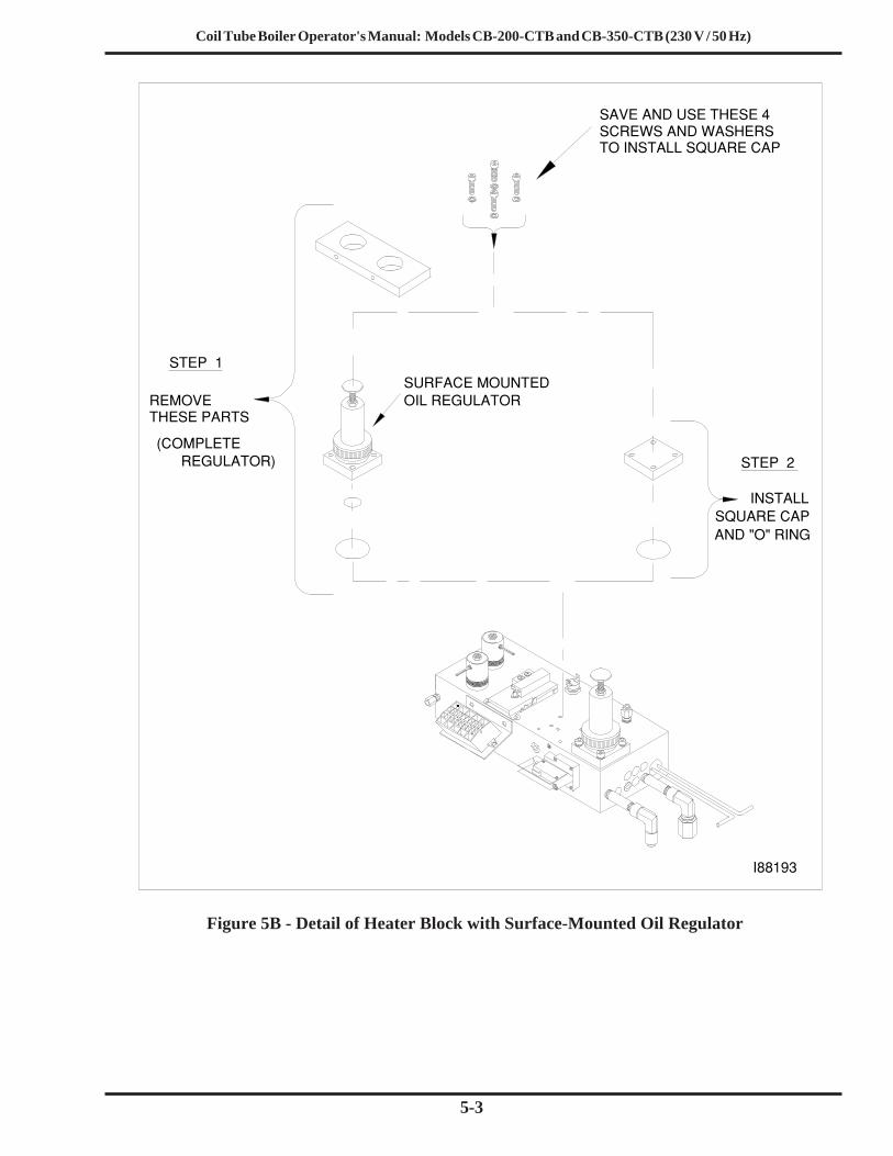
Coil Tube Boiler Operator's Manual: Models CB-200-CTB and CB-350-CTB (230 V / 50 Hz)
5-3
32
1
76
54
8
10
9
REMOVE THESE PARTS
STEP 2
INSTALL
STEP 1
SAVE AND USE THESE 4SCREWS AND WASHERS
SQUARE CAP
I88193
TO INSTALL SQUARE CAP
SURFACE MOUNTEDOIL REGULATOR
AND "O" RING
(COMPLETEREGULATOR)
Figure 5B - Detail of Heater Block with Surface-Mounted Oil Regulator

Coil Tube Boiler Operator's Manual: Models CB-200-CTB and CB-350-CTB (230 V / 50 Hz)
5-4
Priming the Metering Pump
Figure 5C - Priming the Metering Pump
ATTENTION: The priming process must be done precisely as described in this procedure to ensurethat all air is thoroughly bled from the system. Failure to bleed all air from the system will result inrepeated burner shutdowns on reset.
1. Refer to Figure 5C.2. Remove the 5/8" plug from the side of the pump head, and set it aside.3. Remove the 1/2" brass cap from the 1/2" brass nipple. Place a funnel in the opening. Slowly
pour used oil into the funnel until oil comes out of the side of the pump head; this will fill theoil line, canister filter, and pump head with oil.ATTENTION: NEVER run the pump head dry (i.e. without oil in the pump head). Doing so willseverely damage the pump.
4. Apply Permatex #2 non-hardening gasket sealer to the threads of the plug (removed from thepump head). Re-install the plug and tighten.
5. Apply Permatex #2 non-hardening gasket sealer to the threads of the 1/2" brass nipple. Re-installthe 1/2" brass cap on the brass nipple and tighten.
6. Open the bleeder on the pump two to three (2-3) full turns, and position a container to catch oilwhich will flow from the bleeder during pump priming.

Coil Tube Boiler Operator's Manual: Models CB-200-CTB and CB-350-CTB (230 V / 50 Hz)
5-5
7. Activating the PumpNOTE: The coil tube boiler features a priming switch which is mounted on the left-hand side ofthe electrical junction box on the front of the boiler cabinet. The priming switch has twopositions:• PRIME (switch is in the UP position / orange indicator light is ON): this is used only
for pump priming. When the switch is in the UP position, the pump circuit is activated forpriming. The pump will continue to run as long as the switch is in this position. The oilprimary control circuit is de-activated so the burner cannot run while the switch is in the UPposition.
• BURNER (switch is in the DOWN position): this is used for normal burner operation.When the switch is in the DOWN position, the burner controls the operation of the pump.The pump will only run while the burner is running.
a. Refer to Figure 5D to locate the priming switch.b. Turn the priming switch to the UP position. The pump should immediately start running.c. Run the oil pump until proper oil flow has been established and the oil lines have been
completely flushed out. (The following steps provide specific instructions.)
Priming the Metering Pump (continued)
Figure 5D - Detail of Burner Connections/Components
PRIMING LIGHT
OIL PUMP
AIR REGULATOR
AIR GAUGE
OIL GAUGE
CONNECTOR BLOCK
OIL LINECOMPRESSED AIR LINE
PRIMING SWITCHTHERMOSTAT TERMINAL
I88746
BURNER TERMINAL

Coil Tube Boiler Operator's Manual: Models CB-200-CTB and CB-350-CTB (230 V / 50 Hz)
5-6
Priming the Metering Pump (continued)
Vacuum Testing the Oil Pump
Vacuum testing the oil pump is a very accurate way to determine the following:• The condition of the pump -- the ability of the pump to pull a vacuum and suck oil from the tank.• The condition of the fittings, gaskets and seals from the ball valve to the pump -- these
components must all be airtight to avoid suction leaks.
The following procedure provides instructions for vacuum testing the pump and canister filter onsystems equipped with a ball valve.
ATTENTION: For the pump to pull and hold vacuum, it is critical that all fittings are airtight. If any of thesefittings are loose, the pump may not pull a vacuum or may lose the vacuum rapidly. It is also critical that allfittings in the suction line, including fittings on the canister filter, are 100% airtight.
1. Follow the instructions to prime the pump (previous procedure).NOTE: The pump will not pull a vacuum if the pump is dry. There must be oil in the gears ofthe pump before the pump can pull a vacuum.
2. With the pump running, open the bleeder two to three full turns, and make sure that oil is flowingfrom the bleeder. DO NOT close the bleeder yet.
3. Refer to Figure 5C. Close the ball valve and observe the vacuum gauge.NOTE: The ball valve must have a stainless steel ball and should be pressure tested by themanufacturer to ensure that it does not leak. If the ball valve leaks, the vacuum test will not beaccurate.
4. The vacuum should increase within 15 seconds to 15 inches of vacuum. When the vacuumgauge reads 15 inches of vacuum, first close and tighten the bleeder, then turn the pump off.NOTE: If the pump will not pull at least 15 inches of vacuum, there is a very serious suctionleak, or the pump is damaged.
8. Run the pump until a solid stream of oil flows from the pump bleeder. This will bleed all air outof the suction line, oil filter and pump head.ATTENTION: For the metering pump to operate correctly, it is very important that the systemis entirely full of oil and all air is bled out. The burner will shut down if there is any air in thesystem.
9. Close and tighten the bleeder on the pump.10. Turn the priming switch to the DOWN position so that the pump stops running.11. Disconnect the pressure oil line from the burner and position a container to catch oil which will flow
from the pressure oil line during pump priming.12. Turn the priming switch to the UP position. The pump should start running immediately .13. Run the oil pump until the proper flow of oil has been established, and the oil line has been completely
flushed out.14. Turn the priming switch to the DOWN position so that the pump stops running.15. Re-connect the oil line to the connector block.

Coil Tube Boiler Operator's Manual: Models CB-200-CTB and CB-350-CTB (230 V / 50 Hz)
5-7
Vacuum Testing the Oil Pump (continued)
5. If there are no suction leaks, the system will hold vacuum.NOTE: It is acceptable for the vacuum to drop one to five inches within one minute as the sealin the pump seats. The vacuum should then hold steady for 15 minutes.
ATTENTION: If the vacuum drops more than one to five inches within the first minute, there isone or more leaks somewhere between the pump and the ball valve. Do the following:
• Wipe your finger along the cylinder at the shaft of the pump. If there is oil here, the pumpseal is damaged. Replace the pump.
• Disassemble and clean all the fittings from the pump to the ball valve. Properly seal allfittings with Permatex #2 non-hardening gasket sealer or equivalent. Check the condition ofthe o-ring on the canister filter and tighten the four canister filter bolts in a crisscross pattern.
• Repeat the procedure to vacuum test the system to ensure that the system is air tight.

Coil Tube Boiler Operator's Manual: Models CB-200-CTB and CB-350-CTB (230 V / 50 Hz)
5-8

Coil Tube Boiler Operator's Manual: Models CB-200-CTB and CB-350-CTB (230 V / 50 Hz)
6-1
SECTION 6: STARTING AND ADJUSTING THE BURNERUnderstanding Burner Startup and Adjustment
ATTENTION: Before starting the burner, you must fill the coil tube boiler with water. Refer toSection 10 in this manual for more information on the hydronics system. DO NOT bypass the CTBcontrols to operate the burner!
ATTENTION: Please verify that the oil regulator has been removed from the burner as shown inFigure 6A. If the oil regulator has not been removed, please refer to Section 5 for the necessaryinstructions -- Preparing the Burner for Use with the Metering Pump. The metering pump willautomatically supply the correct flow (LPH) of fuel to the burner.
FOR DUAL-STACKED UNITS ONLY: Clean Burn recommends that you complete burner startupand adjustment for one burner before starting the second burner.
Starting and adjusting the burner involves a series of separate procedures which must be accomplishedin sequence without interruption. Review all the procedures before attempting burner startup andadjustment, paying careful attention to safety information statements.
The following procedure should be performed prior to burner startup to ensure that all key componentsof the hydronics system are functioning properly. Ensure that air is purged from the system. If the CTBcirculator becomes air-bound, it will not produce sufficient flow to activate the flow switch, and theburner will not start properly.
1. Turn the load temperature controller (i.e. thermostat or aquastat) OFF.2. Set the operating aquastat (on the CTB) at 71 to 93 oC (160 to 200 oF).
Preparing the Hydronics System for Burner Startup
Preparing the Burner for Startup
1. If you have not already done so, disconnect one wire from the terminal block at the "thermostat"connection. (This prevents the burner from running.) A wiring diagram is provided inAppendix D.
2. Turn the main power to the CTB ON (the green power light on the burner should be ON).3. Wait at least 15 minutes until the preheater block is thoroughly warmed up. Feel the back of
the burner box to make sure the preheater is sufficiently warm. The proving switch on thepreheater block will not allow the burner to start until the block is at least 48 oC (120 oF).
NOTE: The preheater block will remain warm as long as power is supplied to the burner. If themain power supply is ever turned OFF, you must wait at least 15 minutes until the preheaterblock is thoroughly warm before starting the burner.
(Continued)

Coil Tube Boiler Operator's Manual: Models CB-200-CTB and CB-350-CTB (230 V / 50 Hz)
6-2
Preparing the Burner forStartup (continued)
4. Refer to Figure 6A. Loosen thelocking nuts on the air regulator.
5. Turn the adjustment knobs on theair regulator counterclockwiseuntil 13 mm (1/2") of the threads onthe knob are exposed. DO NOTback the knob all the way out.NOTE: The air gauge will notshow any pressure until the burnerstarts. Before starting the burnerfor the first time, it is veryimportant to turn the air regulatorcompletely OFF as described.
6. Initial Adjustment of theCombustion Air BandRotate the combustion air bandto adjust it to the appropriate slotopening as listed in thefollowing Initial AdjustmentCharts. Use a ruler to accuratelyset the slot opening at the widestsection of the slot.
Figure 6A - Component Detail of theCB-500 Series Burner
WARNING: The combustion air band must be properly adjusted to ensure that the burnerignites and burns correctly. DO NOT attempt to start the burner with the combustion air band
wide open or completely closed. The burner may not ignite correctly. Failure to heed this warning mayresult in a fire or explosion hazard.
IMPORTANT NOTE: This initial setting of the combustion air band will allow you to start the burner.You will fine tune the combustion air band further as described later in these instructions.
ATTENTION: The settings shown in the charts below are only initial adjustments. Finaladjustments must be done by inspecting the flame length according to the illustrationsprovided on the following page.NOTE: The oil pressure is automatically adjusted by the metering pump.
Initial Adjustments for CB-200-CTBNOTE: Only Gearmotor part #33530 may be used with the CB-200-CTB.
Maximum Input = 59 KW (200,000 BTUH) @ 5.3 LPH (1.4 GPH) per CB-500 Series BurnerOil Type Oil Pressure/Flame Length Air Bar (PSI) Air Band Nozzle#2 Fuel Oil* check flame length 0.8-1.1 (12-16) 10 mm (3/8") 9-5Used Crankcase Oil check flame length 0.8-1.1 (12-16) 10 mm (3/8") 9-5Used ATF check flame length 0.8-1.1 (12-16) 10 mm (3/8") 9-5Used Hydraulic Oil check flame length 0.8-1.1 (12-16) 10 mm (3/8") 9-5#4 and #5 Fuel Oils check flame length 0.8-1.1 (12-16) 10 mm (3/8") 9-5
AIR REGULATOR
LOCKING NUT
AIR GAUGE
OIL GAUGE
COMBUSTIONAIR BAND
SLOT COVER INSTALLED

Coil Tube Boiler Operator's Manual: Models CB-200-CTB and CB-350-CTB (230 V / 50 Hz)
6-3
Starting the Burner
1. Re-connect the control wire. Turn the aquastat to call for heat (to start the burner).If the burner refuses to start, review the Preparing the Burner for Startupprocedure. If, after repeating this procedure, the burner still refuses to start, check the followingsystem components for proper functioning:
• Verify that the red wire (per the burner wiring diagram) is energized to 230VAC.• Reset the hi-limit switch.• If the flow switch is not closing, the circulator is air-locked. Air must be purged from the
system.• Verify that the prime switch (on the control box) is set to RUN (DOWN position).
2. Adjusting the Air Regulator:As soon as the burner starts running, turn the knob on the air regulator clockwise to achieveproper operating air pressure. Refer to the Initial Adjustment Charts.NOTE: If the safety reset on the primary control is activated and the burner stops running, seeSection 7 for further instructions on restarting you burner.
3. Observing the Flame Length:Visually inspect the flame length through theobservation port. Refer to Figure 6B for an illustrationof the desired flame length. The flame should extendno more than one-half of the way down the combustionchamber.
WARNING: The observation port gets hot as theburner fires. To avoid personal injury, always wear heavy
work gloves and safety glasses when opening the port and viewingthe flame.
CAUTIONWHEN OPENING INSPECTION PORT
PORT MAY BE HOTPROTECT HANDS
WEAR SAFETY GOGGLESKEEP FACE AWAY
OPEN PORT SLOWLY
Preparing the Burner for Startup (continued)
Initial Adjustments for CB-350-CTBNOTE: Only Gearmotor part # 33436 may be used with the CB-350-CTB.
Maximum Input = 103 KW (350,000 BTUH) @ 9.5 LPH (2.5 GPH) per CB-500 Series BurnerOil Type Oil Pressure/Flame Length Air Bar (PSI) Air Band Nozzle#2 Fuel Oil* check flame length 0.8-1.1 (12-16) 12 mm (1/2") 9-5Used Crankcase Oil check flame length 0.8-1.1 (12-16) 12 mm (1/2") 9-5Used ATF check flame length 0.8-1.1 (12-16) 12 mm (1/2") 9-5Used Hydraulic Oil check flame length 0.8-1.1 (12-16) 12 mm (1/2") 9-5#4 and #5 Fuel Oils check flame length 0.8-1.1 (12-16) 12 mm (1/2") 9-5
* If you are burning light viscosity oils such as #2 fuel oil, it may be necessary to install a smaller nozzle. Call yourClean Burn dealer for more information.

Coil Tube Boiler Operator's Manual: Models CB-200-CTB and CB-350-CTB (230 V / 50 Hz)
6-4
Figure 6B - Flame Length Adjustment
4. Check the flame length after the burner has fired for 15 minutes.5. Tighten the locking nuts on the air regulator.
I88372
Starting the Burner (continued)
Correct Maximum Flame Adjustment(Proper Oil and Air Pressure)
• Flame goes half of the way down thecombustion chamber.
• Flame does not touch back of walls ofcombustion chamber.
Incorrect Flame Adjustment(Not Enough Combustion Air)
• Flame must not touch back or walls ofcombustion chamber.
• Increase combustion air by opening theair band on the side of the burner.
Incorrect Flame Adjustment(Air Pressure too high)
• Ensure proper air pressure setting

Coil Tube Boiler Operator's Manual: Models CB-200-CTB and CB-350-CTB (230 V / 50 Hz)
6-5
Starting the Burner (continued)6. Checking for Proper CTB System Operation:
Observe the boiler temperature and water pressure.7. After the burner stops running when the operating aquastat set temperature is reached, check the
following:• air has been purged from water lines• water pressure is satisfactory (i.e. not greater than 1.5 bar (22 psi); normal pressure is
0.8 bar (12 psi)• all system controls functioning properly
8. Reset the operating aquastat to the normal operating range; 82 - 93 oC (180 - 200 oF) and repeat steps6 and 7, observing the CTB operation.
9. Reset the load temperature controller (i.e. thermostat or aquastat) to the normal operatingtemperature.
10. As the CTB temperature drops, the burner will start running. Continue observing the CTBoperation through several burner ON/OFF cycles to ensure proper system performance.
11. Fine Tuning the Combustion Air Band:NOTE: The initial setting of the combustion air band may require additional adjustment.
• Refer to Figure 6A to identify the combustion air band location on the burner.• Observe the flame. The flame should be yellow-white with sharp tips and no "sparkles."• If the flame is orange in color or the flame length is too long, the oil you are burning
requires MORE combustion air. OPEN the air band 3 mm (1/8") to 6 mm (1/4"), and re-checkthe flame for the proper characteristics.
• Re-check the flame after five minutes. You should see a yellow-white flame with sharptips and no "sparkles", and the flame should extend half of the way down the combustionchamber.
12. Checking for a Smokeless Burn:Check for a smokeless burn by observing the stack while the burner is running. If you see anysmoke, repeat the previous steps for setting the combustion air band and adjusting the airregulator. After adjusting the combustion air band, re-check the flame length.NOTE: Check for a smokeless burn periodically (as you do the flame length). Immediatelyreadjust the burner if you ever see smoke coming from the stack. Smoke indicates improper air/fuel adjustment.NOTE: When using instruments to adjust the burner for a smokeless burn, the followingreadings should be achieved:
• Draft over fire should be -.02 inch w.c.• Adjust for a smoke spot of a trace to 2• For the CB-350-CTB adjust for a CO2 reading of 8 to 10% or an O2 reading of 9 to 7%• For the CB-200-CTB adjust for a CO2 reading of 9 to 11.7% or an O2 reading of 8 to 5%• Cad cell reading of 200 to 500 ohms
NOTE: On the CB-200-CTB the flame can not be observed through the inspection door. TheCB-200-CTB must be adjusted with instruments for proper combustion. Obtain the above settingsby adjusting the air band 10 mm (3/8") to 13 mm (1/2"). The metering pump will deliver a constant oilflow and set the flame length.

Coil Tube Boiler Operator's Manual: Models CB-200-CTB and CB-350-CTB (230 V / 50 Hz)
6-6

Coil Tube Boiler Operator's Manual: Models CB-200-CTB and CB-350-CTB (230 V / 50 Hz)
7-1
SECTION 7: RESETTING THE OIL PRIMARY CONTROL
Understanding the Danfoss Oil Primary Control (CB-200-CTB)
The oil primary control will shut the oil pump and oil solenoid off when it detects flame-out during burneroperation. The oil primary control will then wait approximately 15 seconds (while the burner motor, airsolenoid, and transformer are energized) and attempt to re-ignite the burner (recycle mode). If the burner doesnot re-ignite, the control will shut the burner off on safety lock-out. The following procedure explains whatshould be done when this occurs. It is very important that you follow these instructions precisely whenresetting the safety on the primary control and restarting the burner.
Resetting the Danfoss Oil Primary Control (CB-200-CTB)
DANGER! DO NOT reset the oil primary control if oil mist is present in the combustionchamber or when the combustion chamber is hot! DO NOT operate your CTB if excess oil,
oil vapor or fumes have accumulated in or near your boiler. As with any oil burning appliance, improperoperation may result in a fire or explosion hazard.
1. Refer to Figure 7A.2. Allow 5 to 10 minutes for all fuel mist to exhaust from the combustion chamber.3. If the combustion chamber is hot, allow the boiler to cool for at least 30 minutes. DO NOT
push the reset button.4. When you are sure that all fuel mist has cleared and the boiler has cooled, push in and hold the
reset button for three seconds, then release. This will reset the control at any time during its operation.5. If the burner will not restart, call your Clean Burn dealer immediately.
Figure 7A - Danfoss Oil Primary ControlCB-500-CE-5W Burner (CB-200-CTB)
I88853

Coil Tube Boiler Operator's Manual: Models CB-200-CTB and CB-350-CTB (230 V / 50 Hz)
7-2
Understanding the Honeywell Oil Primary Control (CB-350-CTB)
The oil primary control will go into safety lock-out and shut the burner off when it detects flame-outduring burner operation. The following procedure explains what should be done when this occurs. It is veryimportant that you follow these instructions precisely when resetting the safety on the primary controland restarting the burner.
Resetting the Honeywell Oil Primary Control (CB-350-CTB)
DANGER! DO NOT reset the oil primary control if oil mist is present in the combustionchamber or when the combustion chamber is hot! DO NOT operate your CTB if excess oil,
oil vapor or fumes have accumulated in or near your boiler. As with any oil burning appliance, improperoperation may result in a fire or explosion hazard.
1. Refer to Figure 7B.2. Check the combustion chamber for fuel mist by shining a flashlight through the observation port.
If you see fog (fuel mist) in the chamber, DO NOT push the reset button.3. If the combustion chamber is hot, allow the furnace to cool for at least 30 minutes. DO NOT
push the reset button.4. When you are sure that all fuel mist has cleared and the boiler has cooled, push in and hold the
reset button for three seconds, then release. This will reset the control at any time during its operation.5. If the burner will not restart, call your Clean Burn dealer immediately.
ATTENTION: It is veryimportant that the "F" and"T" terminals of the OilPrimary Control are wiredexactly as shown in Figure 7A.NEVER connect jumper wiresto these terminals or severedamage may occur to the OilPrimary Control.
Figure 7B - Honeywell Oil Primary ControlCB-551-CE Burner (CB-350-CTB)
RESET BUTTON
CAD CELL WIRES
THERMOSTAT WIRES
I88373
TT
FF

Coil Tube Boiler Operator's Manual: Models CB-200-CTB and CB-350-CTB (230 V / 50 Hz)
8-1
SECTION 8: ADJUSTING THE DRAFT OVER FIRE
Understanding the Importance of Draft
Draft in the Coil Tube Boiler is created as the hot combustion gases rise up the stack, creating a negativepressure inside the stack and the boiler. This negative pressure is measured as inches of water column(W.C.) of draft. A proper draft overfire of -.02 w.c. is essential so that all combustion products travelaway from the burner, down the combustion chamber, through the boiler flues and up the stack.
Checking for Correct Draft Over Fire
NOTE: Your coil tube boiler is equipped with an observation/draft reading port to check draft over fire. Aqualified serviceman with proper equipment must adjust your CTB for proper draft. Contact your CleanBurn dealer for this service.
1. Insert the probe of the draft gaugeinstrument into the draft reading port in theobservation port as shown in Figure 8A.
2. Adjust the barometric damper to achievethe required draft over fire of -0.02 w.c.(water column).
3. Record the reading in the MaintenanceRecord located in the Appendixes.
4. If correct draft over fire cannot be achieved,contact your Clean Burn dealerimmediately.ATTENTION: Only operate your CTBwith a draft over fire of -0.02 w.c. Poordraft results in back pressure and poorburner performance. DO NOT operate yourCTB with a draft over fire greater than-0.04 w.c.; an abnormally high stacktemperature may result from a draft over firethat is too high.
ATTENTION: Backdraft must be resolved oryour boiler will not operate correctly!Under backdraft conditions, draft overfire readingswill show positive pressure in the combustion chamber.Backdraft means that oil spray,combustion products, and heat are blown back against the burner. Backdraft results in oil-fouledretention heads and electrodes. Severe backdraft will force heat back against the burner and result inheat damage to the cad cell and transformer.
I88257
Figure 8A - Checking for ProperDraft Over Fire

Coil Tube Boiler Operator's Manual: Models CB-200-CTB and CB-350-CTB (230 V / 50 Hz)
8-2
Checking for Correct Draft Over Fire (continued)
Backdraft is caused by the following conditions:• Poor draft caused by improper stack design. (See Section 4.)• Poor draft caused by improper adjustment of the barometric damper.• Incorrect combustion air band setting on the burner. (See Section 6.)• Boiler flues are plugged with ash. (See Section 9.)• Improper seal on clean-out door on back panel. (See Section 9.)• Exhaust fans in your building are sucking gases down the stack.
Understanding the Effect of Exhaust Fans on Draft
Any type of exhaust fan, paint booth, or exhaust system in a building will create negative pressure in thebuilding unless there is a source of make-up air (i.e. fresh air which enters the building and replaces theair removed by the exhaust fans.)
If there is insufficient make-up air, the exhaust fan will suck air and combustion gases down the coiltube boiler stack and create backdraft in the boiler. After the burner is shut down, the backdraft maysuck the residual heat out of the combustion chamber and into the burner causing damage to the burner.Even if the exhaust fan is on another level of the building or in another room away from the boiler, theexhaust fan will still create backdraft at the boiler.
Checking Draft Overfire to Determine Severity of Backdraft
The following procedure is an accurate method of determining how much backdraft is created by theexhaust fans. Once this is determined, you can select the correct method for resolving the backdraft.
1. Turn off ALL exhaust fans and close ALL doors and windows in the building (any open door orwindow will allow make-up air to enter the building and will negate the test).
2. Start the coil tube boiler and adjust the barometric damper so that the draft overfire is -.02 w.c.3. Check the draft overfire again. Now have someone start the exhaust fans.4. Note how much the draft overfire has changed.
ATTENTION: If the draft overfire changed towards positive, it is mandatory that make-up airis provided to the building or severe damage to the boiler and burner will occur. If the draft overfireremained constant at -.02 w.c., there is sufficient make-up air entering the building, and the exhaust fanis not adversely affecting the draft.

Coil Tube Boiler Operator's Manual: Models CB-200-CTB and CB-350-CTB (230 V / 50 Hz)
8-3
Correcting Backdraft
The CTB system designer/installer must ensure that there is the proper amount of combustion air in theboiler/mechanical room.
Combustion Air is the required amount of air that the equipment needs to permit the satisfactorycombustion of oil, the proper venting of combustion gases, and to maintain a safe ambient temperaturewithin the space at safe limits under normal conditions of use.
The following requirements should be followed for proper supply of combustion air:
Units located in confined spaces (units in a boiler room/mechanical room) must have two (2)permanent openings, one near the top of the enclosure and one near the bottom of the enclosure -as follows:
1. If all of the air is taken directly from the outside of the building by use of vertical ducts -must have a total free area of not less than 225 cm2 (35 in2) per gallon of oil of the totalappliance(s) input rating
2. If all of the air is taken directly from the outside of the building by use of horizontal ducts- must have a total free area of not less than 450 cm2 (70 in2) per gallon of oil of the totalappliance(s) input rating
3. If all of the air is taken directly from inside of the building - must have a total free area ofnot less than 900 cm2 (140 in2) per gallon of oil of the total appliances(s) input rating
NOTE: An optional draft inducer (according to local codes only) may be added to help correct backdraft.
CAUTION: Under no circumstances should the equipment room ever be under a negativepressure. Look for exhaust fans, compressors, air handling units, or anything else that may take
air away from the boiler. Also look for chemical fumes, solvents, refrigerants, etc. that may be in usearound the boiler and cause damage to it.

Coil Tube Boiler Operator's Manual: Models CB-200-CTB and CB-350-CTB (230 V / 50 Hz)
8-4

Coil Tube Boiler Operator's Manual: Models CB-200-CTB and CB-350-CTB (230 V / 50 Hz)
9-1
SECTION 9: MAINTENANCEUnderstanding MaintenanceMaintaining your Clean Burn CTB is an important activity which includes several periodic maintenanceactivities and an annual burner tune-up...all are necessary to keep your boiler running in peak condition.
WARNING: Failure to maintain and/or improper servicing by unqualified personnel mayadversely affect the proper, safe operation of your coil tube boiler, may reduce the service
life of your boiler, and may void your warranty.
The following chart summarizes all the maintenance activities which should be performed on the CTB atthe intervals indicated. Instructions/procedures for these activities are included in this chapter.
Maintenance Activity IntervalCleaning the canister filter Before vacuum gauge reads 10" HG of vacuumServicing the metering pump At least once a yearCleaning the check valve/screen At least once a yearCleaning water/sludge out of oil tank At least once a yearCleaning out ash CB-200-CTB* Approx. every 750 hrs. per burner hour meterCleaning out ash CB-350-CTB* Approx. every 1000 hrs. per burner hour meterChecking boiler water condition Periodically by qualified water treatment companyAnnual burner tune-up At least once a year
*It is very important to clean the ash from the CTB on schedule. Normal use of the boiler requiresclean-out at least twice during the heating season. Heavy, around-the-clock usage requires morefrequent clean-out (e.g. one month of continual running of the boiler is 720 hours).
NOTE: IMPORTANT! Record all maintenance activities in the Maintenance Record provided in theAppendixes.
Annual Preventative Maintenance and Burner Tune-up
The Clean Burn CTB requires annual preventative maintenance. The burner also requires an annualtune-up to keep it running in peak condition. The burner tune-up should be performed by a qualifiedClean Burn service technician who has the necessary parts and expertise.
Contact your local Clean Burn dealer to schedule the annual maintenance for your boiler. Variouslevels of service are provided to fit your particular need. This work is usually performed during thewarm-weather months to prepare the boiler for the next heating season.
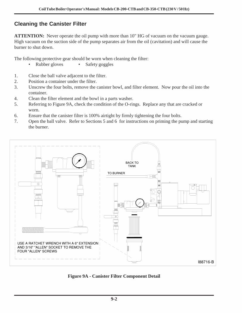
Coil Tube Boiler Operator's Manual: Models CB-200-CTB and CB-350-CTB (230 V / 50 Hz)
9-2
Cleaning the Canister Filter
ATTENTION: Never operate the oil pump with more than 10" HG of vacuum on the vacuum gauge.High vacuum on the suction side of the pump separates air from the oil (cavitation) and will cause theburner to shut down.
The following protective gear should be worn when cleaning the filter:• Rubber gloves • Safety goggles
1. Close the ball valve adjacent to the filter.2. Position a container under the filter.3. Unscrew the four bolts, remove the canister bowl, and filter element. Now pour the oil into the
container.4. Clean the filter element and the bowl in a parts washer.5. Referring to Figure 9A, check the condition of the O-rings. Replace any that are cracked or
worn.6. Ensure that the canister filter is 100% airtight by firmly tightening the four bolts.7. Open the ball valve. Refer to Sections 5 and 6 for instructions on priming the pump and starting
the burner.
Figure 9A - Canister Filter Component Detail
I88716−B
USE A RATCHET WRENCH WITH A 6" EXTENSIONAND 3/16" "ALLEN" SOCKET TO REMOVE THEFOUR "ALLEN" SCREWS
TO BURNER
BACK TOTANK

Coil Tube Boiler Operator's Manual: Models CB-200-CTB and CB-350-CTB (230 V / 50 Hz)
9-3
Servicing the Metering Pump
1. Refer to Figure 9B.2. Remove the pump head cover (part 1).3. Remove the screen (part 2) and wash it.4. Remove and discard the used gasket (part 3).5. Install a new gasket (Clean Burn Part #32422).6. Replace the screen and pump head cover.
Figure 9B - Servicing the Metering Pump
3
2
1
PART No 32423
PART No 32422

Coil Tube Boiler Operator's Manual: Models CB-200-CTB and CB-350-CTB (230 V / 50 Hz)
9-4
Cleaning the Check Valve / Screen
This procedure applies to coil tube boiler installations with inside and outside tanks. The followingprotective gear should be worn when cleaning the check valve/screen:
• Rubber gloves• Safety goggles
1. Refer to Figure 9C. Remove the one-piece suction oil line from the tank.2. Remove the check valve and screen. Clean these components in a parts washer.3. Check the operation of the check valve. The valve must seat so it is airtight to hold pump prime.4. Re-assemble and re-install the components. Apply Permatex #2 non-hardening gasket sealer or
equivalent to the threaded fittings. Firmly tighten all connections so the suction line is 100%airtight.
5. Follow pump priming instructions in Section 5 to re-establish prime.
Figure 9C - Check Valve Detail
VENTCAP
METERING PUMP
SUCTION OIL LINE
CHECK VALVE SCREEN
945 LITER TANK(250 GALLONS)CLEANOUT
CHECK VALVE
FUNNEL WITHBALL VALVE
TO BURNER
EMERGENCYVENT
I88717−B

Coil Tube Boiler Operator's Manual: Models CB-200-CTB and CB-350-CTB (230 V / 50 Hz)
9-5
Cleaning the Ash from the Coil Tube Boiler
ATTENTION: Your CTB may require frequent clean out of the ash due to contaminants in the oil orheavy use. As ash accumulates, CTB heat output declines, and the stack temperature rises. 3 mm (1/8") of ashhas the insulating capacity of 2.5 cm (1") of fiberglass insulation and reduces heat transfer significantly. Neverallow more than 6 mm (1/4") of ash to accumulate in the combustion chamber heat exchanger flues or stack.
The following protective gear should be worn when cleaning the ash:• Respirator for fine particles • Rubber gloves• Safety goggles • Protective clothing
1. Ensure that power has been turned OFF, and all "hot" components have been allowed to coolsufficiently. Shop air should be turned OFF and disconnected. Allow at least one hour for theceramics to cool.
2. Clean the ash from the combustion chamber (see Figure 9D):a. Bleed-down pressure on the air and oil lines by slightly loosening the fittings at the bottom of
the connector block.b. With air and oil pressure completely bled off, disconnect the air and oil pressure lines from
the bottom of the connector block. NOTE: Cover these lines to keep dirt from entering theair/oil supply.
c. Remove the lock nuts on the clean-out door.d. Carefully swing open the clean-out door to expose the coiled heat exchanger, flue passages,
and the combustion chamber.e. Remove the two ceramic sleeve half-pieces from the combustion chamber, and remove the
supporting ceramic stand pieces.f. Use a wire or bristle brush to thoroughly clean out the ash from the combustion chamber and
flue passages.g. While cleaning out the combustion chamber, also check the burner retention head and throat.
Carefully clean these elements.
I88123
Figure 9D - Accessing the Combustion Chamber for Cleaning
ATTENTION: When cleaning thecombustion chamber, ensure thatyou do not gouge or damage therefractory material on the inside ofthe clean-out door and target wall.DO NOT bump or bend burnercomponents while cleaning thecombustion chamber.
Coil Tube Boiler Operator's Manual: Models CB-200-CTB and CB-350-CTB (230 V / 50 Hz)
9-6
End of Season Maintenance
Turn main power to your coil tube boiler OFF at the end of the heating season. Environmental regulations allowyour used oil to be burned only for "heat recovery." DO NOT operate your boiler during warm weather just toburn oil. Contact your local Clean Burn dealer to schedule your annual burner tune-up. Allow onlytrained, authorized service personnel to service your burner.
In the "off" season after the boiler has been cleaned, spray the combustion chamber with a light coat ofoil to reduce corrosion caused by moisture in the air.
NOTE: If the CTB is not used during the cold-weather months, it must be protected to prevent damagefrom freezing temperatures.
Cleaning the Ash (continued)
(2.) h. Thoroughly vacuum any remaining ash residue from the flue passages. A long wand on thehose of your shop vac is helpful in reaching all the way back.
i. Inspect the combustion chamber and its components to ensure that it is in good condition.Inspect the inside of the clean-out door and target wall. Make sure the refractory material onthe inside of the door is in good condition, and the door seals tightly when closed. If thedoor does not seal tightly, replace any damaged components.
3. Clean the ash from the stack components:a. Brush accumulated ash from the stack cap.b. Lightly tap the stack components to loosen the ash.c. Allow ash and dust to settle in the clean-out tee or elbow, then vacuum out.d. Disconnect the stack from the CTB breach.e. Thoroughly vacuum out the back of the boiler, including the boiler breach (through the
breach). If desired, the back panel can be removed for cleaning.ATTENTION: When handling the front door and rear panel, be careful that you do not damagethe insulation seal surfaces. Two technicians may be required to remove and install the rearpanel safely. The panel weighs approximately 39 Kg (85 lbs).
4. Reassemble the boiler components (ceramic stand, ceramic sleeve half-pieces, back panel, etc.)If necessary, refer to Section 3 for additional Assembly information.
5. Close the clean-out door, install and tighten the washer and nuts. Make sure that the clean-outdoor and rear panel close and seal properly. Reconnect all disconnected lines (oil and air) on thebottom of the connector block.NOTE: You may need to bleed air from the oil line before starting the burner. See Section 5for pertinent instructions.
Cleaning the Oil Tank
DO NOT allow water, sludge, or other debris to accumulate in your oil supply tank to the point thatnon-combustible or harmful materials are drawn into the pump or burner.
Drain water and sludge from the bottom of your tank at least once a year, and more frequently withwater accumulation.

Coil Tube Boiler Operator's Manual: Models CB-200-CTB and CB-350-CTB (230 V / 50 Hz)
10-1
SECTION 10: THE CTB HYDRONIC SYSTEMUnderstanding the CTB Hydronic System
The Clean Burn Coil Tube Boiler (CTB) is designed to function as a low-mass boiler (i.e. it will notmaintain boiler water temperature when there is no call for heat). Low-mass boilers require that asufficient, constant flow of water be maintained through the coil in order to: (a) remove the heat fromthe boiler when the burner is firing AND (b) prevent the flow switch from shutting off the burner.
IMPORTANT NOTE: When designing the system layout and application for your CTB, keep in mindthat it is NOT suitable for open systems. The Clean Burn CTB has been designed to operate as a closed loopboiler system. Potable water heating (i.e. for domestic or washing purposes) can be accomplished by incorpo-rating a heat exchanger into the system.
Special Safety Guidelines for the Design and Installation of Hydronic Systems
Adhere to the following Safety Guidelines when designing and setting up the CTB hydronics system:
• The CTB must be installed on non-combustible flooring.
• The CTB must be installed in accordance with national, state, and local plumbing, heating,and electrical codes and the regulations of the serving utilities which may differ from thismanual. Authorities having jurisdiction should be consulted before installations are made.In all cases, reference should be made to all aplicable standards.
• The heating system must be designed by a competent hydronics contractor, and only personsknowledgeable in the layout and installation of hydronic heating systems should install thisboiler.
• The boiler must be connected to an approved chimney in good condition. Serious propertydamage could result if the boiler is connected to a dirty or inadequate chimney. The interiorof the chimney flue must be inspected periodically through the heating season for anyobstructions. A clean and unobstructed chimney flue is necessary to allow noxious fumesthat could cause serious injury to vent safely and will contribute toward maintainingthe boiler's efficiency.
• It is the responsibility of the installing contractor to see that all controls are correctlyinstalled and are operating properly when the installation is completed.
• To ensure optimum performance, qualified personnel must perform proper and timelymaintenance on the CTB according to the procedures provided in Section 9 of this manual.

Coil Tube Boiler Operator's Manual: Models CB-200-CTB and CB-350-CTB (230 V / 50 Hz)
10-2
CTB System Function and Configuration
Water Flow and TemperatureThe Clean Burn Coil Tube Boiler design requires continuous water flow through the boiler heatexchanger to ensure proper system operation. The boiler circulator must be capable of developingsufficient (head) pressure to overcome the resistance of the boiler plus the circulating system at therequired flow rate. If the water flow through the boiler is too low, the flow switch will not allow theburner to operate. (Refer to Appendix A, as needed, for CTB system specifications.)
Heating systems using zone valves, zone pumps, or three-way valves may experience reduced waterflow through the boiler. This condition can cause excessive water temperature rise and unstable boileroperation. The normal temperature rise across the boiler is 11 oC(20 oF). Minimum operating temperaturefor the CTB is 71 oC (160 oF). To avoid condensation, the return water temperature should not fall below60 oC (140 oF).
System PressureThe Clean Burn CTB is designed to operate in closed, pressurized hydronic systems. Certain levels of pressureare required for proper system operation--a minimum of 0.8 bar (12 PSI) should be maintained on thesystem where the boiler supply water temperature is 93 oC (200 oF) or less. If a higher working pressureis required, contact the Clean Burn Service Department for proper pressure requirements.
Sample System Configuration: Primary/Secondary Pumping SystemA sample hydronic system setup using Clean Burn Coil Tube Boilers is shown in Figure 10A. Thissystem, a Primary/Secondary Pumping System, allows for many special hydronic requirements (e.g.water return temperatures below the normal 60 oC (140 oF), variable flow zones, multiple zones, multi-tempera-ture systems, and/or multiple boilers) and provides maximum flexibility while maintaining optimal system func-tioning. A critical advantage of this type of system is that it dramaticallyreduces the danger of thermal shock to the boiler.
In a Primary/Secondary Pumping System (as shown in Figure 10A), the primary loop circulator runswhen any of the zones call for heat. In some system setups, the circulator may run continuously duringthe heating season. The circulator pushes hot water past the zone tees; any of the secondary zone pumpscan draw hot water out of the first tee (as though the tee were a boiler). Each zone then returns coolerwater through the second tee where it mixes with the hot water being pushed through by the primaryloop circulator. The close positioning of the two zone tees is crucial to the operation of the system;the tees must be at least 15 cm (6") but not more than 31 cm (12") apart. This allows for circulators ofdifferent flow rates to be used in the same system while maintaining proper flow and functioning.

Coil Tube Boiler Operator's Manual: Models CB-200-CTB and CB-350-CTB (230 V / 50 Hz)
10-3
PR
IMA
RY
AIR
SE
PA
RA
TO
R
BA
SE
BO
AR
D Z
ON
E
RA
DIA
NT
FLO
OR
LO
OP
ER
GO
MA
X
3−W
AY
MIX
ING
OR
TE
MP
ER
ING
V
ALV
E
EX
PA
NS
ION
TA
NK
FIL
L V
ALV
E
SE
CO
ND
AR
Y L
OO
PS
NO
MO
RE
TH
AN
12"
(31c
m)
AP
AR
T
CO
NC
EP
TU
AL
SC
HE
MA
TIC
:T
HE
DE
SIG
NE
R M
US
T D
ET
ER
MIN
E IF
IT W
ILL
WO
RK
W
ITH
IN T
HE
SY
ST
EM
AN
D E
NS
UR
E C
OM
PLI
AN
CE
W
ITH
EX
IST
ING
CO
DE
S
I887
59
CO
LDS
UP
PLY
WA
TE
R
DO
ME
ST
ICH
OT
WA
TE
R
IND
IRE
CT
WA
TE
RH
EA
TE
R
UN
IT H
EA
TE
RH
YD
RO
NIC
CB
350
CT
B
PR
IMA
RY
LO
OP
CIR
CU
LAT
OR
PR
IMA
RY
/SE
CO
ND
AR
Y S
YS
TE
MW
ITH
MU
LTIP
LE O
R S
ING
LE B
OIL
ER
S
EN
HA
NC
ED
TY
PE
OP
TIO
NA
L
HE
AT
EX
CH
AN
GE
R A
ND
CIR
CU
LAT
OR
MA
Y B
ER
EQ
UIR
ED
IF A
NT
IFR
EE
ZE
IS U
SE
D IN
TH
E R
AD
IAN
T
FLO
OR
LO
OP
CB
350
CT
B
CB
350
CT
B
LO
OP
CO
LDW
AT
ER
EX
PA
NS
ION
TA
NK
PU
RG
ING
VA
LVE
Figu
re 1
0A -
Sam
ple
Prim
ary/
Seco
ndar
y H
ydro
nic
Syst
em D
iagr
am

Coil Tube Boiler Operator's Manual: Models CB-200-CTB and CB-350-CTB (230 V / 50 Hz)
10-4
CTB Setup Options
When designing and setting up the CTB Hydronic System, please be aware of the following options andspecial setup requirements:
(1) The optional circulator (which you may have ordered from Clean Burn for your CTB system) issized to ensure a flow of water through the coil tube ONLY; it is NOT sized to be used as a systemcirculator. An additional circulator must be installed to flow water through the system and to the boiler.
(2) In low load conditions, Clean Burn recommends the installation of a larger storage tank next to theCTB to extend the run time and to reduce the occurrence of short cycling. Position the tank close to theboiler to reduce the required connective piping as shown in sample configuration, Figure 10B.
(3) If hot water is required in the system installation for washing or other related activities, CleanBurn offers Ergomax Heat Exchangers/Storage Tanks in 182, 273, and 450 liter sizes (48, 72, and 119gallon sizes). Contact your local Clean Burn representative for additional details on these CTB system com-ponents. Refer to Figure 10C for a sample system configuration using an Ergomax Heat Exchanger. Thisconfiguration is ideal for installations requiring pressure washing, car/truck washing, etc. The Ergomax unitworks well with a CTB because it stores boiler water in the tank and acts as a buffer (tempering) tank whileenabling reduction of short cycling.

Coil Tube Boiler Operator's Manual: Models CB-200-CTB and CB-350-CTB (230 V / 50 Hz)
10-5
Figu
re 1
0B -
Mod
el C
B-3
50-C
TB
with
Add
ition
al L
arge
r St
orag
e T
ank
ISO
LAT
ION
VA
LVE
TH
E D
ES
IGN
ER
MU
ST
DE
TE
RM
INE
IF T
HIS
SY
ST
EM
CO
NC
EP
TU
AL
SC
HE
MA
TIC
:
WIL
L W
OR
K W
ITH
IN T
HE
SY
ST
EM
AN
D
EN
SU
RE
CO
MP
LIA
NC
E W
ITH
EX
IST
ING
CO
DE
S
AIR
SE
PA
RA
TO
RE
NH
AN
CE
D T
YP
E
(BO
ILE
R W
AT
ER
)
ST
OR
AG
ET
AN
K
AIR
ELI
MIN
AT
OR
FIL
L V
ALV
E
SY
ST
EM
SU
PP
LY
PU
RG
E V
ALV
E
I887
48−A
OP
TIO
NA
L B
OIL
ER
CIR
CU
LAT
OR
SY
ST
EM
R
ET
UR
N
SY
ST
EM
SU
PP
LYC
IRC
ULA
TO
R
WA
TE
RC
OLD

Coil Tube Boiler Operator's Manual: Models CB-200-CTB and CB-350-CTB (230 V / 50 Hz)
10-6
Figu
re 1
0C -
CB
-350
-CT
B w
ith E
rgom
ax In
dire
ct W
ater
Hea
ter
TH
E D
ES
IGN
ER
MU
ST
DE
TE
RM
INE
IF T
HIS
SY
ST
EM
CO
NC
EP
TU
AL
SC
HE
MA
TIC
:
WIL
L W
OR
K W
ITH
IN T
HE
SY
ST
EM
AN
D
EN
SU
RE
CO
MP
LIA
NC
E W
ITH
EX
IST
ING
CO
DE
S
WA
TE
R H
EA
TE
R
ER
GO
MA
X
HE
AT
EX
CH
AN
GE
R
WA
TE
RIN
LET
HO
T W
AT
ER
OU
TLE
T
I887
49−A
CO
LDW
AT
ER
OP
TIO
NA
L B
OIL
ER
CIR
CU
LAT
OR
ISO
LAT
ION
VA
LVE
PU
RG
E V
ALV
E
AIR
ELI
MIN
AT
OR
EN
HA
NC
ED
TY
PE
AIR
SE
PA
RA
TO
R
FIL
L V
ALV
E

Coil Tube Boiler Operator's Manual: Models CB-200-CTB and CB-350-CTB (230 V / 50 Hz)
10-7
Guidelines for CTB Setup and Operation
1. Refer to the appropriate illustration in this section for your CTB system configuration, as well asFigures 4A/4B in the Installation chapter.
2. Connect the supply and return piping to the heating system. (Additional information inSection 4).CAUTION: Hot water pipes shall have clearances of at least 13 mm (1/2") from all combustiblesurfaces. For additional technical reference material, see I=B=R Installation and Piping GuideNo. 200.
3. The relief valve must be installed with the spindle in the vertical position. The relief valvedischarge pipe must be extended to within four inches of the floor or to a drain.
4. To reduce the amount of cold water returned to the boiler (and to protect the boiler from thermalshock), a return blend loop should be utilized.
5. Fill the entire heating system with water and vent air from the system according to the followinginstructions:(a) Close the isolation valve in the boiler supply piping.(b) Isolate all circuits by closing the zone valves or balancing valves.(c) Attach a hose to the purge valve located just below the isolation valve in the boiler supply
piping.NOTE: Ensure that the end of the hose drains into a bucket located in a drain area oroutside.
(d) Starting with one circuit, open the first zone valve ONLY.(e) Open the purge valve.(f) Open the fill valve (the make-up water line should be located on the system side of the
isolation valve in the boiler supply piping.)(g) Allow water to overflow from the bucket until discharge from the hose is bubble-free.
ATTENTION: Air in the hose may cause the hose to "jump" and water to spray out;ensure that the area (and equipment nearby) is protected from any possible water damage.
(h) Open the zone valve to the second zone to be purged, then close the first. Repeat this stepuntil all zones have been purged, but always have one zone open. At completion, open allzone valves.
(i) Close the purge valve, continue filling the system until the pressure gauge reads 0.8 bar (12 psi).Close the fill valve.NOTE: If the make-up water line is equipped with a pressure reducing valve, the systemwill automatically fill to 0.8 bar (12 psi).
(j) Open the isolation valve in the boiler supply piping.(k) Remove the hose from the purge valve.(l) As soon as the boiler is filled, heat the water in the boiler to 82 oC (180 oF) to de-aerate the
water.

Coil Tube Boiler Operator's Manual: Models CB-200-CTB and CB-350-CTB (230 V / 50 Hz)
10-8
Guidelines for Preventing Oxygen Contamination
ATTENTION: Oxygen contamination of boiler water will cause corrosion of iron and steel boilercomponents, and can lead to boiler failure (and void warranty). Causes of oxygen contaminationinclude:
• Addition of excessive make-up water as a result of system leaks• Absorption through open tanks and fittings• Oxygen permeable material in the distribution system
To ensure optimal CTB maintenance and operation, follow these recommendations to eliminatedamaging oxygen contamination:
• Repair system leaks to eliminate the need for the addition of make-up water• Eliminate open tanks from the system• Eliminate and/or repair leaky fittings• Use non-permeable materials in the distribution system• Isolate the boiler from the water heater system (i.e. wash and potable waters) by installing a
heat exchanger.
Guidelines for Initial Cleaning of the Hydronics System and Maintaining Water Quality
• Clean the boiler with an alkaline cleaner (e.g. soda ash or detergent) as recommended by aqualified water treatment company.NOTE: This is necessary to remove oil or other coatings from the tube surfaces. Theseprotective coatings are commonly applied to new tubes to prevent rusting during storage/transit and will cause corrosion if left on the tubes during operation of the boiler.
• After cleaning the boiler, drain the system in a manner and to a location that hot water can bedischarged safely.
• Remove plugs from all available locations, and wash the water side of the boiler asthoroughly as possible using a high-pressure water stream.
• Refill the system with fresh water.• Test the pH of the water in the system. The pH should be higher than 8.5 but lower than 9.5.
Add appropriate boiler water treatment compounds as recommended by your qualified watertreatment company (if necessary) to bring the pH within the specified range.
• Heat the water in the boiler to 82 oC (180 oF) to de-aerate the water.
Guidelines for CTB Operation
After proper and safe CTB boiler setup and installation has been accomplished, CTB operationproceeds as follows:
(a) Refer to Section 6 for instructions on starting the CTB.(b) Following burner startup, set the operating control dial at 82 - 93 oC (180 - 200 oF).
ATTENTION: If, during normal operation, it is necessary to add water to your system more thanonce a year, consult a qualified service technician to check your system for leaks. A leaky system willincrease the volume of make-up water supplied to the boiler which can significantly shorten the life ofthe boiler and cause damage to the boiler.
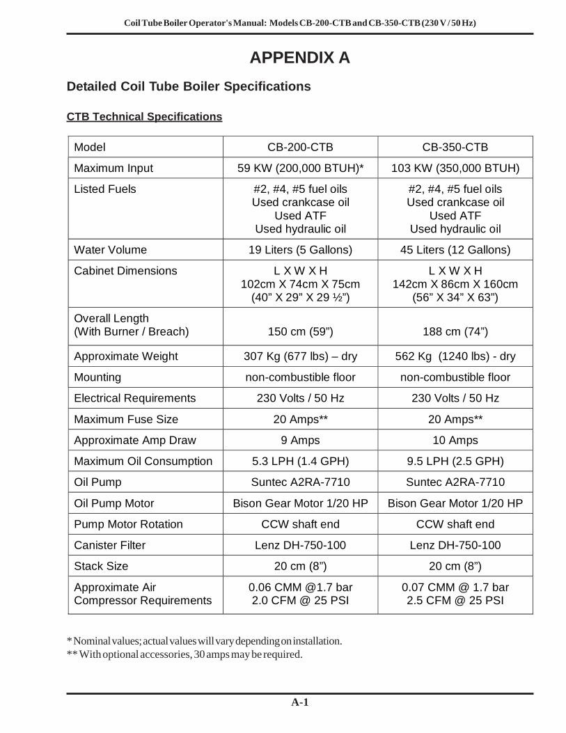
Coil Tube Boiler Operator's Manual: Models CB-200-CTB and CB-350-CTB (230 V / 50 Hz)
A-1
APPENDIX ADetailed Coil Tube Boiler Specifications
CTB Technical Specifications
* Nominal values; actual values will vary depending on installation.** With optional accessories, 30 amps may be required.
Model
CB-200-CTB
CB-350-CTB
Maximum Input
59 KW (200,000 BTUH)*
103 KW (350,000 BTUH)
Listed Fuels
#2, #4, #5 fuel oils Used crankcase oil
Used ATF Used hydraulic oil
#2, #4, #5 fuel oils Used crankcase oil
Used ATF Used hydraulic oil
Water Volume
19 Liters (5 Gallons)
45 Liters (12 Gallons)
Cabinet Dimensions
L X W X H 102cm X 74cm X 75cm
(40” X 29” X 29 ½”)
L X W X H 142cm X 86cm X 160cm
(56” X 34” X 63”)
Overall Length (With Burner / Breach)
150 cm (59”)
188 cm (74”)
Approximate Weight
307 Kg (677 lbs) – dry
562 Kg (1240 lbs) - dry
Mounting
non-combustible floor
non-combustible floor
Electrical Requirements
230 Volts / 50 Hz
230 Volts / 50 Hz
Maximum Fuse Size
20 Amps**
20 Amps**
Approximate Amp Draw
9 Amps
10 Amps
Maximum Oil Consumption
5.3 LPH (1.4 GPH)
9.5 LPH (2.5 GPH)
Oil Pump
Suntec A2RA-7710
Suntec A2RA-7710
Oil Pump Motor
Bison Gear Motor 1/20 HP
Bison Gear Motor 1/20 HP
Pump Motor Rotation
CCW shaft end
CCW shaft end
Canister Filter
Lenz DH-750-100
Lenz DH-750-100
Stack Size
20 cm (8”)
20 cm (8”)
Approximate Air Compressor Requirements
0.06 CMM @1.7 bar 2.0 CFM @ 25 PSI
0.07 CMM @ 1.7 bar 2.5 CFM @ 25 PSI

Coil Tube Boiler Operator's Manual: Models CB-200-CTB and CB-350-CTB (230 V / 50 Hz)
A-2
CB-200-CTB Hydronic Specifications
NOTE: These specifications apply for each CTB unit or coil.• Water flow through the boiler: 57 LPM (15 GPM) at 6.0-6.7 m (20-22 ft.) of head (pressure)• 11 oC (20 oF) temperature rise (∆Τ)• Coil length: 34 m (112 ft) long, 2.5 cm (1") diameter steel tubing made to Sch. 40 piping specs• System operating pressure: 0.8 to 1.5 bar (12 to 22 psi)• Standard relief valve setting: 2 bar (30 psi)• Relief valve capacity: 550 MBH• Heating surface: 3.6 m2 (38.7 ft2)
Burner Technical Specifications
CB-350-CTB Hydronic Specifications
NOTE: These specifications apply for each CTB unit or coil.• Water flow through the boiler: 95 LPM (25 GPM) at 5.5 m (18 ft.) of head (pressure)• 11 oC (20 oF) temperature rise (∆Τ)• Coil length: 48 m (158 ft.) long, 3 cm (1-1/4") diameter steel tubing made to Sch. 40 piping specs• System operating pressure: 0.8 to 1.5 bar (12 to 22 psi)• Standard relief valve setting: 2 bar (30 psi)• Relief valve capacity: 550 MBH• Heating surface: 6.3 m2 (68 ft2)
Model
CB-200-CTB
CB-350-CTB
Burner
CB-500-CE 5W
CB-551-CE
Ignition Transformer
Danfoss 14,000 Volts
Franceformer 14,000 Volts
Nozzle
Delavan 9-5
Delavan 9-5
Burner Motor
1/10 HP 2800 RPM With Centrifugal Switch
1/10 HP 2800 RPM With Centrifugal Switch
Burner Motor Rotation
CCW Shaft End
CCW Shaft End
Compressed Air Requirements
0.06 CMM @ 1.7 bar 2.0 CFM @ 25 PSI
0.07 CMM @ 1.7 bar 2.5 CFM at 25 PSI
Oil Primary Control
Danfoss
Honeywell
Heater Element in Preheater Block
450 Watts
450 Watts
Air Pressure Switch
MPL 808
MPL 808
Heater Thermostat
60 oC (140 oF)
60 oC (140 oF)

Coil Tube Boiler Operator's Manual: Models CB-200-CTB and CB-350-CTB (230 V / 50 Hz)
A-3
CTB Accessories and Parts Reference
C.B. Part # Description350-CTB 200-CTB90187 90199 Boiler Stacking Adapter Kit90188 90200 Boiler Stand (base)
35080 Circulator Flange Gasket O-Ring
35116 Flange, 1" NPT (set)35061 Flange, 1-1/2 NPT (set)35079 Flange, 1-1/4 NPT (set)35053 Flange Gasket, 3-hole
28150 Operating Aquastat, L4006A35110 Electronic Low Water Cut-Off with Probe, 750P-MT-12035111 Probe (only) for Low Water Cut-Off28149 High Temperature Cut-off, L4006H33332 Flow Switch (without paddle)35106 1-1/2" Stainless Steel Paddle for Flow Switch (sized to fit)
35117 1-5/16" Stainless Steel Paddle for Flow Switch (sized to fit)33330 Temp-Pressure Boiler Gauge35048 Relief Valve, 2 bar (30 psi)35049 Well Immersion, 3/4" NPT
Ergomax Indirect Water Heater (Heat Exchangers)35096 E24, 98 liters (26 gallons)35097 E44, 182 liters (48 gallons)35098 E45, 182 liters (48 gallons)35099 E65, 273 liters (72 gallons)35100 E109, 450 liters (119 gallons)
35107 Air Separator, EAS - 1-1/2 (1-1/2" piping with air vent)35108 Air Separator, EAS -2 (2" piping with air vent)
Remote Temperature Controls33532 Wall Thermostat (CB-200-CTB)
33506 Wall Thermostat (CB-350-CTB)33412 Two-Stage Remote Temperature Control (For Dual-Stacked Boilers)

Coil Tube Boiler Operator's Manual: Models CB-200-CTB and CB-350-CTB (230 V / 50 Hz)
A-4

Coil Tube Boiler Operator's Manual: Models CB-200-CTB and CB-350-CTB (230 V / 50 Hz)
A-5
Figure A1 - Model CB-200-CTB Dimensions (Single Boiler)
11 c
m(4
.5")
(36"
)
RE
TU
RN
1−1/
4 N
PT
1−1/
4 N
PT
SU
PP
LY
100 cm (39.25")
7.6
cm (
3")
25 c
m(1
0")
74 c
m (
29.2
5")
91 c
m
15 c
m(5
.75"
)
112 cm (44.25")
43 c
m (
17")
44 c
m (
17.5
")
102
cm(4
0")
6 cm
(2.3
75")
14 c
m(5
.5")
37 c
m(1
4.5"
)
32 c
m(1
2.5"
)
122
cm(4
8")
88 c
m (
34.5
")
OIL
AIR
CO
NT
RO
L B
OX
BLO
CK
AIR
& O
ILC
ON
NE
CT
OR
VA
LVE
RE
LIE
F C
ON
NE
CT
ION
)(E
LEC
TR
ICA
L TE
MP
/PR
ES
SU
RE
FLO
W S
WIT
CH
GA
UG
E
20 c
m (
8")
DIA
.
FLU
EC
OLL
AR
I888
56−A
HIG
H L
IMIT
W/R
ES
ET
FR
ON
TS
ER
VIC
EC
LEA
RA
NC
E
RE
AR
SE
RV
ICE
CLE
AR
AN
CE

Coil Tube Boiler Operator's Manual: Models CB-200-CTB and CB-350-CTB (230 V / 50 Hz)
A-6Figure A3 - Model CB-350-CTB Dimensions (Single Boiler)
CTB Dimensions
13 c
m(5
")
91 c
m (
36")
RE
TU
RN
1−1/
2 N
PT
62 c
m(2
4 1/
4")
117
cm(4
6")
104
cm(4
1")
7.6
cm (
3")
DR
AW
N 2
/20/
03 R
M R
EV
4/2
8/03
RM
18 c
m(7
")
87 c
m(3
4 1/
4")
13 c
m(5
")
14 c
m(5
1/2
")
31 c
m(1
2")
102
cm(4
0")
32 c
m(1
2 1/
2")
122
cm(4
8")
78 c
m(3
0 3/
4")
142
cm(5
6")
OIL
AIR
CO
NT
RO
L B
OX
BLO
CK
AIR
& O
ILC
ON
NE
CT
OR
VA
LVE
RE
LIE
F C
ON
NE
CT
ION
)
(ELE
CT
RIC
AL
TE
MP
/PR
ES
SU
RE
FLO
W S
WIT
CH
GA
UG
E
20 c
m D
IA. (
8")
FLU
EC
OLL
AR
I887
35−A
HIG
H L
IMIT
W/R
ES
ET
FR
ON
TS
ER
VIC
EC
LEA
RA
NC
E
RE
AR
SE
RV
ICE
CLE
AR
AN
CE

Coil Tube Boiler Operator's Manual: Models CB-200-CTB and CB-350-CTB (230 V / 50 Hz)
A-7
CTB Dimensions
Figure A4 - Dual-Stacked Boiler Dimensions (Two CB-350-CTB Boilers)
18 c
m(7
")
31 c
m(1
2 1/
2")
92 c
m (
36")
102
cm(4
0")
FLO
W S
WIT
CH
RE
LIE
FV
ALV
E
AIR
OIL
RE
V 4
/7/0
6 D
S
123
cm(4
8 1/
2")
31 c
m(1
2 1/
4")
DR
AW
N 2
/20/
03 R
M R
EV
4/2
8/03
RM
13 c
m(5
")13
cm
(5")
31 c
m(1
2")
14 c
m(5
1/2
")
122
cm(4
8")
62 c
m(2
4 1/
4")
78 c
m(3
0 3/
4")
142
cm(5
6")
87 c
m(3
4 1/
4")
122
cm(4
8")
201
cm(7
9")
7.6
cm (
3")
210
cm(8
2 1/
2")
1−1/
2 N
PT
RE
TU
RN
RE
TU
RN
1−1/
2 N
PT
1−1/
2 N
PT
SU
PP
LY
SU
PP
LY1−
1/2
NP
T
(ELE
CT
RIC
AL
BLO
CK
CO
NN
EC
TO
RA
IR &
OIL
CO
NN
EC
TIO
N)
GA
UG
ET
EM
P/P
RE
SS
UR
E
CO
NT
RO
L B
OX
CO
LLA
R20
DIA
. (8"
)
FLU
EHIG
H L
IMIT
W/R
ES
ET
OIL
AIR
I887
36−A
FR
ON
TS
ER
VIC
EC
LEA
RA
NC
E
RE
AR
SE
RV
ICE
CLE
AR
AN
CE

Coil Tube Boiler Operator's Manual: Models CB-200-CTB and CB-350-CTB (230 V / 50 Hz)
A-8
Burner Components CB-200-CTB
Figure A5 - CB-500-CE 5W Burner Component Detail (CB-200-CTB)
75
8
9
10
1
2
3
45
67
89 1011
012
1314
15
psi
60
30
20
50psi
40
0
10
I88851 CB − 500 − CE − 5WBURNER
14
11
12
13
22
31
13211
12
1
76
8
1
9
0
2 34
54
19
SEE ILLUSTRATIONI88852 FOR PARTNUMBERS.
6
24
25
1
23
27
26
28
30
20
15 1816
17
21
29
32

Coil Tube Boiler Operator's Manual: Models CB-200-CTB and CB-350-CTB (230 V / 50 Hz)
A-9
Burner Components CB-200-CTB (continued)
Item# C. B. Part# Component Description1 33521 BURNER CONTROL, BHO 642 33523 FRONT PLATE FOR BHO 643 33522 BASE FOR BHO 644 26122 PLATE, DANFOSS PRIMARY5 33526 PRIMARY CABLE WITH PLUG6 26121 COVER, DANFOSS IGNITER7 33524 DANFOSS IGNITER, TYPE EBI 230V8 26120 PLATE, DANFOSS IGNITER9 33528 SPARK-PLUG CABLE10 33525 PHOTO UNIT LD11 26103 AIR INTAKE OUTER PLATE12 11359 AIR INTAKE INNER PLATE13 32178 OIL GAUGE 0-15 PSI14 32235 FEMALE ELBOW (3/16 T x 1/8 NPT)15 32179 AIR GAUGE 0-60 PSI16 32253 FEMALE ELBOW (1/8 TP x 1/8 NPT)17 33161 HOUR METER (50 Hz)18 33166 GREEN LIGHT (POWER) 230V19 33338 AMBER LIGHT (PUMP) 230 V20 31113 FAN SQUIRREL CAGE21 26044 MOTOR MOUNT PLATE22 33337 BLOWER MOTOR (230 V)23 26053 RIGHT SIDE COVER24 11335 HOUSING (INCLUDES ITEM 26)25 13156 HEATER BLOCK ASSEMBLY26 11265 COVER-HINGED27 SEE NOTE NOZZLE ADAPTER ASSEMBLY28 11334 HINGE MOUNTING PLATE29 11285 CONNECTOR RECEPTACLE30 33534 CONNECTOR PLUG31 26052 LATCH BRACKET32 11308 RETENTION HEAD

Coil Tube Boiler Operator's Manual: Models CB-200-CTB and CB-350-CTB (230 V / 50 Hz)
A-10
Burner Components CB-200-CTB (continued)
Figure A6 - CB-500-CE 5W Preheater Block and Electrode AssemblyComponent Detail (CB-200-CTB)
14
2627
25
30
59
32
31
(8)
(8)
11
12
2
1
5
4
23 24
22
(2)
(2)
16
1820
34
41
42
43
39
40
36
38
45
35
33
44
46
47
30
17
21
37
3
48
49
50
51
52
53
54
55
56
57
58
9
8
7
10
6
I88852
(4)
(2)
28
13
29
0
9
1
8
45
67
1
23
1
1 1231
15
17
60
19

Coil Tube Boiler Operator's Manual: Models CB-200-CTB and CB-350-CTB (230 V / 50 Hz)
A-11
Burner Components CB-200-CTB (continued)
Item# C.B. Part# Qty. Component Description1 34169 1 ELECTRODE SCREW - 10-32 x 3/42 33527 1 PLUG IN ELECTRODE3 34165 1 WASHER4 32000 1 9 - 5 NOZZLE5 13150 1 NOZZLE ADAPTOR6 32007 1 PLUG - 1/8 NPT7 33375 1 140 WATTS HEATER8 33381 1 INSULATED CAP CRIMP CONNECTOR9 33418 1 THERMOSTAT L-13010 32199 1 PLUG - 1/16 NPT11 32050 2 SWIVEL FITTING12 32189 2 HEX NIPPLE - 1/8 NPT x 1-1/213 32043 1 MALE CONNECTOR - 3/16T x 1/8 NPT14 54020 1 3/16 COPPER TUBING(OIL GAUGE LINE)15 32201 2 MACH. SCREW PHILLIPS HD. 6-32 x 3/8 Z16 33247 1 TERMINAL BLOCK17 34036 4 MACH. SCREW PHILLIPS HD. 6-32 x 1/4 Z18 26059 1 TERMINAL BLOCK BRACKET19 33278 1 THERMAL CUT-OFF20 33057 1 AIR PRESSURE SWITCH21 26090 1 HEATER BLOCK22 32190 2 HEX NIPPLE - 1/8 NPT x 223 32202 1 FEMALE ELBOW (FOR 1/4" AIR LINE)24 32201 1 FEMALE ELBOW (FOR 3/8" OIL LINE)25 33289 1 PRE-HEATER ELEMENT (450 WATTS)26 33378 1 PROVING SWITCH (NORMALLY OPEN)27 32325 1 MALE ELBOW 1/8 x 1/8 NPT (FOR AIR GAUGE LINE)28 54020 1 3/16 COPPER TUBING(OIL GAUGE LINE)29 33011 1 HEATER BLOCK THERMOSTAT(NORMALLY CLOSED)30 32359 2 REGULATOR SURFACE MOUNT31 34148 8 REGULATOR MOUNTING SCREW32 34114 8 LOCK WASHER #8 Z33 34147 2 REGULATOR THREADED STEM34 34022 2 HEX NU T - 10-32 Z35 32306 2 BONNET36 32226 2 DIAPHRAM RING37 32364 2 CAP AND BALL ASSEMBLY38 32227 2 COMPRESSION SPRING39 32360 2 DIAPHRAM40 32361 2 BRASS POPPET SEAT41 32223 2 POPPET ‘O” RING42 32222 2 POPPET VALVE43 32221 2 POPPET SPRING44 32362 2 BASE45 13142 2 REGULATOR KIT COMPONENTS46 32308 2 REGULATOR OUTER “O” RING47 32309 2 REGULATOR INNER “O” RING48 33311 2 SOLENOID INNER “O” RING49 33312 2 SOLENOID OUTER “O” RING50 33313 2 MANIFOLD MOUNT SOLENOID BODY51 33314 2 BODY “O” RING52 33315 2 PLUNGER ASSEMBLY53 33316 2 PLUNGER GUIDE ASSEMBLY54 33317 2 FLUX PLATE55 33318 2 WASHER SEAL56 33384 2 COIL (230 V)57 33320 2 COIL HOUSING58 33321 2 NUT59 33371 2 AIR/OIL SOLENOID ASSEMBLY (230 V)60 26107 1 REG. SQUARE CAP

Coil Tube Boiler Operator's Manual: Models CB-200-CTB and CB-350-CTB (230 V / 50 Hz)
A-12
Burner Components CB-350-CTB
Figure A7 - CB-551-CE Burner Component Detail (CB-350-CTB)
3
6
5
17
21
20
22
24
14
9 1210
11
15
23
26
I88751 CB − 551 − CEBURNER
8
1
2
7
16
25
1321
1
12
1
76
8
1
9
0
1
2
3
4
56
78
910
11
012
1314
15
psi
60
30
20
50psi
40
0
10
54
13
SEE ILLUSTRATIONI88720 FOR PARTNUMBERS.
4
18
19

Coil Tube Boiler Operator's Manual: Models CB-200-CTB and CB-350-CTB (230 V / 50 Hz)
A-13
Burner Components CB-350-CTB (continued)
Item# C. B. Part# Component Description1 26103 AIR INTAKE OUTER PLATE2 11359 AIR INTAKE INNER PLATE3 33158 HONEYWELL PRIMARY CONTROL4 33341 FRANCEFORMER5 11529 TRANSFORMER PLATE6 33116 CAD CELL7 32178 OIL GAUGE 0-15 PSI8 32235 FEMALE ELBOW (3/16 T x 1/8 NPT)9 32179 AIR GAUGE 0-60 PSI10 32253 FEMALE ELBOW (1/8 TP x 1/8 NPT)11 33161 HOUR METER (50 Hz)12 33166 GREEN LIGHT (POWER) 230 V13 33338 AMBER LIGHT (PUMP) 230 V14 31113 FAN SQUIRREL CAGE15 26044 MOTOR MOUNT PLATE16 33337 BLOWER MOTOR (230 V)17 26053 RIGHT SIDE COVER18 11335 HOUSING (INCLUDES ITEM 20)19 13156 HEATER BLOCK ASSEMBLY20 11265 COVER-HINGED21 SEE NOTE NOZZLE ADAPTER ASSEMBLY22 11334 HINGE MOUNTING PLATE23 33480 CONNECTOR RECEPTACLE24 33479 CONNECTOR PLUG25 26052 LATCH BRACKET26 11376 RETENTION HEAD

Coil Tube Boiler Operator's Manual: Models CB-200-CTB and CB-350-CTB (230 V / 50 Hz)
A-14
Burner Components CB-350-CTB (continued)
Figure A8 - CB-551-CE Preheater Block and Electrode AssemblyComponent Detail (CB-350-CTB)
14
2627
25
30
59
32
31
(8)
(8)
11
12
2
1
5
4
23 24
22
(2)
(2)
16
1820
34
41
42
43
39
40
36
38
45
35
33
44
46
47
30
17
21
37
3
48
49
50
51
52
53
54
55
56
57
58
9
8
7
10
6
I88720
(4)
(2)
28
13
29
0
9
1
8
45
67
1
23
1
1 1231
15
17
60
19

Coil Tube Boiler Operator's Manual: Models CB-200-CTB and CB-350-CTB (230 V / 50 Hz)
A-15
Burner Components CB-350-CTB (continued)
Item# C.B. Part# Qty. Component Description1 34169 1 ELECTRODE SCREW - 10-32 x 3/42 33342 1 SINGLE PIECE ELECTRODE3 34165 1 WASHER4 32000 1 9 - 5 NOZZLE5 13150 1 NOZZLE ADAPTOR6 32007 1 PLUG - 1/8 NPT7 33375 1 140 WATTS HEATER8 33381 1 INSULATED CAP CRIMP CONNECTOR9 33418 1 THERMOSTAT L-13010 32199 1 PLUG - 1/16 NPT11 32050 2 SWIVEL FITTING12 32189 2 HEX NIPPLE - 1/8 NPT x 1-1/213 32043 1 MALE CONNECTOR - 3/16T x 1/8 NPT14 54020 1 3/16 COPPER TUBING(OIL GAUGE LINE)15 32201 2 MACH. SCREW PHILLIPS HD. 6-32 x 3/8 Z16 33247 1 TERMINAL BLOCK17 34036 4 MACH. SCREW PHILLIPS HD. 6-32 x 1/4 Z18 26059 1 TERMINAL BLOCK BRACKET19 33278 1 THERMAL CUT-OFF20 33057 1 AIR PRESSURE SWITCH21 26090 1 HEATER BLOCK22 32190 2 HEX NIPPLE - 1/8 NPT x 223 32202 1 FEMALE ELBOW (FOR 1/4" AIR LINE)24 32201 1 FEMALE ELBOW (FOR 3/8" OIL LINE)25 33289 1 PRE-HEATER ELEMENT (450 WATTS)26 33378 1 PROVING SWITCH (NORMALLY OPEN)27 32325 1 MALE ELBOW 1/8 x 1/8 NPT (FOR AIR GAUGE LINE)28 54020 1 3/16 COPPER TUBING(OIL GAUGE LINE)29 33011 1 HEATER BLOCK THERMOSTAT(NORMALLY CLOSED)30 32359 2 REGULATOR SURFACE MOUNT31 34148 8 REGULATOR MOUNTING SCREW32 34114 8 LOCK WASHER #8 Z33 34147 2 REGULATOR THREADED STEM34 34022 2 HEX NU T - 10-32 Z35 32306 2 BONNET36 32226 2 DIAPHRAM RING37 32364 2 CAP AND BALL ASSEMBLY38 32227 2 COMPRESSION SPRING39 32360 2 DIAPHRAM40 32361 2 BRASS POPPET SEAT41 32223 2 POPPET ‘O” RING42 32222 2 POPPET VALVE43 32221 2 POPPET SPRING44 32362 2 BASE45 13142 2 REGULATOR KIT COMPONENTS46 32308 2 REGULATOR OUTER “O” RING47 32309 2 REGULATOR INNER “O” RING48 33311 2 SOLENOID INNER “O” RING49 33312 2 SOLENOID OUTER “O” RING50 33313 2 MANIFOLD MOUNT SOLENOID BODY51 33314 2 BODY “O” RING52 33315 2 PLUNGER ASSEMBLY53 33316 2 PLUNGER GUIDE ASSEMBLY54 33317 2 FLUX PLATE55 33318 2 WASHER SEAL56 33384 2 COIL (230 V)57 33320 2 COIL HOUSING58 33321 2 NUT59 33371 2 AIR/OIL SOLENOID ASSEMBLY (230 V)60 26107 1 REG. SQUARE CAP
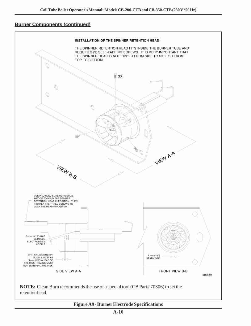
Coil Tube Boiler Operator's Manual: Models CB-200-CTB and CB-350-CTB (230 V / 50 Hz)
A-16
Burner Components (continued)
Figure A9 - Burner Electrode Specifications
NOTE: Clean Burn recommends the use of a special tool (CB Part# 70306) to set theretention head.
3X
VIEW A−A
VIEW B−B
INSTALLATION OF THE SPINNER RETENTION HEAD
THE SPINNER RETENTION HEAD FITS INSIDE THE BURNER TUBE ANDREQUIRES (3) SELF−TAPPING SCREWS. IT IS VERY IMPORTANT THATTHE SPINNER HEAD IS NOT TIPPED FROM SIDE TO SIDE OR FROMTOP TO BOTTOM.
USE PROVIDED SCREWDRIVER ASWEDGE TO HOLD THE SPINNERRETENTION HEAD IN POSITION. THENTIGHTEN THE THREE SCREWS TOLOCK THE HEAD IN POSITION.
5 mm (3/16") GAPBETWEEN
ELECTRODES &NOZZLE
CRITICAL DIMENSION:NOZZLE MUST BE
3 mm (1/8") AHEAD OFTHE DISK. NOZZLE MUST
NOT BE BEHIND THE DISK.
3 mm (1/8")SPARK GAP
SIDE VIEW A−A FRONT VIEW B−BI88850

Coil Tube Boiler Operator's Manual: Models CB-200-CTB and CB-350-CTB (230 V / 50 Hz)
A-17
Burner Components (continued)
Removing the Nozzle for Cleaning:
NOTE: Due to swivel fittings on the air and oil lines, it is not necessary to disconnect these lines whenswinging the burner open.1. Remove the lock-down nut on the mounting flange bolt.2. Disconnect the burner power cable.3. Carefully swing the burner open to its maintenance position.4. Remove the nozzle from the nozzle adapter with a 5/8" socket.
Cleaning the Nozzle:
1. Unscrew the stem from the nozzle head.2. Spray WD-40 or equivalent through the orifice to thoroughly remove any blockage.
CAUTION: DO NOT damage or deform the nozzle orifice; DO NOT use a torch tipcleaner or other inappropriate device to clean the orifice. If the blockage is a "tarry"material or a hard, black material, call your Clean Burn dealer for service.
3. Flush all components with WD-40 to remove oil residues.4. Reassemble the nozzle components. When tightening the stem, just barely "snug" it down.
DO NOT overtighten.5. Check the O-ring on the nozzle stem. Replace the O-ring if it is in the least bit cut or
deformed.6. Lubricate the O-ring on the nozzle stem with a couple of drops of new motor oil, then re-
install the nozzle.7. Check the electrodes for proper gap and clearances.8. Re-install the burner and adjust for optimal performance as necessary.
NOTE: If the nozzle plugs within a few days after cleaning, call your Clean Burn Dealer for service.
Figure A10 - Cleaning the Nozzle
HEAD DISTRIBUTOR STEM
ORIFICE O−RING
NOZZLE SIZE ISSTAMPED ON
FLAT OF NOZZLE HEAD
I88678
Model Nozzle SizeCB-200-CTB Delavan 9-5CB-350-CTB Delavan 9-5

Coil Tube Boiler Operator's Manual: Models CB-200-CTB and CB-350-CTB (230 V / 50 Hz)
A-18

Coil Tube Boiler Operator's Manual: Models CB-200-CTB and CB-350-CTB (230 V / 50 Hz)
B-1
APPENDIX B
Figure B1 - CB-500-CE 5W Burner Wiring Diagram (CB-200-CTB)
Wiring Diagrams
23
CO
NN
EC
TO
R (
FA
CE
)
AIR
SW
ITC
HN
.O.
TR
AN
S−
FO
RM
ER
CAD CELL
OIL
SO
LEN
OID
AIR
SO
LEN
OID
DA
NF
OS
S O
ILP
RIM
AR
Y
BLO
CK
HE
AT
ER
400
WA
TT
S
LIGHTGREEN
LIGHTAMBER
CENTRIFICALSWITCH
BU
RN
ER
MO
TO
R
CA
PA
CIT
OR
HO
UR
ME
TE
R
PR
OV
ING
SW
ITC
HN
.O.
GR
EY
RE
D
WH
ITE
WH
ITE
BLA
CK
BLA
CK
JUM
PE
RS
14
56
78
910
1312
11
RE
D
RE
D
BLA
CK
BLA
CK
140 WATTS HEATER ELEMENTIN NOZZLE ADATER
PU
LL T
HE
SE
WIR
ES
INT
OB
UR
NE
R B
OX
& IN
ST
ALL
INS
UL
L140
NC
TE
MP
. SW
.IN
ST
ALL
ED
ON
NO
ZZ
LEA
DA
PT
ER
CA
P C
RIM
P C
ON
NE
CT
OR
BR
OW
N
BLA
CK
BLA
CK
4
CR
140
PR
EH
EA
TE
R T
HE
RM
OS
TA
T
GR
EE
N
WH
ITE
W H I T E
B L A C K
PU
RP
LE
6G
3 1211 12
BLA
CK
BLU
E
BRN
BLUE
WH
ITE
OR
AN
G
8BLUEJUMPER
YE
LLO
W
BR
OW
N
TH
ER
MA
L C
UT
−OF
F 1
99°
BLA
CK
BLA
CK
BLA
CK
WH
ITE
H44
107
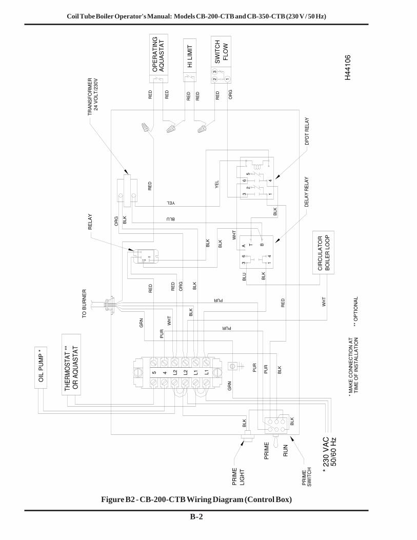
Coil Tube Boiler Operator's Manual: Models CB-200-CTB and CB-350-CTB (230 V / 50 Hz)
B-2
Figure B2 - CB-200-CTB Wiring Diagram (Control Box)
L1 L1L25 L24
A3
T B
1
32
65
41
24 V
OLT
/230
VT
RA
NS
FO
RM
ER
BLK
OR
G
WH
T
BLUC
IRC
ULA
TO
RB
OIL
ER
LO
OP
* 23
0 V
AC
50/
60 H
z
YE
L
BLU
GR
N
* M
AK
E C
ON
NE
CT
ION
AT
T
IME
OF
INS
TA
LLA
TIO
N
TO
BU
RN
ER
BLK
PU
R
SW
ITC
HP
RIM
E
32 1
RE
D
FLO
W
HI L
IMIT
SW
ITC
H
OIL
PU
MP
*
RU
N
PR
IME
AQ
UA
ST
AT
OP
ER
AT
ING
RE
D
BLK
PU
R
BLK
BLK
RE
D
RE
D
PU
R
WH
T
BLK
RE
D
OR
G
WH
T PUR
PUR
RE
D
** O
PT
ION
AL
PR
IME
LIG
HT
BLK
BLK
OR
G
RE
D
GR
N
6 4
BLK
COM
NO
RE
D
YEL
BLK
RE
D
RE
LAY
H44
106

Coil Tube Boiler Operator's Manual: Models CB-200-CTB and CB-350-CTB (230 V / 50 Hz)
B-3
Figure B3 - CB-551-CE Burner Wiring Diagram (CB-350-CTB)
NO
TE
: WH
EN
RE
LEA
SIN
G O
R IN
ST
ALL
ING
WIR
ES
ON
TH
E T
ER
MIN
AL
ST
RIP
,U
SE
TH
E S
MA
LL S
CR
EW
DR
IVE
R P
RO
VID
ED
WIT
H T
HE
BU
RN
ER
TO
RE
LEA
SE
TH
E T
ER
MIN
AL
JAW
S.
TO
LO
CA
TE
TH
E S
CR
EW
DR
IVE
R, O
PE
N T
HE
HIN
GE
DA
CC
ES
S P
LAT
E O
N T
HE
TO
P O
F T
HE
BU
RN
ER
. T
HE
SC
RE
WD
RIV
ER
ISC
LIP
PE
D T
O T
HE
INS
IDE
OF
TH
E B
UR
NE
R H
OU
SIN
G O
N T
HE
RIG
HT
.
TO
RE
LEA
SE
OR
INS
TA
LL A
WIR
E, C
AR
EF
ULL
Y P
US
H T
HE
BLA
DE
OF
TH
ES
CR
EW
DR
IVE
R IN
TO
TH
E R
ELE
AS
E S
LOT
ON
TH
E T
ER
MIN
AL
ST
RIP
UN
TIL
YO
U F
EE
L T
HE
JA
WS
SN
AP
WID
E O
PE
N.
LEA
VE
TH
E B
LAD
E O
F T
HE
SC
RE
WD
RIV
ER
IN T
HE
RE
LEA
SE
SLO
T T
O H
OLD
TH
E J
AW
S O
PE
N W
HIL
E Y
OU
RE
MO
VE
OR
INS
TA
LL A
WIR
E.
TO
RE
LEA
SE
TH
E J
AW
S, C
AR
EF
ULL
Y P
ULL
TH
E B
LAD
E O
F T
HE
SC
RE
WD
RIV
ER
FR
OM
TH
E R
ELE
AS
E S
LOT
.
I883
02

Coil Tube Boiler Operator's Manual: Models CB-200-CTB and CB-350-CTB (230 V / 50 Hz)
B-4
Wiring Diagrams (continued)
Figure B4 - CB -350-CTB Wiring Diagram (Control Box)
L1 L1L25 L24
A3
T B
1
32
65
41
24 V
OLT
TR
AN
SF
OR
ME
R
BLK
WH
T
BLK
BLK
WH
T
BLU
CIR
CU
LAT
OR
BO
ILE
R L
OO
P*
230
VA
C 5
0 H
z
YE
L
BLU
* M
AK
E C
ON
NE
CT
ION
AT
T
IME
OF
INS
TA
LLA
TIO
N
TO
BU
RN
ER
RE
D
RED
BLK
2
PU
R
SW
ITC
HP
RIM
E
32
1F
LOW
HI L
IMIT
SW
ITC
H
OIL
PU
MP
*
RU
N
PR
IME
AQ
UA
ST
AT
OP
ER
AT
ING
RE
D
CIR
CU
LAT
OR
RE
D
BLK
PU
R
BLK
BLK
RE
D RE
D
PU
R
BU
RN
ER
RE
DW
HT
BLK
WH
T PUR
PUR
BU
RN
ER
*
TT
PR
IMA
RY
CIR
CU
LAT
OR
/
RE
D
** O
PT
ION
AL
PR
IME
LIG
HT
A
WH
T
BLK
BLK
BLK
1 2
4
365
21
3
DE
TA
IL O
FT
OG
GLE
SW
ITC
H
I887
53

Coil Tube Boiler Operator's Manual: Models CB-200-CTB and CB-350-CTB (230 V / 50 Hz)
B-5
The CTB sequence of operation is summarized as follows:
(1) A call for heat by the thermostat energizes the DPDT relay which in turn energizes thecirculator delay relay and the boiler loop circulator to establish a flow of water through thecoil.
(2) The flow switch closes. The power then continues from the flow switch through the high limitaquastat, through the operating aquastat, and then to the burner.
(3) If the burner ignites within approximately 15 seconds and the cad cell sees flame, the burnerwill continue to operate until the call for heat is satisfied or the setting of the operatingaquastat is reached.
(4) If the thermostat is not satisfied, but the temperature setting of the operating aquastat isreached, the burner will stop until the return water drops the water temperature in the boiler(re-closing the operating aquastat and turning the burner back on).
(5) The boiler loop circulator will operate as long as the thermostat is calling for heat.(6) The boiler loop circulator circuit includes a delay relay that keeps the circulator operating
approximately ten minutes after the call for heat is satisfied.

Coil Tube Boiler Operator's Manual: Models CB-200-CTB and CB-350-CTB (230 V / 50 Hz)
B-6
Figure B5 - CB-200-CTB Ladder Schematic
CONTROL BOXINSIDE BOILER TERMINAL BLOCK
- CONNECTION AT
CUSTOMER POWER - CONNECTION TO
TOGGLE UP : PRIMETOGLE DOWN: BURNERON FURNACE CABINETD P D T TOGGLE SWITCH
CR2 IS DE-ENERGIZEDOPENS 10 MINUTES AFTER(TRIGGERED BY CR2) ANDWHEN RELAY IS ENERGIZEDCLOSES INSTANTANEOUSLYTDR TIMER CONTACT
NOTE 2:
NOTE 1:
9/28/05
DWG. No.
DATE:RM
44111
No. DATE BY
GRN
OPERATINGAQUASTAT
WHT
PUR
H
BK
SEE NOTE 1
THERMOSTAT
RD
BTDR
AT
CIRC.
CR1
24 VAC
BOILER LOOP MOTOR
RUN - PRIME
SEE NOTE 2
230 VOLTS
HI LIMITFLOW
SWITCH
50 Hz N
PRIMING
MOTOROIL PUMP
49 °C (120 °F)PROVING SWITCH
3
NOZZLE ADAPTOR THERMOSTAT
ACTUATED BY BURNER MOTOR
BLOCK THERMOSTAT
BURNER MOTOR
CENTRIFUGAL SWITCHN. C. HELD OPEN
CR
M
GRN
WHT
PUR RD
BK
OIL SOL.
140 WATTS NOZZLE HEATER
450 WATTS BLOCK HEATER
HOUR METER
IGNITION TRANSF.
AIR CCOMP (OPTIONAL)
AIR PRESSURE
SPARK GAP
POWER ON
PUMP ON
A
AIR SOL.
CR
R
REN
BU
BK
DANFOSS OIL PIRMARY
OR
BR
1BK
8
3
JUM
PER
6
BL
G
WHT12 11
GRAY
4
2
BL
CADCELL
ORANGE BLACK
BLUEYELLOW
CR2
BK BK
2CR
2CR
60 °C (140 °F)
54 °C (130 °F)

Coil Tube Boiler Operator's Manual: Models CB-200-CTB and CB-350-CTB (230 V / 50 Hz)
B-7
Figure B6- CB-350-CTB Ladder Schematic
THERMOSTAT
230 VOLTS
WHT BK
GRN RD
SEE NOTE 1
H
SWITCHHI LIMITFLOW
AQUASTATOPERATING
SEE NOTE 2
BOILER LOOP MOTOR
B TD
DOUBLE POLE RELAY
R T
CR1
A
24 VAC
CIRC.
OIL PUMPMOTOR
RUN - PRIME
50 Hz
PRIMING
N
CONTROL BOXOUTSIDE BOILER TERMINAL BLOCK
- CONNECTION AT
CUSTOMER POWER - CONNECTION TO
- TEST POINT
TOGGLE UP : PRIMETOGLE DOWN: BURNERON BOILER CABINETD P D T TOGGLE SWITCH
CR1 IS DE-ENERGIZEDOPENS 10 MINUTES AFTER(TRIGGERED BY CR1) ANDWHEN RELAY IS ENERGIZEDCLOSES INSTANTANEOUSLYTDR TIMER CONTACT
NOTE 2:
NOTE 1:
PROVING SWITCH
ACTUATED BY BURNER MOTORN. C. HELD OPEN
CENTRIFUGAL SWITCH
WHT
GRN
BK
RD
450 WATTS BLOCK HEATER
AIR COMPRESSOR (OPTIONAL)
T 1
CONTROL
L-140 BLOCK THERMOSTAT60 °C (140 °F)
AIR PRESSURE
CELLCAD
BURNER MOTOR
M 3
49 °C (120 °F)BLK
ORG
IGNITION TRANSF.
SPARK GAP
OIL PRIMARY
F 1 F 2
POWER ON
PUMP ON
HOUR METER
A
OIL SOL.
AIR SOL.
T 2
WHT
L-130 NOZZLE THERMOSTAT 140 WATTS NOZZLE HEATER
DRAFT INDUCER (OPTIONAL)
54 °C (130 °F)
11/15/02DATE:
No. DATE
DWG. No.
BY
88754RM

Coil Tube Boiler Operator's Manual: Models CB-200-CTB and CB-350-CTB (230 V / 50 Hz)
B-8

C-1
Coil Tube Boiler Operator's Manual: Models CB-200-CTB and CB-350-CTB (230 V / 50 Hz)
APPENDIX CAdditional Installation and Maintenance Requirements
Oil/Air Regulator Cover Installation
A cover (C.B. #31185) must be placed over the oil and air regulator to prevent unauthorized adjustment after the equipment has been commissioned by a qualified person (Figure 1).
I88330
The following activities must also be accomplished for boiler installations in the United Kingdom:
• Installing a cover over the oil/air regulators on the burner• Installing a fire valve above the burner
Instructions and/or drawings for these activities are provided in this Appendix.
Figure C1 - Installing a Cover over the Oil/Air Regulators on the Burner
Installing a Cover over the Oil/Air Regulators
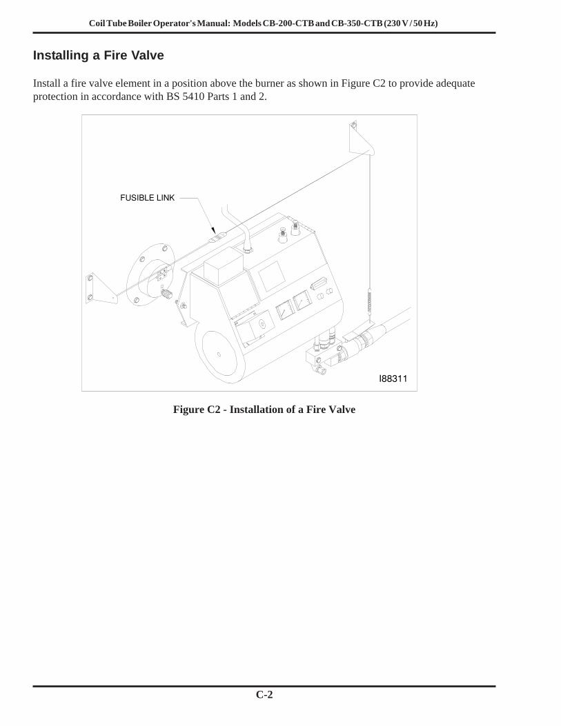
C-2
Coil Tube Boiler Operator's Manual: Models CB-200-CTB and CB-350-CTB (230 V / 50 Hz)
Installing a Fire Valve
Install a fire valve element in a position above the burner as shown in Figure C2 to provide adequateprotection in accordance with BS 5410 Parts 1 and 2.
I88311
FUSIBLE LINK
Figure C2 - Installation of a Fire Valve

Coil Tube Boiler Operator's Manual: Models CB-200-CTB and CB-350-CTB (230 V / 50 Hz)
D-1
APPENDIX DCoil Tube Boiler Service Record
CTB Purchased: Date __________ From (name/phone)________________________________
CTB Installed: Date ___________ By (name/phone)__________________________________
CTB Inspected: Date __________ By (name/phone)__________________________________
Draft Readings Service Record(date / reading) (date / initials of serviceman)
Burner Stack Canister Chamber Stack Oil Tank A.P.M.*Filter & Flues
*A.P.M. = Annual Preventative Maintenance

Coil Tube Boiler Operator's Manual: Models CB-200-CTB and CB-350-CTB (230 V / 50 Hz)
D-2