clean development mechanism simplified project … efficiency... · butibori, distt- nagpur....
TRANSCRIPT

CDM-SSC-PDD (version 02) CDM – Executive Board page 1
CLEAN DEVELOPMENT MECHANISM
SIMPLIFIED PROJECT DESIGN DOCUMENT FOR SMALL-SCALE PROJECT ACTIVITIES (SSC-CDM-PDD)
Version 02
CONTENTS
A. General description of the small-scale project activity B. Baseline methodology C. Duration of the project activity / Crediting period D. Monitoring methodology and plan E. Calculation of GHG emission reductions by sources F. Environmental impacts G. Stakeholders comments Annexes Annex 1: Information on participants in the project activity Annex 2: Information regarding public funding Enclosure Enclosure 1 : Emission Reduction Calculations

CDM-SSC-PDD (version 02) CDM – Executive Board page 2
Revision history of this document
Version Number
Date Description and reason of revision
01 21 January 2003
Initial adoption
02 8 July 2005 • The Board agreed to revise the CDM SSC PDD to reflect guidance and clarifications provided by the Board since version 01 of this document.
• As a consequence, the guidelines for completing CDM SSC PDD have been revised accordingly to version 2. The latest version can be found at <http://cdm.unfccc.int/Reference/Documents>.

CDM-SSC-PDD (version 02) CDM – Executive Board page 3 SECTION A. General description of the small-scale project activity A.1. Title of the small-scale project activity: >> Energy Efficiency Improvement in Thermosetting process at Indo Rama Synthetics (India) Limited,
Butibori, Maharashtra, India.
A.2. Description of the small-scale project activity: >> Indo Rama Synthetics (India) Limited (IRSL) is a multinational group having synthetic fibre complex at
Butibori, Nagpur District, Maharashtra, India. The manufacturing facility comprises of units producing
Polyester Chips, Partially Oriented Yarn (POY), Polyster Staple Fibre (PSF) & Draw Twisted Yarn
(DTY).
IRSL is in the process of expanding the production capacity. In this process, IRSL is putting up new
thermosetting section (CP4) in PSF unit. The technology used in the existing thermosetting sections (
CP1/CP2/CP3) are conventional system (Toyobo make). IRSL can adopt the same technology for the new
thermosetting section (CP4). However IRSL has decided to implement Zimmer tech steam cascading
system as the specific steam consumption of proposed technology is much lesser than the conventional one.
In conventional system, the steam would be used as drying medium. Steam would be supplied at three
levels, high pressure (HP), medium pressure (MP) and low pressure (LP) to three zones. The condensate
from individual zone is collected in condensate tank and supplied to boiler section.
In the proposed project activity, the thermosetting consist of three zones having six rolls each. In the
proposed project activity, the steam is supplied to third zone through pressure control valve. The
condensate of third zone is flashed & flash steam is supplied for II zone, again the condensate of II zone is
flashed & flash steam is supplied for I zone. The flash steam from the condensate of I zone is used for
various low pressure steam purpose. Finally the condensate after flash tank of I zone where the pressure is
around 3.0 bar sent back to the boiler. This cascading system ensures maximum utilization of steam heat
energy.
The purpose of the project activity is to reduce the GHG emissions by improving energy efficiency of steam
utilization system.
The contributions of project activity towards sustainable development are explained with indicators like
socio-economic, environment and technology as follows:

CDM-SSC-PDD (version 02) CDM – Executive Board page 4 1. Socio-economic well being:
During implementation phase of the project activity, Business opportunities for local stakeholders such as
consultants, suppliers, manufacturers, contractors etc has been enhanced.
By reducing the steam demand, fossil fuel saved can be diverted for other needy sections of the economy.
2. Environmental well being:
The specific steam consumption of steam cascading system is comparatively lower than conventional
thermosetting process. There would be savings in steam and hence fossil fuel due to the project activity.
The savings in fossil fuel lead to reduction in GHG emissions.
3. Technological well being:
The technology used in the proposed project activity is steam cascading system in thermosetting unit at
PSF unit. The steam cascading based thermosetting process have the following technological benefits
compared to conventional thermosetting process.
• The maximum utilization of steam heat energy is done at steam cascading system as the flash
steam is utilized in the subsequent zones.
• The energy required for thermosetting process is higher at third zone compared to first zone. The
arrangement of steam distribution from third zone to first zone in the proposed steam cascading
system would match the demand profile.
Because of the above benefits, the specific steam consumption of steam cascading process is 0.58 Ton of
steam per ton of production whereas the conventional process has specific steam consumption of 0.95 Ton
of steam per ton of production.
Hence the technology used for the project activity is efficient.
A.3. Project participants: >> Name of Party involved (*)
((host) indicates a host party)
Private and/or public entity(ies) Project participants(*)
(as applicable)
Party involved wishes to be considered as project
participant (Yes/No)
India (host) Indo Rama Synthetics (India) Limited No
A.4. Technical description of the small-scale project activity: >> A.4.1. Location of the small-scale project activity: >> A.4.1.1. Host Party(ies):
CDM-SSC-PDD (version 02) CDM – Executive Board page 5 >>
India
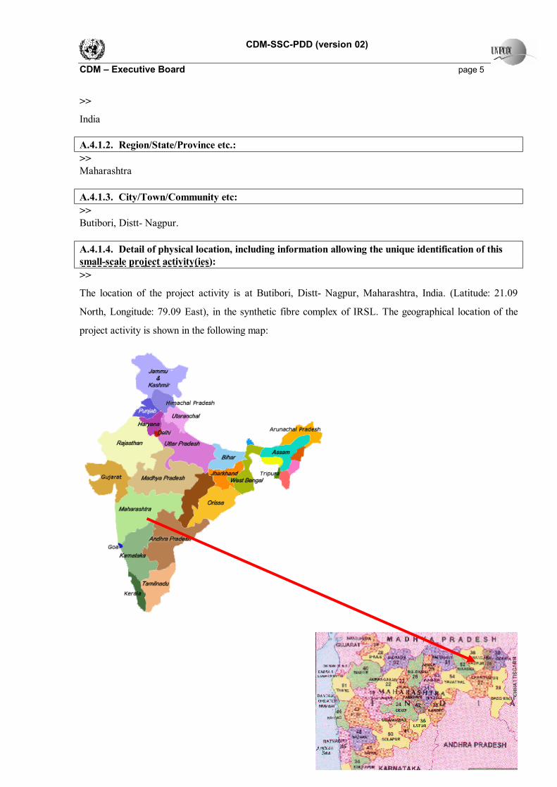
A.4.1.2. Region/State/Province etc.: >> Maharashtra A.4.1.3. City/Town/Community etc: >> Butibori, Distt- Nagpur. A.4.1.4. Detail of physical location, including information allowing the unique identification of this small-scale project activity(ies): >>
The location of the project activity is at Butibori, Distt- Nagpur, Maharashtra, India. (Latitude: 21.09
North, Longitude: 79.09 East), in the synthetic fibre complex of IRSL. The geographical location of the
project activity is shown in the following map:
CDM-SSC-PDD (version 02) CDM – Executive Board page 6 A.4.2. Type and category(ies) and technology of the small-scale project activity: >> As the project activity is energy efficiency improvement in steam utilisation system, it falls under the Type
II - Energy Efficiency Improvement Projects of indicative simplified baseline and monitoring
methodologies for selected small-scale CDM project activity categories. Category D - Energy efficiency
and fuel switching measures for industrial facilities.
The basic criterion for a small scale CDM project activity of Type II Category D is “the aggregate energy
savings of a single project may not exceed the equivalent of 15 GWhe per year”. A total saving of 15 GWhe
per year is equivalent to a maximal saving of 45 GWhth per year in fuel input.
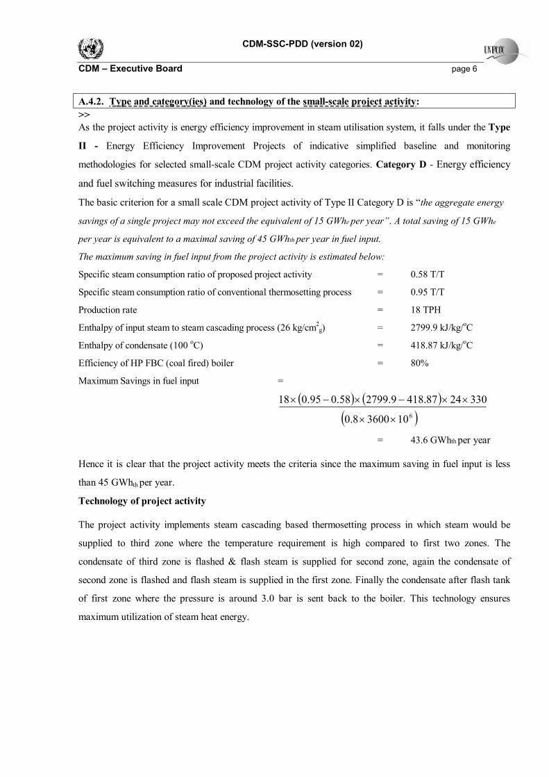
The maximum saving in fuel input from the project activity is estimated below:
Specific steam consumption ratio of proposed project activity = 0.58 T/T
Specific steam consumption ratio of conventional thermosetting process = 0.95 T/T
Production rate = 18 TPH
Enthalpy of input steam to steam cascading process (26 kg/cm2g) = 2799.9 kJ/kg/oC
Enthalpy of condensate (100 oC) = 418.87 kJ/kg/oC
Efficiency of HP FBC (coal fired) boiler = 80%
Maximum Savings in fuel input =
( ) ( )
( )61036008.0
3302487.4189.279958.095.018
××
××−×−×
= 43.6 GWhth per year
Hence it is clear that the project activity meets the criteria since the maximum saving in fuel input is less
than 45 GWhth per year.
Technology of project activity
The project activity implements steam cascading based thermosetting process in which steam would be
supplied to third zone where the temperature requirement is high compared to first two zones. The
condensate of third zone is flashed & flash steam is supplied for second zone, again the condensate of
second zone is flashed and flash steam is supplied in the first zone. Finally the condensate after flash tank
of first zone where the pressure is around 3.0 bar is sent back to the boiler. This technology ensures
maximum utilization of steam heat energy.

CDM-SSC-PDD (version 02) CDM – Executive Board page 7 A.4.3. Brief explanation of how the anthropogenic emissions of anthropogenic greenhouse gas (GHGs) by sources are to be reduced by the proposed small-scale project activity, including why the emission reductions would not occur in the absence of the proposed small-scale project activity, taking into account national and/or sectoral policies and circumstances: >>
The specific steam consumption of proposed project activity (0.58 T/T) is lesser than the baseline (0.9675
T/T) and thereby reducing the steam demand. The steam is supplied by fossil fuel fired boilers. The project
activity would result in reduction of fossil fuel consumption. The CO2 emission due to the combustion of
equivalent fuel quantity would be reduced. In the absence of the project activity, the conventional
thermosetting process would be the option to implement and there would not be any reduction in fuel
consumption. Therefore, the project activity results in reduction of anthropogenic greenhouse gas by
sources which would not occur in the absence of the project activity.
There will be GHG emission reduction of around 33,320 tonnes of CO2e over a 10 year crediting period
due to the project activity.
A.4.3.1 Estimated amount of emission reductions over the chosen crediting period: >>
Years Annual Estimation of emission reduction in tonnes of CO2e
2007-2008 3,332 2008-2009 3,332 2009-2010 3,332 2010-2011 3,332 2011-2012 3,332 2012-2013 3,332 2013-2014 3,332
2014-2015 3,332
2015-2016 3,332
2016-2017 3,332
Total estimated reductions (tonnes of CO2e) 33,320
Total number of crediting years 10 years
Annual Average over the crediting period of estimated reduction (tonnes
of CO2e) 3,332

CDM-SSC-PDD (version 02) CDM – Executive Board page 8 A.4.4. Public funding of the small-scale project activity: >>
No public funding as part of project financing from parties included in Annex I of the convention is
involved in the project activity.
A.4.5. Confirmation that the small-scale project activity is not a debundled component of a larger project activity: >>
The guideline for de-bundling mentioned in paragraph 2 of appendix C of the Simplified Modalities and
Procedures for Small-Scale CDM project activities is given as follows:
A proposed small scale project activity shall be deemed to be a de-bundled component of a large project
activity, if there is a registered small-scale CDM project activity or an application to register another
small-scale CDM project activity.
• With the same project participants;
• In the same project category and technology/measure; and
• Registered within the previous 2 years
• Whose project boundary is within 1 km of the project boundary of the proposed small-scale
activity at the closest point.
The project proponent is commissioning another energy efficiency project in same project category at same
location, but the technology of the other project is replacement of vapour absorption chiller with energy
efficient one, which is altogether different technology/measure from the project activity. Hence, the
proposed project is not a de-bundled component of a large project activity.
CDM-SSC-PDD (version 02) CDM – Executive Board page 9
SECTION B. Application of a baseline methodology: B.1. Title and reference of the approved baseline methodology applied to the small-scale project activity: >>
The project activity satisfies the eligibility criteria to adopt simplified modalities and procedure for small-
scale CDM project activities as explained in paragraph 6 (c) of decision 17/CP.7.
Details of methodology for baseline calculations for small scale CDM projects are referred from the
“Indicative simplified baseline and monitoring methodologies for selected small-scale CDM project activity
categories”. Reference has been taken from Main Category: Type II –Energy Efficiency Improvement
Project; Sub Category: D – Energy efficiency and fuel switching measures for industrial facilities
version 07 - 28 November 2005.
B.2 Project category applicable to the small-scale project activity: >> The project activity falls under Type II –Energy Efficiency Improvement Project; Sub Category: D –
Energy efficiency and fuel switching measures for industrial facilities. This category comprises any
energy efficiency and fuel switching measure implemented at single industrial facility. This category covers
project activities aimed primarily at energy efficiency; Examples include energy efficiency measures (such
as efficient motors), fuel switching measures (such as switching from steam or compressed air to
electricity) and efficiency measures for specific industrial processes (such as steel furnaces, paper drying,
tobacco curing, etc.). The measures may replace existing equipment or be installed in a new facility.
As the project activity installs the energy efficient steam cascading system for thermosetting process, the
project activity is applicable to project category.
B.3. Description of how the anthropogenic emissions of GHG by sources are reduced below those that would have occurred in the absence of the registered small-scale CDM project activity: >>
The barriers associated with the project activity are discussed below:
Barriers due to prevailing practice
IRSL implements Zimmer technology steam cascading system for thermosetting process in PSF unit.
Conventionally, thermosetting unit consists of three zones where the steam at different pressure would be
supplied to each zone individually. The respective condensate would be collected in condensate tank. The
specific steam consumption of conventional thermosetting process would be around 0.9675 T/T. In Zimmer
CDM-SSC-PDD (version 02) CDM – Executive Board page 10 technology the steam is supplied to third zone. The condensate of third zone is flashed and flash steam is
supplied to second zone, again the condensate of second zone is flashed and flash steam is supplied to first
Zone. By this way, the steam is cascaded into different zones and the heat content is effectively utilized in
the process. Hence the expected specific steam consumption of project activity is about 0.58 T/T. In India,
there are only two major textile industries manufacturing polyester staple fibres. IRSL is the first textile
industry which initiated to implement this technology in India.
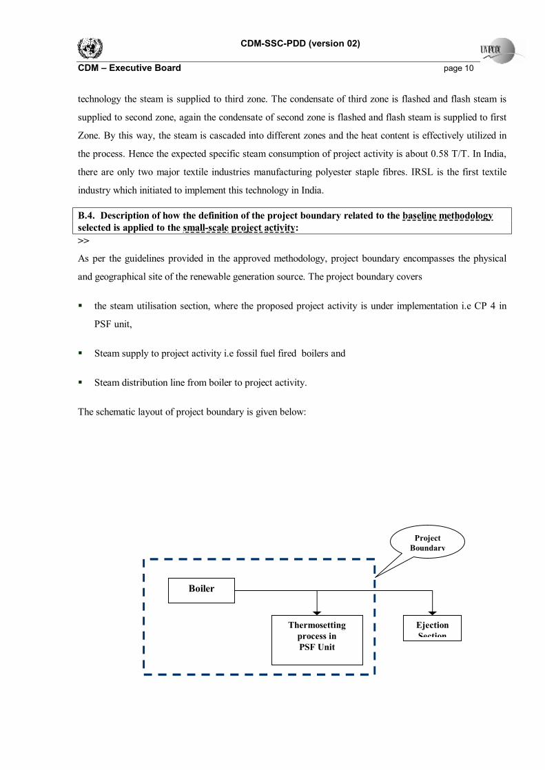
B.4. Description of how the definition of the project boundary related to the baseline methodology selected is applied to the small-scale project activity: >>
As per the guidelines provided in the approved methodology, project boundary encompasses the physical
and geographical site of the renewable generation source. The project boundary covers
§ the steam utilisation section, where the proposed project activity is under implementation i.e CP 4 in
PSF unit,
§ Steam supply to project activity i.e fossil fuel fired boilers and
§ Steam distribution line from boiler to project activity.
The schematic layout of project boundary is given below:
Thermosetting process in PSF Unit
Ejection Section
Project Boundary
Boiler
CDM-SSC-PDD (version 02) CDM – Executive Board page 11 B.5. Details of the baseline and its development: >>
The baseline for the proposed project activity has been estimated by using the methodology specified in the
applicable project category for small-scale CDM project activities. The details are given in section E 1.2.4
and E 1.2.5.
Date of completion of the baseline: 12/07/2006
Name of person/entity determining the baseline: M/s Indo Rama Synthetics (India) Limited
The detail of the project participant is enclosed in Annex 1 of this document.

CDM-SSC-PDD (version 02) CDM – Executive Board page 12 SECTION C. Duration of the project activity / Crediting period: C.1. Duration of the small-scale project activity: >> C.1.1. Starting date of the small-scale project activity: >>
September 05
C.1.2. Expected operational lifetime of the small-scale project activity: >>
15 years - 0 month
C.2. Choice of crediting period and related information: >>
The project activity would use fixed ten years crediting period.
C.2.1. Renewable crediting period: >>
Not applicable
C.2.1.1. Starting date of the first crediting period: >>
Not applicable
C.2.1.2. Length of the first crediting period: >>
Not applicable
C.2.2. Fixed crediting period: >> C.2.2.1. Starting date: >> 15/11/06 C.2.2.2. Length: >> 10 years

CDM-SSC-PDD (version 02) CDM – Executive Board page 13 SECTION D. Application of a monitoring methodology and plan: >> D.1. Name and reference of approved monitoring methodology applied to the small-scale project activity: >>
The approved monitoring methodology of the project activity is as follows:
Type II – Energy Efficiency Improvement Project;
Sub Category: D – Energy efficiency and fuel switching measures for industrial facilities
Reference: The monitoring methodology of the project activity is referred from ‘Paragraph 6,7 and 8’ of
Type II –Energy Efficiency Improvement Project; Sub Category: D – Energy efficiency and fuel switching
measures for industrial facilities version 07 - 28 November 2005.
D.2. Justification of the choice of the methodology and why it is applicable to the small-scale project activity: >>
As per the paragraph 12 of Simplified Modalities and Procedures for Small Scale CDM Project activities,
a proposed project activity shall,
(a) Meet the eligibility criteria for small-scale CDM project activities set out in paragraph 6 (c) of decision
17/CP.7;
(b) Conform to one of the project categories in appendix B to this annex;
(c) Not be a de-bundled component of a larger project activity, as determined through appendix C to this
annex.
As explained earlier in A4.2, the project activity meets the eligibility criteria for small-scale CDM project
activities set out in paragraph 6 (c) of decision 17/CP.7, falls under small-scale CDM project of Type II.
Category D and is not a de-bundled component of a larger project activity.
The monitoring plan has been drawn as per the guidance provided in paragraph 6,7 and 8 of ‘Indicative
simplified baseline and monitoring methodologies for selected small-scale CDM project activity categories
Type II - Category D - version 07 - 28 November 2005’.
Description of monitoring plan
The monitoring plan is formulated to monitor the energy use of the industry facility, processes affected by
the project activity. The metered parameters would be used to calculate energy savings and thereby
emission reductions.

CDM-SSC-PDD (version 02) CDM – Executive Board page 14 GHG Sources
Direct On-Site Emissions
The project activity involves installation of Zimmer tech steam cascading system for thermosetting process.
Steam is used as heating medium. The emission due to combustion of fuel for generating steam required for
thermosetting process where the project activity is under implementation is direct On-Site emissions. The
list of data to be monitored is given in D.3.
Direct Off-Site Emissions
The emissions due to transportation of coal for the project activity are regarded as direct off-site project
emissions. Similar quantum of emissions would have also occurred in the baseline due to the transportation
of coal. Direct off- site emission would be lesser in project activity compared to baseline due to decrease in
amount of coal transported. However, benefits are not claimed for these emission reductions.
Indirect On-Site Emissions
The energy consumption for the construction of the project would lead to indirect on site emissions.
Considering the energy consumption during construction period of the project activity, emissions under this
category would be negligible.
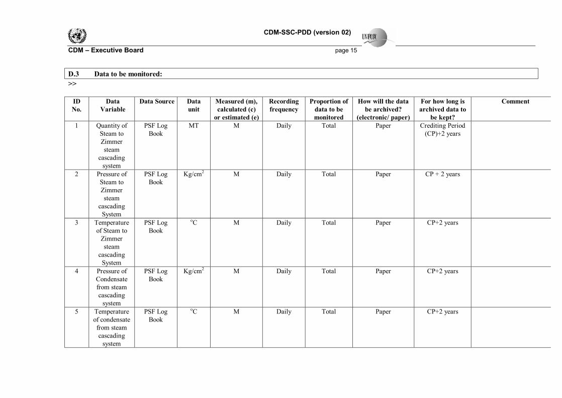
CDM-SSC-PDD (version 02) CDM – Executive Board page 15 D.3 Data to be monitored: >>
ID No.
Data Variable
Data Source Data unit
Measured (m), calculated (c)
or estimated (e)
Recording frequency
Proportion of data to be monitored
How will the data be archived?
(electronic/ paper)
For how long is archived data to
be kept?
Comment
1 Quantity of Steam to Zimmer steam
cascading system
PSF Log Book
MT M Daily Total Paper Crediting Period (CP)+2 years
2 Pressure of Steam to Zimmer steam
cascading System
PSF Log Book
Kg/cm2 M Daily Total Paper CP + 2 years
3 Temperature of Steam to
Zimmer steam
cascading System
PSF Log Book
oC M Daily Total Paper CP+2 years
4 Pressure of Condensate from steam cascading
system
PSF Log Book
Kg/cm2 M Daily Total Paper CP+2 years
5
Temperature of condensate from steam cascading
system
PSF Log Book
oC M Daily Total Paper CP+2 years
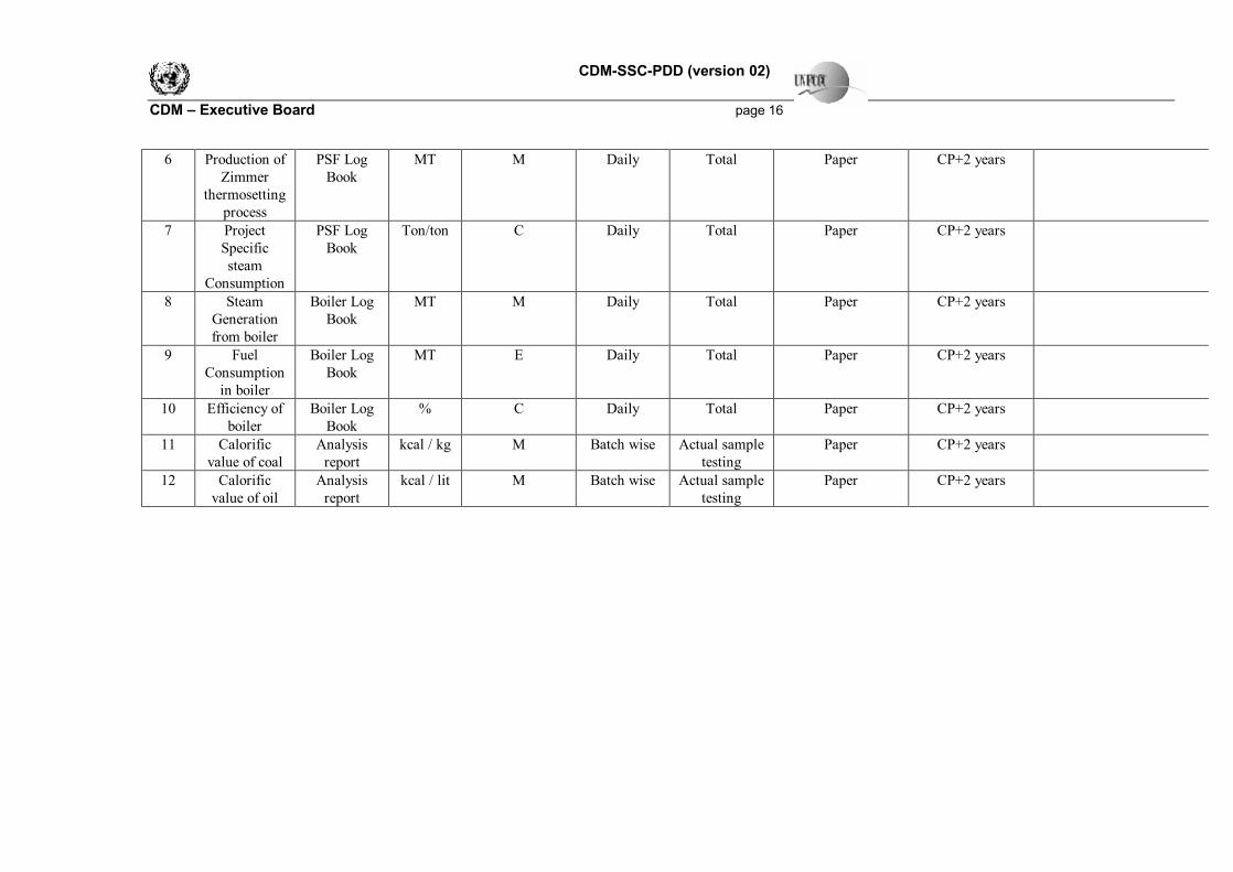
CDM-SSC-PDD (version 02) CDM – Executive Board page 16
6 Production of Zimmer
thermosetting process
PSF Log Book
MT M Daily Total Paper CP+2 years
7 Project Specific steam
Consumption
PSF Log Book
Ton/ton C Daily Total Paper CP+2 years
8 Steam Generation from boiler
Boiler Log Book
MT M Daily Total Paper CP+2 years
9 Fuel Consumption
in boiler
Boiler Log Book
MT E Daily Total Paper CP+2 years
10 Efficiency of boiler
Boiler Log Book
% C Daily Total Paper CP+2 years
11 Calorific value of coal
Analysis report
kcal / kg M Batch wise Actual sample testing
Paper CP+2 years
12 Calorific value of oil
Analysis report
kcal / lit M Batch wise Actual sample testing
Paper CP+2 years

CDM-SSC-PDD (version 02) CDM – Executive Board page 17 D.4. Qualitative explanation of how quality control (QC) and quality assurance (QA) procedures are undertaken: >>
Quality control (QC) and quality assurance (QA) procedures are being undertaken for data monitored. The
details are as follows:
Data
Uncertainty level of data
(High/Medium/Low)
Are QA/QC procedures planned for these data?
D.3.1 Low Yes, it is planned under ISO 9000
D.3.2 Low Yes, it is planned under ISO 9000
D.3.3 Low Yes, it is planned under ISO 9000
D.3.4 Low Yes, it is planned under ISO 9000
D.3.5 Low Yes, it is planned under ISO 9000
D.3.6 Low Yes, it is planned under ISO 9000
D.3.8 Low Yes, it is planned under ISO 9000
D.3.9 Low Yes, it is planned under ISO 9000
D.3.11 Low Yes, it is planned under ISO 9000
D.3.12 Low Yes, it is planned under ISO 9000
Project Parameters affecting Emission Reduction
Quantity of Steam to Zimmer Steam Cascading System
Steam Quantity supplied to Zimmer steam cascading system would be measured by orifice meter. The
regular calibration of orifice meter would be done to ensure the accuracy of the measurement.
Pressure and Temperature of steam to Zimmer Steam cascading system
The supply steam pressure and temperature of project activity would be measured by pressure gauge and
temperature indicator and logged on daily basis. The pressure gauge and temperature indicator would be
calibrated on monthly basis by instrument department of IRSL.

CDM-SSC-PDD (version 02) CDM – Executive Board page 18
Pressure and Temperature of Condensate from Zimmer Steam cascading system
The condensate pressure and temperature from the project activity would be measured by pressure gauge
and temperature indicator and logged on daily basis. Instrument department of IRSL would calibrate the
pressure gauge and temperature indicator on monthly basis to ensure its accuracy.
Production rate of Project activity
Production rate of project activity would be measured by electronic weighing machine and captured in
DCS. The calibration of the weighing machine would be done on yearly basis by the accredited external
agency.
Steam Generation from boiler
Steam generation from boiler would be measured by orifice meter. The regular calibration of orifice meter
would be done to ensure the accuracy of the measurement.
Calorific Value of fuel
The ultimate analysis of fuel would be carried out for every batch received by sending the sample to
external lab.
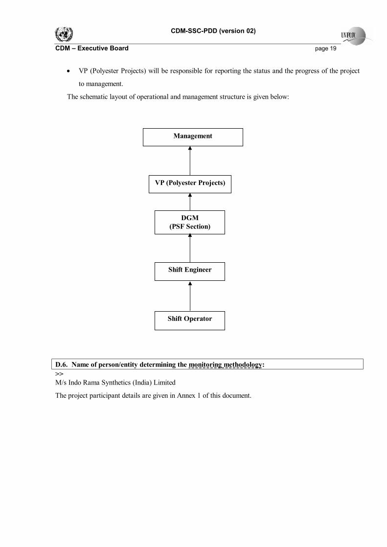
D.5. Please describe briefly the operational and management structure that the project participant(s) will implement in order to monitor emission reductions and any leakage effects generated by the project activity: >>
The operational and management structure of IRSL to monitor emission reductions is discussed below:
• The Shift Operators would be responsible for data recording of the parameters mentioned in the
monitoring plan. They are qualified technicians with 5-10 years experience.
• The Shift Engineer would compile the daily report and submit to Deputy Manager - Utility.
• DGM- PSF Section will verify the data and will take immediate action if required. He will compile
the monthly report and submit to VP (Polyester Projects).
CDM-SSC-PDD (version 02) CDM – Executive Board page 19
• VP (Polyester Projects) will be responsible for reporting the status and the progress of the project
to management.
The schematic layout of operational and management structure is given below:
D.6. Name of person/entity determining the monitoring methodology: >> M/s Indo Rama Synthetics (India) Limited
The project participant details are given in Annex 1 of this document.
Management
VP (Polyester Projects)
DGM (PSF Section)
Shift Engineer
Shift Operator
CDM-SSC-PDD (version 02) CDM – Executive Board page 20
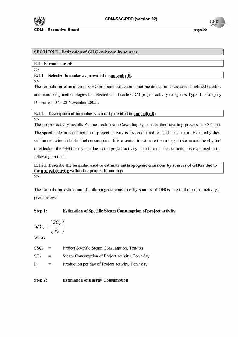
SECTION E.: Estimation of GHG emissions by sources: E.1. Formulae used: >> E.1.1 Selected formulae as provided in appendix B: >> The formula for estimation of GHG emission reduction is not mentioned in ‘Indicative simplified baseline
and monitoring methodologies for selected small-scale CDM project activity categories Type II - Category
D - version 07 - 28 November 2005’.
E.1.2 Description of formulae when not provided in appendix B: >> The project activity installs Zimmer tech steam Cascading system for thermosetting process in PSF unit.
The specific steam consumption of project activity is less compared to baseline scenario. Eventually there
will be reduction in boiler fuel consumption. It is essential to estimate the savings in steam and thereby fuel
to calculate the GHG emissions due to the project activity. The formula for estimation is explained in the
following sections.
E.1.2.1 Describe the formulae used to estimate anthropogenic emissions by sources of GHGs due to the project activity within the project boundary: >>
The formula for estimation of anthropogenic emissions by sources of GHGs due to the project activity is
given below:
Step 1: Estimation of Specific Steam Consumption of project activity
=
P
PP P
SCSSC
Where SSCP = Project Specific Steam Consumption, Ton/ton
SCP = Steam Consumption of Project activity, Ton / day
PP = Production per day of Project activity, Ton / day
Step 2: Estimation of Energy Consumption

CDM-SSC-PDD (version 02) CDM – Executive Board page 21
( ){ }610
OPPSSCECESEC PP ×××−=
Where
ECP = Energy Consumption in Project scenario, TJ/yr
ES = Enthalpy of Steam supplied to project activity, kJ/kg
EC = Enthalpy of Condensate, kJ/kg
P = Production rate of project activity, Ton/day
Op = Operating days per year,
E.1.2.2 Describe the formulae used to estimate leakage due to the project activity, where required, for the applicable project category in appendix B of the simplified modalities and procedures for small-scale CDM project activities >>
As per paragraph 5 of Indicative simplified baseline and monitoring methodology for selected small-scale
CDM project activity -Type II - Category D - version 07 - 28 November 2005. It has been specified that
“If the energy generating equipment is transferred from another activity or if the existing equipment is
transferred to another activity, leakage is to be considered”.
The project activity is Greenfield and the equipments are newly procured and are not transferred from
another activity. Hence the leakage due to project activity is need not to be considered.
E.1.2.3 The sum of E.1.2.1 and E.1.2.2 represents the small-scale project activity emissions: >>
The project activity emissions would be only due to the combustion of coal.
E.1.2.4 Describe the formulae used to estimate the anthropogenic emissions by sources of GHGs in the baseline using the baseline methodology for the applicable project category in appendix B of the simplified modalities and procedures for small-scale CDM project activities: >>
The formula for estimation of anthropogenic emissions by sources of GHGs due to the project activity is
given below:
Step 1: Estimation of Specific Steam Consumption of Baseline

CDM-SSC-PDD (version 02) CDM – Executive Board page 22
=
B
BB P
SCSSC
Where SSCB = Baseline Specific Steam Consumption, Ton/ton
SCB = Steam Consumption in baseline scenario based on the one year average of baseline, Ton /
yr
PB = Production rate at baseline based on the one year average of baseline, Ton / yr
Step 2: Estimation of Energy Consumption
( ){ }610
PSSCECESEC BB ××−=
Where
ECB = Energy Consumption in Baseline scenario, TJ/yr
ESLP = Enthalpy of LP Steam at STP, STT, kJ/kg
STP = Steam Pressure of LP steam is 5 kg/cm2 based on the one year average of baseline
STT = Steam Temperature is 152 oC based on the one year average of baseline
EC = Enthalpy of Condensate at CP, kJ/kg
CP = Condensate pressure is 7.5 kg/cm2, based on the one year average of baseline
SSCB = Baseline Specific Steam Consumption, Ton/ton
P = Production rate of project activity, Ton/day E.1.2.5 Difference between E.1.2.4 and E.1.2.3 represents the emission reductions due to the project activity during a given period: >>
The emission reduction due to the project activity would be estimated by the following formula
( ) ηEFECECBE BP ×−=
Where
BE = Baseline emissions.
EF = Emission Factor of fuel, T CO2 / TJ, Referred from Revised 1996 IPCC Guidelines for
National Greenhouse Gas Inventories.
CDM-SSC-PDD (version 02) CDM – Executive Board page 23 η = Efficiency of boiler, whichever is maximum.
= ValueCalorificnConsumptioFuel
SteamofEnthalpyGenerationSteam
×
×
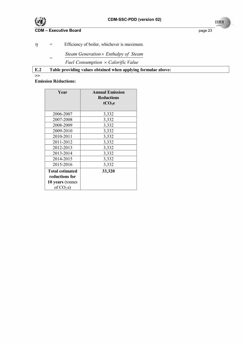
E.2 Table providing values obtained when applying formulae above: >> Emission Réductions:
Year Annual Emission Reductions
tCO2e
2006-2007 3,332 2007-2008 3,332 2008-2009 3,332 2009-2010 3,332 2010-2011 3,332 2011-2012 3,332 2012-2013 3,332 2013-2014 3,332 2014-2015 3,332 2015-2016 3,332
Total estimated reductions for
10 years (tonnes of CO2 e)
33,320

CDM-SSC-PDD (version 02) CDM – Executive Board page 24 SECTION F.: Environmental impacts: F.1. If required by the host Party, documentation on the analysis of the environmental impacts of the project activity: >> The project does not fall under the purview of the Environmental Impact Assessment (EIA) notification1
S.O. 60 (E) of the Ministry of Environment and Forest, Government of India,.
There would not be any significant negative impact over the environment due to the project activity.
1 Reference : http://envfor.nic.in/legis/eia/so-60(e).html
CDM-SSC-PDD (version 02) CDM – Executive Board page 25
SECTION G. Stakeholders’ comments: G.1. Brief description of how comments by local stakeholders have been invited and compiled: >>
The stakeholders are identified on the basis of their involvement at various stages of project activity. They
are as follows:
• Employees of IRSL
• Equipment supplier
The meeting was conducted at IRSL to inform about the project activity and to collect the comments /
concerns of employees. During the meeting, the project activity and its associated benefits were discussed.
G.2. Summary of the comments received: >> Employees: The employees appreciated the efforts taken by IRSL and there is no concern/ comments raised
from them.
Equipment supplier: The equipments would be supplied by the equipment supplier as per the specifications
finalized for the project and erection & commissioning of the equipments at the site would be done by
suppliers.
G.3. Report on how due account was taken of any comments received: >> There are no comments or concerns raised during the consultation with stakeholders. Further, as required
by the CDM cycle, the PDD would be published at the DOE`s web site for public comments

CDM-SSC-PDD (version 02) CDM – Executive Board page 26
Annex 1 CONTACT INFORMATION ON PARTICIPANTS IN THE PROJECT ACTIVITY
Organization: Indo Rama synthetics (India) Limited
Street/P.O.Box: 28, Barakhamba Road,
Building: Dr. Gopal Das Bhawan, 4th floor,
City: New Delhi 110001
State/Region: New Delhi
Postcode/ZIP: 110001
Country: India
Telephone: --
FAX: --
E-Mail: [email protected]
URL: www.indoramaindia.com
Represented by:
Title: President and CFO
Salutation: Mr.
Last Name: Chatterjee
Middle Name:
First Name: Abhinandan
Department: --
Mobile: --
Direct FAX: --
Direct tel: --
Personal E-Mail: --

CDM-SSC-PDD (version 02) CDM – Executive Board page 27 Annex 2 INFORMATION REGARDING PUBLIC FUNDING No public funding as part of project financing from parties included in Annex I of the convention is
involved in the project activity.
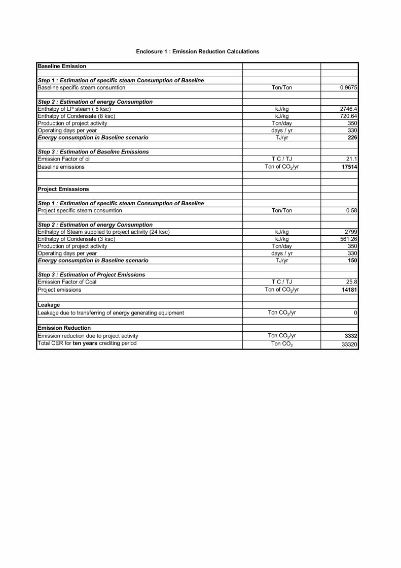
Baseline Emission
Step 1 : Estimation of specific steam Consumption of BaselineBaseline specific steam consumtion Ton/Ton 0.9675
Step 2 : Estimation of energy ConsumptionEnthalpy of LP steam ( 5 ksc) kJ/kg 2746.4Enthalpy of Condensate (8 ksc) kJ/kg 720.64Production of project activity Ton/day 350Operating days per year days / yr 330Energy consumption in Baseline scenario TJ/yr 226
Step 3 : Estimation of Baseline EmissionsEmission Factor of oil T C / TJ 21.1Baseline emissions Ton of CO2/yr 17514
Project Emisssions
Step 1 : Estimation of specific steam Consumption of BaselineProject specific steam consumtion Ton/Ton 0.58
Step 2 : Estimation of energy ConsumptionEnthalpy of Steam supplied to project activity (24 ksc) kJ/kg 2799Enthalpy of Condensate (3 ksc) kJ/kg 561.26Production of project activity Ton/day 350Operating days per year days / yr 330Energy consumption in Baseline scenario TJ/yr 150
Step 3 : Estimation of Project EmissionsEmission Factor of Coal T C / TJ 25.8Project emissions Ton of CO2/yr 14181
LeakageLeakage due to transferring of energy generating equipment Ton CO2/yr 0
Emission ReductionEmission reduction due to project activity Ton CO2/yr 3332Total CER for ten years crediting period Ton CO2 33320
Enclosure 1 : Emission Reduction Calculations