clean oil guide - tektradeclean oil guide 2 contents page chapter 3 0 introduction 4 1 oil...
TRANSCRIPT

100 µmGrain of salt
70 µmHuman hair
40 µmNaked eye visibility
25 µmPollen
8 µmCoal dust
1 µmTobacco smoke
3 µmBacteria
Clean Oil Guide

2
Contents
Page Chapter 3 0 Introduction 4 1 Oil contamination control 4 Wear and tear in oil systems 5 Particle contamination 7 Water contamination 8 Oil degradation 9 Acid contamination 10 2 Oil sampling 10 Where to take an oil sample 11 How to take an oil sample 14 3 Oil sample analysis 15 ISO Standards 16 AS / NAS Classes 17 Evaluation of particle count and machine lifetime 18 Analysis methods and frequencies 18 Testing for varnish 20 4 Oil cleaning methods 20 Filter types 22 Glass fibre based pressure filter 23 Cellulose based offline filter 24 5 Basic filtration definitions 24 Nominal filtration 24 Absolute filtration 24 Beta values 25 Dirt holding capacity 25 Filter by-pass valve 26 6 Installation methods 26 Full-flow filtration 26 Offline filtration 28 7 Economy 29 8 Ordering a filtration system 29 Offline filter sizing
30 9 CJC™ Oil Maintenance Systems 31 10 Handling of oil and oil systems 31 New oil in containers 31 Oil in the system 32 11 Recommendations for buying oil 32 Oil test certificates and test sampling 32 Claims 33 Sampling of new oil 34 12 Appendix

3
Introduction 0Maintenance is the largest single controllable expense in a manufacturing plant. With as many as 80% of all machine failures related to contamination in the oil, pro-active methods are saving industries considerable costs every year.
This booklet offers an introduction to the problems with insufficient oil cleanliness, the causes and the remedy of the problems. All the information presented is generally known and accepted. It was compiled and published by people within the company C.C.JENSEN A/S. We invite you to take advantage of the experience we have gathered over the past 50 years with oil maintenance within various types of applications. The perfect oil cleaning system will control the level of all types of contamination.
For further information, we recommend that you visit www.cjc.dk.
Introduction Page Chapter 3 0 Introduction 4 1 Oil contamination control 4 Wear and tear in oil systems 5 Particle contamination 7 Water contamination 8 Oil degradation 9 Acid contamination 10 2 Oil sampling 10 Where to take an oil sample 11 How to take an oil sample 14 3 Oil sample analysis 15 ISO Standards 16 AS / NAS Classes 17 Evaluation of particle count and machine lifetime 18 Analysis methods and frequencies 18 Testing for varnish 20 4 Oil cleaning methods 20 Filter types 22 Glass fibre based pressure filter 23 Cellulose based offline filter 24 5 Basic filtration definitions 24 Nominal filtration 24 Absolute filtration 24 Beta values 25 Dirt holding capacity 25 Filter by-pass valve 26 6 Installation methods 26 Full-flow filtration 26 Offline filtration 28 7 Economy 29 8 Ordering a filtration system 29 Offline filter sizing
30 9 CJC™ Oil Maintenance Systems 31 10 Handling of oil and oil systems 31 New oil in containers 31 Oil in the system 32 11 Recommendations for buying oil 32 Oil test certificates and test sampling 32 Claims 33 Sampling of new oil 34 12 Appendix
4
1 Oil contamination control
Roller
Ø 5 μm
OilgrooveForce
Ø 1 μm
Oilgroove
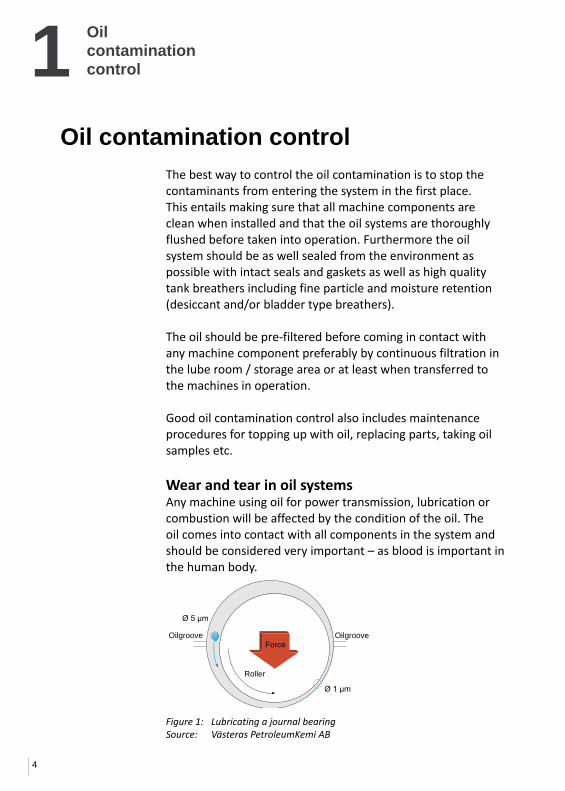
The best way to control the oil contamination is to stop the contaminants from entering the system in the first place. This entails making sure that all machine components are clean when installed and that the oil systems are thoroughly flushed before taken into operation. Furthermore the oil system should be as well sealed from the environment as possible with intact seals and gaskets as well as high quality tank breathers including fine particle and moisture retention (desiccant and/or bladder type breathers).
The oil should be pre-filtered before coming in contact with any machine component preferably by continuous filtration in the lube room / storage area or at least when transferred to the machines in operation.
Good oil contamination control also includes maintenance procedures for topping up with oil, replacing parts, taking oil samples etc.
Wear and tear in oil systemsAny machine using oil for power transmission, lubrication or combustion will be affected by the condition of the oil. The oil comes into contact with all components in the system and should be considered very important – as blood is important in the human body.
Oil contamination control
Figure 1: Lubricating a journal bearingSource: Västeras PetroleumKemi AB
1
5
Oil contamination
control
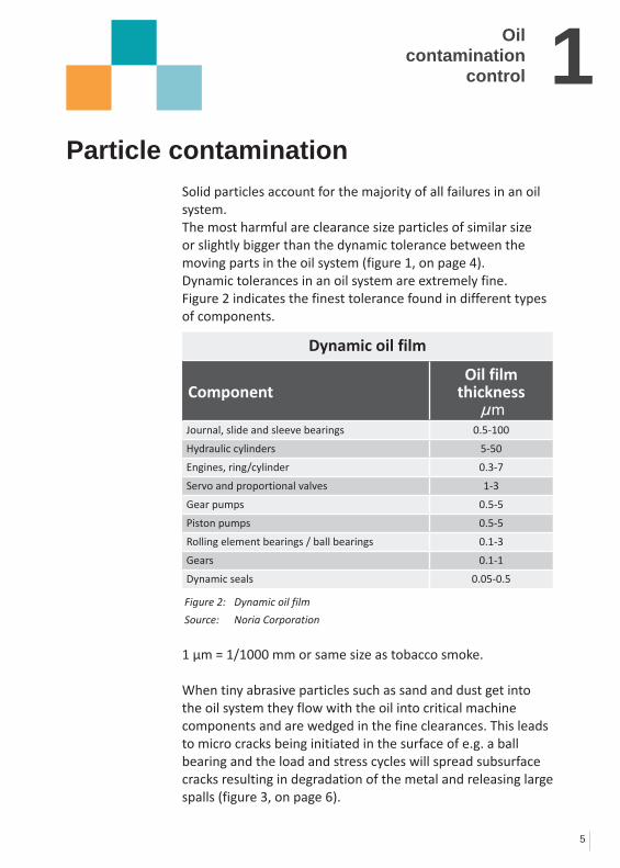
Solid particles account for the majority of all failures in an oil system. The most harmful are clearance size particles of similar size or slightly bigger than the dynamic tolerance between the moving parts in the oil system (figure 1, on page 4). Dynamic tolerances in an oil system are extremely fine. Figure 2 indicates the finest tolerance found in different types of components.
1 µm = 1/1000 mm or same size as tobacco smoke.
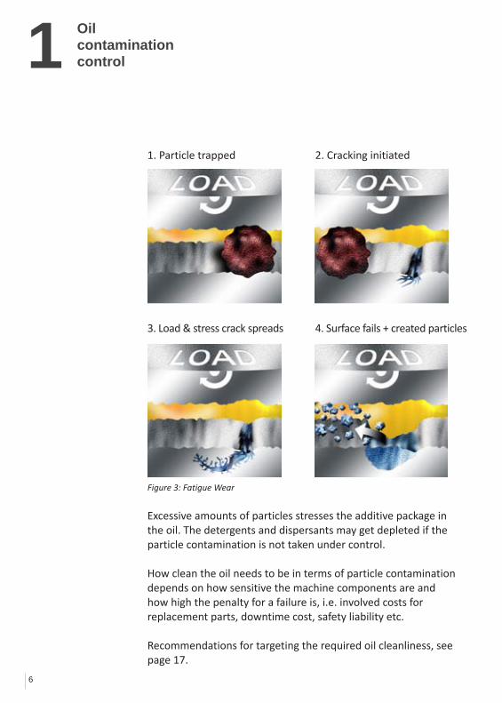
When tiny abrasive particles such as sand and dust get into the oil system they flow with the oil into critical machine components and are wedged in the fine clearances. This leads to micro cracks being initiated in the surface of e.g. a ball bearing and the load and stress cycles will spread subsurface cracks resulting in degradation of the metal and releasing large spalls (figure 3, on page 6).
Particle contamination
Dynamic oil film
ComponentOil film
thickness µm
Journal, slide and sleeve bearings 0.5-100
Hydraulic cylinders 5-50
Engines, ring/cylinder 0.3-7
Servo and proportional valves 1-3
Gear pumps 0.5-5
Piston pumps 0.5-5
Rolling element bearings / ball bearings 0.1-3
Gears 0.1-1
Dynamic seals 0.05-0.5
Figure 2: Dynamic oil film
Source: Noria Corporation
6
1 Oil contamination control
1. Particle trapped 2. Cracking initiated
3. Load & stress crack spreads 4. Surface fails + created particles
Figure 3: Fatigue Wear
Excessive amounts of particles stresses the additive package in the oil. The detergents and dispersants may get depleted if the particle contamination is not taken under control.
How clean the oil needs to be in terms of particle contamination depends on how sensitive the machine components are and how high the penalty for a failure is, i.e. involved costs for replacement parts, downtime cost, safety liability etc.
Recommendations for targeting the required oil cleanliness, see page 17.

7
1Oil contamination
control
Water accounts for a major part of mechanical failures. In some heavily water contaminated oil systems e.g. in the paper industry, water is the predominant cause of failing components.Water reduces the lubricity of the oil, due to the lower viscosity and poor load capacity of water. When water is exposed to the high pressures found in load zones in e.g. bearings and gears, the water droplets collapse (implode). The resulting micro-jets create micro-pitting in metal surfaces and can even result in metal-to-metal contact when water vapor pushes the oil away momentarily.Free hydrogen ions in the water can further worsen the situation, since they migrate into machine components making steel brittle and prone to crack.Water also results in corrosion and erosion leading to pitting damage (see figure 21 in appendix, page 34).
Furthermore, water acts as a catalyst for oil degradation, speeding up the oils tendency to oxidize and form resins, sludge and varnish.
Water can be found in oil as dissolved, emulsified or free water. How much water a specific oil can dissolve or keep suspended in emulsions depends on the base oil, additive package, temperature and pressure. Some oils are designed to keep large amounts of water in suspension e.g. engine lube oils. In order to ensure long oil life and for optimum protection of machine components it is recommended not to have emulsified or free water in oil.For a typical mineral based oil this means less than 100 ppm of water (0.01%).Unfortunately many oil analysis reports state water content very inaccurately as “<0.1%”, which means less than 1000 ppm. To know the actual water content ask for a Karl Fisher Titration test.
Water contamination
Figure 4:Micro pitting
8
1 Oil contamination control
Oil degradation products or soft contaminants are a widespread problem in most industries. They are precursors of deposits often referred to as varnish which are known to cause problems in both hydraulic and lube oil systems.When oil degrades due to elevated temperatures, water or chemical contamination e.g. copper, the composition and functional properties of the oil are changed, resulting in the following products being formed: • Acids • Polymerizedcompoundswhicharedissolved in warm oil (referred to as sludge or resins) • Varnishprecipitatingoutasdepositsoncolder machine components
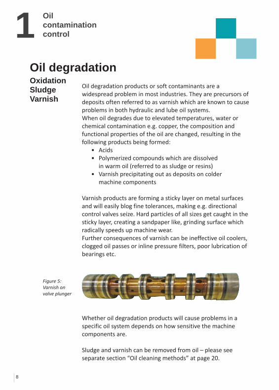
Varnishproductsareformingastickylayeronmetalsurfacesand will easily blog fine tolerances, making e.g. directional control valves seize. Hard particles of all sizes get caught in the sticky layer, creating a sandpaper like, grinding surface which radically speeds up machine wear.Further consequences of varnish can be ineffective oil coolers, clogged oil passes or inline pressure filters, poor lubrication of bearings etc.
Whether oil degradation products will cause problems in a specific oil system depends on how sensitive the machine components are.
Sludge and varnish can be removed from oil – please see separate section “Oil cleaning methods” at page 20.
Oil degradation OxidationSludgeVarnish
Figure 5:Varnish on valve plunger

9
1Oil contamination
control
Acid can be found in oil as by-products of oil degradation, combustion of gas or fuel, hydrolysis of Ester-based fluids etc. The amount of acid in oil should be limited, since acid will cause chemical corrosion of machine components and shorten the lifetime of the oil, just to mention a few of the unwanted effects.
Acid number, also referred to as AN or TAN, is measure by titration with a strong base/alkaline and given in amount of potassium hydroxide in milligrams required to neutralize the acid in one gram of oil (mg KOH/g).
Acid numbers should not be allowed to increase more than +0.5 AN higher than that of new oil, and if +1 AN is spotted immediate action is required (i.e. if new oil has 0.5 AN, then 1.0 AN is alert and 1.5 AN is alarm value).
Acid can be neutralized or removed from oil in different ways.The obvious is to use the alkalinity of the oil to neutralize incoming acid. This is done in gas and diesel engine lube oil utilizing high base numbers (BN or TBN).The rule of thumb is to replace the lube oil if the BN falls below 30% of that of the new lube oil.
Acid formed by hydrolysis in Ester-based fluids (HFD fluids) used in e.g. turbine control systems, can cause much harm. Acid numbers twenty times higher than that of new oil, which have been seen, result in severe acid corrosion of system components.In such fluids the acids number can be lowered and maintained using a neutralizing catalyst such as Ion exchange resin, Fullers earth or Aluminum Oxides.C.C.JENSEN has such ion exchange medium in combination fine filters in the portfolio.
Acid contamination
Figure 6:Oil with high AN/TAN has poor lifetime

2
10
Correct
Wrong
Oilsampling
Oil samplingThe purpose of oil sampling is to utilize the oil as a messenger telling how the machine is doing. This can prompt pro-active actions in order to achieve the highest level of machine performance and reliability at the lowest possible cost. The initial samples serve to establish benchmarks and to identify the machines with critical levels. The routine sampling is done to document that goals are met and can also provide indications of abnormal wear that needs to be addressed.
The quality of analysis results depends first on correct sampling and handling of the sample, secondly on the quality of the laboratory performing the analysis. The importance of the knowledge about where and how to take a sample is paramount and requires special attention.
Where to take an oil sampleReferring to figure 7, preferably derive the oil from a upwards pointing pipe or bend with turbulent flow to produce a representative sample. Sampling points fitted on the lower perimetre of a pipe tend to allow depositing of particles in the sampling valve.
The best place to sample in order to see how machine components are doing, is downstream from the machine before any filtration and before the oil is returned to the system tank. This will show the undiluted result of any wear being created in the machine.The best guarantee of clean oil in the system is to sample from the most contaminated part of the oil system – the bottom drain of the system tank.This bottom drain is typically where the offline/kidney lube filtration system is connected, so a satisfying oil analysis result taken from between the pump and the filter housing of an offline filter, is the best guarantee that the oil and the system is clean.
Figure 7: Pipe cross section with sampling valves
Source: Västeras PetroleumKemi AB

2
11
Sump
Sampling point
Flush min. 1 L
Pump5 times
Max. 80%
Do not touch glass
Oilsampling
If no offline filter system is installed, a vacuum type sampling pump is a valid option. In such case the sample should be drawn 10 cm (4 inches) off the lowest part of the tank (see page 13).
How to take an oil sample- between the pump and the offline filter
To take an oil sample, the following is required: • acertifiedparticlefreeglassorhardplasticbottle (100-200 mL) • acloth • anopenoilcontainerofapprox.fourlitre(oneUSgallon)
Please read the following instructions carefully before taking the oil sample.
Steps for oil sampling
Ensure the oil system is under stable operation condition 1. Place the oil container beneath the sampling valve 2. Open and close the valve five times and leave it open 3. Flush the pipe by draining one litre (one US quart) into the container 4. Open the sample bottle while keeping the cap in your
hand to avoid contaminating it 5. Place the bottle under the oil flow without the pipe
touching the sampling valve 6. Fill the bottle to approximately 80% 7. Place the cap on the bottle immediately after taking the sample. Close the sampling valve
All samples must be clearly marked with number, place of sampling, date and oil type/make (see example at page 12)
Step
s 1-
3St
eps
4St
ep 5
-6St
ep 7
Figure 8:Oil sampling between
the pump and offline filter
12
2 Oilsampling
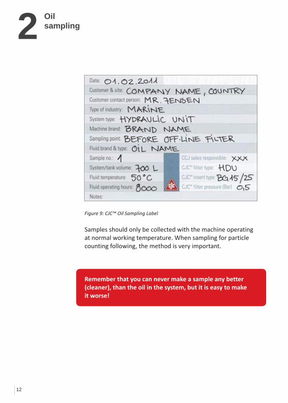
Samples should only be collected with the machine operating at normal working temperature. When sampling for particle counting following, the method is very important.
Remember that you can never make a sample any better (cleaner), than the oil in the system, but it is easy to make it worse!
Figure 9: CJC™ Oil Sampling Label
13
2Oilsampling
Vacuum pump
Step
1St
ep 2
Step
3St
ep 4
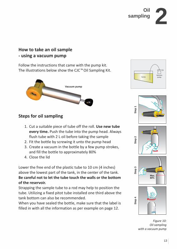
How to take an oil sample- using a vacuum pump
Follow the instructions that came with the pump kit. The illustrations below show the CJC™ Oil Sampling Kit.
Steps for oil sampling
1. Cut a suitable piece of tube off the roll. Use new tube every time. Push the tube into the pump head. Always flush tube with 2 L oil before taking the sample
2. Fit the bottle by screwing it unto the pump head 3. Create a vacuum in the bottle by a few pump strokes, and fill the bottle to approximately 80% 4. Close the lid
Lower the free end of the plastic tube to 10 cm (4 inches) above the lowest part of the tank, in the center of the tank. Be careful not to let the tube touch the walls or the bottom of the reservoir. Strapping the sample tube to a rod may help to position the tube. Utilizing a fixed pitot tube installed one third above the tank bottom can also be recommended.When you have sealed the bottle, make sure that the label is filled in with all the information as per example on page 12.
Figure 10: Oil sampling
with a vacuum pump
SumpVacuumpump
Max. 80%
14
3Oil sample analysis
As a minimum, an oil analysis should include: • aparticlecount • watercontentinppm • viscosity • aciditylevel(TAN)
In oil systems prone to varnish problems e.g. gas turbines and hydraulic control systems, it is recommended to do a varnish test. Methods are described on page 18.If the oil additive content is of interest, a spectral analysis should be included (AES or ICP). The trend is of highest importance, so it is vital to have a baseline showing the additive package in the new oil.It is recommended that the initial tests are performed by an independent laboratory with expert knowledge on lubricants.
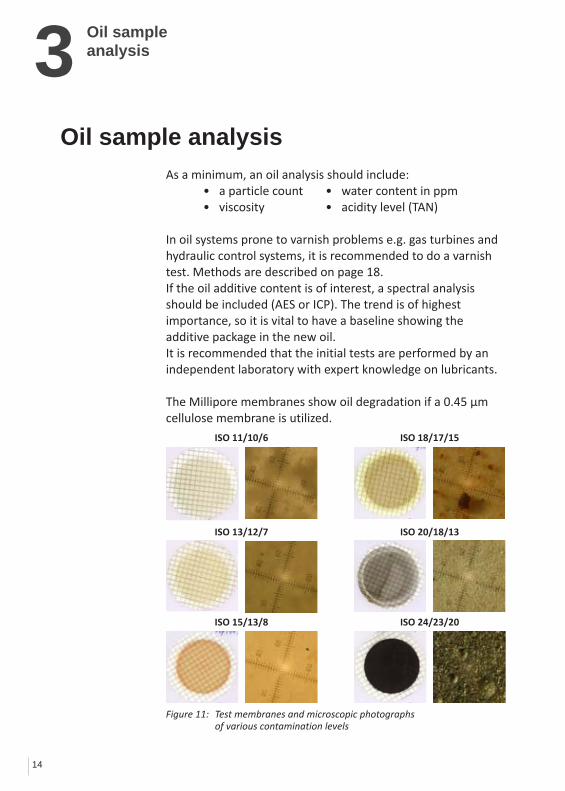
The Millipore membranes show oil degradation if a 0.45 µm cellulose membrane is utilized.
Oil sampleanalysis
ISO 11/10/6
ISO 13/12/7
ISO 18/17/15
ISO 20/18/13
ISO 15/13/8 ISO 24/23/20
Figure 11: Test membranes and microscopic photographs of various contamination levels

3
15
ISO StandardsThe ISO 4406/1999. Method for coding the level of contamination by solid particles, was introduced to facilitate comparisons in particle counting, using automatic particle counters. Here particles are counted in size 4/6/14 µm.
ISO 4407/1999 is describing particle counting using a microscope (particle sizes 2/5/15 µm).
For example a typical sample from new bulk oil, contains in every 100 mL of oil as follows:
450,000 particles ≥ 4 micron 120,000 particles ≥ 6 micron 14,000 particles ≥ 14 micron
In the ISO classification table (on the right), this oil sample has a contamination class of 19/17/14.
Some laboratories give the particle counting per millilitre in stead of per 100 millilitre (mostly USA).
Oil sampleanalysis
Number of particles per 100 ml fluid after their size ranges
More than Till ISO Class
8,000,000 16,000,000 24
4,000,000 8,000,000 23
2,000,000 4,000,000 22
1,000,000 2,000,000 21
500,000 1,000,000 20
250,000 500,000 19
130,000 250,000 18
64,000 130,000 17
32,000 64,000 16
16,000 32,000 15
8,000 16,000 14
4,000 8,000 13
2,000 4,000 12
1,000 2,000 11
500 1,000 10
250 500 9
130 250 8
64 130 7
32 64 6
Figure 12: Contamination classes according to the ISO 4406/1999 standard
16
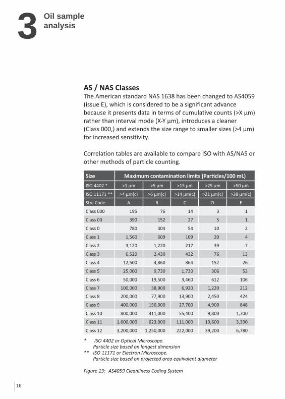
3AS / NAS ClassesThe American standard NAS 1638 has been changed to AS4059 (issue E), which is considered to be a significant advance because it presents data in terms of cumulative counts (>X µm) rather than interval mode (X-Y µm), introduces a cleaner (Class 000,) and extends the size range to smaller sizes (>4 µm) for increased sensitivity.
Correlation tables are available to compare ISO with AS/NAS or other methods of particle counting.
Oil sampleanalysis
Size Maximum contamination limits (Particles/100 mL)
ISO 4402 * >1 µm >5 µm >15 µm >25 µm >50 µm
ISO 11171 ** >4 µm(c) >6 µm(c) >14 µm(c) >21 µm(c) >38 µm(c)
SIze Code A B C D E
Class 000 195 76 14 3 1
Class 00 390 152 27 5 1
Class 0 780 304 54 10 2
Class 1 1,560 609 109 20 4
Class 2 3,120 1,220 217 39 7
Class 3 6,520 2,430 432 76 13
Class 4 12,500 4,860 864 152 26
Class 5 25,000 9,730 1,730 306 53
Class 6 50,000 19,500 3,460 612 106
Class 7 100,000 38,900 6,920 1,220 212
Class 8 200,000 77,900 13,900 2,450 424
Class 9 400,000 156,000 27,700 4,900 848
Class 10 800,000 311,000 55,400 9,800 1,700
Class 11 1,600,000 623,000 111,000 19,600 3,390
Class 12 3,200,000 1,250,000 222,000 39,200 6,780
* ISO 4402 or Optical Microscope. Particle size based on longest dimension** ISO 11171 or Electron Microscope. Particle size based on projected area equivalent diameter
Figure 13: AS4059 Cleanliness Coding System
17
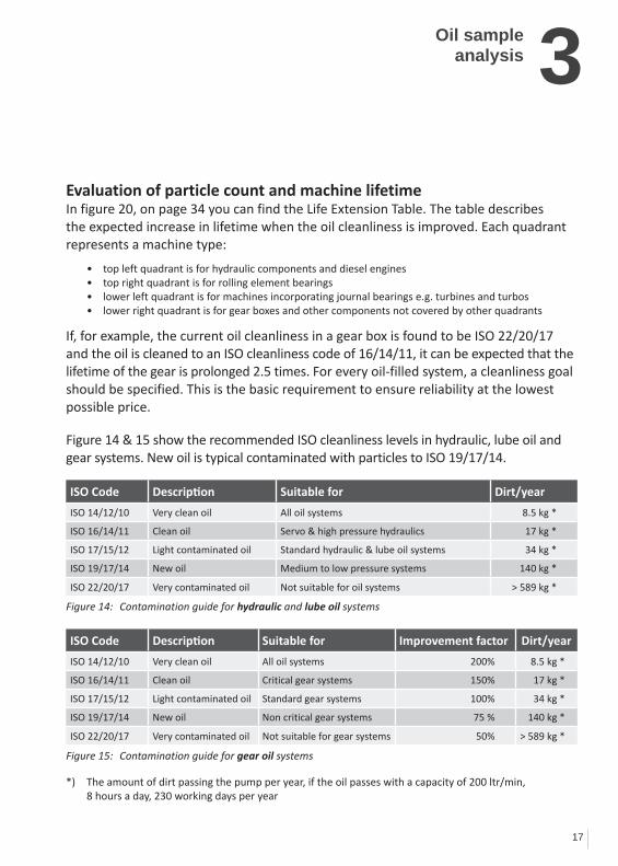
Evaluation of particle count and machine lifetimeIn figure 20, on page 34 you can find the Life Extension Table. The table describes the expected increase in lifetime when the oil cleanliness is improved. Each quadrant represents a machine type:
• topleftquadrantisforhydrauliccomponentsanddieselengines • toprightquadrantisforrollingelementbearings • lowerleftquadrantisformachinesincorporatingjournalbearingse.g.turbinesandturbos • lowerrightquadrantisforgearboxesandothercomponentsnotcoveredbyotherquadrants
If, for example, the current oil cleanliness in a gear box is found to be ISO 22/20/17 and the oil is cleaned to an ISO cleanliness code of 16/14/11, it can be expected that the lifetime of the gear is prolonged 2.5 times. For every oil-filled system, a cleanliness goal should be specified. This is the basic requirement to ensure reliability at the lowest possible price.
Figure 14 & 15 show the recommended ISO cleanliness levels in hydraulic, lube oil and gear systems. New oil is typical contaminated with particles to ISO 19/17/14.
ISO Code Description Suitable for Dirt/year
ISO 14/12/10 Verycleanoil All oil systems 8.5 kg *
ISO 16/14/11 Clean oil Servo & high pressure hydraulics 17 kg *
ISO 17/15/12 Light contaminated oil Standard hydraulic & lube oil systems 34 kg *
ISO 19/17/14 New oil Medium to low pressure systems 140 kg *
ISO 22/20/17 Verycontaminatedoil Not suitable for oil systems > 589 kg *
Figure 14: Contamination guide for hydraulic and lube oil systems
ISO Code Description Suitable for Improvement factor Dirt/year
ISO 14/12/10 Verycleanoil All oil systems 200% 8.5 kg *
ISO 16/14/11 Clean oil Critical gear systems 150% 17 kg *
ISO 17/15/12 Light contaminated oil Standard gear systems 100% 34 kg *
ISO 19/17/14 New oil Non critical gear systems 75 % 140 kg *
ISO 22/20/17 Verycontaminatedoil Not suitable for gear systems 50% > 589 kg *
Figure 15: Contamination guide for gear oil systems
*) The amount of dirt passing the pump per year, if the oil passes with a capacity of 200 ltr/min, 8 hours a day, 230 working days per year
3Oil sampleanalysis

18
3 Oil sampleanalysis
Analysis methods and frequenciesBefore establishing a trend, it is important to have a baseline sample of the fresh new oil. This will be used as reference for later comparison e.g. verifying if the additive package is still intact.
In the implementation phase of a condition monitoring system, analyses must be made frequently, at least every three months, but even better once per month in order to establish a trend. A useful trend consists of minimum eight progressive samples taking from the same oil system under the same operating conditions.
Every oil system should have a log where analysis results are registered. The logbook must also contain information about oil type, oil changes, break-downs, targeted ISO cleanliness code and oil analysis results.
Testing for varnish Many types of oil analysis can indicate the oil being degraded e.g. acid number (TAN), viscosity increase and FTIR, but at C.C.JENSEN we have found that the two following tests give a very detailed picture of the varnish problem:
1. Millipore patch test or colorimetric patch test (MPC) shows sludge/resin/varnish present in the oil by dis-colorization of the white cellulose patch. This indicates oil degradation products, also dissolved in the oil, which may or may not result in varnish on machine components (depending on the oil temperature). The darker the color and the higher the number (typically up to 100) the more the oil is prone to form varnish deposits.
19
3Oil sampleanalysis
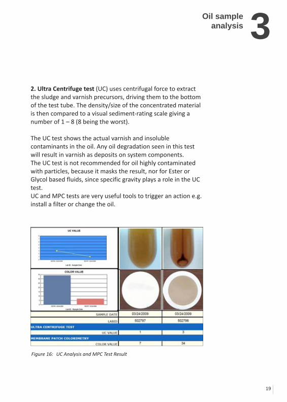
2. Ultra Centrifuge test (UC) uses centrifugal force to extract the sludge and varnish precursors, driving them to the bottom of the test tube. The density/size of the concentrated material is then compared to a visual sediment-rating scale giving a number of 1 – 8 (8 being the worst).
The UC test shows the actual varnish and insoluble contaminants in the oil. Any oil degradation seen in this test will result in varnish as deposits on system components.The UC test is not recommended for oil highly contaminated with particles, because it masks the result, nor for Ester or Glycol based fluids, since specific gravity plays a role in the UC test.UC and MPC tests are very useful tools to trigger an action e.g. install a filter or change the oil.
Figure 16: UC Analysis and MPC Test Result
4
20
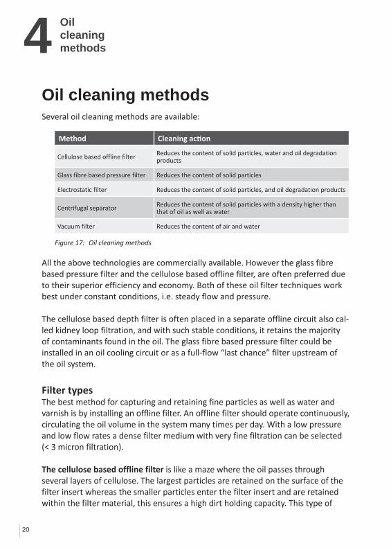
Method Cleaning action
Cellulose based offline filter Reduces the content of solid particles, water and oil degradation products
Glass fibre based pressure filter Reduces the content of solid particles
Electrostatic filter Reduces the content of solid particles, and oil degradation products
Centrifugal separator Reduces the content of solid particles with a density higher than that of oil as well as water
Vacuumfilter Reduces the content of air and water
Oil cleaning methodsSeveral oil cleaning methods are available:
All the above technologies are commercially available. However the glass fibre based pressure filter and the cellulose based offline filter, are often preferred due to their superior efficiency and economy. Both of these oil filter techniques work best under constant conditions, i.e. steady flow and pressure.
The cellulose based depth filter is often placed in a separate offline circuit also cal-led kidney loop filtration, and with such stable conditions, it retains the majority of contaminants found in the oil. The glass fibre based pressure filter could be installed in an oil cooling circuit or as a full-flow “last chance” filter upstream of the oil system.
Filter typesThe best method for capturing and retaining fine particles as well as water and varnish is by installing an offline filter. An offline filter should operate continuously, circulating the oil volume in the system many times per day. With a low pressure and low flow rates a dense filter medium with very fine filtration can be selected (< 3 micron filtration).
The cellulose based offline filter is like a maze where the oil passes through several layers of cellulose. The largest particles are retained on the surface of the filter insert whereas the smaller particles enter the filter insert and are retained within the filter material, this ensures a high dirt holding capacity. This type of
Oilcleaningmethods
Figure 17: Oil cleaning methods

4
21
filter can also be installed in a by-pass circuit, throttling the pressure of the system pump. Using a cellulose based offline filter also enables removal of water, by absorption or coalescing, and removal of oil degradation products such as sludge/varnish from the oil.Varnishcanberemovedfromoilsystemsthroughthedetergent/dispersantadditives in the oil, but the oil needs to be clean from particles, water and sludge before the additives are free to do the varnish cleaning job. Since sludge and varnish precipitate out of cold oil, typically between 10 - 40◦C (50 - 100◦F), cooling the oil in the offline filtration circuit combined with a cellulose based depth filter is highly effective.
The CJC™ Offline Filters removes oil degradation products such as sludge and varnish through polar attraction to the filter medium. A combination of adsorption and absorption fills each cellulose fibre with oil degradation products until the insert completely is saturated. The CJC™ Filter Inserts can hold up to 4 kgs (8 lbs) of varnish depending on type.
Conventional inline pressure filters are typically glass fibre based, because they need to operate under high pressure and high flow conditions, while creating as little restriction as possible. The filter element is pleated in order to increase the surface area and reduce the pressure drop.
Since they are installed after the main system pump, they often live a tough life with cyclic flows and many stops and starts, which is very harmful for the efficiency of any filter. Capturing and retaining fine silt particles is therefore very difficult, which is why most of these inline filters have a rating of 10 – 30 micron. However, many already captured particles will be released again when the filter is exposed to pressure shocks at stop/start.The glass fibre based pressure filter is capable of removing solid particles only – and due to the relatively small filter depth and volume, it has a restricted dirt holding capacity.
See illustrations on pages 22-23.
Modern oil systems often combine the two cleaning systems, where the offline filter removes the contamination and the inline pressure filter serves as security or “last chance” filter before critical components.
Oilcleaningmethods

22
4 Oilcleaningmethods
Glass fibre based pressure filter
End capseal
Core
Pleatsupportband
Mediumsupport
End cap
Element housing O-Ring
Filterelement Unfiltered oil entry
under high pressure
Filtered oilreturnedto oil circuit
Supportlayer
Filter mediumlayer
Outer filter casing
Oilflow
Filter mediumTrapped particles
Function
Pressure filters have a limited dirt holding capacity, usually between 1 and 100 grams, which results in filter element replacement at short intervals in order to ensure efficient filtration.
Typical filtration rating on inline pressure filters are 5 – 50 micron.
Conventional glass fibre based inline pressure fil-ters do not absorb water, nor retain oil degradation products such as sludge and varnish.
Support layer

23
4Oilcleaningmethods
Filtered oil returnedto the oil circuit
Unfiltered oil enters under pressure
Filter housing
Particles passthrough thefilter maze until they are trapped
Filter InsertMade of corrugated wood cellulose discs rotated at 90° to the next and bonded together. This gives a series of connected surfaces with corrugations running north-south and east-west.
The CJC™ Offline Filter has a large dirt holding capa-city of approximately 4 L solids, up to 2 L of water and 4 L oil degradation products (varnish). The CJC™ Offline Filters typically only need replacing every 12 months.
The CJC™ Offline Filter will filter effectively down to 3 µm absolute and remove water and oil degrada-tion products (oxidation products, resin, sludge and varnish) from the oil, continuously cleaning machine components and the whole oil system.
Function
Cellulose based offline filter

5
24
ßx =
Nominal filtration ratings are estimated values, indicating a particulate size range at which the filter is claimed to remove a given percentage. There is no standard for this, so consequently, different products/makes cannot be compared. Operating pressure and concentration of contaminants will affect the retention efficiency of filters with nominal rating.
Absolute filtration ratings describe the pore size, indicating the largest size of particle which can pass through the filter. The filter needs to apply to a standard test method intended for filter usage.The rating of a cellulose based offline filter is often 3 µm absolute or less. The rating of a glass fibre based pressure filter varies according to the requirements of the system component(s) to be protected.
Beta values describe filter efficiencies at given particle sizes. The value is written ßx, where the ”x” represents the particle size in question and ß (”beta”) is the efficiency e.g. ß3 = 200, which means that one out of 200 particles of 3 micron in size will pass through the filter (0.5% passes through and 99.5% are retained in one pass).In order to find the Beta value a standardized “Multipass test ISO 16889” is used, and the Beta value is calculated by the following formula.
number of particles upstream > x (NU) number of particles downstream > x (ND)
This Multipass test is performed under controlled laboratory conditions and does not take into account some of the challenges an inline pres-sure filter will see in most oil systems, such as air bubbles, vibrations, pressure pulses from stop-start etc.
Contaminant
Test filter
ND
NU
ßX = NU
ND
Filter efficiency
E = x 100ßX - 1
ßX
Basic filtration definitions
Basicfiltrationdefinitions
Figure 18: Multipass testSource: ISO Standards
5
25
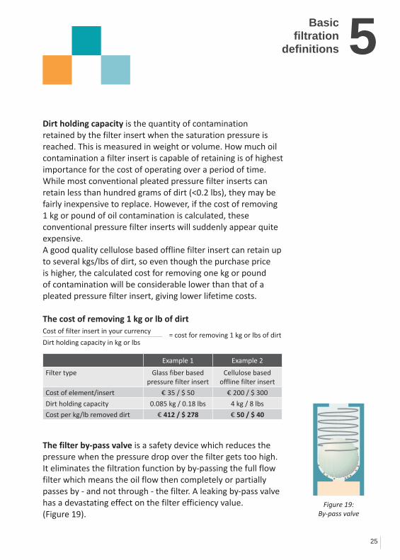
Dirt holding capacity is the quantity of contamination retained by the filter insert when the saturation pressure is reached. This is measured in weight or volume. How much oil contamination a filter insert is capable of retaining is of highest importance for the cost of operating over a period of time.While most conventional pleated pressure filter inserts can retain less than hundred grams of dirt (<0.2 lbs), they may be fairly inexpensive to replace. However, if the cost of removing 1 kg or pound of oil contamination is calculated, these conventional pressure filter inserts will suddenly appear quite expensive.A good quality cellulose based offline filter insert can retain up to several kgs/lbs of dirt, so even though the purchase price is higher, the calculated cost for removing one kg or pound of contamination will be considerable lower than that of a pleated pressure filter insert, giving lower lifetime costs.
The cost of removing 1 kg or lb of dirtCost of filter insert in your currency
Dirt holding capacity in kg or lbs
The filter by-pass valve is a safety device which reduces the pressure when the pressure drop over the filter gets too high. It eliminates the filtration function by by-passing the full flow filter which means the oil flow then completely or partially passes by - and not through - the filter. A leaking by-pass valve has a devastating effect on the filter efficiency value. (Figure 19).
Basicfiltration
definitions
Figure 19: By-pass valve
= cost for removing 1 kg or lbs of dirt
Example 1 Example 2
Filter type Glass fiber based pressure filter insert
Cellulose based offline filter insert
Cost of element/insert € 35 / $ 50 € 200 / $ 300
Dirt holding capacity 0.085 kg / 0.18 lbs 4 kg / 8 lbs
Cost per kg/lb removed dirt € 412 / $ 278 € 50 / $ 40
6
26
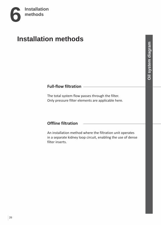
Full-flow filtration
The total system flow passes through the filter. Only pressure filter elements are applicable here.
Offline filtration
An installation method where the filtration unit operates in a separate kidney loop circuit, enabling the use of densefilter inserts.
Installation methods
Oil
syst
em d
iagr
am
Installation methods

6
27
Installation methods
FLOW
H2O
SUMP
Offline filter
In-linefilter
System pump
FLO
W
Contaminants can pass the filter when by-pass valves cannot close completely after they have opened.
Milliporemembrane. Sample taken after offline filtration.
Contaminated Millipore
membrane. Sample taken before offline
filtration.
If the inline filter is not changed regularly it will clog and allow particles to pass through the by-pass valve.

7
28
Before investing in a filtration system, a cost benefit study should be carried out. The involved costs can be divided into two groups: • Purchase costs: costs directly related to the purchase of a filtration system, i.e. purchase price and installation costs. • Operational costs: costs for keeping the filtration system unit in operation, i.e. replacement of filter inserts, energy consumption and repairs.
Purchase Costs + Operational Costs = Total Investment
The total investment has to be lower than the savings obtained through clean oil. • Savings: the reductions in maintenance costs, the
minimizing of lost production hours, prolonged service intervals, longer oil lifetime, extended component life, etc.
In most applications the payback period or the Return Of Investment for a CJC™ Offline Filter is typically from a few weeks up to some month, but rarely more than one year.In industries where any downtime is very costly e.g. steel production, the payback period can be a few hours. This means that if the improved oil condition leads to e.g. just 3 hours of additional production, the filtration system has paid for itself. Because the operation cost of the filter solution also plays a role in the total investment, it is relevant to look at how much oil contamination the filter is capable of retaining – the so-called dirt holding capacity. Most conventional pressure filters can retain less than hundred grams of dirt (less than 0.2 lbs), so they will need to be replaced more often than a good quality cellulose based offline filter capable of retaining several kg or lbs of dirt.The cost of removing 1 kg (or pound) of dirt from the oil is a good factor for comparing different filter makes and help to find the lowest cost of ownership (the total investment).See the calculation of the cost for removing 1 lb dirt on page 25.
Economy
Economy

8
29
Orderinga filtration
system
In the quote for a filtration system from any supplier the following should be included:
• Operationalcostsofthefilteroveraperiodofmin. 5 years (power, filter inserts, spares etc.) • Obtainablefluidsystemcleanlinesslevel (e.g. ISO 17/15/12 and 200 ppm water) • Controlprocedureconfirmingthatthecleanliness level has been achieved (e.g. oil samples)
Offline filter sizingWhen sizing an offline filter the following basic information about the oil system should be specified:
• Oilvolumeinthesystem(tankvolume) • Oiltype(ISOVG) • Oiltemperature:Normaloperationandminimum temperatures (ambient) • Oilcontaminationproblem: ○ particles ○ oil degradation products, sludge and varnish ○ water (ingress or accumulated) • Typeofapplication(indoor/clean,outdoor/dirty, severe ingress etc.) • Machineoperatinghoursperday • Availablepowersupply
This information will help your local distributor to size the correct CJC™ Filter for your oil system.
Aside from continuous filtration of the oil in machines, drums or bulk tanks, the CJC™ Offline Filters can also be utilized for filling and topping up with oil, thus ensuring that only clean oil enters the system.
Ordering a filtration system

30
9 CJC™ Oil MaintenanceSystems
CJC™ HDU Fine Filter • Dry oil with limited water content (accumulated over time) • Hydraulic, lube and gear oils – also Glycols or Ester based fluids • Retains particles and varnish • Water removal by absorption (free, emulsified and some dissolved water) • Reduce acidity level utilizing ion exchange inserts
CJC™ PTU Filter Separator • Water contaminated oil and diesel • Hydraulic,lubeandgearoils–uptoISOVG150 • Retains particles and varnish • Free water is removed by separation (coalescing) • Suitable for oil with good demulsibility (not engine oil, Ester based fluids etc.)
CJC™ Desorbers • Water contaminated oil – even with strong emulsions • Hydraulic,lubeandgearoils–uptoISOVG1000 (depending on Desorber type) • Removes both free, emulsified and dissolved water • Suitable for most oils even engine oil, paper machine oil etc.CJC™ Desorbers do not retain particles and varnish, thus a separate CJC™ HDU Fine Filter is recommended.
CJC™ Varnish Removal Unit • Dry oil with limited water content • Retains varnish very effectively • Suitable for systems with servere varnish production e.g. gas turbines
CJC™ Oil Maintenance Systems
31
10Handling of oiland oil systems
New oil in containers • Newoilshouldbeconsideredcontaminateduntila sample has been analyzed • Oilscontainingadditivesthatarenotnecessaryfor the application are to be considered contaminated • Newoilshouldalwaysbeintroducedtothesystem via a filter, preferably a 3 µm absolute filter • Donotmixoilswithoutpreviouslyinvestigating compatibility • Keeplubricatingproductsinclosedcontainersto
avoid ingress of contaminants
Oil in the system • Observetheoilregularlyduringoperationinorderto discover any sudden appearance of water, air or other contaminants. Using fresh oil as a reference may be he lpful • Checktheoilaftermachinemalfunctionsorother incidents which might affect the oil • Alwaysobservemaximumcleanlinessandaccuracy during sampling • Systemsshouldbesealedasmuchaspossible.All
permanent openings should be equipped with venting filters (preferably desiccant breathers). All systems
should be equipped with permanent filter installations • Whenchangingtheoil,thetankandthesystemshould be emptied completely and the tank should be cleaned
manually of settlings, sludge etc. (this can be avoided by installing CJC™ Offline Filters)
• When replacing seals, only oil-resistant materials should be used. Compatibility with the oil should be checked. • Neverapplynewadditiveswithoutconsultingtheoil supplier/consultant. Ask for written confirmation of the measures to be taken • Alwaysuseindependentanalysisresourceswithhigh quality control and repeatability
Handling of oil and oil systems

11
32
Recommendationsfor buying oil
When buying oil in bulk, buyers have a right to set specific certified requirements to ensure the quality. Below find some examples of requirements and test for the quality of the oil, emphasizing oil cleanliness.
Oil test certificates and test samplingThe results of an oil test of the batch should be presented to the buyer. A sample should be taken during the filling of the first batch. Samples should be marked with the trademark, batch number and size of the consignment. The oil should be analyzed by an independent laboratory and the analysis should include the data described in the oil analysis section of this booklet.
ClaimsIf the oil supplied does not fulfill requirements, returning the consignment might be considered. If the problem can be corrected, new samples must be approved. The supplier must pay all costs, including machinery failure and downtime.
Recommendations for buying oil

11
33
Recommendations for buying oil
Sampling of new oilSamples must be drawn from each manufactured batch. The analysed sample must be a representative sample of the manufactured batch. Test records must be available for the buyer for at least five years.
An analysis certificate must be delivered together with the ordered oil and include at least the following items:
• Visualinspection • Viscosity@40◦C • Density • TotalAcidNumberoffinishedproduct • Airbubbleseparationtime • Contaminants,gravimetricorISOcleanlinesscode
For wind turbine oils, foaming at 50◦C could be included.
The oil must be delivered by tanker trucks, epoxy-painted drums or 20-litre cans. The buyer must indicate the type of container for each individual case. The container must be of first class quality and the type generally used in the oil trade. The container must be marked with the buyer’s trade description, the suppliers trade designation, net content and a continuous manufacturing batch number.

34
12 Appendix
AppendixCLEAN OILBRIGHT IDEAS
Life Extension TableBRIGHT IDEAS
www.cjc.dk
LET – Cleanliness Level ISO Codes CompleteISO Codes, Complete
Current Machine
Cleanliness (ISO C d )
Expected Cleanliness level (ISO Code)
21/19/16 20/18/15 19/17/14 18/16/13 17/15/12 16/14/11 15/13/10 14/12/9 13/11/8 12/10/7
Source: Noria Corp.
(ISO Code)
24/22/19 2 1.61.8 1.3
3 22.3 1.7
4 2.53 2
6 33.5 2.5
7 3.54.5 3
8 45.5 3.5
>10 57 4
>10 68 5
>10 7 10 5.5
>10 >10 >10 8.5
23/21/18 1.5 1.51.5 1.3
2 1.71.8 1.4
3 22.2 1.6
4 2.53 2
5 33.5 2.5
7 3.54.5 3
9 45 3.5
>10 57 4
>10 7 9 5.5
>10 10 10 81.5 1.3 1.8 1.4 2.2 1.6 3 2 3.5 2.5 4.5 3 5 3.5 7 4 9 5.5 10 8
22/20/17 1.3 1.21.2 1.05
1.6 1.51.5 1.3
2 1.71.8 1.4
3 2 2.3 1.7
4 2.53 2
5 33.5 2.5
7 45 3
9 56 4
>10 7 8 5.5
>10 9 10 7
21/19/16 1.3 1.21.2 1.1
1.6 1.51.5 1.3
2 1.71.8 1.5
3 22.2 1.7
4 2.53 2
5 33.5 2.5
7 45 3.5
9 67 4.5
>10 8 9 6
20/18/15 1.3 1.21.2 1.1
1.6 1.51.5 1.3
2 1.71.8 1.5
3 22.3 1.7
4 2.53 2
5 33.5 2.5
7 4.65.5 3.7
>10 6 8 5
19/17/14 1.3 1.21.2 1.1
1.6 1.51.5 1.3
2 1.71.8 1.5
3 22.3 1.7
4 2.53 2
6 34 2.5
8 56 3.5
1 3 1 2 1 6 1 5 2 1 7 3 2 4 3 5 6 4Hydraulics Rolling18/16/13 1.3 1.21.2 1.1
1.6 1.51.5 1.3
2 1.71.8 1.5
3 22.3 1.8
4 3.53.7 3
6 44.5 3.5
17/15/12 1.3 1.21.2 1.1
1.6 1.51.5 1.4
2 1.71.8 1.5
3 22.3 1.8
4 2.53 2.2
16/14/11 1.3 1.31 3 1 2
1.6 1.61 6 1 4
2 1.81 9 1 5
3 22 3 1 8
Hydraulicsand Diesel Engines
Rolling Element Bearings
Journal Bearings Gear
Boxes
C.C.JENSEN A/S - LET, Cleanliness Level, ISO Codes, Complete – No. 17-01, April 2007 Page 1
16/14/11 1.3 1.2 1.6 1.4 1.9 1.5 2.3 1.8
15/13/10 1.4 1.21.2 1.1
1.8 1.51.6 1.3
2.5 1.82 1.6
and Turbo Machinery
Boxes and others
CLEAN OILBRIGHT IDEAS
Life Extension MethodBRIGHT IDEAS
www.cjc.dk
LEM - MOISTURE LevelSource: Noria Corp.
Current Moisture Level, ppm
Life Extension Factor
2 3 4 5 6 7 8 9 10
Source: Noria Corp.
50,000 12,500 6,500 4,500 3,125 2,500 2,000 1,500 1,000 782
25,000 6,250 3,250 2,250 1,563 1,250 1,000 750 500 391
10 000 2 500 1 300 900 625 500 400 300 200 15610,000 2,500 1,300 900 625 500 400 300 200 156
5,000 1,250 650 450 313 250 200 150 100 78
2,500 625 325 225 156 125 100 75 50 39
1,000 250 130 90 63 50 40 30 20 16
500 125 65 45 31 25 20 15 10 8
260 63 33 23 16 13 10 8 5 4
1% water = 10,000 ppm. ● Estimated life extension for mechanical systems utilizing mineral-based fluids.
260 63 33 23 16 13 10 8 5 4
100 25 13 9 6 5 4 3 2 2
C.C.JENSEN A/S - LEM, MOISTURE Level, No. 17-03, April 2007 Page 1
Example: By reducing average fluid moisture levels from 2500 ppmto 156 ppm, machine life (MTBF) is extended by a factor of 5.
Figure 20: Life Extension Table, cleanliness level
Figure 21: Life Extension Method, moisture level

Clean Oil GuideSixth Edition 2011English version
Published by:C.C. JENSEN A/SSvendborg, Denmark
Revision & layout:C.C.JENSEN A/S, Marketing DepartmentSvendborg, Denmark
Print:Tryk TeamSvendborg, Denmark
Sources:”Chemistry in electrical apparatuses”Lars ArvidssonVästerasPetroleumKemiABC.C.JENSEN A/S

BelgiumC.C.JENSEN BelgiumTel.: +32 484 25 36 [email protected]
Benelux C.C.JENSEN Benelux B.V.Tel.: +31 182 37 90 [email protected]
Chile C.C.JENSEN S.L. LimitadaTel.: +56 2 739 2910 [email protected] www.ccjensen.cl
ChinaC.C.JENSEN A/S ChinaTel: +86 10 6436 [email protected]
DenmarkC.C.JENSEN DanmarkTel: +45 7228 [email protected]
FranceC.C.JENSEN FranceTel: +33 3 59 56 16 [email protected]
GermanyKARBERG & HENNEMANN GmbH & Co. KGTel: +49 (0)40 855 04 79 [email protected]
Greece C.C.JENSEN Greece LTD.Tel.: +30 210 42 81 [email protected]
Ireland C.C.JENSEN IrelandTel.: +353 61 374 [email protected]
ItalyKARBERG & HENNEMANN srlTel: +39 059 29 29 [email protected]
Poland C.C.JENSEN Polska Sp. z o.o.Tel.: +48 22 648 83 [email protected]
Spain C.C.JENSEN Ibérica, S. L.Tel.: +34 93 590 63 [email protected]
United Arab Emirates C.C.JENSEN Middle EastTel: +971 4 447 [email protected]
United Kingdom C.C.JENSEN LTD.Tel.: +44 1 388 420 [email protected]
USA C.C.JENSEN INC.Tel.: +1 770 692 [email protected]
C.C.JENSEN Subsidiaries and Sales Offices
Your Local CJC™ Distributor We are represented globally by distributors. Find your nearest distributor on our website: www.cjc.dk
- or give us a call.
Head office: C.C.JENSEN A/SLøvholmen 13 | DK - 5700 Svendborg | Denmark Tel. +45 6321 2014 | Fax: +45 6222 [email protected] | www.cjc.dk
TekTradeBalticVeerenni 56a, Tallinn 11313Tel: +372 6546610, 372 5040732e-mail: [email protected]