cleanroom gripper type rcp2w-gr - atb automation gripper type rcp2w-gr cleanroom gripper type...
TRANSCRIPT
w w w . r o b o c y l i n d e r . d e
GB
RCP2W-GRDust-proof Gripper Type
RCP2CR-GRCleanroom Gripper Type
Cleanroom
Dust-proof
Cleanroom Type and Dust-proof Type Available
Cleanroom Type and Dust-proof Type are added to the gripper slider type. They are optimized for gripper use in cleanrooms and dusty environments.
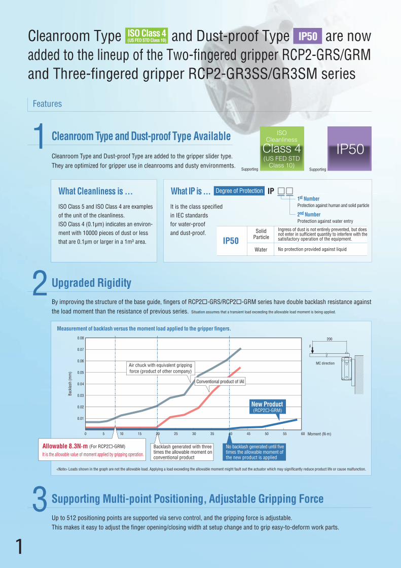
By improving the structure of the base guide, fingers of RCP2-GRS/RCP2-GRM series have double backlash resistance againstthe load moment than the resistance of previous series. Situation assumes that a transient load exceeding the allowable load moment is being applied.
Measurement of backlash versus the moment load applied to the gripper fingers.
Upgraded Rigidity
Up to 512 positioning points are supported via servo control, and the gripping force is adjustable.This makes it easy to adjust the finger opening/closing width at setup change and to grip easy-to-deform work parts.
Supporting Multi-point Positioning, Adjustable Gripping Force
What Cleanliness is ...
ISO Class 5 and ISO Class 4 are examplesof the unit of the cleanliness. ISO Class 4 (0.1µm) indicates an environ-ment with 10000 pieces of dust or lessthat are 0.1µm or larger in a 1m³ area.
0
0.08
0.07
0.06
0.05
0.04
0.03
0.02
0.01
200
F
MC direction
Back
lash
(mm
)
5 1 Moment (N·m)
New Product(RCP2-GRM)
Air chuck with equivalent grippingforce (product of other company)
Backlash generated with three times the allowable moment on conventional productIt is the allowable value of moment applied by gripping operation.
Allowable 8.3N·m
Supporting Supporting
ISOCleanliness
Class 4(US FED STD
Class 10)
IP50
Features
Cleanroom Type and Dust-proof Type are now added to the lineup of the Two-fingered gripper RCP2-GRS/GRM and Three-fingered gripper RCP2-GR3SS/GR3SM series
ISO Class 4(US FED STD Class 10) IP50IP50
1
2
3
(For RCP2-GRM)
<Note> Loads shown in the graph are not the allowable load. Applying a load exceeding the allowable moment might fault out the actuator which may significantly reduce product life or cause malfunction.
Conventional product of IAI
IP50Ingress of dust is not entirely prevented, but does not enter in sufficient quantity to interfere with the satisfactory operation of the equipment.
Solid Particle
No protection provided against liquid.Water
1st NumberProtection against human and solid particle
2nd NumberProtection against water entry
What IP is ... Degree of Protection IP
It is the class specified in IEC standards for water-proofand dust-proof.
No backlash generated until five times the allowable moment of the new product is applied
1
0 15 20 25 30 35 40 45 50 55 60
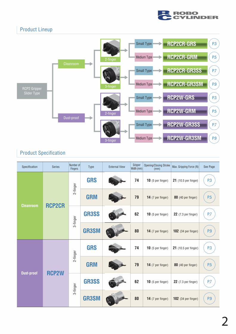
Product Lineup
Product Specification
Small Type
Medium Type
Small Type
Medium Type
Small Type
Medium Type
Small Type
RCP2W-GR3SMMedium Type
2-finger
3-finger
2-finger
3-finger
RCP2CR-GRS
RCP2CR-GRM
RCP2CR-GR3SS
RCP2CR-GR3SM
RCP2W-GRS
RCP2W-GRM
RCP2W-GR3SSDust-proof
Cleanroom
RCP2 Gripper Slider Type
Cleanroom
Specification Series TypeNumber ofFingers External View See Page Gripper
Width (mm)Opening/Closing Stroke
(mm) Max. Gripping Force (N)
74
79
62
80
74
79
62
80
10 (5 per finger)
14 (7 per finger)
10 (5 per finger)
14 (7 per finger)
10 (5 per finger)
14 (7 per finger)
10 (5 per finger)
14 (7 per finger)
21 (10.5 per finger)
80 (40 per finger)
22 (7.3 per finger)
102 (34 per finger)
21 (10.5 per finger)
80 (40 per finger)
22 (7.3 per finger)
102 (34 per finger)
RCP2CR
GRS
GRM
GR3SS
GR3SM
GRS
GRM
GR3SS
GR3SM
RCP2WDust-proof
P.3
P.5
P.7
P.9
P.3
P.5
P.7
P.9
P.3
P.5
P.7
P.9
P.3
P.5
P.7
P.9
2-fin
ger
3-fin
ger
2-fin
ger
3-fin
ger
2
Type Cable Code
Standard TypeP (1m)S (3m)M (5m)
Special LengthX06 (6m) ~ X10 (10m)X11 (11m) ~ X15 (15m)X16 (16m) ~ X20 (20m)
Robot Cable (*)
R01 (1m) ~ R03 (3m)
* Robot cable is standard for applicable P1 controller.
R04 (4m) ~ R05 (5m)R06 (6m) ~ R10 (10m)R11 (11m) ~ R15 (15m)R16 (16m) ~ R20 (20m)
* Please note that, when gripping (pushing), the speed is fixed at 5mm/s.
* The gripping force graph above shows reference numbers. Please allow margins up to ±15%.
P
O I N T
Note on selection
(1) The maximum opening/closing speed indicates the operating speed on one side. The relative operating speed is twice this value.
(2) The maximum gripping force is the sum of the gripping forces of both fingers, at a gripping point where there is no offset or overhang distance. The work part weight that can be actually moved depends on the friction coefficient between the gripper fingers and the work part, as well as on the shape of the work part. As a rough guide, a work part's weight should not exceed 1/10 to 1/20 of the gripping force.
* The gripping point 0 should be the reference point of moment in the drawing.
(3) Refer to “How to Select Gripper” at the end of the RoboCylinder General Catalogfor how to select a gripper.
(4) The rated acceleration while moving is 0.3G.
Legend: 1 Applicable controllers 2 Cable length 3 Options
Actuator SpecificationsMax. Gripping Force and Stroke Stroke and Max. Opening/Closing Speed / Suction Amount
Cable Length
Options
Actuator Specifications
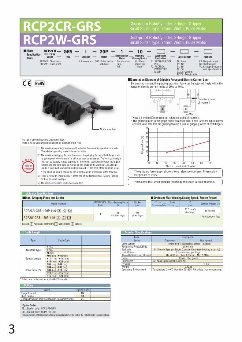
Air Vacuum Joint
00 10 20
Electric current limit (% ratio)30 40 50 60 70
5
10
15
20
25
30
35
Grip
ping
forc
e (N
)
Correlation Diagram of Gripping Force and Electric Current Limit By pressing motion, the gripping (pushing) force can be adjusted freely within the range of electric current limits of 20% to 70%.
* The figure above shows the Cleanroom Type. There is no air vacuum joint equipped on the Dust-proof Type.
L2
L1
Reference pointof moment
Name Option CodeFlange Bracket FBShaft Bracket SBL-shaped Vacuum Joint Specification (Cleanroom Only) VL
Item DescriptionSeries Cleanroom Dust-proof
Drive System Timing belt + trapezoidal screw (1.5 lead)Positioning Repeatability ±0.01mmBacklash 0.15mm or less per finger (constantly pressed out by a spring)Lost Motion 0.1mm or less per fingerAllowable Static Load Moment Ma: 6.3N·m Mb: 6.3N·m Mc: 7.0N·mGuide Cross roller guideCleanliness ISO class 4 (US STD FED class 10) — IP Code — IP50Weight 0.42kgOperating Environment Temperature 0~40°C Humidity 20~85% RH or less (non-condensing)
<Option Code>FB…Bracket only: RCP2-FB-GRSSB…Bracket only: RCP2-SB-GRS* Check the size of the bracket in the option explanation at the end of the RoboCylinder General Catalog.
10(mm)
Suction Amount (*)
1 33.3 mm/s(Per finger)
10 Nl/min
* For Cleanroom Type
StrokeDeceleration Ratio
Model Number Deceleration Ratio
Max. Gripping Force (N)
Stroke(mm)
RCP2CR-GRS-I-20P-1-10- 1 - 2 - 31 21
(10.5 per finger)10
(5 per finger)RCP2W-GRS-I-20P-1-10- 1 - 2 - 3
RCP2CR-GRSRCP2W-GRS Dust-proof RoboCylinder, 2-finger Gripper,
Small Slider Type, 74mm Width, Pulse Motor
Cleanroom RoboCylinder, 2-finger Gripper, Small Slider Type, 74mm Width, Pulse Motor
20P: Pulse motor 20 size
I: Incremental P1: PCON-PL/PO/SE PSEL
P3: PCON-CA PMEC/PSEP MSEP
N : NoneP : 1mS : 3mM : 5mX : CustomR : Robot cable
FB : Flange brackettekcarb tfahS : BS
VL : L-shaped vacuum joint specification
10: 10mm(5mm per
finger)
1: Deceleration ratio 1/1
RCP2CRRCP2W
RCP2CR : CleanroomRCP2W : Dust-proof
Model Specification Items
ISeries Encoder Applicable
Controllers Cable Length Options
GRSType
20PMotor
1Deceleration
Ratio
10Opening/
Closing Stroke
* Keep L1 within 50mm from the reference point of moment.* The gripping force in the graph below assumes that L1 and L2 in the figure above
are zero. Also note that the gripping force is a sum of gripping forces of both fingers.
3
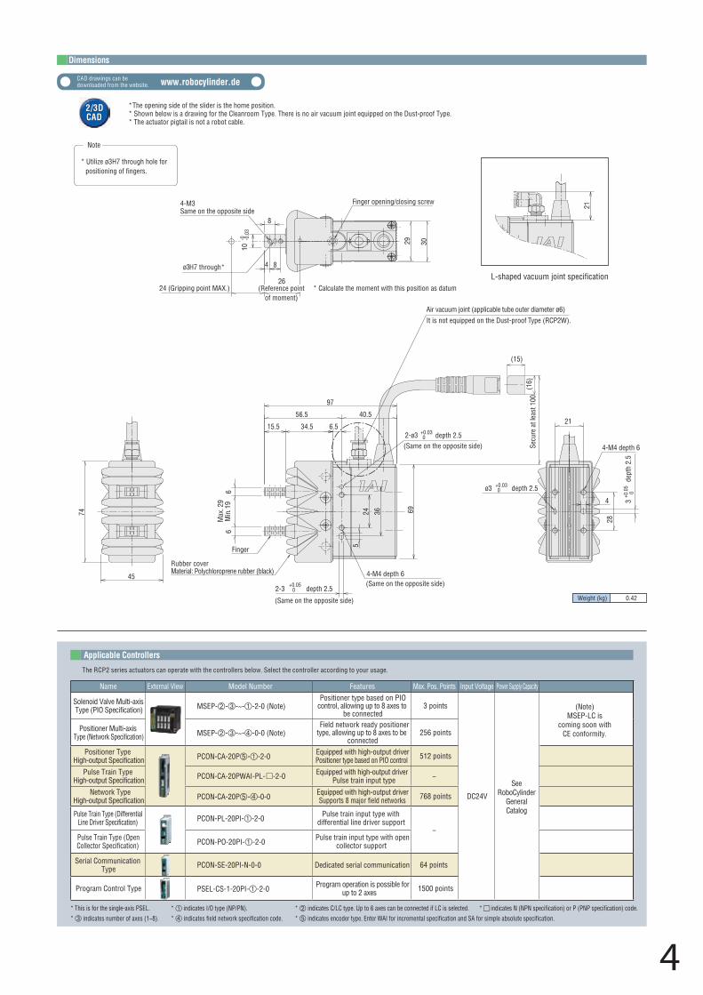
Weight (kg) 0.42
CAD drawings can be downloaded from the website. www.robocylinder.de
Dimensions
Applicable Controllers
The RCP2 series actuators can operate with the controllers below. Select the controller according to your usage.
Name External View Model Number Features Max. Pos. Points Input Voltage Power Supply Capacity
Solenoid Valve Multi-axis Type (PIO Specification) MSEP---~--2-0 (Note)
Positioner type based on PIO control, allowing up to 8 axes to
be connected3 points
DC24V
SeeRoboCylinder
GeneralCatalog
Positioner Multi-axis Type (Network Specification) MSEP---~--0-0 (Note)
Field network ready positioner type, allowing up to 8 axes to be
connected256 points
Positioner TypeHigh-output Specification PCON-CA-20P--2-0 Equipped with high-output driver
Positioner type based on PIO control 512 points
64 points
Pulse Train TypeHigh-output Specification PCON-CA-20PWAI-PL- -2-0 Equipped with high-output driver
Pulse train input type −
Network TypeHigh-output Specification PCON-CA-20P--0-0 Equipped with high-output driver
Supports 8 major field networks 768 points
Pulse Train Type (Differential Line Driver Specification) PCON-PL-20PI--2-0 Pulse train input type with
differential line driver support−
Pulse Train Type (Open Collector Specification) PCON-PO-20PI--2-0 Pulse train input type with open
collector support
Serial Communication Type PCON-SE-20PI-N-0-0 Dedicated serial communication
Program Control Type PSEL-CS-1-20PI--2-0 Program operation is possible for up to 2 axes 1500 points
2/3DCAD2/3DCAD
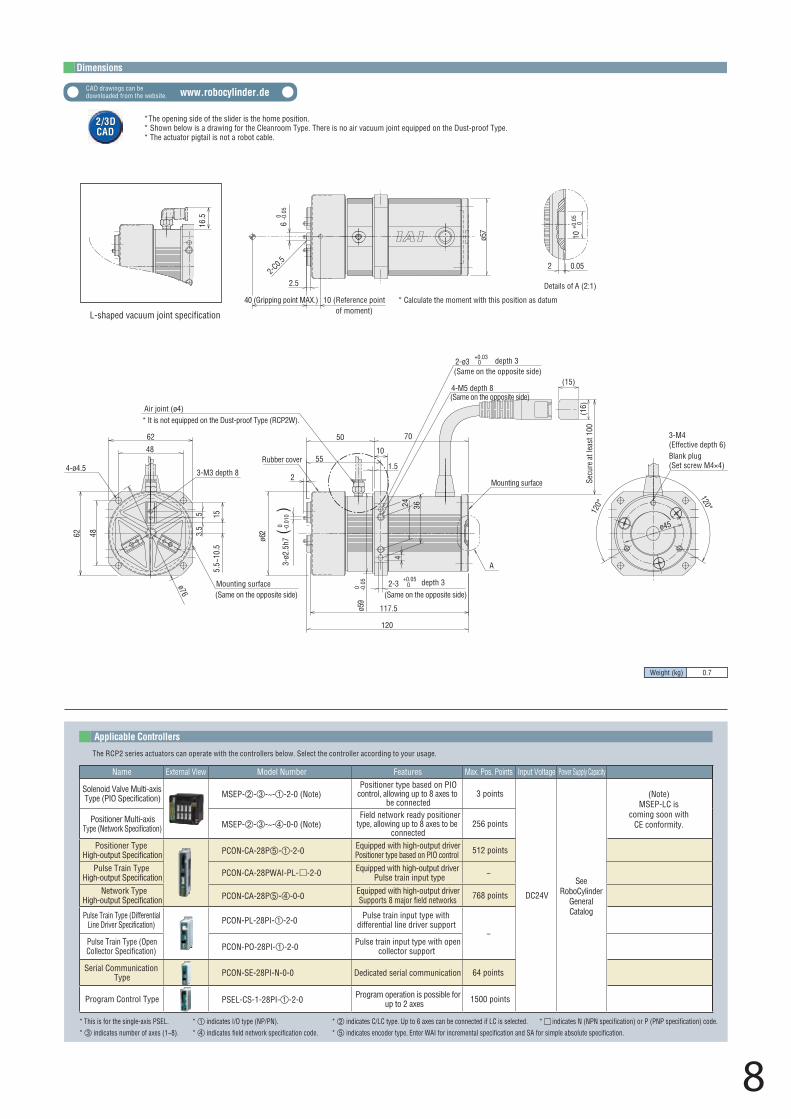
* The opening side of the slider is the home position.* Shown below is a drawing for the Cleanroom Type. There is no air vacuum joint equipped on the Dust-proof Type.* The actuator pigtail is not a robot cable.
* This is for the single-axis PSEL. * indicates I/O type (NP/PN). * indicates C/LC type. Up to 6 axes can be connected if LC is selected. * indicates N (NPN specification) or P (PNP specification) code.* indicates number of axes (1~8). * indicates field network specification code. * indicates encoder type. Enter WAI for incremental specification and SA for simple absolute specification.
4
8
26(Reference point
of moment)
3624
Note
* Calculate the moment with this position as datum
-010
-0.0
3
* Utilize ø3H7 through hole for positioning of fingers.
Finger opening/closing screw4-M3Same on the opposite side
4 8ø3H7 through*
24 (Gripping point MAX.)
29 30
Max
. 29
Min.
19
45
74
66
Rubber coverMaterial: Polychloroprene rubber (black)
Finger
(Same on the opposite side) 4-M4 depth 6
28
ø3 +0.03 0
+0.03 0
depth 2.5
3+0
.05
0de
pth
2.5
21
4
2-ø3 depth 2.5
Air vacuum joint (applicable tube outer diameter ø6)It is not equipped on the Dust-proof Type (RCP2W).
L-shaped vacuum joint specification
97
40.5
(Same on the opposite side)
(Same on the opposite side)
69
Secu
re a
t lea
st 1
00
2-3+0.05
0 depth 2.5
4-M4 depth 6
34.515.5
56.5
6.5
5
21
(15)
(16)
(Note)MSEP-LC is
coming soon withCE conformity.
* Please note that, when gripping (pushing), the speed is fixed at 5mm/s.
* The gripping force graph above shows reference numbers. Please allow margins up to ±15%.
Legend: 1 Applicable controllers 2 Cable length 3 Options
Actuator SpecificationsMax. Gripping Force and Stroke Stroke and Max. Opening/Closing Speed / Suction Amount
Air Vacuum Joint
00 10 20 30 40 50 60 70
20
40
60
80
100
120
140
Electric current limit (% ratio)
Grip
ping
forc
e (N
)
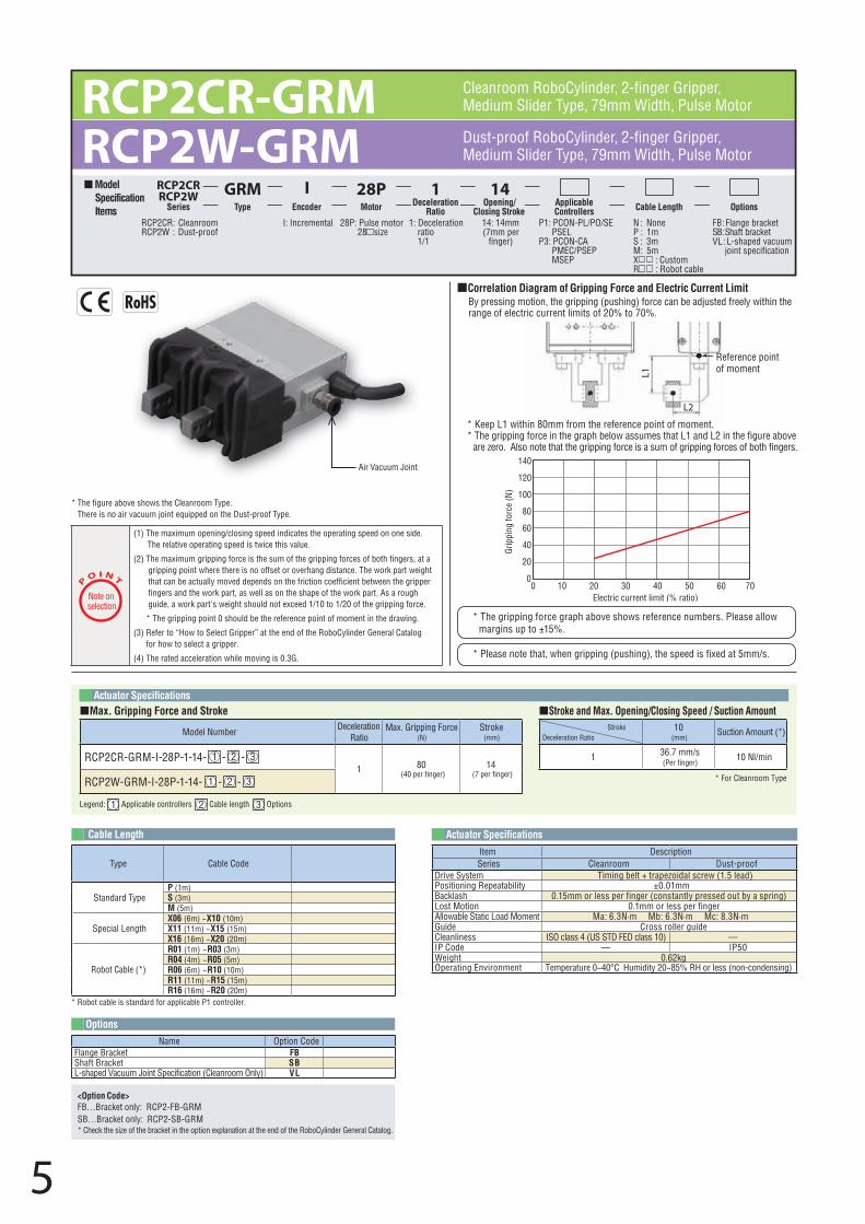
Correlation Diagram of Gripping Force and Electric Current Limit By pressing motion, the gripping (pushing) force can be adjusted freely within the range of electric current limits of 20% to 70%.
* The figure above shows the Cleanroom Type. There is no air vacuum joint equipped on the Dust-proof Type.
L2
L1
Reference pointof moment
RCP2CR-GRM RCP2W-GRM Dust-proof RoboCylinder, 2-finger Gripper,
Medium Slider Type, 79mm Width, Pulse Motor
Cleanroom RoboCylinder, 2-finger Gripper, Medium Slider Type, 79mm Width, Pulse Motor
Model Specification Items
Applicable Controllers Cable Length Options
10(mm)
Suction Amount (*)
1 36.7 mm/s(Per finger)
10 Nl/min
* For Cleanroom Type
StrokeDeceleration Ratio
Model Number Deceleration Ratio
Max. Gripping Force (N)
Stroke(mm)
RCP2CR-GRM-I-28P-1-14- 1 - 2 - 31 80
(40 per finger)14
(7 per finger)RCP2W-GRM-I-28P-1-14- 1 - 2 - 3
RCP2CRRCP2W
Series
GRMType
IEncoder
1Deceleration
Ratio
14Opening/
Closing Stroke
28PMotor
28P: Pulse motor 28 size
I: Incremental P1: PCON-PL/PO/SE PSEL
P3: PCON-CA PMEC/PSEP MSEP
N : NoneP : 1mS : 3mM : 5mX : CustomR : Robot cable
FB : Flange brackettekcarb tfahS : BS
VL : L-shaped vacuum joint specification
14: 14mm(7mm per
finger)
1: Deceleration ratio 1/1
RCP2CR : CleanroomRCP2W : Dust-proof
* Keep L1 within 80mm from the reference point of moment.* The gripping force in the graph below assumes that L1 and L2 in the figure above
are zero. Also note that the gripping force is a sum of gripping forces of both fingers.
5
P
O I N T
Note on selection
(1) The maximum opening/closing speed indicates the operating speed on one side. The relative operating speed is twice this value.
(2) The maximum gripping force is the sum of the gripping forces of both fingers, at a gripping point where there is no offset or overhang distance. The work part weight that can be actually moved depends on the friction coefficient between the gripper fingers and the work part, as well as on the shape of the work part. As a rough guide, a work part's weight should not exceed 1/10 to 1/20 of the gripping force.
* The gripping point 0 should be the reference point of moment in the drawing.
(3) Refer to “How to Select Gripper” at the end of the RoboCylinder General Catalogfor how to select a gripper.
(4) The rated acceleration while moving is 0.3G.
Type Cable Code
Standard TypeP (1m)S (3m)M (5m)
Special LengthX06 (6m) ~ X10 (10m)X11 (11m) ~ X15 (15m)X16 (16m) ~ X20 (20m)
Robot Cable (*)
R01 (1m) ~ R03 (3m)
* Robot cable is standard for applicable P1 controller.
R04 (4m) ~ R05 (5m)R06 (6m) ~ R10 (10m)R11 (11m) ~ R15 (15m)R16 (16m) ~ R20 (20m)
Cable Length
Options
Actuator Specifications
Name Option CodeFlange Bracket FBShaft Bracket SBL-shaped Vacuum Joint Specification (Cleanroom Only) VL
Item DescriptionSeries Cleanroom Dust-proof
Drive System Timing belt + trapezoidal screw (1.5 lead)Positioning Repeatability ±0.01mmBacklash 0.15mm or less per finger (constantly pressed out by a spring)Lost Motion 0.1mm or less per fingerAllowable Static Load Moment Ma: 6.3N·m Mb: 6.3N·m Mc: 8.3N·mGuide Cross roller guideCleanliness ISO class 4 (US STD FED class 10) — IP Code — IP50Weight 0.62kgOperating Environment Temperature 0~40°C Humidity 20~85% RH or less (non-condensing)
<Option Code>FB…Bracket only: RCP2-FB-GRMSB…Bracket only: RCP2-SB-GRM* Check the size of the bracket in the option explanation at the end of the RoboCylinder General Catalog.
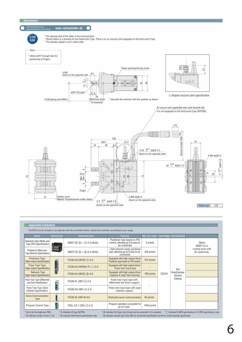
Weight (kg) 0.62
6
(15)
(16)
(Same on the opposite side)
(Same on the opposite side)
(Same on the opposite side)
Finger
Rubber coverMaterial: Polychloroprene rubber (black)
0
5
2-3 +0.050 depth 2.5
4-M4 depth 8
2-ø3 +0.03 0 depth 2.5
74
8
36
8
18
10847.560.5
6.5
Max
. 32
Min.
18
L-shaped vacuum joint specification
79
51
29 (Reference point
of moment)
4-M4Same on the opposite side
120 -0
.03
8.5
4 9ø3H7 through*
51(Gripping point MAX.) * Calculate the moment with this position as datum
Finger opening/closing screw
35 36
28
4-M4 depth 6
24
4 3+0
.05
0de
pth
2.5
ø3+0.03
depth 2.5
Air vacuum joint (applicable tube outer diameter ø6)It is not equipped on the Dust-proof Type (RCP2W).
24 36
21
Secu
re a
t lea
st 1
00
Note
* Utilize ø3H7 through hole for positioning of fingers.
Applicable Controllers
The RCP2 series actuators can operate with the controllers below. Select the controller according to your usage.
Name External View Model Number Features Max. Pos. Points Input Voltage Power Supply Capacity
Solenoid Valve Multi-axis Type (PIO Specification) MSEP---~--2-0 (Note)
Positioner type based on PIO control, allowing up to 8 axes to
be connected3 points
DC24V
SeeRoboCylinder
GeneralCatalog
Positioner Multi-axisType (Network Specification) MSEP---~--0-0 (Note)
Field network ready positioner type, allowing up to 8 axes to be
connected256 points
Positioner TypeHigh-output Specification PCON-CA-28P--2-0 Equipped with high-output driver
Positioner type based on PIO control 512 points
64 points
Pulse Train TypeHigh-output Specification PCON-CA-28PWAI-PL- -2-0 Equipped with high-output driver
Pulse train input type −
Network TypeHigh-output Specification PCON-CA-28P--0-0 Equipped with high-output driver
Supports 8 major field networks 768 points
Pulse Train Type (Differential Line Driver Specification) PCON-PL-28PI--2-0 Pulse train input type with
differential line driver support−
Pulse Train Type (Open Collector Specification) PCON-PO-28PI--2-0 Pulse train input type with open
collector support
Serial Communication Type PCON-SE-28PI-N-0-0 Dedicated serial communication
Program Control Type PSEL-CS-1-28PI--2-0 Program operation is possible for up to 2 axes 1500 points
* This is for the single-axis PSEL. * indicates I/O type (NP/PN). * indicates C/LC type. Up to 6 axes can be connected if LC is selected. * indicates N (NPN specification) or P (PNP specification) code.* indicates number of axes (1~8). * indicates field network specification code. * indicates encoder type. Enter WAI for incremental specification and SA for simple absolute specification.
(Note)MSEP-LC is
coming soon withCE conformity.
CAD drawings can be downloaded from the website. www.robocylinder.de
Dimensions
2/3DCAD2/3DCAD
* The opening side of the slider is the home position.* Shown below is a drawing for the Cleanroom Type. There is no air vacuum joint equipped on the Dust-proof Type.* The actuator pigtail is not a robot cable.
Legend: 1 Applicable controllers 2 Cable length 3 Options
Actuator SpecificationsMax. Gripping Force and Stroke Stroke and Max. Opening/Closing Speed / Suction Amount
P
O I N T
Note on selection
(1) The maximum gripping force is the sum of gripping forces of all fingers at grippingpoint 0 and with overhang distance 0. For the actual transportable work part weight,refer to the explanation to the right.
* The gripping point 0 should be the reference point of moment in the drawing.
(2) Refer to “How to Select Gripper” at the end of the RoboCylinder General Catalogfor how to select a gripper.
(3) The rated acceleration while moving is 0.3G.* The gripping force graph above shows reference numbers. Please allow
margins up to ±15%.
F
F
F
F
L
* Please note that, when gripping (pushing), the speed is fixed at 5mm/s.
Reference point of moment
00 10 20 30 40 50 60 70
5
10
15
20
25
30
35
Electric current limit (% ratio)
Grip
ping
forc
e (N
)
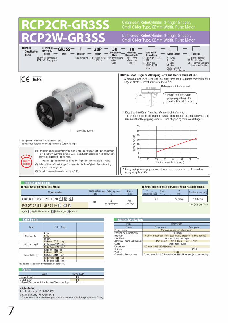
Correlation Diagram of Gripping Force and Electric Current Limit By pressing motion, the gripping (pushing) force can be adjusted freely within the range of electric current limits of 20% to 70%.
* Keep L within 50mm from the reference point of moment.* The gripping force in the graph below assumes that L in the figure above is zero.
Also note that the gripping force is a sum of gripping forces of all fingers.
* The figure above shows the Cleanroom Type. There is no air vacuum joint equipped on the Dust-proof Type.
Air Vacuum Joint
RCP2CR-GR3SSRCP2W-GR3SS Dust-proof RoboCylinder, 3-finger Gripper,
Small Slider Type, 62mm Width, Pulse Motor
Cleanroom RoboCylinder, 3-finger Gripper,Small Slider Type, 62mm Width, Pulse Motor
10(mm)
Suction Amount (*)
30 40 mm/s 10 Nl/min
* For Cleanroom Type
StrokeDeceleration Ratio
Model Number Deceleration Ratio
Max. Gripping Force (N)
Stroke(mm)
RCP2CR-GR3SS-I-28P-30-10- 1 - 2 - 330 22
(7.3 per finger)10
(5 per finger)RCP2W-GR3SS-I-28P-30-10- 1 - 2 - 3
RCP2CRRCP2W
Series
GR3SSType
IEncoder
30Deceleration
Ratio
10Opening/
Closing StrokeApplicable Controllers Cable Length Options
28PMotor
Model Specification Items
28P: Pulse motor 28 size
I: Incremental P1: PCON-PL/PO/SE PSEL
P3: PCON-CA PMEC/PSEP MSEP
N : NoneP : 1mS : 3mM : 5mX : CustomR : Robot cable
FB : Flange brackettekcarb tfahS : BS
VL : L-shaped vacuum joint specification
10: 10mm(5mm per
finger)
30: Deceleration ratio 1/30
RCP2CR : CleanroomRCP2W : Dust-proof
7
Type Cable Code
Standard TypeP (1m)S (3m)M (5m)
Special LengthX06 (6m) ~ X10 (10m)X11 (11m) ~ X15 (15m)X16 (16m) ~ X20 (20m)
Robot Cable (*)
R01 (1m) ~ R03 (3m)
* Robot cable is standard for applicable P1 controller.
R04 (4m) ~ R05 (5m)R06 (6m) ~ R10 (10m)R11 (11m) ~ R15 (15m)R16 (16m) ~ R20 (20m)
Cable Length
Options
Actuator Specifications
Name Option CodeFlange Bracket FBShaft Bracket SBL-shaped Vacuum Joint Specification (Cleanroom Only) VL
Item DescriptionSeries Cleanroom Dust-proof
Drive System Worm gear + worm wheel gearPositioning Repeatability ±0.01mmBacklash 0.3mm or less per finger (constantly pressed out by a spring)Lost Motion 0.1mm or less per fingerAllowable Static Load Moment Ma: 3.8N·m Mb: 3.8N·m Mc: 3.0N·mGuide Cross roller guideCleanliness ISO class 4 (US STD FED class 10) — IP Code — IP50Weight 0.7kgOperating Environment Temperature 0~40°C Humidity 20~85% RH or less (non-condensing)
<Option Code>FB…Bracket only: RCP2-FB-GR3SSB…Bracket only: RCP2-SB-GR3S* Check the size of the bracket in the option explanation at the end of the RoboCylinder General Catalog.
Weight (kg) 0.7
8
(16)
40 (Gripping point MAX.)
ø57
60 -0.0
52.5
2-C0.5
10 (Reference pointof moment)
2 0.05
10+0
.05
0
Details of A (2:1)
(Same on the opposite side)
3-M3 depth 8
ø76
62
4-ø4.5
Mounting surface
48
48
5.35
5.5~
10.5
15
62
ø45
24
L-shaped vacuum joint specification
* Calculate the moment with this position as datum
16.5
(Same on the opposite side)
Blank plug(Set screw M4×4)
2-3+0.05
0 depth 312
0°
Mounting surface
ø59
0 -0.0
5
120°
120
ø62
3-M4(Effective depth 6)
A
117.5
3-ø2
.5h7
0 -0.0
10
()
(Same on the opposite side)
(Same on the opposite side)
55
70
4-M5 depth 8
1.5
2-ø3+0.03
0 depth 3
10
50
2
Air joint (ø4)
Rubber cover
4
36* It is not equipped on the Dust-proof Type (RCP2W).
Secu
re a
t lea
st 1
00
(15)
Applicable Controllers
The RCP2 series actuators can operate with the controllers below. Select the controller according to your usage.
Name External View Model Number Features Max. Pos. Points Input Voltage Power Supply Capacity
Solenoid Valve Multi-axis Type (PIO Specification) MSEP---~--2-0 (Note)
Positioner type based on PIO control, allowing up to 8 axes to
be connected3 points
DC24V
SeeRoboCylinder
GeneralCatalog
Positioner Multi-axis Type (Network Specification) MSEP---~--0-0 (Note)
Field network ready positioner type, allowing up to 8 axes to be
connected256 points
Positioner TypeHigh-output Specification PCON-CA-28P--2-0 Equipped with high-output driver
Positioner type based on PIO control 512 points
64 points
Pulse Train TypeHigh-output Specification PCON-CA-28PWAI-PL- -2-0 Equipped with high-output driver
Pulse train input type −
Network TypeHigh-output Specification PCON-CA-28P--0-0 Equipped with high-output driver
Supports 8 major field networks 768 points
Pulse Train Type (Differential Line Driver Specification) PCON-PL-28PI--2-0 Pulse train input type with
differential line driver support−
Pulse Train Type (Open Collector Specification) PCON-PO-28PI--2-0 Pulse train input type with open
collector support
Serial Communication Type PCON-SE-28PI-N-0-0 Dedicated serial communication
Program Control Type PSEL-CS-1-28PI--2-0 Program operation is possible for up to 2 axes 1500 points
* This is for the single-axis PSEL. * indicates I/O type (NP/PN). * indicates C/LC type. Up to 6 axes can be connected if LC is selected. * indicates N (NPN specification) or P (PNP specification) code.* indicates number of axes (1~8). * indicates field network specification code. * indicates encoder type. Enter WAI for incremental specification and SA for simple absolute specification.
CAD drawings can be downloaded from the website. www.robocylinder.de
Dimensions
2/3DCAD2/3DCAD
* The opening side of the slider is the home position.* Shown below is a drawing for the Cleanroom Type. There is no air vacuum joint equipped on the Dust-proof Type.* The actuator pigtail is not a robot cable.
(Note)MSEP-LC is
coming soon withCE conformity.
Legend: 1 Applicable controllers 2 Cable length 3 Options
Actuator SpecificationsMax. Gripping Force and Stroke Stroke and Max. Opening/Closing Speed / Suction Amount
* The gripping force graph above shows reference numbers. Please allowmargins up to ±15%.
00 10 20 30 40 50 60 70
20
40
60
80
100
120
130
Electric current limit (% ratio)
Grip
ping
forc
e (N
)
Correlation Diagram of Gripping Force and Electric Current Limit By pressing motion, the gripping (pushing) force can be adjusted freely within the range of electric current limits of 20% to 70%.
* Keep L within 80mm from the reference point of moment.* The gripping force in the graph below assumes that L in the figure above is zero.
Also note that the gripping force is a sum of gripping forces of all fingers.
* The figure above shows the Cleanroom Type. There is no air vacuum joint equipped on the Dust-proof Type.
F
F
F
F
L
* Please note that, when gripping (pushing), the speed is fixed at 5mm/s.
Reference point of moment
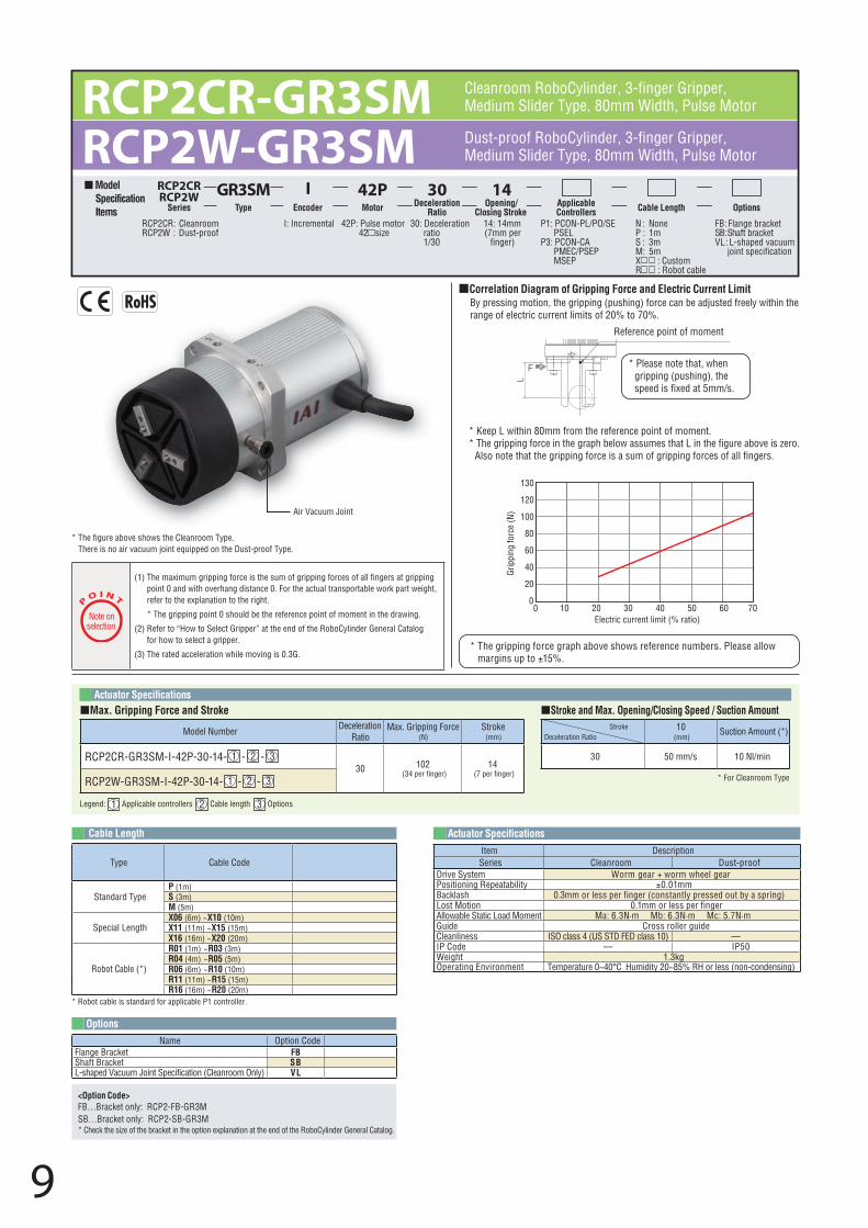
RCP2CR-GR3SM RCP2W-GR3SM
10(mm)
Suction Amount (*)
30 50 mm/s 10 Nl/min
* For Cleanroom Type
StrokeDeceleration Ratio
Model Number Deceleration Ratio
Max. Gripping Force (N)
Stroke(mm)
RCP2CR-GR3SM-I-42P-30-14- 1 - 2 - 330 102
(34 per finger)14
(7 per finger)RCP2W-GR3SM-I-42P-30-14- 1 - 2 - 3
Model Specification Items
RCP2CRRCP2W
Series
GR3SMType
IEncoder
30Deceleration
Ratio
14Opening/
Closing StrokeApplicable Controllers Cable Length Options
42PMotor
42P: Pulse motor 42 size
I: Incremental P1: PCON-PL/PO/SE PSEL
P3: PCON-CA PMEC/PSEP MSEP
N : NoneP : 1mS : 3mM : 5mX : CustomR : Robot cable
FB : Flange brackettekcarb tfahS : BS
VL : L-shaped vacuum joint specification
14: 14mm(7mm per
finger)
30: Deceleration ratio 1/30
RCP2CR : CleanroomRCP2W : Dust-proof
Dust-proof RoboCylinder, 3-finger Gripper,Medium Slider Type, 80mm Width, Pulse Motor
Cleanroom RoboCylinder, 3-finger Gripper, Medium Slider Type, 80mm Width, Pulse Motor
9
P
O I N T
Note on selection
(1) The maximum gripping force is the sum of gripping forces of all fingers at grippingpoint 0 and with overhang distance 0. For the actual transportable work part weight,refer to the explanation to the right.
* The gripping point 0 should be the reference point of moment in the drawing.
(2) Refer to “How to Select Gripper” at the end of the RoboCylinder General Catalogfor how to select a gripper.
(3) The rated acceleration while moving is 0.3G.
Type Cable Code
Standard TypeP (1m)S (3m)M (5m)
Special LengthX06 (6m) ~ X10 (10m)X11 (11m) ~ X15 (15m)X16 (16m) ~ X20 (20m)
Robot Cable (*)
R01 (1m) ~ R03 (3m)
* Robot cable is standard for applicable P1 controller.
R04 (4m) ~ R05 (5m)R06 (6m) ~ R10 (10m)R11 (11m) ~ R15 (15m)R16 (16m) ~ R20 (20m)
Cable Length
Options
Actuator Specifications
Name Option CodeFlange Bracket FBShaft Bracket SBL-shaped Vacuum Joint Specification (Cleanroom Only) VL
Item DescriptionSeries Cleanroom Dust-proof
Drive System Worm gear + worm wheel gearPositioning Repeatability ±0.01mmBacklash 0.3mm or less per finger (constantly pressed out by a spring)Lost Motion 0.1mm or less per fingerAllowable Static Load Moment Ma: 6.3N·m Mb: 6.3N·m Mc: 5.7N·mGuide Cross roller guideCleanliness ISO class 4 (US STD FED class 10) — IP Code — IP50Weight 1.3kgOperating Environment Temperature 0~40°C Humidity 20~85% RH or less (non-condensing)
<Option Code>FB…Bracket only: RCP2-FB-GR3MSB…Bracket only: RCP2-SB-GR3M* Check the size of the bracket in the option explanation at the end of the RoboCylinder General Catalog.
Air Vacuum Joint
Weight (kg) 1.3
10
L-shaped vacuum joint specification
16.5
(16)
(15)
(Same on the opposite side)
(Same on the opposite side)
(Same on the opposite side)
Details of A (2:1)
(Same on the opposite side)
1.5
59
4-M6 depth 12
2-3 +0.050 depth 3
65
Mounting surface
4
1278
A
10+0
.05
0
0.052
ø62
120°120°
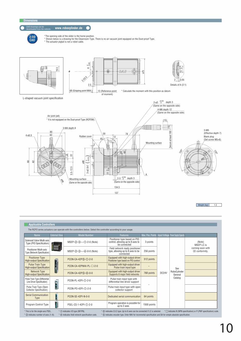
Mounting surfaceø98
6280
6280
3-M4 depth 8
4-ø5.5
2287
5.5~
12.5
2
3-ø2
.5h7
ø80
134.5
137
Rubber cover
Air joint (ø4)
0 -0.0
10
* It is not equipped on the Dust-proof Type (RCP2W).
2-ø3+0.03
0 depth 3
2.5
ø75
80 -0
.05
68 (Gripping point MAX.)
2-C0.5
12 (Reference pointof moment)
* Calculate the moment with this position as datum
770 -0
.05
34 48
Secu
re a
t lea
st 1
00
Blank plug(Set screw M5×6)
3-M5(Effective depth 7)
Applicable Controllers
The RCP2 series actuators can operate with the controllers below. Select the controller according to your usage.
Name External View Model Number Features Max. Pos. Points Input Voltage Power Supply Capacity
Solenoid Valve Multi-axis Type (PIO Specification) MSEP---~--2-0 (Note)
Positioner type based on PIO control, allowing up to 8 axes to
be connected3 points
DC24V
SeeRoboCylinder
GeneralCatalog
Positioner Multi-axis Type (Network Specification) MSEP---~--0-0 (Note)
Field network ready positioner type, allowing up to 8 axes to be
connected256 points
Positioner TypeHigh-output Specification PCON-CA-42P--2-0 Equipped with high-output driver
Positioner type based on PIO control 512 points
64 points
Pulse Train TypeHigh-output Specification PCON-CA-42PWAI-PL- -2-0 Equipped with high-output driver
Pulse train input type −
Network TypeHigh-output Specification PCON-CA-42P--0-0 Equipped with high-output driver
Supports 8 major field networks 768 points
Pulse Train Type (Differential Line Driver Specification) PCON-PL-42PI--2-0 Pulse train input type with
differential line driver support−
Pulse Train Type (Open Collector Specification) PCON-PO-42PI--2-0 Pulse train input type with open
collector support
Serial Communication Type PCON-SE-42PI-N-0-0 Dedicated serial communication
Program Control Type PSEL-CS-1-42PI--2-0 Program operation is possible for up to 2 axes 1500 points
* This is for the single-axis PSEL. * indicates I/O type (NP/PN). * indicates C/LC type. Up to 6 axes can be connected if LC is selected. * indicates N (NPN specification) or P (PNP specification) code.* indicates number of axes (1~8). * indicates field network specification code. * indicates encoder type. Enter WAI for incremental specification and SA for simple absolute specification.
()
(Note)MSEP-LC is
coming soon withCE conformity.
CAD drawings can be downloaded from the website. www.robocylinder.de
Dimensions
2/3DCAD2/3DCAD
* The opening side of the slider is the home position.* Shown below is a drawing for the Cleanroom Type. There is no air vacuum joint equipped on the Dust-proof Type.* The actuator pigtail is not a robot cable.
Name Standard PriceOption Code See PageNMFBSB
→ A-33→ A-26→ A-36
Reversed-homeFlange bracketShaft bracket
– – –
Special Lengths
Type Standard PriceCable Symbol
Standard Type
(Robot Cables)
P (1m)
S (3m)
M (5m)
X06 (6m) ~ X10 (10m)
X11 (11m) ~ X15 (15m)
X16 (16m) ~ X20 (20m)
– – – – – –
* The standard cable is the motor-encoder integrated robot cable.
* See page A-39 for cables for maintenance.
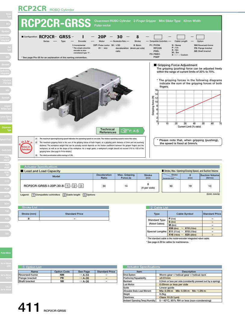
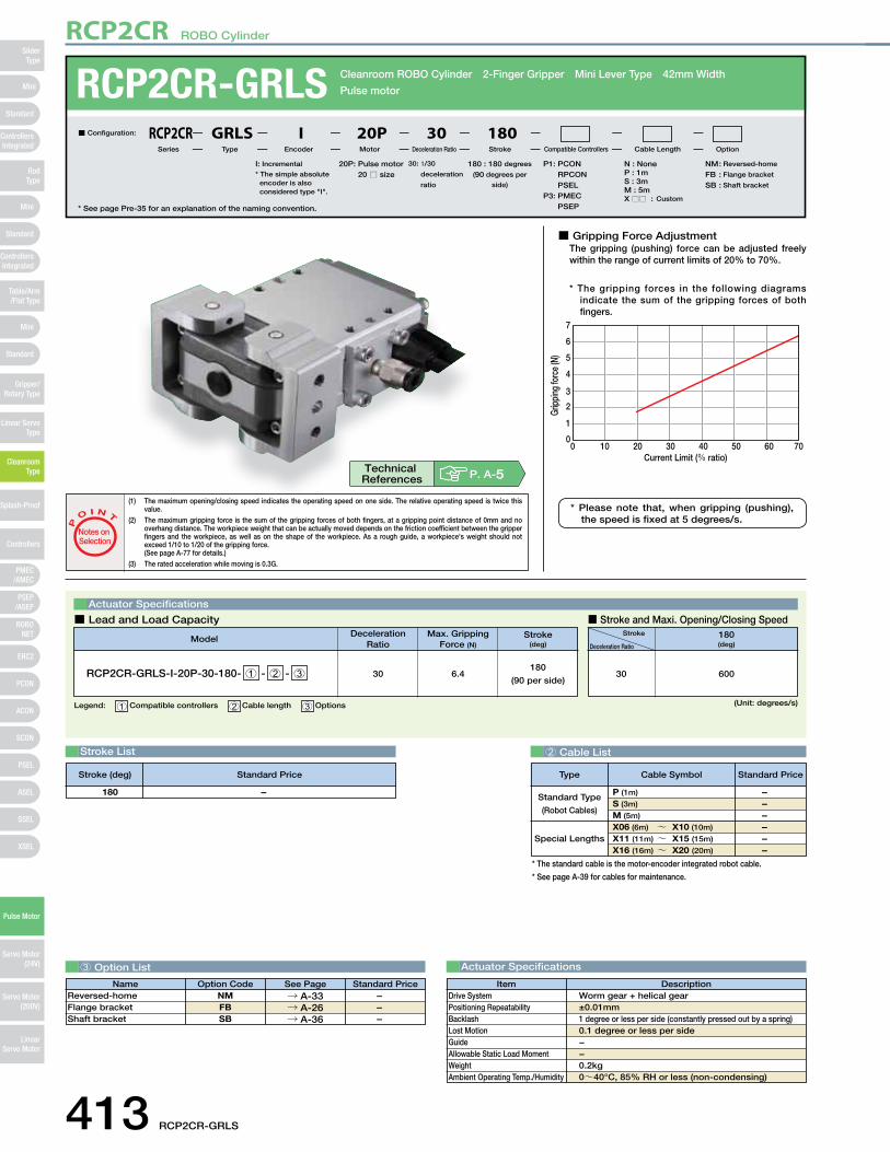
■ Gripping Force AdjustmentThe gripping (pushing) force can be adjusted freely within the range of current limits of 20% to 70%.
* The gripping forces in the following diagrams indicate the sum of the gripping forces of both fingers.
00 10 20
Current Limit (% ratio)30 40 50 60 70
2
4
68
1012
14
16
Grip
ping
forc
e (N
)
Stroke List 2 Cable List
3 Option List Actuator Specifications
DescriptionItemWorm gear + helical gear + helical rack±0.01mm0.2mm or less per side (constantly pressed out by a spring)0.05mm or less per sideLinear guideMa: 0.5N∙m Mb: 0.5N∙m Mc: 1.5N∙m0.2kgClass 10 (0.1μm)0~40°C, 85% RH or less (non-condensing)
Drive SystemPositioning RepeatabilityBacklashLost MotionGuideAllowable Static Load MomentWeightCleanlinessAmbient Operating Temp./Humidity
RCP2CR-GRSS Cleanroom ROBO Cylinder 2-Finger Gripper Mini Slider Type 42mm Width
Pulse motor
* See page Pre-35 for an explanation of the naming convention.
20P: Pulse motor
20 □ size
I: Incremental* The simple absolute
encoder is also considered type "I".
P1: PCONRPCONPSEL
P3: PMECPSEP
N : NoneP : 1mS : 3mM : 5mX □□ : Custom
NM : Reversed-home
FB : Flange bracket
SB : Shaft bracket
8: 8mm(4mm per side)
30 : 1/30 deceleration ratio
■ Configuration: RCP2CR GRSS I 20P 30 8
Series Type Encoder Motor Deceleration Ratio Stroke Compatible Controllers Cable Length Option
Legend: 1 Compatible controllers 2 Cable length 3 Options (Unit: mm/s)
Actuator Specifications
■ Lead and Load Capacity ■ Stroke, Max. Opening/Closing Speed, and Suction Volume
(1) The maximum opening/closing speed indicates the operating speed on one side. The relative operating speed is twice this value.
(2) The maximum gripping force is the sum of the gripping forces of both fingers, at a gripping point distance of 0mm and no overhang
distance. The workpiece weight that can be actually moved depends on the friction coefficient between the gripper fingers and the
workpiece, as well as on the shape of the workpiece. As a rough guide, a workpiece's weight should not exceed 1/10 to 1/20 of the
gripping force. (See page A-74 for details.)
(3) The rated acceleration while moving is 0.3G.
P
O I N T
Notes on Selection
Deceleration Ratio
30 14
Max. Gripping Force (N)
Model Stroke(mm)
RCP2CR-GRSS-I-20P-30-8- 1 - 2 - 38
(4 per side)
Stroke
Deceleration Ratio
8(mm)
Suction Volume(Nl/min)
78 1030
– 8
P. A-5Technical References
* Please note that, when gripping (pushing), the speed is fixed at 5mm/s.
Stroke (mm) Standard Price
411 RCP2CR-GRSS
RCP2CR ROBO Cylinder
Mini
Mini
PSEP/ASEP
PMEC/AMEC
ROBONET
ERC2
PCON
ACON
SCON
PSEL
ASEL
SSEL
XSEL
Standard
Mini
Standard
Standard
ControllersIntegrated
ControllersIntegrated
RodType
Table/Arm/Flat Type
Gripper/Rotary Type
Linear ServoType
Cleanroom Type
Splash-Proof
Controllers
Pulse Motor
Servo Motor (24V)
Servo Motor (200V)
LinearServo Motor
SliderType
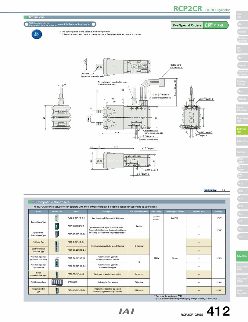
For Special Orders P. A-9
11 0 -0.0
5
94M
AX
22M
IN1446
17
8.5
2-3+0. 05 0 depth 3
(same for opposite side)
34
4
4
3+0. 05 0 depth 3
8-M3 depth 5(same for opposite side) 4-M3 depth 5
2-ø3
Air intake port (applicable tube outer diameter ø4)
+0. 03 0 depth 3
(same for opposite side)ø3
+0. 03 0 depth 3
42
36
33
178.5
4
3 +0. 05 0 depth 3
4-M3 depth 5
ø3+0. 03 0 depth 3
24
30
5
ø4
961.5
2.5 6 57.5
2×2-M3(same for opposite side)
35
17
Secu
re a
t lea
st 1
00
Cable jointconnector*1
Dimensions
* The opening side of the slider is the home position.* 1 The motor-encoder cable is connected here. See page A-39 for details on cables.
Weight (kg) 0.2
1 Compatible Controllers
The RCP2CR series actuators can operate with the controllers below. Select the controller according to your usage.
Name External View Model Description Max. Positioning Points Input Voltage Power Supply Capacity Standard Price See Page
Solenoid Valve Type
PMEC-C-20PI-NP-2-1 Easy-to-use controller, even for beginners
3 points
AC100VAC200V
See P481 – → P477
PSEP-C-20PI-NP-2-0Operable with same signal as solenoid valve.Supports both single and double solenoid types.No homing necessary with simple absolute type.
DC24V 2A max.
–→ P487
Splash-Proof Solenoid Valve Type
PSEP-CW-20PI-NP-2-0 –
Positioner Type PCON-C-20PI-NP-2-0
Positioning is possible for up to 512 points 512 points
–
→ P525
Safety-Compliant Positioner Type
PCON-CG-20PI-NP-2-0 –
Pulse Train Input Type(Differential Line Driver)
PCON-PL-20PI-NP-2-0Pulse train input type with
differential line driver support(−)
–
Pulse Train Input Type(Open Collector)
PCON-PO-20PI-NP-2-0Pulse train input type with
open collector support–
Serial Communication Type
PCON-SE-20PI-N-0-0 Dedicated to serial communication 64 points –
Field Network Type RPCON-20P Dedicated to field network 768 points – → P503
Program Control Type
PSEL-C-1-20PI-NP-2-0Programmed operation is possible
Operation is possible on up to 2 axes1500 points – → P557
* This is for the single-axis PSEL.* 1 is a placeholder for the power supply voltage (1: 100V, 2: 100~240V).
RCP2CR-GRSS 412
RCP2CR ROBO Cylinder
Mini
Mini
PSEP/ASEP
PMEC/AMEC
ROBONET
ERC2
PCON
ACON
SCON
PSEL
ASEL
SSEL
XSEL
Standard
Mini
Standard
Standard
ControllersIntegrated
ControllersIntegrated
SliderType
RodType
Table/Arm/Flat Type
Gripper/Rotary Type
Linear ServoType
Cleanroom Type
Splash-Proof
Controllers
Pulse Motor
Servo Motor (24V)
Servo Motor (200V)
LinearServo Motor
■ Gripping Force AdjustmentThe gripping (pushing) force can be adjusted freely within the range of current limits of 20% to 70%.
* The gripping forces in the following diagrams indicate the sum of the gripping forces of both fingers.
00 10 20
Current Limit (% ratio)30 40 50 60 70
1
2
3
4
5
6
7
Grip
ping
forc
e (N
)
Stroke List
Actuator Specifications
DescriptionItemWorm gear + helical gear±0.01mm1 degree or less per side (constantly pressed out by a spring)0.1 degree or less per side−−0.2kg0~40°C, 85% RH or less (non-condensing)
Drive SystemPositioning RepeatabilityBacklashLost MotionGuideAllowable Static Load MomentWeightAmbient Operating Temp./Humidity
RCP2CR-GRLS Cleanroom ROBO Cylinder 2-Finger Gripper Mini Lever Type 42mm Width
Pulse motor
* See page Pre-35 for an explanation of the naming convention.
20P: Pulse motor 20 □ size
I: Incremental
* The simple absolute encoder is also considered type "I".
P1: PCONRPCONPSEL
P3: PMECPSEP
N : NoneP : 1mS : 3mM : 5mX □□ : Custom
NM : Reversed-home
FB : Flange bracket
SB : Shaft bracket
180 : 180 degrees
(90 degrees per
side)
30 : 1/30
deceleration
ratio
■ Configuration: RCP2CR GRLS I 20P 30 180
Series Type Encoder Motor Deceleration Ratio Stroke Compatible Controllers Cable Length Option
Legend: 1 Compatible controllers 2 Cable length 3 Options (Unit: degrees/s)
Actuator Specifications
■ Lead and Load Capacity ■ Stroke and Maxi. Opening/Closing Speed
(1) The maximum opening/closing speed indicates the operating speed on one side. The relative operating speed is twice this value.
(2) The maximum gripping force is the sum of the gripping forces of both fingers, at a gripping point distance of 0mm and no overhang distance. The workpiece weight that can be actually moved depends on the friction coefficient between the gripper fingers and the workpiece, as well as on the shape of the workpiece. As a rough guide, a workpiece's weight should not exceed 1/10 to 1/20 of the gripping force.(See page A-77 for details.)
(3) The rated acceleration while moving is 0.3G.
P
O I N T
Notes on Selection
Deceleration Ratio
30 6.4
Max. Gripping Force (N)
Model Stroke(deg)
RCP2CR-GRLS-I-20P-30-180- 1 - 2 - 3180
(90 per side)
Stroke
Deceleration Ratio
180(deg)
60030
– 180
P. A-5Technical References
* Please note that, when gripping (pushing), the speed is fixed at 5 degrees/s.
Name Standard PriceOption Code See PageNMFBSB
→ A-33→ A-26→ A-36
Reversed-homeFlange bracketShaft bracket
– – –
3 Option List
Stroke (deg) Standard Price
Special Lengths
Type Standard PriceCable Symbol
Standard Type
(Robot Cables)
P (1m)
S (3m)
M (5m)
X06 (6m) ~ X10 (10m)
X11 (11m) ~ X15 (15m)
X16 (16m) ~ X20 (20m)
– – – – – –
* The standard cable is the motor-encoder integrated robot cable.
* See page A-39 for cables for maintenance.
2 Cable List
413 RCP2CR-GRLS
RCP2CR ROBO Cylinder
Mini
Mini
PSEP/ASEP
PMEC/AMEC
ROBONET
ERC2
PCON
ACON
SCON
PSEL
ASEL
SSEL
XSEL
Standard
Mini
Standard
Standard
ControllersIntegrated
ControllersIntegrated
RodType
Table/Arm/Flat Type
Gripper/Rotary Type
Linear ServoType
Cleanroom Type
Splash-Proof
Controllers
Pulse Motor
Servo Motor (24V)
Servo Motor (200V)
LinearServo Motor
SliderType
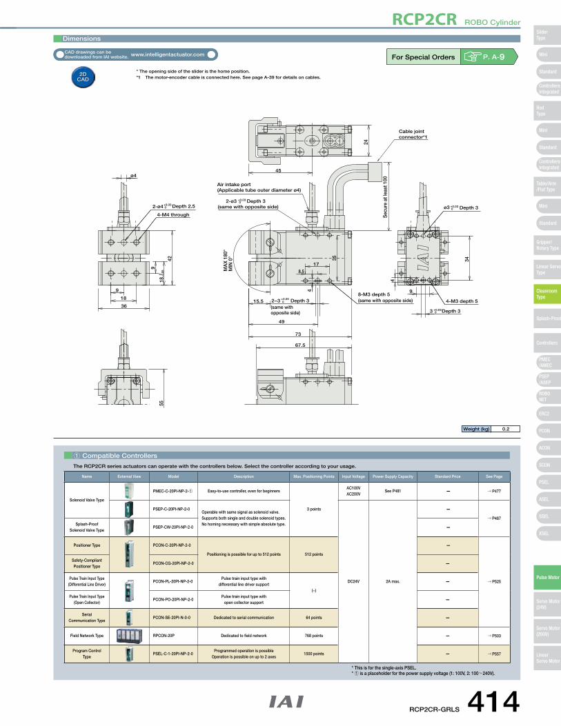
For Special Orders P. A-9
15.5
MA
X 1
80°
MIN
0°
73
9
18 0 −0
.05
34
3 +0.05 0 Depth 3
4
ø4
17
8.5
4
2−3 +0.05 0 Depth 3
(same with opposite side)
4-M3 depth 5
49
42
2-ø3 +0.03 0 Depth 3
(same with opposite side) ø3 +0.03 0 Depth 3
8-M3 depth 5(same with opposite side)
45
67.5
24
2-ø4+0.03 0 Depth 2.5
4-M4 through
18
9
36
9
55
35
Air intake port (Applicable tube outer diameter ø4)
Sec
ure
at le
ast 1
00
Cable jointconnector*1
Dimensions
* The opening side of the slider is the home position.*1 The motor-encoder cable is connected here. See page A-39 for details on cables.
Weight (kg) 0.2
1 Compatible Controllers
The RCP2CR series actuators can operate with the controllers below. Select the controller according to your usage.
Name External View Model Description Max. Positioning Points Input Voltage Power Supply Capacity Standard Price See Page
Solenoid Valve Type
PMEC-C-20PI-NP-2-1 Easy-to-use controller, even for beginners
3 points
AC100VAC200V
See P481 – → P477
PSEP-C-20PI-NP-2-0Operable with same signal as solenoid valve.Supports both single and double solenoid types.No homing necessary with simple absolute type.
DC24V 2A max.
–
→ P487Splash-Proof
Solenoid Valve TypePSEP-CW-20PI-NP-2-0 –
Positioner Type PCON-C-20PI-NP-2-0
Positioning is possible for up to 512 points 512 points
–
→ P525
Safety-Compliant Positioner Type
PCON-CG-20PI-NP-2-0 –
Pulse Train Input Type(Differential Line Driver)
PCON-PL-20PI-NP-2-0Pulse train input type with
differential line driver support(−)
–
Pulse Train Input Type(Open Collector)
PCON-PO-20PI-NP-2-0Pulse train input type with
open collector support–
Serial Communication Type
PCON-SE-20PI-N-0-0 Dedicated to serial communication 64 points –
Field Network Type RPCON-20P Dedicated to field network 768 points – → P503
Program Control Type
PSEL-C-1-20PI-NP-2-0Programmed operation is possible
Operation is possible on up to 2 axes1500 points – → P557
* This is for the single-axis PSEL.* 1 is a placeholder for the power supply voltage (1: 100V, 2: 100~240V).
RCP2CR-GRLS 414
RCP2CR ROBO Cylinder
Mini
Mini
PSEP/ASEP
PMEC/AMEC
ROBONET
ERC2
PCON
ACON
SCON
PSEL
ASEL
SSEL
XSEL
Standard
Mini
Standard
Standard
ControllersIntegrated
ControllersIntegrated
SliderType
RodType
Table/Arm/Flat Type
Gripper/Rotary Type
Linear ServoType
Cleanroom Type
Splash-Proof
Controllers
Pulse Motor
Servo Motor (24V)
Servo Motor (200V)
LinearServo Motor
IAI Industrie r oboter GmbH Ober der Röth 4
D-658 2 4 Schwalb a ch / Frankfurt Germany
T el.:+49- 6 1 96-8895-0 Fax:+49- 6 1 96-8895- 2 4
E-Mail: [email protected] Inte r net: http://ww w .eu.IAI-GmbH.de
IAI, the IAI-logo, RoboCylinder™, the RoboCylinder™-logo, Intel ligentActuator™ and the IntelligentActuator™-logo are trademark s or product names of IAI Corporation or of the subsidiaries in USA, China,Thailand or Germany
IAI America, Inc. 2690 W. 237th Street, Torrance, CA 90505, U.S.APhone: +1-310-891-6015, Fax: +1-310-891-0815
IAI (Shanghai) Co., LtdShanghai Jiahua Business Centee A8-303.808,Hongqiao Rd., Shanghai 200030, China Phone: +86-21-6448-4753, Fax: +86-21-6448-3992
IAI CORPORATION645-1 Shimizu Hirose, Shizuoka 424-0102, JapanPhone: +81-543-64-5105, Fax: +81-543-64-5182
IAI Robot (Thailand) Co., Ltd825 PhairojKijja Tower 12th Floor, Bangna-Trad RD.,Bangna, Bangna, Bangkok 10260, ThailandPhone: +66-2-361-4457, Fax: +66-2-361-4456
The information contained in this catalogis subject to change without notice for the
purpose of product improvement
RCP2CR/RCP2W Series2-/3-Finger Gripper TypeCatalogue No. 0515-E