clearfield city downtown form based code
TRANSCRIPT

Clearfield CityDowntown Form Based Code
Adopted January XX, 2020FINAL REVIEW DRAFT: 01.30.2020
ii
Table of Contents1.0 Introduction1.1 Purpose1.2 General Requirements
2.0 Zoning Districts2.1 Purpose2.2 General Requirements2.3 Zoning District Standards
3.0 Uses3.1 Purpose3.2 General Requirements3.3 Use Type Standards3.4 Use Development Standards
4.0 Street & Block Network4.1 Purpose4.2 Street Types4.3 Street Layout Requirements4.4 Block Layout Requirements4.5 Lot Layout Requirements
5.0 Street & Streetscape Standards5.1 Purpose5.2 General Requirements5.3 Street Type Standards5.4 Pedestrian Realm5.5 Vehicular Realm5.6 Streetscape Design5.7 Alley5.8 Access Road5.9 Neighborhood Street5.10 Commercial Street5.11 State/Main Street Urban Core5.12 700 South Street/State & Main Gateway Corridor
6.0 Building Types6.1 Purpose6.2 General Requirements6.3 Building Type Standards6.4 MIxed-Use/Core Commercial Building6.5 Multi-family Building6.6 Office Building6.7 Commercial Building6.8 Townhouse Building6.9 Garden Court Building6.10 Civic Building6.11 Street Frontage Types6.12 Roof Types6.13 Building Design Standards
7.0 Site & Landscape Standards7.1 Purpose7.2 General Requirements7.3 District Transition Buffer7.4 Parking Lot Buffer7.5 Interior Parking Lot Landscape7.6 Landscape Screening7.7 Installation of Landscape
8.0 Civic Open Space Standards8.1 Purpose8.2 General Requirements 8.3 Open Space Type Standards8.4 Commons 8.5 Plaza8.6 Square 8.7 Green8.8 Park 8.9 Greenway
9.0 Parking Standards9.1 Purpose9.2 General Requirements9.3 Parking Design Standards9.4 Loading Requirements9.5 Site Access Management
10.0 Sign Types10.1 Purpose10.2 General Requirements10.3 Wall Sign10.4 Projecting or Blade Sign10.5 Projecting Marquee Sign10.6 Awning Sign10.7 Canopy-Mounted Sign10.8 Window Sign10.9 Monument Sign10.10 Pole-Mounted Sign
11.0 Administration11.1 Purpose11.2 General Requirements11.3 Pre-Application Meeting11.4 Site Plan Approval11.5 Definitions
FINAL DRAFT 1.30.2020

Chapter 1.0INTRODUCTION
FINAL DRAFT 1.30.2020

1
1.0 Introduction
1.1 Purpose1. Intent
The purpose of the Downtown Clearfield Form-based Code is to allow for a variety of uses with a consistency of form to create a vibrant, mixed-use downtown that is oriented to people in the public realm. The Downtown will serve the community with a mix of shopping, dining, entertainment, office, civic, and residential opportunities set within a walkable setting. A variety of streets will be built or redesigned to safely accommodate multiple modes of transportation, including vehicular, bicycle, and pedestrian.
The planning document Creating Downtown Clearfield and the associated planning process developed the vision framework for the character of Downtown’s future. It may be used as a guiding reference for the purpose and intent of this code document and its standards.
2. Context
The location of Downtown Clearfield offers proximity and easy access from surrounding residential neighborhoods and major transportation corridors, including Interstate 15 and the FrontRunner commuter rail station. Downtown is centered on a major arterial that is also a state highway (Hwy 126). This major arterial, State Street/Main Street, links a series of nodes that comprise Downtown. The regulations of the Downtown Clearfield Form-based Code serve as a means for connecting these nodes by establishing a consistent streetscape and urban form.
1.2 General Requirements1. Applicability
The standards in this Form-Based Code apply to all lots, parcels, and vehicular rights-of-way within all districts in the Clearfield Downtown area unless otherwise specified in the chapters of this code.
2. Definitions
Any terms not defined in this code (Chapter 11 - Administration) or Clearfield City Code Title 11, Chapter 3 shall be clarified with the Zoning Administrator during the plan review process.
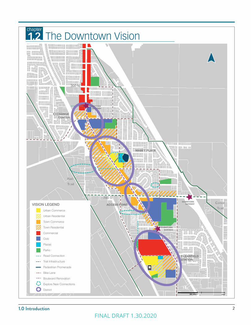
opposite page: Downtown Clearfield Vision Map. For more information and details, refer to Creating Downtown Clearfield Small Area Plan.
FINAL DRAFT 1.30.2020
21.0 Introduction
CREATING DOWNTOWN CLEARFIELD
2016 ■ PAGE 3
The Downtown Vision
EXCHANGE CENTER
MABEY PLACE
ACCESS POINT
CLEARFIELD STATION
VISION LEGEND
CREATING DOWNTOWN CLEARFIELDDRAFT DOWNTOWN VISION
300 N
700 S
Rail
Trail
DOWNTOWN GATEWAY
Canal
TrailUrban Commerce
Urban Residential Town Commerce Town Residential Commercial
Civic
Plazas
Parks Road Connection
Trail Infrastructure
Pedestrian Promenade
Bike Lane
Boulevard Renovation
Explore New Connections
District
DOWNTOWN GATEWAY
DOWNTOWN GATEWAY
.5 mi300 meters
FINAL DRAFT 1.30.2020

FINAL DRAFT 1.30.2020
ZONING DISTRICTSChapter 2.0
FINAL DRAFT 1.30.2020
5
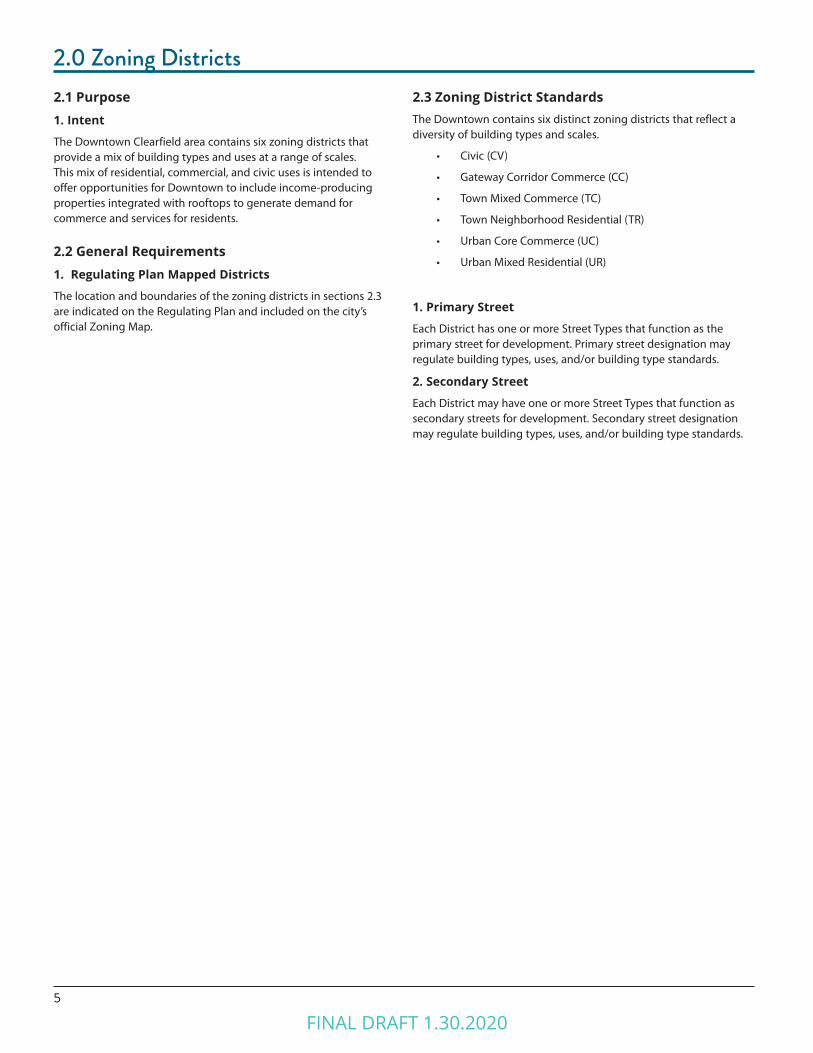
2.0 Zoning Districts2.1 Purpose1. Intent
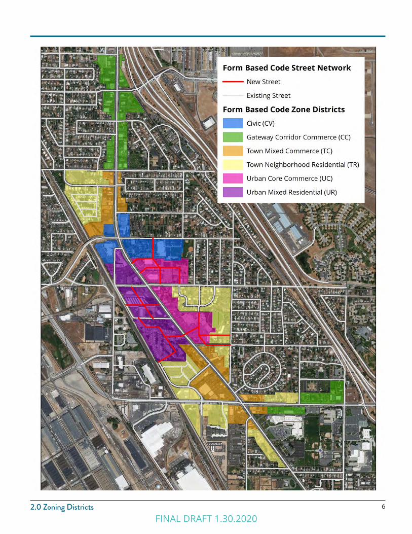
The Downtown Clearfield area contains six zoning districts that provide a mix of building types and uses at a range of scales. This mix of residential, commercial, and civic uses is intended to offer opportunities for Downtown to include income-producing properties integrated with rooftops to generate demand for commerce and services for residents.
2.2 General Requirements1. Regulating Plan Mapped Districts
The location and boundaries of the zoning districts in sections 2.3 are indicated on the Regulating Plan and included on the city’s official Zoning Map.
2.3 Zoning District StandardsThe Downtown contains six distinct zoning districts that reflect a diversity of building types and scales.
• Civic (CV)
• Gateway Corridor Commerce (CC)
• Town Mixed Commerce (TC)
• Town Neighborhood Residential (TR)
• Urban Core Commerce (UC)
• Urban Mixed Residential (UR)
1. Primary Street
Each District has one or more Street Types that function as the primary street for development. Primary street designation may regulate building types, uses, and/or building type standards.
2. Secondary Street
Each District may have one or more Street Types that function as secondary streets for development. Secondary street designation may regulate building types, uses, and/or building type standards.
FINAL DRAFT 1.30.2020
62.0 Zoning DistrictsFINAL DRAFT 1.30.2020
7
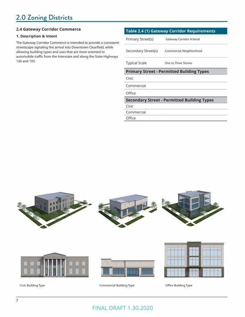
2.0 Zoning Districts2.4 Gateway Corridor Commerce1. Description & Intent
The Gateway Corridor Commerce is intended to provide a consistent streetscape signaling the arrival into Downtown Clearfield, while allowing building types and uses that are more oriented to automobile traffic from the Interstate and along the State Highways 126 and 193.
Commercial Building TypeCivic Building Type Office Building Type
Table 2.4 (1) Gateway Corridor Requirements
Primary Street(s) Gateway Corridor Arterial
Secondary Street(s) Commercial; Neighborhood
Typical Scale One to Three Stories
Primary Street - Permitted Building TypesCivic
Commercial
Office
Secondary Street - Permitted Building TypesCivic
Commercial
Office
FINAL DRAFT 1.30.2020
82.0 Zoning Districts
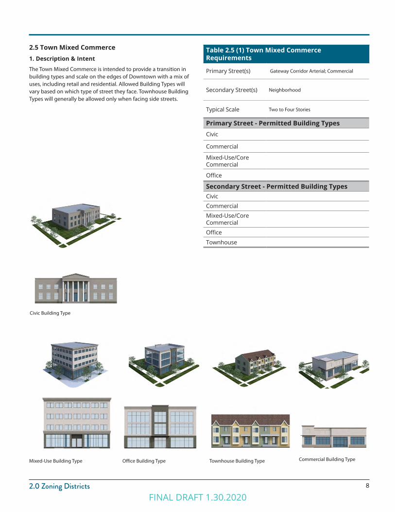
2.5 Town Mixed Commerce1. Description & Intent
The Town Mixed Commerce is intended to provide a transition in building types and scale on the edges of Downtown with a mix of uses, including retail and residential. Allowed Building Types will vary based on which type of street they face. Townhouse Building Types will generally be allowed only when facing side streets.
Office Building TypeMixed-Use Building Type Townhouse Building Type Commercial Building Type
Civic Building Type
Table 2.5 (1) Town Mixed Commerce Requirements
Primary Street(s) Gateway Corridor Arterial; Commercial
Secondary Street(s) Neighborhood
Typical Scale Two to Four Stories
Primary Street - Permitted Building TypesCivic
Commercial
Mixed-Use/Core Commercial
Office
Secondary Street - Permitted Building TypesCivic
Commercial
Mixed-Use/Core Commercial
Office
Townhouse
FINAL DRAFT 1.30.2020

9
2.0 Zoning Districts2.6 Town Neighborhood Residential1. Description & Intent
The Town Neighborhood is intended to primarily be a Residential area on the edges of Downtown Clearfield, providing a transition to surrounding residential neighborhoods. A mix of building types will provide opportunities for small-scale retail, office, or mixed-use to be integrated into the neighborhoods.
Townhouse Building TypeGarden Court Building Type Mixed-Use Building Type
Table 2.6 (1) Town Neighborhood Residential Requirements
Primary Street(s) Commercial; Gateway Corridor Arterial
Secondary Street(s) Neighborhood
Typical Scale Two to Four Stories
Primary Street - Permitted Building TypesMixed-Use/Core Commercial
Townhouse
Secondary Street - Permitted Building TypesTownhouse
Garden Court
FINAL DRAFT 1.30.2020
102.0 Zoning Districts
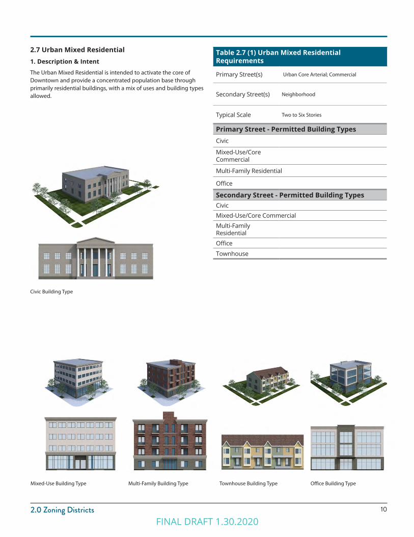
2.7 Urban Mixed Residential1. Description & Intent
The Urban Mixed Residential is intended to activate the core of Downtown and provide a concentrated population base through primarily residential buildings, with a mix of uses and building types allowed.
Civic Building Type
Table 2.7 (1) Urban Mixed Residential Requirements
Primary Street(s) Urban Core Arterial; Commercial
Secondary Street(s) Neighborhood
Typical Scale Two to Six Stories
Primary Street - Permitted Building TypesCivic
Mixed-Use/Core Commercial
Multi-Family Residential
Office
Secondary Street - Permitted Building TypesCivic
Mixed-Use/Core Commercial
Multi-Family Residential
Office
Townhouse
Multi-Family Building TypeMixed-Use Building Type Townhouse Building Type Office Building Type
FINAL DRAFT 1.30.2020

11
2.0 Zoning Districts2.8 Urban Core Commerce1. Description & Intent
The Urban Core Commerce is intended to be the heart of activity and intensity in Downtown Clearfield with a mix of building types. Allowed Building Types will vary based on which type of street they face. Multi-Family Residential Building Types will generally be allowed only when facing side streets or as part of a mixed-use project. Live-Work is considered residential, rather than mixed-use.
Office Building TypeMixed-Use Building Type Multi-Family Building Type
Table 2.6 (1) Urban Core Commerce Requirements
Primary Street(s) Urban Core Arterial; Commercial
Secondary Street(s) Neighborhood
Typical Scale Two to Six Stories
Primary Street - Permitted Building TypesMixed Use
Office
Secondary Street - Permitted Building TypesMixed Use
Multi-Family Residential
Office
FINAL DRAFT 1.30.2020

122.0 Zoning Districts
2.9 Civic1. Description & Intent
The Civic district is intended to provide a civic and office campus in the core of Downtown Clearfield. This district will activate daytime use of the Urban Core areas in Downtown.
Civic Building Type Office Building Type
Table 2.5 (1) Civic Requirements
Primary Street(s) Urban Core Arterial; Commercial
Secondary Street(s) Neighborhood
Typical Scale Two to Six Stories
Primary Street - Permitted Building TypesCivic
Office
Secondary Street - Permitted Building TypesCivic
Office
FINAL DRAFT 1.30.2020

FINAL DRAFT 1.30.2020
Chapter 3.0USES
FINAL DRAFT 1.30.2020
15
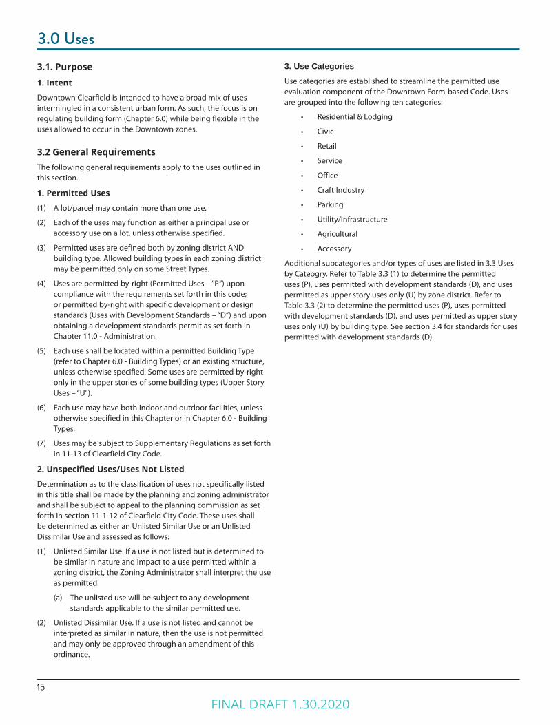
3.0 Uses3.1. Purpose1. Intent
Downtown Clearfield is intended to have a broad mix of uses intermingled in a consistent urban form. As such, the focus is on regulating building form (Chapter 6.0) while being flexible in the uses allowed to occur in the Downtown zones.
3.2 General RequirementsThe following general requirements apply to the uses outlined in this section.
1. Permitted Uses
(1) A lot/parcel may contain more than one use.
(2) Each of the uses may function as either a principal use or accessory use on a lot, unless otherwise specified.
(3) Permitted uses are defined both by zoning district AND building type. Allowed building types in each zoning district may be permitted only on some Street Types.
(4) Uses are permitted by-right (Permitted Uses – “P”) upon compliance with the requirements set forth in this code; or permitted by-right with specific development or design standards (Uses with Development Standards – “D”) and upon obtaining a development standards permit as set forth in Chapter 11.0 - Administration.
(5) Each use shall be located within a permitted Building Type (refer to Chapter 6.0 - Building Types) or an existing structure, unless otherwise specified. Some uses are permitted by-right only in the upper stories of some building types (Upper Story Uses – “U”).
(6) Each use may have both indoor and outdoor facilities, unless otherwise specified in this Chapter or in Chapter 6.0 - Building Types.
(7) Uses may be subject to Supplementary Regulations as set forth in 11-13 of Clearfield City Code.
2. Unspecified Uses/Uses Not Listed
Determination as to the classification of uses not specifically listed in this title shall be made by the planning and zoning administrator and shall be subject to appeal to the planning commission as set forth in section 11-1-12 of Clearfield City Code. These uses shall be determined as either an Unlisted Similar Use or an Unlisted Dissimilar Use and assessed as follows:
(1) Unlisted Similar Use. If a use is not listed but is determined to be similar in nature and impact to a use permitted within a zoning district, the Zoning Administrator shall interpret the use as permitted.
(a) The unlisted use will be subject to any development standards applicable to the similar permitted use.
(2) Unlisted Dissimilar Use. If a use is not listed and cannot be interpreted as similar in nature, then the use is not permitted and may only be approved through an amendment of this ordinance.
3. Use CategoriesUse categories are established to streamline the permitted use evaluation component of the Downtown Form-based Code. Uses are grouped into the following ten categories:
• Residential & Lodging
• Civic
• Retail
• Service
• Office
• Craft Industry
• Parking
• Utility/Infrastructure
• Agricultural
• Accessory
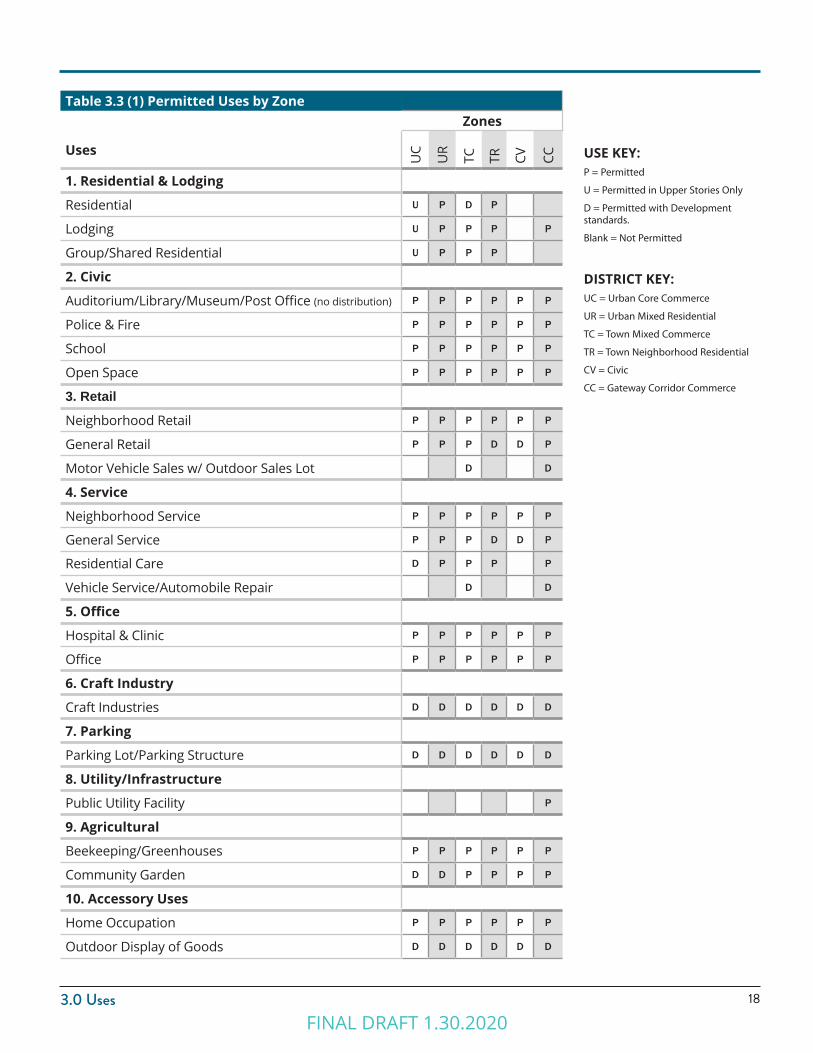
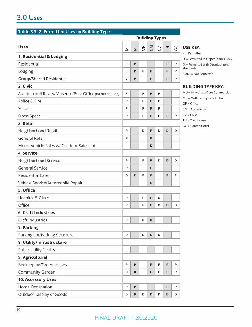
Additional subcategories and/or types of uses are listed in 3.3 Uses by Cateogry. Refer to Table 3.3 (1) to determine the permitted uses (P), uses permitted with development standards (D), and uses permitted as upper story uses only (U) by zone district. Refer to Table 3.3 (2) to determine the permitted uses (P), uses permitted with development standards (D), and uses permitted as upper story uses only (U) by building type. See section 3.4 for standards for uses permitted with development standards (D).
FINAL DRAFT 1.30.2020
163.0 Uses
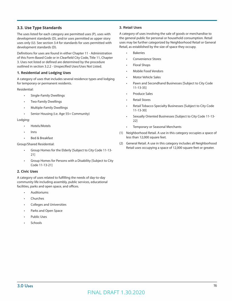
3.3. Use Type StandardsThe uses listed for each category are permitted uses (P), uses with development standards (D), and/or uses permitted as upper story uses only (U). See section 3.4 for standards for uses permitted with development standards (D).
Definitions for uses are found in either Chapter 11 - Administration of this Form-Based Code or in Clearfield City Code, Title 11, Chapter 3. Uses not listed or defined are determined by the procedure outlined in section 3.2.2 - Unspecified Uses/Uses Not Listed.
1. Residential and Lodging Uses
A category of uses that includes several residence types and lodging for temporary or permanent residents.
Residential:
• Single-Family Dwellings
• Two-Family Dwellings
• Multiple-Family Dwellings
• Senior Housing (i.e. Age 55+ Community)
Lodging:
• Hotels/Motels
• Inns
• Bed & Breakfast
Group/Shared Residential:
• Group Homes for the Elderly [Subject to City Code 11-13-21]
• Group Homes for Persons with a Disability [Subject to City Code 11-13-21]
2. Civic Uses
A category of uses related to fulfilling the needs of day-to-day community life including assembly, public services, educational facilities, parks and open space, and offices.
• Auditoriums
• Churches
• Colleges and Universities
• Parks and Open Space
• Public Uses
• Schools
3. Retail UsesA category of uses involving the sale of goods or merchandise to the general public for personal or household consumption. Retail uses may be further categorized by Neighborhood Retail or General Retail, as established by the size of space they occupy.
• Bakeries
• Convenience Stores
• Floral Shops
• Mobile Food Vendors
• Motor Vehicle Sales
• Pawn and Secondhand Businesses [Subject to City Code 11-13-35]
• Produce Sales
• Retail Stores
• Retail Tobacco Specialty Businesses [Subject to City Code 11-13-30]
• Sexually Oriented Businesses [Subject to City Code 11-13-22]
• Temporary or Seasonal Merchants
(1) Neighborhood Retail. A use in this category occupies a space of less than 12,000 square feet.
(2) General Retail. A use in this category includes all Neighborhood Retail uses occupying a space of 12,000 square feet or greater.
FINAL DRAFT 1.30.2020

17
3.0 Uses5. Office Uses
A category of uses for businesses that involve the transaction of affairs of a profession, service, industry, or government, including finance and research.
• Laboratories
• Hospitals
• Medical Clinics
• Offices
6. Craft Industry
The category of uses for businesses that involve the production, distribution, or storage of products, including food and drink.
• Art/Film/Music Studios
• Food & Beverage
• Furniture/Textiles/Woodworking
• Jewelry/Watches/Clocks
• Printing & Publishing
• Printmaking/Sculpting/Welding Studios
7. Parking
A lot that does not contain a permitted building or Open Space Type and is solely used for the short or long-term storage of vehicles.
• Parking Lot, Stand-alone
• Parking Structure, Stand-alone
8. Utility/Infrastructure
A lot that is primarily utilized for the City’s infrastructure needs. Utility and infrastructure needs include such uses as electric or gas services, sewage treatment, water treatment and storage, and energy conversion systems.
• Public Utility Facilities
9. Agricultural
A use of land or buildings for food or plant production purposes.
• Beekeeping/Apiaries
• Greenhouses
• Community Gardens
10. Accessory Uses
A category of uses that are not permitted to serve as the principal use on a lot.
• Home Occupations
• Outdoor Storage and Display of Goods [Subject to City Code 11-13-12]
4. Service
A category of uses that provide patrons services and limited retail products related to those services. Service uses may be further categorized by Neighborhood Service or General Service, as established by the size of space they occupy.
• Amusement and Recreation Facilities
• Assisted Living Facilities
• Automobile Repair Shops
• Business Services
• Convalescent Facilities [does not include Behavior, Drug, or Alcohol Treatment Facilities]
• Daycare Facilities
• Daycares, Residential
• Dry Cleaning Facility
• Fireworks Stands [Subject to City Code 11-13-26]
• Non-depository Lending Establishments [Subject to City Code 11-13-29]
• Nursing or Rest Homes
• Personal Services
• Pet Grooming Facilities
• Physical Therapy Facilities
• Preschools, Commercial
• Preschools, Residential
• Restaurants
• Specialized Schools
• Tattoo or Body Piercing Establishments [Subject to City Code 11-13-31]
• Taverns
• Taxidermists
• Theaters
• Veterinary Services
• Vocational and Technical Training Facilities
(1) Neighborhood Service. A use in this category occupies a space of less than 12,000 square feet.
(2) General Service. A use in this category includes all Neighborhood Service uses occupying a space of 12,000 square feet or greater.
FINAL DRAFT 1.30.2020
183.0 Uses
DISTRICT KEY:UC = Urban Core Commerce
UR = Urban Mixed Residential
TC = Town Mixed Commerce
TR = Town Neighborhood Residential
CV = Civic
CC = Gateway Corridor Commerce
USE KEY:P = Permitted
U = Permitted in Upper Stories Only
D = Permitted with Development standards.
Blank = Not Permitted
Table 3.3 (1) Permitted Uses by ZoneZones
Uses
UC
UR
TC TR CV CC
1. Residential & Lodging
Residential U P D P
Lodging U P P P P
Group/Shared Residential U P P P
2. Civic
Auditorium/Library/Museum/Post Office (no distribution) P P P P P P
Police & Fire P P P P P P
School P P P P P P
Open Space P P P P P P
3. Retail
Neighborhood Retail P P P P P P
General Retail P P P D D P
Motor Vehicle Sales w/ Outdoor Sales Lot D D
4. Service
Neighborhood Service P P P P P P
General Service P P P D D P
Residential Care D P P P P
Vehicle Service/Automobile Repair D D
5. Office
Hospital & Clinic P P P P P P
Office P P P P P P
6. Craft Industry
Craft Industries D D D D D D
7. Parking
Parking Lot/Parking Structure D D D D D D
8. Utility/Infrastructure
Public Utility Facility P
9. Agricultural
Beekeeping/Greenhouses P P P P P P
Community Garden D D P P P P
10. Accessory Uses
Home Occupation P P P P P P
Outdoor Display of Goods D D D D D D
FINAL DRAFT 1.30.2020
19
3.0 Uses
Table 3.3 (2) Permitted Uses by Building TypeBuilding Types
Uses
MU
MF
OF
CM CV TH GC
1. Residential & Lodging
Residential U P P P
Lodging U P P P P P
Group/Shared Residential U P P P P
2. Civic
Auditorium/Library/Museum/Post Office (no distribution) P P P P
Police & Fire P P P P
School P P P P
Open Space P P P P P P
3. Retail
Neighborhood Retail P D P D D D
General Retail P P
Motor Vehicle Sales w/ Outdoor Sales Lot D
4. Service
Neighborhood Service P P P D D D
General Service P P
Residential Care D P P P P P
Vehicle Service/Automobile Repair D
5. Office
Hospital & Clinic P P P D
Office P P P D D D
6. Craft Industries
Craft Industries D D D
7. Parking
Parking Lot/Parking Structure D D D D
8. Utility/Infrastructure
Public Utility Facility
9. Agricultural
Beekeeping/Greenhouses P P P P P P
Community Garden D D P P P P
10. Accessory Uses
Home Occupation P P P P
Outdoor Display of Goods D D D D D D D
BUILDING TYPE KEY:MU = Mixed Use/Core Commercial
MF = Multi-Family Residential
OF = Office
CM = Commercial
CV = Civic
TH = Townhouse
GC = Garden Court
USE KEY:P = Permitted
U = Permitted in Upper Stories Only
D = Permitted with Development standards.
Blank = Not Permitted
FINAL DRAFT 1.30.2020

203.0 Uses
3.4 Use Development StandardsThe uses as permitted with development standards (D), shall meet the following requirements
1. Development Standards by Use Category
(1) Residential and Lodging Uses
(a) Residential Uses and Building Types, including Townhouses and Multi-Family, shall only be allowed on secondary or side streets in the TC and UC districts.
(2) Retail Uses
(a) Pawn and secondhand businesses are limited to a maximum of 5,000 square feet of retail space in the TR and CV zones. This includes pawn and secondhand businesses for general merchandise, military surplus, precious metals and/or gems dealers/processors.
(b) Motor vehicle sales shall have a 1 acre minimum lot size; a permanent on-site office is required. No cars may be displayed outside within 10 feet of the primary street right of way.
(3) Service Uses
(a) Vehicle Services
(i) Vehicle repair is only allowed as a secondary use to vehicle sales.
(ii) Use Limitation. Repair and wash facilities for semi-trucks, recreational vehicles, boats, and other oversized vehicles are not permitted.
(iii) Service Bays. Vehicular service bays, including garages and car wash bays, shall not be located on the front facade, unless otherwise permitted by the Building Type. Service bay doors shall be transparent.
(iv) Outdoor Storage. Disabled or inoperable vehicles and those awaiting pick-up may be stored outdoors if:
i. Vehicles are not stored for more than two days.
ii. The storage area is located in the rear yard and screened from view of the front lot line and/or corner lot line.
ii. The storage area is screened using the Side & Rear yard buffer outlined in 7.0 Landscape, regardless of the adjacent land uses.
(v) Outdoor Activities
i. All repairs or washing activities must occur inside a structure.
ii. Vacuuming activities may occur outdoors, but must be located in the side or rear yards, screened from the front lot line.
iii. Temporary outdoor display of seasonal items, such as windshield wiper fluid or salt, is permitted during business hours under the canopy and adjacent to the principal structure.
(vi) Fuel pumps must be in rear or side of building
(b) Resdiential Care
(i) The first 40’ of the ground floor shall be used for administrative and/or shared common spaces, such as an activity room, dining room, or offices.
(ii) Residential dwelling units shall not be located in the first 40’ of the ground floor.
(4) Craft Industry Uses
(a) All work shall be performed within an enclosed building.
(b) All outside storage shall be screened from view from public streets and adjacent properties.
(5) Parking Uses
(a) Corner Lots. A corner lot shall not be used for a parking lot or structure unless the structure meets the standards of one of the allowed Building Types (refer to Chapter 6.0).
(b) Adjacent Parking Lots. Two parking facilities (lots or structures) cannot be located directly adjacent to one another.
(c) Distance. The parking lot or structure must be within 1,300 feet of the principal entrance to the associated use unless:
(i) At least 75% of the spaces are dedicated for public use.
(ii) An approved parking agreement is in place (refer to Chapter 9.0 Parking).
(d) Pedestrian Access. Must be connected to the associated use by a dedicated, public pedestrian pathway.
(e) Commercial Vehicles. Parking structures for commercial vehicles are not permitted.
(6) Accessory Uses
(a) Outdoor Storage and Display of Goods. Outdoor storage areas shall be located in the rear or side yard of the lot. Display of goods during business hours only, such as sidewalk displays, are not subject to these standards.
(i) Loose materials shall not be stacked higher than six feet.
(ii) Loose materials shall at a minimum be stored in a three-sided shelter and shall be covered.
(iii) Materials shall be set back a minimum of five feet from any lot line.
(iv) All outdoor storage areas shall be screened from view of adjacent parcels and vehicular rights-of-way using the landscape buffer, refer to 7.0 Landscape Requirements for Side and Rear Buffer.
(v) Accessory storage that is not considered “display” includes storage containers. Such storage requires a minimum 6’ visual barrier.
FINAL DRAFT 1.30.2020

21
FINAL DRAFT 1.30.2020
Chapter 4.0STREET & BLOCK NETWORK
FINAL DRAFT 1.30.2020
23
4.0 Street & Block Network
4.1 Purpose1. Intent
The intent of the provisions of this chapter are to create livable, connected neighborhoods in Downtown Clearfield. The street network, blocks, and lot configuration will establish the urban form framework for Downtown Clearfield. A cohesive, connected, and consistent urban form allows incremental developments of a range of sizes to collectively build a vibrant Downtown.
2. Applicability
The following lot, block, and street network requirements are applicable to all public and private rights-of-way in all zones and districts of Downtown Clearfield.
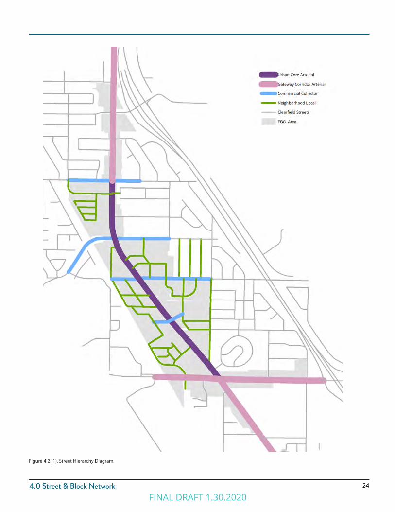
4.2 Street Types
The street network of Downtown Clearfield is comprised of a hierarchy of Street Types to support a diversity of building and frontage types, scales, and uses.
The following Street Types are part of the Downtown Clearfield Street Network. Standards for the configuration of each Street Type are found in Chapter 5.0 Street & Streetscape Standards.
(1) Urban Core (Arterial)
(2) Gateway Corridor (Arterial)
(3) Commercial (Collector)
(4) Neighborhood (Local)
(5) Access Road (Private Local)
(6) Alley (Public or Private)
FINAL DRAFT 1.30.2020
244.0 Street & Block Network
Figure 4.2 (1). Street Hierarchy Diagram.
FINAL DRAFT 1.30.2020

25
4.0 Street & Block Network
2. Disconnected Streets
Disconnected streets may take the following form:
(1) Stub Streets. Where adjoining areas are not subdivided, streets in new subdivisions and developments shall extend to the boundary line of the tract to make provision for the future connection of streets into adjacent areas.
(a) Stub streets shall be provided at intervals no greater than the maximum block length and width specified in Section 4.3 Block Requirements.
(2) Half Streets. Half Streets are prohibited unless approved by the Clearfield City Engineer in unusual circumstances where they are deemed essential and where satisfactory assurances are provided for dedication of the remaining half of the street.
(a) Proposed half streets shall have no less than one-half of the right-of-way dedicated and constructed, including both vehicular and pedestrian realm elements specified for the Street Type (Chapter 5.0).
(3) Cul-de-Sac Streets. Cul-de-sac streets are not permitted except where site impediments prohibit a connected street for accessing the location. Site impediments may include: canals, water bodies, steep slopes greater than 30%, and railroad lines. The following parameters shall be incorporated when the exception is allowed:
(a) The Cul-de-sac shall not be more than 300 feet in length as measured along the centerline from the closest intersection.
(b) The Cul-de-sac shall have a maximum outside turning radius of 50 feet.
(c) The vehicular and pedestrian realm of the cul-de-sac shall follow the cross-section standards for the Neighborhood Street type (see Chapter 5.0). The remaining center of the cul-de-sac shall be landscaped and function as a curbed bioswale. Refer to Figure 4.2 (1).
(d) A pedestrian sidewalk connection shall be provided from the cul-de-sac to the next closest street or pedestrian right-of-way. Refer to Figure 4.2 (2).
4.3 Street Layout Requirements1. Street Network
The following standards apply to all new streets or newly platted vehicular Rights-of-Way whether public or privately held.
(1) Interconnected Network. The network of streets shall form an interconnected pattern with multiple intersections.
(2) Existing Streets. The arrangement of streets shall provide for the continuation of existing streets from adjoining areas into new subdivisions and developments.
(a) Existing stub streets adjacent to a proposed subdivision and/or development shall be connected.
(b) Existing half streets adjacent to a proposed subdivision and/or development shall be completed with the dedication of the remaining right-of-way and the complete construction of the street with the development of said proposed subdivision and property development.
(3) Treatment of Natural Features. Streets shall be designed to respect natural features, such as waterways, trees, or slopes, by following rather than interrupting or dead ending at the feature.
(4) Dead-end Streets. Cul-de-sac and dead-end streets are not permitted.
Figure 4.2 (1). Bio-retention cul-de-sac Figure 4.2 (2). Pedestrian sidewalk connection from cul-de-sac
FINAL DRAFT 1.30.2020

264.0 Street & Block Network
3. Pedestrian Crossings
1) Crosswalks shall meet the following requirements:
(a) Dimensions. Crosswalks shall be a minimum of 6 feet in width, measured from mid-stripe to mid-stripe, per the Manual on Uniform Traffic Control Devices (MUTCD).
(b) Markings. Crosswalks shall be appropriately indicated on the finished street surface with painted or thermoplastic markings and/or textured or colored pavement.
(c) Crossing Distances. Crosswalks shall not extend a distance greater than 36 feet without a landscaped median, bulb-out(s), and/or other pedestrian refuge to increase pedestrian safety and comfort. Refer to Figures 4.3 (1) and 4.3 (2).
(d) Accessible ramps and warning panels, per the American Disabilities Act or any more stringent state requirement, are required where all sidewalks or trails terminate at a crosswalk or curb.
(e) Ramp Orientation. Ramps shall be oriented perpendicular to traffic, requiring two ramps per corner at intersecting streets.
(2) Bulb-outs. Bulb-outs may be utilized at all intersections, and are required at intersections where on-street parking is present, unless otherwise required by the Clearfield Public Works Department and UDOT. Refer to Figure 4.3 (2).
(a) The depth of the bulb-out shall match the utilized on-street parking, either the width of the parallel space or the depth of the diagonal space. If on-street parking is not present, bulb-outs shall accommodate bicycle traffic with a pass-through lane.
(b) The radius of the bulb-out shall match the requirements for the intersection.
(c) Bulb-outs may be installed on one side of the intersection only, if the decreased crossing distance is less than 36 feet.
(3) Mid-block crossings. Mid-block crossing shall incorporate bulb outs and pedestrian crosswalks.
(a) Mid-block crossings are required on all non-UDOT streets when block lengths or sections between intersections are longer than 600 feet. The crossing should generally occur in the middle third of a block face. Typical pedestrian crosswalks standards apply. Refer to Figure 4.3 (3).
(b) Mid-block crossings may be off-set to improve visibility between pedestrians and traffic.
Figure 4.3 (3). Mid Block Crossing
Figure 4.3 (1). Wide Street Crossing with Pedestrian Refuge Median
Figure 4.3 (2). Bulb Out on one side where on-street parking is present.
FINAL DRAFT 1.30.2020
27
4.0 Street & Block Network
4.4 Block Layout Requirements 1. Block Configuration
(1) New blocks not specified on the Regulating Plan shall generally be rectangular but may vary due to natural features or other site constraints.
(2) Newly formed blocks may include existing lots within a zoning district outside the Downtown Clearfield area.
2. Maximum Block Size
Block sizes for new development and redevelopment shall be formed by a maximum perimeter of 2400 linear feet.
(1) Where natural constraints or adjacency to parcels outside the Downtown area impact the block configuration, an exception may be granted from the maximum block size.
(2) Access Roads and/or Pedestrian-only Walkways may form up to two sides of the block perimeter if they meet the Street Type Standards in Chapter 5.
3. Block Access
Vehicular access to blocks along Urban Arterial streets shall be from secondary streets perpendicular to the Urban Arterial streets. If secondary streets do not exist and are not feasible for proposed new developments, alternative access shall be coordinated with the City Engineer and requires UDOT approval.
4. Block Development Connectivity
To provide a minimum level of connectivity via vehicular rights-of-way between adjacent developments and to surrounding streets, a minimum of two access points is required for each development site unless the site meets the following parameters:
(1) For Single- and Two-Family Dwellings: Any subdivision and/or development of 20 or fewer dwellings;
(2) For Multiple-Family Dwellings or Mixed-Use Projects: Any subdivision and/or development of 75 or fewer dwelling units;
(3) A subdivision and/or development that is less than 4 acres.
5. Block Access Configuration
(1) Access to blocks shall be aligned with the access for blocks across the street to create an intersection.
(2) Mid-Block Pedestrian Ways. Mid-block Pedestrian Ways are required on blocks longer than 600 feet.
(a) Mid-block Pedestrian Ways shall generally be located in the middle third of a block face.
(b) Mid-block Pedestrian Ways shall align with Mid-block street crossings. Refer to section 4.3.3.
6. Block Layout
Blocks shall be fronted with lots on at least two faces. Lots shall be oriented along the longer street faces to the extent feasible.
(1) Blocks containing open space may vary from the lot configuration requirements.
(2) Blocks may include an alley that separates the lots.
4.5 Lot Layout Requirements 1. Typical Lot Configuration
All lots shall have frontage along a public street unless otherwise specified in 6.0 Building Type requirements.
(1) Lot Shape. To create regular, rectangular lots, side property lines shall be perpendicular to the vehicular right-of-way to the extent practical.
(2) Through Lots. Through lots fronting on two parallel streets are not permitted except for a lot covering 50 percent or more of a block and the two longest parallel street faces are treated as front property lines per building type requirements (refer to 6.0 Building Types).
(3) Corner Lots. Corner lots have a front yard along one street and a corner yard along a second street. The front yard of a corner lot should be consistent with one adjacent Parcel.
(a) The rear yard of a corner lot is typically the yard against an alley or another lot’s rear yard.
(b) The side yard of a corner lot is adjacent to another lot.
(c) Flag Lots. Flag lots are prohibited.
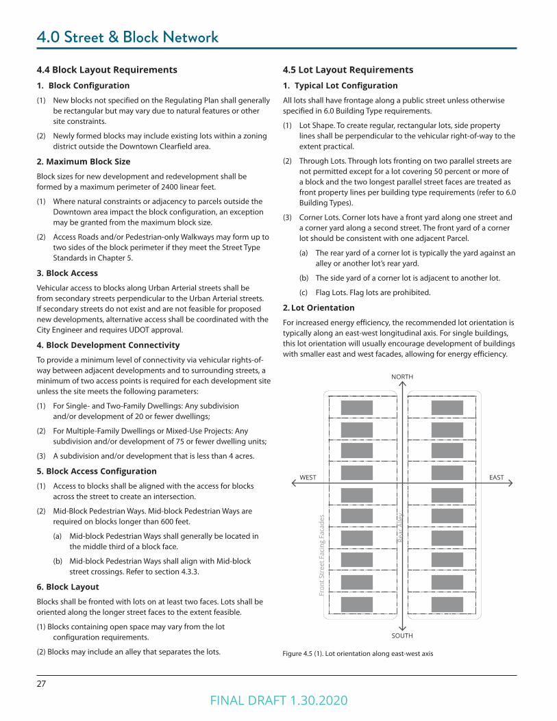
2. Lot Orientation
For increased energy efficiency, the recommended lot orientation is typically along an east-west longitudinal axis. For single buildings, this lot orientation will usually encourage development of buildings with smaller east and west facades, allowing for energy efficiency.
Figure 4.5 (1). Lot orientation along east-west axis
NORTH
SOUTH
WEST EAST
Fron
t Str
eet F
acin
g Fa
cade
s
Rear
Alle
y
FINAL DRAFT 1.30.2020
STREET & STREETSCAPE STANDARDSChapter 5.0
FINAL DRAFT 1.30.2020
29
5.0 Street & Streetscape Standards
5.1 Purpose1. Intent
The standards outlined in this section are intended to:
(1) Create complete streets that address all modes of travel, including pedestrian, bicycle, transit, and vehicular traffic.
(2) Address all features of the street right-of-way, including sidewalks, parkways, traffic lanes, bicycle lanes, and medians.
(3) Create streets appropriate for their context in residential, commercial, or mixed-use districts and that are designed to encourage travel at appropriate volumes and speeds.
(5) Create streets and public rights-of-way that result in stormwater runoff quantity reduction and improve the quality of stormwater runoff.
(6) Develop enhanced streetscapes that support a vibrant and successful downtown by undergrounding utilities and installing consistent site amenities.
2. ApplicabilityThe standards in this section apply to all vehicular rights-of-way within the Clearfield Downtown Form-based Code area.
5.2 General Requirements1. Dedicated Vehicular Rights-of-Way
All proposed streets, landscape or furnishings zones, and sidewalks shall be located in dedicated vehicular Rights-of-Way.
(1) Street Types. All new vehicular rights-of-way shall match one of the street types in Section 5.5, whether publicly dedicated or privately held. The Street Types defined in this section outline the standard street configurations for Downtown Clearfield. New streets shall be designed using the principles and characteristics defined by each street type.
(a) Graphics. The graphics illustrating each street type reflect the standard configuration of that street type. Other configurations may be allowed if the standards are met and agreed upon with Clearfield City.
(2) Public Use. All streets shall be available for public use at all times. Gated streets and streets posted as private are not permitted.
(3) Public Right of Way Dedication. Clearfield City may require additional right-of-way, pavement width, or additional street elements depending on unique site characteristics.
Wherever an existing public right of way fronting a lot, parcel, or development is less than the specified width for a Street Type, the additional width shall be dedicated in order to achieve a continuous streetscape.
2. Street Construction Specifications
All construction in the right-of-way shall follow specifications defined by Clearfield Public Works or as stated by this Form-based Code.
3. Fire Access
Street configurations have been calculated to provide fire truck access. The minimum total width of all travel lanes for vehicular street types shall be 20 feet of drivable surface. If adjacent buildings are taller than 30 feet the minimum total width is 26 feet. If a fire hydrant is present the minimum width is 26 feet, or can be 20 feet with an approved widening to 26 feet for the 20 feet prior and 20 feet after the fire hydrant. Refer to International Fire Code (IFC).
FINAL DRAFT 1.30.2020

305.0 Street & Streetscape Standards
4. Intersections(1) Turning Radii. The following turning radii and curb radii shall
be utilized unless otherwise authorized by the Clearfield City Engineer. Minimum actual turning radii shall be determined by the fire code official.
(a) Intersections should be designed for actual turning radius of the typical design vehicle as opposed to the maximum design vehicle. Small curb radii at intersections shorten pedestrian crossing distances and reduce vehicle turning speeds, thereby balancing the ease of travel of vehicles and pedestrians. Refer to Figure 5.2 (2).
(b) Neighborhood Streets. At the intersection of any street with a Neighborhood Street, the following curb radii shall be utilized.
(i) With on-street parking on both intersecting streets, a 10-foot radius may be utilized.
(ii) Without on-street parking, a 15-foot radius is required.
(c) Commercial Streets. At the intersection of any street with a Commercial Street, the following curb radii shall be utilized.
(i) With on-street parking on both intersecting streets, a 15-foot radius is required.
(ii) Without on-street parking, a 25-foot radius is required.
(d) Arterial Streets. For arterials streets, the curb radii shall be designed according to Clearfield City and UDOT standards.
(e) Alley Intersections. At the intersection of any street with an Alley, the curb radii shall be no greater than 10 feet.
Figure 5.2 (2) Curb Radius vs. Actual Turn Radius with On-Street Parking.
curb radius
turning radius
FINAL DRAFT 1.30.2020
31
5.0 Street & Streetscape Standards
Figure 4.2 (4). Head Out On-Street Parking.
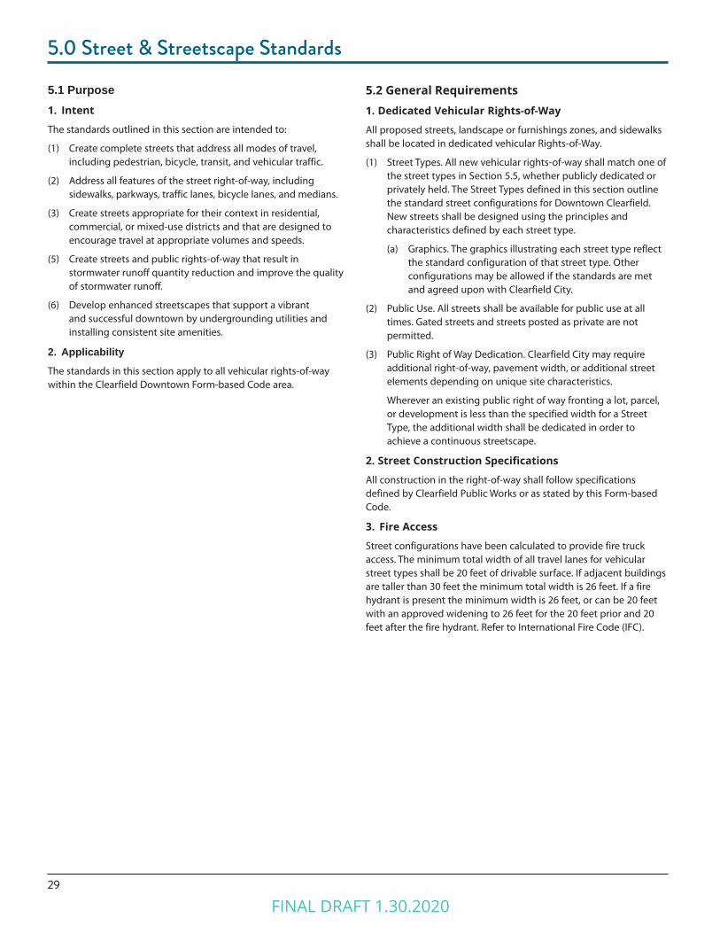
Figure 5.3 (1). Typical Right-of-Way Elements.
Right of Way
Vehicular Realm Pedestrian RealmPedestrian Realm
Travel Lane Travel LaneBicycle Lane
Bicycle Lane
Parking Lane
Parking Lane
Landscape & Furnishing
Zone
Landscape & Furnishing
ZoneSidewalkSidewalk
5.3 Street Type Standards1. Permitted Districts
(1) Adjacent Building Types
(2) Typical Right of Way
2. Typical Street Elements
Typical street elements are divided into the vehicular realm and pedestrian realm. Refer to Figure 5.3 (1): Typical Right-of-Way Elements. Each street type specified in this chapter outlines which elements are applicable. Refer to Section 5.5 of this Chapter.
(1) Pedestrian Realm. The pedestrian realm is comprised of pedestrian facilities and a street buffer area that is landscaped and/or furnished with street furniture.
(2) Vehicular Realm. The vehicular realm is comprised of the travel lanes, on-street parking spaces, and bicycle travel facilities.
FINAL DRAFT 1.30.2020

325.0 Street & Streetscape Standards
5.4 Pedestrian Realm 1. Pedestrian Travel Facilities
The type and width of pedestrian travel facilities, such as sidewalks, paths/trails, or off-street bicycle paths, are determined by Street Type.
2. Street Buffer Areas
The street buffer area, consisting of a landscape zone and/or furnishings zone, serves to buffer pedestrians from the movements of higher speed vehicles in the vehicular realm. The type and width of the Street Buffer area is determined by Street Type. Refer to Figure 5.4 (1).
(a) Landscape Zone. A landscaped area between the back of curb to the sidewalk in which street trees, vegetation/plantings, bioswales, lighting, and signage may be located.
(b) Furnishings Zone. A hardscaped area between the back of curb or edge of pavement to the sidewalk in which street trees, street furniture, lighting, and signage may be located.
Figure 5.4 (1). Street Buffer Examples.
FINAL DRAFT 1.30.2020
33
5.0 Street & Streetscape Standards
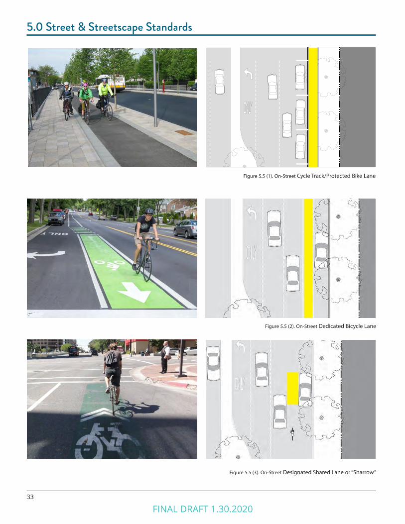
Figure 5.5 (3). On-Street Designated Shared Lane or “Sharrow”
Figure 5.5 (1). On-Street Cycle Track/Protected Bike Lane
Figure 5.5 (2). On-Street Dedicated Bicycle Lane
FINAL DRAFT 1.30.2020
345.0 Street & Streetscape Standards
5.5 Vehicular Realm1. Vehicular Travel Lanes
The number and width of vehicular travel lanes are determined by Street Type.
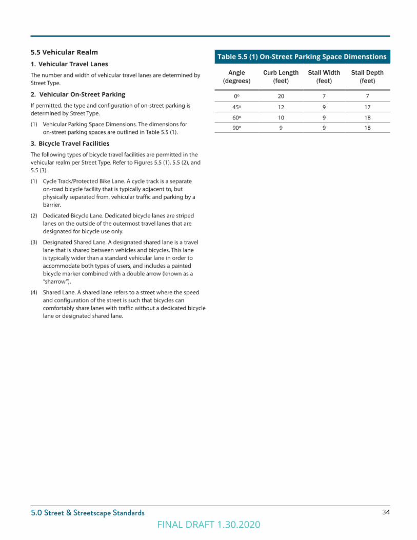
2. Vehicular On-Street Parking
If permitted, the type and configuration of on-street parking is determined by Street Type.
(1) Vehicular Parking Space Dimensions. The dimensions for on-street parking spaces are outlined in Table 5.5 (1).
3. Bicycle Travel Facilities
The following types of bicycle travel facilities are permitted in the vehicular realm per Street Type. Refer to Figures 5.5 (1), 5.5 (2), and 5.5 (3).
(1) Cycle Track/Protected Bike Lane. A cycle track is a separate on-road bicycle facility that is typically adjacent to, but physically separated from, vehicular traffic and parking by a barrier.
(2) Dedicated Bicycle Lane. Dedicated bicycle lanes are striped lanes on the outside of the outermost travel lanes that are designated for bicycle use only.
(3) Designated Shared Lane. A designated shared lane is a travel lane that is shared between vehicles and bicycles. This lane is typically wider than a standard vehicular lane in order to accommodate both types of users, and includes a painted bicycle marker combined with a double arrow (known as a “sharrow”).
(4) Shared Lane. A shared lane refers to a street where the speed and configuration of the street is such that bicycles can comfortably share lanes with traffic without a dedicated bicycle lane or designated shared lane.
Table 5.5 (1) On-Street Parking Space Dimenstions
Angle (degrees)
Curb Length (feet)
Stall Width (feet)
Stall Depth (feet)
0º 20 7 7
45º 12 9 17
60º 10 9 18
90º 9 9 18
FINAL DRAFT 1.30.2020
35
5.0 Street & Streetscape Standards
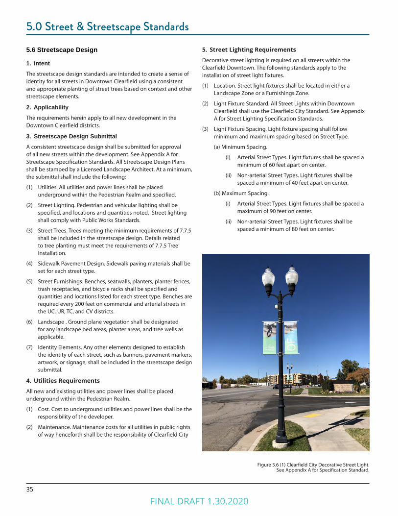
5. Street Lighting Requirements
Decorative street lighting is required on all streets within the Clearfield Downtown. The following standards apply to the installation of street light fixtures.
(1) Location. Street light fixtures shall be located in either a Landscape Zone or a Furnishings Zone.
(2) Light Fixture Standard. All Street Lights within Downtown Clearfield shall use the Clearfield City Standard. See Appendix A for Street Lighting Specification Standards.
(3) Light Fixture Spacing. Light fixture spacing shall follow minimum and maximum spacing based on Street Type.
(a) Minimum Spacing.
(i) Arterial Street Types. Light fixtures shall be spaced a minimum of 60 feet apart on center.
(ii) Non-arterial Street Types. Light fixtures shall be spaced a minimum of 40 feet apart on center.
(b) Maximum Spacing.
(i) Arterial Street Types. Light fixtures shall be spaced a maximum of 90 feet on center.
(ii) Non-arterial Street Types. Light fixtures shall be spaced a minimum of 80 feet on center.
5.6 Streetscape Design
1. IntentThe streetscape design standards are intended to create a sense of identity for all streets in Downtown Clearfield using a consistent and appropriate planting of street trees based on context and other streetscape elements.
2. ApplicabilityThe requirements herein apply to all new development in the Downtown Clearfield districts.
3. Streetscape Design SubmittalA consistent streetscape design shall be submitted for approval of all new streets within the development. See Appendix A for Streetscape Specification Standards. All Streetscape Design Plans shall be stamped by a Licensed Landscape Architect. At a minimum, the submittal shall include the following:
(1) Utilities. All utilities and power lines shall be placed underground within the Pedestrian Realm and specified.
(2) Street Lighting. Pedestrian and vehicular lighting shall be specified, and locations and quantities noted. Street lighting shall comply with Public Works Standards.
(3) Street Trees. Trees meeting the minimum requirements of 7.7.5 shall be included in the streetscape design. Details related to tree planting must meet the requirements of 7.7.5 Tree Installation.
(4) Sidewalk Pavement Design. Sidewalk paving materials shall be set for each street type.
(5) Street Furnishings. Benches, seatwalls, planters, planter fences, trash receptacles, and bicycle racks shall be specified and quantities and locations listed for each street type. Benches are required every 200 feet on commercial and arterial streets in the UC, UR, TC, and CV districts.
(6) Landscape . Ground plane vegetation shall be designated for any landscape bed areas, planter areas, and tree wells as applicable.
(7) Identity Elements. Any other elements designed to establish the identity of each street, such as banners, pavement markers, artwork, or signage, shall be included in the streetscape design submittal.
4. Utilities Requirements
All new and existing utilities and power lines shall be placed underground within the Pedestrian Realm.
(1) Cost. Cost to underground utilities and power lines shall be the responsibility of the developer.
(2) Maintenance. Maintenance costs for all utilities in public rights of way henceforth shall be the responsibility of Clearfield City
Figure 5.6 (1) Clearfield City Decorative Street Light. See Appendix A for Specification Standard.
FINAL DRAFT 1.30.2020

365.0 Street & Streetscape Standards
6. Street Tree Requirements
Street trees are required along all street frontages, except for the Alley. Each Lot is required to have a minimum of one street tree as long as minimum spacing requirements can be met with existing trees planted on the adjacent lot(s). The following standards apply to the installation of street trees.
(1) Location. Street trees shall be located in the Street Buffer in either a Landscape Zone or a Furnishings Zone.
(2) Street Tree Types. Street trees shall be selected based on width of the Street Buffer and/or specific streetscape design standards. Refer to tables 5.6 (1), 5.6 (2), and 5.6 (3) for an approved list of permitted large, medium, and small street trees.
(a) For Street Buffers 6 feet and less small and/or medium trees may be used.
(b) For Street Buffers wider than 6 feet medium and/or large trees may be used.
(3) Street Tree Spacing. Street trees shall follow minimum and maximum spacing based on tree size. Trees shall be located such that minimum spacing requirements are met with existing trees planted on the adjacent lot(s).
(a) Large trees shall be spaced a minimum of 40 and a maximum of 60 feet on center.
(b) Medium and small trees shall be spaced a minimum of 20 and a maximum of 40 feet on center.
(4) Clear Branch Height. Minimum clear branch height is 7 feet.
(5) Limited Distance between Curb and Sidewalk. Where the distance from the back of the curb to the edge of the right-of-way or property line is less than nine feet with a sidewalk, the Clearfield City Urban Forester/Arborist must approve the tree species. Applicant shall work with the Clearfield City Urban Forester/Arborist to determine the appropriate tree species.
(6) Tree Wells. In commercial districts, where the sidewalk extends from the back of curb to the property line, tree wells with tree grates shall be utilized.
(a) The opening in a tree grate for the trunk must be expandable.
(7) Tree Species and Diversity. Streets shall have the same combination of tree species per block on both sides of the streets with changes at intersections. However, tree diversity is important to reduce the risk of catastrophic tree loss due to pests. To promote tree diversity overall in Downtown Clearfield, street tree installations shall work to achieve a diversity as specified in Table 5.6 (4).
Table 5.6 (1) Permitted Large Street Trees Sycamore Maple Acer pseudoplatanus
Emerald Queen Maple Acer platanoides ‘Emerald Queen’
Catalpa Catalpa speciosa
Hackberry Celtis occidentalis
Riversii Beech Fagus sylvatica ‘Riversii’
Gingko Gingko biloba ‘Princeton Sentry’
Honeylocust Gleditsia triacanthos
Kentucky Coffeetree Gymnocladus dioicus
London Planetree Platanus x acerifolia
Japanese Pagodatree Sophora japonica
Sterling Silver Linden Tilia tomentosa ‘Sterling’
Accolade Elm Ulmus carpinifolia ‘Accolade’
Table 5.6. (2) Permitted Medium Street TreesFairview Maple Acer platanoides ‘Fairview’
Briotii Horsechestnut Aesculus x carnea ‘Briotii’
Chinese Fringetree Chionanthus retusus
Yellowwood Cladrastis kentukea
Goldenraintree Koelreuteria paniculata
Fruitless Mulberry Morus alba ‘Fruitless’
Mayday Tree Prunus padus
Lacebark Elm Ulmus parvifolia
Frontier Elm Ulmus parvifolia ‘Frontier’
Japanese Zelkova Zelkova serrata
Chanticleer Pear Pyrus calleryana ‘Chanticleer’
Table 5.6 (3) Permitted Small Street TreesJapanese Tree Lilac Syringa reticulata
Flowering Crabapple Malus spp. Various
Eastern Redbud Cercis canadensis
American Smoke Tree Cotinus obovatus
Winter King Hawthorn Crataegus viridis
Tricolor Beech Fagus sylvatica
Flowering Plum, Krauter Vesuvius Prunus cerasifera
Summer Sprite Linden Tilia cordata
City Sprite Zelkova Zelkova serrata
Table 5.6 (4) Street Tree Diversity in DowntownSpecies No more than 10% of any one species
Genus No more than 20% of any one genus
Family No more than 30% of any one family
FINAL DRAFT 1.30.2020

37
5.0 Street & Streetscape Standards
5.7 Alley1. IntentThe Alley is a very low capacity drive located at the rear of lots or development parcels. From the Alley, access to parking facilities, loading facilities, and service areas, such as refuse and utilities, is possible without a curb cut or driveway interrupting a street type. Refer to the typical plan and section in Figure 5.7 (1).
2. General RequirementsAlleys shall be developed using the standards in Table 5.7 (1). A rolled curb shall be used to provided the necessary travel surface width for fire access.
Table 5.7 (1) Alley Requirements
Permitted Districts All Districts
Permitted Adjacent Building Types All Building Types
Typical Right-of-Way Width 20’ to 26’ (one-way or two way)
Vehicular Realm
Travel Lanes 1 or 2
Lane Width Varies (see Travel Surface Width) 8’ lanes if two-way; 16’ lane if one-way
Center Turn Lanes None
Parking Lanes None
Travel Surface Width
Minimum 20’ (one way traffic only if Fire Access is provided and/or buildings are fire sprinkled.)
Minimum 26’ if buildings are higher than 30 feet or a fire hydrant is present
Median None
Bicycle Facilities Shared
Pedestrian Realm
Pedestrian Facilities Travel lanes are shared among drivers, pedestrians, and bicyclists
Street Buffer None required
10’ to 13’ 10’ to 13’
FINAL DRAFT 1.30.2020
385.0 Street & Streetscape Standards
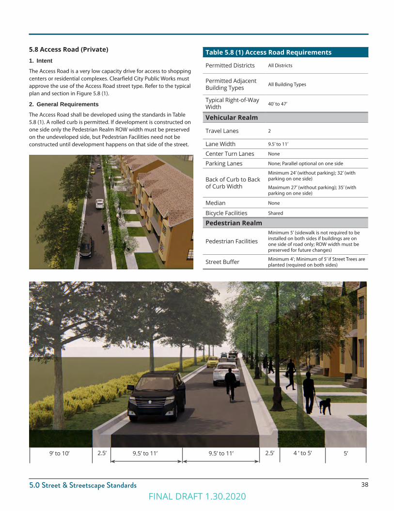
5.8 Access Road (Private)1. IntentThe Access Road is a very low capacity drive for access to shopping centers or residential complexes. Clearfield City Public Works must approve the use of the Access Road street type. Refer to the typical plan and section in Figure 5.8 (1).
2. General RequirementsThe Access Road shall be developed using the standards in Table 5.8 (1). A rolled curb is permitted. If development is constructed on one side only the Pedestrian Realm ROW width must be preserved on the undeveloped side, but Pedestrian Facilities need not be constructed until development happens on that side of the street.
Table 5.8 (1) Access Road Requirements
Permitted Districts All Districts
Permitted Adjacent Building Types All Building Types
Typical Right-of-Way Width 40’ to 47’
Vehicular Realm
Travel Lanes 2
Lane Width 9.5’ to 11’
Center Turn Lanes None
Parking Lanes None; Parallel optional on one side
Back of Curb to Back of Curb Width
Minimum 24’ (without parking); 32’ (with parking on one side)
Maximum 27’ (without parking); 35’ (with parking on one side)
Median None
Bicycle Facilities Shared
Pedestrian Realm
Pedestrian FacilitiesMinimum 5’ (sidewalk is not required to be installed on both sides if buildings are on one side of road only; ROW width must be preserved for future changes)
Street Buffer Minimum 4’; Minimum of 5’ if Street Trees are planted (required on both sides)
9.5’ to 11’ 9.5’ to 11’2.5’ 2.5’ 4 ‘ to 5’ 5’ 9’ to 10’
FINAL DRAFT 1.30.2020
39
5.0 Street & Streetscape Standards
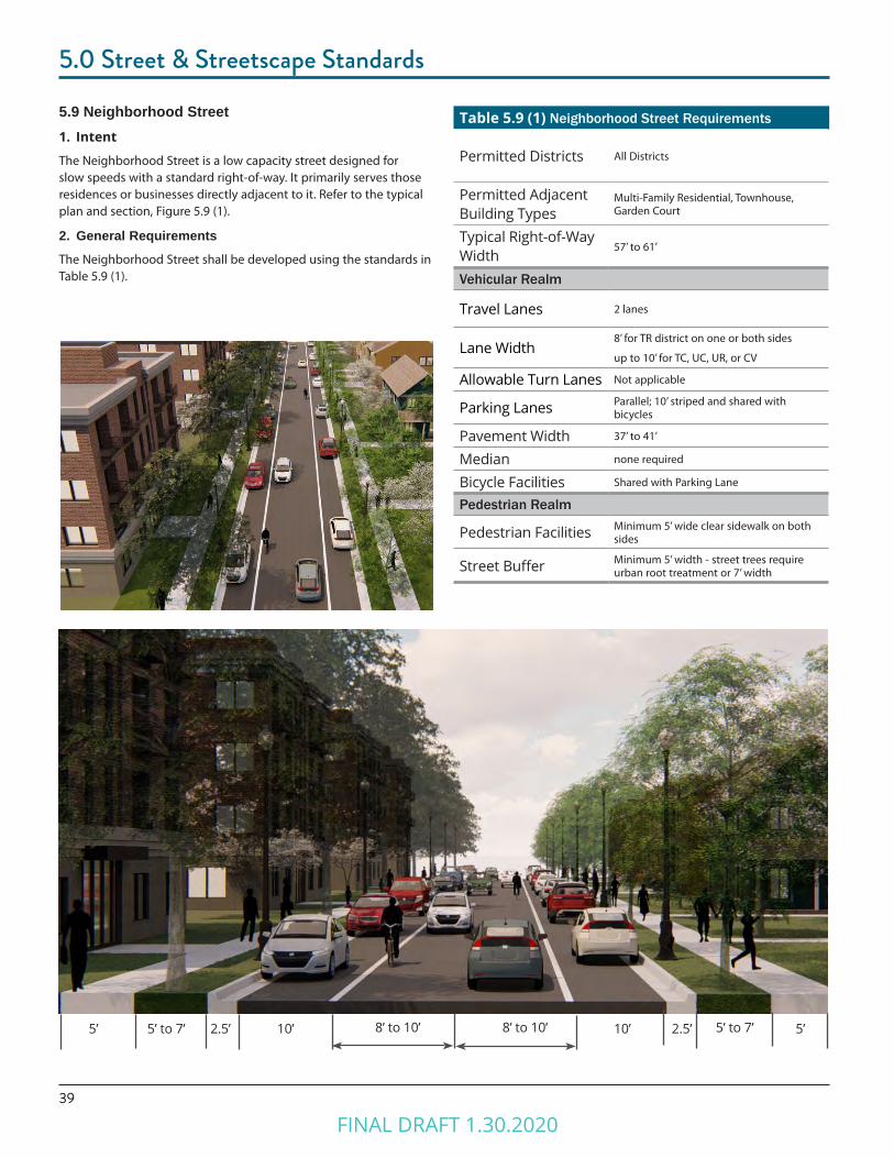
5.9 Neighborhood Street1. Intent
The Neighborhood Street is a low capacity street designed for slow speeds with a standard right-of-way. It primarily serves those residences or businesses directly adjacent to it. Refer to the typical plan and section, Figure 5.9 (1).
2. General RequirementsThe Neighborhood Street shall be developed using the standards in Table 5.9 (1).
Table 5.9 (1) Neighborhood Street Requirements
Permitted Districts All Districts
Permitted Adjacent Building Types
Multi-Family Residential, Townhouse, Garden Court
Typical Right-of-Way Width
57’ to 61’
Vehicular Realm
Travel Lanes 2 lanes
Lane Width8’ for TR district on one or both sides
up to 10’ for TC, UC, UR, or CV
Allowable Turn Lanes Not applicable
Parking Lanes Parallel; 10’ striped and shared with bicycles
Pavement Width 37’ to 41’
Median none required
Bicycle Facilities Shared with Parking Lane
Pedestrian Realm
Pedestrian Facilities Minimum 5’ wide clear sidewalk on both sides
Street Buffer Minimum 5’ width - street trees require urban root treatment or 7’ width
8’ to 10’ 8’ to 10’5’ 5’ to 7’ 5’ to 7’ 5’2.5’ 2.5’10’ 10’
FINAL DRAFT 1.30.2020
405.0 Street & Streetscape Standards
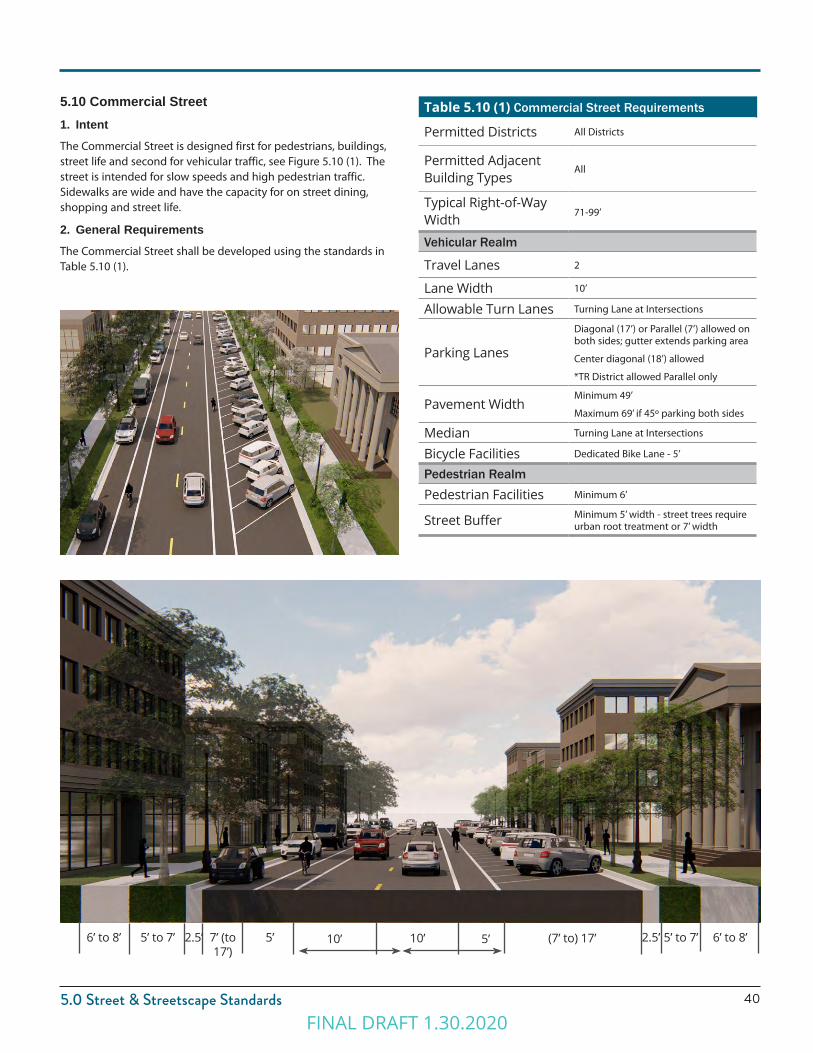
5.10 Commercial Street1. IntentThe Commercial Street is designed first for pedestrians, buildings, street life and second for vehicular traffic, see Figure 5.10 (1). The street is intended for slow speeds and high pedestrian traffic. Sidewalks are wide and have the capacity for on street dining, shopping and street life.
2. General RequirementsThe Commercial Street shall be developed using the standards in Table 5.10 (1).
Table 5.10 (1) Commercial Street Requirements
Permitted Districts All Districts
Permitted Adjacent Building Types
All
Typical Right-of-Way Width 71-99’
Vehicular Realm
Travel Lanes 2
Lane Width 10’
Allowable Turn Lanes Turning Lane at Intersections
Parking Lanes
Diagonal (17’) or Parallel (7’) allowed on both sides; gutter extends parking area
Center diagonal (18’) allowed
*TR District allowed Parallel only
Pavement WidthMinimum 49’
Maximum 69’ if 45º parking both sides
Median Turning Lane at Intersections
Bicycle Facilities Dedicated Bike Lane - 5’
Pedestrian RealmPedestrian Facilities Minimum 6’
Street Buffer Minimum 5’ width - street trees require urban root treatment or 7’ width
10’ 10’6’ to 8’ 5’ to 7’ 5’ to 7’ 6’ to 8’2.5’ 2.5’7’ (to 17’)
(7’ to) 17’5’5’
FINAL DRAFT 1.30.2020

41
5.0 Street & Streetscape Standards
5.11 State/Main Street Highway 126 - Urban Core Arterial1. IntentThis Street Type is for State/Main, which is State Highway 126, in the Urban Core of Downtown Clearfield between 300 North and 700 South. This is a high capacity regional thoroughfare, that acknowledges the Downtown Clearfield context. Figure 5.11 (1).
2. General RequirementsState/Main Street - Urban Core shall be developed using the standards in Table 5.11 (1).
Table 5.11 (1) Urban Core Arterial Requirements
Permitted Adjacent Districts UC, UR, CV, TC
Permitted Adjacent Building Types
Civic , Mixed-Use, Multi-Family, Office
Typical Right-of-Way Width 103’
Vehicular Realm
Travel Lanes 2 lanes in each direction
Lane Width 11’
Turn Lanes Per UDOT corridor agreement
Parking Lanes Optional Parallel, as ROW allows
Pavement Width 72’
Median12’ Planted Median with turn lane pockets (includes 1’ shy distance on each side of median)
Bicycle Facilities 7.5’ Protected Bike Lanes (2’ buffer; 5.5’ travel lane)
Pedestrian Realm Pedestrian Facilities Minimum 8’ wide clear sidewalk
Street Buffer Minimum 7.5’ hardscape
11’ 12’ 7.5’ 7.5’2.5’11’11’ 8’11’8’ 7.5’ 7.5’2.5’
FINAL DRAFT 1.30.2020
425.0 Street & Streetscape Standards
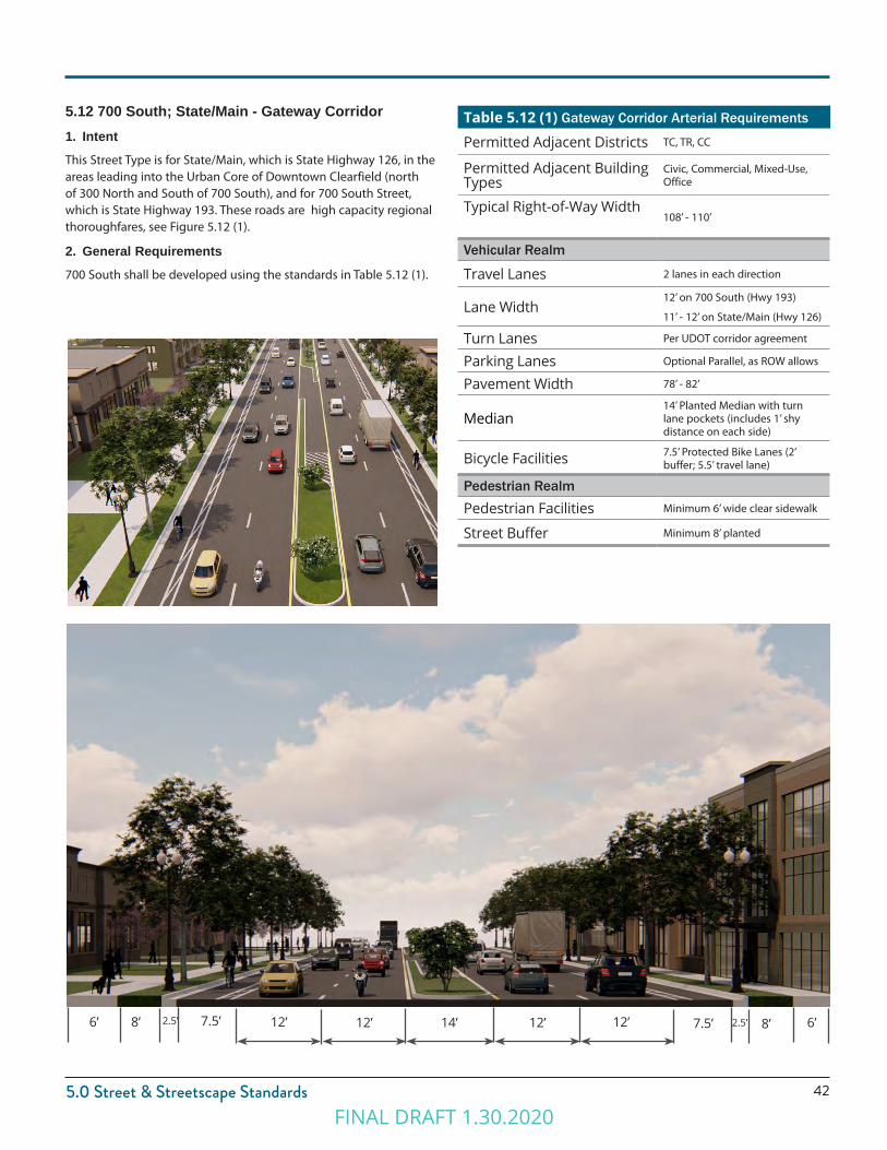
5.12 700 South; State/Main - Gateway Corridor1. IntentThis Street Type is for State/Main, which is State Highway 126, in the areas leading into the Urban Core of Downtown Clearfield (north of 300 North and South of 700 South), and for 700 South Street, which is State Highway 193. These roads are high capacity regional thoroughfares, see Figure 5.12 (1).
2. General Requirements700 South shall be developed using the standards in Table 5.12 (1).
Table 5.12 (1) Gateway Corridor Arterial Requirements
Permitted Adjacent Districts TC, TR, CC
Permitted Adjacent Building Types
Civic, Commercial, Mixed-Use, Office
Typical Right-of-Way Width108’ - 110’
Vehicular Realm
Travel Lanes 2 lanes in each direction
Lane Width12’ on 700 South (Hwy 193)
11’ - 12’ on State/Main (Hwy 126)
Turn Lanes Per UDOT corridor agreement
Parking Lanes Optional Parallel, as ROW allows
Pavement Width 78’ - 82’
Median14’ Planted Median with turn lane pockets (includes 1’ shy distance on each side)
Bicycle Facilities 7.5’ Protected Bike Lanes (2’ buffer; 5.5’ travel lane)
Pedestrian RealmPedestrian Facilities Minimum 6’ wide clear sidewalk
Street Buffer Minimum 8’ planted
12’ 14’ 7.5’ 8’2.5’12’12’ 6’7.5’8’ 2.5’ 12’6’
FINAL DRAFT 1.30.2020

FINAL DRAFT 1.30.2020
Chapter 6.0BUILDING TYPES
FINAL DRAFT 1.30.2020
45
6.0 Building Types
6.1. Purpose1. Intent
The standards are intended to outline the required building types and standards for new construction within the Downtown Clearfield Districts defined in Chapter 2.0.
6.2. General RequirementsAll Building Types must meet the following requirements.
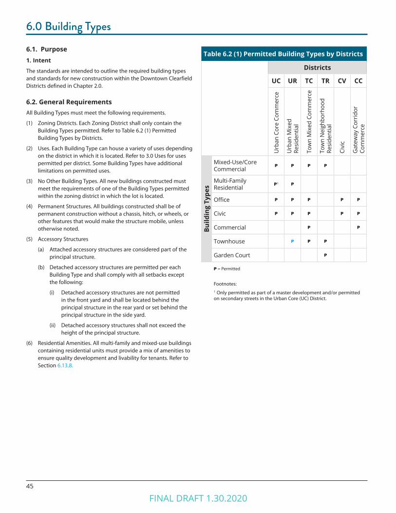
(1) Zoning Districts. Each Zoning District shall only contain the Building Types permitted. Refer to Table 6.2 (1) Permitted Building Types by Districts.
(2) Uses. Each Building Type can house a variety of uses depending on the district in which it is located. Refer to 3.0 Uses for uses permitted per district. Some Building Types have additional limitations on permitted uses.
(3) No Other Building Types. All new buildings constructed must meet the requirements of one of the Building Types permitted within the zoning district in which the lot is located.
(4) Permanent Structures. All buildings constructed shall be of permanent construction without a chassis, hitch, or wheels, or other features that would make the structure mobile, unless otherwise noted.
(5) Accessory Structures
(a) Attached accessory structures are considered part of the principal structure.
(b) Detached accessory structures are permitted per each Building Type and shall comply with all setbacks except the following:
(i) Detached accessory structures are not permitted in the front yard and shall be located behind the principal structure in the rear yard or set behind the principal structure in the side yard.
(ii) Detached accessory structures shall not exceed the height of the principal structure.
(6) Residential Amenities. All multi-family and mixed-use buildings containing residential units must provide a mix of amenities to ensure quality development and livability for tenants. Refer to Section 6.13.8.
Table 6.2 (1) Permitted Building Types by Districts
Districts
UC UR TC TR CV CC
Urb
an C
ore
Com
mer
ce
Urb
an M
ixed
Re
side
ntia
l
Tow
n M
ixed
Com
mer
ce
Tow
n N
eigh
borh
ood
Resi
dent
ial
Civi
c
Gat
eway
Cor
ridor
Co
mm
erce
Build
ing
Type
s
Mixed-Use/Core Commercial
P P P P
Multi-Family Residential
P1 P
Office P P P P P
Civic P P P P P
Commercial P P
Townhouse P P P
Garden Court P
P = Permitted
Footnotes:1 Only permitted as part of a master development and/or permitted on secondary streets in the Urban Core (UC) District.
FINAL DRAFT 1.30.2020

466.0 Building Types
6.3 Building Type StandardsThe following explains and further defines the standards for Building Types. All standards may not apply to all Building Types.
1. Building Site
(1) Minimum Lot or Unit Width. The minimum width of a lot, measured at or parallel to the front property line. Or, the minimum width of a unit.
(2) Maximum Lot or Unit Width. The maximum width of a lot, measured at or parallel to the front property line. Or, the maximum width of a unit.
(3) Maximum Impervious Coverage. The maximum percentage of a lot permitted to be covered by impervious surfaces, including principal structures, accessory structures, pavement, and other impervious surfaces.
(4) Additional Semi-Pervious Coverage. The additional percentage of a lot beyond the Maximum Impervious Coverage, which may be surfaced in a semi-pervious material, including permeable pavers or semi-pervious landscaped roofs.
Figure 6.3 (1). Maximum Impervious & Additional Semi-Pervious Coverage
Figure 6.3 (2). Pervious and Semi-Pervious Coverage
Maximum Impervious Coverage = Building Coverage + Impervious Surfaces
Additional Semi-Pervious
Coverage. (Landscaped
Roof)
Additional Semi-Pervious
Coverage. (Permeable
Paving)
Building Footprint
Parking
FINAL DRAFT 1.30.2020
47
6.0 Building Types
2. Site Access & Parking
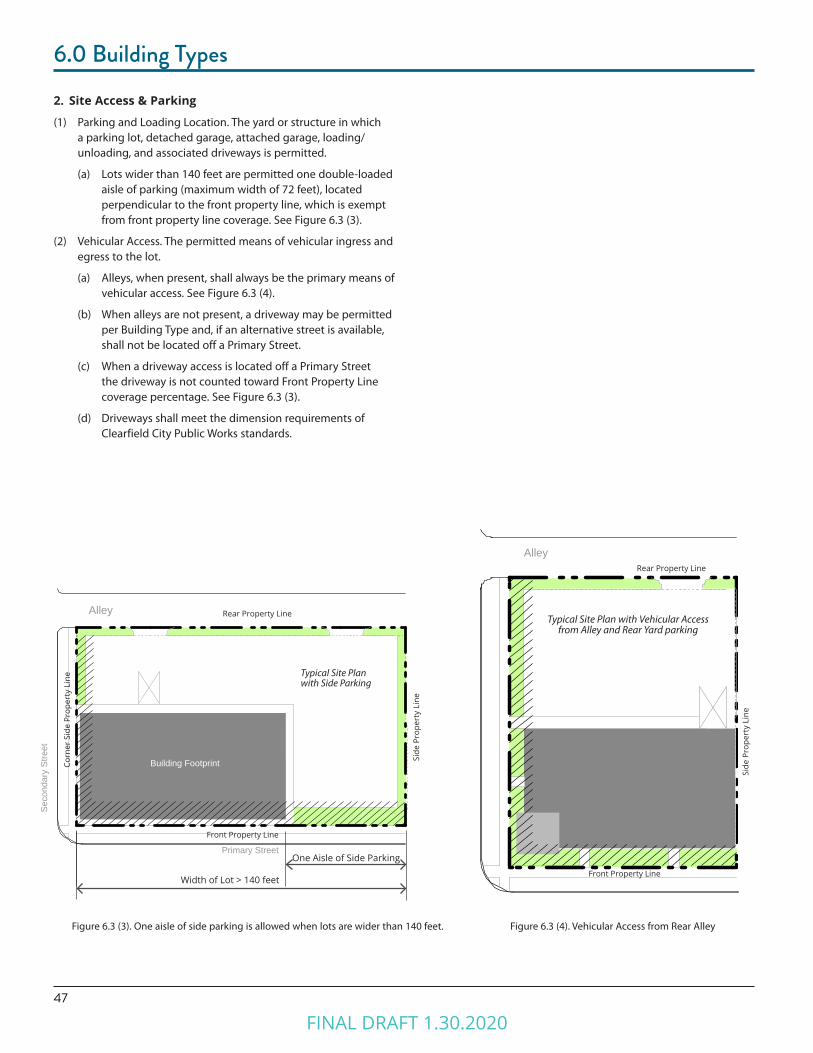
(1) Parking and Loading Location. The yard or structure in which a parking lot, detached garage, attached garage, loading/unloading, and associated driveways is permitted.
(a) Lots wider than 140 feet are permitted one double-loaded aisle of parking (maximum width of 72 feet), located perpendicular to the front property line, which is exempt from front property line coverage. See Figure 6.3 (3).
(2) Vehicular Access. The permitted means of vehicular ingress and egress to the lot.
(a) Alleys, when present, shall always be the primary means of vehicular access. See Figure 6.3 (4).
(b) When alleys are not present, a driveway may be permitted per Building Type and, if an alternative street is available, shall not be located off a Primary Street.
(c) When a driveway access is located off a Primary Street the driveway is not counted toward Front Property Line coverage percentage. See Figure 6.3 (3).
(d) Driveways shall meet the dimension requirements of Clearfield City Public Works standards.
Typical Site Plan with Vehicular Access from Alley and Rear Yard parking
Side
Pro
pert
y Li
ne
Alley
Front Property Line
Figure 6.3 (4). Vehicular Access from Rear AlleyFigure 6.3 (3). One aisle of side parking is allowed when lots are wider than 140 feet.
Alley
Typical Site Plan with Side Parking
Front Property Line
Rear Property Line
Corn
er S
ide
Prop
erty
Lin
e
Seco
ndar
y St
reet
Primary Street
Side
Pro
pert
y Li
ne
Building Footprint
Rear Property Line
One Aisle of Side Parking
Width of Lot > 140 feet
FINAL DRAFT 1.30.2020
486.0 Building Types
3. Building Location
(1) Multiple Principal Structures. The allowance of more than one principal structure on a lot.
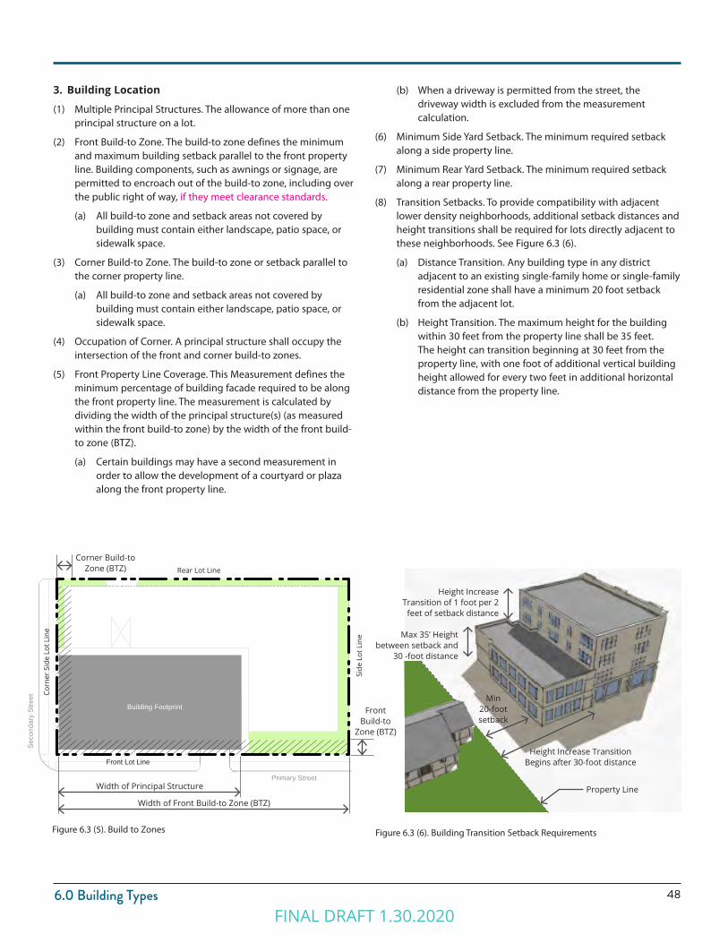
(2) Front Build-to Zone. The build-to zone defines the minimum and maximum building setback parallel to the front property line. Building components, such as awnings or signage, are permitted to encroach out of the build-to zone, including over the public right of way, if they meet clearance standards.
(a) All build-to zone and setback areas not covered by building must contain either landscape, patio space, or sidewalk space.
(3) Corner Build-to Zone. The build-to zone or setback parallel to the corner property line.
(a) All build-to zone and setback areas not covered by building must contain either landscape, patio space, or sidewalk space.
(4) Occupation of Corner. A principal structure shall occupy the intersection of the front and corner build-to zones.
(5) Front Property Line Coverage. This Measurement defines the minimum percentage of building facade required to be along the front property line. The measurement is calculated by dividing the width of the principal structure(s) (as measured within the front build-to zone) by the width of the front build-to zone (BTZ).
(a) Certain buildings may have a second measurement in order to allow the development of a courtyard or plaza along the front property line.
Figure 6.3 (5). Build to Zones
(b) When a driveway is permitted from the street, the driveway width is excluded from the measurement calculation.
(6) Minimum Side Yard Setback. The minimum required setback along a side property line.
(7) Minimum Rear Yard Setback. The minimum required setback along a rear property line.
(8) Transition Setbacks. To provide compatibility with adjacent lower density neighborhoods, additional setback distances and height transitions shall be required for lots directly adjacent to these neighborhoods. See Figure 6.3 (6).
(a) Distance Transition. Any building type in any district adjacent to an existing single-family home or single-family residential zone shall have a minimum 20 foot setback from the adjacent lot.
(b) Height Transition. The maximum height for the building within 30 feet from the property line shall be 35 feet. The height can transition beginning at 30 feet from the property line, with one foot of additional vertical building height allowed for every two feet in additional horizontal distance from the property line.
Figure 6.3 (6). Building Transition Setback Requirements
Building Footprint
Rear Lot Line
Side
Lot
Lin
e
Front Lot Line
Corn
er S
ide
Lot L
ine
Seco
ndar
y St
reet
Primary Street
Corner Build-to Zone (BTZ)
Front Build-to
Zone (BTZ)
Height Increase Transition Begins after 30-foot distance
Min 20-foot setback
Height Increase Transition of 1 foot per 2
feet of setback distance
Max 35’ Height between setback and
30 -foot distance
Width of Principal Structure
Width of Front Build-to Zone (BTZ)Property Line
FINAL DRAFT 1.30.2020

49
6.0 Building Types
Figure 6.3 (7). Building Massing Requirements
4. Building Massing
The following explains the line item requirements for each Building Type.
(1) Minimum Building Width. The minimum building or unit width measured at or parallel to the front property line.
(2) Maximum Building Width. The maximum building or unit width measured at or parallel to the front property line.
(3) Minimum Number of Stories. The minimum stories required for the building, located within the build-to zone; stories above the required minimum height may be stepped back from the facade.
(4) Maximum Number of Stories. The maximum stories allowed for the building.
(a) Half stories. Partial stories located either completely within the roof structure with street-facing windows or in a visible basement exposed a maximum of one half-story above grade.
(b) A building incorporating both a half story within the roof and a visible basement shall count the height of the two half stories as one full story.
(c) To allow for atriums, vaulted ceilings, or upper clerestory stories, full stories may exceed the maximum height as specified by building type but shall be counted as two or more stories.
(5) Stepbacks. Some Building Types require a building facade to step back as its height increases. If required, the upper stories of any building facade with street frontage shall step back a designated amount beyond the building facade of the lower stories.
(6) Ground Story Minimum and Maximum Height (Measuring Height). The permitted range of height in feet for each story. Additional information is as follows:
(a) Floor height is measured in feet between the floor of a story to the ceiling of a story (e.g. clear height).
(b) For single story buildings and the uppermost story of a multiple story building, floor to floor height shall be measured from the floor of the story to the tallest point of the ceiling.
(7) Upper Story, Minimum and Maximum Height (Measuring Height). The permitted range of height in feet for each story. Additional information is as follows:
(a) Floor height is measured in feet between the floor of a story to the ceiling of a story (e.g. clear height).
(b) For single story buildings and the uppermost story of a multiple story building, floor height shall be measured from the floor of the story to the tallest point of the ceiling.
(8) Roof Types
(a) Permitted Roof Type. The roof type(s) permitted for a given Building Type. Refer to 6.12. Roof Types for specific requirements.
(b) Tower. A vertical building extension that may be permitted in conjunction with another roof type on certain Building Types. Refer to 6.12. Roof Types.
street
Fron
t Lot
Lin
e
Upper Story Height
Ground Story Height
Min
/Max
# o
f Sto
ries
Roof Types
Stepback
FINAL DRAFT 1.30.2020
506.0 Building Types
street
Figure 6.3 (8). Facade Requirements.
5. Facade Articulation & Details
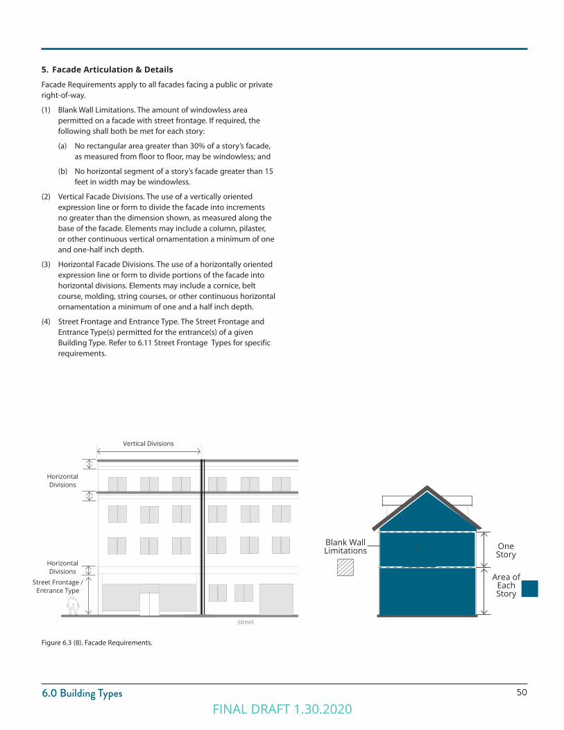
Facade Requirements apply to all facades facing a public or private right-of-way.
(1) Blank Wall Limitations. The amount of windowless area permitted on a facade with street frontage. If required, the following shall both be met for each story:
(a) No rectangular area greater than 30% of a story’s facade, as measured from floor to floor, may be windowless; and
(b) No horizontal segment of a story’s facade greater than 15 feet in width may be windowless.
(2) Vertical Facade Divisions. The use of a vertically oriented expression line or form to divide the facade into increments no greater than the dimension shown, as measured along the base of the facade. Elements may include a column, pilaster, or other continuous vertical ornamentation a minimum of one and one-half inch depth.
(3) Horizontal Facade Divisions. The use of a horizontally oriented expression line or form to divide portions of the facade into horizontal divisions. Elements may include a cornice, belt course, molding, string courses, or other continuous horizontal ornamentation a minimum of one and a half inch depth.
(4) Street Frontage and Entrance Type. The Street Frontage and Entrance Type(s) permitted for the entrance(s) of a given Building Type. Refer to 6.11 Street Frontage Types for specific requirements.
Horizontal Divisions
Street Frontage / Entrance Type
Horizontal Divisions
Area of Each Story
One Story
Blank Wall Limitations
Vertical Divisions
FINAL DRAFT 1.30.2020
51
6.0 Building Types
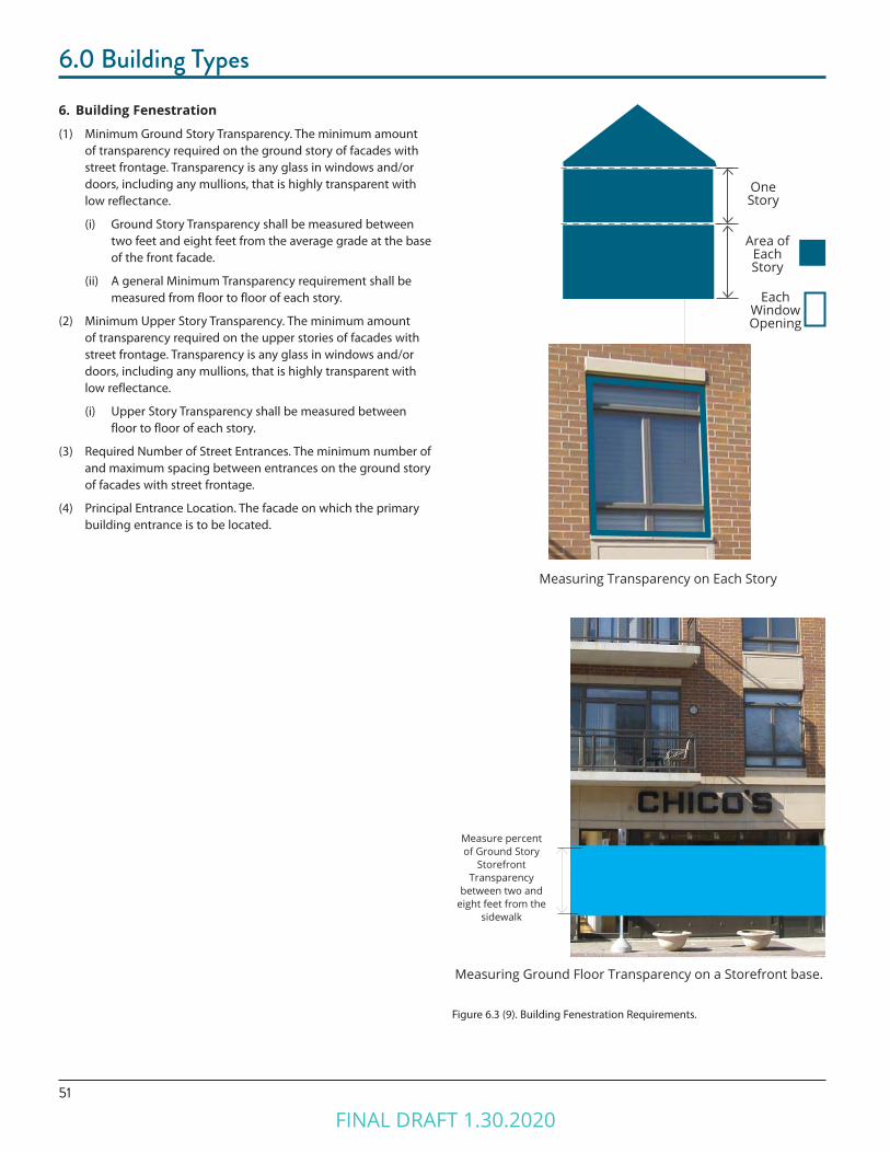
6. Building Fenestration
(1) Minimum Ground Story Transparency. The minimum amount of transparency required on the ground story of facades with street frontage. Transparency is any glass in windows and/or doors, including any mullions, that is highly transparent with low reflectance.
(i) Ground Story Transparency shall be measured between two feet and eight feet from the average grade at the base of the front facade.
(ii) A general Minimum Transparency requirement shall be measured from floor to floor of each story.
(2) Minimum Upper Story Transparency. The minimum amount of transparency required on the upper stories of facades with street frontage. Transparency is any glass in windows and/or doors, including any mullions, that is highly transparent with low reflectance.
(i) Upper Story Transparency shall be measured between floor to floor of each story.
(3) Required Number of Street Entrances. The minimum number of and maximum spacing between entrances on the ground story of facades with street frontage.
(4) Principal Entrance Location. The facade on which the primary building entrance is to be located.
Measuring Ground Floor Transparency on a Storefront base.
Figure 6.3 (9). Building Fenestration Requirements.
Measuring Transparency on Each Story
Measure percent of Ground Story
Storefront Transparency
between two and eight feet from the
sidewalk
Each Window Opening
Area of Each Story
One Story
FINAL DRAFT 1.30.2020
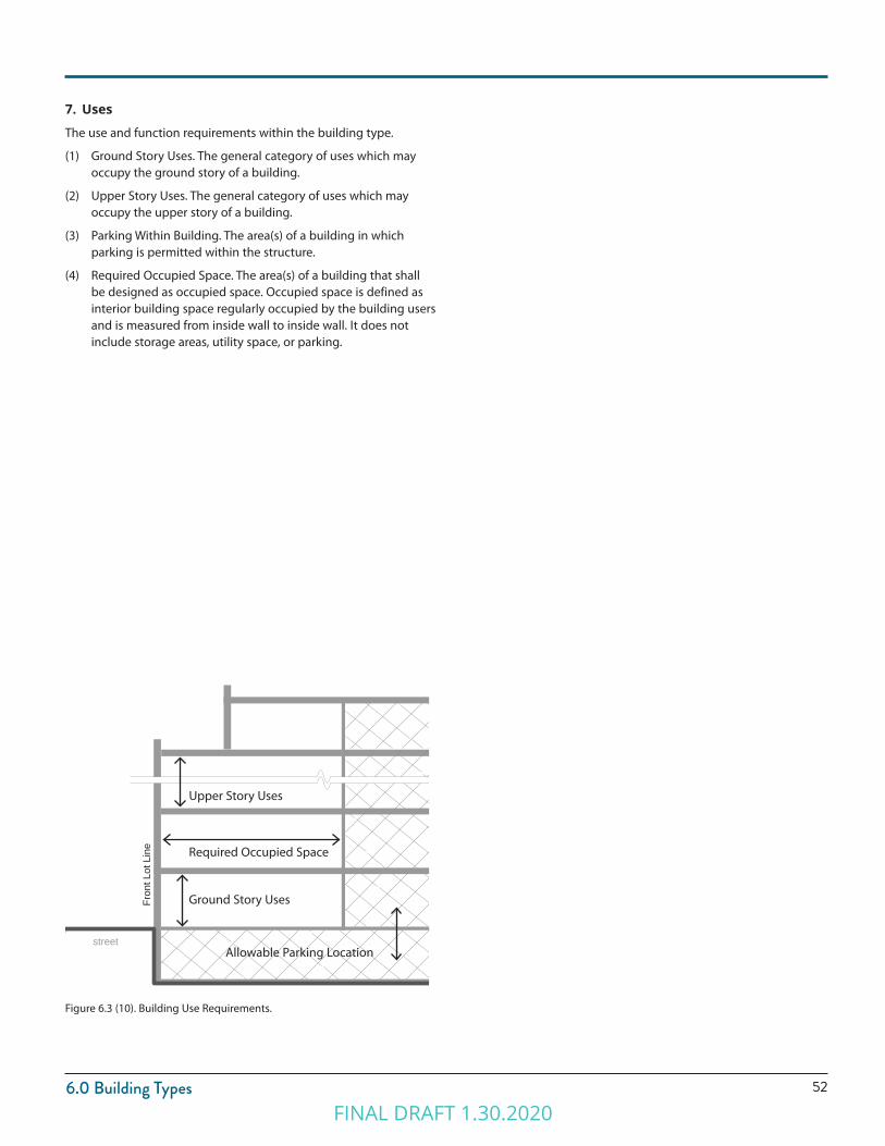
526.0 Building Types
7. Uses
The use and function requirements within the building type.
(1) Ground Story Uses. The general category of uses which may occupy the ground story of a building.
(2) Upper Story Uses. The general category of uses which may occupy the upper story of a building.
(3) Parking Within Building. The area(s) of a building in which parking is permitted within the structure.
(4) Required Occupied Space. The area(s) of a building that shall be designed as occupied space. Occupied space is defined as interior building space regularly occupied by the building users and is measured from inside wall to inside wall. It does not include storage areas, utility space, or parking.
Figure 6.3 (10). Building Use Requirements.
street
Fron
t Lot
Lin
e
Upper Story Uses
Required Occupied Space
Ground Story Uses
Allowable Parking Location
FINAL DRAFT 1.30.2020
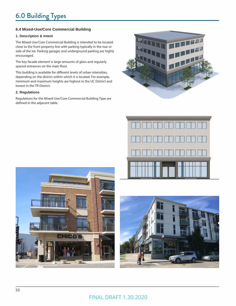
53
6.0 Building Types
6.4 Mixed-Use/Core Commercial Building1. Description & IntentThe Mixed-Use/Core Commercial Building is intended to be located close to the front property line with parking typically in the rear or side of the lot. Parking garages and underground parking are highly encouraged.
The key facade element is large amounts of glass and regularly spaced entrances on the main floor.
This building is available for different levels of urban intensities, depending on the district within which it is located. For example, minimum and maximum heights are highest in the UC District and lowest in the TR District.
2. RegulationsRegulations for the Mixed-Use/Core Commercial Building Type are defined in the adjacent table.
FINAL DRAFT 1.30.2020
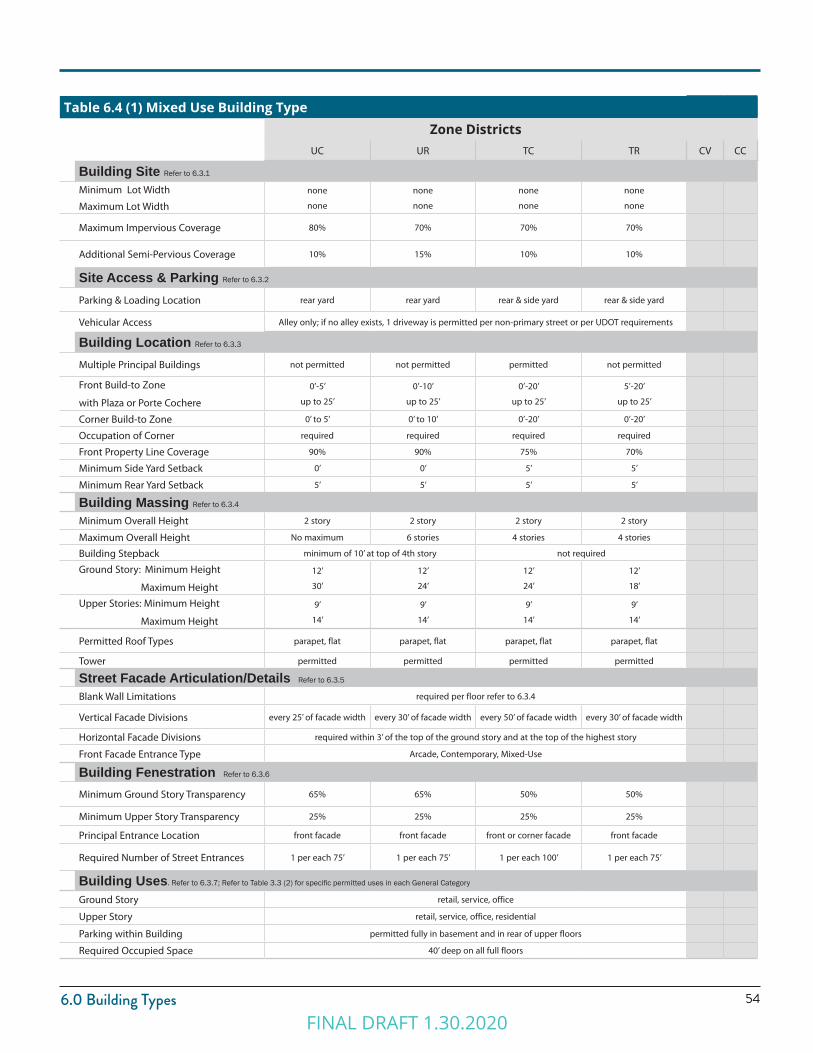
546.0 Building Types
Table 6.4 (1) Mixed Use Building TypeZone Districts
UC UR TC TR CV CC
Building Site Refer to 6.3.1
Minimum Lot Width
Maximum Lot Width
none
none
none
none
none
none
none
none
Maximum Impervious Coverage 80% 70% 70% 70%
Additional Semi-Pervious Coverage 10% 15% 10% 10%
Site Access & Parking Refer to 6.3.2
Parking & Loading Location rear yard rear yard rear & side yard rear & side yard
Vehicular Access Alley only; if no alley exists, 1 driveway is permitted per non-primary street or per UDOT requirements
Building Location Refer to 6.3.3
Multiple Principal Buildings not permitted not permitted permitted not permitted
Front Build-to Zone
with Plaza or Porte Cochere
0’-5’
up to 25’
0’-10’
up to 25’
0’-20’
up to 25’
5’-20’
up to 25’
Corner Build-to Zone 0’ to 5’ 0’ to 10’ 0’-20’ 0’-20’
Occupation of Corner required required required required
Front Property Line Coverage 90% 90% 75% 70%
Minimum Side Yard Setback 0’ 0’ 5’ 5’
Minimum Rear Yard Setback 5’ 5’ 5’ 5’
Building Massing Refer to 6.3.4
Minimum Overall Height 2 story 2 story 2 story 2 story
Maximum Overall Height No maximum 6 stories 4 stories 4 stories
Building Stepback minimum of 10’ at top of 4th story not required
Ground Story: Minimum Height
Maximum Height
12’
30’
12’
24’
12’
24’
12’
18’
Upper Stories: Minimum Height
Maximum Height
9’
14’
9’
14’
9’
14’
9’
14’
Permitted Roof Types parapet, flat parapet, flat parapet, flat parapet, flat
Tower permitted permitted permitted permitted
Street Facade Articulation/Details Refer to 6.3.5
Blank Wall Limitations required per floor refer to 6.3.4
Vertical Facade Divisions every 25’ of facade width every 30’ of facade width every 50’ of facade width every 30’ of facade width
Horizontal Facade Divisions required within 3’ of the top of the ground story and at the top of the highest story
Front Facade Entrance Type Arcade, Contemporary, Mixed-Use
Building Fenestration Refer to 6.3.6
Minimum Ground Story Transparency 65% 65% 50% 50%
Minimum Upper Story Transparency 25% 25% 25% 25%
Principal Entrance Location front facade front facade front or corner facade front facade
Required Number of Street Entrances 1 per each 75’ 1 per each 75’ 1 per each 100’ 1 per each 75’
Building Uses. Refer to 6.3.7; Refer to Table 3.3 (2) for specific permitted uses in each General Category
Ground Story retail, service, office
Upper Story retail, service, office, residential
Parking within Building permitted fully in basement and in rear of upper floors
Required Occupied Space 40’ deep on all full floors
FINAL DRAFT 1.30.2020
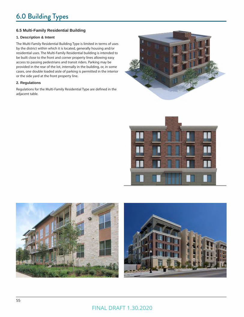
55
6.0 Building Types
6.5 Multi-Family Residential Building1. Description & IntentThe Multi-Family Residential Building Type is limited in terms of uses by the district within which it is located, generally housing and/or residential uses. The Multi-Family Residential building is intended to be built close to the front and corner property lines allowing easy access to passing pedestrians and transit riders. Parking may be provided in the rear of the lot, internally in the building, or, in some cases, one double loaded aisle of parking is permitted in the interior or the side yard at the front property line.
2. RegulationsRegulations for the Multi-Family Residential Type are defined in the adjacent table.
FINAL DRAFT 1.30.2020

566.0 Building Types
Table 6.5 (1) Multi-Family Residential Building TypeZone Districts
UC UR TC TR CV CC
Building Site Refer to 6.3.1
Minimum Lot Width
Maximum Lot Width
80’
none
80’
none
Maximum Impervious Coverage 65% 60%
Additional Semi-Pervious Coverage 10% 15%
Site Access & Parking Refer to 6.3.2
Parking & Loading Location rear or side yard
Vehicular Access Alley; if no alley a maximum 1 per 200 feet frontage or per UDOT requirements
Building Location Refer to 6.3.3
Multiple Principal Buildings permitted
Front Build-to Zone
with Plaza or Porte Cochere
5’-20’
up to 25’
Corner Build-to Zone 5’-20’
Occupation of Corner required
Front Property Line Coverage 80%
Minimum Side Yard Setback 0’
Minimum Rear Yard Setback 5’
Building Massing Refer to 6.3.4
Minimum Overall Height 2 story 2 story
Maximum Overall Height No maximum 6 stories
Building Stepback minimum of 10’ at top of 4th story
Ground Story: Minimum Height
Maximum Height
12’
18’
12’
18’
Upper Stories: Minimum Height
Maximum Height
9’
14’
9’
14’
Permitted Roof Types parapet, pitched, flat
Tower permitted permitted
Street Facade Articulation/Details Refer to 6.3.5
Blank Wall Limitations required per floor refer to 6.3.4
Vertical Facade Divisions every 25’ of facade width every 30’ of facade width
Horizontal Facade Divisions required within 3’ of the top of any visible basement and of the ground story, and at top floor
Front Facade Entrance Type Contemporary, Mixed-Use, Porch, Stoop
Building Fenestration Refer to 6.3.6
Minimum Ground Story Transparency 30% 30%
Minimum Upper Story Transparency 25% 25%
Principal Entrance Location front facade front facade
Required Number of Street Entrances 1 per each 100’ of front facade 1 per each 100’ of front facade
Building Uses. Refer to 6.3.7; Refer to Table 3.3 (2) for specific permitted uses in each General Category
Ground Story residential alone; residential with retail, service, or office as accessory uses
Upper Story residential
Parking within Building permitted fully in basement and in rear of upper floors
Required Occupied Space 40’ deep on all full floors
FINAL DRAFT 1.30.2020
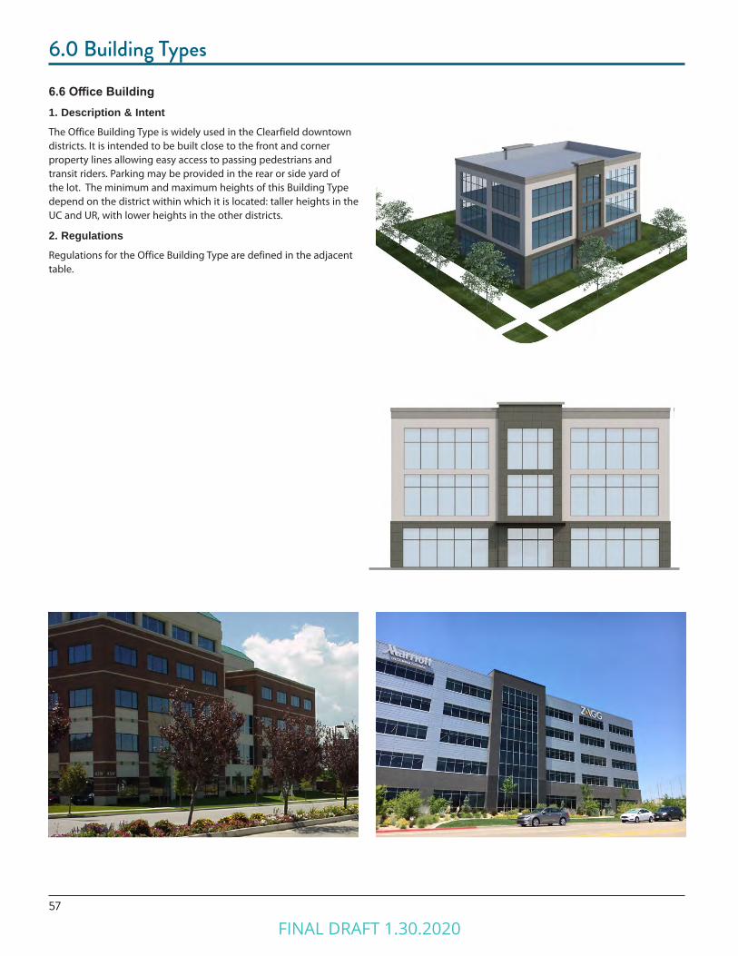
57
6.0 Building Types
6.6 Office Building1. Description & IntentThe Office Building Type is widely used in the Clearfield downtown districts. It is intended to be built close to the front and corner property lines allowing easy access to passing pedestrians and transit riders. Parking may be provided in the rear or side yard of the lot. The minimum and maximum heights of this Building Type depend on the district within which it is located: taller heights in the UC and UR, with lower heights in the other districts.
2. RegulationsRegulations for the Office Building Type are defined in the adjacent table.
FINAL DRAFT 1.30.2020
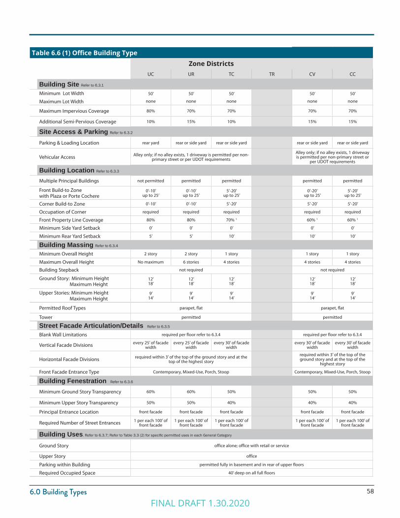
586.0 Building Types
Table 6.6 (1) Office Building TypeZone Districts
UC UR TC TR CV CC
Building Site Refer to 6.3.1
Minimum Lot Width
Maximum Lot Width
50’
none
50’
none
50’
none
50’
none
50’
none
Maximum Impervious Coverage 80% 70% 70% 70% 70%
Additional Semi-Pervious Coverage 10% 15% 10% 15% 15%
Site Access & Parking Refer to 6.3.2
Parking & Loading Location rear yard rear or side yard rear or side yard rear or side yard rear or side yard
Vehicular Access Alley only; if no alley exists, 1 driveway is permitted per non-primary street or per UDOT requirements
Alley only; if no alley exists, 1 driveway is permitted per non-primary street or
per UDOT requirements
Building Location Refer to 6.3.3
Multiple Principal Buildings not permitted permitted permitted permitted permitted
Front Build-to Zonewith Plaza or Porte Cochere
0’-10’ up to 25’
0’-10’ up to 25’
5’-20’ up to 25’
0’-20’ up to 25’
5’-20’ up to 25’
Corner Build-to Zone 0’-10’ 0’-10’ 5’-20’ 5’-20’ 5’-20’
Occupation of Corner required required required required required
Front Property Line Coverage 80% 80% 70% 1 60% 1 60% 1
Minimum Side Yard Setback 0’ 0’ 0’ 0’ 0’
Minimum Rear Yard Setback 5’ 5’ 10’ 10’ 10’
Building Massing Refer to 6.3.4
Minimum Overall Height 2 story 2 story 1 story 1 story 1 story
Maximum Overall Height No maximum 6 stories 4 stories 4 stories 4 stories
Building Stepback not required not required
Ground Story: Minimum Height Maximum Height
12’18’
12’18’
12’18’
12’18’
12’18’
Upper Stories: Minimum Height Maximum Height
9’14’
9’14’
9’14’
9’14’
9’14’
Permitted Roof Types parapet, flat parapet, flat
Tower permitted permitted
Street Facade Articulation/Details Refer to 6.3.5
Blank Wall Limitations required per floor refer to 6.3.4 required per floor refer to 6.3.4
Vertical Facade Divisions every 25’ of facade width
every 25’ of facade width
every 30’ of facade width
every 30’ of facade width
every 30’ of facade width
Horizontal Facade Divisions required within 3’ of the top of the ground story and at the top of the highest story
required within 3’ of the top of the ground story and at the top of the
highest story
Front Facade Entrance Type Contemporary, Mixed-Use, Porch, Stoop Contemporary, Mixed-Use, Porch, Stoop
Building Fenestration Refer to 6.3.6
Minimum Ground Story Transparency 60% 60% 50% 50% 50%
Minimum Upper Story Transparency 50% 50% 40% 40% 40%
Principal Entrance Location front facade front facade front facade front facade front facade
Required Number of Street Entrances 1 per each 100’ of front facade
1 per each 100’ of front facade
1 per each 100’ of front facade
1 per each 100’ of front facade
1 per each 100’ of front facade
Building Uses. Refer to 6.3.7; Refer to Table 3.3 (2) for specific permitted uses in each General Category
Ground Story office alone; office with retail or service
Upper Story office
Parking within Building permitted fully in basement and in rear of upper floors
Required Occupied Space 40’ deep on all full floors
FINAL DRAFT 1.30.2020

59
6.0 Building Types6.7 Civic Building1. Description & IntentThe Civic Building is the most flexible Building Type intended only for civic and institutional types of uses. These buildings are distinctive within the urban fabric created by the other Building Types and could be designed as iconic structures. In contrast to most of the other Building Types, a minimum setback line is required instead of a build to zone, though this setback is required to be landscaped. Parking is limited to the rear in most cases. The minimum and maximum heights of this Building Type depend on the district within which it is located.
2. RegulationsRegulations for the Civic Building type are defined in the adjacent table.
FINAL DRAFT 1.30.2020
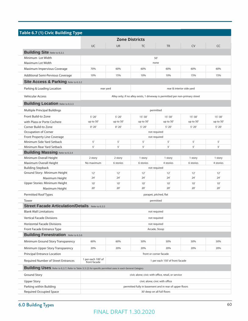
606.0 Building Types
Table 6.7 (1) Civic Building TypeZone Districts
UC UR TC TR CV CC
Building Site Refer to 6.3.1
Minimum Lot Width
Maximum Lot Width
50’
none
Maximum Impervious Coverage 70% 60% 60% 60% 60% 60%
Additional Semi-Pervious Coverage 10% 15% 10% 10% 15% 15%
Site Access & Parking Refer to 6.3.2
Parking & Loading Location rear yard rear & interior side yard
Vehicular Access Alley only; if no alley exists, 1 driveway is permitted per non-primary street
Building Location Refer to 6.3.3
Multiple Principal Buildings permitted
Front Build-to Zone
with Plaza or Porte Cochere
5’-20’
up to 50’
5’-20’
up to 50’
15’-30’
up to 50’
15’-30’
up to 50’
15’-30’
up to 50’
15’-30’
up to 50’
Corner Build-to Zone 0’-20’ 0’-20’ 5’-20’ 5’-20’ 5’-20’ 5’-20’
Occupation of Corner not required
Front Property Line Coverage not required
Minimum Side Yard Setback 5’ 5’ 5’ 5’ 5’ 5’
Minimum Rear Yard Setback 5’ 5’ 5’ 5’ 5’ 5’
Building Massing Refer to 6.3.4
Minimum Overall Height 2 story 2 story 1 story 1 story 1 story 1 story
Maximum Overall Height No maximum 6 stories 6 stories 4 stories 6 stories 4 stories
Building Stepback not required
Ground Story: Minimum Height
Maximum Height
12’
24’
12’
24’
12’
24’
12’
24’
12’
24’
12’
24’
Upper Stories: Minimum Height
Maximum Height
10’
20’
10’
20’
10’
20’
10’
20’
10’
20’
10’
20’
Permitted Roof Types parapet, pitched, flat
Tower permitted
Street Facade Articulation/Details Refer to 6.3.5
Blank Wall Limitations not required
Vertical Facade Divisions not required
Horizontal Facade Divisions not required
Front Facade Entrance Type Arcade, Stoop
Building Fenestration Refer to 6.3.6
Minimum Ground Story Transparency 60% 60% 50% 50% 50% 50%
Minimum Upper Story Transparency 20% 20% 20% 20% 20% 20%
Principal Entrance Location front or corner facade
Required Number of Street Entrances 1 per each 100’ of front facade 1 per each 150’ of front facade
Building Uses. Refer to 6.3.7; Refer to Table 3.3 (2) for specific permitted uses in each General Category
Ground Story civic alone; civic with office, retail, or service
Upper Story civic alone; civic with office
Parking within Building permitted fully in basement and in rear of upper floors
Required Occupied Space 30’ deep on all full floors
FINAL DRAFT 1.30.2020
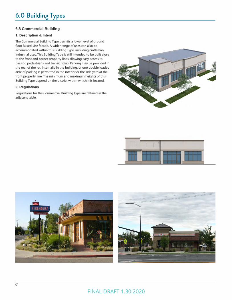
61
6.0 Building Types
6.8 Commercial Building1. Description & IntentThe Commercial Building Type permits a lower level of ground floor Mixed-Use facade. A wider range of uses can also be accommodated within this Building Type, including craftsman industrial uses. This Building Type is still intended to be built close to the front and corner property lines allowing easy access to passing pedestrians and transit riders. Parking may be provided in the rear of the lot, internally in the building, or one double loaded aisle of parking is permitted in the interior or the side yard at the front property line. The minimum and maximum heights of this Building Type depend on the district within which it is located.
2. RegulationsRegulations for the Commercial Building Type are defined in the adjacent table.
FINAL DRAFT 1.30.2020
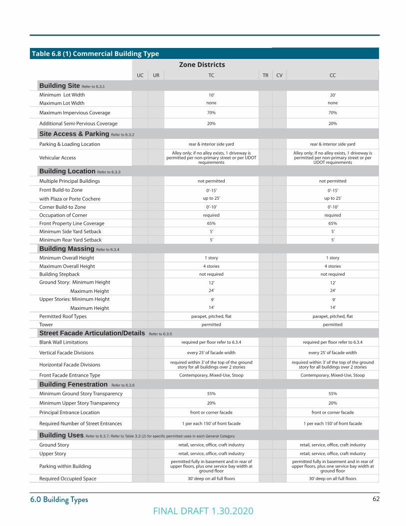
626.0 Building Types
Table 6.8 (1) Commercial Building TypeZone Districts
UC UR TC TR CV CC
Building Site Refer to 6.3.1
Minimum Lot Width
Maximum Lot Width
10’
none
20’
none
Maximum Impervious Coverage 70% 70%
Additional Semi-Pervious Coverage 20% 20%
Site Access & Parking Refer to 6.3.2
Parking & Loading Location rear & interior side yard rear & interior side yard
Vehicular AccessAlley only; if no alley exists, 1 driveway is
permitted per non-primary street or per UDOT requirements
Alley only; if no alley exists, 1 driveway is permitted per non-primary street or per
UDOT requirements
Building Location Refer to 6.3.3
Multiple Principal Buildings not permitted not permitted
Front Build-to Zone
with Plaza or Porte Cochere
0’-15’
up to 25’
0’-15’
up to 25’
Corner Build-to Zone 0’-10’ 0’-10’
Occupation of Corner required required
Front Property Line Coverage 65% 65%
Minimum Side Yard Setback 5’ 5’
Minimum Rear Yard Setback 5’ 5’
Building Massing Refer to 6.3.4
Minimum Overall Height 1 story 1 story
Maximum Overall Height 4 stories 4 stories
Building Stepback not required not required
Ground Story: Minimum Height
Maximum Height
12’
24’
12’
24’
Upper Stories: Minimum Height
Maximum Height
9’
14’
9’
14’
Permitted Roof Types parapet, pitched, flat parapet, pitched, flat
Tower permitted permitted
Street Facade Articulation/Details Refer to 6.3.5
Blank Wall Limitations required per floor refer to 6.3.4 required per floor refer to 6.3.4
Vertical Facade Divisions every 25’ of facade width every 25’ of facade width
Horizontal Facade Divisions required within 3’ of the top of the ground story for all buildings over 2 stories
required within 3’ of the top of the ground story for all buildings over 2 stories
Front Facade Entrance Type Contemporary, Mixed-Use, Stoop Contemporary, Mixed-Use, Stoop
Building Fenestration Refer to 6.3.6
Minimum Ground Story Transparency 55% 55%
Minimum Upper Story Transparency 20% 20%
Principal Entrance Location front or corner facade front or corner facade
Required Number of Street Entrances 1 per each 150’ of front facade 1 per each 150’ of front facade
Building Uses. Refer to 6.3.7; Refer to Table 3.3 (2) for specific permitted uses in each General Category
Ground Story retail, service, office, craft industry retail, service, office, craft industry
Upper Story retail, service, office, craft industry retail, service, office, craft industry
Parking within Buildingpermitted fully in basement and in rear of upper floors, plus one service bay width at
ground floor
permitted fully in basement and in rear of upper floors, plus one service bay width at
ground floor
Required Occupied Space 30’ deep on all full floors 30’ deep on all full floors
FINAL DRAFT 1.30.2020
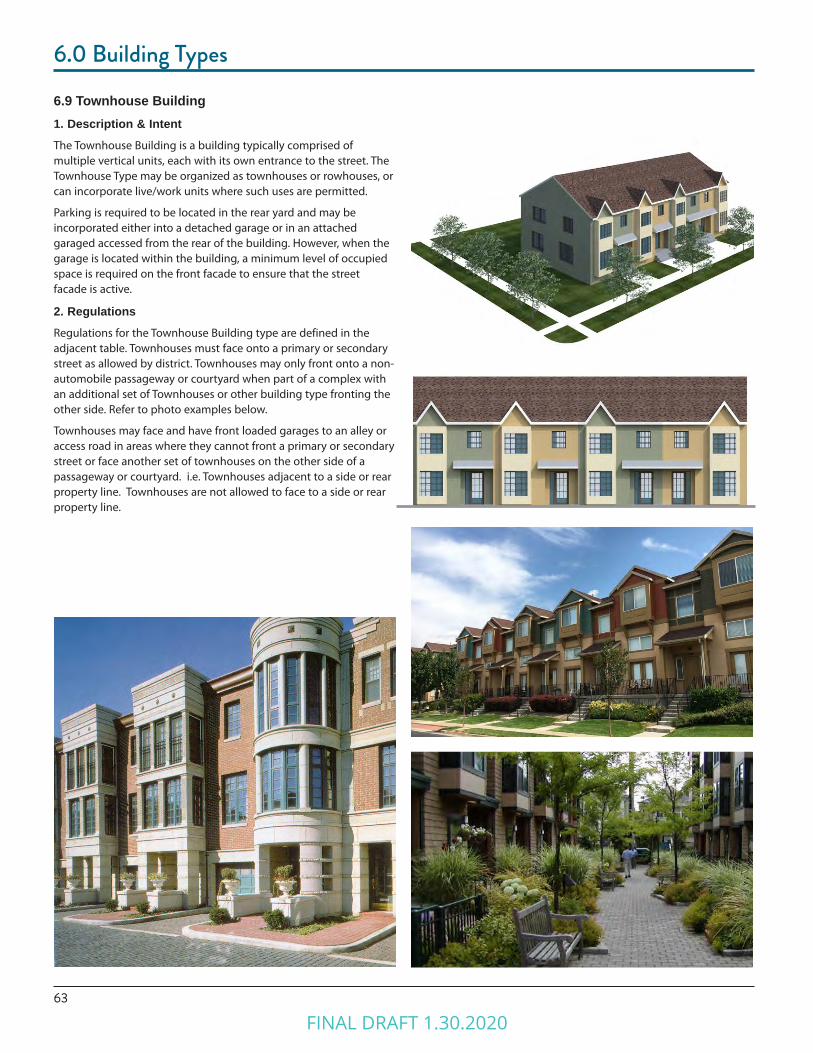
63
6.0 Building Types
6.9 Townhouse Building1. Description & IntentThe Townhouse Building is a building typically comprised of multiple vertical units, each with its own entrance to the street. The Townhouse Type may be organized as townhouses or rowhouses, or can incorporate live/work units where such uses are permitted.
Parking is required to be located in the rear yard and may be incorporated either into a detached garage or in an attached garaged accessed from the rear of the building. However, when the garage is located within the building, a minimum level of occupied space is required on the front facade to ensure that the street facade is active.
2. RegulationsRegulations for the Townhouse Building type are defined in the adjacent table. Townhouses must face onto a primary or secondary street as allowed by district. Townhouses may only front onto a non-automobile passageway or courtyard when part of a complex with an additional set of Townhouses or other building type fronting the other side. Refer to photo examples below.
Townhouses may face and have front loaded garages to an alley or access road in areas where they cannot front a primary or secondary street or face another set of townhouses on the other side of a passageway or courtyard. i.e. Townhouses adjacent to a side or rear property line. Townhouses are not allowed to face to a side or rear property line.
FINAL DRAFT 1.30.2020

646.0 Building Types
Table 6.9 (1) Townhouse Building TypeZone Districts
UC UR TC TR CV CC
Building Site Refer to 6.3.1
Minimum Unit Width
Maximum Building Width (Or # of Units)
20’
120’ (Or 6 units)
20’
130’ (Or 6 units)
20’
140’ (Or 6 units)
Maximum Impervious Coverage 70% 60% 60%
Additional Semi-Pervious Coverage 20% 20% 20%
Site Access & Parking Refer to 6.3.2
Parking & Loading Location rear yard/rear facade
Vehicular Access From alley; if no alley exists, 1 driveway per building per street frontage (garage must be recessed behind entrance)
Building Location Refer to 6.3.3
Multiple Principal Buildings permitted permitted permitted
Front Build-to Zone 5’ to 15’ (10’ min if not facing a street) 5’ to 20’ (10’ min if not facing a street)
Corner Build-to Zone 0’ to 10’ 5’-15’ 5’-15’
Occupation of Corner not required
Front Property Line Coverage 80% 65% 65%
Minimum Building Side Yard Setback 5’
Minimum Rear Yard Setback 5’
Building Massing Refer to 6.3.4
Minimum Overall Height 2 stories (1 story allowed for ADA units)
Maximum Overall Height 3 stories
Building Stepback not required
Ground Story: Minimum Height
Maximum Height
12’
18’
9’
14’
9’
14’
Upper Stories: Minimum Height
Maximum Height
9’
14’
9’
14’
9’
14’
Permitted Roof Types parapet, pitched, flat
Tower not permitted
Street Facade Articulation/Details Refer to 6.3.5
Blank Wall Limitations required per floor refer to 6.3.5
Vertical Facade Divisions Between Units
Horizontal Facade Divisions Per entrance type requirements
Front Facade Entrance Type Contemporary, Stoop, Porch Stoop, Porch
Building Fenestration Refer to 6.3.6
Minimum Ground Story Transparency 25% 20% 20%
Minimum Upper Story Transparency 20% 20% 20%
Principal Entrance Location front or corner facade
Required Number of Street Entrances 1 per unit
Building Uses. Refer to 6.3.7; Refer to Table 3.3 (2) for specific permitted uses in each General Category
Ground Story residential, retail, office, service residential residential
Upper Story residential residential residential
Parking within Building permitted fully in basement and in rear of ground floor
Required Occupied Space 30’ deep on all full floors
FINAL DRAFT 1.30.2020
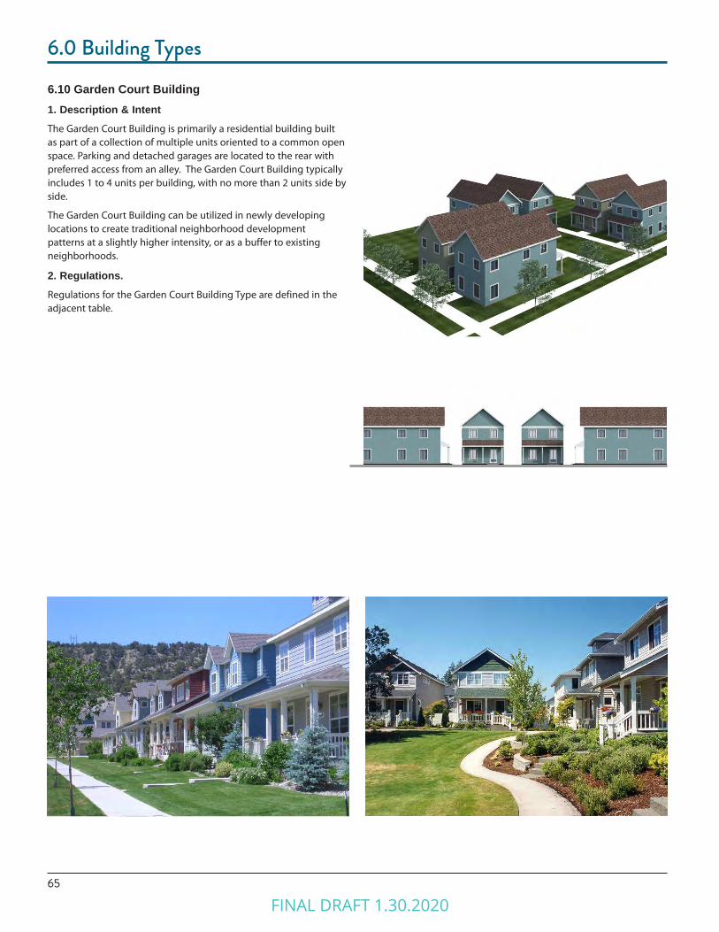
65
6.0 Building Types
6.10 Garden Court Building1. Description & IntentThe Garden Court Building is primarily a residential building built as part of a collection of multiple units oriented to a common open space. Parking and detached garages are located to the rear with preferred access from an alley. The Garden Court Building typically includes 1 to 4 units per building, with no more than 2 units side by side.
The Garden Court Building can be utilized in newly developing locations to create traditional neighborhood development patterns at a slightly higher intensity, or as a buffer to existing neighborhoods.
2. Regulations.Regulations for the Garden Court Building Type are defined in the adjacent table.
FINAL DRAFT 1.30.2020
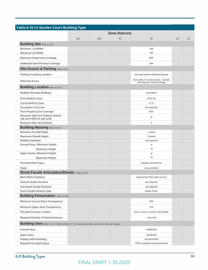
666.0 Building Types
Table 6.10 (1) Garden Court Building TypeZone Districts
UC UR TC TR CV CC
Building Site Refer to 6.3.1
Minimum Lot Width
Maximum Lot Width
100’
200’
Maximum Impervious Coverage 60%
Additional Semi-Pervious Coverage 20%
Site Access & Parking Refer to 6.3.2
Parking & Loading Location rear yard and/or detached garage
Vehicular Access From alley; if no alley exists, 1 shared driveway per street frontage
Building Location Refer to 6.3.3
Multiple Principal Buildings permitted
Front Build-to Zone 10’ to 20’
Corner Build-to Zone 5’-15’
Occupation of Corner not required
Front Property Line Coverage 65%
Minimum Side Yard Setback (interior side yard AND lot side yard)
8’
Minimum Rear Yard Setback 5’
Building Massing Refer to 6.3.4
Minimum Overall Height 1 stories
Maximum Overall Height 3 stories
Building Stepback not required
Ground Story: Minimum Height
Maximum Height
9’
14’
Upper Stories: Minimum Height
Maximum Height
9’
14’
Permitted Roof Types parapet, pitched, flat
Tower not permitted
Street Facade Articulation/Details Refer to 6.3.5
Blank Wall Limitations required per floor refer to 6.3.5
Vertical Facade Divisions not required
Horizontal Facade Divisions not required
Front Facade Entrance Type Stoop, Porch
Building Fenestration Refer to 6.3.6
Minimum Ground Story Transparency 20%
Minimum Upper Story Transparency 15%
Principal Entrance Location front, corner, or corner side facade
Required Number of Street Entrances 1 per unit
Building Uses. Refer to 6.3.7; Refer to Table 3.3 (2) for specific permitted uses in each General Category
Ground Story residential
Upper Story residential
Parking within Building not permitted
Required Occupied Space 100% occupied except basement
FINAL DRAFT 1.30.2020
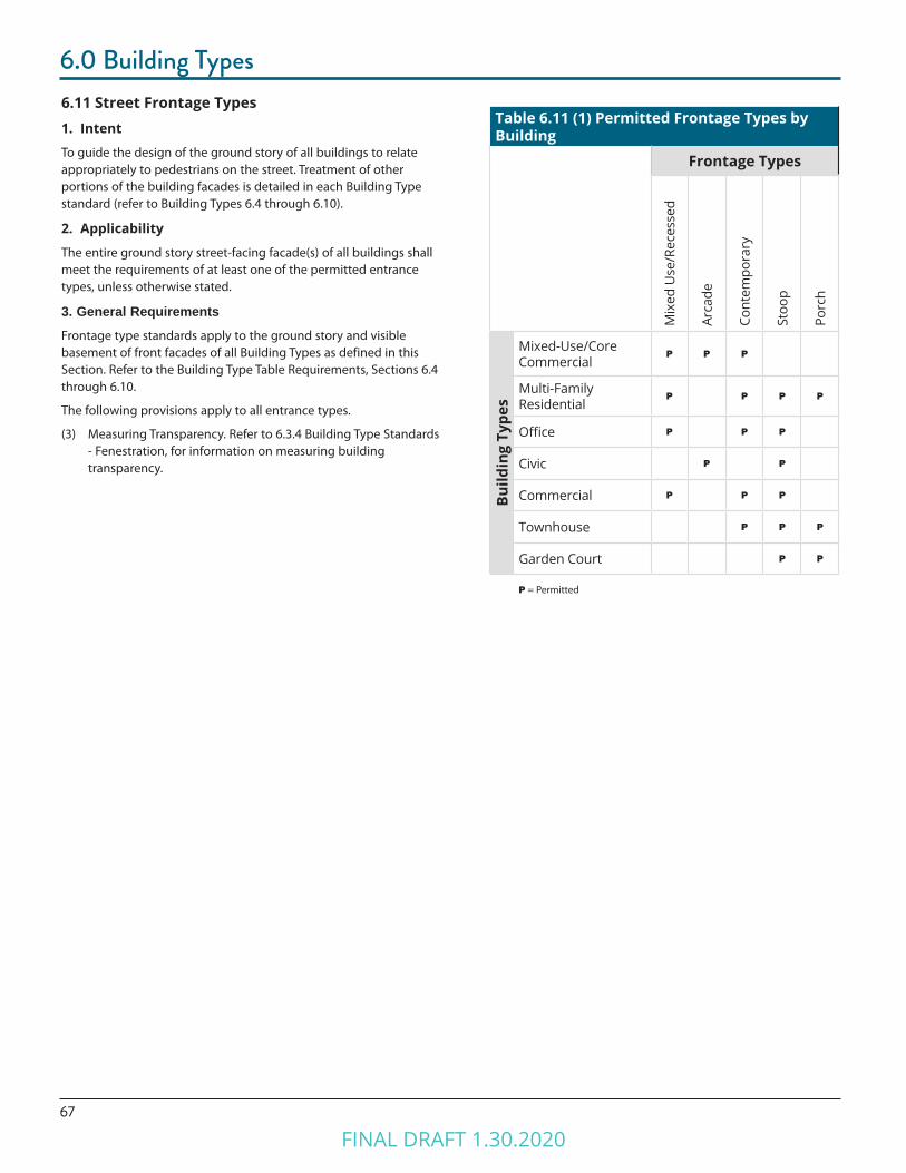
67
6.0 Building Types6.11 Street Frontage Types1. Intent
To guide the design of the ground story of all buildings to relate appropriately to pedestrians on the street. Treatment of other portions of the building facades is detailed in each Building Type standard (refer to Building Types 6.4 through 6.10).
2. Applicability
The entire ground story street-facing facade(s) of all buildings shall meet the requirements of at least one of the permitted entrance types, unless otherwise stated.
3. General RequirementsFrontage type standards apply to the ground story and visible basement of front facades of all Building Types as defined in this Section. Refer to the Building Type Table Requirements, Sections 6.4 through 6.10.
The following provisions apply to all entrance types.
(3) Measuring Transparency. Refer to 6.3.4 Building Type Standards - Fenestration, for information on measuring building transparency.
Table 6.11 (1) Permitted Frontage Types by Building
Frontage Types
Mix
ed U
se/R
eces
sed
Arca
de
Cont
empo
rary
Stoo
p
Porc
h
Build
ing
Type
s
Mixed-Use/Core Commercial
P P P
Multi-Family Residential
P P P P
Office P P P
Civic P P
Commercial P P P
Townhouse P P P
Garden Court P P
P = Permitted
FINAL DRAFT 1.30.2020

686.0 Building Types
4. Mixed-Use Frontage TypeThe Mixed-Use frontage type is a highly transparent ground story treatment designed to serve primarily as the display area and primary entrance for retail or service uses. Refer to Figure 6.11 (1).
Mixed-Use Frontage Requirements(1) Dimensions
Maximum Recessed Width8 feet if recessed entrance is behind front build to zone
Minimum Recessed Depth 3 feet
Maximum Recessed Depth 8 feet
(2) Transparency
Unenclosed by building type
Enclosed Minimum 40% transparency
(3) Elevation
Without visible basement 0’-0” to 1’-0” above adjacent sidewalk
With visible basement not permitted
Horizontal Facade Division Required above ground story
Entrance Door Recessed
(4) Permitted Building Types
Mixed-use; Multi-Family; Office; Commercial
Figure 6.11 (1). Mixed-Use Frontage Type
Expression Line
sidewalk
Transparency
Ground Story
Elevation
Entrance Door
Base
FINAL DRAFT 1.30.2020
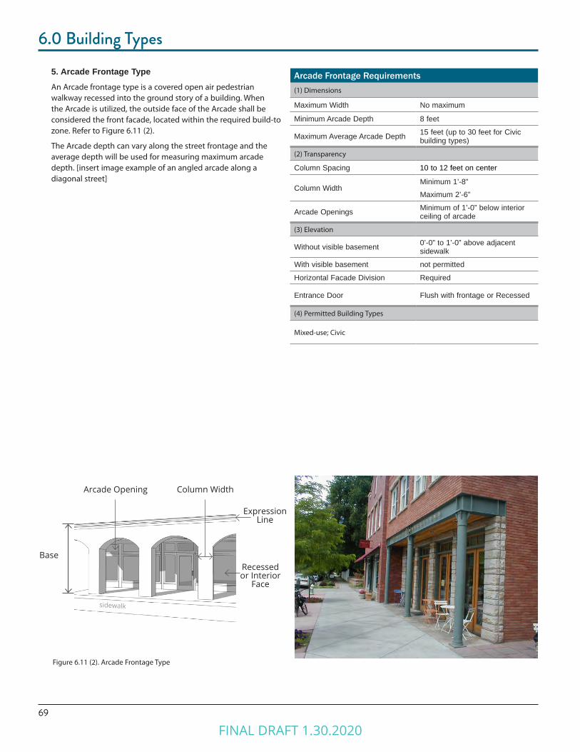
69
6.0 Building Types
5. Arcade Frontage TypeAn Arcade frontage type is a covered open air pedestrian walkway recessed into the ground story of a building. When the Arcade is utilized, the outside face of the Arcade shall be considered the front facade, located within the required build-to zone. Refer to Figure 6.11 (2).
The Arcade depth can vary along the street frontage and the average depth will be used for measuring maximum arcade depth. [insert image example of an angled arcade along a diagonal street]
Arcade Frontage Requirements(1) Dimensions
Maximum Width No maximum
Minimum Arcade Depth 8 feet
Maximum Average Arcade Depth 15 feet (up to 30 feet for Civic building types)
(2) Transparency
Column Spacing 10 to 12 feet on center
Column WidthMinimum 1’-8”Maximum 2’-6”
Arcade Openings Minimum of 1’-0” below interior ceiling of arcade
(3) Elevation
Without visible basement 0’-0” to 1’-0” above adjacent sidewalk
With visible basement not permitted
Horizontal Facade Division Required
Entrance Door Flush with frontage or Recessed
(4) Permitted Building Types
Mixed-use; Civic
Figure 6.11 (2). Arcade Frontage Type
Arcade Opening
Recessed or Interior
Face
Column Width
Expression Line
Base
sidewalk
FINAL DRAFT 1.30.2020

706.0 Building Types
Contemporary Frontage Requirements(1) Dimensions
Maximum Width none
Minimum Recessed Depth 0 feet
Maximum Recessed Depth 5 feet
(2) Transparency
Unenclosed by building type
Enclosed not applicable
(3) Elevation
Without visible basement 0’-0” to 1’-0” above adjacent sidewalk
With visible basement not permitted
Horizontal Facade Division Required above ground story
Entrance Flush with frontage or Recessed
(4) Permitted Building Types
Mixed-use; Multi-Family; Office; Commercial
Expression Line
Transparency
Ground Story Elevation
Entrance Door
6. Contemporary Frontage TypeThe Contemporary frontage type is a highly transparent ground story treatment that is usually flush with the facade of the building. It can serve as a multi-functional entrance type for office, residential, entertainment, or as the display area and primary entrance for retail or service uses. Refer to Figure 6.11 (3).
Figure 6.11 (3). Contemporary Frontage Type
FINAL DRAFT 1.30.2020
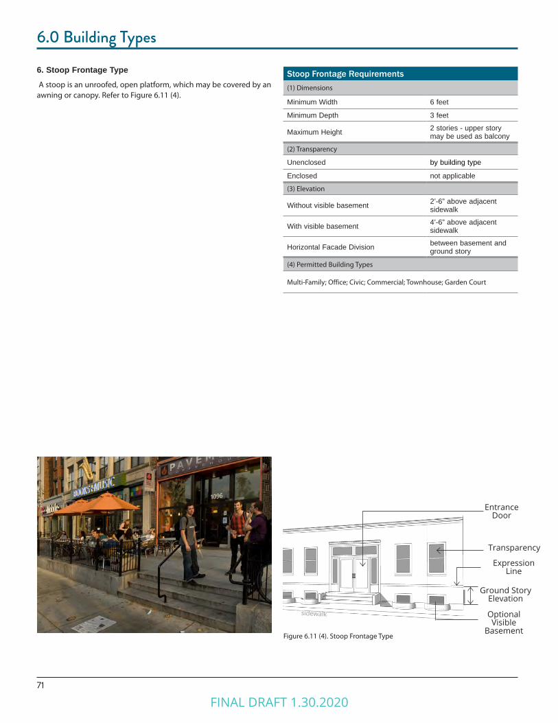
71
6.0 Building Types
Stoop Frontage Requirements(1) Dimensions
Minimum Width 6 feet
Minimum Depth 3 feet
Maximum Height 2 stories - upper story may be used as balcony
(2) Transparency
Unenclosed by building type
Enclosed not applicable
(3) Elevation
Without visible basement 2’-6” above adjacent sidewalk
With visible basement 4’-6” above adjacent sidewalk
Horizontal Facade Division between basement and ground story
(4) Permitted Building Types
Multi-Family; Office; Civic; Commercial; Townhouse; Garden Court
sidewalk
Transparency
Ground Story Elevation
Entrance Door
Optional Visible
Basement
Expression Line
Figure 6.11 (4). Stoop Frontage Type
6. Stoop Frontage Type A stoop is an unroofed, open platform, which may be covered by an awning or canopy. Refer to Figure 6.11 (4).
FINAL DRAFT 1.30.2020
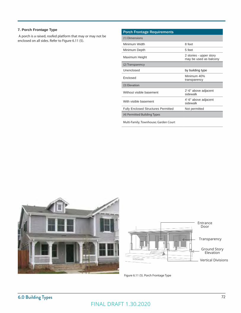
726.0 Building Types
Porch Frontage Requirements(1) Dimensions
Minimum Width 8 feet
Minimum Depth 5 feet
Maximum Height 2 stories - upper story may be used as balcony
(2) Transparency
Unenclosed by building type
Enclosed Minimum 40% transparency
(3) Elevation
Without visible basement 2’-6” above adjacent sidewalk
With visible basement 4’-6” above adjacent sidewalk
Fully Enclosed Structures Permitted Not permitted
(4) Permitted Building Types
Multi-Family; Townhouse; Garden Court
Figure 6.11 (5). Porch Frontage Type
Vertical Divisions
Transparency
Ground Story Elevation
Entrance Door
7. Porch Frontage Type A porch is a raised, roofed platform that may or may not be enclosed on all sides. Refer to Figure 6.11 (5).
sidewalk
FINAL DRAFT 1.30.2020
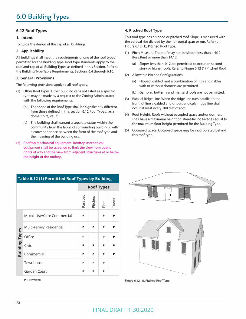
73
6.0 Building Types
Figure 6.12 (1). Pitched Roof Type
6.12 Roof Types1. Intent
To guide the design of the cap of all buildings.
2. Applicability
All buildings shall meet the requirements of one of the roof types permitted for the Building Type. Roof type standards apply to the roof and cap of all Building Types as defined in this Section. Refer to the Building Type Table Requirements, Sections 6.4 through 6.10.
3. General Provisions
The following provisions apply to all roof types.
(1) Other Roof Types. Other building caps not listed as a specific type may be made by a request to the Zoning Administrator with the following requirements:
(b) The shape of the Roof Type shall be significantly different from those defined in this section 6.12 Roof Types, i.e. a dome, spire, vault.
(c) The building shall warrant a separate status within the community from the fabric of surrounding buildings, with a correspondence between the form of the roof type and the meaning of the building use.
(2) Rooftop mechanical equipment. Rooftop mechanical equipment shall be screened to limit the view from public rights of way and the view from adjacent structures at or below the height of the rooftop.
Table 6.12 (1) Permitted Roof Types by Building
Roof Types
Para
pet
Pitc
hed
Flat
Tow
er
Build
ing
Type
s
Mixed-Use/Core Commercial P P P
Multi-Family Residential P P P P
Office P P P
Civic P P P P
Commercial P P P P
Townhouse P P P
Garden Court P P P
P = Permitted
4. Pitched Roof Type
This roof type has a sloped or pitched roof. Slope is measured with the vertical rise divided by the horizontal span or run. Refer to Figure 6.12 (1), Pitched Roof Type.
(1) Pitch Measure. The roof may not be sloped less than a 4:12 (Rise:Run) or more than 14:12.
(a) Slopes less than 4:12 are permitted to occur on second story or higher roofs. Refer to Figure 6.12 (1) Pitched Roof.
(2) Allowable Pitched Configurations.
(a) Hipped, gabled, and a combination of hips and gables with or without dormers are permitted.
(b) Gambrel, butterfly and mansard roofs are not permitted.
(3) Parallel Ridge Line. When the ridge line runs parallel to the front lot line a gabled end or perpendicular ridge line shall occur at least every 100 feet of roof.
(4) Roof Height. Roofs without occupied space and/or dormers shall have a maximum height on street-facing facades equal to the maximum floor height permitted for the Building Type.
(5) Occupied Space. Occupied space may be incorporated behind this roof type.
FINAL DRAFT 1.30.2020
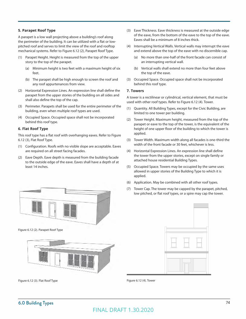
746.0 Building Types
Figure 6.12 (4). Tower
5. Parapet Roof Type
A parapet is a low wall projecting above a building’s roof along the perimeter of the building. It can be utilized with a flat or low-pitched roof and serves to limit the view of the roof and rooftop mechanical systems. Refer to Figure 6.12 (2), Parapet Roof Type.
(1) Parapet Height. Height is measured from the top of the upper story to the top of the parapet.
(a) Minimum height is two feet with a maximum height of six feet.
(b) The parapet shall be high enough to screen the roof and any roof appurtenances from view.
(2) Horizontal Expression Lines. An expression line shall define the parapet from the upper stories of the building on all sides and shall also define the top of the cap.
(3) Perimeter. Parapets shall be used for the entire perimeter of the building, even when multiple roof types are used.
(4) Occupied Space. Occupied space shall not be incorporated behind this roof type.
6. Flat Roof Type
This roof type has a flat roof with overhanging eaves. Refer to Figure 6.12 (3), Flat Roof Type.
(1) Configuration. Roofs with no visible slope are acceptable. Eaves are required on all street facing facades.
(2) Eave Depth. Eave depth is measured from the building facade to the outside edge of the eave. Eaves shall have a depth of at least 14 inches.
Figure 6.12 (3). Flat Roof Type
(3) Eave Thickness. Eave thickness is measured at the outside edge of the eave, from the bottom of the eave to the top of the eave. Eaves shall be a minimum of 8 inches thick.
(4) Interrupting Vertical Walls. Vertical walls may interrupt the eave and extend above the top of the eave with no discernible cap.
(a) No more than one-half of the front facade can consist of an interrupting vertical wall.
(b) Vertical walls shall extend no more than four feet above the top of the eave.
(3) Occupied Space. Occupied space shall not be incorporated behind this roof type.
7. Towers
A tower is a rectilinear or cylindrical, vertical element, that must be used with other roof types. Refer to Figure 6.12 (4). Tower.
(1) Quantity. All Building Types, except for the Civic Building, are limited to one tower per building.
(2) Tower Height. Maximum height, measured from the top of the parapet or eave to the top of the tower, is the equivalent of the height of one upper floor of the building to which the tower is applied.
(3) Tower Width. Maximum width along all facades is one-third the width of the front facade or 30 feet, whichever is less.
(4) Horizontal Expression Lines. An expression line shall define the tower from the upper stories, except on single family or attached house residential Building Types.
(5) Occupied Space. Towers may be occupied by the same uses allowed in upper stories of the Building Type to which it is applied.
(6) Application. May be combined with all other roof types.
(7) Tower Cap. The tower may be capped by the parapet, pitched, low pitched, or flat roof types, or a spire may cap the tower.
Figure 6.12 (2). Parapet Roof Type
FINAL DRAFT 1.30.2020
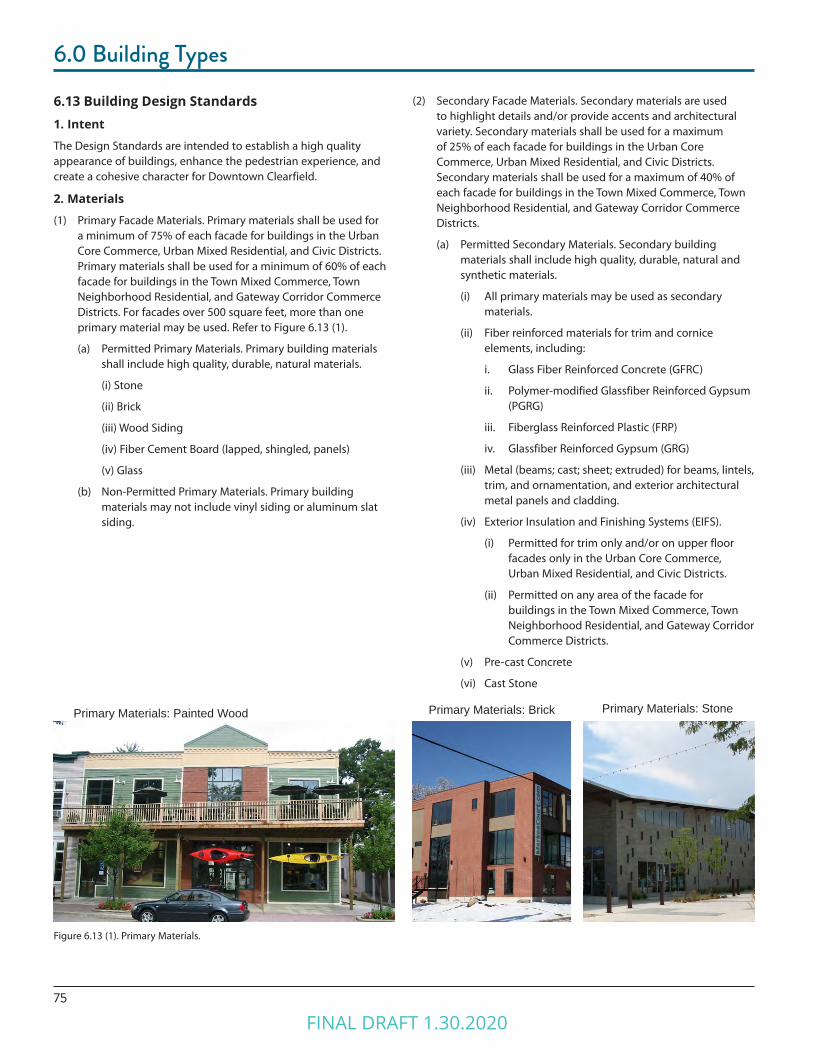
75
6.0 Building Types
6.13 Building Design Standards1. Intent
The Design Standards are intended to establish a high quality appearance of buildings, enhance the pedestrian experience, and create a cohesive character for Downtown Clearfield.
2. Materials
(1) Primary Facade Materials. Primary materials shall be used for a minimum of 75% of each facade for buildings in the Urban Core Commerce, Urban Mixed Residential, and Civic Districts. Primary materials shall be used for a minimum of 60% of each facade for buildings in the Town Mixed Commerce, Town Neighborhood Residential, and Gateway Corridor Commerce Districts. For facades over 500 square feet, more than one primary material may be used. Refer to Figure 6.13 (1).
(a) Permitted Primary Materials. Primary building materials shall include high quality, durable, natural materials.
(i) Stone
(ii) Brick
(iii) Wood Siding
(iv) Fiber Cement Board (lapped, shingled, panels)
(v) Glass
(b) Non-Permitted Primary Materials. Primary building materials may not include vinyl siding or aluminum slat siding.
(2) Secondary Facade Materials. Secondary materials are used to highlight details and/or provide accents and architectural variety. Secondary materials shall be used for a maximum of 25% of each facade for buildings in the Urban Core Commerce, Urban Mixed Residential, and Civic Districts. Secondary materials shall be used for a maximum of 40% of each facade for buildings in the Town Mixed Commerce, Town Neighborhood Residential, and Gateway Corridor Commerce Districts.
(a) Permitted Secondary Materials. Secondary building materials shall include high quality, durable, natural and synthetic materials.
(i) All primary materials may be used as secondary materials.
(ii) Fiber reinforced materials for trim and cornice elements, including:
i. Glass Fiber Reinforced Concrete (GFRC)
ii. Polymer-modified Glassfiber Reinforced Gypsum (PGRG)
iii. Fiberglass Reinforced Plastic (FRP)
iv. Glassfiber Reinforced Gypsum (GRG)
(iii) Metal (beams; cast; sheet; extruded) for beams, lintels, trim, and ornamentation, and exterior architectural metal panels and cladding.
(iv) Exterior Insulation and Finishing Systems (EIFS).
(i) Permitted for trim only and/or on upper floor facades only in the Urban Core Commerce, Urban Mixed Residential, and Civic Districts.
(ii) Permitted on any area of the facade for buildings in the Town Mixed Commerce, Town Neighborhood Residential, and Gateway Corridor Commerce Districts.
(v) Pre-cast Concrete
(vi) Cast Stone
Figure 6.13 (1). Primary Materials.
Primary Materials: Brick Primary Materials: StonePrimary Materials: Painted Wood
FINAL DRAFT 1.30.2020
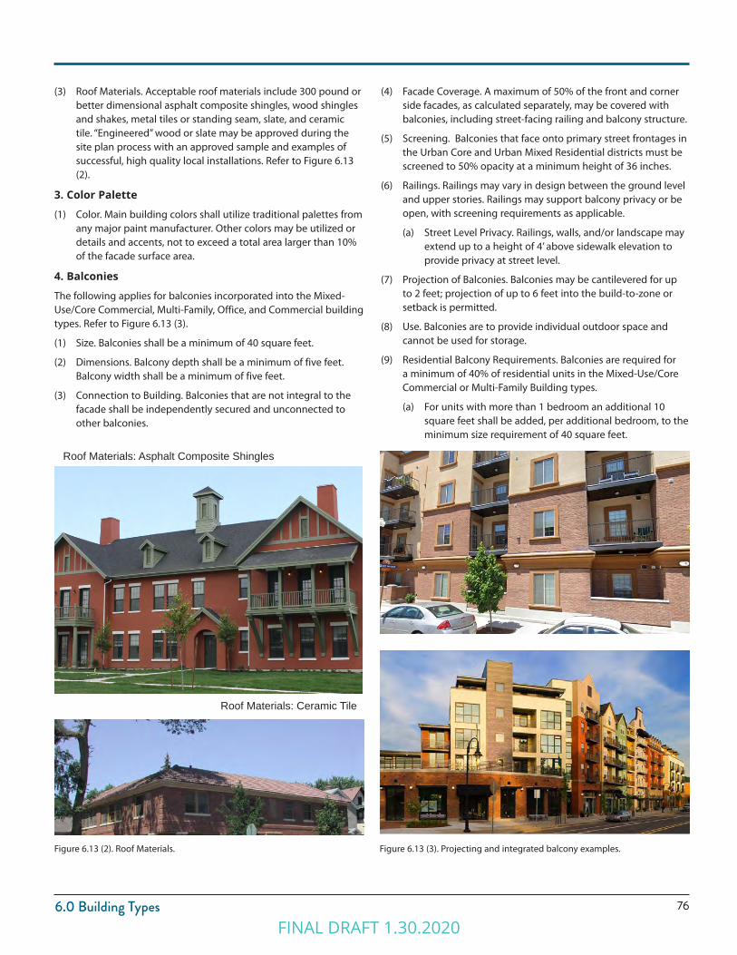
766.0 Building Types
Roof Materials: Ceramic Tile
Figure 6.13 (2). Roof Materials.
Roof Materials: Asphalt Composite Shingles
(3) Roof Materials. Acceptable roof materials include 300 pound or better dimensional asphalt composite shingles, wood shingles and shakes, metal tiles or standing seam, slate, and ceramic tile. “Engineered” wood or slate may be approved during the site plan process with an approved sample and examples of successful, high quality local installations. Refer to Figure 6.13 (2).
3. Color Palette
(1) Color. Main building colors shall utilize traditional palettes from any major paint manufacturer. Other colors may be utilized or details and accents, not to exceed a total area larger than 10% of the facade surface area.
4. Balconies
The following applies for balconies incorporated into the Mixed-Use/Core Commercial, Multi-Family, Office, and Commercial building types. Refer to Figure 6.13 (3).
(1) Size. Balconies shall be a minimum of 40 square feet.
(2) Dimensions. Balcony depth shall be a minimum of five feet. Balcony width shall be a minimum of five feet.
(3) Connection to Building. Balconies that are not integral to the facade shall be independently secured and unconnected to other balconies.
Figure 6.13 (3). Projecting and integrated balcony examples.
(4) Facade Coverage. A maximum of 50% of the front and corner side facades, as calculated separately, may be covered with balconies, including street-facing railing and balcony structure.
(5) Screening. Balconies that face onto primary street frontages in the Urban Core and Urban Mixed Residential districts must be screened to 50% opacity at a minimum height of 36 inches.
(6) Railings. Railings may vary in design between the ground level and upper stories. Railings may support balcony privacy or be open, with screening requirements as applicable.
(a) Street Level Privacy. Railings, walls, and/or landscape may extend up to a height of 4’ above sidewalk elevation to provide privacy at street level.
(7) Projection of Balconies. Balconies may be cantilevered for up to 2 feet; projection of up to 6 feet into the build-to-zone or setback is permitted.
(8) Use. Balconies are to provide individual outdoor space and cannot be used for storage.
(9) Residential Balcony Requirements. Balconies are required for a minimum of 40% of residential units in the Mixed-Use/Core Commercial or Multi-Family Building types.
(a) For units with more than 1 bedroom an additional 10 square feet shall be added, per additional bedroom, to the minimum size requirement of 40 square feet.
FINAL DRAFT 1.30.2020
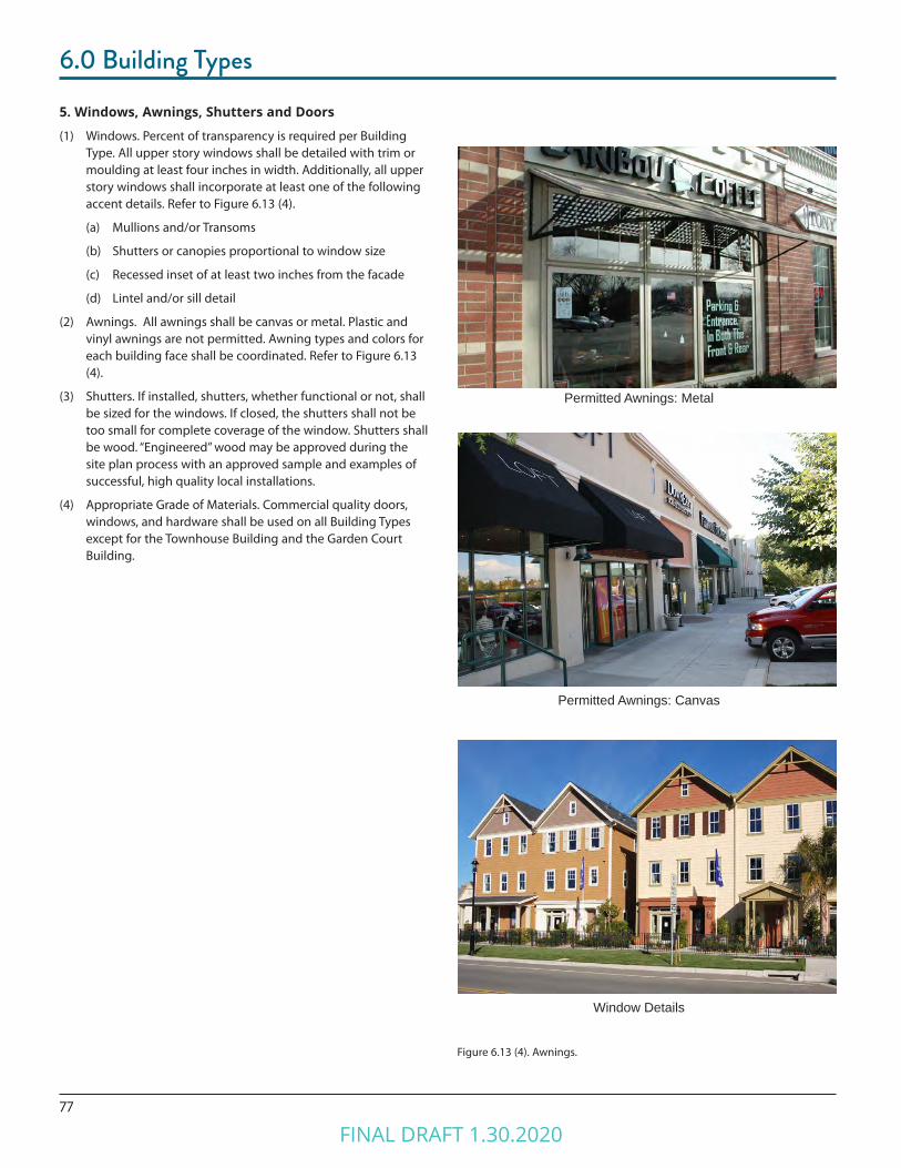
77
6.0 Building Types
5. Windows, Awnings, Shutters and Doors
(1) Windows. Percent of transparency is required per Building Type. All upper story windows shall be detailed with trim or moulding at least four inches in width. Additionally, all upper story windows shall incorporate at least one of the following accent details. Refer to Figure 6.13 (4).
(a) Mullions and/or Transoms
(b) Shutters or canopies proportional to window size
(c) Recessed inset of at least two inches from the facade
(d) Lintel and/or sill detail
(2) Awnings. All awnings shall be canvas or metal. Plastic and vinyl awnings are not permitted. Awning types and colors for each building face shall be coordinated. Refer to Figure 6.13 (4).
(3) Shutters. If installed, shutters, whether functional or not, shall be sized for the windows. If closed, the shutters shall not be too small for complete coverage of the window. Shutters shall be wood. “Engineered” wood may be approved during the site plan process with an approved sample and examples of successful, high quality local installations.
(4) Appropriate Grade of Materials. Commercial quality doors, windows, and hardware shall be used on all Building Types except for the Townhouse Building and the Garden Court Building.
Permitted Awnings: Metal
Permitted Awnings: Canvas
Figure 6.13 (4). Awnings.
Window Details
FINAL DRAFT 1.30.2020
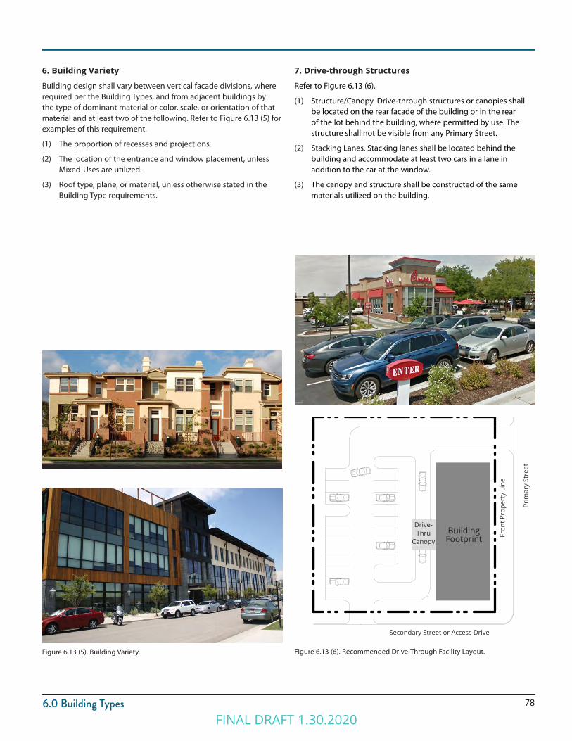
786.0 Building Types
Figure 6.13 (5). Building Variety. Figure 6.13 (6). Recommended Drive-Through Facility Layout.
6. Building Variety
Building design shall vary between vertical facade divisions, where required per the Building Types, and from adjacent buildings by the type of dominant material or color, scale, or orientation of that material and at least two of the following. Refer to Figure 6.13 (5) for examples of this requirement.
(1) The proportion of recesses and projections.
(2) The location of the entrance and window placement, unless Mixed-Uses are utilized.
(3) Roof type, plane, or material, unless otherwise stated in the Building Type requirements.
7. Drive-through Structures
Refer to Figure 6.13 (6).
(1) Structure/Canopy. Drive-through structures or canopies shall be located on the rear facade of the building or in the rear of the lot behind the building, where permitted by use. The structure shall not be visible from any Primary Street.
(2) Stacking Lanes. Stacking lanes shall be located behind the building and accommodate at least two cars in a lane in addition to the car at the window.
(3) The canopy and structure shall be constructed of the same materials utilized on the building.
Prim
ary
Stre
etBuilding
Footprint
Drive-Thru
Canopy
Fron
t Pro
pert
y Li
ne
Secondary Street or Access Drive
FINAL DRAFT 1.30.2020
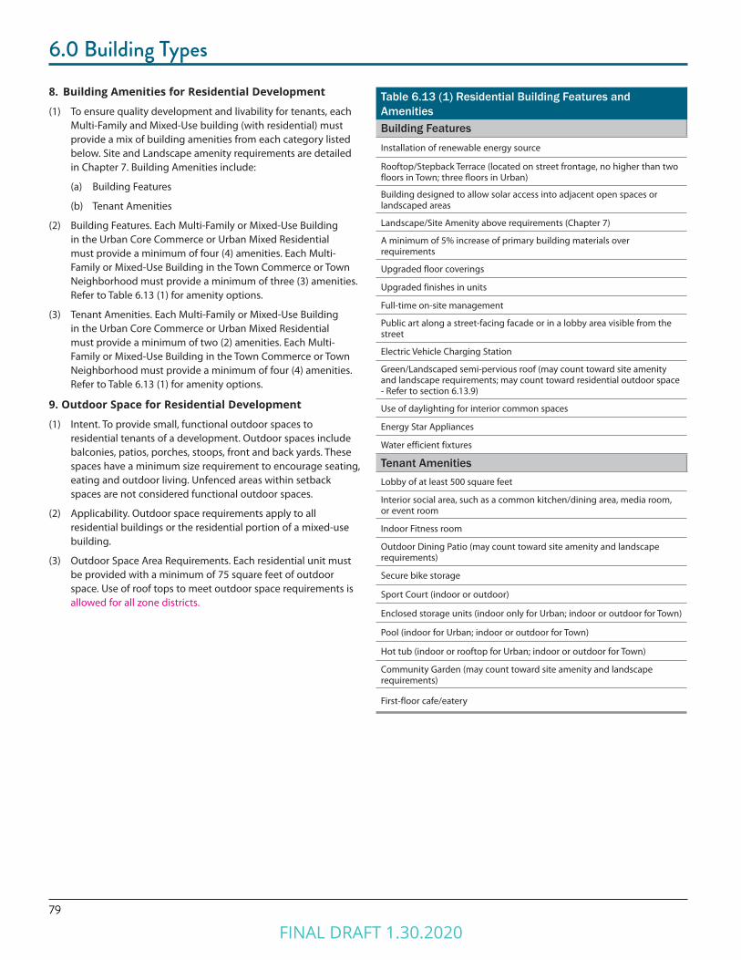
79
6.0 Building Types
8. Building Amenities for Residential Development
(1) To ensure quality development and livability for tenants, each Multi-Family and Mixed-Use building (with residential) must provide a mix of building amenities from each category listed below. Site and Landscape amenity requirements are detailed in Chapter 7. Building Amenities include:
(a) Building Features
(b) Tenant Amenities
(2) Building Features. Each Multi-Family or Mixed-Use Building in the Urban Core Commerce or Urban Mixed Residential must provide a minimum of four (4) amenities. Each Multi-Family or Mixed-Use Building in the Town Commerce or Town Neighborhood must provide a minimum of three (3) amenities. Refer to Table 6.13 (1) for amenity options.
(3) Tenant Amenities. Each Multi-Family or Mixed-Use Building in the Urban Core Commerce or Urban Mixed Residential must provide a minimum of two (2) amenities. Each Multi-Family or Mixed-Use Building in the Town Commerce or Town Neighborhood must provide a minimum of four (4) amenities. Refer to Table 6.13 (1) for amenity options.
9. Outdoor Space for Residential Development
(1) Intent. To provide small, functional outdoor spaces to residential tenants of a development. Outdoor spaces include balconies, patios, porches, stoops, front and back yards. These spaces have a minimum size requirement to encourage seating, eating and outdoor living. Unfenced areas within setback spaces are not considered functional outdoor spaces.
(2) Applicability. Outdoor space requirements apply to all residential buildings or the residential portion of a mixed-use building.
(3) Outdoor Space Area Requirements. Each residential unit must be provided with a minimum of 75 square feet of outdoor space. Use of roof tops to meet outdoor space requirements is allowed for all zone districts.
Table 6.13 (1) Residential Building Features and AmenitiesBuilding FeaturesInstallation of renewable energy source
Rooftop/Stepback Terrace (located on street frontage, no higher than two floors in Town; three floors in Urban)
Building designed to allow solar access into adjacent open spaces or landscaped areas
Landscape/Site Amenity above requirements (Chapter 7)
A minimum of 5% increase of primary building materials over requirements
Upgraded floor coverings
Upgraded finishes in units
Full-time on-site management
Public art along a street-facing facade or in a lobby area visible from the street
Electric Vehicle Charging Station
Green/Landscaped semi-pervious roof (may count toward site amenity and landscape requirements; may count toward residential outdoor space - Refer to section 6.13.9)
Use of daylighting for interior common spaces
Energy Star Appliances
Water efficient fixtures
Tenant AmenitiesLobby of at least 500 square feet
Interior social area, such as a common kitchen/dining area, media room, or event room
Indoor Fitness room
Outdoor Dining Patio (may count toward site amenity and landscape requirements)
Secure bike storage
Sport Court (indoor or outdoor)
Enclosed storage units (indoor only for Urban; indoor or outdoor for Town)
Pool (indoor for Urban; indoor or outdoor for Town)
Hot tub (indoor or rooftop for Urban; indoor or outdoor for Town)
Community Garden (may count toward site amenity and landscape requirements)
First-floor cafe/eatery
FINAL DRAFT 1.30.2020
Chapter 7.0SITE & LANDSCAPE STANDARDS
FINAL DRAFT 1.30.2020
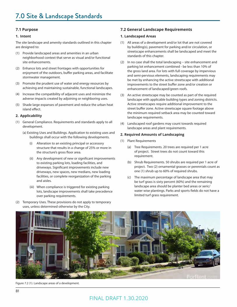
81
7.0 Site & Landscape Standards
7.1 Purpose1. Intent
The site landscape and amenity standards outlined in this chapter are designed to:
(1) Provide landscaped areas and amenities in an urban neighborhood context that serve as visual and/or functional site enhancements.
(2) Enhance lots and street frontages with opportunities for enjoyment of the outdoors, buffer parking areas, and facilitate stormwater management.
(3) Promote the prudent use of water and energy resources by achieving and maintaining sustainable, functional landscapes.
(4) Increase the compatibility of adjacent uses and minimize the adverse impacts created by adjoining or neighboring uses.
(5) Shade large expanses of pavement and reduce the urban heat island effect.
2. Applicability
(1) General Compliance. Requirements and standards apply to all development.
(a) Existing Uses and Buildings. Application to existing uses and buildings shall occur with the following developments.
(i) Alteration to an existing principal or accessory structure that results in a change of 25% or more in the structure’s gross floor area.
(ii) Any development of new or significant improvements to existing parking lots, loading facilities, and driveways. Significant improvements include new driveways, new spaces, new medians, new loading facilities, or complete reorganization of the parking and aisles.
(iii) When compliance is triggered for existing parking lots, landscape improvements shall take precedence over parking requirements.
(2) Temporary Uses. These provisions do not apply to temporary uses, unless determined otherwise by the City.
7.2 General Landscape Requirements1. Landscaped Areas
(1) All areas of a development and/or lot that are not covered by building(s), pavement for parking and/or circulation, or streetscape enhancements shall be landscaped and meet the standards of this chapter.
(2) In no case shall the total landscaping – site enhancement and parking lot enhancement combined - be less than 10% of the gross land area. For lots with full coverage by impervious and semi-pervious elements, landscaping requirements may be met by enhancing the active streetscape with additional improvements to the street buffer zone and/or creation or enhancement of landscaped/green roofs.
(3) An active streetscape may be counted as part of the required landscape with applicable building types and zoning districts. Active streetscapes require additional improvement to the street buffer zone. Active streetscape square footage above the minimum required setback area may be counted toward landscape requirements.
(4) Landscaped roof gardens may count towards required landscape areas and plant requirements.
2. Required Amounts of Landscaping
(1) Plant Requirements
(a) Tree Requirements. 20 trees are required per 1 acre of project. Street trees do not count toward this requirement.
(b) Shrub Requirements. 50 shrubs are required per 1 acre of project. Two (2) ornamental grasses or perennials count as one (1) shrub up to 60% of required shrubs.
(c) The maximum percentage of landscape area that may be turf grass is sixty percent (60%) and the remaining landscape area should be planter bed areas or xeric/water wise plantings. Parks and sports fields do not have a limited turf grass requirement.
Figure 7.2 (1). Landscape areas of a development.
FINAL DRAFT 1.30.2020
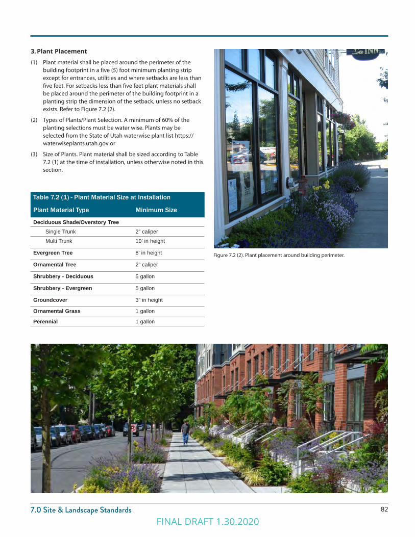
827.0 Site & Landscape Standards
Table 7.2 (1) - Plant Material Size at Installation
Plant Material Type Minimum Size
Deciduous Shade/Overstory TreeSingle Trunk 2” caliper
Multi Trunk 10’ in height
Evergreen Tree 8’ in height
Ornamental Tree 2” caliper
Shrubbery - Deciduous 5 gallon
Shrubbery - Evergreen 5 gallon
Groundcover 3” in height
Ornamental Grass 1 gallon
Perennial 1 gallon
3. Plant Placement
(1) Plant material shall be placed around the perimeter of the building footprint in a five (5) foot minimum planting strip except for entrances, utilities and where setbacks are less than five feet. For setbacks less than five feet plant materials shall be placed around the perimeter of the building footprint in a planting strip the dimension of the setback, unless no setback exists. Refer to Figure 7.2 (2).
(2) Types of Plants/Plant Selection. A minimum of 60% of the planting selections must be water wise. Plants may be selected from the State of Utah waterwise plant list https://waterwiseplants.utah.gov or
(3) Size of Plants. Plant material shall be sized according to Table 7.2 (1) at the time of installation, unless otherwise noted in this section.
Figure 7.2 (2). Plant placement around building perimeter.
FINAL DRAFT 1.30.2020
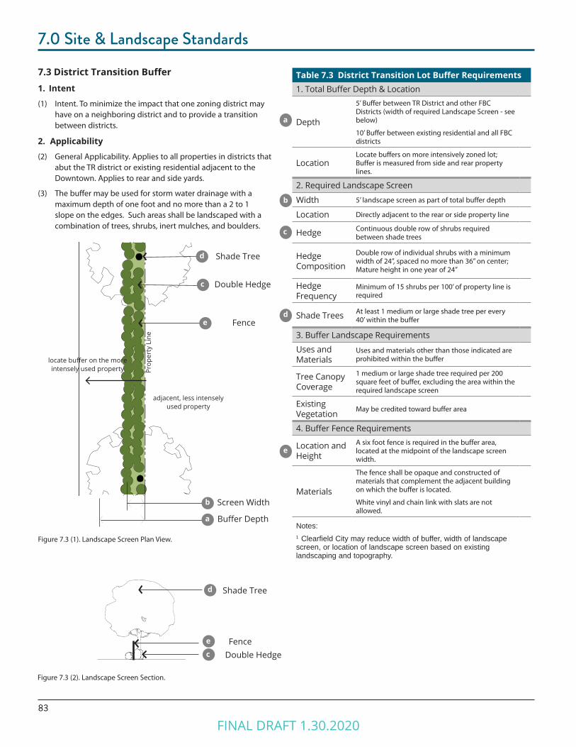
83
7.0 Site & Landscape Standards
7.3 District Transition Buffer1. Intent
(1) Intent. To minimize the impact that one zoning district may have on a neighboring district and to provide a transition between districts.
2. Applicability
(2) General Applicability. Applies to all properties in districts that abut the TR district or existing residential adjacent to the Downtown. Applies to rear and side yards.
(3) The buffer may be used for storm water drainage with a maximum depth of one foot and no more than a 2 to 1 slope on the edges. Such areas shall be landscaped with a combination of trees, shrubs, inert mulches, and boulders.
Figure 7.3 (2). Landscape Screen Section.
Figure 7.3 (1). Landscape Screen Plan View.
Table 7.3 District Transition Lot Buffer Requirements1. Total Buffer Depth & Location
Depth
5’ Buffer between TR District and other FBC Districts (width of required Landscape Screen - see below)
10’ Buffer between existing residential and all FBC districts
LocationLocate buffers on more intensively zoned lot; Buffer is measured from side and rear property lines.
2. Required Landscape Screen
Width 5’ landscape screen as part of total buffer depth
Location Directly adjacent to the rear or side property line
Hedge Continuous double row of shrubs required between shade trees
Hedge Composition
Double row of individual shrubs with a minimum width of 24”, spaced no more than 36” on center; Mature height in one year of 24”
Hedge Frequency
Minimum of 15 shrubs per 100’ of property line is required
Shade Trees At least 1 medium or large shade tree per every 40’ within the buffer
3. Buffer Landscape Requirements
Uses and Materials
Uses and materials other than those indicated are prohibited within the buffer
Tree Canopy Coverage
1 medium or large shade tree required per 200 square feet of buffer, excluding the area within the required landscape screen
Existing Vegetation May be credited toward buffer area
4. Buffer Fence Requirements
Location and Height
A six foot fence is required in the buffer area, located at the midpoint of the landscape screen width.
Materials
The fence shall be opaque and constructed of materials that complement the adjacent building on which the buffer is located.
White vinyl and chain link with slats are not allowed.
Notes:1 Clearfield City may reduce width of buffer, width of landscape screen, or location of landscape screen based on existing landscaping and topography.
a
d
c
b
e
Prop
erty
Lin
e
Shade Tree
Double Hedge
Fence
Shade Tree
Double HedgeFence
adjacent, less intensely used property
locate buffer on the more intensely used property
Screen Width
Buffer Depth
d
c
e
b
d
a
c
e
FINAL DRAFT 1.30.2020
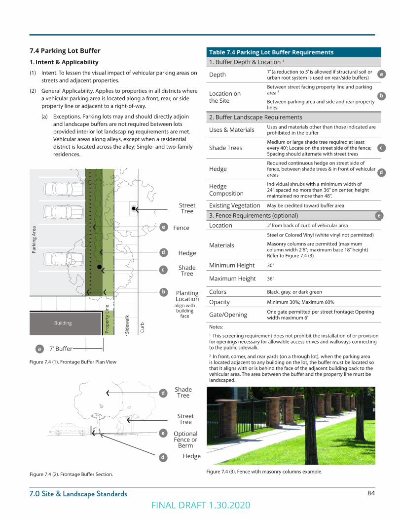
847.0 Site & Landscape Standards
Table 7.4 Parking Lot Buffer Requirements1. Buffer Depth & Location 1
Depth 7’ (a reduction to 5’ is allowed if structural soil or urban root system is used on rear/side buffers)
Location on the Site
Between street facing property line and parking area 2
Between parking area and side and rear property lines.
2. Buffer Landscape Requirements
Uses & Materials Uses and materials other than those indicated are prohibited in the buffer
Shade TreesMedium or large shade tree required at least every 40’; Locate on the street side of the fence; Spacing should alternate with street trees
HedgeRequired continuous hedge on street side of fence, between shade trees & in front of vehicular areas
Hedge Composition
Individual shrubs with a minimum width of 24”, spaced no more than 36” on center, height maintained no more than 48”.
Existing Vegetation May be credited toward buffer area
3. Fence Requirements (optional)
Location 2’ from back of curb of vehicular area
Materials
Steel or Colored Vinyl (white vinyl not permitted)
Masonry columns are permitted (maximum column width 2’6”; maximum base 18” height) Refer to Figure 7.4 (3)
Minimum Height 30”
Maximum Height 36”
Colors Black, gray, or dark green
Opacity Minimum 30%; Maximum 60%
Gate/Opening One gate permitted per street frontage; Opening width maximum 6’
Notes:1 This screening requirement does not prohibit the installation of or provision for openings necessary for allowable access drives and walkways connecting to the public sidewalk.2 In front, corner, and rear yards (on a through lot), when the parking area is located adjacent to any building on the lot, the buffer must be located so that it aligns with or is behind the face of the adjacent building back to the vehicular area. The area between the buffer and the property line must be landscaped.
7.4 Parking Lot Buffer1. Intent & Applicability
(1) Intent. To lessen the visual impact of vehicular parking areas on streets and adjacent properties.
(2) General Applicability. Applies to properties in all districts where a vehicular parking area is located along a front, rear, or side property line or adjacent to a right-of-way.
(a) Exceptions. Parking lots may and should directly adjoin and landscape buffers are not required between lots provided interior lot landscaping requirements are met. Vehicular areas along alleys, except when a residential district is located across the alley; Single- and two-family residences.
Figure 7.4 (3). Fence wtih masonry columns example.Figure 7.4 (2). Frontage Buffer Section.
d
d
e
Shade Tree
Street Tree
Hedge
OptionalFence or
Berm
Figure 7.4 (1). Frontage Buffer Plan View
e
a
b
c
d
Shade Tree
Hedge
Street Tree
Fence
7’ Buffer
Park
ing
Area
Side
wal
k
CurbBuilding
align withbuilding
face
Prop
erty
Lin
e
Planting Location
a
b
c
d
e
FINAL DRAFT 1.30.2020

85
7.0 Site & Landscape Standards
Figure 7.5 (1). Interior Parking Lot Landscaping.
7.5 Interior Parking Lot Landscape Requirements1. Landscape Island Requirements
Required Island Locations 1
Islands are required at the terminal ends of free standing rows or bays of parking 2
Islands are required after every ninth parking space for rows of parking greater than 12 spaces in length 3
Minimum Width
5’; Islands less than 15’ must utilize structural soil under any paved surface within a tree’s critical root zone; Islands under 9’ must install an aeration system and utilize permeable pavement for the curb and gutter.
Required Trees and Storm Water
Minimum of 1 medium or large shade tree per island. Islands shall be designed to accommodate storm (as bio-swales) water run off where the drainage plan can be reasonably designed to accomplish that objective.
2. Landscape Median Requirements
Required Median Location
Required in each free-standing bay of parking along the length of the bay
Minimum Width
5’; Medians less than 15’ must utilize structural soil under any paved surface within a tree’s critical root zone; Medians under 9’ must install an aeration system and utilize permeable pavement
Required Trees and Storm Water
Minimum of 1 medium or large shade tree per median. Medians shall be designed to accommodate storm (as bio-swales) water run off where the drainage plan can be reasonably designed to accomplish that objective.
3. Tree Requirements
Requirements per Parking Space 4
Each parking space must be located within 50’ of a tree planted within parking lot interior
Minimum of 1 shade tree must be planted within parking lot interior or within 7’ of parking lot’s edge for every 5 parking spaces
Tree Shade Goal
Within 20 years of tree installation, 25% of the interior of the parking lot should be shaded by tree canopy. Refer to Table 7.7 (1) for mature canopy estimates.
Notes:1 Landscape islands are not required specifically for stalls with covered parking, this only applies to covered parking areas.2 Freestanding rows or bays of parking are those not abutting the parking lot perimeter or building face, and may have a single or double row of parking.3 There shall be no more than 12 continuous parking spaces in a row without a landscape island.4 Trees within a designated buffer area may not be utilized to meet these requirements
7.5 Interior Parking Lot Landscape1. Intent & Applicability
(1) Intent. To provide shade, minimize paving & associated stormwater runoff, & improve the aesthetic look of parking lots.
(2) General Applicability. All Districts.
(3) Other Internal Parking Lot Areas. Internal areas not dedicated to parking or drives shall be landscaped with a minimum of one medium or large shade tree for the first 150 square feet and one medium or large shade tree for every 650’ thereafter.
(4) Existing Vegetation. Existing vegetation may be credited toward these requirements.
(5) Parking lot interior is defined as the area dedicated to parking on a given parcel as measured from edge of pavement to edge of pavement.
Trees Within Islands
TerminalEnd
Landscape Island
Landscape Median
Prim
ary
Stre
et
a
b
c
d
FINAL DRAFT 1.30.2020
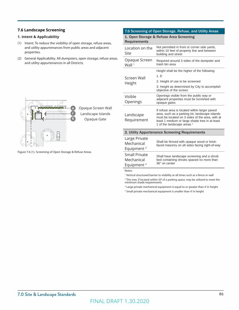
867.0 Site & Landscape Standards
Figure 7.6 (1). Screening of Open Storage & Refuse Areas.
7.6 Screening of Open Storage, Refuse, and Utility Areas1. Open Storage & Refuse Area Screening Requirements
Location on the Site
Not permitted in front or corner side yards, within 10 feet of property line and between building and street
Opaque Screen Wall 1
Required around 3 sides of the dumpster and trash bin area
Screen Wall Height
Height shall be the higher of the following:1. 6’2. Height of use to be screened3. Height as determined by City to accomplish objective of the screen
Visible Openings
Openings visible from the public way or adjacent properties must be furnished with opaque gates
Landscape Requirement
If refuse area is located within larger paved area, such as a parking lot, landscape islands must be located on 3 sides of the area, with at least 1 medium or large shade tree in at least 1 of the landscape areas 2
2. Utility Appurtenance Screening Requirements
Large Private Mechanical Equipment 3
Shall be fenced with opaque wood or brick-faced masonry on all sides facing right-of-way
Small Private Mechanical Equipment 4
Shall have landscape screening and a shrub bed containing shrubs spaced no more than 36” on center
Notes:1 Vertical structured barrier to visibility at all times such as a fence or wall2 This tree, if located within 50’ of a parking space, may be utilized to meet the minimum shade requirements3 Large private mechanical equipment is equal to or greater than 4’ in height4 Small private mechanical equipment is smaller than 4’ in height
7.6 Landscape Screening1. Intent & Applicability
(1) Intent. To reduce the visibility of open storage, refuse areas, and utility appurtenances from public areas and adjacent properties.
(2) General Applicability. All dumpsters, open storage, refuse areas, and utility appurtenances in all Districts.
Opaque Screen Wall
Opaque GateLandscape Islands
a
b
c
FINAL DRAFT 1.30.2020

87
7.0 Site & Landscape Standards
7.7 Installation of Landscape1. Intent
The following provisions aid in ensuring that all required landscaping is installed and maintained properly.
2. ApplicabilityThese provisions apply to landscape installation as required by this section.
3. General RequirementsThe installation of landscaping shall adhere to the following standards.
(1) National Standards. All landscaping and trees shall be installed and maintained in conformance with the best management practices and procedures established by the most recent edition of the American Standard for Nursery Stock (ANSI Z60.1) as published by American Horticulture Industry Association d/b/a AmericanHort (www.americanhort.org). This includes provisions on pruning, fertilizing, support systems, lighting protection, and safety.
4. Installation Timing Requirements
(1) Installation Timing. Landscaping and Site Amenities shall be fully installed prior to the issuance of a certificate of occupancy, or in cases of inclement weather, within the following time periods.
(a) For projects of all building types except Townhouse or Garden Court, all landscaping and site amenities shall be installed within six (6) months of the date of initial occupancy. The date of initial occupancy shall be the date that a certificate of occupancy is issued for the first building or facility of an individual phase or plat of the development.
(b) The front and side yards of all Townhouse or Garden Court building types in all zones shall be landscaped within six (6) months of the date of initial occupancy for the building or structure with which they are associated. The rear yard shall be landscaped within twelve (12) months of the date of initial occupancy. Date of initial occupancy will be the date that a certificate of occupancy is issued for the dwelling unit.
(2) Bond Required. In order to ensure that all required landscaping is installed in an acceptable manner, the developer shall post a separate cash bond with the city recorder or establish an escrow account with an appropriate financial institution. The cash bond or escrow account shall be subject to approval by the city engineer, and shall be in an amount equal to one hundred twenty five percent (125%) of the estimated costs of construction and installation of all required landscaping, parks, playgrounds, recreation facilities, fences, walls, and other amenities shown on the final landscape plan or site plan, as applicable.
(a) The bond or escrow account shall be posted or established in accordance with all other city regulations.
(b) The bond or escrow account shall be posted or established prior to the issuance of a certificate of occupancy for the site.
(c) The bond shall be accompanied by a schedule of anticipated completion dates for such improvements. In no case shall the time period for completion exceed the time periods set forth in this section.
(d) In the event that the improvements are not completed in reasonable conformance with said schedule, the city may undertake to complete the improvements and pay for such improvements from the bond or escrow account.
(3) Guarantee. To guarantee the survival of the installed landscaping, twenty-five percent (25%) of the bond required shall be retained by the city for the period of one year after installation is completed.
4. Condition of Landscape Materials
(1) Condition of Landscape Materials. The landscaping materials used shall be:
(a) Healthy and hardy with a good root system.
(b) Chosen for its form, texture, color, fruit, pattern of growth, and suitability to local conditions.
(c) Tolerant of the natural and man-made environment, including tolerant of drought, wind, salt, and pollution.
(d) Appropriate for the conditions of the site, including slope, water table, and soil type.
(e) Protected from damage by grates, pavers, or other measures.
(f ) Plants that will not cause a nuisance or have negative impacts on an adjacent property.
(g) Species native or naturalized to the Wasatch Front, whenever possible.
(2) Compost, Mulch, and Organic Matter. Compost, mulch, and organic matter may be utilized within the soil mix to reduce the need for fertilizers and increase water retention.
(3) Establishment. All installed plant material shall be fully maintained until established, including watering, fertilization, and replacement as necessary.
FINAL DRAFT 1.30.2020
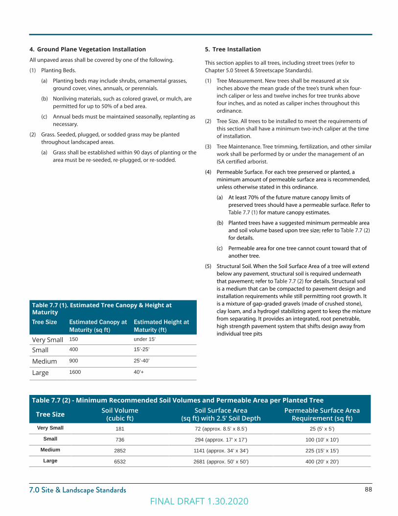
887.0 Site & Landscape Standards
4. Ground Plane Vegetation Installation
All unpaved areas shall be covered by one of the following.
(1) Planting Beds.
(a) Planting beds may include shrubs, ornamental grasses, ground cover, vines, annuals, or perennials.
(b) Nonliving materials, such as colored gravel, or mulch, are permitted for up to 50% of a bed area.
(c) Annual beds must be maintained seasonally, replanting as necessary.
(2) Grass. Seeded, plugged, or sodded grass may be planted throughout landscaped areas.
(a) Grass shall be established within 90 days of planting or the area must be re-seeded, re-plugged, or re-sodded.
5. Tree Installation
This section applies to all trees, including street trees (refer to Chapter 5.0 Street & Streetscape Standards).
(1) Tree Measurement. New trees shall be measured at six inches above the mean grade of the tree’s trunk when four-inch caliper or less and twelve inches for tree trunks above four inches, and as noted as caliper inches throughout this ordinance.
(2) Tree Size. All trees to be installed to meet the requirements of this section shall have a minimum two-inch caliper at the time of installation.
(3) Tree Maintenance. Tree trimming, fertilization, and other similar work shall be performed by or under the management of an ISA certified arborist.
(4) Permeable Surface. For each tree preserved or planted, a minimum amount of permeable surface area is recommended, unless otherwise stated in this ordinance.
(a) At least 70% of the future mature canopy limits of preserved trees should have a permeable surface. Refer to Table 7.7 (1) for mature canopy estimates.
(b) Planted trees have a suggested minimum permeable area and soil volume based upon tree size; refer to Table 7.7 (2) for details.
(c) Permeable area for one tree cannot count toward that of another tree.
(5) Structural Soil. When the Soil Surface Area of a tree will extend below any pavement, structural soil is required underneath that pavement; refer to Table 7.7 (2) for details. Structural soil is a medium that can be compacted to pavement design and installation requirements while still permitting root growth. It is a mixture of gap-graded gravels (made of crushed stone), clay loam, and a hydrogel stabilizing agent to keep the mixture from separating. It provides an integrated, root penetrable, high strength pavement system that shifts design away from individual tree pits
Table 7.7 (2) - Minimum Recommended Soil Volumes and Permeable Area per Planted Tree
Tree Size Soil Volume (cubic ft)
Soil Surface Area (sq ft) with 2.5’ Soil Depth
Permeable Surface Area Requirement (sq ft)
Very Small 181 72 (approx. 8.5’ x 8.5’) 25 (5’ x 5’)
Small 736 294 (approx. 17’ x 17’) 100 (10’ x 10’)
Medium 2852 1141 (approx. 34’ x 34’) 225 (15’ x 15’)
Large 6532 2681 (approx. 50’ x 50’) 400 (20’ x 20’)
Table 7.7 (1). Estimated Tree Canopy & Height at MaturityTree Size Estimated Canopy at
Maturity (sq ft)Estimated Height at Maturity (ft)
Very Small 150 under 15’
Small 400 15’-25’
Medium 900 25’-40’
Large 1600 40’+
FINAL DRAFT 1.30.2020
89
7.0 Site & Landscape Standards
6. Irrigation Systems
Permanent irrigation, beyond establishment, is required and shall adhere to the following standards.
(1) All irrigation systems shall be designed to minimize the use of water.
(2) All irrigation systems shall be installed with an EPA Waterwise controller or approved equal and must be used according to directions to save water.
(3) The irrigation system shall provide sufficient coverage to all landscape areas.
(4) The irrigation system shall not spray or irrigate impervious surfaces, including sidewalks, driveways, streets, and parking and loading areas.
(5) All systems shall be equipped with a back-flow prevention device.
(6) All mechanical systems including controllers and back-flow prevention devices shall be properly screened from public view.
(7) All irrigation plans shall be stamped by Professional Landscape Architect or Certified Irrigation Designer (IA) and submitted to Clearfield City for review.
7. Maintenance of LandscapeAll landscaping shall always be maintained in good condition to ensure a healthy and orderly appearance.
(1) All required landscape shall be maintained to adhere to all requirements of this ordinance.
(2) Replacing Unhealthy Landscaping. Unhealthy landscaping shall be replaced with healthy, live plants by the end of the next applicable growing season. This includes all plant material that shows dead branches over a minimum of 25% of the normal branching pattern.
(3) Maintenance Responsibility. The owner is responsible for the maintenance, repair, and replacement of all landscaping, screening, and curbing required herein.
(4) Maintain Quality and Quantity. Maintenance shall preserve at least the same quantity, quality, and screening effectiveness as initially installed.
(5) Fences and Other Barriers. Fences, walls, and other barriers shall be maintained in good repair and free of rust, flaking paint, graffiti, and broken or damaged parts.
(6) Tree Topping. Tree topping is not permitted. When necessary, crown reduction thinning or pruning is permitted. Refer also to 5.6.6 for required clear branch height of street trees.
(7) City Inspection. All landscaped areas regulated by this ordinance may be inspected by the City.
8. Preservation, Maintenance, And Ownership
(1) In the event that required landscaping improvements are not installed or maintained in a manner consistent with the approved site plan or landscaping plan, the city may at its option cause such landscaping or maintenance to be performed and assess the costs to the affected property owner(s) or other responsible association or entity. (Ord. 2009-40, 11-24-2009)
FINAL DRAFT 1.30.2020

907.0 Site & Landscape StandardsFINAL DRAFT 1.30.2020

FINAL DRAFT 1.30.2020

Chapter 8.0CIVIC OPEN SPACE STANDARDS
FINAL DRAFT 1.30.2020
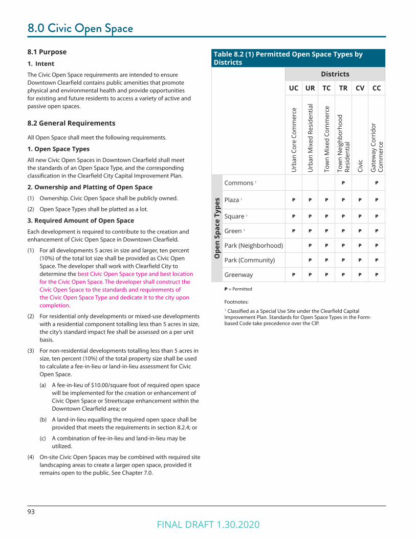
93
8.0 Civic Open Space
8.1 Purpose1. Intent
The Civic Open Space requirements are intended to ensure Downtown Clearfield contains public amenities that promote physical and environmental health and provide opportunities for existing and future residents to access a variety of active and passive open spaces.
8.2 General Requirements
All Open Space shall meet the following requirements.
1. Open Space Types
All new Civic Open Spaces in Downtown Clearfield shall meet the standards of an Open Space Type, and the corresponding classification in the Clearfield City Capital Improvement Plan.
2. Ownership and Platting of Open Space
(1) Ownership. Civic Open Space shall be publicly owned.
(2) Open Space Types shall be platted as a lot.
3. Required Amount of Open Space
Each development is required to contribute to the creation and enhancement of Civic Open Space in Downtown Clearfield.
(1) For all developments 5 acres in size and larger, ten percent (10%) of the total lot size shall be provided as Civic Open Space. The developer shall work with Clearfield City to determine the best Civic Open Space type and best location for the Civic Open Space. The developer shall construct the Civic Open Space to the standards and requirements of the Civic Open Space Type and dedicate it to the city upon completion.
(2) For residential only developments or mixed-use developments with a residential component totalling less than 5 acres in size, the city’s standard impact fee shall be assessed on a per unit basis.
(3) For non-residential developments totalling less than 5 acres in size, ten percent (10%) of the total property size shall be used to calculate a fee-in-lieu or land-in-lieu assessment for Civic Open Space.
(a) A fee-in-lieu of $10.00/square foot of required open space will be implemented for the creation or enhancement of Civic Open Space or Streetscape enhancement within the Downtown Clearfield area; or
(b) A land-in-lieu equalling the required open space shall be provided that meets the requirements in section 8.2.4; or
(c) A combination of fee-in-lieu and land-in-lieu may be utilized.
(4) On-site Civic Open Spaces may be combined with required site landscaping areas to create a larger open space, provided it remains open to the public. See Chapter 7.0.
Table 8.2 (1) Permitted Open Space Types by Districts
Districts
UC UR TC TR CV CC
Urb
an C
ore
Com
mer
ce
Urb
an M
ixed
Res
iden
tial
Tow
n M
ixed
Com
mer
ce
Tow
n N
eigh
borh
ood
Resi
dent
ial
Civi
c
Gat
eway
Cor
ridor
Co
mm
erce
Ope
n Sp
ace
Type
s
Commons 1 P P
Plaza 1 P P P P P P
Square 1 P P P P P P
Green 1 P P P P P P
Park (Neighborhood) P P P P P
Park (Community) P P P P P
Greenway P P P P P P
P = Permitted
Footnotes:1 Classified as a Special Use Site under the Clearfield Capital Improvement Plan. Standards for Open Space Types in the Form-based Code take precedence over the CIP.
FINAL DRAFT 1.30.2020

948.0 Civic Open Space
4. Land In Lieu Substitutions for Open Space
In certain circumstances, “In lieu substitution” or “in lieu of open space substitutions” are encouraged for the benefit of the creating important and critical Civic Open Space areas in Downtown Clearfield. The City may, at its sole discretion, accept land in lieu of Open Space requirements under the following conditions:
(1) The proposed land to be substituted is in a location within a one-quarter mile buffer of Downtown Clearfield that is acceptable to and approved by the City as a substitute site for Civic Open Space.
(2) In lieu substitutions of land intended to fulfill the requirements for Open Space may be allowed when it is factually established, by a qualified land appraiser, that the substituted land is at least equal to or greater than the value of land compared with the development property as if developed fully as proposed. The City may determine to approve the land area to be appraised both from the original site and the proposed substituted site prior to the appraisal. The appraiser will be selected by and contract with the City. Appraisal fees will be reimbursed to the City at cost by the developer. New appraisals may not be required if recent information or appraisals are readily available.
(3) Any land which has been dedicated, set-aside, platted, or otherwise approved as Civic Open Space may not be substituted or used for any purpose other than those allowed in this Chapter.
(4) In lieu substitution applications shall first be reviewed by the Zoning Administrator as a part of the initial application. Approval of the in-lieu substitution shall be obtained from the City Council as part a development agreement before the Final Site Plan or issuance of a building permit, whichever occurs first.
5. Access and Parking
(1) Access. All Civic Open Space shall provide public access from a vehicular right-of-way.
(2) Parking Requirements.
(a) For Civic Open Space 1 acre or smaller Off-street Parking shall not be required for any Civic Open Space Type.
(b) For Civic Open Space larger than 1 acre: Off-street parking shall be provided. Parking may include on-street parking. , unless a use other than Open Space is determined by the City.
6. Connections to Trails and Open Space
Connections to existing trails, planned trails, or other existing or planned Open Space types shall be made when the Open Space abuts an existing or planned trail right-of-way or other Civic Open Space type. Refer to corresponding City trails master plan.
7. Fencing
Open Space Types may incorporate fencing provided that the following requirements are met.
(1) Height. Fencing shall be a maximum height of five (5) feet, unless approved or directed by the City, for such circumstances as proximity to railroad right-of-way and use around swimming pools (minimum of 6 feet required), ball fields, and ball courts.
(2) Level of Opacity. Fence opacity shall be no greater than 80%.
(3) Type. Chain-link fencing is not permitted along any street frontage, except for dedicated sports field or sport court fencing approved by the City.
(4) Spacing of Openings. Openings or gates shall be provided on every street face at a minimum of every 200 feet.
8. Open Water
Open Water Body. All open water bodies, such as lakes, ponds, pools, creeks, and streams, within an Open Space type shall be located at least 20 feet from a property line to allow for pedestrian and bicycle access as well as a landscape area surrounding the water body.
9. Stormwater in Open Space Types
Stormwater management following green infrastructure best practices may be integrated into Open Space Types and utilized to meet stormwater requirements for surrounding parcels, with the following standards:
(1) Stormwater Features. Stormwater features may be designed as formal or natural amenities with additional uses other than stormwater management, such as an amphitheater, sports field, or a pond or pool as part of the landscape design. Stormwater features shall not be fenced and shall not impede public use of the land they occupy.
(2) Qualified Professional. A qualified landscape design professional, such as a landscape architect or landscape designer, shall be utilized to incorporate stormwater features into the design of the Civic Open Spaces to maximize the benefit to both public use and natural systems.
(3) Size of Stormwater feature: A maximum of twenty percent (20%) of the Open Space required area may be used for Stormwater detention/retention. A higher percentage, up to 75%, can be used for Stormwater detention/retention if designed as a functional sports field.
10. Landscape Elements
Landscape elements used in Open Space types must meet the installation and other general requirements of the Landscape Chapter 7.0.
FINAL DRAFT 1.30.2020

95
8.0 Civic Open Space
8.3 Open Space Type Standards
The following standards apply to Open Space Types in Downtown.
1. Dimensions
(1) Minimum and Maximum Size. The minimum and maximum size of the Open Space Type is measured within the parcel lines of the property.
(2) Minimum Dimension. The minimum length or width of the Open Space Type, as measured along the longest two straight lines intersecting at a right angle defining the maximum length and width of the lot.
(3) Minimum Percentage of Vehicular Right-of-Way Frontage Required. The minimum percentage of the civic Open Space perimeter, as measured along the outer parcel line, that shall be located directly adjacent to a vehicular right-of-way, excluding alley frontage. This requirement provides access and visibility to the Open Space.
2. Adjacent Parcels
Parcels directly adjacent to or across the street from an Open Space Type.
(1) Permitted Districts of Adjacent Parcels. The zoning districts permitted directly adjacent to, as well as directly across the street from the Open Space Type.
(2) Orientation of Adjacent Parcels. Parcels adjacent to a Civic Open Space type will have a preferred orientation in relation to each Civic Open Space type to support access and the anticipated relationship between the two.
Figure 8.3 (1). Examples of Measuring the Minimum Dimension of Open Space Types.
FINAL DRAFT 1.30.2020

968.0 Civic Open Space
3. Permitted Improvements
The following types of development and improvements are permitted on an Open Space Type.
(1) Designated Sports Fields. Sport fields, ball courts, or structures designated for one or more specific sports including, but not limited to, baseball fields, softball fields, soccer fields, basketball courts, football fields, tennis courts, pickleball courts, climbing walls, and skate parks are permitted.
(2) Playgrounds. Playgrounds with a designated area for play structures and equipment generally targeted for children 12 and under including, but not limited to, slides, swings, and climbing structures are permitted. All playground and equipment must meet safety and surfacing standards.
(3) Enclosed Structures. Enclosed structures may include such uses as park offices, maintenance sheds, community centers, and restrooms.
(a) Maximum Area. For some Civic Open Space types, fully enclosed structures are permitted, but limited to a maximum building coverage as a percentage of the Open Space area.
(b) Semi-Enclosed Structures. Open-air structures, such as gazebos, are permitted in all Open Space types.
(4) Site Amenities. Site amenities and furniture including, but not limited to, lighting, seating, and bicycle parking are permitted.
(5) Maximum Impervious and Semi-Pervious Surface Permitted. The amounts of impervious and semi-pervious coverage are provided separately to allow an additional amount of semi-pervious surface, such as permeable paving, above the impervious surfaces permitted, including, but not limited to, parking facilities, driveways, sidewalks, paths, and structures as permitted.
(6) Maximum Percentage of Open Water Body. The maximum amount of area within an Open Space Type that may be covered by an open water body, including, but not limited to, ponds, lakes, and pools.
FINAL DRAFT 1.30.2020
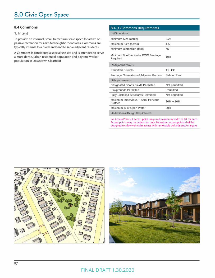
97
8.0 Civic Open Space
8.4 (1) Commons Requirements(1) Dimensions
Minimum Size (acres) 0.25
Maximum Size (acres) 1.5
Minimum Dimension (feet) 45’
Minimum % of Vehicular ROW Frontage Required 10%
(2) Adjacent Parcels
Permitted Districts TR, CC
Frontage Orientation of Adjacent Parcels Side or Rear
(3) Improvements
Designated Sports Fields Permitted Not permitted
Playgrounds Permitted Permitted
Fully Enclosed Structures Permitted Not permitted
Maximum Impervious + Semi-Pervious Surface 30% + 10%
Maximum % of Open Water 30%
(4) Additional Design Requirements
(a) Access Points. 2 access points required; minimum width of 20’ for each. Access points may be pedestrian only. Pedestrian access points shall be designed to allow vehicular access with removable bollards and/or a gate.
8.4 Commons1. Intent
To provide an informal, small to medium scale space for active or passive recreation for a limited neighborhood area. Commons are typically internal to a block and tend to serve adjacent residents.
A Commons is considered a special use site and is intended to serve a more dense, urban residential population and daytime worker population in Downtown Clearfield.
FINAL DRAFT 1.30.2020
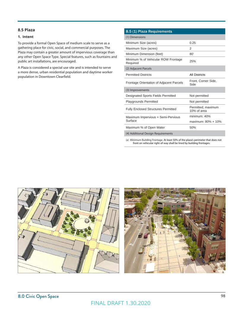
988.0 Civic Open Space
8.5 (1) Plaza Requirements(1) Dimensions
Minimum Size (acres) 0.25
Maximum Size (acres) 2
Minimum Dimension (feet) 80’
Minimum % of Vehicular ROW Frontage Required 25%
(2) Adjacent Parcels
Permitted Districts All Districts
Frontage Orientation of Adjacent Parcels Front, Corner Side, Side
(3) Improvements
Designated Sports Fields Permitted Not permitted
Playgrounds Permitted Not permitted
Fully Enclosed Structures Permitted Permitted; maximum 10% of area
Maximum Impervious + Semi-Pervious Surface
minimum: 40%maximum: 80% + 10%
Maximum % of Open Water 50%
(4) Additional Design Requirements
(a) Minimum Building Frontage. At least 50% of the plaza’s perimeter that does not front on vehicular right-of-way shall be lined by building frontages.
8.5 Plaza1. Intent
To provide a formal Open Space of medium scale to serve as a gathering place for civic, social, and commercial purposes. The Plaza may contain a greater amount of impervious coverage than any other Open Space Type. Special features, such as fountains and public art installations, are encouraged.
A Plaza is considered a special use site and is intended to serve a more dense, urban residential population and daytime worker population in Downtown Clearfield.
FINAL DRAFT 1.30.2020
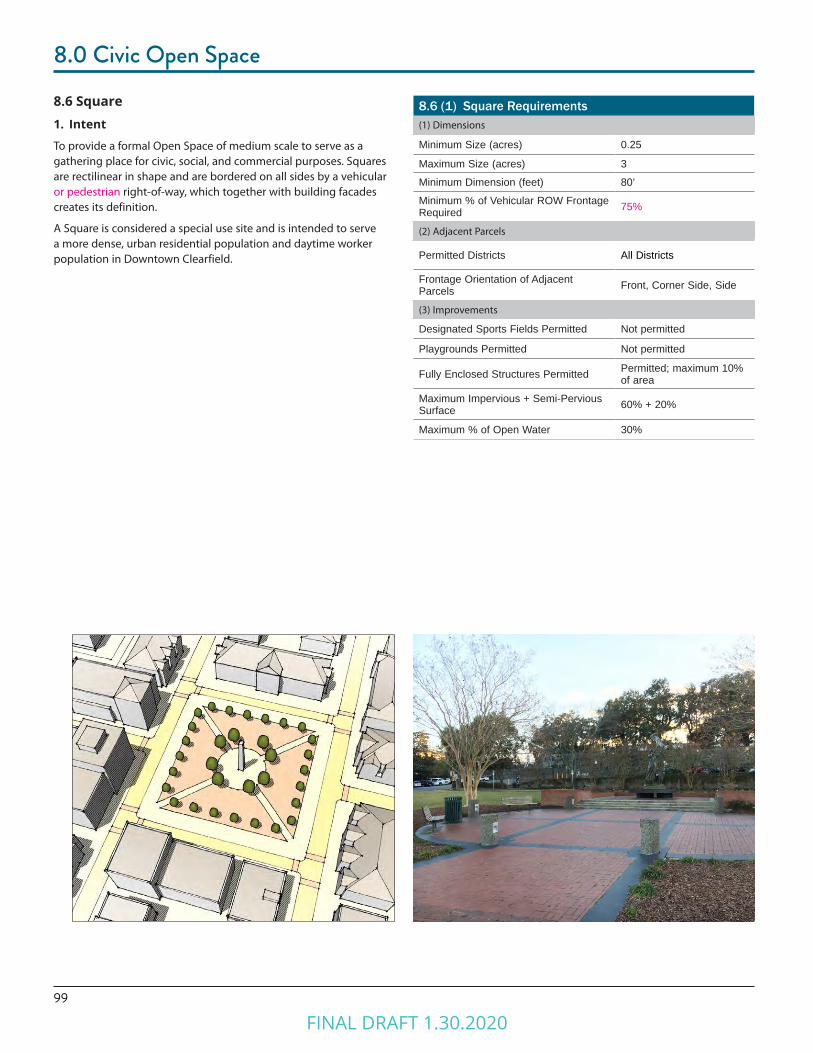
99
8.0 Civic Open Space
8.6 (1) Square Requirements(1) Dimensions
Minimum Size (acres) 0.25
Maximum Size (acres) 3
Minimum Dimension (feet) 80’
Minimum % of Vehicular ROW Frontage Required 75%
(2) Adjacent Parcels
Permitted Districts All Districts
Frontage Orientation of Adjacent Parcels Front, Corner Side, Side
(3) Improvements
Designated Sports Fields Permitted Not permitted
Playgrounds Permitted Not permitted
Fully Enclosed Structures Permitted Permitted; maximum 10% of area
Maximum Impervious + Semi-Pervious Surface 60% + 20%
Maximum % of Open Water 30%
8.6 Square1. Intent
To provide a formal Open Space of medium scale to serve as a gathering place for civic, social, and commercial purposes. Squares are rectilinear in shape and are bordered on all sides by a vehicular or pedestrian right-of-way, which together with building facades creates its definition.
A Square is considered a special use site and is intended to serve a more dense, urban residential population and daytime worker population in Downtown Clearfield.
FINAL DRAFT 1.30.2020
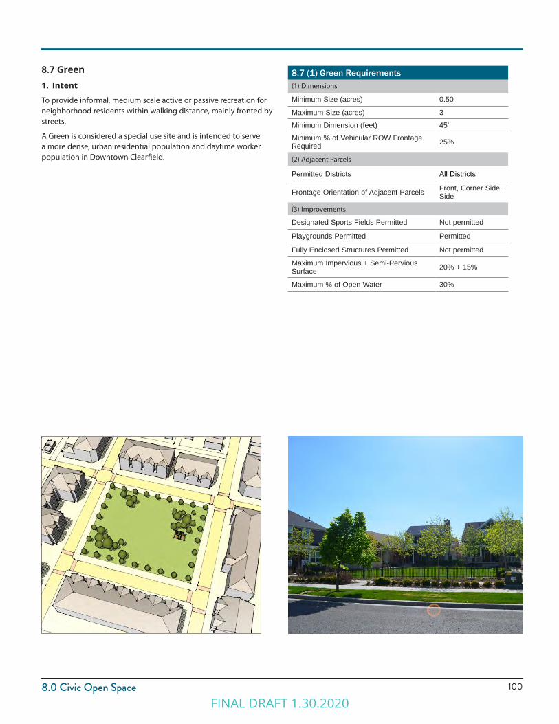
1008.0 Civic Open Space
8.7 Green1. Intent
To provide informal, medium scale active or passive recreation for neighborhood residents within walking distance, mainly fronted by streets.
A Green is considered a special use site and is intended to serve a more dense, urban residential population and daytime worker population in Downtown Clearfield.
8.7 (1) Green Requirements(1) Dimensions
Minimum Size (acres) 0.50
Maximum Size (acres) 3
Minimum Dimension (feet) 45’
Minimum % of Vehicular ROW Frontage Required 25%
(2) Adjacent Parcels
Permitted Districts All Districts
Frontage Orientation of Adjacent Parcels Front, Corner Side, Side
(3) Improvements
Designated Sports Fields Permitted Not permitted
Playgrounds Permitted Permitted
Fully Enclosed Structures Permitted Not permitted
Maximum Impervious + Semi-Pervious Surface 20% + 15%
Maximum % of Open Water 30%
FINAL DRAFT 1.30.2020
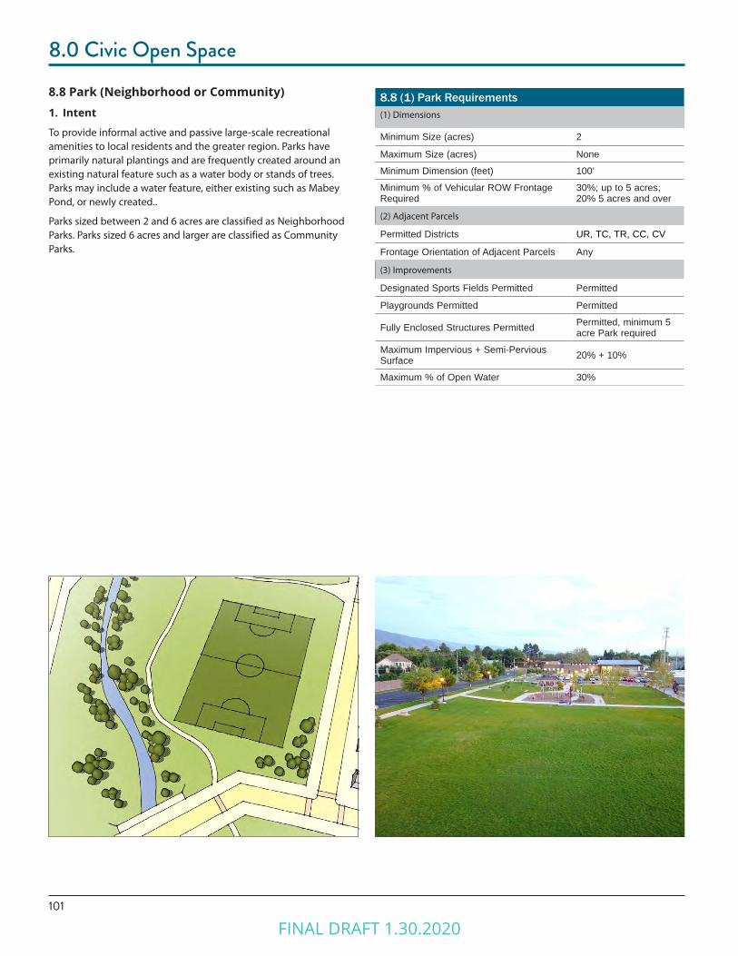
101
8.0 Civic Open Space
8.8 (1) Park Requirements(1) Dimensions
Minimum Size (acres) 2
Maximum Size (acres) None
Minimum Dimension (feet) 100’
Minimum % of Vehicular ROW Frontage Required
30%; up to 5 acres; 20% 5 acres and over
(2) Adjacent Parcels
Permitted Districts UR, TC, TR, CC, CV
Frontage Orientation of Adjacent Parcels Any
(3) Improvements
Designated Sports Fields Permitted Permitted
Playgrounds Permitted Permitted
Fully Enclosed Structures Permitted Permitted, minimum 5 acre Park required
Maximum Impervious + Semi-Pervious Surface 20% + 10%
Maximum % of Open Water 30%
8.8 Park (Neighborhood or Community)1. Intent
To provide informal active and passive large-scale recreational amenities to local residents and the greater region. Parks have primarily natural plantings and are frequently created around an existing natural feature such as a water body or stands of trees. Parks may include a water feature, either existing such as Mabey Pond, or newly created..
Parks sized between 2 and 6 acres are classified as Neighborhood Parks. Parks sized 6 acres and larger are classified as Community Parks.
FINAL DRAFT 1.30.2020
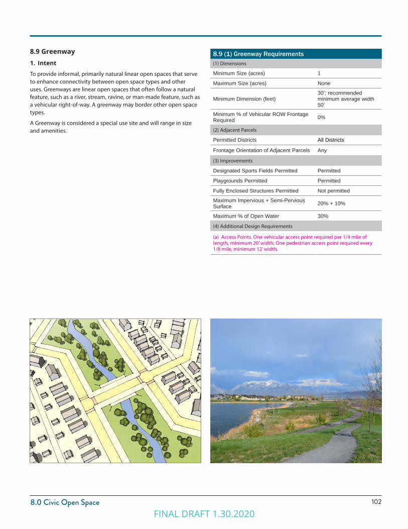
1028.0 Civic Open Space
8.9 (1) Greenway Requirements(1) Dimensions
Minimum Size (acres) 1
Maximum Size (acres) None
Minimum Dimension (feet)30’; recommended minimum average width 50’
Minimum % of Vehicular ROW Frontage Required 0%
(2) Adjacent Parcels
Permitted Districts All Districts
Frontage Orientation of Adjacent Parcels Any
(3) Improvements
Designated Sports Fields Permitted Permitted
Playgrounds Permitted Permitted
Fully Enclosed Structures Permitted Not permitted
Maximum Impervious + Semi-Pervious Surface 20% + 10%
Maximum % of Open Water 30%
(4) Additional Design Requirements
(a) Access Points. One vehicular access point required per 1/4 mile of length, minimum 20’ width; One pedestrian access point required every 1/8 mile, minimum 12’ width.
8.9 Greenway1. Intent
To provide informal, primarily natural linear open spaces that serve to enhance connectivity between open space types and other uses. Greenways are linear open spaces that often follow a natural feature, such as a river, stream, ravine, or man-made feature, such as a vehicular right-of-way. A greenway may border other open space types.
A Greenway is considered a special use site and will range in size and amenities.
FINAL DRAFT 1.30.2020

FINAL DRAFT 1.30.2020
Chapter 9.0PARKING STANDARDS
FINAL DRAFT 1.30.2020

105
9.0 Parking
9.1 Purpose1. Intent
The established provisions are intended to accomplish the following:
(1) Ensure an appropriate level of vehicle parking, loading, and storage to support a variety of land uses.
(2) Provide site design standards to mitigate the impacts of parking lots on adjacent land uses and zoning districts.
(3) Provide specifications for vehicular site access.
(4) To allow shared public on-street parking and in parking lots to serve the needs of visitors and patrons.
(5) To allow projects to match parking to tenant needs.
(6) To support a more walkable, transit-oriented development pattern.
(7) To support and improve walkability, bikeability, and non-vehicular transportation.
(8) To mitigate the impacts of vehicular parking lots on the urban neighborhood context and streetscapes of Downtown Clearfield.
2. ApplicabilityThis section shall apply to all new development and changes in use or intensity of use for existing development, in all Downtown Clearfield districts.
(1) Compliance. Compliance with the standards outlined shall be attained in the following circumstances:
(a) Development of all new parking facilities, loading facilities, and driveways.
(b) Improvements to existing parking facilities, loading facilities, and driveways, including re-configuration, enlargement, or the addition of curbs, walkways, fencing, or landscape installation.
(c) Change in use requiring a change in the amount of parking.
(2) Damage or Destruction. When a use that has been damaged or destroyed by fire, collapse, explosion, or other cause is reestablished, any associated off-street parking spaces or loading facilities must be reestablished based on the requirements of this section.
(3) Site Plan Approval Required. Parking quantities, design, and layout shall be approved through the Site Plan Approval process. Refer to Chapter 11 Site Plan Approval for details.
9.2 General Requirements1. Off-street Parking
Off-street parking spaces shall be provided in conformance with Tables 9.2 (1) Required Vehicular Parking and 9.3 (1) Bicycle Parking.
(1) Required Accessible Parking. Parking facilities accessible for persons with disabilities shall comply with or exceed the standards detailed in the ADA Standards for Accessible Design including quantity, features, and location. (www.ada.gov)
(2) Requirements for Unlisted Uses. Upon receiving a site plan, occupancy certificate, or other permit application for a proposed use not specifically addressed, the Zoning Administrator is authorized to apply off-street parking standards for the use deemed most similar to the proposed use. In instances where an equivalent similar use may not be clearly determined or the standard is in question, the Zoning Administrator may require the applicant to submit a parking study that will help determine the appropriate requirements.
(3) Private Off-Premises Parking. Where private off-site parking facilities are approved, such facilities shall be in the same possession as the property occupied by the building or use to which the parking facilities are accessory.
(a) Such possession may be either by deed or lease, guaranteeing availability of the parking commensurate with the use served by the parking.
(b) The agreement providing for the use of off-site parking, executed by the parties involved, shall be in a form approved by the City Attorney and filed with the Zoning Administrator.
(c) The deed or lease shall require the owner to maintain the required number of parking facilities for the duration of the use served or of the deed or lease, whichever shall terminate sooner.
(d) Location of Parking. Any off-premise parking must be within 660 feet (1/8 mile) from the entrance of the use to the closest parking space measured along a dedicated public or private pedestrian path.
(4) Tandem Parking. To meet minimum parking requirements, tandem parking configured with a 1-car garage and 1-car driveway is permitted for certain building types with approval of the Zoning Administrator through the site plan review process. Permitted building types include:
(a) Garden Court Building Types
(b) Townhouse Building Types
FINAL DRAFT 1.30.2020
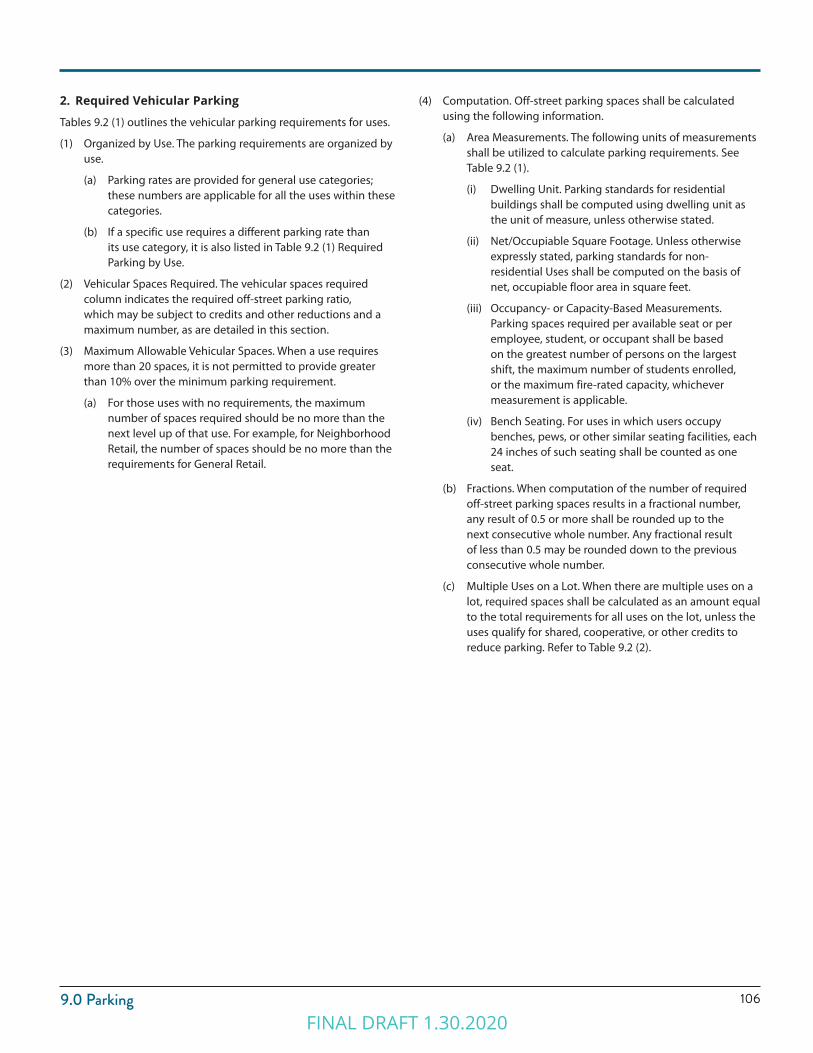
1069.0 Parking
(4) Computation. Off-street parking spaces shall be calculated using the following information.
(a) Area Measurements. The following units of measurements shall be utilized to calculate parking requirements. See Table 9.2 (1).
(i) Dwelling Unit. Parking standards for residential buildings shall be computed using dwelling unit as the unit of measure, unless otherwise stated.
(ii) Net/Occupiable Square Footage. Unless otherwise expressly stated, parking standards for non-residential Uses shall be computed on the basis of net, occupiable floor area in square feet.
(iii) Occupancy- or Capacity-Based Measurements. Parking spaces required per available seat or per employee, student, or occupant shall be based on the greatest number of persons on the largest shift, the maximum number of students enrolled, or the maximum fire-rated capacity, whichever measurement is applicable.
(iv) Bench Seating. For uses in which users occupy benches, pews, or other similar seating facilities, each 24 inches of such seating shall be counted as one seat.
(b) Fractions. When computation of the number of required off-street parking spaces results in a fractional number, any result of 0.5 or more shall be rounded up to the next consecutive whole number. Any fractional result of less than 0.5 may be rounded down to the previous consecutive whole number.
(c) Multiple Uses on a Lot. When there are multiple uses on a lot, required spaces shall be calculated as an amount equal to the total requirements for all uses on the lot, unless the uses qualify for shared, cooperative, or other credits to reduce parking. Refer to Table 9.2 (2).
2. Required Vehicular Parking
Tables 9.2 (1) outlines the vehicular parking requirements for uses.
(1) Organized by Use. The parking requirements are organized by use.
(a) Parking rates are provided for general use categories; these numbers are applicable for all the uses within these categories.
(b) If a specific use requires a different parking rate than its use category, it is also listed in Table 9.2 (1) Required Parking by Use.
(2) Vehicular Spaces Required. The vehicular spaces required column indicates the required off-street parking ratio, which may be subject to credits and other reductions and a maximum number, as are detailed in this section.
(3) Maximum Allowable Vehicular Spaces. When a use requires more than 20 spaces, it is not permitted to provide greater than 10% over the minimum parking requirement.
(a) For those uses with no requirements, the maximum number of spaces required should be no more than the next level up of that use. For example, for Neighborhood Retail, the number of spaces should be no more than the requirements for General Retail.
FINAL DRAFT 1.30.2020
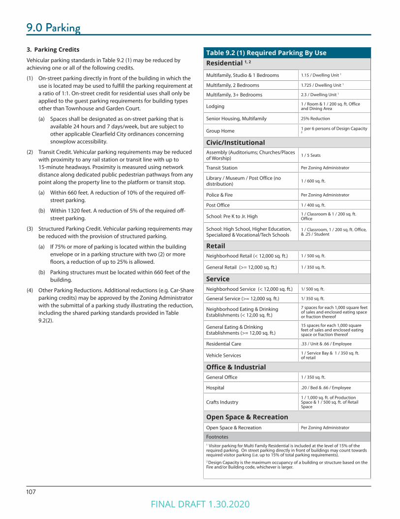
107
9.0 Parking3. Parking Credits
Vehicular parking standards in Table 9.2 (1) may be reduced by achieving one or all of the following credits.
(1) On-street parking directly in front of the building in which the use is located may be used to fulfill the parking requirement at a ratio of 1:1. On-street credit for residential uses shall only be applied to the guest parking requirements for building types other than Townhouse and Garden Court.
(a) Spaces shall be designated as on-street parking that is available 24 hours and 7 days/week, but are subject to other applicable Clearfield City ordinances concerning snowplow accessibility.
(2) Transit Credit. Vehicular parking requirements may be reduced with proximity to any rail station or transit line with up to 15-minute headways. Proximity is measured using network distance along dedicated public pedestrian pathways from any point along the property line to the platform or transit stop.
(a) Within 660 feet. A reduction of 10% of the required off-street parking.
(b) Within 1320 feet. A reduction of 5% of the required off-street parking.
(3) Structured Parking Credit. Vehicular parking requirements may be reduced with the provision of structured parking.
(a) If 75% or more of parking is located within the building envelope or in a parking structure with two (2) or more floors, a reduction of up to 25% is allowed.
(b) Parking structures must be located within 660 feet of the building.
(4) Other Parking Reductions. Additional reductions (e.g. Car-Share parking credits) may be approved by the Zoning Administrator with the submittal of a parking study illustrating the reduction, including the shared parking standards provided in Table 9.2(2).
Table 9.2 (1) Required Parking By UseResidential 1, 2
Multifamily, Studio & 1 Bedrooms 1.15 / Dwelling Unit 1
Multifamily, 2 Bedrooms 1.725 / Dwelling Unit 1
Multifamily, 3+ Bedrooms 2.3 / Dwelling Unit 1
Lodging 1 / Room & 1 / 200 sq. ft. Office and Dining Area
Senior Housing, Multifamily 25% Reduction
Group Home 1 per 6 persons of Design Capacity
2
Civic/InstitutionalAssembly (Auditoriums; Churches/Places of Worship)
1 / 5 Seats
Transit Station Per Zoning Administrator
Library / Museum / Post Office (no distribution)
1 / 600 sq. ft.
Police & Fire Per Zoning Administrator
Post Office 1 / 400 sq. ft.
School: Pre K to Jr. High 1 / Classroom & 1 / 200 sq. ft. Office
School: High School, Higher Education, Specialized & Vocational/Tech Schools
1 / Classroom, 1 / 200 sq. ft. Office, & .25 / Student
RetailNeighborhood Retail (< 12,000 sq. ft.) 1 / 500 sq. ft.
General Retail (>= 12,000 sq. ft.) 1 / 350 sq. ft.
ServiceNeighborhood Service (< 12,000 sq. ft.) 1/ 500 sq. ft.
General Service (>= 12,000 sq. ft.) 1/ 350 sq. ft.
Neighborhood Eating & Drinking Establishments (< 12,00 sq. ft.)
7 spaces for each 1,000 square feet of sales and enclosed eating space or fraction thereof
General Eating & Drinking Establishments (>= 12,00 sq. ft.)
15 spaces for each 1,000 square feet of sales and enclosed eating space or fraction thereof
Residential Care .33 / Unit & .66 / Employee
Vehicle Services 1 / Service Bay & 1 / 350 sq. ft. of retail
Office & IndustrialGeneral Office 1 / 350 sq. ft.
Hospital .20 / Bed & .66 / Employee
Crafts Industry1 / 1,000 sq. ft. of Production Space & 1 / 500 sq. ft. of Retail Space
Open Space & RecreationOpen Space & Recreation Per Zoning Administrator
Footnotes1 Visitor parking for Multi Family Residential is included at the level of 15% of the required parking. On street parking directly in front of buildings may count towards required visitor parking (i.e. up to 15% of total parking requirements).2 Design Capacity is the maximum occupancy of a building or structure based on the Fire and/or Building code, whichever is larger.
FINAL DRAFT 1.30.2020

1089.0 Parking
Table 9.2 (2). Shared Parking Percentages Use Weekdays Weekends
Midnight- 7:00 am
7:00 am- 6:00 pm
6:00 pm- Midnight
Midnight- 7:00 am
7:00 am- 6:00 pm
6:00 pm- Midnight
Residential (Non-Lodging) 100% 50% 80% 100% 80% 80%
Lodging 100% 65% 100% 100% 65% 100%
Retail & Service (General) 5% 100% 80% 5% 100% 60%
Restaurants, Taverns 50% 70% 100% 70% 60% 100%
Theaters & Entertainment 5% 30% 100% 5% 60% 100%
Civic, Office 5% 100% 5% 5% 5% 5%
Churches & Place of Worship 0% 30% 50% 0% 100% 75%
Crafts Industries 5% 100% 10% 5% 50% 10%
4. Multiple Use Reductions
The following reductions may be taken:
(1) Shared Vehicular Parking. An arrangement in which two or more uses with different peak parking demands use the same off-street parking spaces to meet their off-street parking requirements.
(a) General Provisions. Through review of the site plan the Zoning Administrator may permit up to 100% of the parking required for a daytime use to be supplied by the off-street parking spaces provided for a nighttime or Sunday use and vice versa.
(b) Approval. To approve a shared parking arrangement, the Zoning Administrator must find, based on competent evidence provided by the applicant, that there is no substantial conflict in the principal operating hours of the uses for which the sharing of parking is proposed.
(c) Description of Uses with Weekday, Nighttime, and Sunday Peak Parking.
(i) The following uses are considered predominantly weekday uses: office and industrial uses and other similar uses as authorized by the Zoning Administrator.
(ii) The following uses are typically considered predominantly nighttime or Sunday uses: eating and drinking establishments, assembly uses, and other similar uses with peak activity at night or on Sundays, as authorized by the Zoning Administrator.
(2) Cooperative Vehicular Parking. When two or more categories of non-single-family residential uses share a parking lot and are located on the same lot or adjacent lots, the following applies:
(a) General Provisions. Shared parking will be approved in accordance with the following. Refer to Table 9.2 (2).
(i) For each applicable land use category, calculate the number of spaces required as if it were the only use. Refer to Table 9.2 (1).
(ii) Use the figures for each individual land use to calculate the number of spaces required for that use for each time period specified in Table 9.2 (2). This table establishes six time periods per use.
(iii) For each time period, add the number of spaces required for all applicable land uses to obtain a grand total for each of the six time periods.
(iv) Select the time period with the highest total parking requirement and use that as the total number of parking spaces required.
(b) Uses in Different Buildings. Through review of the site plan the Zoning Administrator may approve the cooperative agreement if any of the uses are not located in the same structure or building.
(c) Location of Cooperative Parking. Any cooperative parking must be within 660 feet from the entrance of the use to the closest parking space within the cooperative parking lot, measured along a dedicated pedestrian path.
(d) Off-Site Cooperative Parking Agreement. An agreement approved by the City Attorney providing for cooperative use of off-site parking spaces, executed by the parties involved, shall be reviewed by the Zoning Administrator during review of the site plan.
(i) Off-site cooperative parking arrangements shall continue in effect only as long as the agreement remains in force. Minimum acceptable time period for such contracts is five years.
(ii) If the agreement is no longer in force, then parking must be provided as otherwise required in this section.
FINAL DRAFT 1.30.2020
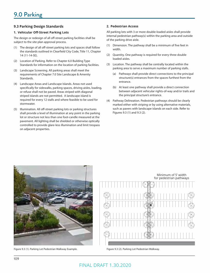
109
9.0 Parking
Minimum of 6’ in width for pedestrian pathways
Figure 9.3 (2). Parking Lot Pedestrian Walkway.
9.3 Parking Design Standards1. Vehicular Off-Street Parking Lots
The design or redesign of all off-street parking facilities shall be subject to the site plan approval process.
(1) The design of all off-street parking lots and spaces shall follow the standards outlined in Clearfield City Code, Title 11, Chapter 14 (11-14-5E).
(2) Location of Parking. Refer to Chapter 6.0 Building Type Standards for information on the location of parking facilities.
(3) Landscape Screening. All parking areas shall meet the requirements of Chapter 7.0 Site Landscape & Amenity Standards.
(4) Landscape Areas and Landscape Islands. Areas not used specifically for sidewalks, parking spaces, driving aisles, loading, or refuse shall not be paved. Areas striped with diagonal striped islands are not permitted. A landscape island is required for every 12 stalls and where feasible to be used for stormwater.
(5) Illumination. All off-street parking lots or parking structures shall provide a level of illumination at any point in the parking lot or structure not less than one foot-candle measured at the pavement. All lighting shall be shielded or otherwise optically controlled to provide glare-less illumination and limit trespass on adjacent properties.
2. Pedestrian Access
All parking lots with 3 or more double-loaded aisles shall provide internal pedestrian pathway(s) within the parking area and outside of the parking drive aisle.
(1) Dimension. The pathway shall be a minimum of five feet in width.
(2) Quantity. One pathway is required for every three double loaded aisles.
(3) Location. The pathway shall be centrally located within the parking area to serve a maximum number of parking stalls.
(a) Pathways shall provide direct connections to the principal structure(s) entrances from the spaces furthest from the entrance.
(b) At least one pathway shall provide a direct connection between adjacent vehicular rights-of-way and/or trails and the principal structure’s entrance.
(4) Pathway Delineation. Pedestrian pathways should be clearly marked either with striping or by using alternative materials, such as pavers with landscape islands on each side. Refer to Figures 9.3 (1) and 9.3 (2).
Minimum of 5’ widthfor pedestrian pathways
Figure 9.3 (1). Parking Lot Pedestrian Walkway Example.
FINAL DRAFT 1.30.2020

1109.0 Parking
3. Required Bicycle Parking & Design
The Required Bicycle Parking Table 9.3 (1) indicates the minimum bicycle parking ratio for a given use. Required Bicycle Parking for quantity required) shall be designed and located as follows. Refer to Figure 9.3 (3).
(1) Dimensions.
(a) Required bicycle parking spaces shall have minimum dimensions of two by six feet (2’x6’) in length.
(b) An aisle a minimum of five feet wide shall be provided behind bicycle parking facilities to allow for maneuvering.
(c) A minimum of two feet shall be provided beside each parked bicycle to allows access. This access may be shared by adjacent bicycles.
(d) Racks shall be installed a minimum of two feet from any wall or other obstruction.
(2) Location. Bicycle parking should be located within 50 feet of the entrance of the use.
(a) Indoor or outdoor spaces are permitted, provided they are located on the lot with which they are associated.
(b) Spaces located within individual dwelling units may not be counted toward bicycle parking requirements.
(c) Bicycle parking facilities shall be separated from vehicular parking areas to protect parked bicycles from damage. The separation may be accomplished through grade separation, distance or physical barrier, such as curbs, wheel stops, poles or other similar features.
(3) Racks and Structures. Racks and structures shall be provided for each unprotected parking space and shall be designed to accommodate both chain and U-shaped locking devices supporting the bicycle frame at two points.
(4) Bicycle Storage. In multifamily or office uses bicycle storage shall be lockable and enclosed. This may include bicycle lockers/units that are located outdoors.
(5) Surface. The parking surface shall be designed and maintained to be mud and dust free. The use of rock or gravel areas for bicycle parking is permitted provided that edging materials are used that clearly demarcate the bicycle parking area and contain the rock material.
(6) Signage. If required bicycle parking for public use is not visible from the street, signs must be posted indicating their location.
(7) Maintenance and Lighting. Areas used for required bicycle parking must be well-lit with acceptable drainage to be reasonably free of mud and standing water.
(8) Shower Facilities. Office and manufacturing uses with more than 50 employees shall provide shower and changing room facilities.
(9) Long Term Parking. For multifamily residential uses, half of the bicycle parking spaces should be provided as long-term parking, safe and secure from vandalism and theft, and protected from the elements.
Figure 9.3 (3). Required Bicycle Parking Location and Design
Table 9.3 (1)Bicycle Parking by Use Bicycle SpacesMultifamily, Studio/ 1 Bedrooms
Minimum 1 bike rack/Dwelling Unit
Multifamily, 2 Bedrooms Minimum 2 bike racks/Dwelling Unit
Civic/Institutional Minimum 2 bike racks/10,000 sf
Retail/Services/Office Minimum 1 bike racks/3,000 sf
Open Space Minimum 10 bike racks/1 Acres, or Per Zoning Administrator
FINAL DRAFT 1.30.2020
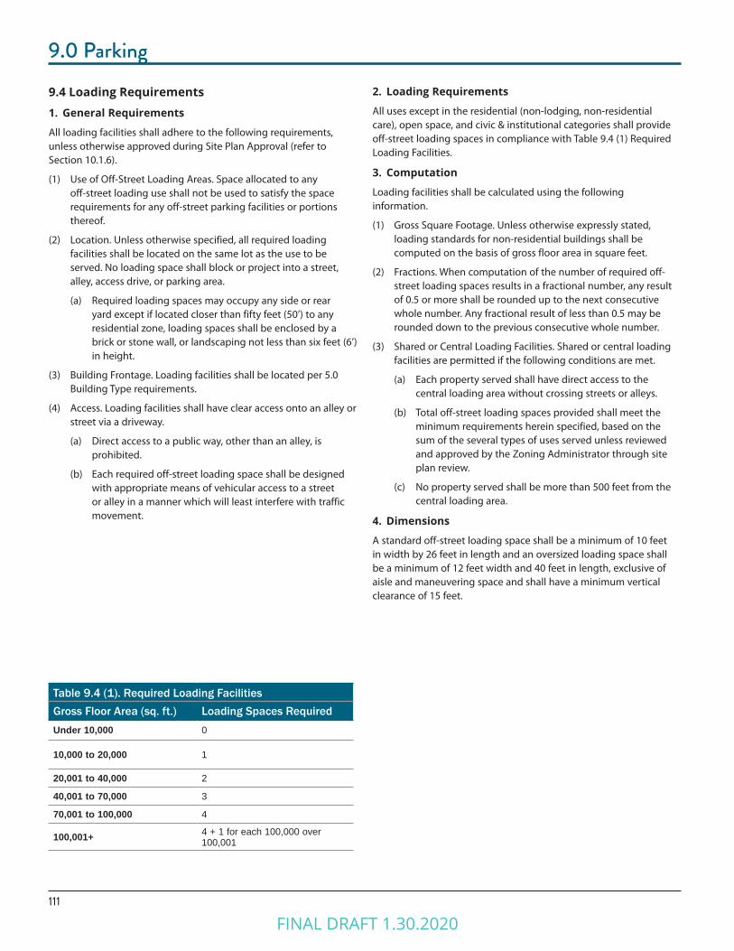
111
9.0 Parking
Table 9.4 (1). Required Loading FacilitiesGross Floor Area (sq. ft.) Loading Spaces RequiredUnder 10,000 0
10,000 to 20,000 1
20,001 to 40,000 2
40,001 to 70,000 3
70,001 to 100,000 4
100,001+ 4 + 1 for each 100,000 over 100,001
9.4 Loading Requirements1. General Requirements
All loading facilities shall adhere to the following requirements, unless otherwise approved during Site Plan Approval (refer to Section 10.1.6).
(1) Use of Off-Street Loading Areas. Space allocated to any off-street loading use shall not be used to satisfy the space requirements for any off-street parking facilities or portions thereof.
(2) Location. Unless otherwise specified, all required loading facilities shall be located on the same lot as the use to be served. No loading space shall block or project into a street, alley, access drive, or parking area.
(a) Required loading spaces may occupy any side or rear yard except if located closer than fifty feet (50’) to any residential zone, loading spaces shall be enclosed by a brick or stone wall, or landscaping not less than six feet (6’) in height.
(3) Building Frontage. Loading facilities shall be located per 5.0 Building Type requirements.
(4) Access. Loading facilities shall have clear access onto an alley or street via a driveway.
(a) Direct access to a public way, other than an alley, is prohibited.
(b) Each required off-street loading space shall be designed with appropriate means of vehicular access to a street or alley in a manner which will least interfere with traffic movement.
2. Loading Requirements
All uses except in the residential (non-lodging, non-residential care), open space, and civic & institutional categories shall provide off-street loading spaces in compliance with Table 9.4 (1) Required Loading Facilities.
3. Computation
Loading facilities shall be calculated using the following information.
(1) Gross Square Footage. Unless otherwise expressly stated, loading standards for non-residential buildings shall be computed on the basis of gross floor area in square feet.
(2) Fractions. When computation of the number of required off-street loading spaces results in a fractional number, any result of 0.5 or more shall be rounded up to the next consecutive whole number. Any fractional result of less than 0.5 may be rounded down to the previous consecutive whole number.
(3) Shared or Central Loading Facilities. Shared or central loading facilities are permitted if the following conditions are met.
(a) Each property served shall have direct access to the central loading area without crossing streets or alleys.
(b) Total off-street loading spaces provided shall meet the minimum requirements herein specified, based on the sum of the several types of uses served unless reviewed and approved by the Zoning Administrator through site plan review.
(c) No property served shall be more than 500 feet from the central loading area.
4. Dimensions
A standard off-street loading space shall be a minimum of 10 feet in width by 26 feet in length and an oversized loading space shall be a minimum of 12 feet width and 40 feet in length, exclusive of aisle and maneuvering space and shall have a minimum vertical clearance of 15 feet.
FINAL DRAFT 1.30.2020
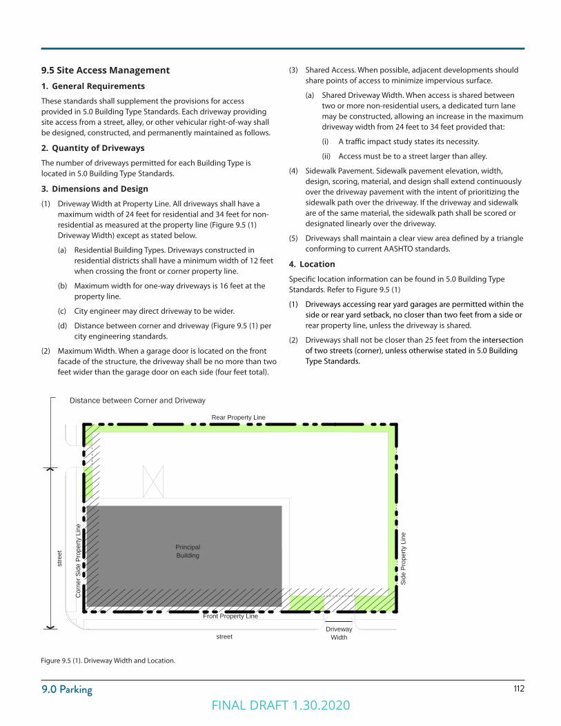
1129.0 Parking
Figure 9.5 (1). Driveway Width and Location.
Front Property Line
Rear Property Line
Cor
ner S
ide
Prop
erty
Lin
e
stre
et
street
Principal Building
Side
Pro
perty
Lin
eDistance between Corner and Driveway
Driveway Width
9.5 Site Access Management1. General Requirements
These standards shall supplement the provisions for access provided in 5.0 Building Type Standards. Each driveway providing site access from a street, alley, or other vehicular right-of-way shall be designed, constructed, and permanently maintained as follows.
2. Quantity of Driveways
The number of driveways permitted for each Building Type is located in 5.0 Building Type Standards.
3. Dimensions and Design
(1) Driveway Width at Property Line. All driveways shall have a maximum width of 24 feet for residential and 34 feet for non-residential as measured at the property line (Figure 9.5 (1) Driveway Width) except as stated below.
(a) Residential Building Types. Driveways constructed in residential districts shall have a minimum width of 12 feet when crossing the front or corner property line.
(b) Maximum width for one-way driveways is 16 feet at the property line.
(c) City engineer may direct driveway to be wider.
(d) Distance between corner and driveway (Figure 9.5 (1) per city engineering standards.
(2) Maximum Width. When a garage door is located on the front facade of the structure, the driveway shall be no more than two feet wider than the garage door on each side (four feet total).
(3) Shared Access. When possible, adjacent developments should share points of access to minimize impervious surface.
(a) Shared Driveway Width. When access is shared between two or more non-residential users, a dedicated turn lane may be constructed, allowing an increase in the maximum driveway width from 24 feet to 34 feet provided that:
(i) A traffic impact study states its necessity.
(ii) Access must be to a street larger than alley.
(4) Sidewalk Pavement. Sidewalk pavement elevation, width, design, scoring, material, and design shall extend continuously over the driveway pavement with the intent of prioritizing the sidewalk path over the driveway. If the driveway and sidewalk are of the same material, the sidewalk path shall be scored or designated linearly over the driveway.
(5) Driveways shall maintain a clear view area defined by a triangle conforming to current AASHTO standards.
4. Location
Specific location information can be found in 5.0 Building Type Standards. Refer to Figure 9.5 (1)
(1) Driveways accessing rear yard garages are permitted within the side or rear yard setback, no closer than two feet from a side or rear property line, unless the driveway is shared.
(2) Driveways shall not be closer than 25 feet from the intersection of two streets (corner), unless otherwise stated in 5.0 Building Type Standards.
FINAL DRAFT 1.30.2020

FINAL DRAFT 1.30.2020

Chapter 10.0SIGN TYPES
FINAL DRAFT 1.30.2020

115
10.0 Sign Types
10.1 Purpose1. Intent
The intent of the sign regulations is to enhance the economy and aesthetic appeal of Downtown Clearfield through the reasonable, orderly, safe, and effective display of signage. Signage should help contribute to the identity and brand of Downtown Clearfield.
2. Applicability
These standards shall apply to signage for all buildings and uses in Downtown Clearfield.
Refer to the Clearfield City Community Development Department for information on the Sign Permitting Process.
10.2 General Requirements1. Compliance
Compliance with the regulations outlined must be attained for the following situations.
(1) Newly Constructed or Reconstructed Signage. All new signs and structural improvements to existing signs.
(2) Change in Use for Single Business Signage. For signage serving one business, whenever the existing use is changed to a new use resulting in a change in signage, including rewording.
(3) Multiple-Business Signage. For signage serving multiple businesses, whenever 50% or more of the existing uses are changed to new uses resulting in a change in signage, including rewording.
(4) Damage or Destruction. When a sign has been damaged or destroyed by fire, collapse, explosion or other cause and the cost of restoration is greater than 50% of the replacement value at the time of the destruction or damage, the replacement sign shall comply with the standards in this chapter.
2. Prohibited, Temporary, Exempt Signage
Refer to Clearfield City Code Title 11-15 (Sign Regulations) for information on prohibited signs, temporary signs, off-premise signs, and exemptions for sign requirements.
3. Sign Location
Unless otherwise specified, signs shall only be located within the boundaries of the lot and not in the right-of-way or on public property.
(1) Certain Sign types may extend beyond a property line into the right-of-way or public property with permission from the City and in accordance with the regulations outlined in this section.
(2) No sign shall be attached to a utility pole, light pole, tree, standpipe, gutter, or drain.
(3) Signs shall be erected to permit free ingress to or egress from any door, window, the roof, or any other exit-way required by the building code or by fire department regulations.
(4) No Sign shall be erected or maintained in such a manner as to obstruct free and clear vision of, interfere with, or be confused with any authorized traffic sign, signal, or device.
FINAL DRAFT 1.30.2020

11610.0 Sign Types
4. Maximum Sign Area and Amounts
(1) Maximum Amount of Signage. Total attached and detached signage for a lot is established based on the district in which the lot is located. Refer to Table 10.2 (1).
(a) Window Signs. Window Signs shall not count towards a lot’s maximum permitted amount of signage. Refer to 10.8 Window Signs.
(b) Directional or Instructional Signs. Directional or Instructional signs are permitted in addition to the maximum Signage quantities.
(i) Signs must meet the requirements specified in Title 11-15-7 (Sign Regulations) of the Clearfield City code.
(c) Exempt and temporary signs are not included in the maximum signage area calculations, unless otherwise specified in Title 11-15 (Sign Regulations) of the Clearfield City code.
(2 ) Computation
(a) Height for freestanding signs is measured from the average grade at the front property line to the top of the sign, sign cabinet, or cap, whichever is highest.
(b) For the purposes of determining sign area, lot width or frontage is measured along the front property line.
(i) If the lot is a corner lot, the width shall be measured along the primary street frontage.
5. Illumination
All signs shall be illuminated according to the following provisions unless otherwise stated.
(1) Signs shall be internally lit to emphasize the lettering or flooded via down lighting to prevent dark sky illumination.
(2) Individual letters or logos may be internally illuminated as permitted per each sign type; no other portion of the sign shall be internally illuminated, except as permitted for Electronic Message Boards or unless otherwise stated.
(3) When an external artificial light source is used to illuminate a Sign, the lamp (or bulb) shall be located, shielded, and directed so as to not be visible from any public street or private residence.
(a) No receptacle or device housing a permitted light source which is attached to the sign itself shall extend more than 18 inches from the face of the Sign.
(4) The illumination of any sign, resulting from any internal or external artificial light source, shall not exceed 250 nits at the Sign face during the day and 125 nits at the Sign face after sunset, with no light trespass onto adjacent property.
(5) If externally lit, all sign illumination shall be directed downward.
Table 10.2 (1). Permitted Quantity of Signage by District.
District Maximum Permitted Quantity of Signage Per Lot
UC, UR, CV 3 square feet per 1 linear foot of lot width with a maximum of 150 square feet
TC, TR, CC 2 square feet per 1 linear foot of lot width with a maximum of 100 square feet
6. Construction and Maintenance Standards
All signs shall meet the construction and maintenance requirements of the Clearfield City Code.
7. Iconic Signs
(1) Iconic Sign Elements. Iconic Sign Elements of three-dimensional symbols or logos are permitted under the following conditions.
(a) Symbol or Logo Size. The symbol may not be larger than five feet in any direction, which shall be included in the overall sign area and the surface area counts towards the Maximum Permitted Quantity of Signage per Lot.
(b) No moving parts or external illumination of the symbol may be provided.
(c) Text. The text letter size may not be more than 30% of the overall area of the sign.
Figure 10.2 (1). Photo Example of an Iconic Sign.
FINAL DRAFT 1.30.2020
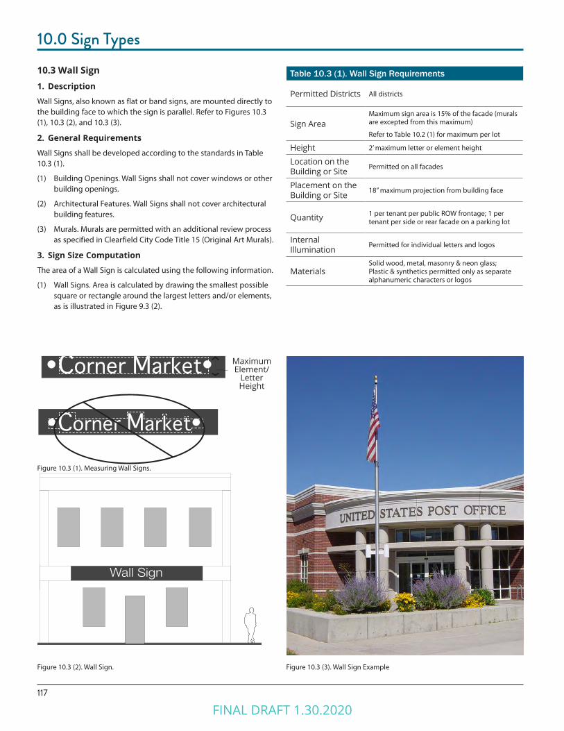
117
10.0 Sign Types
10.3 Wall Sign1. Description
Wall Signs, also known as flat or band signs, are mounted directly to the building face to which the sign is parallel. Refer to Figures 10.3 (1), 10.3 (2), and 10.3 (3).
2. General Requirements
Wall Signs shall be developed according to the standards in Table 10.3 (1).
(1) Building Openings. Wall Signs shall not cover windows or other building openings.
(2) Architectural Features. Wall Signs shall not cover architectural building features.
(3) Murals. Murals are permitted with an additional review process as specified in Clearfield City Code Title 15 (Original Art Murals).
3. Sign Size Computation
The area of a Wall Sign is calculated using the following information.
(1) Wall Signs. Area is calculated by drawing the smallest possible square or rectangle around the largest letters and/or elements, as is illustrated in Figure 9.3 (2).
Figure 10.3 (2). Wall Sign. Figure 10.3 (3). Wall Sign Example
Table 10.3 (1). Wall Sign Requirements
Permitted Districts All districts
Sign AreaMaximum sign area is 15% of the facade (murals are excepted from this maximum)
Refer to Table 10.2 (1) for maximum per lot
Height 2’ maximum letter or element height
Location on the Building or Site Permitted on all facades
Placement on the Building or Site 18” maximum projection from building face
Quantity 1 per tenant per public ROW frontage; 1 per tenant per side or rear facade on a parking lot
Internal Illumination Permitted for individual letters and logos
MaterialsSolid wood, metal, masonry & neon glass; Plastic & synthetics permitted only as separate alphanumeric characters or logos
Wall Sign
Figure 10.3 (1). Measuring Wall Signs.
Corner Market
CCoorrnneerr MMaarrkkeett
Corner Market
CCoorrnneerr MMaarrkkeett
Maximum Element/
Letter Height
FINAL DRAFT 1.30.2020

11810.0 Sign Types
Figure 10.4 (1). Projecting or Blade Sign. Figure 10.4 (2). Projecting or Blade Sign Example
10.4 Projecting or Blade Sign1. Description
A Projecting or Blade Sign is attached to and projects from a building face or hangs from a support structure attached to the building face. Sign faces are typically perpendicular to the building face but may be at an angle greater than 45 degrees from the facade. The sign may be vertically or horizontally oriented. Refer to Figure 10.4 (1).
2. General Requirements
Projecting Signs shall be developed according to the standards in Table 10.4 (1).
3. Sign Size Computation
The area of a Projecting Sign is equal to the area of one of the sign’s faces.
Table 10.4 (1). Projecting or Blade Sign Requirements.Permitted Districts All Districts
Sign AreaMaximum area for sign type is 36”x 48” (12 sq. feet).
Refer to Table 10.2 (1) for maximum per lot
Height 8’ minimum clearance to walk required
Location on the Building or Site
Permitted on front or corner side facades only; Sign and structural supports shall not extend above the eave or parapet
Placement on the Building or Site Shall not project closer than 5’ from back of curb
Quantity 1 per tenant per public ROW frontage
Internal Illumination Permitted for individual letters and logos
MaterialsSolid wood, metal, masonry & neon glass; Plastic & synthetics permitted only as separate alphanumeric characters or logos
SI
GN
Minimum Clearance to Walk 8’
Max Area3’x4’
Sign Projection
FINAL DRAFT 1.30.2020
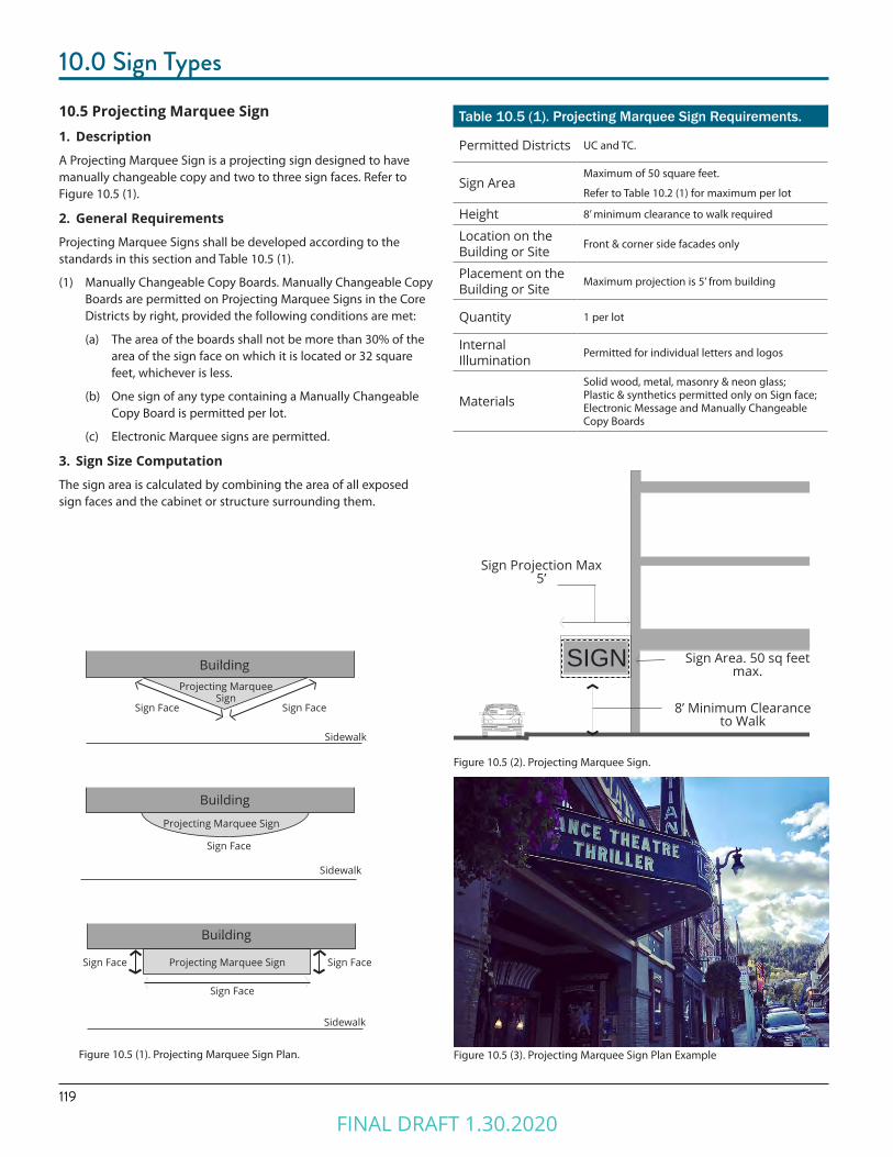
119
10.0 Sign Types
10.5 Projecting Marquee Sign 1. Description
A Projecting Marquee Sign is a projecting sign designed to have manually changeable copy and two to three sign faces. Refer to Figure 10.5 (1).
2. General Requirements
Projecting Marquee Signs shall be developed according to the standards in this section and Table 10.5 (1).
(1) Manually Changeable Copy Boards. Manually Changeable Copy Boards are permitted on Projecting Marquee Signs in the Core Districts by right, provided the following conditions are met:
(a) The area of the boards shall not be more than 30% of the area of the sign face on which it is located or 32 square feet, whichever is less.
(b) One sign of any type containing a Manually Changeable Copy Board is permitted per lot.
(c) Electronic Marquee signs are permitted.
3. Sign Size Computation
The sign area is calculated by combining the area of all exposed sign faces and the cabinet or structure surrounding them.
Table 10.5 (1). Projecting Marquee Sign Requirements.
Permitted Districts UC and TC.
Sign AreaMaximum of 50 square feet.
Refer to Table 10.2 (1) for maximum per lot
Height 8’ minimum clearance to walk required
Location on the Building or Site Front & corner side facades only
Placement on the Building or Site Maximum projection is 5’ from building
Quantity 1 per lot
Internal Illumination Permitted for individual letters and logos
MaterialsSolid wood, metal, masonry & neon glass; Plastic & synthetics permitted only on Sign face; Electronic Message and Manually Changeable Copy Boards
Figure 10.5 (3). Projecting Marquee Sign Plan Example
Figure 10.5 (2). Projecting Marquee Sign.
8’ Minimum Clearance to Walk
Sign Area. 50 sq feet max.
SIGN
Sign Projection Max 5’
Building
Projecting Marquee Sign Sign FaceSign Face
Sign Face
Sidewalk
Projecting Marquee Sign
Building
Sign Face
Sidewalk
BuildingProjecting Marquee
SignSign FaceSign Face
Sidewalk
Figure 10.5 (1). Projecting Marquee Sign Plan.
FINAL DRAFT 1.30.2020

12010.0 Sign Types
Figure 10.6 (2). Awning Sign. Figure 10.6 (3). Awning Sign Example
10.6 Awning Sign1. Description
A sign that is mounted or otherwise applied on or attached to an awning or canopy. Refer to Figures 10.6 (1), 10.6 (2), and 10.6 (3).
2. General Requirements
Awning Signs shall be developed according to the standards in Table 10.6 (1).
3. Sign Size Computation
The area of an Awning Sign is calculated by drawing the smallest possible square or rectangle around the largest letters and/or elements of the sign portion of the awning, as is illustrated in Figure 10.6 (2).
Table 10.6 (1). Awning Sign Requirements.Permitted Districts All districts
Sign AreaUp to 50% of the awning may be used for Signage; Refer to Table 10.2 (1) for maximum per lot
Height 8’ minimum clearance to walk required
Location on the Building or Site Permitted on all facades
Placement on the Building or Site
Maximum projection from building is 7’ from building; Shall not project closer than 2’ from back of curb;
Quantity1 per tenant per street frontage; 1 per tenant per side or rear facade on a parking lot
Internal Illumination Not permitted
Materials Cloth, canvas, metal, or wood; All supports shall be made of metal or wood
8’ Minimum Clearance to
Walk
Sign Projection Max 7’
Figure 10.6 (1). Measuring Awning Signs.
Sign Area
Awning Sign
FINAL DRAFT 1.30.2020

121
10.0 Sign Types
10.7 Canopy-Mounted Sign1. Description
A sign with individual alphanumeric characters and/or logos that are mounted on top of a permanent canopy. Refer to Figures 10.7 (1), 10.7 (2), and 10.7 (3).
2. General Requirements
Canopy-Mounted Signs shall be developed according to the standards in Table 10.7 (1).
3. Sign Size Computation
The area of a Canopy-Mounted Sign is calculated by drawing the smallest possible square or rectangle around the largest letters and/or elements of the sign portion of the Canopy-Mounted Roof Sign, as is illustrated in Figure 10.7 (2).
Table 10.7 (1). Canopy-Mounted Sign Requirements.Permitted Districts All districts
Sign AreaMaximum 50 square feet.
Refer to Table 10.2 (1) for maximum per lot
Height 2’ maximum letter or element height above roof line of the canopy
Location on the Building or Site
Permitted on all facades; not intended for the roof of the building
Placement on the Building or Site
Shall not project beyond the front edge of the canopy;
Quantity1 per tenant per public ROW frontage; 1 per tenant per side or rear facade on a parking lot
Internal Illumination Permitted for individual letters and logos
MaterialsSolid wood, metal, & neon glass; Plastic & synthetics permitted only as separate alphanumeric characters or logos
Figure 10.7 (3). Canopy-Mounted Sign Example.
Figure 10.7 (1). Measuring Canopy-Mounted Signs.
CANOPY-MOUNTED SIGN
Sign Area
Figure 10.7 (2). Canopy-Mounted Sign.
2’ Maximum
Height
FINAL DRAFT 1.30.2020
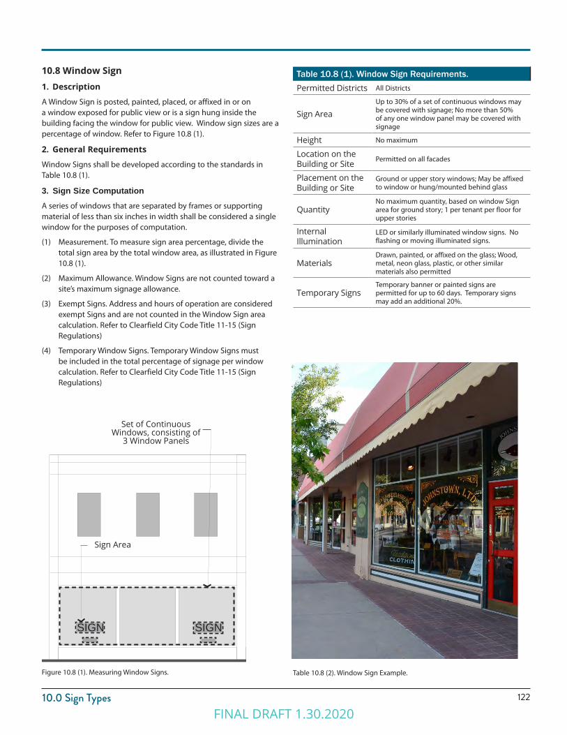
12210.0 Sign Types
Figure 10.8 (1). Measuring Window Signs. Table 10.8 (2). Window Sign Example.
10.8 Window Sign1. Description
A Window Sign is posted, painted, placed, or affixed in or on a window exposed for public view or is a sign hung inside the building facing the window for public view. Window sign sizes are a percentage of window. Refer to Figure 10.8 (1).
2. General Requirements
Window Signs shall be developed according to the standards in Table 10.8 (1).
3. Sign Size ComputationA series of windows that are separated by frames or supporting material of less than six inches in width shall be considered a single window for the purposes of computation.
(1) Measurement. To measure sign area percentage, divide the total sign area by the total window area, as illustrated in Figure 10.8 (1).
(2) Maximum Allowance. Window Signs are not counted toward a site’s maximum signage allowance.
(3) Exempt Signs. Address and hours of operation are considered exempt Signs and are not counted in the Window Sign area calculation. Refer to Clearfield City Code Title 11-15 (Sign Regulations)
(4) Temporary Window Signs. Temporary Window Signs must be included in the total percentage of signage per window calculation. Refer to Clearfield City Code Title 11-15 (Sign Regulations)
Table 10.8 (1). Window Sign Requirements.Permitted Districts All Districts
Sign AreaUp to 30% of a set of continuous windows may be covered with signage; No more than 50% of any one window panel may be covered with signage
Height No maximum
Location on the Building or Site Permitted on all facades
Placement on the Building or Site
Ground or upper story windows; May be affixed to window or hung/mounted behind glass
QuantityNo maximum quantity, based on window Sign area for ground story; 1 per tenant per floor for upper stories
Internal Illumination
LED or similarly illuminated window signs. No flashing or moving illuminated signs.
MaterialsDrawn, painted, or affixed on the glass; Wood, metal, neon glass, plastic, or other similar materials also permitted
Temporary SignsTemporary banner or painted signs are permitted for up to 60 days. Temporary signs may add an additional 20%.
Set of Continuous Windows, consisting of
3 Window Panels
SIGN SIGN
Sign Area
FINAL DRAFT 1.30.2020
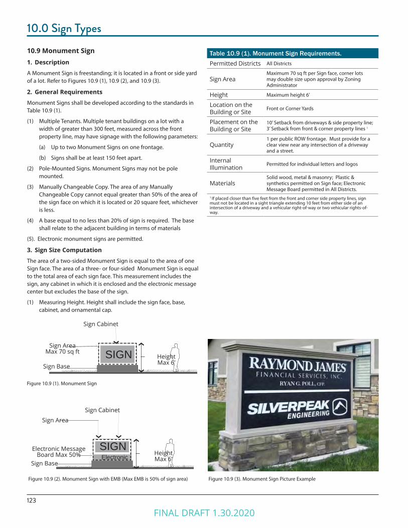
123
10.0 Sign Types
10.9 Monument Sign1. Description
A Monument Sign is freestanding; it is located in a front or side yard of a lot. Refer to Figures 10.9 (1), 10.9 (2), and 10.9 (3).
2. General Requirements
Monument Signs shall be developed according to the standards in Table 10.9 (1).
(1) Multiple Tenants. Multiple tenant buildings on a lot with a width of greater than 300 feet, measured across the front property line, may have signage with the following parameters:
(a) Up to two Monument Signs on one frontage.
(b) Signs shall be at least 150 feet apart.
(2) Pole-Mounted Signs. Monument Signs may not be pole mounted.
(3) Manually Changeable Copy. The area of any Manually Changeable Copy cannot equal greater than 50% of the area of the sign face on which it is located or 20 square feet, whichever is less.
(4) A base equal to no less than 20% of sign is required. The base shall relate to the adjacent building in terms of materials
(5). Electronic monument signs are permitted.
3. Sign Size Computation
The area of a two-sided Monument Sign is equal to the area of one Sign face. The area of a three- or four-sided Monument Sign is equal to the total area of each sign face. This measurement includes the sign, any cabinet in which it is enclosed and the electronic message center but excludes the base of the sign.
(1) Measuring Height. Height shall include the sign face, base, cabinet, and ornamental cap.
Table 10.9 (1). Monument Sign Requirements.Permitted Districts All Districts
Sign AreaMaximum 70 sq ft per Sign face, corner lots may double size upon approval by Zoning Administrator
Height Maximum height 6’
Location on the Building or Site Front or Corner Yards
Placement on the Building or Site
10’ Setback from driveways & side property line; 3’ Setback from front & corner property lines 1
Quantity1 per public ROW frontage. Must provide for a clear view near any intersection of a driveway and a street.
Internal Illumination Permitted for individual letters and logos
MaterialsSolid wood, metal & masonry; Plastic & synthetics permitted on Sign face; Electronic Message Board permitted in All Districts.
1 If placed closer than five feet from the front and corner side property lines, sign must not be located in a sight triangle extending 10 feet from either side of an intersection of a driveway and a vehicular right-of-way or two vehicular rights-of-way.
Figure 10.9 (2). Monument Sign with EMB (Max EMB is 50% of sign area) Figure 10.9 (3). Monument Sign Picture Example
Figure 10.9 (1). Monument Sign
SIGNSign Area
Max 70 sq ftHeightMax 6’Sign Base
Sign Cabinet
SIGN
Sign Area
HeightMax 6’
Sign BaseElectronic
Electronic MessageBoard Max 50%
Sign Cabinet
FINAL DRAFT 1.30.2020
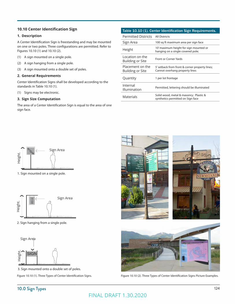
12410.0 Sign Types
10.10 Center Identification Sign1. Description
A Center Identification Sign is freestanding and may be mounted on one or two poles. Three configurations are permitted. Refer to Figures 10.10 (1) and 10.10 (2).
(1) A sign mounted on a single pole.
(2) A sign hanging from a single pole.
(3) A sign mounted onto a double set of poles.
2. General Requirements
Center Identification Signs shall be developed according to the standards in Table 10.10 (1).
(1) Signs may be electronic.
3. Sign Size Computation
The area of a Center Identification Sign is equal to the area of one sign face.
Table 10.10 (1). Center Identification Sign Requirements.Permitted Districts All Districts
Sign Area 100 sq ft maximum area per sign face
Height 10’ maximum height for sign mounted or hanging on a single covered pole;
Location on the Building or Site Front or Corner Yards
Placement on the Building or Site
5’ setback from front & corner property lines; Cannot overhang property lines
Quantity 1 per lot frontage
Internal Illumination Permitted, lettering should be illuminated
Materials Solid wood, metal & masonry; Plastic & synthetics permitted on Sign face
Figure 10.10 (1). Three Types of Center Identification Signs.
3. Sign mounted onto a double set of poles.
Sign Area
Hei
ght.
SIGN
Hei
ght.
1. Sign mounted on a single pole.
Sign AreaSIGN
Hei
ght.
Sign Area
2. Sign hanging from a single pole.
SIGN
Figure 10.10 (2). Three Types of Center Identification Signs Picture Examples.
FINAL DRAFT 1.30.2020

FINAL DRAFT 1.30.2020

Chapter 11.0ADMINISTRATION
FINAL DRAFT 1.30.2020
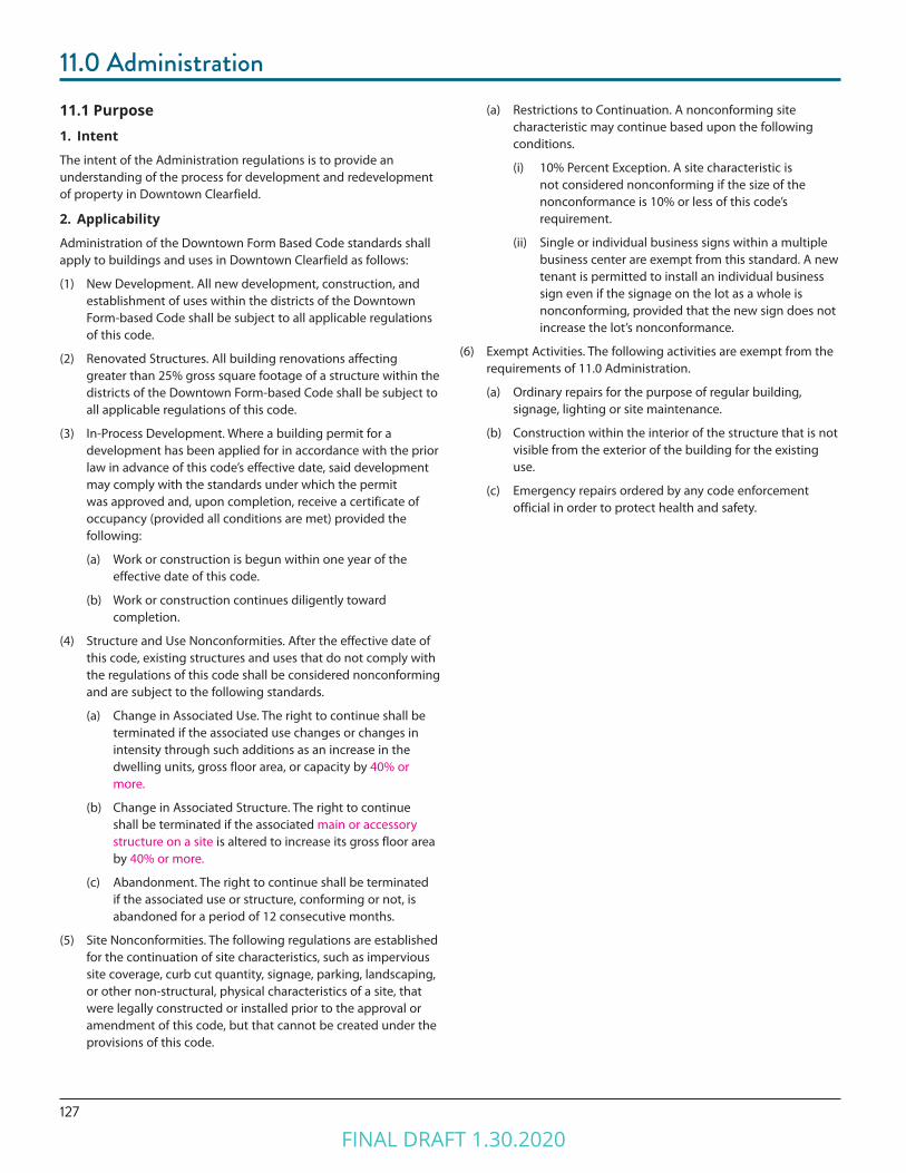
127
11.0 Administration11.1 Purpose1. Intent
The intent of the Administration regulations is to provide an understanding of the process for development and redevelopment of property in Downtown Clearfield.
2. Applicability
Administration of the Downtown Form Based Code standards shall apply to buildings and uses in Downtown Clearfield as follows:
(1) New Development. All new development, construction, and establishment of uses within the districts of the Downtown Form-based Code shall be subject to all applicable regulations of this code.
(2) Renovated Structures. All building renovations affecting greater than 25% gross square footage of a structure within the districts of the Downtown Form-based Code shall be subject to all applicable regulations of this code.
(3) In-Process Development. Where a building permit for a development has been applied for in accordance with the prior law in advance of this code’s effective date, said development may comply with the standards under which the permit was approved and, upon completion, receive a certificate of occupancy (provided all conditions are met) provided the following:
(a) Work or construction is begun within one year of the effective date of this code.
(b) Work or construction continues diligently toward completion.
(4) Structure and Use Nonconformities. After the effective date of this code, existing structures and uses that do not comply with the regulations of this code shall be considered nonconforming and are subject to the following standards.
(a) Change in Associated Use. The right to continue shall be terminated if the associated use changes or changes in intensity through such additions as an increase in the dwelling units, gross floor area, or capacity by 40% or more.
(b) Change in Associated Structure. The right to continue shall be terminated if the associated main or accessory structure on a site is altered to increase its gross floor area by 40% or more.
(c) Abandonment. The right to continue shall be terminated if the associated use or structure, conforming or not, is abandoned for a period of 12 consecutive months.
(5) Site Nonconformities. The following regulations are established for the continuation of site characteristics, such as impervious site coverage, curb cut quantity, signage, parking, landscaping, or other non-structural, physical characteristics of a site, that were legally constructed or installed prior to the approval or amendment of this code, but that cannot be created under the provisions of this code.
(a) Restrictions to Continuation. A nonconforming site characteristic may continue based upon the following conditions.
(i) 10% Percent Exception. A site characteristic is not considered nonconforming if the size of the nonconformance is 10% or less of this code’s requirement.
(ii) Single or individual business signs within a multiple business center are exempt from this standard. A new tenant is permitted to install an individual business sign even if the signage on the lot as a whole is nonconforming, provided that the new sign does not increase the lot’s nonconformance.
(6) Exempt Activities. The following activities are exempt from the requirements of 11.0 Administration.
(a) Ordinary repairs for the purpose of regular building, signage, lighting or site maintenance.
(b) Construction within the interior of the structure that is not visible from the exterior of the building for the existing use.
(c) Emergency repairs ordered by any code enforcement official in order to protect health and safety.
FINAL DRAFT 1.30.2020
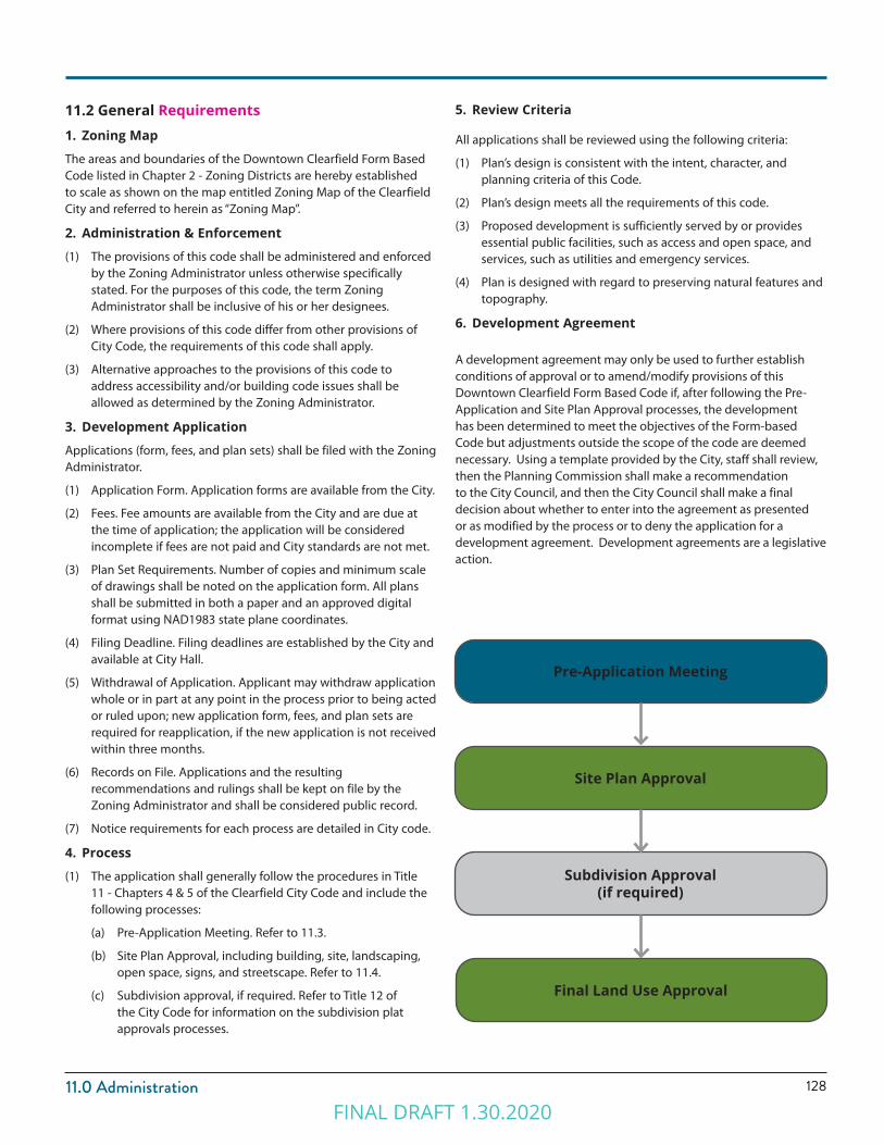
12811.0 Administration
11.2 General Requirements1. Zoning Map
The areas and boundaries of the Downtown Clearfield Form Based Code listed in Chapter 2 - Zoning Districts are hereby established to scale as shown on the map entitled Zoning Map of the Clearfield City and referred to herein as “Zoning Map”.
2. Administration & Enforcement
(1) The provisions of this code shall be administered and enforced by the Zoning Administrator unless otherwise specifically stated. For the purposes of this code, the term Zoning Administrator shall be inclusive of his or her designees.
(2) Where provisions of this code differ from other provisions of City Code, the requirements of this code shall apply.
(3) Alternative approaches to the provisions of this code to address accessibility and/or building code issues shall be allowed as determined by the Zoning Administrator.
3. Development Application
Applications (form, fees, and plan sets) shall be filed with the Zoning Administrator.
(1) Application Form. Application forms are available from the City.
(2) Fees. Fee amounts are available from the City and are due at the time of application; the application will be considered incomplete if fees are not paid and City standards are not met.
(3) Plan Set Requirements. Number of copies and minimum scale of drawings shall be noted on the application form. All plans shall be submitted in both a paper and an approved digital format using NAD1983 state plane coordinates.
(4) Filing Deadline. Filing deadlines are established by the City and available at City Hall.
(5) Withdrawal of Application. Applicant may withdraw application whole or in part at any point in the process prior to being acted or ruled upon; new application form, fees, and plan sets are required for reapplication, if the new application is not received within three months.
(6) Records on File. Applications and the resulting recommendations and rulings shall be kept on file by the Zoning Administrator and shall be considered public record.
(7) Notice requirements for each process are detailed in City code.
4. Process
(1) The application shall generally follow the procedures in Title 11 - Chapters 4 & 5 of the Clearfield City Code and include the following processes:
(a) Pre-Application Meeting. Refer to 11.3.
(b) Site Plan Approval, including building, site, landscaping, open space, signs, and streetscape. Refer to 11.4.
(c) Subdivision approval, if required. Refer to Title 12 of the City Code for information on the subdivision plat approvals processes.
5. Review Criteria
All applications shall be reviewed using the following criteria:
(1) Plan’s design is consistent with the intent, character, and planning criteria of this Code.
(2) Plan’s design meets all the requirements of this code.
(3) Proposed development is sufficiently served by or provides essential public facilities, such as access and open space, and services, such as utilities and emergency services.
(4) Plan is designed with regard to preserving natural features and topography.
6. Development Agreement
A development agreement may only be used to further establish conditions of approval or to amend/modify provisions of this Downtown Clearfield Form Based Code if, after following the Pre-Application and Site Plan Approval processes, the development has been determined to meet the objectives of the Form-based Code but adjustments outside the scope of the code are deemed necessary. Using a template provided by the City, staff shall review, then the Planning Commission shall make a recommendation to the City Council, and then the City Council shall make a final decision about whether to enter into the agreement as presented or as modified by the process or to deny the application for a development agreement. Development agreements are a legislative action.
Pre-Application Meeting
Site Plan Approval
Subdivision Approval (if required)
Final Land Use Approval
FINAL DRAFT 1.30.2020

129
11.0 Administration11.3 Pre-Application Meeting1. Intent
To provide the applicant an opportunity to receive the advice and assistance of the professional staff before preparing formal plans and making an official application.
2. Eligible Applicant
Applicant must schedule a pre-Application meeting prior to submitting an application for Site Plan Approval.
3. Application
Applicant shall submit the following.
(1) Sketch Plan. A sketch plan or plans shall detail the proposal, including the following.
(a) General rough layout of block, and lots, with types of streets and Open Space Type noted.
(b) Existing conditions such as topography, water bodies, aerial photograph, and flood plain.
(c) Approximate distribution of hard surface, landscaping, building types, and uses.
(d) Anticipated method of achieving parking requirements.
(e) Site survey if available.
(2) Exceptions. A description of any desired Exception.
4. Pre-Application Meeting Timeline
Staff shall meet with the Applicant to discuss the proposed plan within 30 days of receipt of the pre-Application meeting request.
11.4 Site Plan Approval1. Intent
To establish a process that allows the City staff and Planning Commission to administratively review development and redevelopment of sites and Building Types, uses, and other site requirements within the Downtown Clearfield to ensure that the full standards and intent of this code are met.
(1) The Staff Review shall include members of local/district agencies, including the North Davis Fire District, and a representative of each affected City Department.
2. Eligible Applicant
Applicant shall apply for Site Plan Approval for all projects within the Downtown Clearfield.
3. Application
The following information shall constitute a complete application. Application shall be submitted digitally and in paper format as required by the City.
(1) Complete Application Items, Form, and Applicable Fees.
(2) Applicant shall submit the following items in compliance with the requirements of the Chapters of this Downtown Form Based Code and Clearfield City Code as applicable. All maps and plans shall include date of preparation, north arrow, and scale.
(a) Site Location Map, Legal Description/Limits of Plan.
(b) Survey Plat. Dimensions of property lines, easements, rights-of-way.
(c) Development Boundaries and Proposed Phasing, if applicable.
(d) Existing Conditions Plan/Demolition Plan. Existing on-site and adjacent off-site structures, streets, utilities, easements, pavement noted either on an aerial photograph or site survey.
(e) Existing Natural Conditions Survey. Existing topography, vegetation, drainageways, floodplain/way, or other unique features either on an aerial photograph or site survey.
(f ) Site Plan. A Site Plan delineating all proposed structures and surfaces, including parking, pavement, decks, patios, landscape, and retaining walls.
(g) Building Plan(s). Floor plans for all buildings illustrating compliance with the requirements of 6.0 Building Types.
(h) Table of Uses. A table of uses is required on the Building Plan delineating locations and square footages of categories of uses and illustrating compliance with 3.0 Uses and 6.0 Building Types.
(i) Building Elevations. Building elevations of all facades, rendered to illustrate compliance with the requirements of 6.0 Building Types.
FINAL DRAFT 1.30.2020
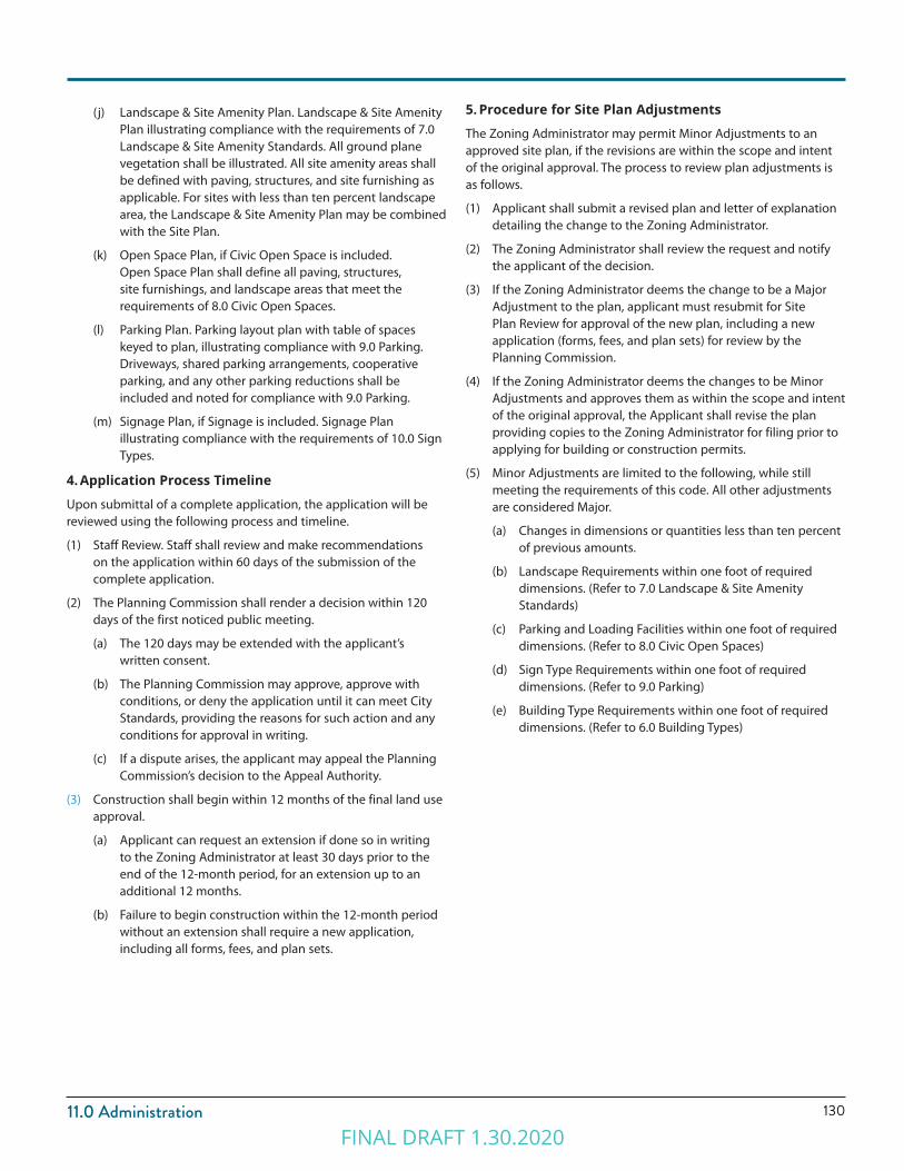
13011.0 Administration
(j) Landscape & Site Amenity Plan. Landscape & Site Amenity Plan illustrating compliance with the requirements of 7.0 Landscape & Site Amenity Standards. All ground plane vegetation shall be illustrated. All site amenity areas shall be defined with paving, structures, and site furnishing as applicable. For sites with less than ten percent landscape area, the Landscape & Site Amenity Plan may be combined with the Site Plan.
(k) Open Space Plan, if Civic Open Space is included. Open Space Plan shall define all paving, structures, site furnishings, and landscape areas that meet the requirements of 8.0 Civic Open Spaces.
(l) Parking Plan. Parking layout plan with table of spaces keyed to plan, illustrating compliance with 9.0 Parking. Driveways, shared parking arrangements, cooperative parking, and any other parking reductions shall be included and noted for compliance with 9.0 Parking.
(m) Signage Plan, if Signage is included. Signage Plan illustrating compliance with the requirements of 10.0 Sign Types.
4. Application Process Timeline
Upon submittal of a complete application, the application will be reviewed using the following process and timeline.
(1) Staff Review. Staff shall review and make recommendations on the application within 60 days of the submission of the complete application.
(2) The Planning Commission shall render a decision within 120 days of the first noticed public meeting.
(a) The 120 days may be extended with the applicant’s written consent.
(b) The Planning Commission may approve, approve with conditions, or deny the application until it can meet City Standards, providing the reasons for such action and any conditions for approval in writing.
(c) If a dispute arises, the applicant may appeal the Planning Commission’s decision to the Appeal Authority.
(3) Construction shall begin within 12 months of the final land use approval.
(a) Applicant can request an extension if done so in writing to the Zoning Administrator at least 30 days prior to the end of the 12-month period, for an extension up to an additional 12 months.
(b) Failure to begin construction within the 12-month period without an extension shall require a new application, including all forms, fees, and plan sets.
5. Procedure for Site Plan Adjustments
The Zoning Administrator may permit Minor Adjustments to an approved site plan, if the revisions are within the scope and intent of the original approval. The process to review plan adjustments is as follows.
(1) Applicant shall submit a revised plan and letter of explanation detailing the change to the Zoning Administrator.
(2) The Zoning Administrator shall review the request and notify the applicant of the decision.
(3) If the Zoning Administrator deems the change to be a Major Adjustment to the plan, applicant must resubmit for Site Plan Review for approval of the new plan, including a new application (forms, fees, and plan sets) for review by the Planning Commission.
(4) If the Zoning Administrator deems the changes to be Minor Adjustments and approves them as within the scope and intent of the original approval, the Applicant shall revise the plan providing copies to the Zoning Administrator for filing prior to applying for building or construction permits.
(5) Minor Adjustments are limited to the following, while still meeting the requirements of this code. All other adjustments are considered Major.
(a) Changes in dimensions or quantities less than ten percent of previous amounts.
(b) Landscape Requirements within one foot of required dimensions. (Refer to 7.0 Landscape & Site Amenity Standards)
(c) Parking and Loading Facilities within one foot of required dimensions. (Refer to 8.0 Civic Open Spaces)
(d) Sign Type Requirements within one foot of required dimensions. (Refer to 9.0 Parking)
(e) Building Type Requirements within one foot of required dimensions. (Refer to 6.0 Building Types)
FINAL DRAFT 1.30.2020
131
11.0 Administration
Complete Application Submitted
Pre-Application Meeting
Site Plan Approval Process
Staff Review(Including representatives of regulatory agencies and City Departments)
Staff Recommendation to Planning Commission(Within 60 Days of Receiving Complete Application)
Planning Commission Decision(Within 120 Days of First Noticed Public Meeting)
Planning Commission Review
Approve with Conditions Approve
Construction Begins (Within 12 months of Approval)
Deny
Submit New Application
Petition Appeal Authority
ApproveDeny
Subdivision Approval (if required)
Final Land Use Approval Granted
FINAL DRAFT 1.30.2020

13211.0 Administration
11.5 Definitions
1. Graphics
The graphics, tables, and text utilized throughout this code are regulatory. In case of a conflict, text shall control over tables and tables shall control over graphics.
2. Defined Terms
For the purposes of this code, the following terms shall have the following meanings.
Animal. All non-human members of the animal kingdom, including domestic and livestock species.
Animal Boarding. The commercial keeping of animals overnight: including kenneling and boarding.
Applicant. The owner of a subject property or the authorized representative of the owner on which a land development application is being made.
Block. The aggregate of lots, passages, lanes, and alleys bounded on all sides by streets.
Block Depth. A block measurement that is the horizontal distance between the front property line on a block face and the front property line of the parallel or approximately parallel block face.
Block Ends. The lots located on the end of a block; these lots are often larger than the lots in the interior of the block or those at the opposite end of the block and can be located on a more intense street type. They are typically more suitable for more intensive development, such as multiple family or mixed-use development.
Block Face. The aggregate of all the building facades on one side of a block.
Block Length. A block measurement that is the horizontal distance along the front property lines of the lots comprising the block.
Build-to-Zone. An area in which the front or corner side facade of a building shall be placed; it may or may not be located directly adjacent to a property line. The zone dictates the minimum and maximum distance a structure may be placed from a property line.
Building Type. A structure defined by the combination of configuration, form, and function.
Church. A building or structure, or portion thereof, used for the performance of religious services. A portion of the building or structure may be used for residential dwelling space for an on-site caretaker or a clergy of the church.
Courtyard. An outdoor area enclosed by a building on at least two sides and is open to the sky.
Coverage, Building. The percentage of a lot developed with a principal or accessory structure.
Coverage, Impervious Site. The percentage of a lot developed with principal or accessory structures and impervious surfaces, such as driveways, sidewalks, and patios.
Craft Industry. A use involving small scale manufacturing, production, assembly, and/or repair with little to no noxious by-products that includes a showroom or small retail outlet.
Critical Root Zone. Also referred to as drip line. The area of soil and roots within the radius beneath the tree’s canopy, within the dripline, or within a circular area of soil and roots with a radius out from the trunk a distance of 1.5 feet for every inch of the tree’s width (measured at 4.5 feet above the mean grade of the tree’s trunk, noted as diameter breast height or DBH throughout this code).
Dedication. The intentional appropriation of land by the owner to the City for public use and/or ownership.
Density. The number of dwelling units located in an area of land, usually denoted as units per acre.
Dwelling Unit. A room or group of connected rooms that include facilities for living, sleeping, cooking, and eating that are arranged, designed, or intended to be used as living quarters for one family, whether owner occupied, rented, or leased.
Easement. A legal interest in land, granted by the owner to another person or entity, which allows for the use of all or a portion of the owner’s land for such purposes as access or placement of utilities.
Eave. The edge of a pitched roof; it typically overhangs beyond the side of a building.
Entrance Type. The permitted treatment types of the ground floor Facade of a Building Type. Refer to 6.0 Building Types for more information and a list of permitted Entrance Types.
Expression Line. An architectural feature. A decorative, three-dimensional, linear element, horizontal or vertical, protruding or indented at least two inches from the exterior facade or a building typically utilized to delineate floors or stories of a building.
Facade. The exterior face of a building, including but not limited to the wall, windows, windowsills, doorways, and design elements such as expression lines. The front facade is any building face adjacent to the front property line.
Family. Family as defined by “Federal Law”.
Grade. The average level of the finished surface of the ground story adjacent to the exterior walls of a building.
Gross Floor Area. The sum of all areas of a building, including accessory storage areas or closets within sales spaces, working spaces, or living spaces and any basement floor area used for retailing activities, the production or processing or goods, or business offices. It shall not include attic space having headroom of seven feet or less and areas devoted primarily to storage, balconies, off-street parking and loading areas, enclosed porches, roof decks, roof gardens, or basement floor area other than specified above.
Impervious Surface. Also referred to as impervious material. Any hard surface, man-made area that does not absorb water, including building roofs, sidewalks, parking, driveways, and other paved surfaces.
FINAL DRAFT 1.30.2020

133
11.0 AdministrationLandscape Area. Area on a lot not dedicated to a structure, parking or loading facility, frontage buffer, side and rear buffer, or interior parking lot landscaping.
Lot. Also referred to as parcel. A plot of land intended to be separately owned, developed, or otherwise used as a unit.
Lot, Corner. A parcel of land abutting at least two vehicular rights-of-way, excluding an alley, at their intersection.
Lot, Flag. A parcel of land having its only access to the adjacent vehicular right-of-way, excluding an alley, through a narrow strip of land.
Lot, Interior. A parcel of land abutting a vehicular Right-of-Way, excluding an Alley, along one (1) Property Line; surrounded by Lots along the remaining Property Lines.
Lot, Through. Also referred to as a double frontage lot. An interior lot having frontage on two approximately parallel vehicular rights-of-way, excluding an alley.
Lot Area. The computed area contained within the property lines; it is typically denoted in square feet or acres.
Lot Depth. The smallest horizontal distance between the Front and Rear Property Lines measured approximately parallel to the Corner and/or Side Property Line.
Lot Frontage. The horizontal distance between the Side Property Lines, measured at the Front Property Lines.
Mullion. A vertical bar between the panes of glass in a window.
Nit. A unit of visible-light intensity, commonly used to specify the brightness of a cathode ray tube or liquid crystal display computer display. Measured by a luminance spectrometer.
Nonconformance. A structure, use, lot, or site characteristic that was legally constructed or operated prior to the effective date of or Amendment to this code, but that cannot be constructed, platted, or operated after the effective date of or Amendment to this code.
Occupied Space. Interior building space regularly occupied by the building users. It does not include storage areas, utility space, or parking.
Open Space Type. The permitted and regulated types of civic open spaces in this code. Refer to 8.0 Civic Open Space Types for more information and a list of the permitted types.
Open Water. A pond, lake, reservoir, or other water feature with the water surface fully exposed.
Owner. The legal or beneficial titleholder of land or holder of a written option or contract to purchase the land.
Pedestrian way. A pathway designed for use by pedestrians; it can be located mid-block allowing pedestrian movement from one street to another without traveling along the block’s perimeter.
Pervious Surface. Also referred to as pervious material. A material or surface that allows for the absorption of water into the ground or plant material, such as permeable pavers or a vegetated roof.
Plat. A map or chart of a division and/or combination of lots.
Primary Street. A street designated on the Street Hierarchy Map that receives priority over other streets in terms of setting front property lines and locating building entrances.
Property Line. Also referred to as lot line. A boundary line of a parcel of land or lot.
Property Line, Corner. A boundary of a lot that is approximately perpendicular to the front property line and is directly adjacent to a public Right-of-Way, other than an alley or railroad.
Property Line, Front. The boundary abutting a right-of-way, other than an Alley, from which the required setback or build-to zone is measured, with the following exceptions. (a) Corner and Through Lots that abut a Primary Street shall have the front property line on that Primary Street. (b) Corner and Through Lots that abut two Primary Streets or do not abut a Primary Street shall utilize the orientation of the two directly adjacent lots or shall have the front property line determined by the Zoning Administrator.
Property Line, Rear. The boundary of a lot that is approximately parallel to the front property line; this line separates lots from one another or separates a lot from an alley.
Property Line, Side. The boundary of a lot that is approximately perpendicular to the front and rear property lines; it is not adjacent to the public right-of-way.
Right-of-Way. Land dedicated or utilized for a Street Type, trail, pedestrian way, utility, railroad, or other similar purpose.
Roof Type. The detail at the top of a building that finishes a Facade,
Scale. The relative size of a building, street, sign, or other element of the built environment.
Semi-Pervious Surface. Also referred to as semi-pervious material. A material that allows for at least 40% absorption of water into the ground or plant material, such as pervious pavers, permeable asphalt and concrete, or gravel.
Setback. The horizontal distance from a property line inward, beyond which a structure may be placed. Structures or other impervious surfaces are not permitted within a setback, unless specifically permitted in this code.
Sign. An object, device, or structure used to advertise, identify, display, direct, or attract attention to an object, person, institution, organization, business, product, service, event, or location by such means as words, letters, figures, images, designs, symbols, or colors. Flags or emblems of any nation, state, city, or organization; works of art which in no way identify a product; and athletic field score boards are not considered signs.
Solar Reflectance Index (SRI). A measure of a constructed surface’s ability to reflect solar heat, as shown by a small temperature rise. The measure utilizes a scale from 0 to 100 and is defined so that a standard black surface is 0 and a standard white surface is 100. To calculate for a given material, obtain the reflectance value and emittance value for the material; calculate the
FINAL DRAFT 1.30.2020
13411.0 Administration
SRI according to ASTM E 1980-01 or the latest version.
Story. A habitable level within a building measured from finished floor to finished floor.
Story, Ground. Also referred to as ground floor. The first floor of a building that is level to or elevated above the finished grade on the front and corner facades, excluding basements or cellars.
Story, Half. A story either in the base of the building, partially below grade and partially above grade, or a story fully within the roof structure with transparency facing the street.
Story, Upper. Also referred to as upper floor. The floors located above the ground story of a building.
Street Face. The facade of a building that faces a public right-of-way.
Street Frontage. Also refer to lot frontage. The portion of a building or lot directly adjacent to a vehicular right-of-way.
Street Type. The permitted and regulated types of streets in this code. Refer to 5.0 Street & Streetscape Standards for more information and a list of the permitted Street Types.
Streetwall. The vertical plane created by building facades along a street. A continuous streetwall occurs when buildings are located in a row next to the sidewalk without vacant lots or significant setbacks.
Structure, Accessory. The general term for a subordinate structure detached from but located on the same Lot as the Principal Structure; it may or may not be inhabitable.
Structure, Principal. Also referred to as the principal building. A building that contains the dominant Use of the Lot. It is typically located toward the front of the lot in the front Build-to Zone or behind the Front Yard Setback.
Swale. A low lying, naturally planted area with gradual slopes that facilitate the transport, absorption, and/or filtration of stormwater.
Tree Canopy. The uppermost area of spreading branches and leaves of a tree.
Tree Canopy Coverage. The area of ground covered or shaded by a tree’s canopy, measured in square feet.
Use. Also referred to as land use. A purpose or activity that may occur within a building or a lot.
Use, Accessory. A use customarily, incidental, and subordinate to the principal use or structure and located on the same lot with such principal use or structure.
Use, Principal. The specific, primary purpose for which a lot or building is utilized.
Visible Basement. A half story partially below grade and partially exposed above with required transparency on the street facade.
Water Body. A body of water, such as a river, pond, or lake that may be man-made or naturally occurring.
Yard. The space on a lot that is unoccupied and unobstructed from the ground to the sky by the principal structure. Lots without a structure do not have yard designations.
Yard, Corner Side. A yard extending from the corner side building facade along a corner side property line between the front yard and rear property line.
Yard, Front. A yard extending from the front facade of the principal structure along the full length of the front property line, between the side property lines or side and corner side property lines.
Yard, Rear. A yard extending from the rear building facade along the rear property line between the side yards or, on a corner lot, the corner side and side yards.
Yard, Side. A yard extending from the side building facade along a side property line between the front yard and rear property line.
Zoning District. A designation given to each lot within the city that dictates the standards for development on that Lot. Refer to 2.0 Zoning Districts for more information and a list of permitted Zoning Districts in Downtown Clearfield.
FINAL DRAFT 1.30.2020

FINAL DRAFT 1.30.2020
Streetscape SpecificationsAppendix A

1
Appendix A: Streetscape Specifications
FINAL DRAFT 01.30.2020
Urban Core Arterial Streetscape SpecificationsApplication
Permitted Districts UC, UR, CV
Permitted Street Types Urban Core Arterial
Design Details
Street LightingDouble Acorn - minimum 60’ spacing; maximum 90’ spacingLocation: Aligned on center of Street Trees
Tree Grates Chinook 6’ x 6’; optional 6’ x 6’ expanders on each side
Street Trees Spacing: Minimum 40’; Maximum 60’
Benches4 or 6 foot bench if perpendicular to street6 or 8 foot bench if parallel
Pavers
Concrete pavers, Harvest Blend Holland Pavers4 inches by 8 inches; approximately 1/2 inch joint
Design Requirements
Pedestrian FacilitiesMinimum 8’ widthConcrete surface - 6.5 to 8 feetPavers - 1.5 feet adjacent to tree grates
Street Buffer
Minimum 7.5’ widthConcrete surface - 6 feetPavers - 1.5 feet adjacent to curb and around tree grates
A.1: Urban Core Arterial Streetscape1. Intent
To provide an enhanced, identifiable streetscape for the core area of Downtown Clearfield.
2. Design Detail Specifications
For details on the streetscape design elements, refer to the individual specification pages in this Appendix.
Pedestrian Facilities
Minimum 8’ width
Street BufferMinimum 7.5’ width
Street Lights Aligned with Street
Trees
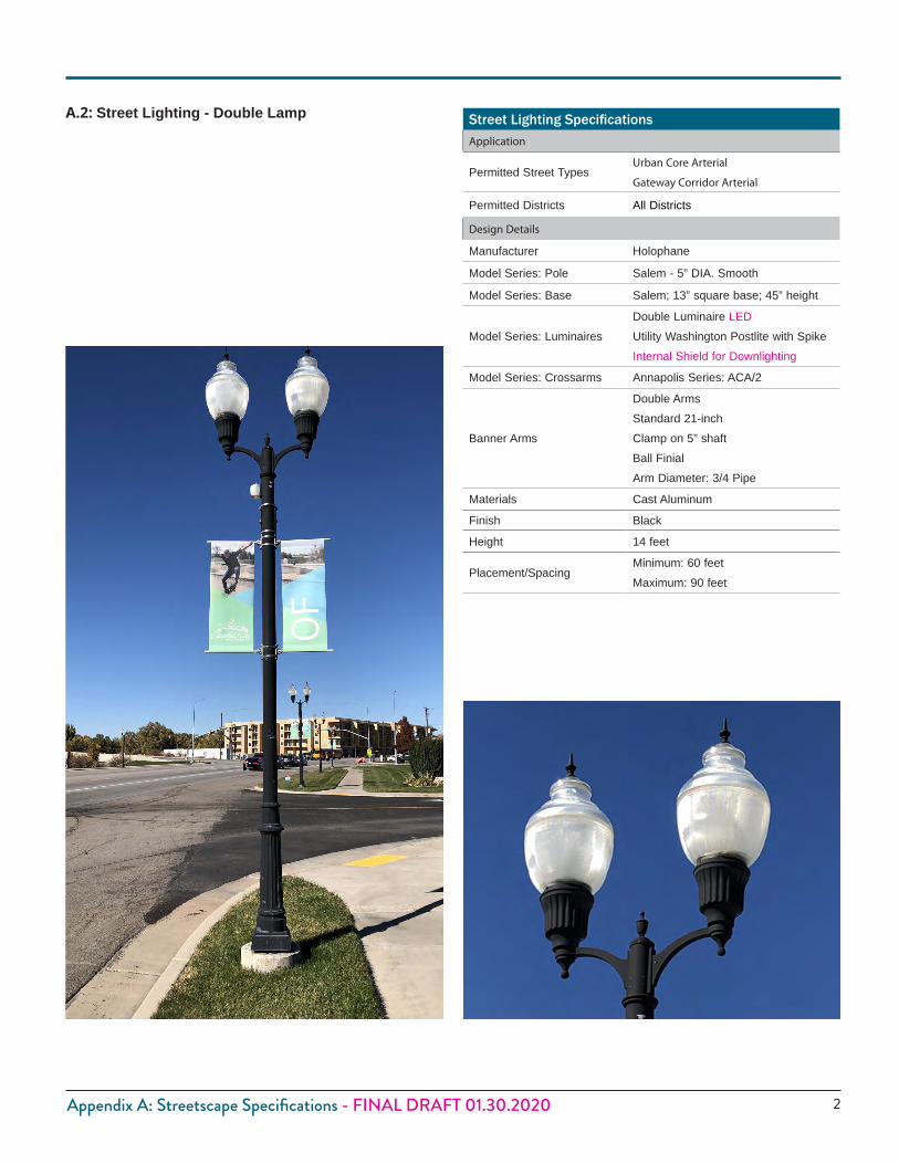
2Appendix A: Streetscape Specifications - FINAL DRAFT 01.30.2020
Street Lighting SpecificationsApplication
Permitted Street TypesUrban Core Arterial
Gateway Corridor Arterial
Permitted Districts All Districts
Design Details
Manufacturer Holophane
Model Series: Pole Salem - 5” DIA. Smooth
Model Series: Base Salem; 13” square base; 45” height
Model Series: LuminairesDouble Luminaire LEDUtility Washington Postlite with SpikeInternal Shield for Downlighting
Model Series: Crossarms Annapolis Series: ACA/2
Banner Arms
Double ArmsStandard 21-inchClamp on 5” shaftBall FinialArm Diameter: 3/4 Pipe
Materials Cast Aluminum
Finish Black
Height 14 feet
Placement/SpacingMinimum: 60 feetMaximum: 90 feet
A.2: Street Lighting - Double Lamp
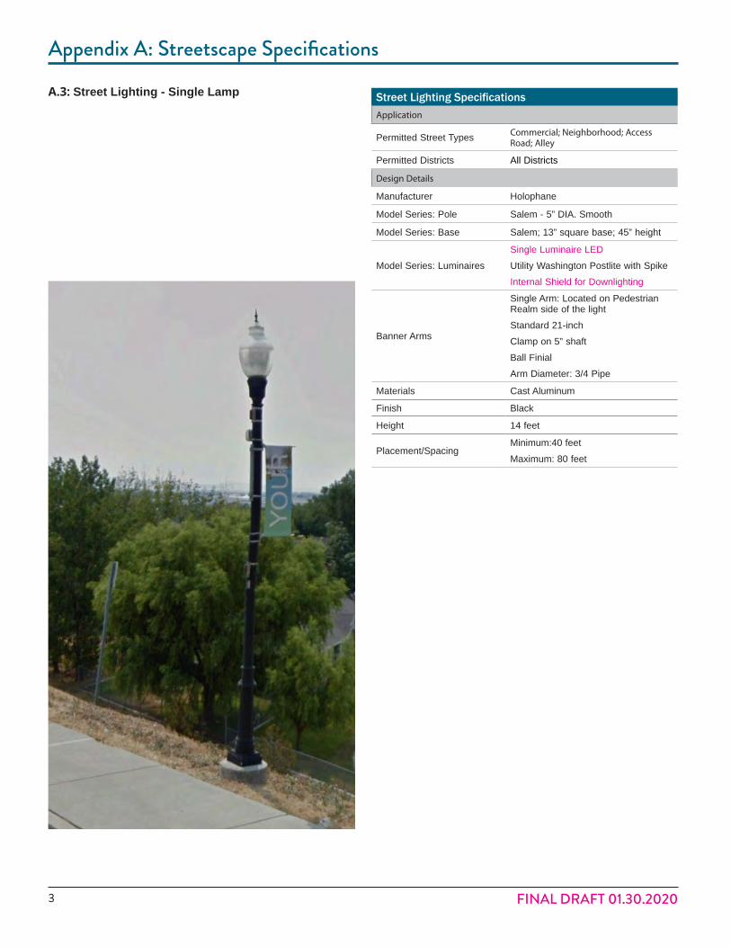
3
Appendix A: Streetscape Specifications
FINAL DRAFT 01.30.2020
Street Lighting SpecificationsApplication
Permitted Street Types Commercial; Neighborhood; Access Road; Alley
Permitted Districts All Districts
Design Details
Manufacturer Holophane
Model Series: Pole Salem - 5” DIA. Smooth
Model Series: Base Salem; 13” square base; 45” height
Model Series: LuminairesSingle Luminaire LEDUtility Washington Postlite with SpikeInternal Shield for Downlighting
Banner Arms
Single Arm: Located on Pedestrian Realm side of the lightStandard 21-inchClamp on 5” shaftBall FinialArm Diameter: 3/4 Pipe
Materials Cast Aluminum
Finish Black
Height 14 feet
Placement/SpacingMinimum:40 feetMaximum: 80 feet
A.3: Street Lighting - Single Lamp
© 2020 Google
© 2020 Google
© 2020 Google

4Appendix A: Streetscape Specifications - FINAL DRAFT 01.30.2020
Tree Grate SpecificationsApplication
Permitted Street Types Urban Core Arterial
Permitted Districts UC, UR, CV
Design Details
Manufacturer Urban Accessories
Model Series: Chinook
Materials Grey Iron
Finish Raw
Size 6’ square
A.4: Tree Grates
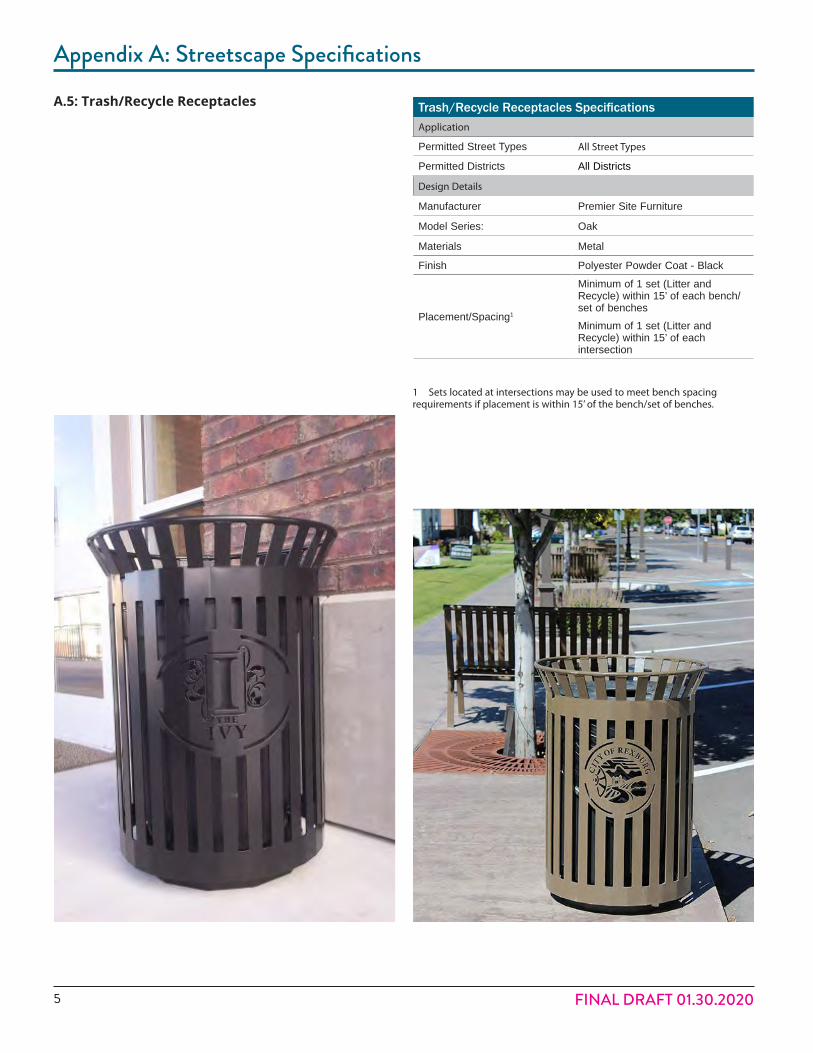
5
Appendix A: Streetscape Specifications
FINAL DRAFT 01.30.2020
Trash/Recycle Receptacles SpecificationsApplication
Permitted Street Types All Street Types
Permitted Districts All Districts
Design Details
Manufacturer Premier Site Furniture
Model Series: Oak
Materials Metal
Finish Polyester Powder Coat - Black
Placement/Spacing1
Minimum of 1 set (Litter and Recycle) within 15’ of each bench/set of benchesMinimum of 1 set (Litter and Recycle) within 15’ of each intersection
1 Sets located at intersections may be used to meet bench spacing requirements if placement is within 15’ of the bench/set of benches.
A.5: Trash/Recycle Receptacles

6Appendix A: Streetscape Specifications - FINAL DRAFT 01.30.2020
Benches SpecificationsApplication
Permitted Street Types All Street Types
Permitted Districts All Districts
Design Details
Manufacturer Premier Site Furniture
Model Series: Mountain Maple (with Back)
Materials Metal (Steel)
Finish Powder Coat - Black
Size 4 LF, 6 LF and/or 8 LF
Placement/Spacing Minimum 1 bench every 200 feet
A.6: Benches
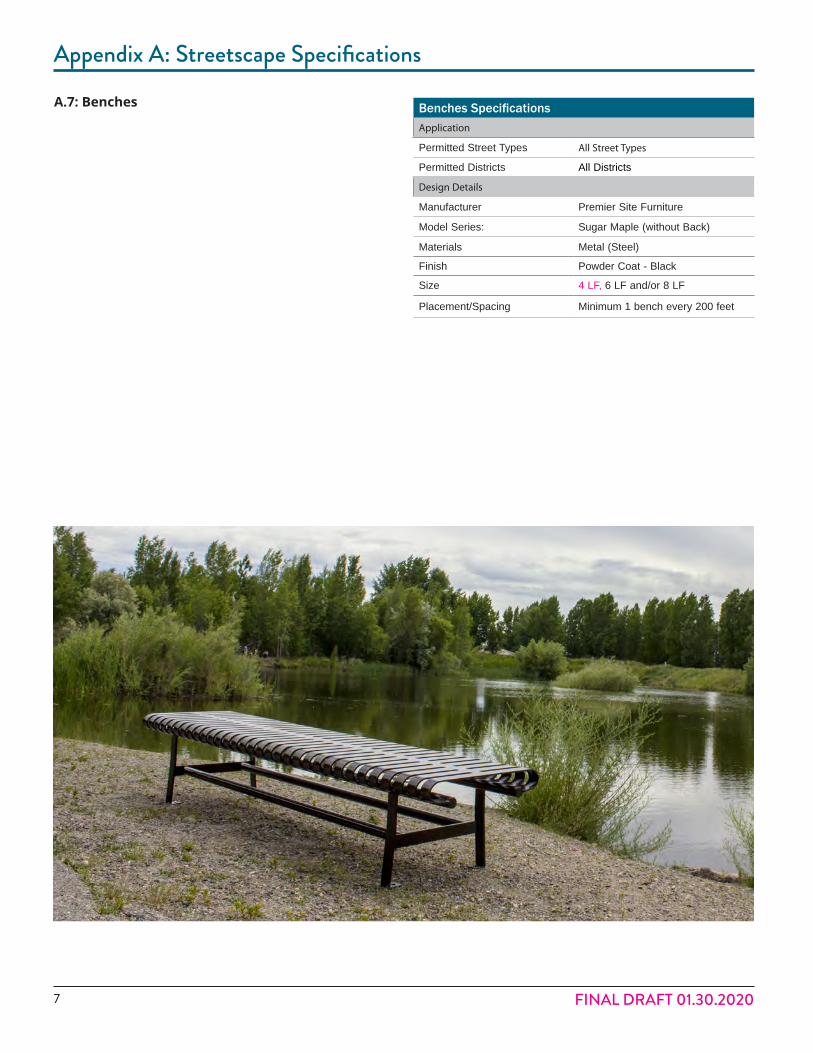
7
Appendix A: Streetscape Specifications
FINAL DRAFT 01.30.2020
Benches SpecificationsApplication
Permitted Street Types All Street Types
Permitted Districts All Districts
Design Details
Manufacturer Premier Site Furniture
Model Series: Sugar Maple (without Back)
Materials Metal (Steel)
Finish Powder Coat - Black
Size 4 LF, 6 LF and/or 8 LF
Placement/Spacing Minimum 1 bench every 200 feet
A.7: Benches
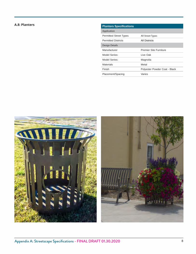
8Appendix A: Streetscape Specifications - FINAL DRAFT 01.30.2020
Planters SpecificationsApplication
Permitted Street Types All Street Types
Permitted Districts All Districts
Design Details
Manufacturer Premier Site Furniture
Model Series: Live Oak
Model Series: Magnolia
Materials Metal
Finish Polyester Powder Coat - Black
Placement/Spacing Varies
A.8: Planters

9
Appendix A: Streetscape Specifications
FINAL DRAFT 01.30.2020
Tree Grate SpecificationsApplication
Permitted Street Types Urban Core Arterial
Permitted Districts UC, UR, CV
Design Details
Manufacturer Urban Accessories
Model Series: Double Wave
Materials Grey Iron
Finish Raw
Size 6’ x 18” sections
A.9: Trench Grates