clearwater beach june 10-12, 2015 maximizing motor life with optimal ... · maximizing motor life...
TRANSCRIPT

Maximizing Motor Life withOptimal Protection and Source Transfer
Mining Electrical Maintenance & Safety Association2015 Technical Conference
6190-118th Avenue · Largo, Florida 33773-3724 U.S.A.PHONE (727) 544-2326 · FAX (727) 546-0121
Clearwater BeachJune 10-12, 2015

Presenter Contact Info
Wayne Hartmann is VP, Protection and Smart Grid Solutions forBeckwith Electric. He provides Customer and Industry linkage toBeckwith Electric’s solutions, as well as contributing expertise forapplication engineering, training and product development.
Wayne HartmannVP, Protection and Smart Grid Solutions
Beckwith Electric Company
904-238-3844
Before joining Beckwith Electric, Wayne performed in application, sales and marketing managementcapacities with PowerSecure, General Electric, Siemens Power T&D and Alstom T&D. During thecourse of Wayne's participation in the industry, his focus has been on the application of protection andcontrol systems for electrical generation, transmission, distribution, and distributed energy resources.
Wayne is very active in IEEE as a Senior Member serving as a Main Committee Member of the IEEEPower System Relaying Committee for 25 years. His IEEE tenure includes having chaired the RotatingMachinery Protection Subcommittee (’07-’10), contributing to numerous standards, guides,transactions, reports and tutorials, and teaching at the T&D Conference and various local PES andIAS chapters. He has authored and presented numerous technical papers and contributed to McGraw-Hill's “Standard Handbook of Power Plant Engineering, 2nd Ed.” 2

• Explore motor failure modes and causes
• Discuss motor protective relay applications
• Detail thermal issues and modeling
• Information needed to set a motor protection relay
• Special Considerations/Applications– Variable Frequency Drives– Motor Bus Transfer (Motor Source Transfer)
Our Session Today
3

A Motor Life Depends On…..
What you feed it
Quality of power• Voltage unbalance• Voltage level• Harmonics
Staying cool
High ambient, compromisedventilation
How onerous of a load
Pulsating load
Too great a load
Power Load
AmbientTemperatureand Cooling
4

What Fails?Per IEEE 2007 Survey
•Bearings (40 - 50%)
•Stator (25 - 35%)
•Rotor (<5%)
•Other Failures
Summary:
5

Motor Failure Modes
IEEE Recommended Practice for the Design of Reliable Industrial andCommercial Power Systems: IEEE Std. 493-2007, Table 10-19 6

Thermal Stress Causes Motor Failure
Many of the motor failure contributors (IEEE Survey) and failed motorcomponents (EPRI Survey) are related to motor overheating.
Thermal stress potentially can cause the failure of all the major motor parts:Stator, Rotor, Bearings, Shaft and Frame.
STATORROTOR
BEARINGS
FRAME
SHAFT
7

Motor Electrical Protection
Phase Fault
Ground Fault
Abnormal Operating Conditions Voltage (Over/Under) Frequency (Under) Voltage and current imbalance Load loss Jamming Jogging
Thermal Overload Process caused (too much load) High ambient conditions (Hot, Blocked ventilation) Power supply issues (Vbal, Harmonics)
8

Short Circuit Development Within Motor
Short circuits in a motor of typically caused byinsulation breakdown in stator
Insulation breakdown from heating caused byissues with
Load
Motor power supply quality• Voltage level, unbalance• Waveform distortion
Environment
9

Short Circuit: Phase Fault
Phase Overcurrent (50)
Stator winding φ-φ faults
Used with breaker rated for faultinterruption• Do not use with fused starters as the
contactors are not rated for phase faultcurrent interruption
52
M
50
MPR
3Y
10

Short Circuit: Phase Fault
Phase Differential (87) Typically applied only on very large
motors ($$$)• Needs extra CTs and cable routing• One window CT per phase• Neutral must be made once neutral end
cabling is passed through window CT
Covers stator winding φ-φ faults May cover certain ground faults
depending on source system grounding
Used with breaker rated for faultinterruption• Do not use with fused starters as the
contactors are not rated for phase faultcurrent interruption
11

Ground Overcurrent (50G) Used on medium/high impedance grounded
systems• If maximum ground fault current is lower
than rating, this scheme may be applied withfused contactor starters
Window CT employed with low ratio forincreased sensitivity
Residual Overcurrent (50N) Sum of phase CT currents
• Summing may be made by residual connectionor mathematically calculated by relay
Used on low impedance (solidly) groundedsystems
Short Circuit: Ground Fault
52
M
51N
MPR
3Y*
52
M
51G
MPR
1
12

Abnormal Operating Condition Protection [1]
Load-Loss (37) Protection against pumps running dry,
deadheaded, belt/linkage breakage Under-power or undercurrent
Load-Jam or Stall (39) Faster then waiting for thermal overload May lessen damage to drive train
Starts/Hour, Time Between Starts (66) Anti-jogging protection
Current Unbalance Element (46) Negative sequence currents rapidly heat
stator when running at rated speed Caused by voltage unbalance in supply
M
MPR
3Y 39 66 46
2 or 3Y
52
37
13

Phase Reversal Protection (46 or 47) Supply phases reversed after event
Anti-Backspin Protection “Down hole” pumps Leaky check valves cause backflow
Voltage Unbalance (47) Caused by unbalanced load on supply
bus or loss of phase (single phasing) Adjusts thermal model (decreases
capacity) based on NEMA deratingschedule
Abnormal Operating Condition Protection [2]
M
MPR
3Y 47
2 or 3Y
52
46 ABS
14

Slide #15
Undervoltage (27) Longer starts (less torque on start) May not allow a start as torque is too low Higher current draw once running
Overvoltage (59) Less current draw May violate dielectric constraints
Power Factor Element (55) Is PF correction connected / effective?
Under-frequency Element (81-U) Decreases ventilation V/Hz Issues
• low f makes for higher V/Hz at same voltage
Abnormal Operating Condition Protection [3]
M
MPR
3Y 27
2 or 3Y
52
55 59 81U
15

Motor Mechanical – Possible Bearing Problems
Lubricant issues Grade, contaminants, availability
Mechanical Excessive radial loading, axial loading
Rough surfaces Fatigue, cracks, shaft currents
Vibration Unbalanced phase currents and harmonics
16

Resistance Temperature Detectors (RTDs)
Detect Bearing Temperature (38) Detect mechanical issues
• Friction causes hear• Misalignment cause heat
Detect Winding Temperature (49) Electrical or non-electrical heating
• Overrides the relay thermal model• Shifts the relay thermal model
Detects Loss of Cooling Efficiency• Cooling system failure• High ambient temperature
17

Protection Offered by Thermal Modeling
Best way to preventshort in motor is not tooverheat and degradethe insulation
Repeated overheatingof motor insulationcauses cumulativedegradation
Protects both the statorand the rotor fromoverheating
Ref: ANSI C37.96-2012
T
I
M
E
18

Efficiency:
An indication of how much electrical energy is convertedto output shaft mechanical energy expressed as apercentage.
Core loss
Stator loss
Rotor Loss
FrictionandWindage
Stray loss
Losses
Electrical Energy in = Mechanical Energy out + Losses (mostly heat)
OutputMechanicalEnergy
Input:Electrical
Energy
How Heat Is Made
19

Thermal Model - Start
The sources of thermal energy that will fill the vessel or heating the motor are:
• Ambient temperature
• Motor losses due to current unbalances and I squared T
• Motor heating due to a start – model protects from too many starts / hour
20

Thermal Model - Run
• The fan is representative of the additional coolingeffect of the motor’s cooling system which iscommonly a fan mounted on the motor shaft.
21

Effect of Voltage
Starting time andcurrent are voltagedependent
Lower voltage causeslower current and lowertorque, therefore longerstart times
Ref: ANSI C37.96-2012
22

Voltage Unbalance Derates Thermal Capacity
Standing voltage unbalance causes current unbalance whichcreates negative sequence current in motor
Negative sequence current causes heating in both the statorand rotor
23

StandardO/L Curves
24

Effect ofHigh Inertia
High inertial starts tend touse a lot of the thermalcapacity available in amotor
Energy absorbed in therotor during a start ~ energyin the load at running RPM
Difficult to coordinate withsingle OC curve
Ref: ANSI C37.96-2012% Current
Tim
e(s
ec
s)
25

Effect ofHigh Inertia
High inertial starts tend to usea lot of the thermal capacityavailable in a motor
Difficult to coordinate withsingle overcurrent curve (OC)
Ref: ANSI C37.96-2012
INTERTIAL START MOTOR AT 100%
26

Rotor Heatingon Start Up
The thermal capacity of the rotor cannot be measured directly
Inferred from curves supplied by the motor manufacturer andmonitoring of operation
On start, rotor resistance is up and large current is drawn
Large negative sequence current at start as rotor is atstandstill 27

Hot/Cold SafeStall Time Ratio
COLD
HOT
LRT
LRTHCR =Motor Data Sheet
Overload CurveMethod
LRC=5.5FLA
LRT cold=8sec
LRT hot=6sec
Motor Specifications
28

Motor Data Sheet ParametersE. Temperature Rise, Insulation Class
E
G. Number of Starts; Cold/Hot
G
F. Locked Rotor Time; Cold/Hot
F
Motor Thermal Parameters
29

Slide #
Motor Thermal Limit Curves
B
A
D
C
B. Hot Running Overload
A. Cold Running Overload
D. Hot Locked Rotor Curve
C. Cold Locked Rotor Curve
30

Start Inhibit Example
40%
80%
Thermal Capacity required to start
Thermal Capacity used due to Overload
Thermal Capacity must decay by20% (from 80% to 60% Used) inorder to start the motor.
80%
60%20%
If the motor had been running in an overloadcondition prior to stopping, the thermalcapacity would be some value; say 80%.
Assume that a motor requires 40%of it’s thermal capacity to start.
31
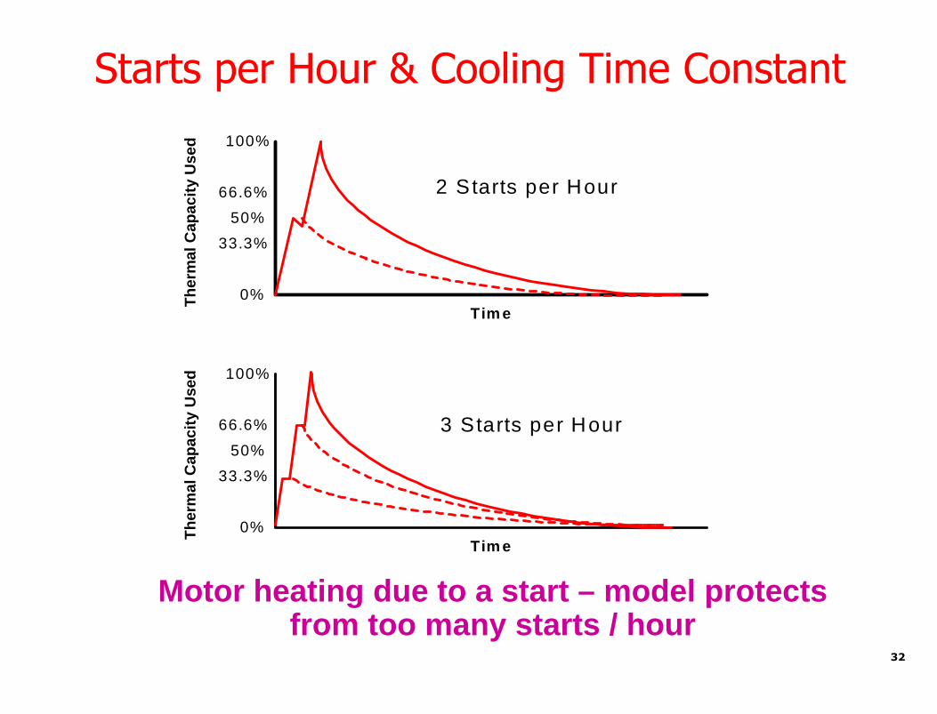
Starts per Hour & Cooling Time Constant
Tim e
Th
erm
al
Cap
acit
yU
sed 100%
50%
33.3%
66.6%
0%
Tim e
Th
erm
alC
ap
acit
yU
sed 100%
50%
33.3%
66.6%
0%
2 Starts per Hour
3 Starts per Hour
Motor heating due to a start – model protectsfrom too many starts / hour
32

Motor Protection
33

Synchronous Motor Protection & Control
34

SPECIAL MOTORPROTECTION TOPICS
35

Special Application #1
Variable Speed Drives
36

Why Drives AreGreat from a
Motor ThermalPerspective
VFD is Ultimate soft start Never go near locked rotor amp draw Much less mechanical stress versus locked rotor across
the line starting Much more thermal reserve available after a VFD start if
motor is stopped and then restart requested37

ProtectionZones
1
2
3
Inverter(IGBT
or IEGT)
DiodeRectifier
IEGT of IGBT PWMVoltage SourceInverter with DiodeConverter
Blown Fuse Over / Under Volts Phase loss Short Circuit
Inverter Overtemp Overload Short circuit Sensor Integrity Ground fault Current balance
DC BusOver /Under Volts
38

VFD Application Protection Zones
ZONE 1: Drive Source
Protects for short circuit in cabling/bus to drive anda failure of the interrupter
May include transformer supplying drive
Suitable transformer protection should be provided
ZONE 2: The Drive Itself
Protections covered by others in this seminar
• Zone 1 uses protective relays operating at nominal frequencyand voltage (in non-fault state)
• Zone 1 protective relays are not affected by off-nominal driveproduced frequency and voltage
39

VFD Application Protection Zones
• Zone 3: The Motor
Senses motor input current Off-nominal frequency and voltage Harmonics
Protects for short circuits, negative sequenceovercurrent, thermal overload 46 and 49 should not be applied at drive input to
sense these issues at the motor terminals
Phase differential may also be applied
40

Zone 1 – Source & Input Transformer
Primary phase and ground overcurrent protection Phase O/C has to allow for motor acceleration Ground O/C may require zero sequence CT depending
on expected ground fault current
If Transformer is in zone Differential protection may be provided on transformer
• This may have limited effectiveness for ground faultswhere the supply system is resistance grounded
Phase O/C is applied for phase faults• Phase O/C has to allow for motor acceleration
Ground O/C• On transformer secondary, Ground O/C may require
zero sequence CT depending on expected groundfault current
41

Typically monitors the input and output voltages and will alarmand/ or trip for over or under voltages and voltage unbalances
Some drives may also include protection of overvoltage on theDC link
Overcurrent protection is provided to protect the converterelectronics and interconnected bus or wiring Current levels are limited to acceptable levels by control
action and the drive is tripped if current is above these levelsfor a preset time.
Volts/Hz limiters and protection to avoid overfluxing at lowerfrequencies
Additional protection may be supplied by monitoring thetemperature of the drive and cooling medium If a link reactor is used it may also have temperature
monitoring and trip settings
Zone 2 – Drive Itself
42

Zone 3 Relay Protection of Motors on VFDs
Primary protection for the drive is contained within the driveitself
Additional motor protection outside of the drive should beapplied if the motor is started across the line or is transferredfrom the drive to line (multiplexed drive application)
Secondary protection may be added in addition to imbeddeddrive control/protection– Philosophical decision– Relay and sensors must be checked to ensure reliable operation
(accurate, secure and dependable)– Entire relay or certain relay elements may not be able to reliably
function at all expected off-nominal frequency and voltage andtherefore not be applied or selectively blocked/disabled when frequencyand voltage are outside of reliable operation limits
43

Cautions for a Motor RelayApplied at VFD Output
Motor Protective Relay (MPR) must operate properly at allexpected frequencies and voltages Properly = accurately, securely and dependably
Instrument transformers (ITs) must operate properly at allexpected frequencies and voltages Properly = accurately, securely and dependably
If MPR/ITs cannot react properly at any expectedfrequency, the MPR must be blocked from operation– This may be accomplished by:
• External signal from drive control system to block relay• Depowering the relay• On-board frequency/voltage sensing and blocking logic built into
the relay
44

Zone 3 – Motor on VFD
If relay and relay elements operate reliably at all expectedoperating conditions, certain elements may be applied Differential (87) Thermal model (49) Phase overcurrent (50/51) Negative sequence overcurrent (46)
Not advised due to lower off nominal conditions: Load loss Under frequency Under voltage Starts per hour (anti-jogging)
Over limit protections, such as over frequency, overvoltageand over excitation protection are not affected by lower offnominal conditions
45

Bypass Contactor
• MPR [MotorProtective Relay] isapplied when motoris supplied directlyfrom the line
• Drive Protects motorwhile on VFD
• Three contactorapplication
Inverter(IGBT
or IEGT)
DiodeRectifier
IEGT or IGBT PWMVoltage SourceInverter with DiodeConverter
2 Blown Fuse2 Over / Under Volts2 Phase loss2 Short Circuit
2 Inverter Overtemp2 Overload2 Short circuit2 Sensor Integrity2 Ground fault2 Current balance
DC BusOver /Under Volts
46

Special Application #2
Motor Source Re-energization (Motor Bus Transfer)
47MMM
Bus 1Supply Source
(Bus 2 Backup Source)
Bus 2Supply Source
(Bus 1 Backup Source)
M M M
UtilitySupply SystemIncoming 1 Incoming 2
N.C.
N.O.
Bus TieBus 1 Bus 2
BUS 1 VT BUS 2 VT
INCOMING 1 VT
INCOMING 2 VTN.C.

• Present source to motor bus is deenergized or challenged• Unplanned utility outage• Fault on utility source• Fault within plant system supplying motor bus
• If challenge to supply occurs, you want to switch to a newsource, very quickly if possible, to avoid restart of motors• Process upset• Process interruption• Locked rotor starting
• The transfer has to be correct• Very dynamic situation while motors are still spinning Phase angle rapidly moves Slip frequency between motors and new source increases Voltage on stranded motor bus decays Coast down period for deenergized motor bus can range cycles to seconds
Why Apply Motor Bus Transfer Systems?
• Proactive plant isolation• Planned utility outage
• Transient torques on motor• Transient torques to driven load
48

• Power supply transfer of on a single motor or motor bus– Old source: Source motors are connected to before transfer– New source: Source for motors after transfer– Parallel transfer: Old source and new sources are paralleled– Sequential transfer: Old source and new sources are not paralleled
Motor Bus Transfer Terminology
MMM
Bus 1Supply Source
(Bus 2 Backup Source)
Bus 2Supply Source
(Bus 1 Backup Source)
M M M
UtilitySupply SystemIncoming 1 Incoming 2
NC NC
NO
Bus TieBus 1 Bus 2
BUS 1 VT BUS 2 VT
INCOMING 1 VT
INCOMING 2 VT
49
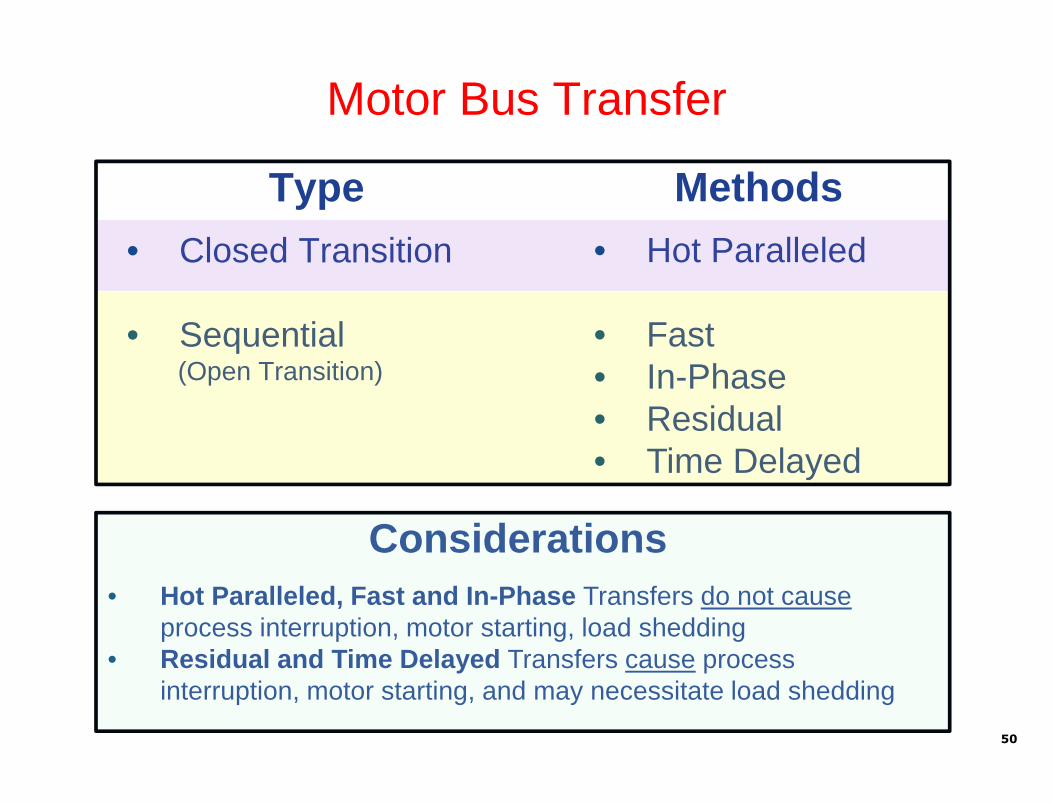
Motor Bus Transfer
Type
• Closed Transition
• Sequential(Open Transition)
Methods
• Hot Paralleled
• Fast• In-Phase• Residual• Time Delayed
Considerations
• Hot Paralleled, Fast and In-Phase Transfers do not causeprocess interruption, motor starting, load shedding
• Residual and Time Delayed Transfers cause processinterruption, motor starting, and may necessitate load shedding
50

MMM
Motor Bus
Source 1(Old Source)
Source 2(New Source)
Closed Transition – Hot Parallel Transfer
Old Source Closed
51
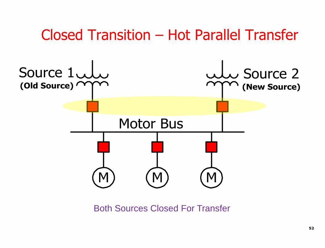
MMM
Motor Bus
Source 1(Old Source)
Source 2(New Source)
Closed Transition – Hot Parallel Transfer
Both Sources Closed For Transfer
52

Closed Transition – Hot Parallel Transfer
MMM
Motor Bus
Source 1(New Source)
Source 2(Old Source)
• New Source Remains Closed• Old Source Opened
53

MMM
Motor Bus
Source 1(Old Source)
Source 2(New Source)
Open Transition
Old Source Closed
54

MMM
Motor Bus
Source 1(Old Source)
Source 2(New Source)
Open Transition
Old Source Opened55

MMM
Motor Bus
Source 1(New Source)
Source 2(Old Source)
Open Transition
• New Source Closes• Old Source Remains Opened
56

VT-SU
VT-B
STATION BUS SYSTEM
STARTUP SOURCE
N.C.
CT-M
N.O.
CT-SU
UNIT AUXILIARYTRANSFORMER
STATION SERVICETRANSFORMER
MAIN SOURCE
MBTS
52M
52SU
M M
VT-M
Two-Breaker Configuration
57

VT-B1
NORMAL SOURCE (Main 1 )
VT-M2
ALTERNATE SOURCE (Main 2)
BUS 1 BUS 2
VT-B2
VT-M1
CT-M1 CT-M2
CT-B1 CT-B2
TRANSFORMERNORMAL SOURCE ALTERNATE SOURCE
TRANSFORMER
MBTS MBTS
N.C.52M1 N.O.
52SU
N.O.
52Tie
MMMM
Three-Breaker Configuration(Main-Tie-Main)
58

Effect of Motor/Load Inertia
• High inertial loads tend to hold up motor buses
• Motors on a bus create a composite decay characteristic
59

Closed Transition - Hot Parallel Transfer
Advantages No disruption of plant process
Simple to implement with sync-check relay supervision acrossnew source breaker
No transient torque on motors during the transfer
Disadvantages Cannot use during fault conditions
Can use only for planned transfers
The two sources must be in sync or within an acceptable smallstatic phase angle difference of each other
Design must ensure that a parallel condition is temporary
If fault occurs when sources are paralleled, circuit breaker andthrough-fault withstand ratings may be violated
The two sources may not be derived from the same primarysource 60
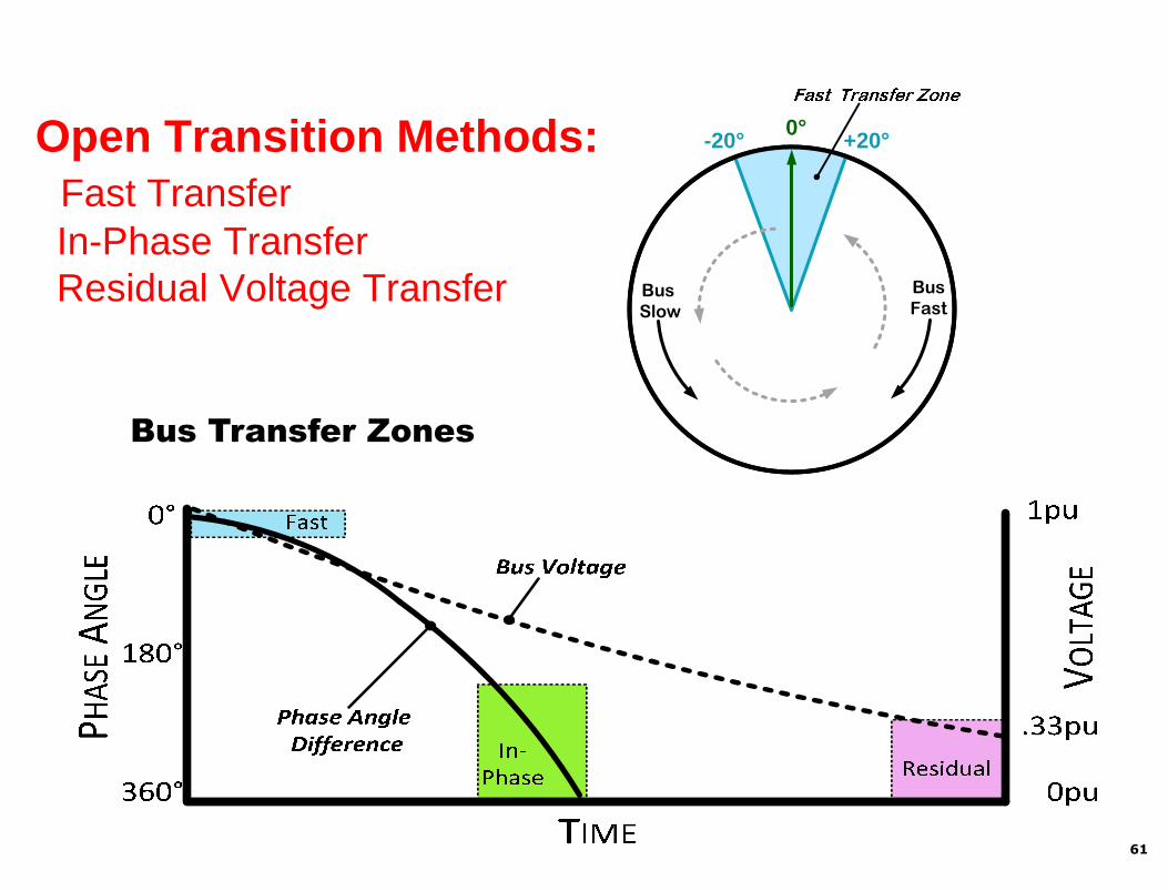
Open Transition Methods:Fast TransferIn-Phase TransferResidual Voltage Transfer
Bus Transfer Zones
40
BusFast
BusSlow
0°-20° +20°
61

MBT Oscillography; Fast Transfer
62

Fast Transfer Method
Presently, the majority of fast transfer systems are NOTsupervised by high-speed sync-check relays !
In many cases, Fast Transfer cannot be correctly performedwithout a high-speed sync check relay
Some modern solid-state or microprocessor-based sync checkelements have a minimum time delay of 0.1 second or 100milliseconds By the time they respond to the phase angle of a decaying motor
bus, the possibility of a successful transfer is long gone Worse yet, the contacts may be still closed and permit transfers
at excessive angles and damage critical motors
63

Fast Transfer Method
New source circuit breaker isclosed if the phase anglebetween the motor bus and thenew source is within or movesinto the Phase Angle Limit
This method requires high-speedsync-check supervision
• Must be able to close highspeed
• Must be able to block highspeed
Circuit breaker closing is alsosupervised by:
• Upper and Lower Voltage Limitcheck on the new source
• Slip Frequency Limit (∆F)
40
BusFast
BusSlow
0°-20° +20°
40
BusFast
BusSlow
0°-20° +20°
64

In-PhaseTransfer Method
65
In-Phase Transfer Method
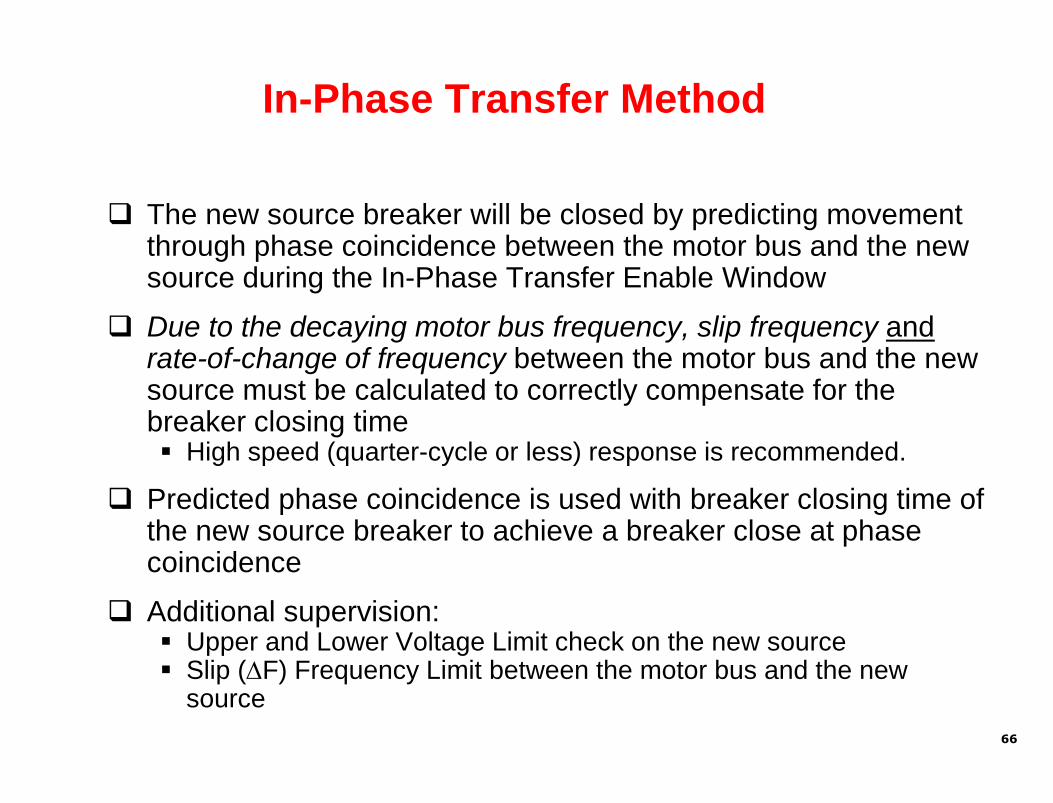
The new source breaker will be closed by predicting movementthrough phase coincidence between the motor bus and the newsource during the In-Phase Transfer Enable Window
Due to the decaying motor bus frequency, slip frequency andrate-of-change of frequency between the motor bus and the newsource must be calculated to correctly compensate for thebreaker closing time High speed (quarter-cycle or less) response is recommended.
Predicted phase coincidence is used with breaker closing time ofthe new source breaker to achieve a breaker close at phasecoincidence
Additional supervision: Upper and Lower Voltage Limit check on the new source Slip (∆F) Frequency Limit between the motor bus and the new
source
66

MBT Oscillography; In-Phase Transfer
Phase Angle
67
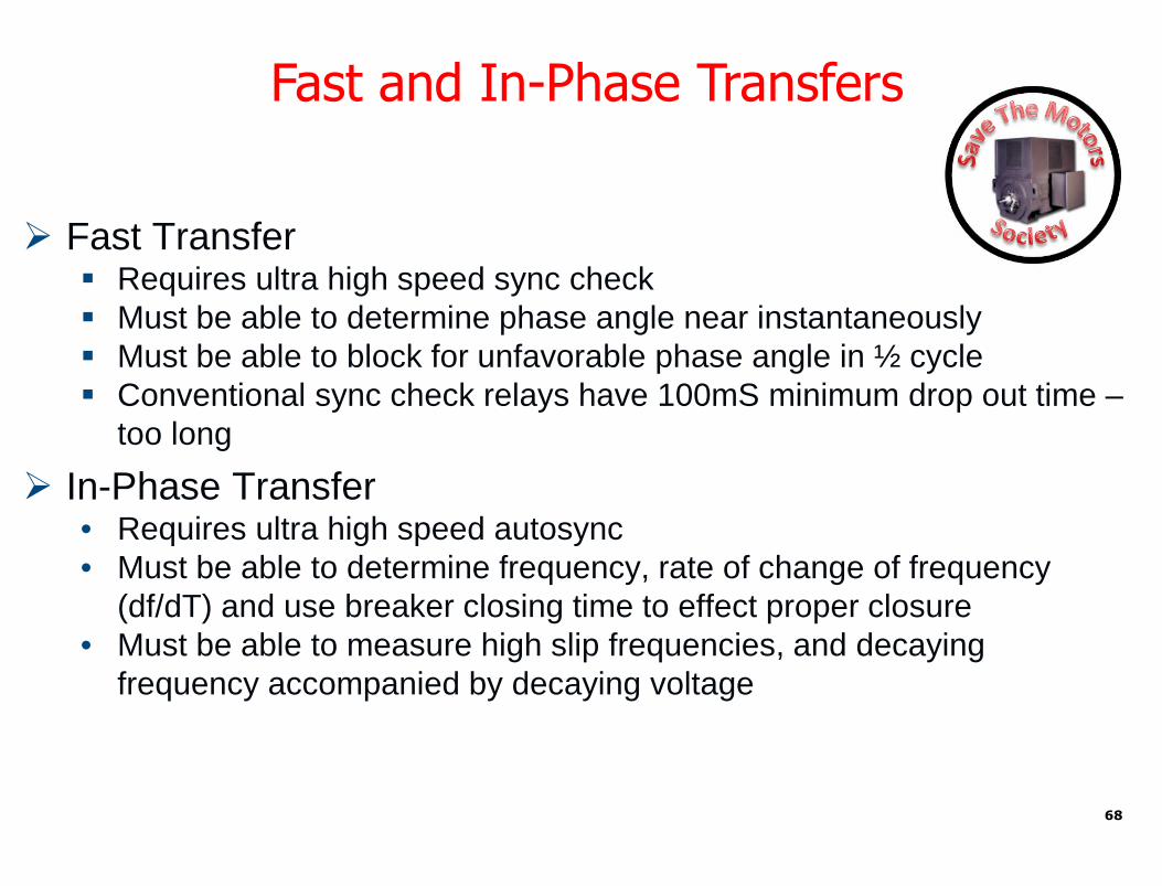
Fast Transfer Requires ultra high speed sync check Must be able to determine phase angle near instantaneously Must be able to block for unfavorable phase angle in ½ cycle Conventional sync check relays have 100mS minimum drop out time –
too long
In-Phase Transfer• Requires ultra high speed autosync• Must be able to determine frequency, rate of change of frequency
(df/dT) and use breaker closing time to effect proper closure• Must be able to measure high slip frequencies, and decaying
frequency accompanied by decaying voltage
Fast and In-Phase Transfers
68

Fast and In-Phase Sequential Transfers
Advantages No disruption of plant process
Minimizes or eliminates transient torque on motors during thetransfer
Can be used during fault conditions
Can be used for planned transfers
Applicable when two sources are not in sync or within anacceptable small static phase angle difference of each other
No concerns of exceeding fault ratings of circuit breakers orthrough fault rating od transformers due to paralleling sources
Applicable for use where two sources may not be derived from thesame primary source, or on a single source
Concerns These transfers must be performed correctly
69
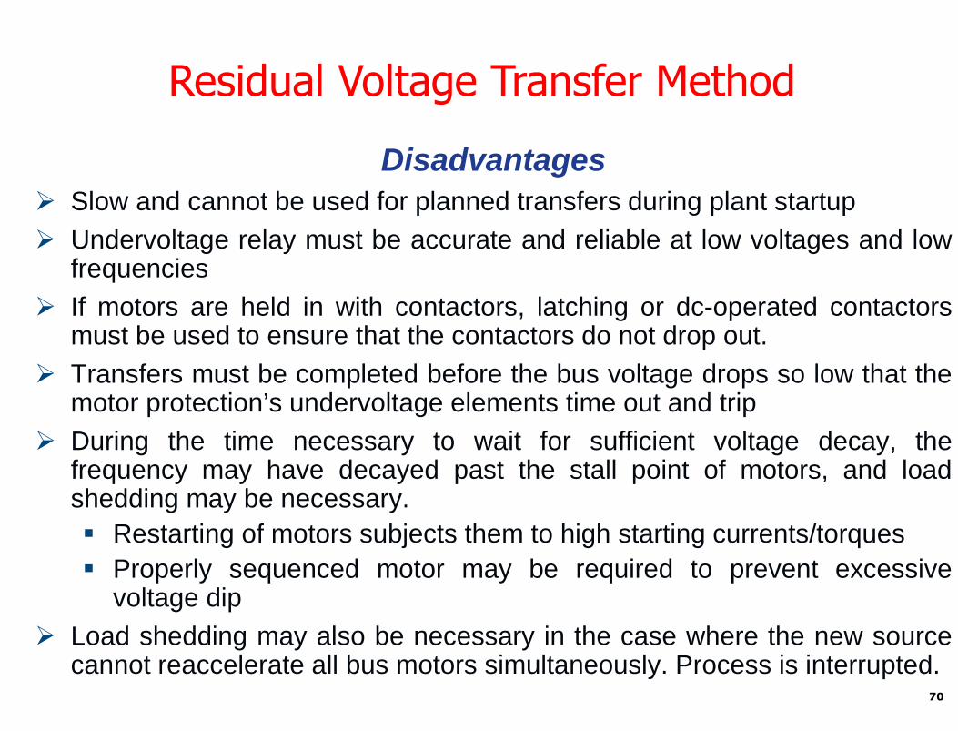
Disadvantages Slow and cannot be used for planned transfers during plant startup
Undervoltage relay must be accurate and reliable at low voltages and lowfrequencies
If motors are held in with contactors, latching or dc-operated contactorsmust be used to ensure that the contactors do not drop out.
Transfers must be completed before the bus voltage drops so low that themotor protection’s undervoltage elements time out and trip
During the time necessary to wait for sufficient voltage decay, thefrequency may have decayed past the stall point of motors, and loadshedding may be necessary.
Restarting of motors subjects them to high starting currents/torques
Properly sequenced motor may be required to prevent excessivevoltage dip
Load shedding may also be necessary in the case where the new sourcecannot reaccelerate all bus motors simultaneously. Process is interrupted.
Residual Voltage Transfer Method
70
Conditions Across New Source Breaker?
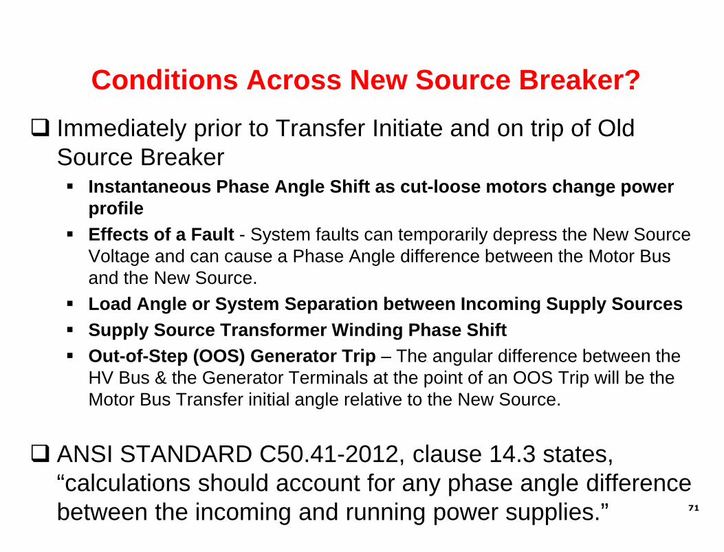
Immediately prior to Transfer Initiate and on trip of OldSource Breaker Instantaneous Phase Angle Shift as cut-loose motors change power
profile
Effects of a Fault - System faults can temporarily depress the New SourceVoltage and can cause a Phase Angle difference between the Motor Busand the New Source.
Load Angle or System Separation between Incoming Supply Sources
Supply Source Transformer Winding Phase Shift
Out-of-Step (OOS) Generator Trip – The angular difference between theHV Bus & the Generator Terminals at the point of an OOS Trip will be theMotor Bus Transfer initial angle relative to the New Source.
ANSI STANDARD C50.41-2012, clause 14.3 states,“calculations should account for any phase angle differencebetween the incoming and running power supplies.” 71

ANSI STANDARDC50.41-2012
72
ANSI STANDARD C50.41-2012, clause 14.3 states,“calculations should account for any phase angle differencebetween the incoming and running power supplies.”

Industry Guidance
• NEMA MG 1-2006 and NEMA/ANSI C50.41-2000, 1.33 V/Hzvector difference to define a safe transfer of an inductionmotor bus and its connected loads from one source to analternate power supply
• This is where the 0.25pu voltage for residual transfersoriginates
• Goal of MBT System is to keep resultant V/Hz below1.33, and minimize motor reacceleration current andtorques
73

Dynamic Test of Motor Bus Transfer System:Initial Static Phase Angles
74

Standard Decay MBT Test Results
75

• Test voltage and frequency decay characteristics of High,Medium, and Low Inertia Motor Buses
• Tests with Multiple Initial Static Phase Angles
• All 15 tests closed under 0.26 pu V/Hz.
• All 15 tests closed well below the 1.33 pu V/Hz and 90 degreelimits*
* ANSI C50.41 Polyphase Induction Motors for Power Generating Stations
• All 15 tests were performed with NO changes to settings. Fast Transfer Method Phase Angle Limit = 20° Fast Transfer Method Slip Frequency Limit = 2.0 Hz ** In-Phase Transfer Method Slip Frequency Limit = 10.0 Hz
** Used to coordinate the actions of the Fast Transfer and the In-Phase TransferMethods to achieve an optimal close with the In-Phase Transfer Method.
Standard Decay MBT Test Results
76

• The ANSI C50.41 “10 cycles or less” criteria would rejectperfectly good transfers by the In-Phase Transfer Method:
A High Inertia close at 0.24 pu V/Hz took 27 cycles
A Medium Inertia close at 0.15 pu V/Hz took 16.7 cycles
A Low Inertia close at 0.15 pu V/Hz took 13.3 cycles
• The arbitrary 10-cycle limit should be ignored as it may takemore than 10 cycles for the motors to rotate back intosynchronism.
• How fast can the motors transfer? When the motors allow it by rotating back into sync ! ! !
• In the fast-moving world of motor bus transfer: 10 cycles (167 ms) is an eternity 10 cycles never was a safe limit for fast transfer*
* Even at a medium frequency decay of 20 Hz/sec (RS), with zero initial slipfrequency (SINIT), the angle movement (ΔØ) in 10 cycles (T) is a dangerous 100°.
ΔØ = 360(SINIT+0.5RST)T
Standard Decay MBT Test Results
77

All transfers used the Sequential Transfer Mode This inherent breaker failure scheme adds a little time to the transfer,
still yielding excellent transfer results Avoids the possibly catastrophic result where the two breakers are
closed at the same time
Simultaneous Transfer Mode initiates both trip andsupervised close breaker operations simultaneously It does not prevent the new breaker from closing if the old breaker
fails to trip
Except in cases of extremely low inertia, the need for speedcould become a vestige of the past With modern technology, we now have the luxury to wait for the old
breaker to trip
Standard Decay MBT Test Results
78

• Synchronous Fast and In-Phase Transfers occur well beforethe 0.33 pu voltage level of the Residual Voltage Slow Transferwould operate.
• Synchronous Transfers vs. blind Residual Voltage Transfers: Much higher voltages Much lower slip frequencies With synchronous closure
• Residual Voltage Transfers subject motors and loads to: The jarring effect of a large phase angle at breaker closure High reacceleration current and associated torque
• Results demonstrate that the Fast and In-Phase Methods, canalso be applied to Low Voltage Motor Buses, rather thanhaving to resort to Residual Voltage Slow Transfers.
Standard Decay MBT Test Results
79

Live Open Transition Transfers Under Normal Operating Load ConditionsMBT FIELD RESULTS VS = 120 FS = 60
LOCATION Transfer Mode
Transfer
Method
Advance
Ø Angle
Close
Ø Angle Close ΔF Close Volts
ANSI
C50.41
pu V/Hz
Open
Transfer
Time
cycles
Max
Transfer
Amps /
FLA
Max
Transfer
pu
Power
Torque
Ratio
TPK/TL
FACILITY 1 Simultaneous FAST -0.1 -20.0 -2.83 93.8 0.3622 1.3 4.6 21.5 4.12
FACILITY 2 Sequential FAST -10.8 -16.3 -0.19 100.4 0.3054 5.0 2.4 5.9 2.38
FACILITY 3 Simultaneous FAST -3.0 -18.5 -0.81 103.4 0.3260 3.3 3.1 9.3 2.48
FACILITY 4 Sequential FAST -0.8 -6.8 -0.23 107.9 0.1489 2.9 2.7 7.2 1.97
FACILITY 5 Simultaneous FAST -1.2 -12.6 -1.76 103.2 0.2360 1.3 2.2 4.9 1.87
FACILITY 6 Simultaneous FAST -1.1 -16.5 -2.25 102.0 0.2939 1.4 1.8 3.3 1.62
FACILITY 7 Sequential FAST -2.8 -17.1 -0.49 98.7 0.3201 2.9 2.9 8.4 2.08
FACILITY 8 Sequential FAST -2.2 -12.7 -0.38 99.0 0.2635 2.9 1.8 3.3 1.50
FACILITY 9 Sequential
Residual
Voltage 152.4 128.4 -1.66 34.7 1.2074 48.7 4.8 23.0 21.74
FACILITY 10 Sequential
IN-PHASE
ØINIT =115° 55.0 -7.7 -2.77 44.4 0.6178 9.4 2.4 6.0 2.39
FACILITY 11 Sequential IN-PHASE 78.9 7.1 -4.48 37.7 0.6644 17.7 2.3 5.2 1.89
FACILITY 12 Simultaneous FAST -0.1 -20.3 -2.23 89.4 0.3838 1.7 1.8 3.4 1.79
Actual MBT from Loaded Facilities

• Fast Transfers occurred in 9 instances
• In-Phase Transfers occurred in 2 instances.
• All Synchronous Transfers were completed at between 0.15and 0.66 pu V/Hz
• All Synchronous Transfer breaker close commands occurredat voltages above which the Residual Voltage Transferundervoltage element would have operated.
• A Residual Voltage Transfer occurred in 1 test when theSynchronous Transfer Methods were purposely disabled, sothe results for a Residual Voltage Transfer could be observed.
• The Residual Voltage Transfer closed at 1.21 pu V/Hz.
Actual MBT from Loaded Facilities
81

• ANSI 50.41 Refers to Ratio: Peak Inrush Current at Transfer, Max
Transfer Amps (MTA) ÷ Subsequent Steady State Full Load Amps (FLA).
• Common Requirement: Motor Starting Current ≤ Specified Multiple of Full Load Current at rated voltage for across-the-line full voltage starting.
• Correlation: As the pu V/Hz rises, then the MTA/FLA would also rise?NO CORRELATION
• Range of MTA/FLA from 1.8 to 4.8 is reasonable compared to a normalmotor start. MTA/FLA may be overstated as load amps may be < FLA.
*2 In-Phase Transfers vs. 6 Fast Transfers: Higher pu V/Hz (0.62 and
0.66 pu V/Hz) but middle of the range MTA/FLA (2.4 and 2.3)
*
Actual MBT from Loaded Facilities
82

The pu V/Hz calculation depends on only three values at closurecompared to the new source: the bus voltage difference, the busfrequency difference, and the phase angle difference.
One could imagine two vastly different sets of motors with two vastlydifferent sets of loads, but transferring with the same three values at closure The calculated pu V/Hz would be exactly the same, but one wonders if the
motors and loads think so. Therefore, the use of the 1.33 pu V/Hz limit across the open breaker as a
criterion for the safe transfer of motor buses leaves room for possibleimprovement.
The above FACILITY 1 through 12 oscillographic records of live motor bustransfers will now be analyzed to derive a new transfer metric, based on thevoltage and current during inrush at the close of the new source breaker. These values will be measured in the time domain and employed to
calculate the resultant peak torque at transfer as a multiple of load torqueprior to transfer as if the aggregate bus were a single induction motordrawing the same current and power.
Actual MBT from Loaded Facilities
83

Motor Torque Calculation
The torque produced is equal to the electromagnetic power transferredthrough the air gap (PAG) divided by the synchronous speed (ωS):
T = PAG/ωS
Assumes all losses (copper losses, iron losses, friction and windage losses) are neglected
The Air Gap Power is calculated for two different conditions:
• Steady state Motor Torque prior to the Transfer (TL)(uses current signal taken from the existing source along with the motorbus voltage signal)
• Peak Motor torque (TPK) after the transfer has taken place(uses current signal taken from the new source along with motorbus voltage signal)
• The ratio TPK /TL is calculated for each facility
The Torque Ratio provides a normalized way of looking at transient torque during motorbustransfer
Actual MBT from Loaded Facilities
84

Facility 1 2 3 4 5 6 7 8 9 10 11 12
Torque
Ratio
(TPK/TL)
4.12 2.38 2.48 1.97 1.87 1.62 2.08 1.50 21.74 2.39 1.89 1.79
Pu
V/Hz0.3622 0.3054 0.3260 0.1489 0.2360 0.2939 0.3201 0.2635 1.2074 0.6178 0.6644 0.3838
Residual Voltage
In-Phase
Fast
Actual MBT from Loaded Facilities
85

Motor Torque Ratio TPK /TL Observations
There is low correlation between pu V/Hz and Torque Ratio
In-Phase Transfer cases (Facilities 10 and 11) have higher pu V/Hz butlower inrush current ratios (Max Transfer Amps/FLA) and Torque Ratios(TPK/TL). Torque Ratios for the two In-Phase Transfers fall right in the middle of
the Torque Ratios for all the Fast Transfers
ANSI C50.41 states that transient torques during improper transfers canreach 20 pu. Facility 9 results demonstrate this with a Torque Ratio of21.74 for a Residual Voltage Transfer close at 128.4 degrees. Yet the ANSI C50.41 pu V/Hz limit of 1.33 would give this Residual
Voltage Transfer a passing grade at 1.2074 pu V/Hz.
Max Transfer pu Power is almost the same (21.5 for Facility 1 and 23 forFacility 9) whereas the motor Torque Ratios are vastly different (4.12 forFacility 1 and 21.74 for Facility 9).
Actual MBT from Loaded Facilities
86
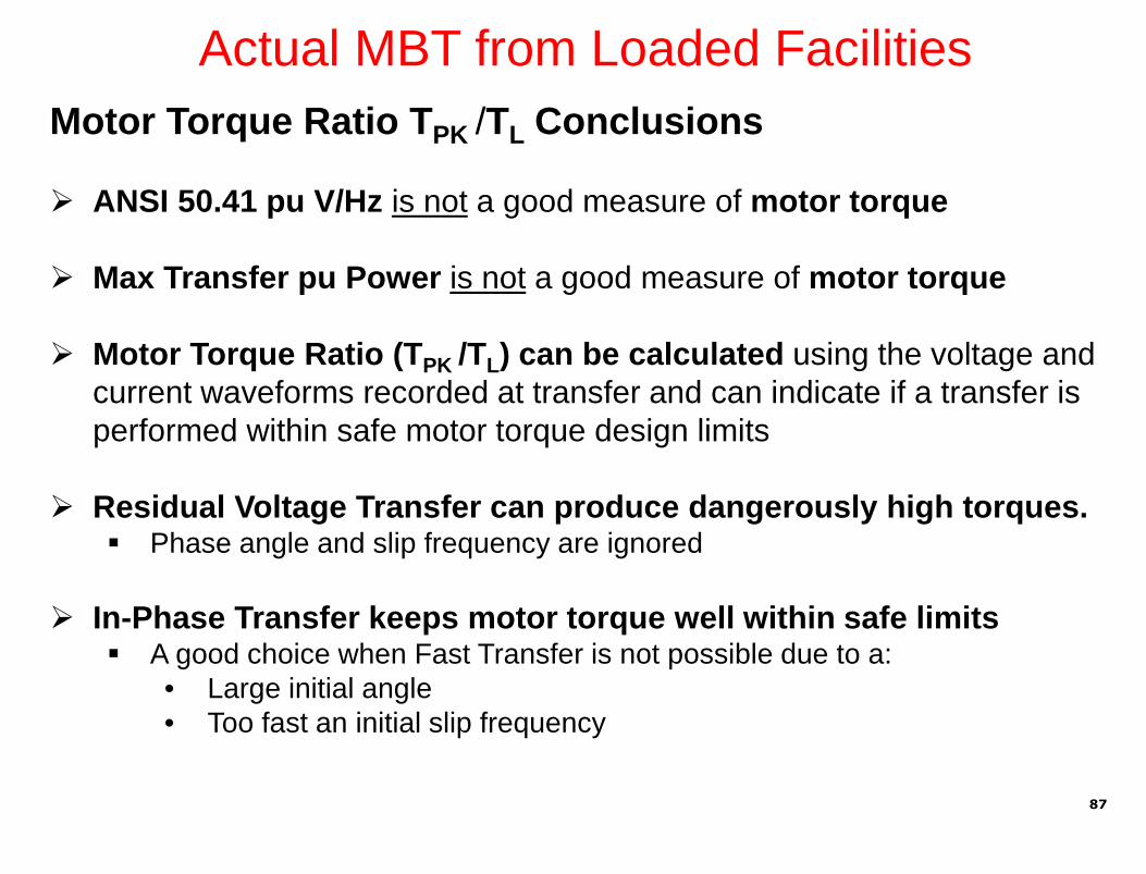
Motor Torque Ratio TPK /TL Conclusions
ANSI 50.41 pu V/Hz is not a good measure of motor torque
Max Transfer pu Power is not a good measure of motor torque
Motor Torque Ratio (TPK /TL) can be calculated using the voltage andcurrent waveforms recorded at transfer and can indicate if a transfer isperformed within safe motor torque design limits
Residual Voltage Transfer can produce dangerously high torques. Phase angle and slip frequency are ignored
In-Phase Transfer keeps motor torque well within safe limits A good choice when Fast Transfer is not possible due to a:
• Large initial angle• Too fast an initial slip frequency
Actual MBT from Loaded Facilities
87

Summary
Proper MBT offers a way to provide process continuity andmotor and driven load asset life
The Fast and In-Phase Transfers are methods to use: Where Hot Parallel transfer cannot be done
Where Residual Transfer takes too long and causes process upset,and high transient torques
Specialized relays and systems are required tosuccessfully implement MBT
MBT System are commercially available You do not have to cobble together systems out of non-purpose
designed hardware and software
88

Questions? Thank You
Remember, only you can prevent motor damage
89

References:
C37.96-2012, “IEEE Guide for AC MotorProtection”
“Adjustable Speed Drive MotorProtection Applications and Issues,”IEEE PSRC Report, 10/08
GE Digital Energy 469 Motor RelayInstruction Book
“Motor Bus Transfer Applications Issuesand Considerations,” IEEE PSRCReport, 05/12
“Motor Bus Transfer SystemPerformance Testing and the Search fora New Transfer Success Criterion”; T.Beckwith, Dr. Murty Yalla; BeckwithElectric; 2015 Georgia Tech ProtectiveRelay Conference
Beckwith Electric M-4272 Motor BusTransfer System Instruction Book
90