cleat benders - production products · cleat benders . model 18 cb model ... read all instructions...
TRANSCRIPT
Model CB30 Shown with Optional Stand
CLEAT BENDERS
MODEL 18 CB MODEL 24 CB MODEL 30 CB
Operation, Parts, and Maintenance Manual
Model: Purchased From:
Serial #: Date Received:
6926 Smithville Hwy., McMinnville, TN 37110 931-934-2211 / Fax: 931-934-2220 www.tennsmith.com

Tennsmith Inc. / 6926 Smithville Hwy. / McMinnville, TN 37110 / 931-934-2211 / Fax 931-934-2220 2
www.tennsmith.com
2
FORWARD This manual has been prepared for the owner and operators of the TENNSMITH Cleat Benders. Its purpose, aside from operational instructions, is to promote safety through the use of accepted operating procedures. Read all instructions thoroughly before operating the cleat bender. Also contained in this manual is the parts list for your cleat bender. It is recommended that only TENNSMITH or factory authorized parts be used for replacement parts.
WARRANTY
Your cleat bender is warranted for three years from the date of purchase. The terms of the warranty are stated on the warranty registration card shipped with your machine. Please complete and return this card to activate your warranty.
SAFETY PRECAUTIONS 1. Know the safety and operating instructions contained in this brochure. Become familiar with and
understand the limitations of this cleat bender. Always practice safety. 2. Wear approved eye safety protection such as glasses, goggles, etc. when operating the cleat
bender to protect your eyes. 3. Wear protective foot wear or safety shoes. Jewelry such as rings and watches should be
removed when operating the machine. 4. Keep your hands clear of the bending area of the cleat bender when making bends. 5. Keep the work area around the cleat bender clear and clean to avoid slipping or tripping. 6. The cleat bender must be securely bolted to a bench or stand. The bench or stand must me
securely mounted to the floor.

Tennsmith Inc. / 6926 Smithville Hwy. / McMinnville, TN 37110 / 931-934-2211 / Fax 931-934-2220 3
www.tennsmith.com
3
RECEIVING THE MACHINE Upon receipt closely examine the cleat bender for damage during shipment. Be certain you have two handles. Any loss or damage should be noted in detail on the delivery receipt and reported to your distributor immediately. INSTALLING THE MACHINE Locate the cleat bender in a well lighted area on a solid, level floor. The cleat bender must be securely bolted to a work bench or TENNSMITH manufactured optional stand. The work bench or stand must be securely mounted to the floor. By positioning the cleat bender at the end of the work table it is possible to bend drive cleat edges on rectangular duct work of substantial size. Examine your clearances before bolting the machine to the bench. Be sure you have adequate room to swing both handles. OPERATING THE MACHINE The segmented base of your cleat bender is designed so that duct sections and fittings of almost every dimension will fit into the bender with one or both legs formed to right angles. Your duct or fittings should be notched at the corners to properly form your drive cleat pockets. Recommended notch depth is 7/16 to ½ inch. Recommended notch angles are 30 to 45 degrees. Insert your notched duct flange under the upper blade of the cleat bender. Raise the top handle to its complete arc point, approximately 150 degrees. Leave the top handle in this position and release the lower handle by depressing the latch and raising the handle at the same time. Raise the lower handle to its complete arc point. At this time push the duct section into the throat of the cleat bender to release the formed drive cleat flange. When released, withdraw the duct section from the tool. Return both handles to their normal down position. If desired, the top leaf of the cleat bender can now be used to close the drive cleat edge to +180 degrees. Your drive cleat edge is now complete. Your cleat bender can also be used to make the actual drive cleats used in joining duel sections together. Your drive cleat blanks should be sheared or slit into the appropriate width, approximately 2 1/8 inches. The bending procedure is the same as for drive cleat edges on ducting with the exception that the lower handle does not have to be released to remove the cleat after each bend. Use the top leaf of the cleat bender to close the drive cleat edge to 180 degrees. PRECAUTIONS DO NOT use the cleat bender to bend rods, nails, or wires. This will cause damage to the edge of the top blade. DO NOT exceed the capacity of the cleat bender which is 20 gauge (0.036 inches) mild steel. DO NOT bend seams, hems or locks unless the material is notched. DO NOT use pipe extensions to gain additional leverage. ALWAYS use material with square sheared edges for best results. Rolled edges, bent, or warped materials will cause the material to bow when bent. Keep shear blades and slitter knives sharp. ALWAYS bend short pieces of material in the center of the cleat bender in order to equalize the stress.

Tennsmith Inc. / 6926 Smithville Hwy. / McMinnville, TN 37110 / 931-934-2211 / Fax 931-934-2220 4
www.tennsmith.com
4
MAINTENANCE Set up a weekly maintenance program for your cleat bender. Check all nuts, bolts, and set screws for tightness. Examine all moving parts for adequate lubrication. The moving parts of the cleat bender should be lubricated periodically and as necessary to maintain ease of operation and prolong the life of your machine. Hinge pins and the latch mechanism should be oiled with a good grade of 30 weight machine oil. A light coating of grease of the latch pin will prolong the life of both the latch and the pin. ORDERING PARTS When ordering parts please furnish the model number and the serial number of you machine.
Tennsmith Inc. / 6926 Smithville Hwy. / McMinnville, TN 37110 / 931-934-2211 / Fax 931-934-2220 5
www.tennsmith.com
5
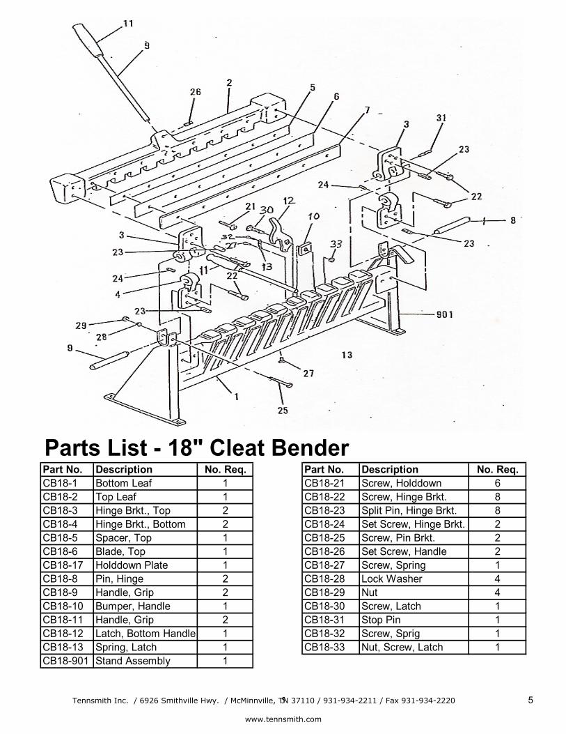
Parts List - 18" Cleat BenderPart No. Description No. Req. Part No. Description No. Req.CB18-1 Bottom Leaf 1 CB18-21 Screw, Holddown 6CB18-2 Top Leaf 1 CB18-22 Screw, Hinge Brkt. 8CB18-3 Hinge Brkt., Top 2 CB18-23 Split Pin, Hinge Brkt. 8CB18-4 Hinge Brkt., Bottom 2 CB18-24 Set Screw, Hinge Brkt. 2CB18-5 Spacer, Top 1 CB18-25 Screw, Pin Brkt. 2CB18-6 Blade, Top 1 CB18-26 Set Screw, Handle 2CB18-17 Holddown Plate 1 CB18-27 Screw, Spring 1CB18-8 Pin, Hinge 2 CB18-28 Lock Washer 4CB18-9 Handle, Grip 2 CB18-29 Nut 4CB18-10 Bumper, Handle 1 CB18-30 Screw, Latch 1CB18-11 Handle, Grip 2 CB18-31 Stop Pin 1CB18-12 Latch, Bottom Handle 1 CB18-32 Screw, Sprig 1CB18-13 Spring, Latch 1 CB18-33 Nut, Screw, Latch 1CB18-901 Stand Assembly 1

Tennsmith Inc. / 6926 Smithville Hwy. / McMinnville, TN 37110 / 931-934-2211 / Fax 931-934-2220 6
www.tennsmith.com
6
Parts List - 24" Cleat BenderPart No. Description No. Req. Part No. Description No. Req.CB24-1 Bottom Leaf 1 CB24-16 Lock Washer, Brkt. 4CB24-2 Top Leaf 1 CB24-17 Nut, Brkt. Screw 4CB24-3 Hinge Brkt., Top 2 CB24-18 Screw, Holddown 8CB24-4 Hinge Brkt., Bottom 2 CB24-19 Screw, Hinge Brkt. 8CB24-5 Latch 1 CB24-20 Split Pin, Hinge Brkt. 8CB24-6 Spacer, Top 1 CB24-21 Set Screw, Hinge Brkt. 2CB24-7 Blade, Top 1 CB24-22 Stop Pin, Hinge Brkt. 1CB24-8 Holddown Plate 1 CB24-23 Screw, Pin Brkt. 2CB24-9 Pin, Hinge 2 CB24-24 Set Screw, Handle 2CB24-10 Handle 2 CB24-25 Screw, Latch 1CB24-11 Handle, Grip 2 CB24-26 Lock Washer, 1/4 3CB24-12 Spring, Latch 2 CB24-27 Nut, 1/4 3CB24-901 Stand Assembly 1 CB24-28 Bumper, Handle 1CB24-13 Brkt., Right Hand Stand 1 CB24-29 Nut, Screw, Latch 1CB24-14 Brkt., Left Hand Stand 1 CB24-30 Screw, Spring 1CB24-15 Screw, Stand Brkt. 4

Tennsmith Inc. / 6926 Smithville Hwy. / McMinnville, TN 37110 / 931-934-2211 / Fax 931-934-2220 7
www.tennsmith.com
7
Parts List - 30" Cleat BenderPart No. Description No. Req. Part No. Description No. Req.CB30-1 Bottom Leaf 1 CB30-15 Screw, Stand Brkt. 4CB30-2 Top Leaf 1 CB30-16 Lock Washer, Brkt. 4CB30-3 Hinge Brkt., Top 2 CB30-17 Nut, Brkt. Screw 4CB30-4 Hinge Brkt., Bottom 2 CB30-18 Screw, Holddown 10CB30-5 Latch 1 CB30-19 Screw, Hinge Brkt. 8CB30-6 Spacer, Top 1 CB30-20 Split Pin, Hinge Brkt. 8CB30-7 Blade, Top 1 CB30-21 Set Screw, Hinge Brkt. 2CB30-8 Holddown Plate 1 CB30-22 Stop Pin, Hinge Brkt. 1CB30-9 Pin, Hinge 2 CB30-23 Screw, Pin Brkt. 2CB30-10 Handle 2 CB30-24 Set Screw, Handle 2CB30-11 Handle, Grip 2 CB30-25 Screw, Latch 1CB30-12 Spring, Latch 1 CB30-26 Lock Washer, 1/4 3CB30-901 Stand Assembly 1 CB30-27 Nut, 1/4 3CB30-13 Brkt., Right Hand Stand 1 CB30-28 Bumper, Handle 1CB30-14 Brkt., Left Hand Stand 1 CB30-29 Nut, Screw, Latch 1

Tennsmith Inc. / 6926 Smithville Hwy. / McMinnville, TN 37110 / 931-934-2211 / Fax 931-934-2220 8
www.tennsmith.com
8
Cleat Bender Specifications
Model 18 24 30 Maximum capacity, mild steel 20 ga / 1,0 mm 20 ga / 1,0 mm 20 ga / 1,0 mm
Maximum Bending 18 in / 457 mm 24 in / 610 mm 30 in / 762 mm
Depth of drive cleat 1/2 in / 12.7 mm 1/2 in / 12.7 mm 1/2 in / 12.7 mm
Dimensions, handles removed LxWxH 25-1/2 x 12-1/2 x 12-1/2 in 648 x 317.5 x 317.5 mm
32 x 10 x 11 in 813 x 254 x 280 mm
38 x 10 x 11-1/2 in 965 x 254 x 292 mm
Shipping Weight 63 lbs / 29 kg 95 lbs / 44 kg 150 lbs / 59 kg
3-YEAR LIMITED WARRANTY
TENNSMITH machinery and component parts are carefully inspected at various stages of production and are tested and inspected prior to shipment. We agree that for a period of twelve (12) months from the date of delivery from our authorized distributor to replace, at our option, any machine (or component part thereof) proving defective within the above period. Additionally, we agree that for a period of thirty-six (36) months from date of delivery to replace component parts proving defective within the stated period. All warranty claims are made F.O.B. our plant, providing such machine (or component part) is returned freight prepaid to our plant, or a designated service center of the undersigned, for our examination. This warranty does not include repair or replacement required because of misuse, abuse, or because of normal wear and tear; or electrical components which are warranty by their manufacturer. Further, we cannot be responsible for the cost of repairs made or attempted outside our factory or designated service center without our authorization. No claims for defects will be honored if the name and data place has been removed. This warranty is made expressly in place of all other warranties or guarantees express or implied, with respect to fitness, merchantability, quality or operative ness. This warranty becomes effective only when the accompanying warranty card is fully and properly filled out returned to the factory within ten (10) days from date of delivery.