clic drive beam injector design update shahin sanaye hajari 1.institute for research in fundamental...
TRANSCRIPT
CLIC Drive Beam Injector Design Update
Shahin Sanaye Hajari
1. Institute For Research in Fundamental Sciences (IPM), Tehran, Iran2. CERN, Geneva, Switzerland
Contents
1. Injector layout and the latest results
2. Optimisation of the magnetic chicane
3. Chicane and the injector overall performance
3.1 Satellite population
3.2 Beam loss at chicane
4. Fourth SHB
1 Injector layout and the latest results 1
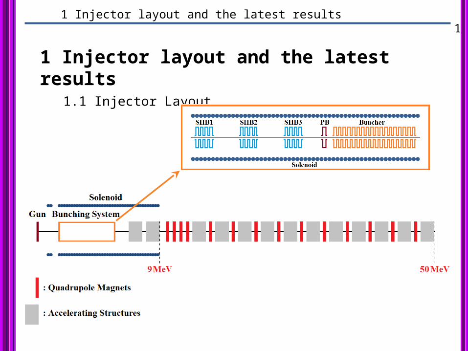
1 Injector layout and the latest results1.1 Injector Layout
1 Injector layout and the latest results 2
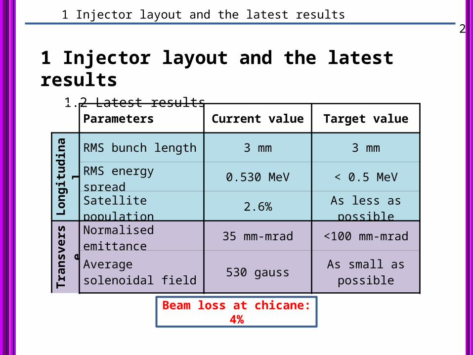
1 Injector layout and the latest results1.2 Latest results
Parameters Current value Target value
Longitudinal
RMS bunch length 3 mm 3 mm
RMS energy spread 0.530 MeV < 0.5 MeV
Satellite population 2.6% As less as possible
Transverse
Normalised emittance 35 mm-mrad <100 mm-mrad
Average solenoidal field 530 gauss As small as possible
Beam loss at chicane: 4%

2 Optimisation of the magnetic chicane 3
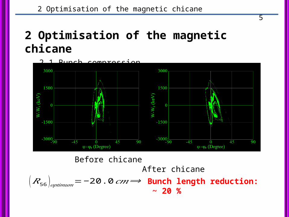
2 Optimisation of the magnetic chicane 2.1 Bunch compression
{𝑧 𝑓=𝑧 𝑖+𝑅56𝛿𝑖
𝛿 𝑓=𝛿𝑖
+2+
(𝑅56 )𝑜𝑝 𝑡𝑖𝑚𝑢𝑚=−⟨𝑧 𝑖𝛿𝑖 ⟩⟨𝛿𝑖
2 ⟩
⟨ 𝑧 𝑓2 ⟩𝑚𝑖𝑛=⟨ 𝑧𝑖2 ⟩− ⟨ 𝑧𝑖 𝛿𝑖 ⟩
2
⟨𝛿𝑖2 ⟩
⇓⇓

2 Optimisation of the magnetic chicane 4
2 Optimisation of the magnetic chicane 2.1 Bunch compression
𝑧 𝑓 −𝑧 𝑖=𝐿 (𝛿)−𝐿 (0 )¿𝑅56𝛿+𝑇 566𝛿
2+𝑈 566 𝛿3
2 Optimisation of the magnetic chicane 5
2 Optimisation of the magnetic chicane 2.1 Bunch compression
Before chicane After chicane
(𝑅56 )𝑜𝑝𝑡𝑖𝑚𝑢𝑚=−20.0 𝑐𝑚⟹ Bunch length reduction: ~ 20 %
2 Optimisation of the magnetic chicane 6
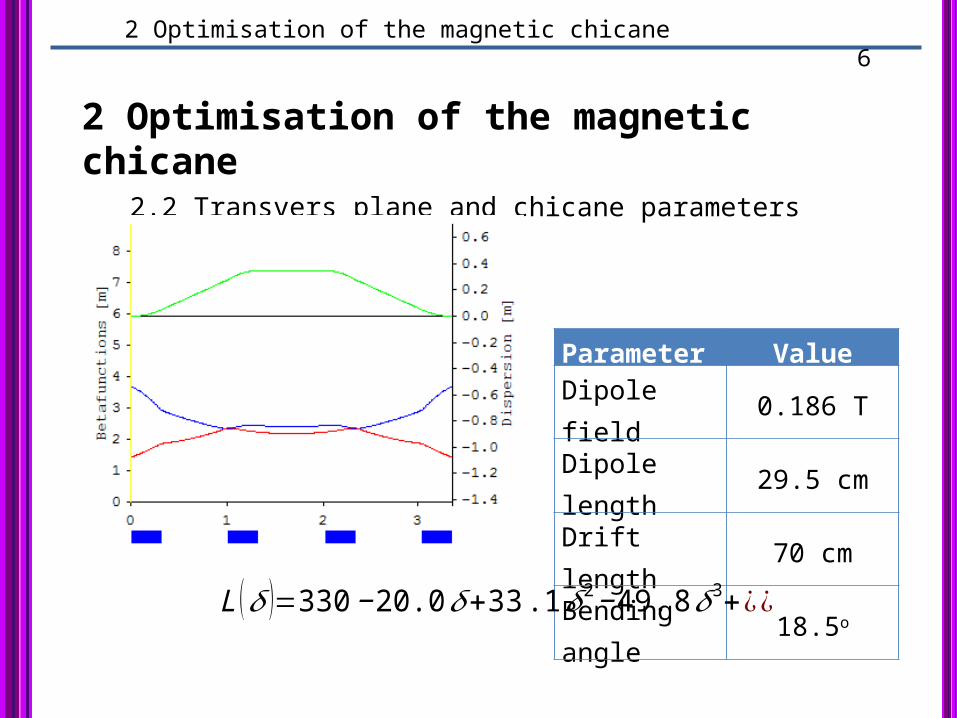
2 Optimisation of the magnetic chicane 2.2 Transvers plane and chicane parameters
Parameter ValueDipole field 0.186 TDipole length 29.5 cmDrift length 70 cmBending angle 18.5o
L (𝛿 )=330−20.0 𝛿+33 .1 𝛿2−49. 8𝛿3+¿¿
3 Chicane and the injector overall performance 7
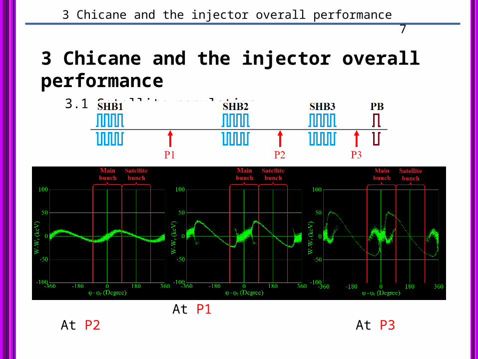
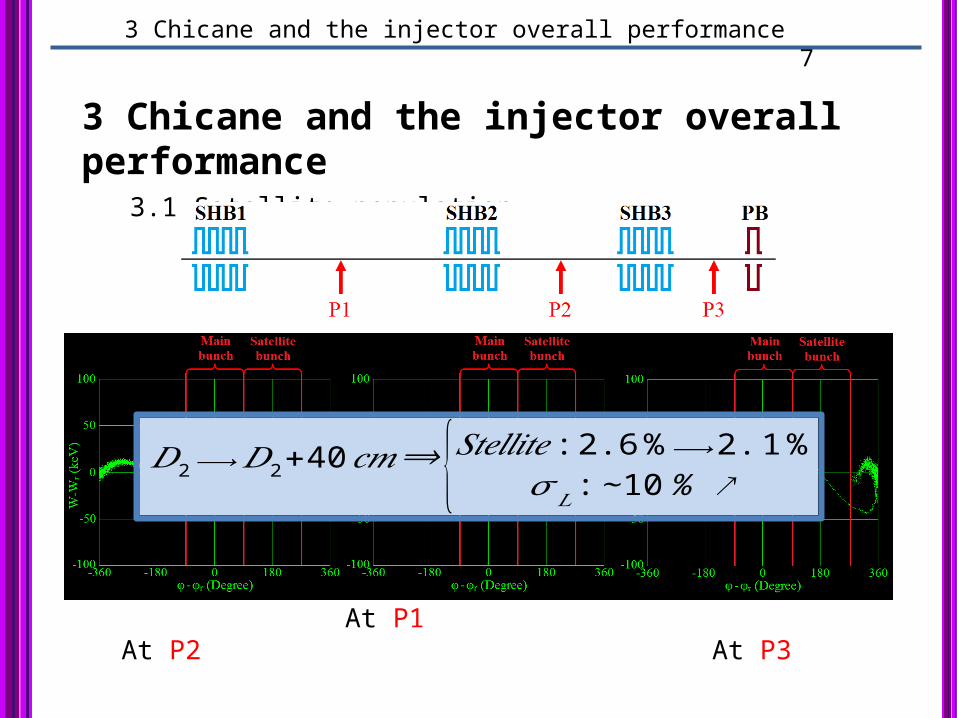
3 Chicane and the injector overall performance 3.1 Satellite population
At P1 At P2 At P3
3 Chicane and the injector overall performance 7
3 Chicane and the injector overall performance 3.1 Satellite population
At P1 At P2 At P3
𝐷2⟶𝐷2+40𝑐𝑚⟹ {𝑆𝑡𝑒𝑙𝑙𝑖𝑡𝑒 :2.6%⟶2.1%𝜎𝐿 :∼10% ↗
3 Chicane and the injector overall performance 8
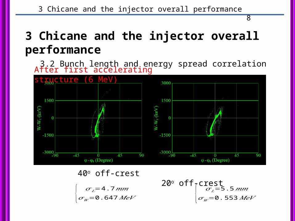
3 Chicane and the injector overall performance 3.2 Bunch length and energy spread correlation
40o off-crest 20o off-crest
{ 𝜎 𝐿=4.7𝑚𝑚𝜎𝑊=0.647 𝑀𝑒𝑉 { 𝜎 𝐿=5.5𝑚𝑚
𝜎𝑊=0.553𝑀𝑒𝑉
After first accelerating structure (6 MeV)
3 Chicane and the injector overall performance 9
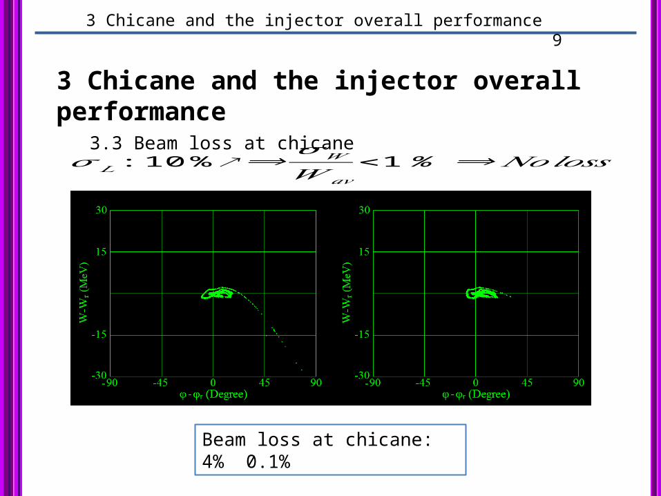
3 Chicane and the injector overall performance 3.3 Beam loss at chicane
𝜎 𝐿 :10 %↗⟹𝜎𝑊
𝑊 𝑎𝑣
<1% ⟹𝑁𝑜𝑙𝑜𝑠𝑠
Beam loss at chicane: 4% 0.1%
4 Fourth SHB 10
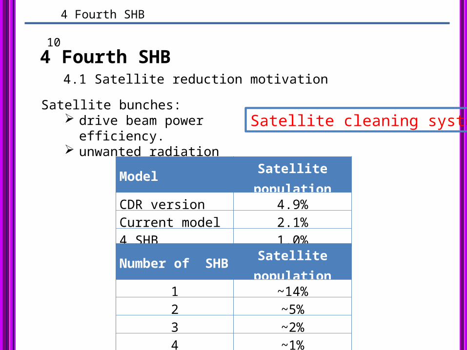
4 Fourth SHB4.1 Satellite reduction motivation
Model Satellite populationCDR version 4.9%Current model 2.1%4 SHB 1.0%
Satellite bunches: drive beam power efficiency. unwanted radiation
Satellite cleaning system
Number of SHB Satellite population1 ~14%2 ~5%3 ~2%4 ~1%
4 Fourth SHB 11
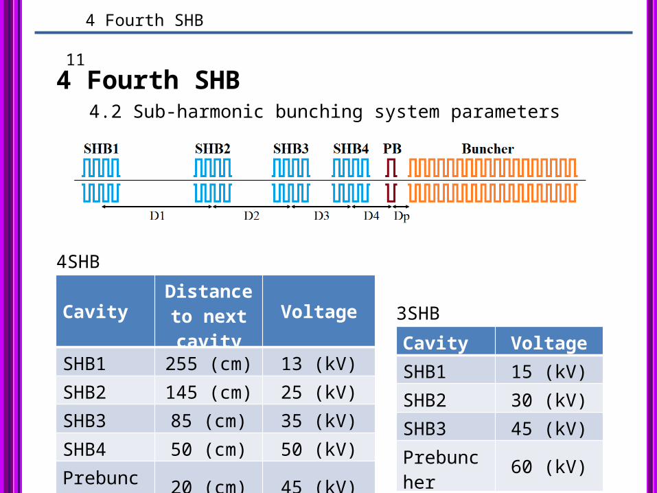
4 Fourth SHB4.2 Sub-harmonic bunching system parameters
CavityDistance to next cavity
Voltage
SHB1 255 (cm) 13 (kV)
SHB2 145 (cm) 25 (kV)
SHB3 85 (cm) 35 (kV)
SHB4 50 (cm) 50 (kV)
Prebuncher 20 (cm) 45 (kV)
Cavity Voltage
SHB1 15 (kV)
SHB2 30 (kV)
SHB3 45 (kV)
Prebuncher 60 (kV)
4SHB
3SHB
5 Conclusion 12
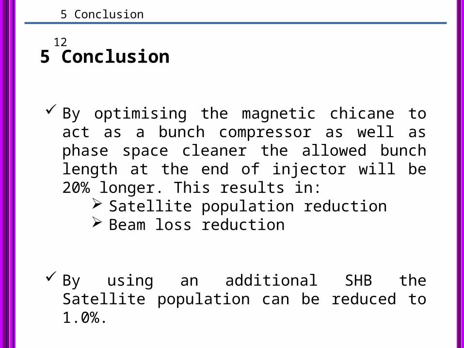
5 Conclusion
By optimising the magnetic chicane to act as a bunch compressor as well as phase space cleaner the allowed bunch length at the end of injector will be 20% longer. This results in:
Satellite population reduction Beam loss reduction
By using an additional SHB the Satellite population can be reduced to 1.0%.

Thanks for your attention.
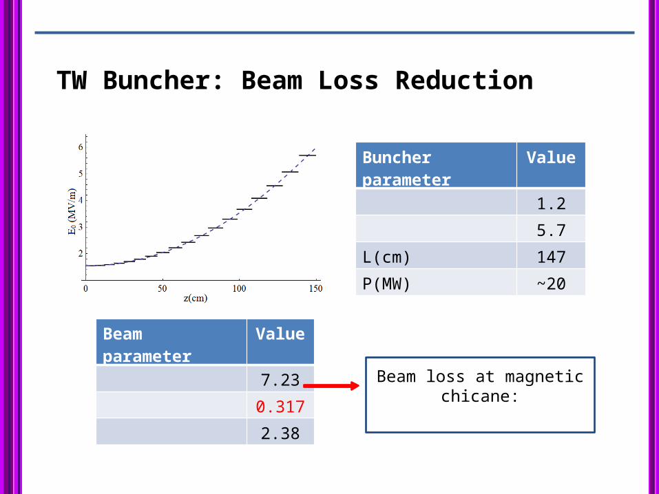
TW Buncher: Beam Loss Reduction
Beam loss at magnetic chicane:
Buncher parameter Value
1.2
5.7
L(cm) 147
P(MW) ~20
Beam parameter Value
7.23
0.317
2.38
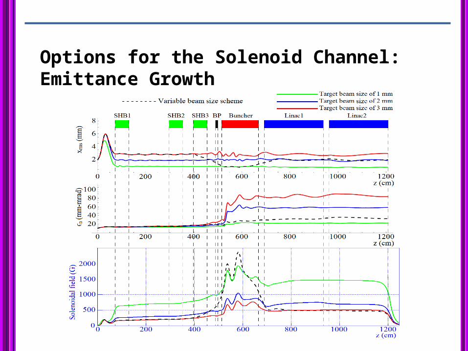
Options for the Solenoid Channel: Emittance Growth