climatix™ climatix ahu application v3.0x pol63x / pol42x
TRANSCRIPT
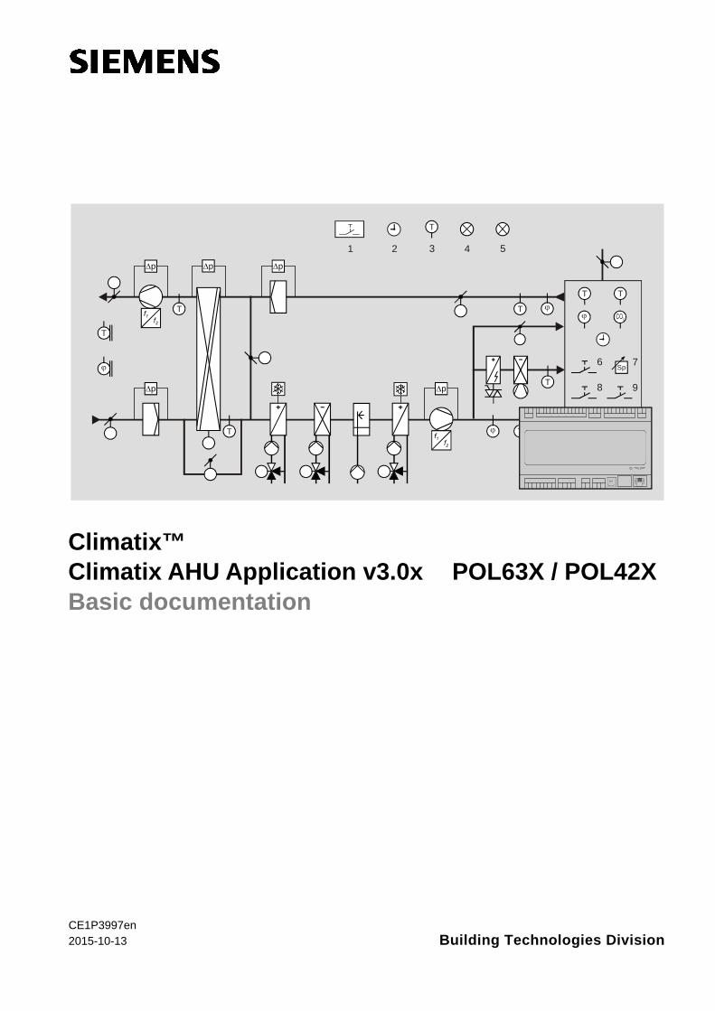
Climatix™ Climatix AHU Application v3.0x POL63X / POL42X Basic documentation
∆p
∆p
∆p ∆p
∆p
T
T
ϕ
T
T ϕ
T T
ϕ
ϕ ρT
T
T
1 2 3 4 5
6 7
8 9
10
Sp
CE1P3997en 2015-10-13
Building Technologies Division

2 / 260
Siemens Climatix AHU Application CE1P3997en Building Technologies Division 2015-10-13
Siemens Switzerland Ltd Building Technologies Division International Headquarters Gubelstrasse 22 6301 Zug Switzerland Tel. +41 41-724 24 24 www.siemens.com/buildingtechnologies
© Siemens Switzerland Ltd, 2015 Subject to change

3 / 260
Siemens Climatix AHU Application CE1P3997en Building Technologies Contents 2015-10-13
Contents
1 About this document .............................................................................. 7
1.1 Overview ................................................................................................... 7
1.2 Revision history ......................................................................................... 8
1.3 Reference documents ............................................................................... 8
1.4 Before you start ......................................................................................... 9
1.5 Document conventions ........................................................................... 10
1.6 Important information on safety .............................................................. 11
1.7 Trademarks and copyrights ..................................................................... 12
1.8 Quality assurance ................................................................................... 12
1.9 Document use / request to the reader .................................................... 13
1.10 Overview ................................................................................................. 13
1.11 Structure and elements ........................................................................... 14
1.12 Operating diagram .................................................................................. 15
1.13 Control functions ..................................................................................... 16
1.14 System properties ................................................................................... 17
1.15 Customer benefits ................................................................................... 19
2 Climatix devices .................................................................................... 20
2.1 Overview ................................................................................................. 20
2.2 Basis controller POL424 ......................................................................... 21
2.3 Basis controller POL63X ......................................................................... 22
2.4 Extension module POL955 ** ................................................................. 23
2.6 Modbus fan and variable speed drive interface ...................................... 24
2.7 Modbus energy meters ........................................................................... 24
2.8 Modbus pressure sensor ........................................................................ 25
2.9 Integrated HMI **..................................................................................... 26
2.10 External HMIs .......................................................................................... 26
2.11 Web@HMI ** ........................................................................................... 30
2.12 Room unit POL822 ................................................................................. 32
3 Preset plant types *** ............................................................................ 35
3.1 Overview ................................................................................................. 35
3.2 AHU 1 – Control for fresh air ................................................................... 36
3.3 AHU 2 – Comfort control ......................................................................... 37
3.4 AHU 3 – Control using Mixing dampers .................................................. 38
3.5 AHU 4 – Control using rotary heat exchanger ........................................ 39
3.6 AHU 5 – Control using bypass dampers ................................................. 40
3.7 Preset AHU – Terminal layout ................................................................. 41
3.8 Preset AHU – Configuration 1 ................................................................. 42
3.9 Preset AHU – Configuration 2 ................................................................. 43
4 Configure application ........................................................................... 44
4.1 Overview ................................................................................................. 44
4.2 Workflow overview .................................................................................. 45
4.3 Configuration step by step ...................................................................... 46

4 / 260
Siemens Climatix AHU Application CE1P3997en Building Technologies Contents 2015-10-13
4.4 Configuration 1 ........................................................................................ 49
4.5 Configuration 2 ........................................................................................ 55
4.6 Configuration IOs .................................................................................... 65
4.7 Fan configuration: EBM-Papst ................................................................ 77
4.8 Check I/O configuration ........................................................................... 78
4.9 Wiring test ............................................................................................... 78
4.10 Integrations.............................................................................................. 79
4.11 SD card functions ** ................................................................................ 80
4.12 Auto update with SD card ....................................................................... 82
4.13 Backup/restore parameters ** ................................................................. 84
5 Function description ............................................................................. 86
5.1 Overview ................................................................................................. 86
5.2 Higher functions ...................................................................................... 87
5.3 Operating mode. ..................................................................................... 89
5.4 Damper control ...................................................................................... 103
5.5 Fan control ............................................................................................ 108
5.6 Temperature control .............................................................................. 121
5.7 Heat recovery with mixed air damper ................................................... 132
5.8 Heat recovery with heat exchanger ...................................................... 135
5.9 Heating/Heating 2 ** .............................................................................. 142
5.10 Electric register/electric register 2 ......................................................... 149
5.11 Cooling/Cooling 2 ** .............................................................................. 153
5.12 Humidity control with POL63X .............................................................. 160
5.13 Dehumidification control with POL42X .................................................. 170
5.14 Air quality control ** ............................................................................... 173
5.15 Auxiliary functions ................................................................................. 174
5.16 Alarm troubleshooting (Alarm outputs) ................................................. 177
6 System settings and Info .................................................................... 179
6.1 Overview ............................................................................................... 179
6.2 Operating levels and access protection ................................................ 180
6.3 Change password ................................................................................. 181
6.4 Supported languages ............................................................................ 182
6.5 System information ............................................................................... 183
6.6 Summer/winter time change ................................................................. 184
6.7 Main settings HMI ................................................................................. 185
6.8 Diagnostics: Controllers and application ............................................... 187
6.9 Diagnostics: Object handler .................................................................. 189
6.10 Application info ...................................................................................... 190
7 Communication ................................................................................... 191
7.1 General .................................................................................................. 191
7.2 TCP/IP (internal) .................................................................................... 192
7.4 Climatix IC remote servicing** ............................................................... 194
7.5 Modbus .................................................................................................. 196
7.6 LON ** ................................................................................................... 197

5 / 260
Siemens Climatix AHU Application CE1P3997en Building Technologies Contents 2015-10-13
7.7 BACnet IP and MSTP ........................................................................... 199
7.8 BACnet Client** ..................................................................................... 200
7.9 AWM (Advanced Web Module) ............................................................. 201
7.10 Modem / SMS **.................................................................................... 202
7.11 Process bus/room units ........................................................................ 205
8 HMI details pages ................................................................................ 208
8.1 Overview ............................................................................................... 208
8.2 Analog outputs ...................................................................................... 209
8.3 Digital outputs ....................................................................................... 212
8.4 Multi-stage outputs ................................................................................ 215
8.5 Analog inputs ........................................................................................ 219
8.6 Digital inputs .......................................................................................... 223
8.7 PID controller ........................................................................................ 227
8.8 Cascade controller ................................................................................ 229
8.9 Scheduler program, general ................................................................. 231
8.10 Weekly schedule ................................................................................... 232
8.11 Daily schedule ....................................................................................... 232
8.12 Exception days and fixed off ................................................................. 233
9 Alarming ............................................................................................... 235
9.1 Overview ............................................................................................... 235
9.2 Functions and workflows ....................................................................... 236
9.3 Alarm lists detail .................................................................................... 238
9.4 Alarm list, active alarms ........................................................................ 238
9.5 Alarm history ......................................................................................... 239
9.6 Event history (new add info!!) ............................................................... 239
9.7 Alarm lists/history settings .................................................................... 240
9.8 Alarm lists .............................................................................................. 241
10 Appendices .......................................................................................... 245
10.1 Overview ............................................................................................... 245
10.2 Point tables: Hardware .......................................................................... 246
10.3 Diagnostics tables for I/O check ........................................................... 248
10.4 Navigation images HMI ......................................................................... 251
10.5 Parameter list room unit ........................................................................ 255
Index ...................................................................................................................................................... 259

6 / 260
Siemens Climatix AHU Application CE1P3997en Building Technologies Contents 2015-10-13

7 / 260
Siemens Climatix AHU Application CE1P3997en Building Technologies Division About this document 2015-10-13
1 About this document 1.1 Overview
This document outlines the Siemens Climatix AHU Application – hereinafter referred to as Climatix AHU Application – for controllers POL63X and POL42X of the Climatix device family.
Carefully read this section prior to starting. It provides important information on: • Document validity • Target audience, prerequisites • Application and safety
The individual topics in the section are: Topic Section Revision history 1.2 Reference documents 1.3 Before you start 1.4 Document conventions 1.5 Important information on safety 1.6 Trademarks and copyrights 1.7 Quality assurance 1.8 Document use / request to the reader 1.9
STOP
Introduction
Topic

8 / 260
Siemens Climatix AHU Application CE1P3997en Building Technologies Division About this document 2015-10-13
1.2 Revision history
Version Date Changes Section Pages 26.07.2012 New document --- --- 29.05.2013 Changes in application 1.4, 2.5,
5.6.3, 5.6.4, 8.4.1 9, 19, 68, 69, 193
21.01.2014 New name Climatix AHU Application Supplements in the workflow Configuration, miscellaneous Configuration IOs, Modbus devices New section Set up EBM fan New section Wiring test SD card functions, file names BACnet devices, AWB module
All 5.1, 5.2, 5.3 5.4, 5.5 5.6 5.7 5.9 5.10 8.6
47, 48, 49 54, 65 67, 72 78 79 80 205
12.01.2015 K-factor explanation Modbus pressure sensors Modbus fan
5.6.4 3.5 5.6.10
70 27 74
14.04.2015 Draft update for V302, yellow marked 15.05.2015 Additional yellow and green marked
changes - Section 3.2, No Triac on POL424
1.3 Reference documents
Document title Type of document Document no. Climatix controllers POL6XX Basic documentation CB1P3903en Climatix controller POL63X.XX/XXX Data sheet CB1Q3230en Climatix controllers POL42X. Data sheet CB1Q3973en Climatix AHU extension module 14 I/O POL955.XX.XXX Data sheet CB2N3262en Climatix communication BACnet MS/TP module POL904.00/xxx Data sheet CB1Q3932en Climatix communication BACnet IP module POL908.00/xxx Data sheet CB1Q3933e Climatix communication LON module POL906.00/XXX Data sheet CB1Q3931en Climatix communication Modbus module POL902.00/XXX Data sheet CB1Q3934en Climatix advanced Web module POL909.5X/XXX Data sheet CB1Q3935en Climatix advanced Web module POL909.5X/XXX Basic documentation CB1P3935en Climatix advanced Web and BACnet module POL909.8X/XXX Data sheet CB1Q3937en Climatix communication M-Bus module POL907 Data sheet CB1Q3936en Climatix remote OPC server POL0L9.00/XX Basic documentation CB1P3904en Climatix IC remote servicing Data sheet A6V10449189 External HMI-DM POL895.51/XXX Data sheet CB1N3941en External HMI-TM POL871.XX/STD Data sheet CB1N3917en Room unit HMI-SG POL822.60/XXX Data sheet CB2N3261en Integration guide lines BACnet MS/TP communication with POL904.00/xxx Integration guide CB1J3967en BACnet IP communication with POL908.00/xxx Integration guide CB1J3962en LON communication with POL906.00/XXX Integration guide CB1J3964en Climatix Modbus communication, slave mode Integration guide CB1J3960en Advanced Web module POL909.50 (AWM) Integration guide CB1J3935en Advanced Web and BACnet module POL909.80 (AWB) Integration guide CB1J3937en

9 / 260
Siemens Climatix AHU Application CE1P3997en Building Technologies Division About this document 2015-10-13
1.4 Before you start
This document applies to the following products:
Name Version Climatix AHU Application 3.xx
The content of sections and parts thereof where the titles are labeled by trailing **, apply to controller POL63X only.
Examples: – Section 2.4, Extension module POL955 ** (can only be used with POL63X) – Section 5.9, Heating/Heating 2 ** (Heating 2 can only be used with POL63X)
The content of sections and parts thereof where the titles are labeled by trailing ***, apply to controller POL42X only.
Example: – See Section 3, Preset plant types *** Description and functional scope of the products are based on the Climatix valid version set 10.0 or higher.
This document is intended for the following audience: • Measuring and control engineering staff of Siemens and OEM customers • Sales and commissioning staff of OEM customers • Siemens employees in sales and support
This document intends to help the target audience to: • Determine and establish control function for customized ventilation and air
conditioning plants and units based on the Climatix AHU application and using Climatix controllers POL63X and POL42X
• Commissioning of these ventilation and air conditioning plants.
The above target audience: • Has general professional knowledge on planning and commissioning HVAC
technology measuring and control solutions • Knowledge on the operating units HMI and POL822 room unit (applies to personnel
that configure and commission applications)
i
i
Validity
Labeling **
Labeling ***
Product versions
Target audience
Use
Requirements

10 / 260
Siemens Climatix AHU Application CE1P3997en Building Technologies Division About this document 2015-10-13
1.5 Document conventions
Below is an overview of all symbols used in this document denoting risks or important information:
This symbol draws your attention to special safety notes and warnings. Failing to observe these notes may result in injury and/or serious damages.
This symbol denotes special information that, when failed to observe, may result in faulty functionality or loss of data.
Notes with this symbol provide important information that requires appropriate attention.
This symbol marks passages containing tips and tricks.
The following abbreviations are used in text and illustrations:
Abbreviation Meaning HMI Human machine interface KP Amplification factor (KP). LED Light emitting diode NC Normally closed (opening contact) NO Normally opened (closing contact) SD Safety device TN Integral action time (I time) BSP Board support package, equal to firmware
STOP
Symbols used
Abbreviations

11 / 260
Siemens Climatix AHU Application CE1P3997en Building Technologies Division About this document 2015-10-13
1.6 Important information on safety
The Climatix devices used together with the Climatix AHU application may only be used to control and monitor functions in ventilation, air conditioning and refrigeration plants. Trouble-free and safe product operation of the above products presupposes transport, storage, mounting, installation, and commissioning as intended as well as careful operation.
Fuses, switches, wiring and grounding must comply with local safety regulations for electrical installations.
When wiring, strictly separate AC 230 V mains voltage from AC 24 V safety extra-low voltage (SELV) to protect against electrical shock!
Only qualified staff trained accordingly may prepare for use, commission, and maintain Climatix devices. Maintenance of Climatix devices is generally limited to regular cleaning. We recommend removing dust and dirt from system components installed in the control panels during standard service.
Only authorized staff may diagnose and correct faults and recommission the plant. This applies to working within the panel as well (e.g. testing or changing fuses).
Refer to the environmental conditions specified in the respective data sheets for storage and transport. If in doubt, contact your supplier. Devices contain electrical and electronic components; do not dispose of them in household garbage. Observe all local and applicable laws.
Field of application
Intended use
Electrical Install
Wiring
Commissioning and maintenance
Maintenance
Faults
Storage and transport
Disposal

12 / 260
Siemens Climatix AHU Application CE1P3997en Building Technologies Division About this document 2015-10-13
1.7 Trademarks and copyrights
The table below lists the third-party trademarks used in this document and their legal owners. The use of trademarks is subject to international and domestic provisions of the law.
Trademarks Legal owner BACnet American National Standard (ANSI/ASHRAE 135-1995) LonLink™ LON® / LonManager® LonMark® LonTalk® LonWorks®
Echelon Corporation
Modbus® The Modbus Organization, Hopkinton, MA, USA All product names listed in the table are registered (®) or not registered (™) trademarks of the owner listed in the table. We forgo the labeling (e.g. using the symbols ® and ™) of trademarks for the purposes of legibility based on the reference in this section. This document may be duplicated and distributed only with the express permission of Siemens, and may be passed on only to authorized persons or companies with the required technical knowledge.
1.8 Quality assurance
These documents were prepared with great care. • The contents of all documents are checked at regular intervals. • All necessary corrections are included in subsequent versions. • Documents are automatically amended as a consequence of modifications and
corrections to the products described. Please make sure that you are aware of the latest document revision date. If you find any lack of clarity while using this document, or if you have any criticisms or suggestions, please contact the product manager in your nearest branch office. Addresses for Siemens RCs are available at www.siemens.com/sbt.
Trademarks, legal owners
Copyright
Document contents
Suggestions

13 / 260
Siemens Climatix AHU Application CE1P3997en Building Technologies Division About this document 2015-10-13
1.9 Document use / request to the reader
Before using our products, it is important that you read the documents supplied with or ordered at the same time as the products (equipment, applications, tools etc.) carefully and in full. We assume that persons using our products and documents are authorized and properly trained and have the requisite technical knowledge to use our products as intended. Additional information on products and applications is available: • On the intranet (for Siemens employees only) at
https://workspace.sbt.siemens.com/content/00001123/default.aspx • At your next Siemens branch office www.siemens.com/sbt or at your system
suppliers. • From the support team in the headquarters [email protected] if
no local POC is available. Siemens assumes no liability to the extent allowed under the law for any losses resulting from a failure to comply with the aforementioned points or for the improper compliance of the same.
1.10 Overview
The Climatix AHU application is an all-in-one solution programmed using the SAPRO Tool to control ventilation and air conditioning units (AHUs). This section provides the following knowledge: • Fundamental plant design • The most important application and system properties • Customer benefits The individual topics in the section are: Topic Section Structure and elements 2.2 Operating diagram 2.3 Control functions 2.4 System properties 2.5 Customer benefits 2.6
Request to the reader
Further information
Exemption from liability
Introduction
Knowledge provided
Topic

14 / 260
Siemens Climatix AHU Application CE1P3997en Building Technologies Division About this document 2015-10-13
1.11 Structure and elements
The Climatix AHU application includes all standard as well as a number of special control and monitoring functions for ventilation and air conditioning units (AHUs). The following diagram illustrates: • The fundamental plant design equipped with the maximum number of air handling
units • Devices that can be connected externally to implement the desired control and
display functions
Figure 1: Plant diagram for fundamental plant design and Devices The above plant elements are: Pos. Element
1 Fire detector 2 Time switch program 3 Free temperature sensor 4 Free alarm display 5 Display of a specified operating mode. 6 Occupancy button 7 Setpoint settings 8 Emergency button 9 Acknowledge alarm
10 Alarm display 11 Heat recovery:
Rotary heat exchanger, plate heat exchanger, water heat exchanger The units used in this example as well as the required sensors and functions are selected and configured accordingly using the Climatix operator unit HMI or via Web browser (HMI@WEB), see section 4, Configure application.
∆p
∆p
∆p ∆p
∆p
T
T
ϕ
T
T ϕ
T T
ϕ
ϕ ρT
T
T
1 2 3 4 5
6 7
8 9
10
11Sp
3997Z01
Plant diagram
Key
Selection and configuration
15 / 260
Siemens Climatix AHU Application CE1P3997en Building Technologies Division About this document 2015-10-13
1.12 Operating diagram
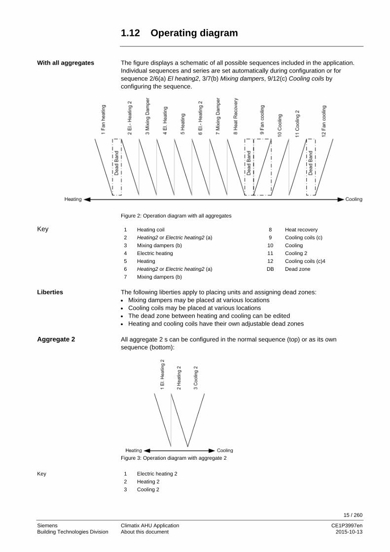
The figure displays a schematic of all possible sequences included in the application. Individual sequences and series are set automatically during configuration or for sequence 2/6(a) El heating2, 3/7(b) Mixing dampers, 9/12(c) Cooling coils by configuring the sequence.
Figure 2: Operation diagram with all aggregates
1 Heating coil 8 Heat recovery 2 Heating2 or Electric heating2 (a) 9 Cooling coils (c) 3 Mixing dampers (b) 10 Cooling 4 Electric heating 11 Cooling 2 5 Heating 12 Cooling coils (c)4 6 Heating2 or Electric heating2 (a) DB Dead zone 7 Mixing dampers (b)
The following liberties apply to placing units and assigning dead zones: • Mixing dampers may be placed at various locations • Cooling coils may be placed at various locations • The dead zone between heating and cooling can be edited • Heating and cooling coils have their own adjustable dead zones All aggregate 2 s can be configured in the normal sequence (top) or as its own sequence (bottom):
Figure 3: Operation diagram with aggregate 2
1 Electric heating 2 2 Heating 2 3 Cooling 2
With all aggregates
Key
Liberties
Aggregate 2
Key

16 / 260
Siemens Climatix AHU Application CE1P3997en Building Technologies Division About this document 2015-10-13
1.13 Control functions
The following table provides an overview of important control functions for the various plant areas: Plant area Control functions Temperature and humidity control.
• Supply air, room and extract air and cascade control with optional limitation of supply air
• Summer/winter compensation of setpoint • External setpoint default or setpoint shift • Plant start of plant when room temperature with separate
setpoint is too low (too high) – in spite of off (standby) Heating and cooling registers
• Control 4 heating registers: 2 warm water, 2 electric registers (with up to 3 steps, or 0-10 V DC) with up to 3 included in the heating sequence
• Limitation of electric register dependent on fan speed (stage)
• Preheat function for hot water register, including frost sensor and/or frost detector
• 2 cooling registers (cold water or up to 3 stages or analog DX)
• Limitation of direct expansion evaporator dependent on fan speed (stage)
• Shut off cooling register when the outside air temperature is too low
Heat recovery • 4 variants for heat recovery • Cooling recovery
Fans and dampers • Fresh air and extract air damper control • Fire damper control with auto test function • Extract air fan can be disabled • Stepped (maximum 3 steps) or frequency controlled or
modulating analog controlled fans Plant control • Emergency off function
• Time switch catalog with daily, weekly and annual program
A complete and detailed description of all available functions is available in section 5 Function description.
Overview
Detailed information

17 / 260
Siemens Climatix AHU Application CE1P3997en Building Technologies Division About this document 2015-10-13
1.14 System properties
The Climatix AHU application is an all-in-one application programmed using the SAPRO tool. It operates on the Climatix controllers POL63X and POL42X. The most important differences to properties are: Basis controller
Properties
POL63X • The user loads the application on the controller • 49 inputs and outputs are available on the basis controller and the
maximum of 2 connectable extension modules POL955.00/ALG POL42X • Application with preset plant types is loaded at the factory
• 21 inputs and outputs are available on the basis controller • No extension modules available
Numerous sensor types are supported to fulfill the widest range of different requirements: • Pt1000, LGNi1000, Ni1000, NTC10k, 0-10 V, modbus sensors The areas for active sensors can be freely selectable. It is configured using dialogs on the Climatix operator unit HMI or via web browser with the following features: • Free placement of hardware inputs/outputs • Selection and configuration of all AHU functions and sensor types • No additional tools or programming required • Step-by-step configuration. Functions that can no longer be selected are
automatically hidden in later steps • Disabled functions are hidden on the operator units (HMI; HMI4Web) and for
communications • Support of various languages • Operator units are password-protected. They can also be connected via the process
bus. So that a single HMI can be used for multiple controllers • A PC-based Climatix Factory Tool supports OEM load the application, configure the
controller, as well as automatically generate the documentation The Climatix controllers can be updated as needed using an SD card to elegantly upload new functions or extensions: • Application software update and controller firmware with backup of plant parameters
using the SD card • Download preconfigured plants using SD cards or a PC with the SCOPE tool • USB interface as the standard connection between the controller and PC
Basis controllers
Sensor types
Configuration
Update and download

18 / 260
Siemens Climatix AHU Application CE1P3997en Building Technologies Division About this document 2015-10-13
System properties, cont’d
The trend toward ready to plug-in AHUs also includes a ready-to-use integration interface that clearly documents and thoroughly tested with various control systems for building automation and control (BACS). The Climatix AHU application supports all communication interfaces listed below so that only the corresponding Climatix communication module is used – without the need for additional engineering. Interfaces • BACnet-IP (B-BC profile) • BACnet-MSTP (B-BC profile) • Modbus RTU or TCP (master) • Modbus RTU (slave) for the POL902 module • LON interface, 64 SNVTs for POL906 module • OPC via TCP/IP connection and Climatix remote OPC-server • WEB package (POL909.50), for visualization, plant image, trend data, alarming and
routing for remote maintenance The Climatix controller can be operated remotely thanks to the integrated TCP/IP interface and an Internet browser. The user is provided the same operating structure as used for an internal or external operator element. • Advanced Web server POL909.50/XXX (POL909.50/XXX) to set up web-based
visualization, operation, trending, archiving as well as alarming, permitting the monitoring of the plant remotely by different users
• Web-HMI (for POL 638.xx only) automatically configures when configuring the plant • SCOPE tool via modem, TCP/IP • Alarm messages per e-mail or SMS (GSM modem required) Climatix AHU package is already prepared to connect to the cloud based remote servicing system in order to support remote monitoring and operation but also in order to remote upgrade the complete controls system with latest version (firmware, application, translation, integration mapping). The Climatix Factory tool supports OEM in its manufacturing process and is matched to the Climatix AHU application. The tool support the OEM when: • Loading the Climatix controller • Configuring the controller and the application • Creating plant diagrams It further creates documentation specific to a configuration report. Climatix change log function is similar to a black box of an air craft. The change log recorded every write access to the objects. With every write will be the new and old value, timestamp and Object ID stored. This log is only for the OEM accessible and be hidden for service and enduser and can be read out via SCOPE tool (UUID is 00000000-0000-0000-0000-000000000001) for diagnostic purposes. The change log cannot be stopped and resists also over a BSP upgrade and application download. Certain alarms are often requested to change to event only to just notify the user of an even but avoid alarm indication. Climatix AHU application is prepared, so users are enabled to change alarm messages to even messages. The alarm snapshot function can be used to capture the state of selected values one cycle before an alarm occurs. When the alarm happens, these values are stored and visible on HMI alarm pages to support the diagnostic of a certain behavior.
Implemented communications
Remote operation, service
Climatix IC remote servicing
Climatix Factory tool
Climatix Change Log
Climatix Event history
Climatix Alarm Snap shot

19 / 260
Siemens Climatix AHU Application CE1P3997en Building Technologies Division About this document 2015-10-13
1.15 Customer benefits
With the Climatic controller product range for OEM, Siemens is supporting the trend within the industry to integrate applications for air conditioning and refrigeration technology into the devices at the factory and to lower in this way the costs of plant installation and commissioning. The Climatix product range as the basis meets the requirements since is covers all application segments, namely: • Standard controllers for simple, cost-optimized HVAC applications such as fan coils • Controller for more challenging, communicative applications • Freely programmable controllers for complex solution for air conditioning units or
cooling units demanding a maximum level of flexibility with regard to communications and extensions
All Climatix POL6xx and POL4XX controllers are freely programmable controllers and can be programmed accordingly for the corresponding use such as ventilation, refrigeration or district heating. The following Climatix AHU application was created for them. The applications were developed in a manner to provide the greatest degree of flexibility to cover the need for application-ready solutions, yet remain very easy to configure via an operator unit. Various ready to use applications were created that are highly flexible allowing for the immediate use thanks to simple configuration via an operator unit to permit fast times to market for OEM customers and allow them to benefit from the application knowledge and Siemens experience in the area of integrating building automation and control systems. No programming knowledge required. Modifications to functionality or hardware extensions are also made by reconfiguring using the operator unit. The applications are based on years of experience in the corresponding application segments. They are tested and equipped and documented with the requisite communication interfaces including BACnet, LON and Modbus. The standardization in turn significantly lowers costs at OEM, reduces support expenses as well and guarantees integration into Siemens or other building automation and control systems. The Climatix AHU application is distinguished by the highest level of hardware and functionality. To meet the widest possible range of requirements for AHU plant types and variants. The application, devices, and parameters as well as communications interfaces are already documents as per the various target users (end users, system integrators, etc.). They do not need to be newly created on a project-by-project basis.
The trend
The basis
The controllers POL6XX and POL4XX
Customer benefits
Security
Reduce costs
Flexibility
Documentation

20 / 260
Siemens Climatix AHU Application CE1P3997en Building Technologies Division Climatix devices 2015-10-13
2 Climatix devices 2.1 Overview
The devices of the Climatix product range forms the basis for operating and control functions of the Climatix AHU application. This section provides the following knowledge: • Design and elements of basis devices and extension modules • Types and functions of operating unit HMI • Functions and display of room unit The individual topics in the section are: Topic Section Basis controller POL424 3.2 Basis controller POL63X 3.3 Extension module POL955 ** 3.4 Integrated HMI ** 3.5 External HMIs 3.6 Web@HMI ** 3.7 Room unit POL822 3.8
Introduction
Knowledge provided
Topic

21 / 260
Siemens Climatix AHU Application CE1P3997en Building Technologies Division Climatix devices 2015-10-13
2.2 Basis controller POL424
The following image displays the controller POL424 with its elements as well as typical examples of connectable field devices:
Figure 4: POL424 with its elements The elements and field devices (examples) in the figure are: Pos. Des. Element / field devices
1 B1…B3 3 analog inputs: For sensors NTC 10 k and Ni1000 (TK5000) / Pt1000
2 X1, X2 2 universal inputs: Can be configured for sensors, resistance transmitters, etc.
3 X3 …X5 3 digital outputs: Can be configured for valves, relays, etc.
4 X6, X7 D1, D2
X8
4 digital inputs with polling voltage DC 24 V: For transmitter with potential-free contacts. 1 digital input for pulse transmitter.
5 A+, B- RS-485 interface: For applications using Modbus RTU communications protocol.
6 CE-, CE+ Process bus interface. 7 0 V, 24 V Supply voltage AC/DC 24 V:
– 43 VA at AC 24 V (1.8 A) without I/O extension module – 24 VA at AC 24 V (1.0 A) without I/O extension module
8 Q3…Q8 Q1
6 relay outputs (NO) for AC 24…230 V 1 relay outputs (switching) for AC 24…230 V
9 DL1 1 digital input (0/1 binary), galvanically separated 10 T-HI Local service interface (USB / RS-485) for HMI and tool 11 BSP, BUS Status indicators for BSP and BUS
1 2 3 4 5 6
7 8 9 10
11
P39
97Z2
1
Mechanical setup
Elements and connections

22 / 260
Siemens Climatix AHU Application CE1P3997en Building Technologies Division Climatix devices 2015-10-13
2.3 Basis controller POL63X
The following image displays the fully equipped controller POL63X with its elements as well as typical examples of connectable field devices:
1 2 3 4
6
5
9 10 117 8
1615
13
P39
03Z0
4
12
17
Ethernet
0V
24V
~
T-SV
T-IP
T-HI
14
Figure 5: POL63X with its elements The elements and field devices (examples) in the figure are: Pos. Des. Element / field devices
1 0 V, 24 V Supply voltage AC/DC 24 V: – 43 VA at AC 24 V (1.8 A) without I/O extension module – 24 VA at AC 24 V (1.0 A) without I/O extension module
2 X1…X8
+24 V
8 universal inputs / outputs: Configurable for sensors, resistance transmitters, relay contacts (potential free), valves, dampers, etc. X1/X2 is only configurable as universal inputs 2 power supplies DC 24 V for sensors
3 Y1, Y2 2 analog outputs DC 0…10 V / 2 mA: For valves, dampers, etc.
4 D1…D5 5 digital inputs with polling voltage DC 24 V: For transmitter with potential-free contacts
5 CLA, CLB LON interface Only available for POL636.00/XXX
6 Q1…Q6 6 relay outputs (NO) for AC 24…230 V: For contactors, fans, pumps, lights, etc.
7 CE-, CE+ Process bus interface 8 A+, B- RS-485 interface:
For applications using Modbus RTU communications protocol 9 T-SV Tool interface / USB standard plug (plug type B)
10 T-IP Ethernet connection (TCP/IP) for tool, touch panel, web browser. POL636.00/XXX only!
11 T-HI Local service interface (USB / RS-485) for HMI and tool 12 BSP, BUS Status indicators for BSP and BUS 13 – Initialization button for BSP upgrade and application update 14 – HMI with LCD and navigation elements.
POL63X.70/… only! 15 – Modem interface (RJ45 / RS232) for remote service tool 16 – SD card reader for BSP and application upgrade 17 – Battery compartment (under the lid)
Mechanical setup
Elements and connections

23 / 260
Siemens Climatix AHU Application CE1P3997en Building Technologies Division Climatix devices 2015-10-13
2.4 Extension module POL955 **
Extension module in Climatix AHU Application is only available with controller POL63X.
The following image displays the I/O extension module POL955.0 with its elements as well as typical examples of connectable field devices:
1
2 34
5
P390
3Z08
Figure 6: POL955.0 with its elements The elements and field devices (examples) in the figure are: Pos. Des. Element / field devices
1 X1…X8 8 universal inputs / outputs: Configurable for sensors, resistance transmitters, relay contacts (potential free), valves, dampers, etc.
2 Q1…Q4 4 relay outputs (potential free): Closing contacts for switching voltage AC 24…230 V For contactors, fans, pumps, lights, etc.)
3 Y1, Y2 2 analog outputs DC 0…10 V / 2 mA For valves, dampers, etc.
4 ADR/TERM DIP switch to set addresses and bus connection 5 BSP, BUS Status LEDs for BSP and BUS
i
Mechanical setup
Elements and connections

24 / 260
Siemens Climatix AHU Application CE1P3997en Building Technologies Division Climatix devices 2015-10-13
2.6 Modbus fan and variable speed drive interface
Climatix AHU application is capable to drive various fan or frequent converter via Modbus. It is even capable to address, configure and run without additional configuration tool to reducing commissioning time and hardware cost, but also gaining additional information for optimization and diagnostic. Type Illustration Properties/ defaults Siemens Sinamics GP120P
• Manual configuration • Supply fan: Modbus adr:31 • Exhaust fan: Modbus adr:21 • Baudrate 9600 • Parity even • Stop Bit 1 • Modbus delay xx, s • Response timeout xx, s • Termination passive/active
Danfoss FC102, FC102
• Supply fan: Modbus adr:32 • Exhaust fan: Modbus adr:22
EBM-Papst EC fan
• Special set up dialog for configuration • Supply fan: Modbus adr:33 • Exhaust fan: Modbus adr:23
For more details see configuration of fan IO or EBM Papst set up.
2.7 Modbus energy meters
Climatix AHU application is capable to drive Carlo Cavazzi energy meter via Modbus communication. Type Illustration Properties/ defaults Energy meter Carlo Cavazzi
• Modbus address: 1 • Modbus baudrate: 9600
For more details see configuration of energy meter.
Modbus driven fans and variable speed drive
Modbus driven energy meters

25 / 260
Siemens Climatix AHU Application CE1P3997en Building Technologies Division Climatix devices 2015-10-13
2.8 Modbus pressure sensor
The differential pressure measuring transducers with Modbus output signal listed below are well suited for use with the Climatix AHU application. A DIL switch is used to assign the address. Additional engineering not required. There are two types of operator units available: Type Illustration Properties QBM68.X
• Differential pressure measuring transducer • Pressure-linear characteristic with selectable
pressure measuring range • Operating voltage:
AC 24 V or DC 15...36 V • Output signals:
Modbus RTU and 0…10 V • Simple and fast mounting • Maintenance free • Calibrated and temperature-compensated
measured signal • Default Modbus address: 40 • Default baudrate: 9600 baud
QBM69.X
• Differential pressure measuring transducer • Pressure-linear characteristic with selectable
pressure measuring range • Operating voltage:
AC 24 V or DC 15...36 V • Output signals:
Modbus RTU 0…10 V • Accessory (option):
2 temperature sensor, analog (LG-Ni1000, PT1000 or NTC10K)
• Maintenance free • Calibrated and temperature-compensated
measured signal • Default Modbus address: 40 • Default baudrate: 9600 baud
The plant diagrams below illustrate an example for using the Modbus pressure sensor in a Climatix AHU application:
Figure 7: Example: Using the Modbus pressure sensor POL63X Climatix controller QBM69.X Differential pressure measuring transducer VSD Variable speed drives (VSD), e.g. for EBM-Papst
∆p
T
T T
TT
T
3975Z03
QBM69XQBM69X
Modbus
VSD
VSD
∆p
∆p∆p
∆p
POL63X
2 types
Application example
Key

26 / 260
Siemens Climatix AHU Application CE1P3997en Building Technologies Division Climatix devices 2015-10-13
2.9 Integrated HMI **
Available only for controller POL63X.070.
To be documented in a later edition.
2.10 External HMIs
The external operating units HMI configures and parameterizes the controllers POL63X and POL42X loaded with the Climatix AHU application. There are three types of operator units available: Type Illustration Properties HMI-DM
– 8-line display with selectable backlight (bl/ws)
– Combined press/rotary knob for comfortable operation
– Alarm button with LED display – Supports local or remote installation – IP 31
HMI-TM
– 8-line, high-resolution display (240 x 128 pixels)
– 6 keys for easy operation – ALARM, INFO and CANCEL keys with
LED indicators – Version POL871.71 for magnetic
mounting; can be used as handheld unit – IP 65
Web@HMI
– Available with POL638 or together with AWM (POL909.5x)
– Same look and feel as HMI-DM or HMI-TM
– Same user access level as HMI-DM or HMI-TM
– Remote parameterization via standard web browser
– Menu screens can be used for documentation (print screen)
– Online trending possibilities The menu structures of the three operator units are identical; the design of the operating elements and functions match at about 90%. The following pages provide a short description based on the HMI-DM.
i
Purpose and types
Identical menu structure

27 / 260
Siemens Climatix AHU Application CE1P3997en Building Technologies Division Climatix devices 2015-10-13
External HMIs, cont’d
The picture below displays the front view of the HMI-DM with display and operating elements:
Figure 8: HMI-DM front view The operating elements and functions are: Pos. Designation Functions
1 Display Displays menus, objects, parameters, parameter values, commands, etc.
2 Setting knob Turn: – Select menu, objects, parameters, parameter values – Changes parameter values Press: – Go to lower levels or to setting pages – Exit setting pages and assume changed values Go to password handling page: Press long
3 ESC button Press: – Go to the next higher level – Exit setting pages and assume changed values Go to HMI setting page: Press long Press: – Go back to last active page (after going to password handling page
using the setting knob) – Go back to last active page (after going to Main Index page using the
Info button) 4 Alarm button LED:
– Off: No alarm – Blinking: Alarm pending – Lit continuously: Pending acknowledged alarm Press button: – Go to last alarm – Go to alarm list (displays pending alarms and alarm history) – Go to alarm history – Go to alarm settings – Acknowledge and reset alarms in the alarm list or alarm history
5 Info button Go to Main Index page: Press Go to HMI basis page: Press long
1
234
5
P399
7Z02
HMI-DM view
Operator elements
28 / 260
Siemens Climatix AHU Application CE1P3997en Building Technologies Division Climatix devices 2015-10-13
External HMIs, cont’d
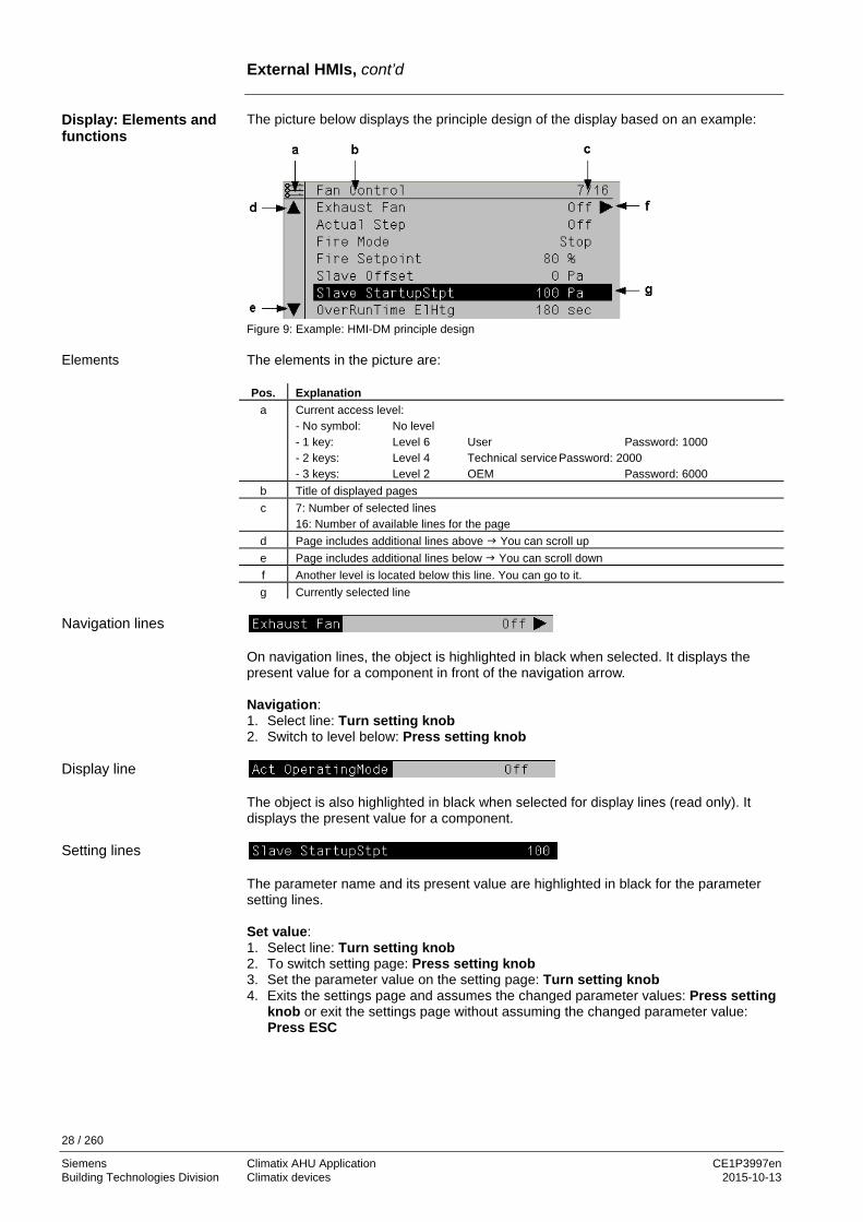
The picture below displays the principle design of the display based on an example:
Figure 9: Example: HMI-DM principle design The elements in the picture are: Pos. Explanation
a Current access level: - No symbol: No level - 1 key: Level 6 User Password: 1000 - 2 keys: Level 4 Technical service Password: 2000 - 3 keys: Level 2 OEM Password: 6000
b Title of displayed pages c 7: Number of selected lines
16: Number of available lines for the page d Page includes additional lines above You can scroll up e Page includes additional lines below You can scroll down f Another level is located below this line. You can go to it. g Currently selected line
On navigation lines, the object is highlighted in black when selected. It displays the present value for a component in front of the navigation arrow. Navigation: 1. Select line: Turn setting knob 2. Switch to level below: Press setting knob
The object is also highlighted in black when selected for display lines (read only). It displays the present value for a component.
The parameter name and its present value are highlighted in black for the parameter setting lines. Set value: 1. Select line: Turn setting knob 2. To switch setting page: Press setting knob 3. Set the parameter value on the setting page: Turn setting knob 4. Exits the settings page and assumes the changed parameter values: Press setting
knob or exit the settings page without assuming the changed parameter value: Press ESC
Display: Elements and functions
Elements
Navigation lines
Display line
Setting lines
29 / 260
Siemens Climatix AHU Application CE1P3997en Building Technologies Division Climatix devices 2015-10-13
External HMIs, cont’d
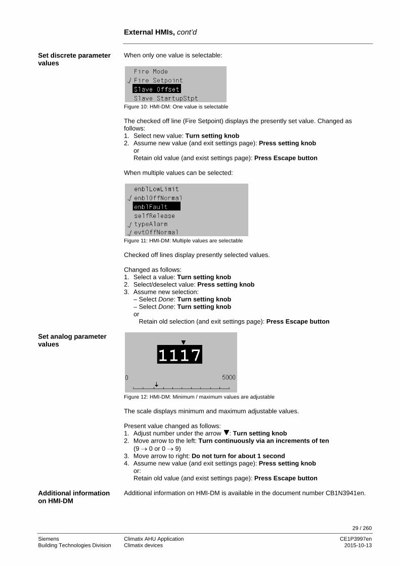
When only one value is selectable:
Figure 10: HMI-DM: One value is selectable The checked off line (Fire Setpoint) displays the presently set value. Changed as follows: 1. Select new value: Turn setting knob 2. Assume new value (and exit settings page): Press setting knob or Retain old value (and exist settings page): Press Escape button When multiple values can be selected:
Figure 11: HMI-DM: Multiple values are selectable Checked off lines display presently selected values. Changed as follows: 1. Select a value: Turn setting knob 2. Select/deselect value: Press setting knob 3. Assume new selection:
– Select Done: Turn setting knob – Select Done: Turn setting knob or Retain old selection (and exit settings page): Press Escape button
Figure 12: HMI-DM: Minimum / maximum values are adjustable The scale displays minimum and maximum adjustable values. Present value changed as follows: 1. Adjust number under the arrow : Turn setting knob 2. Move arrow to the left: Turn continuously via an increments of ten
(9 → 0 or 0 → 9) 3. Move arrow to right: Do not turn for about 1 second 4. Assume new value (and exit settings page): Press setting knob
or: Retain old value (and exist settings page): Press Escape button
Additional information on HMI-DM is available in the document number CB1N3941en.
Set discrete parameter values
Set analog parameter values
Additional information on HMI-DM

30 / 260
Siemens Climatix AHU Application CE1P3997en Building Technologies Division Climatix devices 2015-10-13
2.11 Web@HMI **
Possible directly only with controller POL638. It has a WEB server for a remote servicing using a standard web browser. The other controllers POL6XX can be supplemented for these functions using the communications module AWM, POL909.5X or POL909.8X. For details, see documentation CB1P3935en. Web@HMI is also available via Climatix IC remote servicing.
The following conditions must be met to connect controller POL638 via Ethernet: • Corresponding mapping file (HMI4WEB) is loaded on the controller • The controller is connected to the Ethernet Main Index > System overview > Communication > TCP/IP
Name Range Function IP Displays controller IP address Mask Displays subnet mask Gateway Displays gateway address DHCP
– Active – Passive
Displays type of address assignment: – DHCP server issues addresses – IP address is fixed
Name Displays controller name MAC Displays controller MAC address Change settings Go to page to parameterize onboard TCP/IP settings
Main Index > System overview > Communication > TCP/IP > Change settings
Name Range Function IP Enter controller IP address if DHCP is set to passive Mask Enter subnet mask Gateway Enter gateway address DHCP
– Active – Passive
Displays type of address assignment: – DHCP server issues addresses – IP address is fixed
Name Controller name 100 MBit
– Passive – Active
Change transmission rate: – 10 MBit – 100 MBit
Link – Passive – Active
– No connection to the Ethernet – Connected to Ethernet
User Name User name for logging onto to WEB HMI Password Password for logging onto to WEB HMI FTP User Name User name to log onto FTP access FTP Password Password to log onto FTP access Restart Required !! Execute You must restart the controller with Execute to assume the
data after changing parameters
i
Requirements
Display TCP/IP parameters
Parameterization

31 / 260
Siemens Climatix AHU Application CE1P3997en Building Technologies Division Climatix devices 2015-10-13
Web@HMI, cont’d
Procedure: Step Action
1 Open web browser 2 Enter address (target name or IP address)
The Connect to dialog box is displayed:
3 Enter user name [ADMIN] 4 Enter password [SBTAdmin!] 5 Confirm with OK
Opens the start page for Climatix AHU Application:
6 Show/ hide trend: The new HMI@web provides also the capability to show
online trend of a datapoint Operation is the same as when using a hardware HMI.
Initial connection to Web@HMI

32 / 260
Siemens Climatix AHU Application CE1P3997en Building Technologies Division Climatix devices 2015-10-13
2.12 Room unit POL822
The illustration shows the room unit POL822:
Figure 13: POL822 with its elements The buttons and functions in the figure are: Pos. Sym. Button designation and function
1
On/Off Switch from state Off and On. In state Off, buttons 2–8 are locked and the display is switched off.
2
Presence Switch on/off a programmed occupancy mode.
3 PROG
Program – Long press: Set date and time on the room unit – Short press: Change the scheduler program
4 Minus Adjusts the temperature setpoint. Each press of the button lowers the setpoint by 0.1 °C / 0.5 °F or 0.5 °C/1.0 °F.
5 Plus Adjusts the temperature setpoint. Each press of the button increases the setpoint by 0.1 °C / 0.5 °F or 0.5 °C/1.0 °F.
6 OK Key to confirm date/time and scheduler program entries.
7 Fan Adjusts the fan stage. Each press *) of the button increases the speed by one stage (release and OpMode is also not on Auto). Cyclical: 1-2-3-Auto-1-2-3-Auto, etc.
8 Mode Select between a maximum of three energy modes: Auto, Comfort and Economy The mode changes each time you press*) the button and is displayed with the corresponding symbol. Cyclical: Auto – Comfort – Economy – Auto, etc.
9 Recovery Heat recovery is active.
The function Press buttons position 7 and 8 must be enabled (Integrations/Room Unit Settings/Manual Control Yes). i
View
Buttons and functions

33 / 260
Siemens Climatix AHU Application CE1P3997en Building Technologies Division Climatix devices 2015-10-13
Room unit POL822, cont’d
The display shows: • Selected temperature display
- Extract air temperature (extract air temperature), or - the given room unit temperature, or - mixed room temperature
• Setpoint shift • Energy mode • Plant stage • Time • Day of the week The table below displays and explains all the symbols available on the display.
Indication Meaning
Temperature display range Displays the extract air temperature for the given room unit temperature or the mixed room temperature in °C or °F.
Temperature in °C
Resolution 0.1 °C
Temperature in °F
Resolution 1.0 °F
Setpoint shift Can be displayed/changed to °C or to °F Resolution 0.1 °C/1.0 F or 0.5 °C/1.0 F
Time
Plant stage
Day of week display (POL822.60/xxx only)
1 = Monday
ON/OFF The device does not fully shut down with OFF, but rather goes to standby.
Auto mode active The controller overrides the room unit when the symbol blinks (see section 5.2.2 Prioritization operating modes...) Buttons 1, 2, 5 and 8 are locked.
Economy mode active
Comfort mode active
Cooling
Heating
Automatic plant control
Occupancy mode
Energy tracking
Alarm display
Parameter mode
Displays on the display

34 / 260
Siemens Climatix AHU Application CE1P3997en Building Technologies Division Climatix devices 2015-10-13
Room unit POL822, cont’d
When the controller sends an alarm to the room unit, the • Alarm is displayed • Depending on parameterization, the alarm number, including the grouping, flashes,
or only the alarm is displayed A = Alarm switched off B = Normal alarm C = Warning
For details, see section 7.11 Process bus/room units and section 9.8 Alarm lists.
Alarm display

35 / 260
Siemens Climatix AHU Application CE1P3997en Building Technologies Division Preset plant types *** 2015-10-13
3 Preset plant types *** 3.1 Overview
This section only applies to the controller POL42X.
Five different plant types are saved on the POL42X controllers that can be selected via the HMI on the start page or in the configuration.
They are basic types. They can be modified to the applicable plant accordingly. This affects configurations (1, 2, IOs) and the function as per section 4 Configure application and section 5 Function description.
This section provides the following knowledge: • Plant diagrams and application descriptions of the five plant types • Preset terminal layouts and configuration data on them The topics in the section are: Topic Section AHU 1 – Control for fresh air 4.2 AHU 2 – Comfort control 4.3 AHU 3 – Control using mixing dampers 4.4 AHU 4 – Control using rotary heat exchanger 4.5 AHU 5 – Control using bypass dampers 4.6 Preset AHU – Terminal layout 4.7 Preset AHU – Configuration 1 4.8 Preset AHU – Configuration 2 4.9
i
i
Introduction
Knowledge provided
Topic

36 / 260
Siemens Climatix AHU Application CE1P3997en Building Technologies Division Preset plant types *** 2015-10-13
3.2 AHU 1 – Control for fresh air
The plant diagram displays the participating aggregates and sensors as well as the occupied inputs and outputs on the controller:
1-3
T
T
T
DPDP
ff
1
2
AI
DI
AO
DO
T
Figure 14: AHU 1: Plant diagram with participating aggregates and sensors The features of this application are: • Fresh air unit with room supply air cascade • One or two registers for heating and/or cooling • Auxiliary electric heating for reheating sequence • Fan control (options):
– One to three-stage fan control. – Speed controlled fan control. – Possibility for separate, binary encoded control of individual stages (two digital
outputs per fan).
Plant diagram
Application description

37 / 260
Siemens Climatix AHU Application CE1P3997en Building Technologies Division Preset plant types *** 2015-10-13
3.3 AHU 2 – Comfort control
The plant diagram displays the participating aggregates and sensors as well as the occupied inputs and outputs:
1-3
T
T
T
DPDP
ff
1
2
1-3
DP
ff
1
2
AI
DI
AO
DO
S/W
T
Figure 15: AHU 2: Plant diagram with participating aggregates and sensors The features of this application are: • Supply air/extract air unit with room supply air cascade • One water register for heating and/or cooling • Auxiliary electric heating for reheating sequence • Fan control (options):
– One to three-stage fan control. – Speed controlled fan control. – Possibility for separate, binary encoded control of individual stages (two digital
outputs per fan).
Plant diagram
Application description

38 / 260
Siemens Climatix AHU Application CE1P3997en Building Technologies Division Preset plant types *** 2015-10-13
3.4 AHU 3 – Control using Mixing dampers
The plant diagram displays the participating aggregates and sensors as well as the occupied inputs and outputs:
1-3
T
T
T
DPDP
ff
1
2
1-3
DP
ff
1
2
AI
DI
AO
DO
DP
T
Figure 16: AHU 3: Plant diagram with participating aggregates and sensors The features of this application are: • Comfortable air handling unit with mixing dampers • Supply air/extract air unit with room supply air cascade • Mixing damper control • Two water registers for heating and/or cooling • Auxiliary electric heating for preheating • Fan control (options):
– One to three-stage fan control. – Speed controlled fan control. – Possibility for separate, binary encoded control of individual stages (two digital
outputs per fan).
Plant diagram
Application description

39 / 260
Siemens Climatix AHU Application CE1P3997en Building Technologies Division Preset plant types *** 2015-10-13
3.5 AHU 4 – Control using rotary heat exchanger
The plant diagram displays the participating aggregates and sensors as well as the occupied inputs and outputs:
1-3
T
T
T
DPDP
ff
1
2
1-3
DP
ff
1
2
AI
DI
AO
DO
DP
T
T
Figure 17: AHU 4: Plant diagram with participating aggregates and sensors The features of this application are: • Supply air/extract air unit with room supply air cascade • Rotary heat exchanger • One or two registers for heating and/or cooling • Optional electric heating for reheating sequence • Sensor for frost protecting prior to heat recovery • Fan control (options):
– One to three-stage fan control. – Speed controlled fan control. – Possibility for separate, binary encoded control of individual stages (two digital
outputs per fan).
Plant diagram
Application description

40 / 260
Siemens Climatix AHU Application CE1P3997en Building Technologies Division Preset plant types *** 2015-10-13
3.6 AHU 5 – Control using bypass dampers
The plant diagram displays the participating aggregates and sensors as well as the occupied inputs and outputs:
1-3
T
T
DPDP
ff
1
2
1-3
DP
ff
1
2
AI
DI
AO
DO
DP
T
T
T
Figure 18: AHU 5: Plant diagram with participating aggregates and sensors The features of this application are: • Supply air/extract air unit with room supply air cascade • Plate heat exchanger with analog output to control the bypass damper • Heat recovery unit (via two-way damper) • One or two registers for heating and/or cooling • Optional electric heating for preheating • Fan control (options):
– One to three-stage fan control. – Speed controlled fan control. – Possibility for separate, binary encoded control of individual stages (two digital
outputs per fan).
Notes: – Preheating is only possible as per the outside air temperature since the sensor is
needed to protect the plate heat recovery. – The preheater is always electric. – The electric heat (not the preheater) can have three stages which can then be
configured as binary outputs.
Plant diagram
Application description

41 / 260
Siemens Climatix AHU Application CE1P3997en Building Technologies Division Preset plant types *** 2015-10-13
3.7 Preset AHU – Terminal layout
IOs
AHU 1 AHU 2 AHU 3 AHU 4 AHU 5 AHU Control for fresh air
Comfortable AHU control
AHU control using mixing dampers
AHU control using rotating thermic wheels
AHU control using bypass dampers
Relay outputs DO1 El Heating St1 El Heating St1 Pre El Heating
St1 El Heating St1 Pre El Heating St1
DO3 *Sply Fan St1 *Sply/Exh Fan St1
*Sply/Exh Fan St1
*Sply/Exh Fan St1
*Sply/Exh Fan St1
DO4 *Sply Fan St2 *Sply/Exh Fan St2
*Sply/Exh Fan St2
*Sply/Exh Fan St2
*Sply/Exh Fan St2
DO5 Sply Damp Sply/Exh Damp Sply/Exh Damp Sply/Exh Damp
Q6 Htg Pump Htg/Clg Pump Htg Pump Htg Pump Htg Pump
DO7 Clg Pump El Heating St2 Clg Pump Clg Pump Clg Pump
DO8 El Heating St3
Analog outputs
AO1 Htg Valve Htg/Clg Valve Htg Valve Htg Valve Htg Valve
AO2 Clg Valve Clg Valve Clg Valve Clg Valve
AO3 Sply Fan Sply/Exh Fan Mix Damp HrecWheel HrecPlate
Binary inputs
DI Htg Frost Therm
Htg Frost Therm Htg Frost Therm Htg Frost Therm Htg Frost Therm
DI2 Sply Filter Sply Filter Sply/Exh Filter Sply/Exh Filter Sply/Exh Filter
XI6 Sply Fan Sply/Exh Fan Sply/Exh Fan Sply/Exh Fan Sply/Exh Fan
XI7 El Heating Alarm
El Heating Alarm El Heating Alarm
XI8 SuWi ChangOvr Heat recovery Alm
Universal inputs
XI1 RmTmp RmTmp RmTmp RmTmp RmTmp
XI2 Extract Tmp Extract Tmp
Analog inputs
AI1 SplyTmp SplyTmp SplyTmp SplyTmp SplyTmp
AI2
AI3 OutsTmp OutsTmp OutsTmp OutsTmp OutsTmp
* XY means: (Step1 = DO3 TRUE; Step2 = DO4 TRUE; Step3 = DO3 and DO24TRUE).
i
42 / 260
Siemens Climatix AHU Application CE1P3997en Building Technologies Division Preset plant types *** 2015-10-13
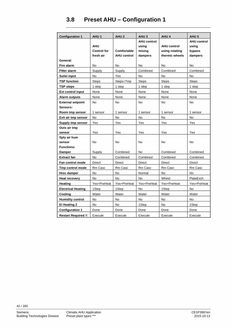
3.8 Preset AHU – Configuration 1
Configuration 1 AHU 1 AHU 2 AHU 3 AHU 4 AHU 5
AHU Control for fresh air
Comfortable AHU control
AHU control using mixing dampers
AHU control using rotating thermic wheels
AHU control using bypass dampers
General: Fire alarm No No No No No
Filter alarm Supply Supply Combined Combined Combined
Su/wi input No Yes No No No
TSP function Steps Steps+Tmp Steps Steps Steps
TSP steps 1 step 1 step 1 step 1 step 1 step
Ext control input None None None None None
Alarm outputs None None None None None
External setpoint No No No No No Sensors: Room tmp sensor 1 sensor 1 sensor 1 sensor 1 sensor 1 sensor
Exh air tmp sensor No No No No No
Supply tmp sensor Yes Yes Yes Yes Yes Outs air tmp sensor Yes Yes Yes Yes Yes Sply air hum sensor No No No No No Functions: Damper Supply Combined No Combined Combined
Extract fan No Combined Combined Combined Combined
Fan control mode Direct Direct Direct Direct Direct
Tmp control mode Rm Casc Rm Casc Rm Casc Rm Casc Rm Casc
Hrec damper No No Normal No No
Heat recovery No No No Wheel PlateExch
Heating Yes+PreHeat Yes+PreHeat Yes+PreHeat Yes+PreHeat Yes+PreHeat
Electrical Heating 1Step 1Step No 1Step No
Cooling Water Water Water Water Water
Humidity control No No No No No
El Heating 2 No No 1Step No 1Step
Configuration 1 Done Done Done Done Done
Restart Required !! Execute Execute Execute Execute Execute

43 / 260
Siemens Climatix AHU Application CE1P3997en Building Technologies Division Preset plant types *** 2015-10-13
3.9 Preset AHU – Configuration 2
Configuration 2 AHU 1 AHU 2 AHU 3 AHU 4 AHU 5
AHU Control for fresh air
Comfortable AHU control
AHU control using mixing dampers
AHU control using rotary heat exchangers
AHU control using bypass dampers
Night cooling No No No No No
Tmp start No No No No No Tmp start/OSSTP blk None None None None None
Fan alarm Supply Combined Combined Combined Combined
Fan fdbk No No No No No Fan comp room tmp No No No No No
Fan comp outs tmp Yes Yes Yes Yes No
Fan htg/clg No No Htg+Clg Htg+Clg Htg+Clg
Tmp stpt selection Htg+Dz Htg+Dz Htg+Dz Htg+Dz Htg+Dz
Room draught limit No No No No No
Sequence fan clg Clg-Fan Clg-Fan Clg-Fan Clg-Fan Clg-Fan Sequence hrec damper No* No* Dmpr-Htg No* No* Deviation alarm tmp No No Sply+Room Sply+Room Sply+Room
Su/Wi comp tmp No No Yes Yes No
Hrec frost protect No* No* No* TempSensor TempSensor
Hrec (pump) cmd No* No* No* No No Heat recovery alarm No* No* No* Yes No
Hrec clg recovery No* No* DmprHrec Hrec Hrec
Hrec efficiency No* No* No* No* No*
Htg frost protect Detector Detector Detector Detector Detector
Heating pump Yes+Kick Yes+Kick Yes+Kick Yes+Kick Yes+Kick
Htg pump alarm No No No No No
Combi Coil None 1 output None None None
El htg alarm Yes Yes No* Yes No*
Hum control unit No* No* No* No* No*
Dehum tmp prio No* No* No* No* No*
Dew point control No* No* No* No* No*
Cooling pump Yes+Kick Yes+Kick Yes+Kick Yes+Kick Yes+Kick
Auxiliary input No No No No No
Configuration 2 Done Done Done Done Done
Restart Required !! Execute Execute Execute Execute Execute
No* means: The function is disabled since the hardware was not selected in Configuration 1. The corresponding function is enabled if you added the sensor or components under Configuration 1.
i

44 / 260
Siemens Climatix AHU Application CE1P3997en Building Technologies Division Configure application 2015-10-13
4 Configure application 4.1 Overview
An operating unit HMI or the HMI@Web is used to configure the Climatix AHU application as per the plant at hand as well as selecting and parameterizing the associated functions. This section provides the following knowledge: • The entire workflow with individual stages • Climatix AHU application as per the current plant is configured in three main steps • Use SD card functions to load and backup applications and configurations, etc.
(POL63X only) The individual topics in the section are: Topic Section Workflow overview 5.2 Configuration main steps 5.3 Configuration 1 5.4 Configuration 2 5.5 Configuration IOs 5.6 Set up EBM fan 5.7 Check I/O configuration 5.8 Wiring test 5.9 SD card functions ** 5.10 Backup/restore parameters ** 5.11
Introduction
Knowledge provided
Topic

45 / 260
Siemens Climatix AHU Application CE1P3997en Building Technologies Division Configure application 2015-10-13
4.2 Workflow overview
The following illustration provides an overview of the entire workflow: From downloading the Climatix AHU application from the Siemens server, to configuring and parameterizing a controller, up to loading additional controllers with the same functionality.
Figure 19: Overview of the entire workflow The entire workflow is typically divided into the following stages: Stage Tasks Sec.
1 Download the current version of files for the Climatix AHU application from the Siemens server.
5.10
2 Load the files to the controller via the SD card. Variant: Load using SCOPE. Note: Climatix POL400 controllers are already preloaded with
the application.
5.10
3 Configure the application as per the plant at hand in three main steps. Important: Complete the checklist
5.3 to 5.9
4 Parameterize associated functions 6 5 Make system settings 7 6 Set up communications. 8 7 Export all configuration and parameter values to an SD card
(generate the parameter file PARAM.ucf). 5.11
Note:
Only possible with POL6XX controllers!
7 * Variant: Save configuration and parameter values on the PC using SCOPE.
–
8 Load the parameter file using the newly created SD card to other controllers with the same functionality (POL6XX)
5.11
8 * Variant: Load parameter file to additional controllers using SCOPE.
–
Z399
7Z03
∆p
∆p
∆p ∆p
∆p
T
T
ϕ
T
T ϕ
T
ϕ
ϕ ρT
T
POL6XX
HMI-DMSCOPE
1
2
23
8
6
7
54
7* 8*
Introduction
Individual stages
46 / 260
Siemens Climatix AHU Application CE1P3997en Building Technologies Division Configure application 2015-10-13
4.3 Configuration step by step
The desired plant designed is configured. HMI is used to execute the three main steps: Step Designation Tasks Sec.
1 Configuration 1 Make the basic settings for the plant. 4.4 2 Configuration 2 Determine subfunctions for plant parts. 4.5 3 Configuration I/Os
– EBM fan – Wiring test – Set IO to …
– Assign previously defined hardware I/Os. – Parameterize sensor conversions. – Set up, if existent. – Check I/O configuration. – Set the I/Os to wiring mode or to Auto
mode.
4.6
5.7 5.8 5.9
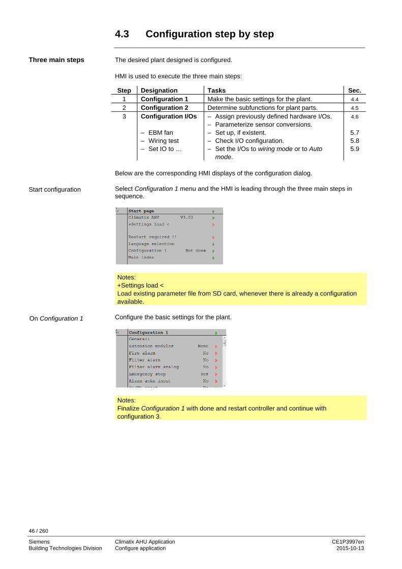
Below are the corresponding HMI displays of the configuration dialog. Select Configuration 1 menu and the HMI is leading through the three main steps in sequence.
Notes: +Settings load < Load existing parameter file from SD card, whenever there is already a configuration available.
Configure the basic settings for the plant.
Notes: Finalize Configuration 1 with done and restart controller and continue with configuration 3.
Three main steps
Start configuration
On Configuration 1

47 / 260
Siemens Climatix AHU Application CE1P3997en Building Technologies Division Configure application 2015-10-13
Configuration main steps, cont’d
Determine subfunctions for plant parts.
Notes: Finalize Configuration 2 with done and restart controller continue with configuration IO’s.
Configure the needed hardware IOs.
Notes: Finalize Configuration IOs with done and restart controller.
Configuration is complete and done and controller is ready to operate.
On Configuration 2
On Configuration IO’s
Configuration done

48 / 260
Siemens Climatix AHU Application CE1P3997en Building Technologies Division Configure application 2015-10-13
Configuration main steps, cont’d
Main Index > Configuration The Configuration page in the Main Index includes the following lines and associated parameter values:
Name Values Explanation Configuration 1 NotDone
Done Link to Configuration 1 page and displays whether or not parameterization of Configuration 1 was completed.
Configuration 2 NotDone Done
Link to Configuration 2 page and displays whether or not parameterization of Configuration 2 was completed.
Configuration IOs NotDone Done
Link to Configuration IOs page and displays whether or not parameterization of Configuration IOs was completed.
Check Config IOs Link to Check Config I/Os page. Doubled Fault
OK
Displays whether an input or output can be used multiple times. Fault generates an alarm that locks the plant.
Not configured Fault OK
Displays whether a function is enabled and the required I/Os are not assigned. Fault generate an alarm that the plant is locked (only enabled for fully configured plant).
The plant cannot start without: – Configuration 1 = Done – Configuration 2 = Done
and – Configuration IOs = Done. Proceed as follows if further configuring required: Select Configuration 1 = Not done All elements are once again visible and can be modified.
In this document, the first column Name in the configuration and parameter tables
always refers to the line in question on the HMI display – whether navigation, display, or setting lines.
It may also deal with plant components or software objects as well as individual parameters: Name Range Explanation Extension modules Fire alarm StartupStpt See section 2.10 External HMIs under Display: Elements and Functions.
STOP
Configuration page
Column title Name

49 / 260
Siemens Climatix AHU Application CE1P3997en Building Technologies Division Configure application 2015-10-13
4.4 Configuration 1
The basic settings for the plant are entered in Configuration 1, subdivided into: • General • Sensor • Plant parts and functions
You complete the process by restarting Configuration 1 in order to be able to subsequently execute Configuration 2. To restart, see line Restart Required !! at the end of the table Plant parts and functions. After this step, only the selected elements are displayed on the HMI – the same applies after Configuration 2 and Configuration IOs.
Start page > Main Index As required, Password Enter for Level 4, then: > Configuration > Configuration 1 --- General
Name Range Explanation Extension modules None The basis controller I/Os are enough for configuration. One One extension module is connecting using address 1.
DIP switches 5 and 6 must be set to ON on the module. Two Two extension modules are connected with addresses 1 and 2. DIP switch 5 must
be set to ON on extension module 1; on extension module 2, DIP switches 4 and 6. Fire alarm No No fire alarm. alarm External fire alarm such as smoke detectors, thermostats, fire detection control
units, etc. tmp Internal fire alarm via temperature measurement of supply and extract air
temperature, when both sensors exist. A fire alarm is triggered when one of the two temperatures breaches a certain value.
alarm+tmp Both fire alarms. Filter alarm No No filter alarm. Combined Supply and extract filter with common alarm input. Supply Supply filter alarm input only. Exhaust Extract filter alarm input only. Sply+Exh Two separate filter alarm inputs for supply and extract filters. Filter alarm analog No No filter alarm via pressure sensor. Supply Supply filter alarm input only. Exhaust Extract filter alarm input only. Sply+Exh Two separate filter alarm inputs for supply and extract filters. Emergency stop No
Yes Input for emergency stop. A TRUE signal at this input immediately shuts down the plant. No alarm is triggered.
Alarm ackn input No Yes
Input to acknowledge/reset an alarm. Alarms still pending are acknowledged; no longer pending alarms are reset.
Su/Wi input No Yes NotHSo NotCWi Both
Input for summer/winter changeover: A TRUE signal on this input means summer = enabled. Active heating in summer and/or active cooling in winter can be suspended. Both: No heating in summer and no cooling in winter
Task
Start
General

50 / 260
Siemens Climatix AHU Application CE1P3997en Building Technologies Division Configure application 2015-10-13
Configuration 1, cont’d
Name Range Explanation TSP function No No time switch program. Steps Time switch program with possible settings for fan stages (Off and Stx). The
parameter TSP Steps determines the number of possible steps x. Steps+tmp Time switch program with settings for fan stages and temperature control mode
(Off, Ecox and Comx). The parameter TSP Steps determines the number of possible stages x. The temperature modes comfort or economy have separate setpoints for temperature control.
TSP steps Enable possible fan steps. This setting influences the number of setpoints for controlled fans.
1Step TSP function = Steps → Possible time switch program settings: Off, St1 TSP function = Steps+tmp → Possible time switch program settings: Off, Eco1, Com1
2Steps TSP function = Steps → Possible time switch program settings: Off, St1, St2 TSP function = Steps+tmp ---> Possible time switch program settings: Off, Eco1, Eco2, Com1, Com2.
3Steps TSP function = Steps → Possible time switch program settings: Off, St1, St2, St3 TSP function = Steps+tmp → Possible time switch program settings: Off, Eco1, Eco2, Eco3, Com1, Com2, Com3
Example 1 Example 2
TSP function = Steps, TSP steps = 2Step Fan control using 2 setpoints for St1 and St2. Temperature control using a setpoint for Comfort mode. TSP function = Steps+tmp, TSP steps = 3 Fan control using 3 setpoints for St1 and St2 and St3. Temperature control using separate setpoints for Eco and Comfort. Under Eco2, the plant operates using the temperature setpoint for Eco and the fan setpoint St2.
Ext control input None No external input for operating mode switch, timer, button, occupancy detector, etc. One One input (e.g. off / on). Two Two inputs (e.g. Auto / Off / St1 / St2). Alarm outputs None No alarm output. One One output (e.g. for high alarms). Two Two outputs (for high and low alarms).
General, cont'd.

51 / 260
Siemens Climatix AHU Application CE1P3997en Building Technologies Division Configure application 2015-10-13
Configuration 1, cont’d
Name Range Explanation Room tmp Sensor (Bit Field)
Sensor 1 Sensor 2 Rm Unit 1 Rm Unit 2 QMX RU*
Inputs for room temperature sensors. You can select whether to apply maximum, minimum, average or individual value for control for more than one sensor in Configuration 2. When selecting any room unit, the interface to the room unit connection is enabled. *QMX will be available in Version V320
Extract tmp sensor No Yes
Input for extract air sensor.
Yes+Hold The maximum, otherwise present temperature is stored when shutting down the plant, to the extent the plant ran for more than 5 minutes. The setting only makes sense when there is no room sensor and Standby start operations (e.g. free cooling) without plant kick are to be used. (Plant kick: Short, cyclical plant start to update the values of the sensors mounted in the duct).
Supply tmp sensor No Yes
Input for supply air sensor.
Outs air tmp Sensor No Yes
Input for outside air sensor.
Yes+Hold The minimum, otherwise present temperature is stored when shutting down the plant, to the extent the plant ran for more than 5 minutes. The setting only makes sense when the sensor is mounted in the duct and night start operations (e.g. free cooling) is used or as safety function for the pump start at a low outside air temperature.
Room hum Sensor No Yes
Input for room humidity sensor.
Supply hum sensor No Yes
Input for supply air humidity sensor.
Outs air hum sensor No Yes
Input for outside air humidity sensor.
Sensor

52 / 260
Siemens Climatix AHU Application CE1P3997en Building Technologies Division Configure application 2015-10-13
Configuration 1, cont’d
Name Range Explanation Damper Open/close damper. No No dampers. Combined Two dampers with only one common output. Supply Supply air damper with output. Supply+Exh Two dampers with separate outputs. Extract fan Extract air fan (supply air fan is always available; cannot be disabled). No No extract air fan. Yes Extract air fan with separate output. Combined Extract and supply air fan with common output. Fan control mode Select fan and control type.
Positions SupplySlv and Extract Slv not possible without enabled extract air fan. Positions Direct and DirectVar possible if the extract air fan is parameterized as combined. The exact number of outputs depends on the number of steps and whether or not the extract air fan is enabled. The number of required inputs/outputs double if the fan is enabled with a separate output. The sensors required for control, e.g. pressure sensors, are enabled here as well.
Direct Up to 3 digital outputs each for stepped fans. DirectVar Up to 3 digital outputs each for stepped controlled variable speed fans via digital
outputs (not 0...10 V or Modbus). FixedSpeed One digital and analog output each for analog – modulating controlled variable
speed drives (e.g. St1 = 2 V, St2 = 5 V, St3 = 8 V). Pressure One digital and analog output each and one analog input each for variable speed
drives in pressure-controlled plants. Flow One digital and analog output each and one analog input each for variable speed
drives in flow-controlled plants. SupplySlv One digital and analog output each and three analog inputs for the variable speed
drives in pressure-controlled plants where the supply air fan operates dependent on the extract fan.
ExhaustSlv One digital and analog output each and three analog inputs for the variable speed drives in pressure-controlled plants where the extract air fan operates dependent on the supply air fan.
Tmp control mode Select control algorithm for temperature control. Supply Supply air temperature control only. Rm Casc Room / supply air temperature cascade control. ExtrSplyC Extract air/supply air cascade control RmSplyC Su Room / supply air cascade control during the summer; supply air temperature
control only during the winter. ExtrSplyC Su Extract/supply air cascade control during the summer; supply air temperature
control only during the winter. Room Room control only. Extract Pure extract air control.
Plant parts and functions

53 / 260
Siemens Climatix AHU Application CE1P3997en Building Technologies Division Configure application 2015-10-13
Configuration 1, cont’d
Name Range Explanation Hrec damper Select heat recovery control with mixed air dampers. No No mixed air damper. Normal Mixed air damper with output signal 100% for complete recirculation. Invers Mixed air damper with output signal 0% for complete recirculation. Heat recovery Select Heat recovery control with wheel, plate or hot water heat exchanger. No No heat recovery. Wheel Wheel heat exchanger. An analog output to control heat wheel. PlateExch Plate heat exchanger. An analog output to control bypass damper. Water Water heat exchanger. An analog output to control the valve. Wheel Inv Wheel heat exchanger output inverted PlateInv Plate heat exchanger output inverted WaterInv Water heat exchanger output inverted Heating No No heating circuit. Yes Heating register without preheating the register.
Analog output for heating valve. +PreH
OutsideTemp. Heating register with preheating the register. Analog output for heating valve + pump.
+PreH FrostTemp. Heating register with preheating the register. Analog output for heating valve + pump.
Electrical heating Electric heating register with control type. No No electric heating register. Analog Electric heating register with control via an analog output. 1Step 1-step electric heating register with control via one analog and one digital output. 2Steps 2-step electric heating register with control via one analog and two digital outputs. 3StepsBin 3-step electric heating register with binary encoded control via one analog and two
digital outputs. Cooling Select cooling register with type. No No cooling register. Water An analog output for the water register valve. DX 1Step One analog and one digital output for 1-step control of a direct expansion
evaporator. DX 2Steps One analog and two digital outputs for 2-step control of a direct expansion
evaporator. DX 3Steps One analog and two digital outputs (binary) for 3-step control of a direct expansion
evaporator. Humidity control Humidification and dehumidification. No No humidification and dehumidification. Hum One analog and one digital output for humidifier. Only possible if the room or supply
air humidity sensor is enabled. DeHum Dehumidification controller. Only possible when cooling enabled. Hum+DeHum Humidification and dehumidification. Heating 2 No No additional heating register. Yes Additional heating register without preheating the register.
Analog output for heating valve. +PreH
OutsideTemp. Heating register with preheating the register depending on outside temperature. Analog output for heating valve + pump.
+PreH FrostTemp. Heating register with preheating the register depending on frost temperature. Analog output for heating valve + pump.
Plant parts and functions, cont’d

54 / 260
Siemens Climatix AHU Application CE1P3997en Building Technologies Division Configure application 2015-10-13
Configuration 1, cont’d
Name Range Explanation El Heating 2 Electric heating register with control type. No No auxiliary electric heating register. Analog Auxiliary electric heating register with control via an analog output. 1Step Auxiliary 1-step electric heating register with control via one analog and one digital
output. 2Steps Auxiliary 2-step electric heating register with control via one analog and two digital
outputs. 3Steps Auxiliary 3-step electric heating register with binary encoded control via one analog
and two digital outputs. Cooling 2 Auxiliary cooling register with type. No No auxiliary cooling register. Water An analog output for the auxiliary water register valve. DX 1Step One analog and one digital output for 1-step control of an additional direct
expansion evaporator. DX 2Steps One analog and two digital outputs for 2-step control of an additional direct
expansion evaporator. DX 3Steps One analog and two digital outputs (binary) for 3-step control of an additional direct
expansion evaporator. Fire damper Fire dampers
No No fire dampers. Yes Feedback signal(s) for fire damper control. FollowUnit Feedback signal(s) for fire damper control. In this case, damper opened with Unit
Start or closed with Unit Stop. This setting only makes sense when the damper also uses shutoff device.
2-4 Same as Yes, but now for 2-4 fire dampers. 2-4+FolwUn Same as FollowUnit, but now for 2-4 fire dampers.
External setpoint No No analog input for connect an external setpoint or an external setpoint compensation.
Volt Input for one 0-10 V DC signal. Ohm Input for one 0-2500 Ohm signal. QAA27 Input for QAA27. BSG21 Input for BSG21 setpoint compensation. Configuration 1 This parameters enable the plant after successful parameterization. Enable occurs
when Configuration 1, Configuration 2 and Configuration IOs are completed, i.e. when each has the value done.
NotDone Plant locked against switching on. Done The plant is unlocked after complete parameterization (Configuration 2 and
Configuration IOs also have a value done), i.e. it can be switched on. Restart Required !! Execute Reset required with Execute after successful parameterization in Configuration 1.
Assumes the appropriate presettings for Configuration 2.
Plant parts and functions, cont’d

55 / 260
Siemens Climatix AHU Application CE1P3997en Building Technologies Division Configure application 2015-10-13
4.5 Configuration 2
The subfunctions of the plant parts are determined in Configuration 2.
Prerequisite: Configuration 1 completed with reset.
Note the following items on the process: – The configuration should be processed in order (i.e. line-for-line). – Configuration 2 must be completed with reset prior to starting Configuration IOs.
Start page > Main Index As required, Password Enter for Level 4, then: > Configuration > Configuration 2
Name Range Function Free cooling No
Yes Free cooling Requirement: Free cooling can only be selected if one outside air temperature sensor and one room or extract air sensor is available. The fan kick function is enabled automatically if only one extract air sensor with saving property is available. If the extract air sensor saves values, the stored temperature is used to start free cooling.
Tmp start Starting the plant in a shut down state based on a room temperature with its own setpoint. Requirement: Function can only be selected if one room or extract air sensor is available. The fan kick function is enabled automatically if only one extract air sensor with saving property is available. If the extract air sensor saves values, the stored temperature is used to start.
No Function not enabled. Htg Function enabled for heating only. Clg Function enabled for cooling only. Htg+Clg Function for enabled heating and cooling. Boost Plant boost with heating and cooling to a separate setpoint.
Requirement: Function can only be selected if one room or extract air sensor is available. No Function not enabled. Htg Function enabled for heating only. Clg Function enabled for cooling only. Htg+Clg Function for enabled heating and cooling.
STOP
Task
Start

56 / 260
Siemens Climatix AHU Application CE1P3997en Building Technologies Division Configure application 2015-10-13
Configuration 2, cont’d
Name Range Function Tmp start/OSSTP blk Block dampers or extract air fan when the plant is started via boost or temperature
differential. Note: The function is implemented for energy considerations. Caution: A bypass damper must exist and be open when the function is enabled. Otherwise, it may damage the plant.
None No block. Damper Dampers remain closed. Damper+Fan Dampers remain closed and only the supply air fan is started. Damper fdbk No No damper feedback. One Feedback for supply air dampers (or a common feedback for both dampers). Digital input
for feedback. Two Separate feedback for supply and extract air damper. Two digital inputs for feedback. Fan steps freq conv Activation of additional digital outputs depending on the selected fan type. 1Step Digital output to enable variable speed drive (always enabled). 2Steps An additional digital output for optional wiring depending on fan step 2. 3Steps Two additional digital outputs for optional wiring depending on fan step 3. Flow display Display flow and possible output. No Function not available. l/s Display of supply air [l/s] and (if enabled) extract air flow. Analog inputs are enabled if not
already enabled by the fan control setting. m3/h Display of supply air [m³/h] and (if enabled) extract air flow. Analog inputs are enabled if
not already enabled by the fan control setting. Fan steps type Required output for fan control relating to settings for fan control mode, TSP steps and
Fan steps freq conv. Separated Digital output for each step.
Example: Fan control mode = direct / TSP steps = 2 / Extract fan = Yes → 4 digital outputs: Step 1 and Step 2 each, separated for supply air and extract air fans.
SepCombine Separate outputs on the first step, common outputs for additional steps. Example: Fan control mode = pressure / TSP function = Step+tmp / TSP steps = 3 / Extract fan = Yes / Fan steps freq conv = 3 → 4 digital outputs: Step 1 each as separate variable speed drive enable, two additional outputs open for use (Fan steps freq conv) for Step 2 and Step 3.
Binary Outputs for the steps are binary coded. The setting is permitted for fan control mode = direct or directVar. Example: Fan control mode = direct / TSP function = Step+tmp / TSP steps = 3 / Extract fan = Yes → 4 digital outputs: 2 digital output each per fan (Step 1 = DO1 TRUE; Step 2 = DO2 TRUE; Step 3 = DO1 und DO2 TRUE).

57 / 260
Siemens Climatix AHU Application CE1P3997en Building Technologies Division Configure application 2015-10-13
Configuration 2, cont’d
Name Range Function Fan alarm Inputs for fan alarms (e.g. thermal contact).
Logical 1 = alarm. No No alarm. Combined Digital input for common alarm. Supply Digital input for supply air fan alarm. Extract Digital input for extract air fan alarm. Sply+Extr Two digital inputs for alarms from supply and extract air fans. Fan fdbk Inputs for operating message from the fans (e.g. pressure switch or relay contact).
Logical 1 = fan running. No No feedback. Combined Digital input for common operating message. Supply Digital input for supply air fan operating message. Extract Digital input for extract air fan operating message. Sply+Extr Two digital inputs for operating messages from supply and extract air fans. Fan deviation alm Setpoint/actual value monitoring of the pressure or flow.
An alarm is triggered for deviation over a set period. No No monitoring. Supply Supply air monitoring only. Extract Extract air monitoring only. Sply+Extr Supply and extract air monitoring. Fan comp room tmp No
Yes Room-temperature dependent fan compensation. Requirement: A room or extract air sensor is enabled.
Fan comp air quality No Yes
Air quality-dependent fan compensation. Analog input for the sensor is enabled.
Fan cmp humidity No Yes
Room humidity-dependent fan compensation. Requirement: Room humidity sensor is enabled.
Fan comp outs tmp No Yes
Outside air-temperature dependent fan compensation. Requirement: Outside air sensor is enabled.
Fan htg / clg The fan is further used as a heating or cooling sequence. No No sequential impact on the fan. Htg Only impacts fan during the heating sequence. Clg Only impacts fan during the cooling sequence. Htg+Clg Impact on fan in both sequences. Tmp stpt selection Predefined variants for temperature setpoints: Htg+Dz Heating setpoint and dead zone are entered.
Cooling setpoint = heating setpoint + dead zone. Htg/Clg Heating and cooling setpoint is entered directly (not for QMX) +/- HalfDz Base setpoint and dead zone is entered.
Heating setpoint = base setpoint – half dead zone. Cooling setpoint = base setpoint + half dead zone.
Clg-Dz Cooling setpoint and dead zone is entered. Heating setpoint = cooling setpoint – dead zone.

58 / 260
Siemens Climatix AHU Application CE1P3997en Building Technologies Division Configure application 2015-10-13
Configuration 2, cont’d
Name Range Function Ext stpt function Sets whether the external setpoint acts as setpoint compensation or in absolute terms.
Value corresponds to the comfort setpoint dependent on the switch Tmp setpoint selection. If the switch Tmp setpoint selection is on HtgClgSpv, the value of the setpoint compensation corresponds to the heating setpoint and the cooling setpoint is calculated from the difference between the entered setpoints for heating and cooling.
Relative Setpoint compensation. Absolute Absolute. Room tmp mix Selection of room temperature used for control if more than one exists. Average Average. Minimum Lowest temperature. Maximum Highest temperature. RoomSnsr1 Room sensor 1. RoomSnsr2 Room sensor 2. RoomUnit1 Room unit 1 RoomUnit2 Room unit 2 Room draught limit No
Yes Limitation to maximum/minimum supply air temperature dependent on room temperature. Requirements: One cascade control is enabled. Function minimizes draughts caused by too large a difference between supply air and room temperature.
Sequence fan clg Sets sequence of fan sequence and cooling sequence. Requirement: Fan htg / clg is enabled.
Fan-Clg Fan sequence before cooling sequence. Clg-Fan Cooling sequence before fan sequence. Sequence hrec dampr Sets sequence for heating register and mixed air dampers during heating.
Requirement: Heat recovery damper is enabled. Damper-Htg Mixed air dampers first. Htg-Damper Heating register first. Deviation alarm Temp Monitors setpoint/actual value temperature.
An alarm is triggered for deviations over a certain period. No No monitoring. Supply Supply air monitoring only. Room/Extr Room temperature monitoring only.
Or if available Extract Sensor Sply+Room/Ex Supply air and room temperature monitoring. Su-wi comp tmp No
Yes Summer/winter compensation of temperature setpoints. Requirement: An outside air sensor must be available.
Heat recovery frost No No frost protection function on heat recovery. Detector Frost protection using a detector.
Digital input for frost protection monitor. TempSensor Frost protection using a sensor.
An analog input for controlled frost protection using a setpoint. Rotation and plates: Outside sensor / water: Water sensor.
Temp+Dtctr Frost protection using a sensor and detector. An analog input for controlled frost protection and a digital input for the frost protection monitor.
PressSnsr Frost protection using a pressure sensor. An analog input for controlled frost protection using a setpoint.
Pres+Dtctr Frost protection using a pressure sensor and detector. An analog input for controlled frost protection and a digital input for the frost protection monitor.

59 / 260
Siemens Climatix AHU Application CE1P3997en Building Technologies Division Configure application 2015-10-13
Configuration 2, cont’d
Name Range Function Hrec (pump) cmd Heat recovery with pump.
Rotary heat exchanger requiring an enable can enable the pump, for example. No No pump. Yes Pump without pump kick: A digital output for pump. Yes+Kick Pump with pump kick: A digital output for pump and activation of pump kick. Hrec pump alarm No Pump without alarm or feedback. Alarm Pump with alarm.
One digital input for the pump alarm: Logical 1 = alarm that immediately shuts down the pump.
Fdbk Pump with feedback. One digital input for feedback: Logical 1 = pump running.
Both Pump with alarm and feedback. Two digital inputs for pump alarm and feedback.
Hrec alarm No No alarm. Alarm Alarm.
One digital input for the pump alarm: Logical 1 = alarm that immediately shuts down the recovery wheel.
Fdbk Feedback message. One digital input for feedback: Pulse input = wheel operating.
Both Pump with alarm and feedback. Two digital inputs for pump alarm and feedback.
Hrec comp air qual Influences air quality of the mixed air dampers. Requirement: HrecDamper is enabled.
No No impact. Yes Function enabled: An analog input for the air quality sensor if not already enabled for Fan
comp. Hrec clg recovery Type of cooling recovery for rotary and plate exchangers. No No cooling recovery. Temp Cooling recovery, by temperature difference outside and inside air. Enthalpy Cooling recovery, by heat content difference outside and inside air. Hrec Damp clg rec Type of cooling recovery for recirculating air damper. No No cooling recovery. Temp Cooling recovery, by temperature difference outside and inside air. Enthalpy Cooling recovery, by heat content difference outside and inside air. Hrec efficiency Calculation for heat recovery efficiency.
Requirement: One outside air temperature sensor as well as a extract air sensor must be available.
No No calculation of heat recovery efficiency. Extr air To calculate using extract air: One analog input for the exhaust sensor if not already
enabled for Hrec frost. Sply air To calculate with a supply air sensor: On analog input for the supplemental supply air
sensor.
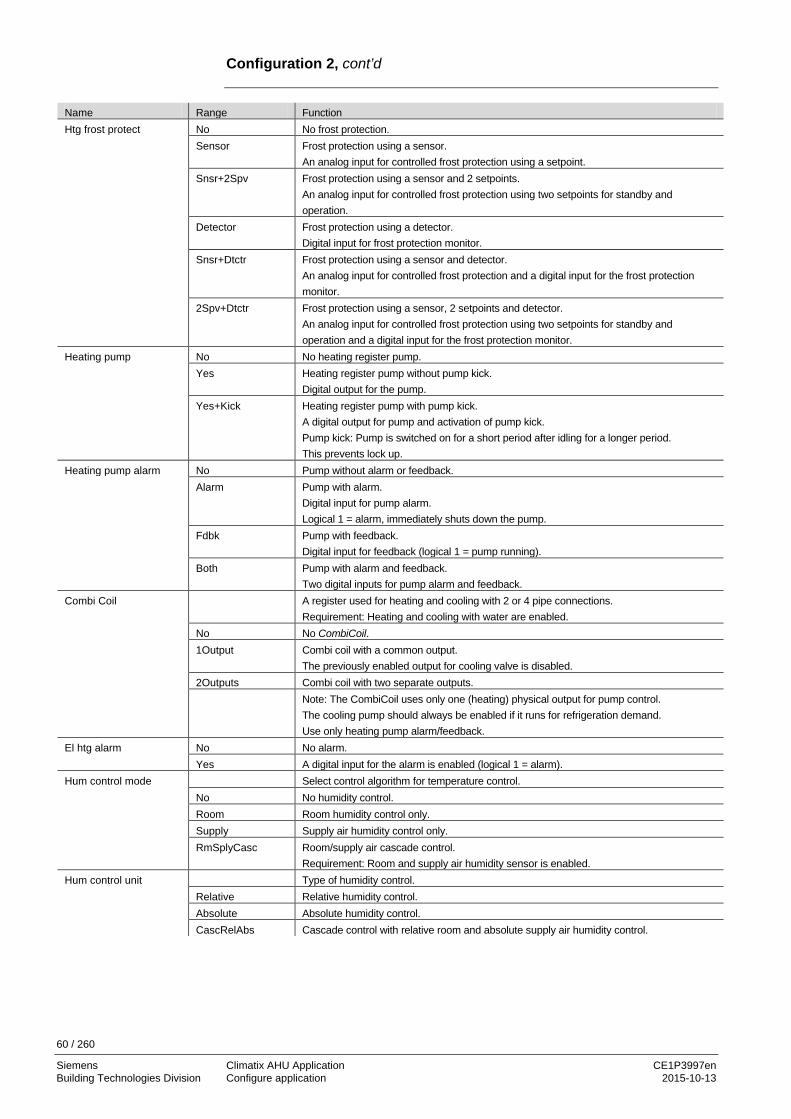
60 / 260
Siemens Climatix AHU Application CE1P3997en Building Technologies Division Configure application 2015-10-13
Configuration 2, cont’d
Name Range Function Htg frost protect No No frost protection. Sensor
Frost protection using a sensor. An analog input for controlled frost protection using a setpoint.
Snsr+2Spv
Frost protection using a sensor and 2 setpoints. An analog input for controlled frost protection using two setpoints for standby and operation.
Detector Frost protection using a detector. Digital input for frost protection monitor.
Snsr+Dtctr Frost protection using a sensor and detector. An analog input for controlled frost protection and a digital input for the frost protection monitor.
2Spv+Dtctr Frost protection using a sensor, 2 setpoints and detector. An analog input for controlled frost protection using two setpoints for standby and operation and a digital input for the frost protection monitor.
Heating pump No No heating register pump. Yes Heating register pump without pump kick.
Digital output for the pump. Yes+Kick Heating register pump with pump kick.
A digital output for pump and activation of pump kick. Pump kick: Pump is switched on for a short period after idling for a longer period. This prevents lock up.
Heating pump alarm No Pump without alarm or feedback. Alarm Pump with alarm.
Digital input for pump alarm. Logical 1 = alarm, immediately shuts down the pump.
Fdbk Pump with feedback. Digital input for feedback (logical 1 = pump running).
Both Pump with alarm and feedback. Two digital inputs for pump alarm and feedback.
Combi Coil A register used for heating and cooling with 2 or 4 pipe connections. Requirement: Heating and cooling with water are enabled.
No No CombiCoil. 1Output Combi coil with a common output.
The previously enabled output for cooling valve is disabled. 2Outputs Combi coil with two separate outputs. Note: The CombiCoil uses only one (heating) physical output for pump control.
The cooling pump should always be enabled if it runs for refrigeration demand. Use only heating pump alarm/feedback.
El htg alarm No No alarm. Yes A digital input for the alarm is enabled (logical 1 = alarm). Hum control mode Select control algorithm for temperature control. No No humidity control. Room Room humidity control only. Supply Supply air humidity control only. RmSplyCasc Room/supply air cascade control.
Requirement: Room and supply air humidity sensor is enabled. Hum control unit Type of humidity control. Relative Relative humidity control. Absolute Absolute humidity control. CascRelAbs Cascade control with relative room and absolute supply air humidity control.

61 / 260
Siemens Climatix AHU Application CE1P3997en Building Technologies Division Configure application 2015-10-13
Configuration 2, cont’d
Name Range Function Hum stpt selection Predefined variants for humidity setpoints. Hum/dehum Humidification and dehumidification setpoint is entered directly. +/- HalfDz Base setpoint and dead zone is entered:
Humidity setpoint = base setpoint – half dead zone. Dehumidification setpoint = base setpoint – half dead zone.
Hum+Dz Humidification setpoint and dead zone is entered: Dehumidification setpoint = humidification setpoint + dead zone.
dehum-Dz Dehumidification setpoint and dead zone is entered: Humidification setpoint = dehumidification setpoint – dead zone.
Dehum tmp prio Dehumidification is reduced dependent on the heating output. No Function not enabled. Yes As of 90%, heating valve position reduces dehumidification. Dew point control No
Yes Dew point monitoring. Minimum limitation to supply air temperature relating to Dew point control.
Hum deviation alarm Monitors setpoint/actual value of humidification. An alarm is triggered for deviations over a certain period.
No No monitoring. Room/Extr Monitors room humidity only. Supply Monitors supply air humidity only. Sply+RmEx Monitors supply air and room humidity. Humidifier pump No No humidifying pump. Yes Humidifying pump without pump kick.
Digital output for the pump. Yes+Kick Humidifying pump with pump kick.
A digital output for pump and activation of pump kick. Pump kick: Pump is switched on for a short period after idling for a longer period. This prevents lock up.
Hum pump alarm No Pump without alarm or feedback. Alarm Pump with alarm.
Digital input for pump alarm. Logical 1 = alarm, immediately shuts down the pump.
Fdbk Pump with feedback. Digital input for feedback (logical 1 = pump running).
Both Pump with alarm and feedback. Two digital inputs for pump alarm and feedback.
Humidifier fdbk No Humidifier without feedback. Yes Humidifier with feedback:
Digital input for feedback is enabled (logical 1 = humidifier running). Cooling pump No No water cooling pump. Yes Water cooling pump without pump kick.
Digital output for the pump. Yes+Kick Water cooling pump with pump kick.
A digital output for pump and activation of pump kick. Pump kick: Pump is switched on for a short period after idling for a longer period. This prevents lock up.
Cooling pump alarm No Pump without alarm or feedback. Alarm Pump with alarm.
Digital input for pump alarm. Logical 1 = alarm, immediately shuts down the pump.
Fdbk Pump with feedback. Digital input for feedback (logical 1 = pump running).
Both Pump with alarm and feedback. Two digital inputs for pump alarm and feedback.

62 / 260
Siemens Climatix AHU Application CE1P3997en Building Technologies Division Configure application 2015-10-13
Configuration 2, cont’d
Name Range Function Cooling DX alarm No Direct expansion evaporator without alarm or feedback. Alarm Direct expansion evaporator with alarm.
Digital input for pump alarm. Logical 1 = alarm, immediately shuts down the pump.
Fdbk Direct expansion evaporator with feedback. Digital input for feedback is enabled (logical 1 = pump running).
Both Direct expansion evaporator with alarm and feedback. Two digital inputs for alarm and feedback.
Heating 2 frost protect No No frost protection. Sensor
Frost protection using a sensor. An analog input for controlled frost protection using a setpoint.
Sensor+2Spv
Frost protection using a sensor and 2 setpoints. An analog input for controlled frost protection using two setpoints for standby and operation.
Detector Frost protection using a detector. Digital input for frost protection monitor.
Snsr+Dtctr Frost protection using a sensor and detector. An analog input for controlled frost protection and a digital input for the frost protection monitor.
2Spv+Dtctr Frost protection using a sensor, 2 setpoints and detector. An analog input for controlled frost protection using two setpoints for standby and operation and a digital input for the frost protection monitor.
Heating 2 pump No No pump. Yes Pump without pump kick.
Digital output for the pump. Yes+Kick Pump with pump kick.
A digital output for pump and activation of pump kick. Pump kick: Pump is switched on for a short period after idling for a longer period. This prevents lock up.
Heating 2 pump alm No Pump without alarm or feedback. alarm Pump with alarm.
Digital input for pump alarm. Logical 1 = alarm, immediately shuts down the pump.
fdbk Pump with feedback. Digital input for feedback (logical 1 = pump running).
Both Pump with alarm and feedback. Two digital inputs for pump alarm and feedback.
Heating 2 control Positioning of additional hot water register. StandAlone Hot water register not integrated in sequence.
An additional analog input for one control sensor (if not already enabled for El Heating 2 or Cooling 2).
Seq H-Heating2 Sequence: First the heater, then heater 2. Note: Only one of the two auxiliary registers (Heating 2 or El heating 2) can be integrated into the sequence prior or after the heater.
Seq Heating2-H Sequence: First heater 2, then heater 1. El heating 2 alarm No No alarm. Yes A digital input for the alarm is enabled (logical 1 = alarm). El Heating 2 control StandAlone Electric register not integrated in sequence.
An additional analog input for one control sensor (if not already enabled for Heating 2 or Cooling 2).
Seq H-Heating2 Sequence: First the heater, then electric heater 2. Seq Heating2-H Sequence: First electric heater 2, then heater.

63 / 260
Siemens Climatix AHU Application CE1P3997en Building Technologies Division Configure application 2015-10-13
Configuration 2, cont’d
Name Range Function Cooling 2 pump No No additional water cooling pump. Yes Water cooling pump without pump kick.
Digital output for the pump. Yes+Kick Water cooling pump with pump kick.
A digital output for pump and activation of pump kick. Pump kick: Pump is switched on for a short period after idling for a longer period. This prevents lock up.
Cooling 2 pump alm No Pump without alarm or feedback. Alarm Pump with alarm.
Digital input for pump alarm. Logical 1 = alarm, immediately shuts down the pump.
Fdbk Pump with feedback. Digital input for feedback (logical 1 = pump running).
Both Pump with alarm and feedback. Two digital inputs for pump alarm and feedback.
Cooling 2 Dx alarm No Additional direct expansion evaporator without alarm or feedback. Alarm Direct expansion evaporator with alarm.
Digital input for pump alarm. Logical 1 = alarm, immediately shuts down the pump.
Fdbk Direct expansion evaporator with feedback. Digital input for feedback is enabled (logical 1 = pump running).
Both Direct expansion evaporator with alarm and feedback. Two digital inputs for alarm and feedback.
Cooling 2 control Positioning of additional cooling register. StandAlone Cooling register not integrated in sequence.
An additional analog input for one control sensor (if not already enabled for Heating 2 or El Heating 2).
InSequence E.g. integrated as second cooling register in the sequence. Fire damper fdbk Feedback from fire dampers. Closed Only one feedback for close.
Digital input. Clsd+Opnd Two separate feedbacks for open and close.
Two digital inputs. Combined Two feedbacks for open and close, but only one signal.
The sequence must be correct 1 → 0 → 1 => Close → Movement → Open. A digital input.
Clsd.Inv One feedback and inverted signal Auxiliary input No No auxiliary input. Input An additional digital input for display only. Alm An additional digital input with alarm. Inp+Alm Two additional digital inputs.
One for display and one with alarm. Aux tmp sensor No No additional analog input. Yes Additional analog input to connect a temperature for display. Aux TSP output No No additional digital output. Yes An auxiliary digital output controller by its own time switch program. Aux A outp fan No No additional analog output. Fan Auxiliary analog output that provides a 0-10 V signal depending on the present fan step. AdjDiscrg AO for adjustable Fan Jet (discharger) Aux op mode indication No No additional digital output. Yes An additional digital output, switched dependent on present operating mode (e.g. Comfort
or Off).

64 / 260
Siemens Climatix AHU Application CE1P3997en Building Technologies Division Configure application 2015-10-13
Configuration 2, cont’d
Name Range Function Configuration 2 This parameters enable the plant after successful parameterization.
Enable occurs when Configuration 1, Configuration 2 and Configuration IOs are completed, i.e. when each has the value done.
NotDone Plant locked against switching on. Done The plant is unlocked after complete parameterization (Configuration 2 and Configuration
IOs also have a value done), i.e. it can be switched on. Restart Required !! Execute Reset required with Execute after successful parameterization in Configuration 2.
Assumes the appropriate presettings for Configuration IOs.
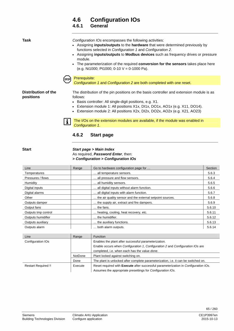
65 / 260
Siemens Climatix AHU Application CE1P3997en Building Technologies Division Configure application 2015-10-13
4.6 Configuration IOs 4.6.1 General
Configuration IOs encompasses the following activities: • Assigning inputs/outputs to the hardware that were determined previously by
functions selected in Configuration 1 and Configuration 2. • Assigning inputs/outputs to Modbus devices such as frequency drives or pressure
module. • The parameterization of the required conversion for the sensors takes place here
(e.g. Ni1000; Pt1000; 0-10 V = 0-1000 Pa).
Prerequisite: Configuration 1 and Configuration 2 are both completed with one reset.
The distribution of the pin positions on the basis controller and extension module is as follows: • Basis controller: All single-digit positions, e.g. X1. • Extension module 1: All positions X1x, DI1x, DO1x, AO1x (e.g. X11, DO14). • Extension module 2: All positions X2x, DI2x, DO2x, AO2x (e.g. X21, AO23)
The I/Os on the extension modules are available, if the module was enabled in Configuration 1.
4.6.2 Start page
Start page > Main Index As required, Password Enter, then: > Configuration > Configuration IOs
Line Range Go to hardware configuration page for … Section Temperatures … all temperature sensors. 5.6.3 Pressures / flows … all pressure and flow sensors. 5.6.4 Humidity … all humidity sensors. 5.6.5 Digital inputs … all digital inputs without alarm function. 5.6.6 Digital alarms … all digital inputs with alarm function. 5.6.7 Other … the air quality sensor and the external setpoint sources. 5.6.8 Outputs damper … the supply air, extract and fire dampers. 5.6.9 Output fans … the fans. 5.6.10 Outputs tmp control … heating, cooling, heat recovery, etc. 5.6.11 Outputs humidifier … the humidifier. 5.6.12 Outputs auxiliary … the auxiliary functions. 5.6.13 Outputs alarm … both alarm outputs. 5.6.14
Line Range Function Configuration IOs Enables the plant after successful parameterization.
Enable occurs when Configuration 1, Configuration 2 and Configuration IOs are completed, i.e. when each has the value done.
NotDone Plant locked against switching on. Done The plant is unlocked after complete parameterization, i.e. it can be switched on. Restart Required !! Execute Reset required with Execute after successful parameterization in Configuration IOs.
Assumes the appropriate presettings for Configuration IOs.
STOP
Task
Distribution of the positions
Start

66 / 260
Siemens Climatix AHU Application CE1P3997en Building Technologies Division Configure application 2015-10-13
4.6.3 Temperatures
The listed hard assignments are possible for all temperature sensors. HW IO Pos Type Supply, Room 1, Room 2, Return, ... , Auxiliary
NUsd, Comm, X1...X8, X11...X18, X21...X28
Pt1k, Ni1k, Ni1kLG, NTC10K, 0-10V T401-402, T411-412, T421-422, T431-432 (Modbus sensors)
• Supply air (supply air temperature) • Room • Room 2 • Extract air (extract air temperature) • Outside (outside air temperature) • Heating frost (0-10 V fix for QAF63 und QAF64) • Exhaust air (exhaust air temperature) • Heat recovery water • Hrec supply (heat recovery supply air temperature) • Supply 2 (extra supply air temperature, when Heating 2 or Cooling 2 are used • Heating 2 frost • Auxiliary (additional connectable temperature) Position Explanation X1...X8 Terminals on basis controller. X11...X18 Terminals on extension module 1. X21...X28 Terminals on extension module 2. Comm Sensor is connected via communication and therefore does not occupy a hardware
input. Some sensors can also be connected via communication (see lists in the documentation on the basics for LON, Modbus, BacNet). Sensors may also be enabled in parallel as well (via hardware and communication). The value selector must be set accordingly when enabling via communication (details page Analog Inputs, section 8.5 Alarm history).
NUsd Not used: The hardware position is not yet selected. The plant is locked against switching on if an enabled sensor is set to NUsd and the following fault issued: Not configured (function enabled, but hardware not assigned).
The following sensor types are possible for all temperature sensors: • Pt1k: Platinum 1000 Ohm • Ni1k: Nickel 1000 Ohm • NTC10K: NTC 10 kOhm • Ni1kLG: Nickel 1000 Ohm LG (Siemens) • Active sensors 0-10 V • T401, T402, T411, T412, T421, T422, T431, T432
( Modbus Address T (T = temperature) 40, position on sensor 1 ) If selected as T40x, the position is changed to Comm
The following is available in addition to these settings for the active temperature sensor:
HW IO Pos. At 0 V At 10 V - Outside Air NUsd, Comm,X1…X28 -50.0…190.0 °C -50.0…190.0 °C Cmn set active Sens - All other Sens NUsd, Comm,X1…X28 -50.0…190.0 °C -50.0…190.0 °C
Hardware assignments
Temperature measurements
Terminal positions
Sensor types

67 / 260
Siemens Climatix AHU Application CE1P3997en Building Technologies Division Configure application 2015-10-13
4.6.4 Pressures / flows
The listed hard assignments are possible for all pressure and flow sensors.
HW IO Pos K-factor Scale (x Pa at 10 V) Supply pressure NUsd...X28 --- 0...5000 Return pressure NUsd…X28 --- 0…5000 Supply air flow NUsd…X28 0.00…99.90 0…5000 Extract air flow NUsd…X28 0.00…99.90 0…5000 Hrec frost pressure NUsd…X28 --- 0…5000
New function on these sensor types: 0-10 V, P401, P402, P411, P412, P421, P422, P431, P432 (Modbus address P (P = pressure) 40, position on sensor 1) If selected as P40x, the position is changed to Comm K-factor is used for each fan to calculate the flow out from a pressure sensor. The K-factor is specified for m³/s and are later, in the controller, multiplied with 1000 to get the value in l/s. Formula: Flow (l/s) = 1 / K-factor * square root of pressure (Pa) * 1000 Position Explanation X1...X8 Terminals on basis controller. X11...X18 Terminals on extension module 1. X21...X28 Terminals on extension module 2. Comm Sensor is connected via communication and therefore does not occupy a hardware
input. Some sensors can also be connected via communication (see lists in the documentation on the basics for LON, Modbus, BacNet). Sensors may also be enabled in parallel as well (via hardware and communication). The value selector must be set accordingly when enabling via communication, see section 8.5. Analog inputs).
NUsd Not used: The hardware position is not yet selected. The plant is locked against switching on if an enabled sensor is set to NUsd and the following fault issued: Not configured (function enabled, but hardware not assigned).
Hardware assignments
Pressure and flow sensors
K-factor
Terminal positions
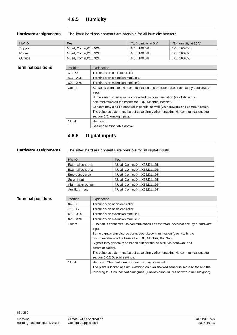
68 / 260
Siemens Climatix AHU Application CE1P3997en Building Technologies Division Configure application 2015-10-13
4.6.5 Humidity
The listed hard assignments are possible for all humidity sensors.
HW IO Pos. Y1 (humidity at 0 V Y2 (humidity at 10 V) Supply NUsd, Comm,X1…X28 0.0…100.0% 0.0…100.0% Room NUsd, Comm,X1…X28 0.0…100.0% 0.0…100.0% Outside NUsd, Comm,X1…X28 0.0…100.0% 0.0…100.0%
Position Explanation X1...X8 Terminals on basis controller. X11...X18 Terminals on extension module 1. X21...X28 Terminals on extension module 2. Comm Sensor is connected via communication and therefore does not occupy a hardware
input. Some sensors can also be connected via communication (see lists in the documentation on the basics for LON, Modbus, BacNet). Sensors may also be enabled in parallel as well (via hardware and communication). The value selector must be set accordingly when enabling via communication, see section 8.5. Analog inputs.
NUsd Not used. See explanation table above.
4.6.6 Digital inputs
The listed hard assignments are possible for all digital inputs. HW IO Pos. External control 1 NUsd, Comm,X4...X28,D1...D5 External control 2 NUsd, Comm,X4...X28,D1...D5 Emergency stop NUsd, Comm,X4...X28,D1...D5 Su-wi input NUsd, Comm,X4...X28,D1...D5 Alarm ackn button NUsd, Comm,X4...X28,D1...D5 Auxiliary input NUsd, Comm,X4...X28,D1...D5 Position Explanation X4...X8 Terminals on basis controller. D1...D5 Terminals on basis controller. X11...X18 Terminals on extension module 1. X21...X28 Terminals on extension module 2. Comm Function is connected via communication and therefore does not occupy a hardware
input. Some signals can also be connected via communication (see lists in the documentation on the basics for LON, Modbus, BacNet). Signals may generally be enabled in parallel as well (via hardware and communication). The value selector must be set accordingly when enabling via communication, see section 8.6.2 Special settings.
NUsd Not used: The hardware position is not yet selected. The plant is locked against switching on if an enabled sensor is set to NUsd and the following fault issued: Not configured (function enabled, but hardware not assigned).
Hardware assignments
Terminal positions
Hardware assignments
Terminal positions

69 / 260
Siemens Climatix AHU Application CE1P3997en Building Technologies Division Configure application 2015-10-13
4.6.7 Digital alarms
The listed hard assignments are possible for all digital alarms. HW IO Pos Htg frost protect, Heating pump...Auxiliary
NUsd, Comm, X4...X28, DI1...DI5
Position Explanation X4...X8 Terminals on basis controller. D1...D5 Terminals on basis controller. X11...X18 Terminals on extension module 1. X21...X28 Terminals on extension module 2. Comm Function is connected via communication and therefore does not occupy a
hardware input. Some signals can also be connected via communication (see lists in the documentation on the basics for LON, Modbus, BacNet). Signals may generally be enabled in parallel as well (via hardware and communication). The value selector must be set accordingly when enabling via communication, see section 8.6.2 Special settings.
NUsd Not used: The hardware position is not yet selected. The plant is locked against switching on if an enabled sensor is set to NUsd and the following fault issued: Not configured (function enabled, but hardware not assigned).
Hardware assignments
Terminal positions

70 / 260
Siemens Climatix AHU Application CE1P3997en Building Technologies Division Configure application 2015-10-13
4.6.8 Other
The listed hardware assigned are possible air quality sensor and the external setpoint adjuster/slider. HW IO Pos Scale (at 10 V; 0 V = 0 ppm, fix) Air quality sensor NUsd, Comm, X1…X28 0…3000 ppm External setpoint NUsd, Comm, X1…X28 ---
Note: Parameterize the External setpoint in menu Unit > Inputs > Other.
Position Explanation X4...X8 Terminals on basis controller. D1...D5 Terminals on basis controller. X11...X18 Terminals on extension module 1. X21...X28 Terminals on extension module 2. Comm Sensor is connected via communication and therefore does not occupy a hardware
input. Some sensors can also be connected via communication (see lists in the documentation on the basics for LON, Modbus, BacNet). Sensors may also be enabled in parallel as well (via hardware and communication). The value selector must be set accordingly when enabling via communication (see Analog inputs, Special settings – section 8.5.2 Special settings).
NUsd Not used: The hardware position is not yet selected. The plant is locked against switching on if an enabled sensor is set to NUsd and the following fault issued: Not configured (function enabled, but hardware not assigned).
4.6.9 Outputs: Dampers
The listed hard assignments are possible for dampers. HW IO Pos. Outs air damper DO Q1...Q24 Extr air damper DO Q1...Q24 Fire damperDO Q1...Q24 Position Explanation Q1...Q6 Terminals on basis controller. Q11...Q14 Terminals on extension module 1. Q21...Q24 Terminals on extension module 2. Comm This output is connected via communication and therefore does not occupy a
hardware input. Some output signals can also be connected via communication (see lists in the documentation on the basics for LON, Modbus, BacNet). Outputs may generally be enabled in parallel as well (via hardware and communication).
NUsd Not used: The hardware position is not yet selected. The plant is locked against switching on if an enabled sensor is set to NUsd and the following fault issued: Not configured (function enabled, but hardware not assigned).
Hardware assignments
Terminal positions
Hardware assignments
Terminal positions

71 / 260
Siemens Climatix AHU Application CE1P3997en Building Technologies Division Configure application 2015-10-13
4.6.10 Outputs: Fans
The listed hard assignments are possible for fans. HW IO Pos. Modbus Fan No, Sinamics, Danfoss, EBM-Papst.
Those devices get driven via Modbus. In case of EBM-Papst, additional work flow appers after IO config.
Supply fan DO1 NUsd, Comm, Q1..Q24 Supply fan DO2 NUsd, Comm, Q1..Q24 Supply fan DO3 NUsd, Comm, Q1..Q24 Extract fan DO1 NUsd, Comm, Q1..Q24 Extract fan DO2 NUsd, Comm, Q1..Q24 Extract fan DO3 NUsd, Comm, Q1..Q24 Supply fan AO NUsd, Comm, X3...X28, Y1...Y22 Extract fan AO NUsd, Comm, X3...X28, Y1...Y22 Position Explanation Q1...Q6 Terminals on basis controller. Q11...Q14 Terminals on extension module 1. Q21...Q24 Terminals on extension module 2. Comm This output is connected via communication and therefore does not occupy a
hardware input. Some output signals can also be connected via communication (see lists in the documentation on the basics for LON, Modbus, BacNet). Outputs may generally be enabled in parallel as well (via hardware and communication). In case a Modbus type of fan or frequence drive is used, Climatix automatically
defines the outputs to COM. Depending on the need, those outputs can still be connected to any hardware output.
NUsd Not used: The hardware position is not yet selected. The plant is locked against switching on if an enabled sensor is set to NUsd and the following fault issued: Not configured (function enabled, but hardware not assigned).
Position Explanation X3...X8 Terminals on basis controller. Y1, Y2 Terminals on basis controller. X11...X18 Terminals on extension module 1. Y11, Y12 Terminals on extension module 1. X21...X28 Terminals on extension module 2. Y21, Y22 Terminals on extension module 2. Comm This output is connected via communication and therefore does not occupy a
hardware input. Some output signals can also be connected via communication (see lists in the documentation on the basics for LON, Modbus, BacNet). Outputs may generally be enabled in parallel as well (via hardware and communication).
NUsd Not used: The hardware position is not yet selected. The plant is locked against switching on if an enabled sensor is set to NUsd and the following fault issued: Not configured (function enabled, but hardware not assigned).
Hardware assignments
Terminal positions for digital outputs
Terminal positions for analog outputs (0...10 V DC)
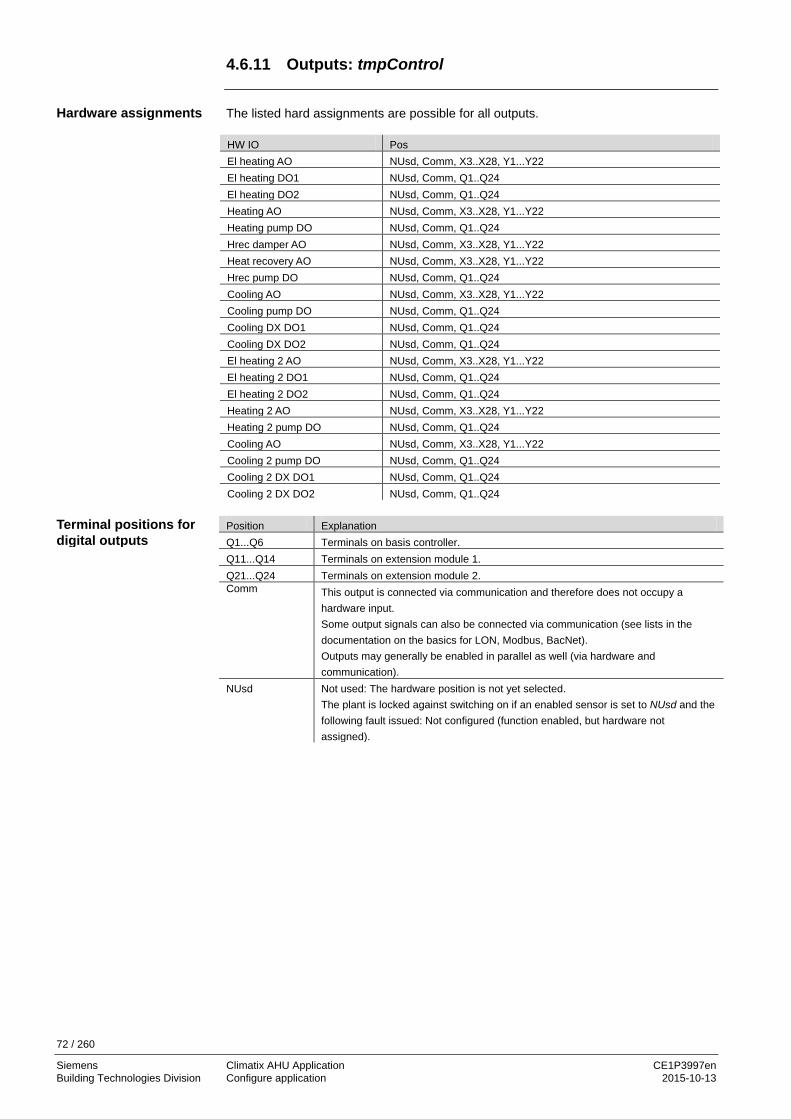
72 / 260
Siemens Climatix AHU Application CE1P3997en Building Technologies Division Configure application 2015-10-13
4.6.11 Outputs: tmpControl
The listed hard assignments are possible for all outputs. HW IO Pos El heating AO NUsd, Comm, X3..X28, Y1...Y22 El heating DO1 NUsd, Comm, Q1..Q24 El heating DO2 NUsd, Comm, Q1..Q24 Heating AO NUsd, Comm, X3..X28, Y1...Y22 Heating pump DO NUsd, Comm, Q1..Q24 Hrec damper AO NUsd, Comm, X3..X28, Y1...Y22 Heat recovery AO NUsd, Comm, X3..X28, Y1...Y22 Hrec pump DO NUsd, Comm, Q1..Q24 Cooling AO NUsd, Comm, X3..X28, Y1...Y22 Cooling pump DO NUsd, Comm, Q1..Q24 Cooling DX DO1 NUsd, Comm, Q1..Q24 Cooling DX DO2 NUsd, Comm, Q1..Q24 El heating 2 AO NUsd, Comm, X3..X28, Y1...Y22 El heating 2 DO1 NUsd, Comm, Q1..Q24 El heating 2 DO2 NUsd, Comm, Q1..Q24 Heating 2 AO NUsd, Comm, X3..X28, Y1...Y22 Heating 2 pump DO NUsd, Comm, Q1..Q24 Cooling AO NUsd, Comm, X3..X28, Y1...Y22 Cooling 2 pump DO NUsd, Comm, Q1..Q24 Cooling 2 DX DO1 NUsd, Comm, Q1..Q24 Cooling 2 DX DO2 NUsd, Comm, Q1..Q24 Position Explanation Q1...Q6 Terminals on basis controller. Q11...Q14 Terminals on extension module 1. Q21...Q24 Terminals on extension module 2. Comm This output is connected via communication and therefore does not occupy a
hardware input. Some output signals can also be connected via communication (see lists in the documentation on the basics for LON, Modbus, BacNet). Outputs may generally be enabled in parallel as well (via hardware and communication).
NUsd Not used: The hardware position is not yet selected. The plant is locked against switching on if an enabled sensor is set to NUsd and the following fault issued: Not configured (function enabled, but hardware not assigned).
Hardware assignments
Terminal positions for digital outputs

73 / 260
Siemens Climatix AHU Application CE1P3997en Building Technologies Division Configure application 2015-10-13
Outputs: tmpControl, cont’d Position Explanation X3...X8 Terminals on basis controller. Y1, Y2 Terminals on basis controller. X11...X18 Terminals on extension module 1. Y11, Y12 Terminals on extension module 1. X21...X28 Terminals on extension module 2. Y21, Y22 Terminals on extension module 2. Comm This output is connected via communication and therefore does not occupy a
hardware input. Some output signals can also be connected via communication (see lists in the documentation on the basics for LON, Modbus, BacNet). Outputs may generally be enabled in parallel as well (via hardware and communication).
NUsd Not used: The hardware position is not yet selected. The plant is locked against switching on if an enabled sensor is set to NUsd and the following fault issued: Not configured (function enabled, but hardware not assigned).
Terminal positions for analog outputs (0...10 V DC)

74 / 260
Siemens Climatix AHU Application CE1P3997en Building Technologies Division Configure application 2015-10-13
4.6.12 Outputs: Humidifier
The listed hard assignments are possible for all outputs. HW IO Pos Humidifier AO NUsd, Comm, X3..X28, Y1...Y22 Humidifier DO NUsd, Comm, Q1..Q24 Humidifier pump DO NUsd, Comm, Q1..Q24 Position Explanation Q1...Q6 Terminals on basis controller. Q11...Q14 Terminals on extension module 1. Q21...Q24 Terminals on extension module 2. Comm This output is connected via communication and therefore does not occupy a
hardware input. Some output signals can also be connected via communication (see lists in the documentation on the basics for LON, Modbus, BacNet). Outputs may generally be enabled in parallel as well (via hardware and communication).
NUsd Not used: The hardware position is not yet selected. The plant is locked against switching on if an enabled sensor is set to NUsd and the following fault issued: Not configured (function enabled, but hardware not assigned).
Position Explanation X3...X8 Terminals on basis controller. Y1, Y2 Terminals on basis controller. X11...X18 Terminals on extension module 1. Y11, Y12 Terminals on extension module 1. X21...X28 Terminals on extension module 2. Y21, Y22 Terminals on extension module 2. Comm This output is connected via communication and therefore does not occupy a
hardware input. Some output signals can also be connected via communication (see lists in the documentation on the basics for LON, Modbus, BacNet). Outputs may generally be enabled in parallel as well (via hardware and communication).
NUsd Not used: The hardware position is not yet selected. The plant is locked against switching on if an enabled sensor is set to NUsd and the following fault issued: Not configured (function enabled, but hardware not assigned).
Hardware assignments
Terminal positions for digital outputs
Terminal positions for analog outputs (0...10 V DC)

75 / 260
Siemens Climatix AHU Application CE1P3997en Building Technologies Division Configure application 2015-10-13
4.6.13 Outputs: Auxiliary
The listed hard assignments are possible for all outputs. HW IO Pos Auxiliary A outp NUsd, Comm, X3..X28, Y1...Y22 TSP output DO NUsd, Comm, Q1..Q24 Aux op mode ind DO NUsd, Comm, Q1..Q24 Position Explanation Q1...Q6 Terminals on basis controller. Q11...Q14 Terminals on extension module 1. Q21...Q24 Terminals on extension module 2. Comm This output is connected via communication and therefore does not occupy a
hardware input. Some output signals can also be connected via communication (see lists in the documentation on the basics for LON, Modbus, BacNet). Outputs may generally be enabled in parallel as well (via hardware and communication).
NUsd Not used: The hardware position is not yet selected. The plant is locked against switching on if an enabled sensor is set to NUsd and the following fault issued: Not configured (function enabled, but hardware not assigned).
Position Explanation X3...X8 Terminals on basis controller. Y1, Y2 Terminals on basis controller. X11...X18 Terminals on extension module 1. Y11, Y12 Terminals on extension module 1. X21...X28 Terminals on extension module 2. Y21, Y22 Terminals on extension module 2. Comm This output is connected via communication and therefore does not occupy a
hardware input. Some output signals can also be connected via communication (see lists in the documentation on the basics for LON, Modbus, BacNet). Outputs may generally be enabled in parallel as well (via hardware and communication).
NUsd Not used: The hardware position is not yet selected. The plant is locked against switching on if an enabled sensor is set to NUsd and the following fault issued: Not configured (function enabled, but hardware not assigned).
Hardware assignments
Terminal positions for digital outputs
Terminal positions for analog outputs (0...10 V DC)

76 / 260
Siemens Climatix AHU Application CE1P3997en Building Technologies Division Configure application 2015-10-13
4.6.14 Outputs, alarms
The listed hard assignments are possible for all outputs. HW IO Pos Alarm DO1 NUsd, Comm, Q1..Q24 Alarm DO2 NUsd, Comm, Q1..Q24 Position Explanation Q1...Q6 Terminals on basis controller. Q11...Q14 Terminals on extension module 1. Q21...Q24 Terminals on extension module 2. Comm This output is connected via communication and therefore does not occupy a
hardware input. Some output signals can also be connected via communication (see lists in the documentation on the basics for LON, Modbus, BacNet). Outputs may generally be enabled in parallel as well (via hardware and communication).
NUsd Not used: The hardware position is not yet selected. The plant is locked against switching on if an enabled sensor is set to NUsd and the following fault issued: Not configured (function enabled, but hardware not assigned).
Hardware assignments
Terminal positions for digital outputs
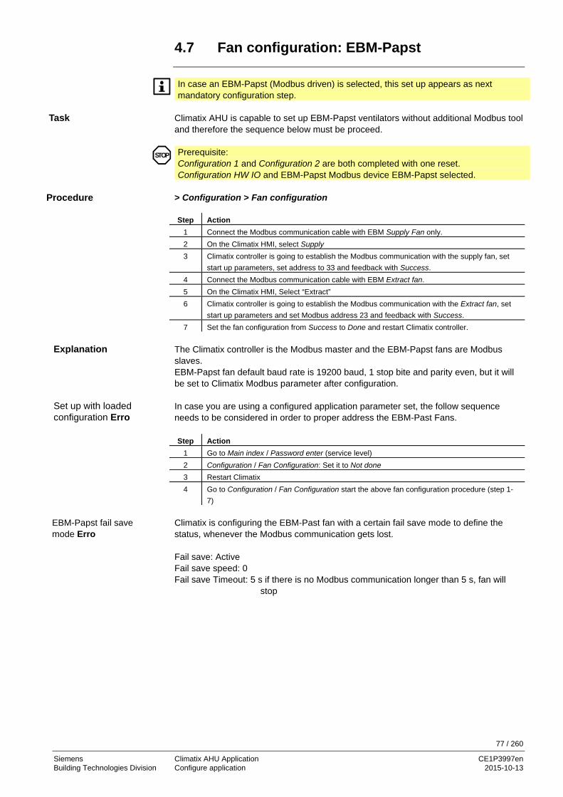
77 / 260
Siemens Climatix AHU Application CE1P3997en Building Technologies Division Configure application 2015-10-13
4.7 Fan configuration: EBM-Papst
In case an EBM-Papst (Modbus driven) is selected, this set up appears as next mandatory configuration step.
Climatix AHU is capable to set up EBM-Papst ventilators without additional Modbus tool and therefore the sequence below must be proceed.
Prerequisite: Configuration 1 and Configuration 2 are both completed with one reset. Configuration HW IO and EBM-Papst Modbus device EBM-Papst selected.
> Configuration > Fan configuration Step Action
1 Connect the Modbus communication cable with EBM Supply Fan only. 2 On the Climatix HMI, select Supply 3 Climatix controller is going to establish the Modbus communication with the supply fan, set
start up parameters, set address to 33 and feedback with Success. 4 Connect the Modbus communication cable with EBM Extract fan. 5 On the Climatix HMI, Select “Extract” 6 Climatix controller is going to establish the Modbus communication with the Extract fan, set
start up parameters and set Modbus address 23 and feedback with Success. 7 Set the fan configuration from Success to Done and restart Climatix controller.
The Climatix controller is the Modbus master and the EBM-Papst fans are Modbus slaves. EBM-Papst fan default baud rate is 19200 baud, 1 stop bite and parity even, but it will be set to Climatix Modbus parameter after configuration. In case you are using a configured application parameter set, the follow sequence needs to be considered in order to proper address the EBM-Past Fans. Step Action
1 Go to Main index / Password enter (service level) 2 Configuration / Fan Configuration: Set it to Not done 3 Restart Climatix 4 Go to Configuration / Fan Configuration start the above fan configuration procedure (step 1-
7) Climatix is configuring the EBM-Past fan with a certain fail save mode to define the status, whenever the Modbus communication gets lost. Fail save: Active Fail save speed: 0 Fail save Timeout: 5 s if there is no Modbus communication longer than 5 s, fan will
stop
STOP
Task
Procedure
Explanation
Set up with loaded configuration Erro
EBM-Papst fail save mode Erro

78 / 260
Siemens Climatix AHU Application CE1P3997en Building Technologies Division Configure application 2015-10-13
4.8 Check I/O configuration
The hardware assigned as per section 4.6 Configuration IOs are checked for the following errors: • Unassigned points • Double occupied hardware inputs or outputs
Prerequisite: Configuration 1 and Configuration 2 completed with one reset each.
Start page > Main Index As required, Password Enter, then: > Configuration > Check config IOs
Line Range Function Not config IO No
Yes Displays whether there are unassigned I/Os.
1st notconfig IO pos 0, 1, ... Displays the position of the first unassigned I/O. The associated plant elements are available in the table in appendix 10.3.
Doubled config IO No Yes
Displays whether hardware input or outputs are occupied in duplicate.
Doubled config IOs Displays positions of the first double occupancy. The associated plant elements are available in the table in appendix 10.3.
Doubled config IO pos XO1...XO28 Displays the first double occupied input or output (exception: DO). Doubled config DO pos Q1...Q24 Displays first double occupied DO. Not used xIO 0... [pcs] Displays number of unused universal inputs/outputs. Not used DI 0... [pcs] Displays the number of unused digital inputs. Not used AO 0... [pcs] Displays the number of unused analog outputs. Not used DO 0... [pcs] Displays the number of unused digital outputs.
4.9 Wiring test
To verify and check the correct panel wiring, the controller can be set into wiring test, where all input values will be showed and all outputs can be forced.
Prerequisite: Configuration 1 and Configuration 2 completed with one reset each.
Start page > Main Index As required, Password Enter, then: > Configuration > Set IO to Overview on outputs and inputs shows the values.
Important: The wiring test needs to be disabled to run the unit: > Configuration > Set IO to: Auto
STOP
STOP
STOP
Task
Start
Task
Start

79 / 260
Siemens Climatix AHU Application CE1P3997en Building Technologies Division Configure application 2015-10-13
4.10 Integrations
There are certain additional configurations possibilities for room unit or energy meter device. - Climatix Room unit POL82xx - Energy meter EM24 Main Index >Configuration > Integrations
Name Range Function +Room units 1 sensor
2 sensor 1 RU 1snsr + RU 2 RU
Inputs for room temperature sensors. You can select whether to apply maximum, minimum, average or individual value for control for more than one sensor in Configuration 2. When selecting 1 RU, 1snsr + RU or 2 RU, the interface to the room unit connection is enabled.
Settings Goes to page with all settings relevant to parameterizing room units. Inputs Go to page with temperature inputs. +Energy meter EM24 No
Yes No energy meter selected.
Settings Go to page with all parameterization for the energy meter or the RS-485 Modbus settings.
Inputs Go to page with energy inputs.
Task
Configuration

80 / 260
Siemens Climatix AHU Application CE1P3997en Building Technologies Division Configure application 2015-10-13
4.11 SD card functions **
Available on controllers POL63X or POL4xx.5x.
The controllers have an SD card slot (formatted to FAT32). The SD card files are ready prepared in Climatix AHU deployment (controller type and geographical region (languages).
SD card functions include • Download application:
– Operating system (XXX_BSP_V10x.ucf). – Applications software (MBRTcode.ucf). – HMI operating software (HMIcomp.ucf). – Web HMI operating software (HMI4Web.ucf). – Language and communication information (OBHcomp.ucf). – Scope light configuration software( ScopeConfig.ucf)
• Download basic configuration: – Plant configuration including parameter (Param.bin or Param.ucf).
• Upload application (Save, upload): – Plant configuration including parameter (Param.bin or Param.ucf).
The function updates/upgrades the controller. – The files for download must be unzipped in the root folder on the SD card. – All files must be *.UCF and compressed where possible (XXXcomp.ucf).
Conduct the following steps to download:
Step Action 1 Insert card into the controller. 2 Turn off power. 3 Using a thin object press the button in the hole next to the controller status display
(noticeable, light resistance and a slight clicking sound) and keep pressed. 4 Turn on power. 5 Wait until the LED flashes red and green. 6 Release the button. 7 Wait until the LED is orange. 8 Turn off / on power.
Overview
Download application Requirements
Files on the SD card
Procedure

81 / 260
Siemens Climatix AHU Application CE1P3997en Building Technologies Division Configure application 2015-10-13
SD card functions, cont’d
You can save the set parameters and configurations on the SD card after successful commissioning and adjustment. For example, you can use is to download to another controller with the same basic configuration (operating system, application, HMI, HMI4Web and language/communications). Requires level 4. The steps to up and download the configuration:
Step Action 1 Insert empty SD card in the controller. 2 Saves data on the SD card (upload):
Main Index > System overview > Save / restore > Config save SD = Execute 3 Wait until:
Main Index > System overview > Save / restore > Config save SD = Done 4 Insert card into the next controller. 5 Download data from the SD card:
Main Index > System overview > Save / restore > Config load SD = Execute 6 Wait until:
Main Index > System overview > Save / restore > Config load SD = Done 7 Restart controller:
Main Index > System overview > Save / restore > Restart Required !! = Execute
Upload and download parameters
Procedure

82 / 260
Siemens Climatix AHU Application CE1P3997en Building Technologies Division Configure application 2015-10-13
4.12 Auto update with SD card
Climatix AHU application V3xx is supporting the end user with automatic upgrade features using SD card: - Load BSP and application files - Save parameter setting to SD card - Load parameter setting from SD card. The detailed procedures are described below and has to be used depending on the actual need. The existing workflow via HMI is still supported. Every SD card can be locked (read only) or unlocked (read/write).
This needs to be considered fort he described workflow. Even at factory time or even in the field, an upgrade of the controls system is requested. It is important to know, before upgrade controls system, a parameter back up is recommend to keep the original parameter settings (see save parameter file to SD card, load parameter file from SD card. SD card preparation (example AHU V302) Copy all the necessary files on SD card root folder.
1. Lock the SD card 2. Repower controller (SD card out), wait until BSP LED lighting green. 3. Insert SD card ← In → Out ← In (within 30 s), upgrade process starts (*wait 1 s at
each step, but not more than 5 s in total) 4. The process will start with a restart of the controller and BSP LED will indicate the
upgrade procedure by red/green blinking. 5. If BSP LED is yellow or OFF, please repower (manually) controller and wait till BSP
LED is green.
Auto update features
SD card lock / unlock
Load BSP and application files
Procedure

83 / 260
Siemens Climatix AHU Application CE1P3997en Building Technologies Division Configure application 2015-10-13
Auto update with SD card, cont'd
In case a control system needs to be upgraded, the existing parameters (commissioning settings shall be back up). 1. SD card unlock 2. SD card ← In → Out ← In, save parameter to SD card process start (*wait 1 s at
each step, but not more than 5 s in total). 3. The BUS LED turns red and the controller is now saving the param.ucf (and
param.bin) to the SD card. The BUS LED is indicating the export process.
4. If BUS LED is off, the save parameter to SD card process has finished. After for example an upgrade, it is requested to load the original parameter files from SD card. Please make sure, a valid param.ucf (file name does not matter)is on the SD card available. Please make sure to have only one param.ucf in the root folder. 1. SD card lock. 2. Insert SD card and repower the controller to initialize the procedure. 3. The controller BUS LED is indicating (red on) the loading process. 4. After load process is completed, controller is saving the parameter setting to
factory setting and makes a restart. 5. Please remove the SD card, otherwise the controller will start the procedure again. - Load firmware and application files can be started 30 s after startup. - The loaded parameter file will be saved in OEM factory store and generate a
restart of the controller. - Auto update via SD card only works with AHU V302 or greater.
Save parameter to SD card
Procedure
Load parameter from SD card
Procedure
Hints

84 / 260
Siemens Climatix AHU Application CE1P3997en Building Technologies Division Configure application 2015-10-13
4.13 Backup/restore parameters ** 4.13.1 Options
The SD card functions are available on POL63X and POL4xx.5x controllers.
The functions Backup/restore parameters offers the following for entire plants: • A fully configured and parameterized plant can be backed up on an SD card or
loaded on the controller from the card • Two different parameter sets for an identically configured plant can be backed up on
the controller and restored. For example, a back up after parameterizing the standard parameters at the factory (Par factory save) and a backup after commissioning the plant (Par service save)
Commands are available for alarm history and internal archiving: – Archive (data points) – Alarm snapshot with history – Trace (communication)
The actions listed below only possible at access level 4. The command Sett.factory save is an exception.
4.13.2 Execute commands Main Index > System overview > Save / load
Name Range Function Settings load SD Loads configuration file (Param.bin) with the plant configuration
and all parameters from the SD card to the controller. A reset required after download!
Caution: The Main Index > Configuration > Configuration 1 = Not done must be set prior to fully downloading a new configuration (only possible if the plant is not operating)
– – Execute
– Passive position. – Execute download.
Done is displayed as soon as the load process is completed. Restart Required !! Restart after downloading parameters.
– – Execute
– Passive position. – Reset.
The controller operate using the configuration loaded from the SD card.
Settings save SD Backs up present plant configuration with all parameters on the SD card:
– – Execute
– Passive position. – Run backup.
Done is displayed in the same line. The SD card can now be removed. An existing parameter file (Param.bin) is overwritten on the card.
Entire plant files (Param.bin)
Individual data sets
Command sequence

85 / 260
Siemens Climatix AHU Application CE1P3997en Building Technologies Division Configure application 2015-10-13
Backup/restore parameters, cont’d
Name Range Function Set appli.default Download configuration with all parameters per the overall
standard program loaded at the factory. Requires complete re-commissioning!
– – Execute
– Passive position. – Download.
Display returns to . Sett.service load Downloads parameter files from commissioning. –
– Execute – Passive position. – Download.
Display returns to . Sett.factory load Downloads parameter files from factory. –
– Execute – Passive position. – Download.
Display returns to . Sett.service save
– – Execute
Saves parameter files from the commissioning to the controller. – Passive position. – Save. Display returns to .
Sett.factory save – – Execute
Saves parameter files from factory. – Passive position. – Save.
Display returns to . A-snapshot save SD – Exports snapshots, alarm history and event history – – Passive position. – Execute – Execute.
Display returns to . – Exported data is not deleted. Archive save SD – Export of internal archive to the SD card. – None – No export to SD card – Full – Export if internal storage is full. – Mth – Export monthly + if full. – Wk – Export weekly + if full. – Now – Export. Display returns to . – Exported data is not deleted. Trace save SD –
– Execute – Passive position. – Execute.
Display returns to . BSP load –
– Execute – Passive position. – Execute
Caution: Stop the controller and load the BSP + application file located on the SD card).
Execution commands, cont’d

86 / 260
Siemens Climatix AHU Application CE1P3997en Building Technologies Division Function description 2015-10-13
5 Function description 5.1 Overview
The previous section 4 Configure application explains the entire workflow for configuring and parameterizing the Climatix AHU application and describes the configuration process in accordance with the plant at hand in three main steps. The application automatically assigned appropriate basic values to the selected functions. These values are displayed in the corresponding HMI menus. Automatically assigned functions and basic values can be changed as needed. This section provides the information to this end, specifically: • Short description of all available standard functions including parameters and ranges • Detailed explanations of the individual functions The topics in the section are: Topic Section Higher functions 6.2 Operating mode 6.3 Damper control 6.4 Fan control 6.5 Temperature control 6.6 Heat recovery with mixed air damper 6.7 Heat recovery with heat exchanger 6.8 Heating/heating 2 ** 6.9 Electric register/electric register 2 6.10 Cooling/cooling 2 ** 6.11 Humidity control with POL63X 6.12 Dehumidification control with POL42X 6.13 Air quality control ** 6.14 Auxiliary functions 6.15 Alarm troubleshooting (alarm outputs) 6.16 ** Applies to POL63X only
Introduction
Knowledge provided
Topic

87 / 260
Siemens Climatix AHU Application CE1P3997en Building Technologies Division Function description 2015-10-13
5.2 Higher functions 5.2.1 About this section
The section Higher functions deals with functions that impact the entire application. The image below illustrates the participating plant elements using symbols:
Figure 20: Overview of the plant elements using symbols The topics in the section are: Topic Section General parameters 6.2.2 Calculation for Summer/winter changeover 6.2.3 5.2.2 General parameters
This section describes the functions of general parameters. None Main Index > Global functions
Name Range Function Su-Wi calculation – Summer
– Winter Displays present status for summer and winter operation. Go to page to parameterize summer/winter changeover.
Manual mode Displays whether one of the outputs is not in auto mode (intervention via HMI), a sensor is out of service or the manual operation mode is not on auto. Go to page with all digital inputs, e.g. to set the alarm class for enabled manual alarm.
– Auto – Manual
– Auto mode: No element in manual mode or out of service. – Manual mode: At least one element is in manual operation or
out of service. Enable manual alarm
– No – Yes
Enables an alarm if when Manual mode = manual. – No alarm trigger. – Alarm trigger.
So/Wi P3997Z09
T
T
T
T
ϕ
ϕ
T
ϕ
Introduction
Elements
Topic
Table of contents
Prerequisites
Parameter

88 / 260
Siemens Climatix AHU Application CE1P3997en Building Technologies Division Function description 2015-10-13
5.2.3 Calculation for Summer/Winter changeover
None. It decides whether the plant is in summer or winter operation based on various options (hardware input, date, temperature). This information is required (as an option) to shut down humidification in summer, to changeover the combi coils and to changeover temperature control (Tmp control mode = RmSplyC Su or RtSplyC Su). You can also disable heating in summer and/or cooling in winter. A hardware input enabled for the changeover (Main Index > Configuration > Configuration 1 > Su/Wi input = Yes) has the highest priority (signal 1 = summer). The SummerHeating and/or WinterCooling function was enabled here as well. The temperature or date can affect the changeover depending on parameterization. Both criteria must be met when both are enabled. There is no changeover and the plant in continuously in winter operation when no criterion is enabled. Winter mode if outside sensor is in alarm. Main Index > Global functions > Su/Wi calculation
Name Range Function State
– Winter – Summer
Status of summer/winter changeover: – Winter operation is enabled. – Summer operation is enabled.
Su/Wi input Status of input on hardware side for changeover. Go to page with all digital input settings. For example, you can change the input’s direction of control there.
– Winter – Summer
– Winter operation enabled: Signal 0. – Summer operation enabled: Signal 1.
Outs air tmp damped Damped outside air temperature. Summer date / time *.* *:* Set date and time for changeover to summer operation.
Example: 23:30 01. Apr → Changeover on April 1 at 11:30 pm. – Asterisks only (*.* *:*):
Changeover date is not relevant; changeover occurs based on temperature. – Permissible time entries:
*:* → 00:00 *:20 → 00:20 10:* → 10:00.
– Date entry: Allowed: 15. May Not allowed by month: Odd / Even.
Winter date / time *.* *:* Set date and time for changeover to winter operation. Example: 10:40:00 PM 01. Oct → Changeover on October 1 at 10:40 pm.
Note: See summer date / time
Time constant 0…36000 [h] Time constant to calculate dampened (determined over this period) outside air temperature. Set this value for the short period to 0 to reset the dampened or assume present outside air temperature.
Outs air tmp summer -64...64 [°C] Changes over to summer operation when the damped outside air temperature is greater than this value.
Outs air tmp winter -64...64 [°C] Changes over to winter operation when the damped outside air temperature is less than this value.
Prerequisite
Function
Parameter
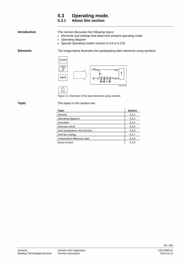
89 / 260
Siemens Climatix AHU Application CE1P3997en Building Technologies Division Function description 2015-10-13
5.3 Operating mode. 5.3.1 About this section
This section discusses the following topics: • Elements and settings that determine present operating mode • Operating diagram • Special Operating modes (section 6.3.6 to 6.3.9). The image below illustrates the participating plant elements using symbols:
Figure 21: Overview of the plant elements using symbols The topics in the section are: Topic Section General 6.3.2 Operating diagrams 6.3.3 Scheduler 6.3.4 External control 6.3.5 Duct temperature, kick function 6.3.6 Free fan cooling 6.3.7 Temperature difference start 6.3.8 Boost function 6.3.9
BMS
Event
P3977Z10
PROG
T
T
T
T
ϕ
ϕ
T
ϕ
Introduction
Elements
Topic
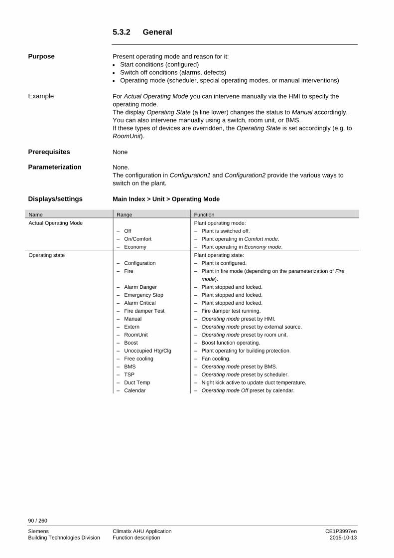
90 / 260
Siemens Climatix AHU Application CE1P3997en Building Technologies Division Function description 2015-10-13
5.3.2 General
Present operating mode and reason for it: • Start conditions (configured) • Switch off conditions (alarms, defects) • Operating mode (scheduler, special operating modes, or manual interventions) For Actual Operating Mode you can intervene manually via the HMI to specify the operating mode. The display Operating State (a line lower) changes the status to Manual accordingly. You can also intervene manually using a switch, room unit, or BMS. If these types of devices are overridden, the Operating State is set accordingly (e.g. to RoomUnit). None None. The configuration in Configuration1 and Configuration2 provide the various ways to switch on the plant. Main Index > Unit > Operating Mode
Name Range Function Actual Operating Mode
– Off – On/Comfort – Economy
Plant operating mode: – Plant is switched off. – Plant operating in Comfort mode. – Plant operating in Economy mode.
Operating state Plant operating state: – Configuration – Plant is configured. – Fire – Plant in fire mode (depending on the parameterization of Fire
mode). – Alarm Danger – Plant stopped and locked. – Emergency Stop – Plant stopped and locked. – Alarm Critical – Plant stopped and locked. – Fire damper Test
– Manual – Extern – RoomUnit – Boost – Unoccupied Htg/Clg – Free cooling – BMS – TSP – Duct Temp – Calendar
– Fire damper test running. – Operating mode preset by HMI. – Operating mode preset by external source. – Operating mode preset by room unit. – Boost function operating. – Plant operating for building protection. – Fan cooling. – Operating mode preset by BMS. – Operating mode preset by scheduler. – Night kick active to update duct temperature. – Operating mode Off preset by calendar.
Purpose
Example
Prerequisites
Parameterization
Displays/settings

91 / 260
Siemens Climatix AHU Application CE1P3997en Building Technologies Division Function description 2015-10-13
General, cont’d
Name Range Function Manual operation Manual plant operation via HMI (only possible for Tsp function ≠
Steps+Tmp). – Auto – Auto mode:
Time switch catalog, free cooling, etc., can switch on the plant. – Off – Plant off. – Stage 1 – Plant operating in stage 1 (using setpoint stage 1 for analog
controlled plants). – Stage 2 – Plant operating in stage 2 (using setpoint stage 2 for analog
controlled plants). – Stage 3 – Plant operating in stage 3 (using setpoint stage 3 for analog
controlled plants). – Eco St1 – Plant operating in Economy at stage 1 (using setpoint stage 1 for
analog controlled plants). – Comf St1 – Plant operating in Comfort mode at stage 1 (using setpoint stage 1
for analog controlled plants). – Eco St2 – Plant operating in Economy at stage 2 (using setpoint stage 2 for
analog controlled plants). – Comf St2 – Plant operating in Comfort mode at stage 2 (using setpoint stage 2
for analog controlled plants). – Eco St3 – Plant operating in Economy at stage 3 (using setpoint stage 3 for
analog controlled plants). – Comf St3 – Plant operating in Comfort mode at stage 3 (using setpoint stage 3
for analog controlled plants). Time switch program – Off
– Stage 1…Stage 3 – Eco – Comf
Displays current command for time switch catalog (for Tsp function = Steps only). Jumps to page to parameterize time switch catalog.
From BACS Displays plant command from BMS (for TspFunction ≠ Steps+Tmp only). The value may also be operated using HMI even when communication not connected.
– Auto – Auto mode: Time switch catalog, free cooling, etc., can switch on the plant.
– Off – Plant off. – Stage 1 – Plant operating in stage 1 (using setpoint stage 1 for analog
controlled plants). – Stage 2 – Plant operating in stage 2 (using setpoint stage 2 for analog
controlled plants). – Stage 3 – Plant operating in stage 3 (using setpoint stage 3 for analog
controlled plants). – Eco St1 – Plant operating in Economy at stage 1 (using setpoint stage 1 for
analog controlled plants). – Comf St1 – Plant operating in Comfort mode at stage 1 (using setpoint stage 1
for analog controlled plants). – Eco St2 – Plant operating in Economy at stage 2 (using setpoint stage 2 for
analog controlled plants). – Comf St2 – Plant operating in Comfort mode at stage 2 (using setpoint stage 2
for analog controlled plants). – Eco St3 – Plant operating in Economy at stage 3 (using setpoint stage 3 for
analog controlled plants). – Comf St3 – Plant operating in Comfort mode at stage 3 (using setpoint stage 3
for analog controlled plants).
Displays/settings, cont’d

92 / 260
Siemens Climatix AHU Application CE1P3997en Building Technologies Division Function description 2015-10-13
General, cont’d
Name Range Function External control Displays current plant command from hardware plant switch. – Auto – Auto mode: Time switch catalog, free cooling, etc., can switch on
the plant. – Off – Plant off. – Stage 1 – Plant operating in stage 1 (using setpoint stage 1 for analog
controlled plants). – Stage 2 – Plant operating in stage 2 (using setpoint stage 2 for analog
controlled plants). – Stage 3 – Plant operating in stage 3 (using setpoint stage 3 for analog
controlled plants). Room unit op mode Displays present plant command from room unit – Auto – Auto mode: Time switch catalog, free cooling, etc., can switch on
the plant. – Comfort – Plant operating in Comfort Mode. – Standby – Plant is in standby. – Economy – Plant operating in Economy Mode. Fan kick exh tmp --- Starts plant to update sensor values for return-air controlled plant and
activated free cooling or UnitStart TmpDelta. (Temperature difference start). Jumps to page to parameterize night kick.
Free cooling --- Free cooling. Goes to page to parameterize free cooling.
Tmp start --- Starts plant at switched off state based on temperature difference. Jumps to page to parameterize temperature difference start.
Boost --- Boost plant start. Jumps to page to parameterize boost plant start.
Power up delay 0…36000 [s] Delayed plant start after controller restart.
Displays/settings, cont’d

93 / 260
Siemens Climatix AHU Application CE1P3997en Building Technologies Division Function description 2015-10-13
5.3.3 Operating diagrams
This section includes the operating diagram for: • Operating modes • Start sequence • Fire alarm • Stop Display of various operating modes: Disabled functions and elements are ignored.
Figure 22: Operating diagram: Operating mode
Table of contents
Operating modes

94 / 260
Siemens Climatix AHU Application CE1P3997en Building Technologies Division Function description 2015-10-13
Operating diagram, cont’d
Plant start sequence. Disabled functions and elements are ignored.
Passive
No
Yes
No
Yes
Yes
No
CommandON, St1..St3
PreHeating
Fire Damperopened
Dampersopened
Fansstarted
UnitON Startup
Active
Figure 23: Operating diagram: Start sequence Conditions to trigger a fire alarm.
FireAlarmInput
SupplyTmp Fire
Alarm
ReturnTmp Fire
Alarm
No Fire Fire
Yes
Yes
Yes
Figure 24: Operating diagram: Fire alarm
Start sequence
Fire alarm

95 / 260
Siemens Climatix AHU Application CE1P3997en Building Technologies Division Function description 2015-10-13
Operating diagram, cont’d Conditions that stop the plant:
Configurationby Download
Configuration 1
Configuration 2
Configuration I/O
ConfigurationI/O Doubled
ConfiguraionI/O not
configured
Controller Power up
Yes
No
Not Done
Not Done
Done
Done
Not Done
Done
Fault
No Fault
OK
Not OK
Ative
Passive
EmergencyStop
Active
Inactive
AlarmHigh Class
0
Active
Inactive
STOPPRelease Stop
Figure 25: Operating diagram: Stop
Stop

96 / 260
Siemens Climatix AHU Application CE1P3997en Building Technologies Division Function description 2015-10-13
5.3.4 Scheduler
A time switch catalog is enabled: Main Index > Configuration > Configuration 1 > TSP function ≠ No The plant is controlled via the time switch program. Main Index > Unit > Operating mode > Time switch program
Name Range Function Schedule – Off
– Stage1…Stage3 Present plant operating mode from the time switch catalog for Tsp function ≤ Steps. Goes to details page to parameterize time switch catalog.
Schedule – Off – Eco St1…Eco St3 – Comf St1…Comf St3
Present plant operating mode from the time switch catalog for Tsp function = Steps+Tmp. Goes to details page to parameterize time switch catalog.
Calendar exception – Passive – Active
Calendar enable exception day. An enabled entry executes the daily switching operations for exception days. Goes to details page to parameterize time switch catalog.
Calendar fix off – Passive – Active
Additional calendar to switch off the plant. Goes to details page to parameterize second calendar.
Prerequisite
Function
Parameter

97 / 260
Siemens Climatix AHU Application CE1P3997en Building Technologies Division Function description 2015-10-13
5.3.5 External control
Here is where the actual plant switch for the AHU unit is configured, i.e. determines whether the plant is switched via an external plant switch, a presence detector, or via a scheduler. The external plant switch is enabled: Main Index > Configuration > Configuration 1 > Ext control input ≠ None For Tmp stpt’s it needs the TSP function Step+Tmp: Main Index > Configuration > Configuration 1 > TSP function = Step+Tmp Plant operation via external plant switch, presence detectors or buttons (Ext control input 1, Ext control input 2). The plant can be switched to auto mode, a set stage or to off depending on parameterization and configuration. The command defaulted here is only enabled when no higher priority command is not active, e.g. manual operation via HMI is enabled. Main Index > Unit > Operating mode > External control
Name Range Function Actual mode Actual plant operating mode as triggered by the plant switch. – Auto – Auto mode:
Time switch catalog, free cooling, etc., can switch on the plant. – Off – Plant off. – Stage 1 – Plant operating in stage 1 (using setpoint stage 1 for analog controlled
plants). – Stage 2 – Plant operating in stage 2 (using setpoint stage 2 for analog controlled
plants). – Stage 3 – Plant operating in stage 3 (using setpoint stage 3 for analog controlled
plants). Tmp stpt input 1 Applied temperature setpoint at the active input Ext control input 1; enabled
only for Tsp function = Steps+Tmp. – Comfort
– Economy – Comfort setpoint. – Economy setpoint.
Note: The present temperature setpoint is determined by the value from Tmp stpt input 2 if both inputs are enabled.
Tmp stpt input 2 Applied temperature setpoint at the active input Ext control input 2; enabled only for Tsp function = Steps+Tmp.
– Comfort – Economy
– Comfort setpoint. – Economy setpoint.
See not for Tmp stpt input 1! Off delay 0…23.0 [h] Switch-off delay.
Plants goes to auto mode after the delay. Notes:
– Off delay = 0 → the present command is pending as long as the impacted input is enabled. This is mandatory for plant switches.
– Off delay > 0 → is used exclusively for external buttons or presence detectors that requires resetting the plant to auto mode after a set period.
Purpose
Prerequisite
Function
Parameter
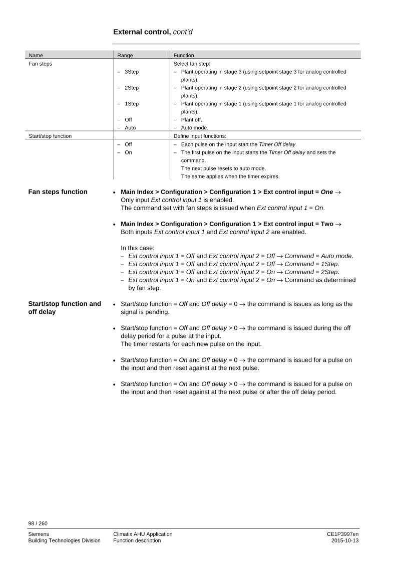
98 / 260
Siemens Climatix AHU Application CE1P3997en Building Technologies Division Function description 2015-10-13
External control, cont’d
Name Range Function Fan steps Select fan step: – 3Step – Plant operating in stage 3 (using setpoint stage 3 for analog controlled
plants). – 2Step – Plant operating in stage 2 (using setpoint stage 2 for analog controlled
plants). – 1Step – Plant operating in stage 1 (using setpoint stage 1 for analog controlled
plants). – Off – Plant off. – Auto – Auto mode. Start/stop function Define input functions: – Off
– On – Each pulse on the input start the Timer Off delay. – The first pulse on the input starts the Timer Off delay and sets the
command. The next pulse resets to auto mode. The same applies when the timer expires.
• Main Index > Configuration > Configuration 1 > Ext control input = One →
Only input Ext control input 1 is enabled. The command set with fan steps is issued when Ext control input 1 = On.
• Main Index > Configuration > Configuration 1 > Ext control input = Two →
Both inputs Ext control input 1 and Ext control input 2 are enabled. In this case: – Ext control input 1 = Off and Ext control input 2 = Off → Command = Auto mode. – Ext control input 1 = Off and Ext control input 2 = Off → Command = 1Step. – Ext control input 1 = Off and Ext control input 2 = On → Command = 2Step. – Ext control input 1 = On and Ext control input 2 = On → Command as determined
by fan step. • Start/stop function = Off and Off delay = 0 → the command is issues as long as the
signal is pending. • Start/stop function = Off and Off delay > 0 → the command is issued during the off
delay period for a pulse at the input. The timer restarts for each new pulse on the input.
• Start/stop function = On and Off delay = 0 → the command is issued for a pulse on
the input and then reset against at the next pulse. • Start/stop function = On and Off delay > 0 → the command is issued for a pulse on
the input and then reset against at the next pulse or after the off delay period.
Fan steps function
Start/stop function and off delay

99 / 260
Siemens Climatix AHU Application CE1P3997en Building Technologies Division Function description 2015-10-13
5.3.6 Duct temperature, kick function
Function automatically enabled when the following conditions are met: – Non room sensor available and – the Extract tmp sensor is not parameterized as saved and – free cooling or start is enabled based on the temperature difference: Main Index > Configuration > Configuration 1 > Room tmp sensor = No and Main Index > Configuration > Configuration 1 > Ext air tmp sensor = Yes and Main Index > Configuration > Configuration 2 > Free cooling = Yes Main Index > Configuration > Configuration 2 > Tmp start ≠ No Plant kick ramps up the plant after a longer period of in operation to update the measured extract temperature in the duct. This temperature is used as the decision-making criterion to start free cooling or temperature difference start and should be kept updated as much as possible. Main Index > Unit > Operating mode > Fan kick exh tmp
Name Range Function Kick time 00:00...23:59 Time to execute kick.
Example: 23:00 Kick is run at 11:00 pm. *:* Time is not relevant; the interval applies accordingly.
Interval time 0.0…36000.0 [h] Interval time to execute kick. Example: 3.0 Run every 3 hours. 0.0 Interval is not relevant; kick time applies accordingly.
On time 0...36000 [s] Kick period. Kick time = 23:00 / interval time = 3 / on time = 300. → The plant is switched-on for 300 seconds if the plant has been off for at least 3 hours as of 11:00 pm.
Kick time = *:* and interval time = 0.0 h → no plant kick is triggered.
Prerequisite
Function
Parameter
Example

100 / 260
Siemens Climatix AHU Application CE1P3997en Building Technologies Division Function description 2015-10-13
5.3.7 Free cooling
Free fan cooling (subsequently referred to as free cooling) cools down a building at night using cool outside air without auxiliary energy for high daytime temperatures. • Free cooling is switched on in the following cases:
– Outside air temperature is greater than the lower level: Out tmp > Min outs tmp and
– outside air temperature is less than the difference from room temperature and switch-on differential: Out tmp < Room tmp - Delta and
– room temperature is greater than the sum of the room setpoint and hysteresis: Room tmp > Room tmp setpoint + hysteresis.
• Free cooling is switched off in the following cases:
– Timer Min run time = 0 and
– plant switches on. or
– outside air temperature is less than the difference from room temperature and switch-off differential: Out tmp > Room tmp – 1 or
– room temperature is less than or equal to room setpoint: Room tmp ≤ Room tmp setpoint
Free cooling (Free cooling) is enabled: Main Index > Configuration > Configuration 2 > Free cooling ≠ No
The function is disabled for faulty outside air or room temperature measurement.
Main Index > Unit > Operating mode > Free cooling
Name Range Function Room tmp setpoint -64.0…64.0 [°C] Room setpoint for free cooling.
Setpoint applies to extract air for free cooling with a extract air sensor. Hysteresis 0.0…64.0 [°C] Hysteresis for switch on. Delta 1.0…64.0 [°C] Minimum difference between room and outside air temperature. Min outs tmp -64.0…64.0 [°C] Minimum outside air temperature to enable night cooling. Min run time 0…999 [min] Minimum runtime after a start.
Purpose
Prerequisite
Parameter

101 / 260
Siemens Climatix AHU Application CE1P3997en Building Technologies Division Function description 2015-10-13
5.3.8 Temperature difference start
Plant start (in switched off state) based on temperature difference prevents the building from cooling down or heating up too much. It is controlled to a separate setpoint for heating and cooling. The heating and or cooling start can be enabled separately: Main Index > Configuration > Configuration 2 > Tmp start The function can be implemented using a extract air sensor if no room sensor is available. Plant start by temperature difference is enabled: Main Index > Configuration > Configuration 2 > Tmp start ≠ No The Tmp start of plant by temperature difference for cooling demand occurs when the following conditions are met: – Room tmp > Tmp start cooling – Timer min off = 0 The shutdown occurs for: – Room tmp < Tmp start cooling – Hysteresis – Timer min run = 0 The Tmp start of plant by temperature difference for heating demand occurs when the following conditions are met: – Room tmp < Tmp start heating – Timer min off = 0 The shutdown for heating demand occurs for: – Room tmp > Tmp start heating + Hysteresis – Timer min run = 0
The function is switched off when the room temperature, or extract air sensor fails.
Main Index > Unit > Operating mode > Tmp start
Name Range Function Start stpt cooling -64.0….64.0 [°C] Start temperature for cooling. Cooling setpoint -64.0….64.0 [°C] Cooling setpoint. Start stpt heating -64.0…64.0 [°C] Start temperature for heating. Heating setpoint -64.0….64.0 [°C] Heating setpoint. Hysteresis 0.1…64.0 [°C] Switch down hysteresis. Minimum off time 0…999 [min] Minimum switch-off time after active heating or cooling. Min run time 0.0…..999.0 [min] Minimum runtime after a start.
Purpose
Prerequisite
Cooling demand
Heating demand
Parameter

102 / 260
Siemens Climatix AHU Application CE1P3997en Building Technologies Division Function description 2015-10-13
5.3.9 Boost function
Boost ensures a comfortable room temperature exists when the plant is switched on normally to Comfort. The heating and or cooling start can be enabled separately: Main Index > Configuration > Configuration 2 > Boost The function can be implemented using an extract air sensor if no room sensor is available. Boost is enabled: Main Index > Configuration > Configuration 2 > Boost ≠ No Boost for cooling demand occurs when the following conditions are met: – Room tmp > Start stpt cooling + Hysteresis
and – Time to normal start via the time switch program < Compensation time The shutdown occurs for: – Room tmp < Start stpt cooling Boost for heating demand occurs when the following conditions are met: – Room tmp < Start stpt heating - Hysteresis
and – Time to normal start via the time switch program < Compensation time The shutdown occurs for: – Room tmp > Start stpt heating
The function is disabled when the room temperature (extract temperature) sensor fails.
Main Index > Unit > Operating mode > Boost
Name Range Function Room tmp setpoint -64.0…64.0 [°C] Boost room setpoint. Start stpt cooling -64.0….64.0 [°C] Start temperature for cooling. Start stpt heating -64.0…64.0 [°C] Start temperature for heating. Hysteresis 0.1…64.0 [°C] Switch down hysteresis. Compensation time 0…999 [min] Time by which plant start is advanced.
5.3.10 Optimum start/stop function.
Not yet available.
Purpose
Prerequisite
Cooling demand
Heating demand
Parameter

103 / 260
Siemens Climatix AHU Application CE1P3997en Building Technologies Division Function description 2015-10-13
5.4 Damper control 5.4.1 Overview
This section describes the control of outside air/exhaust air dampers and the fire dampers. The figure illustrates the participating plant elements (with gray background):
Figure 26: Overview of the plant elements for damper control The topics in the section are: Topic Section General 6.4.2 Outside/exhaust air dampers 6.4.3 Fire dampers 6.4.4
P3977Z04
Introduction
Elements
Topic

104 / 260
Siemens Climatix AHU Application CE1P3997en Building Technologies Division Function description 2015-10-13
5.4.2 General
This section describes functions the impact the entire damper control (outside air and fire dampers). Dampers are enabled in Configuration 1, Configuration 2 and Configuration IOs, preconfigured and the inputs, outputs defined. Main Index > Configuration > Configuration 1
Name Range Function Damper – No
– Combined – Supply – Supply+Exh
– No open/close damper. – Two dampers with common output. – Outside air damper with output. – Two dampers with separate outputs.
Fire damper – No – Yes – FollowUnit – 2 – 2+FolwUn – 3 – 3+FolwUn – 4 – 4+FolwUn
– No fire dampers. – Fire dampers. – Fire dampers are opened with Unit Start or closed with Unit
Stop. – Up to 4 fire dampers can be connected.
Main Index > Configuration > Configuration 2
Name Range Function Damper fdbk – No
– One – No damper feedback. – Feedback for outside air dampers (or a common feedback for
both dampers). – Two – Separate feedback for outside air and extract air damper. Fire damper fdbk
– Closed – Clsd+Opnd – Combined
Feedback from fire dampers. – Only one feedback for close. – Two separate feedbacks for open and close. – Two feedbacks for open and close, but only one signal.
The syntax must be correct: 1 (close) → 0 (moving) → 1 (open)
Main Index > Unit > Damper Control
Name Range Function Off delay by fan off 0…36000 [s] Switch-off delay for outside air, extract and fire dampers.
The dampers are closed after this period after switching off the supply air fan.
Damper --- Jump to damper page to parameterize the outside and extract air damper.
Fire damper – On – Off
Current fire damper status. Jump to fire damper page to parameterize the fire damper.
Content
Prerequisite
Enable
Configuration
Parameterization

105 / 260
Siemens Climatix AHU Application CE1P3997en Building Technologies Division Function description 2015-10-13
5.4.3 Outside/extract air dampers
Outside and extract air dampers are enabled and preconfigured in Configuration 1, Configuration 2 and Configuration IOs. Per settings outside and extract air damper open at plant start and close at plant stop. Damper opening times can be defined separately. A common default period can be set if no damper feedback exists. The damper command can still be kept at pending for a feedback alarm. Only the output for the outside air damper is enabled if two dampers are enabled as combined. This is also true for triggering feedback alarms for the extract air damper, if a separate feedback per damper is enabled. The supply air fan controls the outside air damper. The extract air fan controls the extract air. The signal for the damper actuator depends on the supply air/extract air fan if a combined damper actuator is selected. Please very careful, if using, for example, Fire mode Rune! Main Index > Unit > Damper Control > Damper
Name Range Function Outside air cmd – Off
– On Current state of outside air damper command. Go to page with all digital output settings.
Outside air fdbk – No – Yes
Active feedback as to whether the damper is open. Go to page with all digital input settings. For example, you can set the time for jitter protection (default: 5 s).
Outs off by fdbk alm – No – Yes
Determines, in the event of a feedback fault, whether a damper command is still pending or whether to switch off the command.
StrtUpDly outs fdbk 0…36000 [s] Defines the period after an open command without feedback before a feedback alarm is triggered. Jitter time is enabled exclusively if the feedback is pending after this period.
Extract air cmd – Off – On
Current state of extract air damper command. Go to page with all digital output settings.
Extract air fdbk – No – Yes
Active feedback as to whether the damper is open. Go to page with all digital input settings. For example, you can set the time for jitter protection (default: 5 s).
Extr offby fdbk alm – No – Yes
Determines, in the event of a feedback fault, whether a damper command is still pending or whether to switch off the command.
StrtUpDly Extr fdbk 0…36000 [s] Defines the period after an open command without feedback before a feedback alarm is triggered. Jitter time is enabled exclusively if the feedback is pending after this period.
Opening time 0…36000 [s] Estimates damper opening time for both dampers, if not active feedback (fdbk) is enabled. It is assumed that the dampers are open after this period and that the start release is issued for the fans.
Feedback can only be used as alarm, when Contact function = NO (Normally Open) and the element is set to ON.
Prerequisite
Functions
Parameter

106 / 260
Siemens Climatix AHU Application CE1P3997en Building Technologies Division Function description 2015-10-13
5.4.4 Fire dampers.
Fire dampers are enabled and preconfigured in Configuration 1, Configuration 2 and Configuration IOs. Fire dampers can be controlled via the plant operating mode or the automatic test, or can be continuously open. Reaching and leaving the given end switch is monitored. Displays the current state and operating state of the dampers. The fire dampers are controlled by the supply air as well as the extract air fans. Main Index > Unit > Damper Control > Fire damper
Name Range Function Command – Off
– On Current state of outside air damper command. Go to page with all digital output settings.
Feedback opened – OK – 1 / 2 / 3 / 4 – +all combinations
possible
Active feedback if the damper is open. The feedback opened is automatically set after 115% of open time if fdbk Open is not enabled in Configuration 2.
Feedback closed – OK – 1 / 2 / 3 / 4 – +all combinations
possible
Active feedback if the damper is closed (fire). This feedback must always be available. The alarm is immediately triggered if close cannot be commanded.
State – NotDefined – Closed – Move – Opened
Current damper state. – Only possible during configuration. – Closed. – Moving. – Opened. See example below.
Mode – NotDefined – Ok – Test – Alarm
Damper operating state. – Only possible during configuration. – Okay. – In test mode. – In alarm state.
Opening time 1…600 [s] Positioning time to open the damper (see Data Sheet damper actuator).
Closing time 1…600 [s] Positioning time to close the damper (see Data Sheet damper actuator).
Start manual test – Passive – Active
Active triggers a manual test of the fire dampers. See examples below.
Auto test Time, weekday, date Determines the time for an automatic start of the damper test. The automatic test is disabled for Configuration 1 > Fire damper = FollowUnit. See examples below.
Auto test interval 0...36000 [h] Set the time interval for a period automatic damper test. See examples below.
In case of having 2 fire dampers, 2 DI are needed. In IO configuration, only the first DI needs to be selected, the next after will be taken automatically. Example for 4 fire dampers: Configure DI2, then DI3, DI4 and DI5 are configured and occupied.
Prerequisite
Functions
Parameter
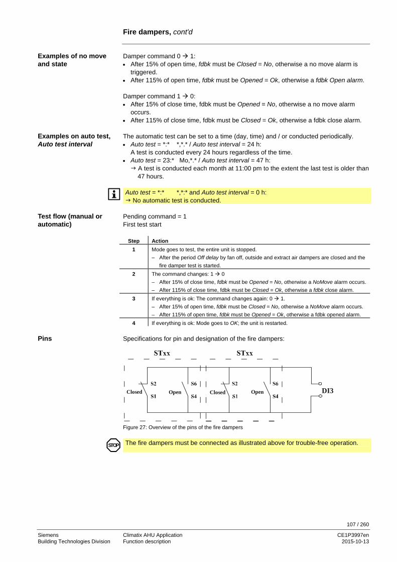
107 / 260
Siemens Climatix AHU Application CE1P3997en Building Technologies Division Function description 2015-10-13
Fire dampers, cont'd
Damper command 0 1: • After 15% of open time, fdbk must be Closed = No, otherwise a no move alarm is
triggered. • After 115% of open time, fdbk must be Opened = Ok, otherwise a fdbk Open alarm. Damper command 1 0: • After 15% of close time, fdbk must be Opened = No, otherwise a no move alarm
occurs. • After 115% of close time, fdbk must be Closed = Ok, otherwise a fdbk close alarm. The automatic test can be set to a time (day, time) and / or conducted periodically. • Auto test = *:* *,*.* / Auto test interval = 24 h:
A test is conducted every 24 hours regardless of the time. • Auto test = 23:* Mo,*.* / Auto test interval = 47 h: A test is conducted each month at 11:00 pm to the extent the last test is older than 47 hours.
Auto test = *:* *,*:* and Auto test interval = 0 h: No automatic test is conducted.
Pending command = 1 First test start
Step Action 1 Mode goes to test, the entire unit is stopped.
– After the period Off delay by fan off, outside and extract air dampers are closed and the fire damper test is started.
2 The command changes: 1 0 – After 15% of close time, fdbk must be Opened = No, otherwise a NoMove alarm occurs. – After 115% of close time, fdbk must be Closed = Ok, otherwise a fdbk close alarm.
3 If everything is ok: The command changes again: 0 1. – After 15% of open time, fdbk must be Closed = No, otherwise a NoMove alarm occurs. – After 115% of open time, fdbk must be Opened = Ok, otherwise a fdbk opened alarm.
4 If everything is ok: Mode goes to OK; the unit is restarted. Specifications for pin and designation of the fire dampers:
Closed Open OpenClosed DI3
Figure 27: Overview of the pins of the fire dampers
STOP
The fire dampers must be connected as illustrated above for trouble-free operation.
Examples of no move and state
Examples on auto test, Auto test interval
Test flow (manual or automatic)
Pins

108 / 260
Siemens Climatix AHU Application CE1P3997en Building Technologies Division Function description 2015-10-13
5.5 Fan control 5.5.1 Overview
This section describes: • Configure supply and extract air fans • Control of the same • Monitoring and alarms The figure illustrates the participating plant elements (with gray background):
Figure 28: Overview of the plant elements for fan control The topics in the section are: Topic Section Configure fan functions 6.5.2 Description of fan modes 6.5.3 Supply air/extract air control 6.5.4 Summer/winter compensation 6.5.5 Supply air/extract air fan, deviation alarms 6.5.6 Operating hours monitoring 6.5.7 Fan compensation 6.5.8
∆p
∆p
P3977Z06
Introduction
Elements
Topic

109 / 260
Siemens Climatix AHU Application CE1P3997en Building Technologies Division Function description 2015-10-13
5.5.2 Configure fan functions
Fan functions are configured in three steps:
Step Action 1 Select and enable 2 Configuration 3 Parameterization
In this step, the fan type and control mode is selection and possible steps are enabled. Main Index > Configuration > Configuration 1
Name Range Function TSP steps Enable possible fan steps. – 1Step
– 2Steps – 3Steps
– Single-step fan (only one setpoint). – 2-step fan (two setpoints). – 3-step fan (three setpoints).
Fan control mode Select fan and control type. – Direct – Digitally controlled stepped fans. – DirectVar – Digitally controlled variable speed drives. – FixedSpeed – Stepped analog controlled variable speed drive with digital release [%]. – Pressure – Pressure-controlled plant with modulating controlled variable speed drive and
digital release [Pa]. – Flow – Volume-controlled plant with modulating controlled variable speed drive and
digital release [l/s]. – SupplySlv – One digital and analog output each for the variable speed drives in pressure-
controlled plants where the supply air fan operates dependent on the extract air fan [Pa]/[l/s]. The extract air fan is pressured controlled and the extract air volume is calculated; the supply air fan is volume controlled and provided to the extract air volume.
– ExhaustSlv – One digital and analog output each for the variable speed drives in pressure-controlled plants where the extract air fan operates dependent on the supply air fan [Pa]/[l/s]. The supply air is pressured controlled and the supply air is calculated; the extract air volume is volume controlled and provided to the supply air volume.
Extract fan – No – Yes
– Extract fan – ---
– Combined Both fans use the same output. The extract air fan must be set to combined if a combined signal is wanted for
extract air and supply air fans. It must be set to No if no extract fan is available.
Procedure
First select and enable
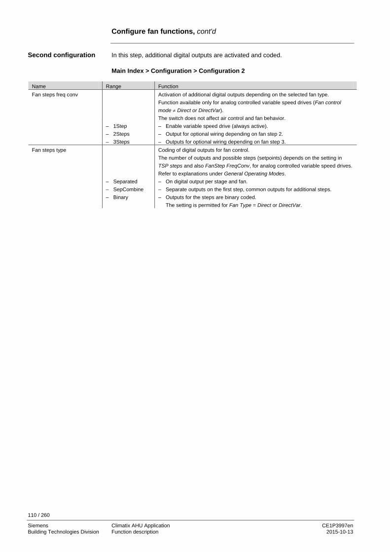
110 / 260
Siemens Climatix AHU Application CE1P3997en Building Technologies Division Function description 2015-10-13
Configure fan functions, cont'd
In this step, additional digital outputs are activated and coded. Main Index > Configuration > Configuration 2
Name Range Function Fan steps freq conv Activation of additional digital outputs depending on the selected fan type.
Function available only for analog controlled variable speed drives (Fan control mode ≠ Direct or DirectVar). The switch does not affect air control and fan behavior.
– 1Step – 2Steps – 3Steps
– Enable variable speed drive (always active). – Output for optional wiring depending on fan step 2. – Outputs for optional wiring depending on fan step 3.
Fan steps type Coding of digital outputs for fan control. The number of outputs and possible steps (setpoints) depends on the setting in TSP steps and also FanStep FreqConv, for analog controlled variable speed drives. Refer to explanations under General Operating Modes.
– Separated – SepCombine – Binary
– On digital output per stage and fan. – Separate outputs on the first step, common outputs for additional steps. – Outputs for the steps are binary coded.
The setting is permitted for Fan Type = Direct or DirectVar.
Second configuration

111 / 260
Siemens Climatix AHU Application CE1P3997en Building Technologies Division Function description 2015-10-13
Configure fan functions, cont'd
In this step, the values for the fan functions are set. Main Index > Unit > Fan Control Comment: Functions not enabled in Configuration 1 and/or Configuration 2 are hidden.
Name Range Function Supply fan – Off
– Stage 1 – Stage 2 – Stage 3
Current supply air fan status. Go to parameter page for supply air fan.
Extract fan – Off – Stage 1 – Stage 2 – Stage 3
Current extract air fan status. Go to parameter page for extract air fan.
Actual step – Off – Stage 1 – Stage 2 – Stage 3
Current calculated, valid stage (setpoint for control) for fans.
Fire mode – Stop – RunSply – RunExh – Run both
Fan behavior in the event of a fire alarm: – Fans are off. – Only the supply air fan starts at the maximum enabled stage. – Only the extract air fan starts at the maximum enabled stage. – Both fans start at the maximum enabled stage.
Fire setpoint 0…100 [%] Output signal for fan start in the event of a fire alarm for all analog controlled variable speed drives.
Slave offset -999….999 [Pa] Setpoint offset for fan control mode = Supply Slv or Extract Slv. Slave start up stpt 0….999 [l/s] Start setpoint for fan control mode = Extract Slv for extract fan until the supply air
fan is operating. The extract air fan then operates using the Slave Offset setpoint.
Rundown time el htg 0…36000 [s] Supply air fan overrun if an electrical heating register is active. Min stage time 0…999 [s] Minimum runtime for a stage prior to stepping up to the next step. Note:
This period remains active when intervening using the operator unit: Even for a direct jump from off to stage 3, the output remains on each individual step for the minimum runtime.
Coasting time 0..99 [s] Coasting time when reducing each stage. Disable high speed -64.0…64.0 [°C]
Stages greater than 1 (setpoint stage 1) are blocked (as with manual operation) if the outside air temperature < Disable HighSpeed. All possible stages are enabled for outside air temperature > Disable HighSpeed + 1 K. In Winter (at low outside air temperature) the function prevents too great a volume of air from discharging requiring heating, saving energy in this manner.
Third parameterization

112 / 260
Siemens Climatix AHU Application CE1P3997en Building Technologies Division Function description 2015-10-13
Configure fan functions, cont'd
Name Range Function Disable fan comp Limit to compensated step up (step up switching): – None – No limit.
For active stage 1 can be switched to stage 2, for active stage 2 to stage 3. For analog controlled variable speed drives (Fan control mode ≠ Direct or DirectVar), can be stepped up per curve (see Fan compensation) for active Stage1 setpoint and Stage2 setpoint.
– Stage 1 – Compensation blocked for active stage 1 (Stage1 setpoint). Can be switched to stage 3 for active stage 2. For analog controlled variable speed drives (Fan control mode ≠ Direct or DirectVar), can be stepped up per curve (see Fan compensation) for active Stage2 setpoint.
– Stage1+Stage2 – Compensation blocked for active step 1 and step 2. For analog controlled variable speed drives, active step 3 compensate to MaxForce.
Summer comp -100….100% Present value for summer compensation. Go to parameter page for summer compensation.
Winter comp -100….100% Present value for winter compensation. Go to parameter page for winter compensation.
Op hours settings Go to parameter page for fan maintenance messages.
Parameters, cont'd

113 / 260
Siemens Climatix AHU Application CE1P3997en Building Technologies Division Function description 2015-10-13
5.5.3 Description of fan modes
This section describes the functions of the various fan modes for: • Fan steps type = Separated • Fan steps type= SepCombine • Fan steps type = Binary The following relationship apply among the values for the parameters Fan control mode, TSP steps, fan step freq conv and Fan steps type: Fan control mode = Direct / DirectVar DO1 DO2 DO3
DOs each for supply air and extract air fan (if selected). Off 0 0 0 Stage1 1 0 0 Stage2 0 1 0 Stage3 0 0 1 Fan control mode ≠ Direct / DirectVar, Fan steps freq conv = 1 DO1
DO1 each for supply air and extract air fan (if selected). Off 0 Stage1 1 Stage2 1 Stage3 1 Fan control mode ≠ Direct / DirectVar, Fan steps freq conv > 1 DO1 DO2 DO3
DOs each for supply air and extract air fan (if selected). Off 0 0 0 Stage1 1 0 0 Stage2 1 1 0 Stage3 1 0 1
Content
Fan steps type = Separated

114 / 260
Siemens Climatix AHU Application CE1P3997en Building Technologies Division Function description 2015-10-13
Description of fan modes, cont'd
Fan control mode = Direct / DirectVar DO1 DO2 DO3
– DO1 each for supply air and extract air fan (if selected). – DO2, DO3: Combined output for both fans.
Off 0 0 0 Stage1 1 0 0 Stage2 0 1 0 Stage3 0 0 1 Fan control mode ≠ Direct / DirectVar, Fan steps freq conv = 1 In this case, Fan steps freq conv = 1 has no impact, since output DO1 is always available for supply and extract air fan. DO1
DO1 each for supply air and extract air fan (if selected). Off 0 Stage1 1 Stage2 1 Stage3 1 Fan control mode ≠ Direct / DirectVar, Fan steps freq conv > 1 DO1 DO2 DO3
– DO1 each for supply air and extract air fan (if selected). – DO2, DO3: Combined output for both fans.
Off 0 0 0 Stage1 1 0 0 Stage2 1 1 0 Stage3 1 0 1 Fan control mode = Direct / DirectVar DO1 DO2
DOs each for supply air and extract air fan (if selected). Off 0 0 Stage1 1 0 Stage2 0 1 Stage3 1 1
For all frequency controlled fans: Stage = active setpoint.
Fan steps type = SepCombine
Fan steps type = Binary
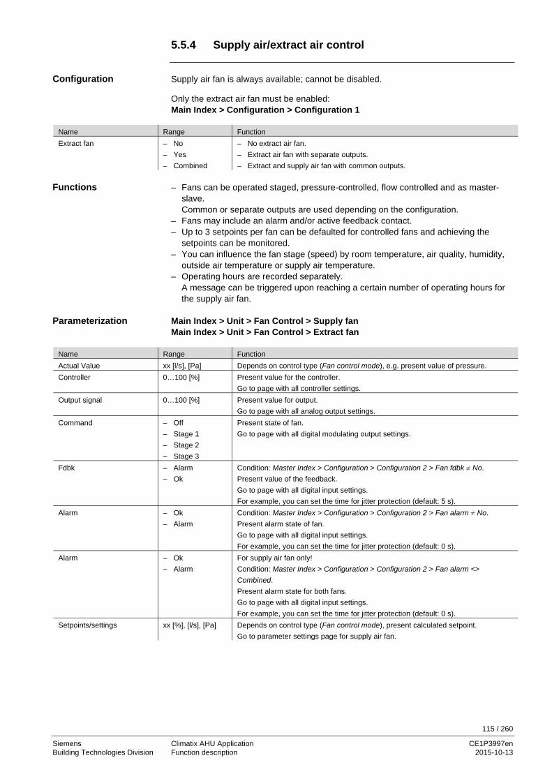
115 / 260
Siemens Climatix AHU Application CE1P3997en Building Technologies Division Function description 2015-10-13
5.5.4 Supply air/extract air control
Supply air fan is always available; cannot be disabled. Only the extract air fan must be enabled: Main Index > Configuration > Configuration 1
Name Range Function Extract fan – No
– Yes – Combined
– No extract air fan. – Extract air fan with separate outputs. – Extract and supply air fan with common outputs.
– Fans can be operated staged, pressure-controlled, flow controlled and as master-
slave. Common or separate outputs are used depending on the configuration.
– Fans may include an alarm and/or active feedback contact. – Up to 3 setpoints per fan can be defaulted for controlled fans and achieving the
setpoints can be monitored. – You can influence the fan stage (speed) by room temperature, air quality, humidity,
outside air temperature or supply air temperature. – Operating hours are recorded separately.
A message can be triggered upon reaching a certain number of operating hours for the supply air fan.
Main Index > Unit > Fan Control > Supply fan Main Index > Unit > Fan Control > Extract fan
Name Range Function Actual Value xx [l/s], [Pa] Depends on control type (Fan control mode), e.g. present value of pressure. Controller 0…100 [%] Present value for the controller.
Go to page with all controller settings. Output signal 0…100 [%] Present value for output.
Go to page with all analog output settings. Command – Off
– Stage 1 – Stage 2 – Stage 3
Present state of fan. Go to page with all digital modulating output settings.
Fdbk – Alarm – Ok
Condition: Master Index > Configuration > Configuration 2 > Fan fdbk ≠ No. Present value of the feedback. Go to page with all digital input settings. For example, you can set the time for jitter protection (default: 5 s).
Alarm – Ok – Alarm
Condition: Master Index > Configuration > Configuration 2 > Fan alarm ≠ No. Present alarm state of fan. Go to page with all digital input settings. For example, you can set the time for jitter protection (default: 0 s).
Alarm – Ok – Alarm
For supply air fan only! Condition: Master Index > Configuration > Configuration 2 > Fan alarm <> Combined. Present alarm state for both fans. Go to page with all digital input settings. For example, you can set the time for jitter protection (default: 0 s).
Setpoints/settings xx [%], [l/s], [Pa] Depends on control type (Fan control mode), present calculated setpoint. Go to parameter settings page for supply air fan.
Configuration
Functions
Parameterization

116 / 260
Siemens Climatix AHU Application CE1P3997en Building Technologies Division Function description 2015-10-13
Supply air/extract air control, cont'd
Main Index > Unit > Fan Control > Supply fan > Setpoints / Settings Main Index > Unit > Fan Control > Extract fan > Setpoints / Settings
Name Range Function Actual step
– Off – Stage1 – Stage2 – Stage3
Present fan stage. – Off. – Stage 1 (setpoint 1) active. – Stage 2 (setpoint 2) active. – Stage 3 (setpoint 3) active.
Act supply stpt 0...100 [%] 0...40'000 [l/s] 0...5000 [Pa]
Depends on control type (Fan control mode ≠ Direct or DirectVar): Present calculated setpoint for fan.
Stage 1 0...100 [%] 0...40'000 [l/s] 0...5000 [Pa]
Depends on control type (Fan control mode ≠ Direct or DirectVar): Setpoint for stage 1 (TSP steps ≥ 1 for controlled fans).
Stage 2 0...100 [%] 0...40'000 [l/s] 0...5000 [Pa]
Depends on control type (Fan control mode ≠ Direct or DirectVar): Setpoint for stage 2 (TSP steps ≥ 2 for controlled fans).
Stage 3 0...100 [%] 0...40'000 [l/s] 0...5000 [Pa]
Depends on control type (Fan control mode ≠ Direct or DirectVar): Setpoint for stage 3 (TSP steps = 3 for controlled fans).
Max forcing 0...(100-Stage max.) [%] 0...(40'000-Stage max.) [l/s] 0...(5000-Stage max.) [Pa
Depends on control type (Fan control mode ≠ Direct or DirectVar): The maximum possible fan compensation is derived from the following formula: Stage max. + Max forcing - Stage x [%], [l/s], [Pa] (see Fan compensation).
Min runtime 0…36000 [s] Define the minimum runtime for the fan after a start. Switch on delay 0…36000 [s] For supply air fan only!
Defines switch-on delay for the supply air fan after a extract fan start. Start up delay fdbk 0…36000 [s] Defines the period after a fan start without feedback before a feedback
alarm is triggered. Jitter time is enabled exclusively if the feedback is pending after this period.
Deviation alarm Condition: Fan control mode ≠ Direct, DirectVar or FixedSpd. Present state for the setpoint/actual value monitoring of the supply air pressure (or volume). Go to parameter page for supply air monitoring.
– Passive – Active
– No alarm. – Alarm pending.
Feedback can only be used as alarm, when Contact function = NO (Normally Open) and the element is set to ON.
Parameters, cont'd

117 / 260
Siemens Climatix AHU Application CE1P3997en Building Technologies Division Function description 2015-10-13
5.5.5 Summer/winter compensation
– An outside air temperature sensor must be available:
Main Index > Configuration > Configuration 1 > Outside tmp sensor = Yes. – Summer/winter compensation must be enabled:
Main Index > Configuration > Configuration 2 > Fancomp Outsidetmp = Yes. – Summer compensation:
Adjustment to setpoint relevant to control when the outside air temperature is high during the summer.
– Winter compensation: Adjustment to setpoint relevant to control when the outside air temperature is low during the winter.
Figure 29: Setpoint compensation during summer
Main Index > Unit > Fan Control > Summer comp Main Index > Unit > Fan Control > Winter Comp
Name Range Function Outside tmp start -64…64 [°C] Outside air temperature at which point the compensation begins to act. Outside tmp end -64…64 [°C] Outside air temperature by which the maximum (summer) or minimum setpoint is
reached. Delta -100…100 [%] Fan setpoint compensation relating to the maximum allowed fan compensation (see
Fan compensation as well).
Setpoint compensation is not undertaken during the summer and winter when the outside air temperature sensor fails. A negative value means a reduction in fan output; a positive value an increase in fan output. For Fan control mode = Direct, DirectVar the delta must be set to -100% or 100%, since a switch down or up occurs is the total added compensation is above 90% (switch down at 10%), but may be less if another compensation is enabled.
Outside tmp end
Delta
Setpoint
Outside tmp start
Setpoint
Outside temperature [°C]
3977
D03
en
Outside tmp start
Delta
Setpoint
Outside tmp end
Setpoint
Outside temperature [°C]
3977
D04
en
Requirements
Functions
Setpoint compensation during summer
Setpoint compensation during the winter
Parameterization

118 / 260
Siemens Climatix AHU Application CE1P3997en Building Technologies Division Function description 2015-10-13
5.5.6 Supply air/extract air fan, deviation alarms.
– Main Index > Configuration > Configuration 1 > Fan control mode ≠ Direct,
DirectVar or FixedSpd – Fan deviation alarm must be enabled:
Main Index > Configuration > Configuration 2 > Fan deviation alarm ≠ No Setpoint/actual value monitoring of air control: An alarm is triggered for the following cases when the air pressure (or volume) deviates from the setpoint during a certain period: – Actual value < Min Limit (is also used as feedback for act value > Min limit, for
example, to enable electric heating). – Actual value > Setpoint + Maximum. – Actual value < Setpoint – Maximum. – When setpoint – Maximum < Min Limit, Min Limit applies as the comparison value. Main Index > Unit > Fan Control > Supply Fan > Setpoints / Settings > Deviation alarm Main Index > Unit > Fan Control > Extract fan > Setpoints / Settings > Deviation alarm
Name Range Function Alarm – Passive
– Active Alarm state. Go to settings page for digital alarms. Set all control-related settings such as alarm delay (default 60 s).
Min limit -0...40’000 [%; Pa] Depends on control type (Fan control mode), an alarm is triggered when it breaches this value.
Maximum deviation -0...40’000 [%; Pa] Depends on control type (Fan control mode); maximum allowed deviation between setpoint and actual value.
Start up delay 0…36000 [s] The function is activated after this period after a start.
Monitoring is switched off when the sensor fails.
5.5.7 Operating hours monitoring
None. An alarm (low class) can be triggered for maintenance purposes when the present operating hours for the supply air fan exceeds the operating hours limit. Main Index > Unit > Fan Control > Op hours settings
Name Range Function Op hours alarm – Passive
– Active Present alarm status.
Enble ophours alarm – No – Yes
Alarm enable.
Op hours limit 0…999999 [h] Operating hours limit to trigger an alarm.
Requirements
Function
Parameterization
Prerequisite
Function
Parameterization

119 / 260
Siemens Climatix AHU Application CE1P3997en Building Technologies Division Function description 2015-10-13
5.5.8 Fan compensation
– Disable comp parameter setting (Main Index > Unit > Fan control > Disable comp)
must be observed for each compensation. – All types of compensation that results in a step-up or switch, are added to the overall
compensation ∑ comp. – All types of compensation that result in a step-down or switch, are subtracted from
the overall compensation ∑ comp. – ∑ comp up and ∑ comp down are limited to 100 %. • Temperature control:
– Fan cooling [%] – Fan compensation [%] (Increase)
• From fan control:
– Summer compensation [%] (if positive). – Winter compensation [%] (if positive).
• From humidification:
– Fan compensation [%] (Increase) • From air quality control:
– Function normal [%] • From temperature control:
– Fan heating [%] – Fan compensation [%] (Decrease)
• From fan control:
– Summer compensation [%] (if negative). – Winter compensation [%] (if negative).
• From humidification:
– Fan compensation [%] (Decrease) • From air quality control:
– Function inverse [%]. Fan control mode = Direct or DirectVar. • ∑ comp up > 90% → if possible step-up of a stage (see Disable comp). • ∑ comp up < 10% → remove compensation stage. • ∑ comp down > 90% → step-down of a stage (Stage1 is the minimum). • ∑ comp down < 10% → the removed stage is enabled again.
General notes
Percentage of ∑ comp up
Percentage of ∑ comp down
Staged fans

120 / 260
Siemens Climatix AHU Application CE1P3997en Building Technologies Division Function description 2015-10-13
Fan compensation, cont'd
Fan control mode ≠ Direct or DirectVar. Calculates maximum compensation (100% compensation): Highest stage setpoint + Max forcing – Stage1 Setpoint with set minimum limitation to Stage1 Setpoint and maximum limitation to Stage max + Max forcing. ∑ comp up 80% Fan control mode Pressure TSP steps 3 Stage1 Setpoint 500 Pa Stage2 Setpoint 800 Pa Stage3 Setpoint 1000 Pa Max forcing 200 Pa Active stage setpoint Stage1, 500 Pa – Maximum compensation = 1000 + 200 – 500 = 700 [Pa] – Compensation setpoint = setpoint Stage1 + 80% of maximum compensation =
500 + 700 * 0,8 = 500 + 560 = 1060 [Pa] – Maximum possible setpoint = Stage3 Setpoint + max force = 1000 + 200 = 1200 [Pa] ∑ comp down 30% Fan control mode Pressure TSP steps 3 Stage1 Setpoint 500 Pa Stage2 Setpoint 800 Pa Stage3 Setpoint 1000 Pa Max forcing 200 Pa Active stage setpoint Stage2, 800 Pa – Maximum compensation 1000 Pa + 200 Pa – 500 Pa = 700 Pa. – Setpoint = setpoint Stage2 - 30% of maximum compensation
= 800 - 700 * 0.3 = 800 - 210 = 590 [Pa] – Minimum possible setpoint = Stage1 Setpoint = 500 Pa, since the setpoint
compensation is limited to this value.
Analog fans
Example 1
Example 2

121 / 260
Siemens Climatix AHU Application CE1P3997en Building Technologies Division Function description 2015-10-13
5.6 Temperature control 5.6.1 Overview
This section describes the functions relating to heating and cooling register control, including: • Temperature setpoints • Compensations and limitations • Deviation alarms • Fan compensation The figure illustrates in a simplified manner the participating plant elements:
Figure 30: Overview of the plant elements for temperature control The topics in the section are: Topic Section General 6.6.2 Temperature setpoints 6.6.3 Summer/winter compensation 6.6.4 Temperature deviation alarm 6.6.5 Supply air temperature minimum/maximum control 6.6.6 Fan heating/cooling 6.6.7 Fan compensation 6.6.8 Common heating/cooling register 6.6.9
T
T
T
T
P3977Z11
T
Introduction
Elements
Topic
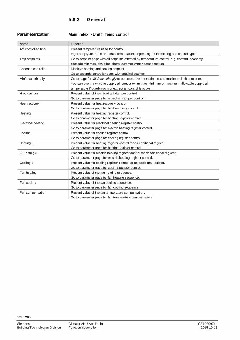
122 / 260
Siemens Climatix AHU Application CE1P3997en Building Technologies Division Function description 2015-10-13
5.6.2 General
Main Index > Unit > Temp control
Name Function Act controlled tmp Present temperature used for control.
Eight supply air, room or extract temperature depending on the setting and control type. Tmp setpoints Go to setpoint page with all setpoints affected by temperature control, e.g. comfort, economy,
cascade min max, deviation alarm, summer-winter compensation. Cascade controller Displays heating and cooling setpoint.
Go to cascade controller page with detailed settings. Min/max ctrlr sply Go to page for Min/max ctlr sply to parameterize the minimum and maximum limit controller.
You can use the existing supply air sensor to limit the minimum or maximum allowable supply air temperature if purely room or extract air control is active.
Hrec damper Present value of the mixed aid damper control. Go to parameter page for mixed air damper control.
Heat recovery Present value for heat recovery control. Go to parameter page for heat recovery control.
Heating Present value for heating register control. Go to parameter page for heating register control.
Electrical heating Present value for electrical heating register control. Go to parameter page for electric heating register control.
Cooling Present value for cooling register control. Go to parameter page for cooling register control.
Heating 2 Present value for heating register control for an additional register. Go to parameter page for heating register control.
El Heating 2 Present value for electric heating register control for an additional register. Go to parameter page for electric heating register control.
Cooling 2 Present value for cooling register control for an additional register. Go to parameter page for cooling register control.
Fan heating Present value of the fan heating sequence. Go to parameter page for fan heating sequence.
Fan cooling Present value of the fan cooling sequence. Go to parameter page for fan cooling sequence.
Fan compensation Present value of the fan temperature compensation. Go to parameter page for fan temperature compensation.
Parameterization

123 / 260
Siemens Climatix AHU Application CE1P3997en Building Technologies Division Function description 2015-10-13
5.6.3 Temperature setpoints
Main Index > Unit > Temp control > Tmp setpoints
Name Range Function Act controlled tmp --- Present temperature used for control.
Eight supply air, room or extract temperature depending on the setting and control type.
Act cooling stpt --- Present calculated room or supply air setpoint for cooling. Act heating stpt --- Present calculated room or supply air setpoint for heating. Act sply clg stpt --- Present calculated supply air setpoint in cooling for a cascade control. Act sply htg stpt --- Present calculated supply air setpoint in heating for a cascade control. External setpoint --- Present external setpoint or setpoint compensation. Sply air comp -10.0…10.0 [°C] Setpoint compensation for winter operation for:
Tmp control mode = RmSplyC Su (room supply air cascade control in summer, pure supply air control in winter). or Tmp control mode = RtSplyC Su (return supply air cascade control in summer, pure supply air control in winter). The room setpoint for cascade control, active in the summer, are active (summer - winter changeover). During winter, these room setpoints must be adapted to the supply air control.
Comfort setpoint 0…99 [°C] Comfort based setpoint. Only available when Tmp stpt selection = +/-Half degree Celsius.
Comfort cooling 0…99 [°C] Comfort cooling setpoint. Only available when Tmp stpt selection = Htg/Clg or Clg-degrees Celsius.
Comfort heating 0…99 [°C] Comfort heating setpoint. Only available when Tmp stpt selection = Htg/Clg or Htg-degrees Celsius.
Comfort dead zone 0…20 [°C] Comfort dead zone. Only available when Tmp stpt selection = Clg-degrees Celsius or Htg+degrees Celsius or +/-Half degree Celsius.
Economy setpoint 0…99 [°C] Economy base setpoint. Only available when Tmp stpt selection = Spv+Halfdegree Celsius.
Economy cooling 0…99 [°C] Economy setpoint for cooling. Only available when Tmp stpt selection = Htg/Clg or Clg-degrees Celsius.
Economy heating 0…99 [°C] Economy setpoint for heating. Only available when Tmp stpt selection = Htg/Clg or Htg-degrees Celsius.
Economy dead zone 0…20 [°C] Economy dead zone. Only available when Tmp stpt selection = Clg-degrees Celsius or Htg+degrees Celsius or +/-Half degree Celsius.
Extra Seq setpoint 0…99 [°C] Setpoint for Heating 2, El Heating 2, Cooling 2 if configured as stand alone.
Parameterization
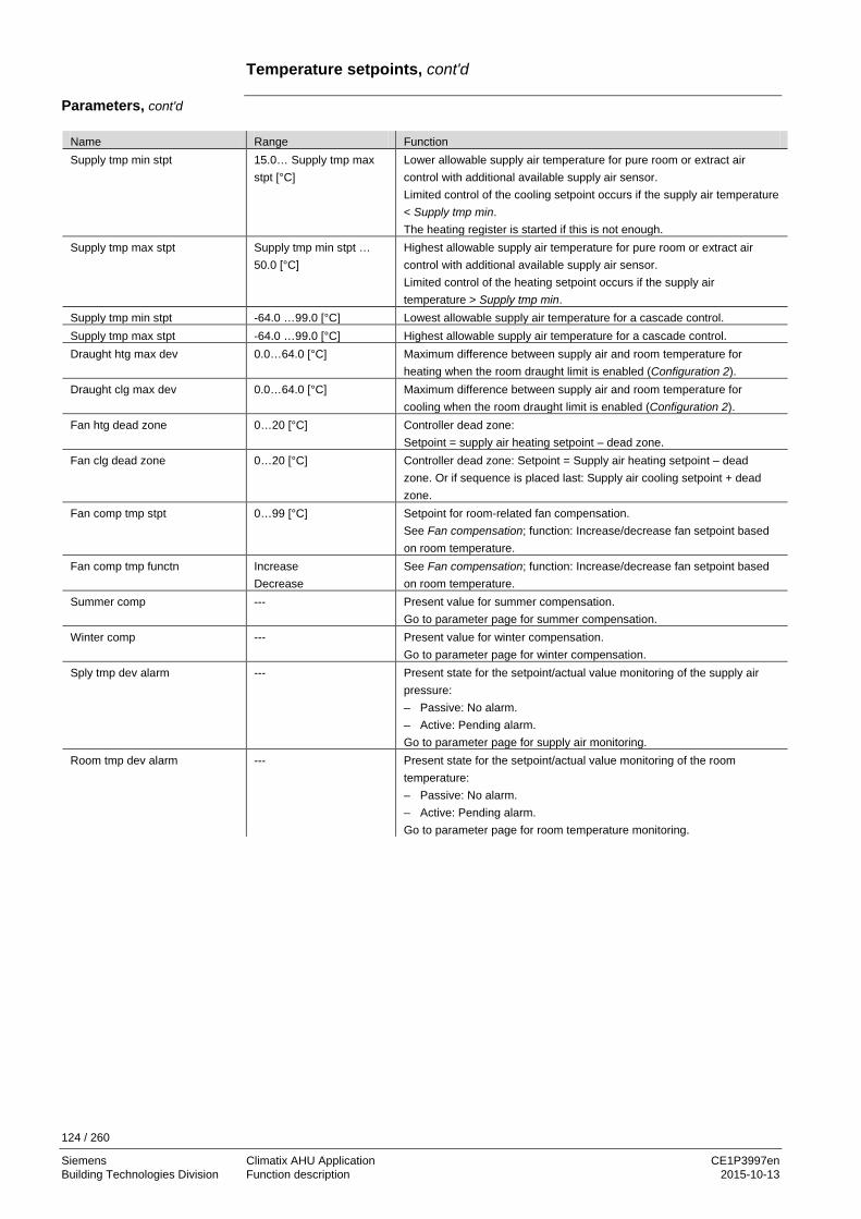
124 / 260
Siemens Climatix AHU Application CE1P3997en Building Technologies Division Function description 2015-10-13
Temperature setpoints, cont'd
Name Range Function Supply tmp min stpt 15.0… Supply tmp max
stpt [°C] Lower allowable supply air temperature for pure room or extract air control with additional available supply air sensor. Limited control of the cooling setpoint occurs if the supply air temperature < Supply tmp min. The heating register is started if this is not enough.
Supply tmp max stpt Supply tmp min stpt … 50.0 [°C]
Highest allowable supply air temperature for pure room or extract air control with additional available supply air sensor. Limited control of the heating setpoint occurs if the supply air temperature > Supply tmp min.
Supply tmp min stpt -64.0 …99.0 [°C] Lowest allowable supply air temperature for a cascade control. Supply tmp max stpt -64.0 …99.0 [°C] Highest allowable supply air temperature for a cascade control. Draught htg max dev 0.0…64.0 [°C] Maximum difference between supply air and room temperature for
heating when the room draught limit is enabled (Configuration 2). Draught clg max dev 0.0…64.0 [°C] Maximum difference between supply air and room temperature for
cooling when the room draught limit is enabled (Configuration 2). Fan htg dead zone 0…20 [°C] Controller dead zone:
Setpoint = supply air heating setpoint – dead zone. Fan clg dead zone 0…20 [°C] Controller dead zone: Setpoint = Supply air heating setpoint – dead
zone. Or if sequence is placed last: Supply air cooling setpoint + dead zone.
Fan comp tmp stpt 0…99 [°C] Setpoint for room-related fan compensation. See Fan compensation; function: Increase/decrease fan setpoint based on room temperature.
Fan comp tmp functn Increase Decrease
See Fan compensation; function: Increase/decrease fan setpoint based on room temperature.
Summer comp --- Present value for summer compensation. Go to parameter page for summer compensation.
Winter comp --- Present value for winter compensation. Go to parameter page for winter compensation.
Sply tmp dev alarm --- Present state for the setpoint/actual value monitoring of the supply air pressure: – Passive: No alarm. – Active: Pending alarm. Go to parameter page for supply air monitoring.
Room tmp dev alarm --- Present state for the setpoint/actual value monitoring of the room temperature: – Passive: No alarm. – Active: Pending alarm. Go to parameter page for room temperature monitoring.
Parameters, cont'd

125 / 260
Siemens Climatix AHU Application CE1P3997en Building Technologies Division Function description 2015-10-13
5.6.4 Summer/winter compensation
– Summer/winter compensation must be enabled:
Main Index > Configuration > Configuration 2 > So-Wi comp tmp = Yes – An outside air temperature sensor must be available:
Main Index > Configuration > Configuration 1 > Outside tmp sensor ≠ No • Summer compensation:
Adjustment to temperature setpoint (depending on control, supply air, room or extract air) relevant to control when the outside air temperature is high during the summer.
• Winter compensation: Adjustment to temperature setpoint (depending on control, supply air, room or extract air) relevant to control when the outside air temperature is low during the winter.
Figure 31: Setpoint compensation during summer
Figure 32: Setpoint compensation during winter Main Index > Unit > Temp control > Setpoints > Summer comp Main Index > Unit > Temp control > Setpoints > Winter comp
Name Range Function Outs air tmp start -64.0…64.0 [°C] Outside air temperature at which point the compensation begins to act. Outs air tmp end -64.0…64.0 [°C] Outside air temperature by which the maximum (summer) or minimum
setpoint is reached. Delta -64.0…64.0 [K] Maximum setpoint temperature-compensation.
Setpoint compensation is not undertaken during the summer and winter when the outside air temperature sensor fails.
Outs air tmp end
Delta
Setpoint
Outs air tmp start
Setpoint of room temperature [°C]
Outside temperature [°C]
3977
D01
en
Outs air tmp start
Delta
Setpoint
Outs air tmp end
Setpoint of room temperature [°C]
Outside temperature [°C]
3977
D02
en
Requirements
Function
Setpoint compensation during summer
Setpoint compensation during the winter
Parameterization

126 / 260
Siemens Climatix AHU Application CE1P3997en Building Technologies Division Function description 2015-10-13
5.6.5 Temperature deviation alarm
– For supply air deviation alarm, a supply air sensor must be available:
Main Index > Configuration > Configuration 1 > Supply tmp sensor = Yes. – Deviation alarm tmp must be enabled:
Main Index > Configuration > Configuration 2 > Deviation alarm tmp ≠ No – For room air deviation alarm, a room or extract air sensor must be available:
Main Index > Configuration > Configuration 1 > Room tmp Sensor = Yes. Setpoint/actual value monitoring of temperature: An alarm is triggered for the following cases when the temperature deviates from the setpoint during a certain period: – Actual value < Min limit. – Actual value > Setpoint + Maximum. – Actual value < Setpoint – Maximum. – When setpoint – Maximum < Min limit, Min limit applies as the comparison value. Main Index > Unit > Temp control > Tmp setpoints > Sply tmp dev alarm Main Index > Unit > Temp control > Tmp setpoints > Room tmp dev alarm
Name Range Function Alarm – Passive
– Active Alarm state. Go to settings page for digital alarms. Set all control-related settings such as alarm delay (default 3600 s).
Min limit 0...99.0 [°C] An alarm is triggered below this temperature. Maximum deviation 0...99.0 [°C] Maximum allowable deviation between setpoint and actual value. Start up delay 0…36000 [s] The function is activated after this period after a start.
Monitoring is switched off when the temperature sensor fails.
Requirements
Function
Parameterization
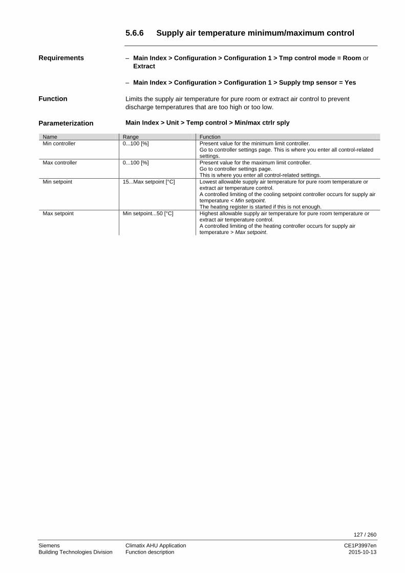
127 / 260
Siemens Climatix AHU Application CE1P3997en Building Technologies Division Function description 2015-10-13
5.6.6 Supply air temperature minimum/maximum control
– Main Index > Configuration > Configuration 1 > Tmp control mode = Room or
Extract – Main Index > Configuration > Configuration 1 > Supply tmp sensor = Yes Limits the supply air temperature for pure room or extract air control to prevent discharge temperatures that are too high or too low. Main Index > Unit > Temp control > Min/max ctrlr sply
Name Range Function Min controller 0...100 [%] Present value for the minimum limit controller.
Go to controller settings page. This is where you enter all control-related settings.
Max controller 0...100 [%] Present value for the maximum limit controller. Go to controller settings page. This is where you enter all control-related settings.
Min setpoint 15...Max setpoint [°C] Lowest allowable supply air temperature for pure room temperature or extract air temperature control. A controlled limiting of the cooling setpoint controller occurs for supply air temperature < Min setpoint. The heating register is started if this is not enough.
Max setpoint Min setpoint...50 [°C] Highest allowable supply air temperature for pure room temperature or extract air temperature control. A controlled limiting of the heating controller occurs for supply air temperature > Max setpoint.
Requirements
Function
Parameterization

128 / 260
Siemens Climatix AHU Application CE1P3997en Building Technologies Division Function description 2015-10-13
5.6.7 Fan heating/cooling
Main Index > Configuration > Configuration 2
Name Range Function Fan htg / clg
– No – Htg – Clg – Htg+Clg
The fan is further used as a heating or cooling sequence. – No sequential impact on the fan. – Only impacts fan during the heating sequence. – Only impacts fan during the cooling sequence. – Impact on fan in both sequences.
Sequence fan clg – Fan-Clg – Clg-Fan
For free cooling only! – Fan sequence prior to cooling sequence. – Cooling sequence prior to fan sequence.
Controller output reduced (increased during cooling) the fan setpoint as it relates to the maximum allowable fan compensation (see Fan compensation as well) in the event the supply air setpoint is not achieved. The fan speed (stage) is reduced when all available heating registers are operating at 100% during heating. This heats up the discharged air. The fan speed (stage) is increased if all available cooling registers are operating at 100% (Sequence fan clg = Clg-Fan) during cooling. This cools down the discharged air. The fan speed (stage) is first increased during the Sequence fan clg = Fan-Clg and the first cooling register is switched on. Main Index > Unit > Temperature control > Fan heating Main Index > Unit > Temperature control > Fan cooling
Name Range Function Controller 0…100 [%] Present value for the controller.
Go to controller settings page. Dead zone 0…20 [°C] Controller dead zone heating:
Setpoint = supply air setpoint – dead zone. Controller dead zone Clg: Setpoint = supply air heating setpoint + dead zone. Or if sequence is placed last (Clg-Fan): Supply air cooling setpoint + dead zone
– Calculated supply air setpoint for heating register: 22 °C. – Dead zone for the fan heating controller (dead zone): 2 °C. Effective setpoint for the controller = 22 °C – 2 °C = 20 °C. Ensures that the fans are only influenced, if the heating register does not supply the required output. This function not required when the heating register is sufficiently sized. – Setpoint supply air pressure:
80 Pa (maximum possible setpoint = setpoint of the maximum enabled stage + Max forcing, e.g. = 120 Pa).
– Maximum allowable fan compensation (100% compensation): 40 Pa. – Controller output: 50%. New setpoint: 80 Pa – (40 Pa * 50%) = 60 Pa
(no exact value. See fan compensation for the precise calculation!) The fan stage is reduced by reducing the setpoint. The air volume to be heated at the heating register becomes smaller and the discharge air temperature increases.
Enable
Functions
Parameterization
Heating example
Calculation

129 / 260
Siemens Climatix AHU Application CE1P3997en Building Technologies Division Function description 2015-10-13
Fan heating/cooling, cont'd
Switching Sequence fan clg: Clg-Fan – Calculated supply air setpoint for cooling: 22 °C. – Dead zone for the fan cooling controller (dead zone): 2 °C. Effective setpoint for the controller: 22 °C + 2 °C = 24 °C. Ensures that the fans are only influenced, if the cooling register does not supply the required output. This function not required when the cooling is sufficiently sized. Switching Sequence fan clg: Fan-Clg – Calculated supply air setpoint for cooling: 24 °C. – Calculated supply air setpoint for heating register: 22 °C. – Dead zone for the fan cooling controller (dead zone): 1 °C. Effective setpoint for the controller: 22 °C + 1 °C = 23 °C. Ensure that fans are influence prior to the start of the cooling register. This function is also used if no cooling register is available. You do not receive any cooler air, but the increased volume also increases the comfort level. – Setpoint supply air pressure: 80 Pa (maximum possible setpoint = setpoint of the
maximum enabled stage + Max Force, e.g. = 120 Pa). – Maximum allowable fan compensation (100% compensation): 40 Pa. – Controller output: 50%. New setpoint: 80 Pa + (40 Pa * 50%) = 100 Pa.
Cooling example
Calculation

130 / 260
Siemens Climatix AHU Application CE1P3997en Building Technologies Division Function description 2015-10-13
5.6.8 Fan compensation
Main Index > Configuration > Configuration 2
Name Range Function Fan comp room tmp – No
– Yes Room-temperature dependent fan compensation.
The controller output reduces or increases the fan setpoint relating to the maximum allowable fan compensation (see as well Fan compensation). The fan setpoints should be increased or decreased for KP>0 if the room temperature is below the setpoint, or for KP<0 if the room temperature is above the setpoint (heating/cooling response). Main Index > Unit > Temperature control > Fan compensation
Name Range Function Controller 0…100 [%] Present value for the controller.
Go to controller settings page. Setpoint 0…99 [°C] Controller setpoint relating to the room temperature. Function – Increase
– Decrease – Increase the fan setpoint. – Reduce the fan setpoint.
– Room temperature setpoint: 22 °C. – Present room temperature: 20 °C. Controller output > 0% (e.g. 50%). The controller output increases the fan setpoint relating to the maximum allowable fan compensation (see as well Fan compensation). – Setpoint supply air pressure: 80 Pa (maximum possible setpoint = setpoint of the
maximum enabled stage + Max Force, e.g. = 120 Pa). – Maximum allowable fan compensation (100% compensation): 40%. – Controller output: 50%. New setpoint: 80 Pa + (40 Pa * 50%) = 100 Pa. The controller output reduces the fan setpoint relating to the maximum allowable fan compensation (see as well Fan compensation). – Setpoint supply air pressure: 80 Pa (maximum possible setpoint = setpoint of the
maximum enabled stage + Max Force, e.g. = 120 Pa). – Maximum allowable fan compensation (100% compensation): 40 Pa. – Controller output: 50%. New setpoint = 80 Pa – (40 Pa * 50%) = 60 Pa.
Enable
Function
Parameterization
Example
Switch function: Increase
Switch function: Decrease

131 / 260
Siemens Climatix AHU Application CE1P3997en Building Technologies Division Function description 2015-10-13
5.6.9 Common heating/cooling register
One heating register water and one cold water register for cooling is enabled. Main Index > Configuration > Configuration 1 > Heating ≠ No Main Index > Configuration > Configuration 1 > Cooling = Water Main Index > Configuration > Configuration 2
Name Range Function Combi Coil – None
– 1 output – 2 outputs
This setting selected whether the combi coil is a 2-pipe (1 output) or 4 pipe (2 outputs).
A common register is used for heating and cooling. The following functions apply depending on the number of outputs:
Outputs Functions 1 – For the CombiCoil with one output, the input for summer-winter changeover must
be enabled so that the information on summer or winter operation is available (Configuration 1 > Su-wi input = Yes).
– The heating register is exclusively active during the winter; the cooling register exclusively during the summer.
– The output for heating is used for heating and cooling (valve). 1/2 – The various control settings can be made separately for heating and cooling.
– If an additional electrical register is activated, it acts as a second heating register during the winter and a normal heating register during the summer. This makes it possible to heating as needed during the summer.
– Both in range 1 output as well as 2 outputs, the frost controller and frost alarm are disabled in summer. This also applies as well if the cooling valve is open.
– Only 1 output is used for the pump (heating). The pump functionality must, however, be enabled as well for cooling if cooling also controls the output.
2 – The summer/winter changeover is not used for combi coils with 2 outputs. The heating output and the cooling output can, however, never by enabled at the same time.
Prerequisite
Configuration
Functions

132 / 260
Siemens Climatix AHU Application CE1P3997en Building Technologies Division Function description 2015-10-13
5.7 Heat recovery with mixed air damper 5.7.1 Overview
This section describes the mixed air damper control for heat or cooling recovery. The figure illustrates in a simplified manner the participating plant elements:
Figure 33: Overview of the plant elements for heat recovery with mixed air damper The topics in the section are: Topic Section Properties 6.7.2 Settings 6.7.3 Startup behavior 6.7.4 5.7.2 Properties
The direction of control action (normal/inverse) and a minimum ration of fresh air can be set. The plant can be started for a set period at full recirculation in dependence on the outside air temperature. Mixed air damper is ramped up to full recirculation, if: – Tmp start (temperature start) heat or cool is enabled. Mixed air damper is ramped up to full fresh air, if: – Summer free cooling – Supply fan after run – Fire mode with running fan
T
ϕ
T ϕ
T
ϕ
P3997Z07
Introduction
Elements
Topic
Control direction and fresh air ratio
Extreme settings recirculating/fresh air

133 / 260
Siemens Climatix AHU Application CE1P3997en Building Technologies Division Function description 2015-10-13
5.7.3 Settings
Main Index > Configuration > Configuration 1
Name Range Function Hrec damper No No mixed air damper. Normal Mixed air damper with output signal 100% for complete recirculation. Inverse Mixed air damper with output signal 0% for complete recirculation.
Main Index > Configuration > Configuration 2
Name Range Function HrecDampr Sequence
Damper-Htg Htg-Damper
Intervention sequence for mixed air dampers and heating register. Mixed air dampers first. Heating register first.
Hrec clg recovery No No cooling recovery. Temp
Cooling recovery, e.g. using rotation or plate heat exchangers as per outside and room temperature.
Enthalpy Cooling recovery, e.g. using rotation or plate, or hot water exchangers as per outside and room enthalpy.
HrecDampr clg recovery No No cooling recovery. Temp Cooling recovery using mixed air damper as per outside and room
temperature. Enthalpy Cooling recovery using mixed air damper as per outside and room enthalpy.
Position Damper-Htg: For heating, the mixed air damper is deployed to the maximum allowable recirculating position (depends on Min FreshAir), before the subsequent heating register starts. Position Htg-Damper: For heating, the heating register is first deployed to full load prior the mixed air damper control starts. The startup function for the mixed air damper control must be disabled (StartupTime = 0 s), since otherwise the heating register starts off directly at 100% and output. Main Index > Unit > Temp control > Hrec damper
Name Range Function Controller 0…100 [%] Present value of the mixed air controller.
Go to controller settings page. Output signal 0…100 [%] Present value for damper actuator output.
Go to page with all analog output settings. Recovery value 0…100 [%] Displays present heat recovery.
For Hrec damper = Normal, this value is always the same as the output signal. For Hrec damper = Inverse, this value is always the inverse of the output signal.
Min fresh air 0…100 [%] Minimum fresh air ratio. The controller output is limited to 100% - Min fresh air. This ensures that some amount of fresh air always makes it to the room.
Start up time 0…600 [s] Time for controller start behavior (100% recirculation). Start up tmp –64.0…64.0 [°C] Temperature limit for start behavior.
Enable
Configuration
HrecDampr Sequence
Parameterization

134 / 260
Siemens Climatix AHU Application CE1P3997en Building Technologies Division Function description 2015-10-13
5.7.4 Startup behavior
The mixed air damper is fully opened during the startup period for outside air temperature < Startup temp at startup. The controller determines the present position after this period expires. If heat demand exists at startup, the heating register is started in parallel, and after successful startup, the mixed air controller for heat recovery deploys to the maximum allowable position (100% - Min fresh air). Temperature-controlled cooling recovery starts, when the following conditions are met: – Outside temperature > Room temperature + 2 K – Room temperature > Room setpoint + 1 K – Cooling output >2% Temperature-controlled cooling recovery stops for the following cases: – Outside temperature ≤ Room temperature
or – Room temperature ≥ Room setpoint. – Enthalpy-guided cooling recovery starts, when the following conditions are met: – Outside air enthalpy > Room air enthalpy + 2 kJ/kg
and – Room temperature > Room setpoint + 1 K The enthalpy-guided cooling recovery stops for the following cases: – Outside air enthalpy ≤ Room air enthalpy
or – Room temperature ≥ Room setpoint.
The following sensors are required for temperature-controlled cooling recovery: – Outside temp sensor – Room or extract air temperature sensors The extract temperature sensor is used if room and extract temperature sensors exist.
The following sensors are required for enthalpy-controlled cooling recovery: – Outside temperature and humidity – Room or extract temperature sensor and humidity. The extract temperature sensor is used if room and extract temperature sensors exist.
For pure supply air control, the room setpoint test is disabled and then only the outside air temperature-room temperature condition or the outside air enthalpy room-room air enthalpy condition is considered.
The function is blocked when the sensor fails.
Situation at start
Cooling recovery
Sensor failure
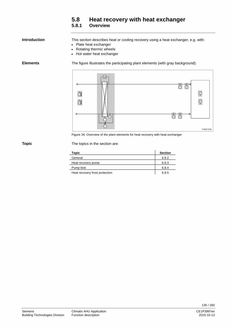
135 / 260
Siemens Climatix AHU Application CE1P3997en Building Technologies Division Function description 2015-10-13
5.8 Heat recovery with heat exchanger 5.8.1 Overview
This section describes heat or cooling recovery using a heat exchanger, e.g. with: • Plate heat exchanger • Rotating thermic wheels • Hot water heat exchanger The figure illustrates the participating plant elements (with gray background):
Figure 34: Overview of the plant elements for heat recovery with heat exchanger The topics in the section are: Topic Section General 6.8.2 Heat recovery pump 6.8.3 Pump kick 6.8.4 Heat recovery frost protection 6.8.5
∆p
T
ϕ
T
T
T
ϕ T
P3997Z08
ϕ
ϕ
Introduction
Elements
Topic

136 / 260
Siemens Climatix AHU Application CE1P3997en Building Technologies Division Function description 2015-10-13
5.8.2 General
Functions are available for plate, wheel or water exchangers (with pump control and frost protection). The plant can be started for a set period at full recirculation in dependence on the outside air temperature. Heat recovery is switched off, if: – Tmp start (unoccupied) cool – Summer free cooling – Fire mode with running fan Main Index > Configuration > Configuration 1
Name Range Function Heat recovery – No
– Wheel – PlateExch – Water
No heat recovery. Rotary heat exchanger. Plate heat exchanger. Water heat exchanger.
Main Index > Configuration > Configuration 2
Name Range Function Heat recovery frost – No
– Detector – Sensor – Dtctr+Snsr – PressSnsr – Pres+Dtctr
– No frost protection. – Frost protection using a detector. – Frost protection using a sensor. – Frost protection using a sensor and detector. – Frost protection using a pressure sensor. – Frost protection using a pressure sensor and detector.
Hrec pump / cmd – No – Yes – Yes+Kick
– No pump. – Heat exchanger pump without pump kick. – Heat exchanger pump with pump kick.
Hrec pump alarm – No – Alarm – Fdbk – Both
– Pump without alarm or feedback. – Pump with alarm. – Pump with feedback. – Pump with alarm and feedback.
Heat recovery alarm – No – Yes
Heat recovery with or without alarming.
Hrec clg recovery – No – Temp
– No cooling recovery. – Cooling recovery, e.g. using rotation, plate, or hot water
exchangers as per outside and room temperature. – Enthalpy – Cooling recovery, e.g. using rotation or plate, or hot water
exchangers as per outside and room enthalpy. HrecDampr clg recovery – No
– Temp – No cooling recovery. – Cooling recovery using mixed air damper as per outside and room
temperature. – Enthalpy – Cooling recovery using mixed air damper as per outside and room
enthalpy.
Functions
Enable
Configuration

137 / 260
Siemens Climatix AHU Application CE1P3997en Building Technologies Division Function description 2015-10-13
General, cont'd
Master Index > Unit > Temperature Control > Heat recovery
Name Range Function Controller 0…100 [%] Present value for the heat exchanger controller.
Go to controller settings page. Output signal 0…100 [%] Present value for analog output.
Go to page with all analog output settings. Pump / cmd – Off
– On Current pump status. Go to heat recovery pump page.
Alarm – Ok – Alarm
Alarm state for heat recovery. Go to page with digital input settings. For example, you can set the time for jitter protection (default: 0 s).
Frost monitor – Ok – Frost
Present state of frost detector. Go to page with digital input settings. The output limited for DeFrost MaxSpeed for Frost state. The plant is shut down after 20 minutes and an alarm is triggered.
Frost protection – 0…100% Present value for the frost controller. Go to Hrec frost protect page to parameterize frost control.
Frost protect press --- Go to pressure frost page to parameterize frost control. Efficiency 0…100% Present value of heat recovery efficiency.
Go to page with settings for heat recovery efficiency. Start up time 0…600 [s] Time for controller start behavior. Start up tmp –64.0…64.0 [°C] Temperature limit for start behavior. Max speed defrost 0…100% Maximum allowable output value for frost detection.
– The pump signal can also be used as the control signal for the rotation thermic
wheel. – A frost protection sensor for rotating, or plate heat exchangers enable an extract air
sensor. – A frost protection sensor on a hot water exchanger enables a water sensor. – The extract air sensor can be used as well to increase efficiency.
Parameterization

138 / 260
Siemens Climatix AHU Application CE1P3997en Building Technologies Division Function description 2015-10-13
General, cont'd
The startup time for the output is set to 100% if the outside air temperature < Start up tmp. Afterwards, the controller determines the present position. If heat demand exists at startup, the heating register is started in parallel, and after successful startup, the controller for heat recovery deploys to the maximum allowable position (100%). Temperature-controlled cooling recovery starts, when the following conditions are met: – Outside temperature > Room temperature + 2 K and – Room temperature > Room setpoint + 1 K Temperature-controlled cooling recovery stops for the following cases: – Outside temperature ≤ Room temperature or – Room temperature ≥ Room setpoint. Enthalpy-controlled cooling recovery starts, when the following conditions are met: – Outside air enthalpy > Room air enthalpy + 2 kJ/kg and – Room temperature > Room setpoint + 1 K Enthalpy-controlled cooling recovery stops for the following cases: – Outside air enthalpy ≤ Room air enthalpy or – Room temperature ≥ Room setpoint. For pure supply air control, the room setpoint test is disabled and then only the outside air temperature-room temperature condition or the outside air enthalpy room-room air enthalpy condition is considered.
An outside air and room or extract air temperature sensor required for temperature-controlled cooling recovery. The extract temperature sensor is used if room and extract temperature sensors exist.
The following sensors are required for enthalpy-controlled cooling recovery: • Outside temperature and humidity • Room or extract temperature sensor and humidity • The extract temperature sensor is used if room and extract temperature sensors
exist The function is blocked when the sensor fails.
Startup behavior
Function cooling recovery
Sensor failure
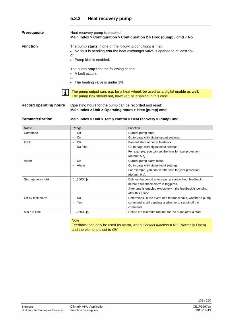
139 / 260
Siemens Climatix AHU Application CE1P3997en Building Technologies Division Function description 2015-10-13
5.8.3 Heat recovery pump
Heat recovery pump is enabled: Main Index > Configuration > Configuration 2 > Hrec (pump) / cmd ≠ No The pump starts, if one of the following conditions is met: • No fault is pending and the heat exchanger valve is opened to at least 5%. or • Pump kick is enabled. The pump stops for the following cases: • A fault occurs. or • The heating valve is under 1%.
The pump output can, e.g. for a heat wheel, be used as a digital enable as well. The pump kick should not, however, be enabled in this case.
Operating hours for the pump can be recorded and reset: Main Index > Unit > Operating hours > Hrec (pump) cmd Main Index > Unit > Temp control > Heat recovery > Pump/Cmd
Name Range Function Command – Off
– On Current pump state. Go to page with digital output settings.
Fdbk – OK – No fdbk
Present state of pump feedback. Go to page with digital input settings. For example, you can set the time for jitter protection (default: 5 s).
Alarm – OK – Alarm
Current pump alarm state. Go to page with digital input settings. For example, you can set the time for jitter protection (default: 0 s).
Start up delay fdbk 0...36000 [s] Defines the period after a pump start without feedback before a feedback alarm is triggered. Jitter time is enabled exclusively if the feedback is pending after this period.
Off by fdbk alarm – No – Yes
Determines, in the event of a feedback fault, whether a pump command is still pending or whether to switch off the command.
Min run time 0...36000 [s] Define the minimum runtime for the pump after a start.
Note Feedback can only be used as alarm, when Contact function = NO (Normally Open) and the element is set to ON.
Prerequisite
Function
Record operating hours
Parameterization

140 / 260
Siemens Climatix AHU Application CE1P3997en Building Technologies Division Function description 2015-10-13
5.8.4 Pump kick
Pump kick is enabled. Main Index > Configuration > Configuration 2 > Hrec (pump)/cmd = Yes+Kick The pump is switched on for a short period for longer idle periods. This prevents lock up. Main Index > Unit > Temp control > Heat recovery > Pump / cmd
Name Range Function Kick date / time Mo 00:00...So 23:29 Weekday and time for pump kick.
Sets the weekday (Mon...Sun) and time to run the pump kick. Examples: Mon *:* Each Monday at midnight. Sat 07:* Each Saturday at 7:00 am. * *:* Time is not relevant; the kick interval applies accordingly.
Kick interval 0.0...36000.0 [h] Idle time for pump kick. Set the idle time after which a pump kick is run. Examples: 168 After 168 hours. 123.4 After 123 hours and 24 minutes. 0 Idle time is not relevant; kick date/time applies accordingly.
Kick on time 0.0...36000 [s] Set the period for the pump kick. Examples: 10 Period = 10 seconds. 0 Period = 1 controller cycle (approx. 150 ms).
Kick date/time = * *:* and kick interval = 0 → no pump kick is run.
Prerequisite
Function
Parameterization

141 / 260
Siemens Climatix AHU Application CE1P3997en Building Technologies Division Function description 2015-10-13
5.8.5 Heat recovery frost protection
Frost protection type is enabled: Master Index > Configuration > Configuration 2, Heat recovery frost ≠ No • Temperature frost protection:
Detects icing via a temperature sensor in the hot water exchanger, if selected, or in the extract air duct, if a plate exchanger or rotation thermic wheel. This applies for the following settings: Heat recovery frost = Detector, Sensor or Dtctr+Snsr.
• Air-side frost protection:
Detects icing using a pressure sensor. This applies for the following settings: Heat recovery frost = PressSnsr und Pres+Dtctr.
– For output Frost controller > Output recovery: The output follows the recovery.
– For output Frost controller < Output recovery: The output follows the frost controller.
– Controller is disabled when the sensor fails. The heat recovery controller goes to 100% output signal as soon as the frost controller is no longer enabled, when the subsequent heating register was enabled during frost control. Master Index > Unit > Temp control > Heat recovery > Frost
Name Range Function Controller 0...100 [%] Present value for the frost controlled.
Go to controller settings page. Setpoint -64...64 [°C] For temperature frost protection only!
For one setpoint: Present setpoint for the frost controller.
Fan stage 1 stpt 0...5000 [Pa] For air-side frost protection only! Setpoint for the controller at fan stage 1.
Fan stage 2/3 stpt 0...5000 [Pa] For air-side frost protection only! Setpoint for the controller at fan stage 2 and 3.
Prerequisite
Two monitoring types
Functions
Parameterization
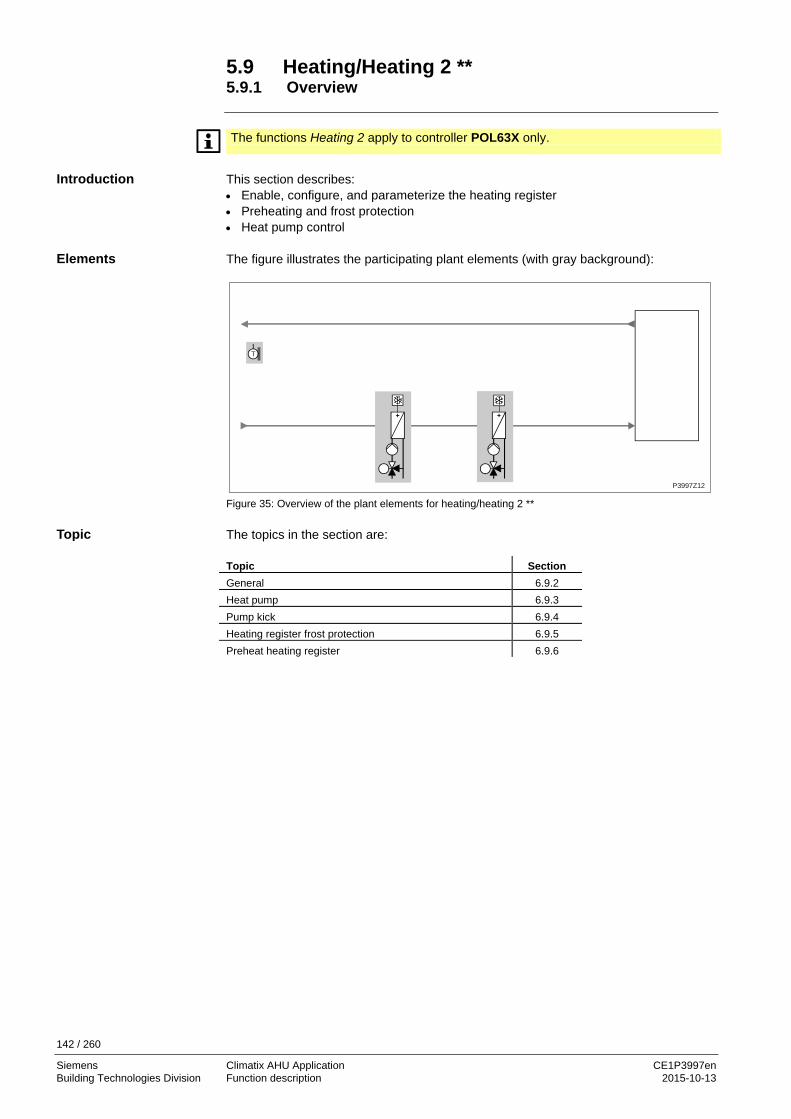
142 / 260
Siemens Climatix AHU Application CE1P3997en Building Technologies Division Function description 2015-10-13
5.9 Heating/Heating 2 ** 5.9.1 Overview
The functions Heating 2 apply to controller POL63X only.
This section describes: • Enable, configure, and parameterize the heating register • Preheating and frost protection • Heat pump control The figure illustrates the participating plant elements (with gray background):
Figure 35: Overview of the plant elements for heating/heating 2 ** The topics in the section are: Topic Section General 6.9.2 Heat pump 6.9.3 Pump kick 6.9.4 Heating register frost protection 6.9.5 Preheat heating register 6.9.6
T
P3997Z12
Introduction
Elements
Topic

143 / 260
Siemens Climatix AHU Application CE1P3997en Building Technologies Division Function description 2015-10-13
5.9.2 General
This section describes enabling, configuring, and parameterizing general heating register functions. Heating / Heating 2 is enabled and preconfigured in Configuration 1, Configuration 2 and Configuration IOs. Main Index > Configuration > Configuration 1
Name Range Function Heating / Heating 2 (PreHeater)
– No – Yes – +PreH OutsideTemp.
– No heating register. – One heating register (fixed sequence 5). – Auxiliary heating register 2 to preheat as per outside
temperature sensor. – +PreH FrostTemp. – Auxiliary heating register 2 to preheat as per frost
temperature sensor. Main Index > Configuration > Configuration 2
Name Range Function Htg frost protect / Heating 2 frost (PreHeater)
– No – Sensor – Sensor2Spv – Detector – Snsr+Dtctr – 2Spv+Dtctr
– No frost protection. – Frost protection using a sensor. – Frost protection using a sensor and 2 setpoints. – Frost protection using a detector. – Frost protection using a sensor and detector. – Frost protection using a sensor, 2 setpoints and detector.
Heating 2 Control / El Heating 2 Control
– StandAlone – Heating-Heating2 – Heating2-Heating
– Own sequence. – First (elec.) heating then (elec.) heating 2 – First (elec.) heating 2 then (elec.) heating.
Heating pump / Heating 2 pump
– No – Yes – Yes+Kick
– No heating register pump. – Heating register pump without pump kick. – Heating register pump with pump kick.
Htg pump alarm / Heating 2 pump alm
– No – Alarm – Fdbk – Both
– Pump without alarm or feedback. – Pump with alarm. – Pump with feedback. – Pump with alarm and feedback.
Heating 2 control – StandAlone – InSequence
– Not integrated in sequence. – Integrated in sequence.
Content
Prerequisite
Enable heating register
Configuration
144 / 260
Siemens Climatix AHU Application CE1P3997en Building Technologies Division Function description 2015-10-13
General, cont'd
The hot ware registers can be operated with pump (pump kick, alarm, feedback) or without pump. Frost detection and controlled frost protection is integrated. The additional heating register can be operated as a separate register with its own setpoint. Heat recovery is switched off, if: – Tmp start (unoccupied) cool – Summer free cooling – Comb coil at summer (only heating, not heating 2)
A maximum of one of the two auxiliary registers Heating 2 or El heating 2 can be integrated into the temperature control sequence prior to or after the heating register.
Main Index > Unit > Temp control > Heating Main Index > Unit > Temp control > Heating 2
Name Range Function Controller 0...100 [%] Present value for the heating controller.
Go to page with all controller settings. Output signal 0...100 [%] Present value for heating valve output.
Go to page with all analog output settings. Setpoint Extra Seq 0.0...99.0 [°C] For Heating 2 only:
Setpoint for additional stand-alone heating register. Frost protection 0...100 [%] Present value for the frost controller.
Go to heating register frost protection page to parameterize frost control.
Pump – On – Off
Current pump status. Go to heat pump page to parameterize the pump.
Pre heating – Passive – Active
Present state of preheating. Go to heating register preheating page to parameterize the preheating function for the register.
Frost monitor – OK – Frost
Present state of frost detector. Go to page with digital input settings. For the Frost state, the pump starts, the heating valve opens to 100% and the plant is shut down and locked.
Functions
Parameterization

145 / 260
Siemens Climatix AHU Application CE1P3997en Building Technologies Division Function description 2015-10-13
5.9.3 Heat pump
Heat pump is enabled: Main Index > Configuration > Configuration 2 > Heating pump ≠ No Main Index > Configuration > Configuration 2 > Heating 2 pump ≠ No The pump starts, if one of the following conditions is met: • No fault is pending and the heating valve is opened to at least 5%. or • The outside air temperature is less than the Pump start tmp or • Pump kick is enabled. The pump stops for the following cases: • A fault occurs. or • The heating valve is under 1%. Operating hours for the pump can be recorded and reset: Main Index > Unit > Operating hours > Heating pump or Heating 2 pump Reset Main Index > Unit > Temp control > Heating > Pump Main Index > Unit > Temp control > Heating 2 > Pump
Name Range Function Command – Off
– On Current pump state. Go to page with digital output settings.
Fdbk – OK – No Fdbk
Present state of pump feedback. Go to page with digital input settings. For example, you can set the time for jitter protection (default: 5 s).
Alarm – OK – Alarm
Current pump alarm state. Go to page with digital input settings. For example, you can set the time for jitter protection (default: 0 s).
Start up delay fdbk 0...36000 [s] Defines the period after a pump start without feedback before a feedback alarm is triggered. Jitter time is enabled exclusively if the feedback is pending after this period.
Off by fdbk alarm – No – Yes
Determines, in the event of a feedback fault, whether a pump command is still pending or whether to switch off the command.
Outs tmp start -64...64 [°C] The pump starts when the outside air temperature drops below this value. Heat is thus available immediately for heating (passive frost protection) when switching on the plant. The function is disabled when no outside air temperature is configured or the sensor fails.
Min run time 0...36000 [s] Define the minimum runtime for the pump after a start.
Feedback can only be used as alarm, when Contact function = NO (Normally Open) and the element is set to ON.
Prerequisite
Functions
Record operating hours
Parameter

146 / 260
Siemens Climatix AHU Application CE1P3997en Building Technologies Division Function description 2015-10-13
5.9.4 Pump kick
Pump kick is enabled. Main Index > Configuration > Configuration 2 > Heating pump = Yes+Kick Main Index > Configuration > Configuration 2 > Heating 2 pump = Yes+Kick The pump is switched on for a short period for longer idle periods. This prevents lock up. Main Index > Unit > Temp control > Heating > Pump Main Index > Unit > Temp control > Heating 2 > Pump
Name Range Function Kick date / time Mo 00:00...So 23:29 Weekday and time for pump kick.
Sets the weekday (Mon...Sun) and time to run the pump kick. Examples: Mon *:* Each Monday at midnight. Sat 07:* Each Saturday at 7:00 am. * *:* Time is not relevant; the kick interval applies accordingly.
Kick interval 0.0...36000.0 [h] Idle time for pump kick. Set the idle time after which a pump kick is run. Examples: 168 After 168 hours. 123.4 After 123 hours and 24 minutes. 0 Idle time is not relevant; kick date/time applies accordingly.
Kick on time 0.0...36000 [s] Set the period for the pump kick. Examples: 10 Period = 10 seconds. 0 Period = 1 controller cycle (approx. 150 ms).
Kick date/time = * *:* and kick interval = 0: No pump kick is run.
Prerequisite
Function
Parameter

147 / 260
Siemens Climatix AHU Application CE1P3997en Building Technologies Division Function description 2015-10-13
5.9.5 Heating register frost protection Frost protection type is enabled: Master Index > Configuration > Configuration 2, Htg frost protect ≠ No Master Index > Configuration > Configuration 2, Heating 2 frost protect ≠ No – For heat demand frost controller > heat demand heating controller The output follows the frost controller.
– For heat demand frost controller > heat demand heating controller The output follows the heat controller.
– Frost control remains active when the plant is off (Building Protection). – Controller is disabled when the sensor fails. – For the Frost state (frost protection monitor is triggered), the pump starts, the heating
valve opens to 100% and the plant is shut down and locked. Master Index > Unit > Temp control > Heating > Frost protection Master Index > Unit > Temp control > Heating 2 > Frost protection
Name Range Function Controller 0...100 [%] Present value for the frost controlled.
Go to controller settings page. Setpoint -64...64 [°C] – For one setpoint:
Present setpoint for the frost controller. – For 2 setpoints:
Present setpoint for the frost controller, if the plant is operating.
Standby Setpoint -64...64 [°C] Present setpoint for the frost controller, if the plant is not operating. This value only exists on one of the following settings is selected: Master Index > Configuration > Configuration 2, HtgFrost = Sensor2Spv or 2Spv+Dtctr
Prerequisite
Functions
Parameter

148 / 260
Siemens Climatix AHU Application CE1P3997en Building Technologies Division Function description 2015-10-13
5.9.6 Preheat heating register
Preheating is enabled: Master Index > Configuration > Configuration 1, Heating = +PreHeat OutsideTemp or FrostTemp. Master Index > Configuration > Configuration 1, Heating 2 = +PreHeat OutsideTemp or FrostTemp. – The heating valve is 100% opened for the period Pre htg on time if the outside air
temperature is lower than Outs air tmp X2 at plant start. The heating valve then goes to the position defaulted by both auxiliary points and are released for plant start (delay for Damper opening Ti and SupplyFan delay)
– It assumes the present position after the complete heating controller is released. – The function is blocked for the period Min off time after preheating is completed. – The function is deactivated when the outside air temperature senor not activated or
fails.
Pre htg on time Damper opening time Supply Fan delay
100
0
HeatingValv %
PosValv %According Curve
tStart/On Open Damper Start Exh Fan Start Supl Fan
Figure 36: Function of the preheat heating register
Main Index > Unit > Temp control > Heating > Preheating Main Index > Unit > Temp control > Heating 2 > Preheating
Name Range Mode On
Off Current status preheating.
Outs air tmp X1 -30.0...5.0 [°C] Lower design temperature. Outs air tmp X2 0.0...50.0 [°C] Upper design temperature. Output signal Y1 0...100 [%] Value for lower design temperature. Output signal Y2 0...100 [%] Value for upper design temperature. Pre htg on time 0...600 [s] Time to preheat lines and register. Min off time 0.0...1400.0 [min] Minimum off time for the function after preheating is completed.
Prerequisite
Functions
Parameter

149 / 260
Siemens Climatix AHU Application CE1P3997en Building Technologies Division Function description 2015-10-13
5.10 Electric register/electric register 2 5.10.1 Overview
This section describes configuring and parameterizing heating register functions. The figure illustrates the participating plant elements (with gray background):
Figure 37: Overview of the plant elements for electric register/electric register 2 The topics in the section are: Topic Section General 6.10.2 Electric register output high limit control 6.10.3
P3997Z13
Introduction
Elements
Topic

150 / 260
Siemens Climatix AHU Application CE1P3997en Building Technologies Division Function description 2015-10-13
5.10.2 General
This section describes enabling, configuring, and parameterizing general electric register functions. Electrical heating / Electrical heating 2 are enabled and preconfigured in Configuration 1, Configuration 2 and Configuration IOs. Both electric registers can be deployed with up to 3 stages (binary). An alarm is possible for each register. Register output is limited by fan out, which prevent the register from overheating. The additional electric heating register can be operated as a separate register with its own setpoint. The heating register is locked, if: – Tmp start (unoccupied) cool – Summer free cooling
A maximum of one of the two additional registers Heating 2 or El Heating 2 can be integrated into the temperature control sequence.
Main Index > Configuration > Configuration 1
Name Range Function Electrical heating / El Heating 2
– No – Analog
– No (additional) electric register. – (Additional) electric register with analog control.
– 1Step (Auxiliary) 1-step electric heating register. – 2Steps (Auxiliary) 2-step electric heating register. – 3Steps (Auxiliary) 3-step electric heating register.
Main Index > Configuration > Configuration 2
Name Range Function El Htg alarm / El heating 2 alarm
No Alarm
No alarm. With alarm.
El heating 2 control StandAlone InSequence
Not integrated in sequence. Integrated in sequence.
The stages are controlled as follows for electric heating registers (2 step): DO1 DO2 Off 0 0 Stage1 1 0 Stage2 1 1 The stages are controlled as follows for electric heating registers (3 step): DO1 DO2 Off 0 0 Stage1 1 0 Stage2 0 1 Stage3 1 1
Content
Prerequisite
Functions
Enable
Configuration
Stage control

151 / 260
Siemens Climatix AHU Application CE1P3997en Building Technologies Division Function description 2015-10-13
General, cont'd
Main Index > Unit > Temp control > Electrical heating / Main Index > Unit > Temp control > El Heating 2
Name Range Function Controller 0...100 [%] Present value for the heating controller.
Go to controller settings page. Output signal 0...100 [%] Present value for output.
Go to page with all analog output settings. Command – Off
– Stage 1 – Stage 2 – Stage 3
Present state of electric register. Go to page with staged output settings.
Extra Seq setpoint 0.0...99.0 [°C] For El Heating 2 only: Setpoint for additional stand-alone heating register.
Alarm – Ok – alarm
Register alarm state. Go to page with digital inputs.
Start stage 1 0...100 [%] Controller heat demand to start the first stage. Start stage 2 Start stage 1...100 [%] Controller heat demand to start the second stage. Start stage 3 Start stage 2...100 [%] Controller heat demand to start the third stage. Stage hys off 0...Start stage 1 [%] Shutdown hysteresis of the stages. See example. Max limitation fan Go to Max fan limitation page to parameterize the register output
limitation by fan output. Start stage 1 = 20 % Off Stage 3: 50% Start stage 2 = 40 % Off Stage 2: 30% Start stage 3 = 60 % Off Stage 1: 10% Stage hys off = 10 %
Parameterization
Example of shutdown hysteresis

152 / 260
Siemens Climatix AHU Application CE1P3997en Building Technologies Division Function description 2015-10-13
5.10.3 Electric register output high limit control
Electric heating register is enabled: Main Index > Configuration > Configuration 1 > Electrical heating ≠ No Main Index > Configuration > Configuration 1 > El Heating 2 ≠ No Main Index > Unit > Temp control > Electrical heating > Max limitation fan Main Index > Unit > Temp control > El Heating 2 > Max limitation fan
Name Range Function Set the maximum allowable electric register output for the given active
fan stage. The value limits the maximum possible control heat demand. The settings depend on electric register and fan output. Must be clarified with the manufacturer as required!
Fan stage 1 0...100 [%] Allowed electric register output when the fan is operating on stage 1 or using the setpoint with the setpoint for stage 1.
Fan stage 2 0...100 [%] Allowed electric register output when the fan is operating on stage 2 or using the setpoint with the setpoint for stage 2.
Fan stage 3 0...100 [%] Allowed electric register output when the fan is operating on stage 3 or using the setpoint with the setpoint for stage 3.
Fan stage1 = 30% Start stage2 = 40% In this case, the controller output for fan state 1 is limited to 30%. So that the switch-on point of 40% for electric register stage 2 is never achieved.
Prerequisite
Parameterization
Example

153 / 260
Siemens Climatix AHU Application CE1P3997en Building Technologies Division Function description 2015-10-13
5.11 Cooling/Cooling 2 ** 5.11.1 Overview
The functions Cooling 2 apply to controller POL63X only.
This section describes configuring and parameterizing heating register functions. The figure illustrates the participating plant elements (with gray background):
Figure 38: Overview of the plant elements for cooling/cooling 2 ** The topics in the section are: Topic Section General 6.11.2 Cooling pump 6.11.3 Pump kick 6.11.4 Direct expansion evaporator control 6.11.5 Expansion evaporator output high limit control 6.11.6
P3997Z14
T
Introduction
Plant elements
Topic

154 / 260
Siemens Climatix AHU Application CE1P3997en Building Technologies Division Function description 2015-10-13
5.11.2 General
This section describes enabling, configuring, and parameterizing general cooling functions. Main Index > Configuration > Configuration 1
Name Range Function Cooling / Cooling 2
– No – Water – DX 1Step – DX 2Steps – DX 3Steps
– No (auxiliary) cooling register. – (auxiliary) cold water register. – (Auxiliary) 1 step direct expansion evaporator aggregate. – (Auxiliary) 2 step direct expansion evaporator aggregate. – (Auxiliary) 3 step direct expansion evaporator aggregate.
Main Index > Configuration > Configuration 2
Name Range Function Cooling pump / Cooling 2 pump
No Yes Yes+Kick
No cooling register pump. Cooling register pump without pump kick. Cooling register pump with pump kick.
Clg pump alarm / Cooling 2 pump alm
No Alarm Fdbk Both
Pump without alarm or feedback. Pump with alarm. Pump with feedback. Pump with alarm and feedback.
ClgDX alarm / Cooling 2 Dx alarm
No Alarm Fdbk Both
Direct expansion evaporator without alarm or feedback. Direct expansion evaporator with alarm. Direct expansion evaporator with feedback. Direct expansion evaporator with alarm and feedback.
Cooling 2 control StandAlone InSequence
Not integrated in sequence. Integrated in sequence.
– You can select between cold water register and direct expansion evaporator for both
cooling registers. – The cold water register can be operated with or without pump (with pump kick,
alarm, feedback). – The direct expansion evaporator register can have up to 3 stages (binary control).
It blocks cooling when outside air temperatures are too low. – The additional cooling register can be operated as an option as a separate register
with its own setpoint, or an additional register can be integrated into the temperature control sequence.
– The cooling register can be forced shut down: – Tmp start (unoccupied) heating – Summer free cooling
The stages are controlled as follows for direct expansion evaporators (2 steps): DO1 DO2 Off 0 0 Stage1 1 0 Stage2 1 1 The stages are controlled as follows for direct expansion evaporators (3 steps): DO1 DO2 Off 0 0 Stage1 1 0 Stage2 0 1 Stage3 1 1
Content
Enable cooling register
Configuration
Functions
Stage control

155 / 260
Siemens Climatix AHU Application CE1P3997en Building Technologies Division Function description 2015-10-13
General, cont'd
Main Index > Unit > Temp control > Cooling Main Index > Unit > Temp control > Cooling 2
Name Range Function Controller 0...100 [%] Present value for cooling controller.
Go to controller settings page. Output signal 0...100 [%] Present value for heating valve output.
Go to page with all analog output settings. Extra Seq setpoint 0.0...99.0 [°C] For Cooling 2 only:
Setpoint for additional stand-alone cooling register. Disable by outs tmp -64...64.0 [°C] Cooling is blocked when the outside air temperature is below this
value. The function is disabled when no outside air temperature is configured or the sensor fails.
Pump. On Off
Current pump status. Jump to pump for cooling register page to parameterize the pump.
Direct expansion Off Stage1 Stage2 Stage3
Present state of direct expansion evaporator. Jump to DX cooling page to parameterize the direct expansion evaporator.
Max limitation fan --- Go to Cooling Fan Max Limitation page to parameterize output limitation for the direct expansion evaporator.
Parameterization

156 / 260
Siemens Climatix AHU Application CE1P3997en Building Technologies Division Function description 2015-10-13
5.11.3 Cooling pump
Pump for cooling register enabled: Main Index > Configuration > Configuration 2 > Cooling pump ≠ No Main Index > Configuration > Configuration 2 > Cooling 2 pump ≠ No The pump starts, when the following conditions are met: • No fault is pending and the cooling valve is at least opened to 5%. or • Pump kick is enabled. The pump stops for the following cases: • A fault occurs. or • The cooling valve is opened under 1%. Operating hours for the pump can be recorded and reset: Main Index > Unit > Operating hours > Cooling pump or Cooling 2 pump reset. Main Index > Unit > Temp control > Cooling > Pump Main Index > Unit > Temp control > Cooling 2 > Pump
Name Range Function Command On
Off Present value of the pump. Go to page with digital output settings.
Fdbk OK No fdbk
Present state of pump feedback. Go to page with digital input settings. For example, you can set the time for jitter protection (default: 5 s).
Alarm OK Alarm
Current pump alarm state. Go to page with digital input settings. For example, you can set the time for jitter protection (default: 0 s).
Start updelay fdbk 0...36000 [s] Defines the period after a pump start without feedback before a feedback alarm is triggered. Jitter time is enabled exclusively if the feedback is pending after this period.
Off by fdbk alarm No Yes
Determines, in the event of a feedback fault, whether a pump command is still pending or whether to switch off the command.
Min run time 0...36000 [s] Define the minimum runtime for the pump after a start. In the event of a fault, the evaporator is shut down immediately without regard to the minimum runtime.
Feedback can only be used as alarm, when Contact function = NO (Normally Open) and the element is set to ON.
Prerequisite
Function
Record operating hours
Parameterization

157 / 260
Siemens Climatix AHU Application CE1P3997en Building Technologies Division Function description 2015-10-13
5.11.4 Pump kick
Pump kick is enabled. Main Index > Configuration > Configuration 2 > Cooling pump = Yes+Kick Main Index > Configuration > Configuration 2 > Cooling 2 pump = Yes+Kick The pump is switched on for a short period for longer idle periods. This prevents lock up. Main Index > Unit > Temp control > Cooling > Pump Main Index > Unit > Temp control > Cooling 2 > Pump
Name Range Function Kick date / time Mo 00:00...So 23:29 Weekday and time for pump kick.
Sets the weekday (Mon...Sun) and time to run the pump kick. Examples: Mon *:* Each Monday at midnight. Sat 07:* Each Saturday at 7:00 am. * *:* Time is not relevant; the kick interval applies accordingly.
Kick interval 0.0...36000.0 [h] Idle time for pump kick. Set the idle time after which a pump kick is run. Examples: 168 After 168 hours. 123.4 After 123 hours and 24 minutes. 0 Idle time is not relevant; kick date/time applies accordingly.
Kick on time 0.0...36000 [s] Set the period for the pump kick. Examples: 10 Period = 10 seconds. 0 Period = 1 controller cycle (approx. 150 ms).
Kick date/time = * *:* and kick interval = 0: No pump kick is run.
Prerequisite
Function
Parameterization

158 / 260
Siemens Climatix AHU Application CE1P3997en Building Technologies Division Function description 2015-10-13
5.11.5 Direct expansion evaporator control
Direct expansion evaporator is enabled: Main Index > Configuration > Configuration 1 > Cooling = DX [x]Step Main Index > Configuration > Configuration 1 > Cooling 2 = DX [x]Step Main Index > Unit > Temp control > Cooling > Direct expansion Main Index > Unit > Temp control > Cooling 2 > Direct expansion
Name Range Function Command – Off
– Stage1 – Stage2 – Stage3
Present state of direct expansion evaporator. Go to page with staged output settings.
Fdbk – Ok – Alarm
Present value of the feedback for the direct expansion evaporator. Go to page with digital input settings. For example, you can set the time for jitter protection (default: 1 s).
Alarm – OK – Alarm
Present alarm state of direct expansion evaporator. Go to page with digital input settings. For example, you can set the time for jitter protection (default: 0 s).
Start up delay fdbk 0...36000 [s] Defines the period after a start without feedback before a feedback alarm is triggered. Jitter time is enabled exclusively if the feedback is pending after this period.
Min run time 0...36000 [s] Define the minimum runtime after a start. Min off time 0...600 [s] Minimum idle time for the direct expansion evaporator after a stop. Min stage time 5...600 [s] Minimum runtime for a stage prior to stepping up to the next step. Note:
This period remains active when intervening using the operator unit: Even for a direct jump from off to stage 3, the output remains on each individual step for the minimum runtime.
Start stage 1 0...100 [%] Controller refrigerator demand to start the first stage. Start stage 2 Start stage 1...100 [%] Controller refrigeration demand to start the second stage. Start stage 3 Start stage 2...100 [%] Controller refrigeration demand to start the third stage. Stage hys off 0...Start stage 1 [%] Shutdown hysteresis of the stages. See example.
Start stage 1 = 20% Start stage 2 = 40% Start stage 3 = 60% Stage hys off = 10% Off stage 3: 50% Off stage 2: 30% Off stage 1: 10%
Feedback can only be used as alarm, when Contact function = NO (Normally Open) and the element is set to ON.
Prerequisite
Parameterization
Example of shutdown hysteresis

159 / 260
Siemens Climatix AHU Application CE1P3997en Building Technologies Division Function description 2015-10-13
5.11.6 Expansion evaporator output high limit control
Direct expansion evaporator is enabled: Main Index > Configuration > Configuration 1 > Cooling = DX... Main Index > Configuration > Configuration 1 > Cooling 2 = DX... Main Index > Unit > Temp control > Cooling > Max limitation fan Main Index > Unit > Temp control > Cooling 2 > Max limitation fan
Name Range Function Set the maximum allowable expansion evaporator output for the given
active fan stage. The value limits the maximum possible refrigeration demand. The settings depend on expansion evaporator and fan output. Must be clarified with the manufacturer as required!
Fan stage 1 0...100 [%] Allowed expansion evaporator output when the fan is operating on stage 1 or using the setpoint with the setpoint for stage 1.
Fan stage 2 0...100 [%] Allowed expansion evaporator output when the fan is operating on stage 2 or using the setpoint with the setpoint for stage 2.
Fan stage 3 0...100 [%] Allowed expansion evaporator output when the fan is operating on stage 3 or using the setpoint with the setpoint for stage 3.
FanStage1 = 30% StartStage2 = 40% In this case, the controller output for fan state 1 is limited to 30%. So that the switch-on point of 40% for expansion evaporator stage 2 is never achieved.
Prerequisite
Parameterization
Example

160 / 260
Siemens Climatix AHU Application CE1P3997en Building Technologies Division Function description 2015-10-13
5.12 Humidity control with POL63X 5.12.1 Overview
This section describes the functions relating to humidity and dehumidification control, including: • Enable and configure • Setpoints and deviation alarms • Humidifier pump • Fan compensation The figure illustrates the participating plant elements (with gray background):
Figure 39: Overview of the plant elements for humidity control with POL63X The topics in the section are: Topic Section General 6.12.2 Humidity setpoints 6.12.3 Humidity deviation alarm 6.12.4 Maximum supply air humidity 6.12.5 Humidification controller 6.12.6 Humidifier pump 6.12.7 Humidifier pump kick 6.12.8 Fan compensation 6.12.9
P3997Z15
ϕ
ϕ
ϕ
Introduction
Elements
Topic

161 / 260
Siemens Climatix AHU Application CE1P3997en Building Technologies Division Function description 2015-10-13
5.12.2 General
This section describes enabling, configuring, and parameterizing general humidity control functions. Main Index > Configuration > Configuration 1
Name Range Function Room hum sensor No
Yes Room humidity sensor.
Supply air hum sensor No Yes
Supply air humidity sensor.
Outs air hum sensor No Yes
Outside air humidity sensor.
Cooling No Water DX1step DX2steps DX3steps
Only required for dehumidification! No (auxiliary) cooling register. (Auxiliary) cold water register. (Auxiliary) 1 step direct expansion evaporator aggregate. (Auxiliary) 2 step direct expansion evaporator aggregate. (Auxiliary) 3 step direct expansion evaporator aggregate.
Humidity control No Hum Dehum Hum+Dehum
No humidification and dehumidification. Humidification only. Dehumidification only. Humidification and dehumidification.
Heater 2 and elec. Heater 2 are switched off if dehumidification is enabled – it should be installed prior to the cooling register.
Main Index > Configuration > Configuration 2
Name Range Function Hum control mode
– No – Room – Supply – RoomCasc
Type of humidity control. – No humidity control. – Room control only. – Supply air temperature control only. – Room / supply air temperature cascade control.
Hum control unit – Relative – Absolute – CacsRelAbs
Type of humidity control. – Relative humidity control. – Absolute humidity control. – Cascade control with relative room and absolute supply air humidity
control.
Content
Enable
Configuration

162 / 260
Siemens Climatix AHU Application CE1P3997en Building Technologies Division Function description 2015-10-13
General, cont'd
Name Range Function Hum stpt selection
– Hum/Dehum – +/- HalfDz – Hum+Dz – dehum-Dz
Predefined variants for humidity setpoints: – Humidification and dehumidification setpoint is entered directly. – Base setpoint and dead zone is entered. – Humidification setpoint and dead zone is entered. – Dehumidification setpoint and dead zone is entered.
Dehum tmp prio – No – Yes
Dehumidification is reduced dependent on the heating output: – Function not enabled. – As of 90%, heating valve position reduces dehumidification.
Dew point control – No – Yes
Dew point monitoring.
Hum deviation alarm – No – Room/Extr – Supply – Sply+RmEx
Monitors setpoint/actual value of humidification. An alarm is triggered for deviations over a certain period: – No monitoring. – Monitors room/extract humidity only. – Monitors supply air humidity only. – Monitors supply air and room/extract humidity.
Humidifier pump – No – Yes – Yes+Kick
– No humidifying pump. – Humidifying pump without pump kick. – Humidifying pump with pump kick.
Hum pump alarm – No – Alarm – Fdbk – Both
– Pump without alarm or feedback. – Pump with alarm. – Pump with feedback. – Pump with alarm and feedback.
Humidifier fdbk – No – Yes
– Humidifier without feedback. – Humidifier with feedback.
Feedback can only be used as alarm, when Contact function = NO (Normally Open) and the element is set to ON.
– Water vapor or air washer is used for humidification. – Enable and analog control signal planned for the humidifier. – A pump (with or without kick functions, with alarm and/or feedback signal) can be
enabled. – Humidification can be locked in summer. – It can monitor achieving the setpoint or deviations over longer periods.
Any eventual dehumidification can be limited when heat demand is too large. – It can also monitor and impact dew point and supply air temperature.
Configure, cont'd
Functions

163 / 260
Siemens Climatix AHU Application CE1P3997en Building Technologies Division Function description 2015-10-13
General, cont'd Main Index > Unit > Humidity control
Name Range Function Act controlled hum --- Actual humidity used to control humidity.
This may be supply air or room humidity depending on setting and control type.
Setpoints
--- Go to setpoint page with all setpoints related to humidity control: Humidification, dehumidification, cascade control, deviation alarm.
Cascade controller
--- Displays humidification and dehumidification setpoint. Go to cascade controller page with detailed settings.
Max controller sply
Go to page for max ctlr sply to parameterize the maximum limit controller. You can limit the maximum allowable supply air humidity via the supply air humidity sensor when room control only is enabled.
Humidification
0...100 [%] Present value of humidity control. Go to parameter page for humidity control.
Dehumidification
0...100 [%] Present value of dehumidification control. Go to parameter page for dehumidification control.
Fan compensation
0...100 [%] Present value of the fan humidity compensation. Go to parameter page for fan humidity compensation.
Summer disable – No – Yes
Shuts off humidification in the summer (summer/winter changeover must be enabled).
Dew point -64...64 [°C] Present calculated dew point. Dew point dead zone
-64...64 [°C] Dead zone for dew point (minimum discharge temperature for temperature control = present calculated dew point + dead zone.
Parameterization

164 / 260
Siemens Climatix AHU Application CE1P3997en Building Technologies Division Function description 2015-10-13
5.12.3 Humidity setpoints Main Index > Unit > Humidity control > Setpoints
Name Range Function Act controlled hum Room [%r.H.] or [g/kg]
Supply [%r.H.] or [g/kg] Actual humidity used for control (%r.H. or g/kg depending on control type). This may be supply air or room humidity depending on setting and control type.
Act dehum stpt 0.0...100.0 [%r.H.] or [g/kg] Actual calculated room or supply air dehumidification setpoint (%r.H. or g/kg).
Act hum stpt 0.0...100.0 [%rH] or [g/kg] Actual calculated room or supply air humidification setpoint (%r.H. or g/kg).
Act sply dehum stpt 0.0...100.0 [%rH] or [g/kg] Actual calculated supply air dehumidification setpoint for a cascade control (%r.H. or g/kg).
Act sply hum stpt 0.0...100.0 [%rH] or [g/kg] Actual calculated supply air humidification setpoint for a cascade control (%r.H. or g/kg).
Setpoint 0…100 [%rH] Base setpoint. Only available when Hum stpt selection = +/-Half degree Celsius.
Dead zone 0…100 [%rH] Comfort dead zone. Only available when Hum stpt selection = Dehum -degrees Celsius or Hum+degrees Celsius or +/-half degree Celsius.
Dehum stpt 0…100 [%rH] Setpoint for dehumidification. Only available when Hum stpt selection = Hum/dehum or Dehum/-degree Celsius.
Hum stpt 0…100 [%rH] Setpoint for humidification. Only available when Hum stpt selection = Hum/dehum or Hum/-degree Celsius.
Setpoint 0…100 [g/kg] Base setpoint. Only available when Hum stpt selection = +/-Half degree Celsius.
Dead zone
0…100 [g/kg] Comfort dead zone. Only available when Hum stpt selection = Dehum -degrees Celsius or Hum+degrees Celsius or +/-half degree Celsius.
Dehum stpt 0…100 [g/kg] Setpoint for dehumidification. Only available when Hum stpt selection = Hum/dehum or Dehum/-degree Celsius.
Hum stpt 0…100 [g/kg] Setpoint for humidification. Only available when Hum stpt selection = Hum/dehum or Hum/-degree Celsius.
Sply hum min stpt 0…100 [%r.H.] Lowest allowable supply air humidity for a cascade control. Sply hum max stpt 0…100 [g/kg] Highest allowable supply air humidity for a cascade control. Sply hum max stpt 0…100 [%r.H.] or [g/kg] Highest allowable supply air humidity for pure cascade control for room
humidity control with supplemental available supply air humidity sensor. Limited control of the humidity controller occurs for supply air humidity > Supply hum min.
Sply hum dev alarm
--- Go to parameter page for supply air monitoring.
Room hum dev alarm
--- Go to parameter page for room humidity monitoring.
Parameter

165 / 260
Siemens Climatix AHU Application CE1P3997en Building Technologies Division Function description 2015-10-13
5.12.4 Humidity deviation alarms Supply air humidity deviation alarm: • A supply air humidity sensor must be available:
Main Index > Configuration > Configuration 1 > Supply hum sensor = Yes. • Deviation alarm must be enabled:
Main Index > Configuration > Configuration 2 > Deviation alarm hum ≠ No. Room air humidity deviation alarm: • A room air humidity sensor must be available:
Main Index > Configuration > Configuration 1 > Room hum Sensor = Yes. Setpoint/actual value monitoring of humidity: An alarm is triggered for the following cases when the humidity deviates from the setpoint during a certain period: – Actual value < Min limit. – Actual value > Setpoint + Maximum. – Actual value < Setpoint – Maximum. – When setpoint – Maximum < Min limit, Min limit applies as the comparison value. Main Index > Unit > Humidity control > Hum setpoints > Sply hum dev alarm Main Index > Unit > Humidity control > Hum setpoints > Room hum dev alarm
Name Range Function Alarm – Passive
– Active Alarm state. Go to settings page for digital alarms. Set all control-related settings such as alarm delay (default 3600 s).
Min limit 0...99.0 [%r.H.] or [g/kg] An alarm is triggered below this humidity. Maximum deviation 0...99.0 [%r.H.] or [g/kg] Maximum allowable deviation between setpoint and actual value. Start up delay 0…36000 [s] The function is enabled after this period after a start.
Monitoring is switched off when the humidity sensor fails.
5.12.5 Maximum supply air humidity
Main Index > Configuration > Configuration 1 > Supply hum sensor = Yes Main Index > Configuration > Configuration 2 > Hum control mode = Room Limit supply air humidity for room control only to prevent discharge humidity that is too high. Main Index > Unit > Humidity control > Max controller sply
Name Range Function Max controller sply 0...100 [%r.H.] or [g/kg] Actual value for the maximum limit controller.
Go to controller settings page. This is where you enter all control-related settings.
Max setpoint 0.0...100 [%r.H.] or [g/kg] Highest allowable supply air humidity for a room humidity control. Limited control of the humidity controller occurs for supply air humidity > Max.
Prerequisite
Function
Parameter
Prerequisite
Function
Parameter

166 / 260
Siemens Climatix AHU Application CE1P3997en Building Technologies Division Function description 2015-10-13
5.12.6 Humidification controller
Main Index > Configuration > Configuration 1 > Humidity control = Hum or Dehum+Hum Humidification controller Main Index > Unit > Humidity control > Humidification
Name Range Function Controller 0…100 [%] Present value for the controller.
Go to page with all controller settings. Output signal 0…100 [%] Present value for output.
Go to page with all analog output settings. Command – Off
– On Present state of humidifier. Go to page with all digital output settings.
Feedback – Ok – No Fdbk
Condition: Master Index > Configuration > Configuration 2 > Humidifier fdbk ≠ No. Present value of the feedback. Go to page with all digital input settings. For example, you can set the time for jitter protection (default: 5 s).
Pump – Off – On
Current pump status. Go to humidifier pump page.
Start up delay fdbk 0…36000 [s] Defines the period after a humidifier start without feedback before a feedback alarm is triggered. Jitter time is enabled exclusively if the feedback is pending after this period.
Off by fdbk alarm – No – Yes
Determines, in the event of a feedback fault, whether a humidifier command is still pending or whether to switch off the command.
Feedback can only be used as alarm, when Contact function = NO (Normally Open) and the element is set to ON.
Prerequisite
Function
Parameter

167 / 260
Siemens Climatix AHU Application CE1P3997en Building Technologies Division Function description 2015-10-13
5.12.7 Humidifier pump
Humidifier pump is enabled: Main Index > Configuration > Configuration 2 > Humidifier Pump ≠ No The pump starts, if one of the following conditions is met: • No fault is pending and the output for the humidifier controller is opened to at least
5%. or • Pump kick is enabled. The pump stops for the following cases: • A fault occurs. or • The humidifier controller is under 1%.
Which conditions apply here? Operating hours for the pump can be recorded and reset: Main Index > Unit > Operating hours > Humidifier pump Main Index > Unit > Humidity control > Humidification > Pump
Name Range Function Command Off
On Current pump state. Go to page with digital output settings.
Feedback OK No Fdbk
Present state of pump feedback. Go to page with digital input settings. For example, you can set the time for jitter protection (default: 5 s).
Alarm OK Alarm
Current pump alarm state. Go to page with digital input settings. For example, you can set the time for jitter protection (default: 0 s).
Start up delay fdbk 0...36000 [s] Defines the period after a pump start without feedback before a feedback alarm is triggered. Jitter time is enabled exclusively if the feedback is pending after this period.
Off by fdbk alarm No Yes
Determines, in the event of a feedback fault, whether a pump command is still pending or whether to switch off the command.
Min run time 0...36000 [s] Define the minimum runtime for the pump after a start.
Feedback can only be used as alarm, when Contact function = NO (Normally Open) and the element is set to ON.
Prerequisite
Function
Record operating hours
Parameter

168 / 260
Siemens Climatix AHU Application CE1P3997en Building Technologies Division Function description 2015-10-13
5.12.8 Humidifier pump kick
Pump kick is enabled. Main Index > Configuration > Configuration 2 > Humidifier pump = Yes+Kick The pump is switched on for a short period for longer idle periods. This prevents lock up. Main Index > Unit > Humidity control > Humidification > Pump
Name Range Function Kick date / time Mo 00:00...So 23:29 Weekday and time for pump kick.
Sets the weekday (Mon...Sun) and time to run the pump kick. Examples: Mon *:* Each Monday at midnight. Sat 07:* Each Saturday at 7:00 am. * *:* Time is not relevant; the kick interval applies accordingly.
Kick interval 0.0...36000.0 [h] Idle time for pump kick. Set the idle time after which a pump kick is run. Examples: 168 After 168 hours. 123.4 After 123 hours and 24 minutes. 0 Idle time is not relevant; kick date/time applies accordingly.
Kick on time 0.0...36000 [s] Set the period for the pump kick. Examples: 10 Period = 10 seconds. 0 Period = 1 controller cycle (approx. 150 ms).
Kick date/time = * *:* and kick interval = 0: No pump kick is run.
Prerequisite
Function
Parameter

169 / 260
Siemens Climatix AHU Application CE1P3997en Building Technologies Division Function description 2015-10-13
5.12.9 Fan compensation
Main Index > Configuration > Configuration 1 > Room hum Sensor = Yes Main Index > Configuration > Configuration 2 > Fan comp humidity = Yes Main Index > Configuration > Configuration 2
Name Range Function Fan comp humidity – No
– Yes Room-temperature dependent fan compensation.
The controller output reduces or increases the fan setpoint relating to the maximum allowable fan compensation (see as well Fan compensation). Fan setpoints are increased or decreased, if: – KP > 0: Room humidity < setpoint. – KP < 0: Room humidity > setpoint Main Index > Unit > Humidity control > Fan compensation
Name Range Function Controller 0…100 [%] Present value for the controller.
Go to controller settings page. Setpoint 0…100 [%] Controller setpoint relating to the room humidity. Function Increase
Decrease Increase the fan setpoint. Reduce the fan setpoint.
– Room humidity setpoint: 50% r.H. – Present room humidity: 40% r.H. Controller output > 0% (e.g. 50%). Switch function: Increase The controller output increases the fan setpoint relating to the maximum allowable fan compensation (See as well Fan compensation). – Setpoint supply air pressure: 80 Pa (maximum possible setpoint = setpoint of the
maximum enabled stage + Max Force, e.g. = 120 Pa). – Maximum allowable fan compensation (100% compensation): 40%. – Controller output: 50%. New setpoint = 80 Pa + (40 Pa * 50%) = 100 Pa. Switch function: Decrease The controller output reduces the fan setpoint relating to the maximum allowable fan compensation (See as well Fan compensation). – Setpoint supply air pressure: 80 Pa (maximum possible setpoint = setpoint of the
maximum enabled stage + Max Force, e.g. = 120 Pa). – Maximum allowable fan compensation (100% compensation): 40 Pa. – Controller output: 50%. New setpoint = 80 Pa – (40 Pa * 50%) = 60 Pa.
Prerequisite
Enable
Function
Parameterization
Example

170 / 260
Siemens Climatix AHU Application CE1P3997en Building Technologies Division Function description 2015-10-13
5.13 Dehumidification control with POL42X 5.13.1 Overview
This section describes how to configure and parameterize dehumidification control with the POL42X. The figure illustrates the participating plant elements (with gray background):
Figure 40: Overview of the plant elements for dehumidification control with POL42X The topics in the section are: Topic Section General 6.13.2 Humidity setpoints 6.13.3
P3997Z16
ϕ
ϕ
ϕ
Introduction
Elements
Topic
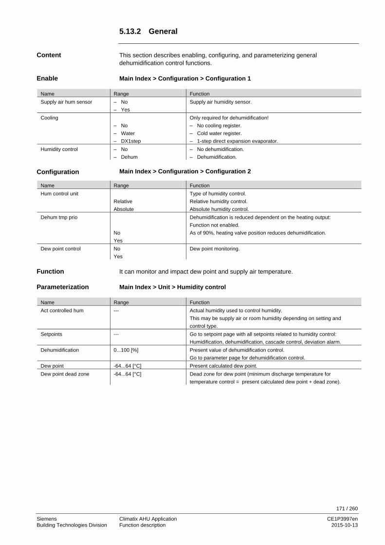
171 / 260
Siemens Climatix AHU Application CE1P3997en Building Technologies Division Function description 2015-10-13
5.13.2 General
This section describes enabling, configuring, and parameterizing general dehumidification control functions. Main Index > Configuration > Configuration 1
Name Range Function Supply air hum sensor – No
– Yes Supply air humidity sensor.
Cooling – No – Water – DX1step
Only required for dehumidification! – No cooling register. – Cold water register. – 1-step direct expansion evaporator.
Humidity control – No – Dehum
– No dehumidification. – Dehumidification.
Main Index > Configuration > Configuration 2
Name Range Function Hum control unit
Relative Absolute
Type of humidity control. Relative humidity control. Absolute humidity control.
Dehum tmp prio No Yes
Dehumidification is reduced dependent on the heating output: Function not enabled. As of 90%, heating valve position reduces dehumidification.
Dew point control No Yes
Dew point monitoring.
It can monitor and impact dew point and supply air temperature. Main Index > Unit > Humidity control
Name Range Function Act controlled hum --- Actual humidity used to control humidity.
This may be supply air or room humidity depending on setting and control type.
Setpoints
--- Go to setpoint page with all setpoints related to humidity control: Humidification, dehumidification, cascade control, deviation alarm.
Dehumidification
0...100 [%] Present value of dehumidification control. Go to parameter page for dehumidification control.
Dew point -64...64 [°C] Present calculated dew point. Dew point dead zone
-64...64 [°C] Dead zone for dew point (minimum discharge temperature for temperature control = present calculated dew point + dead zone).
Content
Enable
Configuration
Function
Parameterization

172 / 260
Siemens Climatix AHU Application CE1P3997en Building Technologies Division Function description 2015-10-13
5.13.3 Humidity setpoints Main Index > Unit > Humidity control > Setpoints
Name Range Function Act controlled hum – Supply [%r.H.] or [g/kg] Actual supply air humidity used for control (%r.H. or g/kg depending on
control type). Act dehum stpt 0.0...100.0 [%r.H.] or [g/kg] Actual calculated room or supply air dehumidification setpoint (%r.H. or
g/kg). Dehum stpt 0…100 [%r.H.] Setpoint for dehumidification.
Only available when Hum stpt selection = Hum/dehum or Dehum/-degree Celsius.
Dehum stpt 0…100 [g/kg] Setpoint for dehumidification. Only available when Hum stpt selection = Hum/dehum or Dehum/-degree Celsius.
Parameterization

173 / 260
Siemens Climatix AHU Application CE1P3997en Building Technologies Division Function description 2015-10-13
5.14 Air quality control **
The function Air quality control applies to controller POL63X only.
The fans (section 5.5.8) and/or mixed air dampers (section 5.7) are influenced based on air quality: – The fresh air volume is increased when CO2 content is too high
(fan speed increases; recirculation flow is reduced). – The fresh air volume is increased when outside CO content is too high (fan speed
decreases; recirculation flow is increased). The figure illustrates the participating plant elements (with gray background):
Figure 41: Overview of the plant elements for air quality control ** Main Index > Configuration > Configuration 2 > Fan comp air qual = Yes and / or Main Index > Configuration > Configuration 2 > Hrec comp air qual = Yes Main Index > Unit > Air quality control
Name Range Function Controller 0…100 [%] Present value for the controller. Go to controller settings page. Function
– Normal – Inverted
The control direction of the controller must be selected depending on demand: Normal for CO2. Inverted for CO.
Setpoint 0…3000 [ppm] Air quality control setpoint.
∆p
∆p
∆p
∆p
T
T
P3997Z17
Function
Elements
Prerequisite
Parameter

174 / 260
Siemens Climatix AHU Application CE1P3997en Building Technologies Division Function description 2015-10-13
5.15 Auxiliary functions 5.15.1 Overview
This section describes the functions for the auxiliary input and output Aux as well as the scheduler program TSP. This functions have no impact on control. They are used exclusively to display, switch or control independent devices. The figure illustrates the participating plant elements:
Figure 42: Overview of the plant elements for auxiliary functions The topics in the section are: Topic Section Inputs/outputs "Aux" 6.15.2 TSP output 6.15.3 5.15.2 Inputs/outputs Aux This section describes configuring and parameterizing auxiliary inputs and outputs (Aux). In Configuration 1: None Main Index > Configuration > Configuration 2
Name Range Function Auxiliary input No
Input Alm Inp+Alm
No auxiliary input. Auxiliary input for display only. Auxiliary input with alarm. Two auxiliary inputs: To display and with alarm.
Aux tmp sensor No Yes
Auxiliary input for temperature sensor.
Aux TSP output No Yes
An auxiliary digital output controller by its own time switch program.
Aux A outp fan No Yes
Auxiliary analog output that provides a 0-10 V signal depending on the present fan step.
Aux op mode indication No Yes
Auxiliary digital output that displays whether a desired operating mode for the plant (e.g. Comfort, Off) is enabled.
P3997Z18
TSP
IN OUT TSP
Content
Elements
Topic
Content
Requirements
Configuration

175 / 260
Siemens Climatix AHU Application CE1P3997en Building Technologies Division Function description 2015-10-13
Inputs/outputs Aux, cont'd Main Index > Unit > Auxiliary
Name Range Function TSP output Off
On Present state of the output controlled by the time switch program. Go to parameter page for the output.
Analog output 0…100 [%] Present value of output Aux A outp fan. Go to page with all analog output settings.
A outp fan step 0 0…100 [%] Voltage value at output for shut off plant (for plant faults as well). A outp fan step 1 0…100 [%] Voltage value on the output for active fan step 1 (setpoint 1 for controlled
fans). A outp fan step 2 0…100 [%] Voltage value on the output for active fan step 2 (setpoint 2 for controlled
fans). A outp fan step 3 0…100 [%] Voltage value on the output for active fan step 3 (setpoint 3 for controlled
fans). Alarm input
Passive Active
Present state of alarm for auxiliary input. Go to page with digital input settings. The behavior NO/NC for the input can be changed there. Logical 0 at input. Logical 1 at input.
Input Off On
Present state of input for auxiliary input. Go to page with digital input settings. The behavior NO/NC for the input can be changed there. Logical 0 at input. Logical 1 at input.
Auxiliary tmp -64.0…64.0 [°C] Present value of temperature at input Aux tmp sensor. Go to page with analog input settings.
Op mode output Off On
Displays whether the desired (using Op mode outp select) operating mode for the plant is enabled. Go to page with digital output settings.
Op mode outp select Off On/Comfort Economy Manual Osstp Free clg Unocc Fan kick Fire dmper Fire Stop Running Htg full Hrec full Clg full
Selection of operating modes to be displayed on output op mode output: Plant off. Plant on or in Comfort mode. Plant in Economy mode. Manual intervention enabled. Boost enabled. Free cooling enabled. Not used, active (Temp. difference start). Plant kick enabled. Fire damper test enabled. Fire alarm enabled; plant in fire alarm mode. Plant stopped and locked. Plant is operating (On/Co/Ec/Osstp/FreeClg/Unocc/Fankick/Startup). Hot water or electrical register on 100%. Heat recovery (plates, water, heat wheel) at 100%. Cooling at 100%.
Parameterization

176 / 260
Siemens Climatix AHU Application CE1P3997en Building Technologies Division Function description 2015-10-13
5.15.3 TSP output Main Index > Unit > Auxiliary > TSP output
Name Range Function Output – Off
– On Present state for output. Go to page with digital output settings.
Manual operation – Off – On – Auto
Manual adjustment of output (always has the highest priority). – Off – On – Auto:
The time switch catalog or the BACS controls the output. Schedule – Off
– On Present value for the time switch program. Go to page with time switch program settings.
Calendar exception – Passive – Active
Present status of calendar for exception days. Go to page with calendar settings. – Calendar not in intervention. – Calendar in intervention.
From BACS – Auto
– Off – On
Control output via BACS: – No intervention by BACS:
The time switch catalog only acts on the output in this position.
– Off from BACS. – On from BACS.
Parameterization

177 / 260
Siemens Climatix AHU Application CE1P3997en Building Technologies Division Function description 2015-10-13
5.16 Alarm troubleshooting (Alarm outputs) Displays communication module states and parameterization of Alarm outputs: • Is determines the alarm to be displayed (high A and/or low B) for a single alarm
output • For two outputs, output 1 always displays the high (A) alarms and output 2 the low
(B) alarms The figure illustrates the participating plant elements:
Figure 43: Overview of the plant elements for alarm troubleshooting Main Index > Configuration > Configuration 1
Name Range Function Alarm outputs None
One Two
Number of alarm outputs.
Main Index > Alarm handling
Name Range Function Alarm acknowledge Off
On Acknowledge button (for pending alarms) or reset button (for alarms that are no longer pending).
Danger (A) Normal Alarm
Displays alarm class danger (the plant is shut down without delay, except for the special case for fire mode).
Critical (A) Normal Alarm
Displays alarm class critical (the plant is shut down normally).
Low (B) Normal Alarm
Displays alarm class low (plant continues to operate).
Warning (C) Normal Alarm
Displays warnings (plant continues to operate). Is not displayed on digital outputs; see below. No warning. Warning pending.
Alarm outp 1 select High (A) H+L (A+B)
Function of alarm output 1 for a single output: Signals only alarms for group a (Danger and Critical). Signals only alarms for groups A and B (Danger, Critical and Low).
Alarm output 1 Normal Alarm
Present state of alarm output 1. Go to page with digital output settings.
Alarm output 2 Normal Alarm
Present state of alarm output 2. Go to page with digital output settings.
P39
97Z1
9
ModbusBACnet/IP
LON 1 2
Function
Elements
Enable
Parameterization

178 / 260
Siemens Climatix AHU Application CE1P3997en Building Technologies Division Function description 2015-10-13
Alarm troubleshooting (Alarm outputs), cont'd
Name Range Function Modbus communicate 0...1 Displays Modbus communication state. Comm module 0 Comm failure State
– Passive – Active
Displays communication state of the module on position 0 (only available when module is plugged in). Go to Comm module overview page. – No error. – Pending error on module 0. Cause of error.
Comm module 1 Comm failure State
– Passive – Active
Displays communication state of the module on position 1 (only available when module is plugged in). Go to Comm module overview page. – No error. – Pending error on module 1. Cause of error.
Comm module 2 Comm failure State
– Passive – Active
Displays communication state of the module on position 2 (only available when module is plugged in). Go to Comm module overview page. – No error. – Pending error on module 2. Cause of error.
Parameters, cont'd

179 / 260
Siemens Climatix AHU Application CE1P3997en Building Technologies Division System settings and Info 2015-10-13
6 System settings and Info 6.1 Overview
Although the workflow is specifically classified in section 4.2 Higher functions as a stage, you can also individually change or read the objects described in the following topics as needed and depending on the situation. This section provides the following knowledge: • System Settings, can be changed as needed • System Information, is read only The topics in the section are: Topic Section Operating levels and access protection 7.2 Change password 7.3 Supported languages 7.4 System information 7.5 Summer/winter time change 7.6 Main settings HMI 7.7 Diagnostics: Controllers and application 7.8 Diagnostics: Object handler 7.9 Application info 7.10
Introduction
Knowledge provided
Topic

180 / 260
Siemens Climatix AHU Application CE1P3997en Building Technologies Division System settings and Info 2015-10-13
6.2 Operating levels and access protection
Password protection in Climatix consists of a maximum of nine passwords, in three levels defined. The passwords can be modifying by HMI as required. Main Index > System overview > Password handling The following functions are possible at the tree levels: Level User, password Functions
No All users, No password required
– Read access to all menu except system parameters, Configuration and detail pages.
– Read access to alarm list and alarm history. 6 User
Password: 1000 – Read access to all menus except configuration. – Write access to most important setpoints
(Setpoints/Settings > Main Setpoints). – Alarms and alarm history can be acknowledged
4 Service, Password: 2000
– Access to all menus except advanced configuration and settings.
2 Factory/OEM Password: 6000
– Access to all menus and system settings.
Each operating level includes the level with the higher number.
Defined levels
Parameterization
Functions on the individual levels

181 / 260
Siemens Climatix AHU Application CE1P3997en Building Technologies Division System settings and Info 2015-10-13
6.3 Change password
You can change the standard passwords. Requires level 4 at a minimum. Main Index > System overview > Password handling
Name Range Function Log in If logged in at level 4, can be increased here to level 2.
Conversely, the system goes to the Main Index page when logging in using a level 6 password The line is unavailable at level 2.
Log off Logging off. Go to Main Index page.
Change user password Requires level 4: The password for level 6 can be changed. Change service password Requires level 4: The password for level 4 can be changed. Change factory password Requires level 2: The password for level 2 can be changed.
Step Action
1 Select Change Service password. 2 Enter the new password under the line Enter password:
– Turn: The active digit changes. – Press: Go to next position. – Press after the fourth position: Go to first position for the Confirm password line.
3 Re-enter the new password as described above. – Press after the fourth position: The new password is accepted.
Press ESC: Pressing ESC cancels entry of the new password. The old password still applies.
Function
Parameter
Example using the Service password

182 / 260
Siemens Climatix AHU Application CE1P3997en Building Technologies Division System settings and Info 2015-10-13
6.4 Supported languages
The following languages already implemented upon delivery:
Splitted in two language set’s North and south – English * * – Swedish * – German * * – Italian * – Spanish * – Chinese * – Danish * – Finnish * – Polish * – French * – Dutch * – Russian * – Turkish *
Additional languages may be implemented upon request
Minimum access level: 6 (User) Main Index > System overview > Language selection
Name Range Function HMI language – English
– Svenska – Deutsch – ……
– English. – Swedish. – German. – …..
AlarmSnapshot -Save SD
– English – Svenska – Deutsch – ……
– English. – Swedish. – German. – …..
Modem -SMS language
– English – Svenska wenka – Deutsch – ……
– English. – Swedish. – German. – …..
Requires access level 4: Main Index > System overview > Language selection
Name Range Function Modem -Language
– English – Svenska – Deutsch – ……
– English. – Swedish. – German. – …..
Previously implemented languages
Parameter
Parameter

183 / 260
Siemens Climatix AHU Application CE1P3997en Building Technologies Division System settings and Info 2015-10-13
6.5 System information 6.5.1 General
Displays and defines special system data for the controller. Requires level 4 password Main Index > System overview > All system settings > Target
Name Range Function Imperial unit sys
– Passive – Active
Changes unit from metric system to imperial. – Metric system enabled. – Imperial system enabled.
BSP version Controller operating system. Reset counter Displays the number of controller resets and can reset the counter
to 0. Internal temp Internal controller temperature. GUID target Unique controller ID number worldwide. GUID application Unique application software ID number worldwide. GUID HMI Unique HMI ID number worldwide. GUID Web HMI Unique web HMI ID number worldwide. GUID OBH Unique ID number of the OBH.bin files worldwide (object handler
support). Serial number Controller serial number. Target ID
– 3 – 4
Controller ID number: – POL 636 controller. – POL 638 controller.
Applic security – Passive – Active
Displays software lock: – Unlocked. – Locked.
Note: Standard AHU is never locked.
Appli start allowed – Yes – No
Displays whether the installed software can operate on this controller. An application with application security may only operate, for example, in the intended controller.
Special settings Go to Target special settings page. 6.5.2 Special settings Main Index > System overview > All system settings > Target > Special settings
Name Range Function Target name --- Change controller name on the bus (TCP/IP name and controller
USB). Default name is, for example, POL638_128. (128: last three bytes of the MAC address).
Modbus termination – Passive – Active
Activate the terminating resistor for the Modbus.
Functions
Parameter
Parameter

184 / 260
Siemens Climatix AHU Application CE1P3997en Building Technologies Division System settings and Info 2015-10-13
6.6 Summer/winter time change Define changeover from daylight saving time (summer) to standard time (winter). The data refers to Middle European Time (MET). Page requires level 4. Main Index > System overview > All system settings > Daylight saving time
Name Range Function Enable Yes
No Displays changeover from daylight saving time to standard time.
Active Passive Active
Displays whether summer time is currently enabled: Passive: Winter time Active: Daylight saving time (summer).
B-time active Passive Active
Displays whether the B-time is enabled for the change from daylight saving time to standard time: B time disabled. B time enabled.
Time 0…12 [h] Number of hours for the adjustment. Start month Jan ... Dec Month when daylight saving time is enabled. Start week day Mo…Su Day of the week to start daylight saving time. Start offset
0 1 2 3 4 5 6 7 8 9 10
Week of the month for the changeover to daylight saving time: Fifth to last week. Fourth to last week. Third to last week. Second to last week. Last week. Not allowed. First week. Second week. Third week. Fourth week. Fifth week.
Start hour 0...23 [h] Time of day of change to daylight saving time. Start delay -32768...32767 [h] Delay for changeover. End month Jan…Dec Month for changeover to standard time. End week day Mo…Su Day of the week for changeover to standard time. End offset
0 1 2 3 4 5 6 7 8 9 10
Week of the month for the changeover to standard time: Fifth to last week. Fourth to last week. Third to last week. Second to last week. Last week. Not allowed. First week. Second week. Third week. Fourth week. Fifth week.
End hour 1...23 [h] Time of day for changeover to standard time. End delay -32768...32767 [h] Missing UTC-difference -720...720 [min] Difference between local time and global UTC.
The following generally applies: UTC - Local time = UTC-difference. For MET (default): 12:00 - 13:00 = -60 min. Caution: Daylight saving time not considered!
Functions
Parameter

185 / 260
Siemens Climatix AHU Application CE1P3997en Building Technologies Division System settings and Info 2015-10-13
6.7 Main settings HMI 6.7.1 General settings The table below lists menus for general operating settings applying to the entire HMI (operator unit). The suffix inbuilt means that this parameter applies only to the HMI integrated in the controllers. Main Index > System overview > sHMI
Name Range Function Temperature (extern) 0-40 °C Show the Temperature measured in the HMI-DM/TM HMI language
English Svenska Deutsch Italiano Espaniol 中文 Dansk Suomi Polski Français Nederlands Русский Turkçe
Displays current language and options for selection: English Swedish German Italian Spanish Chinese Danish Finnish Polish French Dutch Russian Turkish
Imperial unit sys. Passive Active
Display Metric Units e.g. °C Display imperial Units e.g. °F
Reset time 3...30 [min] Setting time after log in after which an access level expires after the last operation. Must log in again after this period.
Message duration: inb. 2...15 [s] Time period during which an error page is displayed. This is the case, for example, when a setpoint is entered that is outside the entry range.
Advanced Requires access level 2: Go to HMI advanced settings page.
6.7.2 Special settings Main Index > System overview > All system settings > HMI > Advanced
Name Range Function Auto password (ext. HMI) - Passive
- Active
Alarm ackn level 2, 4, 6, 253 Sets required access level to acknowledge/reset alarms. 253 no PW needed
Alarm format %s %T: %V Modify the display of alarms, e.g. in the HMI. See token explanation
Contents
Parameter
Parameter

186 / 260
Siemens Climatix AHU Application CE1P3997en Building Technologies Division System settings and Info 2015-10-13
6.7.3 Info LED The LED is located in the INFO button on the top of the HMI-DM:
Figure 44: HMI-DM: LED INFO button The Info LED can have three colors, red, green, and yellow, and can flash. The table below lists the available LED states and their meaning: State Meaning Dark AHU switched off or not configured Green
On / Comfort / Economy Economy
Green, flashing
OSSTP Night cooling Unoccupied Htg/Clg Night Temp Test
Orange flashing Fire damper test Orange Stop (Alarm/Em.stop) Orange / green, flashing
Manual operation
P399
7Z20
Position on HMI
States/meaning
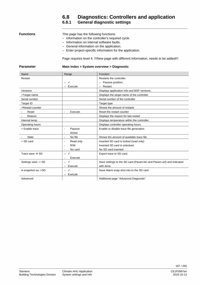
187 / 260
Siemens Climatix AHU Application CE1P3997en Building Technologies Division System settings and Info 2015-10-13
6.8 Diagnostics: Controllers and application 6.8.1 General diagnostic settings This page has the following functions: – Information on the controller's required cycle. – Information on internal software faults. – General information on the application. – Enter project-specific information for the application. Page requires level 4. !!!New page with different information, needs to be added!!! Main Index > System overview > Diagnostic
Name Range Function Restart
– – Execute
Restarts the controller. – Passive position. – Restart.
Versions Displays application Info and BSP versions. +Target name Displays the target name of the controller Serial number Serial number of the controller Target ID Target type +Restart counter Shows the amount of restarts - Reset - Execute Reset the restart counter - Reason Displays the reason for last restart Internal temp. Displays temperature within the controller. Operating hours Displays controller operating hours. + Enable trace - Passive
- Active Enable or disable trace file generation
- State - No file Shows the amount of available trace file + SD card - Read only
- R/W - No card
Inserted SD card is locked (read only) Inserted SD card is unlocked. No SD card inserted
Trace save SD – - Execute
Export trace to SD card.
Settings save -> SD – – Execute
Save settings to the SD card (Param.bin and Param.ucf) and indicated with done.
A-snapshot sa.->SD – – Execute
Save Alarm snap shot into to the SD card
Advanced Additional page "Advanced Diagnostic"
Functions
Parameter

188 / 260
Siemens Climatix AHU Application CE1P3997en Building Technologies Division System settings and Info 2015-10-13
6.8.2 Diagnostics: Advanced settings Main Index > System overview > Diagnostic > Advanced
Name Range Function Oject handler Information about the amounts of objects, memory and more. IO – Module bus Information about the IO-Module bus for the ext. I/O’s Cycle time reset Resets aver. min. and max. times. Cycle time actual 0... [ms] Current cycle time for the controller. Cycle time average 0... [ms] Average required cycle time for the controller since the last controller
start or cycle time reset. Cycle time min 0... [ms] Shortest required cycle time for the controller since the last controller
start or cycle time reset. Cycle time max 0... [ms] Longest required cycle time for the controller since the last controller start
or cycle time reset. MSR failure Internal software failure. MSR failure type Internal software failure type (failure number). MSR started up – Yes
– No Control startup successful.
+GUID target Unique identification number for target
+GUID application Unique identification number for application-file +GUID HMI Unique identification number for HMI file +GUID Web HMI Unique identification number for Web HMI file +GUID OBH Unique identification number for OBH-File +GUID BSP Unique identification number for BSP file Appli.security – Passive
– Active Application security enabled or disabled
Appli.start alowed – Yes – No
Application is allowed to start or not
Parameter

189 / 260
Siemens Climatix AHU Application CE1P3997en Building Technologies Division System settings and Info 2015-10-13
6.9 Diagnostics: Object handler Diagnoses ram, objects and COV or alarm handler clients. Parameters can be read with level 4. They are always write-protected. !!!New link from diagnostic!!! Main Index > System overview > All system settings > Diag object handler
Name Range Function Actual objects Number of actual objects for the enabled configuration. Act object memory ... [B] Actual required memory. Act int memory ... [B] Maximum amount of available dynamic memory. COV act clients Number of subscribed internal and external COV clients. ALH act clients Number of subscribed internal and external alarm handler clients. Valid objects – Yes
– No Displays whether valid data is present in the object handler. For faults, evaluate the measuring and control task of the diagnostic object.
Version Object handler version. Data check sum Internal checksum of the enabled configuration. Max objects Maximum number of enabled objects. Max object memory ... [B] Maximum memory for objects. Max int memory ... [B] Maximum memory for data. COV max clients Maximum number of internal and external COV clients. ALH max clients Maximum number of internal and external alarm handler clients.
Information
Parameter

190 / 260
Siemens Climatix AHU Application CE1P3997en Building Technologies Division System settings and Info 2015-10-13
6.10 Application info
You can always read, i.e. password not required, the main information: – Application name – Application version – Unique target name (automatically) or OEM identification (e.g. Order Nr.)
Additional information can be edited at access level 4 and thus modified to the present plant (e.g. installation location): – Plant Name – Street – City – Main Index > System overview > Plant info – Minimum access level 4:
Main Index > System overview > Plant info > Advanced
Name Explanation/Example Plant Name E.g. plant name Street E.g. plant address City E.g. plant city Advanced Requires access level 4:
You can change name, street and city here. Proceed as follows to enter text:
Step Action 1 Press knob to select entry line 2 Turn knob to change the first position 3 Press the knob to switch to the next line and continue as of step 2. Note:
Maximum of 19 characters. 4 Enter # to finish the entry if the string is less than 19 characters. Note:
No characters allowed after entering #.
Main information
Additional information
Parameter
Example of text entry
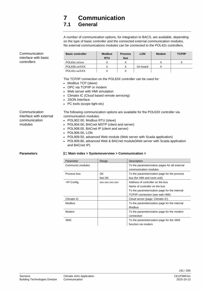
191 / 260
Siemens Climatix AHU Application CE1P3997en Building Technologies Division Communication 2015-10-13
7 Communication 7.1 General A number of communication options, for integration to BACS, are available, depending on the type of basic controller and the connected external communication modules. No external communications modules can be connected to the POL42x controllers.
Basic controller Modbus RTU
Process bus
LON Modem TCP/IP
POL63x.xx/xxx X X X X POL636.xx/XXX X X On board X POL42x.xx/XXX X X
The TCP/IP connection on the POL63X controller can be used for: • Modbus TCP (slave) • OPC via TCP/IP or modem • Web server with HMI simulation • Climatix IC (Cloud based remote servicing) • JSON Interface • PC tools (scope light etc) The following communication options are available for the POL63X controller via communication modules: • POL902.00, Modbus RTU (slave) • POL904.00, BACnet MSTP (client and server) • POL908.00, BACnet IP (client and server) • POL906.00, LON • POL909.50, advanced Web module (Web server with Scada application) • POL909.80, advanced Web & BACnet module(Web server with Scada application
and BACnet IP)
Main index > Systemoverview > Communication >
Parameter Range Description Communic.modules To the parameterization pages for all external
communication modules Process bus OK
Not OK To the parameterization page for the process bus (for HMI and room unit)
+IP-Config. xxx.xxx.xxx.xxx Address of controller on the bus Name of controller on the bus To the parameterization page for the internal TCP/IP connection (see web HMI)
Climatix IC Cloud server (page: Climatix IC) Modbus To the parameterization page for the internal
Modbus Modem To the parameterization page for the modem
connection SMS To the parameterization page for the SMS
function via modem
Communication interface with basic controllers
Communication interface with external communication modules
Parameters

192 / 260
Siemens Climatix AHU Application CE1P3997en Building Technologies Division Communication 2015-10-13
7.2 TCP/IP (internal) The POL63x controller is equipped with a TCP/IP interface. This internal interface can be used for several communications, working together at the same time. All communications use the same TCP/IP settings, but can have different security. The TCP/IP connection on the POL63X controller can be used for: • Modbus TCP (slave) • OPC via TCP/IP or modem • Web server with HMI simulation • Climatix IC (cloud based remote servicing) • JSON • PC tools (scope light etc) The controller can be accessed by either the IP address or the controller name.
Main index > Systemoverview > Communication > +IP-Config. > Parameter Range Description DHCP
Active Passive
Address source: Get address from DHCP server IP address is set fixed by the given address
Actual IP Display of controller’s IP address Actual Mask Display of subnet mask Act.Gateway Display of gateway’s address Given IP Set the IP address xxx.xxx.xxx.xxx Given Mask Set the mask (e.g. 255.255.255.000) Giv Gateway Set the gateway xxx.xxx.xxx.xxx Primary DNS Set/display the primary DNS xxx.xxx.xxx.xxx Secondary DNS Name Display of controller’s name (can be changed in the
settings for the controller) MAC Display of controller’s MAC address Link Active
Passive Shows if the controller is connected to the Ethernet network
100 MBit Active Passive
Shows if the controller is connected to a 100 MBit network
Advanced Extended entry (to page Adv. IP-Config) After modification of value Restart Required !!
Execute
After changing parameters, the controller must always be restarted, ensuring that data are adopted
General
Parameters
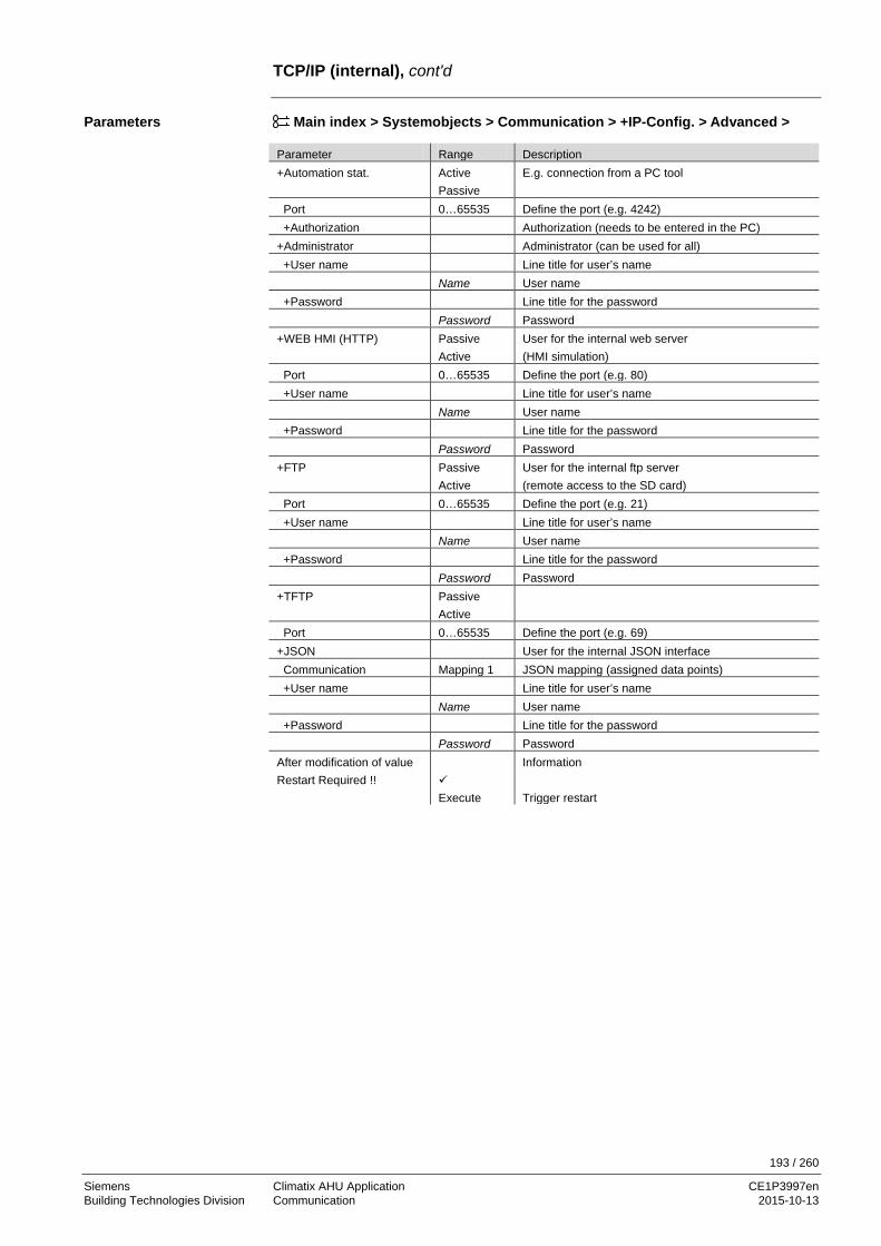
193 / 260
Siemens Climatix AHU Application CE1P3997en Building Technologies Division Communication 2015-10-13
TCP/IP (internal), cont'd
Main index > Systemobjects > Communication > +IP-Config. > Advanced > Parameter Range Description +Automation stat. Active
Passive E.g. connection from a PC tool
Port 0…65535 Define the port (e.g. 4242) +Authorization Authorization (needs to be entered in the PC) +Administrator Administrator (can be used for all) +User name Line title for user’s name Name User name +Password Line title for the password Password Password +WEB HMI (HTTP) Passive
Active User for the internal web server (HMI simulation)
Port 0…65535 Define the port (e.g. 80) +User name Line title for user’s name Name User name +Password Line title for the password Password Password +FTP Passive
Active User for the internal ftp server (remote access to the SD card)
Port 0…65535 Define the port (e.g. 21) +User name Line title for user’s name Name User name +Password Line title for the password Password Password +TFTP Passive
Active
Port 0…65535 Define the port (e.g. 69) +JSON User for the internal JSON interface Communication Mapping 1 JSON mapping (assigned data points) +User name Line title for user’s name Name User name +Password Line title for the password Password Password After modification of value Restart Required !!
Execute
Information Trigger restart
Parameters

194 / 260
Siemens Climatix AHU Application CE1P3997en Building Technologies Division Communication 2015-10-13
7.4 Climatix IC remote servicing**
Climatix AHU V3xx packaging is prepared to connect Climatix POL6xx controller to Climatix IC remote servicing system. Climatix IC is a cloud based remote servicing system to remotely monitor, operate and upgrade Climatix controls system. Climatix POL63xx controllers can be connected via Internet ((T-IP) without any port or IP settings and accessable via normal web browser over the follow URL www.ClimatixIC.com. Climatix IC20 is providing the following main features:
• Read and write data points (watch pages) • Data history trend viewer • Alarm and alarm email notification • Time scheduler and callendar set up • HMI@web • Remote upgrade (BSP and application file) • Remote diagnostics
For more info about Climatix IC, please have a look on Link: https://www.climatixic.com/home/functional description Participating devices – Climatix controller POL63x – Climatix IC user credential – Web browser – Internet connectivity Internet connectivity is running for normal web surfing.
Step Action 1 Connect Internet cable to Ethernet port of POL63x controller (T-IP) 3 Enable Climatix IC 4 Enter distribution ID according your Climatix IC OEM tenant ID 5 Check connectivity status 6 Log in to Climatix IC and check on the unassigned area for your controller (type and
controller name) 6 Assign your controller in Climatix IC
Introduction
Features
Devices
Requirements
Set up Climatix IC

195 / 260
Siemens Climatix AHU Application CE1P3997en Building Technologies Division Communication 2015-10-13
Climatix IC remote servicing**, cont'd
Main Index > Communication>Climatix IC
Name Range Function Enable Yes
No BSP only
Enable controller to Climatix IC Do not enable to Climatix IC For upgrade only, no data transmitting
Serial number Serial number of the controller +State Communication - Ok
- IPErr - ServerErr - InternalErr - ResponseErr
Climatix IC communication status
Cloud server - IPErr - Init - InitErr - Reg - RegErr - Description - Connected
Climatix IC server status
Distributor xxxxxxxxxxxx Distributor ID of the OEM , to be known by OEM informed by OEM tenant administrator
Upgrade allowed Wait Yes NO
Controller is busy with shot down sequence Controller is ready for upgrade procedure Controller does not accept upgrade at all
Upgrade request Active Passive
Climatix IC indicate an upgrade request for the controller Climatix IC does not have an upgrade request from the controller
Advanced Various Additional information like IP address, activation key Plant Info Various Jump to plant information page
!!!Maybe more lines/values in 3.04!!! In case Climatix IC is requesting a controller for an upgrade, it is mandatory to first proceed a shot down sequence of the application to prevent any damage on the machine. As soon the controller has finished the shot down procedure, it is indicating to Climatix IC to progress the remote upgrade. Climatix IC is firstly saving the parameter set (back up), progress the upgrade and restore the parameter set automatically. Main Index > System overview > Communication > Climatix IC > The member Upgrade allowed the update process can be blocked if it set to No
Parameter
Climatix IC Update Control

196 / 260
Siemens Climatix AHU Application CE1P3997en Building Technologies Division Communication 2015-10-13
7.5 Modbus The basic controller is always equipped with a Modbus RTU interface via RS-485. This interface can be defined as a master, slave or can be deactivated, but can’t be used as slave (BSM integration) and master at the same time. The POL638 controller has also Modbus TCP onboard via the TCP/IP interface and can also connect a communication module, POL902, for 2 extra Modbus slave interfaces. Latest version of the module must always be used. Devices used: • Climatix controller POL638 with communication module POL902.00/STD
or • Climatix controller POL638 and POL42x with internal Modbus Tools used for commissioning: • Operator unit (HMI)
Figure 45: Illustration POL638, POL42x and POL902 module
Main index > Systemoverview > Communication > Modbus > Modbus module > or for internal Main index > Systemoverview > Communication > Modbus > RS-485 > or Main index > Systemoverview > Communication > Modbus > TCP/IP >
Main index > Systemoverview > Communication > Modbus >
Parameter Range Description Device type None
Slave Master
Internal Modbus interface is activated by selecting Slave for BMS integration or Master for integration of meters
Note
After changing configuration settings, the controller must always be restarted, ensuring that data are adopted.
Use the Modbus integration documentations, for a detailed description how to integrate the DHN application to any BACS. See section 3 Preset plant types ***, for the needed document number.
General
Devices
Tools
Illustration POL638, POL42x and POL902 module
Configuration
Configuring the internal Modbus interface
Detailed instruction
J3960Z04 Modbus RTU
POL638 POL42x POL902 / POL638

197 / 260
Siemens Climatix AHU Application CE1P3997en Building Technologies Division Communication 2015-10-13
7.6 LON **
A LON interface is always available on the basis controller POL636.xxx. The external LON module POL906.xx also required for controllers POL635.xxx and POL638.xxx. 7.6.1 Internal LON interface Participating devices – Climatix POL636 controller.
Figure 46: Illustration internal LON interface Prerequisites for commissioning a LON section: – Working application loaded on the Climatix controller. – Mapping file (OBH.UCF) is loaded.
Main index > Systemoverview> Communication > LON
After successful LON commissioning via the LON tool, you can access the controller via the LON bus using SCOPE.
For detailed information about LON integration see document CB1P3934.
Interfaces
Devices
Requirements
Configuration
Detailed instruction

198 / 260
Siemens Climatix AHU Application CE1P3997en Building Technologies Division Communication 2015-10-13
7.6.2 External LON module The POL638 controller can connect a communication module, POL906 for LON communication. Latest version of the module must always be used. Devices used: • Climatix controller POL63x • LON communication module POL906.00/STD Tools used: • Operator unit (HMI) • PC with LON tool (NL220, LonMaker)
Figure 47: Illustration external LON module
Main index > Systemobjects > Communication > Communic.modules > LON module >
Note
After changing configuration settings, the controller must always be restarted, ensuring that data are adopted.
Use the LON integration documentations, for a detailed description how to integrate the DHN application to any BACS. See section 1.3 Reference documents, for the needed document number.
P3931Z14LON bus
POL906 / POL6XX
HMI
PC
LON tool Service
BSP BUS
General
Devices
Tools
Illustration POL906
Configuration
Detailed instruction

199 / 260
Siemens Climatix AHU Application CE1P3997en Building Technologies Division Communication 2015-10-13
7.7 BACnet IP and MSTP
Applies to controllers POL63X only.
The POL63x controller can connect a communication module, POL904 for BACnet, MSTP or POL908 for BACnet IP. Latest version of the module must always be used. Devices used: • Climatix controller POL63x • BACnet MSTP communication module POL904.00/STD
or • BACnet IP communication module POL908.00/STD Tools used: • Operator unit (HMI) • PC with web browser
MS
R
BACnet / IP
A
172.16.0.0AL
ML
FL
P3933Z02BACnet / MSTP (RS485)
POL904 / POL6XX POL904 / POL6XX
MS
HMI
BACnet / IP
R
FD FD Figure 48: Illustration POL908 and POL904 ML Management level R IP router OR MSTP/IP router AL Automation level FL / FD Field level / Field devices
Main index > Systemoverview > Communication > Communic.modules > BACnet IP module > or Main index > Systemoverview > Communication > Communic.modules > BACnet MSTP mod. >
Note
After changing configuration settings, the controller must always be restarted, ensuring that data are adopted.
Use the BACnet integration documentations, for a detailed description how to integrate the Climatix AHU application to any BACS. See section 1.3 Reference documents, for the needed document number.
General
Devices
Tools
Illustration POL908 and POL904
Key
Configuration
Detailed instruction

200 / 260
Siemens Climatix AHU Application CE1P3997en Building Technologies Division Communication 2015-10-13
7.8 BACnet Client**
Applies to controllers POL63X only.
Some objects can receive (Read) or send (Write) data from/to other remote BACnet devices (BACnet Servers) on the network. Example: Climatix controller reads outdoor temperature from another device. The binding to the remote BACnet device is done by a file called BACNET.CSV. This file must contain a uniqe internal connection name for each used object and also the uniqe IDs of the remote device, object and property. The BACNET.CSV file is related to the specific project network and the needed binding and are uploaded, at commisioning time, to each BACnet module or Climatix controller. It needs therefore to be separated backuped after commisioning. Participating devices – Climatix controller POL6XX. – Communication module POL908 or POL909.80 (AWB module). – External BACnet server device, from where BACnet data needs to be read. Required tools: – Operator unit (HMI) – SCOPE light tool to download project specific BACnetClient file For integration, the BACnet device ID of the server (remote BACnet device) and the object information must be known. This information is listed e.g. in the object list of the remote BACnet server. The client requires the information to know where to look for the BACnet objects to be integrated. Only present values are supported: – BACnet device ID – BACnet object instance ID – BACnet object type (AnalogInput etc) Use the BACnet integration documentations, for a detailed description how to integrate. See section 1.3 Reference documents, for the needed document number.
Introduction
Devices
Tools
Prerequisite
Detailed instruction

201 / 260
Siemens Climatix AHU Application CE1P3997en Building Technologies Division Communication 2015-10-13
7.9 AWM (Advanced Web Module)
Applies to controllers POL63X only.
The POL63X controller can connect a communication module, POL909 for a Web server with SCADA application. Latest version of the module must always be used. The SCADA application, including plant pictures etc, must be loaded to the module. Devices used: • Climatix controller POL63x • AWM communication module POL909.50/STD
or • AWB (Web and BACnet) communication module POL909.80/STD Tools used: • Operator unit (HMI) • PC with web browser
M
M
MT
LPC
RPC
RPC
POL6XX POL6XX
Ethernet
EthernetP2P
Ethernet
POL909.50
RS232
J3935Z03 Figure 49: Illustration POL909 RPC Remote PC with browser and
mail program RS232 RS232 modem interface including GSM/GPRS
support LPC Local PC with browser and mail
program M Modems
Ethernet Ethernet interface / Ethernet bus
MT Mobile telephone for receiving SMS
Main index > Systemoverview > Communication > Communic.modules > AWM module > or Main index > Systemoverview > Communication > Communic.modules > AWB module >
Note:
After changing configuration settings, the controller must always be restarted, ensuring that data are adopted.
Use the AWM integration documentation, for a detailed description how to use the AWM and SCADA application. See section 1.3 Reference documents, for the needed document number.
General
SCADA application
Devices
Tools
Illustration POL909
Configuration
Detailed instruction

202 / 260
Siemens Climatix AHU Application CE1P3997en Building Technologies Division Communication 2015-10-13
7.10 Modem / SMS **
Applies to controllers POL63X only.
All Climatix 63X controllers possess a modem interface for an external modem. The following functions are available: – Remote-service via SCOPE. – Send alarm SMSs by the controller.
A Siemens TC35 terminal (GSM modem) required, though. Other GSM modems may be connected, but are not tested.
7.10.1 Commission modem/SMS function RJ45 jack, 8 pins. The connection is located on the upper right-hand side of the controller cover:
P3903Z46
1D
SR/R
ID
CD
DTR
GN
DR
x D TxD
CT S
RTS
2 3 4 5 6 7 8
Figure 50: Illustration connection of the commission modem/SMS The illustration displays pin assignment. The following steps required to connect a modem: On the Climatix controller:
Step Action 1 Turn off power. 2 Connect modem. 3 Turn on power. 4 Enter modem settings.
Requirement for commissioning the modem: – The SAPRO application is fully commissioned. – Level 4 (password 2000). – Mapping file (OBH.bin) is loaded.
Step Action 1 In the menu system parameter > communication, select
SMS 2 Configure and parameterize as per the following tables
You can access the controller after you successfully commission the modem using the SCOPE.
Remote service interface
Plug type
Install and commission
Requirements
Commission controller

203 / 260
Siemens Climatix AHU Application CE1P3997en Building Technologies Division Communication 2015-10-13
Modem / SMS, cont'd. Main Index > (System overview >) Communication > SMS
Name Range Function Actual number – Disable
– Nbr 1 – Nbr 2 – Nbr 3 – Nbr 4
Do not send SMS. Send SMS to telephone numbers 1-4.
______ Settings SMS Go to settings page to parameterize SMS. Settings Modem Go to settings page to parameterize modem.
Main Index > (System overview >) Communication > SMS > Settings SMS
Name Range Function Free SMS 1 SAPHIR free SMS….
Free flow text for SMS text 1 Edit SMS text on the page Main Index > System overview > Communication > SMS > Settings SMS > Settings
Free SMS 2 SAPHIR free SMS….
Free flow text for SMS text 2 Edit SMS text on the page Main Index > System overview > Communication > SMS > Settings SMS > Settings
Fix SMS 1… Fix SMS 10
Settings Go to settings page to enter both free flow SMS texts Main Index > (System overview >) Communication > SMS > Settings Modem Main Index > (System overview >) Communication > Modem
Name Range Function Connection type 0 No modem
1 GSM modem
2 Analog modem
Displays whether a modem is connected
State 0…11 See list below (status description) Signal streng GSM Signal strength of GSM modem PIN Modem pin number SMS PIN The controller can also receive SMS.
Is only edited if you have a certain pin that can be set here. This function currently not implemented!
Phone nbr 1 Enter telephone 1 Phone nbr 2 Enter telephone 2 Phone nbr 3 Enter telephone 3 Phone nbr 4 Enter telephone 4 SMS active nbr 0…4 Displays the number to which potential SMS is sent.
0 = SMS switched off.
Configuration
Parameterize SMS
Parameterize modem

204 / 260
Siemens Climatix AHU Application CE1P3997en Building Technologies Division Communication 2015-10-13
Modem / SMS, cont'd
Name Range Function SMS language – English
– Swenka – Deutsch – …
Select SMS language
Send string Displays modem initialization string for send Receive string Displays modem initialization string for receive Special settings Go to modem settings page to enter required parameters, e.g.
initialization string
Value. Operating state 0 OK; SMS 1 OK; general 2 Modem is initializing 3 Modem is transferring data 4 Modem is not logged on with the provider
5 Searching for network 6 Provider prevented network logon 7 Unknown registration state 8 Modem is making connection 9 Modem is connected
10 General error, modem not responding, possibly no modem connected 11 Modem initialization failed
Main Index > System overview > Communication > Modem > Advanced
Name Range Function Enable bus LED – No
– Yes Enable bus LED Off = No modem connect or LED not enabled Yellow = Modem connected and initialized; communication not active Green = Modem connected, communication active Red = Modem connected, but error is active (e.g. missing provider,
initialization not possible, etc.) Init string 1 Modem initialization string 1 Init string 2 Modem initialization string 2 (additional) Force Reset – Passive
– Active Reset modem with new initialization
SMS POU mode – Passive – Active
Passive: SMS are sent as text message Active: SMS sent in PDU mode (some older cell phones can only use this mode)
Cell phone – Passive – Active
Passive: A GSM modem connected as sender Active: Cell phone connected as sender
Baud rate(19200) – Passive – Active
Passive: Baud rate between controller and modem is 57.6 kbps Active: Baud rate is 19.2 kbps
Parameterize modem, cont'd
Status description
Parameterize mode (advanced)

205 / 260
Siemens Climatix AHU Application CE1P3997en Building Technologies Division Communication 2015-10-13
7.11 Process bus/room units
A process bus interface is always available on the basis controllers POL63X and POL424 to connect room units. The application is designed differently, however, for both controllers: – POL636 for a maximum of 2 room units – POL424 for 1 room unit
7.11.1 Commission room unit Participating devices – Climatix controller POL636 or POL424 – Climatix room unit HMI-SG POL822.60 Requirement for commissioning room units: – Commission of the SAPRO application is completed and a constellation with room
unit is selected in the Main index > Configuration > Configuration 1 under Room tmp sensor (you can also select it in the menu Main index > Integrations > Room unit)
– Level 4 (password 2000) – Mapping file (OBH.bin) is loaded
Step Action 1 Select a constellation with room unit in the menu System Parameter > Configuration 1
under Room tmp sensor 2 Configure additional settings as required
See section 2.12 Room unit POL822" Main Index > Communications >
Name Range Function Energy meter EM24 – No
– Yes No energy meter selected
Settings Goes to page with all settings relevant to parameterize the energy meter
Inputs Go to page with inputs Room units – 1 sensor
– 2 sensors – 1 RU – 1snsr+ RU – 2 RU
Inputs for room temperature sensors. You can select whether to apply maximum, minimum, average or individual value for control for more than one sensor in Configuration 2. When selecting 1 RU, 1snsr + RU or 2 RU, the interface to the room unit connection is enabled.
Settings Goes to page with all settings relevant to parameterizing room units
Inputs Go to page with temperature inputs Restart Required !! – Execute You must restart the controller with Execute to assume the
data after changing parameters
Devices
Requirements
Commission room units
Parameter

206 / 260
Siemens Climatix AHU Application CE1P3997en Building Technologies Division Communication 2015-10-13
Commission room unit, cont'd Main Index > Com/Room units > Settings
Name Range Function Room tmp sensor – 1 sensor
– 2 sensors – 1 RU – 1snsr+ RU – 2 RU
Display the room sensor combination selected.
Displayed Alarm – none – event
– permanent
Alarm display on room unit. – Only the alarm symbol flashes for an alarm. – The alarm symbol and alarm number flashes for an alarm.
After press the bell button, the entire display returns and only the alarm symbol flashes.
– For an alarm, the alarm symbol flashes and the alarm number is displayed instead of the clock as long as the alarm is pending.
Displayed temp – RmUnit – RoomMix – Return
Temperature display. – Own, measured in the room unit. – Set in Configuration 2 with Room tmp mix. – Extract air temperature.
Eng system temp – Target – Metric – Imperial
Temperature display in the room unit. – Valid to the controller. – Metric system for the room unit. – Imperial system for the room unit.
Stpt range +/- 0.0…..12.0 [K] Maximal possible setpoint adjustment. Stpt increment - 0.1 [K]
- 0.5 [K] Setpoint adjustment increment.
Hrec display lim 0…100 [%] Threshold to show energy tracking symbol on the display. The symbol is displayed for value Efficiency > Hrec display lim.
Manual control – No – Yes
Enable mode button to changeover operating mode on the room unit. – Changeover is locked. – Changeover is enabled.
Presence time 0…23 [h] Runtime presence. Plants goes to auto mode after the delay. Back2Auto Off-Eco
– Off – On
Reset setpoint adjustment and presence for change in time switch command from Off > Economy. – Reset locked. – Reset enabled.
Back2Auto Off-Cmf – Off – On
Reset setpoint adjustment and presence for change in time switch command from Off > Comfort. – Reset locked. – Reset enabled.
Settings

207 / 260
Siemens Climatix AHU Application CE1P3997en Building Technologies Division Communication 2015-10-13
Commission room unit, cont'd
Back2Auto Eco-Cmf – Off – On
Reset setpoint adjustment and presence for change in time switch command from Economy > Comfort. – Reset locked. – Reset enabled.
Back2Auto Cmf-Eco – Off – On
Reset setpoint adjustment and presence for change in time switch command from Comfort > Economy. – Reset locked. – Reset enabled.
Back2Auto Cmf-Off – Off – On
Reset setpoint adjustment and presence for change in time switch command from Comfort > Off. – Reset locked. – Reset enabled.
Back2Auto Eco-Off – Off – On
Reset setpoint adjustment and presence for change in time switch command from Off > Economy. – Reset locked. – Reset enabled.
Time format – 24 h – 12 h
Time format 24 hour or 12 hour clock.
Room zone 0…..127 Room zone address on the controller: This value may only be changed if multiple controllers are operated on one bus with the room units. The value must always be the same as room unit parameter 5.
Device1 BSP version Room unit 1 firmware version. Device1 comm alarm – passive
– active Present alarm state of communication to room unit 1.
Device2 BSP version Room unit 2 firmware version. Device2 comm alarm – passive
– active Present alarm state of communication to room unit 2.
Process bus Goes to page with all settings relevant to parameterizing the process bus. Settings are only required on this page if the controller is integrated on the process bus system.
Settings cont'd

208 / 260
Siemens Climatix AHU Application CE1P3997en Building Technologies Division HMI details pages 2015-10-13
8 HMI details pages 8.1 Overview Information in the previous sections is normally enough to configure and parameterize the Climatix AHU application. The HMI details pages go one level lower. The object contained therein could be influence in even greater detail.
Most of the listed and briefly outlines values are parameters are designed exclusively for experts.
Possible reliability states (messages) for the base controller and the extension modules may differ.
Detail pages can only be read/written at the following access levels: – Read: Levels 6, 4 and 2, special settings with levels 4 and 2 only. – Write: Levels 4 and 2.
Changes to parameters and settings may have a massive impact on plant operation and safety.
The topics in the section are: Topic Section Analog outputs 9.2 Digital outputs 9.3 Multi-stage outputs 9.4 Analog inputs 9.5 Digital inputs 9.6 PID controller 9.7 Cascade controller 9.8 Scheduler program, general 9.9 Weekly schedule 9.10 Daily schedule 9.11 Exception days and fixed off 9.12
Introduction
Knowledge provided
Access level
Topic

209 / 260
Siemens Climatix AHU Application CE1P3997en Building Technologies Division HMI details pages 2015-10-13
8.2 Analog outputs 8.2.1 General The details page for analog outputs can be reached multiple ways, including: – Main Index > Unit > Outputs > Analog outputs > Plant Element
or – Main Index > Unit > Element Control > Analog Element > Output Signal – Main Index > Unit > Outputs > Analog outputs > Exh fan outp signal
or – Main Index > Unit > Fan Control > Extract fan > Output signal
Name Range Function Manual operation 0…100 [%] Manual intervention on the output. The output goes directly to
manual operation when entering a value (for 0 as well). Is not automatically reset. An alarm can be triggered after a set period when the manual alarm function is enabled.
Present Value 0…100 [%] Present value for output. Fault Ok Active prio – Out of serv.
– Prio1 – …. – Prio16 – Default
– Displays the wired prio elements currently on the output.
Fault priority – OK
– Other – Process Error – Config err
Reliability state for hardware. – Basis controller: Calibration lacking (output defective).
Extension module POL955: Calibration lacking (output defect) or communication to basic controller unavailable or the output is incorrectly configured.
– Basic controller: Process error in program. – Extension module: Message no available. – Basic controller: Output configured incorrectly.
Extension module: Message no available. Advanced Go to advanced settings page (at access levels 4 and 2 only). Priority array Go to Priority array page (at access levels 6, 4 and 2 only).
Access
Examples
Parameters
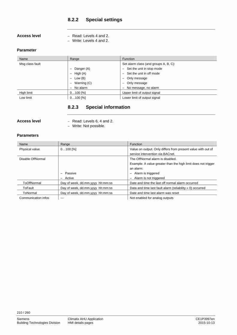
210 / 260
Siemens Climatix AHU Application CE1P3997en Building Technologies Division HMI details pages 2015-10-13
8.2.2 Special settings – Read: Levels 4 and 2. – Write: Levels 4 and 2.
Name Range Function Msg class fault
– Danger (A) – High (A) – Low (B) – Warning (C) – No alarm
Set alarm class (and groups A, B, C): – Set the unit in stop mode – Set the unit in off mode – Only message – Only message – No message, no alarm
High limit 0…100 [%] Upper limit of output signal Low limit 0…100 [%] Lower limit of output signal
8.2.3 Special information – Read: Levels 6, 4 and 2. – Write: Not possible.
Name Range Function Physical value 0…100 [%] Value on output. Only differs from present value with out of
service intervention via BACnet. Disable OffNormal
– Passive – Active
The OffNormal alarm is disabled. Example: A value greater than the high limit does not trigger an alarm: – Alarm is triggered – Alarm is not triggered
ToOffNormal Day of week, dd.mm.yyyy hh:mm:ss Date and time the last off normal alarm occurred ToFault Day of week, dd.mm.yyyy hh:mm:ss Data and time last fault alarm (reliability ≠ 0) occurred ToNormal Day of week, dd.mm.yyyy hh:mm:ss Date and time last alarm was reset Communication infos --- Not enabled for analog outputs
Access level
Parameter
Access level
Parameters
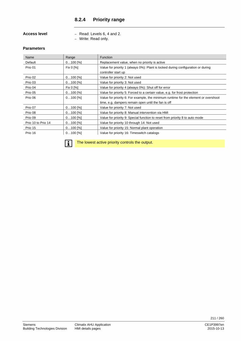
211 / 260
Siemens Climatix AHU Application CE1P3997en Building Technologies Division HMI details pages 2015-10-13
8.2.4 Priority range – Read: Levels 6, 4 and 2. – Write: Read only.
Name Range Function Default 0…100 [%] Replacement value, when no priority is active Prio 01 Fix 0 [%] Value for priority 1 (always 0%): Plant is locked during configuration or during
controller start up Prio 02 0…100 [%] Value for priority 2: Not used Prio 03 0…100 [%] Value for priority 3: Not used Prio 04 Fix 0 [%] Value for priority 4 (always 0%): Shut off for error Prio 05 0…100 [%] Value for priority 5: Forced to a certain value, e.g. for frost protection Prio 06 0…100 [%] Value for priority 6: For example, the minimum runtime for the element or overshoot
time, e.g. dampers remain open until the fan is off Prio 07 0…100 [%] Value for priority 7: Not used Prio 08 0…100 [%] Value for priority 8: Manual intervention via HMI Prio 09 0…100 [%] Value for priority 9: Special function to reset from priority 8 to auto mode Prio 10 to Prio 14 0…100 [%] Value for priority 10 through 14: Not used Prio 15 0…100 [%] Value for priority 15: Normal plant operation Prio 16 0…100 [%] Value for priority 16: Timeswitch catalogs
The lowest active priority controls the output.
Access level
Parameters

212 / 260
Siemens Climatix AHU Application CE1P3997en Building Technologies Division HMI details pages 2015-10-13
8.3 Digital outputs 8.3.1 General The details page for digital outputs can be reached multiple ways, including: – Main Index > Unit > Outputs > Analog outputs > Plant Element
or – Main Index > Unit > Element Control > Analog Element > Output Signal – Main Index > Unit > Outputs > Digital outputs > Htg pump cmd
or – Main Index > Unit > Temp control > Heating > Pump > Command
Name Range Function Manual operation – Off
– On – NULL
Manual operation on element (e.g. pump). Manual operation is not automatically reset! An alarm can be triggered after a set period when the manual alarm function is enabled. NULL: Auto; The program controls the output.
Present Value – Off – On
Present value for output
Reliability – OK
– Other – Process Error – Config err
Reliability state for hardware. – Basis controller: Calibration lacking (output defective).
Extension module POL955: Calibration lacking (output defect) or communication to basic controller unavailable or the output is incorrectly configured.
– Basic controller: Process error in program – Extension module: Message no available. – Basis Controller: Output configured incorrectly. – Extension module: Message not available.
Active prio – Out of serv. – Prio1 – …. – Prio16 – Default
Displays the wired prio elements currently on the output.
Operating hours 0... [h] Number of operating hours for the output Operating seconds (Reset) 0... [s] Number of operating seconds for the output. Input of 0 seconds reset
operating hours to 0 Last op hours reset Wday, dd.mm.yyy
hh:mm:ss Date and time for the last time operating hours was reset
Special settings --- Go to Special settings page (at access levels 4 and 2 only) Special infos --- Go to Special info page (at access levels 6, 4 and 2 only) Priority array --- Go to Priority array page (at access levels 6, 4 and 2 only)
Access
Examples
Parameter

213 / 260
Siemens Climatix AHU Application CE1P3997en Building Technologies Division HMI details pages 2015-10-13
8.3.2 Special settings – Read: Levels 4 and 2. – Write: Levels 4 and 2.
Name Range Function Contact Function
– NO – NC
Changes output from normal open to normal closed: Normal open (default) Normal closed (in this position, the output is enabled when the plant is shut down).
8.3.3 Special information – Read: Levels 6, 4 and 2. – Write: Not writable.
Name Range Function Physical value – Off
– On Value on output. Only differs from present value with out of service intervention via BACnet.
Disable OffNormal – Passive – Active
The OffNormal alarm is disabled: – Alarming is enabled – Alarming is switched off
BACnet fdbk value If connected: Feedback value from the bus Communication infos --- Not enabled for digital outputs
Access level
Parameters
Access level
Parameters

214 / 260
Siemens Climatix AHU Application CE1P3997en Building Technologies Division HMI details pages 2015-10-13
8.3.4 Priority range – Read: Levels 6, 4 and 2. – Write: Read only.
Name Range Function Default – Off
– On – NULL
Replacement value, when no priority is active. NULL means the prio is disabled.
Prio 01 Fix Off Value for priority 1 (always Off): Plant is locked during configuration or during controller start up
Prio 02 – Off – On – NULL
Value for priority 2: Not used
Prio 03 – Off – On – NULL
Value for priority 3: Not used
Prio 04 Fix Off Value for priority 4 (always Off): Shut off for error Prio 05 – Off
– On – NULL
Value for priority 5: Forced to a certain value, e.g. for frost protection
Prio 06 – Off – On – NULL
Value for priority 6: Minimum runtime for the element or overshoot time, e.g. dampers remain open until the fan is off
Prio 07 – Off – On – NULL
Value for priority 7: Not used.
Prio 08 – Off – On – NULL
Value for priority 8: Manual intervention via HMI
Prio 09 – Off – On – NULL
Value for priority 9: Special function to reset from priority 8 to auto mode
Prio 10 to Prio 14 – Off – On – NULL
Value for priority 10 through 14: Not used
Prio 15 – Off – On – NULL
Value for priority 15: Normal plant operation
Prio 16 – Off – On – NULL
Value for priority 16: Timeswitch catalogs
The lowest active priority controls the output.
Access level
Parameters

215 / 260
Siemens Climatix AHU Application CE1P3997en Building Technologies Division HMI details pages 2015-10-13
8.4 Multi-stage outputs 8.4.1 General The details page for multistate outputs can be reached multiple ways, including: – Main Index > Unit > Outputs > Analog outputs > Plant Element
or – Main Index > Unit > Element Control > Analog Element > Output Signal – Main Index > Unit > Outputs > Digital outputs > Supply fan cmd
or – Main Index > Unit > Fan Control > Supply fan > Output signal
Name Range Function Manual operation – Off
– Stage1 – Stage2 – Stage3 – NULL
Manual operation on element (e.g. fan). Manual operation is not automatically reset! An alarm can be triggered after a set period when the manual alarm function is enabled. NULL: Auto; the program controls the output.
Present Value – NULL – Off – Stage1 – Stage2 – Stage3
Present value for output
Reliability – OK – noOutput
– Other Process Error
– Config err
Reliability state for hardware. – Basis controller: Calibration lacking (output defective). – Extension module POL955: Calibration lacking (output defect)
or communication to basic controller unavailable or the output is incorrectly configured.
– Basic controller: Process error in program. Extension module: Message no available.
– Basis Controller: Output configured incorrectly. Extension module: Message no available.
– Basic controller: Output configured incorrectly. Extension module: Message no available.
Active prio – Out of serv. – Prio1 – …. – Prio16 – Default
Displays the wired prio elements currently on the output
Special infos --- Go to Special info page (at access levels 6, 4 and 2 only) Priority array --- Go to Priority array page (at access levels 6, 4 and 2 only)
Access
Examples
Parameters

216 / 260
Siemens Climatix AHU Application CE1P3997en Building Technologies Division HMI details pages 2015-10-13
8.4.2 Special information – Read: Levels 6, 4 and 2. – Write: Not writable.
Name Range Function Physical value – Off
– Stage1 – Stage2 – Stage3
Value on output. Only differs from present value with out of service intervention via BACnet.
Disable OffNormal – Passive – Active
The OffNormal alarm is disabled: – Alarming is enabled – Alarming is switched off
Communication infos --- Not enabled for multistate outputs
Access level
Parameters

217 / 260
Siemens Climatix AHU Application CE1P3997en Building Technologies Division HMI details pages 2015-10-13
8.4.3 Priority range – Read: Levels 6, 4 and 2. – Write: Read only.
Name Range Function Default – Off
– Stage1 – Stage2 – Stage3 – NULL
Replacement value, when no priority is active. NULL means the prio is disabled.
Prio 01 Fix Off Value for priority 1 (always Off): Plant is locked during configuration or during controller start up.
Prio 02 – Off – Stage1 – Stage2 – Stage3 – NULL
Value for priority 2: Not used.
Prio 03 – Off – Stage1 – Stage2 – Stage3 – NULL
Value for priority 3: Not used.
Prio 04 Fix Off Value for priority 4 (always Off): Shut off for error. Prio 05 – Off
– Stage1 – Stage2 – Stage3 – NULL
Value for priority 5: Forced to a certain value, e.g. for frost protection.
Prio 06 – Off – Stage1 – Stage2 – Stage3 – NULL
Value for priority 6: Minimum runtime for the element or overshoot time, e.g. dampers remain open until the fan is off.
Prio 07 – Off – Stage1 – Stage2 – Stage3 – NULL
Value for priority 7: Not used.
Prio 08 – Off – Stage1 – Stage2 – Stage3 – NULL
Value for priority 8: Manual intervention via HMI.
Prio 09 – Off – Stage1 – Stage2 – Stage3 – NULL
Value for priority 9: Special function to reset from priority 8 to auto mode.
Prio 10 bis Prio 14 – Off – Stage1 – Stage2 – Stage3 – NULL
Value for priority 10 through 14: Not used.
Access level
Parameters

218 / 260
Siemens Climatix AHU Application CE1P3997en Building Technologies Division HMI details pages 2015-10-13
Priority range, cont'd
Prio 15 – Off – Stage1 – Stage2 – Stage3 – NULL
Value for priority 15: Normal plant operation.
Prio 16 – Off – Stage1 – Stage2 – Stage3 – NULL
Value for priority 16: Timeswitch catalogs.
The lowest active priority controls the output.
Parameters, cont'd

219 / 260
Siemens Climatix AHU Application CE1P3997en Building Technologies Division HMI details pages 2015-10-13
8.5 Analog inputs 8.5.1 General The details page for analog inputs can be reached multiple ways, including: – Main Index > Unit > Inputs > Element Group > Plant Element
or – Main Overview > Plant Element – Main Index > Unit > Inputs > Temperatures > Outside Air
or – Main Overview > Outside air temp
Name Range Function Present Value Depends on hardware. Present input value. Reliability (Basis Controller)
– OK – No sensor – Over range – Shorted loop – Other – Process Error – Config Error
Reliability state for hardware. – Interrupt for sensors NI1000, PT1000, R2500, NTC10k, NTC100k – Value outside measuring range on 0-10 V DC inputs – Short circuit to sensors NI1000, PT1000, R2500, NTC10k, NTC100k – Calibration lacking. Controller must be returned to the factory – Internal fault – Input not configured
Reliability (Extension Module POL 955)
– OK
– Over range – Under range
– Other
Reliability state for hardware. – Value outside measuring range on 0-10 V DC inputs. Interrupt for
sensors NI1000, PT1000, R2500, NTC10k, NTC100k. – Short circuit to sensors NI1000, PT1000, R2500, NTC10k, NTC100k. – Calibration lacking. Controller must be returned to the factory; internal
fault or input not configured.
High limit active – Passive – Active
Display an Off normal Alarms, when Present Value > High limit.
High limit active – Passive – Active
Display an Off normal Alarms, when Present Value < Low limit.
High limit Depends on hardware. Limit value for a high-limit alarm. Low limit Depends on hardware. Limit value for a low-limit alarm. Sensor correction Depends on hardware. Sensor correction value.
Example: If the present value is 20.4 and the real temperature is 20.1, the value should be set to -0.3.
PT1 filter HW 0…32767 [s] Time constant for the input filter. Allows you, for example, to filter out peaks for pressure sensors.
Time delay 0…65535 [s] Alarm time delay for high and low-limit alarms. Special settings --- Go to Special settings page (at access levels 4 and 2 only). Special infos --- Go to Special info page (at access levels 6, 4 and 2 only).
Access
Examples
Parameters

220 / 260
Siemens Climatix AHU Application CE1P3997en Building Technologies Division HMI details pages 2015-10-13
8.5.2 Special settings – Read: Levels 4 and 2. – Write: Levels 4 and 2.
Name Range Function Out of service
– Passive – Active
Take input offline to manually enter a value, e.g. a temperature. Manual operation is not automatically reset. An alarm can be triggered after a set period when the manual alarm function is enabled. – The input is in Auto mode. – Input is out of service: The present value for the hardware has not
influence on the input. Present value Depends on hardware. Present value. You can enter a value for out of service = active. Alarm config
– enblHighLimit – enblLowLimit – enblOffNormal – enblFault – self Release – type Alarm – evtOffNormal – evtFault – evtNormal – Done
Alarm response: Definition of a trigger for an alarm event. – High-limit alarms are enabled. – Low-limit alarms are enabled. – Not available for analog inputs. – Fault alarms (reliability ≠ 0) are enabled. – Automatic reset of fault and off normal alarms. – Not used. – Not used. – Not used. – Not used. – Assumes changed parameters. Must be set after a change.
Msg class OffNormal – Danger (A) – High (A) – Low (B) – Warning (C) – No Alarm – Event
Defines message class for OffNormal alarms (high limit; low limit): – Plant goes to stop. – Plant shuts down. – The impacted plant portion switches off (e.g. the heat pump). – Message only. – No alarm. – Event history
Msg class fault – Danger (A) – High (A) – Low (B) – Warning (C) – No Alarm
Defines message class for fault alarms (reliability ≠ 0, value = invalid): – Plant goes to stop. – Plant shuts down. – The impacted plant portion switches off (e.g. the heat pump). – Message only. – No alarm.
Access level
Parameters

221 / 260
Siemens Climatix AHU Application CE1P3997en Building Technologies Division HMI details pages 2015-10-13
Special settings, cont'd
Name Range Function Value selector
– Hardware – Comm – Average
– Minimum
– Maximum
– PreferedHW
– PrefComm
Select valid input value for the application: – Value on hardware input. – Value from communications. – Average from the values on hardware input and from
communications. Alarm triggers (if enabled), if one of the two values is invalid.
– Lowest value from the values on hardware input and from communications. Alarm triggers (if enabled), if one of the two values is invalid.
– Highest value from the values on hardware input and from communications. Alarm triggers (if enabled), if one of the two values is invalid.
– Value on hardware input has priority. The value from communications assumed if invalid. Alarm triggers (if enabled), if both values are invalid.
– Value from communications has priority. The value from hardware input assumed if invalid. Alarm triggers (if enabled), if both values are invalid.
Parameters, cont'd

222 / 260
Siemens Climatix AHU Application CE1P3997en Building Technologies Division HMI details pages 2015-10-13
8.5.3 Special information – Read: Levels 6, 4 and 2. – Write: Read only.
Name Range Function BACnet present Value Depends on hardware. Present value on BACnet. Value is frozen for an alarm. Value selector
– Hardware – Comm – Average
– Minimum
– Maximum
– PreferedHW
– PrefComm
Displays valid input value for the application: – Value on hardware input. – Value from communications. – Average from values on the hardware input and
communications. An alarm is triggered when one of the two values are invalid (if enabled).
– Lowest value from the values on hardware input and from communications. Alarm triggers (if enabled), if one of the two values is invalid.
– Highest value from the values on hardware input and from communications. Alarm triggers (if enabled), if one of the two values is invalid.
– Value on hardware input has priority. The value from communications assumed if invalid. Alarm triggers (if enabled), if both values are invalid.
– Value from communications has priority. The value from hardware input assumed if invalid. Alarm triggers (if enabled), if both values are invalid.
Value HW Depends on hardware. Present value for hardware. Value comm Depends on hardware. Present value from communications. Reliability HW Depends on hardware. Present reliability of hardware value. Reliability comm Depends on hardware. Present reliability of value from communications. Disable OffNormal
– Passive – Active
The OffNormal alarm is disabled. Example: A value greater than the high limit does not trigger an alarm: – Alarm is triggered. – Alarm is not triggered.
ToOffNormal Day of week, dd.mm.yyyy hh:mm:ss
Date and time the last off normal alarm occurred.
ToFault Day of week, dd.mm.yyyy hh:mm:ss
Data and time last fault alarm (reliability ≠ 0) occurred.
ToNormal Day of week, dd.mm.yyyy hh:mm:ss
Date and time last alarm was reset.
Communication infos – Comm OK – Comm Err
Information on the communication status for elements. – No error. – Error (varies – depends on communication – not yet
implemented).
Access level
Parameters

223 / 260
Siemens Climatix AHU Application CE1P3997en Building Technologies Division HMI details pages 2015-10-13
8.6 Digital inputs 8.6.1 General The details page for digital inputs can be reached multiple ways, including: – Main Index > Unit > Inputs > Digital inputs > Element
or – Main Index > Unit > Inputs > Digital inputs > Extr air dmper fdbk – Main Index > Unit > Element Control > Element Group > Extr air dmper fdbk
or – Main Index > Unit > Damper control > Damper > Extract air fdbk
Name Range Function Present Value Depends on hardware. Present input value. Value is frozen for an alarm. Reliability (Basis Controller)
– OK – Other – Process Error – Config Error
Reliability state for hardware. – Calibration lacking. Controller must be returned to the factory. – Internal fault. – Input not configured.
Reliability (Extension Module POL 955)
– OK – Other
Reliability state for hardware. – Calibration lacking. Controller must be returned to the factory;
internal fault or input not configured.
OffNormal – Passive – Active
Displays OffNormal alarms: – No alarm. – Alarm
Operating hours 0... [h] Number of operating hours for the input: Time, during which input = TRUE applies.
Operating seconds (Reset) 0... [s] Number of operating seconds for the input. Input of 0 seconds reset operating hours to 0.
Last op hours reset Wday, dd.mm.yyy hh:mm:ss Date and time for the last time operating hours was reset. Time delay 0…65535 [s] Alarm time delays for off normal alarms. Special settings --- Go to Special settings page (at access levels 4 and 2 only). Special infos --- Go to Special info page (at access levels 4 and 2 only).
Access
Examples
Parameters

224 / 260
Siemens Climatix AHU Application CE1P3997en Building Technologies Division HMI details pages 2015-10-13
8.6.2 Special settings – Read: Levels 4 and 2. – Write: Levels 4 and 2.
Name Range Function Out of service
– Passive – Active
Take input offline to manually enter a value, e.g. a temperature. Manual operation is not automatically reset. An alarm can be triggered after a set period when the manual alarm function is enabled. – The input is in Auto mode. – Input is out of service: The present value for the hardware has
not influence on the input. Present value Depends on hardware. Present value. You can enter a value for out of service = active. Alarm config
– enblHighLimit – enblLowLimit – enblOffNormal – enblFault – self Release – type Alarm – evtOffNormal – evtFault – evtNormal – Done
Alarm response: Definition of a trigger for an alarm event. – Not implemented. – Not implemented. – OffNormal Alarm (alarm, e.g. for logical 1 on input) is enabled. – Fault alarms (reliability ≠ 0) are enabled. – Automatic reset of fault and off normal alarms. – Not used. – Not used. – Not used. – Not used. – Assumes changed parameters. See aIl!
Msg class OffNormal – Danger (A) – High (A) – Low (B) – Warning (C) – No Alarm
Defines message class for OffNormal alarms (missing feedback): – Plant goes to stop. – Plant shuts down. – The impacted plant portion switches off (e.g. the heat pump). – Message only. – No alarm.
Note: This switch must be on No Alarm for all inputs not intended to trigger an alarm (e.g. plant switch).
– Event – Event history Msg class fault
– Danger (A) – High (A) – Low (B) – Warning (C) – No Alarm
Defines message class for fault alarms (reliability ≠ 0, value = invalid): – Plant goes to stop. – Plant shuts down. – The impacted plant portion switches off (e.g. the heat pump). – Message only. – No alarm.
Access level
Parameters

225 / 260
Siemens Climatix AHU Application CE1P3997en Building Technologies Division HMI details pages 2015-10-13
Special settings, cont'd
Name Range Function Contact Function
– NO – NC
Changes input from normal open to normal closed: – Normal open (logical 1 on input = TRUE in the program) – Normal closed (logical 0 on input = TRUE in the program)
Value selector – Hardware – Comm – And
– Or
– PreferedHW
– PrefComm
Select valid input value for the application: – Value on hardware input – Value from communications – The input is 1, if the value on the hardware input and the
value from communications = 1. Alarm triggers (if enabled), if one of the two values is invalid.
– The input is 1, if the value on the hardware input or the value from communications = 1. Alarm triggers (if enabled), if one of the two values is invalid.
– Value on hardware input has priority. The value from communications assumed if invalid. Alarm triggers (if enabled), if both values are invalid.
– Value from communications has priority. The value from hardware input assumed if invalid. Alarm triggers (if enabled), if both values are invalid.
Parameters, cont'd

226 / 260
Siemens Climatix AHU Application CE1P3997en Building Technologies Division HMI details pages 2015-10-13
8.6.3 Special information – Read: Levels 4 and 2. – Write: Not writable.
Name Range Function Value selector
– Hardware – Comm – And
– Or
– PreferedHW
– PrefComm
Displays valid input value for the application: – Value on hardware input – Value from communications – The input is 1, if the value on the hardware input and the value
from communications = 1. Alarm triggers (if enabled), if one of the two values is invalid.
– The input is 1, if the value on the hardware input or the value from communications = 1. Alarm triggers (if enabled), if one of the two values is invalid.
– Value on hardware input has priority. The value from communications assumed if invalid. Alarm triggers (if enabled), if both values are invalid.
– Value from communications has priority. The value from hardware input assumed if invalid. Alarm triggers (if enabled), if both values are invalid.
Value HW Text depends on hardware Present value for hardware. Value comm Text depends on hardware Present value from communications. Reliability (Basis Controller)
– OK – Other – Process Error – Config Error
Reliability state for hardware. – Calibration lacking. Controller must be returned to the factory. – Internal fault. – Input not configured.
Reliability (Extension Module POL 955)
– OK
– Other
Reliability state for hardware. – Calibration lacking. Controller must be returned to the factory;
internal fault or input not configured.
Reliability comm – OK – Fault
Present reliability of value from communications.
Disable OffNormal – Passive – Active
The OffNormal alarm is disabled. Example: An alarm is not triggered if alarm input true: – Alarm is triggered. – Alarm is not triggered.
Enable Value – Passive – Active
Displays enable of software input within the application: – Input is disabled. – Input is enabled.
ToOffNormal Day of week, dd.mm.yyyy hh:mm:ss
Date and time the last off normal alarm occurred.
ToFault Day of week, dd.mm.yyyy hh:mm:ss
Data and time last fault alarm (reliability ≠ 0) occurred.
ToNormal Day of week, dd.mm.yyyy hh:mm:ss
Date and time last alarm was reset.
Communication infos – Comm OK – Comm Err
Information on the communication status for elements. – No error. – Function not yet available.
Access level
Parameters

227 / 260
Siemens Climatix AHU Application CE1P3997en Building Technologies Division HMI details pages 2015-10-13
8.7 PID controller 8.7.1 General This section describes parameterization of the PID and cascade controllers.
For all control settings from PID controllers a reference is made on the same page for the loop controller; for all control settings for cascade controllers on the same page for the Cascade controller. All physical units were left out for this reason. Furthermore, the outputs Control output clg und Control output htg for humidity controllers are used for dehumidification or humidification.
The details page for PID controllers can be reached multiple ways, including: – Main Index > Unit > Loop controllers > Controller-Element
or – Main Index > Unit > Element Group > Element > Controller – Main Index > Unit > Loop controllers > Supply fan
or – Main Index > Unit > Fan control > Supply fan > Controller
Name Range Function Control output 0…100 [%] Present output for the controller. Present value Present actual value (input value) for the controller. Setpoint Present setpoint for the controller. Enable
– Passive – Active
Enable controller: – Controller disabled. – Controller enabled.
Fault – Passive – Active
Controller fault status, e.g. faulty sensor signal: – No error. – Error pending. Does not trigger an event, since the cause of a
control fault must be recorded separately (e.g. sensor fault). Status – GESP
– OG – UG – REG – Y-NV – UDEF
– Blocked: Controller not enabled or set to out of service. – Control output = high limit. – Control output = low limit. – Control mode – Direct intervention on hardware output is enabled (e.g. manual via
HMI or frost). – Undefined.
Invert outpt/funct – Passive – Active
Inverts control action of the controller and the output signal in switched off state: – Output signal = 0%. – Output signal = 100%. Function: See relationship between gain and invert under special settings.
Content
Access
Examples
Parameters

228 / 260
Siemens Climatix AHU Application CE1P3997en Building Technologies Division HMI details pages 2015-10-13
General, cont'd
Name Range Function High limit Maximum limit control for the controller. Low limit Minimum limit control for the controller. Special settings Go to Special settings page (at access levels 4 and 2 only).
8.7.2 Special settings
– Read: Levels 4 and 2. – Write: Levels 4 and 2.
Name Range Function Gain -1000...1000 Amplification factor (KP).
Set control action with Invert output/funct (heating or cooling). Function: See relationship gain and invert.
Int action time 0….18000 [s] Integral action time (Tn). Derivative act time 0….18000 [s] Derivative action time (Td). Out of Service – Passive
– Active Out of service: Controller is taken out of the sequence and the control output is set to 0.
Figure 51: Diagram of relationship gain and invert
Invert = PassiveEnable = Passive
Output = 0%
Invert = ActiveEnable = Passive
Output = 100%
Gain < 0 Cooling
Gain > 0 Heating
Input
Output
Setpoint
Output
Gain > 0 Cooling
Gain < 0 Heating
Setpoint Input
3977
D05
en
Parameters, cont'd
Access level
Parameters
Relationship gain and invert
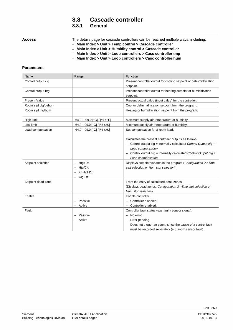
229 / 260
Siemens Climatix AHU Application CE1P3997en Building Technologies Division HMI details pages 2015-10-13
8.8 Cascade controller 8.8.1 General The details page for cascade controllers can be reached multiple ways, including: – Main Index > Unit > Temp control > Cascade controller – Main Index > Unit > Humidity control > Cascade controller – Main Index > Unit > Loop controllers > Casc controller tmp – Main Index > Unit > Loop controllers > Casc controller hum
Name Range Function Control output clg Present controller output for cooling setpoint or dehumidification
setpoint. Control output htg Present controller output for heating setpoint or humidification
setpoint. Present Value Present actual value (input value) for the controller. Room stpt clg/dehum Cool or dehumidification setpoint from the program. Room stpt htg/hum
Heating or humidification setpoint from the program.
High limit -64.0 …99.0 [°C] / [% r.H.] Maximum supply air temperature or humidity. Low limit -64.0…99.0 [°C] / [% r.H.] Minimum supply air temperature or humidity. Load compensation -64.0…99.0 [°C] / [% r.H.] Set compensation for a room load.
Calculates the present controller outputs as follows: – Control output clg = Internally calculated Control Output clg +
Load compensation – Control output htg = Internally calculated Control Output htg +
Load compensation Setpoint selection – Htg+Dz
– Htg/Clg – +/-Half Dz – Clg-Dz
Displays setpoint variants in the program (Configuration 2 >Tmp stpt selection or Hum stpt selection).
Setpoint dead zone
From the entry of calculated dead zones. (Displays dead zones: Configuration 2 >Tmp stpt selection or Hum stpt selection).
Enable – Passive – Active
Enable controller: – Controller disabled. – Controller enabled.
Fault – Passive – Active
Controller fault status (e.g. faulty sensor signal): – No error. – Error pending.
Does not trigger an event, since the cause of a control fault must be recorded separately (e.g. room sensor fault).
Access
Parameters

230 / 260
Siemens Climatix AHU Application CE1P3997en Building Technologies Division HMI details pages 2015-10-13
General, cont'd
Name Range Function Status
– GESP – OG – UG – REG – UDEF
Controller status: – Controller disabled. – Control output = high limit. – Control output = low limit. – Control mode – Undefined
Special settings Go to Special settings page (at access levels 4 and 2 only). 8.8.2 Special settings
Name Range Function Gain 0...1000 Amplification factor (KP). Int action time 0….18000 [s] Integral action time (Tn). Min/max limit -64.0…99.0 [°C] / [% r.H.]
Adjusts high and low limits to end position. Ensures the difference between heating and cooling output in the end position as well as needed.
Min/max limit positive: – Lowest control output clg = low limit + min/max limit – Lowest control output htg = low limit Min/max limit negative: – Lowest control output clg = low limit – Lowest control output htg = low limit + min/max limit Min/max limit positive: – Lowest control output clg = high limit – Lowest control output htg = high limit + min/max limit Min/max limit negative: – Lowest control output clg = high limit + min/max limit – Lowest control output htg = high limit
High limit = 28 Low limit = 16 Min/max limit = -2 Cooling: – Lowest control output clg = low limit ≥ 16 – Lowest control output htg = low limit - min/max limit ≥ 16 – 2 = 14 Heating: – Lowest control output htg = high limit + min/max limit ≥ 28 – 2 = 30 – Lowest control output htg = high limit ≥ 28
Parameters, cont'd
Function during cooling
Function during heating
Example

231 / 260
Siemens Climatix AHU Application CE1P3997en Building Technologies Division HMI details pages 2015-10-13
8.9 Scheduler program, general
This section describes the functions and entries for time switch catalogs and calendars. Possible entries vary depending on the configuration. It is set in Configuration 1: Main Index > Configuration > Configuration 1 > TSP function Main Index > Configuration > Configuration 1 > TSP steps The time switch catalog/calendar available in auxiliary has the set entries Off and On: Main Index > Configuration > Configuration 2 > Aux TSP output The plant can be switched to off or any step (for analog controlled fan, to the given stage setpoint) if no high priority element (e.g. Manual Operation ≠ Auto) is enabled. A maximum of 6 switching entries are possible per week. The calendar Fix Off (in operating mode only) override the calendar exception and this in turn overrides the normal time switch catalog. Up to 10 periods or exception days can be defined for each calendar.
TSP function = Steps+Tmp: The time switch program determines both fan stage setpoint as well as the temperature setpoint (Comfort/Economy).
Content
Possible entries
Calendar in auxiliary
Functions

232 / 260
Siemens Climatix AHU Application CE1P3997en Building Technologies Division HMI details pages 2015-10-13
8.10 Weekly schedule Main Index > Unit > Main overview > Time switch program > Schedule Main Index > Unit > Main setpoints > Time switch program > Schedule Start page > Main overview > Time switch program > Schedule
Name Range Function Present value --- Resulting switching command from the scheduler. Monday – Passive
– Active Display is enabled of the present day is Monday. The last entry for the day applies to 23:59. Go to the daily switching plan for Monday.
Copy schedule – Monday to – Tu to Fr
Copies entries for the time switch program from Monday to Tuesday through Friday: – Passive position (copy disabled). – Copy starts. Returns to display.
Tuesday Similar to Monday. ... ... Sunday Similar to Monday. Exception Displays the enabled command, when the present day is an exception day. Go
to daily switching plan for exception days. Period:Start (Only available at access level 2).
Start date for the weekly schedule. The entry *,* *.00 means that the weekly schedule is always enabled → enable weekly schedule.
Period:Stop (Only available at access level 2). Start date and time for when the weekly schedule no longer applies.
8.11 Daily schedule Main Index > Unit > Main overview > Time switch program > Schedule > Monday....Exception Main Index > Unit > Main setpoints > Time switch program > Schedule > Monday....Exception Start page > Main overview > Time switch program > Schedule > Monday....Exception
Name Range Function Day Schedule
– Passive
– Active
Status of week or exception day in question: – Present week day (system day) does not correspond to the processed
day. – Present week day (system day) corresponds to the processed day.
Time 1 Special case: This entry may not be adjusted; it must always be set to 00:00 and requires password level 4 to change.
Value 1 Switching command for Time 1. Time 2 Switching Time 2.
*: * → entry disabled. Value 2 ... Value 6 Analog value 1. Time 3 ... Time 6 Analog time 2.
Parameter
Parameter

233 / 260
Siemens Climatix AHU Application CE1P3997en Building Technologies Division HMI details pages 2015-10-13
8.12 Exception days and fixed off Exception days are defined in the calendars. These may include certain days, periods or days of the week. On the exception days, the exception days override the weekly schedule. The plant switches per the weekly scheduler under the exceptions set in the daily schedule when an entry is enabled in the calendar exception. The plant switches off when the entry calendar fix Off is enabled. – Main Index > Unit > Main overview > Time switch program > Calendar
exception – Main Index > Unit > Main overview > Time switch program > Calendar fix off – Main Index > Unit > Auxiliary > TSP Output > Calendar exception
Name Range Function Present value
– Passive – Active
Displays whether a calendar entry is currently enabled: – No calendar entry is currently enabled. – A calendar entry is currently enabled.
Choice-x – Date – Range – WeekDay – Passive
Specifies the entry for the exception: – A certain day (e.g. Friday). – A period (e.g. vacation). – A certain day of the week. – Entries are ignored. This value should be set last after the date is entered.
-(Start)date – Choice-x = range: Enter start date for the period. – (Choice-x = date: Enter data for a single day).
-End date Choice-x = range: Enter end date for the period. End date must always be after the start date.
-Week day For Choice-x = weekday only: Enter the day of the week. The following are examples for entries and results: – Choice-x = Date – Choice-1 = Range – Choice-1 = WeekDay Only the entry in (start) is relevant. – -(Start) date = *,01.01.09
Result: January 1, 2009 is an exception day. – -(Start) date = Mo,*.*.00
Each Monday is an exception day. – -(Start) date = *,*.Evn.00
The days for the entire month are exception day for each even month (February, April, June, August, etc.).
Exception days, definition
Exception days, active entries
Fixed off
Path
Examples
Choice-x = Date

234 / 260
Siemens Climatix AHU Application CE1P3997en Building Technologies Division HMI details pages 2015-10-13
Calendar, cont'd.
The entries in (start) date and end date are relevant. • -(Start) date = *,23.06.09 / -End date = *,12.07.09
June 23, 2009 through July 12, 2009 are exception day (e.g. vacation). • -(Start) date = *,23.12.00 / -End date = *,31.12.00
Each year, the days from December 23 through December 31 are exception days. The entry end date = *,01.01.00 does not work here, since January 1 is before December 23.
• -(Start) date = *,23.12.09 / -End date = *,01.01.09 23. December 2009 through 01. January 2010 are exception day.
• -(Start) date = *,*.*.00 / -End date = *,*.*.00 Caution!
This entry is always enabled! The plant is continuously on exception or off. The entries for week day are relevant. • Week day = *,Fr,*
Every Friday is an exception day. • Week day = *,Fr, Evn
Each Friday in even months (February, April, June, August, etc.) is an exception day. • Week day = *,*,*
Caution! This entry is always enabled! The plant is continuously on exception or off.
Examples, cont'd
Choice-1 = Range
Choice-1 = WeekDay

235 / 260
Siemens Climatix AHU Application CE1P3997en Building Technologies Division Alarming 2015-10-13
9 Alarming 9.1 Overview This section describes the reaction to incoming alarms and actions triggered from the alarms. The section provides the following knowledge: – Interpret alarm messages and state indications – Acknowledge and reset alarms. – Set sort criteria for alarm and history list. The topics in the section are: Topic Section Functions and workflows 10.2 Alarm lists detail 10.3 Alarm list, active alarms 10.4 Alarm history 10.5 Alarm lists/history settings 10.6 Alarm lists 10.7
Introduction
Knowledge provided
Topic

236 / 260
Siemens Climatix AHU Application CE1P3997en Building Technologies Division Alarming 2015-10-13
9.2 Functions and workflows The following actions and status indications are listed for incoming alarms, acknowledgements and resets: – Each alarm is reported in clear text, notification class, alarm group, date and time. – Each new alarm generates a line in both the alarm list as well as the history list. – Active alarms:
• The alarm LED flashes on the external HMI. • The alarm bell symbol rings back and forth in the in-built HMI.
– An acknowledge, but still active alarm: • The alarm LED is lit on the external HMI. • The alarm bell symbol is still in the in-built HMI.
– Reset alarms: • Alarm list: Line is deleted. • History list: Display of going alarm.
The following diagrams display the workflows for acknowledgement of unsaved or saved alarms: A. Unsaved alarms:
B. Saved alarms:
Figure 52: Diagram for acknowledge alarms
Active not acceptNormal
Aktivquittiert
NormalAlarm comes Alarm goes
Accept Alarm goes
Flashing OFF
Continuous light
3977
Z02e
n39
77Z0
3en
Inactive accept
Alarm goes
Inactive not accept
NormalAlarm comes Active not
accept
Flashing
Quittieren
Alarm goes Accept
Active accept
Continuous light Continuous light
Normal
OFFFlashingAccept(Resetting)
Actions and state indications
Acknowledge alarms

237 / 260
Siemens Climatix AHU Application CE1P3997en Building Technologies Division Alarming 2015-10-13
Functions and workflows, cont'd The following diagram represents the states and functions of the alarm button relating to detailed info, alarm list, and history list:
Figure 53: Diagram of alarm button function
Alarm LED is flashing
permanently
Press alarm button
Detailed information of last alarm
Press alarm button
History list
Press alarm button
Alarm / history listSettings
Alarm LED flashing
Press alarm button
Press alarm button
No
Yes
No
Yes
3977
Z01e
n
Alarm list
Press alarm button
Press alarm button
Alarm button function

238 / 260
Siemens Climatix AHU Application CE1P3997en Building Technologies Division Alarming 2015-10-13
9.3 Alarm lists detail The Alarm list detail includes the following information on the last occurring alarm:
Line Information 1st line + Alarm name: State 2nd line Notification class 3rd line Date Time of day
Example: + Heating frost tmp: Frost
0 Emerg(A) 15.10.2009 21:32:55
9.4 Alarm list, active alarms Information on the active alarms in the alarm list:
1st line The line displays how many alarms are still not acknowledged: Acknowledge Passive number of unacknowledged alarms. Example: Acknowledge Passive 14 Pressing the setting knob and select Active to acknowledge all unacknowledged alarms or rest the same if the fault as eliminated, but not yet saved.
Other lines
+ Alarm name: State Example: + Supply air temp: Alarm – Press knob: Go to alarm's detail information. – Press alarm knob: Go to the list settings.
List may include up to 50 entries.
Information
Information

239 / 260
Siemens Climatix AHU Application CE1P3997en Building Technologies Division Alarming 2015-10-13
9.5 Alarm history Information on the active and passive alarms in the alarm history:
1st line The line displays how many entries are included in the list: Acknowledge Passive Number of entries. Example: Acknowledge Passive 14 Press setting knobs and select Active to delete all entries from the history list.
Other lines
+ Alarm name: State Example: + Supply air temp: Alarm (coming alarm). - Supply air temp: OK (going alarm). – Press knob: Go to alarm's detail information. – Press alarm knob: Go to the list settings.
List may include up to 50 entries.
9.6 Event history (new add info!!) Information on event history in the alarm history:
Reset Reset the even history list Set order 1
– Time – Object ID – Priority – State
Set order 2 – Time – Object ID – Priority – State
Descending order - Active - passive
List may include up to 50 entries.
Information
Information

240 / 260
Siemens Climatix AHU Application CE1P3997en Building Technologies Division Alarming 2015-10-13
9.7 Alarm lists/history settings No fixed path (the alarm knob is used for example, see diagram in section 9.2 Point tables: Hardware)
Name Range Function Alarm list: Reset Reset/acknowledge pending alarms Sort order 1
– Time – Name – AlarmClass
– State
Main sorting criteria – Sort by data and time. – Sort alphabetically in ascending order. – Sort by notification class (0,1,2,3 corresponding to Danger /
High / Low / Warning). – Sort by status (fault, no fault).
Sort order 2 – Time – Name – AlarmClass – State
Auxiliary sort criteria: See Sort order 1.
Descending order – Passive – Active
Alarms sorted in ascending or descending order. What is the criteria applied for? – Ascending – Descending
Alarm history Reset Deletes history list. Sort order 1 – Time
– Name – AlarmClass – State
Main sorting criteria See Alarm list.
Sort order 2 – Time – Name – AlarmClass – State
Auxiliary sort criteria: See Alarm list.
Descending order – Passive – Active
See Alarm list.
EVENT HISTORY Add info ALARM SNAPSHOT Add info
Parameter

241 / 260
Siemens Climatix AHU Application CE1P3997en Building Technologies Division Alarming 2015-10-13
9.8 Alarm lists 9.8.1 Sort numerically (alarm numbers)
Alarm Text Notification class / group
Alarm no. room unit
Settings 1 Settings 2
Communication test 3/C 1 Time delay 600 s
External setpoint 2/B 20 High Limit 6.0 °C Low Limit -6.0 °C
Time delay 5s
Supplemental alarm 2/B 21 Time delay 0s
Manual mode 2/B 22 Time delay 1800 s
Modbus comm. 2/B 23 Time delay 10 s
Process bus comm. 2/B 23 Time delay 10 s
Room unit temp. 2/B 24 Time delay 17m
Room unit 2 temp. 2/B 24 Time delay 17m
AHU Rturn temp. 2/B 25 Time delay 0s
Room temperature 2/B 26 Time delay 0s
Room temperature 2 2/B 27 Time delay 0s
Extract air temperature 2/B 28 Low Limit -10.0 °C Time delay 0s
Energy recover supply air temperature
2/B 29 Time delay 0s
Supply air temperature 2 2/B 30 Time delay 0s
Supplement temp. 2/B 31 Time delay 0s
Supply air temp. deviation 2/B 32 Max deviation = 10.0 °C Min Limit = 10.0°C StrtUpDly 60 s
Time delay 3600s
RAL temp. deviation 2/B 33 Max deviation = 10.0 °C Min Limit = 10.0°C StrtUpDly 600 s
Time delay 3600 s
H-Reg pump alarm 2/B 34 Time delay 0s
Heating reg. pump RM 2/B 34 StrtUpDly 10 s Time delay 0s
C-Reg 2 CM alarm 2/B 35 Time delay 0s
Cooling register 2 RM 2/B 35 StrtUpDly 10 s Time delay 5s
C-Reg 2 pump alarm 2/B 35 StrtUpDly 30 s Time delay 1s
Cooling register 2 pump RM 2/B 35 Time delay 0s
C-Reg 2 pump alarm 2/B 36 Time delay 0s
Heating reg. 2 pump RM 2/B 36 StrtUpDly 10 s Time delay 0s
Humid. pump alarm 2/B 37 Time delay 0s
Humid. pump RM 2/B 37 StrtUpDly 30 s Time delay 5s
Humidifier RM 2/B 38 StrtUpDly 10 s Time delay 5s
Exhaust air filter alarm 2/B 39 Time delay 0s
Filter alarm 2/B 39 Time delay 0s
Supply air filter alarm 2/B 39 Time delay 0s
Fan op hours alarm 2/B 40 Alarm Lim Op hours 17520 h Time delay 0 s
C-Reg CM alarm 2/B 41 Time delay 0s
C-Reg CM RM 2/B 41 StrtUpDly 30 s Time delay 1s
Cooling register pump Alm 2/B 41 Time delay 0s
Cooling reg. pump RM 2/B 41 StrtUpDly 10 s Time delay 5s
HR Alarm 2/B 42 Time delay 0s
HR pump alarm 2/B 43 Time delay 0s
HR pump RM 2/B 43 StrtUpDly 10 s Time delay 5s

242 / 260
Siemens Climatix AHU Application CE1P3997en Building Technologies Division Alarming 2015-10-13
Alarm list sorted numerically, cont'd
Alarm Text Notification
class / group Alarm no. room unit
Settings 1 Settings 2
HR efficiency 2/B 44 Time delay 600 s
HR damper 2/B 45 Time delay 0 s
Supply air relative humidity 2/B 46 High Limit 100%rel Time delay 0 s
Supply air humidity deviation 2/B 46 Max deviation = 5.0%rel Min Limit = 10.0%rel StrtUpDly 60 s
Time delay 3600 s
AHU relative humidity 2/B 47 High Limit 100%rel Time delay 0 s
RAL humidity deviation 2/B 48 Max deviation = 10.0%rel Min Limit = 10.0%rel StrtUpDly 60 s
Time delay 3600 s
Room air relative humidity 2/B 48 High Limit 100%rel Time delay 0 s
Air quality 2/B 49 High Limit 3000 ppm Time delay 0 s
Supply air temperature 1/A 60 Time delay 0 s
Extract air temperature 2/B 61 Time delay 0 s
Electric reg alarm 1/A 62 Time delay 0 s
Electric reg 2 alarm 1/A 63 Time delay 0 s
Fire dampers closed 1/A 64 Start delay = Closing Time * 1.15 Time delay 5 s
Fire damper change 1/A 64 Time delay 5 s
Fire damper open 1/A 64 Start delay = Opening Time * 1.15 Time delay 5 s
Extract air damper RM 1/A 65 StrtUpDly 180 s Time delay 5 s
Extract air damper RM 1/A 65 StrtUpDly 180 s Time delay 5 s
Fan alarm 1/A 66 Time delay 0 s
Supply air fan alarm 1/A 66 Time delay 0 s
Supply air fan RM 1/A 66 StrtUpDly 60 s Time delay 5 s
Extract air fan alarm 1/A 67 Time delay 0 s
Extract air fan RM 1/A 67 StrtUpDly 30 s Time delay 5 s
Dew point 0/A 68 Time delay 0 s
Supply air fan deviation 0/A 69 StrtUpDly 180 s Time delay 60 s
Supply air flow 0/A 69 High Limit 40000 l/s Time delay 10 s
Supply air pressure 0/A 69 High Limit 5000 Pa Time delay 10 s
Extract air fan deviation 0/A 70 StrtUpDly 180 s Time delay 60 s
Extract air flow 0/A 70 High Limit 20000 l/s Time delay 10 s
Extract air pressure 0/A 70 High Limit 5000 Pa Time delay 10 s
Extract air temp. fire alarm 1/A 81 Limit 50 °C Time delay 2 s
Supply air temp. fire alarm 1/A 81 Limit 70 °C Time delay 2 s
Fire alarm 0/A 81 Time delay 0 s
H-Reg frost temp 1/A 82 Low Limit 5.0 °C Time delay 0 s
Heat recovery water temp. 1/A 83 Low Limit -2.0 °C Time delay 0 s
H-Reg 2 frost temp 1/A 84 Low Limit 5.0 °C Time delay 0 s
H-Reg frost detector 1/A 85 Time delay 0 s
H-Reg 2 frost detector 1/A 86 Time delay 0 s
HR frost detector 1/A 87 Time delay 1200 s
HR frost pressure 1/A 87 High Limit 5000 Pa Time delay 0 s
Conf. alarm H-Reg 2 0/not Exist Time delay 0 s
Duplicate config IO 0/not Exist Time delay 0 s
Unconfigured IO 0/not Exist Time delay 0 s
IO auxiliary module 0/A Time delay 0 s

243 / 260
Siemens Climatix AHU Application CE1P3997en Building Technologies Division Alarming 2015-10-13
9.8.2 Alphabetically (Alarm names)
Alarm text Notification class / group
Alarm no. room unit
Settings 1 Settings 2
Extract air pressure 0/A 70 High Limit 5000 Pa Time delay 10 s
Extract air filter alarm 2/B 39 Time delay 0 s
Extract air filter alarm analog 2/B 39 High Limit 5000 Pa Time delay 600 s
Extract air flow 0/A 70 High Limit 20000 l/s Time delay 10 s
Extract air temp. fire alarm 1/A 81 Limit 50 °C Time delay 2 s
Extract air temperature 2/B 61 Time delay 0 s
Extract air fan deviation 0/A 70 StrtUpDly 180 s Time delay 60 s
Extract air fan alarm 1/A 67 Time delay 0 s
Extract air fan RM 1/A 67 StrtUpDly 30 s Time delay 5 s
AHU relative humidity 2/B 47 High Limit 100%rel Time delay 0 s
Extract air damper RM 1/A 65 StrtUpDly 180 s Time delay 5 s
AHU Rturn temp. 2/B 25 Time delay 0 s
Humid. pump alarm 2/B 37 Time delay 0 s
Humid. pump RM 2/B 37 StrtUpDly 30 s Time delay 5 s
Humidifier RM 2/B 38 StrtUpDly 10 s Time delay 5 s
Fire alarm 0/A 81 Time delay 0 s
Fire damper open 1/A 64 Start delay = Opening Time * 1.15 Time delay 5 s
Fire dampers closed 1/A 64 Start delay = Closing Time * 1.15 Time delay 5 s
Fire damper change 1/A 64 Time delay 5 s
Duplicate config IO 0/not Exist Time delay 0 s
Electric reg 2 alarm 1/A 63 Time delay 0 s
Electric reg alarm 1/A 62 Time delay 0 s
External setpoint 2/B 20 High Limit 6.0 °C Low Limit -6.0 °C
Time delay 5 s
Filter alarm 2/B 39 Time delay 0 s
Extract air damper RM 1/A 65 StrtUpDly 180 s Time delay 5 s
Extract air temperature 2/B 28 Low Limit -10.0 °C Time delay 0 s
Heating reg. 2 pump RM 2/B 36 StrtUpDly 10 s Time delay 0 s
Heating reg. pump RM 2/B 34 StrtUpDly 10 s Time delay 0 s
H-Reg 2 frost temp 1/A 84 Low Limit 5.0 °C Time delay 0 s
H-Reg 2 frost detector 1/A 86 Time delay 0 s
H-Reg frost temp 1/A 82 Low Limit 5.0 °C Time delay 0 s
H-Reg frost detector 1/A 85 Time delay 0 s
H-Reg pump alarm 2/B 34 Time delay 0 s
IO auxiliary module 0/A Time delay 0 s
Communication test 3/C 1 Time delay 600 s
Conf. alarm H-Reg 2 0/not Exist Time delay 0 s
C-Reg 2 pump alarm 2/B 35 StrtUpDly 30 s Time delay 1 s
C-Reg 2 pump alarm 2/B 36 Time delay 0 s
C-Reg 2 CM alarm 2/B 35 Time delay 0 s
Cooling register 2 pump RM 2/B 35 Time delay 0 s
C-Reg CM alarm 2/B 41 Time delay 0 s
C-Reg CM RM 2/B 41 StrtUpDly 30 s Time delay 1 s
Cooling register pump Alm 2/B 41 Time delay 0 s
Cooling reg. pump RM 2/B 41 StrtUpDly 10 s Time delay 5 s

244 / 260
Siemens Climatix AHU Application CE1P3997en Building Technologies Division Alarming 2015-10-13
Alarm list sorted alphabetically, cont'd
Alarm text Notification class/group
Alarm no. room unit
Settings 1 Settings 2
Cooling register 2 RM 2/B 35 StrtUpDly 10 s Time delay 5 s
Air quality 2/B 49 High Limit 3000 ppm Time delay 0 s
Manual mode 2/B 22 Time delay 1800 s
Modbus comm. 2/B 23 Time delay 10 s
Unconfigured IO 0/not Exist Time delay 0 s
Process bus comm. 2/B 23 Time delay 10 s
RAL humidity deviation 2/B 48 Max deviation = 10.0%rel Min Limit = 10.0%rel StrtUpDly 60 s
Time delay 3600 s
RAL temp. deviation 2/B 33 Max deviation = 10.0 °C Min Limit = 10.0 °C StrtUpDly 600 s
Time delay 3600 s
Room air relative humidity 2/B 48 High Limit 100%rel Time delay 0 s
Room unit 2 temp. 2/B 24 Time delay 17 m
Room unit temp. 2/B 24 Time delay 17 m
Room temperature 2/B 26 Time delay 0 s
Room temperature 2 2/B 27 Time delay 0 s
Dew point 0/A 68 Time delay 0 s
Fan op hours alarm 2/B 40 Alarm Lim Op hours 17520 h Time delay 0 s
Fan alarm 1/A 66 Time delay 0 s
HR Alarm 2/B 42 Time delay 0 s
HR frost detector 1/A 87 Time delay 1200 s
HR frost pressure 1/A 87 High Limit 5000 Pa Time delay 0 s
HR damper 2/B 45 Time delay 0 s
HR pump alarm 2/B 43 Time delay 0 s
HR pump RM 2/B 43 StrtUpDly 10 s Time delay 5 s
Heat recovery water temp. 1/A 83 Low Limit -2.0 °C Time delay 0 s
HR efficiency 2/B 44 Time delay 600 s
Energy recover supply air temperature
2/B 29 Time delay 0 s
Supply air pressure 0/A 69 High Limit 5000 Pa Time delay 10 s
Supply air humidity deviation 2/B 46 Max deviation = 5.0%rel Min Limit = 10.0%rel StrtUpDly 60 s
Time delay 3600 s
Supply air relative humidity 2/B 46 High Limit 100%rel Time delay 0 s
Supply air filter alarm 2/B 39 Time delay 0 s
Supply air filter alarm analog 2/B 39 High Limit 5000 Pa Time delay 600 s
Supply air flow 0/A 69 High Limit 40000 l/s Time delay 10 s
Supply air temp. deviation 2/B 32 Max deviation = 10.0 °C Min Limit = 10.0 °C StrtUpDly 60 s
Time delay 3600 s
Supply air temp. fire alarm 1/A 81 Limit 70 °C Time delay 2 s
Supply air temperature 1/A 60 Time delay 0 s
Supply air temperature 2 2/B 30 Time delay 0 s
Supply air fan deviation 0/A 69 StrtUpDly 180 s Time delay 60 s
Supply air fan alarm 1/A 66 Time delay 0 s
Supply air fan RM 1/A 66 StrtUpDly 60 s Time delay 5 s
Supplemental alarm 2/B 21 Time delay 0 s
Supplement temp. 2/B 31 Time delay 0 s

245 / 260
Siemens Climatix AHU Application CE1P3997en Building Technologies Division Appendices 2015-10-13
10 Appendices 10.1 Overview The following pages include: • Auxiliary tables that can be used when configuring • Diagram and tables for reference purposes The topics in the section are: Topic Section Point tables: Hardware 11.2 Diagnostics tables for I/O check 11.3 Navigation images HMI 11.4 Parameter list room unit 11.5
Introduction
Topics

246 / 260
Siemens Climatix AHU Application CE1P3997en Building Technologies Division Appendices 2015-10-13
10.2 Point tables: Hardware As a matter of principle, we recommend the following configuration procedure:
Step Job 1 During configuration (Configuration 1 and Configuration 2) all required I/Os in the table
must be executed using the following templates. 2 Clean up the tables prior to starting I/O configuration. 3 Conduct I/O configuration per the table.
This ensures that: – the plant on the basis controller and the planned extension modules fit. – It is evident at all times which terminals used for the required inputs and outputs. Hardware assignment of the basis controller POL683x
IO Function IO type Connection Comments Digital outputs Q1 Digital T6 (Q13,Q14) Q2 Digital T6 (Q23,Q24) Q3 Digital T6 (Q33,Q34) Q4 Digital T6 (Q43,Q44) Q5 Digital T7 (Q53,Q54) Q6 Digital T7 (Q63,Q64)
Analog outputs Y1 0...10 V DC T3 (Y1,M) Y2 0...10 V DC T3 (Y2,M) Binary inputs DI1 Digital T4 (D1,M) DI2 Digital T4 (D2,M) DI3 Digital T4 (D3,M) DI4 Digital T4 (D4,M) DI5 Digital T4 (D5,M) Universal inputs X1 T2 (X1,M) X2 T2 (X2,M) Universal inputs / outputs X3 T2 (X3,M) X4 T2 (X4,M) X5 T2 (X5,M) X6 T2 (X6,M) X7 T2 (X7,M) X8
Note the following for universal I/Os: – Universals I/Os X1 and X2 can be configured exclusively as inputs (digital,
Ni1000, Pt1000, NTC10K, 0-10 V DC). – Universals I/Os X3 – X8 can be configured as inputs (digital, Ni1000, Pt1000,
NTC10K, 0-10 V DC) or outputs 0-10 V DC.
Procedure for configuration
Basis controller

247 / 260
Siemens Climatix AHU Application CE1P3997en Building Technologies Division Appendices 2015-10-13
Point tables, cont'd. Hardware assignment of extension module POL955 with address 1
IO Function IO type Connection Comments Digital outputs Q11 Digital T3 (Q13,Q14) Q12 Digital T3 (Q23,Q24) Q13 Digital T3 (Q33,Q34) Q14 Digital T4 (Q43,Q44) Analog outputs Y11 0...10 V DC T5 (Y1,M) Y12 0...10 V DC T5 (Y2,M) Universal inputs / outputs X11 T1 (X1,M) X12 T1 (X2,M) X13 T1 (X3,M) X14 T1 (X4,M) X15 T2 (X5,M) X16 T2 (X6,M) X17 T2 (X7,M) X18 T2 (X8,M)
Universals I/Os X11 – X18 can be configured as inputs (digital, Ni1000, Pt1000, NTC10K, 0-10 V DC) or outputs 0-10 V DC.
Hardware assignment of extension module POL955 with address 2
IO Function IO type Connection Comments Digital outputs Q21 Digital T3 (Q13,Q14) Q22 Digital T3 (Q23,Q24) Q23 Digital T3 (Q33,Q34) Q24 Digital T4 (Q43,Q44) Analog outputs Y21 0...10 V DC T5 (Y1,M) Y22 0...10 V DC T5 (Y2,M) Universal inputs / outputs X21 T1 (X1,M) X22 T1 (X2,M) X23 T1 (X3,M) X24 T1 (X4,M) X25 T2 (X5,M) X26 T2 (X6,M) X27 T2 (X7,M) X28 T2 (X8,M)
Universals I/Os X21 – X28 can be configured as inputs (digital, Ni1000, Pt1000, NTC10K, 0-10 V DC) or outputs 0-10 V DC.
Extension module 1
Extension module 2

248 / 260
Siemens Climatix AHU Application CE1P3997en Building Technologies Division Appendices 2015-10-13
10.3 Diagnostics tables for I/O check Clear text can be determined from the following tables: – Not configured, but the required inputs/outputs for a function. – Inputs/outputs that are assigned twice. 1rst notconf IO Pos = 82 Input external control 2 is not assigned an input (Nusd).
Caution: The plant is locked against switch on!
Doubled config IO = Yes Doubled config IOs = 82 81 Doubled conf IO pos = DI3 Meaning: Inputs External contrl 1 and External contrl 2 were assigned the same
output DI3.
Caution: The plant is locked against switch on!
Name Type Position (IO
Check)
Name Type Position (IO
Check) Temperature supply AI 1 Pressure supply AI 21 Temperature room 1 AI 2 Pressure return AI 22 Temperature rum 2 AI 3 Flow supply AI 23 Temperature return AI 4 Flow return AI 24 Temperature out AI 5 Pressure over recovery AI 25 Temperature frost AI 6 Suply Filter Alarm Prs AI 26 Temperature water recovery AI 7 Extract Filter Alarm Prs AI 27 Temperature extract AI 8 Humidity supply AI 31 Temperature supply after recovery AI 9 Humidity room AI 32 Temperature supply Extra seq. AI 10 Humidity out AI 33 Temperature frost Extra heat AI 11 Air quality AI 35 Temperature Aux AI 12 External setpoint AI 36
STOP
STOP
Purpose
Example 1
Example 2
Analog inputs
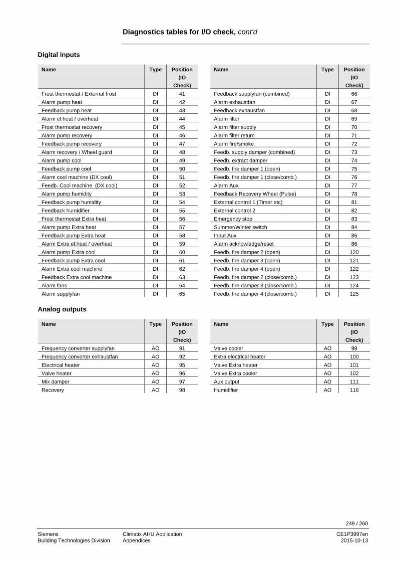
249 / 260
Siemens Climatix AHU Application CE1P3997en Building Technologies Division Appendices 2015-10-13
Diagnostics tables for I/O check, cont'd
Name Type Position (IO
Check)
Name Type Position (IO
Check) Frost thermostat / External frost DI 41 Feedback supplyfan (combined) DI 66 Alarm pump heat DI 42 Alarm exhaustfan DI 67 Feedback pump heat DI 43 Feedback exhaustfan DI 68 Alarm el.heat / overheat DI 44 Alarm filter DI 69 Frost thermostat recovery DI 45 Alarm filter supply DI 70 Alarm pump recovery DI 46 Alarm filter return DI 71 Feedback pump recovery DI 47 Alarm fire/smoke DI 72 Alarm recovery / Wheel guard DI 48 Feedb. supply damper (combined) DI 73 Alarm pump cool DI 49 Feedb. extract damper DI 74 Feedback pump cool DI 50 Feedb. fire damper 1 (open) DI 75 Alarm cool machine (DX cool) DI 51 Feedb. fire damper 1 (close/comb.) DI 76 Feedb. Cool machine (DX cool) DI 52 Alarm Aux DI 77 Alarm pump humidity DI 53 Feedback Recovery Wheel (Pulse) DI 78 Feedback pump humidity DI 54 External control 1 (Timer etc) DI 81 Feedback humidifier DI 55 External control 2 DI 82 Frost thermostat Extra heat DI 56 Emergency stop DI 83 Alarm pump Extra heat DI 57 Summer/Winter switch DI 84 Feedback pump Extra heat DI 58 Input Aux DI 85 Alarm Extra el.heat / overheat DI 59 Alarm acknowledge/reset DI 86 Alarm pump Extra cool DI 60 Feedb. fire damper 2 (open) DI 120 Feedback pump Extra cool DI 61 Feedb. fire damper 3 (open) DI 121 Alarm Extra cool machine DI 62 Feedb. fire damper 4 (open) DI 122 Feedback Extra cool machine DI 63 Feedb. fire damper 2 (close/comb.) DI 123 Alarm fans DI 64 Feedb. fire damper 3 (close/comb.) DI 124 Alarm supplyfan DI 65 Feedb. fire damper 4 (close/comb.) DI 125
Name Type Position (IO
Check)
Name Type Position (IO
Check) Frequency converter supplyfan AO 91 Valve cooler AO 99 Frequency converter exhaustfan AO 92 Extra electrical heater AO 100 Electrical heater AO 95 Valve Extra heater AO 101 Valve heater AO 96 Valve Extra cooler AO 102 Mix damper AO 97 Aux output AO 111 Recovery AO 98 Humidifier AO 116
Digital inputs
Analog outputs

250 / 260
Siemens Climatix AHU Application CE1P3997en Building Technologies Division Appendices 2015-10-13
Diagnostics tables for I/O check, cont'd
Name Type Position (IO
Check)
Name Type Position (IO
Check) Supply damper (combined) DO 131 DX cooling output 1 DO 150 Extract damper DO 132 DX cooling output 2 DO 151 Fire damper DO 133 Extra electrical heater output 1 DO 152 Supply fan output 1 DO 136 Extra electrical heater output 2 DO 153 Supply fan output 2 DO 137 Pump Extra heating DO 154 Supply fan output 3 DO 138 Pump Extra cooling DO 155 Extract fan output 1 DO 139 DX cooling extra cooler output 1 DO 156 Extract fan output 2 DO 140 DX cooling Extra cooler output 2 DO 157 Extract fan output 3 DO 141 Aux time switch program DO 165 Electrical heater output 1 DO 145 Aux operation mode indication DO 166 Electrical heater output 2 DO 146 Alarm output High/A (combined) DO 168 Pump heater DO 147 Alarm output Low/B DO 169 Pump/Maneuver recovery DO 148 Humidifier DO 171 Pump cooler DO 149 Pump humidity DO 172
Digital outputs
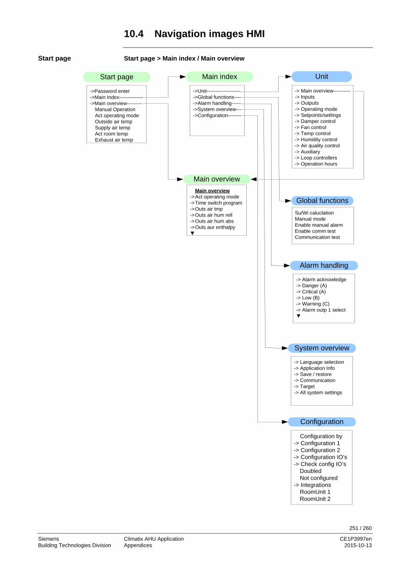
251 / 260
Siemens Climatix AHU Application CE1P3997en Building Technologies Division Appendices 2015-10-13
10.4 Navigation images HMI Start page > Main index / Main overview
->Unit-------------------- ->Global functions----->Alarm handling------>System overview---->Configuration--------
Main index
System overview
Unit
-> Main overview-----------> Inputs-> Outputs-> Operating mode-> Setpoints/settings-> Damper control-> Fan control-> Temp control-> Humidity control-> Air quality control-> Auxiliary-> Loop controllers-> Operation hours
Configuration
Configuration by-> Configuration 1-> Configuration 2-> Configuration IO’s-> Check config IO’s
DoubledNot configured
-> IntegrationsRoomUnit 1RoomUnit 2
-> Language selection-> Application Info-> Save / restore-> Communication-> Target-> All system settings
Su/Wi caluclationManual modeEnable manual alarmEnable comm testCommunication test
Global functions
->Password enter ->Main Index--------------->Main overview---------
Manual OperationAct operating modeOutside air tempSupply air tempAct room tempExhaust air temp
Start page
Main overview->Act operating mode->Time switch program->Outs air tmp ->Outs air hum rell->Outs air hum abs->Outs aur enthalpy▼
Main overview
Alarm handling
-> Alarm acknowledge-> Danger (A)-> Critical (A)-> Low (B)-> Warning (C)-> Alarm outp 1 select▼
Start page

252 / 260
Siemens Climatix AHU Application CE1P3997en Building Technologies Division Appendices 2015-10-13
Navigation images HMI, cont'd Start page > Main index > Unit
Setpoints/Settings-> All settings->Time switch program
Comfort tmp stptComfort tmp stptEconomy tmp stptEconomy tmp stpt
▼
Operating ModeActualManual operation
->Time switch program From Bms-> External control-> Night kick-> Night cooling-> Tmp Start-> Boost Power up delay
Fan control-> Supply fan -> Exhaust fan
Actual stepFire modeFire setpointSlave offset
▼
Temp controlAct controlled tmp
->Tmp setpoints->Cascade controller->Min/max ctrlr sply->Hrec damper->Heat recovery->Heating->Electrical heating->Cooling->Heating 2->El Heating 2->Cooling 2->Fan heating->Fan Cooling->Fan compensation
Damper controlOff delay by fan off
->Damper->Fire damper
Loop controllers-> Supply fan-> Exhaust fan-> Air quality-> Casc controller tmp-> Min supply tmp▼
Unit
-> Main overview-----------> Inputs----------------------> Outputs-------------------> Operating mode--------> Setpoints/settings------> Damper control---------> Fan control---------------> Temp control------------> Humidity control--------> Air quality control-------> Auxiliary-------------------> Loop controllers---------> Operation hours-------
Humidity control Act controlled hum
->Setpoints->Cascade controller->Max controller sply->Humidifiaction▼
Operating hours-> Supply Fan -> ExhFan
Fan SettingsHrec (pump) cmdHeating pump
▼
Main overview->Act operating mode->Time switch program->Outs air tmp ->Outs air hum rell->Outs air hum abs->Outs aur enthalpy▼
Inputs->Temperatures->Pressures/flows->Humidity->Other->Digital inputs->Digital alarms
Outputs->Digital outputs->Analog outputs
AirQuality control ->Controller
FunctionSetpoint
Auxiliary ->TSP output->Analog Output
A outp fan step 0A outp fan step 1A outp fan step 2
▼
Device

253 / 260
Siemens Climatix AHU Application CE1P3997en Building Technologies Division Appendices 2015-10-13
Navigation images HMI, cont'd Start page > Main index > System overview
All System Settings-> Language selection-> Communications-> Password handling-> Application info-> Summer/winter time-> HMI-> Settings save/restore -> Target-> Diagnostic-> Diag object handler
Language selectionCurrent language
Communications->Process bus->Tcp/IP->Modbus->LON->Modem->SMS->IO extension bus->Comm module
overview
Password handlingLog inLog offChange user pwd
Application info[Customer]Standard AHUyyyy-mm-ddNameStreetCity
->Settings
Summer/winter timeEnableActiveB-Time activeTimeStart week dayStart offset▼
HMICurrent languageReset TimeBrightness inbuiltContrast inbuiltMessage duration...
->Special Settings
Settings save/restoreParameter saveParameter loadSet service loadSet factory loadSet service saveSet factory save▼
TargetImperial unit sysBSP versionReset counter::
->Special settings▼
DiagnosticSet service loadCycle time actualCycle time avg.::
->Special settings▼
Diag object handlerActual objectsAct object memory Act internal memory COV act clientsALH act clientsValid objects▼
System overview
-> Language selection-> Application Info-> Save / restore-> Communication-> Target-> All system settings
System overview

254 / 260
Siemens Climatix AHU Application CE1P3997en Building Technologies Division Appendices 2015-10-13
Navigation images HMI, cont'd Start page > Main index > Configuration
Configuration 1General:Extension modulesFire alarmFilter alarmEmergency stopAlarm ackn input▼
Configuration IO’s-> Temperatures-> Pressures / flows-> Humidity-> Digital inputs-> Digital alarms-> Other-> Outputs damper-> Outputs fans-> Outputs tmp control-> Outputs humidifier-> Outputs auxiliary-> Outputs alarmConfiguration IO’sReset required !!
TemperaturesSupply airRoomRoom 2Exhaust airOutside airHeating frost▼
Configuration 2Night coolingTmp startBoostTmp start/OSSTP blkDamper fdbkFan steps freq conv▼
Pressures/flowsSupply air pressureExhaust air pressSupply air flowExhaust air flowHrec frost pressure
HumiditySupply airRoomOutside air
Digital InputsExternal control 1External control 2Emergency stopSu/Wi inputAlarm ackn buttonAuxiliary input
Output fansSupply fan D01Supply fan D02Supply fan D03Exhaust fan D01Exhaust fan D02Exhaust fan D03▼
Outputs tmp controlEl heating A0El heating D01El heating D02Heating A0Heating pump D0Hrec damper A0▼
Outputs humidifierHumidifier A0Humidifier D0Humidifier pump D0
Outputs auxiliaryAuxilary A outpTSP output D0Aux op mode ind D0
Outputs alarmsAlarm D01Alarm D02
Outputs damperOuts air damper D0Extr air damper D0Fire damper D0
OtherAir quality sensorExternal setpoint
Configuration
Configuration by-> Configuration 1-> Configuration 2-> Configuration IO’s-> Check config IO’s
DoubledNot configured
-> IntegrationsRoomUnit 1RoomUnit 2
Digital alarmsAlarm limit thermHtg frost monitorHeating pumpHeating pump fdbkElectrical heatingHrec frost monitor▼
Configuration

255 / 260
Siemens Climatix AHU Application CE1P3997en Building Technologies Division Appendices 2015-10-13
10.5 Parameter list room unit To enter the parameter list, password needs to enter.
Parameter Group/ID
Description Access level for writing
S1 Diagnostic / reset 6
S2 Device / acknowledge all 2
S11 Addr building 4
S12 Addr line 4
S13 Addr device 4
S20 Presence time 6
S21 Apartment 4
S22 Alarm mode 4
S23 OffIsBlckd 6
S24 Displayed roomtemperature 6
S25 Back2Auto Off-Eco 6
S26 Back2Auto Off-Cmf 6
S27 Back2Auto Eco-Cmf 6
S28 Back2Auto Cmf-Eco 6
S29 Back2Auto Cmf-Off 6
S30 Back2Auto Eco-Off 6
S31 Manual control 4
S32 Heatrecovery display limitation 4
S33 Setpoint range +/- 4
S34 Setpoint increment 4
S35 Time format 4
A1 Actual operating mode X
A2 Actual fan step X
A3 Outside air temperature X
A4 Actual valid room temperature X
A5 Supply air temperature X
A6 Extract air temperature X
A7 Actual control mode temperature X
A8 Actual value controlled temperature X
A9 Actual cooling setpoint X
A10 Actual heating setpoint X
A11 Actual supply cooling setpoint X
A12 Actual supply heating setpoint X
A13 Cooling output signal X
A14 Heatrecovery damper recovery value X
A15 Heatrecovery output signal X
A16 Heating output signal X
A17 Electrical heating output signal X
A18 Actual control mode humidity X
A19 Actual value controlled humidity X
A20 Actual dehumidity setpoint X
A21 Actual humidity setpoint X
A22 Actual supply dehumidity setpoint X
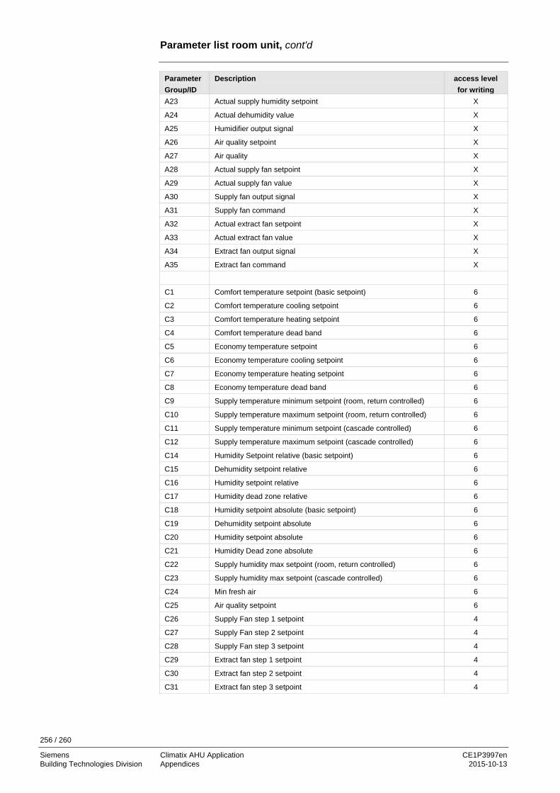
256 / 260
Siemens Climatix AHU Application CE1P3997en Building Technologies Division Appendices 2015-10-13
Parameter list room unit, cont'd
Parameter Group/ID
Description access level for writing
A23 Actual supply humidity setpoint X
A24 Actual dehumidity value X
A25 Humidifier output signal X
A26 Air quality setpoint X
A27 Air quality X
A28 Actual supply fan setpoint X
A29 Actual supply fan value X
A30 Supply fan output signal X
A31 Supply fan command X
A32 Actual extract fan setpoint X
A33 Actual extract fan value X
A34 Extract fan output signal X
A35 Extract fan command X
C1 Comfort temperature setpoint (basic setpoint) 6
C2 Comfort temperature cooling setpoint 6
C3 Comfort temperature heating setpoint 6
C4 Comfort temperature dead band 6
C5 Economy temperature setpoint 6
C6 Economy temperature cooling setpoint 6
C7 Economy temperature heating setpoint 6
C8 Economy temperature dead band 6
C9 Supply temperature minimum setpoint (room, return controlled) 6
C10 Supply temperature maximum setpoint (room, return controlled) 6
C11 Supply temperature minimum setpoint (cascade controlled) 6
C12 Supply temperature maximum setpoint (cascade controlled) 6
C14 Humidity Setpoint relative (basic setpoint) 6
C15 Dehumidity setpoint relative 6
C16 Humidity setpoint relative 6
C17 Humidity dead zone relative 6
C18 Humidity setpoint absolute (basic setpoint) 6
C19 Dehumidity setpoint absolute 6
C20 Humidity setpoint absolute 6
C21 Humidity Dead zone absolute 6
C22 Supply humidity max setpoint (room, return controlled) 6
C23 Supply humidity max setpoint (cascade controlled) 6
C24 Min fresh air 6
C25 Air quality setpoint 6
C26 Supply Fan step 1 setpoint 4
C27 Supply Fan step 2 setpoint 4
C28 Supply Fan step 3 setpoint 4
C29 Extract fan step 1 setpoint 4
C30 Extract fan step 2 setpoint 4
C31 Extract fan step 3 setpoint 4
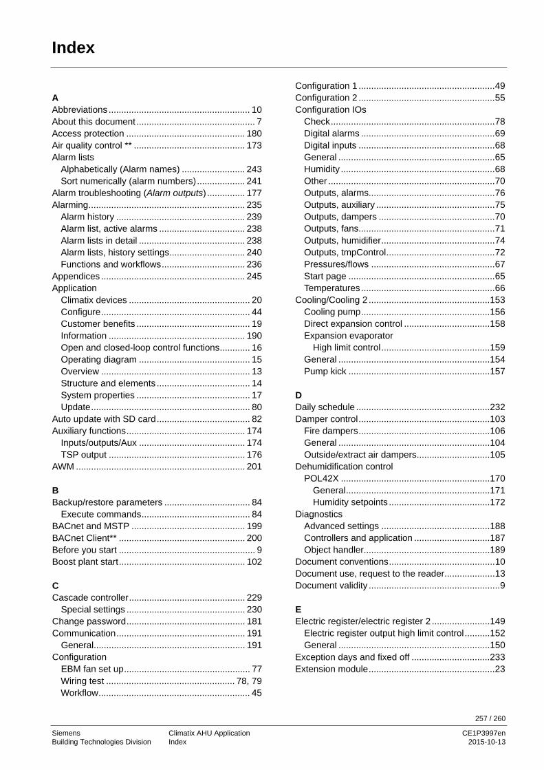
257 / 260
Siemens Climatix AHU Application CE1P3997en Building Technologies Division Index 2015-10-13
Index
A Abbreviations ........................................................ 10 About this document ............................................... 7 Access protection ............................................... 180 Air quality control ** ............................................ 173 Alarm lists
Alphabetically (Alarm names) ......................... 243 Sort numerically (alarm numbers) ................... 241
Alarm troubleshooting (Alarm outputs) ............... 177 Alarming .............................................................. 235
Alarm history ................................................... 239 Alarm list, active alarms .................................. 238 Alarm lists in detail .......................................... 238 Alarm lists, history settings .............................. 240 Functions and workflows ................................. 236
Appendices ......................................................... 245 Application
Climatix devices ................................................ 20 Configure ........................................................... 44 Customer benefits ............................................. 19 Information ...................................................... 190 Open and closed-loop control functions ............ 16 Operating diagram ............................................ 15 Overview ........................................................... 13 Structure and elements ..................................... 14 System properties ............................................. 17 Update ............................................................... 80
Auto update with SD card ..................................... 82 Auxiliary functions ............................................... 174
Inputs/outputs/Aux .......................................... 174 TSP output ...................................................... 176
AWM ................................................................... 201
B Backup/restore parameters .................................. 84
Execute commands ........................................... 84 BACnet and MSTP ............................................. 199 BACnet Client** .................................................. 200 Before you start ...................................................... 9 Boost plant start .................................................. 102
C Cascade controller .............................................. 229
Special settings ............................................... 230 Change password ............................................... 181 Communication ................................................... 191
General ............................................................ 191 Configuration
EBM fan set up .................................................. 77 Wiring test ................................................... 78, 79 Workflow ............................................................ 45
Configuration 1 ...................................................... 49 Configuration 2 ...................................................... 55 Configuration IOs
Check ................................................................. 78 Digital alarms ..................................................... 69 Digital inputs ...................................................... 68 General .............................................................. 65 Humidity ............................................................. 68 Other .................................................................. 70 Outputs, alarms.................................................. 76 Outputs, auxiliary ............................................... 75 Outputs, dampers .............................................. 70 Outputs, fans ...................................................... 71 Outputs, humidifier ............................................. 74 Outputs, tmpControl ........................................... 72 Pressures/flows ................................................. 67 Start page .......................................................... 65 Temperatures ..................................................... 66
Cooling/Cooling 2 ................................................ 153 Cooling pump ................................................... 156 Direct expansion control .................................. 158 Expansion evaporator
High limit control ........................................... 159 General ............................................................ 154 Pump kick ........................................................ 157
D Daily schedule ..................................................... 232 Damper control .................................................... 103
Fire dampers .................................................... 106 General ............................................................ 104 Outside/extract air dampers ............................. 105
Dehumidification control POL42X ........................................................... 170
General ......................................................... 171 Humidity setpoints ........................................ 172
Diagnostics Advanced settings ........................................... 188 Controllers and application .............................. 187 Object handler.................................................. 189
Document conventions .......................................... 10 Document use, request to the reader .................... 13 Document validity .................................................... 9
E Electric register/electric register 2 ....................... 149
Electric register output high limit control .......... 152 General ............................................................ 150
Exception days and fixed off ............................... 233 Extension module .................................................. 23

258 / 260
Siemens Climatix AHU Application CE1P3997en Building Technologies Division Index 2015-10-13
F Fan control .......................................................... 108
Configure fan functions ................................... 109 Deviation alarms .............................................. 118 Fan compensation ........................................... 119 Fan modes ...................................................... 113 Operating hours monitoring ............................. 118 Summer/winter compensation ......................... 117 Supply air/extract air control ............................ 115
Filter ...................................................................... 49 Free cooling ........................................................ 100 Functions, higher .................................................. 87 Functions, higher general parameters .................. 87 Functions, higher summer/winter changeover ...... 88
H Heat recovery with heat exchanger .................... 135
Frost protection ............................................... 141 General ............................................................ 136 Heat recovery pump ........................................ 139 Pump kick ........................................................ 140
Heat recovery with mixed air damper Overview ......................................................... 132 Properties ........................................................ 132 Settings............................................................ 133 Startup behavior .............................................. 134
Heating/heating 2 Pump kick ........................................................ 146
Heating/Heating 2 ............................................... 142 General ............................................................ 143 Heat pump ....................................................... 145 Heating register frost protection ...................... 147 Preheat heating register .................................. 148
HMI External ............................................................. 26 Info LED........................................................... 186 Integrated .......................................................... 26 Main settings ................................................... 185 Navigation images ........................................... 251 Passwords ......................................................... 28 Special settings ............................................... 185
Humidity control POL63X ........................................................... 160
Deviation alarms .......................................... 165 Fan compensation ....................................... 169 Humidification controller .............................. 166 Humidifier pump ........................................... 167 Humidifier pump kick ................................... 168 Maximum supply air humidity ...................... 165 Setpoints ...................................................... 164
Humidity control POL63X General ............................................................ 161
I I/O check, diagnostics tables .............................. 248 Inputs
Analog ............................................................. 219 Digital .............................................................. 223 Special information ......................................... 222 Special settings ............................................... 220
Inputs digital Special information ......................................... 226 Special settings ............................................... 224
Inputs/outputs/Aux .............................................. 174
L Languages, supported ........................................ 182 LON
Commission external interface LON ............... 198 Commission internal interface ........................ 197
LON ** ................................................................ 197
M Modbus ............................................................... 196 Modem / SMS ** ................................................. 202
Function .......................................................... 202 Modem/SMS function, commission ............ 194, 200
N Night kick function ................................................ 99
O Operating levels .................................................. 180 Operating mode .................................................... 89
Boost function ................................................. 102 External control ................................................. 97 Fan cooling ..................................................... 100 General ............................................................. 90 Kick function ...................................................... 99 Operating diagrams .......................................... 93 Scheduler program ........................................... 96 Temperature difference start ........................... 101
Optimum start/stop function ............................... 102 Output
Analogs ........................................................... 209 Priority range .................................................... 211 Special information ......................................... 210 Special settings ............................................... 210
Outputs Digital .............................................................. 212 Multi-stage ...................................................... 215
Outputs digital Priority range ................................................... 214 Special information ......................................... 213 Special settings ............................................... 213
Outputs multi-stage Priority range ................................................... 217 Special information ......................................... 216
Overview ................................................................. 7
P Pages HMI details .............................................. 208

259 / 260
Siemens Climatix AHU Application CE1P3997en Building Technologies Division Index 2015-10-13
Overview ......................................................... 208 Parameterization plant switch ............................... 97 PID controller ...................................................... 227
Special settings ............................................... 228 Point tables
Hardware ......................................................... 246 POL424 ................................................................. 21 POL63X ................................................................ 22 POL955 ................................................................. 23 Preset plant types ***
AHU – Configuration 1 ...................................... 42 AHU – Configuration 2 ...................................... 43 AHU 1 – Fresh air control .................................. 36 AHU 2 – Comfort control ................................... 37 AHU 3 – Mixing dampers .................................. 38 AHU 4 – Rotary heat exchanger ....................... 39 AHU 5 – Bypass dampers ................................. 40 AHU terminal layout .......................................... 41 Overview ........................................................... 35
Prioritization of operating modes .......................... 93 Process bus ........................................................ 205 Pump kick ................................................... 146, 157
Q Quality assurance ................................................. 12
R Reference documents ............................................ 8 Revision history of document ................................. 8 Room unit ............................................................. 32
Commission..................................................... 205 Operating elements ........................................... 32 Parameter list .................................................. 255
S Safety notes .......................................................... 11 Scheduler .............................................................. 96 SD card functions ........................................... 80, 82
Select functions, overview ..................................... 86 Summer/winter changeover .................................. 88 Summer/winter time change ............................... 184 Switch-on sequence .............................................. 93 Symbols used ........................................................ 10 System information
General ............................................................ 183 Special settings ................................................ 183
System overview Modbus pressure sensor ............................. 24, 25
System settings ................................................... 179 Change password ............................................ 181 Summer/winter time change ............................ 184 Supported languages ....................................... 182
System systems Operating levels and access protection ........... 180
T TCP/IP settings ................................................... 192 Temperature control ............................................ 121
Common heating/cooling register .................... 131 Deviation alarm ................................................ 126 Fan compensation ........................................... 130 Fan heating/cooling ......................................... 128 General ............................................................ 122 Setpoints .......................................................... 123 Summer/winter compensation ......................... 125 Supply air temperature limitation ..................... 127
Temperature difference start ............................... 101 Time switch program ........................................... 231 Trademarks and copyrights ................................... 12 TSP output........................................................... 176
W Web@HMI ............................................................. 30 Weekly schedule ................................................. 232 Wiring test ....................................................... 78, 79

260 / 260
Siemens Climatix AHU Application CE1P3997en Building Technologies Division 2015-10-13
Siemens Switzerland Ltd Building Technologies Division International Headquarters Gubelstrasse 22 6301 Zug Switzerland Tel. +41 41-724 24 24 www.siemens.com/buildingtechnologies
© Siemens Switzerland Ltd, 2015 Subject to change