clippers and clampers
TRANSCRIPT

• Clippers & Clampers
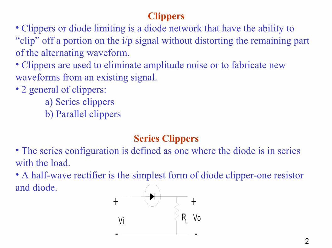
Clippers• Clippers or diode limiting is a diode network that have the ability to “clip” off a portion on the i/p signal without distorting the remaining part of the alternating waveform.• Clippers are used to eliminate amplitude noise or to fabricate new waveforms from an existing signal.• 2 general of clippers:
a) Series clippersb) Parallel clippers
Series Clippers• The series configuration is defined as one where the diode is in series with the load.• A half-wave rectifier is the simplest form of diode clipper-one resistor and diode.
+
-Vi RL Vo
-
+
2
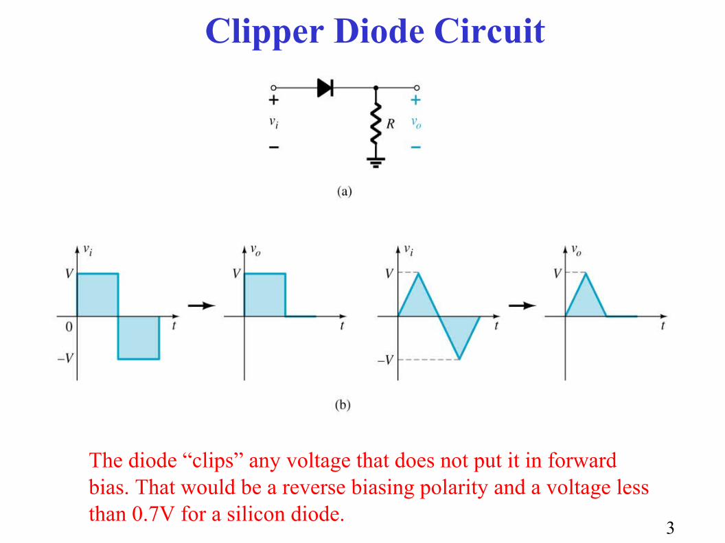
The diode “clips” any voltage that does not put it in forward bias. That would be a reverse biasing polarity and a voltage less than 0.7V for a silicon diode.
Clipper Diode Circuit
3
Vm
Vi
t0 T/2 T
+
-Vi
V
RL Vo-
+
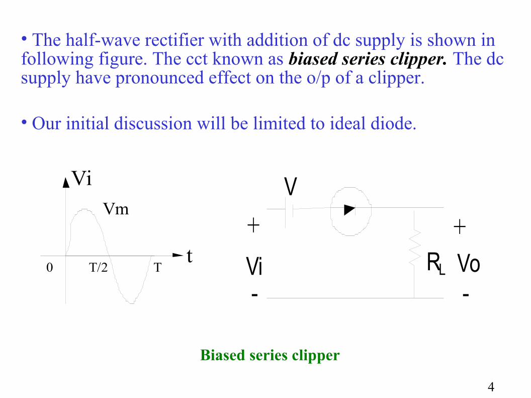
• The half-wave rectifier with addition of dc supply is shown in following figure. The cct known as biased series clipper. The dc supply have pronounced effect on the o/p of a clipper.
• Our initial discussion will be limited to ideal diode.
Biased series clipper
4

5
• +ve region turn the diode ON.• -ve region turn the diode OFF.• Vi > V to turn ON the diode• In general diode is open cct (OFF state) and short cct (ON state)• For Vi > V the Vo = Vi – V• For Vi = V the Vo= 0 V• The complete cct shown above
Vm
Vi
t0 T/2 T
+
-Vi=Vm
V
RL Vo
-
++ -
T/20
Vo
tT
Vm-V
Vi=V (diodes change state)

Parallel Clippers• The diode connection is in parallel configuration with the o/p.• Diode is ideal
+
RL
Vo
-
+
-
Vi
6

By taking the output across the diode, the output is now the voltage when the diode is not conducting.
A DC source can also be added to change the diode’s required forward bias voltage.
Changing Output Perspective
7
8
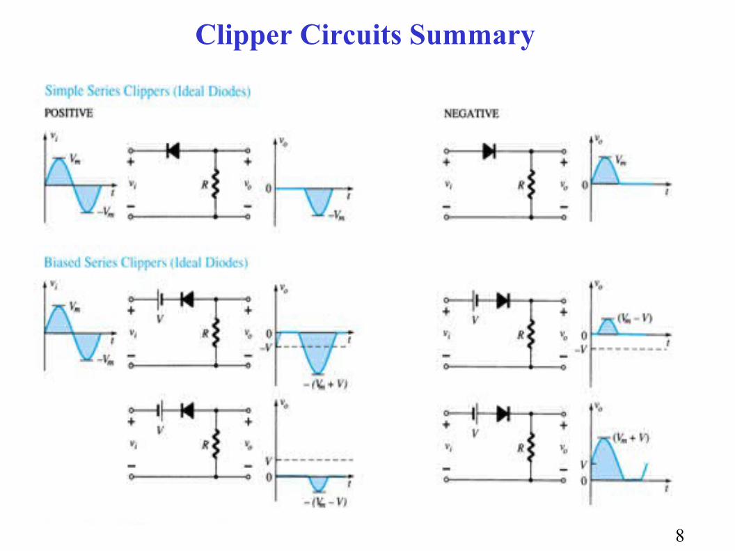
Clipper Circuits Summary

Clipper Circuits Summary
9

Clampers• The clamping network is to “clamp” a signal to a different dc level. Also known as dc restorers. The clamping cct is often used in TV receivers as a dc restorer. • The network consists of:
a) Capacitorb) Diodec) Resistive elementd) Independent dc supply (option)
• The magnitude of R and C must be chosen such that the time constant τ = RC is large enough to ensure that the voltage across the capacitor does not discharge significantly during the interval the diode is nonconducting.• Our analysis basis that all capacitor is fully charge and discharge in 5 time constant.
10

11
+R Vo
-
+
-
Vi
Vi
t0 T/2 T
V
-V

12
Operation of clamper + ve region
+
R Vo
-
+-
Vi
C• 0 - T/2: Diode is ON state (short-cct equivalent)• Assume RC time is small and capacitor charge to V volts very quickly• Vo=0 V (ideal diode)
- ve region • T/2 T: Diode is OFF state (open-cct equivalent)• Both for the stored voltage across capacitor and applied signal current through cathode to anode• KVL: - V- V- Vo = 0 and Vo = -2V
+
R Vo
-
+-
V
C
Vo
-
+V
Vi
t0 T/2 T
V
-V

13
Tips : Clamping networkTotal swing o/p signal = the total swing i/p signal

Summary of Clamper Circuits
14