cloning-free genome alterations in saccharomyces ... · cloning-free genome alterations in...
TRANSCRIPT
Cloning-free genome alterations in Saccharomyces cerevisiae using adaptamer-
mediated PCR
Robert J.D. Reid, Michael Lisby and Rodney Rothstein*
Department of Genetics & Development
Columbia University College of Physicians & Surgeons
New York, NY 10032-2704
Running title: Adaptamer-mediated genome alterations in Saccharomyces
*Corresponding author: Phone (212)305-1733,FAX (212)923-2090,
E-mail: [email protected]
2
Introduction
The budding yeast Saccharomyces cerevisiae is an appealing eukaryotic model system
in part due to its amenability to genome manipulation. Since linear DNA readily undergoes
homologous recombination in yeast, precise alterations of genes in the chromosome can
be done with relative ease.1 For example, targeted gene disruptions to produce null
alleles are performed routinely in yeast and provide a vital tool for understanding gene
function.2,3 Allele replacement methods allow the introduction of novel mutations into any
gene of interest.4 Similarly, gene fusions that append functional epitopes such as green
fluorescent protein (GFP) or an immunogenic tag are another important tool for studying
gene function.5 These methods all rely on the efficient homologous recombination of yeast
to make specific changes to genes at their endogenous chromosomal loci.
In recent years, many genome manipulation techniques have been revised to take
advantage of PCR. Below we describe PCR-based techniques for gene disruption, allele
replacement and epitope fusions using special primers we call adaptamers. Adaptamers
are chimeric primers containing sequences at their 5' end that facilitate the fusion of any two
pieces of DNA by PCR. This principle is illustrated in Figure 1. The two DNA fragments to
be fused are each amplified with an adaptamer and a standard PCR primer. The 5’
sequence tags on the adaptamers are reverse and complementary to each other. In a
second round of PCR, the two amplified DNA fragments are mixed, the complementary
ends anneal and are then extended by the polymerase. Primers are also included that bind
at the termini of the fused DNA fragments leading to exponential amplification of the fused
product.
In each of the techniques described below, adaptamer technology is used to mediate the
fusion of a dominant selectable marker to DNA fragments that provide homology for
chromosomal targeting. Upon transformation of these PCR products into yeast,
homologous recombination yields the targeted genomic integration with high efficiency.
Thus adaptamers obviate the need for traditional cloning in Escherichia coli to build
integrating vectors and offer a considerable savings of time. In addition, these methods
each incorporate directly repeated sequences flanking the selectable marker. This permits
reuse of the genetic marker after its deletion from the genome by direct repeat
recombination.
Gene disruption strategies
One-step gene disruption in yeast is a technique used to replace a functional gene with a
dominant selectable marker in a process requiring homologous recombination.3

3
Traditionally this involves interrupting a cloned gene on a plasmid by inserting a dominant
selectable marker using standard cloning techniques (Figure 2A). The plasmid is cut with
restriction enzymes to produce a linear DNA containing the selectable marker and several
hundred base pairs of DNA on each side of the selectable marker. Upon transformation
into yeast, the homologous DNA flanking the marker promotes two recombination events
that replace the copy of the gene on the chromosome with the inactive copy in a single
step (Figure 2B). The dominant marker allows selection of recombinants after
transformation. Although the recombination events are efficient, this method requires time
consuming cloning steps in E. coli to produce the desired integrating DNA. In addition,
interruption of the gene depends on available restriction sites. In many cases this leaves a
partial fragment of an ORF and may not provide a true null allele. PCR methods
significantly expedite construction of integrating DNA.
PCR-based methods of gene disruption streamline the traditional approach by replacing
cloning in E. coli with PCR amplification. The simplest of these approaches is sometimes
referred to as a “microhomology” or “long primer” method. The homologous DNA is
synthesized as 40 to 60 nucleotide 5’ extensions on primers designed to amplify a
selectable marker (Figure 3A). After amplification, the PCR products are transformed into
yeast and the 40 to 60 base pairs of homology on each end of the DNA promotes
recombination with genomic DNA to disrupt the gene (Figure 3B).6-8
This method greatly simplifies one-step gene disruptions since no cloning is necessary.
In addition, it is possible to create precise deletions of ORFs to ensure production of the null
alleles. However, the length of homology to the genome is limited by the amount of DNA
that can be reasonably synthesized on the 5’ ends of the primers. Recombination is
relatively inefficient with such short homology regions requiring several micrograms of DNA
to produce only a few transformants.7 Increasing the length of homologous DNA to ≥ 600
bp on each side of a selectable marker increases recombination efficiency producing 100-
to 1000-fold more transformants per microgram of DNA.8
The adaptamer-directed gene disruption method described below combines the efficient
genome integration made possible by longer homologous DNA fragments and the rapid
construction methods facilitated by PCR.
Adaptamer-directed gene disruptions
The adaptamer-directed gene disruption method relies on the same principles of
homologous recombination as the gene disruption methods described above. However,
in this strategy yeast intergenic regions are amplified to provide 200 to 500 bp of

4
homology on each side of the gene to be disrupted. The homologous DNA fragments are
then fused to a selectable marker via complementary adaptamers. Upon transformation into
yeast, these DNA fragments recombine with the homologous genomic locus to disrupt the
gene. A set of 6361 primer pairs was designed to amplify yeast intergenic regions. These
contain common 20 bp 5' sequence tags that are not homologous to S. cerevisiae genomic
DNA.9 These intergenic adaptamers can be specifically suited for the task of gene
disruptions and are available from Research Genetics (Huntsville, AL). Figure 4 shows a
map of intergenic adaptamers on an 8 kb segment of yeast chromosome IV. The
intergenic adaptamers are uniformly oriented, independent of gene orientation, so that all
forward primers contain the same 5’ sequence tag called C and all reverse primers contain a
different 5’ sequence tag called D (see Table 1 for sequences).
As outlined in Figure 5, two rounds of PCR are necessary to create a gene disruption
cassette by this method. In the first round, intergenic DNA fragments and the selectable
marker are amplified in four PCR amplifications. Amplification of intergenic regions using the
C and D adaptamer incorporates the sequence tags into the ends of those PCR products
(Figure 5A). Approximately 2 ng genomic DNA is added to 20µl reactions containing 0.5
µM of the specific intergenic adaptamers, 200 µM of each dNTP, and 1.5 units Taq
polymerase. Genomic DNA is prepared by standard methods for use as template
DNA.10 Intergenic adaptamers were designed to have a minimal annealing temperature of
52°C.11 Amplification is performed using the following cycle conditions: 94°C for 3
minutes followed by 30 cycles of 94°C for 30 seconds, 52°C for 30 seconds, 72°C for 1
minute and finally 72°C for 5 minutes. In rare cases where amplification using intergenic
adaptamers has given poor or inconsistent yields using the above conditions, the annealing
temperature was reduced to 45°C for the first eight cycles followed by 22 cycles using the
52°C annealing temperature.
The selectable marker is amplified in two overlapping segments from plasmid pWJ1077
(Figure 5B and 5C). We use the orthologous URA3 gene from Kluyveromyces lactis as a
selectable marker because it complements a S. cerevisiae ura3 mutant and can also be
counter-selected using 5-fluoro-orotic acid (5-FOA).12 Additionally, the sequence
homology between the K. lactis URA3 and the S. cerevisiae URA3 is approximately 70%
at the nucleotide level.13 Therefore, recombination of K. lactis URA3 sequence with the
endogenous URA3 allele is greatly decreased.14,15 We incorporated 143 bp direct
repeats into the URA3 plasmid so the marker can be recycled after integration (see below).
The 3’ section of URA3 is amplified with adaptamer d and internal primer kli5’, while the 5’
section of URA3 is amplified with adaptamer c and internal primer kli3’ (see Table 1 for
5
sequences). Adaptamers c and d have 5' sequence tags that are the reverse and
complement of the 5' tags on the C and D intergenic adaptamers. PCR of selectable
marker segments is performed using 2 ng pWJ1077 plasmid DNA as a template with the
same conditions described above, and substituting 55°C for the annealing temperature.
A second round of PCRs is required to fuse the selectable marker fragments to the
amplified intergenic regions via the complementary sequence tags on the adaptamers. The
left intergenic region is fused to the 3’ URA3 segment through annealing of the d and D
sequence tags, while the right intergenic region is fused to the 5’ URA3 segment by the
annealing of the c and C sequence tags (Figure 5D). Conditions for these PCR fusions are
as follows: 10 to 25 ng of the intergenic PCR amplified DNA are mixed in a 50 µl reaction
with approximately equimolar amounts of the appropriate K. lactis URA3 DNA fragment.
Typically, the template DNA fragments for fusion are simply diluted 50- to 100-fold from
the first round of PCRs into the fusion reaction mixture and do not require purification. Fusion
PCRs also contain 0.5 µM primers, 200 µM of each dNTP and 3.8 units of Taq
polymerase. Cycle conditions are 94°C followed by 30 cycles of 94°C for 30 seconds,
55°C for 30 seconds, 72°C for 1.5 or 2 minutes (depending on total length) and finally
72°C for 10 minutes.
DNA fragments for a gene disruption are produced in two overlapping parts for several
reasons. First, every amplified intergenic region is bounded by the same C and D
sequence tags, thus the split marker approach isolates the complementary c and d ends of
the URA3 gene into two separate PCR fusion reactions ensuring proper orientation of the
fused product. Second, PCR fusions can be accomplished using the 20-mer C or D
sequences as primers rather than the specific adaptamers for each intergenic region (Figure
5D). This simplifies the setup of PCRs when DNAs for many gene disruptions are
produced at once. Finally, while the length an integrating DNA sequence can be long, the
split marker approach generates shorter individual fusion PCR fragments thereby increasing
the reliability of the amplifications.
Typical products produced from first round of PCR and subsequent PCR fusions are
shown in Figure 5E. The fused DNA fragments can be taken directly from the PCR
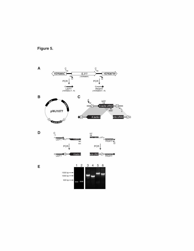
amplification mixtures and used for yeast transformations. The three recombination events
required to reconstitute the selectable URA3 marker and replace the targeted ORF are
illustrated in Figure 6. The homologous intergenic regions target recombination to the
intended locus while the URA3 segments reconstitute the selectable marker16 resulting in a
precise disruption of the ORF. Yeast transformations are performed using the standard
lithium acetate procedure as described.17 Approximately 300 ng of each fusion DNA
fragment is added to competent cells using conditions that give 106 transformants/µg of

6
circular plasmid DNA. The number of transformants in various gene disruption experiments
ranges from 10 to over 200 using these amounts of DNA.
Often the integrated selectable marker is used to follow segregation of the null mutant
during crosses to other strains. In this case, it is best to verify gene disruptions using two
PCRs. Internal K. lactis URA3 primers are paired with primers that bind in the left and right
genomic DNA outside of the intergenic regions to amplify across each recombination
junction (gray arrows in Figure 6A). However, it may also be desirable to recycle the
selectable marker. This is achieved by recombination between the 143 bp direct repeats
flanking URA3 which leads to a pop-out (Figure 6B). This is typically done by growing
overnight cultures of a yeast gene disruption strain without selection for the URA3 marker
and then plating 100-200 µl of the saturated culture onto 5-FOA plates to select for the
pop-out recombinants. Verification of marker-less gene disruptions can be done using a
single PCR reaction that amplifies across the disruption since this is now a short DNA
sequence. For the gene disruptions performed thus far using this method, 11 of 14 yielded
a gene disruption efficiency of 70-90%. Lower gene disruption efficiencies (about 20%)
occur when a particular gene disruption produces a slow growth phenotype. In such cases,
it is more efficient to perform gene disruption in a diploid strain.18
Intergenic PCRs and PCR fusions are simple to perform. Disruption of any yeast gene
requires four specific intergenic adaptamers to amplify the flanking DNA, but all other
components are common. The K. lactis DNA fragments can be amplified in quantity and
used as a resource for many different PCR fusions. Purification of intergenic PCR products
is not necessary between the first and second rounds of PCR except in rare cases where
PCR products contain contaminating non-specific DNA fragments. In addition, PCR
products from the fusion reactions can be added directly to yeast transformation reactions.
Thus all PCRs and the yeast transformations for a gene disruption experiment can usually
be accomplished in a day. While this method incurs an added cost for the extra PCRs
compared to the “long primer” gene disruption method, an overall increase in efficiency can
be realized because fewer transformants need to be screened to identify successful gene
disruptions. This becomes important when multiple gene disruption experiments are
carried out at once.
Intergenic adaptamers have standard names based on the name of the adjacent
chromosome feature to the “left” of the intergenic region. This is illustrated in Figure 5 where
the adaptamers to amplify the "left" intergenic region for ILV1 (iYER085C-F and -R) are
named after the YER085C ORF and the adaptamers to amplify the "right" intergenic region
(iYER086W-F and -R) are named after the systematic name of the ILV1 ORF. While the
nomenclature is standard, it is complicated by the fact that adaptamer pairs do not exist for

7
every intergenic region due to overlapping ORFs. In addition, intergenic regions ≥1.5 Kb
are split into sections of ≤1.2 Kb amplicons.
Lists of all the intergenic adaptamers and sequences are available by contacting Research
Genetics. In addition, maps of all 16 yeast chromosomes showing intergenic adaptamer
binding sites, the systematic name for each set of intergenic primers and the length of the
amplified DNA can be viewed on our website
(http://rothsteinlab.hs.columbia.edu/projects/primersearch.html).
Moving "barcoded" gene disruptions into a new strain
A world-wide consortium of yeast labs recently completed construction of an arrayed
library of yeast gene disruption strains for more than 5000 genes.19 This library represents
a unique resource for an experimental organism and is a valuable addition to yeast
researchers' toolbox. The deletion consortium strains were constructed by the
“microhomology” PCR technique using kanamycin resistance as the selectable marker. The
kanMX4 cassette was PCR amplified and attached to 45 bp of homology from each side
of the targeted coding region. The 5' homology is adjacent to and includes the ORF start
codon while the 3' homology is adjacent to and includes the ORF stop codon. Thus a
precise disruption of each ORF was made. Additionally, the long primers contain two
unique gene-specific sequence tags on the 5’ (UPTAG) and 3’ (DOWNTAG) ends of each
disruption cassette providing distinct "barcode" identifiers for each gene disruption. As an
example, the structure of the ILV1 locus is shown in Figure 7A along with the structure of the
ilv1 deletion strain produced by the consortium.
The UPTAG (checkered box) and DOWNTAG (black box) contain a unique 20 bp
sequence specific to each strain flanked by standard 18 bp primer binding sites for
amplification of these tags so that all the barcodes in a population can be PCR-amplified
using the same pairs of primers. Hybridization of the amplified DNA to a microarray gene
chip that contains the barcodes for all the gene disruption strains can be used to monitor the
presence or absence of a particular disruption strain in a population of cells. This has been
used to identify gene disruptions in a population that are enriched for or selected against in
response to various growth conditions.19
These types of population biology experiments are likely to be useful to a number of
researchers that work with other yeast strain backgrounds. Therefore we have developed
an adaptamer gene disruption method with the specific goal of transferring gene disruptions
containing the unique tags into a new strain. We have moved a number of these tagged

8
gene disruptions into the W303 strain background20 and find that the method is as efficient
as the general method described above.
A simple way to transfer the gene disruptions from the consortium strains to a new strain is
to choose primers that PCR amplify across the gene disruption to produce a DNA
molecule containing the selectable marker, the unique tags, and sufficient homologous DNA
to effect recombination. The DNA can then be transformed to select for G418-resistant
recombinants. However, the KanMX selectable marker is not recyclable and thus cannot
be reused if additional disruptions need to be performed in that strain.
A simple adaptation of the adaptamer-directed gene disruption method described above
allows transfer of the barcoded gene disruptions into a new strain while replacing the
kanamycin resistance cassette with the recyclable K. lactis URA3 marker As shown in
Figure 7B, the intergenic regions flanking the gene disruption are amplified using intergenic
adaptamers and the common primers flanking the UPTAG and DOWNTAG, U2 and D2
respectively. K. lactis URA3 is amplified in overlapping sections as described above (see
Figure 4B). In this case, the 5' sequence tags on the adaptamers are the reverse and
complement of U2 and D2 and are referred to as u2 and d2, respectively. Figure 7C
shows PCR fusion using these adaptamer sequences to generate DNA fragments for
gene disruption.
UPTAG and DOWNTAG sequences in the deletion strains have the same orientation as
the start and stop codons of the disrupted gene and the C and D intergenic adaptamers all
have the same orientation along the chromosome. Therefore amplification of a Watson
strand gene disruption (e.g. MCD1 in Figure 4) is accomplished using the C intergenic
adaptamer with the U2 adaptamer and the D intergenic adaptamer with the D2 adaptamer.
For a Crick strand gene disruption (e.g. NTH1 in Figure 4), the C intergenic adaptamer is
used with the D2 adaptamer and the D intergenic adaptamer is used with the U2
adaptamer.
Amplification of intergenic regions from the consortium strains is performed using the same
PCR conditions described above. Most of the amplification of yeast intergenic regions in
our lab have been performed using relatively clean DNA preparations.10 However, it is
also possible to perform these amplifications by colony PCR.21 This is useful where gene
disruptions are moved from many different strains.
Allele replacements using adaptamers
The ability to introduce a specific mutant allele into the yeast genome is an invaluable
genetic tool. A mutant allele in one strain can be moved into a different strain background by

9
a standard genetic cross. However, this requires successive backcrosses to ensure that the
new mutant strain becomes congenic to the desired background. Allele replacement by
homologous recombination obviates the need for multiple backcrosses because the new
allele is introduced directly into the desired strain. For novel mutations constructed in vitro,
allele replacement methods facilitate the stable integration of the mutant allele into the
genome.
Traditional allele replacement methods require that the mutant allele be subcloned into a
yeast integrating vector that contains a selectable/counter-selectable marker such as URA3.
The integrating plasmid is linearized with a restriction enzyme that cuts once within the mutant
allele. Transformation of this linear DNA into yeast effects homologous recombination to
yield an integrated direct repeat in which a mutant and a wild-type copy of the targeted
gene are separated by URA3. Direct repeat recombination pops out the marker leaving a
single allele. The efficiency of recovering the mutant allele is 50% or less and depends on
the location of the mutation with respect to the ends of the DNA repeats. We have
developed an adaptamer-based allele replacement technique in which mutant alleles are
PCR amplified and fused to a selectable marker for genome integration.22 A major
advantage of the adaptamer method is the high probability that both integrated repeats
contain the mutant lesion. This increases the efficiency with which the mutant allele is
recovered after the selectable/counter-selectable marker is recycled.
The adaptamer-based allele replacement method described below uses the complete
ORF for DNA homology to target integration. This was designed to take advantage of the
complete set of commercially available adaptamers that can amplify every yeast ORF
(Research Genetics, Huntsville, AL).23 All forward ORF adaptamers contain the 19 bp A
sequence tag followed by 20 to 25 nucleotides of homology to a specific ORF starting at
the ATG (See Table 1). All reverse adaptamers contain the 20 bp B sequence tag
followed by 20 to 25 nucleotides of homology at the 3’ end of the ORF and includes the
stop codon. Amplification using these adaptamers produces a precise copy of the ORF
with the A and B tags appended to the 5’ and 3’ ends, respectively (Figure 8A).
The K. lactis URA3 selectable marker is amplified in two overlapping sections as
described earlier (Figure 5C). Fusion of the selectable marker to the amplified ORF is
performed in two parallel reactions. The 5' K. lactis URA3 fragment is fused to the ORF via
the complementary b and B sequence tags while the 3' URA3 fragment is fused via the
complementary a and A sequence tags (Figure 8B). Integration into the genome is
mediated by the homologous ORF DNA, while the URA3 segments recombine to
reconstitute the selectable marker (Figure 8C).
1 0
There are three possible recombination products depending on the position of the
crossovers between the incoming DNA and the chromosome. Either both alleles are
incorporated (as shown in Figure 8D) or one mutation is incorporated and the other is not
(there are two types, one of which is shown in Figure 8E). In fact it is most common to
recover the class in which both integrated direct repeats contain the mutation. We have
shown that when the transferred mutation lies ≥ 80 bp from the end of the fragment, the
crossover occurs between the mutation and the end of the DNA greater than 95% of the
time.22 This is most likely due to the fact that crossing over is stimulated at or near the ends
of the incoming DNA.24
This adaptamer-based allele replacement method is an efficient way to introduce an allele
into a new strain background without cloning in E. coli. The method as presented above
uses complete ORFs as homologous DNA to promote genome integration. This is
advantageous since the pre-made adaptamers for allele replacement of any ORF can be
obtained at a modest cost. Furthermore, the URA3-marked intermediate maintains gene
function as the ORF is not disrupted. This is important when alleles of essential genes must
be transferred. The drawback to this allele replacement method is that random mutations
can be introduced by PCR. Thus, it is important to limit the number of cycles of
amplification and to use a high fidelity polymerase. In cases where ORFs are long, it is
prudent to design new adaptamers that limit the total length of amplified DNA. This is not
necessarily problematic for allele replacement of essential genes. As long as the
homologous DNA includes the N-terminus and the promoter or the C-terminus with the
stop codon, a functional copy of the gene is maintained upon integration. Here as well,
there is a high probability of incorporating the mutation into both repeats.
In-frame gene fusions using adaptamers
Attaching functional epitopes to a gene can be an important route to understanding protein
function. Fusion of immunogenic tags can facilitate protein purification and biochemical
analysis of protein-protein interactions. Indirect immunofluorescence methods using such
epitopes makes it possible to study subcellular localization of a protein and even co-
localization with other proteins provided that distinct immunogenic tags are available.
Microhomology-based integration methods have been used to introduce such changes
directly into the yeast genome, obviating the need for a cloned gene.7 In fact, a set of
plasmids has recently been constructed containing several kinds of useful epitopes adjacent
to selectable markers.5,25 Amplification of the epitopes and markers in these plasmids

1 1
with primers containing homology to a gene can be used to integrate and construct epitope
fusions in the yeast genome.
One drawback to introducing epitopes by the microhomology methods is that, along with
the desired epitope, most of these protocols also integrate a selectable marker and affect
gene structure. This imposes limits on how these epitopes can be used. For instance,
insertions on the 5' end of an ORF to produce an N-terminal protein fusion must also include
a heterologous promoter to drive gene expression. If expression from the endogenous
promoter is important, then it is necessary to use a C-terminal epitope fusion - which may or
may not compromise protein function. This problem is solved by integrating the epitope
as a direct repeat flanking a selectable marker.26 Recombination between the repeats
deletes the marker and other heterologous sequences. However, integrating epitopes
using microhomology is still inefficient.
We have developed an adaptamer-directed method in which fusions can be made to
any functional sequence without leaving a selectable marker in the genome. This is
accomplished by using the epitope sequence as a direct repeat flanking the selectable
marker. The epitope is fused to genomic DNA by first amplifying this DNA with
appropriate adaptamers. We have thus far applied these techniques to produce fusions of
cyan fluorescent protein (CFP) and yellow fluorescent protein (YFP) to Rad52 to
investigate its relocalization in response to DNA damage.27 Below we describe the
method for adding C-terminal or N-terminal CFP and YFP tags to any gene.
The cloning of GFP from Aequorea victoria has provided a useful tool for cell biological
studies in S. cerevisiae and other organisms.28 Subsequent mutagenesis of GFP has
resulted in a number of enhanced variants of the protein having altered fluorescent
properties. In particular, blue- and red-shifted versions, CFP and YFP respectively, that
have non-overlapping excitation and emission spectra have been produced. These
fluorophores can be visualized independently in a living cell, thus facilitating co-localization
experiments. In addition, with appropriate filters, CFP and YFP can potentially be used to
study protein-protein interactions in vivo by means of Fluorescence Resonance Energy
Transfer (FRET).29 Here we utilize the W7 (CFP) and 10C (YFP) clones obtained from R.
Tsien, University of California, San Diego.29,30
We have constructed two plasmids each for CFP and YFP that can be used to create
fusions to any gene of interest (Figure 9). One plasmid contains YFP next to the first two-
thirds segment of URA3. The second plasmid contains the last two-thirds of URA3
followed by the YFP ORF such that when the overlapping segments of URA3 recombine,
the YFP sequences are oriented as direct repeats (Figure 10A). The method as illustrated
1 2
in Figure 10 shows an in-frame fusion of YFP to the 3' end of the ORF. Two PCRs are
performed to amplify the YFP-URA3 DNA fragments. The first plasmid is amplified with
the forward YFP primer GFPstart-F and the internal kli3' URA3 primer. The second plasmid
is amplified with the internal kli5' URA3 primer and the reverse YFP primer GFPend-R.
Parallel PCRs are performed to amplify a 200 to 300 bp section of the 3' end of a coding
region and 200 to 300 bp directly adjacent to that ORF. Adaptamers are used for each of
these PCRs in order to fuse these segments to the YFP-URA3 fragments in the second
round of PCRs (Figure 10B). When C-terminal fusions are made, the stop codon from the
gene is included in the DNA amplified from the intergenic region and omitted in the DNA
amplified from the ORF (see DFxTag2 adaptamer in Table 1). PCR conditions are
identical to those used for the gene disruption methods described above. Co-
transformation and integration of these sequences produces a precise in-frame fusion of
YFP to the targeted ORF. Subsequent recombination between YFP direct repeats pops-
out the marker leaving only the inserted YFP coding sequences (Figure 10C).
The above method describes C-terminal YFP fusions, but can, in principle, be used to
fuse any C-terminal epitope. For N-terminal or internal epitope fusions, the adaptamers
must be designed so that fusion to the ORF maintains the desired reading frame. The
PCRs and transformations described can easily be performed in 1 to 2 working days. In
general, the success-rate of the procedure is high with approximately 50% of the candidate
clones being correct after pop-out of the URA3 marker. Among the incorrect clones, about
half lack an integration at the target site and the other half have acquired mutations during the
PCRs, which underscores the importance of using a high fidelity Taq polymerase. We also
applied this method to short tags such as 6xHIS and FLAG. Because of the small size of
these tags, a region of the flanking non-coding genomic DNA was incorporated as part of
the direct repeat since efficient recombinational pop-out of the URA3 marker requires a
minimum of approximately 100 bp of DNA homology 31,32.
Summary
Each of the adaptamer-directed genome manipulation methods is predicated on the fact
that recombination between two DNAs is enhanced by increasing the length of homology.
Many of the current PCR-based genome manipulation techniques rely on very short
homologies to promote recombination. In these cases homology length is dictated by the
technical limits of oligonucleotide synthesis. Adaptamers circumvent this problem since long
homology regions are produced in a first round of PCR, and then fused to the selectable
marker in a second round of PCR via complementary sequence tags on the adaptamers.
Furthermore, many of the techniques described here rely on pre-existing and commercially

1 3
available adaptamer sets that can be obtained inexpensively rather than designing new
primers for every experiment. Although a cost is incurred by performing multiple PCR
amplifications, the increase in recombination efficiency is dramatic. Finally, the adaptamer-
mediated PCR fusion methodology is versatile and can be applied to varied genome
manipulations.
Acknowledgements
We thank Marisa Wagner, Bilyana Georgieva and Uffe Mortensen for critical reading of
the manuscript. This work was supported by National Institutes of Health grant HG00193
to R. Reid, a grant from the Alfred Benzon Foundation to M. Lisby, National Institutes of
Health grants HG01620 and GM50237 to R. Rothstein and Merck Genome Research
Institute grant 5 to R. Rothstein.
References
1T. L. Orr-Weaver, J. W. Szostak and R. J. Rothstein, Proc. Natl. Acad. Sci. U S A 78,
6354 (1981).
2D. Shortle, J. E. Haber and D. Botstein, Science 217, 371 (1982).
3R. J. Rothstein, in Methods in Enzymology R. Wu, L. Grossman, K. Moldave, Eds.
(Academic Press, Inc., New York, 1983), vol. 101, pp. 202.
4R. Rothstein, Methods Enzymol. 194, 281 (1991).
5M. S. Longtine, See this volume .
6A. Baudin, O. Ozier-Kalogeropoulos, A. Denouel, F. Lacroute and C. Cullin, Nucl. Acids
Res. 21, 3329 (1993).
7A. Wach, A. Brachat, R. Pohlmann and P. Philippsen, Yeast 10, 1793 (1994).
8P. Manivasakam, S. C. Weber, J. McElver and R. H. Schiestl, Nucl. Acids Res. 23, 2799
(1995).
9V. Iyer, P. Brown, M. Keddache and R. Rothstein, Personal communication .
10C. S. Hoffman and F. Winston, Gene 57, 267 (1987).
11V. Iyer, Personal communication .
12J. D. Boeke, J. Trueheart, G. Natsoulis and G. R. Fink, Methods Enzymol. 154, 164
(1987).
13J. R. Shuster, D. Moyer and B. Irvine, Nucl. Acids Res. 15, 8573 (1987).
14A. M. Bailis and R. Rothstein, Genetics 126, 535 (1990).

1 4
15S. D. Priebe, J. Westmoreland, T. Nilsson-Tillgren and M. A. Resnick, Mol. Cell. Biol.
14, 4802 (1994).
16C. Fairhead, B. Llorente, F. Denis, M. Soler and B. Dujon, Yeast 12, 1439 (1996).
17R. H. Schiestl and R. D. Gietz, Curr. Genet. 16, 339 (1989).
18R. J. D. Reid, I. Sunjevaric, M. Keddache and R. Rothstein, Yeast submitted.
19E. A. Winzeler, et al., Science 285, 901 (1999).
20B. J. Thomas and R. Rothstein, Genetics 123, 725 (1989).
21A. C. Ward, BioTechniques 13, 350. (1992).
22N. Erdeniz, U. H. Mortensen and R. Rothstein, Genome Res 7, 1174 (1997).
23J. R. Hudson, Jr., et al., Genome Res 7, 1169 (1997).
24R. Rothstein, Cold Spring Harb. Symp. Quant. Biol. 49, 629 (1984).
25M. S. Longtine, et al., Yeast 14, 953 (1998).
26B. L. Schneider, W. Seufert, B. Steiner, Q. H. Yang and A. B. Futcher, Yeast 11, 1265
(1995).
27M. Lisby, R. Rothstein and U. H. Mortensen, Proc. Natl. Acad. Sci. U S A In Press
(2001).
28J. Abelson, "Green Fluorescent Protein." Academic Press, San Diego, 1999
29R. Heim and R. Y. Tsien, Curr Biol 6, 178 (1996).
30M. Ormo, et al., Science 273, 1392 (1996).
31N. Sugawara and J. E. Haber, Mol. Cell. Biol. 12, 563 (1992).
32M. Keddache and R. Rothstein, Personal communication .
33T. W. Christianson, R. S. Sikorski, M. Dante, J. H. Shero and P. Hieter, Gene 110, 119
(1992).
Table 1. PCR primers and adaptamers.
Primer Sequence Name Description
ccgctgctaggcgcgccgtg... C 5’ nonhomologous sequence tag used for allforward intergenic adaptamers.
gcagggatgcggccgctgac... D 5’ nonhomologous sequence tag used for allreverse intergenic adaptamers.
CTTGACGTTCGTTCGACTGATGAGC kli5’ K. lactis URA3 internal 5’ primer.
GAGCAATGAACCCAATAACGAAATC kli3’ K. lactis URA3 internal 3’ primer.
gtcagcggccgcatccctgcCCTCACTAAAGGGAACAAAAGCTG
d-Kl 3’ K. lactis URA3 “d” adaptamer. Nonhomologousregion is reverse and complement of D.
cacggcgcgcctagcagcggTAACGCCAGGGTTTTCCCAGTCAC
c-Kl 5’ K. lactis URA3 “c” adaptamer. Nonhomologousregion is reverse and complement of C.
GTCGACCTGCAGCGTACG U2 5’ primer for amplification of intergenic DNA from theyeast deletion strains.
CGAGCTCGAATTCATCGAT D2 3’ primer for amplification of intergenic DNA from theyeast deletion strains.
cgtacgctgcaggtcgac gggccc GTGTCACCATGAACGACAATTC
u2-Kl* 5’ K. lactis URA3 “u2” adaptamer. Nonhomologousregion is reverse and complement of U2.
atcgatgaattcgagctcg atcgat GTGATTCTGGGTAGAAGATC
d2-Kl† 3’ K. lactis URA3 “d2” adaptamer. Nonhomologousregion is reverse and complement of D2.
ggaattccagctgaccacc atg … A¥ 5' nonhomologous sequence tag included on allforward ORF adaptamers.
gatccccgggaattgccatg… B 5' nonhomologous sequence tag included on allreverse ORF adaptamers.
catggcaattcccggggatcGTGATTCTGGGTAGAAGATCG
b-Kl 5’ K. lactis URA3 “b” adaptamer. Nonhomologousregion is reverse and complement of B.
catggtggtcagctggaattccCGATGATGTAGTTTCTGGTT
a-Kl 3’ K. lactis URA3 “a” adaptamer. Nonhomologousregion is reverse and complement of A.
gttcttctcctttactcat… g1 5' nonhomologous sequence tag of the GFP 5’ endadaptamer.
ggatgaactatacaaa TAA … g2# 5' nonhomologous sequence tag of the GFP 3’ endadaptamer.
ATGAGTAAAGGAGAAGAAC GFPstart-F 5' GFP primer. Reverse and complement of the g1sequence tag.
TTTGTATAGTTCATCC ATGC GFPend-R 3' GFP primer. Underlined sequence is reverse andcomplement of the nonhomologous 5’ section ofthe g2 sequence tag.
All sequences are listed in the 5’ to 3’ direction. Lowercase sequences denote nonhomologous 5' segments orsequence tags on adaptamers* The underlined sequence is a ApaI restriction site† The underlined sequence is a ClaI restriction site¥ The underlined sequence is the ORF start codon.# The underlined sequence is a stop codon necessary for C-terminal GFP fusions

Figure Legends
Figure 1. Adaptamer-directed PCR fusions. Two different double-stranded
DNA sequences are represented by thick gray and black lines. PCR primers are
illustrated by arrows. Adaptamers are shown as arrows with triangles at their 5'
ends representing the complementary sequence tags A and a. PCR
amplification with these adaptamers incorporates the 5' sequence tags into
double-stranded DNA (diamonds). In a second PCR reaction the first PCR
products are mixed, the incorporated complementary sequence tags anneal and
are extended by the polymerase (dashed lines). In successive PCR cycles,
distal primers (arrows) amplify the fused product.
Figure 2. One-step gene replacement. A. Interruption of a gene cloned on a
plasmid with a selectable marker using standard cloning techniques is
represented by dashed lines. ORFs are indicated by open arrows, yeast
intergenic sequences are illustrated by thick black lines, and plasmid DNA is
indicated by a thin line. The restriction sites to linearize the gene disruption
fragment are marked R. B. Two homology-directed recombination reactions (X)
occur to produce a gene disruption in a single step.
Figure 3. “Microhomology” one-step gene disruptions. A. A selectable
marker is PCR amplified using chimeric primers containing 5’ sequences with
homology to genomic DNA immediately upstream and downstream of the ORF to
be disrupted. B. Integration mediated by short homology regions flanking the
selectable marker.
Figure 4. Orientation of adaptamers on an 8 kilobase pair region of yeast
chromosome IV. A map of 15 kilobase pairs near the centromere of
chromosome IV. The black circle represents the centromere. White arrows
indicate known or predicted open reading frames. Adaptamers (not to scale) are
shown as black arrows with gray (C) or black (D) triangles representing the
standard 5’ sequence tags.
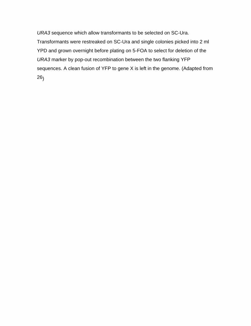
Figure 5. Adaptamer-directed gene disruptions. A. Amplification of
intergenic regions flanking the ILV1 gene on chromosome V. Two PCR reactions
amplify intergenic DNA containing the adaptamer tags (diamonds). B. Plasmid
pWJ1077 containing the K. lactis URA3 gene and the 143 bp direct repeats. C.
Direct repeats flanking the K. lactis URA3 ORF are represented as hatched
boxes and were made by PCR amplifying a 143bp sequence 5’ to the URA3
ORF and cloning it into ClaI and ApaI restriction sites on the 3’ side of the ORF in
plasmid pWJ1077. Amplification of overlapping segments in two PCR reactions
is indicated by shading. D. Fusion PCR reactions using the left intergenic DNA
and the 3’ section of URA3 in one reaction and the right intergenic region and the
5’ portion of URA3 in the second reaction. The upper cartoons illustrate
annealing of single strands mediated by complementary sequence tags while the
bottom cartoons illustrate fused PCR products. E. Example of PCR fragments
used to produce an ILV1 gene disruption. The 352 bp left and 380 bp right
intergenic regions for the ILV1 gene (lanes 1 and 2) were amplified using wild-
type genomic DNA from the W303 strain background as a template. The 1095
bp K. lactis URA3 3’ and 946 bp URA3 5’ DNAs (lanes 3 and 4) were amplified
using plasmid pWJ1077 as a template. 2µl of each reaction were loaded and run
on a 0.8% electrophoresis gel. DNA was visualized by ethidium bromide
staining. Fusion reactions were performed by diluting the PCR products from the
first reactions 100-fold into a 50µl PCR. 2µl of the amplified 1447 bp ILV1-left
fused to URA3-3' and the 1326 bp ILV1-right fused to URA3-5' were loaded and
run on the same gel (lanes 5 and 6).
Figure 6. Integration of two PCR fragments to disrupt a gene. A. Three
recombination events are required to replace a gene in a single step using two
DNA fragments. Thick gray arrows represent primer binding sites for PCR-
analysis of integrations. B. Direct repeat recombination results in "pop-out" of
the URA3 marker leaving a small fragment of non S. cerevisiae DNA in place of
the ORF.
Figure 7. Transfer of gene disruptions from consortium strains to a new
strain. A. Construction of a gene disruption by the yeast deletion consortium
was performed using 45 bp homology to a gene of interest. ILV1 is used as an
example. Unique identifiers on the 5' side of the ORF (UPTAG) and 3' side of the
ORF (DOWNTAG) are indicated by the checkered and black boxes. Each tag
contains a unique 20 bp identifying tag flanked by common 18 bp primer binding
sites for amplification of the unique sequence from any deletion strain. This is
shown in detail for the UPTAG sequence (also see Table 1 for primer
sequences). B. The 18 bp primer binding sites flanking the unique identifying
tags are used in combination with appropriate intergenic primers to amplify the
identifying tag along with the intergenic DNA (see text). C. Fusion of selectable
markers to intergenic regions is mediated by the 18 bp U2 or D2 adaptamers.
Figure 8. Allele replacment using adaptamers. A. Amplification of ORFs is
accomplished using adaptamers designed to precisely amplify every yeast ORF
from start to stop codons. The forward and reverse adaptamers contain 5’
sequence tags referred to as A and B, respectively. A mutation in the amplified
ORF is indicated by an asterisk. B. Fusion to a selectable marker is performed
in two reactions generating DNAs with overlapping segments of the selectable
marker. C. Genome integration is mediated by homologous ORF sequences.
D. Integration producing two mutant copies of the ORF as direct repeats. Pop-
out of the selectable marker results in a single mutated copy of the ORF in the
genome. E. Integration resulting in one mutant and one wild-type copy of the
ORF. Pop-out of the selectable marker can result in the mutant or the wild-type
copy of the allele integrated into the genome.

Figure 9. Construction of CFP/YFP-tagging vectors. DNA sequences
encoding either the blue- or red-shifted version (W7, 10C) of GFP were amplified
by PCR from the corresponding pRSETB vectors 28,29. These DNA fragments
were fused by PCR to either the 5’- or 3’-two-thirds of K. lactis URA3, which was
amplified from pWJ716 21. The resulting PCR products were cloned into the
SacII site of pRS423 32 to make vectors for CFP/YFP-tagging. A. Vector maps of
pWJ1162 and pWJ1163 for CFP-tagging. B. Vector maps of pWJ1164 and
pWJ1165 for YFP-tagging.
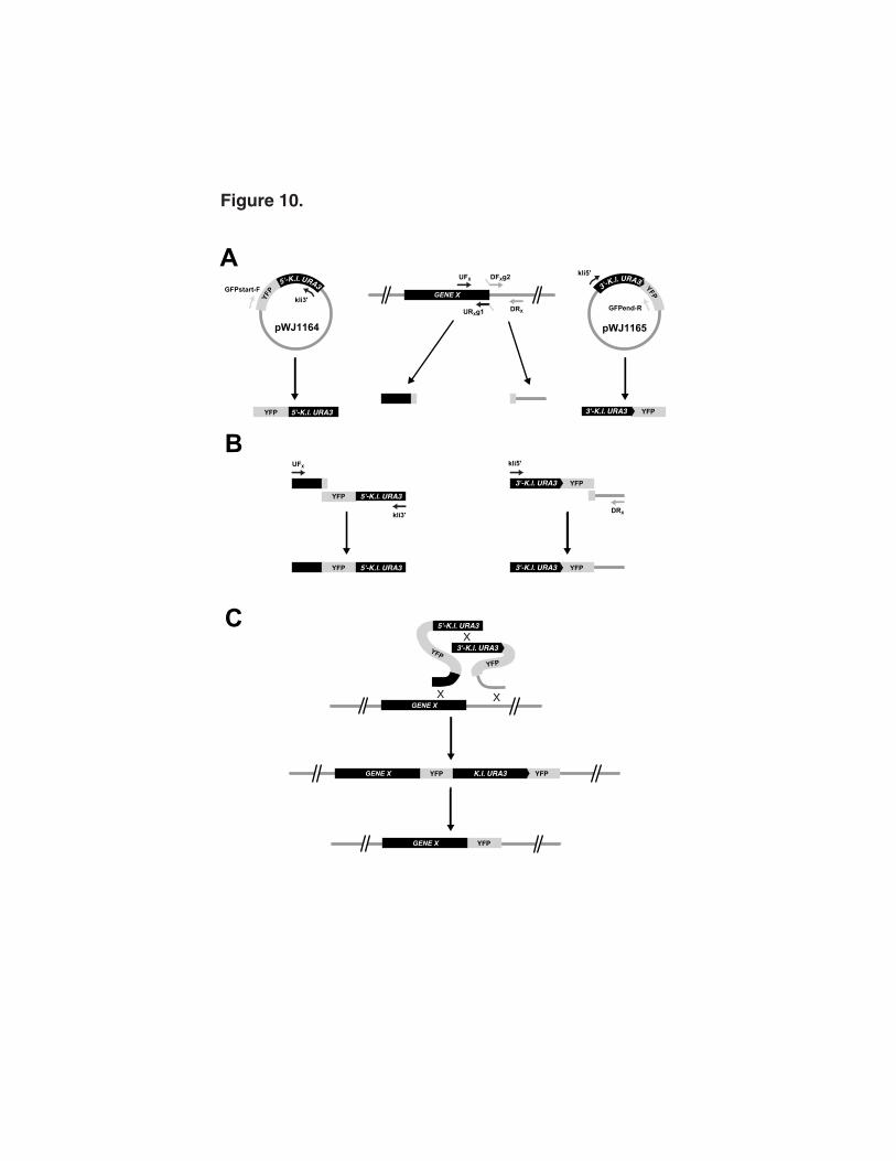
Figure 10. General strategy for CFP/YFP-tagging of yeast proteins. Using
appropriately designed primers, CFP and YFP can be targeted to any site in the
yeast genome. This figure describes the fusion of YFP to the 3’-end of gene X.
The procedure involves two rounds of PCR and a yeast transformation. A. PCR
amplification of target sequences. The first round of PCR amplifies 300 to 500 bp
DNA sequences upstream and downstream of the target site using primer pairs
UFX/URXg1 and DFXg2/DRX, respectively. The URXg1 and DFXg2 primers contain
19 bp 5'-sequence tags complementary to the 5’- and 3’-ends of YFP,
respectively. Since YFP is fused to the 3’-end of gene X in this example, a TAA
stop codon has been added to g2. The stop codon is omitted when making N-
terminal and internal fusions of CFP/YFP. YFP-URA3 sequence cassettes were
PCR amplified from pWJ1164 and pWJ1165 using primer pairs GFPstart-F/kli3'
and kli5'/GFPend-R. B. Fusion of the YFP coding sequence to target sequences.
The sequence tags (g1 and g2) facilitate the fusion of the target sequences to
YFP-URA3 sequences using adaptamer technology 21,22 and the primer pairs
UFX/kli3' and kli5'/DRX. Approximately 100 ng of each PCR fragment was used in
the fusion reactions. C. Integration by homologous recombination. The two PCR
fragments (500 ng of each) were co-transformed into yeast for integration by
homologous recombination using the lithium acetate method 16. The
recombination event results in a YFP direct repeat flanking an intact K. lactis
URA3 sequence which allow transformants to be selected on SC-Ura.
Transformants were restreaked on SC-Ura and single colonies picked into 2 ml
YPD and grown overnight before plating on 5-FOA to select for deletion of the
URA3 marker by pop-out recombination between the two flanking YFP
sequences. A clean fusion of YFP to gene X is left in the genome. (Adapted from
26)

mix fragments
PCR PCRA
a
Figure 1.

ILV1YER085C YER087WXX
Selectable marker
YER085C YER087WSelectable marker
selectable marker
Plasmid backbone DNA
YE
R085C
ILV1
YE
R08
7W
Yeas t D N A
RR
A
B
Figure 2.

Selectable marker
Selectable marker
PCR
Selectable marker
ILV1YER085C YER087WX X
YER085C YER087WSelectable marker
A
B
Figure 3.

Chromosome IV
0K 1531K
C C CCC
DDD D D
1Kbp
NTH1YDL001W YRB1 YDR003WNHP10
Figure 4.
LEFT RIGHT
CC
D D(YER086W )
ILV1 YER087WYER085C
(iYER085C-F, -R) (iYER086W-F, -R)
PCR PCR
A
D
E
C
K.lactis URA3
K.lactis U
kli5'
kli3'
lactis URA3
d
c
Bbla
K.lactis URA3
HIS
3
pWJ1077
500 bp
1000 bp
1500 bp
1 2 3 4 5 6
C
LEFT
kli5'
PCR
K.lactis U
LEFTK.lactis U
RIGHT
kli3'
DPCR
lactis URA3
RIGHTlactis URA3
Figure 5.
K. la
ctis URA3
XYER085C
YER087W
YER085C YER087W
A
B
K.lactis URA3YER085C YER087W
X
X
XILV1YER085C YER087W
K.lactis UR
actis URA3
Figure 6.

PCR Fusion
RIGHT
d2
D2D
lactis URA3
RIGHTlactis URA3
kli5'
u2
LEFT
U2
C
K.lactis U
LEFTK.lactis U
kli3'
C
AILV1
UPTAG DOWNTAG
kanR
B
U2
D2
PCRPCR
C
D
kanR
LEFT RIGHT
18bp 20bp 18bp
Figure 7.

*
*B
A
*
K.lactis URA3* *
A
B
C
D
E
*
K.lactis URA3*
kli3' B* K.lactis URA3
* K.lactis URA3
B
b
kli5'A
K.lactis URA3 *
K.lactis URA3 *
A
a
YFG1
*
*X
X
X
Figure 8.

A
pWJ1162 pWJ1163
pWJ1164 pWJ1165
B
bla 2 µ
H
IS3
3'-K.l. URA3 YFP bla 2
µ
H
IS3
3'-K.l. URA3 CFP
bla 2 µ HIS3
YFP
5'-K.l. URA3
bla 2 µ HIS3
CFP
5'-K.l. URA3
Figure 9.
A
B
C
GENE X
UFX
UFX
kli3'
kli5'
DFXg2
DRX
DRX
URXg1
GENE X
GENE X YFP
3'-K.l. URA3 YFP YFP K.l. URA3
YFP
YFP
GENE X
5'-K.l. URA3
3'-K.l. URA3
YFP 5'-K.l. URA3 YFP3'-K.l. URA3
GFPend-R
GFPstart-F
YFP3'-K.l. URA3
YFP3'-K.l. URA3
kli5'
YFP 5'-K.l. URA3
YFP 5'-K.l. URA3
kli3'
pWJ1164 pWJ1165
Y
FP
5'-K.l. URA3
3'-K.l. URA3 YFP
X
X X
Figure 10.