close control air cooled twin circuit range - combitec 30-80.pdf · close control air cooled twin...
TRANSCRIPT

Close Control Air Cooled Twin Circuit Range
Engineering Data Manual 50/60Hz

ENGINEERING DATA MANUAL 50/60Hz
2
Index
Description Page
YORK Company Profile 3 This Product Range 3 Other YORK Close Control Product Ranges 3 Equipment Nomenclature 4 Indoor Units - Dimensions and Weights 4 Air Cooled Condensers - Dimensions and Weights 5 Guide Specifications 6 General Engineering Details 10 Air Cooled System Schematic 11 Air Cooled Units - Cooling Capacities 50Hz & 60Hz 12 Electrical Details – 50Hz & 60Hz 13 Generic Dimensional Drawing 14 Generic Electrical Drawing 15
Document Reference: Y 4.19-01-03-0

YORK COMPANY PROFILE
3
YORK was formed in 1874 in the City of YORK Pennsylvania USA. The Company has been at the forefront of technology throughout its history being the first company to: commercially master ice making for food and other processes, fully air condition an office building, manufacture the first successful room air conditioner and design equipment using refrigerant Freon. Currently, on a global basis, YORK employs 24,500 people and has 32 factories. It is now the largest independent manufacturer of air conditioning and refrigeration products in the world. YORK designs, manufactures, sells and services: heating and air conditioning systems and compressors for residential, commercial and industrial markets, gas compression equipment for industrial processing, industrial and commercial refrigeration equipment. The company manufactures a wide range of air conditioning products including fan coil units, close control units, under-floor air distribution systems, telecom shelter units, variable air volume systems, air handling units, mini split systems, packaged air conditioners, roof top units, water cooled and air cooled chillers, heat pumps and absorption chillers. We also manufacture a variety of compressors including hermetic, scroll, reciprocating, screw and centrifugal types. YORK products are installed in nuclear submarines operating deep in the ocean and in South African gold mines in the depth of the earth. Eurotunnel, which has the world’s largest chilled water system, is served by YORK chillers as does the worlds tallest building the twin tower Petronas complex in Malaysia. Other notable global installations are the Sydney Opera House, Charles de Gaulle and Jeddah Airports, most of the commercial buildings dominating the Hong Kong skyline, the Islamic University in Riyadh, the UK Houses of Parliament, the Kremlin, the United States Capitol and the Pentagon in Washington DC, the Eiffel Tower restaurant and the Prophets Mosque in Medina: all these and numerous installations world-wide. In our own way YORK influences the weather by providing snow on demand at the worlds major ski resorts.
THIS PRODUCT RANGE CLOSE CONTROL AIR COOLED TWIN CIRCUIT UNITS The Close Control Twin Circuit range comprises 3 sizes providing nominal capacities of 30, 40, 50, 60, 70 & 80 in 10kW increments. Units are twin circuit in a single frame and are available in Upflow and Downflow configurations with top, bottom, front and rear return options. As standard the Twin Circuit Air Cooled range units are equipped with: Scroll Compressors, Electrode Steam Boiler Humidifiers, Stainless Steel Tubular Finned Electric Reheat Elements, EU4 Filtration, belt driven forward curved Centrifugal Fans, R407C Refrigerant and the latest Delta range of microprocessor controllers which have a full Windows networking capability. All units have built in pressure activated fan speed control as standard and all air cooled condensers are single split circuit for 30 & 35°C ambient while two number condensers are utilised for 40 & 45°C ambient, 1 per refrigerant circuit. Cooling media available is air cooled direct expansion only.
OTHER YORK CLOSE CONTROL PRODUCT RANGES CLOSE CONTROL MODULAR UNITS The Close Control Modular range is comprised of 4 module sizes providing nominal capacities of 10, 15, 20, 25, 30, 35 & 40 kW per module. These modules form the basis of the EDPAC modular concept. Unit selections can be based on a single module for a single circuit system or any combination of 2 modules to give a twin circuit or Duplex system. The Duplex configuration is advantageous as both modules can be positioned at different locations within the room. CLOSE CONTROL PLUG FAN UNITS The Close Control Plug Fan range comprises 3 sizes providing nominal capacities of 18-90 kW in 7 models in the Chilled Water version and 18-77 kW in 6 models in the DX version. As standard the units are equipped with a backWard curved radial fan with external static pressures of 350 Pa available. DCS / FCS CHILLED WATER UNITS The DCS / FCS range of Close Control Chilled Water units comprises 3 sizes providing nominal capacities of 60, 80 & 100 kW. Units are available in Upflow and Downflow configurations with top, bottom, front and rear return options. The range of units is ideal for very large data centre applications where air cooled or water/glycol cooled units would be impractical due to the size of the building close control cooling load. TELECOM SHELTER UNITS The Telecom Shelter Unit is designed for the demanding conditions typical of communication and electronic equipment shelters. The range of units is available with nominal cooling capacities from 3 to 15 kW. .

EQUIPMENT NOMENCLATURE
4
The Close Control Twin circuit range of equipment is comprised of Twin Circuit Air Cooled Units with cooling capacities from 30 – 80kW in 10kW increments. Units are available in Upflow and Downflow versions and are supplied with matching Air Cooled Condensers to suit your local ambient conditions. Air Cooled Condensers in this manual are selected for 30°C, 35°C, 40°C & 45°C ambients. For other conditions please refer to your local distributor or the YORK Applications Engineering department.
CLOSE CONTROL TWIN CIRCUIT - DIMENSIONS AND WEIGHTS CLOSE CONTROL TWIN CIRCUIT UNITS Dimensions (mm) Model 30 40 50 60 70 80 W x D x 1980H 1650 x 875 1650 x 875 2000 x 875 2000 x 875 2500 x 875 2500 x 875 Weight ( kgs ) Model 30 40 50 60 70 80 Air Cooled 675 675 905 905 1095 1095 Return Air Acoustic Plenum 50 50 60 60 70 70 Top Discharge Plenum 60 60 70 70 80 80
NOMINAL CAPACITY 30 = 30kW 40 = 40kW 50 = 50kW 60 = 60kW 70 = 70kW 80 = 80kW
TA = TWIN CIRCUIT AIR COOLED
D = DOWNFLOW F = UPFLOW FRONT RETURN
VOLTAGE B = 380-415/3/50
E = 220/3/60 H = 460/3/60 J = 380/3/60
S = STANDARD SCROLL
COMPRESSOR
W = WITHOUT ECX
S = STANDARD CONTROLS G = GRAPHIC CONTROLS
D T A 60 B S W S

AIR COOLED CONDENSERS - DIMENSIONS AND WEIGHTS
5
30oC Ambient Selection
Model 30 40 50 60 70 80 Condenser Model x No. ACS403Ax1 ACS502Ax1 ACS502Bx1 ACS503Ax1 ACS503Bx1 ACS503Cx1 Freefield SPL @ 10m dBA 50 56 56 58 58 58 Airflow (m3/hr) 9645 14568 13692 21852 20538 19395 Fan No. x Diameter (mm) 3 x 400 2 x 500 2 x 500 3 x 500 3 x 500 3 x 500 Condenser Inlet/Outlet (mm) 24/22 35/28 35/28 42/35 42/35 42/35 Dimensions W x D (mm) 1980 x 555 2042 x 828 2042 x 828 2942 x 828 2942 x 828 2942 x 828 Weight (kgs) 55 91 99 118 135 146
35oC Ambient Selection
Model 30 40 50 60 70 80 Condenser Model x No. ACS403Bx1 ACS502Bx1 ACS503Ax1 ACS503Bx1 ACS502Ax2 ACS502Bx2 Freefield SPL @ 10m dBA 50 56 58 58 59 59 Airflow (m3/hr) 8732 13692 21852 20538 14568 13692 Fan No. x Diameter (mm) 3 x 400 2 x 500 3 x 500 3 x 500 2 x 500 2 x 500 Condenser Inlet/Outlet (mm) 28/22 35/28 42/35 42/35 35/28 35/28 Dimensions W x D (mm) 1980 x 555 2042 x 828 2942 x 828 2942 x 828 2042 x 828 2042 x 828 Weight (kgs) 59 99 118 135 182 198
40oC Ambient Selection
Model 30 40 50 60 70 80 Condenser Model x 2 No. ACS402B ACS403A ACS502A ACS502B ACS502C ACS503A Freefield SPL @ 10m dBA 48 50 56 56 56 58 Airflow (m3/hr) 5819 9645 14568 13692 12930 21852 Fan No. x Diameter (mm) 2 x 400 3 x 400 2 x 500 2 x 500 2 x 500 3 x 500 Condenser Inlet/Outlet (mm) 22/20 24/22 35/28 35/28 35/28 42/35 Dimensions W x D (mm) 1380 x 555 1980 x 555 2042 x 828 2042 x 828 2042 x 828 2942 x 828 Weight (Kgs) 1No. / 2No. 43/86 55/110 91182 99/198 107/214 118/236
45oC Ambient Selection
Model 30 40 50 60 70 80 Condenser Model x 2 No. ACS403A ACS502A ACS502C ACS503A ACS503B ACS503C Freefield SPL @ 10m dBA 50 56 56 58 58 58 Airflow (m3/hr) 9645 14568 12930 21852 20538 19395 Fan No. x Diameter (mm) 3 x 400 2 x 500 2 x 500 3 x 500 3 x 500 3 x 500 Condenser Inlet/Outlet (mm) 24/22 35/28 35/28 42/35 42/35 42/35 Dimensions W x D (mm) 1980 x 555 2042 x 828 2042 x 828 2942 x 828 2942 x 828 2942 x 828 Weight (Kgs) 1No. / 2No. 55/110 91/182 107/214 118/236 135/270 146/292 Notes: 1. Standard Air Cooled Condensers have 4 Pole motors. For 6 Pole & 8 Pole low noise versions, consult factory. 2. All Condensers are shipped with mounting feet. When mounted in a horizontal, Condenser models ACS 401 – 403 are
712mm high and Condenser models ACS 501- 503 are 948mm high. 3. For 30°C and 35°C ambient (except models 70 and 80 at 35°C ambient), all Air Cooled Condensers have split headers
with 2 sets of inlet/outlet connections. 4. For models 70 and 80 at 35°C ambient and for all models at 40°C and 45°C ambient, 2 no. condensers are required, 1 per
refrigerant circuit. 5. Condenser airflow and Freefield SPL are per Condenser.

GUIDE SPECIFICATIONS
6
STANDARD FEATURES
Cabinet
The cabinet frames shall be constructed of formed 2.0mm Zintec electroplated steel sections. Paint finish is Epoxy Powder Coated with an “Orange Peel” textured finish. Interior panels to be manufactured from galvanised steel in all cases. Exterior panels are to be as cabinet except in 1.2mm Zintec. Paint Colour to be RAL 9018. The front panels shall be fastened to the frame using quarter turn fasteners. Side panels shall be secured to the frame using steel chrome plated screws. All panels shall be flush fitting, sealed to the frame sections with closed cell foam and insulated with a non-shedding material, which shall be non-combustible, when tested in accordance with B.S. 476 Part 6, 7 and UL 94. The units shall be fully accessible and serviceable from the front.
Cooling Coil
The cooling coils shall be multi-row constructed from 3/8” O/D copper tubes with aluminium fins. Large surface areas shall ensure high sensible heat ratios and low airside pressure drops, resulting in reduced fan power requirements and noise levels. All DX coils shall be tested to 25 bar.
DX Units
Each unit shall have 2 independent refrigerant circuits, each with a liquid distributor, expansion valve, solenoid valve, sight glass and filter drier. Pumpdown is standard on Air Cooled Units.
Fans
Large, low speed, double inlet, double width fans with forward curved impellers and “sealed for life” self aligning bearings shall be used to minimise noise levels. Fans are twin belt driven with a TEFC motor. The motor shall be IP54 rated and insulated to Class F.
Electric Heaters
Electric heaters shall have stainless steel sheathed elements with stainless steel finning, balanced over three phases and rated to operate at ‘black heat’. Control shall be in two stages. Protection is by a high temperature safety cut-out thermostat. The thermostat shall be mounted in the airstream and resetable from the control section of the electrical panel.
Filtration
The filters shall have an atmospheric dust spot efficiency of 30 - 40% in accordance with Ashrae 52/76. This equates to a Eurovent 4/5 rating of EU4/G4. They shall be fitted in the return air stream and be accessible from the front of an Upflow unit and the top of a Downflow unit.
Compressors
Compressors shall be high efficiency hermetically sealed scroll type. Back seating service/isolating valve, high and low pressure switches, motor overload protection and crankcase heaters shall be provided. The compressors shall be mounted on resilient neoprene mountings for vibration isolation.
Humidification
The humidifier shall be of the electrode-boiler type. Features shall include selectable steam output and microprocessor control with alarms and diagnostic facilities. The humidifier control system shall allow the use of a wide range of mains water conditions namely: inlet mains water pressure of 1-10 bars, total hardness of 15-30 French degrees & water inlet electrical conductivity of 400-800 micro siemens. Unit shall optimise drain down frequency for maximum operational economy. Electrical Panel
The electrical panel shall be constructed and assembled in compliance with IEC standards with all components VDE approved. All sub circuits are protected by MCB’s. The high and low voltage sections shall be segregated and all high voltage electrical components shall be touch safe.

GUIDE SPECIFICATIONS
7
Microprocessor Controls
All Units shall be fitted as standard with the latest Delta range of DIN rail mounted Microprocessor Controls. The Control System utilises a main Microprocessor Interface Board equipped with a set of terminals necessary to connect the Board to the controlled devices (e.g. valves, compressors, fans, reheats, sensors and humidifiers). All software is permanently stored in flash RAM and is therefore protected even in the event of a power failure. Unit software is uploaded to the Microprocessor using a RAM key. On multi unit sites, this quickens unit commissioning. The software can also easily be changed or upgraded on site by qualified service personnel. The Microprocessor also has optional built in Modbus & Bacnet communications and full Windows networking capability. When communicating in Modbus or Bacnet, the protocol converter is in the software & there is no need for external Gateways. The User Interface is complete with LCD Display, keypad and LED Indicators allowing the user to easily set the main control parameters (setpoints, differentials and alarm thresholds) and carry out the main working operations (on/off and displaying controlled variables). The User Interface Terminal also performs the following functions: • Initial programming procedure with access protected by a password. • Possibility of changing the basic operation parameters any time, without stopping the program. • Indication of any alarm condition via audible and visual signals (buzzer sounds and alarm messages appear on the display). • Visualisation of the active functions by means of LED indicators. • Visualisation of the measured variables.
GUIDE SPECIFICATIONS
8
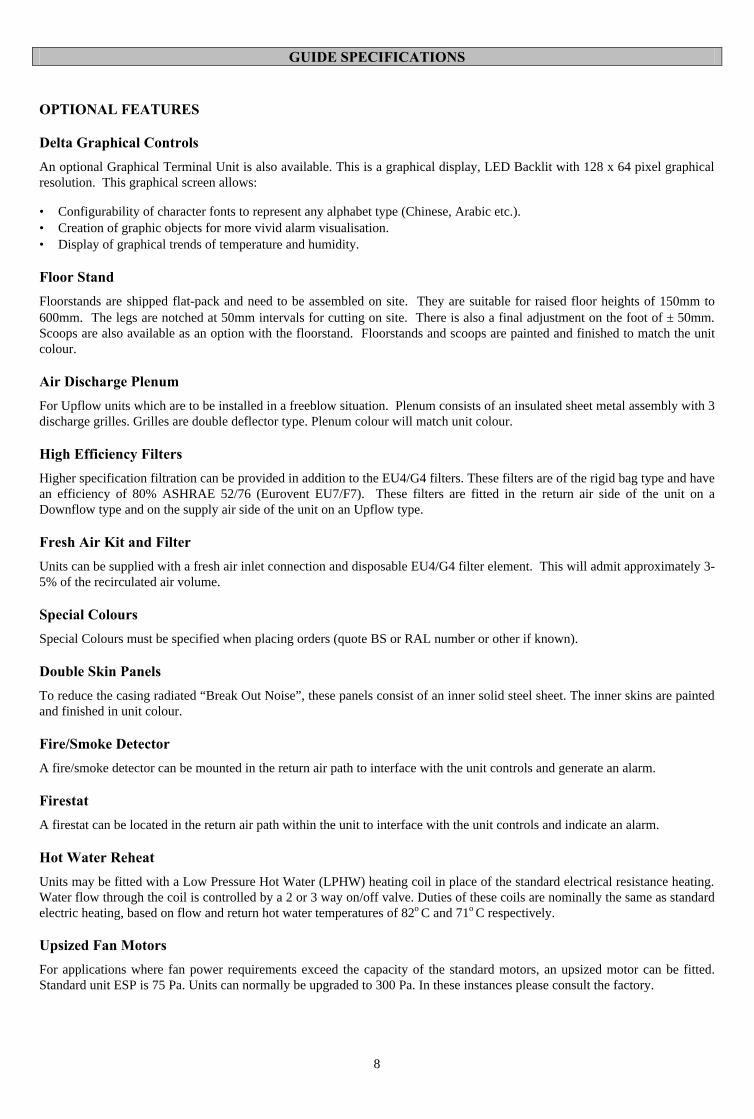
OPTIONAL FEATURES
Delta Graphical Controls
An optional Graphical Terminal Unit is also available. This is a graphical display, LED Backlit with 128 x 64 pixel graphical resolution. This graphical screen allows:
• Configurability of character fonts to represent any alphabet type (Chinese, Arabic etc.). • Creation of graphic objects for more vivid alarm visualisation. • Display of graphical trends of temperature and humidity.
Floor Stand
Floorstands are shipped flat-pack and need to be assembled on site. They are suitable for raised floor heights of 150mm to 600mm. The legs are notched at 50mm intervals for cutting on site. There is also a final adjustment on the foot of ± 50mm. Scoops are also available as an option with the floorstand. Floorstands and scoops are painted and finished to match the unit colour.
Air Discharge Plenum
For Upflow units which are to be installed in a freeblow situation. Plenum consists of an insulated sheet metal assembly with 3 discharge grilles. Grilles are double deflector type. Plenum colour will match unit colour.
High Efficiency Filters
Higher specification filtration can be provided in addition to the EU4/G4 filters. These filters are of the rigid bag type and have an efficiency of 80% ASHRAE 52/76 (Eurovent EU7/F7). These filters are fitted in the return air side of the unit on a Downflow type and on the supply air side of the unit on an Upflow type.
Fresh Air Kit and Filter
Units can be supplied with a fresh air inlet connection and disposable EU4/G4 filter element. This will admit approximately 3-5% of the recirculated air volume.
Special Colours
Special Colours must be specified when placing orders (quote BS or RAL number or other if known).
Double Skin Panels
To reduce the casing radiated “Break Out Noise”, these panels consist of an inner solid steel sheet. The inner skins are painted and finished in unit colour.
Fire/Smoke Detector
A fire/smoke detector can be mounted in the return air path to interface with the unit controls and generate an alarm.
Firestat
A firestat can be located in the return air path within the unit to interface with the unit controls and indicate an alarm.
Hot Water Reheat
Units may be fitted with a Low Pressure Hot Water (LPHW) heating coil in place of the standard electrical resistance heating. Water flow through the coil is controlled by a 2 or 3 way on/off valve. Duties of these coils are nominally the same as standard electric heating, based on flow and return hot water temperatures of 82o C and 71o C respectively. Upsized Fan Motors
For applications where fan power requirements exceed the capacity of the standard motors, an upsized motor can be fitted. Standard unit ESP is 75 Pa. Units can normally be upgraded to 300 Pa. In these instances please consult the factory.
GUIDE SPECIFICATIONS
9
Water Detection
A Water Sensor Module is connected to the Unit Microprocessor Control System and supplied with 10m of cable for underfloor water detection. When water is detected the unit’s alarm system is activated.
Condensate Pump
Where, due to location, it is not possible to gravity drain units, a condensate pump can be fitted to collect any condensate and pump it to the nearest convenient drain point (pump duty is 6 l/min Vs 6m head). For units fitted with humidifiers or units requiring a lift in excess of 6m equivalent head, a larger capacity sump pump is available, (Pump duty is 6 l/min Vs 10m head).
Top Entry Pipework
The unit pipework can be modified to allow entry/connection of services through the top of the unit.
Reverse Fan Deck
For applications where the air should be discharged “backward” from the unit, the fan deck can be reversed to ease the airflow pattern and reduce pressure drop.
GENERAL ENGINEERING DETAILS
10
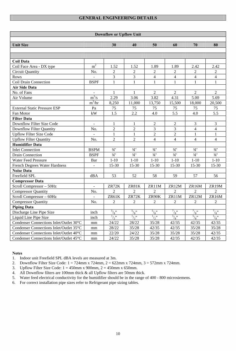
Downflow or Upflow Unit
Unit Size 30 40 50 60 70 80
Coil Data Coil Face Area - DX type m2 1.52 1.52 1.89 1.89 2.42 2.42 Circuit Quantity No. 2 2 2 2 2 2 Rows - 3 3 4 4 4 4 Coil Drain Connection BSPF 1 1 1 1 1 1 Air Side Data No. of Fans - 1 1 2 2 2 2 Air Volume m3/s 2.29 3.06 3.82 4.31 5.00 5.69 m3/hr 8,250 11,000 13,750 15,500 18,000 20,500 External Static Pressure ESP Pa 75 75 75 75 75 75 Fan Motor kW 1.5 2.2 4.0 5.5 4.0 5.5 Filter Data Downflow Filter Size Code - 1 1 2 2 3 3 Downflow Filter Quantity No. 2 2 3 3 4 4 Upflow Filter Size Code - 1 1 2 2 1 1 Upflow Filter Quantity No. 2 2 4 4 4 4 Humidifier Data Inlet Connection BSPM ¾’’ ¾’’ ¾’’ ¾’’ ¾’’ ¾’’ Drain Connection BSPF ¾’’ ¾’’ ¾’’ ¾’’ ¾’’ ¾’’ Water Feed Pressure Bar 1-10 1-10 1-10 1-10 1-10 1-10 French Degrees Water Hardness - 15-30 15-30 15-30 15-30 15-30 15-30 Noise Data Freefield SPL dBA 53 52 58 59 57 56 Compressor Data Scroll Compressor – 50Hz - ZR72K ZR81K ZR11M ZR12M ZR16M ZR19M Compressor Quantity No. 2 2 2 2 2 2 Scroll Compressor – 60Hz - ZR61K ZR72K ZR90K ZR11M ZR12M ZR16M Compressor Quantity No. 2 2 2 2 2 2 Piping Data Discharge Line Pipe Size inch 5/8” 5/8” 5/8” 7/8” 7/8” 7/8” Liquid Line Pipe Size inch 1/2” 1/2” 1/2” 5/8” 5/8” 5/8” Condenser Connections Inlet/Outlet 30°C mm 24/22 28/22 35/28 42/35 42/35 42/35 Condenser Connections Inlet/Outlet 35°C mm 28/22 35/28 42/35 42/35 35/28 35/28 Condenser Connections Inlet/Outlet 40°C mm 22/20 24/22 35/28 35/28 35/28 42/35 Condenser Connections Inlet/Outlet 45°C mm 24/22 35/28 35/28 42/35 42/35 42/35 Notes 1. Indoor unit Freefield SPL dBA levels are measured at 3m. 2. Downflow Filter Size Code: 1 = 724mm x 724mm, 2 = 622mm x 724mm, 3 = 572mm x 724mm. 3. Upflow Filter Size Code: 1 = 450mm x 900mm, 2 = 450mm x 650mm. 4. All Downflow filters are 100mm thick & all Upflow filters are 50mm thick. 5. Water feed electrical conductivity for the humidifier should be in the range of 400 - 800 microsiemens. 6. For correct installation pipe sizes refer to Refrigerant pipe sizing tables.
AIR COOLED SYSTEM SCHEMATIC
11
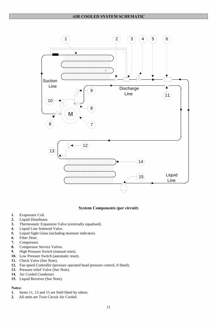
System Components (per circuit)
1. Evaporator Coil. 2. Liquid Distributor. 3. Thermostatic Expansion Valve (externally equalised). 4. Liquid Line Solenoid Valve. 5. Liquid Sight Glass (including moisture indicator). 6. Filter Drier. 7. Compressor. 8. Compressor Service Valves. 9. High Pressure Switch (manual reset). 10. Low Pressure Switch (automatic reset). 11. Check Valve (See Note). 12. Fan speed Controller (pressure operated head pressure control, if fitted). 13. Pressure relief Valve (See Note). 14. Air Cooled Condenser. 15. Liquid Receiver (See Note). Notes: 1. Items 11, 13 and 15 are field fitted by others. 2. All units are Twin Circuit Air Cooled.
M
8
1 2 3 4 5 6
7
8
9
10
1213
14
15
11
SuctionLine Discharge
Line
LiquidLine

AIR COOLED UNITS - COOLING CAPACITIES 50 Hz
12
Model: DTA / FTA 30 40 50 60 70 80 Air On: 22oC, 50% RH Total Capacity kW 31.8 37.2 51.7 59.7 72.2 86.3 Sensible Capacity kW 27.0 32.7 44.9 51.2 61.1 71.8 Air On: 24oC, 50% RH Total Capacity kW 33.8 39.4 55.0 63.0 76.7 91.7 Sensible Capacity kW 28.2 34.3 47.3 53.1 63.9 74.1 Scroll Compressor - ZR72K ZR81K ZR11M ZR12M ZR16M ZR19M Compressor Quantity No. 2 2 2 2 2 2 Airflow m3/s 2.29 3.06 3.82 4.31 5.00 5.69 No. of Fans No. 1 1 2 2 2 2 Fan Motor kW 1.5 2.2 4.0 5.5 4.0 5.5 No. of Motors No. 1 1 1 1 1 1 Electric Reheat kW 15.0 15.0 15.0 15.0 24.9 24.9 No. of Steps No. 2 2 2 2 2 2 Humidifier Capacity kg/hr 8.0 8.0 10.0 10.0 12.0 12.0 Humidifier Power kW 5.8 5.8 7.3 7.3 8.7 8.7
AIR COOLED UNITS - COOLING CAPACITIES 60Hz Model: DTA / FTA 30 40 50 60 70 80 Air On: 22oC, 50% RH Total Capacity kW 32.2 38.5 50.6 60.3 70.7 84.6 Sensible Capacity kW 27.2 33.5 44.3 51.6 60.3 70.8 Air On: 24oC, 50% RH Total Capacity kW 34.3 40.8 53.7 64.1 75.1 89.9 Sensible Capacity kW 28.5 35.1 46.8 53.6 63.1 73.2 Scroll Compressor - ZR61K ZR72K ZR90K ZR11M ZR12M ZR16M Compressor Quantity No. 2 2 2 2 2 2 Airflow m3/s 2.29 3.06 3.82 4.31 5.00 5.69 No. of Fans No. 1 1 2 2 2 2 Fan Motor kW 1.5 2.2 4.0 5.5 4.0 5.5 No. of Motors No. 1 1 1 1 1 1 Electric Reheat kW 15.0 15.0 15.0 15.0 24.9 24.9 No. of Steps No. 2 2 2 2 2 2 Humidifier Capacity kg/hr 8.0 8.0 10.0 10.0 12.0 12.0 Humidifier Power kW 5.8 5.8 7.3 7.3 8.7 8.7 Notes 1. Capacities are based on R407C refrigerant. 2. For capacities at other conditions, please refer to the Computer Selection Program. 3. All units are R22 compatible. 4. Units are also available for R134A applications, please contact the factory.
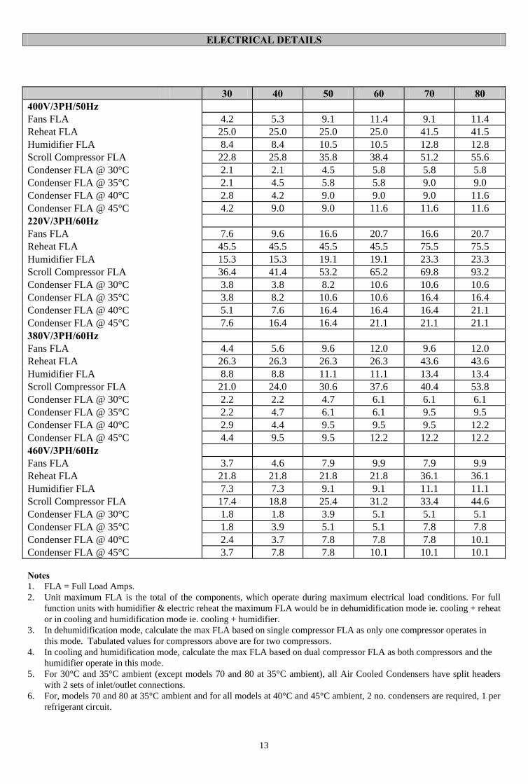
ELECTRICAL DETAILS
13
Notes 1. FLA = Full Load Amps. 2. Unit maximum FLA is the total of the components, which operate during maximum electrical load conditions. For full
function units with humidifier & electric reheat the maximum FLA would be in dehumidification mode ie. cooling + reheat or in cooling and humidification mode ie. cooling + humidifier.
3. In dehumidification mode, calculate the max FLA based on single compressor FLA as only one compressor operates in this mode. Tabulated values for compressors above are for two compressors.
4. In cooling and humidification mode, calculate the max FLA based on dual compressor FLA as both compressors and the humidifier operate in this mode.
5. For 30°C and 35°C ambient (except models 70 and 80 at 35°C ambient), all Air Cooled Condensers have split headers with 2 sets of inlet/outlet connections.
6. For, models 70 and 80 at 35°C ambient and for all models at 40°C and 45°C ambient, 2 no. condensers are required, 1 per refrigerant circuit.
30 40 50 60 70 80 400V/3PH/50Hz Fans FLA 4.2 5.3 9.1 11.4 9.1 11.4 Reheat FLA 25.0 25.0 25.0 25.0 41.5 41.5 Humidifier FLA 8.4 8.4 10.5 10.5 12.8 12.8 Scroll Compressor FLA 22.8 25.8 35.8 38.4 51.2 55.6 Condenser FLA @ 30°C 2.1 2.1 4.5 5.8 5.8 5.8 Condenser FLA @ 35°C 2.1 4.5 5.8 5.8 9.0 9.0 Condenser FLA @ 40°C 2.8 4.2 9.0 9.0 9.0 11.6 Condenser FLA @ 45°C 4.2 9.0 9.0 11.6 11.6 11.6 220V/3PH/60Hz Fans FLA 7.6 9.6 16.6 20.7 16.6 20.7 Reheat FLA 45.5 45.5 45.5 45.5 75.5 75.5 Humidifier FLA 15.3 15.3 19.1 19.1 23.3 23.3 Scroll Compressor FLA 36.4 41.4 53.2 65.2 69.8 93.2 Condenser FLA @ 30°C 3.8 3.8 8.2 10.6 10.6 10.6 Condenser FLA @ 35°C 3.8 8.2 10.6 10.6 16.4 16.4 Condenser FLA @ 40°C 5.1 7.6 16.4 16.4 16.4 21.1 Condenser FLA @ 45°C 7.6 16.4 16.4 21.1 21.1 21.1 380V/3PH/60Hz Fans FLA 4.4 5.6 9.6 12.0 9.6 12.0 Reheat FLA 26.3 26.3 26.3 26.3 43.6 43.6 Humidifier FLA 8.8 8.8 11.1 11.1 13.4 13.4 Scroll Compressor FLA 21.0 24.0 30.6 37.6 40.4 53.8 Condenser FLA @ 30°C 2.2 2.2 4.7 6.1 6.1 6.1 Condenser FLA @ 35°C 2.2 4.7 6.1 6.1 9.5 9.5 Condenser FLA @ 40°C 2.9 4.4 9.5 9.5 9.5 12.2 Condenser FLA @ 45°C 4.4 9.5 9.5 12.2 12.2 12.2 460V/3PH/60Hz Fans FLA 3.7 4.6 7.9 9.9 7.9 9.9 Reheat FLA 21.8 21.8 21.8 21.8 36.1 36.1 Humidifier FLA 7.3 7.3 9.1 9.1 11.1 11.1 Scroll Compressor FLA 17.4 18.8 25.4 31.2 33.4 44.6 Condenser FLA @ 30°C 1.8 1.8 3.9 5.1 5.1 5.1 Condenser FLA @ 35°C 1.8 3.9 5.1 5.1 7.8 7.8 Condenser FLA @ 40°C 2.4 3.7 7.8 7.8 7.8 10.1 Condenser FLA @ 45°C 3.7 7.8 7.8 10.1 10.1 10.1

GENERIC DIMENSIONAL DRAWING
14
B
DR
AIN
DT
A 3
0/40
SIN
GLE
OU
TLE
TO
NLY
CO
MP
1 CO
MP
2
FR
ON
T R
IGH
T C
OR
NE
R
VIE
W B
VIE
W B
SE
RV
ICE
AC
CE
SS
875m
m
DIS
CH
AR
GE
1
LIQ
UID
1
DIS
CH
AR
GE
2
LIQ
UID
2
DIM
A
FA
N
OU
TLE
T
FA
N
OU
TLE
TM
OT
OR
DE
TA
IL B
SE
CT
ION
A-A
(P
LAN
)
AA
98m
m
1980
mm
OU
TLE
T
FA
N
FR
ON
T E
LEV
AT
ION
RE
QU
IRE
D
RH
SID
E P
AN
EL
RE
MO
VE
D
CO
ND
EN
SA
TE

GENERIC ELECTRICAL DRAWING
15
YO
RK
IN
TE
RN
AT
ION
AL
YO
RK