closed loop integrated lighting and daylighting control
TRANSCRIPT
Closed Loop Integrated Lighting and Daylighting Control for Low Energy Buildings
Satyen Mukherjee, Dagnachew Birru, Dave Cavalcanti, Eric Shen, Maulin Patel, Yao-Jung Wen, and Sushanta Das, Philips Research North America
ABSTRACT
Lighting consumes as much as 38% of the total electrical energy in commercial buildings in the United States and higher percentage in emerging economies such as China and India. It is therefore imperative to deploy energy-efficient lighting strategies to realize low-energy sustainable buildings. In addition to high efficiency light sources and fixtures, a variety of control approaches have been explored, including occupancy sensing, daylight harvesting, automated motorized shades, user adaptive control, scheduling and light level tuning. The deployment of these strategies is increasing, albeit at a slow pace. While these technologies provide substantial energy efficiency, further gains in energy savings and comfort can be achieved through the use of integrated controls of daylight and electric lights.
In this paper, the benefits of closed-loop integrated controls of daylight and electric lights over other technologies are presented. In particular, simulated and experimental results from a test bed are presented for the following control scenarios: open-loop and closed-loop independent control of window blinds; closed-loop independent control of electric lighting, and closed-loop integrated control of blinds and lighting. It will be shown that under a variety of conditions, closed loop integrated control results in the highest energy savings. Furthermore, simulation results using EnergyPlus will also show the impact of optimized closed loop integrated control of daylight and electric light on cooling and heating load reduction in buildings.
Introduction
In most buildings lighting is the most pervasive energy consuming element and represent
as much as 38% of the electrical energy consumption (28% of total primary energy) in US commercial buildings, more than any other single end use (EIA 2009). Next to this comes space heating followed closely by space cooling. Therefore, maximizing the lighting usage efficiency or minimizing the lighting energy usage intensity are important steps in realizing low energy, sustainable buildings. Presently this is being addressed using a number of approaches, including use of higher efficiency light sources, and employing smart lighting controls involving occupancy sensing, scheduling, and light level tuning using photosensors. Space heating and cooling controls are typically handled in stand alone HVAC systems independent of lighting controls.
A key challenge in the deployment and maintenance of any commercially viable energy management and controls technology is ensuring optimum energy consumption as well as robust operation over long periods of time, preferably during the entire lifetime of the building. This becomes increasingly complex due to the large number of control parameters and generally harsh environmental variables. To address these challenges, open-loop control strategies are deployed most widely today (Lee & Selkowitz 2006). While these approaches do provide improved energy
9-252©2010 ACEEE Summer Study on Energy Efficiency in Buildings

efficiency, they may not always provide the optimum performance and require calibration or tuning periodically to ensure intended performance. To address these limitations, closed-loop control strategies have been explored (Bierman 2007; Jennings 2000; Rubinstein, Ward & Verderber 1989) with varying degrees of success depending upon the algorithms employed and the loop gain settings.
In this paper, a study of closed-loop integrated controls of daylight and electric lights have been carried out to evaluate the benefits and potential challenges in actual implementation. In the integrated control mode, electric lighting and the blinds were controlled in an integrated manner by sharing the light level measured at a reference point between the two elements and minimizing the lamp energy consumption while maintaining the required light level on the work surface. The integrated controls strategy is compared against two independent control approaches, in which the electric lighting and the blinds were independently controlled to provide user desired light level on the work surfaces while external conditions varied. Analytical simulation of the control strategies have been carried out to quantify the energy savings possible under various conditions. Furthermore, an experimental test bed comprising of motorized blinds on windows, dimmable fluorescent lamps in the ceilings, photo and occupancy sensors has been utilized to quantify the energy savings under real conditions and demonstrate some of the operational limitations of independent control strategies.
Finally, EnergyPlus (EnergyPlus) simulations have been carried out, for typical midsized office buildings, to quantify the impact of optimized closed loop integrated control of daylight and electric light on cooling and heating loads. EnergyPlus, developed by the U.S. DOE, is a building energy analysis and thermal load simulation program which provides simultaneous loads and systems simulation for accurate temperature and comfort prediction. Control Strategies
Building control strategies can be broadly divided into open-loop and closed-loop controls. Open-loop controls are those that adjust the output based on external input only. There is no feedback mechanism to regulate the output. Closed-loop strategies, on the other hand, employ feedback along with external input to regulate the output and meet a certain operating set point, or a range of set points. In this paper, we have explored both open-loop and closed-loop control of window blinds, closed loop control of electric lights, and integrated controls of these building subsystems. In the following subsections, a detailed description of the control strategies evaluated in this paper is provided. Lighting Control System
Figure 1 Closed-loop electric lighting control system
9-253©2010 ACEEE Summer Study on Energy Efficiency in Buildings
Closed-loop electric lighting control systems are currently the most advanced daylight harvesting systems offered on the market. Figure 1 shows a simplified diagram of a closed-loop lighting control system. An interior photosensor measures the combination of daylight and electric light. The sensor output is compared with a reference set point. The electric lights are adjusted accordingly to maintain the task illuminance within a predefined range.
In this study, we assumed a full-range dimmable lighting system and implemented an integral controller where the sensors measure the task plane illuminance. The control law is shown in equation (1), where u(k) is the light dimming signal, e(k) is the difference between sensed illuminance and the set point at the kth time step, and Kp is the constant gain of the controller.
(1)
Venetian Blind Control Systems
While the majority of venetian blinds are still manually operated, automated blind systems have been implemented in cutting-edge practices for efficient daylight harvesting and visual comfort control. In this study, we have considered both open-loop and closed-loop blind controls as described below.
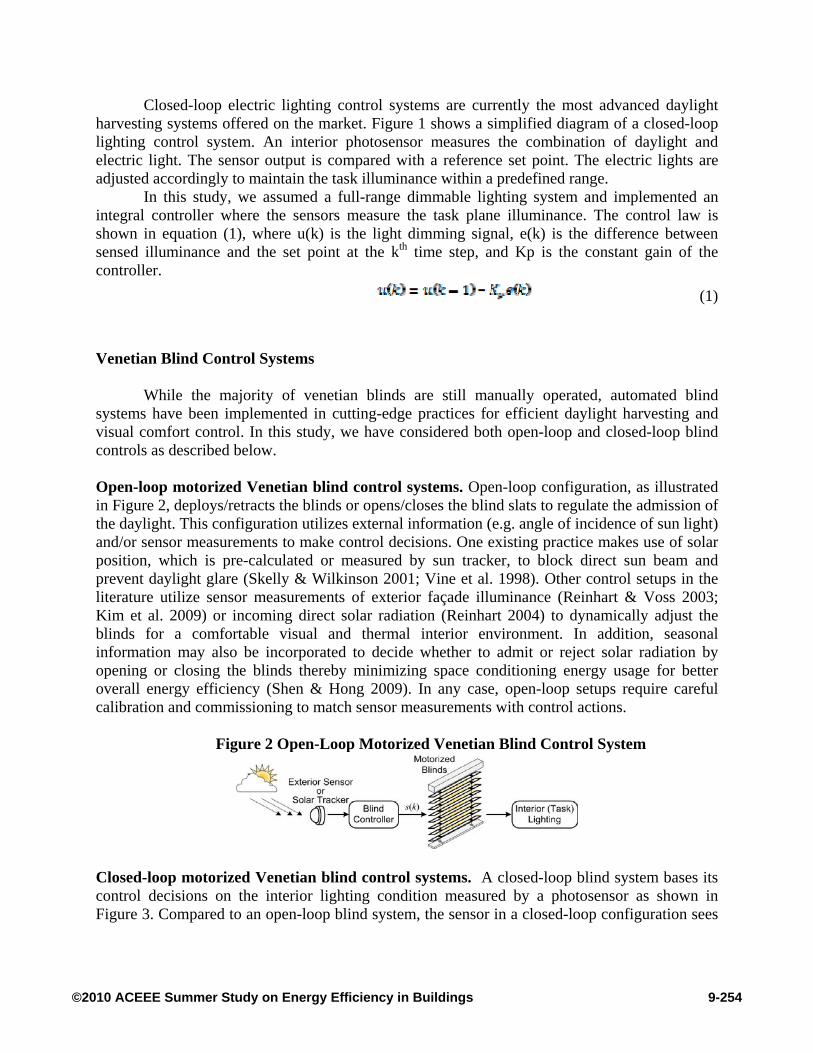
Open-loop motorized Venetian blind control systems. Open-loop configuration, as illustrated in Figure 2, deploys/retracts the blinds or opens/closes the blind slats to regulate the admission of the daylight. This configuration utilizes external information (e.g. angle of incidence of sun light) and/or sensor measurements to make control decisions. One existing practice makes use of solar position, which is pre-calculated or measured by sun tracker, to block direct sun beam and prevent daylight glare (Skelly & Wilkinson 2001; Vine et al. 1998). Other control setups in the literature utilize sensor measurements of exterior façade illuminance (Reinhart & Voss 2003; Kim et al. 2009) or incoming direct solar radiation (Reinhart 2004) to dynamically adjust the blinds for a comfortable visual and thermal interior environment. In addition, seasonal information may also be incorporated to decide whether to admit or reject solar radiation by opening or closing the blinds thereby minimizing space conditioning energy usage for better overall energy efficiency (Shen & Hong 2009). In any case, open-loop setups require careful calibration and commissioning to match sensor measurements with control actions.
Figure 2 Open-Loop Motorized Venetian Blind Control System
Closed-loop motorized Venetian blind control systems. A closed-loop blind system bases its control decisions on the interior lighting condition measured by a photosensor as shown in Figure 3. Compared to an open-loop blind system, the sensor in a closed-loop configuration sees
9-254©2010 ACEEE Summer Study on Energy Efficiency in Buildings
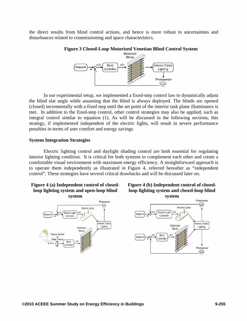
the direct results from blind control actions, and hence is more robust to uncertainties and disturbances related to commissioning and space characteristics.
Figure 3 Closed-Loop Motorized Venetian Blind Control System
In our experimental setup, we implemented a fixed-step control law to dynamically adjust the blind slat angle while assuming that the blind is always deployed. The blinds are opened (closed) incrementally with a fixed step until the set point of the interior task plane illuminance is met. In addition to the fixed-step control, other control strategies may also be applied, such as integral control similar to equation (1). As will be discussed in the following sections, this strategy, if implemented independent of the electric lights, will result in severe performance penalties in terms of user comfort and energy savings. System Integration Strategies
Electric lighting control and daylight shading control are both essential for regulating
interior lighting condition. It is critical for both systems to complement each other and create a comfortable visual environment with maximum energy efficiency. A straightforward approach is to operate them independently as illustrated in Figure 4, referred hereafter as “independent control”. These strategies have several critical drawbacks and will be discussed later on.
Figure 4 (a) Independent control of closed-loop lighting system and open-loop blind
system
Figure 4 (b) Independent control of closed-loop lighting system and closed-loop blind
system
9-255©2010 ACEEE Summer Study on Energy Efficiency in Buildings
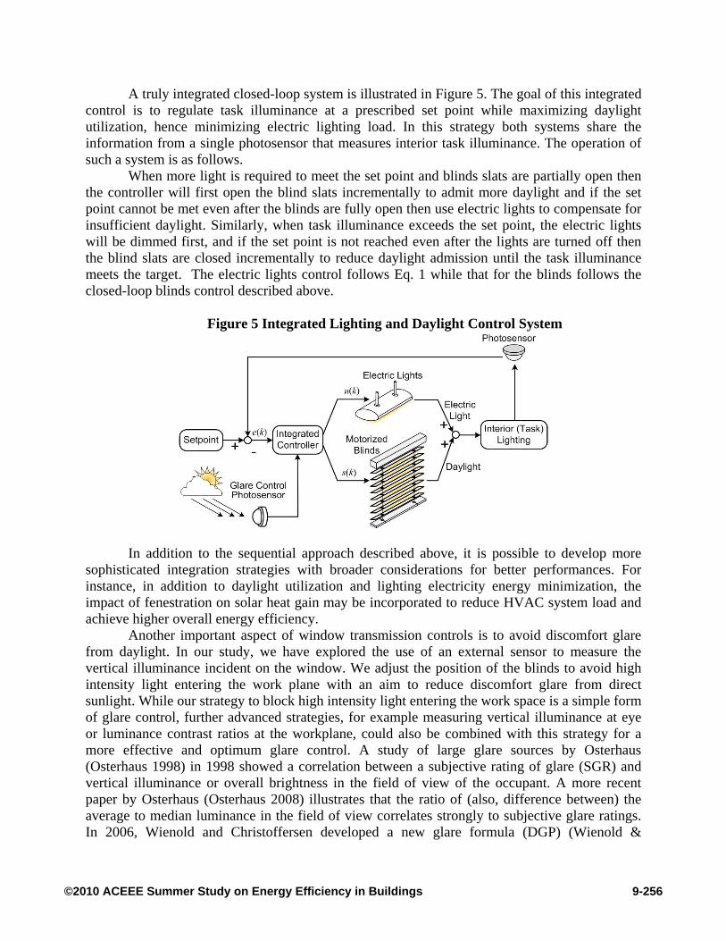
A truly integrated closed-loop system is illustrated in Figure 5. The goal of this integrated control is to regulate task illuminance at a prescribed set point while maximizing daylight utilization, hence minimizing electric lighting load. In this strategy both systems share the information from a single photosensor that measures interior task illuminance. The operation of such a system is as follows.
When more light is required to meet the set point and blinds slats are partially open then the controller will first open the blind slats incrementally to admit more daylight and if the set point cannot be met even after the blinds are fully open then use electric lights to compensate for insufficient daylight. Similarly, when task illuminance exceeds the set point, the electric lights will be dimmed first, and if the set point is not reached even after the lights are turned off then the blind slats are closed incrementally to reduce daylight admission until the task illuminance meets the target. The electric lights control follows Eq. 1 while that for the blinds follows the closed-loop blinds control described above.
Figure 5 Integrated Lighting and Daylight Control System
In addition to the sequential approach described above, it is possible to develop more sophisticated integration strategies with broader considerations for better performances. For instance, in addition to daylight utilization and lighting electricity energy minimization, the impact of fenestration on solar heat gain may be incorporated to reduce HVAC system load and achieve higher overall energy efficiency.
Another important aspect of window transmission controls is to avoid discomfort glare from daylight. In our study, we have explored the use of an external sensor to measure the vertical illuminance incident on the window. We adjust the position of the blinds to avoid high intensity light entering the work plane with an aim to reduce discomfort glare from direct sunlight. While our strategy to block high intensity light entering the work space is a simple form of glare control, further advanced strategies, for example measuring vertical illuminance at eye or luminance contrast ratios at the workplane, could also be combined with this strategy for a more effective and optimum glare control. A study of large glare sources by Osterhaus (Osterhaus 1998) in 1998 showed a correlation between a subjective rating of glare (SGR) and vertical illuminance or overall brightness in the field of view of the occupant. A more recent paper by Osterhaus (Osterhaus 2008) illustrates that the ratio of (also, difference between) the average to median luminance in the field of view correlates strongly to subjective glare ratings. In 2006, Wienold and Christoffersen developed a new glare formula (DGP) (Wienold &
9-256©2010 ACEEE Summer Study on Energy Efficiency in Buildings
Christoffersen 2006) to incorporate the effects from large glare sources. The DGP is based primarily on vertical illuminance at the eye combined with a term to account for individual glare sources. Control Loop Performance
When two or more closed loop subsystems are operating to affect the same variable,
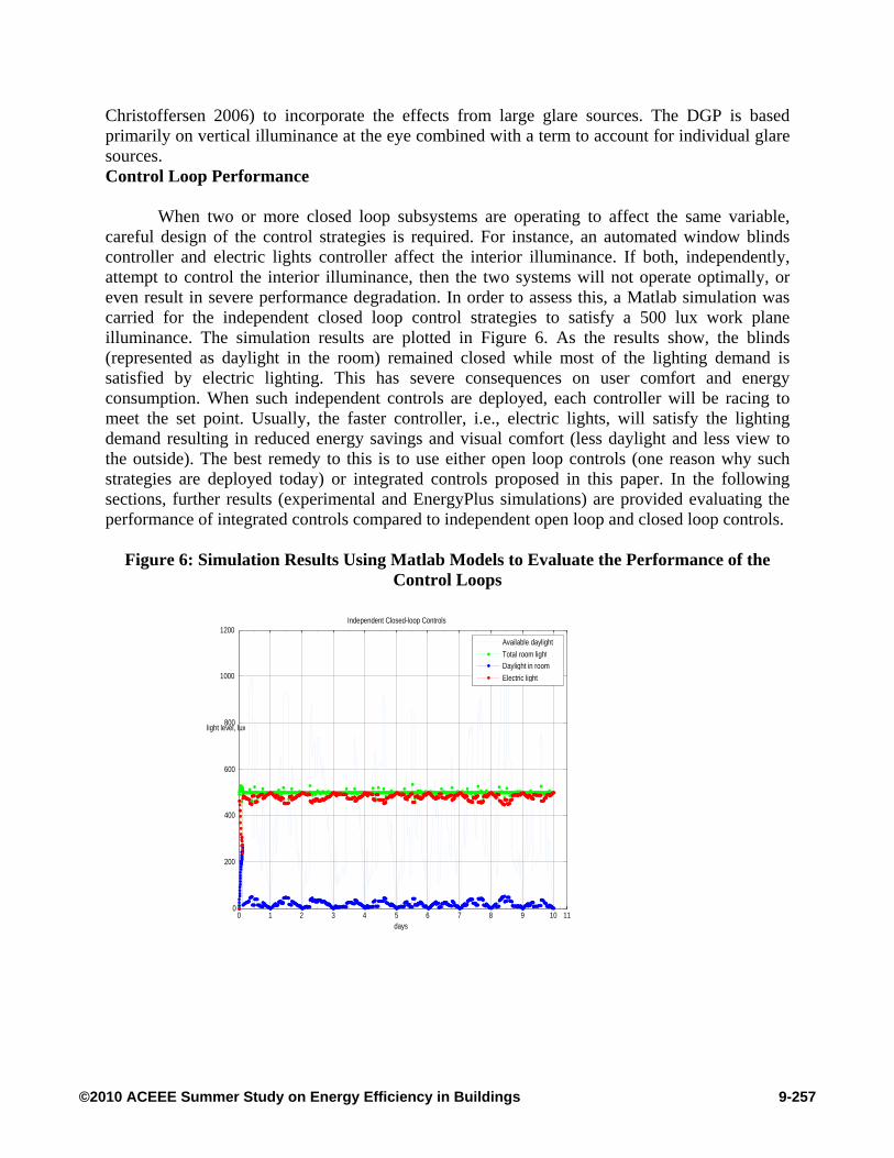
careful design of the control strategies is required. For instance, an automated window blinds controller and electric lights controller affect the interior illuminance. If both, independently, attempt to control the interior illuminance, then the two systems will not operate optimally, or even result in severe performance degradation. In order to assess this, a Matlab simulation was carried for the independent closed loop control strategies to satisfy a 500 lux work plane illuminance. The simulation results are plotted in Figure 6. As the results show, the blinds (represented as daylight in the room) remained closed while most of the lighting demand is satisfied by electric lighting. This has severe consequences on user comfort and energy consumption. When such independent controls are deployed, each controller will be racing to meet the set point. Usually, the faster controller, i.e., electric lights, will satisfy the lighting demand resulting in reduced energy savings and visual comfort (less daylight and less view to the outside). The best remedy to this is to use either open loop controls (one reason why such strategies are deployed today) or integrated controls proposed in this paper. In the following sections, further results (experimental and EnergyPlus simulations) are provided evaluating the performance of integrated controls compared to independent open loop and closed loop controls.
Figure 6: Simulation Results Using Matlab Models to Evaluate the Performance of the
Control Loops
0 1 2 3 4 5 6 7 8 9 10 110
200
400
600
800
1000
1200
days
light level, lux
Independent Closed-loop Controls
Available daylight
Total room lightDaylight in room
Electric light
9-257©2010 ACEEE Summer Study on Energy Efficiency in Buildings
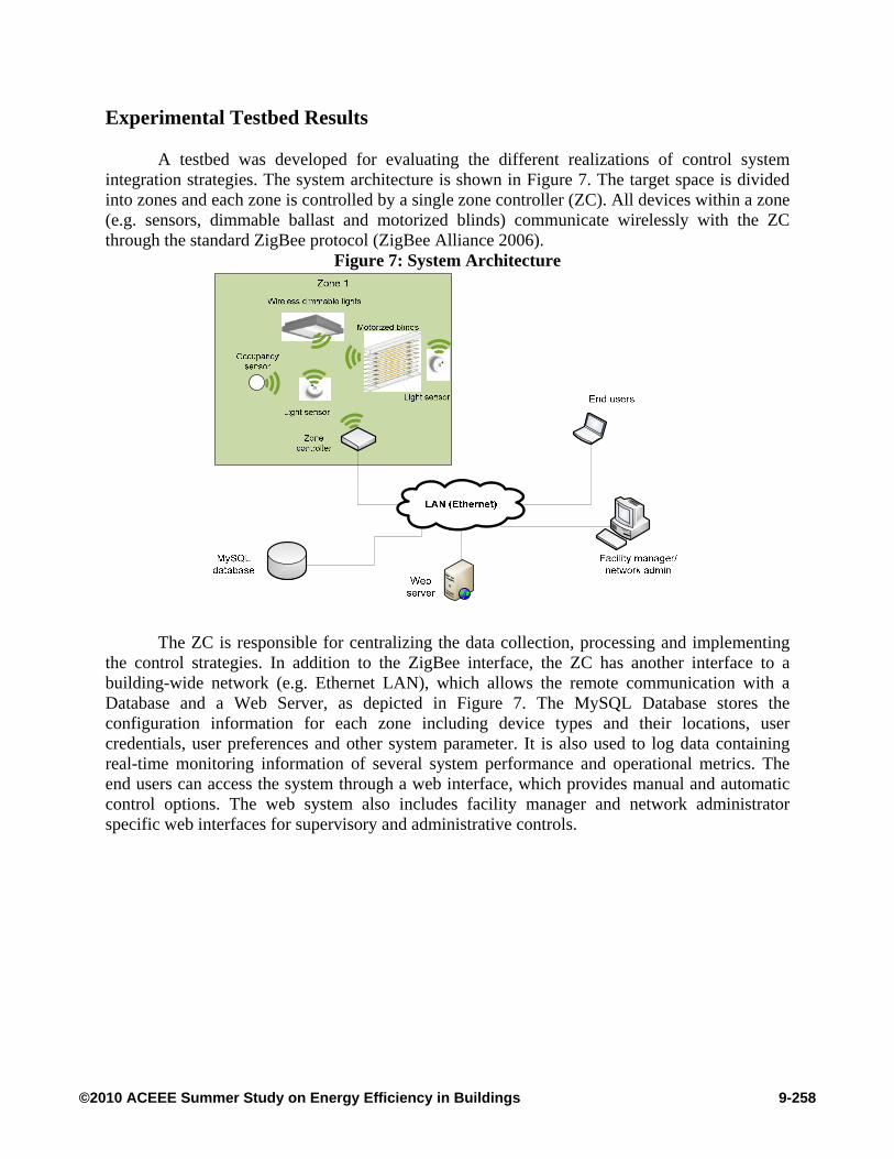
Experimental Testbed Results A testbed was developed for evaluating the different realizations of control system
integration strategies. The system architecture is shown in Figure 7. The target space is divided into zones and each zone is controlled by a single zone controller (ZC). All devices within a zone (e.g. sensors, dimmable ballast and motorized blinds) communicate wirelessly with the ZC through the standard ZigBee protocol (ZigBee Alliance 2006).
Figure 7: System Architecture
The ZC is responsible for centralizing the data collection, processing and implementing the control strategies. In addition to the ZigBee interface, the ZC has another interface to a building-wide network (e.g. Ethernet LAN), which allows the remote communication with a Database and a Web Server, as depicted in Figure 7. The MySQL Database stores the configuration information for each zone including device types and their locations, user credentials, user preferences and other system parameter. It is also used to log data containing real-time monitoring information of several system performance and operational metrics. The end users can access the system through a web interface, which provides manual and automatic control options. The web system also includes facility manager and network administrator specific web interfaces for supervisory and administrative controls.
9-258©2010 ACEEE Summer Study on Energy Efficiency in Buildings
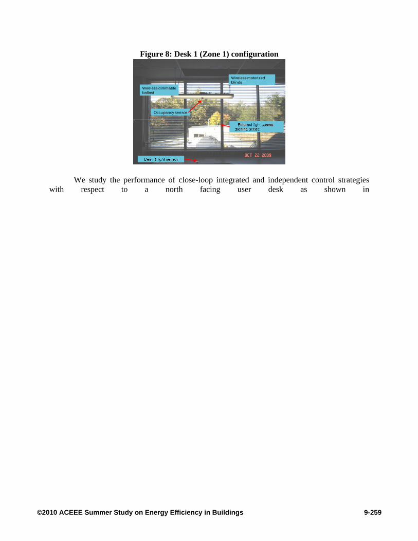
Figure 8: Desk 1 (Zone 1) configuration
Wireless dimmable ballast
Occupancy sensor
Wireless motorized blinds
We study the performance of close-loop integrated and independent control strategies with respect to a north facing user desk as shown in
9-259©2010 ACEEE Summer Study on Energy Efficiency in Buildings

Figure 8 in order to evaluate their daylight harvesting ability and independent and integrated control strategies.
The objective of both closed-loop (independent and integrated) control strategies is to maintain illumination level at the work-plane close to the user provided set point (in lux) as measured by the Desk 1 Light Sensor in
9-260©2010 ACEEE Summer Study on Energy Efficiency in Buildings
Figure 8. In the integrated mode, the blinds and lights are jointly controlled to optimize the amount of daylight used (see Figure 5). On the other hand, in the independent mode, the same light sensor provides current illumination level feedback to two different controllers (see Figure 4), one for lights and another one for blinds, which operate independently to maintain work plane illumination level close to the set point. An exterior light sensor is used in both experiments (see
9-261©2010 ACEEE Summer Study on Energy Efficiency in Buildings

Figure 8) to capture the external lighting conditions.
9-262©2010 ACEEE Summer Study on Energy Efficiency in Buildings
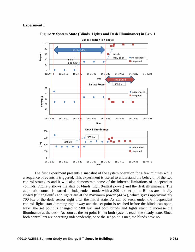
Experiment I
Figure 9: System State (Blinds, Lights and Desk Illuminance) in Exp. I
0
20
40
60
80
100
16:30:43 16:32:10 16:33:36 16:35:02 16:36:29 16:37:55 16:39:22 16:40:48
Deg
rees
Time
Blinds Position (tilt angle)
independent
IntegratedBlinds open 30o
0
10
20
30
40
50
16:30:43 16:32:10 16:33:36 16:35:02 16:36:29 16:37:55 16:39:22 16:40:48
Pow
er (W
)
Time
Ballast Power
Independent
Integrated
0
200
400
600
800
16:30:43 16:32:10 16:33:36 16:35:02 16:36:29 16:37:55 16:39:22 16:40:48
(Lux
)
Time
Desk 1 Illuminance
Independent
Integrated
Independent
300 lux
500 lux
Integrated
500 lux
Blinds fully open
The first experiment presents a snapshot of the system operation for a few minutes while a sequence of events is triggered. This experiment is useful to understand the behavior of the two control strategies and it will also demonstrate some of the inherent limitations of independent controls. Figure 9 shows the state of blinds, light (ballast power) and the desk illuminance. The automatic control is started in independent mode with a 300 lux set point. Blinds are initially closed (tilt angle=0o) and lights are at the maximum power (44 W), which gives approximately 700 lux at the desk sensor right after the initial state. As can be seen, under the independent control, lights start dimming right away and the set point is reached before the blinds can open. Next, the set point is changed to 500 lux, and both blinds and lights react to increase the illuminance at the desk. As soon as the set point is met both systems reach the steady state. Since both controllers are operating independently, once the set point is met, the blinds have no
9-263©2010 ACEEE Summer Study on Energy Efficiency in Buildings
incentive to open further and the lights could not dim anymore. Finally, we switch to integrated control mode which caused the blinds to fully open, while lights are further dimmed to meet the same 500 lux set point at the desk.
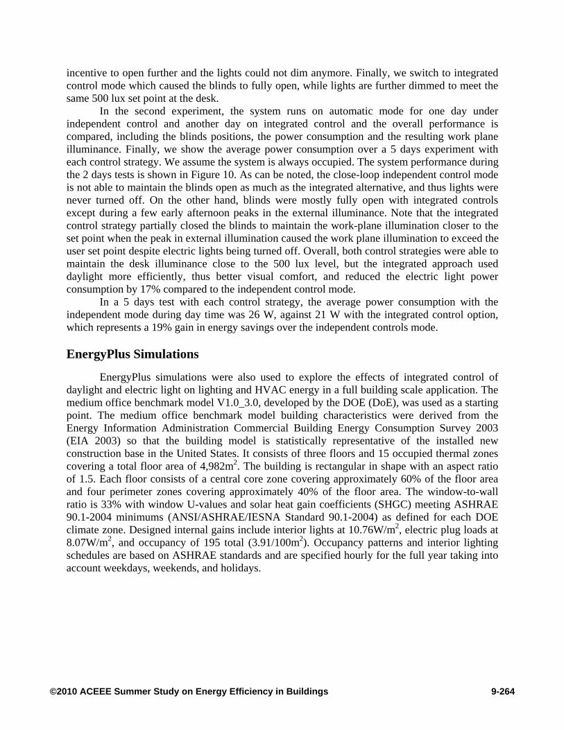
In the second experiment, the system runs on automatic mode for one day under independent control and another day on integrated control and the overall performance is compared, including the blinds positions, the power consumption and the resulting work plane illuminance. Finally, we show the average power consumption over a 5 days experiment with each control strategy. We assume the system is always occupied. The system performance during the 2 days tests is shown in Figure 10. As can be noted, the close-loop independent control mode is not able to maintain the blinds open as much as the integrated alternative, and thus lights were never turned off. On the other hand, blinds were mostly fully open with integrated controls except during a few early afternoon peaks in the external illuminance. Note that the integrated control strategy partially closed the blinds to maintain the work-plane illumination closer to the set point when the peak in external illumination caused the work plane illumination to exceed the user set point despite electric lights being turned off. Overall, both control strategies were able to maintain the desk illuminance close to the 500 lux level, but the integrated approach used daylight more efficiently, thus better visual comfort, and reduced the electric light power consumption by 17% compared to the independent control mode.
In a 5 days test with each control strategy, the average power consumption with the independent mode during day time was 26 W, against 21 W with the integrated control option, which represents a 19% gain in energy savings over the independent controls mode.
EnergyPlus Simulations
EnergyPlus simulations were also used to explore the effects of integrated control of
daylight and electric light on lighting and HVAC energy in a full building scale application. The medium office benchmark model V1.0_3.0, developed by the DOE (DoE), was used as a starting point. The medium office benchmark model building characteristics were derived from the Energy Information Administration Commercial Building Energy Consumption Survey 2003 (EIA 2003) so that the building model is statistically representative of the installed new construction base in the United States. It consists of three floors and 15 occupied thermal zones covering a total floor area of 4,982m2. The building is rectangular in shape with an aspect ratio of 1.5. Each floor consists of a central core zone covering approximately 60% of the floor area and four perimeter zones covering approximately 40% of the floor area. The window-to-wall ratio is 33% with window U-values and solar heat gain coefficients (SHGC) meeting ASHRAE 90.1-2004 minimums (ANSI/ASHRAE/IESNA Standard 90.1-2004) as defined for each DOE climate zone. Designed internal gains include interior lights at 10.76W/m2, electric plug loads at 8.07W/m2, and occupancy of 195 total (3.91/100m2). Occupancy patterns and interior lighting schedules are based on ASHRAE standards and are specified hourly for the full year taking into account weekdays, weekends, and holidays.
9-264©2010 ACEEE Summer Study on Energy Efficiency in Buildings
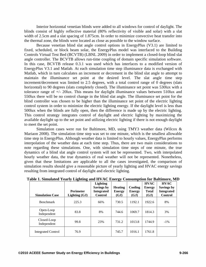
Experiment II
Figure 10: Devices States and Measurements During Exp. II
0
20
40
60
80
100
0:00 12:00 0:00 12:00 0:00 12:00
(Deg
rees
)
Time
Blinds position (Tilt angle)
Independent
Integrated
05
1015202530354045
0:00 12:00 0:00 12:00 0:00 12:00
(Wat
ts)
Time
Ballast Power
Independent
Integrated
0
100
200
300
400
500
600
700
0:00 12:00 0:00 12:00 0:00 12:00
(Lux)
Time
Desk Light Sensor
Independent
Integrated
The benchmark model was modified to implement dimming of electric lighting in
response to available daylight in order to maintain a specified illuminance level at a reference point. Only the perimeter zones of the medium office building receive daylight. In each perimeter zone, a single reference point was located along the centerline of the zone, two thirds deep into the perimeter space (approximately 3m from the windows), and at a workplane height of 0.8m. The illuminance set point for the lighting control system was 500lux and 100% of the lighting in each thermal zone was controllable. An idealized approach to the control was used in order to identify the upper bounds of energy savings. Both the light output and input power were controllable over the full linear range from 0 to 100%.
9-265©2010 ACEEE Summer Study on Energy Efficiency in Buildings
Interior horizontal venetian blinds were added to all windows for control of daylight. The blinds consist of highly reflective material (80% reflectivity of visible and solar) with a slat width of 2.5cm and a slat spacing of 1.875cm. In order to minimize convective heat transfer into the thermal zone, the blinds were located as close as possible to the window surface.
Because venetian blind slat angle control options in EnergyPlus (V3.1) are limited to fixed, scheduled, or block beam solar, the EnergyPlus model was interfaced to the Building Controls Virtual Test Bed (BCVTB) (LBNL 2009) in order to implement a closed-loop blind slat angle controller. The BCVTB allows run-time coupling of domain specific simulation software. In this case, BCVTB release 0.3.1 was used which has interfaces to a modified version of EnergyPlus V3.1 and Matlab. At each simulation time step illuminance data is exchanged with Matlab, which in turn calculates an increment or decrement in the blind slat angle to attempt to maintain the illuminance set point at the desired level. The slat angle time step increment/decrement was limited to 2.5 degrees, with a total control range of 0 degrees (slats horizontal) to 90 degrees (slats completely closed). The illuminance set point was 530lux with a tolerance range of +/- 20lux. This means for daylight illuminance values between 510lux and 550lux there will be no control change in the blind slat angle. The illuminance set point for the blind controller was chosen to be higher than the illuminance set point of the electric lighting control system in order to minimize the electric lighting energy. If the daylight level is less than 500lux when the blinds are fully open, then the difference is made up by the electric lighting. This control strategy integrates control of daylight and electric lighting by maximizing the available daylight up to the set point and utilizing electric lighting if there is not enough daylight to meet the set point.
Simulation cases were run for Baltimore, MD, using TMY3 weather data (Wilcox & Mariaon 2008). The simulation time step was set to one minute, which is the smallest allowable time step in EnergyPlus. Although weather data is limited to hourly values, EnergyPlus performs interpolation of the weather data at each time step. Thus, there are two main considerations to note regarding these simulations. One, with simulation time steps of one minute, the true dynamics of a blind slat angle control system will not be represented. Two, with interpolated hourly weather data, the true dynamics of real weather will not be represented. Nonetheless, given that these limitations are applicable to all the cases investigated, the comparison of simulation results should give a reasonable picture of yearly lighting and HVAC energy savings resulting from integrated control of daylight and electric lighting.
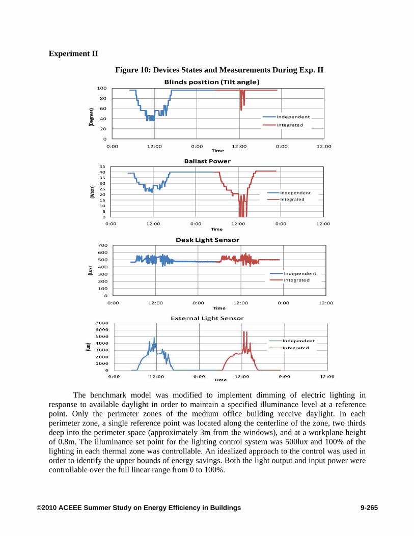
Table 1. Simulated Yearly Lighting and HVAC Energy Consumption for Baltimore, MD
Simulation Case Perimeter
Lighting (GJ)
Lighting Savings by Integrated
Control
Heating Energy
(GJ)
Cooling Energy
(GJ)
HVAC Energy Total (GJ)
HVAC Savings by Integrated
Control
Benchmark 225.3 66% 730.5 1192.1 1922.6 8%
Open-Loop Independent 83.8 8% 744.6 1069.7 1814.3 3%
Closed-Loop Independent 99.8 23% 731.2 1013.8 1744.9 -1%
Integrated Control 76.9 745.7 1016.1 1761.8
9-266©2010 ACEEE Summer Study on Energy Efficiency in Buildings
Results are given in Table 1, comparing the yearly lighting and HVAC energy consumption for four cases studied in this paper. The Benchmark case is the original DOE medium office benchmark model which implements ASHRAE 90.1-2004 envelope with no blinds and no dimming of electric lighting. The Open-loop Independent case adds interior venetian blinds with the slat angle controlled to block direct sun (open-loop control) and implements closed-loop control of electric lighting. The Closed-loop Independent case implements both closed-loop blind control and closed-loop electric lighting control with no integration. The Integrated Control case implements integrated closed-loop control of blind slat angle and electric lighting. The perimeter lighting energy is the energy used only in the perimeter zones of the building. The heating energy is for the whole building and includes the heating system, component energy and the pump energy for the hot water reheat coils. The cooling energy is also for the whole building and includes the cooling system and component related energy as well as the fan energy (which correlates with the cooling energy).
For perimeter lighting energy, Integrated Control saves 66% compared to Benchmark, 8% compared to Open-loop Independent, and 23% compared to Closed-loop Independent. In fact, for interior venetian blinds, simulations show that blinds fixed at zero degrees result in perimeter lighting energy consumption of 77GJ. This is the lower limit of lighting energy, which is achieved with Integrated Control. Open-loop Independent, which blocks direct sun, does not utilize daylight as effectively as Integrated Control. Closed-loop Independent suffers from competing independent controls which results in the blinds staying closed. In the simulations the blinds were reset to the open position at the start of each day, otherwise the blinds would have remained closed for the entire year. Generally, the addition of interior venetian blinds results in decreased cooling energy and increased heating energy, since some solar gain is blocked and reflected by the blinds. Integrated Control further decreases cooling energy by minimizing electric lighting energy, which results in a corresponding increase in heating energy. For HVAC energy, Integrated Control saves 14% compared to Benchmark and 3% compared to Open-loop Independent, while consuming approximately the same as Closed-loop Independent. From a comfort standpoint, both Closed-loop Independent and Integrated Control regulate illuminance to the set point. However, Integrated Control does so by maximizing daylight and view. Open-loop Independent does not regulate illuminance. All three blind controls eliminate discomfort glare due to daylight.
Conclusions
Lighting control systems including daylight integration are gaining prominence in low
energy sustainable buildings. Typical implementations of such systems involve two control loops, one for the dimming lights and another for the motorized blinds or the window treatments. In this paper, for the first time to our knowledge, two control strategies have been evaluated both analytically and experimentally. In the first strategy the two systems (lights and blinds) are controlled independently using separate sensors for each control loop to arrive at the desired light level on the work surface. This is most prevalent in the field. The other strategy is to control the lights and the window blind slat angle in an integrated fashion using the output of a single photosensor on the work surface and deploying control algorithms to minimize the energy consumption and maximizing the use of daylight. Both analytical simulation and experimental results from a laboratory test bed have shown that improved performance in terms of energy
9-267©2010 ACEEE Summer Study on Energy Efficiency in Buildings
savings and occupant comfort can be achieved by employing an integrated control strategy in comparison with independently controlled electric lighting and blinds loops.
Furthermore, EnergyPlus simulations of a benchmark medium sized office building has shown that integrated controls of electric lighting and blinds result in increased savings in HVAC loads compared to fixed blind position. Considerable lighting energy savings result from integrated controls compared to the benchmark case.
Based on our findings in this paper and published literature on this subject, we feel that achieving optimal energy savings in a real building environment is closely tied to providing occupant comfort as well. Therefore successful solutions in the market will require an integrated approach. Defining and quantifying occupant comfort comprehensively remains an open problem.
References:
ANSI/ASHRAE/IESNA Standard 90.1-2004. 2004. Energy Standard for Buildings Except
Low-Rise Residential Buildings. American National Standards Institute, American Society of Heating, Refrigerating and Air-Conditioning Engineers, Illuminating Engineering Society of North America.
Bierman, A. 2007. “Photosensors: Dimming and Switching Systems for Daylight
Harvesting.” Specifier Reports , 11 (1). [DoE] Commercial Building Benchmark Models. http://www1.eere.energy.gov/buildings.
U.S. Department of Energy, Energy Efficiency and Renewable Energy, Office of Building Technologies.
[EIA] Energy Information Administration. 2003. Commercial Building Energy Consumption
Survey. [EIA] Energy Information Administration. 2009. Lighting in Commercial Buildings.
http://www.eia.doe.gov/emeu/cbecs/cbecs2003/lighting/lighting1.html EnergyPlus. http://www.energyplus.gov U.S. Department of Energy, Energy Efficiency and
Renewable Energy, Office of Building Technologies. Jennings, J. 2000. Comparison of Control Options in Private Offices in an Advanced
Lighting Controls Testbed. LBNL-43096 REV LG-219: Lawrence Berkeley National Laboratory.
Kim, J., Park, Y., Yeo, M., and Kim, K. 2009. “An Experimental Study on the Environmental
Performance of the Automated Blind in Summer.” Building and Environment 44: 1517-1527.
[LBNL] 2009. Building Controls Virtual Test Bed Release 0.3.1. https://gaia.lbl.gov/bcvtb.
Berkeley, Calif.: Lawrence Berkeley National Laboratory:
9-268©2010 ACEEE Summer Study on Energy Efficiency in Buildings
Lee, E., and Selkowitz, S. 2006. “The New York Times Headquarters Daylighting Mock-Up: Monitored Performance of the Daylighting Control System.” Energy and Buildings, 914-929.
Osterhaus, W. 2008. “Analysis of Luminance Histograms for the Assessment of Discomfort
Glare in Daylit Offices.” In Proceedings of Balkan Light, Slowenia. Osterhaus, W. 1998. “Brightness as a Simple Indicator for Discomfort Glare from Large
Area Glare Sources.” In Proceedings of Tagungsband First International CIE Symposium on Lighting Quality. Ottawa, Canada.
Reinhart, C. 2004. “Lightswitch-2002: A Model for Manual and Automated Control of
Electric Lighting and Blinds.” Solar Energy 77: 15-28. Reinhart, C., and Voss, K. (2003). “Monitoring Manual Control of Electric Lighting and
Blinds.” Lighting Research and Technology 35 (3): 243-260. Rubinstein, F., Ward, G., and Verderber, R. 1989. “Improving the Performance of Photo-
Electrically Controlled Lighting Systems.” Illuminating Engineering Society 18 (1): 70-94.
Shen, E., and Hong, T. 2009. “Simulation-based Assessment of the Energy Savings Benefits
of Integrated Control in Office Buildings.” Building Simulation 2 (4): 239-251. Skelly, M., and Wilkinson, M. 2001. “The Evolution of Interactive Facades: Improving
Automated Blind Control.” Whole Life Performance of Facades, 129-142. Bath, UK. Vine, E., Lee, E., Clear, R., DiBartolomeo, D., and Selkowitz, S. 1998. “Office Worker
Response to an Automated Venetian Blind and Electric Lighting System: A Pilot Study.” Journal of Energy and Buildings 28: 205-218.
Wienold, J., and Christoffersen, J. 2006. “Evaluation Methods and Development of a New
Glare Prediction Model for Daylight Environments with the Use of CCD Cameras.” Energy and Building 37: 745-757.
Wilcox, S., and Mariaon, W. 2008. User Manual for TMY3 Data Set. NREL Technical Report
NREL/TP-581-43156. ZigBee Alliance. 2006. ZigBee Specification. ZigBee Document Number 054024r01.
9-269©2010 ACEEE Summer Study on Energy Efficiency in Buildings